product catalog - textron aviation special missions
TRANSCRIPT

P R O D U C T C A T A L O G
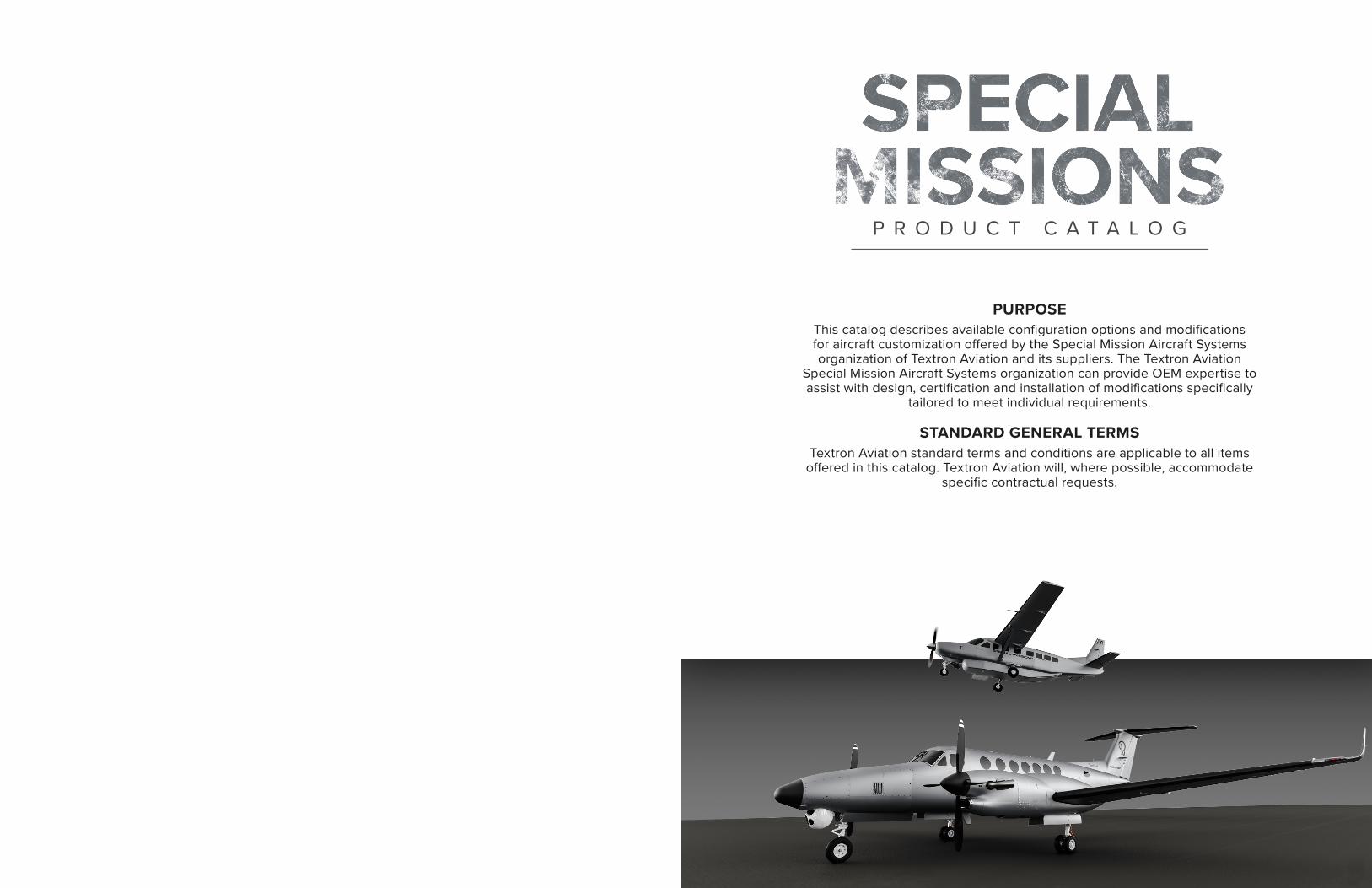
PURPOSEThis catalog describes available configuration options and modifications for aircraft customization offered by the Special Mission Aircraft Systems organization of Textron Aviation and its suppliers. The Textron Aviation
Special Mission Aircraft Systems organization can provide OEM expertise to assist with design, certification and installation of modifications specifically
tailored to meet individual requirements.
STANDARD GENERAL TERMSTextron Aviation standard terms and conditions are applicable to all items
offered in this catalog. Textron Aviation will, where possible, accommodate specific contractual requests.
P R O D U C T C A T A L O G
208 / 208B Solutions Electrical Load Analysis 8
Extended Baggage with Cargo Door 9
Amphibious Floats 10
Single Point Refueling 1 1
Parachute Configuration 12
Dual Camera Port - Square Portal 13
Slim Line Mission Console 14
Night Vision Capability 15
Wing Mount External Load Provisions 16
Belly Mount External Load Provisions 17
Spectrum Series Stretcher 18
B200 & B300 Solutions Aft Toilet Installation 20
Spectrum Dual 2200 Series ALSS 2 1
LifePort Stretcher; Patient Loading and Support 22
System
AvFab Stretcher Installation 23
Four - Place Stretcher / Divan System 24
Voyager Transport Incubator (Carry-On Equipment) 25
Isovac Capsuls Patient Isolation Unit (Loose 26
Equipment)
Model 3507 Observer Seats 27
AvFab High - Density Seating 28
AvFab Two-Place Side-Facing Divan 29
AvFab Single / Dual Aft Jump Seats 30
LifePort Multi-Mission Seat 3 1
UTC 3056 Attendant Seat 32
UTC 3507 Mission Seat 33
Engine Wash Ring and Drain Kit 34
High Float Gear Door (HFGD) 35
Installation of Baggage Door 36
Table of Contents
(8025) Cargo Door 37
Avionics Equipment Rack 38
Digital Audio Control System (DACS) 39
Pulselite Control System 40
Extended Pedestal Installation 4 1
Electrical Load Analysis 42
LCR-100N Internal Hybrid Navigator 43
SKYTRAC 44
B200 Solutions Crown Wing Lockers 46
Single/Dual/Triple Standard Camera Provisions STC 47
Single/Dual/Triple Camera Provisions with Fwd 48
Oversized Camera Portal STC
B300 Solutions (8000) Extended Range (ER) Fuel Tanks 49
(8100) PT6A-67A Engine Upgrade 50
Increased Gross Weight Kit (17,500 lb) 51
Stormscope WX - 1000E 52
TA - 24 Military GPS Receiver 53
TCN - 500 TACAN Installation Kt 54
AN / ARC - 210 VHF / UHF / SATCOM Radio 55
MFD Video Enablement 56
AN / APX - 119 Identification Friend of Foe (IFF) 57
400 Amp Starter Generator 58
Gravel Runway Kit 59
Wet and Contaminated Supplement 60
Nose Ballast Kit 6 1
Special Mission Dual Aft Strakes 62
Radar Pressure Box for Radome 63
X-Band Radome and EO/IR Fairing 64
EO/IR Lift 65
Table of Contents
Utility Nose and Lift Kit 66
Utility Nose Kit 67
Single/Dual/Triple Standard Camera Provisions STC 68
Single/Dual/Triple Camera Provisions with Fwd 69
Oversized Camera Portal STC
LifeRaft Soft Pack w/ 406Mhz ELT - 11 Person 70
(Loose Equipment)
Drop Hatch 7 1
Bubble Window 72
Flight Inspection System - UNIFIS 3000 73
Flight Inspection Installation 74
680A Solutions Elecitcal Load Analysis 76
LifePort Stretcher; Patient Loading and Support 77
System
8
DESCRIPTIONOPTION TYPE:
OPTION WEIGHT (LBS):
9
DESCRIPTIONOPTION TYPE:
OPTION WEIGHT (LBS):
208 / 208B 208 / 208B
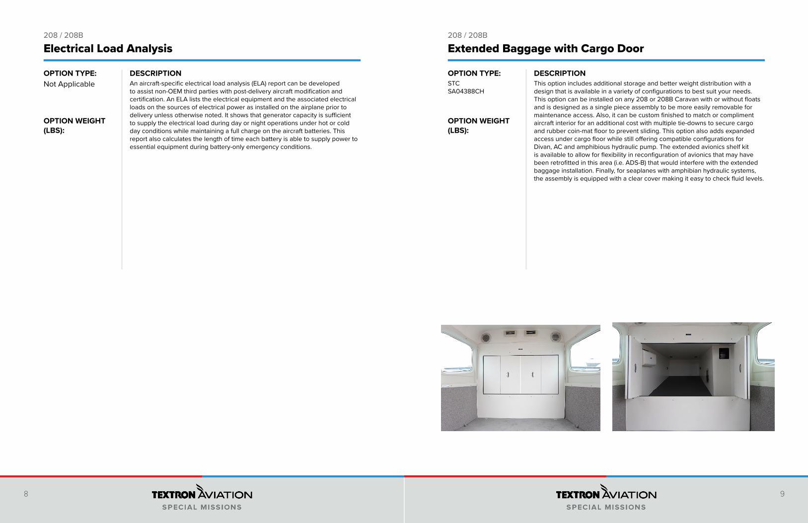
This option includes additional storage and better weight distribution with a design that is available in a variety of configurations to best suit your needs. This option can be installed on any 208 or 208B Caravan with or without floats and is designed as a single piece assembly to be more easily removable for maintenance access. Also, it can be custom finished to match or compliment aircraft interior for an additional cost with multiple tie-downs to secure cargo and rubber coin-mat floor to prevent sliding. This option also adds expanded access under cargo floor while still offering compatible configurations for Divan, AC and amphibious hydraulic pump. The extended avionics shelf kit is available to allow for flexibility in reconfiguration of avionics that may have been retrofitted in this area (i.e. ADS-B) that would interfere with the extended baggage installation. Finally, for seaplanes with amphibian hydraulic systems, the assembly is equipped with a clear cover making it easy to check fluid levels.
STCSA04388CH
An aircraft-specific electrical load analysis (ELA) report can be developed to assist non-OEM third parties with post-delivery aircraft modification and certification. An ELA lists the electrical equipment and the associated electrical loads on the sources of electrical power as installed on the airplane prior to delivery unless otherwise noted. It shows that generator capacity is sufficient to supply the electrical load during day or night operations under hot or cold day conditions while maintaining a full charge on the aircraft batteries. This report also calculates the length of time each battery is able to supply power to essential equipment during battery-only emergency conditions.
Not Applicable
Electrical Load Analysis Extended Baggage with Cargo Door
10
DESCRIPTIONOPTION TYPE:
OPTION WEIGHT (LBS):
11
DESCRIPTIONOPTION TYPE:
OPTION WEIGHT (LBS):
208 / 208B 208 / 208B
• Features more buoyancy at the aft of the float than the legacy model 8000 float
• Hull features fluted, high deadrise forward bottoms and extra buoyancy • Non-skid coating on flat top decks• Internal cables for water rudder controls• Amphibious gear advisory system and gear position indicator on the float
deck of amphibious floats• Four (4) large float hatches for gear with 150 pounds carrying capacity each• Aluminum skins and parts are laser cut and rivet holes are prepunched so
that replacement parts fit easily• Replaceable wear strips on main keel for ease of maintenance • Single point refueling for quicker and more accesible refueling• Low maintenance main gear retraction mechanism and oleo design with no
latches or slides to lubricate or stick
Amphibious Floats
STCSA1311GL
STCSA00059WI
42.00750.00 / 208255.00 / 208B
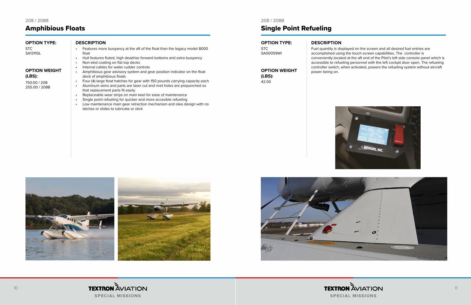
Single Point Refueling
Fuel quantity is displayed on the screen and all desired fuel entries are accomplished using the touch screen capabilities. The controller is conveniently located at the aft end of the Pilot’s left side console panel which is accessible to refueling personnel with the left cockpit door open. The refueling controller switch, when activated, powers the refueling system without aircraft power being on.
12
DESCRIPTIONOPTION TYPE:
OPTION WEIGHT (LBS):
13
DESCRIPTIONOPTION TYPE:
OPTION WEIGHT (LBS):
208 / 208B 208 / 208B
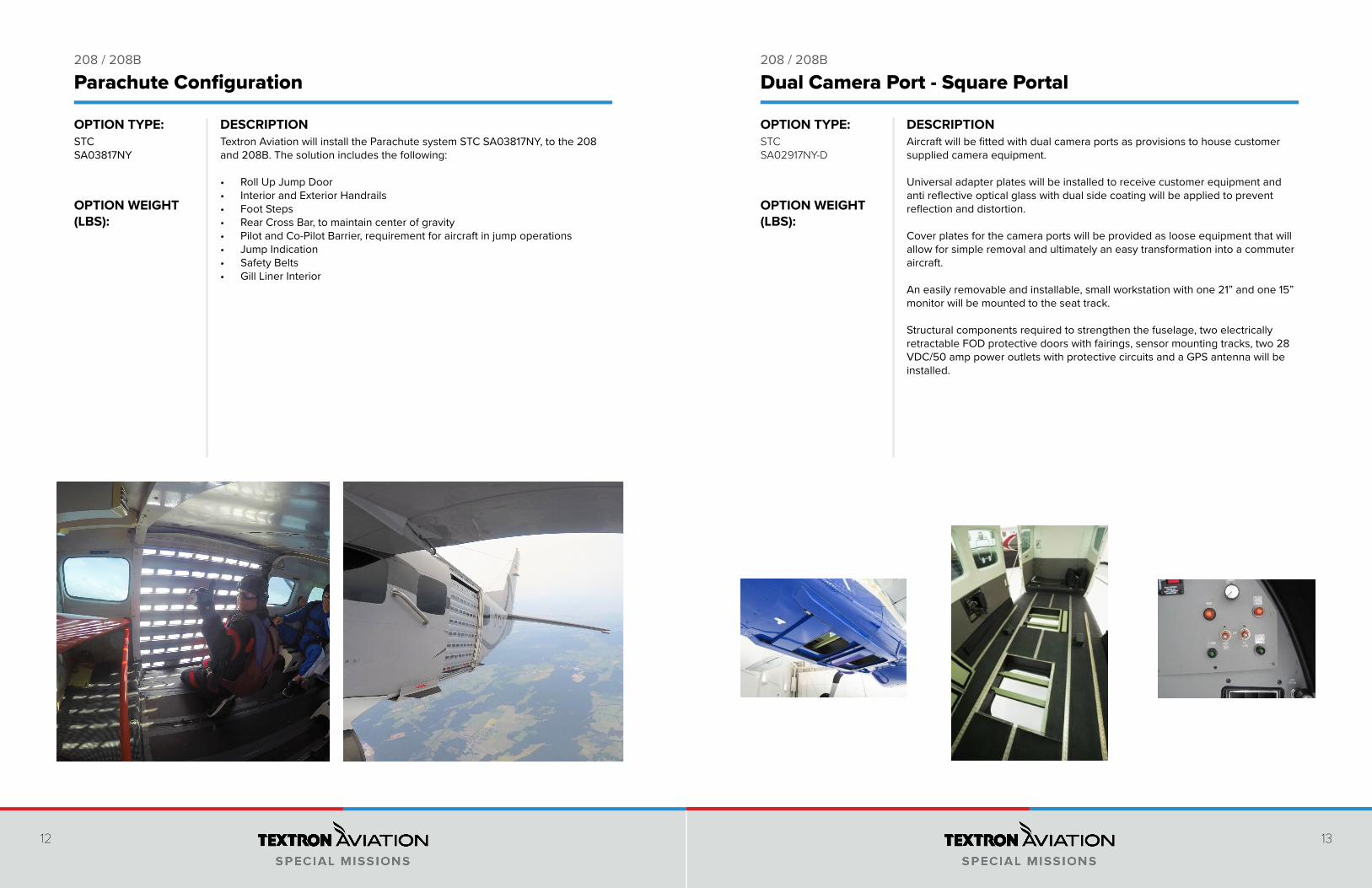
Textron Aviation will install the Parachute system STC SA03817NY, to the 208 and 208B. The solution includes the following:
• Roll Up Jump Door• Interior and Exterior Handrails• Foot Steps• Rear Cross Bar, to maintain center of gravity• Pilot and Co-Pilot Barrier, requirement for aircraft in jump operations• Jump Indication• Safety Belts• Gill Liner Interior
STC SA03817NY
Parachute Configuration
Aircraft will be fitted with dual camera ports as provisions to house customer supplied camera equipment. Universal adapter plates will be installed to receive customer equipment and anti reflective optical glass with dual side coating will be applied to prevent reflection and distortion. Cover plates for the camera ports will be provided as loose equipment that will allow for simple removal and ultimately an easy transformation into a commuter aircraft. An easily removable and installable, small workstation with one 21” and one 15” monitor will be mounted to the seat track. Structural components required to strengthen the fuselage, two electrically retractable FOD protective doors with fairings, sensor mounting tracks, two 28 VDC/50 amp power outlets with protective circuits and a GPS antenna will be installed.
STCSA02917NY-D
Dual Camera Port - Square Portal
14
DESCRIPTIONOPTION TYPE:
OPTION WEIGHT (LBS):
15
DESCRIPTIONOPTION TYPE:
OPTION WEIGHT (LBS):
208 / 208B 208 / 208B
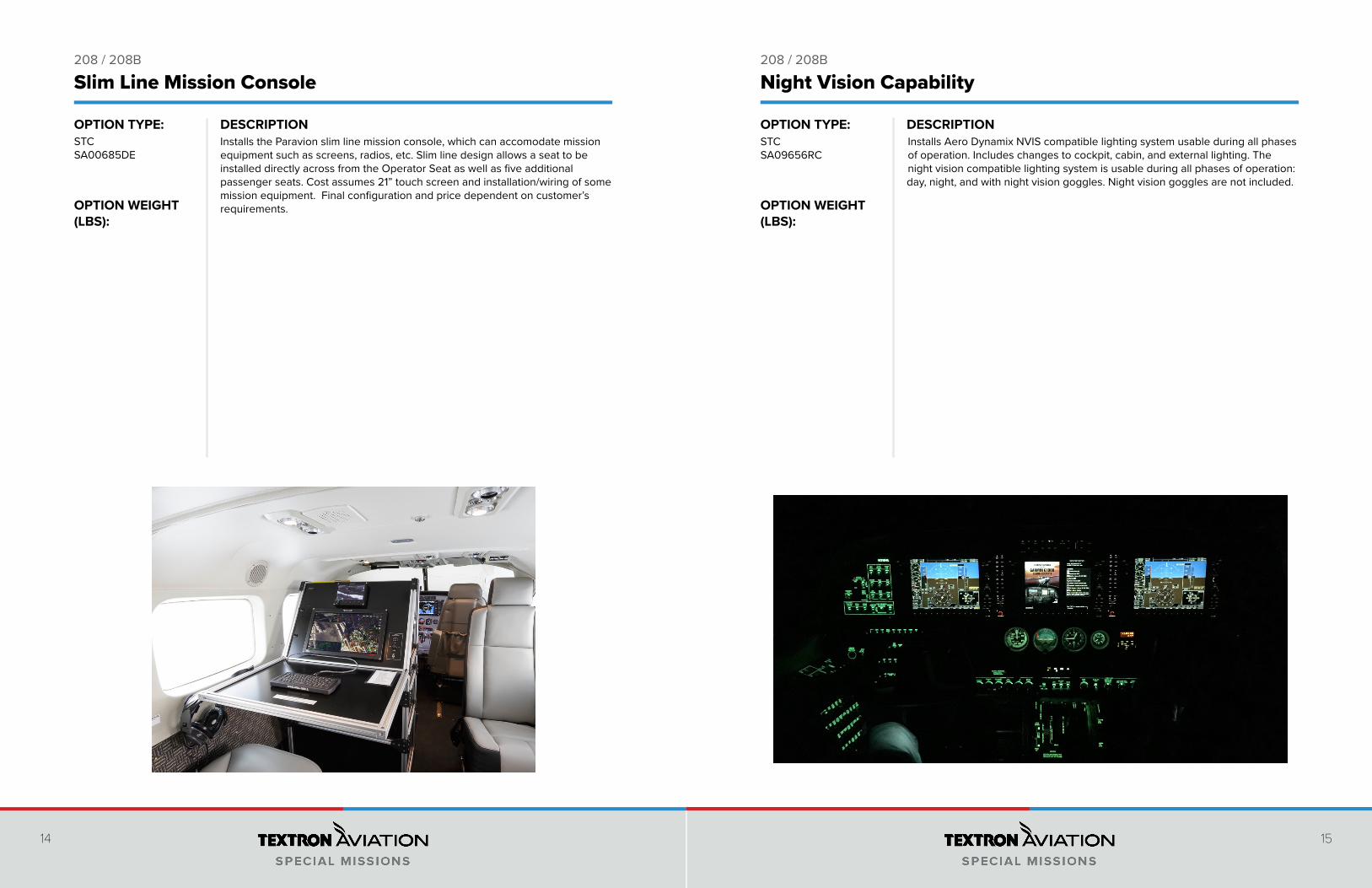
Installs the Paravion slim line mission console, which can accomodate mission equipment such as screens, radios, etc. Slim line design allows a seat to be installed directly across from the Operator Seat as well as five additional passenger seats. Cost assumes 21” touch screen and installation/wiring of some mission equipment. Final configuration and price dependent on customer’s requirements.
STCSA00685DE
Slim Line Mission Console Night Vision Capability
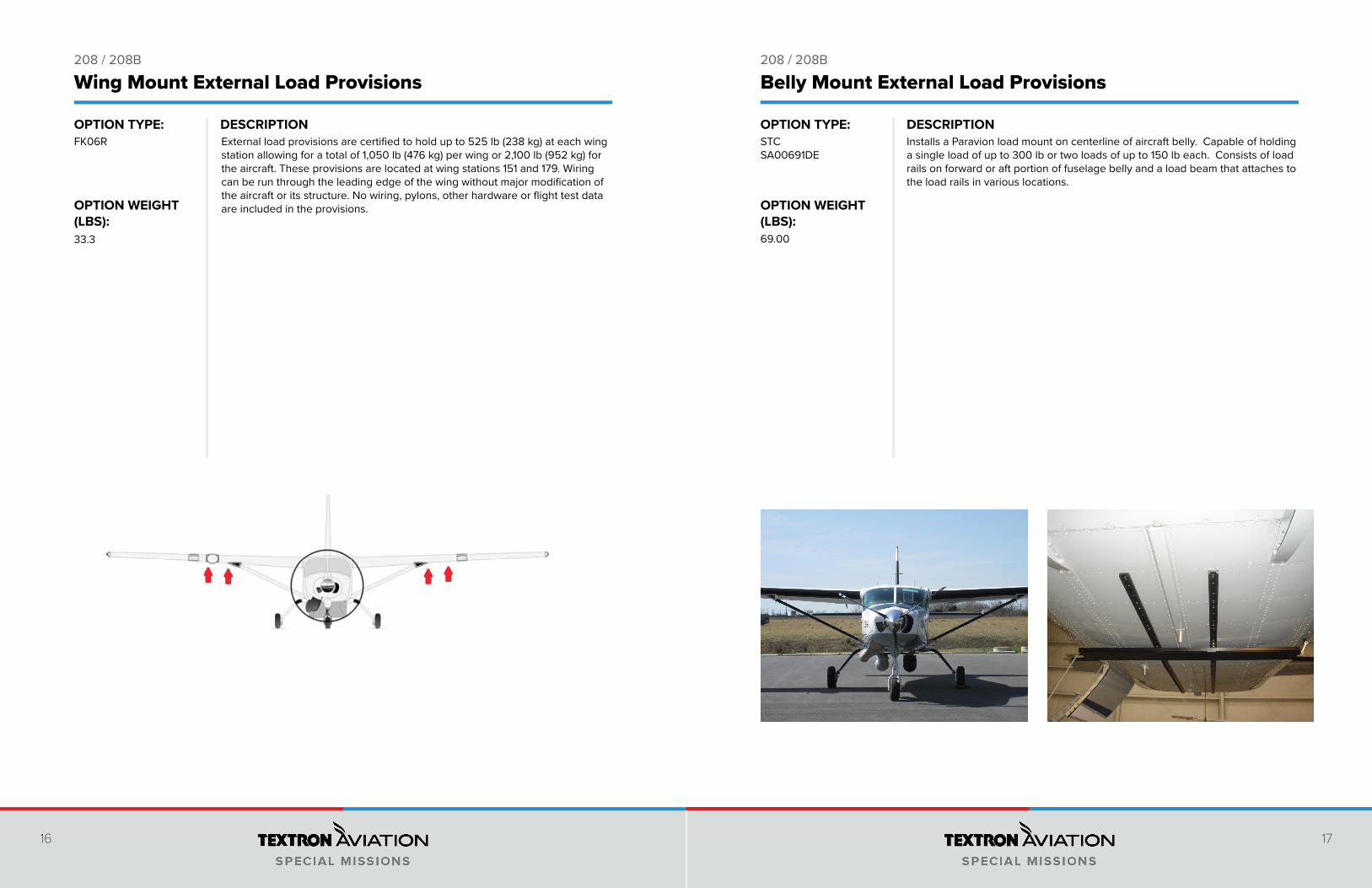
Installs Aero Dynamix NVIS compatible lighting system usable during all phases of operation. Includes changes to cockpit, cabin, and external lighting. The night vision compatible lighting system is usable during all phases of operation: day, night, and with night vision goggles. Night vision goggles are not included.
STCSA09656RC
16
DESCRIPTIONOPTION TYPE:
OPTION WEIGHT (LBS):
17
DESCRIPTIONOPTION TYPE:
OPTION WEIGHT (LBS):
208 / 208B 208 / 208B
Wing Mount External Load Provisions
External load provisions are certified to hold up to 525 lb (238 kg) at each wing station allowing for a total of 1,050 lb (476 kg) per wing or 2,100 lb (952 kg) for the aircraft. These provisions are located at wing stations 151 and 179. Wiring can be run through the leading edge of the wing without major modification of the aircraft or its structure. No wiring, pylons, other hardware or flight test data are included in the provisions.
FK06R
33.3
STCSA00691DE
69.00
Belly Mount External Load Provisions
Installs a Paravion load mount on centerline of aircraft belly. Capable of holding a single load of up to 300 lb or two loads of up to 150 lb each. Consists of load rails on forward or aft portion of fuselage belly and a load beam that attaches to the load rails in various locations.
18
DESCRIPTIONOPTION TYPE:
OPTION WEIGHT (LBS):
208 / 208B
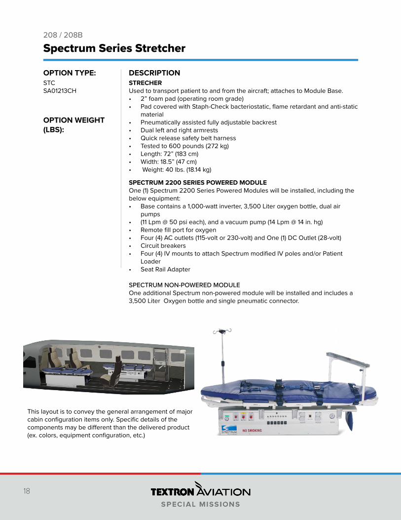
SPECTRUM 2200 SERIES POWERED MODULE One (1) Spectrum 2200 Series Powered Modules will be installed, including the below equipment:• Base contains a 1,000-watt inverter, 3,500 Liter oxygen bottle, dual air
pumps• (11 Lpm @ 50 psi each), and a vacuum pump (14 Lpm @ 14 in. hg)• Remote fill port for oxygen• Four (4) AC outlets (115-volt or 230-volt) and One (1) DC Outlet (28-volt)• Circuit breakers• Four (4) IV mounts to attach Spectrum modified IV poles and/or Patient
Loader• Seat Rail Adapter
SPECTRUM NON-POWERED MODULE One additional Spectrum non-powered module will be installed and includes a 3,500 Liter Oxygen bottle and single pneumatic connector.
STRECHER Used to transport patient to and from the aircraft; attaches to Module Base.• 2” foam pad (operating room grade)• Pad covered with Staph-Check bacteriostatic, flame retardant and anti-static
material• Pneumatically assisted fully adjustable backrest• Dual left and right armrests• Quick release safety belt harness• Tested to 600 pounds (272 kg)• Length: 72” (183 cm)• Width: 18.5” (47 cm)• Weight: 40 lbs. (18.14 kg)
Spectrum Series Stretcher
STCSA01213CH
This layout is to convey the general arrangement of major cabin configuration items only. Specific details of the components may be different than the delivered product (ex. colors, equipment configuration, etc.)
20 21
DESCRIPTION DESCRIPTIONOPTION TYPE:
OPTION WEIGHT (LBS):
OPTION TYPE:
OPTION WEIGHT (LBS):
B200 / B300 B200 / B300
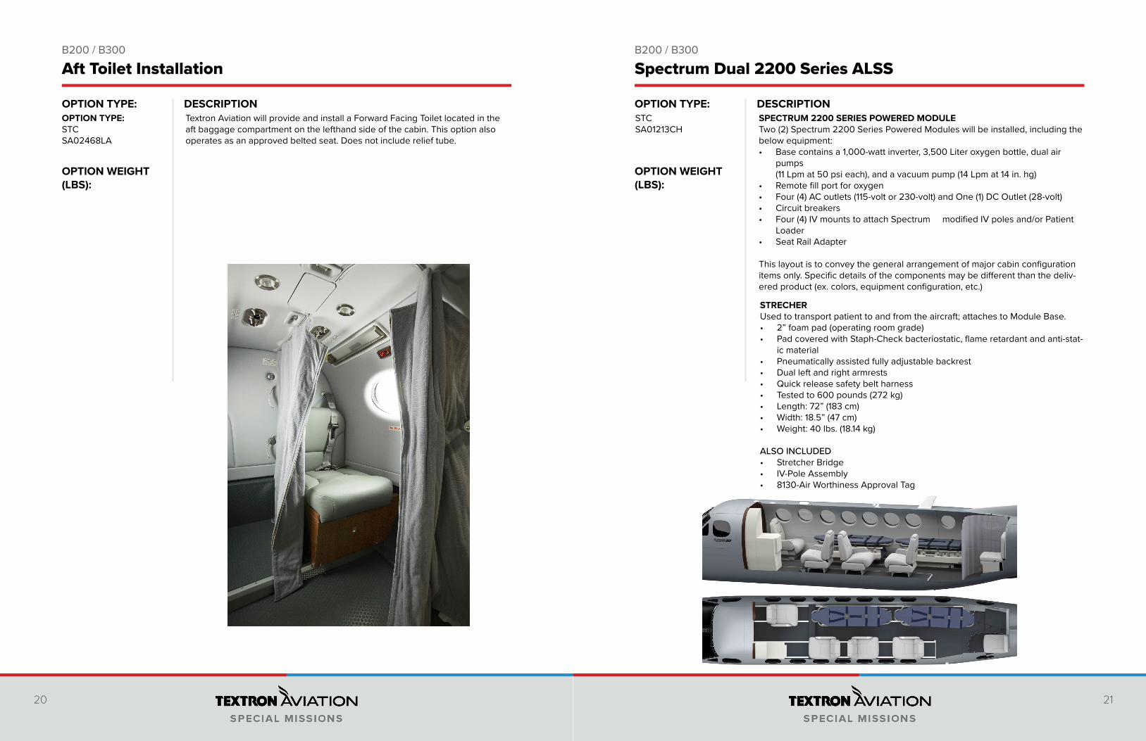
Aft Toilet Installation Spectrum Dual 2200 Series ALSS
Textron Aviation will provide and install a Forward Facing Toilet located in the aft baggage compartment on the lefthand side of the cabin. This option also operates as an approved belted seat. Does not include relief tube.
OPTION TYPE:STCSA02468LA
SPECTRUM 2200 SERIES POWERED MODULE Two (2) Spectrum 2200 Series Powered Modules will be installed, including the below equipment:• Base contains a 1,000-watt inverter, 3,500 Liter oxygen bottle, dual air
pumps (11 Lpm at 50 psi each), and a vacuum pump (14 Lpm at 14 in. hg)
• Remote fill port for oxygen• Four (4) AC outlets (115-volt or 230-volt) and One (1) DC Outlet (28-volt)• Circuit breakers• Four (4) IV mounts to attach Spectrum modified IV poles and/or Patient
Loader• Seat Rail Adapter This layout is to convey the general arrangement of major cabin configuration items only. Specific details of the components may be different than the deliv-ered product (ex. colors, equipment configuration, etc.)
STRECHER Used to transport patient to and from the aircraft; attaches to Module Base.• 2” foam pad (operating room grade)• Pad covered with Staph-Check bacteriostatic, flame retardant and anti-stat-
ic material• Pneumatically assisted fully adjustable backrest• Dual left and right armrests• Quick release safety belt harness• Tested to 600 pounds (272 kg)• Length: 72” (183 cm)• Width: 18.5” (47 cm)• Weight: 40 lbs. (18.14 kg) ALSO INCLUDED• Stretcher Bridge• IV-Pole Assembly• 8130-Air Worthiness Approval Tag
STCSA01213CH
22 23
DESCRIPTION DESCRIPTIONOPTION TYPE:
OPTION WEIGHT (LBS):
OPTION TYPE:
OPTION WEIGHT (LBS):
B200 / B300 B200 / B300
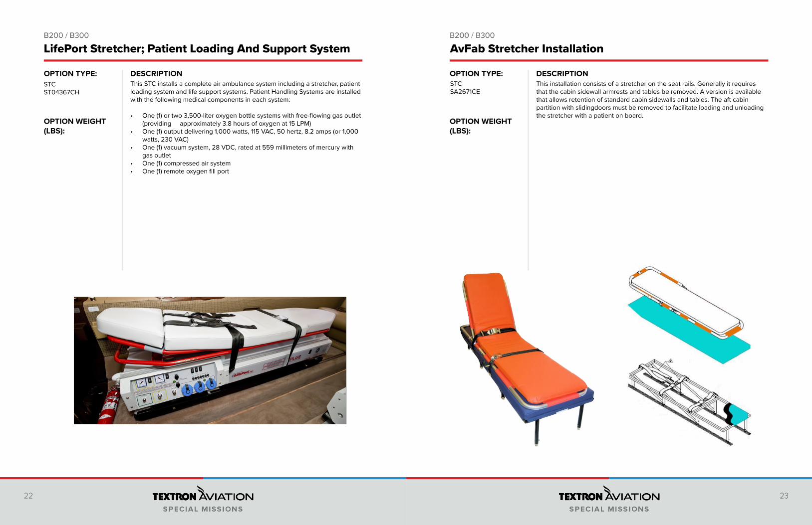
This installation consists of a stretcher on the seat rails. Generally it requires that the cabin sidewall armrests and tables be removed. A version is available that allows retention of standard cabin sidewalls and tables. The aft cabin partition with slidingdoors must be removed to facilitate loading and unloading the stretcher with a patient on board.
AvFab Stretcher Installation
STCSA2671CE
This STC installs a complete air ambulance system including a stretcher, patient loading system and life support systems. Patient Handling Systems are installed with the following medical components in each system:
• One (1) or two 3,500-liter oxygen bottle systems with free-flowing gas outlet (providing approximately 3.8 hours of oxygen at 15 LPM)
• One (1) output delivering 1,000 watts, 115 VAC, 50 hertz, 8.2 amps (or 1,000 watts, 230 VAC)
• One (1) vacuum system, 28 VDC, rated at 559 millimeters of mercury with gas outlet
• One (1) compressed air system • One (1) remote oxygen fill port
LifePort Stretcher; Patient Loading And Support System
STCST04367CH
24 25
DESCRIPTION DESCRIPTIONOPTION TYPE:
OPTION WEIGHT (LBS):
OPTION TYPE:
OPTION WEIGHT (LBS):
B200 / B300 B200 / B300
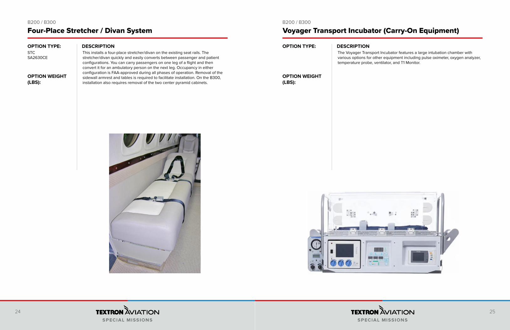
This installs a four-place stretcher/divan on the existing seat rails. The stretcher/divan quickly and easily converts between passenger and patient configurations. You can carry passengers on one leg of a flight and then convert it for an ambulatory person on the next leg. Occupancy in either configuration is FAA-approved during all phases of operation. Removal of the sidewall armrest and tables is required to facilitate installation. On the B300, installation also requires removal of the two center pyramid cabinets.
STCSA2630CE
The Voyager Transport Incubator features a large intubation chamber with various options for other equipment including pulse oximeter, oxygen analyzer, temperature probe, ventilator, and T1 Monitor.
Four-Place Stretcher / Divan System Voyager Transport Incubator (Carry-On Equipment)
26 27
DESCRIPTION DESCRIPTIONOPTION TYPE:
OPTION WEIGHT (LBS):
OPTION TYPE:
OPTION WEIGHT (LBS):
B200 / B300 B200 / B300
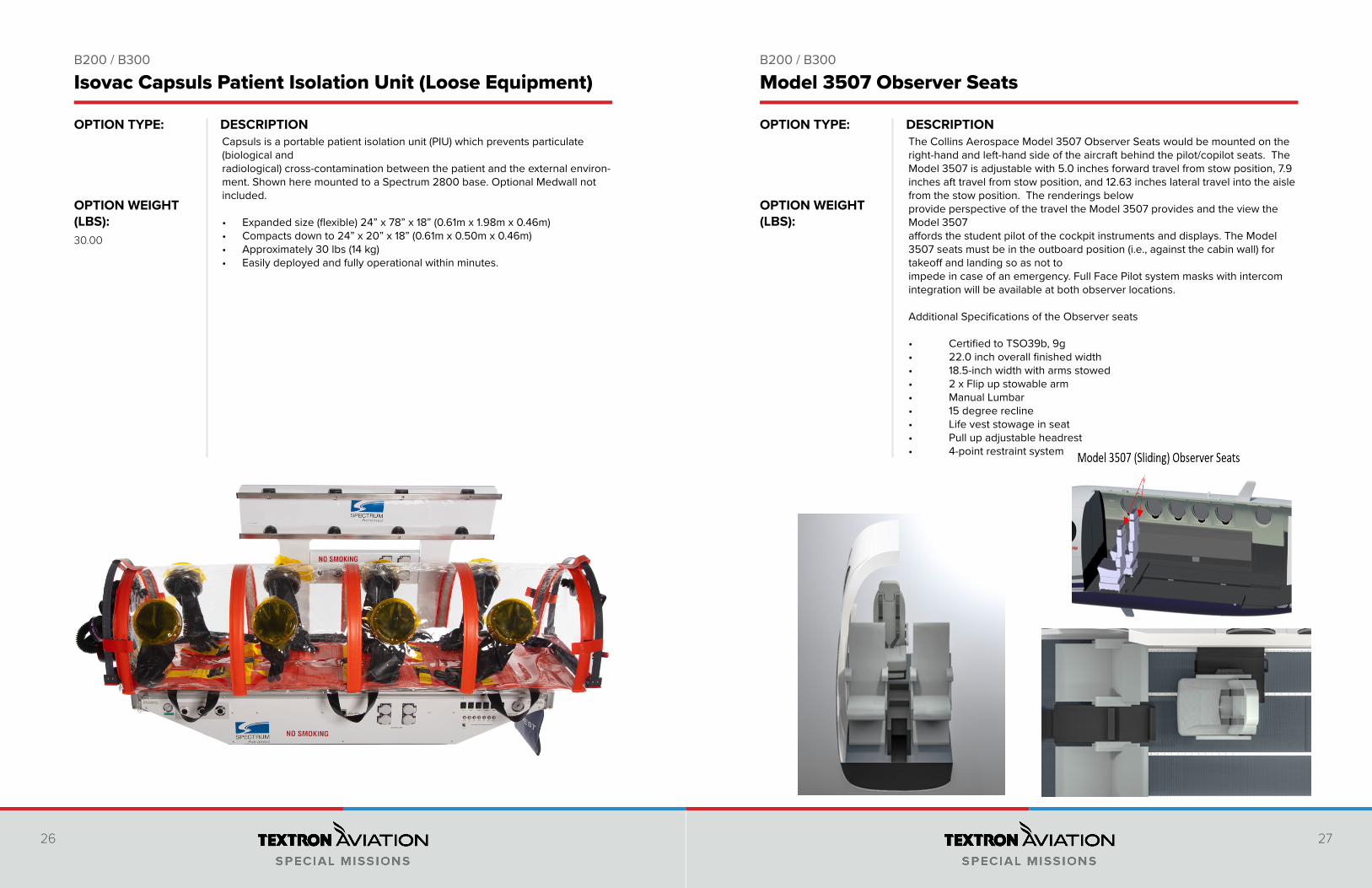
The Collins Aerospace Model 3507 Observer Seats would be mounted on the right-hand and left-hand side of the aircraft behind the pilot/copilot seats. The Model 3507 is adjustable with 5.0 inches forward travel from stow position, 7.9 inches aft travel from stow position, and 12.63 inches lateral travel into the aisle from the stow position. The renderings below provide perspective of the travel the Model 3507 provides and the view the Model 3507 affords the student pilot of the cockpit instruments and displays. The Model 3507 seats must be in the outboard position (i.e., against the cabin wall) for takeoff and landing so as not to impede in case of an emergency. Full Face Pilot system masks with intercom integration will be available at both observer locations.
Additional Specifications of the Observer seats
• Certified to TSO39b, 9g • 22.0 inch overall finished width • 18.5-inch width with arms stowed• 2 x Flip up stowable arm • Manual Lumbar • 15 degree recline• Life vest stowage in seat• Pull up adjustable headrest• 4-point restraint system
Isovac Capsuls Patient Isolation Unit (Loose Equipment) Model 3507 Observer Seats
Capsuls is a portable patient isolation unit (PIU) which prevents particulate (biological and radiological) cross-contamination between the patient and the external environ-ment. Shown here mounted to a Spectrum 2800 base. Optional Medwall not included.
• Expanded size (flexible) 24” x 78” x 18” (0.61m x 1.98m x 0.46m)• Compacts down to 24” x 20” x 18” (0.61m x 0.50m x 0.46m)• Approximately 30 lbs (14 kg)• Easily deployed and fully operational within minutes.
30.00
28 29
DESCRIPTION DESCRIPTIONOPTION TYPE:
OPTION WEIGHT (LBS):
OPTION TYPE:
OPTION WEIGHT (LBS):
B200 / B300 B200 / B300
Globetrotter Traveler
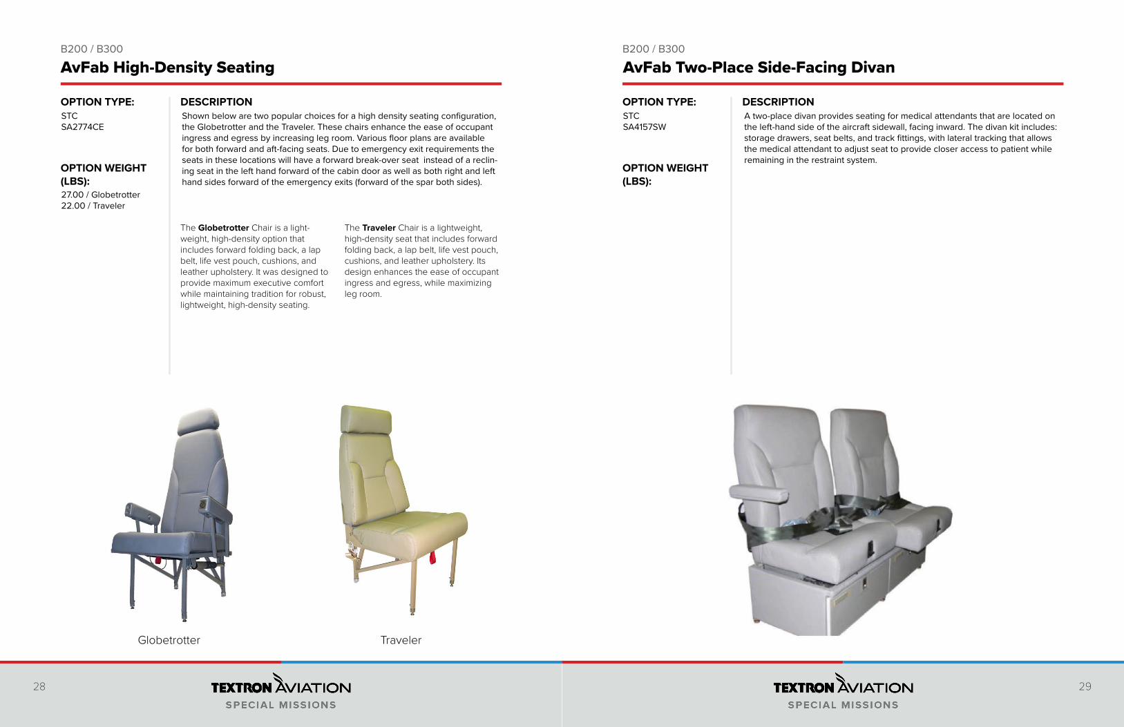
Shown below are two popular choices for a high density seating configuration, the Globetrotter and the Traveler. These chairs enhance the ease of occupant ingress and egress by increasing leg room. Various floor plans are available for both forward and aft-facing seats. Due to emergency exit requirements the seats in these locations will have a forward break-over seat instead of a reclin-ing seat in the left hand forward of the cabin door as well as both right and left hand sides forward of the emergency exits (forward of the spar both sides).
The Globetrotter Chair is a light-weight, high-density option that includes forward folding back, a lap belt, life vest pouch, cushions, and leather upholstery. It was designed to provide maximum executive comfort while maintaining tradition for robust, lightweight, high-density seating.
The Traveler Chair is a lightweight, high-density seat that includes forward folding back, a lap belt, life vest pouch, cushions, and leather upholstery. Its design enhances the ease of occupant ingress and egress, while maximizing leg room.
STCSA2774CE
27.00 / Globetrotter22.00 / Traveler
AvFab High-Density Seating AvFab Two-Place Side-Facing Divan
A two-place divan provides seating for medical attendants that are located on the left-hand side of the aircraft sidewall, facing inward. The divan kit includes: storage drawers, seat belts, and track fittings, with lateral tracking that allows the medical attendant to adjust seat to provide closer access to patient while remaining in the restraint system.
STCSA4157SW
30 31
DESCRIPTION DESCRIPTIONOPTION TYPE:
OPTION WEIGHT (LBS):
OPTION TYPE:
OPTION WEIGHT (LBS):
B200 / B300 B200 / B300
STCSA00635WI
25.00 / Single65.00 / Dual
Textron Aviation will install jump seats that fold down from the side wall of the aircraft in the aft baggage compartment. The seats fold up outboard to allow the space to be used for baggage and can be easily removed. Kits includes everything to make the installation including the seats, complete restraint system, floor board if needed, all fittings, brackets, hardware, life vests, overhead lights, vents, oxygen drop down, comprehensive installation instructions and STC. Upholstery and painting the frames will be done to match existing interior. Available as a single or dual seat.
AvFab Single / Dual Aft Jump Seats
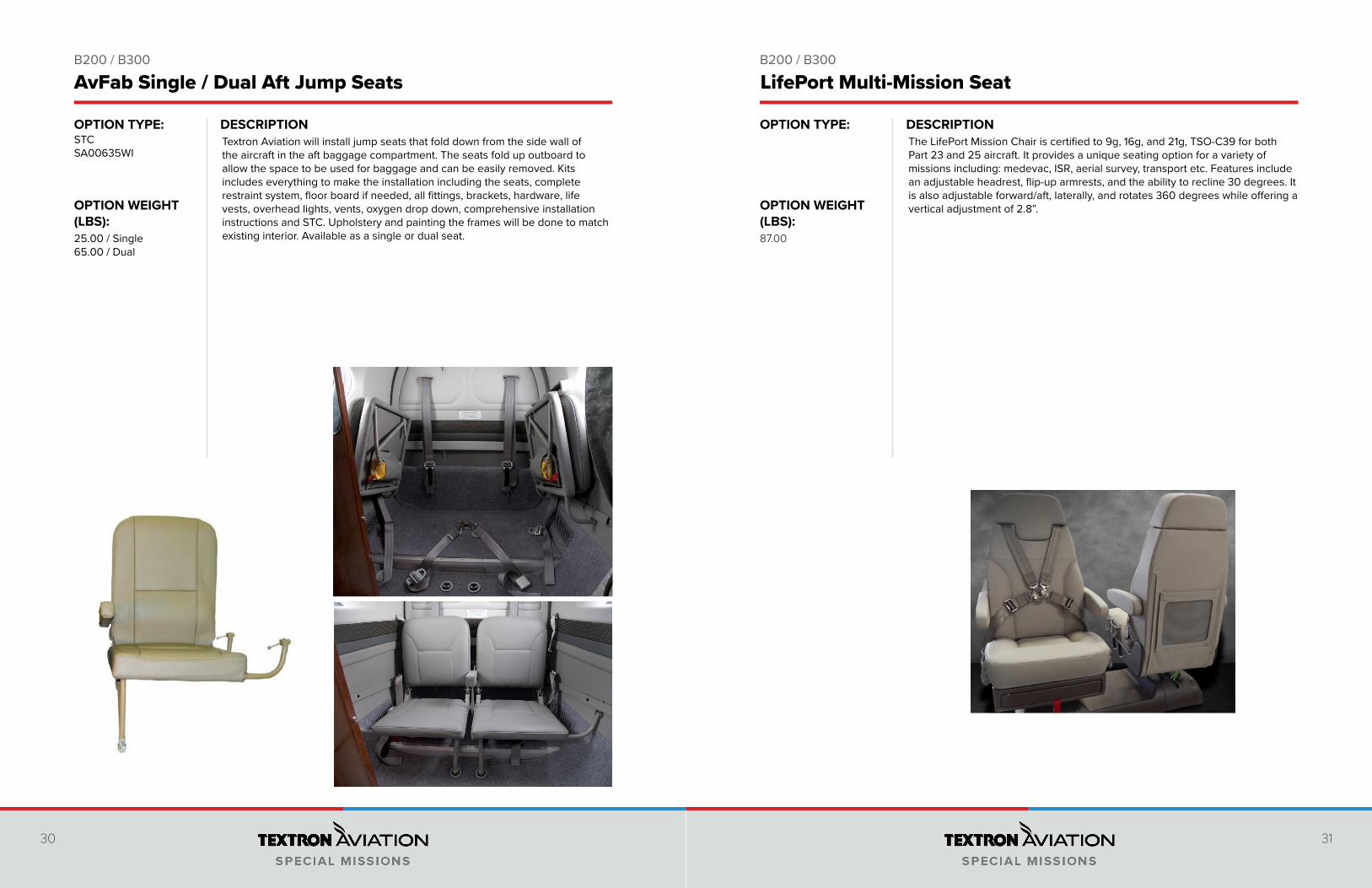
The LifePort Mission Chair is certified to 9g, 16g, and 21g, TSO-C39 for both Part 23 and 25 aircraft. It provides a unique seating option for a variety of missions including: medevac, ISR, aerial survey, transport etc. Features include an adjustable headrest, flip-up armrests, and the ability to recline 30 degrees. It is also adjustable forward/aft, laterally, and rotates 360 degrees while offering a vertical adjustment of 2.8”.
87.00
LifePort Multi-Mission Seat
32 33
DESCRIPTION DESCRIPTIONOPTION TYPE:
OPTION WEIGHT (LBS):
OPTION TYPE:
OPTION WEIGHT (LBS):
B200 / B300 B200 / B300
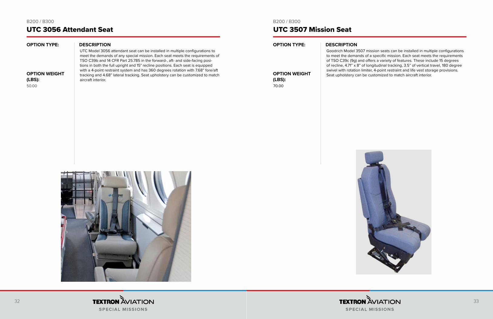
UTC Model 3056 attendant seat can be installed in multiple configurations to meet the demands of any special mission. Each seat meets the requirements of TSO C39b and 14 CFR Part 25.785 in the forward-, aft- and side-facing posi-tions in both the full upright and 15° recline positions. Each seat is equipped with a 4-point restraint system and has 360 degrees rotation with 7.68” fore/aft tracking and 4.68” lateral tracking. Seat upholstery can be customized to match aircraft interior.
50.00
UTC 3056 Attendant Seat
Goodrich Model 3507 mission seats can be installed in multiple configurations to meet the demands of a specific mission. Each seat meets the requirements of TSO C39c (9g) and offers a variety of features. These include 15 degrees of recline, 4.71” x 8” of longitudinal tracking, 3.5” of vertical travel, 180 degree swivel with rotation limiter, 4-point restraint and life vest storage provisions. Seat upholstery can be customized to match aircraft interior.
70.00
UTC 3507 Mission Seat
34 35
DESCRIPTION DESCRIPTIONOPTION TYPE:
OPTION WEIGHT (LBS):
OPTION TYPE:
OPTION WEIGHT (LBS):
B200 / B300 B200 / B300
When operating in highly corrosive environments it is important to keep your engine clean. Textron Aviation will install engine wash rings and drain to ease this maintenance action. The wash rings provide an easy method to clean the engine to help prevent corrosion due to a salty or other adverse environment. This modification installs an Engine Compressor Wash Drain system to provide an efficient method of draining fluids from the engine casing without requiring removal of the forward cowls, reducing maintenance time, and manpower, required to perform engine compressor/turbine washing and rinsing.4.60
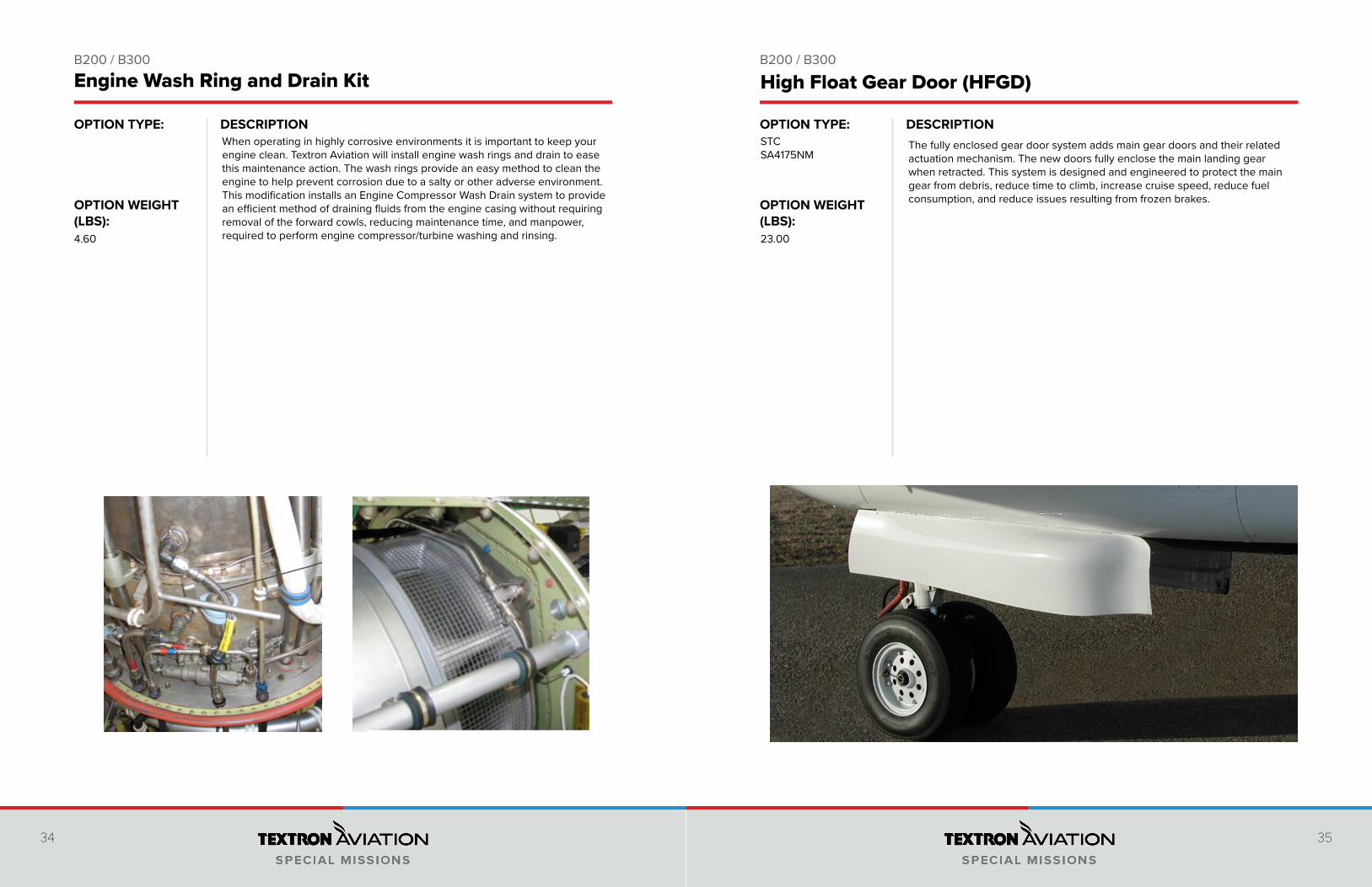
Engine Wash Ring and Drain Kit High Float Gear Door (HFGD)
The fully enclosed gear door system adds main gear doors and their related actuation mechanism. The new doors fully enclose the main landing gear when retracted. This system is designed and engineered to protect the main gear from debris, reduce time to climb, increase cruise speed, reduce fuel consumption, and reduce issues resulting from frozen brakes.
STCSA4175NM
23.00
36 37
DESCRIPTION DESCRIPTIONOPTION TYPE:
OPTION WEIGHT (LBS):
OPTION TYPE:
OPTION WEIGHT (LBS):
B200 / B300 B200 / B300
In lieu of the standard factory OEM cargo door option, this STC installs a baggage door in the aft fuselage. The baggage door is 13” wide by 38” tall and retains the standard airstair door.
STCSA00415WI
Installation of Baggage Door
176.00
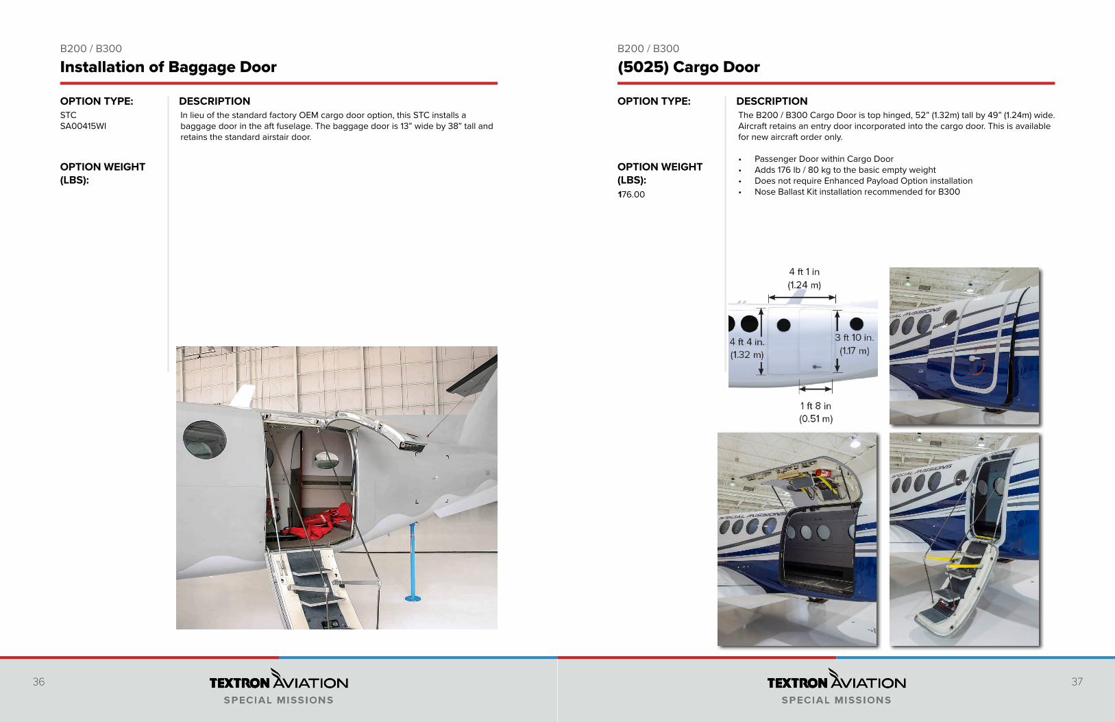
The B200 / B300 Cargo Door is top hinged, 52” (1.32m) tall by 49” (1.24m) wide. Aircraft retains an entry door incorporated into the cargo door. This is available for new aircraft order only.
• Passenger Door within Cargo Door• Adds 176 lb / 80 kg to the basic empty weight• Does not require Enhanced Payload Option installation• Nose Ballast Kit installation recommended for B300
(5025) Cargo Door
38 39
DESCRIPTION DESCRIPTIONOPTION TYPE:
OPTION WEIGHT (LBS):
OPTION TYPE:
OPTION WEIGHT (LBS):
B200 / B300 B200 / B300
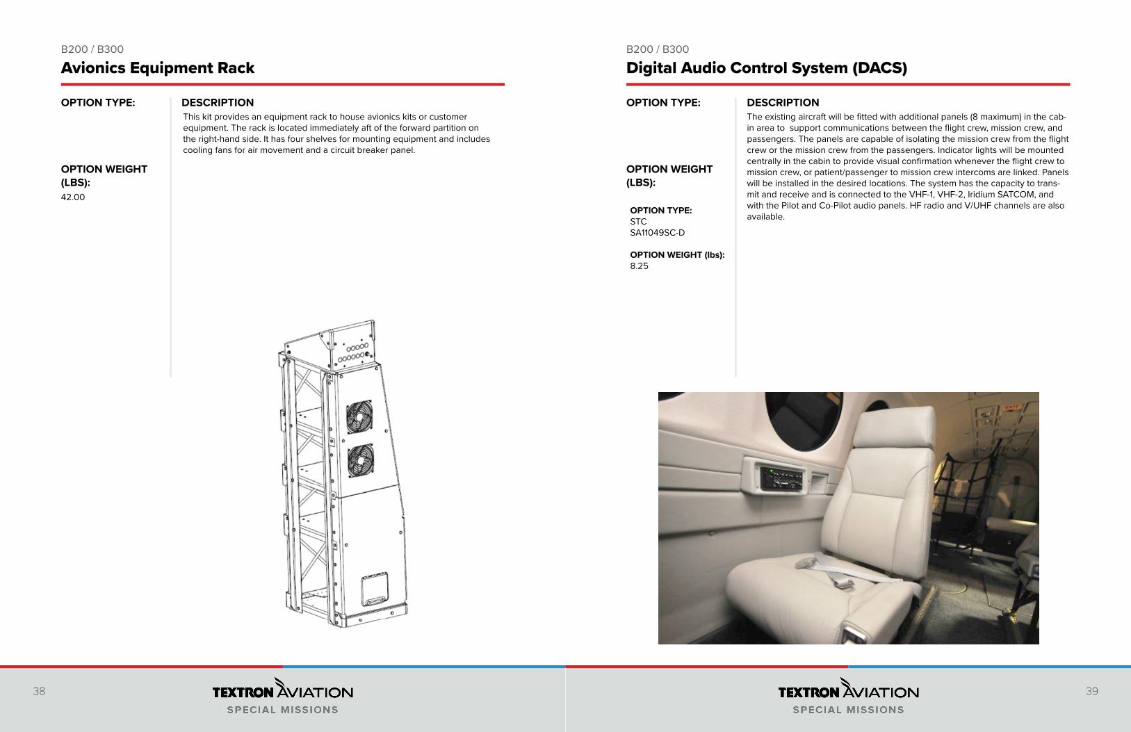
This kit provides an equipment rack to house avionics kits or customer equipment. The rack is located immediately aft of the forward partition on the right-hand side. It has four shelves for mounting equipment and includes cooling fans for air movement and a circuit breaker panel.
42.00
The existing aircraft will be fitted with additional panels (8 maximum) in the cab-in area to support communications between the flight crew, mission crew, and passengers. The panels are capable of isolating the mission crew from the flight crew or the mission crew from the passengers. Indicator lights will be mounted centrally in the cabin to provide visual confirmation whenever the flight crew to mission crew, or patient/passenger to mission crew intercoms are linked. Panels will be installed in the desired locations. The system has the capacity to trans-mit and receive and is connected to the VHF-1, VHF-2, Iridium SATCOM, and with the Pilot and Co-Pilot audio panels. HF radio and V/UHF channels are also available.OPTION TYPE:
STCSA11049SC-D
OPTION WEIGHT (lbs):8.25
Avionics Equipment Rack Digital Audio Control System (DACS)
40 41
DESCRIPTION DESCRIPTIONOPTION TYPE:
OPTION WEIGHT (LBS):
OPTION TYPE:
OPTION WEIGHT (LBS):
B200 / B300 B200 / B300
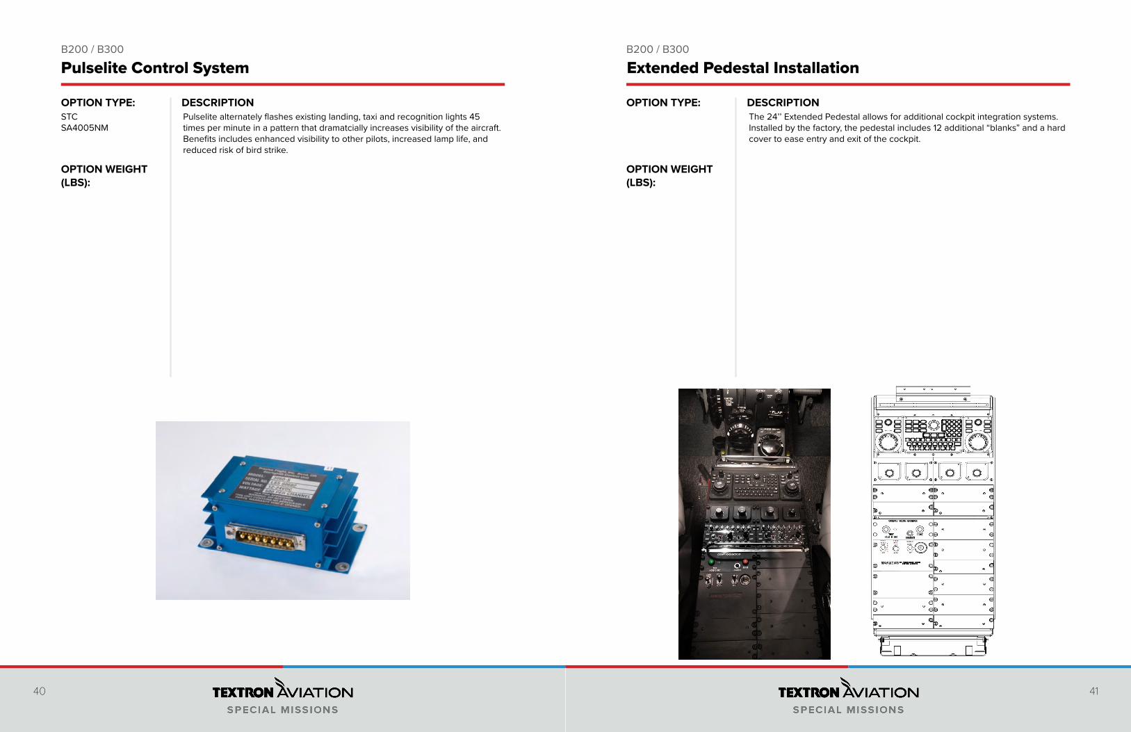
Pulselite alternately flashes existing landing, taxi and recognition lights 45 times per minute in a pattern that dramatcially increases visibility of the aircraft. Benefits includes enhanced visibility to other pilots, increased lamp life, and reduced risk of bird strike.
STCSA4005NM
Pulselite Control System
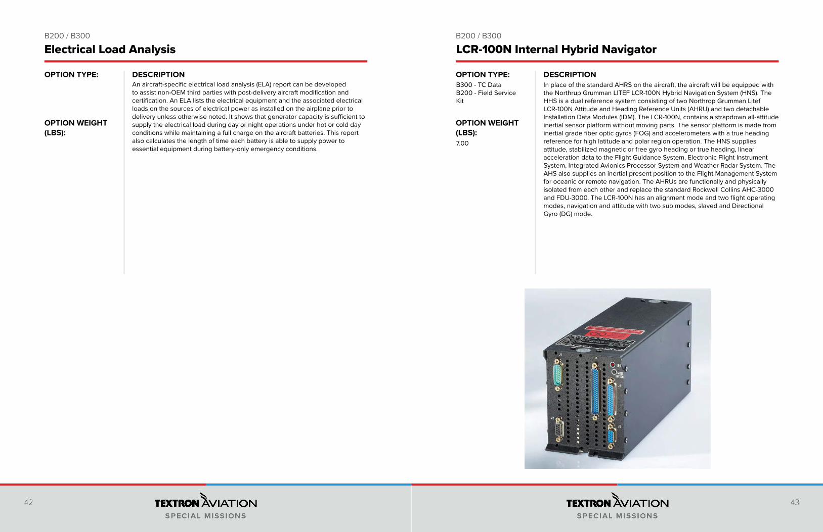
The 24’’ Extended Pedestal allows for additional cockpit integration systems. Installed by the factory, the pedestal includes 12 additional “blanks” and a hard cover to ease entry and exit of the cockpit.
Extended Pedestal Installation
42 43
DESCRIPTION DESCRIPTIONOPTION TYPE:
OPTION WEIGHT (LBS):
OPTION TYPE:
OPTION WEIGHT (LBS):
B200 / B300 B200 / B300
Electrical Load Analysis LCR-100N Internal Hybrid Navigator
An aircraft-specific electrical load analysis (ELA) report can be developed to assist non-OEM third parties with post-delivery aircraft modification and certification. An ELA lists the electrical equipment and the associated electrical loads on the sources of electrical power as installed on the airplane prior to delivery unless otherwise noted. It shows that generator capacity is sufficient to supply the electrical load during day or night operations under hot or cold day conditions while maintaining a full charge on the aircraft batteries. This report also calculates the length of time each battery is able to supply power to essential equipment during battery-only emergency conditions.
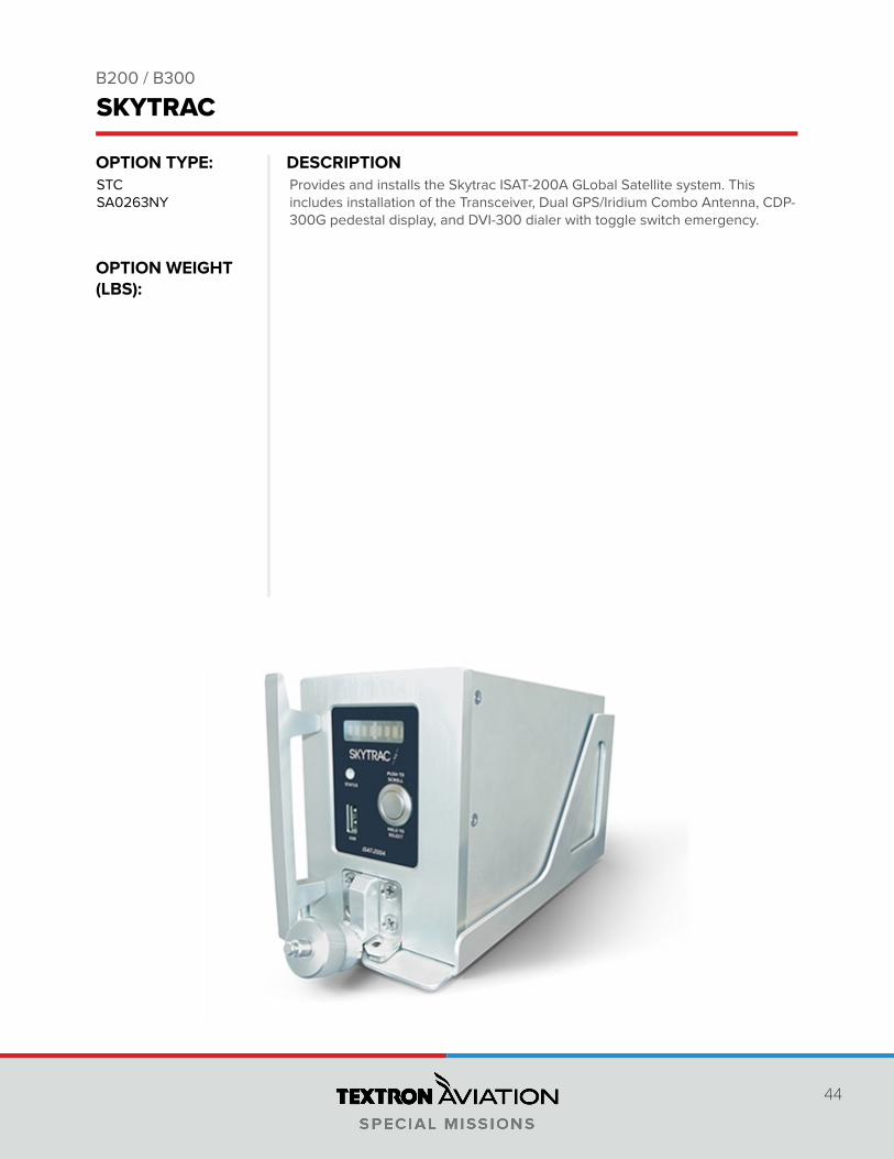
In place of the standard AHRS on the aircraft, the aircraft will be equipped with the Northrup Grumman LITEF LCR-100N Hybrid Navigation System (HNS). The HHS is a dual reference system consisting of two Northrop Grumman Litef LCR-100N Attitude and Heading Reference Units (AHRU) and two detachable Installation Data Modules (IDM). The LCR-100N, contains a strapdown all-attitude inertial sensor platform without moving parts. The sensor platform is made from inertial grade fiber optic gyros (FOG) and accelerometers with a true heading reference for high latitude and polar region operation. The HNS supplies attitude, stabilized magnetic or free gyro heading or true heading, linear acceleration data to the Flight Guidance System, Electronic Flight Instrument System, Integrated Avionics Processor System and Weather Radar System. The AHS also supplies an inertial present position to the Flight Management System for oceanic or remote navigation. The AHRUs are functionally and physically isolated from each other and replace the standard Rockwell Collins AHC-3000 and FDU-3000. The LCR-100N has an alignment mode and two flight operating modes, navigation and attitude with two sub modes, slaved and Directional Gyro (DG) mode.
7.00
B300 - TC DataB200 - Field Service Kit
44
DESCRIPTIONOPTION TYPE:
OPTION WEIGHT (LBS):
B200 / B300
Provides and installs the Skytrac ISAT-200A GLobal Satellite system. This includes installation of the Transceiver, Dual GPS/Iridium Combo Antenna, CDP-300G pedestal display, and DVI-300 dialer with toggle switch emergency.
STCSA0263NY
SKYTRAC
46 47
DESCRIPTION DESCRIPTIONOPTION TYPE:
OPTION WEIGHT (LBS):
OPTION TYPE:
OPTION WEIGHT (LBS):
B200 B200
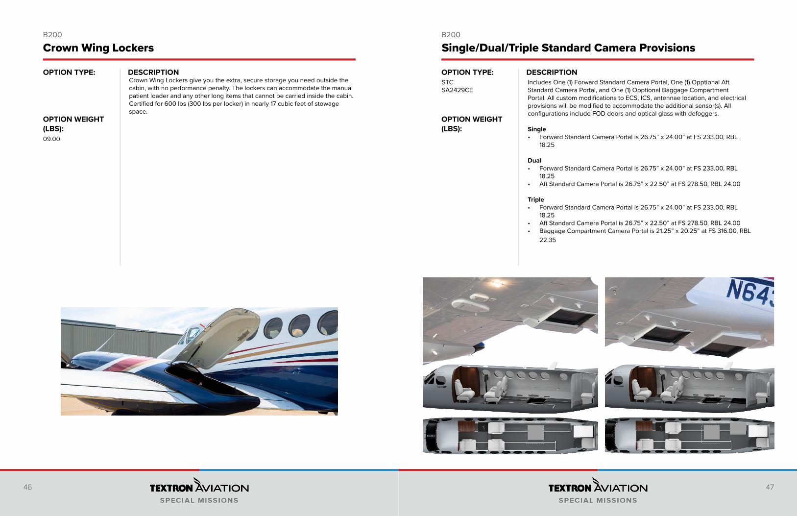
Crown Wing Lockers give you the extra, secure storage you need outside the cabin, with no performance penalty. The lockers can accommodate the manual patient loader and any other long items that cannot be carried inside the cabin. Certified for 600 lbs (300 lbs per locker) in nearly 17 cubic feet of stowage space.
09.00
Crown Wing Lockers
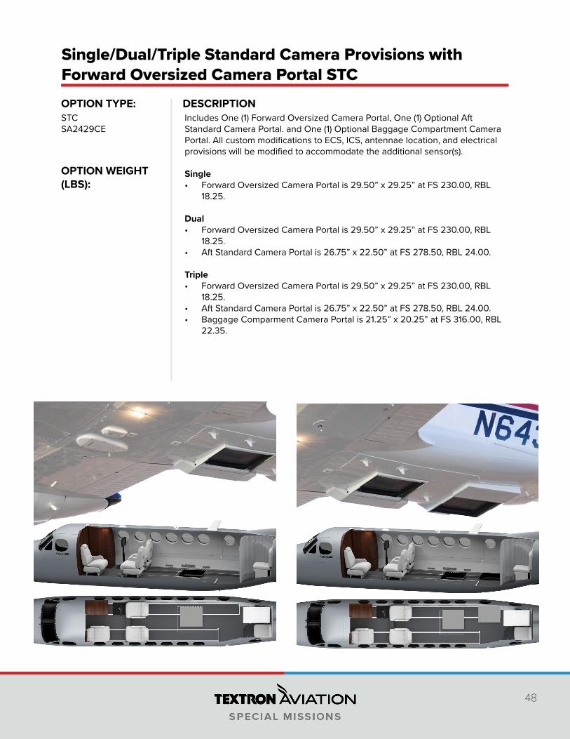
Includes One (1) Forward Standard Camera Portal, One (1) Opptional Aft Standard Camera Portal, and One (1) Opptional Baggage Compartment Portal. All custom modifications to ECS, ICS, antennae location, and electrical provisions will be modified to accommodate the additional sensor(s). All configurations include FOD doors and optical glass with defoggers.
Single• Forward Standard Camera Portal is 26.75” x 24.00” at FS 233.00, RBL
18.25
Dual• Forward Standard Camera Portal is 26.75” x 24.00” at FS 233.00, RBL
18.25• Aft Standard Camera Portal is 26.75” x 22.50” at FS 278.50, RBL 24.00
Triple• Forward Standard Camera Portal is 26.75” x 24.00” at FS 233.00, RBL
18.25• Aft Standard Camera Portal is 26.75” x 22.50” at FS 278.50, RBL 24.00• Baggage Compartment Camera Portal is 21.25” x 20.25” at FS 316.00, RBL
22.35
STCSA2429CE
Single/Dual/Triple Standard Camera Provisions
48
DESCRIPTIONOPTION TYPE:
OPTION WEIGHT (LBS):
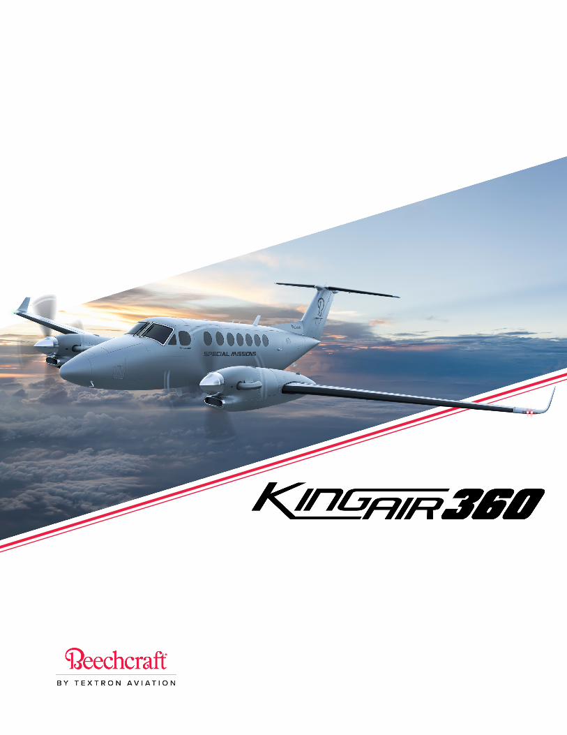
Includes One (1) Forward Oversized Camera Portal, One (1) Optional Aft Standard Camera Portal. and One (1) Optional Baggage Compartment Camera Portal. All custom modifications to ECS, ICS, antennae location, and electrical provisions will be modified to accommodate the additional sensor(s).
Single• Forward Oversized Camera Portal is 29.50” x 29.25” at FS 230.00, RBL
18.25.
Dual• Forward Oversized Camera Portal is 29.50” x 29.25” at FS 230.00, RBL
18.25.• Aft Standard Camera Portal is 26.75” x 22.50” at FS 278.50, RBL 24.00.
Triple• Forward Oversized Camera Portal is 29.50” x 29.25” at FS 230.00, RBL
18.25.• Aft Standard Camera Portal is 26.75” x 22.50” at FS 278.50, RBL 24.00.• Baggage Comparment Camera Portal is 21.25” x 20.25” at FS 316.00, RBL
22.35.
STCSA2429CE
Single/Dual/Triple Standard Camera Provisions with Forward Oversized Camera Portal STC
50 51
DESCRIPTION DESCRIPTIONOPTION TYPE:
OPTION WEIGHT (LBS):
OPTION TYPE:
OPTION WEIGHT (LBS):
B300 B300
High Endurance for Critical Missions• Increased range and endurance• Increases total fuel capacity by 236 gallons (893 liters) to 775 gallons
(2,934 liters)• Deploy world-wide without ferry tanks• 2,500+nm range, 12 hour endurance• Delivers significantly higher mission flexibility
Includes:• Special Mission Rudder• Software Upgrade• Updated Fuel Control Panel• Heavy Weight Landing Gear
This option replaces the standard PT6-60A engines with the PTA-67A engines. Included in the upgrad is a new reinforced truss and an additional oil cooler to aid in cooling during high temperature operations.
Performance Benefits:• Flat rating temp limit increase• improved climb performance• increased cruise speed of 15+ Knots• Maintain horsepower in high/hot conditions.
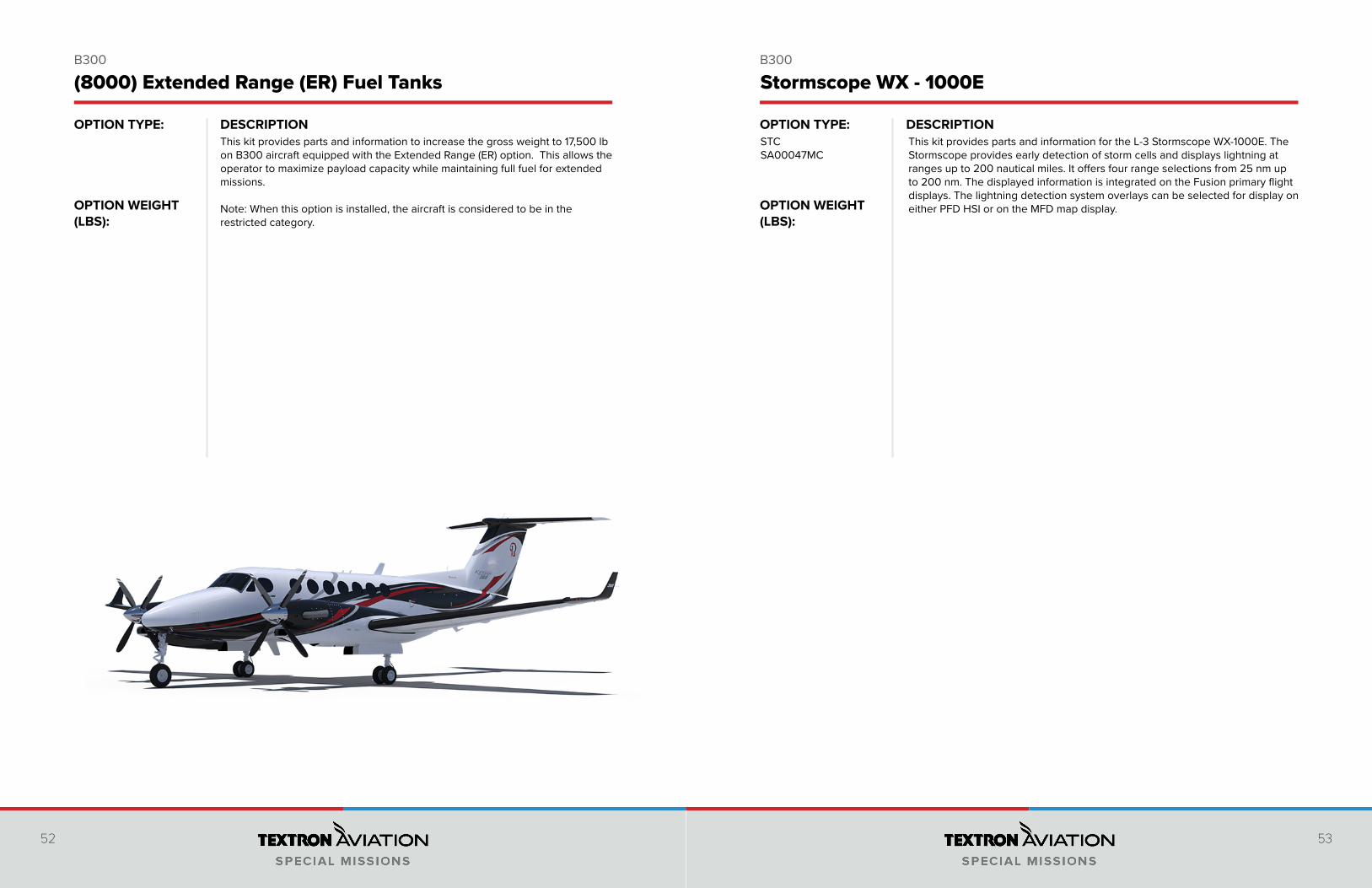
(8000) Extended Range (ER) Fuel Tanks (8100) PT6A-67A Engine Upgrade
53.70
KA360
KA360ER
52 53
DESCRIPTION DESCRIPTIONOPTION TYPE:
OPTION WEIGHT (LBS):
OPTION TYPE:
OPTION WEIGHT (LBS):
B300 B300
(8000) Extended Range (ER) Fuel Tanks Stormscope WX - 1000E
This kit provides parts and information to increase the gross weight to 17,500 lb on B300 aircraft equipped with the Extended Range (ER) option. This allows the operator to maximize payload capacity while maintaining full fuel for extended missions.
Note: When this option is installed, the aircraft is considered to be in the restricted category.
This kit provides parts and information for the L-3 Stormscope WX-1000E. The Stormscope provides early detection of storm cells and displays lightning at ranges up to 200 nautical miles. It offers four range selections from 25 nm up to 200 nm. The displayed information is integrated on the Fusion primary flight displays. The lightning detection system overlays can be selected for display on either PFD HSI or on the MFD map display.
STCSA00047MC
54 55
DESCRIPTION DESCRIPTIONOPTION TYPE:
OPTION WEIGHT (LBS):
OPTION TYPE:
OPTION WEIGHT (LBS):
B300 B300
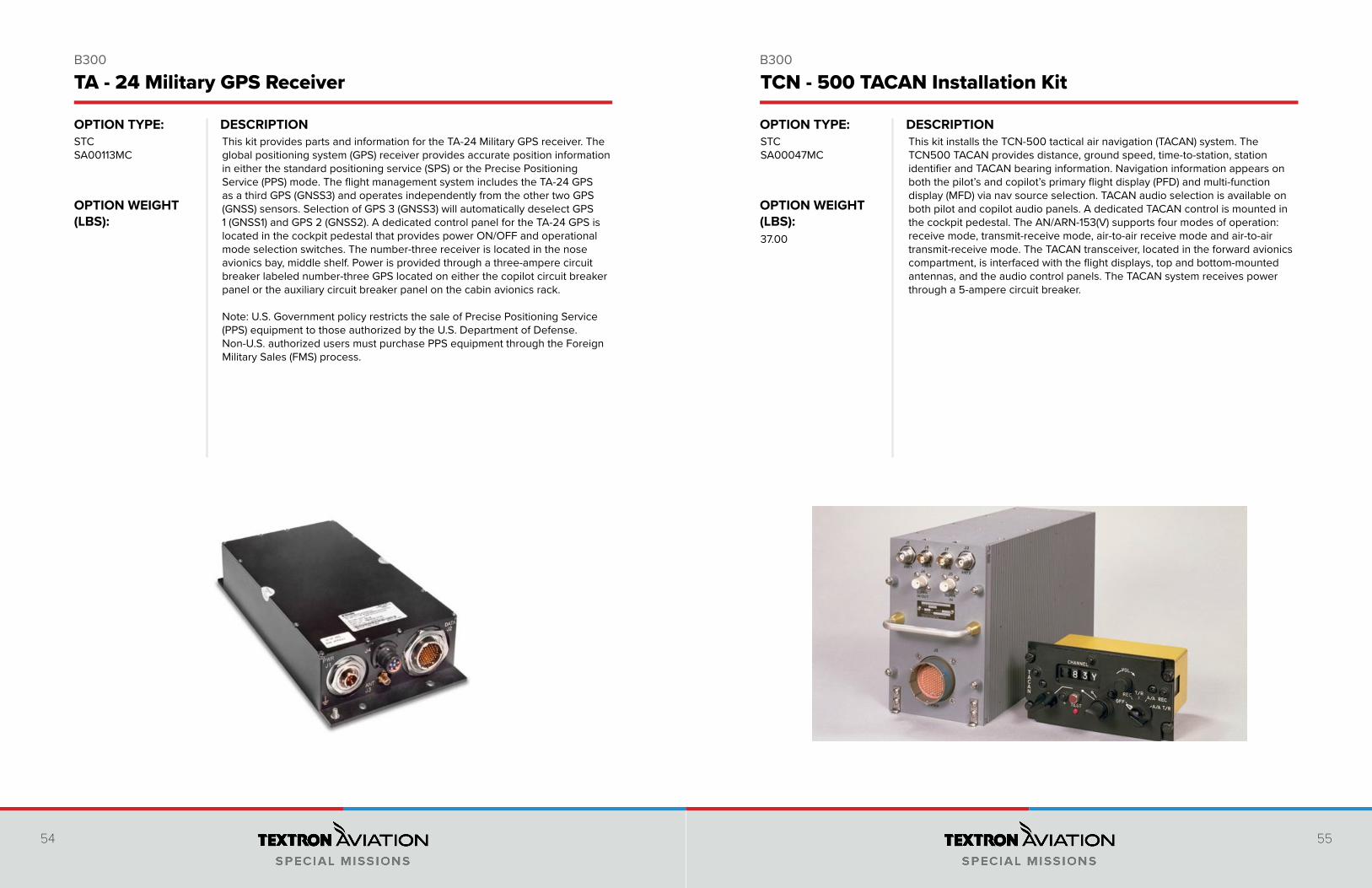
This kit provides parts and information for the TA-24 Military GPS receiver. The global positioning system (GPS) receiver provides accurate position information in either the standard positioning service (SPS) or the Precise Positioning Service (PPS) mode. The flight management system includes the TA-24 GPS as a third GPS (GNSS3) and operates independently from the other two GPS (GNSS) sensors. Selection of GPS 3 (GNSS3) will automatically deselect GPS 1 (GNSS1) and GPS 2 (GNSS2). A dedicated control panel for the TA-24 GPS is located in the cockpit pedestal that provides power ON/OFF and operational mode selection switches. The number-three receiver is located in the nose avionics bay, middle shelf. Power is provided through a three-ampere circuit breaker labeled number-three GPS located on either the copilot circuit breaker panel or the auxiliary circuit breaker panel on the cabin avionics rack.
Note: U.S. Government policy restricts the sale of Precise Positioning Service (PPS) equipment to those authorized by the U.S. Department of Defense. Non-U.S. authorized users must purchase PPS equipment through the Foreign Military Sales (FMS) process.
STCSA00113MC
TA - 24 Military GPS Receiver TCN - 500 TACAN Installation Kit
This kit installs the TCN-500 tactical air navigation (TACAN) system. The TCN500 TACAN provides distance, ground speed, time-to-station, station identifier and TACAN bearing information. Navigation information appears on both the pilot’s and copilot’s primary flight display (PFD) and multi-function display (MFD) via nav source selection. TACAN audio selection is available on both pilot and copilot audio panels. A dedicated TACAN control is mounted in the cockpit pedestal. The AN/ARN-153(V) supports four modes of operation: receive mode, transmit-receive mode, air-to-air receive mode and air-to-air transmit-receive mode. The TACAN transceiver, located in the forward avionics compartment, is interfaced with the flight displays, top and bottom-mounted antennas, and the audio control panels. The TACAN system receives power through a 5-ampere circuit breaker.
STCSA00047MC
37.00
56 57
DESCRIPTION DESCRIPTIONOPTION TYPE:
OPTION WEIGHT (LBS):
OPTION TYPE:
OPTION WEIGHT (LBS):
B300 B300
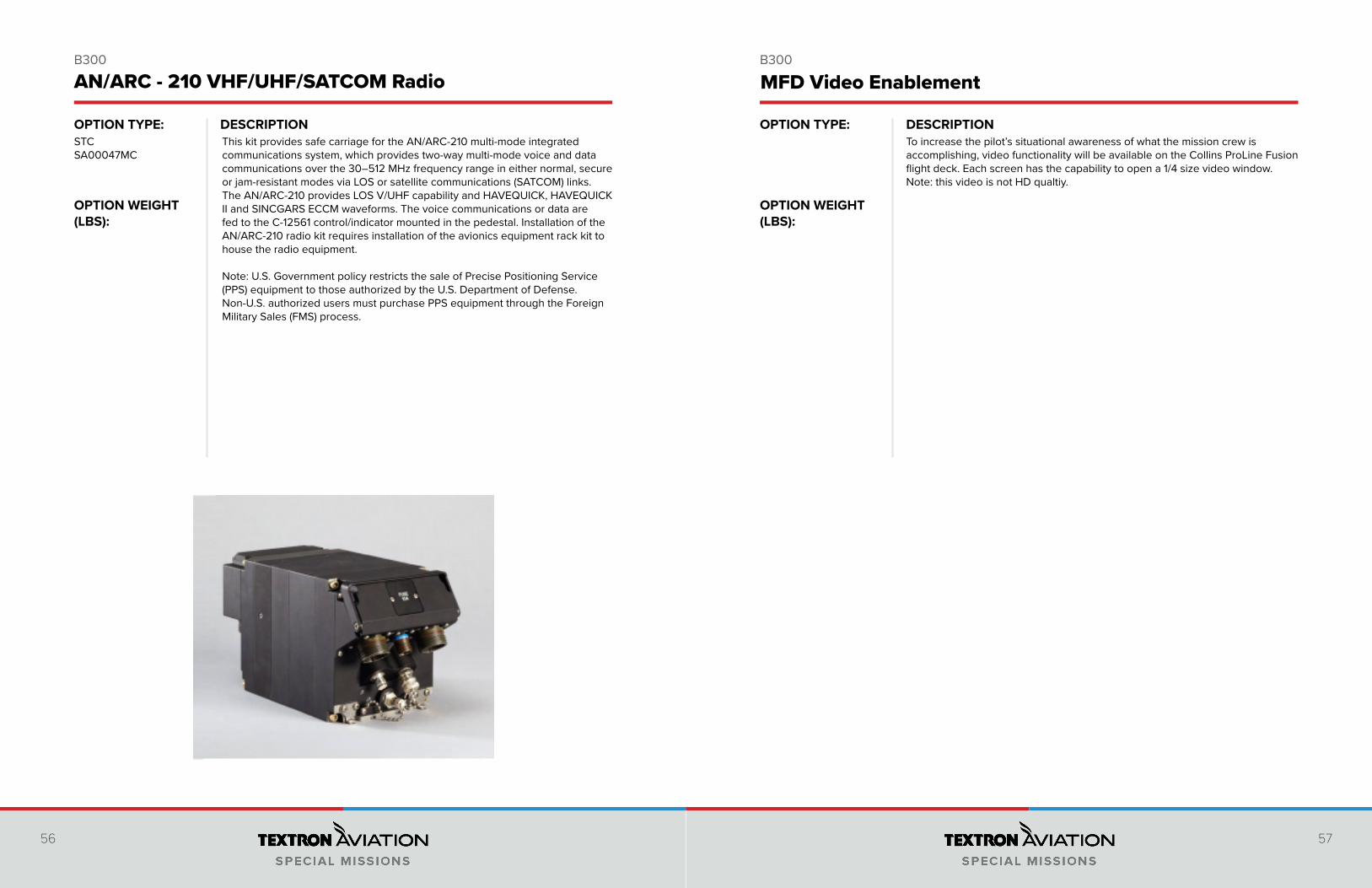
This kit provides safe carriage for the AN/ARC-210 multi-mode integrated communications system, which provides two-way multi-mode voice and data communications over the 30–512 MHz frequency range in either normal, secure or jam-resistant modes via LOS or satellite communications (SATCOM) links. The AN/ARC-210 provides LOS V/UHF capability and HAVEQUICK, HAVEQUICK II and SINCGARS ECCM waveforms. The voice communications or data are fed to the C-12561 control/indicator mounted in the pedestal. Installation of the AN/ARC-210 radio kit requires installation of the avionics equipment rack kit to house the radio equipment.
Note: U.S. Government policy restricts the sale of Precise Positioning Service (PPS) equipment to those authorized by the U.S. Department of Defense. Non-U.S. authorized users must purchase PPS equipment through the Foreign Military Sales (FMS) process.
STCSA00047MC
AN/ARC - 210 VHF/UHF/SATCOM Radio MFD Video Enablement
To increase the pilot’s situational awareness of what the mission crew is accomplishing, video functionality will be available on the Collins ProLine Fusion flight deck. Each screen has the capability to open a 1/4 size video window. Note: this video is not HD qualtiy.
58 59
DESCRIPTION DESCRIPTIONOPTION TYPE:
OPTION WEIGHT (LBS):
OPTION TYPE:
OPTION WEIGHT (LBS):
B300 B300
AN/APX-119 Identification Friend or Foe (IFF)AN/APX-119 Identification Friend or Foe (IFF)
This kit provides parts and information for the AN/APX-119 IFF system. The AN/APX-119 IFF transponder replaces the existing number two Collins TDR94 transponder and provides the same capabilities with the additional capability of Mode 4 IFF. A dedicated IFF control panel located in the cockpit pedestal provides all transponder functionality control as well as TCAS II control when the IFF transponder is selected. The IFF transponder provides cooperative Mark XII identification friend or foe (IFF) capability using full diversity selection, as well as mode select (Mode S) capability. In addition, transponder operation provides interface capability with the airplane’s traffic collision and avoidance system (TCAS).The IFF transponder system is made up of a transponder, two antennas, a crypto applique and a control panel. The IFF transponder receives power from the mission bus and a five-ampere circuit breaker located on the avionics rack auxiliary circuit breaker panel. Installation of the AN/APX-119 IFF kit requires installation of the avionics equipment rack kit to house the IFF transponder.
Note: U.S. Government policy restricts the sale of Precise Positioning Service (PPS) equipment to those authorized by the U.S. Department of Defense. Non-U.S. authorized users must purchase PPS equipment through the Foreign Military Sales (FMS) process.
STCSA00047MC
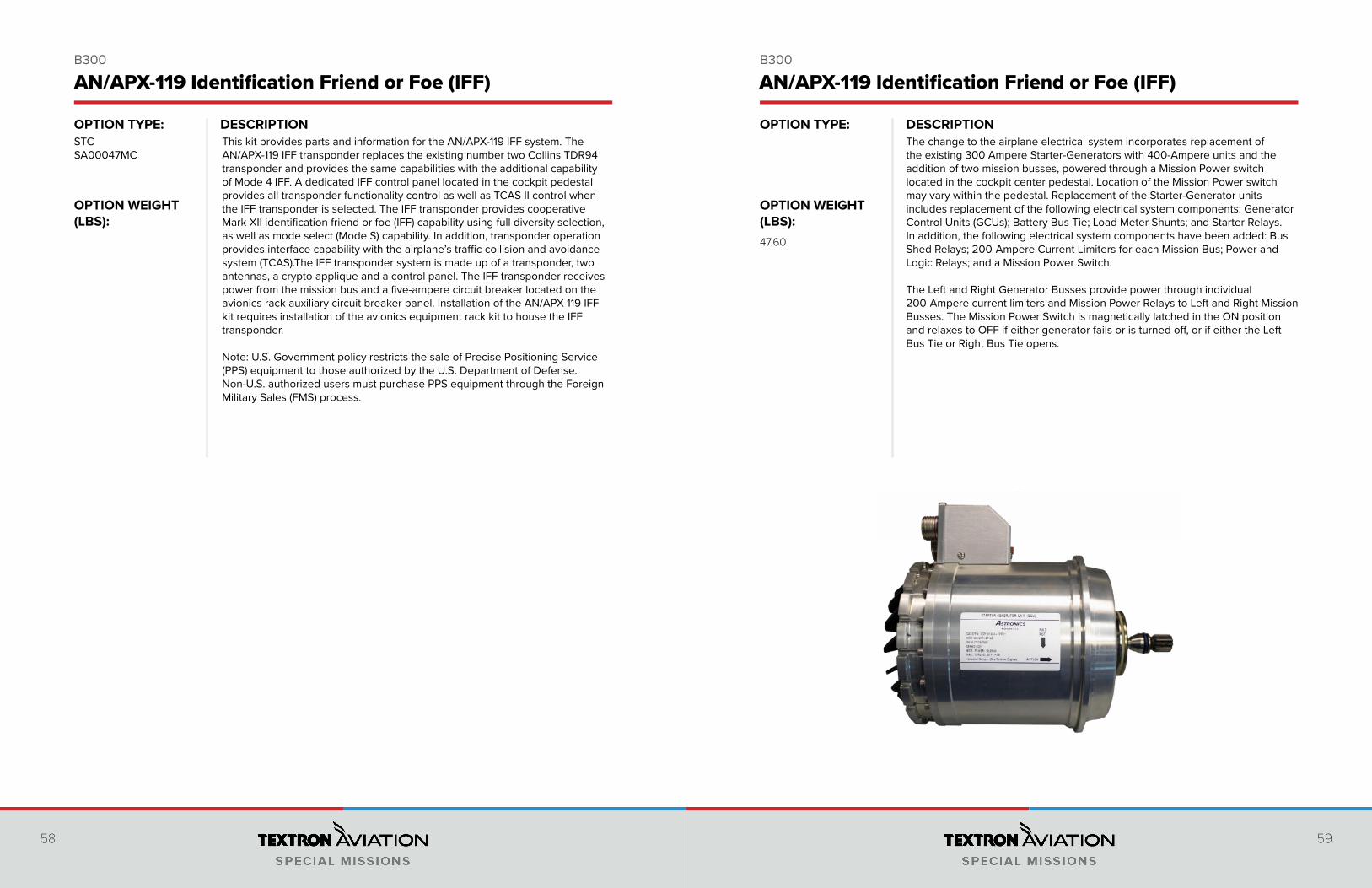
The change to the airplane electrical system incorporates replacement of the existing 300 Ampere Starter-Generators with 400-Ampere units and the addition of two mission busses, powered through a Mission Power switch located in the cockpit center pedestal. Location of the Mission Power switch may vary within the pedestal. Replacement of the Starter-Generator units includes replacement of the following electrical system components: Generator Control Units (GCUs); Battery Bus Tie; Load Meter Shunts; and Starter Relays. In addition, the following electrical system components have been added: Bus Shed Relays; 200-Ampere Current Limiters for each Mission Bus; Power and Logic Relays; and a Mission Power Switch. The Left and Right Generator Busses provide power through individual 200-Ampere current limiters and Mission Power Relays to Left and Right Mission Busses. The Mission Power Switch is magnetically latched in the ON position and relaxes to OFF if either generator fails or is turned off, or if either the Left Bus Tie or Right Bus Tie opens.
47.60
60 61
DESCRIPTION DESCRIPTIONOPTION TYPE:
OPTION WEIGHT (LBS):
OPTION TYPE:
OPTION WEIGHT (LBS):
B300 B300
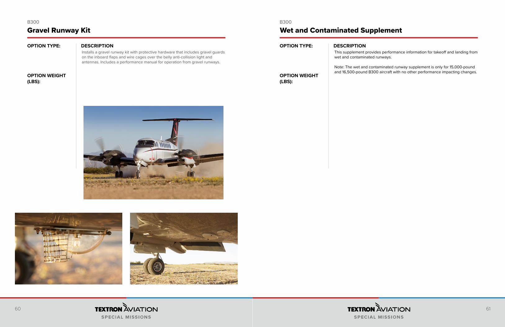
Installs a gravel runway kit with protective hardware that includes gravel guards on the inboard flaps and wire cages over the belly anti-collision light and antennas. Includes a performance manual for operation from gravel runways.
Gravel Runway Kit Wet and Contaminated Supplement
This supplement provides performance information for takeoff and landing from wet and contaminated runways.
Note: The wet and contaminated runway supplement is only for 15,000-pound and 16,500-pound B300 aircraft with no other performance impacting changes.
62 63
DESCRIPTION DESCRIPTIONOPTION TYPE:
OPTION WEIGHT (LBS):
OPTION TYPE:
OPTION WEIGHT (LBS):
B300 B300
For any aircraft with extended range tanks and surveillance type mission equipment the center of gravity of the aircraft is pushed aft. The Nose Ballast installation installs up to 190 lb (86 kg) of ballast in the nose of the aircraft allowing more flexibility of additional fuel or payload.
Nose Ballast Kit
190.90
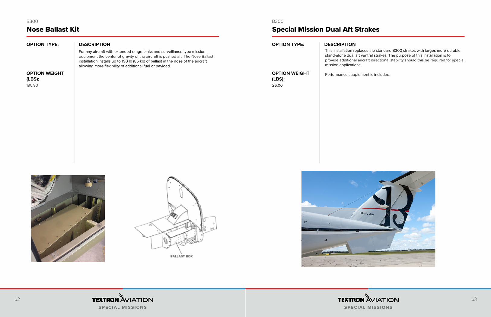
This installation replaces the standard B300 strakes with larger, more durable, stand-alone dual aft ventral strakes. The purpose of this installation is to provide additional aircraft directional stability should this be required for special mission applications. Performance supplement is included.
26.00
Special Mission Dual Aft Strakes
64 65
DESCRIPTION DESCRIPTIONOPTION TYPE:
OPTION WEIGHT (LBS):
OPTION TYPE:
OPTION WEIGHT (LBS):
B300 B300
To allow for a larger array of search radars to fit within the confines of the radome, a radar pressure box will be installed. This pressure box allows for a radar antenna gimbal to be recessed into the pressure vessel. The box has unobstructed dimensions of 12.7” forward to aft, 12.3” left to right, and 7.7” deep giving a minimum usable volume of 1,214 cubic inches.
Note: Radar Pressure Box Kit is installed via Type Certificate27.00
Radar Pressure Box for Radome X-Band Radome and EO/IR Fairing
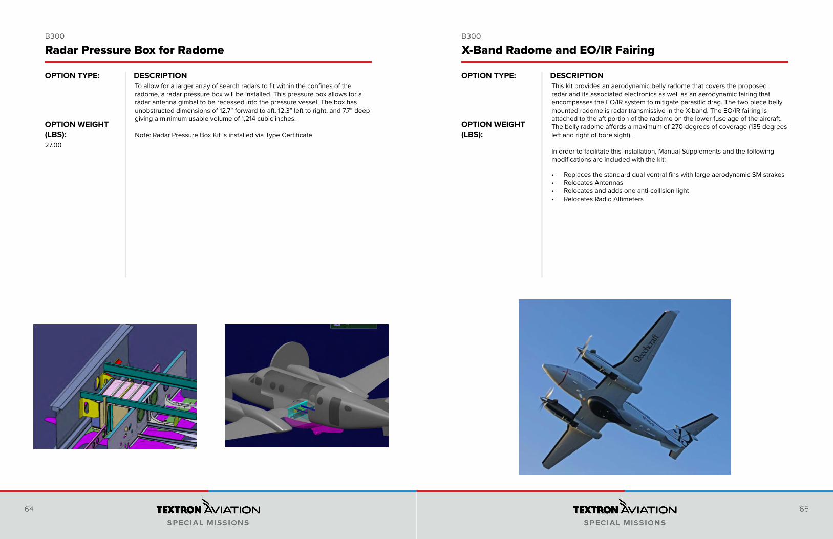
This kit provides an aerodynamic belly radome that covers the proposed radar and its associated electronics as well as an aerodynamic fairing that encompasses the EO/IR system to mitigate parasitic drag. The two piece belly mounted radome is radar transmissive in the X-band. The EO/IR fairing is attached to the aft portion of the radome on the lower fuselage of the aircraft. The belly radome affords a maximum of 270-degrees of coverage (135 degrees left and right of bore sight).
In order to facilitate this installation, Manual Supplements and the following modifications are included with the kit:
• Replaces the standard dual ventral fins with large aerodynamic SM strakes• Relocates Antennas• Relocates and adds one anti-collision light• Relocates Radio Altimeters
66 67
DESCRIPTION DESCRIPTIONOPTION TYPE:
OPTION WEIGHT (LBS):
OPTION TYPE:
OPTION WEIGHT (LBS):
B300 B300
This kit installs a lift for an Electro-Optical Infrared (EO/IR) camera system in the belly mounted radome. This also modifies the center cockpit pedestal to install the EO/IR lift control panel. The control panel allows the pilot to lift and lower the EO/IR Lift / Turret (when installed) and also gives an indication of the lifts position via indicator lights. Logic is added to the landing gear handle position system so that when the contact is broken (moving the landing gear handle to the DN position) the lift system, if down, will stow automatically. Wiring provisions are located in the cabin to allow installation of an EO/IR lift control panel in an operators console if desired. This system will accommodate a sensor up to 18” in diameter and weighing up to 135 lbs.
71.00
EO/IR Lift Utility Nose and Lift Kit
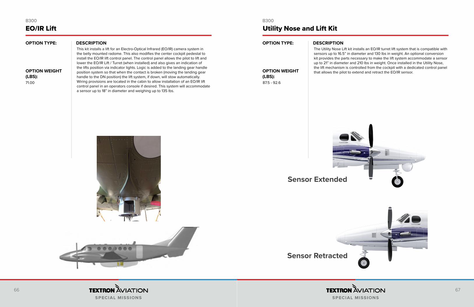
The Utility Nose Lift kit installs an EO/IR turret lift system that is compatible with sensors up to 16.5” in diameter and 130 lbs in weight. An optional conversion kit provides the parts necessary to make the lift system accommodate a sensor up to 21” in diameter and 210 lbs in weight. Once installed in the Utility Nose, the lift mechanism is controlled from the cockpit with a dedicated control panel that allows the pilot to extend and retract the EO/IR sensor.
87.5 - 92.6
Sensor Extended
Sensor Retracted
68 69
DESCRIPTION DESCRIPTIONOPTION TYPE:
OPTION WEIGHT (LBS):
OPTION TYPE:
OPTION WEIGHT (LBS):
B300 B300
The utility nose option extends the nose of the aircraft by 33.75” (0.86 m), providing an equipment bay to store mission equipment. All avionics and weather radar typically installed in the nose cone remain. The equipment bay offers 12 cubic feet of storage and can hold up to 250 lb.
• Integrated to original airframe structure to maximize space and weight• Zero impact on aircraft life• Adds approx. 12 cubic feet of stowage space in additional nose
compartment• New aircraft OEM airframe warranty remains intact• Adds approximately 97.5 lb (44.2 kg) of weight• Improves Aircraft CG to allow additional cabin loading
OPTION TYPE:N/A
OPTION WEIGHT (lbs):97.50
Utility Nose Kit
Includes One (1) Forward Standard Camera Portal, One (1) Opptional Aft Standard Camera Portal, and One (1) Opptional Baggage Compartment Portal. All custom modifications to ECS, ICS, antennae location, and electrical provisions will be modified to accommodate the additional sensor(s). Includes FOD doors and optical glass with defogger.
Single• Forward Standard Camera Portal is 26.75” x 24.00” at FS 267.00, RBL 18.25
Dual• Forward Standard Camera Portal is 26.75” x 24.00” at FS 267.00, RBL 18.25• Aft Standard Camera Portal is 26.75” x 22.50” at FS 312.50, RBL 24.00
Triple• Forward Standard Camera Portal is 26.75” x 24.00” at FS 267.00, RBL 18.25• Aft Standard Camera Portal is 26.75” x 22.50” at FS 312.50, RBL 24.00• Baggage Compartment Camera Portal is 21.25” x 20.25” at FS 350.00, RBL
22.35
STCSA2429CE
Single/Dual/Triple Standard Camera Provisions STC
70 71
DESCRIPTION DESCRIPTIONOPTION TYPE:
OPTION WEIGHT (LBS):
OPTION TYPE:
OPTION WEIGHT (LBS):
Single/Dual/Triple Camera Provisions with Fwd Oversized Camera Portal STC
Includes One (1) Forward Oversized Camera Portal, One (1) Optional Aft Standard Camera Portal. and One (1) Optional Baggage Compartment Camera Portal. All custom modifications to ECS, ICS, antennae location, and electrical provisions will be modified to accommodate the additional sensor(s).
Single• Forward Oversized Camera Portal is 29.50” x 29.25” at FS 264.25, RBL
18.25.
Dual• Forward Oversized Camera Portal is 29.50” x 29.25” at FS 264.25, RBL
18.25.• Aft Standard Camera Portal is 26.75” x 22.50” at FS 312.50, RBL 24.00.
Triple• Forward Oversized Camera Portal is 29.50” x 29.25” at FS 264.25, RBL
18.25.• Aft Standard Camera Portal is 26.75” x 22.50” at FS 312.50, RBL 24.00.• Baggage Comparment Camera Portal is 21.25” x 20.25” at FS 350.00, RBL
22.35.
STCSA2429CE
When you want the highest rated, TSO’d life raft in the industry, but size and weight are a consideration, the Collins Winslow Ultra-Light is the life raft for you. Without compromising on details, we created the Winslow Ultra-Light Type One (UL) Life Raft to meet your needs. Available in both soft valise and hard packs, we offer a wide variety of survival equipment packs to meet your operational requirements. Far part 91 and part 135 options available.
This Ultra-Light Type One life raft fits 11 people with an overload capacity of 16 people. Includes Dual Frequency 406Mhz ELT w/Speech Capability and Embedded GPS. Dimensions: 6.5” X 20” X 34”. Weighing 52-58 lb.
58.00
LifeRaft Soft Pack w/ 406Mhz ELT - 11 Person (Loose Equipment)
72 73
DESCRIPTION DESCRIPTIONOPTION TYPE:
OPTION WEIGHT (LBS):
OPTION TYPE:
OPTION WEIGHT (LBS):
B300 B300
To assist with search and rescue operations, a drop hatch can be provided that allows an operator to drop surveillance or rescue equipment out of the aircraft. The drop hatch is located on the right side of the aircraft approx. between F.S. 312 and F.S. 339. The diameter of the drop hatch is approximately 20” and has a separate integral hatch (4”) to drop dye markers. There is a safety restraint added for the person opening the hatch and dropping stores to secure themselves to. There is also a CAS message that alerts the flight crew when the drop hatch is opened or not latched securely.41.00
Drop Hatch Drop Hatch
This kit installs two bubble windows approximately 17” wide and 22” high, extending out from the fuselage approximately 7” in the aft cabin compartment, one on each side. These windows facilitate low altitude visual observation and use of a hand-held camera during surveillance or search and rescue operations. The windows are independently defogged with heated air. The windows are comprised of laminated stretched acrylic.
Note: Requires Special Mission Strakes. Observer Seats are not included. Not compatible with FM (cargo) units.
74 75
DESCRIPTION DESCRIPTIONOPTION TYPE:
OPTION WEIGHT (LBS):
OPTION TYPE:
OPTION WEIGHT (LBS):
B300 B300
Flight Inspection System - UNIFIS 3000
With the UNIFIS System from Norwegian Special Mission, the King Air B300 is modified for flight inspection purposes. The installation consists of multiple antennas, an optional flight inspection operator console (FIOC), optional flight inspection data analysis rack (FIDAR), laser altimeter, camera, inertial reference system (IRS) and course direction indictor (CDI) to meet the defined tasks. The modification provides a seat rail adapter (SRA) and interconnection panel for quick release and easy maintenance of the system.
Flight Inspection Installation
This modification consists of installing Aerodata’s AeroFIS flight inspection system into B300 aircraft equipped with a full set of flight inspection antennas. The AD-AFIS system provides established radio navigation systems and the ability to inspect advanced automatic dependent surveillance-broadcast (ADS-B) and area navigation (RNAV) procedures. A cockpit information display (CID) shows pilots the flight inspection profile and the way to intercept this profile. The fully automatic AeroFIS flight inspection system comes with an integrated advanced autopilot interface, which increases flight and measurement accuracy, minimizes the cockpit workload and provides better dynamic steering for following the selected flight inspection track.

77
DESCRIPTIONOPTION TYPE:
OPTION WEIGHT (LBS):
78
DESCRIPTIONOPTION TYPE:
OPTION WEIGHT (LBS):
680A 680A
An aircraft-specific electrical load analysis (ELA) report can be developed to assist non-OEM third parties with post-delivery aircraft modification and certification. An ELA lists the electrical equipment and the associated electrical loads on the sources of electrical power as installed on the airplane prior to delivery unless otherwise noted. It shows that generator capacity is sufficient to supply the electrical load during day or night operations under hot or cold day conditions while maintaining a full charge on the aircraft batteries. This report also calculates the length of time each battery is able to supply power to essential equipment during battery-only emergency conditions.
Electrical Load Analysis LifePort Stretcher; Patient Loading And Support System
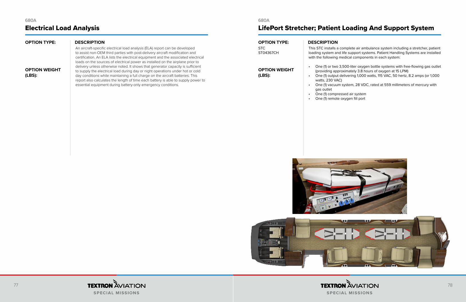
This STC installs a complete air ambulance system including a stretcher, patient loading system and life support systems. Patient Handling Systems are installed with the following medical components in each system:
• One (1) or two 3,500-liter oxygen bottle systems with free-flowing gas outlet (providing approximately 3.8 hours of oxygen at 15 LPM)
• One (1) output delivering 1,000 watts, 115 VAC, 50 hertz, 8.2 amps (or 1,000 watts, 230 VAC)
• One (1) vacuum system, 28 VDC, rated at 559 millimeters of mercury with gas outlet
• One (1) compressed air system • One (1) remote oxygen fill port
STCST04367CH

© 2021 Textron Aviation Inc. All rights reserved. Product names, company names, trademarks, service marks, trade names, trademark designs and logos of Textron Aviation Inc. or its subsid-iaries (collectively “Marks”), whether or not appearing in large print, italics, or with trade marking symbols, are Marks of Textron Aviation Inc. or an affiliate and may be registered in the United
States. Third party marks whether or not appearing in large print, italics, or with trade marking symbols are marks of others.Issued August 2021
U.S. +1.800.456.3580 | INTERNATIONAL +1.316.517.8270 | SPECIALMISSIONS.TXTAV.COM