proceedings w056 - special track 18th cib world building congress may 2010 salford, united kingdom...
TRANSCRIPT

Proceedings
W056 - Special Track
18th CIB World Building Congress
May 2010 Salford, United Kingdom
CIB W056 - Sandwich Panels
CIB Publication 342

CIB WORKING COMMISSION
W056 ‐ SANDWICH PANELS
PAPERS AND POSTGRADUATE PAPERS FROM THE SPECIAL TRACK
HELD AT THE CIB WORLD BUILDING CONGRESS 2010, 10‐13 MAY 2010
THE LOWRY, SALFORD QUAYS, UNITED KINGDOM
Selected papers from the Proceedings of the 18th CIB World Building Congress. Proceedings edited by: Professor Peter Barrett, Professor Dilanthi Amaratunga, Dr. Richard
Haigh, Dr. Kaushal Keraminiyage and Dr. Chaminda Pathirage
W056 Special Track Papers (excluding Postgraduate Papers) reviewed by: Professor Jose
Amorim Faria, Professor Jukka Aalto, Professor Jörg Lange, Dr. Lars Heselius and Professor J. Michael Davies
CIB Publication 342

W056 ‐ SANDWICH PANELS
PAPERS AND POSTGRADUATE PAPERS FROM THE SPECIAL TRACK
The objectives of this Commission are to exchange information and coordinate research programmes in all technical aspects of light‐weight constructions using traditional and new building materials and to prepare synthesised reports on matters of particular interest.

CONTENTS
Papers
Stabilisation of Beams by Sandwich Panels ‐ New Regulations and Recent 1 Research Results ‐ Misiek, T. Kapplein, S. Durr, M. Saal, H.
A Unified Approach for the Local Buckling of Sandwich Panels and Trapezoidal Sheeting 14 Misiek, T. Hassinen, P.
ECCS/CIB Joint Committee on Sandwich Constructions, Recent European 27 Recommendations on Design and Testing Davis, J.M. Hassinen, P. Heselius, L. Misiek, T.
Methods to Measure the Durability of Structural Sandwich Panels 38 Hassinen, P. Pfeiffer, L.
Reliable Composite Roofing: Learning from Experience 51 Roberts, K.
Postgraduate Papers
Openings in Sandwich Elements 61 Warmuth, F. Lange, J.
Optimization of Geometry and Core Materials of Sandwich Panels with Metallic Faces 73 Kurpiela, A. Lange, J. Berner, K.
CIB Brochure 85
Disclaimer 87

5
A Unified Approach for the Local Buckling Of Sandwich Panels and Trapezoidal Sheeting
Misiek, T.
Karlsruhe Institute of Technology, Karlsruhe, Germany
(email: [email protected])
Hassinen, P.
Faculty of Engineering and Architecture, Helsinki University of Technology, Espoo, Finland and
Pontek Consulting Engineers Ltd, Espoo, Finland
(email: [email protected])
Abstract
Failure of thin-walled building components like sandwich panels or trapezoidal sheeting is normally
initiated through a local buckling of the plane elements of the cross-section. For trapezoidal sheeting,
EN 1993-1-3 gives an equation for the determination of the effective width of these plane elements
and thus for the calculation of the load-bearing capacity of these components. The cross-sectional
parts of a lightly or strongly profiled facing of a sandwich panel can be regarded as elastically
supported plane elements, whereas the elastic support is provided by the core material. For the
determination of the load-bearing resistance of sandwich panels with lightly or strongly profiled
facings, a calculation procedure to determine the effective width of the elastically supported plane
elements is needed. Some approaches for the calculation of the effective width already exist. The
papers published so far are using a modified buckling coefficient for the calculation of the buckling
strength, following Winter’s approach such as given in EN 1993-1-3. Because no generally accepted
design procedures exist, the load-bearing resistance of sandwich panels is determined
experimentally. Based on the basic principles of structural stability, the buckling strength of the
elastically supported plane element can be calculated, taking into account the material properties of
the core material and the associated buckling wavelength for minimum buckling strength. Then the
design procedures of EN 1993-1-3 for thin plate buckling of trapezoidal sheeting can be used,
expanded by the procedures of EN 1993-1-5 for taking into account the column type buckling
behaviour for buckling wavelengths smaller than the total width of the plane element. Comparison of
the test results with different arrangements to the calculated values shows a good consistency. For
lightly profiled faces, depending on the depth of the profiling, failure will finally take place through a
plate buckling of the plane elements or by a column buckling of the stiffening profiles, whereas the
latter failure mode is looking similar as the wrinkling failure of a flat facing. Comparison of the
experimental results obtained with different test arrangements to the calculated values show the
present limits of the applicability of the proposed design procedure. The differences in failure modes
are discussed.
Keywords: sandwich panels, face layer, buckling, elastic foundation, elastic half-space

6
b
1. Introduction
The determination of the load-bearing capacity required for the design of sandwich panels is to a
large degree based on test results. In contrast, there is a large number of references for the
determination of the load-bearing capacity of the trapezoidal sheeting, documented in national
standards such as the Swedish StBK-N5 or the German DIN 18807 as well as international standards
such as EN 1993-1-3. This is astonishing because both building components are com-parable in
materials, geometry and load-bearing behaviour. Compared to trapezoidal sheeting the foam core
provides an additional elastic foundation to the plane thin-walled elements.
In the following we will show that the calculation procedures developed for trapezoidal sheeting can
be modified to be applied for sandwich panels. This will start with the basic module, of which all
cross-sections consist: a simple plane element, like a flange of a strongly profiled face of a sandwich
panel.
2. Theoretical background and standardized design procedures
The local buckling of the plane cross-sectional elements shall be taken into account in the
determination of the load-bearing capacity of the thin-walled building components. Because of the
local buckling of the plates of a medium or high slenderness only an effective width, which is smaller
than the total width, can be taken into account.
x
a
y
EIF
= f (EF, t,
F)
x
c = f (EC, G
C,
C)
z
Figure 1: Plate on elastic foundation
The calculation of the effective width is based on the critical buckling stress cr. An additional
support provided by an elastic foundation increases the critical buckling stress cr. This increase is an

7
E t 2
a 2 2 2 2
F
2 2 2
p
addition to the local buckling stress of the plate without foundation calculated according to EN 1993-
1-3. The increase of the critical buckling stress leads to a decrease of the relative slenderness of the
plate and thus to an increase of effective width and load-bearing capacity. Up to now, most of the
present studies capture the effect of the elastic foundation by adjusting the buckling value k as
proposed by Davis, Hakmi and Hassinen (1991). This adjustment is based more on statistical
evaluations of test results. The determination of the critical buckling stress can be based on the elastic
potential, which is shown in Timoshenko and Woinowsky-Krieger (1959) for the plate without
foundation. The calculation of the stiffness of the Winkler’s foundation out of the material
parameters EC and GC of the core material is shown in Stamm and Witte (1974). We obtain the
following equation:
cr , p
2
F m n
12 1 2 m a b
2 1 E
a m n
C C
1 C 3 4 C t m a b
with
E C EC GC 2 1 C
according to Stamm and Witte (1974) to take into account very approximately the anisotropy of the
material properties of core materials such as for example polyurethane and polystyrene foam.
The effective width of the plate can be calculated from the critical buckling stress and the relative
slenderness. EN 1993-1-3 gives the following expressions:
f y p
cr , p
beff , p
1,0 1 0,22 for p
p
0,673
b 2 p
p p
0,673
These equations derived by Winter assume pure plate-like behaviour. This can be found for ratios =
a/b > 1,0. Because of the elastic foundation we obtain a buckling wave pattern with an aspect ratio
a/b which is smaller than 1,0. This has to be taken into account when calculating the critical buckling
stress, leading to an increase of the buckling coefficient k . Unfortunately this also results in a minor
support of the mid-part of the plate by the supports at the longitudinal edges compared to buckling
patterns with higher aspect ratios. Therefore the load-bearing capacity is lower than the one
calculated according to Winter’s equation. Column-like buckling behaviour of the plate has to be
taken into account. This can be done by utilising the procedure given in EN 1995-1-5. In this case an
interpolation between the plate buckling curve according to Winter and the column buckling curve c

8
2 2 2
F
is done. This interpolation is based on the ratio of the elastic critical buckling stress of the plate and
the column:
c p c 2 c
with
0 1,0 where cr , p
1
cr ,c
and
cr ,c
EF t m
12 1 2 a
2 1 C
1 C 3 4 C
E C a t m
f y c
cr ,c
0,5 1
0,21 2
c 0,2 c
1 c
2 2
c
1,0
3. Comparison with results from numerical calculations and tests with flat plates
The presented approach for the determination of the load-bearing resistance of a flat plate on an
elastic foundation was verified using finite-element-calculations and comparisons with test results.
The plates were modelled using four-node shell elements with a linear-elastic ideal-plastic stress-
strain relationship. For the elastic foundation, spring elements with a linear elastic stress-strain
relationship were used. The parameters such as sheet thickness t, yield strength fy and stiffness of the
foundation c (via EC, GC and C) were varied. Figure 2 shows the results of the comparison between
the theoretically derived critical buckling stress and the buckling stress based on FE-calculations.
Using this FE-model and the initial imperfection corresponding to the first eigenvalue of the model,
the ultimate load has been computed. The initial imperfection was scaled to w0 = 0,1 t. The
comparison of the computed results with the results of the procedure based on the interpolation
between the plate buckling curve according to Winter’s equation and the column buckling curve c is
shown in Figure 3.

9
cr,p
,FE
M [
N/m
m²]
c,F
EM
[-]
600
500
400
300
200
100
0
0 100 200 300 400 500 600
cr,p,calc [N/mm²]
Figure 2: Comparison of critical buckling stress based on the finite-element-calculations and on the
analytical expressions
1,0
0,8
0,6
0,4
0,2
0,0
0,0 0,2 0,4 0,6 0,8 1,0
c,calc [-]
Figure 3: Comparison of the results of finite-element-calculations with results of the calculation
procedure: normalised effective width c
To verify the calculation procedure, a series of tests was performed. These tests were done with
trapezoidal sheeting (five ribs) and with cross-sections cut out from the sheeting (one rib). The
trapezoidal sheeting was the upper face of a panel with one strongly profiled face (Figure 4). The

10
inner flat face was removed. Thus, the trapezoidal sheeting provided the only load-bearing
component of the specimen. Due to the remaining foam core, the plane elements of the face still were
supported by an elastic foundation. The normalized effective width c was back-calculated using the
calculation procedure for trapezoidal sheeting according to EN 1993-1-3, supplemented with the
procedures of EN 1993-1-5.
20 mm
23 mm
114 mm
tF1
= 0,47 mm
35 mm
61mm
no face
Figure 4: Trapezoidal sheeting with elastic foundation
According to the calculation procedure, the aspect ratio of the buckling waves should be about =
0,3. Figure 5 shows the buckling waves in the upper flange confirming the calculated value.
Figure 5: Local buckling of the upper flange
An additional series of tests was done with the upper face layer without any foam material. The
geometry and material was identical to the one used in the tests described above. In this case no
elastic foundation for the plate is available and we have a cross-section of a standard trapezoidal
sheeting. Results of the tests are shown in Figure 6.
In addition, the tests results of Davis and Hakmi (1991) and the results of Pokharel and Mahendran
(2003) were used for comparison (Figure 6). Davis and Hakmi performed bending tests on C-shaped

11
c,t
est
[-]
members with a foam core. Pokharel and Mahendran glued flat sheets of different thicknesses and
steel grades to layers of plastic foam material.
1,0
0,8
0,6
0,4
0,2
0,0
Davis and Hakmi 1991
Pokharel and Mahendran 2003
trapezoidal sheeting with elastic
foundation
trapezoidal sheeting without
elastic foundation
0,0 0,2 0,4 0,6 0,8 1,0
c,calc [-]
Figure 6: Comparison of calculation procedure with test results: normalised effective width c
All the test results show a good correlation with the calculated values. The calculated values make
the lower boundary to the test results. Interestingly the values with the highest discrepancy between
test and calculation being on the unsafe side are the ones for the standard trapezoidal sheeting
without any elastic foundation. This is a result of the very high slenderness of the upper flange, the
relative slenderness being of the order of 5,5 to 5,6.
It is interesting to discuss about the effect of the material properties used in the calculation procedure.
The first difference arises in the test method for the determination of the shear modulus GC. Davis
and Hakmi performed tests with small cubes of the core material which were loaded with a pure shear
load. No information is available about the tests of Pokharel and Mahendran. However, it can be
assumed that the tests were done in a similar way based on small cubes. Our tests for the
determination of the shear stiffness were performed with small short-spanning beams according to
EN 14509. The latter test method might lead to higher discrepancies between the measured value and
the actual material properties, resulting in a higher discrepancy between the calculated and
experimental values c,calc and c,test.
The elastic modulus EC of the core material is normally determined as an average value
corresponding to the total thickness of the specimen, determined separately in a compression and
tensile test. For plastic foam materials made in a continuous process the local values strongly deviate
from this mean value, depending on the relative position of the sample in the thickness direction of
the panel. For these sandwich panels, investigations on the distribution of the stiffness presented in

12
Dürr (2008) show that the elastic modulus near to the faces is higher than in the centre plane of the
panel. In addition, different values of the modulus can be obtained close to the faces depending on
their position (top or bottom) during the production. These effects have to be kept in mind when
looking for the results of our tests (which were done with real panels) and presumably also for the
tests of Davies and Hakmi. For the tests of Pokharel and Mahendran which were performed with
foam material glued to the face this effect can be neglected. In fact, when calculating the load bearing
resistance with the values from the tests, calculated values are on the safe side, because the higher
stiffness near the faces gives a stiffer elastic foundation than assumed by using the mean values over
the total core thickness.
4. Strongly profiled sandwich panels
In addition to the buckling tests with trapezoidal sheeting, tests with sandwich panels were also
performed. The panels had a similar geometry as the specimens introduced before. In these tests, the
inner face was not removed, so real sandwich-type load-bearing behaviour existed. The results of the
tests were back-calculated, too. Now, the lower flange of the outer face is also under compression
loading. This can be easily seen by comparing the pictures of this flange taken after the failure
(Figure 7).
Figure 7: Upper and lower flange of the specimens after failure: trapezoidal sheeting with elastic
foundation (left) and sandwich panel (right)
The effective cross-section of the outer face can be calculated with the introduced procedure. At first,
the effective cross-section of the outer face under compression has to be determined by strictly
following the calculation procedure introduced in chapter 2 (approach A). In fact, there will be
always a difference between the calculated effective width and the test results. These differences in
the determination of the effective width will cause further differences in the calculation of the load-
bearing capacity of the sandwich cross-section. In our case, we have also the possibility to use the
effective width of the upper flange from the tests on tests described in chapter 3 (approach B) to
minimize the effect of the former differences. The use of both the both approaches allows us to
compare the results. The calculation has to be done iteratively. For the first iteration we assume a

13
constant compression stress distribution over the whole cross-section of the outer face. We obtain the
following results:
20 mm
23mm 114 mm
11,1 mm
35 mm
11 mm
11,1 mm Approach A: 15,4 mm Approach B: 22,8 mm 11 mm
Figure 8: Effective cross-section of the outer face after the first iteration
Table 1: load-bearing capacity of the sandwich panel after the first iteration
Approach A
Approach B
Test result
Ultimate bending moment
5,27 kNm
6,74 kNm
6,94 kNm
According to this calculation, the compression stress in the lower flange reaches a value of = 148
N/mm² which is below the yield strength. The effective width in the lower flange is larger than
assumed at first. Same is true for the lower part of the webs. Therefore the effective cross-section is
larger than calculated in this first step. The accuracy of the calculated load bearing capacity can be
improved iteratively. For the lower flange, this can be done by calculating the effective width with
= 148 N/mm² instead of fy = 400 N/mm². Special considerations are required for the web. We can use
the simple assumption given in EN 1993-1-3 that the effective width at the lower edge is 1,5-times
the one at the upper width were = fy. After the first iteration, the stresses in the lower flange are
further decreasing, and the stresses in the inner face increase. Load-bearing capacity is increasing
with every iteration. However, the values are converging very soon. Stress distribution based on the
fifth iteration can be accepted to represent the ultimate load:
20 mm
23mm 114 mm
11,1 mm
35 mm
16,7 mm Approach A: 15,4 mm
Approach B: 22,8 mm
Approach A: 20,0 mm
Approach B: 19,0 mm
Approach A: 20,0 mm
Approach B: 19,0 mm
Figure 9: Effective cross-section of the outer face after the fifth iteration

14
Table 2: Load-bearing capacity after five iterations
Approach A
Approach B
Test result
Ultimate bending moment
5,94 kNm
7,14 kNm
6,94 kNm
This is a considerable improvement compared to the results of the first iteration. However, in the
example we have a difference between the values of the pure calculational approach A and the test
result. The difference is in the same order as for the simple flat plate element.
5. Resistance of lightly profiled faces
A local buckling phenomena can also be observed in tests with panels having a slightly profiled face.
Figure 10 shows the face of a lightly profiled sandwich panel (depth of lining approx. 2,0 to 2,5 mm)
in a bending test before reaching the failure load. Finally, failure will occur by global buckling or
wrinkling of the face over the complete width of the panel, depending on the support conditions at the
longitudinal edges of the compressed face.
Figure 10: Local buckling of the slightly profiled face of a sandwich panel
For an extension of our approach to lightly profiled faces on an elastic support, the results of the
buckling tests of Pokharel and Mahendran (2005) were used. Pokharel and Mahendran (2005) varied
the thickness of the faces and the width b of the plane elements of the profiling. The total dimensions
of the faces were 400 mm and 1200 mm in the width and length directions, respectively. All the
edges were fully supported. The effective width of the plane elements between the stiffeners can be
calculated according to the presented calculation procedure. After incorporating the restrictions in
EN 1993-1-3 requiring some reductions in width also the cross-sectional values of the stiffeners itself
can be calculated. The part of the critical buckling stress provided by the stiffeners can now be
calculated using

15
b b
Nu
,test
[k
N]
cr ,s
1,8 E
I s t 2 3
e
Assuming a global buckling failure of the stiffened plate and recalculating the tests with the
equations introduced in section 2 of this paper, the results shown in Figure 11 were obtained.
40,0
4,25 mm 4,25 mm
13 mm b
32,0 1,0 mm
24,0
16,0
8,0 b = 78,5 mm
b = 28,5 mm
0,0
0,0 8,0 16,0 24,0 32,0 40,0
Nu,calc [kN]
Figure 11: Comparison of results of calculation procedure with test results
It can be shown that for the geometry investigated in Pokharel and Mahendran (2005) the effects of
the stiffeners can be neglected and the support at the longitudinal edges as well as the elastic
foundation of the core material are the dominating stabilising effect. In this case, failure occurred by
local buckling of the entire stiffened plate. The overall width dominated against the width of the
lining between the stiffeners.
Typical flat or lightly profiled faces of sandwich panels do not have supports at the longitudinal
edges. The wrinkling stress of these panels is usually calculated using the so-called Plantema-
equation.
cr 0,82 2 E
F E
C G
C
The coefficient 0,82 is in most cases modified to take into account the effects of imperfections etc.
By doing so the transition form the elastic critical buckling tress to the ultimate buckling stress is
done. Further modifications of this coefficient, sometimes denominated as a wrinkling factor, can be
justified by taking into account the geometry of the faces, leading to a value derived from tests.
Further adjustments of this equation are discussed in Pokharel and Mahendran (2005).

16
This problem concerning the flat or lightly profiled faces of typical sandwich panels without a
support on the longitudinal edges could also be calculated within the framework of EN 1993-1-3. The
wrinkling failure can be interpreted as a buckling failure of the stiffeners of the face. After
calculating the elastic critical buckling load of the stiffener, a buckling curve for the stiffener
available in EN 1993-1-3 could be used. The relative slenderness and the buckling curve are given by
f y
d
cr ,s
and
1,0 d 0,65
d 1,47 0,723 d for 0,65 d 1,38
0,66 d 1,38
d
This buckling curve was developed for trapezoidal sheeting using the assumption that the elastic
foundation of the stiffener is provided by the support of the neighbouring longitudinal edges of the
stiffened element.
Further investigations have to be done before applying the design procedures of EN 1993-1-3 for the
design of lightly profiled sandwich panels. At present, the observations can be used to make a
differentiation between lightly and strongly profiled faces of sandwich panels. When calculating the
critical buckling load of the stiffener, the width bP = sW of the web has to be fully effective, thus c =
1,0. As a second criteria, column-buckling of this stiffener must not be the significant failure mode,
so d = 1,0 for column buckling of the stiffener. Then, the face can be regarded as strongly profiled
and the load-bearing capacity of the panel can be calculated as presented in the previous chapters.
6. Conclusion
The determination of the load-bearing capacity required for the design of sandwich panels is to a
large degree based on test results. In contrast, there is a large number of references for the
determination of the load-bearing capacity of trapezoidal sheeting. Because both building
components are comparable in materials, geometry and load-bearing behaviour, a calculation
procedure for sandwich panels which relies on the design principles developed for trapezoidal
sheeting seems to be possible, by taking into account the effects of the elastic foundation provided by
the core layer.
The basic principles of the design model are introduced and compared with Finite-Element-
calculations as well as with test results from different sources, showing the applicability of the
procedures. Apparently this calculation procedure can be applied to strongly profiled faces of

17
sandwich panels as well as for trapezoidal sheeting with bonded plastic foam insulation. The last-
mentioned building components have found increasing dissemination on the market in the last years.
Finally, an overview to the design of lightly profiled sandwich panels was made. Comparison with
test results showed the present limits of the applicability of the design procedures of EN 1993-1-3 if
applied to sandwich panels. Lightly profiled faces show a complex behaviour with interactions from
plate buckling and column buckling failure. This can not be captured on a sufficient safety level at
the moment.
Acknowledgements
ThyssenKrupp Steel Europe AG provided specimens for the experimental investigations. We express
our sincere gratitude for this support.
References
Timoshenko S P Woinowsky-Krieger S (1959) Theory of Plates and Shells, New York, McGraw-
Hill.
Stamm K and Witte H (1974) Sandwichkonstruktionen: Berechnung, Fertigung, Ausführung, Wien
New York, Springer Verlag
Davies M J, Hakmi M R and Hassinen P (1991) “Face buckling stresses in sandwich panels”
Contributions 1991 ECCS Nordic Steel Colloquium, p. 99-110.
Davies M J and Hakmi M R (1991) “Postbuckling behaviour of foam-filled thin-walled steel beams”
Journal of Constructional Steel Research 20: 75 - 83.
Pokharel N and Mahendran M (2003) “Experimental investigations and design of sandwich panels
subject to local buckling effects” Journal of Constructional steel research 59: 1533-1552.
Pokharel N and Mahendran M (2005) “An investigation of lightly profiled sandwich panels subject to
local buckling and flexural wrinkling effects” Journal of Constructional steel research 61: 984-1006.
Dürr M (2008) Die Stabilisierung biegedrillknickgefährdeter Träger durch Sandwichelemente und
Trapezbleche, Berichte der Versuchsanstalt für Stahl, Holz und Steine der Universität Fridericiana in
Karlsruhe, 5. Folge – Heft 17. Karlsruhe 2008.
EN 1993-1-3: Eurocode 3: Design of steel structures – part 1-3: General rules - Supplementary rules
for cold-formed members and sheeting
EN 1993-1-5: Eurocode 3: Design of steel structures – part 1-5: Plated structural elements

18
ECCS/CIB Joint Committee on Sandwich Constructions: Recent European Recommendations on
Design and Testing
Davis, J.M.
83 Park Road Hale, Altrincham Cheshire WA15 9LQ UK
(email: [email protected])
Hassinen, P.
Helsinki University of Technology, Finland
(email: [email protected])
Heselius, L.
LHH Consulting Oy Ab Ltd
(email: [email protected])
Misiek, T.
Karlsruhe Institute of Technology, Karlsruhe, Germany
(email: [email protected])
Abstract
Light-weight sandwich panels, made of two metal faces separated by an insulating core material, are
modern pre-fabricated construction components. The design, manufacture and use of these
composite structural elements have required continuous development of regulations and standards.
The Joint Committee is the combination of two working groups; CIB W056 “Lightweight
constructions” and ECCS TWG 7.9 “Sandwich panels and related structures”. It therefore provides a
powerful forum for the consideration of international research and development of the design, testing
and end-use of sandwich panels. This paper introduces the Joint Committee and its work by outlining
its history and its most important publication, “European Recommendation for sandwich panels”.
The significant influence of the Committee on the recently published European Product Standard EN
14509 is also described. Focus is then directed to the latest publications of the Joint Committee,
namely the “Preliminary European Recommendations for Testing and Design of fastenings for
sandwich panels” and the “State of the art report for Design of Sandwich Panels with Openings”.
The latter is still under preparation and will probably be published in 2010.
Keywords: sandwich panel, light-weight, fastening, opening, CIB, ECCS, recommendations

19
1. The joint committee on sandwich constructions
1.1 CIB steering group S56 and working commission W056
The first sign of the existence of the CIB Steering Group S56 was at the International Symposium on
Low-Rise Lightweight Constructions held in Budapest in April, 1971. A significant product of this
era was CIB Publication 59 “Recommendations for the Structural Design of Lightweight Sandwich
Panels” which was published in 1978. This document gives principles for design with regard to static
out-of-plane and in-plane actions, impact loads and dynamic loads. It also gives recommendations
for design for environmental effects and fire. Finally, it discusses the properties of connections and
construction systems including the principles of the quality control. The report was based on ISO
standard 2394-1973 which introduces the principles of the modern limit state design. The report,
which was far ahead of its time, was written as a framework for national regulations and it probably
provided the first formalised recommendations for the design of sandwich panels. Nowadays, the
emphasis in Europe has moved away from national guidelines and towards harmonized standards for
the whole continent. However, historically, “Recommendations” produced by European-wide
Committees of experts have led to a similar unified outcome.
The name of Steering Group S56 was changed to Working Commission W056 and the membership
reconstituted. It held its first meeting in Espoo, Finland in May, 1984. Initially, developments in
lightweight constructions were introduced and discussed without limitation as to materials or types of
construction. Later, the subjects of W056 became focused more towards mineral wool cored
sandwich panels because of the need for guidelines for this new sandwich panel product. The
coordinators of W056 during this period were Professor J M Davies in 1986 - 89 and Lars Heselius in
1990 - 2006. Thus, W056 extended the Preliminary European Recommendations for Sandwich
Panels written originally by ECCS TWG 7.4 (see 1.2) and the outcome was CIB Publication No 148
which was published in 1993 and reprinted in 1995.
1.2 ECCS technical working group TWG 7.4
The European Convention for Constructional Steelwork (ECCS) has a long and distinguished record
of pre-standardisation work and its Technical Committee TC7 “Cold-formed thin-walled sheet steel
in buildings” has been one of its most successful working committees and, since its inception in
1974, it has produced numerous significant documents. The workload of TC7 quickly increased to
the point where a number of separate Working Groups were required and in 1983, noting the
increasing interest of the market in light-weight metal sheet faced sandwich construction, it was
decided to form a new technical working group TWG 7.4 “Sandwich Panels” to produce European
Recommendations for design, testing and good practice in the use of sandwich panels. The work of
TWG 7.4 started in 1983 under the chairmanship of Dieter Stemman taking full advantage of his
experience with German “Zulassung” documents.

20
TWG 7.4 produced “Preliminary European Recommendations for Sandwich Panels” in two parts.
Part I “Design” was published in 1991 and relates to the analysis, design and testing for the load-
bearing capacity of the sandwich panels. This significant document has provided the basis for a
number of subsequent Recommendations and Standards. Part II “Good Practice” was published in
1990 and introduces subjects such as building physics, fire, installation and erection work.
In the late nineties needs to update the European Recommendations became obvious and ECCS TC7
founded a new Technical Working Group TWG 7.9 “Sandwich Panels and related Subjects”.
Because of the mutual interest, in 1998, ECCS TWG 7.9 and CIB W056 combined to form the Joint
Committee on Sandwich Construction, which is still active today. The first two years of work
resulted in the final manuscript of the “European Recommendations for Sandwich Panels, Part 1:
Design”, which was published as CIB Publication No 257 in 2000 and ECCS Publication No 115 in
2001. The authors pay tribute to the work of Antti Helenius who acted as secretary of W056 and the
Joint Committee for more than ten years.
Based on the work of the CIB W056 Working Commission, a group of members combined together
to write a book covering all aspects of sandwich panel design and construction. Although individual
members took responsibility for individual chapters, this book is unique in that the authors took joint
responsibility for the whole and each chapter was discussed in detail at a series of meetings. The
contributions were edited by Professor J M Davies and the result was published in 2001 entitled
“Lightweight Sandwich Construction”.
The above Recommendations have formed the basis of the European product standard for self-
supporting double skin metal faced insulating panels, EN 14509, which was published in December
2006 and cited in the Journal of CEN in December 2008. Drafting of the product standard was in the
hands of CEN Committee TC128/SC11, which includes most members of the Joint Committee. The
product standard extends the European Recommendations to include all of the “Essential
Requirements” of the Construction Product Directive in accordance with formal mandates.
Because it is a European “product” standard, EN 14509 defines the requirements and the methods of
verification of the essential properties of the factory made sandwich panels. The standard does not
and cannot specify requirements for operations carried out after manufacture such as cutting, fixing
and installation. Consequently, in 2004, the reactivated Joint Committee identified a number of
subjects in which further direction and harmonization is needed. The first items to be considered
were the fastening and openings in sandwich panels.

21
2. The recent European recommendations
2.1 Testing and design of fastenings of sandwich panels
2.1.1 Background
The product Standard EN 14509 does not give any requirements regarding the joints and fastenings
of the sandwich panels. In order to remedy this, the Joint Committee has produced preliminary
recommendations which discuss the experimental determination of the load-bearing resistance of
fastenings, the evaluation of the test results and the principles of the design of fastenings. These
preliminary recommendations, now available as ECCS Publication No 127 and CIB publication No
320 in 2009, are based on the earlier versions of the European Recommendations for Sandwich
Panels ECCS & CIB (2000) updated to accord with current knowledge and experience.
2.1.2 Fastening of sandwich panels
Figure 1: Fixings of sandwich panels: typical application and fastener (right hand Figure courtesy of
Würth).
Because of the inherent rigidity of the sidelap, seam fasteners are not generally used in sandwich
construction. Attention is therefore concentrated on the connections to the supporting structure.
These may be concealed in the sidelap or may be visible and pass through the complete panel.
Whichever solution is adopted, self-tapping or self-drilling screws are generally used. Both of these
are able to cut their own threads into the substructure, however self-tapping screws require pre-
drilling. The screws have a formed drilling bit that allows the screwing and drilling in a single

22
F
operation. In order to produce a rainproof joint, sealing washers with a vulcanised EPDM layer are
used between the screw head and the face. The washers of the screws fixed to the upper flange of the
trapezoidally profiled facing, may take the form of saddle washers to tighten and to support the
profile.
The fasteners between the sandwich panel and the substructure may be loaded by tensile and shear
forces as well as by bending moments (head deflection) due to the thermal movements of the faces.
2.1.3 Tensile and shear resistance of fastenings
The load-bearing performance of fastenings is mainly determined experimentally. Therefore, tensile,
shear and bending tests have to be performed. Attention is generally concentrated on the strength
(capacity) of the connection. However, it is important to appreciate that stiffness and ductility are
also important. In particular, sandwich panel assemblies are generally extremely rigid with regard to
in-plane displacements so that any such movements (due, for example, to thermal elongation or
parasitic stressed skin action) must be accommodated primarily by ductility in the fastening system.
F
e1 e2
direction of span
eC e3
Figure 2: Test arrangement for pull-through resistance based on small-scale specimens at an end
support (ECCS & CIB, 2009).
eC e3
e4 e4
direction of span
Figure 3: Test arrangements for pull-through resistance with small-scale specimens at an intermediate
support (ECCS & CIB, 2009).
The tensile resistance of a fastening represents the minimum value of the pull-through resistance and
the pull-out resistance. The load-bearing capacity of the screw itself does normally not play an
important role in the resistance of the fastenings of sandwich panels. The Recommendations ECCS
& CIB (2009) deal with the pull-through resistance only. For determining the pull-out resistance
reference is made to ECCS (2008).

23
The distance between the end of the panel and the fastener has an influence on the tensile resistance
of the fastening. Therefore, two separate test arrangements have been developed to take into account
the different nature of the fastening at an end support and at an intermediate support as shown in Figs
2 and 3. Figure 4 shows the principal set-up of a test for the determination of the shear resistance of
a screw fastening. Since the influence of the external face decreases with the increasing thickness eC
of the core layer, the tests are to be performed with the largest envisaged panel thickness. As an
alternative, the sole direct load transmission between the internal face and the substructure may be
investigated.
eC e1
t1 F
u
Figure 4: Shear test assembly for screws passing through the panel (ECCS & CIB, 2009).
For the determination of the resistance of a screw to the deflection of the screw head, the shaft of the
fastener is subjected to a repeated deflection of „u‟, where u is the maximum lateral displacement of
the head. The deflection spectrum is as follows: 20.000 cycles with a deflection of 4/7 u, 2.000
cycles with a deflection of 6/7 u and 100 cycles with a deflection of u. This load spectrum is based
on the assumption of a service life of 50 years in a location in central Europe. During the test, the
screw shall not fail and, after cyclic loading, the screw has to achieve at least 80 % of the mean value
of the pull-out resistance without the repeated load.
2.2 Openings in sandwich panels
2.2.1 Background
In the majority of buildings, functional requirements necessitate openings in the wall and roof
cladding. The current state of the art with regard to openings within the sandwich panel wall and roof
construction generally requires the addition of reinforcement in the form of additional framing to
replace the load-bearing capacity which has been removed by the opening (Fig 5). Recent research
results indicate that this additional framing is not always needed. The state of the art report of the
Joint Committee will introduce the possibility of designing panels with openings without the need for
any additional strengthening.
2.2.2 Remaining resistance of panels with openings
The cross-section of the panel which remains after cutting an opening may be able to carry the
applied loads. In this case, the opening is classified as „small‟. The evaluation of the remaining

24
resistance is evidently the primary design task and this includes verification of the resistance of the
net section to the design bending moments and shear forces at the critical points in the vicinity of the
opening taking account of any stress concentrations.
A section A - A
framework A replacement with cross-
beams, e.g. C-sections
Figure 5: Openings requiring additional supporting members (ECCS & CIB, 2010).
remaining cross-section
gross cross-section
Figure 6: Remaining cross-section in the vicinity of an opening (ECCS & CIB, 2010).
The ECCS & CIB report (2010) gives design formulas to calculate the remaining resistance of a panel
with openings (Fig 6).
2.2.3 Activation of the load-bearing resistance of neighbouring panels
If the remaining cross-section of an individual panel is not able to carry the applied loads, the load-
bearing resistance of the neighbouring panels can be activated. Due to the difference of the stiffness
between the panels with and without openings, the whole or a part of the loads applied directly to the
panel with openings will be transferred via the longitudinal joints to the adjacent panels (opening „A‟
in Figure 7). The most severe case is the load transfer from a completely cut sandwich panel

25
A
(opening „B‟ in Figure 7). While in case A the panel might have sufficient capacity to withstand the
load, case B relies entirely on the load transfer. In both cases, the neighbouring panels will receive
additional loads which can be calculated on the basis of the compatibility of the deflections in the
longitudinal joints (Figure 8). These loads are transferred by these joints and therefore, the
assessment of the strength and stiffness of the joints is essential. Furthermore, the load transfer will
result in an eccentric line load applied to the adjacent panel without an opening thus activating its
torsional rigidity and causing additional shear stresses due to the torsional moment.
A
B
Figure 7: Small and full-width openings in sandwich panel walls (ECCS & CIB, 2010).
Figure 8: Line loads on the longitudinal joint between neighbouring sandwich panels with different
bending and shear stiffness (ECCS & CIB, 2010).
The intensity of the load, which can be transferred through the longitudinal joints to adjacent panels,
depends on the bending, shear and torsional rigidity of the complete panels and, in addition, on the
shear rigidity and shear resistance of the longitudinal joint. Simple framework-software can be used
to compute the internal forces and deflections. ECCS & CIB (2010) presents the basic principles of
the design procedure. A test set-up for the determination of the stiffness and resistance of the
longitudinal joints is presented as well as formulas to determine the required bending and torsional
stiffnesses of the panels.
26
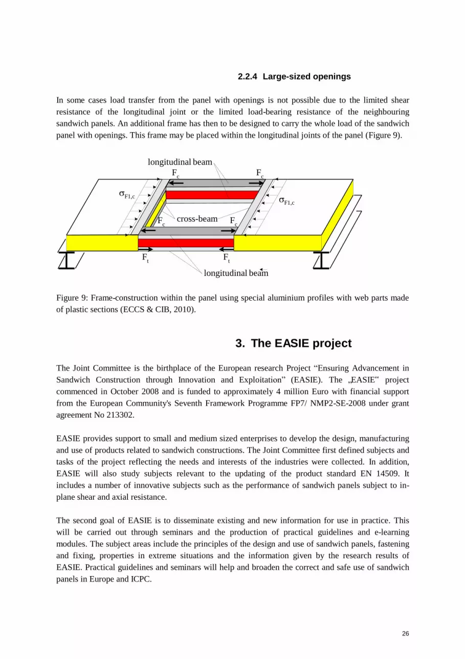
2.2.4 Large-sized openings
In some cases load transfer from the panel with openings is not possible due to the limited shear
resistance of the longitudinal joint or the limited load-bearing resistance of the neighbouring
sandwich panels. An additional frame has then to be designed to carry the whole load of the sandwich
panel with openings. This frame may be placed within the longitudinal joints of the panel (Figure 9).
longitudinal beam
Fc
Fc
F1,c
Fc
cross-beam Fc
F1,c
Ft
Ft
longitudinal beam
Figure 9: Frame-construction within the panel using special aluminium profiles with web parts made
of plastic sections (ECCS & CIB, 2010).
3. The EASIE project
The Joint Committee is the birthplace of the European research Project “Ensuring Advancement in
Sandwich Construction through Innovation and Exploitation” (EASIE). The „EASIE‟ project
commenced in October 2008 and is funded to approximately 4 million Euro with financial support
from the European Community's Seventh Framework Programme FP7/ NMP2-SE-2008 under grant
agreement No 213302.
EASIE provides support to small and medium sized enterprises to develop the design, manufacturing
and use of products related to sandwich constructions. The Joint Committee first defined subjects and
tasks of the project reflecting the needs and interests of the industries were collected. In addition,
EASIE will also study subjects relevant to the updating of the product standard EN 14509. It
includes a number of innovative subjects such as the performance of sandwich panels subject to in-
plane shear and axial resistance.
The second goal of EASIE is to disseminate existing and new information for use in practice. This
will be carried out through seminars and the production of practical guidelines and e-learning
modules. The subject areas include the principles of the design and use of sandwich panels, fastening
and fixing, properties in extreme situations and the information given by the research results of
EASIE. Practical guidelines and seminars will help and broaden the correct and safe use of sandwich
panels in Europe and ICPC.

27
4. Future tasks of the Joint Committee
The earlier work of the Joint Committee has produced independent technical harmonised guidelines
and relevant background documents for the European product standard. The technology of sandwich
panels is still evolving and the Committee seems still to have a useful role as author of technical
guidelines based on new and reliable information without pressure from commercial or other
interests. Because of this continuous development, keeping the available documents up to date is an
important task of the Committee. Future tasks are likely to include the preparation of new guidelines
on the basis of the technical information emerging from projects such as EASIE. Finally, questions
arising from environmental issues in buildings and building products may open new technical tasks
requiring a measure of European collaboration.
References
CIB (1978) Recommendations for the structural design of lightweight sandwich panels. Rotterdam:
CIB - International Council for Research and Innovation in Building Construction, S56 Lightweight
Constructions.
International Organization for Standardization (1973) General principles for the verification of the
safety of structures. ISO 2394.
Davies J M et al. (2001) Lightweight sandwich construction, Oxford, Blackwell Science.
ECCS & CIB (2000) European Recommendations for Sandwich Panels – Part 1: Design.
Brussels/Rotterdam: ECCS - European Convention for constructional steelwork, TWG 7.9 Sandwich
panels and related structures & CIB - International Council for Research and Innovation in Building
Construction, W056 Lightweight Constructions. ECCS Publication No 115 and CIB Publication No.
257.
ECCS (2008) The Testing of Connections with Mechanical Fasteners in Steel Sheeting and Sections.
Brussels: ECCS - European Convention for constructional steelwork, TWG 7.10 Connections in
Cold-formed Steel Structures. ECCS Publication No 124.
ECCS & CIB (2009) Preliminary European Recommendations for Testing and Design of Fastenings
of Sandwich Panels. Brussels/Rotterdam: ECCS - European Convention for constructional steelwork,
TWG 7.9 Sandwich panels and related structures & CIB - International Council for Research and
Innovation in Building Construction, W056 Lightweight Constructions. ECCS Publication No 127
and CIB Publication No. 320.
ECCS & CIB (2010) State of the art report for Design of Sandwich Panels with Openings.
Brussels/Rotterdam: ECCS - European Convention for constructional steelwork, TWG 7.9 Sandwich
panels and related structures & CIB - International Council for Research and Innovation in Building
Construction, W056 Lightweight Constructions. (will be published in 2010?)

28
EN 14509 (2006). Self-supporting double skin metal faced insulating panels - Factory made products
- Specification. Brussels: CEN - Comité Européen de Normalisation.
Ensuring Advancement in Sandwich Construction through Innovation and Exploitation:
www.easie.eu

29
Methods to Measure the Durability of Structural Sandwich Panels
Hassinen, P.
Aalto University Department of Structural Engineering and Building Technology, Finland
(email: [email protected])
Pfeiffer, L.
ThyssenKrupp Steel Europe AG Profit Center Color/Construction, Germany
(email: [email protected])
Abstract
Determination of the intended length of the service life is an increasingly important question and may
be soon a crucial parameter in the development and design of civil engineering structures. Length of
the service life may be limited by a reduction of the resistance or by an unsatisfactory function at the
serviceability state. To determine the service life, knowledge about the deterioration mechanism and
their influence on the structural behaviour is needed. In some cases, information about the
development of the mechanical and environmental loads during the service life is important, too.
European standard EN 14509 introduces experimental methods to measure the changes of the self-
supporting sandwich panels and further, to classify the panels to be fit for the use in external walls
and roofs. The methods are based on an indirect parameter by measuring the changes of the cross
panel tensile strength and not the properties, which are directly used in the analysis and in design.
Ageing of the cross panel tensile test specimens is based on accelerated ageing histories using a high
temperature and moisture. The method is practical and relatively easy to use, however, it does neither
tell about the changes caused by a real natural environment nor the real changes of the ultimate
resistance or the function at the serviceability limit state.
The contribution introduces the parameters which are essential in structural design and then, studies
the possibilities to measure the changes of the parameters in long-term use. The essential parameters
are the wrinkling strength of a face under compressive stresses and the shear strength of the core and
bond. These are followed by a number of other failure modes, such as the resistance at the supports
to pressure and suction loads. The information is based on tests with small-scale specimens, the
results of which will be compared to a limited number of results on full-scale specimens having been
in service and exposed to natural ageing conditions. The contribution concludes the promising
possibilities and draws outlines for development of methods for the use in practice.
This publication was prepared within the scope of the EASIE research project. The project is
sponsored in EU 7th framework programme.
Keywords: sandwich panel, resistance, long-term, durability, ageing, test

30
1. Introduction
1.1 Definition of a sandwich panel
Sandwich panels in the context of this report are composite structures, consisting of a minimum of
two deck layers and a core. The term “panel” is derived from the Latin, French and Dutch word
“paneel” and means “a flat piece of construction” (Brockhaus, 1991, a). This describes the general
shape of a sandwich panel. The word “sandwich” describes generally a combination of different
layers (Brockhaus, 1991, b). A typical sandwich layer in construction consists of three layers. A
rather thick rigid core material is laminated between two thin faces. There are many possible
combinations of facing and core materials, depending on the intended use of the sandwich panel. This
work, however, deals primarily with the most common form of a sandwich panel used currently in the
building construction: factory made engineered elements, consisting of thin metallic facings of a
thickness between 0.4 and 0.75 mm and rigid foam or inorganic wool core.
1.2 Load bearing behaviour of a sandwich panel
The individual layers of sandwich panels by themselves have almost no load-bearing capacity. In a
sandwich panel the layers no longer act separately but are connected in a process of adhesion. Only
this rigid connection makes the structure a sandwich panel and increases the load-bearing capacity
substantially.
While the metal sheet facing alone is almost without bending capacity as is the core by itself, the
connection of the three layers creates a completely new composite structure with widely enhanced
capacities. The composite sandwich panel possesses substantially higher load-bearing capacities with
regard to bending, shear and torsion impact than the sum of its individual components.
Compared to the metal faces, the core in a sandwich panel generally possesses very limited tension or
compression stiffness. The bending moment is therefore distributed to the two faces. For a single
span, three-layer sandwich panel loaded by a distributed load, this leads to compression and tension
in the two faces that are kept apart at a fixed distance by the core.
Based on the properties of the layers and the distribution of the internal stresses, the core carries
through almost all of the shear force. Additionally, the core provides foundations to the faces of the
sandwich panel. Because of that, the properties of the core have a significant influence on the over all
performance of the sandwich panel and need to be carefully evaluated in sandwich panel design.
Losses in the stiffness and strength of the core have immediate influences on the performance of the
whole panel. Such losses can, for example, be caused by durability related degradation.

31
1.3 Durability of construction products
A survey by Sarja (2002) on the typical share of civil engineering products for European countries
shows that:
Civil engineering products represent about 70 to 80% of the national assets.
The energy use for these products during production and maintenance is about 40% of the total
national energy consumption.
Civil engineering products produce about 35% of the total waste.
These figures emphasise the enormous economical importance of civil engineering products for the
societies. Due to the importance and costs of these products, it becomes obvious that there are high
demands to the service ability during the life span of the investment.
Economical effects are dominated by the fact that buildings generally require large investments. The
expectations in the investment can only be fulfilled if the building keeps its functionality over a
certain time period. The estimated time period depends on the type of building. For an industrial
building like a warehouse, for example, it is generally assumed that the building is designed for a
service period of 25 to 30 years. After this period a substantial refurbishment of the building is
generally required.
The most important technological influence for a civil engineering product is the guarantee of the
safe use over a time. Building materials need to be designed in a way, which guarantees an adequate
structural performance. If a structural building material cannot resist against the received load
impacts, the building is damaged or may even collapse. In a worst case scenario, this may lead to a
loss of lives and properties. Therefore, the main task in the regulation is to ensure an adequate
structural performance of the building materials throughout the whole life cycle of the structure.
Legally binding design procedures, which are very much harmonized across Europe, are the base to
guarantee a safe structural performance. For sandwich structures, such procedures are defined in the
European standard on sandwich panels EN 14509, where also requirements towards the durability of
the sandwich panels together with experimental evaluation procedures are described.
In practice, requirements to the fitness for use and to the withstanding the extreme actions during the
use are set down to a structure. The previous requirement defines the serviceability limit state and the
latter one the ultimate limit state. The structure shall maintain the properties in its environment
during its design working life, which defines the requirements on the durability of the structure. The
durability requirements may be achieved by choosing correct materials and manufacturing
techniques. As a result, the deterioration of the structure will stay small enough or the function and
resistance will be guaranteed by regular inspections and refurbishment. In constructions, the first
principle is used in the major cases of structures.
The available durability tests give information about the changes of the strength on a macroscopic
level without explaining the physical and chemical mechanisms affecting the deterioration of the
material. It is believed, that the durability test is able to classify if the product is to fit for the purpose

32
or not. The durability test methods and the loading histories are therefore strongly dependent on the
application.
2. Durability of sandwich panels
The European standard, EN 14 509, makes in chapter 5.2.3 a statement concerning durability;
“Durability and other long term effects.” Detailed information on testing scenarios are written down
in the normative annex B, “Durability testing method for sandwich panels.”
Currently, the durability performance is only evaluated qualitatively. This means that the loss in cross
panel tensile strength under an artificial, durability accelerating climate must stay within certain
boundaries over a time. The cross panel tensile strength is seen as an indicator for over all panel
performance. Depending on the type of degradation pattern (Fig 1), a core material is either fit for the
application or not. The boundaries chosen for an acceptable loss of the strength are, however, lacking
the scientific foundation. Even a loss of 60% of the initial tensile strength can be acceptable in
accordance with the standard. In particular, such a loss in the tensile strength is allowed without any
impact on other relevant design parameters. Because it is not possible to determine the remaining
wrinkling stress after the artificial ageing of the tensile strength, a new small-scale test to study the
development of the wrinkling stress is developed.
Figure 1. Possible degradation patterns for tensile strength (Davies et al.).
3. Wrinkling stress of sandwich panels
3.1 Wrinkling failure modes
The wrinkling of the face under compression is a typical and very important failure mode for
sandwich panels with membrane-like faces (Fig. 2). As stated before, in a loaded sandwich panel, one

33
u w
face is in tension while the other one is loaded by compressive stresses. A membrane under
compression has, on its own, no stability, but it fails immediately through buckling. In a sandwich
panel, the core provides a lateral support for the thin face and prevents the early buckling failure. The
lateral support is activated when the face deforms in a wave-like pattern and induces stresses in the
core material. The loss of the tensile strength of the core or the bond results in an immediate
wrinkling failure of the face. Wrinkling is one of the most critical failure modes in a sandwich panel
construction and it very often determines the ultimate limit state.
Figure 2. a) Wrinkling failure in a span and b) on an intermediate support.
3.2 Determination of wrinkling stress
The wrinkling stress is defined as the ultimate stress, a face can take in compression before it fails in
buckling. The compression in the panel face is, in practice, induced by a bending moment that can, be
caused by wind loads or temperature loads in multi span panels. Determination of the wrinkling stress
of a sandwich panel generally requires full scale testing. The full scale test may be carried out by
subjecting a simply supported beam to four line loads.
In a test setup according to figure 3 the ultimate bending moment (Mu) and the wrinkling stress ( w)
for a lightly profiled panels are given by:
M FBu L M u
8 and eC A1 (1), (2)
where Fu
L
is ultimate load including self weight of panel and loading equipment
span of the test specimen
eC
A1
distance between the centroids of the faces
cross-section area of the face in compression
In order to be able to determine wrinkling stress after an artificial ageing, it is necessary to develop a
small scale wrinkling test set-up which allows the determination of the wrinkling stress or more
precisely the time dependent change of the wrinkling stress. The small sample can then fit into a
climate chamber and tests on the aged samples can be performed.
3.3 Small-scale wrinkling test
The mechanical parameters necessary for the design may be obtained on the basis of the small scale
testing. An exception is the wrinkling strength. For a durability research this poses the problem that it
is not possible to determine the wrinkling strength after an artificial ageing. Therefore, a small scale
test setup determining wrinkling strength has to be developed. When developing a small scale

34
wrinkling test for sandwich panels, it is the general idea to no longer induce compressive stresses in
the face through a bending moment but to cut out a small panel area and expose it to a direct axial
load in the direction of the plane. Baehre (1988) and Pfeiffer (2000) have previously tried to establish
small scale wrinkling tests for the design of sandwich panels. However, it was not possible to
determine the exact wrinkling capacity of a sandwich panel through small scale testing. The main
problem in the earlier work was in finding a way to introduce the in-plane loads without damaging
the thin face locally, a problem that does not occur in a full scale test. Special load application
devices help to overcome the problem. During the test series it has been found that the full-scale
bending test loads the sandwich panel twofold. In the upper face, the in-plane bending stress meets
the deformation caused by the line loads, which evoke the actual bending moment and compressive
stresses in the face. For a direct comparison between six point bending test and a small scale
wrinkling test, this load combination must not be neglected. The results gathered in this project
suggest that the research conducted by Baehre (1988) would have had a positive outcome if the local
deformations were taken into consideration. With the results on hand, it was not possible to find a
small scale test defining the wrinkling strength in the same way as a full scale test does.
3.4 New test set-up
Figure 3. Arrangements of a full-scale and a small-scale wrinkling test with descriptions of the
distribution of the bending moment and compressive stress.
The new test combines the two previously used test methods. Instead of causing compression in the
upper face through a bending moment, the small scale test loads directly the face in a vertical, in-
plane direction (Fig. 3). While the authors in their earlier work used a wooden T-shaped load
application device, which was glued to a rectangular specimen with completely flat faces causing
compression in one face, Baehre (1988) used a micro-profiled specimen with T-shaped load
application devices made of steel. The load application device was not glued to the specimen but
rather clipped onto it. In both cases the T-shaped device was chosen to gradually introduce the load to
the specimen without causing local failures at the point of the loading (Fig. 4). Baehre failed to find a
35
small-scale test, giving similar results as obtained in a full-scale bending test. The reasons for this
were the local deformations in the compressed face under the loading points in the full scale test.
Such deformations weaken the observed wrinkling strength as they cause an additional local moment
and additional stresses in the face. For a small scale test comparable to a full scale test this effect
must be accounted for.
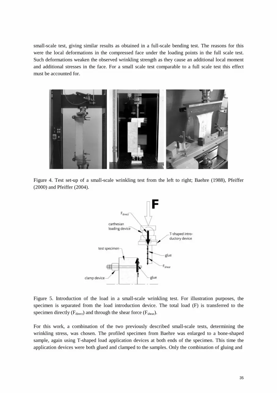
Figure 4. Test set-up of a small-scale wrinkling test from the left to right; Baehre (1988), Pfeiffer
(2000) and Pfeiffer (2004).
Figure 5. Introduction of the load in a small-scale wrinkling test. For illustration purposes, the
specimen is separated from the load introduction device. The total load (F) is transferred to the
specimen directly (Fdirect) and through the shear force (Fshear).
For this work, a combination of the two previously described small-scale tests, determining the
wrinkling stress, was chosen. The profiled specimen from Baehre was enlarged to a bone-shaped
sample, again using T-shaped load application devices at both ends of the specimen. This time the
application devices were both glued and clamped to the samples. Only the combination of gluing and

36
clamping together with the bone shape hinders the specimen from failing early through local
crushing. Gluing the load application device to the samples allows the load to be introduced to the
panel faces over a larger surface area, reducing concentrated load effects. The load is introduced
through a shear force in the glue area and directly to the top and bottom ends, where the specimen
touches the T-shaped device (Fig 5).
To study the effect of the local deformation at the load introduction areas in the full scale test,
samples with and without local deformations were studied. A three step approach was taken. First,
samples with completely undisturbed faces were tested, giving the maximum wrinkling stress that can
be obtained. In a second step, the faces were dented prior to executing the small scale test. The depth
of the imprinted deformations was of the same dimensions as observed in the full scale test. In a third
step, the effect was simulated through a bi-axial loading in the small scale test. An additional load
device was clamped to the specimen loading it in a perpendicular direction. All obtained results were
compared to the results of the full scale bending test. The last procedure resulted in the most accurate
results.
3.5 Test set-up based on rectangular specimen
Preparing of the bone-shaped specimens requires careful machining of the two metal sheets and the
core. To simplify the preparation work, a test set-up has been developed, which base on a rectangular
specimen. To avoid the failure at the end and to create a wrinkling failure in the mid-part of the
specimen, the specimen is loaded by an additional transversal load (Fig. 6).
a) b) c) d)
Figure 6. a) Rectangular small-scale test specimen, b) initial displacement caused by the transversal
load (initial deformation equal to the face thickness, w0 tF), c) displaced mesh and d) displacement
caused by the transversal and axial load (wu 3 tF).

37
ax
ial st
ress
in
rel
ati
on
t
wri
nk
lin
g s
tres
s
Transversal load causes an imperfection in the face and compressive stresses in the core layer. The
level of the transversal load has to be high enough to cause an initial imperfection to the wrinkling
failure and on the other hand, lower than the elastic limit of the core layer (Fig. 7). Experiments on
polyurethane-foam and mineral wool cored specimens have shown the test set-up to give acceptable
modes of wrinkling failures.
1
0,8
0,6
0,4
0,2
Fdef.1
Fdef.2
Fdef.3
Fdef.4
0
0 0,0005 0,001 0,0015 0,002 0,0025 0,003
axial compressive deformation
Figure 7. Influence of the transversal load on the stress-deformation behaviour of the face in the test
described in Fig. 6. Transversal loads Fdef.i cause the transverse stress of 83, 63, 42 and 21 kN/m2
in
the core. The axial stress of the face is compared to an analytically determined ideal wrinkling stress
of 125 N/mm2
in the case.
Small-scale specimens will be exposed to an accelerated influence of the environmental actions.
Because of the small size of the specimen, it is possible to create a large quantity of reliable
information about the changes of the wrinkling stress in function of time and environmental loading
history. The data will make the basis to the development of the design models in order to take into
account the possible deterioration of the strength already in the design phase.
3.6 Comparing small-scale and full-scale tests
In order to calibrate the test setup, a test series, comparing the large-scale and small-scale test
arrangements of the wrinkling stress was undertaken. All specimens in this series were taken from the
same production batch. The full-scale panels were first tested as simply supported beams as described
previously. The test panels had a PUR core between the two steel faces. The wrinkling failure
obtained in the full scale tests resulted in an average wrinkling stress of 180.94 N/mm² (individual
test results between min. 180.75 N/mm² and max. 181.27 N/mm²). The wrinkling failure, obtained
from the small scale test without the additional effect of the transversal load, averaged to 228.73
N/mm² (individual test results between min. 223.06 N/mm² and max. 234.76 N/mm²).
38
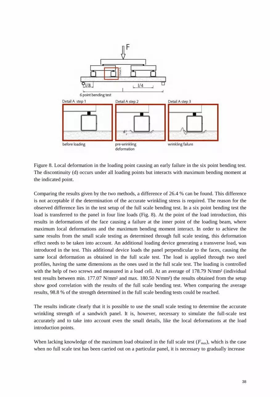
Figure 8. Local deformation in the loading point causing an early failure in the six point bending test.
The discontinuity (d) occurs under all loading points but interacts with maximum bending moment at
the indicated point.
Comparing the results given by the two methods, a difference of 26.4 % can be found. This difference
is not acceptable if the determination of the accurate wrinkling stress is required. The reason for the
observed difference lies in the test setup of the full scale bending test. In a six point bending test the
load is transferred to the panel in four line loads (Fig. 8). At the point of the load introduction, this
results in deformations of the face causing a failure at the inner point of the loading beam, where
maximum local deformations and the maximum bending moment interact. In order to achieve the
same results from the small scale testing as determined through full scale testing, this deformation
effect needs to be taken into account. An additional loading device generating a transverse load, was
introduced in the test. This additional device loads the panel perpendicular to the faces, causing the
same local deformation as obtained in the full scale test. The load is applied through two steel
profiles, having the same dimensions as the ones used in the full scale test. The loading is controlled
with the help of two screws and measured in a load cell. At an average of 178.79 N/mm² (individual
test results between min. 177.07 N/mm² and max. 180.50 N/mm²) the results obtained from the setup
show good correlation with the results of the full scale bending test. When comparing the average
results, 98.8 % of the strength determined in the full scale bending tests could be reached.
The results indicate clearly that it is possible to use the small scale testing to determine the accurate
wrinkling strength of a sandwich panel. It is, however, necessary to simulate the full-scale test
accurately and to take into account even the small details, like the local deformations at the load
introduction points.
When lacking knowledge of the maximum load obtained in the full scale test (Fmax), which is the case
when no full scale test has been carried out on a particular panel, it is necessary to gradually increase
39
the deformation load relative to the load parallel to the face. The load needed on the deformation
device can be calculated on the basis that the stress parallel to the face shall be equal in the both tests.
This means, that a certain load in the small scale test, corresponds to a certain load in the full scale
test, both causing the same stresses parallel to the surface. At the same time this load determines the
load on the additional load device and can be calculated as described in the following:
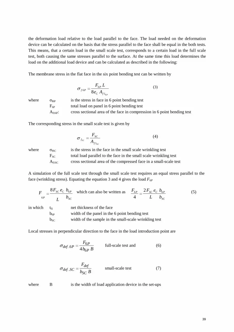
The membrane stress in the flat face in the six point bending test can be written by
F6 P L (3) f 6 P
8eC Af 16 P
where σf6P is the stress in face in 6 point bending test
F6P total load on panel in 6 point bending test
Af16P: cross sectional area of the face in compression in 6 point bending test
The corresponding stress in the small scale test is given by
FSC
(4) fSC A f 1SC
where σfSC is the stress in the face in the small scale wrinkling test
FSC total load parallel to the face in the small scale wrinkling test
Af1SC cross sectional area of the compressed face in a small-scale test
A simulation of the full scale test through the small scale test requires an equal stress parallel to the
face (wrinkling stress). Equating the equation 3 and 4 gives the load F6P
F 8 FSC eC b6 P
which can also be written as F6 P 2 FSC eC b6 P
(5)
6 P L
bSC 4 L bSC
in which tf1 net thickness of the face
b6P width of the panel in the 6 point bending test
bSC width of the sample in the small-scale wrinkling test
Local stresses in perpendicular direction to the face in the load introduction point are
def .6P
F6P
4 b6P B
full-scale test and (6)
def .SC
Fdef
bSC B
small-scale test (7)
where B is the width of load application device in the set-ups
40
For comparison of the two tests, the local transverse stresses need to be equal, which results in
Fdef
F6 P bSC
4b6 P
(8)
Combining the equations 8 and 5 leads to
Fdef 2 FSC eC b6 P bSC 2 FSC eC
(9)
L bSC b6 P L
The load in the additional deformation device can now be calculated, depending on the axial loading
of the sample, the distance between the centroids of the two panel faces, and the span length of the
static system in the six point bending test.
4. Conclusions
The results presented in the paper indicate that the small-scale wrinkling test can be used in the
evaluation of the wrinkling stress. The test requires extensive preparation work such as bone shape or
rectangular cutting and gluing and fixing of the load application devices. Laboratories dealing with
sandwich panel technology on a regular base can adopt the test with some additional work. For
further work on the durability related degradation of the wrinkling stress, it is sufficient to consider
only the durability related changes and thus the relative values. In future research work the test
arrangements without the additional deformation device will be studied. Also a simplified rectangular
wrinkling test set-up will be developed further.
The shear and compression strength of the core is determined in most cases on the basis of the small-
scale tests. Thus, the durability of the shear and compressive strength can be studied by exposing the
specimens to accelerated deterioration processes in a climate chamber. These studies will contribute
further information to the evaluation of the durability of the structural sandwich panels.
References
Sarja A (2002) „Neue Anforderung an die Dauerhaftigkeit von Konstruktionen“ (New requirements
towards durability of constructions), Der Prüfingenieur 20: 46-53.
EN 14 509 “Self-supporting double skin metal faced insulating sandwich panels – Factory made
products – Specification”
Davies JM et al. (2001) Lightweight Sandwich Construction Blackwell Science, Oxford
Baehre R (1988) Experimentelle Ermittlung der aufnehmbaren Knitterspannung von ebenen und
leicht profilierten Stahldeckschichten, Research Report, University of Karlsruhe

41
Pfeiffer L (2000) Der Einfluss der Zugfestigkeit auf die Knitterspannung bei Sandwichelementen,
Final Diploma Thesis, Fachhochschule Mainz (D) and Häme Polytechnic (FIN)
Pfeiffer L (2005) Durability Assessment of Sandwich Panel Construction, Doctoral Thesis,
University of Surrey (GB) and Fachhochschule Mainz (D)
EASIE Ensuring Advancement in Sandwich construction through Innovation and Exploitation, EU 7
th
FP, 2008 to 2011, www.easie.eu

PAGE 1
International Council for Research and
Innovation in Building and Construction
CIB’s mission is to serve its members through encouraging and
facilitating international cooperation and information exchange
in building and construction research and innovation. CIB is en-
gaged in the scientific, technical, economic and social domains
related to building and construction, supporting improvements
in the building process and the performance of the built envi-
ronment.
CIB Membership offers:
• international networking between academia, R&D
organisations and industry
• participation in local and international
CIB conferences, symposia and seminars
• CIB special publications and conference
proceedings
• R&D collaboration
Membership: CIB currently numbers over 400 members origi-
nating in some 70 countries, with very different backgrounds:
major public or semi-public organisations, research institutes,
universities and technical schools, documentation centres,
firms, contractors, etc. CIB members include most of the major
national laboratories and leading universities around the world
in building and construction.
Working Commissions and Task Groups: CIB Members
participate in over 50 Working Commissions and Task Groups,
undertaking collaborative R&D activities organised around:
• construction materials and technologies
• indoor environment
• design of buildings and of the built environment
• organisation, management and economics
• legal and procurement practices
Networking: The CIB provides a platform for academia, R&D
organisations and industry to network together, as well as a
network to decision makers, government institution and other
building and construction institutions and organisations. The
CIB network is respected for its thought-leadership, information
and knowledge.
CIB has formal and informal relationships with, amongst oth-
ers: the United Nations Environmental Programme (UNEP);
the European Commission; the European Network of Building
Research Institutes (ENBRI); the International Initiative for
Sustainable Built Environment (iiSBE), the International Or-
ganization for Standardization (ISO); the International Labour
Organization (ILO), International Energy Agency (IEA); Inter-
national Associations of Civil Engineering, including ECCS, fib,
IABSE, IASS and RILEM.
Conferences, Symposia and Seminars: CIB conferences
and co-sponsored conferences cover a wide range of areas of
interest to its Members, and attract more than 5000 partici-
pants worldwide per year.
Leading conference series include:
• International Symposium on Water Supply and Drainage for
Buildings (W062)
• Organisation and Management of Construction (W065)
• Durability of Building Materials and Components
(W080, RILEM & ISO)
• Quality and Safety on Construction Sites (W099)
• Construction in Developing Countries (W107)
• Sustainable Buildings regional and global triennial conference
series (CIB, iiSBE & UNEP)
• Revaluing Construction
• International Construction Client’s Forum
CIB Commissions (August 2010)
TG58 Clients and Construction Innovation
TG59 People in Construction
TG62 Built Environment Complexity
TG63 Disasters and the Built Environment
TG64 Leadership in Construction
TG65 Small Firms in Construction
TG66 Energy and the Built Environment
TG67 Statutory Adjudication in Construction
TG68 Construction Mediation
TG69 Green Buildings and the Law
TG71 Research and Innovation Transfer
TG72 Public Private Partnership
TG73 R&D Programs in Construction
TG74 New Production and Business Models in Construction
TG75 Engineering Studies on Traditional Constructions
TG76 Recognising Innovation in Construction
TG77 Health and the Built Environment
TG78 Informality and Emergence in Construction
TG79 Building Regulations and Control in the Face of Climate
Change
TG80 Legal and Regulatory Aspects of BIM
TG81 Global Construction Data
W014 Fire
W018 Timber Structures
W023 Wall Structures
W040 Heat and Moisture Transfer in Buildings
W051 Acoustics
W055 Construction Industry Economics
W056 Sandwich Panels
W062 Water Supply and Drainage
W065 Organisation and Management of Construction
W069 Housing Sociology
W070 Facilities Management and Maintenance
W077 Indoor Climate
W078 Information Technology for Construction
W080 Prediction of Service Life of Building Materials and
Components
W083 Roofing Materials and Systems
W084 Building Comfortable Environments for All
W086 Building Pathology
W089 Building Research and Education
W092 Procurement Systems
W096 Architectural Management
W098 Intelligent & Responsive Buildings
W099 Safety and Health on Construction Sites
W101 Spatial Planning and infrastructure Development
W102 Information and Knowledge Management in Building
W104 Open Building Implementation
W107 Construction in Developing Countries
W108 Climate Change and the Built Environment
W110 Informal Settlements and Affordable Housing
W111 Usability of Workplaces
W112 Culture in Construction
W113 Law and Dispute Resolution
W114 Earthquake Engineering and Buildings
W115 Construction Materials Stewardship
W116 Smart and Sustainable Built Environments
W117 Performance Measurement in Construction

PAGE 2
Fee Category 2010 2011 2012 2013
FM1 Fee level 11837 12015 12195 12378 FM2 Fee level 7892 8010 8131 8252 FM3 Fee level 2715 2756 2797 2839 AM1 Fee level 1364 1384 1405 1426 AM2 Fee level 1133 1246 1371 1426 IM Fee level 271 275 279 283
International Council for Research and
Innovation in Building and Construction
Publications: The CIB produces a wide range of special
publications, conference proceedings, etc., most of which are
available to CIB Members via the CIB home pages. The CIB
network also provides access to the publications of its more
than 400 Members.
CIB Annual Membership Fee 2010 – 2013
Membership will be automatically renewed each calen-
dar year in January, unless cancelled in writing 3 months
before the year end
All amounts in EURO
The lowest Fee Category an organisation can be in depends on
the organisation’s profile:
Recent CIB publications include:
• Guide and Bibliography to Service Life and Durability
Research for Buildings and Components (CIB 295)
• Performance Based Methods for Service Life Prediction
(CIB 294)
• Performance Criteria of Buildings for Health and Comfort
(CIB 292)
• Performance Based Building 1st International State-of-the-
Art Report (CIB 291)
• Proceedings of the CIB-CTBUH Conference on Tall Buildings:
Strategies for Performance in the Aftermath of the World
Trade Centre (CIB 290)
• Condition Assessment of Roofs (CIB 289)
• Proceedings from the 3rd International Postgraduate
Research Conference in the Built and Human Environment
• Proceedings of the 5th International Conference on
Performance-Based Codes and Fire Safety Design Methods
• Proceedings of the 29th International Symposium on Water
Supply and Drainage for Buildings
• Agenda 21 for Sustainable Development in Developing
Countries
R&D Collaboration: The CIB provides an active platform
for international collaborative R&D between academia, R&D
organisations and industry.
Publications arising from recent collaborative R&D ac-
tivities include:
• Agenda 21 for Sustainable Construction
• Agenda 21 for Sustainable Construction in Developing
Countries
• The Construction Sector System Approach: An International
Framework (CIB 293)
• Red Man, Green Man: A Review of the Use of Performance
Indicators for Urban Sustainability (CIB 286a)
• Benchmarking of Labour-Intensive Construction Activities:
Lean Construction and Fundamental Principles of Working
Management (CIB 276)
• Guide and Bibliography to Service Life and Durability
Research for Buildings and Components (CIB 295)
• Performance-Based Building Regulatory Systems (CIB 299)
• Design for Deconstruction and Materials Reuse (CIB 272)
• Value Through Design (CIB 280)
Themes: The main thrust of CIB activities takes place
through a network of around 50 Working Commissions and
Task Groups, organised around four CIB Priority Themes:
• Sustainable Construction
• Clients and Users
• Revaluing Construction
• Integrated Design and Delivery Solutions
FM1 Full Member Fee Category 1 | Multi disciplinary building
research institutes of national standing having a broad
field of research
FM2 Full Member Fee Category 2 | Medium size research
Institutes; Public agencies with major research inter-
est; Companies with major research interest
FM3 Full Member Fee Category 3 | Information centres of
national standing; Organisations normally in Category
4 or 5 which prefer to be a Full Member
AM1 Associate Member Fee Category 4 | Sectoral research &
documentation institutes; Institutes for standardisation;
Companies, consultants, contractors etc.; Professional
associations
AM2 Associate Member Fee Category 5 | Departments, fac-
ulties, schools or colleges of universities or technical
Institutes of higher education (Universities as a whole
can not be Member)
IM Individual Member Fee Category 6 | Individuals having
an interest in the activities of CIB (not representing an
organisation)
Fee Reduction:
A reduction is offered to all fee levels in the magnitude of 50%
for Members in countries with a GNIpc less than USD 1000 and
a reduction to all fee levels in the magnitude of 25% for Mem-
bers in countries with a GNIpc between USD 1000 – 7000, as
defined by the Worldbank. (see http://siteresources.worldbank.
org/DATASTATISTICS/Resources/GNIPC.pdf)
Reward for Prompt Payment:
All above indicated fee amounts will be increased by 10%. Mem-
bers will subsequently be rewarded a 10% reduction in case of
actual payment received within 3 months after the invoice date.
For more information contact
CIB General Secretariat:
e-mail: [email protected]
PO Box 1837, 3000 BV Rotterdam,
The Netherlands
Phone +31-10-4110240;
Fax +31-10-4334372
Http://www.cibworld.nl

DISCLAIMER
All rights reserved. No part of this book may be reprinted or
reproduced or utilized in any form or by any electronic,
mechanical, or other means, now known or hereafter
invented, including photocopying and recording, or in any
information storage or retrieval system without
permission in writing from the publishers.
The publisher makes no representation, express or implied,
with regard to the accuracy of the information contained in this book
and cannot accept any legal responsibility or liability in whole or in part
for any errors or omissions that may be made.
The reader should verify the applicability of the information to
particular situations and check the references prior to any reliance
thereupon. Since the information contained in the book is multidisciplinary,
international and professional in nature, the reader is urged to consult with
an appropriate licensed professional prior to taking any action or making
any interpretation that is within the realm of a licensed professional practice.

CIB General Secretariat post box 1837
3000 BV Rotterdam
The Netherlands
E-mail: [email protected]
www.cibworld.nl
CIB Publication 342