probe and tool setter class - welcome to trident machine
TRANSCRIPT

Welcome to Trident Machine ToolsProbe and Tool Setter Class
Probe and Tool Setter Class
• This half day course is designed to provide the user with a basic understanding of the probe and tool setter components, how each is set-up, and using IPS to program their operation.
Schedule• Introductions
• Tool Setters• Classroom
• Fundamentals
• Setting up the tool setter
• Using IPS for tool setter
• Showroom • Tool setter set-up demo
• Tool setter IPS demo
• Lunch
• Probes• Classroom
• Fundamentals
• Setting up the probe
• Using IPS for probing
• Showroom • Probing set-up demo
• Probing IPS demo

Toolsetters
What is “Tool Setting”?
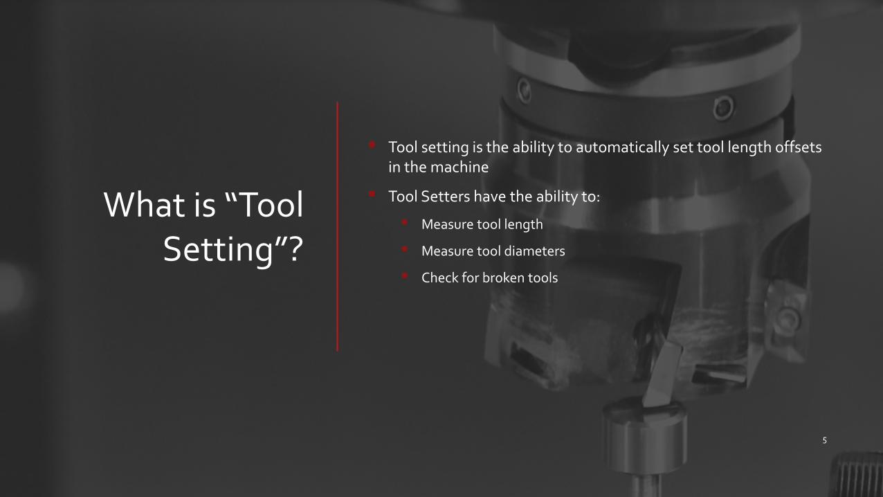
• Tool setting is the ability to automatically set tool length offsets in the machine
• Tool Setters have the ability to:
• Measure tool length
• Measure tool diameters
• Check for broken tools
5
Kinematic tool setters
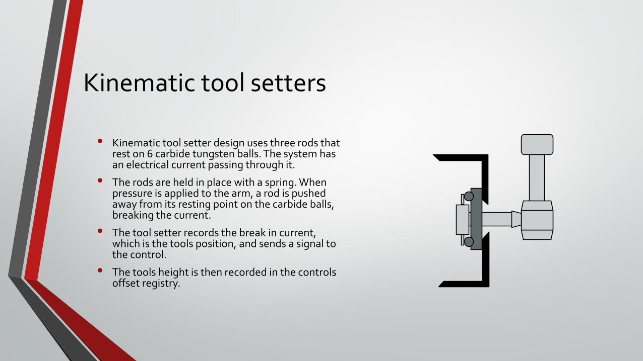
• Kinematic tool setter design uses three rods that rest on 6 carbide tungsten balls. The system has an electrical current passing through it.
• The rods are held in place with a spring. When pressure is applied to the arm, a rod is pushed away from its resting point on the carbide balls, breaking the current.
• The tool setter records the break in current, which is the tools position, and sends a signal to the control.
• The tools height is then recorded in the controls offset registry.
Non-contact laser-based tool setter
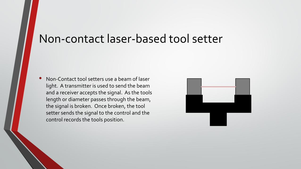
• Non-Contact tool setters use a beam of laser light. A transmitter is used to send the beam and a receiver accepts the signal. As the tools length or diameter passes through the beam, the signal is broken. Once broken, the tool setter sends the signal to the control and the control records the tools position.
Air Gap Height Offsets
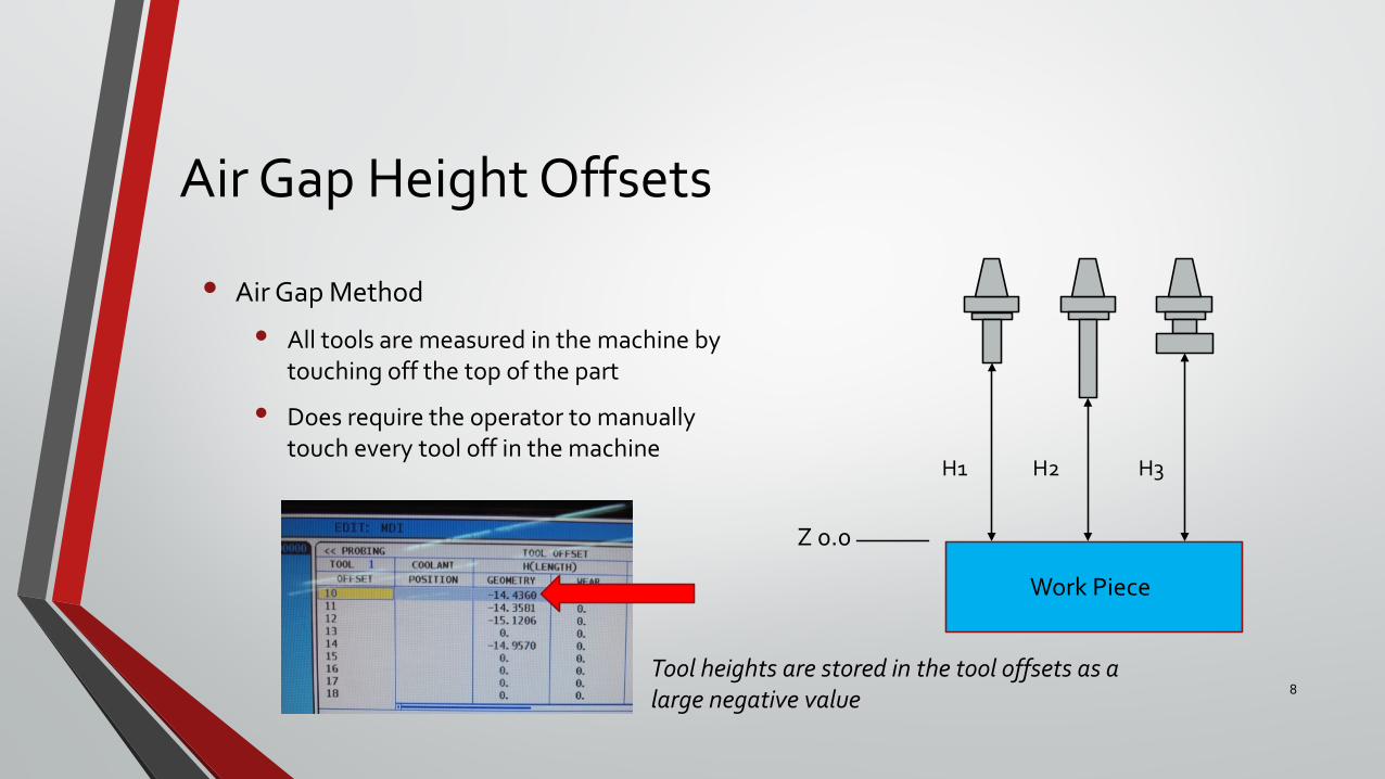
• Air Gap Method
• All tools are measured in the machine by touching off the top of the part
• Does require the operator to manually touch every tool off in the machine
8
Work Piece
H1 H2 H3
Z 0.0
Tool heights are stored in the tool offsets as a large negative value
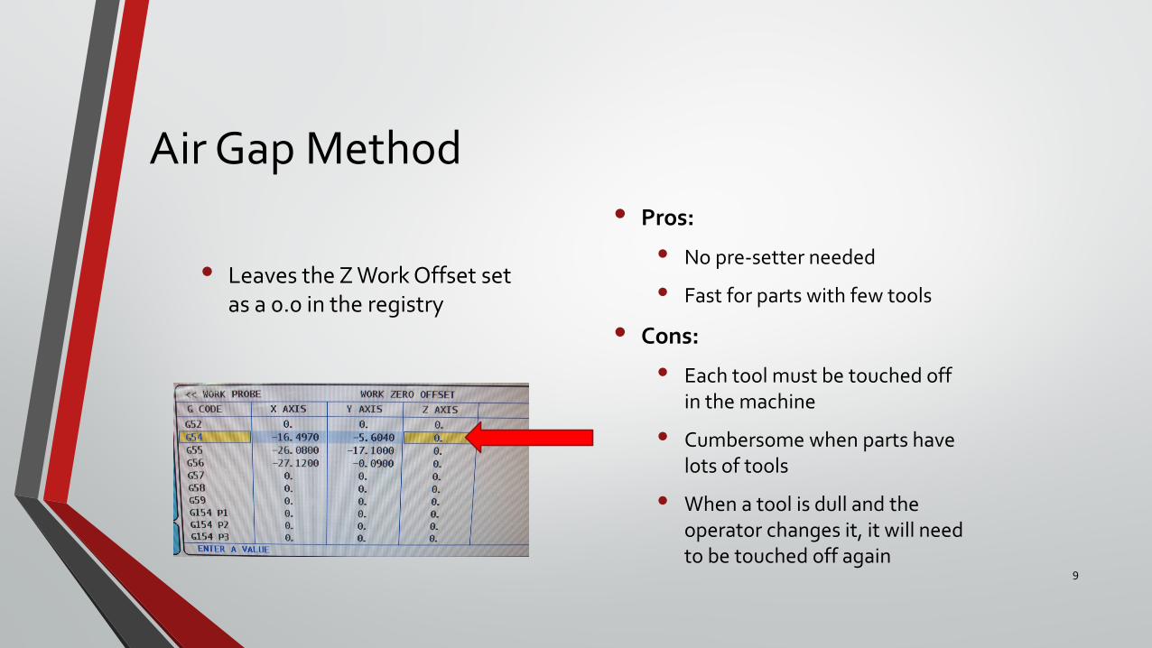
Air Gap Method• Pros:
• No pre-setter needed
• Fast for parts with few tools
• Cons:
• Each tool must be touched off in the machine
• Cumbersome when parts have lots of tools
• When a tool is dull and the operator changes it, it will need to be touched off again
• Leaves the Z Work Offset set as a 0.0 in the registry
9
Gage Line Method
(How Tool Setters Work)
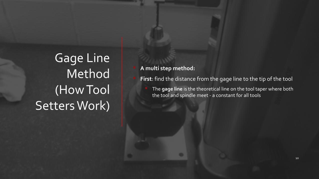
• A multi step method:
• First: find the distance from the gage line to the tip of the tool
• The gage line is the theoretical line on the tool taper where both the tool and spindle meet - a constant for all tools
10
Gage Line Method
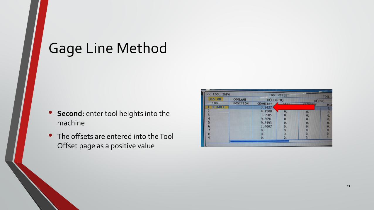
• Second: enter tool heights into the machine
• The offsets are entered into the Tool Offset page as a positive value
11
Gage Line Method
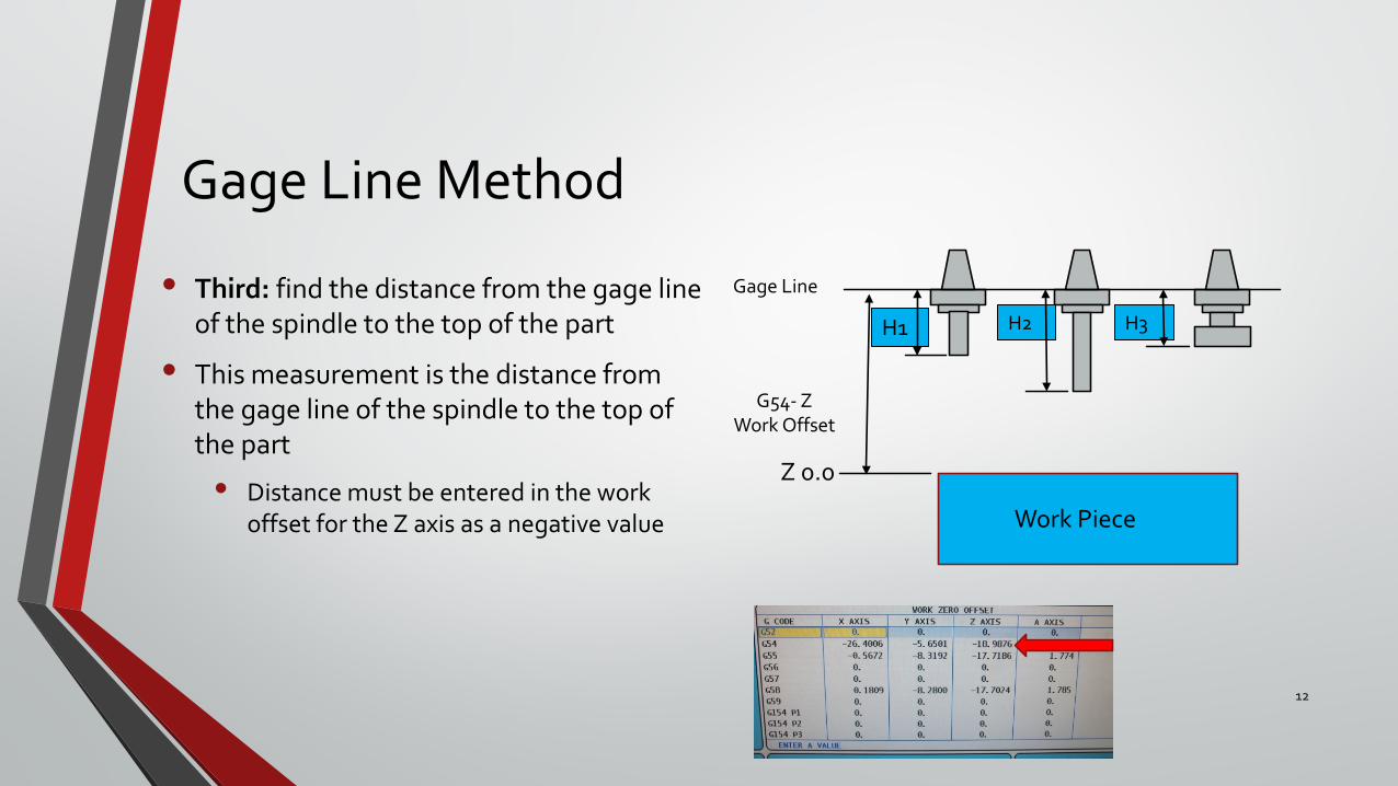
• Third: find the distance from the gage line of the spindle to the top of the part
• This measurement is the distance from the gage line of the spindle to the top of the part
• Distance must be entered in the work offset for the Z axis as a negative value
12
Work Piece
H1 H2 H3
G54- ZWork Offset
Z 0.0
Gage Line
How does this all work?
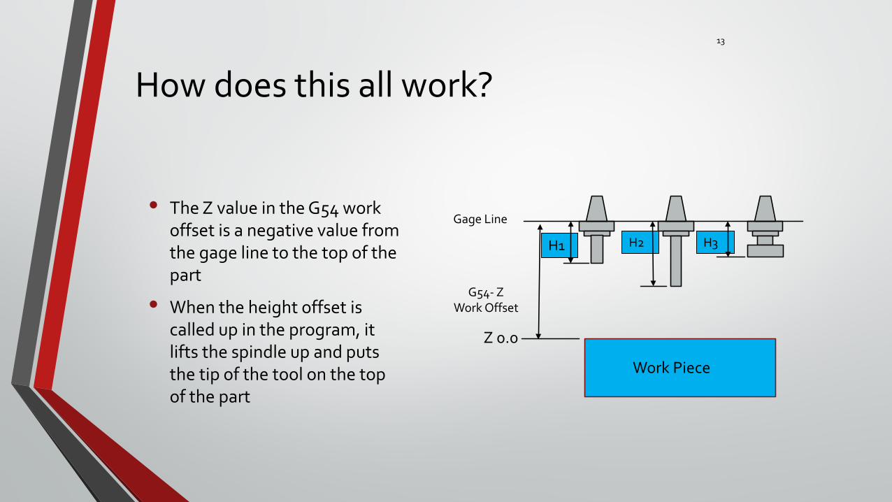
• The Z value in the G54 work offset is a negative value from the gage line to the top of the part
• When the height offset is called up in the program, it lifts the spindle up and puts the tip of the tool on the top of the part
13
Work Piece
H1 H2 H3
G54- ZWork Offset
Z 0.0
Gage Line
Gage Line Method
• Pros:
• Only need to touch one tool off in the machine
• Tools can be preset offline
• Process can become automated
14
• Cons:
• May need more tooling to be able to preset heights
• Requires a tool presetter

Transmission Systems
• Three types of transmission systems for probes:• Hard Wired
• A wire connects the device to the control. This means a probe would need to be manually installed.
• Optical• Uses infrared technology to communicate, wire free,
but batteries must be used in the probe or tool setter.
• Line of sight between the device and receiver must be maintained or there will not be communication.
• Radio • Uses radio frequency to communicate between the
device and control. Very effective in large machines.
15

Communication of Haas CNC• Haas CNC utilize optical
transmission systems.
• Uses infrared technology to communicate.
• The Probe: • Must be in sight of receiver
• Is battery operated
• Uses two modes called Standby and Operating
• Waits in Standby mode until signal is sent for Operating mode
16
Cons:
Needs line of sight with receiver
Suited for smaller machines
Pros:
Can be kept in machine carousel
Can be used in automated operations

Preparing the tool setter
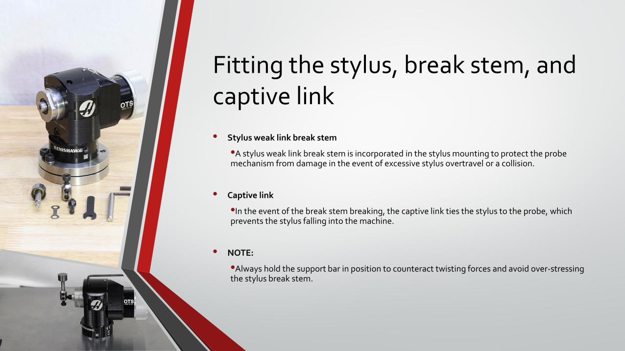
Fitting the stylus, break stem, and captive link• Stylus weak link break stem
•A stylus weak link break stem is incorporated in the stylus mounting to protect the probe mechanism from damage in the event of excessive stylus overtravel or a collision.
• Captive link
•In the event of the break stem breaking, the captive link ties the stylus to the probe, which prevents the stylus falling into the machine.
• NOTE:
•Always hold the support bar in position to counteract twisting forces and avoid over-stressing the stylus break stem.
Installing the Batteries
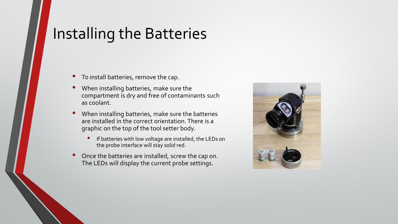
• To install batteries, remove the cap.
• When installing batteries, make sure the compartment is dry and free of contaminants such as coolant.
• When installing batteries, make sure the batteries are installed in the correct orientation. There is a graphic on the top of the tool setter body.
• If batteries with low voltage are installed, the LEDs on the probe interface will stay solid red.
• Once the batteries are installed, screw the cap on. The LEDs will display the current probe settings.
Positioning the Optical Module
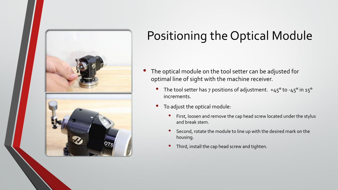
• The optical module on the tool setter can be adjusted for optimal line of sight with the machine receiver.
• The tool setter has 7 positions of adjustment. +45° to -45° in 15°increments.
• To adjust the optical module:
• First, loosen and remove the cap head screw located under the stylus and break stem.
• Second, rotate the module to line up with the desired mark on the housing.
• Third, install the cap head screw and tighten.
Mounting the Tool Setter in the Machine
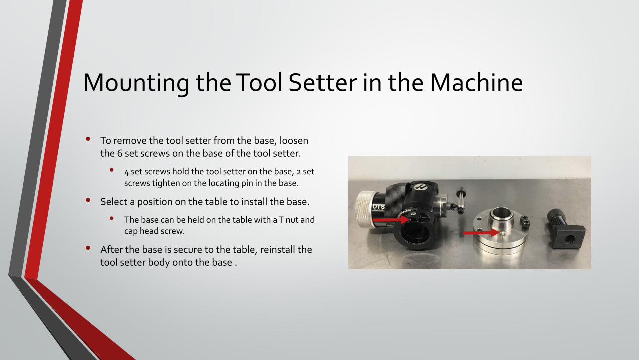
• To remove the tool setter from the base, loosen the 6 set screws on the base of the tool setter.
• 4 set screws hold the tool setter on the base, 2 set screws tighten on the locating pin in the base.
• Select a position on the table to install the base.
• The base can be held on the table with a T nut and cap head screw.
• After the base is secure to the table, reinstall the tool setter body onto the base .
Leveling the stylus
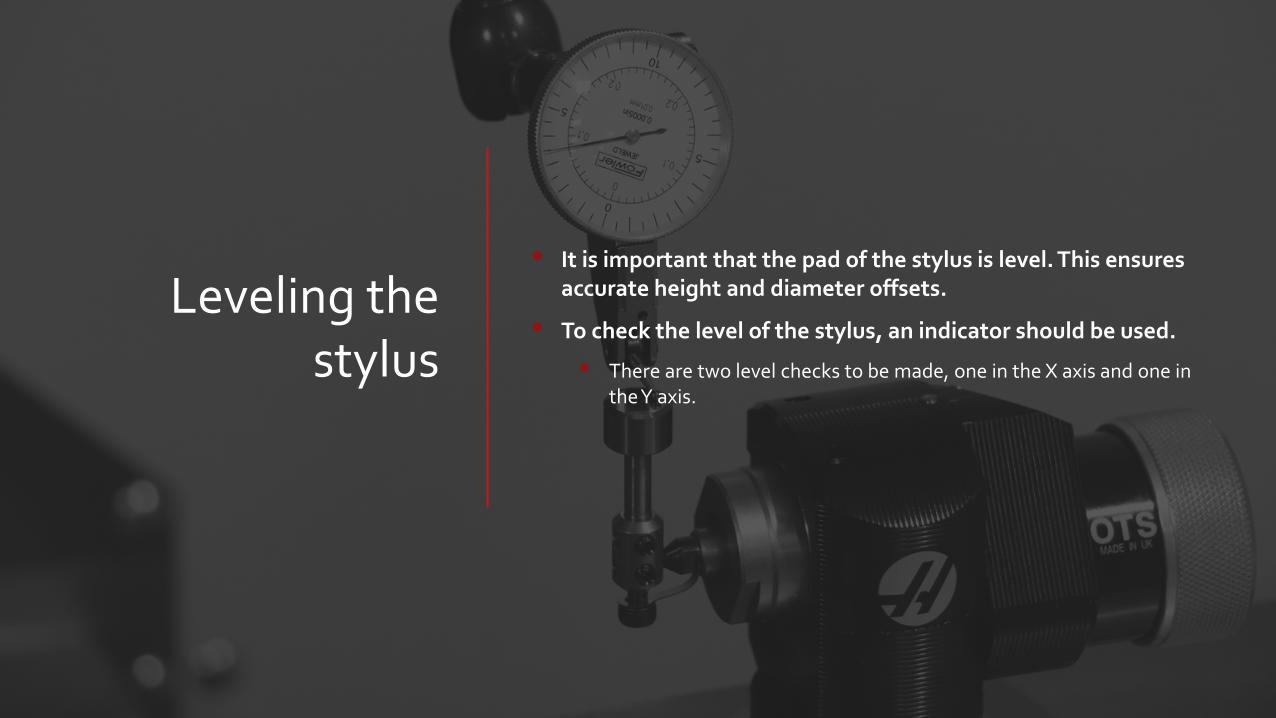
• It is important that the pad of the stylus is level. This ensures accurate height and diameter offsets.
• To check the level of the stylus, an indicator should be used.
• There are two level checks to be made, one in the X axis and one in the Y axis.
Leveling the Y axis
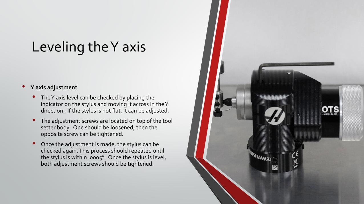
• Y axis adjustment
• The Y axis level can be checked by placing the indicator on the stylus and moving it across in the Y direction. If the stylus is not flat, it can be adjusted.
• The adjustment screws are located on top of the tool setter body. One should be loosened, then the opposite screw can be tightened.
• Once the adjustment is made, the stylus can be checked again. This process should repeated until the stylus is within .0005”. Once the stylus is level, both adjustment screws should be tightened.
Leveling the X axis
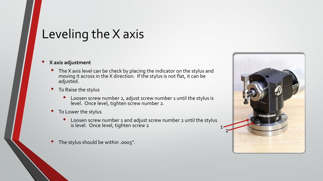
• X axis adjustment
• The X axis level can be check by placing the indicator on the stylus and moving it across in the X direction. If the stylus is not flat, it can be adjusted.
• To Raise the stylus
• Loosen screw number 2, adjust screw number 1 until the stylus is level. Once level, tighten screw number 2.
• To Lower the stylus
• Loosen screw number 1 and adjust screw number 2 until the stylus is level. Once level, tighten screw 2
• The stylus should be within .0005”.
12
Calibrating the OTS
• After the tool setter has been properly set-up and leveled in the machine, it is time to calibrate the tool setter.
• Calibration is required to find the tool setters position on the machine table. Calibration is also required to compensate for any deviation in the tool setter or control readings compared to the master tool.
• These calibration values are stored as macro variables. These variables will be used to calculate the tool size and diameter when the normal tool setting cycles are run.
• The tool setter calibration should be run during the following:
• When a tool setter is first installed or moved on the table
• A new stylus or different stylus has been installed
• The machine or tool setter has been crashed
• At regularly scheduled intervals
Calibrating the OTS on a Haas CNC Mill
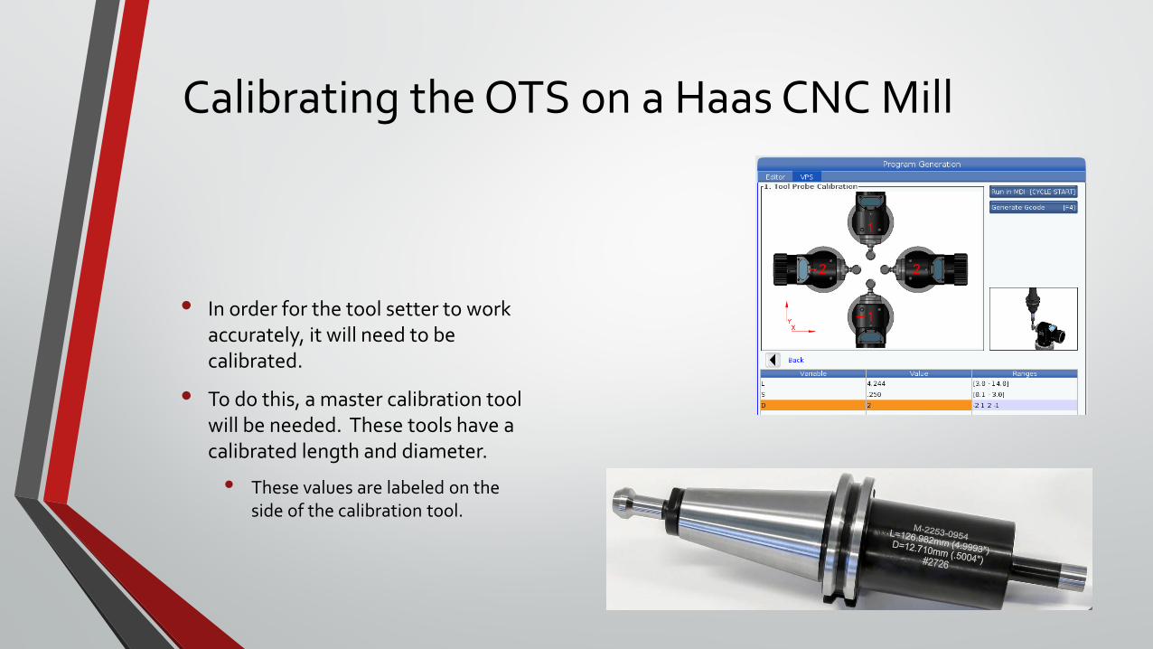
• In order for the tool setter to work accurately, it will need to be calibrated.
• To do this, a master calibration tool will be needed. These tools have a calibrated length and diameter.
• These values are labeled on the side of the calibration tool.
Calibrating the OTS on a Haas CNC Mill
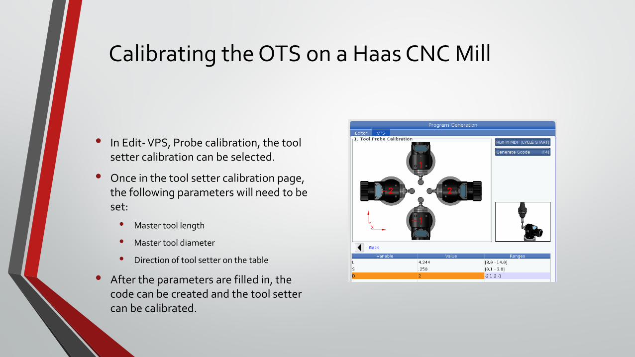
• In Edit- VPS, Probe calibration, the tool setter calibration can be selected.
• Once in the tool setter calibration page, the following parameters will need to be set:
• Master tool length
• Master tool diameter
• Direction of tool setter on the table
• After the parameters are filled in, the code can be created and the tool setter can be calibrated.
Using the tool setter on a Haas CNC mill
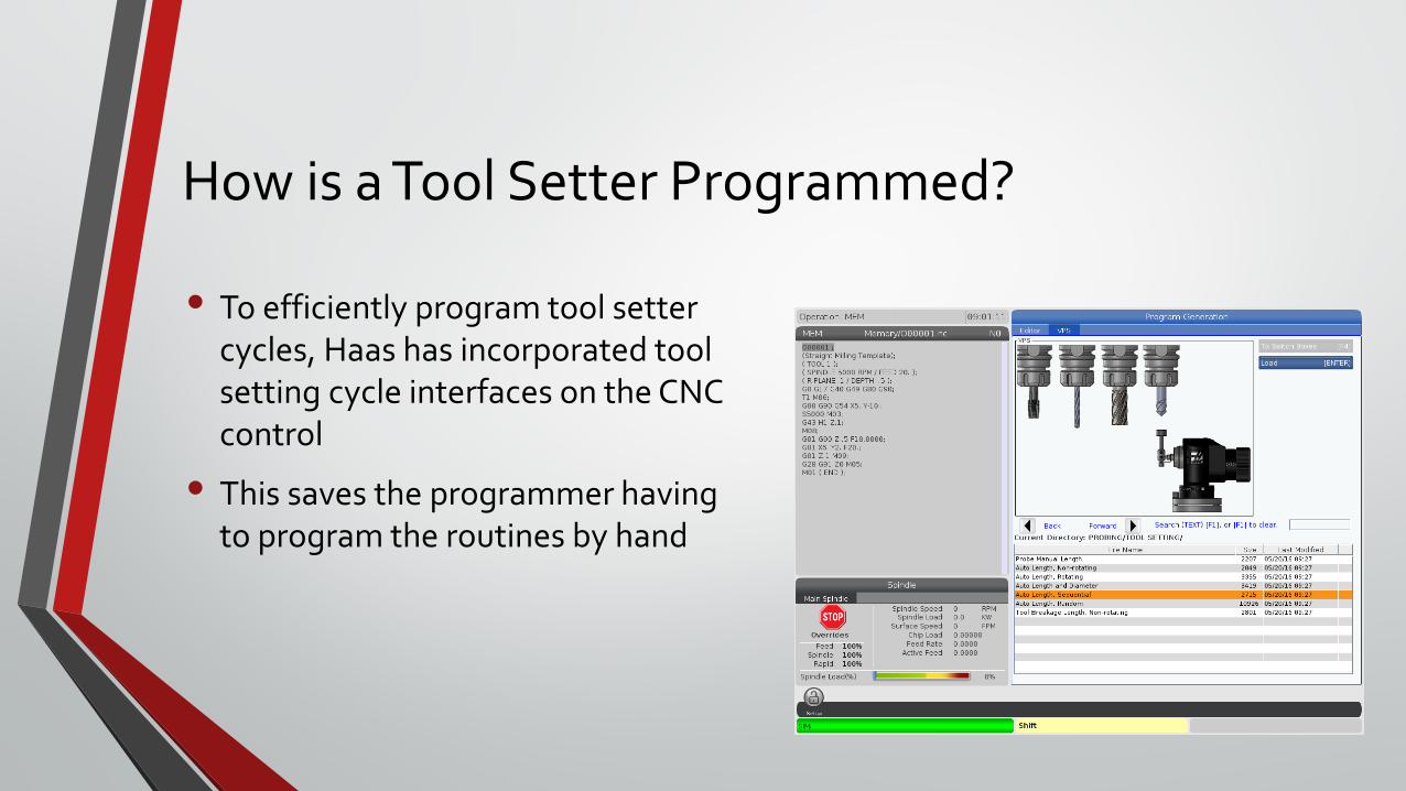
How is a Tool Setter Programmed?
• To efficiently program tool setter cycles, Haas has incorporated tool setting cycle interfaces on the CNC control
• This saves the programmer having to program the routines by hand
How is a Tool Setter Programmed? Cont.
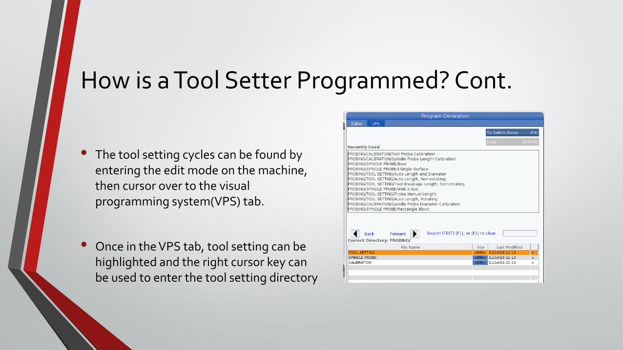
• The tool setting cycles can be found by entering the edit mode on the machine, then cursor over to the visual programming system(VPS) tab.
• Once in the VPS tab, tool setting can be highlighted and the right cursor key can be used to enter the tool setting directory
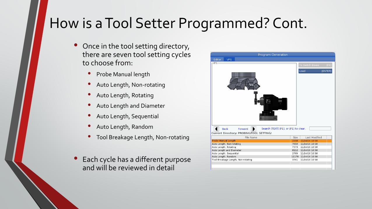
How is a Tool Setter Programmed? Cont.• Once in the tool setting directory,
there are seven tool setting cycles to choose from:
• Probe Manual length
• Auto Length, Non-rotating
• Auto Length, Rotating
• Auto Length and Diameter
• Auto Length, Sequential
• Auto Length, Random
• Tool Breakage Length, Non-rotating
• Each cycle has a different purpose and will be reviewed in detail
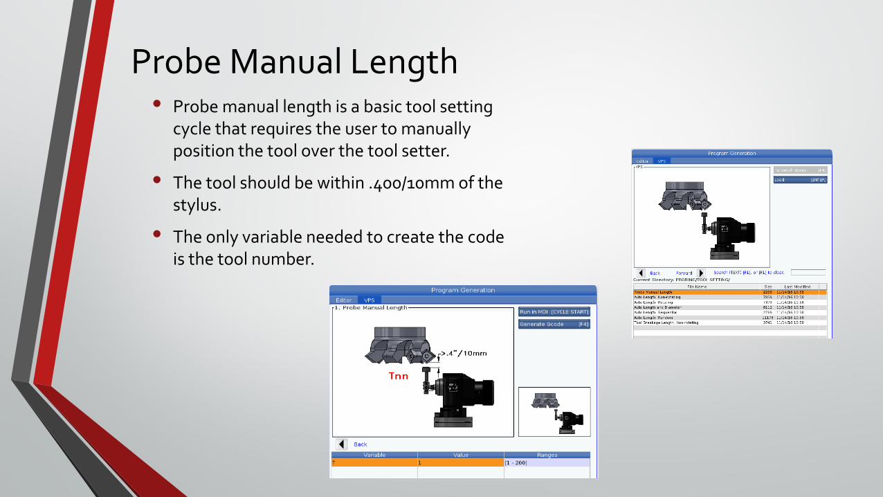
Probe Manual Length• Probe manual length is a basic tool setting
cycle that requires the user to manually position the tool over the tool setter.
• The tool should be within .400/10mm of the stylus.
• The only variable needed to create the code is the tool number.
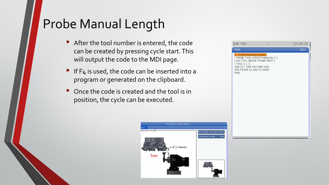
Probe Manual Length• After the tool number is entered, the code
can be created by pressing cycle start. This will output the code to the MDI page.
• If F4 is used, the code can be inserted into a program or generated on the clipboard.
• Once the code is created and the tool is in position, the cycle can be executed.
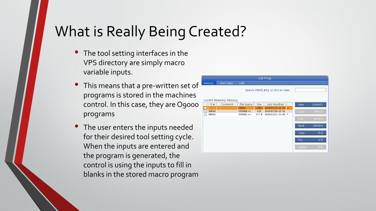
What is Really Being Created?• The tool setting interfaces in the
VPS directory are simply macro variable inputs.
• This means that a pre-written set of programs is stored in the machines control. In this case, they are O9000 programs
• The user enters the inputs needed for their desired tool setting cycle. When the inputs are entered and the program is generated, the control is using the inputs to fill in blanks in the stored macro program
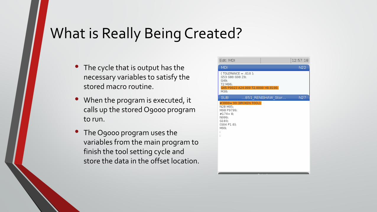
What is Really Being Created?
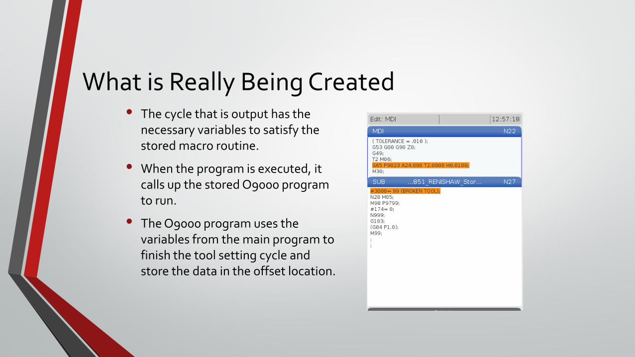
• The cycle that is output has the necessary variables to satisfy the stored macro routine.
• When the program is executed, it calls up the stored O9000 program to run.
• The O9000 program uses the variables from the main program to finish the tool setting cycle and store the data in the offset location.
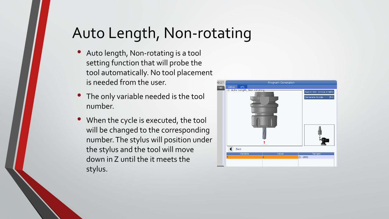
Auto Length, Non-rotating• Auto length, Non-rotating is a tool
setting function that will probe the tool automatically. No tool placement is needed from the user.
• The only variable needed is the tool number.
• When the cycle is executed, the tool will be changed to the corresponding number. The stylus will position under the stylus and the tool will move down in Z until the it meets the stylus.
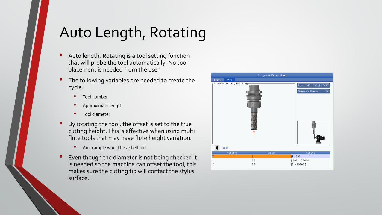
Auto Length, Rotating• Auto length, Rotating is a tool setting function
that will probe the tool automatically. No tool placement is needed from the user.
• The following variables are needed to create the cycle:
• Tool number
• Approximate length
• Tool diameter
• By rotating the tool, the offset is set to the true cutting height. This is effective when using multi flute tools that may have flute height variation.
• An example would be a shell mill.
• Even though the diameter is not being checked it is needed so the machine can offset the tool, this makes sure the cutting tip will contact the stylus surface.
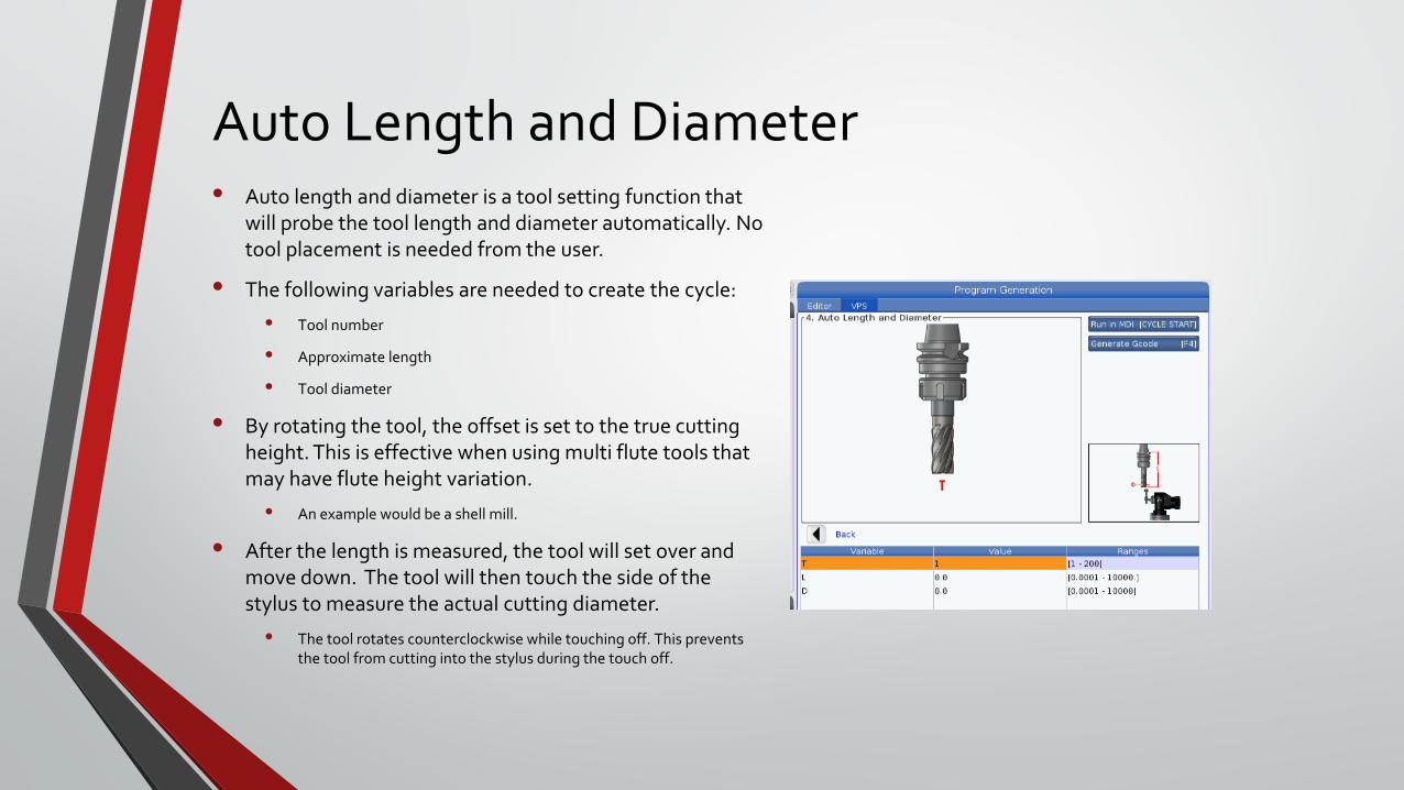
Auto Length and Diameter• Auto length and diameter is a tool setting function that
will probe the tool length and diameter automatically. No tool placement is needed from the user.
• The following variables are needed to create the cycle:
• Tool number
• Approximate length
• Tool diameter
• By rotating the tool, the offset is set to the true cutting height. This is effective when using multi flute tools that may have flute height variation.
• An example would be a shell mill.
• After the length is measured, the tool will set over and move down. The tool will then touch the side of the stylus to measure the actual cutting diameter.
• The tool rotates counterclockwise while touching off. This prevents the tool from cutting into the stylus during the touch off.
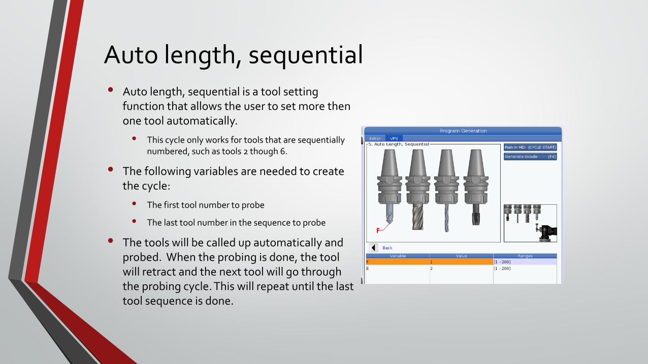
Auto length, sequential • Auto length, sequential is a tool setting
function that allows the user to set more then one tool automatically.
• This cycle only works for tools that are sequentially numbered, such as tools 2 though 6.
• The following variables are needed to create the cycle:
• The first tool number to probe
• The last tool number in the sequence to probe
• The tools will be called up automatically and probed. When the probing is done, the tool will retract and the next tool will go through the probing cycle. This will repeat until the last tool sequence is done.
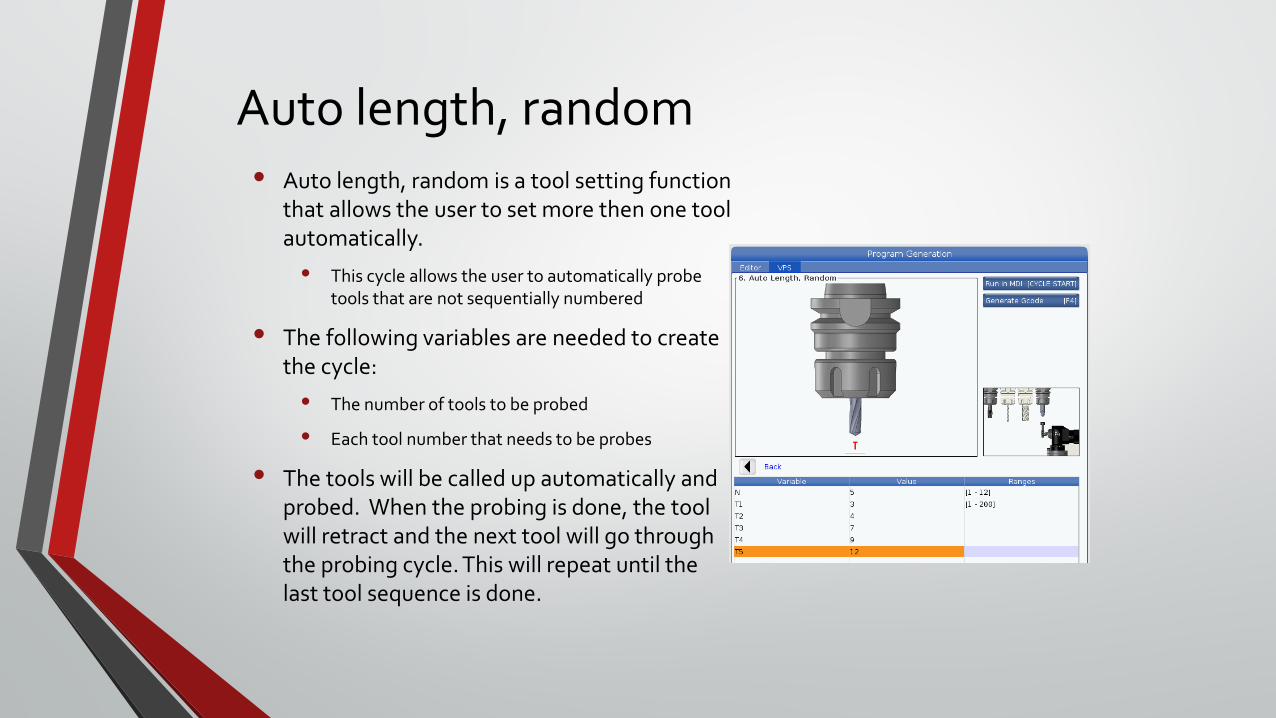
Auto length, random • Auto length, random is a tool setting function
that allows the user to set more then one tool automatically.
• This cycle allows the user to automatically probe tools that are not sequentially numbered
• The following variables are needed to create the cycle:
• The number of tools to be probed
• Each tool number that needs to be probes
• The tools will be called up automatically and probed. When the probing is done, the tool will retract and the next tool will go through the probing cycle. This will repeat until the last tool sequence is done.
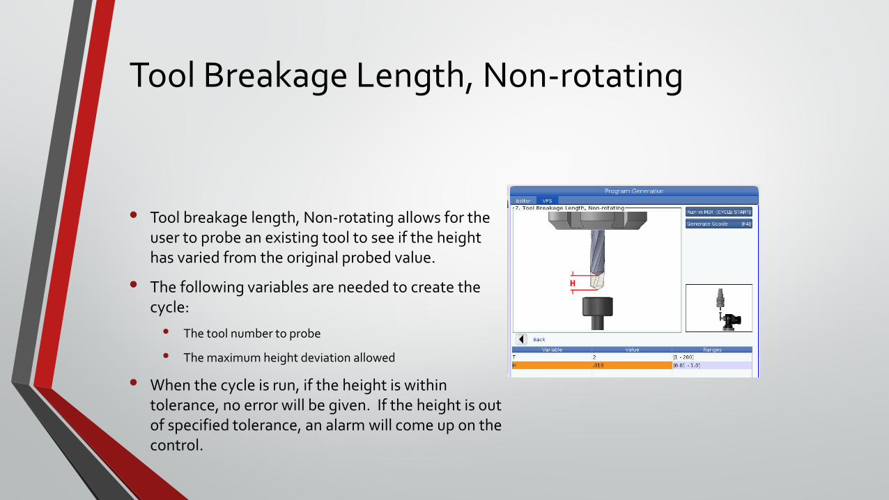
Tool Breakage Length, Non-rotating
• Tool breakage length, Non-rotating allows for the user to probe an existing tool to see if the height has varied from the original probed value.
• The following variables are needed to create the cycle:
• The tool number to probe
• The maximum height deviation allowed
• When the cycle is run, if the height is within tolerance, no error will be given. If the height is out of specified tolerance, an alarm will come up on the control.

Spindle Probes
What are Probes?
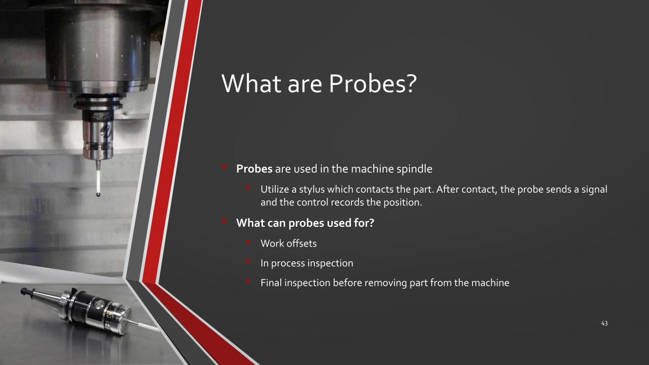
• Probes are used in the machine spindle
• Utilize a stylus which contacts the part. After contact, the probe sends a signal and the control records the position.
• What can probes used for?
• Work offsets
• In process inspection
• Final inspection before removing part from the machine
43
Probe Uses
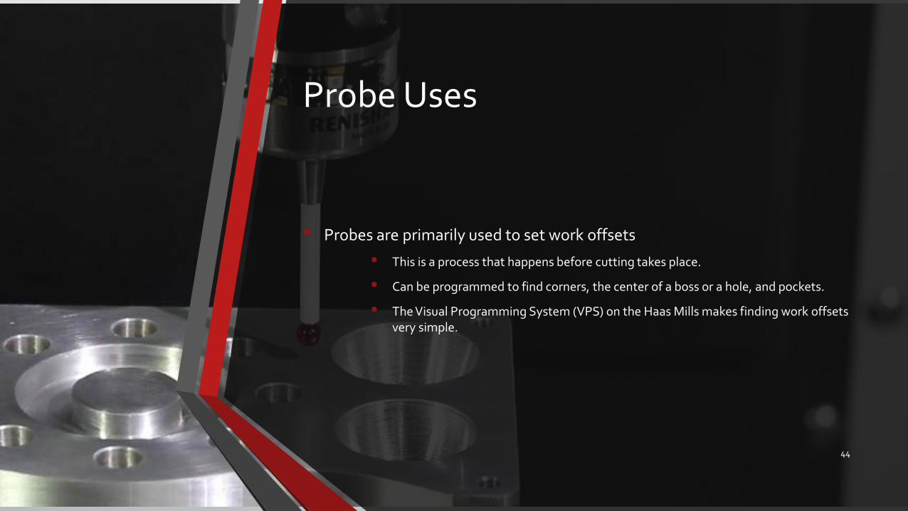
• Probes are primarily used to set work offsets
• This is a process that happens before cutting takes place.
• Can be programmed to find corners, the center of a boss or a hole, and pockets.
• The Visual Programming System (VPS) on the Haas Mills makes finding work offsets very simple.
44
Kinematic Touch Trigger Probe
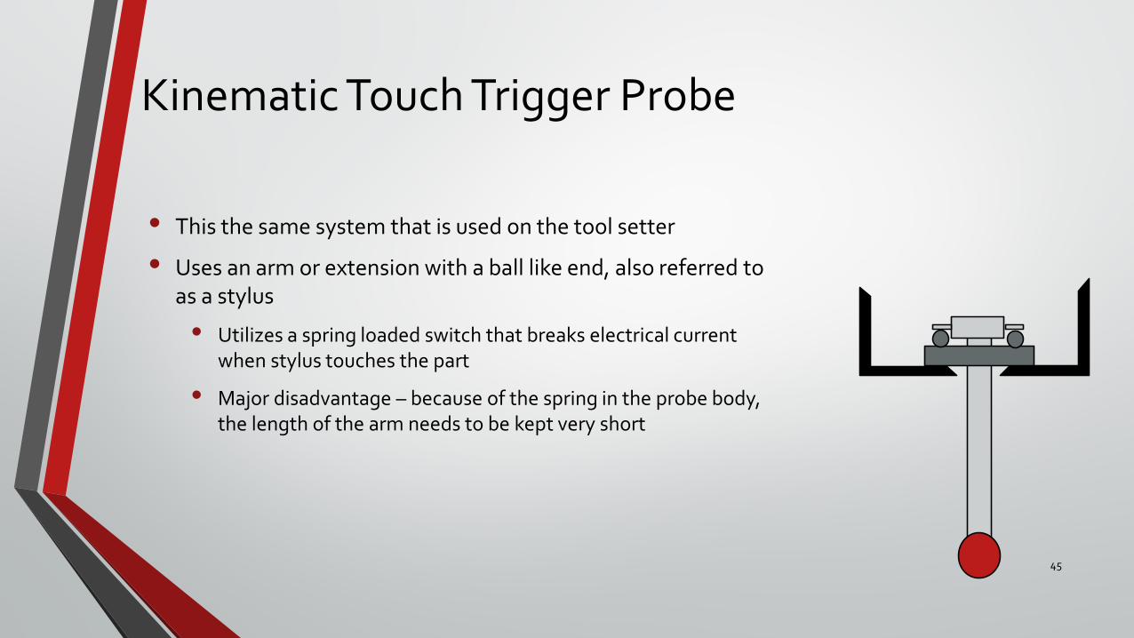
• This the same system that is used on the tool setter
• Uses an arm or extension with a ball like end, also referred to as a stylus
• Utilizes a spring loaded switch that breaks electrical current when stylus touches the part
• Major disadvantage – because of the spring in the probe body, the length of the arm needs to be kept very short
45
Strain Gauge Probe
• Works by sensing contact force and not pressure
• With low contact force, longer arms can be used
• Probes have improved functionality when measuring 3D surfaces and in multi axis inspection
• Offer a higher repeatability than Kinematic probes
46
What Can Probes Help Reduce?
• Successful probing operations can help with the following:
• Set-up/offset errors
• Detecting in process tool wear
• Reduce operator inspection
• Reduce scrap rates
47
Transmission Systems
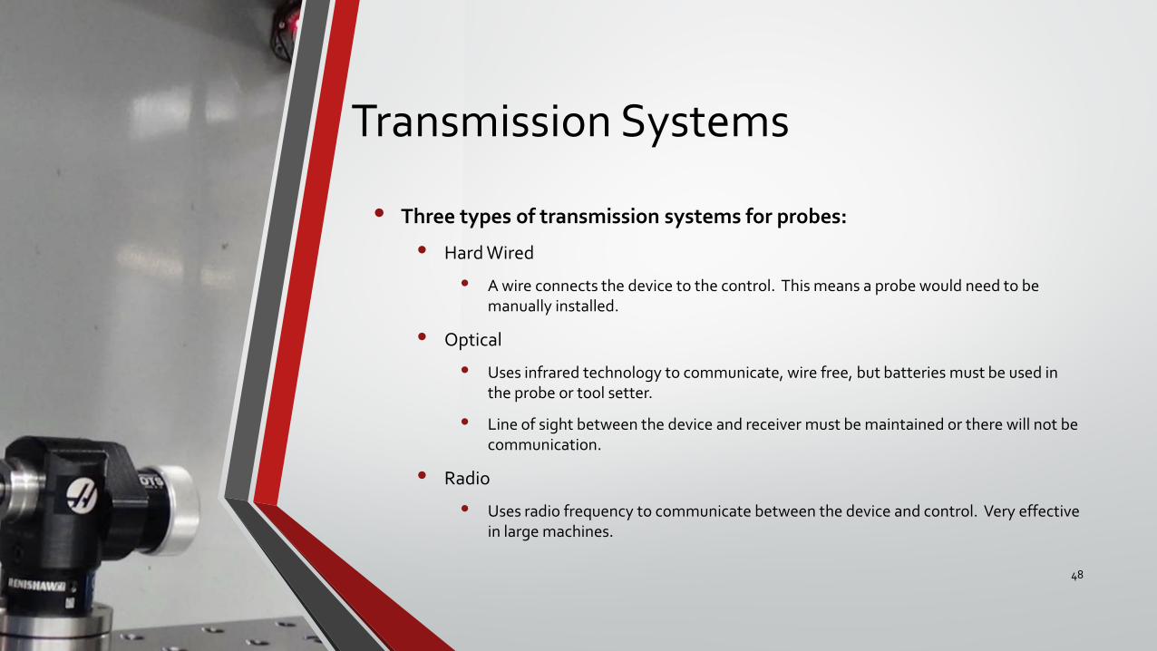
• Three types of transmission systems for probes:
• Hard Wired
• A wire connects the device to the control. This means a probe would need to be manually installed.
• Optical
• Uses infrared technology to communicate, wire free, but batteries must be used in the probe or tool setter.
• Line of sight between the device and receiver must be maintained or there will not be communication.
• Radio
• Uses radio frequency to communicate between the device and control. Very effective in large machines.
48
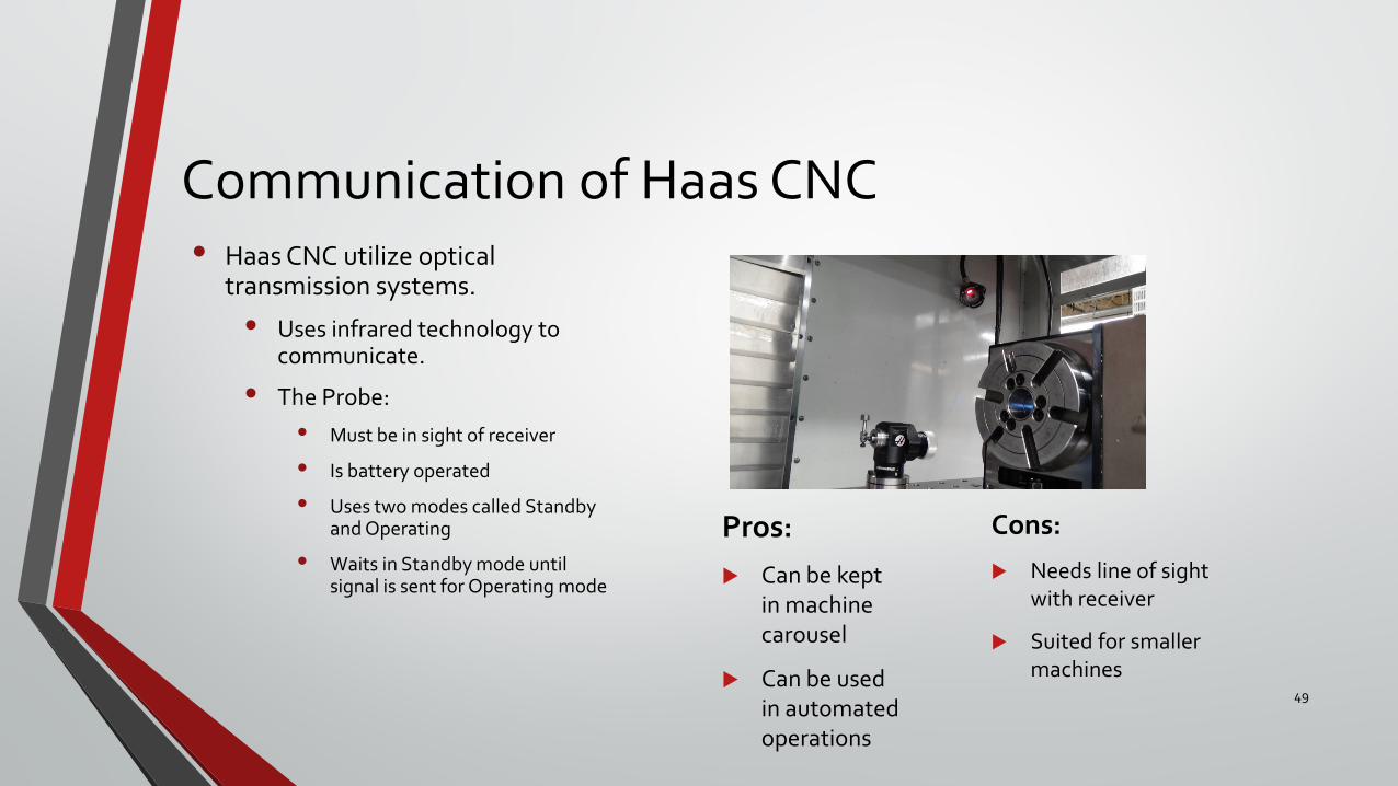
Communication of Haas CNC• Haas CNC utilize optical
transmission systems.
• Uses infrared technology to communicate.
• The Probe: • Must be in sight of receiver
• Is battery operated
• Uses two modes called Standby and Operating
• Waits in Standby mode until signal is sent for Operating mode
49
Cons:
Needs line of sight with receiver
Suited for smaller machines
Pros:
Can be kept in machine carousel
Can be used in automated operations
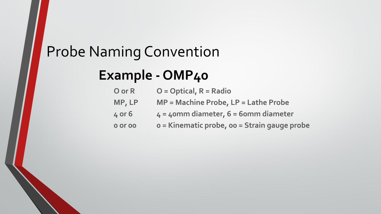
O or R O = Optical, R = RadioMP, LP MP = Machine Probe, LP = Lathe Probe4 or 6 4 = 40mm diameter, 6 = 60mm diameter0 or 00 0 = Kinematic probe, 00 = Strain gauge probe
Probe Naming ConventionExample - OMP40
Assembling your spindle probe
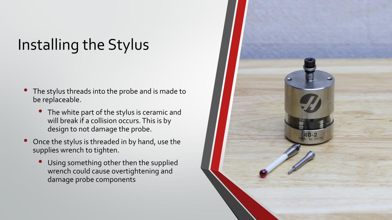
Installing the Stylus
• The stylus threads into the probe and is made to be replaceable.
• The white part of the stylus is ceramic and will break if a collision occurs. This is by design to not damage the probe.
• Once the stylus is threaded in by hand, use the supplies wrench to tighten.
• Using something other then the supplied wrench could cause overtightening and damage probe components
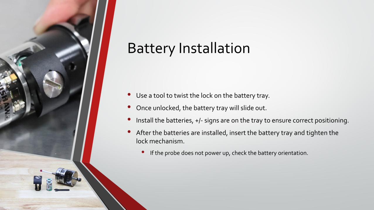
Battery Installation
• Use a tool to twist the lock on the battery tray.
• Once unlocked, the battery tray will slide out.
• Install the batteries, +/- signs are on the tray to ensure correct positioning.
• After the batteries are installed, insert the battery tray and tighten the lock mechanism.
• If the probe does not power up, check the battery orientation.
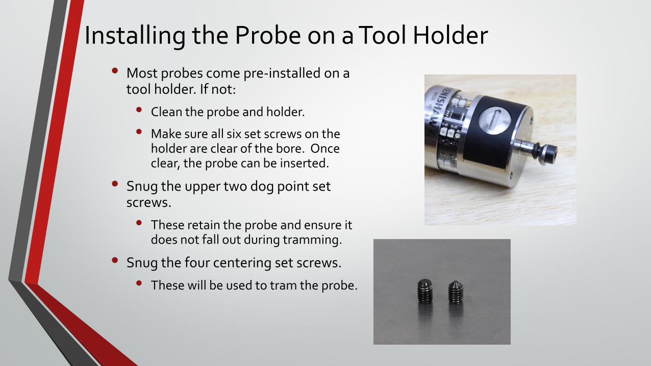
Installing the Probe on a Tool Holder• Most probes come pre-installed on a
tool holder. If not:
• Clean the probe and holder.
• Make sure all six set screws on the holder are clear of the bore. Once clear, the probe can be inserted.
• Snug the upper two dog point set screws.
• These retain the probe and ensure it does not fall out during tramming.
• Snug the four centering set screws.
• These will be used to tram the probe.
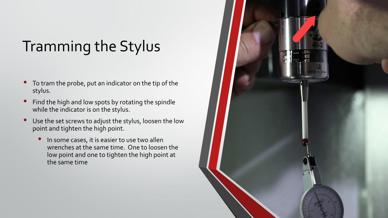
Tramming the Stylus
• To tram the probe, put an indicator on the tip of the stylus.
• Find the high and low spots by rotating the spindle while the indicator is on the stylus.
• Use the set screws to adjust the stylus, loosen the low point and tighten the high point.
• In some cases, it is easier to use two allenwrenches at the same time. One to loosen the low point and one to tighten the high point at the same time
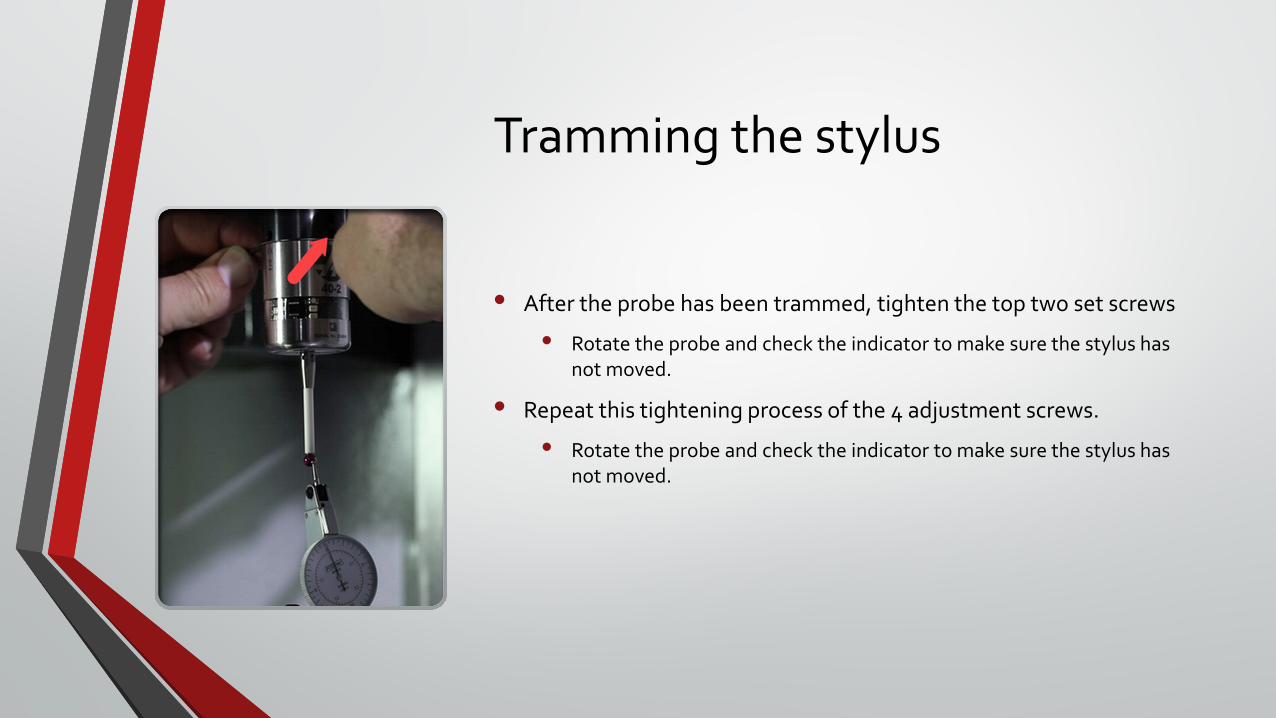
Tramming the stylus
• After the probe has been trammed, tighten the top two set screws
• Rotate the probe and check the indicator to make sure the stylus has not moved.
• Repeat this tightening process of the 4 adjustment screws.
• Rotate the probe and check the indicator to make sure the stylus has not moved.
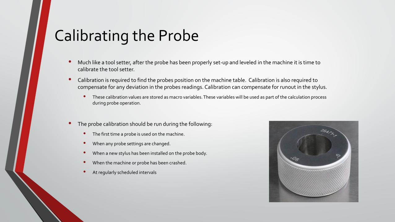
Calibrating the Probe• Much like a tool setter, after the probe has been properly set-up and leveled in the machine it is time to
calibrate the tool setter.
• Calibration is required to find the probes position on the machine table. Calibration is also required to compensate for any deviation in the probes readings. Calibration can compensate for runout in the stylus.
• These calibration values are stored as macro variables. These variables will be used as part of the calculation process during probe operation.
• The probe calibration should be run during the following:
• The first time a probe is used on the machine.
• When any probe settings are changed.
• When a new stylus has been installed on the probe body.
• When the machine or probe has been crashed.
• At regularly scheduled intervals
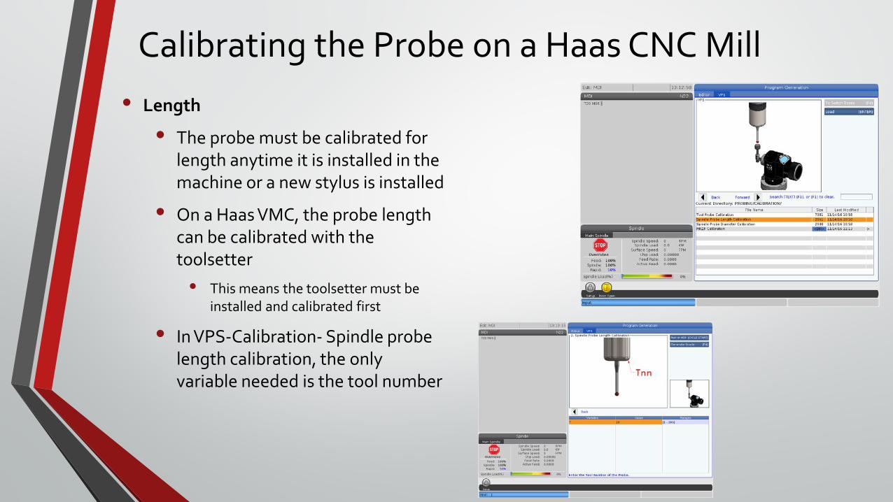
Calibrating the Probe on a Haas CNC Mill• Length
• The probe must be calibrated for length anytime it is installed in the machine or a new stylus is installed
• On a Haas VMC, the probe length can be calibrated with the toolsetter
• This means the toolsetter must be installed and calibrated first
• In VPS-Calibration- Spindle probe length calibration, the only variable needed is the tool number
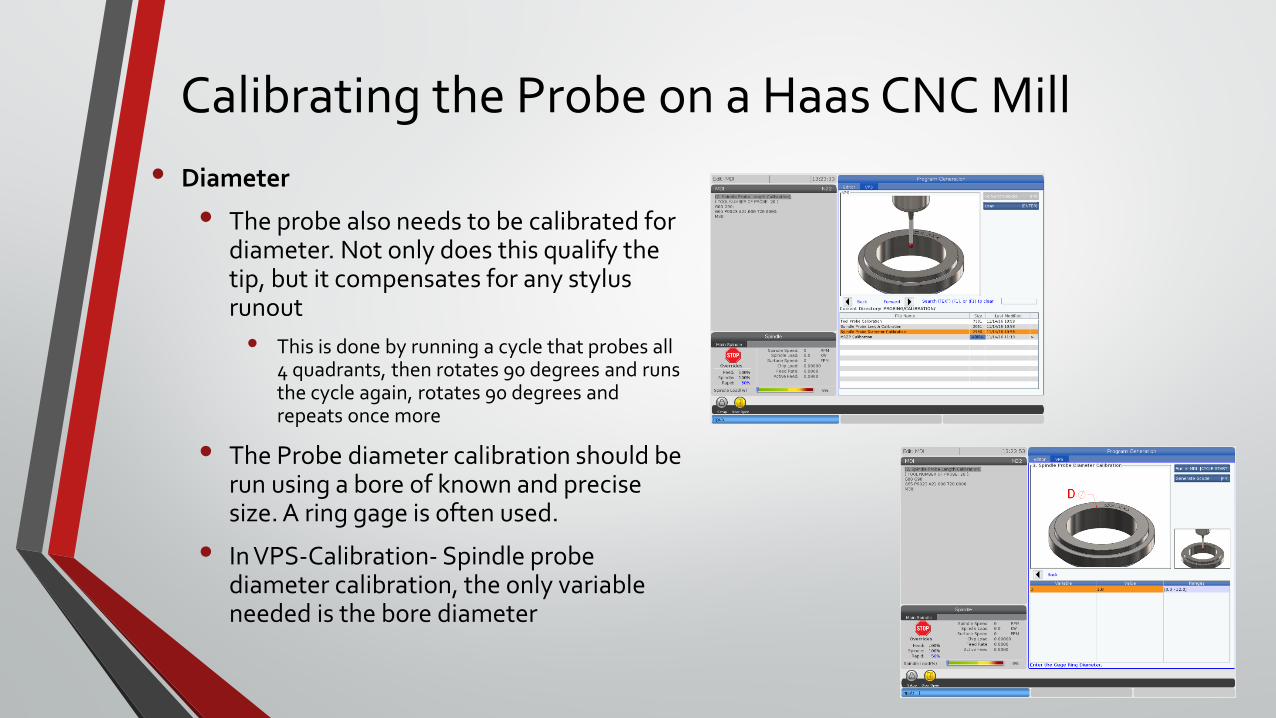
Calibrating the Probe on a Haas CNC Mill• Diameter
• The probe also needs to be calibrated for diameter. Not only does this qualify the tip, but it compensates for any stylus runout
• This is done by running a cycle that probes all 4 quadrants, then rotates 90 degrees and runs the cycle again, rotates 90 degrees and repeats once more
• The Probe diameter calibration should be run using a bore of known and precise size. A ring gage is often used.
• In VPS-Calibration- Spindle probe diameter calibration, the only variable needed is the bore diameter
Using the spindle probe on a Haas CNC mill
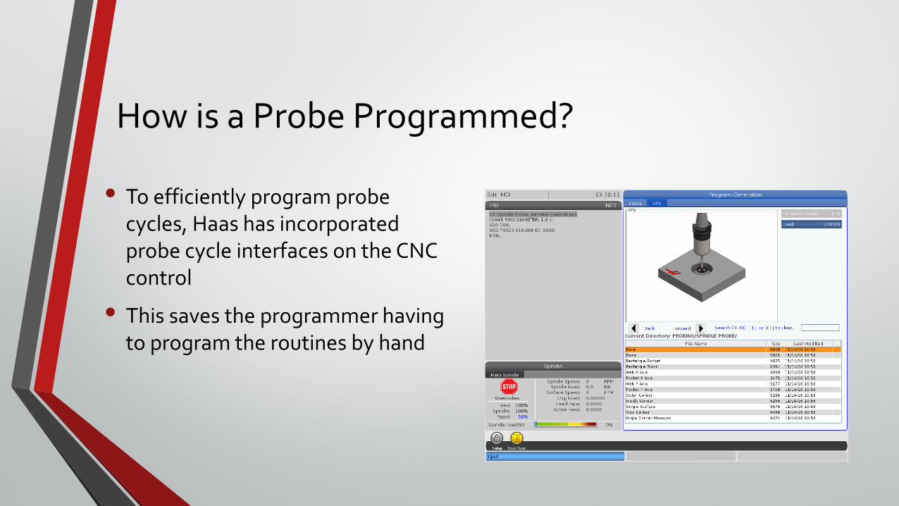
How is a Probe Programmed?
• To efficiently program probe cycles, Haas has incorporated probe cycle interfaces on the CNC control
• This saves the programmer having to program the routines by hand
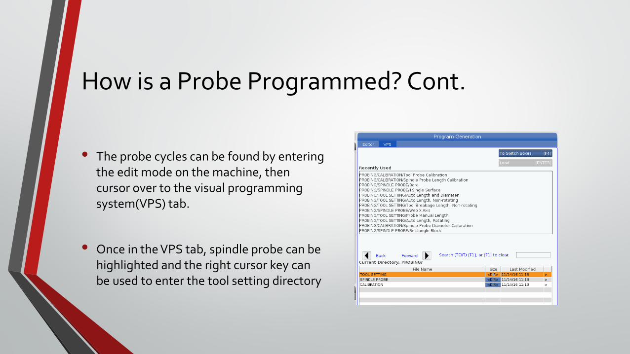
How is a Probe Programmed? Cont.
• The probe cycles can be found by entering the edit mode on the machine, then cursor over to the visual programming system(VPS) tab.
• Once in the VPS tab, spindle probe can be highlighted and the right cursor key can be used to enter the tool setting directory
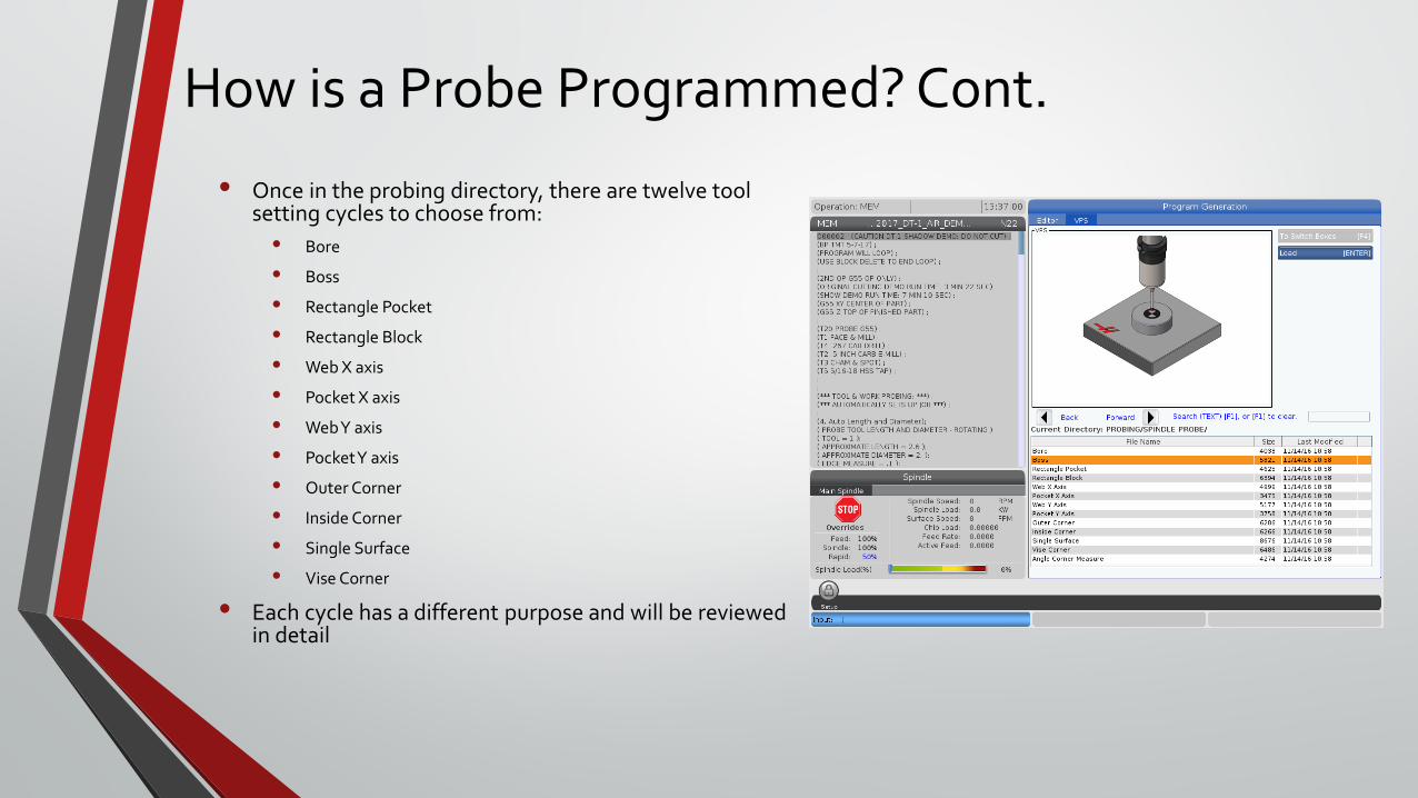
How is a Probe Programmed? Cont.
• Once in the probing directory, there are twelve tool setting cycles to choose from:
• Bore
• Boss
• Rectangle Pocket
• Rectangle Block
• Web X axis
• Pocket X axis
• Web Y axis
• Pocket Y axis
• Outer Corner
• Inside Corner
• Single Surface
• Vise Corner
• Each cycle has a different purpose and will be reviewed in detail
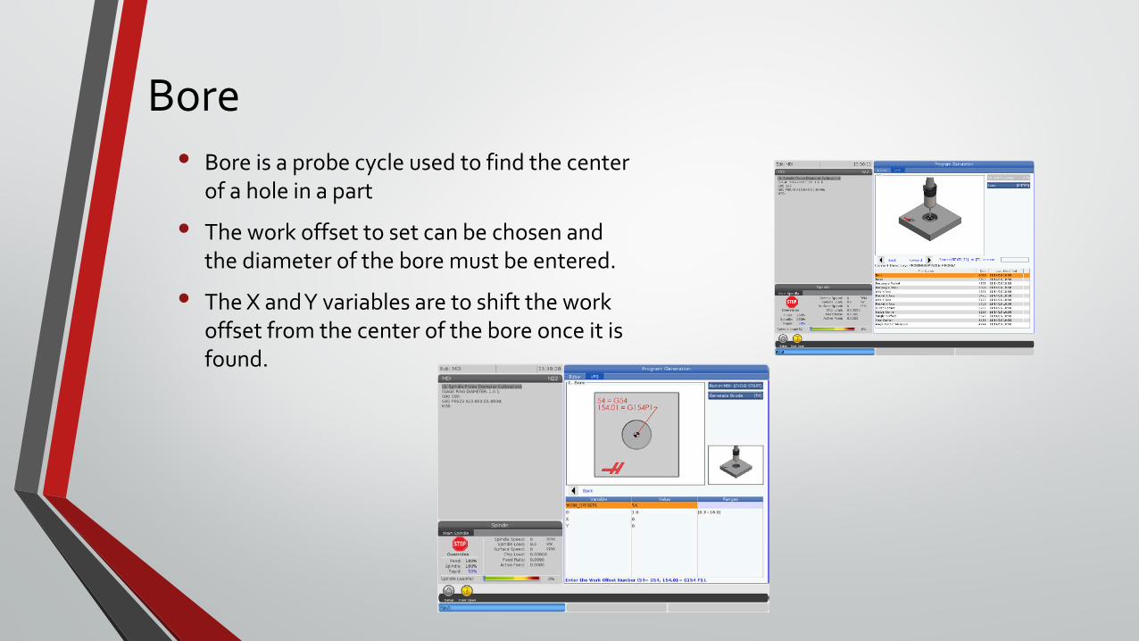
Bore• Bore is a probe cycle used to find the center
of a hole in a part
• The work offset to set can be chosen and the diameter of the bore must be entered.
• The X and Y variables are to shift the work offset from the center of the bore once it is found.
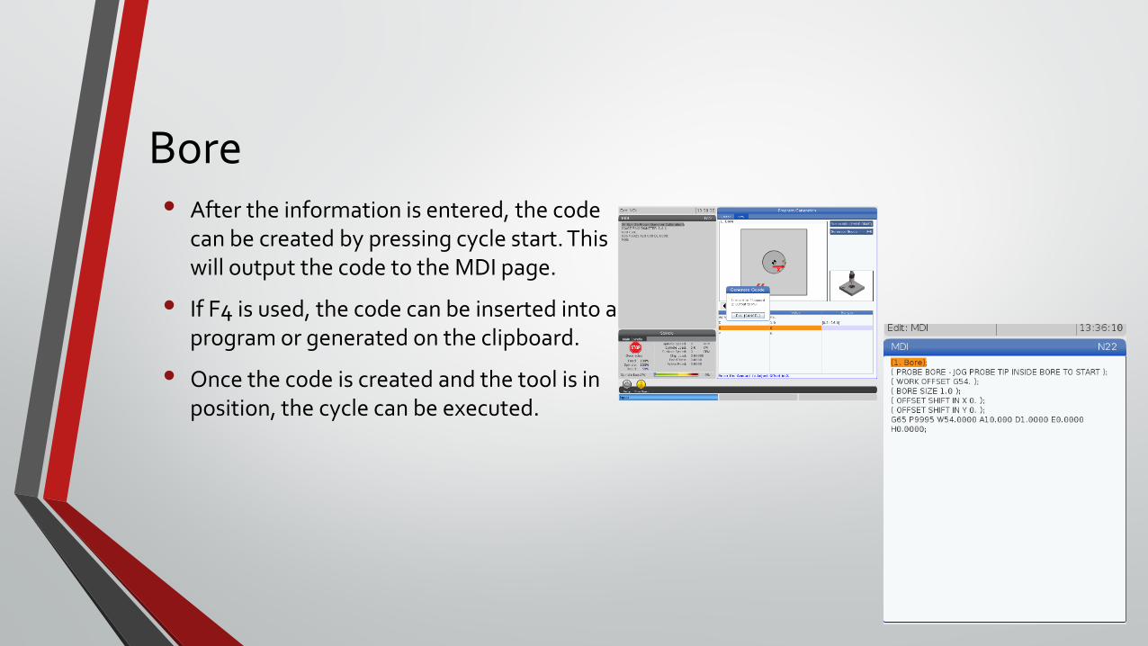
Bore• After the information is entered, the code
can be created by pressing cycle start. This will output the code to the MDI page.
• If F4 is used, the code can be inserted into a program or generated on the clipboard.
• Once the code is created and the tool is in position, the cycle can be executed.
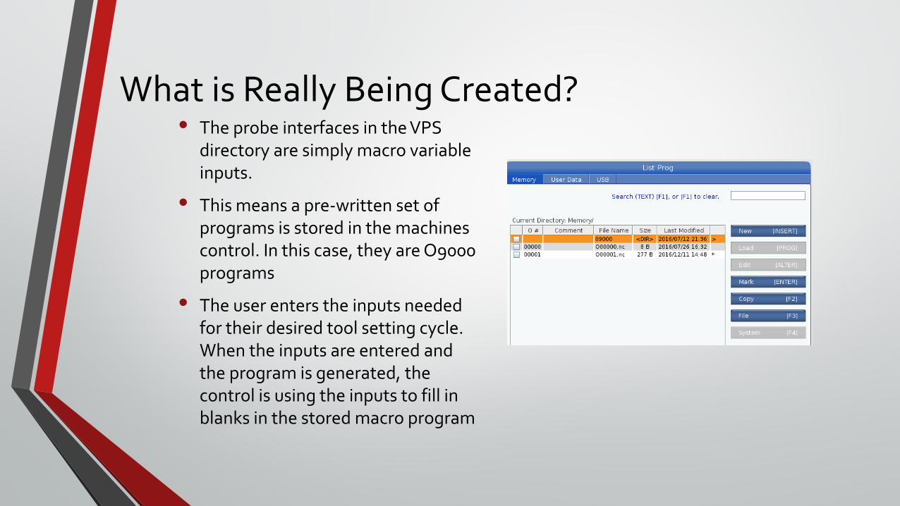
What is Really Being Created?• The probe interfaces in the VPS
directory are simply macro variable inputs.
• This means a pre-written set of programs is stored in the machines control. In this case, they are O9000 programs
• The user enters the inputs needed for their desired tool setting cycle. When the inputs are entered and the program is generated, the control is using the inputs to fill in blanks in the stored macro program
What is Really Being Created• The cycle that is output has the
necessary variables to satisfy the stored macro routine.
• When the program is executed, it calls up the stored O9000 program to run.
• The O9000 program uses the variables from the main program to finish the tool setting cycle and store the data in the offset location.
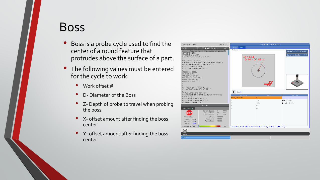
Boss• Boss is a probe cycle used to find the
center of a round feature that protrudes above the surface of a part.
• The following values must be entered for the cycle to work:
• Work offset #
• D- Diameter of the Boss
• Z- Depth of probe to travel when probing the boss
• X- offset amount after finding the boss center
• Y- offset amount after finding the boss center
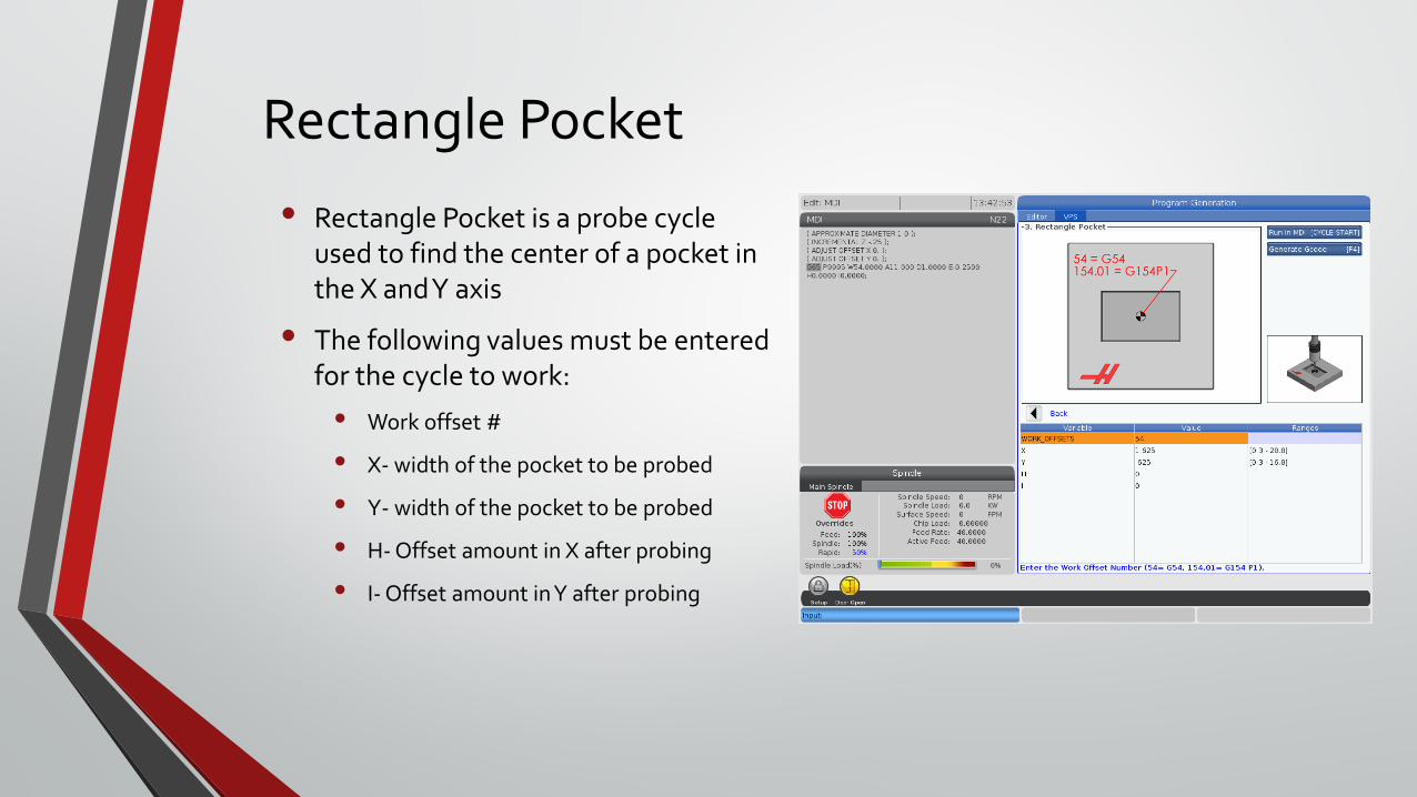
Rectangle Pocket
• Rectangle Pocket is a probe cycle used to find the center of a pocket in the X and Y axis
• The following values must be entered for the cycle to work:
• Work offset #
• X- width of the pocket to be probed
• Y- width of the pocket to be probed
• H- Offset amount in X after probing
• I- Offset amount in Y after probing
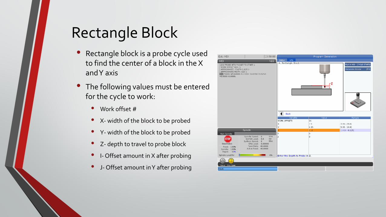
Rectangle Block• Rectangle block is a probe cycle used
to find the center of a block in the X and Y axis
• The following values must be entered for the cycle to work:
• Work offset #
• X- width of the block to be probed
• Y- width of the block to be probed
• Z- depth to travel to probe block
• I- Offset amount in X after probing
• J- Offset amount in Y after probing
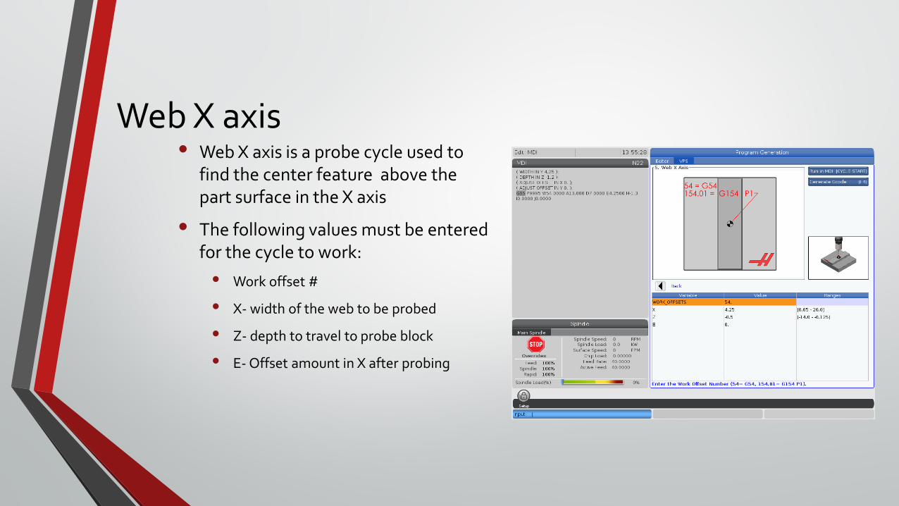
Web X axis• Web X axis is a probe cycle used to
find the center feature above the part surface in the X axis
• The following values must be entered for the cycle to work:
• Work offset #
• X- width of the web to be probed
• Z- depth to travel to probe block
• E- Offset amount in X after probing
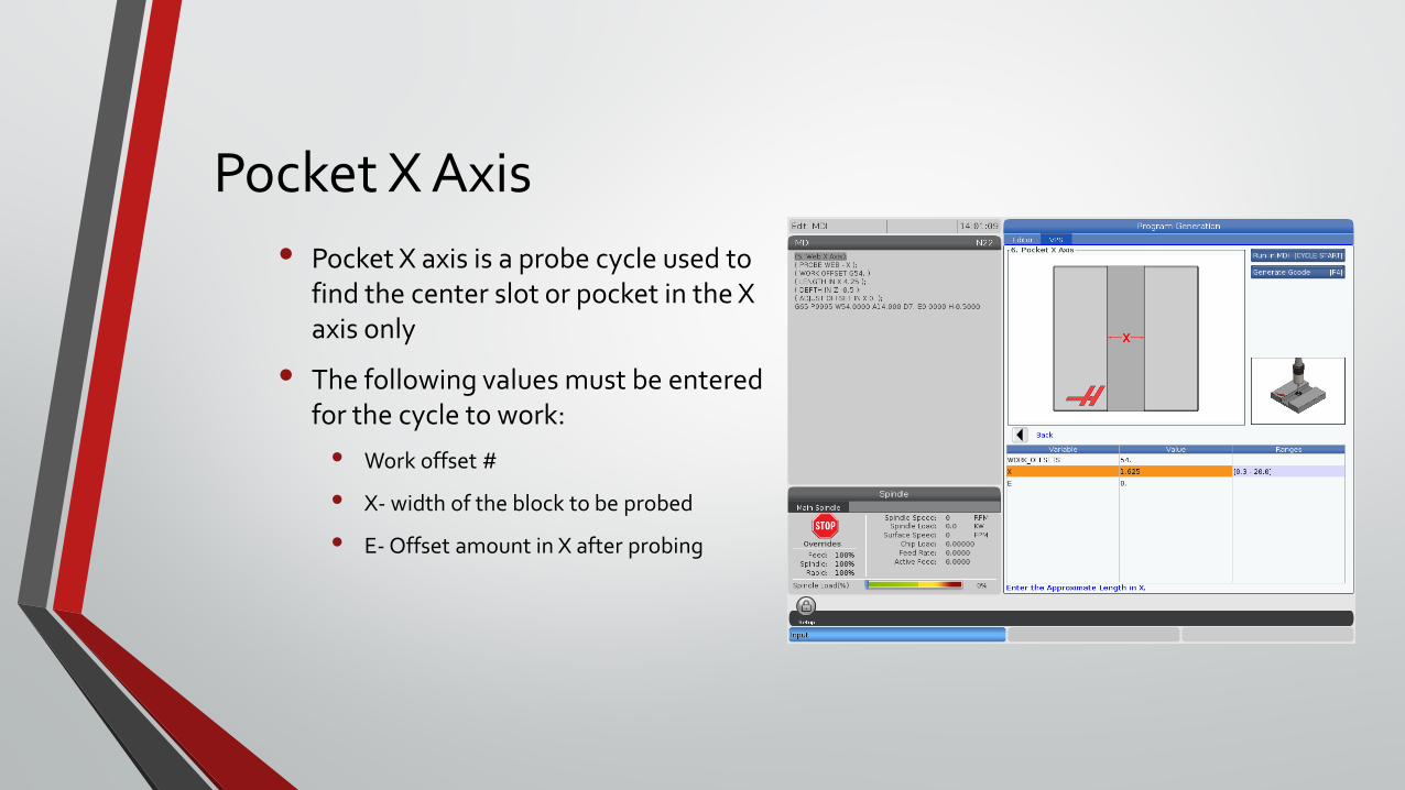
Pocket X Axis• Pocket X axis is a probe cycle used to
find the center slot or pocket in the X axis only
• The following values must be entered for the cycle to work:
• Work offset #
• X- width of the block to be probed
• E- Offset amount in X after probing
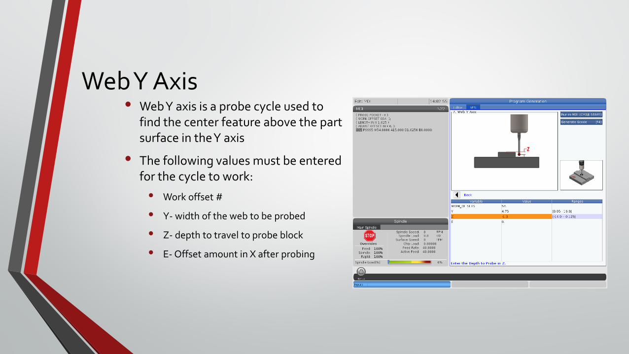
Web Y Axis• Web Y axis is a probe cycle used to
find the center feature above the part surface in the Y axis
• The following values must be entered for the cycle to work:
• Work offset #
• Y- width of the web to be probed
• Z- depth to travel to probe block
• E- Offset amount in X after probing
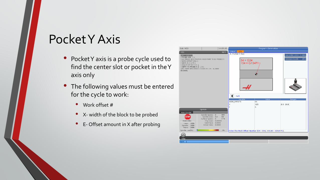
Pocket Y Axis• Pocket Y axis is a probe cycle used to
find the center slot or pocket in the Y axis only
• The following values must be entered for the cycle to work:
• Work offset #
• X- width of the block to be probed
• E- Offset amount in X after probing
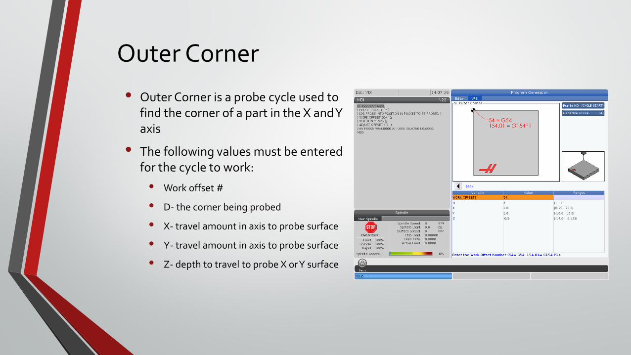
Outer Corner
• Outer Corner is a probe cycle used to find the corner of a part in the X and Y axis
• The following values must be entered for the cycle to work:
• Work offset #
• D- the corner being probed
• X- travel amount in axis to probe surface
• Y- travel amount in axis to probe surface
• Z- depth to travel to probe X or Y surface
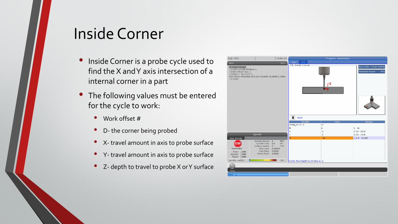
Inside Corner
• Inside Corner is a probe cycle used to find the X and Y axis intersection of a internal corner in a part
• The following values must be entered for the cycle to work:
• Work offset #
• D- the corner being probed
• X- travel amount in axis to probe surface
• Y- travel amount in axis to probe surface
• Z- depth to travel to probe X or Y surface
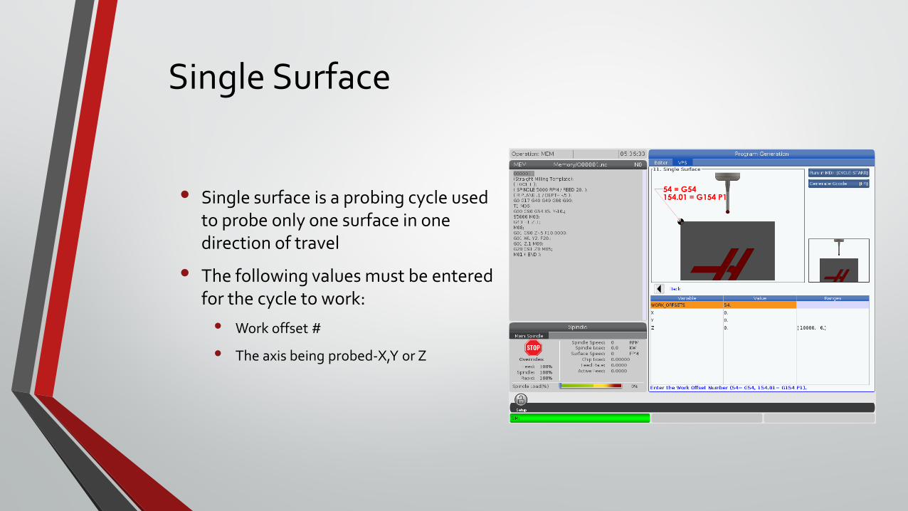
Single Surface
• Single surface is a probing cycle used to probe only one surface in one direction of travel
• The following values must be entered for the cycle to work:
• Work offset #
• The axis being probed-X,Y or Z
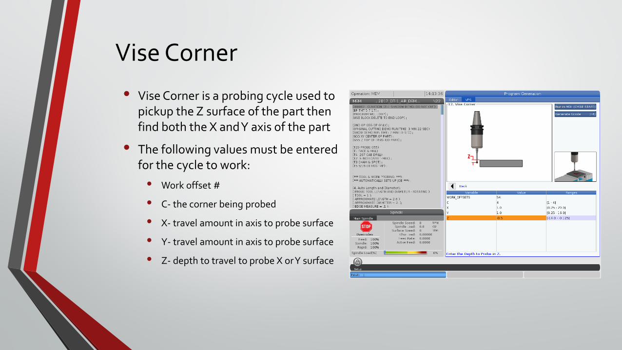
Vise Corner
• Vise Corner is a probing cycle used to pickup the Z surface of the part then find both the X and Y axis of the part
• The following values must be entered for the cycle to work:
• Work offset #
• C- the corner being probed
• X- travel amount in axis to probe surface
• Y- travel amount in axis to probe surface
• Z- depth to travel to probe X or Y surface