preparation of nio catalyst on fecral substrate using various techniques at higher oxidation process
TRANSCRIPT

1
Preparation of NiO Catalyst on FeCrAl Substrate Using Various
Techniques at Higher Oxidation Process
Darwin Sebayang1, Yanuandri Putrasari1, Sulaiman Hasan1, Mohd Ashraf Othman1 and Pudji Untoro2
1Universiti Tun Hussein Onn Malaysia, 2Badan Tenaga Nuklir Nasional
1Malaysia 2Indonesia
1. Introduction
Catalytic converter consists of three major components, i.e substrate, catalyst, and washcoat. The first one is a substrate, a support for catalyst material. The FeCrAl is generally considered as metallic substrates due to their advantage in the high-temperature corrosion resistance, including the strong adherence of oxide film on the surface of substrate when applied the appropriate surface treatment (Twigg & Webster, 2006; Pilone, 2009; Klower et al., 1998; Cueff et al., 2004; Badini & Laurella; 2001; Czyrska-Filemonowicz et al., 1999; Liu et al., 2001; Amano et al., 2008; Checmanowski & Szczygiel, 2008). This material is based on ferritic steels with 5-8 wt% aluminium, 17-22 wt% chromium, plus small additions of reactive elements, which are added to improve the oxidation resistance and oxide adhesion (Nicholls & Quadakkers, 2002). Meanwhile, a catalyst is the accelerate agent for chemical reaction in terms of oxidation and reduction of emission gas. The existing of excellent oxidation catalyst materials was usually based on the precious metal (Pt, Pd, and Rd). However, those materials are expensive and limited supply (Koltsakis & Stamatelos, 1997; Benson et al., 2000). For this reason, the cheaper ranges of oxides (e.g. CuO, V2O5, NiO, MoO3, and Cr2O3) compared to precious metals are being investigated as an alternative catalyst (Kolaczkowski, 2006). This work reports the use of NiO catalyst developed from Ni as a starting material. A washcoat is a catalysts carrier with high surface area. This material is usually an oxide layer such as Al2O3, SiO2, TiO2, or SiO2-Al2O3 (Heck et al., 2002). Nickel forms under a normal temperature and pressure conditions only one oxide, NiO. The mechanism by which oxidation of a nickel proceeds was involved the outward migration of cations and electrons, which forming a single-phase scale (Birks et al., 2006). The conventional technique for adhering catalyst on substrate is by washcoating techniques that generally comprise of preparing a coating formed from a high surface area oxide blended with one or more catalysts and dipping the monolith structure into that coating blend (Huang & Bar-Ilan, 2003; Eleta et al., 2009). One of the most common methods to form a thin layer of oxide coatings on the metallic substrate is dip coatings, which combined with some

Electroplating
4
pre-treatments, such as growing a number of textured alumina whiskers on the surface of the metal support and shortened the diffusion path before depositing the washcoat (Zao, et al., 2003; Jia et al., 2007). The other methods are co-precipitation, sol-gel and spray-pyrolysis methods were also applied for preparation of FeCrAlloy supported perovskite for catalytic combustion of methane (Yanqing, et al., 2010). Furthermore, another technological procedure to develop and adhere to the catalysts on the FeCrAl substrate are based on electrophoretic deposition (Sun et al., 2007; Corni et al., 2008), solution combustion synthesis (SCS) (Specchia et al., 2004), aluminizing technique (Wu et al., 2007), and hydrothermal method (Zamaro et al., 2008; Wei et al., 2005; Mies et al., 2007; Sivaiah, 2010). However, the existing methods still have some limitations, especially due to the rather complicated method to applying the catalyst which is in the form of powder. This paper presents an innovative method for preparation of NiO catalyst on FeCrAl substrate through the combination of electroplating, ultrasonic treatment and oxidation process. Electroplating method was applied to coat Ni to the FeCrAl. The ultrasonic treatment was used in order to accelerate the solid particles to high velocities (Suslick et al., 1999). And, the oxidation process was aimed to convert Ni into NiO on the FeCrAl surface and to develop Al2O3 layer as well.
2. Methodology
2.1 Materials
The FeCrAl foils strip (Aluchrom YHf) was supplied by ThyssenKrupp VDM, Germany. The chemical compositions of the specimen according to ThyssenKrupp Data Sheet No. 4049 are listed in Table 1. The Al2O3 powders, SiC powders, nickel sulphamate (Ni(SO3NH2)2.4H2O), nickel chloride (NiCl·6H2O), boric acid (H2BO3), sodium lauryal sulphate (C12H25SO4Na), hydrochloric acid (HCl), sodium hydroxide (NaOH), methanol (99%), ethanol (99%) and nickel plates (high-purity Ni) were obtained from Sigma Aldrich, Sdn. Bhd. (Malaysia).
Ni Cr Fe C Mn Si Al Zr Y Hf N min - 19.0
bal - - - 5.5 - - - -
max 0.3 22.0 0.05 0.50 0.50 6.5 0.07 0.10 0.10 0.01
Table 1. Chemical composition (wt. %) of FeCrAl
2.2 Experimental procedures
The approach started with assessment of FeCrAl treated by using various nickels electroplating process based on the weight gain during oxidation, followed by short term oxidation process, and long term oxidation process. The steps are summarized in flowchart as shown in Figure 1.
2.2.1 First step: Assessment of FeCrAl treated using various nickel electroplating process
In this study, the various electroplating processes of nickel on the FeCrAl were carried out as the preliminary study to obtain the optimum method to develop nickel oxide on the FeCrAl substrate.

Preparation of NiO Catalyst on FeCrAl Substrate Using Various Techniques at Higher Oxidation Process
5
Ultrasonic during nickel electroplating
Electrolyte:Nickel Sulphamate 300g/l
Nickel Chloride 5 g/lBoric Acid 30 g/l
Sodium Lauryel 250 g/l
Parameter:Temperature 40°CSample 2 cm x1 cmPeriod 30 minutes
Anode & cathode range + 2.5cmCurrent density 2 A/dm2
pH 3.5 - 4.5
Ultrasonic frequency 35 kHz
Ultrasonic prior to nickel electroplating
Methanol 100 ml SiC or Al2O3 powder 20 g
Ultrasonic frequency 35 kHz
Time 30 minutes
Nickel electroplatingElectrolyte:
Nickel Sulphamate 300g/lNickel Chloride 5 g/l
Boric Acid 30 g/lSodium Lauryel 250 g/l
Parameter:Temperature 40°C
Sample 2 cm x1 cmPeriod 30 minutes
Anode & cathode range + 2.5cmCurrent density 2 A/dm2
pH 3.5 - 4.5
Oxidation Temperature 900 oC
Time 100 hours using cyclic approach
Nickel electroplating using electrolyte
modificationElectrolyte:
Nickel Sulphamate 300g/lNickel Chloride 5 g/l
Boric Acid 30 g/lSodium Lauryel 250 g/l
SiC or Al2O3 powder 200 g/l
Parameter:Temperature 40°CSample 2 cm x1 cmPeriod 30 minutes
Anode & cathode range + 2.5cmCurrent density 2 A/dm2
pH 3.5 - 4.5
Nickel electroplatingElectrolyte:
Nickel Sulphamate 300g/lNickel Chloride 5 g/l
Boric Acid 30 g/lSodium Lauryel 250 g/l
Parameter:Temperature 40°CSample 2 cm x1 cmPeriod 30 minutes
Anode & cathode range + 2.5cmCurrent density 2 A/dm2
pH 3.5 - 4.5
Ultrasonic after nickel electroplating
Methanol solution 100 ml Ultrasonic frequency 35 kHz
Time 30 minutes
Nickel electroplatingElectrolyte:
Nickel Sulphamate 300g/lNickel Chloride 5 g/l
Boric Acid 30 g/lSodium Lauryel 250 g/l
Parameter:Temperature 40°CSample 2 cm x1 cmPeriod 30 minutes
Anode & cathode range + 2.5cmCurrent density 2 A/dm2
pH 3.5 - 4.5
Long term oxidation Using cyclic approach
Temperature 900, 1000, and 1100 oC
Time 100-hours
FeCrAl substrate
Select The best method
in terms of high temperature oxidation resistance
(weight gain).
Short term oxidation Using TGA
Temperature 1000 oCTime six hours
Al2O3 & NiO layers analysisOxide growth
Oxidation rate (kp)SEM cross section image and EDX
chemical mapping
Stop
Stop
Al2O3 & NiO layers analysisOxide growth
Oxidation rate (kp)SEM cross section image and EDX
chemical mapping
Stop
Surface analysis AFM & SEM on roughness,
surface area, and morphology
FeCrAl substrateTreated using
selected method. Ultrasonic variation
time 10, 20, 30, 40 & 50
minutes
FeCrAl substrateTreated using selected
method
Step 1: assessment of FeCrAl treated using various nickel electroplating process
Step 2: short term oxidation Step 3: long term oxidation
a
b c
Fig. 1. Flow chart of the research, a) assessment of FeCrAl treated using various nickel electroplating, b) short term oxidation, c) long term oxidation
Electroplating
6
The study analyzed the influence of various electroplating processes of nickel on the FeCrAl metallic monolith for high-temperature oxidation resistance. The proposed new ideas to adhere to nickel as a catalyst on the FeCrAl substrate is divided into five methods as follows: Nickel electroplating, ultrasonic treatment prior to, during, and after nickel electroplating, and nickel electroplating using electrolyte modification. The optimum result in terms of high-temperature oxidation resistance which obtained from this investigation was then selected for further study/testing.
2.2.1.1 Nickel electroplating
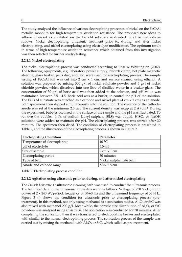
The nickel electroplating process was conducted according to Rose & Whittington (2002). The following equipments, e.g. laboratory power supply, retorch clamp, hot plate magnetic steering, glass beaker, petri disc, and, etc. were used for electroplating process. The sample testing of FeCrAl foil was cut into 2 cm x 1 cm, and surface cleaned using ethanol. A solution was prepared by mixing 300 g/l of nickel sulphate powder and 5 g/l of nickel chloride powder, which dissolved into one litre of distilled water in a beaker glass. The concentration of 30 g/l of boric acid was then added to the solution, and pH value was maintained between 3.5 - 4.5. Boric acid acts as a buffer, to control the pH of the solution. The FeCrAl substrate was attached as a cathode and nickel plate (4 cm x 1 cm) as an anode. Both specimens then dipped simultaneously into the solution. The distance of the cathode-anode was set at the minimum 2.5 cm. The current density was setup at 2 A/dm2. During the experiment, bubbles occurred at the surface of the sample and the pH was fluctuated. To remove the bubbles, 0.1% of sodium lauryl sulphate (SLS) was added. H2SO4 or NaOH solutions were added to maintain the pH. The electroplating process was started after 30 minutes. The specimen then dried. The condition of electroplating process is presented in Table 2, and the illustration of the electroplating process is shown in Figure 2.
Electroplating Condition Parameter Temperature of electroplating 40 °C pH of electrolyte 3.5-4.5 Size of sample 2 cm x 1 cm Electroplating period 30 minutes Type of bath Nickel sulphamate bath Anode and cathode range Min. 2.5 cm
Table 2. Electroplating process condition
2.2.1.2 Agitation using ultrasonic prior to, during, and after nickel electroplating
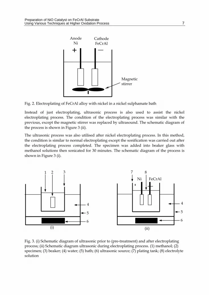
The Fritsch Loborette 17 ultrasonic cleaning bath was used to conduct the ultrasonic process. The technical data in the ultrasonic apparatus were as follows: Voltage of 230 V/1~, input power of 2 x 240 W/period, frequency of 50-60 Hz and the ultrasound frequency of 35 kHz. Figure 3 (i) shows the condition for ultrasonic prior to electroplating process (pre-treatment). In this method, not only using methanol as a sonication media, Al2O3 or SiC was also mixed with methanol 200 g/l. Meanwhile, the particle size distribution of Al2O3 or SiC powders was analyzed using Cilas 1180. The sonication was conducted for 30 minutes. After completing the sonication, then it was transferred to electroplating beaker and electroplated with similar to the normal electroplating process. The sonication process of the sample was carried out by mixing the methanol with Al2O3 or SiC, which called as pre-treatment.
Preparation of NiO Catalyst on FeCrAl Substrate Using Various Techniques at Higher Oxidation Process
7
Fig. 2. Electroplating of FeCrAl alloy with nickel in a nickel sulphamate bath
Instead of just electroplating, ultrasonic process is also used to assist the nickel electroplating process. The condition of the electroplating process was similar with the previous, except the magnetic stirrer was replaced by ultrasound. The schematic diagram of the process is shown in Figure 3 (ii).
The ultrasonic process was also utilised after nickel electroplating process. In this method, the condition is similar to normal electroplating except the sonification was carried out after the electroplating process completed. The specimen was added into beaker glass with methanol solutions then sonicated for 30 minutes. The schematic diagram of the process is shown in Figure 3 (i).
Fig. 3. (i) Schematic diagram of ultrasonic prior to (pre-treatment) and after electroplating process; (ii) Schematic diagram ultrasonic during electroplating process. (1) methanol; (2) specimen; (3) beaker; (4) water; (5) bath; (6) ultrasonic source; (7) plating tank; (8) electrolyte solution
+ __
AnodeNi
Cathode FeCrAl
Magnetic stirrer
4
3
5
2 1
6
(i) (ii)
7 8
+ __ Ni FeCrAl
4
5
6
Electroplating
8
2.2.1.3 Nickel electroplating using electrolyte modification
The new concept of electroplating was applied in this study to develop washcoat onto FeCrAl substrate, which done by mixing the electrolyte with 200 g/l of Al2O3 or SiC powder. This method is similar to normal electroplating except the electrolyte was modified. During electroplating process, the electrolyte was agitated using a magnetic stirrer to dissolve Al2O3 or SiC powder.
2.2.1.4 Oxidation process
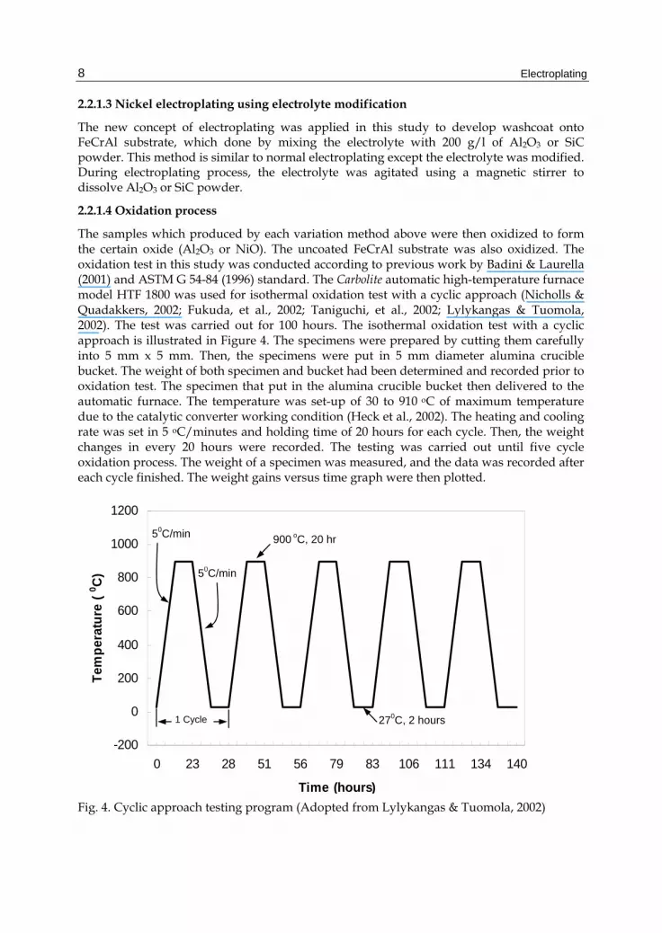
The samples which produced by each variation method above were then oxidized to form the certain oxide (Al2O3 or NiO). The uncoated FeCrAl substrate was also oxidized. The oxidation test in this study was conducted according to previous work by Badini & Laurella (2001) and ASTM G 54-84 (1996) standard. The Carbolite automatic high-temperature furnace model HTF 1800 was used for isothermal oxidation test with a cyclic approach (Nicholls & Quadakkers, 2002; Fukuda, et al., 2002; Taniguchi, et al., 2002; Lylykangas & Tuomola, 2002). The test was carried out for 100 hours. The isothermal oxidation test with a cyclic approach is illustrated in Figure 4. The specimens were prepared by cutting them carefully into 5 mm x 5 mm. Then, the specimens were put in 5 mm diameter alumina crucible bucket. The weight of both specimen and bucket had been determined and recorded prior to oxidation test. The specimen that put in the alumina crucible bucket then delivered to the automatic furnace. The temperature was set-up of 30 to 910 oC of maximum temperature due to the catalytic converter working condition (Heck et al., 2002). The heating and cooling rate was set in 5 oC/minutes and holding time of 20 hours for each cycle. Then, the weight changes in every 20 hours were recorded. The testing was carried out until five cycle oxidation process. The weight of a specimen was measured, and the data was recorded after each cycle finished. The weight gains versus time graph were then plotted.
Fig. 4. Cyclic approach testing program (Adopted from Lylykangas & Tuomola, 2002)
-200
0
200
400
600
800
1000
1200
0 23 28 51 56 79 83 106 111 134 140
Time (hours)
Tem
per
atu
re (
0 C)
1 Cycle
900 oC, 20 hr
270C, 2 hours
50C/min
50C/min

Preparation of NiO Catalyst on FeCrAl Substrate Using Various Techniques at Higher Oxidation Process
9
2.2.2 Second step: Short term oxidation process
Prior to short term oxidation, the surface FeCrAl substrate was analysed in order to obtain the information of substrate surface, which previously treated using the selected method. The surface analysis was carried out by using step-and-scan automation of Atomic Force Microscopy (AFM) by Park model XE-100. Roughness (Ra) measurement was taken by horizontal straight-line mode. The Ra profiles were analysed and presented in order to clarify the roughness which caused by ultrasonic treatment of the FeCrAl surface specimens. The mean Ra is a result from a random 100 μm2 scan area of specimens. The 3D images from AFM were presented to analyze the topography of a specimen. The grain area (μm2) as 2D image was measured by using AFM analysis to calculate the total surface area of a specimen. The scanned surface areas of a specimen were calculated and approached by spherical surface analysis (Henke et al., 2002). This approach was adopted for this research. The approach assumed that the grain morphologies as a nodule on FeCrAl substrate in half of sphere form. Then, the mean area obtained from AFM was assumed as an area of circles where the diameter similar to the sphere. The half of sphere surface area was calculated by using sphere surface area formula. The surface analyses were carried out after ultrasonic pre-treatment without nickel electroplating to observe any changes in surface characteristic. The short term oxidation analysis focused on weight gain, oxidation rate (kp), morphology of oxide layer and cross section elemental mapping of washcoat (Al2O3 layer). Meanwhile, the oxidation test for six hours was conducted using Diamond, Perkin Elmer thermo gravimetric analyzer (TGA). The specimens were prepared by cutting into 2 mm x 2 mm. All of specimens are tested for oxidation by putting them into the TGA at 1000 oC for 360 minutes. Then, the data plotted into the graph of weight gain (mg/mm2) versus temperature (oC) or time (minutes). The graph was analyzed to obtain the parabolic rate constant (Smallman & Bishop, 1999; Badini & Laurella, 2001). The parabolic growth equation of the film thickness with time obtained by:
x2 = kp . t (1)
where x is the layer thickness or the weight gain; t is the oxidation treatment time; kp is the parabolic rate constant. In this study, the weight gain (x) is a resulted from mass gain per
unit surface area of specimens WA (Badini & Laurella, 2001). Then, the eq. (1) can be
written as follow:
2WA = kp . t (2)
where kp is obtained from the slope of a linear regression-fitted line of 2WA vs t plot.
The microstructure analyses were carried out using JEOL Scanning Electron Microscope (SEM) model JSM-6380LA attached with Energy Dispersive X-ray (EDX). Prior to microstructure analysis, the specimen is mounted, ground and polished and coated with gold or platinum. The sample mounting conducted by hot press and cold mounting technique at a cross-sectional side of the specimen. The Buehler automatic hot mounting press machine was implemented for hot mounting process. The mounting parameters were 15 minutes mounting period, 2000 psi mounting pressure and 150 oC as the mounting temperature. For the cold mounting process, the ratio composition of resin and hardener
Electroplating
10
was 10 : 1. Then, the specimens were put into a mould at room temperature for minimum 24 hours until hardened. The specimens were ground using the SiC paper from 240 to 2000 grit, followed by polishing process, in order to obtain clear and shiny surface specimens.
After polishing, the specimens were observed under the digital microscope to ensure that the specimen did not have any scratches before further analyzed by SEM/EDX. The specimen was then coated with gold or platinum by using the sputter coating apparatus. The sputter coating was set in 20 mA of coating current and 20 minutes of coating time.
The back scattered mode of SEM was used to obtain a high-quality image of the specimen. The ranges of magnification, 100 x, 500 x, 1000 x, 1500 x and 2000 x, were used to observe both surface and cross-section of the specimen. The EDX mapping and line analysis techniques were also implemented in order to reveal the distribution of oxide layers on the FeCrAl surface substrate.
2.2.3 Third step: Long term oxidation process
This step is aimed to explore the behaviour of nickel layer on FeCrAl when subjected to the selected treatment at variation time for 10, 20, 30, 40 and 50 minutes, with high oxidation temperature for 100 hours. The oxidation process conducted using a cyclic approach testing, similar with previous sub section 2.2.1.4. To assess the high-temperature oxidation resistance of FeCrAl, the temperature oxidation of 1000 and 1100 oC were also applied. As similar with short term oxidation, in this step the oxide growth, and oxidation rate (kp) were also analysed. Nickel and nickel oxide morphologies were studied on the samples cross section at various temperatures. EDX attached to SEM was also used to obtain the elemental distribution of the samples cross section similar with sub section 2.2.2.
3. Results and discussion
3.1 Assessment of FeCrAl treated using various nickel electroplating process based on weight gain
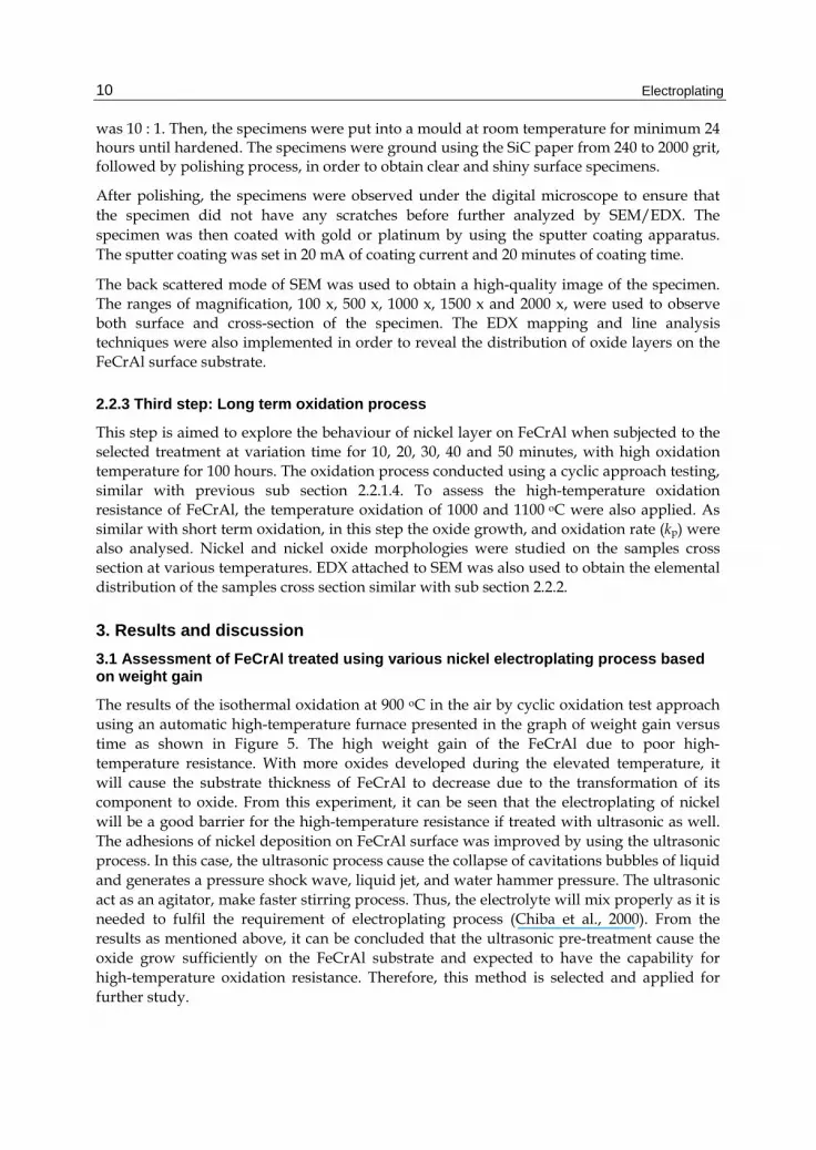
The results of the isothermal oxidation at 900 oC in the air by cyclic oxidation test approach using an automatic high-temperature furnace presented in the graph of weight gain versus time as shown in Figure 5. The high weight gain of the FeCrAl due to poor high-temperature resistance. With more oxides developed during the elevated temperature, it will cause the substrate thickness of FeCrAl to decrease due to the transformation of its component to oxide. From this experiment, it can be seen that the electroplating of nickel will be a good barrier for the high-temperature resistance if treated with ultrasonic as well. The adhesions of nickel deposition on FeCrAl surface was improved by using the ultrasonic process. In this case, the ultrasonic process cause the collapse of cavitations bubbles of liquid and generates a pressure shock wave, liquid jet, and water hammer pressure. The ultrasonic act as an agitator, make faster stirring process. Thus, the electrolyte will mix properly as it is needed to fulfil the requirement of electroplating process (Chiba et al., 2000). From the results as mentioned above, it can be concluded that the ultrasonic pre-treatment cause the oxide grow sufficiently on the FeCrAl substrate and expected to have the capability for high-temperature oxidation resistance. Therefore, this method is selected and applied for further study.

Preparation of NiO Catalyst on FeCrAl Substrate Using Various Techniques at Higher Oxidation Process
11
Oxidation test of FeCrAl at 900 oC
-0.012
-0.002
0.008
0.018
0.028
0.038
0 20 40 60 80 100Time (hours)
Wei
gh
t g
ain
(m
g.m
m-2
)
FeCrAl FeCrAl + Electroplating
FeCrAl + Electroplating + Ultrasonic Ultrasonic during electroplating
FeCrAl + Electroplating + SiC FeCrAl + Electroplating + Al2O3
FeCrAl + Pretreatment with SiC FeCrAl + Pretreatment with Al2O3
Fig. 5. Effect of various electroplating process on weight gain vs time of FeCrAl during oxidation at 900 oC
3.2 Analysis of FeCrAl substrate before and after short term oxidation
3.2.1 Surface analysis
Figure 6 shows the roughness profile of the FeCrAl (a) untreated, (b) ultrasonic treatment with SiC for 10 minutes and (c) ultrasonic treatment with Al2O3 for 10 minutes without nickel electroplating. From these profiles, the highest, medium, and lowest gap between peaks and valley occurred on FeCrAl untreated, treatment with Al2O3 and with SiC, respectively.
The mean roughness of FeCrAl was presented in Table 3. The mean roughness of each specimen was obtained by using the horizontal straight-line method on random position of 10 μm x 10 μm image. Meanwhile, the 3D images for all specimens were presented in Figure 7.
Materials Mean Roughness, Ra (nm)
FeCrAl untreated 31.409
FeCrAl ultrasonic treatment with SiC 15.790
FeCrAl ultrasonic treatment with Al2O3 34.470
Table 3. Mean roughness of FeCrAl surface

Electroplating
12
(a)
(b)
(c)
Fig. 6. Roughness profile of FeCrAl surface a) untreated, b) ultrasonic treatment with SiC for 10 minutes, c) ultrasonic treatment with Al2O3 for 10 minutes
Based on the roughness test results, the FeCrAl treated with Al2O3 has the highest surface roughness value compared to the untreated and treated using ultrasonic with SiC. Based on the particle size distribution analysis that was conducted, for 60% distribution of Al2O3 powder is 42.07 μm with specific surface 5658.19 cm2/g and 60% distribution of SiC powder is 87.56 μm with specific surface only 2279.44 cm2/g. It can be estimated that the roughness of FeCrAl surface depends on the particle size and homogeneity of the powders. The surface roughness of FeCrAl was as also estimated can be increased by the higher specific area of powders.
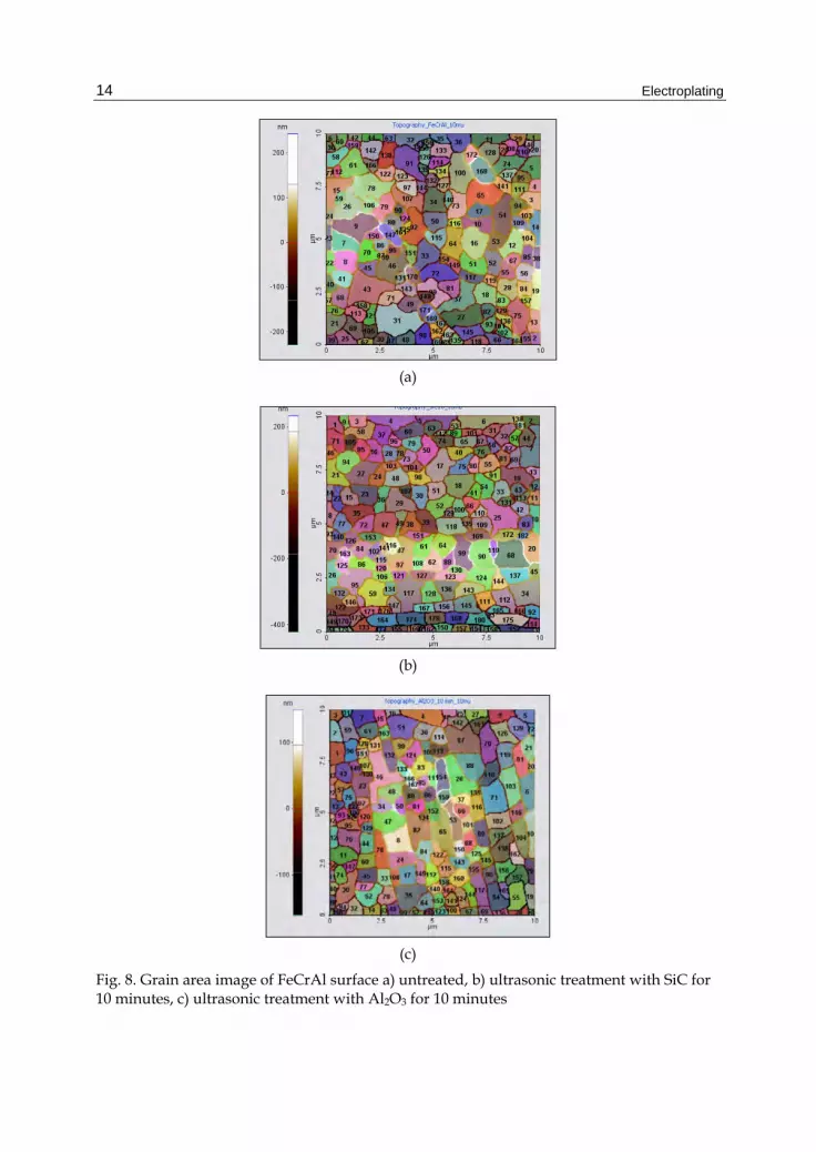
Figure 8 shows the grains of FeCrAl (a) untreated, (b) ultrasonic treatment with SiC for 10 minutes and (c) ultrasonic treatment Al2O3 for 10 minutes. These images resulted from 10 μm x 10 μm random scanning area on each specimen. The grain numbers and grain area were presented in Table 4. The table shows that the grain numbers on FeCrAl ultrasonic treatment with SiC is the highest, followed by untreated FeCrAl, and the lowest is FeCrAl ultrasonic treatment with Al2O3. The highest grain area is FeCrAl ultrasonic treatment with Al2O3, then FeCrAl untreated, and the smallest is FeCrAl ultrasonic treatment with SiC.
Materials Grain numbers Mean area (μm2) FeCrAl untreated 172 5.412 x 10⁻¹ FeCrAl ultrasonic treatment with SiC 183 5.058 x 10⁻¹ FeCrAl ultrasonic treatment with Al2O3 167 5.599 x 10⁻¹
Table 4. Mean of grain area on FeCrAl surface

Preparation of NiO Catalyst on FeCrAl Substrate Using Various Techniques at Higher Oxidation Process
13
(a) (b)
(c)
Fig. 7. Roughness 3D images of FeCrAl surface a) untreated, b) ultrasonic treatment with SiC for 10 minutes, c) ultrasonic treatment with Al2O3 for 10 minutes
The surface area acts as a main role on the catalyst reaction effectiveness. In order to accommodate the catalyst in significant amounts, substrate must be provided with a high surface area. Twigg & Webster (2006) suggest that the design of substrate must provide a maximum superficial surface area which accommodates to the exhaust gas, as it is upon this surface that the catalytic coating is applied, and on which the pollutant and reactant gases must impinge in order to react.
3.2.2 Parabolic rate constant
The parabolic rate constant (kp) can be used to predict the time to failure of the FeCrAl materials (Klower et al., 1998). The formation rate of an oxide scale, growing on the surface of a FeCrAl surface at the beginning of the oxidation test agrees with the Wagner theory. At high-temperature oxide, films are thickened according to the parabolic rate law, x2 α t and the mechanism by which thickening proceeded has been explained by Wagner (Smallman & Bishop, 1999; Badini & Laurella, 2001).
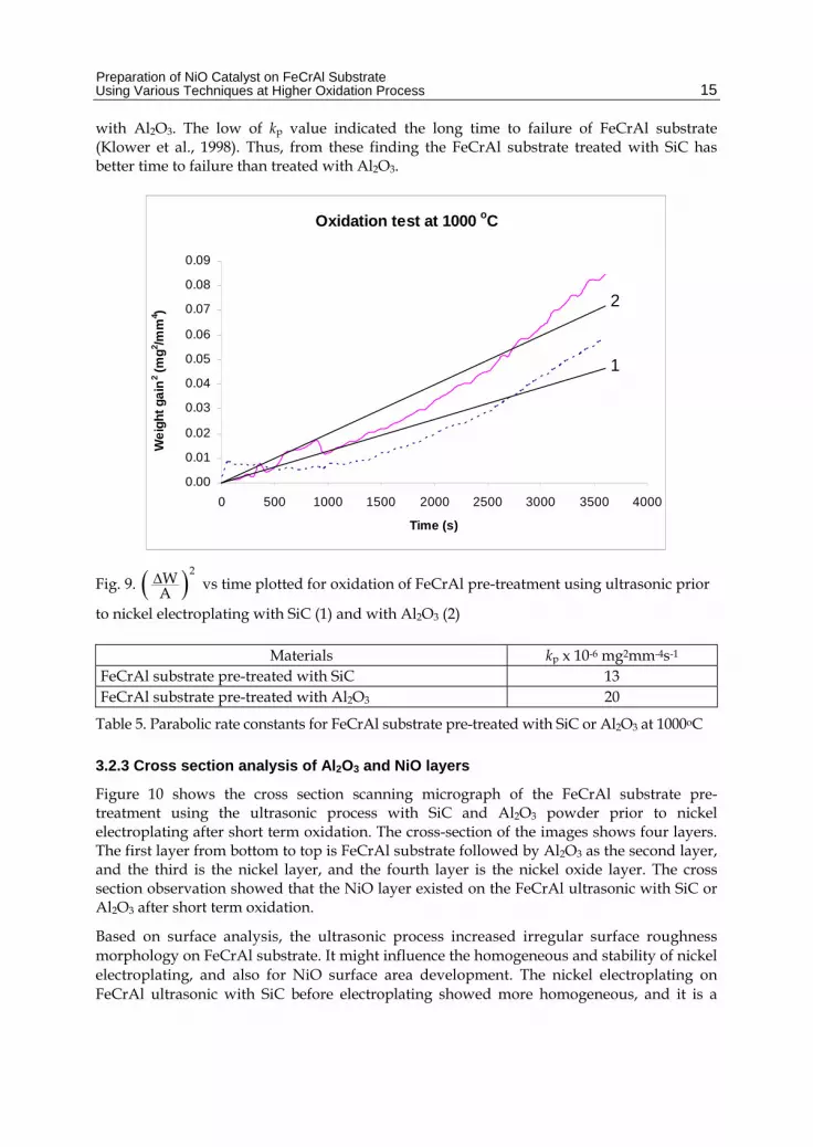
Figure 9 shows the nature of the fit of the parabolic rate law of the early oxidation test of FeCrAl substrate pre-treatment using ultrasonic with SiC or Al2O3 at 1000 oC for 60 minutes. The parabolic rate constants obtained from the present experiments are listed Table 5. FeCrAl substrate pre-treated with SiC has lower kp than the FeCrAl substrate pre-treated
Electroplating
14
(a)
(b)
(c)
Fig. 8. Grain area image of FeCrAl surface a) untreated, b) ultrasonic treatment with SiC for 10 minutes, c) ultrasonic treatment with Al2O3 for 10 minutes
Preparation of NiO Catalyst on FeCrAl Substrate Using Various Techniques at Higher Oxidation Process
15
with Al2O3. The low of kp value indicated the long time to failure of FeCrAl substrate (Klower et al., 1998). Thus, from these finding the FeCrAl substrate treated with SiC has better time to failure than treated with Al2O3.
Oxidation test at 1000 oC
2
1
0.00
0.01
0.02
0.03
0.04
0.05
0.06
0.07
0.08
0.09
0 500 1000 1500 2000 2500 3000 3500 4000
Time (s)
We
igh
t g
ain
2 (m
g2 /m
m4 )
Fig. 9. 2WA vs time plotted for oxidation of FeCrAl pre-treatment using ultrasonic prior
to nickel electroplating with SiC (1) and with Al2O3 (2)
Materials kp x 10-6 mg2mm-4s-1 FeCrAl substrate pre-treated with SiC 13 FeCrAl substrate pre-treated with Al2O3 20
Table 5. Parabolic rate constants for FeCrAl substrate pre-treated with SiC or Al2O3 at 1000oC
3.2.3 Cross section analysis of Al2O3 and NiO layers
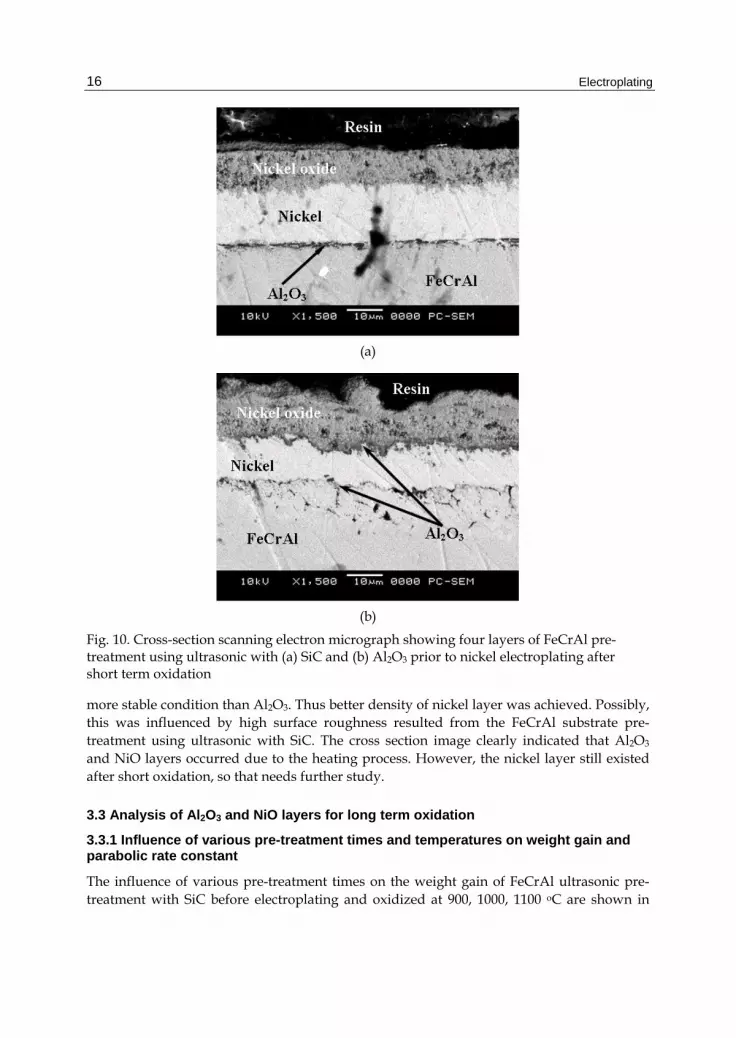
Figure 10 shows the cross section scanning micrograph of the FeCrAl substrate pre-treatment using the ultrasonic process with SiC and Al2O3 powder prior to nickel electroplating after short term oxidation. The cross-section of the images shows four layers. The first layer from bottom to top is FeCrAl substrate followed by Al2O3 as the second layer, and the third is the nickel layer, and the fourth layer is the nickel oxide layer. The cross section observation showed that the NiO layer existed on the FeCrAl ultrasonic with SiC or Al2O3 after short term oxidation.
Based on surface analysis, the ultrasonic process increased irregular surface roughness morphology on FeCrAl substrate. It might influence the homogeneous and stability of nickel electroplating, and also for NiO surface area development. The nickel electroplating on FeCrAl ultrasonic with SiC before electroplating showed more homogeneous, and it is a
Electroplating
16
(a)
(b)
Fig. 10. Cross-section scanning electron micrograph showing four layers of FeCrAl pre-treatment using ultrasonic with (a) SiC and (b) Al2O3 prior to nickel electroplating after short term oxidation
more stable condition than Al2O3. Thus better density of nickel layer was achieved. Possibly, this was influenced by high surface roughness resulted from the FeCrAl substrate pre-treatment using ultrasonic with SiC. The cross section image clearly indicated that Al2O3 and NiO layers occurred due to the heating process. However, the nickel layer still existed after short oxidation, so that needs further study.
3.3 Analysis of Al2O3 and NiO layers for long term oxidation
3.3.1 Influence of various pre-treatment times and temperatures on weight gain and parabolic rate constant
The influence of various pre-treatment times on the weight gain of FeCrAl ultrasonic pre-treatment with SiC before electroplating and oxidized at 900, 1000, 1100 oC are shown in
Preparation of NiO Catalyst on FeCrAl Substrate Using Various Techniques at Higher Oxidation Process
17
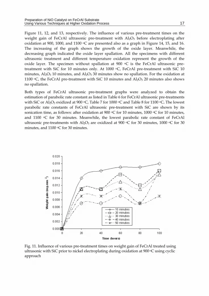
Figure 11, 12, and 13, respectively. The influence of various pre-treatment times on the weight gain of FeCrAl ultrasonic pre-treatment with Al2O3 before electroplating after oxidation at 900, 1000, and 1100 oC are presented also as a graph in Figure 14, 15, and 16. The increasing of the graph shows the growth of the oxide layer. Meanwhile, the decreasing graph indicated the oxide layer spallation. All the specimens with different ultrasonic treatment and different temperature oxidation represent the growth of the oxide layer. The specimen without spallation at 900 oC is the FeCrAl ultrasonic pre-treatment with SiC for 10 minutes only. At 1000 oC, FeCrAl pre-treatment with SiC 10 minutes, Al2O3 10 minutes, and Al2O3 30 minutes show no spallation. For the oxidation at 1100 oC, the FeCrAl pre-treatment with SiC 10 minutes and Al2O3 20 minutes also shows no spallation.
Both types of FeCrAl ultrasonic pre-treatment graphs were analyzed to obtain the estimation of parabolic rate constant as listed in Table 6 for FeCrAl ultrasonic pre-treatments with SiC or Al2O3 oxidized at 900 oC, Table 7 for 1000 oC and Table 8 for 1100 oC. The lowest parabolic rate constants of FeCrAl ultrasonic pre-treatment with SiC are shown by its sonication time, as follows: after oxidation at 900 oC for 10 minutes, 1000 oC for 10 minutes, and 1100 oC for 30 minutes. Meanwhile, the lowest parabolic rate constant of FeCrAl ultrasonic pre-treatments with Al2O3 are oxidized at 900 oC for 30 minutes, 1000 oC for 30 minutes, and 1100 oC for 30 minutes.
Fig. 11. Influence of various pre-treatment times on weight gain of FeCrAl treated using ultrasonic with SiC prior to nickel electroplating during oxidation at 900 oC using cyclic approach

Electroplating
18
Fig. 12. Influence of various pre-treatment times on weight gain of FeCrAl treated using ultrasonic with SiC prior to nickel electroplating during oxidation at 1000 oC using cyclic approach
Fig. 13. Influence of various pre-treatment times on weight gain of FeCrAl treated using ultrasonic with SiC prior to nickel electroplating during oxidation at 1100 oC using cyclic approach

Preparation of NiO Catalyst on FeCrAl Substrate Using Various Techniques at Higher Oxidation Process
19
Fig. 14. Influence of various pre-treatment times on weight gain of FeCrAl treated using ultrasonic with Al2O3 prior to nickel electroplating during oxidation at 900 oC using cyclic approach.
Fig. 15. Influence of various pre-treatment times on weight gain of FeCrAl treated using ultrasonic with Al2O3 prior to nickel electroplating during oxidation at 1000 oC using cyclic approach
Electroplating
20
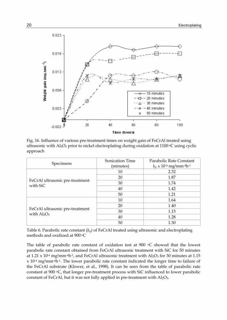
Fig. 16. Influence of various pre-treatment times on weight gain of FeCrAl treated using ultrasonic with Al2O3 prior to nickel electroplating during oxidation at 1100 oC using cyclic approach
Specimens Sonication Time
(minutes) Parabolic Rate Constant
kp x 10-4 mg2mm-4h-1
FeCrAl ultrasonic pre-treatment with SiC
10 2.32 20 1.87 30 1.74 40 1.42 50 1.21
FeCrAl ultrasonic pre-treatment with Al2O3
10 1.64 20 1.40 30 1.15 40 1.28 50 1.30
Table 6. Parabolic rate constant (kp) of FeCrAl treated using ultrasonic and electroplating methods and oxidized at 900 oC
The table of parabolic rate constant of oxidation test at 900 oC showed that the lowest parabolic rate constant obtained from FeCrAl ultrasonic treatment with SiC for 50 minutes at 1.21 x 10⁻⁴ mg2mm-4h-1, and FeCrAl ultrasonic treatment with Al2O3 for 30 minutes at 1.15 x 10⁻⁴ mg2mm-4h-1. The lower parabolic rate constant indicated the longer time to failure of the FeCrAl substrate (Klower, et al., 1998). It can be seen from the table of parabolic rate constant at 900 oC, that longer pre-treatment process with SiC influenced to lower parabolic constant of FeCrAl, but it was not fully applied in pre-treatment with Al2O3.
Preparation of NiO Catalyst on FeCrAl Substrate Using Various Techniques at Higher Oxidation Process
21
Specimens Sonication Time
(minutes) Parabolic Rate Constant
kp x 10-4 mg2mm-4h-1
FeCrAl ultrasonic pre-treatment with SiC
10 0.64 20 1.83 30 1.15 40 0.85 50 0.84
FeCrAl ultrasonic pre-treatment with Al2O3
10 2.44 20 1.82 30 1.73 40 1.92 50 1.75
Table 7. Parabolic rate constant (kp) of FeCrAl treated using ultrasonic and electroplating methods and oxidized at 1000 oC
Specimens Sonication Time
(minutes) Parabolic Rate Constant
kp x 10-4 mg2mm-4h-1
FeCrAl ultrasonic pre-treatment with SiC
10 1.97 20 2.55 30 1.83 40 2.86 50 1.96
FeCrAl ultrasonic pre-treatment with Al2O3
10 2.65 20 2.36 30 1.52 40 1.56 50 1.54
Table 8. Parabolic rate constant (kp) of FeCrAl treated using ultrasonic and electroplating methods and oxidized at 1100 oC
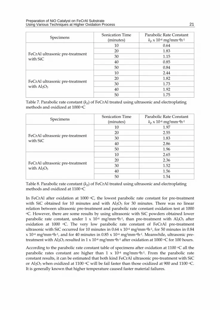
In FeCrAl after oxidation at 1000 oC, the lowest parabolic rate constant for pre-treatment with SiC obtained for 10 minutes and with Al2O3 for 30 minutes. There was no linear relation between ultrasonic pre-treatment and parabolic rate constant oxidation test at 1000 oC. However, there are some results by using ultrasonic with SiC powders obtained lower parabolic rate constant, under 1 x 10⁻⁴ mg2mm-4h-1, than pre-treatment with Al2O3 after oxidation at 1000 oC. The very low parabolic rate constant of FeCrAl pre-treatment ultrasonic with SiC occurred for 10 minutes in 0.64 x 10⁻⁴ mg2mm-4h-1, for 50 minutes in 0.84 x 10⁻⁴ mg2mm-4h-1, and for 40 minutes in 0.85 x 10⁻⁴ mg2mm-4h-1. Meanwhile, ultrasonic pre-treatment with Al2O3 resulted in 1 x 10⁻⁴ mg2mm-4h-1 after oxidation at 1000 oC for 100 hours.
According to the parabolic rate constant table of specimens after oxidation at 1100 oC all the parabolic rates constant are higher than 1 x 10⁻⁴ mg2mm-4h-1. From the parabolic rate constant results, it can be estimated that both kind FeCrAl ultrasonic pre-treatment with SiC or Al2O3 when oxidized at 1100 oC will be fail faster than those oxidized at 900 and 1100 oC. It is generally known that higher temperature caused faster material failures.
Electroplating
22
3.3.2 Cross section analysis of Al2O3 and NiO layers
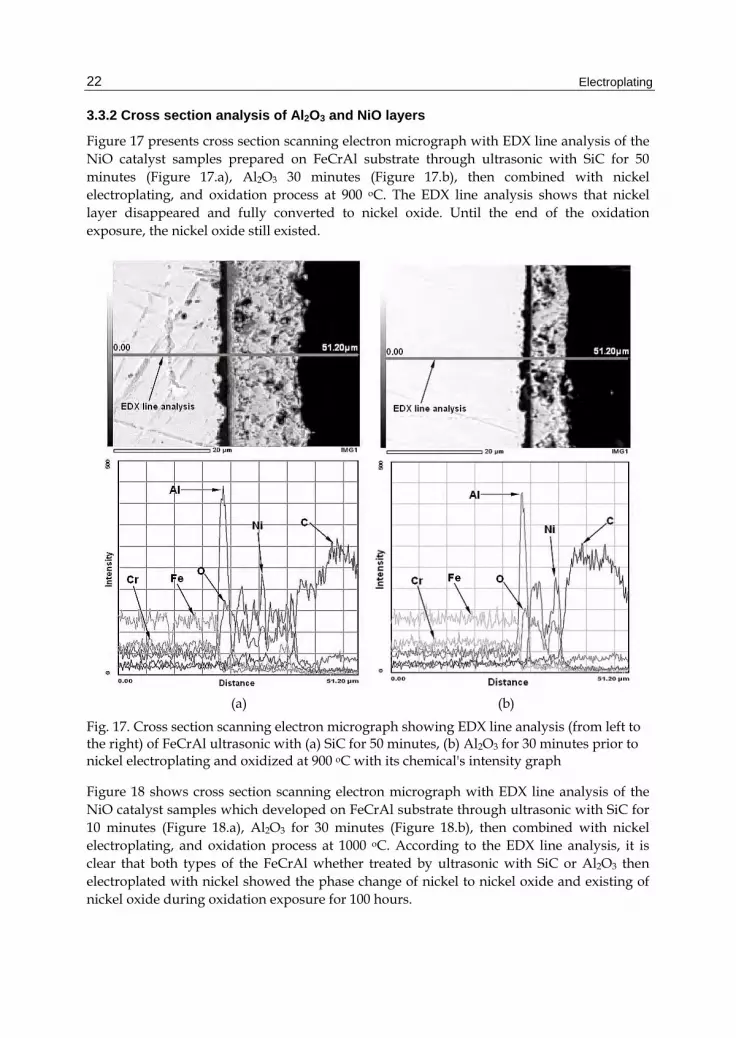
Figure 17 presents cross section scanning electron micrograph with EDX line analysis of the NiO catalyst samples prepared on FeCrAl substrate through ultrasonic with SiC for 50 minutes (Figure 17.a), Al2O3 30 minutes (Figure 17.b), then combined with nickel electroplating, and oxidation process at 900 oC. The EDX line analysis shows that nickel layer disappeared and fully converted to nickel oxide. Until the end of the oxidation exposure, the nickel oxide still existed.
(a) (b)
Fig. 17. Cross section scanning electron micrograph showing EDX line analysis (from left to the right) of FeCrAl ultrasonic with (a) SiC for 50 minutes, (b) Al2O3 for 30 minutes prior to nickel electroplating and oxidized at 900 oC with its chemical's intensity graph
Figure 18 shows cross section scanning electron micrograph with EDX line analysis of the NiO catalyst samples which developed on FeCrAl substrate through ultrasonic with SiC for 10 minutes (Figure 18.a), Al2O3 for 30 minutes (Figure 18.b), then combined with nickel electroplating, and oxidation process at 1000 oC. According to the EDX line analysis, it is clear that both types of the FeCrAl whether treated by ultrasonic with SiC or Al2O3 then electroplated with nickel showed the phase change of nickel to nickel oxide and existing of nickel oxide during oxidation exposure for 100 hours.
Preparation of NiO Catalyst on FeCrAl Substrate Using Various Techniques at Higher Oxidation Process
23
(a) (b)
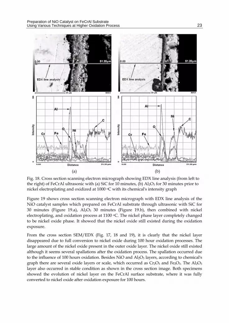
Fig. 18. Cross section scanning electron micrograph showing EDX line analysis (from left to the right) of FeCrAl ultrasonic with (a) SiC for 10 minutes, (b) Al2O3 for 30 minutes prior to nickel electroplating and oxidized at 1000 oC with its chemical's intensity graph
Figure 19 shows cross section scanning electron micrograph with EDX line analysis of the NiO catalyst samples which prepared on FeCrAl substrate through ultrasonic with SiC for 30 minutes (Figure 19.a), Al2O3 30 minutes (Figure 19.b), then combined with nickel electroplating, and oxidation process at 1100 oC. The nickel phase layer completely changed to be nickel oxide phase. It showed that the nickel oxide still existed during the oxidation exposure.
From the cross section SEM/EDX (Fig. 17, 18 and 19), it is clearly that the nickel layer disappeared due to full conversion to nickel oxide during 100 hour oxidation processes. The large amount of the nickel oxide present in the outer oxide layer. The nickel oxide still existed although it seems several spallations after the oxidation process. The spallation occurred due to the influence of 100 hours oxidation. Besides NiO and Al2O3 layers, according to chemical's graph there are several oxide layers or scale, which occurred as Cr2O3 and Fe2O3. The Al2O3 layer also occurred in stable condition as shown in the cross section image. Both specimens showed the evolution of nickel layer on the FeCrAl surface substrate, where it was fully converted to nickel oxide after oxidation exposure for 100 hours.

Electroplating
24
(a) (b)
Fig. 19. Cross section scanning electron micrograph showing EDX line analysis (from left to the right) of FeCrAl ultrasonic with (a) SiC for 30 minutes, (b) Al2O3 for 30 minutes prior to nickel electroplating, and oxidized at 1100 oC with its chemical's intensity graph
4. Conclusion
A systematic study was conducted to evaluate the new method of developing NiO through oxidation in combination between nickel electroplating and ultrasonic technique. The NiO was obtained when treated at short term of oxidation for 6 hours at 900 oC and fully developed for 100 hours after oxidation at 900, 1000 and 1100 oC. The NiO catalyst successfully developed from nickel plating, which obtained on the surface of FeCrAl substrate through the electroplating combined with the ultrasonic process and oxidation process. For future work, the chemical properties of nickel oxide catalyst prepared on
Preparation of NiO Catalyst on FeCrAl Substrate Using Various Techniques at Higher Oxidation Process
25
FeCrAl substrate through the ultrasonic technique combined with the electroplating and oxidation process will be further investigated.
5. Acknowledgements
The authors would like to thank the Ministry of Higher Education Malaysia and Universiti Tun Hussein Onn Malaysia (UTHM) through the funding support of Fundamental Research Grant Scheme (FRGS), Vot no. 0265 and 0361. The authors would also like to thank Dr. W.J. Quadakkers from Juelich Research Centre and the ThyssenKrupp VDM GmbH for providing the material.
6. References
Amano, T.; Takezawa, Y.; Shiino, A. & Shishido, T. (2008). Surface Morphology of Scale on FeCrAl (Pd, Pt, Y) alloys. Journal of Alloys and Compounds, Vol. 452, No. 1, pp. 16-22
American Society for Testing and Materilas [ASTM]. (1996). Standard Practice for Simple Static Oxidation Testing. America: G 54-84.
Badini, C. & Laurella, F. (2001). Oxidation of FeCrAl Alloy: Influence of Temperature and Atmosphere on Scale Growth Rate and Mechanism. Surface and Coating Technology, Vol. 135, No. 2-3, pp. 291-298
Benson, M.; Bennett, C.R.; Harry, J.E.; Patel, M.K. & M. Cross. (2000). The Recovery Mechanism of Platinum Group Metals from Catalytic Converters in Spent Automotive Exhaust Systems. Resources, Conservation and Recycling, Vol. 31, No. 1, pp. 1-7
Birks, N.; Meier, G.H. & F.S. Pettit. (2006). Introduction to The High Temperature Oxidation of Metals, 2nd ed, Cambridge University Press, ISBN 978-0-511-16089-9, New York, USA
Checmanowski, J.G. & Szczygiel, B. (2008). High Temperature Oxidation Resistance of FeCrAl Alloys Covered with Ceramic SiO2–Al2O3 Coatings Deposited by Sol–gel Method. Corrosion Science, Vol. 50, No. 12, pp. 3581-3589
Chiba. A.; Gotou. T.; Kobayashi, K. & Wu, W. (2000). Influence of sonication of nickel plating in a nickel sulfamate bath. Metal Finishing, Vol. 98, No. 9, pp. 66-69
Corni, I.; Ryan, M.P. & Boccaccini, A.R. (2008). Electrophoretic deposition: From traditional ceramics to nanotechnology. Journal of the European Ceramic Society, Vol. 28, No. 7, pp. 1353–1367
Cueff, R.; Buscail, H.; Caudron, E.; Riffard, F.; Issartel, C. & El Meski, S. (2004). Effect of Reactive Element Oxide Coating on the High Temperature Oxidation Behaviour of FeCrAl Alloys. Applied Surface Science, Vol. 229, No. 1-4, pp. 233-241
Czyrska-Filemonowicz, A.; Szot , K.; Wasilkowska , A.; Gil , A. & Quadakkers, W.J. (1999). Microscopy (AFM, TEM, SEM) Studies of Oxide Scale Formation on FeCrAl Based ODS Alloys. Solid State Ionics, Vol. 117, No. 1-2, pp. 13-27

Electroplating
26
Eleta, A.; Navarro, P.; Costa, L. & Montes, M. (2009). Deposition of zeolitic coatings onto Fecralloy microchannels: Washcoating vs. in situ growing. Microporous and Mesoporous Materials, Vol. 123, No. 1-3, pp. 113–122
Fukuda, K.; Takao, K.; Hoshi, T. & Furukumi, O. (2002). Improved High Temperature Oxidation Resistance of REM Added Fe-20%Cr-5%Al Alloy by Pre-Annealing Treatment. In: Materials Aspects in Automotive Catalytic Converters, Hans Bode (Ed.), 59-82, Wiley-VCH Verlag GmbH, ISBN 3-527-30491-6, Weinheim, Germany
Heck, R. M.; Farrauto, R. J. & Gulati, S. T. (2002). Catalytic Air Pollution Control Commercial Technology 3rd ed, John Wiley & Sons, ISBN 978 -0-470-27503-0, New Jersey
Henke, L.; Nagy, N. & Krull, U.J. (2002). An AFM determination of the effects on surface roughness caused by cleaning of fused silica and glass substrates in the process. Biosensors and Bioelectronics, Vol. 17, pp. 547-555
Huang, Y. & Bar-Ilan, A. (2003). Method for washcoating a catalytic material onto a monolithic structure. U. S. Patent 6759358
Jia, L.; Shen, M. & Wang, J. (2007). Preparation and characterization of dip-coated γ-alumina based ceramic materials on FeCrAl foils. Surface & Coatings Technology, Vol. 201, No. 16-17, pp. 7159–7165
Klöwer, J.; Kolb-Telieps, A.; Bode, H.; Brede, M.; Lange, J.; Brück, R. & Wieres, L. (1998). Development of high-temperature corrosion resistant FeCrAl alloys for automotive catalytic converters. Materials Week Congress for Innovative Materials, Processes, and Applications, Munich, Germany, 12-15.10.1998
Kolaczkowski, S. (2006). Treatment of Volatile Organic Carbon (VOC) Emissions from Stationary Sources: Catalytic Oxidation of The Gaseous Phase. In: Structured Catalysts and Reactors 2nd ed, A. Cybulski. & J. A. Moulijn, (Eds.), 147-169, Taylor & Francis Group, ISBN 0-8247-2343-0, Boca Raton, FL
Koltsakis, G.C. & Stamatelos, A.M. (1997). Catalytic Automotive Exhaust After Treatment. Progress in Energy and Combustion Science, Vol. 23, No. 1, pp. 1-39
Liu, G.; Rozniatowski, K. & Kurzydlowski, K.J. (2001). Quantitative Characteristics of FeCrAl Films Deposited by Arc and High-velocity Arc Spraying. Materials Characterization, Vol. 46, No. 2-3, pp. 99-104
Lylykangas,R. & Tuomola, H. (2002). A New Type of Metallic Substrate. In: Materials Aspects in Automotive Catalytic Converters, Hans Bode (Ed.), 152-170, Wiley-VCH Verlag GmbH, ISBN 3-527-30491-6, Weinheim, Germany
Mies, M.J.M.; Rebrov, E.V.; Jansen, J.C.; Croon, M.H.J.M. & Schouten, J.C. (2007). Hydrothermal synthesis of a continuous zeolite Beta layer by optimization of time, temperature and heating rate of the precursor mixture. Microporous and Mesoporous Materials, Vol. 106, No. 1-3, pp. 95–106
Nicholls, J. R. & Quadakkers, W. J. (2002). Materials Issues Relevant to the Development of Future Metal Foil Automotive Cataltic Converters. In: Materials Aspects in Automotive Catalytic Converters, Hans Bode (Ed.), 31-48, Wiley-VCH Verlag GmbH, ISBN 3-527-30491-6, Weinheim, Germany

Preparation of NiO Catalyst on FeCrAl Substrate Using Various Techniques at Higher Oxidation Process
27
Pilone, D. (2009). Ferritic Stainless Steels for High Temperature Applications in Oxidizing Environments. Recent Patents on Materials Science, Vol. 2, No. 1, pp. 27-31, ISSN 1874-4648
Rose, I. & Whittington, C. (2002). Nickel Plating Handbook. OMG Group, Finland Sivaiah, M.V.; Petit, S.; Beaufort, M.F.; Eyidi, D.; Barrault, J.; Batiot-Dupeyrat, C. &
Valange, S. (2010). Nickel based catalysts derived from hydrothermally synthesized 1:1 and 2:1 phyllosilicate as precursors for carbon dioxide reforming of methane. Microporous and Mesoporous Materials, Vol. 140, No. 1-3, pp. 69-80
Smallman, R.E. & Bishop, R.J. (1999). Modern Physical Metallurgy and Materials Engineering Science, Process, Applications 6th ed. Butterwort-Heinemann Elsevier, ISBN 0-7506-4564-4, Oxford.
Specchia, A.; Civera, A. & Saracco, G. (2004). In situcombustion synthesis of perovskite catalysts for efficient and clean methane premixed metal burner. Chemical Engineering Science, Vol. 59, No. 22-23, pp. 5091-5098
Sun, H.; Quan, X.; Chen,S.; Zhao, H. & Zhao, Y. (2007). Preparation of well-adhered g-Al2O3 washcoat on metallic wire mesh monoliths by electrophoretic deposition. Applied Surface Scienc, 253, pp. 3303–3310
Suslick K.S.; Didenko, Y.; Fang, M.; Hyeon, T.; Kolbeck, K.J.; Mc Namara III, W.B.; Mdleleni, M.M. & Wong, M. (1999). Acoustic cavitation and its chemical consequences. Philosophical Transactions: Mathematical, Physical and Engineering Sciences, Vol. 357, pp. 335-353
Taniguchi, S., Andoh, A., & Shibata, T. (2002). Improvement in The Oxidation Resistance of Al-deposited Fe-Cr-Al Foil by Pre-oxidation. In: Materials Aspects in Automotive Catalytic Converters, Hans Bode (Ed.), 83-105, Wiley-VCH Verlag GmbH, ISBN 3-527-30491-6, Weinheim, Germany
Twigg, M. V. & Webster, D. E. (2006). Metal and Coated Metal Catalysts. In: Structured Catalysts and Reactors 2nd ed, A. Cybulski. & J. A. Moulijn, (Eds.), 71-108, Taylor & Francis Group, ISBN 0-8247-2343-0, Boca Raton, FL
Wei, Q.; Chen, Z.X.; Nie, Z.R.; Hao, Y.L.; Zou, J.X. & Wang, Z.H. (2005). Mesoporous activated alumina layers deposited on FeCrAl metallic substrates by an in situ hydrothermal method. Journal of Alloys and Compounds, Vol. 396, No. 1-2, pp. 283–287
Wu, X.; Weng, D.; Zhao, S. & Chen, W. (2007). Influence of an aluminized intermediate layer on the adhesion of a g-Al2O3 washcoat on FeCrAl. Surface & Coatings Technology, Vol. 190, No. 2-3, pp. 434– 439
Yanqing, Z.; Jieming, X.; Cuiqing, L.; Xin, X. & Guohua, L. (2010). Influence of preparation method on performance of a metal supported perovskite catalyst for combustion of methane. Journal of Rare Earths, Vol. 28, No. 1, pp. 54-58
Zamaro, JM.; Ulla, M.A. & Miro, E.E. (2008). ZSM5 growth on a FeCrAl steel support. Coating characteristics upon the catalytic behavior in the NOx SCR. Microporous and Mesoporous Materials, Vol. 115, No. 1-2, pp. 113–122

Electroplating
28
Zhao, S.; Zhang, J.; Weng, D. & Wu, X. (2003). A method to form well-adhered γ-Al2O3 layers on FeCrAl metallic supports. Surface and Coating Technology, Vol. 167, No. 1, pp. 97-105