power cylinder - tt-net
TRANSCRIPT

SUB01.05TSE Issued January 1,2020
TSUBAKI
POWER CYLINDER
< U-Series >
Instruction Manual
ATTENTION Make sure that this instruction manual is delivered
to the final user who uses this product.
Units described herein are SI {Gravitational}. Figure in { } is for reference.
TSUBAKIMOTO CHAIN CO.
NOTICE In the case of special specification, it might be partially different from this instruction manual. Refer to the attached final drawing for “★” sections.
※The final drawing of standard specification is not attached, so please check the catalog or website as necessary.
TSUBAKI POWER CYLINDER U-series
Safety Precaution
You must read this instruction manual and other attached documents prior to use (installation, operation, maintenance, inspection, etc). Understand the equipment and read all instructions thoroughly before installing or operating.
Keep this manual visible to all users Safety precautions in this manual are classified into two categories, “WARNING” and
“CAUTION”. These are defined as follows:
WARNING Death or serious injury may result from misusing the product without following the instructions.
CAUTION Minor or moderate injury, as well as damage to the product may result from misusing the product without following the instructions.
Notice that under “CAUTION” lead to serious results depending on the surrounding situation.
Therefore, this section is just as significant as the other, and requires much attention.
WARNING
< General > Do not handle POWER CYLINDER under live-wire condition. Before starting work,
switch off the power supply, otherwise electrical shock may occur. Transporting, installing, wiring, operating, maintaining and inspecting must be carried
out by skilled and professional engineers, otherwise explosion, fire, electrical shock, injury, damage to the equipment may occur.
When using with an equipment for transporting human, install a suitable protection device on that equipment for safety purposes. Otherwise an accident resulting in death, injury or damage to the equipment may occur due to accidental falling.
Keep the brake free from water or oil. Weak brake torque may cause accidents such as falling and disfunctioning of the product.
Do not use the standard POWER CYLINDER in an explosive atmosphere. Use explosion-proof type POWER CYLINDER in such environments, otherwise explosion, ignition,fire, electrical shock, injury or damage to the equipment may occur.
< Transportation > Do not stand under the product when it is lifted for transportation, otherwise the
product may fall and result in death or serius injury. < Wiring >
If you do not connect the power cable according to the wiring diagram shown in the terminal or this instruction manual, electrical shock or fire may occur. ( In case of no terminal box, insulate terminals completely. )
Do not bend, pull or pinch the power cable or motor lead wires, otherwise electrical shock may occur.
Make sure you ground the earth terminal to avoid electrical shocks.
< Operation > Always supply power as specified on the nameplate, otherwise burnout or fire may occur. Do not operate while the terminal box cover is removed. After wiring, fix the terminal
box cover to its original place, otherwise electrical shock may occur. Do not stand by or touch any rotating portion (manual shaft, etc. ) and rod during
operation, otherwise injury may occur. In case of power failure, make sure the power is off. Otherwise power may come back
suddenly and injure a person or damage the equipment. < Maintenance and safety check >
When inspecting the product during operation, do not approach or touch any rotating portion( manual shaft, etc.) and rod, otherwise accidents resulting in death or injury may occur.
Do not remove the cover for internal inspection during operation. This may cause burns due to the splashing of high temperature oil.
In case of inspecting the tooth on gears and screw while the motor is not running, double check that all the gears and screw are also completely stopped. Otherwise it may cause serious accident such a getting involved in the device, falling, uncontrollable operation, etc.
When performing an internal inspection, make sure that the motor and all the gears are stopped, and that the inside of the machine is cool enough and well ventilated. Set personnel outside of the product to supervise and support the person inspecting inside. Internal parts are well lubricated. You must take safety measures to prevent accidents such as slipping.
Do not operate without placing the safety cover back on. This can cause potentially hazardous situations.
< Maintenance and Safety check for brake > Do not operate the POWER CYLINDER while the brake is released by manual release
bolt, otherwise the equipment may fall over and/or malfunction. Before operating, be sure to turn the power on and off after stopping the rotation of the
driven machine, and check the brake function. Otherwise, accidents may occur. After checking or adjusting the brake gap, do not operate the motor without the fan cover.
Otherwise you might be caught in the equipment or accident may occur. In addition, injury and damage to the equipment may occur by fall and uncontrollable operation.
When using for a lifting and lowering device, do not release the brake while loaded. This can cause the machine to jerk and drop the material it is carrying, which can lead to major accidents or damage to the equipment.
CAUTION
< General > Do not use the POWER CYLINDER beyond the capacity of those specified on its name
plate or manufacturing specifications. Otherwise electrical shock, injury, damage to the equipment, etc. may occur.
Do not insert your fingers or other objects in the opening of the POWER CYLINDER, otherwise electrical shock, injury, fire or damage to the equipment may occur.
Do not use a damaged POWER CYLINDER continuously, otherwise injury, fire, etc. may occur.
Do not remove the name plate. Any remodeling carried out by the customer is not covered by our guarantee and
therefore we cannot be held responsible. Use within the travel stroke specified. If not, the product can potentially breakdown.

< Upon receipt of the POWER CYLINDER you purchased >
Make sure the package is in upright position prior to opening. Check the POWER CYLINDER you received is exactly what you ordered. If an incorrect
product is installed to your equipment, injury, damage to the equipment, etc. may occur. < Transportation >
Pay full attention not to drop or overturn the product during transportation. If the POWER CYLINDER has a hanging ring, use it to lift the cylinder. However, after installing it on the machine, do not lift the whole machine with the hanger. Confirm the weight of the POWER CYLINDER with an outline diagram or catalog before lifting. Must not lift the POWER CYLINDER if its weight exceeds the maximum rated weight assigned to the lifting device. Otherwise the bolt damages or falling, injury and damage to the equipment may occur.
< Installation > Do not place any flammable objects around the POWER CYLINDER. Otherwise fire may
occur. Do not place any obstacles which may block the ventilation around the POWER
CYLINDER. Otherwise cooling of the POWER CYLINDER becomes less effective and burns or fire may occur due to abnormal overheating.
Do not climb or hang on to the POWER CYLINDER, otherwise injury may occur. In case of operating manually with manual handle, operate without any load. Otherwise
injury or damage to the equipment may occur. < Lubricant >
When the Power Cylinder is used for food processing machinery, etc. avoid contact with the lubricant oil by installing devices such as oil pans. Otherwise oil leaks from the Power Cylinder may damage the food products.
< Wiring > Make sure the wiring of the limit switch and the position of the travel stroke are
appropriate before operating. Otherwise injury or damage to the equipment may occur. Do not touch the terminals when measuring insulation resistance, otherwise electrical
shock may occur. Perform wiring according to the electric equipment technical standard or internal wiring
manual, otherwise burnout or fire may occur. Protection devices are not equipped with the motor. Installation of the overload
protection device is mandatory under the technical standards of Electrical Installations. Installation of other protection devices ( such as ground-fault circuit breakers, etc. ) in addition to the overload protection device is recommended. Without these devices, damage or fire may occur.
Before installing the POWER CYLINDER to another machine, check the traveling direction of rod. Incorrect traveling direction may cause injury or damage to the equipment.
When using star-delta, use an electromagnetic switch on the primary side, and select from 3 contractors.
When 400V class inverter is used to drive the Motor, install a suppression filter or reactor to the inverter side or use one which is enhanced insulation on the motor side. Otherwise dielectric breakdown may cause fire or damage to the equipment.
Do not mistake the starter condenser and the driving condenser. If the starter condenser is used for driving, the condenser will be damaged.
Do not damage the vinyl cover of the starter condenser, otherwise electrical shock may occur.
Keep the voltage drop of the wiring within 2%. Otherwise the POWER CYLINDER may not start due to voltage drop in case of a long wiring distance.
When changing rotation direction, stop the motor completely and then reverse. Otherwise forwarding and reversing rotation by plugging may cause damage to the

equipment. When using POWER CYLINDER with brake, do not supply the electricity to the brake
coil continuously while the motor is turned off. Otherwise burnout of the brake coil or fire may occur.
< Operation > During operation, some types of POWER CYLINDER become heated. Be careful not to
touch, otherwise burn injury may occur. Stop the operation immediately when you suspect any problems, otherwise electrical
shock, injury or fire may occur. Do not use the power cylinder beyond the rated load. Otherwise, injury, damage to the
equipment or damage to the POWER CYLINDER may occur. During operation, do not loosen oil plug, otherwise burns may occur due to the splashing
of high temperature oil. Do not touch the conductive portion of the starter condenser for single phase motor until
discharged completely, otherwise electrical shock may occur. When changing the rotating direction of single phase motor except reversible motor, be
sure to stop the motor completely and then reverse. Otherwise the direction may not be changed and be out of control.
When used for a lifting device, do not release the brake while the load is lifted. It may result in falling accident.
< Maintenance and Safety check > Do not touch the terminals when measuring the insulation resistance, otherwise
electrical shock may occur. In case of changing lubricant, follow the instruction manual. Be sure to use the
recommended lubricants, otherwise damage to POWER CYLINDER may occur. The surface temperature of the POWER CYLINDER becomes high. Do not touch with
bare hands, otherwise burn injury may occur. Do not change the lubricant during operation or immediately after stopping the motor,
otherwise burn injury may occur. When measuring insulation resistance of explosion-proof motors, make sure that there is
no explosive gas or steam atmosphere around, otherwise explosion or fire may occur. For abnormal situations, carry out diagnosis according to the instruction manual. Never
resume operation until you investigate the cause of the problem. Where the brake gap exceeds that of the allowed limit, the coil may burn due to bad
suction, or the damper plate may damage because of an increase impact force. Be sure to do maintenance and inspection.
< Disassembly & assembly > Repair, disassembly and assembly of the POWER CYLINDER must be handled by
specialists, otherwise electrical shock, injury or fire, ect. may occur. < Scrapping >
When scrapping the Power Cylinder or disposing the lubricant, dispose as general industrial waste.

1
Thank you for purchasing Tsubaki Power Cylinder. POWER CYLINDER U series has superior features compared to pneumatic and hydraulic cylinder or other linear actuators commonly used. This product is both mechanically and electrically sophisticated. Therefore, careful attention to this manual is essential in order to obtain optimum performance. This operation manual covers from how to install to methods of maintenance. Please read carefully and pay special attention to details on inspection, handling, and maintenance.
Contents
1. Checking the package --- P. 3
2. Installation --- P. 4
3. Wiring --- P. 7
4. Caution before operation --- P. 9
5. General caution --- P. 10
6. Maintenance --- P. 13
7. Position Detect Unit (option) --- P. 19
8. Reference circuit --- P. 23
9. Brake Motor --- P. 24
10. Warranty --- P. 33

2
Caution for handling the products 1. Operation manual
Deliver this instruction manual to the final customer who uses the Power Cylinder. Read the instruction manual carefully, and use the product properly.
If you find the misplaced pages or missing pages, request the distributor where you purchased the product, or our sales office with the information of product name and model number.
2. For safety
If you suspect danger during operation, take safety precautions immediately, to avoid serious accidents.
Consider and plan ahead, so that danger will not be a factor, in case the operation becomes abnormal.
3. When performing maintenance or inspection Wear proper working clothes and protective equipments (safety device, gloves, shoes, etc.). Make sure the environment is appropriate, before performing maintenance and inspection to
avoid secondary disaster. Make sure the power is switched off, and the machine has stopped completely before carrying
out maintenance and inspection. Be careful that the power is not turned on accidentally. Comply the Industrial Safety and Hygiene part 2, chapter 1, section 1: the general standards.
4. Storage
Though Power Cylinder is an entirely enclosed structure, store in a dry & well conditioned room indoors to avoid rust. In case Power Cylinder is left outdoor with tentative wiring after installing equipment, cover it with vinyl sheet to protect from rain, water, or moisture. If it is stored in a place prone to sudden temperature change, dew condensation may cause damage or rust.
It is dangerous to pour liquid such as water, or place metal pieces inside the product. Do not put foreign particles inside the equipment.
Do not store or use in corrosive or flammable atmosphere. Do not store or use as disassembled parts, because this can damage the product, or cause
electrical shock. Do not use in a sealed container where heat radiation cannot be expected. Do not bring hands, feet and body to the moving parts of the entire equipment including Power
Cylinder. Otherwise they can get caught in the machine, and cause hazardous situations. Shut down the power source immediately, perform safety procedure, and contact the distributor
from whom you purchased the product or our sales office, in case of malfunction (abnormal odor, noise and vibration).
3
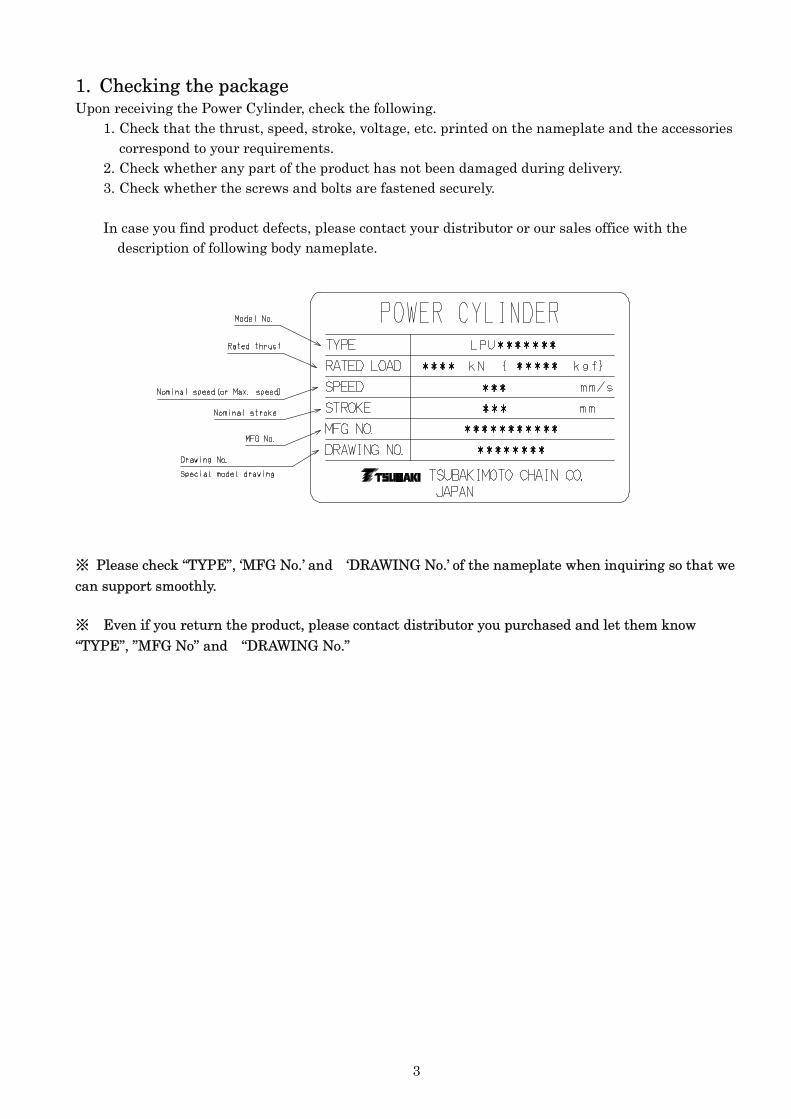
1. Checking the package Upon receiving the Power Cylinder, check the following.
1. Check that the thrust, speed, stroke, voltage, etc. printed on the nameplate and the accessories correspond to your requirements.
2. Check whether any part of the product has not been damaged during delivery. 3. Check whether the screws and bolts are fastened securely.
In case you find product defects, please contact your distributor or our sales office with the
description of following body nameplate.
※ Please check “TYPE”, ‘MFG No.’ and ‘DRAWING No.’ of the nameplate when inquiring so that we can support smoothly.
※ Even if you return the product, please contact distributor you purchased and let them know “TYPE”, ”MFG No” and “DRAWING No.”

4
2. Installation ★2-1. Installation position
Though Power Cylinder is an entirely enclosed structure, suitable for standard outdoor use, appropriate cover is required at all time in case of snow or thick vapor. For location exposed to sea breezes and salt, it is require for some specification such as painting specifications, structure of limit switch to be changed. Ambient temperature is usually –15 ℃ to +40℃. (Low temperature may cause poor performance.) When using out of this range, be sure to use an insulation cover. ※ In case of special specification, please confirm the final drawing because use conditions such a use environment or ambient temperature might be different.
★2-2. Direction Install the Power Cylinder onto your equipment in any direction you wish. ※ If the direction is specified on the final drawing, follow the instructions.
★2-3. Method of Installation
Use Trunnion or Clevis mounting. (see Fig.1) Do not tighten the outer tube of Power Cylinder from the outside in any mounting method. (see Fig.2) Apply grease to the Trunnion hole, the hole of Clevis and pin of the end fixture, when assembling. (except special specification with bush etc. ) Install the Trunnion pin or clevis and linkage pin to parallel direction.
トラニオンマウント クレビスマウント
Do not tighten
Fig. 1
Fig.2
Trunnion Mounting Clevis Mounting

5
★2-4. Prevention of rod rotation The rod builds up the rotational force along with the thrust. Prevent this rotation by using your equipment/ machine. The rotational torque generated by rod is shown in Table 1.
※ In case of the special specification, such as anti-rod rotation might be different from following table, so please confirm the final drawing.
Table 1
Type Stroke Rod rotational torque N・m {kgf・m}
LPUB6000 LPUC6000
500 – 1000 124{12.7}
1500 71{7.24}
LPUB8000 LPUC8000
500 – 1500 166{17.0}
LPUB12000 LPUC12000
500 – 1500 333{34.0}
2000 194{19.8}
LPUB12000 LPUC12000
500 – 2000 444{45.3}
LPUB22000 LPUC22000
500 – 2000 915{93.5}
LPUB32000 LPUC32000 500 – 2000 1109 { 113 }
LPUB50000 LPUC50000 500 – 2000 2166 { 221 }
6
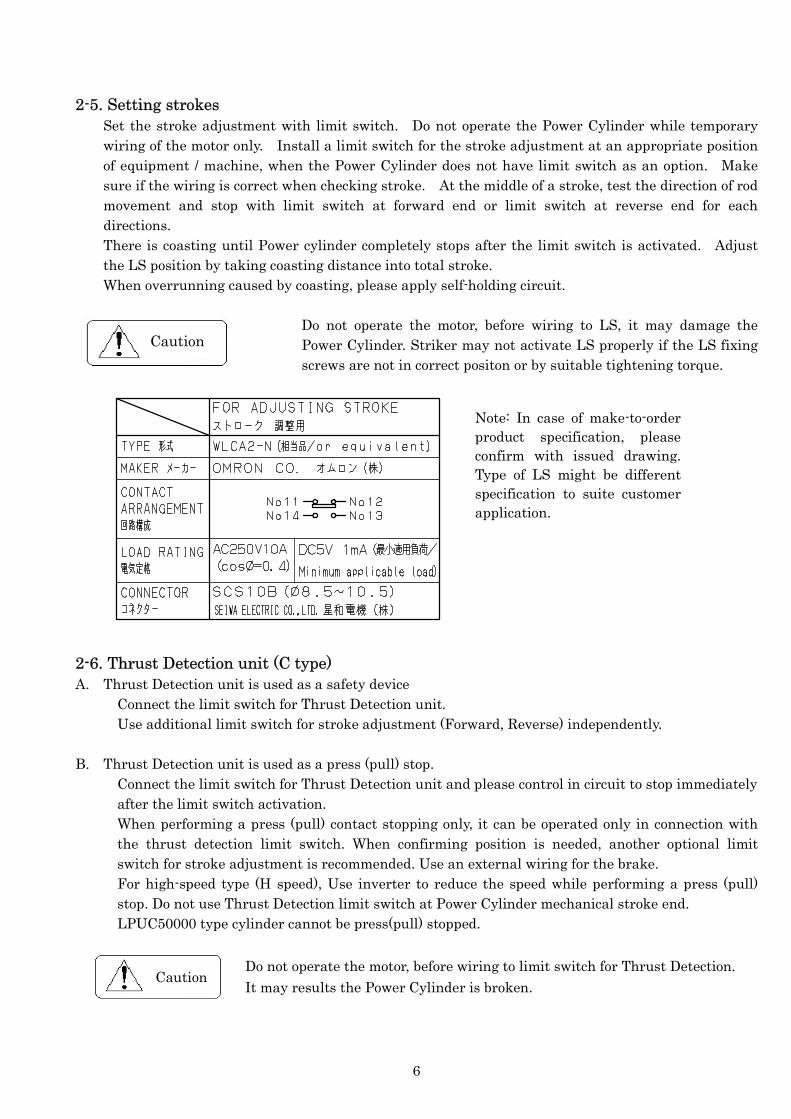
2-5. Setting strokes
Set the stroke adjustment with limit switch. Do not operate the Power Cylinder while temporary wiring of the motor only. Install a limit switch for the stroke adjustment at an appropriate position of equipment / machine, when the Power Cylinder does not have limit switch as an option. Make sure if the wiring is correct when checking stroke. At the middle of a stroke, test the direction of rod movement and stop with limit switch at forward end or limit switch at reverse end for each directions. There is coasting until Power cylinder completely stops after the limit switch is activated. Adjust the LS position by taking coasting distance into total stroke. When overrunning caused by coasting, please apply self-holding circuit.
Do not operate the motor, before wiring to LS, it may damage the Power Cylinder. Striker may not activate LS properly if the LS fixing screws are not in correct positon or by suitable tightening torque.
2-6. Thrust Detection unit (C type) A. Thrust Detection unit is used as a safety device
Connect the limit switch for Thrust Detection unit. Use additional limit switch for stroke adjustment (Forward, Reverse) independently.
B. Thrust Detection unit is used as a press (pull) stop. Connect the limit switch for Thrust Detection unit and please control in circuit to stop immediately after the limit switch activation. When performing a press (pull) contact stopping only, it can be operated only in connection with the thrust detection limit switch. When confirming position is needed, another optional limit switch for stroke adjustment is recommended. Use an external wiring for the brake. For high-speed type (H speed), Use inverter to reduce the speed while performing a press (pull) stop. Do not use Thrust Detection limit switch at Power Cylinder mechanical stroke end. LPUC50000 type cylinder cannot be press(pull) stopped.
Do not operate the motor, before wiring to limit switch for Thrust Detection.
unit. It may results the Power Cylinder is broken.
Caution
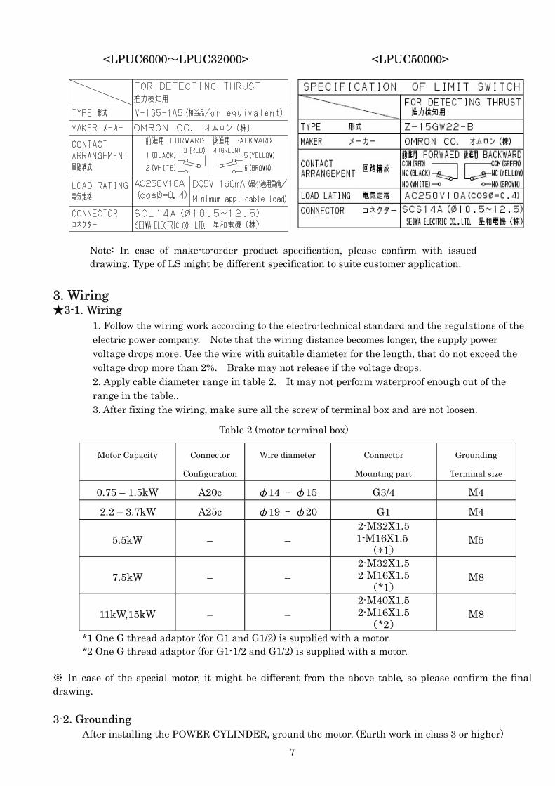
Note: In case of make-to-order product specification, please confirm with issued drawing. Type of LS might be different specification to suite customer application.
Caution
7
<LPUC6000~LPUC32000> <LPUC50000> 3. Wiring ★3-1. Wiring
1. Follow the wiring work according to the electro-technical standard and the regulations of the electric power company. Note that the wiring distance becomes longer, the supply power voltage drops more. Use the wire with suitable diameter for the length, that do not exceed the voltage drop more than 2%. Brake may not release if the voltage drops. 2. Apply cable diameter range in table 2. It may not perform waterproof enough out of the range in the table.. 3. After fixing the wiring, make sure all the screw of terminal box and are not loosen.
Motor Capacity Connector
Configuration
Wire diameter Connector
Mounting part
Grounding
Terminal size
0.75 – 1.5kW A20c φ14 – φ15 G3/4 M4
2.2 – 3.7kW A25c φ19 – φ20 G1 M4
5.5kW – – 2-M32X1.5 1-M16X1.5
(*1) M5
7.5kW – – 2-M32X1.5 2-M16X1.5
(*1) M8
11kW,15kW – – 2-M40X1.5 2-M16X1.5
(*2) M8
*1 One G thread adaptor (for G1 and G1/2) is supplied with a motor. *2 One G thread adaptor (for G1-1/2 and G1/2) is supplied with a motor. ※ In case of the special motor, it might be different from the above table, so please confirm the final drawing. 3-2. Grounding
After installing the POWER CYLINDER, ground the motor. (Earth work in class 3 or higher)
Note: In case of make-to-order product specification, please confirm with issued drawing. Type of LS might be different specification to suite customer application.
Table 2 (motor terminal box)

8
★3-3. Wiring motor and brake Confirm regulations of the power provider regarding switch and fuse
Type
LPU6000 S,L,M,H LPU8000 S,L,M LPU12000 L,M LPU16000 L LPU50000 L,M,H
LPU8000 H LPU12000 H LPU16000 M,H LPU22000 L,M,H LPU32000 L,M,H
Rod operational direction Extend Retract
Caution
Table 3 (Rod rotational direction)
* Rod operate direction is different from each power cylinder size and speed, please confirm Rod of POWER CYLINDER moves in the table 3 (normal wiring as wiring reference).
* Connect as ‘External wiring’ when the drawing specifies so.
* In case the special specification, it might be different connection from the above figure. Also extend and retract direction might be different from normal wiring. Please confirm
the final drawing.
5.5~15kW

9
★3-4. Wiring method when inverter is used
1. When the inverter drives the motor, it is necessary to use a separate power supply for the brake. When brake is connected as external power supply, remove the short piece, and then apply the normal power source to the brake. Do not source output power from the inverter.
2. For 200V class brake motor, use the electro-magnetic switch which rated load of AC250V, 7A and larger. For 400V class brake motor, use contact voltage of AC400 to 440V, inductive load of 1A and larger (ex. magnetic contactor for 2.2kW motor). The DC Module has a surge absorption protective element. Add necessary protective elements to each contact point.
3. If external DC wiring of 2.2, 3.7kW is required, please contact us.
※ In case of made-to-order product, please confirm the final drawing, the connection might not be same.
4. Caution before operation Confirm the following before operation 4-1. Wiring and Power source
Check whether the wiring is correct, especially the relation between the phase of motor (rotational direction) and limit switches for stroke adjustment. Set the rod at the middle of the stroke, turn on the power and check operational direction by inching drive. Make sure the forward button works for rod extend motion, and the limit switch works for stop, and the same for reverse motion. Do not operate the motor, before wiring to limit switch for Thrust Detection. It may results the Power Cylinder is broken.
4-2. Connection to the machine/equipment Make sure that there is no lateral load to the cylinder rod. In case Power Cylinder swings at all strokes, make sure the interference at the end fixture and the another portion.

10
5.General caution ★5-1. Manual operation
In case the rod is operated by manual handle, first rod to be free from all the load, and then turn the manual handle. Otherwise, the load force the rod turned and lead to accidents. Rod moves backward when the manual handle is turned CW, and moves forward when it’s turned CCW. Rod movement stroke per rotation by manual handle is shown in Table 4.
※ In case of made-to-order product, confirm the final drawing. Rod movement might not be same as following Table.
Some made-to-order products don’t have manual operating function.
Table 4 (Rod movement/manual handle rotation) ※ ‘with Interlock type’, made-to-order, refer to the diagram on final drawing or specification sheet The manual interlock has 2 types shown as below.
A. Cover type B. Handle type
Caution
When removing the cover from the body, LS works.
When inserting the handle to the manual shaft, the LS work.
Type of speed S L M H S L M H L M H L M H L M H L M H L M H
Rod movement
(mm)
LPUB50000
LPUC50000
0.3 0.5 0.6
LPUB16000
LPUC16000
LPUB22000
LPUC22000
2.9 3.2 3.51.7 2.3 1.2
Type of PowerCylinder
LPUB8000
1.0 0.7 1.0 1.21.2 0.8 1.2 1.7
LPUB12000
LPUC8000 LPUC12000
LPUB6000
LPUC6000
1.7 1.2 2.2
LPUB32000
LPUC32000
2.1 2.4 2.4
11
Caution
★5-2. Wet slip clutch (B type) It consists of 2 pieces of dish springs, which produce friction to hold the gear. When the torque exceeds the preset level, the gear slips, and works as overload protection. Torque is set when shipping, so no need to adjust. It is recommended to use with “Tsubaki Shock Relay” as an electrical overload protection device.
Maximum level of torque declines in case of long time slipping due to the wear of friction.
★5-3. Thrust detection unit (C type) Built with dish spring, it detects the thrust load axially. When the load exceeds the preset load, the axial movement of striker activates the limit switch. Adjustment by limit switch is set when shipping, so no need to adjust.
Limit switch for thrust load is set at factory, do not disassemble or adjust the position of Limit switch and striker. In case the LS or striker is moved, cylinder or equipment may be broken due to no activation of limit switch for thrust load. Please return the product to our factory if you need to maintenance or reconfiguration. The thrust detection cable is wired at factory. Wire color is referred on p.7 for the wiring.
Do not operate the motor, before wiring to limit switch for Thrust Detection.
It may results the Power Cylinder is broken. ※ Confirm with final drawing in case of the special specification with servo motor because the
protection device may not equipped for “A type”. ★5-4. Fluctuation of voltage and frequency
In case the input voltage and/ or frequency for motor is fluctuated and/or out of range of specified value, motor characteristic may vary. The motor is designed to withstand voltage fluctuation within approximately plus/ minus 10% of the rated voltage and frequency change within approximately plus/ minus 5%. In general, voltage is rather lower than the specified value, and in case the voltage drop is large, the following defects would happen. Be aware of the thickness, length of wire and the power source capacity shortage etc. so that the voltage drop would be minimized than specified value.
1. Brake is not released and motor cannot start. 2. Starting torque /thrust is not enough, and it’s hard to start up. 3. Less tolerable to overload 4. Overheat
※ Servo motor or special motor might be different from above.
Caution
Caution
12
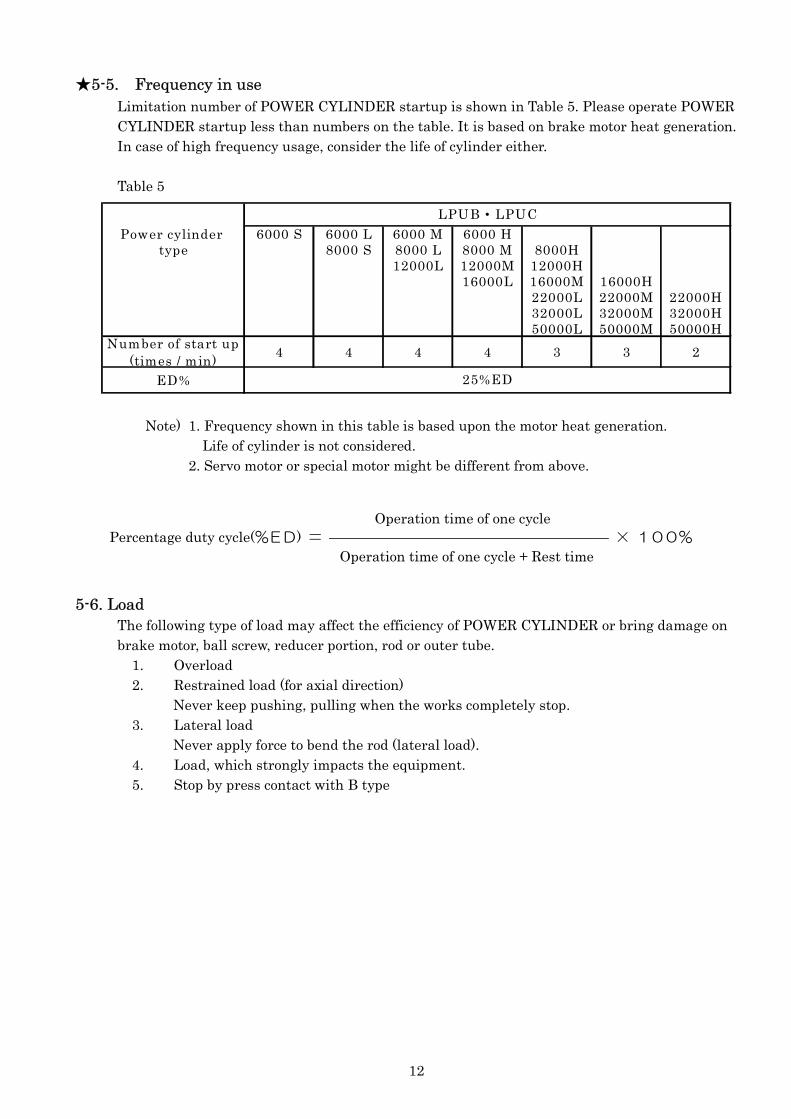
★5-5. Frequency in use Limitation number of POWER CYLINDER startup is shown in Table 5. Please operate POWER CYLINDER startup less than numbers on the table. It is based on brake motor heat generation. In case of high frequency usage, consider the life of cylinder either. Table 5
Note) 1. Frequency shown in this table is based upon the motor heat generation.
Life of cylinder is not considered. 2. Servo motor or special motor might be different from above.
5-6. Load The following type of load may affect the efficiency of POWER CYLINDER or bring damage on brake motor, ball screw, reducer portion, rod or outer tube.
1. Overload 2. Restrained load (for axial direction)
Never keep pushing, pulling when the works completely stop. 3. Lateral load
Never apply force to bend the rod (lateral load). 4. Load, which strongly impacts the equipment. 5. Stop by press contact with B type
Operation time of one cycle Percentage duty cycle(%ED) = ———————————————————— × 100% Operation time of one cycle + Rest time
Power cylinder 6000 S 6000 L 6000 M 6000 Htype 8000 S 8000 L 8000 M 8000H
12000L 12000M 12000H16000L 16000M 16000H
22000L 22000M 22000H32000L 32000M 32000H50000L 50000M 50000H
Number of start up(times / min)
4 4 4 4 3 3 2
ED% 25%ED
LPUB・LPUC
13
6. Maintenance ★6-1. Grease up the actuator / screw
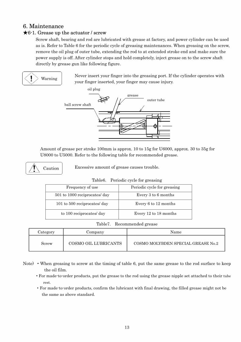
Screw shaft, bearing and rod are lubricated with grease at factory, and power cylinder can be used as is. Refer to Table 6 for the periodic cycle of greasing maintenances. When greasing on the screw, remove the oil plug of outer tube, extending the rod to at extended stroke end and make sure the power supply is off. After cylinder stops and hold completely, inject grease on to the screw shaft directly by grease gun like following figure.
Never insert your finger into the greasing port. If the cylinder operates with your finger inserted, your finger may cause injury.
Amount of grease per stroke 100mm is approx. 10 to 15g for U6000, approx. 30 to 35g for U8000 to U5000. Refer to the following table for recommended grease.
Excessive amount of grease causes trouble.
Table6. Periodic cycle for greasing
Frequency of use Periodic cycle for greasing
501 to 1000 reciprocates/ day Every 3 to 6 months
101 to 500 reciprocates/ day Every 6 to 12 months
to 100 reciprocates/ day Every 12 to 18 months
Table7. Recommended grease
Category Company Name
Screw COSMO OIL LUBRICANTS COSMO MOLYBDEN SPECIAL GREASE No.2
Note) ・When greasing to screw at the timing of table 6, put the same grease to the rod surface to keep the oil film.
・For made-to-order products, put the grease to the rod using the grease nipple set attached to their tube
rest. ・For made-to-order products, confirm the lubricant with final drawing, the filled grease might not be
the same as above standard.
Warning
Caution
outer tube grease
ball screw shaft
oil plug

14
★6-2. Grease in gear housing
Gear is lubricated at factory and it is not necessary to grease maintenance. Following types of grease are used.
1. Planetary gear portion: Sumitomo Mineral Molygear No.1 2. Helical, spur gear portion: Idemitsu Daphne Eponex SR No. 1 ※ In case of the made-to order type, confirm with the final drawing, used grease might not be same
as above. ★6-3. Trouble shooting
Refer to the following table in case of trouble.
Table 8
Trouble Possible Cause Action
Does not work even if the start button is pressed
1. Wrong wiring of motor, limit switch, control unit.
2. Disconnection of motor starter or wire and lead wire.
3. Failure of the electro-magnetic contactor, control unit.
4. Failure of limit switch.
Check wiring. Repair and replace. Repair. Replace.
Does not rotate even though the motor sounds like running.
1. Single phase operation. 2. Voltage drop in power source. 3. Too much stroke of electromagnet of brake. 4. Burn out of brake lining. 5. Slip of torque limiter (B type).
Check the wiring. Increase power source capacity, consider power source size. Adjustment. Replace. Adjust and replace the friction facing.
Does not generate specified thrust.
1. Voltage drop in power source. 2. Decrease of the setting of torque limiter (B type). 3. Bad connection of equipment. 4. Failure of brake release
Increase capacity of power source, Consider power source size. Adjust and replace the friction facing. Repair. Adjust the gap or replace
Unable to stop accurately.
1. Wear of brake lining. 2. Oil, water penetration to friction facing of the brake. 3. Change the lining. 4. Forget manual brake release. 5. Excessive load.
Adjust. Replace the friction facing. Disassemble and cleanup. Replace the friction facing. Run in. Set the correct position. Reduce the load, consider the capacity.
Motor is overheated. 1. Excessive load. 2. Too much frequency.
Reduce the load, consider the capacity. Consider the capacity.
Damage to the equipment.
1. Impact load. 2. Lateral load. 3. Too much usage.
Repair. Repair. Repair
15
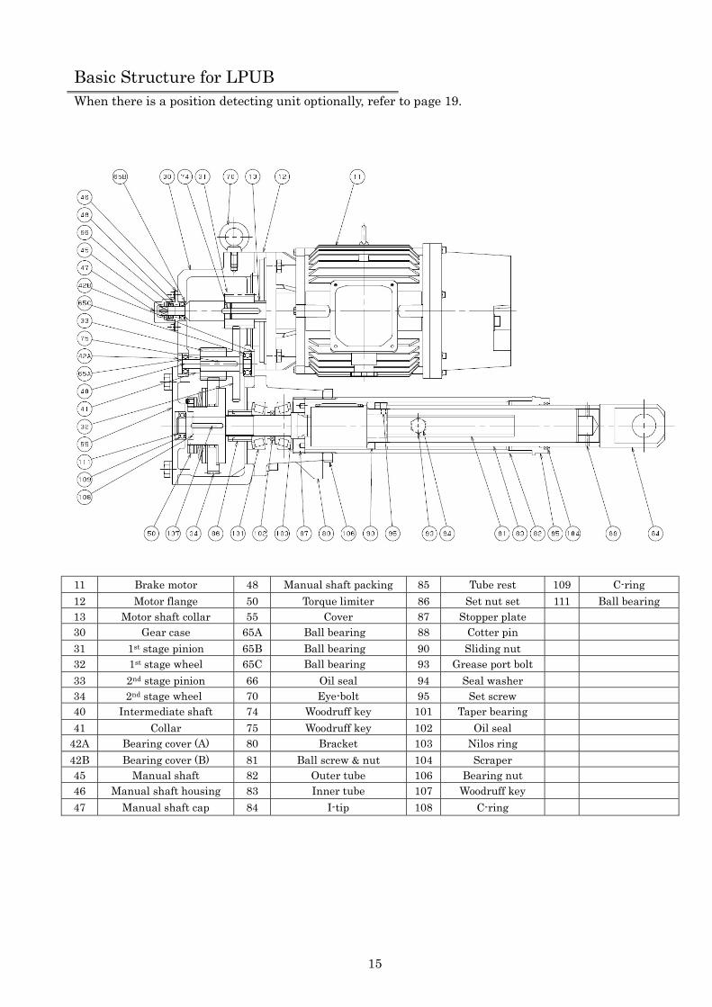
Basic Structure for LPUB When there is a position detecting unit optionally, refer to page 19.
11 Brake motor 48 Manual shaft packing 85 Tube rest 109 C-ring
12 Motor flange 50 Torque limiter 86 Set nut set 111 Ball bearing 13 Motor shaft collar 55 Cover 87 Stopper plate 30 Gear case 65A Ball bearing 88 Cotter pin
31 1st stage pinion 65B Ball bearing 90 Sliding nut 32 1st stage wheel 65C Ball bearing 93 Grease port bolt
33 2nd stage pinion 66 Oil seal 94 Seal washer 34 2nd stage wheel 70 Eye-bolt 95 Set screw 40 Intermediate shaft 74 Woodruff key 101 Taper bearing
41 Collar 75 Woodruff key 102 Oil seal 42A Bearing cover (A) 80 Bracket 103 Nilos ring
42B Bearing cover (B) 81 Ball screw & nut 104 Scraper 45 Manual shaft 82 Outer tube 106 Bearing nut 46 Manual shaft housing 83 Inner tube 107 Woodruff key
47 Manual shaft cap 84 I-tip 108 C-ring

16
Basic Structure for LPUC When there is a position detecting unit optionally, refer to page 19.
11 Brake motor 48 Manual shaft packing 87 Stopper plate 117 Brearing holder 154 LS case packing
12 Motor flange 55 Cover 88 Cotter pin 118 C-ring 155 LS cover packing
13 Motor shaft collar 56 Bush 90 Sliding nut 130 Bracket 160 SKY packing
30 Gear case 65A Ball bearing 93 Grease port bolt 131 Bearing holder(A) 161 Micro switch
31 1st
stage pinion 65B Ball bearing 94 Seal washer 132 Bearing holder(B) 162 Terminal stand
32 1st
stage wheel 65C Ball bearing 95 Set screw 133 Bearing holder(C) 170 Connector
33 2nd
stage pinion 66 Oil seal 101 Taper bearing 134 Ball screw & nut 180 Rolled bushing
34 2nd
stage wheel 70 Eye-bolt 102 Oil seal 135 Spring stopper
40 Intermediate shaft 74 Woodruff key 103 Nilos ring 138 Dish spring unit
41 Collar 75 Woodruff key 104 Scraper 139 Spring collar
42A Bearing cover (A) 82 Outer tube 106 Bearing nut 140 LS ring
42B Bearing cover (B) 83 Inner tube 107 Woodruff key 150 LS case
45 Manual shaft 84 I-tio 108 C-ring 151 Striker
46 Manual shaft housing 85 Tube rest 109 C-ring 152 Striker base
47 Manual shaft cap 86 Set nut set 111 Ball bearing 153 LS cover

17
Planetary gear unit for LPUB(C)
14A MA case(A)
14B MA case(B)
15 Motor joint
16 Planetary gear
21 Oil seal
22 Ball bearing
23A C-ring
23B C-ring
31 1st stage pinion
45 Manual shaft
74 Woodruff key

18
External Limit switch for stroke adjustment (B, C type) ◆LPU8000 and smaller
◆LPU12000 and larger
◆More than LPU12000
201 LS flange 1 212 Sems screw M4×6 2202 Coupler 1 213 Hexagon nut M10 3
203 Striker 1 214 Spring washer For M10 3
204 LS rod fixing piece 2 215 Washer For M10 3
205 LS mounting base 2 216 Set screw M5×10 3
206 LS tightening piece 6 217 Set screw M6×10 3
207 LS support rod 1 218 Sems screw M5×45 8
208 LS rod A 1 219 Countersunk screw M5×10 4209 LS rod B 1 220 Limit switch WLCA2-N 2
210 LS stopper 2 221 Connector SCS10B 2
211 Square set screw M10×22 2
201 LS flange 1202 Coupler 1 213 Hexagon nut M10 10
203 Striker 1 214 Spring washer For M10 10
215 Washer For M10 1
205 LS mounting base 2 216 Set screw M8×12 4
217 Set screw M10×20 3
207 LS support rod 4 218 Sems screw M6×20 8
219 Countersunk screw M6×12 6209 LS rod B 1 220 Limit switch WLCA2-N 2
210 LS stopper 2 221 Connector SCS10B 2

19
7. Structure of Position detection unit Position detection unit can include up to three types of position detection device at the same time.
Micro switch: 4 pieces. Potentiometer: 1 pc. Rotary encoder: 1 pc.
7-1. Structure
Following shows the unit diagram consisting of micro switch, potentiometer and rotary encoder.
7-2. General caution 1) Adjust the stroke position by micro switch after installing Power Cylinder on equipment.
Micro switch function is tested at factory assemble, but stroke positon by micro switch is not adjusted. Never rotate the rod with fixed screw shaft after the stroke adjustment.
2) Position detection unit consists of precision parts. Never apply shock or vibration. 3) Never rotate LS cam strongly after fixing it by the set of screws. Otherwise, built in reducer
can break. 4) When the LS cam overruns micro switch by coasting, please take a self-hold on the circuit.
Cam Potentiometer Gear head
Screw
Rotary Encoder
Micro Switch LS 4 Connector Micro Switch LS3
Micro Switch LS1 Micro Switch LS2
Terminal
Caution Do not operate the motor, before wiring to Limit Switch for Thrust Detection unit. It may results the Power Cylinder is broken.
Upinion

20
★7-3. Connection 1) Use the bottom half of terminal block (“wiring side by customer”) in the unit for the
connection to each detector. Connection of each detector to terminal block is previously completed.
2) In case of long distance wiring, signal loss can get worse. 3) Make sure to ground the shield wire of the detector unit and signal. 4) Locate the signal and power line separately. Put noise filter, shield the signal line, in case
there is a source of noise. (Use shield wire for wiring rotary encoder.) 5) Use suitable diameter of cable, which corresponds to the connector of position detection unit.
In case of smaller diameter cable or bulk cable, waterproof is poor. Applicable cable diameter: SCL14B (12.5 to 14.5 mm dia.)
6) In case of wiring in rain or other wet environment, avoid water from entering the position detection unit. It will damage the product.
7) After connection, confirm that be sure to the bolt for the cover mounting is tighten. Special pay attention if using under the water environment.
When leaving it while tentative wiring, cover it with vinyl sheet etc. in order to protect from rain, water, or moisture. If it is stored in a place prone to sudden temperature change, dew condensation may cause damage or rust.
Caution
Wiring side by customer
Potentiometer is connected from back side
Caution ! The back of terminal has printed board. It is wired as broken line.
Pre-wired by Tsubaki
Pre-wired side Terminal

21
LS cam
Set screw
★7-4. Specification of each position detector Micro switch (Option code: K2 or K4)
※ In case of the special specification, confirm the final drawing because model number, specification or the number might be different.
Setting of internal LS (Option code: K2 or K4) 2 or 4 pieces of micro switches as internal LS can be installed in the position detection unit. Rotation of screw is transferred to cam rotational angle through reduction unit, and stroke is adjusted by cam and micro switches. 1. Make sure the connection is correct when adjusting the stroke. 2. At the middle of the stroke, make sure the micro switch for forward end is activated by cam
and stopped by pushing the rod forward. The micro switch for backward end is activated by cam and stopped by pulling the rod backward.
3. There is a coast until rod stops after micro switch is activated. Take this coast into consideration when adjusting the position by micro switch.
4. Rotary cam is fixed to the shaft, which is directly connected to the reducer with 2 pieces of setscrew. Loosen these 2 pieces of screws and rotate the cam when adjusting. Built in reducer can be broken, if the cam is rotated without loosening these set screws. Use hex wrench, “named 2”.
5. Set the cam in order from the inmost. (Backside of the cam cannot move if you set its front side first.) Tighten the setscrew after setting.
Potentiometer (Option code: P)
1. Potentiometer is set at half of the resistance (500 ohm) at the middle of the stroke, unless otherwise specified.
2. Never rotate the rod during transportation or installation; otherwise the relation between the stroke and resistance can get out of control. When the resistance is incorrect, reset 500 ohm at the middle of stroke.
※Potentiometer output the stroke of the POWER CYLINDER as the change of the value of resistance. ※In case of the special specification, confirm the final drawing because model number, specification or the number might be different.
Specif ication of micro switch
Type D2VW-5L2A-1M or equivalent
Maker OMRON
Contact
Configuration
LS1 LS2 LS3 LS4
Capacity AC250V4A (COSφ=0.7)
Potentiometer Specification
Terminal #
Type CP-30
Maker Sakae
Total
resistance 1.0kΩ
Power rating 0.75W
Insulation
rating
AC1000V
(1min )
Effective
electrical
angle
355°
Effective
angle of
rotation
360°
(infinite)
(17) (18) (4) (8)
(7) (4) (6) (5) (4) (15)
(16) (4) ( )shows terminal #
P1
(1) P3
(3)
P2 (2) Rod Forward
( ) shows terminal #

22
Rotary encoder (Option code: R)
Output is set at 10 pulses per stroke 1 mm. Output connection
※Use with an equipment like sequencer or program controller, which controls the stroke as a digital signal.
1. Incremental type encoder is built in for standard unit. 2. It is possible to set an accurate home position of the machine in combination with a limit
switch because home position output is read out every 600 pulses. 3. Because the output is open collector type,output signal can be obtained when connected to a
pull up resistor. Output voltage for signal 1 and 2: “H” is “(supply voltage - 1)V or more” “L” is “1V or less”. Reference for pull up resistance: DC 5V: 220Ω / DC12V: 470Ω / DC24V:1kΩ
4. Rotary encoder is a precision instrument. Never apply vibration or shock. 5. Use shield wire for wiring of rotary encoder.
Encoder Specification Type TS5305N251 Maker Tamagawa Seiki Co., Ltd Output pulse
600C / T
Output form
Open collector output
Output wave
90° phase difference, 2 phase square wave,- home
position signal
Output voltage
H - L 1V or less
Power supply
DC5V to 24V 100mA or less
Signal 1 Signal 2 Signal Z +5 to 24V 0V Case
(9) (10) (11) (12) (13) (14)
Output circuit
( ) represents the terminal number.
Output wave form
Signal 1
Signal 2
Signal Z
Extending

23
8. Reference circuit Following shows reference circuit with thrust detection LS and external LS. Please confer with us if motor capacity or optional control devices are different.
LS01: Stroke adjusting external limit switch for extending LS21: Thrust detecting limit switch for extending LS02: Stroke adjusting external limit switch for retracting LS22: Thrust detecting limit switch for retracting
NOTE: 1) This diagram is an example when the thrust detecting limit switch is used for overload
protection. 2) This diagram shows a single-acting circuit. When using in an inching circuit, remove wire
connection between N1 and N2, N3 and N4 and short-circuit the PBS. 3) If the power source voltage for the motor is different from the control voltage, place a
transformer into a portion in the diagram. 4) The lead wires B1 and B2 for the brake are connected to the motor terminal blocks U and W
using short piece. 5) When individually turning off the brake, remove the short piece and apply a normal power
source voltage other than inverter output to B1 and B2 from the outside.
power supply
Brake motor
(ex. 3.7kW, brake internal wiring)
short piece
short piece
power
module
Caution In order to stop the cylinder immediately, please take a circuit to reduce the electrical time lag.
※If the electrical time lag is large, the cylinder stops will be delayed, and damage to equipment or shorter life may occur.

24
9. Brake motor ★9-1. 0.75, 1.5kW, 2.2 kW
It is usually sufficient to monitor the operational status of the brake, but be aware of the following while brake function is not well:
This brake works with friction force between the brake plate⑥, the armature③ and the lining⑤, brake lining will be worn while operation. It is necessary to change brake plate⑥, the armature③ and the lining⑤after 3 times of ‘Gap adjustments’.
It is necessary to clean up the brake every 6 months because it will have wear of dust and particles due to the brake operation.
(1) Brake structure
(2) Brake inspection and gap adjustment
1) Loosen the bolts⑧ for brake cover and remove the brake cover⑨. 2) Tighten Adjustable nuts⑩ (3 pcs.) clockwise, and adjust the gap to range listed below with
verifying the gap dimensions with a thickness gauge. Check the gap at several points along the circumference to be the Fixed core④ and Armature③ are parallel to each other, then apply locking agent. (Do not repeat loosening and tightening, the adjustable nuts⑩ may damage to the nuts and lose locking effect.)
【Note】 ・Before tightening the adjustable nuts⑩, insert the hexagon socket screw key into the hexagon
socket of the guide bolt so that the guide bolt may not come loose by rotating together. ・Replace with a new adjustable nut⑩ if the adjustable nut⑩ is removed or repeatedly
tightened and loosened. (Size 0.75kW:M5×P0.8, 1.5,2,2kW:M8×P1.25 ) Remove grease from the guide bolt⑬ and the adjustable nut⑩, and apply anti-loosening liquid in this case. Do not take down the brake because it may make reassembly impossible and incorrect reassembly may lead to a brake malfunction.
⑥Brake plate ⑦Seal washer ⑧Bolts for brake cover ⑨Brake cover ⑩Adjustable nuts ⑪Hub
① Bolts for manual release (+Pan head machine screw)
② Double nuts ③ Armature ④ Fixed core ⑤ Lining
⑫Water proof packing ⑬Guide bolt
Gap
External gap

25
3) After adjusting the gap, make sure the brake operates normally by connecting to power source. Observe the gap is appropriate to prevent the armature③, brake plate⑥ and lining⑤ from contacting during rotation. If they do come in contact, readjust the gap.
4) Attach the brake cover⑨ with bolts⑧.
Motor kW 0.75kW 1.5kW 2.2Kw
Brake Type 200V SLB07LP SLB15LP SLB22LP 400V SLB07LPV SLB15LPV SLB22LPV
Initial lining (mm) 8 9 Lining limit (mm) 7 8
Gap standard (mm)
0.15~0.20 (1.05~1.10)
0.2~0.25 (1.10~1.15)
Gap limit (mm)
0.5 (1.4)
0.5 (1.4)
(3) Manual release operation
Carry out the following steps to release the brake manually, or without connecting to power source. Make sure to release manually when no load is applied to the screw shaft and nut. 1) Loosen the double nuts② by the bolts① placed for manual release (2 pcs.). 2) Tighten the bolts① for manual release (2 pcs.) gradually by hand or with a Phillips driver
until they hit the armature③. After they hit the armature③, completely tighten the bolts① with a Phillips driver(Complete rotation is approx. 45°).
【Note】Do not tighten the bolts forcefully. Otherwise, the armature may deform and bolts or female screws at cover may be damaged, which will lead to brake failure. 3) In the above operation, the lining⑤ is released from the armature③ and brake plate⑥,
allowing the braking force to be removed. However, the braking force is not removed depending on the individuality. In that case, tighten the bolts① again to 45°with a Phillips driver.
4) When setting back to regular braking condition, loosen the bolts① (3 rotations) until they reach the bolt projection lengths (see (1) Brake structure) or the further and tighten the double nuts② to the extent that the rubber of the seal washer⑦ deforms (Reference tightening torque: 4.9Nm). When these steps are completed, make sure the brake works normally with motor.
【Note】Securely tighten the double nuts②. Otherwise, the sealing for brake cover may not perform efficiently.
( )External gap value

26
★9-2. 3.7kW It is usually sufficient to monitor the operational status of the brake, but be aware of the following while brake function is not well:
The brake lining becomes worn and brake toque will be lower, due to the force of friction between the brake plate⑪, the armature④ and the lining⑤. It is necessary to change the lining in case the thickness will become below limit.
It is necessary to clean up every 6 months the brake lining wear.
(1) Brake structure
(2) Brake inspection and gap adjustment It is necessary to adjust the gap when the thickness of lining and gap reach limit, otherwise brake will
be not able to function well. Depending on usage condition, the lining and gap may reach to limit, Lining limit as following.
Brake gap and lining limit
⑦ Yoke ⑦ Stud bolts ⑬ Hub ② Coil ⑧ Liner ⑭ Silencer fitting ③ Spring ⑨ Distance collar ⑮ O-ring ④ Armature ⑩ Hexagon nut ⑯ Brake cover ⑤ Lining ⑪ Brake plate ⑰ Clip ⑥ Bracket ⑫ Water proof packing ⑱ Key
Motor kw 3.7kW(200V) 3.7kW(400V) Brake type VNB371K(NB-31186) VNB371K(NB-31187)
Initial lining (mm) 12.0 Lining limit (mm) 9.6
Gap standard (mm) 0.3 Gap limit (mm) 0.6

27
Brake gap measurement
Gap adjustment procedure 1) Remove the brake cover⑯.
Insert the hexagon bolts (Please prepare M8X50) into holes (2 pcs.) for manual release on Yoke①. Tighten the bolts to fix the yoke① and the armature④.
【Note】In case of separate the yoke① and the armature④, the brake spring and O-ring will comes out. It is difficult to reassemble.
【Note】Attached brake release screw (M8X70L) is not available to fix Yoke① and Armature④
2) Remove the hexagon nut⑩ and pull the yoke①. 【Note】The yoke① has wire connection with motor, please handle carefully not to damage the
wire.
Brake gap
Bolt holes for manual release
28
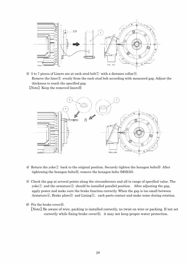
3) 5 to 7 pieces of Liners are at each stud bolt⑦ with a distance collar⑨.
Remove the liner⑧ evenly from the each stud bolt according with measured gap. Adjust the thickness to reach the specified gap.
【Note】Keep the removed liners⑧
4) Return the yoke① back to the original position. Securely tighten the hexagon bolts⑩ After tightening the hexagon bolts⑩, remove the hexagon bolts (M8X50).
5) Check the gap at several points along the circumference and all in range of specified value. The
yoke① and the armature③ should be installed parallel position. After adjusting the gap, apply power and make sure the brake function correctly. When the gap is too small between Armature④, Brake plate⑪ and Lining⑤, each parts contact and make noise during rotation.
6) Fix the brake cover⑯.
【Note】Be aware of wire, packing is installed correctly, no twist on wire or packing. If not set correctly while fixing brake cover⑯, it may not keep proper water protection.

29
(3) Manual release operation Conduct the following when the brake is released manually. Do not turn on the brake power and Never apply any load to the rod when releasing the brake manually.
1) Remove the sealing bolts (2pcs) with M10 seal washer. (Figure1) 2) Inset the bolts for manual release (M8X70L) attached with motor in two positions and tighten it into
the screw hole in the cover. (Figure2) 3) The head surface of release screw hits the end. Keep tighten the bolts another 90°after it becomes
heavy, brake will be released. 【Note】Do not tighten the bolts too much. Otherwise, the armature may deform and bolts or female
screws at cover may be damaged, which will lead to break failure. 4) When setting back to regular braking condition, remove the bolts for manual release (M8X70L).
When these steps are completed, make sure works normally with motor. 【Note】Securely tighten the sealing bolts. Otherwise, the sealing for brake cover may not perform
efficiently, water may enter the brake.
(Figure1)
(Figure2)
Sealing bolt(Hexagon nut) M10(with seal washer)
Bolts for manual release(Hexagon bolt attached motor)M8 × 70

30
9-3. 5.5kW to 15kW It is usually sufficient to monitor the operational status of the brake on your own, but please be aware of the following:
The brake lining becomes worn because of the force of friction between the brake disc[68]and the pressure plate[49]. It is necessary to change the lining after 4 to 6 times ‘wear adjustments’. It is necessary to clean up the brake every 6 months because it accumulates a lot of dust and particles due to the continuous wearing of the brake lining (1) Brake Structure
●5.5、7.5kW(Brake type: BE11)
[49] Pressure plate [65] Pressure ring [276] Brake spring(blue)
[50] Brake spring (normal) [66] Sealing strip [702] Friction disk [54] Magnet body, complete [67] Counter spring [718] Damping spring [60] Stud [68] Brake disk [61] Hex nut [69] Circular spring

31
●11,15kW(Brake type: BE20)
(2) Brake inspection and gap adjustment 1) Remove the fan cover. 2) Push the sealing strip [66] aside and vacuum off any abrasion. 3) Measure the brake disc [68]. In the case the thickness of the brake disc is lower than minimum
thickness and the surface roughness of lining markedly progress, replace the brake disc. (Minimum brake disk thickness, see the below chapter)
4) Measure the working air gap A. Use a thickness gauge and measure at three points offset by 120°) (see the following figure)
・5.5、7.5kW(BE11): between Pressure plate [49] and Damping spring [718] ・11kW(BE20): between Pressure plate [49] and Magnet body [54]
5) Tighten the hex nuts [61] until the working air gap is set correctly.
[28] Closing cap [61] Adjusting nut [69] Circular spring [49] Pressure plate [65] Pressure ring [276] Brake spring(blue)
[50] Brake spring (normal) [66] Sealing strip [702] Friction disk [54] Magnet body, complete [67] Counter spring [60] Stud [68] Brake disk
Working air gap [mm] Brake disc [mm] Min thickness Min MAX
0.3 1.2 10.0

32
6) Set the floating clearance [S] between the conical coil springs (pressed flat) and the setting nuts (see the following figure). The floating clearance requires moving on with any abrasion of brake lining. If this clearance will be shortage the brake does not work correctly.
7) Attach the sealing strip [66] and Reinstall the removed parts.
Floating clearance S [mm] 2.0
(3) Manual Release Operation Conduct the following in case the brake is released manually without turning on the brake power.
Never apply any load to the rod when releasing it manually.
When the brake is not excited the brake disc [1] is fastened and pressed against the press plate [5] by the spring force [4] of brake spring [6]. When the brake coil is excited by connecting power source
The brake disc [1] operates with space of the working air gap A because the brake coil vacuums the press plate [5] by electromagnetic power [10].
In case of manual brake release, tighten the brake release screw [12] to the brake release equipment. The brake release lever moves to the fan side. The disc brake operates since the press plate [5] is vacuumed to the brake coil side. Attach the brake release screw to the motor
[ 1 ] Brake disc [ 8 ] Magnet [ 2 ] Friction disc [ 9 ] Motor shaft [ 3 ] Driver [ 10 ] Electromagnetic power [ 4 ] Spring force [ 11 ] Brake release lever [ 5 ] Press plate [ 12 ] Brake release screw [ 6 ] Brake spring [ A ] Working air gap [ 7 ] Brake coil [ S ] Floating clearance
Brake release equipment (Screw type)
33
10. Warranty 10-1. Warranty period without charge
18 months effective the date of shipment or 12 months effective the first use of Goods, including installation of Goods to Buyer’s equipment or machines - whichever comes first.
10-2. Warranty coverage
Should any damage or problem with the Goods arise within the warranty period, given that the Goods were operated and maintained under instructions provided in the manual, Seller would repair and replace at no charge once the Goods are returned to Seller. The following are excluded from the warranty.
1) Any cost related to removal or re-installation of Goods from the Buyer’s equipment or machines to repair or replace parts.
2) Cost to transport Buyer’s equipment or machines to the Buyer’s repair shop. 3) Costs to reimburse any profit loss due to any repair or damage and consequential losses
caused by the Buyer.
10-3. Warranty with charge Seller will charge any investigation and repair of Goods caused by: 1) Improper installation by failing to follow the instruction manual. 2) Insufficient maintenance or improper operation by the Buyer. 3) Incorrect installation of Goods into other equipment or machines. 4) Structure change of the Goods by any modifications or alterations by the Buyer. 5) Any repair by engineers other than the Seller or those designated by the Seller. 6) Operation in inappropriate environment not specified in the manual. 7) Force Majeure or forces beyond the Seller’s control such as natural disaster and injustice done
by third party. 8) Secondary damage or problem incurred by the Buyer’s equipment or machines. 9) Defected parts supplied, or specified by the Buyer. 10) Incorrect wiring or parameter setting by the Buyer. 11) The end of life cycle of the Goods under normal use condition. 12) Losses or damages not liable to the Seller
10-4. Dispatch the Seller’s engineer
Service to dispatch Seller’s engineer for investigation, adjustment or trial testing, etc. of Seller’s Goods are at Buyer’s expense.

TSUBAKI POWER CYLINDER
China RoHS Instruction
本资料是中国R0HS的必备资料 (China RoHS requisite document)
LPUB、LPUC、LPUA
零部件名称
(Part Name)
有害有毒物质或者元素 (Hazardous Substances or Elements)
铅
(Pb)
汞
(Hg)
镉
(Cd)
六价铬
(Cr(Ⅵ))
多溴联苯
(PBB)
多溴二苯醚
(PBDE)
电动机
(Motor) × ○ ○ ○ ○ ○
铝制推力检测箱体 (Aluminum Case for a Thrust detecting mechanism)
× ○ ○ ○ ○ ○
位置检测装置
(Position Detecting Unit) × ○ ○ ○ ○ ○
外接限位开关部的铝制零部件 (Aluminum Parts of Stroke adjusting external LS)
× ○ ○ ○ ○ ○
本表格依据SJ/T 11364 的规定编制
(This document is prepared in conformity with SJ/T 11364.)
○:表示该有害物质在该部件所有均质材料中的含量均在GB/T 26572规定的限量要求以下
(Show that the concentration of the hazardous substance does not exceed the concentration limits
specified in GB/T 26572.)
×:表示该有害物质至少在该部件的某一均质材料中的含量超出 GB/T 26572规定的限量要求
(Show that the concentration of the hazardous substance exceed the concentration limits specified in
GB/T 26572.)

TSUBAKIMOTO CHAIN CO. 1-1, Kohtari-Kuresumi, Nagaokakyo
Kyoto 617- 0833, Japan
Internet : http://tsubakimoto.com/
Global Associated Partners:
Tsubakimoto Singapore Pte. Ltd.
http://tsubaki.sg/
U.S. Tsubaki Power Transmission, LLC
http://www.ustsubaki.com/
Taiwan Tsubakimoto Co.
http://tsubakimoto.com.tw/
Tsubaki of Canada Limited
http://tsubaki.ca/
Tsubakimoto Chain (Shanghai) Co., Ltd.
http://tsubaki.cn/
Tsubaki Australia Pty. Limited
http://tsubaki.com.au/
Tsubakimoto Europe B.V.
http://tsubaki.eu/
Tsubakimoto U.K. Ltd.
http://tsubaki.eu/