tt-3020c/tt-3022d maritime/fisheries capsat transceiver
TRANSCRIPT
TT-3020C/TT-3022D
Maritime/FisheriesCapsat Transceiver
for theInmarsat-C Network
Technical Reference Manual
Version A
© Copyright Thrane & Thrane A/S. June 1996Tobaksvejen 23, DK-2860 Soeborg. Denmark
Information in this document is subject to change without noticeand does not represent a commitment on the part of Thrane & ThraneA/S.
© 1996 Thrane & Thrane A/S. All right reserved. Printed inDenmark.
Document Number TT-99-107311-A Release Date: 11MAR97
Thrane & ThraneTT-3020C/TT-3022D Capsat Transceiver
Technical Reference Manual
11MAR97 Page i
Table of Contents
1. Introduction 1
2. Maritime facilities 3
2.1 Scanning and Login 3
2.2 Distress 3
2.3 Link Test 3
2.4 Message transmission 4
2.5 EGC message reception 4
3. System Generation 5
3.1 Alteration of the System Parameters 53.1.1 TT-3606A Message Terminal 53.1.2 IBM Compatible PC 53.1.3 Computerised equipment/handheld terminals6
3.2 Entering your mobile number 6
3.3 Initialise System Parameters 6
4. Optional GPS 8
4.1 Introduction to the GPS System 8
4.2 The GPS Module 94.2.1 Feature list 10
4.3 Satellite Navigation 10
4.4 Almanac 114.4.1 Error Outputs 12
5. Transceiver Software Details 14
5.1 EGC Message header format 14
5.2 Baudot Characters 17
5.3 Use of the Transceiver built-in speaker 18
6. Front Panel 19
7. Interfaces 20
7.1 DC input (X1) 207.1.1 On/Off features 22
7.2 Antenna connector (X2) 22
7.3 DTE interface (X3) 23
7.4 I/O interface (X4) 257.4.1 ArcNet 26
Thrane & ThraneTT-3020C/TT-3022D Capsat TransceiverTechnical Reference Manual
Page ii 11MAR97
7.5 Printer interface (X5) 27
8. Capsat Transceiver Service 29
8.1 Service 298.1.1 Main Board 298.1.2 Power supply 318.1.3 Optional GPS Module 328.1.3.1 Test Summary Word 32
8.2 Fault diagnostics 34
8.3 Replacements 358.3.1 How to replace the Main Board 358.3.2 How to replace the Power Supply board 368.3.3 How to install/replace the optional GPSModule 37
8.4 The TT-3020C/TT-3022D status screeninformation 398.4.1 Hardware information 398.4.1.1 LO Vtune/Level 408.4.1.2 OSC offset/Acc. 408.4.1.3 RX/TX/AGC 408.4.1.4 B/S 41
8.4.2 Software information 428.4.2.1 Synchronisation 428.4.2.2 Logged in 428.4.2.3 TDM type 438.4.2.4 TDM channel number 438.4.2.5 Current channel 438.4.2.6 Current protocol 438.4.2.7 TDM origin 448.4.2.8 TDM frame number 448.4.2.9 BB error rate 448.4.2.10 Serial number 448.4.2.11 Mobile number 448.4.2.12 Preferred ocean 458.4.2.13 Activities in queue 45
8.4.3 Printing the information 458.4.4 Storing the information in a file fortransmission 45
9. Handling of communication-error situations 46
9.1 No synchronisation 46
9.2 Protocol errors 479.2.1 List of Link Error Messages 499.2.1.1 LES messages in case of a pending orrejected call 499.2.1.2 LES messages in case of an abortedcall 499.2.1.3 Transceiver Messages 50
9.3 Login impossible 52
9.4 Tuning fails 52
10. How to disassemble the Transceiver 53
Thrane & ThraneTT-3020C/TT-3022D Capsat Transceiver
Technical Reference Manual
11MAR97 Page 1
1. Introduction
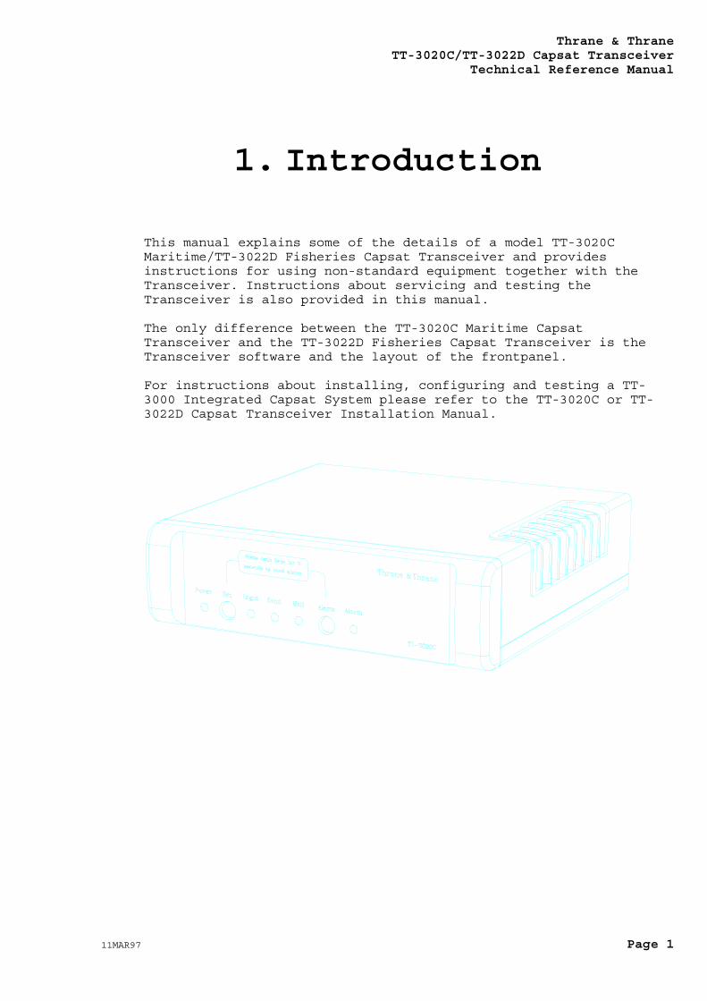
This manual explains some of the details of a model TT-3020CMaritime/TT-3022D Fisheries Capsat Transceiver and providesinstructions for using non-standard equipment together with theTransceiver. Instructions about servicing and testing theTransceiver is also provided in this manual.
The only difference between the TT-3020C Maritime CapsatTransceiver and the TT-3022D Fisheries Capsat Transceiver is theTransceiver software and the layout of the frontpanel.
For instructions about installing, configuring and testing a TT-3000 Integrated Capsat System please refer to the TT-3020C or TT-3022D Capsat Transceiver Installation Manual.
Thrane & ThraneTT-3020C/TT-3022D Capsat TransceiverTechnical Reference Manual
Page 2 11MAR97
Thrane & ThraneTT-3020C/TT-3022D Capsat Transceiver
Technical Reference Manual
11MAR97 Page 3
2. Maritime facilities
2.1 Scanning and LoginScanning and login must be manually started by the user.
The Bulletin Board Error Rate is an indication of the satellitelink quality. If the BBER exceeds 80% of the last hundred receivedbulletin board packets an alarm will be indicated on the messageterminal and on the TT-3042C Alarm/Distress Box. This advises theoperator to initiate a manual scan of NCS Common Channels.
2.2 DistressThe Maritime Transceiver can send a distress to an LES by pressingthe TT-3020C/TT-3022D Set and Alarm frontpanel buttons or bypressing the Alarm button on theTT-3042C Alarm/Distress Box. The Transceiver will now send anunspecified distress.
2.3 Link TestA manual distress alert test is possible.
The Maritime/Fisheries Transceiver will ask the user during a LinkTest (Performance Verification Test) to manually send a testdistress alert.
If the request is ignored the Transceiver will automatically sendthe Distress Test after 2 minutes.
Thrane & ThraneTT-3020C/TT-3022D Capsat TransceiverTechnical Reference Manual
Page 4 11MAR97
2.4 Message transmissionThe Maritime/Fisheries Transceiver will allow you to send your textmessages with distress priority in case of an emergency. Suchmessages will be routed to a default destination that is pre-programmed in the LES. This destination is normally the Search AndRescue (SAR) authority in the country where the LES is located.
2.5 EGC message receptionIn the TT-3020C the EGC System and SafetyNet calls can not beturned off.
In the TT-3022D the EGC System and SafetyNet calls can be turnedoff.
Thrane & ThraneTT-3020C/TT-3022D Capsat Transceiver
Technical Reference Manual
11MAR97 Page 5
3. System Generation
3.1 Alteration of the SystemParameters
Alteration of the TT-3020C/TT-3022D Capsat Transceiver parametersmay be accomplished by means of:
TT-3606A Message Terminal.
IBM compatible PC running DOS version 2.00 or later, with acommunication software or theMessage Terminal emulating software TT-10202 ver 3.00 or later.
Computerised equipment.
Handheld terminals, etc.
Please follow the below listed guide lines to set up the connectedequipment in a direct terminal emulating manner.
In terminal emulation mode a ':' prompt appears. Commands areentered after the prompt. The commands are executed by pressing the<CR> key.
3.1.1 TT-3606A Message TerminalEnter the terminal emulation mode by selecting:
OPTIONS - CONFIGURATION - TERMINAL
3.1.2 IBM Compatible PCEnter the terminal emulation mode in the TT-10202 A/B software byselecting:
OPTIONS - CONFIGURATION - TERMINAL
Thrane & ThraneTT-3020C/TT-3022D Capsat TransceiverTechnical Reference Manual
Page 6 11MAR97
3.1.3 Computerised equipment/handheldterminals
Your computer/terminal should display the ASCII characters as theyappear being send from the TT-3020C/TT-3022D Capsat Transceiver.
No alphabet or protocol conversion should take place.
3.2 Entering your mobile numberFor ease of operation and general information when you operate yourCapsat system, you should consider to enter the mobile number.
Just type in the Inmarsat-C 9 digit number that you have receivedfrom your PTT authorities.
The Mobile Number in the Transceiver is entered using the 'set - u'command:
:set -u ?<CR>
Mobile Number :492380049
Enter new number >
An Inmarsat-C mobile number is always in the range:
400000000 to 499999999
If you type a number outside this range the Transceiver will ignoreit.
You should not attempt to use your equipment before you havereceived a mobile number.
The Transceiver only uses the mobile number when sending MessagePosition Reports (see the Message Handling Software OperatorsGuide), to indicate which Transceiver originated the positionmessage.
3.3 Initialise System ParametersThis option will set most parameters in the non-volatile Flash-memory to their default values.
Thrane & ThraneTT-3020C/TT-3022D Capsat Transceiver
Technical Reference Manual
11MAR97 Page 7
It should only be used in case the contents of the non-volatilememory has been destroyed, or a new Transceiver is to be used forthe very first time.
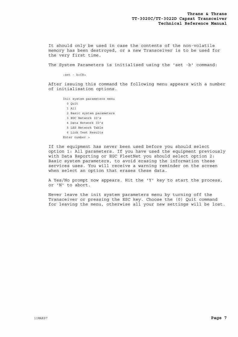
The System Parameters is initialised using the 'set -b' command:
:set - b<CR>
After issuing this command the following menu appears with a numberof initialisation options.
Init system parameters menu
0 Quit
1 All
2 Basic system parameters
3 EGC Network ID's
4 Data Network ID's
5 LES Network Table
6 Link Test Results
Enter number >
If the equipment has never been used before you should selectoption 1: All parameters. If you have used the equipment previouslywith Data Reporting or EGC FleetNet you should select option 2:Basic system parameters, to avoid erasing the information theseservices uses. You will receive a warning reminder on the screenwhen select an option that erases these data.
A Yes/No prompt now appears. Hit the 'Y' key to start the process,or 'N' to abort.
Never leave the init system parameters menu by turning off theTransceiver or pressing the ESC key. Choose the (0) Quit commandfor leaving the menu, otherwise all your new settings will be lost.
Thrane & ThraneTT-3020C/TT-3022D Capsat TransceiverTechnical Reference Manual
Page 8 11MAR97
4. Optional GPS
4.1 Introduction to the GPSSystem
The Global Positioning System (GPS) is based on 21 satellites(plus 3 spares) orbiting at an altitude of 10,900 nauticalmiles (20,183 km) with an orbital period of 12 hours, whichwill ensure that at least four satellites will be visiblefrom any point on earth.
Each satellite transmits a unique C/A code on the samefrequency. The C/A code (Course/Acquisition) is a sequence of1023 pseudo-random binary numbers.
Every satellite starts its transmission of the C/A code atthe exactly same time (the timing is accomplished by thesatellites atomic clock). The GPS receiver knows the C/A codefor each satellite and by comparing the received signal withthe C/A code of the satellite it is currently tracking it candetermine the time delay between the two.
If we assume the GPS receiver has an accurate clock (atomic)it can synchronise its C/A code for the satellite it istracking to start at the same time as the satellite startsthe C/A code transmission. The time delay between the twocodes will then equal the time it takes the electromagneticwave to travel from the satellite to the GPS receiver,multiplying this with the speed of light will give us thedistance to the satellite. This measurement is calledsatellite ranging.
The GPS receiver also needs to know the position of thesatellite it is tracking. The GPS receiver has an "almanac"where all the satellites orbital parameters are stored. The"almanac" is frequently transmitted by all satellites so theGPS receiver has access to the newest. In addition to thiseach satellite will transmit minor corrections to its orbitalparameters, the Ephemeris parameters.
The GPS receiver can establish its position by making asatellite ranging measurement to three different satellites.The GPS receiver does not as we assumed have an atomic clock
Thrane & ThraneTT-3020C/TT-3022D Capsat Transceiver
Technical Reference Manual
11MAR97 Page 9
as reference, and therefore it will need a satellite rangingmeasurement to a fourth satellite in order to synchronise itsinternal clock with the atomic clocks on the satellites.
To summarise the GPS receiver must make satellite rangingmeasurements to four different satellites before it candetermine its position and the time. This navigation solutionis called a 3-D solution.
Time and position can also be determined by the GPS modulewith only three different satellites using the last computedaltitude. This navigation solution is called a 2-D solution.
The accuracy of the C/A code, can be degraded through anoperational mode called "Selective Availability" or "S/A".The Selective Availability is implemented to deny non-military GPS users high position accuracy. In principle theSelective Availability introduces errors into the satelliteranging measurement by manipulating the satellites clock.
The Standard Position Service (SPS) uses the C/A code withSelective Availability. SPS is planned to provide thecapability to obtain horizontal position accuracy within 100meters (95 percent probability) and vertical positionaccuracy within 156 meters (95 percent probability).
4.2 The GPS ModuleThe Capsat Transceiver uses a GARMIN GPS 20 module as anoption.
The GARMIN GPS 20 module is a single-board, parallel GlobalPositioning System (GPS) receiver suitable for integration.GPS 20 track up to eight satellites at a time. The GPS Moduleuses spread-spectrum receiver technology for reception of L1GPS, 1575.42-MHz Standard Positioning Service (SPS) signals.The GARMIN GPS module design utilises the latest surfacemount technology as well as high level circuit integration toachieve superior performance while minimising space and powerrequirements.
Rapid Time-To-First-Fix (TTFF) is achieved utilisingefficient search algorithms that make use of all trackedsatellites. A typical TTFF is 15 seconds with a currentalmanac and ephemeris data loaded from on-board batterybackup memory. The GPS module provides position within 100m. Typical acquisition time for GARMIN GPS 20 with initialposition, time and almanac known and ephemeris data unknownis 2 minutes from cold, 7 minutes with almanac known but
Thrane & ThraneTT-3020C/TT-3022D Capsat TransceiverTechnical Reference Manual
Page 10 11MAR97
position and time unknown and 15 minutes if no data known.The GPS module board automatically update satellite orbitaldata as it operates. The GPS Module can maintain thisperformance in applications where the board temperature isbetween -30 to +85 degrees Celsius.
If the GPS module is not operated for a period of more thansix month or if initial data is significantly inaccurate easeof acquisition can be achieved upon power-up by providing thereceiver its Position, Velocity and Time data from acompletely powered down state.
The GPS module works in automatic mode in which the moduledetermines the desired mode (2-D or 3-D navigation solution)based on satellite availability and geometry considerations.However, because the GPS 20 module track eight satellites the2-D mode condition will be minimal.
4.2.1 Feature listFull navigation accuracy provided by Standard PositioningService (SPS)
High performance receiver tracks up to 8 satellites whileproviding fast first fix and low power consumption.
On-board clock and memory are sustained by a memory backupbattery
User initialisation is not required
4.3 Satellite Navigation
The GPS Module provides four (3D) and three (2D) satellitenavigation solutions. The Default Primary Navigationsolution is 3D, Four Satellite Vehicle (4SV) Navigation.Three Satellite Navigation is considered a secondarynavigation solution, which requires a known altitude.
Automatic Three Satellite Navigation utilising the last knownaltitude is implemented from a Four Satellite Navigationstate when only three satellites are unobscured.
Thrane & ThraneTT-3020C/TT-3022D Capsat Transceiver
Technical Reference Manual
11MAR97 Page 11
Either method will provide you with a position. However. the4SV-(3D) solution will be the most accurate of all thesolutions when satellites with good geometry are available.
In general, accurate three-dimensional (3D) positiondeterminations are based on the measurement of the transittime of RF signals from four satellites. Three of the foursatellites provide the horizontal X and Y co-ordinates.However, with errors of different atmospheric delays andimperfections in clocks standards, the horizontal positioncan be located in two places along the Z-axis which isperpendicular to the horizontal plane. The fourth satelliteessentially removes the error on the Z-axis; thus an accuratealtitude is given.
The GPS Module automatically proceeds from an acquisitionstate, or 3SV navigation state, to a 4SV navigation statewhen four or more satellite measurements are consideredreliable. At various points in time, satellites may becomeobscured. The GPS Module minimises the effects ofobscuration by tracking remaining in view in order tomaintain Four Satellite Navigation as much as possible.
4.4 Almanac
The Almanac used by the GPS Module is a set of Keplerianorbital parameters which approximate the entire orbits of theGPS satellites. This information is used by the GPS Module todetermine where to best search for the satellites signals.Once a satellite is being tracked by the GPS Module, theEphemeris parameters, which are more accurate but only span afour-hour portion of the orbit, are used to continue trackingthe satellite or reacquire a satellite where it's signal isbest. Note that the almanac parameters for all GPSsatellites are broadcast by each GPS satellite, but each GPSsatellite broadcasts ephemeris only for itself.
The almanac parameters are uploaded to the GPS satellitesonce per week. The almanac parameters are also continuallybroadcast from the GPS satellites so that GPS User sets, suchas the GPS Module, have access to the most current almanac.Although updated weekly, the almanac parameters are stillacceptable for use for longer periods of time, up to severalmonths, except for the rare cases in which satellites havebeen repositioned or new satellites have been launched. Evenin these circumstances, the almanac data for the unalteredsatellites is still acceptable for use.
Thrane & ThraneTT-3020C/TT-3022D Capsat TransceiverTechnical Reference Manual
Page 12 11MAR97
When the GPS Module is tracking any GPS satellite, it isconstantly reading the almanac parameters for all GPSsatellites, comparing them against the almanac parameterscurrently being used and updating them when they change.
The accuracy of these sets of almanac data will degrade withtime, and eventually cause longer acquisition times if theset remains without power for a period of several months.
As mentioned above, please note that the GPS Module updatesthe almanac data for all satellites if it is tracking atleast one satellite.
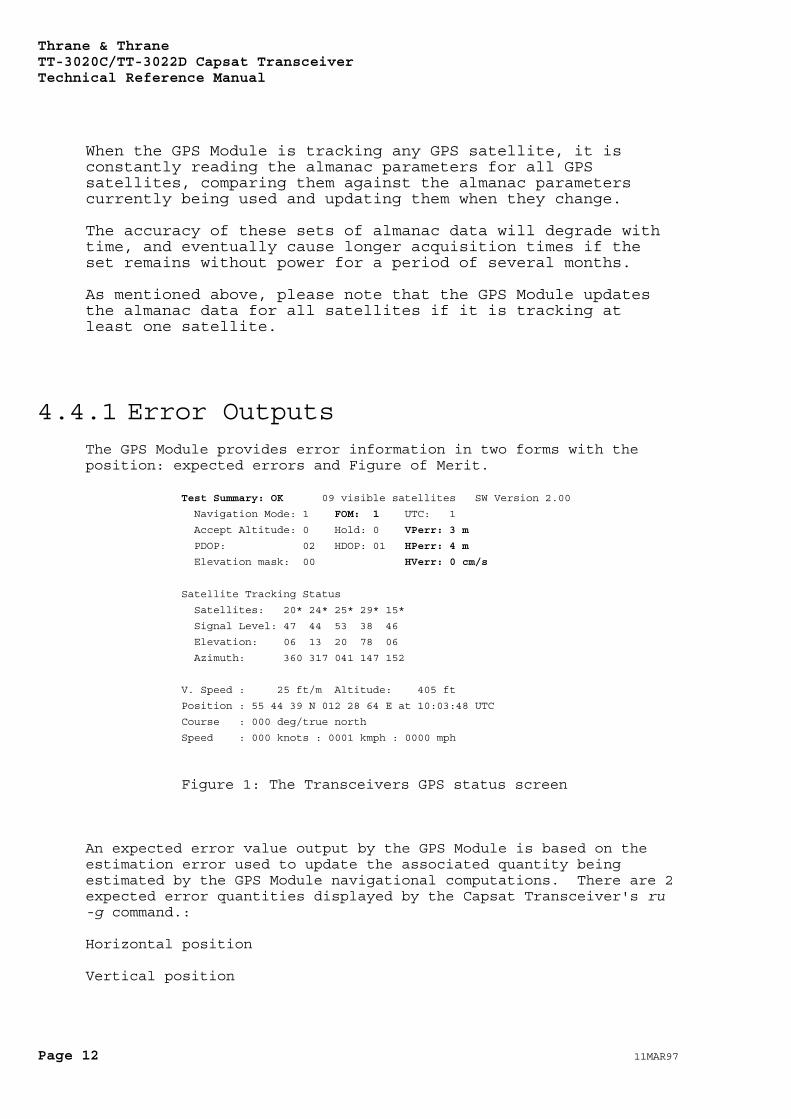
4.4.1 Error OutputsThe GPS Module provides error information in two forms with theposition: expected errors and Figure of Merit.
Test Summary: OK 09 visible satellites SW Version 2.00
Navigation Mode: 1 FOM: 1 UTC: 1
Accept Altitude: 0 Hold: 0 VPerr: 3 m
PDOP: 02 HDOP: 01 HPerr: 4 m
Elevation mask: 00 HVerr: 0 cm/s
Satellite Tracking Status
Satellites: 20* 24* 25* 29* 15*
Signal Level: 47 44 53 38 46
Elevation: 06 13 20 78 06
Azimuth: 360 317 041 147 152
V. Speed : 25 ft/m Altitude: 405 ft
Position : 55 44 39 N 012 28 64 E at 10:03:48 UTC
Course : 000 deg/true north
Speed : 000 knots : 0001 kmph : 0000 mph
Figure 1: The Transceivers GPS status screen
An expected error value output by the GPS Module is based on theestimation error used to update the associated quantity beingestimated by the GPS Module navigational computations. There are 2expected error quantities displayed by the Capsat Transceiver's ru-g command.:
Horizontal position
Vertical position
Thrane & ThraneTT-3020C/TT-3022D Capsat Transceiver
Technical Reference Manual
11MAR97 Page 13
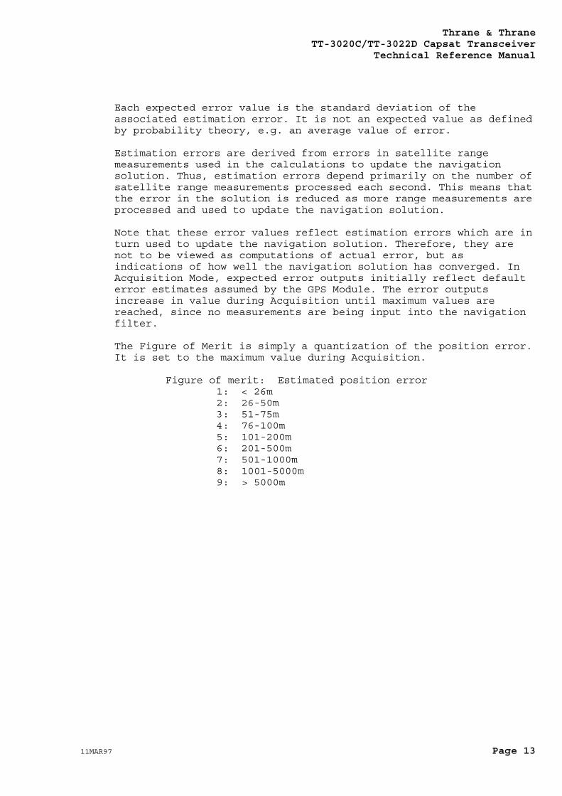
Each expected error value is the standard deviation of theassociated estimation error. It is not an expected value as definedby probability theory, e.g. an average value of error.
Estimation errors are derived from errors in satellite rangemeasurements used in the calculations to update the navigationsolution. Thus, estimation errors depend primarily on the number ofsatellite range measurements processed each second. This means thatthe error in the solution is reduced as more range measurements areprocessed and used to update the navigation solution.
Note that these error values reflect estimation errors which are inturn used to update the navigation solution. Therefore, they arenot to be viewed as computations of actual error, but asindications of how well the navigation solution has converged. InAcquisition Mode, expected error outputs initially reflect defaulterror estimates assumed by the GPS Module. The error outputsincrease in value during Acquisition until maximum values arereached, since no measurements are being input into the navigationfilter.
The Figure of Merit is simply a quantization of the position error.It is set to the maximum value during Acquisition.
Figure of merit: Estimated position error1: < 26m2: 26-50m3: 51-75m4: 76-100m5: 101-200m6: 201-500m7: 501-1000m8: 1001-5000m9: > 5000m
Thrane & ThraneTT-3020C/TT-3022D Capsat TransceiverTechnical Reference Manual
Page 14 11MAR97
5. Transceiver SoftwareDetails
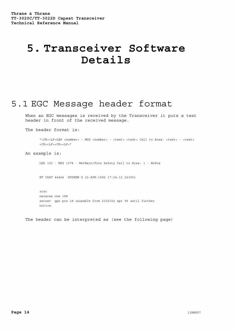
5.1 EGC Message header formatWhen an EGC messages is received by the Transceiver it puts a textheader in front of the received message.
The header format is:
"<CR><LF>LES <number> - MSG <number> - <text> <text> Call to Area: <text> - <text>
<CR><LF><CR><LF>"
An example is:
LES 102 - MSG 1078 - MetWarn/Fore Safety Call to Area: 1 - NoPos
BT CSAT 46464 HYDRNW G 22-APR-1996 17:24:12 263051
zczc
navarea one 188
satnav gps prn 18 unusable from 210215z apr 96 until further
notice.
The header can be interpreted as (see the following page)
Thrane & ThraneTT-3020C/TT-3022D Capsat Transceiver
Technical Reference Manual
11MAR97 Page 15
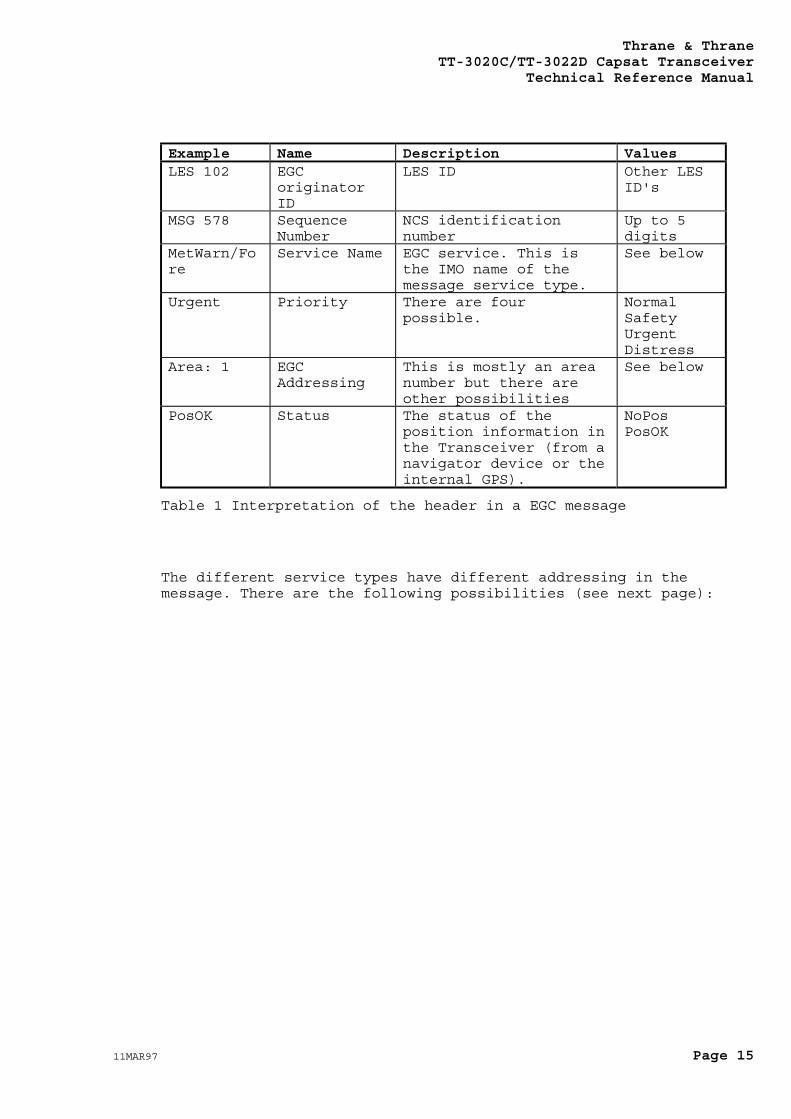
Example Name Description ValuesLES 102 EGC
originatorID
LES ID Other LESID's
MSG 578 SequenceNumber
NCS identificationnumber
Up to 5digits
MetWarn/Fore
Service Name EGC service. This isthe IMO name of themessage service type.
See below
Urgent Priority There are fourpossible.
NormalSafetyUrgentDistress
Area: 1 EGCAddressing
This is mostly an areanumber but there areother possibilities
See below
PosOK Status The status of theposition information inthe Transceiver (from anavigator device or theinternal GPS).
NoPosPosOK
Table 1 Interpretation of the header in a EGC message
The different service types have different addressing in themessage. There are the following possibilities (see next page):
Thrane & ThraneTT-3020C/TT-3022D Capsat TransceiverTechnical Reference Manual
Page 16 11MAR97
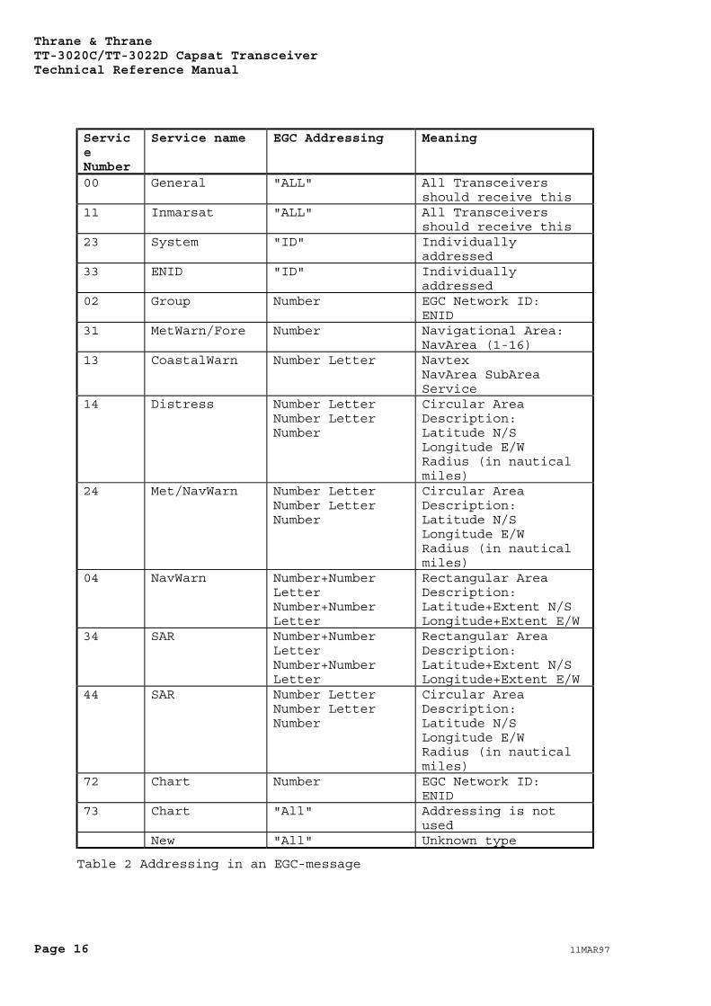
ServiceNumber
Service name EGC Addressing Meaning
00 General "ALL" All Transceiversshould receive this
11 Inmarsat "ALL" All Transceiversshould receive this
23 System "ID" Individuallyaddressed
33 ENID "ID" Individuallyaddressed
02 Group Number EGC Network ID:ENID
31 MetWarn/Fore Number Navigational Area:NavArea (1-16)
13 CoastalWarn Number Letter NavtexNavArea SubAreaService
14 Distress Number LetterNumber LetterNumber
Circular AreaDescription:Latitude N/SLongitude E/WRadius (in nauticalmiles)
24 Met/NavWarn Number LetterNumber LetterNumber
Circular AreaDescription:Latitude N/SLongitude E/WRadius (in nauticalmiles)
04 NavWarn Number+NumberLetterNumber+NumberLetter
Rectangular AreaDescription:Latitude+Extent N/SLongitude+Extent E/W
34 SAR Number+NumberLetterNumber+NumberLetter
Rectangular AreaDescription:Latitude+Extent N/SLongitude+Extent E/W
44 SAR Number LetterNumber LetterNumber
Circular AreaDescription:Latitude N/SLongitude E/WRadius (in nauticalmiles)
72 Chart Number EGC Network ID:ENID
73 Chart "All" Addressing is notused
New "All" Unknown type
Table 2 Addressing in an EGC-message
Thrane & ThraneTT-3020C/TT-3022D Capsat Transceiver
Technical Reference Manual
11MAR97 Page 17
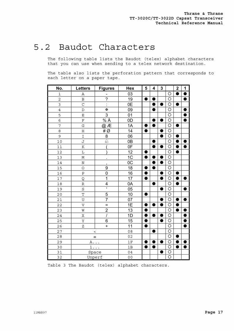
5.2 Baudot CharactersThe following table lists the Baudot (telex) alphabet charactersthat you can use when sending to a telex network destination.
The table also lists the perforation pattern that corresponds toeach letter on a paper tape.
No. Letters Figures Hex 5 4 3 2 11 A - 03 � �
2 B ? 19 � � �
3 C : 0E � � �
4 D 09 � �
5 E 3 01 �
6 F % Å 0D � � �
7 G @ Æ 1A � � �
8 H # Ø 14 � �
9 I 8 06 � �
10 J 0B � � �
11 K ( 0F � � � �
12 L ) 12 � �
13 M . 1C � � �
14 N , 0C � �
15 O 9 18 � �
16 P 0 16 � � �
17 Q 1 17 � � � �
18 R 4 0A � �
19 S ' 05 � �
20 T 5 10 �
21 U 7 07 � � �
22 V = 1E � � � �
23 W 2 13 � � �
24 X / 1D � � � �
25 Y 6 15 � � �
26 Z + 11 � �
27 < 08 �28 ≡ 02 �
29 A... 1F � � � � �30 1... 1B � � � �31 Space 04 �32 Unperf 00
Table 3 The Baudot (telex) alphabet characters.
Thrane & ThraneTT-3020C/TT-3022D Capsat TransceiverTechnical Reference Manual
Page 18 11MAR97
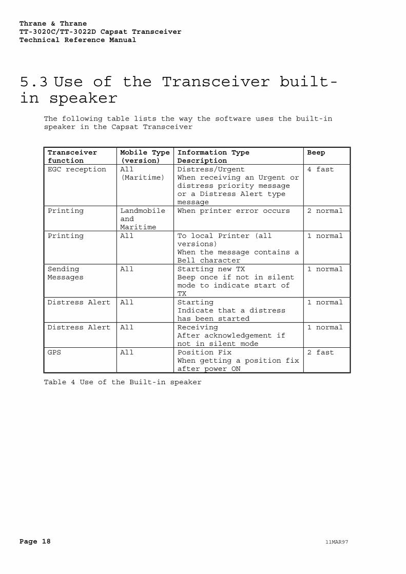
5.3 Use of the Transceiver built-in speaker
The following table lists the way the software uses the built-inspeaker in the Capsat Transceiver
Transceiverfunction
Mobile Type(version)
Information TypeDescription
Beep
EGC reception All(Maritime)
Distress/UrgentWhen receiving an Urgent ordistress priority messageor a Distress Alert typemessage
4 fast
Printing LandmobileandMaritime
When printer error occurs 2 normal
Printing All To local Printer (allversions)When the message contains aBell character
1 normal
SendingMessages
All Starting new TXBeep once if not in silentmode to indicate start ofTX
1 normal
Distress Alert All StartingIndicate that a distresshas been started
1 normal
Distress Alert All ReceivingAfter acknowledgement ifnot in silent mode
1 normal
GPS All Position FixWhen getting a position fixafter power ON
2 fast
Table 4 Use of the Built-in speaker
Thrane & ThraneTT-3020C/TT-3022D Capsat Transceiver
Technical Reference Manual
11MAR97 Page 19
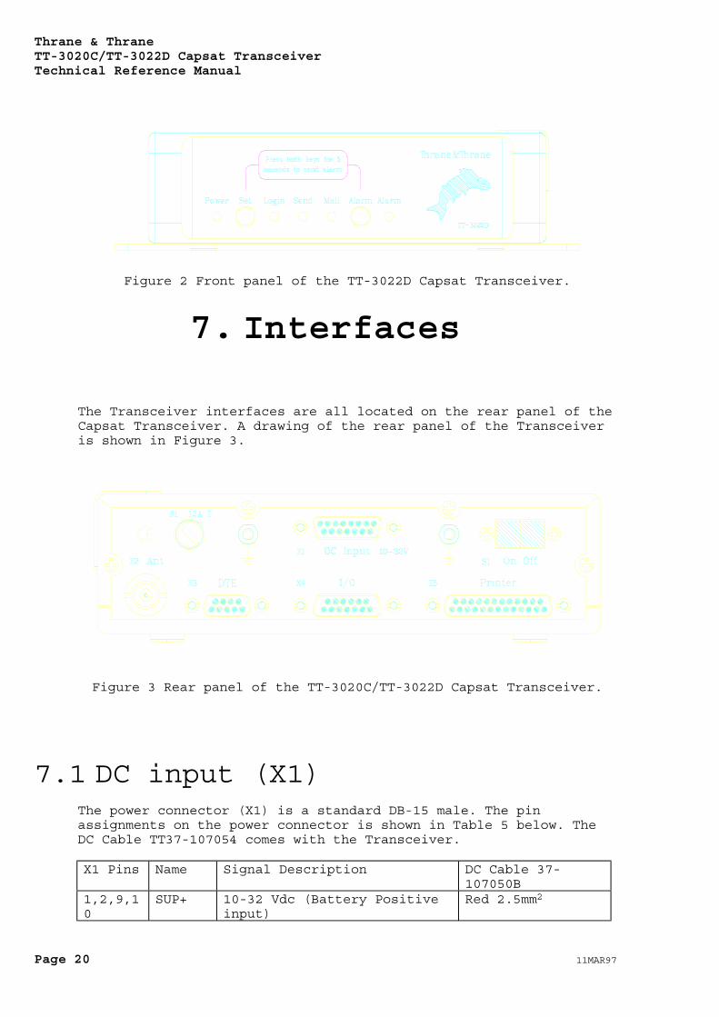
6. Front Panel
The Front Panel of the Transceiver is shown in Figure 2. Thefunction of the five indicators and the two buttons are as follows.
The Power indicator will always be on when there is DC-power on theTransceiver.
The Set button is used to set the serial port to the defaultvalues. If this button is pressed at power-on the serial port isset to 4800 baud, 8 databits, no parity, 1 stopbit. If the buttonis pressed when the Transceiver has been turned-on nothing willhappen. The button has to be pressed at power-on if the functionare to take effect.
The Login indicator will be on when the Transceiver is logged intoan earth station. If the Transceiver is in sync. but hasn't beenlogged into an earth station the indicator will flash. If theTransceiver is unable to get sync. the indicator will be off.
The Send indicator will be flashing when the Transceiver goes intothe Transmit protocol. When the Transceiver is transmitting theindicator will be on. When the transmission is completed theindicator will flash until an acknowledgement is received from theLES.
The Mail indicator will flash if the Transceiver is about toreceive a Non-EGC message. When the message has been received theindicator will be on. The indicator will be on until the messagehas been read. If the Capsat program is used the message will beread immediately. Because of this the user will se the Mailindicator flash when a message is about to be received and thenturn off when the message has been received.
The Alarm button is used together with the Set button to send adistress alert. Press the Set button and the Alarm buttonsimultaneously for at least 5 seconds until the Alarm LED startsflashing.
The Alarm indicator will normally be off. When a distress alert hasbeen sent the Alarm LED will flash until an acknowledgement hasbeen received from the LES. Then the indicator will be on.
Thrane & ThraneTT-3020C/TT-3022D Capsat TransceiverTechnical Reference Manual
Page 20 11MAR97
Figure 2 Front panel of the TT-3022D Capsat Transceiver.
7. Interfaces
The Transceiver interfaces are all located on the rear panel of theCapsat Transceiver. A drawing of the rear panel of the Transceiveris shown in Figure 3.
Figure 3 Rear panel of the TT-3020C/TT-3022D Capsat Transceiver.
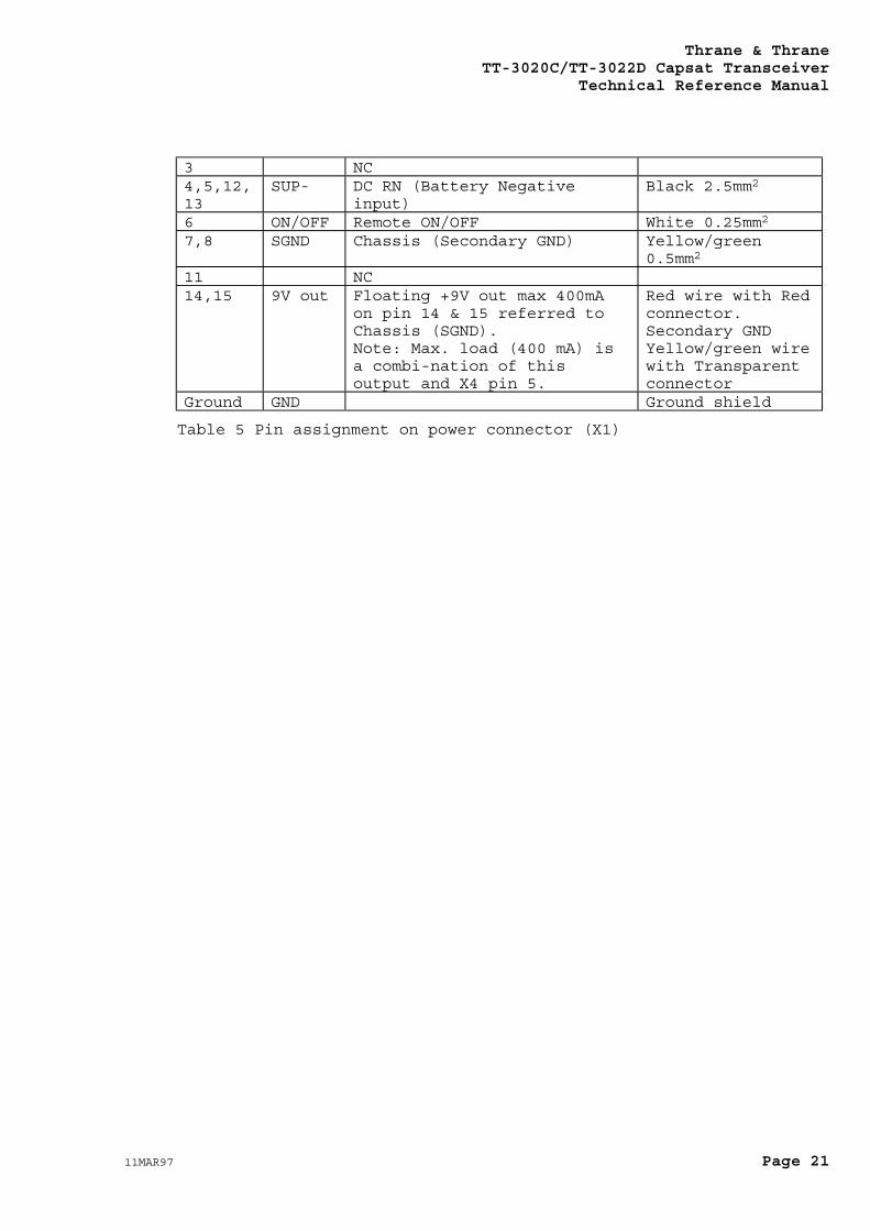
7.1 DC input (X1)The power connector (X1) is a standard DB-15 male. The pinassignments on the power connector is shown in Table 5 below. TheDC Cable TT37-107054 comes with the Transceiver.
X1 Pins Name Signal Description DC Cable 37-107050B
1,2,9,10
SUP+ 10-32 Vdc (Battery Positiveinput)
Red 2.5mm2
Thrane & ThraneTT-3020C/TT-3022D Capsat Transceiver
Technical Reference Manual
11MAR97 Page 21
3 NC4,5,12,13
SUP- DC RN (Battery Negativeinput)
Black 2.5mm2
6 ON/OFF Remote ON/OFF White 0.25mm2
7,8 SGND Chassis (Secondary GND) Yellow/green0.5mm2
11 NC14,15 9V out Floating +9V out max 400mA
on pin 14 & 15 referred toChassis (SGND).Note: Max. load (400 mA) isa combi-nation of thisoutput and X4 pin 5.
Red wire with Redconnector.Secondary GNDYellow/green wirewith Transparentconnector
Ground GND Ground shield
Table 5 Pin assignment on power connector (X1)
Thrane & ThraneTT-3020C/TT-3022D Capsat TransceiverTechnical Reference Manual
Page 22 11MAR97
Pin 6 is used as an power switch for the TT-3020C/TT-3022D CapsatTransceiver. When this pin is left floating the Transceiver isturned off, but if pin 6 is shorted to the negative terminal of thebattery or DC-supply the Transceiver will be switched on. Thismakes it possible for other equipment for remote power control ofthe TT-3020C/TT-3022D.
The remote power control can be controlled by an external relay orsolid state switch.
The battery input is floating, i.e. there is no galvanic connectionfrom any of the battery poles to the cabinet frame.
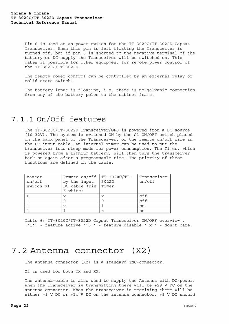
7.1.1 On/Off featuresThe TT-3020C/TT-3022D Transceiver/GPS is powered from a DC source(10-32V). The system is switched ON by the S1 ON/OFF switch placedon the back panel of the Transceiver, or the remote on/off wire inthe DC input cable. An internal Timer can be used to put thetransceiver into sleep mode for power consumption. The Timer, whichis powered from a lithium battery, will then turn the transceiverback on again after a programmable time. The priority of thesefunctions are defined in the table.
Masteron/offswitch S1
Remote on/offby the inputDC cable (pin6 white)
TT-3020C/TT-3022DTimer
Transceiveron/off
0 x x off1 0 0 off1 x 1 on1 1 x on
Table 6: TT-3020C/TT-3022D Capsat Transceiver ON/OFF overview .‘’1’’ - feature active ‘’0’’ - feature disable ‘’x’’ - don’t care.
7.2 Antenna connector (X2)The antenna connector (X2) is a standard TNC-connector.
X2 is used for both TX and RX.
The antenna-cable is also used to supply the Antenna with DC-power.When the Transceiver is transmitting there will be +28 V DC on theantenna connector. When the transceiver is receiving there will beeither +9 V DC or +14 V DC on the antenna connector. +9 V DC should
Thrane & ThraneTT-3020C/TT-3022D Capsat Transceiver
Technical Reference Manual
11MAR97 Page 23
be used if a TT-3005B antenna is used with the transceiver. If anyother Antenna Type is used +14 V DC should be used.
The TT-3005B will not be damaged if it is supplied with +14 V DC.It will be operational, but the power consumption will be higherthan necessary.
If a different antenna type is used and is supplied with +9 V DC itwill not be operational. The antenna will however not be damaged bythis.
The Transceiver will have a default antenna supply voltage of +14 VDC. With this supply voltage all antennas will be operational withthe Transceiver.
The supply voltage to the antenna can be changed to +9V DC by thecommand:
set -z antvolt=low
The supply voltage to the antenna can be changed back to +14V DC bythe command:
set -z antvolt=high
7.3 DTE interface (X3)The TT-3020C/TT-3022D Capsat Transceiver communicates with acontroller device via the standard EIA/TIA-232E ports on a female 9pole Sub-D connector (X3).
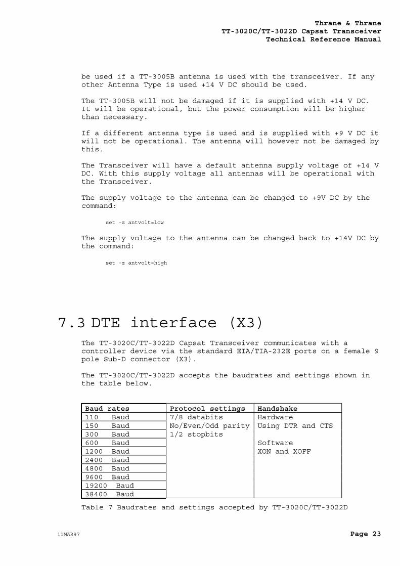
The TT-3020C/TT-3022D accepts the baudrates and settings shown inthe table below.
Baud rates Protocol settings Handshake110 Baud 7/8 databits Hardware150 Baud No/Even/Odd parity Using DTR and CTS300 Baud 1/2 stopbits600 Baud Software1200 Baud XON and XOFF2400 Baud4800 Baud9600 Baud19200 Baud38400 Baud
Table 7 Baudrates and settings accepted by TT-3020C/TT-3022D
Thrane & ThraneTT-3020C/TT-3022D Capsat TransceiverTechnical Reference Manual
Page 24 11MAR97
The serial port communication parameters are factory programmed to:
4800 Baud, 8 databits, no parity, 1 stopbit
The parameters of the serial port can be changed with the command:
set -c <baudrate, parity, databits, stopbits, 1 or 0>
where the last number should be 1 if software handshake will beused and 0 if software handshake will not be used.
As an example if you want 9600 baud, no parity, 8 databits, 1stopbit and no software handshake you must type:
set -c 9600, N, 8, 1, 0
Default values can be retained by typing:
set -c 4800, N, 8, 1, 0
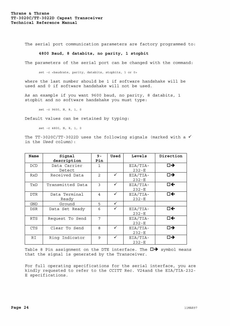
The TT-3020C/TT-3022D uses the following signals (marked with a in the Used column):
Name Signaldescription
9-Pin
Used Levels Direction
DCD Data CarrierDetect
1 EIA/TIA-232-E
RxD Received Data 2 EIA/TIA-232-E
TxD Transmitted Data 3 EIA/TIA-232-E
DTR Data TerminalReady
4 EIA/TIA-232-E
GND Ground 5DSR Data Set Ready 6 EIA/TIA-
232-ERTS Request To Send 7 EIA/TIA-
232-ECTS Clear To Send 8 EIA/TIA-
232-ERI Ring Indicator 9 EIA/TIA-
232-E
Table 8 Pin assignment on the DTE interface. The symbol meansthat the signal is generated by the Transceiver.
For full operating specifications for the serial interface, you arekindly requested to refer to the CCITT Rec. V24and the EIA/TIA-232-E specifications.
Thrane & ThraneTT-3020C/TT-3022D Capsat Transceiver
Technical Reference Manual
11MAR97 Page 25
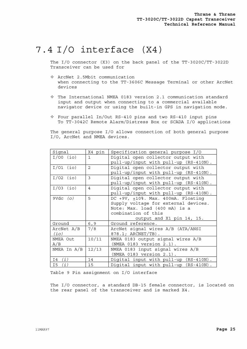
7.4 I/O interface (X4)The I/O connector (X3) on the back panel of the TT-3020C/TT-3022DTransceiver can be used for
ArcNet 2.5Mbit communicationwhen connecting to the TT-3606C Message Terminal or other ArcNetdevices
The International NMEA 0183 version 2.1 communication standardinput and output when connecting to a commercial availablenavigator device or using the built-in GPS in navigation mode.
Four parallel In/Out RS-410 pins and two RS-410 input pinsTo TT-3042C Remote Alarm/Distress Box or SCADA I/O applications
The general purpose I/O allows connection of both general purposeI/O, ArcNet and NMEA devices.
Signal X4 pin Specification general purpose I/OI/O0 (io) 1 Digital open collector output with
pull-up/input with pull-up (RS-410N).I/O1 (io) 2 Digital open collector output with
pull-up/input with pull-up (RS-410N).I/O2 (io) 3 Digital open collector output with
pull-up/input with pull-up (RS-410N).I/O3 (io) 4 Digital open collector output with
pull-up/input with pull-up (RS-410N).9Vdc (o) 5 DC +9V, ±10%. Max. 400mA. Floating
Supply voltage for external devices.Note: Max. load (400 mA) is acombination of this output and X1 pin 14, 15.
Ground 6,9 Ground reference.ArcNet A/B(io)
7/8 ArcNet signal wires A/B (ATA/ANSI878.1; ARCNET/TB).
NMEA OutA/B
10/11 NMEA 0183 output signal wires A/B(NMEA 0183 version 2.1).
NMEA In A/B 12/13 NMEA 0183 input signal wires A/B(NMEA 0183 version 2.1).
I4 (i) 14 Digital input with pull-up (RS-410N).I5 (i) 15 Digital input with pull-up (RS-410N).
Table 9 Pin assignment on I/O interface
The I/O connector, a standard DB-15 female connector, is located onthe rear panel of the transceiver and is marked X4.
Thrane & ThraneTT-3020C/TT-3022D Capsat TransceiverTechnical Reference Manual
Page 26 11MAR97
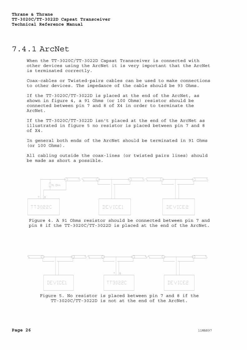
7.4.1 ArcNetWhen the TT-3020C/TT-3022D Capsat Transceiver is connected withother devices using the ArcNet it is very important that the ArcNetis terminated correctly.
Coax-cables or Twisted-pairs cables can be used to make connectionsto other devices. The impedance of the cable should be 93 Ohms.
If the TT-3020C/TT-3022D is placed at the end of the ArcNet, asshown in figure 4, a 91 Ohms (or 100 Ohms) resistor should beconnected between pin 7 and 8 of X4 in order to terminate theArcNet.
If the TT-3020C/TT-3022D isn't placed at the end of the ArcNet asillustrated in figure 5 no resistor is placed between pin 7 and 8of X4.
In general both ends of the ArcNet should be terminated in 91 Ohms(or 100 Ohms).
All cabling outside the coax-lines (or twisted pairs lines) shouldbe made as short a possible.
Figure 4. A 91 Ohms resistor should be connected between pin 7 andpin 8 if the TT-3020C/TT-3022D is placed at the end of the ArcNet.
Figure 5. No resistor is placed between pin 7 and 8 if theTT-3020C/TT-3022D is not at the end of the ArcNet.

Thrane & ThraneTT-3020C/TT-3022D Capsat Transceiver
Technical Reference Manual
11MAR97 Page 27
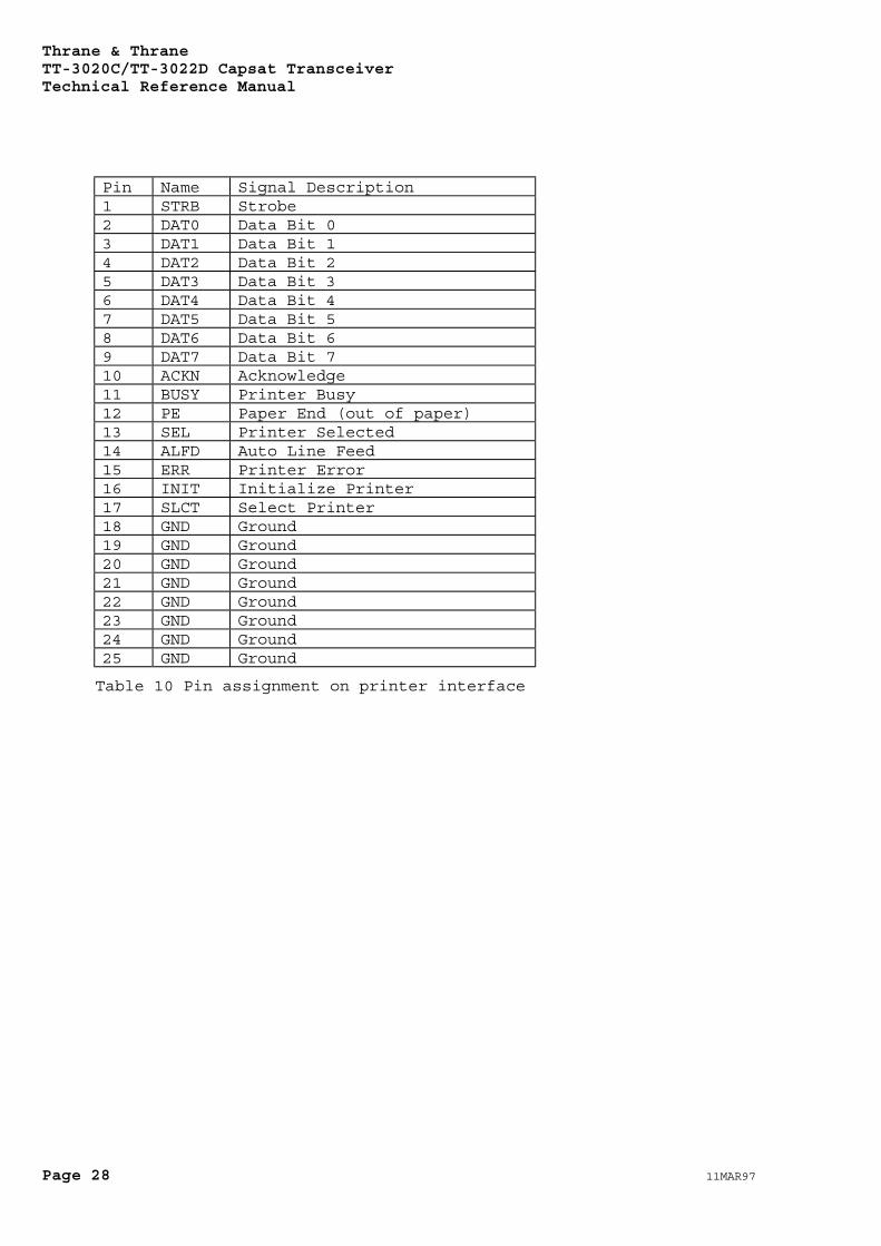
7.5 Printer interface (X5)The printer port connector, X5, is located on the rear panel.
This parallel interface conforms to the standard Centronicsinterface used e.g. on IBM compatible PC's.
Thrane & ThraneTT-3020C/TT-3022D Capsat TransceiverTechnical Reference Manual
Page 28 11MAR97
Pin Name Signal Description1 STRB Strobe2 DAT0 Data Bit 03 DAT1 Data Bit 14 DAT2 Data Bit 25 DAT3 Data Bit 36 DAT4 Data Bit 47 DAT5 Data Bit 58 DAT6 Data Bit 69 DAT7 Data Bit 710 ACKN Acknowledge11 BUSY Printer Busy12 PE Paper End (out of paper)13 SEL Printer Selected14 ALFD Auto Line Feed15 ERR Printer Error16 INIT Initialize Printer17 SLCT Select Printer18 GND Ground19 GND Ground20 GND Ground21 GND Ground22 GND Ground23 GND Ground24 GND Ground25 GND Ground
Table 10 Pin assignment on printer interface
Thrane & ThraneTT-3020C/TT-3022D Capsat Transceiver
Technical Reference Manual
11MAR97 Page 29
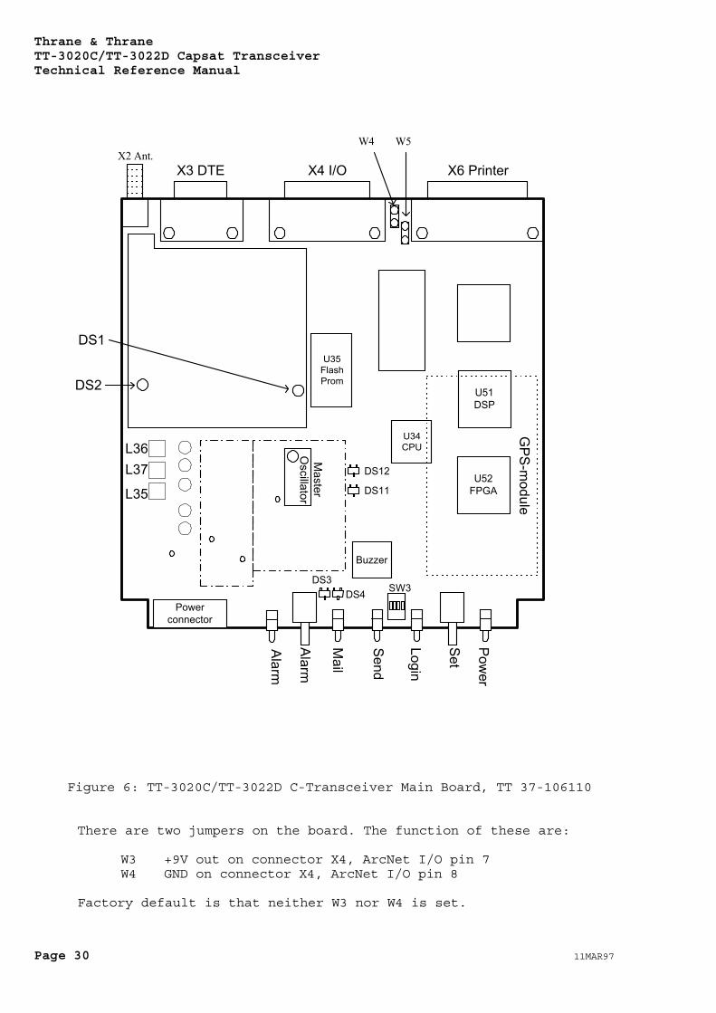
8. Capsat TransceiverService
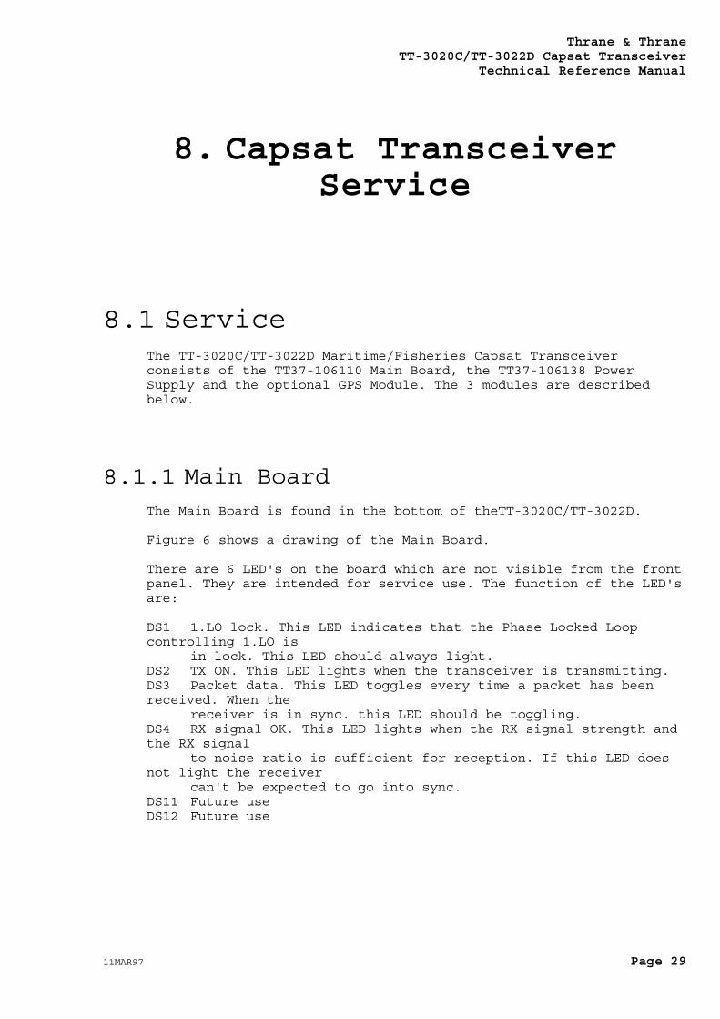
8.1 ServiceThe TT-3020C/TT-3022D Maritime/Fisheries Capsat Transceiverconsists of the TT37-106110 Main Board, the TT37-106138 PowerSupply and the optional GPS Module. The 3 modules are describedbelow.
8.1.1 Main BoardThe Main Board is found in the bottom of theTT-3020C/TT-3022D.
Figure 6 shows a drawing of the Main Board.
There are 6 LED's on the board which are not visible from the frontpanel. They are intended for service use. The function of the LED'sare:
DS1 1.LO lock. This LED indicates that the Phase Locked Loopcontrolling 1.LO is
in lock. This LED should always light.DS2 TX ON. This LED lights when the transceiver is transmitting.DS3 Packet data. This LED toggles every time a packet has beenreceived. When the
receiver is in sync. this LED should be toggling.DS4 RX signal OK. This LED lights when the RX signal strength andthe RX signal
to noise ratio is sufficient for reception. If this LED doesnot light the receiver
can't be expected to go into sync.DS11 Future useDS12 Future use
Thrane & ThraneTT-3020C/TT-3022D Capsat TransceiverTechnical Reference Manual
Page 30 11MAR97
X3 DTE X4 I/O X6 Printer
Powerconnector
Buzzer
U35FlashProm
U51DSP
U52FPGA
U34CPU
X2 Ant.W4 W5
DS2
DS1
DS12
DS11
DS3DS4 SW3
Power
Login
Send
Alarm
Alarm
GPS-m
odule
L36L37
L35
Master
Oscillator
Set
Figure 6: TT-3020C/TT-3022D C-Transceiver Main Board, TT 37-106110
There are two jumpers on the board. The function of these are:
W3 +9V out on connector X4, ArcNet I/O pin 7W4 GND on connector X4, ArcNet I/O pin 8
Factory default is that neither W3 nor W4 is set.
Thrane & ThraneTT-3020C/TT-3022D Capsat Transceiver
Technical Reference Manual
11MAR97 Page 31
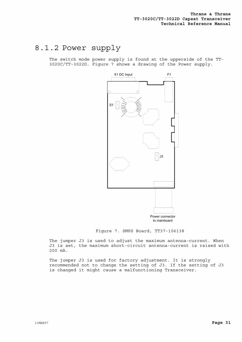
8.1.2 Power supplyThe switch mode power supply is found at the upperside of the TT-3020C/TT-3022D. Figure 7 shows a drawing of the Power supply.
X1 DC Input F1
Power connectorto mainboard
S1
J3
Figure 7. SMPS Board, TT37-106138
The jumper J3 is used to adjust the maximum antenna-current. WhenJ3 is set, the maximum short-circuit antenna-current is raised with200 mA.
The jumper J3 is used for factory adjustment. It is stronglyrecommended not to change the setting of J3. If the setting of J3is changed it might cause a malfunctioning Transceiver.
Thrane & ThraneTT-3020C/TT-3022D Capsat TransceiverTechnical Reference Manual
Page 32 11MAR97
8.1.3 Optional GPS ModuleThe optional GPS module is (if used) located in the bottom of theTT-3020C/TT-3022D. It is fastened to the TT37-106110 C-TransceiverMain Board with four stays. This is indicated in Figure 6 withdashed lines. The GPS-module is located on the opposite side of theMain Board than the one shown in Figure 6
The built-in GPS module will always be self-tested at power-on. Incase you suspect a malfunction in the module you should check theGPS status screen by selecting:
OPTIONS - GPS STATUS
Look at the first line at Test Summary and see the statusinformation readout. Normally you should see OK, but in case oferror you will see an error code.
The error code is a 16 bit error word and is described in thefollowing section.
In case you want to test the module manually you can also start thetest from the Terminal mode. Type:
OPTIONS - CONFIGURATION - TERMINAL MODE
Then hit the ENTER key and see the colon prompt appear. Now typethe command:
ru -t<ENTER>
And hit the ESC key to get back to the main menu. After max. 60seconds the test results are available in the GPS Status window.
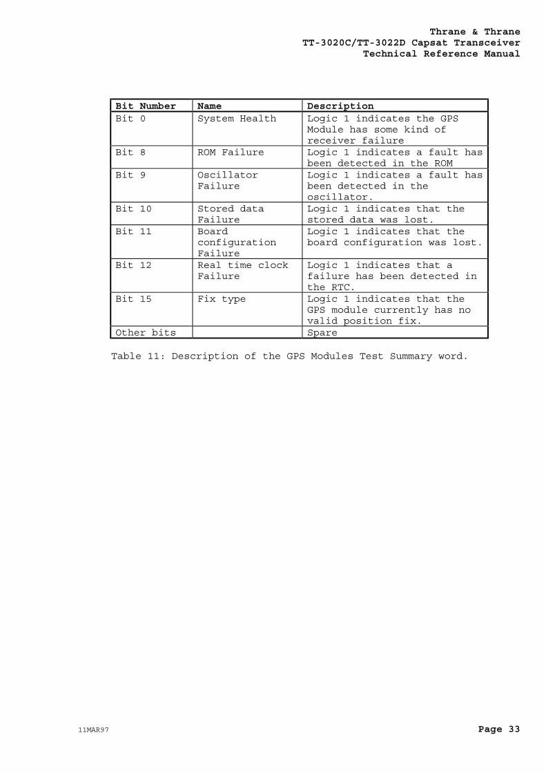
8.1.3.1 Test Summary WordIf the built-in self-test fails, a 4 digit number will appear inthe first line of the GPS status together with the word ERROR. Thisindicates the cause of the error as a hexadecimal number. Thenumber is composed of error bits in different locations asdescribed below.
Bit 0 is the least significant bit (displayed as 0001H) and bit 12is the most significant used bit (displayed as 1000H).
Thrane & ThraneTT-3020C/TT-3022D Capsat Transceiver
Technical Reference Manual
11MAR97 Page 33
Bit Number Name DescriptionBit 0 System Health Logic 1 indicates the GPS
Module has some kind ofreceiver failure
Bit 8 ROM Failure Logic 1 indicates a fault hasbeen detected in the ROM
Bit 9 OscillatorFailure
Logic 1 indicates a fault hasbeen detected in theoscillator.
Bit 10 Stored dataFailure
Logic 1 indicates that thestored data was lost.
Bit 11 BoardconfigurationFailure
Logic 1 indicates that theboard configuration was lost.
Bit 12 Real time clockFailure
Logic 1 indicates that afailure has been detected inthe RTC.
Bit 15 Fix type Logic 1 indicates that theGPS module currently has novalid position fix.
Other bits Spare
Table 11: Description of the GPS Modules Test Summary word.
Thrane & ThraneTT-3020C/TT-3022D Capsat TransceiverTechnical Reference Manual
Page 34 11MAR97
8.2 Fault diagnosticsIf the TT-3020C/TT-3022D Capsat Transceiver for some reason doesn'twork properly and a hardware fault is suspected it can be useful totry to locate the fault.
At power-on the CPU performs a selftest. This selftest can befollowed by watching the indicators on the Front Panel. Theselftest takes about 7 seconds. During this period the indicatorswill flash. When the selftest is completed only the Power indicatorshould light.
If any other indicators lights after the selftest it is likely thatthere is a fault on the Main Board.
If no indicators lights before, during and after the selftests itis likely that there is a fault on the Power Supply Board. Beforeproceeding you should make sure that the Transceiver is connectedto a 10 - 32 V DC power source. Verify that the On/off switch onthe rear panel has been turned on and that the remote on/off pin(pin 6) of X1 has been connected to Battery negative (pin 4, 5, 12,13).
With a simple check it is possible to check that the power supplyis working.
Remove the bottom plate of the Transceiver. Refer to section 10 forinformation on how to do this. This operation must only beperformed by T&T approved personnel.
With the bottom plate removed you will have access to the MainBoard shown in Figure 6. Examine the board and locate L35, L36 andL37 in the lower left quarter of the board. L35, L36 and L37 areshown on the drawing in Figure 6.
With a voltmeter you should now measure the voltage between chassisand L36. The measurement can be made from chassis to either side ofL36. This voltage should be about 9.5 V DC.
Now measure the voltage between chassis and L35. The measurementcan be made from chassis to either side of L35. This voltage shouldbe about 5.0 V DC.
Next measure the voltage between chassis and L37. The measurementcan be made from chassis to either side of L37. This voltage shouldbe about 5.0 V DC.
Finally disconnect the antenna cable from the Antenna connector(X2). With the voltmeter measure the DC-voltage from chassis to theinner-connector of X2. This voltage should be about +14 V. (It ispossible to change the antenna voltage to +9V with a softwarecommand. If this facility has been used the voltage should only be+9 V. Please refer to section 7.2 for information about how tochange the antenna voltage).
Thrane & ThraneTT-3020C/TT-3022D Capsat Transceiver
Technical Reference Manual
11MAR97 Page 35
If any of these voltages are not present it is likely that thePower supply board is malfunctioning. The Power supply board mustbe replaced and/or send to repair.
If all of the mentioned voltages are present the fault is likely tobe located on the Main Board.
8.3 ReplacementsInformation about how to replace the Main Board, the Power Supplyboard and the GPS-module is given in section 8.3.1, 8.3.2 and8.3.3.
For information about how to disassemble the transceiver pleaserefer to section 10.
8.3.1 How to replace the Main BoardThe identity of the TT-3020C/TT-3022D Capsat Transceiver iscontained in a Flash-prom. This Flash-prom can't be removed fromthe board.
If it is required to replace the TT37-106110 Main Board and theTransceiver has to remain the same logical mobile unit in theInmarsat-C System the whole Transceiver has to be returned toThrane & Thrane.
If it is not required for the Transceiver to remain the samelogical unit the board is simply replaced by a new board.
Please refer to section 10 for information on how to disassemblethe TT-3020C/TT-3022D Capsat Transceiver.
WARNINGDo not attempt to tune theTT-3020C/TT-3022D Master
oscillator. This operationmust only be performed by
T&T approved servicepersonnel.
(The location of the Masteroscillator is indicated on
Figure 6)

Thrane & ThraneTT-3020C/TT-3022D Capsat TransceiverTechnical Reference Manual
Page 36 11MAR97
8.3.2 How to replace the Power Supplyboard
This board can be changed with no further action.
Thrane & ThraneTT-3020C/TT-3022D Capsat Transceiver
Technical Reference Manual
11MAR97 Page 37
8.3.3 How to install/replace theoptional GPS Module
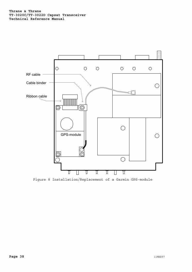
The optional-GPS module is electrically connected to theTransceiver via a small ribbon cable and a 14 cm long RF cable.
If you need to change the GPS module or install one for the firsttime, you must disassemble the Transceiver and take out the TT37-106110 Main Board.
The GPS-module is fastened to the C-transceiver with 4 stays, 4screws and 4 nuts. To install a GPS-module please follow thefollowing procedure (refer to Figure 8):
1) Fasten the 4 stays to the TT37-106110 Main Board using the 4screws.
2) Place the Garmin GPS-module on the stays.
3) Put the cable binder around the RF cable. Place the cable binderon the stay to the right of the ribbon cable as shown in Figure 8.
3) Fasten the GPS-module and cable binder to the stays using the 4nuts.
4) Connect the Ribbon cable and the RF cable.
The Transceiver is now assembled again.
At power-on the Transceiver will automatically detect the presenceof a GPS module. No further actions are required to tell theTransceiver that a GPS module has been installed.
Thrane & ThraneTT-3020C/TT-3022D Capsat TransceiverTechnical Reference Manual
Page 38 11MAR97
GPS-module
Ribbon cable
RF cable
Cable binder
Figure 8 Installation/Replacement of a Garmin GPS-module
Thrane & ThraneTT-3020C/TT-3022D Capsat Transceiver
Technical Reference Manual
11MAR97 Page 39
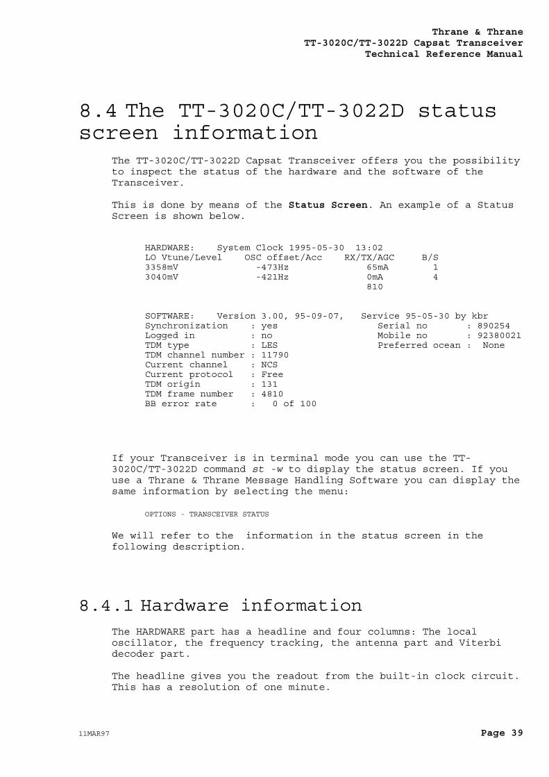
8.4 The TT-3020C/TT-3022D statusscreen information
The TT-3020C/TT-3022D Capsat Transceiver offers you the possibilityto inspect the status of the hardware and the software of theTransceiver.
This is done by means of the Status Screen. An example of a StatusScreen is shown below.
HARDWARE: System Clock 1995-05-30 13:02LO Vtune/Level OSC offset/Acc RX/TX/AGC B/S3358mV -473Hz 65mA 13040mV -421Hz 0mA 4 810
SOFTWARE: Version 3.00, 95-09-07, Service 95-05-30 by kbrSynchronization : yes Serial no : 890254Logged in : no Mobile no : 92380021TDM type : LES Preferred ocean : NoneTDM channel number : 11790Current channel : NCSCurrent protocol : FreeTDM origin : 131TDM frame number : 4810BB error rate : 0 of 100
If your Transceiver is in terminal mode you can use the TT-3020C/TT-3022D command st -w to display the status screen. If youuse a Thrane & Thrane Message Handling Software you can display thesame information by selecting the menu:
OPTIONS - TRANSCEIVER STATUS
We will refer to the information in the status screen in thefollowing description.
8.4.1 Hardware informationThe HARDWARE part has a headline and four columns: The localoscillator, the frequency tracking, the antenna part and Viterbidecoder part.
The headline gives you the readout from the built-in clock circuit.This has a resolution of one minute.
Thrane & ThraneTT-3020C/TT-3022D Capsat TransceiverTechnical Reference Manual
Page 40 11MAR97
The rows in each column are now described:
8.4.1.1 LO Vtune/LevelThis row gives information about the status of the localoscillator.
LO Vtune indicates what the tuning voltage to the Local Oscillatoris at the moment.
When the Transceiver is receiving this voltage will typically be inthe area 3000 - 4500 mV. When the Transceiver is transmitting thevoltage will typically be in the area 5500 - 7200 mV. The voltagemust never be below 1500 mV or above 7750 mV.
LO Level shows the voltage level of the detector circuit. Thisvoltage indicates the level of the Local Oscillator signal.
This voltage will typically be in the range 2800 - 4200 mV.
8.4.1.2 OSC offset/Acc.This row gives information about the frequency inaccuracy of theTransceiver relative to the LES due to short term environmental,and long term crystal ageing frequency variation.
The OSC offset value indicates the momentary frequency inaccuracyand the OSC Acc. value indicates an accumulated frequencyinaccuracy.
The software will compensate the receive- and the transmit-frequencies for these inaccuracies.
8.4.1.3 RX/TX/AGCThis row gives you information about the antenna current and thepresent AGC (Automatic Gain Control) setting.
The receiving current (RX) is the current that the transceiver willmeasure on the antenna connector, in the idle receive state.
The value depends on the type of antenna used. For a TT-3005Bantenna it will typically be 65 mA. A typically value for othertypes of Antenna Units is 100 mA.
If the antenna is disconnected the current will be 0 mA.
Thrane & ThraneTT-3020C/TT-3022D Capsat Transceiver
Technical Reference Manual
11MAR97 Page 41
The transmit power consumption (TX) is the value that was measuredat the last transmission on the antenna connector.
This value will typically be around 2400 - 3000mA. If you have notused the TT-3020C/TT-3022D for transmissions yet, the value will be0mA.
The Automatic Gain Control level (AGC) indicates the state of anattenuator in the receiver. This attenuator is used to perform theautomatic gain control. When the received signal is strong theattenuation will be high and when the received signal is very weakthere will be no attenuation.
A very low AGC value corresponds to a low attenuation and thus aweak signal and/or a very long cable between the Transceiver andthe antenna. A high AGC value corresponds to a high attenuation andthus a strong signal and/or a short cable.
With a good signal the AGC value will typically be about 800. Withno antenna connected the AGC value will be about 0.
8.4.1.4 B/S
BThe bulletin board check (B) is done by the main processor onthe basis of the received data for each 8.64 seconds of data.This 8.64 seconds of data is called a frame. The frame willcontain packets, and the first and most important is thebulletin board packet, which contains a frame number and theidentification and possible services of the emitting station andthis particular channel.The bulletin board check will normally read 1, which signifies avalid bulletin board, but when tuning or transmitting it mayread 0.
The readout is valid for the last-received data, so in case thetransceiver looses signal for a longer period, the data shownhere will be from the last received frame.
SThe Signal Strength (S) can vary from 0 to 5 where 5 is the bestsignal. You should have a reading above 2 to ensure a propercommunications link.The signal strength is measured directly on the received signal(after demodulating), where the renormalization count (R) iscalculated after the decoding, so (R) has a 8.64 seconds delayin respect to (S).
The value is measured as an average over 512 demodulated bits.
Thrane & ThraneTT-3020C/TT-3022D Capsat TransceiverTechnical Reference Manual
Page 42 11MAR97
The resulting number is on a scale from 0 to 5 that has thefollowing correspondence with the signal-to-noise ratio:
Signalstrength
0 1 2 3 4 5
SNR in dBHz <29 29-31 31-33 33-35 35-37 >37
The Signal Strength (S) will always be correct even when theTransceiver looses the synchronisation.
8.4.2 Software informationThe SOFTWARE part has a headline and two columns: The currentlyavailable information about the satellite link, and the long terminformation with an overview of user commands waiting to beexecuted.
The headline gives you the version number of the TT-3020C/TT-3022Dsoftware, and the corresponding release date, and the date and timeof last service together with the initials of the service engineer.
The rows in each column are now described:
8.4.2.1 SynchronisationThis corresponds to the status of the front panel LED "login". Thereadout will be "Yes" if the transceiver can receive and decode thesatellite signal properly.
8.4.2.2 Logged inThis corresponds to the status of the front panel LED "login". Thereadout will be "Yes" if the user has issued a login command andreceived a login acknowledgement from the Network Co-ordinatingStation (NCS) in the current ocean region. The readout will be "No"the first time the equipment is turned on, and if the user issues alogout command and receives a logout acknowledgement from the NCSin the current ocean region.
Thrane & ThraneTT-3020C/TT-3022D Capsat Transceiver
Technical Reference Manual
11MAR97 Page 43
8.4.2.3 TDM typeThis tells you if the transceiver is currently tuned to an NCS oran LES channel, or in rare cases a stand-alone station. Thepossible readouts are: NCS, LES, Joint NCS or Standby NCS,
8.4.2.4 TDM channel numberThis is a number from 8000 to 14000, that corresponds to anInmarsat-C system receive or transmit frequency.
8.4.2.5 Current channelThis information tells what type of channel the transceiver isusing. If receiving the channel can be an NCS, LES, and iftransmitting it can be "Message" or "Signalling". When changingchannel the readout will be "Retuning".
The possible readouts are: NCS, LES, Signalling, Message orRetuning.
8.4.2.6 Current protocolThis will tell you what protocol the transceiver is engaged in.
The possible readouts are:
Free
Pending
Sending Distress
Sending Distress Test
Login
Logout
Changing NCS
Scanning
Link Test
Transmission
Receiving message
Confirmation request
Message delivery
Position report
Data report
Link Test request
Thrane & ThraneTT-3020C/TT-3022D Capsat TransceiverTechnical Reference Manual
Page 44 11MAR97
The "Pending" status will appear if the Land Earth Station haspostponed a transmission or a link test. In this case the LES willautomatically inform the transceiver when to try the protocolagain.
8.4.2.7 TDM originThis number is received in the frame-data from the current station.It will correspond to a station found either in the LES or the NCStable.
8.4.2.8 TDM frame numberThis is the number of the current received data-frame. The numbersstart from 0 at midnight and ends a 9999 just before midnight,which gives a new frame every 8.64 seconds. In case the readoutshows "-" the transceiver did not receives a valid bulletin board(see column six in the hardware part).
8.4.2.9 BB error rateThe transceiver keeps a statistics of the bulletin boards last 100frames. This gives an idea of the signal quality in the last 15minutes. When transmitting, the transceiver will not increase theerror rate. This figure is transmitted to the LES as part of a linktest.
8.4.2.10 Serial numberThe serial number is mostly hardware identification but also alogical identification of a transceiver, as a specific serialnumber must follow a specific mobile number.
8.4.2.11 Mobile numberThis number is the call code of the unit. It is not used by theequipment to perform it duties, but is merely shown to help youremembering it.
Thrane & ThraneTT-3020C/TT-3022D Capsat Transceiver
Technical Reference Manual
11MAR97 Page 45
8.4.2.12 Preferred oceanThis information will be used for the next login command youperform.
8.4.2.13 Activities in queueThis information will only be present if you have specified severalcommands in a row. Transmit commands has the lowest priority ofall.
8.4.3 Printing the informationUsing the message terminal window program, this information canreadily be printed out. Just select the following menus:
OPTIONS - TRANSCEIVER STATUS - PRINT
Using the TT-3020C/TT-3022D interface this operation can beaccomplished by giving the command:
st -w p
where the letter 'p' means "print".
8.4.4 Storing the information in a filefor transmission
In some cases it may be useful to store the status information in afile (on disk) for later use or even transmission via the Inmarsat-C system.
Using the message terminal window program, this information caneasily be stored. Just select the following menus:
OPTIONS - TRANSCEIVER STATUS - SAVE
You can now view the file, load it into the editor and add your owncomments, and perhaps transmit the file later.
Thrane & ThraneTT-3020C/TT-3022D Capsat TransceiverTechnical Reference Manual
Page 46 11MAR97
9. Handling ofcommunication-error
situations
9.1 No synchronisationIf you turn on your TT-3020C/TT-3022D Capsat Transceiver and theLOGIN Indicator does not start to either flash or to light steadyafter 5 minutes, you should check the following:
Do you have an antenna connected?
Is the antenna cable properly fitted?
Look at the status screen. Check the RX reading indicating theantenna current. This current should be above 20 mA. If not theAntenna is not proberly connected.
Check the reading of the status screen's AGC level with the antennaconnected and without the antenna connected.
with antenna: AGC level approx. 800without antenna: AGC level approx. 0
Check the reading of the NCS origin ID. Does this match your oceanregion?
1-44 Atlantic West101-144 Atlantic East201-244 Pacific301-344 Indian
Has the antenna direct line-of-sight to the selected satellite?
Atlantic West 54ºWAtlantic East 15.5ºWPacific 178ºEIndian 64.5ºE
Thrane & ThraneTT-3020C/TT-3022D Capsat Transceiver
Technical Reference Manual
11MAR97 Page 47
9.2 Protocol errorsWhenever a link error occurs you will see either
Message from Transceiver:or
Message from Land Station:
appear before the reason of the error.
Only in case of non-delivery you will still find message codeslike:
Land Station gives error code: PRF
where PRF would stand for "Protocol Failure".
These codes cannot completely be eliminated as they can vary fromstation to station. In case you want a full explanation you shouldcontact the Station Operator.
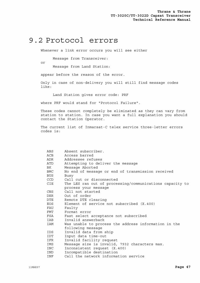
The current list of Inmarsat-C telex service three-letter errorscodes is:
ABS Absent subscriber.ACB Access barredADR Addressee refusesATD Attempting to deliver the messageBK Message AbortedBMC No end of message or end of transmission receivedBUS BusyCCD Call cut or disconnectedCIE The LES ran out of processing/communications capacity to
process your messageCNS Call not startedDER Out of orderDTE Remote DTE clearingEOS Element of service not subscribed (X.400)FAU FaultyFMT Format errorFSA Fast select acceptance not subscribedIAB Invalid answerbackIAM Was unable to process the address information in the
following messageIDS Invalid data from shipIDT Input data time-outIFR Invalid facility requestIMS Message size is invalid, 7932 characters max.INC Inconsistent request (X.400)IND Incompatible destinationINF Call the network information service
Thrane & ThraneTT-3020C/TT-3022D Capsat TransceiverTechnical Reference Manual
Page 48 11MAR97
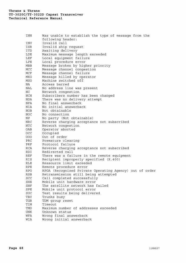
INH Was unable to establish the type of message from thefollowing header:
INV Invalid callISR Invalid ship requestITD Awaiting deliveryLDE Maximum message length exceededLEF Local equipment failureLPE Local procedure errorMBB Message broken by higher priorityMCC Message channel congestionMCF Message channel failureMKO Message killed by operatorMSO Machine switched offNA Access barredNAL No address line was presentNC Network congestionNCH Subscribers number has been changedNDA There was no delivery attemptNFA No final answerbackNIA No initial answerbackNOB Not obtainableNOC No connectionNP No party (Not obtainable)NRC Reverse charging acceptance not subscribedNTC Network congestionOAB Operator abortedOCC OccupiedOOO Out of orderPRC Premature clearingPRF Protocol failureRCA Reverse charging acceptance not subscribedRDI Redirected callREF There was a failure in the remote equipmentRIS Recipient improperly specified (X.400)RLE Ressource limit exceededRPE Remote procedure errorRPO RPOA (Recognized Private Operating Agency) out of orderRSB Retransmission still being attemptedSCC Call completed successfullySHE Mobile unit hardware errorSNF The satellite network has failedSPE Mobile unit protocol errorSUC Test results being deliveredTBY Trunks busyTGR TDM group resetTIM TimeoutTMD Maximum number of addresses exceededUNK Unknown statusWFA Wrong final answerbackWIA Wrong initial answerback
Thrane & ThraneTT-3020C/TT-3022D Capsat Transceiver
Technical Reference Manual
11MAR97 Page 49
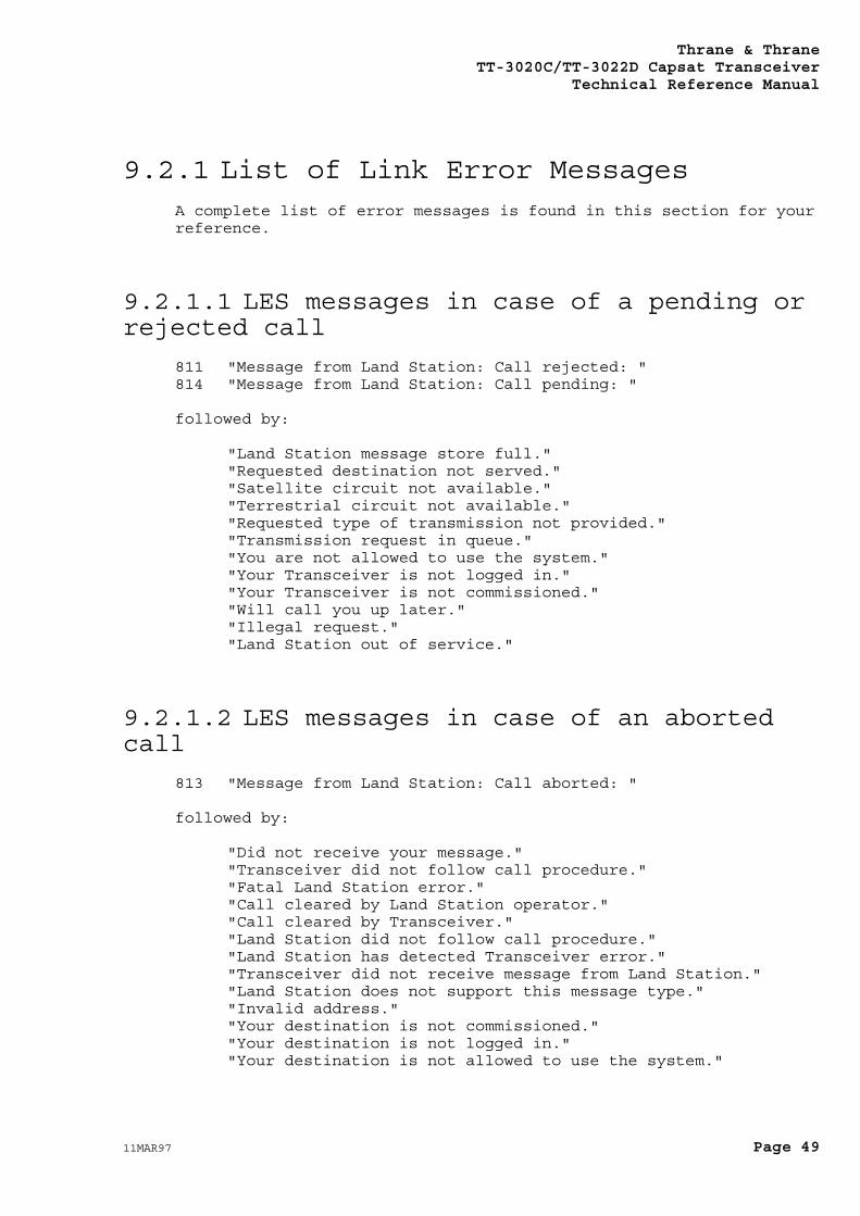
9.2.1 List of Link Error MessagesA complete list of error messages is found in this section for yourreference.
9.2.1.1 LES messages in case of a pending orrejected call
811 "Message from Land Station: Call rejected: "814 "Message from Land Station: Call pending: "
followed by:
"Land Station message store full.""Requested destination not served.""Satellite circuit not available.""Terrestrial circuit not available.""Requested type of transmission not provided.""Transmission request in queue.""You are not allowed to use the system.""Your Transceiver is not logged in.""Your Transceiver is not commissioned.""Will call you up later.""Illegal request.""Land Station out of service."
9.2.1.2 LES messages in case of an abortedcall
813 "Message from Land Station: Call aborted: "
followed by:
"Did not receive your message.""Transceiver did not follow call procedure.""Fatal Land Station error.""Call cleared by Land Station operator.""Call cleared by Transceiver.""Land Station did not follow call procedure.""Land Station has detected Transceiver error.""Transceiver did not receive message from Land Station.""Land Station does not support this message type.""Invalid address.""Your destination is not commissioned.""Your destination is not logged in.""Your destination is not allowed to use the system."
Thrane & ThraneTT-3020C/TT-3022D Capsat TransceiverTechnical Reference Manual
Page 50 11MAR97
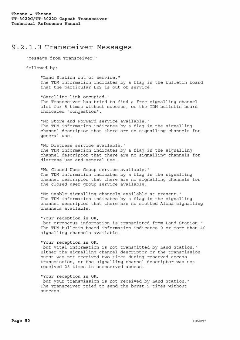
9.2.1.3 Transceiver Messages"Message from Transceiver:"
followed by:
"Land Station out of service."The TDM information indicates by a flag in the bulletin boardthat the particular LES is out of service.
"Satellite link occupied."The Transceiver has tried to find a free signalling channelslot for 5 times without success, or the TDM bulletin boardindicated "congestion".
"No Store and Forward service available."The TDM information indicates by a flag in the signallingchannel descriptor that there are no signalling channels forgeneral use.
"No Distress service available."The TDM information indicates by a flag in the signallingchannel descriptor that there are no signalling channels fordistress use and general use.
"No Closed User Group service available."The TDM information indicates by a flag in the signallingchannel descriptor that there are no signalling channels forthe closed user group service available.
"No usable signalling channels available at present."The TDM information indicates by a flag in the signallingchannel descriptor that there are no slotted Aloha signallingchannels available.
"Your reception is OK, but erroneous information is transmitted from Land Station."The TDM bulletin board information indicates 0 or more than 40signalling channels available.
"Your reception is OK, but vital information is not transmitted by Land Station."Either the signalling channel descriptor or the transmissionburst was not received two times during reserved accesstransmission, or the signalling channel descriptor was notreceived 25 times in unreserved access.
"Your reception is OK, but your transmission is not received by Land Station."The Transceiver tried to send the burst 9 times withoutsuccess.
Thrane & ThraneTT-3020C/TT-3022D Capsat Transceiver
Technical Reference Manual
11MAR97 Page 51
"Land Station did not respond to transmission request"The Transceiver did not receive an assignment to send amessage.
"Land Station did receive request, but did not respond to it."The Transceiver timed-out waiting for a response packet fromthe LES.
"Transmission aborted by operator."The user or the Transceiver aborted the operation.
"The Land Station does not exist in this Ocean Region."The coast station selected for transmission was not found inthe LES table.
"Cannot acquire synchronisation at the satellite channel."Either the transceivers synthesisers did not lock after 10seconds, or the synchronisation was not found, or the trackingwas not successful.
"Did not receive any message from Land Station."The Transceiver tried 4 times to request message packets fromthe LES.
"Land Station did not finish message."The Transceiver tried 4 times to end a message reception withthe LES.
"Reception aborted by operator."The user or the Transceiver aborted message reception.
"Transmission hardware error."Error detected in transmit queue hardware.
"Frequency cannot be tracked."The Transceiver could not get the frequency difference within150 Hz of the TDM carrier.
"Land Station did not follow call procedure."The LES did not reserve a signalling channel slot for theTransceiver as expected.
"Inmarsat-C System is now in Restoration mode."The system cannot be used for login, logout and link tests asthe NCS is out of operation at the moment.
"Land Station does not support Land Mobile Alerts"The TDM channel information indicated that the LES did notsupport the alert service.
"No response from Land Station."The Transceiver sent a login request 4 times without aresponse.
Thrane & ThraneTT-3020C/TT-3022D Capsat TransceiverTechnical Reference Manual
Page 52 11MAR97
"Illegal service specified."The store-and-forward service type was not specified for thetransmission.
"Expected Land Station was not found"The Transceiver has checked the LES ID in your DNID tableagainst the origin ID in the LES TDM and found that they weredifferent. Either your Transceiver tuned to the wrongchannel, or the LES TDM channel has been configuredincorrectly.
9.3 Login impossibleIf your Transceiver cannot login you should first of all contactyour LES Operator to verify that the Transceiver is in fact presentin the Inmarsat-C System database.
If you have just sent the commissioning forms to your PTTauthorities, your Transceiver may not yet be registered withInmarsat.
In any circumstance you should not use the equipment if you do notknow the mobile number of your Capsat System.
9.4 Tuning failsIf your Transceiver looses synchronisation while in a protocol(e.g. message transmission), this may have been caused by incorrectchannel information.
If this happens the Transceiver will automatically check if the LESNetwork Table version number stored in memory is different from theversion that the Inmarsat-C system currently uses.
If this is the case, the Transceiver will automatically start alogin, to get a new LES Network Table.
You should then attempt to send your message again.
If the tuning still fails you should printout and inspect thehardware status screen. Please refer to section 8.4 on page 39.
If you only have a problem with one specific LES, you should takenote of the Signal Strength value in the Status Screen, when theTransceiver is tuned to the particular channel.
For further information please contact your dealer.
Thrane & ThraneTT-3020C/TT-3022D Capsat Transceiver
Technical Reference Manual
11MAR97 Page 53
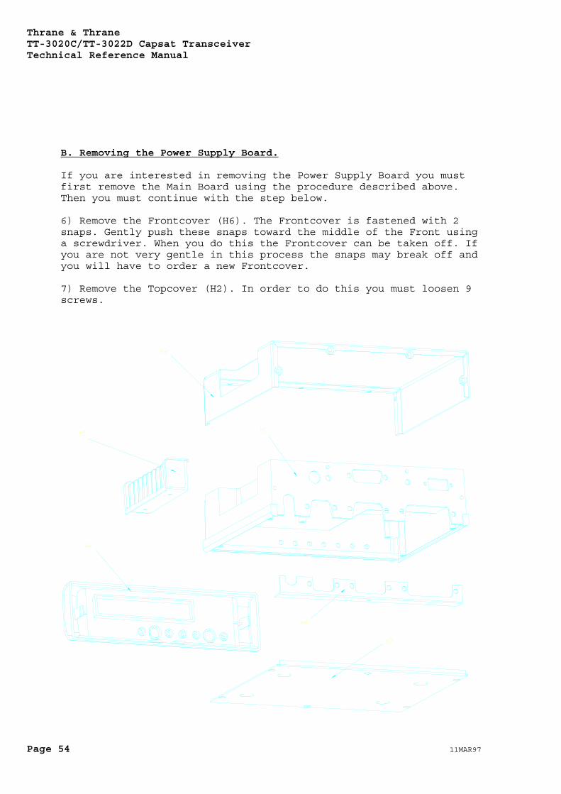
10. How to disassemble theTransceiver
If you have to disassemble the TT-3020C/TT-3022D Capsat Transceiverit is important, that you follow the procedure described in thissection. Otherwise you will find it very difficult and you risk topermanently damage the Transceiver.
WARNINGDo not try to
disassemble the TT-3020C/TT-3022D CapsatTransceiver yourself.This operation mustonly be performed byT&T approved service
personnel.
The procedure used to disassemble the TT-3020C/TT-3022D CapsatTransceiver depends on whether you want to remove the Main Board orthe Power Supply Board.
A. Removing the Main Board.
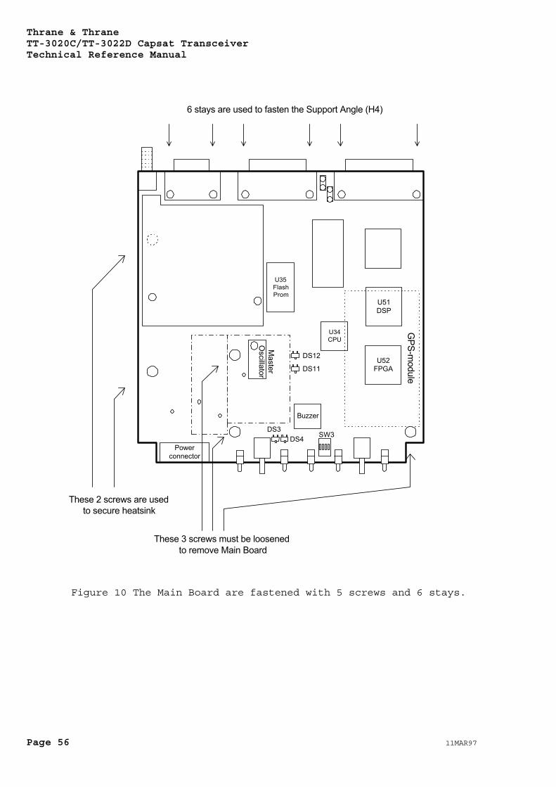
To remove the Main Board you must follow the procedure (pleaserefer to the drawing on Figure 9):
1) Remove the Bottomcover (H3). To do this you must loosen 6screws. The Main Board will now be visible.
2) Remove the Shield cover from the Main Board (please refer toFigure 10). The Shield cover has been soldered to the Shield Frame.You must unsolder the Shield cover in order to remove it.
3) The next step is to remove the Heatsink Block (H5). The HeatsinkBlock is secured by 2 screws through the Main Board. One of thesescrews were located under the Shield cover. These 2 screws areloosened and the Heatsink are removed. The screws used to fastenthe Main Board is shown in Figure 10
4) Remove the Support Angle (H4). To do this you must loosen 6stays.
5) It is now possible to remove the Main Board (TT37-106110). Thisis done by loosening the remaining 3 screws. Gently take the boardout of the Frame (H1). Disconnect the power connector.
Thrane & ThraneTT-3020C/TT-3022D Capsat TransceiverTechnical Reference Manual
Page 54 11MAR97
B. Removing the Power Supply Board.
If you are interested in removing the Power Supply Board you mustfirst remove the Main Board using the procedure described above.Then you must continue with the step below.
6) Remove the Frontcover (H6). The Frontcover is fastened with 2snaps. Gently push these snaps toward the middle of the Front usinga screwdriver. When you do this the Frontcover can be taken off. Ifyou are not very gentle in this process the snaps may break off andyou will have to order a new Frontcover.
7) Remove the Topcover (H2). In order to do this you must loosen 9screws.

Thrane & ThraneTT-3020C/TT-3022D Capsat Transceiver
Technical Reference Manual
11MAR97 Page 55
Figure 9 Mechanical parts of the TT-3020C/TT-3022D CapsatTransceiver.
8) The Power Supply now becomes visible. The Power Supply isremoved from the Frame (H1). To do this you must first loosen 2stays and 7 screws. Gently take the board out of the Frame (H1).
You have now completely disassembled the TT-3020C/TT-3022D CapsatTransceiver. To Assemble the Transceiver reverse the process. Inthis case however you must fasten the 6 stays to the Main Boardbefore you mount any screws on the board.
Thrane & ThraneTT-3020C/TT-3022D Capsat TransceiverTechnical Reference Manual
Page 56 11MAR97
Powerconnector
Buzzer
U35FlashProm
U51DSP
U52FPGA
U34CPU
DS12
DS11
DS3DS4 SW3
GPS-m
odule
Master
Oscillator
These 2 screws are usedto secure heatsink
These 3 screws must be loosenedto remove Main Board
6 stays are used to fasten the Support Angle (H4)
Figure 10 The Main Board are fastened with 5 screws and 6 stays.
Thrane & ThraneTT-3020C/TT-3022D Capsat Transceiver
Technical Reference Manual
11MAR97 Page 57
Index— A—
aborted call, 45activities in queue, 40AGC value, 37Alarm button, 18Alarm indicator, 18Almanac, 10Antenna connector, 20Antenna voltage, 20ArcNet communication, 22ArcNet termination, 23
— B—
Baudrate, 21BB error rate, 40bulletin board check, 37
— C—
C/A code, 7current channel, 39current protocol, 39
— D—
DB-15 female connector, 23DB-15 male, 19DC input, 19Distress, 2
— E—
EGC System and SafetyNetcalls, 3
Ephemeris parameters, 10
— F—
Figure of Merit, 11Four Satellite Navigation, 9frequency inaccuracy, 36
— G—
Global Positioning System,7, 8
GPS built-in self-test, 29GPS Test Summary, 29
— H—
hardware information, 35
— L—
logged in, 38login impossible, 48Login indicator, 18
— M—
Main indicator, 18mobile number, 5, 40
— N—
NMEA 0183 communication, 22no synchonization, 42
— O—
On/off features, 20
— P—
Parallel I/O, 22pending call, 45Power indicator, 18Power supply, 28preferred ocean, 40protocol errors, 43
— R—
receiving current, 36rejected call, 45
— S—
Satellite Navigation, 9Satellite ranging, 7Selective Availability, 8Send indicator, 18serial number, 40Set button, 18signal strength, 37software information, 38speaker, 17Standard Position Service, 8synchronization, 38
— T—
TDM channel number, 38TDM frame, 37TDM frame number, 39TDM origin, 39TDM type, 38three-dimensional, 9Time-To-First-Fix, 8TNC connector, 20

Thrane & ThraneTT-3020C/TT-3022D Capsat TransceiverTechnical Reference Manual
Page 58 11MAR97
transmit power consumption,36
tuning fails, 48