power application highlights
TRANSCRIPT
Power Application Highlights
EFFICIENT. ROBUST. SCALABLE.
Industrial Home Appliance
eMobility
Committed to excellence
V1.0.1

RUTRONIK POWER
The Markets are ChangingChanging markets demand new solutions. Many markets are saturated, and products are being ever more replaceable and increasingly offering similar functionality thanks to growing standardization. Technological, regulatory and economic challenges along with growing functional complexity are a reality of numerous market segments, particularly for the industrial, automation, automotive and white goods (electronic household appliances for private and commercial use) segments.
RUTRONIK POWER
2 3Industrial | eMobility | Home Appliancewww.rutronik.com/POWER www.rutronik.com/POWERIndustrial | eMobility | Home Appliance| |
Consult – Know-how. Built-in. The technical competence from Rutronik
Worldwide and individual consulting on the spot:
by competent sales staff, application engineers and
product specialists.
Logistics – Reliability. Built-in. The delivery service from Rutronik
Innovative and flexible solutions: from supply chain management
to individual logistics systems.
Components – Variety. Built-in. The product portfolio from Rutronik
Wide product range of semiconductors, passive and
electromechanical components, storage, displays & boards and
wireless technologies for optimum coverage of your needs.
Committed to excellence
Quality – Security. Built-in.Quality management without compromise
The integrated management system (IMS) encompasses
quality control, environmental protection and occupational
health and safety.
Our Product Portfolio
Semiconductors
PassiveComponents
ElectromechanicalComponents
Displays & Boards
WirelessTechnologies
Storage Technologies
Follow us https://www.facebook.com/rutronik
https://twitter.com/Rutronik
https://www.youtube.com/user/Rutronik24
https://rutronik-tec.com
Get your Rutronik App:
Content
RUTRONIK POWER 4 - 9
RUTRONIK24 19
RUTRONIK SMART 73
RUTRONIK EMBEDDED 74
RUTRONIK AUTOMOTIVE 75
Industrial Application Frequency Inverter . . . . . 8 – 9
Rectifiers 10
MOSFETs 11
Open Frame Solutions 12
LED Drivers 13
SiC Power Devices 14 – 15
DC/DC Converters 16 – 21
Motor Drivers 22
Passive Components 23 – 33
Elektromechanical Components 34 – 39
eMobility Application – Forklift Vehicle . . . . . 40 – 41
MOSFETs 42 – 44
SiC Schottky Barrier Diodes 45
Embedded Power ICs 46
Passive Components 47 – 55
Electromechanical Components 56 – 61
Home Appliance Application – Induction Hob . . 62 – 63
AC/DC Modules/Adapters 64 – 65
Intelligent Power Modules 66 – 67
Passive Components 67 – 71
Electromechanical Components 72

Digital PowerOne “power future trend” is that of “digital power”, also refer-red to as “intelligent digital power”. In electrical engineering, this buzzword refers to digitally controlled or monitored power supply units. In conventional switched-mode power supply units, an analog switch controls and monitors the output voltage. In digital power supply units, a microcontroller or DSP handles one or several of these functions. The control process is integrated into the controller at software level.
One of the major advantages of digitally-controlled switched power supply units over analog solutions is the option of being able to intervene in the control process at any time and to adapt it to the current needs of the power supply. While this increases the level of effectiveness of the digital PSU compared to an analog variant, this does also increase the amount of technical development work required, which is reflected in the costs. Digital technology aims to satisfy the needs of the now ever more complex power supply systems.
Functional Safety and RobustnessInnovations that do not take safety into account cannot endure, which is why high functional safety and robustness are essential. In a robustness validation, for example, the reliability of electronic components is assessed by comparing the specific product requirements against the actual service life, taking into account the increase in efficiency.
The fundamental concept behind functional safety is the strategy for reducing actual risks. The goal is to create a safe system in that every reasonable measure has been taken to avoid damage to property and danger to people, ensuring traditional safety measures.
RUTRONIK accommodates as broad a range of requirements as possible here – whether low-cost or high-performance. For example, for a motor control circuit in the power range of 2KW, RUTRONIK offers appropriately designed IGBT modules, gate drivers as well as microcontrollers, driver modules, heatsinks and plug connectors.
For power semiconductors, RUTRONIK caters for everything today, from discrete to high-integration components, power ICs and power modules. As a broadline distributor, RUTRONIK offers all other components in addition to its power semiconductors, not only active but also electromechanical and passive components. The spectrum ranges from simple plug connectors to supercaps. This covers around 98% of the PCB. This also applies to other product segments such as high-current connectors supporting up to 1000A and supercaps supporting up to 3400 farad/cell.
But RUTRONIK POWER is much more than a broad selection of components. The decisive difference lies in RUTRONIK com-piling relevant expertise, not only for individual products and technologies, but also on their compatibility with one another.
This helps to guarantee extensive support – with development at application level by professionally qualified Field Application Engineers (FAEs), Product Managers at component level and supply at the end of a product lifecycle lasting several years. FAEs are particularly important for technical customer support.
RUTRONIK’s experts advise and support activities ranging from the design-in process, the product evaluation and appli-cation development, the strategic marketing of product groups for which theoretical assistance is necessary, down to the
EffectsThese trends cover many industries and are directly related to operating conditions, technologies and manufacturing processes. In other words, changes to operating conditions or other techniques or manufacturing processes will also mean the involvement of different requirements imposed upon the installed components. This can be more clearly illustrated in the example of energy storage. If the conditions in which a battery is operated or if new technologies or manufacturing processes are implemented, this gives rise to new requirements imposed upon the charging strategy or the battery management system.
The operating parameters are of critical importance to the service life of an energy storage facility within an application. While developers often have no influence on the operating con-ditions, there is scope for optimization in the battery manage-ment system, although this scope is often used inadequately.
As a result, operating conditions are changed without imple-menting the battery management system accordingly. In this connection, the most frequent recorded electrical failures are due to defective or discharged starter batteries. Specifically in the automotive industry, such battery failures were mainly found in luxury vehicles until the year 2000. The main cause was the growth in electronic component use and other electricity consumers in the vehicles, because even in a parked vehicle, the starter battery is constantly being discharged by the monitoring and control electronics. While the currents involved here – referred to as “standby currents” – are low, the battery can suffer from deep discharge if left dormant for long periods of time. For manufacturers, this raises the question of whether this know-how needs to be developed internally or whether the market might offer a suitable solution.
development of logistics solutions with comprehensive system solutions that are optimized to the customer’s needs.
RUTRONIK POWER focuses less on individual components and more on the overall solution.
RUTRONIK gives absolute priority not only to reducing the prevailing complexity of the offer-range but also to providing support at the product development stage at application level with relevant technical expertise and vertical system solutions based on suitable components.
Trends in High-Performance Electronics
In addition to the trends in the market segments, there are also developments that are affecting the entire high-performance electronics sector. The most important of these developments are “digital power” also with the related topics of “functional safety” and “robustness”. These have direct effects on operating conditions, technology and manufacturing methods.
The Answer – RUTRONIK POWER
RUTRONIK POWER is much more than a complete portfolio of power components for various voltage classes and different applications. RUTRONIK POWER also offers a selection of components for a variety of applications suitable for the respective circuit. This means that under every position in the block diagram, there are products from multiple selected suppliers in the respective product segments.
RUTRONIK POWER
4 5Industrial | eMobility | Home Appliancewww.rutronik.com/POWER www.rutronik.com/POWERIndustrial | eMobility | Home Appliance| |
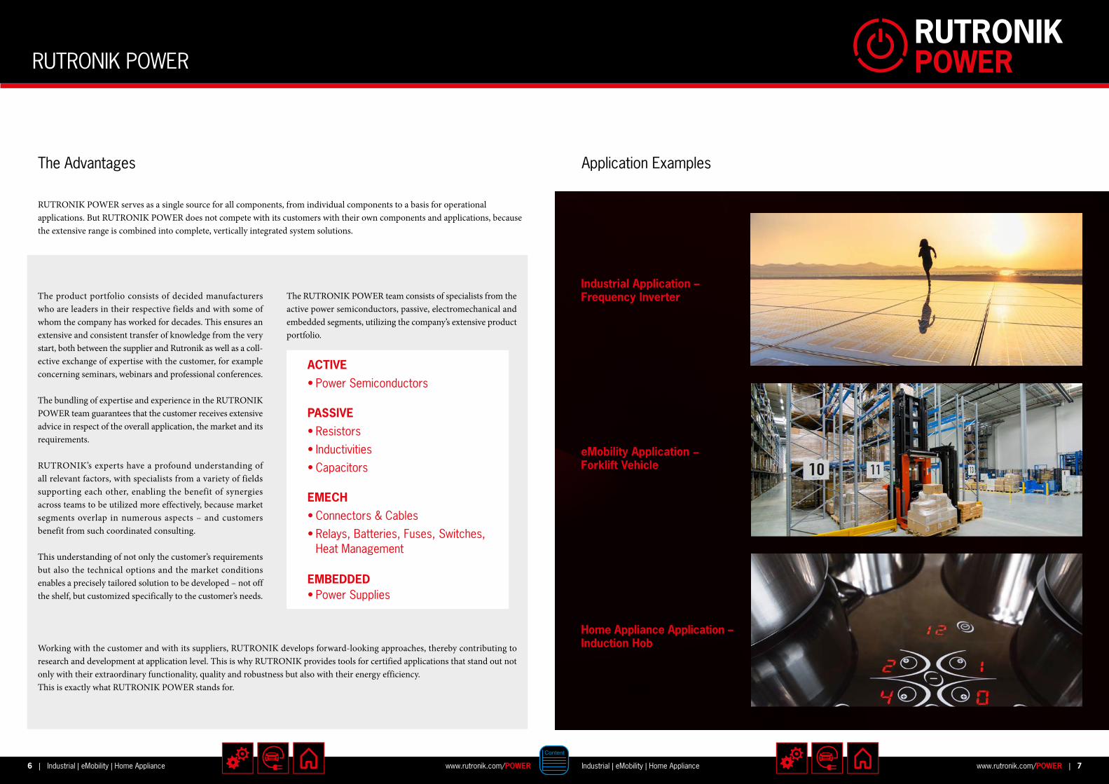
The product portfolio consists of decided manufacturers who are leaders in their respective fields and with some of whom the company has worked for decades. This ensures an extensive and consistent transfer of knowledge from the very start, both between the supplier and Rutronik as well as a coll-ective exchange of expertise with the customer, for example concerning seminars, webinars and professional conferences.
The bundling of expertise and experience in the RUTRONIK POWER team guarantees that the customer receives extensive advice in respect of the overall application, the market and its requirements.
RUTRONIK’s experts have a profound understanding of all relevant factors, with specialists from a variety of fields supporting each other, enabling the benefit of synergies across teams to be utilized more effectively, because market segments overlap in numerous aspects – and customers benefit from such coordinated consulting.
This understanding of not only the customer’s requirements but also the technical options and the market conditions enables a precisely tailored solution to be developed – not off the shelf, but customized specifically to the customer’s needs.
The RUTRONIK POWER team consists of specialists from the active power semiconductors, passive, electromechanical and embedded segments, utilizing the company’s extensive product portfolio.
Working with the customer and with its suppliers, RUTRONIK develops forward-looking approaches, thereby contributing to research and development at application level. This is why RUTRONIK provides tools for certified applications that stand out not only with their extraordinary functionality, quality and robustness but also with their energy efficiency. This is exactly what RUTRONIK POWER stands for.
ACTIVE• Power Semiconductors
PASSIVE• Resistors• Inductivities• Capacitors
EMBEDDED• Power Supplies
EMECH• Connectors & Cables• Relays, Batteries, Fuses, Switches,
Heat Management
The Advantages
RUTRONIK POWER serves as a single source for all components, from individual components to a basis for operational applications. But RUTRONIK POWER does not compete with its customers with their own components and applications, because the extensive range is combined into complete, vertically integrated system solutions.
Application Examples
Home Appliance Application – Induction Hob
Industrial Application – Frequency Inverter
eMobility Application − Forklift Vehicle
RUTRONIK POWER
6 7Industrial | eMobility | Home Appliancewww.rutronik.com/POWER www.rutronik.com/POWERIndustrial | eMobility | Home Appliance| |

Micro-controller
Brake Chopper Inverter
PositionSensing
Hall & GMRSensors
+
PFC
MCurrentSensing
Auxiliary Power SuppliesDC/DC
Isolated Gate Driver
29
3
6
7
8
12
11
10
4
5
DC
AC230V
13
AC 380VFilter
1
16
14
15
LegendApplication: up to 5 KW
Activ
e
NO Type Dio
des
Infin
eon
Litt
elfu
se
Rec
om
Roh
m
ST Vish
ay2 Rectifier (Bridge) X X
3
AC/DC PWM-PFC Controller X XDiode X X X XMOSFet X X X XRectifier X X X X
4 IGBT Module (Brake Chopper) X X
6Diode X X XRectifier X X X
7IGBT X XIGBT Module X X X XMOSFet X X X X
8 Sensor X X
9Hall Switch X X XMagnetic Position Sensor X X X
10 Microcontroller X X
11
DC/DC Converter (Module) XDC/DC Switching Converter X X X XDiode X X X XLDO X X X XMOSFet X X X X XRectifier X X X X
12Gate Driver X X X XGate Driver (Isolated) X X XMotor Control IC X X X
13AC/DC Converter Module XDiode (Protection) X X X X X XDiode (Schottky) X X X X X
14IGBT Module X XIPM X X XTIM X
15 IGBT X X
Pass
ive
NO Type AVX
KEK
O
Vari
con
Litt
elfu
se
KR
AH
Mur
ata
Puls
e
Rub
ycon
Sum
ida
Vish
ay
WIM
A
1
Filter X X XResistor (liquid-cooled) X
Resistor (wire-wound) X
2Varistor X X XCapacitor (Foil) X
3
Capacitor (Electrolyte) X
Capacitor (Foil) XInductor X X X
5Capacitor (Electrolyte) X
Capacitor (Foil) X X X6 Resistor X
EmbeddedNO Type FSP13 Power Supply X
Pass
ive
NO Type AVX
KEK
O
Vari
con
Litt
elfu
se
KR
AH
Mur
ata
Puls
e
Rub
ycon
Sum
ida
Vish
ay
WIM
A
7Inductor X X X
Power Transformer X X
Resistor X
8Current Transformer X X X
Capacitor (Foil) X
9Varistor X X X
Capacitor (Foil) X
10 Varistor X X X
11 Capacitor (Foil) X X
12 Resistor (wire-wound) X
13 Capacitor (Foil) X
16Resistor (liquid-cooled) X
Resistor (wire-wound) X
E-M
ech
NO Type Amph
enol
FC
I
ASSM
ANN
W
SW
JAE
Litt
elfu
se
Om
ron
1 Fuse X2 Heatsink (Extruded profile) X3 Heatsink (Extruded profile) X4 Heatsink (Extruded profile) X5 Heatsink (Extruded profile) X6 Heatsink (Extruded profile) X
7
Heatsink XHeatsink (Extruded profile) XHeatsink (SMD and copper) XHeatsink (Stamped finger shaped) X
8
Connector XHeatsink (Cross cut CPU) XHeatsink (Round pin fin CPU) XHeatsink (Stamped CPU) XConnector X
9
Heatsink (Cross cut CPU) XHeatsink (Round pin fin CPU) XHeatsink (Stamped CPU) XConnector X
10
Heatsink (Cross cut CPU) XHeatsink (Round pin fin CPU) XHeatsink (SMD and copper) XHeatsink (Stamped CPU) X
11 Heatsink (Extruded profile) X13 Heatsink (Extruded profile) X14 Relay X
Industrial Application – Frequency Inverter
8 9Industrial | eMobility | Home Appliancewww.rutronik.com/POWER www.rutronik.com/POWERIndustrial | eMobility | Home Appliance| |
Selection Guide
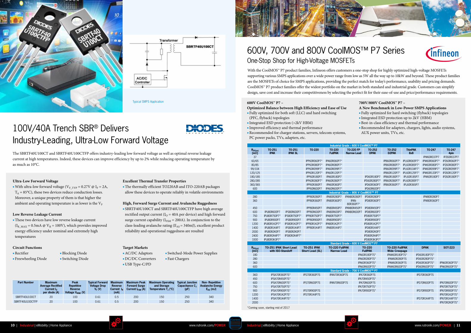
100V/40A Trench SBR® Delivers Industry-Leading, Ultra-Low Forward VoltageThe SBRTF40U100CT and SBRTF40U100CTFP offers industry-leading low forward voltage as well as optimal reverse leakage current at high temperatures. Indeed, these devices can improve efficiency by up to 2% while reducing operating temperature by as much as 10°C.
Ultra-Low Forward Voltage With ultra-low forward voltage (VF_TYP = 0.27V @ IF = 2A, TA = 85°C), these two devices reduce conduction losses. Moreover, a unique property of them is that higher the ambient and operating temperature is as lower is the VF
Low Reverse Leakage Current These two devices have low reverse leakage current (IR_MAX = 0.5mA @ VR = 100V), which provides improved energy efficiency under nominal and extremely high temperatures
Circuit Functions Rectifier Freewheeling Diode
Part Number Maximum Average Rectified
Current IOper diode (A)
Peak Repetitive Reverse
Voltage VRRM (V)
Typical Forward Voltage Drop
VF (V)
Maximum Reverse
Current IR(mA)
Maximum Peak Forward Surge Current IFSM (A)
Maximum Operating and Storage
Temperature TJ (ºC)
Typical Junction Capacitance CJ
(pF)
Non- Repetitive Avalanche Energy
EAS (mJ)
SBRTF40U100CT 20 100 0.61 0.5 200 150 250 340
SBRTF40U100CTFP 20 100 0.61 0.5 200 150 250 340
Target Markets AC/DC Adaptors DC/DC Converters USB Type-C/PD
Excellent Thermal Transfer Properties The thermally efficient TO220AB and ITO-220AB packages allow these devices to operate reliably in volatile environments
High, Forward Surge Current and Avalanche Ruggedness SBRTF40U100CT and SBRTF40U100CTFP have high average rectified output current (IO = 40A per device) and high forward surge current capability (IFSM = 200A). In conjunction to the class-leading avalanche rating (EAS = 340mJ), excellent product reliability and operational ruggedness are resulted
Typical SMPS Application
Blocking Diode Switching Diode
Switched-Mode Power Supplies Fast Chargers
600V, 700V and 800V CoolMOS™ P7 SeriesOne-Stop Shop for High-Voltage MOSFETsWith the CoolMOS™ P7 product families, Infineon offers customers a one-stop shop for highly optimized high-voltage MOSFETs supporting various SMPS applications over a wide power range from low as 5W all the way up to 10kW and beyond. These product families are the MOSFETs of choice for SMPS applications, providing the perfect match for today’s performance, usability and pricing demands.CoolMOS™ P7 product families offer the widest portfolio on the market in both standard and industrial grade. Customers can simplify design, save cost and increase their competitiveness by selecting the perfect fit for their ease-of-use and price/performance requirements.
700V/800V CoolMOS™ P7 – A New Benchmark in Low-Power SMPS Applications Fully optimized for hard switching (flyback) topologies Integrated ESD protection up to 2kV (HBM) Best-in-class efficiency and thermal performance Recommended for adapters, chargers, lights, audio systems, AUX power units, TVs, etc.
600V CoolMOS™ P7 – Optimized Balance between High Efficiency and Ease of Use Fully optimized for both soft (LLC) and hard switching (PFC, flyback) topologies Integrated ESD protection (>2kV HBM) Improved efficiency and thermal performance Recommended for charger stations, servers, telecom systems, PC power packs, TVs, adapters, etc.
Industrial Grade – 600 V CoolMOS™ P7RDS(on) [mΩ]
TO-251 IPAK
TO-251 IPAK SL
TO-220 TO-220 FullPAK
TO-220 FP Narrow Lead
TO-252 DPAK
TO-252 D2PAK
ThinPAK 8x8
TO-247 TO-247 4pin
37 IPW60R037P7 IPZ60R037P7 60/65 IPP60R060P7* IPA60R060P7* IPB60R060P7* IPL60R065P7* IPW60R060P7* IPZ60R060P7*80/85 IPP60R080P7* IPA60R080P7* IPB60R080P7* IPL60R085P7* IPW60R080P7* IPZ60R080P7*99/104 IPP60R099P7* IPA60R099P7* IPB60R099P7* IPL60R104P7* IPW60R099P7* IPZ60R099P7*120/125 IPP60R120P7* IPA60R120P7* IPB60R120P7* IPL60R125P7* IPW60R120P7* IPZ60R120P7*180/185 IPP60R180P7 IPA60R180P7 IPD60R180P7 IPB60R180P7* IPL60R185P7 IPW60R180P7 IPZ60R180P7*280/285 IPP60R280P7* IPA60R280P7* IPD60R280P7* IPB60R280P7* IPL60R285P7*360/365 IPP60R360P7 IPA60R360P7 IPD60R360P7 IPB60R360P7* IPL60R365P7
600 IPP60R600P7 IPA60R600P7* IPD60R600P7Industrial Grade – 800 V CoolMOS™ P7
280 IPP80R280P7 IPA80R280P7 IPAN80R280P7 IPD80R280P7 IPW80R280P7360 IPP80R360P7 IPA80R360P7 IPAN-
80R360P7*IPD80R360P7 IPW80R360P7
450 IPP80R450P7 IPA80R450P7 IPAN80R450P7 IPD80R450P7 600 IPU80R600P7 IPS80R600P7 IPP80R600P7 IPA80R600P7 IPAN80R600P7 IPD80R600P7750 IPU80R750P7* IPS80R750P7* IPP80R750P7* IPA80R750P7* IPD80R750P7*900 IPU80R900P7 IPS80R900P7 IPP80R900P7 IPA80R900P7 IPD80R900P71200 IPU80R1K2P7* IPS80R1K2P7* IPP80R1K2P7* IPA80R1K2P7* IPD80R1K2P7*1400 IPU80R1K4P7 IPS80R1K4P7 IPP80R1K4P7 IPA80R1K4P7 IPD80R1K4P7 2000 IPU80R2K0P7 IPS80R2K0P7 IPD80R2K0P72400 IPU80R2K4P7* IPS80R2K4P7* IPD80R2K4P7*3300 IPU80R3K3P7* IPD80R3K3P7*
Standard Grade – 600 V CoolMOS™ P7RDS(on) [mΩ]
TO-251 IPAK Short Lead with ISO-Standoff
TO-251 IPAK Short Lead (SL)
TO-220 FullPAK Narrow Lead
TO-220 FullPAK
TO-220 FullPAK Wide Creepage
DPAK SOT-223
180 IPA60R180P7S* IPAW60R180P7S* IPD60R180P7S*280 IPA60R280P7S* IPAW60R280P7S IPD60R280P7S*360 IPA60R360P7S* IPAW60R360P7S IPD60R360P7S* IPN60R360P7S*600 IPA60R600P7S* IPAW60R600P7S* IPD60R600P7S* IPN60R600P7S*
Standard Grade – 700 V CoolMOS™ P7360 IPSA70R360P7S* IPS70R360P7S IPAN70R360P7S IPA70R360P7S IPD70R360P7S 450 IPSA70R450P7S* IPA70R450P7S*600 IPSA70R600P7S* IPS70R600P7S IPAN70R600P7S IPA70R600P7S IPD70R600P7S IPN70R600P7S*750 IPSA70R750P7S* IPA70R750P7S* IPN70R750P7S*900 IPSA70R900P7S* IPS70R900P7S IPA70R900P7S* IPD70R900P7S IPN70R900P7S*1200 IPSA70R1K2P7S* IPS70R1K4P7S IPN70R1K2P7S*1400 IPSA70R1K4P7S* IPD70R1K4P7S IPN70R1K4P7S*2000 IPN70R2K0P7S*
*Coming soon, starting mid of 2017
10 11Industrial | eMobility | Home Appliancewww.rutronik.com/POWER www.rutronik.com/POWERIndustrial | eMobility | Home Appliance| |
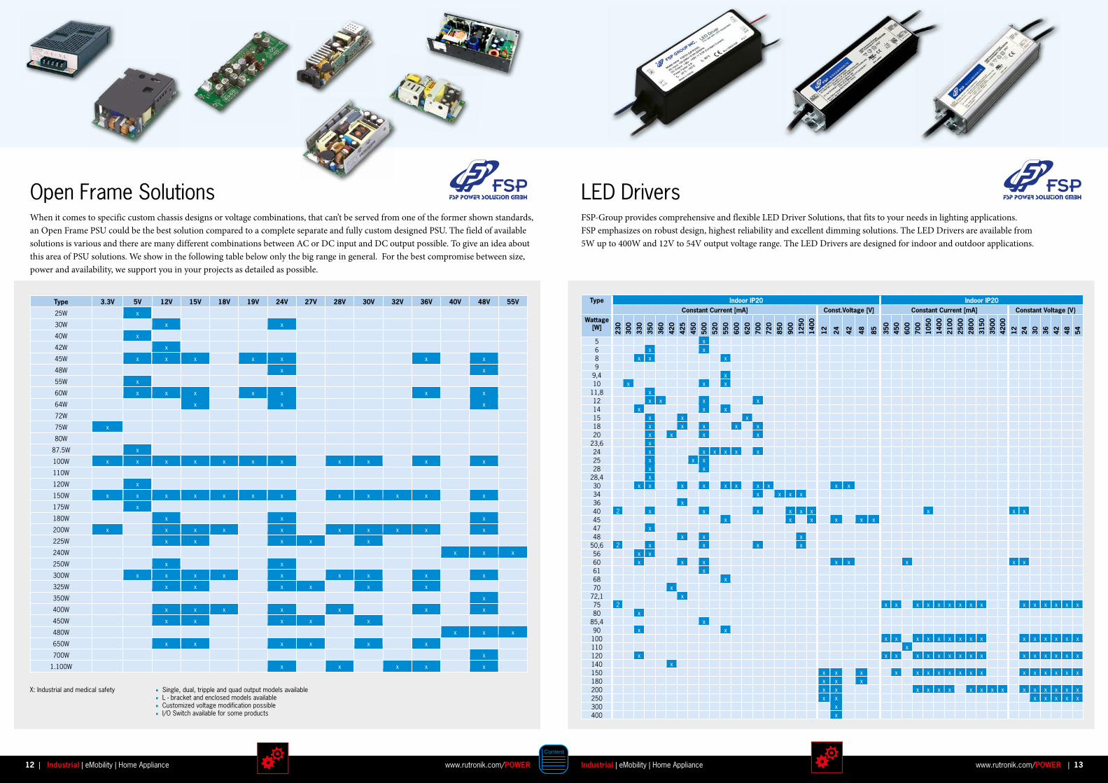
When it comes to specific custom chassis designs or voltage combinations, that can’t be served from one of the former shown standards, an Open Frame PSU could be the best solution compared to a complete separate and fully custom designed PSU. The field of available solutions is various and there are many different combinations between AC or DC input and DC output possible. To give an idea about this area of PSU solutions. We show in the following table below only the big range in general. For the best compromise between size, power and availability, we support you in your projects as detailed as possible.
FSP-Group provides comprehensive and flexible LED Driver Solutions, that fits to your needs in lighting applications. FSP emphasizes on robust design, highest reliability and excellent dimming solutions. The LED Drivers are available from 5W up to 400W and 12V to 54V output voltage range. The LED Drivers are designed for indoor and outdoor applications.
AC Inlet C6, C8 and C14 available multiple output available I/O Switch available for some products DC plug and cable length can be modified customized voltage modification possible
Single, dual, tripple and quad output models available L - bracket and enclosed models available Customized voltage modification possible I/O Switch available for some products
Open Frame Solutions LED Drivers
LED DriversType 3 .3V 5V 12V 15V 18V 19V 24V 27V 28V 30V 32V 36V 40V 48V 55V
25W x
30W x x
40W x
42W x
45W x x x x x x x
48W x x
55W x
60W x x x x x x x
64W x x x
72W
75W x
80W
87.5W x
100W x x x x x x x x x x x
110W
120W x
150W x x x x x x x x x x x x
175W x
180W x x x
200W x x x x x x x x x x
225W x x x x x
240W x x x
250W x x
300W x x x x x x x x x
325W x x x x x x
350W x
400W x x x x x x x
450W x x x x x
480W x x x
650W x x x x x x
700W x
1.100W x x x x x
X: Industrial and medical safety
Type Indoor IP20 Indoor IP20Constant Current [mA] Const .Voltage [V] Constant Current [mA] Constant Voltage [V
Wattage [W]
230
300
330
350
360
420
425
450
500
520
550
600
620
700
720
850
900
1250
1400
12 24 42 48 85 350
450
600
700
1050
1400
2100
2500
2800
3150
3500
4200
12 24 30 36 42 48 54
5 x6 x x8 x x x9
9,4 x10 x x x
11,8 x12 x x x x14 x x x15 x x x18 x x x x x20 x x x x
23,6 x24 x x x x x x25 x x x28 x x
28,4 x30 x x x x x x x x x x34 x x x x36 x40 2 x x x x x x x x x45 x x x x x x47 x48 x x x
50,6 2 x x x x56 x x60 x x x x x x x x61 x68 x70 x
72,1 x75 2 x x x x x x x x x x x x x x x80 x
85,4 x90 x x100 x x x x x x x x x x x x x x x110 x120 x x x x x x x x x x x x x x x x140 x150 x x x x x x x x x x x x x x x x x180 x x x200 x x x x x x x x x x x x x x x x250 x x x x x x x300 x400 x
12 13Industrial | eMobility | Home Appliancewww.rutronik.com/POWER www.rutronik.com/POWERIndustrial | eMobility | Home Appliance| |
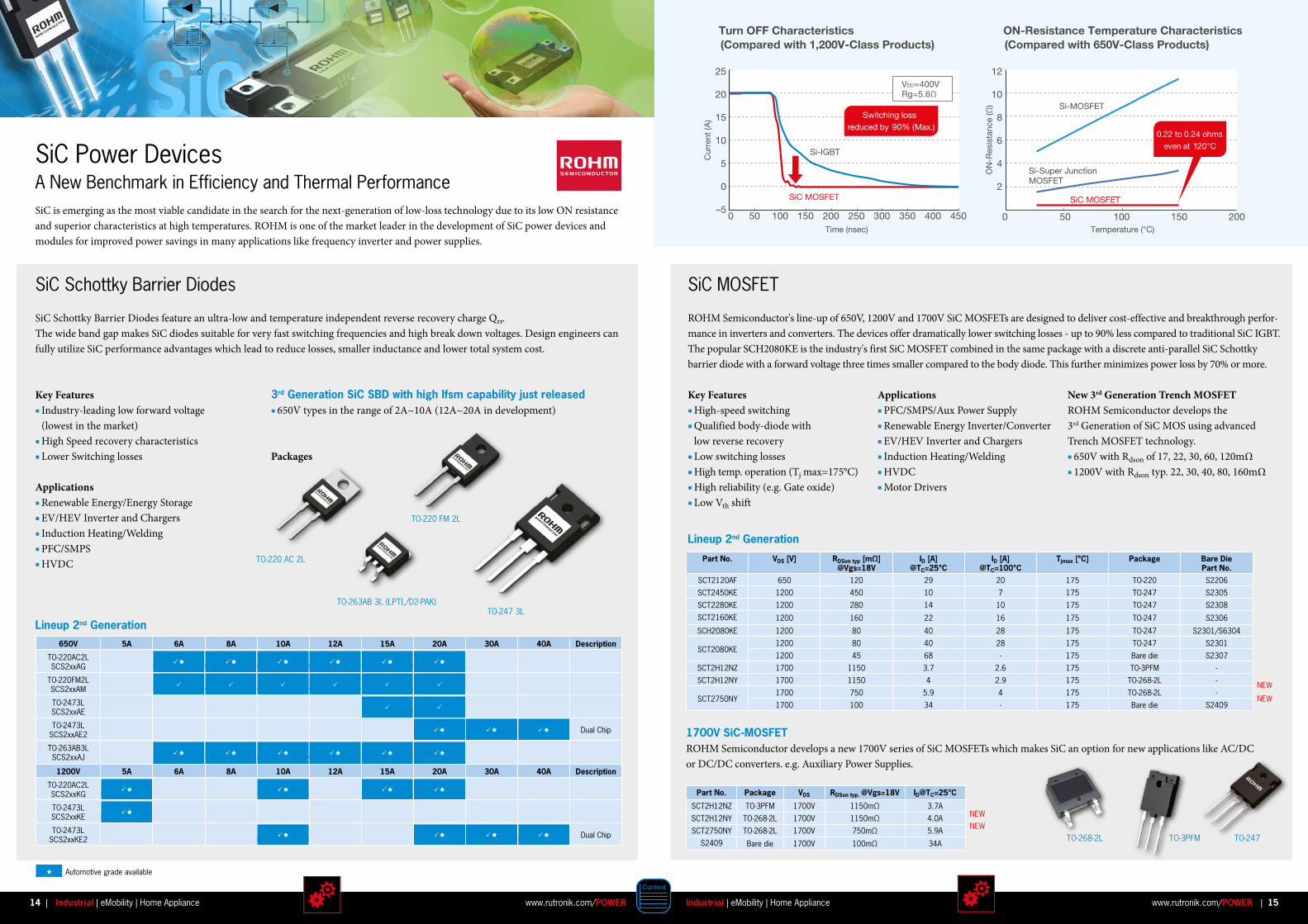
SiC is emerging as the most viable candidate in the search for the next-generation of low-loss technology due to its low ON resistance and superior characteristics at high temperatures. ROHM is one of the market leader in the development of SiC power devices and modules for improved power savings in many applications like frequency inverter and power supplies.
3rd Generation SiC SBD with high Ifsm capability just released 650V types in the range of 2A~10A (12A~20A in development)
Packages
New 3rd Generation Trench MOSFETROHM Semiconductor develops the 3rd Generation of SiC MOS using advanced Trench MOSFET technology. 650V with Rdson of 17, 22, 30, 60, 120mΩ 1200V with Rdson typ. 22, 30, 40, 80, 160mΩ
SiC Power DevicesA New Benchmark in Efficiency and Thermal Performance
SiC Schottky Barrier Diodes
SiC Schottky Barrier Diodes feature an ultra-low and temperature independent reverse recovery charge Qrr. The wide band gap makes SiC diodes suitable for very fast switching frequencies and high break down voltages. Design engineers can fully utilize SiC performance advantages which lead to reduce losses, smaller inductance and lower total system cost.
Key Features Industry-leading low forward voltage (lowest in the market) High Speed recovery characteristics Lower Switching losses
Applications Renewable Energy/Energy Storage EV/HEV Inverter and Chargers Induction Heating/Welding PFC/SMPS HVDC
Lineup 2nd Generation
Lineup 2nd Generation
SiC MOSFET
ROHM Semiconductor's line-up of 650V, 1200V and 1700V SiC MOSFETs are designed to deliver cost-effective and breakthrough perfor-mance in inverters and converters. The devices offer dramatically lower switching losses - up to 90% less compared to traditional SiC IGBT. The popular SCH2080KE is the industry's first SiC MOSFET combined in the same package with a discrete anti-parallel SiC Schottky barrier diode with a forward voltage three times smaller compared to the body diode. This further minimizes power loss by 70% or more.
Key Features High-speed switching Qualified body-diode with low reverse recovery Low switching losses High temp. operation (Tj max=175°C) High reliability (e.g. Gate oxide) Low Vth shift
Applications PFC/SMPS/Aux Power Supply Renewable Energy Inverter/Converter EV/HEV Inverter and Chargers Induction Heating/Welding HVDC Motor Drivers
1700V SiC-MOSFET ROHM Semiconductor develops a new 1700V series of SiC MOSFETs which makes SiC an option for new applications like AC/DC or DC/DC converters. e.g. Auxiliary Power Supplies.
TO-268-2L
TO-247 3L
TO-3PFM
TO-263AB 3L (LPTL/D2-PAK)
TO-220 FM 2L
TO-220 AC 2L
TO-247
Time (nsec)
Cur
rent
(A)
VDD=400VRg=5.6Ω
Si-IGBT
SiC MOSFET
ON
-Res
ista
nce
(Ω)
ON-Resistance Temperature Characteristics(Compared with 650V-Class Products)
Temperature (°C)
Si-MOSFET
Si-Super JunctionMOSFET
SiC MOSFET
50 100 150 200 250 300 350 400 4500–5
20
15
10
5
0
0 50 100 150
Turn OFF Characteristics(Compared with 1,200V-Class Products)
25
200
2
4
6
8
10
12
Switching loss reduced by 90% (Max.)
0.22 to 0.24 ohmseven at 120°C
650V 5A 6A 8A 10A 12A 15A 20A 30A 40A Description
TO-220AC2L SCS2xxAG
TO-220FM2L SCS2xxAM
TO-2473L SCS2xxAE
TO-2473L SCS2xxAE2 Dual Chip
TO-263AB3L SCS2xxAJ
1200V 5A 6A 8A 10A 12A 15A 20A 30A 40A Description
TO-220AC2L SCS2xxKG
TO-2473L SCS2xxKE
TO-2473L SCS2xxKE2 Dual Chip
Part No . VDS [V] RDSon typ [mΩ] @Vgs=18V
ID [A] @TC=25°C
ID [A] @TC=100°C
Tjmax [°C] Package Bare Die Part No .
SCT2120AF 650 120 29 20 175 TO-220 S2206
SCT2450KE 1200 450 10 7 175 TO-247 S2305
SCT2280KE 1200 280 14 10 175 TO-247 S2308
SCT2160KE 1200 160 22 16 175 TO-247 S2306
SCH2080KE 1200 80 40 28 175 TO-247 S2301/S6304
SCT2080KE1200 80 40 28 175 TO-247 S2301
1200 45 68 - 175 Bare die S2307
SCT2H12NZ 1700 1150 3.7 2.6 175 TO-3PFM -
SCT2H12NY 1700 1150 4 2.9 175 TO-268-2L -
SCT2750NY1700 750 5.9 4 175 TO-268-2L -
1700 100 34 - 175 Bare die S2409
Part No . Package VDS RDSon typ . @Vgs=18V ID@TC=25°C
SCT2H12NZ TO-3PFM 1700V 1150mΩ 3.7A
SCT2H12NY TO-268-2L 1700V 1150mΩ 4.0A
SCT2750NY TO-268-2L 1700V 750mΩ 5.9A
S2409 Bare die 1700V 100mΩ 34A
Automotive grade available
NEW
NEW
NEW
NEW
14 15Industrial | eMobility | Home Appliancewww.rutronik.com/POWER www.rutronik.com/POWERIndustrial | eMobility | Home Appliance| |

The NCS3 series of DC/DC converters offers a single output voltage from input voltage ranges of 9-36V and 18-75V. The NCS3 is housed in an industry standard package with a standard pinout.
The CRE1 series is a cost effective 1W DC/DC converter series in industry standard packages with industry standard pinout. Popular input and output voltages are available. The galvanic isolation allows the device to be configured to provide an isolated negative rail in systems where only positive rails exist.
NCS3 SeriesIsolated 3W 4:1 Input Single Output DC/DC Converters
CRE1 SeriesIsolated 1W Single Output Isolated DC/DC Converters
Features & Benefits UL 60950 recognised 4:1 wide range voltage input Operating temperature range -40°C to 85°C with derating
Features UL 60950 recognition pending Single isolated output 1kVDC or 3kVDC option ‘Hi Pot Test’ Wide temperature performance at full 1W load -40°C to 85°C
Selection Guide Selection Guide
Applications Telecommunications Battery powered systems Process control Distributed power systems
1.5 kVDC Isolation ‘Hi Pot Test’ 3.3V, 5V, 12V & 15V outputs No electrolytic capacitors Continuous short circuit protection
Industry standard pinout 3.3V, 5V, 12V & 24V inputs 5V, 12V & 15V outputs Pin compatible with CME, CRL2, LME, MEE1, MEE3, NKE, NME, & NML series
Order Code Input Voltage
Output Voltage
Minimum Load
Rated Input Current12V or 48V
Input
Rated Input Current
24V Input
Output Current
Efficiency 12V or 48V
Input
Efficiency 24V Input
Ripple and Noise
MTTF1
Min . Typ . Min . Typ . Typ . Max .
V V % mA mA mA % % % % mVp/p mVp/p kHrs
NCS3S1203SC 12 3.3 10 250 125 700 74 77 73 76 32 55 1335
NCS3S1205SC 12 5 5 305 150 600 79 82 79 81 34 60 1081
NCS3S1212SC 12 12 0 300 150 250 81 84 80 83 28 55 1272
NCS3S1215SC 12 15 0 300 150 200 82 86 81 85 20 50 1617
NCS3S4803SC 48 3.3 10 124 65 700 70 74 74 77 22 55 1327
NCS3S4805SC 48 5 5 153 80 600 77.5 80 79 81 36 75 1117
NCS3S4812SC 48 12 0 150 80 250 77 81 80 83 31 65 1211
NCS3S4815SC 48 15 0 149 80 200 78 81 81 83 22 55 1574
Order Code Nominal Input Voltage
Output Voltage
Output Current Load Regulation Ripple & Noise Input Current at Rated Load
Efficiency Isolation Capacitance
Typ . Max . Typ . Max . Min . Typ .
V V mA % % mVp/p mA % % pF
CRE1S0505DC 5 5 200 12 14 16 40 286 67 70 30
CRE1S0505SC 5 5 200 12 14 16 40 286 67 70 30
CRE1S0515SC 5 15 67 6 7.5 10 25 250 77 80 40
CRE1S1205SC 12 5 200 8 10 12 30 117 68 71 33
CRE1S1212SC 12 12 83 4 5 8 20 104 75 80 55
CRE1S2405SC 24 5 200 8.5 10 13 30 58 67 71 40
CRE1S2412SC 24 12 83 3 4 10 25 52 75 80 78
3kVDC Isolation Options
CRE1S0305S3C 3.3 5 200 10 12 15 25 400 72 75 35
CRE1S0505S3C 5 5 200 6 8 15 25 250 73 77 24
1) Calculated using MIL-HDBK-217 FN2
16 17Industrial | eMobility | Home Appliancewww.rutronik.com/POWER www.rutronik.com/POWERIndustrial | eMobility | Home Appliance| |

The MGJ1 series of DC/DC converters is ideal for powering ‘high side’ and ‘low side’ gate drive circuits for IGBTs and MOSFETS in bridge circuits. A choice of asymmetric output voltages allows optimum drive levels for best system efficiency. The MGJ1 series is characterised for high isolation requirements commonly seen in bridge circuits used in motor drives and inverters, while the MGJ1industrial grade temperature rating and construction gives long service life and reliability.
MGJ1 Series5.2kVDC Isolated 1W SM Gate Drive DC/DC Converters
Features & Benefits Patent pending Optimised bipolar output voltages for IGBT / MOSFET gate drives Reinforced insulation to UL 60950 recognition pending ANSI / AAMI ES60601-1 recognition pending 5.2kVDC isolation test voltage ‘Hi Pot Test’
Selection Guide
Thermal shutdown Characterised partial discharge performance DC link voltage 3kVDC
Ultra low coupling capacitance Surface mount package style 5V, 12V & 24V inputs +15V/-9V, +15V/-5V & +19V/-5V outputs Operation to 105°C Short circuit protection
Order Code1
Nominal
Input Voltage
Output Voltage 1
Output Voltage 2
Output Current 1
Output Current 2
Input Current at Rated Load
Output 1 Load Regulation
Output 2 Load Regulation
(Typ) (Max) (Typ) (Max)
V mA %
MGJ1D051505MPC 5 15 -5 50 50 320 7 8.1 0.3 0.5
MGJ1D051510MPC 5 15 -10 40 40 310 7.6 8.8 0 0.1
MGJ1D051905MPC 5 19 -5 42 42 320 6.2 7.4 0.2 0.3
MGJ1D121505MPC 12 15 -5 50 50 115 5.6 6.6 0.3 0.4
MGJ1D121509MPC 12 15 -9 42 42 115 6.6 7.6 0 0.1
MGJ1D121905MPC 12 19 -5 42 42 115 5.1 6 0.2 0.3
MGJ1D241505MPC 24 15 -5 50 50 65 3.8 5.2 0.2 0.3
MGJ1D241509MPC 24 15 -9 42 42 65 4.5 6 0 0.1
MGJ1D241905MPC 24 19 -5 42 42 65 3.4 4.5 0.2 0.3
Order Code1 Ripple & Noise (Typ)3
Ripple & Noise (Max)3
Efficiency (Min)
Efficiency (Typ)
Isolation Capacitance
MTTF2
MIL . Tel .
mVp-p % pF kHrs
MGJ1D051505MPC 15 30 60 63.5 5 1964 70733
MGJ1D051510MPC 14 30 60 64 5 1872 65924
MGJ1D051905MPC 14 30 61 64.5 5 1816 55135
MGJ1D121505MPC 10 20 67 71.5 5 2214 39194
MGJ1D121509MPC 10 20 68 73 5 2069 37971
MGJ1D121905MPC 10 20 67 72 5 1908 37172
MGJ1D241505MPC 15 30 57 64 5 1500 33052
MGJ1D241509MPC 15 30 60 64 5 1378 31761
MGJ1D241905MPC 15 30 58 64 5 1356 29139
1) Components are supplied in tape and reel packaging, please refer to package specification section. Orderable part numbers are MGJ1D051505MPC-R7 (80 pieces per reel), or MGJ1D051505MPC-R13 (400 pieces per reel).
2) Calculated using MIL-HDBK-217 FN2 and Telcordia SR-332 calculation model with nominal input voltage at full load. 3) See ripple & noise test method.All specifications typical at TA=25°C, nominal input voltage and rated output current unless otherwise specified.
Faster . Easier . Just more personal . rutronik24 .com
e-commerce made easy
18 19Industrial | eMobility | Home Appliancewww.rutronik.com/POWER www.rutronik.com/POWERIndustrial | eMobility | Home Appliance| |

High - Isolation DC/DC Converters for Gate DriversAC/DC inverters found in frequency inverter applications are often floated a few hundred voltages. Most applications typically are using an isolation level which is twice the working voltage in order to remain safe. Taking into account the rapid switching rates and high floating voltages, converters with high degrees of isolation are needed to power up these gate drivers. Optocouplers act as a barrier for the control signal, but there is also a need for an insulator on the power side. RECOM’s specialized converters for gate-drivers combine the asymmetric voltages often necessary for optimized switching into one module. Whether IGBT or SiC MOSFET, RECOM’s specialized DC/DC converters are simple drop-in modules to extend the lifetime and reliability of these AC/DC inverters.
IGBT RxxP2xx, RxxPxx, RP, RH & RKZ series in a compact SIP7 case RV & RGZ series in a low profile DIP14 and mini DIP24 case +15V and -9V outputs Up to 6.4kVDC isolation
SiC RxxP22005D, RKZ-xx2005D series in a compact SIP7 case +20V and -5V outputs Up to 6.4kVDC isolation 5V, 12V, 15V or 24V inputs
5V, 12V or 24V inputs 1W or 2W total outputs Symmetric power Up to 86% efficiency Up to +90°C operating t emperature EN certified 3 year warranty
2W total output Symmetric power or symmetric current output Up to 87% efficiency Up to +90°C operating temperature EN and UL certified 3 year warranty
R-78 Series – Wide Input Switching Regulators for Battery-Driven SystemsRECOM's R-78 series is the original non-isolated, high-efficiency switching regulator, designed as a pin compatible drop-in replacement for LM78 linear regulators with no heatsink required! They offer all the advantages of a switching regulator – high-efficiency, wide input voltage range, and accurate output voltage regulation - with a low cost for production quantities.
Features Step-down and boost regulators with up to 97% efficiency Ambient temp. range -40°C to +85°C MTBF up to 3.0 million hours Ultra-high specifications High efficiency - no heatsink required RoHS and Reach compliant Built-in EN-55022 FCC class B filter 3 year warranty
Applications Drop-in replacement for LM78xx Point-of-load Distributed supply systems Battery operated systems Controllers and sensors Positioning systems Robotics Medical Telecommunications Measurement equipment
Typical Application Regulated Low Voltage Supplies
Wide input range 18V to 72V – can be used within 24V, 48V or 60V batteries 12V output for interface and display electronics 5V high current output for digital electronics Further descoupling filtering may be neccsessary between the converters
The R-78 series offers a risk-free, pre-tested solution that makes designing a switching regulator circuit unnecessary. It meets all of the most commonly requested specifications yet makes no compromise in quality and reliability as it is guaranteed with a full 3-year warranty.
Applications best utilizing the R-78 switching converters include replacement of up to 3A linear regulators in power supplies (unlike linear regulators, Recom converters can be run continuously at 100% load without the need for derating), industrial 24VDC power supplies, high voltage battery powered supplies (24V, 48V or 60V battery packs) and universal input power supplies (e.g. a 5V regulated output from any supply voltage between 9V and 72V).
20 21Industrial | eMobility | Home Appliancewww.rutronik.com/POWER www.rutronik.com/POWERIndustrial | eMobility | Home Appliance| |
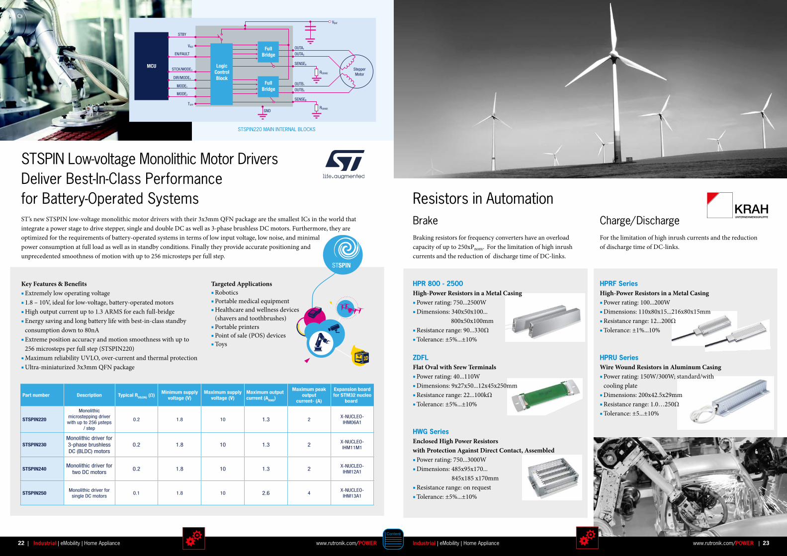
Key Features & Benefits Extremely low operating voltage 1.8 – 10V, ideal for low-voltage, battery-operated motors High output current up to 1.3 ARMS for each full-bridge Energy saving and long battery life with best-in-class standby consumption down to 80nA Extreme position accuracy and motion smoothness with up to 256 microsteps per full step (STSPIN220) Maximum reliability UVLO, over-current and thermal protection Ultra-miniaturized 3x3mm QFN package
STSPIN Low-voltage Monolithic Motor Drivers Deliver Best-In-Class Performance for Battery-Operated SystemsST’s new STSPIN low-voltage monolithic motor drivers with their 3x3mm QFN package are the smallest ICs in the world that integrate a power stage to drive stepper, single and double DC as well as 3-phase brushless DC motors. Furthermore, they are optimized for the requirements of battery-operated systems in terms of low input voltage, low noise, and minimal power con sumption at full load as well as in standby conditions. Finally they provide accurate positioning and unprecedented smoothness of motion with up to 256 microsteps per full step.
Targeted Applications Robotics Portable medical equipment Healthcare and wellness devices (shavers and toothbrushes) Portable printers Point of sale (POS) devices Toys
PRODUCT TABLE
MCU
STBY
StepperMotor
VREF
VBAT
RSENSE
RSENSEGND
OUTA1
OUTA2
OUTB1
SENSEB
SENSEA
OUTB2
TOFF
EN/FAULT
STCK/MODE3
DIR/MODE4
MODE1
MODE2
Logic Control Block
Full Bridge
Full Bridge
Part number DescriptionMinimum supply
Typical RDS(ON) (Ω)voltage (V)
Maximum supply voltage (V)
Maximum output current (ARMS)
Maximum peak output
current- (A)
Expansion board for STM32 nucleo
board
STSPIN220
Monolithic microstepping driver with up to 256 µsteps
/ step
0.2 1.8 10 1.3 2X-NUCLEO-IHM06A1
STSPIN230 0.2Monolithic driver for 3-phase brushless DC (BLDC) motors
1.8 10 1.3 2X-NUCLEO-IHM11M1
STSPIN240Monolithic driver for
two DC motors0.2 1.8 10 1.3 2
X-NUCLEO-IHM12A1
STSPIN250Monolithic driver for
single DC motors0.1 1.8 10 2.6 4
X-NUCLEO-IHM13A1
STSPIN220 MAIN INTERNAL BLOCKS
Brake Charge/ DischargeBraking resistors for frequency converters have an overload capacity of up to 250xPnom. For the limitation of high inrush currents and the reduction of discharge time of DC-links.
For the limitation of high inrush currents and the reductionof discharge time of DC-links.
Resistors in Automation
HPR 800 - 2500High-Power Resistors in a Metal Casing Power rating: 750...2500W Dimensions: 340x50x100... 800x50x100mm Resistance range: 90...330Ω Tolerance: ±5%...±10%
ZDFLFlat Oval with Srew Terminals Power rating: 40...110W Dimensions: 9x27x50...12x45x250mm Resistance range: 22...100kΩ Tolerance: ±5%...±10%
HWG SeriesEnclosed High Power Resistors with Protection Against Direct Contact, Assembled Power rating: 750...3000W Dimensions: 485x95x170... 845x185 x170mm Resistance range: on request Tolerance: ±5%...±10%
HPRF SeriesHigh-Power Resistors in a Metal Casing Power rating: 100...200W Dimensions: 110x80x15...216x80x15mm Resistance range: 12...200Ω Tolerance: ±1%...10%
HPRU SeriesWire Wound Resistors in Aluminum Casing Power rating: 150W/300W; standard/with cooling plate Dimensions: 200x42.5x29mm Resistance range: 1.0…250Ω Tolerance: ±5...±10%
22 23Industrial | eMobility | Home Appliancewww.rutronik.com/POWER www.rutronik.com/POWERIndustrial | eMobility | Home Appliance| |

High Performance Radial Series and Special Terminals with Low Thermal Resistance
QXW 105°C 2000h Ultra miniaturized Rated voltage: 400 to 450V Capacitance: 12 to 220μF Case size: 8x25 to 18x50mm
BXW 105°C 12000h Ultra miniaturized Rated voltage: 160 to 450V Capacitance: 10 to 820μF Broad range of case sizes
CXW 105°C 5000h Bigger than QXW series, but longer life Same ripple as QXW series Rated voltage: 400 to 450V Capacitance: 12 to 220μF Case size: 8x25 to 18x50mm
LUR 85°C 5000h Long life Low thermal resistance High ripple current Rated voltage: 350 to 500V
LHR 105°C 5000h Long life Low thermal resistance High ripple current Rated voltage: 350 to 450V
HFG 105°C 5000h High ripple current Added high capacitance items by increased case length (4pin) Rated voltage: 350 to 450V Capacitance: 390 to 2700μF
For Your Applications with Special Demands
Features Up to 580V Stud mounting Multi pin Low thermal resistance High temperature High reliability Extreme performance
Benefits Miniaturized Snap-In capacitors utilizing high density foil to fit into low profile cases Higher power density (CV value) in same case size for high power inverters Screw type capacitors for very low thermal resistance and high ripple current Screw type capacitors with stud mounting for reduced mounting area and i mproved heat transfer
Applications Power supply Inverter Energy storage
Aluminium Electrolytic Capacitors for Rigid ApplicationsFocus Snap-In Series for DC-Link Circuits
NXG 105°C 10000h Super long life Rated voltage: 400 to 450V Capacitance: 120 to 560μF Case size: 20x45 to 35x50mm
VXR 105°C 7000h Super long life Rated voltage: 160 to 450V Capacitance: 39 to 2200μF Case size: 22x25 to 35x50mm
Lifetime
Lifetime
Lifetime
Lifetime
Lifetime
Capacitance
Case size
Ripple Voltage
Capacitance
Capacitance
Capacitance
Capacitance
Case size
Case size
Case size
Case size
Ripple
Ripple
Ripple
Ripple
Voltage
Voltage
Voltage
Voltage
02468
10
02468
10
02468
10
02468
10
02468
10
HXG 105°C 3000h High Ripple Miniaturized Rated voltage: 400 to 450V Capacitance: 65 to 680μF Case size: 22x25 to 35x60mm
Lifetime
Lifetime
Lifetime
Lifetime
Lifetime
Capacitance
Case size
Ripple Voltage
Capacitance
Capacitance
Capacitance
Capacitance
Case size
Case size
Case size
Case size
Ripple
Ripple
Ripple
Ripple
Voltage
Voltage
Voltage
Voltage
02468
10
02468
10
02468
10
02468
10
02468
10
VXG 105°C 5000h Long life Rated voltage: 10 to 500V Capacitance: 47 to 56000μF Case size: 22x25 to 35x60mm
Lifetime
Lifetime
Lifetime
Lifetime
Lifetime
Capacitance
Case size
Ripple Voltage
Capacitance
Capacitance
Capacitance
Capacitance
Case size
Case size
Case size
Case size
Ripple
Ripple
Ripple
Ripple
Voltage
Voltage
Voltage
Voltage
02468
10
02468
10
02468
10
02468
10
02468
10
MXG 105°C 3000h Standard Rated voltage: 10 to 500V Capacitance: 39 to 68000μF Case size: 20x25 to 35x60mm
Lifetime
Lifetime
Lifetime
Lifetime
Lifetime
Capacitance
Case size
Ripple Voltage
Capacitance
Capacitance
Capacitance
Capacitance
Case size
Case size
Case size
Case size
Ripple
Ripple
Ripple
Ripple
Voltage
Voltage
Voltage
Voltage
02468
10
02468
10
02468
10
02468
10
02468
10
Quality
Reliability
Robustness
Lifetime
Lifetime
Lifetime
Lifetime
Lifetime
Capacitance
Case size
Ripple Voltage
Capacitance
Capacitance
Capacitance
Capacitance
Case size
Case size
Case size
Case size
Ripple
Ripple
Ripple
Ripple
Voltage
Voltage
Voltage
Voltage
02468
10
02468
10
02468
10
02468
10
02468
10
24 25Industrial | eMobility | Home Appliancewww.rutronik.com/POWER www.rutronik.com/POWERIndustrial | eMobility | Home Appliance| |

AVX offers wide range of film dielectric components including low power SMD solutions for the commercial and automotive industry and medium power film capacitors suited to all power electronic applications.
AVX Film Capacitors
Features & Benefits Self healing property for high dielectric strength No piezo effect Low ESL/ESR Low DC Bias Excellent thermal behavior
ApplicationsAVX SMD Chip film and Medium power film capacitors are used in wide range of application sectors such as: Automotive HEV and PHEV Inductive heating Industrial/Professional Renewable/Smart Energy Power Electronics Medical
SMD Chip Film Case Size: 1206 - 6054 Working Voltage: 16V – 630V Capacitance: 1nF – 4.7μF
Medium Power Film Case Size: Radial, Axial, custom Working Voltage: 75V – 3kV Capacitance: 0.01μF – 25500μF
SMD Chip Film CapacitorsThe self healing property of film dielectric provides an open failure mode capacitor with excellent reliability. The intrinsic characteristic of film provides a capacitor which exhibits low DC Bias, excellent thermal behavior, no piezo effect and low ESR/ESL and dissipation factor with excellent thermal behavior and thermal shock resistance.SMD film capacitors are available in three dielectrics: PEN, PET-HT, and PPS, and in case sizes ranging from 1206 to 6054.
Medium Power CapacitorsMedium power film capacitors are used for AC & DC filtering, protection, discharge and tuning. Parts offer high RMS current, high temperature up to 105°C and use dry segmented metallization. The segmentation provides controlled self- healing, designed to achieve very high dielectric strength and avoid catastrophic failure. During operation, any dielectric breakdown becomes insulated locally, minimizing the risk of short circuit and the capacitor continues functioning normally
www.vishay.com
Film CapacitorsFilm capacitors satisfy a large variety of electronic applications, because the dielectrics have excellent electrical characteristics, high stability and a long life time.
DC-Link MKP1848 Family Series DC-link capacitors act as energy buffer between the DC/DC converter and the AC/DC inverter. DC/DC converters are used in switch-mode power supplies.
Capacitor Type Function Family Applications
EMC RFI X1 338 1
EMC RFI Y2 338 6
Buffer DC-link DC & ripple MKP1848
Snubber AC & Pulse Reduce spikes 383 / 386M
3 Phase Solar String Inverter Single Phase Solar String Inverter
Capacitor Function Product Family C-range V-range Terminals
EMC X1 RFI F 338 1 10nF...1µF 440 VAC2 and 4-Pins
EMC Y2 RFI BFC2 338 6 1nF...470nF 300 VAC 2-Pins
Input & DC Link
DC & Ripple
DC Link MKP 1848 1µF...400µF 450...
1.200 VDC
2 and 4-Pins
Snubber Capacitors
Reduce Spikes
AC & Pulse
BFC2 383 1nF...2.7µF 250... 2.500 VDC
2-Pins
MKP 386M 100nF...4.7µF 630... 2.500 VDC
4-Pins / Tab Term.
Capacitor Function Product Family C-range V-range Terminals
EMC X1 RFI F 339M 1nF...40µF 310 VAC2 and 4-Pins
EMC Y2 RFI BFC2 338 6 1nF...470nF 300 VAC 2-Pins
Input & DC Link
DC & Ripple
DC Link MKP 1848 1µF...400µF 450...
1.200 VDC
2 and 4-Pins
Snubber Capacitors
Reduce Spikes
AC & Pulse
BFC2 383 1nF...2,7µF 250... 2.500 VDC
2-Pins
MKP 386M 100nF...4,7µF 630... 2.500 VDC
4-Pins / Tab Term.
Focus Applications R.E. Inverters SMPS’s On board chargers Motor drives Welders
Features & Benefits High peak current capabilities High RMS current capabilities Lifetime > 100.000h Halogen free materials
MKP1848 – Automotive AEC-Q200 approved MKP1848C –High density economic pack MKP1848S –Slim low building height design Broadest capacitance range in the market Proven reliability with zero field
For the following applications Vishay recommends these appropriate film capacitors:
AC Motor Drives Industrial UPS Capacitor Type Function Family Applications
EMC (Input) RFI X2 339 (310Vac)
EMC (Input) RFI Y2 338 6
EMC (Output) AC & Pulse AC 383 / 375
Snubber AC & Pulse Reduce spikes MKP1848
Buffer DC-link DC + ripple
Single Phase Solar String Inverter
26 27Industrial | eMobility | Home Appliancewww.rutronik.com/POWER www.rutronik.com/POWERIndustrial | eMobility | Home Appliance| |

Keko Varicon is a Europe based manufacturer of overvoltage protection with over half a century of production history. Keko Varicon offers one of the widest ranges of varistors and dual function components that comprise both, a varistor and a capacitor. Keko Varicon is a ISO/TS 16949 certified company with UL, VDE approvals among others.
Features Varistors for SPD Class I: High Iimp up to 12,5kA (10/350μs) – stacked varistors High Inom up to 30kA (8/20μs) – stacked varistors Varistors for SPD Class II & III: High Imax up to 45kA (8/20μs) – single disc varistors High Inom up to 20kA (8/20μs) – single disc varistors
Available Product Series ZOV, ZOVR, ZOVS, ZOVH Varistors for Class I, II &III according to UL 1449, IEC 61643-11 Very low leakage currents Custom electrical performances Custom designs available for all types of SPDs Metallized varistor blocks or epoxy coated varistors with rigid terminals available Stacked varistors for improved surge current and energy capabilities
Applications Up to 12.5kA (10/350 pulse) DC voltage range from 85V to 900V AC voltage range from 60V to 680V Custom design size and shape Traffic and railway signal systems Power distribution control equipment Railroad equipment Mobile power supply stations Switch boards Power supplies and motor controls in transportation Industrial and consumer electrical equipment
AVX Ceramic Capacitors exhibit low parasitics and excellent EMI filtering capabilities. AVX MLC Capacitors are available in a wide range of values, styles, voltage ratings and dielectrics.
AVX Ceramic Capacitors
Varistors – Protect Your Home
Features & Benefits Low ESR and ESL High Q/Ultra low ESR series High reliability Flexible termination available for SMD Low inductance series capacitors SMPS Capacitors with excellent high frequency performance RoHS Compliant
ApplicationsAVX Capacitors are used in wide range of application sectors such as: Industrial/Professional Consumer Commercial Home appliances Automation Lighting Automotive (AEC-Q200) Renewable/Smart Energy
Ultra Low ESR NP0 - “U” dielectric parts are designed for RF applications requiring ultra-low ESR NP0 parts are suitable for use in MHz range with very stable characteristics X7R/X5R parts are suitable for use for use in general kHz range X8R/X8L parts are designed for high temperature applications up to +150°C
AVX Ceramic capacitors are available in single element 01005 to 2225 case size, multiple element 0508 and 0612 arrays. SMPS capacitors are supplied in stacked configuration with through-hole technology or SMT leads. Through-hole technology components are supplied as conformally epoxy coated axial and radial devices.
Some of the innovative AVX solutions include FLEXITERM™ capacitors have superior resistance to both: Mechanical stress (board flexure - 5mm bend test guaranteed) and Thermal stress (increased temperature cycling performance, 3000 cycles and beyond). FLEXISAFE – Specifically designed with an industry leading set of safety features for safety critical applications. Combines FLEXITERM™ layer in conjunction with the cascade design.
Case Sizes SMT: 01005 - 2225 EIA SMT Array: 0508 2x Array 0508 4xArray 0612 4xArray Leaded: Axial and Radial Stacked
Electrical Characteristics Working Voltage: 4.0 - 5000Vdc
Capacitance: 0.1pF - 1300µF Dielectric: NP0, X8R, X8L, X7R, X7S, X6S, X5R, Y5V
28 29Industrial | eMobility | Home Appliancewww.rutronik.com/POWER www.rutronik.com/POWERIndustrial | eMobility | Home Appliance| |
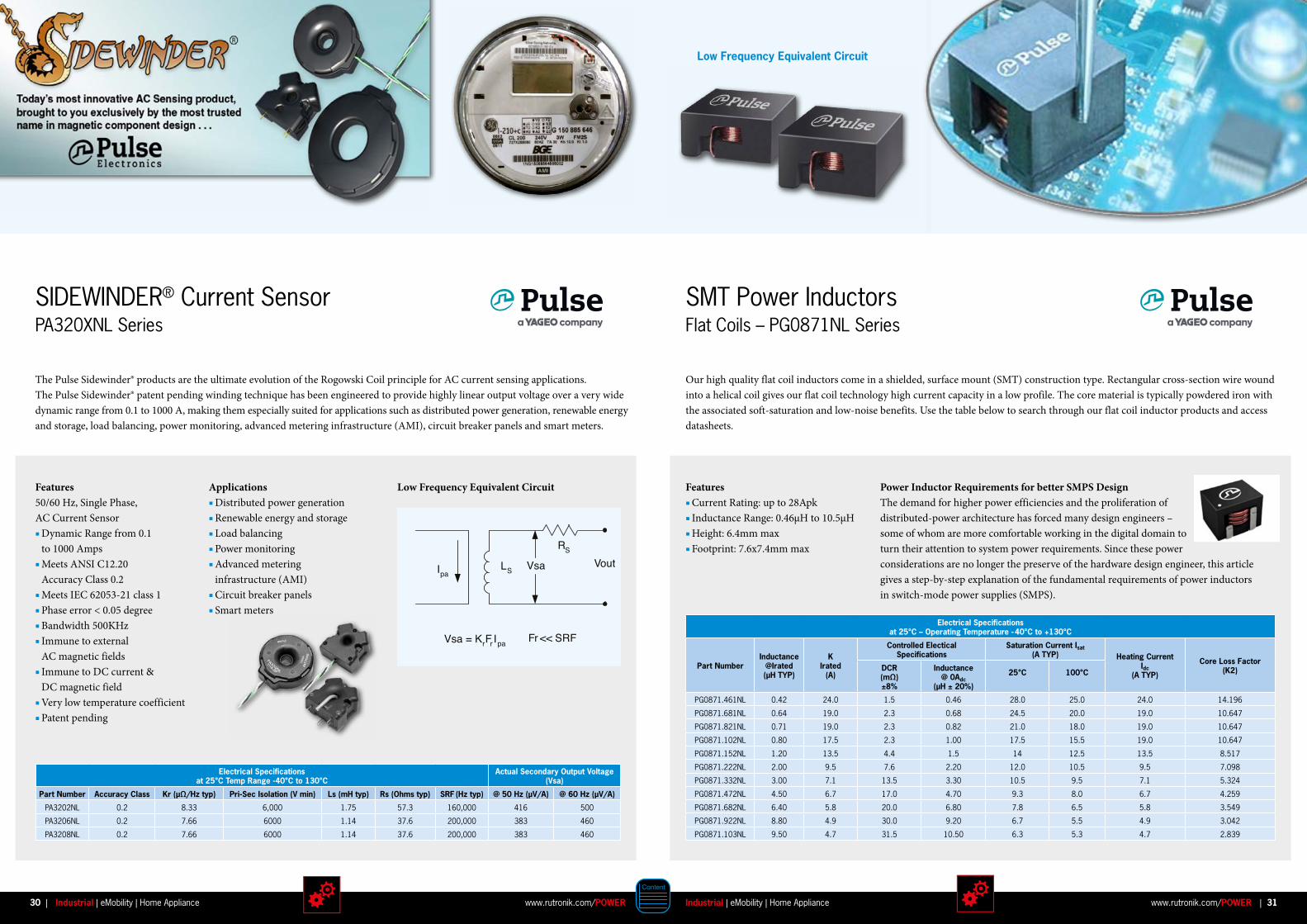
SIDEWINDER® Current SensorPA320XNL Series
SMT Power InductorsFlat Coils – PG0871NL Series
Features 50/60 Hz, Single Phase, AC Current Sensor Dynamic Range from 0.1 to 1000 Amps Meets ANSI C12.20 Accuracy Class 0.2 Meets IEC 62053-21 class 1 Phase error < 0.05 degree Bandwidth 500KHz Immune to external AC magnetic fields Immune to DC current & DC magnetic field Very low temperature coefficient Patent pending
Features Current Rating: up to 28Apk Inductance Range: 0.46µH to 10.5µH Height: 6.4mm max Footprint: 7.6x7.4mm max
Applications Distributed power generation Renewable energy and storage Load balancing Power monitoring Advanced metering infrastructure (AMI) Circuit breaker panels Smart meters
Low Frequency Equivalent Circuit
Electrical Specifications at 25°C Temp Range -40°C to 130°C
Actual Secondary Output Voltage (Vsa)
Part Number Accuracy Class Kr (µΩ/Hz typ) Pri-Sec Isolation (V min) Ls (mH typ) Rs (Ohms typ) SRF (Hz typ) @ 50 Hz (µV/A) @ 60 Hz (µV/A)
PA3202NL 0.2 8.33 6,000 1.75 57.3 160,000 416 500
PA3206NL 0.2 7.66 6000 1.14 37.6 200,000 383 460
PA3208NL 0.2 7.66 6000 1.14 37.6 200,000 383 460
Electrical Specifications at 25°C – Operating Temperature - 40°C to +130°C
Part NumberInductance
@Irated(µH TYP)
KIrated
(A)
Controlled Electical Specifications
Saturation Current Isat(A TYP) Heating Current
Idc(A TYP)
Core Loss Factor (K2)DCR
(mΩ)±8%
Inductance@ 0Adc
(µH ± 20%)
25°C 100°C
PG0871.461NL 0.42 24.0 1.5 0.46 28.0 25.0 24.0 14.196
PG0871.681NL 0.64 19.0 2.3 0.68 24.5 20.0 19.0 10.647
PG0871.821NL 0.71 19.0 2.3 0.82 21.0 18.0 19.0 10.647
PG0871.102NL 0.80 17.5 2.3 1.00 17.5 15.5 19.0 10.647
PG0871.152NL 1.20 13.5 4.4 1.5 14 12.5 13.5 8.517
PG0871.222NL 2.00 9.5 7.6 2.20 12.0 10.5 9.5 7.098
PG0871.332NL 3.00 7.1 13.5 3.30 10.5 9.5 7.1 5.324
PG0871.472NL 4.50 6.7 17.0 4.70 9.3 8.0 6.7 4.259
PG0871.682NL 6.40 5.8 20.0 6.80 7.8 6.5 5.8 3.549
PG0871.922NL 8.80 4.9 30.0 9.20 6.7 5.5 4.9 3.042
PG0871.103NL 9.50 4.7 31.5 10.50 6.3 5.3 4.7 2.839
LS
RS
Vout
Vsa = KrFrIpa
VsaIpa
Fr << SRF
LS
RS
Vout
Vsa = KrFrIpa
VsaIpa
Fr << SRF
The Pulse Sidewinder® products are the ultimate evolution of the Rogowski Coil principle for AC current sensing applications. The Pulse Sidewinder® patent pending winding technique has been engineered to provide highly linear output voltage over a very wide dynamic range from 0.1 to 1000 A, making them especially suited for applications such as distributed power generation, renewable energy and storage, load balancing, power monitoring, advanced metering infrastructure (AMI), circuit breaker panels and smart meters.
Our high quality flat coil inductors come in a shielded, surface mount (SMT) construction type. Rectangular cross-section wire wound into a helical coil gives our flat coil technology high current capacity in a low profile. The core material is typically powdered iron with the associated soft-saturation and low-noise benefits. Use the table below to search through our flat coil inductor products and access datasheets.
Power Inductor Requirements for better SMPS DesignThe demand for higher power efficiencies and the proliferation of distributed-power architecture has forced many design engineers –some of whom are more comfortable working in the digital domain to turn their attention to system power requirements. Since these power considerations are no longer the preserve of the hardware design engineer, this article gives a step-by-step explanation of the fundamental requirements of power inductors in switch-mode power supplies (SMPS).
Low Frequency Equivalent Circuit
30 31Industrial | eMobility | Home Appliancewww.rutronik.com/POWER www.rutronik.com/POWERIndustrial | eMobility | Home Appliance| |

Benefits Compact component sizes Operating currents up to 100A Low losses / high efficiency High frequencies For automotive, industrial, medical and consumer applications Production possibilities in Europe and Asia Innovative and cost effective solutions (DTC approach) Rapid prototyping of new, customized core and bobbin geometries
SUMIDA offers a wide range of chokes in many different technologies for automotive, industrial, medical and consumer applications. The product spectrum covers standard types as well as custom solutions – designed and manufactured on a highest quality level.
SUMIDA Chokes – Solutions for Every Application
Applications Common Mode Chokes (CMC) Differential Mode Chokes (DMC) Storage (output) chokes Power Factor Correction (PFC) chokes Used in Switch Mode Power Supplies (SMPS) and inverter circuits
Versions Horizontal / vertical designs Toroid / E- / U- and other core shapes Drum and rod core designs SMD / THD or customized connection technologies Potted / varnished versions if needed
Special Features According to international safety standards Insulation Systems on request Wide selection of ferrite, amorphous metal-compound and iron powder materials Many different winding and finishing technologies available Customized (application-specific) solutions possible Wide range of exisiting standard solutions Flexible pinning Extensive test and qualification capabilities e.g. temperature, shock, vibration, AEC-Q200 etc.
32 33Industrial | eMobility | Home Appliancewww.rutronik.com/POWER www.rutronik.com/POWERIndustrial | eMobility | Home Appliance| |
Signal relays are also used in frequency inverters for alarm signalling, to trigger a brake mechanism or to control the input to a PLC. As an alternative to an electro-mechanical solution, MOSFET relays G3VM are finding growing acceptance in these applications. For Output Switching the G3MC, an SSR Relay, is able to switch up to 2A/250VAC, and is just 4.5mm thick.
New Relays Improve Frequency Inverter Performance
G6DN AC SeriesOmron Electronic Components recently unveiled a new compact and efficient power relay for frequency inverters, the G6DN, capable of switching 5A at 250VAC.
Features Smallest design of its specification – just 5mm thick x 20mm x 12.5mm high Low coil power consumption – just 110mW Electrical life of 80K operations at 5A / 250VAC
G7J AC SeriesFor high current applications, the G7J is a high capacity, high dielectric strength relay.
Features Switching currents up to 25A Available with up to 4 poles for switching 3 phase currents No contact chattering for momentary voltage drops up to 50% of rated voltage Withstanding more than 4kV between contacts of different polarity and between coil and contacts Full disconnection isolation (3mm) via open contact PCB and Wallmount types available
G2RL DC SeriesFor the DC intermediate circuit to reduce inrush currents as the load capacitors charge, a relay like the G2RL is very suitable. Features Low profile of just 15.7mm Switching capacity up to 16A DC High sensitivity type (250mW) available
Alternative AC Solutions G7Z: DIN rail mounting type, four pole relay with a capacity of up to 160A when 4 contacts in parallel. G7L: a PCB mounting type, 1 or 2 pole relay with 20A to 30A contact rating, full disconnection isolation (3mm) via open contact G6RL: just 12.3mm high, able to interrupt 10A at 250VAC with a dielectric strength of 5kV between the coil and the contacts G5Q: which offers 8kV withstand and can switch up to 10A
Energy efficiency is key in the design of industrial frequency inverters – and relays play a major role in ensuring that it is achieved. Important factors in component selection are long electrical life and coil isolation.
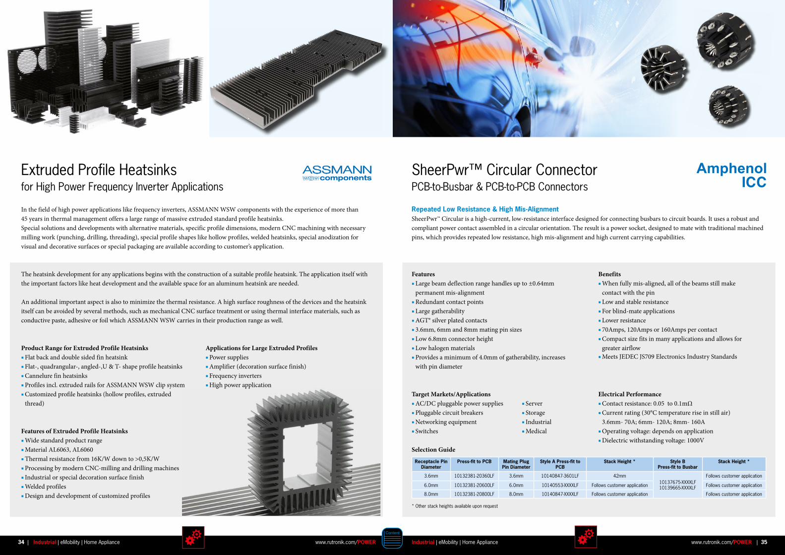
SheerPwr™ Circular ConnectorPCB-to-Busbar & PCB-to-PCB Connectors
Electrical Performance Contact resistance: 0.05 to 0.1mΩ Current rating (30°C temperature rise in still air) 3.6mm- 70A; 6mm- 120A; 8mm- 160A Operating voltage: depends on application Dielectric withstanding voltage: 1000V
Features Large beam deflection range handles up to ±0.64mm permanent mis-alignment Redundant contact points Large gatherability AGT® silver plated contacts 3.6mm, 6mm and 8mm mating pin sizes Low 6.8mm connector height Low halogen materials Provides a minimum of 4.0mm of gatherability, increases with pin diameter
Benefits When fully mis-aligned, all of the beams still make contact with the pin Low and stable resistance For blind-mate applications Lower resistance 70Amps, 120Amps or 160Amps per contact Compact size fits in many applications and allows for greater airflow Meets JEDEC JS709 Electronics Industry Standards
Receptacle Pin Diameter
Press-fit to PCB Mating Plug Pin Diameter
Style A Press-fit to PCB
Stack Height * Style BPress-fit to Busbar
Stack Height *
3.6mm 10132381-20360LF 3.6mm 10140847-3601LF 42mm10137675-XXXXLF10139665-XXXXLF
Follows customer application
6.0mm 10132381-20600LF 6.0mm 10140553-XXXXLF Follows customer application Follows customer application
8.0mm 10132381-20800LF 8.0mm 10140847-XXXXLF Follows customer application Follows customer application
* Other stack heights available upon request
Repeated Low Resistance & High Mis-AlignmentSheerPwr™ Circular is a high-current, low-resistance interface designed for connecting busbars to circuit boards. It uses a robust and compliant power contact assembled in a circular orientation. The result is a power socket, designed to mate with traditional machined pins, which provides repeated low resistance, high mis-alignment and high current carrying capabilities.
Target Markets/Applications AC/DC pluggable power supplies Pluggable circuit breakers Networking equipment Switches
Server Storage Industrial Medical
Selection Guide
34 35Industrial | eMobility | Home Appliancewww.rutronik.com/POWER www.rutronik.com/POWERIndustrial | eMobility | Home Appliance| |
The heatsink development for any applications begins with the construction of a suitable profile heatsink. The application itself with the important factors like heat development and the available space for an aluminum heatsink are needed.
An additional important aspect is also to minimize the thermal resistance. A high surface roughness of the devices and the heatsink itself can be avoided by several methods, such as mechanical CNC surface treatment or using thermal interface materials, such as conductive paste, adhesive or foil which ASSMANN WSW carries in their production range as well.
Product Range for Extruded Profile Heatsinks Flat back and double sided fin heatsink Flat-, quadrangular-, angled-,U & T- shape profile heatsinks Cannelure fin heatsinks Profiles incl. extruded rails for ASSMANN WSW clip system Customized profile heatsinks (hollow profiles, extruded thread)
Features of Extruded Profile Heatsinks Wide standard product range Material AL6063, AL6060 Thermal resistance from 16K/W down to >0,5K/W Processing by modern CNC-milling and drilling machines Industrial or special decoration surface finish Welded profiles Design and development of customized profiles
Applications for Large Extruded Profiles Power supplies Amplifier (decoration surface finish) Frequency inverters High power application
Extruded Profile Heatsinks for High Power Frequency Inverter Applications
In the field of high power applications like frequency inverters, ASSMANN WSW components with the experience of more than 45 years in thermal management offers a large range of massive extruded standard profile heatsinks. Special solutions and developments with alternative materials, specific profile dimensions, modern CNC machining with necessary milling work (punching, drilling, threading), special profile shapes like hollow profiles, welded heatsinks, special anodization for visual and decorative surfaces or special packaging are available according to customer’s application.
Description Part Numbers
Right Angle Header 1012739X-XXXXXXXLF
Vertical receptacle 1012740X-XXXXXXXLF
Part Numbers
Benefits Provide excellent power density and multiple power voltage Low profile configuration ideal for 1U power supplies or power distribution system Maximizes heat dissipation for effective system cooling Meets next-generation environmental requirements Adaptable to extreme environments For both co-planar applications and backplane applications Design flexibility and choices for customers Termination flexibility
Electrical Performance High power contact current: Up to 65A/contact at 30°C T-rise in still air Low power contact current rating Up to 25A/contact at 30°C T-rise in still air Operating voltage High power on 7.00mm pitch -400V High power on 5.00mm pitch -200V Low power on 3.5mm pitch -218V Dielectric withstanding voltage High/low power contacts: 2500V
Features Up to 65A per contact for high power and up to 25A per contact for low power 9.6mm height Highly vented housing design Halogen-free housing material Operating temperature ranges from -40°C to 125°C Right angle header, right angle receptacle and vertical receptacle types Number and placement of power and signal contacts are configurable for customer needs Solder or press-fit tails
Electrical Performance Insulation resistance: > 1000mΩ max. at end of life Contact resistance Power contact: 0.4mΩ max. at end of life Signal contact: 20mΩ max. at end of life
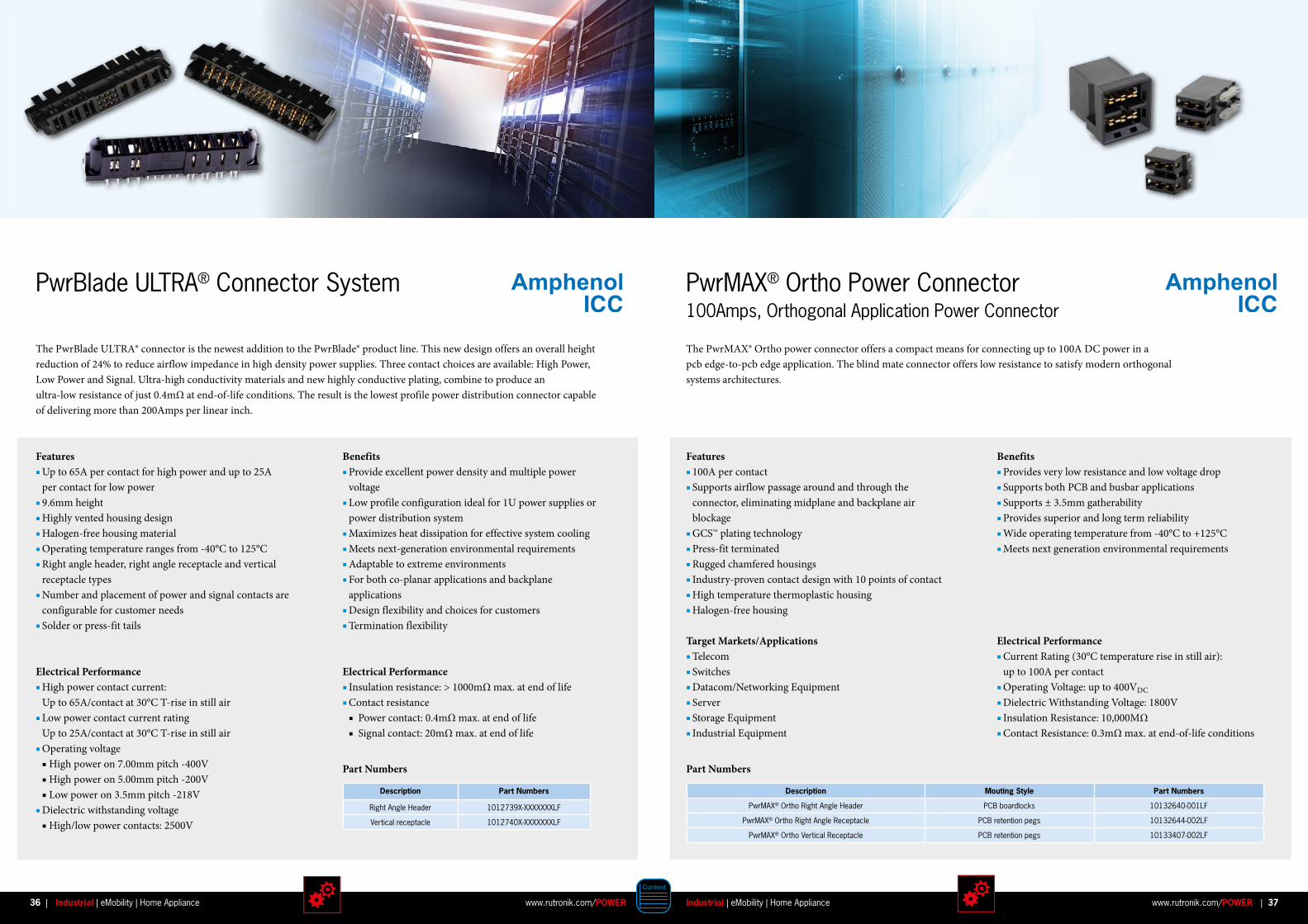
The PwrBlade ULTRA® connector is the newest addition to the PwrBlade® product line. This new design offers an overall height reduction of 24% to reduce airflow impedance in high density power supplies. Three contact choices are available: High Power, Low Power and Signal. Ultra-high conductivity materials and new highly conductive plating, combine to produce an ultra-low resistance of just 0.4mΩ at end-of-life conditions. The result is the lowest profile power distribution connector capable of delivering more than 200Amps per linear inch.
PwrBlade ULTRA® Connector System
The PwrMAX® Ortho power connector offers a compact means for connecting up to 100A DC power in a pcb edge-to-pcb edge application. The blind mate connector offers low resistance to satisfy modern orthogonalsystems architectures.
Features 100A per contact Supports airflow passage around and through the connector, eliminating midplane and backplane air blockage GCS™ plating technology Press-fit terminated Rugged chamfered housings Industry-proven contact design with 10 points of contact High temperature thermoplastic housing Halogen-free housing
Benefits Provides very low resistance and low voltage drop Supports both PCB and busbar applications Supports ± 3.5mm gatherability Provides superior and long term reliability Wide operating temperature from -40°C to +125°C Meets next generation environmental requirements
PwrMAX® Ortho Power Connector 100Amps, Orthogonal Application Power Connector
Electrical Performance Current Rating (30°C temperature rise in still air): up to 100A per contact Operating Voltage: up to 400VDC
Dielectric Withstanding Voltage: 1800V Insulation Resistance: 10,000MΩ Contact Resistance: 0.3mΩ max. at end-of-life conditions
Description Mouting Style Part Numbers
PwrMAX® Ortho Right Angle Header PCB boardlocks 10132640-001LF
PwrMAX® Ortho Right Angle Receptacle PCB retention pegs 10132644-002LF
PwrMAX® Ortho Vertical Receptacle PCB retention pegs 10133407-002LF
Part Numbers
Target Markets/Applications Telecom Switches Datacom/Networking Equipment Server Storage Equipment Industrial Equipment
36 37Industrial | eMobility | Home Appliancewww.rutronik.com/POWER www.rutronik.com/POWERIndustrial | eMobility | Home Appliance| |
High-current Connector for Green Energy
DW Series
Features & Benefits Power and signal contacts in one robust insulator Easy to harness signal contact unit High reliability One side floats when mounted for easy mating Electric shock prevention Electrification countermeasure UL approved
Applications Storage Battery Systems Power Supply Systems Power Supply control equipment
Electrical Characteristics Current Rating: 150A-500A No. of contacts: 1 to 2 pos. Operating temperature: -40°C to +105°C
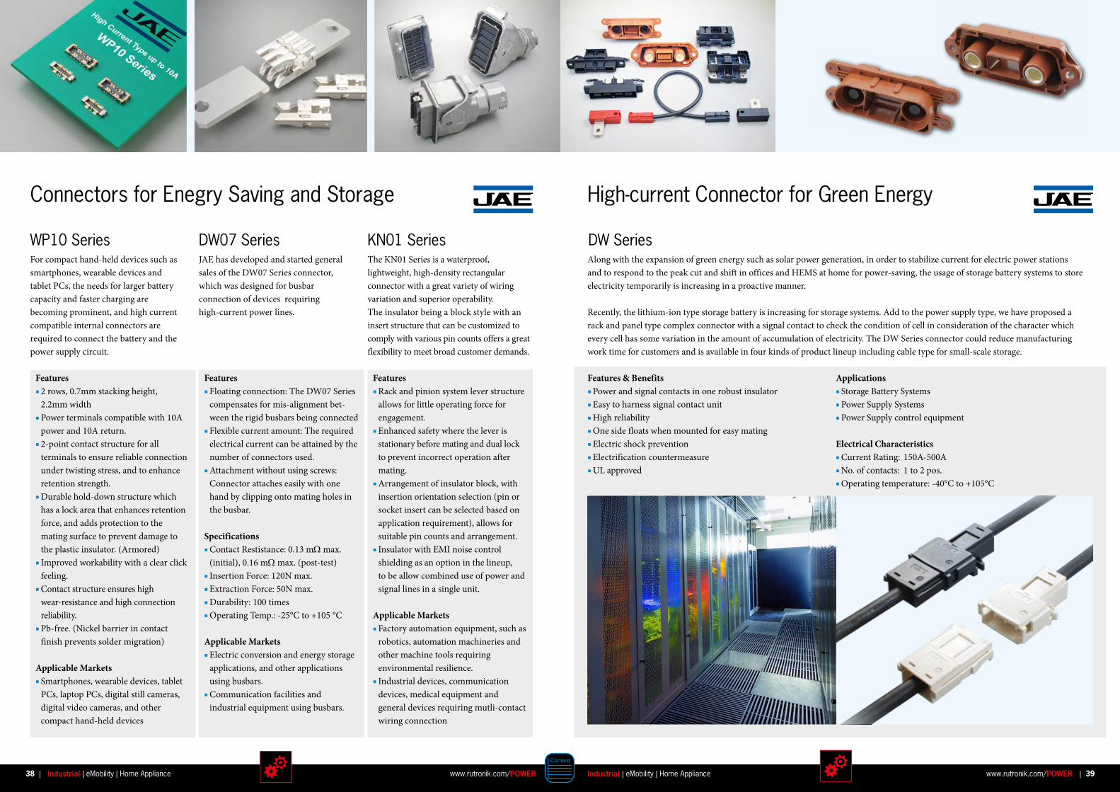
KN01 SeriesJAE has developed and started general sales of the DW07 Series connector, which was designed for busbar connection of devices requiring high-current power lines.
The KN01 Series is a waterproof, light weight, high-density rectangular con nector with a great variety of wiring variation and superior operability. The insulator being a block style with an insert structure that can be customized to comply with various pin counts offers a great flexibility to meet broad customer demands.
Along with the expansion of green energy such as solar power generation, in order to stabilize current for electric power stations and to respond to the peak cut and shift in offices and HEMS at home for power-saving, the usage of storage battery systems to store electricity temporarily is increasing in a proactive manner.
Recently, the lithium-ion type storage battery is increasing for storage systems. Add to the power supply type, we have proposed a rack and panel type complex connector with a signal contact to check the condition of cell in consideration of the character which every cell has some variation in the amount of accumulation of electricity. The DW Series connector could reduce manufacturing work time for customers and is available in four kinds of product lineup including cable type for small-scale storage.
Features Floating connection: The DW07 Series compensates for mis-alignment bet-ween the rigid busbars being connected Flexible current amount: The required electrical current can be attained by the number of connectors used. Attachment without using screws: Connector attaches easily with one hand by clipping onto mating holes in the busbar.
Specifications Contact Restistance: 0.13 mΩ max. (initial), 0.16 mΩ max. (post-test) Insertion Force: 120N max. Extraction Force: 50N max. Durability: 100 times Operating Temp.: -25°C to +105 °C
Applicable Markets Electric conversion and energy storage applications, and other applications using busbars. Communication facilities and industrial equipment using busbars.
Features Rack and pinion system lever structure allows for little operating force for engagement. Enhanced safety where the lever is stationary before mating and dual lock to prevent incorrect operation after mating. Arrangement of insulator block, with insertion orientation selection (pin or socket insert can be selected based on application requirement), allows for suitable pin counts and arrangement. Insulator with EMI noise control shielding as an option in the lineup, to be allow combined use of power and signal lines in a single unit.
Applicable Markets Factory automation equipment, such as robotics, automation machineries and other machine tools requiring environmental resilience. Industrial devices, communication devices, medical equipment and general devices requiring mutli-contact wiring connection
Connectors for Enegry Saving and Storage
DW07 Series WP10 Series For compact hand-held devices such as smartphones, wearable devices and tablet PCs, the needs for larger battery capacity and faster charging are becoming prominent, and high current compatible internal connectors are required to connect the battery and the power supply circuit.
Features 2 rows, 0.7mm stacking height, 2.2mm width Power terminals compatible with 10A power and 10A return. 2-point contact structure for all terminals to ensure reliable connection under twisting stress, and to enhance retention strength. Durable hold-down structure which has a lock area that enhances retention force, and adds protection to the mating surface to prevent damage to the plastic insulator. (Armored) Improved workability with a clear click feeling. Contact structure ensures high wear-resistance and high connection reliability. Pb-free. (Nickel barrier in contact finish prevents solder migration)
Applicable Markets Smartphones, wearable devices, tablet PCs, laptop PCs, digital still cameras, digital video cameras, and other compact hand-held devices
38 39Industrial | eMobility | Home Appliancewww.rutronik.com/POWER www.rutronik.com/POWERIndustrial | eMobility | Home Appliance| |
Battery/Hybrid Modul
Battery Load Switch
BatteryManagement DC/DC
Power Management
Gate Driver
M3-Phase Inverter
Position Sensing
Current Sensing
Hall & GMRSensor
Micro-controller
Status Indication
Digital Power Control
Control lever Accelerator pedal Display
USB, Serial COM
Brea
kres
isto
r
UserInterface
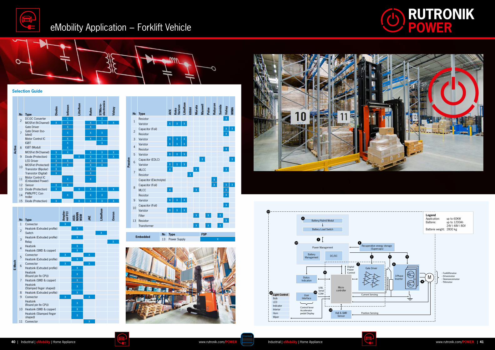
- Forkliftmotor- Drivemotor- Steerancemotor- Tiltmotor
BulbLEDIndicatorInteriorHornWiper
Recuperation energy storage (Supercaps)
Light Control
2
1
6
53
7 8
9
10
4
13
12
14
11
LegendApplication: up to 60KWBatterie: up to 1200Ah 24V | 48V | 80VBatterie weight: 2800 kg
15
Activ
e
NO Type Dio
des
Infin
eon
Litt
elfu
se
Roh
m
STM
icro
-el
ectr
onic
s
Vish
ay
2DC-DC Converter X XMOSFet (N-Channel) X X X X X
7
Gate Driver X XGate Driver (Iso-lated) X X X
Motor Control IC X X X
8
IGBT X X
IGBT (Modul) X
MOSFet (N-Channel) X X X X X
9 Diode (Protection) X X X X X
10
LED Driver X X X XMOSFet (Protected) X X X XTransistor (Bipolar) X XTransistor (Digital) X X
11 Motor Control IC (Embedded Power) X X
12 Sensor X X13 Diode (Protection) X X X X X
14 PWM/PFC Con-troller X X X
15 Diode (Protection) X X X X X
E-M
ech
NO Type Amph
e-no
l FC
I
ASS-
MAN
N
WSW
JAE
Litt
elfu
se
Om
ron
1 Connector X
2Heatsink (Extruded profile) X
Switch X
3Heatsink (Extruded profile) X
Relay X
4Heatsink X
Heatsink (SMD & copper) X
5Connector X X
Heatsink (Extruded profile) X
6Connector X X
Heatsink (Extruded profile) X
7
Heatsink (Round pin fin CPU) X
Heatsink (SMD & copper) X
Heatsink (Stamped finger shaped) X
8 Heatsink (Extruded profile) X
9 Connector X X
10
Heatsink (Round pin fin CPU) X
Heatsink (SMD & copper) X
Heatsink (Stamped finger shaped) X
11 Connector X
Pass
ive
NO Type AVX
Kek
o
Vari
con
Litt
elfu
se
KR
AH
Mur
ata
Max
wel
l
Puls
e
Rub
ycon
Sum
ida
Vish
ay
WIM
A
1Resistor X
Varistor X X X
2Capacitor (Foil) X X
Resistor X
3 Varistor X X X
4Varistor X X X
Resistor X
5 Varistor X X X
6Capacitor (EDLC) X X
Varistor X X X
7MLCC X X X
Resistor X
8
Capacitor (Electrolyte) X
Capacitor (Foil) X X X
MLCC X X X
Resistor X
9 Varistor X X X
10Capacitor (Foil) X
Varistor X X X
13
Filter X X X
Resistor X
Transformer X X X
EmbeddedNO Type FSP
13 Power Supply X
eMobility Application − Forklift Vehicle
40 41www.rutronik.com/POWER www.rutronik.com/POWERIndustrial | eMobility | Home Appliance| |Industrial | eMobility | Home Appliance
Selection Guide
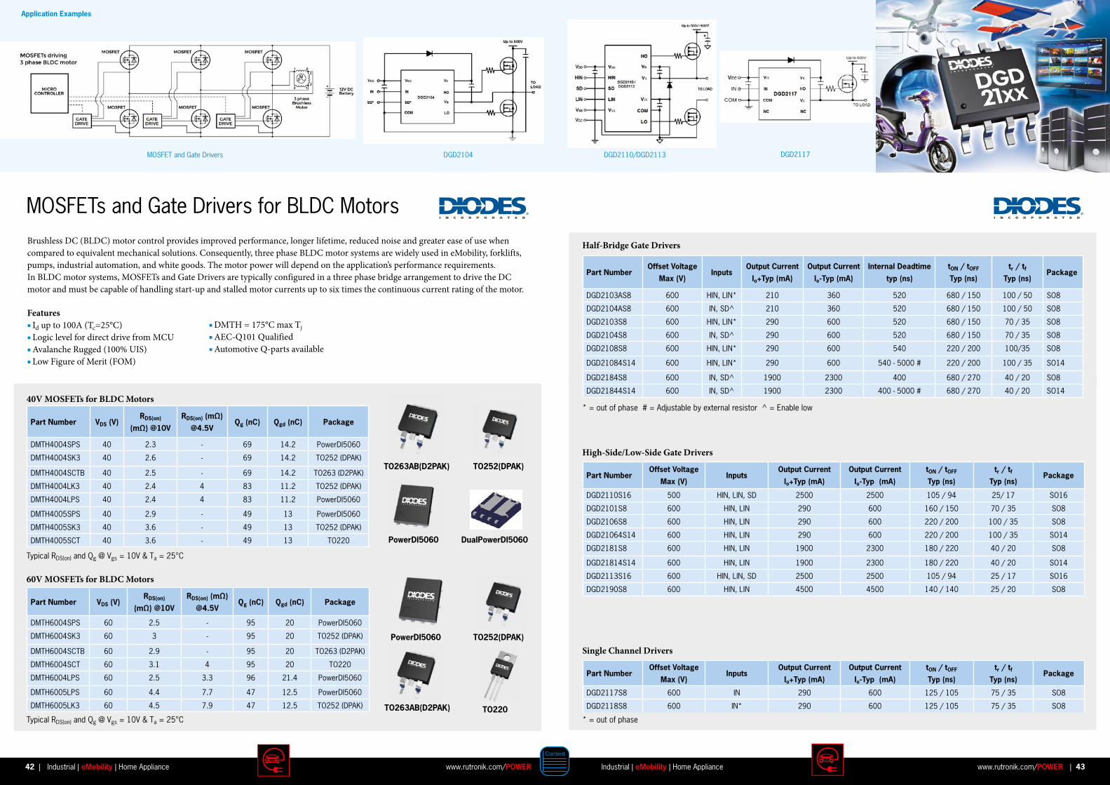
MOSFETs and Gate Drivers for BLDC MotorsBrushless DC (BLDC) motor control provides improved performance, longer lifetime, reduced noise and greater ease of use when compared to equivalent mechanical solutions. Consequently, three phase BLDC motor systems are widely used in eMobility, forklifts, pumps, industrial automation, and white goods. The motor power will depend on the application’s performance requirements.In BLDC motor systems, MOSFETs and Gate Drivers are typically configured in a three phase bridge arrangement to drive the DC motor and must be capable of handling start-up and stalled motor currents up to six times the continuous current rating of the motor.
40V MOSFETs for BLDC Motors
60V MOSFETs for BLDC Motors
Typical RDS(on) and Qg @ Vgs = 10V & Ta = 25°C
Typical RDS(on) and Qg @ Vgs = 10V & Ta = 25°C
* = out of phase # = Adjustable by external resistor ^ = Enable low
* = out of phase
Part Number VDS (V)RDS(on)
(mΩ) @10V
RDS(on) (mΩ)
@4 .5VQg (nC) Qgd (nC) Package
DMTH4004SPS 40 2.3 - 69 14.2 PowerDI5060
DMTH4004SK3 40 2.6 - 69 14.2 TO252 (DPAK)
DMTH4004SCTB 40 2.5 - 69 14.2 TO263 (D2PAK)
DMTH4004LK3 40 2.4 4 83 11.2 TO252 (DPAK)
DMTH4004LPS 40 2.4 4 83 11.2 PowerDI5060
DMTH4005SPS 40 2.9 - 49 13 PowerDI5060
DMTH4005SK3 40 3.6 - 49 13 TO252 (DPAK)
DMTH4005SCT 40 3.6 - 49 13 TO220
Part Number VDS (V)RDS(on)
(mΩ) @10V
RDS(on) (mΩ)
@4 .5VQg (nC) Qgd (nC) Package
DMTH6004SPS 60 2.5 - 95 20 PowerDI5060
DMTH6004SK3 60 3 - 95 20 TO252 (DPAK)
DMTH6004SCTB 60 2.9 - 95 20 TO263 (D2PAK)
DMTH6004SCT 60 3.1 4 95 20 TO220
DMTH6004LPS 60 2.5 3.3 96 21.4 PowerDI5060
DMTH6005LPS 60 4.4 7.7 47 12.5 PowerDI5060
DMTH6005LK3 60 4.5 7.9 47 12.5 TO252 (DPAK)
Features Id up to 100A (Tc=25°C) Logic level for direct drive from MCU Avalanche Rugged (100% UIS) Low Figure of Merit (FOM)
TO263AB(D2PAK)
PowerDI5060
TO252(DPAK)
TO252(DPAK)
PowerDI5060
TO263AB(D2PAK)
DualPowerDI5060
TO220
Part NumberOffset Voltage
Max (V)Inputs
Output Current
Io+Typ (mA)
Output Current
Io-Typ (mA)
Internal Deadtime
typ (ns)
tON / tOFF
Typ (ns)
tr / tf
Typ (ns)Package
DGD2103AS8 600 HIN, LIN* 210 360 520 680 / 150 100 / 50 SO8
DGD2104AS8 600 IN, SD^ 210 360 520 680 / 150 100 / 50 SO8
DGD2103S8 600 HIN, LIN* 290 600 520 680 / 150 70 / 35 SO8
DGD2104S8 600 IN, SD^ 290 600 520 680 / 150 70 / 35 SO8
DGD2108S8 600 HIN, LIN* 290 600 540 220 / 200 100/35 SO8
DGD21084S14 600 HIN, LIN* 290 600 540 - 5000 # 220 / 200 100 / 35 SO14
DGD2184S8 600 IN, SD^ 1900 2300 400 680 / 270 40 / 20 SO8
DGD21844S14 600 IN, SD^ 1900 2300 400 - 5000 # 680 / 270 40 / 20 SO14
Part NumberOffset Voltage
Max (V)Inputs
Output Current
Io+Typ (mA)
Output Current
Io-Typ (mA)
tON / tOFF
Typ (ns)
tr / tf
Typ (ns)Package
DGD2110S16 500 HIN, LIN, SD 2500 2500 105 / 94 25/ 17 SO16
DGD2101S8 600 HIN, LIN 290 600 160 / 150 70 / 35 SO8
DGD2106S8 600 HIN, LIN 290 600 220 / 200 100 / 35 SO8
DGD21064S14 600 HIN, LIN 290 600 220 / 200 100 / 35 SO14
DGD2181S8 600 HIN, LIN 1900 2300 180 / 220 40 / 20 SO8
DGD21814S14 600 HIN, LIN 1900 2300 180 / 220 40 / 20 SO14
DGD2113S16 600 HIN, LIN, SD 2500 2500 105 / 94 25 / 17 SO16
DGD2190S8 600 HIN, LIN 4500 4500 140 / 140 25 / 20 SO8
Part NumberOffset Voltage
Max (V)Inputs
Output Current
Io+Typ (mA)
Output Current
Io-Typ (mA)
tON / tOFF
Typ (ns)
tr / tf
Typ (ns)Package
DGD2117S8 600 IN 290 600 125 / 105 75 / 35 SO8
DGD2118S8 600 IN* 290 600 125 / 105 75 / 35 SO8
Half-Bridge Gate Drivers
High-Side/Low-Side Gate Drivers
Single Channel Drivers
DMTH = 175°C max Tj AEC-Q101 Qualified Automotive Q-parts available
Application Examples
MOSFET and Gate Drivers DGD2104 DGD2110/DGD2113 DGD2117
42 43www.rutronik.com/POWER www.rutronik.com/POWERIndustrial | eMobility | Home Appliance| |Industrial | eMobility | Home Appliance
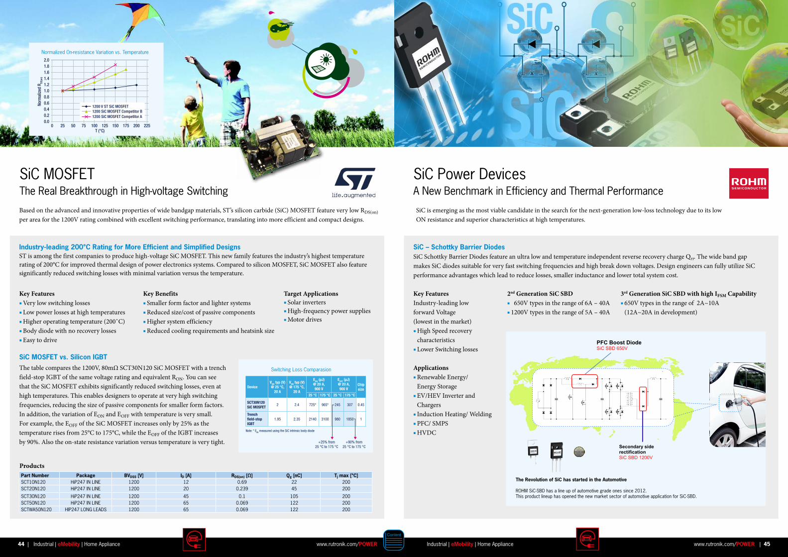
SiC is emerging as the most viable candidate in the search for the next-generation low-loss technology due to its low ON resistance and superior characteristics at high temperatures.
3rd Generation SiC SBD with high IFSM Capability 650V types in the range of 2A~10A (12A~20A in development)
2nd Generation SiC SBD 650V types in the range of 6A – 40A 1200V types in the range of 5A – 40A
SiC Power DevicesA New Benchmark in Efficiency and Thermal Performance
SiC – Schottky Barrier DiodesSiC Schottky Barrier Diodes feature an ultra low and temperature independent reverse recovery charge Qrr. The wide band gap makes SiC diodes suitable for very fast switching frequencies and high break down voltages. Design engineers can fully utilize SiC performance advantages which lead to reduce losses, smaller inductance and lower total system cost.
Key Features Industry-leading low forward Voltage (lowest in the market) High Speed recovery characteristics Lower Switching losses
Bild ?
Applications Renewable Energy/ Energy Storage EV/HEV Inverter and Chargers Induction Heating/ Welding PFC/ SMPS HVDC
Secondary side rectificationSiC SBD 1200V
PFC Boost DiodeSiC SBD 650V
Part Number Package BVDSS [V] ID [A] RDS(on) [Ω] Qg [nC] Tj max [°C]SCT10N120 HiP247 IN LINE 1200 12 0.69 22 200SCT20N120 HiP247 IN LINE 1200 20 0.239 45 200
SCT30N120 HiP247 IN LINE 1200 45 0.1 105 200SCT50N120 HiP247 IN LINE 1200 65 0.069 122 200SCTWA50N120 HIP247 LONG LEADS 1200 65 0.069 122 200
SiC MOSFETThe Real Breakthrough in High-voltage Switching
Based on the advanced and innovative properties of wide bandgap materials, ST’s silicon carbide (SiC) MOSFET feature very low RDS(on) per area for the 1200V rating combined with excellent switching performance, translating into more efficient and compact designs.
Key Features Very low switching losses Low power losses at high temperatures Higher operating temperature (200˚C) Body diode with no recovery losses Easy to drive
Products
Key Benefits Smaller form factor and lighter systems Reduced size/cost of passive components Higher system efficiency Reduced cooling requirements and heatsink size
Target Applications Solar inverters High-frequency power supplies Motor drives
The table compares the 1200V, 80mΩ SCT30N120 SiC MOSFET with a trench field-stop IGBT of the same voltage rating and equivalent RON. You can see that the SiC MOSFET exhibits significantly reduced switching losses, even at high temperatures. This enables designers to operate at very high switching frequencies, reducing the size of passive components for smaller form factors. In addition, the variation of EON and EOFF with temperature is very small. For example, the EOFF of the SiC MOSFET increases only by 25% as the temperature rises from 25°C to 175°C, while the EOFF of the IGBT increases by 90%. Also the on-state resistance variation versus temperature is very tight.
SiC MOSFET vs . Silicon IGBT
Industry-leading 200°C Rating for More Efficient and Simplified Designs ST is among the first companies to produce high-voltage SiC MOSFET. This new family features the industry’s highest temperature rating of 200°C for improved thermal design of power electronics systems. Compared to silicon MOSFET, SiC MOSFET also feature significantly reduced switching losses with minimal variation versus the temperature.
TABLE 1 - SWITCHING LOSS COMPARISON
DeviceVON typ (V)@ 25 °C,
20 A
VON typ (V)
20 A@ 175 °C,
@ 20 A,900 V
EON (µJ)@ 20 A,EOFF (µJ)
900 VChipsize
25 °C 175 °C 25 °C 175 °C
SCT30N120 SiC MOSFET
2 2.4 725* 965* 245 307 0.45
Trench
IGBT1.95fi eld-stop 2.35 2140 3100 980 1850 1
Note: * EON measured using the SiC intrinsic body diode
+25% from25 °C to 175 °C
+90% from25 °C to 175 °C
Switching Loss Comparasion
2.01.81.61.41.21.00.80.6
0.20.4
0.00 25 50 75 100
T (°C)125
Norm
aliz
ed R
DS(o
n)
150 175 200 225
1200 SiC MOSFET Competitor B1200 SiC MOSFET Competitor A
1200 V ST SiC MOSFET
Normalized On-resistance Variation vs. Temperature
The Revolution of SiC has started in the Automotive
ROHM SiC-SBD has a line up of automotive grade ones since 2012. This product lineup has opened the new market sector of automotive application for SiC-SBD.
44 45www.rutronik.com/POWER www.rutronik.com/POWERIndustrial | eMobility | Home Appliance| |Industrial | eMobility | Home Appliance
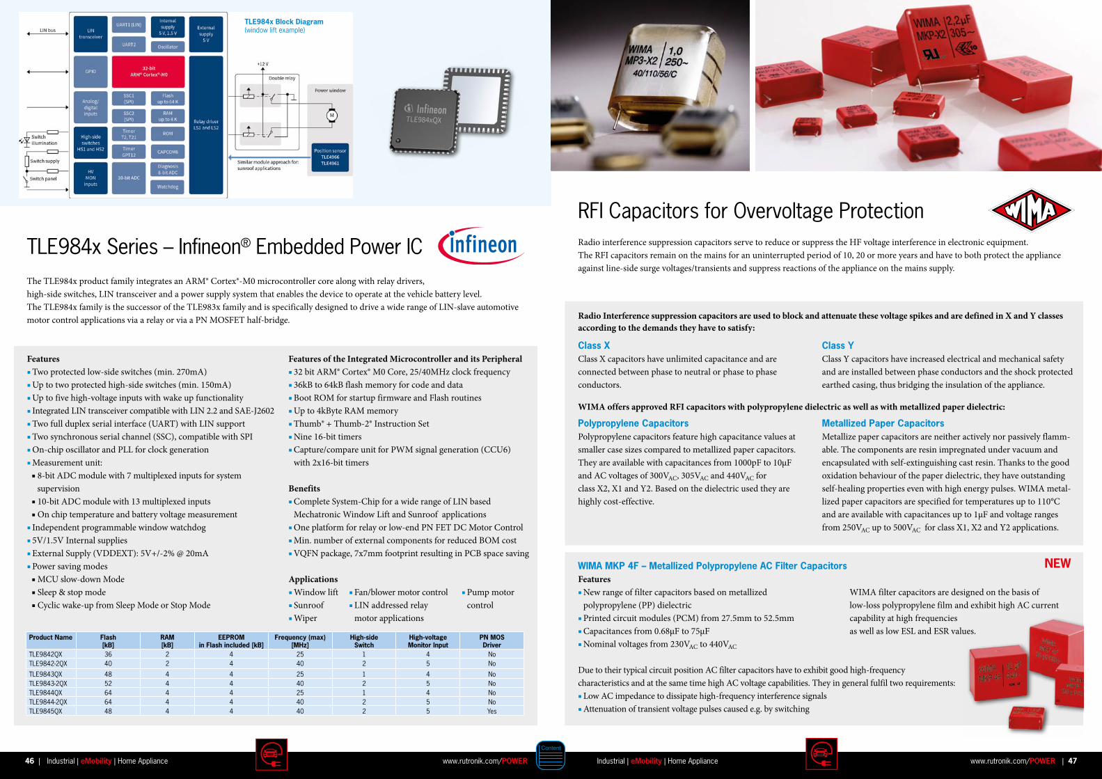
TLE984x Series – Infineon® Embedded Power ICThe TLE984x product family integrates an ARM® Cortex®-M0 microcontroller core along with relay drivers, high-side switches, LIN transceiver and a power supply system that enables the device to operate at the vehicle battery level. The TLE984x family is the successor of the TLE983x family and is specifically designed to drive a wide range of LIN-slave automotive motor control applications via a relay or via a PN MOSFET half-bridge.
Features Two protected low-side switches (min. 270mA) Up to two protected high-side switches (min. 150mA) Up to five high-voltage inputs with wake up functionality Integrated LIN transceiver compatible with LIN 2.2 and SAE-J2602 Two full duplex serial interface (UART) with LIN support Two synchronous serial channel (SSC), compatible with SPI On-chip oscillator and PLL for clock generation Measurement unit:
8-bit ADC module with 7 multiplexed inputs for system supervision 10-bit ADC module with 13 multiplexed inputs On chip temperature and battery voltage measurement Independent programmable window watchdog 5V/1.5V Internal supplies External Supply (VDDEXT): 5V+/-2% @ 20mA Power saving modes
MCU slow-down Mode Sleep & stop mode Cyclic wake-up from Sleep Mode or Stop Mode
Features of the Integrated Microcontroller and its Peripheral 32 bit ARM® Cortex® M0 Core, 25/40MHz clock frequency 36kB to 64kB flash memory for code and data Boot ROM for startup firmware and Flash routines Up to 4kByte RAM memory Thumb® + Thumb-2® Instruction Set Nine 16-bit timers Capture/compare unit for PWM signal generation (CCU6) with 2x16-bit timers
Benefits Complete System-Chip for a wide range of LIN based Mechatronic Window Lift and Sunroof applications One platform for relay or low-end PN FET DC Motor Control Min. number of external components for reduced BOM cost VQFN package, 7x7mm footprint resulting in PCB space saving
Applications Window lift Sunroof Wiper
TLE984x Block Diagram (window lift example)
Fan/blower motor control LIN addressed relay motor applications
Pump motor control
Product Name Flash [kB]
RAM [kB]
EEPROM in Flash included [kB]
Frequency (max) [MHz]
High-side Switch
High-voltage Monitor Input
PN MOS Driver
TLE9842QX 36 2 4 25 1 4 NoTLE9842-2QX 40 2 4 40 2 5 No
TLE9843QX 48 4 4 25 1 4 NoTLE9843-2QX 52 4 4 40 2 5 NoTLE9844QX 64 4 4 25 1 4 NoTLE9844-2QX 64 4 4 40 2 5 NoTLE9845QX 48 4 4 40 2 5 Yes
RFI Capacitors for Overvoltage Protection Radio interference suppression capacitors serve to reduce or suppress the HF voltage interference in electronic equipment. The RFI capacitors remain on the mains for an uninterrupted period of 10, 20 or more years and have to both protect the appliance against line-side surge voltages/transients and suppress reactions of the appliance on the mains supply.
Radio Interference suppression capacitors are used to block and attenuate these voltage spikes and are defined in X and Y classes according to the demands they have to satisfy:
Class XClass X capacitors have unlimited capacitance and are connected between phase to neutral or phase to phase conductors.
Polypropylene Capacitors Polypropylene capacitors feature high capacitance values at smaller case sizes compared to metallized paper capacitors. They are available with capacitances from 1000pF to 10µF and AC voltages of 300VAC, 305VAC and 440VAC for class X2, X1 and Y2. Based on the dielectric used they are highly cost-effective.
WIMA MKP 4F – Metallized Polypropylene AC Filter Capacitors Features New range of filter capacitors based on metallized polypropylene (PP) dielectric Printed circuit modules (PCM) from 27.5mm to 52.5mm Capacitances from 0.68µF to 75µF Nominal voltages from 230VAC to 440VAC
Due to their typical circuit position AC filter capacitors have to exhibit good high-frequency characteristics and at the same time high AC voltage capabilities. They in general fulfil two requirements: Low AC impedance to dissipate high-frequency interference signals Attenuation of transient voltage pulses caused e.g. by switching
Class YClass Y capacitors have increased electrical and mechanical safety and are installed between phase conductors and the shock protected earthed casing, thus bridging the insulation of the appliance.
Metallized Paper CapacitorsMetallize paper capacitors are neither actively nor passively flamm-able. The components are resin impregnated under vacuum and encapsulated with self-extinguishing cast resin. Thanks to the good oxidation behaviour of the paper dielectric, they have outstanding self-healing properties even with high energy pulses. WIMA metal-lized paper capacitors are specified for temperatures up to 110°C and are available with capacitances up to 1µF and voltage ranges from 250VAC up to 500VAC for class X1, X2 and Y2 applications.
WIMA offers approved RFI capacitors with polypropylene dielectric as well as with metallized paper dielectric:
WIMA filter capacitors are designed on the basis of low-loss polypropylene film and exhibit high AC current capability at high frequencies as well as low ESL and ESR values.
NEW
46 47www.rutronik.com/POWER www.rutronik.com/POWERIndustrial | eMobility | Home Appliance| |Industrial | eMobility | Home Appliance
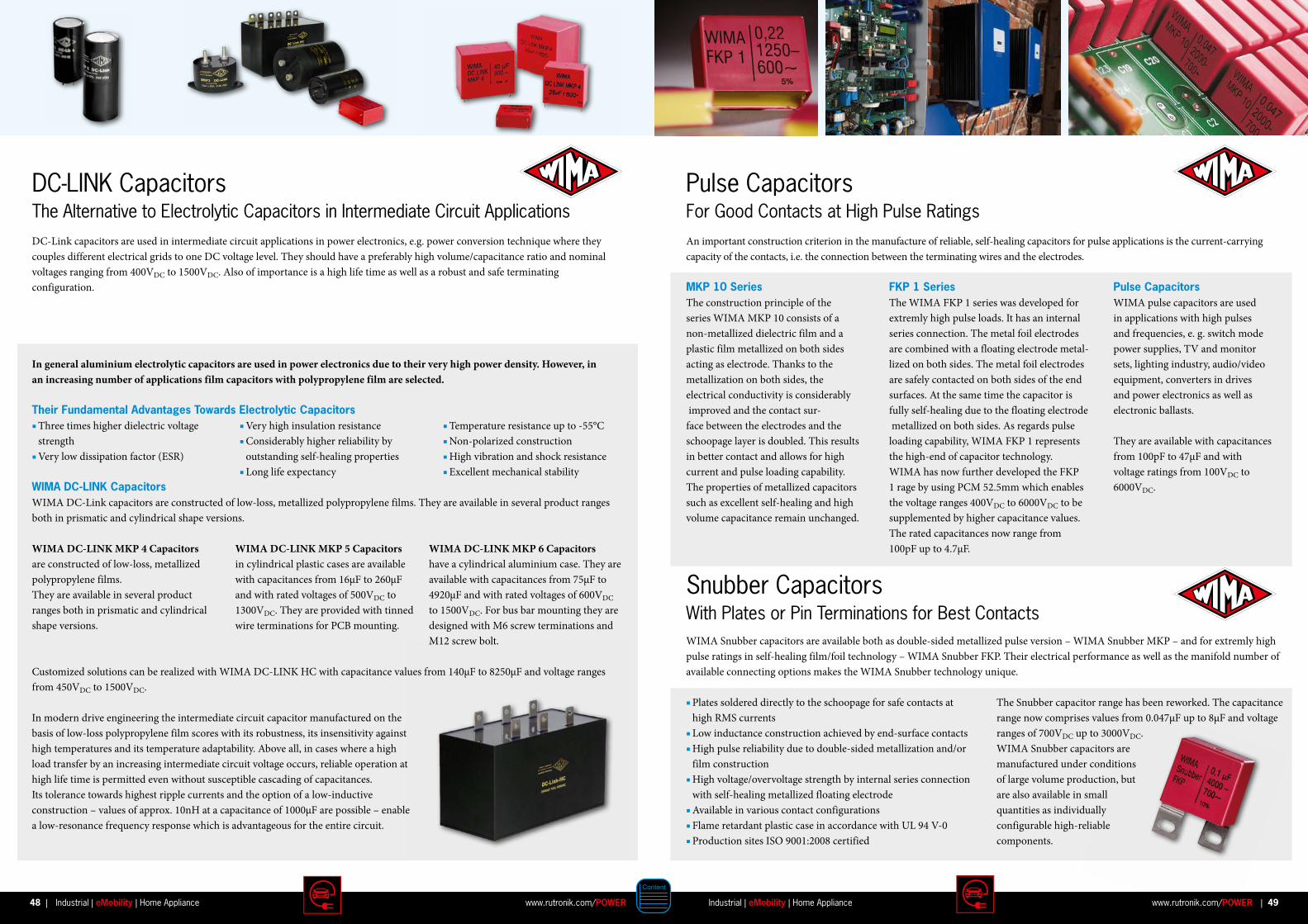
Pulse CapacitorsFor Good Contacts at High Pulse Ratings
Snubber CapacitorsWith Plates or Pin Terminations for Best Contacts
An important construction criterion in the manufacture of reliable, self-healing capacitors for pulse applications is the current-carrying capacity of the contacts, i.e. the connection between the terminating wires and the electrodes.
MKP 10 Series The construction principle of the series WIMA MKP 10 consists of a non-metallized dielectric film and a plastic film metallized on both sides acting as electrode. Thanks to the metallization on both sides, the electrical conductivity is considerably improved and the contact sur-face between the electrodes and the schoopage layer is doubled. This results in better contact and allows for high current and pulse loading capability. The properties of metallized capacitors such as excellent self-healing and high volume capacitance remain unchanged.
WIMA Snubber capacitors are available both as double-sided metallized pulse version – WIMA Snubber MKP – and for extremly high pulse ratings in self-healing film/foil technology – WIMA Snubber FKP. Their electrical performance as well as the manifold number of available connecting options makes the WIMA Snubber technology unique.
FKP 1 Series The WIMA FKP 1 series was developed for extremly high pulse loads. It has an internal series connection. The metal foil electrodes are combined with a floating electrode metal-lized on both sides. The metal foil electrodes are safely contacted on both sides of the end surfaces. At the same time the capacitor is fully self-healing due to the floating electrode metallized on both sides. As regards pulse loading capability, WIMA FKP 1 represents the high-end of capacitor technology. WIMA has now further developed the FKP 1 rage by using PCM 52.5mm which enables the voltage ranges 400VDC to 6000VDC to be supplemented by higher capacitance values. The rated capacitances now range from 100pF up to 4.7µF.
Pulse Capacitors WIMA pulse capacitors are used in applications with high pulses and frequencies, e. g. switch mode power supplies, TV and monitor sets, lighting industry, audio/video equipment, converters in drives and power electronics as well as electronic ballasts.
They are available with capacitances from 100pF to 47µF and with voltage ratings from 100VDC to 6000VDC.
Plates soldered directly to the schoopage for safe contacts at high RMS currents Low inductance construction achieved by end-surface contacts High pulse reliability due to double-sided metallization and/or film construction High voltage/overvoltage strength by internal series connection with self-healing metallized floating electrode Available in various contact configurations Flame retardant plastic case in accordance with UL 94 V-0 Production sites ISO 9001:2008 certified
The Snubber capacitor range has been reworked. The capacitance range now comprises values from 0.047µF up to 8µF and voltage ranges of 700VDC up to 3000VDC. WIMA Snubber capacitors are manu factured under conditions of large volume production, but are also available in small quantities as individually configurable high- reliable components.
DC-LINK CapacitorsThe Alternative to Electrolytic Capacitors in Intermediate Circuit ApplicationsDC-Link capacitors are used in intermediate circuit applications in power electronics, e.g. power conversion technique where they couples different electrical grids to one DC voltage level. They should have a preferably high volume/capacitance ratio and nominal voltages ranging from 400VDC to 1500VDC. Also of importance is a high life time as well as a robust and safe terminating configuration.
In general aluminium electrolytic capacitors are used in power electronics due to their very high power density. However, in an increasing number of applications film capacitors with polypropylene film are selected.
Three times higher dielectric voltage strength Very low dissipation factor (ESR)
WIMA DC-Link capacitors are constructed of low-loss, metallized polypropylene films. They are available in several product ranges both in prismatic and cylindrical shape versions.
WIMA DC-LINK MKP 4 Capacitors are constructed of low-loss, metallized polypropylene films. They are available in several product ranges both in prismatic and cylindrical shape versions.
WIMA DC-LINK Capacitors
Very high insulation resistance Considerably higher reliability by outstanding self-healing properties Long life expectancy
Temperature resistance up to -55°C Non-polarized construction High vibration and shock resistance Excellent mechanical stability
WIMA DC-LINK MKP 5 Capacitorsin cylindrical plastic cases are available with capacitances from 16µF to 260µF and with rated voltages of 500VDC to 1300VDC. They are provided with tinned wire terminations for PCB mounting.
WIMA DC-LINK MKP 6 Capacitors have a cylindrical aluminium case. They are available with capacitances from 75µF to 4920µF and with rated voltages of 600VDC to 1500VDC. For bus bar mounting they are designed with M6 screw terminations and M12 screw bolt.
Customized solutions can be realized with WIMA DC-LINK HC with capacitance values from 140µF to 8250µF and voltage ranges from 450VDC to 1500VDC.
Their Fundamental Advantages Towards Electrolytic Capacitors
In modern drive engineering the intermediate circuit capacitor manufactured on the basis of low-loss polypropylene film scores with its robustness, its insensitivity against high temperatures and its temperature adaptability. Above all, in cases where a high load transfer by an increasing intermediate circuit voltage occurs, reliable operation at high life time is permitted even without susceptible cascading of capacitances. Its tolerance towards highest ripple currents and the option of a low-inductive construction – values of approx. 10nH at a capacitance of 1000µF are possible – enable a low-resonance frequency response which is advantageous for the entire circuit.
48 49www.rutronik.com/POWER www.rutronik.com/POWERIndustrial | eMobility | Home Appliance| |Industrial | eMobility | Home Appliance
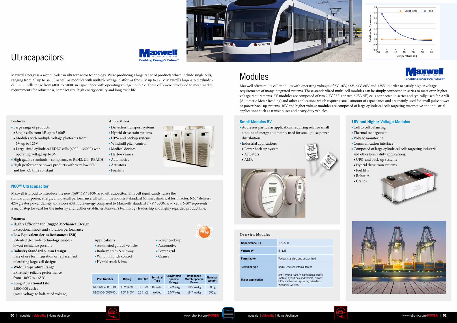
Ultracapacitors
ModulesMaxwell Energy is a world leader in ultracapacitor technology. We’re producing a large range of products which include single cells, ranging from 3F up to 3400F as well as modules with multiple voltage platforms from 5V up to 125V. Maxwell's large-sized cylindri-cal EDLC cells range from 600F to 3400F in capacitance with operating voltage up to 3V. These cells were developed to meet market requirements for robustness, compact size, high energy density and long cycle life.
Features Large range of products Single cells from 3F up to 3400F Modules with multiple voltage platforms from 5V up to 125V Large-sized cylindrical EDLC cells (600F – 3400F) with operating voltage up to 3V High quality standards – compliance to RoHS, UL, REACH High performance power products with very low ESR and low RC time constant
N60TM Ultracapacitor
Applications Driverless transport systems Hybrid drive train systems UPS- and backup systems Windmill pitch control Medical devices Harbor cranes Automotive Actuators Forklifts
Maxwell is proud to introduce the new N60™ 3V / 3400-farad ultracapacitor. This cell significantly raises the standard for power, energy, and overall performance, all within the industry-standard 60mm cylindrical form factor. N60™ delivers 42% greater power density and stores 40% more energy compared to Maxwell’s standard 2.7V / 3000-farad cells. N60™ represents a major step forward for the industry and further establishes Maxwell’s technology leadership and highly regarded product line.
Maxwell offers multi-cell modules with operating voltages of 5V, 16V, 48V, 64V, 86V and 125V in order to satisfy higher voltage requirements of many integrated systems. These standardized multi-cell modules can be simply connected in series to meet even higher voltage requirements. 5V modules are composed of two 2.7V / 3F (or two 2.7V / 5F) cells connected in series and typically used for AMR (Automatic Meter Reading) and other applications which require a small amount of capacitance and are mainly used for small pulse power or power back-up systems. 16V and higher voltage modules are composed of large cylindrical cells targeting automotive and industrial applications such as transit buses and heavy duty vehicles.
Small Modules 5V Addresses particular applications requiring relative small amount of energy and mainly used for small pulse power distribution Industrial applications: Power back-up system Actuators AMR
16V and Higher Voltage Modules Cell to cell balancing Thermal management Voltage monitoring Communication interface Composed of large cylindrical cells targeting industrial and other heavy duty applications: UPS- and back-up systems Hybrid drive train systems Forklifts Robotics Cranes
Capacitance (F) 1.5~500
Voltage (V) 5~125
Form factor Various standard and customized
Terminal type Radial lead and internal thread
Major application
AMR, hybrid tram, Windmill pitch control system, hybrid bus and vehicle, cranes, UPS- and back-up systems, driverless transport systems
Part Number Rating DC-ESR Terminal Type
Gravimetric Specific Energy
Impedance Match Specific
Power
Nominal Weight
NE03V03400ST001 3.0V 3400F 0.15 mΩ Threaded 8.4 Wh/kg 18.5 kW/kg 505 g
NE03V03400SW001 3.0V 3400F 0.15 mΩ Welded 8.5 Wh/kg 18.7 kW/kg 500 g
Features Highly Efficient and Rugged Mechanical Design Exceptional shock and vibration performance Low Equivalent Series Resistance (ESR) Patented electrode technology enables lowest resistance possible Industry Standard 60mm Design Ease of use for integration or replacement of existing large-cell designs Wide Temperature Range Extremely reliable performance from -40°C to +65°C Long Operational Life 1,000,000 cycles (rated voltage to half-rated voltage)
Applications Automated guided vehicles Railway, tram & subway Windmill pitch control Hybrid truck & bus
Overview Modules Power back-up Automotive Power grid Cranes
50 51www.rutronik.com/POWER www.rutronik.com/POWERIndustrial | eMobility | Home Appliance| |Industrial | eMobility | Home Appliance

XP™ products are engineered specifically for applications that operate over long durations in environments with high temperature and humidity. Proprietary product and manufacturing enhancements, designed into XP™, significantly reduce the likelihood of long term reliability issues resulting from prolonged operation in adverse environmental conditions. Under biased test conditions (2.7V, 90% relative humidity, 60°C), XP™ products deliver a 3 times improvement compared to benchmarked industry‐standard cells.
XP™ products are offered at capacitances ranging from 3F to 50F with dimensions and electrical specifications identical to those of Maxwell's corresponding standard cells. All products have been extensively tested to ensure adherence to strict performance standards and will be compliant with RoHS, UL and REACH.
XPTM -Series XTRA Performance
Product Overview XPTM -Series
*Biased Humidity Test (at VR, 60°C, and 90% RH)
Features & Benefits Highly Efficient Rugged Component Biased Humidity Test Conditions
(at VR, 60°C, and 90% RH) Low Equivalent Series Resistance(ESR) Patented electrode technology
and contact methods enables lowest resistance
Wide Temperature Range Very good temperature performance
down to -40°C and up to +65°C
Applications Advanced metering Emergency lighting Smoke detectors Security devices Medical devices Safety devices Automotive
Long Operational Life Offers >500k cycles
(nominal voltage down to half voltage) High Endurance Endurance equal to standard series Highly superior results at
Biased Humidity Test
Maxwell Part Number
RUTRONIK Part Number
CapacitanceRating DC-ESR Terminal
TypeMax Leakage
Current Size Biased Humidity Life*
ESHSR-0003C0-002R7UC KUK974 2.7V 3F <55 mΩ Radial Lead 5µA 8x20mm 2,000 Hrs
ESHSR-0005C0-002R7UC KUK973 2.7V 5F <35 mΩ Radial Lead 8µA 10x20mm 2,500 Hrs
ESHSR-0006C0-002R7UC KUK972 2.7V 6F <33 mΩ Radial Lead 17µA 8x30mm 2,000 Hrs
ESHSR-0010C0-002R7UC KUK971 2.7V 10F <30 mΩ Radial Lead 23µA 10x30mm 2,500 Hrs
ESHSR-0025C0-002R7UC KUK965 2.7V 25F <25 mΩ Radial Lead 49µA 16x25mm 3,000 Hrs
ESHSR-0050C0-002R7UC KUK970 2.7V 50F <16 mΩ Radial Lead 73µA 18x40mm 3,000 Hrs
Aluminium Electrolytic Capacitors for Automotive ApplicationsQuality, Reliability, Robustness
HBX 125°C 3000h High current, low ESR High voltage inverter Rated voltage: 250 to 275V Capacitance: 30 to 56μF
RX30 130°C 4000h High current, low ESR Rated voltage: 10 to 400V Capacitance: 1 to 4700μF Can be specified up to 150°C
MXG 105°C 3000h Multi pin terminal available AECQ-200 possible Rated voltage: up to 500V Capacitance: up to 68000μF
Features Multi pin High temperature Long lifetime High currents Snap-In capacitors with AECQ-200
Benefits Miniaturized Snap-In capacitors utilizing high density foil to fit into low profile cases Higher power density (CV value) in same case size for high power inverters Special series for demanding applications Customized solutions
Applications Charging circuits Power train DC/DC converter BLDC control High voltage inverter
BXW 105°C 12000h Miniaturization Long lifetime AECQ-200 possible Rated voltage: 160 to 450V Capacitance: 10 to 820μF
PEV 105°C 10000h Polymer Hybrid technology High current, low ESR Stable over lifetime Rated voltage: up to 63V Capacitance: up to 330μF
PFV 125°C 4000h Polymer Hybrid technology High current, low ESR Stable over lifetime Rated voltage: up to 63V Capacitance: up to 470μF Can be specified up to 150°C
N:\Markom\Bilder\FOTOLIA\MPE-08.09.20040001_neu elektroauto tanken säule.jpg
52 53www.rutronik.com/POWER www.rutronik.com/POWERIndustrial | eMobility | Home Appliance| |Industrial | eMobility | Home Appliance
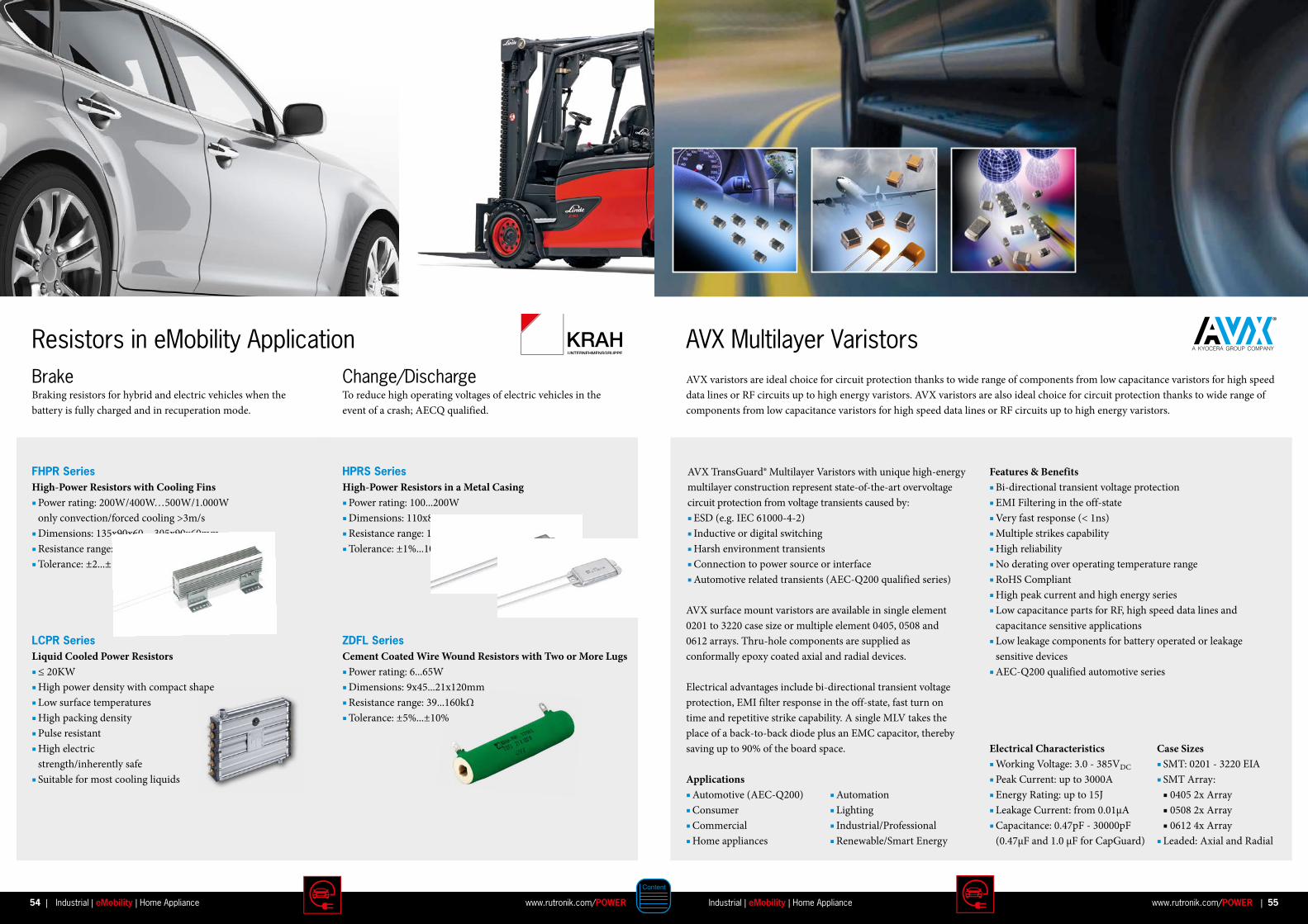
Brake Change/DischargeBraking resistors for hybrid and electric vehicles when the battery is fully charged and in recuperation mode.
To reduce high operating voltages of electric vehicles in theevent of a crash; AECQ qualified.
Resistors in eMobility Application
FHPR SeriesHigh-Power Resistors with Cooling Fins Power rating: 200W/400W…500W/1.000W only convection/forced cooling >3m/s Dimensions: 135x90x60…305x90x60mm Resistance range: 0.80…250Ω Tolerance: ±2...±10%
LCPR SeriesLiquid Cooled Power Resistors ≤ 20KW High power density with compact shape Low surface temperatures High packing density Pulse resistant High electric strength/inherently safe Suitable for most cooling liquids
HPRS SeriesHigh-Power Resistors in a Metal Casing Power rating: 100...200W Dimensions: 110x80x15...216x80x15mm Resistance range: 12...200Ω Tolerance: ±1%...10%
ZDFL SeriesCement Coated Wire Wound Resistors with Two or More Lugs Power rating: 6...65W Dimensions: 9x45...21x120mm Resistance range: 39...160kΩ Tolerance: ±5%...±10%
AVX varistors are ideal choice for circuit protection thanks to wide range of components from low capacitance varistors for high speed data lines or RF circuits up to high energy varistors. AVX varistors are also ideal choice for circuit protection thanks to wide range of components from low capacitance varistors for high speed data lines or RF circuits up to high energy varistors.
AVX Multilayer Varistors
Features & Benefits Bi-directional transient voltage protection EMI Filtering in the off-state Very fast response (< 1ns) Multiple strikes capability High reliability No derating over operating temperature range RoHS Compliant High peak current and high energy series Low capacitance parts for RF, high speed data lines and capacitance sensitive applications Low leakage components for battery operated or leakage sensitive devices AEC-Q200 qualified automotive series
Electrical Characteristics Working Voltage: 3.0 - 385VDC
Peak Current: up to 3000A Energy Rating: up to 15J Leakage Current: from 0.01µA Capacitance: 0.47pF - 30000pF (0.47µF and 1.0 µF for CapGuard)
Case Sizes SMT: 0201 - 3220 EIA SMT Array: 0405 2x Array 0508 2x Array 0612 4x Array Leaded: Axial and Radial
AVX TransGuard® Multilayer Varistors with unique high-energy multilayer construction represent state-of-the-art overvoltage circuit protection from voltage transients caused by: ESD (e.g. IEC 61000-4-2) Inductive or digital switching Harsh environment transients Connection to power source or interface Automotive related transients (AEC-Q200 qualified series)
AVX surface mount varistors are available in single element 0201 to 3220 case size or multiple element 0405, 0508 and 0612 arrays. Thru-hole components are supplied as conformally epoxy coated axial and radial devices. Electrical advantages include bi-directional transient voltage protection, EMI filter response in the off-state, fast turn on time and repetitive strike capability. A single MLV takes the place of a back-to-back diode plus an EMC capacitor, thereby saving up to 90% of the board space.
Applications Automotive (AEC-Q200) Consumer Commercial Home appliances
Automation Lighting Industrial/Professional Renewable/Smart Energy
54 55www.rutronik.com/POWER www.rutronik.com/POWERIndustrial | eMobility | Home Appliance| |Industrial | eMobility | Home Appliance

SMT Current Sense TransformerPA1005.XXXQNL Series
Features AEC-Q200 qualified Height: 5.5mm max Footprint: 8.4mm x 7.2mm max Current Rating: up to 20A Frequency Range: 50kHz to 1MHz
Electrical Specifications @ 25°C – Operating Temperature -40°C to +125°C
Part Number Turns Ratio Current Rating (A) Secondary Inductance (mH MIN)
DCR (mΛ Max) Hipot(VRMS)Primary
(8-7)Secondary
(1-3)
PA1005.020QNL 1:20 20 0.08 0.75 550 900
PA1005.030QNL 1:30 20 0.18 0.75 870 900
PA1005.040QNL 1:40 20 0.32 0.75 1140 900
PA1005.050QNL 1:50 20 0.50 0.75 1500 900
PA1005.060QNL 1:60 20 0.72 0.75 2250 900
PA1005.070QNL 1:70 20 0.98 0.75 4750 900
PA1005.100QNL 1:100 20 2.00 0.75 5500 900
PA1005.125QNL 1:125 20 3.00 0.75 6500 900
PA1005.150QNL 1:150 20 4.32 0.75 9000 900
Our surface mount and through hole current sense magnetics are excellent solutions for low-cost regulation of switch mode power supplies. RoHS compliant and available with both reinforced and functional safety levels, our current sensing products are ideal for Smart Grid and other applications focused on energy management. View our current sensing products, request a custom design or view our Sidewinder® products for AC current sensing applications.
ApplicationsCurrent sensors serve one specific purpose – to detect alternating current (AC) or direct current (DC) in a wire in order to generate a proportional signal. Current sensing is especially critical for power metering applications. The technology behind current sensors (more specifically current sense transformers) comes in various forms
Low resistance current shunts Current transformers with amorphous metal core Hall Effect devices Rogowski Coils Sidewinder products
Application Circuit SchematicMechanical
Power InductorsOffer High Temperature and High Current for the Best Power Solutions
The IHLP® inductor is different from most inductors. The inductor body is a soft magnetic composite (SMC), not a ferrite. It is made from an iron powder mixture and cemented together using a resin binder. This powder mixture, when pressed around the inductor coil, greatly enhances the electrical properties of the inductor and gives protection from environmental forces. After pressing, the component is cured in an oven to increase the bonding strength of the resin binders with the iron powder, yielding excellent electrical and physical properties.
Type Inductance min . (µH)
Inductance max . (µH)
DCR min . (mΩ)
DCR max . (mΩ)
Rated Current min . (A)
Rated Current max . (A)
Size in mm
IHLP-01 series0.047 22 0.75 129 1.9 80 1616 to 6767
Power inductor case sizes 1616 through 6767; original series; best saturation, lowest core loss
IHLP-A1 series0.047 22 0.75 129 1.9 80 1616 to 6767
Power inductor case sizes 1616 through 6767; automotive version of the standard -01 series
IHLP-11 series0.1 100 0.67 270 1.7 55 1212 to 6767
Power inductor case sizes 1212 through 6767; medium permeability series; low DCR
IHLP-1A series0.1 100 0.67 270 1.7 55 1616 to 6767
Power inductor case sizes 1616 through 6767; automotive version of the standard -11 series
IHLP-51 series0.47 100 0.67 174 1.2 80 1616 to 8787
Power inductor case sizes 1616 through 8787; high temperature series
IHLP-5A series0.47 100 0.67 174 1.2 80 1616 to 8787
Power inductor case sizes 1616 through 8787; automotive version of the standard -51 series
Surface-Mount Inductors
Applications Automotive DC/DC converters Filters for noise suppression DC/DC converters Power supplies for computers,
notebooks, graphic cards, servers Class “D” amplifiers LCD TVs and portable MP3 speakers LED driver power Commercial LED lighting LCD display backlights
Benefits High power Low profile Customized options available Using low-profile IHLP® inductors in your automotive applications helps you to go green
DC Amps
L in
µH
Ferrite Inductor
IHLP
1.2
1.0
0.8
0.6
0.4
0.2
0 5 10 15 20 25
SATURATION – IHLP VS. FERRITE INDUCTORSaturation – IHLP vs. Ferrite Inductor
AEC-Q200QUALIFIED
56 57www.rutronik.com/POWER www.rutronik.com/POWERIndustrial | eMobility | Home Appliance| |Industrial | eMobility | Home Appliance
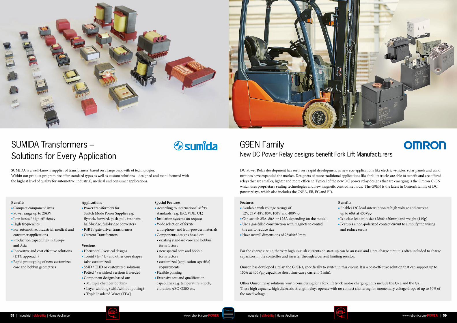
58 59www.rutronik.com/POWER www.rutronik.com/POWERIndustrial | eMobility | Home Appliance| |Industrial | eMobility | Home Appliance
DC Power Relay development has seen very rapid development as new eco-applications like electric vehicles, solar panels and wind turbines have expanded the market. Designers of more traditional applications like fork lift trucks are able to benefit and are offered relays that are smaller, lighter and more efficient. Typical of the new DC power relay designs that are emerging is the Omron G9EN which uses proprietary sealing technologies and new magnetic control methods. The G9EN is the latest in Omron’s family of DC power relays, which also includes the G9EA, EB, EC and ED.
Features Available with voltage ratings of 12V, 24V, 48V, 80V, 100V and 400VDC Can switch 25A, 80A or 125A depending on the model Use a gas-filled construction with magnets to control the arc to reduce size Have overall dimensions of 28x64x50mm
Benefits Enables DC load interruption at high voltage and current up to 60A at 400VDC
Is a class leader in size (28x64x50mm) and weight (140g) Features a non-polarized contact circuit to simplify the wiring and reduce errors
For the charge circuit, the very high in-rush currents on start-up can be an issue and a pre-charge circuit is often included to charge capacitors in the controller and inverter through a current limiting resistor.
Omron has developed a relay, the G9EJ-1, specifically to switch in this circuit. It is a cost-effective solution that can support up to 150A at 400VDC capacitive short time carry current (1min).
Other Omron relay solutions worth considering for a fork lift truck motor charging units include the G7L and the G7J. These high capacity, high dielectric strength relays operate with no contact chattering for momentary voltage drops of up to 50% of the rated voltage.
Benefits Compact component sizes Power range up to 20kW Low losses / high efficiency High frequencies For automotive, industrial, medical and consumer applications Production capabilities in Europe and Asia Innovative and cost effective solutions (DTC approach) Rapid prototyping of new, customized core and bobbin geometries
SUMIDA Transformers – Solutions for Every Application
Applications Power transformers for Switch Mode Power Supplies e.g. flyback, forward, push-pull, resonant, half-bridge, full-bridge converters IGBT / gate driver transformers Current Transformers
Versions Horizontal / vertical designs Toroid / E- / U- and other core shapes (also customized) SMD / THD or customized solutions Potted / varnished versions if needed Component designs based on: Multiple chamber bobbins Layer winding (with/without potting) Triple Insulated Wires (TIW)
SUMIDA is a well-known supplier of transformers, based on a large bandwith of technologies.Within our product program, we offer standard types as well as custom solutions – designed and manufactured withthe highest level of quality for automotive, industrial, medical and consumer applications.
Special Features According to international safety standards (e.g. IEC, VDE, UL) Insulation systems on request Wide selection of ferrite, amorphous- and iron-powder materials Components designs based on: existing standard core and bobbin form factors new special core and bobbin form factors customized (application-specific) requirements Flexible pinning Extensive test and qualification capabilities e.g. temperature, shock, vibration AEC-Q200 etc.
G9EN FamilyNew DC Power Relay designs benefit Fork Lift Manufacturers
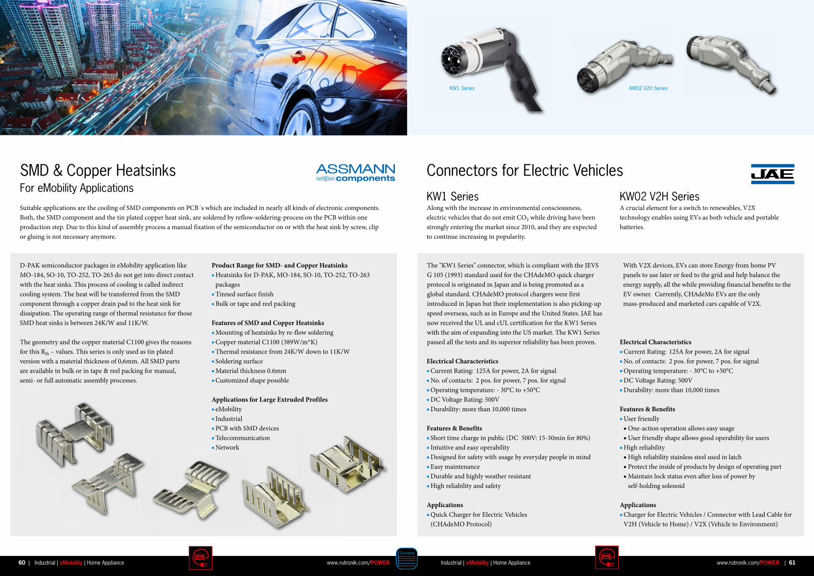
KW1 Series KW02 V2H Series
KW1 Series KW02 V2H Series Along with the increase in environmental consciousness, electric vehicles that do not emit CO2 while driving have been strongly entering the market since 2010, and they are expected to continue increasing in popularity.
A crucial element for a switch to renewables, V2X technology enables using EVs as both vehicle and portable batteries.
Features & Benefits Short time charge in public (DC 500V: 15-30min for 80%) Intuitive and easy operability Designed for safety with usage by everyday people in mind Easy maintenance Durable and highly weather resistant High reliability and safety
Electrical Characteristics Current Rating: 125A for power, 2A for signal No. of contacts: 2 pos. for power, 7 pos. for signal Operating temperature: - 30°C to +50°C DC Voltage Rating: 500V Durability: more than 10,000 times Features & Benefits
User friendly One-action operation allows easy usage User friendly shape allows good operability for users High reliability High reliability stainless steel used in latch Protect the inside of products by design of operating part Maintain lock status even after loss of power by
self-holding solenoid
Applications Quick Charger for Electric Vehicles (CHAdeMO Protocol)
Applications Charger for Electric Vehicles / Connector with Lead Cable for V2H (Vehicle to Home) / V2X (Vehicle to Environment)
Electrical Characteristics Current Rating: 125A for power, 2A for signal No. of contacts: 2 pos. for power, 7 pos. for signal Operating temperature: - 30°C to +50°C DC Voltage Rating: 500V Durability: more than 10,000 times
Connectors for Electric Vehicles
The "KW1 Series" connector, which is compliant with the JEVS G 105 (1993) standard used for the CHAdeMO quick charger protocol is originated in Japan and is being promoted as a global standard. CHAdeMO protocol chargers were first introduced in Japan but their implementation is also picking-up speed overseas, such as in Europe and the United States. JAE has now received the UL and cUL certification for the KW1 Series with the aim of expanding into the US market. The KW1 Series passed all the tests and its superior reliability has been proven.
With V2X devices, EVs can store Energy from home PV panels to use later or feed to the grid and help balance the energy supply, all the while providing financial benefits to the EV owner. Currently, CHAdeMo EVs are the only mass-produced and marketed cars capable of V2X.
Suitable applications are the cooling of SMD components on PCB´s which are included in nearly all kinds of electronic components. Both, the SMD component and the tin plated copper heat sink, are soldered by reflow-soldering-process on the PCB within one production step. Due to this kind of assembly process a manual fixation of the semiconductor on or with the heat sink by screw, clip or gluing is not necessary anymore.
SMD & Copper Heatsinks For eMobility Applications
Product Range for SMD- and Copper Heatsinks Heatsinks for D-PAK, MO-184, SO-10, TO-252, TO-263 packages Tinned surface finish Bulk or tape and reel packing
Features of SMD and Copper Heatsinks Mounting of heatsinks by re-flow soldering Copper material C1100 (389W/m*K) Thermal resistance from 24K/W down to 11K/W Soldering surface Material thickness 0.6mm Customized shape possible
Applications for Large Extruded Profiles eMobility Industrial PCB with SMD devices Telecommunication Network
D-PAK semiconductor packages in eMobility application like MO-184, SO-10, TO-252, TO-263 do not get into direct contact with the heat sinks. This process of cooling is called indirect cooling system. The heat will be transferred from the SMD component through a copper drain pad to the heat sink for dissipation. The operating range of thermal resistance for those SMD heat sinks is between 24K/W and 11K/W.
The geo metry and the copper material C1100 gives the reasons for this Rth – values. This series is only used as tin plated version with a material thickness of 0,6mm. All SMD parts are available in bulk or in tape & reel packing for manual, semi- or full auto matic assembly processes.
60 61www.rutronik.com/POWER www.rutronik.com/POWERIndustrial | eMobility | Home Appliance| |Industrial | eMobility | Home Appliance
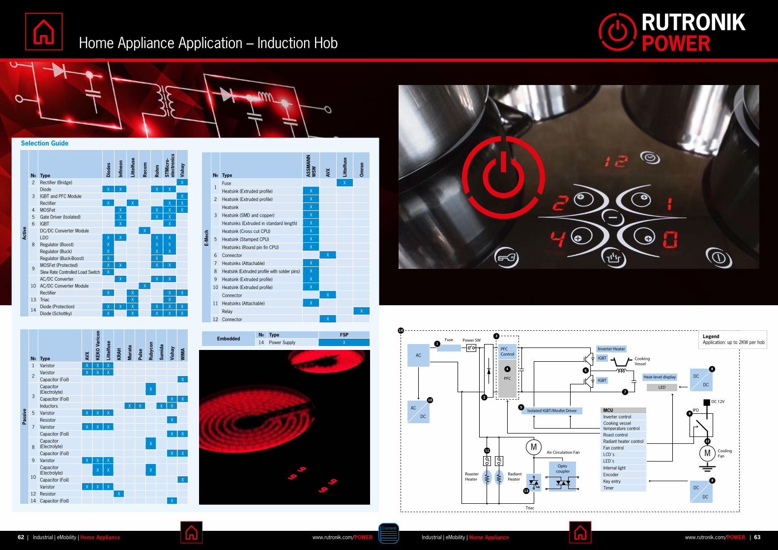
Fuse Power SW
Radiant Heater
Roaster Heater
Triac
Air Circulation FanM
Isolated IGBT/Mosfet Driver
Cooking Vessel
Inverter Heater
IGBT
IGBTHeat-level display
IPD
DC 12V
Cooling Fan
LED
PFC Control
PFC
Opto coupler
AC
DC
DC
DC
AC
DC
DC
MCUInverter controlCooking vessel temperature controlRoast controlRadiant heater controlFan controlLCD´sLED´s
Internal lightEncoderKey entryTimer
1
10
7
12
11
8
9
4
14
3
5
86
M
13
LegendApplication: up to 2KW per hob
2
Activ
e
NO Type Dio
des
Infin
eon
Litt
elfu
se
Rec
om
Roh
m
STM
icro
-el
ectr
onic
s
Vish
ay2 Rectifier (Bridge) X
3Diode X X X X
IGBT and PFC Module X
Rectifier X X X X
4 MOSFet X X X X
5 Gate Driver (Isolated) X X X
6 IGBT X X
8
DC/DC Converter Module X
LDO X X X X
Regulator (Boost) X X X
Regulator (Buck) X X X
Regulator (Buck-Boost) X X
9MOSFet (Protected) X X X X
Slew Rate Controlled Load Switch X
10AC/DC Converter X X X
AC/DC Converter Module X
Rectifier X X X X
13 Triac X X
14Diode (Protection) X X X X X X
Diode (Schottky) X X X X X
Pass
ive
NO Type AVX
KEK
O V
aric
on
Litt
elfu
se
KR
AH
Mur
ata
Puls
e
Rub
ycon
Sum
ida
Vish
ay
WIM
A
1 Varistor X X X
2Varistor X X X
Capacitor (Foil) X
3
Capacitor (Electrolyte) X
Capacitor (Foil) X X
Inductors X X X X
5 Varistor X X X
7Resistor X
Varistor X X X
Capacitor (Foil) X X
8Capacitor (Electrolyte) X
Capacitor (Foil) X X
9 Varistor X X X
10
Capacitor (Electrolyte) X X X
Capacitor (Foil) X
Varistor X X X
12 Resistor X
14 Capacitor (Foil) X
E-M
ech
NO Type ASSM
ANN
W
SW
AVX
Litt
elfu
se
Om
ron
1Fuse X
Heatsink (Extruded profile) X
2 Heatsink (Extruded profile) X
3
Heatsink X
Heatsink (SMD and copper) X
Heatsinks (Extruded in standard length) X
5
Heatsink (Cross cut CPU) X
Heatsink (Stamped CPU) X
Heatsinks (Round pin fin CPU) X
6 Connector X
7 Heatsinks (Attachable) X
8 Heatsink (Extruded profile with solder pins) X
9 Heatsink (Extruded profile) X
10 Heatsink (Extruded profile) X
11
Connector X
Heatsinks (Attachable) X
Relay X
12 Connector X
EmbeddedNO Type FSP
14 Power Supply X
Home Appliance Application – Induction Hob
62 63www.rutronik.com/POWER www.rutronik.com/POWERIndustrial | eMobility | Home Appliance Industrial | eMobility | Home Appliance| |
Selection Guide
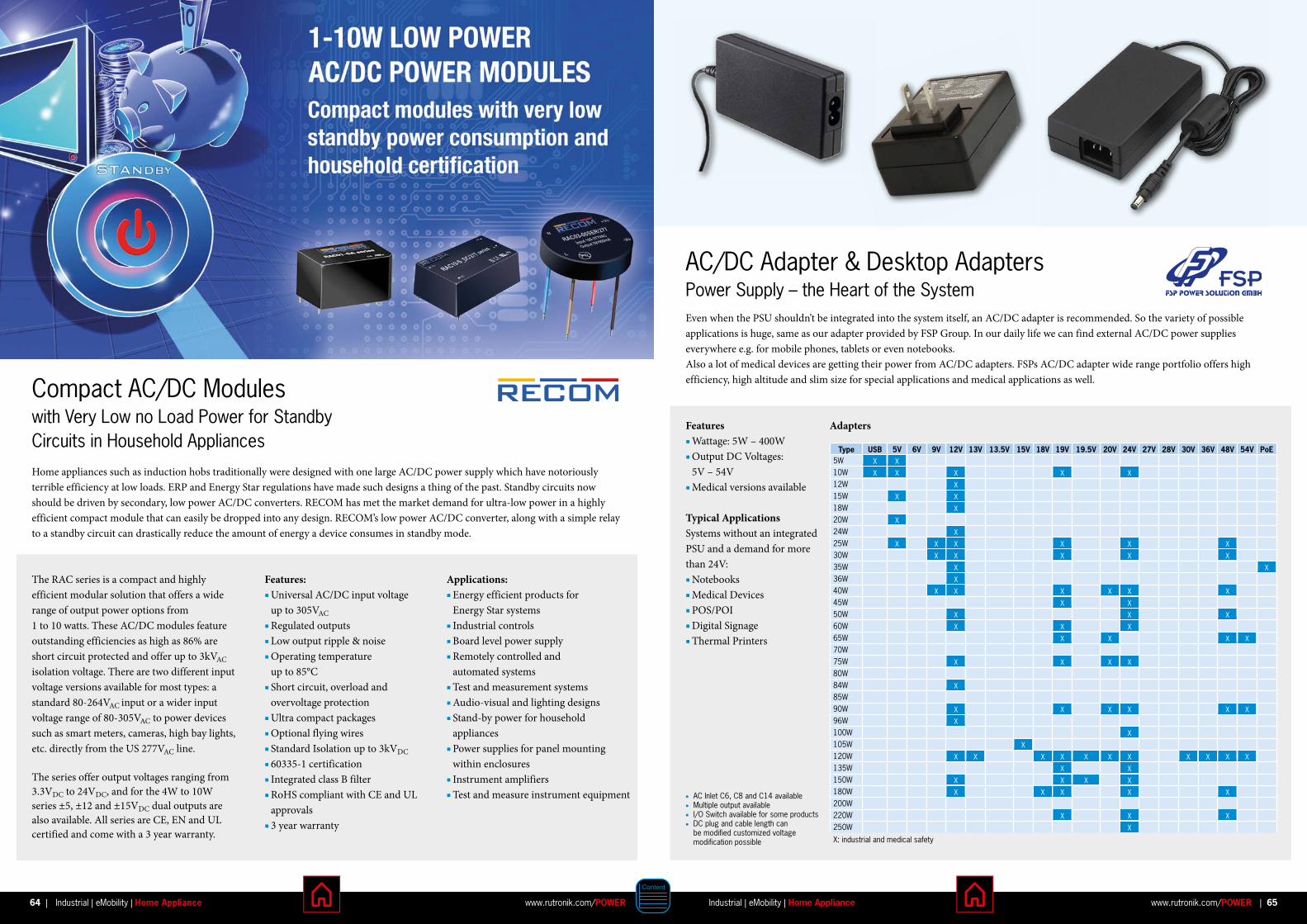
Features Wattage: 5W – 400W Output DC Voltages: 5V – 54V Medical versions available
Typical ApplicationsSystems without an integrated PSU and a demand for more than 24V: Notebooks Medical Devices POS/POI Digital Signage Thermal Printers
Even when the PSU shouldn’t be integrated into the system itself, an AC/DC adapter is recommended. So the variety of possible applications is huge, same as our adapter provided by FSP Group. In our daily life we can find external AC/DC power supplies everywhere e.g. for mobile phones, tablets or even notebooks. Also a lot of medical devices are getting their power from AC/DC adapters. FSPs AC/DC adapter wide range portfolio offers high efficiency, high altitude and slim size for special applications and medical applications as well.
Type USB 5V 6V 9V 12V 13V 13 .5V 15V 18V 19V 19 .5V 20V 24V 27V 28V 30V 36V 48V 54V PoE5W X X10W X X X X X12W X15W X X18W X20W X24W X25W X X X X X X30W X X X X X35W X X36W X40W X X X X X X45W X X50W X X X60W X X X65W X X X X70W75W X X X X80W84W X85W90W X X X X X X96W X100W X105W X120W X X X X X X X X X X X135W X X150W X X X X180W X X X X X200W220W X X X250W X
X: industrial and medical safety
AC Inlet C6, C8 and C14 available Multiple output available I/O Switch available for some products DC plug and cable length can
be modified customized voltage modification possible
AC/DC Adapter & Desktop AdaptersPower Supply – the Heart of the System
Adapters
Home appliances such as induction hobs traditionally were designed with one large AC/DC power supply which have notoriously terrible efficiency at low loads. ERP and Energy Star regulations have made such designs a thing of the past. Standby circuits now should be driven by secondary, low power AC/DC converters. RECOM has met the market demand for ultra-low power in a highly efficient compact module that can easily be dropped into any design. RECOM’s low power AC/DC converter, along with a simple relay to a standby circuit can drastically reduce the amount of energy a device consumes in standby mode.
Compact AC/DC Modules with Very Low no Load Power for Standby Circuits in Household Appliances
Features: Universal AC/DC input voltage up to 305VAC
Regulated outputs Low output ripple & noise Operating temperature up to 85°C Short circuit, overload and overvoltage protection Ultra compact packages Optional flying wires Standard Isolation up to 3kVDC
60335-1 certification Integrated class B filter RoHS compliant with CE and UL approvals 3 year warranty
Applications: Energy efficient products for Energy Star systems Industrial controls Board level power supply Remotely controlled and automated systems Test and measurement systems Audio-visual and lighting designs Stand-by power for household appliances Power supplies for panel mounting within enclosures Instrument amplifiers Test and measure instrument equipment
The RAC series is a compact and highly efficient modular solution that offers a wide range of output power options from 1 to 10 watts. These AC/DC modules feature out standing efficiencies as high as 86% are short circuit protected and offer up to 3kVAC isolation voltage. There are two different input voltage versions available for most types: a standard 80-264VAC input or a wider input voltage range of 80-305VAC to power devices such as smart meters, cameras, high bay lights, etc. directly from the US 277VAC line.
The series offer output voltages ranging from 3.3VDC to 24VDC, and for the 4W to 10W series ±5, ±12 and ±15VDC dual outputs are also available. All series are CE, EN and UL certified and come with a 3 year warranty.
64 65www.rutronik.com/POWER www.rutronik.com/POWERIndustrial | eMobility | Home Appliance Industrial | eMobility | Home Appliance| |

Infineon’s Intelligent Power Modules (IPM) Intelligent Power Modules designed by Infineon represent a functional product family that is dedicated to useful integration of electronics into power modules. Depending on the level of integration and power to be handled, Infineon offers a wide variety of semiconductors in different packages, voltage and current classes, and integrations. These Semiconductor products are separated in CIPOS™ Nano, CIPOS™ Micro, CIPOS™ Mini, CIPOS™ Mini-DCB and MIPAQ™ module families (from lowest to highest power capability).
CIPOS™ Mini PFC Integrated Inverter IPM With the CIPOS™ Mini PFC integrated inverter Infineon offers an IPM with Power Factor Control + Inverter in one package for 2kW power rating. It integrates various power and control components to provide customers with high reliability optimize PCB size and cost leadership.
Due to DCB substrate the CIPOS™ Mini PFC + Inverter offers excellent thermal performance. Electrical appliances must com-ply with IEC61000.3-2 which limits harmonic current emissions.
Product Name Converter Section Inverter Section Power Capabilty [kW]
PKG TypeVCES [V] Ii max .[A] fPWM(PFC)
typ .[kHz]VCES [V] IC [A] fPWM max . [kHz]
IFCM04P60GA 650 TBD TBD 600 -4/+4 20 (0.5) Fullpack
IFCM06P60GA 650 TBD TBD 600 -6/+6 20 (0.8) Fullpack
IFCM10S60GD 650 (30) (20) 600 -10/+10 20 (1.2) DCB
IFCM10P60GD 650 (30) (40) 600 -10/+10 20 (1.2) DCB
IFCM15S60GD 650 (30) (20) 600 -15/+15 20 (2) DCB
IFCM15P60GD 650 (30) (40) 600 -15/+15 20 (2) DCB
Features: TRENCHSTOP™ IGBTs Dual-in-line molded module with full pack and DCB substrate PFC + inverter in one package Power capability: 2kW Various PFC switching available : 20kHz or 40kHz PFC topology: single switch boost Rugged SOI gate driver technology with stability against transient and negative voltage Integrated bootstrap functionality Over current shutdown Temperature monitor Under-voltage lockout at all channels Low side common emitter
* Note : ( ) = preliminary data only
Key Benefits System size reduction with PFC integration into inverter module Cost down due to less BOM counts and less assembly cost Smaller and cheaper heatsink Possibility to design switching performance of PFC IGBT by using external driver circuit
Target ApplicationsRefrigerators, washing machine, residential air-conditioners and other home appliances; Low power motor drives.
Integration of various power and control components provide customers with high reliability, optimize PCB size and cost leadership:
All these families are highly integrated, compact power modules designed to drive motors in applications ranging from home appliances to fans, pumps and general purpose drives. These energy-efficient intelligent power modules integrate latest power semiconductor and control ICs technology leveraging Infineon’s advanced IGBTs, MOSFETs, next-generation gate driver ICs and state-of-the-art thermo-mechanical technology. In today's competitive, dynamic environment, there is constant pressure to find new ways to increase energy efficiency. At the same time, software's increasingly important role in systems directly contributes to their complexity – and increases costs. iMOTION™ platform, including controller and coming soon more integrated functions, offers complete inverter system that reduce design complexity and system cost, to overcome design challenges.
NEW
Block Diagram IPM inverter
IGBT Intelligent Power Module: Compact and high-perform . AC motor drive for simple and rugged designs up to 3kW
SLLIMM™ 2nd SeriesSmall Low-Loss Intelligent Molded Module
The SLLIMM 2nd series is ST’s new family of compact, high efficiency, dual-in-line intelligent power modules, with optional extra features. This family is designed using a new internal configuration with two gate drivers, one high-side driver and one low-side driver as well as an improved trench gate fieldstop IGBT. The best compromise between conduction and switching energy with an outstanding robustness and EMI behavior makes the new series ideal to enhance the efficiency of compressor, pumps, fans and motor drives working up to 20kHz in hard-switching circuitries and for applications with a power range from 300W to 3kW.
Key Features 600VDC rating from 8A to 35A at 25°C Low VCE (sat)
Optimized driver and silicon for low EMI Lowest Rth value on the market for the DBC package versions Internal bootstrap diode 175°C max. operating junction temperature Separate open emitter outputs NTC on board Integrated temp. sensor on low-side driver Comparator for fault protection Shutdown input/fault output Isolation rating of 1500VRMS/min
Key Benefits Easy to drive through microcontroller 175°C maximum junction temperature for higher robustness and reliability
Key Applications Industrial motor drives 3-phase inverter for motor drives up to 3kW Home appliances
ThisserieswillcomplementandovercomethealreadyavailableSLLIMMseriesintermofpowerandfeatures,packages’typesandflexibilityandittakesoverthemainfunctionsofpreviousone,addingsomemorefeaturesandenlargingthetechnologypackageoption.
Package Part NumberICN (A)
@ 25 °C (@ 80 °C)
Voltage (V)
Vce(sat) (V) at ICN 25 °C (80 °C)
Rthj-c (max)(°C/W)
Min Viso (V)
Max TJ
(°C)
SDIP2F-26L
STGIF5CH60TS-L(E) 8 (5)
600 1.7 (1.5)
5.0
1500 175
STGIF7CH60TS-L(E) 10 (7) 4.8
STGIF10CH60TS-L(E) 15 (10) 4.6
SDIP2B-26L
STGIB8CH60TS-L(E) 12 (8) 3.0
STGIB10CH60TS-L(E) 15 (10) 2.26
STGIB15CH60TS-L(E) 20 (15) 1.85
STGIB20M60TS-L(E) 25 (20) 1.4
STGIB30M60TS-L(E) 35 (30) 1.2
Temperaturesensing/protection:T=NTConboardS=Temperaturesensing
Packageandleadsfinishoptions:F=FullmoldedB=DBC(directbondcopper)E=ShortleadsandemitterforwardL=Longleads
SLLIMM RTH
0 10 20 30
1
2
3
4
5
6
RTH (°C/W)
iCN (A)
2nd series FM
2nd series DBC
1st series DBC
~20% RTH reduction
SLLIMM Series: Positioning
1 kW200 W 2 kW 3 kW
Small Pump
Refrigerator
Power Tools
WM
Room A/C
Small IndustrialInverter & Pump
Package A/C
End Products
Power
SLLIMM 2nd series
SLLIMM 2nd series
SLLIMM
© STMicroelectronics - October 2015 - Printed in United Kingdom - All rights reservedThe STMicroelectronics corporate logo is a registered trademark of the STMicroelectronics group of companies
All other names are the property of their respective owners
For more information on ST products and solutions, visit www.st.comOrder code: FLSLLIMM21015
FLSLLIMM21015.indd 2 10/6/2015 4:09:56 PM
SLLIMM Rth SLLIMM Series: Positioning
ThisserieswillcomplementandovercomethealreadyavailableSLLIMMseriesintermofpowerandfeatures,packages’typesandflexibilityandittakesoverthemainfunctionsofpreviousone,addingsomemorefeaturesandenlargingthetechnologypackageoption.
Package Part NumberICN (A)
@ 25 °C (@ 80 °C)
Voltage (V)
Vce(sat) (V) at ICN 25 °C (80 °C)
Rthj-c (max)(°C/W)
Min Viso (V)
Max TJ
(°C)
SDIP2F-26L
STGIF5CH60TS-L(E) 8 (5)
600 1.7 (1.5)
5.0
1500 175
STGIF7CH60TS-L(E) 10 (7) 4.8
STGIF10CH60TS-L(E) 15 (10) 4.6
SDIP2B-26L
STGIB8CH60TS-L(E) 12 (8) 3.0
STGIB10CH60TS-L(E) 15 (10) 2.26
STGIB15CH60TS-L(E) 20 (15) 1.85
STGIB20M60TS-L(E) 25 (20) 1.4
STGIB30M60TS-L(E) 35 (30) 1.2
Temperaturesensing/protection:T=NTConboardS=Temperaturesensing
Packageandleadsfinishoptions:F=FullmoldedB=DBC(directbondcopper)E=ShortleadsandemitterforwardL=Longleads
SLLIMM RTH
0 10 20 30
1
2
3
4
5
6
RTH (°C/W)
iCN (A)
2nd series FM
2nd series DBC
1st series DBC
~20% RTH reduction
SLLIMM Series: Positioning
1 kW200 W 2 kW 3 kW
Small Pump
Refrigerator
Power Tools
WM
Room A/C
Small IndustrialInverter & Pump
Package A/C
End Products
Power
SLLIMM 2nd series
SLLIMM 2nd series
SLLIMM
© STMicroelectronics - October 2015 - Printed in United Kingdom - All rights reservedThe STMicroelectronics corporate logo is a registered trademark of the STMicroelectronics group of companies
All other names are the property of their respective owners
For more information on ST products and solutions, visit www.st.comOrder code: FLSLLIMM21015
FLSLLIMM21015.indd 2 10/6/2015 4:09:56 PM
Temp. sensing/protection:T= NTC on board S= Temperature sensing
Package and leads finish options:F= Full moldedB= DBC (direct bond copper)
E= Short leads and emitter forwardL= Long leads
66 67www.rutronik.com/POWER www.rutronik.com/POWERIndustrial | eMobility | Home Appliance Industrial | eMobility | Home Appliance| |

A tradition of more than 50 years in the production of passive components has given Keko Varicon abundant experience and a large scale of knowledge needed by a high quality manufacturer in branches such as the telecommunications, AC lines and PCB board. All these have helped to make KEKO VARICON become a world-known and top of the art manufacturer in this sector. Household appliances, telecommunications, milking machines, alarm systems. High quality and relatively inexpensive varistors provide best protection against overvoltage surges for sophisticated equipment. Our products protect high end medical equipment, entertainment and consumer electronics, power supplies, energy meters, etc.
SV SeriesLead Style Epoxy Coated Square or Rectangular Shaped Varistors Full custom parameter designed medium voltage varistors AC voltage range from 60V to 550V Peak single pulse surge current up to 15kA
CV Series Transient Surge Suppressors, Disc Shaped Varistors It requieres little mounting space due to radial lead construction
CV+ SeriesExtended Version of CV Disc Shaped Varistors High current and energy capabilities
PV Series of Low & Medium Voltage Plastic – Encapsulated Varistors SMD Equivalent to leaded disc varistors Non-flammable thermoplastic encapsulation
DV Series of Medium Voltage Varistors SMD with very low profile
Varistors – Specialist in Overvoltage Protection
Vishay’s Power Metal Strip® current sensing resistors combine superior performance in high-temperature applications with a wide range of package sizes and a choice of resistance values from 0.0002Ω to 1Ω. These state-of-the-art products deliver overload capabilities equivalent to wirewound devices and temperature coefficients as low as 20ppm/°C.Current sensing Power Metal Strip® resistors allow control circuitry to monitor the level of current in a circuit by translating current into a voltage that can be monitored easily. The devices work by resisting the current flow in a circuit to a calibrated level, thus allowing a voltage drop to be detected and monitored by control circuitry. The low resistance values of Power Metal Strip® resistors allow this function to be carried out with exceptional efficiency.
Series WSLTPower Metal Strip® Surface-Mount Resistors
Key Benefits Wide range of package sizes (0603 to 5931) Wide resistance range (0.2mΩ to 1Ω) High-temperature performance (up to 275°C) Tight tolerances (down to ±0.1 %) Low temperature coefficients (down to ±20ppm/°C) Excellent overload capability (equivalent to wirewound) Automotive Grade qualified
Automotive Engine controls Anti-lock brakes Airbag Traction controls Multimedia Climate controls Electronic power steering Electric/hybrid vehicles
Consumer Goods Home electronics White goods Gaming systems Lighting controls Video cameras Television
Industrial Power supplies Power tools Bar code scanners HVAC Other current detection
Telecom Cell phones Modems Pagers Base stations Bluetooth Switching circuits
Medical and Instrumentation Monitoring systems Defibrillators Implantables Electronic scales Diagnostic equipment
Computer DC/DC converter Disk drives Power supplies Graphic cards PCMCIA Li-Ion battery management
Applications
68 69www.rutronik.com/POWER www.rutronik.com/POWERIndustrial | eMobility | Home Appliance Industrial | eMobility | Home Appliance| |

Benefits Compact solutions Covering wide operational temperature range Low losses / high efficiency High frequencies und high current types Cost effective production set-up
Applications DC/DC converters (Step-up / Step-down converters) POL power supplies EMI filter applications Input & output chokes Used in automotive, industrial, medical and consumer applications (e.g. LED head lights, ECUs, etc.)
SUMIDA offers a wide range of power inductors in many different technologies for automotive, industrial, medical and consumer applications. The product spectrum covers standard types as well as custom solutions – designed and manufactured on a highest quality level.
SUMIDA Power Inductors – Solutions for Every Application
Versions Ferrite and metal composite versions Shielded or non-shielded types Horizontal / vertical / low-profile types SMD / Pin-Type customized solutions Flat wire versions for high-current applications Low leakage-inductance types
Special Features According to international safety standards Wide range of AEC-Q200 products Operating temperature up to 150°C Insulation systems on request Customized component geometries possible Large selection of standard component families
70 71www.rutronik.com/POWER www.rutronik.com/POWERIndustrial | eMobility | Home Appliance Industrial | eMobility | Home Appliance| |
New Relays Address Size & Cost Pressures Switching relays are still central to induction and other electric hob design, providing the primary means of controlling the power to rings, hot plates and heating elements. Design of this key component needs to fully keep pace with the increasingly demanding regulations covering these appliances. For example, the 5th edition of IEC 60335-1 has now been published. At the same time, relay manufacturers need to recognise the numerous and conflicting pressures facing designers. They need to minimise the cost of the appliance and reduce size to create elegant products in ever smaller homes. Energy efficiency is also a constant demand.
G5NB-EL-HAOmron has introduced new relay designs that are ideal for power switching in induction hobs. Latest addition is the G5NB-EL, one of the smallest PCB power relays in its class facilitating a size reduction. The relay benefits from the latest contact design and materials, leading to a long electrical life of 200,000 operations.
Features Able to switch 7A at 250VAC
Conformant to IEC 60335-1 Just 7mm thick and 20.5mm deep x 15.3mm high Long electrical life
G2RL & G2RL-CV-HAFor the highest current loads, the G2RL and G2RL-CV-HA are recommended. This relay family includes a wide range of options including single and double pole versions.
Features Supports loads up to 16A at 250VAC Conformant to IEC 60335-1, EN61810, UL508 and CA22.2 12.7x29x15.7mm Supports ambient temperatures of up to 105°C (-CV, -HA) High sensitivity version with a coil current of 250mW (rated at 10A)
G5Q-EL-HAThe G5Q is a further option and is an attractive alternative to sugar cube relays. It is a compact single-pole relay offering a higher load carrying capacity than the G5NB, but a smaller size than the G2RL.
Features Handles loads of up to 10A Rated at up to 105°C Just 10mm thick and 20.3mm long by 15.8mm Low coil current of 200mW (SPST-NO)
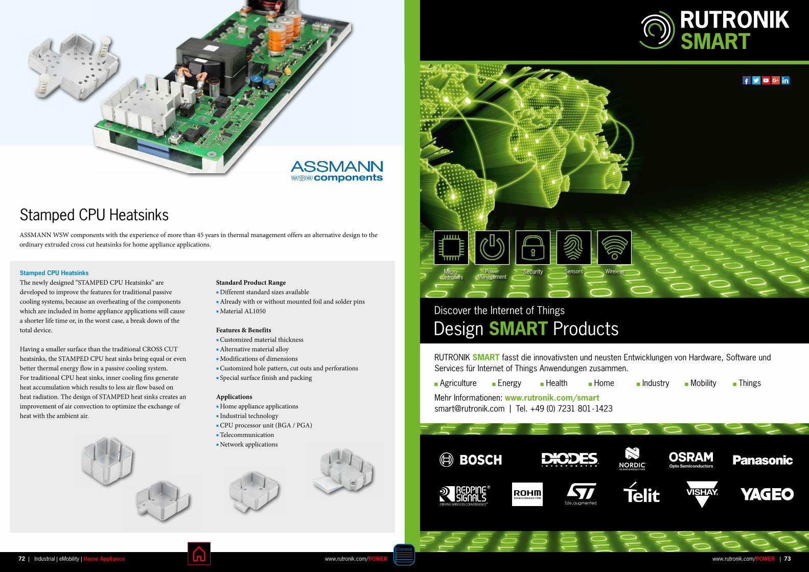
ASSMANN WSW components with the experience of more than 45 years in thermal management offers an alternative design to the ordinary extruded cross cut heatsinks for home appliance applications.
Stamped CPU Heatsinks
Standard Product Range Different standard sizes available Already with or without mounted foil and solder pins Material AL1050
Features & Benefits Customized material thickness Alternative material alloy Modifications of dimensions Customized hole pattern, cut outs and perforations Special surface finish and packing
Applications Home appliance applications Industrial technology CPU processor unit (BGA / PGA) Telecommunication Network applications
Stamped CPU HeatsinksThe newly designed “STAMPED CPU Heatsinks” are developed to improve the features for traditional passive cooling systems, because an overheating of the components which are included in home appliance applications will cause a shorter life time or, in the worst case, a break down of the total device.
Having a smaller surface than the traditional CROSS CUT heatsinks, the STAMPED CPU heat sinks bring equal or even better thermal energy flow in a passive cooling system. For traditional CPU heat sinks, inner cooling fins generate heat accumulation which results to less air flow based on heat radiation. The design of STAMPED heat sinks creates an improvement of air convection to optimize the exchange of heat with the ambient air.
Discover the Internet of Things
Design SMART ProductsRUTRONIK SMART fasst die innovativsten und neusten Entwicklungen von Hardware, Software und Services für Internet of Things Anwendungen zusammen.
Agriculture Energy Health Home Industry Mobility Things
Mehr Informationen: www .rutronik .com/[email protected] | Tel. +49 (0) 7231 801 - 1423
WirelessSensorsMicro- controllers
Power Management
Security
73www.rutronik.com/POWER |72 www.rutronik.com/POWERIndustrial | eMobility | Home Appliance|
RUTRONIK AUTOMOTIVE offers you a new range of bundled hardware, software and services. RUTRONIK AUTOMOTIVE brings together entire solutions to build applications for:
Safety Drive Train Body Electronics Comfort & Convenience Connected Car eMobility
More information: www .rutronik .com/[email protected] | Tel. +49 (0) 7231 801 - 1552
AUTOMOTIVE
Discover Innovation in Motion
AUTOMOTIVE ProductsCombine Technologies
Realize EMBEDDED Designs
Boards &
Systems
Wireless Displays Storage Drive Train
DRIVE TRAIN eMOBILITY
eMobilityComfort &
ConvenienceCOMFORT &
CONVENIENCE
Body
ElectronicsBODY ELECTRONICS
Safety
SAFETYConnected Car
Connected Car
RUTRONIK EMBEDDED brings together entire solutions to build applications for:
Digital Signage Transportation Industrial Control Medical
More information: www .rutronik .com/[email protected] | Tel. +49 (0) 7231 801 - 1776
74 75www.rutronik.com/POWERIndustrial | eMobility | Home Appliance| |

Spain Rutronik España S.L.
Barcelona C/ Tarragona 149-157, 6º 2a 8014 Barcelona Tel. +34 93 4 44 24 12
Madrid C/ Santa Leonor 65, Avalon Parque Empresarial, Edificio A, Pta 4a, 28037 Madrid Tel. +34 91 3 00 55 28
San Sebastian P0 Ubarburu 39 - Polígono 27 office 303 20014 Donostia Tel. +34 943 5095-00
Sweden Rutronik Nordic AB Kista Science Tower Färögatan 33, 16451 Kista Tel. +46 8 50 55 49 00
Switzerland Rutronik Elektronische Bauelemente AG
Volketswil Brunnenstrasse 1 8604 Volketswil Tel. +41 44 9 47 37 37
Turkey Rutronik Elektronische Bauelemente GmbH
Barbaros Mahallesi, Ardic Sokak, Varyap Meridian G2 Blok, No.: 09 34746 Bati Atasehir, Istanbul [email protected]
United Kingdom & Ireland Rutronik UK Ltd.
Headquarters UK The Valley, Bolton 1-3 Courtyard, Calvin Street BL1 8PB, Lancashire, UK Tel. +44 1204 602200
Swindon Whitehill Way Windmill Hill Business Park SN5 6QR Swindon Tel. +44 1793 441885
France Rutronik S.A.S 6, Mail de l’Europe 78170 La Celle St Cloud Tel. +33 1 30 08 33 00 [email protected] Tel. +33 5 57 26 40 00Grenoble Tel. +33 4 76 61 00 90Le Mans Tel. +33 2 43 78 16 97Lyon Tel. +33 4 72 76 80 00Rennes Tel. +33 2 23 45 14 40Strasbourg Tel. +33 3 88 78 12 12
Hungary Rutronik Magyarország Kft. Alíz utca 1, 1117 Budapest Tel. +36 12 31 33 49
Italy Rutronik Italia S.r.l. Via Caldera 21 Centro Direzionale S.Siro 20153 Milano (MI) Tel. +39 02 4 09 51-1 [email protected] Tel. +39 051 64 63 20 1Florence Tel. +39 055 8 82 73 32Padua Tel. +39 049 8 69 78 00Rome Tel. +39 06 228 782-1
Turin Tel. +39 011 9 02 20 00
Lithuania Rutronik Elektronische Bauelemente GmbH Jonavos g. 30, 44262 Kaunas Tel. +370 37 261780
Netherlands Rutronik Elektronische Bauelemente GmbH Takkebijsters 51a 4817BL Breda Tel. +31 76 57 230 00
Norway Rutronik Elektronische Bauelemente GmbH Olaf Helsets vei 6, 0694 Oslo Tel. +47 22 76 79 20
Austria Rutronik Elektronische Bauelemente Ges. m. b. H. Durisolstraße 11 4600 Wels Tel. +43 7242 4 49 01
Belgium Rutronik Belgium BV Keppekouter 1 Ninovesteenweg 198 9320 Erembodegem-Aalst Tel. +32 53 73 99 71
Bulgaria Rutronik Elektronische Bauelemente GmbH Blvd. Nikola Vaptzarov 35 Business Center Lozenetz Floor 1, Office No 1B 1407 Sofia Tel. +359 2 974 86 46
Czech Republic Rutronik Elektronische Bauelemente CZ s.r.o.
Brno Pražákova 1008/69, 15. f loor 639 00 Brno Tel. +420 5 4 54 24-681
Prague Na Pankraci 1638/43 140 00 Praha 4 Tel. +420 2 33 34 31 20
Denmark Rutronik Electronics Denmark ApS Herstedøstervej 27-29 2620 Albertslund Tel. +45 7020 19 63
Estonia Rutronik Elektronische Bauelemente GmbH Riia 142 50411 Tartu Tel. +372 6500620
Finland Rutronik Elektronische Bauelemente GmbH Malminkaari 5 00700 Helsinki Tel. +358 9 32 91 22 00
Poland Rutronik Polska Sp. z o.o. ul. Bojkowska 37 44-101 Gliwice Tel. +48 32 4 61 20 00
Gdynia ul. Batorego 28-32 81-366 Gdynia Tel. +48 58 7 83 20-20
Warszawa ul. Broniewskiego 3 01-785 Warszawa Tel. +48 22 462 70-50
Portugal Rutronik Elektronische Bauelemente GmbH Travessa Joaquim Sá Leonardo 85 Antas 4760-042 Vila Nova de Famalicão Tel. +351 252 312-336/337
Romania Rutronik Elektronische Bauelemente GmbH Strada Divizia 9 Cavalerie 64 300254 Timişoara Tel. +40 25 6401240
Bucureşti Tel. +40 21 3000141
Russia Rutronik Beteiligungsgesellschaft mbH
Moscow Leningradskoye Hwy, 57, Kor.2 125195 Moskwa Tel. +7 499 9633184
Saint Petersburg Naberezhnaya Reki Moyki 58 Office 609 191186 Saint Petersburg Tel. +7 812 321-63-68
Serbia Rutronik Elektronische Bauelemente GmbH Maglajska 24a, 11000 Belgrade Tel. +381 (11) 40412 90
Slovakia Rutronik Elektronische Bauelemente GmbH, o.z. Lazovná 11 97401 Banská Bystrica Tel. +421 48 4 72 23-00
Slovenia Rutronik Elektronische Bauelemente GmbH Motnica 5 1236 Trzin Tel. +386 1 5 61 09 80
European Branches
USA Rutronik Inc.
Dallas 2745 North Dallas Parkway Parkway Centre III, Suite 660 75093 Plano, TX Tel. +1 469 782 0900
California 6203 San Ignacio Ave., Suite 110 95119 San Jose, CA Tel. +1 669 247 5098
Massachusetts 300 Baker Avenue, Suite 300 01742 Concord, MA
Mexico Rutronik Mexico S.A. DE C.V.
Prolongacion Tecnologico Norte 950B int. 1 PISO 11-C, Colonia San Pablo, Corporativo Blanco 76130 Querétaro, Tel. +52 442 103 1805
China Rutronik Electronics (Shenzhen) Co., Ltd
Shenzhen Room 807, No.98 Fuhua 1 Road Futian District, 518048 Shenzhen City Tel. +86 755 21 37 60 00 Fax +86 755 21 37 60 01
Shanghai Room 1010, Dongchen Tower, No. 60 Mudan Road, Pudong New District Shanghai 201204 Tel. +86 21 38 86 78 88
Chengdu Room 709, Building G, China Overseas International Center, No. 333 Jiaozi Avenue, 610041 Chengdu Tel. +86 28 8651 2664
Hong Kong Rutronik Electronics Asia HK Ltd
54/F, Hopewell Centre 183 Queens Road East, Wan Chai Hong Kong, Tel. +852 3602 3135
India Rutronik Electronics Singapore Pte Ltd
Office No- 201, Regus, 2nd Floor 26/1 Hosur Road Bommanahalli Bangalore Kamataka Bangalore-560068, India Tel. +91 9880146135
Malaysia Rutronik Electronics Singapore Pte Ltd
73-3-1, iDeal@The One, Penang, Jalan Mahsuri, Bayan Baru 11950 Bayan Lepas, Penang Tel. +60 124 280 181
Singapore Rutronik Electronics Singapore Pte Ltd
10 ANG MO KIO Street 65 Techpoint #06-02A 569059 Singapore Tel. +65 6932 9778
Taiwan Rutronik Electronics Asia HK Ltd
3F., No. 183, Zhouzi Street, Neihu District Taipei City 11493, Taiwan Tel. +886 2 2659 5889
Thailand Rutronik Electronics Singapore Pte Ltd
2/1 Soi Rom Klao 25/2 Rom Klao Road, Khlongsamprawet Ladkrabang 10520 Bangkok Tel. +66 2 737 6423
International Branches
Germany – HeadquartersRutronik Elektronische Bauelemente GmbH | Industriestraße 2 | 75228 Ispringen / PforzheimTel. +49 7231 801-0 | Fax +49 7231 82282 | E-Mail: [email protected] | www.rutronik.com
Berlin Justus-von-Liebig-Straße 7 12489 Berlin Tel. +49 30 8 09 27 16-0
Dresden Radeburger Straße 172 01109 Dresden Tel. +49 351 20 53 30-0
Erfurt Flughafenstraße 4 99092 Erfurt Tel. +49 361 2 28 36-30
Frankfurt Frankfurter Straße 151 c 63303 Dreieich Tel. +49 6103 2 70 03-0
Freiburg Basler Landstraße 8 79111 Freiburg Tel. +49 761 61 16 77-0
Hamburg Neue Gröningerstraße 10 20457 Hamburg Tel. +49 40 3 59 60 06-20
Hannover Rendsburger Straße 32 30659 Hannover Tel. +49 511 228507-0
Mannheim Amselstraße 33 68307 Mannheim Tel. +49 621 76 21 26-0
München Landsberger Straße 392 81241 München Tel. +49 89 88 99 91-0
Nürnberg Südwestpark 10/12 90449 Nürnberg Tel. +49 911 6 88 68-0
Gütersloh Brockweg 133 33332 Gütersloh Tel. +49 5241 2 32 71-0 Ratingen Gothaer Straße 2 40880 Ratingen Tel. +49 2102 99 00-0
ENG
| K
NA
| Spe
cific
atio
ns s
ubje
ct to
cha
nge
with
out n
otic
e. P
leas
e no
te, t
here
cou
ld b
e so
me
limita
tions
for
som
e fr
anch
ised
pro
duct
line
s in
sev
eral
cou
ntrie
s. F
or m
ore
info
rmat
ion,
ple
ase
cont
act o
ur s
ales
team
.
Committed to excellence