post office electrical engineers' journal vol 54 pt 2 july 1961
TRANSCRIPT
THE POST OFFICE
ELECTRICAL ENGINEERS'
JOURNAL
CONTEJ'\TS
Page A 12 MC/S COAXIAL LINE EQUIPMENT-C.E.L. No. SA
H. J. K. Bordiss, A.M.I.E.E., and A. P. Davies ............ . 73
OVER-CEILING CABLING FOR TELEPHONE EXCHANGES \V. G. Roberts, A.M.I.E.E., and J. A. Povey, A.M.I.E.E ... . . . . . . . . . . . . . . 82
PULSE CODE MODULATION, Part 1-An Introduction to Pulse Code Modulation J. S. \Vhyte, M.Sc.(Eng.), A.M.J.E.E..... . . . . . . . . . . . . . . . . . . . . . . . . 86
DIALLING OF INTERNATIONAL TRUNK TELEPHONE CALLS BY UNITED KINGDOM SUBSCRIBERS-C. J. Maurer, C.G.l.A., B.Sc.(Eng.), A.M.l.E.E.. . . . . . . . . . . . . . . . . . . . . . . . . . . . 92
A JOINT-USER CATHODIC-PROTECTION SCHEME C. E. Morse.................. . ... . . . . . .
DEVELOPMENT OF A NON-STAINING MATERIAL FOR TELEPHONE FEET ..
CO-ORDINATION OF THE CATHODIC PROTECTION OF BURIED STRUCTURES.
SUBSCRIBER DIALLING OF INTERNATIONAL TELEX CALLS E. E. Daniels, and A. E. T. Forster, A.M.I.E.E ................... .
THE ENGINEER-IN-CHIEF'S LIBRARY INFORMATION SERVICE D. C. Griffiths, B.Sc . . . . . . . . . . . . . . . . . . . . . . . . . . . . . · . . . · · · · · · · · · · · ·
TIME-DIVISION-MULTIPLEX TELEGRAPHY O N THE TRANSATLANTIC TELEPHONE CABLE
95
100
101
103
111
H. E. Evans and A. C. Croisdale, M.B.E., B.Sc.(Eng.), A.M.I.E.E....... . . . . . . . . . . . . . . . . . . . . 113
SPEAKER EQUIPMENT FOR SUBMARINE CABLE SYSTEMS M. Stephenson, A.M.I.E.E., and L. A. Redburn ............ , . 118
CODING DESK AND CODE-MARK READER FOR USE WITH AUTOMATIC LETTER-SORTING l\tIACIDNES-T. Pilling, B.Sc.(Tech.), A.M.I.E.E., and P. Horrocks, A.M.1.E.E... ............ 122
SECOND PLENARY ASSEMBLY OF THE INTERNATIONAL TELEGRAPH AND TELEPHONE CONSULTATIVE COMMITTEE (C.C.I.T.T.), NEW DELHI, DECEMBER 1960...... 130
H.M.T.S. "ALERT" T. L. Jones.
NOTES AND COMMENTS .......... .
INSTITUTION OF POST OFFICE ELECTRICAL ENGINEERS .. .......... .
REGIONAL NOTES ........ ............... .
ASSOCIATE SECTION NOTES .......... ......... .
STAFF CHANGES ....
134
139
140
142
143
148
BOOK REVIEWS ...... . . . 81, 85, 91, 94, 110, 112, 121, 147
Price 2s. 6d. (Post Paid 3s. 6d,)
Published in April, July, October and January by The Post Office Electrical Engineers' Journal, G.P.0., 2-12 Gresham Street, London, E.C.2.
Annual Subscription (post paid): Home and Overseas, 14s. (Canada and U.S.A,, 2 dollars 25 cents).
THE POST OFFICE ELECTRICAL ENGINEERS' JOURNAL Vol. 54 Part 2 JULY 1961
A 12 Mc/s Coaxial Line Equipment-C.E.L. No. SA
H. J. K. BORDISS, A.M.I.E.E .• and A. P. DA VIES·r U.D.C. 621.395.52: 621.395.44: 621.315.212
This article describes the first 12 Mc/s bandwidth coaxial system to be designed and installed in the United Kingdon1. It is suitable for 2,700 telephone circuits or up to 1,200 telephone circuits together with a video circuit for a 625-line television signal. Auton1atic correction is applied for predictable system variations, and the use of modern components and long-life valves replaces the duplicatecomponent and standby-amplifier practices adopted hitherto. Up to 13 dependent stations may be power-fed in tandem over the coaxial pairs, and some addition to the conventional power arrangements
has been necessary.
INTRODUCTION
THE development of coaxial cable systems over the past 20 years has been directed in part towards exploiting more of the potential frequency band
width of l in. diameter coaxial cable pairs, and in part towards consolidating and improving existing systems. Among the more recently designed systems are the 4 Mc/s bandwidth systems (C.E.L. No. 4A and 6A) and the 12 Mc/s bandwidth system (C.E.L. No. 8A), which is the :;ubject of this article. The two 4 Me/s bandwidth ;ystems have already been described in this Journal1·2, :ind much of the description given of system design is 'qually applicable to the 12 Mc/s bandwidth system and .viii not be repeated here.
Coaxial-Equipment. Line (C.E.L.), No. 8A has been lesigned and manufactured by Standard Telephones and :ables, Ltd.; for use both in the United Kingdom and )Verseas. The first application in the United Kingdo1n 1as been to the London-Oxford-Birmingham route, �hich comprises two coaxial line-regulated sections: "ondon-Oxford and Oxford-Birmingham. Orders have ieen placed for two further schemes. namely a Londonlirmingham scheme and a Birmingham-Manchester . chem e.
C.E.L. No. 8A is designed to transmit frequencies in he range 0·3-12·5 Mc/s and can be used either with up o 45 telephony supergroups (2,700 circuits) or with a ombination of telephone circuits and a television ircuit having a video bandwidth of approximately ·7 Mc/s. Details of the alternative uses proposed were
,iven in a previous contribution to this Journal,3 but ince that contribution was prepared thoughts regarding he Post Office interim frequency allocation have changed.
To meet urgent circuit requirements on the first ,ondon-Oxford-Birmingham route, a temporary alloca-
t Main Lines Development and Maintenance Branch,E.-in-C.'s. 1ffice.
lion of two blocks, each of 15 supergroups, is being made. These are expected to use the frequency bands 312-4.028 kc/s and 6,388-IO,I04 kc/s. Longer-term development is being directed towards an assembly of three blocks of 15 supergroups, one possible frequency allocation being as shown in Fig. I. When a television circuit is required
PILOT FREQUENCIES
308 4,287 IZ,435 kc/s 1 BAND r I BAND z BAND 3 I -� . -.=:=;=-1 -===--=:i .
the whole of the frequency range occupied by the two upper blocks can be made available for it.
The nominal repeater spacing with this system is 3 miles, the spacing being arranged to be compatible with that of 4 Mc/s systems, using 6-mile spacing. on other coaxial pairs in the same cable, but, exceptionally, repeater sections may be up to 3·125 miles in length . The speaker and supervisory system used with C.E.L. No. 8A is broadly similar to that used with C.E.L. No. 6A, the principal differences being pointed out in subsequent paragraphs.
In common with other coaxial systems. C.E.L. No. 8A operates from an a.c. mains supply, and in this system power is fed to the dependent stations at 2.000 volts r.m.s., 50 c/s, between the centre conductors of the coaxial pairs. The maximum number of stations which can be fed in tandem from a power-feeding point is 13 •
this number being chosen to achieve compatibility with C.E.L. No. 6A on other coaxial pair:s in the same cable. The power supply at each dependent station is regulated within close limits, as explained in the sections dealing with the line amplifier and the power system.
The equipment is of 51-type construction' with the exception of the power regulators, which are mounted in free-standing cubicles.
DESIGN OF THE SYSTEM
The system has been designed for use in conjunction with the Post Office standard 375E-type coaxial pair, but can be made suitable for use with other types of! in. dia-
73
meter coaxial pairs by the use of "difference" equalizers. The overall insertion gain of the transmission path is 20 db over the frequency range 0·3-12·5 Mc/s, the nominal relative levels* at the input and output of the high-frequency line being -45 dbr and -25 dbr, respectively. The maximum length of a coaxial lineregulated section under the conditions prevailing in the United Kingdom would be so1ne 210 miles and would include two terminal stations, two intermediate powerfeeding stations and 75 dependent stations.
The system gain/frequency characteristic is under the control of three line pilot signals with frequencies of 308 kc/s, 4,287 kc/s and 12,435 kc/s.
Compensation for changes in the attenuation of the coaxial pairs with change of ten1perature is effected at each station by varying the gain/frequency characteristic of the line amplifiers. This compensation is governed, at dependent stations, by a pilot regulator which is fed from an auxiliary output of each line amplifier and actuated by the 4,287 kc/s pilot. At terminal and power-feeding stations the levels of the 308 kc/s, 4,287 kc/s and 12,435 kc/s pilot signals are monitored by pilot regulators of a different design and, as well as providing for cableten1perature regulation, serve Lo control networks which modify the gain/frequency characteristic of the line to compensate for (a) the aging of the line-amplifier valves, and (b) variations in repeater-station ambient temperature.
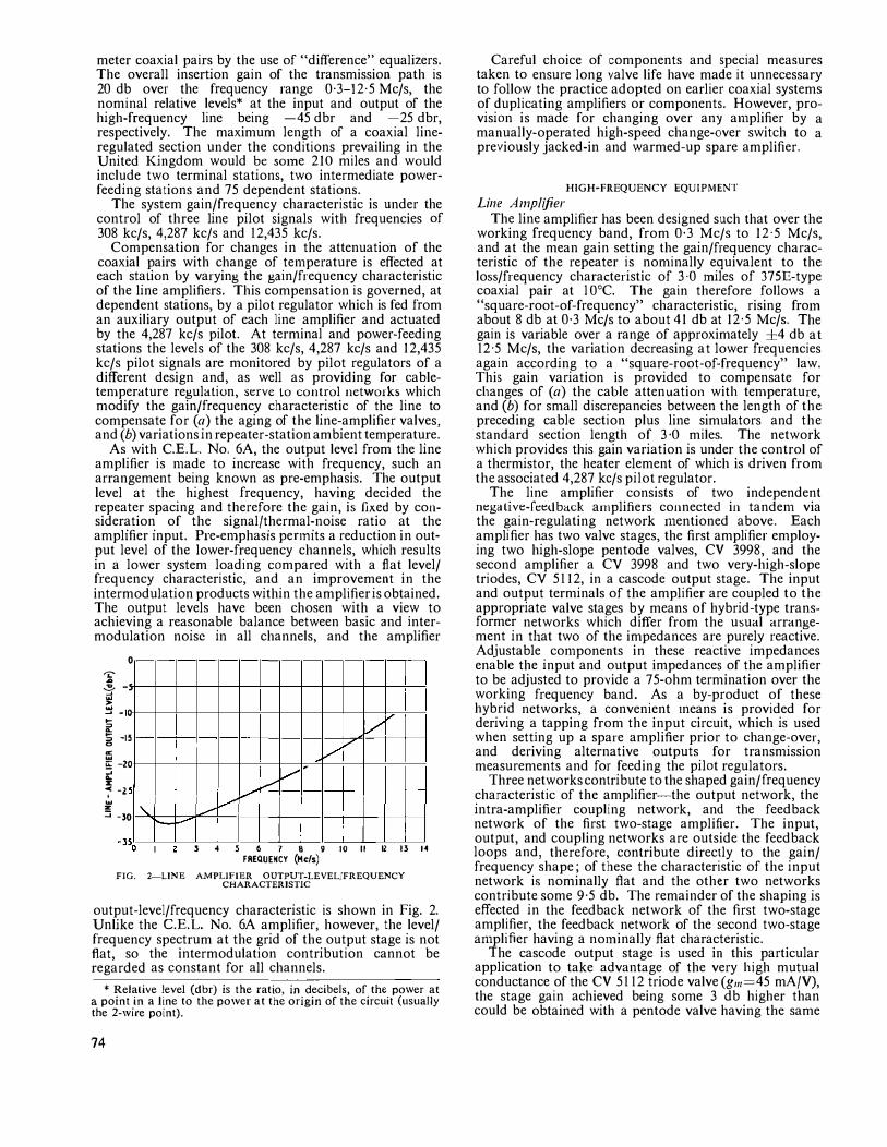
As with C.E.L. No. 6A, the output level from the line amplifier is n1ade to increase with frequency, such an arrangement being known as pre-emphasis. The output level at the highest frequency, having decided the repeater spacing and therefore the gain, is fixed by consideration of the signal/thermal-noise ratio at the amplifier input. Pre-en1phasis pennits a reduction in output level of the lower-frequency channels, which results in a lower system loading compared with a flat level/ frequency characteristic, and an improvement in the intermodulation products within the amplifier is obtained. The output levels have been chosen with a view to achieving a reasonable balance between basic and intermodulation noise in all channels, and the amplifier
0
'"i:' �
"" -'
� __. -10 � � -15 0
�
ii:: -zo
� � -z w
z
'
::::; -30 ' , __
:/1
v
./ v
� v""
l -4 5 6 7 8 9 10 II 12 13 H FREQUENCY (Hcfs)
FIG. 2-LINE AMPLIFIER OUTPUT-LEVEL/FREQUENCY CHARACTERISTIC
output-level/frequency characteristic is shown in Fig. 2. Unlike the C.E.L. No. 6A amplifier, however, the level/ frequency spectrum at the grid of the output stage is not flat, so the intermodulation contribution cannot be regarded as constant for all channels.
* Relalive level (dbr) is the ratio, in decibels, of the power at a point in a line to the po\ver at the origin of the circuit (usually the 2-\vire point).
74
Careful choice of components and special measures taken to ensure long valve life have made it unnecessary to follow the practice adopted on earlier coaxial systems of duplicating amplifiers or components. Ho\vever, provision is made for changing over any atnplifier by a manually-operated high-speed change-over switch to a previously jacked-in and warmed-up spare amplifier.
HIGH-FREQUENCY EQUIPMENT
Line Amplifier The line amplifier has been designed such that over the
working frequency band, from 0·3 Mc/s to 12·5 Mc/s, and at the mean gain setting the gain/frequency characteristic of the repeater is nominally equivalent to the loss/frequency characteristic of 3·0 1niles of 37SE-type coaxial pair at l 0°C. The gain therefore follows a "square-root-of-frequency" characteristic, rising fro1n about 8 db at 0·3 Mc/s to about 41 db at 12·5 Mc/s. The gain is variable over a range of approximately ±4 db at 12·5 Mc/s, the variation decreasing at lower frequencies again according to a "square-root-of-frequency" law. This gain variation is provided to compensate for changes of (a) the cable attenuation with ten1perature, and (b) for small discrepancies between the length of the preceding cable section plus line simulators and the standard section length of 3 ·O miles. The network which provides this gain variation is under the control of a thermistor, the heater element of which is driven from the associated 4,287 kc/s pilot regulator.
The line amplifier consists of two independent negative-fee<lback a1nplifiers connected in tanden1 via the gain-regulating network 1nentioned above. Each amplifier has two valve stages, the first amplifier employing two high-slope pentode valves, CV 3998, and the second amplifier a CV 3998 and two very-high-slope triodes, CV 5112, in a cascade output stage. The input and output terminals of the amplifier are coupled to the appropriate valve stages by means of hybrid-type transformer networks which differ from the usual arrangement in that two of the impedances are purely reactive. Adjustable con1ponents in these reactive impedances enable the input and output impedances of the amplifier to be adjusted to provide a 75-ohm termination over the working frequency band. As a by-product of these hybrid networks, a convenient tneans is provided for deriving a tapping from the input circuit, which is used when setting up a spare amplifier prior to change-over, and deriving alternative outputs for transmission measurements and for feeding the pilot regulators.
Three networks contribute to the shaped gain/frequency characteristic of the amplifier-the output network, the intra-amplifier coupling network, and the feedback network of the first two-stage amplifier. The input, output, and coupling networks are outside the feedback loops and, therefore, contribute directly to the gain/ frequency shape; of these the characteristic of the input network is nominally flat and the other two networks contribute some 9·5 db. The remainder of the shaping is effected in the feedback network of the first two-stage amplifier, the feedback network of the second two-stage a1nplifier having a no1ninally flat characteristic.
The cascade output stage is used in this particular application to take advantage of the very high mutual conductance of the CV 5112 triode valve(g,,,�45 mA/V), the stage gain achieved being some 3 db higher than could be obtained with a pentode valve having the same
grid-cathode spacing. Thus, the grid swing of the "lower'' triode, to achieve the required output level, is less than would otherwise be required and a lower value of intermodulation is obtained.
The difficulties of wideband-amplifier design with increasing upper frequency have been reflected in the fact that the amount of feedback obtainable at the upper frequencies is somewhat less than usual. From the point of view of gain stability, this consideration contributed to the decision to provide power regulators at all dependent stations.
Other features of the amplifier include the use of local d.c. feedback to stabilize the anode current in the valves, and the use of gold-plated valve pins and valveholder springs. Experience gained with the latter suggests their reliability is as good as that obtained with soldered connexions, and stray impedances associated \Vith the flying leads of soldered-in valves at the higher frequencies are eliminated. The effects on the amplifier of valve aging and repeater-station a1nbient temperature are corrected outside the amplifier on a power-feeding section basis, as described later.
Transn1it Line An1plifier
The line amplifier used on the transmit rack-side at tern1inal and power-feeding stations is very similar to the line amplifier already described, except that the feedback circuit of the input amplifier section has been modified to give a gain/frequency characteristic rising from about 18·5 db at 0·3 Mc/s to about 43 db at 12·5 Mc/s. The gain of the an1p]ifier is maintained constant, the exact value being determined by the resistor value chosen to replace the thermistor-bead resistance. A separate pre-en1phasis network is used in conjunction with the amplifier to obtain the required nominal output-level/ frequency characteristic (shown in Fig. 2).
Flat-Gain Amplifier The fiat-gain amplifiers are used at terminal and
power-feeding stations only. They consist essentially of the output-amplifier section, and the input and output transformers of the line amplifier. The feedback network has been modified to achieve a flat overall gain/frequency characteristic. A gain of 25 db over the working frequency band is realized.
Pilot Regulators
The 4,287 kc/s pilot regulator used at dependent stations consists of:
(a) a 4,287 kc/s narrow band-pass crystal filter, (b) a three-stage amplifier broadly tuned to the pilot
frequency and employing local d.c. feedback on each stage, and negative feedback overa11,
(c) a germanium-diode rectifier circuit_. and (d) a critically biased 2 kc/s oscillator. The type of valve used in both amplifier and oscillator
is the 6AK5, with gold-plated pins. The bias voltage applied to the oscillator stage
consists of three component voltages connected in series: a positive bias derived from the rectifier circuit (c) and, therefore, proportional to the pilot level; a standing negative bias derived from a voltage-reference tube in the power panel; and a negative bias derived from the oscillator valve itself and, therefore, proportional to the 2 kc/s output level. The algebraic sum of these bias voltages is arranged to be -3 volts d.c.,
and the output from the 2 kc/s oscillator feeds the thennistor which controls the intra-a1nplifier regulating network in the line amplifiers.
The sequence of operation is son1ewhat different fron1 that on C.E.L. No. 6A. An increase of the 4,287 kc/s pilot level at the amplifier output results in a corresponding increase in the positive-bias co1nponent in the regulator. ]'his increase is offset by an increase in the negative component derived fron1 the oscillator valve, which, therefore, means an increase in the 2 kc/s output to the thermistor heater in the associated line amplifier. As the impedance of the amplifier coupling network is arranged to vary inversely with the ten1perature of the thermistor, the amplifier gain is reduced until the pilot level is again restored to its normal value. The control ratio obtained between the pilot variation at the input and output of the amplifier is 4·5:1. A limiting circuit is incorporated in the 2 kc/s oscillator stage to restrict the output under abnormal conditions to a value which will not damage the thermistor heater.
The regulator rectifier circuit also provides two additional d.c. outputs to (a) control a pilot monitoring relay, which gives an alarm when the output pilot level deviates nominally 2 db from normal, and (b) operate a portable recording decibelmeter, which may be connected by the removal of a soldered strap.
The regulators used at terminal and power-feeding stations differ from the dependent-station model in the following respects:
(a) Three types of input filters have been designed to pass either 308 kc/s, 4,287 kc/s or 12,435 kc/s.
(b) The germanium-diode rectifier circuit is replaced by a more con1plex circuit using thermionic diodes which, in addition to contributing a bias voltage to the 2 kc/s oscillator, provide bias voltages which are fed to an elen1entary con1puting circuit. The function of this computing circuit is to examine the magnitudes of received pilot level changesi determine from them which effect (cable temperature, repeater te111perature or valve aging) or con1bination of effects is causing the changes, and then supply bias voltages to the oscillator stages of the regulators so that the appropriate shape-correcting networks are activated. Without this co1nputer circuit, interaction between the regulators could produce intolerable changes in gain and equalization.
(c) At terminal stations, duplicate regulators are used as pilot monitors, one of the diodes in each regulator being used to feed current to a pilot-level meter (P.O. Decibelmeter No. 16) and to a recording decibelmeter' (Decibelmeter No. 28A).
(d) The control ratio has been increased to approximately 10: I.
Pilot Oscillators
The pilot frequencies used with C.E.L. No. SA are generated by oscillators which, in respect of circuit arrangement and performance, are sin1ilar to those used on C.E.L. No. 6A, though the facility of using the oscillator panel as a stabilizer for a pilot signal derived from carrier generating equipment is not provided. Frequency stabilities of I part in 105 are obtained when the oscillators are working with normal power supplies and within the ambient te1nperature range 15-35°C, with the exception of the 308 kc/s oscillator where a stability of 2 parts in 10' is acceptable. Similarly, the level stabilities are better than ±0· l db, under the same conditions, except that for the 12,435 kc/s oscillator
75
±0·2 db level stability is obtained. The harmonic content of the output signals is very low, being of the order of 60 db below the level of the pilot frequency.
Two oscillators are provided for each frequency, with automatic change-over should the working oscillator fail.
Pilot-Stop Filters
Filters with narrow stop bands centred on each of the three pilot frequencies are provided at both the trans1nit and receive terminals. The transmit filters serve to suppress television and other extraneous signals that might interfere with the pilot signals. The receive filters suppress the pilot frequencies to prevent interference with television signals or with pilot signals of other systems.
Net111orks A number of fixed and adjustable networks are
included in the system, the characteristics of each being chosen to suit the particular purpose for which the network is employed. The principal networks and their uses arc as follows:
(a) Line Simulators. These are provided before each line amplifier for the purpose of building out the preceding cable section to the equivalent loss of 3 miles of cable. Four simulator values are available1 having insertion losses to match the attenuation of !, !i ! and I mile of 375E coaxial pair at IO'C.
(b) Slope (Emphasis) Networks. At the transmit tern1inal a "slope" network precedes the transmit line amplifier, the network attenuation characteristic being shaped to obtain, in conjunction with the gain shape of that amplifier, the required nominal output-level/ frequency characteristic, as shown in Fig. 2. It will be observed that the output level rises about 20 db over the frequency range, and at the receive terminal this characteristic is reversed in two de-emphasis networks (see Fig. 8). The first network follows the receive line amplifier and reduces the signal emphasis to about 14db, but the final network follows the last flat amplifier. The reason for this arrangement is that optin1um noise performance of the flat amplifiers is obtained with this level range of 14 db.
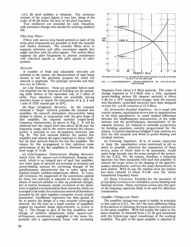
(c) Gab1/Frequency Character;stic Shaping Net1vorks. Apart from the square-root-of-frequency shaping network, which is an integral part of each line amplifier, two other types of network are provided at terminal and power-feeding stations for correcting changes of the gain/frequency characteristic due to valve aging and repeater-station ambient-temperature effects. At transmit tcrn1inals, the magnitude of the corrections applied by these two networks is adjusted in discrete steps by means of manual switches to take up predicted changes, but at receive terminals overall correction of the deviations is applied automatically by these networks, which are arranged to be under the continuous control of thermistors actuated by the pilot regulator-computer circuit already mentioned. Insufficient experience has been gained so far to permit the design of a very accurate valve-aging network, but life tests on a small number of amplifiers suggest an equalizer shape approximately as shown in Fig. 3. The change in gain of the line amplifiers with change of ambient temperature (after square-rootof-frequency correction) is negligible at the lower frequencies and is approximately linear with increasing
76
--r -I
I I :1
-1
LOSS 1 11--
ldb) 0 I CURVE 8 j
_,
-1
-l
-4
_, ,., 0·4 0·8 1·2 4
FREQUENCY (Mc/s) • 12 20
The slope varies from curve A, through the mid-setting response, curve B. 10 the limit of curve C as the valves age
FIG. 3-LOSS/FREQUENCY CHARACTERISTICS OF VALVE-AGING EQUALIZER
frequency from about 4·5 Mc/s upwards. The order of change expected at 12·5 Mc/s over a fully equipped power-feeding section (26 repeater sections) is about 4 db for a 10°C temperature change; both the manual and thermistor controlled networks have been designed to cater for ±4 db variation at 12·5 Mc/s.
(d) Attenuation Residual Equalizers. As is usual with coaxial systems, equalization errors due to imperfections in the main equalization, i.e. small residual differences between the loss/frequency characteristic of the cable sections and the gain/frequency characteristics of the repeater stations, are reduced to tolerable proportions by building equalizers suitably proportioned for the system. Constant-impedance bridged-T type sections are built for this purpose and fitted at power-feeding and terminal stations.
(e) Trinuning Equalizers. It is, of course, important to keep the equalization errors mentioned in (d) as small as possible, otherwise the sunnnation of these errors, some of which tend to be systematic, would make large inroads into the noise margin of the system. On the C.E.L. No. 8A system, therefore, a trimming equalizer has been associated with each line amplifier to remove the larger errors in the shaping of the gain/frequency characteristic, and has the same characteristic at each station. With its use, the residual error per station has been reduced to about 0·3 db over the whole transmitted frequency band.
(f) Delay Correctors. Facilities for the provision of group-delay correctors are included at power-feeding and terminal stations. Delay correction covers only that part of the frequency spectrum likely to be used for television transmission.
A111plijier Change-over Panel The amplifier change-over panel is similar in principle
to that used on C.E.L. No. 6A,2 the main difference being in the method of obtaining the input signal for application to the spare amplifier. With this system the input to the spare amplifier is obtained from a 23 db pad associated with the hybrid-type input transformer of the working amplifier. The gain of the spare amplifier is adjusted to
obtain the same output level, measured at the main h.f. output socket, as that measured at the "transmission measuring" output socket of the working amplifier (the latter being 23 db below normal signal output). This gain adjustment is carried out using the 4,287 kc/s pilot as a reference signal and employing portable frcquencyselcctive measuring equipment.
The panel also incorporates a meter which monitors the voltage applied to the thermistor in the working amplifier, and which is calibrated to indicate the approximate amount of gain correction (at 4,287 kc/s) being applied by the regulator at any time.
THE POWER SYSTEM
The system employs a.c. power-feeding at 2,000 volts r.m.s. over the coaxial pairs to a maximum of 13 stations connected in parallel on any power-fed section. Although at first sight the power arrangements appear conventional, some important refinements to existing techniques have been incorporated, and the reasons for their adoption merit explanation. For the first time on coaxial line systems used by the Post Office it has been found necessary to:
(a) provide voltage regulation at dependent repeater stations,
(b) control the power factor of the cable power circuit, and
(c) control the linearity of the rackside power-units. It has also been considered necessary to improve the
security against interruption of the power supplies to the dependent stations, and the Post Office has designed an equipment for feeding a standby source of power to the cable from the dependent station at the end of a powerfeeding section, in the reverse direction to that of the normal supply. This power is applied under remote control, as discussed in a subsequent paragraph.
Voltage Regulation It has already been stated that the gain/frequency
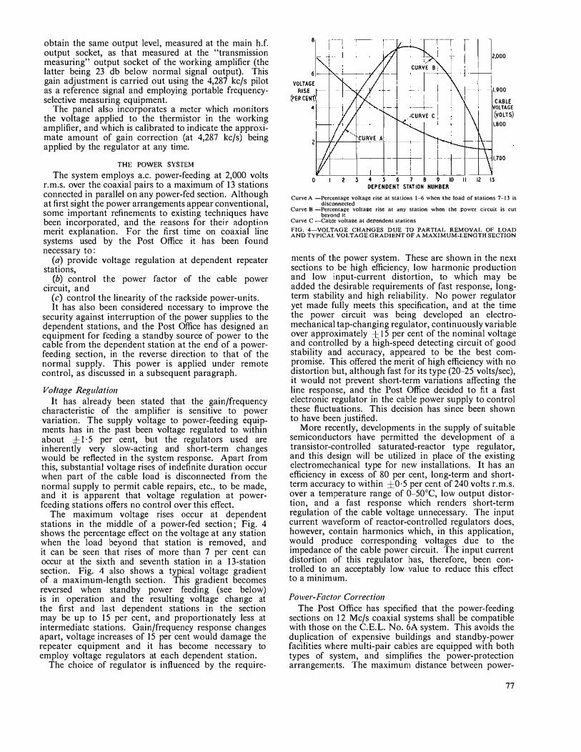
characteristic of the amplifier is sensitive to power variation. The supply voltage to power-feeding equipments has in the past been voltage regulated to within about ±I· 5 per cent, but the regulators used are inherently very slow-acting and short-term changes would be reflected in the system response. Apart from this, substantial voltage rises of indefinite duration occur when part of the cable load is disconnected from the normal supply to permit cable repairs, etc., to be made, and it is apparent that voltage regulation at powerfceding stations offers no control over this effect.
The maximum voltage rises occur at dependent stations in the middle of a power-fed section; Fig. 4 shows the percentage effect on the voltage at any station when the load beyond that station is removed, and it can be seen that rises of more than 7 per cent can occur at the sixth and seventh station in a 13-station section. Fig. 4 also shows a typical voltage gradient of a maximum-length section. This gradient becomes reversed when standby power feeding (see below) is in operation and the resulting voltage change at the first and last dependent stations in the section may be up to 15 per cent, and proportionately less at intermediate stations. Gain/frequency response changes apart, voltage increases of 15 per cent would damage the repeater equipment and it has become necessary to employ voltage regulators at each dependent station.
The choice of regulator is influenced by the require-
• --1
. --,--r i 1 12.000 I .,
CURVE 8
I l+-i
' I -
1-1 !1,900
I CABLE I ·---+-- VOLTAGE JCURVE C (VOLTS)
1,800
0 -4 5 6 7 8 9 10 11 12 13 DEPENDENT STATION NUMBER
Curve A -Percentage voltage rise at sta1io11s 1-6 when the load of stations 7-13 is disconnected
Curve B -Percentage voltage rise at any station when the power circuit is cut beyond it
Curve C -Cable voltage at dependent stations
FIG. 4---VOLTAGE CHANGES DUE TO PARTIAL REMOVAL OF LOAD AND TYPICAL VOLTAGE GRADIENT OF A MAXIMUM-LENGTH SECTION
n1ents of the power system. These are shown in the next sections to be high efficiency, low hannonic production and low input-current distortion, to which may be added the desirable requirements of fast response, longterm stability and high reliability. No power regulator yet made fully meets this specification, and at the time the power circuit was being developed an electromechanical tap-changing regulator, continuously variable over approximately et 15 per cent of the nominal voltage and controlled by a high-speed detecting circuit of good stability and accuracy, appeared to be the best compromise. This offered the merit of high efficiency with no distortion but, although fast for its type (20-25 volts/sec), it would not prevent short-term variations affecting the line response, and the Post Office decided to fit a fast electronic regulator in the cable power supply to control these fluctuations. This decision has since been shown to have been justified.
More recently, developments in the supply of suitable semiconductors have permitted the development of a transistor-controlled saturated-reactor type regulator, and this design will be utilized in place of the existing electromechanical type for new installations. It has an efficiency in excess of 80 per cent, long-term and shortterm accuracy to within ±0·5 per cent of 240 volts r.m.s. over a temperature range of 0-50°C, low output distortion, and a fast response which renders short-term regulation of the cable voltage unnecessary. The input current waveform of reactor-controlled regulators does, however, contain harmonics which, in this application, would produce corresponding voltages due to the impedance of the cable power circuit. The input current distortion of this regulator has, therefore, been controlled to an acceptably lo\.v value to reduce this effect to a minimum.
Po1ver-Factor Correction The Post Office has specified that the power-feeding
sections on 12 Mc/s coaxial systems shall be compatible with those on the C.E.L. No. 6A system. This avoids the duplication of expensive buildings and standby-power facilities where multi-pair cables are equipped with both types of system, and simplifies the power-protection arrangements. The maximun1 distance between power-
77
feeding stations is, therefore, nominally 78 1niles with 25 dependent repeaters at 3-mile intervals, and the cable power sections may comprise up to 13 dependents (practical considerations of utilization of existing buildings, etc., usually make the average spacing of dependent repeaters rather less than 3 miles).
To feed power to 13 stations in tandem it has been necessary to restrict the dependent-station load to a minin1un1 and increase the efficiency of the whole power circuit. By using rack-side power units to the design outlined below and by utilizing a power regulator of high efficiency, the dependent-station load has been made about 180 VA, which results in a load on the cable circuit of about 2·4 kV A, neglecting losses predominantly due to the resistance of the cable power circuit and its reactance. The resistance loss is inherent and is about 300 watts. However, the reactance is capacitive due to the cable and power-separating-filter earth capacitances, and to avoid the considerable wattless current that would otherwise result, the power-factor of each 3-mile repeater section has been corrected close to unity by lumped inductance in each dependent power cubicle. By this means the maximum cable power load, i.e. the dependent-station load plus losses, has been restricted to about 2·75 kVA. Some idea of the power that would otherwise be dissipated in losses can be gained from the fact that over 200 mA of inductive current is needed to offset the capacitive current in each section, i.e. over twice the "useful" or resistive current, which is about 100 mA.
The main factor restricting the current which can be fed over the cable is the inductor in the power-separating filter. This component has to carry the full-load current and at the same time meet stringent h.f. intermodulation requirements. The working rating of this inductor on the C.E.L. No. 8A system is I ·5 amp, so to transmit the required power of 2·75 kVA the cable voltage has been increased from the 1,000 volts r.m.s. used for C.E.L. No. 4A and No. 6A to 2,000 volts r.m.s., and is transmitted as a 1,000-0-1,000-volts supply, centre-tapped to earth.
Equip1ne11t Po1ver Units The usual method of deriving h.t. voltages for trans
mission equipment is to rectify a voltage derived from a transfonner winding, using a bridge circuit, and to reduce the JOO c/s ripple component with a low-pass filter. The input impedance of this arrangement is non-linear at the supply frequency and consequently the input current waveform is very distorted; thus, since the cable power circuit has some impedance, a distorted voltage component is introduced. This distortion has always existed on previous coaxial systems and has tended to increase in successive cable sections. As the valve heaters respond to the r.m.s. value of the applied voltage, and the value of the h.t. voltage tends to follow the a.c. peak value, changes in waveform directly affect this relationship and the power loading of the system is not directly predictable. Also, when stations revert to operation on local power-which is generally sinusoidal-the heater voltage and h.t. voltage relationship is again disturbed and a change of amplifier performance may result.
To avoid this effect, and to obtain the highest efficiency from the power unit, the silicon bridge rectifiers have been terminated in a circuit designed to presen't a constant and substantially resistive load, with the result that an input power factor of the order of 0·92 to 0·95 is
78
obtained. It has also been possible to rectify the ripple component at the output of the main h.t. rectifier to provide a d.c. voltage which is stabilized to -84 volts by a voltage reference tube and is used to provide a bias voltage for the pilot regulator. The main h.t. SUjJply is at 200 volts, but for operating the pair of cascade valves in the line amplifier this is reinforced to a 360-volt supply. A second voltage reference tube provides a constant + 108-volt supply from which the amplifier valve d.c. bias is derived.
Standby (Reverse) Power Feeding Although C.E.L. No. 8A dependent stations are
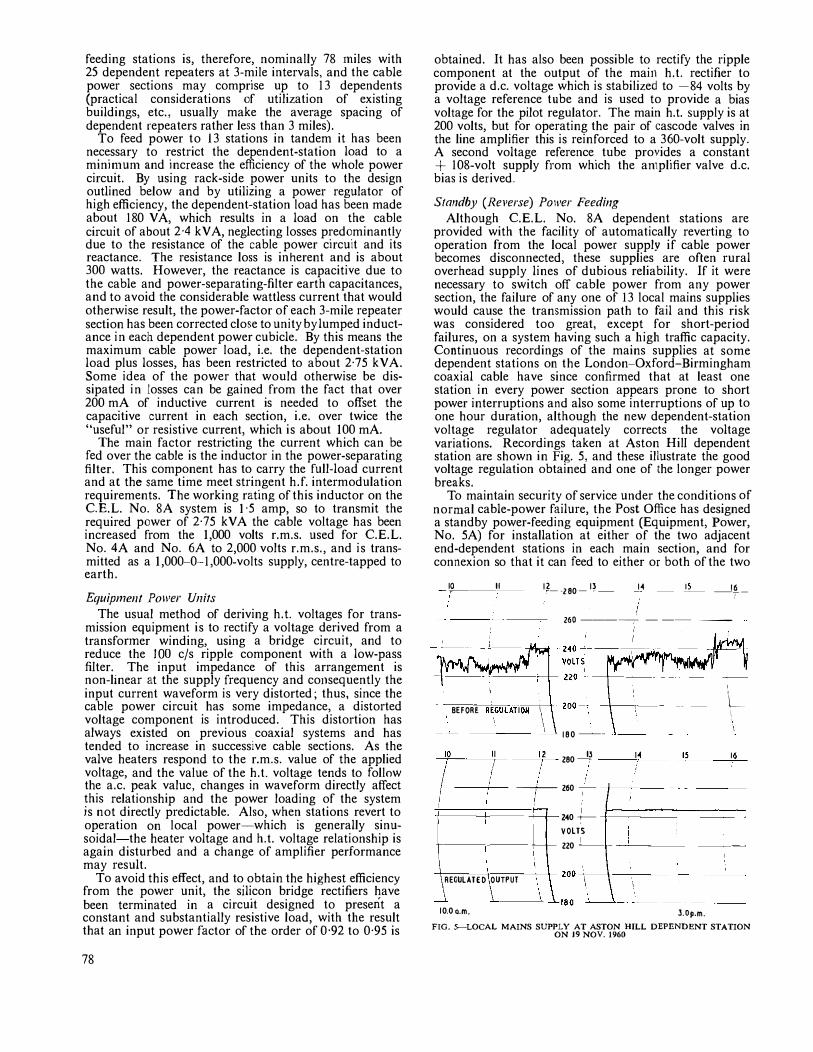
provided with the facility of automatically reverting to operation from the local power supply if cable power becomes disconnected, these supplies are often rural overhead supply lines of dubious reliability. If it were necessary to switch off cable power from any power section, the failure of any one of 13 local mains supplies would cause the transmission path to fail and this risk was considered too great, except for short-period failures, on a system having such a high traffic capacity. Continuous recordings of the mains supplies at some dependent stations on the London-Oxford-Birmingham coaxial cable have since confirmed that at least one station in every power section appears prone to short power interruptions and also some interruptions of up to one hour duration, although the new dependent-station voltage regulator adequately corrects the voltage variations. Recordings taken at Aston Hill dependent station are shown in Fig. 5, and these illustrate the good voltage regulation obtained and one of the longer power breaks.
To maintain security of service under the conditions of normal cable-power failure, the Post Office has designed a standby power-feeding equipment (Equipment, Power, No. 5A) for installation at either of the two adjacent end-dependent stations in each main section, and for connexion so that it can feed to either or both of the two
�"�-�1�1---1�--280-1�- J:4 -" - __ !�_
200 ---� - -- --
BEFORE REGULATION I
\ 180 ---
-'il0�--7--- -�",___ 280 �3 --�'e-' -
! i
!
-c----+- --+--- 200 - -+--,
'
\-\
" "
2'40 +---- -!======--==::-:
REGULATED OUTPUT
10.0o.m,
VOLTS 220 -1 - - �----
200-\-
180�-� J.Op.m.
FIG. >-LOCAL MAINS SUPPLY AT ASTON HILL DEPENDENT STATION ON 19 NOV. 1960
PULSIMG ,
.,��1 ___ 1�J.t',,, CONTROL PAIR -i----�� IOO
CP .,:r"I I LAA
A DEPENDENT-STATIONjcA BLEj. •IJ-j�
50V RF
KEY BOX --·--·--· .
END-DEPENDENT STATION R F
•Ii-"--...__.-..,, ,,,q ii .1,,, LAA LBA �LA LB+ �
r NOTE 2
r---UNBALANCE ++-! OFF --o PB i CIRCUIT BREAKER LINE MAINS -����"'-\�-��.�--,
,STANDBY--<> ( ��RLOAD . __j ' ' I I '
POWER 'Ar READY"
POWER 'FEEDING" .240V ! OFF --o I
HEUTRA� MAINS -���---------+--� STANDBY-<>
Notes: I. Relays LAA and LBA take I ·5-2 sec to release 2. Relay RF takes 3-4 sec 10 operate 3. The control-pair switch is shown with the key-box operated
FIG. 6-SIMPLIFIEO SCHEMATIC DIAGRAM OF STANDBY (REVERSE) PO\VER-FEEDING ARRANGEMENTS
power sections it serves. It derives its power from a local mains supply which is made as reliable as possible, and facilities are provided to connect an automatic-start portable generator to the equipment if required.
It is essential to prevent both the normal and standby power supplies from being connected simultaneously to one cable section; it has, therefore, been necessary to provide remote control for the automatic application of standby cable power. This has been achieved by providing in each dependent station a wall-mounted "reverse-powercontrol" key-box, fitted with interlocked key cylinders that can only be turned by a key which is normally trapped by the incoming-cable-power isolating-switch at that station and which is only released when the switch is operated to its "off" position. A rotary switch is mechanically coupled to the key cylinders in this keybox, and when the key is inserted and turned it applies the correct conditions to an interstice pair to cause the standby power equipment to switch power to the cable (in the reverse direction to normal cahle power). Thus, standby power can only be connected after normal power has been switched off, and normal power cannot be reapplied until the standby power has been disconnected. By fitting the reverse-power control key-box on the wall, a time delay has been deliberately introduced between the disconnexion of one cable supply and the reapplication of the other. During the transition the dependent stations concerned switch automatically to their local power supplies.
The remote-control signals are simple ones but are difficult to simulate, and are unlikely to be imitated by a cable fault. A simplified schematic diagram of the control and switching arrangement is given in Fig. 6. When the start conditions are received over the cable from any operated key-box, 60-volt d.c. pulses, obtained from the Equipment Power No. SA, are connected to the
PA
TO CABLE POWER CIRCUIT
A-wire of the control pair and pulse relay A (contained for convenience inside the key-box) at the station initiating the start condition. Relay A then pulses back an earth condition over the B-wire of the pair, and these pulses are con1pared, in the Equipment Power No. SA, with the 60-volt d.c. pulses. Only if the two trains of pulses are equal and out-of-phase can the circuit connect the standby power supplies to the cable.
Some circuit elaboration is required to prevent false operation and to ensure the correct switching sequence; some of the guard-circuit delay timing is given with Fig. 6. A duplicate set of equipment for feeding power to the other cable section is contained within the one equipment cubicle, previously illustrated.3
Power Proteclion
,,�------'-� The introduction of a second cable
power supply complicates the power protection scheme applied to coaxial
systems, as it is now necessary to ensure, before any cable work can be performed, that power cannot be applied to the cable from either direction. This has required a keycontrolled isolating switch to be fitted in both the incoming-cable and outgoing-cable power feeds at each dependent station, and, as the existing station key-boxes do not cater for this development, an auxiliary "cable isolating" key-box has been provided which releases a key for use in the main key-box only when the keys from the two isolating switches controlling that section have been inserted and turned. As these keys can be withdrawn from the isolating switches only when they are in the "off" position, the two relevant coaxial pairs in the cable are rendered safe.
Power Constanplion It has already been stated that the dependent-station
power consumption is about 180 VA. The approximate load of a terminal station (six rack-sides) is 1,200 VA and that of a power-feeding station (four rack-sides) is about 800 VA. The total load of a terminal station feeding power to 13 dependent stations is approximately 4·0 kVA and that of a power-feeding station feeding 26 dependent stations is approximately 6·3 kV A.
THE SUPERVISORY EQUIPMENT The supervisory and speaker arrangements are broadly
comparable to those of the C.E.L. No. 6A system, described previously.2 However, some small changes have been shown by experience to be desirable, and these have been embodied in this system, although simplicity remains the basic principle. A minimum of eight interstice cable pairs are required, and nine pairs are provided wherever possible.
Speaker Circuit A 4-wire circuit is provided between terminal stations,
and all intermediate stations have access to this circuit and are able to speak in either direction. Amplifiers are fitted at every fourth station, i.e. at about 12-mile intervals, and the circuit is equalized in accordance with
79
present audio standards. As on C.E.L. No. 6A, the calling equipment is operated from a d.c. supply (220 volts in this case) at the terminal stations; calling between terminal and dependent stations, and between one dependent station and another, is effected over the phanton1s of the 4-wire speaker circuit, but direct calling between terminals is now carried out over an additional interstice pair. The signalling remains non-selective, but the sensitivity of the calling circuit at dependent stations has been improved so that it is less affected than hitherto by the added impedance due to dependent-station "alarm off" keys being inadvertently left operated. The speakerextension facilities at tenninal stations have been made 1nore compatible with existing station-speaker facilities but the conference facility, which enables a general conversation to take place between ter1ninal stations and a number of dependent stations (effected by disconnecting the balance of the 2-wire/4-wire terminating set at one end), has been retained.
Supervisory Circuit
The chief difference from the C.E.L. No. 6A arrangement is the provision of a fault-location bridge circuit which has a calibration that is unaffected by temperature variation of the interstice pair resistance. This is achieved by using a separate interstice pair as one of the bridge ratio arms; this pair is similarly affected by the cable ten1perature and, hence, the resistance ratio remains unchanged. The "main-station marker" method of calibration used previously is thus no longer required.
Separate alarm pairs are again provided for indicating the failure of the 4,287 kc/s regulating pilot in each direction, but the power-failure alarm is now grouped with the other ancillary alanns on a "miscellaneous alarm" pair. The extent of the power failure can readily be deduced from whether or not the pilot-failure alarm is also operated. Where a ninth interstice pair is available, a further alarm is provided to warn the terminal stations if any dependent station is being operated from the local power supply.
STATION RACK-SIDE ARRANGEMENTS
Dependent Repeater The transmission equipment is mounted on t\vo 6 ft
rack-sides fitted back-to-back, with a separate cabletermination box secured to the racking above one of the rack-sides in a similar manner to the C.E.L. No. 6A dependent-station equipment. Due to the greater bulk of the power-separating filters and to the decision to exclude all voltages above 250 volts a.c. from the transmission rack-sides, these filters have been mounted on a framework and secured above the other transmission rack-side, behind the cable termination box.
The power equipment (excluding the power units, which are rack-mounted as before) is fitted within a freestanding cubicle of greater mechanical strength than 51-type rack assemblies. A photograph of a typical dependent repeater was included in an earlier article, 3
but a block schematic diagram of the arrangement is shown in Fig. 7.
It was originally proposed that the power cubicle should contain the power equipment for two C.E.L. No. 8A systems, but using the revised arrangements the electronic regulator dispenses with three large items and this will permit three dependent-station power equipments to be fitted in the power cubicle at new installations. The items omitted are a large manual
80
POWER FEEDING
DIRECTION
P:S.F.
P.S.F. = Power-separating filter L.S. = Line simulawr
P.F. CORRECTOR = Power-faclOr corrector AMPL. C/O = Amplifier change-over panel
FIG. 7-BLOCK SCHEMATIC DIAGRAM OF A DEPENDENT REPEATER
switch, a cable-power switching relay (it is not now necessary to isolate the power transformer from the cable power circuit), and the power-factor correcting choke, as the required inductance is now obtained by controlling the core air-gap of the new and simpler cable power transformer.
A change of layout within the cable-termination box is also to be made on new equipment as some difficulties in obtaining consistent crosstalk measurements at the higher frequencies were experienced at the first dependent stations. The changes to this box to achieve the required crosstalk performance include fitting a new terminal block to provide better coaxial screening, and two new longitudinal-wave stop coils have been inserted in the input and output leads of the power-separating filter to increase the longitudinal impedance.
Tenninal Repeater
The line terminal equipment is mounted on six 9 ft rack-sides fitted side by side, and there is a free-standing power-feeding cubicle. The six rack-sides are as follows:
(a) Transmit. (b) Cable terminating, power separating, and main-
tenance testing. ( c) Receive (A). (d) Receive (B). (e) Monitoring. (f) Supervisory.
A block schematic diagram of the terminal station equipment is given in Fig. 8.
Po1ver-Feed;ng Repeater
A complete power-feeding station comprises four 9 ft rack-sides mounted side by side, with possibly a further two rack-sides for monitoring equipment if this should be needed. The free-standing power-feeding cubicle is required, and it contains equipment to feed power to the two power sections it serves.
The block schematic diagram for each direction of transmission is basically similar to the receive and transmit portions of the terminal equipment connected in tandem but without the pilot monitoring, stopping and injection facilities. This arrangement permits the omission of two of the flat amplifiers while retaining full facilities for line-residual, ambient-temperature and valve-aging equalization.
TRAFFIC
INPUT
TRAFFIC
OUTPUT
S.C.E
PILOT STOP FILTERS
��
FLAT AMPL
PILOT COMBINING
PANEL
•
MANUAL A.T.E. V.�A.E.
'
12.435 �-- £QUAL�Z£RS
ALTERNATIVE AMPL. POSH.
ALTERNATIVE AMPL. POSH.
PILOT MONITOR<;
?ILOT REGULATORS
S.C.E. = Station-cabling equalizer A T.E. = Ambicnt-temIJemture equalizer V.A.E. = Valvc-aging equalizer R.A.E. o-- Residual-attenuation equalizer
AMPL. C/O = Amtilifier change-over IJanel P.S.F. = Power-seJJarating filter LS.C. = Longitudinal-wave stoIJ coil
L.S. = Line simulator
FIG. 8-BLOCK SCHEMATIC DIAGRAM OF THE TERMINAL-STATION EQUIPMENT
ACKNOWLEDGEMENTS
The authors wish to acknowledge the assistance and information given by the manufacturers of the C.E.L. No. 8 coaxial system, Standard Telephones and Cables, Ltd., and by J. Langham Thompson, Ltd., who developed the electronic voltage regulator.
References 1 DAVIS, E. A 4 Mc/s Coaxial Line Equipment-C.E.L.
Book Review
"Progress in Semiconductors." Vol. 5. Edited by A. F. Gibson, B.Sc., Ph.D., Dr. F. A. KrOger, and Prof. R. E. Burgess. Heywood & Co., Ltd. vii + 316 pp. 128 ill. 63s.
This volume, the fifth of an annual series, contains seven papers by specialists in various branches of the field of semiconductors. The fact that the field is becoming subdivided into specialisms need not frighten the interested reader from pursuing one or more branches of it, and for many readers of this Journal the first two papers will doubless claim their chief attention.
The electrical properties of semiconductor surfaces play an important part in determining the initial values and the stabilities of the current gain, the leakage current, and the noise factor of junction transistors, and are well reviewed in the first paper. The second paper reports some very careful
No. 4A. P.O.E.E.J., Vol. 50, p. 92, July J 957. 2 C OLLIER, M. E., and SIMPSON, w. G. A New 4 Mc/s Coaxial
Line Equipment-C.E.L. No. 6A. P.O.E.E.J., Vol. 50, p. 24� Apr. 1957.
3 The London-Oxford-Binningham 12 Mc/s Coaxial Line Systen1. P.O.E.E.J., Vol. 52, p. 270, Jan. 1960.
� HARRIS, E. T. c., and SPRATT, c. J. An Improved Forn1 of Mechanical Construction for Transn1ission Equipment-51-Type Construction. P.O.E.E.J., Vol. 51, p. 197, Oct. 1958.
:-. PARSONS, A. P., and DIDCOCK, F. E. Recording Dccibelmeters. P.O.E.E.J., Vol. 51, p. 145, July 1958.
measurements of the wavelength-dependence of the infrared absorption of germanium and silicon, and presents a detailed interpretation of the observations in terms of the permitted energy-momentum relationships (bands) in these crystals. The thermal conductivity of semiconductors is the subject of another paper which, however, only briefly considers thermo-electric conversion (in which the subject matter plays such a basic part).
The remaining papers cover: indium antirnonide (useful" as a magnetic-field sensor and as a detector in the range from infra-red to 7-micron wavelengths), the chemical bond in semiconductors (a largely descriptive and, in parts, perhaps still controversial treatment), magneto-optical phenomena in semiconductors, and the band structure and electronic properties of graphite crystals. The treatment in each paper is competent and each contains a wealth of reference to the: original publications.
F.F.R.
8l
Over-Ceiling Cabling for Telephone Exchanges
W. G. ROBERTS, A.M.r.E.E., and J. A. POVEY, A.M.r.E.E.t U.D.C. 621.316.17: 621.395.722
For telephone exchange equipment installed in single-storey buildings, it was considered that economies could be achieved in cable quantities and installation time by running the internal cables in the space between the ceiling and the roof. Trial installations employing this technique have demonstrated its practicability and advantages, and it is intended to use the method as a standard practice, single-storey buildings in consequence being designed with
roofs suitable for this method.
INTRODUCTION
THE installation of telephone exchange equipment involves appreciable cost and time, and particular attention has been given to a number of proposals for
reducing the time required for cabling, which, excluding the termination of the cables, has accounted for between 20 and 30 per cent of the total expenditure on installation labour. With conventional cabling practice the cables are laced with twine to open cable racking, which is sited above the level of the equipment racks and is supported by the racks or suspended from the ceiling. The cable racks run along and across the apparatus room, diagonal runs not being readily employable. Proposals for reducing cabling costs have largely been aimed at the
t Exchange Equipment and Accommodation Branch, E.-in-C.'s Office.
modification or elimination of lacing, which, whilst involving relatively negligible material costs, occupies much of the time. It was realized, however, that to achieve more substantial economies, schemes involving reductions in cable quantities would need to be pursued.
A number of cabling practices employed in other countries are appreciably different from the open-cableracking methods used currently by the British Post Office. They include the use of shrouded cable runs (or trunking) either at floor or ceiling level, in some cases with cabling access from the floor above to provide, in effect, under-floor cabling. It appears likely that such schemes have overall appearance rather than economy as a primary objective, and their provision often requires a degree of liaison between the building architect and the equipment installation engineer which it is preferable to avoid. They appear more costly than the present Post Office practice, but they might be advantageous where the maximum amount of fabrication at the factory was of practical importance.
A proposal that in suitable buildings p.v.c. cables should be taken through the ceiling and run freely and directly over the ceiling timbers between equipment terminating points was thought to offer worthwhile cabling economies. A full-scale trial carried out at
FIG. I-CABLING ABOVE THE CEILING AT BISHOPS CLEEVE EXCHANGE
82
Brierley Hill exchange, in the Midland Region, achieved encouraging results, showing that such a practice provided an acceptable overall installation and produced the substantial savings of both installation time and cable quantities which had been expected.
It is now intended that over-ceiling cabling shall be employed generally for telephone exchanges in singlestorey buildings, and several such installations have already been completed.
EFFECT ON BUJLDING DESIGN
A big advantage of cabling over ceilings is that the height of the apparatus room can be reduced and need be only 11 ft 6 in. with a flat ceiling. The standard height under a flat ceiling is 13 ft when conventional cabling methods are used.
Consideration has been given to cheaper forms of roof construction, the introduction of which would probably have eliminated the ceiling or have provided a roof of inadequate strength for over-ceiling cabling purposes. It was determined, however, that the cost saving which might thereby be achieved would roughly balance that resulting from a reduction of the apparatus-room height from 13 ft to 11 ft 6 in. In consequence, the merits of over-ceiling cabling can be considered largely independently of building cost, although some restrictions on building design may be imposed. It appears reasonable to assume that fully satisfactory building designs will emerge which either will not introduce consequential additional costs, or will involve building costs substantially less than the equipment-installation savings.
OVER-CEILlNG CABLING METHOD
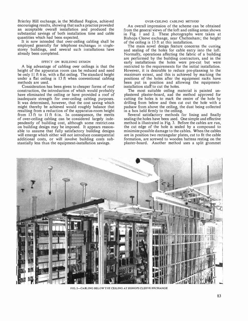
An overall impression of the scheme can be obtained from the general views of the loft and ceiling areas shown in Fig. 1 and 2. These photographs were taken at Bishops Cleeve exchange, near Cheltenham; the height of the ceiling is 13 ft at this installation.
The main novel design feature concerns the cutting and sealing of the holes for cable entry into the loft. Normally, operations affecting the fabric of a building are performed by the building contractors, and in the early installations the holes were pre-cut but were restricted to the requirements for the initial installation. However, it is desirable to reduce pre-planning to the maximum extent, and this is achieved by marking the positions of the holes after the equipment racks have been put in position and allowing the equipmentinstallation staff to cut the holes.
The most suitable ceiling material is painted unplastered plaster-board, and the method approved for cutting the holes is to mark the centre of the hole by drilling from below and then cut out the hole with a padsaw from above the ceiling, the dust being collected in a box beld firmly to the ceiling.
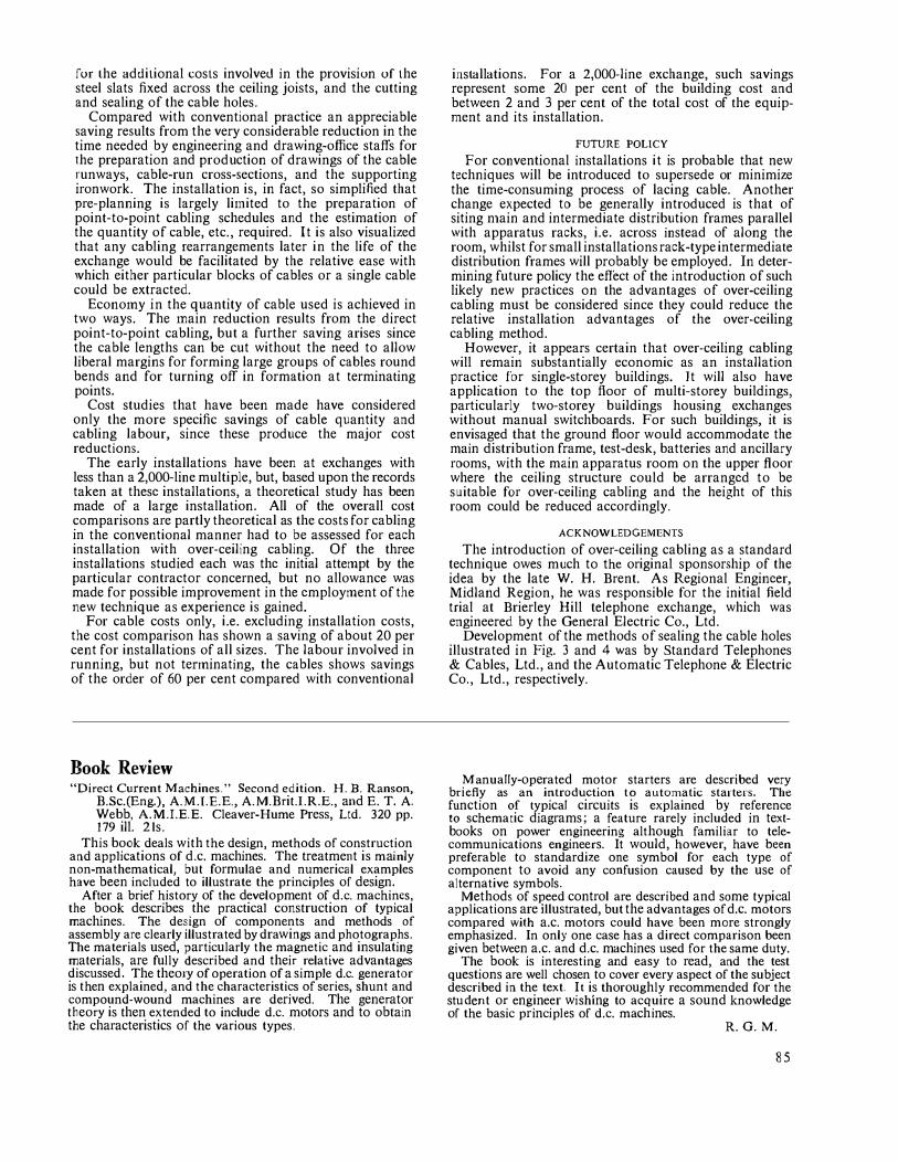
Several satisfactory methods for lining and finally sealing the holes have been used. One simple and effective method is illustrated in Fig. 3. Before the cables are run, the cut edge of the hole is sealed by a compound to minimize possible damage to the cables. When the cables are in position two rectangular plates, cut to fit the cable formation, are screwed to wooden battens resting on the plaster-board. Another method uses a split grommet
FIG. 2-CABLING BELOW THE CEILING AT BISHOPS CLEEVE EXCHANGE
83
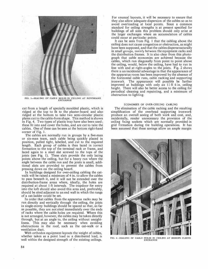
FIG. 3-SEALING OF CABLE HOLES IN CEILING AT ROWNHAMS EXCHANGE
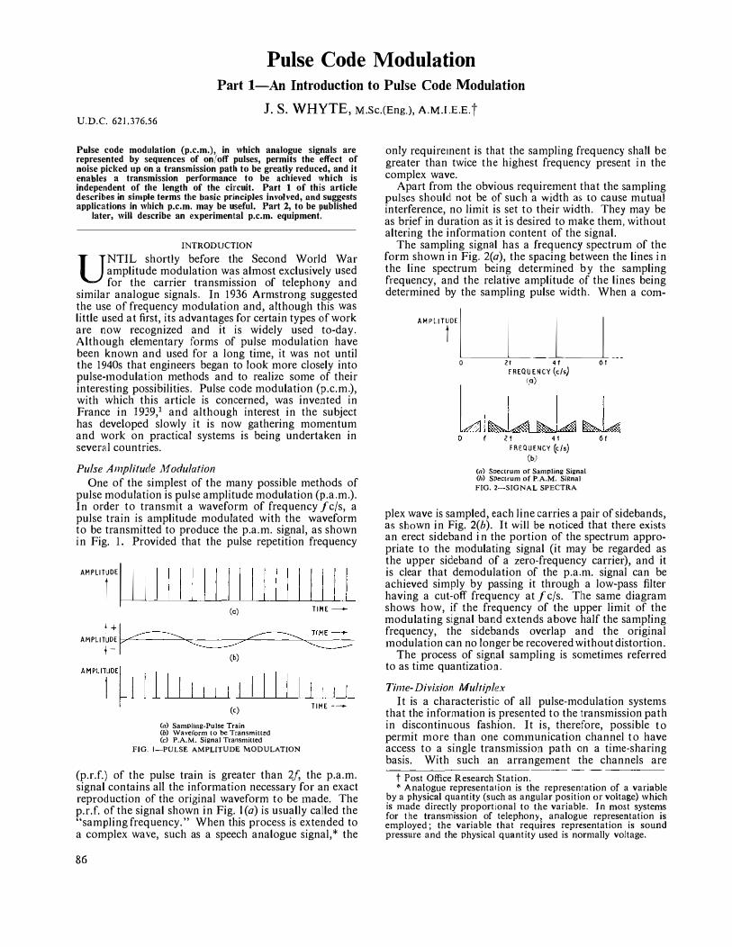
cut from a length of specially moulded plastic, which is ridged at the top to fit to the plaster-board and also ridged at the bottom to take two semi-circular plastic plates cut to the cable-form shape. This method is shown in Fig. 4. Two types of plastic tray have also been used; these fit into and cover the holes, and are cut to take the cables. One of these can be seen at the bottom right-hand corner of Fig. 1.
The cables are normally run in groups by a five-man or six-man team, each cable being quickly placed in position, pulled tight, labelled, and cut to the required length. Each group of cables is then laced in correct formation to the top of the terminal rack or frame, and laced again to a steel slat screwed to the tops of the joists (see Fig. 1). These slats provide the only lacing points above the ceiling, but for a heavy run where the angle between the cable run and the joists is small, additional slats are provided to prevent the cables from pressing down on the ceiling board.
In buildings designed for over-ceiling cabling the catwalk will be raised a minimum of 4 in. to allow the cables to pass beneath it, and it will not be extended over the distribution-frame areas where, ideally, the holes are required at about 1 ft intervals. The trapdoor for entry into the loft should also avoid this area and, preferably, should be sited adjacent to an end wall in which the rungs of a cat-ladder could be set.
In order that cables from the apparatus racks may be run directly and vertically through the ceiling, the joists in single-storey buildings should be spaced so that, as far as possible, they are not sited immediately over the ends of racks where the cable holes are required. Where this is not arranged, however, the cables may be taken directly through, but at an angle to, the ceiling without unsightliness. This may also be necessary when avoiding obstructions in the roof, such as the cat-walk or a ventilation duct.
With orthodox equipment layouts the weight of cables, whether taken as a point load or a distributed load, is well within the designed strength of the existing ceilings.
84
For unusual layouts, it will be necessary to ensure that they also allow adequate dispersion of the cables so as to avoid overloading at local points. Since a common standard for ceiling strengths is at present specified for buildings of all sizes this problem should only arise at the larger exchanges where an accumulation of cables could occur at particular points.
It can be seen from Fig. 1 that the cabling above the ceiling does not cause congestion or obstruction, as might have been supposed, and that the cables disperse naturally in small groups, mainly between the equipment racks and the distribution frames. It is also clear from this photograph that cable economies are achieved because the cables, which run diagonally from point to point above the ceiling, would, below the ceiling, have had to run in line with and at right-angles to the joists. Fig. 2 shows there is an incidental advantage in that the appearance of the apparatus room bas been improved by the absence of the horizontal cable runs, cable racking and supporting ironwork. The appearance will possibly be further improved at buildings with only an 11 ft 6 in. ceiling height. There will also be better access to the ceiling for periodical cleaning and repainting, and a minimum of obstruction to lighting.
ECONOMIES OF OYER-CEILING CABLING
The elimination of the cable racking and the resulting simplification of the overhead supporting ironwork produce an overall saving of both work and cost, and, incidentally, render unnecessary the provision of the ceiling fixing sockets which are normally provided in grid formation during the building operations. It has been assumed that these savings allow an ample margin
FIG. 4--SEALING OF CABLE HOLES IN CEILING AT BISHOPS CLEEVE EXCHANGE
fur the additional costs involved in the provision of the steel slats fixed across the ceiling joists, and the cutting and sealing of the cable holes.
Co1npared with conventional practice an appreciable saving results from the very considerable reduction in the time needed by engineering and drawing-office staffs for the preparation and production of drawings of the cable runways, cable-run cross-sections, and the supporting ironwork. The installation is, in fact, so simplified that pre-planning is largely li1nited to the preparation of point-to-point cabling schedules and the estimation of the quantity of cable, etc., required. It is also visualized that any cabling rearrangements later in the life of the exchange would be facilitated by the relative ease with 'vhich either particular blocks of cables or a single cable could be extracted.
Econo1ny in the quantity of cable used is achieved in two ways. The 1nain reduction results from the direct point-to-point cabling, but a further saving arises since the cable lengths can be cut without the need to allow liberal margins for forming large groups of cables round bends and for turning off in formation at terminating points.
Cost studies that have been made have considered only the more specific savings of cable quantity and cabling labour, since these produce the major cost reductions.
The early installations have been at exchanges with less than a 2,000-line multiple, but, based upon the records taken at these installations, a theoretical study has been made of a large installation. All of the overall cost comparisons are partly theoretical as the costs for cabling in the conventional manner had to be assessed for each installation with over-ceiling cabling. Of the three installations studied each was the initial attempt by the particular contractor concerned, but no allowance was made for possible improvement in the employment of the new technique as experience is gained.
For cable costs only, i.e. excluding installation costs, the cost comparison has shown a saving of about 20 per cent for installations of all sizes. The labour involved in running, but not tenninating, the cables shows savings of the order of 60 per cent compared with conventional
Book Review "Direct Current Machines." Second edition. H. B. Ranson,
B.Sc.(Eng.), A.M.I.E.E., A.M.Brit.l.R.E., and E.T. A. Webb, A.M.I.E.E. Cleaver-Hume Press, Ltd. 320 pp. 179 ill. 2ls.
This book deals with the design, methods of construction and applications of d.c. machines. The treatment is mainly non-mathematical, but formulae and numerical examples have been included to illustrate the principles of design.
After a brief history of the development of d.c. machines, the book describes the practical construction of typical machines. The design of components and methods of assembly are clearly illustrated by drawings and photographs. The materials used, particularly the magnetic and insulating materials, are fully described and their relative advantages discussed. The theory of operation of a simple d.c. generator is then explained, and the characteristics of series, shunt and compound-wound machines are derived. The generator theory is then extended to include d.c. motors and to obtain the characteristics of the various types.
installations. For a 2,000-line exchange, such savings represent some 20 per cent of the building cost and between 2 and 3 per cent of the total cost of the equipment and its installation.
FUTURE POLICY
For conventional installations it is probable that new techniques will be introduced to supersede or minimize the time-consuming process of lacing cable. Another change expected to be generally introduced is that of siting n1ain and intermediate distribution frames parallel with apparatus racks, i.e. across instead of along the room, whilst for small installations rack-type intermediate distribution frames will probably be employed. In determining future policy the effect of the introduction of such likely new practices on the advantages of over-ceiling cabling must be considered since they could reduce the relative installation advantages of the over-ceiling cabling method.
However, it appears certain that over-ceiling cabling will remain substantially economic as an installation practice for single-storey buildings. It will also have application to the top floor of multi-storey buildings, particularly two-storey buildings housing exchanges without manual switchboards. For such buildings, it is envisaged that the ground floor would accommodate the main distribution frame, test-desk, batteries and ancillary rooms, with the main apparatus room on the upper floor where the ceiling structure could be arranged to be suitable for over-ceiling cabling and the height of this room could be reduced accordingly.
ACKNOWLEDGEMENTS
The introduction of over-ceiling cabling as a standard technique owes much to the original sponsorship of the idea by the late W. H. Brent. As Regional Engineer, Midland Region, he was responsible for the initial field trial at Brierley Hill telephone exchange, which was engineered by the General Electric Co., Ltd.
Development of the methods of sealing the cable holes illustrated in Fig. 3 and 4 was by Standard Telephones & Cables, Ltd., and the Automatic Telephone & Electric Co., Ltd., respectively.
Manually-operated motor starters are described very briefly as an introduction to automatic starters. The function of typical circuits is explained by reference to schematic diagrams; a feature rarely included in textbooks on power engineering although familiar to telecommunications engineers. It would, however, have been preferable to standardize one symbol for each type of component to avoid any confusion caused by the use of alternative symbols.
Methods of speed control are described and some typical applications are illustrated, but the advantages of d.c. motors compared with a.c. motors could have been more strongly emphasized. In only one case has a direct comparison been given between a.c. and d.c. machines used for the same duty.
The book is interesting and easy to read, and the test questions are well chosen to cover every aspect of the subject described in the text. It is thoroughly recommended for the student or engineer wishing to acquire a sound knowledge of the basic principles of d.c. machines.
R.G.M.
85
Pulse Code Modulation
Part 1-An Introduction to Pulse Code Modulation
J. S. WHYTE, M.Sc.(Eng,), A.M.l E.E.t U.D.C. 621.376.56
Pulse code modulation (p.c.m.), in which analogue signals are represented by sequences of on/off pulses, permits the effect of noise picked up on a transmission path to be greatly reduced, and it enables a transmission performance to be achieved which is independent of the length of the circuit. Part 1 of this article describes in sin1ple terms the basic principles involved, and suggests applications in which p.c.m. may be useful. Part 2, to be published
later, will describe an experimental p.c.m. equipment.
INTRODUCTION
UNTIL shortly before the Second World War amplitude modulation was almost exclusively used for the carrier transmission of telephony and
similar analogue signals. In 1936 Arn1strong suggested the use of frequency modulation and, although this was little used at first, its advantages for certain types of work are now recognized and it is widely used to-day. Although elementary forms of pulse modulation have been known and used for a long titne, it was not until the 1940s that engineers began to look more closely into pulse-1nodulation methods and to realize some of their interesting possibilities. Pulse code modulation (p.c.m.), with which this article is concerned, was invented in France in 1939,1 and although interest in the subject has developed slowly it is now gathering momentum and work on practical systems is being undertaken in several countries.
Pulse A111plitude ModulaNon
One of the simplest of the many possible methods of pulse modulation is pulse amplitude modulation (p.a.m.). In order to transmit a waveform of frequency f c/s, a pulse train is atnplitude modulated with the \Vaveform to be transmitted to produce the p.a.m. signal, as shown in Fig. I. Provided that the pulse repetition frequency AHPLITrw 111 1111111111111
(c) TIME-l +�
� � T!ME-_,.. AMPLITUDE � '--------j -(b)
I I I I I I I I I I I I I 11 I I . I I
AMPLITUOEI (<)
(a) Sampling-Pulse Train (b) \Vaveform to be Transmitt�d (c) P.A.M. Signal Transmitted
FIG. I-PULSE AMPLITUDE MODULATION
TIME -----(p.r.f.) of the pulse train is greater than 2/, the p.a.m. signal contains all the information necessary for an exact reproduction of the original waveform to be inade. The p.r.f. of the signal shown in Fig. l(a) is usually called the "sampling frequency." When this process is extended to a complex wave, such as a speech analogue signal,* the
86
only require1nent is that the sampling frequency shall be greater than twice the highest frequency present in the complex wave.
Apart from the obvious requirement that the sampling pulses should not be of such a width as to cause mutual interference, no limit is set to their width. They may be as brief in duration as it is desired to n1ake them, without altering the infonnation content of the signal.
The sampling signal has a frequency spectrum of the form shown in Fig. 2(a), the spacing between the lines in the line spectrum being determined by the sampling frequency, and the relative amplitude of the lines being determined by the sampling pulse width. When a corn-AHPLIT'U__l_J __
0 21 4 t 0 I FREQUENCY (c/s) ra)
IA1�IAJ 1%.141 �1,4 0 l f 4 f
FREQUENCY (c/s) (b)
(n) Spectrum of Sampling Signal (!J) Spectrum of P.A.M. Signal
FIG. 2-SIGNAL SPECTRA
plex wave is sampled, each line carries a pair of sidebands, as shown in Fig. 2(b). It will be noticed that there exists an erect sideband i n the portion of the spectrum appropriate to the modulating signal (it may be regarded as the upper sideband of a zero-frequency carrier), and it is clear that demodulation of the p.a.n1. signal can be achieved simply by passing it through a low-pass filter having a cut-off frequency at f c/s. The same diagram shows how, if the frequency of the upper limit of the modulating signal band extends above half the sampling frequency, the sidebands overlap and the original 1nodulation can no longer be recovered without distortion.
The process of signal sampling is sometimes referred to as time quantization.
Tin1e-DivLr;ion Multiplex
It is a characteristic of all pulse-modulation systen1s that the information is presented to the transmission path in discontinuous fashion. It is, therefore, possible to permit more than one com1nunication channel to have access to a single transmission path on a time-sharing basis. With such an arrangement the channels are
t Post Office Research Station. *Analogue representation is the representation of a variable
by a physical quantity (such as angular position or voltage) which is made directly proportional to the variable. In most systems for the transmission of telephony, analogue representation is employed; the variable that requires representation is sound pressure and the physical quantity used is norn1ally voltage.
SPACE DIVISION
SPEECH ANALOGUE SIGNALS
j CHANNEL 1
CHAH� CHAN� S \11 1
CHAN�
AMPLITUDE
TIME DIVISION
MULTIPLEX
P.A.M. SIGNALS (< CHAr[LS)
"TRANSMISSION PATH
(o)
r 5.1 '"'I
SPACE DIVISION
SPEECH P.A.M. ANALOGUO
SIGNALS SIGNALS I l
�NNELI
� � NEL2
- 5W2 � !lEL3
�NEL4
t ! ___;__j_.i.._ I ! : I t--cl -z�l _,4c-71 -<z--+3 -<4--+1 -<z-3<--<4--t-1 2 3 4 I 2 3 4 i 2 3 4
TIME-(b)
{a) Four-Channel T.D.M. System using P.A.M. (b) Form or Line Signal with 4-Channel T.D.M. System
FIG. 3-SJMPLE MULTI-CHANNEL SYSTEM USING T.D.M.
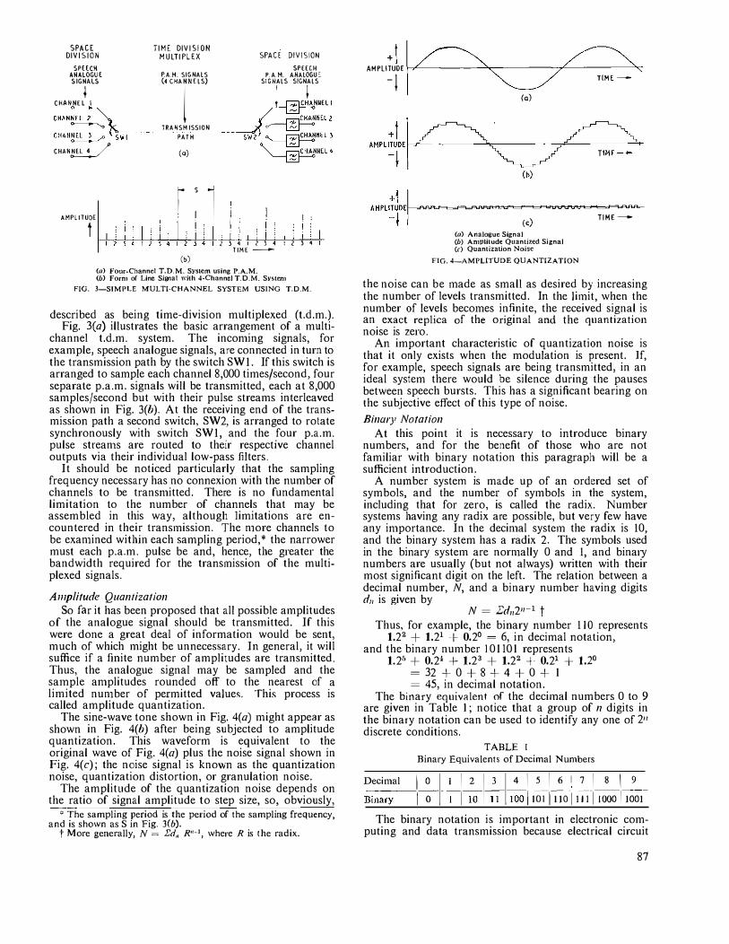
described as being time-division multiplexed (t.d.m.). Fig. 3(a) illustrates the basic arrangement of a multi
channel t.d.m. system. The incon1ing signals, for example, speech analogue signals, are connected in turn to the transmission path by the switch SW!. If this switch is arranged to sa1nple each channel 8,000 times/second, four separate p.a.m. signals will be transmitted, each at 8,000 samples/second but with their pulse streams interleaved as shown in Fig. 3(b). At the receiving end of the transmission path a second switch, SW2, is arranged to rotate synchronously with switch SW!, and the four p.a.m. pulse strean1s are routed to their respective channel outputs via their individual low-pass filters.
It should be noticed particularly that the sampling frequency necessary has no connexion with the number of channels to be transn1itted. There is no fundamental limitation to the number of channels that may be assembled in this way, although limitations are encountered in their trans1nission. The n1ore channels to be exan1ined within each sampling period,* the narrower must each p.a.m. pulse be and, hence, the greater the bandwidth required for the trans1nission of the multiplexed signals.
A111plitude Quantization So far it has been proposed that all possible amplitudes
of the analogue signal should be transmitted. If this were done a great deal of information would be sent, much of which might be unnecessary. In general, it will suffice if a finite number of amplitudes are transmitted. Thus, the analogue signal may be sampled and the sa1nple an1plitudes rounded off to the nearest of a limited nun1ber of permitted values. This process is called amplitude quantization.
The sine-wave tone shown in Fig. 4(a) might appear as shown in Fig. 4(b) after being subjected to amplitude quantization. This waveform is equivalent to the original wave of Fig. 4(a) plus the noise signal shown in Fig. 4(c); the noise signal is knov,rn as the quantization noise, quantization distortion, or granulation noise.
The amplitude of the quantization noise depends on the ratio of signal amplitude to step size, so, obviously,
*The sampling period is the period of the sampling frequency, and is shown as Sin Fig. 3(b).
t More generally, N = £d,, R"-1, where R is the radix.
+11 � � AMPLITUOE I ' � ' -i
TlME-o-(o)
I<) (a) Analogue Signal (b) Amplitude Quantiied Signal (r) Quantization Noise
FIG. 4-AMPLITUDE QUANTIZATION
TIME-
the noise can be 1nade as small as desired by increasing the number of levels transmitted. In the li1nit, \Vhen the number of levels beco1nes infinite, the received signal is an exact replica of the o riginal and the quantization noise is zero.
An important characteristic of quantization noise is that it only exists when the modulation is present. If, for exa1nple, speech signals are being transmitted, in an ideal system there would be silence during the pauses between speech bursts. This has a significant bearing on the subjective effect of this type of noise.
Binary Notation
At this point it is necessary to introduce binary numbers, and for the benefit of those who are not familiar with binary notation this paragraph will be a sufficient introduction.
A nu1nber syste1n is made up of an ordered set of symbols, and the number of symbols in the system, including that for zero, is called the radix. Number systems having any radix are possible, but very few have any in1portance. In the decin1al systc1n the radix is 10, and the binary system has a radix 2. The symbols used in the binary system are norn1ally 0 and 1, and binary numbers are usually (but not always) written with their most significant digit on the left. The relation between a decimal number, N, and a binary number having digits d11 is given by
N = I:d,,2n-1 t
Thus, for exan1ple, the binary number 110 represents 1.22 + 1.21 + 0.2° = 6, in decimal notation,
and the binary number I 0 II 0 I represents 1.2" + 0.2' + 1.23 + 1.22 �. 0.21 + 1.2°
= 32 + 0 + 8 + 4 + 0 + I = 45, in decimal notation.
The binary equivalent of the deci1nal numbers 0 to 9 are given in Table 1; notice that a group of n digits in the binary notation can be used to identify any one of 211
discrete conditions.
TABLE t Binary Equivalents of Decimal Nun1bers
Deci1nal 10 1 112 1 3 1 41516171819 B-
i-na
-ry-
-j O tjIO_l_I 100 jlOiTiJoTiJll 1000 I 1001-
The binary notation is important in electronic computing and data transmission because electrical circuit
87
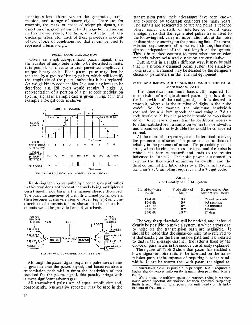
techniques lend themselves to the generation, transmission, and storage of binary digits. There are, for example, the mark or space of telegraph signals, the direction of magnetization of hard magnetic materials as in ferrite-core stores, the firing or extinction of gasdischarge tubes, etc. Each of these provides a one-outof-two choice of conditions, so that it can be used to represent a binary digit.
PULSE CODE MODULATION
Given an amplitude-quantized p.a.m. signal, since the number of amplitude levels to be described is finite, it is possible to allocate to each permitted amplitude a unique binary code. Each p.a.m. pulse may then be replaced by a group of binary pulses, which will identify the amplitude of the p.a.m. pulse that it has replaced. An n-digit binary code enables 2" quantizing levels to be described, e.g. 128 levels would require 7 digits. A representation of a portion of a pulse code modulation (p.c.m.) signal in a simple case is given in Fig. 5; in this example a 3-digit code is shown.
6
CODING LEVELS 3
2
I
0
PULSE } AMPLITUDES TO BE CODED
PULSE } AMPLITUDES IN BINARY NOTATION
P.C.M.SIGHAL I
SAMPLING INSTANT s
c-P.A.M. PULSES� -
.r" J
/
' _,
I II
'
OOI OOI 011 IOI I IO
II 11 II
- - ' ', DECISION LI HES
'. \
I', I :t-
TIME-
6 4 ' 0
110 110 IOO OIO OOO
II II T!ME-
FIG. 5-DERIVATION OF 3-DJGIT P.C.M. SIGNAL
Replacing each p.a.m. pulse by a coded group of pulses in this way does not prevent channels being multiplexed on a time-division basis in the manner already described. The basic arrangement of a multi-channel p.c.m. system then becomes as shown in Fig. 6. As in Fig. 3(a) only one direction of transmission is shown in the sketch but circuits would be provided on a 4-wire has is.
SPEECH ANALOGUE
SIGNALS P.A.M.
j CHAHHEL I
CHAHNEL2 ---------.
Cll�HNC� 3,...,
CH�
P.C.H.
l SPEECH
ANALOGUE
r"·"·1 '"j'lS
:'.'.; CHANNEL l
�HEL2
�HELJ
� NEL4
FIG. 6-MULTI-CHANNEL P.C.M. SYSTEM
Although the p.c.m. signal requires a pulse rate /1 times as great as does the p.a.1n. signal, and hence requires a transmission path with n times the bandwidth of that required for the p.a.m. signal, this penalty brings with it most significant advantages.
All transmitted pulses are of equal amplitude* and, consequently, regenerative repeaters may be used in the
88
transmission path; their advantages have been known and exploited by telegraph engineers for many years. The signals are regenerated before the point is reached \Vhere noise, crosstalk or interference would cause ambiguity, so that the regenerated pulses transmitted to the following link carry no information about the noise or distortions occurring on the preceding link. The transmission requirements of a p.c.1n. link are, therefore, almost independent of the total length of the system. This is in 1narked contrast to most other transn1ission methods, where noise and distortion are cumulative.
Putting this in a slightly different way, it may be said that in a properly designed p.c.m. system the signal-tonoise ratio in a channel may be decided by the designer's choice of parameters in the terminal equipment.
NOISE AND BANDWIDTH CONSIDERATIONS FOR THE P.C.M.
TRANSMISSION PATH
The theoretical minimum bandwidth required for transmission of a single-channel p.c.m. signal is n times the bandwidth of the analogue signal it is desired to transmit, where 11 is the number of digits in the pulse code2• So, for example, the minimum bandwidth required for a 4 kc/s speech channel using a 7-digit code would be 28 kc/s; in practice it would be excessively difficult to achieve and maintain the conditions necessary to attain satisfactory transn1ission within this bandwidth, and a bandwidth nearly double this would be considered normal.
At the input of a repeater, or at the terminal receiver, the presence or absence of a pulse has to be detected reliably in the presence of noise. The probability of an error, when the circumstances are ideal and the noise is white,f has been calculated' and leads to the results indicated in Table 2. The noise power is assu1ned to exist in the theoretical minimum bandwidth, and the third column of the table refers to a l 2-channel system, using an 8 kc/s sampling frequency and a 7-digit code.
TABLE 2 Error Liability of P.C.M. Systen1
Signal·to·Noise Ratio
17·4 db 19·6 db 21 ·0 db 22·0 db 23·0 db
Probability of Error
JQ-l 10·0 JQ-8 10-10 10-12
Equivalent to One Error About Every
15 milliseconds 1 ·5 seconds 2·5 minutes 4 hours 17 days
The very sharp threshold will be noticed, and it should clearly be possible to make a system in which errors due to noise on the transmission path are negligible. It should be noted that the signal-to-noise ratio referred to is that existing on the transmission path and is unrelated to that in the 1nessage channel; the latter is fixed by the choice of parameters in the encoder, as already explained.
The figures of Table 2 show that p.c.m. has enabled a lower signal-to-noise ratio to be tolerated on the transmission path at the expense of requiring a wider bandwidth. It can be shown that with p.c.m. the signal-to-
* Multi·level p.c.111. is possible in principle, but it requires a higher signal·tO·noise ratio on the transn1ission path than binary p.c.m.
t White noise, or uniform spectru1n random noise, is random noise whose spectral distribution between specified frequency lin1its is such that the noise power per unit band\vidth is independent of frequency.
noise ratio in decibels (in the message channel) varies linearly with the number of digits per code group, and hence with the bandwidth occupied. By contrast, with frequency 1nodulation the signal-to-noise ratio varies only as the logarithm of the bandwidth.*
Although it.does not achieve the full theoretical capacity of an ideal systern.3, p.c.m. makes the nearest approach to this of any system so far discovered.
APPLICATIONS OF P.C.M.
From what has already been said it will be apparent that p.c.m., whilst requiring a relatively large bandwidth, enables high-quality transmissions to be made over low-grade circuits. Profitable fields of application may, therefore, exist where bandwidth is cheap but where the transmission-path quality is poor or the noise is high. In seeking suitable applications it has to be remembered that the encoder and decoder may be relatively complicated devices and therefore costly. Sometimes this may be offset in the manner shown in Fig. 6, in which a single encoder and decoder arc shared by a number of inessage channels, thereby reducing the cost per channel.
It is perhaps a little surprising to find that two of the most likely applications for p.c.m. are apparently so different. These are the transmission of very large numbers of telephone channels for long distances through circular waveguides, and small numbers of telephone channels over short distances using deloaded audio-type cables. However, both fit the requirements mentioned in the previous paragraph.
Trans-continental transmission by microwave radiorelay systems and inter-continental transmission via artificial earth satellites are other possible systems where p.c.m. may be used, but the bandwidth requirements of p.c.m. signals are detractions in any system involving unguided transmission paths. Hov-:ever, when the need to work with the lowest possible level of received signal overrides other considerations, as may arise in space communications, p.c.m. may be advantageous.
The important advantages of p.c.m. for military use are outside the scope of this article.
Before examining some of these suggested applications in more detail, sotne indication is given in Table 3 of the bandwidths that typical applications might involve.
Although reference to multi-channel operation has so far been concerned exclusively with time-division multiplex (see Fig. 3), other arrangements are possible and may be preferable. An existing block of message channels assembled on a frequency-division multiplex (f.d.m.) basis may be coded as a single unit. A number of f.d.m./p.c.m. signals could then be multiplexed again oa a frequency-division basis, and this might well prove to be a convenient arrangement for use with a trunk waveguide. The f.d.m. signals from coaxial cable systems might be coded, and the p.c.m. signal-. modulated on to a number of r.f. carriers for transmission over the waveguide. This would give greatly improved flexibility whilst retaining the desirable properties of p.c.m. transmission. In a country like the United IUngdom, where a highly developed transmission system already
"'If R =peak-to-peak signal to r.m.s.-noise ratio in the message channel, and 11 = ratio of bandwidth occupied to the message-channel band
width for p.c.m. = ratio of t of bandwidth occupied to the message-channel
bandwidth for f.m., then, for binary p.c.1n., 20 log10 R � 6n + 10·8,
and for f.n1., 20 log10 R = 30 log1a11 + constant.
B
exists on an f.d.m. basis, the introduction of trunk waveguides is unlikely to occur except on the basis of "living together" \Vith the existing plant for many years, and compatible but flexible methods of usage will have to be employed.
TABLE 3
Typical Parameters for Various P.C.M. Transmissions
Number of l Channel Type of Channels Bandwidth
Signal Presented to Encoder
Telephony 12
i 200 c/s-3·5 kc/s
Te!eohony 960 200 c/s-3 ·5 kc/s
Telephony 10,000 200 c/s-3 ·5 kc/s
I F.D.M. group 1 60--108 kc/s = 12channels F.D.M. baseband 1 60-4,082 kc/s = 16supergroups = 960 channels
405-line television I I 0--3 Mc/s
I Number Sampling i of Digits
FrequC[Jcy
I in P.C.M.
Code
8 kcls
I 7
8 kc/s 7
8 kcls 7
114 kc/s 9
9Mc/s 9
7Mc/s 6
I AD,rn,;m,<o
Bandwidth Required
I I
I I I
I
670 kc/s
54 Me/s
560 Mc/s
I Me/s
80 Mcfs
42 Mc/s
A point of interest arises with the sampling rate suggested for a 12-channel f.d.m. group: although the highest frequency to be transmitted is !08 kc/s, the sampling frequency is only 114 kc/s. The justification for this apparent contravention of the restrictions imposed by the sampling theorem is best explained by reference to the frequency spectrum of the p.a.m. signal, shown in Fig. ,7. The lower and upper sidebands of the
A
SAMPLU.G
FREQUENCY
0 6 5460 IOB j 114
FREQUENCY (kc/s)
2 X SAMPLING FREQUENCY
FIG. 7-FREQUENCY SPECTRUM OF P.A.M. SIGNAL CARRYING A SINGLE 12-CBANNEL F.D.M. GROUP
114 kc/s sampling frequency are designated A and B, respectively; C is the lower sideband of twice the sampling frequency and D the lower sideband of three times the sampling frequency. It is seen that there is no overlapping between any of these sidebands and the wanted signal band of 60-108 kc/s, which can, therefore, be recovered by bandpass filtration.
Trunk Waveguide Use When an Ho1 mode wave travelling along a circular
waveguide encounters an irregularity in the guide, part of the energy in the wave will be converted into other 1nodes. These modes will be propagated along the waveguide at a different velocity from the wanted mode, and at some later irregularity be partly re-converted into the wanted Hol mode. Regarding the guide as a four-terminal network, this is equivalent to having a ripple on the group-delay characteristic) and, consequently, a multichannel f.m. signal would experience inter-channel crosstalk. Whilst it may not be impossible to employ f.m. on circular waveguides under so1ne circu1nstances, the majority of opinion considers that a more robust modulation method will be desirable, and p.c.m. seems likely to provide a good solution.
Junction-Cable Working Most long-distance telephone circuits in the United
Kingdom are provided over high-frequency plant using
89
f.d.m. techniques. Because the cost of the line plant is roughly proportional to its length and the cost of the terminal plant is independent of length, the cost per mile increases as the distance decreases, and a point is reached \.Vhen it is cheaper to provide physical 2-wire circuits using loaded audio cable. The circuit length at which the change-over occurs depends on many factors which affect individual cases differently, but a crossover in the region of 30 miles is typical in current United Kingdotn practice.
/ i------
v 0 J
I
I v
6 a 10 10 40 60 80 100 CIRCUIT ROUTE LENGTH IN MILES
FIG� 8-LENGTH DISTRIBUTION OF TRUNKS AND JUNCTIONS IN THE UNITED KINGDOM
The curve in Fig. 8 shows the length distribution of trunk and junction circuits in this country; it is approximate only, being based on a fairly small sample. It shows, however, that over 90 per cent of the circuits are under 30 miles in length and, therefore, outside the economical scope of existing types of carrier plant. There is potentially a very large field of application for a multi-channel system which could make use of existing audio-type cables if they were deloaded, and be a competitor to physical 2-wire circuits less than 30 miles long.
The high-frequency losses of such cables are large, but this may be countered by suitable spacing of the repeaters. Crosstalk between pairs is the most difficult problem, and attempts to solve this problem for f.d.m. systems have been made4 using frequency frogging to overcome near-end crosstalk and syllabic compandors on each channel to overcome far-end crosstalk, while relatively wide frequency spacing of the channels has been used to reduce the costs of filters. Phase modulation has also been suggested as a way of reducing costs.5 None of these systems, however, has found any widespread use in the United Kingdom network.
The ability of p.c.m. to provide a high signal-to-noise ratio in the message channel when the signal-to-noise ratio on the transmission path is low seems ideally suited to overcoming the crosstalk problem on audio-type cables. The close spacing of repeaters that would be necessary (about 2,000 yd) should not present insuperable difficulties if transistors, with their low -pov.ier consumption, were used in the repeaters. A practical system might provide 12 channels per cable pair, using a sampling rate of 8 kc/s and a 7-digit code, with regenerative repeaters inserted at 2,000 yd intervals in place of the loading coils. The repeaters would require about eight transistors each, and would be power-fed over the cable. Probably about 90 per cent of the pairs in a cable could be so equipped.
90
Both the encoder and the decoder are relatively complicated and costly, but they could be shared between the 12 channels by making them common equipment, as sho\Vll in Fig. 6.
This type of system will stand or fall on the cost per channel end. Some engineers believe that it will be possible to use such a syste1n to bring the crossover point, previously referred to, down from about 30 miles to about 10 miles, and the optimists speak of 3 to 5 miles. What will be achieved in practice is likely to be very much controlled by circumstances. For exa1nple, if it is necessary to increase the number of junctions between two exchanges a few miles apart in central London, and all existing ductways are full, there may be a choice of putting a p.c.m. system on some of the existing audio pairs or laying a new duct route along congested city streets. For a p.c.m. system to be profitable here may be easy; when spare ductways exist, the competition will obviously be much keener.
Integrated Con1111unicaOons Syste111s
The present telephone network comprises three components: subscribers' lines, switching points, and trunks or junctions. The lines connecting subscribers to their exchanges normally serve one subscriber or at most two subscribers, whereas the trunks and junctions are shared between many subscribers. The application of electronic switching to exchanges is receiving much attention at the present time6• 7, and the similarity between some of the techniques used in electronic exchanges and those described in this article will be obvious. It is, therefore, natural to inquire if it would be profitable to exploit these similarities.
In order to reduce the cost of subscribers' lines, which at present account for a large part of the total network cost, it is clearly desirable to extend multi-channel transmission techniques well out into the subscribers' line network.
The arrangement of such an integrated communication system is shown in outline in Fig. 9. The concentrator,
CONCENTRATOR,
SUB'.':.CRIBERS' -MUl!1��EXOR
Litt ES P. C. M. ENCODER
5PEEcH ANALOGUE SIGNAL)
CENTRAL
SWITCHl�G
NETWORK
P. C. M.
CONCENTRATOR, MULT IPLEXOR
ANO P. C. M.
DECODER.
SUBSCRIBERS' UHES
5PEEcH ANALOGUE SIGNALS
FIG. 9-INTEGRATED COMMUNICATJO;..r SYSTEM
at which the p.c.m. encoding takes place, is placed as near to a group of subscribers as possible so that a large part of the subscriber's line is provided on a multichannel basis. Once encoded, each signal re1nains in this digital form throughout all subsequent switching and transmission processes until it is decoded in the neighbourhood of the distant subscriber. Consequently, the overall transmission perfor1nance from subscriber to subscriber becomes independent of the length of the circuit and the number of switching operations involved.
The inter-connexion of many such systems presents formidable synchronization problems, but the rewards for success are attractive and it has already been shown experimentally that some of the problems are capable of solution. 8
Delta Modulation The type of p.c.m. described so far is not the only
possible way of converting a continuously varying signal into binary form. Another method, invented by de Jager in 1952, 0 is known as delta modulation, and has the merit of extremely simple decoding.
The transmitted signal consists of pulses of amplitude + I or - I, and the decoder is merely an integrator which adds up all the pulses in the train. This is illustrated in Fig. 10. The arrangement of the encoder is shown in
INPUT/ ���
BEFORE o o � Qr'� OUTPUT I
n � n r
SMOOTHING \nY O TIME-
PULSE I ' I I I I I I I I I I I I I 11 I I I I 11 I TRAIN · I I I I I I l i I I I 11 l I I I I I I I
TIME�
Nole: The error signal appears as quantization noise FIG. 10--DELTA MODULATION
Fig. 11. The pulse generator produces an output pulse of either +I or - I according to the polarity of its trigger input. Its output pulses are integrated, as in the decoder, and the integrated signal V is compared with the inco1ning signal U, in order to determine whether the
PULSE PULSE GENERATOR >-----�-�TRAIN
TO LINE
I TRIGGER
ANALOGUE COMPARATOR,..._---� SIGNAL IN PUT
FIG. II-SIMPLE DELTA-MODULATION SYSTEM (SINGLE CHANNEL)
Book Review
"Transistor Circuit Analysis and Design." F. C. Fitchen. D. Van Nostrand Co., Ltd. xi + 356 pp. 247 ill. 56s.
"Transistor Circuit Analysis and Design" is intended as an introductory text book; it is directed at electrical engineering students and circuit development engineers. It introduces the r.:.lectrical behaviour of the transistor via its characteristic curves, and in the second chapter gives a useful introduction to the elementary physics of semiconductors. Some information follows on the methods of manufacture of several types of transistor, and the next chapter deals in some detail with d.c. stabilization. Chapter 4 introduces low-frequency equivalent circuits, but, surprisingly, the high-frequency equivalent circuit is left until the next chapter, which is headed "Single-Stage Amplifier Design."
The next two chapters deal with large-signal amplifiers and multi-stage amplifiers, and Chapter 8 discusses feedback at some length and in an elementary manner-perhaps too elementary to be of use to the practical circuit engineer.
next pulse to be sent should be positive or negative.. If at any ti1ne U is greater than V, the next pulse to be sent will be positive so as to increase V, and vice versa.
A comparison of delta modulation and p.c.m. leads to the general conclusion that delta modulation gives better quality than p.c.m . for gross digit rates less than 25-30 kilobits/second (kb/s), and the situation is reversed for digit rates above this.10 Since commercial-quality speech requires 50-60 kb/s there is some incentive to use normal p.c.m. The special attractions offered by the simplicity of the channel equipment of a delta-modulation system only apply to a single-channel system; a multichannel t.d.m. delta-1nodulation system is much more complicated, because it is necessary to store the integrated signal from each channel in order that it shall be available for the next comparison.
Other forms of delta modulation have been proposed involving multiple integration.s, but, whilst these give improved quality, they still are not as good as norn1al p.c.m. at high digit rates, and it is concluded that the applications of delta modulation are very limited.
(To be concluded)
References
1 French Patent No. 852183 (3 Oct. 1939). 2 OLIVER, B. M., PIERCE, J. R., and SHANNON, c. E. The Philos
ophy of P.C.M. Proceedings I.R.E., Vol. 36, p. 1324, Nov. 1948. a SHANNON, C. E. A Mathematical Theory of Communication.
Bell Syste111 Technical Journal, Vol. 27, July-Oct. 1948, 4 REYNOLDS, J., and JEYNES, E. The Design and Field Trial of
a 12-Circuit Carrier Telephone System for use on Unloaded Audio Cables. P.O.E.E.J., Vol. 50, p. 173, Oct. 1957.
5 HOLLOWAY, D. G. New Carrier Equipment for Short Lines. The "Q" System. StrowgerJ011r11a/, Vol. 8, p. 62, Feb. 1952.
6 FLOWERS, T. l-1. A Review of Electronic Exchange Develop-1nents. British Co1111111111icatio11s and Eleclro11ics, Vol. 7, p. 895, Dec. 1960.
7 I.E.E. Conference on Electronic Telephone Exchanges. P.O.E.E.J., Vol. 53, p. 235, Jan. 1961.
8 VAUGHAN, H. E. Research Model for Time-Separation Integrated Comn1unication. Bell Syste111 Technical Jo11r11al, Vol. 38, No. 4, p. 909, July 1959.
9 DE JAGER, F. Delta Modulation. Philips Research Reports, Vol. 7, p. 442, 1952.
10 ZETTERBERG, L. H. A Comparison Between Delta and Pulse Code Modulation. Ericsson Tech11ics, Vol. 2, p, 95, 1955.
One is surprised to find, on p. 189, the statement: dA/dA = 1. Chapter 8 also considers automatic gain control, and surprisingly includes the unrelated topic of d.c. amplifiers. Chapter 9 deals with communication amplifiers, and also includes material on noise and additional information on high-frequency equivalent circuits. Chapter 10, headed "Communication Circuits and Systems," deals \Vith oscillators, modulators, mixers and radio receivers. Despite the title of the chapter it makes no mention of line communication. The final chapter covers pulse circuits in a mere 17 pages; in the reviewer's opinion this important topic should either have been given more space or omitted altogether.
Some of the material in the book could have been better arranged, and the titles of the chapters do not always describe their contents accurately; thus, section 8-5 is more appropriate to Chapter 7, and sections 9-4 and part of 5-3 should have been included in Chapter 4.
To sum up: the book is useful as an introduction to the subject, but sometimes does not go far enough into the subjects to be of real use to the circuit designer.
H.G. B.
91
Dialling of International Trunk Telephone Calls by
United Kingdom Subscribers
C. J. MAURER, C.G.I.A., B.Sc.(Eng.), A.M.l.E.E.t U.D.C. 621.395.374: 621.395.5
Commencing in 1964, facilities 'vill be provided for subscribers in the London area to dial their own calls to continental countries, and similar facilities will subsequently be made available to provincial subscribers. The routing and switching arrangements that will be
adopted and the 1nethods of signalling to be used are outlined.
INTRODUCTION
THERE were approximately 3,000,000 telephone calls from subscribers in the United Kingdom to subscribers on the mainland of Europe during the past
year and 2,400,000 of these calls originated in the London area. Among the remaining 600,000 calls the greatest concentration was approximately 50,000 which originated in the Manchester area. Of the 3,000,000 calls, 26 per cent terminated in Fran1,;e, 18 per cent in Germany, 16·7 per cent in Holland, 10 per cent in Switzerland, 8·7 per cent in Belgium, 8 per cent in Scandinavia, 6 · 7 per cent in Italy and 5 ·9 per cent in the remaining countries.
At the present time all continental calls are controlled by operators at the continental 1nanual exchange in London, and many of the calls are established on demand by the London operator, without the intervention of an operator in the distant country. The signalling systems used to establish such calls have been described previously.1, 2 The norn1al operating procedure is for operators to key the national numbers of the wanted subscribers, although, to reach certain continental exchanges, specially allocated short codes are used. The majority of European countries have developed comprehensive national numbering plans for their own subscriber-trunk-dialling sche1nes, and national networks are gradually becoming fully automatic.
In the United Kingdom fully automatic trunk operation (subscriber trunk dialling') has been introduced at certain centres, and will be brought into use at many others in the near future. A further step towards a completely automatic world-wide telephone service is to enable subscribers in different European countries to call each other by direct dialling. This service, which will be known as international subscriber dialling (I.S.D.), is planned to be introduced in the London area in 1964 and will be extended to subscribers in the provinces later.
A subscriber in the United Kingdom wishing to make an I.S.D. call will dial a special code to obtain access to the international switching equipment. The "country code" of the country required will then be dialled, followed by the national number of the wanted subscriber.
Two-digit country codes have been allocated by the International Telegraph and Telephone Consultative Committee (C.C.I.T.T.) for each country in Europe and for countries in the Near and Middle East. These country codes, together with the national numbering schemes of each country, enable the whole of Europe and the Near and Middle East to be linked in a combined numbering scheme so that, with the exception of the local
t Telephone Exchange Systen1s Development Branch, E.-in-C.'s Office.
92
access code required to route a call to the international switching equipment, all subscribers in this area will use the same country codes for international calls. The country code allocated to the United Kingdom is 44, and hence the European number for a London subscriber ABC 1234 would be 44 OJ ABC 1234.
OUTGOING I.S.D. TRAFFIC
In the United Kingdom all outgoing I.S.D. traffic will initially be routed via the international automatic exchange in London, and connexion to this exchange will be obtained by dialling the digits 0 10. The initial digit 0 will connect the subscriber to an originating S.T.D. register, and the digits 10 will indicate to the register that the call is an I.S.D. call. At this stage the action taken by the originating register will depend upon the type of exchange concerned. For example, at London and at the provincial director centres, register-translator equipment using magnetic-drum-storage techniques is being installed at central points, and the facilities required of the originating register for I.S.D. calls have been included in the design of this equipment. At non-director centres the use of auxiliary equipn1ent will be necessary to complete an J.S.D. call.
Calls Originating in London
The method of dealing with I.S.D. calls originating in London will be considered first because such calls involve less complex arrangements than calls originating in provincial exchanges. All London I.S.D. calls will be switched in London using 2-wire circuits, whereas it is intended that 4-wire switching should be used in London for I.S.D. calls to and from provincial exchanges. The central register-translator equipment will store the digits 10, the country code and the national number of the wanted subscriber. When the digits 10 and the country code have been received, the register will obtain from the translator the routing information necessary to route the call to the international exchange in London and to determine the meter-pulse rate appropriate to the country required. Metering for l.S.D. calls will employ the same technique of periodic metering as for S.T.D. calls."1
The routing information received will be used to extend the connexion to the international exchange and, when this has occurred, the originating register will repeat the country code and the national number to an international register at the international exchange. After the routing digits have been sent, the digital information will be passed as strowger pulses at 10 p.p.s., with shortened inter-train pauses. When the originating S.T.D. register has passed the information forward it will be released and the speech path will be extended to the international exchange in preparation for the reception or supervisory tones or verbal announcements.
S1vitching al the International Exchange of Calls Originating in the London Director Area. At the international exchange the incoming circuits will terminate on
relay-sets having access to international registers capable of routing the call to the country required. Since all outgoing routes to the continent will use the C.C.l.T.T. international 2 v.f. signalling system,' the register will be arranged to send the digital information in binary form. The incoming strowger-pulse trains will be converted to binary-code signals as each digit is received and the digits will be stored in binary form in preparation for subsequent transmission.
The access relay-set at the international exchange will contain a 2-wire/4-wire terminating set because the outgoing international line circuits were designed for 4-wire operation and for 4-wire switching and are not equipped with 2-wire/4-wire terminating sets.
When the international register has received five digits, it will signal these digits to a translator to determine the outgoing route and to obtain certain other information. The five digits will include the country code and the first three digits of the national number. Whilst it may appear that there would be no need to examine anything further than the country code to determine the routing, this will not be so for a call to any country that has more than one international switching centre. For example, there are three international switching centres in Germany-Frankfurt, Dlisseldorf and Hamburg-and traffic intended for each of these areas will, if a free circuit is available, be routed to the appropriate centre. There is therefore a need to examine sufficient digits of the national number to determine to which centre in a country the call should be routed. The C.C.l.T.T. have recommended that the correct route to any centre should be determined from an examination of the first two digits of the "significant number."* It will be recalled that the national number of a subscriber
ABC 1234 in London would be 01ABC1234. The digit 0 is not part of the significant number butis included in the published national number. For countries having an access digit published as part of their national numbers and having more than one international centre, the translator associated with the international register must examine the first, second, fourth and fifth digits received to determine the routing. For countries that do not publish the access digit as part of the national number the translator will need to examine the first, second, third and fourth digits to determine the routing.
As well as determining the outgoing route the translator must indicate the type of seizure signal to be transmitted, i.e. a terminal or transit signal depending upon whether the route is direct or via an international transit exchange in another country. The translator will also give information relating to international accounting and the action to be taken with respect to the third digit received. Connexion of the access relay-set to the outgoing international line circuit will be by a marker-controlled switching system which will provide rapid switching of the connexion. Details of the signalling and switching arrangements will be the subject of a later article in this Journal.
Inforn1ation sent over the International Circuit. When the access relay-set is connected to the outgoing international line circuit, signalling wires will be extended to the register to control the transmission of v .f. signals from the line relay-set. If the call can be set up over a terminal route, a terminal seizure signal will be transmitted, and when this has been acknowledged by a terminal proceed-to-send signal, transmission of the digital signals can commence. However, as the call will
be subscriber dialled, the first digit that must be transmitted is the digit 0, and this may or may not be the third digit stored in the register. The digit 0 replaces the language digitt and is used at the incoming terminal to indicate that the call is subscriber dialled and no end-ofpulsing signal will be received. It is for this reason that the translator gives a signal to the register to indicate the action to be taken with respect to the third digit. For all calls the register will transrnit digit 0 on receipt of a terminal proceed-to-send signal. If, for the particular country concerned, the national number includes a prefix digit, which inay be 0 or any other digit, the instruction from the translator will be to inhibit the transmission of the third digit stored. Should the published national number not include a prefix, then the translator instruction will be to send the third digit stored, after sending the digit 0. Should the call be set up via an international transit centre a transit seizure signal \vill be sent initially and this will be acknowledged by a transit proceed-tosend signal. The country code will then be transmitted and this will cause the call to be switched through the international transit exchange and seize a circuit to the destination country. The return of the terminal proceedto-send signal fro1n the country of destination will be detected by the originating international register at London. The procedure will then be as for a call set up over a terminal link.
The C.C.l.T.T. recommended international signalling syste1n permits routings to be used that involve two transit centres, and, for such calls, a second transit proceed-to-send signal would be received, which would cause the retransmission of the country code as for the single-transit-centre connexion.
When a number-received signal has been detected, indicating that the complete number has been transmitted, the controlling international register will be released and the speech path of the international circuit extended to the calling subscriber. Supervisory tones or verbal announcen1ents should then be received from the distant terminal exchange. If engaged conditions can be detected electrically in the country of destination, an engaged line will cause the transmission of a busy signal which \Vill result in the release of the international circuit at London and the return of local busy tone to the calling subscriber. The national syste1ns of certain countries do not, however, permit congestion conditions within their networks to be detected electrically and, in such circumstances, supervisory tones will be transmitted from the point at which congestion occurs. When the calledsubscriber-answer signal is received at London, it is repeated to the originating S.T.D. centre to start metering at the meter pulse rate previously selected.
Calls fro1n Provincial Director Exchanges At a provincial director centre a similar technique to
that described for a call from London will probably be used initially, with a separate group of trunk circuits to the London international exchange. These circuits will use a new national I v .f. in-band signalling system with a
* Significant nun1ber-The significant number is defined as the combination of digits necessary for the selection of a subscriber at a trunk exchange in his own country.
+ Language digit-A language digit is a digit from 1 to 9 which determines the service language that must be used on the connexion, i.e. the language that an assistance operator at an incoming international terminal nlust speak when assisting on a particular call.
93
standard outgoing-line relay-set at the provincial centre. At the international exchange the incoming line relay-set \Vill be designed to extend the 4-wire national circuit to an international register-access relay-set which will have access to the registers used to carry the London international traffic.
Calls fro111 Non-Director Exchanges At non-director exchanges receipt of the digits 10 by
the S.T.D. register will, as has previously been mentioned, cause auxiliary equipment to be associated with the circuit to enable the call to be co1npleted. There are very few non-director centres at \vhich the continental traffic exceeds 100 calls per week, and hence, for the majority of non-director exchanges, it is unecono1nical to provide direct circuits to the international exchange in London. In consequence, it is proposed to route this traffic via the new transit netv.·ork5, a 4-wire switched net1;vork to which all non-director exchanges will have access. As this network will use fast multi-frequency signalling for transmitting the digital infonnation from the originating register, a separate group of registers will be required at the international exchange for this traffic. These registers, apart from the method of receiving the digital information, will be similar to the register previously described.
ADU! BUNAL FACILI ril:S Rl:.QUIREU AT THE 1:-.lTERNATJONAL EXCHANGE
With the present manual operation of continental calls, tickets from which information can be abstracted for international accounting are prepared by the controlling operator. When continental calls are set up automatically, the subscriber will also be charged automatically by meter pulses originating from the exchange at which the controlling S.T.D. register is located, and thus accounting infonnation will not be available at the international exchange. Automatic records will therefore be taken at the international exchange of the total duration of calls to each destination, and information will be recorded on a route-destination basis.
Book Review "'Wires and R.F. Cables." G. W. A. Du mmer, M.B.E.,
M.l.E.E., and W. T. Blackband, M.Sc., A.M.l.E.E. Sir Isaac Pitman & Sons, Ltd. xiii + 240 pp. 69 ill. 47s. 6d.
This is Volume 5 in Pitman's "Radio and Electronic Components" series, which indicates the main scope of the work and the perhaps rather unexpected association of subjects. It brings together information which is scattered throughout many publications, but while ranging over a comparatively wide field it would be misleading to suggest that this is merely a pocket book, albeit a good one. Indeed, it is probable that some practical details appear here in print for the first time.
.Some general information on components and a list or specifications precede the section on wires, covered wires and sleeving, which is approximately a quarter of the volume. In this section, design requirements, manufacture, and measuring and test procedures are considered. Particular features are three extensive inset tables summarizing types, and giving electrical, physical, and mechanical properties.
The cables section occupies the bulk of the volume.
94
Facilities will also be provided to permit the control of certain classes of continental calls by operators at distant manual boards) and the register equipment at London will cater for alternative routing should the circuits in the primary routing to the required destination be engaged.
INCOMING I.S.D. TRAFFIC
The facilities required to provide automatic access to subscribers in the United l(ingdom have been included in the equipment at present installed for incoming operatorcontrolled traffic. Additional equipment will be provided prior to the introduction of I.S.D. for the 4-wire switching of incoming traffic to the major provincial centres and later to permit certain incoming traffic to be routed over the new transit network.
CONCLUSION
Calls to Europe from subscribers in the United Kingdom are increasing at a rate of more than 10 per cent per annum. With this rate of i ncrease, the number of calls will be doubled in seven years, and if manual control is continued a large increase in the number of manual boards and operators will be necessary. Whilst it will be many years before automatic facilities are available to every subscriber in Europe, it is expected that the rate at which the I.S.D. traffic will grow will exceed the growth of the traffic requiring manual control at London.
1 TURNBULL, M. G. Introduction of Sen1i-Auton1atic Operation of Continental Telephone Ser vices. P.O.E.E.J., Vol. 52, p. 89, July 1959.
2 MILES, J. V. C.C.I.F. Field Trials of International SemiAuton1atic Telephone Operation. P.O.E.E.J., Vol. 45, pp. 120 and 160, Oct. 1952 and Jan. 1953.
3 Subscriber Trunk Dialling. P.O.E.E.J., Vol. 51, Part 4, Jan. 1959.
4 WALKER, N. Periodic Metering. P.0.E.E.J., Vol. 51, p. 320, Jan. 1959.
5 TOBIN, w. J. E., and STRATTON, J. A New Switching and Transmission Plan for the Inland Trunk Network. P.O.E.E.J., p. 75, July 1960.
Although the main treatment rightly bears the context in mind, i.e. the connecting up of components and apparatus, there is sufficient matter to be of interest and help to the communication-line engineer. A chapter on standardization, giving a world list of r.f. cables, takes up some 25 pages, which seems rather generous. In another chapter, propagation, skin effect, transfer impedance, voltage rating and thermal resistance are touched upon, but the chapter on design is perhaps of most interest. Here we have discussed such matters as stranding and braiding, and partially-airspaced cables. Testing is dealt with rather briefly, although one or two useful points are brought out. The classified bibliography is excellent.
This work is recommended as well worth acquiring, but certain errors must be pointed out. Apart from obvious mis-prints, including an author's name on the dust cover, tanh (o + jfi) instead of(•+ jfi) appears in table 10.2, and again in equation 10.7. Furthermore, in the latter case, it should be followed by the word "squaring" not "expanding." In equation 12.3, tanh is used instead of coth, and fig. 12.2 would be improved by indicating that measured values should be divided by the correction factor.
P.R.B.
A Joint-User Cathodic-Protection Scheme
C. E. MORSEt U.D.C. 620.197
One of the difficulties frequently encountered when applying cathodic protection to a buried structure is avoiding an increase in the natural rate of corrosion of other buried structures. A satisfactory solution to this problem is to apply cathodic protection jointly to all the services in the area. The first joint cathodicprotection scheme in this country, at Sturminster Newton, is described and details are given of some of the problems that had to
be solved.
INTRODUCTION
CATHODIC protection' is now widely used to prevent corrosion of buried or submerged metallic structures. A direct current is passed into the soil
from a positive electrode (the anode or ground-bed) and flows into the structure to be protected, which becomes the negative electrode, thus neutralizing any anodic areas of the structure where corrosion would otherwise occur. The three recommended methods of cathodic protection are as follows.
(a) Reactive Anodes, usually billets of magnesium, are buried adjacent to the structure to be protected and are connected to it to form a primary cell, with the soil as the electrolyte. The voltage and current available are low and the method is therefore only suitable for small schemes and is generally limited to soils with resistivity below about 2,000 ohm-cm.
(b) Mains-Operated Rectifiers are used as sources of impressed current; the negative side is connected to the structure to be protected and the positive side to a ground-bed about 100 yd away. A single rectifier is capable of protecting a considerable area of metal, amounting to several n1iles of pipe-line or cable under favourable conditions.
(c) Electrical Drainage can be used for protection against the effects of d.c. electric traction systems, the protective current being obtained by diverting traction currents via a drainage bond. A mains-operated rectifier may be connected in series with the drainage bond to supplement the protection current.
One of the difficulties of applying cathodic protection to a buried structure such as a gas main or telephone cable is that the protection current in passing through the soil will cause cathodic and anodic areas where it ftoVii·s into and out of any other metallic structures that may be in its path. As corrosion may occur at such anodic areas it is necessary to make interference tests and to take remedial action, such as providing metallic bonds between the protected and unprotected structures where significant anodic areas are discovered.
In urban areas there may be so many points of proximity with other services that interference testing and bonding may render prohibitive the cost of applying cathodic protection to a single service; the solution is usually to protect all the services simultaneously and share the capital and running costs betwt:en them. The work of a committee that was formed to co-ordinate the cathodic protection of buried structures is described elsewhere.2
The first joint cathodic-protection scheme to be under-
t Engineering Branch, South Western Region.
taken in the United Kingdom was in the Sturminster Newton, Dorset, telephone exchange area and is described in this article. Several other schemes are now working or are in hand.
HISTORY OF SCHEME
The corrosion fault� on telephone cables in the Sturminster Newton exchange area increased in the years 1952 to 1954, averaging four faults per year during this period, and in 1955 a scheme to protect the worst section of route by magnesium anodes was ;-.,repared but was rejected because of the cost of installation. An impressed-current scheme, using a rectifier at the telephone exchange, was started in 1957 but was suspended because of difficulties in obtaining a wayleave for the ground-bed.
At the same time the rural district council wt:re becoming concerned about the corrosion pinholes appearing in their water mains, and in 1958, at a ineeting attended by representatives of the Southern Gas Board, the Southern Electricity Board, Sturminster Rural District Council and the Post Office, it was agreed that an electrical survey should be made and proposals formulated for a joint scheme to protect the gas and water pipes and telephone cables.
The Post Office accepted responsibility for planning the scheme and directing the testing, including providing the test equipment and generating sets, while the gas and water authorities agreed to co-operate as required in testing and in the excavation of pipes and cables. As the electricity distribution was mainly overhead, the Electricity Board declined direct participation in the scheme but agreed to co-operate in interference tests on the few underground electricity cables that might be affected.
PLANT REQUIRI!\G PROTECTION
The plant requiring protection was as follows: (a) The Sturminster Newton to Okeford Fitzpaine
section of the Blandford to Sturminster Newton gas main. This is an 8 in. internal-diameter cast-iron pipe laid in 1957, and is coated with Dr. Angus Smith's compound.
(b) A 6 in. bitumen-asbestos-coated steel water main, between Sturminster Newton and Okeford Fitzpaine. laid in 1936.
(c) A 4 in. cast-iron water main, between Sturminster Newton and Whitmore Cross; date of installation nof known, but probably before 1920.
(d) The Post Office telephone cable system in and around Sturminster Newton.
(e) As much as possible of the local network of gas and water services in Sturminster Newton.
PRELIMINARY PLANNING
The sections of water mains most subject to corrosion extended through Sturminster Newton to a point known locally as Banbury (Fig. 1). Tests on samples of soil and corroded water main from this area indicated that the soil around the damaged area of pipe examined was
95
0
• •••••••GAS MAIN
I 4
! 2
-··-·-WATER MAIN
Test Points are Numbered 1-17
� -.....__,...==· �
E:R
__ /'N,�··· ··.· ...... '\ - ' \ ·· ....... I \ r �;.
I MILE
--co-oeo--c:>•TELEPHONE CABLE
FIG. 1-MAP OF STURMINSTER NEWTON, SHOWING GAS MAINS, WATER MAINS AND TELEPHONE CABLES
96
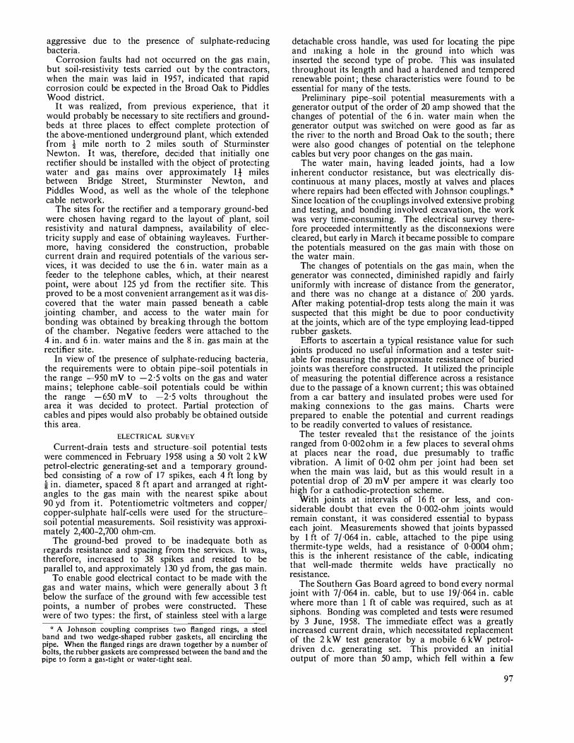
aggressive due to the presence of sulphate-reducing bacteria.
Corrosion faults had not occurred on the gas n1ain, but soil-resistivity tests carried out by the contractors, when the main was laid in 1957, indicated that rapid corrosion could be expected in the Broad Oak to Piddles Wood district.
It was realized, from previous experience, that it would probably be necessary to site rectifiers and groundbeds at three places to effect complete protection of the above-mentioned underground plant, which extended from l mile north to 2 nliles south of Sturn1inster Newton. It was, therefore, decided that initially one rectifier should be installed with the object of protecting water and gas mains over approximately It miles between Bridge Street, Sturminster Newton, and Piddles Wood, as well as the whole of the telephone cable network.
The sites for the rectifier and a temporary ground-bed were chosen having regard to the layout of plant, soil resistivity and natural dampness, availability of electricity supply and ease of obtaining wayleaves. Furthermore, having considered the construction, probable current drain and required potentials of the various services, i t was decided to use the 6 in. water main as a feeder to the telephone cables, which, at their nearest point, were about 125 yd from the rectifier site. This proved to be a most convenient arrangement as it was discovered that the water main passed beneath a cable jointing chamber, and access to the water main for bonding was obtained by breaking through the bottom of the chamber. Negative feeders were attached to the 4 in. and 6 in. water mains and the 8 in. gas main at the rectifier site.
In view of tbe presence of sulphate-reducing bacteria, the requirements were to obtain pipe-soil potentials in the range -950 mV to -2·5 volts on the gas and water mains; telephone cable-soil potentials could be within the range -650 mV to -2·5 volts throughout the area it was decided to protect. Partial protection of cables and pipes would also probably be obtained outside this area.
ELECTRICAL SUR VEY
Current-drain tests and structure-soil potential tests were commenced in February 1958 using a 50 volt 2 kW petrol-electric generating-set and a temporary groundbcd consisting of a row of 17 spikes, each 4 ft long by i in. diameter, spaced 8 ft apart and arranged at rightangles to the gas main with the nearest spike about 90 yd from it. Potentiometric voltmeters and copper/ copper-sulphate half-cells were used for the structuresoil potential measurements. Soil resistivity was approximately 2,400-2,700 ohm-cm.
The ground-bed proved to be inadequate both as regards resistance and spacing fron1 the services. It was, therefore, increased to 38 spikes and resited to be parallel to, and approximately 130 yd from, the gas main.
To enable good electrical contact to be made with the gas and water n1ains, which were generally about 3 ft below the surface of the ground with few accessible test points, a number of probes were constructed. These were of two types: the first, of stainless steel with a large
*A Johnson coupling comprises two flanged rings, a steel band and two wedge-shaped rubber gaskets, all encircling the pipe. When the flanged rings are drawn together by a number of bolts, the rubber gaskets are compressed bet\veen the band and the pipe to form a gas-tight or \Vater-tight seal.
detachable cross handle, was used for locating the pipe and 1naking a hole in the ground into which was inserted the second type of probe. This v.·as insulated throughout its length and had a hardened and tempered rene\vable point; these characteristics were found to be essential for nlany of the tests.
Preli1ninary pipe-soil potential measurements with a generator output of the order of 20 amp showed that the changes of potential of the 6 in. water 1nain when the generator output was switched on were good as far as the river to the north and Broad Oak to the south; there were also good changes nf potential on the telephone cables but very poor changes on the gas n1ain.
The water 1nain, having leaded joints, had a low inherent conductor resistance, but was electrically discontinuous at 1nany places, nlostly at valves and places where repairs had been effected with Johnson couplings.* Since location of the couplings involved extensive probing and testing, and bonding involved excavation, the work was very time-consuming. The electrical survey therefore proceeded inter1nittently as the disconnexions were cleared, but early in March it became possible to compare the potentials measured on the gas 1nain with those on the water main.
The changes of potentials on the gas 1nain, when the generator was connected, diminished rapidly and fairly unifor1nly with increase of distance from the generator, and there was no change at a distance of 200 yards. After making potential-drop tests along the main it was suspected that this might be due to poor conductivity at the joints, which are of the type employing lead-tipped rubber gaskets.
Efforts to ascertain a typical resistance value for such joints produced no useful information and a tester suitable for measuring the approxitnate resistance of buried joints was therefore constructed. It utilized the principle of measuring the potential difference across a resistance due to the passage of a known current; this \Vas obtained from a car battery and insulated probes were used for making connexions to the gas mains. Charts were prepared to enable the potential and current readings to be readily converted to values of resistance.
The tester revealed that the resistance of the joints ranged from 0·002 ohm in a few places to several ohms at places near the road, due presumably to traffic vibration. A limit of 0·02 ohm per joint had been set when the main was laid, but as this would result in a potential drop of 20 m V per ampere it was clearly too high for a cathodic-protection scheme.
With joints at intervals of 16 ft or less, and considerable doubt that even the 0·002-ohm joints would remain constant, it was considered essential to bypass each joint. Measurements showed that joints bypassed by 1 ft of 7/'064 in. cable, attached to the pipe using thermite-type welds, had a resistance of 0·0004 ohm; this is the inherent resistance of the cable, indicating that well-made thermite welds have practically no resistance.
The Southern Gas Board agreed to bond every normal joint with 7/'064 in. cable, but to use 19/'064 in. cable where more than I ft of cable was required, such as at siphons. Bonding was completed and tests were resumed by 3 June, 1958. The immediate effect was a greatly increased current drain, which necessitated replacement of the 2 kW test generator by a mobile 6 kW petroldriven d.c. generating set. This provided an initial output of more than 50 amp, which fell within a few
97
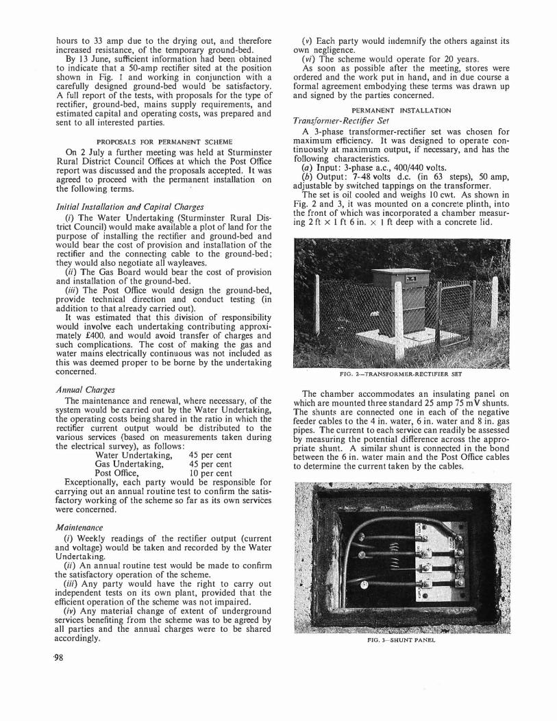
hours to 33 amp due to the drying out, and therefore increased resistance, of the temporary ground-bed.
By 13 June, sufficient information had been obtained to indicate that a 50-amp rectiner sited at the position shown in Fig. I and working in conjunction with a carefully designed ground-bed would be satisfactory. A full report of the tests, with proposals for the type of rectifier, ground-bed, mains supply requirements, and estimated capital and operating costs, was prepared and sent to all interested parties.
PROPOSALS FOR PERMANENT SCHEME
On 2 July a further meeting was held at Sturminster Rural District Council Offices at which the Post Office report was discussed and the proposals accepted. It was agreed to proceed with the permanent installation on the following terms.
Initial Installation and Capital Charges (i) The Water Undertaking (Sturminster Rural Dis
trict Council) would make available a plot of land for the purpose of installing the rectifier and ground-bed and would bear the cost of provision and installation of the rectifier and the connecting cable to the ground-bed; they would also negotiate all wayleaves.
(ii) The Gas Board would bear the cost of provision .and installation of the ground-bed.
(iii) The Post Office would design the ground-bed, provide technical direction and conduct testing (in .addition to that already carried out).
It was estimated that this division of responsibility would involve each undertaking contributing approximately £400, and would avoid transfer of charges and such complications. The cost of making the gas and water mains electrically continuous was not included as this was deemed proper to be borne by the undertaking ·concerned.
Annual Charges The maintenance and renewal, where necessary, of the
system would be carried out by the Water Undertaking, the operating costs being shared in the ratio in which the rectifier current output would be distributed to the various services (based on measurements taken during the electrical survey), as follows:
Water Undertaking, 45 per cent Gas Undertaking, 45 per cent Post Office, 10 per cent
Exceptionally, each party would be responsible for ·carrying out an annual routine test to confirm the satisfactory working of the scheme so far as its own servites were concerned.
Maintenance (i) Weekly readings of the rectilier output (current
.and voltage) would be taken and recorded by the Water Undertaking.
(ii) An annual routine test would be made to connrm the satisfactory operation of the scheme.
(iii) Any party would have the right to carry out independent tests on its own plant, provided that the ·efficient operation of the scheme was not impaired.
(iv) Any material change of extent of underground ·services benefiting from the scheme was to be agreed by .all parties and the annual charges were to be shared .accordingly.
•98
(v) Each party would indemnify the others against its own negligence.
(vi) The scheme would operate for 20 years. As soon as possible after the meeting, stores were
ordered and the work put in hand, and in due course a formal agreement embodying these terms was drawn up and signed by the parties concerned.
PERMANENT INSTALLATION
Transformer-Rectifier Set A 3-phase transformer-rectifier set was chosen for
maximum efficiency. It was designed to operate continuously at maximum output, if necessary, and has the following characteristics.
(a) Input: 3-phase a.c., 400/440 volts. (b) Output: 7-48 volts d.c. (in 63 steps), 50 amp,
adjustable by switched tappings on the transformer. The set is oil cooled and weighs 10 cwt. As shown in
Fig. 2 and 3, it was mounted on a concrete plinth, into the front of which was incorporated a chamber measuring 2 ft x 1 ft 6 in. x I ft deep with a concrete lid.
FIG. 2-TRANSFORMER·RECTIFIER SET
The chamber accommodates an insulating panel on which are mounted three standard 25 amp 75 m V shunts. The shunts are connected one in each of the negative feeder cables to the 4 in. water, 6 in. water and 8 in. gas pipes. The current to each service can readily be assessed by measuring the potential difference across the appropriate shunt. A similar shunt is connected in the bond between the 6 in. water main and the Post Office cables to determine the current taken by the cables.
FIG. 3-SHUNT PANEL
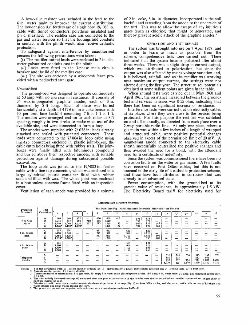
A low-value resistor was included in the feed to the 6 in. water main to improve the current distribution. The low-tension d.c. feeders are of single core 19f'083 in. cable with tinned conductors, polythene insulated and p.v.c. sheathed. The rectifier case was connected to the gas and water services so that the footings and conduits in contact with the plinth would also receive cathodic protection.
To safeguard against interference by unauthorized persons the following precautions \Vere taken:
(i) The rectifier output leads were enclosed in 2 in. diameter galvanized conduits cast in the plinth.
(ii) Locks were fitted to the 3-phase main circuitbreaker and the lid of the rectifier case.
(iii) The site was enclosed hy a wire-1nesh fence provided with a padlocked steel gate.
Ground-Bed The ground-bed was designed to operate continuously
at 50 amp with no increase in resistance. It consists of 34 wax-impregnated graphite anodes, each of 3 in. diameter by 5. ft long. Each of these was buried horizontally at a depth of 4 ft 6 in. in a coke breeze \vith 10 per cent lime backfill measuring 7 ft x 1 ft x 1 ft. The anodes were arranged end on to each other at 8 ft spacing, roughly in two circles to make most use of the available site, and were connected to form a loop.
The anodes were supplied with 7/'036 in. leads already attached and sealed with patented connectors. These leads were connected to the 7 /'064 in. loop cable using line-tap connectors enclosed in plastic joint-boxes, the cable entry holes being fitted with rubber seals. The jointboxes were finally filled with bituminous compound and buried above their respective anodes, with suitable protection against damage during subsequent possible excavation.
The loop cable was joined to the 19/'083 in. feeder cable with a line-tap connector, which was enclosed in a large cylindrical plastic container fitted with rubber seals and filled with wax. The whole joint was enclosed in a bottomless concrete frame fitted with an inspection cover.
Ventilation of each anode was provided by a column
of 2 in. coke, 8 in. in diameter, incorporated in the soil backfill and extending from the anode to the underside of the turf. This was to allow the escape of any injurious gases (such as chlorine) that might be generated, and thereby prevent acidic attack of the graphite anodes."
OPERATION AND TEST RESULTS
The system was brought into use on 7 April 1959, and in order to learn as much as possible from the scheme, comprehensive tests were carried out. These indicated that the system became polarized after about three weeks. There was a slight drop in current output, which was attributed to polarization, but since the output \Vas also affected by inains voltage variation and, it is believed, rainfall, and as the rectifier was working near maximum output current, the settings were not altered during the first year. The structure-soil potentials obtained at some salient points are given in the table.
When annual tests were carried out in May 1960 and April 1961, the resistance measured between the groundbed and services in series was 0·55 ohm, indicating that there had been no significant increase of resistance.
Interference tests were carried out on electricity cables at six places where they were close to the services being protected. For this purpose the rectifier was switched on and off manually, as directed from each place over a 2-way portable radio link. At only one place, where a gas main was within a few inches of a length of wrapped and armoured cable, were positive potential changes observed in excess of the permissible limit of 20 m V. A 1nagnesium anode connected to the electricity cable sheath successfully neutralized the positive changes and thus avoided the need for a bond, with the attendant need for a certificate of indemnity.
Since the system was co1nmissioned there have been no corrosion faults on the water or gas mains. A few faults have occurred on Post Office cables, but this is not unusual in the early life of a cathodic-protection scheme, and these have been attributed to corrosion that was already in an advanced state.
Power consumption, with the ground-bed at its present value of resistance, is approximately l ·5 kW. The Electricity Board tariff for electricity used for
Measured Soil-Structure Potentials
Protected Structure I C
Tesl I Test Point (see Fig, I) and Measured Potentials (Millivolts-see Note 6) ondition -
l-,-
,-,-
,- , -
.- j-
,-1-
6--
7--
8-1-
9-1_
1_0
_1_1_1
_ l_1_2
_ l_l_
J_ : _
1_
4_1 _
1_s
_ l _16-l _
l_
7_ -1· A 6091 640 I '" I -760 I 630 6
00 6
10 -
1---,,,-,---ru-1--=--1
'--=----=-
-
1
--=--
1---=--
1
--=--
S in. Gas B J,245 854 860 656 I.OOO - - 787 778 - - I - - - - -Main I C 1,440 1,040 1,020 822 713 l,220 1,140 - 949 , 870 745 1 _ _ - _ 1 _ -
D 1,620• I.ISO* 1,290• - 1,295 1,170 - 938 I 899 862 I - - - - I - -A 603 I 63' I - - 637 617 - ----;n--=-
-
1"'
1--=--
1--=--1--=--1--=--
--=--1
--=--1---=--
6 in. Water B 1.400 J,040 - - I 749 972
-
951 - I 020 - - - - - - -Main C 1, 410 J,200 I - - 957 J,080 - 1,160 - 1:1.:0 I 899 - - - - - -
--
,
-
In
-
. w-..
-"-I ; I ::;;i•11�0
•1 ; ; 1· ; : t�o ; !,;;� -; I ;;; I �91 ; ,I ; I ; ; I ; I ; Main C 1 1,500 - - - - I - - 1,160 - 877 - - - - - - I -
D 1,720 - - - - - - 1,\\0 - 896 - - - - - - --:1--A -1, --
-:
,
-- --=--'1--=--
1--=--1--=----=--
--=--i
-
-=--
1--=--
1
-
-=-
-
1
-
--m15i81---,;Q1----,;J
1---;(;2
152j Cables c - - - - - - - - - - - 952 737 954 973 I 080 t,200 Telephone B - - - - - - - _ 1 _ - - 889615- 882 956-
D - - - - - - - - - - - 1,020 835 1,120 1.220 1:1so I.220
Notes: I. The test conditions were: A-Before rectifier switched on; B-approximately 2 hours after rectifier switched on; C- 3 weeks later; D-1 year later. 2. Average rectifier output: 25·5 volts, 48 amp. 3. Current measured at metershun1s: 8 in. gas main, 20 amp; 6 in. water main plus telephone cables, 18·3 amp; 4 in. water main, 9·3 amp; and telephone cables only,
3·5 amp. 4. The substantially increased readings(•) measured after one year at Poin!s south of the re;:1ifier were due to an additional rectifier connected to the gas main at
Banbury during the year. 5. Effective cathodic protection extended considerably beyond the limits of the map (Fig. I) on Post Office cables, and also to a considerable oortion of local gas and
wa1er services and small mains around the town. 6. The pmentials quoted are negative with reference to a copper/copper-sulphate half-cell.
99
cathodic protection is calculated on a "kilowatt per annum" basis, fractions being counted as a whole kilowatt. The total cost for power consumed during the year ending 31 March 1960 was approximately £100, this being the charge for 2 kW.
CONCLUSION There is little doubt that the whole-hearted co-opera
tion of all parties concerned made a significant contribution to the success of this scheme. The sharing of capital costs in a joint scheme can show considerable savings compared with individual schemes, although due to unexpected difficulties and the need for extended testing that advantage did not apply to the Post Office in this scheme. However, 1nany valuable lessons were learned both from the engineering and economic viewpoints, and the Post Office contribution of £10 to the annual cost of power represents a very good investtnent in combating corrosion that was previously costing approximately £400 per year.
In view of the man.y indeterininate factors affecting such schemes, any future sche1nes n1ust be assessed on their merits. The opportunity has already occurred to
apply effectively some of the experience gained from the sche1ne described in this article.
ACKNOWLEDGEMENTS
The author is grateful to the staff of the Sturminster Rural District Council, the Poole and East Dorset Water Board, and the Southern Gas Board, as well as to the staff of the Bournemouth Telephone Area, for their excellent co-operation. The assistance given by the Chemical Research Laboratories of the Department of Scientific and Industrial Research and by Post Office Headquarters Departments is gratefully acknowledged.
Especial thanks are due to Mr. J. F. Rowe for his constructive criticis1n and help during the preparation of this article.
References 1 GERRARD, J. Cathodic Protection of Underground Cables.
P.O.E.E.J., Vol. 44, p. 71, July 1951. 2 Co-ordination of the Cathodic Protection of Buried Struc
tures. (In this issue of the P.O.E.E.J.) 3 NACE Technical Comn1ittee Report: Final Report on Four
Annual Anode Inspections. Corrosion, Vol. 12, p. 47t, Jan. 1956.
Development of a Non-Staining Material for Telephone Feet U.D.C. 621.395. 721.4: 678.4
DURING 1957-58 a number of complaints were received of damage to the surfaces of desks caused by stains from the rubber feet on 300-type tele
phones. Preliminary experiments showed that the stains appeared only after the instrument was moved and the contact areas were exposed to light; the contact areas then darkened rapidly.
Analysis of the rubber feet causing the trouble showed that they complied with the specification' for the quality of the rubber. This specification, however, did not restrict the choice of antioxidant and in this instance a staining antioxidant had been used. Feet of earlier manufacture were also examined and they were found to be free from staining antioxidants.
At this stage in the investigation a new factor arose. The 700-type telephone was being developed and included rubber feet which were fitted by a push-in action and not held by a screw, as in the 300-type. The upper surface of the foot was thus inside the case in close proximity to the relay contacts. Ordinary vulcanized natural rubber was unsuitable in a situation such as this as there was a strong possibility of staining of the contacts by sulphur compounds evolved from the rubber.
It was, therefore, decided to specify a chloroprene compound; chloroprene is a synthetic rubber, the most widely known types being marketed under the trade name of Neoprene. A specification' was available, but this specification also did not preclude the use of a staining
1 B.S. 1154: 1952. Vulcanized Rubber Con1pounds. Compound Z 12.
2 B.S. 2752: 1956. Vulcanized Chloroprene Rubber Con1-pounds.
100
type of antioxidant. Since it clearly was not practicable to specify the composition of the feet in detail (the stain producing properties of different antioxidants cannot be predicted fron1 their chen1ical composition), it was considered that a "non-staining" test on the compound would be the best method of controlling this property.
The feet are liable to con1e into contact with a variety of organic and inorganic finishes (lacquers, paints, leathercloths, etc.), so the conditions of the test must be made as general as possible. After discussions with n1anufacturers of the chloroprene rubber, and many experiments, the following test was drawn up.
A piece of chloroprene sheet, or a piece of a chloroprene foot with a flat surface, is placed on:
(a) a surface treated with clear nitrocellulose lacquer (typical surfaces are wood or linoleum), and
(b) a piece of p.v.c. leathercloth. A pressure of 5 lb/in' is applied, and each assembly
is placed in an oven at 50°C for 72 hours. At the end of this time the assemblies are removed fro1n the oven; then the samples of compound are removed and the contact areas exposed to air at room temperature for 24 hours. Any visible change of the surface is regarded as a failure.
The test has been embodied in a specification, and feet for all types of telephone will be made to this specification in future. It is available, of course, for any other cases where a non-staining rubber composition is required. This is an interesting example of the interaction of two materials, rubber feet and desk surface, both of which separately would be considered satisfactory but which in combination give rise to trouble.
L. E.T.
Co-ordination of the Cathodic Protection of Buried Structures
U.D.C. 620.197
THE application of cathodic protection to underground pipes or cables 1nay accelerate the natural rate of corrosion of nearby unprotected structures.
It is therefore necessary for representatives of the organizations responsible for the buried structures concerned to arrange for suitable tests to be 1nade to assess where corrosion da1nage is likely to occur, and to agree on the remedial action to be taken.
The Joint Committee for the Co-ordination of the Cathodic Protection of Buried Structures was formed with the object of studying the problems likely to arise, to make suitable reco1nmendations, and eventually to facilitate the drafting of a Code of Practice. Details of the Joint Committee and its Technical Panel were briefly described in a previous note.1 This article describes the recent activities of the Com1nittee and of the Technical Panel.
PUBLICATIONS
The Joint Committee has produced a number of publications which should ensure satisfactory co-operation between the various authorities concerned with the application of a cathodic-protection scheme. A brief description of these docun1ents is given below.
"Cathodic Protection of Buried Structures." This pamphlet was published in December 1957 to draw attention to the work of the Joint Committee. It also su1nmarizes the electroche1nical principles of corrosion and cathodic protection, the methods of applyingcathodic protection, how corrosion interference may occur, methods of reducing the interference and, finally, a short pr�cis of research in progress.
Reconunendation No. 1 ('"Reco1n1nendation For a Standard Method of Measuring the Potential Difference Between a Buried Structure and the Soil and the Change Produced by a Cathodic Protection Installation"). General information is given of suitable instruments and copper/copper-sulphate half-cells that are recommended for making potential measurements and on how the tests should be made. An addendum amplifies the test procedure that should be followed when an unprotected structure is metallically handed to a cathodicallyprotected structure.
Note on Reco1111ne11dation No. 1 ("Measuren1ents to Determine the Interaction Between Cathodically Protected and Unprotected Structures"). The Note discusses the errors caused by the incorrect placing of the copper/copper-sulphate half-cell and by connecting the measuring instrument to the buried structure at points remote from the desired test position. In some instances the changes of potential measured can be substantially in error because of potential gradients in the soil, and a convenient method of test which is accurate in all circumstances has yet to be evolved. Organizations are asked to submit the results of tests of potential difference for consideration by the Technical Panel.
Recon1111endatio11 No. 2 ("Reco1n1nended Procedure for Exchanging Information Regarding Proposed Cathodic Protection Installations"). In general cathodic
1 Joint Con1mittee for the Co-ordination of the Cathodic Protection of Buried Slructures. P.O.E.E.J., Vol. 47, p. 225, Jan. 1955.
protection is planned in at least two stages. During the initial stage only approximate details will be decided concerning the positions of rectifiers, ground-beds, anodes and the proposed dates of operation, etc. During the second stage tests will be made to decide the final positions for the cathodic-protection equipment and the current output required. Subsequently it may be necessary to make tests on nearby structures and to decide on the n1ethods to be employed to reduce any corrosion interference that may arise. This document sets out the type of information that should be given at the earlier stages to other organizations that may be affected by the cathodic-protection scheme.
Reco111111endatio11 No. 3 ("Bonding Between the Sheaths of Alternating Current Power Cables and Other Structures"). A com1non method of avoiding corrosion interference is to bond unprotected structures to the cathodically-protected plant. If necessary the current through the bond may be controlled by means of a suitable series resistance. Particular care is required if the bond is connected to an electricity supply system, and the document describes the precautions that should be taken in such cases.
Reco1111nendatio11 No. 4 ("Corrosion Interference due to the Application of Cathodic Protection using Reactive Anodes"). If the principles in the recommendation are taken into account \\-'hen the anodes are instaJled, corrosion interference with other buried plant and interference tests can be avoided or reduced. Recommended minimu1n separating distances between the anodes and nearby plant are given.
Document JC 6. This document was published solely for the use of the organizations represented on the Joint Comn1ittee and summarizes the change in electrical conditions recommended on buried structures that are near to protected plant. It recommends a maxi1num permissible positive change in the structure-to-soil potential and also a maximum desirable negative potential. Information is also given on the method of measuring these potentials and on bonding and similar measures to be adopted when the conditions fall outside the recommended limits.
Document JC 38 ("Form of Indemnity for use where Structures are to be Bonded Together in Connexion with a Cathodic Protection Scheme"). An indemnity is usually required when underground plant is to be bonded to the sheaths or armouring of electricity supply cables since there is the possibility of large earth-fault currents flowing through the bond.
"Cathod;c Protection Installations" (Tables giving a summary of information on cathodic-protection installations in the United Kingdom reported to the Joint Committee). Information is given for the period up to 31 October 1959, concerning 804 installations, of which 516 were working (291 being operated by the Post Office) and 216 were still under discussion. Summary tables show the distribution of these installations, the authorities operating the equipments and the methods used to counteract adverse potential changes on electricity supply apparatus. Owing to the work involved this list is no longer being kept up to date.
IOI
RESEARCH
Financial support was provided by the member organizations for research to be undertaken by Dr. T. W. Farrar at Cambridge, under the directio.n of Dr. T. P. Hoar. A study was made of the relationship between anode-current density and electrode potential for mild steel in dilute solutions of soil electrolytes and in conditions simulating the natural corrosion of metal buried in various soils.
Many experiments were made using specially designed corrosion cells, and the general conclusion reached was that a change in potential of+ 10 m V between naturally corroding iron or steel and the adjacent soil water or soil produces a 40 per cent to 80 per cent increase in anodecurrent density. A potential change of +20 m V produces a t\vo-fold to three-fold increase in anode-current density.
In general it was shown that the increase of potential for a ten-fold increase in anode-current density is between 40 and 65 m V under most conditions. The anodecurrent density is taken as being directly proportional to the overall rate of anodic corrosion.
In discussing the results of the foregoing research the Technical Panel agreed that account must also be taken of potential gradients in the soil when making corrosion test measurements and that the test limit of +20 mV given in Document JC 6 should continue in use for a further period.
FIELD EXPERIMENTS
A number of long-term experiments and inquiries have been made or are in progress and these are expected to provide information to assist the drafting of various recommendations.
At Stowmarket the Eastern Electricity Board, in conjunction with the Central Electricity Generating Board (C.E.G.B.), have been conducting experiments with samples of buried cables to assess the corrosion damage caused by maintaining the cable sheaths at various fixed potentials. Short lengths of bare leadcovered cables and also of bitumen-covered armoured and unarmoured cables were buried in a clay soil for a year. The potentials of each sample were then controlled by means of a potentiostat2 at fixed values for a further 2i years.
An examination of the samples showed that the amount of pitting of the lead on bare and covered samples appears to confirm that the presence of anodic corrosion products on the surface of the lead slows down the theoretical rate of corrosion. As expected, the amount of corrosion and depth of pitting was greatest on bare lead samples at potentials of -250 to -440 m V relative to copper/copper-sulphate and much less at potentials of -450 and -550 m V to the same reference electrode. Comparatively slight corrosion occurred on the coated and armoured samples but the rate of corrosion wou1d probably increase as the coatings aged and deteriorated.
A particularly interesting experiment was made jointly by the South Eastern Electricity Board, the C.E.G.B. and
2 EVANS, ULICK R. The Corrosion and Oxidation of Metals (Edward Arnold, Ltd., I 960), p.228.
the Post Office at Patching in Sussex. The experiment :vas designed
. to provide information on the long-term
interference hkely to be caused by a Post Office cathodicprotection scheme in which the potential is applied to the telephone cable sheaths by means of a mains rectifier installed at the telephone exchange.
Fourteen copper/copper-sulphate half-cells were buried at
. ':'arious positions adjacent to telephone cables, electr1c1ty cables and water mains. Test leads from the structures and the half-cells were connected toa SO-channel recorder with which was associated a digital voltmeter. The cathodic-protection equipment and the recorder were controlled by a master switching unit which S\vitched the rectifier on and off at predetermined intervals. Provision was also made for measuring local rainfall and soil resistivity.
The equipment was automatically brought into use for 7i minutes in every hour over a period of about four months, and 150 readings were recorded in each hour. The thousands of recorded readings are being converted to a form suitable for use by a computer and they will eventuaUy be analysed automatically. It is hoped to obtain 1nformat1on about the way in which positive or negative changes on cathodically-protected and nearby unprotected structures are affected by long-term variations in rectifier output and changes in soil resistivity or rainfall, or due to variations in polarization of the buried structures.
RESISTANCE BONDS
Discussions are proceeding between the C.E.G.B. and the Post Office on the safety and reliability of resistance bonds connected between telephone cable sheaths and the sheaths or armouring of electricity supply cables. Jn the event of an earth fault on the electricity supply system it is possible that a large earth-fault current may pass through the resistance bond to the sheaths of the telephone cables and this condition may persist for 3 seconds or more.
Apart from ensuring that such conditions do not endanger personnel likely to come into contact with the sheaths of telephone cables, it is essential to ensure that the rise in temperature does not melt the resistor and, in addition, the sudden expansion of air in a restricted enclosure due to the rise of temperature should not cause an explosion. It would appear that these requirements can best be met by using nichrome strip of sufficient mass to absorb the heat likely to be generated and thereby hm1t the temperature nse to about 300°C. In addition, the enclosure in which the resistor is mounted should be of adequate size.
CODE OF PRACTICE
Nominated members of the Technical Panel are now engaged in preparing suitable drafts to form the basis of a British Standard Code of Practice. The agreed draft will be submitted in the near future to the Codes of Practice Committee for Electrical Engineering or to a new Committee for the Code of Practice on Cathodic Protection, which is being formed.
J.R. W.
-- ·- ---------------------
102
Subscriber Dialling of International Telex Calls
E. E. DANIELS and A. E.T. FORSTER, A.M.I.EE.t U.D.C. 621.394.34:621.394.5
The conversion to automatic lVOrking of the inland telex service in the United Kingdom was completed in December 1960. Facilities are now being introduced to enable telex subscribers to dial calls to most European countries, and the switching and signalling problems involved in international working are discussed. Features of the equipment provided in the international Slritching unit in
London are described.
INTRODUCTION
THE conversion of the telex service within the United Kingdom to automatic working commenced in 1958 with the opening of exchanges in
Leeds and London (Shoreditch). The bringing into service of the London (Fleet) exchange in December 19601 marked the completion of this process and prepared the way for the introduction of facilities to enable telex subscribers in this country to dial international calls. Such facilities will be provided by an international switching unit that has been installed in the Fleet exchange and which is being progressively brought into use during 1961. About 90 per cent of all outgoing international telex traffic will then be switched automatically. the routes served being shown in Fig. 1.
PARIS
----�----- - - -... Notes:
' c
INTERCONNEXION OF DIFFERENT TYPES OF AUTOMATIC TELEX SYSTEM
Although an international telex service had been set up prior to the war, it was not until the post-war years, following the decision of the International Telegraph and Telephone Consultative Committee (C.C.l.T.T.) to establish a network independent of the telephone service, that significant development occurred. The rapid growth that has followed has made it essential for the participating countries to use auton1atic switching techniques for handling the increased traffic. In designing automatic telex systems there has been, for obvious reasons, a tendency in each country to use switching mechanis1ns and techniques similar to those used in the national telephone service, and therefore it is not surprising to find that the various national telex systems are based on a range of fundamentally different switching principles. Both register and non-register systems are used, and whilst some register systems use dial selection.
t Telegraph Branch, E.-in-C. 's Office. l WILCOCK, A., and BAXTER, E. c. Fleet (London) Automatic
Telex Exchange. P.O.E.E.J., Vol. 54, p. 53, Apr. 1961.
\ "- '
·'L ,.- � \. ......__ ,,.....__.
j
1. The type of switching syslcm used in ea:h co:.mtrY is indicated as follows: KB-keyboard selection, register (C.CJ.T.T. signalling Type B) D--dial-selcction, non-register 2. The lmernal system used in Luxemburg employs keyboard selection wilh DR-dial-selection, register registers. but for traffic from !he United Kingdom the 1ermi11al conditions are KA-keyboard selection, register (C.C.l.T.T. signalling Type A) the same as for a dial-selection non-register system.
FIG. 1-SUBSCRIBER-DIA.LLING TELEX ROUTES FROM LONDON TO EUROPE (1961)
103

others use the teleprinter keyboard to transmit the digits of the number required.
Other detailed but important differences between syste1ns include the method of indicating ineffective calls. For example, some systerns use teleprinter signals for this purpose, whereas others use simple functional indications such as the stopping and starting of the teleprinter 1notor.
In planning the conversion of international telex services to automatic 'vorking therefore, one of the principal problems that had to be resolved was the basis on which systems of different types should be interconnected and, in particular, ho\V the differences should be accommodated. This problem was considered by the C.C.I.T.T. and was resolved by the standardization, for use over international circuits, of two ranges of signals, termed Type A and Type B. The two ranges of signals correspond with the two basic fonns of signalling used in national telex •ystems. In addition, the C.C.l.T.T. agreed that, where two systems using different signalling techniques have to be interconnected, the equipn1ent at the outgoing (or calling) end of a circuit
system to which the traffic is incoming. Jn addition, \Vith teleprinter selection-signals, the optional use of an end-of-selection signal is recognized in order to facilitate working fro1n register systems into systems having mixed numbering schemes. Although the use of teleprinter keyboards opens up the possibility of using letter codes to identify subscribers, the C.C.l.T.T. has specified that, to avoid difficulties with calls originated from dialling systems, only figures shall be used for subscribers' numbers published internationaily.
A Call-Connect Signal is used to indicate establishment of the connexion and that charging for the call should commence. Since it is a cardinal principle of the telex service that calls should be capable of being received whilst the teleprinter set is unattended, the call-connect signal is returned as soon as connexion is 1nade to the called teleprinter.
Clearing. Either the calling or the called party may initiate the clearing signal, which is a simple inversion to
SIGNALLING SIGNALLING SIGNALLING SIGNALLING should conform to the signalling conditions of the system at the incoming end of the circuit.
PATH PATH PATH PATH
1 FORWARD- BACKWARO- FORWARO- BACKWARD·
-- - - �R �E_L!N� - - - - -A- - ���E� - -
A
- - 7�(�0� �-A- - � :N:T�I� - _ ... _ - �(:O�E�) The adoption of the above prin
ciples has the advantage that, if two similar systems have to be interconnected, relatively simple arrangements can be used. If dissimilar syste1ns are involved, the cost of conversion equip1nent is shared between the two countries concerned.
-- - - - - - -- - - - - - -CALL 1· CALL CONFIRMATION
- - - - - - - - -- - - - - - -
PROCEED TO SELECT ,
' ' i\ '1
---- - - - - - -- - - - i - - - - - - --
SELECTION : \' ITELEPRINTER
I I I I SIGNALS
1' \ I
Type A and Type B Signalling
The basic principles of the two standard signalling systems are shown in Fig. 2. The C.C.l.T.T. has recognized that, within a particular type of signalling, specified alternative signals may be used for indicating specific conditions. The main differences between the twosystemslie in the signalling condition of the backward path during selection and that, whereas dial-selection syste1ns use Type B signalling exclusively, keyboard selection can use either Type A or Type B.
The functions of most of the signals are self-explanatory, and the following co1n1nents are limited, therefore, to those signals which require some explanation.
A Call-Co1?finnation Signal is returned from the incoming equipment in response to the calling signal, and is provided to enable the international trunk circuit to be tested automatically when it is seized for a call.
A Proceed-to-Select Signal is used to indicate that the incoming equipment is ready to receive the digits of the required number. In certain circumstances a single signal can be used to combine the functions of callconfirmation and proceed-to-select signals.
, '
·r
TYPE A SIGNALLING
Notes
40ms
' ' : \ / :olAL PULSES
v 1 OR : 11 , TELEPRINTER
I I \ 1 SIGNALS , "
TYPE B SIGNALLING
I. The conventions used to indicate polarities of signals arc:
2Sms
2Sms
Selection Signals may be either dial pulses (nominal speed lO p.p.s., ratio 60 : 40) or teleprinter signals. For the latter, the use of auxiliary characters is permitted to enable the class-of-traffic of calls to be determined. This allows traffic between various categories of user to be controlled where this is a requirement in the national
A = start polarity ( = space polarity, + 80 volts in the United Kingdom) z = stop polarity ( = mark polarity, - 80 volts in the United Kingdom)
104
(the use of A and Z to indicate start and stop polarities is internationally recognized).
2. The dilrations indicated for the signals are nominal.
FIG. 2-PRINCIPLES OF C.C.I.T.T. TYPE A AND TYPE B INTERNATIONAL TELEX TRUNK SIGNALLING
permanent start polarity. This inversion is detected as a clearing signal when it has persisted for at least 300 milliseconds, and it is therefore readily possible to discriminate between teleprinter signals and the clearing signal.
Service Signals arc used to indicate busy and other conditions which prevent calls from being established. Some systems use teleprinter signals for this purpose so that the caller receives a printed indication of the condition, whilst others use functional pulse signals and no printed signal is given. The service signal is, however, always followed by the clearing signal so that Jines and switching equipment are not held unnecessarily. This clearing signal is also used in many metering systen1s to avoid charging for ineffective calls.
INCOMING INTERNATIONAL TRAFFIC
The C.C.I.T.T. recommendation that the outgoing equipment in the calling country should be adapted to suit the system of the called country makes it unnecessary to provide any special conversion equipment for in� coming traffic, and the incoming international circuits therefore terminate directly on lst selectors in the Fleet international telex exchange.
OUTGOING INTERNATIONAL TRAFFIC
Since for outgoing traffic the equipment in this country must conform to the requirements of the systems used in the distant countries, it is necessary to route the outgoing traffic through equipment which has been designed to meet the detailed signalling conditions of each distant system.
Because of the range of different systems to which
INCOMING INTERNATIONAL
CIRCUITS
I THROUG H 0 TANDEM
(NOTE 1) ==
INTERNATIONAL SWITCHBOARD
INLAND SYSTEM
access is required and the need to avoid having to provide too many different types of conversion equipment, it was decided to deal separately with the conversions on the forward and backward signalling paths. The facilities for dealing with signals on the backward path are incorporated in the trunk relay-sets, whilst any conversions required for signals on the forward path are made in the outgoing register-translators. Registertranslators are required, in any event, for working to distant register systems to store the digits of the called subscriber's number, and it is profitable to take advantage of this to introduce any translation that may be necessary in the forward-path signals.
Trunking Arrange111ents
To make an international call, a subscriber in this country dials the code 20 (corresponding to the selector level which gives access from the inland system to the international exchange), followed by a code of one or two digits to identify the distant country, and then by the called subscriber's number. The code allocated to each destination country is dependent upon the method of access to the particular country and is called the "country code."
The trunking of the international switching unit is shown in simplified form in Fig. 3.
Calls to Dial-Selection Non-Register Syste111s. For access to dial-selection non-register systems which have only one route from this country, the trunk circuits are taken direct from the selector level corresponding to the code allocated to the country concerned. The use of direct-selection 1nethods is possible because the dials in this country conform to the standard reco1n1nended by the C.C.l.T.T. Furthermore, telegraph circuits allow dial pulses to be transmitted without distortion becoming a problem.
To enable calls to be routed to more than one entry point in dial-selection non-register syste1ns, routing translators similar to those used in the inland service2
2 FORSTER, A. E. T., BARTON, R. W., and ELLIS, w. A� The Automatic Telex Service, l.P.O.E.E., Printed Paper No. 215, 1959.
INTERNATIONAL � SWITCHBOARD {-
PROVINCIAL == EXCHANGES -
_
SERVICE POINTS AVAILABLE _ ____ __.:..:: TO UNITED KINGDOM
r
Notes:
SERVICE POINTS
- -
INTERNATIONAL SWITCHBOARD
(HOTE 2)
INTERNATIONAL
AV�k���JG 10 ----
�- }
CALLS == LONDON SUBSCRIBERS
I. Level 9 of the incoming international lst selectors gives access to the inter national switchboard for calls via cable circuits.
2. Level 201 gives access to the international switchboard [or calls via radio circuits.
FIG. 3-TRUNKING PRINCIPLES OF THE INTERNATIONAL AUTOMATIC TELEX EXCHANGE
c
SUBSCRIBERS
202
) DIAL-SELECTION NON -REGISTER SYSTEMS TO WHICH MORE THAN ONE POINT OF ENTRY MAY BE
==i_cT0'-"2N"D'-'S>!E'-LE<!CelT;!!OR!>S_ REQUIRED. WEST GERMANY BELGIUM (c.C.l.T.T. SIGNALLING TYPE s)
1-�''""'"�'=-SELECTORS ROUTING
TRANSLATOR
DIAL-SELECTION REGISTER SYSTEMS: SWEOEN (c.C.l.T.T. SIGNALLING TYPE B)
KEYBOARD-SELECTION REGISTER SYSTEMS: 1TALY (C.C.l.T.T. SIGNALLING TYPE B)
KEY BOARO-SELECTION REGISTER SYSTEMS: NE THERLANDS FRANCE NORWAY (c.C.l.T.T. SIGNALLING TYPE A)
105
are provided. This arrangement allows for discrimination on receipt of the initial digit of the called subscriber's number. Trunk routes taken fro111 selector levels preceding the routing translators tenninate on 2nd selectors in the distant country, while trunk routes connected via routing translators terminate on 1 st selectors in the distant country because the routing translator restores the initial digit of the called subscriber's number.
Calls to Dial-Selection Register Systems. Calls to distant dial-selection register systems are routed through an outgoing register-translator so that the digits dialled by the calling subscriber can be stored whilst a register is being connected in the distant system.
For access to such systems a 2-digit country code is allocated, and the outgoing register-translators are reached through access relay-sets connected to the selector level corresponding to the first digit of the country code, the access relay-set accepting the second digit of the country code whilst the register is being connected. This digit is subsequently transferred to the register, which then receives the digits of the subscriber's number direct.
The register-translator commences translation as soon as the first digit of the called subscriber's number has been received. The first part of the translation consists of one or two digits to control the outgoing selectors in this country to select the outgoing circuit. When the trunk relay-set receives the proceed-to-select signal from the distant system it causes the register to transmit the digits of the called subscriber's number directly into the distant system. The register normally releases when either the call-connect signal or a service signal is received over the backward-signalling path. A forced-release facility is included as a safeguard against incomplete dialling.
The register-translator is able to make the necessary discrimination by examination of the initial digit of the called subscriber's number and so produce distinctive translations to enable calls to be correctly routed to systems having more than one point of entry.
Access to Keyboard-SelecUon Syste111s. The outgoing register-translator is also able to route calls to keyboardselection systems. The register is seized in the same manner as for a cail to a dial-selection register system. The outgoing translation may commence after the receipt of any predetermined digit according to the requirements of the distant system. The first part of the translation, in the form of dial pulses, selects the outgoing trunk circuit as already described. The second part of the translation, in the form of 5-unit teleprinter signals, commences as soon as the trunk relay-set receives the proceed-to-select signal from the distant system. The register adds to the digital signals any auxiliary signals which may be required by the distant system.
ACCOUNTING
With the introduction of subscriber dialling of international telex calls it is necessary to arrange for the automatic recording of information required for international accounting purposes, as well as to ensure that calling subscribers are automatically debited with the appropriate charges. These requirements affect the signalling arrangements via the backward path, and before the backward-path signalling arrangements are discussed a brief description of the accounting and metering facilities provided is necessary.
106
Subscribers' Accounts
The charges for dialled international calls are recorded on the subscribers' meters and are bulked with inland call charges. The time-zone 1netering equipment installed in the inland exchanges includes facilities for 1netering on international callsi and has been designed to distinguish the international access code 20 and so set up the conditions for dealing with international calls. It next examines the following digits to identify the country and select the appropriate pulse rate.
The method of metering for international calls is the san1e as that used for inland calls, i.e. one meter pulse is applied when the connexion is established and further pulses, fed from a common pulse machine, are connected at regular intervals. The first periodic pulse is suppressed so that the interval between the initial pulse and the next periodic pulse fed to the subscriber's meter is at least the nominal periodicity of the particular charging rate. The metering system has been designed to provide for metering at the 30 rates shown in the table.
Metering Rates for Inland and International Telex Calls (Pulses per Minute)
1 6
12 20 36 72
2 7
14 21 42 84
3 8
15 24 48 96
4 9
16 27 54
108
5 10 18 30 60
120
In order that the metering rate to a particular country can be determined fron1 the examination of the country code, it is essential that there should be a uniform rate to the whole of the countty concerned. Hitherto, for the telex. service to some countries, there have been a nun1ber of tariff zones each with different rates for calls from this country. However, to provide for the introduction of fully automatic working, the tariffs have been modified to provide for a single rate to each country.
International Accounts
To obtain data from which to prepare accounts to exchange with other ad1ninistrations, meters are associated with each international trunk circuit to record the value of the outgoing traffic carried. A pair of meters is associated with each outgoing circuit, one meter recording the number of chargeable calls, the other the aggregate chargeable time in units of a minute. The trunk relay-sets include a facility for suppressing metering on calls dialled from selected service points, from the international switchboard, and for calls that are transitswitchcd in this country. For this purpose a discriminating condition (de-metering) is provided on the backward path within Fleet exchange to enable the metering circuits to be switched out for calls originating from particular points. The circuit arrangements for providing this signal are shown in Fig. 4.
Metering facilities are not provided on incoming international circuits.
BACKWARD-PATH SIGNALLING
Calls to Systems Using Type A Signalling The automatic telex system in this country uses Type B
signalling so that, for inland calls, inversion to stop polarity on the backward path is an indication that connexion to the called teleprinter has been established. However, on international calls to systems using Type A
V.F. STATIC RELAY
INLAND TRUNK CIRCUIT TO PROVINCIAL SUBSCRIBER __ (V�A��N�-
-+-.
TIME-ZONE METERING
EQUIPMENT
.f.80V SERVICE POINT
' ' I I
' I
' '
I I ' I
' ' '
INTERNATIONAL AUTOMATIC
TELEX EXCHANGE
BACKWARDSIGNALLING
PATH
f"' +BOY
INTERNATIONAL TRUNK RELAY-SET
Relay M S operates to apply metering conditions when earth is connected as shown. This applies only on calls from subscribers. It docs not operate on calls
from service points.
FIG. 4-DE-METERING DISCRIMINATION
signalling, inversion to stop polarity on the backward path occurs when the international trunk circuit is seized. It is essential to a1low this inversion to be transmitted back to the caller to enable printed service-signals to be received on the calling teleprinter. On international calls, therefore, the inversion to stop polarity is not used to start metering in the time-zone metering equipment, and it is necessary to provide a special signal for this purpose.
The Type A call-connect signal standardized by the C.C.l.T.T. is a pulse of start polarity of 150 ± 11 ms. To discriminate between this signal and teleprinter signals requires a circuit element which cannot be readily achieved using conventional electromechanical techniques, and therefore, to avoid unnecessary complication of the time-zone metering equipments in all the inland exchanges, the detection of this signal is carried out in the international trunk relay-set, which in its turn transmits to the time-zone metering equipment a 270 ms pulse of start polarity to indicate that metering should commence (see Fig. 5(a)). This pulse is capable of being detected by a simple relay circuit in the time-zone metering equipment and its duration has been chosen so as to avoid spurious characters being printed by the teleprinter. Since systems using Type A signalling invariably provide for the automatic return of the called-subscriber's answer-back signal, the equip1nent in this country does not need to transmit the "who are you" (WR U) signal for this purpose. It is necessary, therefore, on international calls, for the time-zone metering equipment to distinguish the code 20 and to render inoperative the facility provided for automatically obtaining the answer-back signal on inland calls.
Calls to Systems Using T;pe B Signalling with NonPrinting Service-Signals
Systems which do not provide for printed servicesignals usually indicate ineffective calls either by forced release (effected by the busy signal of 200 ms stop polarity and 1,500 ms start polarity, continuously repeated) or by
NOTE ISO ANSWER-BACK {A __,msr-· �!t���:.L__ SIGNALS RECEIVEO Z� --- - �
FROM THE I TELEPRINTER INTERNATIONAL 1 SIGNALS t:9 OCC TRUNK CIRCUIT A I :_ .:;:_:._"""S--z �- - -
f-..--RELAY-SET o:ScRIMINATES 1 AT THIS POINT
ISO 2:70 _ _,ms,_�
TO THE CALLING 1 EXCHANGE FROM 1
EFFECTIVE CALL
INEFFECTIVE CALL
EFFECTIVE CALL SIGNALS RETURNED {� _____f1_fl__[� ����-1_
THE INTERNATIONAL A : -- - =-r-- INEFFECTIVE TRUNK RELAY-SET z 1 ::....::."'":.. -..J CALL
(a) C.C.I.T.T. Type A Signalling with Printed Service-Signals.
NOTE ; A EFFECTIVE
SIGNALS RECEIVED 'Z 1 CALL FROM THE 1 INTERNATIONAL l ,
TRUNK CIRCUIT A� INEFFECTIVE Z · 1 CALL -j 200 f- r-RELAY-SET DISCRIMINATES (BUSY SIGNAL) ms 1 AT THIS POINT ' I -j 2:70 �ANSWER-BACK {A 1 · ms . ���Al:� EFFECTIVE SIGNALS RETURNEO Z�""---:::ool_ CALL TO THE CALLING I
EXCHANGE FROM I TELEPRINTER THE INTERNATIONAL 1 • SIGNALS t:9 OCC TRUNK RELAY- SET A L.J"'" �� ...,_,......--- INEFFECTIVE
Z I -""----..J CALL ' .1200 I 1lms l
(/J) C.C.I.T.T. Type B Signalling with Non-Printing Service-Signals
Note: A indicates start polarity, Z indicates SIOP polarity
FIG. 5-SIGNAL CONVERSIONS IN THE TRUNK RELAY-SETS OF SIGNALS ON THE BACKWARD PATH
failure of the teleprinter motor to start when dialling has finished (permanent start polarity on the backward path). On systems of this type it is usual not to return the answer-back signal automatically but to indicate connexion to the called party by a simple inversion to stop polarity, which causes the calling teleprinter motor to start.
So that callers in the United Kingc. .>m may meet similar conditions on both inland and international calls, the non-printing service-signals received on international calls are converted into printed signals. In addition, the called subscriber's answer-back signal is obtained automatically. These facilities are provided by the outgoing international trunk relay-set, and the principle involved is illustrated in Fig. 5(b).
The busy signal (a 200 ms pulse of stop polarity) is converted into the OCC signal,* and permanent start polarity on the backward-signalling path is converted into the NP signalt. For the latter conversion it is necessary to recognize that all the digits have been dialled, and since, in general, the numbering schemes of most of the systems concerned are mixed, discrimination is effected 6·0 to 9·0 seconds after dialling has finished. With this method of discrimination there is, of course, some slight risk of slow dialling by subscribers resulting in the return of the NP signal.
On effective calls the receipt of the call-connect signal in the international trunk relay-set initiates the transmission of the WRU signal to obtain the answer-back signal of the called teleprinter. Failure to receive signals in response to the WRU signal is interpreted as indicating a faulty line; the DER signalt is returned to the caller
* OCC-subscriber-engaged signal. t NP-Spare-line or spare-level signal. t DER-Subscriber's-line-faulty signal.
107
and the call forcibly released to prevent subscribers from being unnecessarily charged for unsatisfactory calls.
The trunk relay-set for circuits to systems using Type B signalling also returns the 270 ms pulse of start polarity to the ti1ne-zone n1etering equipment to start 1netering on effective calls. This signal is returned, therefore, for calls to both Type A and Type B systems, thus giving a uniform signalling condition on all international calls and so n1aking it unnecessary for the time-zone metering equipment to have to determine the type of signalling involved on each call.
Calls to Syste111s Using Type B Signalling with Printed Service-Signals
For cans to systems using Type B signalling with printed service-signals, the international trunk relay-set is arranged to allow the service signals to be returned to the caller in the form received over the international trunk circuit. The trunk relay-set determines that a call is ineffective if teleprinter signals are received within just over 200 ms after the inversion to stop polarity. An effective can is indicated by steady stop polarity for 2 seconds following the inversion to stop polarity, and the trunk relay-set recognizes this and returns the 270 ms pulse of start polarity back towards the calling exchange to start metering.
With the above method of distinguishing between effective and ineffective calls, it is necessary to take precautions to ensure that a call is not allowed to proceed if there is premature operation of the keyboard of the called teleprinter (or premature transn1ission of the answer-back code if the machine has been seized with the answer-back mechanism off-normal), otherwise the metering would be suppressed. This is achieved by arranging that, when a call is recognized as ineffective, a timing circuit is brought into operation to force the release of the call after an interval of about 3 seconds, which is just long enough for a normal service-signal text to be transmitted and to be received on the calling teleprinter.
TRANSIT TRAFFIC
The C.C.l.T.T. has specified that, to facilitate the barring of irregular transit traffic, national telex syste1ns shall be so arranged that transit routings can be deter-1nined by the initial digit transmitted by the calling country. To meet this requiren1ent, level 0 of incoming international selectors is used to provide access to the outgoing international exchange to cater for transit traffic (there is no automatic access from level 20 of international lst selectors to the outgoing international circuits). The international lst selectors are equipped with normal-post spring-sets so arranged that any incoming circuit can be barred tandem access if so required.
Level 0 of the incon1ing international selectors is -connected via a group of through tandem relay-sets, one of whose principal functions is to ensure that uniform Type B signalling conditions are returned to each calling system regardless of the type of signalling used in the destination system. For transit calls the through tandem relay-sets also pass forward a signal to the outgoing trunk l'elay-set, to suppress the operation of the trunk meters. The charges for such calls are normally recorded in the originating country and therefore should not be included in totals recorded on the outgoing trunk relay-sets.
108
THE GENTEX SER VICE FOR INTERNATIONAL TELEGRAMS TO EUROPE
In the design of the international automatic telex exchange allowance has been made for dealing with international telegrams by 1neans of the gentex service.
The gentex service, which is based on an automatic sv,:itching network interconnecting the Post Offices in the principal European towns and cities, has been built up over the past 5 years and is linked to the telex network in a variety of ways in the participating countries. For traffic to some countries a comrnon trunk route will be used for both telex and gentex, and to others, separate groups of circuits will be required. l f a common group of circuits is used it will be essential that the meters provided on the trunk circuits for recording telex traffic should not be operated for gentex calls, and this will be arranged either by making use of the de-metering discrimination provided for service traffic or by separate access to the trunk relay-sets. Incoming gentex trunk circuits will terminate on lst selectors in the same way as international telex trunks.
SWlrCHlNG .tQUJ!'MENT
Outgoing International Register-Translator The outgoing register-translator, which is electro
mechanical, is shown in block-schematic form in Fig. 6. The register-translator is reached via an access relay-set '"'hich, as previously explained, is provided with facilities to store one digit whilst the register-hunter is selecting a free register, in order to allow subscribers to dial international calls without having to pause between digits. The hunter has an availability of 50 and is non-homing, but is provided with a step-on feature to equalize traffic over the group and also to minimize the possibility of successive seizure of a faulty register-translator. The translation function of the register-translator is based on the use of a 2000-type selector mechanism, and the register-translator is therefore able to discriminate on sequences of two digits. These two digits are, respectively, the second digit of the country code ("Z" digit) and the first digit of the called subscriber's number(" A" digit), so that one group of register-translators is able to serve 10 countries and to discri1ninate on the first digit of the called number for routing and other purposes. In discriminating, the register-translator determines:
(a) The trunk route to be used for the call. The register is able to send a dial-pulse train of one or two digits to select the appropriate trunk route.
(b) Whether dial-selection or keyboard-selection signals are required by the distant system.
(c) Whether the distant system uses Type A or Type B signalling. This information is necessary to enable the release of the register-translator to be controlled by the signals on the backward path.
(d) Whether the distant system uses a uniform or a mixed numbering scheme. For uniform numbering schemes the first digit of the subscriber's number indicates the number of digits to follow.
(e) How many digits of the called subscriber's number must be stored before the outgoing translation can com1nence. In certain instances it is necessary to have received all the digits of the subscriber's number before commencing translation, and in such circumstances, if the distant systen1 uses a mixed numbering scheme, discrimination is effected about 5 seconds after the receipt of the last digit. If the distant system uses a uniform
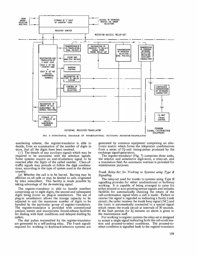
FROM { � �-} ACCESS TO OVERSEAS GROUP- STORAGE OF 'z' DIG!T ROUTES VIA GROUP SELECTOR
MULTIPlE � OF COUNTRY CODE
� SELECTORS
REGISTER HUNTER
- - - - - -
� REGISTER-ACCESS RELAY-SET
------ ---- -------- - --------------- -I I \ \ � TRANSMISSION OF I RECOGNITION OF ·1 TRANSMISSION U.K.TRAHSLATION PROCEEO-TO-SELECT
TRANSMISSION OF OVERSEAS SIGNAL FROM (DIAL PULSES) TRUNK RELAY-SET OF OVERSEAS KEYBOARD
SELECTION SELECTION (DIAL PULSES) INCLUDING � COUNT ANO 51 AUXILIARY
REGISTRATION AND ANALYSIS METERS CHARACTERS
TRANSLATION OF 2-0IGIT CODE
(o!Glt'z.' OF THE -n I COUNTRY CODE BARRING + CONTROL
DIGIT 'A' OF THE
SUB������R·s H RECOGNITION OF l NUMBER ) - TYPE OF CALLED -,__ _____
SYSTEM I L[J
-H CONTROL OF I CONTINUOUS OVERSEAS TRANSMISSION SELECTION I ' �
OF KEYBOARD
I CHARACTERS
v ' RECOGNITION OF I � ORIGIN OF CALL
>--' Li.J (SUBSCRIBER OR SERVICE POSITION)
' 7!·UNIT
STORAGE OF I TIMING '8' - 'F' DIGITS OF CONTROL �
su���i��ER·s NUMBER '
OUTGOIN G REGISTER-TRANS LATOR I COMMON SIGNAL - DISTRIBUTION
EQUIPMENT FIG. 6-FUNCTIONAL DIAGRAM OF INTERNATIONAL OUTGOING REGISTER-TRANSLATOR
numbering scheme, the register-translator is able to decide, from an examination of the number of digits in store, that all the digits have been received.
(f) The details of any auxiliary signals which may be required to be associated with the selection signals. Some systems require an end-of-selection signal to be inserted after the digits of the called number. Class-oftraffic signals may precede or follow the digit combinations, according to the type of system used in the distant country.
(g) Whether the call is to be barred. Barring may be effective on all calls or may be limited to calls originated by telex subscribers. This facility is made possible by taking advantage of the de-metering signal.
The register-translator is able to handle numbers comprising up to eight digits, the second and subsequent digits being stored on plug-in uniselectors. The use of plug-in uniselectors allows the storage capacity to be adjusted to suit the maxi1num number of digits to be handled by the particular group of register-translators. The register-translator is provided with conventional analysis meters and incorporates forced-release facilities for dealing with fault conditions and delayed dialling by callers.
The dial pulses transmitted by the register-translator are generated by a self-pulsing relay. The 5-unit signals required for working to keyboard-selection systems are
generated by common equipment comprising an electronic matrix which forms the teleprinter combinations from a series of 7-!-unit timing-pulses produced by the exchange signal-generators.
The register-translator (Fig. 7) comprises three units, the selector and uniselector digit-store, a relay-set, and a translation field. An automatic routiner is provided for maintenance purposes.
Trunk Relay-Set for Working to Systems using Type B
Signalling The relay-set used for trunks to systems using Type B
signalling provides for either unidirectional or bothway working. It is capable of being arranged to cater for either printed or non-printing service-signals and includes facilities for automatically checking the return of the call-confirmation signal when a call is made. Failure to receive this signal is regarded as indicating a faulty trunk circuit; the caller receives the trunk busy signal (NC) and the trunk is automatically connected to a special signal which retests the trunk circuit at intervals of 30 seconds. If the fault persists for 2! minutes an alarm is given to the maintenance staff.
For working to register systems the relay-set is designed to accept a single signal indicating both the call-confirmation and proceed-to-select conditions. The proceed-toselect condition is signalled back to the register-translator
109
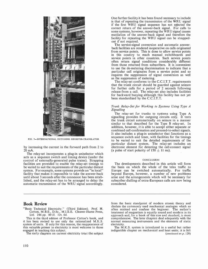
FIG. 7-INTERNATIONAL OUTGOING REGISTER-TRANSLATOR
by increasing the current in the forward path from 2 to 20mA.
The relay-set incorporates a plug-in uniselector which acts as a sequence switch and timing device (under the control of externally-generated pulse trains). Strapping facilities are provided to enable the relay-set timings to be varied to suit the requirements of the particular distant system. For example, some systems provide an "in local" facility that makes it impossible to take the answer-back until about 3 seconds after the connexion has been established, and the relay-set has to be arranged to delay the automatic transmission of the WRU signal accordingly.
Book Review "Basic Technical Electricity." (Third Edition). Prof. H.
Cotton, M.B.E., D.Sc., M.I.E.E. Cleaver-Hume Press, Ltd. 246 pp. 80 ill. 12s. 6d.
This is the third edition of Professor Cotton's book, and it has been revised to use only the rationalized M.K.S. system of units. If only for this reason, the reappearance of this valuable primer in electricity is most welcome to those engaged in teaching this subject.
The early chapters on current electricity treat the subject
110
One further facility it has been found necessary to include is that of repeating the transmission of the WRU signal if the first WRU signal sequence has not effected the correct return of the answer-back signal. For calls to some systems, however, repeating the WRU signal causes mutilation of the answer-back signal and therefore the facility for repeating the WRU signal can be strappedout if not required.
The service-signal conversion and automatic answerback facilities are rendered inoperative on calls originated from service points. This is done to allow service points in this country to reach manual switchboards and service points in other countries. Such service points often return signal conditions considerably different from those returned from subscribers. It is convenient to use the de-metering discrimination to indicate that a particular call originates from a service point and so requires the suppression of signal conversion as well as the suppression of metering.
The relay-set conforms to the C.C.l.T.T. requirements that the trunk circuit should be guarded against seizure for further calls for a period of 2 seconds following release from a call. The relay-set also includes facilities for backward busying although this facility has not yet been standardized by the C.C.l.T.T.
Trunk Relay-Set for Working to Systems Using Type A Signalling
The relay-set for trunks to systems using Type A signalling provides for outgoing circuits only. It tests the trunk circuit automatically on seizure in a manner similar to that described for the Type B relay-set. In addition, however, it is able to accept either separate or combined call-confirmation and proceed-to-select signals. It also includes a plug-in uniselector that functions as a sequence switch and timer, with facilities for the timings to be varied to suit the detailed requirements of the particular distant system. The relay-set includes an electronic element for detecting the call-connect signal (a pulse of start polarity of 150 ± 11 ms).
CONCLUSION
The developments described in this article will form the basis on which the whole of the telex traffic to Europe can be switched automatically. For traffic beyond Europe, however, a number of new problems arise and the arrangements which will be necessary for subscriber dialling of extra-European calls are now being considered.
from the basic standpoint of modern atomic theory and disdain the commonly used mechanical analogies which so often mislead and confuse the beginner. The author's treatment of magnetism is equally sound and modern in its approach and, for a book of this size and standard, is most comprehensive. The later chapters deal adequately with the normal measuring instruments and the elements of static electricity.
The M.K.S. system is introduced in a useful but rather indigestible chapter on mechanical and heat units; it is felt
(co111i1111ed 011 p. 129)
The Engineer-in-Chief's Library Information Service D. C. GRIFFITHS, B.sc.t
U.D.C. 025.5
The classification system used in the E.-in-C. 's Library, possible alternative systems and the method of storing and retrieYing informatiori are described. Some notes on the Library Circular
and the handling of inquiries are also included.
A LIBRARY is a natural store of information.
This information is stored not only in books but also in periodicals, reports, specifications, pamph
lets and reprints. In fact, in a special technical library such as the Engineer-in-Chief's Library, periodicals, reports, reprints and the like are often more fruitful than books as sources of information because they are more up-to-date. The dual function of a library therefore is to store information and to retrieve it readily when required. With the ever-increasing output of scientific and technical information, the problem of retrieving it has become very exacting, necessitating an efficient classification system. In theory, if all the information entering a library \.\lere classified by a perfectly efficient system it would be quite an easy matter to find it when required. In practice, however, this does not hold true; no perfect system has yet been devised, and it is not practicable to classify all information entering a library. Books, for instance, may contain information on subjects outside the broad classification used for shelving purposes.
The Engineer-in-Chief's Library uses the Universal Decimal Classification (U.D.C.) system, which has the disadvantage that it is never completely up-to-date because additions and modifications necessitated by new discoveries and new techniques must be agreed at international level. Nevertheless, it is claimed by many to be the best available for use in the field of electrical engineering and it is certainly n1ore widely used than any other single classification system, especially in Western Europe; Electrical Engineering Abstracts, Physics Abstracts and Electronic Technology Abstracts, and many other scientific and technical periodicals use the system for classifying their contents. This is most convenient because the abstract journals mentioned above are the basis of the Engineer-in-Chief's Library card-abstract index that provides the master reference for finding required information.
Each issue of each of the abstract journals is scrutinized when received in the Library, and a selection inade of those which have, or might have in the future, a bearing on the work of the Post Office Engineering Department. The selected abstracts are then cut from single-sided issues of the journals concerned, pasted on cards and filed in U.D.C. order. In this way a card-abstract index containing so111e 70,000 references to scientific and technical literature of especial interest to the work of the Post Office Engineering Department has been built up during the past 26 years. A separate cardabstract index containing references to some 9,000 reports is also maintained.
On the subject of efficient classification and information retrieval, consideration has been given to the possibility of introducing ne'v systems into the Engineer-in-Chief's Library. One such syste111 uses the "Rapid Selector"1• 2,
t Post Office Research Station.
an electronic selecting machine devised in 1940 by Dr. Vannevar Bush at the Massachusetts Institute of Technology. In this device abstracts on microfilm are printed alongside a pattern of dots arranged by key words in code form according to the information on each abstract. The pattern is rapidly scanned electronically and is compared by the machine with a pattern corresponding to the information desired. Each time the two patterns coincide the appropriate abstract is rephotographed on to a stationary film, the speed of operation being about 2,000 frames/second. A similar keyword machine was described in 1956 by J. Samain. 3
Manufacturers of electronic computers in the U.S.A. have become interested in the problem of information retrieval, but it is not clear when an economical system will become available for use by small or medium-sized libraries. The multiple key-word system has the advantage over a tree system, such as the U.D.C., that new words can be introduced immediately and a complex cross-reference system is automatically provided. In a tree classification such as the U.D.C. system every article does not fit clearly into one and only one place, and multiple entries are often necessary. The ultimate long· term aim might be a machine which would read and code or classify automatically. Another possible system might be a combination of a system like the U.D.C. for broad classification and a key-word system for detailed classification within each broad class.
The field of interest of the Post Office Engineering Department is extremely \.vide, and it is not surprising to find that a large variety of inquiries are received in the Library. Most of them originate from the research and development staff of the Department. Simple mquiries arc dealt with by the Library clerical staff, while requests for information of a scientific or technical nature and more difficult inquiries are handled by the Librarian or the Assistant Librarian. Some of the inquiries received cannot always be answered by referring to the card-abstract index, either because no published literature on the subject exists or because the subject is one which is not covered by the index. Such inquiries very often involve a considerable amount of searching, but attempts arc always made to obtain the required infurmaliun from ulher sources, such as reference books, other libraries, information centres, or manufacturers. Occasionally it is necessary to consult administrations and business concerns overseas for information.
Not all the inquiries originate within the Post Office Engineering Department: a large nun1ber are received from other libraries, other Government Departments, industrial firms and even the general public. A few arc most unusual. Some years ago, for exan1ple, a letter was received from a 14-year-old schoolboy who had been instructed by his science master to obtain information on the history of the telephone and to obtain, in particular, a photograph of Alexander Graham Bell. Another inquirer wanted to know the time of high-tide at Littlehampton a few days later. More recently a letter was received from a patient in a neighbouring hospital requesting a list of names and addresses of solicitors in the district.
111
Besides supplying information on demand, the Library also arranges the regular dissemination of information in the form of a fortnightly Library Circular which has a restricted circulation v-i'ithin the Post Office and certain selected Government Departments. It contains a list of accessions to the Library (books, reports, specifications, translations, etc.), a list of titles of selected articles from current periodicals received in the Library, and a list of selected abstracts (from abstract journals) of articles published in journals not received in the Library. No attempt is made to classify the titles or abstracts; they are listed in exactly the same order as they appear in the periodical from which they are taken.
Formerly, the Circular was published monthly and contained abstracts classified in subject order by U.D.C. These abstracts were prepared by the scientific and technical experts among the research and development staff of the Post Office Research Station, and, while the practice had the advantage that new developments in a subject were immediately brought to the notice of the specialist most concerned with them, it also caused considerable delay in the dissemination of information which might be important to other readers. It was usual for so much delay to occur during the preparation of the abstracts, the provision of classification numbers, and the general editing and production that on the average some four or five months elapsed between the publication of an article and its appearance in abstract form in the Circular. For a library circular to be really useful it should impart its information to its readers as soon as possible, and for this reason the
Book Review
"Introduction to Congestion Theory in Telephone Systems." R. Syski, D.l.C., Dip!. Ing., B.Sc., Graduate I.E.E., F.S.S. Published for Automatic Telephone and Electric Company, Ltd., by Oliver & Boyd. xvi + 742 pp. 93 ill. I05s.
This is a long book which, after a general introduction to the subject, continues with a description of the Strowger stcp-bystep and crossbar systems, together with descriptions of the apparatus used in each. Then follows an outline of probability theory based on sample space and measure theory, and including a description of stochastic processes; the matter in this chapter is advanced.
A chapter allocated to traffic characteristics describes several input processes and the statistical properties of traffic. The next chapter deals with the lost-call system, including the evaluation of traffic loss when traffic from a finite number of sources is offered to a full-availability group of trunks, on the assumption that calls arriving when all trunks are engaged are lost; the Erlang lost-call formula and the Engset formula are included.
In the next chapter waiting systems arc described together with single-channel queuing systems having various input distributions and call holding times; also included are systems having several channels whose waiting-time distribution was investigated by Erlang and Vaulot. The recent method of Kendall of "embedded" Markov chains is fully described. Then follows a chapter relating to limited availability, and describing the O'Dell method of estimating the traffic capacity of gradings based on the Erlang interconnected scheme.
112
Circular was changed to its present form about eight yearn ago. The readers generally much prefer the Circular in this form. It is concise; it can be scanned much more quickly; and in normal circumstances the delay in publishing important information is not more than three weeks.
It is interesting to note that the number of entries in the Library Circular has increased nearly four times in the last ten years and now amounts to about 7 ,OOO each year. This is an indication of the rapid increase during this period in the quantity of literature that has any bearing on the work of the Engineering Department.
The Engineer-in-Chief's Library also serves a large staff not located at Dallis Hill, and although they are served by Branch libraries of various sizes under the control of the main library, and by the local circulation of journals, they rely on the central library at Dallis Hill for many of their requirements, and the Library Circular is particularly necessary to them. Even the staff located close to the central library require the Circular, because it is not practicable nowadays for them to scan every issue of every journal of possible interest, or to examine all the other types of accessions.
References
1 SHAW, R. R. The Rapid Selector. Journal o; uocu111e111atto11, Vol. 5, p. 164, Dec. 1949.
z Photoelectric Librarian. Electro11ics, Vol. 22, No. 9, p. 122, Sept. 1949.
3 SAMAIN, J. A New Technique for the Classification and Selection of Documents. Onde Electrique, Vol. 36, p. 671, July 1956.
Link systems are the subject of the next chapter, which describes the Jacobeus method of calculating the lost traffic and also other methods based on equations of state; in this
·�chapter several recent investigations on common-control arrangements are described. A further chapter deals with a variety of problems appertaining to loss-call and waiting-call systems not included in the earlier chapters; among these may be mentioned the case of delayed calls served in random order, which was investigated by Palm, and waiting systems with the possibility of call release.
The last chapter deals with miscellaneous problems, among which may be mentioned: communication theory, the economic provision of plant, and Moe's principle described in the book by Jensen. Finally, there is a mathematical appendix, an index of authors, and a subject index.
The book gives an extensive survey of the theoretical aspects of telephone traffic and trunking, the treatment being generally mathematical. A large number of recent works on the subject are included, the treatment of each following that of the original work. It also includes many papers given at recent conferences on the application of the theory of probability to telephone engineering. The author has, in fact, collected together most of the recent work on this subject, much of which would not otherwise be readily accessible. The book must be considered fundamentally as a reference book-indeed, a very thorough one; it represents a considerable effort and can be recommended as a useful addition to published works on probability and its application to telephone systems.
A. T. H.
Time-Division-Multiplex Telegraphy on the Transatlantic Telephone Cable
H. E. EVANS and A. C. CROISDALE, M.B.E., B.Sc.(Eng.), A.M.I.EE."[
U.D.C. 621.394.441 :621.395.5:621.315.28
The use of synchronous time-division working, made possible by the excellent performance of the frequency-modulation voicefrequency telegraph channels and the low noise level of the transmission path, offers a method of doubling the traffic-carrying capacity of telegraph channels on the transatlantic telephone cable. The multiplex channels made available by time-division working facilitate the provision of part-rate circuits for renter-to-renter
services.
INTRODUCTION
THE telegraph circuits on the transatlantic telephone cable are provided by means of 120 c/s spaced frequency-modulation voice-frequency channels.1
The performance of these channels is such that they may be operated at speeds of about 80 bauds with less than 12 per cent distortion. 2 The good signal-to-noise ratio of the transmission path is a vital factor in obtaining this performance.
To exploit the capabilities of the voice-frequency (v.f.) telegraph channels and to make the best use of the bandwidth available for telegraph purposes, 2-channel timedivision-multiplex working has been adopted, and this virtually doubles the traffic-carrying capacity of the v.f. channels compared with their capacity when used for normal 50-baud start-stop working.
The use of time-division-multiplex telegraphy also facilitates the provision of quarter-rate or half-rate channels (i.e. channels able to transmit only 100 or 200 characters/minute compared with the normal 400 characters/minute). This is a fundamental requirement for intercontinental working, because many renters cannot justify a full-rate channel and are attracted by the saving in rental of a part-rate channel that nevertheless gives an exclusive circuit and hence rapid message transmission, particularly for short coded messages. It does mean, however, that secrecy between derived channels must be very strictly maintained, and suitable precautions are an essential part of the circuit design of a timedivision system.
TIME-DIVISION WORKING
Time-division telegraph working is a method by means of which each of a number of telegraph circuits is given, in succession, exclusive use of a common transmission path. The mode of signalling employed on each of the circuits must have some fundamental characteristic in common with that used on the other circuits concerned, e.g. the lengths of the signal elements or of the characters must be similar. The method used for sharing the aggregate time may be either "element interleaving" or "character interleaving" or a mixture of both.
Use o/6-Unit Code With the 5-unit code normally used for teleprinter
working in this country, each character consists of a "start" signal followed by five intelligence signals each of
t Mr. Evans was formerly with the External Telecommunications Executive and Mr. Croisdale is in the Telegraph Branch, E.-in-C. 's Office.
the same duration as the start signal (each signal unit being termed an element) and a "stop" signal of opposite polarity to the start signal and of a length equal to oneand-a-half elements. This method of signalling is known as start-stop working and permits satisfactory performance even though a small discrepancy in speed may exist between the transmitting and the receiving apparatus. If, however, the actions of the transmitter and receiver can be accurately and continuously synchronized, the start and stop signals may be dispensed with and the actual number of elements/character may thus be reduced from seven and a half to five. These start and stop signals must be re-inserted by the receiving apparatus of such a synchronous telegraph transmission system so that the 5-unit characters transmitted may be passed on automatically to a start-stop net\vork using the normal code.
The re-insertion of the start and stop signals presents no problem as far as characters are concerned, but, if supervisory signals involving continuous stop or continuous start polarities are being received, they, too, will have both start and stop signals inserted at intervals corresponding to every five elements, thus converting such signals to ''letter shift" and "all space" signals respectively. Not only would this preclude the use of these signals for their normal functions, for instance, for calling or clearing in telex working, but the conversion of continuous stop polarity into a letter-shift signal would cause the receiving teleprinter to change from figures to letters if there were any pause during the trans1nission of groups of figures or other upper-case characters. This would be unacceptable, and it is thus essential to restore to continuous-stop-polarity and continuous-start-polarity signals their normal supervisory functions.
Whilst the supervisory requirements may be met by using a particular 5-unit signal composed of all startpolarity elements to indicate that the following signal elements are supervisory and do not form parts o f characters, i t is probably more convenient to convert the 5-unit code into a 6-unit one. This is arranged by inserting an extra element at the beginning of each character, using a start-polarity signal to indicate that the following five elements represent one of the 32 characters of the 5-unit code and a stop-polarity signal before any supervisory signal which may be desired. This produces the following code (the start-polarity signal being represented by A and the stop-polarity signal by Z):
Character Letter A Letter B
5-Unit Code ZZAAA ZAAZZ
Supervisory Signal Continuous start polarity
6-Unit Code AZZAAA AZAAZZ
ZAAAAA
The number of elements required for each character i s thus reduced from the seven and a half usual i n start-stop working to six for synchronous \vorking.
Normal inland 50-baud working has a potential transmission rate of 400 characters/minute. This is, however,
113
dependent upon the 1notor speeds of the trans1nitters, and a latitude of! per cent is normally allowed. The International Telegraph and Telephone Consultative Committee (C.C.J.T.T.) has made a recommendation,* partly based on error-correcting practice for radio telegraph circuits, that a character length of 145jf ms should be used on synchronous time-division systems. This gives a rate of 411 t characters/minute, which enables the time� division system to accept signals from a 50-baud (7}-unit) automatic transmitter running almost 3 per cent faster than the nominal 400 characters/minute, and this standard has been adopted. If two 50-baud (7j-unit) circuits are operated in multiplex using a 6-unit code at a speed of 41 q characters/minute, the aggregate telegraph speed will be 41 !if x 2 x 6 elements/minute = 82,f bauds.
REQUIREMENTS FOR A TIME-DIVISION MULTIPLEX SYSTEM
A time-division multiplex system should be capable of meeting the following requirements:
(a) It should provide two 400 characters/minute derived channels on a v.f. channel capable of transmitting signals at approximately 80 bauds.
(b) It should transmit all the 32 characters of the International Alphabet No. 2t as well as the calling and clearing signals required for manual telex working.
(c) It should provide quarter-rate, half-rate or full-rate circuits for renter-to-renter services or point-to-point public services.
(d) Complete secrecy must be provided between all the multiplex channels under all conditions.
DESCRIPTION OF TAT MULTIPLEX SYSTEM
The TAT Multiplex System has been designed to meet the above requirements and to work at an aggregate speed of 82t bauds. It is an electromechanical system using distributors, cam-operated contacts, relays and a robust and reliable synchronizing unit of a type used by Cable & Wireless, Ltd., for many years. 3 It was decided at the outset not to try to introduce any electronic components in the design, though there are sections of the equipment which might, with advantage, be replaced by electronic counterparts.
* C.C.I.T.T. Reco1nmendation C 23, Docu1nent of the Eighth Plenary Session, Geneva, 1956.
t C.C.I.T.T. Recommendation C 24, Docun1ent of the Eighth Plenary Session, Geneva, 1956.
A phonic (or synchronous) motor is used as the basic drive for the equipment and this motor is driven by the output from a crystal-controlled oscillator, frequencydivided and applied to the motor at 30 c/s. The speed of the phonic-1notor drive of the transmitting or "n1aster" equipment is thus directly governed by the crystalcontrolled oscillator. The torque of the phonic motor is limited and it was therefore decided that the maximum load of each should be restricted to four channel-units. The receiving equipment, termed the "slave," also uses a crystal-controlled oscillator for basic speed control but, in addition, applies small timing corrections, derived from the transitions of the aggregate signals, to synchronize itself exactly with the transmitter and to retain the correct phase relationship. With the high stability of the crystal-controlled oscillators (one part in 10'/year) the frequency difference is small, and over a period of l 0-15 minutes the receiver should remain in phase with the transmitter even if a line interruption occurs, although this should be rare on the transatlantic telephone cable.
Fig. 1 is a simplified block schematic diagram of the TAT Multiplex system (one direction only).
The various alternative facilities provided by the equipment are shown in Table l . If two full-rate circuits
TABLE l Facilities Provided by TAT Multiplex Systen1
Arrangement of
System I Nun1ber of I Number and Rate of
V.F. Channels Circuits Provided Required ------ 1 2 I 4 Full Rate
2 I I 4 Half Rate
-3--1 I { 1 Full Rate
2 Half Rale
4 I I
I I {I Full Rate 1 Half Rate
2 Quarter Rate
are required, only element-interleaving is used, but if half-rate or quarter-rate circuits are provided these reduced-rate circuits are character-interleaved first and the resultant sub-aggregate is then element-interleaved, as shown in Table 2. In this table the four derived circuits
INPUT TRANSMITTER
START-STOPr- . CHANN ELUNiTA
. -------i SIGNALS • ,
(so BAUDS) �+---<
INPUT A
I TAT I CABLE
I
'ELEMENT INTERLEAVED! •SYNCHRONOUS SIGNALS
SYNCHRONIZING UNIT
R E C E IVER OUTPUT
114
i DISTRIBUTOR l5l STORE 2Dd STORE I C HANNEL UNIT B ·---·---·
>Oo/• 1· [)RIVE
CRYSTAL- i CO NTROLLED·, O S CILLATOR
& FREQUENCY DIVIDER
(02217 BAUDS) ' -------- --I I CRYSTAL• CONTROLLED I O S C ILLATOR
& FREQUENCY
DIVIDER
Only one direction of transmission is shown
j DISTR18UTOR ·
���!�
FIG. I-SIMPLIFIED BLOCK SCHEMATIC DIAGRAM OF TAT MULTIPLEX SYSTEM
are designated A, B, C and D, and the signal elements of the characters appropriate to each circuit are shown thus: A1, A2, A3, A41 A5, A6; B1 . . • B6; C1 • . • C6; D1 • • • D6•
To ensure that, no matter what the various multiplex channels may be transmitting, there are always ample transitions of the aggregate signals to enable synchronism to be inaintained, the signals of channels B and D are inverted and this, together with a pattern of inversion of the second element of the 6-unit code, as shown in Table 3, prevents intelligible printing on any of the channels if the receiver should become out of phase due to a fault.
TABLE 3 Inversion of Elen1ents and Channel Outputs
Arrangement Signal Store Derived Output-2nd Channel
of Circuit Rate Element of Output
Syste1n 6-unit Code - '
A Full Inverted Norn1al 1 B Full Inverted Inverted
c Full Inverted Normal D Full Inverted ' Inverted I
---
A Half Inverted Normal 2 B Half Inverted Inverted
c Half Norn1al Normal D Half Normal Inverted
I A Full Inverted
I Normal
3 B Half Inverted Inverted D Half Nonnal Inverted
- -A Full Inverted Norn1al
4 B Half lnverled Inverted c Quarter Normal Normal D Quarter Norn1al Inverted
Tra11sn1itang Unit The transmitter is housed on two chassis. The upper
one accommodates a phonic motor and four channel units, on which are mounted the necessary cam contacts and distributors for setting up characters in the stores and for assembling the aggregate signals from the inforn1ation contained in the stores. The second chassis
TABLE 2 Method of Interleaving Channel Signals
Arrangement
accommodates relay units, capacitors, fuses, guard lan1ps, resistors and the system-arrangernent switch. By means of this switch any one of the four systern arrangements shown in Table I can be selected. The channel units and channel relay units are arranged mechanically so that they can be removed and replaced, without interfering with the other channels, whilst the equipment is in service.
Storage and Re-tra11s1nission of Signals The teleprinter signals from the circuits connected to
the multiplex system will arrive at random, being originated either automatically at 400 characters/minute (or at 200 or 100 characters/minute if the circuit is partrate) or manually. The difficulty of dealing with characters having random arrival times in relation to the characters with which they are to be interleaved has been overcome in previous systems by using a buffer signalstore such as perforated tape, or by controlling the release of the renter's automatic transn1itter by pulses generated by the multiplex apparatus. Both these methods have severe limitations, and the TAT Multiplex System uses an electrical 2-character store and has a character "clearance1' rate higher than the renter's sending rate.
The start signal of each incoming character releases a rotary distributor in the channel unit (Fig. 2). The distributor arm completes a half reV<Jlution and is then arrested by the stop signal. The contacts of this distributor are double and are bridged by a brush on the distributor arm. Each 180° sector of the distributor face, apart from carrying llve pairs of contacts for selecting and storing the five elements of the incoming character, also carries an extra pair of contacts midway between the position of rest of the distributor arm and the contacts of the first elemeut. The purpose of this additional pair of contacts is to control the release of the signal elernents from the store, as follows.
The first element of the 5-unit signal is stored on a relay, to facilitate the polarity reversal mentioned earlier, as this elen1ent becomes the second of the 6-unit code, and the remaining four elen1ents are stored on capacitors. If theie is no character in store when the continuouslyrevolving cams of the 1nultiplex channel unit are in
position to "read off" (this must happen frequently as the multiplex system is running at 411 t characters/1ninute compared
Number of I of Systcn1 (Facilities as V.F. Channels
I used
Derived Circuits
Sequence of Transtnission of Elements and Characters
\Vith the renter's non1inal transmitting speed of 400 characters/ ininute), it is necessary to trans-
in Table I)
�} 2
6} A 1
2
gs 3 �} 4
i}
Ai A2 Aa A� A� As, A1 .. B1 B2 B3 B4 Ba Bs, B1 .....
mit a signal which will be interpreted by the receiver as a continuous stop-polarity signal. This will consist of one element of stop polarity (indicating a supervisory signal), one clement of start polarity (the first of the 5-unit elements of stop polarity, reversed) followed by four elements of stop polarity thus, ZAZZZZ (Z indicating stop polarity and A start polarity).
Whm the distributor is released by an inco1ning start signal, it first bridges the extra contacts referred to above and, by operating relays, arranges for
115
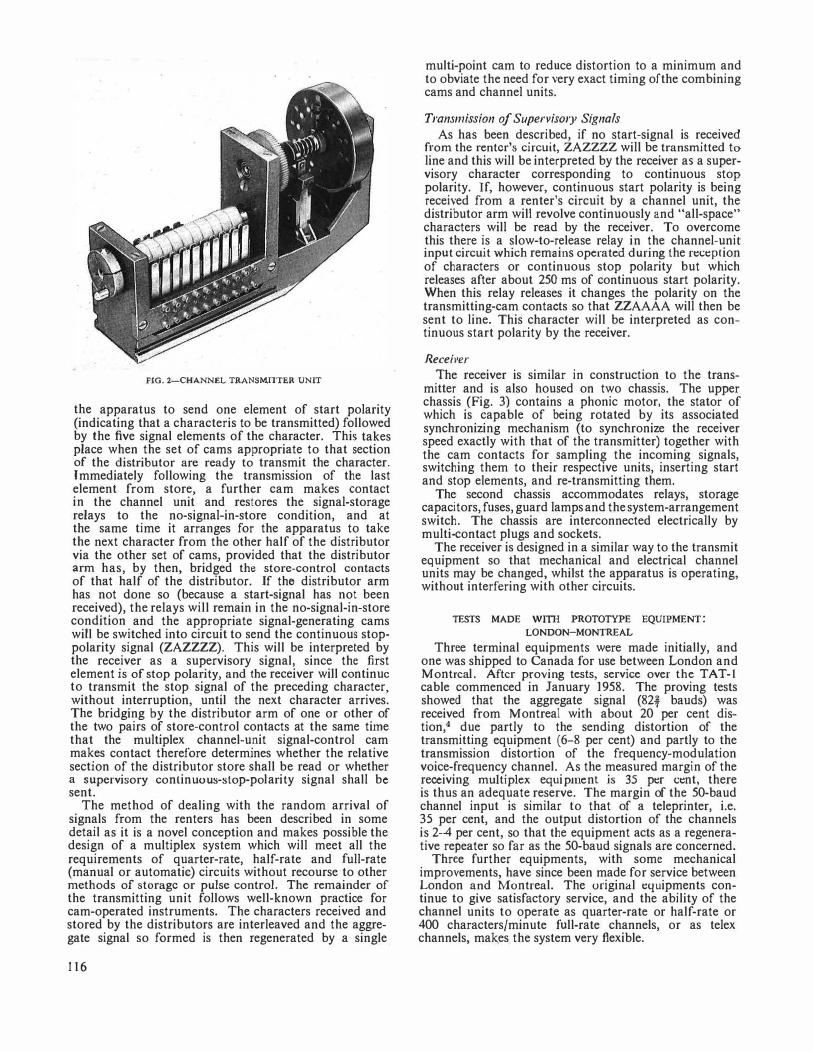
FIG. 2-CHANNEL TRANSM!1TER UNIT
the apparatus to send one element of start polarity (indicating that a characteris to be transmitted) followed by the five signal elements of the character. This takes place when the set of cams appropriate to that section of the distributor are ready to transmit the character. Immediately following the transmission of the last element from store, a further cam makes contact in the channel unit and restores the signal-storage relays to the no-signal-in-store condition, and at the same time it arranges for the apparatus to take the next character from the other half of the distributor via the other set of cams, provided that the distributor arm has, by then, bridged the store-control contacts of that half of the distributor. If the distributor arm has not done so (because a start-signal has not been received), the relays will remain in the no-signal-in-store condition and the appropriate signal-generating cams will be switched into circuit to send the continuous stoppolarity signal (ZAZZZZ). This will be interpreted by the receiver as a supervisory signal, since the first element is of stop polarity, and the receiver will continue to transmit the stop signal of the preceding character, without interruption, until the next character arrives. The bridging by the distributor arm of one or other of the two pairs of store-control contacts at the same time that the multiplex channel-unit signal-control cam makes contact therefore determines whether the relative section of the distributor store shall be read or whether a supervisory continuous-stop-polarity signal shall be sent.
The method of dealing with the random arrival of signals from the renters has been described in some detail as it is a novel conception and makes possible the design of a multiplex system which will meet all the requirements of quarter-rate, half-rate and full-rate (manual or automatic) circuits without recourse to other methods of storage or pulse control. The remainder of the transmitting unit follows well-known practice for cam-operated instruments. The characters received and stored by the distributors are interleaved and the aggregate signal so formed is then regenerated by a single
116
multi-point cam to reduce distortion to a minimum and to obviate the need for very exact timing of the combining cams and channel units.
Transmission of Supervisory Signals
As has been described, if no start-signal is received from the renter's circuit, ZAZZZZ will be transmitted to line and this will be interpreted by the receiver as a supervisory character corresponding to continuous stop polarity. If, however, continuous start polarity is being received from a renter's circuit by a channel unit, the distributor arm will revolve continuously and "all-space" characters will be read by the receiver. To overcome this there is a slow-to-release relay in the channel-unit input circuit which remains operated during the reception of characters or continuous stop polarity but which releases after about 250 ms of continuous start polarity. When this relay releases it changes the polarity on the transmitting-cam contacts so that ZZAAAA will then be sent to line. This character will be interpreted as continuous start polarity by the receiver.
Receiver
The receiver is similar in construction to the transmitter and is also housed on two chassis. The upper chassis (Fig. 3) contains a phonic motor, the stator of which is capable of being rotated by its associated synchronizing mechanism (to synchronize the receiver speed exactly with that of the transmitter) together with the cam contacts for sampling the incoming signals, switching them to their respective units, inserting start and stop elements, and re-transmitting them.
The second chassis accommodates relays, storage capacitors, fuses, guard lamps and the system-arrangement switch. The chassis are interconnected electrically by multi-contact plugs and sockets.
The receiver is designed in a similar way to the transmit equipment so that mechanical and electrical channel units may be changed, whilst the apparatus is operating, without interfering with other circuits.
TESTS MADE Willi PROTOTYPE EQUIPMENT: LONDON-MONTREAL
Three terminal equipments were made initially, and one was shipped to Canada for use between London and Montreal. After proving tests, service over the TAT-1 cable commenced in January 1958. The proving tests showed that the aggregate signal (82-f bauds) was received from Montreal with about 20 per cent distion,4 due partly to the sending distortion of the transmitting equipment (6-8 per cent) and partly to the transmission distortion of the frequency-modulation voice-frequency channel. As the measured margin of the receiving multiplex equipment is 35 per cent, there is thus an adequate reserve. The margin of the 50-baud channel input is similar to that of a teleprinter, i.e. 35 per cent, and the output distortion of the channels is 2-4 per cent, so that the equipment acts as a regenerative repeater so far as the 50-baud signals are concerned.
Three further equipments, with some mechanical improvements, have since been made for service between London and Montreal. The original equipments continue to give satisfactory service, and the ability of the channel units to operate as quarter-rate or half-rate or 400 characters/minute full-rate channels, or as telex channels, makes the system very flexible.
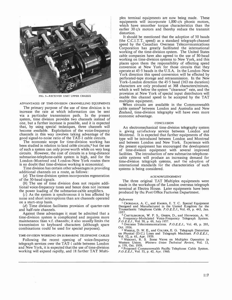
FIG. 3-RECEIVER UNIT UPPER CHASSIS
ADVANTAGES OF TIME-DIVISION CHANNELLING EQUIPMENTS
The primary purpose of the use of time division is to increase the rate at which information can be sent via a particular transmission path. In the present system, time division provides two channels instead of one, but a further increase is possible, and it is expected that, by using special techniques, three channels will become available. Exploitation of the voice-frequency channels in this way involves taking advantage of the good signal-to-noise ratio of the TAT-1 cable circuits.
The economic scope for time-division working has been studied in relation to land cable circuits,5 but the use of such a system can only prove worth while on very long circuits. However, the cost of circuits in a long-distance submarine-telephone-cable system is high, and for the London-Montreal and London-New York routes there is no doubt that time-division working is economical.
Time division has certain other advantages in providing additional channels on a route, as follows:
(a) The time-division system incorporates regeneration of the 50-baud signals.
(b) The use of time division does not requi�e additional voice-frequency tones and hence does not mcrease the power loading of the submarine-cable amplifiers.
(c) As the system is synchronous it is less affected by noise and short interruptions than are channels operated on a start-stop basis.
(d) Time division facilitates provision of quarter-rate and half-rate channels.
Against these advantages it must be admitted that a time-division system is complicated and requires more maintenance than v.f. channels; it also usually limits the transmission to keyboard characters (although spare combinations could be used for special purposes).
TIME-DIVISION WORKING ON SUBMARINE TELEPHONE CABLES
Following the recent opening of voice-frequency telegraph services over the TAT-I cable between London and New York, it is expected that the use of time-divisio!1 working will expand rapidly, and 18 further TAT Multi-
plex terminal equipments are now being made. These equipments will incorporate 1,000 c/s phonic motors, which have smoother torque characteristics than the earlier 30 c/s motors and thereby reduce the transmit distortion.
It should be mentioned that the adoption of 50 bauds (the C.C.I.T.T. speed) as a standard telegraph-channel speed by the Canadian Overseas Telecommunications Corporation has greatly facilitated the international working of the time-division system. The United States cable companies have also agreed to the use of 50-baud working on time-division systems to New York, and this places upon them the responsibility of effecting speed conversion at New York for those circuits that they operate at 45·5 bauds in the U.S.A. In the London-New York direction this speed conversion will be effected by perforated-tape storage and retransmission. In the New York-London direction the 45·5 baud (163 ms duration) characters are only produced at 368 characters/minute, which is well below the system "clearance" rate, and the provision at New York of special input distributors will enable this channel speed to be accepted by the TAT multiplex equipment.
When circuits are available in the Commonwealth cable system6 between London and Australia and New Zealand, time-division telegraphy will have even more economic advantage.
CONCLUSION
An electromechanical time-division telegraphy system is giving satisfactory service between London and Montreal. It is expected that further equipments of this type will be introduced between London and Montreal and between London and New York. Experience with the present equipment has encouraged the development of time-division equipment with several improved facilities. The introduction of new submarine-telephonecable systems will produce an increasing demand for time-division telegraph systems, and the adoption of international standards for the characteristics of such systems is being considered.
ACKNOWLEDGEMENT
The three original TAT Multiplex equipments were made in the workshops of the London overseas telegraph terminal at Electra House. Later equipments have been produced by the Post Office Factories Department.
References
1 Cao1soALE, A. C., and HARRIS, E. T. C. Special Equipment Designed and Manufactured in the United Kingdom for the Transatlantic Telephone Cable. P.O.E.E.J., Vol. 49, p. 443, Jan. 1957.
2 CHITILEBURGH, w. F. s., GREEN, D., and HEYWOOD, A. W. A Frequency-Modulated Voice-Frequency Telegraph System. P.O.E.E.J., Vol. 50, p. 69, July 1957.
3 Overseas Telecommunications. P.O.E.E.J., Vol. 49, p. 205, Oct. 1956.
4 WHEELE, D. W. E., and COLLIER, E. G. Telegraph Distortion on Physical (D.C.) Lines and Telegraph Machines. P.O.E.E.J., Vol. 52, p. 61, Apr. 1959.
5 WISHART, R. S. Some Views on Multiplex Operation in Western Union. Western Union Tec/111ica/ Review, Vol. 13, p. 139, Oct. 1959.
• Proposed Commonwealth Pacific Telephone Cable System. P.O.E.E.J., Vol. 53, p. 42, Apr. 1960.
111
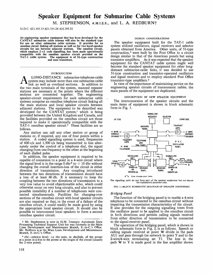
Speaker Equipment for Submarine Cable Systems M. STEPHENSON, A.M.I.E.E., and L. A. REDBURNt
U.D.C. 62 J.395.JJ :62 J.J t 5.28: 621.l95.52
An engineering speaker equipment that ha!ll heen developed for the CANTAT submarine cable scheme "ill also be the standard type for use on other submarine cable systems. It provides for an on1nibus circuit linking all stations as well as for two local speaker circuits for use between adjacent stations. The omnibus circuit, which employs 2 v.f. code signalling, has been made operationally con1patible with the omnibus speaker circuit provided on the TAT-I cable systen1. The equipn1ent is of 51-type construction
and uses transistors.
INTRODUCTION
A LONG-DISTANCE submarine-telephone-cable
system may include more than one submarine-cable link as well as overland sections. In addition to
the two main terminals of the system, manned repeater stations are necessary at the points where the different sections are connected together. The engineering speaker-circuit requirements for such subn1arine cable systems comprise an omnibus telephone circuit linking a11 the main stations and local speaker circuits between adjacent stations. The equipment to be described was developed for the CANT AT system,' which is being provided between the United Kingdom and Canada, and the facilities provided on the omnibus circuit are those required to make it operationally compatible with the TAT-I omnibus speaker circuit.2 These facilities are as follows.
Any station can call any other station or group of stations or, if required, any one of four points within a station. A coded signalling system is used, frequencies of 600 c/s and 1,500 c/s being transmitted to line alternately under the control of a telephone dial, the signal changing from one frequency to the other at the beginning of each dialled pulse.
In addition, the speaker equipment is required to be capable of connexion to a point in a 4-wire circuit where the signal level is in the range 0 dbr* to + 10 dbr without changing the overall insertion-loss of the circuit in either direction of transmission. Any coupling introduced between the two directions of transmission should have a loss of at least 60 db. It is necessary to keep the coupling between the two directions of transmission to a very low value to avoid objectionable echo, which could otherwise occur on very long circuits, and also to prevent possible instability if a number of telephones were connected simultaneously. Facilities for changing-over sections of the omnibus circuit \Vith local speaker circuits are also required so that, in the event of a failure of the omnibus circuit, it could readily be made good by using the appropriate local speaker circuit. It should also be possible to interconnect local speakers to form a second omnibus speaker circuit.
t Mr. Stephenson is now in H.M. Treasury Automatic Data Processing Technical Support Unit but was formerly in the Main Lines Development and Maintenance Branch, E.-in-C. 's Office. Mr. Redburn is in the Main Lines Development and Maintenance Branch, E.-in-C. 's Office.
* dbr-relative level; i.e. the ratio, in decibels, of the power at a point in a line to the power at the origin of the circuit (usually the 2-wire point).
118
DESIGN CONSIDERATIONS
The speaker equipment built for the TAT-I cable system utilized oscillators, signal receivers and selector panels obtained from America. Other units, of 51-type construction, 3 were built by the Post Office to a circuit design similar to that of the American panels but using transistor amplifiers. As it was expected that the speaker equipment for the CANTA T cable system might well become the standard speaker equipment for other longdistance submarine-cable links, it was decided to use 51-type construction and transistor-operated oscillators and signal receivers and to employ standard Post Office transistor-type amplifiers. 4
In view of the importance of maintaining service on the engineering speaker circuits of transoceanic cables, the main panels of the equipment are duplicated.
DESCRIPTION OF NEW SPEAKER EQUIPMENT
The interconnexion of the speaker circuits and the main items of equipn1ent is shown in block schematic form in Fig. l.
UP SIOE
SIGNALLING RECEIVER
db Line change-over links
SELECTOR 00\llN SIDE
The signalling units do not form part of the speaker equipment but are shown ror explanatory purposes only.
FIG. 1-BLOCK SCHEMATIC DIAGRAM OF SPEAKER EQUIPMENT
Bridging Panel The function of the bridging panel is to enable a 4-wire
telephone to be connected to the omnibus circuit without impairing the transmission characteristics of the circuit. It also provides for the outgoing signalling tones from the oscillator panel to be applied to the omnibus circuit in both directions and permits calling signals received from either direction of transmission to be connected to the signal-receiver panel.
The operation of the bridging panel, which is shown in block schematic form in Fig. 2, is as follows. Speech or calling signals received at point W divide in the pads AUi and pass through the network to point Y and to the 2-wire/4-wire terminating set TI. The loss in the path W to Y is made good in the line amplifier shown
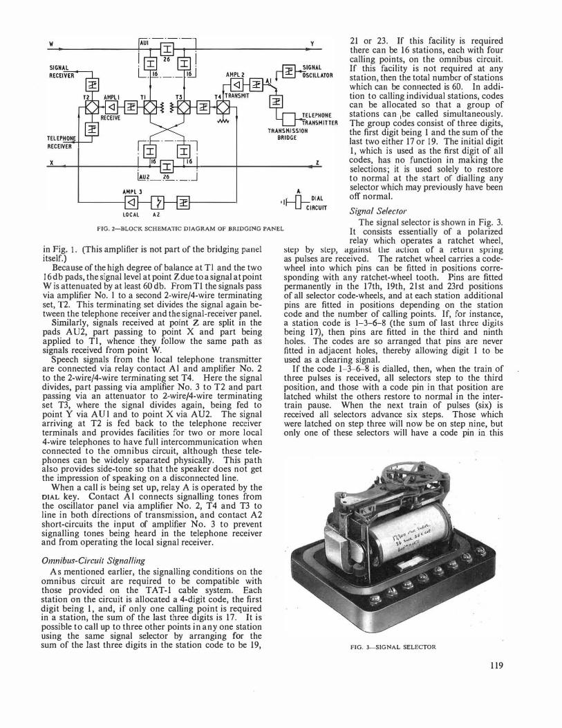
x
AHPL l
LOCAL A2
y
TELEPHONE TRANSMITTER
TRANSMISSION BRIDGE
z
A.
ILfl . DIAL
I 'Lft1RCUIT
21 or 23. If this facility is required there can be 16 stations, each with four calling points, on the omnibus circuit. If this facility is not required at any station, then the total number of stations which can be connected is 60. In addition to calling individual stations, codes can be allocated so that a group of stations can 1be called simultaneously. The group codes consist of three digits, the first digit being 1 and the sum of the last two either 17 or 19. The initial digit 1, which is used as the first digit of all codes, has no function in making the selections; it is used solely to restore to normal at the start of dialling any selector which may previously have been off normal.
Signal Selector
FIG. 2-BLOCK SCHEMATIC DIAGRAM OF BRIDGING PANEL The signal selector is shown in Fig. 3.
It consists essentially of a polarized
in Fig. 1. (This amplifier is not part of the bridging panel itself.)
Because of the high degree of balance at T l and the two 16 db pads, the signal level at point Zdue to a signal at point W is attenuated by at least 60 db. From T1 the signals pass via amplifier No. l to a second 2-wire/4-wire terminating set, T2. This terminating set divides the signal again between the telephone receiver and the signal-receiver panel.
Similarly, signals received at point Z are split in the pads A U2, part passing to point X and part being applied to T l , whence they follow the same path as signals received from point W.
Speech signals from the local telephone transmitter are connected via relay contact Al and amplifier No. 2 to the 2-wire/4-wire terminating set T4. Here the signal divides, part passing via amplifier No. 3 to T2 and part passing via an attenuator to 2-wire/4-wire terminating set T3, where the signal divides again, being fed to point Y via AUl and to point X via AU2. The signal arriving at T2 is fed back to the telephone receiver terminals and provides facilities for two or more local 4-wire telephones to have full intercommunication when connected to the omnibus circuit, although these telephones can be widely separated physically. This path also provides side-tone so that the speaker does not get the impression of speaking on a disconnected line.
When a call is being set up, relay A is operated by the DIAL key. Contact Al connects signalling tones from the oscillator panel via amplifier No. 2, T4 and T3 to line in both directions of transmission, and contact A2 short-circuits the input of amplifier No. 3 to prevent signalling tones being heard in the telephone receiver and from operating the local signal receiver.
Omnibus-Circuit Signalling
As mentioned earlier, the signalling conditions on the omnibus circuit are required to be compatible with those provided on the TAT-1 cable system. Each station on the circuit is allocated a 4-digit code, the first digit being 1, and, if only one calling point is required in a station, the sum of the last three digits is 17. It is possible to call up to three other points in any one station using the same signal selector by arranging for the sum of the last three digits in the station code to be 19,
relay which operates a ratchet wheel, slep by slt:p, againsl lhe action of a return spring as pulses are received. The ratchet wheel carries a codewheel into which pins can be fitted in positions corresponding with any ratchet-wheel tooth. Pins are fitted permanently in the 17th, 19th, 2 l st and 23rd positions of all selector code-wheels, and at each station additional pins are fitted in positions depending on the station code and the number of calling points. If, for instance, a station code is 1-3-6-8 (the sum of last three digits being 17), then pins are fitted in the third and ninth holes. The codes are so arranged that pins are never fitted in adjacent holes, thereby allowing digit 1 to be used as a clearing signal.
If the code 1-3-6-8 is dialled, then, when the train of three pulses is received, all selectors step to the third position, and those with a code pin in that position are latched whilst the others restore to normal in the intertrain pause. When the next train of pulses (six) is received all selectors advance six steps. Those which were latched on step three will now be on step nine, but only one of these selectors will have a code pin in this
FIG. 3-SIGNAL SELECTOR
119
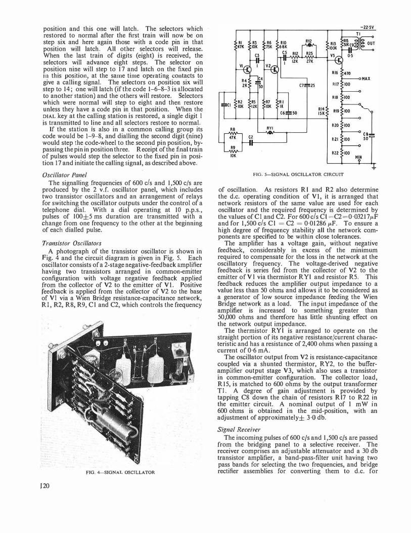
position and this one will latch. The selectors which restored to normal after the first train will now be on step six and here again those with a code pin in that position will latch. All other selectors will release. When the last train of digits (eight) is received, the selectors will advance eight steps. The selector on position nine will step to 17 and latch on the fixed pin in this position, at the same time operating contacts to give a calling signal. The selectors on position six will step to 14; one will latch (if the code 1-6-8-3 is allocated to another station) and the others will restore. Selectors which were normal will step to eight and then restore unless they have a code pin in that position. When the DIAL key at the calling station is restored, a single digit l is transmitted to line and all selectors restore to normal. , If the station is also in a common calling group its code would be 1-9-8, and dialling the second digit (nine) would step the code-wheel to the second pin position, bypassing the pin in position three. Receipt of the final train of pulses would step the selector to the fixed pin in position 17 and initiate the calling signal, as described above.
Oscillator Panel
The signalLing frequencies of 600 c/s and 1,500 c/s are produced by the 2 v.f. oscillator panel, which includes two transistor oscillators and an arrangement of relays for switching the oscillator outputs under the control of a telephone dial. With a dial operating at 10 p.p.s., pulses of 100±5 ms duration are transmitted with a change from one frequency to the other at the beginning of each dialled pulse.
Transistor Oscillators
A photograph of the transistor oscillator is shown in fig. 4 and the circuit diagram is given in Fig. 5. Each oscillator consists of a 2-stage negative-feedback amplifier having two transistors arranged in common-emitter configuration with voltage negative feedback applied from the collector of V2 to the emitter of VI. Positive feedback is applied from the collector of V2 to the base of V l via a Wien Bridge resistance-capacitance network, RI, R2, R8, R9, Cl and C2, which controls the frequency
fIG. 4-SIGNAL OSCILLATOR
J20
FIG. 5-SIGNAL OSCILLATOR CIRCUIT
of oscillation. As resistors Rl and R2 also determine the d.c. operating condition of VI, it is arranged that network resistors of the same value are used for each oscillator and the required frequency is determined by the values of Cl and C2. For 600 c/s Cl =C2=0·03217µF and for 1,500 c/s Cl = C2 = 0·01 2 8 6 µF. To ensure a high degree of frequency stability all the network components are specified to be within close tolerances.
The amplifier has a voltage gain, without negative feedback, considerably in excess of the minimum required to compensate for the loss in the network at the oscillatory frequency. The voltage-derived negative feedback is series fed from the collector of V2 to the emitter of Vl via thermistor R Y l and resistor RS. This feedback reduces the amplifier output impedance to a value less than 50 ohms and allows it to be considered as a generator of low source impedance feeding the Wien Bridge network as a load. The input impedance of the amplifier is increased to something greater than 50,000 ohms and therefore has little shunting effect on the network output impedance.
The thermistor RYl is arranged to operate on the straight portion of its negative resistance/current characteristic and has a resistance of 2,400 ohms when passing a current of 0·6 mA.
The oscillator output from V2 is resistance-capacitance coupled via a shunted thermistor, RY2, to the butferamplifier output stage V3, which also uses a transistor in common-emitter configuration. The collector load, R15, is matched to 600 ohms by the output transformer TI. A degree of gain adjustment is provided by tapping C8 down the chain of resistors Rl7 to R22 in the emitt�r circuit. A nominal output of l mW in 600 ohms is obtained in the mid-position, with an adjustment of approximately± 3 ·O db.
Signal Receiver
The incoming pulses of 600 c/s and 1,500 c/s are passed from the bridging panel to a selective receiver. The receiver comprises an adjustable attenuator and a 30 db transistor amplifier, a band-pass-filter unit having two pass bands for selecting the two frequencies, and bridge rectifier assemblies for converting them to d.c. for
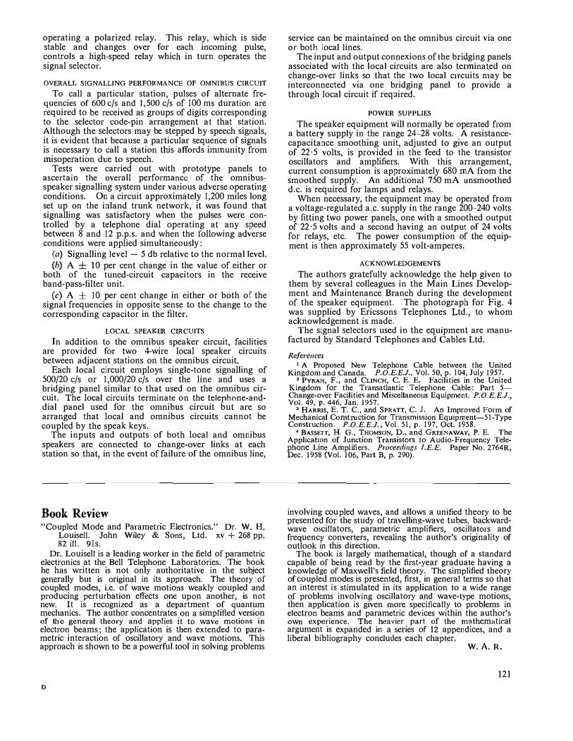
operating a polarized relay. This relay, which is side stable and changes over for each incoming pulse, controls a high-speed relay which in turn operates the signal selector.
OVERALL SIGNALLING PERFORMANCE OF OMNIBUS CIRCUIT
To call a particular station, pulses of alternate frequencies of 600 c/s and 1,500 c/s of 100 ms duration are required to be received as groups of digits corresponding to the selector code-pin arrangement at that station.
Although the selectors may be stepped by speech signals, it is evident that because a particular sequence of signals is necessary to call a station this affords iJrununity from 1nisoperation due to speech.
Tests were carried out with prototype panels to ascertain the overall performance of the omnibusspeaker signalling system under various adverse operating conditions. On a circuit approximately 1,200 miles long set up on the inland trunk network, it was found that signalling was satisfactory when the pulses were controlled by a telephone dial operating at any speed between 8 and 12 p.p.s. and when the following adverse conditions were applied simultaneously:
(a) Signalling level - 5 db relative to the normal level. (b) A ± 10 per cent change in the value of either or
both of the tuned-circuit capacitors in the receive band-pass-filter unit.
(c) A ± 10 per cent change in either or both of the signal frequencies in opposite sense to the change to the corresponding capacitor in the filter.
LOCAL SPEAKER CIRCUITS
In addition to the omnibus speaker circuit, facilities are provided for two 4-wire local speaker circuits between adjacent stations on the omnibus circuit.
Each local circuit employs single-tone signalling of 500/20 c/s or 1,000/20 c/s over the line and uses a bridging panel similar to that used on the omnibus circuit. The local circuits terminate on the telephone-anddial panel used for the omnibus circuit but are so arranged that local and omnibus circuits cannot be coupled by the speak keys.
The inputs and outputs of both local and omnibus speakers are connected to change-over links at each station so that, in the event of failure of the omnibus line,
Book Review "Coupled Mode and Pa1ametnc Electronics." Dr. W. H.
Louise!!. John Wiley & Sons, Ltd. xv + 268 pp. 82ill. 91s.
Dr. Louisell is a leading worker in the field of parametric electronics at the Bell Telephone Laboratories. The book he has written is not only authoritative in the subject generally but is original in its approach. The theory of coupled modes, i.e. of wave motions weakly coupled and producing perturbation effects one upon another, is not new. It is recognized as a department of quantum mechanics. The author concentrates on a simplified version of the general theory and applies it to wave motions in electron beams; the application is then extended to parametric interaction of oscillatory and wave motions. This approach is shown to be a powerful tool in solving problems
D
service can be maintained on the omnibus circuit via one or both local lines.
The input and output connexions of the bridging panels associated with the local circuits are also tenninated on change-over links so that the two local circuits n1ay be interconnected via one bridging panel to provide a through local circuit if required.
POWER SUPPLIES
The speaker equipment will normally be operated from a battery supply in the range 24-28 volts. A resistancecapacitance smoothing unit, adjusted to give an output of 22·5 volts, is provided in the feed to the transistor oscillators and a111plifiers. With this arrangement, current consumption is approximately 680 mA from the smoothed supply. An additional 750 mA unsmoothed d.c. is required for lamps and relays.
When necessary, the equipment may be operated from a voltage-regulated a.c. supply in the range 200-240 volts by fitting two power panels, one with a smoothed output of 22·5 volts and a second having an output of 24 volts for relays, etc. The power consumption of the equipment is then approximately 55 volt-amperes.
ACKNOWLEDGEMENTS
The authors gratefully acknowledge the help given to them by several colleagues in the Main Lines Development and Maintenance Branch during the development of the speaker equipment. The photograph for Fig. 4 was supplied by Ericssons Telephones Ltd., to whom acknowledgement is made.
The signal selectors used in the equipment are 1nanufactured by Standard Telephones and Cables Ltd.
References 1 A Proposed New Telephone Cable bet\veen the United
Kingdom and Canada. P.O.E.E.J., Vol . 50, p, 104, July 1957. 2 PYRAH, F., and CLINCH, C. E. E. Facilities in the United
Kingdom for the Transatlantic Telephone Cable: Part 5-Change-over Facilities and Miscellaneous Equipment. P.O.E.E.J., Vol. 49, p. 446, Jan. 1957.
a HARRIS, E.T. c., and SPRATT, c. J. An Improved Fonn of Mechanical Construction for Transmission Equipment-51-Type Construction. P.O.E.E.J., Vol. 51, p. 197, Oct. 1958.
4 BASSETT, H. G., THOMSON, D., and GREENAWAY, P. E. The Application of Junction Transistors to Audio-Frequency Telephone Line Amplifiers. Proceedings l.E.E. Paper No. 2764R, Dec. 1958 (Vol. 106, Part B, p. 290).
involving cou pled waves, and allows a unified theory to be presented for the study of travelling-wave tubes, backwardwave oscillators, parametric amplifiers, oscillators and frequency converters, revealing the author's originality of outlook in this direction.
The book is largely mathematical, though of a standard capable of being read by the first-year graduate having a knowledge of Maxwell's field theory. The simplified theory of coupled modes is presented, first, in general terms so that an interest is stimulated in its application to a wide range of problems involving oscillatory and wave-type motions, then application is given more specifically to problems in electron beams and parametric devices within the author's own experience. The heavier part of the mathematical argument is expanded in a series of 12 appendices, and a liberal bibliography concludes each chapter.
W.A.R.
121
Coding Desk and Code-Mark Reader for Use with Automatic Letter-Sorting Machines
T. PILLING, B.Sc.(Tech.), A.M.I.E.E., and P. HORROCKS, A.M.I.E.E.t U.D.C. 681.178: 535.37
To enable letters to be sorted mechanically they are marked with special code marks which are used to control the automatic sorting machines. The electrical and mechanical features of the coding desks and code-mark readers developed for use with the mechanized sorting equipment at Luton are described. The factors determining
the material used for code-marking letters are also discussed.
INTRODUCTION
THE experimental mechanized sorting equipment at Luton and the various developments that preceded its installation have already been described.1 In
this article the method of marking the mail with the appropriate code marks, so that it can be sorted automatically, and the way in which the code marks are detected and used to control the mechanical lettersorting machine are described in more detail.
CHOICE OF CODE MA TERI AL
One possible method of marking letters with a code would be to use a normal printing technique and some form of quick-drying ink. However, even if a suitable ink could be found, it would be difficult to differentiate, in every instance, between the code marks and any other coincident marks on a letter. In addition, the code marks would deface the postal item. It would, therefore, be essential with such a scheme to have a portion of the
envelope reserved for Post Office use, and such a restriction would be very undesirable.
Another possible method is to use magnetic ink. When a letter marked with such an ink is passed under a reading head an electrical signal is obtained from the reading-head coil. A test was carried out using this method, but considerable difficulty was found in keeping the coded front surface of the letter in contact with the reading head. Another disadvantage of magnetic ink is that it is grey in colour, and hence its use defaces the postal item.
A third and acceptable method is to mark the letters with a substantially colourless phosphorescent material. Such a material is practically unnoticeable in normal light, but when excited by ultra-violet light it gives out light which can be detected with a suitable photo-electric cell. Post Office chemists found phosphorescent materials that were medically acceptable and that also gave out sufficient light when excited with ultra-violet light of the correct wavelength.2
The only remaining difficulty was the fixing of the code marks on the envelopes. Many ideas were tried, but the one eventually adopted, at least for the present, was a hot-transfer process. In this method a paper tape is coated with a releasing agent and then with a mixture of the phosphorescent material and a thermosetting resin. The phosphorescent side of the tape is placed in contact with the letter, and the back of the
't Mr. Pilling is at the Post Office Research Station. Mr. Horrocks is in the Telephone Manager's Office, Liverpool; at the time this article was written he was at the Post Office Research Station.
122
tape is struck with hot punches. The area of material under the punches is released from the tape, becomes fluid and sticks to the envelope. This is the method used in the experimental mechanized sorting equipment at Luton.
PRELIMINARY EXPERIMENTS WITH PHOSPHORESCENT
MATERIAL
In order to test the feasibility of printing code marks on letters and the subsequent reading of these code marks, experimental equipment was constructed in which facilities were provided for feeding letters, one at a time, into a viewing position and then dropping them into a printing position. Each letter was then placed in position, by means of rollers, with its right-hand short edge against a stop. Operation of a key caused the letter to be clamped, and heated pins then pressed the "phosphorescent" tape into contact with the letter. These pins, 14 in number, were so placed that code marks l in. in the horizontal direction and -A in. in the vertical direction and spaced at kin. centres were printed vertically on the front of the letter i in. from the righthand short edge. By means of toggle switches any arrangement of code marks could be selected, and Fig. I
shows a letter printed with these code marks-the phosphorescent marks being indicated in black for the purpose of illustration. After printing, the code bars
IJ4.,,, k J1n...e.01 S:f-�
•
�6, t/� •
. f{otrtN<, Hl'r/Vl.
•
•
. •
. .
FIG. I-CODE MARKING ON A LEITER
and clamp were retracted, a gate was opened and the letter dropped on to a roller-conveyor system. This carried the code-marked letters past an ultra-violet lamp, thus exciting the phosphor, and the letters were then conveyed so that the code marks passed a narrow slit behind which was a suitable photo-cell. The resulting electrical signal was read by means of computor techniques, using a time-base generated from the machine itself.
The apparatus was installed at Luton Post Office in October 1959 and tested using actual mail. From the results obtained it was concluded that good quality marks could be printed on a very high percentage of the
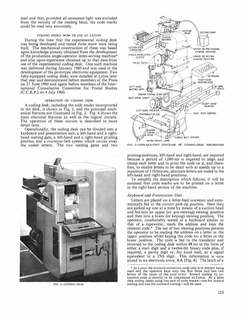
mail and that, provided all unwanted light was excluded from the vicinity of the reading head, the code marks could be read very accurately.
CODING DESKS NOW IN USE AT LUTON
During the time that the experimental coding desk was being developed and tested three more were being built. The mechanical construction of these was based upon knowledge already obtained from the development of the production single-operator letter-sorting machine3 and also upon experience obtained up to that date from use of the experimental coding desk. One such machine was delivered during January 1960 and was used in the development of the prototype electronic equipment. Two fully-equipped coding desks were installed at Luton later that year and demonstrated before members of the Press on 21June1960 and again before members of the International Consultative Committee for Postal Studies (C.C.E.P.) on 4 July 1960.
OPERATION OF CODING DESK
A coding desk, including the code reader incorporated in the desk, is shown in Fig. 2, and the principal mechanical features are illustrated in Fig. 3. Fig. 4 shows the main electrical features as well as the logical circuits. The operation of these circuits is described in more detail later.
Operationally, the coding desk can be divided into a keyboard and presentation unit, a left-hand and a righthand waiting gate, a left-hand and a right-hand printing position and a conveyor-belt system which carries away the coded letters. The two waiting gates and two
FIG. 2-CODING DESK
FIG. 3-EXPLANATORY DIAGRAM OF CODING-DESK MECHANJSM
printing positions, left-hand and right-hand, are required because a period of 1,090 ms is required to align and clamp each letter and to print the code on it, and therefore, to enable letters to be dealt with at speeds up to a maximum of 11 O/minute, alternate letters are coded in the left-band and right-hand positions.
To simplify the description which follows, it will be assumed that code marks are to be printed on a letter in the right-hand section of the machine.
Keyboard and Presentation Unit
Letters are placed on a Jetter-feed conveyor and automatically fed to the correct pick-up position. Here they are picked up one at a time by means of a suction head and fed into an upper (or pre-viewing) viewing position and then into a lower (or keying) viewing position. The operator, comfortably seated at a keyboard similar to that of a typewriter, reads the address and keys the relevant code.* The use of two viewing positions permits the operator to be reading the address on a letter in the upper position whilst keying the code for a letter in the lower position. The code is fed to the translator and returned to the coding desk within 48 ms in the form of either a start digit and a twelve-bit binary code plus, if required, a parity digit or, for local mail, as a signal equivalent to a 15th digit. This information is now stored in an electronic store, RA (Fig. 4). The latch of a
'"At Luton the outward extraction code only is at present heing used and the operator keys only the first three and last two letters of the name of the post town. Inward sorting by extraction code is shortly to be introduced at Luton. At a later date coding desks using two sets of code marks-one for inward sorting and one for outward sorting-will be used.
123
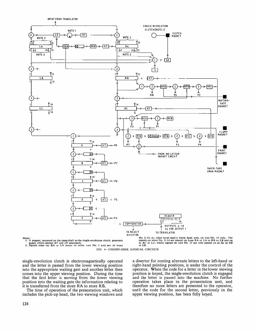
INPUT fROH TRANSLATOR
RA
SINGLE-REVOLUTION
CLUTCH {NOTE t) CLUTCH
HAGNET
2 l<I 15 ���--�
NOTE Z
" r---l �.--',
"
Notes: 1. A magnet, mounted on the same shaf1 as the single-revolution clutch, generates
pulses which operate RT and LT alternately. 2. Signals enu:r the RA ur LA sto1c5 011 either wire No. 1 and any of wires
NOTE Z
�--+-- FROM NO-LETfER INHIBIT CIRCUIT
READER
\l/AITINGGATE
HAGNET
CLAMP' MAGNET
PRINT HAGNET
PAPER-TAPE DRAW MAGNET
TO REJECT DIVERTOR
No. 2-14, or, when local mail is being dealt with, on wire No. 15 only. The signals on wires No. 2-14 are passed on from RA or LA to RR or LB and on to RC or LC, whilst signals on wire No. 15 are only passed on as far as RB or LD.
FIG. 4-CODING-DESK LOGICAL CIRCUITS
single-revolution clutch is electromagnetically operated and the letter is passed from the lower viewing position into the appropriate waiting gate and another letter then comes into the upper viev.-·ing position. During the titne that the first letter is moving from the lower viewing position into the waiting gate the information relating to it is transferred from the store RA to store RB.
The time of operation of the presentation unit, which includes the pick-up head, the two viewing windows and
124
a divertor for routing alternate letters to the left-hand or right-hand printing positions, is under the control of the operator. When the code for a letter in the lower viewing position is keyed, the single-revolution clutch is engaged and the letter is passed into the machine. No further operation takes place in the presentation unit, and therefore no more letters are presented to the operator, unt;l the code for the second letter, previously in the upper viewing position, has been fully keyed.
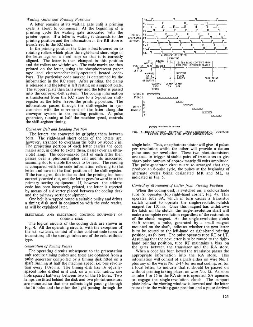
J¥aiting Gates and Printing Pos;tions A letter re1nains at its waiting gate until a printing
cycle is about to commence. At the beginning of a printing cycle the waiting gate associated with the printer opens. If a letter is waiting it descends to the printing position and the infonnation in the RB store is transferred to the RC store.
In the printing position the letter is first lowered on to rotating rollers which place the right-hand short edge of the letter against a fixed stop so that it is correctly aligned. The letter is then clamped in this position and the rollers are withdrawn. The code marks are then printed on the letter, using the phosphorescent paper tape and electromechanicaily-operated heated codebars. The particular code marked is determined by the information in the RC store. After printing, the cla1np is released and the letter is left resting on a support plate. The support plate then falls away and the letter is passed into the conveyor-belt system. The coding information is transferred from the RC store to a 5-position shiftregister as the letter leaves the printing position. The information passes through the shift-register in synchronism with the movement of the letter along the conveyor system to the reading position. A pulse generator, running at half the machine speed, controls the shift-register timing.
Conveyor Belt and Reading Position
The letters are conveyed by gripping them between belts. The right-hand short edges of the letters are, however, arranged to overhang the belts by about 2 in. The projecting portion of each letter carries the code marks and, in order to excite them, passes over an ultraviolet lamp. The code-marked part of each letter then passes over a photo1nultiplier cell and its associated scanning slot to enable the code to be read. The reading is compared with the code information referring to the letter and now in the final position of the sltift-register. If the two agree, this indicates that the printing has been correctly carried out, and the letter goes forward into the primary sorting equipment. If, however, the address code has been incorrectly printed, the letter is rejected by means of a diverter placed between the coding desk and the primary sorting equipment.
One belt is wrapped round a suitable pulley and drives a timing disk used in conjunction with the code reader, as will be explained later.
ELECTRICAL AND ELECTRONIC CONTROL EQUIPMENT OF
CODING DESK
The logical circuits of the coding desk are shown in Fig. 4. All the operating circuits, with the exception of the h. t. switches, consist of either cold-cathode tubes or transistors; ail the storage tubes are of the cold-cathode type.
Generation of Tilning Pulses The operating circuits subsequent to the presentation
unit require timing pulses and these are obtained from a pulse generator controlled by a timing disk fitted on a shaft running at half the machine speed, i.e. one revolution every 1,090 ms. The timing disk has 16 equallyspaced holes drilled in it and, on a smailcr radius, one hole spaced half-way between two of the 16 holes. Two lamps are fitted behind the disk and two phototransistors are mounted so that one collects light passing through the 16 holes and the other the light passing through the
Ml
PI
PULSE- P3
GENERATOR " OUTPUTS "
" P7
PB ALIGNMENT OF L E T TER
i PRINTING
POSITION GA TE PRINTER CODE PRINTER TO CODE READER
LE �� E-,-
-t
---- - · - -�
WAl�H G;fMOTVJN1G � L(TTER BEING CON\ EYED fROM
WAITING- SUPPORT GATE PLATE
MAGNET DROPS CODE BEING OPERATES READ
STORE B
STORE C
SHIFT-B
('
REGISTER �
WAITING CLAMP CLAMP . GATE OH OFF
OPENS
= v2222222222221
=
EZZZ:l Information in store
= =
= =
FIG. 5-RELATIONSHIP BETWEEN PULSE-GENERATOR OUTPUTS LETTER POSITION AND STORE INFORMATION
single hole. Thus, one phototransistor will give 16 pulses per revolution whilst the other will provide a datum pulse once per revolution. These two phototransistors are used to trigger bi-stable pairs of transistors to give sharp pulse outputs of approximately 50 volts amplitude. The pulse-generator circuits are so arranged that they produce an 8-pulse cycle, the pulses at the beginning of alternate cycles being designated MR and ML, as indicated in Fig. 5.
Control of Move1nent of Letter front V;ew;ng Position
When the coding desk is switched on, a cold-cathode tube, S, operates (top right-hand corner, Fig. 4). This operates tube SA, which in turn causes a transistor switch circuit to operate the single-revolution-clutch magnet for 150 ms. Once this magnet has withdrawn the latch on the clutch, the single-revolution shaft will make a co1nplete revolution regardless of the restoration of the clutch magnet. As the single-revolution-clutch shaft rotates, a pulse, generated by a small magnet mounted on the shaft, indicates whether the next letter is to be routed to the left-hand or right-hand printing position, as follows. The pulse operates tube RT or LT. Assuming that the next letter is to be routed to the righthand printing position, tube RT maintains a bias on the gates between the tran:slalor an<l tht: RA store.
When a code has been keyed the translator passes the appropriate information into the RA store. This information will consist of signals either on wire No. 1 plus any of the wires No. 2-14 for normal coding, or, for a local letter, to indicate that it should be passed on without printing taking place, on wire No. 15. As soon as tube I or 15 in the RA store is operated, SA operates to engage the single-revolution clutch. The support plate below the viewing window is lowered and the letter passes into the waiting-gate position and a pulse derived
125
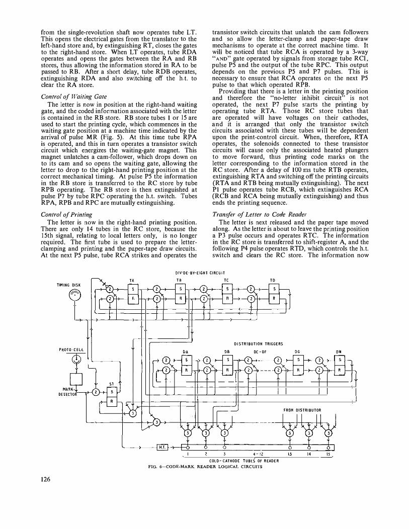
from the single-revolution shaft now operates tube LT. This opens the electrical gates from the translator to the left-hand store and, by extinguishing RT, closes the gates to the right-hand store. When LT operates, tube RDA operates and opens the gates between the RA and RB stores, thus allowing the information stored in RA to be passed to RB. After a short delay, tube RDB operates, extinguishing RDA and also switching off the h.t. to clear the RA store.
Control of Waiting Gate
The letter is now in position at the right-hand waiting gate, and the coded information associated with the letter is contained in the RB store. RB store tubes 1 or 15 are used to start the printing cycle, which commences in the waiting gate position at a machine time indicated by the arrival of pulse MR (Fig. S). At this time tube RPA is operated, and this in turn operates a transistor switch circuit which energizes the waiting-gate magnet. This magnet unlatches a cam-follower, which drops down on to its cam and so opens the waiting gate, allowing the letter to drop to the right-hand printing position at the correct mechanical timing. At pulse P5 the information in the RB store is transferred to the RC store by tube RPB operating. The RB store is then extinguished at pulse P7 by tube RPC operating the h.t. switch. Tubes RPA, RPB and RPC are mutually extinguishing.
Control of Printing
The letter is now in the right-hand printing position. There are only 14 tubes in the RC store, because the l Sth signal, relating to local letters only, is no longer required. The first tube is used to prepare the letterclamping and printing and the paper-tape draw circuits. At the next PS pulse, tube RCA strikes and operates the
transistor switch circuits that unlatch the cam followers and so allow the letter-clamp and paper-tape draw mechanisms to operate at the correct machine time. It will be noticed that tube RCA is operated by a 3-way "AND" gate operated by signals from storage tube RCl, pulse PS and the output of the tube RPC. This output depends on the previous PS and P7 pulses. This is necessary to ensure that RCA operates on the next PS pulse to that which operated RPB.
Providing that there is a letter in the printing position and therefore the "no-letter inhibit circuit" is not operated, the next P7 pulse starts the printing by operating tube RTA. Those RC store tubes that are operated will have voltages on their cathodes, and it is arranged that only the transistor switch circuits associated with these tubes will be dependent upon the print-control circuit. When, therefore, RTA operates, the solenoids connected to these transistor circuits will cause only the associated heated plungers to move forward, thus printing code marks on the letter corresponding to the information stored in the RC store. After a delay of 100 ms tube RTB operates, extinguishing RTA and switching off the printing circuits (RTA and RTB being mutually extinguishing). The next PI pulse operates tube RCB, which extinguishes RCA (RCB and RCA being mutually extinguishing) and thus ends the printing sequence.
Transfer af Letter to Code Reader
The letter is next released and the paper tape moved along. As the letter is about to leave the printing position a P3 pulse occurs and operates R TC. The information in the RC store is transferred to shift-register A, and the following P4 pulse operates RTD, which controls the h. t. switch and clears the RC store. The information no\v
D!V'DE-BY-E\GHT CIRCUIT
TA
TIM ING DISK
126
TB TC TD
DlSTR1BUT10H TRIGGERS
DC -OF
COLD-CATHODE TUBES OF READER
FIG. 6-CODE-MARK READER LOGICAL CIRCUITS
DG OH
FROM DISTRIBUTOR
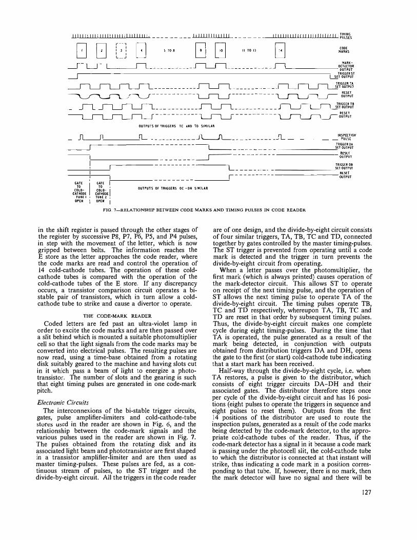
l!lll!!lllll!ll!!lll!!lllllll!!I _ _ _____ _ 111111111111111 I I 111II11(!!I!111 !!111 !111 !i�ll�E\
DD r--, ' ' ' ' ' ' ' L __ _1
II TO I] COOE 11AflkS
11AflKOHECTOll �------- oulPUT TRIGGER ST SET OUTPUT
___ ________ � ____________ n_ __ J--L__J--L_J{ir;or;u\11PL� �-----------L____fl____f-----------� iJi�J1
___ _ _______ SL___Jl_ _________ _ _ ��1ii1�J¥ ----------- l___Il______J---- -- --- -l_JL_SL___J�Ji�JT
OUlPUTS OF TRIGGERS TC AND 10 SIMILAR
- -----_____ .lL___Jl___ - - ------- - �-------111�����1011 --��-------- - - -- ---- �
-________ ---------"l,li�GJfp��
- - - - - - - - _____r---- - - - -- - -- - ---------- �J���T �----- --------- -----� TRJGGH 09
--------�SH OUTPUl
GATE '1 TO COLOCATKOOE TUBE I • OPEN \
GATE I TO COLO·
I CATKOOE TUBE Z , OPEN I
--------- �����T
OUHUTS OF lAIGGERS OC -OK SIH!LAR
FIG. 7-RELATJONSHIP BETWEEN CODE MARKS AND TIMING PULSES IN CODE READER
in the shift register is passed through the other stages of the register by successive PS, P7, P6, PS, and P4 pulses, in step with the movement of the letter, which is now gripped between belts. The information reaches the E store as the letter approaches the code reader, where the code marks are read and control the operation of 14 cold-cathode tubes. The operation of these coldcathode tubes is compared with the operation of the cold-cathode tubes of the E store. If any discrepancy occurs, a transistor comparison circuit operates a bistable pair of transistors, which in turn allow a coldcathode tube to strike and cause a divertor to operate.
THE CODE-MARK READER
Coded letters are fed past an ultra-violet lamp in order to excite the code marks and are then passed over a slit behind which is mounted a suitable photomultiplier cell so that the light signals from the code marks may be converted into electrical pulses. The resulting pulses are now read, using a time-base obtained from a rotating disk suitably geared to the machine and having slots cut in it which pass a beam of light to energize a phototransistor. The number of slots and the gearing is such that eight timing pulses are generated in one code-mark pitch.
Electronic CircuUs
The interconnexions of the bi-stable trigger circuits, gates, pulse amplifier-limiters and cold-cathode-tube sturt:s used in the reader are shown in Fig. 6, and the relationship between the code-mark signals and the various pulses used in the reader are shown in Fig. 7. The pulses obtained from the rotating disk and its associated light beam and phototransistor are first shaped in a transistor amplifier-limiter and are then used as master timing-pulses. These pulses are fed, as a continuous stream of pulses, to the ST trigger and the divide-by-eight circuit. All the triggers in the code reader
are of one design, and the divide-by-eight circuit consists of four similar triggers, TA, TB, TC and TD, connected together by gates controlled by the master timing-pulses. The ST trigger is prevented from operating until a code mark is detected and the trigger in turn prevents the divide-by-eight circuit from operating.
When a letter passes over the photomultiplier, the first mark (which is always printed) causes operation of the mark-detector circuit. This allows ST to operate on receipt of the next timing pulse, and the operation of ST allows the next timing pulse to operate TA of the divide-by-eight circuit. The timing pulses operate TB, TC and TD respectively, whereupon TA, TB, TC and TD are reset in that order by subsequent timing pulses. Thus, the divide-by-eight circuit makes one complete cycle during eight timing-pulses. During the time that TA is operated, the pulse generated as a result of the mark being detected, in conjunction with outputs obtained from distribution triggers DA and DH, opens the gate to the first (or start) cold-cathode tube indicating that a start mark has been received.
Half-way through the divide-by-eight cycle, i.e. when TA restores, a pulse is given to the distributor, which consists of eight trigger circuits DA-DH and their associated gates. The distributor therefore steps once per cycle of the divide-by-eight circuit and has 16 positions (eight pulses to operate the triggers in sequence and eight pulses to reset them). Outputs from the first 14 positions of the distributor are used to route the inspection pulses, generated as a result of the code marks being detected by the code-mark detector, to the appropriate cold-cathode tubes of the reader. Thus, if the code-mark detector has a signal in it because a code mark is passing under the photocell slit, the cold-cathode tube to which the distributor is connected at that instant will strike, thus indicating a code mark in a position corresponding to that tube. If, however, there is no mark, then the mark detector will have no signal and there will be
127
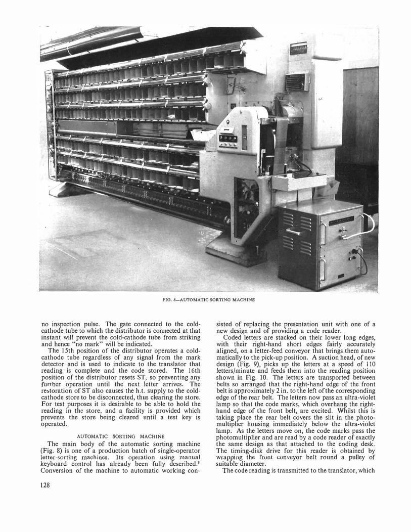
FIG. 8-AUTOMATIC SORTINO MACHINE
no inspection pulse. The gate connected to the coldcathode tube to which the distributor is connected at that instant will prevent the cold-cathode tube from striking and hence "no mark" will be indicated.
The l 5th position of the distributor operates a coldcathode tube regardless of any signal from the mark detector and is used to indicate to the translator that reading is complete and the code stored. The 16th position of the distributor resets ST, so preventing any further operation until the next letter arrives. The re:storation of ST also causes the b.t. supply to the coldcathode store to be disconnected, thus clearing the store. For test purposes it is desirable to be able to bold the reading in the store, and a facility is provided which prevents the store being cleared until a test key is operated.
AUTOMATIC SORTING MACHINE
The main body of the automatic sorting machine (Fig. 8) is one of a production batch of single-operator letter-sorting machines. Its operation using manual keyboard control has already been fully described.3 Conversion of the machine to automatic working con-
128
sisted of replacing the presentation unit with one of a new design and of providing a code reader.
Coded letters are stacked on their lower long edges, with their right-hand short edges fairly accurately aligned, on a letter-feed conveyor that brings them automatically to the pick-up position. A suction head, of new design (Fig. 9), picks up the letters at a speed of 110 letters/minute and feeds them into the reading position shown in Fig. 10. The letters are transported between belts so arranged that the right-hand edge of the front belt is approximately 2 in. to the left of the corresponding edge of the rear belt. The letters now pass an ultra-violet lamp so that the code marks, which overhang the righthand edge of the front belt, are excited. Whilst this is taking place the rear belt covers the slit in the photomultiplier housing immediately below the ultra-violet lamp. As the letters move on, the code marks pass the photomultiplier and are read by a code reader of exactly the same design as that attached to the coding desk. The timing-disk drive for this reader is obtained by wrapping the front conveyor belt round a pulley of suitable diameter.
The code reading is transmitted to the translator, which
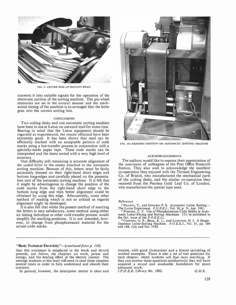
FIG. 9-LETTER PICK-UP SUCTION HEAD
converts it into suitable signals for the operation of the electronic portion of the sorting machine. The pin-wheel memories are set in the normal manner and the mechanical timing of the machine is so arranged that the letter goes into the correct sorting box.
CONCLUSIONS
Two coding desks and one automatic sorting machine have been in use at Luton on outward mail for some time. Bearing in mind that the Luton equipment should be regarded as experimental, the results obtained have been extremely good. It has been shown that mail can be efficiently marked with an acceptable pattern of code marks using a hot-transfer process in conjunction with a specially-made paper tape. These code marks can be interpreted and the items sorted with a very high level of accuracy.
One difficulty still remaining is accurate alignment of the coded letter in the reader attached to the automatic sorting machine. Because of this, letters must be fairly accurately dressed on their right-hand short edges and bottom long-edges and carefully placed on the presentation unit of the automatic sorting machine. It is felt that it might be advantageous to change the position of the code marks from the right-hand short edge to the bottom long edge and then better alignment could be obtaim:tl by using this edge. Alternatively, some other method of reading which is not so critical as regards alignment might be developed.
It is also felt that whilst the present method of marking the letters is very satisfactory, some method using either an inking technique or other cold transfer process would simplify the marking positions. It is not intended, however, to change from phosphorescent material for the actual code marks.
"Basic Technical Electricity"-(co11ti1111ed from p. 110)
that this treatment is misplaced in the book and should precede, not follow, the chapters on work, power and energy, and the heating effect of the electric current. The average students at this level will need to read these chapters several times in order to fully understand and absorb their contents.
In general, however, the descriptive matter is clear and
FIG. 10-READING POSITION ON AUTOMATIC SORTING MACHINE
ACKNOWLEDGEMENTS
The authors would like to express their appreciation of the assistance of colleagues at the Post Office Research Station. They also wish to acknowledge the excellent co-operation they enjoyed with the Thrissel Engineering Co. of Bristol, who manufactured the mechanical parts of the coding desks, and the similar co-operation they received from the Peerless Gold Leaf Co. of London, who manufacture the special tape used.
References 1 PILUKG, T., and GERARD, P. S. Automatic Letter Sorting
The Luton Experiment. P.O.E.E.J., Vol. 54, p. 31, Apr. 1961. 2 FORSTER, C. F. Use of Phosphorescent Code Marks in Auto
matic Letter-Facing and Sorting Machines. (To be published in the Oct. issue of the P.O.E.E.J.).
3 COPPING, G. P., BEAK, K. L., and LANGTON, H.J. A SingleOperator Letter-Sorting Machine. P.O.E.E.J., Vol. 51, pp. 104 and 188, July and Oct. 1958.
concise, with good illustrations and a liberal sprinkling of worked examples. There is also a set of test questions for each chapter, which students will find mosl searching. If they can answer these questions satisfactorily they will have acquired a sound and invaluable foundat ion for more advanced work. l.P.O.E.E. Library No. 1892. G.H.K.
129
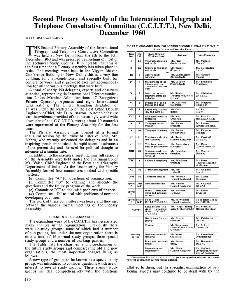
Second Plenary Assembly of the International Telegraph and Telephone Consultative Committee (C.C.I.T.T.), New Delhi,
December 1960 U.D.C. 061.3: 621.394/395
THE Second Plenary Assembly of the International Telegraph and Telephone Consultative Committee was held at New Delhi from the 8th to the l6th
December 1960 and was preceded by meetings of most of the Technical Study Groups. It is notable that this is the first time that a Plenary Assembly has taken place in Asia. The meetings were held in the Vigyan Bhavan Conference Building in New Delhi; this is a very fine building, fully air-conditioned and specially built for conference work, and it provided excellent accommodation for all the various meetings that were held.
A total of nearly 350 delegates, experts and observers attended, representing 54 International Telecommunication Union Member Administrations, 17 Recognized Private Operating Agencies and eight International Organizations. The United Kingdom delegation of 13 was under the leadership of the Post Office Deputy Engineer-in-Chief, Mr. D. A. Barron. A notable feature was the evidence provided of the increasingly world-wide character of the C.C.I.T.T.'s work; about 10 countries were represented at the Plenary Assembly for the first time.
The Plenary Assembly was opened at a formal inaugural session by the Prime Minister of India, Mr. Nehru, who warmly welcomed the delegates and in an inspiring speech emphasized the rapid scientific advances of the present day and the need for political thought to advance at a similar rate.
In addition to the inaugural meeting, nine full sessions of the Assembly were held under the chairmanship of Mr. Yaish, Chief Engineer of the Posts and Telegraphs Department of India. At the first meeting the Plenary Assembly formed four committees to deal with specific matters:
(a) Committee "A" for questions of organization. (b) Committee "B" to examine and allocate the
']Uestions and the future program of the work. (c) Committee "C" to deal with problems of finance. (d) Committee "D" to deal with problems of new and
developing countries. The work of these committees was heavy and they met
between the various formal meetings of the Plenary Assembly.
CHANGES IN ORGANIZATION
The expanding work of the C.C.l.T.T.has necessitated many changes in the organization. Previously there were 12 study groups, some of which had a number of sub-groups, but under the new organization there is now a total of 16 normal study groups, three special study groups and a number of working parties.
The Table lists the chairmen and vice-chairmen of the future study groups and compares the old and new organizations, the most important changes being as follows.
A new type of group, to be known as a special study group, was introduced to consider questions which are of interest to several study groups. These special study groups will deal comprehensively with the questions
130
C.C.l.T.T. ORGANIZATION FOLLO\VING SECOND PLENARY ASSEMBLY
Study Groups and \Vorking Parties
N= Old Study Group or I Chairman Vice-Chairman No. S.G. Working Party
I 2/1 Telegraph operation Mr. Perry Mr. Vargues and tariffs (Netherlands) (France)
II 2/2 Telephone operation Mr. Terras Mr. Balchandani and tariffs (France) (India)
III 2 General tariff Mr. Langenberger Mr. Garrido principles (Switzerland) (Spain)
IV 4 Maintenance of the Mr. Valloton Mr. Postelnicu international tele- (Switzerland) (Rumania) communication net-
I work
v 5 Protection against Mr. Riedel Mr. Mikhailov elcc1romagnctic dis- (Federal Republic of CU.S.S.RJ turbance Germany)
VI 6 Protection of cable Mr. Halstriim Mr. MuQtadir sheaths and poles (Denmark) (Pakistan)
VII 7 Definitions. vocabu- Mr. Gella I Mr. Bilti lary and symbols (Spain) (Italy)
VIII 8 Alphabetic telegraph Mr. Kerr Mr. Savilzky apparatus (Australia) <Ukrainian S.S.R.)
IX 9 I T�!e�raph tram- Mr. Roquet Mr. Renton mission (France) (United Kingdom)
x 10 Telegraph switching Mr. Jansen Mr. Faugeras (Netherlands) (France)
XI i II Telephone switching Mr. Tobin Mr. Vassilieff
I and signalling (United Kingdom) CU.S.S.R.>
XII 12 Telephone !rans- Mr. Swedenborg Mr. Krout! mission performance (Sweden) (Czechoslovakia)
XIII 2/4 Semi-automatic and Mr Lambiotte
I Mr. Cho\•et
automatic telephone (Belgium) (France) networks
XIV 8 FacNimile telegraphy Mr. Fijalkowski Mr. Bitter (Poland) (Federal Republic
ur Germany)
xv l/I Transmissionsystcms l Mr. Job I Mr. Gagl!ardi j (France) (Italy)
XVI 1/2 I Telephone circuits Mr. Franklin Mr. Claeys (United Kingdom) (Belgium)
Special Data Data transmission Mr. Rhodes Mr. Vaughan A \V,P. (United Kingdom) (U.S.A.)
Special World semi-auto- Mr. Bloecker Mr. Bjurel
• matic and automatic (U.S.A.) (Sweden) nenvork
Special Noise Noise (Joint Mr. H. \Villiams To be designated by c \V.P. C.C.I.T.T./C.C.l.RJ (United Kingdom) the C.C.l.R.
Long.distance tele- Mr. Angel (Desig- I Mr. Franklin
CMTT' vision transmi�sion nated by !he C.C.I.R.)t (Uni led Kingdom) (Joint C.C.l.R./ C.C.I.T.T.)
Use of lines for tele- Mr. Bassole Mr. Fabiianski graphy (France) (Poland)
Coslin11
I Mr. Bornemann Mr. F.riksen (Federal Reputlic of (Denmark) Germany)
\Vorking National au1omatic Mr. Banks Mr. Kamerbeek Parties networks (Australia) (Netherlands)
Telegraph mechani- Mr. Bonacci Mr. Hempstead zation (Italy) (U.S.A.)
Inter-continental
I Mr. Billen Mr. McGuire
maintenance (United Kingdom) (Telephone Associa-tion of Canada)
• Conumss1on Mixte C.C.1.K.,'C.C.I.I.r. pour Jes Questions relatives aux transmissions de television sur une grande disrnnce,
allotted to them, but the specialist examination of particular aspects may continue to be dealt with by the
Plan Committees
Main Committee Mr. Anlinori (Italy)
Plan Sub-Committee for Africa Mr. Tedros (Ethiopia)
Plan Sub-Committee for Asia Mr. Vasudevan (India)
Plan Sub-Comm.ittce for L111in Mr. NU.Dez
America (Mexico)
Temporary Study Group for the Mr. NU.ilez Inter-American Telecommunica- (Mexico) tion Network
t Temporary appointment pending nomination by C.C.l.R.
Mr. Hamidt (Pakistan)
Mr.Mili (Tunisia)
Mr. Matsuda (Japan)
Mr. Ospina
(Colombia)
Mr. Tejeda (Venezuela)
appropriate study groups, and the draft recommendations of the special study groups will, as necessary, be examined by the study groups interested. Three special groups have been formed:
(i) Special Study Group "A," dealing with data transmission.
(ii) Special Study Group "B," dealing with the world semi-automatic and automatic network. This is mainly an integrating study group to co-ordinate the studies to be carried out by the individual study groups on the subject.
(iii) Special Study Group "C" ( jointly with the C.C.I.R.), replacing the old Noise Working Party.
Major changes in the existing study groups were as follows:
(a) Study Group 1 and its associated sub-groups have been divided into two study groups: Study Group XV dealing with transn1ission syste1ns and Study Group XVI dealing with telephone circuits. A working party replaces the old Sub-Study Group 1/3 dealing with the use of lines for telegraphy.
(b) Study Group 2 and Sub-Study Groups 2/1 and 2/2 have been divided into three study groups now known as Study Group I (Telegraph Operation and Tariffs), Study Group II (Telephone Operation and Tariffs) and Study Group III (General Tariff Principles).
(c) Study Group 4 (Maintenance of the International Telecommunication Network), Study Group 5 (Protection against Electromagnetic Disturbance), Study Group 6 (Protection of Cable Sheaths and Poles), and Study Group 7 (Definitions, Vocabulary and Symbols) are now known as Study Groups IV, V ,VI and VII.
(d) Study Group 8 (Telegraph Apparatus) has been divided into two study groups, one (Study Group Vlll) dealing with Alphabetic Telegraph Apparatus and the other (Study Group XIV) dealing with Facsimile Telegraph Apparatus.
(e) Study Group 9 (Telegraph Transmission), Study Group 10 (Telegraph Switching), Study Group 11 (Telephone Switching and Signalling), and Study Group 12 (Telephone Transmission Performance) are now known as Study Groups IX, X, X! and XII.
A new study group was set up (Study Group Xlll) which will deal with the co-ordination of the development of international semi-automatic and automatic networks, the determination of the operating conditions for intercontinental service, traffic studies, world numbering plan, etc.
In addition to the joint working party already mentioned on the Use of Lines for Telegraphy, new working parties for Costing, National Automatic Networks, Telegraph Mechanization, and Inter-continental Maintenance were set up.
QUESTIONS OF CONCERN TO THE "
NEW OR DEVELOPING"
COUNTRIES
The Assembly devoted a good deal of time to the part the C.C.I.T.T. might play in meeting the requirements of the "new or developing" countries.
It was considered that the best way to handle questions affecting these countries would be to take advantage of the Plan Committee already existing, supplemented by regional sub-committees. This resulted from the agreement reached that the best course would be to adapt existing structures, rather than to set up new bodies. Furthermore, an extension of the terms of reference of the Plan Committee (a joint body made up of the International Radio and International Telegraph and Telephone Consultative Committees and other organizations) would, it was felt, automatically ensure the requisite co-ordination between the studies undertaken by the two Consultative Committees.
The Assembly accordingly set up two additional regional sub�committees, one for Africa and one for Latin America (one for Asia was already in existence). It was proposed that each sub-committee would meet in the region with which it is concerned. These regional sub-committees, in addition to drawing up a plan for development of networks, will indicate the technical, operating and tariff questions which the countries in the various regions will have to face, directly or indirectly, when the plan is implemented.
The Assembly gave no ruling about the way in which these matters should be handled, preferring to profit by the experience to be acquired, but it did consider the following courses of action:
(a) If the questions have been dealt with already by the International Radio or International Telegraph and Telephone Consultative Committee, the sub-committees could extract the provisions of interest to underdeveloped countries from the recommendations issued by these Consultative Committees, and submit them in a readily assimilable form. If, on the other hand, the questions are of world-wide importance, they could be referred to the appropriate bodies within either of the two Consultative Committees.
(b) If the questions are of purely local interest, the regional sub-committees could deal with them directly or refer them, as described above, to the appropriate bodies within either of the two Consultative Committees. These latter would, if required, set up special working parties meeting in the particular parts of the world involved.
The Assembly adopted a Mexican proposal to form a temporary committee to consider matters in connexion with the development of the Inter-American Telecommunication Network (a joint body made up of the two international Consultative Committees) until the regional sub-committee can take over.
The Assembly also discussed the provision of technical literature for the "new or developing" countries. It asked that these countries should be told that they could obtain technical information about their telecommunications problems, national or international, from the I.T.U. General Secretariat, which would consult the Secretariat of the particular Consultative Committee concerned.
WORK OF STUDY GROUPS AND WORKING PARTIES
An important function of the Plenary Assembly was approving the reports of the work which had been carried
131
out by the individual study groups since the last Assembly, and a brief summary of this work is given below.
Study Group I
Sub-Group l/ l (Specification of Trunk Lines). A carrier program circuit having a bandwidth of 50 c/s to 6,400 c/s, as an alternative to the present circuit of 50 c/s to 10,000 c/s, has now been adopted as standard, the noise and crosstalk performance of long program circuits was considered, and a specification for an emphasis network was recommended. The reco1nmendations pertaining to the 12 Mc/s telephony coaxial system were substantially completed but the simultaneous use of this system for telephony and television remains to be studied. The basic electrical characteristics of a smalldiameter coaxial cable were agreed, together with the essential system characteristics for 300-circuit telephone working. The study of the line equipment for use with this cable will be continued, with the object of widening the transmission band for telephony and for television.
Recommendations were approved for the channel translating equipments with out-band signalling providing eight channels in a 48 kc/s basic group. A provisional specification for a telephone speech compandor has been agreed and preliminary studies for the standardization of program compandors commenced.
Sub-Group 1/2 (Use of Lines for Telephony). Most of the effort of this sub-group has been devoted to studying the transmission requirements of a world-wide switching plan, and general principles have been agreed on which future study will be based.
Sub-Group 1/3 (Use of Lines for Telegraphy). The study of several questions of detail of the characteristics of circuits used for facsimile and v.f. telegraphy was completed.
Sub-Group l/4 (Use of Lines for Program and Television Transmission). This sub-group did not meet in New Delhi. Its outstanding questions were dealt with by Study Group I. The specification for the psophometer program-weighting network was revised and new limits for the harmonic distortion of program circuits were agreed.
Study Group 2 (Co-ordination of Operation and Tariffs) Most of the questions assigned to Study Group 2 were
dealt with by its sub-groups, as follows: Sub-Group 2/1 (Telegraph Operation and Tariffs) and
Sub-Group 2/2 (Telephone Operation and Tariffs). The main considerations of these two sub-groups have been the problems arising from increasing conversion to automatic working of the telex and telephone services; a number of minor matters have also been dealt with. New operational, accounting and charging provisions were studied and recommendations made. In addition, both sub-groups spent considerable time studying the conditions for the leasing of private circuits, but owing to the complexity of the problem were not able to reach satisfactory agreements.
Sub-Group 2/3 (Costing). Studies relating to the cost of fully-automatic telephone and telex calls have been undertaken for the use of Study Groups 2/1 and 2/2.
Sub-Group 2/4 (Automatic Operation in the Telephone Service). The Sub-Study Group continued to deal with the traffic and engineering problems arising from the increasing use of automatic working in the telephone service.
132
Study Group 3 (Co-ordination of Line and Radio) Study Group 3 held a brief meeting devoted mainly
to the disposal of outstanding questions. An alternative frequency allocation for 24-circuit radio systems was recommended to the C.C.I.R., and the recommended transmission levels for interconnecting line and radio syste1ns of small capacity, especially in view of the increased use of transistors, were reviewed.
Study Group 4 (Maintenance of the International Network)
Since the last Assembly, Study Group 4 has extensively revised the nlaintenance regulations, which were approved by the Assembly and will be published in the new Volume IV of the C.C.I.T.T. Red Book. The study group has also been dealing with the variations of attenuation and short breaks in transmission on international circuits. Target figures of the variation of circuit transmission loss with time which may be achieved on a 1,000-mile circuit, with and without group automatic gain control, have been indicated. Study will continue on the possibility of batch testing large groups of circuits, which, in conjunction with automatic testing devices, may considerably change the method of controlling the quality of international circuits in the future.
Study Group 5 (Protection against Dangers and Disturbances of Electromagnetic Origin)
The main work was to agree the draft of the first three parts of the Directives. These Directives recommend the measures necessary to permit the operation, without undue risk or interference, of telecommunication lines in the vicinity of power and traction systems. Further work has yet to be done on the re1naining five parts. The Directives will be published individually in a revised form.
Study Group 6 (Protection and Specifications of Cable Sheaths and Poles)
This Group's work was concentrated on examining the final drafts of Chapters 1, 2, 5 and 6 of the new "Recommendations for the Protection of Underground Cables against Corrosion." Outstanding work consists of producing the remaining chapters up to Chapter 11. When completed, the new Recommendations will replace the original "Recommendations at Paris in 1949" and also the "Recommendations for the Protection of Underground Cables against the Action of Stray Currents Arising from Electric Traction Systems," drafted at Florence in 1951.
Study Group 7 (Definitions, Vocabulary and Symbols) Recommendations were made for a number of new
and revised terms and definitions, symbols, and techniques for electrical diagrams. The existing C.C.I.T.T., C.C.I.R., and I.E.C. lists of graphical symbols for telecommunications and light-current engineering are in urgent need of revision, and it is proposed that this work should be done through the medium of a joint committee representing the above organizations. The List of Definitions of Essential Telecommunication Terms (the C.C.I.T.T. Yellow Book) is also in need of revision, but as this will take a considerable time, it was agreed that a limited reprint of the first edition, together with a supplement, shall be put in hand immediately.
Study Group 8 (Telegraph Apparatus) A more precise meaning has been given to the prac
tical measurement of telegraph distortion and margin, and characteristics of regenerative repeaters, answer-
back units and remote-control signals for message switching systems are now specified. A number of older recommendations have now been discarded. One new question set for study is concerned with the requirements for synchronous multiplex systems for use over submarine telephone repeatered cables, which will be of particular interest to Administrations participating in the Commonwealth cable project.
The study group also approved reco1nmendations on photo-telegraphy for higher-speed transmissions over carrier circuits and also proposed basic characteristics for a possible subscribers' facsimile service. An important agreement reached was on the design of a standard test chart for photo-telegraph transmission which will be published by the l.T.U. A joint meeting is proposed with the World Meteorological Organization to agree standards for the remote control of fascimile apparatus for weather charts.
Study Group 9 (Telegraph Transmission) This study group answered 15 questions. Probably
the most valuable agreement was for an integrated transmission plan for switched telegraph networks such as telex. The maximum permissible distortion of telegraph signals entering an international circuit is now specified, together with the limiting value of distortion for the international circuit. Other agreements reached were on a formula to be used for planning purposes to dete1mine the aggregate distortion of a multi-link telegraph circuit, a means of assessing the efficiency of ARQ* radio teleprinter circuits, and the standardization of v.f. telegraph systems for modulation rates in therange 75-100 bauds.
Study Group 10 (Telegraph Switching) Agreement was reached on a number of outstanding
details affording greater precision in specifying supervisory signalling conditions over cable and radio (ARQ) circuits for telex and gentex services. For example, separate conceptions of clearing signal and clearconfirmation signal, sin1ilar to those of the call and callconfirmation signals, were adopted.
Study Group 11 (Telephone Switching and Signalling) The report of Study Group 11 dealt with a number of
outstanding problems relating to international subscriber dialling. The main items under this heading were concerned with aspects of subscriber charging, the settlement of international accounts and the standardization of national tones. The study of the characteristics of the guard circuit of signalling receivers was continued. New problems for study are concerned with recommendations for world-wide sen1i-automatic and automatic operation, and the signalling and switching aspects of the transmission plan proposed by Study Group !. A further question which is of interest to new and developing countries is concerned with the factors to be taken into account in the development of national switching networks.
Study Group 12 (Telephone Transmission Performance) The Study Group did not meet in New Delhi but its
report recommended that the old SFERTt standard of
* ARQ-Auton1atic error-correcting. t SFER T-Systen1e Fondan1ental Euro peen de RCfCrence pour
la Transn1ission Telephonique (European Fundan1ental Telephone Transmission Reference System).
+ ARAEN-Appareil de Reference pour la Dt!tennination des Affaiblissemcnts Equivalents pour la NettetC (Reference Equipment for the Determination of Equivalent Attenuation for Articulation).
transmission perfonnance should not be re-installed in the ne\v laboratory premises but a modification of the ARAENt standard should be used instead to measure reference equivalents. Much completed work on the effects of circuit noise on custo1ners' opinions \vas approved. Future work of the study group will be the consideration of the effects of compandors and tropospheric-scatter radio propagation on transmission performance.
Working Party .for Data Trans111i.ssion This was a new autonomous \\forking party and had
held only one meeting. However, recommendations were approved for the allowable limits of power of data signals transmitted over telephone-type circuits for both leased and switched networks, and also for the equivalence between binary notation symbols and the significant conditions of a two-condition code. The future program of work of the new Special Study Group A, arising from the rapidly developing art of data transmission, is very extensive.
Circuit Noise Working Party
The joint C.C.l.R./C.C.l.T.T. Working Party on circuit noise last met in Geneva in 1959. Study Group 1, in reviewing the work of this working party, considered that the most important questions had been satisfactorily answered. These were for a common noise specification for circuits routed on cable or wideband radio-relay links which will be incorporated in the new volume of recommendations. The program of future work of the new Special Study Group C to deal with noise will include studies of noise on troposphericscatter links, the noise requirements of telegraphy, and methods of specifying noise performance.
'THE NEXT PLENARY ASSEMBLY
Two invitations were given for the next Plenary Assembly. The Government of the U.S.S.R. invited delegates to Moscow and the Government of Colombia invited delegates to the City of Bogota. A ballot was held, the result of which was, in favour of Moscow 25, in favour of Bogota 18. Thus the next Plenary Assembly will be held in Moscow in 1964.
CONCLUSION
This note of the work of the Plenary Assembly cannot be concluded without mentioning the great efforts made by the Indian Administration to make the Plenary Assembly a success. Organization both inside and outside the meetings was excellent. Many excursions were arranged, some of a technical nature, to view the various telecom1nunication installations and manufacturing organizations in India, and also to many places of historical interest in the vicinity of Delhi. All delegates will remember with pleasure the week-end when the Government of India arranged a visit by overnight sleeper trains to the town of Agra for delegates to see its ancient buildings and to visit the Taj Mahal, firstly in daylight and again late at night to see the famous spectacle by moonlight. The Government of India are to be warmly thanked for all the efforts they made on this excursion and for all the other hospitality they so generously provided.
J. R.
133
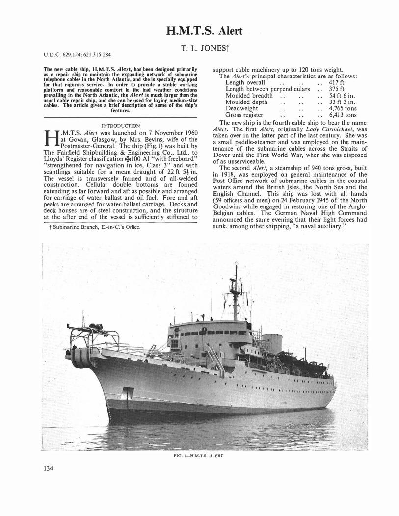
H.M. T .S. Alert
T. L. JONESt U.D.C. 629.124:621.315.284
The new cable ship, H.M.T.S. Ale1·t, has)een designed primar.ily
as a repair ship to maintain the ex_Panding ne_twork
.of subm
.arme
telephone cables in the North Atlantic, and sh� 1s specially eqmp�ed for that rigorous service. In order to provide a stable wo��mg platform and reasonable comfort in the bad weather conditions prevailing in the North Atlantic, the Ale1•t is muc� larger !han �he usual cable repair ship, and she can be used for laymg medmm-�1ze cables. The article gives a brief description of some of the ship's
features.
INTRODUCTION
H.M.T.S. Alert was launched on 7 November 1960 at Govan, Glasgow, by Mrs. Be.vins, wife o_f the Postmaster-General. The ship (Fig.I) was built by
The Fairfield Shipbuilding & Engineering Co., Ltd., to Lloyds' Register classification +ioo Al "with freeboar?" "strengthened for navigation in ice, Class 3" and w�th scantlings suitable for a mean draught of 22 ft St m.
The vessel is transversely framed and of all-welded construction. Cellular double bottoms are formed extending as far forward and aft as possible and arranged for carriage of water ballast and oil fu�l. Fore and aft peaks are arranged for water-balla�t carnage. Decks and deck houses are of steel construct10n, and the structure at the after end of the vessel is sufficiently stiffened to
t Submarine Branch, E.-in-C.'s Office.
l
support cable machinery up to 120 tons weight. The Alert's principal characteristics are as follows:
Length overall . . . . 417 ft Length between i:erpendiculars 375 ft Moulded breadth 54 ft 6 in. Moulded depth 33 ft 3 in. Deadweight 4,765 tons Gross register 6,413 tons
The new ship is the fourth cable ship to bear the name Alert. The first Alert, originally Lady Carmichael, was taken over in the latter part of the last century. She was a small paddle-steamer and was employed on the maintenance of the submarine cables across the Straits of Dover until the First World War, when she was disposed of as unserviceable.
The second Alert, a steamship of 940 tons gross, built in 1918 was employed on general maintenance of the Post Office network of submarine cables in the coastal waters around the British Isles, the North Sea and the English Channel. This ship was lost with all hands (59 officers and men) on 24 February 1945 off the North Goodwins while engaged in restoring one of the AngloBelgian cables. The German Naval High Command announced the same evening that their light forces had sunk, among other shipping, "a naval auxiliary."
·j
FIG. 1-H.M.T.S. ALERT
134
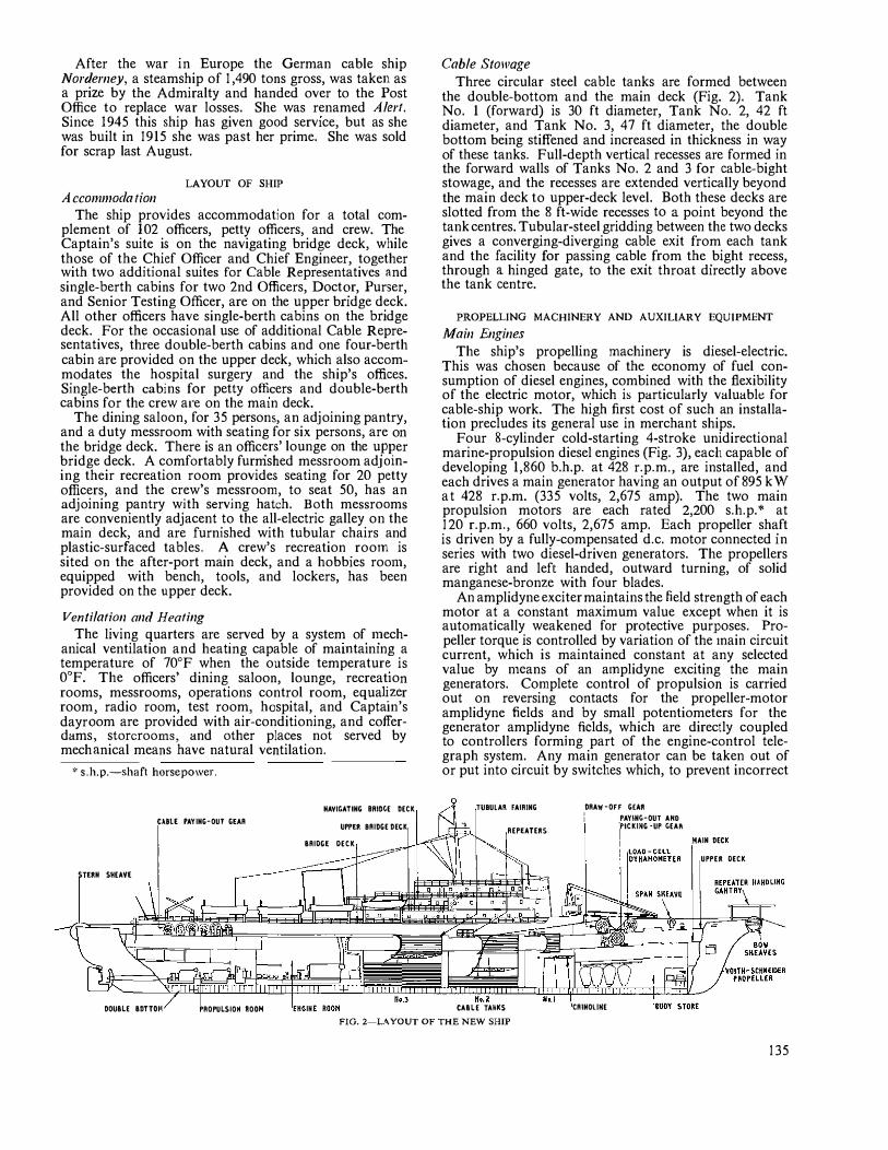
After the war in Europe the German cable ship Norderney, a steamship of 1,490 tons gross, was taken as a prize by the Admiralty and handed over to the Post Office to replace war losses. She was renamed A lert. Since 1945 this ship has given good service, but as she was built in 1915 she was past her prime. She was sold for scrap last August.
LAYOUT OF SHIP
A cco111111oda tion The ship provides accommodation for a total com
plement of 102 officers, petty officers, and crew. The Captain's suite is on the navigating bridge deck, while those of the Chief Officer and Chief Engineer, together with two additional suites for Cable Representatives and single-berth cabins for two 2nd Officers, Doct�r, Purser, and Senior Testing Officer, are on the upper bndge deck. All other officers have single-berth cabins on the bndge deck. For the occasional use of additional Cable Representatives, three double-berth cabins and one four-berth cabin are provided on the upper deck, which also accommodates the hospital surgery and the ship's offices. Single-berth cabins for petty officers and double-berth cabins for the crew are on the main deck.
The dining saloon, for 35 persons, an adjoining pantry, and a duty messroom with seating for six persons, are on the bridge deck. There is an offic�rs' lounge on the upper bridge deck. A comfortably furmshed messroom adioming their recreation room provides seating for 20 petty officers, and the crew's messroon1, to seat 50, has an adjoining pantry with serving hatch. Both messrooms are conveniently adjacent to the all-electric galley on the main deck and are furnished with tubular chairs and plastic-surfaced tables. � crew's recreation . room is sited on the after-port main deck, and a hobbies roo111, equipped with bench, tools, and lockers, has been provided on the upper deck.
Ventilation and Heating The living quarters are served by a system of. n.'ech
anical ventilation and heating capable of ma111ta1n1ng a temperature of 70°F when the outside temperatur� is 0°F. The officers' dining saloon, lounge, recreat
_1on
rooms, messrooms, operations control room, equa�z�r room radio room, test room, hospital, and Captain s dayrdom are provided with air-conditioning, and cofferdams storerooms and other places not served by mech�nical means
'have natural ventilation.
* s.h.p.-shaft horsepower.
CMllE PAYING-OUT GEAR
STERN SHEAVE
NAVIGATING BRIDGE DECK
UPPER BRIDGE DECK
BRIDGE DECK
Cable Stowage
Three circular steel cable tanks are formed between the double-bottom and the main deck (Fig. 2). Tank No. 1 (forward) is 30 ft diameter, Tank No. 2, 42 ft diameter, and Tank No. 3, 47 ft diameter, the double bottom being stiffened and increased in thickness in way of these tanks. Full-depth vertical recesses are formed in the forward walls of Tanks No. 2 and 3 for cable-bight stowage, and the recesses are extended vertically beyond the main deck to upper-deck level. Both these decks are slotted from the 8 ft-wide recesses to a point beyond the tank centres. Tubular-steel gridding between the two decks gives a converging-diverging cable exit from each tank and the facility for passing cable from the bight recess, through a hinged gate, to the exit throat directly above the tank centre.
PROPELLING MACHINERY AND AUXILIARY EQUIPMENT
Main Engines
The ship's propelling machinery is diesel-electric. This was chosen because of the economy of fuel consumption of diesel engines, combined with the flexibility of the electric motor, which is particularly valuabl� for cable-ship work. The high first cost of such an installation precludes its general use in merchant ships.
Four 8-cylinder cold-starting 4-stroke unidirectional marine-propulsion diesel engines (Fig. 3), each capable of developing 1,860 b.h.p. at 428 r.p.m., are installed, and each drives a main generator having an output of 895 kW at 428 r.p.m. (335 volts, 2,675 amp). The two main propulsion motors are each rated 2,200 s.h.p.* at 120 r.p.m., 660 volts, 2,675 amp. Each propeller shaft is driven by a fully-compensated d.c. motor connected in series with two diesel-driven generators. The propellers are right and left handed, outward turning, of solid manganese-bronze with four blades.
An amplidyne exciter maintains the field strength of each motor at a constant maximum value except when it is automatically weakened for protective purposes. Propeller torque is controlled by variation of the 1nain circuit current, which is maintained constant at any selected value by n1cans of an a1nplidyne exciting the main generators. Con1plete control of propulsion is carried out on reversing contacts for the propeller-motor amplidyne fields and by small potentiometers for the generator amplidyne fields, which are directly coupled to controllers forming part of the engine-control telegraph system. Any main generator can be taken out of or put into circuit by switches which, to prevent incorrect
TUBULAll FAIRING
REPEATERS
DRAW-OFF G£AR I PAYING-OUT AHO
rCKING-UP GEA!\
I MAIN DECK
UPPER DECK
�����;i��������,���li�=IU!!��liih��WJ���=J=f r;rlt�':-tvo�iir�����DER -=
Kt. l DOUBLE BDTTOl1 PROPULSIOH ROOH CABLE TA�KS CRlNOllNE
FIG. 2-LA YOUT OF THE NEW SHIP
135
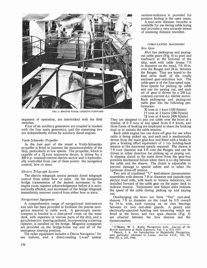
FIG. 3-ENGINE ROOM, LOOKING FORWARD
sequence of operation, are interlocked with the field switches.
Four of six auxiliary generators are coupled in tandem with the four main generators, and the remaining two are independently driven by auxrnary diesel engines.
Voith-Schneider Propeller In the fore part of the vessel a Voith-Schneider
propeller is fitted to increase the manoeuvrability of the ship, particularly at low speeds. The propeller, which is capable of a 2} tons transverse thrust, is driven by a 200 h.p. constant-current electric motor and is hydraulically controlled from one of three points: the navigation control, bow or stern.
Electric Telegraph System
The electric telegraph system permits direct telegraph control from either bow or stern. On the navigation bridge transmission of the desired movement to the engine room requires acknowledgement before it is automatically effected, and movement of the bridge telegraph immediately removes control from. either bow or stern.
Navigational Equipment
A comprehensive range of navigational instruments and aids has been provided to facilitate the precise navigation essential to cable work. A gyroscopic master compass is located in a dust-proof room on the main deck, with repeaters in various parts of the ship, and a gyro/telemotor steering pedestal, incorporating a steering repeater, is installed on the bridge. Magnetic compasses are provided on the bridge-house top and aft of the emergency steering position.
The radar equipment includes a Decca Navigator,1 for use inshore, and a direct-reading Loran2 system
136
receiver-indicator is provided for position finding in the open ocean.
A taut-wire distance recorder is available for use during cable laying and provides a very accurate means of assessing distance travelled.
CABLE-LAYING MACmNERY
Bow Gear
Alert has picking-up and payingout cable gears (Fig. 4) to port and starboard at the fore-end of the ship, each with cable drums 7 ft in diameter on the tread, 7 ft 10 in. over the flanges and 24 in. between the flanges. They are keyed to the final drive shaft of the totally enclosed gear-reduction box. The cable-gear is of the four-speed type, three speeds for picking up cable and one for paying out, and each set of gear is driven by a 250 h. p. constant-current d.c. electric motor. Each picking-up and paying-out cable gear has the following performance.
30 tons at 1 knot (100 ft/min) 15 tons at 2 knots (200 ft/rnin) 7t tons at 4 knots (400 ft/min)
They are designed to pay out cable over the bows at a tension of 0-9 tons at any speed from 0-8 knots, and three forms of braking are employed to share the braking load or to sustain the cable tension.
Each cable engine has one draw-off gear for use when cable is being picked up, and each unit is mechanically driven from the main gear-box and fitted with a brake to give a braking effort equivalent of 1 ton holding-back tension at the maximum speeds required. The sheave is 7 ft root diameter and 8 ft over the flanges, and can be driven in either direction for picking up or paying out. A slipping clutch in the main drive from the gear-box prevents mechanical failure when there is no slip between the cable and the sheave. The clutch is adjustable to prevent damage to special cables and to select the optimum draw-off tension.
Two sets of combined "U" lead-sheave dynamometer assemblies with sheaves 7 ft in diameter and capsule-type electric load cells, with leads to tension indicators, are installed forward of the cable gear on the upper deck to indicate tension. Tachometer and Selsyn units indicate the speed of the cable during picking up and paying out.
Overhanging the bows are three "Vee" cast-steel sheaves 7 ft in diameter on the tread by 8 ft overall by 14 in. wide, each running on its· own bearings between its own cast-steel guards. A gantry and electrically-operated hoisting and traversing winch are fitted at the bows, and two span sheaves (Fig. 5) are situated between the bow sheaves and the dynamometers.
1 O'BRIEN, W. J. Radio Navigation Aids. Joumal of the British I11stit11tio11 of Radio Engineers, Vol. 7, p. 215, 1947.
2 PIERCE, J. A. An Introduction to Hyperbolic Navigation, with particular reference to Loran. Journal l.E.E., Vol. 93, Part III, p. 243, 1946.
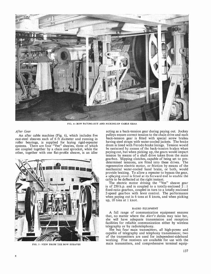
FIG. 4-BOW PA YING-OUT AND PICKING-UP CABLE GEAR
After Gear
An after cable machine (Fig. 6), which includes five cast-steel sheaves each of 6 ft diameter and running in roller bearings, is supplied for laying rigid-repeater systems. There are four "Vee" sheaves, three of which are coupled together by a chain and sprocket, while the other, together with one fiat-profile sheave, is an idler
FIG. 5-VIEW FROM THE BOW SHEAVES
E
acting as a back-tension gear during paying out. Jockey pulleys ensure correct tension to the chain drive and each back-tension gear is fitted with special screw brakes having steel straps with water-cooled jackets. The brake drum is lined with Ferodo brake linings. Tension would be sustained by means of the back-tension brakes when paying out, but when picking up, the gears would impart tension by means of a shaft drive taken from the main gearbox. Slipping clutches, capable of being set to predetermined tensions, are fitted into these drives. The regenerative electric motor, or friction by means of the mechanical water-cooled hand brake, or both, would provide braking. To allow a repeater to bypass the gear, a splaying stool is fitted at its forward end to enable the cable to be deflected at the right instant.
The electric motor driving the "Vee" sheave gear is of 250 h.p. and is coupled to a totally enclosed 2 : 1
fixed-ratio gearbox, coupled in turn to a totally enclosed 2-speed gearbox with lever control. The performance when paying out is 6 tons at 8 knots, and when picking up, 10 tons at 1 knot.
RADIO EQUIPMENT
A full range of communication equipment ensures that, no matter where the Alert's duties may take her, she will have adequate transmission and reception facilities for reliable communication either by wireless telegraphy or by radiotelephony.
She bas four main transmitters, all high-power and capable of telegraphy and telephony transmission; two of the transmitters are used for independent-sideband working. Five receivers are available for use with the main transmitters, and comprehensive terminal equip-
137
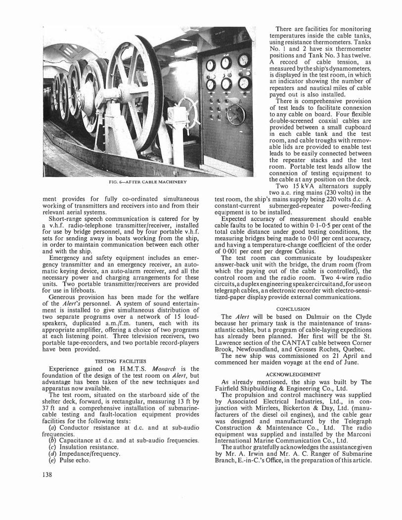
FIG. 6-AFTER CABLE MACHJNERY
ment provides for fully co-ordinated simultaneous working of transmitters and receivers into and from their relevant aerial systems.
Short-range speech communication is catered for by a v.h.f. radio-telephone transmitter/receiver, installed for use by bridge personnel, and by four portable v.h.f. sets for sending away in boats working from the ship, in order to maintain communication between each other and with the ship.
Emergency and safety equipment includes an emergency transmitter and an emergency receiver, an automatic keying device, an auto-alarm receiver, and all the necessary power and charging arrangements for these units. Two portable transmitter/receivers are provided for use in lifeboats.
Generous provision has been made for the welfare of the Alert's personnel. A system of sound entertainment is installed to give simultaneous distribution of two separate programs over a network of 15 loudspeakers, duplicated a.m./f.m. tuners, each with its appropriate amplifier, offering a choice of two programs at each listening point. Three television receivers, two portable tape-recorders, and two portable record-players have been provided.
TESTING FACILITIES
Experience gained on H.M.T.S. Monarch is the foundation of the design of the test room on Alert, but advantage has been taken of the new techniques and apparatus now available.
The test room, situated on the starboard side of the shelter deck, forward, is rectangular, measuring 13 ft by 37 ft and a comprehensive installation of submarinecable testing and fault-location equipment provides facilities for the following tests:
(a) Conductor resistance at d.c. and at sub-audio frequencies.
(b) Capacitance at d.c. and at sub-audio frequencies. (c) Insulation resistance. (d) Impedance/frequency. (e) Pulse echo.
138
There are facilities for monitoring temperatures inside the cable tanks, using resistance thermometers. Tanks No. L and 2 have six thermometer positions and Tank No. 3 has twelve. A record of cable tension, as measured by the ship's dynamometers, is displayed in the test room, in which an indicator showing the number of repeaters and nautical miles of cable payed out is also installed.
There is comprehensive provision of test leads to facilitate connexion to any cable on board. Four flexible double-screened coaxial cables are provided between a small cupboard in each cable tank and the test room, and cable troughs with removable lids are provided to enable test leads to be easily connected between the repeater stacks and the test room. Portable test leads allow the connexion of testing equipment to the cable at any position on the deck.
Two 15 kV A alternators supply two a.c. ring mains (230 volts) in the
test room, the ship's mains supply being 220 volts d.c. A constant-current submerged-repeater power-feeding equipment is to be installed.
Expected accuracy of measurement should enable cable faults to be located to within 0· 1-0·5 per cent of the total cable distance under good testing conditions, the measuring bridges being made to 0·01 per cent accuracy, and having a temperature-change coefficient of the order of 0·001 per cent per degree Celsius.
The test room can communicate by loudspeaker answer-back unit with the bridge, the drum room (from which the paying out of the cable is controlled), the control room and the radio room. Two 4-wire radio circuits, a duplex engineering speaker circuit and, for useon telegraph cables, an electronic recorder with electro-sensitized-paper display provide external communications.
CONCLUSION
The Alert will be based on Dalmuir on the Clyde because her primary task is the maintenance of transatlantic cables, but a program of cable-laying expeditions has already been planned. Her first will be the St. Lawrence section of the CANT AT cable between Corner Brook, Newfoundland, and Grosses Roches, Quebec.
The new ship was commissioned on 21 April and commenced her maiden voyage at the end of June.
ACKNOWLEDGEMENT
As already mentioned, the ship was built by The Fairfield Shipbuilding & Engineering Co., Ltd.
The propulsion and control machinery was supplied by Associated Electrical Industries, Ltd., in conjunction with Mirrlees, Bickerton & Day, Ltd. (manufacturers of the diesel oil engines), and the cable gear was designed and manufactured by the Telegraph Construction & Maintenance Co., Ltd. The radio equipment was supplied and installed by the Marconi International Marine Communication Co., Ltd.
The author gratefully acknowledges the assistance given by Mr. A. Irwin and Mr. A. C. Ranger of Submarine Branch, E.-in-C.'s Office, in the preparation of this article.
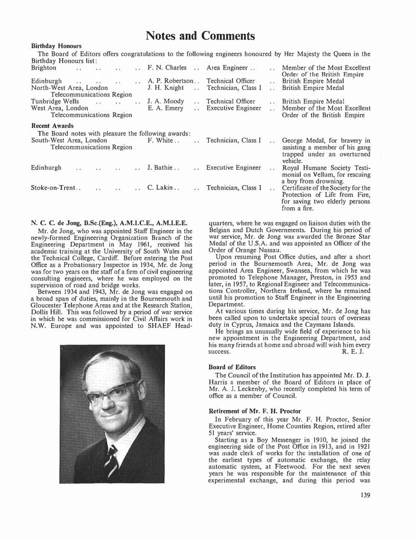
Notes and Comments Birthday Honours
The Board of Editors offers congratulations to the following engineers honoured by Her Majesty the Queen in the Birthday Honours list: Brighton
Edinburgh North-West Area, London
Telecommunications Region Tunbridge Wells West Area, London
Telecommunkations Region
Recent Awards
F. N. Charles
A. P. Robertson . .
J. H. Knight
J. A. Moody E. A. Emery
The Board notes with pleasure the following awards: South-West Area, London F. White ..
Telecommunications Region
Edinburgh J. Bathie ..
Stoke-on-Trent .. C. Lakin . .
N. C. C. de Jong, B.Sc.(Eng.), A.M.I.C.E., A.M.I.E.E. Mr. de Jong, who was appointed Staff Engineer in the
newly-formed Engineering Organization Branch of the Engineering Department in May 1961, received his academic training at the University of South Wales and the Technical College, Cardiff. Before entering the Post Office as a Probationary Inspector in 1934, Mr. de Jong was for two years on the staff of a firm of civil engineering consulting engineers, where he was employed on the supervision of road and bridge works.
Between 1934 and 1943, Mr. de Jong was engaged on a broad span of duties, mainly in the Bournemouth and Gloucester Telephone Areas and at the Research Station, Dollis Hill. This was followed by a period of war service in which he was commissioned for Civil Affairs work in N.W. Europe and was appointed to SHAEF Head-
A1·ea Engineer ..
Technical Officer Technician, Class I
Technical Officer Executive Engineer
Technician, Class I
Executive Engineer
Technician, Class I
Member of the Most Excellent Order of the Briti�h Empire British Empire Medal British Empire Medal
British Empire Medal Member of the Most Excellent Order of the British Empire
George Medal, for bravery in assisting a member of his gang trapped under an overturned vehicle. Royal Humane Society Testimonial on Vellum, for rescuing a boy from drowning. Certificate of the Society for the Protection of Life from Fire, for saving two elderly persons from a fire.
quarters, where he was engaged on liaison duties with the Belgian and Dutch Governments. During his period of war service, Mr. de Jong was awarded the Bronze Star Medal of the U.S.A. and was appointed an Officer of the Order of Orange Nassau.
Upon resuming Post Office duties, and after a short period in the Bournemouth Area, Mr. de Jong was appointed Area Engineer, Swansea, from which he was promoted to Telephone Manager, Preston, in 1953 and later, in 1957, to Regional Engineer and Telecommunications Controller, Northern Ireland, where he remained until his promotion to Staff Engineer in the Engineering Department.
At various times during his service, Mr. de Jong has been called upon to undertake special tours of overseas duty in Cyprus, Jamaica and the Caymans Islands.
He brings an unusually wide field of experience to his new appointment in the Engineering Department, and his many friends at home and abroad will wish him every success. R. E. J.
Board of Editors The Council of the Institution has appointed Mr. D. J.
Harris a member of the Board of Editors in place of Mr. A. J. Leckenby, who recently completed his term of office as a member of Council.
Retirement of Mr. F. H. Proctor
In February of this year Mr. F. H. Proctor, Senior Executive Engineer, Home Counties Region, retired after 51 years' service.
Starting as a Boy Messenger in 1910, he joined the engineering side of the Post Office in 1913, and in 1921 was made clerk of works for the installation of one of the earliest types of automatic exchange, the relay automatic system, at Fleetwood. For the next seven years he was responsible for the maintenance of this experimental exchange, and during this period was
139
specially commended for action in maintaining service during floods.
Promoted in 1930 to the rapidly growing Automatic Trunking Group in the Engineer-in-Chief's office under Mr. G. F. O'dell, he was concerned for the next 10 years with the trunking design of automatic exchanges of various types. On the introduction of Regionalization_, he was retained in Equipment Branch to prepare Engineering Instructions on auton1atic exchange planning and design. After the war he was very 1nuch concerned with the introduction of n1ulti-fee nletering in nondirector exchanges and the various expedients required to expand the auton1atic telephone syste1n to nleet the
post-war demand for service. In 1952 Mr. Proctor was transferred to the Home
Counties Region and was engaged in the planning of the first cordless switchboard installation at Thanet exchange and the early planning of the new zone centres at Cambridge, Reading and Tunbridge Wells.
The complex trunking rearrangements resulting from the introduction of group charging and, later, S.T.D. were a worthy challenge to his experience, and on his retirement he left behind firm plans for a number of S.T.D. installations as well as many friends who will recall his ever-cheerful and friendly disposition and his kindly good humour.
Institution of Post Office Electrical Engineers
Results of Essay Competition, 1960-61
A prize of £6 6s. and an Institution Certificate have been awarded to the following competitor in respect of the essay named:
E. G. Clayton, Technical Officer, Norwich. "Further Education and the Post Office."
Prizes of £3 3s. each and Institution Certificates have been awarded to the following four competitors:
J. W. Rolph, Leading Technical Officer, Engineering Department (Subscribers' Apparatus and Miscellaneous Services Branch). "Some Developments of P.V.C. Extensible Handset Cords."
D. A. Hill, Technical Officer, Skegness. "Informing the Staff."
W. M. Cormack, Technical Officer, Wick. "A Basic Description of Radio System 10/3."
J. A. Wood, Technical Officer, Herley. "Electronic Telegraph Switching."
Institution Certificates of Merit have been awarded to: H. H. Templeton, Technician I, Dumfermline. "General
Observations on Telegraph Machines and Improvements in their Design."
L. S. Hurst, Technical Officer, Tunbridge Wells. "The Secondary Cell-A Centenarian.''
R. Kaye, Technical Officer, Barnsley. "Coming to Grips with the 2000-type Switch."
E. G. Wilson, Technical Officer, Narborough. "The Changing Face of the Unit Automatic Exchange."
D. F. Angrave, Technician IIA, Leicester. "Magnetic Recording and its Application in Telephony."
The Council of the Institution is indebted to Mr. J. Stratton, Chairman of the judging panel, for the following review of the five prize-winning essays:
The first prize was awarded to Mr. E. G. Clayton, Technical Officer, Norwich Telephone Area, for his essay on "Further Education and the Post Office." The author divides his essay into two parts, in the first of which he deals with the need for a change in attitude to further education by members of the Post Office engineering staff. He discusses the studies that should be undertaken according to the aptitude of the man concerned and according to his probable future, e.g. either craftsman or technician. He suggests that an improvement on "day release" would be a "block release scheme" with periods of three to four weeks' release at a lime. He then stresses the need, particularly for those who are interested in further advancement, of broadening either the syllabus or liberalizing their studies, and suggests a possible course of studies. This leads him to the second part of his essay, in which he examines the case for a
140
more liberal education and gives examples of what is being attempted, particularly in this country.
The second prize was awarded to Mr. J. W. Rolph, Leading Technical Officer in the Subscribers' Apparatus and Miscellaneous Services Branch Laboratory, Engineering Department, for his essay on "Some Developments of P. V.C. Extensible Handset Cords." The author mentions the disadvantages of the plaited type of cord and describes the way in which the new p.v.c. helical coiled type was developed. Starting with the invitation to cord manufacturers to submit samples, he describes how the samples were tested and developed. In some cases it was necessary also to develop a means of carrying out the required test. For example, a stretching machine was constructed, and not only the behaviour of the sheath was watched but the cords were tested periodically for noise. The author mentions the advantages in appearance, cheapness of manufacture and maintenance of p.v.c. insulated and sheathed cord. He goes on to discuss the construction in more detail and looks forward to further improvements with the continued development of synthetic materials.
The third prize was awarded to Mr. D. A. Hill, Technical Officer, Skegness, Peterborough Telephone Area, for his essay on "Informing the Staff." The author starts by stressing the need for a skilled and well-informed staff, particularly with regard to the developments that have taken place recently. He states that a well-informed staff is an efficient and happy one and he details the various methods used to in1part information during staff training, such as youth-in-training courses, technical classes and correspondence courses, and he follows up other courses that the staff can take, such as those requiring day release, the City & Guilds and National Certificate courses, and the Central Training School courses for established staff. He then deals with what he calls information by the written word, describing briefly such methods as Engineering Instructions and Staff Handbooks, and mentions the semi-official staff bulletins; for instance, those on Regional maintenance matters. Neither does he overlook journals and magazines that can be purchased by the staff, such as the Post Office Electrical Engineers' Journal and the Post Office Teleco111n1u11icatio11s Journal. He concludes by stressing the need to present information to the staff by means of all the varieties of modern methods of presentation and with results that depend upon the "receptiveness and responsiveness of the staff."
The fourth prize was awarded to Mr. W. M. Cormack, Technical Officer, Wick, Aberdeen Telephone Area, for his essay "A Basic Description of Radio System 10/3." Jn this essay the author describes the mainland-Orkney section of the microwave radio-relay system linking the Shetland and
Orkney Islands with the rest of the country. He describes a radio system that can provide 240 telephone circuits and illustrates the description Y.lith schematic diagrams of the link, terminal transmitter, terminal receiver and repeater. He concludes with a description of the aerials and their associated waveguides.
Mr. J. A. Wood, Technical Officer, Harley, Brighton Telephone Area, was awarded the fifth prize for his essay "Electronic Telegraph Switching." In this essay the author describes the electronic telegraph exchange that has been installed at Gatwick Airport. It is known as STRAD, an abbreviation of "signal transmitting, receiving and distributing." First, he briefly describes the purpose of this equipment, namely to enable telegraph messages to be received, stored and retransmitted to the required destinations automatically and under the control of an operator. This is followed by a fairly detailed description of the system and, in particular, of the magnetic drums used. He concludes with a short description of other features and suggests that as time progresses we are likely to see the introduction of more of these switching systems.
The Council of the Institution records its appreciation to Messrs. J. Stratton, W. B. Jago and C. Grant, who kindly undertook to adjudicate upon the essays entered for the competition.
N.B.-Particulars of the next co111petitio11, entry for which closes on 31 Deceniber 1961, wifl be published later.
Institution Field Medal Awards, 1959-60 Session
In addition to the lnstitution Senior and Junior silver and bronze medals, up to three bronze medals, the Field Medals, are awarded annually for the best papers read at meetings of the Institution on field subjects primarily of Regional interest.
Field Medals were awarded to the following authors for papers read during the 1959-60 session:
J. R. Young, Cardiff (Wales and Border Counties). "Maintenance and the Area Organization."
I<. R. Seamans and F. D. Payne, Cambridge (Home Counties Region). "Oil-Fired Boilers."
R. J.. Forster, Newcastle (North Eastern Region). "Gas Pressurized Telephone Cables."
Precis of the medal-winning papers arc as follows:
Maintenance and the Area Organization
This is a thought-provoking paper in that it discusses the pros and cons of various novel proposals for Area organization to achieve efficient maintenance practices and procedures. Staff functions and responsibilities, as well as the procedures which may be adopted to use the staff to the best advantage, are discussed. The merits of functional versus territorial working in the field are examined, and the author 1.:oncludes lhat a syste1n of semi-functional working has considerable merit in small Areas. In the bigger exchanges, the author suggests that efficient working is promoted if a man is responsible for a section of the exchange, the section including various types of equipment, rather than if the man is responsible for a particular type of switch only. The overhaul fault-history scheme is much favoured and extension of the scheme is advocated.
Oil-Fired Boilers
This paper discusses the characteristics and properties of the various fuel oils, the construction and merits of the various types of burners in use, and describes the boilers used for oil-fired central heating. Automatic temperaturecontrol, fuel storage and comparative costs of solid-fired and oil-fired installations are also dealt with. The interest throughout is in relation to Post Office buildings and the
descriptions and treatment given make this a paper that should prove to be particularly useful to those engineering officers engaged on accommodation and building services matters.
Gas Pressurized Telephone Cables
This paper describes the principles and practice of gas pressurization as applied to trunk, junction and local cables, and gives examples of the application of the techniques to cables in the Newcastle Telephone Area. The survey given in the paper embraces such aspects as gas seals, stores and equipment, testing apparatus and fault-location methods. Estimated costs are given for the pressurization of audiofrequency and coaxial cables and an indication of the cost of applying the continuous flow method of pressurization to local cables in the Whitley Bay area is also included. The paper ends with a brief survey of improvements in techniques which are likely to materialize in the near future.
S. WELCH, General Secretary.
Additions to the Library
Library requisition forms are available from Honorary Local Secretaries, from Associate Section Centre Secretaries and representatives, and from the Librarian, I.P.0.E.E., G.P.O., 2-12 Gresham Street, London, E.C.2.
2621 The Nature of the Unil'erse. F. Hoy]e (Brit. 1960). A revised edition of the Reith Lectures.
2622 Transistors-Circuits a11d Serrici11g, B. R. A. Bettridge (Brit. 1960).
A short booklet on the subject. 2623 Thyratrons. C. M. Swenne (Dutch 1960).
Designed to introduce the electrical engineer to the applications of thyratrons, and excludes elaborate physical and mathematical treatment.
2624 Radio and Tele11isio11 Serl'icing. Edited by J. P. Hawker and J. Reddihough (Brit. 1960).
Contains circuits and servicing data for 1959-60 models.
2626 Electronic Eq11ipn1e111 Reliability. G. W. A. Du1nn1er and N. Griffin (Brit. 1960).
A summary of present knowledge on the subject; an attempt has been made to sort and classify that knowledge.
2627-The World of Mathenutlics (4 Volumes). J. R. Newman 2630 (Brit. 1960).
The volumes are an anthology of the literature of mathematics, the richness of its ideas and multiplicity of its aspects.
Vol. I: General Survey; Historical and Biographical; Arithmetic, Numbers and the Art of Counting; Mathematics of Space and Motion.
Vol. II: Mathematics and the Physical World; Mathematics and Social Service; The La'�,.s of Chance.
Vol. Ill: Statistics and the Design of Experiments; The Supreme Art of Abstraction; Group Theory; Mathematics of Infinity; Mathematical Truth and the Structure of �athematics; The Mathematical Way of Thinking; Mathematics and Logic; The Unreasonableness of Mathematics; How to solve it; The Vocabulary of Mathematics; Mathematics as an Art.
Vol. IV: The Mathematician; Can a Machine Think; Mathematics in Warfare; A Mathematical Theory of Art; Mathematics of the Good; Mathematics in Literature; Mathematics in Music; Mathematics as a Culture; Amusements, Puzzles and Fancies.
W. D. FLORENCE, Librarian.
141
Regional Notes
Midland Region
THE ROSS SPUR The general efTe<.:l of road works and major projects,
such as motorways, on the Post Office engineering organization is well known. This note outlines the work necessitated in the West Midland Area by the Ross Spur motorway.
Th� diversi�n of existing plant was necessary along the l i- miles of this motorway within the West Midland Area but a considerable amount of work was also involved in providing four steel pipes for future cables. Five separate sections of new track were concerned, ranging in length from 820 yd along the approach viaducts and the Queenhill bridge over the River Severn, and two viaducts of 180 yd and 130 yd over streams and marshy ground, to two short lengths of 50 yd and 20 yd under road and rail bridges.
The e_ventual location and formation of the steel pipes was decided only after detailed analysis of all the structural problems involyed, including lack of space in the verges, and the expansion and contraction not only of the bridges but of the pipes themselves.
The main bridge and its approaches are so designed that temperature changes are counteracted by expansion and ar�iculated jo!nts across the bridge structure, the joints being located 1n pairs approximately 45 ft apart in alternate spans. A longitudinal movement of It in. is allowed for at each of the expansion joints.
The type of cable eventually to be drawn into the pipes was envisaged as a coaxial cable having a diameter of 2·75 in. with a minimum bending radius of 18 in. With such a cable it would not be practicable due to Jack of width in the 2 ft 6 in. verges, to house a con;entional "expansion l�op." Various m�thods of overcoming this particular difficulty were examined, such as bypassing the bridge completely or using smaller-diameter cables. It was finally recommended by the External Plant and Protection Branch of the Engineering Department, and later agreed by the m�torway con�ulting engineers, that two pipes should be �aid on each .side of �he motorway in "pipe bays" to be incorporated 111 the bndge structure. Expansion chambers, 17 ft. 6 in. long by 2 ft 7 in. wide by 5 in. deep, have been provided at each of the 28 expansion joints to accommodate plug joints having small cables looped around the chamber and across the bridge joint.
The expansion chambers, which are 164 ft apart in the appro�ch spans and 300 ft in the main bridge, are covered by 3
. 1n. reinforced�concrete slabs, readily removable to
prov�de access for cabling and jointing purposes. It was not considered necessary to provide expansion chambers at the articulated joints, the pipes being wrapped with sisalcraft paper and enclosed in a concrete surround. . Betw�en expansion joints the movement of the steel pipes, 1n rel�t101� to the bri<;tge structure, is allowed for by laying the pipes 1n sand, \.vh1ch is retained at each end of a section by light concrete walls. The surface is paved as for a footway, with tarmacadam or paving slabs.
In the smaller viaducts over the streams, where the movement between spans is estimated at /11 in., it was decided that chambers for cabling and jointing purposes would not be necessary, and that the pipes could be concreted in the bays .. Expc:insion is catered for by arranging the joints to coincide with those of the bridge, the outside end of the sockt;l of one pipe being flush with the bridge structure on one side of the JOtnt and the spigot of the next pipe projecting across the gap into the socket but not being driven quite home.
Two steel pipes have been laid across the motorway at each end of the 1 �-mile length within the West Midland Area to I?rovid� connexion between the pipes on either side of the bndge viaducts and the future 4-way duct which it is anticipated may be laid on the north side.
142
A non-competitive contract for laying the pipes under normal Post Office supervision was arranged with the bridge contractors, A. E. Farr, Ltd., and the work is no\.v complete.
F. L. S.
South Western Region
TEMPORARY TELEVISION LINKS Corrosion, due to the smoky atmosphere in the Severn
Tunnel, recently made it necessary to renew the bearers carrying the main underground cables through the tunnel. The cables concerned were the Bristol-Newport audio cable the Bristol-Cardiff carrier cables, and the Bristol-Newpor t coaxial cabl1,;. This last cable carries the television programs for both the British Broadcasting Corporation transmitter at
Wenvoe and the Independent Television Authority transmitter at St. Hilary Down. Jn view of the fact that work on the cables could only be done on selected Sunday mornings because of the railway traffic, and that in the event of a fault arising on the coaxial cable due to moving the joints it might not have been possible to clear the fault until the following Sunday, arrangements were made for protection channels to be provided for the two main television-program links.
The protection channels consisted of two unidirectional radio links from Pilning repeater station on the English side of the tunnel to Castleton radio station on the Welsh side. The two sets of outside-broadcast type radio equipment were supplied by the Inland Radio Planning and Provision Branch, Engineering Department, and the transmitters were installed on tables in Pilning repeater station and the receivers at Castleton radio station. The links operated in the 4,000 Mc/s band, and parabolic aerials were used at both ends of the radio links. The Bristol Area staff under the direction of officers of the Inland Radio Pla�ning and Provision Branch, Engineering Department, and the South
Western Region, erected the aerial at Pilning, using a series of brackets which were made locally, on three 40 ft medium poles adequately stayed. The waveguide was run from the aerial, down the poles, along a row of extra-light poles and into the repeater station through a ventilator. The coaxial systems were fitted with branching pads at Pilning repeater station and both cable and radio links were fed in parallel with the picture signals. It was found that the secondharmonic distortion in the radio equipment made it necessary to disconnect the 308 kc/s pilot from the coaxial system when using the radio link.
The whole work was completed in three weeks which included the Christmas holidays and, although they were never used in actual service, pictures acceptable to both the Independent Television Authority and the British Broadcasting Corporation were carried over the radio links.
H.W.N.L.
Wales and Border Counties
SHIP-IN-DOCK TELEPHONE SERVICES IN "DANGER AREAS"
In connexion with the provision of a new Esso oil refinery at Milford Haven, Pembrokeshire, a ship-in-dock telephone service was provided recently to three berths at the end of a l,180 yd jetty.
The installation presented two problems, firstly to select and install equipment that would conform to the standards laid down in the "British Standard Code of Practice, C.P.1003, 1948, for The Installation and Maintenance of Flameproof Electrical Equipment for Industries Other Than Coal Mining," and secondly to so install the equipment that damage by mishandling would be reduced to a minimum.
From the shore end of the jetty, 1,100 yd of 30-pair 20 lb/mile polythene-insulated p.v.c. sheathed cable, with single-wire armouring and outer p.v.c. sheath, was laid in specially provided cable trays to the marine terminal, situated near the end of the jetty and just outside the "Danger Area." The cable wa<; terminated on a standard Post Office distribution case. From this point polythene cables, armoured and p.v.c. sheathed, were provided to Simplex flame-proof terminal boxes (Catalogue No. F.7181) specially modified to take a 10-pair connexion strip. These boxes arc very adaptable and can easily be used to accommodate Post Office block-terminals or connexion strips. Walsall Flame-Proof Glands No. 1762 BX were used between the armoured ea ble and Simplex box.
From the terminal boxes to the socket outlets 2-core Pyrotenax mineral-insulated copper-sheathed cables, p.v.c.scrved overall to prevent corrosion of the copper sheathing by salt water were used.
·
Each telephone line was made available at two points, one at each end of the berth, so that whichever way round the ship berthed a socket outlet was available at a point accessible to the captain's office. Separate cables were run from the Simplex box to each socket outlet, and a Walsall Pygmy Switch, Type 1895 BX/T, v-,ras interposed in each cable to isolate the socket outlets for maintenance purposes or when they are not in use. The socket outlets used are Walsall 1982 BX, which have recently been modified to incorporate an external locking device to prevent the operator from attempting to withdraw the plug without first of all switching off.
A 3-core 23/'0076 in. cable with tinned copper conductors is used for ship to jetty. The three cores are laid up with strengthening cords and a layer of Neoprene, and the insulant is vulcanized rubber. A tinned copper-braided screen provides additional mechanical strength, the whole
being encased in a heavy Neoprene sheath; 100 yd lengths are used locally as the standard length. The cable was supplied by British Insulated Callender's Cables, Ltd. One end of the cable was terminated on a Walsall Plug No. 1570 BX, and the other end on a Reyrolle Flameproof Inlet Plug No. 4060 SV. Storage of the cable \Vhen not in use presented a problem; eventually ordinary garden-hose reels mounted on stands were used.
The telephones are an Ericsson Hameproof type (Telephones No. 266). These were housed in specially designed cases made of marine-quality resin-bonded plywood, and the ftameproof bells (No. 69A) were also fitted inside the case. On the outside of the case a Reyrolle Socket No. 4000 SV was mounted, and wiring between the bell and the socket was carried out in Pyrotenax, p.v.c. served. To the Reyrolle socket a Reyrolle flanged base No. 4072 was added to provide the essential 1 in. flame path specified in the Code of Practice C.P.1003. All terminal joints were finished with Hellerman sleeves for the sake of appearance and as added protection.
The Telephone No. 266, housed in its carrying case, and 100 yd of flexible cable coiled on the reel provide a
complete and easily transportable unit enabling the telephone to be installed on the ship by two men in approximately five minutes. Spare reels of cable already made up with plugs and sockets are stored at the marine terminal, together with spare Telephones No. 266 fitted in their cases complete with bells. Replacements of cable and telephone can be made immediately by the operators.
To date several hundred tankers have used the ship-indock installation. The detailed descriptions of the cables and apparatus used are given in the hope that the information might be helpful to others \Vho have a similar installation to design or maintain.
J. s.
Associate Section Notes
Bath Centre
Two papers were presented to the Centre in the first quarter of 1961. Both these papers have been submitted for inclusion in the national Associate Section competition.
The first paper, on "Transistors," was given in January by Mr. C. W. Read. Mr. Read, a former secretary of the Centre, presented this, his third lecture to the Centre, in a concise yet explicit manner and was complimented hy Mr. Vranch, the Centre's chairman.
In February, the second paper was read by the secretary, Mr. D. G. Rossiter. Theories of atomic and nuclear structure were presented, and the applications of atomic energy, both creative and destructive, were explained. The lecture was illustrated by the film "The Conquest of the Atom."
The annual "Telecommunications Ball" was held in February at the Pump Room, Bath, and was once again both a social and financial success despite formidable opposition from a rival "Rugger Ball."
Throughout the year, and especially during the last quarter, close liaison has been maintained with the Gloucester Centre. ln March, the Gloucester Centre was host to the Bath Centre for an inter-centre quiz at Cheltenham. The organizers deserved the congratulations received for an excellent evening. It was a close contest but the Bath members were the eventual winners, thus completing a home-and-away double.
In April, a joint meeting of the Bath and Gloucester Centres was held at Bath, when Mr. Knox, President of the Associate Section, spoke on "Appraisements and Promotions." The meeting was excellently attended and well received. I would like, through the aegis of the Journal, to
heartily recommend both speaker and subject to all other Associate Centres. In replying to the vote of thanks proposed by the Bath chairman, Mr. Knox (a native of the West country) spoke of the warmth and friendliness of the familiar "Burr," and its effect on the exiled ear.
D. G. R.
Shrewsbury Centre
A social evening was held on Friday, 10 March. It was a very successful evening, the members present having a thoroughly good time. A lecture, ''Gas Pressurization of Telephone Cables," was given in the automatic telephone exchange on 27 March by Messrs. H. B. Cooper and R. A. M. Light of Cambridge. We were very pleased to welcome members from the Hereford branch, several members of the senior section, and guests from the Midland Electricity Board. The three visits during June to the Granada television studios in Manchester were the finish of our 1960-61 session.
The annual general meeting will be held at the automatic telephone exchange on Friday, 8 September. Please come along and give us your support; our membership is now 150, and the committee feel that a really successful Centre depends upon the full support of all members.
H. C.
Hereford Centre
The 1960-61 session has ended after a full and varied program of fairly well-attended meetings.
The annual general meeting was held on 24 November, and the officers elected were: Clrair111a11: Mr. G. Jenkins;
143
Vice-Cliair111a11: Mr. E. Wellington; Honorary Secretary: Mr. E. A. Talboys; Treasurer: Mr. I-I. D. Goodman; Co1111nittee Me111bers: Messrs. F. E. R. Page, D. C. Booton and A. T. Daniels.
On 8 December, members visited the Hereford automatic telephone exchange to see the S.T.D. equipment.
The annual Mullard film meeting took place on 25 January and provided a very educational and entertaining evening.
Nearly 50 persons attended the meeting on 2 February to hear the paper on "The Pay-on-Answer Call Office System" given by Messrs. J. D. Collingwood and E. Newell of the Subscribers' Apparatus and Miscellaneous Services Branch and the Telephone Exchange Systems Development Branch, Engineering Department, respectively. We are grateful for their visit to this Centre and for answering the many queries arising from their lecture.
A visit was paid to Stourport power station on 2 March, and on 27 March Hereford Centre members who travelled to the Shrewsbury Centre lo attend the meeting on "Gas Pressurization of Telephone Cables," by Messrs. H. B. Cooper and R. A. M. Light, of Cambridge, were rewarded with a most interesting talk and an opportunity to see the equipment and models provided to illustrate the paper.
The final item in the program was a visit to the factory of Cadbury Bros., Ltd., at Bournville, which took place on 13 April.
We look forward to an equally interesting 1961-62 session and hope that new members will come forward and increase the strength of this Centre.
E. A. T.
Chester Centre
The annual general meeting was held in the automatic telephone exchange on 9 February and the following members were elected to Office: Chainnan: Mr. D. Simmonds; Secretary: Mr. E. M. Walsh; Treasurer: Mr. D. B. Hickie; Con11nittee: Messrs. T. Parsonage, W. Williams, B. T.Childe, A. Fleet, S. Hoyle, J. H. Roberts, R. Furnival and E. W. Whitley; Librarian: Mr. M. Jones.
The 13.st session included a visit to the de Havilland Aircraft Co., Ltd., Chester, where a number of Comet 4 airliners were in various stages of assembly. We were entertained to a very interesting tour of the factory, and members were much impressed with the complexity and size of the aircraft. An assembly line technique, with test and inspection at each stage, is used, and the management and staff must be congratulated on the organization and effort required to complete the project.
A film show and Jccture by Mullard, Ltd., attained its usual high standard and we look forward to the time when we can arrange a visit to the Mullard radio-equipment factory.
The program for the forthcoming session is being prepared and members will be advised when arrangements have been completed.
E. M. W.
Cornwall Centre
Messrs. Cooper and Light, of Cambridge, gave a paper in January on "Gas Pressurization of Telephone Cables," and brought along a considerable a1nount of equipn1ent for members to see. Because of the opening of S.T.D. in Truro, the February meeting was postponed until 2 March when Mr. Cutliffe, of Plymouth, gave a talk entitled "My Job." After Mr. Cutliffe's talk members expressed surprise at the variety of jobs done by the traffic side of the Post Office.
On 29 March, Mr. Long, of the South Western Regional Office, gave a lecture on the Bristol-Plymouth Independent Television Authority link, and illustrated this interesting talk with film strip.
Our annual general meeting was held in April. We hope to arrange the following visits for the summer session: Culdrose Royal Navy Auxiliary Service, Lizard lifeboat station, British Railways electrical signal box at Plymouth
144
North Road station, Independent Television Authority station at Plymouth, and a \Veek-end visit to the London Telecommunications Region.
A.R. B.
Ayr Centre
The Ayr Centre concluded a successful session with a visit to Killoch Colliery on 20 May. Of the Centre's two visits and four meetings the visits were, on the whole, better attended, the average attendances at the visits being 25 members and at the meetings 19 members. The subjects of the meetings were as follows: (a) lecture on the solar system, (h) discussion on any subject submitted by the members, (c) lectures on the conversion of the telephone system to automatic working and S.T.D., and (d) a lecture entitled "Maths Made Interesting."
The first and second meetings were enjoyable, and it is hoped that the open discussion on any subject will encourage members of the Centre to come along and give talks on subjects pertaining to their duties, or on any subject which would be of interest to the members. The lecture on S.T.D. was given by Mr. Brothers of Scotland West. It was not only enjoyed by the members, but was of particular interest owing to the introduction of S.T.D. at Ayr on 25 March. The fourth and final meeting, when a lecture "Maths Made Interesting" was given, was taken by one of our colleagues, Mr. A. Bagnall, who so ably made mathematics not only interesting but inspiring. We extend our thanks to him and hope that other members will follow Mr. Bagnall's example during the next session.
J. H.
Colwyn Bay Centre
The use of the welfare accommodation in the new repeater station for our meetings has resulted in a considerable increase in the numbers of members attending. A successful session has been held, the following events taking place:
"Postal Mechanization," a talk by Mr. C. J. Lamping. The postal staff were our guests at this meeting.
"This is the B.B.C," a film of the work of the British Broadcasting Corporation, which was introduced by their North Wales representative, Mr. S. Jones.
A film show presented by Mullard, Ltd. Visit to John Summer's steel works. "Police Work and Communications," by a member of the
police force. "S.T.D. Stage II." The membership is now 65 and our average attendance at
meetings in the 1960-61 session was 22 members. E. W.W.
Ipswich Centre
The Ipswich Centre's 1961 program started on 12 January with a talk, "Water Supply," by Mr. J. L. Ringrose, Ipswich waterworks manager. Mr. Ringrose outlined the history of the Ipswich water supply, from the time when the water sources were springs and supplies were provided via wooden ducts made from tree trunks, to the present network of mains and automatic pumping stations. The methods of supplying water from new sources, and the resulting problems, were among the many points covered by our speaker. We are greatly indebted to Mr. Ringrose for a most excellent talk, and for making us realize the amount of work and planning that goes to provide a service which we all tend to take so much for granted.
Another of our public utilities was the subject of the February meeting when Mr. F. H. Barrs of British Railways gave his talk "Railway Modernization." The methods and problems of communication, control of goods and passenger traffic, and railway signalling were described in some detail. Members were impressed by the modern communications already existing on British Railways and still more impressed by plans for the future. A great interest was shown by
members, particularly at question time, and we are grateful to Mr. Barrs, who gave us a most instructive and entertaining evening.
An additional item to our February program was provided, thanks to the efforts of one of our members, Mr. T. A. D. Clark. The subject was "Can You Make a Million?", a talk on the working of the Stock Exchange by Mr. Gayler, former City Editor of the Sunday Dispatch. This talk covered share transactions, dealing with brokers, and methods of investment. The talk was appreciated by members and thanks are due to Mr. Gayler for a most interesting evening.
A topical and excellent talk on S.T.D. was given at our March meeting by Mr. J. A. Wraight of Home Counties
Regional headquarters. Mr. Wraight covered the introduction of group charging, and explained the way in which the country was divided into the various areas. This was followed by the reasons for S.T.D. and the various advantages to the Post Office Engineering Department and the subscriber, and the talk ended with a description of S.T.D. trunking and working of the equipment. This subject was of great interest since S.T.D. equipment is currently being provided at the Colchester and Jpswich automatic telephone exchanges. We are grateful to Mr. Wraight for a most excellent and instructive talk.
Our summer program includes visits to the British Broadcasting Corporation television centre, Davey Paxman & Co., Ltd., Colchester, Ipswich waterworks, and Marconi's Wireless Telegraph Co., Ltd., Chelmsford, which should provide members with good entertainment as well as interesting information. E. W. C.
Tunbridge Wells Centre
Our first visit of the 1960-61 session was to Winget, Ltd., Rochester, where we saw cement mixers of all shapes and sizes being made, including some of the large semi-automatic mixers used in road making, and refrigeration plants being made and assembled. In November we visited the television switching centre at Museum exchange as a follow-up to the talk on the switching centre by Mr. Newman in January 1960. In January 1961 we visited Marley Tiles, Ltd., Sevenoaks, who arranged an interesting display of some of their processes in the laboratory. Afterwards we toured the factory, where the roofing tiles are made, and had tea in the executive dining room.
Of the nine papers and talks during the year, four were given by our own members. These were: "Lathe Tools and Practical Lathe Work" by Mr. J. V. Hartley, "Cathodic Protection" by M. B. Hatch, "Electrical Design and Installation in Large Buildings" by Mr. R. Winn, and "Recent Introduction of New Subscribers' Apparatus" by Mr. R. Smitheringale. In March, Mr. A. H. C. Knox, President of the Associate Section, presented Institution Certificates and prizes for Associate Section papers to Mr. B. A. R. Cockett for his paper on "Metals" and Mr. P.R. Cheat for his paper on "The A.N. and M.W. Party."
On 5 April, in the lecture room of the Tunbridge Wells Civic Centre, we held our annual social event, which this year was a quiz arranged between teams from the Hastings Associate Section, Messrs. L. J. S. Waters, R. Hills and H. Northwood; the Tunbridge Wells Senior Section, Messrs. A. R. Cottam, S. J. Davis and J. Gordon; and the Tunbridge Wells Associate Section, Messrs. C. A. Osbon, J. V. Hartley and R. A. Davey. Mr. E. A. Bracken, the Telephone .Manager, was the question master. He was assisted by Mr. C. S. Scantlebury, Chief Telecommunications Superintendent, and Mr. L. P. Fitzgerald, Senior Sales Superintendent, who acted as judges. Hastings Associate Section won, and we ended the evening with refreshments at the Telephone Club. R. A. D.
London Centre
In February Mr. G. E. Gorringe of City Area presented his paper "The Electronic Digital Computer," firstly before
the Circuit Laboratory branch and then later in the month at Waterloo Bridge House. His talk to some 70 members of the Associate Section and Main Institution, supplemented by many slides and a demonstration model, showing the principle of binary addition, was an introduction to computer techniques with particular reference to the National Elliott 405 Computer, used as the London Electronic Agency for Pay and Statistics (L.E.A.P.S.); when fully working it will each week compute the pay of some 112,000 Post Office employees in London.
In a talk "External Plant Engineering-Review of Modern Practice and Recent Developments," given before the Centre in March, Mr. W. H. Lamb of the External Plant Construction Group, London Telecommunications
Region, described some of the many new developments taking place in the external field. His talk ranged over new plant items, including the propane burners which have replaced blow-lamps, duct laying, cabling and jointing techniques, with particular reference to the problems of polythene cable, mechanical aids, and some current experimental projects, including a fascinating self-propelled pneumatic rodding device. He finished by discussing the problems presented by the large number of major road works now taking place in London. Exhibits of some of the developments described were on show at the meeting.
It was with great pleasure that we learned that one of our members, Mr. J. W. Rolph of the Subscribers' Apparatus and Miscellaneous Services Branch Laboratory, Engineering Department, has won a 1960-61 Institution Essay Competition prize for his essay "Some Developments of P.V.C. Extensible Handset Cords."
The semi-finals of the Inter-Area Technical Quiz \Vere held before Easter. At the Circuit Laboratory, West Area (Adjudicator, Mr. L. C. Marshall, Area Liaison Officer) beat East Area (Adjudicator, Mr. M. A. J. Wheatley, Area Liaison Officer) by 39 points to 31l, while South-West Area (Adjudicator, Mi. G. Everett, Area Liaison Officer) beat City Area (Adjudicator, Mr. H. T. A. Sharpe, Area Liaison Officer) by 48 points to 39} in their match at the newly-opened Fleet Building. City Area were hospitable hosts, providing an enjoyable supper and a tour of the new assembly hall and conference rooms conducted by Mr. Sharpe, Area Engineer. The final, held in May, was won by the South-West Area, and it is hoped to arrange contests between the finalists and other Centres in the country.
Following the successful opening of the present session by a visit to the London Planetarium, North-West Area organized a second visit in March to hear again the Chief Astronomer, Dr. H. C. King, talk on this occasion about "The Limits of the Universe." As many members were unsuccessful in obtaining tickets for the original presentation, the North-We_st Area committee kindly organized the visit as a Centre meeting to enable the other Areas comprising the London Centre to partake. The attendance exceeded 400 and the evening again concluded with a private viewing of Madame Tussaud's Exhibition.
During March a visit was organized to see the new British Broadcasting Corporation television studios at White City. The very interesting tour included studios, control rooms, scenery department and the vast property store. It was concluded by a telerecording of International Concert Hall with the Stuttgart Chamber Orchestra.
It was a great shock to learn of the untimely and sudden death in February of Mr. N. J. W. Scott, the chairman of Cable and Wireless Branch. He will be missed the more as he had recently accepted the post again, after a break of some years, in order to recreate interest in the Associate Section at Electra House. D. W. W.
Brighton Centre
The annual general meeting was held on 11 April 1961 after a reasonably successful season.
During November we were challenged b y the London Centre to a Technical Quiz. Our team, which consisted of
145
Messrs. Leach, Bayfield, Bridge, Holmden, Rhody and Upton, did very well indeed, and after a close contest managed to beat the London Centre by a narrow mal'gin.
The annual dinner, held on 10 February, was enjoyed by the 60 members who attended, including the President of the Associate Section, Mr. A. H. C. Knox, and a past President, Mr. H. R. Harbottle.
G. F. C.
Hastings Centre
During the recent winter session this centre has held nine meetings. At five of these meetings the speaker has been one of our local members, and four of these talks have been "first-ever" efforts. The Committee hope that the very favourable reception, by well-attended meetings, of these locally-produced papers will encourage other members to present papers in the coming season.
Tunbridge Wells Centre members were our hosts for our annual combined meeting, when the quiz portion of the program produced some strange answers to some very strange questions.
T.W.W.
Middlesbrough Centre
The January meeting of the Centre proved to be very popular when some 15-20 members watched three interesting films, "From Us to View," dealing with the manufacture of television receiver tubes, "Indianapolis 500," and "Raising the Roof."
"Auto Telex" by Mr. M. A. Landers was the title of the February meeting held on Tuesday, 7 February. A reduced attendance did not affect the presentation of an excellent lecture, which gave a very clear idea of the principles of the telex system. The lecture was followed by a tour of Middlesbrough automatic telex exchange.
On the evening of Monday, 6 March, a party of 20 members visited a local brewery and were shown the process of brewing beer. The cleanliness of the equipment and the wide use of stainless steel seemed to add flavour to the product, which everyone was invited to sample. During the same week an invitation was received from the Radio Retail Trades Association to attend a film show, held at Cleveland Scientific Institute, and given by Mullard, Ltd. Some 30-40 members attended and all agreed that it was a most instructive and entertaining evening.
The last meeting of the 1960-61 session was a talk by Mr. F. Walker on "Refrigeration and Ventilation in
Exchanges" and was held on Tuesday, 11 April. N.W.
Sheffield Centre
Our winter session has been a very full one, comprising nine varied and interesting lectures and visits.
In October a lecture 011 "Mechanical Aids" by Mr. H. Culkin, of North Eastern Regional Headquarters, Leeds, was intended to attract more of our external members, and it was successful in bolh thi� respe<.:l and in being of interest to others.
A visit to Beatson Clark & Co., Ltd., Rotherham, during November enabled us to see the manufacture of glass bottles by both semi-automatic and fully-automatic methods. In the fully-automatic plant, raw material is fed in at one end and comes out at the other end as finished bottles ready for inspection. Each plant is capable of producing 2,500 bottles per hour.
Mr. J. V. Day of Leeds spoke to us on "Postal l\1echanization" at our November meeting, outlining the history of mechanization in the Post Office. He pointed out that the first stamp-cancelling machine, a hand-driven model, came into use as early as 1857. With the aid of slides and diagrams he described the various modern mechanical aids for the movement and processing of mails, with particular reference to the new Leeds office, which we hope to visit at some future date.
146
During December we held our usual Christmas social. This was a great success, again largely due to the organization of Mr. and Mrs. Knowles, and despite the efforts of the committee to make the coffee!
A most interesting and instructive lecture on "Digital Computers" was given at the January meeting by Mr. T. A. Stones of Ferranti, Ltd. After outlining the principle of the computer the speaker pointed out that, as regards the operator, the preparation of a program for the machine requires considerable training. Computers are available, however, which will, on being fed with a simple code, prepare their own detailed program. On the other hand, standard programs exist for most routine calculations. To illustrate the fantastic speeds at which these instruments will \York, it was mentioned that there is under development a computer which will perform one million operations per second.
A late evening visit during January enabled us to see the various processes involved in the production of the Sheffield Telegraph. Starting in the wire room, where news is received by teleprinter, we reached the presses in time to see the first copies of the early edition come off, just after midnight.
At the February meeting Messrs. Barton and Ellis, Telegraph Branch, Engineering Department, described the automatic telex service. In particular, the speakers dealt with the international aspect of the service and demonstrated this type of call on a laboratory network.
Despite its title, the lecture by Mr. J. N. Shearme, Post Office Research Station, given during March, on analysissynthesis telephony proved to be very interesting. After briefly describing the mechanism of speech production, the speaker showed how speech could be analysed into components which, in turn, could be represented by signals requiring much less bandwidth for transmission than the speech waveform itself. At the receiving end these signals can be used to build up a synthetic version of the speech. The speaker described the principles of two types of Vocoder for carrying out the process, and demonstrated the results with tape recordings.
J.E. S.
Bradford Centre
The program for the past session included visits to a glass works, a petrol refinery, and a full-day visit by air to Dublin.
A talk on colour photography and a film illustrating the theory and use of transistors were very well received.
"Open night" was very successful when over 150 friends and relatives of members of the operating and engineering staffs were shown round the Bradford central exchange. Refreshments were provided for our guests. It is hoped that these visits will help to show what we do, creating better understanding on all sides.
R. C. S.
Leeds Centre
On 20 January the Leeds Centre held its first meeting of 1961, which was a talk by Mr. T. A. Stones of Ferranli, Ltd., entitled "Digital Computers and their Applications." It was held, as usual, in the comfort of the Griffin Hotel at Leeds, where a large number of members and their guests found the subject very entertaining.
An additional item was a visit to the television factory of Mullard, Ltd., at Simonstone. This was a visit of exceptional interest to Post Office engineers, but it was limited to two parties of five members each.
A paper entitled "Closed Circuit Television" was presented by Messrs. J. B. Holt and W. E. Ready, Main Lines Development and Maintenance Branch and Main Lines Planning and Provision Branch, Engineering Department, respectively, on Wednesday, 15 February. It dealt with the London Stock Exchange television network and the possibilities that could develop from it. The talk was supported by a demonstration of 625-line television, given by the Pye Industrial Television Unit from Bradford.
A most interesting talk was given by the Leeds Area Engineers, Messrs. E. Hopkinson and P. D. Gilbey, about their plans for the Area over the next few years. An enthusiastic audience raised many points when the meeting was opened for discussion. It was agreed by all present that this meeting was a great success and \Ve hope to arrange a similar meeting for next year's program.
T. M. S.
Aberdeen Centre
The program for the remainder of the 1960-61 session was as follows:
On 8 February Mr. R. D. Thirsk gave a talk on "The Post Office Engineer, Past, Present and Future" and Mr. A. J.
Blair gave a talk on "External Development." Both speakers are members of the Senior Section. The talks were success· fully broadcast by land lines to six outstationed centres. The attendance was, including guests, 40 at Aberdeen and 26 at the outstations.
On 9 March, Mr. J. C. Earls, a lecturer at Aberdeen University, gave a very interesting talk on "Electronic Switching Circuits.''
Mr. G. E. Gilmore, an Associate Section member, gave a talk on "Cable Corrosion" and the attendance at Aberdeen was 18 and at three outstations was 12.
The program for the 1961-62 session is under preparation. J.B. L.
Dundee Centre
On Friday, 14 April, Dundee Centre held its annual general meeting in Telephone House at the culmination of an interesting year of outings and lectures. The chairman presented Messrs. R. B. Duncan, G. Duff, J. R. S. Lawson and D. L. Miller with encouragement awards for papers given during the session. Many tributes were paid to Mr. L. E. Pinner, our liaison officer, who has had lo resign this post due to pressure of work.
Our finances are in a sound state and our membership has increased from 188 to 195 members, despite the loss of 10 members due to their promotion.
Book Review
"Great Ideas of Modern Mathematics: Their Nature and Use." Jagjit Singh. Dover Publications, Inc., New York. viii - 312 pp. 65 ill. $1.55.
Mathematics is a traditionally unpopular subject, and the usual run of mathematical textbooks are hardly calculated to inspire much interest or enthusiasm in an initially unwilling student. To counter this attitude a number of books have been written in an attempt to popularize the subject by giving what is missing from the conventional textbooks, namely, an explanation of why mathematics is so useful, what it aims lo do, and how it sets about it. One of the most successful of these books is "Mathematics for the Million" by Professor Hogben. It deals with what G. H Hardy rather disparagingly called "school" mathematics, i.e. the sort of mathematics which constitutes the syllabus for the G.C.E. examination and which was completely developed by the beginning of the 18th century.
The present book by Dr. Singh is another attempt at popularizing mathematics, but in this case at a rather higher level. He has selected a number of branches of mathematics which have been initiated in, or have undergone a significant development during, the last century or so and has described them in simple terms. He assumes that his readers are reasonably well acquainted with "school" mathematics and
The following office-bearers were re·elected: Cliainnan: Mr. R. L. Topping; Vice·Chainnan: Mr. D. L. Miller; Secretary: Mr. J. S. Brown; Treasurer: Mr. J. R. S. Lawson; Co111111i1tee: Messrs. R. J. Hendry, A. K. Carrie, R. B. Duncan, G. Deuchars, R. C. Smith and A. W. Brighton. After the business was concluded, there was a short interval during which tea was served. Mr. D. Cook then presented a program of stereophonic recordings.
Details of the program for the next session will be published in a later issue.
J. S. B.
Edinburgh Centre
The November meeting consisted of a program of general interest films, presented by the secretary. Included in the program were "Antarctic Crossing," by courtesy of the Petroleum Films Bureau, and "Journey into Spring," by courtesy of British Transport Films.
On 13 December Mr. T. C. Watters presented his paper entitled "The Development of the Artificial Traffic Equip· ment." Fairly detailed explanations (with illustrations by slides) were given of the basic circuits used and of the intro· duction of remote working. A number of artificial traffic equipments were on display and a demonstration was given. It was regrettable that this lecture did not have better support as it proved to be of immense interest, especially to automatic exchange maintenance staff.
At the January meeting !vlr. G. Peacock, Edinburgh Telephone Area, gave a most informative talk on "The Sales Division."
In February, the meeting consisted of a series of tenminute talks by members, and the subjects included "Swimming" by Mr. W. A. W. Laidlaw, "The Magnetic Drum" by Mr. D. S. Henderson, "Stage Lighting" by Mr. A. Robertson, "Motor Cycle Trials" by Mr. P. J. Peebles, and "Car Rallies" by Mr. R. P. Donaldson.
"Microwaves for the Layman" by Mr. J. R. S. Lawson of the Dundee Centre was the title of the March lecture, and we were most fortunate in being given the opportunity to hear this most interesting talk.
D. M. P.
are probably in some way concerned with science. For this reason his style is more formal and restrained than that of Professor Hogben-he is guiding the faithful rather than preaching to the savages.
The topics discussed include the concept of number, the theory of sets, the theory of groups, non-Euclidean geometry, probability theory and the connexion of logic with mathe· matics-subjects that are now finding wide application in different branches of science. As it is only recently that some of these topics have been included in university under· graduate courses, many older graduates will find the book a useful introduction to subjects on which their juniors have just cut their teeth.
Mathematics at this level is rarely understandable without considerable mental effort and the reader whose training goes no further than school mathematics may find the ideas too abstract. But the scientist who needs to know something about the subjects concerned and who has kept his mental elastic well oiled will probably manage to read the book quite easily no matter what his speciality. It is faintly coloured by the author's personal views and has a slight philosophical bias, but these feM:ures in no way detract from the excellence of the book; it can be recommended un· reservedly to all classes of readers as an introduction to modern mathematics.
H.J. 0.
147

Staff Changes Promotions
Nan1e Region, etc. Date
Regional Engineer and Teleco1111111111icatio11s Controller to Sta.lf E.,1gi11eer de Jong, N. C. C. N.I. to E.-in-C.O. 1.5.61
Senior Executil'e Engineer to Assista11t Staff Engineer Smith, W. J. E.-in-C.O . . . Pilling, T. E.-in-C.0. . . . . Eley, A. C. Mid. Reg. to Joint P.O./
M.O.W. Group
Executive Engineer to Area Engineer Barratt, J. W. N.E. Reg. Pocock, D. G. L.T. Reg. . . . .
McDo\vell, E. E.-in-C.0. to L.T. Reg.
Exec11tii•e Engineer to Senior Exec11Nre Engineer
Belton, R. C. , . E.-in-C.0 . . . Sewter, J. B. . . E.-in-C.O. . . . .
Dyer, E. T. . . L.T. Reg. to E.-in-C.O. White, I. G. . . E.-in-C.O . . . Spencer, H. J. C. E.-in-C.0 . . . Benson, D. L. E.-in-C.0 . . .
Assistant Engineer to Executil1e Engineer
Fitch, J. W. . . Howell, T. W. H. Wright, P. J. . . Brent, E. R. S. Thomas, G. A. Weatherall, R. J. Hobbs, J. G. Willn1ott, W. H. Hunter, R. S . . . Godfrey, S. W. Johnson, N. G.
E.-in-C.O . . . E.-in-C.0 . . . L.T. Reg. . . . . L.T. Reg. to E.-in-C.O. L.T. Reg. L.T. Reg. E.-in-C.0. E.-in-C.O. E.-in-C.0. E.-in-C.O. E.-in-C.O.
Assistant Engineer (Open Co111petitio11)
Perry, W. M. Warrick, D. . . Favre, R. A . . . Small, D. J. . . Buick, R. P . . . Sanders, M. V. Caves, D. T . . .
E.-in-C.0. N.J. E.-in-C.O. E.-in-C.O. E.-in-C.O. E.-in-C.0. E.-in-C.0.
Inspector to Assistant Engineer
Catchpole, H ... Hughes, G. H. Le\vington, H. W. Scott, C. . . Wallis, E. A. . . Lampert, G. F. Thomas, E. B. Kent, L. P. . . Devine, W. L. F. Newton, C. B. Bradshaw, W. H. Atkins, H. C .. .
L.T. Reg. W.B.C. H.C. Reg. W.B.C.
Mid. Reg. S.W. Reg. W.B.C. N.W. Reg. W.B.C. L.T. Reg. W.B.C. S.W. Reg.
Technical Officer to Assistant Engineer Stoneham, -R. J. L.T. Reg. tO E.-in-C.O. Spendley, G.B. E.-in-C.0. . . . . Heather, J.M. L.T. Reg. to E.-in-C.0. Gilbey, A. W. H.C. Reg. to E.-in-C.O. Ellis, G. N.E. Reg. to E.-in-C.O. Lindsey, B. W. L.T. Reg. to E.-in-C.O. Cole, H. L.T. Reg. to E.-in-C.0. Brooks, G. G. Mid. Reg. to E.-in-C.O. Smart, L. F. . . L.T. Reg. to E.-in-C.O. Beck, K. G. G. H.C. Reg. to E.-in-C.O. King, G. H. L.T. Reg. to E.-in-C.0. Soar, A. . . H.C. Reg. to E.-in-C.O. Parrott, F. J. . . L.T. Reg. to E.-in-C.0. Phillips, 0. R. E.-in-C.0. Cummings, J. . . E.-in-C.0.
148
17.1.61 24.1.61
1.2.61
25.1.61 17.2.61
4.4.61
18.1.61 18.1.61 18.1.61 18.1.61
6.2.61 6.2.61
16.1.61 2.1.61
21.12.60 9.1.61
16.1.61 16.1.61 23.1.61 17.2.61
8.3.61 8.3.61 8.3.61
9.1.61 16.1.61 16.1.61
9.1.61 9.1.61
10.1.61 30.3.61
2.1.61 2.1.61 4.1.61
23.1.61 12.1.61 23.1.61
9.2.61 2.1.61 2.1.61
16.2.61 15.2.61
6.2.61
19.1.61 19.1.61 19.1.61 19.1.61 19.1.61 19.1.61 19.1.61 19.1.61 19.1.61 19.1.61 19.1.61 19.1.61 19.1.61 19.1.61 19.1.61
Na1ne Region, etc.
Technical Officer to Assistant E11gi11eer-co11tinued Gould, P. M . . . Pratt, L. D. C. Billington, P. J. Coon1bes, M .. . Kottrisch, L. D. W. Patey, A. A. F. Kennett, E. J. An1brose, M. J. Davies, T. M. Taunton, E. F. Wood, R. E . . .
McKinlay, E. D. Robinson, E. H. Ede, V. D. . . Halford, W. K. Cox, P. C. Brennan, W. B. Dalton, W. J . .. Pinkney, E. . . Hodgson, S. D. Wood, R. L . . . Cooper, R. L . . . Smith, J. F. . .
Masefield, J. L. Dodd, G. R . . . Kirby, V. B . . . KelsaU, D. R. Howarth, J. Holt, J.M. Lott, L. J. . . Walton, L. E. , . Richards, R. W. Pearce, J. A. Nolde, E. H. Stanley, D. Hills, D. Pilcher, B. . .
Moore, R. A . . . Willian1s, B. R. Dewick, P, W. Leggett, G. R. Raitt, T. R. K. Cottrell, E. A. Blecker, A. F .. .
Abberley, G . . . Clark, R. . . Haselup, D. G. Peters, H. . . White, E. A. . . Gaggs, D. B . .. Baldwin, L. W. Holt, W. J. . . Locker, D. C . .. Jones, R. E. C.
Mulroy, M. J. A. Wingfield, F. G. Westbrook, K. A. E . .. Higgs, J. S. . . Barnes, G. H . . . Balderson, R. J. Bartley, J. H. T. Chalk, J. G. . . Fulcher, N. W. R. Spencer, G. W. D. Potter, F. A.
Mather, S. . . Sn1ith, D. O. . .
H.C. Reg. to E.-in-C.0. L.T. Reg. to E.-in-C.O. E.-in-C.O . . . E.-in-C.O. . . . . L.T. Reg. to E.-in-C.O. E.-in-C.O . . . E.-in-C.O. . . . . L.T. Reg. to E.-in-C.O. W.B.C. to E.-in-C.O. Scot. N.E. Reg. N.E. Reg.
Mid. Reg. Mid. Reg. Mid. Reg. L.T. Reg. L.T. Reg. H.C. Reg. N.E. Reg. N.E. Reg. H.C. Reg. E.-in-C.O. E.-in-C.O. S.W. Reg. S.W. Reg. S.W. Reg. N.W. Reg .. . N.W. Reg . . .
N.W. Reg. . . . . E.T.E. to E.-in-C.O. H.C. Reg. to E.-in-C.O. E.-in-C.O. . . . . L.T. Reg. to E.-in-C.O. E.-in-C.O . . .
E.-in-C.O . . . E.-in-C.O. . . . . L.T. Reg. to E.-in-C.O. E.-in-C.O. . . . . L.T. Reg. to E.-in-C.O. E.-in-C.O . . . E.-in-C.O. . . . . Scot. to E.-in-C.O. E.-in-C.O.
Mid. Reg. Mid. Reg. Mid. Reg. L.T. Reg. L.T. Reg. L.T. Reg. N.W. Reg . . . N.W. Reg . . . L.T. Reg. L.T. Reg. L.T. Reg. L.T. Reg. L.T. Reg. L.T. Reg. L.T. Reg. L.T. Reg. L.T. Reg. L.T. Reg. L.T. Reg. L.T. Reg. L.T. Reg. E.T.E. N.W. Reg . . . N.W. Reg.
Technical Officer to J11spector
T\vynan1, R. L. L. T. Reg. Badger, F. W. . . L.T. Reg. Barrows, D. A. L. T. Reg. Payne, F. G. M. L.T. Reg. Curtis, E. H. . . L.T. Reg.
Date
19.1.61 19.1.61 19.1.61 19.1.61 19.1.61 19.1.61 19.1.61 19.1.61 19.1.61 23.1.61
20.12.60 20.12.60
12.1.61 12.1.61 12.1.61
2.1.61 2.1.61
25.1.61 4.1.61 4.1.61
25.1.61 25.1.61 19.1.61
2.1.61
1.1.61
6.1.61
3.1.61
3.1.61
3.1.61
24.2.61 24.2.61 24.2.61 24.2.61 24.2.61 24.2.61 24.2.61 24.2.61 24.2.61 24.2.61 24.2.61 24.2.61 24.2.61 24.2.61 23.2.61 23.2.61 23.2.61 16.2.61 16.2.61 16.2.61 23.1.61 28.2.61
8.3.61 8.3.61 8.3.61 8.3.61 8.3.61 8.3.61 8.3.61 8.3.61 8.3.61
21.3.61 8.3.61 8.3.61 8.3.61
27.3.61 1.3.61 1.3.61
23.1.61 2.1.61 2.1.61 2.1.61
30.1.61
Nan1e Region, etc.
Tech11ical Officer to /11spector-co11ti11ued
Helfer, R. C. . . L.T. Reg.--Sn1ith, P. M. . . L.T. Reg. Dash, F. E. L.T. Reg. Sampson, J. D. L.T. Reg. Jaquest, G. S. J. L.T. Reg. Gentle, E. G. L.T. Reg. Spencer, L. J. . . L.T. Reg. Ledshan1, K. . . S.W. Reg. Daniel, E. A. . . L.T. Reg.
Tech11icia11 I to /11spector
Hughes, E. G ... Ogg, J. F.
Davidson, J. P. Richards, L. F. N. Palfrey1nan, R. T. Wale, R.R.
Reynolds, J. Hardy, W. Fellows, S. E ... North, F. Settle, K. W . .. Cartwright, R. Faulkner, F. A. Cadwallader, A. Burke, T. A. Ashton, W. Ackerley, J. Vasey, F. A. Holman, J. A. Stilgoe, J. J. Toft, G. H. Billings, D. F . .. Small, A. G. Board1nan, J . . .
Read, W. H . . . Horan, F. G . . . Taylor, H.J. V. Harrison, H. . .
W.B.C. Scot. Scot. W. B.C. W.B.C.
Mid. Reg. Mid. lleg. Mid. Reg. Mid. Reg. H.C. Reg. N. E. Reg. H.C. Reg. S.W. Reg. S.W. Reg. S.W. Reg. N.W. Reg. N.W. Reg. N.W. Reg. S.W. Reg. N.E. Reg. W.B.C. Mid. Reg. W.B.C. Mid. Reg. S.W. Reg. N.W. Reg. N.W. Reg. N.W. Reg.
Senior Scientific Officer to Principal Scientific Officer Harrison, J. C. E.-in-C. O . ..
Experi111e11tal Officer (Open Co111petitio11)
Phippen, J. H. E. -in-C� Craft, J. L. (Mrs.) E.-in-C.O. Addley, J. A. E.-in-C.O . ..
Na111e
Area Engineer Clark, C. W. A.
Region, etc.
L.T. Reg.
Senior Executfre Engineer Clark, R. J. Mid. Reg.
Executh•e E11gi11eer
Morgan, L. 0. * Painter, C. H.* Hudson, W. E. B Marks, T. A . .. Johnson, H. N. Bryant, J. W . . . Horner, F. H .. .
Assistant Engineer
Howson, S. A. G. Lickorish, H. J. McGhee, A. B.
L.T. Reg. Mid. Reg. E.T.E. H.C. Reg. E.-in-C.O.
N.E. Reg. E.-in-C.O.
H.C. Reg. E.-in-C.O.
Scot.
Promotions-co11ti11ued
Date
2.l.61 2.l.61 2.l.61
4. l.61 2.1.61 9.1.61 4.l.61
9.l.61 6.2.61
21.12.60 16.l.61
9.l.61 2.l.61 2.l.61
23.1.61 12.l.61 !2.l.61 12. l.61 25.l.61
4.l.61 25. l.61 16.1.61
2.1.61 6.1.61 3.1.61 3.1.61
3.1.61 6.2.61
23.2.61 15.3.61 22.3.61 15.3.61 22.3.61 22.3.61 28.2.61 28.2.61
1.3.61
8.2.61
5. l.61
11.1.61 2.2.61
Na1ne Region, etc.
Assistant Experi111e11tal Officer (Open Co111petitio11) Banks, P. H. T. E.-in-C.O. Hutchings, M. J. E.-in-C.O . .. Taylor, C. B. . . E.-in-C.O. . .
Assista11t (Scientific) (Opell Co111petitio11) Key, E. C. (Miss) E.-in-C.O. Hetzel, D. L. . . E.-in-C.O. White, B. A. . . E.-in-C.O. Stannard, A. P. E.-in-C.O. Ran1, G. H. E.-in -C.O.
Tech11ical Assistant II to Technical Assistant I
Cooper, G. V. H.C. Reg. to E.-in-C.O. Stewart, W. Scot. Habgood, F. C. H.C. Reg. to E.-in-C.O. Parker, H. K. A. E.-in-C.O . .. Rayn1ond, G. H. N.I. to E.-in-C. O. ,. 1-Iarris, R. J. . . E.-in-C.O. . .
Workshop Supen1isor I to Technical Assista11t JI
Jamieson, R. S. Scot.
Dra11ghts111a11 to Leading Dra11ghtsn1a11
Wilkes, H. C. . . S.W. Reg. to E.-in-C.O.
Executfre Officer to Higher Exec11til'e Officer
Coon1ber, E. G. E.-in-C.O . ..
Execufh'e Officer (Open Co111petitio11) Acland, G. A. J. (Miss) E.-in-C.O.
Clerical Officer to Executil'e Officer
Cross, F. H. E.-in-c.o: (/11 absentia)
Firth, J. H. Read, C. W. M. (Miss) Felstead, C. N. . . Watson, E. M. (Mrs.)
Carter, E. G . .. Hale, S. C. Ranson1, R. J. Sanders, R. E. J.
E.-in-C.O. E.-in-C.O. E.-in-C.O. E.-in-C.O. E.-in-C.O. E.-in-C.O. E.-in-C.O. E.-in-C.O.
Retirements and Resignations
Date
18.3.61
19.2.61
2.12.60 5.12.60
16.12.60 31.12.60
31.1.61 24.2.61 24.3.61
21.12.60
7.l.61 22.1.61
Nan1e Region, etc.
Assistant E11gi11eer-co11ti1111ed Wilson, A. E. T.
Hunter, J. S. L. Hannah, H. W. G. Bailey, A. J. (Resigned)
Royle, J. Kohli, R. V. B. Partridge, C. F. H. Fraser, W. Ferneyhough, J. B. Watson, J. H ... Barnes, F. Barber, W. Brewer, W. E.,. Holt, W.R. Eddleston, E. , , Parker, J. W. H. Barker, L. C.
Doherty, A. . .
Barrett, H. C ...
E.-in -C.O. W.B.C.
L.T. Reg. E.-in-C.O. N.W. Reg . .. N.W. Reg . .. S.W. Reg. .. Scot. .. Mid. Reg. N.W. Reg . .. L.T. Reg. L.T. Reg. .. S.W. Reg. .. S.W. Reg. N.W. Reg . .. Mid. Reg. L.T. Reg. N.E. Reg. L.T. Reg.
Date
30.1.61 2.2.61 3.3.61
20.1.61 25.1.61 27.1.61
2.2.61 21.3.61
9.3.61 9.3.61 4.4.61 9.3.61 4.4.61 �.3.61
27.10.60
20.12.60
10.8.59
13.3.61
2.1.61
2.1.61 2.1.61 2.1.61
11.1.61 4.1.61 9.1.61
18.1.61 30.1.61
Date
25.1.61 29.l.61 31.1.61 27.1.61
1.1.61 3.1.61
23.1.61 1.2.61 7.2.61
20.2.61 26.2.61 28.2.61
5.2.61 21.2.61
7.3.61 8.3.61
15.3.61 17.3.61 20.3.61
*It is regretted that, due to 111isinforn1ation, Messrs. L. 0. Morgan and C. H. Painter were shown under "Deaths" in the April I 961 issue.
149
Retirements and Resignations-continued
Name Region, etc.
Assistant E11gineer-co11ti11ued Hopkins, G. J. S.W. Reg. Sherwin, H. R. N.W. Reg. Willia1ns, R. V. Mid. Reg. Thon1as, P. J. . . E.-in-C.O.
(Resigned) Clifton, J. J. (Resig11ed) E.-in-C.O.
Inspector Barnes, C. S. . . Hathaway, J. H. V. Short, J. W. . . Toleman, A. C. W. Jones, H. L. . . Barnett, R. Knight, W. H. Burgess, T. Brown, A. G. H. Howell, A. J . . . Drew, W. A. Peed, H.J. Foulston, H. . .
Experbnental Officer Bell, D. (Resigned)
L.T. Reg. Mid. Reg. L.T. Reg. L.T. Reg. LT. Reg. N.W. Reb. H.C. Reg. N.W. Reg. S.W. Reg. S.W. Reg. L.T. Reg. L.T. Reg. N.E. Reg.
E.-in-C.O.
Te1nporary Scientific Officer Mometa, K. B. (Mrs.) E.-in-C.0
(Resigned)
Assistant Experilnental Officer New, L. J. (Resigned) E.-in-C.O. Kershaw, B. L. E.-in-C.O.
(Resigned) Harrington, D. E.-in-C.O.
(Resigned)
Name
Area Engineer Smith, G. E.
Region, etc.
Ministry of Transport to L.T. Reg.
Senior Executfre Engineer Ellenden, A. H. E.-in-C.0. to H.C. Reg.
Executil'e Engineer Iles, A. R. Horrocks, P . . . McDowell, E .. .
Windell, S. R .. .
Buck, G. A.
Name
Assistant Engineer Pearce, T. H . . . McQuaid, J. Hines, J. E. Whitaker, F. S. Pilton, E. R. . . Came, A. G. W.
150
E.-in-C.O. to Kuwait E.·in-C.O. to N.W. Reg . . . Ministry of Transport to
E.-in-C.O. Approved Employment to
E.-in-C.O. E.-in-C.O. to H.C. Reg.
Region, etc.
N.W. Reg N.I. L.T. Reg. E.-in-C.0. L.T. Reg. S.W. Reg.
Date
26.3.61 26.3.61
31.3.61 24.2.61
31.3.61
3.1.61 3.1.61 8.1.61
27.1.61 11.2.61 26.2.61 28.2.61 17.1.61
1.2.61 27.2.61
9.3.61 16.3.61 30.3.61
31.3.61
2.12.60
6.1.61 28.2.61
20.3.61
Nan1e
Assista11t (Scientific) Cowell, C. H.
(Resigned) Watson, P. A.
(Resigned)
Region, etc.
E.-in-C.O.
E.-in-C.O.
Te1nporary Assistant (Scientific) White, A. G. (Resigned) E.-in-C.O. Stannett, C. K. E.-in-C.O.
(Resigned) Letts, A. G. (Resigned) E.-in-C.O.
Motor Transport Officer II Wright, F. V. . . E.-in-C.O.
Motor Transport Officer III Edwards, w. H. E.-in-C.O.
Senior Draughts1nan Wainwright, S. W. Shipley, E. J. . .
Leading Draughtsn1a11
H.C. Reg. E.-in-C.O.
Hainpton, T. E. E.-in-C.O . . .
Executil•e Officer Proctor, V. L. A. (Mrs.) E.-in·C.O.
(Resigned) Turney, H. E. . . E.-in-C.O.
Transfers
Date
1.1.61
23.1.61
4.1.61 9.1.61 9.1.61
24.2.61
4.4.61
Deaths
Date
19.1.61 1.2.61
15.2.61 5.3.61 6.3.61
16.3.61
Name
Assistant Engineer Logue, H.
Collins, R. F. Myers, H. B. . . De Nicholas, R. W. Everett, D. T . . .
Crewes, C. R . . .
Dwight, K. T . . . Robinson, R. A. Metcalf, P. F ...
Experimental Officer Griffin, E. J.
Executive Officer Rice, V. H.
Name
Inspector Titheridge, A. N. Frost, S. W. C. Shorrock, H. Read, H.
. .
Technical Assistant II Clench, E. A. . .
Region, etc.
E.-in-C.O. to Board of Trade
E.-in-C.O. to L.T. Reg. E.-in·C.O. to Mid. Reg. L.T. Reg. to E.-in-C.O. Malaya to E.-in-C.O. E.-in-C.O. to Mid. Reg. L.T. Reg. to E.-in-C.O. Scot. to New Hebrides E.-in-C.O, to Mid. Reg.
E.-in-C.O. to Patent Office
E.-in-C.O. to A.G.D.
Region, etc.
H.C. Reg. L.T. Reg. N.W. Reg. N.W. Reg.
E.-in-C.O. . .
Date
28.10.60
6.11.60
3.2.61 5.2.61
10.2.61
15.3.61
31.12.60
20.3.61 31.3.61
20.10.60
31.1.61
31.3.61
Date
4.4.61
2.1.61 2.1.61
23.1.61 28.1.61 30.1.61
7.2.61 15.2.61 20.3.61
4.4.61
30.1.61
Date
11.10.60 4.1.61 7.2.61
20.2.61
22.1.61
BOARD OF EDITORS
D. A. BARRON, M.Sc., M.I.E.E., Chairman. L. F. SCANTLEBURY, Whit.Sch., A.C.G.J., D.I.C., M.I.E.E. T. H. FLOWERS, M.B.E., B.Sc.(Eng.), M.I.E.E. W. J. E. TonrN, B.Sc.(Eng.), A.C.G.I., D.I.C., M.I.E.E. G. J. MILLEN, A.M.l.E.E. D. J. HARRIS, B.Sc.(Eng.), A.M.l.E.E. R. F. WALDEUKAVI). E. DAVIS, A.M.I.E.E., Managing Editor. A. G. LEIGHTON, B.Sc.(Eng.), A.M.I.E.E., Deputy Managing
Editor. J. MARTIN, B.Sc.(Eng.), A.M.I.E.E.}Assistant Editors. R. A. SUDELL B. FARR, A.B.I., Secretary-Treasurer. B. CRoss, Advertisement Manager.
Copyright The entire contents of this Journal are covered by general
copyright, and special permission is necessary for reprinting long extracts, but editors are welcome to use not more than one-third of any article, provided that credit is given at the beginning or end thus: "From The Post Office Electrical Engineers' Jouma/."
The Board of Editors is not responsible for the statements made or the opinions expressed in any of the articles in this Journal, unless such statement is made specifically by the Board.
Subscriptions and Back Numbers
The Journal is published quarterly, in April, July, October and January, price 2s. 6d. (Js. 6d. post paid) per copy or 14s. per year post paid (2 dollars 25 cents, Canada and U.S.A.). Back numbers will be supplied, if available, price 2s. 6d. (Js. 6d. post paid) per copy. Orders should be sent to The Post Office Electrical
19 Ranges D.C. Voltage 0-100mV. 0- 2.5 v. 0- 10 v. 0- 25 v. 0- 100 v. 0- 250 v. 0-1000 v.
A.C. Voltage 0- 10V. 0- 25 v. 0- 100 v. 0- 250 v. 0-1000 v.
for less ...
complete with test Leads and Crocodile Clips.
Engineers' Journal, G.P.O., 2-12 Gresham Street, London, E.C.2. Employees of the British Post Office can obtain the Journal
through local agents.
Binding
Readers can have their copies of volumes bound at a cost of l 5s. by sending the complete set of parts to the local Post Office distribution agent or to The Post Office Electrical Engineers' Journal, G.P.O., 2-12 Gresham Street, London, E.C.2.
Remittances
Remittances should be made payable to"TheP.O.E.E. Joumal" and should be crossed " & Co."
Advertisements
All correspondence relating t o advertisement space reservations, copy, proofs, etc., should be addressed to the Advertisement Manager, The Post Office Electrical Engineers' Journal, G.P.O., 2-12 Gresham Street, London, E.C.2.
Communications
With the exceptions indicated above, all communications should be addressed to the Managing Editor, The Post Office Electrical Engineers' Joumal, G.P.O., 2-12 Gresham Street, London, E.C.2. Telephone: HEAdquarters 1234.
Model Answer Books
Books of model answers to certain of the City and Guilds of London Institute examinations in telecommunications are published by the Board of Editors. Details of the books available are given at the end of the Supplement to the Journal.
DESIGNED to offer the widest possible range of accurate and reliable measurements at the lowest possible price, the versatility and usefulness of the Mult imi nor are now further extended by specially designed leads. These new leads, available at no extra cost, will accept crocodile clips or PRODCLIPS.
The Multiminor takes full advantage of the possibilities of printed circuit techniques to achieve outstanding compactness and economy of weight. The scale is clear and open. The fine red coloured pointer and effectively damped movement facilitate easy and rapid reading.
For use in Radio, TV, Electronics, Motor Vehicles, domestic appliances, workshop equipment, you'll find the Multimmor a great little meter I
Use PRODCLIPS with the Multiminor (Pat. No. 748811) These cleverly designed sprin1Hoaded iosulated p rods are the com· plcte answer to a loog .. staoding problem. Press the trigger to open, release to grip. Keep your hands free no matter how dllHcull of access your test points mat be! IS/- pet pair
... with the
I� llJ Iii I� 11 � C•lal Resistance 0- 20,000Q 0-2MQ
D.C. Current 0-100µA 0- 1mA 0-10mA 0-100mA 0- 1 A
Leather case if required 19/
Size Sf X 31 X 1f in.
Write now for illustrated literature to:
Weight: 1 lb. approx. �"\Y'® LTD AVOCET HOUSE • 92-96 VAUXHALL BRIDGE ROAD
LONDON S.W. I VICtoria 3404 (12 line�)
--------------------------------1.rf A MEMBER OF THE METAL INDUSTRIES GROUP OF COMPANIES
S P E R R Y answers the GP O's need In large multi-exchange centres throughout Britain, Sperry Magnetic Storage Drums are making their valuable contribution to Subscriber Trunk Dialling, helping to bring easier, quicker and cheaper trunk calls. To meet the GP 0 requirement and to help satisfy demand for other new memory storage and computer applications, on the ground· and in the air, Sperry engineers are following a policy of development and extension. The range already includes types A and B which were designed primarily for telephone switching; type C which caters for general computer applications; type D which, being light and compact, is ideal for mobile use; and the type E which meets the requirement for large storage capacity at the minimum cost.
r--------��----�-----------�
I I .
I I so v1ng I I tomorrow's problems S�(ff �l �
! today ! �----------------�---------J
S P E R R Y Gyroscope Company Limited BRENTFORD (Middx.) BRACKNELL (Berks.)
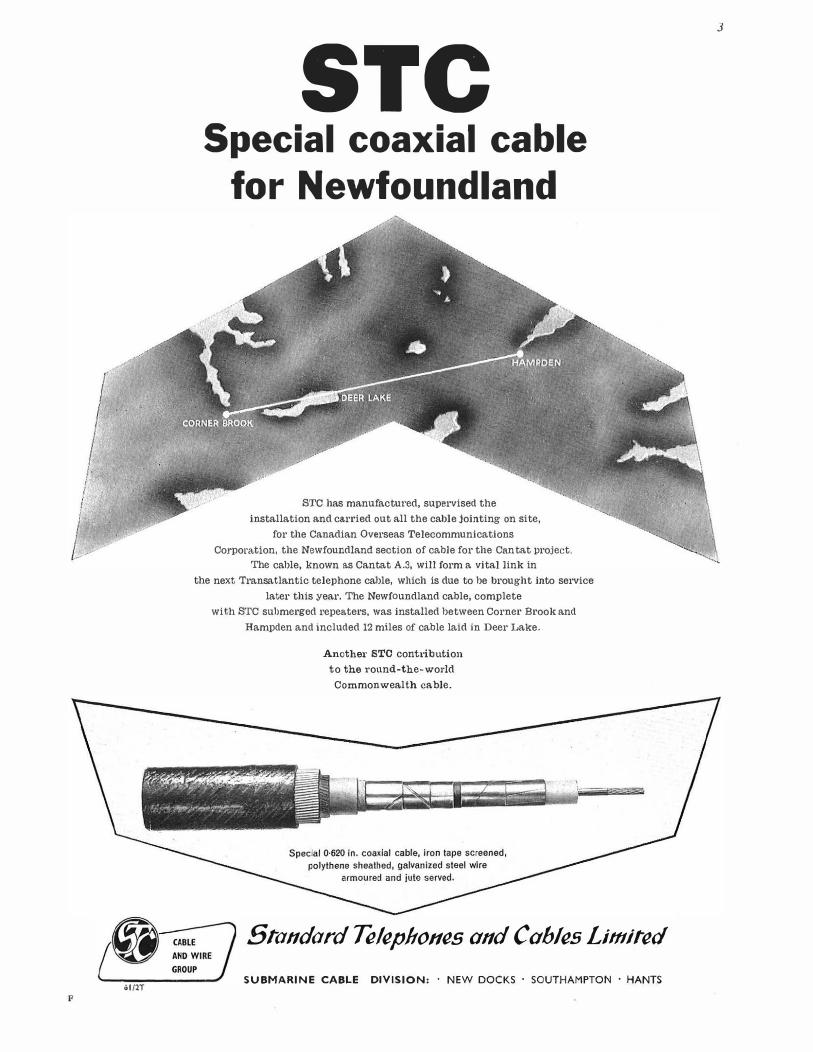
ol/2T F
STC Special coaxial cable
for Newfoundland
STC has manufactured, supervised the
installation and carried out all the cable jointing on site,
for the Canadian Overseas Telecommunications
Corporation, the Newfoundland section of cable for the Can tat oroject.
The cable, !mown as Cantat A.3, will form a vital link in
the next Transatlantic telephone cable, which is due to be brought into service
later this year. The Newfoundland cable, complete
with STC submerged repeaters, was installed between Corner Brook and
Hampden and included 12 miles of cable laid in Deer Lake.
Another STC contribution
to the round-the-world
Commonwealth cable.
Sia11dard Teleplto11es and Cahles Limired
SUBMARINE CABLE DIVISION: · NEW DOCKS · SOUTHAMPTON • HANTS
3

TELCON METALS HIGH PERMEABILITY MAGNETIC ALLOYS
These alloys cover a wide range of permeabilities, resistivities and saturation inductions. They all have low electrical losses and are widely used in electrical and electronic equipment.
Typical applications include current transformer cores, magnetic screens, pulse and audiofrequency transformers, chokes, relay parts, transductors and saturable reactors,
telephone diaphragms and small motors. Most Alloys are available in strip (6" wide f' thick down to 0·0005" thick) and
wire (f' dia. down to 0·001 6" dia.). They are also available in sheet ( 1 8" wide and 5 ft. long), in bar of bright drawn finish, in forged section and in rod
(6 ft. long and if' dia. down to t" dia.). Summary of typical properties
I Super·
I I Radio· Magnetic Properties mumetal Mumetal
so• metal
Initial Permeability 50000 �0000 3 SOO Maximum Permeability 200000 100 OOO 30000
Satuntion Ferric Induction {gauss) 8000 8000 16 OOO
Remanence, Brem, from saturation (gauss) 5 000 4700 10000 Co ercivi ty, He. (oersteds) 0·01 0·04 0·15 Hysteresis loss at B sat (erg/cc/cycle) 13 38 1 OOO Curie Point (C) 390 390 500-550
I Super-
I Radio· Radio·
metal metal 36
10 000 2 000 100 OOO 10000
16 OOO 12000
11 OOO 3500 0·04 0·30
400 450 500-550 2 80
I R.2799 I 10 at o•c 48 at 20°C
noo at o•c 2200 at 20°C
60
R.2800
190 at o•c 110 at 2o•c
8800 at o•c 1900 at 1o•c
150
H.C.R. A rectangular hysteresis loop alloy for Magnetic amplifiers and saturable reactors. Saturation induction: 15 600 gauss Retentivity: 15 ooo gauss Coercivity: 0.13 Oe Hysteresis loss - 650 ergs/ cm3/cycle Bmax = 15000
0 Supermumetal 100 is under development. Please apply for current details.
Your enquiries are invited
TELCON METALS ·LTD MANOR ROYAL . CRAWLEY . SUSSEX Telephone: Crawley 1560, Telex 8748. Telegram s: Telcon, Crawley, Telex.
MEMBER OF THE � GROUP OF COMPANIES
AN INTRODUCTION
TO THE
THEORY AND PRACTICE
OF
TRANSISTORS
By J. R. Tillman, D.Sc., A.R.C.S., and
F. F. Robel'ts, B.Sc.(Eng.), A.M.I.E.E.
A new work for physicists and electronic engineers at
graduate and Higher National Certificate level. It
gives the theoretical background of semiconductor
and transistor physics and then covers technology,
electrical properties of semiconductors, diodes, and
transistors with applications. 57/6 net.
a PITMAN book
VALUABLE FREE BOOK Tells You How to Pass Your C. & G. or Promotion Exam. at First Attempt!
All Post Office personnel who are anxious to obtain early promotion should at once send for a copy of our h andbook "ENGINEERING OPPORTUNloTIES" which, among other intensely inter· esting matter, describes our unique methods of preparation for the G.P.O., LIJlllTED COM· PETITIONS for appointment as As.sistant Engineer, Executive Engineer, Trame Officer, Telecommunl· cations Trame Superintendent; CITY AND GUILDS EXAMINATIONS for the Telecommunl· cation Technicians' Certificate and for individual subjects-Mathematics, Engineering Science, Engineering Drawing, Elementary Telecommunication Practice, Telecommunication Principles, Radio and Line Transmission, Telegraphy and Telephony, Line Plant Practice. It also contains details of our courses covering the City and Guilds Examinations in Electrical Engineering Practice, the Grad. Brit.I.R.E. and A.M.S.E. Examinations, in addition to a wide range of non·examination courses in all branches of engineering-Radio and Electrootcs. Electrical, Mechanical, etc.
We also provide tuition for the Radio Amateurs' Examination and the P.M.G. Certificates for Radio Operators, with or without Morse trainine. Details are eiven In the handbook.
We definitely guarantee "NO PASS-NO FEE"
If you intend to make the most of today's oppor. tunities, you cannot afford to miss reading "ENGINEER
ING OPPORTUNITIES.'' It tells you everything you want to know to secure advancement, and describes many oppor·
tunities you may now be missing through lack of information· Send for your copy today-FREE aod without obligation.
BRITISH INSTITUTE
BI ET OF ENGINEERING TECHNOLOGY 369 COLLEGE HOUSE,
29-31 WRlGHT'S LANE, LONDON, W.8
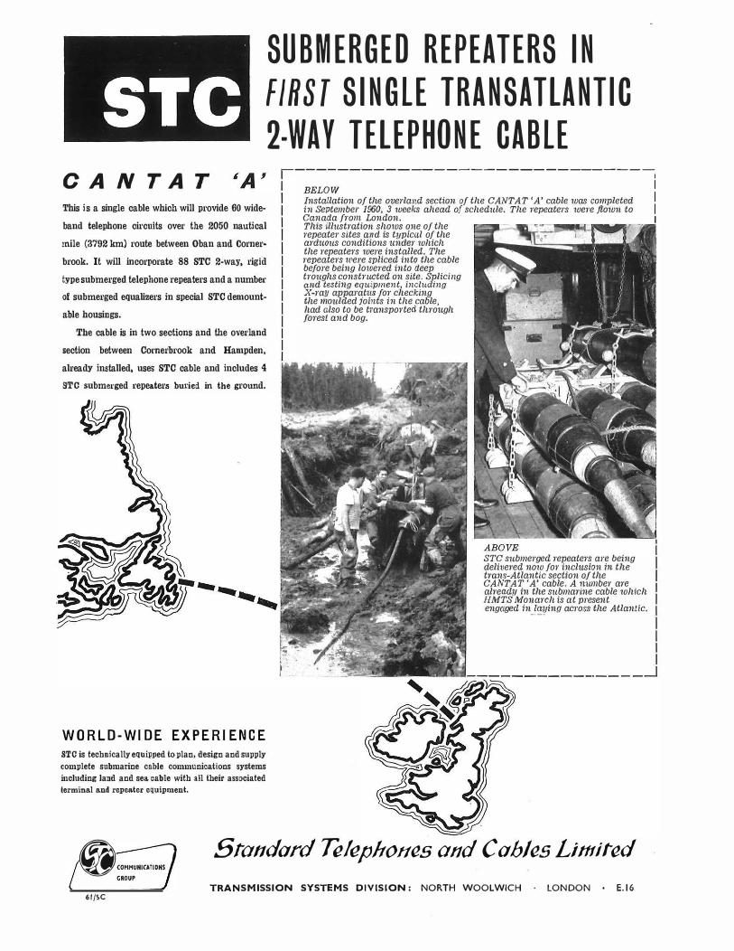
STC
SUBMERGED REPEATERS IN
FIRST SINGLE TRANSATLANTIC
2-WAY TELEPHONE CABLE
CAN TAT 1------------- ----------------,
I I I I
This is a single cable which will provide 60 wide
band telephone circuits over the 2050 nautical
mile (3792 km) route between Oban ancl Corner
brook. It will incorporate 88 STC 2-way, rigid
type submergecl telephone repeaters and a number
of submerged equalizers in special STC demount
able housings.
The cable is in two sections and the overland
section between Comerbrook ancl Hampden,
already installed, uses STC cable and includes 4
STC subme1·ged repeaters buried in the ground.
WORLD-WI DE EX PERI ENCE
STC is technically equipped to plan, design and supply
complete submarine cable communications systems
including land and sea cable with all their associated
terminal and repeater equipment.
BELOW Installation of the overland section of the CANT AT 'A' cable was completed in September 1960, 3 weeks ahead of schedule. The repeaters were flown to Canada from London. This illustration shows one of the repeater sites and is t11piccil of the arduous conditions under which the repeaters were installed. The repeaters were spliced into the cable before being lowered into deep troughs constructed on site. Splici.ng and testing eqttipment, includi.ng X-ray apparat11S for checking the moulded joints in the cable, had also to be transported through forest and bog.
STC submerged repeaters are being delivered now for incl1ision i.n the trans-Atlant-ic section of the CANT AT 'A' cable. A munber are alread11 in the submarine cable which
HMTS Monarch is at present engaged in_!�ing across the Atlantic.
@COHHUHICATIOHS GROUP
Standard Telephones and Cah/es Limiled
TRANSMISSION SYSTEMS DIVISION: NORTH WOOLWICH LONDON E.16 61/SC
There's a
DENSO anti-corrosion Product
... that will meet your particular requirement-whether it is to protect an oil-line across a continent or under water, or to seal a service entry. No matter how large or small the job, DENSO can safeguard it from corrosion and provide a long term water and gas seal.
PETROLATUM-BASED Tapes on cotton, glass or synthetic fibre-with or without plastic film backings.
BITUMEN-BASED Tapes on cotton, glass, synthetic fibre or paper.
PETROLATUM-BASED Cords, Twists, Pastes and Mastics.
BITUMEN-BASED Compounds.
OXIDISING OILS and BITUMINOUS LACQUERS.
The DENSO SERVICE is available to advise on your corrosion problem.
Specialists in a11ti-corl'osio11 treatment for over 30 years.
WINN & COALES LTD DENSO HOUSE CHAPEL ROAD
LONDON S.E.27
Aoenis Jhrouohoul tlie Commonwe1tllh
London-Ti/: GIPsy Hill 1511 (ii) fro)
M•nchtSlfl�AlsoConlt.Jcting D1pt.) T•I: Salt 8?11
Brlf,ul-Tc!: 56623
Dublm-T1I: 6"61
ELECTRONIC EQUIPMENT
& ENCAPSULATED COMPONENTS
PLUG-IN
OSCILLATOR
This fixed frequency oscillator is constructed on a standard octal base and encapsulated in epoxy resin. Output: 10 mw into a 600 ohm load. Frequency: As required within the range 700-2000 c.p.s. sinusoidal.
FIELD CABLE
TEST SET
This tester locates the position of breaks or short circuits in sheathed conductor cables to within a fraction of an inch.
INSPECTION MIRRORS P.O. TRANSISTOR
AMPLIFIER
An example of the design and manufacture of an encapsulated transistor amplifier in epoxy resins.
This mirror, which is specially made for the G.P.O., is adjustable. This is particularly suitable for use on switchboards and in cable forms where it can be inserted in a flat position and the mirror then inclined to the required angle for viewing.
WHITELEY ELECTRICAL RADIO CO. LTD · MANSFIELD · NOTTS WA/14
DISCRIMINATION
IN 1 CUBIC INCH
HIGH FREQUENCY
CRYSTAL FILTERS
Write for Data Sheets to: * For 50 k/cs, 25 k/cs, 12·5 k/cs
Channel Spacing in VHF Equipments
~ """'"" GROUP
Siandard Telephones and Cables Limiied
QUARTZ CRYSTAL DIVISION HARLOW ESSEX 61/2MQ
MACDONALD TECHNICAL BOOKS
ELECTRONICS A BIBLIOGRAPHICAL GUIDE C. K. MOORE, B.Sc., andK. J. SPENCER, A.L.A.
ro x 7t in. 416 pages July 65s. net
MAGNETIC MATERIALS IN THE ELECTRICAL INDUSTRY 2nd edition (r evi sed and enlarged)
P. R. BARDELL, B.Sc., M.l.E.E., F.Inst.P.
8j- x St in. 320 pages 166 figures 32s. 6d. net
PRINTED CIRCUITS Their design and application
J. M. C. DUKES, M.A.(Cantab.), D.I.C., A.M.l.E.E.
8! x st in. 232 pages 92 figures 40s. net
TELECOMMUNICATIONS W. FRASER, M.Sc.(Eng.), A.M.I.E.E.
8:i x st in. 772 pages 418 figures 65s. net
16 MADDOX ST., LONDON, W.1
Basic Principles of Electronics
and Telecommunications
M. D. ARMITAGE, B.Sc., A.M.J.E.E., A.Inst.P.
Senior Lecturer, Depart111e111 of Applied Physics,
Nortltampto11 College of Adl'a11ced Tecft110/ogy
A modern treatment of the fundamentals of electrostatics,
electromagnetism, and electrochemistry, together with the
thermionic valve and transistor, at a standard suitable for
the technical college student. As a textbook covering the
syllabus of the Principles 'A' section of the new City
and Guilds of London Institute's Telecommunications
Technicians' Course No. 49 it is more than adequate. It
will also be useful to 0. N.C. students requiring a 'light
current' treatment and for the later years of the City and
Guilds Electrical Technicians' Course. Topics including
calculation are illustrated by numerous worked examples,
and there are also many exercises for the student-a
number being complete questions from past examination
papers. sr x 5·}*, 342 pages, 230 diagrams.
September 1961 About E 20s. net
GEORGE G. HARRAP & CO. LTD
182 High Holborn, London, W.C. I
SOLDERING INSTRUMENTS
and EQUIPMENT
Illustrated
L64 ,\" DETACHABLE
BIT MODEL IN
PROTECTIVE
SHIELD l700
FITTED WITH
ACCESSORIES FOR
BIT CLEANING, ETC.
All VOLT RANGES
6/7 to 230/250 VOLTS
British and Foreign
Patents and Registered
designs
For further information and full illustrated catalogue apply head office
ADCOLA PRODUCTS LIMITED GAUDEN ROAD, CLAPHAM HIGH STREET,
LONDON, S.W.4
Telephones: MACaulay 3101 and 4272 Telegrams: SOLJOINT
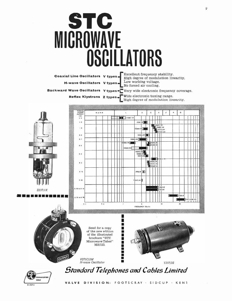
STC MICROWAVE
OSCILLATORS [Excellent frequency stability. V types. High degr�e of modulation linearity.
v types. Low workrng voltage. No forced air cooling.
Coaxial Line Oscillators
H-wave Oscillators
Backward Wave Oscillators V types •tvery wide electronic frequency coverage.
z types-[Wide electronic tuning range.
Z237/JT<
•••••••••••••
Reflex Klystrons
�
I'! .. . :,
• J I
ri ,i 1. h ••
.
1 I
...
� :i:
'
"'
l'fPICAL. POWtR 8 AH D
OUTPUT (WJ ''
''
'0
•·•
.. ,
...
...
•·•
0 "
....
0·021o0·12
O·OI ta 0·06
.
0·1 .. , = � ,1.'"1 •'j} J�;·;;.�, <
Send for a copy of the new edition of the illustrated
brochure "STC Microwave Tubes"
MS/113.
V271C/3M H-wave Oscillator
High degree of modulation linearity.
t. ., l I s c • J
I VttoC IM
Z23t, 1G 1l 1l vm•t�ll I� V761C I M
V26iC. 1M I 'vi11'c JI.I v715c 3M
V24JAi 2f l Il V'3SA/ !K (J •
V211AJIK[.m J I.I ��i:�ci 11!� Y2lJA./IK
V231C /IK�� V239CjlK
V241C/1K Ill .,. __ VHSA It.I
, Y1UC/ 1K v2i1citK vi1tCJtK
"''''"[I]
VtllC IK m
-l'l"" Y2S7/U
I
I I • • •
' FREQUENCY (Gc/sl
.0'�:·.•;:_1•.
..
'·�
,.
I • I 0
-- Ym/ 1£ �,,.,,, ... ,"°.'()
30
f '·' _ ,..,_, n' • -,;
• • • • • • • • • Y257/2E
(@ .. � .. ····
Sia11dard Telephones and Cah/(!s limiied GROUP
61/6MS VALVE DIVISION: FOOTSCRAY · SIDCUP · KEN1
9
,
'
'�
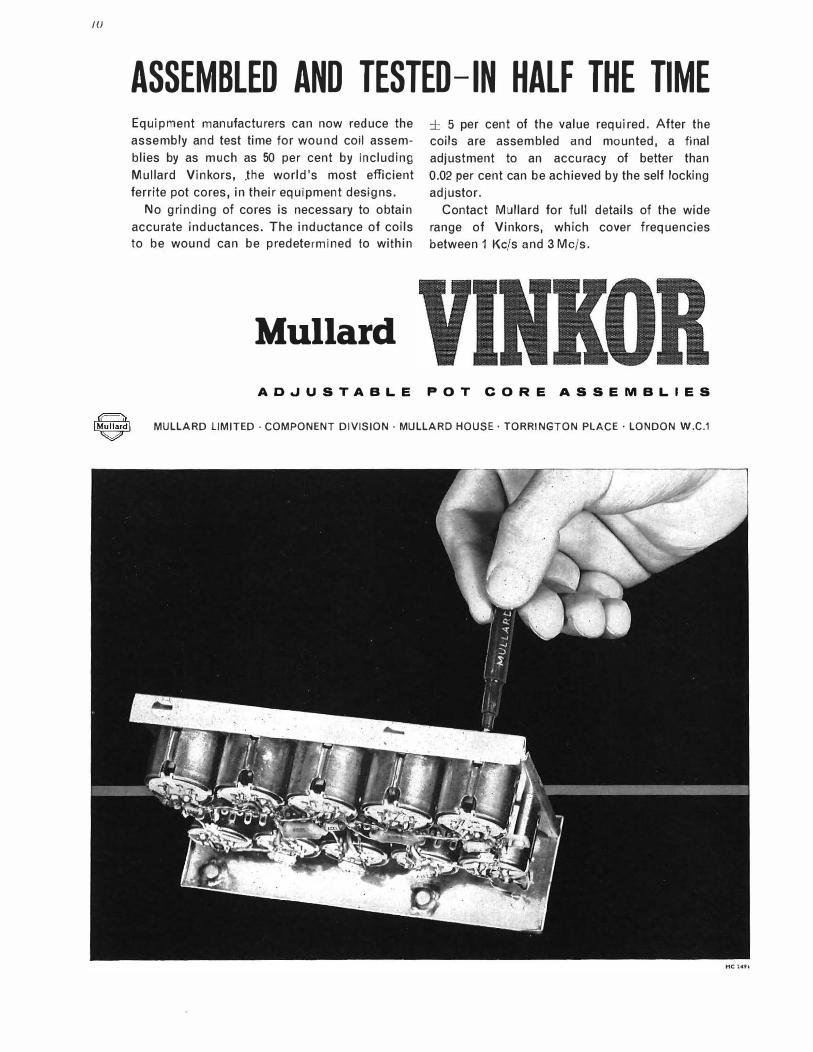
JU
ASSEMBLED AND TESTED-IN HALF THE TIME Equipment manufacturers can now reduce the
assembly and test time for wound coil assem
blies by as much as 50 per cent by including
Mullard Vinkors, .the world's most efficient
ferrite pot cores, in their equipment designs.
No grinding of cores is necessary to obtain
accurate inductances. The inductance of coils
to be wound can be predetermined to within
Mullard
± 5 per cent of the value required. After the
coils are assembled and mounted, a final
adjustment to an accuracy of better than
0.02 per cent can be achieved by the self locking
adjustor.
Contact Mullard for full details of the wide
range of Vinkors, which cover frequencies
between 1 Kc/sand 3 Mc/s.
ADJUSTABLE POT CORE ASSEMBLIES
1@1 MULLARD LIMITED · COMPONENT DIVISION· MULLARD HOUSE· TORRINGTON PLACE· LONDON W.C.1
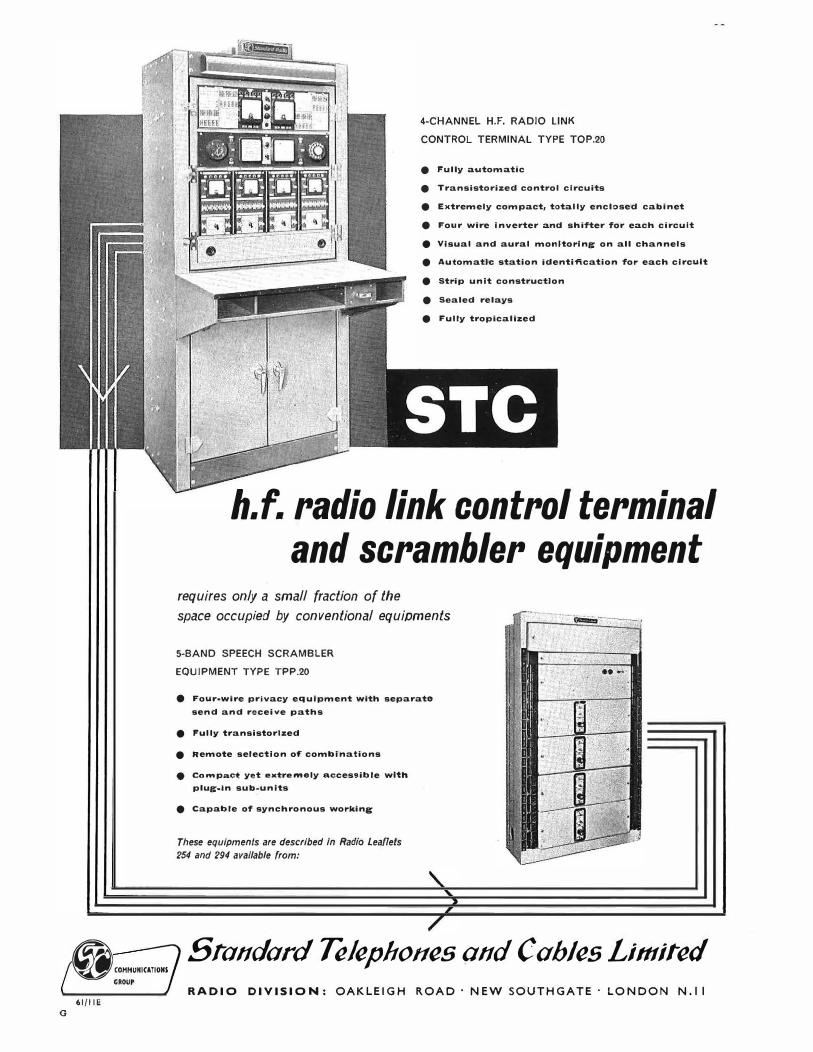
0
@COHHUHICATIOHS GROUP
61/11 E
4-CHANNEL H.F. RADIO LINK
CONTROL TERMINAL TYPE TOP.20
e Fully automatic
e Transistorized control circuits
e Extremely compact, totally enclosed cabinet
e Four wire inverter and shifter for each circuit
e Visual and aural monitoring on all channels
e Automatic station Identification for each circuit
e Strip unit construction
e Scaled relays
e Fully troplcallzed
h.f. radio link control terminal and scrambler equipment
requires only a small fraction of the
space occupied by conventional equipments
5-BAND SPEECH SCRAMBLER
EQUIPMENT TYPE TPP.20
e Four-wire privacy equipment with separate
send and receive paths
e Fully transistorized
e Remote selection of' combinations
e Co...,pact yet oxtro...,oly accessible with
plug-In sub-units
e Capable of synchronous working
These equipments are described In Radio Leaflets
254 and 294 avallable from:
-......, ____ ,
Sia11dard Te!epltoffes q11d Cahles Limited RADIO DIVISION: OAKLEIGH ROAD · NEW SOUTHGATE · LONDON N.11

12
STC are supplying "Carrier Telephone Multiplex Equipment" for the large
NATO radio communications network (ACE-HIGH Project) which will cover
ScandJnavla, Europe and the Mediterranean. The STC channel, group and super
group frequency translating equipment will provide over 2,000 channel ends.
STC are also supplying Transmission Testing Equipment, and equipment and visual
aids for training courses.
STC world-wide experience
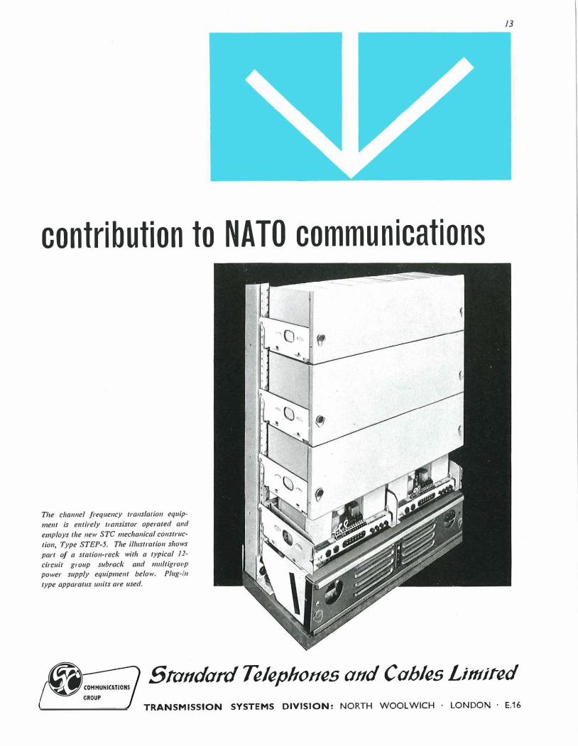
contribution to NATO communications
The c/1a1111el freq11e11cy tra11sla1io11 equip
ment is entirely trnnsistor operated a11d
employs the new STC mecha11ical co11struc
tion, Type STEP-5. The il/11stratio11 shows
part of a station-rack with a typical 12-
circuit group subrack and m11ltigro11p
power supply equipment below. Plug-in
type apparatus 1111its are used.
13
@"""'""""" GROUP
Sra11dard Telephot1es and Cuhles Limiied
TRANSMISSION SYSTEMS DIVISION: NORTH WOOLWICH · LONDON · E.16
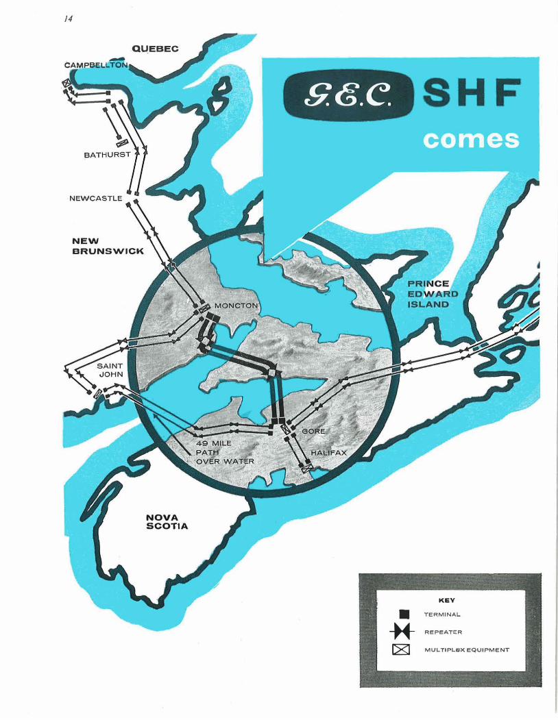
14
QUEBEC
CAMPBEl.tTON
NEWCASTLE
NEW
BRUNSWICK.
NOVA SCOTIA
S.G.e SHF
KEY
• TERMINAL
* REPEATER
C8J MULTIPLe-X EQUIPMENT
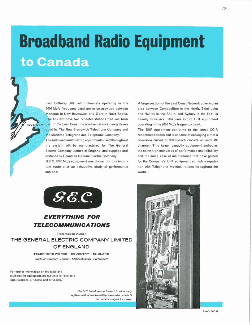
Broadband Radio Equipment
Two bothway SHF radio channels operating in the
6000 Mc/s frequency band are to be provided between
Moncion in New Brunswick and Gore in Nova Scotia.
T e link witl have two repeater stations and will form
part of the East Coast microwave network being devel
oped by The New Brunswick Telephone Company and
he Maritime Telegraph and Telephone Company.
The radio and multiplexing equipments used throughout
the system will be manufactured by The General
Electric Company Limited of England, and supplied and
installed by Canadian General Electric Company.
G.E.C. 6000 Mc/s equipment was chosen for this impor
tant route after an exhaustive study of performance
and cost.
EVERYTHING FOR
TELECOM MUN/CATIONS
Transmission Division
THE GENERAL ELECTRIC COMPANY LIMITED
OF ENGLAND
TELEPHONE WORKS · COVENTRY • ENGLAND
Works at Coventry· London· Middlesbrough • Portsmouth
For further Information on the radio and
multiplexing equipment, please write for Standard
SpeciOcallons SP0.5555 and SP0.1385.
The SHF panel swung forward to allow easy
replacement of /he /ravelling wave lube, which is
permanent magnet focussed.
A large section of the East Coast Network covering an
area between Campbellton in the North, Saini John
and Halifax in the South, and Sydney in the East, is
already in service. This uses G.E.C. UHF equipment
operating in the 2000 Mc/s frequency band.
The SHF equipment conforms to the latest CCIR
recommendations and is capable of conveying either a
television circuit or 960 speech circuits on each RF
channel. This larger capacity equipment embodies
the same high standards of performance and reliability
and the same ease of maintenance that have gained
for the Company's UHF equipment so high a reputa
tion with Telephone Administrations throughout the
world.
Sm•e's GEC 81
15

l��-1'tv«e7// I Rigid top and base frames g.ive com
I I I I I I I I I I
/!5�::==;;�e�:g�����;:::--------_:_ plete protection to components
within internal space. Multi
position holes provide alternative
screw mountings for equipment
within unit.
* Datum "Space-frame" construc
tion promotes maximum cooling of
components. The standard of engineering and finish is first class. Full range
of sizes available.
�
�-----1--�4---�
"Set back" cross-members ensure
maximum clear panel space.
Special gate chassis opens to provide
access within unit, and facilitates
wiring and fault-tracing.
May be used with telescopic or
fixed runners. Facilities for quick
release from cabinet and runners,
also "safe transit" fixing.
����Lf1/� �� -c_A�B-l_N�E�T-S�� -C�A-S�E_s��-C�O�N�S-O�L-E�S� ��C�H--,A�S�s-1_s� -U�N�'-T�S����
coMPANY
DATUM METAL p1 nODUCTS £ TlJ. Telephone: Watford 22351
n I I I I Telegrams: Datum, Watford COLNE WAY TRADING ESTATE · WATFORD-BY-PASS · WATFORD • HERTS
For many years Eclipse magnets have been chosen for eddy-current braking duty, not only in electricity meters but in power relays and many damping devices. They have been chosen particularly for new development work. Eclipse accumulated experience is then invaluable.
PERMANENT MAGNETS for industry
!� Eclipse publication "Permanent Magnets Summarized" contains a special illustrated section on eddy-current braking magnets.
1 .. 0' /l /J (J 0 OL\ -�(� Made by the designers and manufacturers of Eclipse Permanent Magnet Chucks
JAMES NEILL & CO . (SHEFFIELD) LTD SHEFFIELD ENGLAND Mto
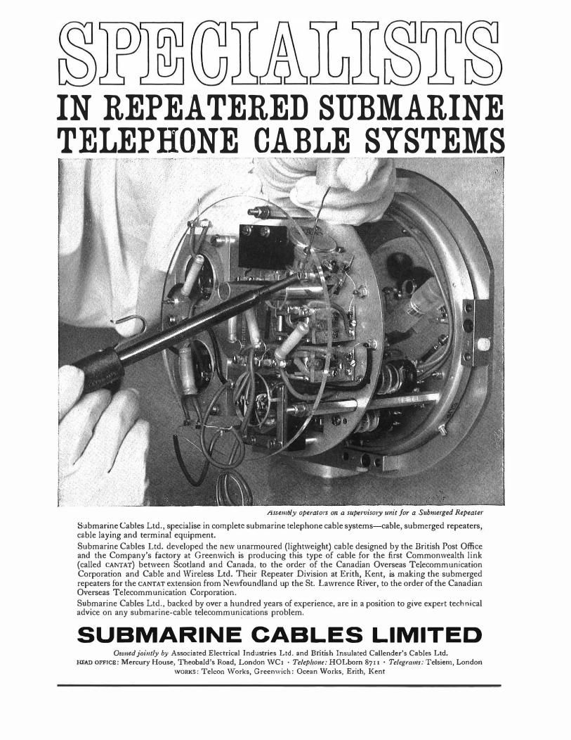
IN REPEATERED SUBMARINE
TELEPHONE CABLE SYSTEMS
·�
Assembly operators 011 a supervisory writ for a Submerged Repeater
Submarine Cables Ltd., specialise in complete submarine telephone cable systems-cable, submerged repeaters, cable laying and terminal equipment.
Submarine Cables Ltd. developed the new unarmoured (lightweight) cable designed by the British Post Office and the Company's factory at Greenwich is producing this type of cable for the first Commonwealth link (called CANTAT) between Scotland and Canada, to the order of the Canadian Overseas Telecommunication Corporation and Cable and Wireless Ltd. Their Repeater Division at Erith, Kent, is making the submerged repeaters for the CANTAT extension from Newfoundland up the St. Lawrence River, to the order of the Canadian Overseas Telecommunication Corporation.
Submarine Cables Ltd., backed by over a hundred years of experience, are in a position to give expert technical advice on any submarine-cable telecommunications problem.
SUBMARINE CABLES LIMITED Owned jointly by Associated Electrical Industries Ltd. and British Insulated Callender's Cables Ltd.
HEAD OFFICE: Mercury House, Theobald's Road, London WC1 · Telepho11e: HOLborn 8711 • Te/egrams:Telsiem, London
WORKS: Telcon \¥orks, Greenwich: Ocean 'Works, Erith, Kent
I

18
INVERNESS � -� ABERDEEN- INVERNE
Radio Lml<. Three Channels
CARL ISLE - KIRK O'SHOTTS I Rd:JO ,.,,.
r .. o (h.tnnf'/'
MANCHESTER- CARLISLE
-GLASGOW KIRK O'SHOTTS
Ttfful1t101t lqu1pr.1MI (OntrJ
DUNDEE e
CARLISLE
MANCHESTER - RIVINGTON MOOR· CN11fl.C1b» Un!
Ottf' Ch1nnrl In Nth dfflllOl'I
mtludm1 Tr1n1f1lion £011/pn1Mf
BIRMINGHAM - MANCHESTER C011l1l·C1blt UnA
Tlun Ch•nnf'ls in r1ch dMttllon mcWinr T11nsUllOl'I Cqu;pmtnt
WEST WALES M1ntdd Pf'nuu� • Bl"n Pt1111
R�10t11t• TwoChlnntls
C01•1'l.C1W. UnA Two Ch1n11tls In Hth dktcllOfl
lnctuJlno 111n1l1tlon lqulpmtnl
LEICESTER-DUNDEE
Radio Lin/<.
Two Bolhway Channels
LONDON - BIRMlllGHAM R1dloLlnA
Thrtt Ch1nn1/1 Jn Hth dlttclfon r LONDON -NORWICH R1dloLlni
TwoCh1nnrb
. .:: �--- - � . - �---_-.,... __ _ CAftDJFF BRIS�-;:=:: :::J ; ::: :::: �.::
EUROVISION LONDON (MUSEUM)
- TOLSfORD HILL T11nsl1Uon EqulpO'lrnt(Onf1)
CARDIFF - WENVOE Co.1•11l°C10lt Uni.
Onf' Chlntttl"' Heh
0dJ1tcllon
SOUTH"AMPTON
- CHILLERTON (1.0.W.)
S.G.e.
LONDON KEY
EVERYTHING

FOR
Broadband
Radio E uip en once again chosen by the
BRITISH POST OFFICE
G.E.C. has been awarded contracts to supply and install three radio
channels between Aberdeen and Inverness and two bothway radio channels
between Harrogate and Leicester. The Harrogate-Leicester link is an extension of
the link already announced between Dundee and Harrogate, and is the second
stage ot a new national broadband microwave network for telephony.
The North ot Scotland link will carry television signals from Aberdeen
to a new transmitter near Inverness.
Both systems operate in the 6000 Mc/s frequency band and can be extended
by the addition of further RF channels. One RF channel acts as a standby
channel lo several working channels and can be switched in automatically
in the event of failure or degradation of a working channel.
The equipment conforms to the latest CCIR recommendations.
For further information, please write for Standard Specification SPO 5555
TELECOMMUNICATIONS TRANSMISSION DIVISION
THE GENERAL ELECTRIC COMPANY LIMITED OF ENGLAND
Telephone Works· Coventry· England Works at Coventry· London· Middlesbrough . Portsmouth
19
mce's GEC 81
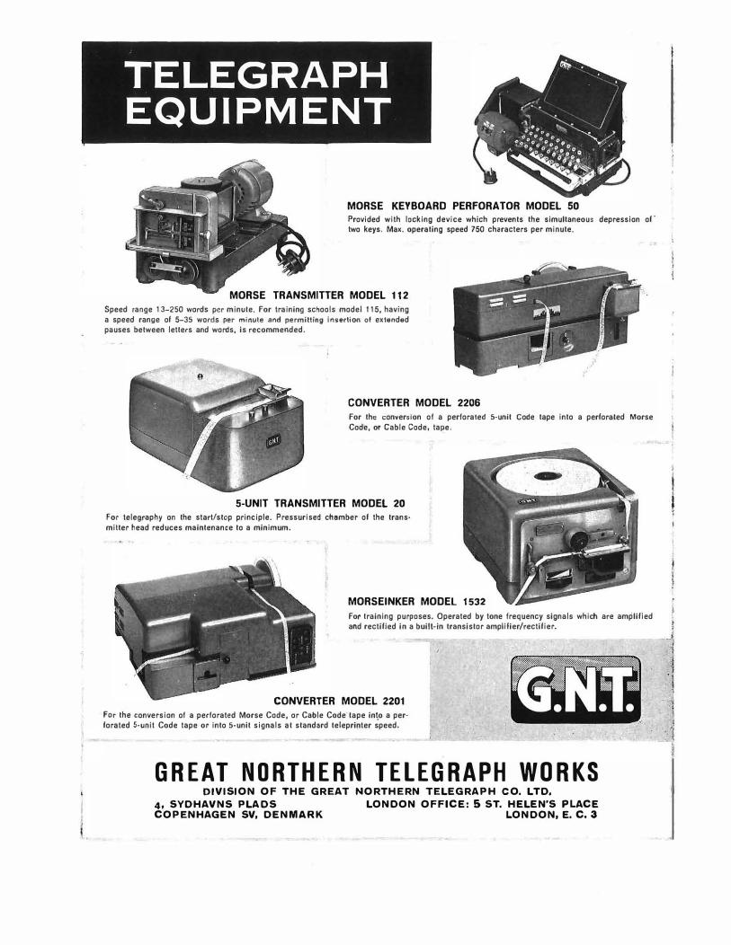
TELEGRAPH EQUIPMENT
MORSE KEYBOARD PERFORATOR MODEL 50
Provided with locking device which prevents the simultaneous depression of· two keys. Max. operating speed 750 characters per minute.
MORSE TRANSMITTER MODEL 112
Speed range 13-250 words per minute. For training schools model 115, having a speed range of 5-35 words per minute and permitting inurtion of extended pauses between letters and words, is recommended.
CONVERTER MODEL 2206
For the conversion of a perforated 5-unit Code tape into a perforated Morse Code, or Cable Code, ta�e.
5-UNIT TRANSMITTER MODEL 20
For telegraphy on the start/stop principle. Pressurised chamber of the trans· milter head reduces maintenance to a minimum.
MORSEINKER MODEL 1532
For training purposes, Operated by tone frequency signals which are amplified and rectified in a built-in transistor amplifier/rectifier.
CONVERTER MODEL 2201
For the conversion of a perforated Morse Code, or Cable Code- tape in�o a perforated 5-unit Code tape or into 5-unlt signals at standard teleprinter speed.
GREAT NORTHERN TELEGRAPH WORKS DIVISION OF THE GREAT NORTHERN TELEGRAPH CO. LTD,
4, SYDHAVNS PLADS LONDON OFFICE: 5 ST. HELEN'S PLACE COPENHAGEN SV, DENMARK LONDON, E. C. 3
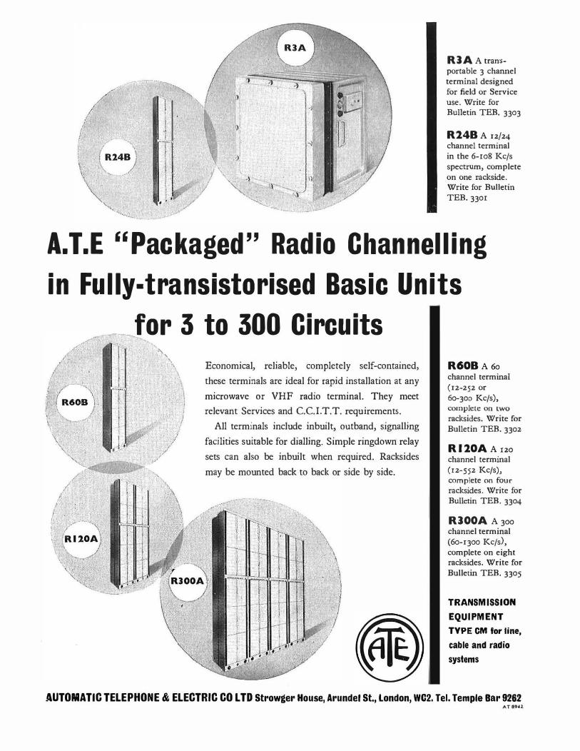
/ _,
,t ;.
I , '•,\ ! f ( Rl4':} \ •\
\ '·· ,.•
,, ' .. � .... -.::_
l I I ·1
"l '. .: ' ;1\ , _,,/ ,;. .....
RJA A trans-portable 3 channel
terminal designed
for field or Service p use. Write for
-1 Bulletin TEB. 3303
· � I I R2.4B A 12/24 channel terminal
'.) in the 6-108 Kc/s
spectrum, complete
� on one rackside. l\-- Write for Bulletin
'-., TEB. 3301 ....
. � ...... � ......... �-
A.T.E ''Packaged'' Radio Channelling
in Fully-transistorised Basic Units
I .
I . .
[' /�---··��\ '. . /� 120,; \ • • ,. ... •·-v-·v."
'
--�----for 3 to 300 Circuits 'l' 1 -, • �'\
l \
lj .J .i'
Economical, reliable, completely self-contained,
these terminals are ideal for rapid installation at any
microwave or VHF radio terminal. They meet
relevant Services and C.C.I.T.T. requirements.
All terminals include inbuilt, outband, signamng
facilities suitable for dialling. Simple ringdown relay
sets can also be inbuilt when required. Racksides
may be mounted back to back or side by side.
R60B A 60 channel terminal
(12-252 or
60-300 Kc/s), complete on two
racksides. Write for
Bulletin TEB. 3302
Rl2.0A A 120 channel terminal
(12-552 Kc/s), complete on four racksides. Write for
Bulletin TEB. 3304
RJOOA A300 channel terminal
(60-1300 Kc/s),
complete on eight racksides. Write for
Bulletin TEB. 3305
TRANSMISSION
EQUIPMENT
TYPE CM for line,
cable and radio
systems
AUTOMATIC TELEPHONE & ELECTRIC CO LTD Strowger House, Arundel St., London, WC2. Tel. Temple Bar 9282 AT89U
22
perfect pictures and
P6467
Space Heating is easy
and economical with
PROPAGAS Propane
PROPAGAS PROPANE
PRECISION FUEL
Quick, trouble-free and economical, PROPAGAS propane is in general
use throughout the country for
permanent or temporary space
heating in factories, workshops,
church halls and large buildings.
Gases �
for :radiant heaters
PROP AGAS propane and BOTTOGAS butane are the Precision Fuels for industrial furnaces, the glass industry, air heaters, bitumen and mastic heating, floodlights, blow torches, fork lift trucks, agriculture.
PRO PA GAS propane and BOTTOGAS butane come from the British Refineries of the Shell and BP Groups. They are backed by a nationwide distribution service and technical resources second to none.
Shell-1V.lex and B.P. Gases Limited (Regd. users of Trade Marks)
Cecil Chambers, 76-86 Strand, London WC2 Phone: TEMple Bar 1234

24
MANUFACTURE
f
SURVEY

25
/LCOM LEf� ...............
TELECOMMUNICATIONS I
-.__SER IOE
-
consult
TRANSMISSION DIVISION
TH& GIENBRAL ELECTRIC COMPANY LIMITED OP BNGLAND Telephone Works • Coventry • England Works at Coventry · Middlesbrough • London • Portsmouth
'-------���----- Smee'sCECB6
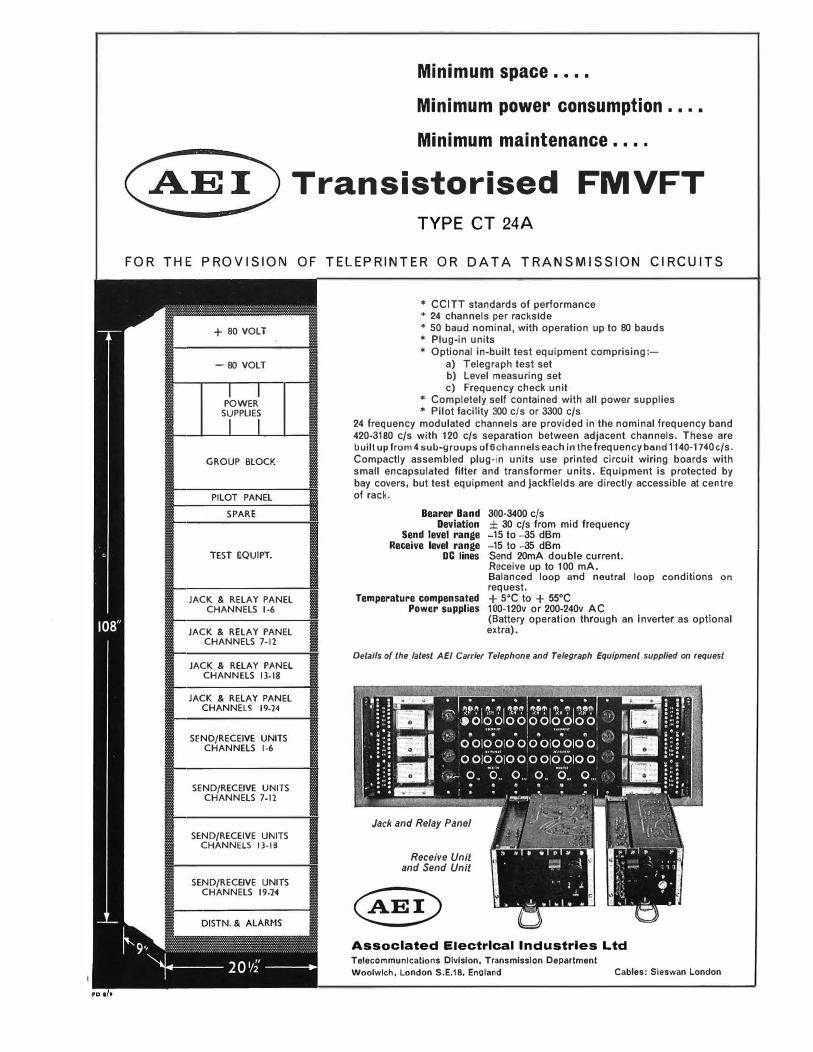
Minimum space ....
Minimum power consumption . • • •
Minimum maintenance ....
Transistorised FMVFT
TYPE CT 24A
FOR THE PROVISION OF TELEPRINTER OR DATA TRANSMISSION CIRCUITS
+ 80 VOLT
- 80 VOLT
POWER SUPPLIES
GROUP BLOCK
PILOT PANEL
SPARE
TEST EQUIPT.
JACK & RELAY PANEL CHANNELS 1-6
JACK & RELAY PANEL CHANNELS 7-12
JACK & RELAY PANEL CHANNELS 13-18
JACK & RELAY PANEL CHANNELS 19-24
SEND/RECEIVE UNITS CHANNELS 1-6
SEND/RECEIVE UNITS CHANNELS 7-11
SEND/RECEIVE UNITS CHANNELS 13-18
SEND/RECEIVE UNITS CHANNELS 19-14
* CCITT standards of performance * 24 channels per rackslde * 50 baud nominal, with operation up to 80 bauds * Plug-in units * Optional in-built test equipment comprising:-
a) Telegraph test set b) Level measuring set c) Frequency check unit
* Completely self contained with all power supplies * Pilot facility 300 c/s or 3300 c/s
24 frequency modulated channels are provided in the nominal frequency band 420-3180 c/s with 120 c/s separation between adjacent channels. These are built up from 4 sub-groups of 6channels each in the frequency band 1140-1740c/s. Compactly assembled plug-in units use printed circuit wiring boards with small encapsulated fitter and transformer units. Equipment is protected by bay covers, but test equipment and jackfields are directly accessible at centre of rack.
Bearer Band 300-3400 c/s Deviation ± 30 c/s from mid frequency
Send level range -15 to -35 dBm Receive level range -15 to -35 dBm
DC lines Send 20mA double current. Receive up to 100 mA. Balanced loop and neutral loop conditions on
request. Temperature compensated + 5�C to + 55°C
Power supplies 100-120v or 200-240v AC (Battery operation through an Inverter as optional extra).
Details of the latest AEI Carrier Telephone and Telegraph Equipment supplied on request
Jack and Relay Panel
Receive Unit and Send Unit
Associated Electrical Industries Ltd Telecommunlcatlons Division, Transmission Department
Woolwlch, London S.E.18, Enoland Cables: Sleswan London
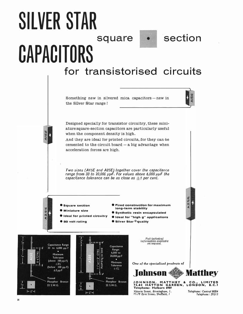
SILVER STAR square • ·section
CAPACITORS
H
for transistorised circuits
Something new in silvered mica capacitors-new in
the Silver Star range !
Designed specially for transistor circuitry, these mini
ature square-section capacitors are particularly useful
when the component density is high.
And they are ideal for printed circuits, for they can be
cemented to the circuit board - a big advantage when
acceleration forces are high.
Two sizes (A 15£ and A25E) together cover the capacitance range from 33 lo 20,000 µµF. For values above 6,000 µµF the capacitance tolerance can be as close as ± 1 per cent.
• Square section
• Miniature size
• Fired construction for maximum long-term stablllty
• Synthetic resin encapsulated • Ideal for printed circuitry e Ideal for "high g" applications
e 50 volt rating •Sliver Star®quallty
Full technical information available
on request.
One of the specialised products of
l!!!w(
John§on +Matthey JOHNSON, MATTHEY & CO., LIMITED H-83 HATTON GARDEN, LONDON, E.C.I Telephone: Holborn 6989 Viuoria Street, Birmingham, I . Telephone: Central 8004 15.79 Eyre Street, Sheffield, I Telephone: 29212

This map indicates
the positions of TMC
installations.
GENERAL
* Can be energized from suitable bat
teries or a.c. mains.
->!<- Plug-in units and panels make trans
port, installation and maintenance
easier.
* Great care has been taken to simplify
the problem of Installation. Racksides
may be mounted side-by-side back-to
back or back to a wall. Cable entries
are arranged for both overhead and
floor-duct distribution.
ADA
* Channel spacings of 120, 170 or 240 c/s.
* Speeds of 50-66 to 100-120 bauds.
* 24.18or12channels on one self-contained
rackside.
* Bothway and unidirectional versions.
* Local loops for polar or neutral full and
half duplex.
Compact plug-in sub-units, units and
panels give maximum flexibility.

CH
V.F.
telegraph
equipment
TMC
SELLING AGENTS
A rapidly increasing quantity of TMC
transistorized frequency modulated V.F.
telegraph equipment is being installed
throughout the world, of which these Canadian
Networks are typical applications.
From the experience and practical knowledge
gained TMC can offer a comprehensive service
embracing a wide range of multiplex telegraph
systems to satisfy varied world demands with
simplicity and efficiency.
In addition to these transistorized F.M.T.
systems TMC has now developed a very versatile
speech plus 3 duplex telegraph channel
equipment.
Further information from:
Telephone Manufacturing Company Limited
Transmission Division:
Cray Works, Sevenoaks Way, Orpington, Kent
Telephone: Orpington 26611
Australia and New Zealand :
Telephone Manufacturing Co. (A'sia) Pty. Ltd., Sydney, New South Wales
Canada and U.S.A. :
Telephone Manufacturing Co. Ltd., Toronto, Ontario
Also represented in other countries.
iic \1'J ire\'/O\\ nt\
iic S\�b\e se\\inr,s
1c f\ne scre\\ldri'-'er
* space 5;\\lil\lb
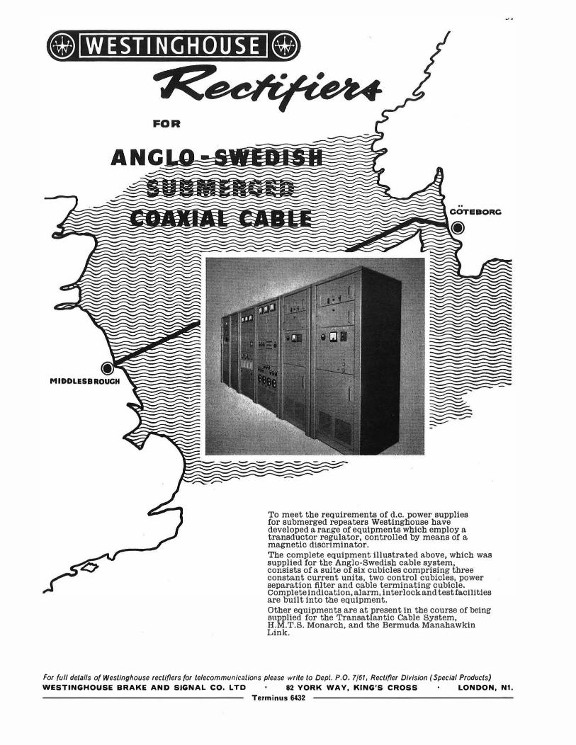
WESTINGHOUSE
FOR
To meet the requirements of d.c. power supplies for submerged repeaters Westinghouse have developed a range of equipments which employ a transductor regulator, controlled by means of a magnetic discriminator.
The complete equipment illustrated above, which was supplied for the Anglo-Swedish cable system, consists of a suite of six cubicles comprising three constant current units, two control cubicles, power separation filter and cable terminating cubicle. Complete indication, alarm, interlock and testfacilities are built into the equipment.
Other equipments are at present in the course of being supplied for the Transatlantic Cable System, H.M.T.S. Monarch, and the Bermuda Manahawkin Link.
For full details of Westinghouse rectifiers for telecommunications please write to Dept. P.O. 7/61, Rectifier Division (Special Products)
WESTINGHOUSE BRAKE AND SIGNAL CO. LTD 82 YORK WAY, KING'S CROSS LONDON, N1.
Terminus 6432
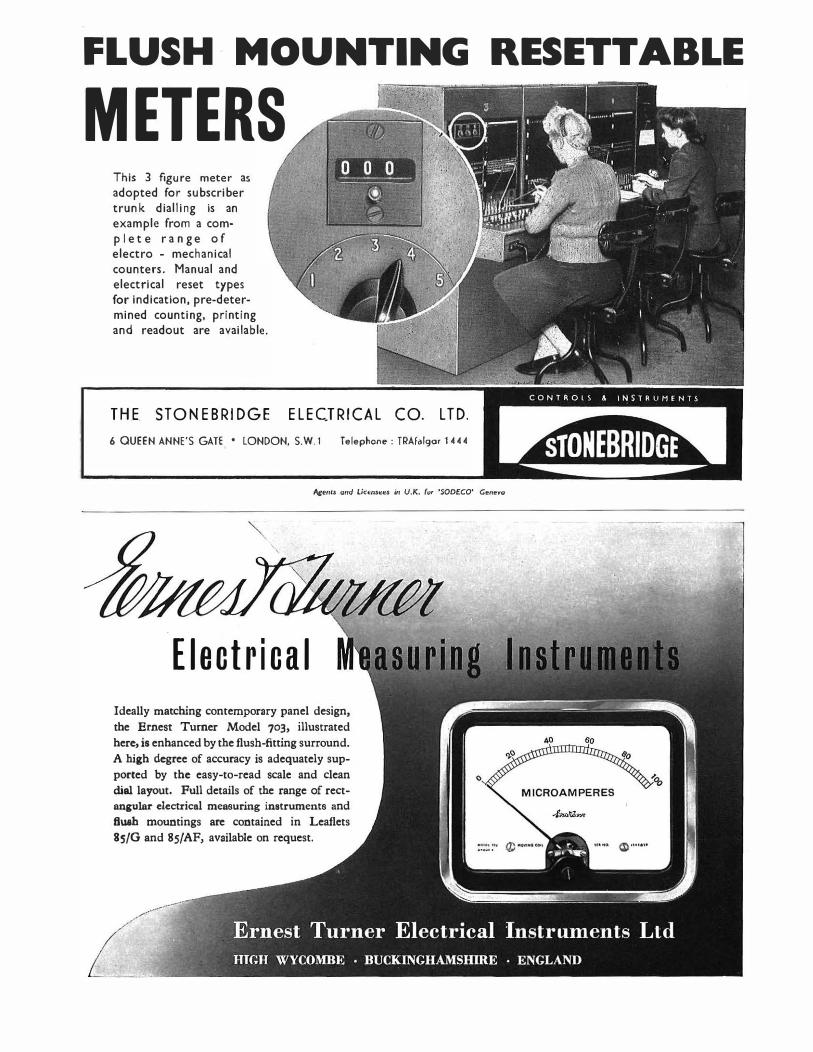
FLUSH· MOUNTING RESETTABLE
METERS This 3 figure meter as adopted for subscriber trunk dialling is an example from a com-p 1 e t e r a n ge of electro - mechanical counters. Manual and electrical reset types for indication, pre-determined counting, printing and readout are available.
TH.E. STONEBRIDGE ELECTRICAL CO. LTD.
6 QUEEN ANNE'S GATE • LONDON, S.W.1 Telephone: TRAfalgar 1444
Agents and Lice11st:es in U.K. (or 'SODECO' Geneva
Electrical
Ideally matching contemporary panel design,
the Ernest Turner Model 703, illustrated
here, is enhanced by the flush-fitting surround.
A high degree of accuracy is adequately sup
ported by the easy-to-read scale and clean
dial layout. Full details of the range of rect
angular electrical measuring instruments and
ftuah mountings are contained in Leaflets
85/G and 85/AF, available on request.
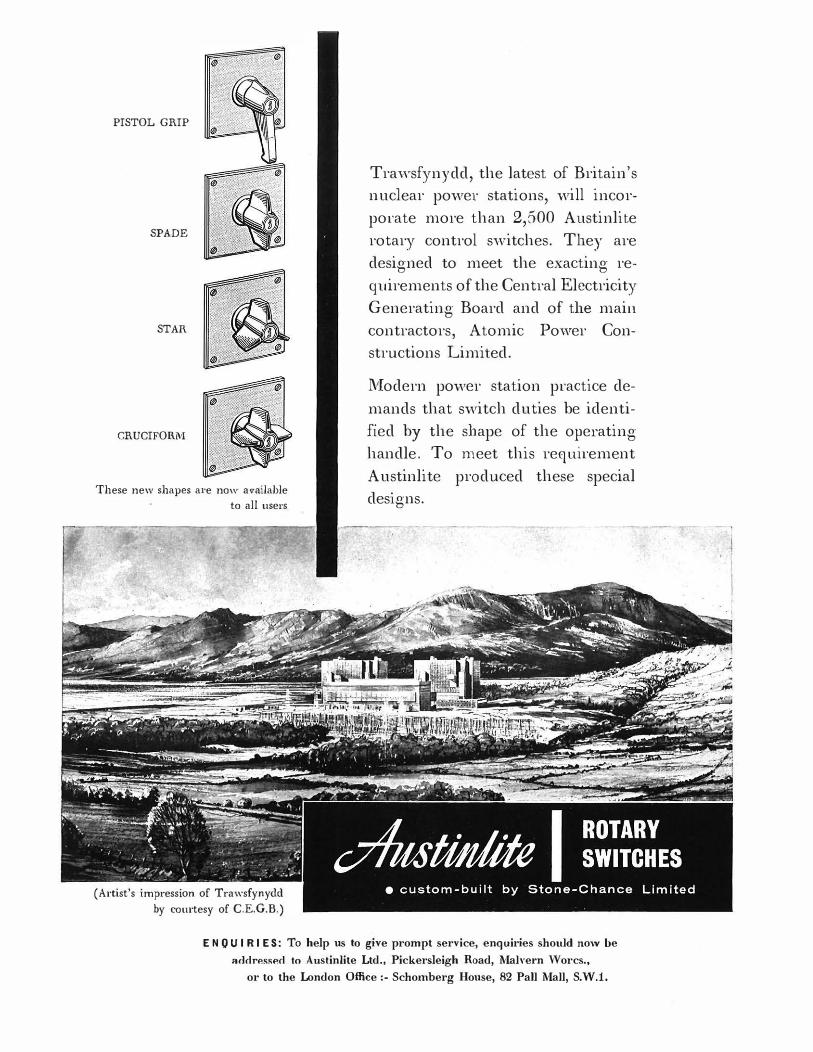
PISTOL GRIP
SPADE
STAR
CRUCIFORM
These new shapes a1·e now a\•ailable
to all use1·s
(Artist's impression of Trawsfynydd
by courtesy of C.E.G.B.)
Travvsfynydd, the latest of Britain's nuclear power stations, will incor
porate more than 2,500 Austinlite rotary control s·witches. They are
designed to meet the exacting requirements of the Central Electricity
Generating Board and of the main contractors, Atomic Povver Constructions Limited.
lVIodern power station practice de
mands that switch duties be identified by the shape of the operating handle. To meet this requirement
Austinlite produced these special designs.
E N O U I R I ES: To help us to give prompt service, enquiries should now be
acldressP.d to Austinlite Ltd., Pickersleigh Road, MalYel'n ''Vorcs.,
or to the London Office:- Schomberg House, 82 Pall Mall, S.V\'.1.
s ctt,. .... •'- c•""'""
""'""'""'o .. • •"•"•"'
VllSC
0110UI" "flla .. sLa"ft .. O
aau•"""'�,.., o.,e-•
,. 0 ........ ...
ea•'-• o•""ia"
., ......... 0... •"·"·"'
.,,.o
14 technicol brochures describe the
new A.T.E. transistorised
telephone carrier
equipment TYPE CM for cable, radio and line systems
BASIC UNITS
TEB 3001 Transmission Equipment Type CM Basic Features
TEB 3101 Channelling and Signalling Equipment-CT12A TEB 3102 Signalling Equipment TEB 3103 Group Translating Equipment-GT5A
TEB 3104 Supergroup Translating Equipment-ST5A
CABLE SYSTEMS
TEB 3201 12-Channel Cable Carrier System-C12G TEB 3202 Coaxial Line Equipment-C300A
RADIO MULTIPLEX TERMINALS
TEB 3301 Multiplex Equipment-R24B
TEB 3302 Multiplex Equipment-R60B TEB 3303 Multiplex Equipment-R3A TEB 3304 Multiplex Equipment-Al 20C TEB 3305 Multiplex Equipment-R300C
OPEN WIRE SYSTEMS
TEB 3401 3-Ghannel Open-Wire Carrier Systems-W3G
TEB 3402 12-Channel Open Wire Carrier Systems-W12H
WRITE NOW FOR THE BROCHURES YOU REQUIRE TO:-
AUTOMATIC TELEPHONE
& ELECTRIC CO. LTD. Strowger House, Arundel Street, London, W.C.2. Telephone: TEMple Bar 9262
AT8971
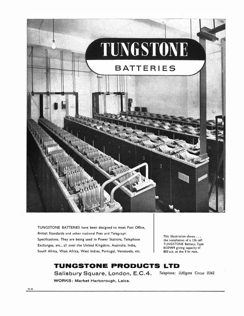
TCH
TUNGSTONE BATTERIES have been designed to meet Post Office,
British Standards and other national Post and Telegraph
Specifications. They are being used in Power Stations, Telephone
Exchanges, etc., all over the United Kingdom, Australia, India,
South Africa, West Africa, West Indies, Portugal, Venezuela, etc.
This illustration shows ... the installation of a 126 cell TUNGSTONE Battery, Type BSSFW9 giving capacity of 800 a.h. at the 9 hr rate,
TUNGSTONE PRODUCTS LTD
Salisbury Square, London, E.C.4.
WORKS: Market Harborough, Leics.
Telephone: LUDgate Circus 0342

Nine- and six-way
conduits being laid
at the junction
of Oxford Street
and Portman Street, London W.1.
For information write to The Secretary
NATIONAL SALT GLAZED PIPE MANUFACTURERS' ASSOCIATION Hanover Court, Hanover Square, LONDON, W.1.
Telephone MA Yfair 036.J.
serve ...
the West End well
Only glazed vitrified clay conduits can guarantee the degree of protection demanded by the authorities for the permanent security of our tele-communications. The importance of using glazed vitrified clay conduits is widely accepted to-day, especially in our cities where the flow of traffic must be disturbed to the minimum and where the heavy cost of re-excavation must be avoided. Experience has proved that there is no adequate
substitute for glazed vitrified clay conduits.

The Post and Telegraph Authorities of more than 80 countries
rely on Marconi telecommunications equipment
SURVEYS * Marconi's telecommunications survey teams are at work in many parts of the world. Marconi's is the only company maintaining a permanent research group working entirely on wave propagation.
INSTALLATION * Marconi's installation teams undertake complete responsibility for system installation, including erection of buildings and civil engineering works as well as the installation of the telecommunications equipment and auxiliary plant.
PLANNING* Marconi's vast experience is reflected in the quality of its system planning organisation which is constantly employed on planning major telecommunications systems for many parts of the world.
MAINTENANCE* Marcon i's provide a complete system maintenance service and undertake the training of operating and maintenance staff, either locally or in England. Marconi's will also establish and manage local training schools for Post and Telegraph Authorities.
HZ
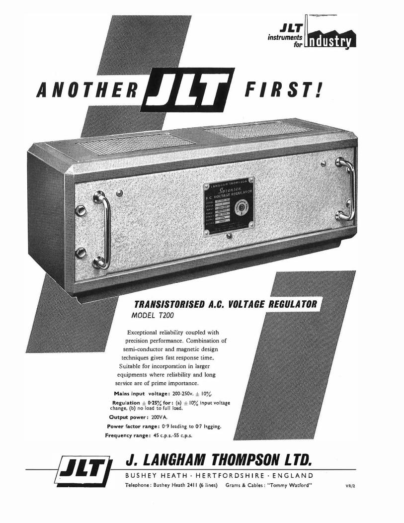
.JLT instruments
for�..._._. ............ 1.-
MODEL T200
Exceptional reliability coupled with
precision performance. Combination of
semi-conductor and magnetic design
techniques gives fast response time.
Suitable for incorporation in larger
equipments where reliability and long
service are of prime importance.
Mains input voltage: 200-250v. ± 10%.
Regulation ± 0·25% for: (a) ± 10% input voltage change, (b) no load to full load.
Output power: 200V A.
Power factor range: 0·9 leading to 0·7 hgglng.
Frequency range: 45 c.p.s.-55 c.p.s.
FIRST!
J. LANGHAM THOMPSON LTD. BUSHEY HEATH · HERTFORDSHIRE · ENGLAND Telephone: Bushey Heath 2411 (6 lines) Grams & Cables: "Tommy Watford" VR/2

SUDAN
CHOOSES
ERICSSON The Posts and Telegraphs Department of the Republic
of Sudan is installing a carrier cable scheme,
with a maximum capacity of 120 circuits, along
the railway between Khartoum and Sennar-
a distance of approximately 300 l<m. The 120 circuits
are obtained from two parallel 60 channel systems
in the band 12-252 kc/s on two buried single-quad
40 lb polythene cables.
The fully transistorized carrier equipment used on the
scheme Is being supplied by Ericsson.
All channelling and translation equipment is
conventional, but the line equipment has features
which were necessitated by the use of (a) comparatively
high-loss cable, (b) by the distances between
points where electrical power is available and
(c) by the necessity of providing certain railway
signalling facilities.
The bulk of the line equipment comprises intermediate
repeaters (shown on opposite page) which are
buried at intervals of 10 km along the line to provide
amplification and equalisation for all four
cable pairs. The amplifiers are power fed over
the phantoms of two of the pairs from the terminals
or main repeaters which are spaced up to 150 km apart.
The transistorized carrier equipment, designed and
built to the same high standards of reliability
and performance always associated with Ericsson
Telecommunication equipment, has also been
chosen for two further schemes linking Sennar with
Kosti (approx. 120 km) and, in the southern Sudan, Wau
with Babanusa (approx. 450 km).
If your communication problem is one of choice between
open-wire or cable, and initial cost relative to
reliability and performance, a word with our
engineers will cost you nothing and may well prove
extremely beneficial.
:
�11•11111111111111111111(1 Rabak
Kosti
Buried Repeater
Khartoum
Abu Usher
El Manaqll
0
Rufa•a
El Hasiheisa
Wad Medani
Senna.-
�(,
Haraz
special features
A group of 12 or a sub-group of'J channels may be extracted at main repeaters.
Access to the cable physicals, for D.C. signal· ling or local audio circuits, may be obtained by by-pass filter units.
Identification of any faulty intermediate repeater from a terminal or main repeater station.
Automatic gain regulation with alarm on failure.
Automatic change-over facilities when the two 60 channel systems are operated "Main and Stand-by".
II ERICSSON TELEPHONES LIMITED • ETELCO LIMITED
Head Office: 22 Lincoln's Inn Fields, London; W.C.2. Tel: HOL. 6936 ·Works: Beaston, Nottingham and Sundel"land.
INDEX TO ADVERTISERS
PAGE
Adcola Products, Ltd. 8
Associated Electrical Industries, Ltd. 26
Automatic Telephone & Electric Co., Ltd. 21, 34-35
Avo, Ltd. I
British Institute of Engineering Technology 4
Cathodeon Crystals, Ltd. 43
Datum Metal Products, Ltd. 16
Ericsson Telephones, Ltd. 40-41
General Electric Co., Ltd., The 14-15, 18-19, 24-25
Great Northern Telegraph Co., Ltd. 20
Harrap, George G., & Co., Ltd. 8
Johnson, Matthey & Co., Ltd. 27
Macdonald & Co. (Publishers), Ltd.
Marconi's Wireless Telegraph Co., Ltd.
Mullard, Ltd.
National Salt Glazed Pipe Manufacturers' Association
Neill, James, & Co. (Sheffield), Ltd.
AN INTRODUCTION
8
38
10
37
16
TO THE THEORY AND PRACTICE
OF TRANSISTORS By J. R. Tillman, D.Sc., A.R.C.S., and
F. F. Roberts, B.Sc.(Eng.), A.M.I.E.E.
A new work for physicists and electronic engineers at graduate and
Higher National Certificate level. It gives the theoretical background of
semiconductor and transistor physics and then covers technology,
electrical properties of semiconductors, diodes, and transistors with
applications. 57 /6 net.
A GUIDE TO TECHNICAL WRITING By C. Baker, A.R.Ae.S.
Covers in a practical manner the preparation of explanatory documents,
manuals, brochures, reports, specifications, etc. Of interest to the
student and technician alike. rs/- net.
RADIO AND ELECTRONIC
COMPONENTS: Vol. V
WIRES AND R.F. CABLES By G. \V. A. Dummer, M.B.E., M.I.E.E., and
\V. T. Blackband, M.Sc., A.M.I.E.E.
The first time that such a comprehensive book has been written on the
subject. This volume covers Wires, Sleevings and Radio-Frequency
Cables, together with an extensive bibliography. There is also a unique
World List of both Military and Commercial R.F. Cables, in addition
to comparison charts of characteri<tics. 47 /6 net.
PITMAN
Painton & Co., Ltd . . .
Pirelli-General Cable Works, Ltd.
Pitman, Sir Isaac, & Sons, Ltd.
Shell-Mex & B.P. Gases , Ltd.
Sperry Gyroscope Co. Ltd. . .
PAGE
30
22
4, 42
23
2
Standard Telephcmes & Cables, Ltd.
Stone-Chance, Ltd. (Austinlite)
Stonebridge Electrical Co., Ltd. , The
Submarine Cables, Ltd.
3,5, 7,9 ,11, 12-13,44
33
Telcon Metals, Ltd . ..
Telephone Manufacturing Co., Ltd.
Thompson, J. Langham, Ltd.
Tungstone Products, Ltd.
Turner, Ernest, Electrical Instruments, Ltd.
Westinghouse Brake & Signal Co., Ltd.
Whiteley Electrical Radio Co., Ltd.
Winn & Coates, Ltd ...
32
17
4
28-29
39
36
32
31
6
6
MODEL ANSWER BOOKS CITY AND GUILDS OF LONDON INSTITUTE TELECOMMUNICATION TECHNICIANS' COURSE
TELECOMMUNICATION PRINCIPLES A
TELECOMMUNICATION PRINCIPLES B
Price 7s. 6d. each. Post Paid 8s.
ELEMENTARY TELECOMMUNICATIONS
PRACTICE
Price Ss. each. Post Paid Ss. 6d.
The following two model answer books, although published for the old Telecommunications Engineering Course, are still useful and are offered at a considerably reduced price.
TELEPHONE EXCHANGE SYSTEMS I
(Telephony and Telegraphy A, Telephony B)
TELEGRAPHY II
(Telegraphy B, Telegraphy C)
Price ls. each. Post Paid ls. 6d.
Orders to The Post Office Electrical Engineers' journal
G.P.O., 2-12 Gresham Street, London, E.C.2
Published by Tlie Post Office Electrical Enctneers' Journal. G.P.0., 2-12 Gresham Street London E.C.2 and printed in Orear Britain at The Baynard Press by Sanders Phillips and Co .. Ltd .• Cbrysscl1
° Road. London.
" S.W.9

CATHODEON CRYSTALS LIMITED
LINTON CAMBRIDGES IRE TELEPHONE LINTON 501 (4 lin )
i!\ i(,g_; . '(jl
STC D .IS TRI BUT I 0 N
CABLE
STC Rm·al Distribution Cable meets the need for an
economic type of telephone distribution cable for use in rural
communities. It has been installed in many countries through
out the world, including tropical and sub-tropical areas.
Easy to handle and light in weight, it is a self-supporting
cable in which the self protected pairs of conductors are
formed round a central support wire. It can be suspended
from existing crossarms or poles by means of a simple
system of clamps.
STC manufactures many types of dist1:ibution cable,
including aerial self-supporting and underground types
(armoured and unarmoured) as used by the British
Post Office, Foreign Telephone Administrations,
oil companies and other industries.
For further details ask for Catalogues H/100 and H/105.
Sia11dard Telephones a11d Cables Limiied RUBBER & PLASTIC CABLE DIVISION: CORPORATION ROAD NEWPORT MON
61/SH