polymer nanofilms with enhanced microporosity by interfacial
TRANSCRIPT
1
Polymer nanofilms with enhanced microporosity by interfacial polymerisation
Maria F. Jimenez-Solomon1†
, Qilei Song1†
, Kim E. Jelfs2, Marta Munoz-Ibanez
1 and Andrew G. Livingston
1*
1Department of Chemical Engineering, Imperial College London, London SW7 2AZ, UK,
2Department of Chemistry, Imperial College London. London SW7 2AZ, UK.
†These authors contributed equally to this work.
* e-mail: [email protected]
Highly permeable and selective membranes are desirable for energy-efficient gas and liquid separations.
Microporous organic polymers have attracted significant attention in this respect owing to their high
porosity, permeability, and molecular selectivity. However, it remains challenging to fabricate selective
polymer membranes with controlled microporosity which are stable in solvents. Here we report a new
approach to designing crosslinked, rigid polymer nanofilms with enhanced microporosity by
manipulating the molecular structure. Ultra-thin polyarylate nanofilms with thickness down to 20 nm
were formed in-situ by interfacial polymerisation. Enhanced microporosity and higher interconnectivity
of intermolecular network voids, as rationalised by molecular simulations, are achieved by utilising
contorted monomers for the interfacial polymerisation. Composite membranes comprising polyarylate
nanofilms with enhanced microporosity fabricated in-situ on crosslinked polyimide ultrafiltration
membranes show outstanding separation performance in organic solvents, with up to two orders of
magnitude higher solvent permeance than membranes fabricated with nanofilms made from non-
contorted planar monomers.
Conventional gas and liquid separation processes such as evaporation and distillation are widely used in
the oil and gas, energy, chemical, and pharmaceutical industries, but are energy-intensive. An
alternative to these processes is membrane separation technology, which typically consumes an order of
magnitude less energy. To enable wider deployment of membrane technology, highly permeable
membranes are required to process large volumes of gas or solvent using a viable membrane area over
a feasible timeframe1-2
. There are two main strategies being followed to this end. One is to design the
polymer structure at the molecular level so as to provide greater interconnected microporosity3-10
,
whilst a second approach is to reduce the thickness of the separating layer to nanometre scale11-16
.
Microporous organic materials with well-defined pore structure are excellent candidates for highly
permeable and selective membranes1, such as metal-organic frameworks (MOFs) and porous
coordination polymers (PCPs)17-18
, covalent organic frameworks (COFs)19-20
, and porous organic cages
2
(POCs)21-23
. However, the fabrication of these crystalline solids to form defect-free membranes is
technically challenging. Recent significant progress includes fabrication of MOFs to form selective
membranes by secondary crystal growth24
, assembly of MOF nanosheets15
, interfacial synthesis25
, or
mixed matrix membranes10,26
. By contrast, industrial membranes are dominated by solution processing
of polymers and interfacial polymerisation, for example in producing polyamide desalination
membranes. Notable examples of microporous polymers are polymers of intrinsic microporosity
(PIMs)6-7,27-31
. Owing to the shape and rigidity of the component monomers, the polymer chains have
contorted, rigid backbones resulting in inefficient packing, creating interconnected voids of less than 2
nm which behave as micropores. Due to their solubility in common solvents, linear-type PIMs can be
processed into thin films which are highly permeable and selective for gas separations32-33
. However, it
is this solubility in a range of solvents which restricts their applications in organic solvent nanofiltration
(OSN)34-35
. Several efforts to make these PIM thin films solvent resistant have been reported, including
thermal oxidative crosslinking9, chemical crosslinking
28, and blending with thermally reactive
polymers34
; however these approaches introduce further processing steps.
Efforts to achieve higher separation performance, particularly higher permeance, have also sought to
create ever-thinner membranes, such as PIM-1 nanofilms36
, and MOF nanosheets15
. Unexpectedly,
recent work has shown that decreasing the thickness of solution cast films of PIM-1 below 100 nm
resulted in a decrease, rather than an increase, in heptane permeance36
. This was attributed to structural
relaxation of the polymer molecules in the thin films. This effect has also been observed in gas
permeation37
, and suggests that linear macromolecules may not be suitable for ultra-thin nanofilms. By
contrast, for nanofilms comprising crosslinked polymer networks or carbon networks, solvent
permeance continues to increase as thickness is reduced. Fabrication of free-standing ultra-thin
nanofilm membranes using metal hydroxide nanostrands as sacrificial substrates38-39
was recently
extended to formation of crosslinked polyamide nanofilms by interfacial polymerisation followed by
DMF activation11
. The resulting highly permeable ultra-thin free-standing polyamide nanofilms offer
superior performance to conventional filtration membranes; however, sophisticated nanoscale
processing steps are required in their fabrication.
3
Previous work indicates that introducing rigid moieties into polyamide nanofilms with thickness of 100
nm made by interfacial polymerisation enhances nanofilm porosity40
. Nanofiltration performance was
demonstrated for removal of salts from water, but these polyamide membranes had defects, limiting
their application to other molecular separations40
.
Here we report a new synthetic approach to designing polymer nanofilm membranes with enhanced
microporosity without complex processing. We employed interfacial polymerisation with contorted and
non-contorted monomers to synthesise defect-free, highly crosslinked polyarylate nanofilms down to
20 nm in thickness directly on ultrafiltration (UF) supports. The nanofilms fabricated with contorted
monomers exhibit higher microporosity and interconnectivity than those made from non-contorted
monomers. This results in up to two orders of magnitude higher permeance for organic solvents, and
higher adsorption for gases. We hypothesize that upon interfacial polymerisation, the contorted
monomers are held in non-coplanar orientations by the network structure, enhancing interconnectivity
of intermolecular voids. This hypothesis is supported by our experimental results and molecular
simulations. This work demonstrates that interfacial synthesis using contorted monomers provides
nanofilms with a wide range of solvent resistance, tuneable structural diversity and enhanced
microporosity defined by the geometry of monomers.
Formation of polymer nanofilms
Polymer nanofilms were synthesised by interfacial polymerisation. We selected the interfacial
polymerisation technique because it gives highly cross-linked polymer nanofilms in situ, ensuring
stability in organic solvents. This simple, reproducible, and easily controllable technique has been used
for synthesis of polyamide membranes for applications in reverse osmosis desalination and organic
solvent nanofiltration11,41
, MOF capsules42
and gas separation membranes25
. Here, polyarylate (PAR)
(aromatic polyester) nanofilms were formed by reacting a phenol with trimesoyl chloride (TMC) at the
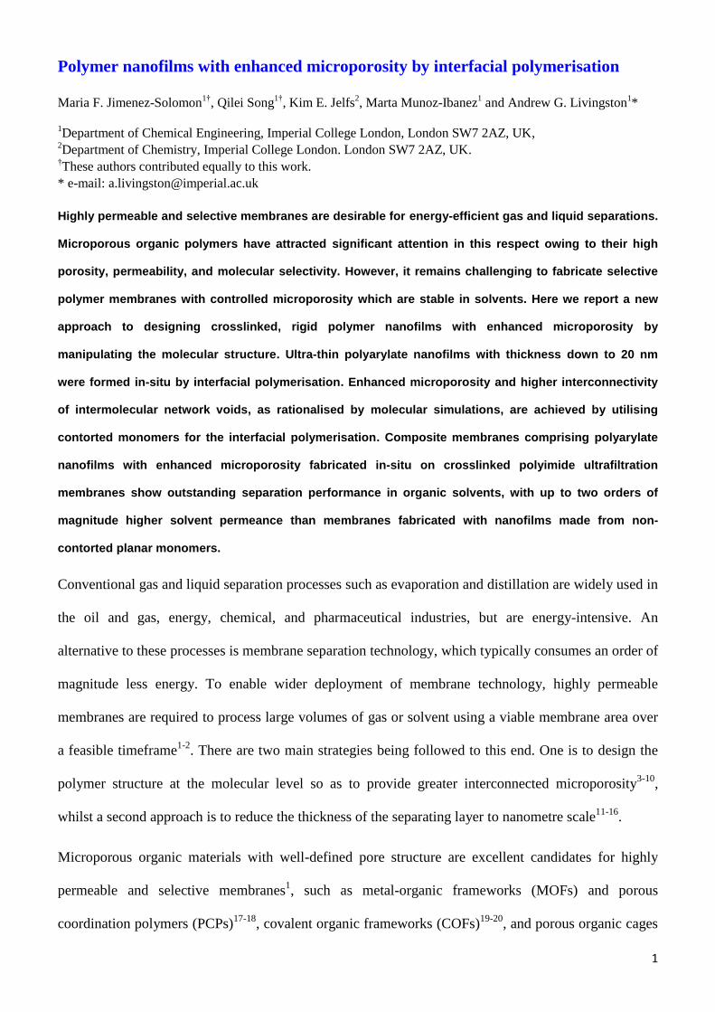
interface between two immiscible solutions (Fig. 1a,c, and Supplementary Fig. 1). We used contorted
phenols including spiro-structured 5,5′,6,6′-tetrahydroxy-3,3,3′,3′-tetramethylspirobisindane (TTSBI)
and 9,9-bis(4-hydroxyphenyl)fluorene (BHPF) to form polyarylates with enhanced microporosity, and
4
selected dihydroxyanthraquinone (DHAQ), and 1,3-benzenediol (RES) with planar structures as non-
contorted controls (Fig. 1a, and Supplementary Fig. 2 and 3). The spiro-centre within TTSBI has an
angle of 90°, so when it reacts with TMC the TTSBI units are held in non-coplanar orientation by the
polymer network (Fig. 1b), enhancing interconnectivity of network voids. The spiro-centre prohibits
the efficient packing of polymer segments in the networks, leading to relatively higher free volume.
Figure 1d shows a three dimensional view of a modelled amorphous cell containing a porous PAR-
TTSBI network. To exploit their rigidity, solvent stability and enhanced porosity, we synthesised PAR
nanofilms directly on porous supports and used them as selective membranes for gas separations and
organic solvent nanofiltration (Fig. 1e and 1f).
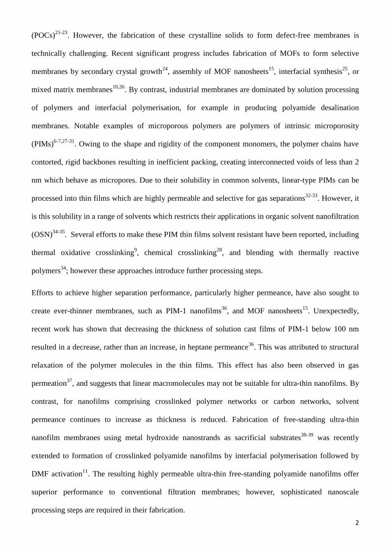
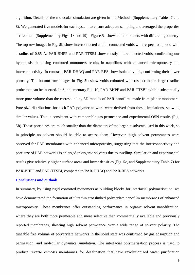
Polyarylate nanofilms with thickness down to 20 nm can be formed via interfacial polymerisation (Fig.
2a), and were transferred onto anodised alumina supports, allowing clear imaging with scanning
electron microscopy (SEM) (Supplementary Fig. 4). The nanofilm thickness can be tuned by varying
the concentration of monomers (Supplementary Fig. 4 and 5). To study the morphology and bulk
properties of each polyarylate, we synthesised PAR powders via interfacial polymerisation in a two
phase mixed reactor with rigorous stirring (PAR-IP) (Supplementary Fig. 2), and in monophasic liquid
reactions (PAR-MP) (Supplementary Fig. 3). Polymer solids made interfacially show film-like
morphologies (Fig. 2b and Supplementary Fig. 6), whereas powders from monophasic reactions show
agglomerated particles (Supplementary Fig. 7). Their chemical structure as aromatic polyesters was
validated using infrared spectroscopy (Supplementary Fig. 8). Wide-angle X-ray scattering (WAXS)
patterns confirm that these polymers are essentially amorphous except for PAR-DHAQ made by
interfacial polymerisation, which shows some crystalline peaks possibly due to crystallization of
monomers (Supplementary Fig. 9). The lattice spacings in WAXS for PAR polymers correspond well
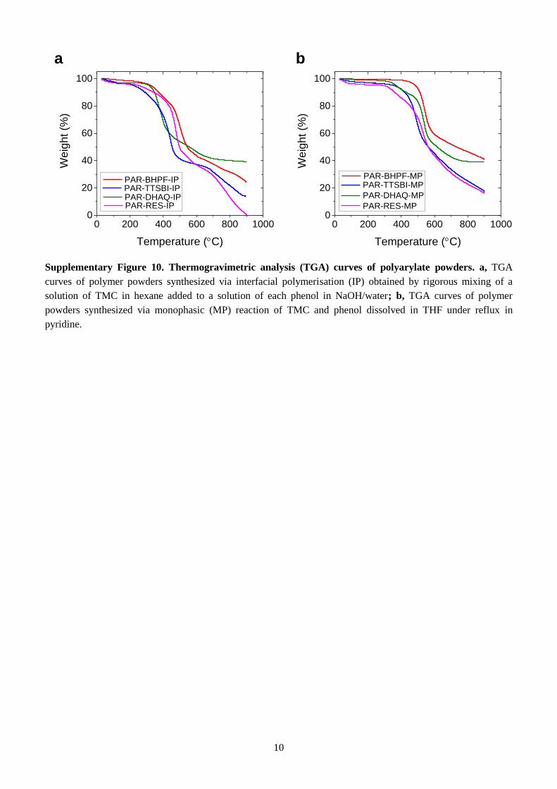
with the level of microporosity observed in gas sorption and modelling. Thermal analysis of all
powders revealed high-temperature stability, with decomposition temperature under nitrogen
atmosphere above 400°C (Supplementary Fig. 10).
5
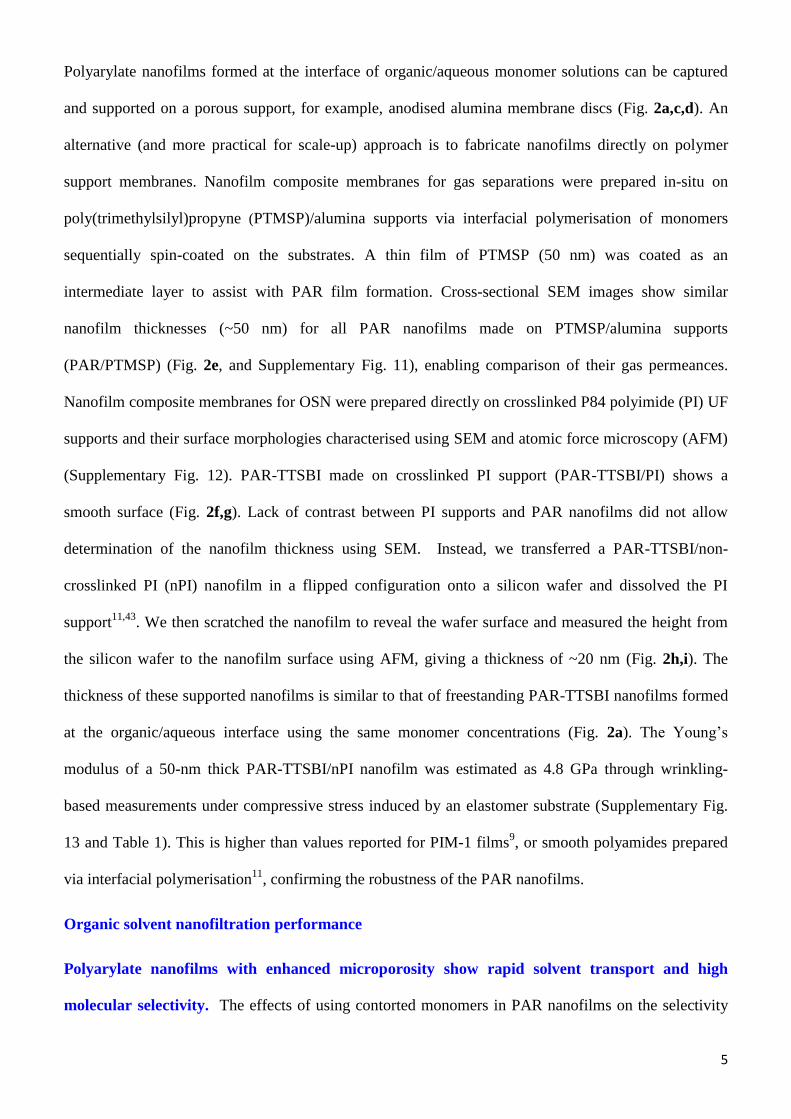
Polyarylate nanofilms formed at the interface of organic/aqueous monomer solutions can be captured
and supported on a porous support, for example, anodised alumina membrane discs (Fig. 2a,c,d). An
alternative (and more practical for scale-up) approach is to fabricate nanofilms directly on polymer
support membranes. Nanofilm composite membranes for gas separations were prepared in-situ on
poly(trimethylsilyl)propyne (PTMSP)/alumina supports via interfacial polymerisation of monomers
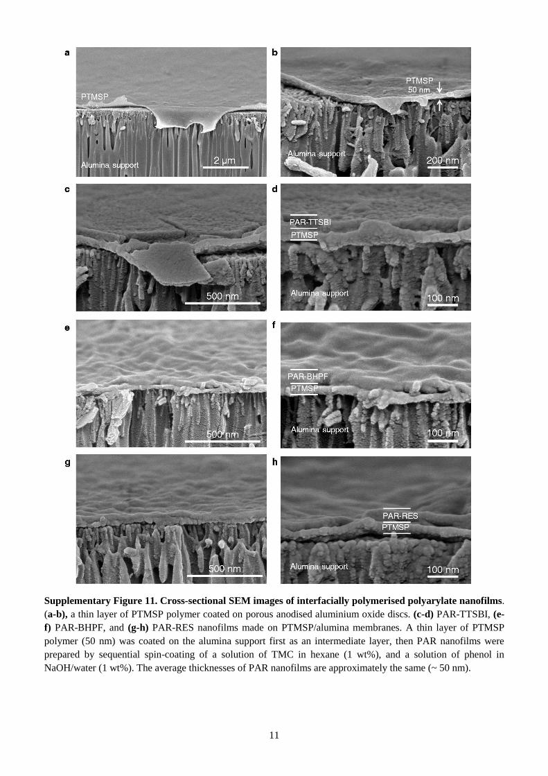
sequentially spin-coated on the substrates. A thin film of PTMSP (50 nm) was coated as an
intermediate layer to assist with PAR film formation. Cross-sectional SEM images show similar
nanofilm thicknesses (~50 nm) for all PAR nanofilms made on PTMSP/alumina supports
(PAR/PTMSP) (Fig. 2e, and Supplementary Fig. 11), enabling comparison of their gas permeances.
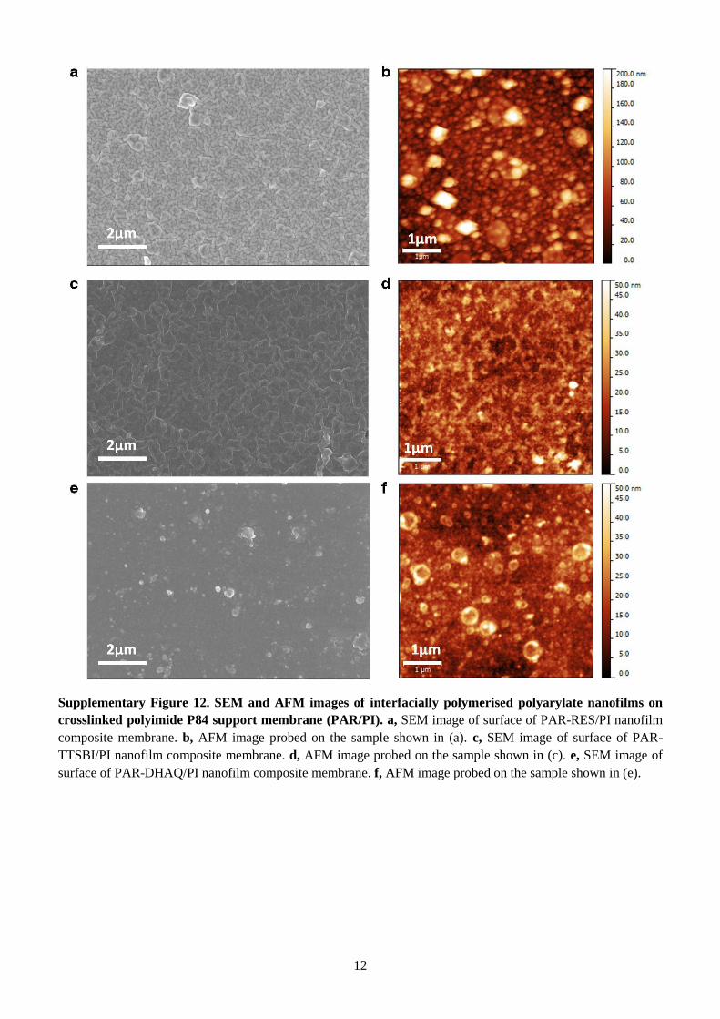
Nanofilm composite membranes for OSN were prepared directly on crosslinked P84 polyimide (PI) UF
supports and their surface morphologies characterised using SEM and atomic force microscopy (AFM)
(Supplementary Fig. 12). PAR-TTSBI made on crosslinked PI support (PAR-TTSBI/PI) shows a
smooth surface (Fig. 2f,g). Lack of contrast between PI supports and PAR nanofilms did not allow
determination of the nanofilm thickness using SEM. Instead, we transferred a PAR-TTSBI/non-
crosslinked PI (nPI) nanofilm in a flipped configuration onto a silicon wafer and dissolved the PI
support11,43
. We then scratched the nanofilm to reveal the wafer surface and measured the height from
the silicon wafer to the nanofilm surface using AFM, giving a thickness of ~20 nm (Fig. 2h,i). The
thickness of these supported nanofilms is similar to that of freestanding PAR-TTSBI nanofilms formed
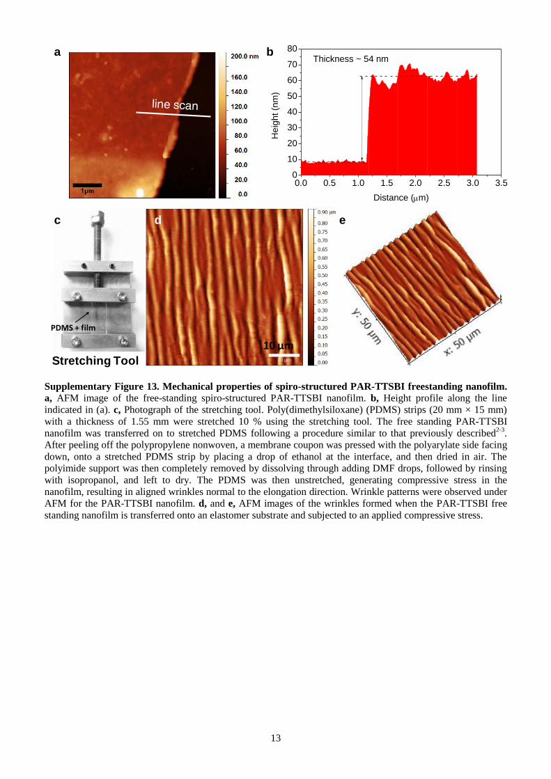
at the organic/aqueous interface using the same monomer concentrations (Fig. 2a). The Young’s
modulus of a 50-nm thick PAR-TTSBI/nPI nanofilm was estimated as 4.8 GPa through wrinkling-
based measurements under compressive stress induced by an elastomer substrate (Supplementary Fig.
13 and Table 1). This is higher than values reported for PIM-1 films9, or smooth polyamides prepared
via interfacial polymerisation11
, confirming the robustness of the PAR nanofilms.
Organic solvent nanofiltration performance
Polyarylate nanofilms with enhanced microporosity show rapid solvent transport and high
molecular selectivity. The effects of using contorted monomers in PAR nanofilms on the selectivity
6
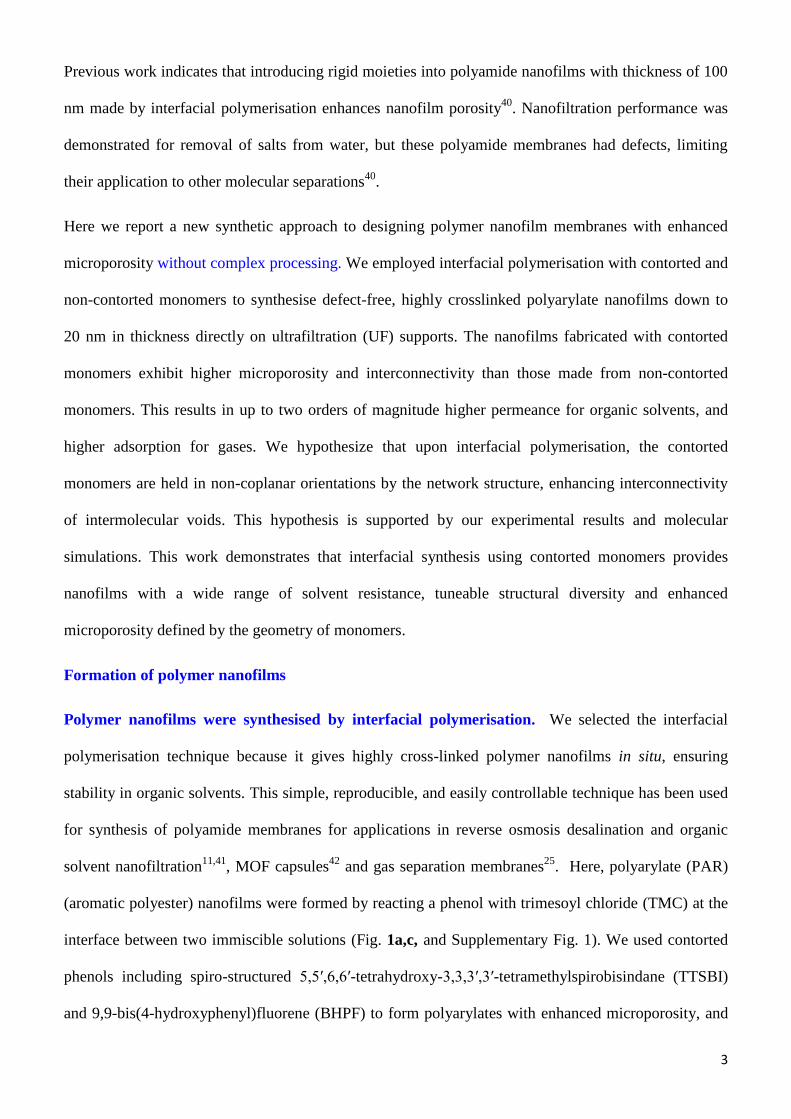
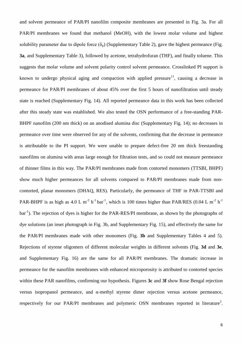
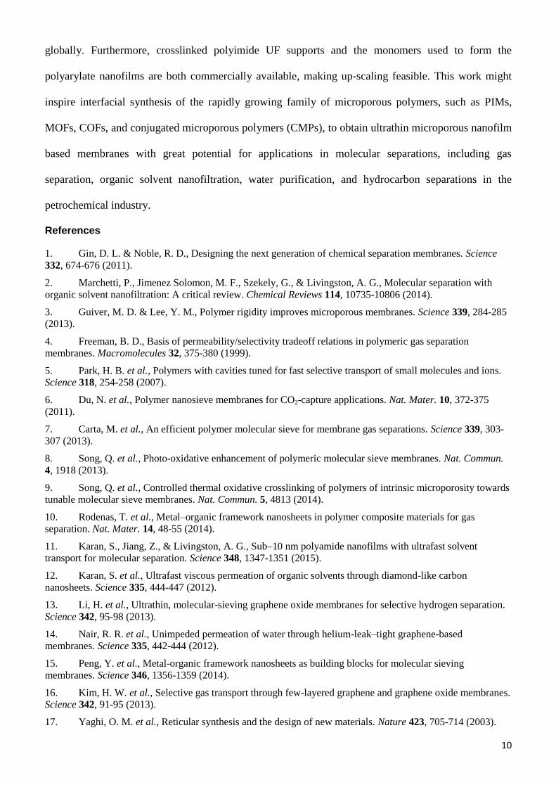
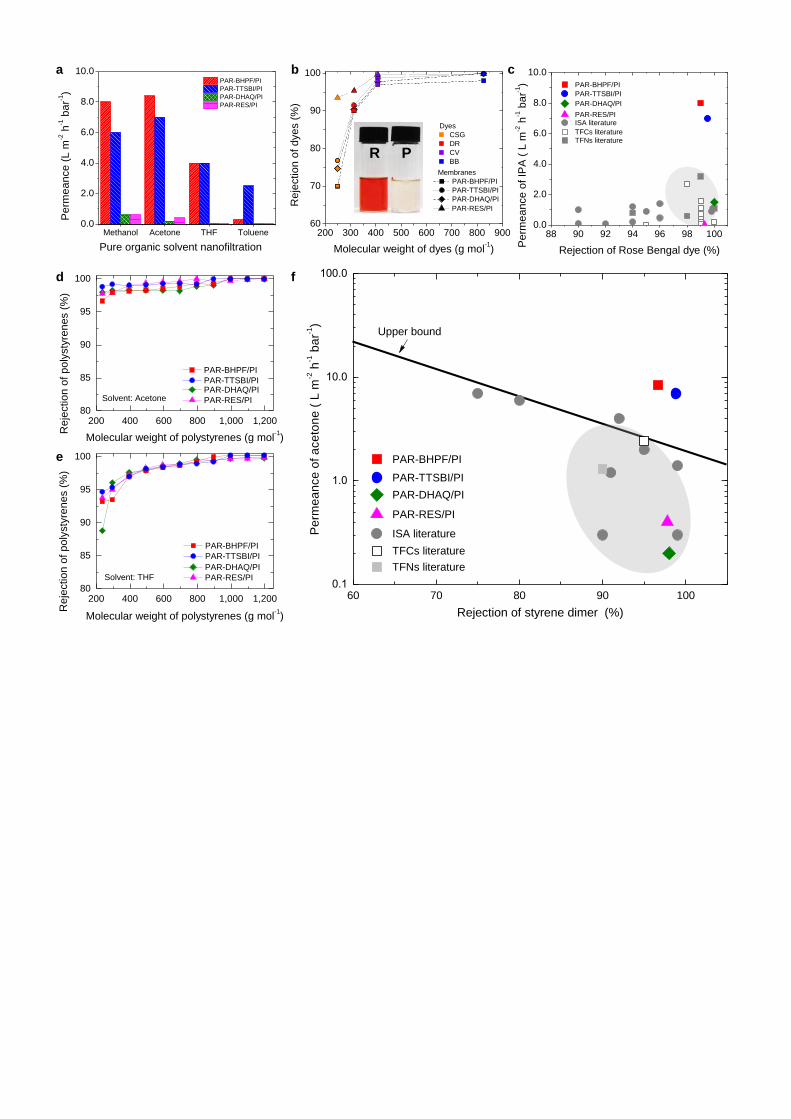
and solvent permeance of PAR/PI nanofilm composite membranes are presented in Fig. 3a. For all
PAR/PI membranes we found that methanol (MeOH), with the lowest molar volume and highest
solubility parameter due to dipole force (δp) (Supplementary Table 2), gave the highest permeance (Fig.
3a, and Supplementary Table 3), followed by acetone, tetrahydrofuran (THF), and finally toluene. This
suggests that molar volume and solvent polarity control solvent permeance. Crosslinked PI support is
known to undergo physical aging and compaction with applied pressure11
, causing a decrease in
permeance for PAR/PI membranes of about 45% over the first 5 hours of nanofiltration until steady
state is reached (Supplementary Fig. 14). All reported permeance data in this work has been collected
after this steady state was established. We also tested the OSN performance of a free-standing PAR-
BHPF nanofilm (200 nm thick) on an anodised alumina disc (Supplementary Fig. 14); no decreases in
permeance over time were observed for any of the solvents, confirming that the decrease in permeance
is attributable to the PI support. We were unable to prepare defect-free 20 nm thick freestanding
nanofilms on alumina with areas large enough for filtration tests, and so could not measure permeance
of thinner films in this way. The PAR/PI membranes made from contorted monomers (TTSBI, BHPF)
show much higher permeances for all solvents compared to PAR/PI membranes made from non-
contorted, planar monomers (DHAQ, RES). Particularly, the permeance of THF in PAR-TTSBI and
PAR-BHPF is as high as 4.0 L m-2
h-1
bar-1
, which is 100 times higher than PAR/RES (0.04 L m-2
h-1
bar-1
). The rejection of dyes is higher for the PAR-RES/PI membrane, as shown by the photographs of
dye solutions (an inset photograph in Fig. 3b, and Supplementary Fig. 15), and effectively the same for
the PAR/PI membranes made with other monomers (Fig. 3b and Supplementary Tables 4 and 5).
Rejections of styrene oligomers of different molecular weights in different solvents (Fig. 3d and 3e,
and Supplementary Fig. 16) are the same for all PAR/PI membranes. The dramatic increase in
permeance for the nanofilm membranes with enhanced microporosity is attributed to contorted species
within these PAR nanofilms, confirming our hypothesis. Figures 3c and 3f show Rose Bengal rejection
versus isopropanol permeance, and α-methyl styrene dimer rejection versus acetone permeance,
respectively for our PAR/PI membranes and polymeric OSN membranes reported in literature2.
7
Compared to these previously reported membranes2, the PAR nanofilm composite membranes with
enhanced microporosity from this work show outstanding solvent permeance at the same selectivity.
A comparison between the OSN performance of polyarylate nanofilms with enhanced microporosity
and previously reported sub-10-nm polyamide nanofilms11
is provided in Supplementary Table 6. For
nanofilm composite membranes utilising crosslinked PI supports, the polyarylate nanofilms offer
comparable or better permeance than the polyamide nanofilms formed using nanostrands. The
nanofilms mounted on alumina supports are harder to compare directly as their thicknesses differ
widely. We note that among the polyamide nanofilms it is uniquely the m-phenylenediamine (MPD)
based nanofilms that exhibit increased effective area through crumpling, and that respond favourably to
dimethylformamide (DMF) activation. MPD and TMC are conventional monomers for desalination
membranes, and the exceptional performance of the nanofilms derives from the complex nanoscale
fabrication. However, there are significant challenges around the scale-up of both nanostrand
fabrication and DMF activation. In contrast our polyarylate nanofilms are produced in-situ on
ultrafiltration support membranes using regular interfacial polymerisation techniques, and their high
permeance is due to the non-conventional contorted monomers employed. This supports designing the
molecular architecture of nanofilms, using a wide range of chemistries, as an attractive alternative to
the use of complex processing steps, to produce high permeance membranes.
Microporosity of polyarylate networks
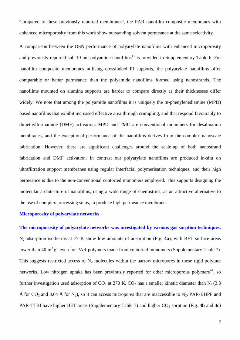
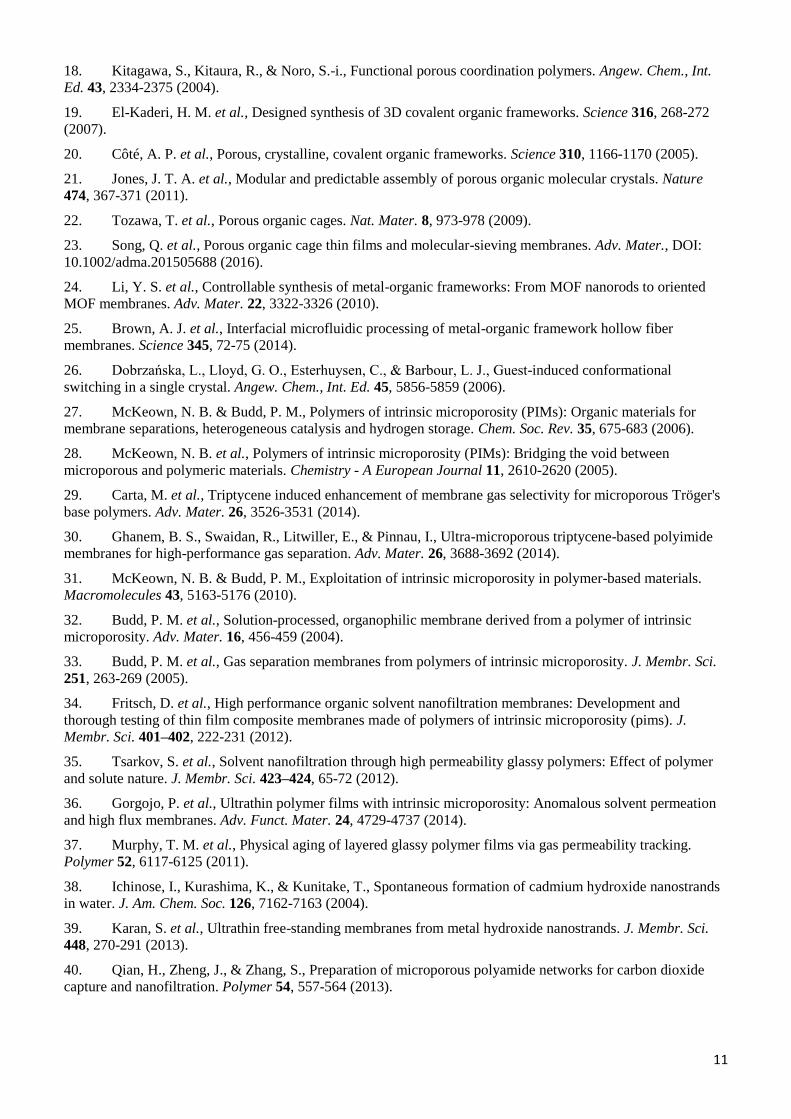
The microporosity of polyarylate networks was investigated by various gas sorption techniques.
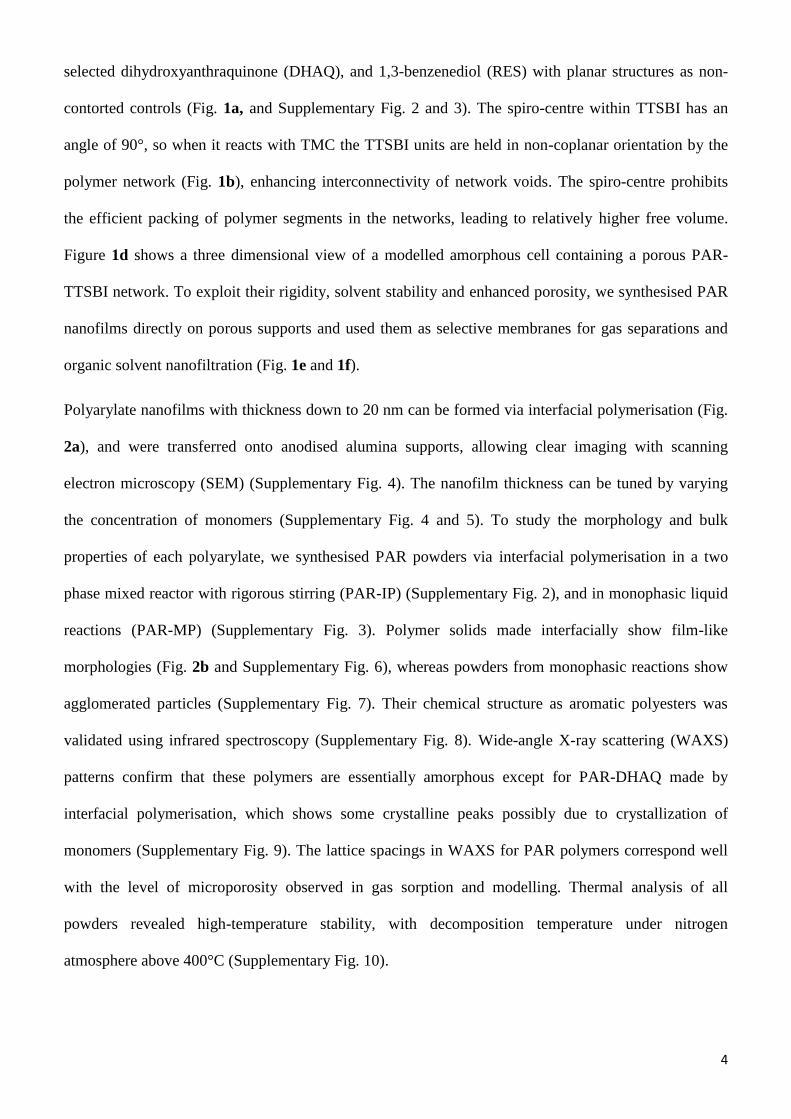
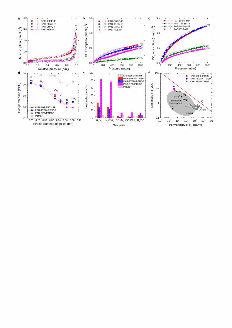
N2 adsorption isotherms at 77 K show low amounts of adsorption (Fig. 4a), with BET surface areas
lower than 40 m2 g
-1 even for PAR polymers made from contorted monomers (Supplementary Table 7).
This suggests restricted access of N2 molecules within the narrow micropores in these rigid polymer
networks. Low nitrogen uptake has been previously reported for other microporous polymers44
, so
further investigation used adsorption of CO2 at 273 K. CO2 has a smaller kinetic diameter than N2 (3.3
Å for CO2 and 3.64 Å for N2), so it can access micropores that are inaccessible to N2. PAR-BHPF and
PAR-TTBI have higher BET areas (Supplementary Table 7) and higher CO2 sorption (Fig. 4b and 4c)
8
than PAR-DHAQ and PAR-RES, with a characteristically steep uptake at low relative pressure
particularly for PAR-MP powders, corroborating the microporous nature of PAR powders made from
contorted monomers. PAR-MP powders show higher CO2 sorption (Fig. 4b) than PAR-IP powders
(Fig. 4c), possibly due to entrapment of starting materials and solvents in-between films formed during
interfacial polymerisation with rigorous stirring. The CO2 adsorption isotherms were analysed with the
Langmuir model, giving much higher specific surface area for polyarylate nanofilms made from
contorted monomers (150-160 m2
g-1
) via monophasic reaction, compared to polyarylates made from
non-contorted monomers (61 m2
g-1
).
Selective gas transport in polyarylate nanofilms. We prepared defect-free PAR nanofilms supported
on PTMSP (PAR/PTMSP) and studied single gas permeations at 295 K with gas molecules of different
kinetic diameters, including He (2.60 Å), H2 (2.89 Å), CO2 (3.3 Å), O2 (3.46 Å), N2 (3.64 Å), and CH4
(3.8 Å). The intermediate thin layer of PTMSP ages (Supplementary Fig. 17). However, it still gives
sufficiently high gas permeance that allows the measurement of intrinsic gas transport properties of the
relatively dense PAR nanofilms. As shown in Fig. 4d, gas permeance for PAR/PTMSP membranes
decreases as He>H2>CO2>O2>N2>CH4, suggesting a molecular sieving separation, consistent with the
selective permeation of solvents. The PAR-RES nanofilms show much lower permeances for large gas
molecules (e.g. N2 and CH4), resulting in much higher selectivities of small gas molecules over larger
ones (H2/N2 and H2/CH4 up to 100), as shown in Fig. 4e. The PTMSP thin film supported on alumina
shows no selectivity for H2/CO2, confirming that H2/CO2 selectivity for PAR/PTMSP membranes is
due to the molecular sieving effect of the PAR nanofilms. Figure 4f shows a plot of H2/CO2 selectivity
versus the permeability of CO2 for the PAR nanofilms, calculated based on the thickness of the PAR
layer, along with the upper-bound limit of polymer membranes45, including the fast-growing family of
PIM polymers46. PAR-TTSBI/PTMSP and PAR-BHPF/PTMSP membranes show higher selectivity
compared to polymer membranes with similar H2 permeability, placing them close to the upper bound.
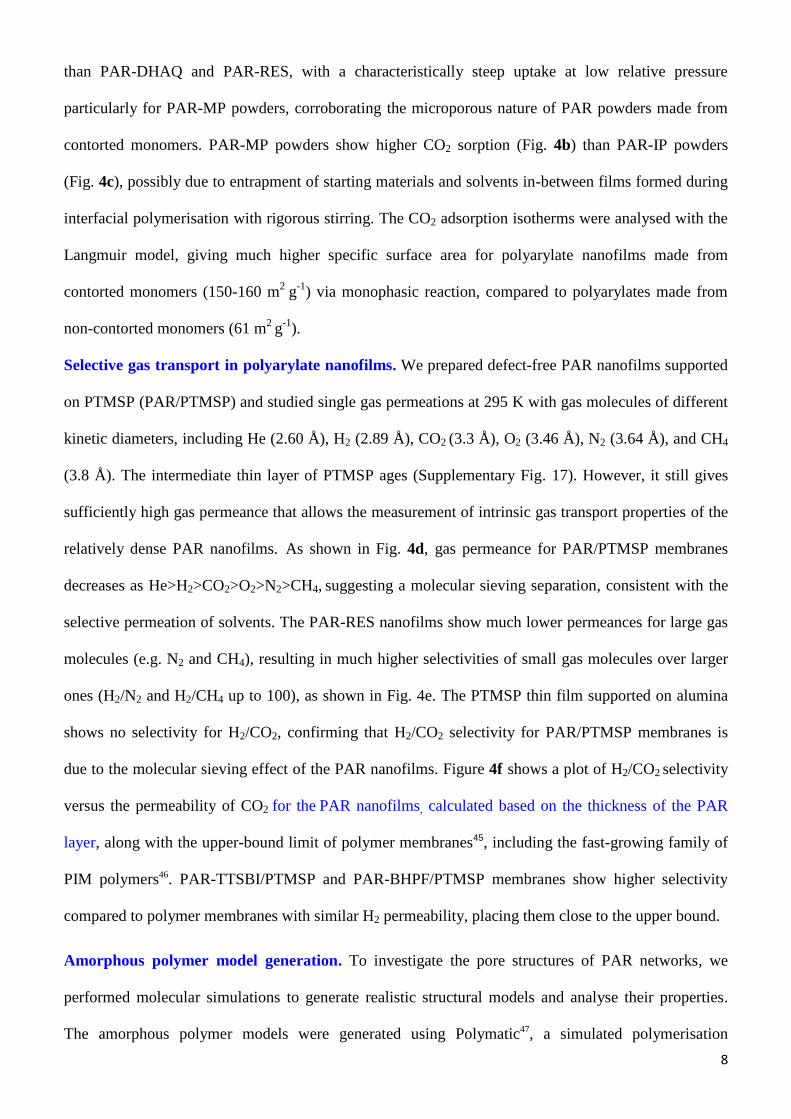
Amorphous polymer model generation. To investigate the pore structures of PAR networks, we
performed molecular simulations to generate realistic structural models and analyse their properties.
The amorphous polymer models were generated using Polymatic47, a simulated polymerisation
9
algorithm. Details of the molecular simulation are given in the Methods (Supplementary Tables 7 and
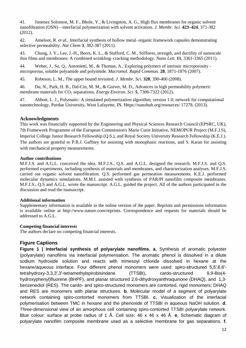
8). We generated five models for each system to ensure adequate sampling and averaged the properties
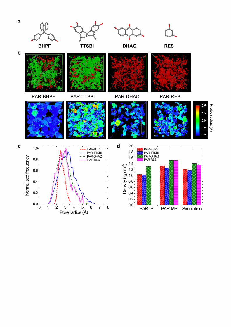
across them (Supplementary Figs. 18 and 19). Figure 5a shows the monomers with different geometry.
The top row images in Fig. 5b show interconnected and disconnected voids with respect to a probe with
a radius of 0.85 Å. PAR-BHPF and PAR-TTSBI show mostly interconnected voids, confirming our
hypothesis that using contorted monomers results in nanofilms with enhanced microporosity and
interconnectivity. In contrast, PAR-DHAQ and PAR-RES show isolated voids, confirming their lower
porosity. The bottom row images in Fig. 5b show voids coloured with respect to the largest radius
probe that can be inserted. In Supplementary Fig. 19, PAR-BHPF and PAR-TTSBI exhibit substantially
more pore volume than the corresponding 3D models of PAR nanofilms made from planar monomers.
Pore size distributions for each PAR polymer network were derived from these simulations, showing
similar values. This is consistent with comparable gas permeance and experimental OSN results (Fig.
5b). These pore sizes are much smaller than the diameters of the organic solvents used in this work, so
in principle no solvent should be able to access them. However, high solvent permeances were
observed for PAR membranes with enhanced microporosity, suggesting that the interconnectivity and
pore size of PAR networks is enlarged in organic solvents due to swelling. Simulation and experimental
results give relatively higher surface areas and lower densities (Fig. 5c, and Supplementary Table 7) for
PAR-BHPF and PAR-TTSBI, compared to PAR-DHAQ and PAR-RES networks.
Conclusions and outlook
In summary, by using rigid contorted monomers as building blocks for interfacial polymerisation, we
have demonstrated the formation of ultrathin crosslinked polyarylate nanofilm membranes of enhanced
microporosity. These membranes offer outstanding performance in organic solvent nanofiltration,
where they are both more permeable and more selective than commercially available and previously
reported membranes, showing high solvent permeance over a wide range of solvent polarity. The
tuneable free volume of polyarylate networks in the solid state was confirmed by gas adsorption and
permeation, and molecular dynamics simulation. The interfacial polymerisation process is used to
produce reverse osmosis membranes for desalination that have revolutionized water purification
10
globally. Furthermore, crosslinked polyimide UF supports and the monomers used to form the
polyarylate nanofilms are both commercially available, making up-scaling feasible. This work might
inspire interfacial synthesis of the rapidly growing family of microporous polymers, such as PIMs,
MOFs, COFs, and conjugated microporous polymers (CMPs), to obtain ultrathin microporous nanofilm
based membranes with great potential for applications in molecular separations, including gas
separation, organic solvent nanofiltration, water purification, and hydrocarbon separations in the
petrochemical industry.
References
1. Gin, D. L. & Noble, R. D., Designing the next generation of chemical separation membranes. Science
332, 674-676 (2011).
2. Marchetti, P., Jimenez Solomon, M. F., Szekely, G., & Livingston, A. G., Molecular separation with
organic solvent nanofiltration: A critical review. Chemical Reviews 114, 10735-10806 (2014).
3. Guiver, M. D. & Lee, Y. M., Polymer rigidity improves microporous membranes. Science 339, 284-285
(2013).
4. Freeman, B. D., Basis of permeability/selectivity tradeoff relations in polymeric gas separation
membranes. Macromolecules 32, 375-380 (1999).
5. Park, H. B. et al., Polymers with cavities tuned for fast selective transport of small molecules and ions.
Science 318, 254-258 (2007).
6. Du, N. et al., Polymer nanosieve membranes for CO2-capture applications. Nat. Mater. 10, 372-375
(2011).
7. Carta, M. et al., An efficient polymer molecular sieve for membrane gas separations. Science 339, 303-
307 (2013).
8. Song, Q. et al., Photo-oxidative enhancement of polymeric molecular sieve membranes. Nat. Commun.
4, 1918 (2013).
9. Song, Q. et al., Controlled thermal oxidative crosslinking of polymers of intrinsic microporosity towards
tunable molecular sieve membranes. Nat. Commun. 5, 4813 (2014).
10. Rodenas, T. et al., Metal–organic framework nanosheets in polymer composite materials for gas
separation. Nat. Mater. 14, 48-55 (2014).
11. Karan, S., Jiang, Z., & Livingston, A. G., Sub–10 nm polyamide nanofilms with ultrafast solvent
transport for molecular separation. Science 348, 1347-1351 (2015).
12. Karan, S. et al., Ultrafast viscous permeation of organic solvents through diamond-like carbon
nanosheets. Science 335, 444-447 (2012).
13. Li, H. et al., Ultrathin, molecular-sieving graphene oxide membranes for selective hydrogen separation.
Science 342, 95-98 (2013).
14. Nair, R. R. et al., Unimpeded permeation of water through helium-leak–tight graphene-based
membranes. Science 335, 442-444 (2012).
15. Peng, Y. et al., Metal-organic framework nanosheets as building blocks for molecular sieving
membranes. Science 346, 1356-1359 (2014).
16. Kim, H. W. et al., Selective gas transport through few-layered graphene and graphene oxide membranes.
Science 342, 91-95 (2013).
17. Yaghi, O. M. et al., Reticular synthesis and the design of new materials. Nature 423, 705-714 (2003).
11
18. Kitagawa, S., Kitaura, R., & Noro, S.-i., Functional porous coordination polymers. Angew. Chem., Int.
Ed. 43, 2334-2375 (2004).
19. El-Kaderi, H. M. et al., Designed synthesis of 3D covalent organic frameworks. Science 316, 268-272
(2007).
20. Côté, A. P. et al., Porous, crystalline, covalent organic frameworks. Science 310, 1166-1170 (2005).
21. Jones, J. T. A. et al., Modular and predictable assembly of porous organic molecular crystals. Nature
474, 367-371 (2011).
22. Tozawa, T. et al., Porous organic cages. Nat. Mater. 8, 973-978 (2009).
23. Song, Q. et al., Porous organic cage thin films and molecular-sieving membranes. Adv. Mater., DOI:
10.1002/adma.201505688 (2016).
24. Li, Y. S. et al., Controllable synthesis of metal-organic frameworks: From MOF nanorods to oriented
MOF membranes. Adv. Mater. 22, 3322-3326 (2010).
25. Brown, A. J. et al., Interfacial microfluidic processing of metal-organic framework hollow fiber
membranes. Science 345, 72-75 (2014).
26. Dobrzańska, L., Lloyd, G. O., Esterhuysen, C., & Barbour, L. J., Guest-induced conformational
switching in a single crystal. Angew. Chem., Int. Ed. 45, 5856-5859 (2006).
27. McKeown, N. B. & Budd, P. M., Polymers of intrinsic microporosity (PIMs): Organic materials for
membrane separations, heterogeneous catalysis and hydrogen storage. Chem. Soc. Rev. 35, 675-683 (2006).
28. McKeown, N. B. et al., Polymers of intrinsic microporosity (PIMs): Bridging the void between
microporous and polymeric materials. Chemistry - A European Journal 11, 2610-2620 (2005).
29. Carta, M. et al., Triptycene induced enhancement of membrane gas selectivity for microporous Tröger's
base polymers. Adv. Mater. 26, 3526-3531 (2014).
30. Ghanem, B. S., Swaidan, R., Litwiller, E., & Pinnau, I., Ultra-microporous triptycene-based polyimide
membranes for high-performance gas separation. Adv. Mater. 26, 3688-3692 (2014).
31. McKeown, N. B. & Budd, P. M., Exploitation of intrinsic microporosity in polymer-based materials.
Macromolecules 43, 5163-5176 (2010).
32. Budd, P. M. et al., Solution-processed, organophilic membrane derived from a polymer of intrinsic
microporosity. Adv. Mater. 16, 456-459 (2004).
33. Budd, P. M. et al., Gas separation membranes from polymers of intrinsic microporosity. J. Membr. Sci.
251, 263-269 (2005).
34. Fritsch, D. et al., High performance organic solvent nanofiltration membranes: Development and
thorough testing of thin film composite membranes made of polymers of intrinsic microporosity (pims). J.
Membr. Sci. 401–402, 222-231 (2012).
35. Tsarkov, S. et al., Solvent nanofiltration through high permeability glassy polymers: Effect of polymer
and solute nature. J. Membr. Sci. 423–424, 65-72 (2012).
36. Gorgojo, P. et al., Ultrathin polymer films with intrinsic microporosity: Anomalous solvent permeation
and high flux membranes. Adv. Funct. Mater. 24, 4729-4737 (2014).
37. Murphy, T. M. et al., Physical aging of layered glassy polymer films via gas permeability tracking.
Polymer 52, 6117-6125 (2011).
38. Ichinose, I., Kurashima, K., & Kunitake, T., Spontaneous formation of cadmium hydroxide nanostrands
in water. J. Am. Chem. Soc. 126, 7162-7163 (2004).
39. Karan, S. et al., Ultrathin free-standing membranes from metal hydroxide nanostrands. J. Membr. Sci.
448, 270-291 (2013).
40. Qian, H., Zheng, J., & Zhang, S., Preparation of microporous polyamide networks for carbon dioxide
capture and nanofiltration. Polymer 54, 557-564 (2013).
12
41. Jimenez Solomon, M. F., Bhole, Y., & Livingston, A. G., High flux membranes for organic solvent
nanofiltration (OSN)—interfacial polymerization with solvent activation. J. Membr. Sci. 423–424, 371-382
(2012).
42. Ameloot, R. et al., Interfacial synthesis of hollow metal–organic framework capsules demonstrating
selective permeability. Nat Chem 3, 382-387 (2011).
43. Chung, J. Y., Lee, J.-H., Beers, K. L., & Stafford, C. M., Stiffness, strength, and ductility of nanoscale
thin films and membranes: A combined wrinkling–cracking methodology. Nano Lett. 11, 3361-3365 (2011).
44. Weber, J., Su, Q., Antonietti, M., & Thomas, A., Exploring polymers of intrinsic microporosity -
microporous, soluble polyamide and polyimide. Macromol. Rapid Commun. 28, 1871-1876 (2007).
45. Robeson, L. M., The upper bound revisited. J. Membr. Sci. 320, 390-400 (2008).
46. Du, N., Park, H. B., Dal-Cin, M. M., & Guiver, M. D., Advances in high permeability polymeric
membrane materials for CO2 separations. Energy Environ. Sci. 5, 7306-7322 (2012).
47. Abbott, L. J., Polymatic: A simulated polymerization algorithm; version 1.0; network for computational
nanotechnology, Purdue University, West Lafayette, IN. Https://nanohub.org/resources/ 17278. (2013).
Acknowledgments This work was financially supported by the Engineering and Physical Sciences Research Council (EPSRC, UK),
7th Framework Programme of the European Commission's Marie Curie Initiative, NEMOPUR Project (M.F.J.S),
Imperial College Junior Research Fellowship (Q.S.), and Royal Society University Research Fellowship (K.E.J.).
The authors are grateful to P.R.J. Gaffney for assisting with monophasic reactions, and S. Karan for assisting
with mechanical property measurements.
Author contributions
M.F.J.S. and A.G.L. conceived the idea. M.F.J.S., Q.S. and A.G.L. designed the research. M.F.J.S. and Q.S.
performed experiments, including synthesis of materials and membranes, and characterization analyses. M.F.J.S.
carried out organic solvent nanofiltration. Q.S. performed gas permeation measurements. K.E.J. performed
molecular dynamics simulations. M.M.I. assisted with synthesis of PAR/PI nanofilm composite membranes.
M.F.J.S., Q.S and A.G.L. wrote the manuscript. A.G.L. guided the project. All of the authors participated in the
discussion and read the manuscript.
Additional information
Supplementary information is available in the online version of the paper. Reprints and permissions information
is available online at http://www.nature.com/reprints. Correspondence and requests for materials should be
addressed to A.G.L.
Competing financial interests
The authors declare no competing financial interests.
Figure Captions
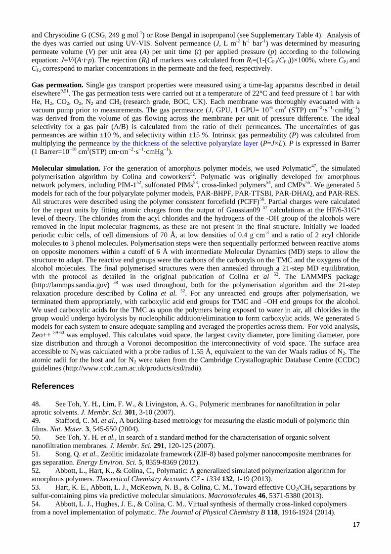
Figure 1 | Interfacial synthesis of polyarylate nanofilms. a, Synthesis of aromatic polyester
(polyarylate) nanofilms via interfacial polymerisation. The aromatic phenol is dissolved in a dilute
sodium hydroxide solution and reacts with trimesoyl chloride dissolved in hexane at the
hexane/aqueous interface. Four different phenol monomers were used: spiro-structured 5,5′,6,6′-
tetrahydroxy-3,3,3′,3′-tetramethylspirobisindane (TTSBI), cardo-structured 9,9-Bis(4-
hydroxyphenyl)fluorene (BHPF), and planar structured 2,6-dihydroxyanthraquinone (DHAQ), and 1,3-
benzenediol (RES). The cardo- and spiro-structured monomers are contorted, rigid monomers; DHAQ
and RES are monomers with planar structures. b, Molecular model of a segment of polyarylate
network containing spiro-contorted monomers from TTSBI. c, Visualization of the interfacial
polymerisation between TMC in hexane and the phenoxide of TTSBI in aqueous NaOH solution. d,
Three-dimensional view of an amorphous cell containing spiro-contorted TTSBI polyarylate network.
Blue colour: surface at probe radius of 1 Å. Cell size: 46 x 46 x 46 Å. e, Schematic diagram of
polyarylate nanofilm composite membrane used as a selective membrane for gas separations. f,
13
Schematic diagram of polyarylate nanofilm composite membrane used as a solvent-stable selective
membrane for organic solvent nanofiltration (OSN).
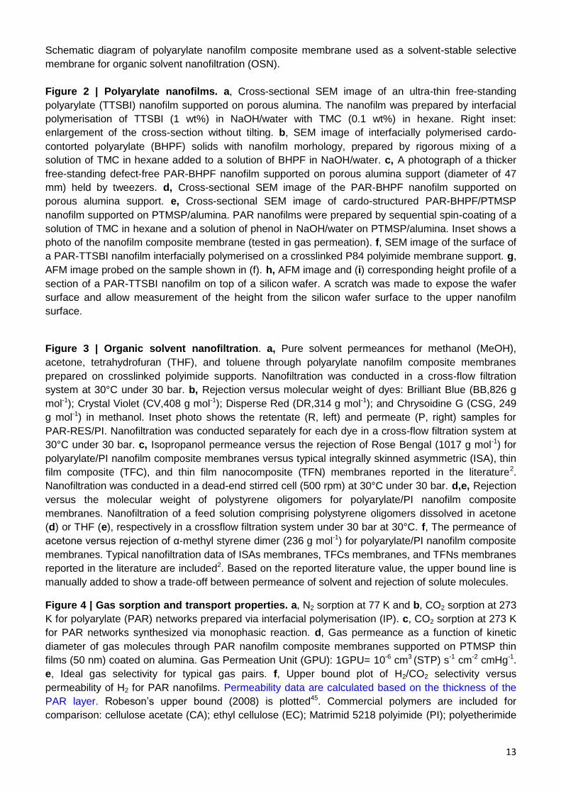
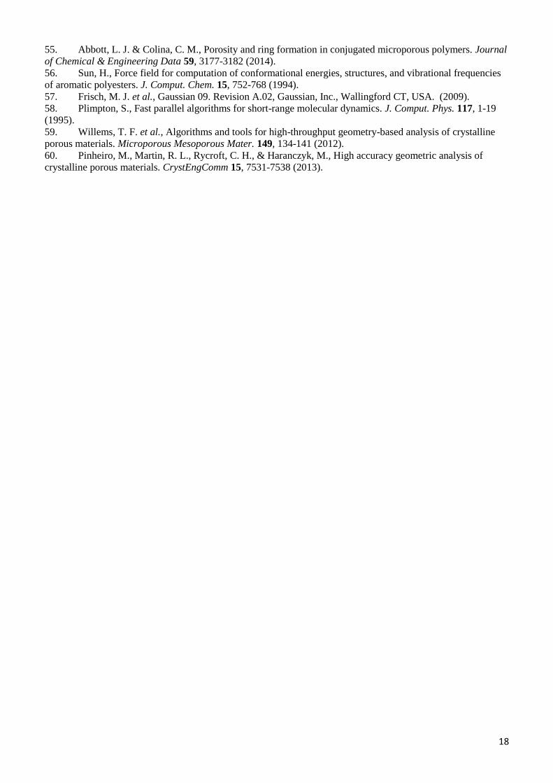
Figure 2 | Polyarylate nanofilms. a, Cross-sectional SEM image of an ultra-thin free-standing
polyarylate (TTSBI) nanofilm supported on porous alumina. The nanofilm was prepared by interfacial
polymerisation of TTSBI (1 wt%) in NaOH/water with TMC (0.1 wt%) in hexane. Right inset:
enlargement of the cross-section without tilting. b, SEM image of interfacially polymerised cardo-
contorted polyarylate (BHPF) solids with nanofilm morhology, prepared by rigorous mixing of a
solution of TMC in hexane added to a solution of BHPF in NaOH/water. c, A photograph of a thicker
free-standing defect-free PAR-BHPF nanofilm supported on porous alumina support (diameter of 47
mm) held by tweezers. d, Cross-sectional SEM image of the PAR-BHPF nanofilm supported on
porous alumina support. e, Cross-sectional SEM image of cardo-structured PAR-BHPF/PTMSP
nanofilm supported on PTMSP/alumina. PAR nanofilms were prepared by sequential spin-coating of a
solution of TMC in hexane and a solution of phenol in NaOH/water on PTMSP/alumina. Inset shows a
photo of the nanofilm composite membrane (tested in gas permeation). f, SEM image of the surface of
a PAR-TTSBI nanofilm interfacially polymerised on a crosslinked P84 polyimide membrane support. g,
AFM image probed on the sample shown in (f). h, AFM image and (i) corresponding height profile of a
section of a PAR-TTSBI nanofilm on top of a silicon wafer. A scratch was made to expose the wafer
surface and allow measurement of the height from the silicon wafer surface to the upper nanofilm
surface.
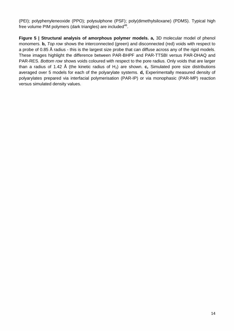
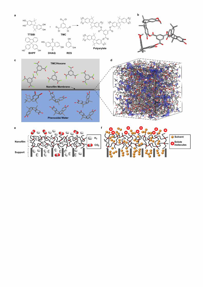
Figure 3 | Organic solvent nanofiltration. a, Pure solvent permeances for methanol (MeOH),
acetone, tetrahydrofuran (THF), and toluene through polyarylate nanofilm composite membranes
prepared on crosslinked polyimide supports. Nanofiltration was conducted in a cross-flow filtration
system at 30°C under 30 bar. b, Rejection versus molecular weight of dyes: Brilliant Blue (BB,826 g
mol-1); Crystal Violet (CV,408 g mol-1); Disperse Red (DR,314 g mol-1); and Chrysoidine G (CSG, 249
g mol-1) in methanol. Inset photo shows the retentate (R, left) and permeate (P, right) samples for
PAR-RES/PI. Nanofiltration was conducted separately for each dye in a cross-flow filtration system at
30°C under 30 bar. c, Isopropanol permeance versus the rejection of Rose Bengal (1017 g mol-1) for
polyarylate/PI nanofilm composite membranes versus typical integrally skinned asymmetric (ISA), thin
film composite (TFC), and thin film nanocomposite (TFN) membranes reported in the literature2.
Nanofiltration was conducted in a dead-end stirred cell (500 rpm) at 30°C under 30 bar. d,e, Rejection
versus the molecular weight of polystyrene oligomers for polyarylate/PI nanofilm composite
membranes. Nanofiltration of a feed solution comprising polystyrene oligomers dissolved in acetone
(d) or THF (e), respectively in a crossflow filtration system under 30 bar at 30°C. f, The permeance of
acetone versus rejection of α-methyl styrene dimer (236 g mol-1) for polyarylate/PI nanofilm composite
membranes. Typical nanofiltration data of ISAs membranes, TFCs membranes, and TFNs membranes
reported in the literature are included2. Based on the reported literature value, the upper bound line is
manually added to show a trade-off between permeance of solvent and rejection of solute molecules.
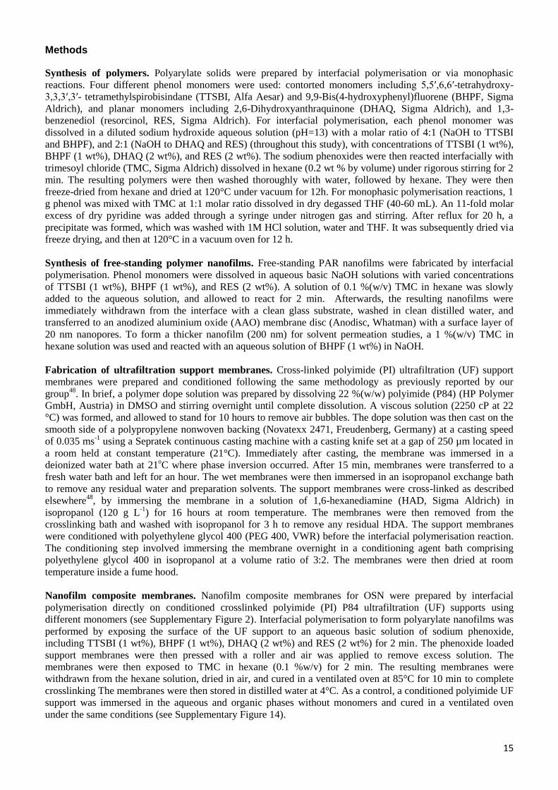
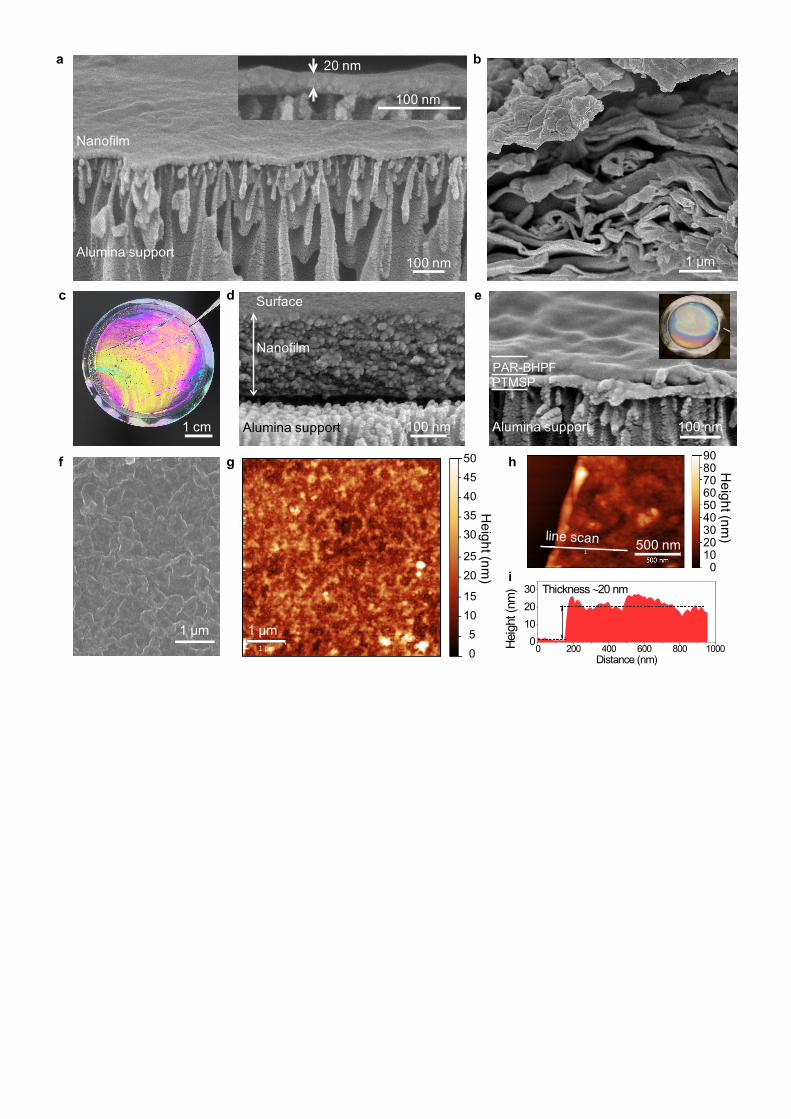
Figure 4 | Gas sorption and transport properties. a, N2 sorption at 77 K and b, CO2 sorption at 273
K for polyarylate (PAR) networks prepared via interfacial polymerisation (IP). c, CO2 sorption at 273 K
for PAR networks synthesized via monophasic reaction. d, Gas permeance as a function of kinetic
diameter of gas molecules through PAR nanofilm composite membranes supported on PTMSP thin
films (50 nm) coated on alumina. Gas Permeation Unit (GPU): 1GPU= 10-6 cm3 (STP) s-1 cm-2 cmHg-1.
e, Ideal gas selectivity for typical gas pairs. f, Upper bound plot of H2/CO2 selectivity versus
permeability of H2 for PAR nanofilms. Permeability data are calculated based on the thickness of the
PAR layer. Robeson’s upper bound (2008) is plotted45. Commercial polymers are included for
comparison: cellulose acetate (CA); ethyl cellulose (EC); Matrimid 5218 polyimide (PI); polyetherimide
14
(PEI); polyphenyleneoxide (PPO); polysulphone (PSF); poly(dimethylsiloxane) (PDMS). Typical high
free volume PIM polymers (dark triangles) are included46.
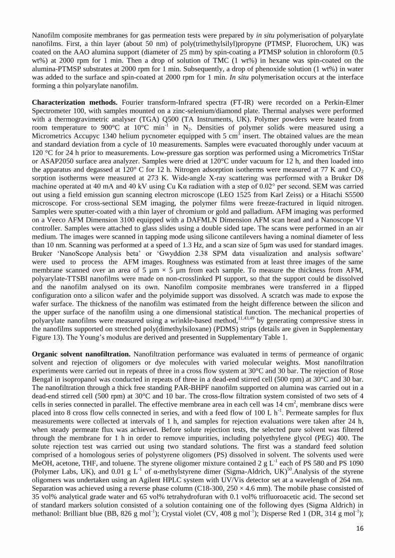
Figure 5 | Structural analysis of amorphous polymer models. a, 3D molecular model of phenol
monomers. b, Top row shows the interconnected (green) and disconnected (red) voids with respect to
a probe of 0.85 Å radius - this is the largest size probe that can diffuse across any of the rigid models.
These images highlight the difference between PAR-BHPF and PAR-TTSBI versus PAR-DHAQ and
PAR-RES. Bottom row shows voids coloured with respect to the pore radius. Only voids that are larger
than a radius of 1.42 Å (the kinetic radius of H2) are shown. c, Simulated pore size distributions
averaged over 5 models for each of the polyarylate systems. d, Experimentally measured density of
polyarylates prepared via interfacial polymerisation (PAR-IP) or via monophasic (PAR-MP) reaction
versus simulated density values.
15
Methods
Synthesis of polymers. Polyarylate solids were prepared by interfacial polymerisation or via monophasic
reactions. Four different phenol monomers were used: contorted monomers including 5,5′,6,6′-tetrahydroxy-
3,3,3′,3′- tetramethylspirobisindane (TTSBI, Alfa Aesar) and 9,9-Bis(4-hydroxyphenyl)fluorene (BHPF, Sigma
Aldrich), and planar monomers including 2,6-Dihydroxyanthraquinone (DHAQ, Sigma Aldrich), and 1,3-
benzenediol (resorcinol, RES, Sigma Aldrich). For interfacial polymerisation, each phenol monomer was
dissolved in a diluted sodium hydroxide aqueous solution (pH=13) with a molar ratio of 4:1 (NaOH to TTSBI
and BHPF), and 2:1 (NaOH to DHAQ and RES) (throughout this study), with concentrations of TTSBI (1 wt%),
BHPF (1 wt%), DHAQ (2 wt%), and RES (2 wt%). The sodium phenoxides were then reacted interfacially with
trimesoyl chloride (TMC, Sigma Aldrich) dissolved in hexane (0.2 wt % by volume) under rigorous stirring for 2
min. The resulting polymers were then washed thoroughly with water, followed by hexane. They were then
freeze-dried from hexane and dried at 120°C under vacuum for 12h. For monophasic polymerisation reactions, 1
g phenol was mixed with TMC at 1:1 molar ratio dissolved in dry degassed THF (40-60 mL). An 11-fold molar
excess of dry pyridine was added through a syringe under nitrogen gas and stirring. After reflux for 20 h, a
precipitate was formed, which was washed with 1M HCl solution, water and THF. It was subsequently dried via
freeze drying, and then at 120°C in a vacuum oven for 12 h.
Synthesis of free-standing polymer nanofilms. Free-standing PAR nanofilms were fabricated by interfacial
polymerisation. Phenol monomers were dissolved in aqueous basic NaOH solutions with varied concentrations
of TTSBI (1 wt%), BHPF (1 wt%), and RES (2 wt%). A solution of 0.1 %(w/v) TMC in hexane was slowly
added to the aqueous solution, and allowed to react for 2 min. Afterwards, the resulting nanofilms were
immediately withdrawn from the interface with a clean glass substrate, washed in clean distilled water, and
transferred to an anodized aluminium oxide (AAO) membrane disc (Anodisc, Whatman) with a surface layer of
20 nm nanopores. To form a thicker nanofilm (200 nm) for solvent permeation studies, a 1 %(w/v) TMC in
hexane solution was used and reacted with an aqueous solution of BHPF (1 wt%) in NaOH.
Fabrication of ultrafiltration support membranes. Cross-linked polyimide (PI) ultrafiltration (UF) support
membranes were prepared and conditioned following the same methodology as previously reported by our
group48
. In brief, a polymer dope solution was prepared by dissolving 22 %(w/w) polyimide (P84) (HP Polymer
GmbH, Austria) in DMSO and stirring overnight until complete dissolution. A viscous solution (2250 cP at 22
°C) was formed, and allowed to stand for 10 hours to remove air bubbles. The dope solution was then cast on the
smooth side of a polypropylene nonwoven backing (Novatexx 2471, Freudenberg, Germany) at a casting speed
of 0.035 ms-1
using a Sepratek continuous casting machine with a casting knife set at a gap of 250 µm located in
a room held at constant temperature (21°C). Immediately after casting, the membrane was immersed in a
deionized water bath at 21oC where phase inversion occurred. After 15 min, membranes were transferred to a
fresh water bath and left for an hour. The wet membranes were then immersed in an isopropanol exchange bath
to remove any residual water and preparation solvents. The support membranes were cross-linked as described
elsewhere48
, by immersing the membrane in a solution of 1,6-hexanediamine (HAD, Sigma Aldrich) in
isopropanol (120 g L-1
) for 16 hours at room temperature. The membranes were then removed from the
crosslinking bath and washed with isopropanol for 3 h to remove any residual HDA. The support membranes
were conditioned with polyethylene glycol 400 (PEG 400, VWR) before the interfacial polymerisation reaction.
The conditioning step involved immersing the membrane overnight in a conditioning agent bath comprising
polyethylene glycol 400 in isopropanol at a volume ratio of 3:2. The membranes were then dried at room
temperature inside a fume hood.
Nanofilm composite membranes. Nanofilm composite membranes for OSN were prepared by interfacial
polymerisation directly on conditioned crosslinked polyimide (PI) P84 ultrafiltration (UF) supports using
different monomers (see Supplementary Figure 2). Interfacial polymerisation to form polyarylate nanofilms was
performed by exposing the surface of the UF support to an aqueous basic solution of sodium phenoxide,
including TTSBI (1 wt%), BHPF (1 wt%), DHAQ (2 wt%) and RES (2 wt%) for 2 min. The phenoxide loaded
support membranes were then pressed with a roller and air was applied to remove excess solution. The
membranes were then exposed to TMC in hexane (0.1 %w/v) for 2 min. The resulting membranes were
withdrawn from the hexane solution, dried in air, and cured in a ventilated oven at 85°C for 10 min to complete
crosslinking The membranes were then stored in distilled water at 4°C. As a control, a conditioned polyimide UF
support was immersed in the aqueous and organic phases without monomers and cured in a ventilated oven
under the same conditions (see Supplementary Figure 14).
16
Nanofilm composite membranes for gas permeation tests were prepared by in situ polymerisation of polyarylate
nanofilms. First, a thin layer (about 50 nm) of poly(trimethylsilyl)propyne (PTMSP, Fluorochem, UK) was
coated on the AAO alumina support (diameter of 25 mm) by spin-coating a PTMSP solution in chloroform (0.5
wt%) at 2000 rpm for 1 min. Then a drop of solution of TMC (1 wt%) in hexane was spin-coated on the
alumina-PTMSP substrates at 2000 rpm for 1 min. Subsequently, a drop of phenoxide solution (1 wt%) in water
was added to the surface and spin-coated at 2000 rpm for 1 min. In situ polymerisation occurs at the interface
forming a thin polyarylate nanofilm.
Characterization methods. Fourier transform-Infrared spectra (FT-IR) were recorded on a Perkin-Elmer
Spectrometer 100, with samples mounted on a zinc-selenium/diamond plate. Thermal analyses were performed
with a thermogravimetric analyser (TGA) Q500 (TA Instruments, UK). Polymer powders were heated from
room temperature to 900°C at 10°C min-1
in N2. Densities of polymer solids were measured using a
Micrometrics Accupyc 1340 helium pycnometer equipped with 5 cm3 insert. The obtained values are the mean
and standard deviation from a cycle of 10 measurements. Samples were evacuated thoroughly under vacuum at
120 °C for 24 h prior to measurements. Low-pressure gas sorption was performed using a Micrometrics TriStar
or ASAP2050 surface area analyzer. Samples were dried at 120°C under vacuum for 12 h, and then loaded into
the apparatus and degassed at 120° C for 12 h. Nitrogen adsorption isotherms were measured at 77 K and CO2
sorption isotherms were measured at 273 K. Wide-angle X-ray scattering was performed with a Bruker D8
machine operated at 40 mA and 40 kV using Cu Kα radiation with a step of 0.02° per second. SEM was carried
out using a field emission gun scanning electron microscope (LEO 1525 from Karl Zeiss) or a Hitachi S5500
microscope. For cross-sectional SEM imaging, the polymer films were freeze-fractured in liquid nitrogen.
Samples were sputter-coated with a thin layer of chromium or gold and palladium. AFM imaging was performed
on a Veeco AFM Dimension 3100 equipped with a DAFMLN Dimension AFM scan head and a Nanoscope VI
controller. Samples were attached to glass slides using a double sided tape. The scans were performed in an air
medium. The images were scanned in tapping mode using silicone cantilevers having a nominal diameter of less
than 10 nm. Scanning was performed at a speed of 1.3 Hz, and a scan size of 5µm was used for standard images.
Bruker ‘NanoScope Analysis beta’ or ‘Gwyddion 2.38 SPM data visualization and analysis software’
were used to process the AFM images. Roughness was estimated from at least three images of the same
membrane scanned over an area of 5 µm × 5 µm from each sample. To measure the thickness from AFM,
polyarylate-TTSBI nanofilms were made on non-crosslinked PI support, so that the support could be dissolved
and the nanofilm analysed on its own. Nanofilm composite membranes were transferred in a flipped
configuration onto a silicon wafer and the polyimide support was dissolved. A scratch was made to expose the
wafer surface. The thickness of the nanofilm was estimated from the height difference between the silicon and
the upper surface of the nanofilm using a one dimensional statistical function. The mechanical properties of
polyarylate nanofilms were measured using a wrinkle-based method,11,43,49
by generating compressive stress in
the nanofilms supported on stretched poly(dimethylsiloxane) (PDMS) strips (details are given in Supplementary
Figure 13). The Young’s modulus are derived and presented in Supplementary Table 1.
Organic solvent nanofiltration. Nanofiltration performance was evaluated in terms of permeance of organic
solvent and rejection of oligomers or dye molecules with varied molecular weights. Most nanofiltration
experiments were carried out in repeats of three in a cross flow system at 30°C and 30 bar. The rejection of Rose
Bengal in isopropanol was conducted in repeats of three in a dead-end stirred cell (500 rpm) at 30°C and 30 bar.
The nanofiltration through a thick free standing PAR-BHPF nanofilm supported on alumina was carried out in a
dead-end stirred cell (500 rpm) at 30°C and 10 bar. The cross-flow filtration system consisted of two sets of 4
cells in series connected in parallel. The effective membrane area in each cell was 14 cm2, membrane discs were
placed into 8 cross flow cells connected in series, and with a feed flow of 100 L h-1
. Permeate samples for flux
measurements were collected at intervals of 1 h, and samples for rejection evaluations were taken after 24 h,
when steady permeate flux was achieved. Before solute rejection tests, the selected pure solvent was filtered
through the membrane for 1 h in order to remove impurities, including polyethylene glycol (PEG) 400. The
solute rejection test was carried out using two standard solutions. The first was a standard feed solution
comprised of a homologous series of polystyrene oligomers (PS) dissolved in solvent. The solvents used were
MeOH, acetone, THF, and toluene. The styrene oligomer mixture contained 2 g L-1
each of PS 580 and PS 1090
(Polymer Labs, UK), and 0.01 g L-1
of α-methylstyrene dimer (Sigma-Aldrich, UK)50
.Analysis of the styrene
oligomers was undertaken using an Agilent HPLC system with UV/Vis detector set at a wavelength of 264 nm.
Separation was achieved using a reverse phase column (C18-300, 250 × 4.6 mm). The mobile phase consisted of
35 vol% analytical grade water and 65 vol% tetrahydrofuran with 0.1 vol% trifluoroacetic acid. The second set
of standard markers solution consisted of a solution containing one of the following dyes (Sigma Aldrich) in
methanol: Brilliant blue (BB, 826 g mol-1
); Crystal violet (CV, 408 g mol-1
); Disperse Red 1 (DR, 314 g mol-1
);
17
and Chrysoidine G (CSG, 249 g mol-1
) or Rose Bengal in isopropanol (see Supplementary Table 4). Analysis of
the dyes was carried out using UV-VIS. Solvent permeance (J, L m-2
h-1
bar-1
) was determined by measuring
permeate volume (V) per unit area (A) per unit time (t) per applied pressure (p) according to the following
equation: J=V/(A·t·p). The rejection (Ri) of markers was calculated from Ri=(1-(CP,i/CF,i))×100%, where CP,i and
CF,i correspond to marker concentrations in the permeate and the feed, respectively.
Gas permeation. Single gas transport properties were measured using a time-lag apparatus described in detail
elsewhere9,51
. The gas permeation tests were carried out at a temperature of 22°C and feed pressure of 1 bar with
He, H2, CO2, O2, N2 and CH4 (research grade, BOC, UK). Each membrane was thoroughly evacuated with a
vacuum pump prior to measurements. The gas permeance (J, GPU, 1 GPU= 10-6
cm3 (STP) cm
−2·s
−1·cmHg
−1)
was derived from the volume of gas flowing across the membrane per unit of pressure difference. The ideal
selectivity for a gas pair (A/B) is calculated from the ratio of their permeances. The uncertainties of gas
permeances are within ±10 %, and selectivity within ±15 %. Intrinsic gas permeability (P) was calculated from
multiplying the permeance by the thickness of the selective polyarylate layer (P=J×L). P is expressed in Barrer
(1 Barrer=10−10
cm3(STP) cm·cm
−2·s
−1·cmHg
−1).
Molecular simulation. For the generation of amorphous polymer models, we used Polymatic47
, the simulated
polymerisation algorithm by Colina and coworkers52
. Polymatic was originally developed for amorphous
network polymers, including PIM-152
, sulfonated PIMs53
, cross-linked polymers54
, and CMPs55
. We generated 5
models for each of the four polyarylate polymer models, PAR-BHPF, PAR-TTSBI, PAR-DHAQ, and PAR-RES.
All structures were described using the polymer consistent forcefield (PCFF)56
. Partial charges were calculated
for the repeat units by fitting atomic charges from the output of Gaussian09 57
calculations at the HF/6-31G*
level of theory. The chlorides from the acyl chlorides and the hydrogens of the -OH group of the alcohols were
removed in the input molecular fragments, as these are not present in the final structure. Initially we loaded
periodic cubic cells, of cell dimensions of 70 Å, at low densities of 0.4 g cm-3
and a ratio of 2 acyl chloride
molecules to 3 phenol molecules. Polymerisation steps were then sequentially performed between reactive atoms
on opposite monomers within a cutoff of 6 Å with intermediate Molecular Dynamics (MD) steps to allow the
structure to adapt. The reactive end groups were the carbons of the carbonyls on the TMC and the oxygens of the
alcohol molecules. The final polymerised structures were then annealed through a 21-step MD equilibration,
with the protocol as detailed in the original publication of Colina et al 52
. The LAMMPS package
(http://lammps.sandia.gov) 58
was used throughout, both for the polymerisation algorithm and the 21-step
relaxation procedure described by Colina et al. 52
. For any unreacted end groups after polymerisation, we
terminated them appropriately, with carboxylic acid end groups for TMC and –OH end groups for the alcohol.
We used carboxylic acids for the TMC as upon the polymers being exposed to water in air, all chlorides in the
group would undergo hydrolysis by nucleophilic addition/elimination to form carboxylic acids. We generated 5
models for each system to ensure adequate sampling and averaged the properties across them. For void analysis,
Zeo++ 59-60
was employed. This calculates void space, the largest cavity diameter, pore limiting diameter, pore
size distribution and through a Voronoi decomposition the interconnectivity of void space. The surface area
accessible to N2 was calculated with a probe radius of 1.55 Å, equivalent to the van der Waals radius of N2. The
atomic radii for the host and for N2 were taken from the Cambridge Crystallographic Database Centre (CCDC)
guidelines (http://www.ccdc.cam.ac.uk/products/csd/radii).
References 48. See Toh, Y. H., Lim, F. W., & Livingston, A. G., Polymeric membranes for nanofiltration in polar
aprotic solvents. J. Membr. Sci. 301, 3-10 (2007).
49. Stafford, C. M. et al., A buckling-based metrology for measuring the elastic moduli of polymeric thin
films. Nat. Mater. 3, 545-550 (2004).
50. See Toh, Y. H. et al., In search of a standard method for the characterisation of organic solvent
nanofiltration membranes. J. Membr. Sci. 291, 120-125 (2007).
51. Song, Q. et al., Zeolitic imidazolate framework (ZIF-8) based polymer nanocomposite membranes for
gas separation. Energy Environ. Sci. 5, 8359-8369 (2012).
52. Abbott, L., Hart, K., & Colina, C., Polymatic: A generalized simulated polymerization algorithm for
amorphous polymers. Theoretical Chemistry Accounts C7 - 1334 132, 1-19 (2013).
53. Hart, K. E., Abbott, L. J., McKeown, N. B., & Colina, C. M., Toward effective CO2/CH4 separations by
sulfur-containing pims via predictive molecular simulations. Macromolecules 46, 5371-5380 (2013).
54. Abbott, L. J., Hughes, J. E., & Colina, C. M., Virtual synthesis of thermally cross-linked copolymers
from a novel implementation of polymatic. The Journal of Physical Chemistry B 118, 1916-1924 (2014).
18
55. Abbott, L. J. & Colina, C. M., Porosity and ring formation in conjugated microporous polymers. Journal
of Chemical & Engineering Data 59, 3177-3182 (2014).
56. Sun, H., Force field for computation of conformational energies, structures, and vibrational frequencies
of aromatic polyesters. J. Comput. Chem. 15, 752-768 (1994).
57. Frisch, M. J. et al., Gaussian 09. Revision A.02, Gaussian, Inc., Wallingford CT, USA. (2009).
58. Plimpton, S., Fast parallel algorithms for short-range molecular dynamics. J. Comput. Phys. 117, 1-19
(1995).
59. Willems, T. F. et al., Algorithms and tools for high-throughput geometry-based analysis of crystalline
porous materials. Microporous Mesoporous Mater. 149, 134-141 (2012).
60. Pinheiro, M., Martin, R. L., Rycroft, C. H., & Haranczyk, M., High accuracy geometric analysis of
crystalline porous materials. CrystEngComm 15, 7531-7538 (2013).
a b
c dTMC/Hexane
Phenoxide/ Water
TTSBI TMC
BHPF DHAQ RES
Polyarylate
Nanofilm Membrane
e f
H2
CO2
Solvent
Solute molecules
Support
Nanofilm
OH
OH
HO
HO
OHHO
O Cl
O O
Cl Cl
+
O
O
OOO
O
O
O
O
O
HO
OH
O
O
O
O
O
O
OOH
OH
0 200 400 600 800 1000
0102030
Heig
ht (n
m)
Distance (nm)
Thickness ∼20 nm
Nanofilm
d
1 µm
1 µm
b20 nm
100 nm
Alumina support
Nanofilm
a
100 nm
PAR-BHPF
100 nm
PTMSP
Alumina support
e
h
i
500 nm
1 cm
f
c
g
1 µm
100 nmAlumina support
Surface
05
1015
2025
3035404550
0102030405060708090
Height (nm
)
Height (nm
)
60 70 80 90 1000.1
1.0
10.0
100.0
ISA literaturePe
rme
an
ce
of a
ce
ton
e (
L m
-2 h
-1 b
ar-1
)
Rejection of styrene dimer (%)
TFCs literature
Upper bound
TFNs literature
PAR-DHAQ/PI
PAR-TTSBI/PI
PAR-BHPF/PI
PAR-RES/PI
b ca
d f
e
200 300 400 500 600 700 800 90060
70
80
90
100
Dyes
CSG
DR
CV
BB
Membranes
PAR-BHPF/PI
PAR-TTSBI/PI
PAR-DHAQ/PIRe
jectio
n o
f d
ye
s (
%)
Molecular weight of dyes (g mol-1)
PAR-RES/PI
Methanol Acetone THF Toluene0.0
2.0
4.0
6.0
8.0
10.0P
erm
ea
nce
(L
m-2 h
-1 b
ar-1
)
PAR-BHPF/PI
PAR-TTSBI/PI
PAR-DHAQ/PI
PAR-RES/PI
Pure organic solvent nanofiltration
200 400 600 800 1,000 1,20080
85
90
95
100
Re
jectio
n o
f p
oly
sty
ren
es (
%)
Molecular weight of polystyrenes (g mol-1)
PAR-DHAQ/PI
PAR-RES/PISolvent: Acetone
PAR-BHPF/PI
PAR-TTSBI/PI
200 400 600 800 1,000 1,20080
85
90
95
100
Re
jectio
n o
f p
oly
sty
ren
es (
%)
Molecular weight of polystyrenes (g mol-1)
PAR-DHAQ/PI
PAR-RES/PISolvent: THF
PAR-BHPF/PI
PAR-TTSBI/PI
88 90 92 94 96 98 1000.0
2.0
4.0
6.0
8.0
10.0
ISA literature
Pe
rme
an
ce
of IP
A (
L m
-2 h
-1 b
ar-1
)
Rejection of Rose Bengal dye (%)
TFCs literature TFNs literature
PAR-DHAQ/PI
PAR-BHPF/PI
PAR-TTSBI/PI
PAR-RES/PI
R P
a b c
d e f
0.0 0.2 0.4 0.6 0.8 1.00.0
1.0
2.0
3.0
4.0
PAR-BHPF-IP
PAR-TTSBI-IP
PAR-DHAQ-IP
N2 a
dso
rptio
n (
mm
ol g
-1)
Relative pressure (p/p0)
PAR-RES-IP
0 200 400 600 800 10000.0
0.5
1.0
1.5
CO
2 a
dso
rptio
n (
mm
ol g
-1)
Pressure (mbar)
PAR-BHPF-IP
PAR-TTSBI-IP
PAR-DHAQ-IP
PAR-RES-IP
PAR-BHPF-MP
PAR-TTSBI-MP
PAR-DHAQ-MP
0 200 400 600 800 10000.0
0.5
1.0
1.5
PAR-RES-MP
CO
2 a
dso
rptio
n (
mm
ol g
-1)
Pressure (mbar)
10-1
100
101
102
103
104
105
0.1
1
10
100
PI
PDMS
PIMs
PAR-BHPF/PTMSP
PAR-TTSBI/PTMSP
PAR-RES/PTMSP
CA
PSF
PPO
EC
PEI
Commercial
linear polymers
Se
lectivity o
f H
2/C
O2
Permeability of H2 (Barrer)
0.26 0.28 0.30 0.32 0.34 0.36 0.38 0.4010
-1
100
101
102
103
Ga
s p
erm
ea
nce
(G
PU
)
Kinetic diameter of gases (nm)
PAR-BHPF/PTMSP
PAR-TTSBI/PTMSP
PAR-RES/PTMSP
PTMSP
He H2
CO2
O2
N2
CH4
0
20
40
60
80
100
120
Ide
al se
lectivity (
-)
Knudsen diffusion
PAR-BHPF/PTMSP
PAR-TTSBI/PTMSP
PAR-RES/PTMSP
PTMSP
H2/N
2H
2/CH
4CO
2/N
2CO
2/CH
4H
2/CO
2
Gas pairs
c d
Probe radius (Å)
PAR-RES
a
PAR-TTSBI PAR-DHAQPAR-BHPF
0 1 2 3 4 5 6 7 80.0
0.2
0.4
0.6
0.8
1.0 PAR-TTSBI
Norm
alise
d fre
quen
cy
Pore radius (Å)
PAR-DHAQ
PAR-BHPF
PAR-RES
PAR-IP PAR-MP Simulation0.00.20.40.60.81.01.21.41.61.82.0
Dens
ity (
g cm
-3)
PAR-BHPF PAR-TTSBI PAR-DHAQ PAR-RES
TTSBIBHPF DHAQ RESb
1
Polymer nanofilms with enhanced microporosity by interfacial
polymerisation
Maria F. Jimenez-Solomon1†
, Qilei Song1†
, Kim E. Jelfs2, Marta Munoz-Ibanez
1 and Andrew G. Livingston
1*
1Department of Chemical Engineering, Imperial College London, London SW7 2AZ, UK,
2Department of Chemistry, Imperial College London. London SW7 2AZ, UK.
†These authors contributed equally to this work.
* e-mail: [email protected]
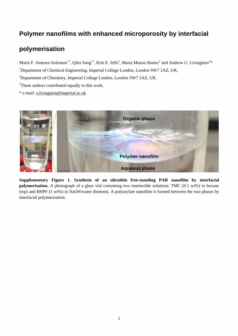
Supplementary Figure 1. Synthesis of an ultrathin free-standing PAR nanofilm by interfacial
polymerisation. A photograph of a glass vial containing two immiscible solutions: TMC (0.1 wt%) in hexane
(top) and BHPF (1 wt%) in NaOH/water (bottom). A polyarylate nanofilm is formed between the two phases by
interfacial polymerisation.
Aqueous phase
Organic phase
Polymer nanofilm
2
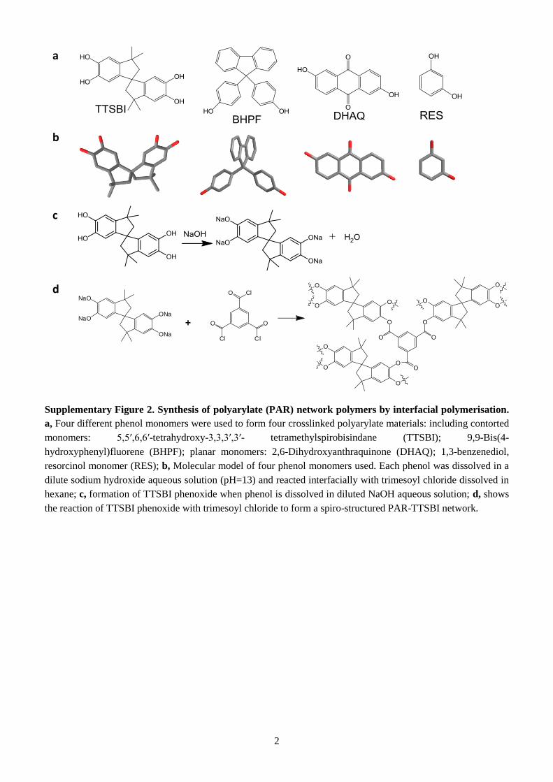
Supplementary Figure 2. Synthesis of polyarylate (PAR) network polymers by interfacial polymerisation.
a, Four different phenol monomers were used to form four crosslinked polyarylate materials: including contorted
monomers: 5,5′,6,6′-tetrahydroxy-3,3,3′,3′- tetramethylspirobisindane (TTSBI); 9,9-Bis(4-
hydroxyphenyl)fluorene (BHPF); planar monomers: 2,6-Dihydroxyanthraquinone (DHAQ); 1,3-benzenediol,
resorcinol monomer (RES); b, Molecular model of four phenol monomers used. Each phenol was dissolved in a
dilute sodium hydroxide aqueous solution (pH=13) and reacted interfacially with trimesoyl chloride dissolved in
hexane; c, formation of TTSBI phenoxide when phenol is dissolved in diluted NaOH aqueous solution; d, shows
the reaction of TTSBI phenoxide with trimesoyl chloride to form a spiro-structured PAR-TTSBI network.
a
b
c
d
ONa
ONa
NaO
NaO
O Cl
O O
Cl Cl
+
O
O
OO
O
O
O
O
O
O
O
O
O
O
O
3
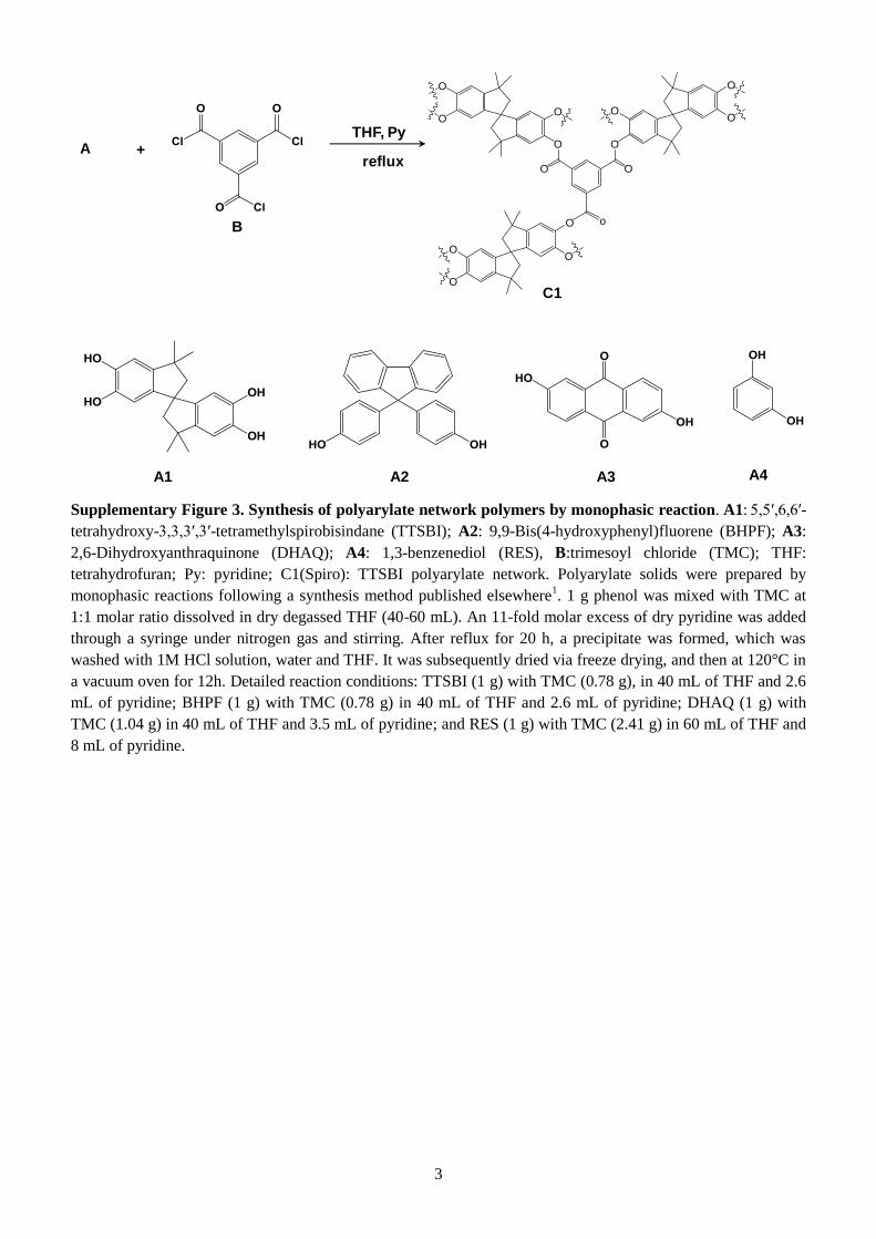
Supplementary Figure 3. Synthesis of polyarylate network polymers by monophasic reaction. A1: 5,5′,6,6′-
tetrahydroxy-3,3,3′,3′-tetramethylspirobisindane (TTSBI); A2: 9,9-Bis(4-hydroxyphenyl)fluorene (BHPF); A3:
2,6-Dihydroxyanthraquinone (DHAQ); A4: 1,3-benzenediol (RES), B:trimesoyl chloride (TMC); THF:
tetrahydrofuran; Py: pyridine; C1(Spiro): TTSBI polyarylate network. Polyarylate solids were prepared by
monophasic reactions following a synthesis method published elsewhere1. 1 g phenol was mixed with TMC at
1:1 molar ratio dissolved in dry degassed THF (40-60 mL). An 11-fold molar excess of dry pyridine was added
through a syringe under nitrogen gas and stirring. After reflux for 20 h, a precipitate was formed, which was
washed with 1M HCl solution, water and THF. It was subsequently dried via freeze drying, and then at 120°C in
a vacuum oven for 12h. Detailed reaction conditions: TTSBI (1 g) with TMC (0.78 g), in 40 mL of THF and 2.6
mL of pyridine; BHPF (1 g) with TMC (0.78 g) in 40 mL of THF and 2.6 mL of pyridine; DHAQ (1 g) with
TMC (1.04 g) in 40 mL of THF and 3.5 mL of pyridine; and RES (1 g) with TMC (2.41 g) in 60 mL of THF and
8 mL of pyridine.
THF, Py
reflux+
A1 A2 A3
B
A
A4
C1
O
OO
O
O
O
O
O
O
O
o
O
O
O
O
4
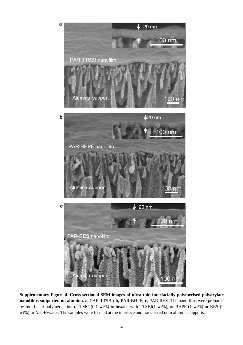
Supplementary Figure 4. Cross-sectional SEM images of ultra-thin interfacially polymerised polyarylate
nanofilms supported on alumina. a, PAR-TTSBI; b, PAR-BHPF; c, PAR-RES. The nanofilms were prepared
by interfacial polymerisation of TMC (0.1 wt%) in hexane with TTSBI(1 wt%), or BHPF (1 wt%) or RES (2
wt%) in NaOH/water. The samples were formed at the interface and transferred onto alumina supports.
5
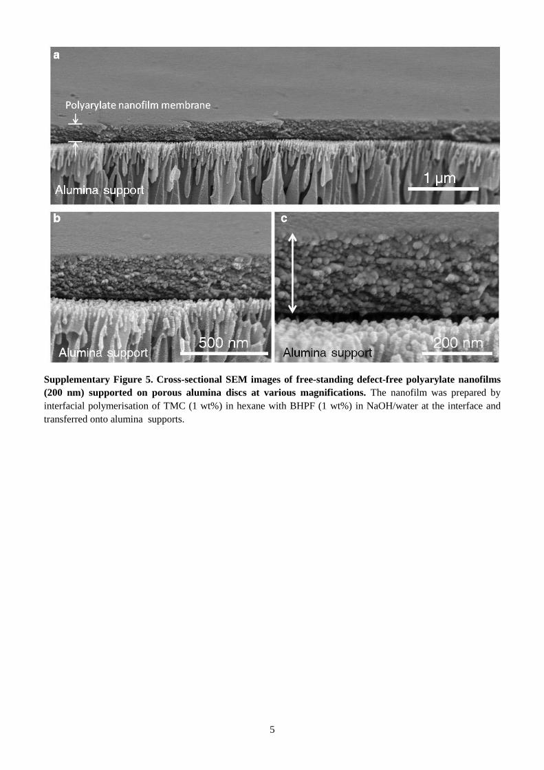
Supplementary Figure 5. Cross-sectional SEM images of free-standing defect-free polyarylate nanofilms
(200 nm) supported on porous alumina discs at various magnifications. The nanofilm was prepared by
interfacial polymerisation of TMC (1 wt%) in hexane with BHPF (1 wt%) in NaOH/water at the interface and
transferred onto alumina supports.
6
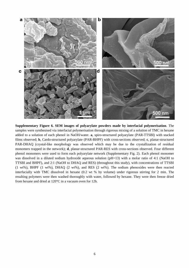
Supplementary Figure 6. SEM images of polyarylate powders made by interfacial polymerisation. The
samples were synthesised via interfacial polymerisation through rigorous mixing of a solution of TMC in hexane
added to a solution of each phenol in NaOH/water. a, spiro-structured polyarylate (PAR-TTSBI) with stacked
films observed; b, Cardo-structured polyarylate (PAR-BHPF) with cross-sections observed; c, planar-structured
PAR-DHAQ (crystal-like morphology was observed which may be due to the crystallization of residual
monomers trapped in the network); d, planar-structured PAR-RES with cross-sections observed. Four different
phenol monomers were used to form each polyarylate network (Supplementary Fig. 2). Each phenol monomer
was dissolved in a diluted sodium hydroxide aqueous solution (pH=13) with a molar ratio of 4:1 (NaOH to
TTSBI and BHPF), and 2:1 (NaOH to DHAQ and RES) (throughout this study), with concentrations of TTSBI
(1 wt%), BHPF (1 wt%), DHAQ (2 wt%), and RES (2 wt%). The sodium phenoxides were then reacted
interfacially with TMC dissolved in hexane (0.2 wt % by volume) under rigorous stirring for 2 min. The
resulting polymers were then washed thoroughly with water, followed by hexane. They were then freeze dried
from hexane and dried at 120°C in a vacuum oven for 12h.
7
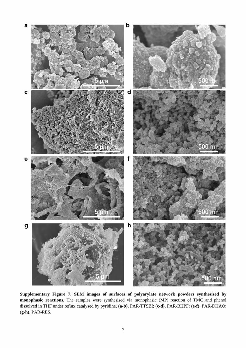
Supplementary Figure 7. SEM images of surfaces of polyarylate network powders synthesised by
monophasic reactions. The samples were synthesised via monophasic (MP) reaction of TMC and phenol
dissolved in THF under reflux catalysed by pyridine. (a-b), PAR-TTSBI; (c-d), PAR-BHPF; (e-f), PAR-DHAQ;
(g-h), PAR-RES.
8
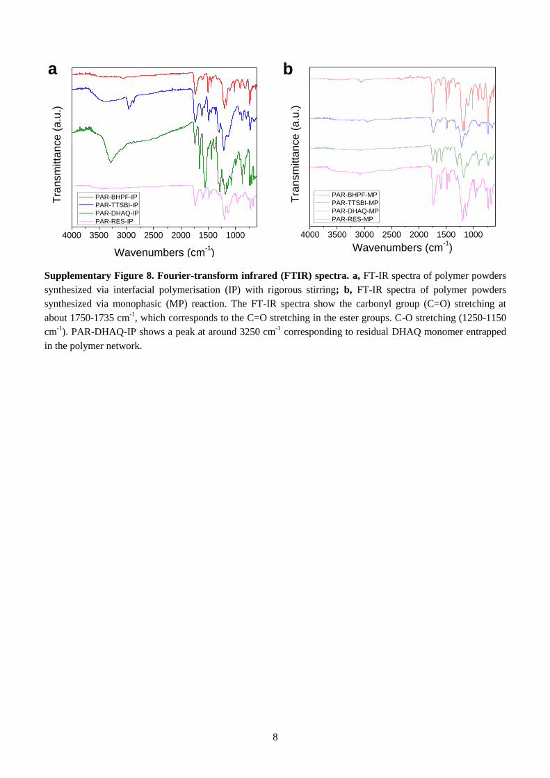
Supplementary Figure 8. Fourier-transform infrared (FTIR) spectra. a, FT-IR spectra of polymer powders
synthesized via interfacial polymerisation (IP) with rigorous stirring; b, FT-IR spectra of polymer powders
synthesized via monophasic (MP) reaction. The FT-IR spectra show the carbonyl group (C=O) stretching at
about 1750-1735 cm-1
, which corresponds to the C=O stretching in the ester groups. C-O stretching (1250-1150
cm-1
). PAR-DHAQ-IP shows a peak at around 3250 cm-1
corresponding to residual DHAQ monomer entrapped
in the polymer network.
a b
4000 3500 3000 2500 2000 1500 1000
Tra
nsm
itta
nce
(a
.u.)
Wavenumbers (cm-1)
PAR-BHPF-MP
PAR-TTSBI-MP
PAR-DHAQ-MP
PAR-RES-MP
4000 3500 3000 2500 2000 1500 1000
T
ran
sm
itta
nce
(a
.u.)
Wavenumbers (cm-1)
PAR-BHPF-IP
PAR-TTSBI-IP
PAR-DHAQ-IP
PAR-RES-IP
9
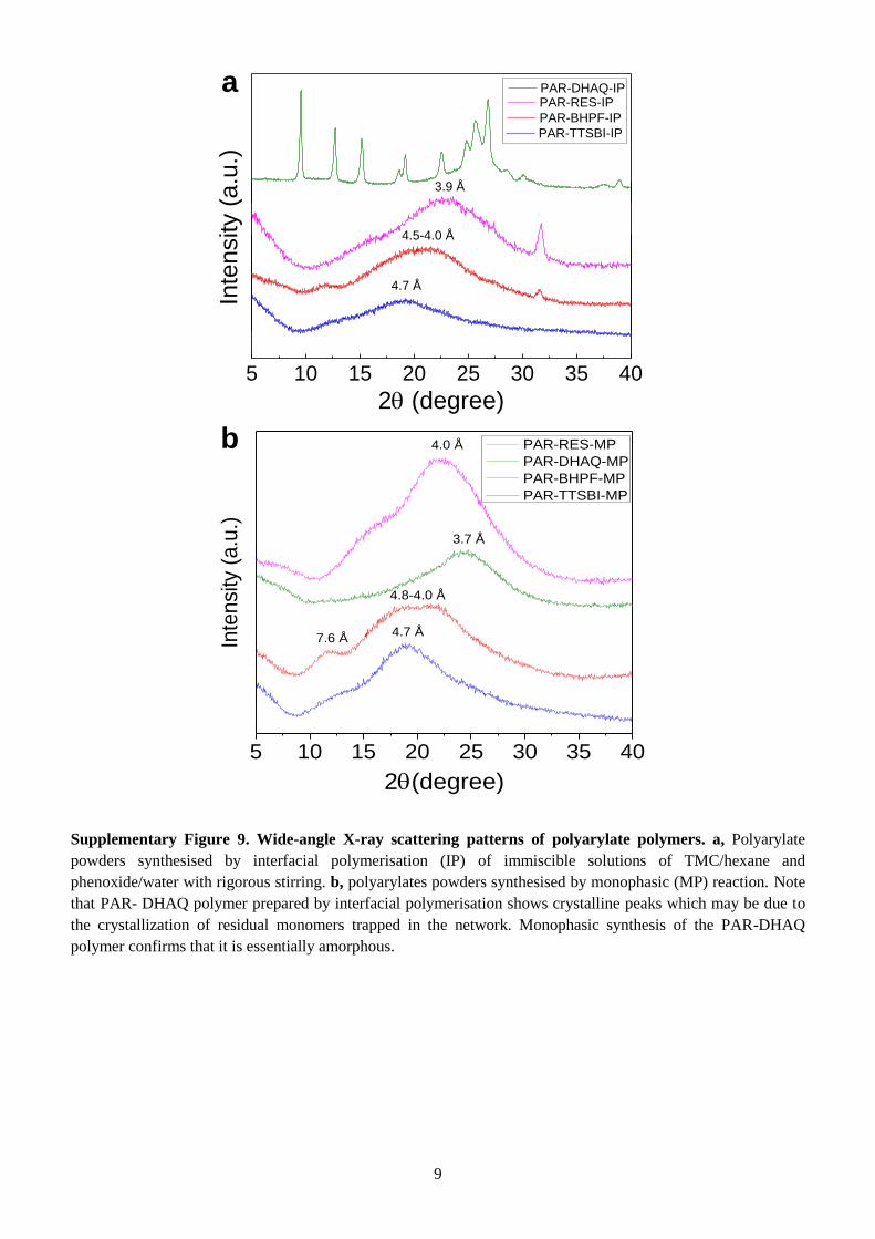
Supplementary Figure 9. Wide-angle X-ray scattering patterns of polyarylate polymers. a, Polyarylate
powders synthesised by interfacial polymerisation (IP) of immiscible solutions of TMC/hexane and
phenoxide/water with rigorous stirring. b, polyarylates powders synthesised by monophasic (MP) reaction. Note
that PAR- DHAQ polymer prepared by interfacial polymerisation shows crystalline peaks which may be due to
the crystallization of residual monomers trapped in the network. Monophasic synthesis of the PAR-DHAQ
polymer confirms that it is essentially amorphous.
5 10 15 20 25 30 35 40
PAR-RES-MP
PAR-DHAQ-MP
PAR-BHPF-MP
PAR-TTSBI-MP
7.6 Å 4.7 Å
4.8-4.0 Å
3.7 Å
4.0 Å
Inte
nsi
ty (
a.u
.)
2(degree)
5 10 15 20 25 30 35 40
PAR-TTSBI-IP
3.9 Å
4.5-4.0 Å
4.7 Å
2 (degree)
PAR-BHPF-IP
Inte
nsity (
a.u
.)
PAR-RES-IP
PAR-DHAQ-IP
a
b
10
Supplementary Figure 10. Thermogravimetric analysis (TGA) curves of polyarylate powders. a, TGA
curves of polymer powders synthesized via interfacial polymerisation (IP) obtained by rigorous mixing of a
solution of TMC in hexane added to a solution of each phenol in NaOH/water; b, TGA curves of polymer
powders synthesized via monophasic (MP) reaction of TMC and phenol dissolved in THF under reflux in
pyridine.
a b
0 200 400 600 800 10000
20
40
60
80
100
We
igh
t (%
)
Temperature (C)
PAR-BHPF-IP
PAR-DHAQ-IP PAR-TTSBI-IP
PAR-RES-IP
0 200 400 600 800 10000
20
40
60
80
100
We
igh
t (%
)
Temperature (C)
PAR-BHPF-MP PAR-TTSBI-MP
PAR-DHAQ-MP
PAR-RES-MP
11
Supplementary Figure 11. Cross-sectional SEM images of interfacially polymerised polyarylate nanofilms.
(a-b), a thin layer of PTMSP polymer coated on porous anodised aluminium oxide discs. (c-d) PAR-TTSBI, (e-
f) PAR-BHPF, and (g-h) PAR-RES nanofilms made on PTMSP/alumina membranes. A thin layer of PTMSP
polymer (50 nm) was coated on the alumina support first as an intermediate layer, then PAR nanofilms were
prepared by sequential spin-coating of a solution of TMC in hexane (1 wt%), and a solution of phenol in
NaOH/water (1 wt%). The average thicknesses of PAR nanofilms are approximately the same (~ 50 nm).
12
Supplementary Figure 12. SEM and AFM images of interfacially polymerised polyarylate nanofilms on
crosslinked polyimide P84 support membrane (PAR/PI). a, SEM image of surface of PAR-RES/PI nanofilm
composite membrane. b, AFM image probed on the sample shown in (a). c, SEM image of surface of PAR-
TTSBI/PI nanofilm composite membrane. d, AFM image probed on the sample shown in (c). e, SEM image of
surface of PAR-DHAQ/PI nanofilm composite membrane. f, AFM image probed on the sample shown in (e).
13
Supplementary Figure 13. Mechanical properties of spiro-structured PAR-TTSBI freestanding nanofilm.
a, AFM image of the free-standing spiro-structured PAR-TTSBI nanofilm. b, Height profile along the line
indicated in (a). c, Photograph of the stretching tool. Poly(dimethylsiloxane) (PDMS) strips (20 mm × 15 mm)
with a thickness of 1.55 mm were stretched 10 % using the stretching tool. The free standing PAR-TTSBI
nanofilm was transferred on to stretched PDMS following a procedure similar to that previously described2-3
.
After peeling off the polypropylene nonwoven, a membrane coupon was pressed with the polyarylate side facing
down, onto a stretched PDMS strip by placing a drop of ethanol at the interface, and then dried in air. The
polyimide support was then completely removed by dissolving through adding DMF drops, followed by rinsing
with isopropanol, and left to dry. The PDMS was then unstretched, generating compressive stress in the
nanofilm, resulting in aligned wrinkles normal to the elongation direction. Wrinkle patterns were observed under
AFM for the PAR-TTSBI nanofilm. d, and e, AFM images of the wrinkles formed when the PAR-TTSBI free
standing nanofilm is transferred onto an elastomer substrate and subjected to an applied compressive stress.
Stretching Tool
c ed
ba
10 µm
PDMS + film
0.0 0.5 1.0 1.5 2.0 2.5 3.0 3.50
10
20
30
40
50
60
70
80
He
igh
t (n
m)
Distance (m)
Thickness ~ 54 nm
14
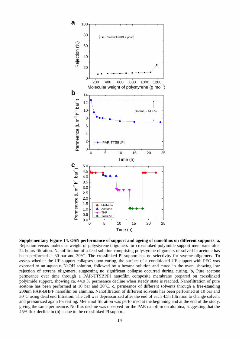
Supplementary Figure 14. OSN performance of support and ageing of nanofilms on different supports. a,
Rejection versus molecular weight of polystyrene oligomers for crosslinked polyimide support membrane after
24 hours filtration. Nanofiltration of a feed solution comprising polystyrene oligomers dissolved in acetone has
been performed at 30 bar and 30°C. The crosslinked PI support has no selectivity for styrene oligomers. To
assess whether the UF support collapses upon curing, the surface of a conditioned UF support with PEG was
exposed to an aqueous NaOH solution, followed by a hexane solution and cured in the oven, showing low
rejection of styrene oligomers, suggesting no significant collapse occurred during curing. b, Pure acetone
permeance over time through a PAR-TTSBI/PI nanofilm composite membrane prepared on crosslinked
polyimide support, showing ca. 44.9 % permeance decline when steady state is reached. Nanofiltration of pure
acetone has been performed at 10 bar and 30°C. c, permeance of different solvents through a free-standing
200nm PAR-BHPF nanofilm on alumina. Nanofiltration of different solvents has been performed at 10 bar and
30°C using dead end filtration. The cell was depressurized after the end of each 4.5h filtration to change solvent
and pressurized again for testing. Methanol filtration was performed at the beginning and at the end of the study,
giving the same permeance. No flux decline was observed for the PAR nanofilm on alumina, suggesting that the
45% flux decline in (b) is due to the crosslinked PI support.
a
b
c
0 5 10 15 20 250
2
4
6
8
10
12
14
Pe
rme
an
ce
(L
m-2 h
-1 b
ar-1
)
PAR-TTSBI/PI
Time (h)
Decline ~ 44.9 %
0 5 10 15 20 250.0
0.5
1.0
1.5
2.0
2.5
3.0
3.5
4.0
4.5
5.0
Pe
rme
an
ce
(L
m-2 h
-1 b
ar-1
)
Time (h)
Methanol
Acetone
THF
Toluene
200 400 600 800 1000 12000
20
40
60
80
100
Re
jectio
n (
%)
Molecular weight of polystyrene (g mol-1)
Crosslinked PI support
15
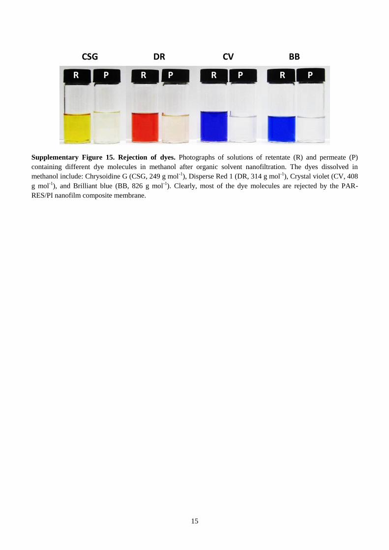
Supplementary Figure 15. Rejection of dyes. Photographs of solutions of retentate (R) and permeate (P)
containing different dye molecules in methanol after organic solvent nanofiltration. The dyes dissolved in
methanol include: Chrysoidine G (CSG, 249 g mol-1
), Disperse Red 1 (DR, 314 g mol-1
), Crystal violet (CV, 408
g mol-1
), and Brilliant blue (BB, 826 g mol-1
). Clearly, most of the dye molecules are rejected by the PAR-
RES/PI nanofilm composite membrane.
CSG DR CV BB
R P R P R P R P
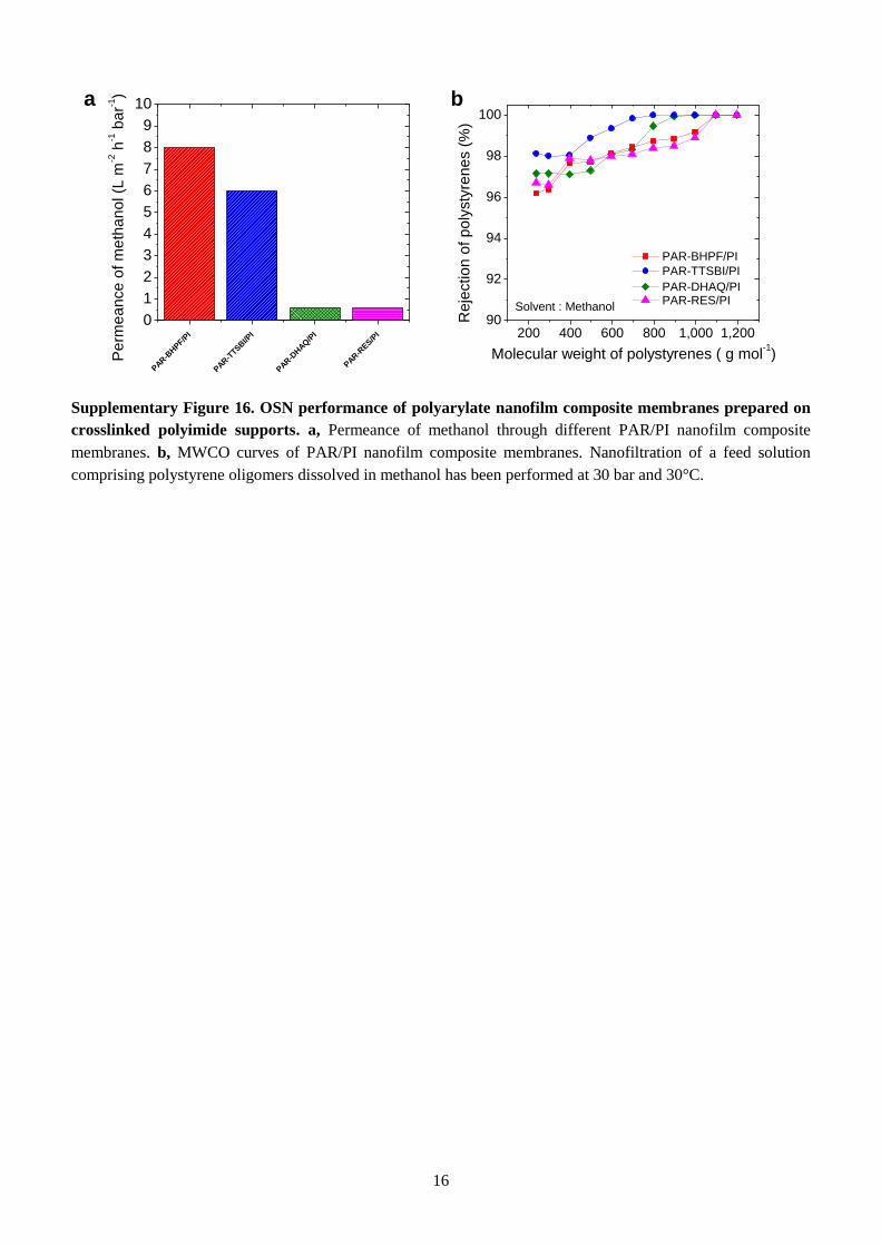
16
Supplementary Figure 16. OSN performance of polyarylate nanofilm composite membranes prepared on
crosslinked polyimide supports. a, Permeance of methanol through different PAR/PI nanofilm composite
membranes. b, MWCO curves of PAR/PI nanofilm composite membranes. Nanofiltration of a feed solution
comprising polystyrene oligomers dissolved in methanol has been performed at 30 bar and 30°C.
a b
PAR-B
HPF/P
I
PAR-T
TSBI/P
I
PAR-D
HAQ/P
I
PAR-R
ES/P
I
0
1
2
3
4
5
6
7
8
9
10P
erm
ea
nce
of
me
tha
no
l (L
m-2 h
-1 b
ar-1
)
200 400 600 800 1,000 1,20090
92
94
96
98
100
Re
jectio
n o
f p
oly
sty
ren
es (
%)
Molecular weight of polystyrenes ( g mol-1)
PAR-DHAQ/PI
PAR-BHPF/PI
PAR-TTSBI/PI
PAR-RES/PISolvent : Methanol
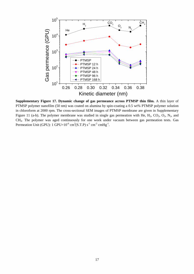
17
Supplementary Figure 17. Dynamic change of gas permeance across PTMSP thin film. A thin layer of
PTMSP polymer nanofilm (50 nm) was coated on alumina by spin-coating a 0.5 wt% PTMSP polymer solution
in chloroform at 2000 rpm. The cross-sectional SEM images of PTMSP membrane are given in Supplementary
Figure 11 (a-b). The polymer membrane was studied in single gas permeation with He, H2, CO2, O2, N2, and
CH4. The polymer was aged continuously for one week under vacuum between gas permeation tests. Gas
Permeation Unit (GPU): 1 GPU=10-6
cm3(S.T.P) s
-1 cm
-2 cmHg
-1.
0.26 0.28 0.30 0.32 0.34 0.36 0.3810
1
102
103
104
105
CH4
N2
O2
CO2
Ga
s p
erm
ea
nce
(G
PU
)
Kinetic diameter (nm)
PTMSP
PTMSP 12 h
PTMSP 24 h
PTMSP 48 h
PTMSP 96 h
PTMSP 168 h
He
H2
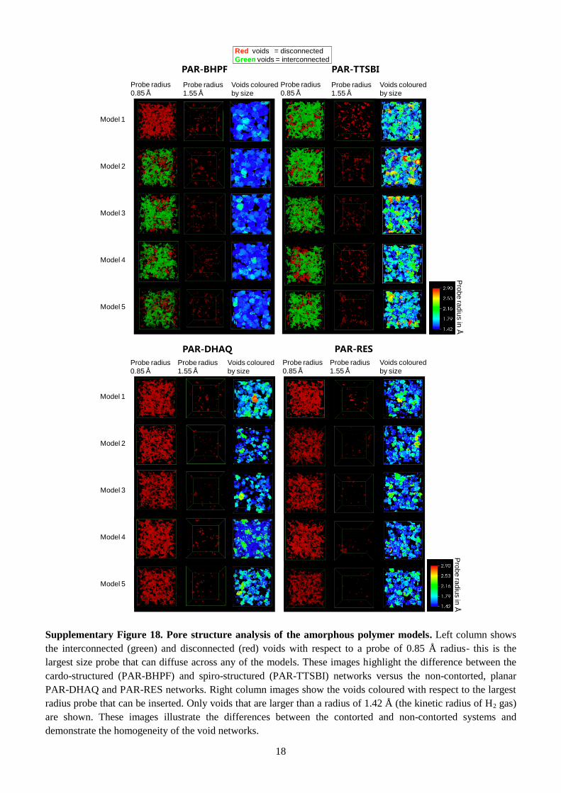
18
Supplementary Figure 18. Pore structure analysis of the amorphous polymer models. Left column shows
the interconnected (green) and disconnected (red) voids with respect to a probe of 0.85 Å radius- this is the
largest size probe that can diffuse across any of the models. These images highlight the difference between the
cardo-structured (PAR-BHPF) and spiro-structured (PAR-TTSBI) networks versus the non-contorted, planar
PAR-DHAQ and PAR-RES networks. Right column images show the voids coloured with respect to the largest
radius probe that can be inserted. Only voids that are larger than a radius of 1.42 Å (the kinetic radius of H2 gas)
are shown. These images illustrate the differences between the contorted and non-contorted systems and
demonstrate the homogeneity of the void networks.
PAR-DHAQ
PAR-TTSBI
Model 1
Probe radius
0.85 Å Probe radius
1.55 Å
Model 2
Model 3
Model 4
Model 5
Probe radius
0.85 Å
Probe radius
1.55 Å
Voids coloured
by size
Voids coloured
by size
Pro
be
rad
ius in
Å
Red voids = disconnected
Green voids = interconnected
PAR-BHPF
Probe radius
0.85 Å Probe radius
1.55 Å
Voids coloured
by size
PAR-RES
Probe radius
0.85 Å
Probe radius
1.55 Å
Voids coloured
by size
Pro
be
rad
ius in
Å
Model 1
Model 2
Model 3
Model 4
Model 5
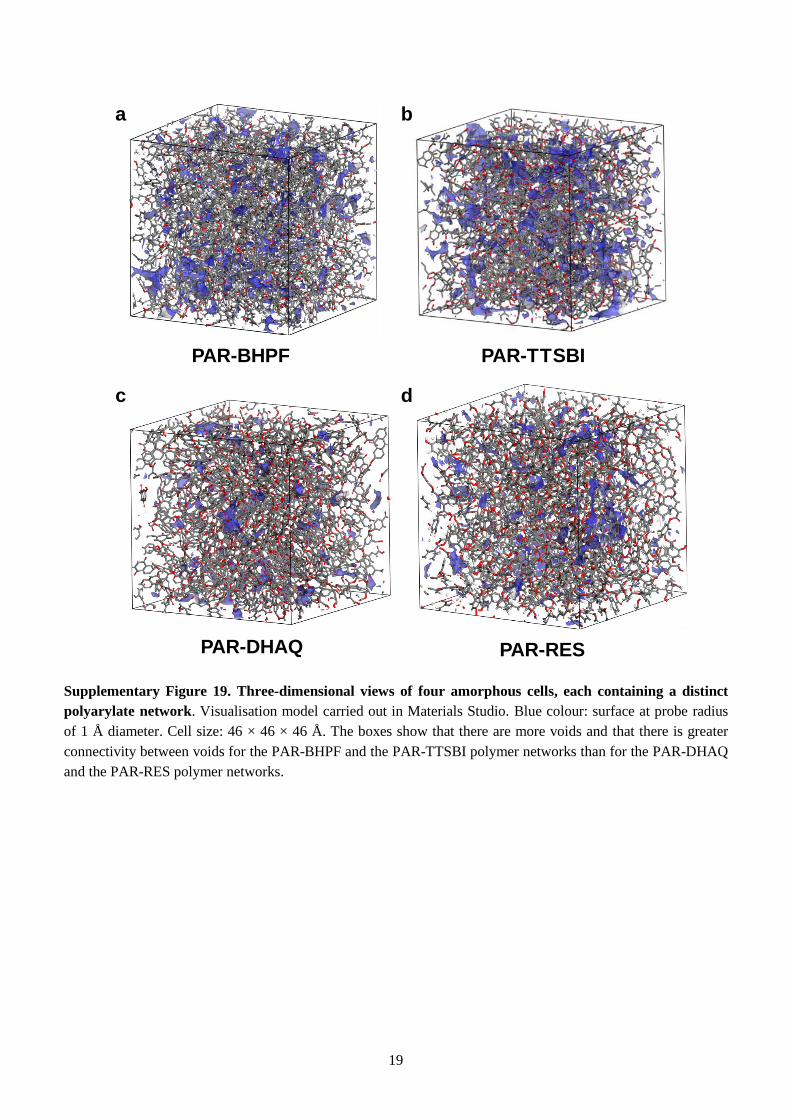
19
Supplementary Figure 19. Three-dimensional views of four amorphous cells, each containing a distinct
polyarylate network. Visualisation model carried out in Materials Studio. Blue colour: surface at probe radius
of 1 Å diameter. Cell size: 46 × 46 × 46 Å. The boxes show that there are more voids and that there is greater
connectivity between voids for the PAR-BHPF and the PAR-TTSBI polymer networks than for the PAR-DHAQ
and the PAR-RES polymer networks.
PAR-TTSBI
PAR-DHAQ
PAR-BHPF
PAR-RES
dc
a b
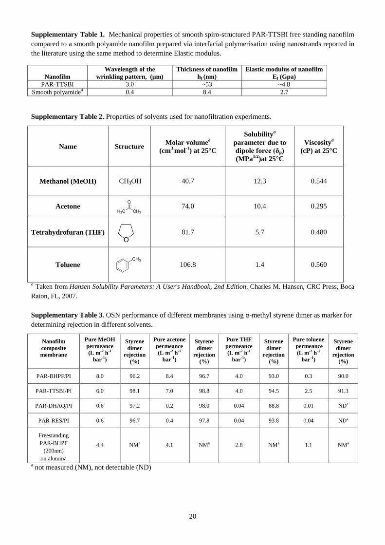
20
Supplementary Table 1. Mechanical properties of smooth spiro-structured PAR-TTSBI free standing nanofilm
compared to a smooth polyamide nanofilm prepared via interfacial polymerisation using nanostrands reported in
the literature using the same method to determine Elastic modulus.
Nanofilm
Wavelength of the
wrinkling pattern, (µm)
Thickness of nanofilm
hf (nm)
Elastic modulus of nanofilm
Ef (Gpa)
PAR-TTSBI 3.0 ~53 ~4.8
Smooth polyamide4 0.4 8.4 2.7
Supplementary Table 2. Properties of solvents used for nanofiltration experiments.
Name Structure Molar volume
a
(cm3 mol
-1) at 25°C
Solubilitya
parameter due to
dipole force (δp)
(MPa1/2
)at 25°C
Viscositya
(cP) at 25°C
Methanol (MeOH) CH3OH 40.7 12.3 0.544
Acetone 74.0 10.4 0.295
Tetrahydrofuran (THF)
81.7 5.7 0.480
Toluene 106.8 1.4 0.560
a Taken from Hansen Solubility Parameters: A User's Handbook, 2nd Edition, Charles M. Hansen, CRC Press, Boca
Raton, FL, 2007.
Supplementary Table 3. OSN performance of different membranes using α-methyl styrene dimer as marker for
determining rejection in different solvents.
Nanofilm
composite
membrane
Pure MeOH
permeance
(L m-2 h-1
bar-1)
Styrene
dimer
rejection
(%)
Pure acetone
permeance
(L m-2 h-1
bar-1)
Styrene
dimer
rejection
(%)
Pure THF
permeance
(L m-2 h-1
bar-1)
Styrene
dimer
rejection
(%)
Pure toluene
permeance
(L m-2 h-1
bar-1)
Styrene
dimer
rejection
(%)
PAR-BHPF/PI 8.0 96.2 8.4 96.7 4.0 93.0 0.3 90.0
PAR-TTSBI/PI 6.0 98.1 7.0 98.8 4.0 94.5 2.5 91.3
PAR-DHAQ/PI 0.6 97.2 0.2 98.0 0.04 88.8 0.01 NDa
PAR-RES/PI 0.6 96.7 0.4 97.8 0.04 93.8 0.04 NDa
Freestanding
PAR-BHPF
(200nm)
on alumina
4.4 NMa 4.1 NMa 2.8 NMa 1.1 NMa
a not measured (NM), not detectable (ND)
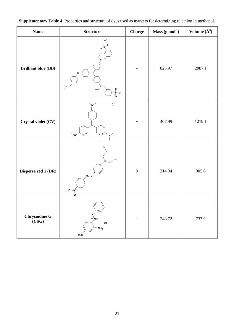
21
Supplementary Table 4. Properties and structure of dyes used as markers for determining rejection in methanol.
Name Structure Charge Mass (g mol-1
) Volume (Å3)
Brilliant blue (BB)
- 825.97 2087.1
Crystal violet (CV)
+ 407.99 1219.1
Disperse red 1 (DR)
0 314.34 905.6
Chrysoidine G
(CSG)
+ 248.72 737.9
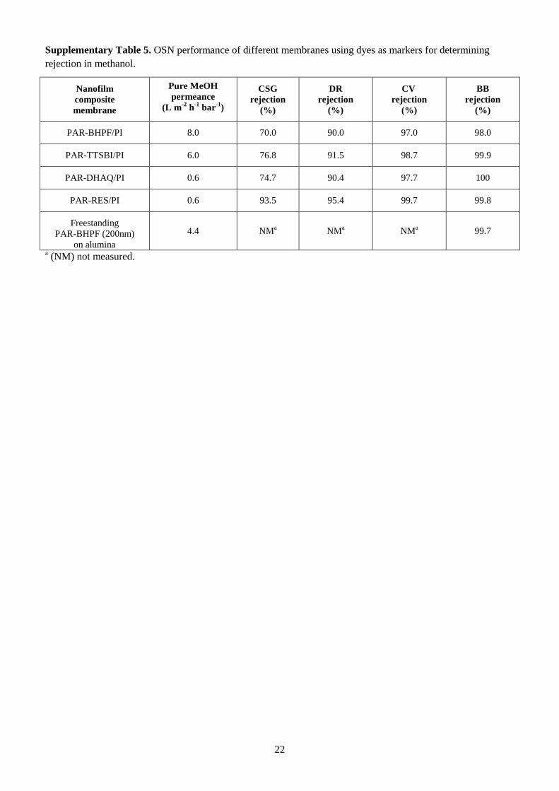
22
Supplementary Table 5. OSN performance of different membranes using dyes as markers for determining
rejection in methanol.
Nanofilm
composite
membrane
Pure MeOH
permeance
(L m-2
h-1
bar-1
)
CSG
rejection
(%)
DR
rejection
(%)
CV
rejection
(%)
BB
rejection
(%)
PAR-BHPF/PI 8.0 70.0 90.0 97.0 98.0
PAR-TTSBI/PI 6.0 76.8 91.5 98.7 99.9
PAR-DHAQ/PI 0.6 74.7 90.4 97.7 100
PAR-RES/PI 0.6 93.5 95.4 99.7 99.8
Freestanding
PAR-BHPF (200nm)
on alumina
4.4 NMa NM
a NM
a 99.7
a (NM) not measured.
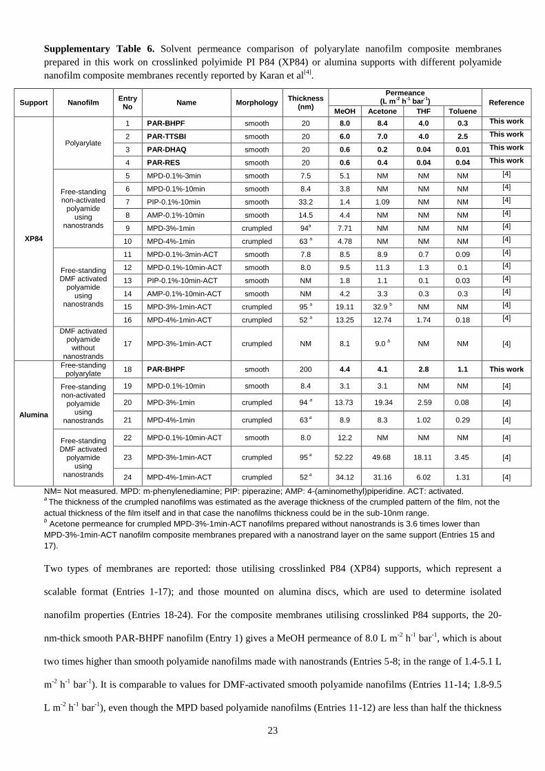
23
Supplementary Table 6. Solvent permeance comparison of polyarylate nanofilm composite membranes
prepared in this work on crosslinked polyimide PI P84 (XP84) or alumina supports with different polyamide
nanofilm composite membranes recently reported by Karan et al[4]
.
Support Nanofilm Entry
No Name Morphology
Thickness (nm)
Permeance (L m
-2 h
-1 bar
-1) Reference
MeOH Acetone THF Toluene
XP84
Polyarylate
1 PAR-BHPF smooth 20 8.0 8.4 4.0 0.3 This work
2 PAR-TTSBI smooth 20 6.0 7.0 4.0 2.5 This work
3 PAR-DHAQ smooth 20 0.6 0.2 0.04 0.01 This work
4 PAR-RES smooth 20 0.6 0.4 0.04 0.04 This work
Free-standing non-activated
polyamide using
nanostrands
5 MPD-0.1%-3min smooth 7.5 5.1 NM NM NM [4]
6 MPD-0.1%-10min smooth 8.4 3.8 NM NM NM [4]
7 PIP-0.1%-10min smooth 33.2 1.4 1.09 NM NM [4]
8 AMP-0.1%-10min smooth 14.5 4.4 NM NM NM [4]
9 MPD-3%-1min crumpled 94a 7.71 NM NM NM [4]
10 MPD-4%-1min crumpled 63 a 4.78 NM NM NM [4]
Free-standing DMF activated
polyamide using
nanostrands
11 MPD-0.1%-3min-ACT smooth 7.8 8.5 8.9 0.7 0.09 [4]
12 MPD-0.1%-10min-ACT smooth 8.0 9.5 11.3 1.3 0.1 [4]
13 PIP-0.1%-10min-ACT smooth NM 1.8 1.1 0.1 0.03 [4]
14 AMP-0.1%-10min-ACT smooth NM 4.2 3.3 0.3 0.3 [4]
15 MPD-3%-1min-ACT crumpled 95 a 19.11 32.9
b NM NM [4]
16 MPD-4%-1min-ACT crumpled 52 a 13.25 12.74 1.74 0.18 [4]
DMF activated polyamide
without nanostrands
17 MPD-3%-1min-ACT crumpled NM 8.1 9.0 b NM NM [4]
Alumina
Free-standing polyarylate
18 PAR-BHPF smooth 200 4.4 4.1 2.8 1.1 This work
Free-standing non-activated
polyamide using
nanostrands
19 MPD-0.1%-10min smooth 8.4 3.1 3.1 NM NM [4]
20 MPD-3%-1min crumpled 94 a 13.73 19.34 2.59 0.08 [4]
21 MPD-4%-1min crumpled 63 a 8.9 8.3 1.02 0.29 [4]
Free-standing DMF activated
polyamide using
nanostrands
22 MPD-0.1%-10min-ACT smooth 8.0 12.2 NM NM NM [4]
23 MPD-3%-1min-ACT crumpled 95 a 52.22 49.68 18.11 3.45 [4]
24 MPD-4%-1min-ACT crumpled 52 a 34.12 31.16 6.02 1.31 [4]
NM= Not measured. MPD: m-phenylenediamine; PIP: piperazine; AMP: 4-(aminomethyl)piperidine. ACT: activated. a
The thickness of the crumpled nanofilms was estimated as the average thickness of the crumpled pattern of the film, not the
actual thickness of the film itself and in that case the nanofilms thickness could be in the sub-10nm range. b Acetone permeance for crumpled MPD-3%-1min-ACT nanofilms prepared without nanostrands is 3.6 times lower than
MPD-3%-1min-ACT nanofilm composite membranes prepared with a nanostrand layer on the same support (Entries 15 and
17).
Two types of membranes are reported: those utilising crosslinked P84 (XP84) supports, which represent a
scalable format (Entries 1-17); and those mounted on alumina discs, which are used to determine isolated
nanofilm properties (Entries 18-24). For the composite membranes utilising crosslinked P84 supports, the 20-
nm-thick smooth PAR-BHPF nanofilm (Entry 1) gives a MeOH permeance of 8.0 L m-2
h-1
bar-1
, which is about
two times higher than smooth polyamide nanofilms made with nanostrands (Entries 5-8; in the range of 1.4-5.1 L
m-2
h-1
bar-1
). It is comparable to values for DMF-activated smooth polyamide nanofilms (Entries 11-14; 1.8-9.5
L m-2
h-1
bar-1
), even though the MPD based polyamide nanofilms (Entries 11-12) are less than half the thickness
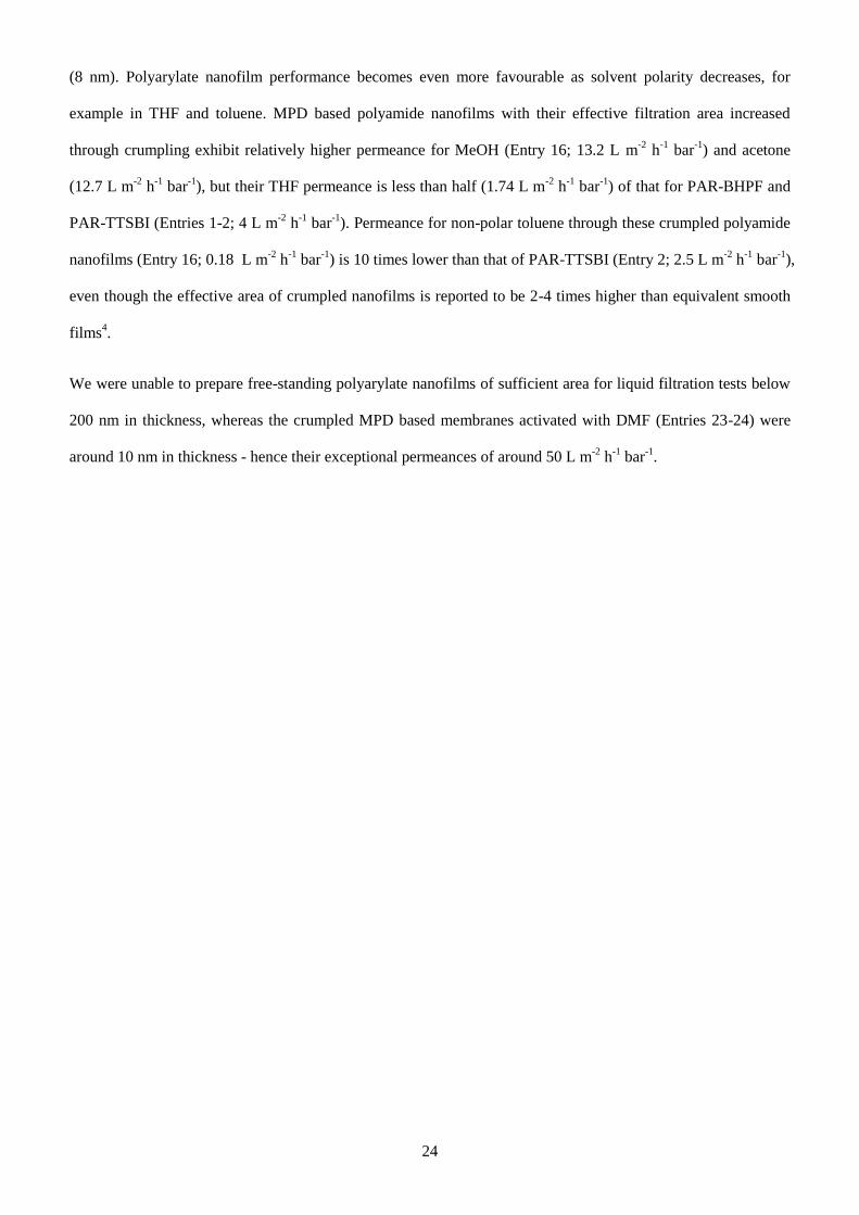
24
(8 nm). Polyarylate nanofilm performance becomes even more favourable as solvent polarity decreases, for
example in THF and toluene. MPD based polyamide nanofilms with their effective filtration area increased
through crumpling exhibit relatively higher permeance for MeOH (Entry 16; 13.2 L m-2
h-1
bar-1
) and acetone
(12.7 L m-2
h-1
bar-1
), but their THF permeance is less than half (1.74 L m-2
h-1
bar-1
) of that for PAR-BHPF and
PAR-TTSBI (Entries 1-2; 4 L m-2
h-1
bar-1
). Permeance for non-polar toluene through these crumpled polyamide
nanofilms (Entry 16; 0.18 L m-2
h-1
bar-1
) is 10 times lower than that of PAR-TTSBI (Entry 2; 2.5 L m-2
h-1
bar-1
),
even though the effective area of crumpled nanofilms is reported to be 2-4 times higher than equivalent smooth
films4.
We were unable to prepare free-standing polyarylate nanofilms of sufficient area for liquid filtration tests below
200 nm in thickness, whereas the crumpled MPD based membranes activated with DMF (Entries 23-24) were
around 10 nm in thickness - hence their exceptional permeances of around 50 L m-2
h-1
bar-1
.
25
Supplementary Table 7. Parameters derived from experimental and modelling data. For the modelling data the
table shows the average over 5 models.
Parameters PAR-BHPF PAR-TTSBI PAR-DHAQ PAR-RES
Experimental
Density PAR-IP
(g cm-3
) 1.0327 + 0.0158 1.0366 + 0.0324 1.3207 + 0.0121 NM
a
Density PAR-MP
(g cm-3
) 1.2666 + 0.0042 1.3367 + 0.0036 1.5188 + 0.0262 1.5151 + 0.0030
Simulation
Final density
at 300K, 1bar
(g cm-3
)
1.187 + 0.0030 1.213 + 0.0010 1.421 + 0.0070 1.380 ± 0.004
Diameter of
the largest
cavity (Å)
5.6 + 0.1 5.6 + 0.1 4.4 + 0.3 4.3 ± 0.2
Largest “free”
sphere (Å) 1.7 + 0.1 1.6 + 0.1 1.3 + 0.1 1.3 ± 0.0
Surface area
for 1 Å radius
probe (m2 g
-1)
810 + 8 674 + 39 339 + 32 0.0
Surface area
for 1.55 Å (N2)
probe (m2 g
-1)
102 + 10 74 + 6 18 + 5 0.0
Experimental
Surface area
for N2 via IP
(m2 g
-1)
30.75 28.77 12.35 11.96
Surface area
for CO2 via IP
(m2 g
-1)
79.16 89.78 18.38 35.42
Surface area
for CO2 via MP
(m2 g
-1)
150.90 161.50 67.73 61.10
a NM: not measured. Note: we have difficulty in measuring the skeletal density of this sample by helium
pycnometry.
Supplementary Table 8. Parameters derived from experimental and modelling data. For the modelling data the
table shows the average over 5 models. Polymerisation completeness is calculated assuming that all C=O groups
reacting is a “complete polymerisation”. For all cases there is essentially one large interconnected network, with
one or a few unreacted molecules.
Polymer
Percentage
polymerisation
complete
Polymerisation
steps performed
No. of molecules
in final model
No. of unreacted
COOH groups
No. of unreacted
OH groups
PAR-BHPF 86.7 ± 0.7 317 ± 3 6 ± 2 49 ± 3 49 ± 3
PAR-TTSBI 100.0 ± 0.1 402 ± 0 4 ± 1 0 ± 0 402* ± 0
PAR-DHAQ 91.8 ± 1.2 440 ± 6 2 ± 1 41 ± 6 41 ± 6
PAR-RES 98.0 ± 0.4 564 ± 2 1.2 ± 0.4 11.6 ± 2.1 11.6 ± 2.1
* Contrary to expectation, it was observed that the TTSBI frequently reacted with two trimesoyl chlorides on one side. The
PAR-TTSBI systems have many OH functional groups remaining as there were twice the number needed on the original
precursor.
26
Supplementary References
1. Jeromenok, J., Böhlmann, W., Antonietti, M., & Weber, J., Intrinsically microporous polyesters from
betulin – toward renewable materials for gas separation made from birch bark. Macromol. Rapid Commun. 32,
1846-1851 (2011).
2. Chung, J. Y., Lee, J.-H., Beers, K. L., & Stafford, C. M., Stiffness, strength, and ductility of nanoscale
thin films and membranes: A combined wrinkling–cracking methodology. Nano Lett. 11, 3361-3365 (2011).
3. Freger, V., Swelling and morphology of the skin layer of polyamide composite membranes: An atomic
force microscopy study. Environmental Science & Technology 38, 3168-3175 (2004).
4. Karan, S., Jiang, Z., & Livingston, A. G., Sub–10 nm polyamide nanofilms with ultrafast solvent
transport for molecular separation. Science 348, 1347-1351 (2015).