pm250 power module - franklin empire
TRANSCRIPT


PM250 Power Module
___________________
___________________
___________________
___________________
___________________
___________________
___________________
___________________
___________________
SINAMICS
SINAMICS G120 PM250 Power Module
Hardware Installation Manual
Edition 01/2016
01/2016 A5E36265179B-AA
Changes in this manual 1
Fundamental safety instructions
2
Introduction 3
Installing/mounting 4
Connection 5
Operation, service and maintenance
6
Technical specifications 7
Spare parts and accessories 8
Appendix 9

Siemens AG Division Digital Factory Postfach 48 48 90026 NÜRNBERG GERMANY
A5E36265179B-AA Ⓟ 01/2016 Subject to change
Copyright © Siemens AG 2006 - 2016. All rights reserved
Legal information Warning notice system
This manual contains notices you have to observe in order to ensure your personal safety, as well as to prevent damage to property. The notices referring to your personal safety are highlighted in the manual by a safety alert symbol, notices referring only to property damage have no safety alert symbol. These notices shown below are graded according to the degree of danger.
DANGER indicates that death or severe personal injury will result if proper precautions are not taken.
WARNING indicates that death or severe personal injury may result if proper precautions are not taken.
CAUTION indicates that minor personal injury can result if proper precautions are not taken.
NOTICE indicates that property damage can result if proper precautions are not taken.
If more than one degree of danger is present, the warning notice representing the highest degree of danger will be used. A notice warning of injury to persons with a safety alert symbol may also include a warning relating to property damage.
Qualified Personnel The product/system described in this documentation may be operated only by personnel qualified for the specific task in accordance with the relevant documentation, in particular its warning notices and safety instructions. Qualified personnel are those who, based on their training and experience, are capable of identifying risks and avoiding potential hazards when working with these products/systems.
Proper use of Siemens products Note the following:
WARNING Siemens products may only be used for the applications described in the catalog and in the relevant technical documentation. If products and components from other manufacturers are used, these must be recommended or approved by Siemens. Proper transport, storage, installation, assembly, commissioning, operation and maintenance are required to ensure that the products operate safely and without any problems. The permissible ambient conditions must be complied with. The information in the relevant documentation must be observed.
Trademarks All names identified by ® are registered trademarks of Siemens AG. The remaining trademarks in this publication may be trademarks whose use by third parties for their own purposes could violate the rights of the owner.
Disclaimer of Liability We have reviewed the contents of this publication to ensure consistency with the hardware and software described. Since variance cannot be precluded entirely, we cannot guarantee full consistency. However, the information in this publication is reviewed regularly and any necessary corrections are included in subsequent editions.

PM250 Power Module Hardware Installation Manual, 01/2016, A5E36265179B-AA 5
Table of contents
1 Changes in this manual ........................................................................................................................... 7
2 Fundamental safety instructions .............................................................................................................. 9
2.1 General safety instructions ....................................................................................................... 9
2.2 Safety instructions for electromagnetic fields (EMF) .............................................................. 13
2.3 Handling electrostatic sensitive devices (ESD) ...................................................................... 13
2.4 Industrial security .................................................................................................................... 14
2.5 Residual risks of power drive systems .................................................................................... 15
3 Introduction ........................................................................................................................................... 17
4 Installing/mounting ................................................................................................................................ 19
4.1 Installation conditions.............................................................................................................. 19
4.2 Power losses and air cooling requirements ............................................................................ 20
4.3 Mounting the Power Modules ................................................................................................. 22 4.3.1 Installing Power Modules ........................................................................................................ 22 4.3.2 Dimension drawings and drilling dimensions .......................................................................... 23
4.4 Control Unit installation ........................................................................................................... 25
4.5 Installing supplementary components .................................................................................... 25
5 Connection ........................................................................................................................................... 27
5.1 Line and motor connection ..................................................................................................... 29 5.1.2 Permissible line supplies ........................................................................................................ 29 5.1.3 Dimensioning the protective conductor ................................................................................... 32 5.1.4 Connection overview............................................................................................................... 34 5.1.5 Length of motor cable ............................................................................................................. 34 5.1.6 Motor connection .................................................................................................................... 35 5.1.7 Inverter terminals .................................................................................................................... 36 5.1.8 Establishing connections ........................................................................................................ 36
5.2 EMC-compliant installation ..................................................................................................... 38 5.2.1 Avoiding electromagnetic interference .................................................................................... 38 5.2.2 Avoiding electromagnetic influence (EMI) .............................................................................. 38 5.2.3 Installing the converter in compliance with EMC rules ........................................................... 41 5.2.4 EMC-compliant cabinet design ............................................................................................... 42 5.2.5 Equipotential bonding ............................................................................................................. 43
6 Operation, service and maintenance ..................................................................................................... 47
6.1 Operation ................................................................................................................................ 47
6.2 Maintenance ........................................................................................................................... 48
6.3 Replacing fans ........................................................................................................................ 49
7 Technical specifications ........................................................................................................................ 53

Table of contents
PM250 Power Module 6 Hardware Installation Manual, 01/2016, A5E36265179B-AA
7.1 Overload capability of the inverter ......................................................................................... 53
7.2 Cable cross-sections and tightening torques ......................................................................... 55
7.3 General data .......................................................................................................................... 56
7.4 Power-dependent data ........................................................................................................... 58 7.4.1 Current derating depending on the pulse frequency.............................................................. 60
7.5 Restrictions for special ambient conditions ............................................................................ 61
7.6 Electromagnetic compatibility of the inverter ......................................................................... 63 7.6.1 Assigning the inverter to EMC categories .............................................................................. 64 7.6.2 Harmonics .............................................................................................................................. 66 7.6.3 EMC limit values in South Korea ........................................................................................... 67
8 Spare parts and accessories ................................................................................................................. 69
8.1 Spare parts ............................................................................................................................. 69
8.2 Optional accessories .............................................................................................................. 70 8.2.1 Reactors and filters as base components .............................................................................. 70 8.2.2 Line filter ................................................................................................................................. 71 8.2.3 Output reactor ........................................................................................................................ 74 8.2.4 Sine-wave filter....................................................................................................................... 78 8.2.5 Connecting a motor holding brake ......................................................................................... 81 8.2.5.1 Mounting and connecting the brake relay .............................................................................. 82 8.2.5.2 Mounting and connecting the brake relay .............................................................................. 82 8.2.5.3 Technical data of the brake relay? ......................................................................................... 83 8.2.5.4 Mounting and connecting the brake relay .............................................................................. 83 8.2.6 Shield connection kit .............................................................................................................. 84
9 Appendix .............................................................................................................................................. 85
9.1 Manuals and technical support .............................................................................................. 85 9.1.1 Overview of the manuals ....................................................................................................... 85 9.1.2 Configuring support ................................................................................................................ 88 9.1.3 Product Support ..................................................................................................................... 89
9.2 Disposal ................................................................................................................................. 89
9.3 Standards ............................................................................................................................... 90
9.4 Abbreviations ......................................................................................................................... 91
Index .................................................................................................................................................... 93

PM250 Power Module Hardware Installation Manual, 01/2016, A5E36265179B-AA 7
Changes in this manual 1
Changes with respect to the manual, edition 09/2012 All chapters in the manual have been completely revised.

Changes in this manual
PM250 Power Module 8 Hardware Installation Manual, 01/2016, A5E36265179B-AA

PM250 Power Module Hardware Installation Manual, 01/2016, A5E36265179B-AA 9
Fundamental safety instructions 2 2.1 General safety instructions
DANGER
Danger to life due to live parts and other energy sources
Death or serious injury can result when live parts are touched. • Only work on electrical devices when you are qualified for this job. • Always observe the country-specific safety rules.
Generally, six steps apply when establishing safety: 1. Prepare for shutdown and notify all those who will be affected by the procedure. 2. Disconnect the machine from the supply.
– Switch off the machine. – Wait until the discharge time specified on the warning labels has elapsed. – Check that it really is in a no-voltage condition, from phase conductor to phase
conductor and phase conductor to protective conductor. – Check whether the existing auxiliary supply circuits are de-energized. – Ensure that the motors cannot move.
3. Identify all other dangerous energy sources, e.g. compressed air, hydraulic systems, or water.
4. Isolate or neutralize all hazardous energy sources by closing switches, grounding or short-circuiting or closing valves, for example.
5. Secure the energy sources against switching on again. 6. Ensure that the correct machine is completely interlocked.
After you have completed the work, restore the operational readiness in the inverse sequence.
WARNING
Danger to life through a hazardous voltage when connecting an unsuitable power supply
Touching live components can result in death or severe injury. • Only use power supplies that provide SELV (Safety Extra Low Voltage) or PELV-
(Protective Extra Low Voltage) output voltages for all connections and terminals of the electronics modules.

Fundamental safety instructions 2.1 General safety instructions
PM250 Power Module 10 Hardware Installation Manual, 01/2016, A5E36265179B-AA
WARNING
Danger to life when live parts are touched on damaged devices
Improper handling of devices can cause damage.
For damaged devices, hazardous voltages can be present at the enclosure or at exposed components; if touched, this can result in death or severe injury. • Ensure compliance with the limit values specified in the technical data during transport,
storage and operation. • Do not use any damaged devices.
WARNING
Danger to life through electric shock due to unconnected cable shields
Hazardous touch voltages can occur through capacitive cross-coupling due to unconnected cable shields. • As a minimum, connect cable shields and the conductors of power cables that are not
used (e.g. brake cores) at one end at the grounded housing potential.
WARNING
Danger to life due to electric shock when not grounded
For missing or incorrectly implemented protective conductor connection for devices with protection class I, high voltages can be present at open, exposed parts, which when touched, can result in death or severe injury. • Ground the device in compliance with the applicable regulations.
WARNING
Danger to life due to electric shock when opening plug connections in operation
When opening plug connections in operation, arcs can result in severe injury or death. • Only open plug connections when the equipment is in a no-voltage state, unless it has
been explicitly stated that they can be opened in operation.
WARNING
Danger to life due to fire spreading if housing is inadequate
Fire and smoke development can cause severe personal injury or material damage. • Install devices without a protective housing in a metal control cabinet (or protect the
device by another equivalent measure) in such a way that contact with fire is prevented. • Ensure that smoke can only escape via controlled and monitored paths.

Fundamental safety instructions 2.1 General safety instructions
PM250 Power Module Hardware Installation Manual, 01/2016, A5E36265179B-AA 11
WARNING
Danger to life through unexpected movement of machines when using mobile wireless devices or mobile phones
Using mobile wireless devices or mobile phones with a transmit power > 1 W closer than approx. 2 m to the components may cause the devices to malfunction, influence the functional safety of machines therefore putting people at risk or causing material damage. • Switch the wireless devices or mobile phones off in the immediate vicinity of the
components.
WARNING
Danger to life due to the motor catching fire in the event of insulation overload
There is higher stress on the motor insulation through a ground fault in an IT system. If the insulation fails, it is possible that death or severe injury can occur as a result of smoke and fire. • Use a monitoring device that signals an insulation fault. • Correct the fault as quickly as possible so the motor insulation is not overloaded.
WARNING
Danger to life due to fire if overheating occurs because of insufficient ventilation clearances
Inadequate ventilation clearances can cause overheating of components with subsequent fire and smoke. This can cause severe injury or even death. This can also result in increased downtime and reduced service lives for devices/systems. • Ensure compliance with the specified minimum clearance as ventilation clearance for
the respective component.
WARNING
Danger of an accident occurring due to missing or illegible warning labels
Missing or illegible warning labels can result in accidents involving death or serious injury. • Check that the warning labels are complete based on the documentation. • Attach any missing warning labels to the components, in the national language if
necessary. • Replace illegible warning labels.
NOTICE
Device damage caused by incorrect voltage/insulation tests
Incorrect voltage/insulation tests can damage the device. • Before carrying out a voltage/insulation check of the system/machine, disconnect the
devices as all converters and motors have been subject to a high voltage test by the manufacturer, and therefore it is not necessary to perform an additional test within the system/machine.

Fundamental safety instructions 2.1 General safety instructions
PM250 Power Module 12 Hardware Installation Manual, 01/2016, A5E36265179B-AA
WARNING
Danger to life when safety functions are inactive
Safety functions that are inactive or that have not been adjusted accordingly can cause operational faults on machines that could lead to serious injury or death. • Observe the information in the appropriate product documentation before
commissioning. • Carry out a safety inspection for functions relevant to safety on the entire system,
including all safety-related components. • Ensure that the safety functions used in your drives and automation tasks are adjusted
and activated through appropriate parameterizing. • Perform a function test. • Only put your plant into live operation once you have guaranteed that the functions
relevant to safety are running correctly.
Note Important safety notices for Safety Integrated functions
If you want to use Safety Integrated functions, you must observe the safety notices in the Safety Integrated manuals.
Fundamental safety instructions 2.2 Safety instructions for electromagnetic fields (EMF)
PM250 Power Module Hardware Installation Manual, 01/2016, A5E36265179B-AA 13
2.2 Safety instructions for electromagnetic fields (EMF)
WARNING
Danger to life from electromagnetic fields
Electromagnetic fields (EMF) are generated by the operation of electrical power equipment such as transformers, converters or motors.
People with pacemakers or implants are at a special risk in the immediate vicinity of these devices/systems. • Ensure that the persons involved are the necessary distance away (minimum 2 m).
2.3 Handling electrostatic sensitive devices (ESD) Electrostatic sensitive devices (ESD) are individual components, integrated circuits, modules or devices that may be damaged by either electric fields or electrostatic discharge.
NOTICE
Damage through electric fields or electrostatic discharge
Electric fields or electrostatic discharge can cause malfunctions through damaged individual components, integrated circuits, modules or devices. • Only pack, store, transport and send electronic components, modules or devices in their
original packaging or in other suitable materials, e.g conductive foam rubber of aluminum foil.
• Only touch components, modules and devices when you are grounded by one of the following methods: – Wearing an ESD wrist strap – Wearing ESD shoes or ESD grounding straps in ESD areas with conductive flooring
• Only place electronic components, modules or devices on conductive surfaces (table with ESD surface, conductive ESD foam, ESD packaging, ESD transport container).

Fundamental safety instructions 2.4 Industrial security
PM250 Power Module 14 Hardware Installation Manual, 01/2016, A5E36265179B-AA
2.4 Industrial security
Note Industrial security
Siemens provides products and solutions with industrial security functions that support the secure operation of plants, solutions, machines, equipment and/or networks. They are important components in a holistic industrial security concept. With this in mind, Siemens’ products and solutions undergo continuous development. Siemens recommends strongly that you regularly check for product updates.
For the secure operation of Siemens products and solutions, it is necessary to take suitable preventive action (e.g. cell protection concept) and integrate each component into a holistic, state-of-the-art industrial security concept. Third-party products that may be in use should also be considered. For more information about industrial security, visit this address (http://www.siemens.com/industrialsecurity).
To stay informed about product updates as they occur, sign up for a product-specific newsletter. For more information, visit this address (http://support.automation.siemens.com).
WARNING
Danger as a result of unsafe operating states resulting from software manipulation
Software manipulation (e.g. by viruses, Trojan horses, malware, worms) can cause unsafe operating states to develop in your installation which can result in death, severe injuries and/or material damage. • Keep the software up to date.
You will find relevant information and newsletters at this address (http://support.automation.siemens.com).
• Incorporate the automation and drive components into a holistic, state-of-the-art industrial security concept for the installation or machine. You will find further information at this address (http://www.siemens.com/industrialsecurity).
• Make sure that you include all installed products into the holistic industrial security concept.

Fundamental safety instructions 2.5 Residual risks of power drive systems
PM250 Power Module Hardware Installation Manual, 01/2016, A5E36265179B-AA 15
2.5 Residual risks of power drive systems The control and drive components of a drive system are approved for industrial and commercial use in industrial line supplies. Their use in public line supplies requires a different configuration and/or additional measures.
These components may only be operated in closed housings or in higher-level control cabinets with protective covers that are closed, and when all of the protective devices are used.
These components may only be handled by qualified and trained technical personnel who are knowledgeable and observe all of the safety instructions on the components and in the associated technical user documentation.
When assessing the machine's risk in accordance with the respective local regulations (e.g., EC Machinery Directive), the machine manufacturer must take into account the following residual risks emanating from the control and drive components of a drive system:
1. Unintentional movements of driven machine components during commissioning, operation, maintenance, and repairs caused by, for example,
– Hardware and/or software errors in the sensors, control system, actuators, and cables and connections
– Response times of the control system and of the drive
– Operation and/or environmental conditions outside the specification
– Condensation/conductive contamination
– Parameterization, programming, cabling, and installation errors
– Use of wireless devices/mobile phones in the immediate vicinity of the control system
– External influences/damage
2. In the event of a fault, exceptionally high temperatures, including an open fire, as well as emissions of light, noise, particles, gases, etc. can occur inside and outside the inverter, e.g.:
– Component failure
– Software errors
– Operation and/or environmental conditions outside the specification
– External influences/damage
Inverters of the Open Type/IP20 degree of protection must be installed in a metal control cabinet (or protected by another equivalent measure) such that contact with fire inside and outside the inverter is not possible.

Fundamental safety instructions 2.5 Residual risks of power drive systems
PM250 Power Module 16 Hardware Installation Manual, 01/2016, A5E36265179B-AA
3. Hazardous shock voltages caused by, for example,
– Component failure
– Influence during electrostatic charging
– Induction of voltages in moving motors
– Operation and/or environmental conditions outside the specification
– Condensation/conductive contamination
– External influences/damage
4. Electrical, magnetic and electromagnetic fields generated in operation that can pose a risk to people with a pacemaker, implants or metal replacement joints, etc., if they are too close
5. Release of environmental pollutants or emissions as a result of improper operation of the system and/or failure to dispose of components safely and correctly
Note
The components must be protected against conductive contamination (e.g. by installing them in a control cabinet with degree of protection IP54 according to IEC 60529 or NEMA 12).
Assuming that conductive contamination at the installation site can definitely be excluded, a lower degree of cabinet protection may be permitted.
For more information about residual risks of the components in a drive system, see the relevant sections in the technical user documentation.

PM250 Power Module Hardware Installation Manual, 01/2016, A5E36265179B-AA 17
Introduction 3
Overview PM250 Power Modules belong to the modular family of SINAMICS G120 inverters. A G120 inverter comprising Control Unit and Power Module.
Dynamic braking with energy recovery into the line supply is characteristic for PM250 Power Modules.
PM250 Power Modules are designed for 3 AC 380 V … 480 V. Depending on the power rating, they are supplied in frame sizes FSC … FSF.
The degree of protection is IP20. • FSC 7.5 kW … 15 kW • FSD 18.5 kW … 30 kW • FSE 37 kW … 46 kW • FSF 55 kW … 90 kW
The specified power ratings refer to Low Overload operation. See also Technical specifications (Page 53)
Control Units for PM250 Power Modules You can operate the Power Modules with one of the following Control Units.
● CU230P-2
● CU240B-2
● CU240E
● CU240E-2
● CU240S
● CU250S-2
Note Commissioning the inverter
You must first commission the inverter before you can use it. Commissioning is described in the operating instructions of the relevant Control Unit. Please refer to the List Manual of the Control Unit for additional information on the inverter. See also Manuals and technical support (Page 85)

Introduction
PM250 Power Module 18 Hardware Installation Manual, 01/2016, A5E36265179B-AA
Permissible power range of the motors For the Power Modules, induction motors are permissible in the range from 25 % … 150 % of the inverter power without any restrictions.
Use motors for inverter operation or with higher insulation levels.

PM250 Power Module Hardware Installation Manual, 01/2016, A5E36265179B-AA 19
Installing/mounting 4 4.1 Installation conditions
When installing the Power Modules carefully observe the conditions listed below in order to guarantee reliable, continuous and disturbance-free operation.
● The Power Module is designed for installation in a control cabinet.
● The Power Module is certified for use in environments with degree of pollution 2 without condensation; i.e. in environments where no conductive pollution/dirt occurs. Condensation is not permissible.
● The Power Modules fulfill degree of protection IP20.
● Permissible cross-sections for terminals: Cable cross-sections and tightening torques (Page 55) .
● EMC-compliant installation: EMC-compliant installation (Page 38).
Inverters for systems in the United States / Canada (UL/cUL) ● For configurations in conformance with UL/cUL, use the UL/cUL-approved fuses, Class J
or Siemens 3NE1 semiconductor fuses, which are specified in this manual.
If you use semiconductor fuses as branch protection, then you must install them in the same electrical cabinet as the inverter.
Fuse types and characteristic values: Power-dependent data (Page 58).
● Only use copper cables rated for 75 °C.
● The integrated semiconductor short-circuit protection does not provide cable protection. On the system side, provide cable protection in conformance with NEC or CEC, Part 1 and the local regulations.
● The inverter features internal motor overload protection corresponding to UL508C. The protection threshold is 115 % of the inverter full load current. When commissioning, you can adapt the motor overload protection using parameter p0640.
● The inverter is suitable for operation on line supplies whose short-circuit current at 3 AC 480 V is not higher than 65 kA (symmetrical) if you connect upstream fuses Class J or semiconductor fuses (JFHR2). Semiconductor fuses JFHR2 have not been released for frame size FSC.

Installing/mounting 4.2 Power losses and air cooling requirements
PM250 Power Module 20 Hardware Installation Manual, 01/2016, A5E36265179B-AA
Additional requirements for CSA compliance: Install the inverter with an external suppression device with the following properties:
● Surge voltage protection device - Recognized Component XUHT2
● Rated voltage 480 V (phase with respect to ground), 480 V (phase to phase)
● Terminal voltage, VPR = 2000 V
● Suitable for SPD applications, type 1 or type 2
Alternatively, use a surge protection device, article number 5SD7 424-1 from Siemens AG.
4.2 Power losses and air cooling requirements
Cooling requirements Depending on the power loss of the individual components, the control cabinet will require a cooling airflow to prevent the components from overheating.
Formula for calculating the cooling airflow:
• Power loss: Total of the power losses of the individual components. • Δ T Permissible temperature rise in the electrical cabinet
Measures in order to ensure that the components are adequately cooled 1. Add the power losses of the individual components.
– Power Module data: "Technical specifications (Page 53)".
– The Control Unit power loss is less than 0.04 kW.
– Use the manufacturers data for components, for example reactors or filters
2. Calculate the air flow required, using the formula above.
3. Ensure that the control cabinet is appropriately ventilated and equipped with suitable air filters.
4. Ensure that the components have the specified clearances with respect to one another.

Installing/mounting 4.2 Power losses and air cooling requirements
PM250 Power Module Hardware Installation Manual, 01/2016, A5E36265179B-AA 21
5. Ensure that the components are provided with adequate cooling air through the cooling openings.
6. Use the appropriate air barriers to prevent cooling air short circuits
Image 4-1 Air barriers for avoiding cooling air short circuits

Installing/mounting 4.3 Mounting the Power Modules
PM250 Power Module 22 Hardware Installation Manual, 01/2016, A5E36265179B-AA
4.3 Mounting the Power Modules
4.3.1 Installing Power Modules
Installing Power Modules The following is required to correctly install a Power Module:
● Install the Power Module in a control cabinet.
● Install the Power Module vertically with the line and motor connections facing downwards.
● Comply with the installation regulations specified in the following sections:
– Minimum clearances to other components
– Fixing elements
– Tightening torques for fixing elements
Protection against the spread of fire The inverter may be operated only in closed housings or in higher-level control cabinets with protective covers that are closed, and when all of the protective devices are used. The installation of the inverter in a metal control cabinet or the protection with another equivalent measure must prevent the spread of fire and emissions outside the control cabinet.
Protection against condensation or electrically conductive contamination Protect the inverter, e.g. by installing it in a control cabinet with degree of protection IP54 according to IEC 60529 or NEMA 12. Further measures may be necessary for particularly critical operating conditions.
If condensation or conductive pollution can be excluded at the installation site, a lower degree of control cabinet protection may be permitted.
Installing/mounting 4.3 Mounting the Power Modules
PM250 Power Module Hardware Installation Manual, 01/2016, A5E36265179B-AA 23
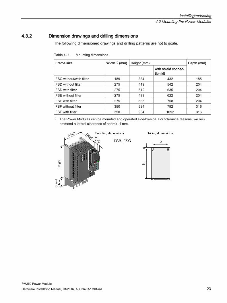
4.3.2 Dimension drawings and drilling dimensions The following dimensioned drawings and drilling patterns are not to scale.
Table 4- 1 Mounting dimensions
Frame size Width 1) (mm) Height (mm) Depth (mm) with shield connec-
tion kit FSC without/with filter 189 334 432 185 FSD without filter 275 419 542 204 FSD with filter 275 512 635 204 FSE without filter 275 499 622 204 FSE with filter 275 635 758 204 FSF without filter 350 634 792 316 FSF with filter 350 934 1092 316 1) The Power Modules can be mounted and operated side-by-side. For tolerance reasons, we rec-
ommend a lateral clearance of approx. 1 mm.
Installing/mounting 4.3 Mounting the Power Modules
PM250 Power Module 24 Hardware Installation Manual, 01/2016, A5E36265179B-AA
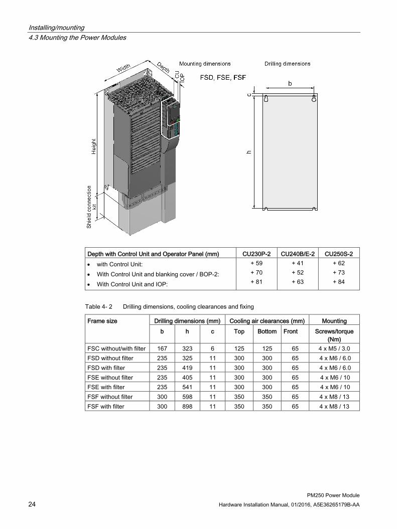
Depth with Control Unit and Operator Panel (mm) CU230P-2 CU240B/E-2 CU250S-2 • with Control Unit: • With Control Unit and blanking cover / BOP-2: • With Control Unit and IOP:
+ 59 + 70 + 81
+ 41 + 52 + 63
+ 62 + 73 + 84
Table 4- 2 Drilling dimensions, cooling clearances and fixing
Frame size Drilling dimensions (mm) Cooling air clearances (mm) Mounting b h c Top Bottom Front Screws/torque
(Nm) FSC without/with filter 167 323 6 125 125 65 4 x M5 / 3.0 FSD without filter 235 325 11 300 300 65 4 x M6 / 6.0 FSD with filter 235 419 11 300 300 65 4 x M6 / 6.0 FSE without filter 235 405 11 300 300 65 4 x M6 / 10 FSE with filter 235 541 11 300 300 65 4 x M6 / 10 FSF without filter 300 598 11 350 350 65 4 x M8 / 13 FSF with filter 300 898 11 350 350 65 4 x M8 / 13

Installing/mounting 4.4 Control Unit installation
PM250 Power Module Hardware Installation Manual, 01/2016, A5E36265179B-AA 25
4.4 Control Unit installation Plug the Control Unit onto the Power Module as shown in the diagram. By plugging on the Control Unit, you also establish all of the electrical connections between the Control Unit and the Power Module. Press the release button on the Power Module to remove the Control Unit.
4.5 Installing supplementary components Depending on the particular application, additional components may be required for your system. Information about additional components is provided in the following Sections:
Connection overview (Page 34)
Optional accessories (Page 70).

Installing/mounting 4.5 Installing supplementary components
PM250 Power Module 26 Hardware Installation Manual, 01/2016, A5E36265179B-AA
PM250 Power Module Hardware Installation Manual, 01/2016, A5E36265179B-AA 27
Connection 5
Install the inverters so that you are compliant with local regulations for erecting and installing low voltage systems.
Fundamental safety instructions (Page 9)
DANGER
Danger to life through electric shock due to the residual charge of the DC link capacitors
Because of the DC link capacitors, a hazardous voltage is present for up to 5 minutes after the power supply has been switched off.
Contact with live parts can result in death or serious injury. • Do not open the protective cover of the device until 5 minutes have elapsed. • Before starting any work, check that the system is in a voltage-free state by measuring
all terminals, also to ground. • Ensure that the associated warning plate in the appropriate language is attached.
Note Operating displays for inverter operation
If, when switching over a function from ON to OFF, an LED or other similar display is not lit or not active; this does not indicate that the device is switched-off or in a no-current condition.
Note Safety devices
Install suitable protective equipment between the line supply and inverter.
Technical specifications (Page 53)
You will find additional information on the Internet at:
To protect against indirectly touching part of the motor circuit of an inverter and to automatically shut down in the case of a fault according to DIN EN 60364-4-41 (VDE 0100-410). (http://support.automation.siemens.com/WW/view/en/103474630)

Connection
PM250 Power Module 28 Hardware Installation Manual, 01/2016, A5E36265179B-AA
WARNING
Danger to life due to fire or electric shock when using unsuitable residual current protection devices
The inverter can cause a current to flow in the protective conductor. This current can cause the residual current device (RCD) or residual current monitoring (RCM) to incorrectly trip (nuisance trip). In the case of a fault (ground fault), the fault current can contain a DC component, which prevents the RCD/RCM from tripping, with the risk of subsequent fault or electric shock. • Use the protection and monitoring devices recommended in the documentation.
CAUTION
Risk of injury due to hot surfaces
During operation and for a short time after the inverter shuts down, the surface of the device can reach a high temperature. • During this time, avoid any direct contact with the surface of the inverter.
Protection and monitoring equipment One of the following measures is suitable in order to ensure touch protection for the inverter:
● Isolated line supply (IT line supply) for frame sizes FSC … FSF: Create an isolated line supply for the inverter using an isolation transformer.
● Residual current device (RCD) or residual current monitoring (RCM) for frame size FSC: The equipment must satisfy the following properties and general conditions:
– super-resistant RCD/RCM type B, with a trip current of 300 mA. e.g. a SIQUENCE circuit breaker from Siemens.
– Only one inverter is supplied from each RCD/RCM
– The motor cables are shielded and are not longer than 50 m. You can find additional information on the motor cables in Length of motor cable (Page 34)
Note Fuses and residual current devices and/or monitoring devices
A residual current device (RCD) or residual current monitoring (RCM) does not replace the fuses listed in the Technical data.

Connection 5.1 Line and motor connection
PM250 Power Module Hardware Installation Manual, 01/2016, A5E36265179B-AA 29
5.1 Line and motor connection Note:
Arrangement of the line and motor terminals (Page 36).
EMC-compliant installation (Page 38).
The machine manufacturer must ensure that in operation the voltage drop between the transformer input terminals and the inverter when operated with its rated values is less than 1%.
5.1.1 Permissible line supplies
Note Restrictions for installation altitudes above 2000 m
Above an installation altitude of 2000 m, the permissible line supplies are restricted.
Restrictions for special ambient conditions (Page 61).
The inverter is designed for the following power distribution systems according to IEC 60364-1 (2005).
Connection 5.1 Line and motor connection
PM250 Power Module 30 Hardware Installation Manual, 01/2016, A5E36265179B-AA
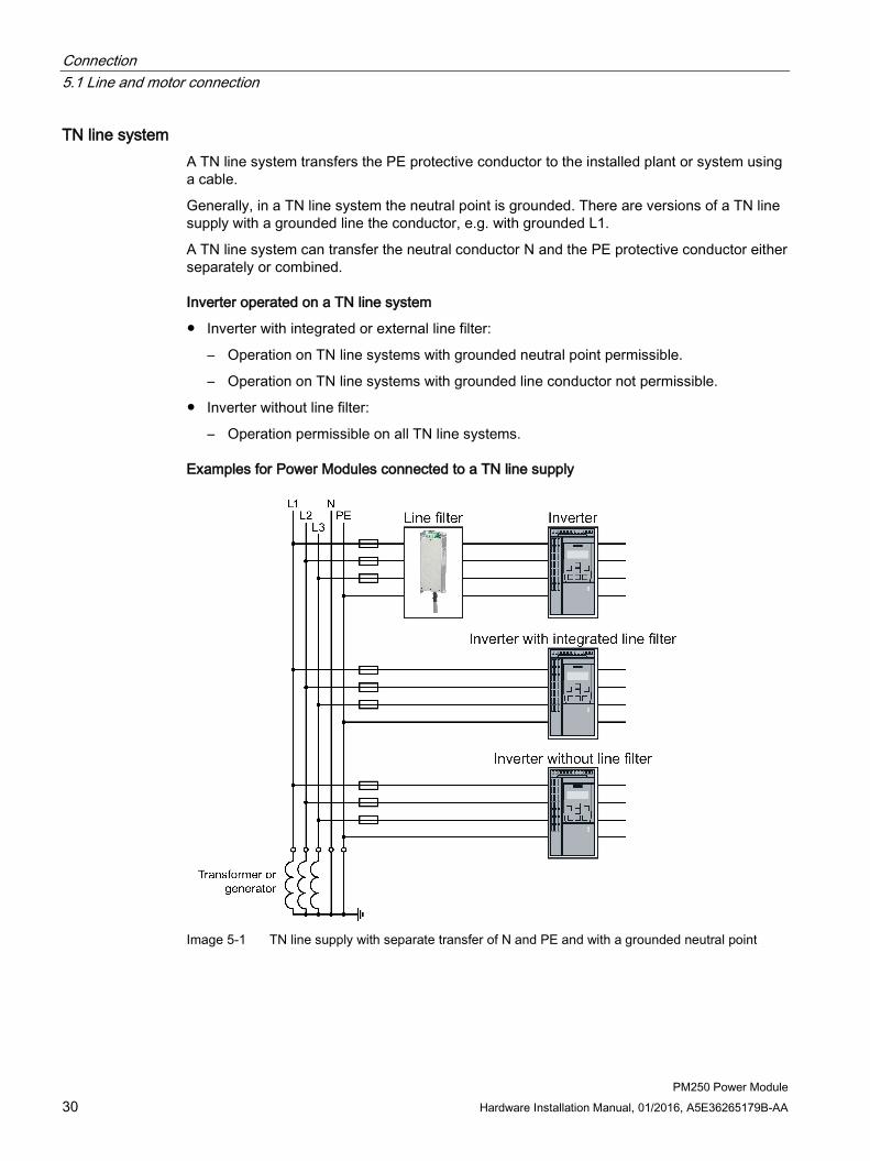
TN line system A TN line system transfers the PE protective conductor to the installed plant or system using a cable.
Generally, in a TN line system the neutral point is grounded. There are versions of a TN line supply with a grounded line the conductor, e.g. with grounded L1.
A TN line system can transfer the neutral conductor N and the PE protective conductor either separately or combined.
Inverter operated on a TN line system
● Inverter with integrated or external line filter:
– Operation on TN line systems with grounded neutral point permissible.
– Operation on TN line systems with grounded line conductor not permissible.
● Inverter without line filter:
– Operation permissible on all TN line systems.
Examples for Power Modules connected to a TN line supply
Image 5-1 TN line supply with separate transfer of N and PE and with a grounded neutral point

Connection 5.1 Line and motor connection
PM250 Power Module Hardware Installation Manual, 01/2016, A5E36265179B-AA 31
TT line system In a TT line system, the transformer grounding and the installation grounding are independent of one another.
There are TT line supplies where the neutral conductor N is either transferred – or not.
Inverter operated on a TT line system
● Inverter with integrated or external line filter:
– Operation on TT line systems with grounded neutral point permissible.
– Operation on TT line systems without grounded neutral point not permissible.
● Inverter without line filter:
– Operation on all TT line systems permissible.
● For installations in compliance with IEC, operation on a TT line system is permissible. For installations in compliance with UL, operation on a TT line system is not permissible.
Examples for Power Modules connected to a TT line supply
Image 5-2 TT line system with neutral conductor N and with grounded neutral point

Connection 5.1 Line and motor connection
PM250 Power Module 32 Hardware Installation Manual, 01/2016, A5E36265179B-AA
IT system In an IT line system, all of the conductors are insulated with respect to the PE protective conductor – or connected to the PE protective conductor through an impedance.
There are IT line supplies where the neutral conductor N is either transferred – or not.
Inverter operated on an IT line system
● Inverters with integrated line filter:
– Operation on IT line systems not permissible.
● Inverter without line filter:
– Operation on all IT line systems permissible.
Example of a Power Module connected to an IT line system
Image 5-3 IT line supply where the neutral conductor N is transferred and with impedance with
respect to the PE protective conductor
Behavior of the inverter when a ground fault occurs
In some instances, even for a ground fault, the inverter should still remain functional. In cases such as these, you must install an output reactor. This prevents an overcurrent trip or damage to the drive.
5.1.2 Dimensioning the protective conductor
WARNING
Danger to life caused by high leakage currents for an interrupted protective conductor
The drive components conduct a high leakage current via the protective conductor. Touching conductive parts when the protective conductor is interrupted can result in death or serious injury. • Lay the protective conductor as specified.
Connection 5.1 Line and motor connection
PM250 Power Module Hardware Installation Manual, 01/2016, A5E36265179B-AA 33
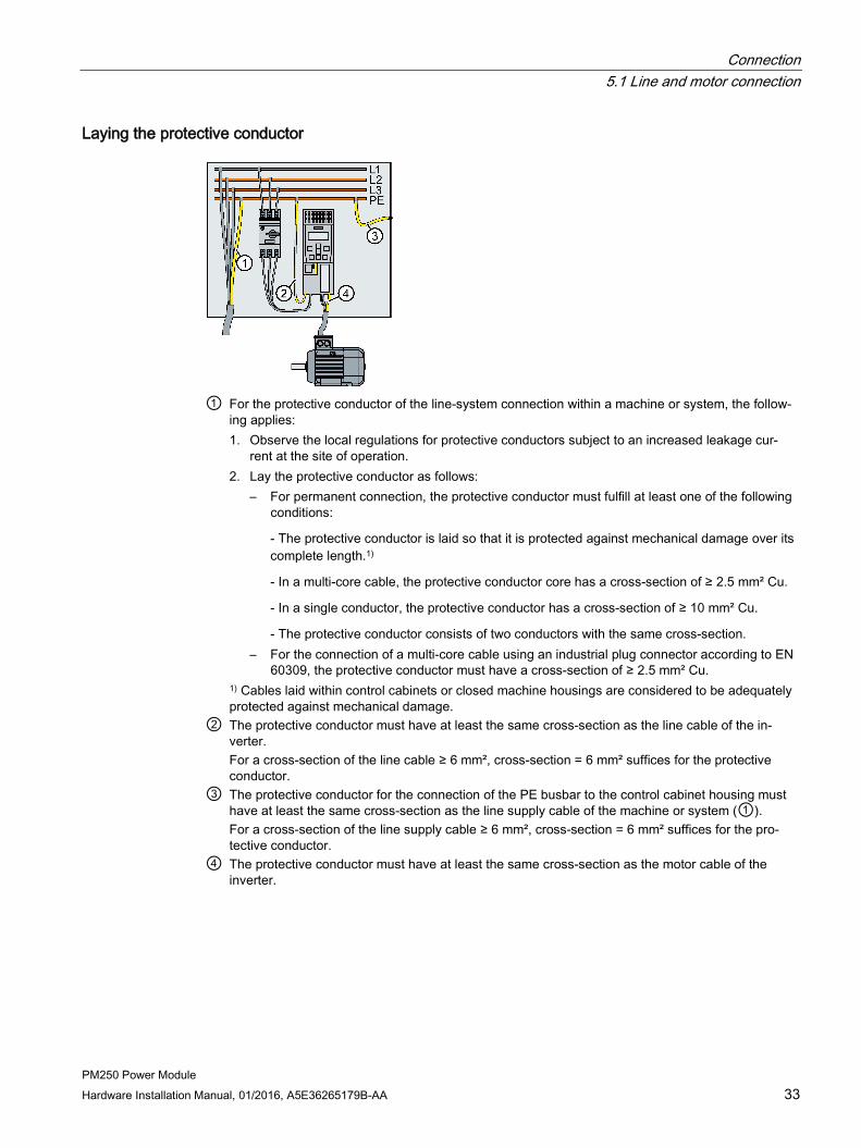
Laying the protective conductor
① For the protective conductor of the line-system connection within a machine or system, the follow-
ing applies: 1. Observe the local regulations for protective conductors subject to an increased leakage cur-
rent at the site of operation. 2. Lay the protective conductor as follows:
– For permanent connection, the protective conductor must fulfill at least one of the following conditions:
- The protective conductor is laid so that it is protected against mechanical damage over its complete length.1)
- In a multi-core cable, the protective conductor core has a cross-section of ≥ 2.5 mm² Cu.
- In a single conductor, the protective conductor has a cross-section of ≥ 10 mm² Cu.
- The protective conductor consists of two conductors with the same cross-section. – For the connection of a multi-core cable using an industrial plug connector according to EN
60309, the protective conductor must have a cross-section of ≥ 2.5 mm² Cu. 1) Cables laid within control cabinets or closed machine housings are considered to be adequately protected against mechanical damage.
② The protective conductor must have at least the same cross-section as the line cable of the in-verter. For a cross-section of the line cable ≥ 6 mm², cross-section = 6 mm² suffices for the protective conductor.
③ The protective conductor for the connection of the PE busbar to the control cabinet housing must have at least the same cross-section as the line supply cable of the machine or system (①). For a cross-section of the line supply cable ≥ 6 mm², cross-section = 6 mm² suffices for the pro-tective conductor.
④ The protective conductor must have at least the same cross-section as the motor cable of the inverter.
Connection 5.1 Line and motor connection
PM250 Power Module 34 Hardware Installation Manual, 01/2016, A5E36265179B-AA
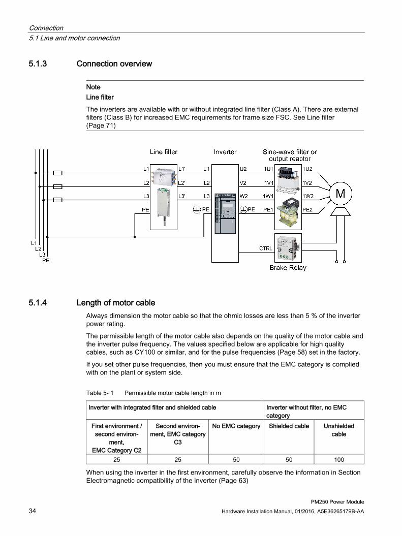
5.1.3 Connection overview
Note Line filter
The inverters are available with or without integrated line filter (Class A). There are external filters (Class B) for increased EMC requirements for frame size FSC. See Line filter (Page 71)
5.1.4 Length of motor cable Always dimension the motor cable so that the ohmic losses are less than 5 % of the inverter power rating.
The permissible length of the motor cable also depends on the quality of the motor cable and the inverter pulse frequency. The values specified below are applicable for high quality cables, such as CY100 or similar, and for the pulse frequencies (Page 58) set in the factory.
If you set other pulse frequencies, then you must ensure that the EMC category is complied with on the plant or system side.
Table 5- 1 Permissible motor cable length in m
Inverter with integrated filter and shielded cable Inverter without filter, no EMC category
First environment / second environ-
ment, EMC Category C2
Second environ-ment, EMC category
C3
No EMC category Shielded cable Unshielded cable
25 25 50 50 100
When using the inverter in the first environment, carefully observe the information in Section Electromagnetic compatibility of the inverter (Page 63)
Connection 5.1 Line and motor connection
PM250 Power Module Hardware Installation Manual, 01/2016, A5E36265179B-AA 35
When using an output reactor or sine-wave filter, the following cable lengths (m) are permissible:
Table 5- 2 Permissible length of the motor cable in m with output reactor or sine-wave filter
Frame size Output reactor Sine-wave filter Shielded cable Unshielded cable Shielded cable Unshielded cable
FSC 100 150 200 300 FSD … FSF 200 300 200 300
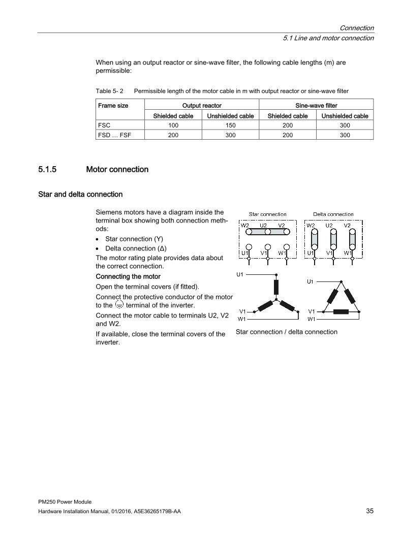
5.1.5 Motor connection
Star and delta connection Siemens motors have a diagram inside the terminal box showing both connection meth-ods: • Star connection (Y) • Delta connection (Δ) The motor rating plate provides data about the correct connection. Connecting the motor Open the terminal covers (if fitted). Connect the protective conductor of the motor to the terminal of the inverter. Connect the motor cable to terminals U2, V2 and W2. If available, close the terminal covers of the inverter.
Star connection / delta connection
Connection 5.1 Line and motor connection
PM250 Power Module 36 Hardware Installation Manual, 01/2016, A5E36265179B-AA
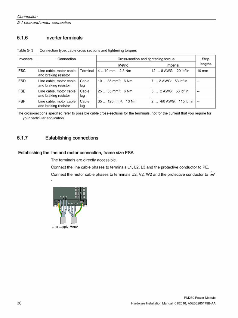
5.1.6 Inverter terminals
Table 5- 3 Connection type, cable cross sections and tightening torques
Inverters Connection Cross-section and tightening torque Strip lengths Metric Imperial
FSC Line cable, motor cable and braking resistor
Terminal 4 …10 mm: 2.3 Nm 12 … 8 AWG: 20 lbf in 10 mm
FSD Line cable, motor cable and braking resistor
Cable lug
10 … 35 mm2: 6 Nm 7 … 2 AWG: 53 lbf in --
FSE Line cable, motor cable and braking resistor
Cable lug
25 … 35 mm2: 6 Nm 3 … 2 AWG: 53 lbf in
--
FSF Line cable, motor cable and braking resistor
Cable lug
35 … 120 mm2: 13 Nm 2 … 4/0 AWG: 115 lbf in
--
The cross-sections specified refer to possible cable cross-sections for the terminals, not for the current that you require for your particular application.
5.1.7 Establishing connections
Establishing the line and motor connection, frame size FSA The terminals are directly accessible.
Connect the line cable phases to terminals L1, L2, L3 and the protective conductor to PE.
Connect the motor cable phases to terminals U2, V2, W2 and the protective conductor to .

Connection 5.1 Line and motor connection
PM250 Power Module Hardware Installation Manual, 01/2016, A5E36265179B-AA 37
Establishing the line and motor connection, frame sizes FSD … FSF The terminals for the line and motor connection have covers to provide touch protection.
1. To connect up, release the catches on both sides of the terminal covers using a screwdriver
2. Lift up the covers as shown in the diagram.
3. Connect the line cable phases to L1, L2, L3 and the protective conductor to PE.
4. Connect the motor cable phases to U2, V2, W2 and the protective conductor to .
5. Close the covers once you have established the connections.
Connection rules for Power Modules, FSD … FSF The power connection covers must be closed in order that degree of protection IP20 is maintained. Connect the line and motor cable to the inverter using ring-shaped cable lugs according to DIN 462. A suitable ring-shaped cable lug is shown at the left in the dia-gram, and an unsuitable standard cable lug is shown at the right.

Connection 5.2 EMC-compliant installation
PM250 Power Module 38 Hardware Installation Manual, 01/2016, A5E36265179B-AA
5.2 EMC-compliant installation
5.2.1 Avoiding electromagnetic interference Only the concurrent use of filtering, grounding and shielding ensure an installation in accordance with the EMC requirements.
The next sections cover all of the most important rules for the installation of inverter and drive systems.
5.2.2 Avoiding electromagnetic influence (EMI) The inverters are designed for operation in industrial environments where high values of EMI are expected. Safe, reliable and disturbance-free operation is only guaranteed if the devices are installed by appropriately trained and qualified personnel.
Control cabinet design ● Establish all of the connections so that they are durable.
● Connect the metallic parts and components of the control cabinet to the frame of the cabinet through a good electrical connection.
– Side panels
– Rear panels
– Cover plate
– Base plates
Use the largest possible contact area or many individual screw connections.
● Connect the PE bar and the EMC shield bar to the control cabinet frame through a good electrical connection established through a large surface area.
● Connect all metal enclosures of the components installed in the cabinet with the control cabinet frame through a large surface area to ensure a good electrical connection. To achieve this, mount the components on a bare metal surface and mounting plate with good conductivity, which you then connect to the control cabinet frame through the largest possible surface area to establish a good connection, especially with the PE and EMC shield bars.
● For screw connections onto painted or anodized surfaces, establish a good conductive contact using one of the following methods:
– Use special (serrated) contact washers that cut through the painted or anodized surface.
– Remove the insulating coating at the contact locations.

Connection 5.2 EMC-compliant installation
PM250 Power Module Hardware Installation Manual, 01/2016, A5E36265179B-AA 39
● Equip the following components with interference suppression elements:
– Coils of contactors
– Relays
– Solenoid valves
– Motor holding brakes
Interference suppression elements include RC elements or varistors for AC-operated coils and freewheeling diodes for DC-operated coils.
Connect the interference suppression element directly at the coil.
Radio interference suppression ● Connect interference suppressors to all contactors, relays, solenoid valves and motor
holding brakes directly at the coil in order to dampen high-frequency radiation when these devices are switched off. Use RC elements or varistors for AC-operated coils and freewheeling diodes or varistors for DC-operated coils.
Cable routing and shielding
Cables in the control cabinet
● Route the power cables of the drive so that there is a minimum clearance of 25 cm to signal and data cables. Power cables are line, DC link and motor cables – as well as connecting cables between the Braking Module and braking resistor. Alternatively, implement the separation using metal partitions connected to the mounting plate through a good electrical connection.
● Route power cables with low noise levels separately from power cables with high noise levels
– Power cables with low noise level: - line cables from the line to the line filter
– Power cables with high noise level: - cables between the line filter and inverter - DC link cables - cables between the Braking Module and braking resistor - motor cables
● Route the cables so that signal and data cables as well as power cables with low noise level only cross power cables with a high noise level at right angles.
● Keep all cables as short as possible.
● Route the cables as close as possible to grounded enclosure parts such as mounting plates or the cabinet frame.
● Route signal and data cables as well as the associated equipotential bonding cables parallel and as close to one another as possible.
● Connect the cable shields as closely as possible to the point where the cable enters the control cabinet.
Connection 5.2 EMC-compliant installation
PM250 Power Module 40 Hardware Installation Manual, 01/2016, A5E36265179B-AA
● Connect the shields to the grounded enclosure at both ends with a good electrical connection through the largest possible surface area.
● Route incoming and outgoing cables/conductors within a zone (where unshielded single-conductor cables are used), twisted or in parallel and as close to one another as possible.
● Ground any unused conductors of signal and data cables at both ends.
● Signal and data cables should enter the cabinet only at one point (e.g. from below).
Cables outside the control cabinet
● Route the power cables of the drive so that there is a minimum clearance of 25 cm to signal and data cables.
● Use shielded motor cables.
● Use shielded signal and data cables.
● Route the shielded motor cable separately from the cables to the motor temperature sensors.
Cable shields
● For shielded cables, only use cables with finely-stranded, braided shields.
● Connect the shield at the grounded enclosure as well as at the EMC shield bar.
– Connect the shields to the grounded enclosures through a large surface area at both ends of the cables to establish a low ohmic connection. Attach the shields to the appropriate EMC shield bars.
– Immediately after the cable enters the cabinet, connect the cable shields to the EMC shield bar through a larger surface area to establish a low ohmic conduction.
● If possible, always route the cable shields without any interruptions.
● Only use metallic or metallized connectors for the plug connections for shielded data cables (e.g. PROFIBUS connection).
Further information You can find additional information about the EMC installation guidelines under (https://support.industry.siemens.com/cs/ww/de/view/60612658/en):

Connection 5.2 EMC-compliant installation
PM250 Power Module Hardware Installation Manual, 01/2016, A5E36265179B-AA 41
5.2.3 Installing the converter in compliance with EMC rules
Rules for cable installation to ensure EMC ● Install the inverter on a metal mounting plate. The mounting plate must be unpainted and
highly electrically conductive.
● Use shielded cables for the following connections:
– Motor and motor temperature sensor
– Braking resistor (not available for all inverters)
– Fieldbus
– Inputs and outputs of the terminal strip
● Connect the cable shields to ensure EMC:
Image 5-4 Examples of correct EMC-compliant shield connection
Example EMC-compliant wiring for connecting the line supply and motor - as well as for the Control Unit.
① Line feeder cable - non-shielded - with strain relief using cable ties
② shielded motor cable with hose clamp for shielding and strain relief
③ Shielded cable for the Control Unit with shielding using a serrated strip on the CU shield plate.

Connection 5.2 EMC-compliant installation
PM250 Power Module 42 Hardware Installation Manual, 01/2016, A5E36265179B-AA
5.2.4 EMC-compliant cabinet design The most cost-effective method of implementing interference suppression measures within the control cabinet is to ensure that interference sources and interference sinks are spatially separated.
EMC zone concept within the control cabinet Split up the complete control cabinet into EMC zones.
Electromagnetically decouple the zones from one another, either using large clearances (approximately 25 cm) – or using a separate metal enclosure or sheet metal partition with a large surface area. Assign the various devices to zones in the control cabinet.
• Zone A: Line supply connection Limit values for conducted interference emission and interference immunity must not be exceeded.
• Zone B: Power electronics Sources of interference
• Zone C: Controller and sensors Interference sinks Zone D: Motor, braking resistor and corresponding cables Sources of interference
Classification of the control cabinet or the drive system into EMC zones
Non-shielded cables can be used within a zone. It is not permissible to route cables of various zones in common cable harnesses or common cable ducts.
If necessary, you must use filters and/or coupling modules at the interfaces of the zones.
Use shielded cables for all communication and signal cables that exit the control cabinet. Connect the shields to the cabinet ground through a large surface area and low ohmic connection. Ensure that there are no potential differences between these zones, to avoid inadmissibly high equalization currents flowing through the cable shields.

Connection 5.2 EMC-compliant installation
PM250 Power Module Hardware Installation Manual, 01/2016, A5E36265179B-AA 43
5.2.5 Equipotential bonding
Grounding measures Proceed as follows to ground the drive system:
● For several cabinets, install a common PE bar for all cabinet elements
● Connect all of the drive system components to the PE conductor
● Connect the PE conductor to the PE bar of the control cabinet.
Measures for high frequency equipotential bonding Proceed as follows, to ensure high-frequency equipotential bonding:
● Connect the metallic components in the control cabinet to the PE bar and the EMC bar through a larger surface area so that a good electrical connection is established.
– Either through a large surface area between the metal contact surfaces of the cabinet components with a minimum cross-section of several cm² for each contact location.
– Or, alternatively using short, finely stranded, braided copper wires with cross-sections ≥ 95 mm² / 000 (3/0) (-2) AWG.
● In plants and systems with several cabinet elements, screw the frames of the individual cabinet elements at several locations to one another using serrated washers to establish a good electrical connection.
● In plants and systems with very long rows of cabinets, which are installed in two groups back to back, connect the PE bars of the two cabinet groups at as many locations as possible.
● Therefore, connect the protective ground conductor and the cable shield to the motor and the inverter.
Additional measures for high frequency equipotential bonding Route finely stranded or braided copper conductors in parallel to the motor cable with the shortest possible distance between them:
● in older systems with already existing unshielded cables
● for cables with poor high-frequency properties of the shield
● for poor grounding systems

Connection 5.2 EMC-compliant installation
PM250 Power Module 44 Hardware Installation Manual, 01/2016, A5E36265179B-AA
Diagrams for grounding and high-frequency equipotential bonding measures The following diagram illustrates all grounding and high-frequency equipotential bonding measures using the example of a cabinet with a SINAMICS G120.
Grounding measures ① Conventional grounding without any special HF properties High-frequency equipotential bonding measures ② Electrically conductive connection to the mounting panel through the largest possible surface ③ HF equipotential bonding ④ Connect the shield through a large contact surface and ground ⑤ Connect the shield through an electrically conductive heavy-gauge threaded joint (gland) and
ground
Image 5-5 Grounding and high-frequency equipotential bonding measures in the drive system and in the plant
Connection 5.2 EMC-compliant installation
PM250 Power Module Hardware Installation Manual, 01/2016, A5E36265179B-AA 45
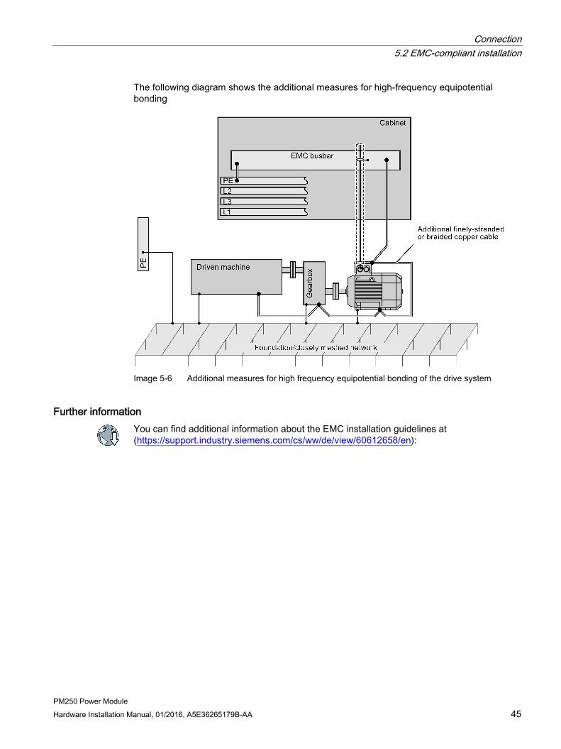
The following diagram shows the additional measures for high-frequency equipotential bonding
Image 5-6 Additional measures for high frequency equipotential bonding of the drive system
Further information You can find additional information about the EMC installation guidelines at (https://support.industry.siemens.com/cs/ww/de/view/60612658/en):

Connection 5.2 EMC-compliant installation
PM250 Power Module 46 Hardware Installation Manual, 01/2016, A5E36265179B-AA
PM250 Power Module Hardware Installation Manual, 01/2016, A5E36265179B-AA 47
Operation, service and maintenance 6 6.1 Operation
Voltage dips and brief power interruptions For Power Modules, frame sizes FSD … FSF, voltage dips or power interruptions of up to 3 ms can cause the inverter to be shut down with fault F30003 or F30027.
You can restart the inverter by acknowledging the fault using OFF1 and then entering a new ON command.
Alternatively, activate the automatic restart. You can find details in the Control Unit operating instructions in Chapter "Advanced commissioning".
Overview of the manuals (Page 85).
WARNING
Risk of fire or electric shock as a result of defective components
If a cable protection element responds, this can indicate that a fault current was interrupted.
Check the circuit components and all of the components of the inverter and replace defective parts and components to reduce the risk of a fire or an electric shock.
Repair
WARNING
Danger due to incorrect repair
Repairs may only be carried out by Siemens Service, by repair centers authorized by Siemens or by authorized personnel who are thoroughly acquainted with all the warnings and operating procedures contained in this manual. • Only use original spare parts when carrying out repairs.

Operation, service and maintenance 6.2 Maintenance
PM250 Power Module 48 Hardware Installation Manual, 01/2016, A5E36265179B-AA
6.2 Maintenance The purpose of maintenance is to maintain the specified condition of the Power Module. Regularly remove dirt and pollution, and replace the fan in plenty of time. Replacing fans (Page 49)
Cleaning Clean the inverter with an anti-static brush, a vacuum cleaner and areas that are difficult to access, using dry compressed air (max. 1 bar).
Ventilation The devices must be installed in a cabinet. Ensure that the cabinet's ventilation slots are not blocked. Check that the fan is functioning correctly.
Cables and screw terminals Regularly check the cables for damage, and immediately replace any defective parts.
Regularly check that the screw terminals have been correctly tightened. Retighten the screws if necessary.
Note
The actual maintenance intervals depend on the installation and operating conditions.
Siemens offers its customers support in the form of service contracts. For further information, contact your Siemens regional office or sales office.
Operation, service and maintenance 6.3 Replacing fans
PM250 Power Module Hardware Installation Manual, 01/2016, A5E36265179B-AA 49
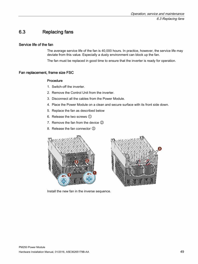
6.3 Replacing fans
Service life of the fan The average service life of the fan is 40,000 hours. In practice, however, the service life may deviate from this value. Especially a dusty environment can block up the fan.
The fan must be replaced in good time to ensure that the inverter is ready for operation.
Fan replacement, frame size FSC
Procedure
1. Switch-off the inverter.
2. Remove the Control Unit from the inverter.
3. Disconnect all the cables from the Power Module.
4. Place the Power Module on a clean and secure surface with its front side down.
5. Replace the fan as described below
6. Release the two screws ①
7. Remove the fan from the device ②
8. Release the fan connector ③
Install the new fan in the inverse sequence.

Operation, service and maintenance 6.3 Replacing fans
PM250 Power Module 50 Hardware Installation Manual, 01/2016, A5E36265179B-AA
Fan replacement, frame sizes FSD and FSE:
Procedure
1. Switch the inverter off.
2. Disconnect all the cables from the Power Module.
3. Release the fan cover catches ⑤
4. Release and remove the fan cover ②, ③
5. Remove the fan connector ③
6. Release the fan catches ⑤
7. Remove the fan from the device ②
Install the new fan in the inverse sequence.
Operation, service and maintenance 6.3 Replacing fans
PM250 Power Module Hardware Installation Manual, 01/2016, A5E36265179B-AA 51
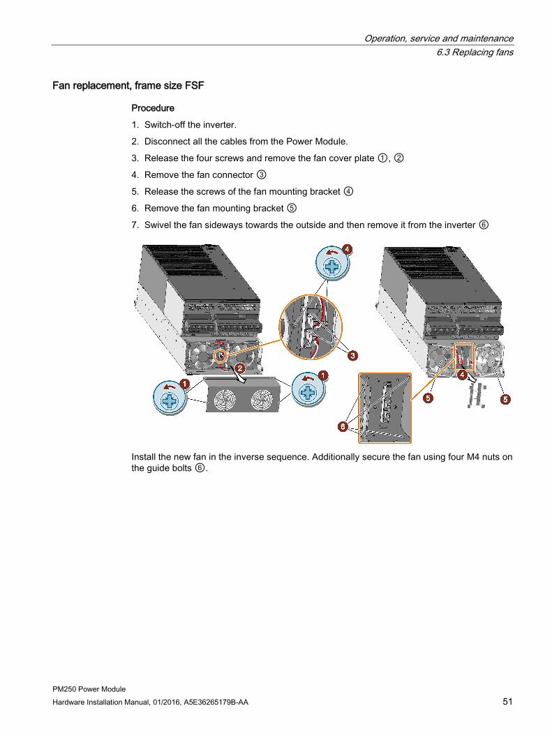
Fan replacement, frame size FSF
Procedure
1. Switch-off the inverter.
2. Disconnect all the cables from the Power Module.
3. Release the four screws and remove the fan cover plate ①, ②
4. Remove the fan connector ③
5. Release the screws of the fan mounting bracket ④
6. Remove the fan mounting bracket ⑤
7. Swivel the fan sideways towards the outside and then remove it from the inverter ⑥
Install the new fan in the inverse sequence. Additionally secure the fan using four M4 nuts on the guide bolts ⑥.

Operation, service and maintenance 6.3 Replacing fans
PM250 Power Module 52 Hardware Installation Manual, 01/2016, A5E36265179B-AA

PM250 Power Module Hardware Installation Manual, 01/2016, A5E36265179B-AA 53
Technical specifications 7
Power loss of the Power Modules The power loss values specified are typical values. You will find further information on the Internet at: Power loss data for partial load operation (https://support.industry.siemens.com/cs/ww/en/view/94059311)
7.1 Overload capability of the inverter Overload capability is the property of the inverter to temporarily supply a current that is higher than the rated current to accelerate a load. Two typical load cycles are defined to clearly demonstrate the overload capability: "Low Overload" and "High Overload"
Definitions
Base load
Constant load between the accelerating phases of the drive Low Overload High Overload • LO base load input current
Permissible input current for a "Low Overload" load cycle
• LO base load output current Permissible output current for a "Low Overload" load cycle
• LO base load power Rated power based on the LO base load output current
• HO base load input current Permissible input current for a "High Overload" load cycle
• HO base load output current Permissible output current for a "High Overload" load cycle
• HO base load power Rated power based on the HO base load output current
If not specified otherwise, the power and current data in the technical data always refer to a load cycle according to Low Overload.
We recommend the "SIZER" engineering software to select the inverter.
You will find additional information about SIZER on the Internet: Download SIZER (http://support.automation.siemens.com/WW/view/en/10804987/130000).

Technical specifications 7.1 Overload capability of the inverter
PM250 Power Module 54 Hardware Installation Manual, 01/2016, A5E36265179B-AA
Load cycles and typical applications: "Low Overload" load cycle "High Overload" load cycle The "Low Overload" load cycle assumes a uniform base load with low requirements placed on brief accelerating p phases. Typi-cal applications when designing according to "Low Overload" include: • Pumps, fans and compressors • Wet or dry blasting technology • Mills, mixers, kneaders, crushers,
agitators • Basic spindles • Rotary kilns • Extruders
The "High Overload" load cycle permits, for reduced base load, dynamic accelerating phases. Typical applications when desig-ning according to "High Overload" include: • Horizontal and vertical conveyor
technology (conveyor belts, roller conveyors, chain conveyors)
• Centrifuges • Escalators/moving stairways • Lifters/Lowerers • Elevators • Gantry cranes • Cable railways • Storage and retrieval machines
Typical inverter load cycles
Technical specifications 7.2 Cable cross-sections and tightening torques
PM250 Power Module Hardware Installation Manual, 01/2016, A5E36265179B-AA 55
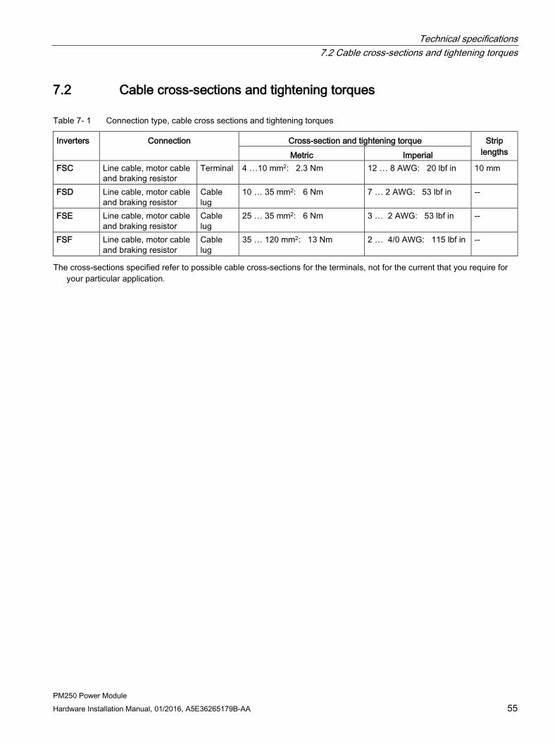
7.2 Cable cross-sections and tightening torques
Table 7- 1 Connection type, cable cross sections and tightening torques
Inverters Connection Cross-section and tightening torque Strip lengths Metric Imperial
FSC Line cable, motor cable and braking resistor
Terminal 4 …10 mm2: 2.3 Nm 12 … 8 AWG: 20 lbf in 10 mm
FSD Line cable, motor cable and braking resistor
Cable lug
10 … 35 mm2: 6 Nm 7 … 2 AWG: 53 lbf in --
FSE Line cable, motor cable and braking resistor
Cable lug
25 … 35 mm2: 6 Nm 3 … 2 AWG: 53 lbf in --
FSF Line cable, motor cable and braking resistor
Cable lug
35 … 120 mm2: 13 Nm 2 … 4/0 AWG: 115 lbf in --
The cross-sections specified refer to possible cable cross-sections for the terminals, not for the current that you require for your particular application.

Technical specifications 7.3 General data
PM250 Power Module 56 Hardware Installation Manual, 01/2016, A5E36265179B-AA
7.3 General data
Property Version Line voltage 3-phase 380 … 480 VAC ± 10% Output voltage 3-phase 0 VAC … input voltage x 0.87 (max.) Input frequency 50 Hz … 60 Hz, ± 3 Hz Output frequency 0 … 550 Hz, depending on the control mode Power factor λ 0.9 Inrush current < LO base load input current Pulse frequency (factory setting)
4 kHz The pulse frequency can be adjusted up to 16 kHz in 2 kHz steps. The higher the pulse frequency, the lower the available output current.
Current derating depending on the pulse frequency (Page 60) Electromagnetic compatibili-ty
The devices comply with EN 61800-3: 2004 suitable for Category C2 and C3 environments.
Braking methods DC braking, energy recovery (up to 100% of the output power) Degree of protection IP20 built-in devices (they must be installed in an electrical cabinet) Environmental conditions for transport in the transport packaging Climatic environmental conditions
The device is suitable for temperatures that conform with 2K4 according to EN 60721-3-2 in the range -40° … +70° C
Mechanical environmental conditions (shocks and vibrations)
The device is suitable for operation in mechanical environmental conditions that conform with 2M3 according to EN 60721-3-2
Protection against chemical substances
The device is protected against damaging chemical substances that conform with 2C2 ac-cording to EN 60721-3-2
Biological environmental conditions
The device is suitable for operation in biological environmental conditions that conform with 2B2 according to EN 60721-3-2
Environmental conditions for long-term storage in the product packaging Climatic environmental conditions
The device is suitable for temperatures that conform with 1K4 according to EN 60721-3-1 in the range -25° … +55° C
Mechanical environmental conditions (shocks and vibrations)
The device is suitable for operation in mechanical environmental conditions that conform with 1M2 according to EN 60721-3-1
Protection against chemical substances
The device is protected against damaging chemical substances that conform with 1C2 ac-cording to EN 60721-3-1
Biological environmental conditions
The device is suitable for operation in biological environmental conditions that conform with 1B2 according to EN 60721-3-1
Environmental conditions during operation
Installation altitude Restrictions for spe-cial ambient conditions (Page 61)
without derating: with derating:
up to 1000 m above sea level up to 4000 m above sea level

Technical specifications 7.3 General data
PM250 Power Module Hardware Installation Manual, 01/2016, A5E36265179B-AA 57
Property Version Climatic environmental conditions
Better than 3K3 according to EN 60721-3-3 • Temperature range without derating 1)
– LO base load power 0 °C … +40 °C – HO base load power: 0° C … +50° C
• Temperature range with derating 1) – LO/HO base load power: 0 °C … +60 °C
Restrictions for special ambient conditions (Page 61) • Relative humidity: 5 … 95%, condensation not permitted • Oil mist, salt mist, ice formation, condensation, dripping water, spraying water, splashing
water and water jets are not permitted
Mechanical environmental conditions (shocks and vibrations)
The device is suitable for operation in mechanical environmental conditions that conform with 3M1 according to EN 60721-3-3 • Vibration test according to IEC 60068-2-6 with 10 vibration cycles per axis
– in the range 10 Hz … 57Hz with a deflection of 0.075 mm – in the range 57 Hz … 150Hz with an acceleration of 1 g
• Shock resistance according to IEC 60068-2-27 with three impulses per axis in both direc-tions – Peak acceleration: 5 g – Duration: 30 ms
Protection against chemical substances
protected against damaging chemical substances that conform with 3C2 according to EN 60721-3-3
Biological environmental conditions
suitable for operation in biological environmental conditions that conform with 3C2 according to EN 60721-3-3
Cooling air clean and dry air Pollution suitable for environments with degree of pollution 2 according to EN 61800-5-1, condensa-
tion not permitted Approvals UL, cUL, CE, c-tick, SEMI F47.
The drive only satisfies the UL requirements when UL-certified fuses are used.

Technical specifications 7.4 Power-dependent data
PM250 Power Module 58 Hardware Installation Manual, 01/2016, A5E36265179B-AA
7.4 Power-dependent data
Note
The values for Low Overload (LO) are identical with those of the rated values.
Table 7- 2 PM250, IP20, frame sizes C, 3 AC 380 V … 480 V
Article No. - with filter 6SL3225-… 0BE25-5AA1 0BE27-5AA1 0BE31-1AA1 LO base load power LO base load input current LO base load output current
7.5 kW 18 A 18 A
11 kW 25 A 25 A
15 kW 32 A 32 A
HO base load power HO base load input current HO base load output current
5. 5 kW 13.2 A 13.2 A
7.5 kW 19 A 19 A
11 kW 26 A 26 A
Fuse 20 A, Class J 32 A, Class J 35 A, Class J Power loss 0.24 kW 0.30 kW 0.31 kW Required cooling air flow 38 l/s 38 l/s 38 l/s Tightening torque for line and motor cables 2.3 Nm / 20 lbf in 2.3 Nm / 20 lbf in 2.3 Nm / 20 lbf in Weight 7.5 kg 7.5 kg 7.5 kg
Table 7- 3 PM250, IP20, frame sizes D, 3 AC 380 V … 480 V
Article No. - with filter 6SL3225-… 0BE31-5AA0 0BE31-8AA0 0BE32-2AA0 LO base load power LO base load input current LO base load output current
18.5 kW 36 A 38 A
22 kW 42 A 45 A
30 kW 56 A 60 A
HO base load power HO base load input current HO base load output current
15 kW 30 A 32 A
18.5 kW 36 A 38 A
22 kW 42 A 45 A
Fuse according to IEC Fuse according to UL
3NA3820 50 A, Class J 3NE1817-0
3NA3822 63 A, Class J 3NE1818-0
3NA3824 80 A, Class J 3NE1820-0
Power loss 0.44 kW 0.55 kW 0.72 kW Required cooling air flow 22 l/s 22 l/s 39 l/s Tightening torque for line and motor cables 6 Nm / 53 lbf in 6 Nm / 53 lbf in 6 Nm / 53 lbf in Weight 15 kg 15 kg 16 kg
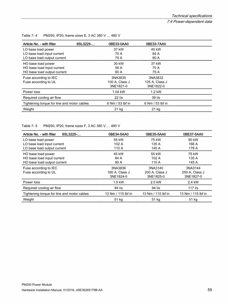
Technical specifications 7.4 Power-dependent data
PM250 Power Module Hardware Installation Manual, 01/2016, A5E36265179B-AA 59
Table 7- 4 PM250, IP20, frame sizes E, 3 AC 380 V … 480 V
Article No. - with filter 6SL3225-… 0BE33-0AA0 0BE33-7AA0 LO base load power LO base load input current LO base load output current
37 kW 70 A 75 A
45 kW 84 A 90 A
HO base load power HO base load input current HO base load output current
30 kW 56 A 60 A
37 kW 70 A 75 A
Fuse according to IEC Fuse according to UL
3NA3830 100 A, Class J
3NE1821-0
3NA3832 125 A, Class J
3NE1822-0
Power loss 1.04 kW 1.2 kW Required cooling air flow 22 l/s 39 l/s Tightening torque for line and motor cables 6 Nm / 53 lbf in 6 Nm / 53 lbf in Weight 21 kg 21 kg
Table 7- 5 PM250, IP20, frame sizes F, 3 AC 380 V … 480 V
Article No. - with filter 6SL3225-… 0BE34-5AA0 0BE35-5AA0 0BE37-5AA0 LO base load power LO base load input current LO base load output current
55 kW 102 A 110 A
75 kW 135 A 145 A
90 kW 166 A 178 A
HO base load power HO base load input current HO base load output current
45 kW 84 A 90 A
55 kW 102 A 110 A
75 kW 135 A 145 A
Fuse according to IEC Fuse according to UL
3NA3836 160 A, Class J
3NE1824-0
3NA3140 200 A, Class J
3NE1825-0
3NA3144 250 A, Class J
3NE1827-0 Power loss 1.5 kW 2.0 kW 2.4 kW Required cooling air flow 94 l/s 94 l/s 117 l/s Tightening torque for line and motor cables 13 Nm / 115 lbf in 13 Nm / 115 lbf in 13 Nm / 115 lbf in Weight 51 kg 51 kg 51 kg

Technical specifications 7.4 Power-dependent data
PM250 Power Module 60 Hardware Installation Manual, 01/2016, A5E36265179B-AA
7.4.1 Current derating depending on the pulse frequency Article number 6SL3225-…
LO base load power
LO baseload output current [A] at a pulse frequency of… 4 kHz 6 kHz 8 kHz 10 kHz 12 kHz 14 kHz 16 kHz
-0BE25-5AA0 7.5 18.0 12.5 11.9 10.6 9.20 7.90 6.60 -0BE27-5AA0 11 25.0 18.1 17.1 15.2 13.3 11.4 9.50 -0BE31-1AA0 15 32.0 24.7 23.4 20.8 18.2 15.6 12.8 -0BE31-5AA0 18.5 38.0 32.3 26.6 22.8 19.0 17.1 15.2 -0BE31-8AA0 22 45.0 38.3 31.5 27.0 22.5 20.3 18.0 -0BE32-2AA0 30 60.0 51.0 42.0 36.0 30.0 27.0 24.0 -0BE33-0AA0 37 75.0 63.8 52.5 45.0 37.5 33.8 30.0 -0BE33-7AA0 45 90.0 76.5 63.0 54.0 45.0 40.5 36.0 -0BE34-5AA0 55 110 93.5 77.0 -- -- -- -- -0BE35-5AA0 75 145 123 102 -- -- -- -- -0BE37-5AA0 90 178 151 125 -- -- -- --
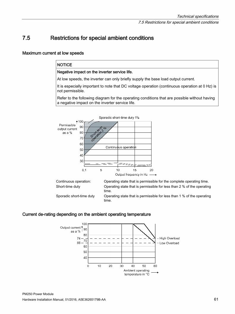
Technical specifications 7.5 Restrictions for special ambient conditions
PM250 Power Module Hardware Installation Manual, 01/2016, A5E36265179B-AA 61
7.5 Restrictions for special ambient conditions
Maximum current at low speeds
NOTICE
Negative impact on the inverter service life.
At low speeds, the inverter can only briefly supply the base load output current.
It is especially important to note that DC voltage operation (continuous operation at 0 Hz) is not permissible.
Refer to the following diagram for the operating conditions that are possible without having a negative impact on the inverter service life.
Continuous operation: Operating state that is permissible for the complete operating time. Short-time duty Operating state that is permissible for less than 2 % of the operating
time. Sporadic short-time duty Operating state that is permissible for less than 1 % of the operating
time.
Current de-rating depending on the ambient operating temperature

Technical specifications 7.5 Restrictions for special ambient conditions
PM250 Power Module 62 Hardware Installation Manual, 01/2016, A5E36265179B-AA
The Control Unit and operator panel can restrict the maximum permissible operating ambient temperature of the Power Module.
Current derating or temperature reduction depending on the installation altitude Above 1000 m above sea level you must reduce the inverter output current or the permissible operating ambient temperature as a result of the lower cooling capability of the air. Refer to the following diagrams for the values.
Permissible line supplies depending on the installation altitude ● Installation altitude up to 2000 m above sea level
– Connection to every supply system permitted for the inverter.
● Installation altitudes between 2000 m and 4000 m above sea level
– Connection to a TN system with grounded neutral point.
– TN systems with grounded line conductor are not permitted.
– The TN line system with grounded neutral point can also be supplied using an isolation transformer.
– The phase-to-phase voltage does not have to be reduced.

Technical specifications 7.6 Electromagnetic compatibility of the inverter
PM250 Power Module Hardware Installation Manual, 01/2016, A5E36265179B-AA 63
7.6 Electromagnetic compatibility of the inverter The electromagnetic compatibility refers to both the immunity and the emitted interference of a device.
The following disturbance variables must be taken into consideration when evaluating the electromagnetic compatibility:
● Conducted low-frequency disturbance variables (harmonics)
● Conducted high-frequency disturbance variables
● Field-based, low-frequency disturbance variables
● Field-based, high-frequency disturbance variables
The permitted limit values are defined in the EMC product standard EN 61800-3 in EMC categories C1 to C4.
Below you will find some key definitions relating to this.
Classification of EMC behavior The EMC environment and the EMC Categories are defined in the EMC product standard EN 61800-3 as follows:
Environments:
First environment (public systems)
An environment that includes domestic premises and establishments that are connected directly to a public low-voltage line supply without the use of an intermediate transformer.
Example: Houses, apartments, commercial premises, or offices in residential buildings.
Second environment (industrial systems)
An environment that includes all other establishments which are not connected directly to a public low-voltage line supply.
Example: Industrial areas and technical areas of buildings that are supplied by an assigned transformer.
Categories
Category C4
Drive systems with a rated voltage ≥ 1,000 V, with an LO output current ≥ 400 A, or for use in complex systems in the second environment
Drive systems which correspond to category C4 may only be installed in the second environment.
Technical specifications 7.6 Electromagnetic compatibility of the inverter
PM250 Power Module 64 Hardware Installation Manual, 01/2016, A5E36265179B-AA
Category C3
Drive systems with a rated voltage < 1,000 V, which are intended for use in the second environment and not for use in the first environment.
Drive systems which correspond to category C3 may only be installed in the second environment.
Category C2
Drive systems with a rated voltage < 1,000 V, which are neither plug-in devices nor moveable devices and which, when used in the first environment, are only intended to be installed and commissioned by an expert.
Drive systems which correspond to category C2 may only be used in the first environment if they are installed by an expert, with limit values for electromagnetic compatibility observed.
Category C1
Drive systems with a rated voltage < 1000 V, which are intended for use in the first environment.
Drive systems which correspond to category C1 can be installed in the first environment without restrictions.
Note Expert
An expert is a person or organization with the necessary experience for installing and/or commissioning drive systems (Power Drive Systems - PDS), including the associated EMC aspects.
7.6.1 Assigning the inverter to EMC categories The inverters have been tested in accordance with the EMC product standard EN 61800-3.
The declaration of conformity is available at Hotspot-Text (http://support.automation.siemens.com/WW/view/en/58275445)
Requirements for electromagnetic compatibility To comply with the requirements of EN 61800-3, all drives must be installed in accordance with the manufacturer's instructions and EMC directives.
The EMC regulations are available at Hotspot-Text (http://support.automation.siemens.com/WW/view/en/58275445)
The installation must be performed by an expert who has the necessary experience for installing and/or commissioning power drives, including their EMC aspects.

Technical specifications 7.6 Electromagnetic compatibility of the inverter
PM250 Power Module Hardware Installation Manual, 01/2016, A5E36265179B-AA 65
Second environment - category C4 The unfiltered inverters correspond to category C4.
EMC measures in the second environment, category C4, are carried out on the basis of an EMC plan on the system level.
Further information: EMC-compliant installation (Page 38).
Second environment - category C3
Immunity
With respect to their immunity, the inverters are suitable for the second environment, Category C3.
Interference emission for filtered inverters
Inverters with integrated filter are suitable for use in the second environment, Category C3.
Interference emission for unfiltered inverters
If you are using unfiltered inverters in an industrial plant, you must either use an external filter for the inverter or install corresponding filters on the system level (conducted high-frequency disturbance variables).
When installed professionally in accordance with EMC guidelines, the inverters fulfill the requirements of the standard in relation to category C3 (field-based high-frequency disturbance variables).
Second environment - category C2
Immunity
With respect to their immunity, the inverters are suitable for the second environment, Category C2.
Emitted interference
General preconditions in order to maintain the limit values regarding noise emission for the second environment, Category C2:
In order for the inverters to comply with the limit values for category C2 relating to emitted interference, the following conditions must be fulfilled:
● You are using an inverter with an integrated filter
● The motor cable is shorter than 25 m.
● The pulse frequency does not exceed 4 kHz
● The current does not exceed the value of the LO input current Power-dependent data (Page 58)
● You are using a shielded motor connection cable with low capacitance

Technical specifications 7.6 Electromagnetic compatibility of the inverter
PM250 Power Module 66 Hardware Installation Manual, 01/2016, A5E36265179B-AA
First environment - category C2
Immunity
With respect to their immunity, the inverters are suitable for the first environment, Category C2.
Emitted interference
● Low-frequency, cable-conducted interference voltages (harmonics)
Your line supply defines as to whether the inverter can satisfy the requirements of the first environment, Category C2.
In this regard, contact your power supply utility.
A table showing the typical harmonic currents of the Power Modules can be found in section Harmonics (Page 66).
● High-frequency cable-conducted interference voltages:
The limit values for the first environment, Category C2, are maintained under the following preconditions:
– You are using an inverter with an integrated filter
– You are using a shielded motor connection cable with low capacitance
– The current does not exceed the value of the LO input current (see Power-dependent data (Page 58))
– The pulse frequency does not exceed 4 kHz
– The motor cable is shorter than 25 m.
– The installation must be carried out by an expert who has the necessary experience for installing and/or commissioning power drives, included the associated EMC aspects.
● High-frequency emitted interference
When installed professionally in accordance with EMC guidelines, the inverters fulfill the requirements of the standard in relation to category C2.
7.6.2 Harmonics Harmonic number
5th 7th 11th 13th 17th 19th 23rd 25th Current as a % for FSC 1) 54 39 11 5.5 5 3 2 2 Current as a % for FSD … FSF 2) 37 21 7 5 4 3 3 2 1) Typical harmonic currents as a % referred to the LO input current for UK 1 %
2) Typical harmonic currents as a %

Technical specifications 7.6 Electromagnetic compatibility of the inverter
PM250 Power Module Hardware Installation Manual, 01/2016, A5E36265179B-AA 67
7.6.3 EMC limit values in South Korea
The EMC limit values to be complied with for South Korea correspond to the limit values of the EMC product standard for variable-speed electric drives EN 61800-3, Category C2 or limit value class A, Group 1 according to EN55011. By applying suitable supplementary measures, the limit values according to Category C2 or according to limit value class A, Group 1 are maintained. Further, additional measures may be required, for instance, using an additional radio interference suppression filter (EMC filter). The measures for EMC-compliant design of the system are described in detail in this manual respectively in the Installation Guideline EMC.
Please note that the final statement on compliance with the standard is given by the respective label attached to the individual unit.
You can find the Configuration Manual "EMC installation guidelines" under (http://support.automation.siemens.com/WW/view/en/60612658)

Technical specifications 7.6 Electromagnetic compatibility of the inverter
PM250 Power Module 68 Hardware Installation Manual, 01/2016, A5E36265179B-AA
PM250 Power Module Hardware Installation Manual, 01/2016, A5E36265179B-AA 69
Spare parts and accessories 8 8.1 Spare parts
6SL3200-0SF03-0AA0 fan kit
For FSC Power Modules:
● 6SL3225-0BE25-5AA0 (7.5 kW)
● 6SL3225-0BE27-5AA0 (11 kW)
● 6SL3225-0BE31-1AA0 (15 kW)
6SL3200-0SF04-0AA0 fan kit
For FSD Power Modules:
● 6SL3225-0BE31-5AA0 (18.5 kW)
● 6SL3225-0BE31-8AA0 (22 kW)
For FSE Power Modules:
● 6SL3225-0BE33-0AA0 (37 kW)
6SL3200-0SF05-0AA0 fan kit
For FSD Power Modules:
● 6SL3225-0BE32-2AA0 (30 kW)
For FSE Power Modules:
● 6SL3225-0BE33-7AA0 (45 kW)
6SL3200-0SF06-0AA0 fan kit
For FSF Power Modules:
● 6SL3225-0BE34-5AA0 (55 kW)
● 6SL3225-0BE35-5AA0 (75 kW)
6SL3200-0SF08-0AA0 fan kit
For FSF Power Modules:
● 6SL3225-0BE37-5AA0 (90 kW)
Cover kit 6SL3200-0SM11-0AA0
For FSD and FSE Power Modules
Cover kit 6SL3200-0SM12-0AA0
For FSF Power Modules:

Spare parts and accessories 8.2 Optional accessories
PM250 Power Module 70 Hardware Installation Manual, 01/2016, A5E36265179B-AA
Repair and wearing parts and/or consumables
You can find additional information about repair and wearing parts or consumables that can be ordered here (https://www.automation.siemens.com/sow?sap-language=EN)
8.2 Optional accessories
Which components are available? ● Line filter
● Output reactors
● Sine-wave filter
● Brake Relay and Safe Brake Relay
Reactors and filters are designed for Power Modules, frame size FSC as base components.
Reactors and filters as base components (Page 70)
8.2.1 Reactors and filters as base components Reactors and filters as base components are available for Power Modules, frame size FSC. An overview of the permitted base component combinations is provided below. You can also install base components next to the Power Module.
Permissible combinations of base components

Spare parts and accessories 8.2 Optional accessories
PM250 Power Module Hardware Installation Manual, 01/2016, A5E36265179B-AA 71
8.2.2 Line filter With a line filter, the inverter can achieve a higher radio interference class.
The line filters integrated in the inverter correspond to Class A according to EN55011.
The filters are available for radio interference suppression class A or B according to EN55011. Details are provided in the following tables.
NOTICE
The line filter is damaged when operated on inadmissible line supplies
The line filter is only suitable for operation on TN or TT line systems with a grounded neutral point. The line filter is damaged if operated on all other line supplies. • For inverters equipped with line filter, only connect to TN or TT line systems with a
grounded neutral point.
Dimensions and drilling patterns
Image 8-1 FSC dimensions
Image 8-2 Mounting position FSC
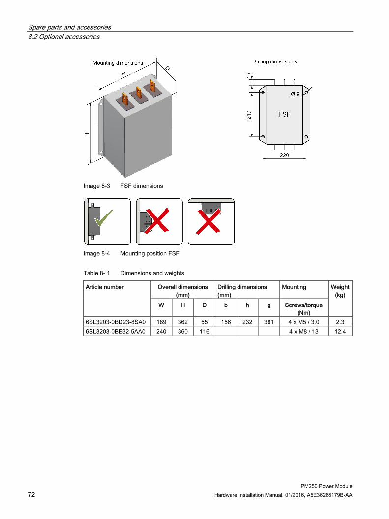
Spare parts and accessories 8.2 Optional accessories
PM250 Power Module 72 Hardware Installation Manual, 01/2016, A5E36265179B-AA
Image 8-3 FSF dimensions
Image 8-4 Mounting position FSF
Table 8- 1 Dimensions and weights
Article number Overall dimensions (mm)
Drilling dimensions (mm)
Mounting Weight (kg)
W H D b h g Screws/torque (Nm)
6SL3203-0BD23-8SA0 189 362 55 156 232 381 4 x M5 / 3.0 2.3 6SL3203-0BE32-5AA0 240 360 116 4 x M8 / 13 12.4

Spare parts and accessories 8.2 Optional accessories
PM250 Power Module Hardware Installation Manual, 01/2016, A5E36265179B-AA 73
Technical specifications and assignment tables
Table 8- 2 Technical specifications
Article number Power loss (W) at 50 Hz
Connection (mm2) Degree of pro-tection
Line / PE Power Module
6SL3203-0BD23-8SA0 7.5 … 15 4 mm2 screw terminals Integrated, 400 mm IP20 6SL3203-0BE32-5AA0 60 M8 studs M8 studs IP00
Table 8- 3 Assignment table
Line filter Power Module Article number Class Article number Frame
size 6SL3203-0BD23- 8SA0 B 6SL3225-0BE25-5AA0 6SL3225-0BE27-5AA0
6SL3225- 0BE31-1AA0 FSC
6SL3203-0BE32- 5AA0 A 6SL3225-0BE34-5AA0 6SL3225-0BE35-5AA0 6SL3225- 0BE37-5AA0
FSF

Spare parts and accessories 8.2 Optional accessories
PM250 Power Module 74 Hardware Installation Manual, 01/2016, A5E36265179B-AA
8.2.3 Output reactor
Mounting position
Clearances to other devices Keep shaded areas free of any devices and components.
Image 8-5 Minimum clearances of the output reactor to other devices, space-saving mounting
examples
If you use an output reactor, then it is not permissible that the output frequency exceeds 150 Hz. It is not permissible that the pulse frequency is higher than 4 kHz.

Spare parts and accessories 8.2 Optional accessories
PM250 Power Module Hardware Installation Manual, 01/2016, A5E36265179B-AA 75
Dimensions and drilling patterns
Image 8-6 Output reactor as base component for frame size FSC
Image 8-7 Standalone output reactor for frame sizes FSD … FSF

Spare parts and accessories 8.2 Optional accessories
PM250 Power Module 76 Hardware Installation Manual, 01/2016, A5E36265179B-AA
Table 8- 4 Dimensions and weights
Article number Overall dimensions (mm)
Drilling dimensions (mm)
Tightening screws/torque
(Nm)
Weight (kg)
Reactor that can be mounted under the unit W H D b h c
6SL3202-0AJ23-2CA0 189 334 80 156 232 5.5 4 x M5 / 3.0 9 Reactor that cannot be mounted under the unit
W H D b t1 t2 6SE6400-3TC05-4DD0 225 210 150 176 69 70.5 4 x M6 / 6.0 11.5 6SE6400-3TC03-8DD0 225 210 179 176 93 75.5 4 x M6 / 6.0 19 6SE6400-3TC05-4DD0 225 210 140 138 264 4 x M6 / 6.0 11.5 6SE6400-3TC08-0ED0 225 210 150 176 69 70.5 4 x M6 / 6.0 12 6SE6400-3TC07-5ED0 270 248 209 200 102 91.5 4 x M8 / 13 26.5 6SE6400-3TC14-5FD0 350 321 288 264 140 134 4 x M8 / 13 57 6SE6400-3TC15-4FD0 270 248 209 200 102 90 4 x M8 / 13 24 6SE6400-3TC14-5FD0 350 321 288 264 140 134 4 x M8 / 13 57
Technical specifications and assignment tables
Table 8- 5 Technical specifications
Article number Line supply connection
PE connec-tion
Connection at the Power Module
Degree of
protec-tion
Power loss (W)
6SL3202-0AJ23-2CA0 6 mm2 screw ter-minals
M5 bolts Integrated, 350 mm
IP00 60
6SE6400-3TC05-4DD0 M6 cable lug M6 screw M6 cable lug IP20 200 6SE6400-3TC03-8DD0 M6 cable lug M6 screw M6 cable lug IP20 200 6SE6400-3TC05-4DD0 M6 cable lug M6 screw M6 cable lug IP20 200 6SE6400-3TC08-0ED0 M6 cable lug M6 screw M6 cable lug IP20 170 6SE6400-3TC07-5ED0 M6 cable lug M6 screw M6 cable lug IP20 277 6SE6400-3TC14-5FD0 M8 cable lug M8 screw M8 cable lug IP20 469 6SE6400-3TC15-4FD0 M8 cable lug M6 screw M8 cable lug IP20 245 6SE6400-3TC14-5FD0 M8 cable lug M8 screw M8 cable lug IP20 469

Spare parts and accessories 8.2 Optional accessories
PM250 Power Module Hardware Installation Manual, 01/2016, A5E36265179B-AA 77
Table 8- 6 Assignment table
Output reactor Power Module Article number Article number Frame
size 6SL3202-0AJ23-2CA0 6SL3225-0BE25-5☐A0 6SL3225-0BE27-5☐A0
6SL3225-0BE31-1☐A0 FSC
6SE6400-3TC05-4DD0 6SL3225-0BE31-5☐A0 FSD 6SE6400-3TC03-8DD0 6SL3225-0BE31-8☐A0 FSD 6SE6400-3TC05-4DD0 6SL3225-0BE32-2☐A0 FSD 6SE6400-3TC08-0ED0 6SL3225-0BE33-0☐A0 FSE 6SE6400-3TC07-5ED0 6SL3225-0BE33-7☐A0 FSE 6SE6400-3TC14-5FD0 6SL3225-0BE34-5☐A0 FSF 6SE6400-3TC15-4FD0 6SL3225-0BE35-5☐A0 FSF 6SE6400-3TC14-5FD0 6SL3225-0BE37-5☐A0 FSF

Spare parts and accessories 8.2 Optional accessories
PM250 Power Module 78 Hardware Installation Manual, 01/2016, A5E36265179B-AA
8.2.4 Sine-wave filter The sine-wave filter at the inverter output limits the voltage rate-of-rise and the peak voltages at the motor winding. The maximum permissible length of motor feeder cables is increased to 300 m.
The following applies when using a sine-wave filter:
● Operation is only permissible with pulse frequencies from 4 kHz to 8 kHz. From 110 kW power rating of the Power Modules (according to the rating plate) only 4 kHz is permissible.
● The inverter power is reduced by 5%.
● The maximum output frequency of the inverter is 150 Hz at 380 V to 480 V.
● Operation and commissioning may only be performed with the motor connected, as the sine-wave filter is not no-load proof.
● An output reactor is superfluous.
Dimensions and drilling patterns
Image 8-8 Dimensions - footprint filter
Mounting position
Image 8-9 Mounting position - footprint filter

Spare parts and accessories 8.2 Optional accessories
PM250 Power Module Hardware Installation Manual, 01/2016, A5E36265179B-AA 79
Image 8-10 Dimensions - standalone filter
Image 8-11 Mounting position - standalone filter
Table 8- 7 Dimensions and weights
Sine-wave filter Overall dimensions (mm)
Drilling dimensions (mm)
Tightening screws/torque
(Nm)
Weight (kg)
Footprint filter W H D b h g 6SL3202-0AE22-0SA0 189 336 140 167 323 351 4 x M5 / 3.0 12 6SL3202-0AE23-3SA0 189 336 140 167 323 351 4 x M5 / 3.0 23 Standalone filter W H D b t g 6SL3202-0AE24-6SA0 250 305 260 230 127 90.5 4 x M8 / 13 24 6SL3202-0AE26-2SA0 250 315 262 230 127 90.5 4 x M8 / 13 34 6SL3202-0AE28-8SA0 275 368 275 250 132 100.5 4 x M8 / 13 45 6SL3202-0AE31-5SA0 350 440 305 320 157 113 4 x M8 / 13 63 6SL3202-0AE31-8SA0 350 468 305 320 157 113 4 x M8 / 13 80

Spare parts and accessories 8.2 Optional accessories
PM250 Power Module 80 Hardware Installation Manual, 01/2016, A5E36265179B-AA
Technical specifications and assignment tables
Table 8- 8 Technical specifications
Article number Connection (mm2) Degree of
protec-tion
dU/dt limit [V/ms]
Power loss [W] at 50 Hz
Motor / PE Power Module
6SL3202-0AE22-0SA0 10 mm² screw terminals
Integrated, 500 mm IP20 ≤ 500 40
6SL3202-0AE23-3SA0 10 mm² screw terminals
Integrated, 500 mm IP20 ≤ 500 65
6SL3202-0AE24-6SA0 25 … 50 mm² screw terminals
25 … 50 mm² screw terminals
IP00 1) ≤ 500 80
6SL3202-0AE26-2SA0 25 … 50 mm² screw terminals
25 … 50 mm² screw terminals
IP00 1) ≤ 500 65
6SL3202-0AE28-8SA0 25 … 95 mm² screw terminals
25 … 95 mm² screw terminals
IP00 1) ≤ 500 100
6SL3202-0AE31-5SA0 50 … 150 mm² screw terminals
50 … 150 mm² screw terminals
IP00 1) ≤ 500 180
6SL3202-0AE31-8SA0 50 … 150 mm² screw terminals
50 … 150 mm² screw terminals
IP00 1) ≤ 500 190
1) With terminal cover IP20
Table 8- 9 Assignment table
Sine-wave filter Power Module Article number Article number Frame size 6SL3202-0AE22-0SA0 6SL3225-0BE25-5☐A0 FSC 6SL3202-0AE23-3SA0 6SL3225-0BE27-5☐A0 6SL3225-0BE31-1☐A0 FSC 6SL3202-0AE24-6SA0 6SL3225-0BE31-5☐A0 6SL3225-0BE31-8☐A0 FSD 6SL3202-0AE26-2SA0 6SL3225-0BE32-2☐A0 FSD 6SL3202-0AE28-8SA0 6SL3225-0BE33-0☐A0 6SL3225-0BE33-7☐A0 FSE 6SL3202-0AE31-5SA0 6SL3225-0BE34-5☐A0 6SL3225-0BE35-5☐A0 FSF 6SL3202-0AE31-8SA0 6SL3225-0BE37-5☐A0 FSF

Spare parts and accessories 8.2 Optional accessories
PM250 Power Module Hardware Installation Manual, 01/2016, A5E36265179B-AA 81
8.2.5 Connecting a motor holding brake The inverter uses the Brake Relay to control the motor holding brake. Two types of Brake Relay exist:
● The Brake Relay controls the motor holding brake
● The Safe Brake Relay controls a 24 V motor holding brake and monitors the brake control for short-circuit or cable breakage.
Note Brake Relay and Safe Brake Relay
The Brake Relay and the Safe Brake Relay do not differ from each other in the installation and the connection to the inverter. Connection to the inverter
To ensure that you have the correct cable for connecting the Brake Relay irrespective of the inverter size, you are supplied with two preassembled cables with different lengths. Connect the appropriate cable to the Brake Module and to the inverter as shown below.
If you are using your own cable, ensure that the cable is insulated and rated for 600 V.
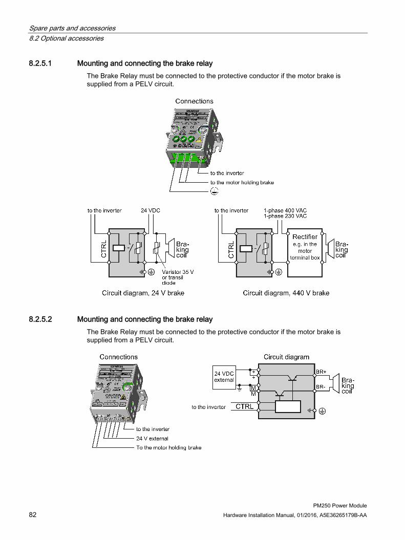
Spare parts and accessories 8.2 Optional accessories
PM250 Power Module 82 Hardware Installation Manual, 01/2016, A5E36265179B-AA
8.2.5.1 Mounting and connecting the brake relay The Brake Relay must be connected to the protective conductor if the motor brake is supplied from a PELV circuit.
8.2.5.2 Mounting and connecting the brake relay The Brake Relay must be connected to the protective conductor if the motor brake is supplied from a PELV circuit.

Spare parts and accessories 8.2 Optional accessories
PM250 Power Module Hardware Installation Manual, 01/2016, A5E36265179B-AA 83
8.2.5.3 Technical data of the brake relay?
Brake Relay 6SL32520BB000AA0
Safe Brake Relay 6SL32520BB010AA0
Input voltage via the Power Module 20.4 ... 28.8 VDC 1) Input current via the Power Module Max. 2.5 A Max. connection cross-section: 2.5 mm² 2.5 mm² Degree of protection IP20 IP20 Switching capability of the NO contact
1-phase 440 VAC, 3.5 A 1-phase 30 VDC, 12 A
-
Output voltage - 24 V Output current - max. 2 A 1) External, controlled power supply required. Recommended voltage: 26 VDC
8.2.5.4 Mounting and connecting the brake relay
Installing the Brake Relay If you use the optional shield plate, install the Brake Relay on the shield plate of the Power Module.
If you do not use the shield plate, install the Brake Relay as close as possible to the Power Module.
Connecting the Brake Relay to the inverter The connector for the brake relay is located at the front of the Power Module for the FSC frame size. These Power Modules have a cable entry for the connecting cable to the Brake Relay.
The connector for the Brake Relay is located at the bottom of the Power Module for the FSD … FSF frame sizes.

Spare parts and accessories 8.2 Optional accessories
PM250 Power Module 84 Hardware Installation Manual, 01/2016, A5E36265179B-AA
8.2.6 Shield connection kit The shield connection kit is used to connect the shield of the control and motor cable in an EMC-compliant fashion.
The instructions for installing the shield connection kit are available in the Internet at (https://support.industry.siemens.com/cs/ww/de/view/23621093/en):
Article numbers of the shield connection kit for the different Power Modules
● FSC: 6SL3262-1AC00-0DA0
● FSD: 6SL3262-1AD00-0DA0
● FSE: 6SL3262-1AD00-0DA0
● FSF: 6SL3262-1AF00-0DA0

PM250 Power Module Hardware Installation Manual, 01/2016, A5E36265179B-AA 85
Appendix 9 9.1 Manuals and technical support
9.1.1 Overview of the manuals
Manuals with additional information that can be downloaded: EMC-compliant electrical cabinet design
● PM250 Hardware Installation Manual (https://support.industry.siemens.com/cs/ww/de/view/64875934/en) Installing Power Modules, reactors and filters. Technical specifications, maintenance (this manual)
● CU230P-2 Compact Operating Instructions (https://support.industry.siemens.com/cs/ww/en/view/109477360) Commissioning the inverter.
● CU240B/E-2 Compact Operating Instructions (https://support.industry.siemens.com/cs/ww/en/view/109477361) Commissioning the inverter.
● CU250S-2 Compact Operating Instructions (https://support.industry.siemens.com/cs/ww/en/view/99730303) Commissioning the inverter.
● CU230P-2 operating instructions (https://support.industry.siemens.com/cs/ww/en/view/109478827) Installing, commissioning and maintaining the inverter. Advanced commissioning
● CU240B/E-2 operating instructions (https://support.industry.siemens.com/cs/ww/en/view/109478828) Installing, commissioning and maintaining the inverter. Advanced commissioning
● CU250S-2 operating instructions (https://support.industry.siemens.com/cs/ww/en/view/109478829) Installing, commissioning and maintaining the inverter. Advanced commissioning

Appendix 9.1 Manuals and technical support
PM250 Power Module 86 Hardware Installation Manual, 01/2016, A5E36265179B-AA
● CU230P-2 List Manual (https://support.industry.siemens.com/cs/ww/en/view/109477248) Parameter list, alarms and faults. Graphic function diagrams
● CU240B/E-2 List Manual (https://support.industry.siemens.com/cs/ww/en/view/109477251) Parameter list, alarms and faults. Graphic function diagrams
● CU250S-2 List Manual (https://support.industry.siemens.com/cs/ww/en/view/109477253) Parameter list, alarms and faults. Graphic function diagrams
● EMC installation guideline (http://support.automation.siemens.com/WW/view/en/60612658) EMC-compliant control cabinet design, potential equalization and cable routing
● Accessories manual (https://support.industry.siemens.com/cs/ww/en/ps/13225/man) Installation descriptions for inverter components, e.g. line reactors and line filters. The printed installation descriptions are supplied together with the components.
Finding the most recent edition of a manual If there a multiple editions of a manual, select the latest edition:

Appendix 9.1 Manuals and technical support
PM250 Power Module Hardware Installation Manual, 01/2016, A5E36265179B-AA 87
Configuring a manual Further information about the configurability of manuals is available in the Internet:
MyDocumentationManager (https://www.industry.siemens.com/topics/global/en/planning-efficiency/documentation/Pages/default.aspx).
Select "Display and configure" and add the manual to your "mySupport-documentation":
Not all manuals can be configured.
The configured manual can be exported in RTF, PDF or XML format.

Appendix 9.1 Manuals and technical support
PM250 Power Module 88 Hardware Installation Manual, 01/2016, A5E36265179B-AA
9.1.2 Configuring support
Catalog Ordering data and technical information for SINAMICS G inverters.
Catalog D31 for download or online catalog (Industry Mall):
Everything about SINAMICS G120 (www.siemens.en/sinamics-g120)
SIZER The configuration tool for SINAMICS, MICROMASTER and DYNAVERT T drives, motor starters, as well as SINUMERIK, SIMOTION controllers and SIMATIC technology
SIZER on DVD:
Article number: 6SL3070-0AA00-0AG0
Download SIZER (http://support.automation.siemens.com/WW/view/en/10804987/130000)
EMC (electromagnetic compatibility) technical overview Standards and guidelines, EMC-compliant control cabinet design
EMC overview (https://support.industry.siemens.com/cs/ww/en/view/103704610)
EMC Guidelines configuration manual EMC-compliant control cabinet design, potential equalization and cable routing
EMC installation guideline (http://support.automation.siemens.com/WW/view/en/60612658)
Safety Integrated for novices technical overview Application examples for SINAMICS G drives with Safety Integrated
Safety Integrated for novices (https://support.industry.siemens.com/cs/ww/en/view/80561520)

Appendix 9.2 Disposal
PM250 Power Module Hardware Installation Manual, 01/2016, A5E36265179B-AA 89
9.1.3 Product Support Additional information about the product and more is available in the Internet: Product support (http://www.siemens.com/automation/service&support).
This address provides the following:
● Actual product information (Update), FAQ (frequently asked questions), downloads.
● The Newsletter contains the latest information on the products you use.
● The Knowledge Manager (Intelligent Search) helps you find the documents you need.
● Users and specialists from around the world share their experience and knowledge in the Forum.
● You can find your local representative for Automation & Drives via our contact database under "Contact & Partner".
● Information about local service, repair, spare parts and much more can be found under "Services".
9.2 Disposal Protecting the environment and preserving its resources are corporate goals of the highest priority for Siemens. Our worldwide environmental management system according to ISO 14001 ensures compliance with legislation and sets high standards in this regard. Environmentally friendly design, technical safety and health protection are always firm goals, even at the product development stage.
Recommendations for the environmentally friendly disposal of the machine and its components are given in the following chapter.
● Be sure to comply with local disposal regulations.
● Separate the housing parts according to their material.
● Dispose of the parts in accordance with the applicable legal regulations.
● Dispose of the packaging material in accordance with the applicable legal regulations.
Components ● Sort the components for recycling according to whether they are:
– Electronic waste
– Scrap iron, e.g. shield plates
– Aluminum
– Insulating materials and plastics

Appendix 9.3 Standards
PM250 Power Module 90 Hardware Installation Manual, 01/2016, A5E36265179B-AA
9.3 Standards
European low-voltage directive 2006/95/EC The SINAMICS G120 product series meets the requirements of the low-voltage directive 2006/95/EC. The devices are certified that they comply with the following standards:
EN 61800-5-1 - Semiconductor power inverters - General requirements and line-commutated inverters
European machinery directive 2006/42/EC The SINAMICS G120 inverter series does not fall within the area covered by the Machinery Directive. However, the use of the products in a typical machine application has been fully assessed for compliance with the main regulations in this directive concerning health and safety. A declaration regarding the acceptance is available upon request.
European EMC directive 2004/108/EC When installed in accordance with the recommendations specified in this manual, the SINAMICS G120 complies with all regulations of the EMC Directive according to the definition provided by EN 61800-3 "EMC Product Standard for Power Drive Systems".
ISO 9001 Siemens AG uses a quality management system that meets the requirements of ISO 9001.
Underwriters Laboratories The DEVICE is LISTED by UL and CUL for POWER CONVERSION in an environment with the pollution degree 2.
You can find up-to-date information about the Power Modules at http://support.automation.siemens.com/WW/view/en/30563173/133400.
SEMI F47 Specification for semiconductor process equipment voltage drop immunity
SINAMICS G120 Power Modules PM250 meet the requirements of the standard SEMI F47-0706.
KC (Korea) Inverters with the KC marking satisfy EMC requirements for South Korea. For details, see EMC limit values in South Korea (Page 67).

Appendix 9.4 Abbreviations
PM250 Power Module Hardware Installation Manual, 01/2016, A5E36265179B-AA 91
RCM (Australia) Inverters, frame sizes FSD … FSF with integrated filter satisfy the EMC requirements for Australia.
9.4 Abbreviations Abbreviation State AC Alternating current CE Communauté Européenne CU Control Unit DC Direct current DI Digital input DIP DIP switch DO Digital output ECD Equivalent circuit diagram EEC European Economic Community ELCB Earth leakage circuit breaker EMC Electromagnetic compatibility (EMC) EMI Electromagnetic interference FS… Frame size ... GSG Getting Started Guide HO High overload I/O Input/Output IGBT Insulated gate bipolar transistor LED Light emitting diode LO Low overload NC NC contact NEMA National Electrical Manufacturers Association NO NO contact OPI Operating instructions PELV Protective extra low voltage PM Power Module PPE Personnel protective equipment PT Push-through technology RCCB Residual-current operated circuit breaker RCD Residual current device RFI Radio frequency interference SELV Safety extra-low voltage VT Variable torque

Appendix 9.4 Abbreviations
PM250 Power Module 92 Hardware Installation Manual, 01/2016, A5E36265179B-AA

PM250 Power Module Hardware Installation Manual, 01/2016, A5E36265179B-AA 93
Index
A Accessories, 85
Air barrier, 21
B Base components, 70
Base load, 53
Base load input current, 53
Base load output current, 53
Base load power, 53
Brake Relay, 81
C Cable lug, 37
ring-shaped, 37
Standard, 37
Catalog, 88
Category C1, 64
Category C2, 34, 64
Category C3, 34, 64
Category C4, 63
Classification of EMC behavior, 63
Configuring support, 88
Control Units for PM250 Power Modules, 17
Cooling, 20
D Derating
Installation altitude, 62
Dimension drawings, 75
Disposal, 89
Drilling pattern, 75
E Electrical installation, 27
EMC, 42
EMC installation guideline, 85
F First environment, 63
G Getting Started, 85
H Hardware Installation Manual, 85
Harmonics, 66
High Overload, 54
Hotline, 89
I Industrial systems, 63
Industry Mall, 88
Installation altitude, 62
Installing, 22
IP21 degree of protection, 19
IT system, 29
L Line and motor connection, frame size FSC, 36
Line and motor connection, frame sizes FSD … FSF, 37

Index
PM250 Power Module 94 Hardware Installation Manual, 01/2016, A5E36265179B-AA
Line reactor
Dimension drawings, 75
Line supply type, 29
Low Overload, 54
M Maintenance
Cleaning, 48
Dirt, 48
Pollution, 48
Terminals, 48
Ventilation, 48
N Neutral conductor, 29
O Operating instructions, 85
P Parameter Manual, 85
Power distribution systems, 29
Protective conductor, 29
Public systems, 63
Q Questions, 89
R Radio interference class, 71
S Safe Brake Relay, 81
Safety notes
Electrical installation, 27
Second environment, 63
Service life of the fan, 49
Sine-wave filter, 78
SIZER, 88
Standards
EN 61800-3, 63, 64
EN 61800-3, 63, 64
Star/delta connection, 35
Support, 89
T Terminal cover, 37
TN line system, 29
TT line system, 29