photorealistic reproduction with anisotropic reflection on
TRANSCRIPT
Photorealistic Reproduction with Anisotropic Reflection on MobileDevices using Densely Sampled Images
Shoichiro Mihara, Haruhisa Kato and Masaru SuganoKDDI Research, Inc., Saitama, Japan
Keywords: Photorealistic Reproduction, Augmented Reality, Image-based Rendering.
Abstract: Photorealistic reproduction of real objects with complexities of geometry and optics on mobile devices hasbeen a long-standing challenge in augmented reality owing to the difficulties of modeling and rendering thereal object faithfully. Although image-based rendering, which does not require the objects to be modeled,has been proposed, it still fails to photorealistically reproduce the object’s complete appearance containingcomplex optical properties such as anisotropic reflection.We propose a novel system for use on mobiledevices capable of reproducing real objects photorealistically from all angles based on new view generationusing densely sampled images. In order to realize the proposed system, we developed a method of selecting theimage closest to a given camera view from densely sampled images by quantifying the similarity of two rays,performed rigid geometric transformation to preserve the vertical direction for stable viewing, and introducedcolor correction for consistency of color between the generated view and the real world. Through experiments,we confirmed that our proposed system can reproduce real objects with complex optical properties morephotorealistically compared with conventional augmentedreality.
1 INTRODUCTION
Applications designed to reproduce real objects havebecome widespread throughout the market, especiallyapplications for mobile devices. For example, inelectronic commerce, applications for mobile devicessuch asIKEA Place1 are available that make it pos-sible for the appearance of items to be observed asif they were at hand by rendering them overlaid on areal-world background; this is based on a techniquecalled augmented reality. However, the appearanceof the objects reproduced by these applications is notphotorealistic because they are not rendered based onmaterials faithful to the original objects.
Modern rendering techniques can be classifiedinto two different categories; model-based render-ing and image-based rendering (Levoy and Hanra-han, 1996)(Gortler et al., 1996). As for model-based rendering, the reflectance properties repre-sented by a bidirectional reflectance distribution func-tion (BRDF) is necessary to render objects photore-alistically. However, to measure anisotropic BRDFwhich arises from microstructures such as a hairlineprocessed metal or woven fabric, an expensive mea-suring instrument and an enormous amount of mea-suring time are required due to the need to observe
1http://www.ikea.com/gb/en/customer-service/ikea-apps/
light reflected at the object surface in all directions.Image-based rendering that does not rely on geomet-ric representation has been proposed to reproduce realobjects or scenes by synthesizing virtual views fromarbitrary camera positions using densely sampled im-ages from a real or virtual environment. Althoughit is a technique powerful enough to reproduce high-quality virtual views, it still fails to photorealisticallyreproduce the complete appearance containing com-plex optical properties such as anisotropic reflectionbecause it is essentially based on interpolation of dis-cretely sampled images which can miss capturing pro-nounced variations in anisotropic reflection, which ishighly sensitive to viewing direction.
In this research, we propose a novel system foruse on mobile devices that can reproduce real ob-jects photorealistically by generating new views fromall angles using densely sampled images. Our pro-posed system can be utilized for various applications:for example, examining unique cultural assets or rareminerals for educational purposes, viewing items soldon online shopping sites, and enjoying a realistic vir-tual world for entertainment. The proposed systemhas three main advantages. First, as with image-based rendering, it can reproduce objects photoreal-istically without constructing a geometric represen-tation. Second, our proposed system can be easilyimplemented and run on mobile devices with meager
Mihara, S., Kato, H. and Sugano, M.Photorealistic Reproduction with Anisotropic Reflection on Mobile Devices using Densely Sampled Images.DOI: 10.5220/0007342202170227In Proceedings of the 14th International Joint Conference on Computer Vision, Imaging and Computer Graphics Theory and Applications (VISIGRAPP 2019), pages 217-227ISBN: 978-989-758-354-4Copyright c© 2019 by SCITEPRESS – Science and Technology Publications, Lda. All rights reserved
217
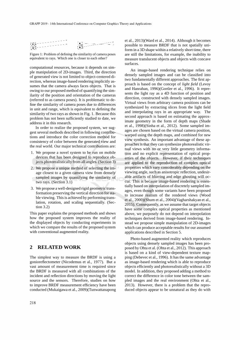
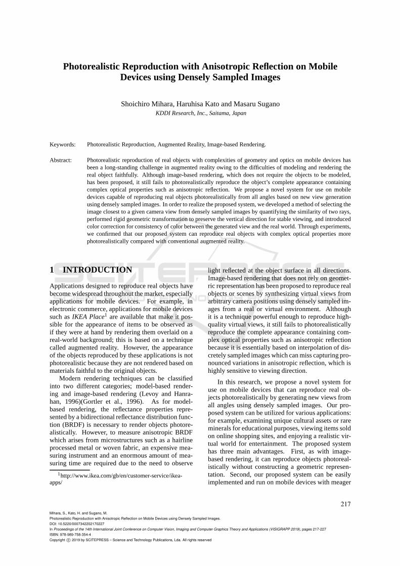
Figure 1: Problem of defining the similarity of camera posesequivalent to rays. Which one is closer to each other?
computational resources, because it depends on sim-ple manipulation of 2D-images. Third, the directionof generated view is not limited to object-centered di-rection, whereas image-based rendering implicitly as-sumes that the camera always faces objects. That isowing to our proposed method of quantifying the sim-ilarity of the position and orientation of the cameras(referred to as camera poses). It is problematic to de-fine the similarity of camera poses due to differencesin unit and range, which is equivalent to defining thesimilarity of two rays as shown in Fig. 1. Because thisproblem has not been sufficiently studied to date, weaddress it in this research.
In order to realize the proposed system, we sug-gest several methods described in following contribu-tions and introduce the color correction method forconsistency of color between the generated view andthe real world. Our major technical contributions are:
1. We propose a novel system to be run on mobiledevices that has been designed to reproduce ob-jects photorealistically from all angles. (Section 3)
2. We propose a unique method of selecting the im-age closest to a given camera view from denselysampled images by quantifying the similarity oftwo rays. (Section 3.1)
3. We propose a well-designed rigid geometric trans-formation preserving the vertical direction for sta-ble viewing. This is achieved by performing trans-lation, rotation, and scaling sequentially. (Sec-tion 3.2)
This paper explains the proposed methods and showshow the proposed system improves the reality ofthe displayed objects by conducting experiments inwhich we compare the results of the proposed systemwith conventional augmented reality.
2 RELATED WORK
The simplest way to measure the BRDF is using agonioreflectometer (Nicodemus et al., 1977). But avast amount of measurement time is required sincethe BRDF is measured with all combinations of theincident and reflection directions by moving the lightsource and the sensors. Therefore, studies on howto improve BRDF measurement efficiency have beenconducted (Mukaigawa et al., 2009)(Tunwattanapong
et al., 2013)(Ward et al., 2014). Although it becomespossible to measure BRDF that is not spatially uni-form in a 3D shape within a relatively short time, thereare still the limitations, for example, the inability tomeasure translucent objects and objects with concavesurfaces.
An image-based rendering technique relies ondensely sampled images and can be classified intotwo fundamentally different approaches. The first ap-proach is based on the concept oflight field (Levoyand Hanrahan, 1996)(Gortler et al., 1996). It repre-sents the light ray as a 4D function of position anddirection, constructed with densely sampled images.Virtual views from arbitrary camera positions can besynthesized by extracting slices from the light fieldand interpolating rays in an appropriate way. Thesecond approach is based on estimating the approx-imate geometry in the form of depth maps (Shadeet al., 1998)(Sinha et al., 2012). Some sampled im-ages are chosen based on the virtual camera position,warped using the depth maps, and combined for newview synthesis. An important advantage of these ap-proaches is that they can synthesize photorealistic vir-tual views with no or very little geometry informa-tion and no explicit representation of optical prop-erties of the objects. However, if their techniquesare applied to the reproduction of complex opticalproperties which vary considerably depending on theviewing angle, such as anisotropic reflection, undesir-able artifacts of blurring and edge ghosting will oc-cur. This is because image-based rendering is essen-tially based on interpolation of discretely sampled im-ages, even though some variants have been proposedto increase realism of the rendered views (Woodet al., 2000)(Shum et al., 2004)(Vagharshakyan et al.,2015). Consequently, as we assume that target objectshave some complex optical properties as mentionedabove, we purposely do not depend on interpolationtechniques derived from image-based rendering. In-stead we propose simple manipulation of 2D-imageswhich can produce acceptable results for our assumedapplications described in Section 5.
Photo-based augmented reality which reproducesobjects using densely sampled images has been pro-posed by Ohta et al. (Ohta et al., 2012). This approachis based on a kind of view-dependent texture map-ping (Debevec et al., 1996). It has the same advantageas image-based rendering which is able to reproduceobjects efficiently and photorealistically without a 3Dmodel. In addition, they proposed adding a method tocorrect the difference in color tone between the sam-pled images and the real environment (Ohta et al.,2013). However, there is a problem that the repro-duced objects appear to be unnatural as they do with
GRAPP 2019 - 14th International Conference on Computer Graphics Theory and Applications
218
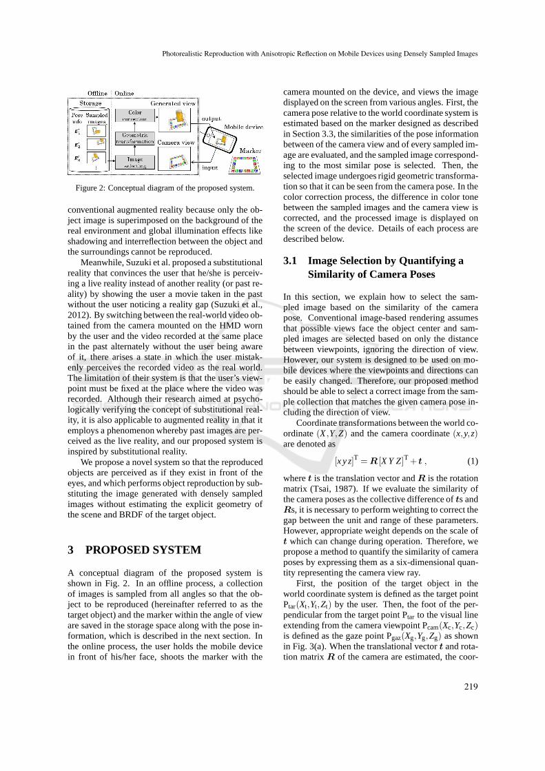
Figure 2: Conceptual diagram of the proposed system.
conventional augmented reality because only the ob-ject image is superimposed on the background of thereal environment and global illumination effects likeshadowing and interreflection between the object andthe surroundings cannot be reproduced.
Meanwhile, Suzuki et al. proposed a substitutionalreality that convinces the user that he/she is perceiv-ing a live reality instead of another reality (or past re-ality) by showing the user a movie taken in the pastwithout the user noticing a reality gap (Suzuki et al.,2012). By switching between the real-world video ob-tained from the camera mounted on the HMD wornby the user and the video recorded at the same placein the past alternately without the user being awareof it, there arises a state in which the user mistak-enly perceives the recorded video as the real world.The limitation of their system is that the user’s view-point must be fixed at the place where the video wasrecorded. Although their research aimed at psycho-logically verifying the concept of substitutional real-ity, it is also applicable to augmented reality in that itemploys a phenomenon whereby past images are per-ceived as the live reality, and our proposed system isinspired by substitutional reality.
We propose a novel system so that the reproducedobjects are perceived as if they exist in front of theeyes, and which performs object reproduction by sub-stituting the image generated with densely sampledimages without estimating the explicit geometry ofthe scene and BRDF of the target object.
3 PROPOSED SYSTEM
A conceptual diagram of the proposed system isshown in Fig. 2. In an offline process, a collectionof images is sampled from all angles so that the ob-ject to be reproduced (hereinafter referred to as thetarget object) and the marker within the angle of vieware saved in the storage space along with the pose in-formation, which is described in the next section. Inthe online process, the user holds the mobile devicein front of his/her face, shoots the marker with the
camera mounted on the device, and views the imagedisplayed on the screen from various angles. First, thecamera pose relative to the world coordinate system isestimated based on the marker designed as describedin Section 3.3, the similarities of the pose informationbetween of the camera view and of every sampled im-age are evaluated, and the sampled image correspond-ing to the most similar pose is selected. Then, theselected image undergoes rigid geometric transforma-tion so that it can be seen from the camera pose. In thecolor correction process, the difference in color tonebetween the sampled images and the camera view iscorrected, and the processed image is displayed onthe screen of the device. Details of each process aredescribed below.
3.1 Image Selection by Quantifying aSimilarity of Camera Poses
In this section, we explain how to select the sam-pled image based on the similarity of the camerapose. Conventional image-based rendering assumesthat possible views face the object center and sam-pled images are selected based on only the distancebetween viewpoints, ignoring the direction of view.However, our system is designed to be used on mo-bile devices where the viewpoints and directions canbe easily changed. Therefore, our proposed methodshould be able to select a correct image from the sam-ple collection that matches the given camera pose in-cluding the direction of view.
Coordinate transformations between the world co-ordinate(X,Y,Z) and the camera coordinate(x,y,z)are denoted as
[x y z]T =R [X Y Z]T + t , (1)
wheret is the translation vector andR is the rotationmatrix (Tsai, 1987). If we evaluate the similarity ofthe camera poses as the collective difference ofts andRs, it is necessary to perform weighting to correct thegap between the unit and range of these parameters.However, appropriate weight depends on the scale oft which can change during operation. Therefore, wepropose a method to quantify the similarity of cameraposes by expressing them as a six-dimensional quan-tity representing the camera view ray.
First, the position of the target object in theworld coordinate system is defined as the target pointPtar(Xt,Yt,Zt) by the user. Then, the foot of the per-pendicular from the target point Ptar to the visual lineextending from the camera viewpoint Pcam(Xc,Yc,Zc)is defined as the gaze point Pgaz(Xg,Yg,Zg) as shownin Fig. 3(a). When the translational vectort and rota-tion matrixR of the camera are estimated, the coor-
Photorealistic Reproduction with Anisotropic Reflection on Mobile Devices using Densely Sampled Images
219
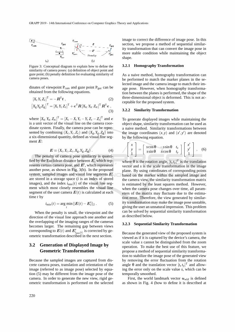
Figure 3: Conceptual diagram to explain how to define thesimilarity of camera poses: (a) definition of object point andgaze point; (b) penalty definition for evaluating similarity ofcamera poses.
dinates of viewpoint Pcam and gaze point Pgaz can beobtained from the following equations.
[XcYc Zc]T =−R
Tt , (2)
[
XgYg Zg]T
= [XcYc Zc]T +e
TR [Xtc Ytc Ztc]
TR
Te ,
(3)
where[Xtc Ytc Ztc]T = [Xc−Xt Yc−Yt Zc−Zt]
T andeis a unit vector of the visual line on the camera coor-dinate system. Finally, the camera pose can be repre-sented by combining(Xc,Yc,Zc) and(Xg,Yg,Zg) intoa six-dimensional quantity, defined as visual line seg-mentE:
E ≡ (Xc,Yc,Zc,Xg,Yg,Zg) . (4)
The penalty of camera pose similarity is quanti-fied by the Euclidean distance betweenE, which rep-resents certain camera pose, andE′, which representsanother pose, as shown in Fig. 3(b). In the proposedsystem, sampled images and visual line segmentsE′
iare stored in a storage space (i is an index of storedimages), and the indeximin(t) of the visual line seg-ment which most closely resembles the visual linesegment of the user cameraE(t) is calculated at eachtime t by
imin(t) = arg mini
‖E(t)−E′i‖2 . (5)
When the penalty is small, the viewpoint and thedirection of the visual line approach one another andthe overlapping of the imaging ranges of the camerasbecomes larger. The remaining gap between viewscorresponding toE(t) andE′
imin(t)is corrected by ge-
ometric transformation described in the next section.
3.2 Generation of Displayed Image byGeometric Transformation
Because the sampled images are captured from dis-crete camera poses, translation and orientation of theimage (referred to as image pose) selected by equa-tion (5) may be different from the image pose of thecamera. In order to generate the new view, rigid ge-ometric transformation is performed on the selected
image to correct the difference of image pose. In thissection, we propose a method of sequential similar-ity transformation that can convert the image pose inmore stable condition while maintaining the objectshape.
3.2.1 Homography Transformation
As a naive method, homography transformation canbe performed to match the marker planes in the se-lected image and the camera image to match their im-age pose. However, when homography transforma-tion between the planes is performed, the shape of thethree-dimensional object is deformed. This is not ac-ceptable for the proposed system.
3.2.2 Similarity Transformation
To generate displayed images while maintaining theobject shape, similarity transformation can be used asa naive method. Similarity transformations betweenthe image coordinates(x,y) and (x′,y′) are denotedby the following equation.
xy1
=
[
scosθ −ssinθ txssinθ scosθ ty
]
x′
y′
1
, (6)
whereθ is the rotation angle,[tx ty]T is the translationvector ands is the scale transformation in the imageplane. By using coordinates of corresponding pointsbased on the marker within the sampled image andthe camera view, the similarity transformation matrixis estimated by the least squares method. However,when the camera pose changes over time, all param-eters of the matrix may fluctuate due to the estima-tion error. Therefore, the view generated by similar-ity transformation may make the image pose unstable,giving the user an unnatural impression. This problemcan be solved by sequential similarity transformationas described below.
3.2.3 Sequential Similarity Transformation
Because the generated view of the proposed system isviewed as if it is captured by the device’s camera, thescale values cannot be distinguished from the zoomoperation. To make the best use of this feature, wepropose a method of sequential similarity transforma-tion to stabilize the image pose of the generated viewby removing the error fluctuation from the rotationangleθ and the translation vector[tx ty]T and allow-ing the error only on the scale values, which can betemporally smoothed.
First, the world landmark vectoruwld is definedas shown in Fig. 4 (how to define it is described at
GRAPP 2019 - 14th International Conference on Computer Graphics Theory and Applications
220
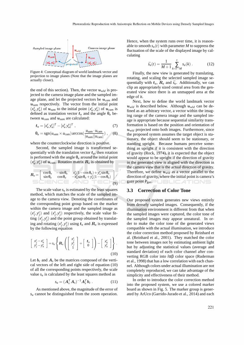
Figure 4: Conceptual diagram of world landmark vector andprojection to image planes (Note that the image planes areactually closer).
the end of this section). Then, the vectoruwld is pro-jected to the camera image plane and the sampled im-age plane, and let the projected vectors beucam andusam respectively. The vector from the initial point(xs
u,ysu) of usam to the initial point(xc
u,ycu) of ucam is
defined as translation vectortu and the angleθu be-tweenucam andusamare calculated:
tu = [xcu yc
u]T − [xs
u ysu]
T, (7)
θu = sgn(usam×ucam)arccos(usam·ucam
|usam||ucam|) , (8)
where the counterclockwise direction is positive.Second, the sampled image is transformed se-
quentially with the translation vectortu, then rotationis performed with the angleθu around the initial point(xc
u,ycu) of ucam. Rotation matrixRu is obtained by
Ru =
[
cosθu −sinθu xcu(1−cosθu)+yc
u sinθusinθu cosθu −xc
usinθu+ycu(1−cosθu)
]
.
(9)
The scale valuesu is estimated by the least squaresmethod, which matches the scale of the sampled im-age to the camera view. Denoting the coordinates ofthe corresponding point group based on the markerwithin the camera image and the sampled image as(xc
j ,ycj) and (xs
j ,ysj) respectively, the scale value fit-
ting (xcj ,y
cj) and the point group obtained by translat-
ing and rotating(xsj ,y
sj) usingtu andRu is expressed
by the following equation
[
xcj −xc
uyc
j −ycu
]
= su
Ru
xsj
ysj
1
+
[
tu
0
]
−
[
xcu
ycu
]
.
(10)
Let bc andAs be the matrices composed of the verti-cal vectors of the left and right side of equation (10)of all the corresponding points respectively, the scalevaluesu is calculated by the least squares method as
su = (ATs As)
−1A
Ts bc . (11)
As mentioned above, the magnitude of the error ofsu cannot be distinguished from the zoom operation.
Hence, when the system runs over time, it is reason-able to smoothsu(t) with parameterM to suppress thefluctuation of the scale of the displayed image by cal-culating
su(t) =1
M+1
t
∑k=t−M
su(k) . (12)
Finally, the new view is generated by translating,rotating, and scaling the selected sampled image se-quentially withtu, Ru and su. Additionally, we canclip an appropriately sized central area from the gen-erated view since there is an unmapped area at theedge of it.
Next, how to define the world landmark vectoruwld is described below. Althoughuwld can be de-fined as an arbitrary vector, a vector within the imag-ing range of the camera image and the sampled im-age is appropriate because sequential similarity trans-formation is based on the position and orientation ofuwld projected onto both images. Furthermore, sincethe proposed system assumes the target object is sta-tionary, the object should seem to be stationary, orstanding upright. Because humans perceive some-thing as upright if it is consistent with the directionof gravity (Rock, 1974), it is expected that the objectwould appear to be upright if the direction of gravityin the generated view is aligned with the direction inthe camera view that is the actual direction of gravity.Therefore, we defineuwld as a vector parallel to thedirection of gravity, where the initial point is camera’sgaze point Pgaz.
3.3 Correction of Color Tone
Our proposed system generates new views entirelyfrom densely sampled images. Consequently, if theillumination environment is different from that whenthe sampled images were captured, the color tone ofthe sampled images may appear unnatural. In or-der to make the color tone of the generated viewscompatible with the actual illumination, we introducethe color correction method proposed by Reinhard etal. (Reinhard et al., 2001). They matched the colortone between images not by estimating ambient lightbut by adjusting the statistical values (average andstandard deviation) of each color channel after con-verting RGB color intolαβ color space (Rudermanet al., 1998) that has a low correlation with each chan-nel. Although colors under actual illumination are notcompletely reproduced, we can take advantage of thesimplicity and effectiveness of their method.
In order to introduce the color correction methodinto the proposed system, we use a colored markerboard as shown in Fig. 5. The marker group is gener-ated by ArUco (Garrido-Jurado et al., 2014) and each
Photorealistic Reproduction with Anisotropic Reflection on Mobile Devices using Densely Sampled Images
221
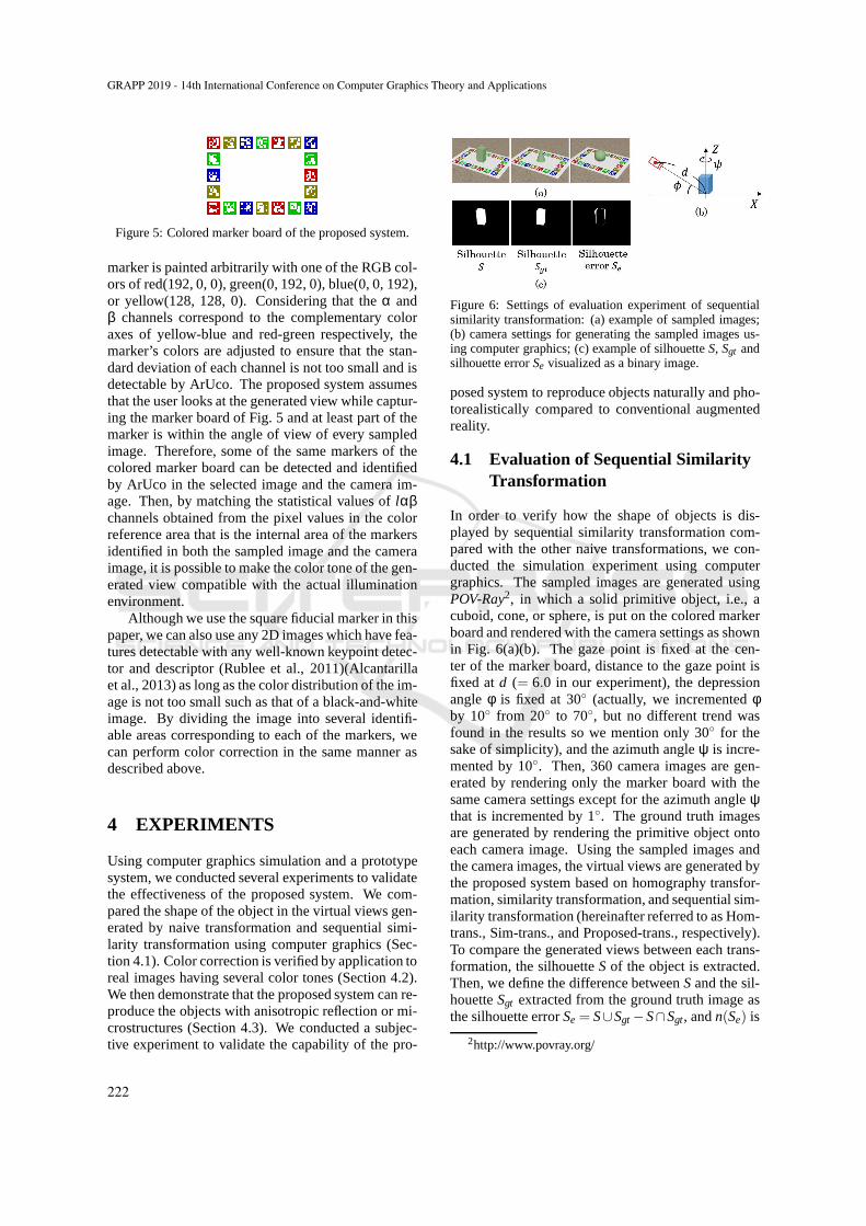
Figure 5: Colored marker board of the proposed system.
marker is painted arbitrarily with one of the RGB col-ors of red(192, 0, 0), green(0, 192, 0), blue(0, 0, 192),or yellow(128, 128, 0). Considering that theα andβ channels correspond to the complementary coloraxes of yellow-blue and red-green respectively, themarker’s colors are adjusted to ensure that the stan-dard deviation of each channel is not too small and isdetectable by ArUco. The proposed system assumesthat the user looks at the generated view while captur-ing the marker board of Fig. 5 and at least part of themarker is within the angle of view of every sampledimage. Therefore, some of the same markers of thecolored marker board can be detected and identifiedby ArUco in the selected image and the camera im-age. Then, by matching the statistical values oflαβchannels obtained from the pixel values in the colorreference area that is the internal area of the markersidentified in both the sampled image and the cameraimage, it is possible to make the color tone of the gen-erated view compatible with the actual illuminationenvironment.
Although we use the square fiducial marker in thispaper, we can also use any 2D images which have fea-tures detectable with any well-known keypoint detec-tor and descriptor (Rublee et al., 2011)(Alcantarillaet al., 2013) as long as the color distribution of the im-age is not too small such as that of a black-and-whiteimage. By dividing the image into several identifi-able areas corresponding to each of the markers, wecan perform color correction in the same manner asdescribed above.
4 EXPERIMENTS
Using computer graphics simulation and a prototypesystem, we conducted several experiments to validatethe effectiveness of the proposed system. We com-pared the shape of the object in the virtual views gen-erated by naive transformation and sequential simi-larity transformation using computer graphics (Sec-tion 4.1). Color correction is verified by application toreal images having several color tones (Section 4.2).We then demonstrate that the proposed system can re-produce the objects with anisotropic reflection or mi-crostructures (Section 4.3). We conducted a subjec-tive experiment to validate the capability of the pro-
Figure 6: Settings of evaluation experiment of sequentialsimilarity transformation: (a) example of sampled images;(b) camera settings for generating the sampled images us-ing computer graphics; (c) example of silhouetteS, Sgt andsilhouette errorSe visualized as a binary image.
posed system to reproduce objects naturally and pho-torealistically compared to conventional augmentedreality.
4.1 Evaluation of Sequential SimilarityTransformation
In order to verify how the shape of objects is dis-played by sequential similarity transformation com-pared with the other naive transformations, we con-ducted the simulation experiment using computergraphics. The sampled images are generated usingPOV-Ray2, in which a solid primitive object, i.e., acuboid, cone, or sphere, is put on the colored markerboard and rendered with the camera settings as shownin Fig. 6(a)(b). The gaze point is fixed at the cen-ter of the marker board, distance to the gaze point isfixed atd (= 6.0 in our experiment), the depressionangleφ is fixed at 30◦ (actually, we incrementedφby 10◦ from 20◦ to 70◦, but no different trend wasfound in the results so we mention only 30◦ for thesake of simplicity), and the azimuth angleψ is incre-mented by 10◦. Then, 360 camera images are gen-erated by rendering only the marker board with thesame camera settings except for the azimuth angleψthat is incremented by 1◦. The ground truth imagesare generated by rendering the primitive object ontoeach camera image. Using the sampled images andthe camera images, the virtual views are generated bythe proposed system based on homography transfor-mation, similarity transformation, and sequential sim-ilarity transformation (hereinafter referred to as Hom-trans., Sim-trans., and Proposed-trans., respectively).To compare the generated views between each trans-formation, the silhouetteS of the object is extracted.Then, we define the difference betweenSand the sil-houetteSgt extracted from the ground truth image asthe silhouette errorSe = S∪Sgt −S∩Sgt, andn(Se) is
2http://www.povray.org/
GRAPP 2019 - 14th International Conference on Computer Graphics Theory and Applications
222
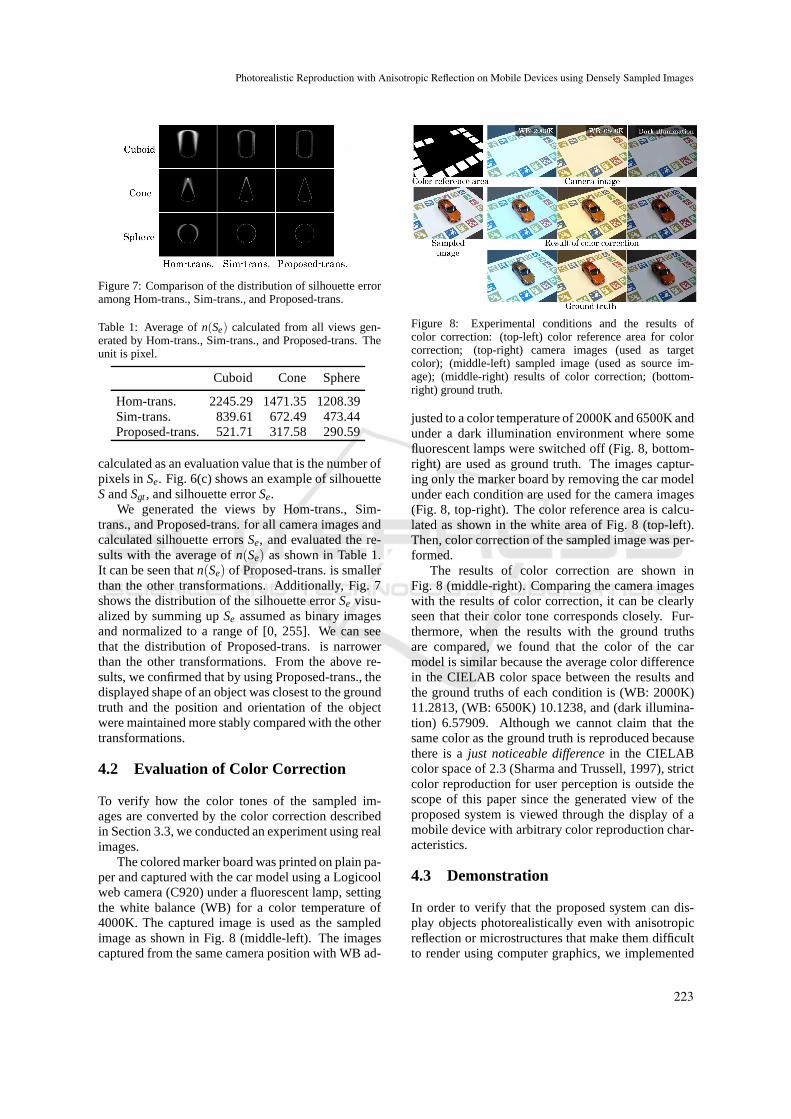
Figure 7: Comparison of the distribution of silhouette erroramong Hom-trans., Sim-trans., and Proposed-trans.
Table 1: Average ofn(Se) calculated from all views gen-erated by Hom-trans., Sim-trans., and Proposed-trans. Theunit is pixel.
Cuboid Cone Sphere
Hom-trans. 2245.29 1471.35 1208.39Sim-trans. 839.61 672.49 473.44Proposed-trans. 521.71 317.58 290.59
calculated as an evaluation value that is the number ofpixels inSe. Fig. 6(c) shows an example of silhouetteSandSgt, and silhouette errorSe.
We generated the views by Hom-trans., Sim-trans., and Proposed-trans. for all camera images andcalculated silhouette errorsSe, and evaluated the re-sults with the average ofn(Se) as shown in Table 1.It can be seen thatn(Se) of Proposed-trans. is smallerthan the other transformations. Additionally, Fig. 7shows the distribution of the silhouette errorSe visu-alized by summing upSe assumed as binary imagesand normalized to a range of [0, 255]. We can seethat the distribution of Proposed-trans. is narrowerthan the other transformations. From the above re-sults, we confirmed that by using Proposed-trans., thedisplayed shape of an object was closest to the groundtruth and the position and orientation of the objectwere maintained more stably compared with the othertransformations.
4.2 Evaluation of Color Correction
To verify how the color tones of the sampled im-ages are converted by the color correction describedin Section 3.3, we conducted an experiment using realimages.
The colored marker board was printed on plain pa-per and captured with the car model using a Logicoolweb camera (C920) under a fluorescent lamp, settingthe white balance (WB) for a color temperature of4000K. The captured image is used as the sampledimage as shown in Fig. 8 (middle-left). The imagescaptured from the same camera position with WB ad-
Figure 8: Experimental conditions and the results ofcolor correction: (top-left) color reference area for colorcorrection; (top-right) camera images (used as targetcolor); (middle-left) sampled image (used as source im-age); (middle-right) results of color correction; (bottom-right) ground truth.
justed to a color temperature of 2000K and 6500K andunder a dark illumination environment where somefluorescent lamps were switched off (Fig. 8, bottom-right) are used as ground truth. The images captur-ing only the marker board by removing the car modelunder each condition are used for the camera images(Fig. 8, top-right). The color reference area is calcu-lated as shown in the white area of Fig. 8 (top-left).Then, color correction of the sampled image was per-formed.
The results of color correction are shown inFig. 8 (middle-right). Comparing the camera imageswith the results of color correction, it can be clearlyseen that their color tone corresponds closely. Fur-thermore, when the results with the ground truthsare compared, we found that the color of the carmodel is similar because the average color differencein the CIELAB color space between the results andthe ground truths of each condition is (WB: 2000K)11.2813, (WB: 6500K) 10.1238, and (dark illumina-tion) 6.57909. Although we cannot claim that thesame color as the ground truth is reproduced becausethere is ajust noticeable differencein the CIELABcolor space of 2.3 (Sharma and Trussell, 1997), strictcolor reproduction for user perception is outside thescope of this paper since the generated view of theproposed system is viewed through the display of amobile device with arbitrary color reproduction char-acteristics.
4.3 Demonstration
In order to verify that the proposed system can dis-play objects photorealistically even with anisotropicreflection or microstructures that make them difficultto render using computer graphics, we implemented
Photorealistic Reproduction with Anisotropic Reflection on Mobile Devices using Densely Sampled Images
223
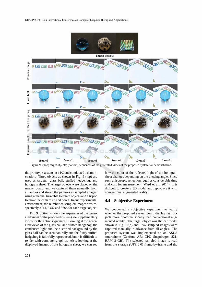
Figure 9: (Top) target objects; (bottom) sequences of the generated views of the proposed system for demonstration.
the prototype system on a PC and conducted a demon-stration. Three objects as shown in Fig. 9 (top) areused as targets: glass ball, stuffed hedgehog, andhologram sheet. The target objects were placed on themarker board, and we captured them manually fromall angles and stored the pictures as sampled images,using a manual turntable to rotate objects and a tripodto move the camera up and down. In our experimentalenvironment, the number of sampled images was re-spectively 3741, 3442 and 3665 for each target object.
Fig. 9 (bottom) shows the sequences of the gener-ated views of the proposed system (see supplementaryvideo for the entire sequences). Looking at the gener-ated views of the glass ball and stuffed hedgehog, thecondensed light and the distorted background by theglass ball can be seen naturally and the fluffy stuffedhedgehog is faithfully reproduced, but it is difficult torender with computer graphics. Also, looking at thedisplayed images of the hologram sheet, we can see
how the color of the reflected light of the hologramsheet changes depending on the viewing angle. Sincesuch anisotropic reflection requires considerable timeand cost for measurement (Ward et al., 2014), it isdifficult to create a 3D model and reproduce it withconventional augmented reality.
4.4 Subjective Experiment
We conducted a subjective experiment to verifywhether the proposed system could display real ob-jects more photorealistically than conventional aug-mented reality. The target object was the car modelshown in Fig. 10(b) and 3747 sampled images werecaptured manually in advance from all angles. Theproposed system was implemented on an ASUSsmartphone (Zenfone AR: CPU Snapdragon 821,RAM 8 GB). The selected sampled image is readfrom the storage (UFS 2.0) frame-by-frame and the
GRAPP 2019 - 14th International Conference on Computer Graphics Theory and Applications
224
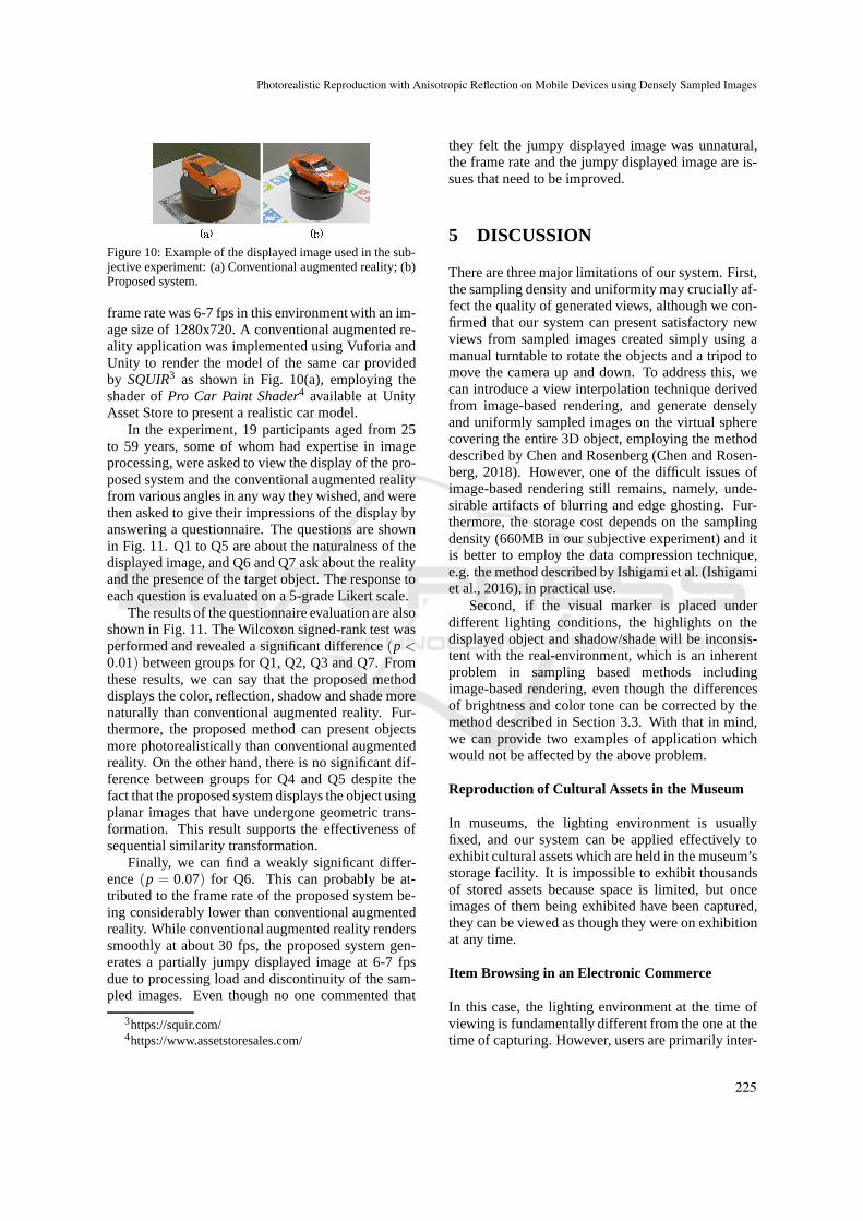
Figure 10: Example of the displayed image used in the sub-jective experiment: (a) Conventional augmented reality; (b)Proposed system.
frame rate was 6-7 fps in this environment with an im-age size of 1280x720. A conventional augmented re-ality application was implemented using Vuforia andUnity to render the model of the same car providedby SQUIR3 as shown in Fig. 10(a), employing theshader ofPro Car Paint Shader4 available at UnityAsset Store to present a realistic car model.
In the experiment, 19 participants aged from 25to 59 years, some of whom had expertise in imageprocessing, were asked to view the display of the pro-posed system and the conventional augmented realityfrom various angles in any way they wished, and werethen asked to give their impressions of the display byanswering a questionnaire. The questions are shownin Fig. 11. Q1 to Q5 are about the naturalness of thedisplayed image, and Q6 and Q7 ask about the realityand the presence of the target object. The response toeach question is evaluated on a 5-grade Likert scale.
The results of the questionnaire evaluation are alsoshown in Fig. 11. The Wilcoxon signed-rank test wasperformed and revealed a significant difference(p<
0.01) between groups for Q1, Q2, Q3 and Q7. Fromthese results, we can say that the proposed methoddisplays the color, reflection, shadow and shade morenaturally than conventional augmented reality. Fur-thermore, the proposed method can present objectsmore photorealistically than conventional augmentedreality. On the other hand, there is no significant dif-ference between groups for Q4 and Q5 despite thefact that the proposed system displays the object usingplanar images that have undergone geometric trans-formation. This result supports the effectiveness ofsequential similarity transformation.
Finally, we can find a weakly significant differ-ence(p = 0.07) for Q6. This can probably be at-tributed to the frame rate of the proposed system be-ing considerably lower than conventional augmentedreality. While conventional augmented reality renderssmoothly at about 30 fps, the proposed system gen-erates a partially jumpy displayed image at 6-7 fpsdue to processing load and discontinuity of the sam-pled images. Even though no one commented that
3https://squir.com/4https://www.assetstoresales.com/
they felt the jumpy displayed image was unnatural,the frame rate and the jumpy displayed image are is-sues that need to be improved.
5 DISCUSSION
There are three major limitations of our system. First,the sampling density and uniformity may crucially af-fect the quality of generated views, although we con-firmed that our system can present satisfactory newviews from sampled images created simply using amanual turntable to rotate the objects and a tripod tomove the camera up and down. To address this, wecan introduce a view interpolation technique derivedfrom image-based rendering, and generate denselyand uniformly sampled images on the virtual spherecovering the entire 3D object, employing the methoddescribed by Chen and Rosenberg (Chen and Rosen-berg, 2018). However, one of the difficult issues ofimage-based rendering still remains, namely, unde-sirable artifacts of blurring and edge ghosting. Fur-thermore, the storage cost depends on the samplingdensity (660MB in our subjective experiment) and itis better to employ the data compression technique,e.g. the method described by Ishigami et al. (Ishigamiet al., 2016), in practical use.
Second, if the visual marker is placed underdifferent lighting conditions, the highlights on thedisplayed object and shadow/shade will be inconsis-tent with the real-environment, which is an inherentproblem in sampling based methods includingimage-based rendering, even though the differencesof brightness and color tone can be corrected by themethod described in Section 3.3. With that in mind,we can provide two examples of application whichwould not be affected by the above problem.
Reproduction of Cultural Assets in the Museum
In museums, the lighting environment is usuallyfixed, and our system can be applied effectively toexhibit cultural assets which are held in the museum’sstorage facility. It is impossible to exhibit thousandsof stored assets because space is limited, but onceimages of them being exhibited have been captured,they can be viewed as though they were on exhibitionat any time.
Item Browsing in an Electronic Commerce
In this case, the lighting environment at the time ofviewing is fundamentally different from the one at thetime of capturing. However, users are primarily inter-
Photorealistic Reproduction with Anisotropic Reflection on Mobile Devices using Densely Sampled Images
225
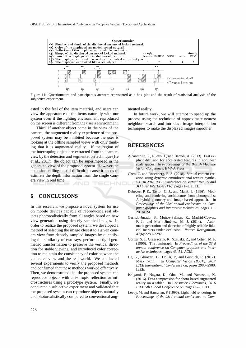
Figure 11: Questionnaire and participant’s answers represented as a box plot and the result of statistical analysis of thesubjective experiment.
ested in the feel of the item material, and users canview the appearance of the items naturally with oursystem even if the lighting environment reproducedon the screen is different from the user’s environment.
Third, if another object come in the view of thecamera, the augmented reality experience of the pro-posed system may be inhibited because the user islooking at the offline sampled views with only think-ing that it is augmented reality. If the region ofthe interrupting object are extracted from the cameraview by the detection and segmentation technique (Heet al., 2017), the object can be superimposed in thegenerated view of the proposed system. However theocclusion culling is still difficult because it needs toestimate the depth information from the single cam-era view in real time.
6 CONCLUSIONS
In this research, we propose a novel system for useon mobile devices capable of reproducing real ob-jects photorealistically from all angles based on newview generation using densely sampled images. Inorder to realize the proposed system, we developed amethod of selecting the image closest to a given cam-era view from densely sampled images by quantify-ing the similarity of two rays, performed rigid geo-metric transformation to preserve the vertical direc-tion for stable viewing, and introduced color correc-tion to maintain the consistency of color between thegenerated view and the real world. We conductedseveral experiments to verify the proposed methodsand confirmed that these methods worked effectively.Then, we demonstrated that the proposed system canreproduce objects with anisotropic reflection or mi-crostructures using a prototype system. Finally, weconducted a subjective experiment and validated thatthe proposed system can reproduce objects naturallyand photorealistically compared to conventional aug-
mented reality.In future work, we will attempt to speed up the
process using the technique of approximate nearestneighbors search and introduce image interpolationtechniques to make the displayed images smoother.
REFERENCES
Alcantarilla, P., Nuevo, J., and Bartoli, A. (2013). Fast ex-plicit diffusion for accelerated features in nonlinearscale spaces. InProceedings of the British MachineVision Conference. BMVA Press.
Chen, C. and Rosenberg, E. S. (2018). Virtual content cre-ation using dynamic omnidirectional texture synthe-sis. In2018 IEEE Conference on Virtual Reality and3D User Interfaces (VR), pages 1–2. IEEE.
Debevec, P. E., Taylor, C. J., and Malik, J. (1996). Mod-eling and rendering architecture from photographs:A hybrid geometry-and image-based approach. InProceedings of the 23rd annual conference on Com-puter graphics and interactive techniques, pages 11–20. ACM.
Garrido-Jurado, S., Munoz-Salinas, R., Madrid-Cuevas,F. J., and Marın-Jimenez, M. J. (2014). Auto-matic generation and detection of highly reliable fidu-cial markers under occlusion.Pattern Recognition,47(6):2280–2292.
Gortler, S. J., Grzeszczuk, R., Szeliski, R., and Cohen, M. F.(1996). The lumigraph. InProceedings of the 23rdannual conference on Computer graphics and inter-active techniques, pages 43–54. ACM.
He, K., Gkioxari, G., Dollar, P., and Girshick, R. (2017).Mask r-cnn. In Computer Vision (ICCV), 2017IEEE International Conference on, pages 2980–2988.IEEE.
Ishigami, F., Nagata, K., Ohta, M., and Yamashita, K.(2016). Data compression for photo-based augmentedreality on a tablet. InConsumer Electronics, 2016IEEE 5th Global Conference on, pages 1–2. IEEE.
Levoy, M. and Hanrahan, P. (1996). Light field rendering. InProceedings of the 23rd annual conference on Com-
GRAPP 2019 - 14th International Conference on Computer Graphics Theory and Applications
226
puter graphics and interactive techniques, pages 31–42. ACM.
Mukaigawa, Y., Sumino, K., and Yagi, Y. (2009). Rapidbrdf measurement using an ellipsoidal mirror and aprojector. IPSJ Transactions on Computer Vision andApplications, 1:21–32.
Nicodemus, F. E., Richmond, J. C., Hsia, J. J., Ginsberg,I. W., and Limperis, T. (1977). Geometrical con-siderations and nomenclature for reflectance, volume160. US Department of Commerce, National Bureauof Standards.
Ohta, M., Sato, T., Motokurumada, M., and Yamashita, K.(2013). Real-time color correction for a photo-basedaugmented reality system. InConsumer Electronics(GCCE), 2013 IEEE 2nd Global Conference on, pages102–103. IEEE.
Ohta, M., Yokomichi, R., Motokurumada, M., and Ya-mashita, K. (2012). A photo-based augmented realitysystem with html5/javascript. InConsumer Electron-ics (GCCE), 2012 IEEE 1st Global Conference on,pages 425–426. IEEE.
Reinhard, E., Adhikhmin, M., Gooch, B., and Shirley, P.(2001). Color transfer between images.IEEE Com-puter graphics and applications, 21(5):34–41.
Rock, I. (1974). The effect of retinal and phenomenal orien-tation of the perception of form.Scientific American,230(1):78–86.
Rublee, E., Rabaud, V., Konolige, K., and Bradski, G.(2011). Orb: An efficient alternative to sift or surf.In Computer Vision (ICCV), 2011 IEEE internationalconference on, pages 2564–2571. IEEE.
Ruderman, D. L., Cronin, T. W., and Chiao, C.-C. (1998).Statistics of cone responses to natural images: impli-cations for visual coding.JOSA A, 15(8):2036–2045.
Shade, J., Gortler, S., He, L.-w., and Szeliski, R. (1998).Layered depth images. InProceedings of the 25th an-nual conference on Computer graphics and interac-tive techniques, pages 231–242. ACM.
Sharma, G. and Trussell, H. J. (1997). Digital colorimaging. IEEE Transactions on Image Processing,6(7):901–932.
Shum, H.-Y., Sun, J., Yamazaki, S., Li, Y., and Tang, C.-K.(2004). Pop-up light field: An interactive image-basedmodeling and rendering system.ACM Transactionson Graphics (TOG), 23(2):143–162.
Sinha, S. N., Kopf, J., Goesele, M., Scharstein, D., andSzeliski, R. (2012). Image-based rendering for sceneswith reflections.ACM Trans. Graph., 31(4):100–1.
Suzuki, K., Wakisaka, S., and Fujii, N. (2012). Substitu-tional reality system: a novel experimental platformfor experiencing alternative reality.Scientific reports,2:srep00459.
Tsai, R. (1987). A versatile camera calibration techniquefor high-accuracy 3d machine vision metrology usingoff-the-shelf tv cameras and lenses.IEEE Journal onRobotics and Automation, 3(4):323–344.
Tunwattanapong, B., Fyffe, G., Graham, P., Busch, J., Yu,X., Ghosh, A., and Debevec, P. (2013). Acquiringreflectance and shape from continuous spherical har-
monic illumination. ACM Transactions on graphics(TOG), 32(4):109.
Vagharshakyan, S., Bregovic, R., and Gotchev, A. (2015).Image based rendering technique via sparse represen-tation in shearlet domain. In2015 IEEE InternationalConference on Image Processing (ICIP), pages 1379–1383. IEEE.
Ward, G., Kurt, M., and Bonneel, N. (2014). Reducinganisotropic bsdf measurement to common practice. InMaterial Appearance Modeling, pages 5–8.
Wood, D. N., Azuma, D. I., Aldinger, K., Curless, B.,Duchamp, T., Salesin, D. H., and Stuetzle, W. (2000).Surface light fields for 3d photography. InPro-ceedings of the 27th annual conference on Computergraphics and interactive techniques, pages 287–296.ACM Press/Addison-Wesley Publishing Co.
Photorealistic Reproduction with Anisotropic Reflection on Mobile Devices using Densely Sampled Images
227