not for reproduction - toyota manuals
TRANSCRIPT
Not For R
epro
duction
TABLE OF CONTENTS
1
LC150_OM_OM60J77E_(AE)
1 Before driving Adjusting and operating features such as door locks, mirrors, and steering column.
2 When driving Driving, stopping and safe-driving information.
3 Interior features Air conditioning and audio systems, as well as other in-terior features for a comfortable driving experience.
4 Maintenance and care
Cleaning and protecting your vehicle, performing do-it-yourself maintenance, and maintenance information.
5 When trouble arises
What to do if the vehicle needs to be towed, gets a flat tire, or is involved in an accident.
6 Vehicle specifications Detailed vehicle information.
Index Alphabetical listing of information contained in this man-ual.
Not For R
epro
duction
TABLE OF CONTENTS Index
2
LC150_OM_OM60J77E_(AE)
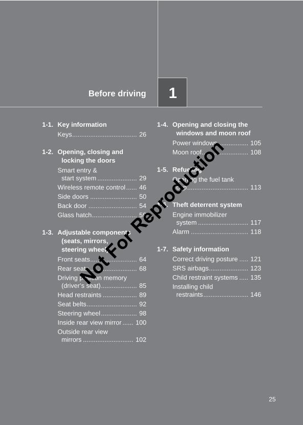
1-1. Key informationKeys...................................... 26
1-2. Opening, closing and locking the doors
Smart entry & start system ... 29Wireless remote control ........ 46Side doors............................. 50Back door.............................. 54Glass hatch........................... 59
1-3. Adjustable components (seats, mirrors, steering wheel)
Front seats............................ 64Rear seats ............................ 68Driving position memory
(driver’s seat) ...................... 85Head restraints ..................... 89Seat belts.............................. 92Steering wheel ...................... 98Inside rear view mirror ........ 100Outside rear view mirrors.... 102
1-4. Opening and closing the windows and moon roof
Power windows .................. 105Moon roof ........................... 108
1-5. RefuelingOpening the fuel tank
cap ................................... 113
1-6. Theft deterrent systemEngine immobilizer
system.............................. 117Alarm.................................. 118
1-7. Safety informationCorrect driving posture....... 121SRS airbags ....................... 123Child restraint systems....... 135Installing child restraints..... 146
1 Before driving
For vehicles with a navigation system, refer to the “Navigation System Owner’sManual” for information regarding the equipment listed below.
• Navigation system• Air conditioning• Hands-free system (for cellular
phone)• Toyota parking assist monitor
• Rear view monitor system• Rear seat entertainment system• Audio/video system• Toyota parking assist-sensor• Wide view front & side monitor
Not For R
epro
duction
1
2
3
4
5
6
3
LC150_OM_OM60J77E_(AE)
2-1. Driving proceduresDriving the vehicle .............. 162Engine (ignition) switch
(vehicles without a smart entry & start system)......... 175
Engine (ignition) switch (vehicles with a smart entry & start system)......... 179
Automatic transmission....... 187Manual transmission........... 193Turn signal lever ................. 195Parking brake...................... 196Horn .................................... 197
2-2. Instrument clusterGauges and meters ............ 198Indicators and warning
lights ................................. 202Multi-information display
(Non-Optitron type meters) ............................. 206
Multi-information display (Optitron type meters)....... 211
Multi-information display (Accessory meters)........... 219
2-3. Operating the lights and wipers
Headlight switch ................. 226Fog light switch .................. 232Windshield wipers and
washer ............................. 233Rear window wiper and
washer ............................. 238Headlight cleaner switch .... 240
2-4. Using other driving systemsCruise control ..................... 242Dynamic radar cruise
control .............................. 246Toyota parking
assist-sensor.................... 259Rear view monitor system
(vehicles with an accessory meter)............................... 269
Wide view front & side monitor (vehicles with an accessory meter)............................... 273
Driving assist systems........ 281PCS (Pre-Crash Safety
system) ............................ 287
2-5. Driving informationCargo and luggage............. 294Winter driving tips............... 297Trailer towing...................... 300
2 When driving
Not For R
epro
duction
TABLE OF CONTENTS Index
4
LC150_OM_OM60J77E_(AE)
3-1. Using the air conditioning system and defogger
Front manual air conditioning system .............................. 314
Front automatic air conditioning system .............................. 320
Rear manual air conditioning system .............................. 330
Rear automatic air conditioning system .............................. 333
Heater idle up switch .......... 336Rear window defogger
switch................................ 337
3-2. Using the audio systemAudio system types............. 339Using the radio.................... 341Using the CD player............ 344Playing MP3 and
WMA discs........................ 353Operating an iPod............... 361Operating a USB
memory............................. 369Optimal use of the audio
system .............................. 378Using the AUX port ............. 381Using the steering wheel
audio switches .................. 383
3-3. Using the hands-free system (for mobile phone)
Hands-free system (for mobile phone)............ 386
Using the hands-free system (for mobile phone)............ 391
Making a phone call ........... 397Setting a mobile phone ...... 400Security and system
setup ................................ 403Using the phone book ........ 406
3-4. Using the interior lightsInterior lights list ................. 410• Personal/interior light
main switch ...................... 411• Personal/interior lights ..... 412• Lounge illumination control
switches ........................... 413
3-5. Using the storage featuresList of storage features....... 415• Glove box......................... 416• Card holder ...................... 417• Console box ..................... 418• Bottle holders/door
pockets............................. 420• Cup holders...................... 421• Auxiliary boxes................. 425
3 Interior features
Not For R
epro
duction
1
2
3
4
5
6
5
LC150_OM_OM60J77E_(AE)
3-6. Other interior featuresCool box.............................. 428Sun visors ........................... 431Vanity mirror ....................... 432Clock................................... 433Outside temperature
display .............................. 434Ashtray................................ 436Conversation mirror ............ 437Power outlet........................ 438Seat heaters ....................... 442Armrest ............................... 445Coat hooks.......................... 446Assist grips ......................... 447Floor mat............................. 448Luggage compartment
features............................. 450
4-1. Maintenance and careCleaning and protecting
the vehicle exterior........... 458Cleaning and protecting
the vehicle interior............ 462
4-2. MaintenanceMaintenance
requirements .................... 465
4-3. Do-it-yourself maintenanceDo-it-yourself service
precautions ...................... 468Hood................................... 472Engine compartment .......... 473Tires ................................... 492Tire inflation pressure......... 495Wheels ............................... 497Air conditioning filter........... 499Wireless remote control/
electronic key battery ....... 501Checking and replacing
fuses ................................ 505Light bulbs.......................... 517
4 Maintenance and care
Not For R
epro
duction
TABLE OF CONTENTS Index
6
LC150_OM_OM60J77E_(AE)
5-1. Essential informationEmergency flashers ............ 532If your vehicle needs
to be towed ....................... 534If you think something is
wrong................................ 541Fuel pump shut off system
(gasoline engine only) ...... 542
5-2. Steps to take in an emergencyIf a warning light turns
on or a warning buzzer sounds... ........................... 543
If a warning message is displayed .......................... 553
If you have a flat tire ........... 573If the engine will
not start............................. 592If the shift lever cannot be
shifted from P ................... 594If you lose your keys ........... 595If the electronic key does
not operate properly ......... 596If the vehicle battery is
discharged ........................ 599If your vehicle overheats..... 604If you run out of fuel and
the engine stalls (diesel engine only) .......... 607
If the vehicle becomes stuck ................................. 608
If your vehicle has to be stopped in an emergency ............... 610
6-1. SpecificationsMaintenance data
(fuel, oil level, etc.) ........... 614Fuel information ................. 630
6-2. CustomizationCustomizable features ....... 632
Abbreviation list ............... 644
Alphabetical index ........... 645
What to do if... ................. 654
5 When trouble arises 6 Vehicle specifications
Index
Not For R
epro
duction

1
2
3
4
5
6
7
LC150_OM_OM60J77E_(AE)
Not For R
epro
duction
8
LC150_OM_OM60J77E_(AE)
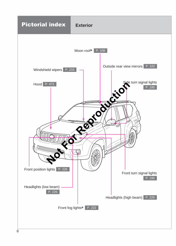
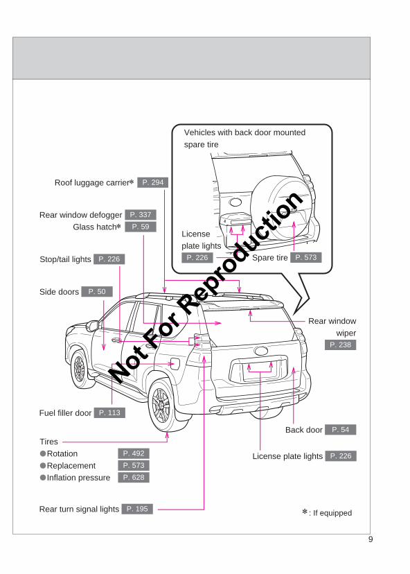
Pictorial index Exterior
Headlights (low beam)P. 226
Headlights (high beam) P. 226
Front fog lights∗ P. 232
Hood P. 472
Windshield wipers P. 233
Moon roof∗ P. 108
Outside rear view mirrors P. 102
Front turn signal lightsP. 195
Side turn signal lightsP. 195
Front position lights P. 226Not F
or Rep
roducti
on
9
LC150_OM_OM60J77E_(AE)
∗: If equipped
Vehicles with back door mounted spare tire
Spare tire P. 573
License plate lights
P. 226
Tires●Rotation●Replacement●Inflation pressure
P. 492P. 573P. 628
Back door P. 54
Fuel filler door P. 113
Rear turn signal lights P. 195
Side doors P. 50
Rear window defogger Glass hatch∗
P. 337P. 59
License plate lights P. 226
Stop/tail lights P. 226
Roof luggage carrier∗ P. 294
Rear windowwiper
P. 238
Not For R
epro
duction
10
LC150_OM_OM60J77E_(AE)
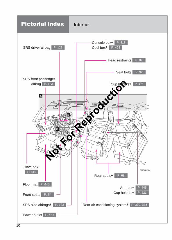
Pictorial index Interior
Rear seats∗ P. 68
Cup holders∗ P. 421SRS front passenger
airbag P. 123
SRS driver airbag P. 123
Head restraints P. 89
Console box∗ Cool box∗
P. 418P. 428
Armrest∗ Cup holders∗
P. 445P. 421
Glove boxP. 416
Rear air conditioning system∗ P. 330, 333SRS side airbags∗ P. 123
Power outlet P. 438
Floor mat P. 448
Front seats P. 64
Seat belts P. 92
Not For R
epro
duction
11
LC150_OM_OM60J77E_(AE)
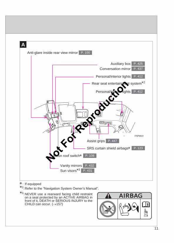
A
Moon roof switch∗ P. 108
Vanity mirrors Sun visors*3
P. 432P. 431
SRS curtain shield airbags∗ P. 123
Auxiliary box Conversation mirror
P. 425P. 437
Personal/interior lights P. 412
Rear seat entertainment system*2
Personal/interior lights P. 412
Anti-glare inside rear view mirror P. 100
Assist grips P. 447
∗: If equipped*2: Refer to the “Navigation System Owner’s Manual”.
*3: NEVER use a rearward facing child restrainton a seat protected by an ACTIVE AIRBAG infront of it, DEATH or SERIOUS INJURY to theCHILD can occur. (→157)
Not For R
epro
duction
12
LC150_OM_OM60J77E_(AE)
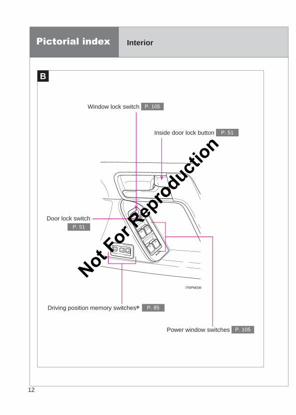
B
Pictorial index Interior
Window lock switch P. 105
Power window switches P. 105
Door lock switchP. 51
Driving position memory switches∗ P. 85
Inside door lock button P. 51
Not For R
epro
duction
13
LC150_OM_OM60J77E_(AE)
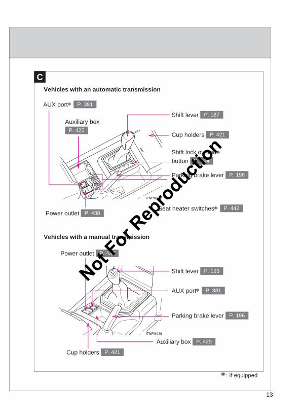
C
∗: If equipped
Cup holders P. 421
Parking brake lever P. 196
Vehicles with an automatic transmission
Vehicles with a manual transmission
Shift lever P. 187Auxiliary box
P. 425
AUX port∗ P. 381
Power outlet P. 438Seat heater switches∗ P. 442
Shift lock override button P. 594
Parking brake lever P. 196
Shift lever P. 193
Auxiliary box P. 425
AUX port∗ P. 381
Power outlet P. 438
Cup holders P. 421
Not For R
epro
duction
14
LC150_OM_OM60J77E_(AE)
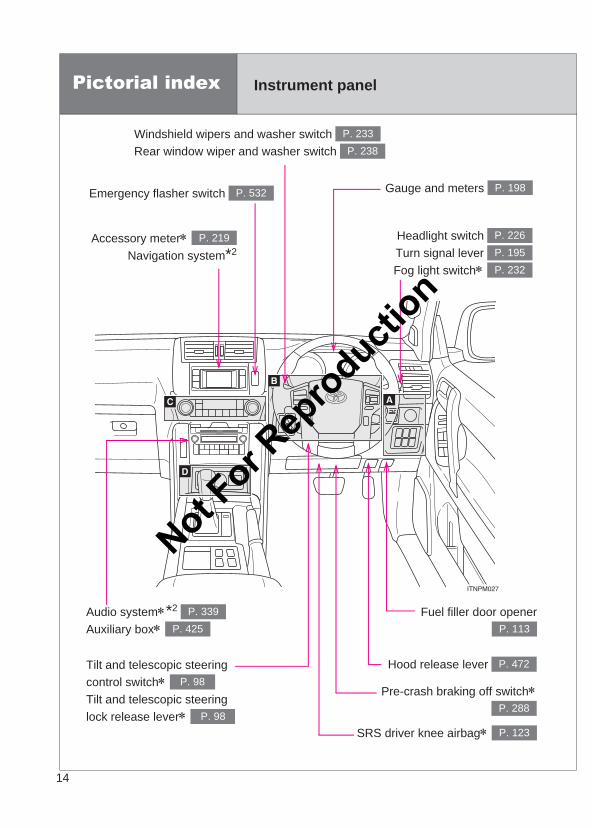
Pictorial index Instrument panel
Headlight switch Turn signal lever Fog light switch∗
P. 226P. 195P. 232
Windshield wipers and washer switch Rear window wiper and washer switch
P. 233P. 238
Gauge and meters P. 198
SRS driver knee airbag∗ P. 123
Fuel filler door openerP. 113
Emergency flasher switch P. 532
Accessory meter∗ Navigation system*2
P. 219
Hood release lever P. 472
Audio system∗*2 Auxiliary box∗
P. 339P. 425
Tilt and telescopic steering control switch∗ Tilt and telescopic steering lock release lever∗
P. 98
P. 98
Pre-crash braking off switch∗P. 288
Not For R
epro
duction
15
LC150_OM_OM60J77E_(AE)
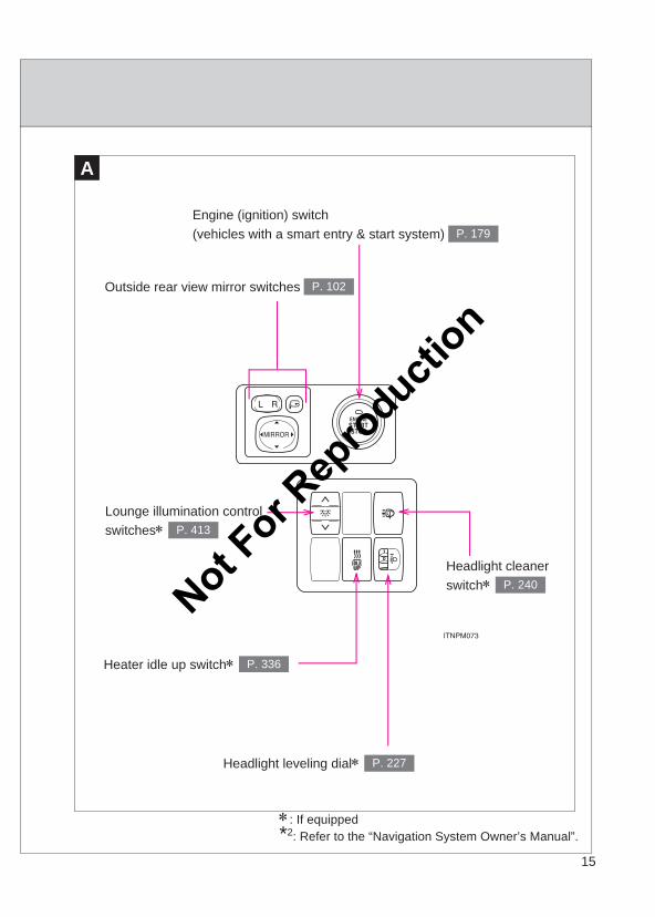
A
∗: If equipped*2: Refer to the “Navigation System Owner’s Manual”.
Outside rear view mirror switches P. 102
Headlight cleaner switch∗ P. 240
Headlight leveling dial∗ P. 227
Heater idle up switch∗ P. 336
Lounge illumination control switches∗ P. 413
Engine (ignition) switch (vehicles with a smart entry & start system) P. 179
Not For R
epro
duction
16
LC150_OM_OM60J77E_(AE)
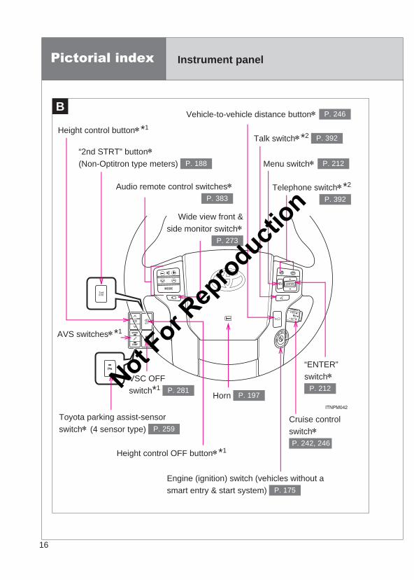
B
Pictorial index Instrument panel
Wide view front &side monitor switch∗
P. 273
VSC OFF switch*1 P. 281
Telephone switch∗*2
P. 392
Audio remote control switches∗P. 383
Vehicle-to-vehicle distance button∗ P. 246
Menu switch∗ P. 212“2nd STRT” button∗ (Non-Optitron type meters) P. 188
Toyota parking assist-sensor switch∗ (4 sensor type) P. 259
Height control button∗*1
Horn P. 197
Talk switch∗*2 P. 392
Height control OFF button∗*1
“ENTER” switch∗
P. 212
Cruise control switch∗ P. 242, 246
Engine (ignition) switch (vehicles without a smart entry & start system) P. 175
AVS switches∗*1
Not For R
epro
duction
17
LC150_OM_OM60J77E_(AE)
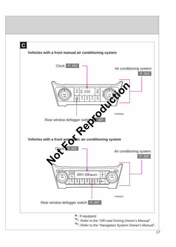
CVehicles with a front manual air conditioning system
Vehicles with a front automatic air conditioning system
Clock P. 433
Rear window defogger switch P. 337
Air conditioning systemP. 314
Clock P. 433
Rear window defogger switch P. 337
Air conditioning systemP. 320
∗: If equipped*1: Refer to the “Off-road Driving Owner’s Manual”.*2: Refer to the “Navigation System Owner’s Manual”.
Not For R
epro
duction
18
LC150_OM_OM60J77E_(AE)
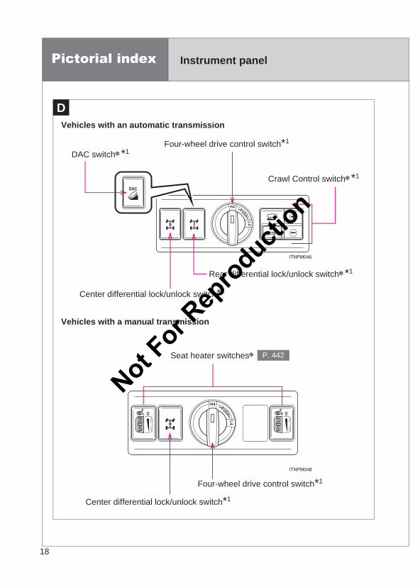
D
Pictorial index Instrument panel
Vehicles with an automatic transmission
Vehicles with a manual transmission
Seat heater switches∗ P. 442
Center differential lock/unlock switch*1
Four-wheel drive control switch*1
Four-wheel drive control switch*1
DAC switch∗*1
Rear differential lock/unlock switch∗*1
Center differential lock/unlock switch*1
Crawl Control switch∗*1
Not For R
epro
duction

19
LC150_OM_OM60J77E_(AE)
∗: If equipped*1: Refer to the “Off-road Driving Owner’s Manual”.
Not For R
epro
duction
20
LC150_OM_OM60J77E_(AE)
For your information
Main Owners Manual
Please note that this manual applies to all models and all equipment, includ-ing options. Therefore, you may find some explanations for equipment notinstalled on your vehicle.
All specifications provided in this manual are current at the time of printing.However, because of the Toyota policy of continual product improvement, wereserve the right to make changes at any time without notice.
Depending on specifications, the vehicle shown in the illustrations may differfrom your vehicle in terms of equipment.
Accessories, spare parts and modification of your Toyota
A wide variety of non-genuine spare parts and accessories for Toyotavehicles are currently available in the market. Using these spare parts andaccessories which are not genuine Toyota produces may adversely affectthe safety of your vehicle, even though these parts may be approved bycertain authorities in your country. Toyota therefore cannot accept anyliability or guarantee spare parts and accessories which are not genuineToyota products, nor for replacement or installation involving such parts.
This vehicle should not be modified with non-genuine Toyota products.Modification with non-genuine Toyota products could affect its performance,safety or durability, and may even violate governmental regulations. Inaddition, damage or performance problems resulting from the modificationmay not be covered under warranty.
Installation of a mobile two-way radio system
As the installation of a mobile two-way radio system in your vehicle mayaffect electronic systems such as the multi-port fuel injection system/sequen-tial multi-port fuel injection system, cruise control system, anti-lock brakesystem, SRS airbag system and seat belt pretensioner system, be sure tocheck with your Toyota dealer for precautionary measures or special instruc-tions regarding installation.
Not For R
epro
duction
21
LC150_OM_OM60J77E_(AE)
Vehicle data recordings
Your Toyota is equipped with several sophisticated computers that will recordcertain data, such as:
• Engine speed• Accelerator status• Brake status• Vehicle speed• Shift position (except manual transmission)The recorded data varies according to the vehicle grade level and optionswith which it is equipped. Furthermore, these computers do not record con-versations, sounds or pictures.
● Data usage
Toyota may use the data recorded in these computers to diagnose malfunc-tions, conduct research and development, and improve quality.
Toyota will not disclose the recorded data to a third party except:
• With the consent of the vehicle owner or with the consent of the lessee ifthe vehicle is leased
• In response to an official request by the police, a court of law or a govern-ment agency
• For use by Toyota in a lawsuit• For research purposes where the data is not tied to a specific vehicle or
vehicle owner
Not For R
epro
duction
22
LC150_OM_OM60J77E_(AE)
Event data recorder
Your Toyota has computers that monitor and control certain aspects of yourvehicle. These computers assist in driving and maintaining optimal vehicleperformance.
Besides storing data useful for troubleshooting, there is an event datarecorder (EDR) that records data in a crash or near crash event.
The SRS airbag sensor assembly contains the EDR. In a crash or near crashevent, this device may record the following information:
• Engine speed• Whether the brake pedal was depressed or not• Vehicle speed• To what extent the accelerator pedal was depressed• The transmission shift position• Whether the driver wore seat belt or not• SRS airbag deployment data• SRS airbag system diagnostic dataThe information above is intended to be used for the purpose of improvingvehicle safety performance. Unlike general data recorders, the EDR doesnot record sound data such as conversation between passengers.
● Disclosure of the EDR data
Toyota will not disclose the data recorded in an EDR to a third party exceptwhen:
• An agreement from the vehicle’s owner (or the leasing company for aleased vehicle) is obtained
• In response to an official request by the police, a court of law or a govern-ment agency
• Necessary, for use by Toyota in a lawsuitHowever, if necessary, Toyota may:
• Use the data for research on Toyota vehicle safety performance• Disclose the data to a third party for research purposes without disclosing
details of the vehicle owner, and that only when deemed necessary• Disclose summarized data cleared of vehicle identification information to a
non-Toyota organization for research purposes
Not For R
epro
duction
23
LC150_OM_OM60J77E_(AE)
Scrapping of your Toyota
The SRS airbag and seat belt pretensioner devices in your Toyota containexplosive chemicals. If the vehicle is scrapped with the airbags and seat beltpretensioners left as they are, this may cause an accident such as fire. Besure to have the systems of the SRS airbag and seat belt pretensionerremoved and disposed of by a qualified service shop or by your Toyotadealer before you scrap your vehicle.
CAUTION
■General precautions while drivingDriving under the influence: Never drive your vehicle when under the influ-ence of alcohol or drugs that have impaired your ability to operate your vehi-cle. Alcohol and certain drugs delay reaction time, impair judgment andreduce coordination, which could lead to an accident that could result indeath or serious injury.
Defensive driving: Always drive defensively. Anticipate mistakes that otherdrivers or pedestrians might make and be ready to avoid accidents.
Driver distraction: Always give your full attention to driving. Anything that dis-tracts the driver, such as adjusting controls, talking on a cellular phone orreading can result in a collision with resulting death or serious injury to you,your occupants or others.
■General precaution regarding children’s safetyNever leave children unattended in the vehicle, and never allow children tohave or use the key.
Children may be able to start the vehicle or shift the vehicle into neutral.There is also a danger that children may injure themselves by playing withthe windows, the moon roof, or other features of the vehicle. In addition, heatbuild-up or extremely cold temperatures inside the vehicle can be fatal tochildren.
Not For R
epro
duction
24
LC150_OM_OM60J77E_(AE)
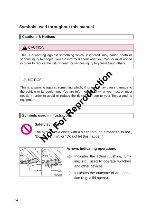
Symbols used throughout this manual
Cautions & Notices
Symbols used in illustrations
CAUTION
This is a warning against something which, if ignored, may cause death orserious injury to people. You are informed about what you must or must not doin order to reduce the risk of death or serious injury to yourself and others.
NOTICE
This is a warning against something which, if ignored, may cause damage tothe vehicle or its equipment. You are informed about what you must or mustnot do in order to avoid or reduce the risk of damage to your Toyota and itsequipment.
Safety symbol
The symbol of a circle with a slash through it means “Do not”,“Do not do this”, or “Do not let this happen”.
Arrows indicating operations
Indicates the action (pushing, turn-ing, etc.) used to operate switchesand other devices.
Indicates the outcome of an opera-tion (e.g. a lid opens).
Not For R
epro
duction
1Before driving
25
LC150_OM_OM60J77E_(AE)
1-1. Key informationKeys.................................... 26
1-2. Opening, closing and locking the doors
Smart entry & start system ...................... 29
Wireless remote control ...... 46Side doors .......................... 50Back door ........................... 54Glass hatch......................... 59
1-3. Adjustable components (seats, mirrors, steering wheel)
Front seats.......................... 64Rear seats .......................... 68Driving position memory
(driver’s seat).................... 85Head restraints ................... 89Seat belts............................ 92Steering wheel .................... 98Inside rear view mirror ...... 100Outside rear view
mirrors ............................ 102
1-4. Opening and closing the windows and moon roof
Power windows................. 105Moon roof.......................... 108
1-5. RefuelingOpening the fuel tank
cap.................................. 113
1-6. Theft deterrent systemEngine immobilizer
system ............................ 117Alarm ................................ 118
1-7. Safety informationCorrect driving posture ..... 121SRS airbags...................... 123Child restraint systems ..... 135Installing child
restraints......................... 146
Not For R
epro
duction
26
LC150_OM_OM60J77E_(AE)
1-1. Key information
Keys
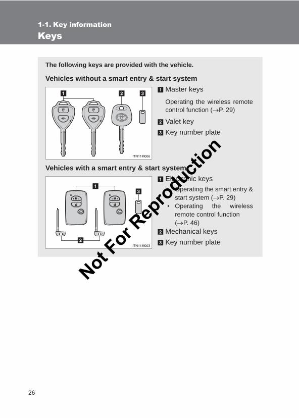
The following keys are provided with the vehicle.
Vehicles without a smart entry & start systemMaster keys
Operating the wireless remotecontrol function (→P. 29)
Valet keyKey number plate
Vehicles with a smart entry & start systemElectronic keys• Operating the smart entry &
start system (→P. 29)• Operating the wireless
remote control function (→P. 46)
Mechanical keysKey number plate
Not For R
epro
duction
27
1-1. Key information
1
Before driving
LC150_OM_OM60J77E_(AE)
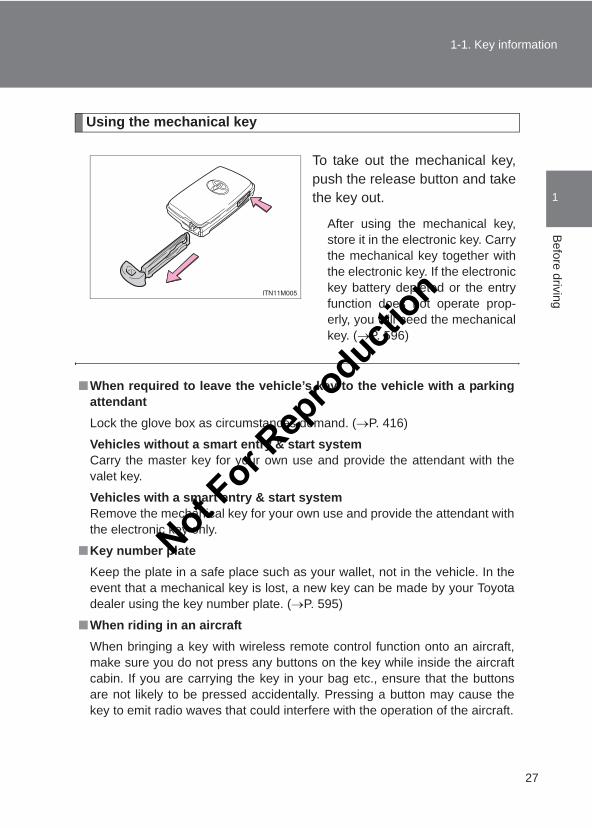
Using the mechanical key
To take out the mechanical key,push the release button and takethe key out.
After using the mechanical key,store it in the electronic key. Carrythe mechanical key together withthe electronic key. If the electronickey battery depleted or the entryfunction does not operate prop-erly, you will need the mechanicalkey. (→P. 596)
■When required to leave the vehicle’s key to the vehicle with a parkingattendantLock the glove box as circumstances demand. (→P. 416)
Vehicles without a smart entry & start systemCarry the master key for your own use and provide the attendant with thevalet key.
Vehicles with a smart entry & start systemRemove the mechanical key for your own use and provide the attendant withthe electronic key only.
■Key number plateKeep the plate in a safe place such as your wallet, not in the vehicle. In theevent that a mechanical key is lost, a new key can be made by your Toyotadealer using the key number plate. (→P. 595)
■When riding in an aircraftWhen bringing a key with wireless remote control function onto an aircraft,make sure you do not press any buttons on the key while inside the aircraftcabin. If you are carrying the key in your bag etc., ensure that the buttonsare not likely to be pressed accidentally. Pressing a button may cause thekey to emit radio waves that could interfere with the operation of the aircraft.
Not For R
epro
duction
28
1-1. Key information
LC150_OM_OM60J77E_(AE)
NOTICE
■To prevent key damageObserve the following:
●Do not drop the keys, subject them to strong shocks or bend them.
●Do not expose the keys to high temperatures for a long period of time.
●Do not get the keys wet or wash them in an ultrasonic washer etc.
●Do not attach metallic or magnetic materials to the keys or place the keysclose to such materials.
●Do not disassemble the keys.
●Do not attach a sticker or anything else to the surface of the electronic key.
●Do not place the keys near objects that produce magnetic fields, such asTVs, audio systems, induction cookers, or medical electrical equipment,such as low-frequency therapy equipment.
■Carrying the electronic key on your personCarry the electronic key 10 cm (3.9 in.) or more away from electric appli-ances that are turned on. Radio waves emitted from electric applianceswithin 10 cm (3.9 in.) of the electronic key may interfere with the key, causingthe key to not function properly.
■ In case of a smart entry & start system malfunction or other key-relatedproblemsTake your vehicle with all the electronic keys provided with your vehicle toyour Toyota dealer.
■When a vehicle key is lostIf the key remains lost, the risk of vehicle theft increases significantly. Visityour Toyota dealer immediately with all remaining electronic keys that wasprovided with your vehicle.
Not For R
epro
duction
29
1
Before driving
LC150_OM_OM60J77E_(AE)
1-2. Opening, closing and locking the doors
Smart entry & start system∗
∗: If equipped
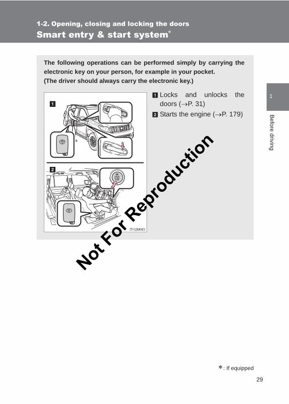
The following operations can be performed simply by carrying theelectronic key on your person, for example in your pocket.(The driver should always carry the electronic key.)
Locks and unlocks thedoors (→P. 31)Starts the engine (→P. 179)
Not For R
epro
duction
30
1-2. Opening, closing and locking the doors
LC150_OM_OM60J77E_(AE)
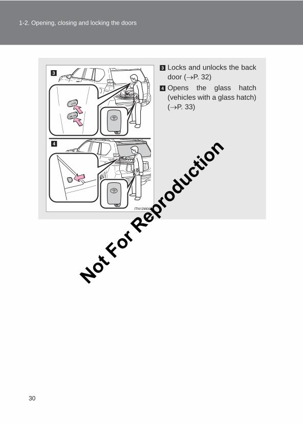
Locks and unlocks the backdoor (→P. 32)Opens the glass hatch(vehicles with a glass hatch)(→P. 33)
Not For R
epro
duction
31
1-2. Opening, closing and locking the doors
1
Before driving
LC150_OM_OM60J77E_(AE)
Unlocking and locking the doors (front door handles only)
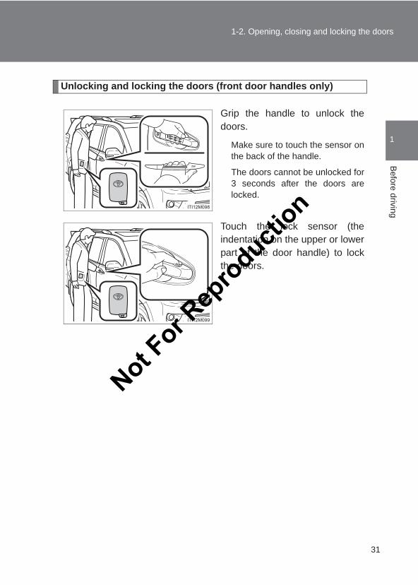
Grip the handle to unlock thedoors.
Make sure to touch the sensor onthe back of the handle.
The doors cannot be unlocked for3 seconds after the doors arelocked.
Touch the lock sensor (theindentation on the upper or lowerpart of the door handle) to lockthe doors.
Not For R
epro
duction
32
1-2. Opening, closing and locking the doors
LC150_OM_OM60J77E_(AE)
Unlocking and locking the back door
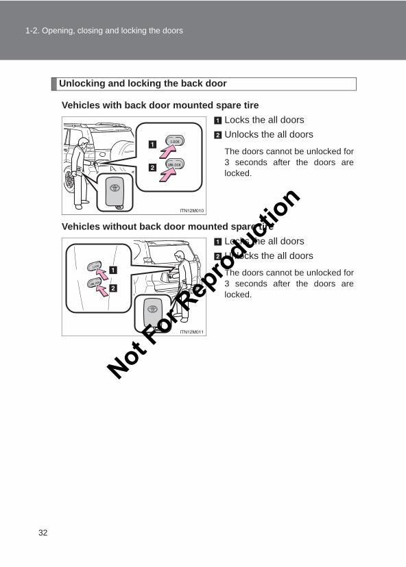
Vehicles with back door mounted spare tireLocks the all doorsUnlocks the all doors
The doors cannot be unlocked for3 seconds after the doors arelocked.
Vehicles without back door mounted spare tireLocks the all doorsUnlocks the all doors
The doors cannot be unlocked for3 seconds after the doors arelocked.
Not For R
epro
duction
33
1-2. Opening, closing and locking the doors
1
Before driving
LC150_OM_OM60J77E_(AE)
Opening the glass hatch
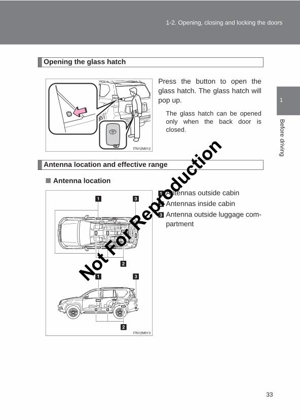
Press the button to open theglass hatch. The glass hatch willpop up.
The glass hatch can be openedonly when the back door isclosed.
Antenna location and effective range
■ Antenna locationAntennas outside cabinAntennas inside cabinAntenna outside luggage com-partment
Not For R
epro
duction
34
1-2. Opening, closing and locking the doors
LC150_OM_OM60J77E_(AE)
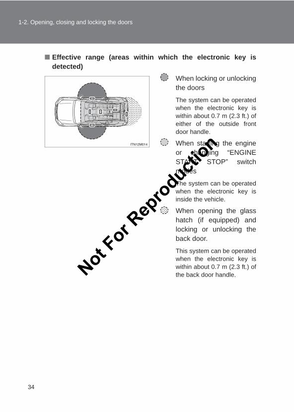
■ Effective range (areas within which the electronic key isdetected)
When locking or unlockingthe doors
The system can be operatedwhen the electronic key iswithin about 0.7 m (2.3 ft.) ofeither of the outside frontdoor handle.
When starting the engineor changing “ENGINESTART STOP” switchmodes
The system can be operatedwhen the electronic key isinside the vehicle.
When opening the glasshatch (if equipped) andlocking or unlocking theback door.
This system can be operatedwhen the electronic key iswithin about 0.7 m (2.3 ft.) ofthe back door handle.Not F
or Rep
roducti
on
35
1-2. Opening, closing and locking the doors
1
Before driving
LC150_OM_OM60J77E_(AE)
■Operation signalsA buzzer sounds and the emergency flashers flash to indicate that the doorshave been locked/unlocked. (Locked: once; Unlocked: twice)
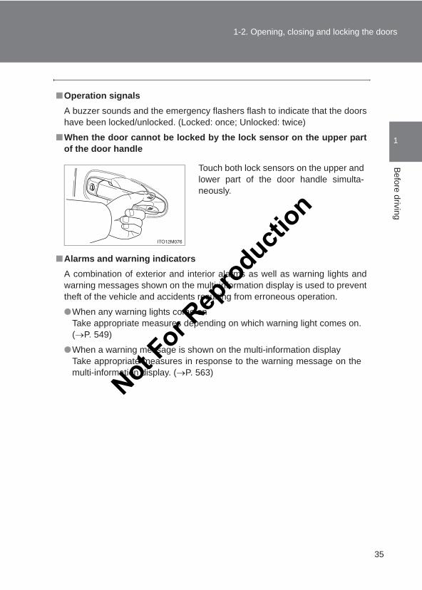
■When the door cannot be locked by the lock sensor on the upper partof the door handle
■Alarms and warning indicatorsA combination of exterior and interior alarms as well as warning lights andwarning messages shown on the multi-information display is used to preventtheft of the vehicle and accidents resulting from erroneous operation.
●When any warning lights come onTake appropriate measures depending on which warning light comes on.(→P. 549)
●When a warning message is shown on the multi-information displayTake appropriate measures in response to the warning message on themulti-information display. (→P. 563)
Touch both lock sensors on the upper andlower part of the door handle simulta-neously.
Not For R
epro
duction
36
1-2. Opening, closing and locking the doors
LC150_OM_OM60J77E_(AE)
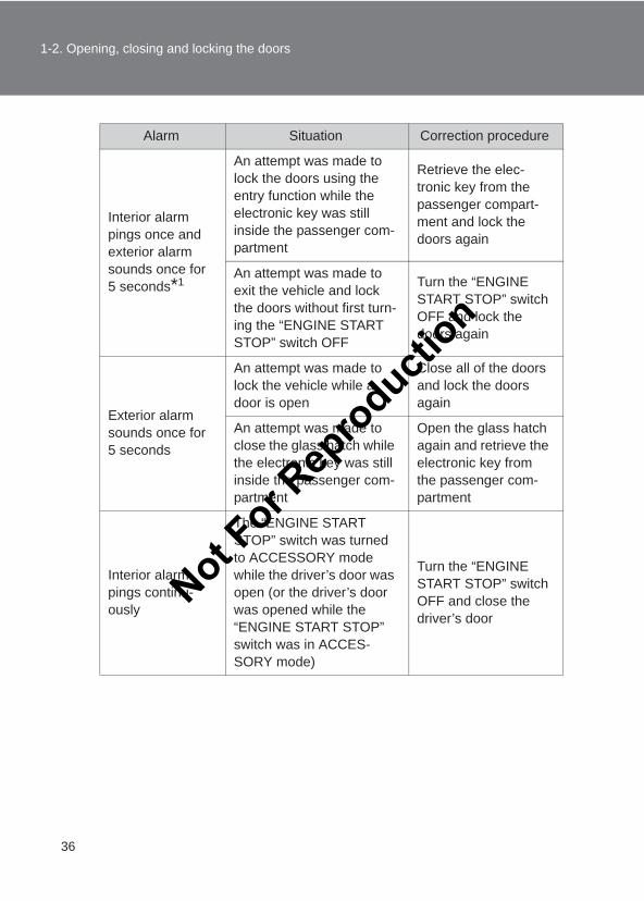
Alarm Situation Correction procedure
Interior alarm pings once and exterior alarm sounds once for 5 seconds*1
An attempt was made to lock the doors using the entry function while the electronic key was still inside the passenger com-partment
Retrieve the elec-tronic key from the passenger compart-ment and lock the doors again
An attempt was made to exit the vehicle and lock the doors without first turn-ing the “ENGINE START STOP” switch OFF
Turn the “ENGINE START STOP” switch OFF and lock the doors again
Exterior alarm sounds once for 5 seconds
An attempt was made to lock the vehicle while a door is open
Close all of the doors and lock the doors again
An attempt was made to close the glass hatch while the electronic key was still inside the passenger com-partment
Open the glass hatch again and retrieve the electronic key from the passenger com-partment
Interior alarm pings continu-ously
The “ENGINE START STOP” switch was turned to ACCESSORY mode while the driver’s door was open (or the driver’s door was opened while the “ENGINE START STOP” switch was in ACCES-SORY mode)
Turn the “ENGINE START STOP” switch OFF and close the driver’s door
Not For R
epro
duction
37
1-2. Opening, closing and locking the doors
1
Before driving
LC150_OM_OM60J77E_(AE)
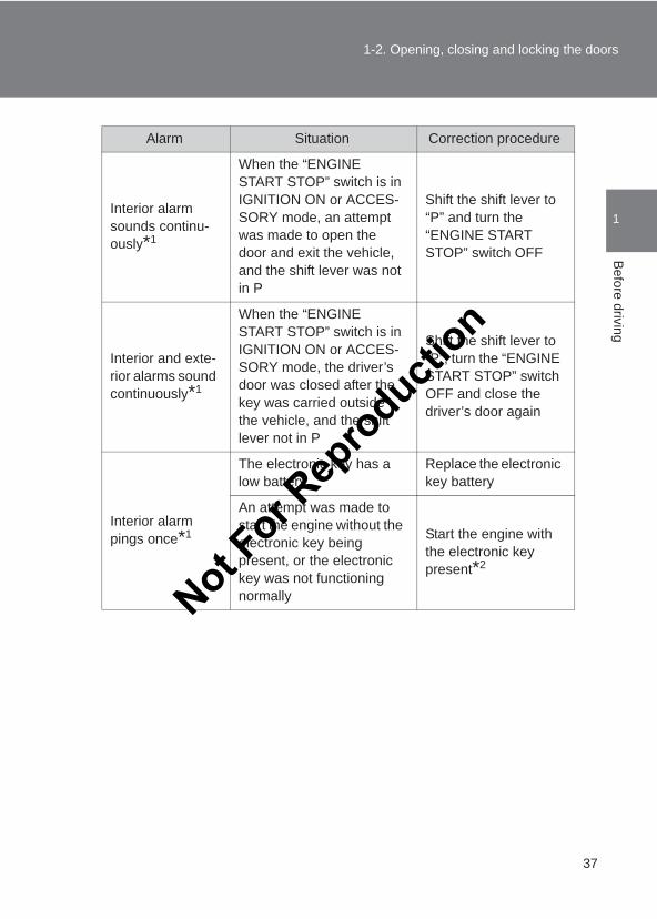
Alarm Situation Correction procedure
Interior alarm sounds continu-ously*1
When the “ENGINE START STOP” switch is in IGNITION ON or ACCES-SORY mode, an attempt was made to open the door and exit the vehicle, and the shift lever was not in P
Shift the shift lever to “P” and turn the “ENGINE START STOP” switch OFF
Interior and exte-rior alarms sound continuously*1
When the “ENGINE START STOP” switch is in IGNITION ON or ACCES-SORY mode, the driver’s door was closed after the key was carried outside the vehicle, and the shift lever not in P
Shift the shift lever to “P”, turn the “ENGINE START STOP” switch OFF and close the driver’s door again
Interior alarm pings once*1
The electronic key has a low battery
Replace the electronic key battery
An attempt was made to start the engine without the electronic key being present, or the electronic key was not functioning normally
Start the engine with the electronic key present*2
Not For R
epro
duction
38
1-2. Opening, closing and locking the doors
LC150_OM_OM60J77E_(AE)
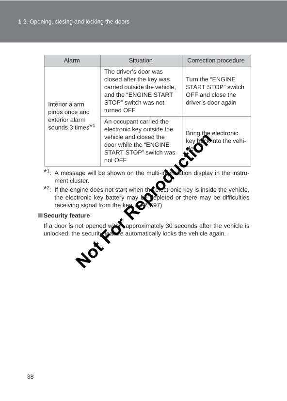
*1: A message will be shown on the multi-information display in the instru-ment cluster.
*2: If the engine does not start when the electronic key is inside the vehicle,the electronic key battery may be depleted or there may be difficultiesreceiving signal from the key. (→P. 597)
■Security featureIf a door is not opened within approximately 30 seconds after the vehicle isunlocked, the security feature automatically locks the vehicle again.
Alarm Situation Correction procedure
Interior alarm pings once and exterior alarm sounds 3 times*1
The driver’s door was closed after the key was carried outside the vehicle, and the “ENGINE START STOP” switch was not turned OFF
Turn the “ENGINE START STOP” switch OFF and close the driver’s door again
An occupant carried the electronic key outside the vehicle and closed the door while the “ENGINE START STOP” switch was not OFF
Bring the electronic key back into the vehi-cle
Not For R
epro
duction
39
1-2. Opening, closing and locking the doors
1
Before driving
LC150_OM_OM60J77E_(AE)
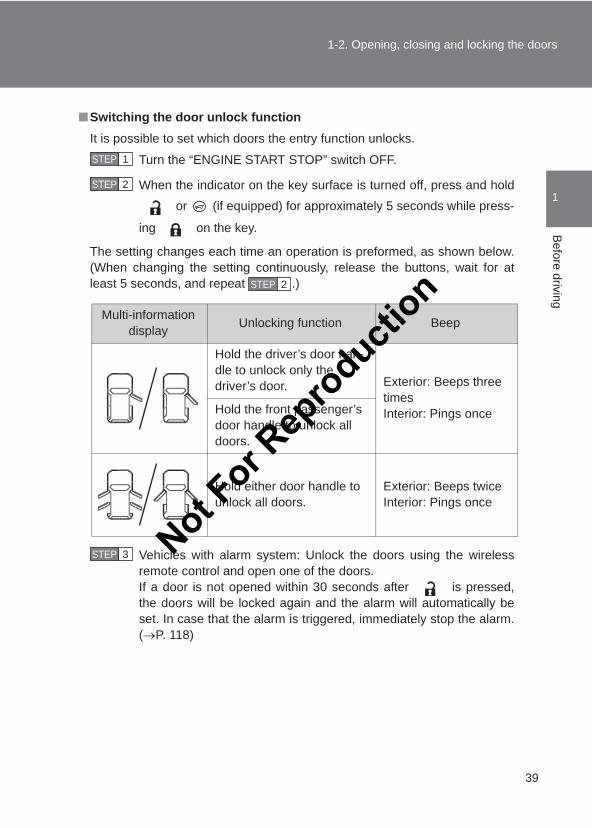
■Switching the door unlock functionIt is possible to set which doors the entry function unlocks.
Turn the “ENGINE START STOP” switch OFF.
When the indicator on the key surface is turned off, press and hold or (if equipped) for approximately 5 seconds while press-
ing on the key.
The setting changes each time an operation is preformed, as shown below.(When changing the setting continuously, release the buttons, wait for atleast 5 seconds, and repeat .)
Vehicles with alarm system: Unlock the doors using the wirelessremote control and open one of the doors.If a door is not opened within 30 seconds after is pressed,the doors will be locked again and the alarm will automatically beset. In case that the alarm is triggered, immediately stop the alarm.(→P. 118)
STEP 1
STEP 2
STEP 2
Multi-information display Unlocking function Beep
Hold the driver’s door han-dle to unlock only the driver’s door. Exterior: Beeps three
timesInterior: Pings onceHold the front passenger’s
door handle to unlock all doors.
Hold either door handle to unlock all doors.
Exterior: Beeps twiceInterior: Pings once
STEP 3 Not For R
epro
duction
40
1-2. Opening, closing and locking the doors
LC150_OM_OM60J77E_(AE)
■Battery-saving functionIn the following circumstances, the entry function is disabled in order to pre-vent the vehicle battery from discharging and the electronic key battery fromdepleting.
●When the entry function has not been used for 5 days or more
●When the electronic key has been left within approximately 2 m (6 ft.) ofthe vehicle for 10 minutes or more
● If the entry function has not been used for 14 days or more, the vehiclecannot be unlocked by a door other than the driver’s door. To unlock thevehicle, grip the driver’s door handle or use the wireless remote controlor the mechanical key.
The system will resume operation when:
●The vehicle is locked using the lock sensor when carrying the electronickey on your person.
●The vehicle is locked/unlocked using the wireless remote control. (→P. 46)
●The vehicle is locked/unlocked using the mechanical key. (→P. 596)
Not For R
epro
duction
41
1-2. Opening, closing and locking the doors
1
Before driving
LC150_OM_OM60J77E_(AE)
■Conditions affecting operationThe smart entry & start system uses weak radio waves. In the following situ-ations, the communication between the electronic key and the vehicle maybe affected, preventing the smart entry & start system, wireless remote con-trol and immobilizer system from operating properly. (Ways of coping: →P. 596)
●When the electronic key battery is depleted
●Near a TV tower, electric power plant, gas station, radio station, large dis-play, airport or other facility that generates strong radio waves or electri-cal noise
●When carrying a portable radio, cellular phone, cordless phone or otherwireless communication devices
●When the electronic key is in contact with, or is covered by the followingmetallic objects
• Cards to which aluminum foil is attached• Cigarette boxes that have aluminum foil inside• Metallic wallets or bags• Coins• Hand warmers made of metal• Media such as CDs and DVDs
●When multiple electronic keys are in the vicinity
●When another wireless key (that emits radio waves) is being used nearby
●When carrying the electronic key together with the following devices thatemit radio waves
• Another vehicle’s electronic key or a wireless key that emits radiowaves
• Personal computers or personal digital assistants (PDAs)• Digital audio players• Portable game systems
● If window tint with a metallic content or metallic objects are attached tothe rear window
Not For R
epro
duction
42
1-2. Opening, closing and locking the doors
LC150_OM_OM60J77E_(AE)
■Note for the entry function●Even when the electronic key is within the effective range (detection
areas), the system may not operate properly in the following cases:
• The electronic key is too close to the window or outside door handle,near the ground, or in a high place when the doors are locked orunlocked.
• The electronic key is near the ground or in a high place, or too close tothe rear bumper center when the glass hatch is opened.
• The electronic key is on the instrument panel, luggage cover or floor, orin the glove box.
●Do not leave the electronic key on top of the instrument panel or near thedoor pockets when exiting the vehicle. Depending on the radio wavereception conditions, it may be detected by the antenna outside the cabinand the door will become lockable from the outside, possibly trapping theelectronic key inside the vehicle.
●As long as the electronic key is within the effective range, the doors maybe locked or unlocked by anyone. However, only the doors detecting theelectronic key can be used to unlock the vehicle.
●The doors may lock or unlock if the electronic key is within the effectiverange and a large amount of water splashes on the door handle, such asin the rain or in a car wash. The doors will automatically be locked afterapproximately 30 seconds if a door is not opened and closed.
● If the wireless remote control is used to lock the doors when the elec-tronic key is near the vehicle, there is a possibility that the door may notbe unlocked by the entry function. (Use the wireless remote control tounlock the doors.)Not F
or Rep
roducti
on
43
1-2. Opening, closing and locking the doors
1
Before driving
LC150_OM_OM60J77E_(AE)
■Note for locking the doors●Touching the door lock sensor while wearing gloves may delay or prevent
lock operation. Remove the gloves and touch the lock sensor again.
●When the lock operation is performed using the lock sensor, recognitionsignals will be shown up to two consecutive times. After this, no recogni-tion signals will be given.
● If the door handle becomes wet while the electronic key is within theeffective range, the door may lock and unlock repeatedly. Place the keyin a position 2 m (6 ft.) or more separate from the vehicle while the vehi-cle is being washed. (Take care to ensure that the key is not stolen.)
● If the electronic key is inside the vehicle and a door handle becomes wetduring a car wash, a message may be shown on the multi-informationdisplay and a buzzer will sound outside the vehicle. To turn off the alarm,lock all the doors.
●The lock sensor may not work properly if it comes into contact with ice,snow, mud, etc. Clean the lock sensor and attempt to operate it again, oruse the lock sensor on the lower part of the door handle.
●Fingernails may scrape against the door during operation of the doorhandle.Be careful not to injure fingernails or damage the surface of the door.
■Note for the unlocking function●Gripping the door handle when wearing a glove may not unlock the door.
●A sudden approach to the effective range or door handle may prevent thedoors from being unlocked. In this case, return the door handle to theoriginal position and check that the doors unlock before pulling the doorhandle again.
● If there is another electronic key in the detection area, it may take slightlylonger to unlock the doors after the door handle is gripped.
■When the vehicle is not driven for extended periods●To prevent theft of the vehicle, do not leave the electronic key within 2 m
(6 ft.) of the vehicle.
●The smart entry & start system can be deactivated in advance. (→P. 632)
Not For R
epro
duction
44
1-2. Opening, closing and locking the doors
LC150_OM_OM60J77E_(AE)
■To operate the system properlyMake sure to carry the electronic key when operating the system. Do not getthe electronic key too close to the vehicle when operating the system fromthe outside of the vehicle.
Depending on the position and holding condition of the electronic key, thekey may not be detected correctly and the system may not operate properly.(The alarm may go off accidentally, or the door lock prevention may not func-tion.)
■ If the smart entry & start system does not operate properly●Locking and unlocking the doors: Use the mechanical key. (→P. 596)
●Starting the engine: →P. 597
■Electronic key battery depletion●The standard battery life is 1 to 2 years.
● If the battery becomes low, an alarm will sound in the cabin when theengine stops. (→P. 35)
●As the electronic key always receives radio waves, the battery willbecome depleted even if the electronic key is not used. The followingsymptoms indicate that the electronic key battery may be depleted.Replace the battery when necessary. (→P. 501)
• The smart entry & start system or the wireless remote control does notoperate.
• The detection area becomes smaller.• The LED indicator on the key surface does not turn on.
●To avoid serious deterioration, do not leave the electronic key within 1 m(3 ft.) of the following electrical appliances that produce a magnetic field:
• TVs• Personal computers• Cellular phones, cordless phones and battery chargers• Recharging cellular phones or cordless phones• Induction cookers• Table lamps
Not For R
epro
duction
45
1-2. Opening, closing and locking the doors
1
Before driving
LC150_OM_OM60J77E_(AE)
■When the electronic key battery is fully depleted→P. 501
■CustomizationSettings (e.g. smart entry & start system) can be changed. (Customizable features →P. 632)
CAUTION
■Caution regarding interference with electronic devices●People with implanted pacemakers or cardiac defibrillators should main-
tain a reasonable distance between themselves and the smart entry &start system antennas. (→P. 34)The radio waves may affect the operation of such devices. If necessary,the entry function can be disabled. Ask your Toyota dealer for details, suchas the frequency of radio waves and timing of emitting the radio waves.Then, consult your doctor to see if you should disable the entry function.
●User of any electrical medical device other than implanted pacemakersand implanted cardiac defibrillators should consult the manufacturer of thedevice for information about its operation under the influence of radiowaves.Radio waves could have unexpected effects on the operation of suchmedical devices.
Ask your Toyota dealer for details on disabling the entry function.
Not For R
epro
duction
46
1-2. Opening, closing and locking the doors
LC150_OM_OM60J77E_(AE)
Wireless remote control
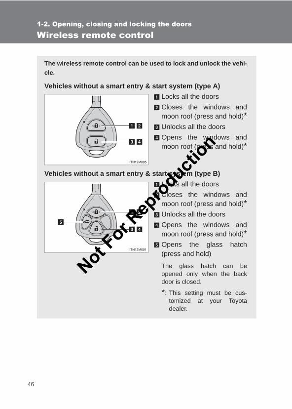
The wireless remote control can be used to lock and unlock the vehi-cle.
Vehicles without a smart entry & start system (type A)Locks all the doorsCloses the windows andmoon roof (press and hold)*Unlocks all the doorsOpens the windows andmoon roof (press and hold)*
Vehicles without a smart entry & start system (type B)Locks all the doorsCloses the windows andmoon roof (press and hold)*Unlocks all the doorsOpens the windows andmoon roof (press and hold)*Opens the glass hatch(press and hold)
The glass hatch can beopened only when the backdoor is closed.
*: This setting must be cus-tomized at your Toyotadealer.
Not For R
epro
duction
47
1-2. Opening, closing and locking the doors
1
Before driving
LC150_OM_OM60J77E_(AE)
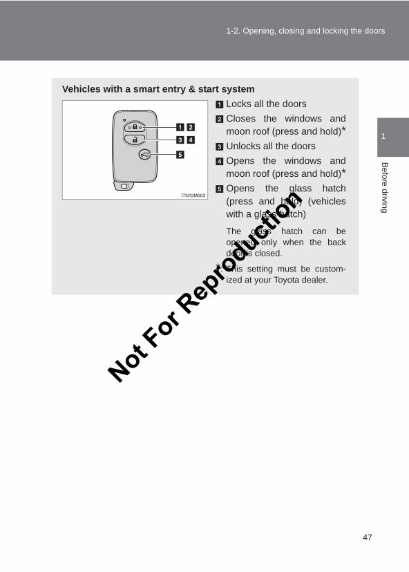
Vehicles with a smart entry & start systemLocks all the doorsCloses the windows andmoon roof (press and hold)*Unlocks all the doorsOpens the windows andmoon roof (press and hold)*Opens the glass hatch(press and hold) (vehicleswith a glass hatch)
The glass hatch can beopened only when the backdoor is closed.
*: This setting must be custom-ized at your Toyota dealer.
Not For R
epro
duction
48
1-2. Opening, closing and locking the doors
LC150_OM_OM60J77E_(AE)
■Operation signalsDoors: A buzzer sounds and the emergency flashers flash to indicate thatthe doors have been locked/unlocked. (Locked: Once; Unlocked: Twice)Windows and moon roof: A buzzer sounds to indicate that the windows andmoon roof are operating.Glass hatch: A buzzer sounds once to indicate that the glass hatch havebeen opened.
■Door lock buzzerIf an attempt to lock the doors is made when a door is not fully closed, abuzzer sounds continuously for 5 seconds. Fully close the door to stop thebuzzer, and lock the vehicle once more.
■Security feature→P. 38
■Alarm (if equipped)Using the wireless remote control to lock the doors will set the alarm system.(→P. 118)
■Conditions affecting operationVehicles without a smart entry & start systemThe wireless remote control function may not operate normally in the follow-ing situations:
●Near a TV tower, radio station, electric power plant, airport or other facil-ity that generates strong radio waves
●When carrying a portable radio, cellular phone or other wireless commu-nication device
●When multiple wireless keys are in the vicinity
●When the wireless key is in contact with, or is covered by a metallicobject
●When a wireless key (that emits radio waves) is being used nearby
●When the wireless key has been left near an electrical appliance such asa personal computer
Vehicles with a smart entry & start system→P. 41
Not For R
epro
duction
49
1-2. Opening, closing and locking the doors
1
Before driving
LC150_OM_OM60J77E_(AE)
■ If the wireless remote control does not operate properlyLocking and unlocking the doors: Use the mechanical key. (→P. 596)
■Key battery depletionVehicles without a smart entry & start systemIf the wireless remote control function does not operate, the battery may bedepleted. Replace the battery when necessary. (→P. 501)
Vehicles with a smart entry & start system→P. 44
■When the electronic key battery is fully depleted→P. 501
■CustomizationSettings (e.g. wireless remote control system) can be changed. (Customizable features →P. 632)
CAUTION
■When closing the windows or moon roof using wireless remote controlObserve the following precautions. Failing to do so may result in death orserious injury.
●Check to make sure that all passengers do not have any part of their bodyin a position where it could be caught when a window or moon roof isbeing operated.
●To prevent inadvertent power windows and moon roof operation, never leta small child have and use the wireless remote control.
■Jam protection function●Never try jamming any part of your body to activate the jam protection
function intentionally.
●The jam protection function may not work if something gets caught justbefore the window or moon roof fully closes.
Not For R
epro
duction
50
1-2. Opening, closing and locking the doors
LC150_OM_OM60J77E_(AE)
Side doors
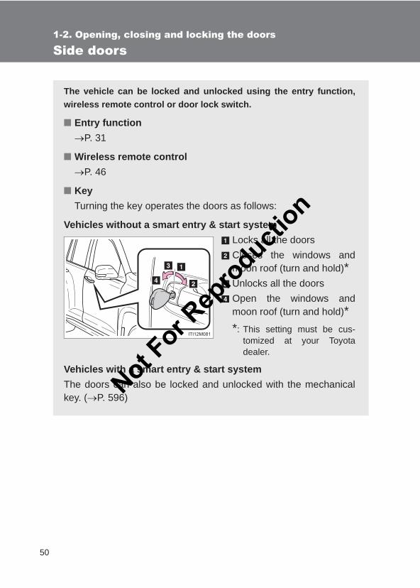
The vehicle can be locked and unlocked using the entry function,wireless remote control or door lock switch.
■ Entry function→P. 31
■ Wireless remote control→P. 46
■ KeyTurning the key operates the doors as follows:
Vehicles without a smart entry & start systemLocks all the doorsCloses the windows andmoon roof (turn and hold)*Unlocks all the doorsOpen the windows andmoon roof (turn and hold)**: This setting must be cus-
tomized at your Toyotadealer.
Vehicles with a smart entry & start systemThe doors can also be locked and unlocked with the mechanicalkey. (→P. 596)N
ot For R
epro
duction
51
1-2. Opening, closing and locking the doors
1
Before driving
LC150_OM_OM60J77E_(AE)
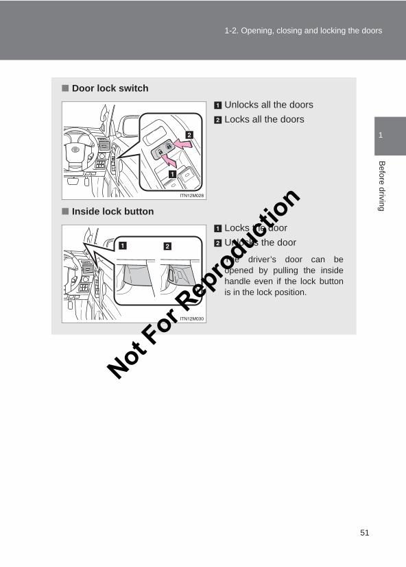
■ Door lock switchUnlocks all the doorsLocks all the doors
■ Inside lock buttonLocks the doorUnlocks the door
The driver’s door can beopened by pulling the insidehandle even if the lock buttonis in the lock position.
Not For R
epro
duction
52
1-2. Opening, closing and locking the doors
LC150_OM_OM60J77E_(AE)
Locking the driver’s door from the outside without a key
Move the inside lock button to the lock position.Close the door while pulling the door handle.
Vehicles without a smart entry & start systemThe door cannot be locked if the key is in the engine switch.
Vehicles with a smart entry & start systemThe door cannot be locked if the “ENGINE START STOP” switch is inACCESSORY or IGNITION ON mode, or the electronic key is leftinside the vehicle.
The key may not be detected correctly and the door may be locked.
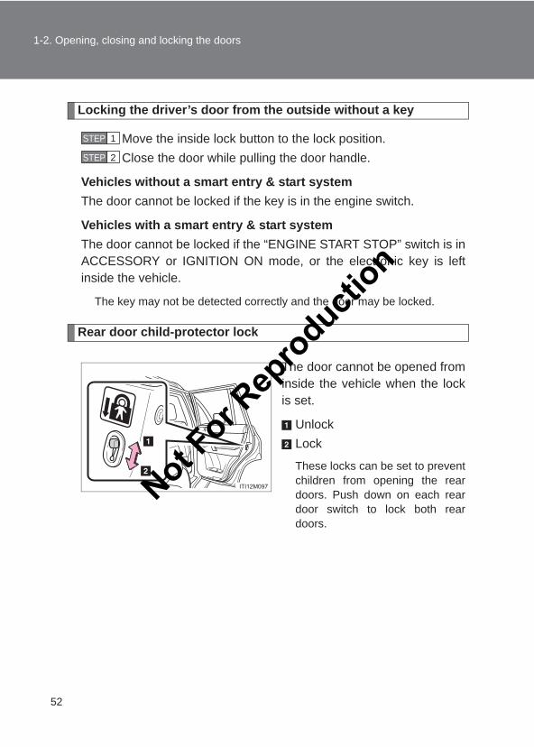
Rear door child-protector lock
The door cannot be opened frominside the vehicle when the lockis set.
UnlockLock
These locks can be set to preventchildren from opening the reardoors. Push down on each reardoor switch to lock both reardoors.
STEP 1
STEP 2
Not For R
epro
duction
53
1-2. Opening, closing and locking the doors
1
Before driving
LC150_OM_OM60J77E_(AE)
■Using the mechanical key (vehicles with a smart entry & start system)The doors can also be locked and unlocked with the mechanical key. (→P. 596)
■CustomizationSettings (e.g. unlocking function using a key) can be changed. (Customizable features →P. 632)
CAUTION
■To prevent an accidentObserve the following precautions while driving the vehicle.Failing to do so may result in a door opening and an occupant falling out,resulting in death or serious injury.
●Always use a seat belt.
●Always lock all the doors.
●Ensure that all the doors are properly closed.
●Do not pull the inside handle of the doors while driving.The doors may be opened and the passengers are thrown out of the vehi-cle and it may result in death or serious injury.
Be especially careful for the driver’s door, as the door may be openedeven if the inside lock button is in locked position.
●Set the rear door child-protector locks when children are seated in the sec-ond seat. Not F
or Rep
roducti
on
54
1-2. Opening, closing and locking the doors
LC150_OM_OM60J77E_(AE)
Back door
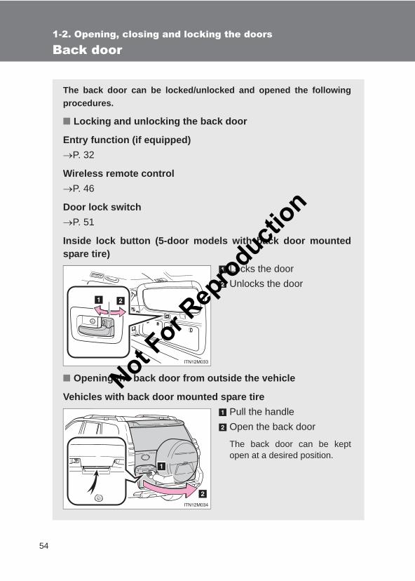
The back door can be locked/unlocked and opened the followingprocedures.
■ Locking and unlocking the back door
Entry function (if equipped)→P. 32
Wireless remote control→P. 46
Door lock switch→P. 51
Inside lock button (5-door models with back door mountedspare tire)
Locks the doorUnlocks the door
■ Opening the back door from outside the vehicle
Vehicles with back door mounted spare tirePull the handleOpen the back door
The back door can be keptopen at a desired position.
STEP 1
Not For R
epro
duction
55
1-2. Opening, closing and locking the doors
1
Before driving
LC150_OM_OM60J77E_(AE)
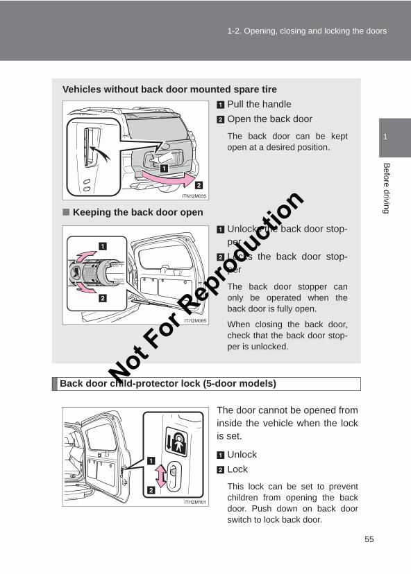
Back door child-protector lock (5-door models)
The door cannot be opened frominside the vehicle when the lockis set.
UnlockLock
This lock can be set to preventchildren from opening the backdoor. Push down on back doorswitch to lock back door.
Vehicles without back door mounted spare tirePull the handleOpen the back door
The back door can be keptopen at a desired position.
■ Keeping the back door openUnlocks the back door stop-perLocks the back door stop-per
The back door stopper canonly be operated when theback door is fully open.
When closing the back door,check that the back door stop-per is unlocked.
Not For R
epro
duction
56
1-2. Opening, closing and locking the doors
LC150_OM_OM60J77E_(AE)
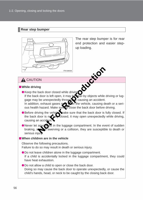
Rear step bumper
The rear step bumper is for rearend protection and easier step-up loading.
CAUTION
■While driving●Keep the back door closed while driving.
If the back door is left open, it may hit near-by objects while driving or lug-gage may be unexpectedly thrown out, causing an accident.In addition, exhaust gases may enter the vehicle, causing death or a seri-ous health hazard. Make sure to close the back door before driving.
●Before driving the vehicle, make sure that the back door is fully closed. Ifthe back door is not fully closed, it may open unexpectedly while driving,causing an accident.
●Never let anyone sit in the luggage compartment. In the event of suddenbraking, sudden swerving or a collision, they are susceptible to death orserious injury.
■When children are in the vehicleObserve the following precautions.Failure to do so may result in death or serious injury.
●Do not leave children alone in the luggage compartment.If a child is accidentally locked in the luggage compartment, they couldhave heat exhaustion.
●Do not allow a child to open or close the back door.Doing so may cause the back door to operate unexpectedly, or cause thechild’s hands, head, or neck to be caught by the closing back door.
Not For R
epro
duction
57
1-2. Opening, closing and locking the doors
1
Before driving
LC150_OM_OM60J77E_(AE)
CAUTION
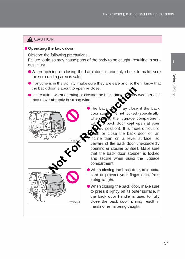
■Operating the back doorObserve the following precautions.Failure to do so may cause parts of the body to be caught, resulting in seri-ous injury.
●When opening or closing the back door, thoroughly check to make surethe surrounding area is safe.
● If anyone is in the vicinity, make sure they are safe and let them know thatthe back door is about to open or close.
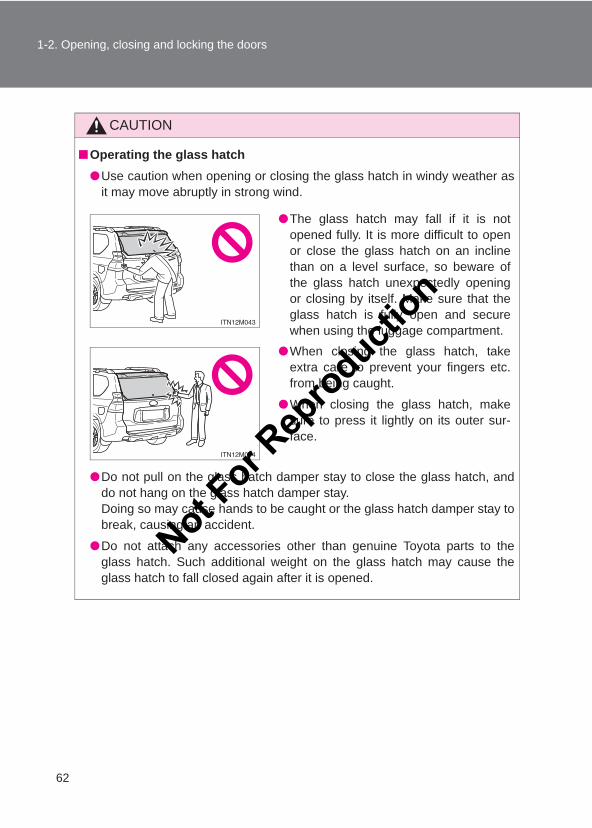
●Use caution when opening or closing the back door in windy weather as itmay move abruptly in strong wind.
●The back door may close if the backdoor stopper is not locked (specifically,when using the luggage compartmentwith the back door kept open at yourdesired position). It is more difficult toopen or close the back door on anincline than on a level surface, sobeware of the back door unexpectedlyopening or closing by itself. Make surethat the back door stopper is lockedand secure when using the luggagecompartment.
●When closing the back door, take extracare to prevent your fingers etc. frombeing caught.
●When closing the back door, make sureto press it lightly on its outer surface. Ifthe back door handle is used to fullyclose the back door, it may result inhands or arms being caught.
Not For R
epro
duction
58
1-2. Opening, closing and locking the doors
LC150_OM_OM60J77E_(AE)
CAUTION
●Do not pull on the back door damper stay to close the back door, and donot hang on the back door damper stay.Doing so may cause hands to be caught or the back door damper stay tobreak, causing an accident.
●Do not attach any accessories other than genuine Toyota parts to the backdoor. Such additional weight on the back door may cause the back door tofall closed again after it is opened.
NOTICE
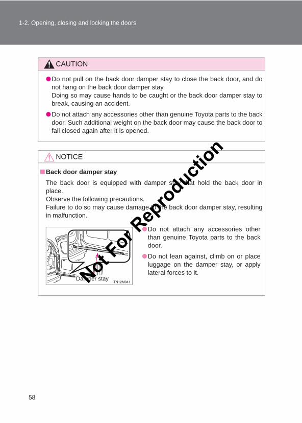
■Back door damper stayThe back door is equipped with damper stay that hold the back door inplace.Observe the following precautions.Failure to do so may cause damage to the back door damper stay, resultingin malfunction.
●Do not attach any accessories otherthan genuine Toyota parts to the backdoor.
●Do not lean against, climb on or placeluggage on the damper stay, or applylateral forces to it.
Damper stayNot For R
epro
duction
59
1
1-2. Opening, closing and locking the doorsB
efore driving
LC150_OM_OM60J77E_(AE)
Glass hatch∗
∗: If equipped
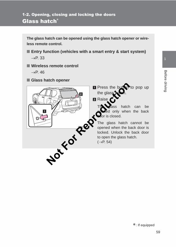
The glass hatch can be opened using the glass hatch opener or wire-less remote control.
■ Entry function (vehicles with a smart entry & start system)→P. 33
■ Wireless remote control→P. 46
■ Glass hatch openerPress the button to pop upthe glass hatch.Raise
The glass hatch can beopened only when the backdoor is closed.
The glass hatch cannot beopened when the back door islocked. Unlock the back doorto open the glass hatch. (→P. 54)
Not For R
epro
duction
60
1-2. Opening, closing and locking the doors
LC150_OM_OM60J77E_(AE)
■When opening the glass hatch●Open the glass hatch slowly and carefully.
●Use the glass hatch opener when the back door is closed.
■Opening the glass hatch while the rear window wiper is in operationRear window wiper operation will stop moving. Operation will recommenceafter the glass hatch has been closed.
■Function to prevent the glass hatch being locked with the electronickey inside (vehicles with a smart entry & start system)●When all doors are being locked, closing the glass hatch with the elec-
tronic key left inside the luggage compartment will sound an alarm.In this case, the glass hatch can be opened using the entry function.
●Even when the spare electronic key is put in the luggage compartmentwith all the doors locked, the key confinement prevention function can beactivated so the glass hatch can be opened. In order to prevent theft,take all electronic keys with you when leaving the vehicle.
●Even when the electronic key is put in the luggage compartment with allthe doors are locked, the key may not be detected depending on theplaces and the surrounding radio wave conditions. In this case, the keyconfinement prevention function cannot be activated, causing the doorsto lock when the glass hatch is closed. Make sure to check where the keyis before closing the glass hatch.
■After closing the glass hatchCheck that the glass hatch is firmly closed. If it is not firmly closed, the rearwindow wiper and washer will not operate correctly.Not F
or Rep
roducti
on
61
1-2. Opening, closing and locking the doors
1
Before driving
LC150_OM_OM60J77E_(AE)
CAUTION
■While driving●Keep the glass hatch closed while driving.
If the glass hatch is left open, it may hit near-by objects while driving orluggage may be unexpectedly thrown out, causing an accident.In addition, exhaust gases may enter the vehicle, causing death or a seri-ous health hazard. Make sure to close the glass hatch before driving.
●Before driving the vehicle, make sure that the glass hatch is fully closed. Ifthe glass hatch is not fully closed, it may open unexpectedly while driving,causing an accident.
■When children are in the vehicleDo not allow a child to open or close the glass hatch.Doing so may cause the glass hatch to operate unexpectedly, or cause thechild’s hands, head, or neck to be caught by the closing glass hatch.
■Operating the glass hatchObserve the following precautions.Failure to do so may cause parts of the body to be caught, resulting in seri-ous injury.
●Remove any heavy loads, such as snow and ice, from the glass hatchbefore opening it. Failure to do so may cause the glass hatch fall closedagain after it is opened.
●When opening or closing the glass hatch, thoroughly check to make surethe surrounding area is safe.
● If anyone is in the vicinity, make sure they are safe and let them know thatthe glass hatch is about to open or close.
Not For R
epro
duction
62
1-2. Opening, closing and locking the doors
LC150_OM_OM60J77E_(AE)
CAUTION
■Operating the glass hatch●Use caution when opening or closing the glass hatch in windy weather as
it may move abruptly in strong wind.
●Do not pull on the glass hatch damper stay to close the glass hatch, anddo not hang on the glass hatch damper stay.Doing so may cause hands to be caught or the glass hatch damper stay tobreak, causing an accident.
●Do not attach any accessories other than genuine Toyota parts to theglass hatch. Such additional weight on the glass hatch may cause theglass hatch to fall closed again after it is opened.
●The glass hatch may fall if it is notopened fully. It is more difficult to openor close the glass hatch on an inclinethan on a level surface, so beware ofthe glass hatch unexpectedly openingor closing by itself. Make sure that theglass hatch is fully open and securewhen using the luggage compartment.
●When closing the glass hatch, takeextra care to prevent your fingers etc.from being caught.
●When closing the glass hatch, makesure to press it lightly on its outer sur-face.
Not For R
epro
duction
63
1-2. Opening, closing and locking the doors
1
Before driving
LC150_OM_OM60J77E_(AE)
NOTICE
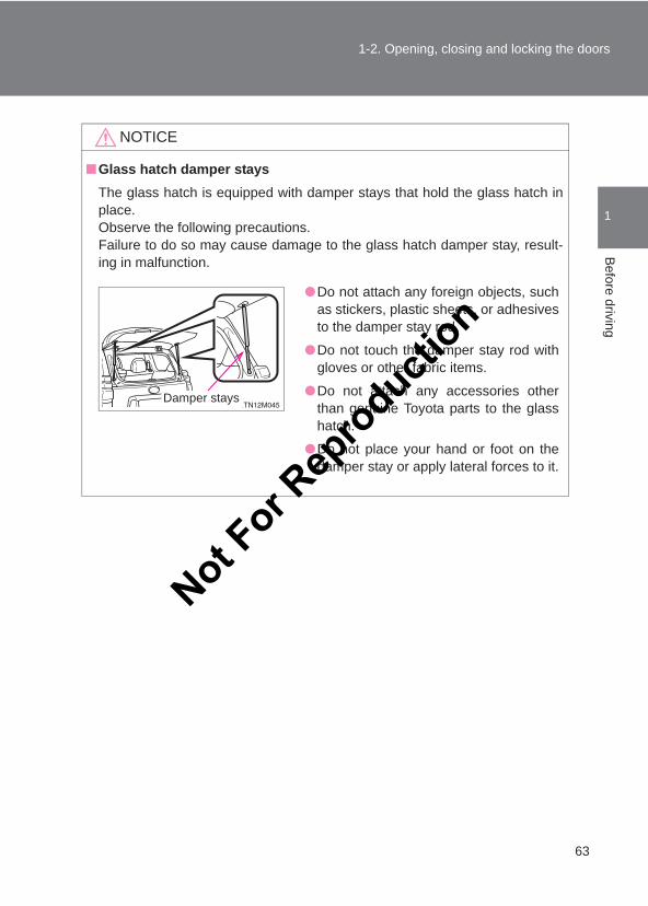
■Glass hatch damper staysThe glass hatch is equipped with damper stays that hold the glass hatch inplace.Observe the following precautions.Failure to do so may cause damage to the glass hatch damper stay, result-ing in malfunction.
●Do not attach any foreign objects, suchas stickers, plastic sheets, or adhesivesto the damper stay rod.
●Do not touch the damper stay rod withgloves or other fabric items.
●Do not attach any accessories otherthan genuine Toyota parts to the glasshatch.
●Do not place your hand or foot on thedamper stay or apply lateral forces to it.
Damper stays
Not For R
epro
duction
64
LC150_OM_OM60J77E_(AE)
1-3. Adjustable components (seats, mirrors, steering wheel)
Front seats
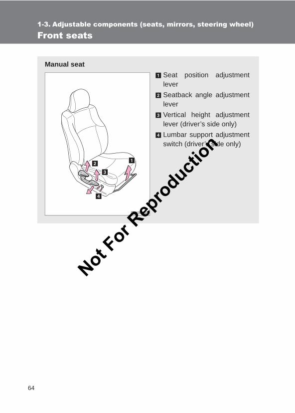
Manual seatSeat position adjustmentleverSeatback angle adjustmentleverVertical height adjustmentlever (driver’s side only)Lumbar support adjustmentswitch (driver’s side only)
Not For R
epro
duction
65
1-3. Adjustable components (seats, mirrors, steering wheel)
1
Before driving
LC150_OM_OM60J77E_(AE)
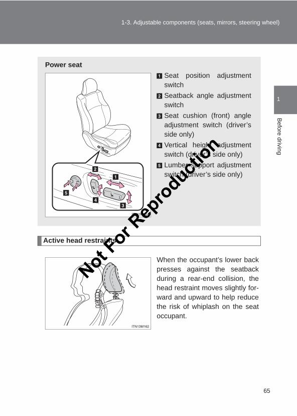
Active head restraints
When the occupant’s lower backpresses against the seatbackduring a rear-end collision, thehead restraint moves slightly for-ward and upward to help reducethe risk of whiplash on the seatoccupant.
Power seatSeat position adjustmentswitchSeatback angle adjustmentswitchSeat cushion (front) angleadjustment switch (driver’sside only)Vertical height adjustmentswitch (driver’s side only)Lumber support adjustmentswitch (driver’s side only)
Not For R
epro
duction
66
1-3. Adjustable components (seats, mirrors, steering wheel)
LC150_OM_OM60J77E_(AE)
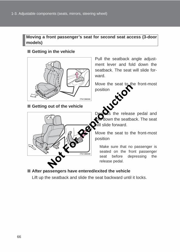
Moving a front passenger’s seat for second seat access (3-doormodels)
■ Getting in the vehiclePull the seatback angle adjust-ment lever and fold down theseatback. The seat will slide for-ward.
Move the seat to the front-mostposition
■ Getting out of the vehicleDepress the release pedal andfold down the seatback. The seatwill slide forward.
Move the seat to the front-mostposition
Make sure that no passenger isseated on the front passengerseat before depressing therelease pedal.
■ After passengers have entered/exited the vehicleLift up the seatback and slide the seat backward until it locks.
Not For R
epro
duction
67
1-3. Adjustable components (seats, mirrors, steering wheel)
1
Before driving
LC150_OM_OM60J77E_(AE)
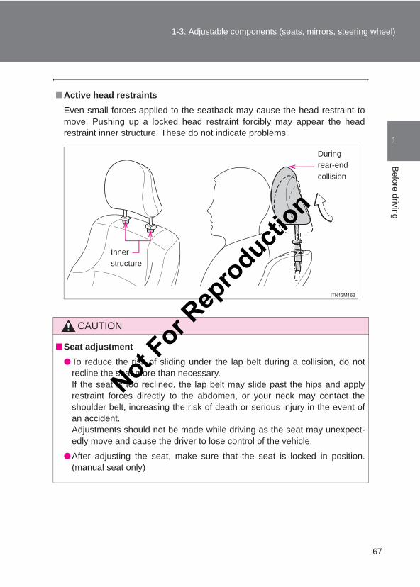
■Active head restraintsEven small forces applied to the seatback may cause the head restraint tomove. Pushing up a locked head restraint forcibly may appear the headrestraint inner structure. These do not indicate problems.
CAUTION
■Seat adjustment●To reduce the risk of sliding under the lap belt during a collision, do not
recline the seat more than necessary.If the seat is too reclined, the lap belt may slide past the hips and applyrestraint forces directly to the abdomen, or your neck may contact theshoulder belt, increasing the risk of death or serious injury in the event ofan accident.Adjustments should not be made while driving as the seat may unexpect-edly move and cause the driver to lose control of the vehicle.
●After adjusting the seat, make sure that the seat is locked in position.(manual seat only)
During rear-end collision
Inner structure
Not For R
epro
duction
68
1-3. Adjustable components (seats, mirrors, steering wheel)
LC150_OM_OM60J77E_(AE)
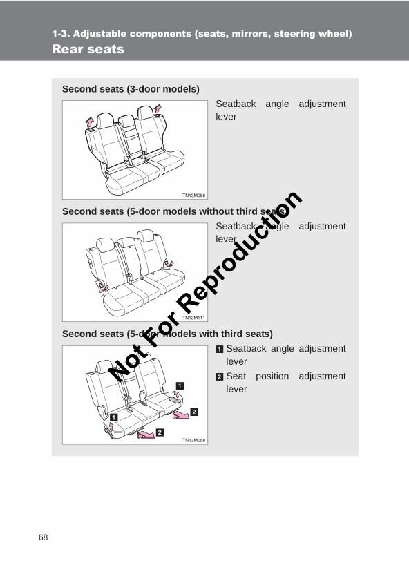
Rear seats
Second seats (3-door models)Seatback angle adjustmentlever
Second seats (5-door models without third seats)Seatback angle adjustmentlever
Second seats (5-door models with third seats)Seatback angle adjustmentleverSeat position adjustmentlever
Not For R
epro
duction
69
1-3. Adjustable components (seats, mirrors, steering wheel)
1
Before driving
LC150_OM_OM60J77E_(AE)
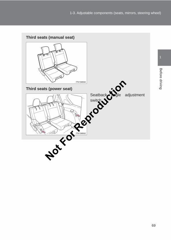
Third seats (manual seat)
Third seats (power seat)Seatback angle adjustmentswitch
Not For R
epro
duction
70
1-3. Adjustable components (seats, mirrors, steering wheel)
LC150_OM_OM60J77E_(AE)
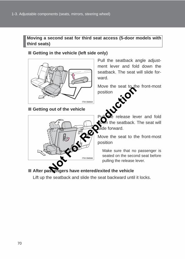
Moving a second seat for third seat access (5-door models withthird seats)
■ Getting in the vehicle (left side only)Pull the seatback angle adjust-ment lever and fold down theseatback. The seat will slide for-ward.
Move the seat to the front-mostposition
■ Getting out of the vehiclePull the release lever and folddown the seatback. The seat willslide forward.
Move the seat to the front-mostposition
Make sure that no passenger isseated on the second seat beforepulling the release lever.
■ After passengers have entered/exited the vehicleLift up the seatback and slide the seat backward until it locks.
Not For R
epro
duction
71
1-3. Adjustable components (seats, mirrors, steering wheel)
1
Before driving
LC150_OM_OM60J77E_(AE)
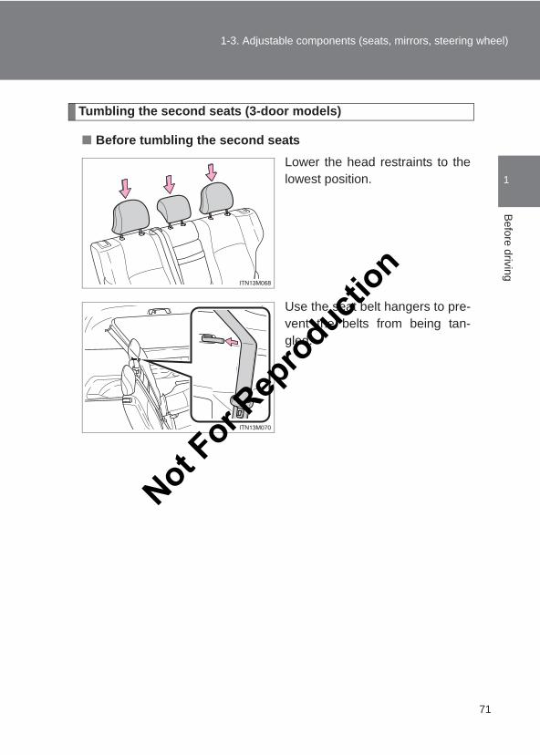
Tumbling the second seats (3-door models)
■ Before tumbling the second seatsLower the head restraints to thelowest position.
Use the seat belt hangers to pre-vent the belts from being tan-gled.
Not For R
epro
duction
72
1-3. Adjustable components (seats, mirrors, steering wheel)
LC150_OM_OM60J77E_(AE)
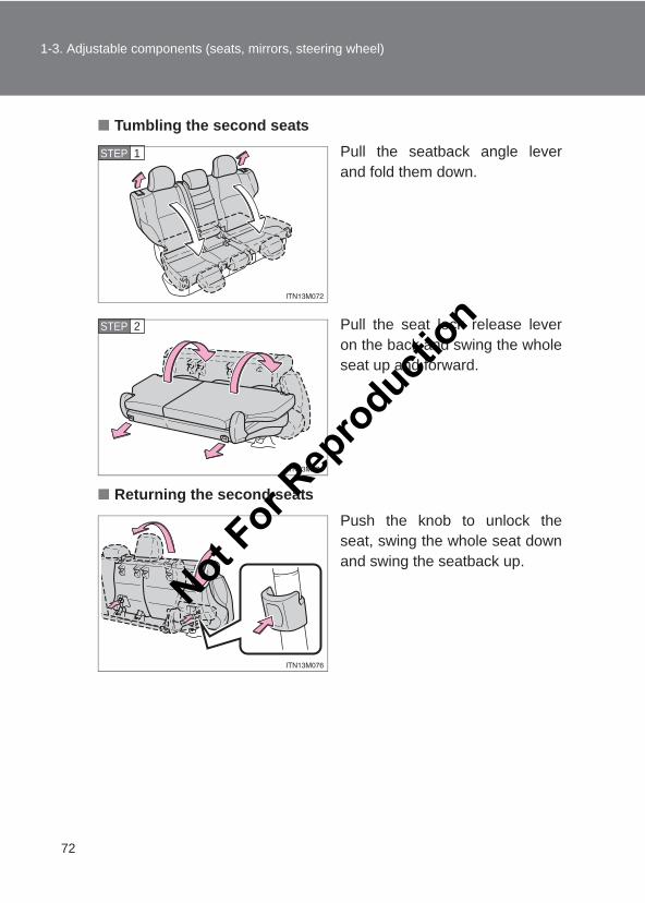
■ Tumbling the second seatsPull the seatback angle leverand fold them down.
Pull the seat lock release leveron the back and swing the wholeseat up and forward.
■ Returning the second seatsPush the knob to unlock theseat, swing the whole seat downand swing the seatback up.
STEP 1
STEP 2
Not For R
epro
duction
73
1-3. Adjustable components (seats, mirrors, steering wheel)
1
Before driving
LC150_OM_OM60J77E_(AE)
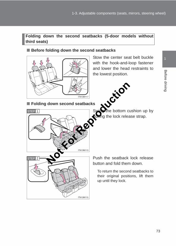
Folding down the second seatbacks (5-door models withoutthird seats)
■ Before folding down the second seatbacksStow the center seat belt bucklewith the hook-and-loop fastenerand lower the head restraints tothe lowest position.
■ Folding down second seatbacksSwing the bottom cushion up bypulling the lock release strap.
Push the seatback lock releasebutton and fold them down.
To return the second seatbacks totheir original positions, lift themup until they lock.
STEP 1
STEP 2 Not For R
epro
duction
74
1-3. Adjustable components (seats, mirrors, steering wheel)
LC150_OM_OM60J77E_(AE)
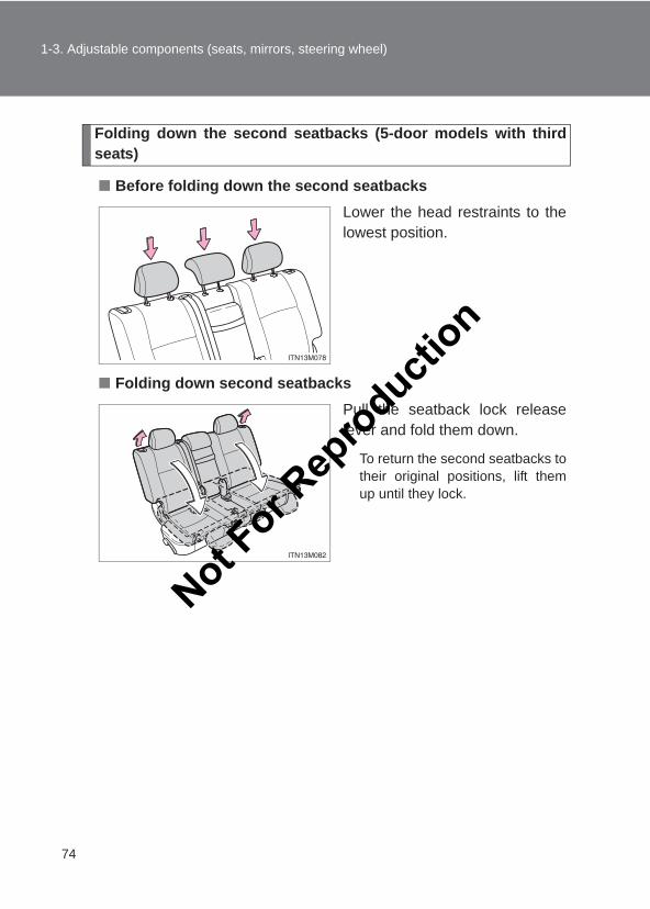
Folding down the second seatbacks (5-door models with thirdseats)
■ Before folding down the second seatbacksLower the head restraints to thelowest position.
■ Folding down second seatbacksPull the seatback lock releaselever and fold them down.
To return the second seatbacks totheir original positions, lift themup until they lock.
Not For R
epro
duction
75
1-3. Adjustable components (seats, mirrors, steering wheel)
1
Before driving
LC150_OM_OM60J77E_(AE)
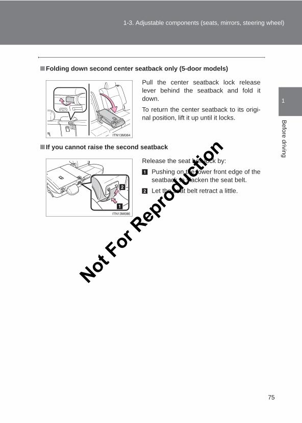
■Folding down second center seatback only (5-door models)
■ If you cannot raise the second seatback
Pull the center seatback lock releaselever behind the seatback and fold itdown.
To return the center seatback to its origi-nal position, lift it up until it locks.
Release the seat belt lock by:
Pushing on the lower front edge of theseatback to slacken the seat belt.
Let the seat belt retract a little.
Not For R
epro
duction
76
1-3. Adjustable components (seats, mirrors, steering wheel)
LC150_OM_OM60J77E_(AE)
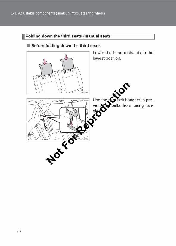
Folding down the third seats (manual seat)
■ Before folding down the third seatsLower the head restraints to thelowest position.
Use the seat belt hangers to pre-vent the belts from being tan-gled.
Not For R
epro
duction
77
1-3. Adjustable components (seats, mirrors, steering wheel)
1
Before driving
LC150_OM_OM60J77E_(AE)
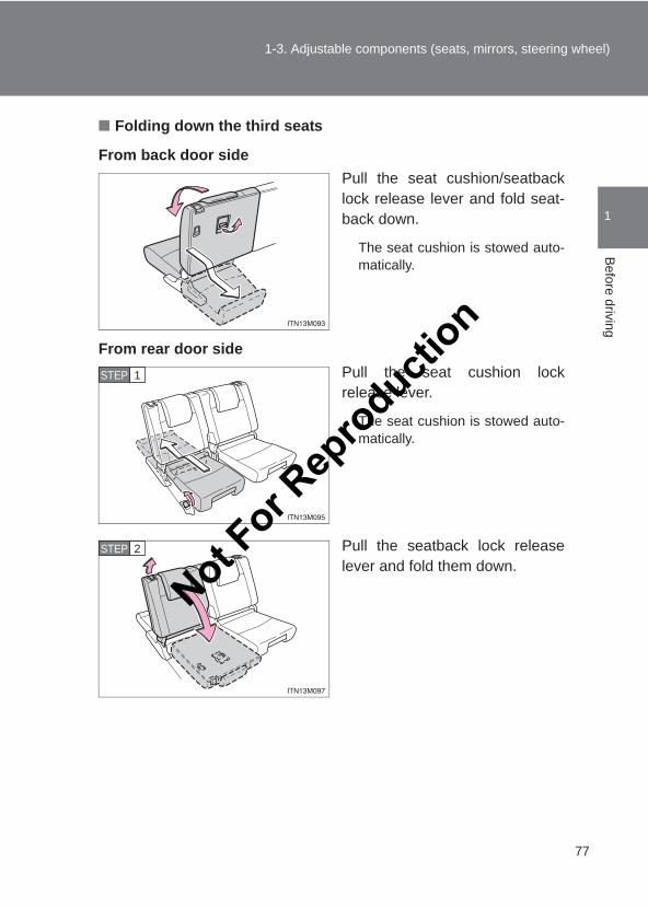
■ Folding down the third seats
From back door sidePull the seat cushion/seatbacklock release lever and fold seat-back down.
The seat cushion is stowed auto-matically.
From rear door sidePull the seat cushion lockrelease lever.
The seat cushion is stowed auto-matically.
Pull the seatback lock releaselever and fold them down.
STEP 1
STEP 2
Not For R
epro
duction
78
1-3. Adjustable components (seats, mirrors, steering wheel)
LC150_OM_OM60J77E_(AE)
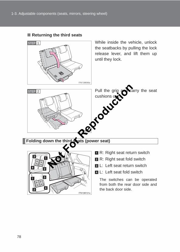
■ Returning the third seatsWhile inside the vehicle, unlockthe seatbacks by pulling the lockrelease lever, and lift them upuntil they lock.
Pull the grip and carry the seatcushions out.
Folding down the third seats (power seat)
R: Right seat return switchR: Right seat fold switchL: Left seat return switchL: Left seat fold switch
The switches can be operatedfrom both the rear door side andthe back door side.
STEP 1
STEP 2
Not For R
epro
duction
79
1-3. Adjustable components (seats, mirrors, steering wheel)
1
Before driving
LC150_OM_OM60J77E_(AE)
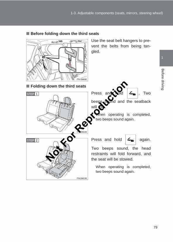
■ Before folding down the third seatsUse the seat belt hangers to pre-vent the belts from being tan-gled.
■ Folding down the third seatsPress and hold . Two
beeps sound and the seatbackwill rise.
When operating is completed,two beeps sound again.
Press and hold again.
Two beeps sound, the headrestraints will fold forward, andthe seat will be stowed.
When operating is completed,two beeps sound again.
ITN13M133
STEP 1
ITN13M135
STEP 2
Not For R
epro
duction
80
1-3. Adjustable components (seats, mirrors, steering wheel)
LC150_OM_OM60J77E_(AE)
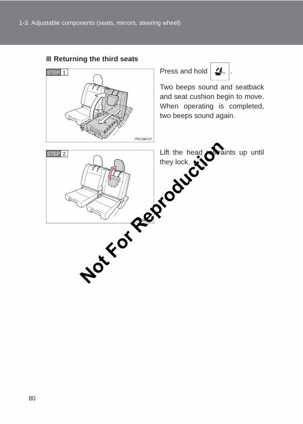
■ Returning the third seatsPress and hold .
Two beeps sound and seatbackand seat cushion begin to move.When operating is completed,two beeps sound again.
Lift the head restraints up untilthey lock.
STEP 1
STEP 2
Not For R
epro
duction
81
1-3. Adjustable components (seats, mirrors, steering wheel)
1
Before driving
LC150_OM_OM60J77E_(AE)
■The third power seats can be operated when●The “ENGINE START STOP” switch is off.
●The shift lever is in P position (vehicles with an automatic transmission)or the parking brake is applied (vehicles with a manual transmission) withthe “ENGINE START STOP” switch in IGNITION ON mode.
■During third power seat stowing operationDo not remove your hand from the switch until the operation stops automati-cally. If you remove your hand from the switch, the operation will stop andthe buzzer will sound continuously. The buzzer will stop when the switch ispressed again.
■Enlarging the luggage compartment (vehicles with third power seats)The third seat can be used for sitting when it is in the position shown in
of the folding down the third seats. (→P. 78)This can be convenient for enlarging the luggage compartment, for instancewhen the luggage is against the back of the seatback.
STEP 2
Not For R
epro
duction
82
1-3. Adjustable components (seats, mirrors, steering wheel)
LC150_OM_OM60J77E_(AE)
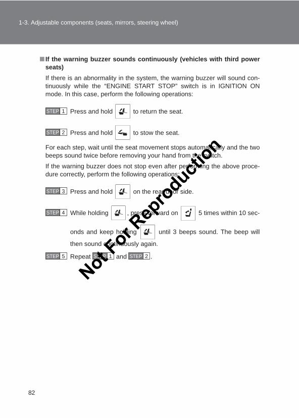
■ If the warning buzzer sounds continuously (vehicles with third powerseats)If there is an abnormality in the system, the warning buzzer will sound con-tinuously while the “ENGINE START STOP” switch is in IGNITION ONmode. In this case, perform the following operations:
Press and hold to return the seat.
Press and hold to stow the seat.
For each step, wait until the seat movement stops automatically and the twobeeps sound twice before removing your hand from the switch.
If the warning buzzer does not stop even after performing the above proce-dure correctly, perform the following operations:
Press and hold on the rear door side.
While holding , press forward on 5 times within 10 sec-
onds and keep holding until 3 beeps sound. The beep will
then sound continuously again.
Repeat and .
STEP 1
STEP 2
STEP 3
STEP 4
STEP 5 STEP 1 STEP 2
Not For R
epro
duction
83
1-3. Adjustable components (seats, mirrors, steering wheel)
1
Before driving
LC150_OM_OM60J77E_(AE)
CAUTION
■When folding the seatbacks downObserve the following precautions. Failure to do so may result in death orserious injury.
●Do not fold the seatbacks down while driving.
●Stop the vehicle on level ground, set the parking brake and shift the shiftlever to P (automatic transmission) or 1 (manual transmission).
●Do not allow anyone to sit on a folded seatback or in the luggage compart-ment while driving.
●Do not allow children to enter the luggage compartment.
■Seat adjustment●To reduce the risk of sliding under the lap belt during a collision, do not
recline the seat more than necessary.If the seat is too reclined, the lap belt may slide past the hips and applyrestraint forces directly to the abdomen, or your neck may contact theshoulder belt, increasing the risk of death or serious injury in the event ofan accident.Adjustments should not be made while driving as the seat may unexpect-edly move and cause the driver to lose control of the vehicle.
●Be careful not to get hands or feet pinched between the rear console boxand the rear second seat when folding down the seatback.
Not For R
epro
duction
84
1-3. Adjustable components (seats, mirrors, steering wheel)
LC150_OM_OM60J77E_(AE)
CAUTION
■When stowing the third seatsObserve the following precautions. Failure to do so may result in death orserious injury.
●Check that there is no luggage and that there are no other people aroundthe seat before stowing operation.
●Conduct the procedure slowly and carefully (vehicles with manual thirdseats).
●Do not insert hands or feet into the moving parts of the seat.
●Do not allow children to operate the seat.
●Do not use the seat if only the seat cushion has been stowed (vehicleswith manual third seats).
■After returning the seatbacks to the upright positionObserve the following precautions. Failure to do so may result in death orserious injury.
●Make sure the seatback is securely locked by pushing it forward and rear-ward on the top.
●Check that the seat belts are not twisted or caught in the seatback.
NOTICE
■When returning the third seat (vehicles with a luggage cover)If the luggage cover is installed in the luggage compartment, make sure youremove it before returning the third seat. (→P. 454) The luggage cover maybe damaged by the seat.
Not For R
epro
duction
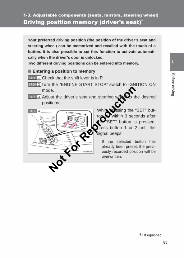
85
1
1-3. Adjustable components (seats, mirrors, steering wheel)B
efore driving
LC150_OM_OM60J77E_(AE)
Driving position memory (driver’s seat)∗
∗: If equipped
Your preferred driving position (the position of the driver’s seat andsteering wheel) can be memorized and recalled with the touch of abutton. It is also possible to set this function to activate automati-cally when the driver’s door is unlocked.Two different driving positions can be entered into memory.
■ Entering a position to memoryCheck that the shift lever is in P.Turn the “ENGINE START STOP” switch to IGNITION ONmode.Adjust the driver’s seat and steering wheel to the desiredpositions.
While pressing the “SET” but-ton, or within 3 seconds afterthe “SET” button is pressed,press button 1 or 2 until thesignal beeps.
If the selected button hasalready been preset, the previ-ously recorded position will beoverwritten.
STEP 1
STEP 2
STEP 3
STEP 4
Not For R
epro
duction
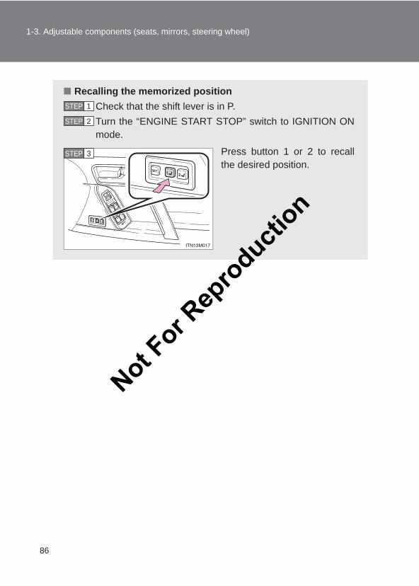
86
1-3. Adjustable components (seats, mirrors, steering wheel)
LC150_OM_OM60J77E_(AE)
■ Recalling the memorized positionCheck that the shift lever is in P.Turn the “ENGINE START STOP” switch to IGNITION ONmode.
Press button 1 or 2 to recallthe desired position.
STEP 1
STEP 2
STEP 3
Not For R
epro
duction
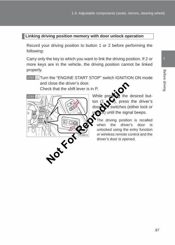
87
1-3. Adjustable components (seats, mirrors, steering wheel)
1
Before driving
LC150_OM_OM60J77E_(AE)
Linking driving position memory with door unlock operation
Record your driving position to button 1 or 2 before performing thefollowing:
Carry only the key to which you want to link the driving position. If 2 ormore keys are in the vehicle, the driving position cannot be linkedproperly.
Turn the “ENGINE START STOP” switch IGNITION ON modeand close the driver’s door.Check that the shift lever is in P.
While pressing the desired but-ton (1 or 2), press the driver’sdoor lock switches (either lock orunlock) until the signal beeps.
The driving position is recalledwhen the driver’s door isunlocked using the entry functionor wireless remote control and thedriver’s door is opened.
STEP 1
STEP 2
Not For R
epro
duction
88
1-3. Adjustable components (seats, mirrors, steering wheel)
LC150_OM_OM60J77E_(AE)
■Operating the driving position memory after turning the engine offMemorized positions (except the steering wheel position) can be activatedup to 180 seconds after the driver’s door is opened and another 60 secondsafter it is closed again, even after turning the “ENGINE START STOP” switchoff.
■Canceling the linked door unlock operationTurn the “ENGINE START STOP” switch IGNITION ON mode andclose the driver’s door.
While pressing “SET” button, press driver’s door lock switches(either lock or unlock) until the signal beeps.
■Stopping seat position operation part-way throughPerform any of the following operations:
●Press the “SET” button.
●Press button 1 or 2.
●Adjust the seat using the switches (only cancels seat position recall).
CAUTION
■Seat adjustment cautionTake care during seat adjustment so that the seat does not strike the rearpassenger or squeeze your body against the steering wheel.
STEP 1
STEP 2
Not For R
epro
duction
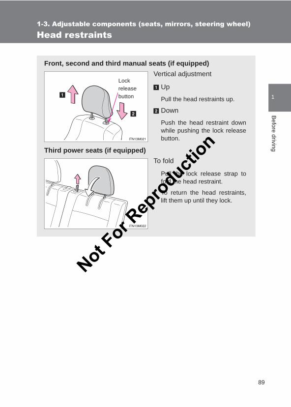
89
1
1-3. Adjustable components (seats, mirrors, steering wheel)B
efore driving
LC150_OM_OM60J77E_(AE)
Head restraints
Front, second and third manual seats (if equipped)Vertical adjustment
Up
Pull the head restraints up.
Down
Push the head restraint downwhile pushing the lock releasebutton.
Third power seats (if equipped)To fold
Pull the lock release strap tofold the head restraint.
To return the head restraints,lift them up until they lock.
Lockreleasebutton
Not For R
epro
duction
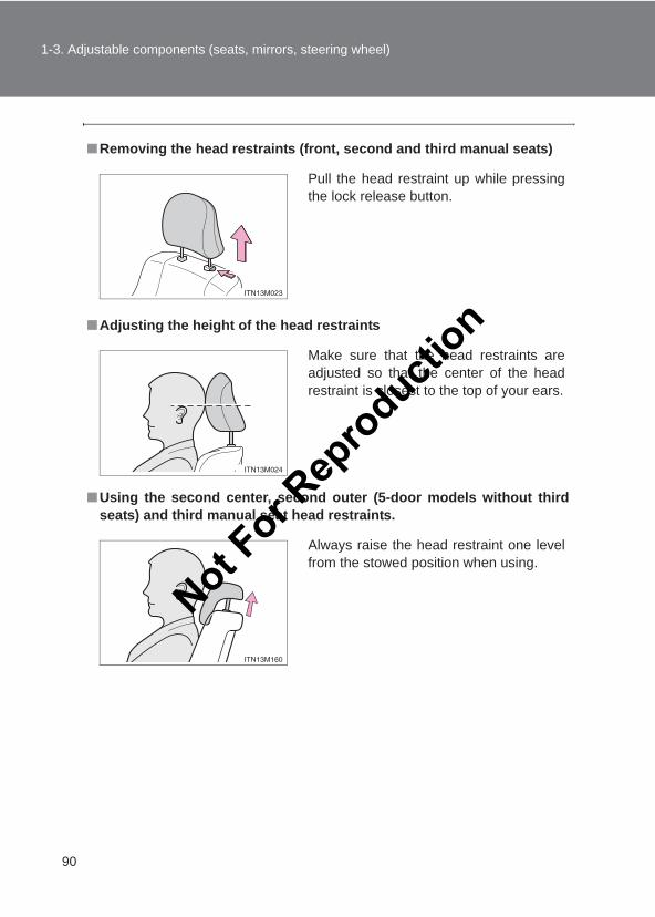
90
1-3. Adjustable components (seats, mirrors, steering wheel)
LC150_OM_OM60J77E_(AE)
■Removing the head restraints (front, second and third manual seats)
■Adjusting the height of the head restraints
■Using the second center, second outer (5-door models without thirdseats) and third manual seat head restraints.
Pull the head restraint up while pressingthe lock release button.
Make sure that the head restraints areadjusted so that the center of the headrestraint is closest to the top of your ears.
Always raise the head restraint one levelfrom the stowed position when using.
Not For R
epro
duction
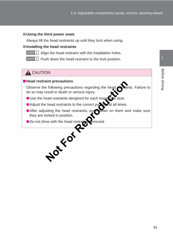
91
1-3. Adjustable components (seats, mirrors, steering wheel)
1
Before driving
LC150_OM_OM60J77E_(AE)
■Using the third power seatsAlways lift the head restraints up until they lock when using.
■ Installing the head restraintsAlign the head restraint with the installation holes.
Push down the head restraint to the lock position.
CAUTION
■Head restraint precautionsObserve the following precautions regarding the head restraints. Failure todo so may result in death or serious injury.
●Use the head restraints designed for each respective seat.
●Adjust the head restraints to the correct position at all times.
●After adjusting the head restraints, push down on them and make surethey are locked in position.
●Do not drive with the head restraints removed.
STEP 1
STEP 2
Not For R
epro
duction
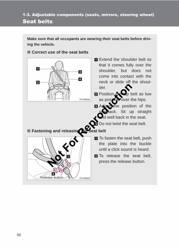
92
1-3. Adjustable components (seats, mirrors, steering wheel)
LC150_OM_OM60J77E_(AE)
Seat belts
Make sure that all occupants are wearing their seat belts before driv-ing the vehicle.
■ Correct use of the seat beltsExtend the shoulder belt sothat it comes fully over theshoulder, but does notcome into contact with theneck or slide off the shoul-der.Position the lap belt as lowas possible over the hips.Adjust the position of theseatback. Sit up straightand well back in the seat.Do not twist the seat belt.
■ Fastening and releasing the seat beltTo fasten the seat belt, pushthe plate into the buckleuntil a click sound is heard.To release the seat belt,press the release button.
Release button
Not For R
epro
duction
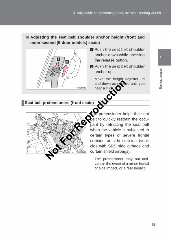
93
1-3. Adjustable components (seats, mirrors, steering wheel)
1
Before driving
LC150_OM_OM60J77E_(AE)
Seat belt pretensioners (front seats)
The pretensioner helps the seatbelt to quickly restrain the occu-pant by retracting the seat beltwhen the vehicle is subjected tocertain types of severe frontalcollision or side collision (vehi-cles with SRS side airbags andcurtain shield airbags).
The pretensioner may not acti-vate in the event of a minor frontalor side impact, or a rear impact.
■ Adjusting the seat belt shoulder anchor height (front andouter second [5-door models] seats)
Push the seat belt shoulderanchor down while pressingthe release button.Push the seat belt shoulderanchor up.
Move the height adjuster upand down as needed until youhear a click.
Not For R
epro
duction

94
1-3. Adjustable components (seats, mirrors, steering wheel)
LC150_OM_OM60J77E_(AE)
Pre-crash seat belts (front seats of vehicles with pre-crash safetysystem)
If the pre-crash sensor detects that a collision is unavoidable, the pre-crash safety system will retract the seat belt, thus enhancing theeffectiveness of the seat belt pretensioner in a crash.
The same will happen if the driver makes an emergency braking or losescontrol of the vehicle. (→P. 287)
■Emergency locking retractor (ELR)The retractor will lock the belt during a sudden stop or on impact. It may alsolock if you lean forward too quickly. A slow, easy motion will allow the belt toextend so that you can move around fully.
■Automatic locking retractor (ALR) (if equipped)When a second seat passenger’s shoulder belt is completely extended andthen retracted even slightly, the belt is locked in that position and cannot beextended. This feature is used to hold the child restraint system (CRS) firmly.To free the belt again, fully retract the belt and then pull the belt out oncemore. (→P. 146)
Not For R
epro
duction
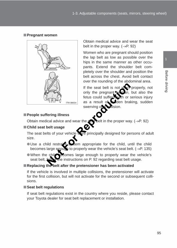
95
1-3. Adjustable components (seats, mirrors, steering wheel)
1
Before driving
LC150_OM_OM60J77E_(AE)
■Pregnant women
■People suffering illnessObtain medical advice and wear the seat belt in the proper way. (→P. 92)
■Child seat belt usageThe seat belts of your vehicle were principally designed for persons of adultsize.●Use a child restraint system appropriate for the child, until the child
becomes large enough to properly wear the vehicle’s seat belt. (→P. 135)●When the child becomes large enough to properly wear the vehicle’s
seat belt, follow the instructions on P. 92 regarding seat belt usage.■Replacing the belt after the pretensioner has been activated
If the vehicle is involved in multiple collisions, the pretensioner will activatefor the first collision, but will not activate for the second or subsequent colli-sions.
■Seat belt regulationsIf seat belt regulations exist in the country where you reside, please contactyour Toyota dealer for seat belt replacement or installation.
Obtain medical advice and wear the seatbelt in the proper way. (→P. 92)
Women who are pregnant should positionthe lap belt as low as possible over thehips in the same manner as other occu-pants. Extend the shoulder belt com-pletely over the shoulder and position thebelt across the chest. Avoid belt contactover the rounding of the abdominal area.
If the seat belt is not worn properly, notonly the pregnant woman, but also thefetus could suffer death or serious injuryas a result of sudden braking, suddenswerving or a collision.
Not For R
epro
duction
96
1-3. Adjustable components (seats, mirrors, steering wheel)
LC150_OM_OM60J77E_(AE)
CAUTION
Observe the following precautions to reduce the risk of injury in the event ofsudden braking, sudden swerving or an accident.Failure to do so may cause death or serious injury.
■Wearing a seat belt●Ensure that all passengers wear a seat belt.
●Always wear a seat belt properly.
●Each seat belt should be used by one person only. Do not use a seat beltfor more than one person at once, including children.
●Toyota recommends that children be seated in the rear seat and alwaysuse a seat belt and/or an appropriate child restraint system.
●To achieve a proper seating position, do not recline the seat more thannecessary. The seat belt is most effective when the occupants are sittingup straight and well back in the seats.
●Do not wear the shoulder belt under your arm.
●Always wear your seat belt low and snug across your hips.
■Seat belt pretensionersIf the pretensioner has activated, the SRS warning light will come on. In thatcase, the seat belt cannot be used again and must be replaced at yourToyota dealer.
Not For R
epro
duction
97
1-3. Adjustable components (seats, mirrors, steering wheel)
1
Before driving
LC150_OM_OM60J77E_(AE)
CAUTION
■Child restraint lock function belt precautionDo not allow children to play with the child restraint lock function belt. If thebelt becomes twisted around a child’s neck, it will not be possible to pull thebelt out leading to choking or other serious injuries that could result in death.If this occurs and the buckle cannot be unfastened, scissors should be usedto cut the belt.
■Adjustable shoulder anchorAlways make sure the shoulder belt is positioned across the center of yourshoulder. The belt should be kept away from your neck, but not falling offyour shoulder. Failure to do so could reduce the amount of protection in anaccident and cause death or serious injuries in the event of a sudden stop,sudden swerve or accident. (→P. 93)
■Seat belt damage and wear●Do not damage the seat belts by allowing the belt, plate, or buckle to be
jammed in the door.
● Inspect the seat belt system periodically. Check for cuts, fraying, and looseparts. Do not use a damaged seat belt until it is replaced. Damaged seatbelt cannot protect an occupant from death or serious injury.
●Ensure that the belt and plate are locked and the belt is not twisted.If the seat belt does not function correctly, immediately contact your Toyotadealer.
●Replace the seat assembly, including the belts, if your vehicle has beeninvolved in a serious accident, even if there is no obvious damage.
●Do not attempt to install, remove, modify, disassemble or dispose of theseat belts. Have any necessary repairs carried out by your Toyota dealer.Inappropriate handling of the pretensioner may prevent it from operatingproperly, resulting in death or serious injury.
Not For R
epro
duction
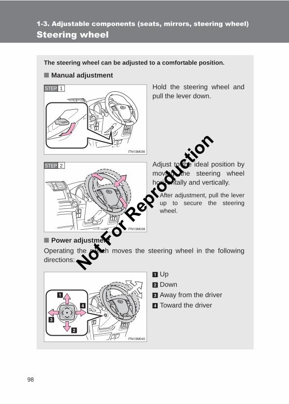
98
1-3. Adjustable components (seats, mirrors, steering wheel)
LC150_OM_OM60J77E_(AE)
Steering wheel
The steering wheel can be adjusted to a comfortable position.
■ Manual adjustmentHold the steering wheel andpull the lever down.
Adjust to the ideal position bymoving the steering wheelhorizontally and vertically.
After adjustment, pull the leverup to secure the steeringwheel.
■ Power adjustmentOperating the switch moves the steering wheel in the followingdirections:
UpDownAway from the driverToward the driver
STEP 1
STEP 2
Not For R
epro
duction
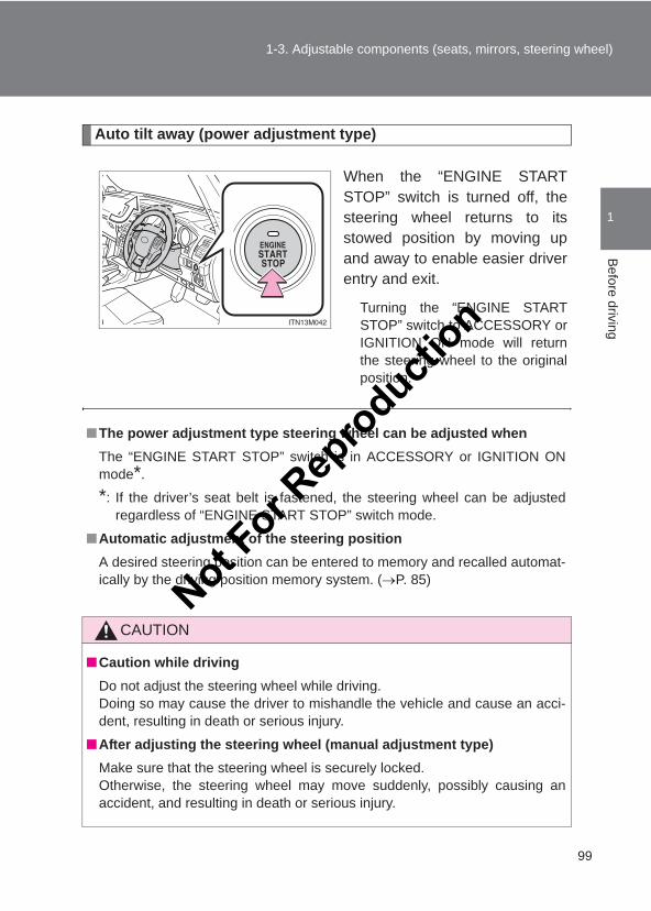
99
1-3. Adjustable components (seats, mirrors, steering wheel)
1
Before driving
LC150_OM_OM60J77E_(AE)
Auto tilt away (power adjustment type)
When the “ENGINE STARTSTOP” switch is turned off, thesteering wheel returns to itsstowed position by moving upand away to enable easier driverentry and exit.
Turning the “ENGINE STARTSTOP” switch to ACCESSORY orIGNITION ON mode will returnthe steering wheel to the originalposition.
■The power adjustment type steering wheel can be adjusted whenThe “ENGINE START STOP” switch is in ACCESSORY or IGNITION ONmode*.
*: If the driver’s seat belt is fastened, the steering wheel can be adjustedregardless of “ENGINE START STOP” switch mode.
■Automatic adjustment of the steering positionA desired steering position can be entered to memory and recalled automat-ically by the driving position memory system. (→P. 85)
CAUTION
■Caution while drivingDo not adjust the steering wheel while driving.Doing so may cause the driver to mishandle the vehicle and cause an acci-dent, resulting in death or serious injury.
■After adjusting the steering wheel (manual adjustment type)Make sure that the steering wheel is securely locked. Otherwise, the steering wheel may move suddenly, possibly causing anaccident, and resulting in death or serious injury.
Not For R
epro
duction
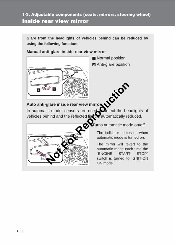
100
1-3. Adjustable components (seats, mirrors, steering wheel)
LC150_OM_OM60J77E_(AE)
Inside rear view mirror
Glare from the headlights of vehicles behind can be reduced byusing the following functions.
Manual anti-glare inside rear view mirrorNormal positionAnti-glare position
Auto anti-glare inside rear view mirrorIn automatic mode, sensors are used to detect the headlights ofvehicles behind and the reflected light is automatically reduced.
Turns automatic mode on/off
The indicator comes on whenautomatic mode is turned on.
The mirror will revert to theautomatic mode each time the“ENGINE START STOP”switch is turned to IGNITIONON mode.ITN13M044
IndicatorNot For R
epro
duction
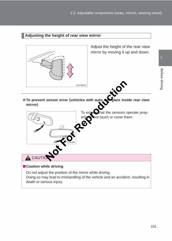
101
1-3. Adjustable components (seats, mirrors, steering wheel)
1
Before driving
LC150_OM_OM60J77E_(AE)
Adjusting the height of rear view mirror
Adjust the height of the rear viewmirror by moving it up and down.
■To prevent sensor error (vehicles with auto anti-glare inside rear viewmirror)
CAUTION
■Caution while drivingDo not adjust the position of the mirror while driving.Doing so may lead to mishandling of the vehicle and an accident, resulting indeath or serious injury.
To ensure that the sensors operate prop-erly, do not touch or cover them.
ITY13C080
Not For R
epro
duction
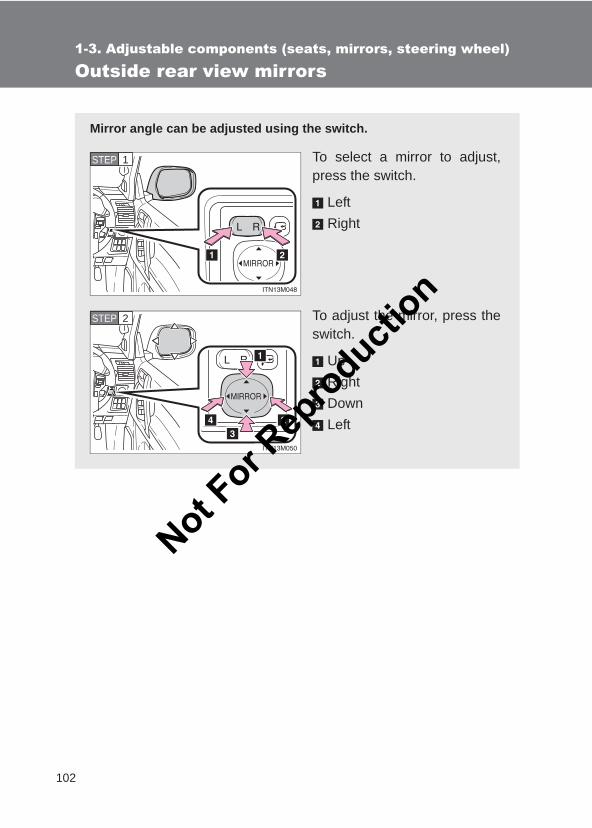
102
1-3. Adjustable components (seats, mirrors, steering wheel)
LC150_OM_OM60J77E_(AE)
Outside rear view mirrors
Mirror angle can be adjusted using the switch.
To select a mirror to adjust,press the switch.
LeftRight
To adjust the mirror, press theswitch.
UpRightDownLeft
STEP 1
STEP 2
Not For R
epro
duction
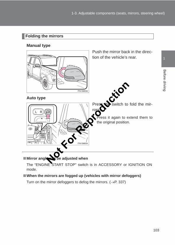
103
1-3. Adjustable components (seats, mirrors, steering wheel)
1
Before driving
LC150_OM_OM60J77E_(AE)
Folding the mirrors
Manual typePush the mirror back in the direc-tion of the vehicle’s rear.
Auto typePress the switch to fold the mir-rors.
Press it again to extend them tothe original position.
■Mirror angle can be adjusted whenThe “ENGINE START STOP” switch is in ACCESSORY or IGNITION ONmode.
■When the mirrors are fogged up (vehicles with mirror defoggers)Turn on the mirror defoggers to defog the mirrors. (→P. 337)
Not For R
epro
duction
104
1-3. Adjustable components (seats, mirrors, steering wheel)
LC150_OM_OM60J77E_(AE)
CAUTION
■When driving the vehicleObserve the following precautions while driving.Failing to do so may result in loss of control of the vehicle and cause an acci-dent, resulting in death or serious injury.
●Do not adjust the mirrors while driving.
●Do not drive with the mirrors folded.
●Both the driver and passenger side mirrors must be extended and properlyadjusted before driving.
■When a mirror is movingTo avoid personal injury and mirror malfunction, be careful not to get yourhand caught by the moving mirror.
■When the mirror defoggers are operating (vehicles with mirror defog-gers)Do not touch the rear view mirror surfaces, as they can become very hot andburn you.
NOTICE
■ If ice should jam the mirrorDo not operate the control or scrape the mirror face. Use a spray de-icer tofree the mirror.Not F
or Rep
roducti
on
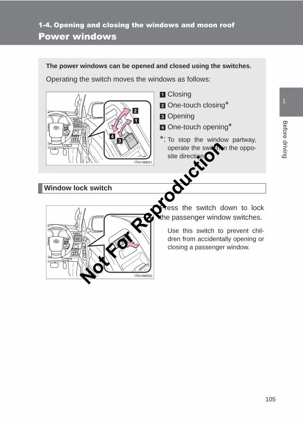
105
1
Before driving
LC150_OM_OM60J77E_(AE)
1-4. Opening and closing the windows and moon roof
Power windows
Window lock switch
Press the switch down to lockthe passenger window switches.
Use this switch to prevent chil-dren from accidentally opening orclosing a passenger window.
The power windows can be opened and closed using the switches.
Operating the switch moves the windows as follows:
ClosingOne-touch closing*OpeningOne-touch opening*
*: To stop the window partway,operate the switch in the oppo-site direction.
Not For R
epro
duction
106
1-4. Opening and closing the windows and moon roof
LC150_OM_OM60J77E_(AE)
■The power windows can be operated whenThe “ENGINE START STOP” switch is in IGNITION ON mode.
■Operating the power windows after turning the engine offThe power windows can be operated for approximately 45 seconds evenafter the “ENGINE START STOP” switch is turned to ACCESSORY mode orturned off. They cannot, however, be operated once either front door isopened.
■Jam protection functionIf an object becomes caught between the window and the window frame,window travel is stopped and the window is opened slightly.
■When the power window does not close normallyIf the jam protection function is operating abnormally and a window cannotbe closed, perform the following operations using the power window switchon the relevant door.
●After stopping the vehicle, the window can be closed by holding thepower window switch in the one-touch closing position while the“ENGINE START STOP” switch is turned to IGNITION ON mode.
● If the window still cannot be closed even by carrying out the operationexplained above, initialize the function by performing the following proce-dure.
Hold the power window switch in the one-touch closing position.Continue holding the switch for a further 6 seconds after the win-dow has closed.
Hold the power window switch in the one-touch opening position.Continue holding the switch for a further 2 seconds after the win-dow has opened completely.
Hold the power window switch in the one-touch closing positiononce again. Continue holding the switch for a further 2 secondsafter the window has closed.
STEP 1
STEP 2
STEP 3
Not For R
epro
duction
107
1-4. Opening and closing the windows and moon roof
1
Before driving
LC150_OM_OM60J77E_(AE)
If you release the switch while the window is moving, start again from thebeginning. If the window continues to close but then re-open slightly evenafter performing the above procedure correctly, have the vehicle inspectedby your Toyota dealer.
■Door lock linked window operationThe power windows can be opened and closed using the wireless remotecontrol or mechanical key if customized at your Toyota dealer. (→P. 46, 50)
■CustomizationSettings (e.g. linked door lock operation) can be changed. (Customizable features →P. 632)
CAUTION
■Closing the windowsObserve the following precautions. Failing to do so may result in death or serious injury.
●Check to make sure that all passengers do not have any part of their bodyin a position where it could be caught when a window is being operated.
●Do not allow children to operate the power windows. Closing a power window on someone can cause serious injury, and insome instances, even death.
■Jam protection function●Never use any part of your body to intentionally activate the jam protection
function.
●The jam protection function may not work if something gets caught justbefore the window fully closes.
Not For R
epro
duction
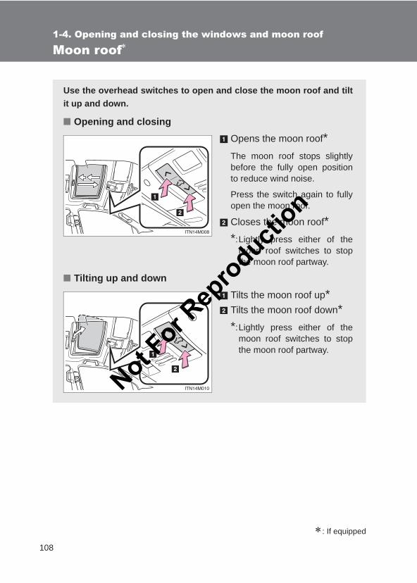
108
1-4. Opening and closing the windows and moon roof
LC150_OM_OM60J77E_(AE)
Moon roof∗
∗: If equipped
Use the overhead switches to open and close the moon roof and tiltit up and down.
■ Opening and closingOpens the moon roof*The moon roof stops slightlybefore the fully open positionto reduce wind noise.
Press the switch again to fullyopen the moon roof.
Closes the moon roof**:Lightly press either of the
moon roof switches to stopthe moon roof partway.
■ Tilting up and downTilts the moon roof up*Tilts the moon roof down**:Lightly press either of the
moon roof switches to stopthe moon roof partway.
Not For R
epro
duction
109
1-4. Opening and closing the windows and moon roof
1
Before driving
LC150_OM_OM60J77E_(AE)
■The moon roof can be operated whenThe “ENGINE START STOP” switch is in IGNITION ON mode.
■Operating the moon roof after turning the engine offThe moon roof can be operated for approximately 45 seconds after the“ENGINE START STOP” switch is turned to ACCESSORY mode or turnedoff. It cannot, however, be operated once either front door is opened.
■Jam protection functionIf an object is detected between the moon roof and the frame while the moonroof is closing or tilting down, travel is stopped and the moon roof opensslightly.
■SunshadeThe sunshade can be opened and closed manually. However, the sunshadewill open automatically when the moon roof is opened.
■Door lock linked moon roof operationThe moon roof can be opened and closed using the wireless remote controlor mechanical key if customized at your Toyota dealer. (→P. 46, 50)
■Moon roof open reminder functionAn alarm will sound when the driver’s door is opened with the moon roof notfully closed and the “ENGINE START STOP” switch off.
Not For R
epro
duction
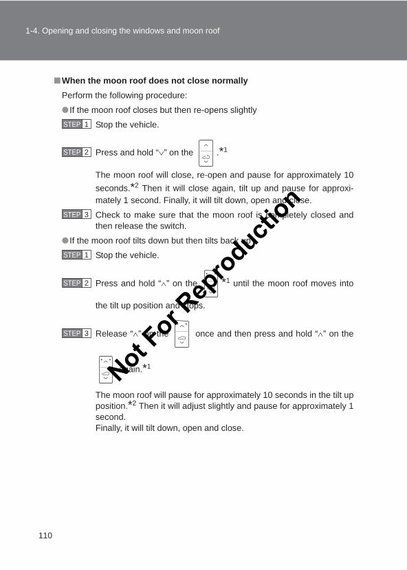
110
1-4. Opening and closing the windows and moon roof
LC150_OM_OM60J77E_(AE)
■When the moon roof does not close normallyPerform the following procedure:
● If the moon roof closes but then re-opens slightly
Stop the vehicle.
Press and hold “∨” on the .*1
The moon roof will close, re-open and pause for approximately 10seconds.*2 Then it will close again, tilt up and pause for approxi-mately 1 second. Finally, it will tilt down, open and close.
Check to make sure that the moon roof is completely closed andthen release the switch.
● If the moon roof tilts down but then tilts back up
Stop the vehicle.
Press and hold “∧” on the *1 until the moon roof moves into
the tilt up position and stops.
Release “∧” on the once and then press and hold “∧” on the
again.*1
The moon roof will pause for approximately 10 seconds in the tilt upposition.*2 Then it will adjust slightly and pause for approximately 1second.Finally, it will tilt down, open and close.
STEP 1
STEP 2
STEP 3
STEP 1
STEP 2
STEP 3
Not For R
epro
duction
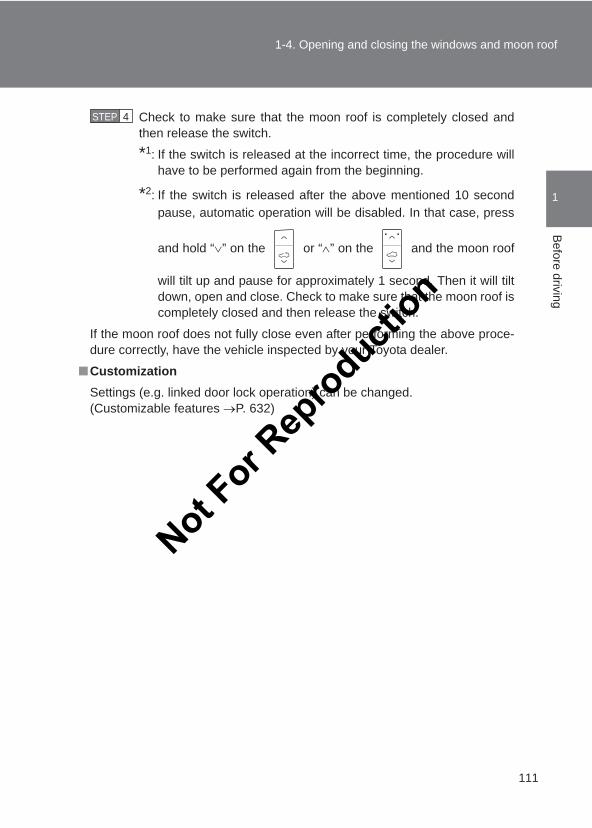
111
1-4. Opening and closing the windows and moon roof
1
Before driving
LC150_OM_OM60J77E_(AE)
Check to make sure that the moon roof is completely closed andthen release the switch.
*1: If the switch is released at the incorrect time, the procedure willhave to be performed again from the beginning.
*2: If the switch is released after the above mentioned 10 secondpause, automatic operation will be disabled. In that case, press
and hold “∨” on the or “∧” on the and the moon roof
will tilt up and pause for approximately 1 second. Then it will tiltdown, open and close. Check to make sure that the moon roof iscompletely closed and then release the switch.
If the moon roof does not fully close even after performing the above proce-dure correctly, have the vehicle inspected by your Toyota dealer.
■CustomizationSettings (e.g. linked door lock operation) can be changed. (Customizable features →P. 632)
STEP 4
Not For R
epro
duction
112
1-4. Opening and closing the windows and moon roof
LC150_OM_OM60J77E_(AE)
CAUTION
■Opening the moon roofObserve the following precautions.Failing to do so may cause death or serious injury.
●Do not allow any passengers to put their hands or heads outside the vehi-cle while it is moving.
●Do not sit on top of the moon roof.
■Closing the moon roofObserve the following precautions. Failing to do so may result in death or serious injury.
●Check to make sure that all passengers do not have any part of their bod-ies in a position where it could be caught when the moon roof is beingoperated.
●Do not allow children to operate the moon roof. Closing the moon roof on someone can cause death or serious injury.
■Jam protection function●Never use any part of your body to intentionally activate the jam protection
function.
●The jam protection function may not work if something gets caught justbefore the moon roof fully closes.
Not For R
epro
duction
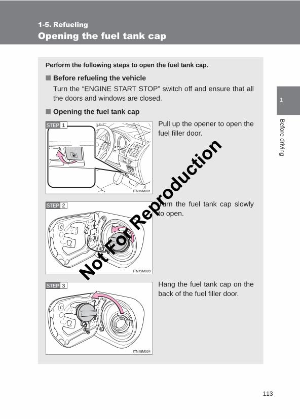
113
1
Before driving
LC150_OM_OM60J77E_(AE)
1-5. Refueling
Opening the fuel tank cap
Perform the following steps to open the fuel tank cap.
■ Before refueling the vehicleTurn the “ENGINE START STOP” switch off and ensure that allthe doors and windows are closed.
■ Opening the fuel tank capPull up the opener to open thefuel filler door.
Turn the fuel tank cap slowlyto open.
Hang the fuel tank cap on theback of the fuel filler door.
STEP 1
STEP 2
STEP 3Not F
or Rep
roducti
on
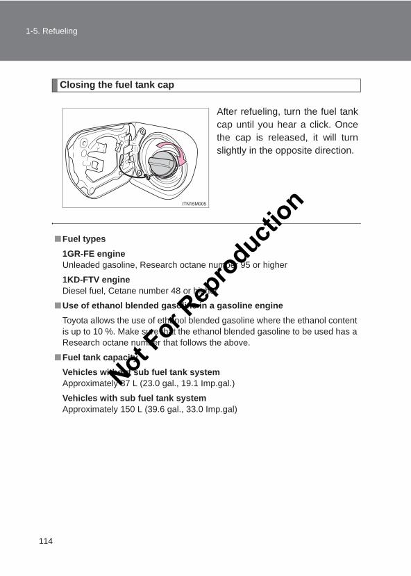
114
1-5. Refueling
LC150_OM_OM60J77E_(AE)
Closing the fuel tank cap
After refueling, turn the fuel tankcap until you hear a click. Oncethe cap is released, it will turnslightly in the opposite direction.
■Fuel types1GR-FE engineUnleaded gasoline, Research octane number 95 or higher
1KD-FTV engineDiesel fuel, Cetane number 48 or higher
■Use of ethanol blended gasoline in a gasoline engineToyota allows the use of ethanol blended gasoline where the ethanol contentis up to 10 %. Make sure that the ethanol blended gasoline to be used has aResearch octane number that follows the above.
■Fuel tank capacityVehicles without sub fuel tank systemApproximately 87 L (23.0 gal., 19.1 Imp.gal.)
Vehicles with sub fuel tank systemApproximately 150 L (39.6 gal., 33.0 Imp.gal)
Not For R
epro
duction
115
1-5. Refueling
1
Before driving
LC150_OM_OM60J77E_(AE)
CAUTION
■When refueling the vehicleObserve the following precautions while refueling the vehicle. Failure to doso may result in death or serious injury.
●After exiting the vehicle and before opening the fuel door, touch anunpainted metal surface to discharge any static electricity. It is important todischarge static electricity before refueling because sparks resulting fromstatic electricity can cause fuel vapors to ignite while refueling.
●Always hold the grips on the fuel tank cap and turn it slowly to remove it. A whooshing sound may be heard when the fuel tank cap is loosened.Wait until the sound cannot be heard before fully removing the cap. In hotweather, pressurized fuel may spray out of the filler neck and cause injury.
●Do not allow anyone that has not discharged static electricity from theirbody to come close to an open fuel tank.
●Do not inhale vaporized fuel.Fuel contains substances that are harmful if inhaled.
●Do not smoke while refueling the vehicle.Doing so may cause the fuel to ignite and cause a fire.
●Do not return to the vehicle or touch any person or object that is staticallycharged.This may cause static electricity to build up, resulting in a possible ignitionhazard.
Not For R
epro
duction
116
1-5. Refueling
LC150_OM_OM60J77E_(AE)
CAUTION
■When refuelingSecurely insert the fuel nozzle into the fuel filler neck. If fuel is added withthe nozzle slightly lifted away from the fuel filler neck, the automatic shut offfunction may not operate, resulting in fuel overflowing from the tank.
■When replacing the fuel capDo not use anything but a genuine Toyota fuel tank cap designed for yourvehicle. Doing so may cause a fire or other incident which may result indeath or serious injury.
NOTICE
■RefuelingDo not spill fuel during refueling.Doing so may damage the vehicle, such as causing the emission controlsystems to operate abnormally or damaging fuel system components or thevehicle’s painted surface.
Not For R
epro
duction
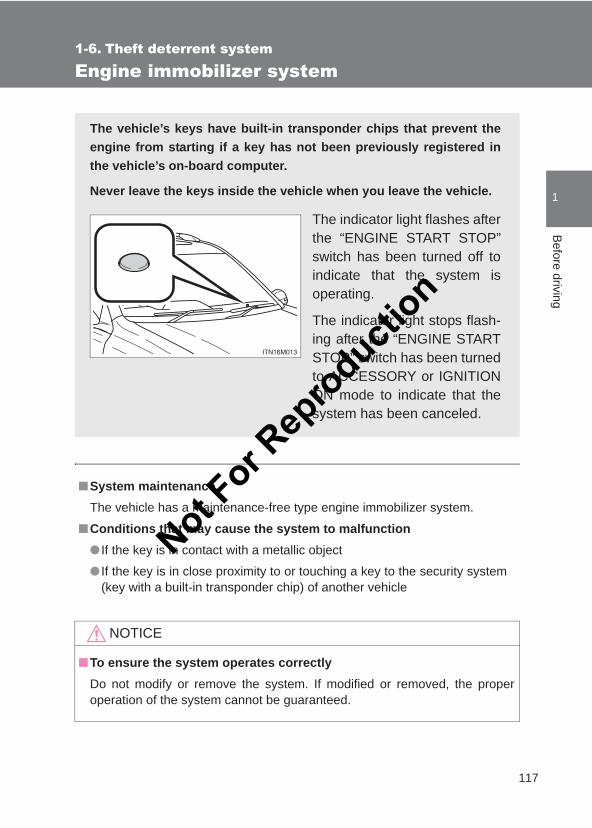
117
1
Before driving
LC150_OM_OM60J77E_(AE)
1-6. Theft deterrent system
Engine immobilizer system
■System maintenanceThe vehicle has a maintenance-free type engine immobilizer system.
■Conditions that may cause the system to malfunction● If the key is in contact with a metallic object
● If the key is in close proximity to or touching a key to the security system(key with a built-in transponder chip) of another vehicle
NOTICE
■To ensure the system operates correctlyDo not modify or remove the system. If modified or removed, the properoperation of the system cannot be guaranteed.
The vehicle’s keys have built-in transponder chips that prevent theengine from starting if a key has not been previously registered inthe vehicle’s on-board computer.
Never leave the keys inside the vehicle when you leave the vehicle.
The indicator light flashes afterthe “ENGINE START STOP”switch has been turned off toindicate that the system isoperating.
The indicator light stops flash-ing after the “ENGINE STARTSTOP” switch has been turnedto ACCESSORY or IGNITIONON mode to indicate that thesystem has been canceled.
Not For R
epro
duction
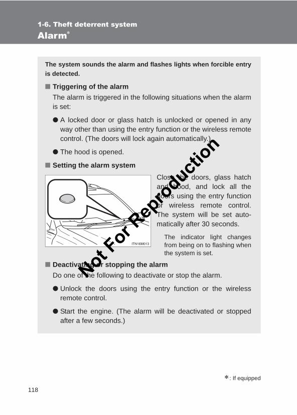
118
1-6. Theft deterrent system
LC150_OM_OM60J77E_(AE)
Alarm∗
∗: If equipped
The system sounds the alarm and flashes lights when forcible entryis detected.
■ Triggering of the alarmThe alarm is triggered in the following situations when the alarmis set:
● A locked door or glass hatch is unlocked or opened in anyway other than using the entry function or the wireless remotecontrol. (The doors will lock again automatically.)
● The hood is opened.
■ Setting the alarm systemClose the doors, glass hatchand hood, and lock all thedoors using the entry functionor wireless remote control.The system will be set auto-matically after 30 seconds.
The indicator light changesfrom being on to flashing whenthe system is set.
■ Deactivating or stopping the alarmDo one of the following to deactivate or stop the alarm.
● Unlock the doors using the entry function or the wirelessremote control.
● Start the engine. (The alarm will be deactivated or stoppedafter a few seconds.)
Not For R
epro
duction
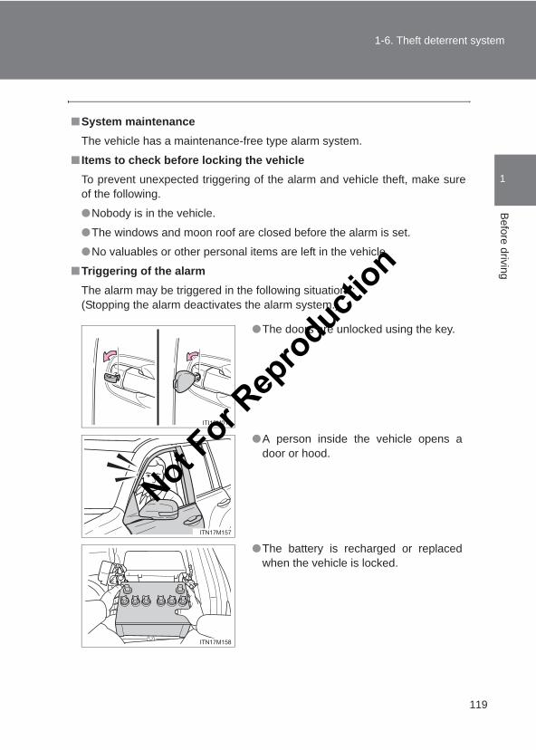
119
1-6. Theft deterrent system
1
Before driving
LC150_OM_OM60J77E_(AE)
■System maintenanceThe vehicle has a maintenance-free type alarm system.
■ Items to check before locking the vehicleTo prevent unexpected triggering of the alarm and vehicle theft, make sureof the following.
●Nobody is in the vehicle.
●The windows and moon roof are closed before the alarm is set.
●No valuables or other personal items are left in the vehicle.
■Triggering of the alarmThe alarm may be triggered in the following situations:(Stopping the alarm deactivates the alarm system.)
●The doors are unlocked using the key.
●A person inside the vehicle opens adoor or hood.
●The battery is recharged or replacedwhen the vehicle is locked.
Not For R
epro
duction
120
1-6. Theft deterrent system
LC150_OM_OM60J77E_(AE)
■Alarm-operated door lock●When the alarm is operating, the doors are locked automatically to pre-
vent intruders.
●Do not leave the key inside the vehicle when the alarm is operating, andmake sure the key is not inside the vehicle when recharging or replacingthe battery.
NOTICE
■To ensure the system operates correctlyDo not modify or remove the system. If modified or removed, the properoperation of the system cannot be guaranteed.
Not For R
epro
duction
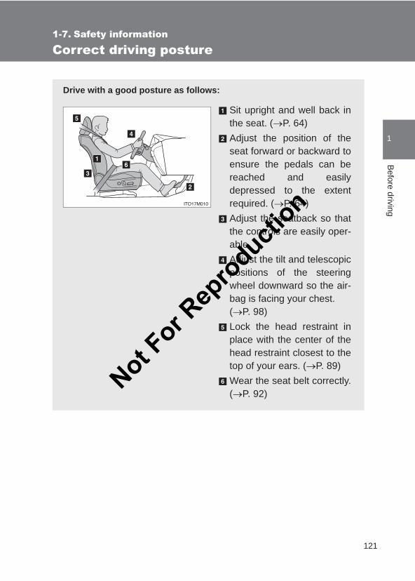
121
1
Before driving
LC150_OM_OM60J77E_(AE)
1-7. Safety information
Correct driving posture
Drive with a good posture as follows:
Sit upright and well back inthe seat. (→P. 64)Adjust the position of theseat forward or backward toensure the pedals can bereached and easilydepressed to the extentrequired. (→P. 64)Adjust the seatback so thatthe controls are easily oper-able.Adjust the tilt and telescopicpositions of the steeringwheel downward so the air-bag is facing your chest. (→P. 98)Lock the head restraint inplace with the center of thehead restraint closest to thetop of your ears. (→P. 89)Wear the seat belt correctly.(→P. 92)
Not For R
epro
duction
122
1-7. Safety information
LC150_OM_OM60J77E_(AE)
CAUTION
■While driving●Do not adjust the position of the driver’s seat.
Doing so could cause the driver to lose control of the vehicle.
●Do not place a cushion between the driver or passenger and the seatback.A cushion may prevent correct posture from being achieved, and reducethe effectiveness of the seat belt and head restraint, increasing the risk ofdeath or serious injury to the driver or passenger.
●Do not place anything under the front seats.Objects placed under the front seats may become jammed in the seattracks and stop the seat from locking in place. This may lead to an acci-dent, resulting in death or serious injury. The adjustment mechanism mayalso be damaged.
■Adjusting the seat position●Take care when adjusting the seat position to ensure that other passen-
gers are not injured by the moving seat.
●Do not put your hands under the seat or near the moving parts to avoidinjury.Fingers or hands may become jammed in the seat mechanism.
Not For R
epro
duction
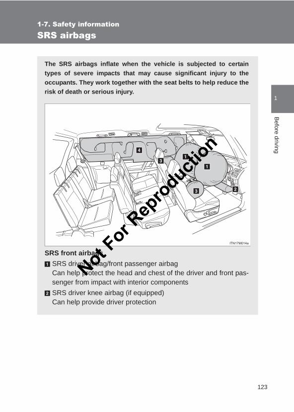
123
1
1-7. Safety informationB
efore driving
LC150_OM_OM60J77E_(AE)
SRS airbags
The SRS airbags inflate when the vehicle is subjected to certaintypes of severe impacts that may cause significant injury to theoccupants. They work together with the seat belts to help reduce therisk of death or serious injury.
SRS front airbagsSRS driver airbag/front passenger airbagCan help protect the head and chest of the driver and front pas-senger from impact with interior componentsSRS driver knee airbag (if equipped)Can help provide driver protection
Not For R
epro
duction
124
1-7. Safety information
LC150_OM_OM60J77E_(AE)
SRS side and curtain shield airbagsSRS side airbags (if equipped)Can help protect the torso of the front seat occupantsSRS curtain shield airbags (if equipped)Can help protect primarily the head of occupants in the outerseats
Not For R
epro
duction
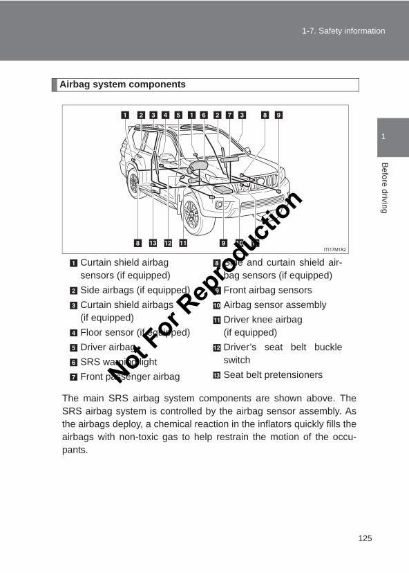
125
1-7. Safety information
1
Before driving
LC150_OM_OM60J77E_(AE)
Airbag system components
The main SRS airbag system components are shown above. TheSRS airbag system is controlled by the airbag sensor assembly. Asthe airbags deploy, a chemical reaction in the inflators quickly fills theairbags with non-toxic gas to help restrain the motion of the occu-pants.
Curtain shield airbag sensors (if equipped)Side airbags (if equipped)Curtain shield airbags (if equipped)Floor sensor (if equipped)Driver airbagSRS warning lightFront passenger airbag
Side and curtain shield air-bag sensors (if equipped)Front airbag sensorsAirbag sensor assemblyDriver knee airbag (if equipped)Driver’s seat belt buckleswitchSeat belt pretensionersNot F
or Rep
roducti
on
126
1-7. Safety information
LC150_OM_OM60J77E_(AE)
■ If the SRS airbags deploy (inflate)●Bruising and slight abrasions may result from contact with a deploying
(inflating) SRS airbag.
●A loud noise and white powder will be emitted.
●Vehicles with SRS curtain shield airbagsParts of the airbag module (steering wheel hub, airbag cover and inflator)as well as the front seats, second seats, and parts of the front, center andrear pillars and roof side rail, may be hot for several minutes. The airbagitself may also be hot.
Vehicles without SRS curtain shield airbagsParts of the airbag module (steering wheel hub, airbag cover and inflator)as well as the front seats may be hot for several minutes. The airbag itselfmay also be hot.
●The windshield may crack.
■SRS airbag deployment conditions (SRS front airbags)●The SRS front airbag will deploy in the event of an impact that exceeds
the set threshold level (the level of force corresponding to an approxi-mately 20 - 30 km/h [12 - 18 mph] frontal collision with a fixed wall thatdoes not move or deform).
However, this threshold velocity will be considerably higher if the vehiclestrikes an object, such as a parked vehicle or sign pole, which can move ordeform on impact, or if the vehicle is involved in an underride collision (e.g.a collision in which the front of the vehicle “underrides”, or goes under, thebed of a truck, etc.).
●Depending on the type of collision, it is possible that only the seat beltpretensioners will activate.
Not For R
epro
duction
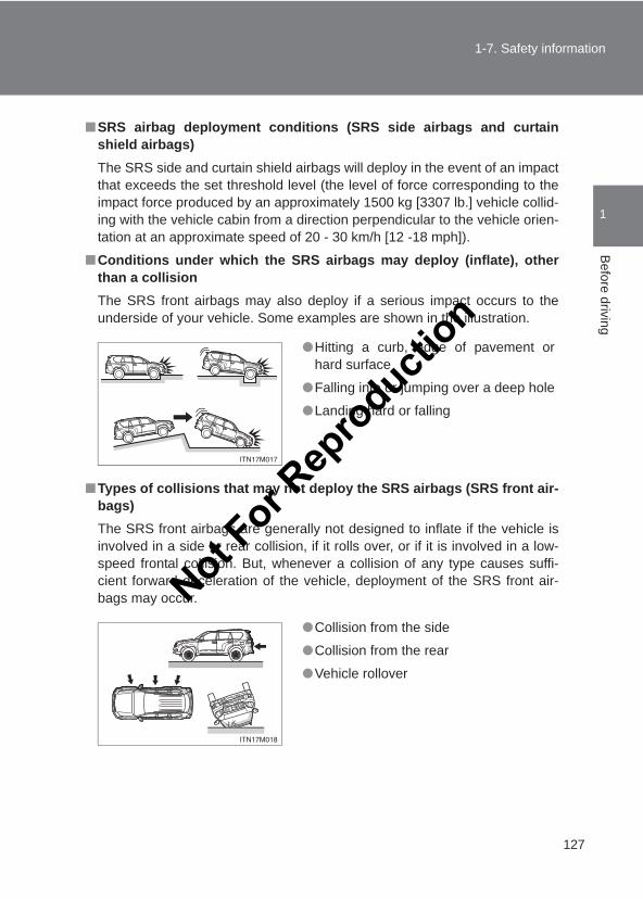
127
1-7. Safety information
1
Before driving
LC150_OM_OM60J77E_(AE)
■SRS airbag deployment conditions (SRS side airbags and curtainshield airbags)The SRS side and curtain shield airbags will deploy in the event of an impactthat exceeds the set threshold level (the level of force corresponding to theimpact force produced by an approximately 1500 kg [3307 lb.] vehicle collid-ing with the vehicle cabin from a direction perpendicular to the vehicle orien-tation at an approximate speed of 20 - 30 km/h [12 -18 mph]).
■Conditions under which the SRS airbags may deploy (inflate), otherthan a collisionThe SRS front airbags may also deploy if a serious impact occurs to theunderside of your vehicle. Some examples are shown in the illustration.
■Types of collisions that may not deploy the SRS airbags (SRS front air-bags)The SRS front airbags are generally not designed to inflate if the vehicle isinvolved in a side or rear collision, if it rolls over, or if it is involved in a low-speed frontal collision. But, whenever a collision of any type causes suffi-cient forward deceleration of the vehicle, deployment of the SRS front air-bags may occur.
●Hitting a curb, edge of pavement orhard surface
●Falling into or jumping over a deep hole
●Landing hard or falling
●Collision from the side
●Collision from the rear
●Vehicle rollover
Not For R
epro
duction
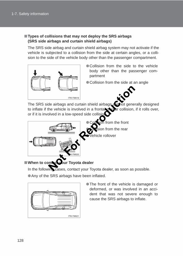
128
1-7. Safety information
LC150_OM_OM60J77E_(AE)
■Types of collisions that may not deploy the SRS airbags (SRS side airbags and curtain shield airbags)The SRS side airbag and curtain shield airbag system may not activate if thevehicle is subjected to a collision from the side at certain angles, or a colli-sion to the side of the vehicle body other than the passenger compartment.
The SRS side airbags and curtain shield airbags are not generally designedto inflate if the vehicle is involved in a frontal or rear collision, if it rolls over,or if it is involved in a low-speed side collision.
■When to contact your Toyota dealerIn the following cases, contact your Toyota dealer, as soon as possible.
●Any of the SRS airbags have been inflated.
●Collision from the side to the vehiclebody other than the passenger com-partment
●Collision from the side at an angle
●Collision from the front
●Collision from the rear
●Vehicle rollover
●The front of the vehicle is damaged ordeformed, or was involved in an acci-dent that was not severe enough tocause the SRS airbags to inflate.
Not For R
epro
duction
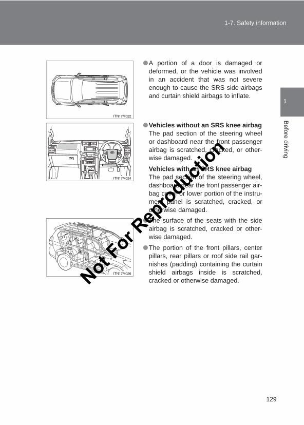
129
1-7. Safety information
1
Before driving
LC150_OM_OM60J77E_(AE)
●A portion of a door is damaged ordeformed, or the vehicle was involvedin an accident that was not severeenough to cause the SRS side airbagsand curtain shield airbags to inflate.
●Vehicles without an SRS knee airbagThe pad section of the steering wheelor dashboard near the front passengerairbag is scratched, cracked, or other-wise damaged.
Vehicles with an SRS knee airbagThe pad section of the steering wheel,dashboard near the front passenger air-bag cover or lower portion of the instru-ment panel is scratched, cracked, orotherwise damaged.
●The surface of the seats with the sideairbag is scratched, cracked or other-wise damaged.
●The portion of the front pillars, centerpillars, rear pillars or roof side rail gar-nishes (padding) containing the curtainshield airbags inside is scratched,cracked or otherwise damaged.Not F
or Rep
roducti
on
130
1-7. Safety information
LC150_OM_OM60J77E_(AE)
CAUTION
■SRS airbag precautionsObserve the following precautions regarding the SRS airbags. Failure to do so may cause death or serious injury.
●The driver and all passengers in the vehicle must wear their seat beltsproperly.The SRS airbags are supplemental devices to be used with the seat belts.
●The SRS driver airbag deploys with considerable force, and can causedeath or serious injury especially if the driver is very close to the airbag.
Since the risk zone for the driver’s airbag is the first 50 - 75 mm (2 - 3 in.)of inflation, placing yourself 250 mm (10 in.) from your driver airbag pro-vides you with a clear margin of safety. This distance is measured from thecenter of the steering wheel to your breastbone. If you sit less than 250mm (10 in.) away now, you can change your driving position in severalways:
• Move your seat to the rear as far as you can while still reaching thepedals comfortably.
• Slightly recline the back of the seat. Although vehicle designs vary,many drivers can achieve the 250 mm (10 in.) distance, even with thedriver seat all the way forward, simply by reclining the back of the seatsomewhat. If reclining the back of your seat makes it hard to see theroad, raise yourself by using a firm, non-slippery cushion, or raise theseat if your vehicle has that feature.
• If your steering wheel is adjustable, tilt it downward. This points the air-bag toward your chest instead of your head and neck.
The seat should be adjusted as recommended above, while still maintain-ing control of the foot pedals, steering wheel, and your view of the instru-ment panel controls.
Not For R
epro
duction
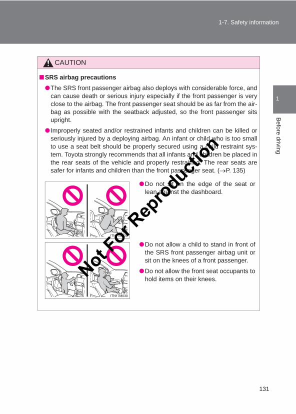
131
1-7. Safety information
1
Before driving
LC150_OM_OM60J77E_(AE)
CAUTION
■SRS airbag precautions●The SRS front passenger airbag also deploys with considerable force, and
can cause death or serious injury especially if the front passenger is veryclose to the airbag. The front passenger seat should be as far from the air-bag as possible with the seatback adjusted, so the front passenger sitsupright.
● Improperly seated and/or restrained infants and children can be killed orseriously injured by a deploying airbag. An infant or child who is too smallto use a seat belt should be properly secured using a child restraint sys-tem. Toyota strongly recommends that all infants and children be placed inthe rear seats of the vehicle and properly restrained. The rear seats aresafer for infants and children than the front passenger seat. (→P. 135)
●Do not sit on the edge of the seat orlean against the dashboard.
●Do not allow a child to stand in front ofthe SRS front passenger airbag unit orsit on the knees of a front passenger.
●Do not allow the front seat occupants tohold items on their knees.Not F
or Rep
roducti
on
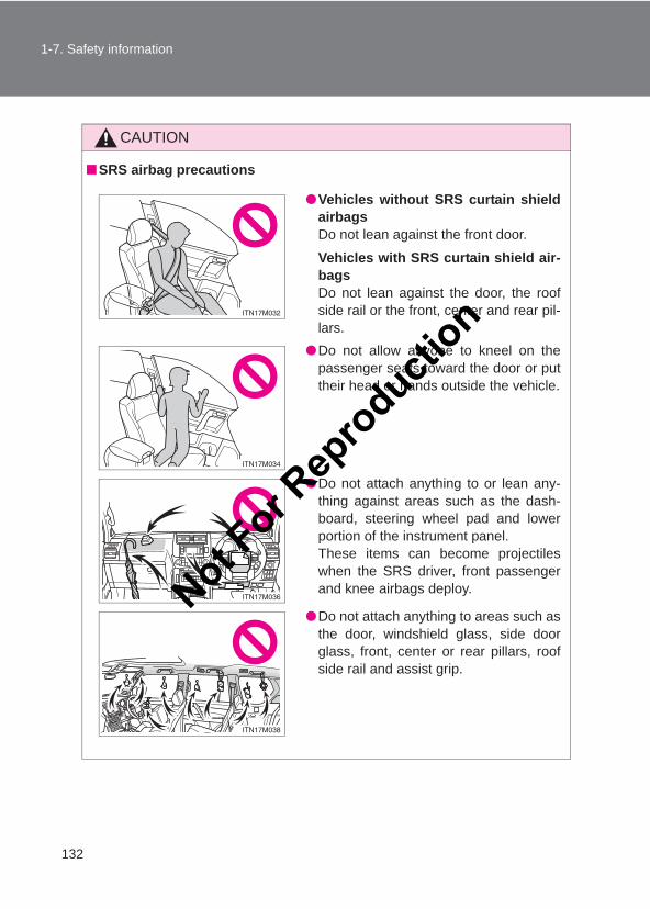
132
1-7. Safety information
LC150_OM_OM60J77E_(AE)
CAUTION
■SRS airbag precautions
●Vehicles without SRS curtain shieldairbagsDo not lean against the front door.
Vehicles with SRS curtain shield air-bagsDo not lean against the door, the roofside rail or the front, center and rear pil-lars.
●Do not allow anyone to kneel on thepassenger seats toward the door or puttheir head or hands outside the vehicle.
●Do not attach anything to or lean any-thing against areas such as the dash-board, steering wheel pad and lowerportion of the instrument panel. These items can become projectileswhen the SRS driver, front passengerand knee airbags deploy.
●Do not attach anything to areas such asthe door, windshield glass, side doorglass, front, center or rear pillars, roofside rail and assist grip.
Not For R
epro
duction
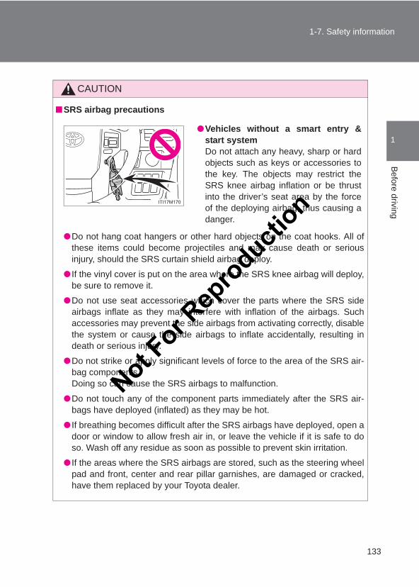
133
1-7. Safety information
1
Before driving
LC150_OM_OM60J77E_(AE)
CAUTION
■SRS airbag precautions
●Do not hang coat hangers or other hard objects on the coat hooks. All ofthese items could become projectiles and may cause death or seriousinjury, should the SRS curtain shield airbag deploy.
● If the vinyl cover is put on the area where the SRS knee airbag will deploy,be sure to remove it.
●Do not use seat accessories which cover the parts where the SRS sideairbags inflate as they may interfere with inflation of the airbags. Suchaccessories may prevent the side airbags from activating correctly, disablethe system or cause the side airbags to inflate accidentally, resulting indeath or serious injury.
●Do not strike or apply significant levels of force to the area of the SRS air-bag components. Doing so can cause the SRS airbags to malfunction.
●Do not touch any of the component parts immediately after the SRS air-bags have deployed (inflated) as they may be hot.
● If breathing becomes difficult after the SRS airbags have deployed, open adoor or window to allow fresh air in, or leave the vehicle if it is safe to doso. Wash off any residue as soon as possible to prevent skin irritation.
● If the areas where the SRS airbags are stored, such as the steering wheelpad and front, center and rear pillar garnishes, are damaged or cracked,have them replaced by your Toyota dealer.
●Vehicles without a smart entry &start systemDo not attach any heavy, sharp or hardobjects such as keys or accessories tothe key. The objects may restrict theSRS knee airbag inflation or be thrustinto the driver’s seat area by the forceof the deploying airbag, thus causing adanger.
Not For R
epro
duction
134
1-7. Safety information
LC150_OM_OM60J77E_(AE)
CAUTION
■Modification and disposal of SRS airbag system componentsDo not dispose of your vehicle or perform any of the following modificationswithout consulting your Toyota dealer. The SRS airbags may malfunction ordeploy (inflate) accidentally, causing death or serious injury.
● Installation, removal, disassembly and repair of the SRS airbags
●Repairs, modifications, removal or replacement of the steering wheel,instrument panel, dashboard, seats or seat upholstery, front, center andrear pillars or roof side rail
●Repairs or modifications of the front fender, front bumper, or side of theoccupant compartment
● Installation of snow plows, winches, etc. to the front grille (bull bars, kan-garoo bar etc.)
●Modifications to the vehicle’s suspension system
● Installation of electronic devices such as mobile two-way radios and CDplayers
●Modifications to your vehicle for a person with a physical disability
Not For R
epro
duction
135
1
1-7. Safety informationB
efore driving
LC150_OM_OM60J77E_(AE)
Child restraint systems
Points to remember
Studies have shown that installing a child restraint on a rear seat ismuch safer than installing one to the front passenger seat.
● Choose a child restraint system that suits your vehicle and isappropriate to the age and size of the child.
● For installation details, follow the instructions provided with thechild restraint system.General installation instructions are provided in this manual. (→P. 146)
● If child restraint system regulations exist in the country where youreside, please contact your Toyota dealer for the child restraint sys-tem installation.
● Toyota recommends that you use a child restraint system whichconforms to the regulation ECE No.44.
Types of child restraints
Child restraint systems are classified into the following 5 groupsaccording to the regulation ECE No.44.
Group 0: Up to 10 kg (22 lb.) (0 - 9 months)
Group 0+: Up to 13 kg (28 lb.) (0 - 2 years)
Group I: 9 to 18 kg (20 to 39 lb.) (9 months - 4 years)
Group II: 15 to 25 kg (34 to 55 lb.) (4 years - 7 years)
Group III: 22 to 36 kg (49 to 79 lb.) (6 years - 12 years)
In this owner’s manual, the following 3 types of popular child restraintsystems that can be secured with the seat belts are explained:
Toyota strongly urges the use of child restraint systems.
Not For R
epro
duction
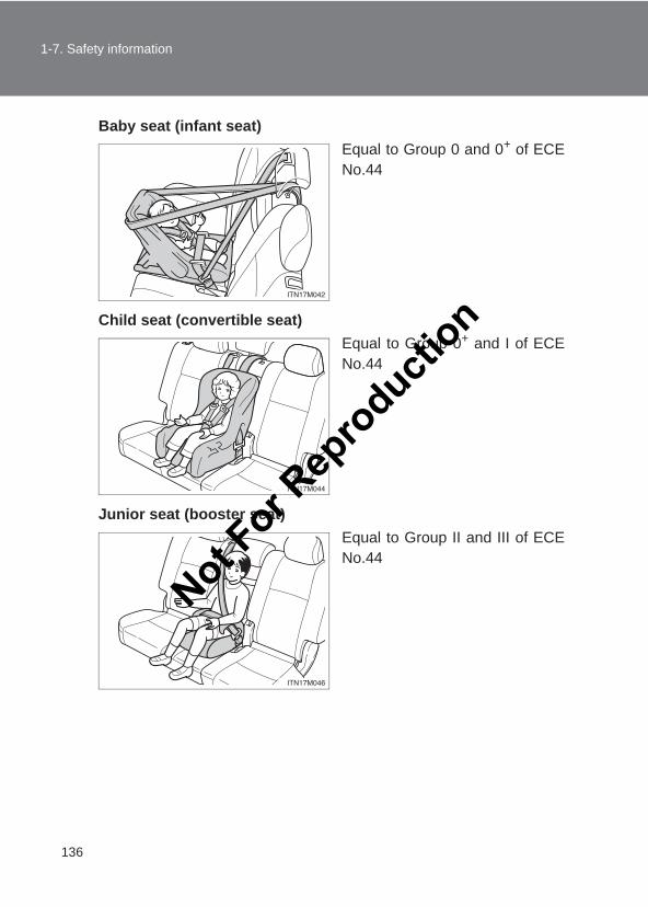
136
1-7. Safety information
LC150_OM_OM60J77E_(AE)
Baby seat (infant seat)Equal to Group 0 and 0+ of ECENo.44
Child seat (convertible seat)Equal to Group 0+ and I of ECENo.44
Junior seat (booster seat)Equal to Group II and III of ECENo.44
Not For R
epro
duction
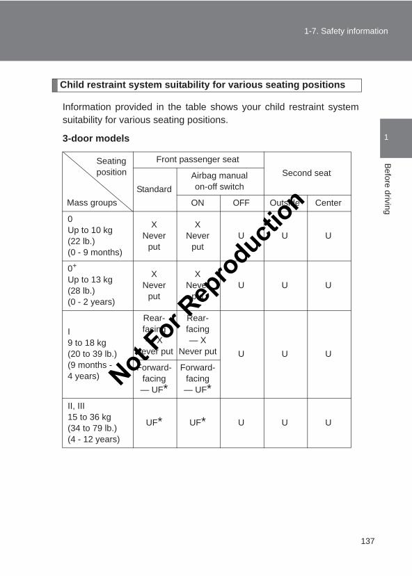
137
1-7. Safety information
1
Before driving
LC150_OM_OM60J77E_(AE)
Child restraint system suitability for various seating positions
Information provided in the table shows your child restraint systemsuitability for various seating positions.
3-door models
Front passenger seatSecond seat
StandardAirbag manual on-off switch
ON OFF Outside Center
0Up to 10 kg (22 lb.)(0 - 9 months)
X Never
put
X Never
putU U U
0+
Up to 13 kg (28 lb.)(0 - 2 years)
X Never
put
X Never
putU U U
I9 to 18 kg (20 to 39 lb.)(9 months - 4 years)
Rear-facing — X
Never put
Rear-facing — X
Never put U U UForward-
facing — UF*
Forward-facing — UF*
II, III15 to 36 kg (34 to 79 lb.)(4 - 12 years)
UF* UF* U U U
Mass groups
Seating position
Not For R
epro
duction
138
1-7. Safety information
LC150_OM_OM60J77E_(AE)
Key of letters inserted in the above table:U: Suitable for “universal” category child restraint system approved
for the use in this mass group.UF: Suitable for forward-facing “universal” category child restraint
system approved for the use in this mass group.X: Not suitable seat position for children in this mass group.
NOTE:
*: Move the seatback to the most upright position.The child restraint system mentioned in the table may not be avail-able outside of the EU area.
Other child restraint system which is different from the system men-tioned in the table can be used, but the suitability of the systems mustbe carefully checked with the child restraint system manufacturerconcerned and the seller of those seats.
Not For R
epro
duction
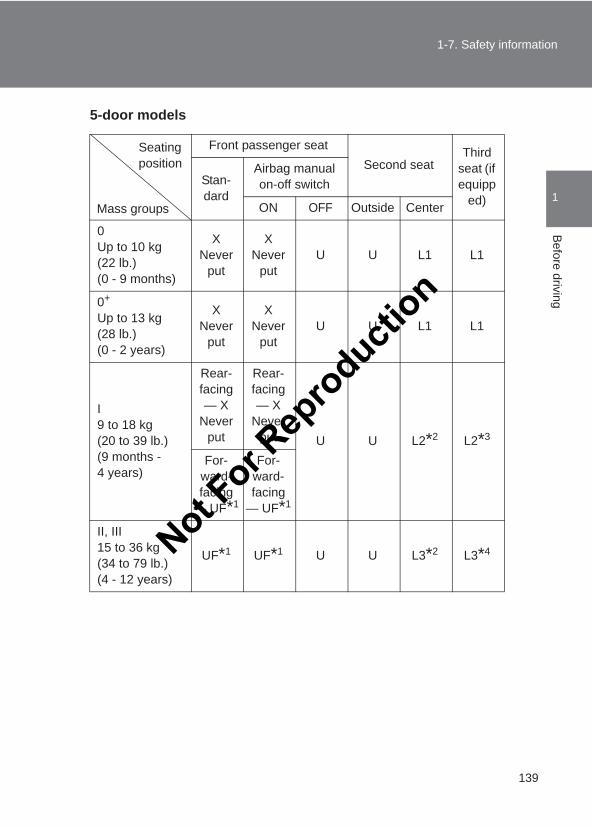
139
1-7. Safety information
1
Before driving
LC150_OM_OM60J77E_(AE)
5-door models
Front passenger seatSecond seat
Third seat (if equipp
ed)Stan-dard
Airbag manual on-off switch
ON OFF Outside Center
0Up to 10 kg (22 lb.)(0 - 9 months)
X Never
put
X Never
putU U L1 L1
0+
Up to 13 kg (28 lb.)(0 - 2 years)
X Never
put
X Never
putU U L1 L1
I9 to 18 kg (20 to 39 lb.)(9 months - 4 years)
Rear-facing — X
Never put
Rear-facing — X
Never put U U L2*2 L2*3
For-ward-facing
— UF*1
For-ward-facing
— UF*1
II, III15 to 36 kg (34 to 79 lb.)(4 - 12 years)
UF*1 UF*1 U U L3*2 L3*4
Mass groups
Seating position
Not For R
epro
duction
140
1-7. Safety information
LC150_OM_OM60J77E_(AE)
Key of letters inserted in the above table:U: Suitable for “universal” category child restraint system approved
for the use in this mass group.UF: Suitable for forward-facing “universal” category child restraint
system approved for the use in this mass group.L1: Suitable for “TOYOTA G0+, BABYSAFE PLUS (0 to 13 kg [0 to
28 lb.])” approved for the use in this mass groupL2: Suitable for “TOYOTA DUO+ (without ISOFIX, 9 to 18 kg [20 to
39 lb.])” approved for the use in this mass groupL3: Suitable for “TOYOTA KID (15 to 36 kg [34 to 79 lb.])” approved
for the use in this mass groupX: Not suitable seat position for children in this mass group.
NOTE:
*1: When you use a child restraint system in this position, move theseatback to the most upright position.
*2: When you use a child restraint system in this position, move thehead restraint to the lowest position.
*3: When you use a child restraint system in this position, move thehead restraint to the upmost position. (vehicles with third manualseats)
*4: When you use a child restraint system in this position, remove thehead restraint. (vehicles with third manual seats)
The child restraint system mentioned in the table may not be avail-able outside of the EU area.
Other child restraint system which is different from the system men-tioned in the table can be used, but the suitability of the systems mustbe carefully checked with the child restraint system manufacturerconcerned and the seller of those seats.
Not For R
epro
duction
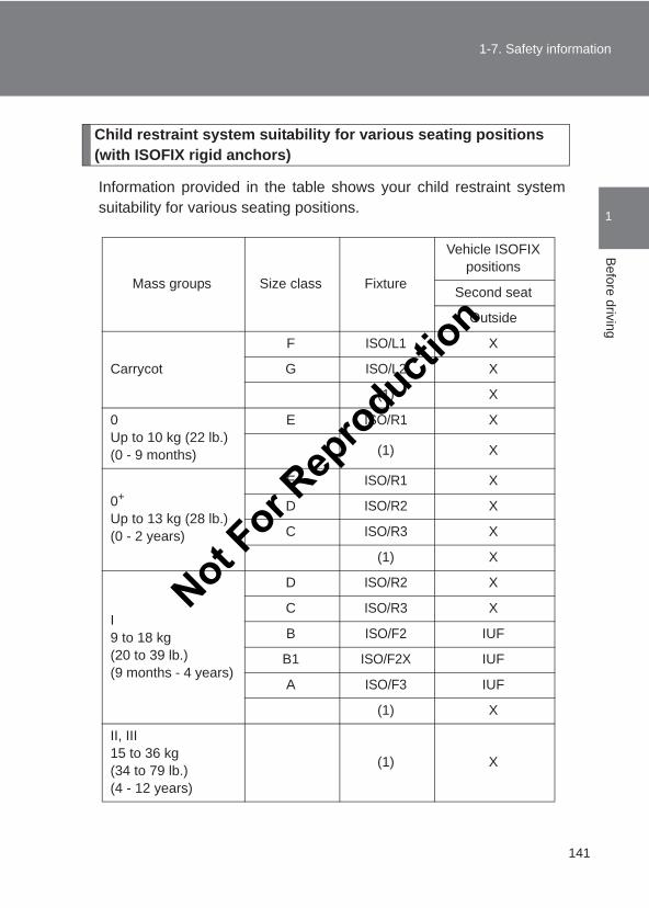
141
1-7. Safety information
1
Before driving
LC150_OM_OM60J77E_(AE)
Child restraint system suitability for various seating positions (with ISOFIX rigid anchors)
Information provided in the table shows your child restraint systemsuitability for various seating positions.
Mass groups Size class Fixture
Vehicle ISOFIX positions
Second seat
Outside
Carrycot
F ISO/L1 X
G ISO/L2 X
(1) X
0Up to 10 kg (22 lb.)(0 - 9 months)
E ISO/R1 X
(1) X
0+
Up to 13 kg (28 lb.)(0 - 2 years)
E ISO/R1 X
D ISO/R2 X
C ISO/R3 X
(1) X
I9 to 18 kg(20 to 39 lb.)(9 months - 4 years)
D ISO/R2 X
C ISO/R3 X
B ISO/F2 IUF
B1 ISO/F2X IUF
A ISO/F3 IUF
(1) X
II, III15 to 36 kg(34 to 79 lb.)(4 - 12 years)
(1) X
Not For R
epro
duction
142
1-7. Safety information
LC150_OM_OM60J77E_(AE)
(1) For the child restraint system which do not carry the ISO/XX sizeclass identification (A to G), for the applicable mass group, thecar manufacturer shall indicate the vehicle specific ISOFIX childrestraint system(s) recommended for each position
Key of letters inserted in the above table:
IUF:Suitable for ISOFIX forward-facing child restraint systems of uni-versal category approved for use in this mass group
X: ISOFIX position not suitable for ISOFIX child restraint systems inthis mass group and/or this size class.
The child restraint system mentioned in the table may not be avail-able outside of the EU area.
Other child restraint systems different from the systems mentioned inthe table can be used, but the suitability of the systems must be care-fully checked with the child restraint system manufacturer andretailer.
Not For R
epro
duction
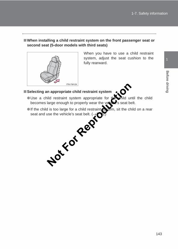
143
1-7. Safety information
1
Before driving
LC150_OM_OM60J77E_(AE)
■When installing a child restraint system on the front passenger seat orsecond seat (5-door models with third seats)
■Selecting an appropriate child restraint system●Use a child restraint system appropriate for the child until the child
becomes large enough to properly wear the vehicle’s seat belt.
● If the child is too large for a child restraint system, sit the child on a rearseat and use the vehicle’s seat belt. (→P. 92)
When you have to use a child restraintsystem, adjust the seat cushion to thefully rearward.
Not For R
epro
duction
144
1-7. Safety information
LC150_OM_OM60J77E_(AE)
CAUTION
■Using a child restraint systemThe use of a child restraint system not suitable for the vehicle may not prop-erly secure the infant or child. It may result in death or serious injury (in theevent of sudden braking, sudden swerving or an accident).
■Child restraint precautions●For effective protection in automobile accidents and sudden stops, a child
must be properly restrained, using a seat belt or child restraint systemdepending on the age and size of the child. Holding a child in your arms isnot a substitute for a child restraint system. In an accident, the child can becrushed against the windshield, or between you and the vehicle’s interior.
●Toyota strongly urges the use of a proper child restraint system that con-forms to the size of the child, installed on the rear seat. According to acci-dent statistics, the child is safer when properly restrained in the rear seatthan in the front seat.
●Never install a rear-facing child restraint system on the front passengerseat. In the event of an accident, the force of the rapid inflation of the frontpassenger airbag can cause death or serious injury to the child.
●A forward-facing child restraint system may be installed on the front pas-senger seat only when it is unavoidable. Always move the seat as far backas possible, because the front passenger airbag could inflate with consid-erable speed and force. Otherwise, the child may be killed or seriouslyinjured.
Not For R
epro
duction
145
1-7. Safety information
1
Before driving
LC150_OM_OM60J77E_(AE)
CAUTION
■Child restraint precautions●Do not allow the child to lean his/her head or any part of his/her body
against the door or the area of the seat, front, center and rear pillars orroof side rail from which the SRS side airbags or SRS curtain shield air-bags deploy even if the child is seated in the child restraint system. It isdangerous if the SRS side airbags and curtain shield airbags inflate, andthe impact could cause death or serious injury to the child.
●Make sure you have complied with all installation instructions provided bythe child restraint manufacturer and that the system is properly secured. Ifit is not secured properly, it may cause death or serious injury to the childin the event of a sudden stop, sudden swerve or an accident.
■Child restraint lock function belt precautionDo not allow children to play with the child restraint lock function belt. If thebelt becomes twisted around a child’s neck, it will not be possible to pull thebelt out leading to choking or other serious injuries that could result in death.If this occurs and the buckle cannot be unfastened, scissors should be usedto cut the belt.
■When the child restraint system is not in use●Keep the child restraint system properly secured on the seat even if it is
not in use. Do not store the child restraint system unsecured in the pas-senger compartment.
● If it is necessary to detach the child restraint system, remove it from thevehicle or store it securely in the luggage compartment. This will prevent itfrom injuring passengers in the event of a sudden stop, sudden swerve oran accident.
Not For R
epro
duction
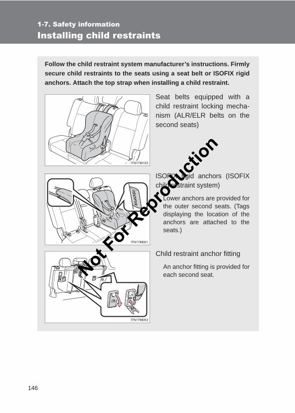
146
1-7. Safety information
LC150_OM_OM60J77E_(AE)
Installing child restraints
Follow the child restraint system manufacturer’s instructions. Firmlysecure child restraints to the seats using a seat belt or ISOFIX rigidanchors. Attach the top strap when installing a child restraint.
Seat belts equipped with achild restraint locking mecha-nism (ALR/ELR belts on thesecond seats)
ISOFIX rigid anchors (ISOFIXchild restraint system)
Lower anchors are provided forthe outer second seats. (Tagsdisplaying the location of theanchors are attached to theseats.)
Child restraint anchor fitting
An anchor fitting is provided foreach second seat.Not F
or Rep
roducti
on
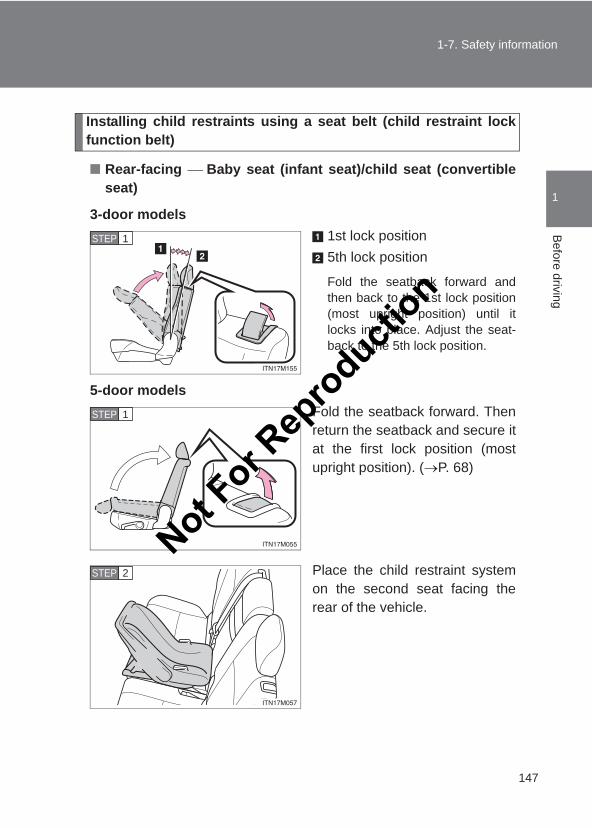
147
1-7. Safety information
1
Before driving
LC150_OM_OM60J77E_(AE)
Installing child restraints using a seat belt (child restraint lockfunction belt)
■ Rear-facing Baby seat (infant seat)/child seat (convertibleseat)
3-door models1st lock position5th lock position
Fold the seatback forward andthen back to the 1st lock position(most upright position) until itlocks into place. Adjust the seat-back to the 5th lock position.
5-door modelsFold the seatback forward. Thenreturn the seatback and secure itat the first lock position (mostupright position). (→P. 68)
Place the child restraint systemon the second seat facing therear of the vehicle.
STEP 1
STEP 1
STEP 2
Not For R
epro
duction
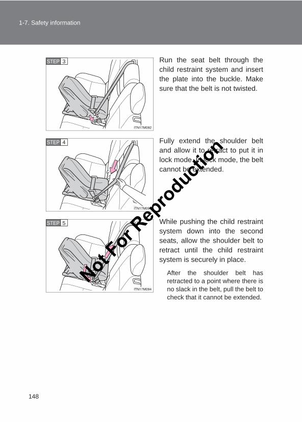
148
1-7. Safety information
LC150_OM_OM60J77E_(AE)
Run the seat belt through thechild restraint system and insertthe plate into the buckle. Makesure that the belt is not twisted.
Fully extend the shoulder beltand allow it to retract to put it inlock mode. In lock mode, the beltcannot be extended.
While pushing the child restraintsystem down into the secondseats, allow the shoulder belt toretract until the child restraintsystem is securely in place.
After the shoulder belt hasretracted to a point where there isno slack in the belt, pull the belt tocheck that it cannot be extended.
STEP 3
STEP 4
STEP 5
Not For R
epro
duction
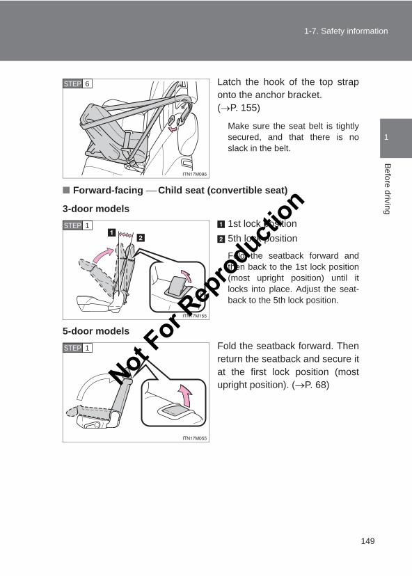
149
1-7. Safety information
1
Before driving
LC150_OM_OM60J77E_(AE)
Latch the hook of the top straponto the anchor bracket. (→P. 155)
Make sure the seat belt is tightlysecured, and that there is noslack in the belt.
■ Forward-facing Child seat (convertible seat)
3-door models1st lock position5th lock position
Fold the seatback forward andthen back to the 1st lock position(most upright position) until itlocks into place. Adjust the seat-back to the 5th lock position.
5-door modelsFold the seatback forward. Thenreturn the seatback and secure itat the first lock position (mostupright position). (→P. 68)
STEP 6
STEP 1
STEP 1
Not For R
epro
duction
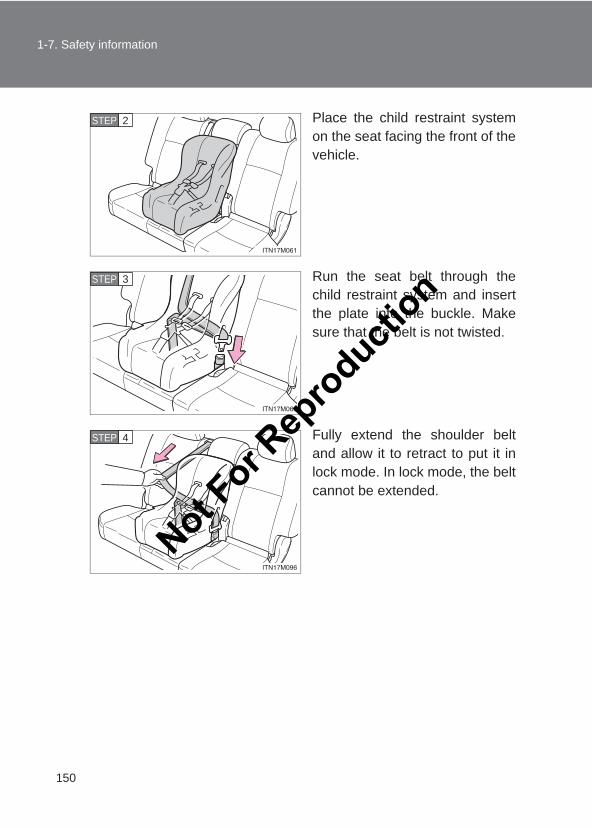
150
1-7. Safety information
LC150_OM_OM60J77E_(AE)
Place the child restraint systemon the seat facing the front of thevehicle.
Run the seat belt through thechild restraint system and insertthe plate into the buckle. Makesure that the belt is not twisted.
Fully extend the shoulder beltand allow it to retract to put it inlock mode. In lock mode, the beltcannot be extended.
STEP 2
STEP 3
STEP 4
Not For R
epro
duction
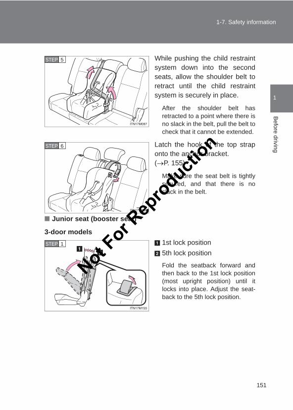
151
1-7. Safety information
1
Before driving
LC150_OM_OM60J77E_(AE)
While pushing the child restraintsystem down into the secondseats, allow the shoulder belt toretract until the child restraintsystem is securely in place.
After the shoulder belt hasretracted to a point where there isno slack in the belt, pull the belt tocheck that it cannot be extended.
Latch the hook of the top straponto the anchor bracket. (→P. 155)
Make sure the seat belt is tightlysecured, and that there is noslack in the belt.
■ Junior seat (booster seat)
3-door models1st lock position5th lock position
Fold the seatback forward andthen back to the 1st lock position(most upright position) until itlocks into place. Adjust the seat-back to the 5th lock position.
STEP 5
STEP 6
STEP 1
Not For R
epro
duction
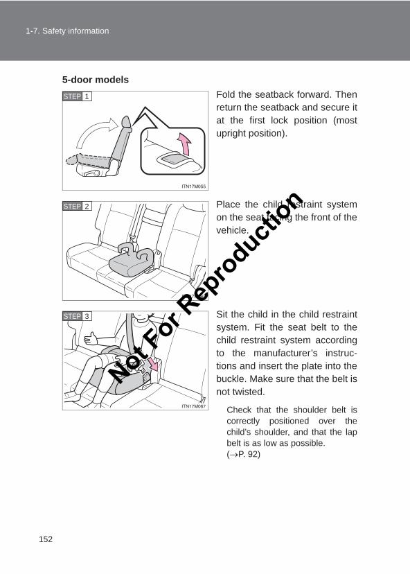
152
1-7. Safety information
LC150_OM_OM60J77E_(AE)
5-door modelsFold the seatback forward. Thenreturn the seatback and secure itat the first lock position (mostupright position).
Place the child restraint systemon the seat facing the front of thevehicle.
Sit the child in the child restraintsystem. Fit the seat belt to thechild restraint system accordingto the manufacturer’s instruc-tions and insert the plate into thebuckle. Make sure that the belt isnot twisted.
Check that the shoulder belt iscorrectly positioned over thechild’s shoulder, and that the lapbelt is as low as possible. (→P. 92)
STEP 1
STEP 2
STEP 3
Not For R
epro
duction
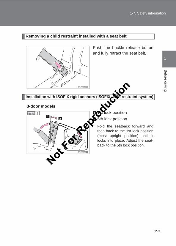
153
1-7. Safety information
1
Before driving
LC150_OM_OM60J77E_(AE)
Removing a child restraint installed with a seat belt
Push the buckle release buttonand fully retract the seat belt.
Installation with ISOFIX rigid anchors (ISOFIX child restraint system)
3-door models1st lock position5th lock position
Fold the seatback forward andthen back to the 1st lock position(most upright position) until itlocks into place. Adjust the seat-back to the 5th lock position.
STEP 1
Not For R
epro
duction
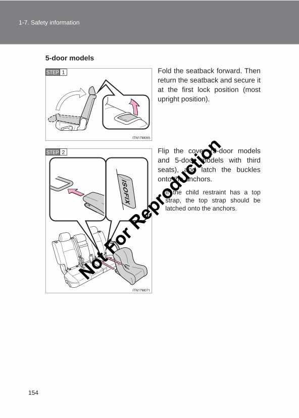
154
1-7. Safety information
LC150_OM_OM60J77E_(AE)
5-door models
Fold the seatback forward. Thenreturn the seatback and secure itat the first lock position (mostupright position).
Flip the cover (3-door modelsand 5-door models with thirdseats), and latch the bucklesonto the anchors.
If the child restraint has a topstrap, the top strap should belatched onto the anchors.
STEP 1
STEP 2
Not For R
epro
duction
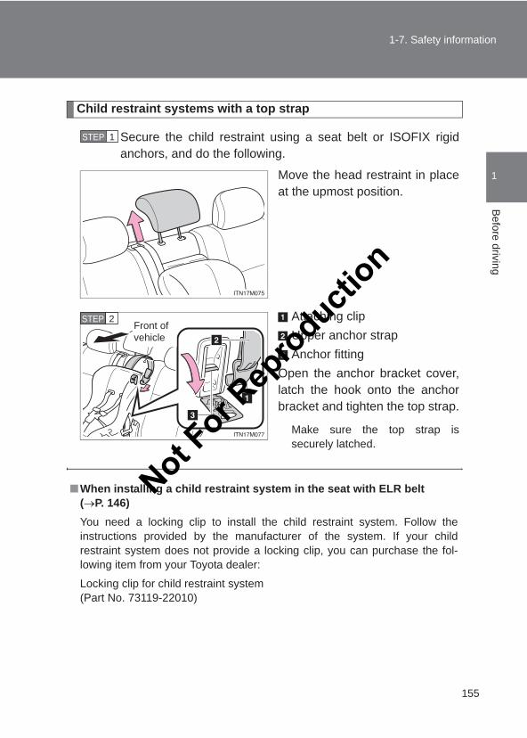
155
1-7. Safety information
1
Before driving
LC150_OM_OM60J77E_(AE)
Child restraint systems with a top strap
Secure the child restraint using a seat belt or ISOFIX rigidanchors, and do the following.
Move the head restraint in placeat the upmost position.
Attaching clipUpper anchor strapAnchor fitting
Open the anchor bracket cover,latch the hook onto the anchorbracket and tighten the top strap.
Make sure the top strap issecurely latched.
STEP 1
STEP 2Front of vehicle
■When installing a child restraint system in the seat with ELR belt(→P. 146)You need a locking clip to install the child restraint system. Follow theinstructions provided by the manufacturer of the system. If your childrestraint system does not provide a locking clip, you can purchase the fol-lowing item from your Toyota dealer:
Locking clip for child restraint system (Part No. 73119-22010)
Not For R
epro
duction
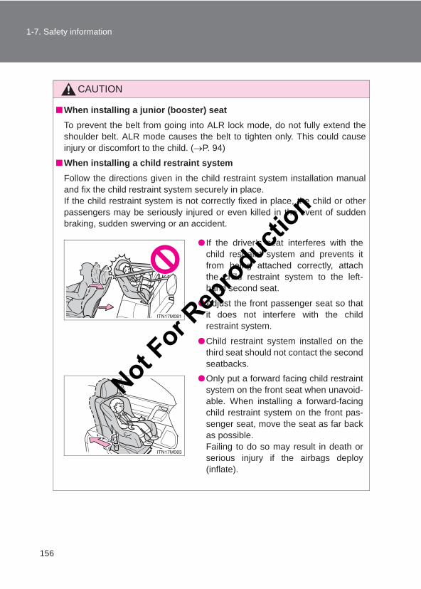
156
1-7. Safety information
LC150_OM_OM60J77E_(AE)
CAUTION
■When installing a junior (booster) seatTo prevent the belt from going into ALR lock mode, do not fully extend theshoulder belt. ALR mode causes the belt to tighten only. This could causeinjury or discomfort to the child. (→P. 94)
■When installing a child restraint systemFollow the directions given in the child restraint system installation manualand fix the child restraint system securely in place.If the child restraint system is not correctly fixed in place, the child or otherpassengers may be seriously injured or even killed in the event of suddenbraking, sudden swerving or an accident.
● If the driver’s seat interferes with thechild restraint system and prevents itfrom being attached correctly, attachthe child restraint system to the left-hand second seat.
●Adjust the front passenger seat so thatit does not interfere with the childrestraint system.
●Child restraint system installed on thethird seat should not contact the secondseatbacks.
●Only put a forward facing child restraintsystem on the front seat when unavoid-able. When installing a forward-facingchild restraint system on the front pas-senger seat, move the seat as far backas possible. Failing to do so may result in death orserious injury if the airbags deploy(inflate).
Not For R
epro
duction
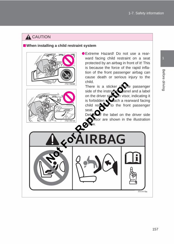
157
1-7. Safety information
1
Before driving
LC150_OM_OM60J77E_(AE)
CAUTION
■When installing a child restraint system
●Extreme Hazard! Do not use a rear-ward facing child restraint on a seatprotected by an airbag in front of it! Thisis because the force of the rapid infla-tion of the front passenger airbag cancause death or serious injury to thechild.There is a sticker on the passengerside of the instrument panel and a labelon the driver side sun visor, indicating itis forbidden to attach a rearward facingchild restraint to the front passengerseat.Details of the label on the driver sidesun visor are shown in the illustrationbelow.
Not For R
epro
duction
158
1-7. Safety information
LC150_OM_OM60J77E_(AE)
CAUTION
■When installing a child restraint system● If child restraint system regulations exist in the country where you reside,
please contact your Toyota dealer for the child restraint system installation.
●When installing a child restraint system on the second center seat, adjustboth seat cushions to the same position (vehicles with third manual/powerseats) and align both seatbacks at the same angle. The seatbacks mustbe adjusted to the same angle. Otherwise, the child restraint system can-not be securely restrained and this may cause death or serious injuries ina collision.
●When a junior (booster) seat is installed, always ensure that the shoulderbelt is positioned across the center of the child’s shoulder. The belt shouldbe kept away from the child’s neck, but not so that it could fall off thechild’s shoulder. Failing to do so may result in death or serious injury in theevent of sudden braking, sudden swerving or an accident.
●Ensure that the belt and plate are securely locked and the seat belt is nottwisted.
●Push and pull the child restraint system from side to side and forward to besure it is secure.
●After securing a child restraint system, never adjust the seat.
●Follow all installation instructions provided by the child restraint systemmanufacturer.
Not For R
epro
duction
159
1-7. Safety information
1
Before driving
LC150_OM_OM60J77E_(AE)
CAUTION
■To correctly attach a child restraint system to the anchors●When using the lower anchors, be sure that there are no foreign objects
around the anchors and that the seat belt is not caught behind the childrestraint system. Make sure the child restraint system is securely attached,or it may cause death or serious injury to the child or other passengers inthe event of sudden braking, sudden swerving or an accident.
■Using child restraint anchoragesWARNING: child restraint anchorages are designed to withstand only thoseloads imposed by correctly fitted child restraints. Under no circumstancesare they to be used for adult seatbelts, harnesses, or for attaching otheritems or equipment to the vehicle.
●When using the right side loweranchors for the child restraint system,do not sit in the center seat. Seat belt function may be impaired,such as being positioned overly high orloose-fitting, which may result in deathor serious injury in the event of suddenbraking, sudden swerving or an acci-dent.
Not For R
epro
duction
160
LC150_OM_OM60J77E_(AE)
2-1. Driving proceduresDriving the vehicle ............ 162Engine (ignition) switch
(vehicles without a smart entry & start system)....... 175
Engine (ignition) switch (vehicles with a smart entry & start system)....... 179
Automatic transmission..... 187Manual transmission......... 193Turn signal lever ............... 195Parking brake.................... 196Horn.................................. 197
Not For R
epro
duction
2When driving
161
LC150_OM_OM60J77E_(AE)
2-2. Instrument clusterGauges and meters .......... 198Indicators and warning
lights ............................... 202Multi-information display
(Non-Optitron type meters) ........................... 206
Multi-information display (Optitron type meters)..... 211
Multi-information display (Accessory meters)......... 219
2-3. Operating the lights and wipers
Headlight switch ............... 226Fog light switch................. 232Windshield wipers and
washer............................ 233Rear window wiper and
washer............................ 238Headlight cleaner switch... 240
2-4. Using other driving systemsCruise control.................... 242Dynamic radar cruise
control............................. 246Toyota parking
assist-sensor .................. 259Rear view monitor system
(vehicles with an accessory meter) ............................. 269
Wide view front & side monitor (vehicles with an accessory meter) ............................. 273
Driving assist systems ...... 281PCS (Pre-Crash Safety
system) ........................... 287
2-5. Driving informationCargo and luggage ........... 294Winter driving tips ............. 297Trailer towing .................... 300
For details of equipment related to off-road driving,such as the four-wheel drive system, refer to the “Off-road Driving Owner’s Manual”.
Not For R
epro
duction
162
LC150_OM_OM60J77E_(AE)
2-1. Driving procedures
Driving the vehicle
The following procedures should be observed to ensure safe driv-ing:
■ Starting the engine→P. 179
■ Driving
Automatic transmissionWith the brake pedal depressed, shift the shift lever to D.(→P. 187)Release the parking brake. (→P. 196)
Gradually release the brake pedal and gently depress theaccelerator pedal to accelerate the vehicle.
Manual transmissionWhile depressing the clutch pedal, shift the shift lever to 1.(→P. 193)Release the parking brake. (→P. 196)
Gradually release the clutch pedal. At the same time, gentlydepress the accelerator pedal to accelerate the vehicle.
■ Stopping
Automatic transmissionWith the shift lever in D, depress the brake pedal.If necessary, set the parking brake.If the vehicle is to be stopped for an extended period of time, shiftthe shift lever to P or N. (→P. 187)
STEP 1
STEP 2
STEP 3
STEP 1
STEP 2
STEP 3
STEP 1
STEP 2
Not For R
epro
duction
163
2-1. Driving procedures
2
When driving
LC150_OM_OM60J77E_(AE)
Manual transmissionWhile depressing the clutch pedal, depress the brakepedal.If necessary, set the parking brake.If the vehicle is to be stopped for an extended period of time, shiftthe shift lever to N. (→P. 193)
■ Parking the vehicle
Automatic transmissionWith the shift lever in D, depress the brake pedal.Set the parking brake. (→P. 196)Shift the shift lever to P. (→P. 187)If parking on a hill, block the wheels as needed.
Press the “ENGINE START STOP” switch to stop theengine.Lock the door, making sure that you have the key on yourperson.
Manual transmissionWhile depressing the clutch pedal, depress the brakepedal.Set the parking brake. (→P. 196)Shift the shift lever to N. (→P. 193)If parking on a hill, shift the shift lever to 1 or R and block thewheels as needed.
Press the “ENGINE START STOP” switch to stop theengine.Lock the door, making sure that you have the key on yourperson.
STEP 1
STEP 2
STEP 1
STEP 2
STEP 3
STEP 4
STEP 5
STEP 1
STEP 2
STEP 3
STEP 4
STEP 5
Not For R
epro
duction
164
2-1. Driving procedures
LC150_OM_OM60J77E_(AE)
Starting off on a steep uphill
Automatic transmissionMake sure that the parking brake is set and shift the shift leverto D. Gently depress the accelerator pedal. Release the parking brake.
Manual transmissionWith the parking brake firmly set and the clutch pedal fullydepressed, shift the shift lever to 1. Lightly depress the accelerator pedal at the same time asgradually releasing the clutch pedal. Release the parking brake.
■Driving in the rain●Drive carefully when it is raining, because visibility will be reduced, the
windows may become fogged-up, and the road will be slippery.
●Drive carefully when it starts to rain, because the road surface will beespecially slippery.
●Refrain from high speeds when driving on an expressway in the rain,because there may be a layer of water between the tires and the roadsurface, preventing the steering and brakes from operating properly.
■Engine speed while drivingIn the following conditions, the engine speed may become high while driving.This is due to automatic up-shifting control or down-shifting implementationto meet driving conditions. It does not indicate sudden acceleration.
●The vehicle is judged to be driving uphill or downhill
●When the accelerator pedal is released
STEP 1
STEP 2
STEP 3
STEP 1
STEP 2
STEP 3
Not For R
epro
duction
165
2-1. Driving procedures
2
When driving
LC150_OM_OM60J77E_(AE)
■Breaking in your new ToyotaTo extend the life of the vehicle, observing the following precautions is rec-ommended:
●For the first 300 km (200 miles):Avoid sudden stops.
●For the first 800 km (500 miles):Do not tow a trailer.
●For the first 1000 km (600 miles):
• Do not drive at extremely high speeds.• Avoid sudden acceleration.• Do not drive continuously in the low gears.• Do not drive at a constant speed for extended periods.• Do not drive slowly with the manual transmission in a high gear.
■Drum-in-disc type parking brake systemYour vehicle has a drum-in-disc type parking brake system.This type of brake system needs bedding-down of the brake shoes periodi-cally or whenever the parking brake shoes and/or drum are replaced.Have your Toyota dealer perform the bedding-down operation.
■ Idling time before stopping the engine (diesel engine)To prevent damage to the turbocharger, allow the engine to idle immediatelyafter high-speed driving or driving up a hill.
Driving condition Idling time
Normal city driving Not necessary
High-speed driving
Constant speed of approx. 80 km/h (50 mph)
Approximately 20 seconds
Constant speed of approx. 100 km/h (63 mph)
Approximately 1 minute
Steep hill driving or continuous driving at 100 km/h (63 mph) or more (race track driving etc.)
Approximately 2 minutes
Not For R
epro
duction
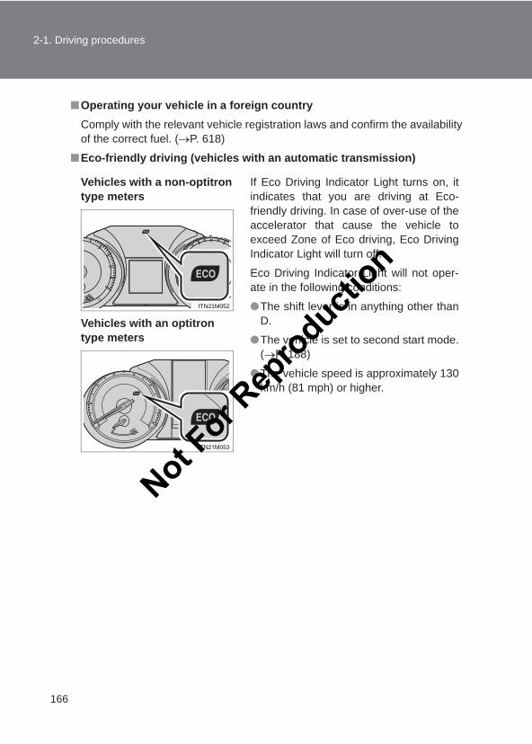
166
2-1. Driving procedures
LC150_OM_OM60J77E_(AE)
■Operating your vehicle in a foreign countryComply with the relevant vehicle registration laws and confirm the availabilityof the correct fuel. (→P. 618)
■Eco-friendly driving (vehicles with an automatic transmission)
Vehicles with a non-optitron type meters
Vehicles with an optitron type meters
If Eco Driving Indicator Light turns on, itindicates that you are driving at Eco-friendly driving. In case of over-use of theaccelerator that cause the vehicle toexceed Zone of Eco driving, Eco DrivingIndicator Light will turn off.
Eco Driving Indicator Light will not oper-ate in the following conditions:
●The shift lever is in anything other thanD.
●The vehicle is set to second start mode.(→P. 188)
●The vehicle speed is approximately 130km/h (81 mph) or higher.
ITN21M052
Not For R
epro
duction
167
2-1. Driving procedures
2
When driving
LC150_OM_OM60J77E_(AE)
CAUTION
■When starting the vehicleOn vehicles with an automatic transmission, always keep your foot on thebrake pedal while stopped with the engine running. This prevents the vehiclefrom creeping.
■When driving the vehicle●Do not drive if you are unfamiliar with the location of the brake and accel-
erator pedals to avoid depressing the wrong pedal.
• Accidentally depressing the accelerator pedal instead of the brakepedal will result in sudden acceleration that may lead to an accidentthat could result in death or serious injury.
• When backing up, you may twist your body around, leading to a diffi-culty in operating the pedals. Make sure to operate the pedals properly.
• Make sure to keep a correct driving posture even when moving thevehicle only slightly. This allows you to depress the brake and acceler-ator pedals properly.
• Depress the brake pedal using your right foot. Depressing the brakepedal using your left foot may delay response in an emergency, result-ing in an accident.
●Do not drive the vehicle over or stop the vehicle near flammable materials.The exhaust system and exhaust gases can be extremely hot. These hotparts may cause a fire if there is any flammable material nearby.
●On vehicles with an automatic transmission, do not let the vehicle rollbackwards while the shift lever is in a driving position, or roll forward whilethe shift lever is in R.Doing so may cause the engine to stall or lead to poor brake and steeringperformance, resulting in an accident or damage to the vehicle.
● If the smell of exhaust is noticed inside the vehicle, open the windows andcheck that the back door is closed. Large amounts of exhaust in thevehicle can cause driver drowsiness and an accident, resulting in death ora serious health hazard. Have the vehicle inspected by your Toyota dealerimmediately.
Not For R
epro
duction
168
2-1. Driving procedures
LC150_OM_OM60J77E_(AE)
CAUTION
■When driving the vehicle●On vehicles with an automatic transmission, do not shift the shift lever to P
while the vehicle is moving.Doing so can damage the transmission and may result in a loss of vehiclecontrol.
●Do not shift the shift lever to R while the vehicle is moving forward.Doing so can damage the transmission and may result in a loss of vehiclecontrol.
●Do not shift the shift lever to D (vehicles with an automatic transmission) or1 (vehicles with a manual transmission) while the vehicle is moving back-ward.Doing so can damage the transmission and may result in a loss of vehiclecontrol.
●Moving the shift lever to N while the vehicle is moving will disengage theengine from the transmission.Engine braking is not available when N is selected.
●During normal driving, do not turn off the engine. Turning the engine offwhile driving will not cause loss of steering or braking control, but thepower assist to these systems will be lost. This will make it more difficult tosteer and brake, so you should pull over and stop the vehicle as soon as itis safe to do so.However, in the event of an emergency, such as if it becomes impossibleto stop the vehicle in the normal way: →P. 610
●Use engine braking (downshift) to maintain a safe speed when drivingdown a steep hill.Using the brakes continuously may cause the brakes to overheat and loseeffectiveness. (→P. 188)
●Do not adjust the positions of the steering wheel, the seat, or the inside oroutside rear view mirrors while driving.Doing so may result in a loss of vehicle control that can cause accidents,resulting in death or serious injury.
●Always check that all passengers’ arms, heads or other parts of their bodyare not outside the vehicle, as this may result in death or serious injury.
Not For R
epro
duction
169
2-1. Driving procedures
2
When driving
LC150_OM_OM60J77E_(AE)
CAUTION
■When driving on slippery road surfaces●Sudden braking, acceleration and steering may cause tire slippage and
reduce your ability to control the vehicle, resulting in an accident.
●Sudden changes in engine speed, such as engine braking caused by up-shifting and down-shifting, may cause the vehicle to skid, resulting in anaccident.
●After driving through a puddle, lightly depress the brake pedal to makesure that the brakes are functioning properly. Wet brake pads may preventthe brakes from functioning properly. If the brakes on only one side are wetand not functioning properly, steering control may be affected, resulting inan accident.
■When shifting the shift leverOn vehicles with an automatic transmission, be careful not to shift the shiftlever with the accelerator pedal depressed. Shifting the shift lever to a gearother than P or N may lead to unexpected rapid acceleration of the vehiclethat may cause an accident and result in death or serious injury.
■ If you hear a squealing or scraping noise (brake pad wear indicators)Have the brake pads checked and replaced by your Toyota dealer as soonas possible.Rotor damage may result if the pads are not replaced when needed.
It is dangerous to drive the vehicle when the wear limits of the brake padsand/or those of the brake discs are exceeded.Not F
or Rep
roducti
on
170
2-1. Driving procedures
LC150_OM_OM60J77E_(AE)
CAUTION
■When the vehicle is stopped●Do not race the engine.
If the vehicle is in any gear other than P (vehicles with an automatic trans-mission only) or N, the vehicle may accelerate suddenly and unexpectedly,causing an accident.
●Do not leave the vehicle with the engine running for a long time.If such a situation cannot be avoided, park the vehicle in an open spaceand check that exhaust fumes do not enter the vehicle interior.
● In order to prevent accidents due to the vehicle rolling away, always keepdepressing the brake pedal while the engine is running, and apply theparking brake as necessary.
● If the vehicle is stopped on an incline, in order to prevent accidents causedby the vehicle rolling forward or backward, always depress the brake pedaland securely apply the parking brake as needed.
●Avoid revving or racing the engine.Running the engine at high speed while the vehicle is stopped may causethe exhaust system to overheat, which could result in a fire if combustiblematerial is nearby.
■When the vehicle is parked●Do not leave glasses, cigarette lighters, spray cans, or soft drink cans in
the vehicle when it is in the sun.Doing so may result in the following:
• Gas may leak from a cigarette lighter or spray can, and may lead to afire.
• The temperature inside the vehicle may cause the plastic lenses andplastic material of glasses to deform or crack.
• Soft drink cans may fracture, causing the contents to spray over theinterior of the vehicle, and may also cause a short circuit in the vehi-cle’s electrical components.
●Do not leave cigarette lighters in the vehicle. If a cigarette lighter is in aplace such as the glove box or on the floor, it may be lit accidentally whenluggage is loaded or the seat is adjusted, causing a fire.
Not For R
epro
duction
171
2-1. Driving procedures
2
When driving
LC150_OM_OM60J77E_(AE)
CAUTION
■When the vehicle is parked●Do not attach adhesive discs to the windshield or windows. Do not place
containers such as air fresheners on the instrument panel or dashboard.Adhesive discs or containers may act as lenses, causing a fire in the vehi-cle.
●Do not leave a door or window open if the curved glass is coated with ametallized film such as a silver-colored one. Reflected sunlight may causethe glass to act as a lens, causing a fire.
●Always apply the parking brake, shift the shift lever to P (vehicles with anautomatic transmission only), stop the engine and lock the vehicle.Do not leave the vehicle unattended while the engine is running.
●Do not touch the exhaust pipes while the engine is running or immediatelyafter turning the engine off. Doing so may cause burns.
●Do not leave the engine running in an area with snow build-up, or where itis snowing. If snowbanks build up around the vehicle while the engine isrunning, exhaust gases may collect and enter the vehicle. This may leadto death or a serious health hazard.
■Exhaust gasesExhaust gases include harmful carbon monoxide (CO), which is colorlessand odorless. Inhaling exhaust gases may lead to death or a serious healthhazard.
● If the vehicle is in a poorly ventilated area, stop the engine. In a closedarea, such as a garage, exhaust gases may collect and enter the vehicle.This may lead to death or a serious health hazard.
●The exhaust system should be checked occasionally. If there is a hole orcrack caused by corrosion, damage to a joint or abnormal exhaust noise,be sure to have the vehicle inspected and repaired by your Toyota dealer.Failure to do so may allow exhaust gases to enter the vehicle, resulting indeath or a serious health hazard.
Not For R
epro
duction
172
2-1. Driving procedures
LC150_OM_OM60J77E_(AE)
CAUTION
■When taking a nap in the vehicleAlways turn the engine off. Otherwise, if you accidentally move the shift leveror depress the accelerator pedal, this could cause an accident or fire due toengine overheating. Additionally, if the vehicle is parked in a poorly venti-lated area, exhaust gases may collect and enter the vehicle, leading todeath or a serious health hazard.
■When braking●When the brakes are wet, drive more cautiously.
Braking distance increases when the brakes are wet, and this may causeone side of the vehicle to brake differently than the other side. Also, theparking brake may not securely hold the vehicle.
● If the power brake assist function does not operate, do not follow othervehicles closely and avoid hills or sharp turns that require braking. In thiscase, braking is still possible, but the brake pedal should be depressedmore firmly than usual. Also, the braking distance will increase.
●Do not pump the brake pedal if the engine stalls. Each push on the brake pedal uses up the reserve for the power-assistedbrakes.
●The brake system consists of 2 individual hydraulic systems: If one of thesystems fails, the other will still operate. In this case, the brake pedalshould be depressed more firmly than usual and the braking distance willincrease.If this happens, do not continue to drive the vehicle. Have your brakesfixed immediately.Not F
or Rep
roducti
on
173
2-1. Driving procedures
2
When driving
LC150_OM_OM60J77E_(AE)
NOTICE
■When driving the vehicleAutomatic transmission●Do not depress the accelerator and brake pedals at the same time during
driving, as this may restrain driving torque.
●Do not use the accelerator pedal or depress the accelerator and brakepedals at the same time to hold the vehicle on a hill.
Manual transmission●Do not depress the accelerator and brake pedals at the same time during
driving, as this may restrain driving torque.
●Do not shift gears unless the clutch pedal is fully depressed. After shifting,do not release the clutch abruptly. Doing so may damage the clutch, trans-mission and gears.
●Observe the following to prevent the clutch from being damaged.
• Do not rest your foot on the clutch pedal while driving.• Do not use any gears other than the 1st gear when starting off and
moving forward.• Do not use the clutch to hold the vehicle when stopping on an uphill
grade.●Do not shift the shift lever to R when the vehicle is still moving. Doing so
may damage the clutch, transmission and gears.
■When parking the vehicleOn vehicles with an automatic transmission, always shift the shift lever to P.Failure to do so may cause the vehicle to move or the vehicle may acceler-ate suddenly if the accelerator pedal is accidentally depressed.
Not For R
epro
duction
174
2-1. Driving procedures
LC150_OM_OM60J77E_(AE)
NOTICE
■Avoiding damage to vehicle parts●Do not turn the steering wheel fully in either direction and hold it there for
an extended period of time. Doing so may damage the power steering pump.
●When driving over bumps in the road, drive as slowly as possible to avoiddamaging the wheels, underside of the vehicle, etc.
●Diesel engine only: Make sure to idle the engine immediately after high-speed driving or hill climbing. Stop the engine only after the turbochargerhas cooled down.Failure to do so may cause damage to the turbocharger.
■ If you get a flat tire while drivingA flat or damaged tire may cause the following situations. Hold the steeringwheel firmly and gradually depress the brake pedal to slow down the vehicle.
● It may be difficult to control your vehicle.
●The vehicle will make abnormal sounds or vibrations.
●The vehicle will lean abnormally.
Information on what to do in case of a flat tire. (→P. 573)
■When encountering flooded roadsDo not drive on a road that has flooded after heavy rain etc. Doing so maycause the following serious damage to the vehicle:
●Engine stalling
●Short in electrical components
●Engine damage caused by water immersion
In the event that you drive on a flooded road and the vehicle is flooded, besure to have your Toyota dealer check the following:
●Brake function
●Changes in quantity and quality of oil and fluid used for the engine, trans-mission, transfer, differentials, etc.
●Lubricant condition for the propeller shaft, bearings and suspension joints(where possible), and the function of all joints, bearings, etc.
Not For R
epro
duction
175
2-1. Driving procedures
2
When driving
LC150_OM_OM60J77E_(AE)
Engine (ignition) switch (vehicles without a smart entry & start system)
■ Starting the engine
Automatic transmissionCheck that the parking brake is set.Check that the shift lever is set in P.Firmly depress the brake pedal.Turn the engine switch to the “START” position to start theengine.
Manual transmission (gasoline engine)Check that the parking brake is set.Check that the shift lever is set in N.Firmly depress the clutch pedal.Turn the engine switch to the “START” position to start theengine.
Manual transmission (diesel engine)Check that the parking brake is set.Check that the shift lever is set in N.Firmly depress the clutch pedal.Turn the engine switch to the “ON” position.The indicator turns on.
After the indicator light goes out, turn the engineswitch to the “START” position to start the engine.
STEP 1
STEP 2
STEP 3
STEP 4
STEP 1
STEP 2
STEP 3
STEP 4
STEP 1
STEP 2
STEP 3
STEP 4
STEP 5 Not For R
epro
duction
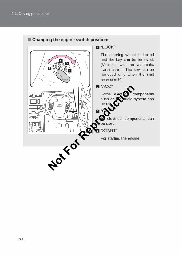
176
2-1. Driving procedures
LC150_OM_OM60J77E_(AE)
■ Changing the engine switch positions“LOCK”
The steering wheel is lockedand the key can be removed.(Vehicles with an automatictransmission: The key can beremoved only when the shiftlever is in P.)
“ACC”
Some electrical componentssuch as the audio system canbe used.
“ON”
All electrical components canbe used.
“START”
For starting the engine.
Not For R
epro
duction
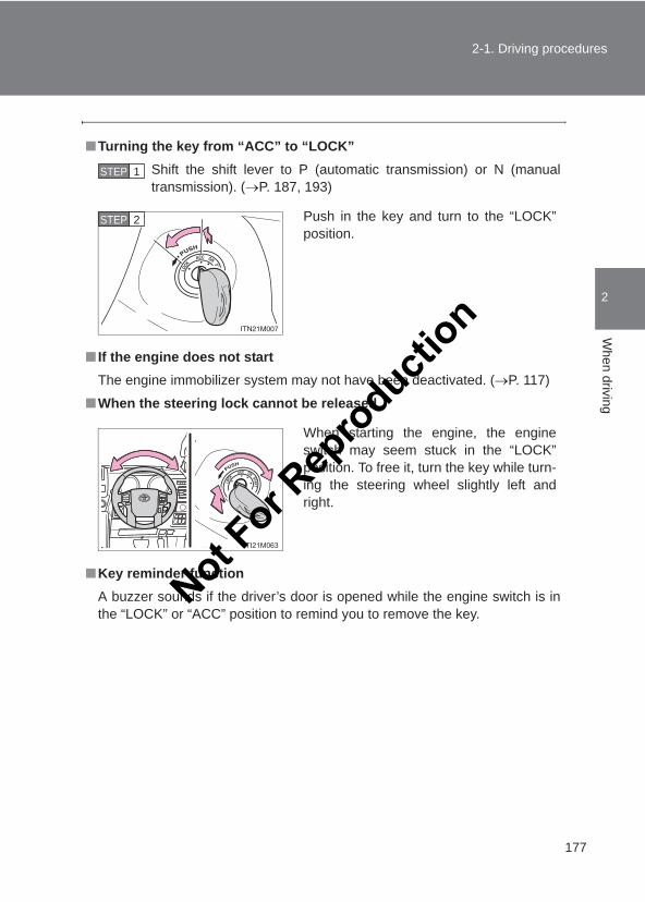
177
2-1. Driving procedures
2
When driving
LC150_OM_OM60J77E_(AE)
■Turning the key from “ACC” to “LOCK”Shift the shift lever to P (automatic transmission) or N (manualtransmission). (→P. 187, 193)
■ If the engine does not startThe engine immobilizer system may not have been deactivated. (→P. 117)
■When the steering lock cannot be released
■Key reminder functionA buzzer sounds if the driver’s door is opened while the engine switch is inthe “LOCK” or “ACC” position to remind you to remove the key.
STEP 1
Push in the key and turn to the “LOCK”position.
STEP 2
When starting the engine, the engineswitch may seem stuck in the “LOCK”position. To free it, turn the key while turn-ing the steering wheel slightly left andright.
Not For R
epro
duction
178
2-1. Driving procedures
LC150_OM_OM60J77E_(AE)
CAUTION
■When starting the engineAlways start the engine while sitting in the driver’s seat. Do not depress theaccelerator pedal while starting the engine under any circumstances.Doing so may cause an accident resulting in death or serious injury.
■Caution when drivingDo not turn the engine switch to the “LOCK” position while driving. If in an emergency, you must turn the engine off while the vehicle is moving,turn the engine switch only to the “ACC” position to stop the engine. An acci-dent may result if the engine is stopped while driving.
NOTICE
■To prevent battery dischargeDo not leave the engine switch in the “ACC” or “ON” position for long periodsof time without the engine running.
■When starting the engine●Do not crank the engine for more than 30 seconds at a time. This may
overheat the starter and wiring system.
●Do not race a cold engine.
● If the engine becomes difficult to start or stalls frequently, have the enginechecked immediately. Not F
or Rep
roducti
on
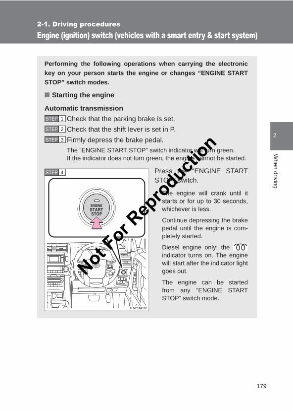
179
2-1. Driving procedures
2
When driving
LC150_OM_OM60J77E_(AE)
Engine (ignition) switch (vehicles with a smart entry & start system)
Performing the following operations when carrying the electronickey on your person starts the engine or changes “ENGINE STARTSTOP” switch modes.
■ Starting the engine
Automatic transmissionCheck that the parking brake is set.Check that the shift lever is set in P.Firmly depress the brake pedal.The “ENGINE START STOP” switch indicator will turn green.If the indicator does not turn green, the engine cannot be started.
Press the “ENGINE STARTSTOP” switch.
The engine will crank until itstarts or for up to 30 seconds,whichever is less.
Continue depressing the brakepedal until the engine is com-pletely started.
Diesel engine only: the indicator turns on. The enginewill start after the indicator lightgoes out.
The engine can be startedfrom any “ENGINE STARTSTOP” switch mode.
STEP 1
STEP 2
STEP 3
STEP 4
Not For R
epro
duction
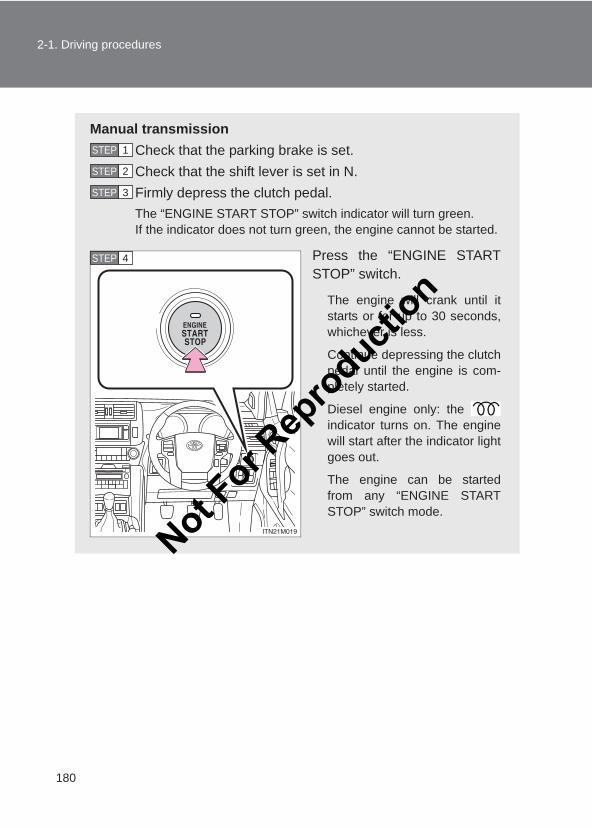
180
2-1. Driving procedures
LC150_OM_OM60J77E_(AE)
Manual transmissionCheck that the parking brake is set.Check that the shift lever is set in N.Firmly depress the clutch pedal.The “ENGINE START STOP” switch indicator will turn green.If the indicator does not turn green, the engine cannot be started.
Press the “ENGINE STARTSTOP” switch.
The engine will crank until itstarts or for up to 30 seconds,whichever is less.
Continue depressing the clutchpedal until the engine is com-pletely started.
Diesel engine only: the indicator turns on. The enginewill start after the indicator lightgoes out.
The engine can be startedfrom any “ENGINE STARTSTOP” switch mode.
STEP 1
STEP 2
STEP 3
STEP 4
Not For R
epro
duction
181
2-1. Driving procedures
2
When driving
LC150_OM_OM60J77E_(AE)
■ Stopping the engine
Automatic transmissionStop the vehicle.Shift the shift lever to P.Set the parking brake. (→P. 196)Press the “ENGINE START STOP” switch.Release the brake pedal and check that the indicator on the“ENGINE START STOP” switch is off.
Manual transmissionStop the vehicle.Shift the shift lever to N.Set the parking brake. (→P. 196)Press the “ENGINE START STOP” switch.Release the brake pedal and check that the indicator on the“ENGINE START STOP” switch is off.
STEP 1
STEP 2
STEP 3
STEP 4
STEP 5
STEP 1
STEP 2
STEP 3
STEP 4
STEP 5
Not For R
epro
duction
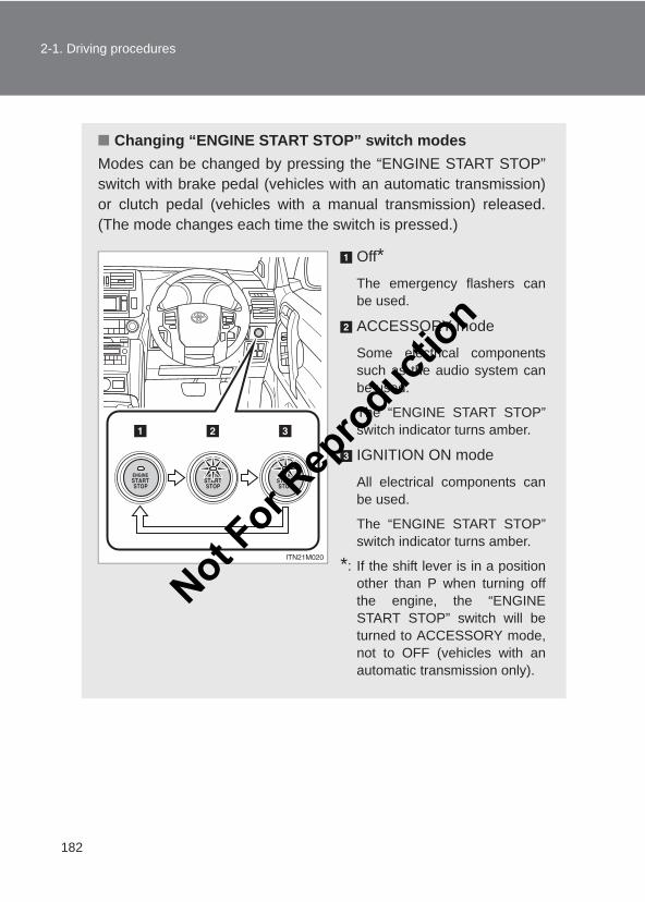
182
2-1. Driving procedures
LC150_OM_OM60J77E_(AE)
■ Changing “ENGINE START STOP” switch modesModes can be changed by pressing the “ENGINE START STOP”switch with brake pedal (vehicles with an automatic transmission)or clutch pedal (vehicles with a manual transmission) released.(The mode changes each time the switch is pressed.)
Off*The emergency flashers canbe used.
ACCESSORY mode
Some electrical componentssuch as the audio system canbe used.
The “ENGINE START STOP”switch indicator turns amber.
IGNITION ON mode
All electrical components canbe used.
The “ENGINE START STOP”switch indicator turns amber.
*: If the shift lever is in a positionother than P when turning offthe engine, the “ENGINESTART STOP” switch will beturned to ACCESSORY mode,not to OFF (vehicles with anautomatic transmission only).
Not For R
epro
duction
183
2-1. Driving procedures
2
When driving
LC150_OM_OM60J77E_(AE)
When stopping the engine with the shift lever in a position otherthan P (Vehicles with an automatic transmission)
If the engine is stopped with the shift lever in a position other than P,the “ENGINE START STOP” switch will not be turned off but insteadbe turned to ACCESSORY mode. Perform the following procedure toturn the switch off:
Check that the parking brake is set.Shift the shift lever to P.Check that the indicator on the “ENGINE START STOP”switch is illuminated in amber and then press the “ENGINESTART STOP” switch once.Check that the indicator on the “ENGINE START STOP”switch is off.
■Auto power off functionVehicles with an automatic transmissionWhen the shift lever is in P, if the vehicle is left in ACCESSORY or IGNITIONON mode with the engine not running for more than 20 minutes (ACCES-SORY mode) or one hour (IGNITION ON mode), the “ENGINE STARTSTOP” switch will automatically turn off. However, this function cannotentirely prevent battery discharge. Do not leave the vehicle with the“ENGINE START STOP” switch in ACCESSORY or IGNITION ON mode forlong periods of time when the engine is not running.
Vehicles with a manual transmissionIf the vehicle is left in ACCESSORY or IGNITION ON mode with the enginenot running for more than 20 minutes (ACCESSORY mode) or one hour(IGNITION ON mode), the “ENGINE START STOP” switch will automaticallyturn off. However, this function cannot entirely prevent battery discharge. Donot leave the vehicle with the “ENGINE START STOP” switch in ACCES-SORY or IGNITION ON mode for long periods of time when the engine is notrunning.
STEP 1
STEP 2
STEP 3
STEP 4
Not For R
epro
duction
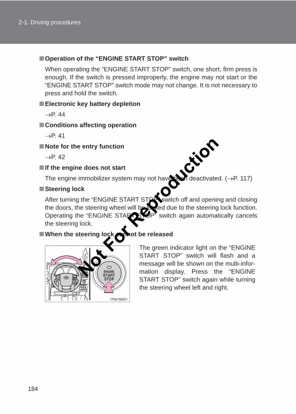
184
2-1. Driving procedures
LC150_OM_OM60J77E_(AE)
■Operation of the “ENGINE START STOP” switchWhen operating the “ENGINE START STOP” switch, one short, firm press isenough. If the switch is pressed improperly, the engine may not start or the“ENGINE START STOP” switch mode may not change. It is not necessary topress and hold the switch.
■Electronic key battery depletion→P. 44
■Conditions affecting operation→P. 41
■Note for the entry function→P. 42
■ If the engine does not startThe engine immobilizer system may not have been deactivated. (→P. 117)
■Steering lockAfter turning the “ENGINE START STOP” switch off and opening and closingthe doors, the steering wheel will be locked due to the steering lock function.Operating the “ENGINE START STOP” switch again automatically cancelsthe steering lock.
■When the steering lock cannot be released
The green indicator light on the “ENGINESTART STOP” switch will flash and amessage will be shown on the multi-infor-mation display. Press the “ENGINESTART STOP” switch again while turningthe steering wheel left and right.
Not For R
epro
duction
185
2-1. Driving procedures
2
When driving
LC150_OM_OM60J77E_(AE)
■Steering lock motor overheating preventionTo prevent the steering lock motor from overheating, the motor may be sus-pended if the engine is turned on and off repeatedly in a short period of time.In this case, refrain from operating the engine. After about 10 seconds, thesteering lock motor will resume functioning.
■When the “ENGINE START STOP” switch indicator flashes in amberThe system may be malfunctioning. Have the vehicle inspected by yourToyota dealer immediately.
■ If the electronic key battery is depleted→P. 501
CAUTION
■When starting the engineAlways start the engine while sitting in the driver’s seat. Do not depress theaccelerator pedal while starting the engine under any circumstances.Doing so may cause an accident resulting in death or serious injury.
■Caution while drivingIf the vehicle begins to slide due to engine failure or other circumstances, donot lock or open the doors until the vehicle reaches a safe and completestop. Activation of the steering lock in this circumstance may lead to an acci-dent, resulting in death or serious injury.
■Stopping the engine in an emergencyIf you want to stop the engine in an emergency while driving the vehicle,press and hold the “ENGINE START STOP” switch for more than 2 seconds,or press it briefly 3 times or more in succession.However, do not touch the “ENGINE START STOP” switch while drivingexcept in an emergency. Turning the engine off while driving will not causeloss of steering or braking control, but the power assist to these systems willbe lost. This will make it more difficult to steer and brake, so you should pullover and stop the vehicle as soon as it is safe to do so.
Not For R
epro
duction
186
2-1. Driving procedures
LC150_OM_OM60J77E_(AE)
NOTICE
■To prevent battery discharge●Do not leave the “ENGINE START STOP” switch in ACCESSORY or IGNI-
TION ON mode for long periods of time without the engine running.
● If the indicator on the “ENGINE START STOP” switch is illuminated, the“ENGINE START STOP” switch is not off. When exiting the vehicle,always check that the “ENGINE START STOP” switch is off.
●On vehicles with an automatic transmission, do not stop the engine whenthe shift lever is in a position other than P. If the engine is stopped inanother shift lever position, the “ENGINE START STOP” switch will not beturned off but instead be turned to ACCESSORY mode. If the vehicle is leftin ACCESSORY mode, battery discharge may occur.
■When starting the engine●Do not race a cold engine.
● If the engine becomes difficult to start or stalls frequently, have the enginechecked immediately.
■Symptoms indicating a malfunction with the “ENGINE START STOP”switchIf the “ENGINE START STOP” seems to be operating somewhat differentlythan usual, such as the switch sticking slightly, there may be a malfunction.Contact your Toyota dealer immediately.
Not For R
epro
duction
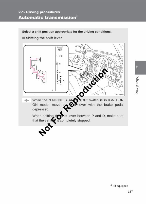
187
2-1. Driving procedures
2
When driving
LC150_OM_OM60J77E_(AE)
Automatic transmission∗
∗: If equipped
Select a shift position appropriate for the driving conditions.
■ Shifting the shift lever
While the “ENGINE START STOP” switch is in IGNITIONON mode, move the shift lever with the brake pedaldepressed.
When shifting the shift lever between P and D, make surethat the vehicle is completely stopped.
Not For R
epro
duction
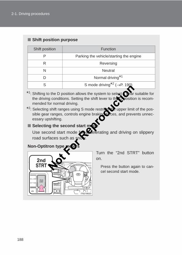
188
2-1. Driving procedures
LC150_OM_OM60J77E_(AE)
■ Shift position purpose
*1: Shifting to the D position allows the system to select a gear suitable forthe driving conditions. Setting the shift lever to the D position is recom-mended for normal driving.
*2: Selecting shift ranges using S mode restricts the upper limit of the pos-sible gear ranges, controls engine braking forces, and prevents unnec-essary upshifting.
■ Selecting the second start modeUse second start mode for accelerating and driving on slipperyroad surfaces such as snow.
Non-Optitron type metersTurn the “2nd STRT” buttonon.
Press the button again to can-cel second start mode.
Shift position Function
P Parking the vehicle/starting the engine
R Reversing
N Neutral
D Normal driving*1
S S mode driving*2 (→P. 190)
Not For R
epro
duction
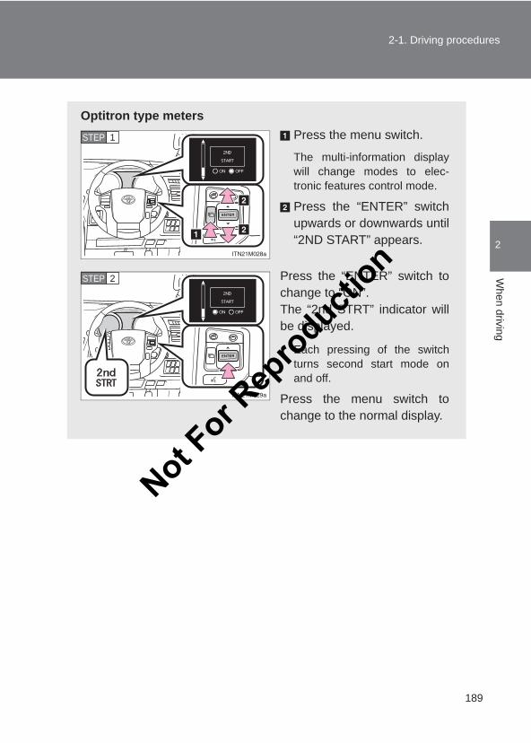
189
2-1. Driving procedures
2
When driving
LC150_OM_OM60J77E_(AE)
Optitron type metersPress the menu switch.
The multi-information displaywill change modes to elec-tronic features control mode.
Press the “ENTER” switchupwards or downwards until“2ND START” appears.
Press the “ENTER” switch tochange to “ON”.The “2nd STRT” indicator willbe displayed.
Each pressing of the switchturns second start mode onand off.
Press the menu switch tochange to the normal display.
STEP 1
STEP 2
Not For R
epro
duction
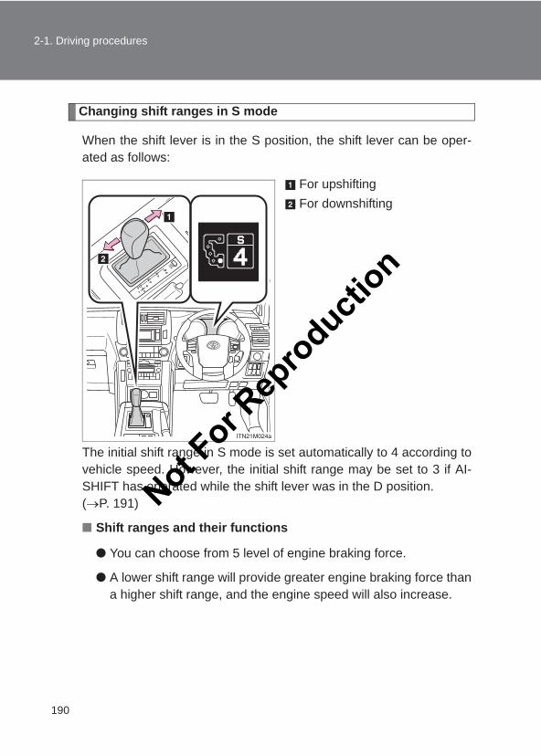
190
2-1. Driving procedures
LC150_OM_OM60J77E_(AE)
Changing shift ranges in S mode
When the shift lever is in the S position, the shift lever can be oper-ated as follows:
For upshiftingFor downshifting
The initial shift range in S mode is set automatically to 4 according tovehicle speed. However, the initial shift range may be set to 3 if AI-SHIFT has operated while the shift lever was in the D position. (→P. 191)
■ Shift ranges and their functions
● You can choose from 5 level of engine braking force.
● A lower shift range will provide greater engine braking force thana higher shift range, and the engine speed will also increase.
Not For R
epro
duction
191
2-1. Driving procedures
2
When driving
LC150_OM_OM60J77E_(AE)
■Driving on a downhillOn declines, there may be case where the vehicle shifts down automaticallyto obtain engine braking. As a result of the downshifting, the engine speedmay increase.
■Second start mode automatic deactivationSecond start mode is automatically deactivated if the engine is turned offafter driving in second start mode.
■S modeWhen the shift range is 4 or lower, holding the shift lever toward “+” sets theshift range to 5.
■AI-SHIFTAI-SHIFT automatically selects a suitable gear according to driver perfor-mance and driving conditions.AI-SHIFT automatically operates when the shift lever is in the D position.(Shifting the shift lever to the S position cancels the function.)
■When driving with the cruise control or dynamic radar cruise controlEngine braking will not occur in S mode, even when downshifting to 4. (→P. 242, 246)
■ If the shift lever cannot be shifted from P→P. 594
■ If the “S” indicator does not come on even after shifting the shift leverto SThis may indicate a malfunction in the automatic transmission system. Havethe vehicle inspected by your Toyota dealer immediately. (In this situation, the transmission will operate in the same manner as whenthe shift lever is in D.)
■Downshift restriction warning buzzer (S mode)To help ensure safety and driving performance, downshifting operation maysometimes be restricted. In some circumstances, downshifting may not bepossible even when the shift lever is operated. (A buzzer will sound twice.)
Not For R
epro
duction
192
2-1. Driving procedures
LC150_OM_OM60J77E_(AE)
CAUTION
■When driving on slippery road surfacesDo not accelerate or shift gears suddenly. Sudden changes in engine braking may cause the vehicle to spin or skid,resulting in an accident.
Not For R
epro
duction
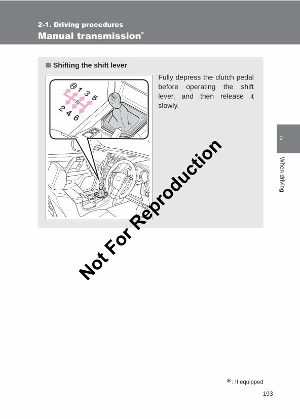
193
2-1. Driving procedures
2
When driving
LC150_OM_OM60J77E_(AE)
Manual transmission∗
∗: If equipped
■ Shifting the shift leverFully depress the clutch pedalbefore operating the shiftlever, and then release itslowly.
Not For R
epro
duction
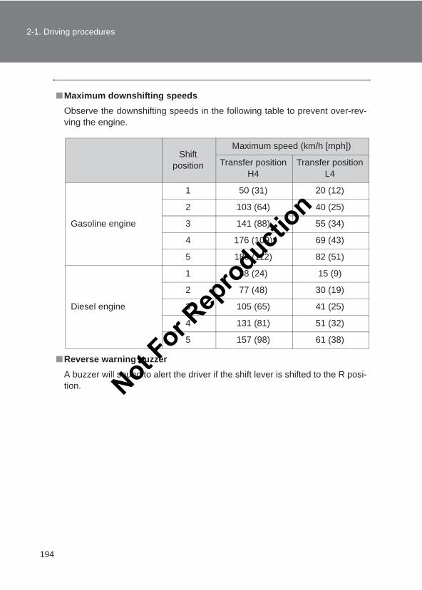
194
2-1. Driving procedures
LC150_OM_OM60J77E_(AE)
■Maximum downshifting speedsObserve the downshifting speeds in the following table to prevent over-rev-ving the engine.
■Reverse warning buzzerA buzzer will sound to alert the driver if the shift lever is shifted to the R posi-tion.
Shift position
Maximum speed (km/h [mph])
Transfer positionH4
Transfer positionL4
Gasoline engine
1 50 (31) 20 (12)
2 103 (64) 40 (25)
3 141 (88) 55 (34)
4 176 (109) 69 (43)
5 180 (112) 82 (51)
Diesel engine
1 38 (24) 15 (9)
2 77 (48) 30 (19)
3 105 (65) 41 (25)
4 131 (81) 51 (32)
5 157 (98) 61 (38)
Not For R
epro
duction
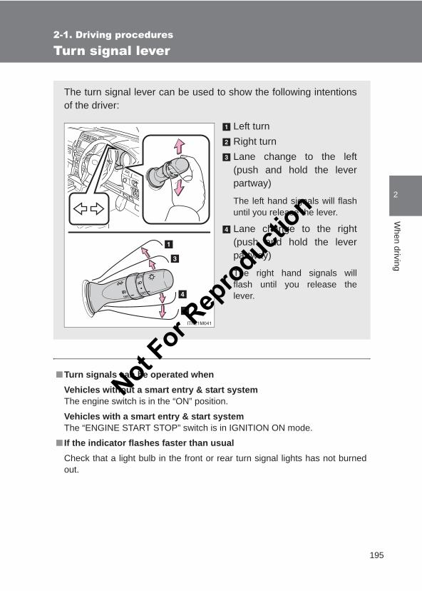
195
2-1. Driving procedures
2
When driving
LC150_OM_OM60J77E_(AE)
Turn signal lever
■Turn signals can be operated whenVehicles without a smart entry & start systemThe engine switch is in the “ON” position.
Vehicles with a smart entry & start systemThe “ENGINE START STOP” switch is in IGNITION ON mode.
■ If the indicator flashes faster than usualCheck that a light bulb in the front or rear turn signal lights has not burnedout.
The turn signal lever can be used to show the following intentionsof the driver:
Left turnRight turnLane change to the left(push and hold the leverpartway)
The left hand signals will flashuntil you release the lever.
Lane change to the right(push and hold the leverpartway)
The right hand signals willflash until you release thelever.
Not For R
epro
duction
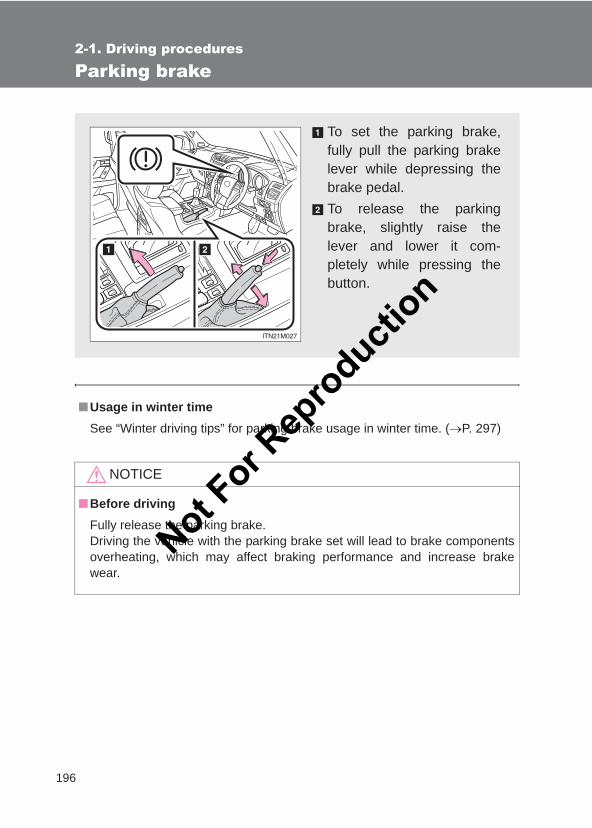
196
2-1. Driving procedures
LC150_OM_OM60J77E_(AE)
Parking brake
■Usage in winter timeSee “Winter driving tips” for parking brake usage in winter time. (→P. 297)
NOTICE
■Before drivingFully release the parking brake.Driving the vehicle with the parking brake set will lead to brake componentsoverheating, which may affect braking performance and increase brakewear.
To set the parking brake,fully pull the parking brakelever while depressing thebrake pedal.To release the parkingbrake, slightly raise thelever and lower it com-pletely while pressing thebutton.
Not For R
epro
duction
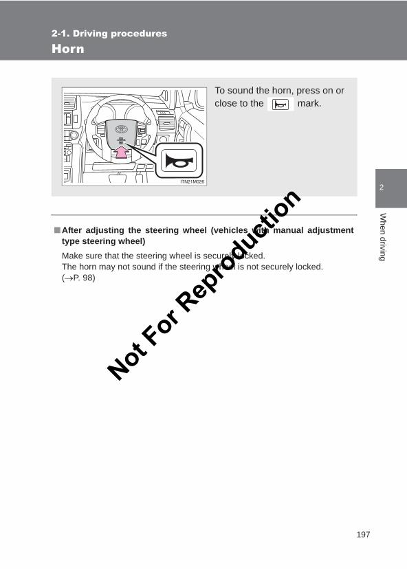
197
2-1. Driving procedures
2
When driving
LC150_OM_OM60J77E_(AE)
Horn
■After adjusting the steering wheel (vehicles with manual adjustmenttype steering wheel)Make sure that the steering wheel is securely locked.The horn may not sound if the steering wheel is not securely locked. (→P. 98)
To sound the horn, press on orclose to the mark.
Not For R
epro
duction
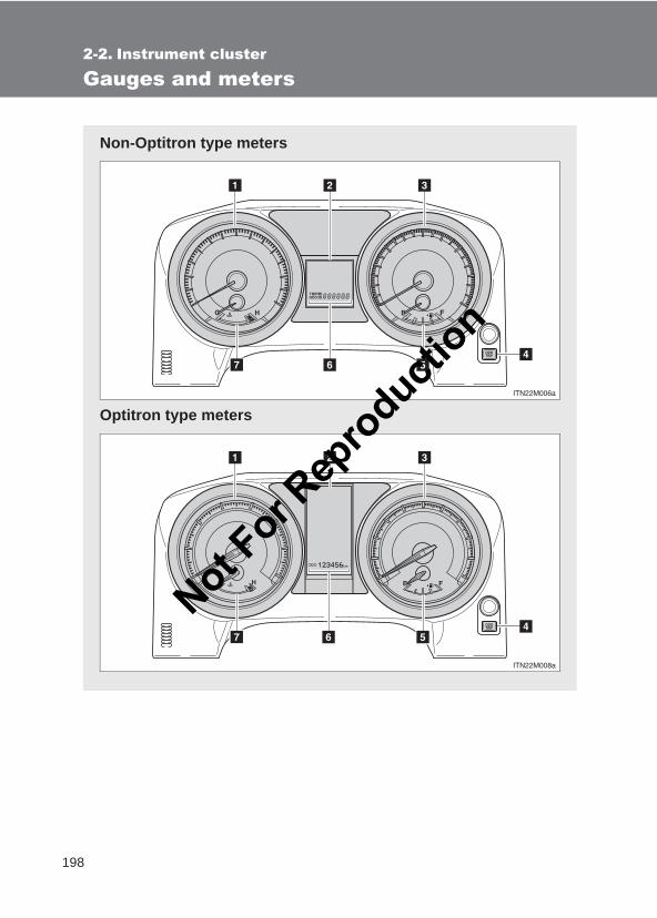
198
LC150_OM_OM60J77E_(AE)
2-2. Instrument cluster
Gauges and meters
Non-Optitron type meters
Optitron type meters
Not For R
epro
duction
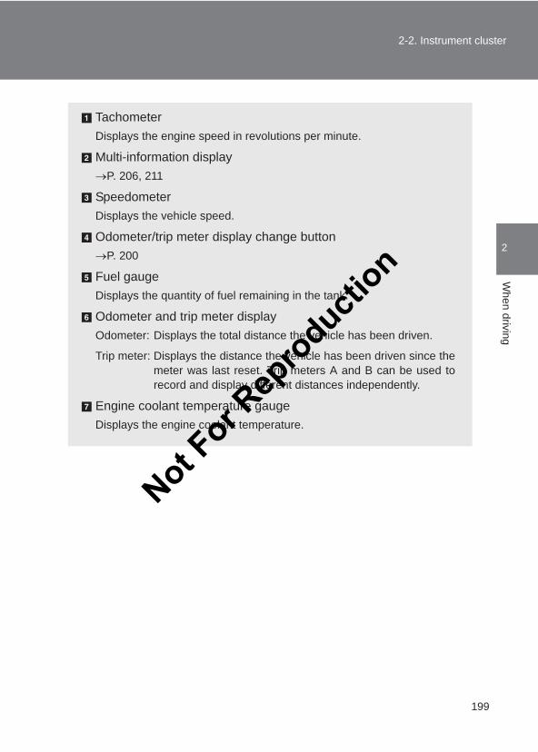
199
2-2. Instrument cluster
2
When driving
LC150_OM_OM60J77E_(AE)
TachometerDisplays the engine speed in revolutions per minute.
Multi-information display→P. 206, 211
SpeedometerDisplays the vehicle speed.
Odometer/trip meter display change button→P. 200
Fuel gaugeDisplays the quantity of fuel remaining in the tank.
Odometer and trip meter displayOdometer: Displays the total distance the vehicle has been driven.
Trip meter: Displays the distance the vehicle has been driven since themeter was last reset. Trip meters A and B can be used torecord and display different distances independently.
Engine coolant temperature gaugeDisplays the engine coolant temperature.
Not For R
epro
duction
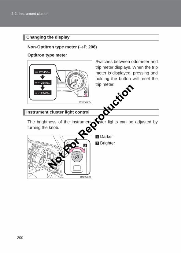
200
2-2. Instrument cluster
LC150_OM_OM60J77E_(AE)
Changing the display
Non-Optitron type meter (→P. 206)
Optitron type meterSwitches between odometer andtrip meter displays. When the tripmeter is displayed, pressing andholding the button will reset thetrip meter.
Instrument cluster light control
The brightness of the instrument cluster lights can be adjusted byturning the knob.
DarkerBrighter
Not For R
epro
duction
201
2-2. Instrument cluster
2
When driving
LC150_OM_OM60J77E_(AE)
■The meters and display illuminate whenVehicles without a smart entry & start systemThe engine switch is in the “ON” position.
Vehicles with a smart entry & start systemThe “ENGINE START STOP” switch is in IGNITION ON mode.
■The brightness of the instrument cluster lightsVehicles with a non-optitron type meterWhen the headlight switch is turned to on, the brightness will be reducedslightly.
Vehicles with an optitron type meterWhen the headlight switch is turned to on, the brightness will be reducedslightly unless the control dial is turned fully clockwise.
■When disconnecting and reconnecting battery terminalsThe trip meter data will be reset.If the trip meter was displayed last, the ODO screen will be displayed afterresetting.
NOTICE
■To prevent damage to the engine and its components●Do not let the indicator needle of the tachometer enter the red zone, which
indicates the maximum engine speed.
●The engine may be overheating if the engine coolant temperature gauge isin the red zone (H). In this case, immediately stop the vehicle in a safeplace, and check the engine after it has cooled completely. (→P. 604)
Not For R
epro
duction
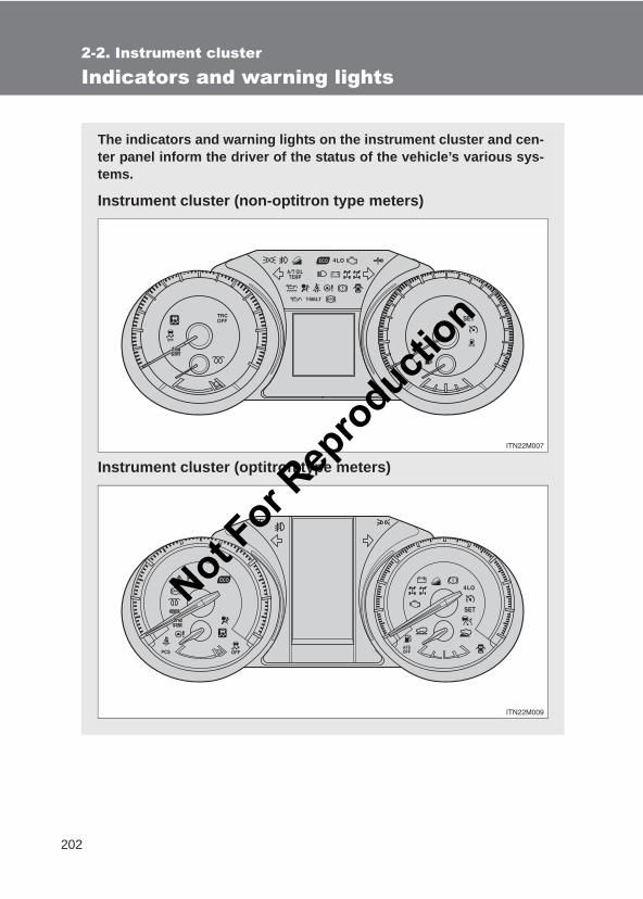
202
2-2. Instrument cluster
LC150_OM_OM60J77E_(AE)
Indicators and warning lights
The indicators and warning lights on the instrument cluster and cen-ter panel inform the driver of the status of the vehicle’s various sys-tems.
Instrument cluster (non-optitron type meters)
Instrument cluster (optitron type meters)
Not For R
epro
duction
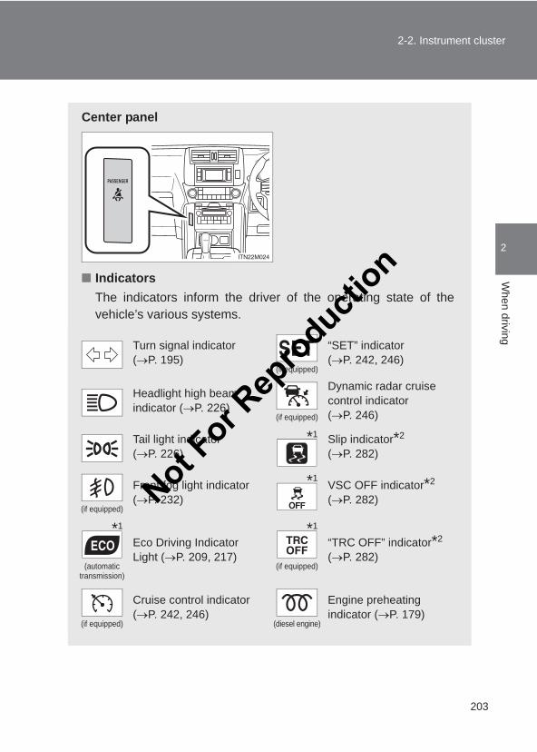
203
2-2. Instrument cluster
2
When driving
LC150_OM_OM60J77E_(AE)
Center panel
■ IndicatorsThe indicators inform the driver of the operating state of thevehicle’s various systems.
Turn signal indicator (→P. 195)
(if equipped)
“SET” indicator (→P. 242, 246)
Headlight high beam indicator (→P. 226)
(if equipped)
Dynamic radar cruise control indicator(→P. 246)
Tail light indicator (→P. 226)
Slip indicator*2 (→P. 282)
(if equipped)
Front fog light indicator (→P. 232)
VSC OFF indicator*2 (→P. 282)
(automatic transmission)
Eco Driving Indicator Light (→P. 209, 217)
(if equipped)
“TRC OFF” indicator*2 (→P. 282)
(if equipped)
Cruise control indicator(→P. 242, 246)
(diesel engine)
Engine preheating indicator (→P. 179)
*1
*1
*1 *1
Not For R
epro
duction
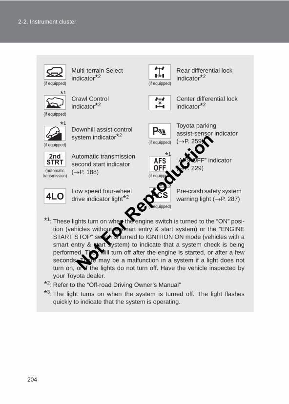
204
2-2. Instrument cluster
LC150_OM_OM60J77E_(AE)
*1: These lights turn on when the engine switch is turned to the “ON” posi-tion (vehicles without a smart entry & start system) or the “ENGINESTART STOP” switch is turned to IGNITION ON mode (vehicles with asmart entry & start system) to indicate that a system check is beingperformed. They will turn off after the engine is started, or after a fewseconds. There may be a malfunction in a system if a light does notturn on, or if the lights do not turn off. Have the vehicle inspected byyour Toyota dealer.
*2: Refer to the “Off-road Driving Owner’s Manual”*3: The light turns on when the system is turned off. The light flashes
quickly to indicate that the system is operating.
(if equipped)
Multi-terrain Select indicator*2
(if equipped)
Rear differential lock indicator*2
(if equipped)
Crawl Control indicator*2
Center differential lock indicator*2
(if equipped)
Downhill assist control system indicator*2
(if equipped)
Toyota parking assist-sensor indicator (→P. 259)
(automatic transmission)
Automatic transmission second start indicator (→P. 188)
(if equipped)
“AFS OFF” indicator (→P. 229)
Low speed four-wheel drive indicator light*2
(if equipped)
Pre-crash safety system warning light (→P. 287)
*1
*1
*1
*1, 3
Not For R
epro
duction
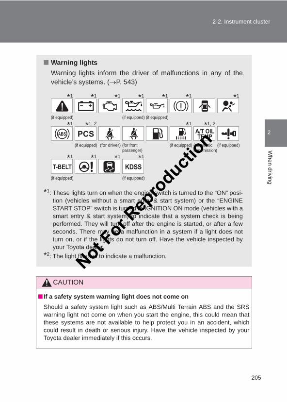
205
2-2. Instrument cluster
2
When driving
LC150_OM_OM60J77E_(AE)
CAUTION
■ If a safety system warning light does not come onShould a safety system light such as ABS/Multi Terrain ABS and the SRSwarning light not come on when you start the engine, this could mean thatthese systems are not available to help protect you in an accident, whichcould result in death or serious injury. Have the vehicle inspected by yourToyota dealer immediately if this occurs.
■ Warning lightsWarning lights inform the driver of malfunctions in any of thevehicle’s systems. (→P. 543)
*1: These lights turn on when the engine switch is turned to the “ON” posi-tion (vehicles without a smart entry & start system) or the “ENGINESTART STOP” switch is turned to IGNITION ON mode (vehicles with asmart entry & start system) to indicate that a system check is beingperformed. They will turn off after the engine is started, or after a fewseconds. There may be a malfunction in a system if a light does notturn on, or if the lights do not turn off. Have the vehicle inspected byyour Toyota dealer.
*2: The light flashes to indicate a malfunction.
(if equipped) (if equipped) (if equipped)
(if equipped) (for driver) (for front passenger)
(if equipped) (automatictransmission)
(if equipped)
(if equipped) (if equipped)
*1 *1 *1 *1 *1 *1 *1
*1 *1, 2 *1 *1, 2
*1 *1 *1 *1
Not For R
epro
duction
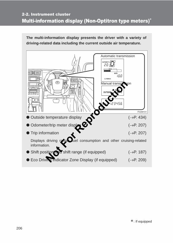
206
2-2. Instrument cluster
LC150_OM_OM60J77E_(AE)
Multi-information display (Non-Optitron type meters)∗
∗: If equipped
The multi-information display presents the driver with a variety ofdriving-related data including the current outside air temperature.
● Outside temperature display (→P. 434)
● Odometer/trip meter display (→P. 207)
● Trip information (→P. 207)
Displays driving range, fuel consumption and other cruising-relatedinformation.
● Shift position and shift range (if equipped) (→P. 187)
● Eco Driving Indicator Zone Display (if equipped) (→P. 209)
Automatic transmission
Manual transmission
Not For R
epro
duction
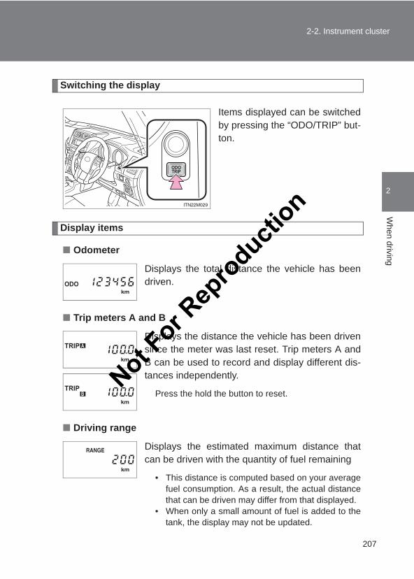
207
2-2. Instrument cluster
2
When driving
LC150_OM_OM60J77E_(AE)
Switching the display
Items displayed can be switchedby pressing the “ODO/TRIP” but-ton.
Display items
■ Odometer
■ Trip meters A and B
■ Driving range
Displays the total distance the vehicle has beendriven.
Displays the distance the vehicle has been drivensince the meter was last reset. Trip meters A andB can be used to record and display different dis-tances independently.
Press the hold the button to reset.
Displays the estimated maximum distance thatcan be driven with the quantity of fuel remaining
• This distance is computed based on your averagefuel consumption. As a result, the actual distancethat can be driven may differ from that displayed.
• When only a small amount of fuel is added to thetank, the display may not be updated.
Not For R
epro
duction
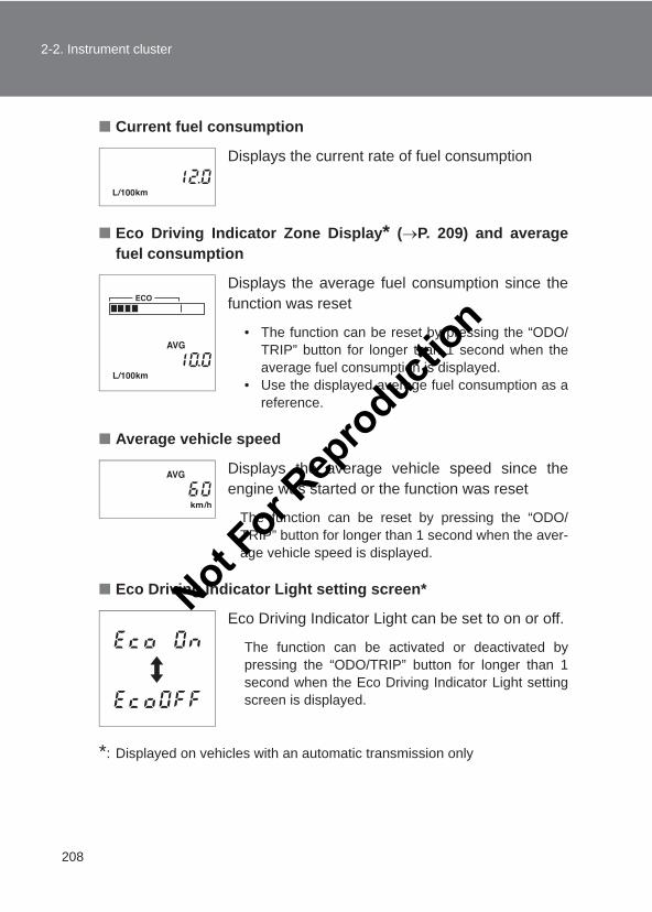
208
2-2. Instrument cluster
LC150_OM_OM60J77E_(AE)
■ Current fuel consumption
■ Eco Driving Indicator Zone Display* (→P. 209) and averagefuel consumption
■ Average vehicle speed
■ Eco Driving Indicator Light setting screen*
*: Displayed on vehicles with an automatic transmission only
Displays the current rate of fuel consumption
Displays the average fuel consumption since thefunction was reset
• The function can be reset by pressing the “ODO/TRIP” button for longer than 1 second when theaverage fuel consumption is displayed.
• Use the displayed average fuel consumption as areference.
Displays the average vehicle speed since theengine was started or the function was reset
The function can be reset by pressing the “ODO/TRIP” button for longer than 1 second when the aver-age vehicle speed is displayed.
Eco Driving Indicator Light can be set to on or off.
The function can be activated or deactivated bypressing the “ODO/TRIP” button for longer than 1second when the Eco Driving Indicator Light settingscreen is displayed.
Not For R
epro
duction
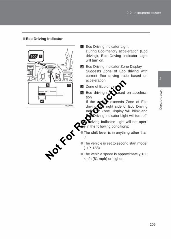
209
2-2. Instrument cluster
2
When driving
LC150_OM_OM60J77E_(AE)
■Eco Driving Indicator
Eco Driving Indicator LightDuring Eco-friendly acceleration (Ecodriving), Eco Driving Indicator Lightwill turn on.
Eco Driving Indicator Zone DisplaySuggests Zone of Eco driving withcurrent Eco driving ratio based onacceleration.
Zone of Eco driving
Eco driving ratio based on accelera-tionIf the vehicle exceeds Zone of Ecodriving, the right side of Eco DrivingIndicator Zone Display will blink andEco Driving Indicator Light will turn off.
Eco Driving Indicator Light will not oper-ate in the following conditions:
●The shift lever is in anything other thanD.
●The vehicle is set to second start mode.(→P. 188)
●The vehicle speed is approximately 130km/h (81 mph) or higher.Not F
or Rep
roducti
on
210
2-2. Instrument cluster
LC150_OM_OM60J77E_(AE)
■When disconnecting and reconnecting battery terminalsThe following information data will be reset:
●Trip meter
●Average fuel consumption
●Average vehicle speed
If the trip meter was displayed last, the ODO screen will be displayed afterresetting.
CAUTION
■The information display at low temperatures (vehicles with an auto-matic transmission)Allow the interior of the vehicle to warm up before using the information dis-play. At extremely low temperatures, the information display monitor mayrespond slowly, and display changes may be delayed.For example, there is a lag between the driver’s shifting and the new gearnumber appearing on the display. This lag could cause the driver to down-shift again, causing rapid and excessive engine braking and possibly anaccident resulting in death or serious injury.
NOTICE
■The multi-information display at low temperaturesAllow the interior of the vehicle to warm up before using the information dis-play. At extremely low temperatures, the information display monitor mayrespond slowly, and display changes may be delayed.
Not For R
epro
duction
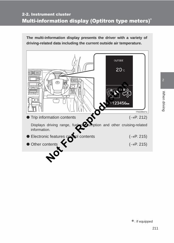
211
2-2. Instrument cluster
2
When driving
LC150_OM_OM60J77E_(AE)
Multi-information display (Optitron type meters)∗
∗: If equipped
The multi-information display presents the driver with a variety ofdriving-related data including the current outside air temperature.
● Trip information contents (→P. 212)
Displays driving range, fuel consumption and other cruising-relatedinformation.
● Electronic features control contents (→P. 215)
● Other contents (→P. 215)
Not For R
epro
duction
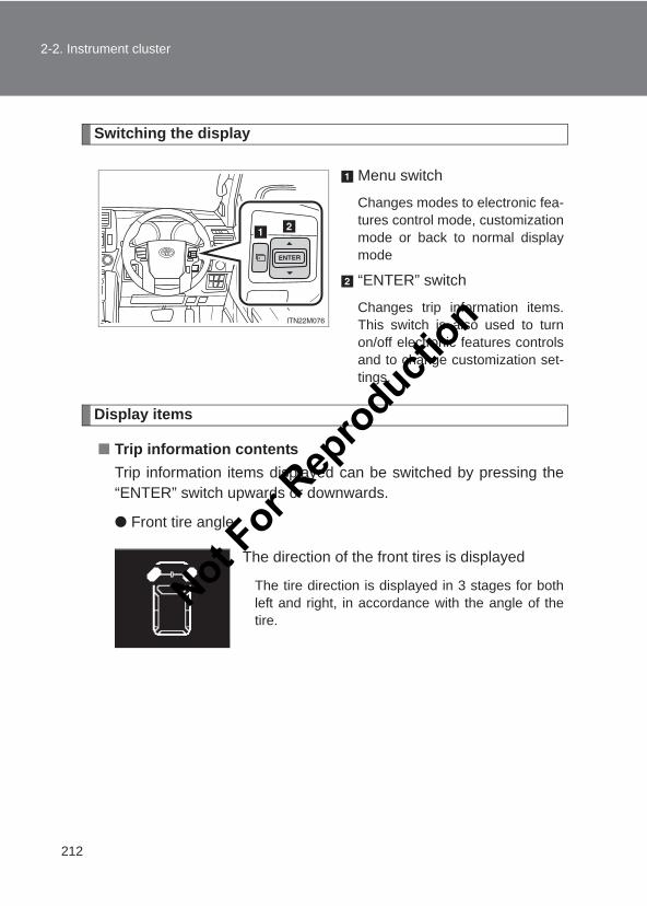
212
2-2. Instrument cluster
LC150_OM_OM60J77E_(AE)
Switching the display
Menu switch
Changes modes to electronic fea-tures control mode, customizationmode or back to normal displaymode
“ENTER” switch
Changes trip information items.This switch is also used to turnon/off electronic features controlsand to change customization set-tings.
Display items
■ Trip information contentsTrip information items displayed can be switched by pressing the“ENTER” switch upwards or downwards.
● Front tire angle
The direction of the front tires is displayed
The tire direction is displayed in 3 stages for bothleft and right, in accordance with the angle of thetire.
Not For R
epro
duction
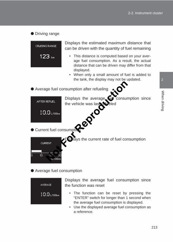
213
2-2. Instrument cluster
2
When driving
LC150_OM_OM60J77E_(AE)
● Driving range
● Average fuel consumption after refueling
● Current fuel consumption
● Average fuel consumption
Displays the estimated maximum distance thatcan be driven with the quantity of fuel remaining
• This distance is computed based on your aver-age fuel consumption. As a result, the actualdistance that can be driven may differ from thatdisplayed.
• When only a small amount of fuel is added tothe tank, the display may not be updated.
Displays the average fuel consumption sincethe vehicle was last refueled
Displays the current rate of fuel consumption
Displays the average fuel consumption sincethe function was reset
• The function can be reset by pressing the“ENTER” switch for longer than 1 second whenthe average fuel consumption is displayed.
• Use the displayed average fuel consumption asa reference.
Not For R
epro
duction
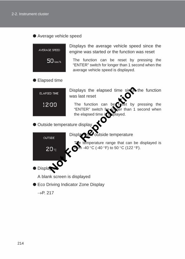
214
2-2. Instrument cluster
LC150_OM_OM60J77E_(AE)
● Average vehicle speed
● Elapsed time
● Outside temperature display
● Display off
A blank screen is displayed
● Eco Driving Indicator Zone Display
→P. 217
Displays the average vehicle speed since theengine was started or the function was reset
The function can be reset by pressing the“ENTER” switch for longer than 1 second when theaverage vehicle speed is displayed.
Displays the elapsed time since the functionwas last reset
The function can be reset by pressing the“ENTER” switch for longer than 1 second whenthe elapsed time is displayed.
Displays the outside temperature
The temperature range that can be displayed isfrom -40 °C (-40 °F) to 50 °C (122 °F).
Not For R
epro
duction
215
2-2. Instrument cluster
2
When driving
LC150_OM_OM60J77E_(AE)
■ Electronic features control contents● Multi-terrain Select (if equipped)
→Refer to the “Off-road Driving Owner’s Manual”
● Toyota parking assist-sensor (if equipped) (→P. 259)
● AFS (Adaptive Front-lighting System) (if equipped) (→P. 229)
● Second start mode (if equipped) (→P. 188)
■ Other contents● Shift position and shift range (if equipped) (→P. 187)
● Rear height control air suspension display (if equipped)
→Refer to the “Off-road Driving Owner’s Manual”
● Multi-terrain Select display (if equipped)
→Refer to the “Off-road Driving Owner’s Manual”
● Toyota parking assist-sensor display* (if equipped) (→P. 259)
● Crawl Control display* (if equipped)
→Refer to the “Off-road Driving Owner’s Manual”
● Dynamic radar cruise control display* (if equipped) (→P. 246)
● Warning messages (→P. 553)
Automatically displayed when a malfunction occurs in one of thevehicles systems
● Customization
Settings (e.g. available language) can be changed. (Customizable features →P. 632)
*: Automatically displayed when the system is used
Not For R
epro
duction
216
2-2. Instrument cluster
LC150_OM_OM60J77E_(AE)
■Electronic features control can be turned on/off when“ENGINE START STOP” switch is in IGNITION ON mode.
■System check displayAfter turning the “ENGINE START STOP” switch to IGNITION ON mode,“TOYOTA” is displayed while system operation is checked. When the sys-tem check is complete, the normal screen will return.
■Conditions for ending electronic features controlIn the following situations, the electronic features control will end automati-cally:
●The menu switch is pressed
●Toyota parking assist-sensor starts operating
●The Crawl Control is operated
●The dynamic radar cruise control is operated
●A warning message appears after the electronic features control screenis displayed
Not For R
epro
duction
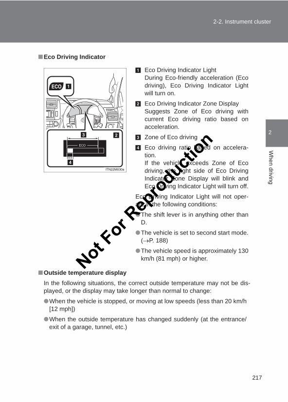
217
2-2. Instrument cluster
2
When driving
LC150_OM_OM60J77E_(AE)
■Eco Driving Indicator
■Outside temperature displayIn the following situations, the correct outside temperature may not be dis-played, or the display may take longer than normal to change:
●When the vehicle is stopped, or moving at low speeds (less than 20 km/h[12 mph])
●When the outside temperature has changed suddenly (at the entrance/exit of a garage, tunnel, etc.)
Eco Driving Indicator LightDuring Eco-friendly acceleration (Ecodriving), Eco Driving Indicator Lightwill turn on.
Eco Driving Indicator Zone DisplaySuggests Zone of Eco driving withcurrent Eco driving ratio based onacceleration.
Zone of Eco driving
Eco driving ratio based on accelera-tion.If the vehicle exceeds Zone of Ecodriving, the right side of Eco DrivingIndicator Zone Display will blink andEco Driving Indicator Light will turn off.
Eco Driving Indicator Light will not oper-ate in the following conditions:
●The shift lever is in anything other thanD.
●The vehicle is set to second start mode.(→P. 188)
●The vehicle speed is approximately 130km/h (81 mph) or higher.Not F
or Rep
roducti
on
218
2-2. Instrument cluster
LC150_OM_OM60J77E_(AE)
■When “--” or “E” is displayedThe system may be malfunctioning. Take your vehicle to your Toyota dealer.
■When disconnecting and reconnecting battery terminalsThe following information data will be reset:
●Average fuel consumption after refueling
●Average fuel consumption
●Average vehicle speed
●Elapsed time
CAUTION
■The information display at low temperatures (vehicles with an auto-matic transmission)Allow the interior of the vehicle to warm up before using the information dis-play. At extremely low temperatures, the information display monitor mayrespond slowly, and display changes may be delayed.For example, there is a lag between the driver’s shifting and the new gearnumber appearing on the display. This lag could cause the driver to down-shift again, causing rapid and excessive engine braking and possibly anaccident resulting in death or serious injury.
NOTICE
■The multi-information display at low temperaturesAllow the interior of the vehicle to warm up before using the information dis-play. At extremely low temperatures, the information display monitor mayrespond slowly, and display changes may be delayed.
Not For R
epro
duction
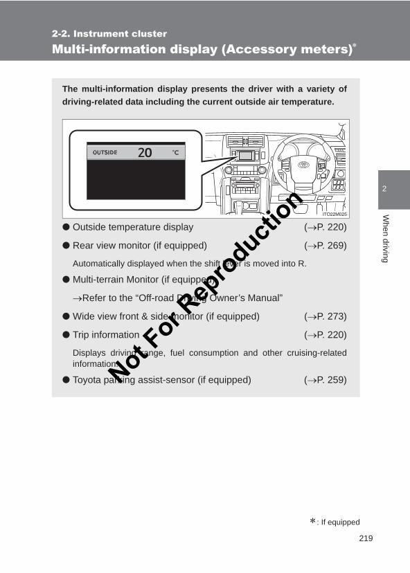
219
2-2. Instrument cluster
2
When driving
LC150_OM_OM60J77E_(AE)
Multi-information display (Accessory meters)∗
∗: If equipped
The multi-information display presents the driver with a variety ofdriving-related data including the current outside air temperature.
● Outside temperature display (→P. 220)
● Rear view monitor (if equipped) (→P. 269)
Automatically displayed when the shift lever is moved into R.
● Multi-terrain Monitor (if equipped)
→Refer to the “Off-road Driving Owner’s Manual”
● Wide view front & side monitor (if equipped) (→P. 273)
● Trip information (→P. 220)
Displays driving range, fuel consumption and other cruising-relatedinformation.
● Toyota parking assist-sensor (if equipped) (→P. 259)Not For R
epro
duction
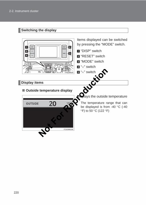
220
2-2. Instrument cluster
LC150_OM_OM60J77E_(AE)
Switching the display
Items displayed can be switchedby pressing the “MODE” switch.
“DISP” switch“RESET” switch“MODE” switch“∨” switch“∧” switch
Display items
■ Outside temperature displayDisplays the outside temperature
The temperature range that canbe displayed is from -40 °C (-40°F) to 50 °C (122 °F)
Not For R
epro
duction
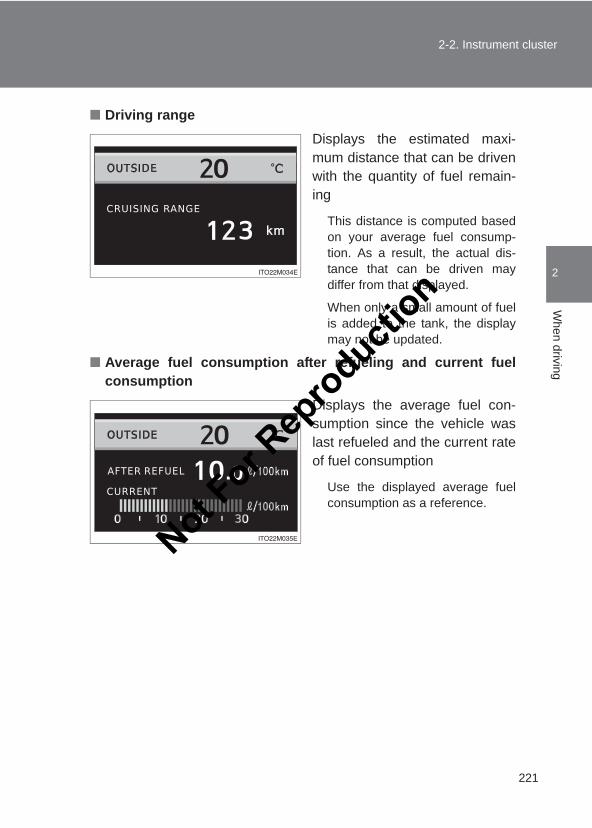
221
2-2. Instrument cluster
2
When driving
LC150_OM_OM60J77E_(AE)
■ Driving range Displays the estimated maxi-mum distance that can be drivenwith the quantity of fuel remain-ing
This distance is computed basedon your average fuel consump-tion. As a result, the actual dis-tance that can be driven maydiffer from that displayed.
When only a small amount of fuelis added to the tank, the displaymay not be updated.
■ Average fuel consumption after refueling and current fuelconsumption
Displays the average fuel con-sumption since the vehicle waslast refueled and the current rateof fuel consumption
Use the displayed average fuelconsumption as a reference.
Not For R
epro
duction
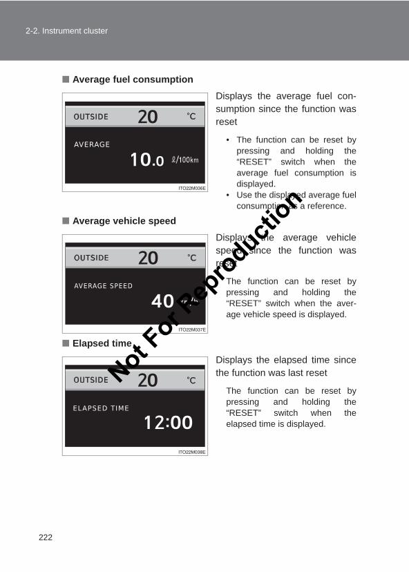
222
2-2. Instrument cluster
LC150_OM_OM60J77E_(AE)
■ Average fuel consumptionDisplays the average fuel con-sumption since the function wasreset
• The function can be reset bypressing and holding the“RESET” switch when theaverage fuel consumption isdisplayed.
• Use the displayed average fuelconsumption as a reference.
■ Average vehicle speedDisplays the average vehiclespeed since the function wasreset
The function can be reset bypressing and holding the“RESET” switch when the aver-age vehicle speed is displayed.
■ Elapsed timeDisplays the elapsed time sincethe function was last reset
The function can be reset bypressing and holding the“RESET” switch when theelapsed time is displayed.
Not For R
epro
duction
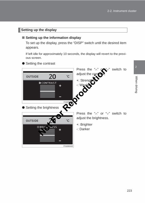
223
2-2. Instrument cluster
2
When driving
LC150_OM_OM60J77E_(AE)
Setting up the display
■ Setting up the information displayTo set up the display, press the “DISP” switch until the desired itemappears.
If left idle for approximately 10 seconds, the display will revert to the previ-ous screen.
● Setting the contrast
Press the “∧” or “∨” switch toadjust the contrast.
+: Strengthen-: Weaken
● Setting the brightness
Press the “∧” or “∨” switch toadjust the brightness.
+: Brighter-: DarkerNot F
or Rep
roducti
on
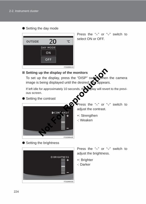
224
2-2. Instrument cluster
LC150_OM_OM60J77E_(AE)
● Setting the day mode
Press the “∧” or “∨” switch toselect ON or OFF.
■ Setting up the display of the monitorsTo set up the display, press the “DISP” switch when the cameraimage is being displayed until the desired item appears.
If left idle for approximately 10 seconds, the display will revert to the previ-ous screen.
● Setting the contrast
Press the “∧” or “∨” switch toadjust the contrast.
+: Strengthen-: Weaken
● Setting the brightness
Press the “∧” or “∨” switch toadjust the brightness.
+: Brighter-: Darker
Not For R
epro
duction
225
2-2. Instrument cluster
2
When driving
LC150_OM_OM60J77E_(AE)
■Liquid crystal displaySmall spots or light spots may appear on the display. This phenomenon ischaracteristic of liquid crystal displays, and there is no problem continuing touse the display.
■Outside temperature displayIn the following situations, the correct outside temperature may not be dis-played, or the display may take longer than normal to change.
●When stopped, or driving at low speeds (less than 20 km/h [12 mph])
●When the outside temperature has changed suddenly (at the entrance/exit of a garage, tunnel, etc.)
■When “--” or “E” is displayed on the outside temperature displayThe system may be malfunctioning. Take your vehicle to your Toyota dealer.
■When disconnecting and reconnecting battery terminalsThe following information data and settings will be reset:
●Average fuel consumption after refueling
●Average fuel consumption
●Average vehicle speed
●Elapsed time
■CustomizationSetting of available languages can be changed.(Customizable features →P. 632)
NOTICE
■The multi-information display at low temperaturesAllow the interior of the vehicle to warm up before using the liquid crystalinformation display. At extremely low temperatures, the information displaymonitor may respond slowly, and display changes may be delayed.
Not For R
epro
duction
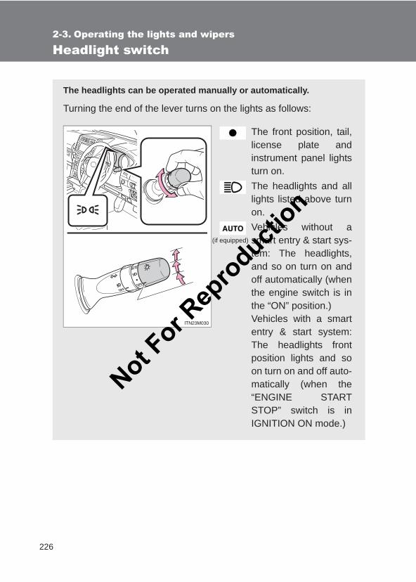
226
LC150_OM_OM60J77E_(AE)
2-3. Operating the lights and wipers
Headlight switch
The headlights can be operated manually or automatically.
Turning the end of the lever turns on the lights as follows:
The front position, tail,license plate andinstrument panel lightsturn on.The headlights and alllights listed above turnon.Vehicles without asmart entry & start sys-tem: The headlights,and so on turn on andoff automatically (whenthe engine switch is inthe “ON” position.) Vehicles with a smartentry & start system:The headlights frontposition lights and soon turn on and off auto-matically (when the“ENGINE STARTSTOP” switch is inIGNITION ON mode.)
(if equipped)
Not For R
epro
duction
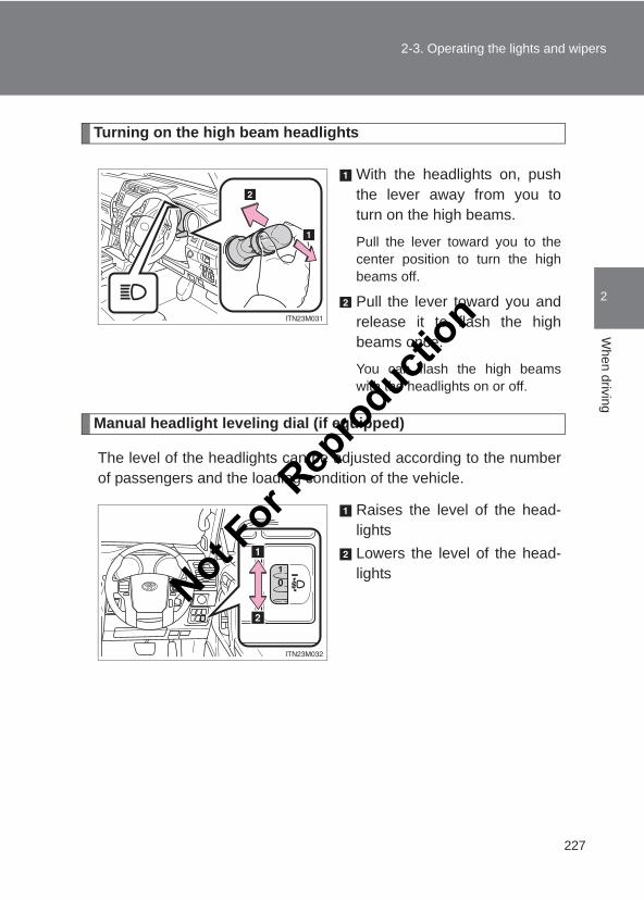
227
2-3. Operating the lights and wipers
2
When driving
LC150_OM_OM60J77E_(AE)
Turning on the high beam headlights
With the headlights on, pushthe lever away from you toturn on the high beams.
Pull the lever toward you to thecenter position to turn the highbeams off.
Pull the lever toward you andrelease it to flash the highbeams once.
You can flash the high beamswith the headlights on or off.
Manual headlight leveling dial (if equipped)
The level of the headlights can be adjusted according to the numberof passengers and the loading condition of the vehicle.
Raises the level of the head-lightsLowers the level of the head-lightsNot F
or Rep
roducti
on
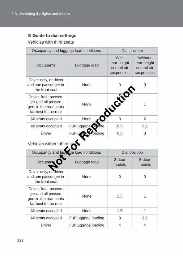
228
2-3. Operating the lights and wipers
LC150_OM_OM60J77E_(AE)
■ Guide to dial settingsVehicles with third seats
Vehicles without third seats
Occupancy and luggage load conditions Dial position
Occupants Luggage load
With rear height control air
suspension
Without rear height control air
suspension
Driver only, or driver and one passenger in
the front seatNone 0 0
Driver, front passen-ger and all passen-
gers in the rear seats farthest to the rear
None 0 1
All seats occupied None 0 2
All seats occupied Full luggage loading 0.5 2.5
Driver Full luggage loading 0.5 3
Occupancy and luggage load conditions Dial position
Occupants Luggage load 3-door models
5-door models
Driver only, or driver and one passenger in
the front seatNone 0 0
Driver, front passen-ger and all passen-
gers in the rear seats farthest to the rear
None 1.5 1
All seats occupied None 1.5 1
All seats occupied Full luggage loading 3 3.5
Driver Full luggage loading 4 4
Not For R
epro
duction
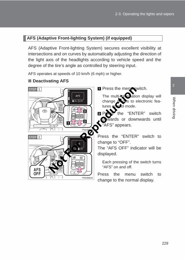
229
2-3. Operating the lights and wipers
2
When driving
LC150_OM_OM60J77E_(AE)
AFS (Adaptive Front-lighting System) (if equipped)
AFS (Adaptive Front-lighting System) secures excellent visibility atintersections and on curves by automatically adjusting the direction ofthe light axis of the headlights according to vehicle speed and thedegree of the tire’s angle as controlled by steering input.
AFS operates at speeds of 10 km/h (6 mph) or higher.
■ Deactivating AFSPress the menu switch.
The multi-information display willchange modes to electronic fea-tures control mode.
Press the “ENTER” switchupwards or downwards until“AFS” appears.
Press the “ENTER” switch tochange to “OFF”.The “AFS OFF” indicator will bedisplayed.
Each pressing of the switch turns“AFS” on and off.
Press the menu switch tochange to the normal display.
STEP 1
STEP 2
Not For R
epro
duction
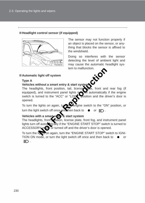
230
2-3. Operating the lights and wipers
LC150_OM_OM60J77E_(AE)
■Headlight control sensor (if equipped)
■Automatic light off systemType AVehicles without a smart entry & start systemThe headlights, front position, tail, license plate, front and rear fog (ifequipped), and instrument panel lights turn off automatically if the engineswitch is turned to the “ACC” or “LOCK” position and the driver’s door isopened.
To turn the lights on again, turn the engine switch to the “ON” position, orturn the light switch off once and then back to or .
Vehicles with a smart entry & start systemThe headlights, front position, license plate, front fog, and instrument panellights turn off automatically if the “ENGINE START STOP” switch is turned toACCESSORY mode or turned off and the driver’s door is opened.
To turn the lights on again, turn the “ENGINE START STOP” switch to IGNI-TION ON mode, or turn the light switch off once and then back to or
.
The sensor may not function properly ifan object is placed on the sensor, or any-thing that blocks the sensor is affixed tothe windshield.
Doing so interferes with the sensordetecting the level of ambient light andmay cause the automatic headlight sys-tem to malfunction.
Not For R
epro
duction
231
2-3. Operating the lights and wipers
2
When driving
LC150_OM_OM60J77E_(AE)
Type B●When only the tail lights come on: The front position, tail, license plate,
front, and instrument panel lights turn off if the “ENGINE START STOP”switch is turned to ACCESSORY mode or turned off and the driver’s dooropened.
●When the headlights come on: The headlights, front position, tail, licenseplate, front, and instrument panel lights turn off 30 seconds after a dooror the glass hatch (if equipped) is opened and closed.
To turn the lights on again, turn the “ENGINE START STOP” switch to IGNI-TION ON mode, or turn the light switch off once and then back to or
.
■Automatic headlight leveling system (if equipped)The level of the headlights is automatically adjusted according to the numberof passengers and the loading condition of the vehicle to ensure that theheadlights do not interfere with other road users.
■ If the “AFS OFF” indicator flashesIt may indicate a malfunction in the system. Contact your Toyota dealer.
■CustomizationSettings (e.g. light sensor sensitivity) can be changed.(Customizable features →P. 632)
NOTICE
■To prevent battery dischargeDo not leave the lights on longer than necessary when the engine is not run-ning.
Not For R
epro
duction
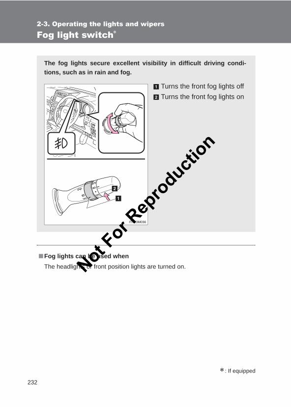
232
2-3. Operating the lights and wipers
LC150_OM_OM60J77E_(AE)
Fog light switch∗
∗: If equipped
■Fog lights can be used whenThe headlights or front position lights are turned on.
The fog lights secure excellent visibility in difficult driving condi-tions, such as in rain and fog.
Turns the front fog lights offTurns the front fog lights on
Not For R
epro
duction
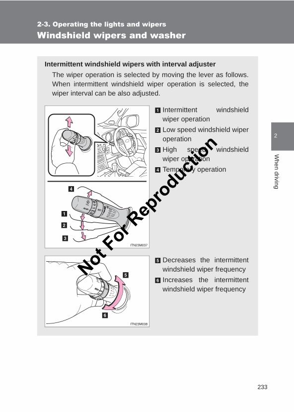
233
2-3. Operating the lights and wipers
2
When driving
LC150_OM_OM60J77E_(AE)
Windshield wipers and washer
Intermittent windshield wipers with interval adjusterThe wiper operation is selected by moving the lever as follows.When intermittent windshield wiper operation is selected, thewiper interval can be also adjusted.
Intermittent windshieldwiper operationLow speed windshield wiperoperationHigh speed windshieldwiper operationTemporary operation
Decreases the intermittentwindshield wiper frequencyIncreases the intermittentwindshield wiper frequency
Not For R
epro
duction
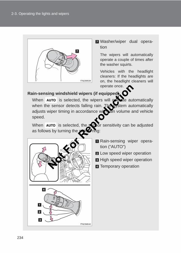
234
2-3. Operating the lights and wipers
LC150_OM_OM60J77E_(AE)
Washer/wiper dual opera-tion
The wipers will automaticallyoperate a couple of times afterthe washer squirts.
Vehicles with the headlightcleaners: If the headlights areon, the headlight cleaners willoperate once.
Rain-sensing windshield wipers (if equipped)When is selected, the wipers will operate automaticallywhen the sensor detects falling rain. The system automaticallyadjusts wiper timing in accordance with rain volume and vehiclespeed.
When is selected, the sensor sensitivity can be adjustedas follows by turning the switch ring:
Rain-sensing wiper opera-tion (“AUTO”)Low speed wiper operationHigh speed wiper operationTemporary operationNot F
or Rep
roducti
on
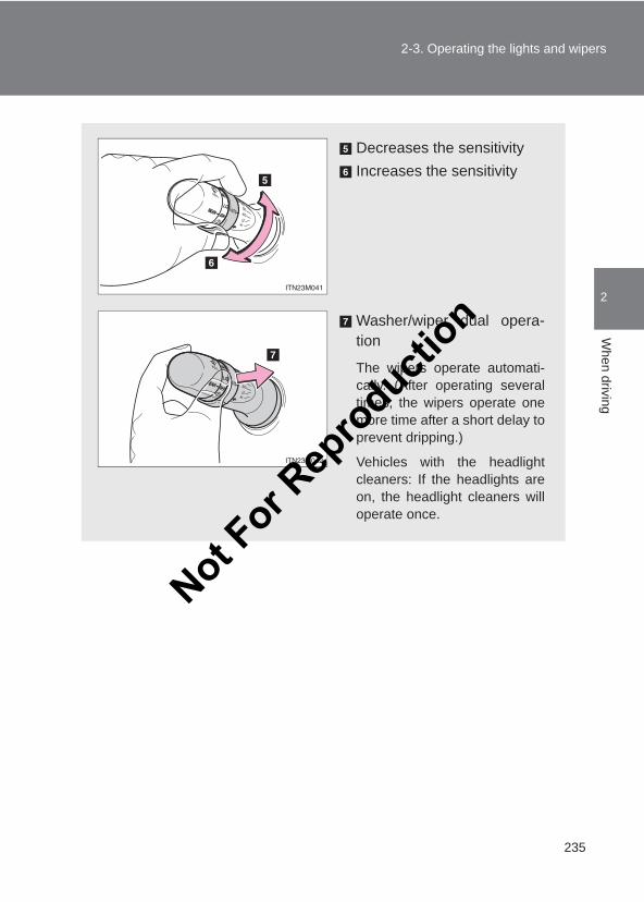
235
2-3. Operating the lights and wipers
2
When driving
LC150_OM_OM60J77E_(AE)
Decreases the sensitivityIncreases the sensitivity
Washer/wiper dual opera-tion
The wipers operate automati-cally. (After operating severaltimes, the wipers operate onemore time after a short delay toprevent dripping.)
Vehicles with the headlightcleaners: If the headlights areon, the headlight cleaners willoperate once.
Not For R
epro
duction
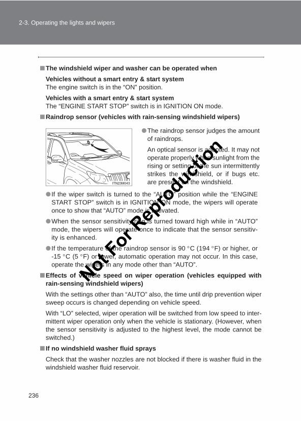
236
2-3. Operating the lights and wipers
LC150_OM_OM60J77E_(AE)
■The windshield wiper and washer can be operated whenVehicles without a smart entry & start systemThe engine switch is in the “ON” position.
Vehicles with a smart entry & start systemThe “ENGINE START STOP” switch is in IGNITION ON mode.
■Raindrop sensor (vehicles with rain-sensing windshield wipers)
● If the wiper switch is turned to the “AUTO” position while the “ENGINESTART STOP” switch is in IGNITION ON mode, the wipers will operateonce to show that “AUTO” mode is activated.
●When the sensor sensitivity ring is turned toward high while in “AUTO”mode, the wipers will operate once to indicate that the sensor sensitiv-ity is enhanced.
● If the temperature of the raindrop sensor is 90 °C (194 °F) or higher, or-15 °C (5 °F) or lower, automatic operation may not occur. In this case,operate the wipers in any mode other than “AUTO”.
■Effects of vehicle speed on wiper operation (vehicles equipped withrain-sensing windshield wipers)With the settings other than “AUTO” also, the time until drip prevention wipersweep occurs is changed depending on vehicle speed.
With “LO” selected, wiper operation will be switched from low speed to inter-mittent wiper operation only when the vehicle is stationary. (However, whenthe sensor sensitivity is adjusted to the highest level, the mode cannot beswitched.)
■ If no windshield washer fluid spraysCheck that the washer nozzles are not blocked if there is washer fluid in thewindshield washer fluid reservoir.
●The raindrop sensor judges the amountof raindrops.
An optical sensor is adopted. It may notoperate properly when sunlight from therising or setting of the sun intermittentlystrikes the windshield, or if bugs etc.are present on the windshield.
Not For R
epro
duction
237
2-3. Operating the lights and wipers
2
When driving
LC150_OM_OM60J77E_(AE)
CAUTION
■Caution regarding the use of windshield wipers in “AUTO” modeThe windshield wipers may operate unexpectedly if the sensor is touched orthe windshield is subject to vibration in “AUTO” mode. Take care that yourfingers or anything else does not become caught in the windshield wipers.
NOTICE
■When the windshield is dryDo not use the wipers, as they may damage the windshield.
■When the washer fluid tank is emptyDo not operate the switch continually as the washer fluid pump may over-heat.
■When there is no washer fluid spray from the nozzleDamage to the washer fluid pump may be caused if the lever is pulledtoward you and held continually.
■When a nozzle becomes blockedDo not try to clear it with a pin or other object. The nozzle will be damaged.
Not For R
epro
duction
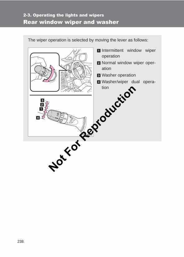
238
2-3. Operating the lights and wipers
LC150_OM_OM60J77E_(AE)
Rear window wiper and washer
The wiper operation is selected by moving the lever as follows:
Intermittent window wiperoperationNormal window wiper oper-ationWasher operationWasher/wiper dual opera-tion
Not For R
epro
duction
239
2-3. Operating the lights and wipers
2
When driving
LC150_OM_OM60J77E_(AE)
■The rear window wiper and washer can be operated when●Vehicles without a smart entry & start system
The engine switch is in the “ON” position.
Vehicles with a smart entry & start systemThe “ENGINE START STOP” switch is in IGNITION ON mode.
●The glass hatch (if equipped) is closed.
■ If no washer fluid spraysCheck that the washer nozzles are not blocked if there is washer fluid in thewasher fluid reservoir.
NOTICE
■When the rear window is dryDo not use the wiper, as it may damage the rear window.
■When the washer fluid tank is emptyDo not operate the switch continually as the washer fluid pump may over-heat.
Not For R
epro
duction
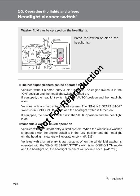
240
2-3. Operating the lights and wipers
LC150_OM_OM60J77E_(AE)
Headlight cleaner switch∗
∗: If equipped
■The headlight cleaners can be operated whenVehicles without a smart entry & start system: The engine switch is in the“ON” position and the headlight switch is turned on.If equipped, the headlight switch is in the “AUTO” position and the headlightis on.
Vehicles with a smart entry & start system: The “ENGINE START STOP”switch is in IGNITION ON mode and the headlight switch is turned on.
If equipped, the headlight switch is in the “AUTO” position and the headlightis on.
■Windshield washer linked operationVehicles without a smart entry & start system: When the windshield washeris operated with the engine switch is in the “ON” position and the headlighton, the headlight cleaners will operate once. (→P. 233)
Vehicles with a smart entry & start system: When the windshield washer isoperated with the “ENGINE START STOP” switch is in IGNITION ON modeand the headlight on, the headlight cleaners will operate once. (→P. 233)
Washer fluid can be sprayed on the headlights.
Press the switch to clean theheadlights.
Not For R
epro
duction
241
2-3. Operating the lights and wipers
2
When driving
LC150_OM_OM60J77E_(AE)
NOTICE
■When the washer fluid tank is emptyDo not press the switch continually as the washer fluid pump may overheat.
Not For R
epro
duction
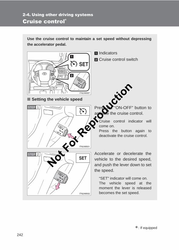
242
LC150_OM_OM60J77E_(AE)
2-4. Using other driving systems
Cruise control∗
∗: If equipped
Use the cruise control to maintain a set speed without depressingthe accelerator pedal.
IndicatorsCruise control switch
■ Setting the vehicle speed
Press the “ON-OFF” button toactivate the cruise control.
Cruise control indicator willcome on.Press the button again todeactivate the cruise control.
Accelerate or decelerate thevehicle to the desired speed,and push the lever down to setthe speed.
“SET” indicator will come on.The vehicle speed at themoment the lever is releasedbecomes the set speed.
STEP 1
STEP 2
Not For R
epro
duction
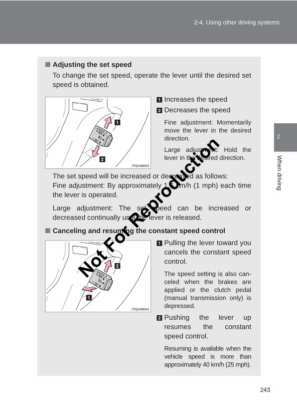
243
2-4. Using other driving systems
2
When driving
LC150_OM_OM60J77E_(AE)
■ Adjusting the set speedTo change the set speed, operate the lever until the desired setspeed is obtained.
Increases the speedDecreases the speed
Fine adjustment: Momentarilymove the lever in the desireddirection.
Large adjustment: Hold thelever in the desired direction.
The set speed will be increased or decreased as follows:Fine adjustment: By approximately 1.6 km/h (1 mph) each timethe lever is operated.
Large adjustment: The set speed can be increased ordecreased continually until the lever is released.
■ Canceling and resuming the constant speed controlPulling the lever toward youcancels the constant speedcontrol.
The speed setting is also can-celed when the brakes areapplied or the clutch pedal(manual transmission only) isdepressed.
Pushing the lever upresumes the constantspeed control.
Resuming is available when thevehicle speed is more thanapproximately 40 km/h (25 mph).
Not For R
epro
duction
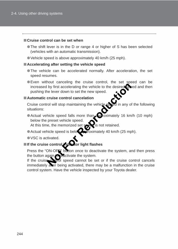
244
2-4. Using other driving systems
LC150_OM_OM60J77E_(AE)
■Cruise control can be set when●The shift lever is in the D or range 4 or higher of S has been selected
(vehicles with an automatic transmission).
●Vehicle speed is above approximately 40 km/h (25 mph).
■Accelerating after setting the vehicle speed●The vehicle can be accelerated normally. After acceleration, the set
speed resumes.
●Even without canceling the cruise control, the set speed can beincreased by first accelerating the vehicle to the desired speed and thenpushing the lever down to set the new speed.
■Automatic cruise control cancelationCruise control will stop maintaining the vehicle speed in any of the followingsituations:
●Actual vehicle speed falls more than approximately 16 km/h (10 mph)below the preset vehicle speed.At this time, the memorized set speed is not retained.
●Actual vehicle speed is below approximately 40 km/h (25 mph).
●VSC is activated.
■ If the cruise control indicator light flashesPress the “ON-OFF” button once to deactivate the system, and then pressthe button again to reactivate the system.If the cruise control speed cannot be set or if the cruise control cancelsimmediately after being activated, there may be a malfunction in the cruisecontrol system. Have the vehicle inspected by your Toyota dealer.
Not For R
epro
duction
245
2-4. Using other driving systems
2
When driving
LC150_OM_OM60J77E_(AE)
CAUTION
■To avoid operating the cruise control by mistakeSwitch the cruise control off using the “ON-OFF” button when not in use.
■Situations unsuitable for cruise controlDo not use cruise control in any of the following situations.Doing so may result in loss of control and could cause an accident resultingin death or serious injury.
● In heavy traffic
●On roads with sharp bends
●On winding roads
●On slippery roads, such as those covered with rain, ice or snow
●On steep hillsVehicle speed may exceed the set speed when driving down a steep hill.
●When your vehicle is towing a trailer or during emergency towing
Not For R
epro
duction
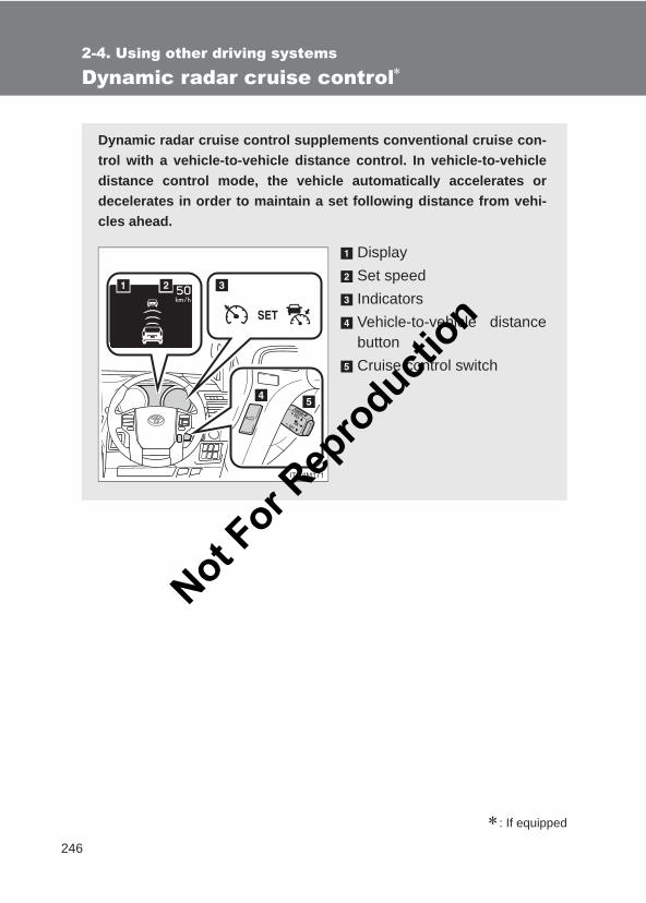
246
2-4. Using other driving systems
LC150_OM_OM60J77E_(AE)
Dynamic radar cruise control∗
∗: If equipped
Dynamic radar cruise control supplements conventional cruise con-trol with a vehicle-to-vehicle distance control. In vehicle-to-vehicledistance control mode, the vehicle automatically accelerates ordecelerates in order to maintain a set following distance from vehi-cles ahead.
DisplaySet speedIndicatorsVehicle-to-vehicle distancebuttonCruise control switch
Not For R
epro
duction
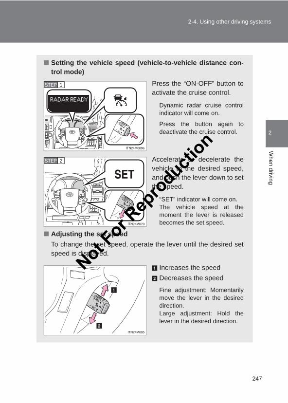
247
2-4. Using other driving systems
2
When driving
LC150_OM_OM60J77E_(AE)
■ Setting the vehicle speed (vehicle-to-vehicle distance con-trol mode)
Press the “ON-OFF” button toactivate the cruise control.
Dynamic radar cruise controlindicator will come on.
Press the button again todeactivate the cruise control.
Accelerate or decelerate thevehicle to the desired speed,and push the lever down to setthe speed.
“SET” indicator will come on.The vehicle speed at themoment the lever is releasedbecomes the set speed.
■ Adjusting the set speedTo change the set speed, operate the lever until the desired setspeed is displayed.
Increases the speedDecreases the speed
Fine adjustment: Momentarilymove the lever in the desireddirection.Large adjustment: Hold thelever in the desired direction.
STEP 1
STEP 2
Not For R
epro
duction
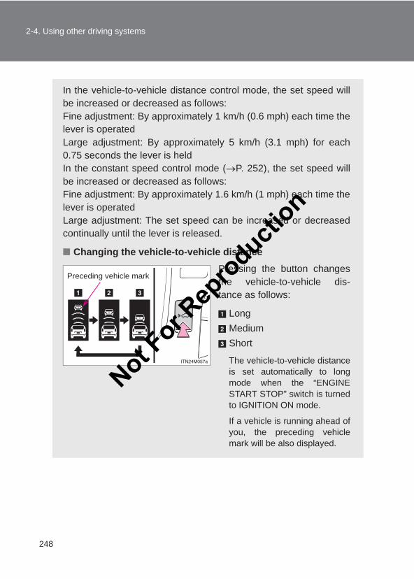
248
2-4. Using other driving systems
LC150_OM_OM60J77E_(AE)
In the vehicle-to-vehicle distance control mode, the set speed willbe increased or decreased as follows:Fine adjustment: By approximately 1 km/h (0.6 mph) each time thelever is operatedLarge adjustment: By approximately 5 km/h (3.1 mph) for each0.75 seconds the lever is heldIn the constant speed control mode (→P. 252), the set speed willbe increased or decreased as follows:Fine adjustment: By approximately 1.6 km/h (1 mph) each time thelever is operatedLarge adjustment: The set speed can be increased or decreasedcontinually until the lever is released.
■ Changing the vehicle-to-vehicle distancePressing the button changesthe vehicle-to-vehicle dis-tance as follows:
LongMediumShort
The vehicle-to-vehicle distanceis set automatically to longmode when the “ENGINESTART STOP” switch is turnedto IGNITION ON mode.
If a vehicle is running ahead ofyou, the preceding vehiclemark will be also displayed.
Preceding vehicle mark
Not For R
epro
duction
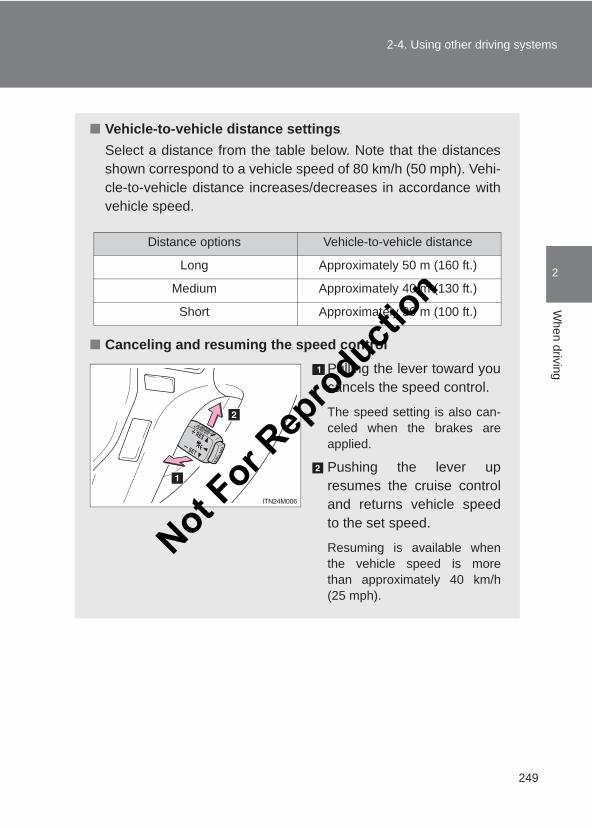
249
2-4. Using other driving systems
2
When driving
LC150_OM_OM60J77E_(AE)
■ Vehicle-to-vehicle distance settingsSelect a distance from the table below. Note that the distancesshown correspond to a vehicle speed of 80 km/h (50 mph). Vehi-cle-to-vehicle distance increases/decreases in accordance withvehicle speed.
■ Canceling and resuming the speed controlPulling the lever toward youcancels the speed control.
The speed setting is also can-celed when the brakes areapplied.
Pushing the lever upresumes the cruise controland returns vehicle speedto the set speed.
Resuming is available whenthe vehicle speed is morethan approximately 40 km/h(25 mph).
Distance options Vehicle-to-vehicle distance
Long Approximately 50 m (160 ft.)
Medium Approximately 40 m (130 ft.)
Short Approximately 30 m (100 ft.)
Not For R
epro
duction
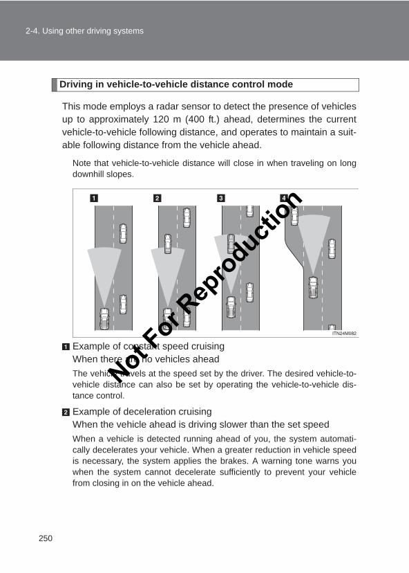
250
2-4. Using other driving systems
LC150_OM_OM60J77E_(AE)
Driving in vehicle-to-vehicle distance control mode
This mode employs a radar sensor to detect the presence of vehiclesup to approximately 120 m (400 ft.) ahead, determines the currentvehicle-to-vehicle following distance, and operates to maintain a suit-able following distance from the vehicle ahead.
Note that vehicle-to-vehicle distance will close in when traveling on longdownhill slopes.
Example of constant speed cruisingWhen there are no vehicles aheadThe vehicle travels at the speed set by the driver. The desired vehicle-to-vehicle distance can also be set by operating the vehicle-to-vehicle dis-tance control.
Example of deceleration cruisingWhen the vehicle ahead is driving slower than the set speedWhen a vehicle is detected running ahead of you, the system automati-cally decelerates your vehicle. When a greater reduction in vehicle speedis necessary, the system applies the brakes. A warning tone warns youwhen the system cannot decelerate sufficiently to prevent your vehiclefrom closing in on the vehicle ahead.
Not For R
epro
duction
251
2-4. Using other driving systems
2
When driving
LC150_OM_OM60J77E_(AE)
Example of follow-up cruising When following a vehicle driving slower than the set speedThe system continues follow-up cruising while adjusting for changes in thespeed of the vehicle ahead in order to maintain the vehicle-to-vehicle dis-tance set by the driver.
Example of acceleration When there are no longer any vehicles ahead driving slower thanthe set speedThe system accelerates until the set speed is reached. The system thenreturns to constant speed cruising.
Approach warning
When your vehicle is too close to a vehicle ahead, and sufficientautomatic deceleration via the cruise control is not possible, the dis-play will flash and the buzzer will sound to alert the driver. An exam-ple of this would be if another driver cuts in front of you while you arefollowing a vehicle. Apply the brakes to ensure an appropriate vehi-cle-to-vehicle distance.
■Warnings may not occur whenIn the following instances, there is a possibility that the warnings will not occur:
●When the speed of the vehicle ahead matches or exceeds your vehiclespeed
●When the vehicle ahead is traveling at an extremely slow speed
● Immediately after the cruise control speed was set
●At the instant the accelerator is applied
Not For R
epro
duction
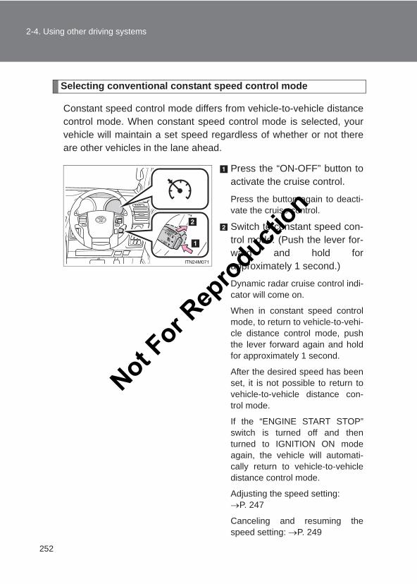
252
2-4. Using other driving systems
LC150_OM_OM60J77E_(AE)
Selecting conventional constant speed control mode
Constant speed control mode differs from vehicle-to-vehicle distancecontrol mode. When constant speed control mode is selected, yourvehicle will maintain a set speed regardless of whether or not thereare other vehicles in the lane ahead.
Press the “ON-OFF” button toactivate the cruise control.
Press the button again to deacti-vate the cruise control.
Switch to constant speed con-trol mode. (Push the lever for-ward and hold forapproximately 1 second.)
Dynamic radar cruise control indi-cator will come on.
When in constant speed controlmode, to return to vehicle-to-vehi-cle distance control mode, pushthe lever forward again and holdfor approximately 1 second.
After the desired speed has beenset, it is not possible to return tovehicle-to-vehicle distance con-trol mode.
If the “ENGINE START STOP”switch is turned off and thenturned to IGNITION ON modeagain, the vehicle will automati-cally return to vehicle-to-vehicledistance control mode.
Adjusting the speed setting: →P. 247
Canceling and resuming thespeed setting: →P. 249
Not For R
epro
duction
253
2-4. Using other driving systems
2
When driving
LC150_OM_OM60J77E_(AE)
■Dynamic radar cruise can be set when●The shift lever is in the D or range 4 or higher of S has been selected.
●Vehicle speed is above approximately 50 km/h (30 mph).
■Accelerating after setting the vehicle speedThe vehicle can be accelerated normally. After acceleration, the set speedresumes. However, during vehicle-to-vehicle distance control mode, thevehicle speed may decrease below the set speed in order to maintain thedistance to the vehicle ahead.
■Automatic cancelation of vehicle-to-vehicle distance controlVehicle-to-vehicle distance control driving is automatically canceled in thefollowing situations:
●Actual vehicle speed falls below approximately 40 km/h (25 mph).
●VSC is activated.
●The sensor cannot operate correctly because it is covered in some way.
●The windshield wipers are operating at high speed (when the wiperswitch is set to the “AUTO” mode or the high speed wiper operation posi-tion).
●When second start mode is set.
●Bad weather causes the detection function to become extremely unsta-ble.
If vehicle-to-vehicle distance control driving is automatically canceled for anyother reason, there may be a malfunction in the system. Contact your Toyotadealer.
■Automatic cancelation of constant speed controlThe cruise control will stop maintaining the vehicle speed in the following sit-uations:
●Actual vehicle speed is more than approximately 16 km/h (10 mph)below the set vehicle speed.At this time, the memorized set speed is not retained.
●Actual vehicle speed falls below approximately 40 km/h (25 mph).
●VSC is activated.
Not For R
epro
duction
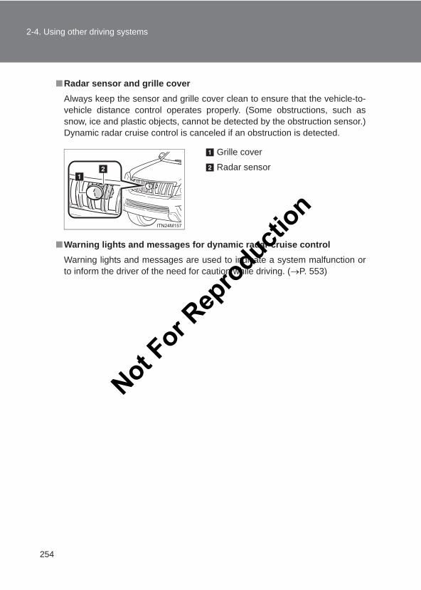
254
2-4. Using other driving systems
LC150_OM_OM60J77E_(AE)
■Radar sensor and grille coverAlways keep the sensor and grille cover clean to ensure that the vehicle-to-vehicle distance control operates properly. (Some obstructions, such assnow, ice and plastic objects, cannot be detected by the obstruction sensor.)Dynamic radar cruise control is canceled if an obstruction is detected.
■Warning lights and messages for dynamic radar cruise controlWarning lights and messages are used to indicate a system malfunction orto inform the driver of the need for caution while driving. (→P. 553)
Grille cover
Radar sensor
Not For R
epro
duction
255
2-4. Using other driving systems
2
When driving
LC150_OM_OM60J77E_(AE)
CAUTION
■Before using dynamic radar cruise controlDo not overly rely on vehicle-to-vehicle distance control. Be aware of the set speed. If automatic deceleration/acceleration is notappropriate, adjust the vehicle speed, as well as the distance between yourvehicle and vehicles ahead by applying the brakes etc.
■Cautions regarding the driving assist systemsObserve the following precautions.Failure to do so may cause an accident resulting in death or serious injury.
●Assisting the driver to measure following distanceThe dynamic radar cruise control is only intended to help the driver indetermining the following distance between the driver’s own vehicle and adesignated vehicle traveling ahead. It is not a mechanism that allows care-less or inattentive driving, and it is not a system that can assist the driver inlow-visibility conditions. It is still necessary for driver to pay close attentionto the vehicle’s surroundings.
●Assisting the driver to judge proper following distanceThe dynamic radar cruise control determines whether the following dis-tance between the driver’s own vehicle and a designated vehicle travelingahead is appropriate or not. It is not capable of making any other type ofjudgement. Therefore, it is absolutely necessary for the driver to remainvigilant and to determine whether or not there is a possibility of danger inany given situation.
●Assisting the driver to operate the vehicleThe dynamic radar cruise control has no capability to prevent or avoid acollision with a vehicle traveling ahead. Therefore, if there is ever any dan-ger, the driver must take immediate and direct control of the vehicle andact appropriately in order to ensure the safety of all involved.
Not For R
epro
duction
256
2-4. Using other driving systems
LC150_OM_OM60J77E_(AE)
CAUTION
■To avoid inadvertent cruise control activationSwitch the cruise control off using the “ON-OFF” button when not in use.
■Situations unsuitable for dynamic radar cruise controlDo not use dynamic radar cruise control in any of the following situations.
Doing so may result in inappropriate speed control and could cause an acci-dent resulting in death or serious injury.
● In heavy traffic
●On roads with sharp bends
●On winding roads
●On slippery roads, such as those covered with rain, ice or snow
●On steep downhills, or where there are sudden changes between sharp upand down gradientsVehicle speed may exceed the set speed when driving down a steep hill.
●At entrances to expressways
●When weather conditions are bad enough that they may prevent the sen-sors from functioning correctly (fog, snow, sandstorm, heavy rain, etc.)
●When an approach warning buzzer is heard often
●When your vehicle is towing a trailer or during emergency towing
● In traffic conditions where the vehicle is repeatedly sped up and sloweddown at frequent intervalsNot F
or Rep
roducti
on
257
2-4. Using other driving systems
2
When driving
LC150_OM_OM60J77E_(AE)
CAUTION
■When the sensor may not be correctly detecting the vehicle aheadApply the brakes as necessary when any of the following types of vehiclesare in front of you.As the sensor may not be able to correctly detect these types of vehicles,the approach warning (→P. 251) will not be activated, and a fatal or seriousaccident may result.
●Vehicles that cut in suddenly
●Vehicles traveling at low speeds
●Vehicles that are not moving
●Vehicles with small rear ends (trailers with no load on board etc.)
●Motorcycles traveling in the same lane
■Conditions under which the vehicle-to-vehicle distance control maynot function correctlyApply the brakes as necessary in the following conditions as the radar sen-sor may not be able to correctly detect vehicles ahead, and a fatal or seriousaccident may result:
●When water or snow thrown up by the surrounding vehicles hinders thefunctioning of the sensor
●When your vehicle is pointing upwards (caused by a heavy load in the lug-gage compartment etc.)
●When the road curves or when the lanes are narrow
●When steering wheel operation or your position in the lane is unstable
●When the vehicle ahead of you decelerates suddenly
●Excessive exhaust gas (black smoke) is coming from the vehicle ahead orother vehicles around you, obscuring your front view
●The rear section of the vehicle ahead is extremely dirty
●The vehicle ahead has higher ground clearance
Not For R
epro
duction
258
2-4. Using other driving systems
LC150_OM_OM60J77E_(AE)
CAUTION
■To ensure the sensor functions correctlyDo not do the following to the sensor or grille as doing so may cause thesensor not to function correctly and could result in an accident:
●Sticking or attaching anything to them
●Leaving them dirty
●Disassembling or subjecting them to strong shocks
●Modifying or painting them
●Replacing them with non-genuine parts
■Handling the radar sensorObserve the following to ensure the cruise control system can function effec-tively.
Otherwise, the system may not function correctly and could result in an acci-dent.
●Keep the sensor and grille cover clean at all times.Clean the sensor and grille cover with a soft cloth so you do not mark ordamage them.
●Do not subject the sensor or surrounding area to a strong impact. If the sensor moves even slightly off position, the system may malfunction.If the sensor or surrounding area is subject to a strong impact, alwayshave the area inspected and adjusted by your Toyota dealer.
●Do not disassemble the sensor.
●Do not attach accessories or stickers to the sensor, grille cover or sur-rounding area.
●Do not modify or paint the sensor and grille cover.
●Do not replace them with non-genuine parts.
Not For R
epro
duction
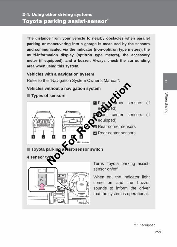
259
2-4. Using other driving systems
2
When driving
LC150_OM_OM60J77E_(AE)
Toyota parking assist-sensor∗
∗: If equipped
The distance from your vehicle to nearby obstacles when parallelparking or maneuvering into a garage is measured by the sensorsand communicated via the indicator (non-optitron type meters), themulti-information display (optitron type meters), the accessorymeter (if equipped), and a buzzer. Always check the surroundingarea when using this system.
Vehicles with a navigation systemRefer to the “Navigation System Owner’s Manual”.
Vehicles without a navigation system■ Types of sensors
Front corner sensors (ifequipped)Front center sensors (ifequipped)Rear corner sensorsRear center sensors
■ Toyota parking assist-sensor switch
4 sensor typeTurns Toyota parking assist-sensor on/off
When on, the indicator lightcome on and the buzzersounds to inform the driverthat the system is operational.
Not For R
epro
duction
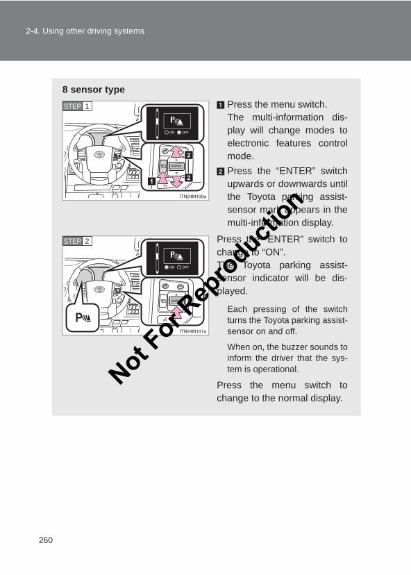
260
2-4. Using other driving systems
LC150_OM_OM60J77E_(AE)
8 sensor typePress the menu switch.The multi-information dis-play will change modes toelectronic features controlmode.Press the “ENTER” switchupwards or downwards untilthe Toyota parking assist-sensor mark appears in themulti-information display.
Press the “ENTER” switch tochange to “ON”.The Toyota parking assist-sensor indicator will be dis-played.
Each pressing of the switchturns the Toyota parking assist-sensor on and off.
When on, the buzzer sounds toinform the driver that the sys-tem is operational.
Press the menu switch tochange to the normal display.
STEP 1
STEP 2
Not For R
epro
duction
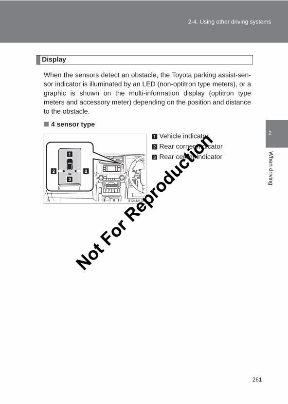
261
2-4. Using other driving systems
2
When driving
LC150_OM_OM60J77E_(AE)
Display
When the sensors detect an obstacle, the Toyota parking assist-sen-sor indicator is illuminated by an LED (non-optitron type meters), or agraphic is shown on the multi-information display (optitron typemeters and accessory meter) depending on the position and distanceto the obstacle.
■ 4 sensor typeVehicle indicatorRear corner indicatorRear center indicator
Not For R
epro
duction
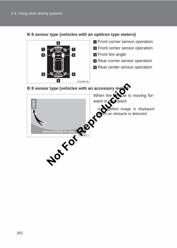
262
2-4. Using other driving systems
LC150_OM_OM60J77E_(AE)
■ 8 sensor type (vehicles with an optitron type meters)Front corner sensor operationFront center sensor operationFront tire angleRear corner sensor operationRear center sensor operation
■ 8 sensor type (vehicles with an accessory meter)When the vehicle is moving for-ward or backward
A simplified image is displayedwhen an obstacle is detected.
Not For R
epro
duction
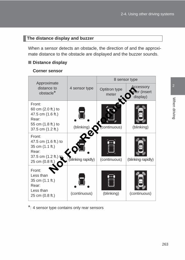
263
2-4. Using other driving systems
2
When driving
LC150_OM_OM60J77E_(AE)
The distance display and buzzer
When a sensor detects an obstacle, the direction of and the approxi-mate distance to the obstacle are displayed and the buzzer sounds.
■ Distance display
Corner sensor
*: 4 sensor type contains only rear sensors
Approximate distance to obstacle*
4 sensor type
8 sensor type
Optitron type meter
Accessory meter (insert
display)
Front:60 cm (2.0 ft.) to 47.5 cm (1.6 ft.)Rear:55 cm (1.8 ft.) to 37.5 cm (1.2 ft.) (blinking) (continuous) (blinking)
Front:47.5 cm (1.6 ft.) to 35 cm (1.1 ft.)Rear:37.5 cm (1.2 ft.) to 25 cm (0.8 ft.) (blinking rapidly) (continuous) (blinking rapidly)
Front:Less than 35 cm (1.1 ft.)Rear:Less than 25 cm (0.8 ft.) (continuous) (blinking) (continuous)
Not For R
epro
duction
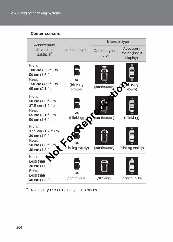
264
2-4. Using other driving systems
LC150_OM_OM60J77E_(AE)
Center sensors
*: 4 sensor type contains only rear sensors
Approximate distance to obstacle*
4 sensor type
8 sensor type
Optitron type meter
Accessory meter (insert
display)
Front:100 cm (3.3 ft.) to 50 cm (1.6 ft.)Rear:150 cm (4.9 ft.) to 65 cm (2.1 ft.)
(blinking slowly) (continuous) (blinking
slowly)
Front:50 cm (1.6 ft.) to 37.5 cm (1.2 ft.)Rear:65 cm (2.1 ft.) to 50 cm (1.6 ft.) (blinking) (continuous) (blinking)
Front:37.5 cm (1.2 ft.) to 30 cm (1.0 ft.)Rear:50 cm (1.6 ft.) to 40 cm (1.3 ft.) (blinking rapidly) (continuous) (blinking rapidly)
Front:Less than 30 cm (1.0 ft.)Rear:Less than 40 cm (1.3 ft.) (continuous) (blinking) (continuous)
Not For R
epro
duction
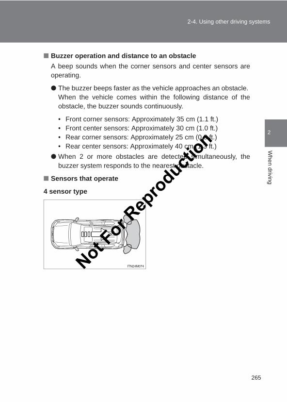
265
2-4. Using other driving systems
2
When driving
LC150_OM_OM60J77E_(AE)
■ Buzzer operation and distance to an obstacleA beep sounds when the corner sensors and center sensors areoperating.
● The buzzer beeps faster as the vehicle approaches an obstacle. When the vehicle comes within the following distance of theobstacle, the buzzer sounds continuously.
• Front corner sensors: Approximately 35 cm (1.1 ft.)• Front center sensors: Approximately 30 cm (1.0 ft.)• Rear corner sensors: Approximately 25 cm (0.8 ft.)• Rear center sensors: Approximately 40 cm (1.3 ft.)
● When 2 or more obstacles are detected simultaneously, thebuzzer system responds to the nearest obstacle.
■ Sensors that operate
4 sensor type
Not For R
epro
duction
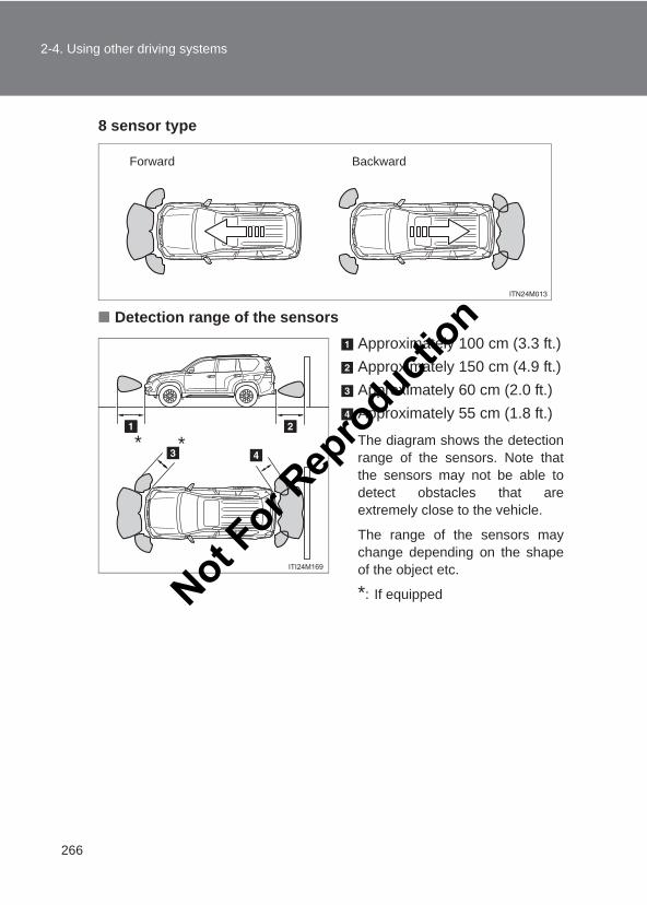
266
2-4. Using other driving systems
LC150_OM_OM60J77E_(AE)
8 sensor type
■ Detection range of the sensorsApproximately 100 cm (3.3 ft.)Approximately 150 cm (4.9 ft.)Approximately 60 cm (2.0 ft.)Approximately 55 cm (1.8 ft.)
The diagram shows the detectionrange of the sensors. Note thatthe sensors may not be able todetect obstacles that areextremely close to the vehicle.
The range of the sensors maychange depending on the shapeof the object etc.
*: If equipped
Forward Backward
* *
Not For R
epro
duction
267
2-4. Using other driving systems
2
When driving
LC150_OM_OM60J77E_(AE)
■Sensor detection information●Certain vehicle conditions and the surrounding environment may affect
the ability of a sensor to correctly detect an obstacle. Particular instanceswhere this may occur are listed below.
• There is dirt, snow or ice on a sensor.• A sensor is frozen.• A sensor is covered in any way.• The vehicle is leaning considerably to one side.• On an extremely bumpy road, on an incline, on gravel, or on grass.• The vicinity of the vehicle is noisy due to vehicle horns, motorcycle
engines, air brakes of large vehicles, or other loud noises producingultrasonic waves.
• There is another vehicle equipped with parking assist sensors in thevicinity.
• A sensor is coated with a sheet of spray or heavy rain.• The vehicle is equipped with a fender pole or radio antenna.• Towing eyelets are installed.• A bumper or sensor receives a strong impact.• The vehicle is approaching a tall or right-angled curb.• In harsh sunlight or intense cold weather.• A non-genuine Toyota suspension (lowered suspension etc.) is
installed.In addition to the examples above, there are instances in which, because oftheir shape, signs and other objects may be judged by a sensor to be closerthan they are.
●The shape of the obstacle may prevent a sensor from detecting it. Payparticular attention to the following obstacles:
• Wires, fences, ropes, etc.• Cotton, snow and other materials that absorb sound waves• Sharply-angled objects• Low obstacles• Tall obstacles with upper sections projecting outwards in the direction
of your vehicle
Not For R
epro
duction
268
2-4. Using other driving systems
LC150_OM_OM60J77E_(AE)
■ If the vehicle indicator remains on while the rear corner and rear centerindicators flash and the malfunction beep sounds for approximately 8seconds. (vehicles with a non- optitron type meter)Have the vehicle inspected by your Toyota dealer.
■ If the vehicle indicator and the rear corner and rear center indicatorsflash and the malfunction beep sounds for approximately 8 seconds.(vehicles with a non- optitron type meter)Clean the sensors with soft cloth.
■ If a message is displayed (vehicles with an optitron type meter)→P. 553
■Customization that can be configured at Toyota dealerSetting of buzzer volume can be changed.(Customizable features →P. 632)
CAUTION
■Caution when using the Toyota parking assist-sensorObserve the following precautions.Failing to do so may result in the vehicle being unable to be driven safelyand possibly cause an accident.
●Do not use the sensor at speeds in excess of 10 km/h (6 mph).
●Do not attach any accessories within the sensor range.
NOTICE
■Notes when washing the vehicleDo not apply intensive bursts of water or steam to the sensor area.Doing so may result in the sensor malfunctioning.
Not For R
epro
duction
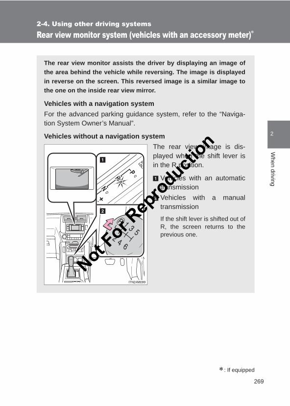
269
2-4. Using other driving systems
2
When driving
LC150_OM_OM60J77E_(AE)
Rear view monitor system (vehicles with an accessory meter)∗
∗: If equipped
The rear view monitor assists the driver by displaying an image ofthe area behind the vehicle while reversing. The image is displayedin reverse on the screen. This reversed image is a similar image tothe one on the inside rear view mirror.
Vehicles with a navigation systemFor the advanced parking guidance system, refer to the “Naviga-tion System Owner’s Manual”.
Vehicles without a navigation systemThe rear view image is dis-played when the shift lever isin the R position.
Vehicles with an automatictransmissionVehicles with a manualtransmission
If the shift lever is shifted out ofR, the screen returns to theprevious one.
Not For R
epro
duction
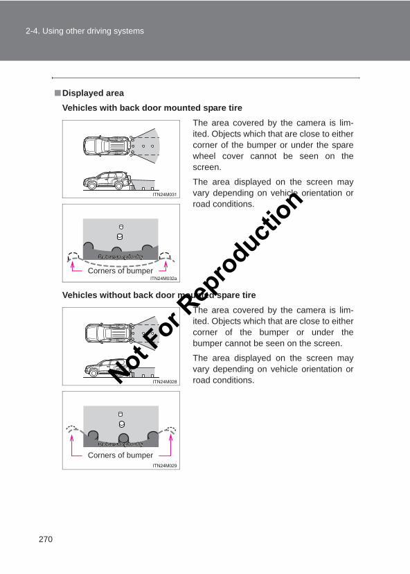
270
2-4. Using other driving systems
LC150_OM_OM60J77E_(AE)
■Displayed areaVehicles with back door mounted spare tire
Vehicles without back door mounted spare tire
The area covered by the camera is lim-ited. Objects which that are close to eithercorner of the bumper or under the sparewheel cover cannot be seen on thescreen.
The area displayed on the screen mayvary depending on vehicle orientation orroad conditions.
Corners of bumper
The area covered by the camera is lim-ited. Objects which that are close to eithercorner of the bumper or under thebumper cannot be seen on the screen.
The area displayed on the screen mayvary depending on vehicle orientation orroad conditions.
Corners of bumper
Not For R
epro
duction
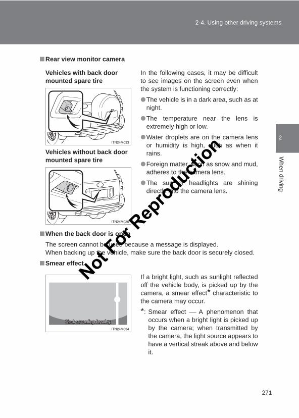
271
2-4. Using other driving systems
2
When driving
LC150_OM_OM60J77E_(AE)
■Rear view monitor camera
■When the back door is openThe screen cannot be used because a message is displayed.When backing up the vehicle, make sure the back door is securely closed.
■Smear effect
Vehicles with back door mounted spare tire
Vehicles without back door mounted spare tire
In the following cases, it may be difficultto see images on the screen even whenthe system is functioning correctly:
●The vehicle is in a dark area, such as atnight.
●The temperature near the lens isextremely high or low.
●Water droplets are on the camera lensor humidity is high, such as when itrains.
●Foreign matter, such as snow and mud,adheres to the camera lens.
●The sun or headlights are shiningdirectly into the camera lens.
If a bright light, such as sunlight reflectedoff the vehicle body, is picked up by thecamera, a smear effect* characteristic tothe camera may occur.
*: Smear effect A phenomenon thatoccurs when a bright light is picked upby the camera; when transmitted bythe camera, the light source appears tohave a vertical streak above and belowit.
Not For R
epro
duction
272
2-4. Using other driving systems
LC150_OM_OM60J77E_(AE)
CAUTION
■When using the rear view monitor systemObserve the following precautions to avoid an accident that could result indeath or serious injuries:
●Never depend solely on the monitor system when reversing.
●Always check visually and with the mirrors to confirm your intended path isclear.
●Depicted distances between objects and flat surfaces differ from actualdistances.
■Conditions which may affect the rear view monitor system● If the back of the vehicle has been hit, the camera’s position and mounting
angle may have changed. Have the vehicle inspected by your Toyotadealer.
●Rapid temperature changes, such as when hot water is poured on thevehicle in cold weather, may cause the system to function abnormally.
● If the camera lens is extremely dirty, it cannot transmit a clear image.Rinse with water and wipe with a soft cloth. If the camera lens is extremelydirty, wash with a mild cleanser and rinse.
●The displayed image may be darker and moving images may be slightlydistorted when the system is cold.
Not For R
epro
duction
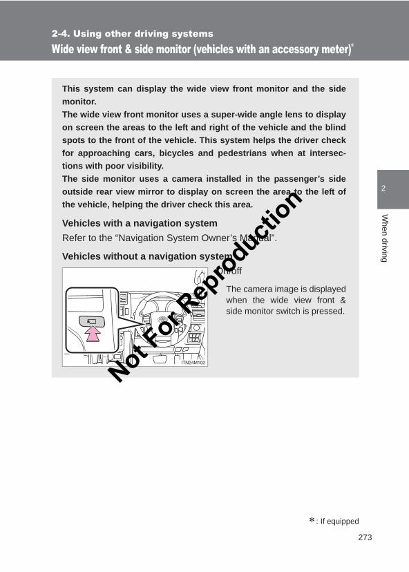
273
2-4. Using other driving systems
2
When driving
LC150_OM_OM60J77E_(AE)
Wide view front & side monitor (vehicles with an accessory meter)∗
∗: If equipped
This system can display the wide view front monitor and the sidemonitor.The wide view front monitor uses a super-wide angle lens to displayon screen the areas to the left and right of the vehicle and the blindspots to the front of the vehicle. This system helps the driver checkfor approaching cars, bicycles and pedestrians when at intersec-tions with poor visibility.The side monitor uses a camera installed in the passenger’s sideoutside rear view mirror to display on screen the area to the left ofthe vehicle, helping the driver check this area.
Vehicles with a navigation systemRefer to the “Navigation System Owner’s Manual”.
Vehicles without a navigation systemOn/off
The camera image is displayedwhen the wide view front &side monitor switch is pressed.
Not For R
epro
duction
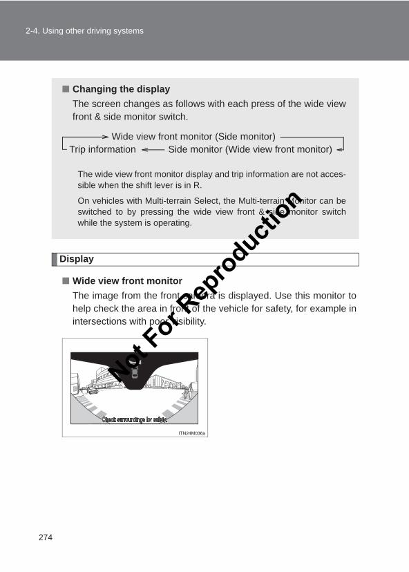
274
2-4. Using other driving systems
LC150_OM_OM60J77E_(AE)
Display
■ Wide view front monitorThe image from the front camera is displayed. Use this monitor tohelp check the area in front of the vehicle for safety, for example inintersections with poor visibility.
■ Changing the displayThe screen changes as follows with each press of the wide viewfront & side monitor switch.
The wide view front monitor display and trip information are not acces-sible when the shift lever is in R.
On vehicles with Multi-terrain Select, the Multi-terrain Monitor can beswitched to by pressing the wide view front & side monitor switchwhile the system is operating.
Trip informationWide view front monitor (Side monitor)
Side monitor (Wide view front monitor)
Not For R
epro
duction
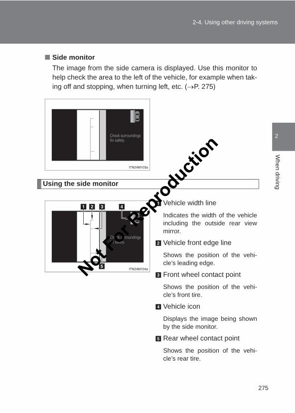
275
2-4. Using other driving systems
2
When driving
LC150_OM_OM60J77E_(AE)
■ Side monitorThe image from the side camera is displayed. Use this monitor tohelp check the area to the left of the vehicle, for example when tak-ing off and stopping, when turning left, etc. (→P. 275)
Using the side monitor
Vehicle width line
Indicates the width of the vehicleincluding the outside rear viewmirror.
Vehicle front edge line
Shows the position of the vehi-cle’s leading edge.
Front wheel contact point
Shows the position of the vehi-cle’s front tire.
Vehicle icon
Displays the image being shownby the side monitor.
Rear wheel contact point
Shows the position of the vehi-cle’s rear tire.
Not For R
epro
duction
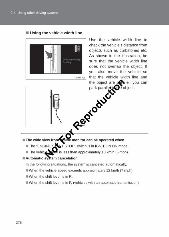
276
2-4. Using other driving systems
LC150_OM_OM60J77E_(AE)
■ Using the vehicle width lineUse the vehicle width line tocheck the vehicle’s distance fromobjects such as curbstones etc.As shown in the illustration, besure that the vehicle width linedoes not overlap the object. Ifyou also move the vehicle sothat the vehicle width line andthe object are parallel, you canpark parallel to the object.
■The wide view front & side monitor can be operated when●The “ENGINE START STOP” switch is in IGNITION ON mode.
●The vehicle speed is less than approximately 10 km/h (6 mph).
■Automatic system cancelationIn the following situations, the system is canceled automatically.
●When the vehicle speed exceeds approximately 12 km/h (7 mph).
●When the shift lever is in R.
●When the shift lever is in P. (vehicles with an automatic transmission)
Not For R
epro
duction
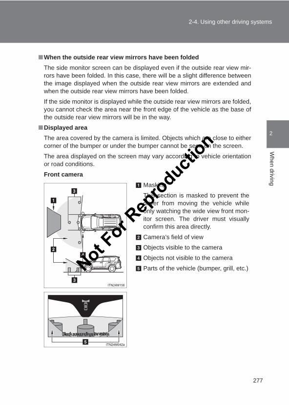
277
2-4. Using other driving systems
2
When driving
LC150_OM_OM60J77E_(AE)
■When the outside rear view mirrors have been foldedThe side monitor screen can be displayed even if the outside rear view mir-rors have been folded. In this case, there will be a slight difference betweenthe image displayed when the outside rear view mirrors are extended andwhen the outside rear view mirrors have been folded.
If the side monitor is displayed while the outside rear view mirrors are folded,you cannot check the area near the front edge of the vehicle as the base ofthe outside rear view mirrors will be in the way.
■Displayed areaThe area covered by the camera is limited. Objects which are close to eithercorner of the bumper or under the bumper cannot be seen on the screen.
The area displayed on the screen may vary according to vehicle orientationor road conditions.
Front cameraMasking
This section is masked to prevent thedriver from moving the vehicle whileonly watching the wide view front mon-itor screen. The driver must visuallyconfirm this area directly.
Camera’s field of view
Objects visible to the camera
Objects not visible to the camera
Parts of the vehicle (bumper, grill, etc.)Not For R
epro
duction
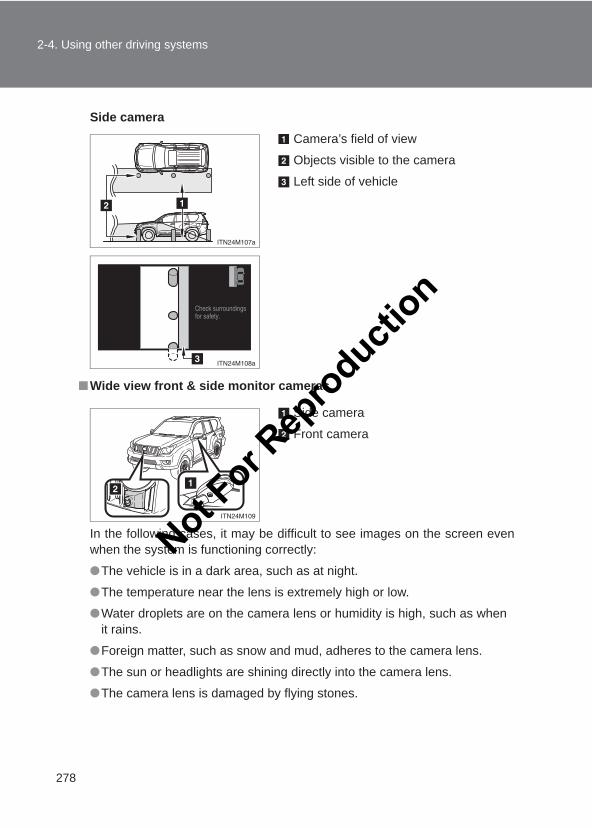
278
2-4. Using other driving systems
LC150_OM_OM60J77E_(AE)
Side camera
■Wide view front & side monitor cameras
In the following cases, it may be difficult to see images on the screen evenwhen the system is functioning correctly:
●The vehicle is in a dark area, such as at night.
●The temperature near the lens is extremely high or low.
●Water droplets are on the camera lens or humidity is high, such as whenit rains.
●Foreign matter, such as snow and mud, adheres to the camera lens.
●The sun or headlights are shining directly into the camera lens.
●The camera lens is damaged by flying stones.
Camera’s field of view
Objects visible to the camera
Left side of vehicle
Side camera
Front camera
Not For R
epro
duction
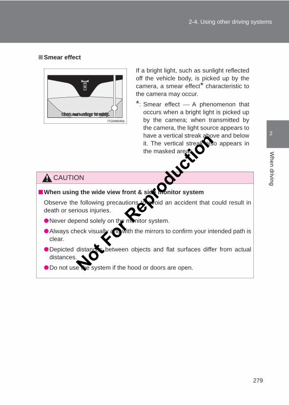
279
2-4. Using other driving systems
2
When driving
LC150_OM_OM60J77E_(AE)
■Smear effect
CAUTION
■When using the wide view front & side monitor systemObserve the following precautions to avoid an accident that could result indeath or serious injuries.
●Never depend solely on the monitor system.
●Always check visually and with the mirrors to confirm your intended path isclear.
●Depicted distances between objects and flat surfaces differ from actualdistances.
●Do not use the system if the hood or doors are open.
If a bright light, such as sunlight reflectedoff the vehicle body, is picked up by thecamera, a smear effect* characteristic tothe camera may occur.
*: Smear effect A phenomenon thatoccurs when a bright light is picked upby the camera; when transmitted bythe camera, the light source appears tohave a vertical streak above and belowit. The vertical streak also appears inthe masked areas.
Not For R
epro
duction
280
2-4. Using other driving systems
LC150_OM_OM60J77E_(AE)
CAUTION
■Conditions which may affect the wide view front & side monitor system● If the front of the vehicle or the passenger side outside rear view mirror
has been hit, the camera’s position and mounting angle may havechanged. Have the vehicle inspected by your Toyota dealer.
●Rapid temperature changes, such as when hot water is poured on thevehicle in cold weather, may cause the system to function abnormally.
● If the camera lens is extremely dirty, it cannot transmit a clear image.Rinse with water and wipe with a soft cloth. If the camera lens is extremelydirty, wash with a mild cleanser and rinse.
●The displayed image may be darker and moving images may be slightlydistorted when the system is cold.
●Situations unsuitable for wide view front & side monitor
• On icy or slick road surfaces, or in snow.• When using tire chains or emergency tires.• On roads that are not flat or straight, such as curves or slopes.
● If the tires are changed, the position of the guide lines displayed on thescreen may be incorrect. When changing the tires, consult your Toyotadealer.
●Depending on the circumstances of the vehicle (number of passengers,amount of luggage, etc.), the position of the guide lines displayed on thescreen may change. Be sure to check visually behind and all around thevehicle before proceeding.
NOTICE
■When using the wide view front & side monitorEven if an obstacle is no longer visible on the side monitor, do not turn thesteering wheel further in the direction the vehicle is turning until the vehiclehas moved completely past the obstacle. If the steering wheel is turned tofull lock, the vehicle will turn in the smallest possible turning circle, and maycollide with the obstacle.
Not For R
epro
duction
281
2-4. Using other driving systems
2
When driving
LC150_OM_OM60J77E_(AE)
Driving assist systems
To help enhance driving safety and performance, the following sys-tems operate automatically in response to various driving situations.Be aware, however, that these systems are supplementary andshould not be relied upon too heavily when operating the vehicle.
■ ABS (Anti-lock Brake System)Helps to prevent wheel lock when the brakes are applied suddenly, or ifthe brakes are applied while driving on a slippery road surface
■ Multi Terrain ABS (Anti-lock Brake System) (vehicles with aMulti-terrain Select system)→Refer to the “Off-road Driving Owner’s Manual”
■ Brake assistGenerates an increased level of braking force after the brake pedal isdepressed when the system detects a panic stop situation
■ VSC (Vehicle Stability Control)Helps the driver to control skidding when swerving suddenly or turningon slippery road surfaces
■ TRC (Traction Control) for H4 modeHelps to maintain drive power and prevent the 4 wheels from spinningwhen starting the vehicle or accelerating on slippery roads
■ Active TRC (Traction Control) for L4 mode*→Refer to the “Off-road Driving Owner’s Manual”
■ Hill-start assist control (if equipped)→Refer to the “Off-road Driving Owner’s Manual”
■ KDSS (Kinetic Dynamic Suspension System) (if equipped)→Refer to the “Off-road Driving Owner’s Manual”
■ PCS (Pre-Crash Safety system) (if equipped)→P. 287
*: The function only works in vehicles with Multi-terrain Select when Multiterrain Select is switched on
Not For R
epro
duction
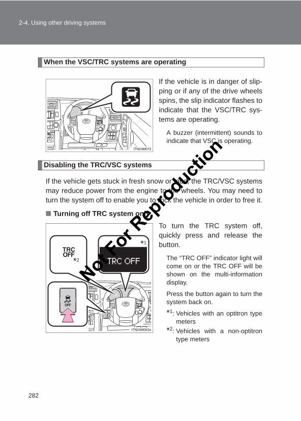
282
2-4. Using other driving systems
LC150_OM_OM60J77E_(AE)
When the VSC/TRC systems are operating
If the vehicle is in danger of slip-ping or if any of the drive wheelsspins, the slip indicator flashes toindicate that the VSC/TRC sys-tems are operating.
A buzzer (intermittent) sounds toindicate that VSC is operating.
Disabling the TRC/VSC systems
If the vehicle gets stuck in fresh snow or mud, the TRC/VSC systemsmay reduce power from the engine to the wheels. You may need toturn the system off to enable you to rock the vehicle in order to free it.
■ Turning off TRC system onlyTo turn the TRC system off,quickly press and release thebutton.
The “TRC OFF” indicator light willcome on or the TRC OFF will beshown on the multi-informationdisplay.
Press the button again to turn thesystem back on.
*1: Vehicles with an optitron typemeters
*2: Vehicles with a non-optitrontype meters
*1
*2
Not For R
epro
duction
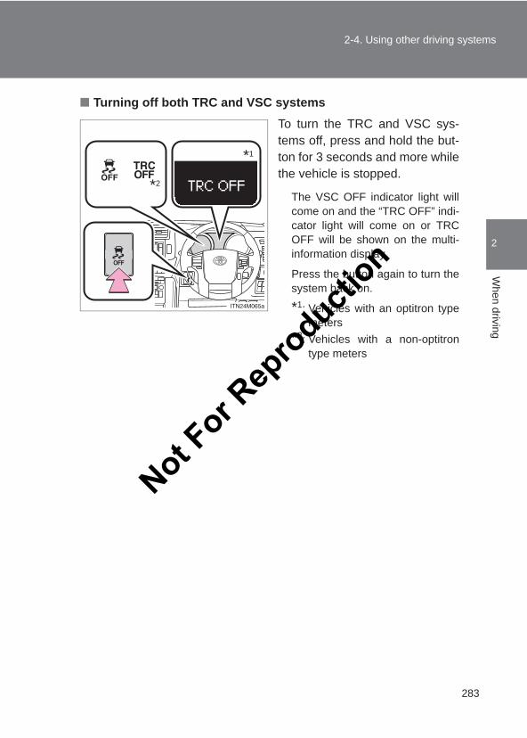
283
2-4. Using other driving systems
2
When driving
LC150_OM_OM60J77E_(AE)
■ Turning off both TRC and VSC systemsTo turn the TRC and VSC sys-tems off, press and hold the but-ton for 3 seconds and more whilethe vehicle is stopped.
The VSC OFF indicator light willcome on and the “TRC OFF” indi-cator light will come on or TRCOFF will be shown on the multi-information display.
Press the button again to turn thesystem back on.
*1: Vehicles with an optitron typemeters
*2: Vehicles with a non-optitrontype meters
*1
*2
Not For R
epro
duction
284
2-4. Using other driving systems
LC150_OM_OM60J77E_(AE)
■Sounds and vibrations caused by the ABS, brake assist, VSC and TRCsystems●A sound may be heard from the engine compartment when the engine is
started or just after the vehicle begins to move. This sound does not indi-cate that a malfunction has occurred in any of these systems.
●Any of the following conditions may occur when the above systems areoperating. None of these indicates that a malfunction has occurred.
• Vibrations may be felt through the vehicle body and steering.• A motor sound may be heard after the vehicle comes to a stop.• The brake pedal may pulsate slightly after the ABS is activated.• The brake pedal may move down slightly after the ABS is activated.
■Reactivation of the TRC/VSC systems after turning off the engineTurning off the engine after turning off the TRC/VSC systems will automati-cally reactivate them.
■Reactivation of the TRC system linked to vehicle speedWhen only the TRC system is turned off, the TRC system will turn on whenvehicle speed increases. However, when both TRC and VSC systems areturned off, the systems will not turn on even when vehicle speed increases.
■When the brake system operates continuouslyThe brake actuator may overheat. In this case, the TRC and VSC will stopoperating, a buzzer will sound and the “TRC OFF” indicator will come on(non-optitron type meters) or the TRC OFF will be shown on the multi-infor-mation display (optitron type meters). Refrain from using the system until the“TRC OFF” indicator turns off (non-optitron type meters) or the messagegoes off (optitron type meters). (There is no problem with continuing normaldriving.)
■ If the slip indicator comes on...It may indicate a malfunction in the VSC or TRC system. Consult yourToyota dealer.
Not For R
epro
duction
285
2-4. Using other driving systems
2
When driving
LC150_OM_OM60J77E_(AE)
CAUTION
■The ABS does not operate effectively when●The limits of tire gripping performance have been exceeded (such as
excessively worn tires on a snow covered road).
●The vehicle hydroplanes while driving at high speed on the wet or slickroad.
■Stopping distance when the ABS is operating may exceed that of nor-mal conditionsThe ABS is not designed to shorten the vehicle’s stopping distance. Alwaysmaintain a safe distance from the vehicle in front of you, especially in the fol-lowing situations:
●When driving on dirt, gravel or snow-covered roads
●When driving with tire chains
●When driving over bumps in the road
●When driving over roads with potholes or roads with uneven surfaces
■TRC may not operate effectively whenDirectional control and power may not be achievable while driving on slip-pery road surfaces, even if the TRC system is operating. Do not drive the vehicle in conditions where stability and power may be lost.
■When the VSC is activatedThe slip indicator light flashes and a warning buzzer sounds. Always drivecarefully.Reckless driving may cause an accident. Exercise particular care when theindicator light flashes and a buzzer sounds.
Not For R
epro
duction
286
2-4. Using other driving systems
LC150_OM_OM60J77E_(AE)
CAUTION
■When the TRC/VSC systems are turned offBe especially careful and drive at a speed appropriate to the road condi-tions. As these are the systems to help enhance vehicle stability and drivingforce, do not turn the TRC/VSC systems off unless necessary.
■Replacing tiresMake sure that all tires are of the same size, brand, tread pattern and totalload capacity. In addition, make sure that the tires are inflated to the recom-mended tire inflation pressure level.
The ABS and VSC will not function correctly if different tires are installed onthe vehicle.Contact your Toyota dealer for further information when replacing tires orwheels.
■Handling of tires and the suspensionUsing tires with any kind of problem or modifying the suspension will affectthe driving assist systems, and may cause the system to malfunction.
Not For R
epro
duction
287
2-4. Using other driving systems
2
When driving
LC150_OM_OM60J77E_(AE)
PCS (Pre-Crash Safety system)∗
∗: If equipped
When the radar sensor detects that a frontal collision is highly likelyor even unavoidable, safety systems such as the brakes and seatbelts are automatically engaged to lessen impact as well as vehicledamage.
■ Pre-crash seat belts (front seat belts only)If the pre-crash sensor detects that a collision is unavoidable,the pre-crash safety system will retract the seat belt before thecollision occurs.The same will happen if the driver makes an emergency brakingor loses control of the vehicle. (→P. 94)
However, when the VSC system is disabled, the system will notoperate in the event of skidding.
■ Pre-crash brake assistWhen there is a high possibility of a frontal collision, the systemapplies greater braking force in relation to how strongly thebrake pedal is depressed.
■ Pre-crash brakingWhen there is a high possibility of a frontal collision, the systemwarns the driver using a warning light, warning display andbuzzer. If the system determines that a collision is unavoidable,the brakes are automatically applied to reduce the collisionspeed. Pre-crash braking can be disabled using the pre-crashbraking off switch.
■ AVS (Adaptive Variable Suspension System) control (ifequipped)When the system determines that there is a high possibility of afrontal collision, the AVS optimizes the damping effect→Refer to the “Off-road Driving Owner’s Manual”
Not For R
epro
duction
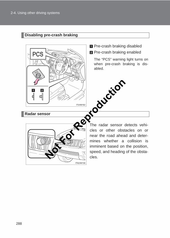
288
2-4. Using other driving systems
LC150_OM_OM60J77E_(AE)
Disabling pre-crash braking
Pre-crash braking disabledPre-crash braking enabled
The “PCS” warning light turns onwhen pre-crash braking is dis-abled.
Radar sensor
The radar sensor detects vehi-cles or other obstacles on ornear the road ahead and deter-mines whether a collision isimminent based on the position,speed, and heading of the obsta-cles.Not F
or Rep
roducti
on
289
2-4. Using other driving systems
2
When driving
LC150_OM_OM60J77E_(AE)
■The pre-crash safety system is operational when●Pre-crash seat belts (situation 1):
• Vehicle speed is greater than about 5 km/h (4 mph).• The speed at which your vehicle is approaching the obstacle or the
vehicle ahead is greater than about 30 km/h (19 mph).• The front occupants are wearing a seat belt.
●Pre-crash seat belts (situation 2):
• Vehicle speed greater than about 30 km/h (19 mph).• The system detects sudden braking or skidding.• The front occupants are wearing a seat belt.
●Pre-crash brake assist:
• Vehicle speed is greater than about 30 km/h (19 mph).• The speed at which your vehicle is approaching the obstacle or the
vehicle running ahead of you is greater than about 30 km/h (19 mph).• The brake pedal is depressed.
●Pre-crash braking:
• The pre-crash braking off switch is not pressed.• Vehicle speed is greater than about 15 km/h (10 mph).• The speed at which your vehicle is approaching the obstacle or the
vehicle running ahead of you is greater than about 15 km/h (10 mph).●AVS (Adaptive Variable Suspension System) control (if equipped):
• Vehicle speed is greater than about 5 km/h (4 mph).• The speed at which your vehicle is approaching the obstacle or the
vehicle running ahead of you is greater than about 30 km/h (19 mph).Not For R
epro
duction
290
2-4. Using other driving systems
LC150_OM_OM60J77E_(AE)
■Conditions that may trigger the system even if there is no possibility ofa collision●When there is an object by the roadside at the entrance to a curve
●When passing an oncoming vehicle on a curve
●When driving over a narrow iron bridge
●When there is a metal object on the road surface
●When driving on an uneven road surface
●When passing an oncoming vehicle on a right-turn
●When your vehicle rapidly closes on the vehicle in front
●When a grade separation/interchange, sign, billboard, or other structureappears to be directly in the vehicle’s line of travel
●When a billboard or other metallic structure appears to be in the directline of travel due to driving on a hill
●When an extreme change in vehicle height occurs
●When the axis of the radar is out of adjustment
●When passing through certain toll gates
●When driving on a bridge
When the system is activated in the situations described above, there is alsoa possibility that the seat belts will retract quickly and the brakes will beapplied with a force greater than normal. When the seat belt is locked in therestricted position, stop the vehicle in a safe place, release the seat belt andrefasten it. Not F
or Rep
roducti
on
291
2-4. Using other driving systems
2
When driving
LC150_OM_OM60J77E_(AE)
■Situations in which the pre-crash safety system does not functionproperlyThe system may not function effectively in situations such as the following:
●On roads with sharp bends or uneven surfaces
● If a vehicle suddenly moves in front of your vehicle, such as at an inter-section
● If a vehicle suddenly cuts in front of your vehicle, such as when overtak-ing
● In inclement weather such as heavy rain, fog, snow or sand storms
●When your vehicle is skidding with the VSC system off
●When an extreme change in vehicle height occurs
●When the axis of the radar is out of adjustment
■Automatic cancelation of Pre-crash safety systemWhen a malfunction occurs due to sensor contaminations, etc. that results inthe sensors being unable to detect obstacles, the pre-crash safety systemwill be automatically disabled. In this case, the system will not activate evenif there is a collision possibility.
■Obstacles not detectedThe sensor cannot detect plastic obstacles such as traffic cones. There mayalso be occasions when the radar sensor cannot detect pedestrians, ani-mals, bicycles, motorcycles, trees, or snowdrifts.
■When there is a malfunction in the systemWarning lights and/or warning messages will turn on or flash. (→P. 553)Not F
or Rep
roducti
on
292
2-4. Using other driving systems
LC150_OM_OM60J77E_(AE)
CAUTION
■Limitations of the pre-crash safety systemDo not overly rely on the pre-crash safety system. Always drive safely, takingcare to observe your surroundings and checking for any obstacles or otherroad hazards.Failure to do so may cause an accident resulting in death or serious injury.
■Cautions regarding the assist contents of the systemBy means of alarms and brake control, the pre-crash safety system isintended to assist the driver in avoiding collisions through the process ofLOOK-JUDGE-ACT. There are limits to the degree of assistance the systemcan provide, so please keep in mind the following important points.
●Assisting the driver in watching the roadThe pre-crash safety system is only able to detect obstacles directly infront of the vehicle, and only within a limited range. It is not a mechanismthat allows careless or inattentive driving, and it is not a system that canassist the driver in low-visibility conditions. It is still necessary for the driverto pay close attention to the vehicle’s surroundings.
●Assisting the driver in making correct judgmentWhen attempting to estimate the possibility of a collision, the only dataavailable to the pre-crash safety system is that from obstacles it hasdetected directly in front of the vehicle. Therefore, it is absolutely neces-sary for the driver to remain vigilant and to determine whether or not thereis a possibility of collision in any given situation.
●Assisting the driver in taking actionThe pre-crash safety system’s braking assist feature is designed to helpreduce the severity of a collision, and so only acts when the system hasjudged that a collision is unavoidable. This system by itself is not capableof automatically avoiding a collision or bringing the vehicle to a stop safety.For this reason, when encountering a dangerous situation the driver musttake direct and immediate action in order to ensure the safety of allinvolved.
Not For R
epro
duction
293
2-4. Using other driving systems
2
When driving
LC150_OM_OM60J77E_(AE)
CAUTION
■When the sensor may not be correctly detecting the vehicle aheadApply the brakes as necessary in any of the following situations.
●When water or snow thrown up by the surrounding vehicles hinders thefunctioning of the sensor
●When your vehicle is pointing upwards (caused by a heavy load in the lug-gage compartment etc.)
●Vehicles that cut in suddenly
●Vehicles with small rear ends (trailers with no load on board etc.)
●Motorcycles traveling in the same lane
■Handling the radar sensorObserve the following to ensure the pre-crash safety system can functioneffectively:
●Keep the sensor and front grille clean at all times.Clean the sensor and front grille with a soft cloth so you do not mark ordamage them.
●Do not subject the sensor or surrounding area to a strong impact.If the sensor moves even slightly off position, the system may becomeinaccurate or malfunction. If the sensor or surrounding area is subject to astrong impact, always have the area inspected and adjusted by yourToyota dealer.
●Do not disassemble the sensor.
●Do not attach accessories or stickers to the sensor, grille or surroundingarea.
●Do not modify or paint the sensor and grille cover.
Not For R
epro
duction
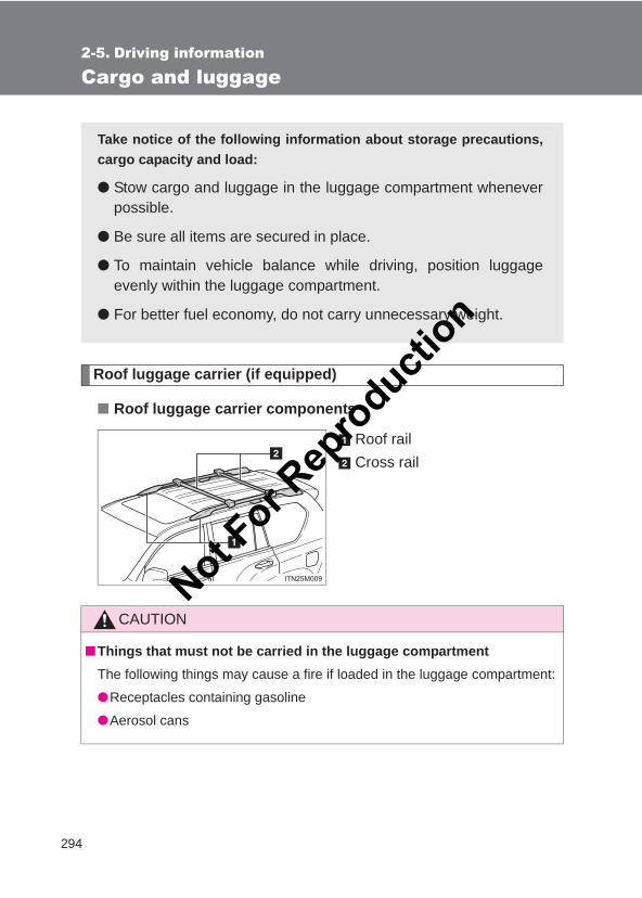
294
LC150_OM_OM60J77E_(AE)
2-5. Driving information
Cargo and luggage
Roof luggage carrier (if equipped)
■ Roof luggage carrier components
Roof railCross rail
Take notice of the following information about storage precautions,cargo capacity and load:
● Stow cargo and luggage in the luggage compartment wheneverpossible.
● Be sure all items are secured in place.
● To maintain vehicle balance while driving, position luggageevenly within the luggage compartment.
● For better fuel economy, do not carry unnecessary weight.
CAUTION
■Things that must not be carried in the luggage compartmentThe following things may cause a fire if loaded in the luggage compartment:
●Receptacles containing gasoline
●Aerosol cans
Not For R
epro
duction
295
2-5. Driving information
2
When driving
LC150_OM_OM60J77E_(AE)
CAUTION
■Storage precautionsObserve the following precautions.Failure to do so may result in death or serious injury.
●Stow cargo and luggage in the luggage compartment whenever possible.
●Do not stack anything in the luggage compartment higher than the seat-backs. Such items may be thrown about and possibly injure people in the vehiclein the event of a sudden braking, sudden swerving or an accident.
●Do not place cargo or luggage in or on the following locations as the itemmay get under the clutch, brake or accelerator pedal and prevent the ped-als from being depressed properly, block the driver’s vision, or hit thedriver or passengers, causing an accident:
• At the feet of the driver• On the front passenger or rear seats (when stacking items)• On the luggage cover• On the instrument panel• On the dashboard
●Secure all items in the occupant compartment, as they may shift and injuresomeone in the event of a sudden braking, sudden swerving or an acci-dent.
●When you fold down the rear seats, long items should not be place directlybehind the front seats.
●Never allow anyone to ride in the luggage compartment. It is not designedfor passengers. They should ride in their seats with their seat belts prop-erly fastened. Otherwise, they are much more likely to suffer death or seri-ous bodily injury, in the event of a sudden braking, sudden swerving or anaccident.
■Roof luggage carrier precautionsTo use the roof rails as a roof luggage carrier, you must fit the roof rails withtwo or more genuine Toyota cross rails or their equivalent. Follow the manufacturer’s instructions and precautions when installing thecross rails or their equivalent.
Not For R
epro
duction
296
2-5. Driving information
LC150_OM_OM60J77E_(AE)
CAUTION
■Load and distribution●Do not overload your vehicle.
●Do not apply loads unevenly. Improper loading may cause deterioration of steering or braking controlwhich may cause death or serious injury.
■When loading cargoObserve the following precautions:
●Place the cargo so that its weight is distributed evenly between the frontand rear axles.
● If loading long or wide cargo, never exceed the vehicle overall length orwidth. (→P. 614)
●Before driving, make sure the cargo is securely fastened on the roof lug-gage carrier.
●Loading cargo on the roof luggage carrier will make the center of gravity ofthe vehicle higher. Avoid high speeds, sudden starts, sharp turns, suddenbraking or abrupt maneuvers, otherwise it may result in loss of control orvehicle rollover due to failure to operate this vehicle correctly and result indeath or serious injury.
● If driving for a long distance, on rough roads, or at high speeds, stop thevehicle now and then during the trip to make sure the cargo remains in itsplace.
●Do not exceed 80 kg (176 lb.) cargo weight on the roof luggage carrier.
NOTICE
■When loading cargo (vehicles with a moon roof)Be careful not to scratch the surface of the moon roof.
Not For R
epro
duction
297
2-5. Driving information
2
When driving
LC150_OM_OM60J77E_(AE)
Winter driving tips
Carry out the necessary preparations and inspections before drivingthe vehicle in winter. Always drive the vehicle in a manner appropri-ate to the prevailing weather conditions.
■ Pre-winter preparations● Use fluids that are appropriate to the prevailing outside tem-
peratures.
• Engine oil• Engine coolant• Washer fluid
● Have a service technician inspect the level and specific grav-ity of battery electrolyte.
● Have the vehicle fitted with four snow tires or purchase a setof tire chains for the rear tires.
Ensure that all tires are the same size and brand, and that chainsmatch the size of the tires.
■ Before driving the vehiclePerform the following according to the driving conditions:
● Do not try to forcibly open a window or move a wiper that isfrozen. Pour warm water over the frozen area to melt the ice.Wipe away the water immediately to prevent it from freezing.
● To ensure proper operation of the climate control system fan,remove any snow that has accumulated on the air inlet ventsin front of the windshield.
● Remove any ice that has accumulated on the vehicle chassis.
● Periodically check for and remove any excess ice or snowthat may have accumulated in the wheel well or on thebrakes.
Not For R
epro
duction
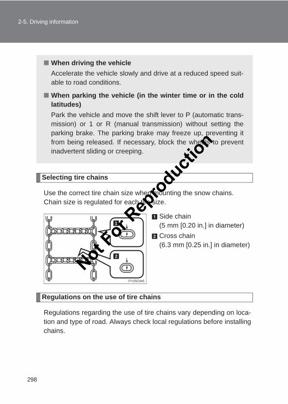
298
2-5. Driving information
LC150_OM_OM60J77E_(AE)
Selecting tire chains
Use the correct tire chain size when mounting the snow chains. Chain size is regulated for each tire size.
Side chain(5 mm [0.20 in.] in diameter)Cross chain(6.3 mm [0.25 in.] in diameter)
Regulations on the use of tire chains
Regulations regarding the use of tire chains vary depending on loca-tion and type of road. Always check local regulations before installingchains.
■ When driving the vehicleAccelerate the vehicle slowly and drive at a reduced speed suit-able to road conditions.
■ When parking the vehicle (in the winter time or in the coldlatitudes)Park the vehicle and move the shift lever to P (automatic trans-mission) or 1 or R (manual transmission) without setting theparking brake. The parking brake may freeze up, preventing itfrom being released. If necessary, block the wheels to preventinadvertent sliding or creeping.
1
2
ITY25C045
Not For R
epro
duction
299
2-5. Driving information
2
When driving
LC150_OM_OM60J77E_(AE)
■Tire chain installationObserve the following precautions when installing and removing chains:
● Install and remove tire chains in a safe location.
● Install tire chains on the rear tires. Do not install tire chains on the fronttires.
● Install tire chains on rear tires as tightly as possible. Retighten chainsafter driving 0.5 - 1.0 km (1/4 - 1/2 mile).
● Install tire chains following the instructions provided with the tire chains.
CAUTION
■Driving with snow tiresObserve the following precautions to reduce the risk of accidents.Failing to do so may result in a loss of vehicle control and cause death orserious injury.
●Use tires of the specified size.
●Maintain the recommended level of air pressure.
●Do not drive at speeds in excess of the speed limit or the speed limit spec-ified for the snow tires being used.
●Use snow tires on all, not just some wheels.
■Driving with tire chainsObserve the following precautions to reduce the risk of accidents.Failing to do so may result in the vehicle being unable to be driven safely,and may cause death or serious injury.
●Do not drive in excess of the speed limit specified for the tire chains beingused, or 50 km/h (30 mph), whichever is lower.
●Avoid driving on bumpy road surfaces or over potholes.
●Avoid sudden turns and braking, as use of chains may adversely affectvehicle handling.
●Slow down sufficiently before entering a curve to ensure that vehicle con-trol is maintained.
Not For R
epro
duction
300
2-5. Driving information
LC150_OM_OM60J77E_(AE)
Trailer towing
Your vehicle is designed primarily as a passenger-and-load carryingvehicle. Towing a trailer will have an adverse effect on handling, per-formance, braking, durability, and fuel consumption. For your safetyand the safety of others, do not overload the vehicle or trailer.
Toyota warranties do not apply to damage or malfunction caused bytowing a trailer for commercial purposes.
For towing purposes, Toyota recommend use of the following parts:
● When towing a caravan trailer etc., use a distributing hitch.
● When the total trailer weight is greater than the vehicle weight,use a sway control device.
■ Weight limitsConfirm that the total trailer weight, gross vehicle weight, grossaxle weight and trailer tongue load are all within the limits.
■ Gross vehicle weightThe gross vehicle weight must not exceed the following:
2900 kg (6393 lb.): 1GR engine2990 kg (6592 lb.): 1KD engine (5-door models)2600 kg (5732 lb.): 1KD engine (3-door models)
The gross vehicle weight is the sum weight of the unloaded vehi-cle, driver, passengers, luggage, hitch and trailer tongue load.Also included is the weight of any special equipment installed onyour vehicle.
Not For R
epro
duction
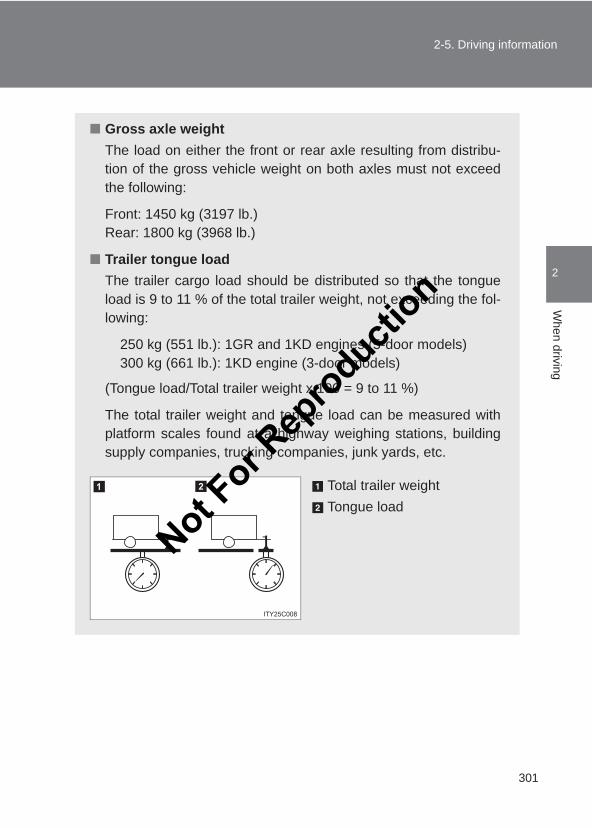
301
2-5. Driving information
2
When driving
LC150_OM_OM60J77E_(AE)
■ Gross axle weightThe load on either the front or rear axle resulting from distribu-tion of the gross vehicle weight on both axles must not exceedthe following:
Front: 1450 kg (3197 lb.)Rear: 1800 kg (3968 lb.)
■ Trailer tongue loadThe trailer cargo load should be distributed so that the tongueload is 9 to 11 % of the total trailer weight, not exceeding the fol-lowing:
250 kg (551 lb.): 1GR and 1KD engines (5-door models)300 kg (661 lb.): 1KD engine (3-door models)
(Tongue load/Total trailer weight x 100 = 9 to 11 %)
The total trailer weight and tongue load can be measured withplatform scales found at a highway weighing stations, buildingsupply companies, trucking companies, junk yards, etc.
Total trailer weightTongue load
Not For R
epro
duction
302
2-5. Driving information
LC150_OM_OM60J77E_(AE)
Hitch
Trailer hitch assemblies have different weight capacities establishedby the hitch manufacturer. Even though the vehicle may be rated fortowing a higher weight, the operator must never exceed the maxi-mum weight rating specified for the trailer hitch.
Connecting trailer lights
Use the wire harness stored in the rear end under the jack.
■When connecting and disconnecting a trailer (vehicles with rear heightcontrol air suspension)●Connecting
Set the rear height control air suspension to LO mode.
Turn off the “ENGINE START STOP” switch or the rear height con-trol air suspension.
Connect the trailer.
Turn on the switch that was turned off on step 2.
Set the rear height control air suspension to N mode.
●Disconnecting
Set the rear height control air suspension to LO mode.
Turn off the rear height control air suspension.
Turn off the “ENGINE START STOP” switch.
Set the supporting leg of a trailer on the ground and raise the hitchby 100 mm (4 in.).
Turn on the “ENGINE START STOP” switch.
Turn on the rear height control air suspension.
Wait until vehicle height is stabilized.
Make sure the hitch is disconnected. If the hitch does not disconnect, raisethe hitch higher and repeat steps 2 through 7.
STEP 1
STEP 2
STEP 3
STEP 4
STEP 5
STEP 1
STEP 2
STEP 3
STEP 4
STEP 5
STEP 6
STEP 7
Not For R
epro
duction

303
2-5. Driving information
2
When driving
LC150_OM_OM60J77E_(AE)
■Before towingCheck that the following conditions are met:
●The vehicle’s tires are properly inflated. (→P. 628)
●Trailer tires are inflated according to the trailer manufacturer’s recom-mendation.
●All trailer lights work.
●All lights work each time you connect them.
●The trailer ball is set up at the proper height for the coupler on the trailer.
●The trailer is level when it is hitched.Do not drive if the trailer is not level, and check for improper tongueweight, overloading, worn suspension, or other possible causes.
●The trailer cargo is securely loaded.
●The rear view mirrors conform to all applicable federal, state/provincial orlocal regulations. If they do not, install rear view mirrors appropriate fortowing purposes.
■Break-in scheduleToyota recommends that you do not use a new vehicle or a vehicle with anynew power train components (engine, transmission, differential, wheel bear-ings, etc.) to tow a trailer for the first 800 km (500 miles) of driving.
■Maintenance● If you tow a trailer, your vehicle will require more frequent maintenance
due to the additional load. (See “Warranty and Service Booklet”.)
●Retighten the fixing bolts of the towing ball and bracket after approxi-mately 1000 km (600 miles) of trailer towing.Not F
or Rep
roducti
on
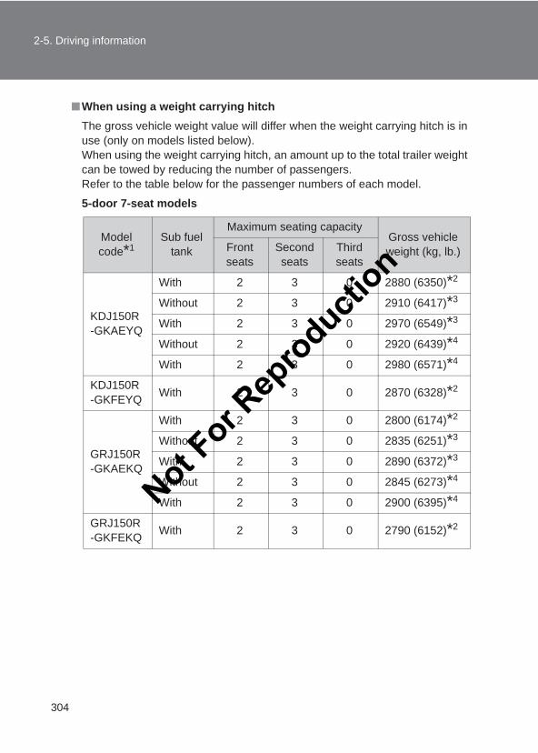
304
2-5. Driving information
LC150_OM_OM60J77E_(AE)
■When using a weight carrying hitchThe gross vehicle weight value will differ when the weight carrying hitch is inuse (only on models listed below).When using the weight carrying hitch, an amount up to the total trailer weightcan be towed by reducing the number of passengers.Refer to the table below for the passenger numbers of each model.
5-door 7-seat models
Model code*1
Sub fuel tank
Maximum seating capacityGross vehicle weight (kg, lb.)Front
seatsSecond seats
Third seats
KDJ150R-GKAEYQ
With 2 3 0 2880 (6350)*2
Without 2 3 0 2910 (6417)*3
With 2 3 0 2970 (6549)*3
Without 2 3 0 2920 (6439)*4
With 2 3 0 2980 (6571)*4
KDJ150R-GKFEYQ With 2 3 0 2870 (6328)*2
GRJ150R-GKAEKQ
With 2 3 0 2800 (6174)*2
Without 2 3 0 2835 (6251)*3
With 2 3 0 2890 (6372)*3
Without 2 3 0 2845 (6273)*4
With 2 3 0 2900 (6395)*4
GRJ150R-GKFEKQ With 2 3 0 2790 (6152)*2
Not For R
epro
duction
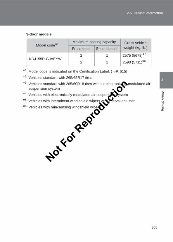
305
2-5. Driving information
2
When driving
LC150_OM_OM60J77E_(AE)
3-door models
*1: Model code is indicated on the Certification Label. (→P. 615)
*2: Vehicles standard with 265/65R17 tires
*3: Vehicles standard with 265/60R18 tires without electronically modulated airsuspension system
*4: Vehicles with electronically modulated air suspension system
*5: Vehicles with intermittent wind shield wipers with interval adjuster
*6: Vehicles with rain-sensing windshield wipers
Model code*1 Maximum seating capacity Gross vehicle weight (kg, lb.)Front seats Second seats
KDJ155R-GJAEYW2 1 2575 (5678)*5
2 1 2590 (5711)*6
Not For R
epro
duction
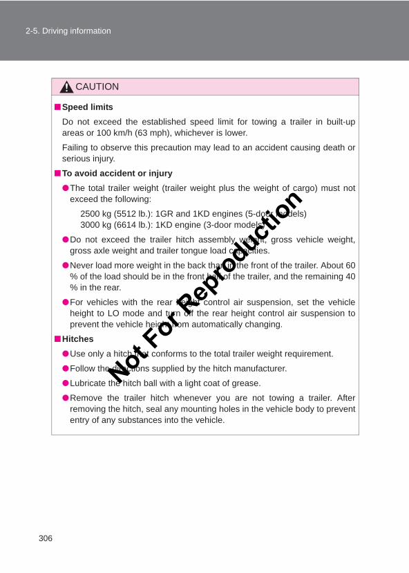
306
2-5. Driving information
LC150_OM_OM60J77E_(AE)
CAUTION
■Speed limitsDo not exceed the established speed limit for towing a trailer in built-upareas or 100 km/h (63 mph), whichever is lower.
Failing to observe this precaution may lead to an accident causing death orserious injury.
■To avoid accident or injury●The total trailer weight (trailer weight plus the weight of cargo) must not
exceed the following:
2500 kg (5512 lb.): 1GR and 1KD engines (5-door models)3000 kg (6614 lb.): 1KD engine (3-door models)
●Do not exceed the trailer hitch assembly weight, gross vehicle weight,gross axle weight and trailer tongue load capacities.
●Never load more weight in the back than in the front of the trailer. About 60% of the load should be in the front half of the trailer, and the remaining 40% in the rear.
●For vehicles with the rear height control air suspension, set the vehicleheight to LO mode and turn off the rear height control air suspension toprevent the vehicle height from automatically changing.
■Hitches●Use only a hitch that conforms to the total trailer weight requirement.
●Follow the directions supplied by the hitch manufacturer.
●Lubricate the hitch ball with a light coat of grease.
●Remove the trailer hitch whenever you are not towing a trailer. Afterremoving the hitch, seal any mounting holes in the vehicle body to prevententry of any substances into the vehicle.
Not For R
epro
duction
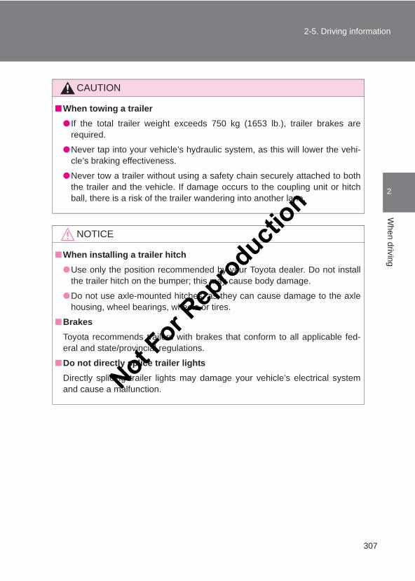
307
2-5. Driving information
2
When driving
LC150_OM_OM60J77E_(AE)
CAUTION
■When towing a trailer● If the total trailer weight exceeds 750 kg (1653 lb.), trailer brakes are
required.
●Never tap into your vehicle’s hydraulic system, as this will lower the vehi-cle’s braking effectiveness.
●Never tow a trailer without using a safety chain securely attached to boththe trailer and the vehicle. If damage occurs to the coupling unit or hitchball, there is a risk of the trailer wandering into another lane.
NOTICE
■When installing a trailer hitch●Use only the position recommended by your Toyota dealer. Do not install
the trailer hitch on the bumper; this may cause body damage.
●Do not use axle-mounted hitches, as they can cause damage to the axlehousing, wheel bearings, wheels or tires.
■BrakesToyota recommends trailers with brakes that conform to all applicable fed-eral and state/provincial regulations.
■Do not directly splice trailer lightsDirectly splicing trailer lights may damage your vehicle’s electrical systemand cause a malfunction.Not F
or Rep
roducti
on
308
2-5. Driving information
LC150_OM_OM60J77E_(AE)
Trailer towing tips
Your vehicle will handle differently when towing a trailer. The 3 maincauses of vehicle-trailer accidents are driver error, excessive speedand improper trailer loading. Keep the following in mind when towing:
● Before starting out, check the trailer lights and the vehicle-trailerconnections. Recheck after driving a short distance.
● Practice turning, stopping and reversing with the trailer attached inan area away from traffic until you become accustomed to the feelof the vehicle.
● Reversing with a trailer attached is difficult and requires practice.Grip the bottom of the steering wheel and move your hand to the leftto move the trailer to the left. Move your hand to the right to movethe trailer to right. (This is generally opposite to reversing without atrailer attached.) Avoid sharp or prolonged turning. Have someoneguide you when reversing to reduce the risk of an accident.
● As stopping distance is increased when towing a trailer, vehicle-to-vehicle distance should be increased. For each 10 km/h (6 mph) ofspeed, allow at least one vehicle and trailer length.
● Avoid sudden braking as you may skid, resulting in jackknifing andloss of control. This is especially true on wet or slippery surfaces.
● Avoid jerky starts or sudden acceleration.
● Avoid jerky steering and sharp turns, and slow down before makingturns.
● Note that when making a turn, the trailer wheels will be closer thanthe vehicle wheels to the inside of the turn. Compensate by makinga larger than normal turning radius.
Not For R
epro
duction
309
2-5. Driving information
2
When driving
LC150_OM_OM60J77E_(AE)
● Crosswinds and rough roads will adversely affect handling of yourvehicle and trailer, causing sway. Periodically check the rear to pre-pare for being passed by large trucks or buses, which may cause yourvehicle and trailer to sway. If swaying occurs, firmly grip the steeringwheel, reduce speed immediately but gradually, and steer straightahead. Never increase speed. If you make no extreme correction withthe steering or brakes, your vehicle and trailer will stabilize.
● Take care when passing other vehicles. Passing requires consider-able distance. After passing a vehicle, do not forget the length ofyour trailer, and be sure you have plenty of room before changinglanes.
● In order to maintain efficient engine braking and electrical chargingperformance, do not use 6th gear (manual) or overdrive (automatic).On vehicles with an automatic transmission: Transmission shift rangeposition must be in 4, in S mode.
● Due to the added load of the trailer, your vehicle’s engine mayoverheat on hot days (at temperatures over 30 °C [85 °F]) whendriving up a long or steep grade. If the engine coolant temperaturegauge indicates overheating, immediately turn off the air condition-ing (if in use), pull your vehicle off the road and stop in a safe spot.(→P. 604)
● Always place wheel blocks under both the vehicle and the trailerwheels when parking. Apply the parking brake firmly, and put thetransmission in P (automatic transmission) or in the 1st or R (manualtransmission). Avoid parking on a slope, but if unavoidable, do so onlyafter performing the following:
Not For R
epro
duction
310
2-5. Driving information
LC150_OM_OM60J77E_(AE)
Apply the brakes and keep them applied.Have someone place wheel blocks under both the vehicle andtrailer wheels.When the wheel blocks are in place, release the brakes slowlyuntil the blocks absorb the load.Apply the parking brake firmly.Shift into the 1st or R (manual transmission) or P (automatictransmission) and turn off the engine.
● When restarting after parking on a slope:
With the transmission in the P position (automatic transmis-sion) or the clutch pedal (manual transmission) depressed,start the engine. On vehicles with an automatic transmission,be sure to keep the brake pedal depressed.Shift into 3, 2, 1, or the R position (if reversing).Release the parking brake (also brake pedal on vehicles withan automatic transmission), and slowly pull or back away fromthe wheel blocks. Stop and apply the brakes.Have someone retrieve the blocks.
CAUTION
■To avoid an accident●Observe the legal maximum speeds for trailer towing.
●Slow down and downshift before descending steep or long downhillgrades. Do not make sudden downshifts.
●Avoid holding the brake pedal down too long or applying the brakes toofrequently. This could cause the brakes to overheat and result in reducedbraking efficiency.
STEP 1
STEP 2
STEP 3
STEP 4
STEP 5
STEP 1
STEP 2
STEP 3
STEP 4
Not For R
epro
duction
311
2-5. Driving information
2
When driving
LC150_OM_OM60J77E_(AE)
Not For R
epro
duction
312
LC150_OM_OM60J77E_(AE)
3-1. Using the air conditioning system and defogger
Front manual air conditioning system ............................ 314
Front automatic air conditioning system ............................ 320
Rear manual air conditioning system ............................ 330
Rear automatic air conditioning system ............................ 333
Heater idle up switch ........ 336Rear window defogger
switch.............................. 337
3-2. Using the audio systemAudio system types........... 339Using the radio.................. 341Using the CD player.......... 344Playing MP3 and
WMA discs...................... 353Operating an iPod............. 361Operating a USB
memory........................... 369Optimal use of the audio
system ............................ 378Using the AUX port ........... 381Using the steering wheel
audio switches ................ 383
Not For R
epro
duction
3Interior features
313
LC150_OM_OM60J77E_(AE)
3-3. Using the hands-free system (for mobile phone)
Hands-free system (for mobile phone) .......... 386
Using the hands-free system (for mobile phone) .......... 391
Making a phone call.......... 397Setting a mobile phone..... 400Security and system
setup............................... 403Using the phone book....... 406
3-4. Using the interior lightsInterior lights list................ 410• Personal/interior light
main switch..................... 411• Personal/interior lights .... 412• Lounge illumination control
switches.......................... 413
3-5. Using the storage featuresList of storage features ..... 415• Glove box ....................... 416• Card holder..................... 417• Console box.................... 418• Bottle holders/door
pockets ........................... 420• Cup holders .................... 421• Auxiliary boxes ............... 425
3-6. Other interior featuresCool box............................ 428Sun visors ......................... 431Vanity mirror ..................... 432Clock................................. 433Outside temperature
display ............................ 434Ashtray.............................. 436Conversation mirror .......... 437Power outlet...................... 438Seat heaters ..................... 442Armrest ............................. 445Coat hooks........................ 446Assist grips ....................... 447Floor mat........................... 448Luggage compartment
features........................... 450
Not For R
epro
duction
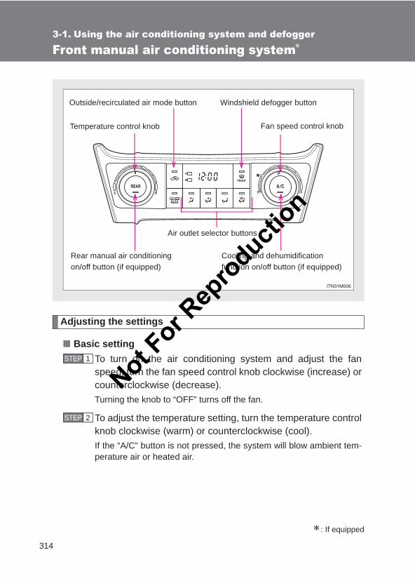
314
LC150_OM_OM60J77E_(AE)
3-1. Using the air conditioning system and defogger
Front manual air conditioning system∗
Adjusting the settings
■ Basic settingTo turn on the air conditioning system and adjust the fanspeed, turn the fan speed control knob clockwise (increase) orcounterclockwise (decrease).Turning the knob to “OFF” turns off the fan.
To adjust the temperature setting, turn the temperature controlknob clockwise (warm) or counterclockwise (cool).If the “A/C” button is not pressed, the system will blow ambient tem-perature air or heated air.
∗: If equipped
Outside/recirculated air mode button
Temperature control knob
Cooling and dehumidification function on/off button (if equipped)
Fan speed control knob
Rear manual air conditioning on/off button (if equipped)
Windshield defogger button
Air outlet selector buttons
STEP 1
STEP 2
Not For R
epro
duction
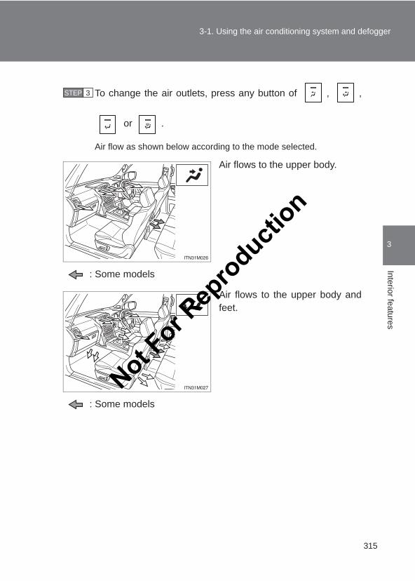
315
3-1. Using the air conditioning system and defogger
3
Interior features
LC150_OM_OM60J77E_(AE)
To change the air outlets, press any button of , ,
or .
Air flow as shown below according to the mode selected.
Air flows to the upper body.
: Some models
Air flows to the upper body andfeet.
: Some models
STEP 3
Not For R
epro
duction
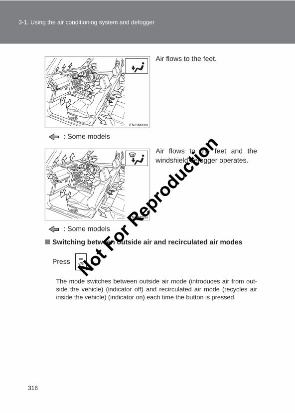
316
3-1. Using the air conditioning system and defogger
LC150_OM_OM60J77E_(AE)
Air flows to the feet.
: Some models
Air flows to the feet and thewindshield defogger operates.
: Some models
■ Switching between outside air and recirculated air modes
Press .
The mode switches between outside air mode (introduces air from out-side the vehicle) (indicator off) and recirculated air mode (recycles airinside the vehicle) (indicator on) each time the button is pressed.
Not For R
epro
duction
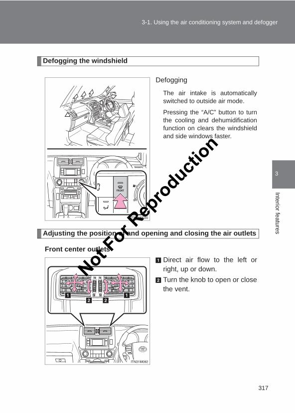
317
3-1. Using the air conditioning system and defogger
3
Interior features
LC150_OM_OM60J77E_(AE)
Defogging the windshield
Defogging
The air intake is automaticallyswitched to outside air mode.
Pressing the “A/C” button to turnthe cooling and dehumidificationfunction on clears the windshieldand side windows faster.
Adjusting the position of and opening and closing the air outlets
Front center outletsDirect air flow to the left orright, up or down.Turn the knob to open or closethe vent.
Not For R
epro
duction
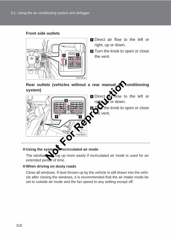
318
3-1. Using the air conditioning system and defogger
LC150_OM_OM60J77E_(AE)
Front side outletsDirect air flow to the left orright, up or down.Turn the knob to open or closethe vent.
Rear outlets (vehicles without a rear manual air conditioningsystem)
Direct air flow to the left orright, up or down.Turn the knob to open or closethe vent.
■Using the system in recirculated air modeThe windows will fog up more easily if recirculated air mode is used for anextended period of time.
■When driving on dusty roadsClose all windows. If dust thrown up by the vehicle is still drawn into the vehi-cle after closing the windows, it is recommended that the air intake mode beset to outside air mode and the fan speed to any setting except off.
Not For R
epro
duction
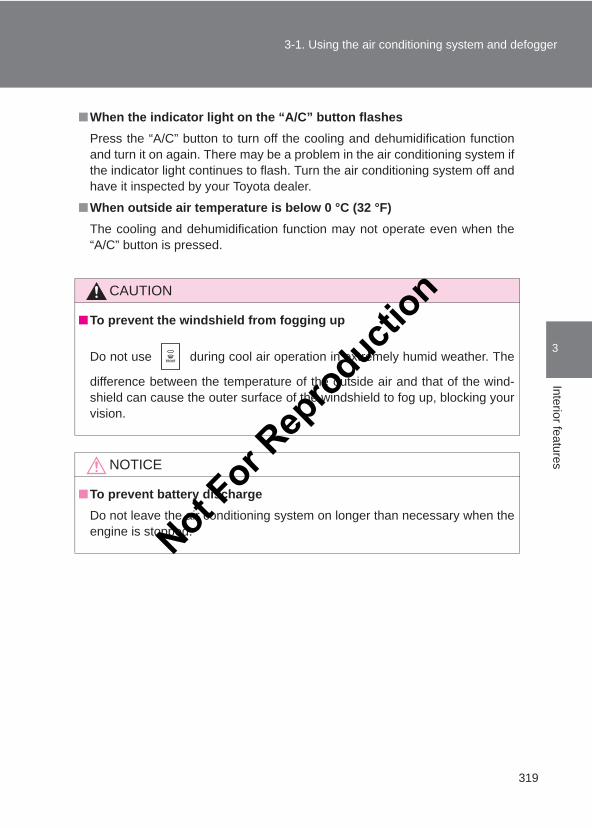
319
3-1. Using the air conditioning system and defogger
3
Interior features
LC150_OM_OM60J77E_(AE)
■When the indicator light on the “A/C” button flashesPress the “A/C” button to turn off the cooling and dehumidification functionand turn it on again. There may be a problem in the air conditioning system ifthe indicator light continues to flash. Turn the air conditioning system off andhave it inspected by your Toyota dealer.
■When outside air temperature is below 0 °C (32 °F)The cooling and dehumidification function may not operate even when the“A/C” button is pressed.
CAUTION
■To prevent the windshield from fogging up
Do not use during cool air operation in extremely humid weather. The
difference between the temperature of the outside air and that of the wind-shield can cause the outer surface of the windshield to fog up, blocking yourvision.
NOTICE
■To prevent battery dischargeDo not leave the air conditioning system on longer than necessary when theengine is stopped.Not F
or Rep
roducti
on
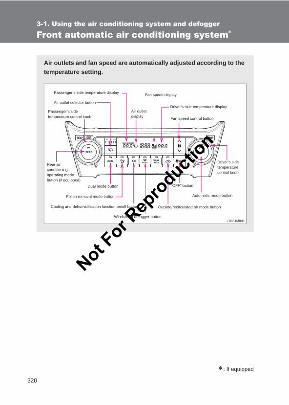
320
3-1. Using the air conditioning system and defogger
LC150_OM_OM60J77E_(AE)
Front automatic air conditioning system∗
∗: If equipped
Air outlets and fan speed are automatically adjusted according to thetemperature setting.
Air outlet selector button
Passenger’s side temperature control knob
Rear air conditioning operating mode button (if equipped)
Dual mode button
Pollen removal mode button
Outside/recirculated air mode button
“OFF” button
Passenger’s side temperature display
Air outlet display
Driver’s side temperaturecontrol knob
Fan speed display
Driver’s side temperature display
Fan speed control button
Automatic mode button
Cooling and dehumidification function on/off button
Windshield defogger button
Not For R
epro
duction
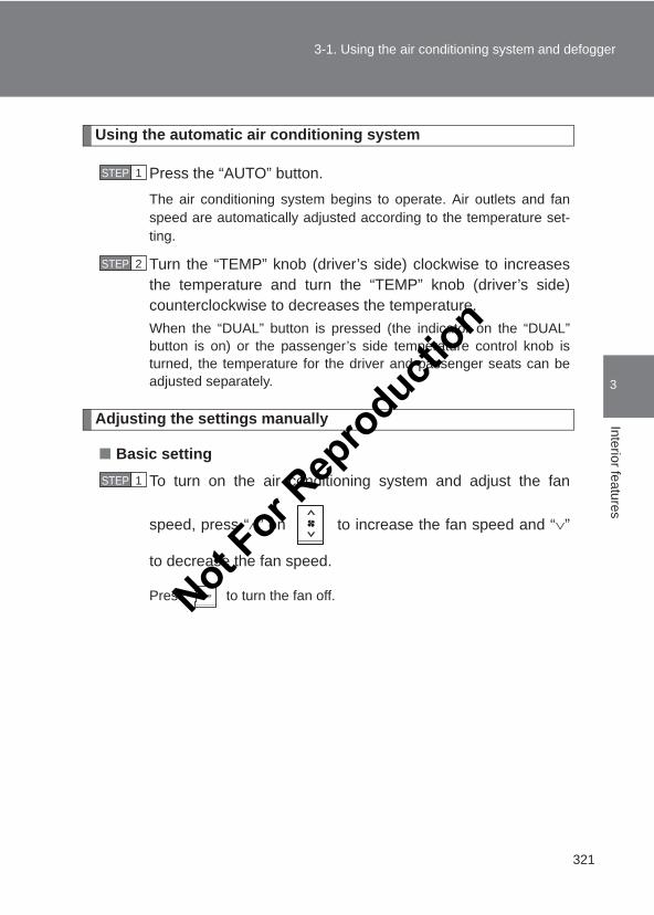
321
3-1. Using the air conditioning system and defogger
3
Interior features
LC150_OM_OM60J77E_(AE)
Using the automatic air conditioning system
Press the “AUTO” button.The air conditioning system begins to operate. Air outlets and fanspeed are automatically adjusted according to the temperature set-ting.
Turn the “TEMP” knob (driver’s side) clockwise to increasesthe temperature and turn the “TEMP” knob (driver’s side)counterclockwise to decreases the temperature.When the “DUAL” button is pressed (the indicator on the “DUAL”button is on) or the passenger’s side temperature control knob isturned, the temperature for the driver and passenger seats can beadjusted separately.
Adjusting the settings manually
■ Basic setting
To turn on the air conditioning system and adjust the fan
speed, press “∧” on to increase the fan speed and “∨”
to decrease the fan speed.
Press to turn the fan off.
STEP 1
STEP 2
STEP 1
Not For R
epro
duction
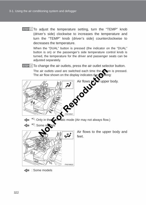
322
3-1. Using the air conditioning system and defogger
LC150_OM_OM60J77E_(AE)
To adjust the temperature setting, turn the “TEMP” knob(driver’s side) clockwise to increases the temperature andturn the “TEMP” knob (driver’s side) counterclockwise todecreases the temperature.When the “DUAL” button is pressed (the indicator on the “DUAL”button is on) or the passenger’s side temperature control knob isturned, the temperature for the driver and passenger seats can beadjusted separately.
To change the air outlets, press the air outlet selector button.The air outlets used are switched each time the button is pressed.The air flow shown on the display indicates the following:
Air flows to the upper body.
*1: Only in the automatic mode (Air may not always flow.)
*2: Some models
Air flows to the upper body andfeet.
: Some models
STEP 2
STEP 3
Not For R
epro
duction
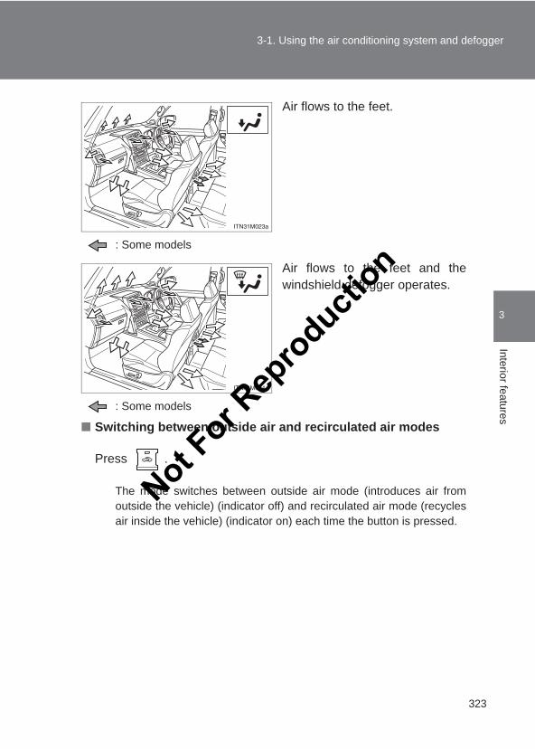
323
3-1. Using the air conditioning system and defogger
3
Interior features
LC150_OM_OM60J77E_(AE)
Air flows to the feet.
: Some models
Air flows to the feet and thewindshield defogger operates.
: Some models
■ Switching between outside air and recirculated air modes
Press .
The mode switches between outside air mode (introduces air fromoutside the vehicle) (indicator off) and recirculated air mode (recyclesair inside the vehicle) (indicator on) each time the button is pressed.
Not For R
epro
duction
324
3-1. Using the air conditioning system and defogger
LC150_OM_OM60J77E_(AE)
Changing the rear seat settings (vehicles with a rear automaticair conditioning system)
■ Adjusting the temperature setting
Press the “REAR” button.“REAR” is shown on the display.
Turn the “TEMP” knob (passenger’s side) clockwise toincreases the temperature and turn the “TEMP” knob (pas-senger’s side) counterclockwise to decreases the tempera-ture.
■ Adjusting the fan speed
Press “∧” on to increase the fan speed and “∨” to decrease
the fan speed.
Press to turn the fan off.
■ Changing the air outlets
Press .
The air outlets switch each time the button is pressed (→P. 334)
STEP 1
STEP 2
Not For R
epro
duction
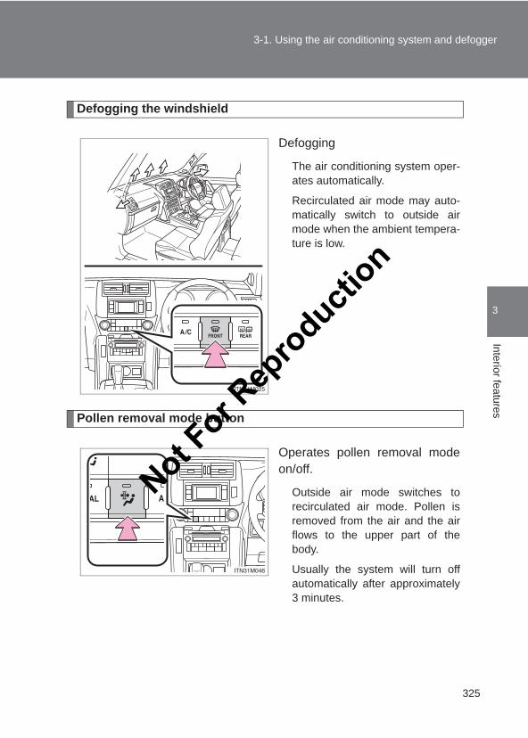
325
3-1. Using the air conditioning system and defogger
3
Interior features
LC150_OM_OM60J77E_(AE)
Defogging the windshield
Defogging
The air conditioning system oper-ates automatically.
Recirculated air mode may auto-matically switch to outside airmode when the ambient tempera-ture is low.
Pollen removal mode button
Operates pollen removal modeon/off.
Outside air mode switches torecirculated air mode. Pollen isremoved from the air and the airflows to the upper part of thebody.
Usually the system will turn offautomatically after approximately3 minutes.
Not For R
epro
duction
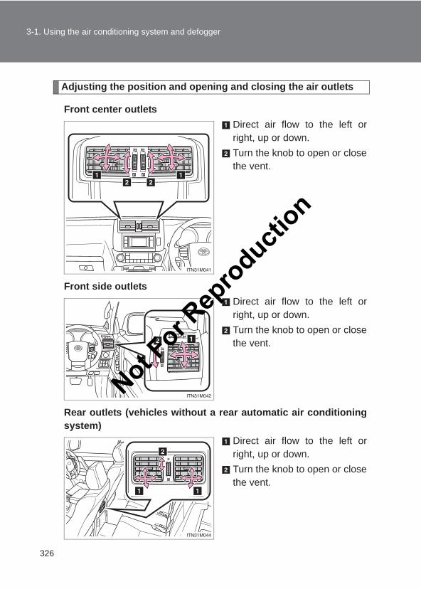
326
3-1. Using the air conditioning system and defogger
LC150_OM_OM60J77E_(AE)
Adjusting the position and opening and closing the air outlets
Front center outletsDirect air flow to the left orright, up or down.Turn the knob to open or closethe vent.
Front side outletsDirect air flow to the left orright, up or down.Turn the knob to open or closethe vent.
Rear outlets (vehicles without a rear automatic air conditioningsystem)
Direct air flow to the left orright, up or down.Turn the knob to open or closethe vent.
Not For R
epro
duction
327
3-1. Using the air conditioning system and defogger
3
Interior features
LC150_OM_OM60J77E_(AE)
■Using automatic modeFan speed is adjusted automatically according to the temperature settingand ambient conditions. As a result, the following may occur.
● Immediately after the switch is pressed, the fan may stop for a while untilwarm or cool air is ready to flow.
●Cool air may flow to the area around the upper body when the heater ison.
■Switching between outside air and recirculated air modesRecirculated air mode or outside air mode may be automatically switched toin accordance with the temperature setting, inside temperature, outside tem-perature, etc.
■Using the system in recirculated air modeThe windows will fog up more easily if the recirculated air mode is used.
■Window defogger featureRecirculated air mode may automatically switch to outside air mode in situa-tions where the windows need to be defogged.
■Pollen removal mode● In order to prevent the windows from fogging up when the outside air is
cold, the following may occur.
• Outside air mode does not switch to recirculated air mode.• The air conditioning system operates automatically.• The operation cancels after 1 minute.
● In rainy weather, the windows may fog up. Press .
■When driving on dusty roadsClose all windows. If dust thrown up by the vehicle is still drawn into the vehi-cle after closing the windows, it is recommended that the air intake mode beset to outside air mode and the fan speed to any setting except off.
Not For R
epro
duction
328
3-1. Using the air conditioning system and defogger
LC150_OM_OM60J77E_(AE)
■When the indicator light on the “A/C” button flashes
Press the “A/C” button to turn off the cooling and dehumidification functionand turn it on again. There may be a problem in the air conditioning controlsystem if the indicator light continues to flash. Turn the air conditioning sys-tem off and have it inspected by your Toyota dealer.
■When outside air temperature is below 0 °C (32 °F)
The cooling and dehumidification function may not operate even when the“A/C” button is pressed.
■Using the rear automatic air conditioning system●When the rear automatic air conditioning system is on, the indicator light
on the “REAR” button is turned on.
● If the system is left untouched for approximately 10 seconds after chang-ing to the rear automatic air conditioning system, the control mode in thefront control panel returns to the front.
■Air conditioning odors●During use, various odors from inside and outside the vehicle may enter
into and accumulate in the air conditioning system. This may then causeodor to be emitted from the vents.
●To reduce potential odors from occurring:
• It is recommended that the air conditioning system be set to outside airmode prior to turning the vehicle off.
• The start timing of the blower may be delayed for a short period of timeimmediately after the air conditioning system is started in automaticmode.
■CustomizationSettings (e.g. A/C automatic mode button operation) can be changed.(Customizable features →P. 632)
Not For R
epro
duction
329
3-1. Using the air conditioning system and defogger
3
Interior features
LC150_OM_OM60J77E_(AE)
CAUTION
■To prevent the windshield from fogging up
Do not use during cool air operation in extremely humid weather. The
difference between the temperature of the outside air and that of the wind-shield can cause the outer surface of the windshield to fog up, blocking yourvision.
NOTICE
■To prevent battery dischargeDo not leave the air conditioning system on longer than necessary when theengine is stopped.
Not For R
epro
duction
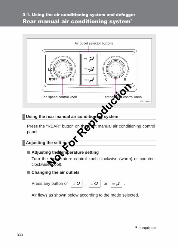
330
3-1. Using the air conditioning system and defogger
LC150_OM_OM60J77E_(AE)
Rear manual air conditioning system∗
Using the rear manual air conditioning system
Press the “REAR” button on the front manual air conditioning controlpanel.
Adjusting the settings
■ Adjusting the temperature settingTurn the temperature control knob clockwise (warm) or counter-clockwise (cool).
■ Changing the air outlets
Press any button of , or .
Air flows as shown below according to the mode selected.
∗: If equipped
Temperature control knob
Air outlet selector buttons
Fan speed control knob
Not For R
epro
duction
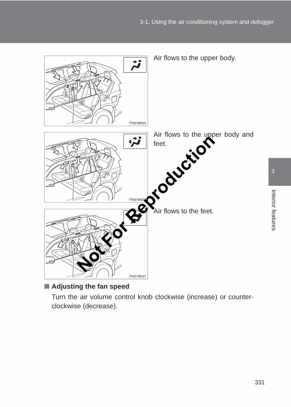
331
3-1. Using the air conditioning system and defogger
3
Interior features
LC150_OM_OM60J77E_(AE)
Air flows to the upper body.
Air flows to the upper body andfeet.
Air flows to the feet.
■ Adjusting the fan speedTurn the air volume control knob clockwise (increase) or counter-clockwise (decrease).
Not For R
epro
duction
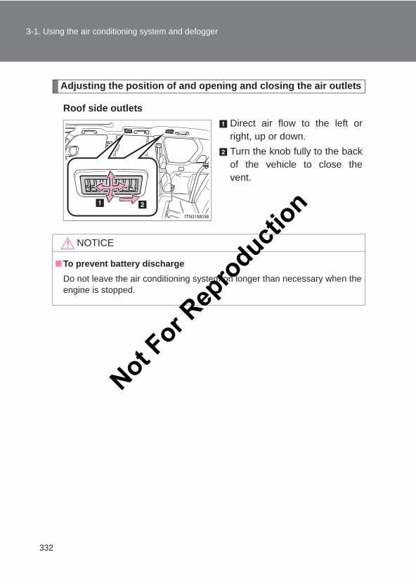
332
3-1. Using the air conditioning system and defogger
LC150_OM_OM60J77E_(AE)
Adjusting the position of and opening and closing the air outlets
Roof side outletsDirect air flow to the left orright, up or down.Turn the knob fully to the backof the vehicle to close thevent.
NOTICE
■To prevent battery dischargeDo not leave the air conditioning system on longer than necessary when theengine is stopped.
Not For R
epro
duction
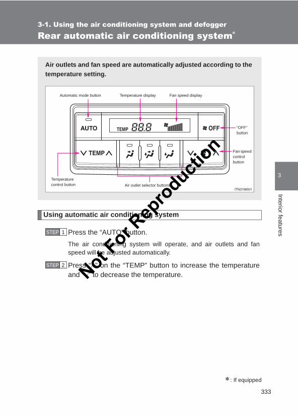
333
3-1. Using the air conditioning system and defogger
3
Interior features
LC150_OM_OM60J77E_(AE)
Rear automatic air conditioning system∗
Using automatic air conditioning system
Press the “AUTO” button.The air conditioning system will operate, and air outlets and fanspeed will be adjusted automatically.
Press “∧” on the “TEMP” button to increase the temperatureand “∨” to decrease the temperature.
∗: If equipped
Air outlets and fan speed are automatically adjusted according to thetemperature setting.
Automatic mode button Temperature display Fan speed display
Temperature control button Air outlet selector buttons
“OFF” button
Fan speed controlbutton
STEP 1
STEP 2
Not For R
epro
duction
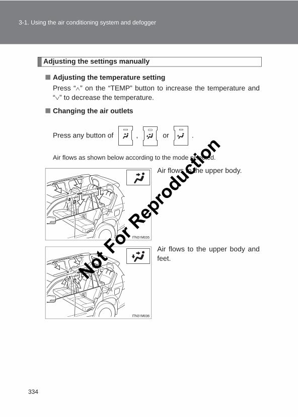
334
3-1. Using the air conditioning system and defogger
LC150_OM_OM60J77E_(AE)
Adjusting the settings manually
■ Adjusting the temperature settingPress “∧” on the “TEMP” button to increase the temperature and“∨” to decrease the temperature.
■ Changing the air outlets
Press any button of , or .
Air flows as shown below according to the mode selected.
Air flows to the upper body.
Air flows to the upper body andfeet.
Not For R
epro
duction
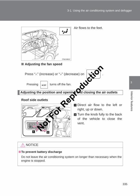
335
3-1. Using the air conditioning system and defogger
3
Interior features
LC150_OM_OM60J77E_(AE)
Air flows to the feet.
■ Adjusting the fan speed
Press “∧” (increase) or “∨” (decrease) on .
Pressing turns off the fan.
Adjusting the position and opening and closing the air outlets
Roof side outletsDirect air flow to the left orright, up or down.Turn the knob fully to the backof the vehicle to close thevent.
NOTICE
■To prevent battery dischargeDo not leave the air conditioning system on longer than necessary when theengine is stopped.
Not For R
epro
duction
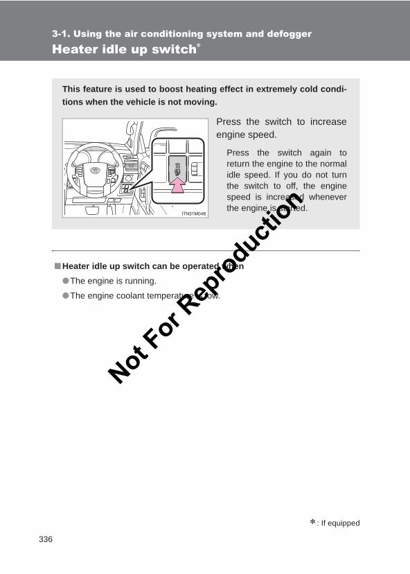
336
3-1. Using the air conditioning system and defogger
LC150_OM_OM60J77E_(AE)
Heater idle up switch∗
∗: If equipped
■Heater idle up switch can be operated when●The engine is running.
●The engine coolant temperature is low.
This feature is used to boost heating effect in extremely cold condi-tions when the vehicle is not moving.
Press the switch to increaseengine speed.
Press the switch again toreturn the engine to the normalidle speed. If you do not turnthe switch to off, the enginespeed is increased wheneverthe engine is started.
Not For R
epro
duction
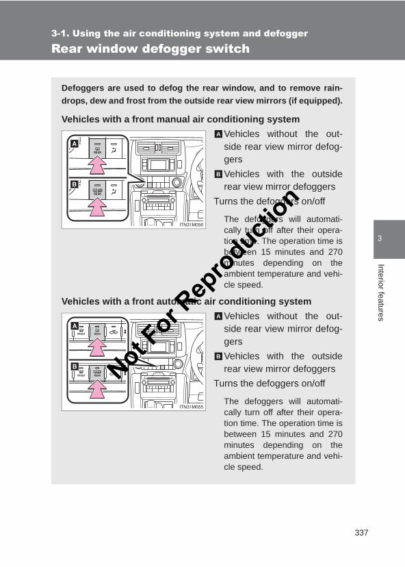
337
3-1. Using the air conditioning system and defogger
3
Interior features
LC150_OM_OM60J77E_(AE)
Rear window defogger switch
Defoggers are used to defog the rear window, and to remove rain-drops, dew and frost from the outside rear view mirrors (if equipped).
Vehicles with a front manual air conditioning systemVehicles without the out-side rear view mirror defog-gersVehicles with the outsiderear view mirror defoggers
Turns the defoggers on/off
The defoggers will automati-cally turn off after their opera-tion time. The operation time isbetween 15 minutes and 270minutes depending on theambient temperature and vehi-cle speed.
Vehicles with a front automatic air conditioning systemVehicles without the out-side rear view mirror defog-gersVehicles with the outsiderear view mirror defoggers
Turns the defoggers on/off
The defoggers will automati-cally turn off after their opera-tion time. The operation time isbetween 15 minutes and 270minutes depending on theambient temperature and vehi-cle speed.
A
B
A
B
Not For R
epro
duction
338
3-1. Using the air conditioning system and defogger
LC150_OM_OM60J77E_(AE)
■The defoggers can be operated whenVehicles without a smart entry & start systemThe engine switch is in the “ON” position.
Vehicles with a smart entry & start systemThe “ENGINE START STOP” switch is in IGNITION ON mode.
■The outside rear view mirror defoggers (vehicles with the outside rearview mirror defoggers)Turning the rear window defogger on will turn the outside rear view mirrordefoggers on.
CAUTION
■When the outside rear view mirror defoggers are on (vehicles with theoutside rear view mirror defoggers)Do not touch the outside surface of the rear view mirrors, as they canbecome very hot and burn you.
Not For R
epro
duction
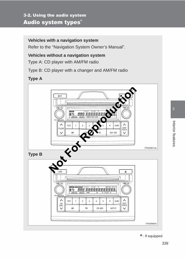
339
3
Interior features
LC150_OM_OM60J77E_(AE)
3-2. Using the audio system
Audio system types∗
∗: If equipped
Vehicles with a navigation systemRefer to the “Navigation System Owner’s Manual”.
Vehicles without a navigation systemType A: CD player with AM/FM radio
Type B: CD player with a changer and AM/FM radio
Type A
Type B
Not For R
epro
duction
340
3-2. Using the audio system
LC150_OM_OM60J77E_(AE)
■Using mobile phonesInterference may be heard through the audio system’s speakers if a mobilephone is being used inside or close to the vehicle while the audio system isoperating.
NOTICE
■To prevent battery dischargeDo not leave the audio system on longer than necessary with the engine off.
■To avoid damaging the audio systemTake care not to spill drinks or other fluids over the audio system.
Title Page
Using the radio P. 341
Using the CD player P. 344
Playing MP3 and WMA discs P. 353
Operating an iPod P. 361
Operating a USB memory P. 369
Optimal use of the audio system P. 378
Using the AUX port P. 381
Using the steering switches P. 383
Not For R
epro
duction
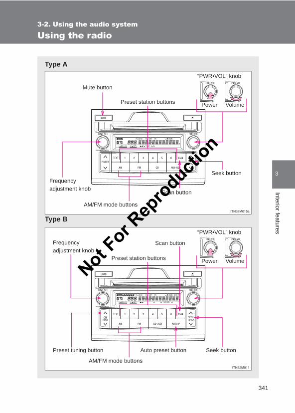
341
3-2. Using the audio system
3
Interior features
LC150_OM_OM60J77E_(AE)
Using the radio
Type A
Type B
AM/FM mode buttons
VolumePower
“PWR•VOL” knob
Preset station buttons
Scan button
Seek buttonFrequency adjustment knob
Mute button
AM/FM mode buttons
VolumePower
“PWR•VOL” knob
Preset station buttons
Preset tuning button
Scan button
Seek button
Frequency adjustment knob
Auto preset button
Not For R
epro
duction
342
3-2. Using the audio system
LC150_OM_OM60J77E_(AE)
Setting station presets
■ Manually operationSearch for the desired stations by turning the “TUNE•SEL”knob or pressing “∧” or “∨” on the “SEEK/TRACK” button.Press and hold the button (from the 1 button to the 6 button)the station is to be set to until you hear a beep.
■ Automatically operation (type B)Press and hold the “AUTO•P” button until you hear a beep.
Up to 6 stations are set in order of reception quality. When thesetting is complete, 2 beeps will be heard.
Press the “AUTO•P” button again to return to the previously set sta-tions. This temporary memory function is useful if you move out of thereception area while driving.
To preset the stations, press and hold each of the 1 button to the 6 but-ton in turn until you hear a beep.
Scanning radio stations
■ Scanning the preset radio stations
Press and hold the “SCAN” button until you hear a beep.Preset stations will be played for 5 seconds each.
When the desired station is reached, press the button again.
■ Scanning all the radio stations within range
Press the “SCAN” button.All the stations with reception will be played for 5 seconds each.
When the desired station is reached, press the button again.
STEP 1
STEP 2
STEP 1
STEP 2
STEP 1
STEP 2
Not For R
epro
duction
343
3-2. Using the audio system
3
Interior features
LC150_OM_OM60J77E_(AE)
Silencing the sound (type A)
Press the “MUTE” button.
Press the button again to turn the system back on.
■When the battery is disconnectedAll preset stations are erased.
■Reception sensitivity● It is difficult to maintain perfect radio reception at all times due to the con-
tinually changing position of the antenna, differences in signal strengthand surrounding objects, such as trains and transmitters.
●When the “AUTO•P” button is used, automatic station selection and auto-matic registering of the stations may not be possible. (type B)
●The radio antenna is mounted inside the rear quarter window. To main-tain clear radio reception, do not attach metallic window tinting or othermetallic objects to the antenna wire mounted inside the rear quarter win-dow.
Not For R
epro
duction
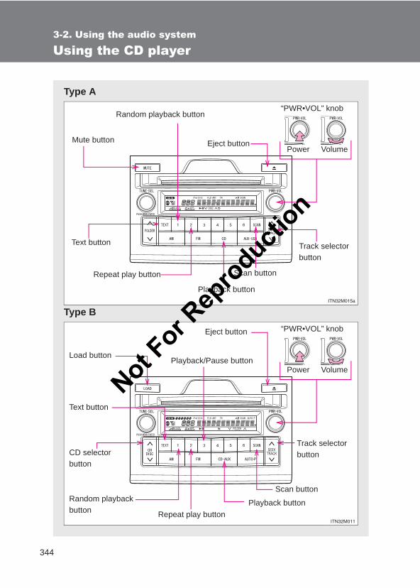
344
3-2. Using the audio system
LC150_OM_OM60J77E_(AE)
Using the CD player
Type A
Type B
Repeat play button
VolumePower
“PWR•VOL” knobRandom playback button
Scan button
Track selector button
Text button
Mute button Eject button
Playback button
Playback button
Scan button
Track selector buttonCD selector
button
Random playback button
Eject button
Text button
Repeat play button
Playback/Pause buttonVolumePower
“PWR•VOL” knob
Load button
Not For R
epro
duction
345
3-2. Using the audio system
3
Interior features
LC150_OM_OM60J77E_(AE)
Loading a CD
■ Loading a CD
Type AInsert a CD.
Type BPress the “LOAD” button.“WAIT” is shown on the display.
When the indicator on the slot turns from amber to green,insert a CD.The display changes from “WAIT” to “LOAD”.
■ Loading multiple CDs (type B)Press and hold the “LOAD” button until you hear a beep.“WAIT” is shown on the display.
When the indicator on the slot turns from amber to green,insert a CD.The display changes from “WAIT” to “LOAD”.
The indicator on the slot turns to amber when the CD is beinginserted.
When the indicator on the slot turns from amber to green,insert the next CD.Repeat the procedure for the remaining CDs.
To cancel the operation, press the “LOAD” button. If you do notinsert a disc within 15 seconds, loading will be canceled automati-cally.
STEP 1
STEP 2
STEP 1
STEP 2
STEP 3
Not For R
epro
duction
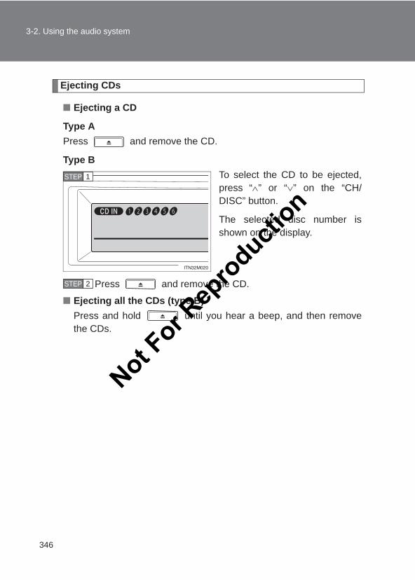
346
3-2. Using the audio system
LC150_OM_OM60J77E_(AE)
Ejecting CDs
■ Ejecting a CD
Type APress and remove the CD.
Type BTo select the CD to be ejected,press “∧” or “∨” on the “CH/DISC” button.
The selected disc number isshown on the display.
Press and remove the CD.
■ Ejecting all the CDs (type B)Press and hold until you hear a beep, and then removethe CDs.
STEP 1
STEP 2
Not For R
epro
duction
347
3-2. Using the audio system
3
Interior features
LC150_OM_OM60J77E_(AE)
Selecting, fast-forwarding, reversing and scanning tracks
■ Selecting a trackPress “∧” to move up or “∨” to move down using the “SEEK/TRACK” button until the desired track number is displayed.
■ Fast-forwarding and reversing tracksTo fast-forward or reverse, press and hold “∧” or “∨” on the “SEEK/TRACK” button until you hear a beep.
■ Scanning tracksPress the “SCAN” button.The first ten seconds of each track will be played.
To cancel, press the “SCAN” button again.
Press the button again when the desired track is reached.
Selecting a CD (type B)
■ Selecting a CD to playTo select the desired CD, press “∧” or “∨” on the “CH/DISC” button.
■ Scanning loaded CDsPress and hold the “SCAN” button until you hear a beep.The first ten seconds of the first track on each CD will be played.
To cancel, press the “SCAN” button again.
Press the button again when the desired CD is reached.
STEP 1
STEP 2
STEP 1
STEP 2
Not For R
epro
duction
348
3-2. Using the audio system
LC150_OM_OM60J77E_(AE)
Playing and pausing tracks (type B)
To play or pause a track, press the 3 ( ) button.
Random playback
■ Current CDPress the 1 (RAND) button.
Songs are played in random order.
To cancel, press the 1 (RAND) button again.
■ All CDs (type B)Press and hold the 1 (RAND) button until you hear a beep.
Tracks on all loaded CDs are played in random order.
To cancel, press the 1 (RAND) button again.
Repeat play
■ Repeating a trackPress the 2 (RPT) button.
To cancel, press the 2 (RPT) button again.
■ Repeating all of the tracks on a CD (type B)Press and hold the 2 (RPT) button until you hear a beep.
To cancel, press the 2 (RPT) button again.Not F
or Rep
roducti
on
349
3-2. Using the audio system
3
Interior features
LC150_OM_OM60J77E_(AE)
Switching the display
Press the “TEXT” button.
Each time the button is pressed, the display changes in the followingorder: Elapsed time → CD title → Track title.
Silencing the sound (type A)
Press the “MUTE” button.
Press the button again to turn the system back on.
■CD player protection featureTo protect the internal components, playback is automatically stopped whena problem is detected.
■DisplayUp to 12 characters can be displayed at a time.If there are 13 or more characters, pressing and holding the “TEXT” buttonfor 1 second or more enables to display the remaining characters.A maximum of 24 characters can be displayed.If the “TEXT” button is pressed for more than 1 second again or has notbeen operated for more than 6 seconds, the display will return to the first 12characters.
Depending on the contents recorded, the characters may not be displayedproperly or may not be displayed at all.Not F
or Rep
roducti
on
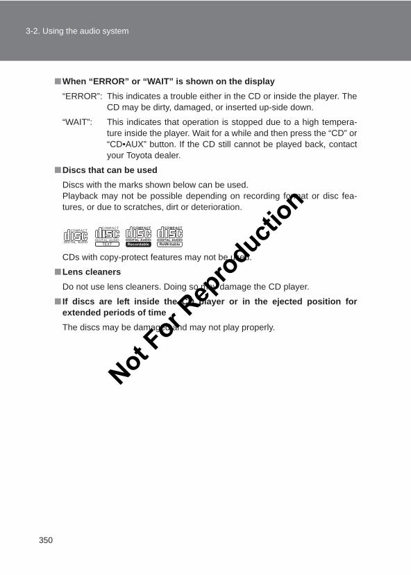
350
3-2. Using the audio system
LC150_OM_OM60J77E_(AE)
■When “ERROR” or “WAIT” is shown on the display“ERROR”: This indicates a trouble either in the CD or inside the player. The
CD may be dirty, damaged, or inserted up-side down.
“WAIT”: This indicates that operation is stopped due to a high tempera-ture inside the player. Wait for a while and then press the “CD” or“CD•AUX” button. If the CD still cannot be played back, contactyour Toyota dealer.
■Discs that can be usedDiscs with the marks shown below can be used.Playback may not be possible depending on recording format or disc fea-tures, or due to scratches, dirt or deterioration.
CDs with copy-protect features may not be used.
■Lens cleanersDo not use lens cleaners. Doing so may damage the CD player.
■ If discs are left inside the CD player or in the ejected position forextended periods of timeThe discs may be damaged and may not play properly.
Not For R
epro
duction
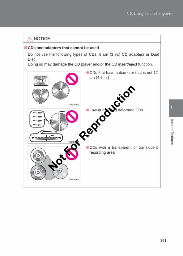
351
3-2. Using the audio system
3
Interior features
LC150_OM_OM60J77E_(AE)
NOTICE
■CDs and adapters that cannot be usedDo not use the following types of CDs, 8 cm (3 in.) CD adapters or DualDisc.Doing so may damage the CD player and/or the CD insert/eject function.
●CDs that have a diameter that is not 12cm (4.7 in.)
●Low-quality and deformed CDs
●CDs with a transparent or translucentrecording area
Not For R
epro
duction
352
3-2. Using the audio system
LC150_OM_OM60J77E_(AE)
NOTICE
■CD player precautionsFailure to follow the precautions below may result in serious damage to theCDs or the player itself.
●Do not insert anything other than CDs into the CD slot.
●Do not apply oil to the CD player.
●Store CDs away from direct sunlight.
●Never try to disassemble any part of the CD player.
●CDs that have tape, stickers or CD-Rlabels attached to them, or that havehad the label peeled off
●Do not insert more than one CD at atime.
Not For R
epro
duction
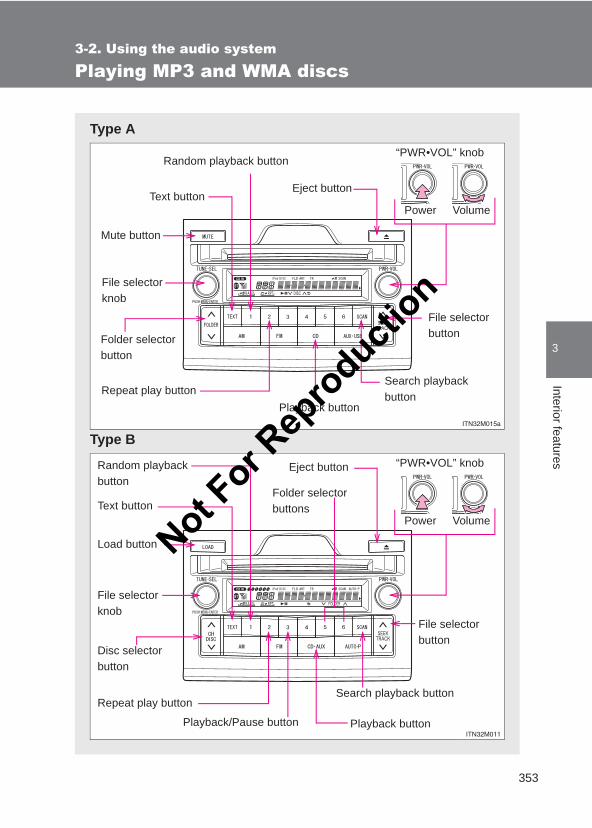
353
3-2. Using the audio system
3
Interior features
LC150_OM_OM60J77E_(AE)
Playing MP3 and WMA discs
Type A
Type B
Repeat play button
VolumePower
“PWR•VOL” knobRandom playback button
Search playback button
File selector buttonFolder selector
button
Mute button
Eject button
Playback button
Text button
File selector knob
Playback button
Search playback button
File selector button
Disc selector button
Random playback button
Eject button
Text button
Repeat play button
Playback/Pause button
VolumePower
“PWR•VOL” knob
Load button
File selector knob
Folder selector buttons
Not For R
epro
duction
354
3-2. Using the audio system
LC150_OM_OM60J77E_(AE)
Loading and ejecting MP3 and WMA discs
→P. 345, 346
Selecting MP3 and WMA discs
→P. 347
Selecting and scanning a folder
■ Selecting a folder one at a timePress “∧” or “∨” on the “FOLDER” button or the 6 (∧) or 5 (∨) buttonto select the desired folder.
■ Returning to the first folderPress and hold “∨” on the “FOLDER” button or the 5 (∨) button untilyou hear a beep.
■ Scanning the first file of all the foldersPress and hold the “SCAN” button until you hear a beep.The first ten seconds of the first file in each folder will be played.
When the desired folder is reached, press the “SCAN” buttonagain.
Fast-forwarding and reversing files
To fast-forward or reverse, press and hold “∧” or “∨” on the “SEEK/TRACK” button until you hear a beep.
STEP 1
STEP 2
Not For R
epro
duction
355
3-2. Using the audio system
3
Interior features
LC150_OM_OM60J77E_(AE)
Selecting and scanning files
■ Selecting a fileTurn the “TUNE•SEL” knob or press “∧” or “∨” on the “SEEK/TRACK” button to select the desired file.
■ Scanning the files in a folder (type B)Press the “SCAN” button.
The first ten seconds of each file will be played.
To cancel, press the “SCAN” button again.
When the desired file is reached, press the “SCAN” button again.
Playing and pausing files (type B)
To play or pause a file, press the 3 ( ) button.
Random playback
■ Playing files from a folder in random orderPress the 1 (RAND) button.
To cancel, press the 1 (RAND) button again.
■ Playing all the files from a disc in random orderPress and hold the 1 (RAND) button until you hear a beep.
To cancel, press the 1 (RAND) button again.Not F
or Rep
roducti
on
356
3-2. Using the audio system
LC150_OM_OM60J77E_(AE)
Repeat play
■ Repeating a filePress the 2 (RPT) button.
To cancel, press the 2 (RPT) button again.
■ Repeating all the files in a folderPress and hold the 2 (RPT) button until you hear a beep.
To cancel, press the 2 (RPT) button again.
Switching the display
Press the “TEXT” button.
Each time the button is pressed, the display changes in the followingorder: Folder no./File no./Elapsed time → Folder name → File name → Album title (MP3 only) → Track title → Artist name
Silencing the sound (type A)
Press the “MUTE” button.
Press the button again to turn the system back on.
Not For R
epro
duction
357
3-2. Using the audio system
3
Interior features
LC150_OM_OM60J77E_(AE)
■CD player protection feature→P. 349
■Display→P. 349
■When “ERROR”, “WAIT” or “NO MUSIC” is shown on the display“ERROR”: This indicates a problem either in the CD or inside the player.
The CD may be dirty, damaged, or inserted up-side down.
“WAIT”: This indicates that operation is stopped due to a high temper-ature inside the player. Wait for a while and then press the“CD” or “CD•AUX” button. If the CD still cannot be playedback, contact your Toyota dealer.
“NO MUSIC”: This indicates that an MP3/WMA file is not included in the CD.
■Discs that can be used→P. 350
■Lens cleaners→P. 350
■ If discs are left inside the CD player or in the ejected position forextended periods of time→P. 350
■MP3 and WMA filesMP3 (MPEG Audio LAYER3) is a standard audio compression format.
Files can be compressed to approximately 1/10 of their original size by usingMP3 compression.
WMA (Windows Media Audio) is a Microsoft audio compression format.
This format compresses audio data to a size smaller than that of the MP3format.
There is a limit to the MP3 and WMA file standards that can be used and tothe media/formats on which the files are recorded.
Not For R
epro
duction
358
3-2. Using the audio system
LC150_OM_OM60J77E_(AE)
●MP3 file compatibility
• Compatible standardsMP3 (MPEG1 LAYER3, MPEG2 LSF LAYER3)
• Compatible sampling frequenciesMPEG1 LAYER3: 32, 44.1, 48 (kHz)MPEG2 LSF LAYER3: 16, 22.05, 24 (kHz)
• Compatible bit rates (compatible with VBR)MPEG1 LAYER3: 64, 80, 96, 112, 128, 160, 192, 224, 256, 320 (kbps)MPEG2 LSF LAYER3: 64, 80, 96, 112, 128, 144, 160 (kbps)
• Compatible channel modes: stereo, joint stereo, dual channel andmonaural
●WMA file compatibility
• Compatible standardsWMA Ver. 7, 8, 9
• Compatible sampling frequencies32, 44.1, 48 (kHz)
• Compatible bit rates (only compatible with 2-channel playback)Ver. 7, 8: CBR 48, 64, 80, 96, 128, 160, 192 (kbps)Ver. 9: CBR 48, 64, 80, 96, 128, 160, 192, 256, 320 (kbps)
●Compatible media
Media that can be used for MP3 and WMA playback are CD-Rs and CD-RWs.
Playback in some instances may not be possible if the CD-R or CD-RW isnot finalized. Playback may not be possible or the audio may jump if thedisc is scratched or marked with fingerprints.Not F
or Rep
roducti
on
359
3-2. Using the audio system
3
Interior features
LC150_OM_OM60J77E_(AE)
●Compatible disc formats
The following disc formats can be used:
• Disc formats: CD-ROM Mode 1 and Mode 2CD-ROM XA Mode 2, Form 1 and Form 2
• File formats: ISO9660 Level 1, Level 2, (Romeo, Joliet)MP3 and WMA files written in any format other than those listed abovemay not play correctly, and their file names and folder names may notbe displayed correctly.
Items related to standards and limitations are as follows:
• Maximum directory hierarchy: 8 levels (including the root)• Maximum length of folder names/file names: 32 characters• Maximum number of folders: 192 (including the root)• Maximum number of files per disc: 255
●File names
The only files that can be recognized as MP3/WMA and played are thosewith the extension .mp3 or .wma.
●Discs containing multi-session recordings
As the audio system is compatible with multi-sessions, it is possible to playdiscs that contain MP3 and WMA files. However, only the first session canbe played.
● ID3 and WMA tags
ID3 tags can be added to MP3 files, making it possible to record the tracktitle, artist name, etc.
The system is compatible with ID3 Ver. 1.0, 1.1, and Ver. 2.2, 2.3 ID3 tags.(The number of characters is based on ID3 Ver. 1.0 and 1.1.)
WMA tags can be added to WMA files, making it possible to record thetrack title and artist name in the same way as with ID3 tags.
Not For R
epro
duction
360
3-2. Using the audio system
LC150_OM_OM60J77E_(AE)
●MP3 and WMA playback
When a disc containing MP3 or WMA files is inserted, all files on the discare first checked. Once the file check is finished, the first MP3 or WMA fileis played. To make the file check finish more quickly, we recommend youdo not write in any files other than MP3 or WMA files or create any unnec-essary folders.
Discs that contain a mixture of music data and MP3 or WMA format datacannot be played.
●Extensions
If the file extensions .mp3 and .wma are used for files other than MP3 andWMA files, they will be mistakenly recognized and played as MP3 andWMA files. This may result in large amounts of interference and damageto the speakers.
●Playback
• To play MP3 file with steady sound quality, we recommend a fixed bitrate of least 128 kbps and a sampling frequency of 44.1 kHz.
• CD-R or CD-RW playback may not be possible in some instances,depending on the characteristics of the disc.
• There is a wide variety of freeware and other encoding software forMP3 and WMA files on the market, and depending on the status of theencoding and the file format, poor sound quality or noise at the start ofplayback may result. In some cases, playback may not be possible atall.
• When files other than MP3 or WMA files are recorded on a disc, it maytake more time to recognize the disc and in some cases, playback maynot be possible at all.
• Microsoft, Windows, and Windows Media are the registered trade-marks of Microsoft Corporation in the U.S.A. and other countries.
NOTICE
■CDs and adapters that cannot be used→P. 351
■CD player precautions→P. 352
Not For R
epro
duction
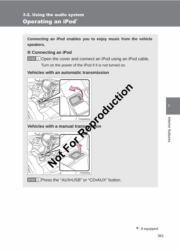
361
3-2. Using the audio system
3
Interior features
LC150_OM_OM60J77E_(AE)
Operating an iPod∗
∗: If equipped
Connecting an iPod enables you to enjoy music from the vehiclespeakers.
■ Connecting an iPodOpen the cover and connect an iPod using an iPod cable.Turn on the power of the iPod if it is not turned on.
Vehicles with an automatic transmission
Vehicles with a manual transmission
Press the “AUX•USB” or “CD•AUX” button.
STEP 1
STEP 2
Not For R
epro
duction
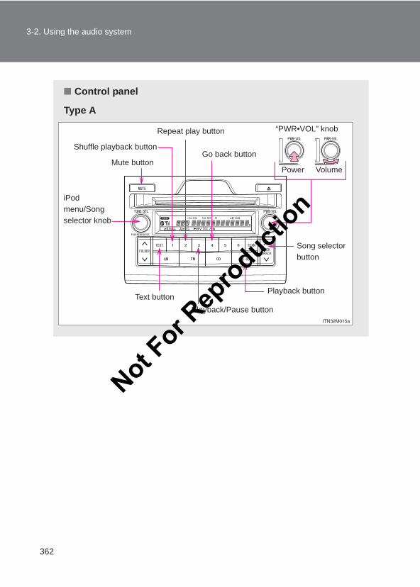
362
3-2. Using the audio system
LC150_OM_OM60J77E_(AE)
■ Control panel
Type A
Repeat play button
VolumePower
“PWR•VOL” knob
Shuffle playback button
Playback button
Song selector button
Mute buttonGo back button
Playback/Pause buttonText button
iPod menu/Song selector knob
Not For R
epro
duction
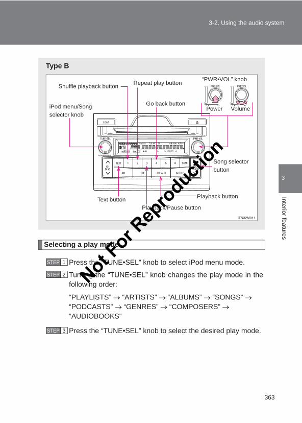
363
3-2. Using the audio system
3
Interior features
LC150_OM_OM60J77E_(AE)
Selecting a play mode
Press the “TUNE•SEL” knob to select iPod menu mode.
Turning the “TUNE•SEL” knob changes the play mode in thefollowing order:
“PLAYLISTS” → “ARTISTS” → “ALBUMS” → “SONGS” →“PODCASTS” → “GENRES” → “COMPOSERS” →“AUDIOBOOKS”
Press the “TUNE•SEL” knob to select the desired play mode.
Type B
VolumePower
“PWR•VOL” knob
Playback buttonText button
Song selector button
Shuffle playback button Repeat play button
Go back buttoniPod menu/Song selector knob
Playback/Pause button
STEP 1
STEP 2
STEP 3
Not For R
epro
duction
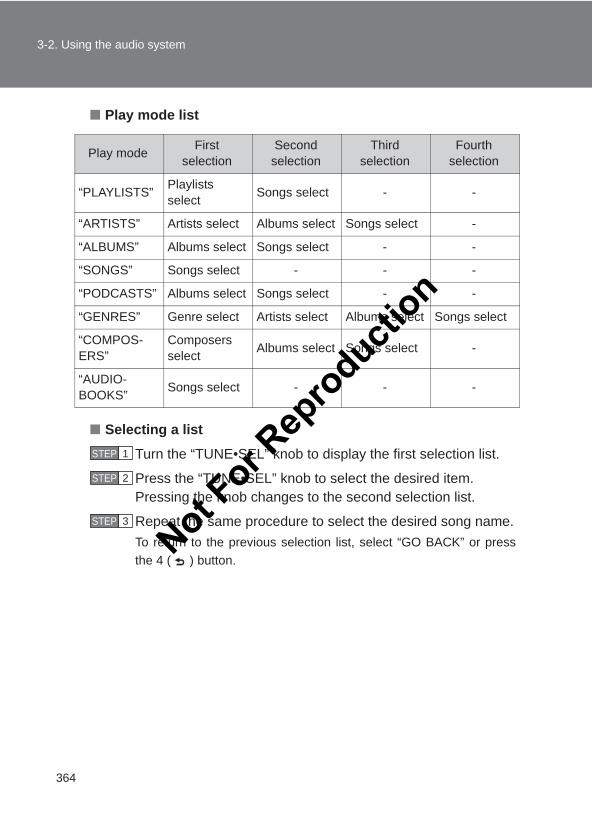
364
3-2. Using the audio system
LC150_OM_OM60J77E_(AE)
■ Play mode list
■ Selecting a list
Turn the “TUNE•SEL” knob to display the first selection list.
Press the “TUNE•SEL” knob to select the desired item.Pressing the knob changes to the second selection list.
Repeat the same procedure to select the desired song name.To return to the previous selection list, select “GO BACK” or pressthe 4 ( ) button.
Play mode First selection
Second selection
Third selection
Fourth selection
“PLAYLISTS” Playlists select Songs select - -
“ARTISTS” Artists select Albums select Songs select -
“ALBUMS” Albums select Songs select - -
“SONGS” Songs select - - -
“PODCASTS” Albums select Songs select - -
“GENRES” Genre select Artists select Albums select Songs select
“COMPOS-ERS”
Composers select Albums select Songs select -
“AUDIO-BOOKS” Songs select - - -
STEP 1
STEP 2
STEP 3
Not For R
epro
duction
365
3-2. Using the audio system
3
Interior features
LC150_OM_OM60J77E_(AE)
Selecting songs
Turn the “TUNE•SEL” knob or press “∧” or “∨” on the “SEEK/TRACK”button to select the desired song.
Playing and pausing songs
To play or pause a song, press the 3 ( ) button.
Fast-forwarding and rewinding songs
To fast-forward or rewind, press and hold “∧” or “∨” on the “SEEK/TRACK” button until you hear a beep.
Shuffle playback
■ Playing songs from one playlist or album in random orderPress the 1 (RAND) button.
To cancel, press the 1 (RAND) button again.
■ Playing songs from all the playlists or albums in random orderPress and hold the 1 (RAND) button until you hear a beep.
To cancel, press the 1 (RAND) button again.
Repeat play
Press the 2 (RPT) button.
To cancel, press the 2 (RPT) button again.
Not For R
epro
duction
366
3-2. Using the audio system
LC150_OM_OM60J77E_(AE)
Switching the display
Press the “TEXT” button.
Each time the button is pressed, the display changes in the followingorder: Elapsed time → Album title → Track title → Artist name
Silencing the sound (type A)
Press the “MUTE” button.
Press the button again to turn the system back on.
Adjusting sound quality and volume balance
Press the “TUNE•SEL” knob to enter iPod menu mode.
Pressing the “TUNE•SEL” knob changes sound modes. (→P. 378)
■About iPod ●Apple is not responsible for the operation of this device or its compliance
with safety and regulatory standards.
● iPod is a trade mark of Apple inc., registered in the U.S. and other coun-tries.
■ iPod functions●When an iPod is connected and the audio source is changed to iPod
mode, the iPod will resume play from the same point in which it was lastused.
●Depending on the iPod that is connected to the system, certain functionsmay not be available. Disconnecting the device and reconnecting it onceagain may resolve some malfunctions.
STEP 1
STEP 2
Not For R
epro
duction
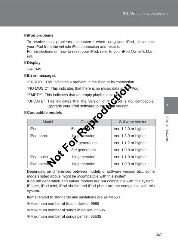
367
3-2. Using the audio system
3
Interior features
LC150_OM_OM60J77E_(AE)
■ iPod problemsTo resolve most problems encountered when using your iPod, disconnectyour iPod from the vehicle iPod connection and reset it. For instructions on how to reset your iPod, refer to your iPod Owner’s Man-ual.
■Display→P. 349
■Error messages“ERROR”: This indicates a problem in the iPod or its connection.
“NO MUSIC”: This indicates that there is no music data in the iPod.
“EMPTY”: This indicates that an empty playlist is selected.
“UPDATE”: This indicates that the version of the iPod is not compatible.Upgrade your iPod software to the latest version.
■Compatible models
Depending on differences between models or software version etc., somemodels listed above might be incompatible with this system. iPod 4th generation and earlier models are not compatible with this system.iPhone, iPod mini, iPod shuffle and iPod photo are not compatible with thissystem.
Items related to standards and limitations are as follows:
●Maximum number of lists in device: 9999
●Maximum number of songs in device: 65535
●Maximum number of songs per list: 65535
Model Generation Software version
iPod 5th generation Ver. 1.2.0 or higher
iPod nano 1st generation Ver. 1.3.0 or higher
2nd generation Ver. 1.1.2 or higher
3rd generation Ver. 1.0.0 or higher
iPod touch 1st generation Ver. 1.1.0 or higher
iPod classic 1st generation Ver. 1.0.0 or higherNot For R
epro
duction
368
3-2. Using the audio system
LC150_OM_OM60J77E_(AE)
CAUTION
■Caution while drivingDo not connect iPod or operate the controls.
NOTICE
■To prevent damage to iPod●Do not leave iPod in the vehicle. The temperature inside the vehicle may
become high, resulting in damage to the player.
●Do not push down on or apply unnecessary pressure to the iPod while it isconnected as this may damage the iPod or its terminal.
●Do not insert foreign objects into the port as this may damage the iPod orits terminal.
Not For R
epro
duction
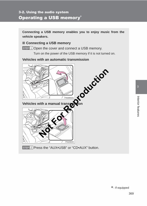
369
3-2. Using the audio system
3
Interior features
LC150_OM_OM60J77E_(AE)
Operating a USB memory∗
∗: If equipped
Connecting a USB memory enables you to enjoy music from thevehicle speakers.
■ Connecting a USB memoryOpen the cover and connect a USB memory.Turn on the power of the USB memory if it is not turned on.
Vehicles with an automatic transmission
Vehicles with a manual transmission
Press the “AUX•USB” or “CD•AUX” button.
STEP 1
STEP 2
Not For R
epro
duction
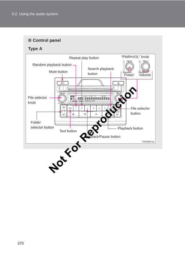
370
3-2. Using the audio system
LC150_OM_OM60J77E_(AE)
■ Control panel
Type A
Repeat play button
VolumePower
“PWR•VOL” knob
Random playback button
Playback button
File selector button
Folder selector button
Mute button
Playback/Pause buttonText button
File selector knob
Search playback button
Not For R
epro
duction
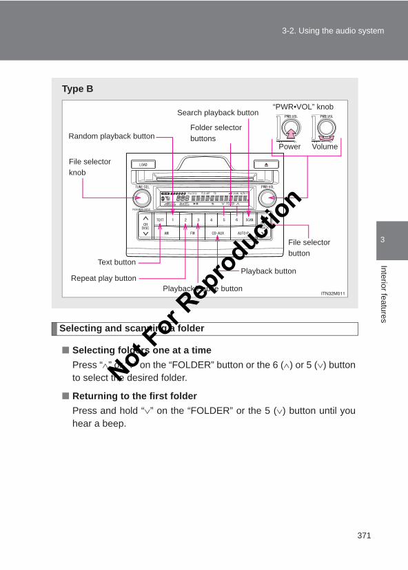
371
3-2. Using the audio system
3
Interior features
LC150_OM_OM60J77E_(AE)
Selecting and scanning a folder
■ Selecting folders one at a timePress “∧” or “∨” on the “FOLDER” button or the 6 (∧) or 5 (∨) buttonto select the desired folder.
■ Returning to the first folderPress and hold “∨” on the “FOLDER” or the 5 (∨) button until youhear a beep.
Type B
Playback buttonText button
Playback/Pause button
File selector button
Random playback button
Repeat play button
File selector knob
Folder selector buttons
VolumePower
“PWR•VOL” knobSearch playback button
Not For R
epro
duction
372
3-2. Using the audio system
LC150_OM_OM60J77E_(AE)
■ Scanning the first file of all the foldersPress and hold the “SCAN” button until you hear a beep.The first ten seconds of the first file in each folder will be played.
When the desired folder is reached, press the “SCAN” buttonagain.
Selecting and scanning files
■ Selecting filesTurn the “TUNE•SEL” knob or press “∧” or “∨” on the “SEEK/TRACK” button to select the desired file.
■ Scanning the files in a folderPress the “SCAN” button.
The first ten seconds of each file will be played.
To cancel, press the “SCAN” button again.
When the desired file is reached, press the “SCAN” button again.
Playing and pausing files
To play or pause a file, press the 3 ( ) button.
Fast-forwarding and rewinding files
To fast-forward or rewind, press and hold “∧” or “∨” on the “SEEK/TRACK” button until you hear a beep.
STEP 1
STEP 2
Not For R
epro
duction
373
3-2. Using the audio system
3
Interior features
LC150_OM_OM60J77E_(AE)
Random playback
■ Playing files from a folder in random orderPress the 1 (RAND) button.
To cancel, press the 1 (RAND) button again.
■ Playing all the files from a USB memory in random orderPress and hold the 1 (RAND) button until you hear a beep.
To cancel, press the 1 (RAND) button again.
Repeat play
■ Repeating a filePress the 2 (RPT) button.
To cancel, press the 2 (RPT) button again.
■ Repeating all the files in a folderPress and hold the 2 (RPT) button until you hear a beep.
To cancel, press the 2 (RPT) button again.
Switching the display
Press the “TEXT” button.
Each time the button is pressed, the display changes in the followingorder: Elapsed time → Folder name → File name → Album title (MP3 only) → Track title → Artist name
Silencing the sound (type A)
Press the “MUTE” button.
Press the button again to turn the system back on.
Not For R
epro
duction
374
3-2. Using the audio system
LC150_OM_OM60J77E_(AE)
■USB memory functionsDepending on the USB memory that is connected to the system, certainfunctions may not be available. Disconnecting the device and reconnecting itonce again may resolve some malfunctions.
■Display→P. 349
■Error messages“ERROR”: This indicates a problem in the USB memory or its connection.
“NO MUSIC”: This indicates that no MP3/WMA files are included in the USBmemory.
■USB memory●Compatible devices
USB memory that can be used for MP3 and WMA playback
●Compatible device formats
The following device formats can be used:
• USB communication formats: USB2.0 FS (12mbps)• File formats: FAT16/32 (Windows)• Correspondence class: Mass storage classMP3 and WMA files written in any format other than those listed abovemay not play correctly, and their file names and folder names may not bedisplayed correctly.
Items related to standards and limitations are as follows:
• Maximum directory hierarchy: 8 levels• Maximum number of folders in a device: 999 (including the root)• Maximum number of files in a device: 65025• Maximum number of files per folder: 255
Not For R
epro
duction
375
3-2. Using the audio system
3
Interior features
LC150_OM_OM60J77E_(AE)
●MP3 and WMA files
MP3 (MPEG Audio LAYER 3) is a standard audio compression format.
Files can be compressed to approximately 1/10 of their original size usingMP3 compression.
WMA (Windows Media Audio) is a Microsoft audio compression format.
This format compresses audio data to a size smaller than that of the MP3format.
There is a limit to the MP3 and WMA file standards that can be used andto the media/formats on which the files are recorded.
●MP3 file compatibility
• Compatible standardsMP3 (MPEG1 AUDIO LAYERII, III, MPEG2 AUDIO LAYERII, III,MPEG2.5)
• Compatible sampling frequenciesMPEG1 AUDIO LAYERII, III: 32, 44.1, 48 (kHz)MPEG2 AUDIO LAYERII, III: 16, 22.05, 24 (kHz)MPEG2.5: 8, 11.025, 12 (kHz)
• Compatible bit rates (compatible with VBR)MPEG1 AUDIO LAYERII, III: 32-320 (kbps)MPEG2 AUDIO LAYERII, III: 32-160 (kbps)MPEG2.5: 32-160 (kbps)
• Compatible channel modes: stereo, joint stereo, dual channel andmonaural
●WMA file compatibility
• Compatible standardsWMA Ver. 9
• Compatible sampling frequenciesHIGH PROFILE 32, 44.1, 48 (kHz)
• Compatible bit rates HIGH PROFILE 32-320 (kbps, VBR)
●File names
The only files that can be recognized as MP3/WMA and played are thosewith the extension .mp3 or .wma.
Not For R
epro
duction
376
3-2. Using the audio system
LC150_OM_OM60J77E_(AE)
● ID3 and WMA tags
ID3 tags can be added to MP3 files, making it possible to record the tracktitle, artist name, etc.
The system is compatible with ID3 Ver. 1.0, 1.1, and Ver. 2.2, 2.3, 2.4 ID3tags. (The number of characters is based on ID3 Ver. 1.0 and 1.1.)
WMA tags can be added to WMA files, making it possible to record thetrack title and artist name in the same way as with ID3 tags.
●MP3 and WMA playback
• When a device containing MP3 or WMA files is connected, all files inthe USB memory device are checked. Once the file check is finished,the first MP3 or WMA file is played. To make the file check finish morequickly, we recommend that you do not include any files other thanMP3 or WMA files or create any unnecessary folders.
• When the USB device is connected and the audio source is changed toUSB memory mode, the USB device will start playing the first file in thefirst folder. If the same device is removed and reinserted (and the con-tents have not been changed), the USB device will resume play fromthe same point in which it was last used.
●Extensions
If the file extensions .mp3 and .wma are used for files other than MP3 andWMA files, they will be mistakenly recognized and played as MP3 andWMA files. This may result in large amounts of interference and damageto the speakers.
●Playback
• To play MP3 files with steady sound quality, we recommend a fixed bitrate of at least 128 kbps and a sampling frequency of 44.1 kHz.
• There is a wide variety of freeware and other encoding software forMP3 and WMA files on the market, and depending on the status of theencoding and the file format, poor sound quality or noise at the start ofplayback may result. In some cases, playback may not be possible atall.
• Microsoft, Windows, and Windows Media are registered trademarks ofMicrosoft Corporation in the U.S.A. and other countries.
Not For R
epro
duction
377
3-2. Using the audio system
3
Interior features
LC150_OM_OM60J77E_(AE)
CAUTION
■Caution while drivingDo not connect USB memory or operate the controls.
NOTICE
■To prevent damage to USB memory●Do not leave USB memory in the vehicle. The temperature inside the vehi-
cle may become high, resulting in damage to the player.
●Do not push down on or apply unnecessary pressure to the USB memorywhile it is connected as this may damage the USB memory or its terminal.
●Do not insert foreign objects into the port as this may damage the USBmemory or its terminal.
Not For R
epro
duction
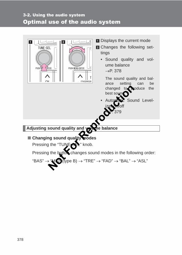
378
3-2. Using the audio system
LC150_OM_OM60J77E_(AE)
Optimal use of the audio system
Adjusting sound quality and volume balance
■ Changing sound quality modesPressing the “TUNE•SEL” knob.
Pressing the button changes sound modes in the following order:
“BAS” → “MID” (type B) → “TRE” → “FAD” → “BAL” → “ASL”
Displays the current modeChanges the following set-tings• Sound quality and vol-
ume balance→P. 378
The sound quality and bal-ance setting can bechanged to produce thebest sound.
• Automatic Sound Level-izer on/off→P. 379
Not For R
epro
duction
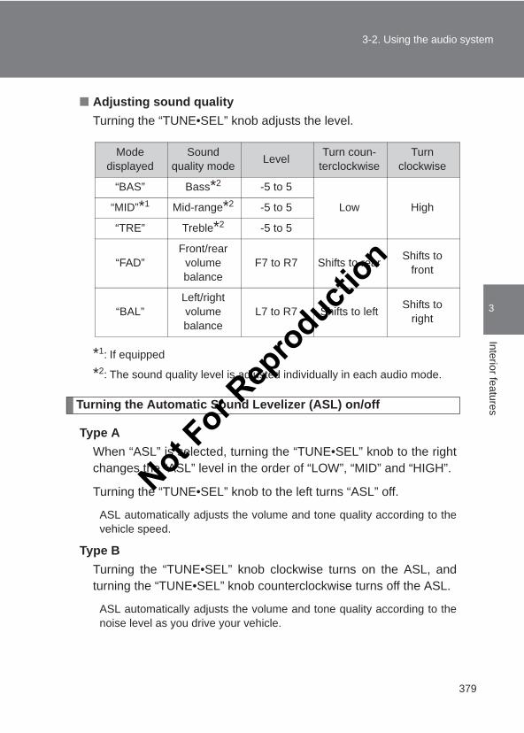
379
3-2. Using the audio system
3
Interior features
LC150_OM_OM60J77E_(AE)
■ Adjusting sound qualityTurning the “TUNE•SEL” knob adjusts the level.
*1: If equipped
*2: The sound quality level is adjusted individually in each audio mode.
Turning the Automatic Sound Levelizer (ASL) on/off
Type AWhen “ASL” is selected, turning the “TUNE•SEL” knob to the rightchanges the “ASL” level in the order of “LOW”, “MID” and “HIGH”.
Turning the “TUNE•SEL” knob to the left turns “ASL” off.
ASL automatically adjusts the volume and tone quality according to thevehicle speed.
Type BTurning the “TUNE•SEL” knob clockwise turns on the ASL, andturning the “TUNE•SEL” knob counterclockwise turns off the ASL.
ASL automatically adjusts the volume and tone quality according to thenoise level as you drive your vehicle.
Mode displayed
Sound quality mode Level Turn coun-
terclockwiseTurn
clockwise
“BAS” Bass*2 -5 to 5
Low High“MID”*1 Mid-range*2 -5 to 5
“TRE” Treble*2 -5 to 5
“FAD”Front/rear
volume balance
F7 to R7 Shifts to rear Shifts to front
“BAL”Left/right volume balance
L7 to R7 Shifts to left Shifts to right
Not For R
epro
duction
380
3-2. Using the audio system
LC150_OM_OM60J77E_(AE)
■Trademark owned by SRS Labs, Inc. (Type A)
The audio systems utilize SRS FOCUS and SRS TruBass audioenhancement technologies, under license from SRS Labs, Inc., in all modeexcept AM radio mode.
FOCUS, TruBass, SRS and symbols are trademarks of SRS Labs,Inc.FOCUS and TruBass technologies are incorporated under license fromSRS Labs, Inc.
R
Not For R
epro
duction
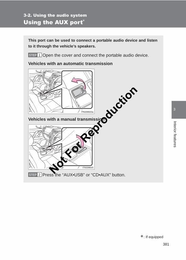
381
3-2. Using the audio system
3
Interior features
LC150_OM_OM60J77E_(AE)
Using the AUX port∗
∗: If equipped
This port can be used to connect a portable audio device and listento it through the vehicle’s speakers.
Open the cover and connect the portable audio device.
Vehicles with an automatic transmission
Vehicles with a manual transmission
Press the “AUX•USB” or “CD•AUX” button.
STEP 1
STEP 2 Not For R
epro
duction

382
3-2. Using the audio system
LC150_OM_OM60J77E_(AE)
■Operating portable audio devices connected to the audio systemThe volume can be adjusted using the vehicle’s audio controls. All the otheradjustments must be made on the portable audio device itself.
■When using a portable audio device connected to the power outletNoise may occur during playback. Use the power source of the portableaudio device.
Not For R
epro
duction
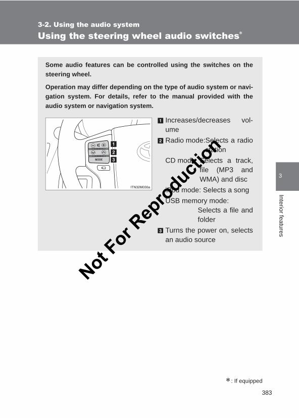
383
3-2. Using the audio system
3
Interior features
LC150_OM_OM60J77E_(AE)
Using the steering wheel audio switches∗
∗: If equipped
Some audio features can be controlled using the switches on thesteering wheel.
Operation may differ depending on the type of audio system or navi-gation system. For details, refer to the manual provided with theaudio system or navigation system.
Increases/decreases vol-umeRadio mode:Selects a radio
stationCD mode: Selects a track,
file (MP3 andWMA) and disc
iPod mode: Selects a songUSB memory mode:
Selects a file andfolder
Turns the power on, selectsan audio source
Not For R
epro
duction
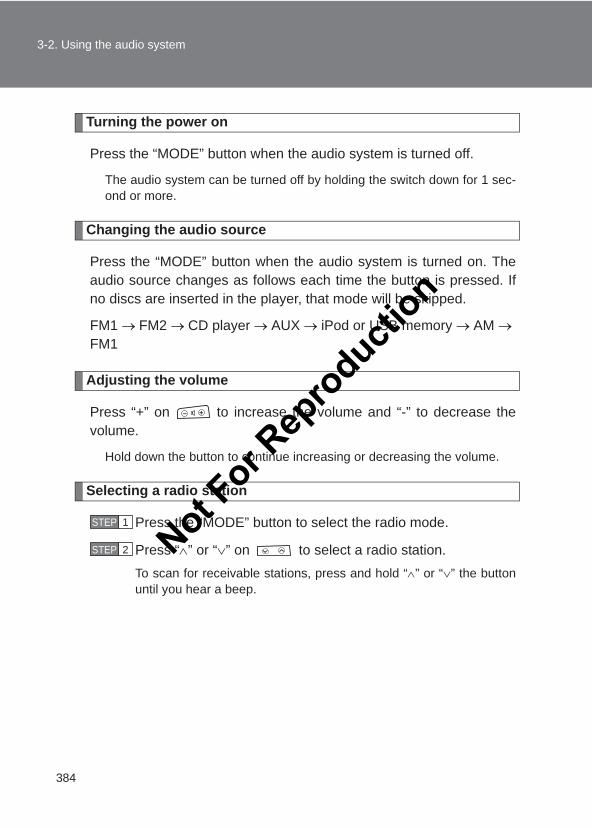
384
3-2. Using the audio system
LC150_OM_OM60J77E_(AE)
Turning the power on
Press the “MODE” button when the audio system is turned off.
The audio system can be turned off by holding the switch down for 1 sec-ond or more.
Changing the audio source
Press the “MODE” button when the audio system is turned on. Theaudio source changes as follows each time the button is pressed. Ifno discs are inserted in the player, that mode will be skipped.
FM1 → FM2 → CD player → AUX → iPod or USB memory → AM → FM1
Adjusting the volume
Press “+” on to increase the volume and “-” to decrease thevolume.
Hold down the button to continue increasing or decreasing the volume.
Selecting a radio station
Press the “MODE” button to select the radio mode.
Press “∧” or “∨” on to select a radio station.To scan for receivable stations, press and hold “∧” or “∨” the buttonuntil you hear a beep.
STEP 1
STEP 2 Not For R
epro
duction
385
3-2. Using the audio system
3
Interior features
LC150_OM_OM60J77E_(AE)
Selecting a track/file or song
Press the “MODE” button to select CD, iPod or USB memorymode.
Press “∧” or “∨” on to select the desired track/file orsong.
Selecting a folder
Press the “MODE” button to select USB memory mode.
Press and hold “∧” or “∨” on until you hear a beep.
Selecting a disc in the CD player
Press the “MODE” button to select CD mode.
Press and hold “∧” or “∨” on until you hear a beep.
■Canceling automatic selection of a radio stationPress again.
CAUTION
■To reduce the risk of an accidentExercise care when operating the audio switches on the steering wheel.
STEP 1
STEP 2
STEP 1
STEP 2
STEP 1
STEP 2
Not For R
epro
duction
386
LC150_OM_OM60J77E_(AE)
3-3. Using the hands-free system (for mobile phone)
Hands-free system (for mobile phone)∗
∗: If equipped
The hands-free system is a function that allows you to use yourmobile phone without touching it.
This system supports Bluetooth® mobile phones. Bluetooth® is awireless data system that allows the mobile phone to wirelessly con-nect to the hands-free system and make/receive calls.
Vehicles with a navigation systemRefer to the “Navigation System Owner’s Manual”.
Vehicles without a navigation system■ Hands-free system quick guide
Setting a mobile phone. (→P. 393)Adding an entry to the phonebook. (Up to 20 names can bestored.) (→P. 406)
Dialing by inputting a name. (→P. 397)
■ Hands-free function list
Title Page
Using the hands-free system■Using the hands-free phone system for
the first timeP. 391
STEP 1
STEP 2
STEP 3
Not For R
epro
duction
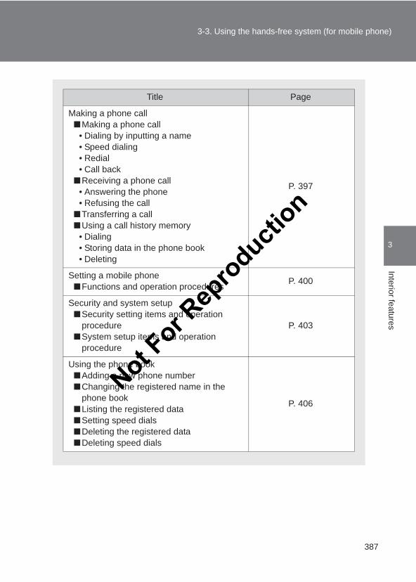
387
3-3. Using the hands-free system (for mobile phone)
3
Interior features
LC150_OM_OM60J77E_(AE)
Title Page
Making a phone call■Making a phone call
• Dialing by inputting a name• Speed dialing• Redial• Call back
■Receiving a phone call• Answering the phone• Refusing the call
■Transferring a call■Using a call history memory
• Dialing• Storing data in the phone book• Deleting
P. 397
Setting a mobile phone■Functions and operation procedures P. 400
Security and system setup■Security setting items and operation
procedure■System setup items and operation
procedure
P. 403
Using the phone book■Adding a new phone number■Changing the registered name in the
phone book■Listing the registered data■Setting speed dials■Deleting the registered data■Deleting speed dials
P. 406
Not For R
epro
duction
388
3-3. Using the hands-free system (for mobile phone)
LC150_OM_OM60J77E_(AE)
■Conditions under which the system will not operate● If using a mobile phone that does not support Bluetooth®.
● If the mobile phone is switched off.
● If you are outside service range.
● If the mobile phone is not connected.
● If the mobile phone’s battery is low.
●The mobile phone is behind the seat or in the glove box or console box
●Metal is covering or touching the phone
■Signal statusThis display may not correspond exactly with the mobile phone itself.
■When using the hands-free system●The audio system and voice guidance are muted when making a call.
● If both parties speak at the same time, it may be difficult to hear.
● If the incoming call volume is overly loud, an echo may be heard.
●Try to face toward the microphone as much as possible when speaking.
● In the following circumstances, it may be difficult to hear the other party:
• When driving on unpaved roads• When driving at high speeds• When a window is open• When the air conditioning is blowing directly on the microphone• When the air conditioning is set to highNot F
or Rep
roducti
on
389
3-3. Using the hands-free system (for mobile phone)
3
Interior features
LC150_OM_OM60J77E_(AE)
■When transferring ownership of the vehicleBe sure to initialize the system to prevent personal data from being improp-erly accessed. (→P. 405)
■About Bluetooth®
■Compatible modelsCompatible with HFP (Hands Free Profile) Ver. 1.5 and OPP (Object PushProfile) Ver. 1.1.
If your mobile phone does not support HFP, you cannot enter the Bluetooth®
phone. If your mobile phone supports OPP alone, you cannot use theBluetooth® phone.
Bluetooth is a registered trademark ofBluetooth SIG. Inc.
Not For R
epro
duction
390
3-3. Using the hands-free system (for mobile phone)
LC150_OM_OM60J77E_(AE)
CAUTION
■Caution while drivingDo not use a mobile phone or connect the Bluetooth® phone.
■Caution regarding interference with electronic devices●Your audio unit is fitted with Bluetooth® antennas. People with implanted
pacemakers or cardiac defibrillators should maintain a reasonable dis-tance between themselves and the Bluetooth® antennas.The radio waves may affect the operation of such devices.
●Before using Bluetooth® devices, users of any electrical medical deviceother than implanted pacemakers and implanted cardiac defibrillatorsshould consult the manufacturer of the device for information about itsoperation under the influence of radio waves. Radio waves could haveunexpected effects on the operation of such medical devices.
NOTICE
■To prevent damage to mobile phonesDo not leave mobile phones in the vehicle. The temperature inside the vehi-cle may become high, resulting in damage to the phone.
Not For R
epro
duction
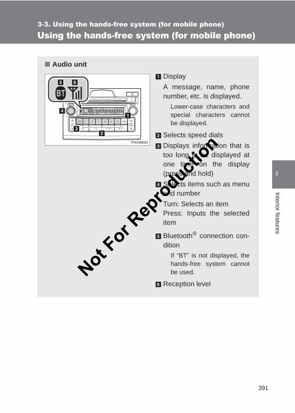
391
3-3. Using the hands-free system (for mobile phone)
3
Interior features
LC150_OM_OM60J77E_(AE)
Using the hands-free system (for mobile phone)
■ Audio unitDisplayA message, name, phonenumber, etc. is displayed.
Lower-case characters andspecial characters cannotbe displayed.
Selects speed dialsDisplays information that istoo long to be displayed atone time on the display(press and hold)Selects items such as menuand numberTurn: Selects an item Press: Inputs the selecteditem
Bluetooth® connection con-dition
If “BT” is not displayed, thehands-free system cannotbe used.
Reception levelNot F
or Rep
roducti
on
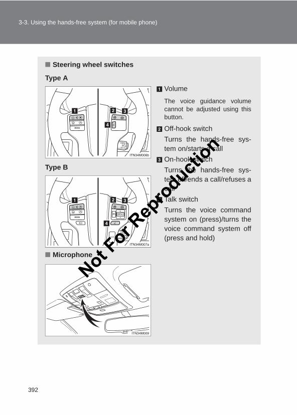
392
3-3. Using the hands-free system (for mobile phone)
LC150_OM_OM60J77E_(AE)
■ Steering wheel switches
Type AVolume
The voice guidance volumecannot be adjusted using thisbutton.
Off-hook switchTurns the hands-free sys-tem on/starts a callOn-hook switchTurns the hands-free sys-tem off/ends a call/refuses acallTalk switchTurns the voice commandsystem on (press)/turns thevoice command system off(press and hold)
Type B
■ Microphone
Not For R
epro
duction
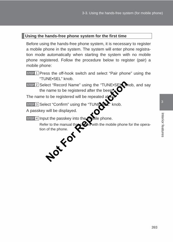
393
3-3. Using the hands-free system (for mobile phone)
3
Interior features
LC150_OM_OM60J77E_(AE)
Using the hands-free phone system for the first time
Before using the hands-free phone system, it is necessary to registera mobile phone in the system. The system will enter phone registra-tion mode automatically when starting the system with no mobilephone registered. Follow the procedure below to register (pair) amobile phone:
Press the off-hook switch and select “Pair phone” using the“TUNE•SEL” knob.Select “Record Name” using the “TUNE•SEL” knob, and saythe name to be registered after the beep.
The name to be registered will be repeated aloud.
Select “Confirm” using the “TUNE•SEL” knob.A passkey will be displayed.
Input the passkey into the mobile phone.Refer to the manual that comes with the mobile phone for the opera-tion of the phone.
STEP 1
STEP 2
STEP 3
STEP 4
Not For R
epro
duction
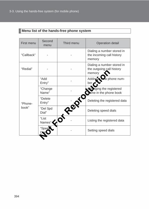
394
3-3. Using the hands-free system (for mobile phone)
LC150_OM_OM60J77E_(AE)
Menu list of the hands-free phone system
First menu Second menu Third menu Operation detail
“Callback” - -Dialing a number stored in the incoming call history memory
“Redial” - -Dialing a number stored in the outgoing call history memory
“Phone-book”
“Add Entry” - Adding a new phone num-
ber
“Change Name” - Changing the registered
name in the phone book
“Delete Entry” - Deleting the registered data
“Del Spd Dial” - Deleting speed dials
“List Names” - Listing the registered data
“Speed Dial” - Setting speed dials
Not For R
epro
duction
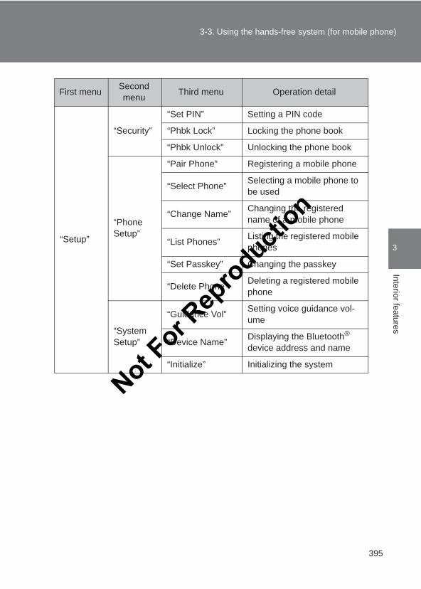
395
3-3. Using the hands-free system (for mobile phone)
3
Interior features
LC150_OM_OM60J77E_(AE)
“Setup”
“Security”
“Set PIN” Setting a PIN code
“Phbk Lock” Locking the phone book
“Phbk Unlock” Unlocking the phone book
“Phone Setup”
“Pair Phone” Registering a mobile phone
“Select Phone” Selecting a mobile phone to be used
“Change Name” Changing the registered name of a mobile phone
“List Phones” Listing the registered mobile phones
“Set Passkey” Changing the passkey
“Delete Phone” Deleting a registered mobile phone
“System Setup”
“Guidance Vol” Setting voice guidance vol-ume
“Device Name” Displaying the Bluetooth® device address and name
“Initialize” Initializing the system
First menu Second menu Third menu Operation detail
Not For R
epro
duction
396
3-3. Using the hands-free system (for mobile phone)
LC150_OM_OM60J77E_(AE)
■Automatic volume adjustmentWhen vehicle speed reaches 80 km/h (50 mph) or more, the volume auto-matically increases. The volume returns to the previous volume setting whenvehicle speed drops to 70 km/h (43 mph) or less.
■Operations that cannot be performed while driving●Operating the system with the “TUNE•SEL” knob
●Registering a mobile phone to the system
■Changing the passkey→P. 402
Not For R
epro
duction
397
3-3. Using the hands-free system (for mobile phone)
3
Interior features
LC150_OM_OM60J77E_(AE)
Making a phone call
Dialing by inputting a name
Press the talk switch and say a registered name.The desired name or number is displayed.
Dial by one of the following methods:a. Press the off-hook switch.
b. Select “Dial” using the “TUNE•SEL” knob.
In , if the pronounced name cannot be recognized, select thedesired name using the “TUNE•SEL” knob.
■ Making a phone call● Dialing by inputting a name
“Dial by name”
● Speed dialing
● Dialing a number stored in the outgoing history memory “Redial”
● Dialing a number stored in the incoming history memory “Call back”
■ Receiving a phone call● Answering the phone
● Refusing the call
■ Transferring a call■ Using the call history memory
● Dialing
● Storing data in the phone book
● Deleting
STEP 1
STEP 2
STEP 1
Not For R
epro
duction
398
3-3. Using the hands-free system (for mobile phone)
LC150_OM_OM60J77E_(AE)
Speed dialing
Press the off-hook switch.Press the preset button in which the desired number is regis-tered.
Press the off-hook switch.
When receiving a phone call
■ Answering the phonePress the off-hook switch.
■ Refusing the callPress the on-hook switch.
Transferring a call
A call can be transferred between the mobile phone and system whiledialing, receiving a call, or during a call. Use one of the followingmethods:
a. Operate the mobile phone.
Refer to the manual that comes with the mobile phone for the opera-tion of the phone.
b. Press the off-hook switch*.
*: This operation can be performed only when transferring a callfrom the mobile phone to the system during a call.
STEP 1
STEP 2
STEP 3
Not For R
epro
duction
399
3-3. Using the hands-free system (for mobile phone)
3
Interior features
LC150_OM_OM60J77E_(AE)
Using a call history memory
Follow the procedure below to use number stored in call historymemory:
Press the off-hook switch and select “Redial” (when using anumber stored in the outgoing call history memory) or “Callback” (when using a number stored in the incoming call his-tory memory) using the “TUNE•SEL” knob.Select the desired number using the “TUNE•SEL” knob.The following operations can be performed:
Dialing: Press the off-hook switch or select “Dial” using the“TUNE•SEL” knob.
Storing the number in the phone book: Select “Store” and then“Confirm” using the “TUNE•SEL” knob.
Deleting: Select “Delete” and then “Confirm” using the“TUNE•SEL” knob.
■Call historyUp to 5 numbers can be stored in each of the outgoing and incoming call his-tory memories.
■When talking on the phone●Do not talk simultaneously with the other party.
●Keep the volume of the receiving voice down. Otherwise, voice echo willincrease.
STEP 1
STEP 2
STEP 3
Not For R
epro
duction
400
3-3. Using the hands-free system (for mobile phone)
LC150_OM_OM60J77E_(AE)
Setting a mobile phone
Registering a mobile phone in the hands-free phone system allowsthe system to function. The following function can be used for regis-tered mobile phones:
■ Functions and operation proceduresTo enter menu for each function, follow the steps below.
Press the off-hook switch and select “Setup” using the“TUNE•SEL” knob.Select “Phone Setup” using the “TUNE•SEL” knob.Select one of the following items using the “TUNE•SEL”knob:
● Registering a mobile phone“Pair Phone”
● Selecting a mobile phone to be used“Select Phone”
● Changing the registered name of a mobile phone“Change Name”
● Listing the registered mobile phones“List Phones”
● Changing the passkey“Set Passkey”
● Deleting a registered mobile phone“Delete Phone”
STEP 1
STEP 2
STEP 3
Not For R
epro
duction
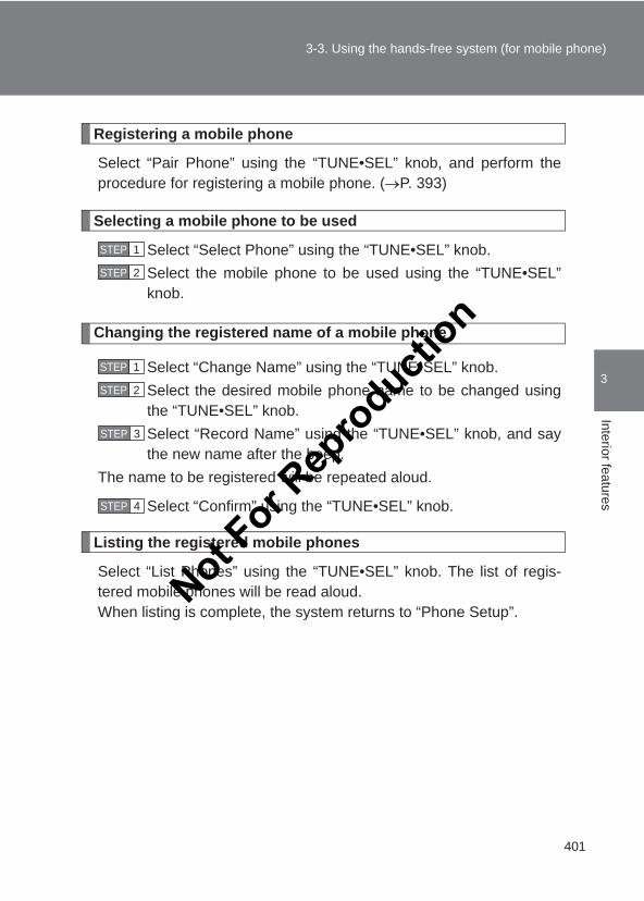
401
3-3. Using the hands-free system (for mobile phone)
3
Interior features
LC150_OM_OM60J77E_(AE)
Registering a mobile phone
Select “Pair Phone” using the “TUNE•SEL” knob, and perform theprocedure for registering a mobile phone. (→P. 393)
Selecting a mobile phone to be used
Select “Select Phone” using the “TUNE•SEL” knob.Select the mobile phone to be used using the “TUNE•SEL”knob.
Changing the registered name of a mobile phone
Select “Change Name” using the “TUNE•SEL” knob.Select the desired mobile phone name to be changed usingthe “TUNE•SEL” knob.Select “Record Name” using the “TUNE•SEL” knob, and saythe new name after the beep.
The name to be registered will be repeated aloud.
Select “Confirm” using the “TUNE•SEL” knob.
Listing the registered mobile phones
Select “List Phones” using the “TUNE•SEL” knob. The list of regis-tered mobile phones will be read aloud.When listing is complete, the system returns to “Phone Setup”.
STEP 1
STEP 2
STEP 1
STEP 2
STEP 3
STEP 4
Not For R
epro
duction
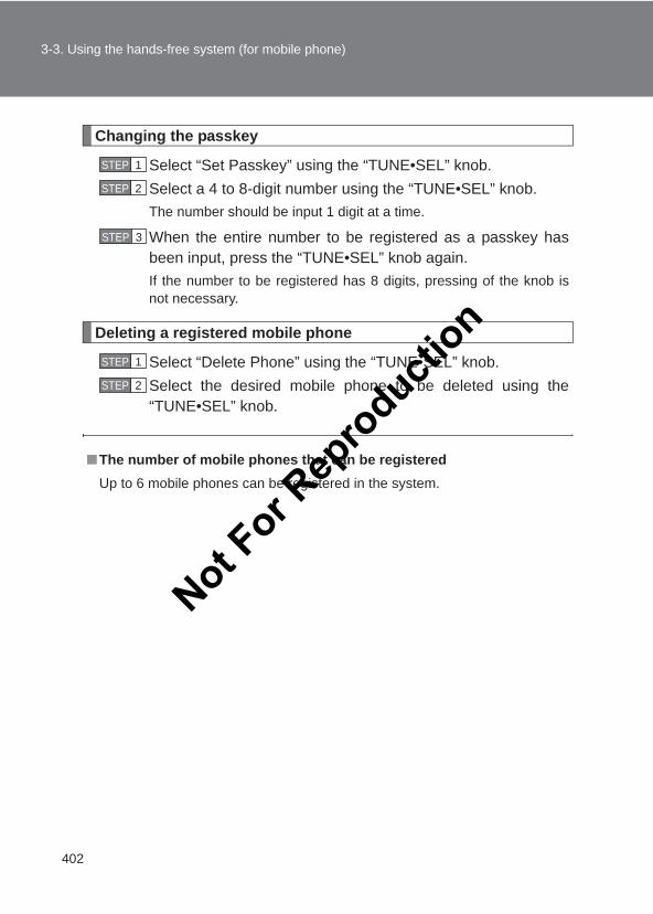
402
3-3. Using the hands-free system (for mobile phone)
LC150_OM_OM60J77E_(AE)
Changing the passkey
Select “Set Passkey” using the “TUNE•SEL” knob.Select a 4 to 8-digit number using the “TUNE•SEL” knob.The number should be input 1 digit at a time.
When the entire number to be registered as a passkey hasbeen input, press the “TUNE•SEL” knob again.If the number to be registered has 8 digits, pressing of the knob isnot necessary.
Deleting a registered mobile phone
Select “Delete Phone” using the “TUNE•SEL” knob.Select the desired mobile phone to be deleted using the“TUNE•SEL” knob.
■The number of mobile phones that can be registeredUp to 6 mobile phones can be registered in the system.
STEP 1
STEP 2
STEP 3
STEP 1
STEP 2
Not For R
epro
duction
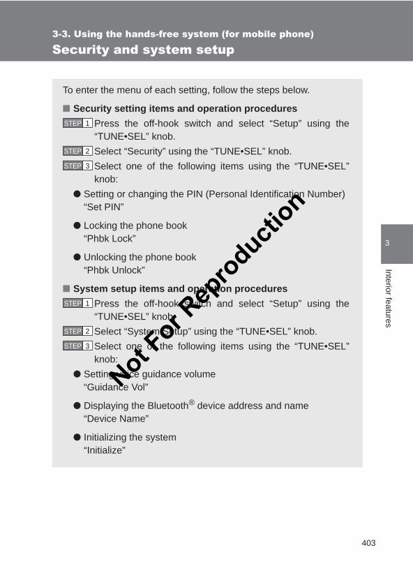
403
3-3. Using the hands-free system (for mobile phone)
3
Interior features
LC150_OM_OM60J77E_(AE)
Security and system setup
To enter the menu of each setting, follow the steps below.
■ Security setting items and operation proceduresPress the off-hook switch and select “Setup” using the“TUNE•SEL” knob.Select “Security” using the “TUNE•SEL” knob.Select one of the following items using the “TUNE•SEL”knob:
● Setting or changing the PIN (Personal Identification Number)“Set PIN”
● Locking the phone book“Phbk Lock”
● Unlocking the phone book“Phbk Unlock”
■ System setup items and operation proceduresPress the off-hook switch and select “Setup” using the“TUNE•SEL” knob.Select “System Setup” using the “TUNE•SEL” knob.Select one of the following items using the “TUNE•SEL”knob:
● Setting voice guidance volume“Guidance Vol”
● Displaying the Bluetooth® device address and name“Device Name”
● Initializing the system“Initialize”
STEP 1
STEP 2
STEP 3
STEP 1
STEP 2
STEP 3
Not For R
epro
duction
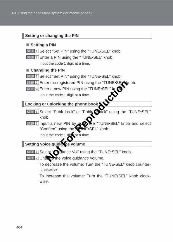
404
3-3. Using the hands-free system (for mobile phone)
LC150_OM_OM60J77E_(AE)
Setting or changing the PIN
■ Setting a PINSelect “Set PIN” using the “TUNE•SEL” knob.Enter a PIN using the “TUNE•SEL” knob.Input the code 1 digit at a time.
■ Changing the PINSelect “Set PIN” using the “TUNE•SEL” knob.Enter the registered PIN using the “TUNE•SEL” knob.Enter a new PIN using the “TUNE•SEL” knob.Input the code 1 digit at a time.
Locking or unlocking the phone book
Select “Phbk Lock” or “Phbk Unlock” using the “TUNE•SEL”knob.Input a new PIN by using the “TUNE•SEL” knob and select“Confirm” using the “TUNE•SEL” knob.Input the code 1 digit at a time.
Setting voice guidance volume
Select “Guidance Vol” using the “TUNE•SEL” knob.Change the voice guidance volume.To decrease the volume: Turn the “TUNE•SEL” knob counter-clockwise.To increase the volume: Turn the “TUNE•SEL” knob clock-wise.
STEP 1
STEP 2
STEP 1
STEP 2
STEP 3
STEP 1
STEP 2
STEP 1
STEP 2 Not For R
epro
duction
405
3-3. Using the hands-free system (for mobile phone)
3
Interior features
LC150_OM_OM60J77E_(AE)
Displaying the Bluetooth® device address and name
Select “Device Name” using the “TUNE•SEL” knob.Turn the “TUNE•SEL” knob to display the Bluetooth® deviceaddress and name.Select “Go Back” using the “TUNE•SEL” knob to return to“System Setup”.
Initializing the system
Select “Initialize” and then “Confirm” using the “TUNE•SEL”knob.Select “Confirm” again using the “TUNE•SEL” knob.
■ Initialization●The following data in the system can be initialized:
• Phone book• Outgoing and incoming call history• Speed dials• Registered mobile phone data• Security code• Passkeys for the mobile phones• Guidance volume• Receiver volume• Ring tone volume
●Once the initialization has been completed, the data cannot be restoredto its original state.
■When the phone book is lockedThe following functions cannot be used:
●Dialing by inputting a name
●Speed dialing
●Dialing a number stored in the call history memory
●Using the phone book
STEP 1
STEP 2
STEP 3
STEP 1
STEP 2
Not For R
epro
duction
406
3-3. Using the hands-free system (for mobile phone)
LC150_OM_OM60J77E_(AE)
Using the phone book
To enter the menu of each setting, follow the steps below.
Press the off-hook switch and select “Phonebook” using the“TUNE•SEL” knob.Select one of the following items using the “TUNE•SEL”knob:
● Adding a new phone number“Add Entry”
● Changing the registered name in the phone book“Change Name”
● Listing the registered data“List Names”
● Setting speed dials“Speed Dial”
● Deleting the registered data“Delete Entry”
● Deleting speed dials“Del Spd Dial”
STEP 1
STEP 2
Not For R
epro
duction
407
3-3. Using the hands-free system (for mobile phone)
3
Interior features
LC150_OM_OM60J77E_(AE)
Adding a new phone number
The following methods can be used to add a new phone number:
● Transferring data from the mobile phone
● Inputting a phone number using the “TUNE•SEL” knob
● Selecting a phone number from outgoing or incoming call history
■ Adding procedureSelect “Add Entry” using the “TUNE•SEL” knob.
Use one of the following methods to input a telephone num-ber:
Transferring data from the mobile phone:STEP2-1 Select “By Phone” and then “Confirm” using the
“TUNE•SEL” knob.STEP2-2 When “Transfer” appears in the display, transfer
the data from the mobile phone.Refer to the manual that comes with the mobile phonefor the details of transferring data.
STEP2-3 Select the desired data using the “TUNE•SEL”knob.
Inputting a phone number using the “TUNE•SEL” knob:STEP2-1 Select “Manual Input” using the “TUNE•SEL” knob.STEP2-2 Input a phone number using the “TUNE•SEL”
knob, and press the “TUNE•SEL” knob again.Input the phone number 1 digit at a time.
Selecting a phone number from outgoing or incoming call history:STEP2-1 Select “Call History” using the “TUNE•SEL” knob.STEP2-2 Select “Outgoing” or “Incoming” using the
“TUNE•SEL” knob.STEP2-3 Select the desired data using the “TUNE•SEL”
knob.
STEP 1
STEP 2
Not For R
epro
duction
408
3-3. Using the hands-free system (for mobile phone)
LC150_OM_OM60J77E_(AE)
Select “Record Name” using the “TUNE•SEL” knob, and saythe desired name after the beep.
The name to be registered will be repeated aloud.
Select “Confirm” using the “TUNE•SEL” knob.Select “Confirm” again using the “TUNE•SEL” knob.In , selecting “Speed Dial” instead of “Confirm” registers thenewly added phone number as a speed dial.
Changing the registered name in the phone book
Select “Change Name” using the “TUNE•SEL” knob.Select the desired name to be changed using the“TUNE•SEL” knob.Select “Record Name” using the “TUNE•SEL” knob, and saythe new name after the beep.
The name to be registered will be repeated aloud.
Select “Confirm” using the “TUNE•SEL” knob.
Listing the registered data
Selecting “List Names” using the “TUNE•SEL” knob. The list of theregistered data will be read aloud.
When listing is complete, the system returns to “Phonebook”.
Pressing the off-hook switch while an entry is being read aloudselects the entry, and calls the registered phone number.
STEP 3
STEP 4
STEP 5
STEP 5
STEP 1
STEP 2
STEP 3
STEP 4
Not For R
epro
duction
409
3-3. Using the hands-free system (for mobile phone)
3
Interior features
LC150_OM_OM60J77E_(AE)
Setting speed dials
Select “Speed Dial” using the “TUNE•SEL” knob.Select the desired data using the “TUNE•SEL” knob.Select the desired preset button, and register the data intospeed dial by either of the following methods:a. Press the desired preset button, and select “Confirm” using
the “TUNE•SEL” knob.b. Press and hold the desired preset button.
Deleting the registered data
Select “Delete Entry” using the “TUNE•SEL” knob.Select the desired data to be deleted using the “TUNE•SEL”knob.
Deleting speed dials
Select “Del Spd Dial” using the “TUNE•SEL” knob.Press the preset button to which the desired speed dial is reg-istered after the beep.
The name to be deleted will be heard.
Select “Confirm” using the “TUNE•SEL” knob.
■Limitation of number of digitsA phone number that exceeds 24 digits cannot be registered.
STEP 1
STEP 2
STEP 3
STEP 1
STEP 2
STEP 1
STEP 2
STEP 3
Not For R
epro
duction
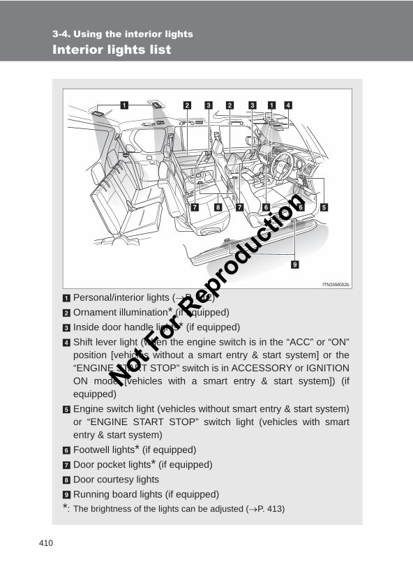
410
LC150_OM_OM60J77E_(AE)
3-4. Using the interior lights
Interior lights list
Personal/interior lights (→P. 412)Ornament illumination* (if equipped)Inside door handle lights* (if equipped)Shift lever light (when the engine switch is in the “ACC” or “ON”position [vehicles without a smart entry & start system] or the“ENGINE START STOP” switch is in ACCESSORY or IGNITIONON mode [vehicles with a smart entry & start system]) (ifequipped)Engine switch light (vehicles without smart entry & start system)or “ENGINE START STOP” switch light (vehicles with smartentry & start system)Footwell lights* (if equipped)Door pocket lights* (if equipped)Door courtesy lightsRunning board lights (if equipped)
*: The brightness of the lights can be adjusted (→P. 413)
Not For R
epro
duction
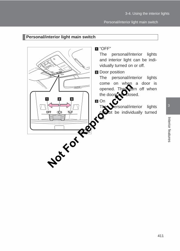
411
3-4. Using the interior lights
3
Interior features
LC150_OM_OM60J77E_(AE)
Personal/interior light main switch
“OFF”The personal/Interior lightsand interior light can be indi-vidually turned on or off.Door positionThe personal/interior lightscome on when a door isopened. They turn off whenthe doors are closed.OnThe personal/interior lightscannot be individually turnedoff.
Personal/interior light main switch
Not For R
epro
duction
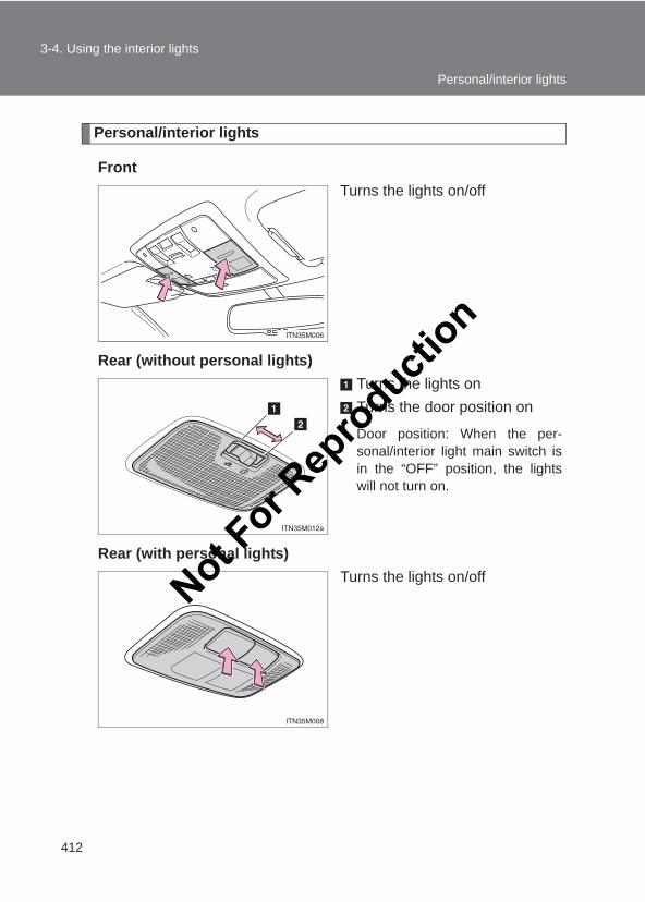
412
3-4. Using the interior lights
LC150_OM_OM60J77E_(AE)
Personal/interior lights
FrontTurns the lights on/off
Rear (without personal lights)Turns the lights onTurns the door position on
Door position: When the per-sonal/interior light main switch isin the “OFF” position, the lightswill not turn on.
Rear (with personal lights)Turns the lights on/off
Personal/interior lights
Not For R
epro
duction
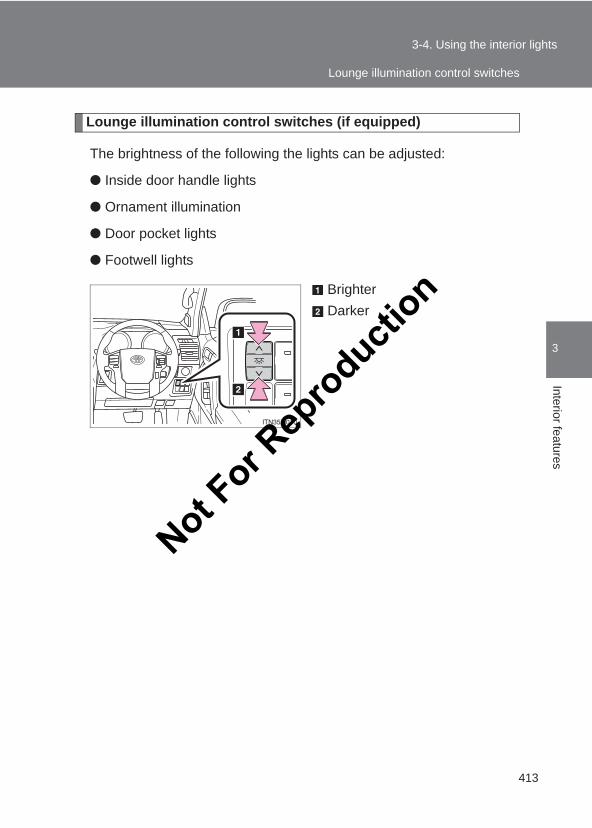
413
3-4. Using the interior lights
3
Interior features
LC150_OM_OM60J77E_(AE)
Lounge illumination control switches (if equipped)
The brightness of the following the lights can be adjusted:
● Inside door handle lights
● Ornament illumination
● Door pocket lights
● Footwell lights
BrighterDarker
Lounge illumination control switches
Not For R
epro
duction
414
3-4. Using the interior lights
LC150_OM_OM60J77E_(AE)
■ Illuminated entry systemVehicles without a smart entry & start systemThe lights automatically turn on/off according to the engine switch position,whether the doors are locked/unlocked, and whether the doors are open/closed.
Vehicles with a smart entry & start systemThe lights automatically turn on/off according to “ENGINE START STOP”switch mode, the presence of the electronic key, whether the doors arelocked/unlocked, and whether the doors are open/closed.
■To prevent battery dischargeIf the following lights remain on when the door is not fully closed and the per-sonal/interior light main switch is in the door position, the lights will go offautomatically after 20 minutes:
●Personal/interior light
● Inside door handle lights (if equipped)
●Ornament illumination (if equipped)
●Door pocket lights (if equipped)
●Footwell lights (if equipped)
●Running board lights (if equipped)
■CustomizationSettings (e.g. time elapsed before the interior lights turn off) can be changed. (Customizable features →P. 632)Not F
or Rep
roducti
on
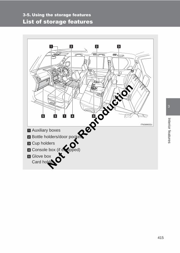
415
3
Interior features
LC150_OM_OM60J77E_(AE)
3-5. Using the storage features
List of storage features
Auxiliary boxesBottle holders/door pocketsCup holdersConsole box (if equipped)Glove boxCard holderNot F
or Rep
roducti
on
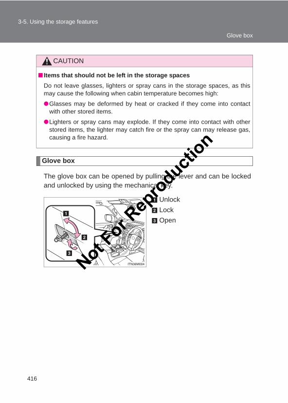
416
3-5. Using the storage features
LC150_OM_OM60J77E_(AE)
Glove box
The glove box can be opened by pulling the lever and can be lockedand unlocked by using the mechanical key.
UnlockLockOpen
CAUTION
■ Items that should not be left in the storage spacesDo not leave glasses, lighters or spray cans in the storage spaces, as thismay cause the following when cabin temperature becomes high:
●Glasses may be deformed by heat or cracked if they come into contactwith other stored items.
●Lighters or spray cans may explode. If they come into contact with otherstored items, the lighter may catch fire or the spray can may release gas,causing a fire hazard.
Glove box
Not For R
epro
duction
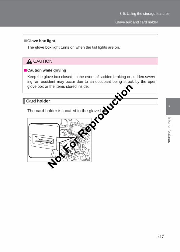
417
3-5. Using the storage features
3
Interior features
LC150_OM_OM60J77E_(AE)
Card holder
The card holder is located in the glove box.
■Glove box lightThe glove box light turns on when the tail lights are on.
CAUTION
■Caution while drivingKeep the glove box closed. In the event of sudden braking or sudden swerv-ing, an accident may occur due to an occupant being struck by the openglove box or the items stored inside.
Glove box and card holder
Not For R
epro
duction
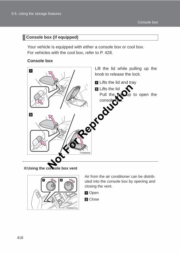
418
3-5. Using the storage features
LC150_OM_OM60J77E_(AE)
Console box (if equipped)
Your vehicle is equipped with either a console box or cool box.For vehicles with the cool box, refer to P. 428.
Console box
Lift the lid while pulling up theknob to release the lock.
Lifts the lid and trayLifts the lidPull the tray up to open theconsole box.
■Using the console box vent
Air from the air conditioner can be distrib-uted into the console box by opening andclosing the vent.
Open
Close
Console box
Not For R
epro
duction
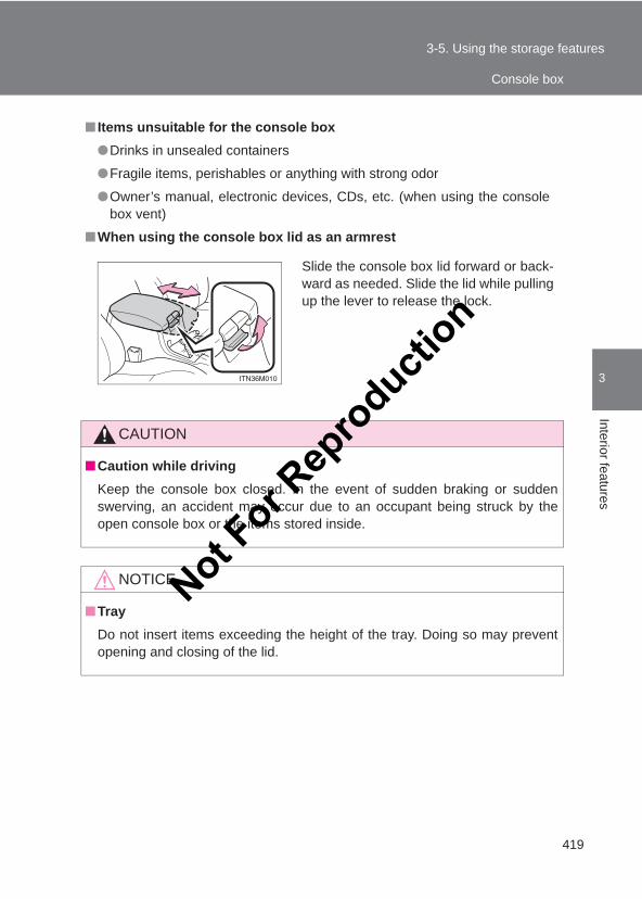
419
3-5. Using the storage features
3
Interior features
LC150_OM_OM60J77E_(AE)
■ Items unsuitable for the console box●Drinks in unsealed containers
●Fragile items, perishables or anything with strong odor
●Owner’s manual, electronic devices, CDs, etc. (when using the consolebox vent)
■When using the console box lid as an armrest
CAUTION
■Caution while drivingKeep the console box closed. In the event of sudden braking or suddenswerving, an accident may occur due to an occupant being struck by theopen console box or the items stored inside.
NOTICE
■TrayDo not insert items exceeding the height of the tray. Doing so may preventopening and closing of the lid.
Slide the console box lid forward or back-ward as needed. Slide the lid while pullingup the lever to release the lock.
Console box
Not For R
epro
duction
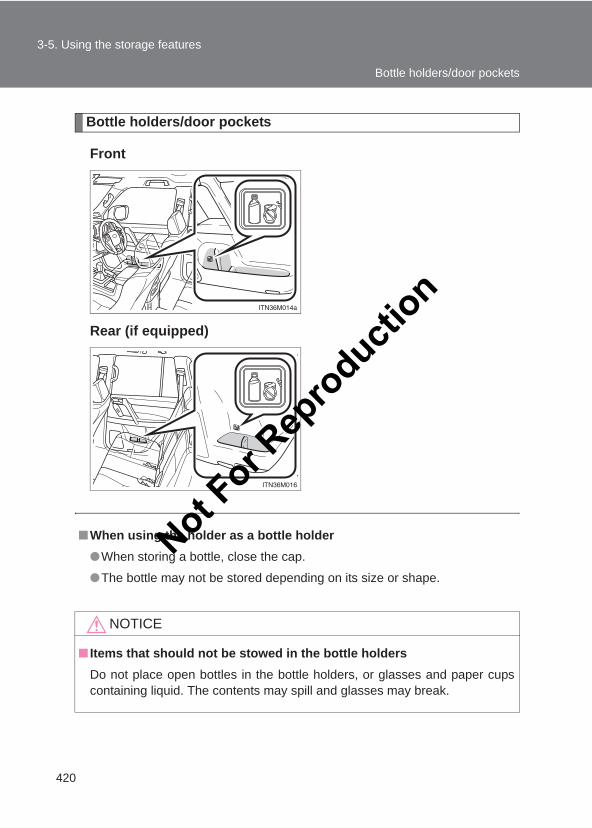
420
3-5. Using the storage features
LC150_OM_OM60J77E_(AE)
Bottle holders/door pockets
Front
Rear (if equipped)
■When using the holder as a bottle holder●When storing a bottle, close the cap.
●The bottle may not be stored depending on its size or shape.
NOTICE
■ Items that should not be stowed in the bottle holdersDo not place open bottles in the bottle holders, or glasses and paper cupscontaining liquid. The contents may spill and glasses may break.
Bottle holders/door pockets
Not For R
epro
duction
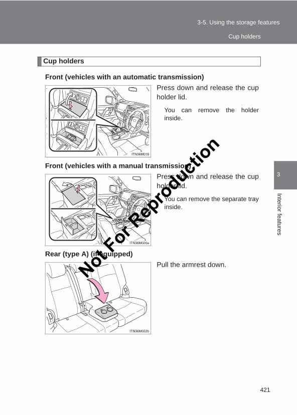
421
3-5. Using the storage features
3
Interior features
LC150_OM_OM60J77E_(AE)
Cup holders
Front (vehicles with an automatic transmission)Press down and release the cupholder lid.
You can remove the holderinside.
Front (vehicles with a manual transmission)Press down and release the cupholder lid.
You can remove the separate trayinside.
Rear (type A) (if equipped)Pull the armrest down.
Cup holders
Not For R
epro
duction
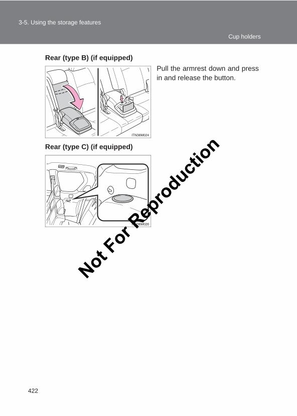
422
3-5. Using the storage features
LC150_OM_OM60J77E_(AE)
Rear (type B) (if equipped)Pull the armrest down and pressin and release the button.
Rear (type C) (if equipped)
Cup holders
Not For R
epro
duction
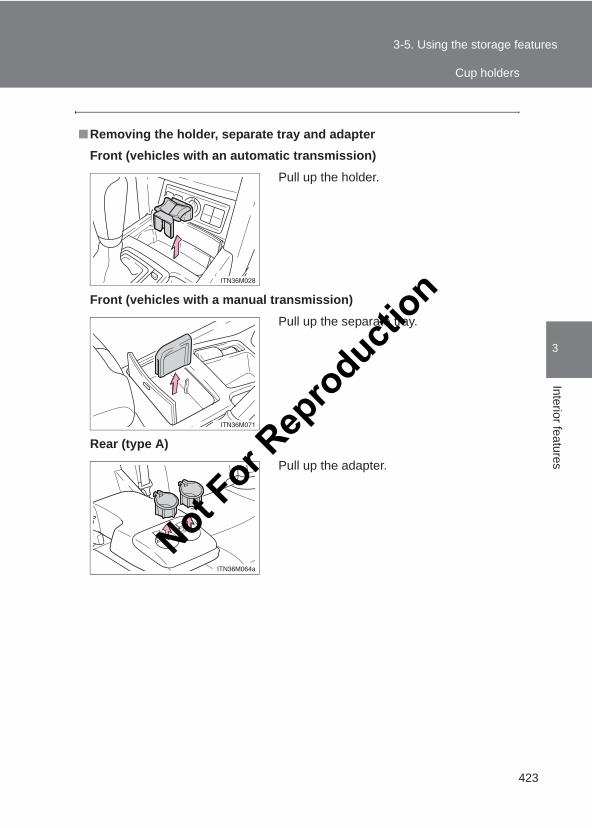
423
3-5. Using the storage features
3
Interior features
LC150_OM_OM60J77E_(AE)
■Removing the holder, separate tray and adapterFront (vehicles with an automatic transmission)
Front (vehicles with a manual transmission)
Rear (type A)
Pull up the holder.
Pull up the separate tray.
Pull up the adapter.
Cup holders
Not For R
epro
duction
424
3-5. Using the storage features
LC150_OM_OM60J77E_(AE)
CAUTION
■ Items unsuitable for the cup holderDo not place anything other than cups, mugs or beverage cans in the cupholders.Other items may be thrown out of the holders in the event of sudden braking,sudden swerving or an accident, cause injury. If possible, cover hot drinks toprevent burns.
■When not in useKeep the cup holders closed. In the event of sudden braking or suddenswerving, an accident may occur due to an occupant being struck by theopen cup holders or the items stored inside.
NOTICE
■To prevent damage to the rear cup holders (rear [type B])Stow the cup holders before stowing the armrest.
Cup holders
Not For R
epro
duction
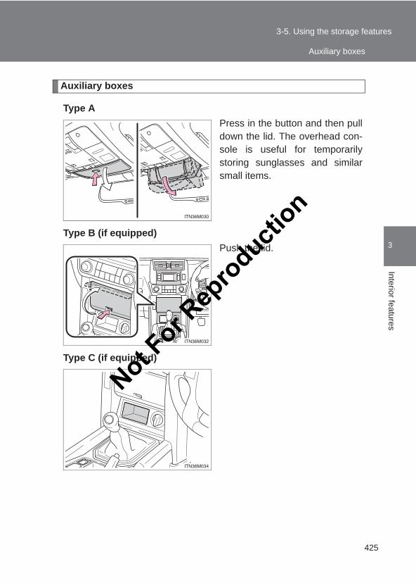
425
3-5. Using the storage features
3
Interior features
LC150_OM_OM60J77E_(AE)
Auxiliary boxes
Type APress in the button and then pulldown the lid. The overhead con-sole is useful for temporarilystoring sunglasses and similarsmall items.
Type B (if equipped)Push the lid.
Type C (if equipped)
Auxiliary boxes
Not For R
epro
duction
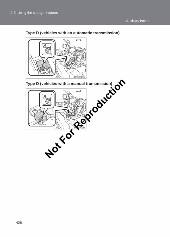
426
3-5. Using the storage features
LC150_OM_OM60J77E_(AE)
Type D (vehicles with an automatic transmission)
Type D (vehicles with a manual transmission)
Auxiliary boxes
Not For R
epro
duction
427
3-5. Using the storage features
3
Interior features
LC150_OM_OM60J77E_(AE)
CAUTION
■Caution while driving●Keep the auxiliary boxes closed. In the event of sudden braking or sudden
swerving, an accident may occur due to an occupant being struck by anopen auxiliary box or the items stored inside.
●Do not place cups, beverage cans or bottles in the box. They may bethrown out of the box in the event of sudden braking, sudden swerving oran accident, resulting in injury. (type D)
■ Items unsuitable for storing (type A)●Do not store items heavier than 0.2 kg (0.4 lb.).
Doing so may cause the auxiliary box to open and the items inside may fallout, resulting in an accident.
●Do not put large items in the overhead console.The overhead console may not be able to be shut from the conversationmirror state.
Auxiliary boxes
Not For R
epro
duction
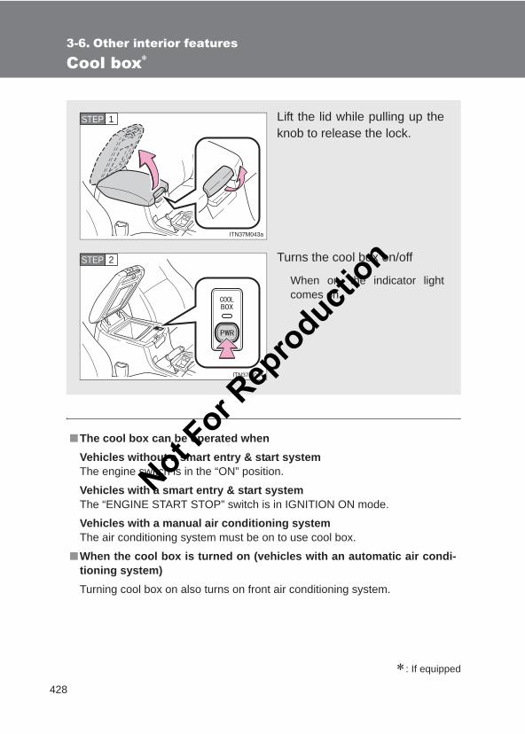
428
LC150_OM_OM60J77E_(AE)
3-6. Other interior features
Cool box∗
∗: If equipped
■The cool box can be operated whenVehicles without a smart entry & start systemThe engine switch is in the “ON” position.
Vehicles with a smart entry & start systemThe “ENGINE START STOP” switch is in IGNITION ON mode.
Vehicles with a manual air conditioning systemThe air conditioning system must be on to use cool box.
■When the cool box is turned on (vehicles with an automatic air condi-tioning system)Turning cool box on also turns on front air conditioning system.
Lift the lid while pulling up theknob to release the lock.
Turns the cool box on/off
When on, the indicator lightcomes on.
STEP 1
STEP 2
Not For R
epro
duction
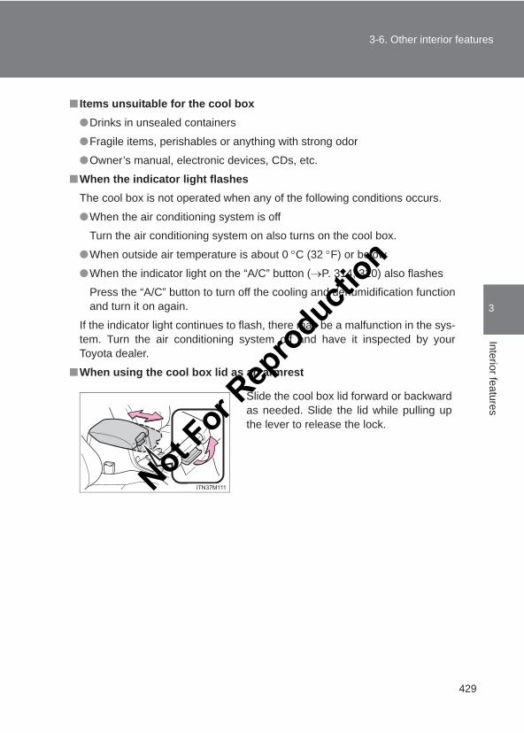
429
3-6. Other interior features
3
Interior features
LC150_OM_OM60J77E_(AE)
■ Items unsuitable for the cool box●Drinks in unsealed containers
●Fragile items, perishables or anything with strong odor
●Owner’s manual, electronic devices, CDs, etc.
■When the indicator light flashesThe cool box is not operated when any of the following conditions occurs.
●When the air conditioning system is off
Turn the air conditioning system on also turns on the cool box.
●When outside air temperature is about 0 °C (32 °F) or below
●When the indicator light on the “A/C” button (→P. 314, 320) also flashes
Press the “A/C” button to turn off the cooling and dehumidification functionand turn it on again.
If the indicator light continues to flash, there may be a malfunction in the sys-tem. Turn the air conditioning system off and have it inspected by yourToyota dealer.
■When using the cool box lid as an armrest
Slide the cool box lid forward or backwardas needed. Slide the lid while pulling upthe lever to release the lock.
Not For R
epro
duction
430
3-6. Other interior features
LC150_OM_OM60J77E_(AE)
CAUTION
■Caution while drivingKeep the cool box closed. In the event of sudden braking or sudden swerv-ing, an accident may occur due to an occupant being struck by the open coolbox or the items stored inside.
NOTICE
■To prevent battery dischargeDo not leave the cool box on longer than necessary when the engine isstopped.
Not For R
epro
duction
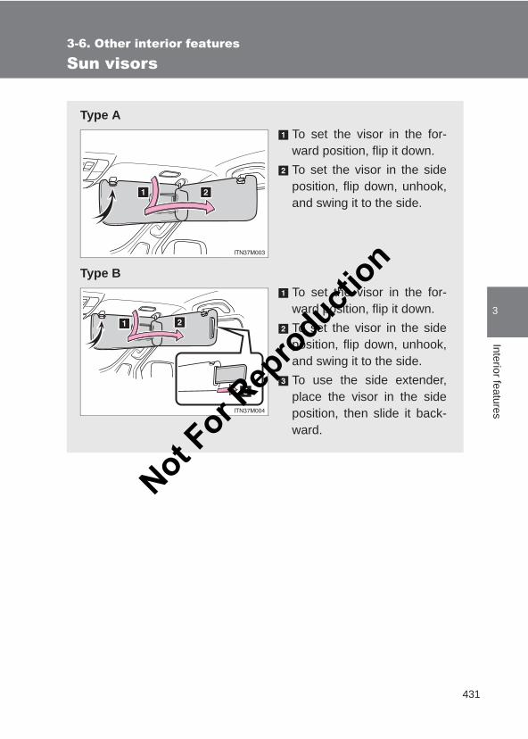
431
3-6. Other interior features
3
Interior features
LC150_OM_OM60J77E_(AE)
Sun visors
Type ATo set the visor in the for-ward position, flip it down.To set the visor in the sideposition, flip down, unhook,and swing it to the side.
Type BTo set the visor in the for-ward position, flip it down.To set the visor in the sideposition, flip down, unhook,and swing it to the side.To use the side extender,place the visor in the sideposition, then slide it back-ward.
Not For R
epro
duction
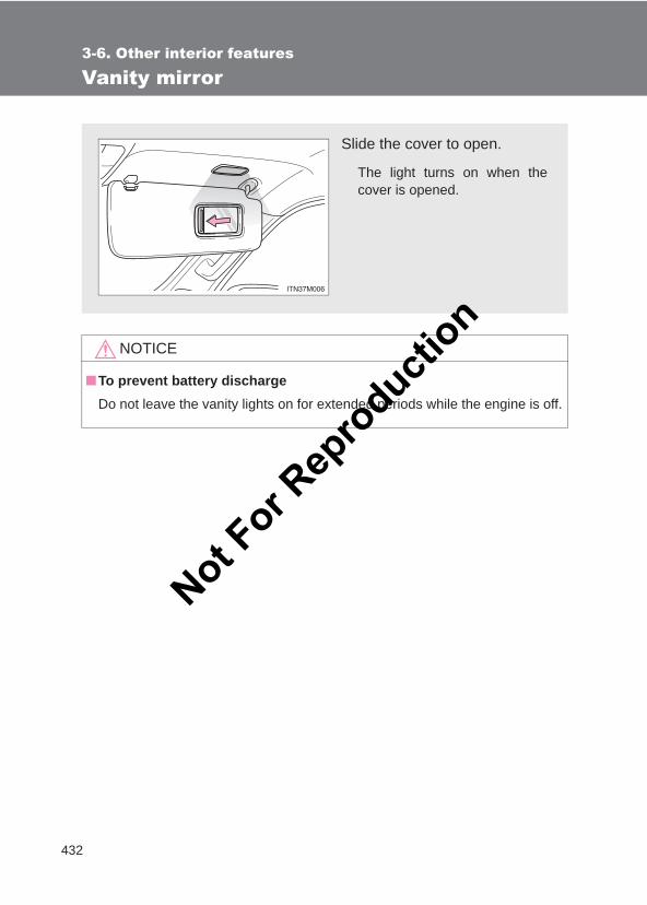
432
3-6. Other interior features
LC150_OM_OM60J77E_(AE)
Vanity mirror
NOTICE
■To prevent battery dischargeDo not leave the vanity lights on for extended periods while the engine is off.
Slide the cover to open.
The light turns on when thecover is opened.
Not For R
epro
duction

433
3-6. Other interior features
3
Interior features
LC150_OM_OM60J77E_(AE)
Clock
■The clock is displayed whenVehicles without a smart entry & start systemThe engine switch is in the “ACC” or “ON” position.
Vehicles with a smart entry & start systemThe “ENGINE START STOP” switch is in ACCESSORY or IGNITION ONmode.
■When disconnecting and reconnecting battery terminalsThe clock data will be reset.
Vehicles with a front manual air conditioning systemAdjusts the hoursAdjusts the minutes
Vehicles with a front automatic air conditioning systemAdjusts the hoursAdjusts the minutesRounds the nearest hour**: e.g. 1:00 to 1:29 → 1:00
1:30 to 1:59 → 2:00
Not For R
epro
duction
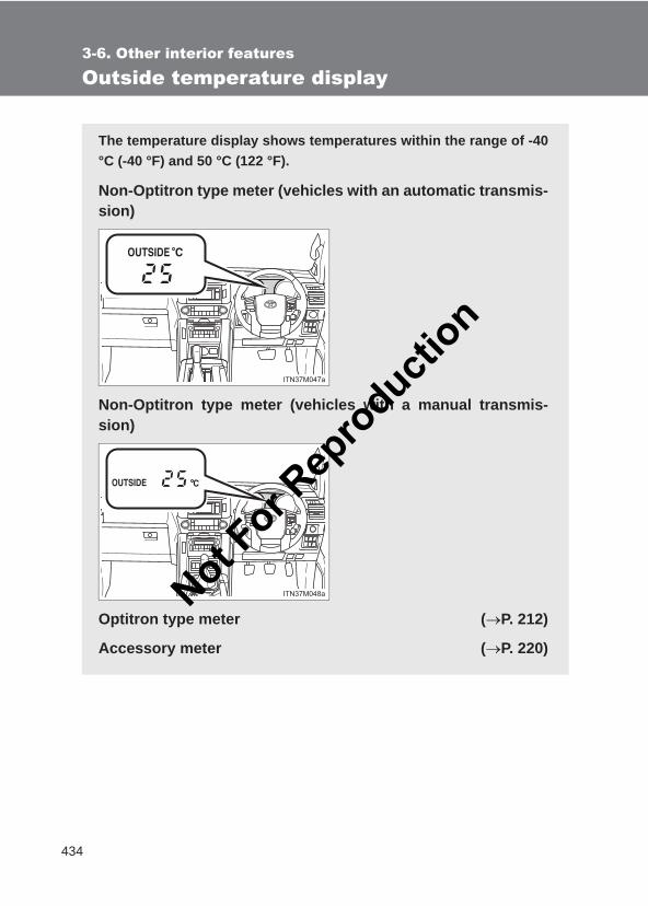
434
3-6. Other interior features
LC150_OM_OM60J77E_(AE)
Outside temperature display
The temperature display shows temperatures within the range of -40°C (-40 °F) and 50 °C (122 °F).
Non-Optitron type meter (vehicles with an automatic transmis-sion)
Non-Optitron type meter (vehicles with a manual transmis-sion)
Optitron type meter (→P. 212)
Accessory meter (→P. 220)
Not For R
epro
duction
435
3-6. Other interior features
3
Interior features
LC150_OM_OM60J77E_(AE)
■The outside temperature is displayed whenVehicles without a smart entry & start systemThe engine switch is in the “ON” position.
Vehicles with a smart entry & start systemThe “ENGINE START STOP” switch is in IGNITION ON mode.
■DisplayIn the following situations, the correct outside temperature may not be dis-played, or the display may take longer than normal to change:
●When the vehicle is stopped, or moving at low speeds (less than 20 km/h[12 mph])
●When the outside temperature has changed suddenly (at the entrance/exit of a garage, tunnel, etc.)
■When “--”or “E” is displayedThe system may be malfunctioning. Take your vehicle to your Toyota dealer.
Not For R
epro
duction
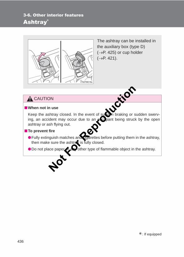
436
3-6. Other interior features
LC150_OM_OM60J77E_(AE)
Ashtray∗
∗: If equipped
CAUTION
■When not in useKeep the ashtray closed. In the event of sudden braking or sudden swerv-ing, an accident may occur due to an occupant being struck by the openashtray or ash flying out.
■To prevent fire●Fully extinguish matches and cigarettes before putting them in the ashtray,
then make sure the ashtray is fully closed.
●Do not place paper or any other type of flammable object in the ashtray.
The ashtray can be installed inthe auxiliary box (type D) (→P. 425) or cup holder (→P. 421).
Not For R
epro
duction
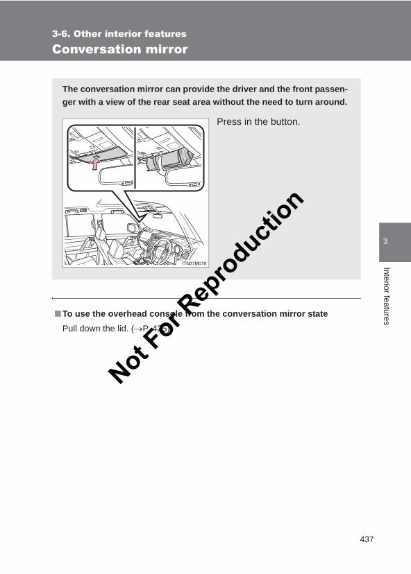
437
3-6. Other interior features
3
Interior features
LC150_OM_OM60J77E_(AE)
Conversation mirror
■To use the overhead console from the conversation mirror statePull down the lid. (→P. 425)
The conversation mirror can provide the driver and the front passen-ger with a view of the rear seat area without the need to turn around.
Press in the button.
Not For R
epro
duction
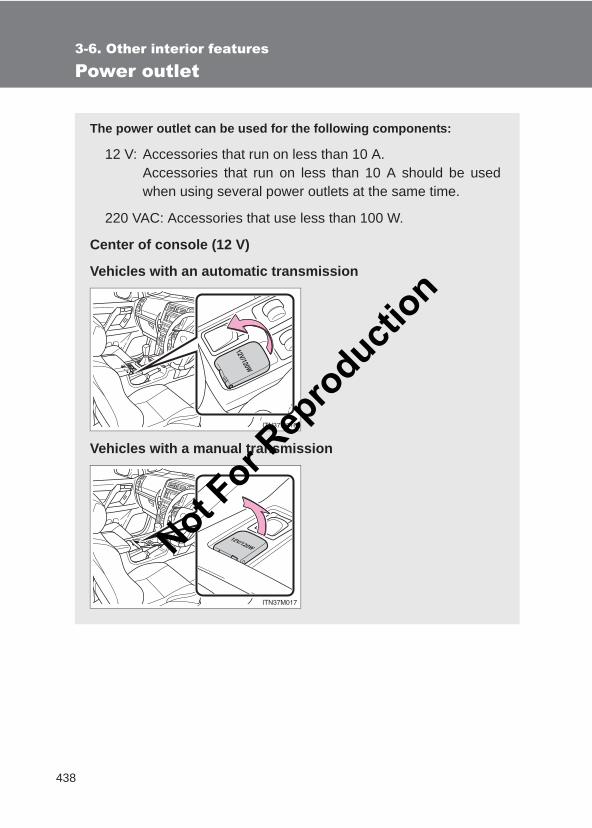
438
3-6. Other interior features
LC150_OM_OM60J77E_(AE)
Power outlet
The power outlet can be used for the following components:
12 V: Accessories that run on less than 10 A.Accessories that run on less than 10 A should be usedwhen using several power outlets at the same time.
220 VAC: Accessories that use less than 100 W.
Center of console (12 V)
Vehicles with an automatic transmission
Vehicles with a manual transmission
Not For R
epro
duction
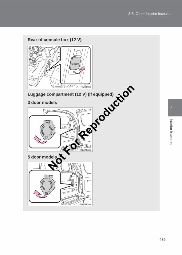
439
3-6. Other interior features
3
Interior features
LC150_OM_OM60J77E_(AE)
Rear of console box (12 V)
Luggage compartment (12 V) (if equipped)
3 door models
5 door models
Not For R
epro
duction
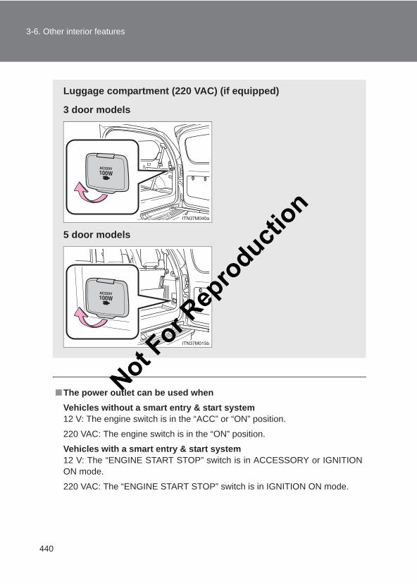
440
3-6. Other interior features
LC150_OM_OM60J77E_(AE)
■The power outlet can be used whenVehicles without a smart entry & start system12 V: The engine switch is in the “ACC” or “ON” position.
220 VAC: The engine switch is in the “ON” position.
Vehicles with a smart entry & start system12 V: The “ENGINE START STOP” switch is in ACCESSORY or IGNITIONON mode.
220 VAC: The “ENGINE START STOP” switch is in IGNITION ON mode.
Luggage compartment (220 VAC) (if equipped)
3 door models
5 door models
Not For R
epro
duction
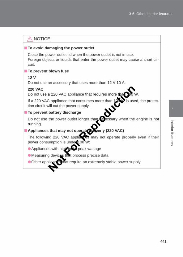
441
3-6. Other interior features
3
Interior features
LC150_OM_OM60J77E_(AE)
NOTICE
■To avoid damaging the power outletClose the power outlet lid when the power outlet is not in use.Foreign objects or liquids that enter the power outlet may cause a short cir-cuit.
■To prevent blown fuse12 VDo not use an accessory that uses more than 12 V 10 A.
220 VACDo not use a 220 VAC appliance that requires more than 100 W.
If a 220 VAC appliance that consumes more than 100 W is used, the protec-tion circuit will cut the power supply.
■To prevent battery dischargeDo not use the power outlet longer than necessary when the engine is notrunning.
■Appliances that may not operate properly (220 VAC)The following 220 VAC appliances may not operate properly even if theirpower consumption is under 100 W:
●Appliances with high initial peak wattage
●Measuring devices that process precise data
●Other appliances that require an extremely stable power supply
Not For R
epro
duction
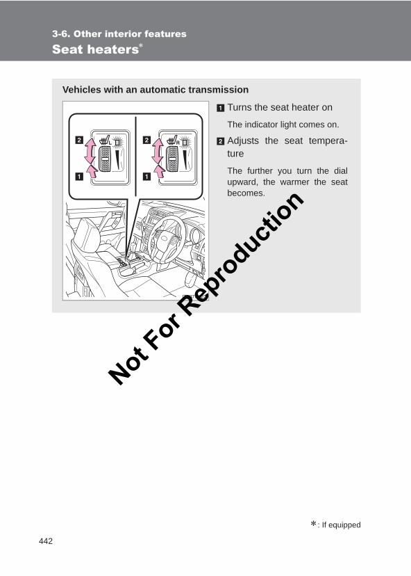
442
3-6. Other interior features
LC150_OM_OM60J77E_(AE)
Seat heaters∗
∗: If equipped
Vehicles with an automatic transmission
Turns the seat heater on
The indicator light comes on.
Adjusts the seat tempera-ture
The further you turn the dialupward, the warmer the seatbecomes.
Not For R
epro
duction
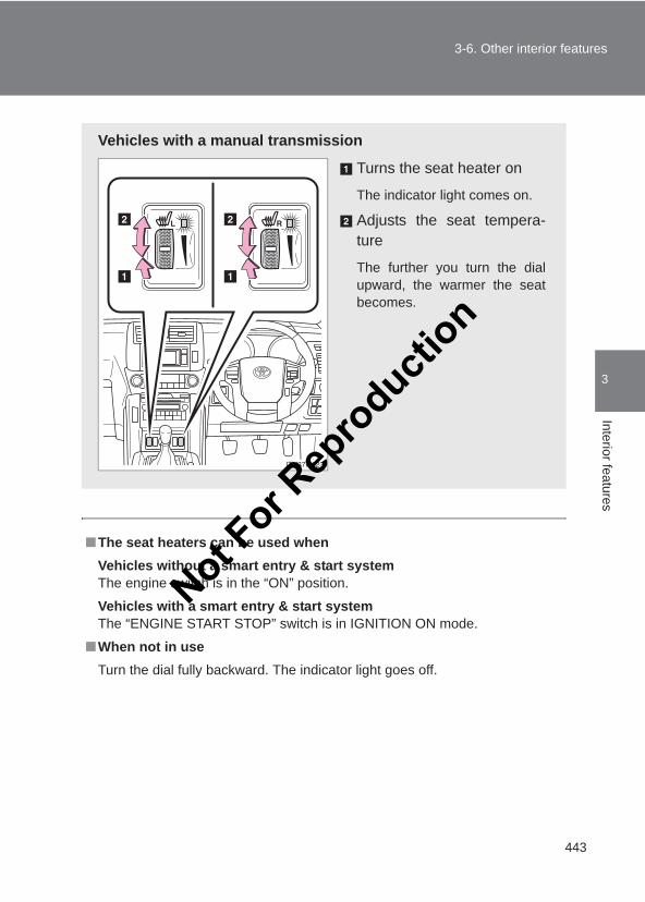
443
3-6. Other interior features
3
Interior features
LC150_OM_OM60J77E_(AE)
■The seat heaters can be used whenVehicles without a smart entry & start systemThe engine switch is in the “ON” position.
Vehicles with a smart entry & start systemThe “ENGINE START STOP” switch is in IGNITION ON mode.
■When not in useTurn the dial fully backward. The indicator light goes off.
Vehicles with a manual transmission
Turns the seat heater on
The indicator light comes on.
Adjusts the seat tempera-ture
The further you turn the dialupward, the warmer the seatbecomes.
Not For R
epro
duction
444
3-6. Other interior features
LC150_OM_OM60J77E_(AE)
CAUTION
■Burns●Use caution when seating the following persons in a seat with the seat
heater on to avoid the possibility of burns:
• Babies, small children, the elderly, the sick and the physically chal-lenged
• Persons with sensitive skin• Persons who are fatigued• Persons who have taken alcohol or drugs that induce sleep (sleeping
drugs, cold remedies, etc.)●Do not cover the seat with anything when using the seat heater.
Using the seat heater with a blanket or cushion increases the temperatureof the seat and may lead to overheating.
●Do not use the seat heater more than necessary. Doing so may causeminor burns or overheating.
NOTICE
■To prevent seat heater damageDo not put heavy objects that have an uneven surface on the seat and donot stick sharp objects (needles, nails, etc.) into the seat.
■To prevent battery dischargeTurn the seat heaters off when the engine is not running.Not F
or Rep
roducti
on
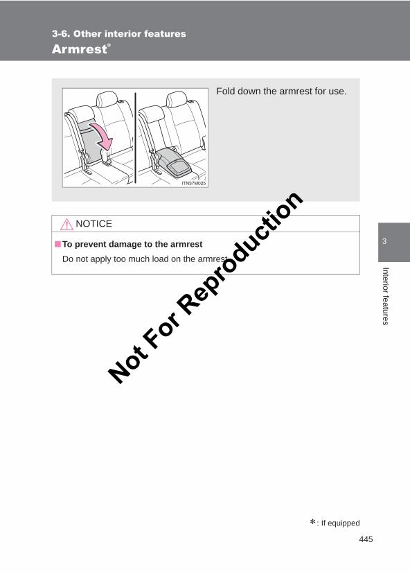
445
3-6. Other interior features
3
Interior features
LC150_OM_OM60J77E_(AE)
Armrest∗
∗: If equipped
NOTICE
■To prevent damage to the armrestDo not apply too much load on the armrest.
Fold down the armrest for use.
Not For R
epro
duction
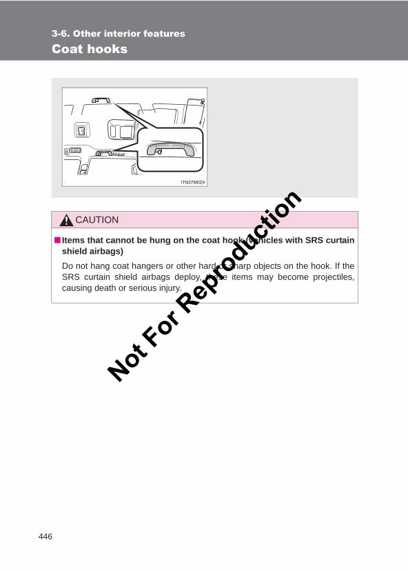
446
3-6. Other interior features
LC150_OM_OM60J77E_(AE)
Coat hooks
CAUTION
■ Items that cannot be hung on the coat hook (vehicles with SRS curtainshield airbags)Do not hang coat hangers or other hard or sharp objects on the hook. If theSRS curtain shield airbags deploy, these items may become projectiles,causing death or serious injury.
Not For R
epro
duction
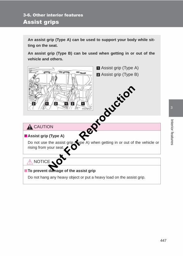
447
3-6. Other interior features
3
Interior features
LC150_OM_OM60J77E_(AE)
Assist grips
CAUTION
■Assist grip (Type A)Do not use the assist grip (Type A) when getting in or out of the vehicle orrising from your seat.
NOTICE
■To prevent damage of the assist gripDo not hang any heavy object or put a heavy load on the assist grip.
An assist grip (Type A) can be used to support your body while sit-ting on the seat.
An assist grip (Type B) can be used when getting in or out of thevehicle and others.
Assist grip (Type A)Assist grip (Type B)
Not For R
epro
duction
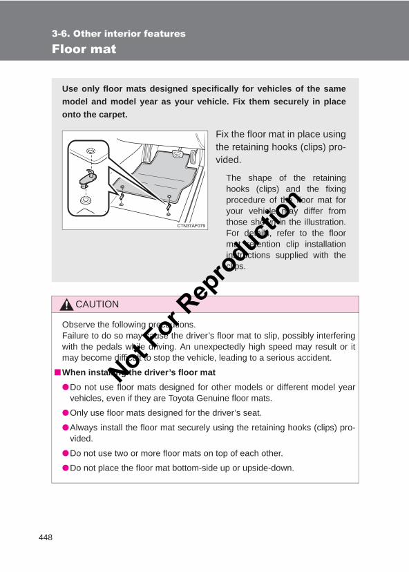
448
3-6. Other interior features
LC150_OM_OM60J77E_(AE)
Floor mat
CAUTION
Observe the following precautions. Failure to do so may cause the driver’s floor mat to slip, possibly interferingwith the pedals while driving. An unexpectedly high speed may result or itmay become difficult to stop the vehicle, leading to a serious accident.
■When installing the driver’s floor mat●Do not use floor mats designed for other models or different model year
vehicles, even if they are Toyota Genuine floor mats.
●Only use floor mats designed for the driver’s seat.
●Always install the floor mat securely using the retaining hooks (clips) pro-vided.
●Do not use two or more floor mats on top of each other.
●Do not place the floor mat bottom-side up or upside-down.
Use only floor mats designed specifically for vehicles of the samemodel and model year as your vehicle. Fix them securely in placeonto the carpet.
Fix the floor mat in place usingthe retaining hooks (clips) pro-vided.
The shape of the retaininghooks (clips) and the fixingprocedure of the floor mat foryour vehicle may differ fromthose shown in the illustration.For details, refer to the floormat retention clip installationinstructions supplied with theclips.
Not For R
epro
duction
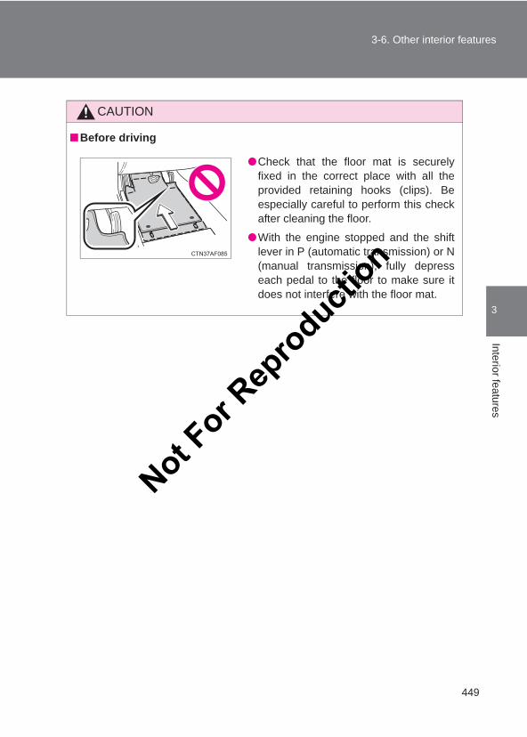
449
3-6. Other interior features
3
Interior features
LC150_OM_OM60J77E_(AE)
CAUTION
■Before driving
●Check that the floor mat is securelyfixed in the correct place with all theprovided retaining hooks (clips). Beespecially careful to perform this checkafter cleaning the floor.
●With the engine stopped and the shiftlever in P (automatic transmission) or N(manual transmission), fully depresseach pedal to the floor to make sure itdoes not interfere with the floor mat.
Not For R
epro
duction
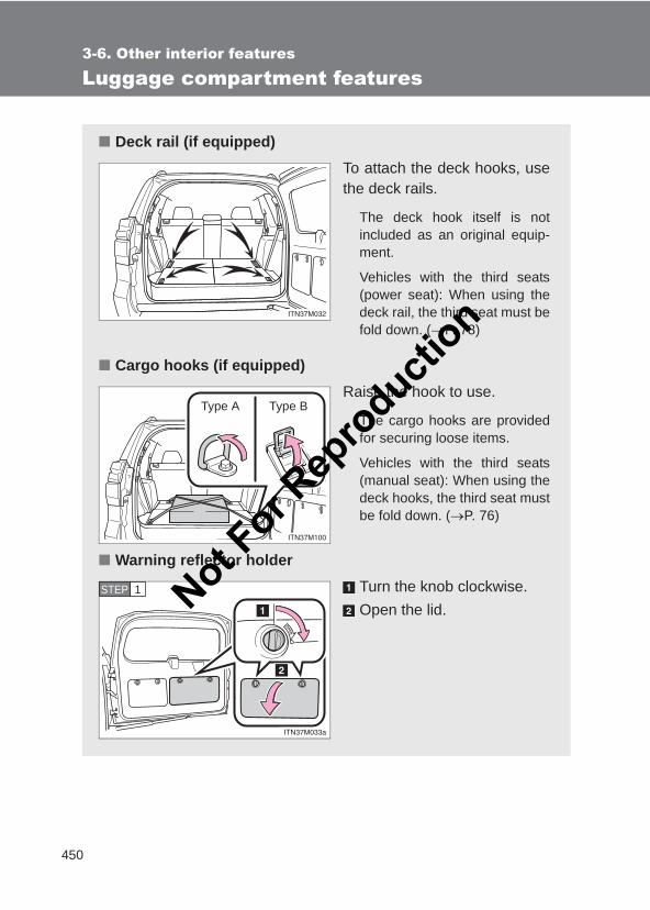
450
3-6. Other interior features
LC150_OM_OM60J77E_(AE)
Luggage compartment features
■ Deck rail (if equipped)To attach the deck hooks, usethe deck rails.
The deck hook itself is notincluded as an original equip-ment.
Vehicles with the third seats(power seat): When using thedeck rail, the third seat must befold down. (→P. 78)
■ Cargo hooks (if equipped)Raise the hook to use.
The cargo hooks are providedfor securing loose items.
Vehicles with the third seats(manual seat): When using thedeck hooks, the third seat mustbe fold down. (→P. 76)
■ Warning reflector holderTurn the knob clockwise.Open the lid.
Type A Type B
STEP 1 Not For R
epro
duction
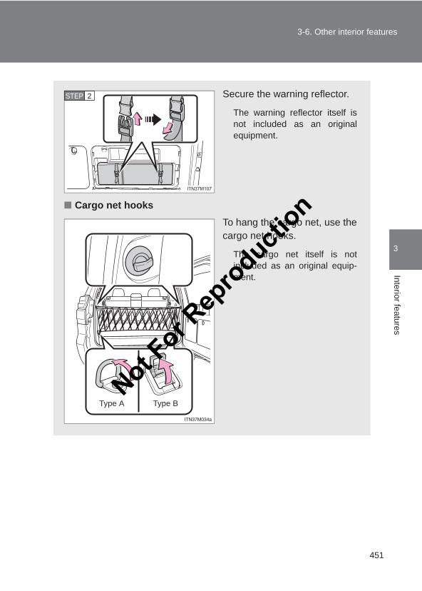
451
3-6. Other interior features
3
Interior features
LC150_OM_OM60J77E_(AE)
Secure the warning reflector.
The warning reflector itself isnot included as an originalequipment.
■ Cargo net hooksTo hang the cargo net, use thecargo net hooks.
The cargo net itself is notincluded as an original equip-ment.
STEP 2
Type A Type BNot F
or Rep
roducti
on
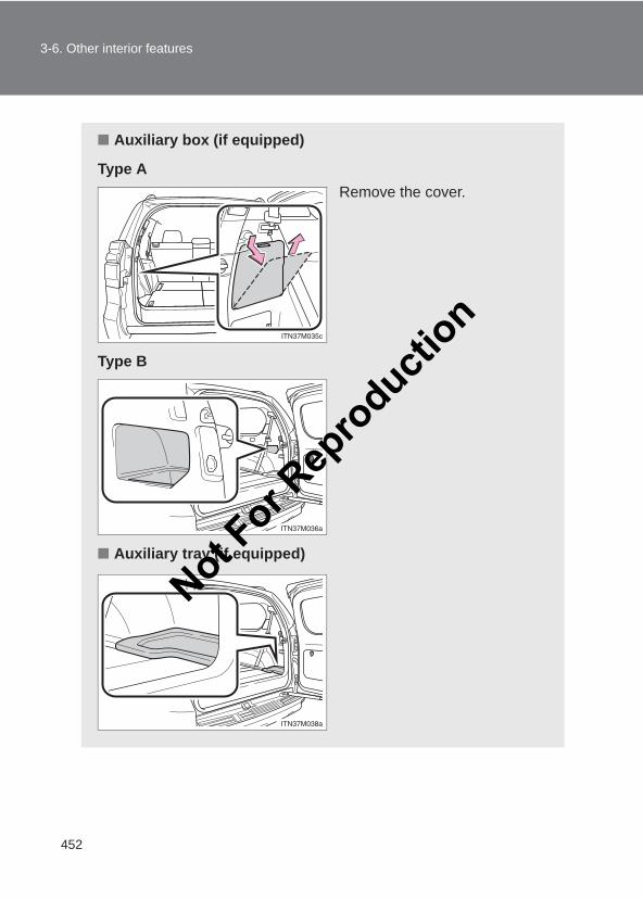
452
3-6. Other interior features
LC150_OM_OM60J77E_(AE)
■ Auxiliary box (if equipped)
Type ARemove the cover.
Type B
■ Auxiliary tray (if equipped)
Not For R
epro
duction
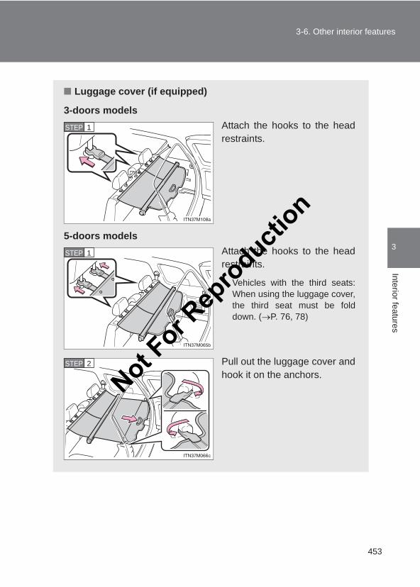
453
3-6. Other interior features
3
Interior features
LC150_OM_OM60J77E_(AE)
■ Luggage cover (if equipped)
3-doors modelsAttach the hooks to the headrestraints.
5-doors modelsAttach the hooks to the headrestraints.
Vehicles with the third seats:When using the luggage cover,the third seat must be folddown. (→P. 76, 78)
Pull out the luggage cover andhook it on the anchors.
STEP 1
STEP 1
STEP 2
Not For R
epro
duction
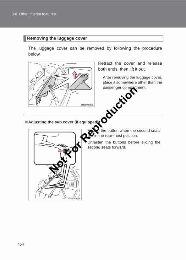
454
3-6. Other interior features
LC150_OM_OM60J77E_(AE)
Removing the luggage cover
The luggage cover can be removed by following the procedurebelow.
Retract the cover and releaseboth ends, then lift it out.
After removing the luggage cover,place it somewhere other than thepassenger compartment.
■Adjusting the sub cover (if equipped)
Fasten the button when the second seatsare in the rear-most position.
Unfasten the buttons before sliding thesecond seats forward.
Not For R
epro
duction
455
3-6. Other interior features
3
Interior features
LC150_OM_OM60J77E_(AE)
CAUTION
■When the cargo hooks are not in useTo avoid injury, always return the cargo hooks to their stowed positions.
■Caution while drivingKeep the auxiliary box closed. In the event of sudden braking or suddenswerving, an accident may occur due to an occupant being struck by anopen auxiliary box or the items stored inside.
■Caution for the luggage coverDo not allow children to climb on the luggage cover. Climbing on the luggagecover could result in damage to the luggage cover, possibly causing death orserious injury to the child.
Not For R
epro
duction

456
3-6. Other interior features
LC150_OM_OM60J77E_(AE)
Not For R
epro
duction
4Maintenance and care
457
LC150_OM_OM60J77E_(AE)
4-1. Maintenance and careCleaning and protecting
the vehicle exterior ......... 458Cleaning and protecting
the vehicle interior .......... 462
4-2. MaintenanceMaintenance
requirements................... 465
4-3. Do-it-yourself maintenanceDo-it-yourself service
precautions ..................... 468Hood ................................. 472Engine compartment......... 473Tires.................................. 492Tire inflation pressure ....... 495Wheels.............................. 497Air conditioning filter ......... 499Wireless remote control/
electronic key battery...... 501Checking and replacing
fuses ............................... 505Light bulbs ........................ 517
Not For R
epro
duction
458
LC150_OM_OM60J77E_(AE)
4-1. Maintenance and care
Cleaning and protecting the vehicle exterior
■Automatic car washes●Fold the mirrors back before washing the vehicle. Start washing from the
front of the vehicle. Make sure to extend the mirrors before driving.
●Brushes used in automatic car washes may scratch the vehicle surfaceand harm your vehicle’s paint.
■High pressure car washes●Do not allow the nozzles of the car wash to come within close proximity
of the windows and the air suspension unit.
●Before using the car wash, check that the fuel filler door on your vehicleis closed properly.
Perform the following to protect the vehicle and maintain it in primecondition:
● Working from top to bottom, liberally apply water to the vehiclebody, wheel wells and underside of the vehicle to remove anydirt and dust.
● Wash the vehicle body using a sponge or soft cloth, such as achamois.
● For hard-to-remove marks, use car wash soap and rinse thor-oughly with water.
● Wipe away any water.
● Wax the vehicle when the waterproof coating deteriorates.
If water does not bead on a clean surface, apply wax when the vehiclebody is cool.
Not For R
epro
duction
459
4-1. Maintenance and care
4
Maintenance and care
LC150_OM_OM60J77E_(AE)
■Aluminum wheels●Remove any dirt immediately by using a neutral detergent. Do not use
hard brushes or abrasive cleaners. Do not use strong or harsh chemicalcleaners. Use the same mild detergent and wax as used on the paint.
●Do not use detergent on the wheels when they are hot, for example afterdriving for long distance in the hot weather.
●Wash detergent from the wheels immediately after use.
■Bumpers and side moldingsDo not scrub with abrasive cleaners.
■Notes for vehicles with a smart entry & start system (if equipped)● If the door handle becomes wet while the electronic key is within the
effective range, the door may lock and unlock repeatedly. Place the keyin a position 2 m (6 ft.) or more separate from the vehicle while the vehi-cle is being washed. (Take care to ensure that the key is not stolen.)
● If the electronic key is inside the vehicle and a door handle becomes wetduring a car wash, a message may be shown on the multi-informationdisplay and a buzzer will sound outside the vehicle. To turn off the alarm,lock all the doors.
Not For R
epro
duction
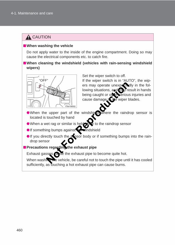
460
4-1. Maintenance and care
LC150_OM_OM60J77E_(AE)
CAUTION
■When washing the vehicleDo not apply water to the inside of the engine compartment. Doing so maycause the electrical components etc. to catch fire.
■When cleaning the windshield (vehicles with rain-sensing windshieldwipers)
●When the upper part of the windshield where the raindrop sensor islocated is touched by hand
●When a wet rag or similar is held close to the raindrop sensor
● If something bumps against the windshield
● If you directly touch the sensor body or if something bumps into the rain-drop sensor
■Precautions regarding the exhaust pipeExhaust gasses cause the exhaust pipe to become quite hot.
When washing the vehicle, be careful not to touch the pipe until it has cooledsufficiently, as touching a hot exhaust pipe can cause burns.
Set the wiper switch to off.If the wiper switch is in “AUTO”, the wip-ers may operate unexpectedly in the fol-lowing situations, and may result in handsbeing caught or other serious injuries andcause damage to the wiper blades.
“OFF”
Not For R
epro
duction
461
4-1. Maintenance and care
4
Maintenance and care
LC150_OM_OM60J77E_(AE)
NOTICE
■To prevent paint deterioration and corrosion on the body and compo-nents (aluminum wheels etc.)●Wash the vehicle immediately in the following cases:
• After driving near the sea coast• After driving on salted roads• If coal tar or tree sap is present on the paint surface• If you see dead insects, insect droppings or bird droppings on the paint• After driving in an area contaminated with soot, oily smoke, mine dust,
iron powder or chemical substances• If the vehicle becomes heavily soiled in dust or mud• If liquids such as benzene and gasoline are spilled on the paint surface
● If the paint is chipped or scratched, have it repaired immediately.
●To prevent the wheels from corroding, remove any dirt and store in a placewith low humidity when storing wheels.
■Cleaning the exterior lights●Wash carefully. Do not use organic substances or scrub with a hard brush.
This may damage the surfaces of the lights.
●Do not apply wax on the surfaces of the lights.Wax may cause damage to the lenses.
■To prevent damage to the windshield wiper armsWhen lifting the wiper arms away from the windshield, pull the driver sidewiper arm upward first, and repeat for the passenger side. When returningthe wipers to their original position, do so from the passenger side first.
■When using an automatic car wash (vehicles with rain sensing wind-shield wipers)Set the wiper switch to the off position.If the wiper switch is in “AUTO”, the wipers may operate and the wiperblades may be damaged.
Not For R
epro
duction

462
4-1. Maintenance and care
LC150_OM_OM60J77E_(AE)
Cleaning and protecting the vehicle interior
The following procedures will help protect your vehicle’s interior andkeep it in top condition:
■ Protecting the vehicle interiorRemove dirt and dust using a vacuum cleaner. Wipe dirty sur-faces with a cloth dampened with lukewarm water.
■ Cleaning the leather areas● Remove dirt and dust using a vacuum cleaner.
● Wipe any excess dirt and dust with a soft cloth dampened withdiluted detergent.
Use a diluted water solution of approximately 5 % neutral wool deter-gent.
● Wring out any excess water from the cloth and thoroughlywipe off all remaining traces of detergent.
● Wipe the surface with a dry, soft cloth to remove any remain-ing moisture. Allow the leather to dry in a shaded ventilatedarea.
■ Cleaning the synthetic leather areas● Remove loose dirt using a vacuum cleaner.
● Apply a mild soap solution to the synthetic leather using asponge or soft cloth.
● Allow the solution to soak in for a few minutes. Remove thedirt and wipe off the solution with a clean, damp cloth.
Not For R
epro
duction
463
4-1. Maintenance and care
4
Maintenance and care
LC150_OM_OM60J77E_(AE)
■Caring for leather areasToyota recommends cleaning the interior of the vehicle at least twice a yearto maintain the quality of the vehicle’s interior.
■Shampooing the carpetsThere are several commercial foaming-type cleaners available. Use asponge or brush to apply the foam. Rub in overlapping circles. Do not usewater. The excellent results are obtained when keeping the carpet as dry aspossible.
■Seat beltsClean with mild soap and lukewarm water using a cloth or sponge. Alsocheck the belts periodically for excessive wear, fraying or cuts.
CAUTION
■Water in the vehicle●Do not splash or spill liquid in the vehicle.
Doing so may cause electrical components etc. to malfunction or catchfire.
●Do not get any of the SRS components or wiring in the vehicle interior wet. (→P. 125)An electrical malfunction may cause the airbags to deploy or not functionproperly, resulting in death or serious injury.
■Cleaning the interior (especially instrument panel) Do not use polish wax or polish cleaner. The instrument panel may reflect offthe windshield, obstructing the driver’s view and leading to an accident,resulting in death or serious injury.
Not For R
epro
duction
464
4-1. Maintenance and care
LC150_OM_OM60J77E_(AE)
NOTICE
■Cleaning detergents●Do not use the following types of detergent, as they may discolor the vehi-
cle interior or cause streaks or damage to painted surfaces:
• Non-seat portions: Organic substances such as benzene or gasoline,alkaline or acidic solutions, dye, and bleach
• Seats: Alkaline or acidic solutions, such as thinner, benzene, and alco-hol
●Do not use polish wax or polish cleaner. The instrument panel’s or otherinterior part’s painted surface may be damaged.
■Preventing damage to leather surfacesObserve the following precautions to avoid damage to and deterioration ofleather surfaces:
●Remove any dust or dirt from leather surfaces immediately.
●Do not expose the vehicle to direct sunlight for extended periods of time.Park the vehicle in the shade, especially during summer.
●Do not place items made of vinyl, plastic, or containing wax on the uphol-stery, as they may stick to the leather surface if the vehicle interior heatsup significantly.
■Water on the floorDo not wash the vehicle floor with water.Vehicle systems such as the audio system may be damaged if water comesinto contact with electrical components such as the audio system above orunder the floor of the vehicle. Water may also cause the body to rust.
■Cleaning the inside of the rear window●Do not use glass cleaner to clean the rear window, as this may cause
damage to the rear window defogger heater wires or antenna. Use a clothdampened with lukewarm water to gently wipe the window clean. Wipe thewindow in strokes running parallel to the heater wires or antenna.
●Be careful not to scratch or damage the heater wires or antenna.
Not For R
epro
duction
465
4
Maintenance and care
LC150_OM_OM60J77E_(AE)
4-2. Maintenance
Maintenance requirements
To ensure safe and economical driving, day-to-day care and regularmaintenance is essential. Toyota recommends performing the fol-lowing maintenance:
■ Scheduled maintenanceScheduled maintenance should be performed at specified inter-vals according to the maintenance schedule.
For full details of your maintenance schedule, read the “Warranty andService Booklet”.
■ Do-it-yourself maintenanceWhat about do-it-yourself maintenance?
Many maintenance items are easy to do yourself if you have a littlemechanical ability and a few basic automotive tools.
Note, however, that some maintenance tasks require special toolsand skills. These are best performed by qualified technicians. Even ifyou are an experienced do-it-yourself mechanic, we recommend thatrepairs and maintenance be conducted by your Toyota dealer who willkeep a record of maintenance on your vehicle. This record could behelpful should you ever require Warranty Service.
Not For R
epro
duction
466
4-2. Maintenance
LC150_OM_OM60J77E_(AE)
■Where to go for service?It makes good sense to take your vehicle to your local Toyota dealer for ser-vice.
Toyota technicians are well-trained specialists receiving the latest serviceinformation through technical bulletins, service tips, and in-dealership train-ing programs. They learn to work on Toyota before they work on your vehi-cle, rather than while they are working on it. Doesn’t that seem like the bestway?
Your Toyota dealer has invested a lot of money in special Toyota tools andservice equipment. It helps them to do the job better and at less cost.
Your Toyota dealer’s service department will perform all of the scheduledmaintenance on your vehicle reliably and economically.
■Does your vehicle need repair?Be on the alert for changes in performance and sounds, and visual tip-offsthat indicate service is needed. Some important clues are:
●Engine missing, stumbling, or pinging
●Appreciable loss of power
●Strange engine noises
●A fluid leak under the vehicle (However, water dripping from the air condi-tioning after use is normal.)
●Change in exhaust sound (This may indicate a dangerous carbon mon-oxide leak. Drive with the windows open and have the exhaust systemchecked immediately.)
●Flat-looking tires, excessive tire squeal when cornering, uneven tire wear
●Vehicle pulls to one side when driving straight on a level road
●Strange noises related to suspension movement
●Loss of brake effectiveness, spongy feeling brake pedal, pedal almosttouches the floor, vehicle pulls to one side when braking
●Engine coolant temperature continually higher than normal
If you notice any of these clues, take your vehicle to your Toyota dealer assoon as possible. Your vehicle may need adjustment or repair.
Not For R
epro
duction
467
4-2. Maintenance
4
Maintenance and care
LC150_OM_OM60J77E_(AE)
CAUTION
■ If your vehicle is not properly maintainedImproper maintenance could result in serious damage to the vehicle andpossible serious injury or death.
■Handling of the batteryBattery posts, terminals and related accessories contain lead and lead com-pounds which are known to cause brain damage. Wash your hands afterhandling. (→P. 483)
Not For R
epro
duction
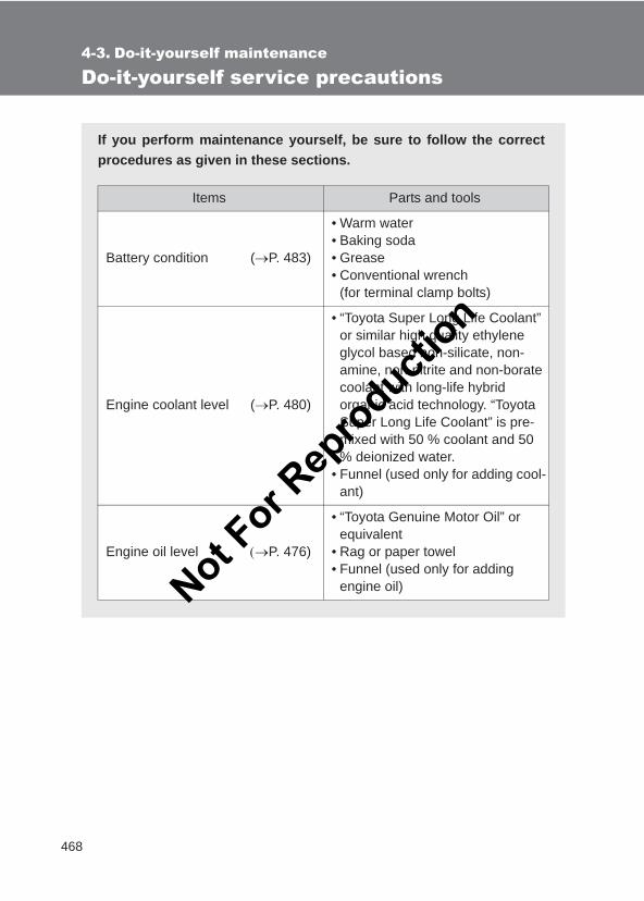
468
LC150_OM_OM60J77E_(AE)
4-3. Do-it-yourself maintenance
Do-it-yourself service precautions
If you perform maintenance yourself, be sure to follow the correctprocedures as given in these sections.
Items Parts and tools
Battery condition (→P. 483)
• Warm water• Baking soda• Grease• Conventional wrench
(for terminal clamp bolts)
Engine coolant level (→P. 480)
• “Toyota Super Long Life Coolant” or similar high quality ethylene glycol based non-silicate, non-amine, non-nitrite and non-borate coolant with long-life hybrid organic acid technology. “Toyota Super Long Life Coolant” is pre-mixed with 50 % coolant and 50 % deionized water.
• Funnel (used only for adding cool-ant)
Engine oil level (→P. 476)
• “Toyota Genuine Motor Oil” or equivalent
• Rag or paper towel• Funnel (used only for adding
engine oil)Not For R
epro
duction
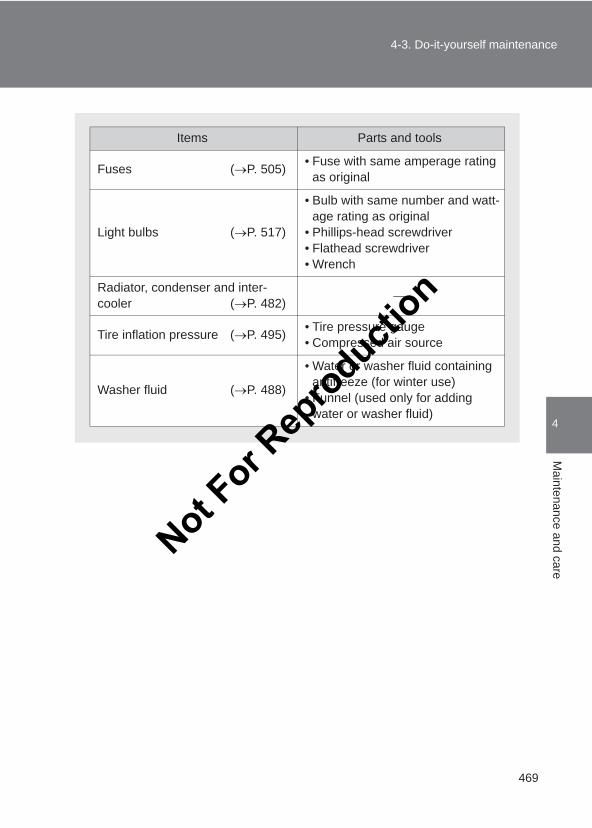
469
4-3. Do-it-yourself maintenance
4
Maintenance and care
LC150_OM_OM60J77E_(AE)
Items Parts and tools
Fuses (→P. 505) • Fuse with same amperage rating as original
Light bulbs (→P. 517)
• Bulb with same number and watt-age rating as original
• Phillips-head screwdriver• Flathead screwdriver• Wrench
Radiator, condenser and inter-cooler (→P. 482)
Tire inflation pressure (→P. 495) • Tire pressure gauge• Compressed air source
Washer fluid (→P. 488)
• Water or washer fluid containing antifreeze (for winter use)
• Funnel (used only for adding water or washer fluid)
Not For R
epro
duction
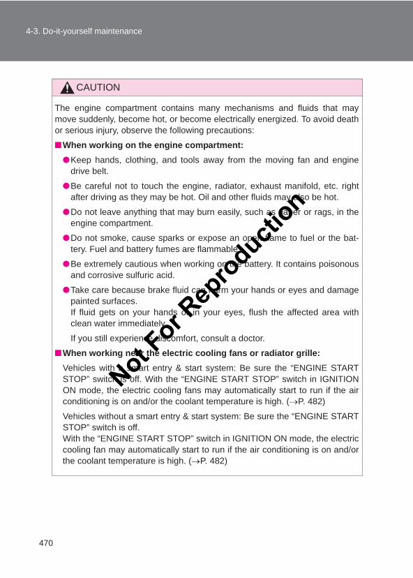
470
4-3. Do-it-yourself maintenance
LC150_OM_OM60J77E_(AE)
CAUTION
The engine compartment contains many mechanisms and fluids that maymove suddenly, become hot, or become electrically energized. To avoid deathor serious injury, observe the following precautions:
■When working on the engine compartment:●Keep hands, clothing, and tools away from the moving fan and engine
drive belt.
●Be careful not to touch the engine, radiator, exhaust manifold, etc. rightafter driving as they may be hot. Oil and other fluids may also be hot.
●Do not leave anything that may burn easily, such as paper or rags, in theengine compartment.
●Do not smoke, cause sparks or expose an open flame to fuel or the bat-tery. Fuel and battery fumes are flammable.
●Be extremely cautious when working on the battery. It contains poisonousand corrosive sulfuric acid.
●Take care because brake fluid can harm your hands or eyes and damagepainted surfaces.If fluid gets on your hands or in your eyes, flush the affected area withclean water immediately.
If you still experience discomfort, consult a doctor.
■When working near the electric cooling fans or radiator grille:Vehicles with a smart entry & start system: Be sure the “ENGINE STARTSTOP” switch is off. With the “ENGINE START STOP” switch in IGNITIONON mode, the electric cooling fans may automatically start to run if the airconditioning is on and/or the coolant temperature is high. (→P. 482)
Vehicles without a smart entry & start system: Be sure the “ENGINE STARTSTOP” switch is off.With the “ENGINE START STOP” switch in IGNITION ON mode, the electriccooling fan may automatically start to run if the air conditioning is on and/orthe coolant temperature is high. (→P. 482)
Not For R
epro
duction
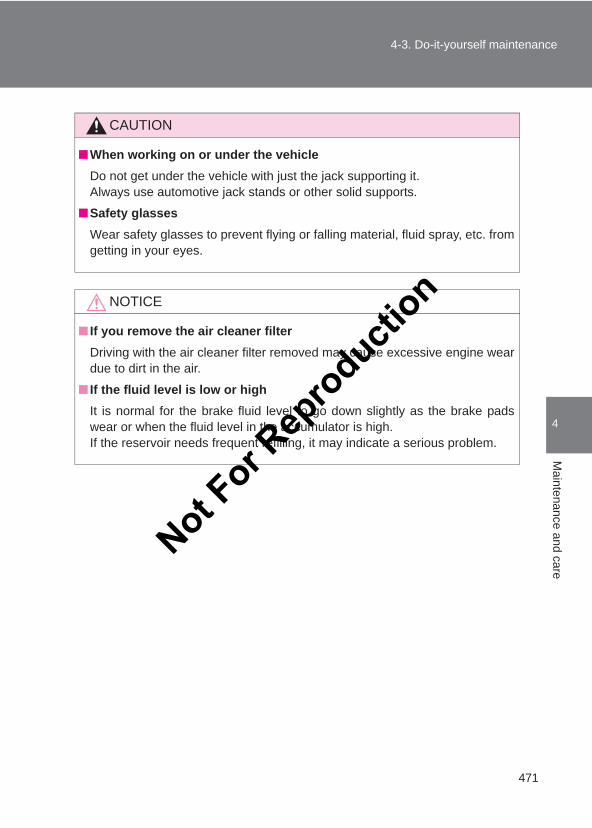
471
4-3. Do-it-yourself maintenance
4
Maintenance and care
LC150_OM_OM60J77E_(AE)
CAUTION
■When working on or under the vehicleDo not get under the vehicle with just the jack supporting it.Always use automotive jack stands or other solid supports.
■Safety glassesWear safety glasses to prevent flying or falling material, fluid spray, etc. fromgetting in your eyes.
NOTICE
■ If you remove the air cleaner filterDriving with the air cleaner filter removed may cause excessive engine weardue to dirt in the air.
■ If the fluid level is low or highIt is normal for the brake fluid level to go down slightly as the brake padswear or when the fluid level in the accumulator is high.If the reservoir needs frequent refilling, it may indicate a serious problem.
Not For R
epro
duction
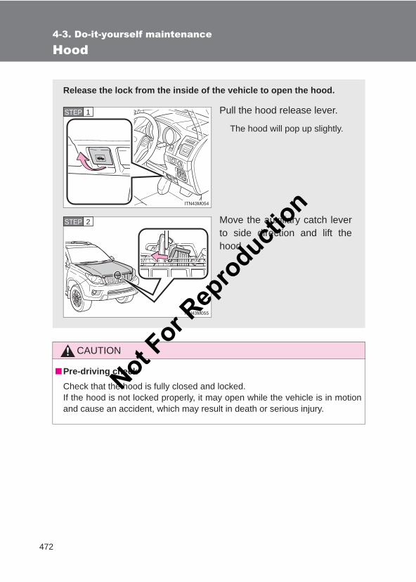
472
4-3. Do-it-yourself maintenance
LC150_OM_OM60J77E_(AE)
Hood
CAUTION
■Pre-driving checkCheck that the hood is fully closed and locked.If the hood is not locked properly, it may open while the vehicle is in motionand cause an accident, which may result in death or serious injury.
Release the lock from the inside of the vehicle to open the hood.
Pull the hood release lever.
The hood will pop up slightly.
Move the auxiliary catch leverto side direction and lift thehood.
STEP 1
STEP 2
Not For R
epro
duction
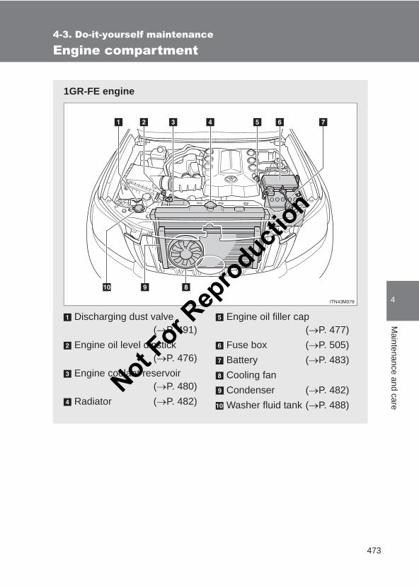
473
4-3. Do-it-yourself maintenance
4
Maintenance and care
LC150_OM_OM60J77E_(AE)
Engine compartment
1GR-FE engine
Discharging dust valve(→P. 491)
Engine oil level dipstick(→P. 476)
Engine coolant reservoir(→P. 480)
Radiator (→P. 482)
Engine oil filler cap(→P. 477)
Fuse box (→P. 505)Battery (→P. 483)Cooling fanCondenser (→P. 482)Washer fluid tank (→P. 488)
Not For R
epro
duction
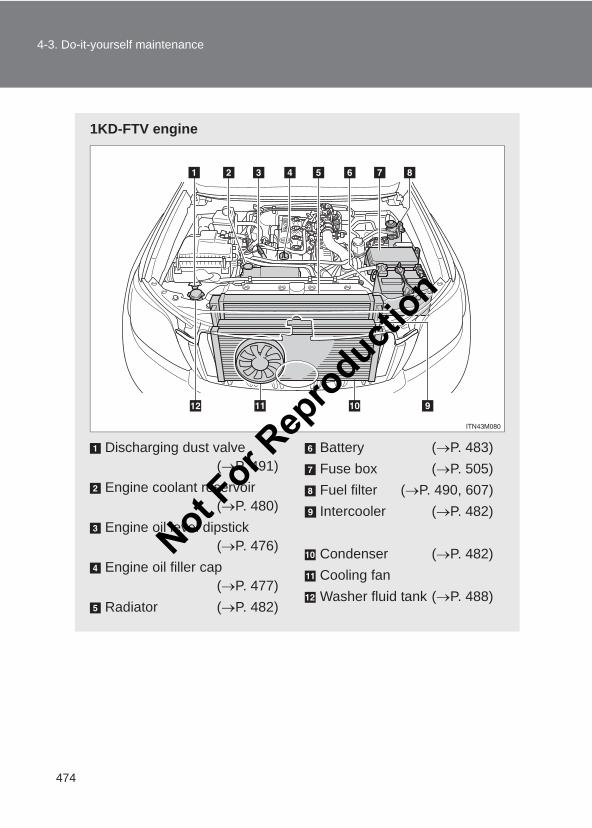
474
4-3. Do-it-yourself maintenance
LC150_OM_OM60J77E_(AE)
1KD-FTV engine
Discharging dust valve(→P. 491)
Engine coolant reservoir(→P. 480)
Engine oil level dipstick(→P. 476)
Engine oil filler cap(→P. 477)
Radiator (→P. 482)
Battery (→P. 483)Fuse box (→P. 505)Fuel filter (→P. 490, 607)Intercooler (→P. 482)
Condenser (→P. 482)Cooling fanWasher fluid tank (→P. 488)
Not For R
epro
duction
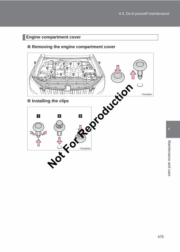
475
4-3. Do-it-yourself maintenance
4
Maintenance and care
LC150_OM_OM60J77E_(AE)
Engine compartment cover
■ Removing the engine compartment cover
■ Installing the clips
Not For R
epro
duction
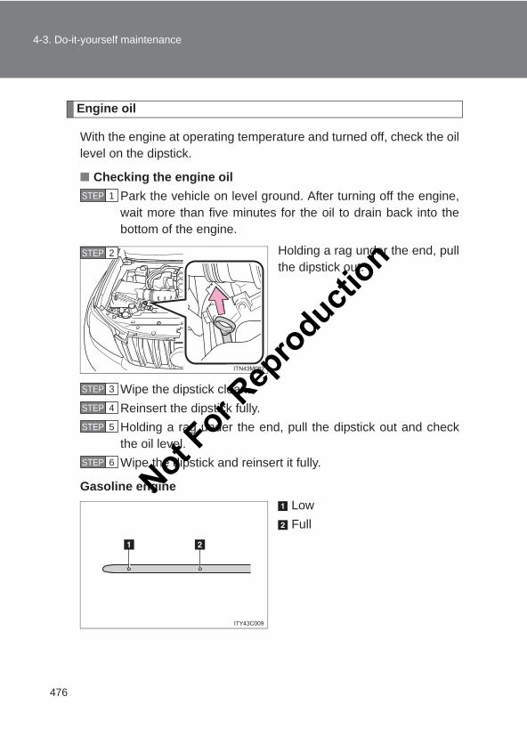
476
4-3. Do-it-yourself maintenance
LC150_OM_OM60J77E_(AE)
Engine oil
With the engine at operating temperature and turned off, check the oillevel on the dipstick.
■ Checking the engine oilPark the vehicle on level ground. After turning off the engine,wait more than five minutes for the oil to drain back into thebottom of the engine.
Holding a rag under the end, pullthe dipstick out.
Wipe the dipstick clean.Reinsert the dipstick fully.Holding a rag under the end, pull the dipstick out and checkthe oil level.Wipe the dipstick and reinsert it fully.
Gasoline engineLowFull
STEP 1
STEP 2
STEP 3
STEP 4
STEP 5
STEP 6
Not For R
epro
duction
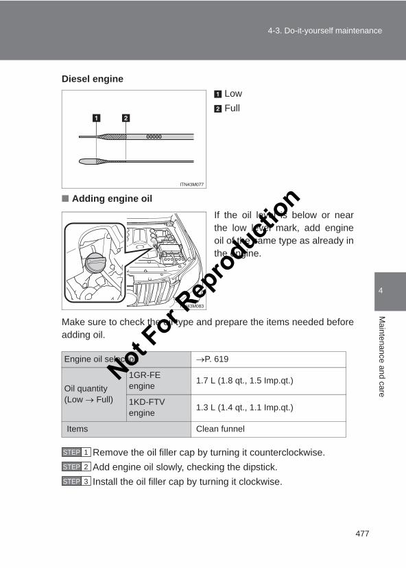
477
4-3. Do-it-yourself maintenance
4
Maintenance and care
LC150_OM_OM60J77E_(AE)
Diesel engineLowFull
■ Adding engine oilIf the oil level is below or nearthe low level mark, add engineoil of the same type as already inthe engine.
Make sure to check the oil type and prepare the items needed beforeadding oil.
Remove the oil filler cap by turning it counterclockwise.Add engine oil slowly, checking the dipstick.Install the oil filler cap by turning it clockwise.
Engine oil selection →P. 619
Oil quantity(Low → Full)
1GR-FE engine 1.7 L (1.8 qt., 1.5 Imp.qt.)
1KD-FTV engine 1.3 L (1.4 qt., 1.1 Imp.qt.)
Items Clean funnel
STEP 1
STEP 2
STEP 3
Not For R
epro
duction
478
4-3. Do-it-yourself maintenance
LC150_OM_OM60J77E_(AE)
■Engine oil consumption●The amount of engine oil consumed depends on the oil viscosity, the
quality of the oil and the way the vehicle is driven.
●More oil is consumed under driving conditions such as high speeds andfrequent acceleration and deceleration.
●A new engine consumes more oil.
●When judging the amount of oil consumption, keep in mind that the oilmay have become diluted, making it difficult to judge the true level accu-rately.
●Oil consumption: Max. 1.0 L per 1000 km (1.1 qt./600 miles, 0.9 lmp. qt./600 miles)
● If you consume more than 1.0 L (1.1 qt., 0.9 lmp.qt.) every 1000 km (600miles), contact your Toyota dealer.
CAUTION
■Used engine oil●Used engine oil contains potentially harmful contaminants which may
cause skin disorders such as inflammation or skin cancer, so care shouldbe taken to avoid prolonged and repeated contact. To remove used engineoil from your skin, wash thoroughly with soap and water.
●Dispose of used oil and filters only in a safe and acceptable manner. Donot dispose of used oil and filters in household trash, in sewers or onto theground. Call your Toyota dealer, service station or auto parts store forinformation concerning recycling or disposal.
●Do not leave used engine oil within the reach of children.
Not For R
epro
duction
479
4-3. Do-it-yourself maintenance
4
Maintenance and care
LC150_OM_OM60J77E_(AE)
NOTICE
■To prevent serious engine damageCheck the oil level on regular basis.
■When replacing the engine oil●Be careful not to spill engine oil on the vehicle components.
●Avoid overfilling, or the engine could be damaged.
●Check the oil level on the dipstick every time you refill the vehicle.
●Be sure the engine oil filler cap is properly tightened.
Not For R
epro
duction
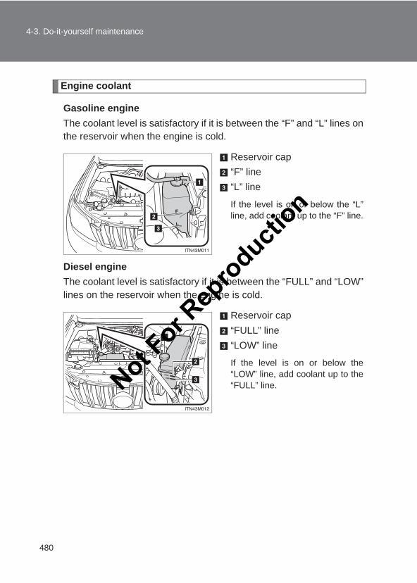
480
4-3. Do-it-yourself maintenance
LC150_OM_OM60J77E_(AE)
Engine coolant
Gasoline engineThe coolant level is satisfactory if it is between the “F” and “L” lines onthe reservoir when the engine is cold.
Reservoir cap“F” line“L” line
If the level is on or below the “L”line, add coolant up to the “F” line.
Diesel engineThe coolant level is satisfactory if it is between the “FULL” and “LOW”lines on the reservoir when the engine is cold.
Reservoir cap“FULL” line“LOW” line
If the level is on or below the“LOW” line, add coolant up to the“FULL” line.Not F
or Rep
roducti
on
481
4-3. Do-it-yourself maintenance
4
Maintenance and care
LC150_OM_OM60J77E_(AE)
■Coolant selectionOnly use “Toyota Super Long Life Coolant” or a similar high quality ethyleneglycol based non-silicate, non-amine, non-nitrite, and non-borate coolantwith long-life hybrid organic acid technology.
“Toyota Super Long Life Coolant” is a mixture of 50 % coolant and 50 %deionized water. (Enabled: -35 °C [-31 °F])
For more details about engine coolant, contact your Toyota dealer.
■ If the coolant level drops within a short time of replenishingVisually check the radiator, hoses, engine coolant reservoir caps, drain cockand water pump. If you cannot find a leak, have your Toyota dealer test the cap and check forleaks in the cooling system.
CAUTION
■When the engine is hotDo not remove the radiator cap, or the coolant reservoir cap. The cooling system may be under pressure and may spray hot coolant if thecap is removed, causing serious injuries, such as burns.
NOTICE
■When adding coolantCoolant is neither plain water nor straight antifreeze. The correct mixture ofwater and antifreeze must be used to provide proper lubrication, corrosionprotection and cooling. Be sure to read the antifreeze or coolant label.
■ If you spill coolantBe sure to wash it off with water to prevent it from damage to parts or paint.
Not For R
epro
duction
482
4-3. Do-it-yourself maintenance
LC150_OM_OM60J77E_(AE)
Radiator, condenser and intercooler
Check the radiator, condenser and intercooler and clear any foreignobjects. If any of the above parts are extremely dirty or you are not sure oftheir condition, have your vehicle inspected by your Toyota dealer.
CAUTION
■When the engine is hotDo not touch the radiator, condenser or intercooler as they may be hot andcause serious injuries, such as burns.
Not For R
epro
duction
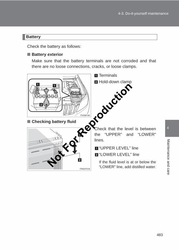
483
4-3. Do-it-yourself maintenance
4
Maintenance and care
LC150_OM_OM60J77E_(AE)
Battery
Check the battery as follows:
■ Battery exteriorMake sure that the battery terminals are not corroded and thatthere are no loose connections, cracks, or loose clamps.
TerminalsHold-down clamp
■ Checking battery fluidCheck that the level is betweenthe “UPPER” and “LOWER”lines.
“UPPER LEVEL” line“LOWER LEVEL” line
If the fluid level is at or below the“LOWER” line, add distilled water.Not F
or Rep
roducti
on
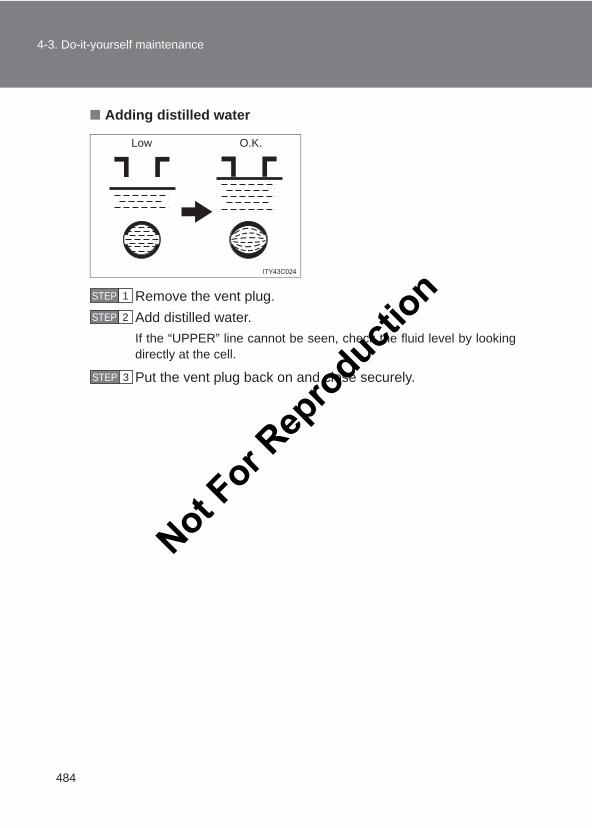
484
4-3. Do-it-yourself maintenance
LC150_OM_OM60J77E_(AE)
■ Adding distilled water
Remove the vent plug.Add distilled water.If the “UPPER” line cannot be seen, check the fluid level by lookingdirectly at the cell.
Put the vent plug back on and close securely.
Low O.K.
STEP 1
STEP 2
STEP 3STEP 3
Not For R
epro
duction
485
4-3. Do-it-yourself maintenance
4
Maintenance and care
LC150_OM_OM60J77E_(AE)
■Before rechargingWhen recharging, the battery produces hydrogen gas which is flammableand explosive. Therefore, observe the following before recharging:
● If recharging with the battery installed on the vehicle, be sure to discon-nect the ground cable.
●Make sure the power switch on the charger is off when connecting anddisconnecting the charger cables to the battery.
■After recharging/reconnecting the battery (vehicles with a smart entry& start system)The engine may not start. Follow the procedure below to initialize the sys-tem.
Shift the shift lever to P (automatic transmission) or depress thebrake pedal with the shift lever in N (manual transmission).
Open and close any of the doors.
Restart the engine.
●Unlocking the doors using the smart entry & start system may not bepossible immediately after reconnecting the battery. If this happens, usethe wireless remote control or the mechanical key to lock/unlock thedoors.
●Start the engine with the “ENGINE START STOP” switch in ACCES-SORY mode. The engine may not start with the “ENGINE START STOP”switch turned OFF. However, the engine will operate normally from thesecond attempt.
●The “ENGINE START STOP” switch mode is recorded by the vehicle. Ifthe battery is reconnected, the vehicle will return the “ENGINE STARTSTOP” switch mode to the status it was in before the battery was discon-nected. Make sure to turn off the engine before disconnect the battery.Take extra care when connecting the battery if the “ENGINE STARTSTOP” switch mode prior to discharge is unknown.
If the system will not start even after multiple attempts, contact your Toyotadealer.
STEP 1
STEP 2
STEP 3
Not For R
epro
duction
486
4-3. Do-it-yourself maintenance
LC150_OM_OM60J77E_(AE)
CAUTION
■Chemicals in the batteryBatteries contain poisonous and corrosive sulfuric acid and may producehydrogen gas which is flammable and explosive. To reduce the risk of deathor serious injury, take the following precautions while working on or near bat-tery:
●Do not cause sparks by touching the battery terminals with tools.
●Do not smoke or light a match near the battery.
●Avoid contact with eyes, skin and clothes.
●Never inhale or swallow electrolyte.
●Wear protective safety glasses when working near the battery.
●Keep children away from the battery.
■Where to safely charge the batteryAlways charge the battery in an open area. Do not charge the battery in agarage or closed room where there is not sufficient ventilation.
■Emergency measures regarding electrolyte● If electrolyte gets in your eyes
Flush your eyes with clean water for at least 15 minutes and get immedi-ate medical attention. If possible, continue to apply water with a sponge orcloth while traveling to the nearest medical facility.
● If electrolyte gets on your skinWash the affected area thoroughly. If you feel pain or burning, get medicalattention immediately.
● If electrolyte gets on your clothesIt can soak through clothing on to your skin. Immediately take off the cloth-ing and follow the procedure above if necessary.
● If you accidentally swallow electrolyteDrink a large quantity of water or milk. Get emergency medical attentionimmediately.
Not For R
epro
duction
487
4-3. Do-it-yourself maintenance
4
Maintenance and care
LC150_OM_OM60J77E_(AE)
NOTICE
■When recharging the batteryNever recharge the battery while the engine is running. Also, be sure allaccessories are turned off.
■When adding distilled waterAvoid overfilling. Water spilled during battery recharging may cause corro-sion.
Not For R
epro
duction
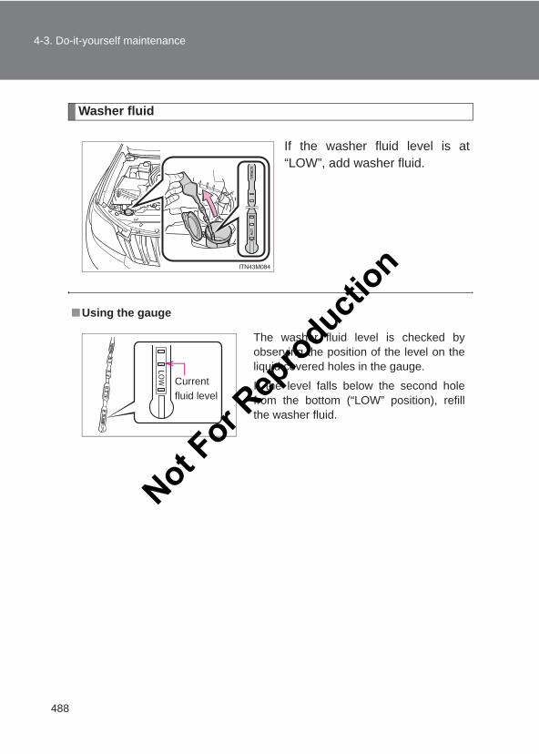
488
4-3. Do-it-yourself maintenance
LC150_OM_OM60J77E_(AE)
Washer fluid
If the washer fluid level is at“LOW”, add washer fluid.
■Using the gauge
The washer fluid level is checked byobserving the position of the level on theliquid covered holes in the gauge.
If the level falls below the second holefrom the bottom (“LOW” position), refillthe washer fluid.
Current fluid level
Not For R
epro
duction
489
4-3. Do-it-yourself maintenance
4
Maintenance and care
LC150_OM_OM60J77E_(AE)
CAUTION
■When adding washer fluidDo not add washer fluid when the engine is hot or running as washer fluidcontains alcohol and may catch fire if spilled on the engine etc.
NOTICE
■Do not use any fluid other than washer fluidDo not use soapy water or engine antifreeze instead of washer fluid. Doing so may cause streaking on the vehicle’s painted surfaces.
■Diluting washer fluidDilute washer fluid with water as necessary. Refer to the freezing temperatures listed on the label of the washer fluid bot-tle.
Not For R
epro
duction
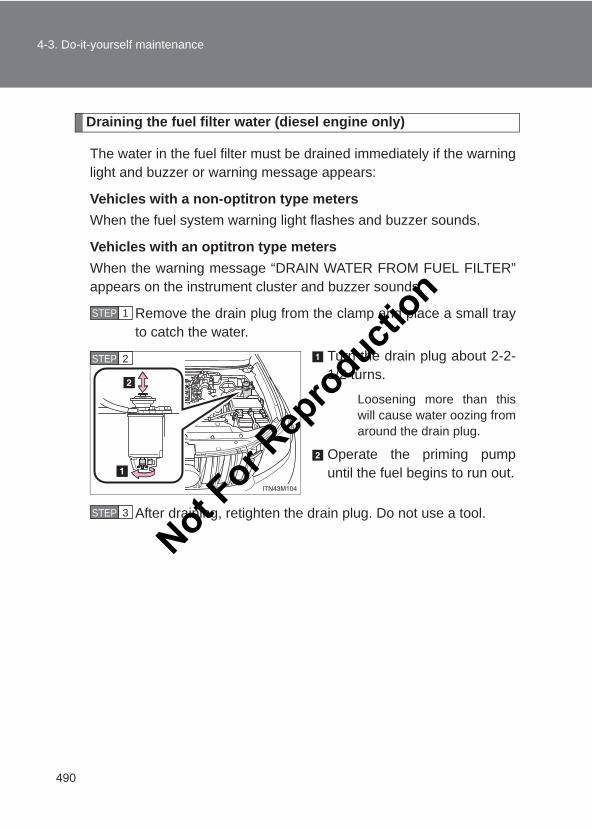
490
4-3. Do-it-yourself maintenance
LC150_OM_OM60J77E_(AE)
Draining the fuel filter water (diesel engine only)
The water in the fuel filter must be drained immediately if the warninglight and buzzer or warning message appears:
Vehicles with a non-optitron type metersWhen the fuel system warning light flashes and buzzer sounds.
Vehicles with an optitron type metersWhen the warning message “DRAIN WATER FROM FUEL FILTER”appears on the instrument cluster and buzzer sounds.
Remove the drain plug from the clamp and place a small trayto catch the water.
Turn the drain plug about 2-2-1/2 turns.
Loosening more than thiswill cause water oozing fromaround the drain plug.
Operate the priming pumpuntil the fuel begins to run out.
After draining, retighten the drain plug. Do not use a tool.
STEP 1
STEP 2
STEP 3
Not For R
epro
duction
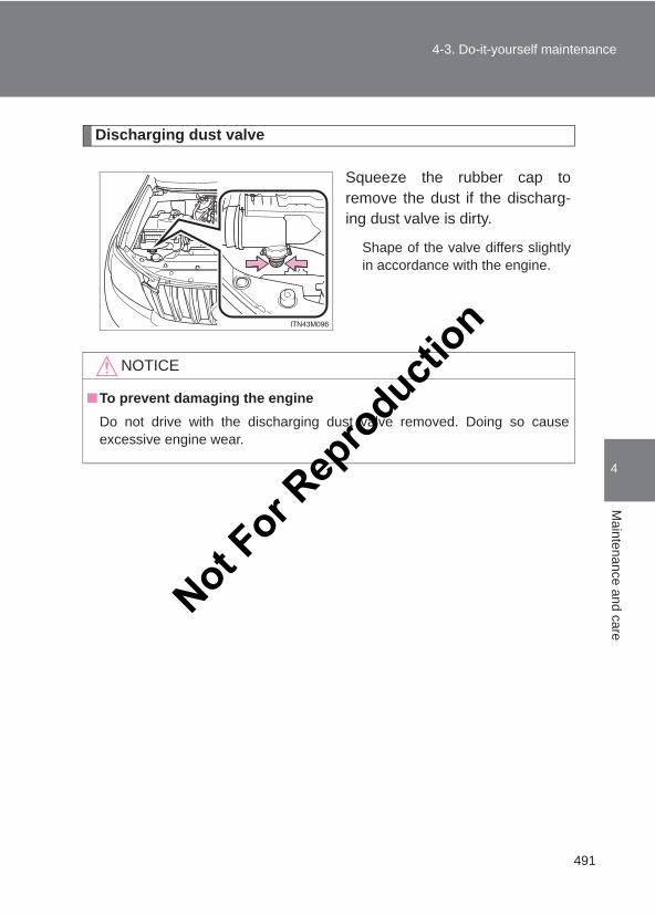
491
4-3. Do-it-yourself maintenance
4
Maintenance and care
LC150_OM_OM60J77E_(AE)
Discharging dust valve
Squeeze the rubber cap toremove the dust if the discharg-ing dust valve is dirty.
Shape of the valve differs slightlyin accordance with the engine.
NOTICE
■To prevent damaging the engineDo not drive with the discharging dust valve removed. Doing so causeexcessive engine wear.
Not For R
epro
duction
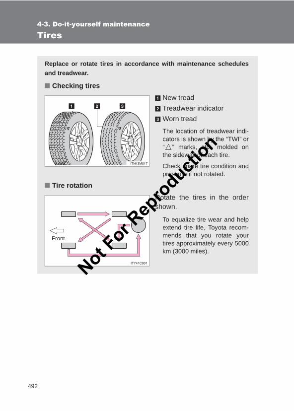
492
4-3. Do-it-yourself maintenance
LC150_OM_OM60J77E_(AE)
Tires
Replace or rotate tires in accordance with maintenance schedulesand treadwear.
■ Checking tiresNew treadTreadwear indicatorWorn tread
The location of treadwear indi-cators is shown by the “TWI” or“ ” marks, etc., molded onthe sidewall of each tire.
Check spare tire condition andpressure if not rotated.
■ Tire rotationRotate the tires in the ordershown.
To equalize tire wear and helpextend tire life, Toyota recom-mends that you rotate yourtires approximately every 5000km (3000 miles).
Front
Not For R
epro
duction
493
4-3. Do-it-yourself maintenance
4
Maintenance and care
LC150_OM_OM60J77E_(AE)
■When to replace your vehicle’s tiresTires should be replaced if:
●You have tire damage such as cuts, splits, cracks deep enough toexpose the fabric, and bulges indicating internal damage
●A tire goes flat repeatedly or cannot be properly repaired due to the sizeor location of a cut or other damage
If you are not sure, consult with your Toyota dealer.
■Tire lifeAny tire over 6 years old must be checked by a qualified technician even if ithas seldom or never been used or damage is not obvious.
■ If the tread on snow tires wears down below 4 mm (0.16 in.)The effectiveness of the tires as snow tires is lost.
CAUTION
■When inspecting or replacing tiresObserve the following precautions to prevent accidents.Failure to do so may cause damage to parts of the drive train as well as dan-gerous handling characteristics, which may lead to an accident resulting indeath or serious injury.
●Do not mix tires of different makes, models or tread patterns.Also, do not mix tires of remarkably different treadwear.
●Do not use tire sizes other than those recommended by Toyota.
●Do not mix differently constructed tires (radial, bias-belted or bias-plytires).
●Do not mix summer, all season and snow tires.
●Do not use tires that have been used on another vehicle.Do not use tires if you do not know how they were used previously.
Not For R
epro
duction
494
4-3. Do-it-yourself maintenance
LC150_OM_OM60J77E_(AE)
NOTICE
■Driving on rough roadsTake particular care when driving on roads with loose surfaces or potholes.These conditions may cause losses in tire inflation pressure, reducing thecushioning ability of the tires. In addition, driving on rough roads may causedamage to the tires themselves, as well as the vehicle’s wheels and body.
■ If tire inflation pressures become low while drivingDo not continue driving, or your tires and/or wheels may be ruined.
Not For R
epro
duction
495
4-3. Do-it-yourself maintenance
4
Maintenance and care
LC150_OM_OM60J77E_(AE)
Tire inflation pressure
■Effects of incorrect tire inflation pressureDriving with incorrect tire inflation pressure may result in the following:
●Reduced fuel efficiency
●Reduced driving comfort and tire life
●Reduced safety
●Damage to the drive train
If a tire needs frequent inflating, have it checked by your Toyota dealer.
■ Instructions for checking tire inflation pressureWhen checking tire inflation pressure, observe the following:
●Check only when the tires are cold.If your vehicle has been parked for at least 3 hours and has not beendriven for more than 1.5 km or 1 mile, you will get an accurate cold tireinflation pressure reading.
●Always use a tire pressure gauge.The appearance of the tire can be misleading. In addition, tire inflationpressure that is even just a few pounds off can affect ride quality andhandling.
●Do not reduce tire inflation pressure after driving. It is normal for tire infla-tion pressure to be higher after driving.
●Never exceed the vehicle capacity weight.Passengers and luggage weight should be placed so that the vehicle isbalanced.
Make sure to maintain the proper tire inflation pressure. Tire inflationpressure should be checked at least once per month. However,Toyota recommends that tire inflation pressure be checked onceevery two weeks. (→P. 628)
Not For R
epro
duction
496
4-3. Do-it-yourself maintenance
LC150_OM_OM60J77E_(AE)
CAUTION
■Proper inflation is critical to save tire performanceKeep your tires properly inflated. Otherwise, the following conditions mayoccur and result in an accident causing death or serious injury:
●Excessive wear
●Uneven wear
●Poor handling
●Possibility of blowouts resulting from overheated tires
●Poor sealing of the tire bead
●Wheel deformation and/or tire separation
●A greater possibility of tire damage from road hazards
NOTICE
■When inspecting and adjusting tire inflation pressureBe sure to put the tire valve caps back on.Without the valve caps, dirt or moisture could get into the valve and causeair leakage, which could result in an accident. If the caps are lost, replacethem as soon as possible.
Not For R
epro
duction
497
4-3. Do-it-yourself maintenance
4
Maintenance and care
LC150_OM_OM60J77E_(AE)
Wheels
If a wheel is bent, cracked or heavily corroded, it should be replaced.Otherwise, the tire may separate from the wheel or cause loss ofhandling control.
■ Wheel selectionWhen replacing wheels, care should be taken to ensure thatthey are equivalent to those removed in load capacity, diameter,rim width, and inset*.Replacement wheels are available at your Toyota dealer.
Toyota does not recommend using the following:
*: Conventionally referred to as “offset”.
● Wheels of different sizes or types
● Used wheels
● Bent wheels that have been straightened
■ Aluminum wheel precautions● Use only Toyota wheel nuts and wrenches designed for use
with your aluminum wheels.
● When rotating, repairing or changing your tires, check that thewheel nuts are still tight after driving 1600 km (1000 miles).
● Be careful not to damage the aluminum wheels when usingtire chains.
● When balancing your wheels, use only Toyota genuine bal-ance weights or the equivalent. If clip-on balance weights arebeing used, use a plastic or rubber hammer to install theweight.
Not For R
epro
duction
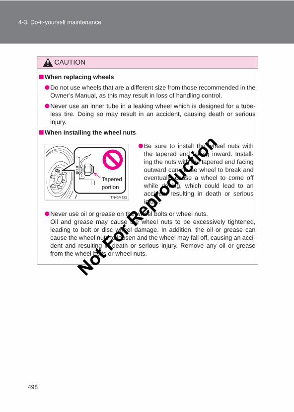
498
4-3. Do-it-yourself maintenance
LC150_OM_OM60J77E_(AE)
CAUTION
■When replacing wheels●Do not use wheels that are a different size from those recommended in the
Owner’s Manual, as this may result in loss of handling control.
●Never use an inner tube in a leaking wheel which is designed for a tube-less tire. Doing so may result in an accident, causing death or seriousinjury.
■When installing the wheel nuts
●Never use oil or grease on the wheel bolts or wheel nuts.Oil and grease may cause the wheel nuts to be excessively tightened,leading to bolt or disc wheel damage. In addition, the oil or grease cancause the wheel nuts to loosen and the wheel may fall off, causing an acci-dent and resulting in death or serious injury. Remove any oil or greasefrom the wheel bolts or wheel nuts.
●Be sure to install the wheel nuts withthe tapered end facing inward. Install-ing the nuts with the tapered end facingoutward can cause wheel to break andeventually cause a wheel to come offwhile driving, which could lead to anaccident resulting in death or seriousinjury.
Tapered portion
Not For R
epro
duction
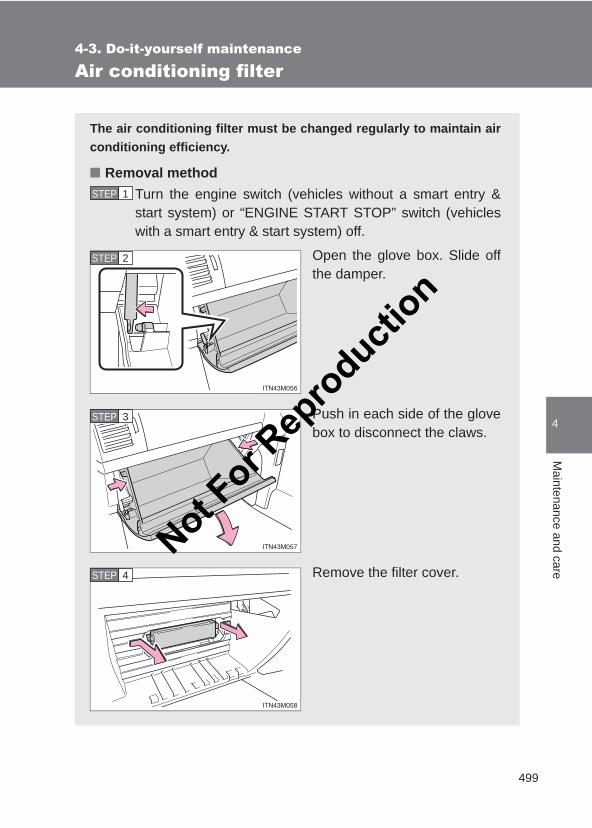
499
4-3. Do-it-yourself maintenance
4
Maintenance and care
LC150_OM_OM60J77E_(AE)
Air conditioning filter
The air conditioning filter must be changed regularly to maintain airconditioning efficiency.
■ Removal methodTurn the engine switch (vehicles without a smart entry &start system) or “ENGINE START STOP” switch (vehicleswith a smart entry & start system) off.
Open the glove box. Slide offthe damper.
Push in each side of the glovebox to disconnect the claws.
Remove the filter cover.
STEP 1
STEP 2
STEP 3
STEP 4
Not For R
epro
duction
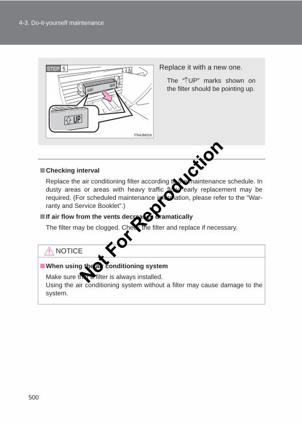
500
4-3. Do-it-yourself maintenance
LC150_OM_OM60J77E_(AE)
■Checking intervalReplace the air conditioning filter according to the maintenance schedule. Industy areas or areas with heavy traffic flow, early replacement may berequired. (For scheduled maintenance information, please refer to the “War-ranty and Service Booklet”.)
■ If air flow from the vents decreases dramaticallyThe filter may be clogged. Check the filter and replace if necessary.
NOTICE
■When using the air conditioning systemMake sure that a filter is always installed.Using the air conditioning system without a filter may cause damage to thesystem.
Replace it with a new one.
The “↑UP” marks shown onthe filter should be pointing up.
STEP 5
Not For R
epro
duction
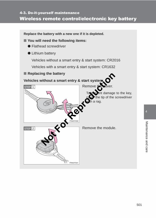
501
4-3. Do-it-yourself maintenance
4
Maintenance and care
LC150_OM_OM60J77E_(AE)
Wireless remote control/electronic key battery
Replace the battery with a new one if it is depleted.
■ You will need the following items:● Flathead screwdriver
● Lithium battery
Vehicles without a smart entry & start system: CR2016
Vehicles with a smart entry & start system: CR1632
■ Replacing the battery
Vehicles without a smart entry & start systemRemove the cover.
To prevent damage to the key,cover the tip of the screwdriverwith a rag.
Remove the module.
STEP 1
STEP 2
Not For R
epro
duction
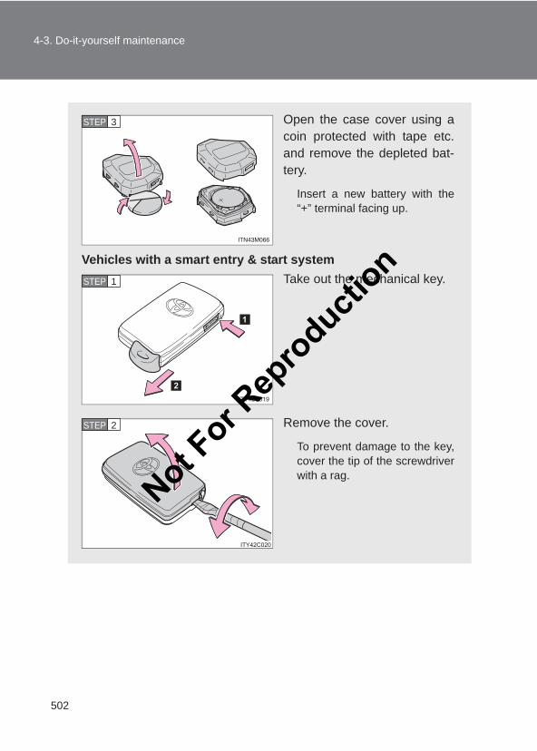
502
4-3. Do-it-yourself maintenance
LC150_OM_OM60J77E_(AE)
Open the case cover using acoin protected with tape etc.and remove the depleted bat-tery.
Insert a new battery with the“+” terminal facing up.
Vehicles with a smart entry & start systemTake out the mechanical key.
Remove the cover.
To prevent damage to the key,cover the tip of the screwdriverwith a rag.
STEP 3
STEP 1
STEP 2
Not For R
epro
duction
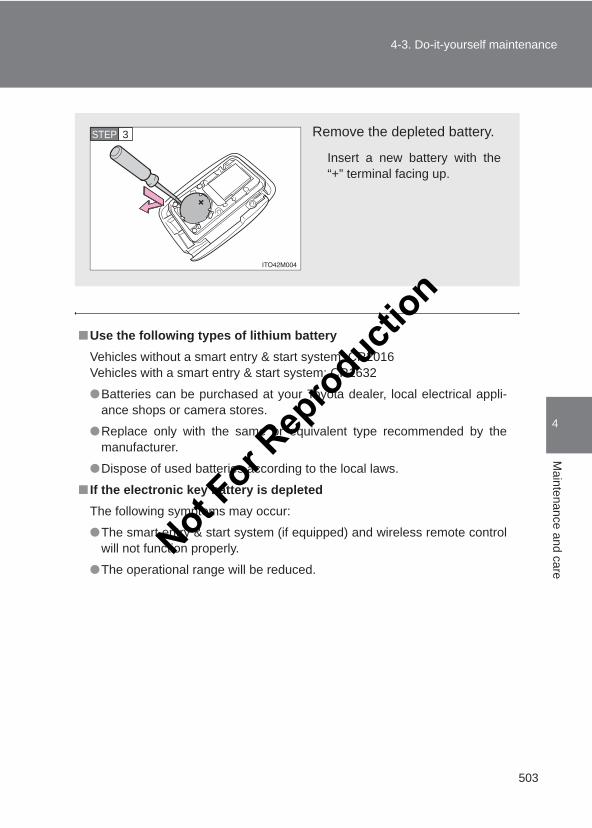
503
4-3. Do-it-yourself maintenance
4
Maintenance and care
LC150_OM_OM60J77E_(AE)
■Use the following types of lithium batteryVehicles without a smart entry & start system: CR2016 Vehicles with a smart entry & start system: CR1632
●Batteries can be purchased at your Toyota dealer, local electrical appli-ance shops or camera stores.
●Replace only with the same or equivalent type recommended by themanufacturer.
●Dispose of used batteries according to the local laws.
■ If the electronic key battery is depletedThe following symptoms may occur:
●The smart entry & start system (if equipped) and wireless remote controlwill not function properly.
●The operational range will be reduced.
Remove the depleted battery.
Insert a new battery with the“+” terminal facing up.
STEP 3
Not For R
epro
duction
504
4-3. Do-it-yourself maintenance
LC150_OM_OM60J77E_(AE)
CAUTION
■Removed battery and other partsThese parts are small and if swallowed by a child, they can cause choking.Keep away from children. Failure to do so could result in death or seriousinjury.
NOTICE
■For normal operation after replacing the batteryObserve the following precautions to prevent accidents:
●Always work with dry hands.Moisture may cause the battery to rust.
●Do not touch or move any other components inside remote control.
●Do not bend the battery terminals.
Not For R
epro
duction
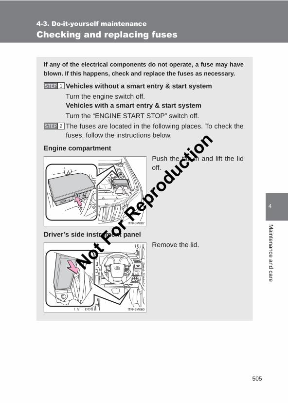
505
4-3. Do-it-yourself maintenance
4
Maintenance and care
LC150_OM_OM60J77E_(AE)
Checking and replacing fuses
If any of the electrical components do not operate, a fuse may haveblown. If this happens, check and replace the fuses as necessary.
Vehicles without a smart entry & start systemTurn the engine switch off.Vehicles with a smart entry & start systemTurn the “ENGINE START STOP” switch off. The fuses are located in the following places. To check thefuses, follow the instructions below.
Engine compartmentPush the tab in and lift the lidoff.
Driver’s side instrument panelRemove the lid.
STEP 1
STEP 2
Not For R
epro
duction
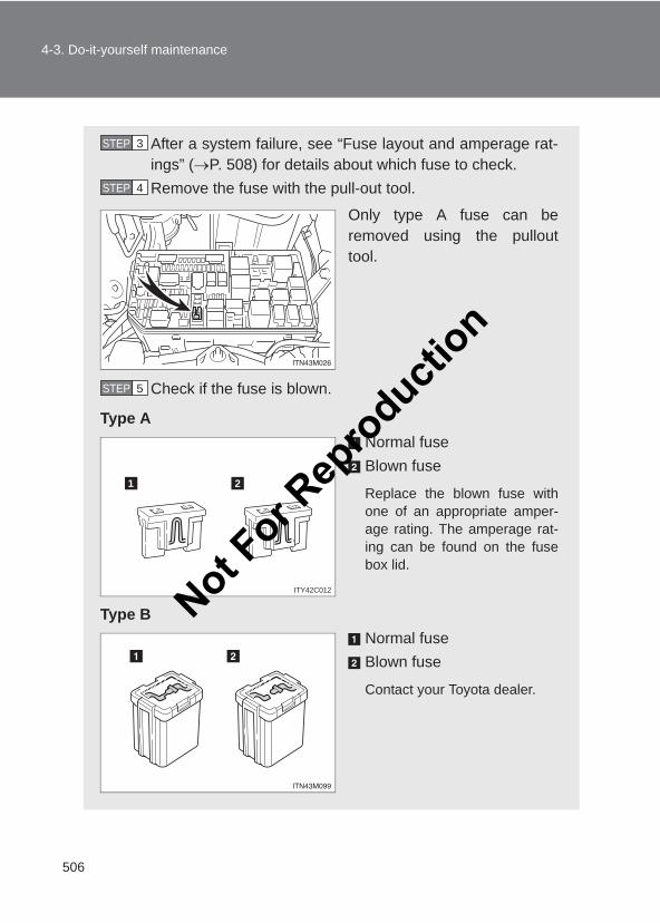
506
4-3. Do-it-yourself maintenance
LC150_OM_OM60J77E_(AE)
After a system failure, see “Fuse layout and amperage rat-ings” (→P. 508) for details about which fuse to check.Remove the fuse with the pull-out tool.
Only type A fuse can beremoved using the pullouttool.
Check if the fuse is blown.
Type ANormal fuseBlown fuse
Replace the blown fuse withone of an appropriate amper-age rating. The amperage rat-ing can be found on the fusebox lid.
Type BNormal fuseBlown fuse
Contact your Toyota dealer.
STEP 3
STEP 4
STEP 5
1 2
ITY42C012Not For R
epro
duction
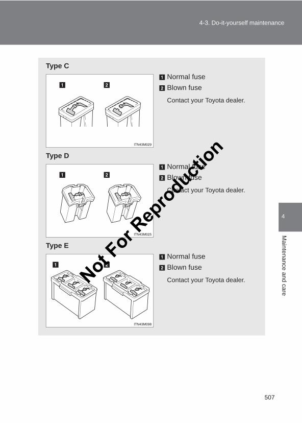
507
4-3. Do-it-yourself maintenance
4
Maintenance and care
LC150_OM_OM60J77E_(AE)
Type CNormal fuseBlown fuse
Contact your Toyota dealer.
Type DNormal fuseBlown fuse
Contact your Toyota dealer.
Type ENormal fuseBlown fuse
Contact your Toyota dealer.Not For R
epro
duction
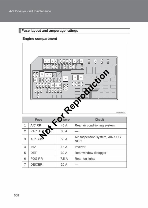
508
4-3. Do-it-yourself maintenance
LC150_OM_OM60J77E_(AE)
Fuse layout and amperage ratings
Engine compartment
Fuse Ampere Circuit
1 A/C RR 40 A Rear air conditioning system
2 PTC HTR NO.3 30 A
3 AIR SUS 50 A Air suspension system, AIR SUS NO.2
4 INV 15 A Inverter
5 DEF 30 A Rear window defogger
6 FOG RR 7.5 A Rear fog lights
7 DEICER 20 A
Not For R
epro
duction
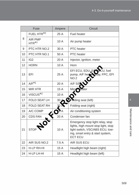
509
4-3. Do-it-yourself maintenance
4
Maintenance and care
LC150_OM_OM60J77E_(AE)
8FUEL HTR*2 25 A Fuel heater
AIR PMP HTR*1 10 A Air pump heater
9 PTC HTR NO.2 30 A PTC heater
10 PTC HTR NO.1 50 A PTC heater
11 IG2 20 A Injector, ignition, meter
12 HORN 10 A Horn
13 EFI 25 AEFI ECU, EDU, ECT ECU, fuel pump, A/F heater relay, FPC, EFI NO.2
14 A/F*1 20 A A/F SSR
15 MIR HTR 15 A Mirror heater
16 VISCUS*2 10 A
17 FOLD SEAT LH 30 A Folding seat (left)
18 FOLD SEAT RH 30 A Folding seat (right)
19 A/C COMP 10 A Air conditioning system
20 CDS FAN 20 A Condenser fan
21 STOP 10 A
Emergency stop light relay, stop lights, high mount stop light, stop light switch, VSC/ABS ECU, tow-ing, smart entry & start system, ECT ECU
22 AIR SUS NO.2 7.5 A AIR SUS ECU
23 H-LP RH-HI 15 A Headlight high beam (right)
24 H-LP LH-HI 15 A Headlight high beam (left)
Fuse Ampere Circuit
Not For R
epro
duction
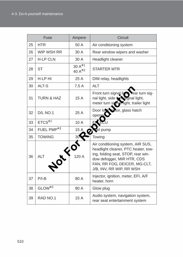
510
4-3. Do-it-yourself maintenance
LC150_OM_OM60J77E_(AE)
25 HTR 50 A Air conditioning system
26 WIP WSH RR 30 A Rear window wipers and washer
27 H-LP CLN 30 A Headlight cleaner
28 ST 30 A*1
40 A*2 STARTER MTR
29 H-LP HI 25 A DIM relay, headlights
30 ALT-S 7.5 A ALT
31 TURN & HAZ 15 AFront turn signal light, rear turn sig-nal light, side turn signal light, meter turn signal light, trailer light
32 D/L NO.1 25 A Door lock motor, glass hatch opener
33 ETCS*1 10 A EFI ECU
34 FUEL PMP*3 15 A Fuel pump
35 TOWING 30 A Towing
36 ALT 120 A
Air conditioning system, AIR SUS, headlight cleaner, PTC heater, tow-ing, folding seat, STOP, rear win-dow defogger, MIR HTR, CDS FAN, RR FOG, DEICER, MG-CLT, J/B, INV, RR WIP, RR WSH
37 P/I-B 80 A Injector, ignition, meter, EFI, A/F heater, horn
38 GLOW*2 80 A Glow plug
39 RAD NO.1 15 A Audio system, navigation system, rear seat entertainment system
Fuse Ampere Circuit
Not For R
epro
duction
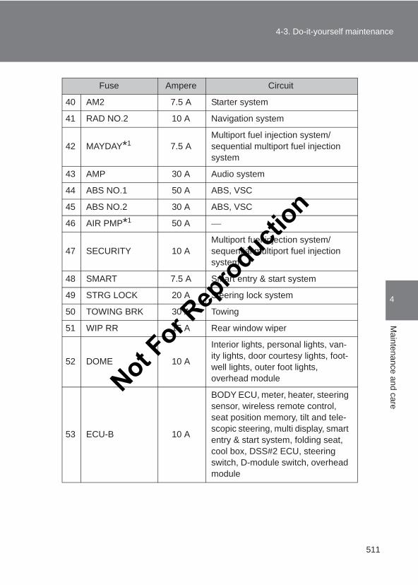
511
4-3. Do-it-yourself maintenance
4
Maintenance and care
LC150_OM_OM60J77E_(AE)
40 AM2 7.5 A Starter system
41 RAD NO.2 10 A Navigation system
42 MAYDAY*1 7.5 AMultiport fuel injection system/sequential multiport fuel injection system
43 AMP 30 A Audio system
44 ABS NO.1 50 A ABS, VSC
45 ABS NO.2 30 A ABS, VSC
46 AIR PMP*1 50 A
47 SECURITY 10 AMultiport fuel injection system/sequential multiport fuel injection system
48 SMART 7.5 A Smart entry & start system
49 STRG LOCK 20 A Steering lock system
50 TOWING BRK 30 A Towing
51 WIP RR 15 A Rear window wiper
52 DOME 10 A
Interior lights, personal lights, van-ity lights, door courtesy lights, foot-well lights, outer foot lights, overhead module
53 ECU-B 10 A
BODY ECU, meter, heater, steering sensor, wireless remote control, seat position memory, tilt and tele-scopic steering, multi display, smart entry & start system, folding seat, cool box, DSS#2 ECU, steering switch, D-module switch, overhead module
Fuse Ampere Circuit
Not For R
epro
duction
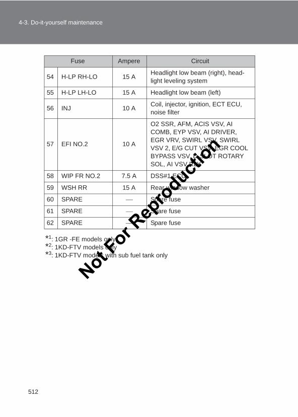
512
4-3. Do-it-yourself maintenance
LC150_OM_OM60J77E_(AE)
*1: 1GR -FE models only*2: 1KD-FTV models only*3: 1KD-FTV models with sub fuel tank only
54 H-LP RH-LO 15 A Headlight low beam (right), head-light leveling system
55 H-LP LH-LO 15 A Headlight low beam (left)
56 INJ 10 A Coil, injector, ignition, ECT ECU, noise filter
57 EFI NO.2 10 A
O2 SSR, AFM, ACIS VSV, AI COMB, EYP VSV, AI DRIVER, EGR VRV, SWIRL VSV, SWIRL VSV 2, E/G CUT VSV, EGR COOL BYPASS VSV, D-SLOT ROTARY SOL, AI VSV RLY
58 WIP FR NO.2 7.5 A DSS#1 ECU
59 WSH RR 15 A Rear window washer
60 SPARE Spare fuse
61 SPARE Spare fuse
62 SPARE Spare fuse
Fuse Ampere Circuit
Not For R
epro
duction
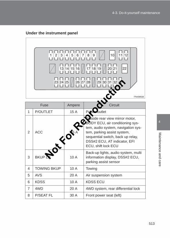
513
4-3. Do-it-yourself maintenance
4
Maintenance and care
LC150_OM_OM60J77E_(AE)
Under the instrument panel
Fuse Ampere Circuit
1 P/OUTLET 15 A Power outlet
2 ACC 7.5 A
Outside rear view mirror motor, BODY ECU, air conditioning sys-tem, audio system, navigation sys-tem, parking assist system, sequential switch, back up relay, DSS#2 ECU, AT indicator, EFI ECU, shift lock ECU
3 BKUP LP 10 ABack-up lights, audio system, multi information display, DSS#2 ECU, parking assist sensor
4 TOWING BKUP 10 A Towing
5 AVS 20 A Air suspension system
6 KDSS 10 A KDSS ECU
7 4WD 20 A 4WD system, rear differential lock
8 P/SEAT FL 30 A Front power seat (left)
Not For R
epro
duction
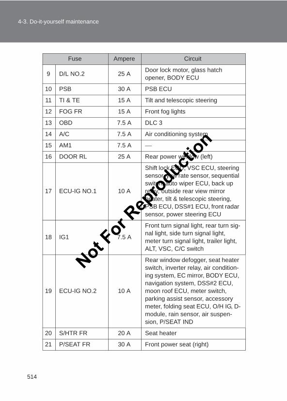
514
4-3. Do-it-yourself maintenance
LC150_OM_OM60J77E_(AE)
9 D/L NO.2 25 A Door lock motor, glass hatch opener, BODY ECU
10 PSB 30 A PSB ECU
11 TI & TE 15 A Tilt and telescopic steering
12 FOG FR 15 A Front fog lights
13 OBD 7.5 A DLC 3
14 A/C 7.5 A Air conditioning system
15 AM1 7.5 A
16 DOOR RL 25 A Rear power window (left)
17 ECU-IG NO.1 10 A
Shift lock ECU, VSC ECU, steering sensor, yaw rate sensor, sequential switch, auto wiper ECU, back up relay, outside rear view mirror heater, tilt & telescopic steering, PSB ECU, DSS#1 ECU, front radar sensor, power steering ECU
18 IG1 7.5 A
Front turn signal light, rear turn sig-nal light, side turn signal light, meter turn signal light, trailer light, ALT, VSC, C/C switch
19 ECU-IG NO.2 10 A
Rear window defogger, seat heater switch, inverter relay, air condition-ing system, EC mirror, BODY ECU, navigation system, DSS#2 ECU, moon roof ECU, meter switch, parking assist sensor, accessory meter, folding seat ECU, O/H IG, D-module, rain sensor, air suspen-sion, P/SEAT IND
20 S/HTR FR 20 A Seat heater
21 P/SEAT FR 30 A Front power seat (right)
Fuse Ampere Circuit
Not For R
epro
duction
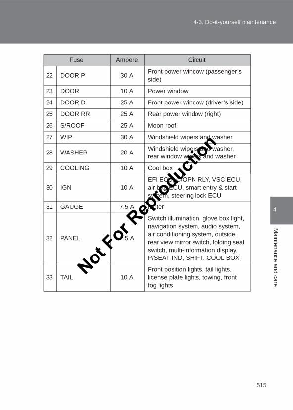
515
4-3. Do-it-yourself maintenance
4
Maintenance and care
LC150_OM_OM60J77E_(AE)
22 DOOR P 30 A Front power window (passenger’s side)
23 DOOR 10 A Power window
24 DOOR D 25 A Front power window (driver’s side)
25 DOOR RR 25 A Rear power window (right)
26 S/ROOF 25 A Moon roof
27 WIP 30 A Windshield wipers and washer
28 WASHER 20 A Windshield wipers and washer, rear window wipers and washer
29 COOLING 10 A Cool box
30 IGN 10 AEFI ECU, C/OPN RLY, VSC ECU, air bag ECU, smart entry & start system, steering lock ECU
31 GAUGE 7.5 A Meter
32 PANEL 7.5 A
Switch illumination, glove box light, navigation system, audio system, air conditioning system, outside rear view mirror switch, folding seat switch, multi-information display, P/SEAT IND, SHIFT, COOL BOX
33 TAIL 10 AFront position lights, tail lights, license plate lights, towing, front fog lights
Fuse Ampere Circuit
Not For R
epro
duction
516
4-3. Do-it-yourself maintenance
LC150_OM_OM60J77E_(AE)
■After a fuse is replaced● If the lights do not turn on even after the fuse has been replaced, a bulb
may need replacement. (→P. 517)
● If the replaced fuse blows again, have the vehicle inspected by yourToyota dealer.
■ If there is an overload in a circuitThe fuses are designed to blow, protecting the wiring harness from damage.
CAUTION
■To prevent system breakdowns and vehicle fireObserve the following precautions.Failure to do so may cause damage to the vehicle, and possibly a fire orinjury.
●Never use a fuse of a higher amperage rating than indicated, or use anyother object in place of a fuse.
●Always use a genuine Toyota fuse or equivalent.Never replace a fuse with a wire, even as a temporary fix.
●Do not modify the fuses or fuse boxes.
NOTICE
■Before replacing fusesHave the cause of electrical overload determined and repaired by yourToyota dealer as soon as possible.
Not For R
epro
duction
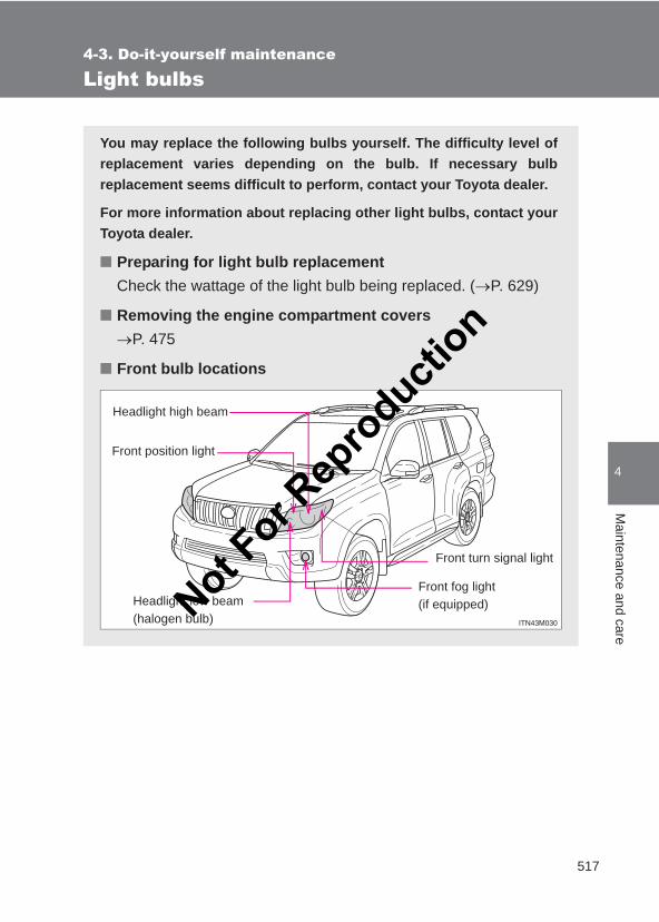
517
4-3. Do-it-yourself maintenance
4
Maintenance and care
LC150_OM_OM60J77E_(AE)
Light bulbs
You may replace the following bulbs yourself. The difficulty level ofreplacement varies depending on the bulb. If necessary bulbreplacement seems difficult to perform, contact your Toyota dealer.
For more information about replacing other light bulbs, contact yourToyota dealer.
■ Preparing for light bulb replacementCheck the wattage of the light bulb being replaced. (→P. 629)
■ Removing the engine compartment covers→P. 475
■ Front bulb locations
Headlight low beam(halogen bulb)
Front fog light (if equipped)
Headlight high beam
Front position light
Front turn signal light
Not For R
epro
duction
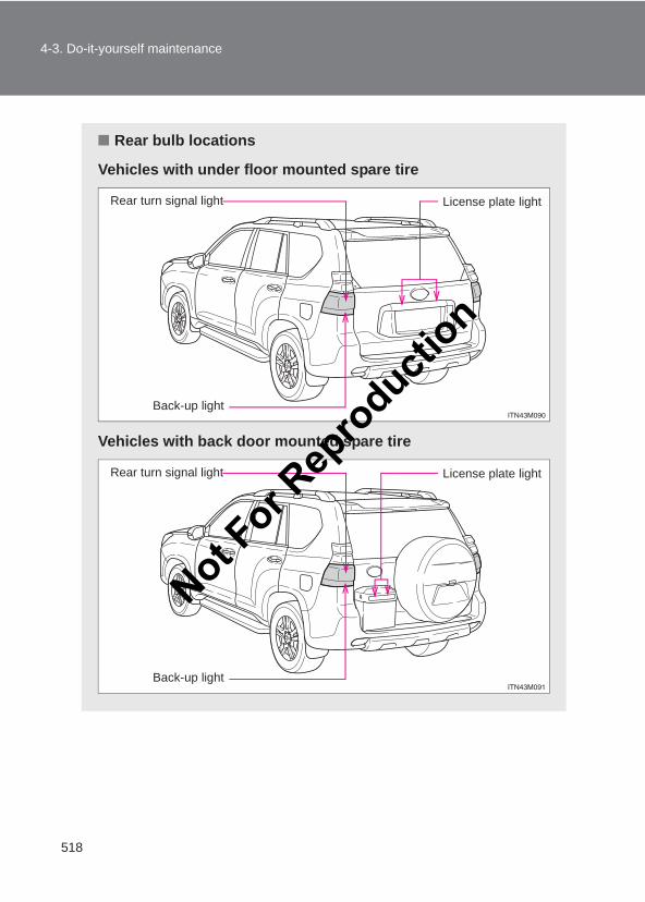
518
4-3. Do-it-yourself maintenance
LC150_OM_OM60J77E_(AE)
■ Rear bulb locations
Vehicles with under floor mounted spare tire
Vehicles with back door mounted spare tire
Rear turn signal light
Back-up light
License plate light
Rear turn signal light
Back-up light
License plate light
Not For R
epro
duction
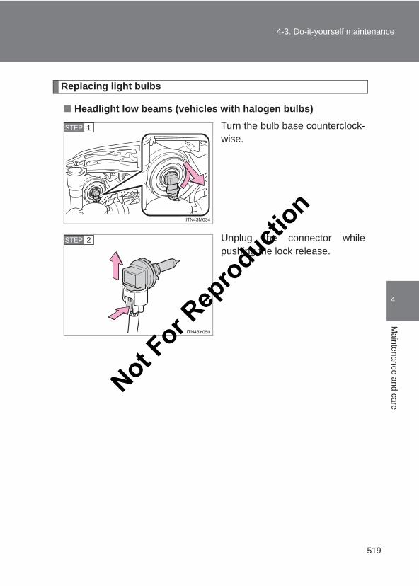
519
4-3. Do-it-yourself maintenance
4
Maintenance and care
LC150_OM_OM60J77E_(AE)
Replacing light bulbs
■ Headlight low beams (vehicles with halogen bulbs)Turn the bulb base counterclock-wise.
Unplug the connector whilepushing the lock release.
STEP 1
STEP 2
Not For R
epro
duction
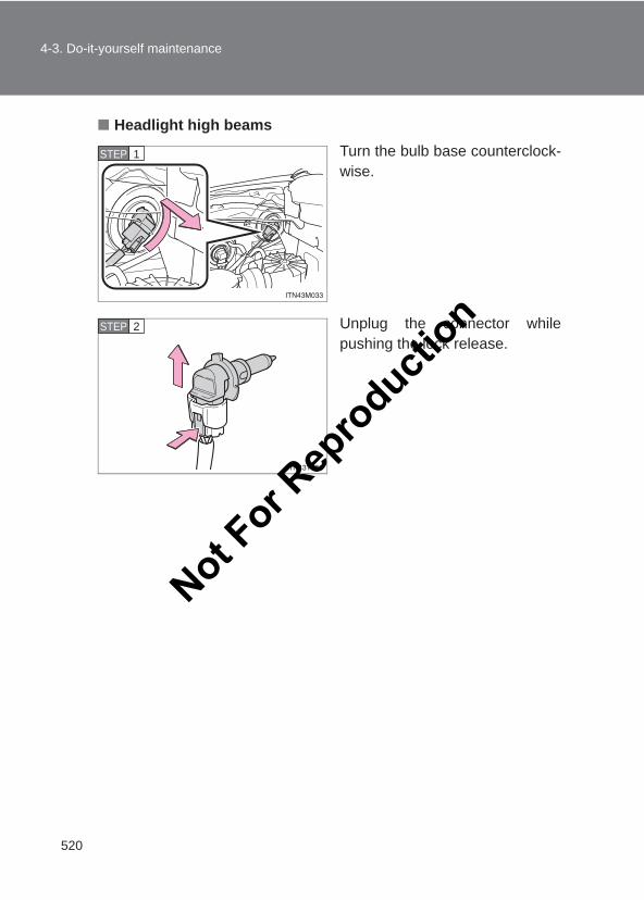
520
4-3. Do-it-yourself maintenance
LC150_OM_OM60J77E_(AE)
■ Headlight high beamsTurn the bulb base counterclock-wise.
Unplug the connector whilepushing the lock release.
STEP 1
STEP 2
Not For R
epro
duction
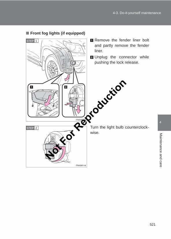
521
4-3. Do-it-yourself maintenance
4
Maintenance and care
LC150_OM_OM60J77E_(AE)
■ Front fog lights (if equipped)Remove the fender liner boltand partly remove the fenderliner.Unplug the connector whilepushing the lock release.
Turn the light bulb counterclock-wise.
STEP 1
STEP 2
Not For R
epro
duction
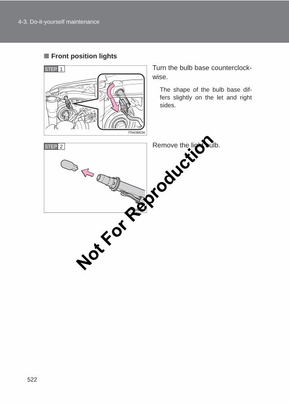
522
4-3. Do-it-yourself maintenance
LC150_OM_OM60J77E_(AE)
■ Front position lightsTurn the bulb base counterclock-wise.
The shape of the bulb base dif-fers slightly on the let and rightsides.
Remove the light bulb.
STEP 1
STEP 2
Not For R
epro
duction
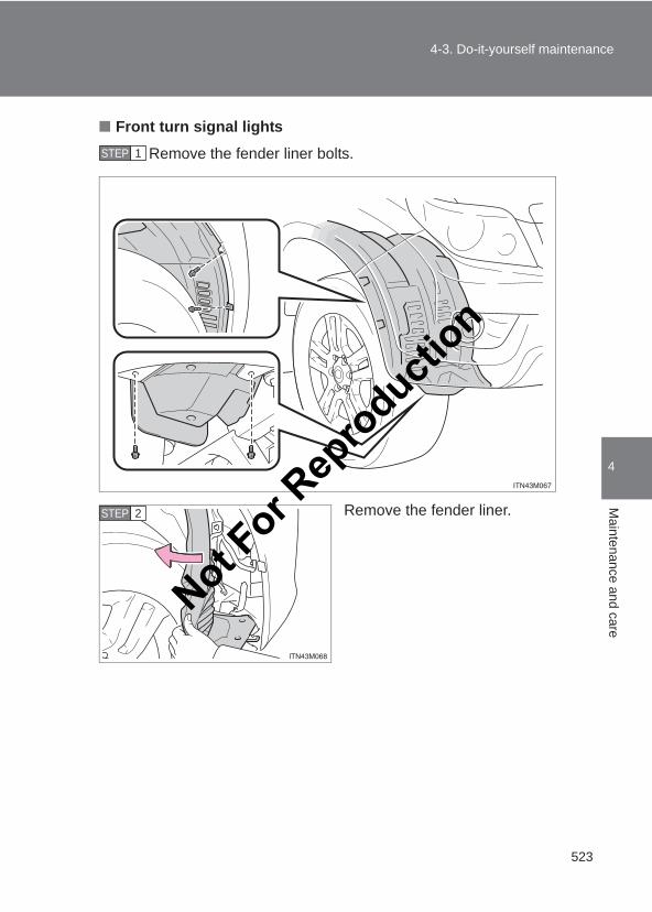
523
4-3. Do-it-yourself maintenance
4
Maintenance and care
LC150_OM_OM60J77E_(AE)
■ Front turn signal lights
Remove the fender liner bolts.
Remove the fender liner.
STEP 1
STEP 2
Not For R
epro
duction
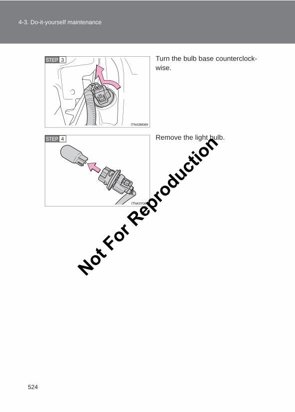
524
4-3. Do-it-yourself maintenance
LC150_OM_OM60J77E_(AE)
Turn the bulb base counterclock-wise.
Remove the light bulb.
STEP 3
STEP 4
Not For R
epro
duction
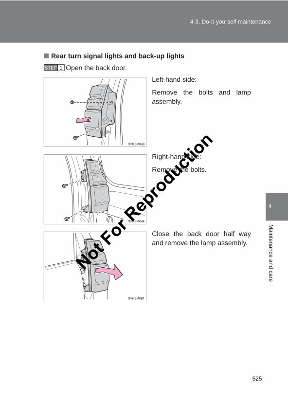
525
4-3. Do-it-yourself maintenance
4
Maintenance and care
LC150_OM_OM60J77E_(AE)
■ Rear turn signal lights and back-up lights
Open the back door.
Left-hand side:
Remove the bolts and lampassembly.
Right-hand side:
Remove the bolts.
Close the back door half wayand remove the lamp assembly.
STEP 1
Not For R
epro
duction
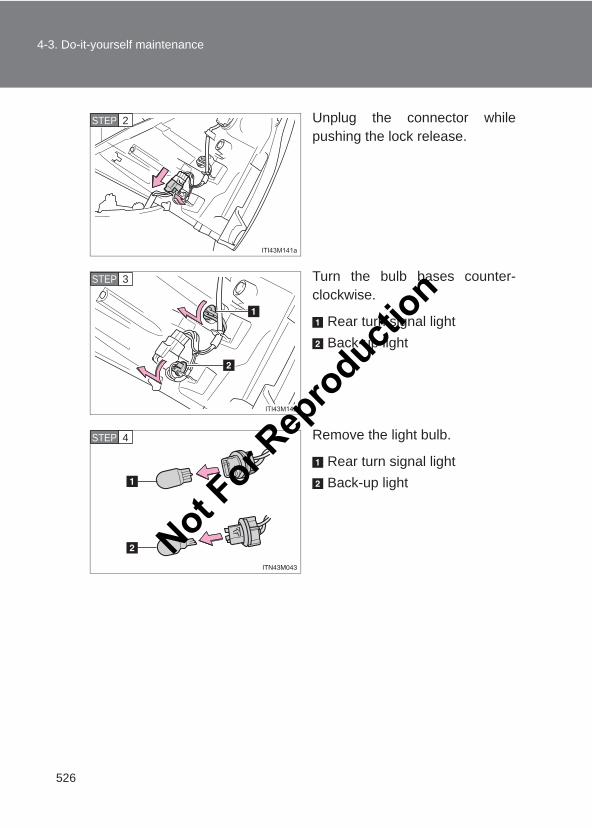
526
4-3. Do-it-yourself maintenance
LC150_OM_OM60J77E_(AE)
Unplug the connector whilepushing the lock release.
Turn the bulb bases counter-clockwise.
Rear turn signal lightBack-up light
Remove the light bulb.
Rear turn signal lightBack-up light
STEP 2
STEP 3
STEP 4
Not For R
epro
duction
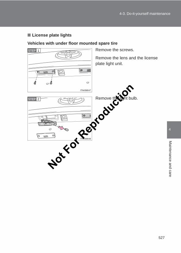
527
4-3. Do-it-yourself maintenance
4
Maintenance and care
LC150_OM_OM60J77E_(AE)
■ License plate lights
Vehicles with under floor mounted spare tireRemove the screws.
Remove the lens and the licenseplate light unit.
Remove the light bulb.
STEP 1
STEP 2
Not For R
epro
duction
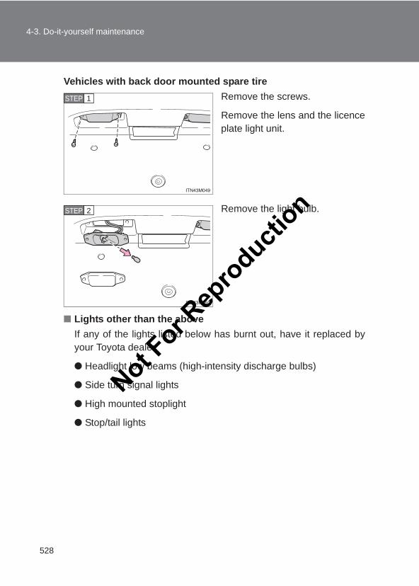
528
4-3. Do-it-yourself maintenance
LC150_OM_OM60J77E_(AE)
Vehicles with back door mounted spare tireRemove the screws.
Remove the lens and the licenceplate light unit.
Remove the light bulb.
■ Lights other than the aboveIf any of the lights listed below has burnt out, have it replaced byyour Toyota dealer.
● Headlight low beams (high-intensity discharge bulbs)
● Side turn signal lights
● High mounted stoplight
● Stop/tail lights
STEP 1
STEP 2
Not For R
epro
duction
529
4-3. Do-it-yourself maintenance
4
Maintenance and care
LC150_OM_OM60J77E_(AE)
■High-intensity discharge (HID) headlightsIf voltage to the high-intensity discharge bulbs is insufficient, the light maynot come on, or may go out temporarily. The high-intensity discharge bulbswill come on when normal power is restored.
■LED light bulbsThe side turn signal lights, tail/stop lights and high mounted stoplight con-sists of a number of LEDs. If any of the LEDs burn out, take your vehicle toyour Toyota dealer to have the light replaced.
■Condensation build-up on the inside of the lensContact your Toyota dealer for more information in the following situations.Temporary condensation build-up on the inside of the headlight lens doesnot indicate a malfunction.
●Large drops of water are built up on the inside of the lens.
●Water has built up inside the headlight.
Not For R
epro
duction
530
4-3. Do-it-yourself maintenance
LC150_OM_OM60J77E_(AE)
CAUTION
■Replacing light bulbs●Turn off the headlights. Do not attempt to replace the bulb immediately
after turning off the headlights.The bulbs become very hot and may cause burns.
●Do not touch the glass portion of the light bulb with bare hands. Hold thebulb by the plastic or metal portion.If the bulb is scratched or dropped it may blow out or crack.
●Fully install light bulbs and any parts used to secure them. Failure to do somay result in heat damage, fire, or water entering the headlight unit. Thismay damage the headlights or cause condensation to build up on the lens.
■High-intensity discharge (HID) headlights●Contact your Toyota dealer before replacing high-intensity discharge
headlights (including light bulbs).
●Do not touch the high-intensity discharge headlight’s high voltage socketwhen the headlights are turned on.An extremely high voltage of 20000 V will be discharged and could resultin death or serious injury by electric shock.
●Do not attempt to repair or disassemble light bulbs, connectors, electriccircuits or component parts.Doing so may result in death or serious injury due to electric shock.
■To prevent damage or fire●Make sure bulbs are fully seated and locked.
●Check the wattage of the bulb before installing to prevent heat damage.Not For R
epro
duction
5When trouble arises
531
LC150_OM_OM60J77E_(AE)
5-1. Essential informationEmergency flashers.......... 532If your vehicle needs
to be towed..................... 534If you think something is
wrong.............................. 541Fuel pump shut off system
(gasoline engine only) .... 542
5-2. Steps to take in an emergency
If a warning light turns on or a warning buzzer sounds... ......................... 543
If a warning message is displayed ........................ 553
If you have a flat tire ......... 573If the engine will
not start........................... 592If the shift lever cannot be
shifted from P ................. 594If you lose your keys......... 595If the electronic key does not
operate properly ............. 596If the vehicle battery is
discharged ...................... 599If your vehicle
overheats........................ 604If you run out of fuel and
the engine stalls (diesel engine only) ........ 607
If the vehicle becomes stuck ............................... 608
If your vehicle has to be stopped in an emergency...................... 610
Not For R
epro
duction
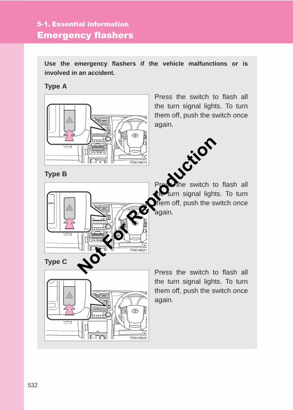
532
LC150_OM_OM60J77E_(AE)
5-1. Essential information
Emergency flashers
Use the emergency flashers if the vehicle malfunctions or isinvolved in an accident.
Type APress the switch to flash allthe turn signal lights. To turnthem off, push the switch onceagain.
Type BPress the switch to flash allthe turn signal lights. To turnthem off, push the switch onceagain.
Type CPress the switch to flash allthe turn signal lights. To turnthem off, push the switch onceagain.
Not For R
epro
duction
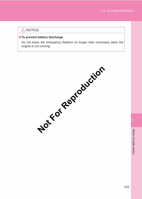
5
533
5-1. Essential informationW
hen trouble arises
LC150_OM_OM60J77E_(AE)
NOTICE
■To prevent battery dischargeDo not leave the emergency flashers on longer than necessary when theengine is not running.
Not For R
epro
duction
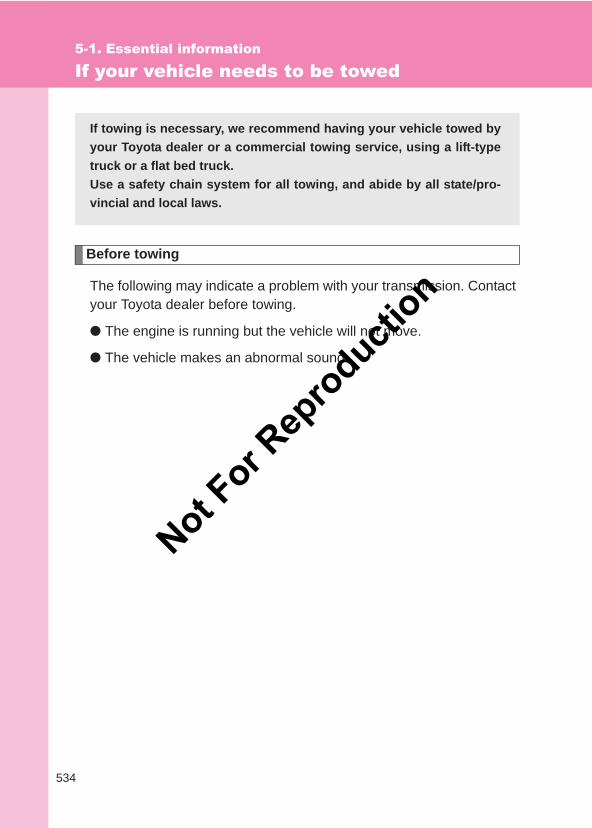
534
5-1. Essential information
LC150_OM_OM60J77E_(AE)
If your vehicle needs to be towed
Before towing
The following may indicate a problem with your transmission. Contactyour Toyota dealer before towing.
● The engine is running but the vehicle will not move.
● The vehicle makes an abnormal sound.
If towing is necessary, we recommend having your vehicle towed byyour Toyota dealer or a commercial towing service, using a lift-typetruck or a flat bed truck.Use a safety chain system for all towing, and abide by all state/pro-vincial and local laws.
Not For R
epro
duction
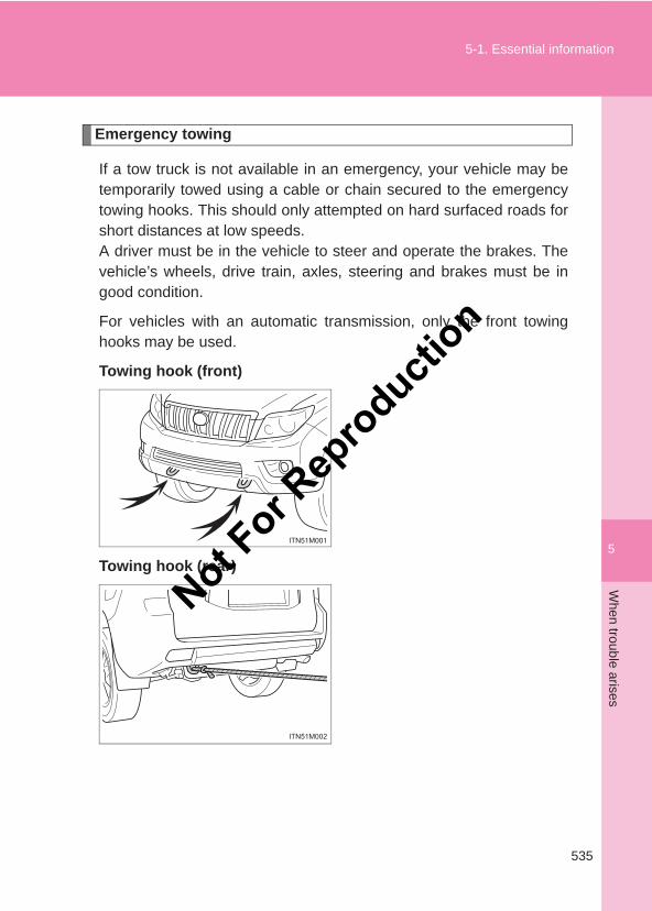
5
535
5-1. Essential informationW
hen trouble arises
LC150_OM_OM60J77E_(AE)
Emergency towing
If a tow truck is not available in an emergency, your vehicle may betemporarily towed using a cable or chain secured to the emergencytowing hooks. This should only attempted on hard surfaced roads forshort distances at low speeds.A driver must be in the vehicle to steer and operate the brakes. Thevehicle’s wheels, drive train, axles, steering and brakes must be ingood condition.
For vehicles with an automatic transmission, only the front towinghooks may be used.
Towing hook (front)
Towing hook (rear)
Not For R
epro
duction
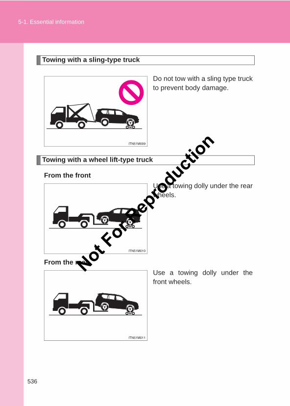
536
5-1. Essential information
LC150_OM_OM60J77E_(AE)
Towing with a sling-type truck
Do not tow with a sling type truckto prevent body damage.
Towing with a wheel lift-type truck
From the frontUse a towing dolly under the rearwheels.
From the rearUse a towing dolly under thefront wheels.
Not For R
epro
duction
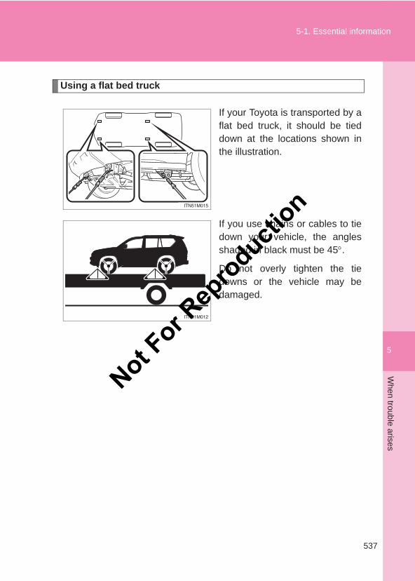
5
537
5-1. Essential informationW
hen trouble arises
LC150_OM_OM60J77E_(AE)
Using a flat bed truck
If your Toyota is transported by aflat bed truck, it should be tieddown at the locations shown inthe illustration.
If you use chains or cables to tiedown your vehicle, the anglesshaded in black must be 45°.
Do not overly tighten the tiedowns or the vehicle may bedamaged.
Not For R
epro
duction
538
5-1. Essential information
LC150_OM_OM60J77E_(AE)
■Before emergency towingVehicles without a smart entry & start system
Release the parking brake.
Put the four-wheel drive control switch in H4F. (The center differen-tial is unlocked.)
Shift the shift lever in N (automatic transmission) or neutral (manualtransmission).
Put the engine switch in the “ACC” (engine off) or “ON” position(engine running).
Vehicles with a smart entry & start systemThe “ENGINE START STOP” switch must be in the ACCESSORYmode (engine off) or IGNITION ON mode (engine running).
Put the four-wheel drive control switch in H4. (The center differen-tial is unlocked.)
Put the vehicle height in the N mode and press height control switchto turn off the rear height control air suspension. (if equipped)
Shift the shift lever in N (automatic transmission) or neutral (manualtransmission).
Release the parking brake.
STEP 1
STEP 2
STEP 3
STEP 4
STEP 1
STEP 2
STEP 3
STEP 4
STEP 5
Not For R
epro
duction
5
539
5-1. Essential informationW
hen trouble arises
LC150_OM_OM60J77E_(AE)
CAUTION
■Caution while towing●Use extreme caution when towing the vehicle.
Avoid sudden starts or erratic driving maneuvers which place excessivestress on the emergency towing hook and the cables or chains. Always becautious of the surroundings and other vehicles while towing.
●Vehicles with a smart entry & start system:Do not turn the “ENGINE START STOP” switch off.Doing so will lock the steering wheel and prevent operation, possibly caus-ing an accident and resulting in death or serious injury.
● If the engine is not running, the power assist for the brakes and steeringwill not function, making steering and braking more difficult.
■Before emergency towing (vehicles with rear height control air suspen-sion)When your vehicle is towed, put the vehicle height in the “N” mode and pushthe height control off button to turn off the rear height control suspensionsystem.Otherwise, the vehicle height may be changed in the automatic levelingfunction, resulting in an unexpected accident. For details, refer to the “Off-road driving Owner’s manual”.
Not For R
epro
duction
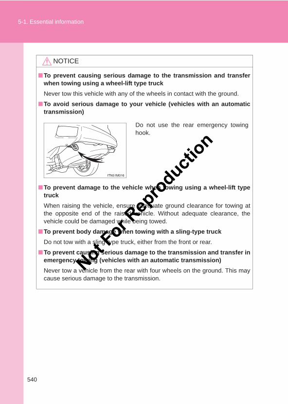
540
5-1. Essential information
LC150_OM_OM60J77E_(AE)
NOTICE
■To prevent causing serious damage to the transmission and transferwhen towing using a wheel-lift type truckNever tow this vehicle with any of the wheels in contact with the ground.
■To avoid serious damage to your vehicle (vehicles with an automatictransmission)
■To prevent damage to the vehicle when towing using a wheel-lift typetruckWhen raising the vehicle, ensure adequate ground clearance for towing atthe opposite end of the raised vehicle. Without adequate clearance, thevehicle could be damaged while being towed.
■To prevent body damage when towing with a sling-type truckDo not tow with a sling-type truck, either from the front or rear.
■To prevent causing serious damage to the transmission and transfer inemergency towing (vehicles with an automatic transmission)Never tow a vehicle from the rear with four wheels on the ground. This maycause serious damage to the transmission.
Do not use the rear emergency towinghook.
Not For R
epro
duction
5
541
5-1. Essential informationW
hen trouble arises
LC150_OM_OM60J77E_(AE)
If you think something is wrong
If you notice any of the following symptoms, your vehicle probablyneeds adjustment or repair. Contact your Toyota dealer as soon aspossible.
■ Visible symptoms● Fluid leaks under the vehicle
(Water dripping from the air conditioning after use is normal.)
● Flat-looking tires or uneven tire wear
● Engine coolant temperature gauge needle continually pointshigher than normal
■ Audible symptoms● Changes in exhaust sound
● Excessive tire squeal when cornering
● Strange noises related to the suspension system
● Pinging or other noises related to the engine
■ Operational symptoms● Engine missing, stumbling or running roughly
● Appreciable loss of power
● Vehicle pulls heavily to one side when braking
● Vehicle pulls heavily to one side when driving on a level road
● Loss of brake effectiveness, spongy feeling, pedal almosttouches the floor
Not For R
epro
duction
542
5-1. Essential information
LC150_OM_OM60J77E_(AE)
Fuel pump shut off system (gasoline engine only)
Follow the procedure below to restart the engine after the system isactivated.
Vehicles without a smart entry & start systemTurn the engine switch to the “ACC” or “LOCK” position.Restart the engine.
Vehicles with a smart entry & start systemTurn the “ENGINE START STOP” switch to ACCESSORY modeor turn it off.Restart the engine.
NOTICE
■Before starting the engineInspect the ground under the vehicle.If you find that fuel has leaked on to the ground, the fuel system has beendamaged and is in need of repair. Do not restart the engine.
To minimize the risk of fuel leakage when the engine stalls or whenan airbag inflates upon collision, the fuel pump shut off systemstops the supply of fuel to the engine.
STEP 1
STEP 2
STEP 1
STEP 2
Not For R
epro
duction
5
543
When trouble arises
LC150_OM_OM60J77E_(AE)
5-2. Steps to take in an emergency
If a warning light turns on or a warning buzzer sounds...
Stop the vehicle immediately. Continuing to drive the vehiclemay be dangerous.
The following warning indicates a possible problem in the brake sys-tem. Immediately stop the vehicle in a safe place and contact yourToyota dealer.
*: Parking brake engaged warning buzzer:A buzzer will sound if the vehicle is driven at a speed of approximately 5 km/h(3 mph) or more.
Warning light Warning light/Details
Brake system warning light (warning buzzer)*• Low brake fluid• Malfunction in the brake system
This light also comes on when the parking brake is not released. If the light turns off after the parking brake is fully released the system is operating normally.
Calmly perform the following actions if any of the warning lightscomes on or flashes. If a light comes on or flashes, but then goesoff, this does not necessarily indicate a malfunction in the system.However, if this continues to occur, have the vehicle inspected byyour Toyota dealer.
Not For R
epro
duction
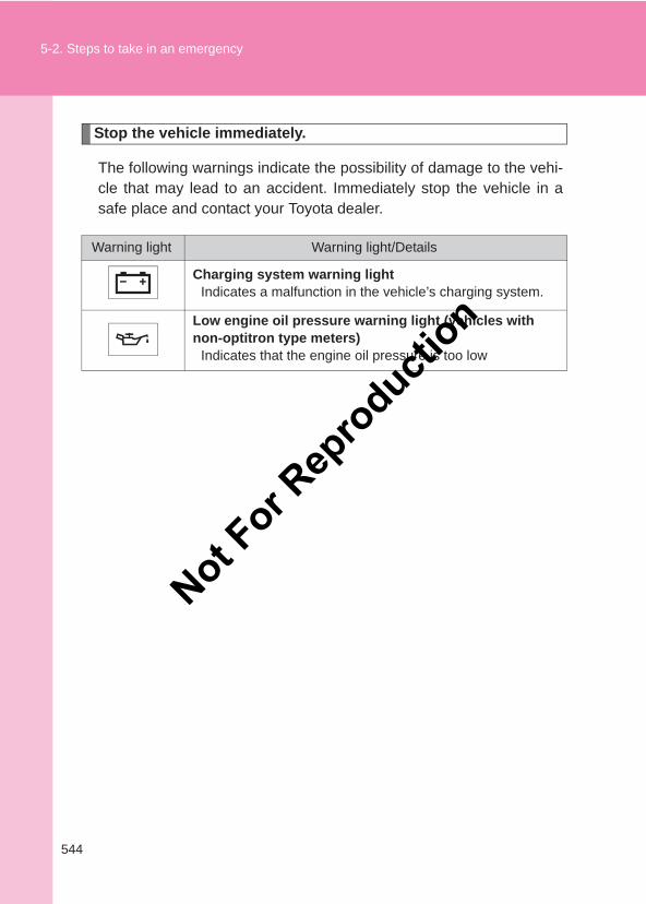
544
5-2. Steps to take in an emergency
LC150_OM_OM60J77E_(AE)
Stop the vehicle immediately.
The following warnings indicate the possibility of damage to the vehi-cle that may lead to an accident. Immediately stop the vehicle in asafe place and contact your Toyota dealer.
Warning light Warning light/Details
Charging system warning lightIndicates a malfunction in the vehicle’s charging system.
Low engine oil pressure warning light (vehicles with non-optitron type meters)
Indicates that the engine oil pressure is too low
Not For R
epro
duction
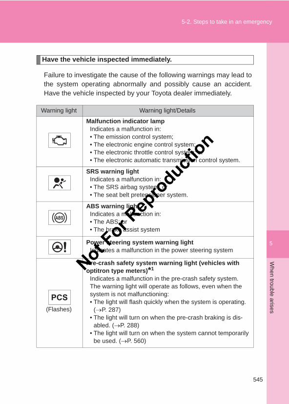
5
545
5-2. Steps to take in an emergencyW
hen trouble arises
LC150_OM_OM60J77E_(AE)
Have the vehicle inspected immediately.
Failure to investigate the cause of the following warnings may lead tothe system operating abnormally and possibly cause an accident.Have the vehicle inspected by your Toyota dealer immediately.
Warning light Warning light/Details
Malfunction indicator lampIndicates a malfunction in:• The emission control system;• The electronic engine control system;• The electronic throttle control system; or• The electronic automatic transmission control system.
SRS warning lightIndicates a malfunction in:• The SRS airbag system; or• The seat belt pretensioner system.
ABS warning lightIndicates a malfunction in:• The ABS; or• The brake assist system
Power steering system warning lightIndicates a malfunction in the power steering system
(Flashes)
Pre-crash safety system warning light (vehicles with optitron type meters)*1
Indicates a malfunction in the pre-crash safety system.The warning light will operate as follows, even when the system is not malfunctioning:• The light will flash quickly when the system is operating.
(→P. 287)• The light will turn on when the pre-crash braking is dis-
abled. (→P. 288)• The light will turn on when the system cannot temporarily
be used. (→P. 560)
Not For R
epro
duction
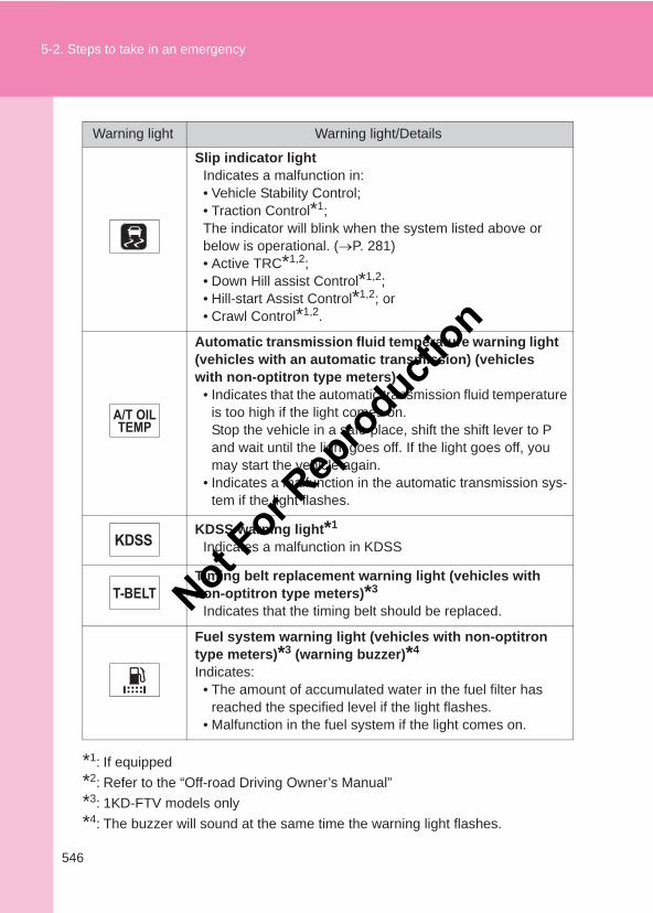
546
5-2. Steps to take in an emergency
LC150_OM_OM60J77E_(AE)
*1: If equipped*2: Refer to the “Off-road Driving Owner’s Manual”*3: 1KD-FTV models only*4: The buzzer will sound at the same time the warning light flashes.
Slip indicator lightIndicates a malfunction in:• Vehicle Stability Control;• Traction Control*1;The indicator will blink when the system listed above or below is operational. (→P. 281)• Active TRC*1,2;• Down Hill assist Control*1,2;• Hill-start Assist Control*1,2; or• Crawl Control*1,2.
Automatic transmission fluid temperature warning light (vehicles with an automatic transmission) (vehicles with non-optitron type meters)
• Indicates that the automatic transmission fluid temperature is too high if the light comes on.Stop the vehicle in a safe place, shift the shift lever to P and wait until the light goes off. If the light goes off, you may start the vehicle again.
• Indicates a malfunction in the automatic transmission sys-tem if the light flashes.
KDSS warning light*1
Indicates a malfunction in KDSS
Timing belt replacement warning light (vehicles with non-optitron type meters)*3
Indicates that the timing belt should be replaced.
Fuel system warning light (vehicles with non-optitron type meters)*3 (warning buzzer)*4
Indicates:• The amount of accumulated water in the fuel filter has
reached the specified level if the light flashes.• Malfunction in the fuel system if the light comes on.
Warning light Warning light/Details
Not For R
epro
duction
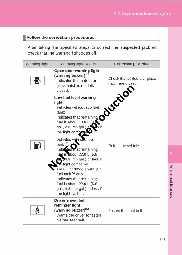
5
547
5-2. Steps to take in an emergencyW
hen trouble arises
LC150_OM_OM60J77E_(AE)
Follow the correction procedures.
After taking the specified steps to correct the suspected problem,check that the warning light goes off.
Warning light Warning light/Details Correction procedure
Open door warning light (warning buzzer)*1
Indicates that a door or glass hatch is not fully closed.
Check that all doors or glass hatch are closed.
Low fuel level warning light
Vehicles without sub fuel tank: Indicates that remaining fuel is about 13.0 L (3.4 gal., 2.8 Imp.gal.) or less if the light comes on.
Refuel the vehicle.Vehicles with sub fuel tank*2:Indicates that remaining fuel is about 22.0 L (5.8 gal., 4.8 Imp.gal.) or less if the light comes on.1KD-FTV models with sub fuel tank*2 only:Indicates that remaining fuel is about 22.0 L (5.8 gal., 4.8 Imp.gal.) or less if the light flashes.
Driver’s seat beltreminder light(warning buzzer)*3
Warns the driver to fasten his/her seat belt.
Fasten the seat belt.
Not For R
epro
duction
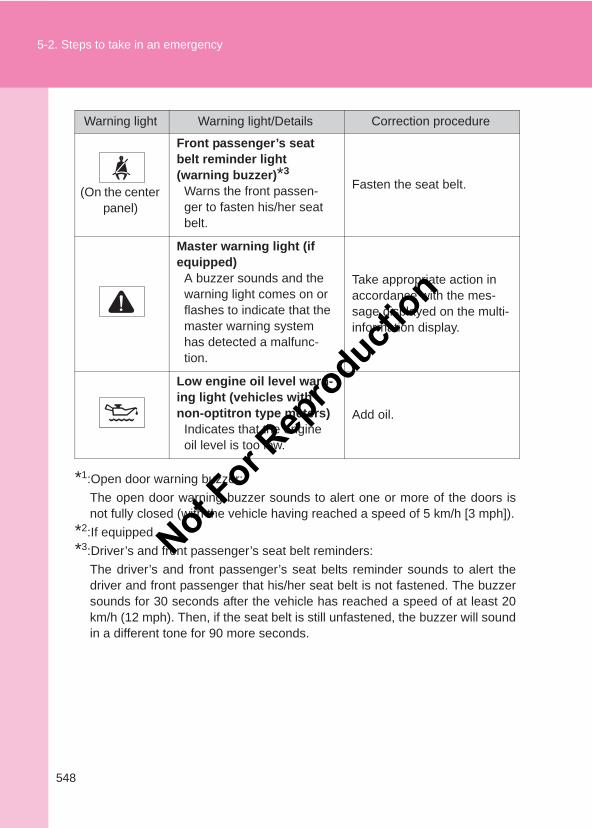
548
5-2. Steps to take in an emergency
LC150_OM_OM60J77E_(AE)
*1:Open door warning buzzer:The open door warning buzzer sounds to alert one or more of the doors isnot fully closed (with the vehicle having reached a speed of 5 km/h [3 mph]).
*2:If equipped*3:Driver’s and front passenger’s seat belt reminders:
The driver’s and front passenger’s seat belts reminder sounds to alert thedriver and front passenger that his/her seat belt is not fastened. The buzzersounds for 30 seconds after the vehicle has reached a speed of at least 20km/h (12 mph). Then, if the seat belt is still unfastened, the buzzer will soundin a different tone for 90 more seconds.
(On the center panel)
Front passenger’s seat belt reminder light(warning buzzer)*3
Warns the front passen-ger to fasten his/her seat belt.
Fasten the seat belt.
Master warning light (if equipped)
A buzzer sounds and the warning light comes on or flashes to indicate that the master warning system has detected a malfunc-tion.
Take appropriate action in accordance with the mes-sage displayed on the multi-information display.
Low engine oil level warn-ing light (vehicles with non-optitron type meters)
Indicates that the engine oil level is too low.
Add oil.
Warning light Warning light/Details Correction procedure
Not For R
epro
duction
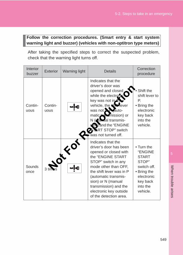
5
549
5-2. Steps to take in an emergencyW
hen trouble arises
LC150_OM_OM60J77E_(AE)
Follow the correction procedures. (Smart entry & start systemwarning light and buzzer) (vehicles with non-optitron type meters)
After taking the specified steps to correct the suspected problem,check that the warning light turns off.
Interior buzzer Exterior Warning light Details Correction
procedure
Contin-uous
Contin-uous
Indicates that the driver’s door was opened and closed while the electronic key was not in the vehicle, the shift lever was not in P (auto-matic transmission) or N (manual transmis-sion) and the “ENGINE START STOP” switch was not turned off.
• Shift the shift lever to P.
• Bring the electronic key back into the vehicle.
Sounds once 3 times
Indicates that the driver’s door has been opened or closed with the “ENGINE START STOP” switch in any mode other than OFF, the shift lever was in P (automatic transmis-sion) or N (manual transmission) and the electronic key outside of the detection area.
• Turn the “ENGINE START STOP” switch off.
• Bring the electronic key back into the vehicle.
Not For R
epro
duction
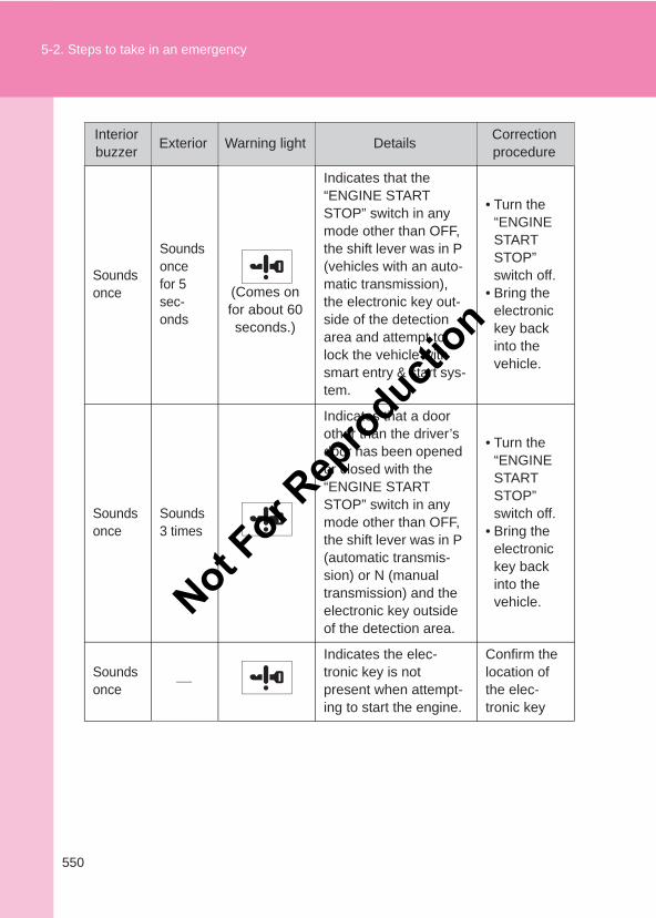
550
5-2. Steps to take in an emergency
LC150_OM_OM60J77E_(AE)
Sounds once
Sounds once for 5 sec-onds
(Comes on for about 60 seconds.)
Indicates that the “ENGINE START STOP” switch in any mode other than OFF, the shift lever was in P (vehicles with an auto-matic transmission), the electronic key out-side of the detection area and attempt to lock the vehicle with smart entry & start sys-tem.
• Turn the “ENGINE START STOP” switch off.
• Bring the electronic key back into the vehicle.
Sounds once
Sounds 3 times
Indicates that a door other than the driver’s door has been opened or closed with the “ENGINE START STOP” switch in any mode other than OFF, the shift lever was in P (automatic transmis-sion) or N (manual transmission) and the electronic key outside of the detection area.
• Turn the “ENGINE START STOP” switch off.
• Bring the electronic key back into the vehicle.
Sounds once
Indicates the elec-tronic key is not present when attempt-ing to start the engine.
Confirm the location of the elec-tronic key
Interior buzzer Exterior Warning light Details Correction
procedure
Not For R
epro
duction
5
551
5-2. Steps to take in an emergencyW
hen trouble arises
LC150_OM_OM60J77E_(AE)
■ If the malfunction indicator lamp comes on while drivingThe malfunction indicator lamp will come on if the fuel tank becomes com-pletely empty. If the fuel tank is empty, refuel the vehicle immediately. Themalfunction indicator lamp will go off after several trips.
If the malfunction indicator lamp does not go off, contact your Toyota dealeras soon as possible.
■ If the low speed four-wheel drive indicator light or the center differen-tial lock indicator light blinksTake the specified steps. (→Refer to the “Off-road Driving Owner’s Manual”)
■Front passenger detection sensor and passenger seat belt reminder● If luggage is placed on the front passenger seat, the front passenger
detection sensor may cause the warning light to flash, even if a passen-ger is not sitting in the seat.
● If a cushion is placed on the seat, the sensor may not detect a passen-ger, and the warning light may not operate properly.
■CustomizationThe vehicle speed linked seat belt reminder buzzer can be disabled.(Customizable features →P. 634)
Not For R
epro
duction
552
5-2. Steps to take in an emergency
LC150_OM_OM60J77E_(AE)
CAUTION
■ If both the ABS and the brake system warning lights remain onStop your vehicle in a safe place immediately and contact your Toyotadealer. The vehicle will become extremely unstable during braking, and theABS system may fail, which could cause an accident resulting in death orserious injury.
■When the power steering system warning light comes onThe steering wheel may become extremely heavy.If the steering wheel becomes heavier than usual when operating, holdfirmly and operate using more force than usual.
NOTICE
■ If the fuel filter warning light comes onNever drive the vehicle with the warning light on. Continued driving withwater accumulated in the fuel filter will damage the fuel injection pump.
Not For R
epro
duction
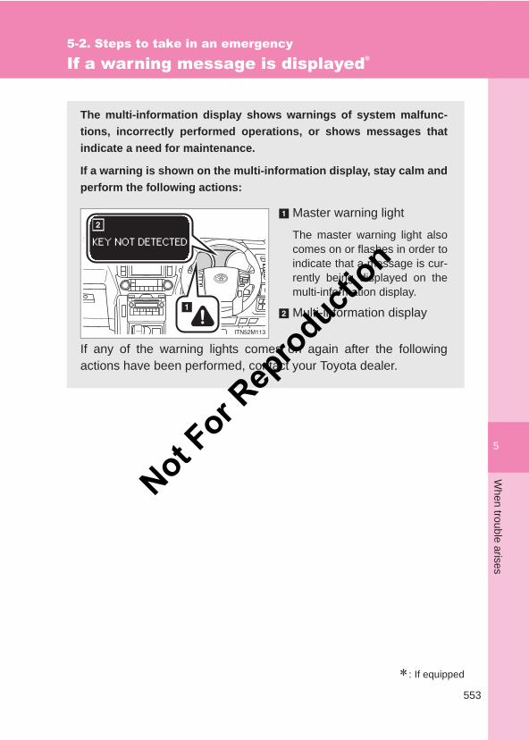
5
553
5-2. Steps to take in an emergencyW
hen trouble arises
LC150_OM_OM60J77E_(AE)
If a warning message is displayed∗
∗: If equipped
The multi-information display shows warnings of system malfunc-tions, incorrectly performed operations, or shows messages thatindicate a need for maintenance.
If a warning is shown on the multi-information display, stay calm andperform the following actions:
Master warning light
The master warning light alsocomes on or flashes in order toindicate that a message is cur-rently being displayed on themulti-information display.
Multi-information display
If any of the warning lights comes on again after the followingactions have been performed, contact your Toyota dealer.
Not For R
epro
duction
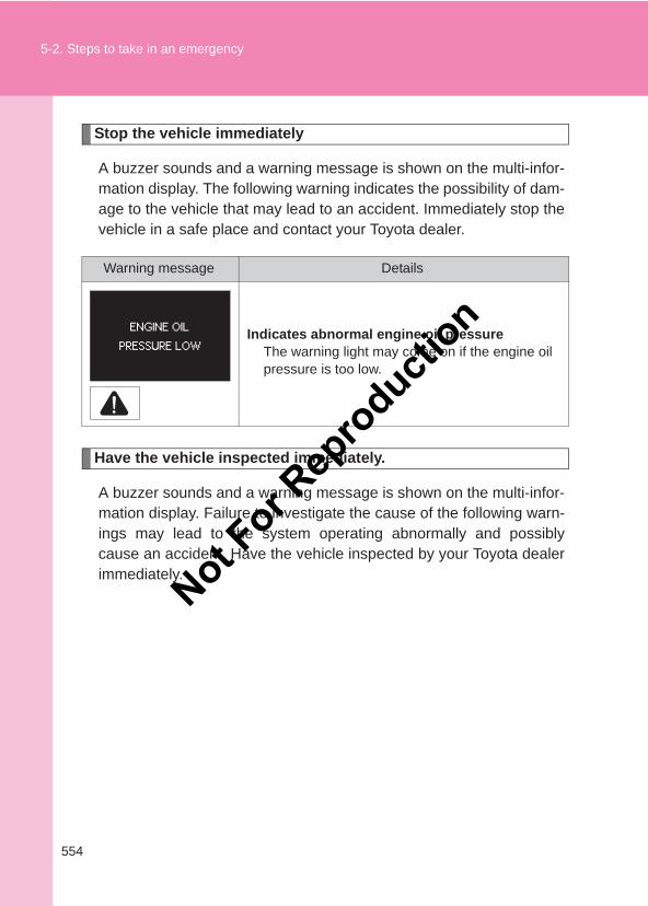
554
5-2. Steps to take in an emergency
LC150_OM_OM60J77E_(AE)
Stop the vehicle immediately
A buzzer sounds and a warning message is shown on the multi-infor-mation display. The following warning indicates the possibility of dam-age to the vehicle that may lead to an accident. Immediately stop thevehicle in a safe place and contact your Toyota dealer.
Have the vehicle inspected immediately.
A buzzer sounds and a warning message is shown on the multi-infor-mation display. Failure to investigate the cause of the following warn-ings may lead to the system operating abnormally and possiblycause an accident. Have the vehicle inspected by your Toyota dealerimmediately.
Warning message Details
Indicates abnormal engine oil pressureThe warning light may come on if the engine oil pressure is too low.
Not For R
epro
duction
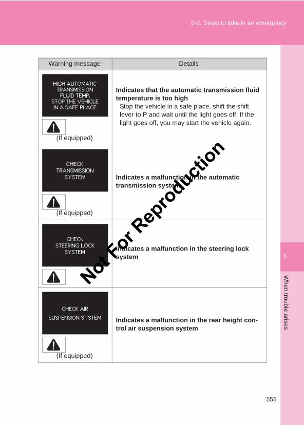
5
555
5-2. Steps to take in an emergencyW
hen trouble arises
LC150_OM_OM60J77E_(AE)
Warning message Details
(If equipped)
Indicates that the automatic transmission fluid temperature is too high
Stop the vehicle in a safe place, shift the shift lever to P and wait until the light goes off. If the light goes off, you may start the vehicle again.
(If equipped)
Indicates a malfunction in the automatic transmission system
Indicates a malfunction in the steering lock system
(If equipped)
Indicates a malfunction in the rear height con-trol air suspension system
Not For R
epro
duction
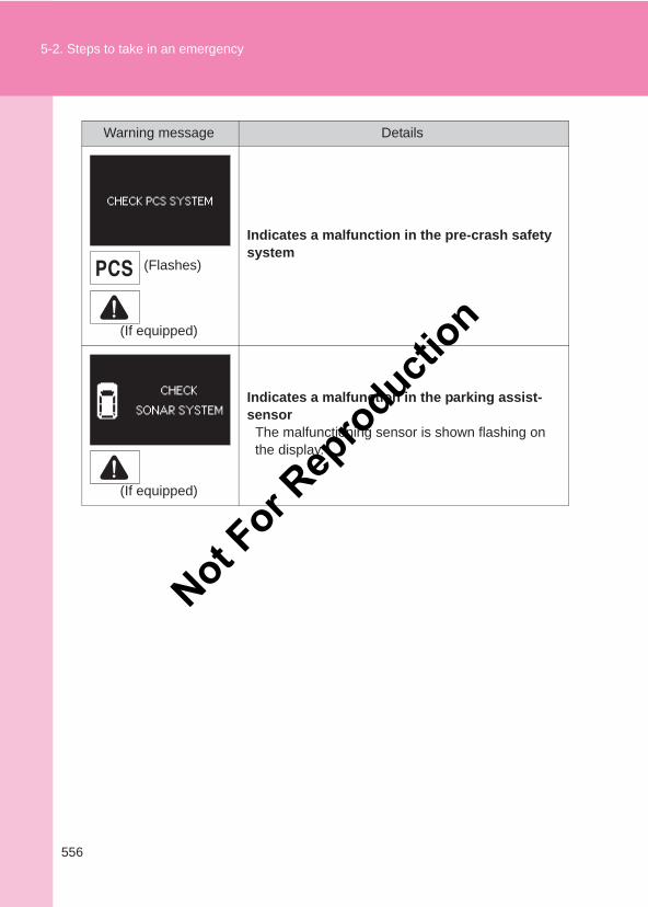
556
5-2. Steps to take in an emergency
LC150_OM_OM60J77E_(AE)
(Flashes)
(If equipped)
Indicates a malfunction in the pre-crash safety system
(If equipped)
Indicates a malfunction in the parking assist-sensor
The malfunctioning sensor is shown flashing on the display.
Warning message Details
Not For R
epro
duction
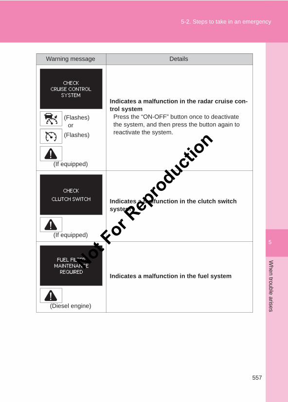
5
557
5-2. Steps to take in an emergencyW
hen trouble arises
LC150_OM_OM60J77E_(AE)
(Flashes)or
(Flashes)
(If equipped)
Indicates a malfunction in the radar cruise con-trol system
Press the “ON-OFF” button once to deactivate the system, and then press the button again to reactivate the system.
(If equipped)
Indicates a malfunction in the clutch switch system
(Diesel engine)
Indicates a malfunction in the fuel system
Warning message Details
Not For R
epro
duction
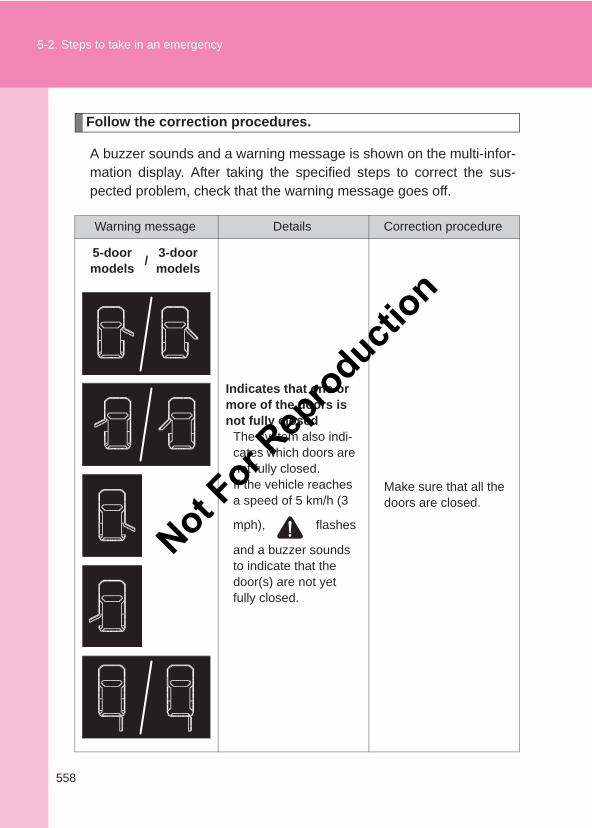
558
5-2. Steps to take in an emergency
LC150_OM_OM60J77E_(AE)
Follow the correction procedures.
A buzzer sounds and a warning message is shown on the multi-infor-mation display. After taking the specified steps to correct the sus-pected problem, check that the warning message goes off.
Warning message Details Correction procedure
5-door models / 3-door
models
Indicates that one or more of the doors is not fully closed
The system also indi-cates which doors are not fully closed.If the vehicle reaches a speed of 5 km/h (3
mph), flashes
and a buzzer sounds to indicate that the door(s) are not yet fully closed.
Make sure that all the doors are closed.
Not For R
epro
duction
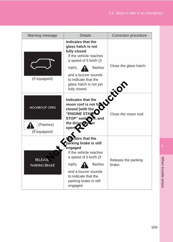
5
559
5-2. Steps to take in an emergencyW
hen trouble arises
LC150_OM_OM60J77E_(AE)
(If equipped)
Indicates that the glass hatch is not fully closed
If the vehicle reaches a speed of 5 km/h (3
mph), flashes
and a buzzer sounds to indicate that the glass hatch is not yet fully closed.
Close the glass hatch.
(Flashes)
(If equipped)
Indicates that the moon roof is not fully closed (with the “ENGINE START STOP” switch off, and the driver’s door open)
Close the moon roof.
Indicates that the parking brake is still engaged
If the vehicle reaches a speed of 5 km/h (3
mph), flashes
and a buzzer sounds to indicate that the parking brake is still engaged.
Release the parking brake.
Warning message Details Correction procedure
Not For R
epro
duction
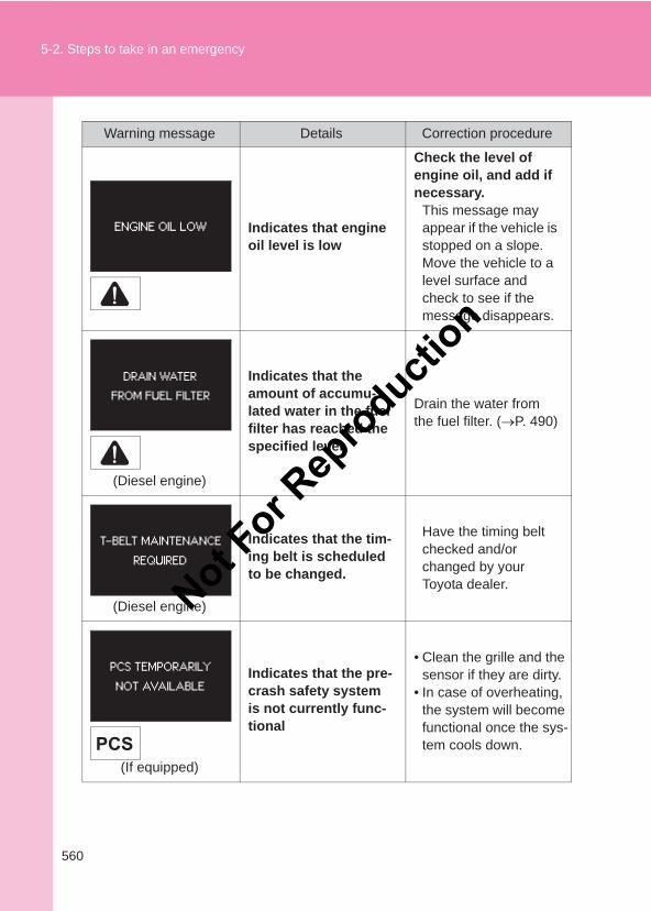
560
5-2. Steps to take in an emergency
LC150_OM_OM60J77E_(AE)
Indicates that engine oil level is low
Check the level of engine oil, and add if necessary.
This message may appear if the vehicle is stopped on a slope. Move the vehicle to a level surface and check to see if the message disappears.
(Diesel engine)
Indicates that the amount of accumu-lated water in the fuel filter has reached the specified level
Drain the water from the fuel filter. (→P. 490)
(Diesel engine)
Indicates that the tim-ing belt is scheduled to be changed.
Have the timing belt checked and/or changed by your Toyota dealer.
(If equipped)
Indicates that the pre-crash safety system is not currently func-tional
• Clean the grille and the sensor if they are dirty.
• In case of overheating, the system will become functional once the sys-tem cools down.
Warning message Details Correction procedure
Not For R
epro
duction
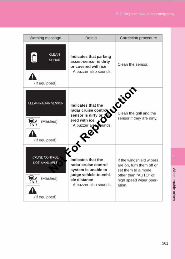
5
561
5-2. Steps to take in an emergencyW
hen trouble arises
LC150_OM_OM60J77E_(AE)
(If equipped)
Indicates that parking assist-sensor is dirty or covered with ice
A buzzer also sounds.
Clean the sensor.
(Flashes)
(If equipped)
Indicates that the radar cruise control sensor is dirty or cov-ered with ice
A buzzer also sounds.
Clean the grill and the sensor if they are dirty.
(Flashes)
(If equipped)
Indicates that the radar cruise control system is unable to judge vehicle-to-vehi-cle distance
A buzzer also sounds.
If the windshield wipers are on, turn them off or set them to a mode other than “AUTO” or high speed wiper oper-ation.
Warning message Details Correction procedure
Not For R
epro
duction
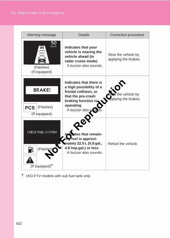
562
5-2. Steps to take in an emergency
LC150_OM_OM60J77E_(AE)
*: 1KD-FTV models with sub fuel tank only
(Flashes)(If equipped)
Indicates that your vehicle is nearing the vehicle ahead (in radar cruise mode)
A buzzer also sounds.
Slow the vehicle by applying the brakes.
(Flashes)
(If equipped)
Indicates that there is a high possibility of a frontal collision, or that the pre-crash braking function is operating
A buzzer also sounds.
Slow the vehicle by applying the brakes.
(Flashes)
(If equipped)*
Indicates that remain-ing fuel is approxi-mately 22.0 L (5.8 gal., 4.8 Imp.gal.) or less
A buzzer also sounds.
Refuel the vehicle.
Warning message Details Correction procedure
Not For R
epro
duction
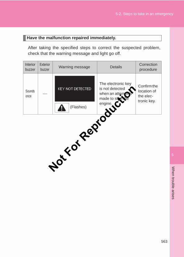
5
563
5-2. Steps to take in an emergencyW
hen trouble arises
LC150_OM_OM60J77E_(AE)
Have the malfunction repaired immediately.
After taking the specified steps to correct the suspected problem,check that the warning message and light go off.
Interior buzzer
Exteriorbuzzer Warning message Details Correction
procedure
Sounds once
(Flashes)
The electronic key is not detected when an attempt is made to start the engine.
Confirm the location of the elec-tronic key.
Not For R
epro
duction
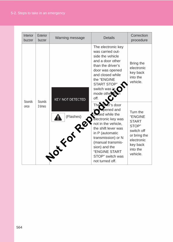
564
5-2. Steps to take in an emergency
LC150_OM_OM60J77E_(AE)
Sounds once
Sounds 3 times
(Flashes)
The electronic key was carried out-side the vehicle and a door other than the driver’s door was opened and closed while the “ENGINE START STOP” switch was in a mode other than off.
Bring the electronic key back into the vehicle.
The driver’s door was opened and closed while the electronic key was not in the vehicle, the shift lever was in P (automatic transmission) or N (manual transmis-sion) and the “ENGINE START STOP” switch was not turned off.
Turn the “ENGINE START STOP” switch off or bring the electronic key back into the vehicle.
Interior buzzer
Exteriorbuzzer Warning message Details Correction
procedure
Not For R
epro
duction
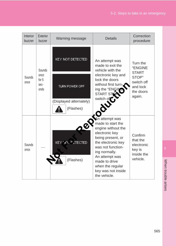
5
565
5-2. Steps to take in an emergencyW
hen trouble arises
LC150_OM_OM60J77E_(AE)
Sounds once
Sounds once for 5 sec-onds
(Displayed alternately)
(Flashes)
An attempt was made to exit the vehicle with the electronic key and lock the doors without first turn-ing the “ENGINE START STOP” switch off.
Turn the “ENGINE START STOP” switch off and lock the doors again.
Sounds once
(Flashes)
An attempt was made to start the engine without the electronic key being present, or the electronic key was not function-ing normally.An attempt was made to drive when the regular key was not inside the vehicle.
Confirm that the electronic key is inside the vehicle.
Interior buzzer
Exteriorbuzzer Warning message Details Correction
procedure
Not For R
epro
duction
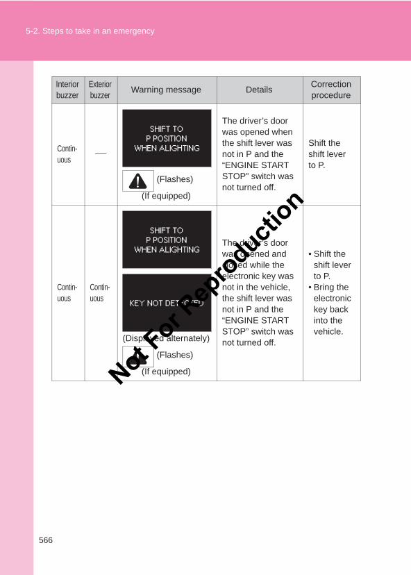
566
5-2. Steps to take in an emergency
LC150_OM_OM60J77E_(AE)
Contin-uous
(Flashes)
(If equipped)
The driver’s door was opened when the shift lever was not in P and the “ENGINE START STOP” switch was not turned off.
Shift the shift lever to P.
Contin-uous
Contin-uous
(Displayed alternately)
(Flashes)
(If equipped)
The driver’s door was opened and closed while the electronic key was not in the vehicle, the shift lever was not in P and the “ENGINE START STOP” switch was not turned off.
• Shift the shift lever to P.
• Bring the electronic key back into the vehicle.
Interior buzzer
Exteriorbuzzer Warning message Details Correction
procedure
Not For R
epro
duction
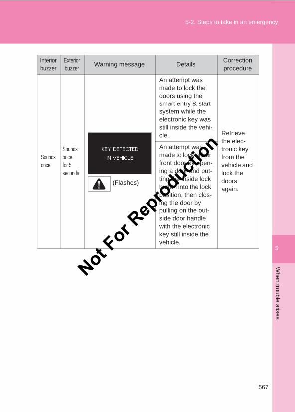
5
567
5-2. Steps to take in an emergencyW
hen trouble arises
LC150_OM_OM60J77E_(AE)
Sounds once
Sounds once for 5 seconds
(Flashes)
An attempt was made to lock the doors using the smart entry & start system while the electronic key was still inside the vehi-cle. Retrieve
the elec-tronic key from the vehicle and lock the doors again.
An attempt was made to lock either front door by open-ing a door and put-ting the inside lock button into the lock position, then clos-ing the door by pulling on the out-side door handle with the electronic key still inside the vehicle.
Interior buzzer
Exteriorbuzzer Warning message Details Correction
procedure
Not For R
epro
duction
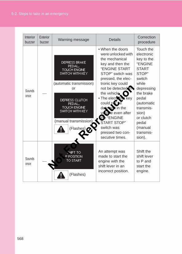
568
5-2. Steps to take in an emergency
LC150_OM_OM60J77E_(AE)
Sounds once
(automatic transmission)or
(manual transmission)
(Flashes)
• When the doors were unlocked with the mechanical key and then the “ENGINE START STOP” switch was pressed, the elec-tronic key could not be detected in the vehicle.
• The electronic key could not be detected in the vehicle even after the “ENGINE START STOP” switch was pressed two con-secutive times.
Touch the electronic key to the “ENGINE START STOP” switch while depressing the brake pedal (automatic transmis-sion) or clutch pedal (manual transmis-sion).
Sounds once
(Flashes)
An attempt was made to start the engine with the shift lever in an incorrect position.
Shift the shift lever to P and start the engine.
Interior buzzer
Exteriorbuzzer Warning message Details Correction
procedure
Not For R
epro
duction
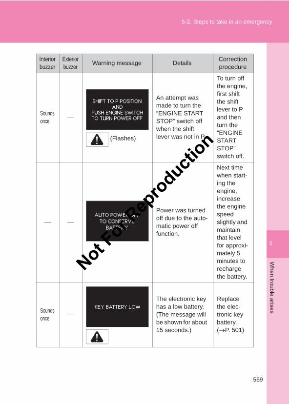
5
569
5-2. Steps to take in an emergencyW
hen trouble arises
LC150_OM_OM60J77E_(AE)
Sounds once
(Flashes)
An attempt was made to turn the “ENGINE START STOP” switch off when the shift lever was not in P.
To turn off the engine, first shift the shift lever to P and then turn the “ENGINE START STOP” switch off.
Power was turned off due to the auto-matic power off function.
Next time when start-ing the engine, increase the engine speed slightly and maintain that level for approxi-mately 5 minutes to recharge the battery.
Sounds once
The electronic key has a low battery. (The message will be shown for about 15 seconds.)
Replace the elec-tronic key battery. (→P. 501)
Interior buzzer
Exteriorbuzzer Warning message Details Correction
procedure
Not For R
epro
duction
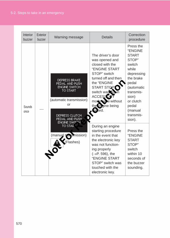
570
5-2. Steps to take in an emergency
LC150_OM_OM60J77E_(AE)
Sounds once
(automatic transmission)or
(manual transmission)
(Flashes)
The driver’s door was opened and closed with the “ENGINE START STOP” switch turned off and then the “ENGINE START STOP” switch was put in ACCESSORY mode twice without the engine being started.
Press the “ENGINE START STOP” switch while depressing the brake pedal (automatic transmis-sion) or clutch pedal (manual transmis-sion).
During an engine starting procedure in the event that the electronic key was not function-ing properly (→P. 596), the “ENGINE START STOP” switch was touched with the electronic key.
Press the “ENGINE START STOP” switch within 10 seconds of the buzzer sounding.
Interior buzzer
Exteriorbuzzer Warning message Details Correction
procedure
Not For R
epro
duction
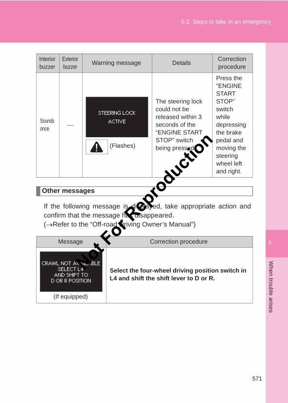
5
571
5-2. Steps to take in an emergencyW
hen trouble arises
LC150_OM_OM60J77E_(AE)
Other messages
If the following message is displayed, take appropriate action andconfirm that the message has disappeared.(→Refer to the “Off-road Driving Owner’s Manual”)
Sounds once
(Flashes)
The steering lock could not be released within 3 seconds of the “ENGINE START STOP” switch being pressed.
Press the “ENGINE START STOP” switch while depressing the brake pedal and moving the steering wheel left and right.
Message Correction procedure
(If equipped)
Select the four-wheel driving position switch in L4 and shift the shift lever to D or R.
Interior buzzer
Exteriorbuzzer Warning message Details Correction
procedure
Not For R
epro
duction
572
5-2. Steps to take in an emergency
LC150_OM_OM60J77E_(AE)
(If equipped)
Confirm the operating conditions.
■Warning light display in radar cruise mode (if equipped)In the following cases, the warning light may not be displayed even if vehi-cle-to-vehicle distance decreases:
●When your vehicle and the vehicle ahead are traveling at the samespeed or the vehicle ahead is traveling more quickly than your vehicle
●When the vehicle ahead is traveling at a very low speed
● Immediately after cruise control speed is set
●At the instant the accelerator pedal is depressed
NOTICE
■While the engine oil level warning is displayedContinued engine operation with low engine oil will damage the engine.
Message Correction procedure
Not For R
epro
duction
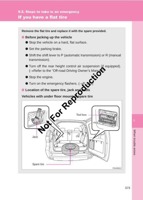
5
573
5-2. Steps to take in an emergencyW
hen trouble arises
LC150_OM_OM60J77E_(AE)
If you have a flat tire
Remove the flat tire and replace it with the spare provided.
■ Before jacking up the vehicle● Stop the vehicle on a hard, flat surface.
● Set the parking brake.
● Shift the shift lever to P (automatic transmission) or R (manualtransmission).
● Turn off the rear height control air suspension (if equipped).(→Refer to the “Off-road Driving Owner’s Manual”)
● Stop the engine.
● Turn on the emergency flashers. (→P. 532)
■ Location of the spare tire, jack and tools
Vehicles with under floor mounted spare tire
Jack
Tool box
Spare tire
Not For R
epro
duction
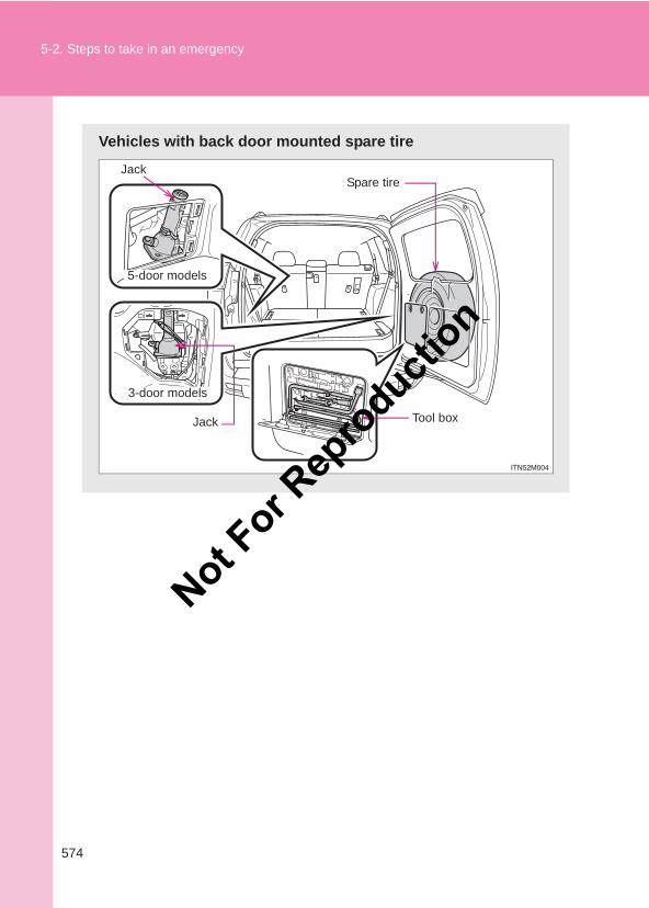
574
5-2. Steps to take in an emergency
LC150_OM_OM60J77E_(AE)
Vehicles with back door mounted spare tire
Spare tireJack
Tool boxJack
5-door models
3-door models
Not For R
epro
duction
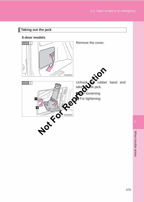
5
575
5-2. Steps to take in an emergencyW
hen trouble arises
LC150_OM_OM60J77E_(AE)
Taking out the jack
5-door modelsRemove the cover.
Unhook the rubber band andtake out the jack.
For looseningFor tightening
STEP 1
STEP 2
Not For R
epro
duction
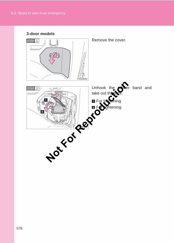
576
5-2. Steps to take in an emergency
LC150_OM_OM60J77E_(AE)
3-door modelsRemove the cover.
Unhook the rubber band andtake out the jack.
For looseningFor tightening
STEP 1
STEP 2
Not For R
epro
duction
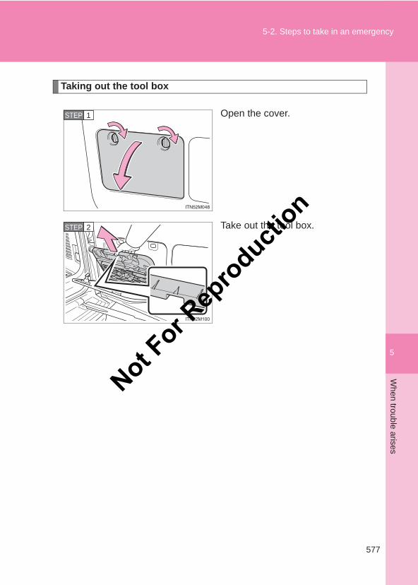
5
577
5-2. Steps to take in an emergencyW
hen trouble arises
LC150_OM_OM60J77E_(AE)
Taking out the tool box
Open the cover.
Take out the tool box.
STEP 1
STEP 2
Not For R
epro
duction
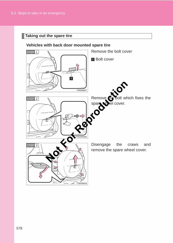
578
5-2. Steps to take in an emergency
LC150_OM_OM60J77E_(AE)
Taking out the spare tire
Vehicles with back door mounted spare tireRemove the bolt cover
Bolt cover
Remove the bolt which fixes thespare wheel cover.
Disengage the craws andremove the spare wheel cover.
ITN52M007
STEP 1
STEP 2
STEP 3
Not For R
epro
duction
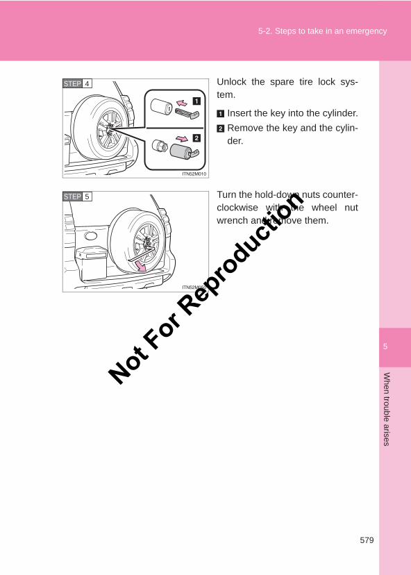
5
579
5-2. Steps to take in an emergencyW
hen trouble arises
LC150_OM_OM60J77E_(AE)
Unlock the spare tire lock sys-tem.
Insert the key into the cylinder.Remove the key and the cylin-der.
Turn the hold-down nuts counter-clockwise with the wheel nutwrench and remove them.
STEP 4
STEP 5
Not For R
epro
duction
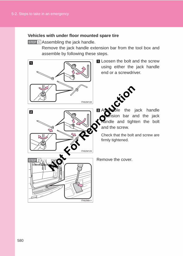
580
5-2. Steps to take in an emergency
LC150_OM_OM60J77E_(AE)
Vehicles with under floor mounted spare tireAssembling the jack handle.Remove the jack handle extension bar from the tool box andassemble by following these steps.
Loosen the bolt and the screwusing either the jack handleend or a screwdriver.
Assemble the jack handleextension bar and the jackhandle and tighten the boltand the screw.
Check that the bolt and screw arefirmly tightened.
Remove the cover.
STEP 1
STEP 2
Not For R
epro
duction
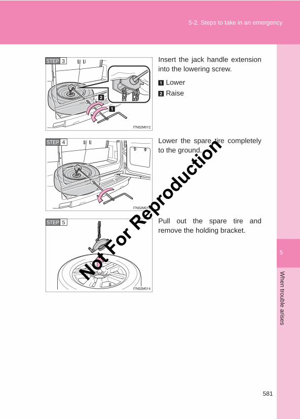
5
581
5-2. Steps to take in an emergencyW
hen trouble arises
LC150_OM_OM60J77E_(AE)
Insert the jack handle extensioninto the lowering screw.
LowerRaise
Lower the spare tire completelyto the ground.
Pull out the spare tire andremove the holding bracket.
STEP 3
STEP 4
STEP 5
Not For R
epro
duction
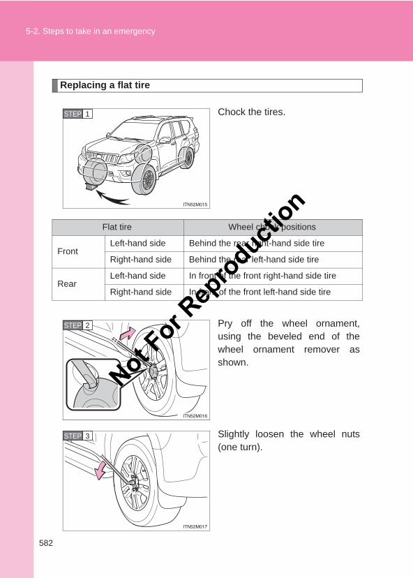
582
5-2. Steps to take in an emergency
LC150_OM_OM60J77E_(AE)
Replacing a flat tire
Chock the tires.
Pry off the wheel ornament,using the beveled end of thewheel ornament remover asshown.
Slightly loosen the wheel nuts(one turn).
STEP 1STEP 1
Flat tire Wheel chock positions
FrontLeft-hand side Behind the rear right-hand side tire
Right-hand side Behind the rear left-hand side tire
RearLeft-hand side In front of the front right-hand side tire
Right-hand side In front of the front left-hand side tire
STEP 2
STEP 3
Not For R
epro
duction
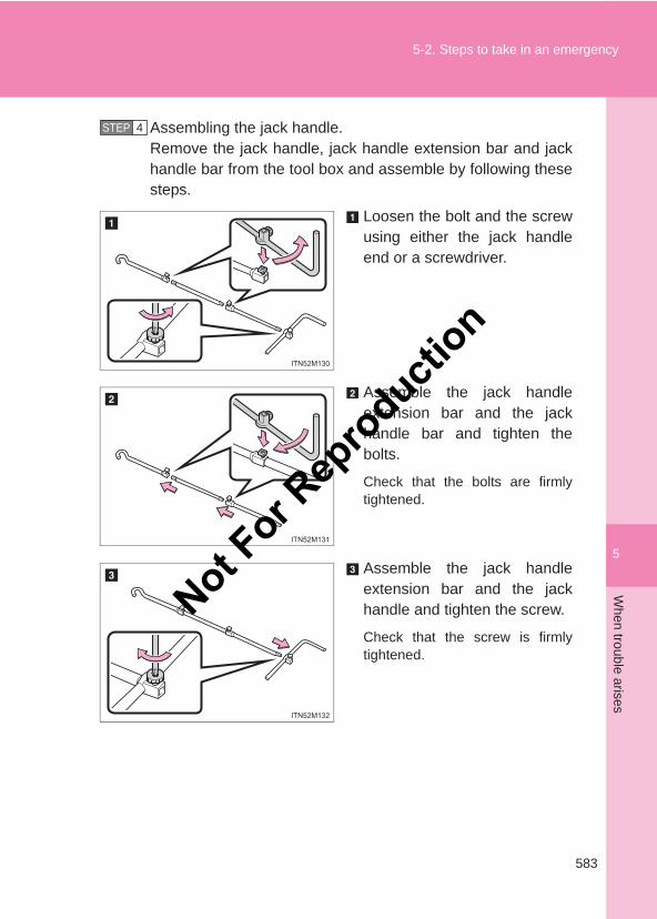
5
583
5-2. Steps to take in an emergencyW
hen trouble arises
LC150_OM_OM60J77E_(AE)
Assembling the jack handle.Remove the jack handle, jack handle extension bar and jackhandle bar from the tool box and assemble by following thesesteps.
Loosen the bolt and the screwusing either the jack handleend or a screwdriver.
Assemble the jack handleextension bar and the jackhandle bar and tighten thebolts.
Check that the bolts are firmlytightened.
Assemble the jack handleextension bar and the jackhandle and tighten the screw.
Check that the screw is firmlytightened.
STEP 4
Not For R
epro
duction
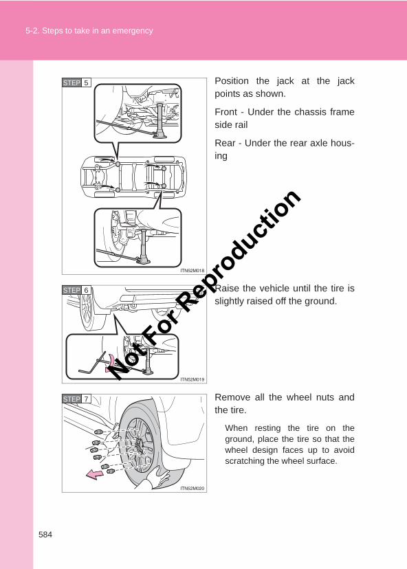
584
5-2. Steps to take in an emergency
LC150_OM_OM60J77E_(AE)
Position the jack at the jackpoints as shown.
Front - Under the chassis frameside rail
Rear - Under the rear axle hous-ing
Raise the vehicle until the tire isslightly raised off the ground.
Remove all the wheel nuts andthe tire.
When resting the tire on theground, place the tire so that thewheel design faces up to avoidscratching the wheel surface.
STEP 5
STEP 6
STEP 7
Not For R
epro
duction
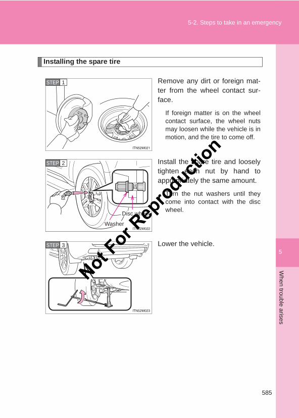
5
585
5-2. Steps to take in an emergencyW
hen trouble arises
LC150_OM_OM60J77E_(AE)
Installing the spare tire
Remove any dirt or foreign mat-ter from the wheel contact sur-face.
If foreign matter is on the wheelcontact surface, the wheel nutsmay loosen while the vehicle is inmotion, and the tire to come off.
Install the spare tire and looselytighten each nut by hand toappropriately the same amount.
Turn the nut washers until theycome into contact with the discwheel.
Lower the vehicle.
STEP 1
Washer
STEP 2
Disc wheel
STEP 3
Not For R
epro
duction
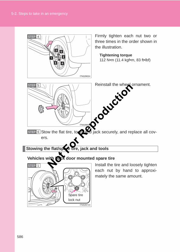
586
5-2. Steps to take in an emergency
LC150_OM_OM60J77E_(AE)
Firmly tighten each nut two orthree times in the order shown inthe illustration.
Tightening torque112 N•m (11.4 kgf•m, 83 ft•lbf)
Reinstall the wheel ornament.
Stow the flat tire, tools and jack securely, and replace all cov-ers.
Stowing the flat/spare tire, jack and tools
Vehicles with back door mounted spare tireInstall the tire and loosely tighteneach nut by hand to approxi-mately the same amount.
STEP 4
STEP 5
STEP 6
STEP 1
Spare tire lock nut
Not For R
epro
duction
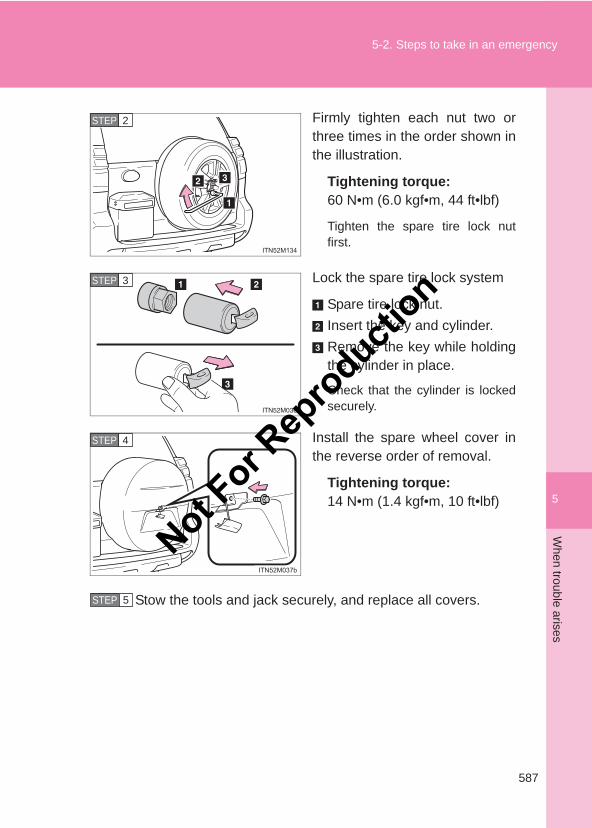
5
587
5-2. Steps to take in an emergencyW
hen trouble arises
LC150_OM_OM60J77E_(AE)
Firmly tighten each nut two orthree times in the order shown inthe illustration.
Tightening torque:60 N•m (6.0 kgf•m, 44 ft•lbf)
Tighten the spare tire lock nutfirst.
Lock the spare tire lock system
Spare tire lock nut.Insert the key and cylinder.Remove the key while holdingthe cylinder in place.
Check that the cylinder is lockedsecurely.
Install the spare wheel cover inthe reverse order of removal.
Tightening torque:14 N•m (1.4 kgf•m, 10 ft•lbf)
Stow the tools and jack securely, and replace all covers.
STEP 2
STEP 3
STEP 4
STEP 5
Not For R
epro
duction
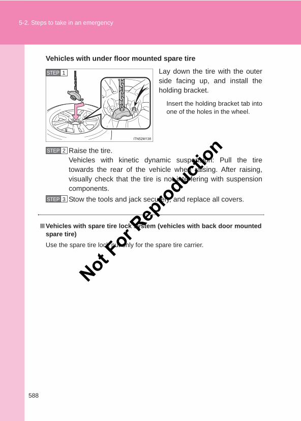
588
5-2. Steps to take in an emergency
LC150_OM_OM60J77E_(AE)
Vehicles with under floor mounted spare tire
Lay down the tire with the outerside facing up, and install theholding bracket.
Insert the holding bracket tab intoone of the holes in the wheel.
Raise the tire.Vehicles with kinetic dynamic suspension: Pull the tiretowards the rear of the vehicle when raising. After raising,visually check that the tire is not interfering with suspensioncomponents.Stow the tools and jack securely, and replace all covers.
STEP 1
■Vehicles with spare tire lock system (vehicles with back door mountedspare tire)Use the spare tire lock nut only for the spare tire carrier.
STEP 2
STEP 3
Not For R
epro
duction
5
589
5-2. Steps to take in an emergencyW
hen trouble arises
LC150_OM_OM60J77E_(AE)
CAUTION
■Using the tire jackImproper use of the tire jack may cause the vehicle to suddenly fall off thejack, leading to death or serious injury.
●Do not use the tire jack for any purpose other than replacing tires or install-ing and removing tire chains.
●Only use the tire jack that comes with this vehicle for replacing a flat tire. Do not use it on other vehicles, and do not use other tire jacks for replac-ing tires on this vehicle.
●Always check that the tire jack is securely set to the jack point.
●Do not put any part of your body under the vehicle while it is supported bythe jack.
●Do not start or run the engine while your vehicle is supported by the jack.
●Do not raise the vehicle while someone is inside.
●When raising the vehicle, do not put an object on or under the jack.
●Do not raise the vehicle to a height greater than that required to replacethe tire.
●Use a jack stand if it is necessary to get under the vehicle.
●Vehicles with rear height control air suspension: Be sure to turn off theheight control and stop the engine.
Take particular care when lowering the vehicle to ensure that no one workingon or near the vehicle will be injured.
■Using the jack handleTighten all the jack handle bolts securely using a Phillips-head screwdriver,to prevent the extension parts from coming apart unexpectedly.
Not For R
epro
duction
590
5-2. Steps to take in an emergency
LC150_OM_OM60J77E_(AE)
CAUTION
■Replacing a flat tireObserve the following precautions to reduce the risk of death or seriousinjury:
●Do not touch the disc wheels or the area around the brakes immediatelyafter the vehicle has been driven.After the vehicle has been driven the disc wheels and the area around thebrakes will be extremely hot. Touching these areas with hands, feet orother body parts while changing a tire, etc. may result in burns.
●Vehicles with under floor mounted spare tire: Lower the spare tire com-pletely to the ground before removing it from under the vehicle.
●Do not try to remove the wheel ornament by hand. Take due care in han-dling the ornament to avoid unexpected personal injury.
●Have the wheel nuts tightened with a torque wrench to 112 N•m (11.4kgf•m, 83 ft•lbf) as soon as possible after changing wheels.Failure to follow these precautions could cause the nuts to loosen and thewheel may fall off, which could lead to an accident causing death or seri-ous injury.
●Do not attach a heavily damaged wheel ornament, as it may fly off thewheel while the vehicle is moving.
●When installing a tire, only use wheel nuts that have been specificallydesigned for that wheel.
● If there are any cracks or deformations in the bolt screws, nut threads orbolt holes of the wheel, have the vehicle inspected by your Toyota dealer.
Failure to follow these precautions could cause the wheel nuts to loosen andthe tire to fall off, resulting in death or serious injury.
■When installing the wheel nutsBe sure to install the wheel nuts with the tapered end facing inward.(→P. 498)
Not For R
epro
duction
5
591
5-2. Steps to take in an emergencyW
hen trouble arises
LC150_OM_OM60J77E_(AE)
CAUTION
■After using the tools and jackBefore driving, make sure all the tools and jack are securely in place in theirstorage location to reduce the possibility of personal injury during a collisionor sudden braking.
NOTICE
■Do not drive the vehicle with a flat tire.Do not continue driving with a flat tire.Driving even a short distance with a flat tire can damage the tire and thewheel beyond repair.
■When stowing the flat tire (vehicles with under floor mounted sparetire)Ensure that there is no object caught between the tire and the vehicle under-body.
■When assembling the jack handle extensionTighten all the joints securely. Otherwise the extension may come off and itmay damage the paint or vehicle body.
Not For R
epro
duction
592
5-2. Steps to take in an emergency
LC150_OM_OM60J77E_(AE)
If the engine will not start
If the engine will not start even though correct starting proceduresare being followed (→P. 175, 179), consider each of the followingpoints:
■ The engine will not start even when the starter motor oper-ates normally.One of the following may be the cause of the problem:
● There may not be sufficient fuel in the vehicle’s tank.Gasoline engine: Refuel the vehicle.Diesel engine: (→P. 607)
● The engine may be flooded. (gasoline engine)Try to restart the engine again following correct starting proce-dures. (→P. 179)
● There may be a malfunction in the engine immobilizer system. (→P. 117)
■ The starter motor turns over slowly, the interior lights andheadlights are dim, or the horn does not sound or sounds ata low volume.One of the following may be the cause of the problem:
● The battery may be discharged. (→P. 599)
● The battery terminal connections may be loose or corroded.
■ The starter motor does not turn over.The engine starting system may be malfunctioning due to anelectrical problem such as an open circuit or a blown fuse. How-ever, an interim measure is available to start the engine. (→P. 593)
Not For R
epro
duction
5
593
5-2. Steps to take in an emergencyW
hen trouble arises
LC150_OM_OM60J77E_(AE)
Emergency start function (vehicles with a smart entry & startsystem)
When the engine does not start, the following steps can be used asan interim measure to start the engine if the “ENGINE START STOP”switch is functioning normally.
Set the parking brake.Put the shift lever in P (automatic transmission) or N (manualtransmission).Set the “ENGINE START STOP” switch to the ACCESSORYmode.Push and hold the “ENGINE START STOP” switch for about15 seconds while depressing the brake pedal (automatictransmission) or brake and clutch pedal (manual transmis-sion) firmly.
Even if the engine can be started using the above steps, the systemmay be malfunctioning. Have the vehicle checked by your Toyotadealer.
■ The starter motor does not turn over, the interior lights andheadlights do not turn on, or the horn does not sound.One of the following may be the cause of the problem:
● One or both of the battery terminals may be disconnected.
● The battery may be discharged. (→P. 599)
● There may be a malfunction in the steering lock system.
Contact your Toyota dealer if the problem cannot be repaired, or ifrepair procedures are unknown.
STEP 1
STEP 2
STEP 3
STEP 4 Not For R
epro
duction
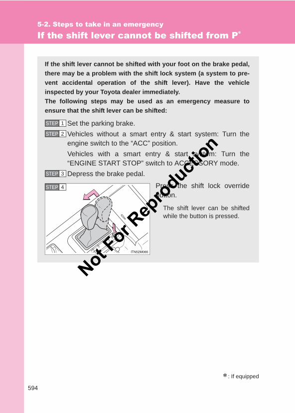
594
5-2. Steps to take in an emergency
LC150_OM_OM60J77E_(AE)
If the shift lever cannot be shifted from P∗
∗: If equipped
If the shift lever cannot be shifted with your foot on the brake pedal,there may be a problem with the shift lock system (a system to pre-vent accidental operation of the shift lever). Have the vehicleinspected by your Toyota dealer immediately.The following steps may be used as an emergency measure toensure that the shift lever can be shifted:
Set the parking brake.Vehicles without a smart entry & start system: Turn theengine switch to the “ACC” position.Vehicles with a smart entry & start system: Turn the“ENGINE START STOP” switch to ACCESSORY mode.Depress the brake pedal.
Press the shift lock overridebutton.
The shift lever can be shiftedwhile the button is pressed.
STEP 1
STEP 2
STEP 3
STEP 4
Not For R
epro
duction
5
595
5-2. Steps to take in an emergencyW
hen trouble arises
LC150_OM_OM60J77E_(AE)
If you lose your keys
New genuine keys can be made by your Toyota dealer. For vehicleswith the smart entry & start system, bring the other key and the keynumber stamped on the key number plate. For vehicles without thesmart entry & start system, bring a master key and the key numberstamped on the key number plate.
Not For R
epro
duction
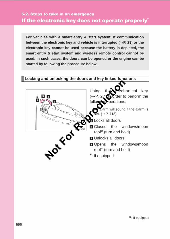
596
5-2. Steps to take in an emergency
LC150_OM_OM60J77E_(AE)
If the electronic key does not operate properly∗
Locking and unlocking the doors and key linked functions
Using the mechanical key(→P. 27) in order to perform thefollowing operations:
An alarm will sound if the alarm isset. (→P. 118)
Locks all doorsCloses the windows/moonroof* (turn and hold)Unlocks all doorsOpens the windows/moonroof* (turn and hold)
*: If equipped
∗: If equipped
For vehicles with a smart entry & start system: If communicationbetween the electronic key and vehicle is interrupted (→P. 29) or theelectronic key cannot be used because the battery is depleted, thesmart entry & start system and wireless remote control cannot beused. In such cases, the doors can be opened or the engine can bestarted by following the procedure below.
Not For R
epro
duction
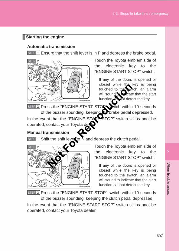
5
597
5-2. Steps to take in an emergencyW
hen trouble arises
LC150_OM_OM60J77E_(AE)
Starting the engine
Automatic transmissionEnsure that the shift lever is in P and depress the brake pedal.
Touch the Toyota emblem side ofthe electronic key to the“ENGINE START STOP” switch.
If any of the doors is opened orclosed while the key is beingtouched to the switch, an alarmwill sound to indicate that the startfunction cannot detect the key.
Press the “ENGINE START STOP” switch within 10 secondsof the buzzer sounding, keeping the brake pedal depressed.
In the event that the “ENGINE START STOP” switch still cannot beoperated, contact your Toyota dealer.
Manual transmissionShift the shift lever to N and depress the clutch pedal.
Touch the Toyota emblem side ofthe electronic key to the“ENGINE START STOP” switch.
If any of the doors is opened orclosed while the key is beingtouched to the switch, an alarmwill sound to indicate that the startfunction cannot detect the key.
Press the “ENGINE START STOP” switch within 10 secondsof the buzzer sounding, keeping the clutch pedal depressed.
In the event that the “ENGINE START STOP” switch still cannot beoperated, contact your Toyota dealer.
STEP 1
STEP 2
STEP 3
STEP 1
STEP 2
STEP 3
Not For R
epro
duction
598
5-2. Steps to take in an emergency
LC150_OM_OM60J77E_(AE)
■Stopping the engineVehicles with an automatic transmissionShift the shift lever to P and press the “ENGINE START STOP” switch asyou normally do when stopping the engine.
Vehicles with a manual transmissionShift the shift lever to N and press the “ENGINE START STOP” switch asyou normally do when stopping the engine.
■Replacing the key batteryAs the above procedure is a temporary measure, it is recommended that theelectronic key battery be replaced immediately when the battery is depleted.(→P. 501)
■AlarmUsing the mechanical key to lock the doors will not set the alarm system.If a door is unlocked using the mechanical key when the alarm system is set,the alarm may be triggered. (→P. 118)
■Changing “ENGINE START STOP” switch modesAutomatic transmissionWithin 10 seconds of the buzzer sounding, release the brake pedal andpress the “ENGINE START STOP” switch.The engine does not start and modes will be changed each time the switchis pressed. (→P. 182)
Manual transmissionWithin 10 seconds of the buzzer sounding, release the clutch pedal andpress the “ENGINE START STOP” switch.The engine does not start and modes will be changed each time the switchis pressed. (→P. 182)
Not For R
epro
duction
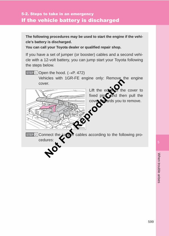
5
599
5-2. Steps to take in an emergencyW
hen trouble arises
LC150_OM_OM60J77E_(AE)
If the vehicle battery is discharged
The following procedures may be used to start the engine if the vehi-cle’s battery is discharged.You can call your Toyota dealer or qualified repair shop.
If you have a set of jumper (or booster) cables and a second vehi-cle with a 12-volt battery, you can jump start your Toyota followingthe steps below.
Open the hood. (→P. 472)Vehicles with 1GR-FE engine only: Remove the enginecover.
Lift the edge of the cover tofixed pins, and then pull thecover towards you to remove.
Connect the jumper cables according to the following pro-cedures:
STEP 1
STEP 2
Not For R
epro
duction
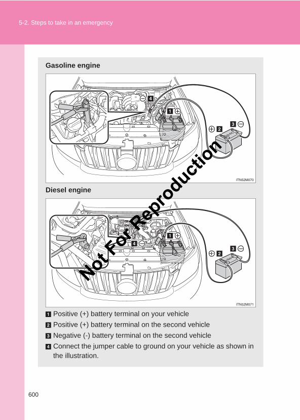
600
5-2. Steps to take in an emergency
LC150_OM_OM60J77E_(AE)
Gasoline engine
Diesel engine
Positive (+) battery terminal on your vehiclePositive (+) battery terminal on the second vehicleNegative (-) battery terminal on the second vehicleConnect the jumper cable to ground on your vehicle as shown inthe illustration.
Not For R
epro
duction
5
601
5-2. Steps to take in an emergencyW
hen trouble arises
LC150_OM_OM60J77E_(AE)
Start the engine of the second vehicle. Increase the enginespeed slightly and maintain at that level for approximately 5minutes to recharge the battery of your vehicle.Vehicles with a smart entry & start system: Open and closeany of the doors with the “ENGINE START STOP” switchoff.Maintain the engine speed of the second vehicle and startthe engine of your vehicle by turning the “ENGINE STARTSTOP” switch to IGNITION ON mode (vehicles with a smartentry & start system) or turning the engine switch to the“ON” position (vehicles without a smart entry & start sys-tem).Once the vehicle’s engine has started, remove the jumpercables in the exact reverse order in which they were con-nected.Vehicles with 1GR-FE engine only: To install the enginecover, conduct the removal procedure in reverse. Afterinstalling, check that the fixed pins are inserted securely.
Once the engine starts, have the vehicle checked at your Toyotadealer as soon as possible.
STEP 3
STEP 4
STEP 5
STEP 6
STEP 7
Not For R
epro
duction
602
5-2. Steps to take in an emergency
LC150_OM_OM60J77E_(AE)
■Starting the engine when the battery is discharged (vehicles with anautomatic transmission)The engine cannot be started by push-starting.
■To prevent battery discharge●Turn off the headlights and the audio system while the engine is off.
●Turn off any unnecessary electrical components when the vehicle is run-ning at a low speed for an extended period, such as in heavy traffic.
■When the battery is removed or dischargedMake sure that the key is not inside the vehicle when recharging or replacingthe battery. The key may be locked in the vehicle if the alarm is activated.(→P. 119)
■Charging the batteryThe electricity stored in the battery will discharge gradually even when thevehicle is not in use, due to natural discharge and the draining effects of cer-tain electrical appliances. If the vehicle is left for a long time, the battery maydischarge, and the engine may be unable to start. (The battery rechargesautomatically during driving.)
CAUTION
■Avoiding battery fires or explosionsObserve the following precautions to prevent accidentally igniting the flam-mable gas that may be emitted from the battery.
●Make sure the jumper cable is connected to the correct terminal and that itis not unintentionally in contact with any other than the intended terminal.
●Do not allow the + and - clamps of the jumper cables to come into contactwith each other.
●Do not smoke, use matches, cigarette lighters or allow open flame nearthe battery.
Not For R
epro
duction
5
603
5-2. Steps to take in an emergencyW
hen trouble arises
LC150_OM_OM60J77E_(AE)
CAUTION
■Battery precautionsThe battery contains poisonous and corrosive acidic electrolyte, whilerelated parts contain lead and lead compounds. Observe the following pre-cautions when handling the battery:
●When working with the battery, always wear safety glasses and take carenot to allow any battery fluids (acid) to come into contact with skin, clothingor the vehicle body.
●Do not lean over the battery.
● In the event that battery fluid comes into contact with the skin or eyes,immediately wash the affected area with water and seek medical attention.Place a wet sponge or cloth over the affected area until medical attentioncan be received.
●Always wash your hands after handling the battery support, terminals, andother battery-related parts.
●Do not allow children near the battery.
■To prevent damaging the vehicle (vehicles with a manual transmission)Do not pull- or push-start the vehicle, because the catalytic converter mayoverheat and become a fire hazard.
NOTICE
■When handling jumper cablesWhen connecting the jumper cables, ensure that they do not become entan-gled in the cooling fans or belt.
■To prevent damage to the engine cover●When removing the cover, make sure that you pull the cover towards you
after lifting the front edge to remove the fixed pins.
●When installing the cover, do not force the cover or subject it to strongshocks.
Not For R
epro
duction
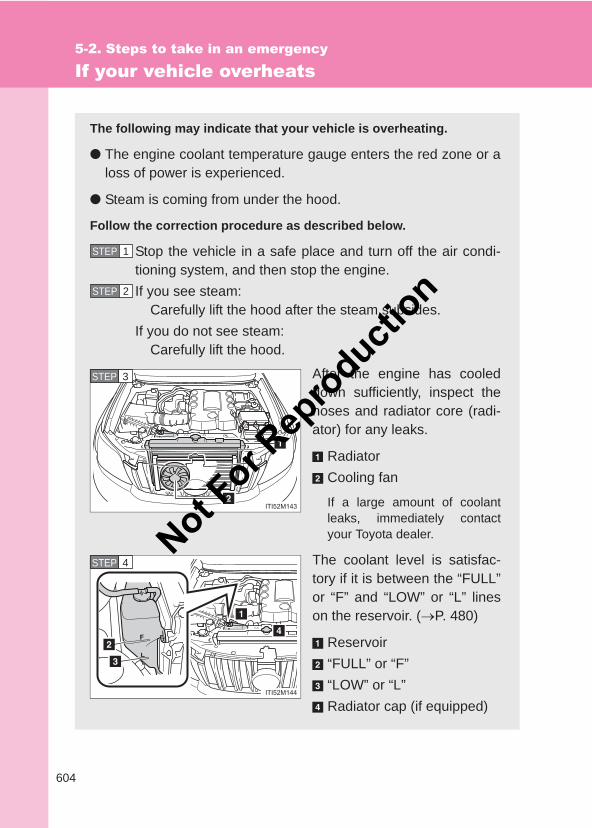
604
5-2. Steps to take in an emergency
LC150_OM_OM60J77E_(AE)
If your vehicle overheats
The following may indicate that your vehicle is overheating.
● The engine coolant temperature gauge enters the red zone or aloss of power is experienced.
● Steam is coming from under the hood.
Follow the correction procedure as described below.
Stop the vehicle in a safe place and turn off the air condi-tioning system, and then stop the engine.If you see steam:
Carefully lift the hood after the steam subsides.If you do not see steam:
Carefully lift the hood.
After the engine has cooleddown sufficiently, inspect thehoses and radiator core (radi-ator) for any leaks.
RadiatorCooling fan
If a large amount of coolantleaks, immediately contactyour Toyota dealer.
The coolant level is satisfac-tory if it is between the “FULL”or “F” and “LOW” or “L” lineson the reservoir. (→P. 480)
Reservoir“FULL” or “F”“LOW” or “L”Radiator cap (if equipped)
STEP 1
STEP 2
STEP 3
STEP 4Not F
or Rep
roducti
on
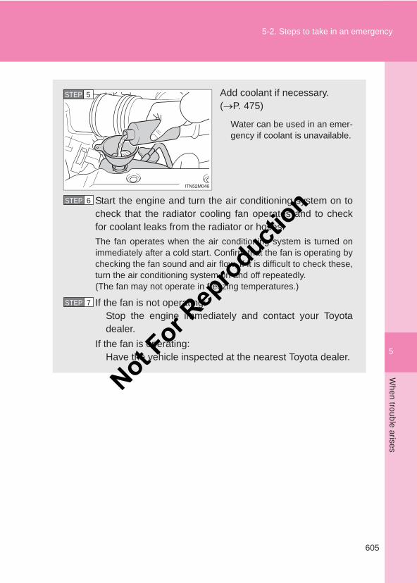
5
605
5-2. Steps to take in an emergencyW
hen trouble arises
LC150_OM_OM60J77E_(AE)
Add coolant if necessary. (→P. 475)
Water can be used in an emer-gency if coolant is unavailable.
Start the engine and turn the air conditioning system on tocheck that the radiator cooling fan operates and to checkfor coolant leaks from the radiator or hoses.The fan operates when the air conditioning system is turned onimmediately after a cold start. Confirm that the fan is operating bychecking the fan sound and air flow. If it is difficult to check these,turn the air conditioning system on and off repeatedly.(The fan may not operate in freezing temperatures.)
If the fan is not operating:Stop the engine immediately and contact your Toyotadealer.
If the fan is operating:Have the vehicle inspected at the nearest Toyota dealer.
STEP 5
STEP 6
STEP 7
Not For R
epro
duction
606
5-2. Steps to take in an emergency
LC150_OM_OM60J77E_(AE)
CAUTION
■To prevent an accident or injury when inspecting under the hood ofyour vehicle● If steam is seen coming from under the hood, do not open the hood until
the steam has subsided. The engine compartment may be very hot, caus-ing serious injury such as burns.
●Keep hands and clothing (especially a tie, a scarf or a muffler) away fromthe fan and other belts. Failure to do so may cause the hands or clothingto be caught, resulting in serious injury.
●Do not loosen the radiator cap, or the coolant reservoir cap while theengine and radiator are hot.Serious injury, such as burns, may result from hot coolant and steamreleased under pressure.
NOTICE
■When adding engine coolantWait until the engine has cooled down before adding engine coolant.When adding coolant, do so slowly. Adding cool coolant to a hot engine tooquickly can cause damage to the engine.
■To prevent damage to the cooling systemObserve the following precautions:
●Avoid contaminating the coolant with foreign matter (such as sand or dustetc.).
●Do not use commercially available coolant additives.
Not For R
epro
duction
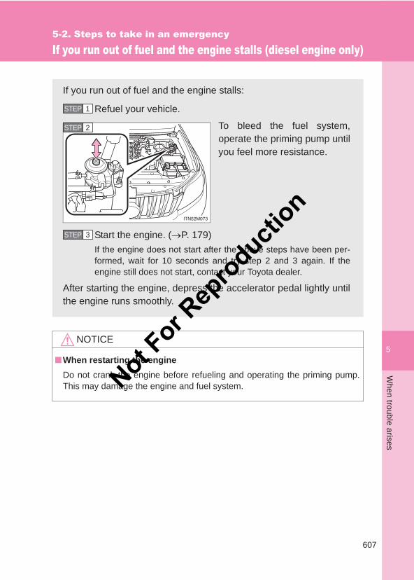
5
607
5-2. Steps to take in an emergencyW
hen trouble arises
LC150_OM_OM60J77E_(AE)
If you run out of fuel and the engine stalls (diesel engine only)
NOTICE
■When restarting the engineDo not crank the engine before refueling and operating the priming pump.This may damage the engine and fuel system.
If you run out of fuel and the engine stalls:
Refuel your vehicle.
To bleed the fuel system,operate the priming pump untilyou feel more resistance.
Start the engine. (→P. 179)If the engine does not start after the above steps have been per-formed, wait for 10 seconds and try step 2 and 3 again. If theengine still does not start, contact your Toyota dealer.
After starting the engine, depress the accelerator pedal lightly untilthe engine runs smoothly.
STEP 1
STEP 2
STEP 3
Not For R
epro
duction
608
5-2. Steps to take in an emergency
LC150_OM_OM60J77E_(AE)
If the vehicle becomes stuck
Carry out the following procedures if the tires spin or the vehiclebecomes stuck in mud, dirt, or snow:
Stop the engine. Set the parking brake and put the shiftlever in P (automatic transmission) or N (manual transmis-sion).Remove the mud, snow, or sand from around the stuck tire.Place wood, stones or some other material to help providetraction under the tires.Restart the engine.Shift the shift lever to the D or R position (automatic trans-mission) or 1 or R position (manual transmission), andcarefully apply the accelerator to free the vehicle.Turn off TRC and VSC if these functions are hamperingyour attempts to free the vehicle. (→P. 282)
STEP 1
STEP 2
STEP 3
STEP 4
STEP 5
Not For R
epro
duction
5
609
5-2. Steps to take in an emergencyW
hen trouble arises
LC150_OM_OM60J77E_(AE)
CAUTION
■When attempting to free a stuck vehicleIf you choose to push the vehicle back and forth to free it, make sure the sur-rounding area is clear, to avoid striking other vehicles, objects or people. Thevehicle may also lunge forward or lunge back suddenly as it becomes free.Use extreme caution.
■When shifting the shift leverFor vehicles with an automatic transmission, be careful not to shift the shiftlever with the accelerator pedal depressed.This may lead to unexpected rapid acceleration of the vehicle that maycause an accident and result in death or serious injury.
NOTICE
■To avoid damaging the transmission and other components●Avoid spinning the wheels and do not rev the engine.
● If the vehicle remains stuck even after these procedures are performed,the vehicle may require towing to be freed.
Not For R
epro
duction
610
5-2. Steps to take in an emergency
LC150_OM_OM60J77E_(AE)
If your vehicle has to be stopped in an emergency
Only in an emergency, such as if it becomes impossible to stop thevehicle in the normal way, stop the vehicle using the following pro-cedure:
Steadily step on the brake pedal with both feet and firmlydepress it.Do not pump the brake pedal repeatedly as this will increase theeffort required to slow the vehicle.
Shift the shift lever to N.
If the shift lever is shifted to N After slowing down, stop the vehicle in a safe place by theroad.Stop the engine.
STEP 1
STEP 2
STEP 3
STEP 4
Not For R
epro
duction
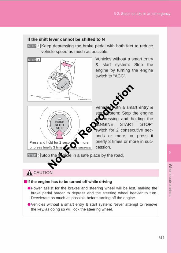
5
611
5-2. Steps to take in an emergencyW
hen trouble arises
LC150_OM_OM60J77E_(AE)
CAUTION
■ If the engine has to be turned off while driving●Power assist for the brakes and steering wheel will be lost, making the
brake pedal harder to depress and the steering wheel heavier to turn.Decelerate as much as possible before turning off the engine.
●Vehicles without a smart entry & start system: Never attempt to removethe key, as doing so will lock the steering wheel.
If the shift lever cannot be shifted to NKeep depressing the brake pedal with both feet to reducevehicle speed as much as possible.
Vehicles without a smart entry& start system: Stop theengine by turning the engineswitch to “ACC”.
Vehicles with a smart entry &start system: Stop the engineby pressing and holding the“ENGINE START STOP”switch for 2 consecutive sec-onds or more, or press itbriefly 3 times or more in suc-cession.
Stop the vehicle in a safe place by the road.
STEP 3
STEP 4
Press and hold for 2 seconds or more,or press briefly 3 times or more
STEP 5
Not For R
epro
duction

612
5-2. Steps to take in an emergency
LC150_OM_OM60J77E_(AE)
Not For R
epro
duction
6Vehicle specifications
613
LC150_OM_OM60J77E_(AE)
6-1. SpecificationsMaintenance data
(fuel, oil level, etc.).......... 614Fuel information ................ 630
6-2. CustomizationCustomizable features...... 632
Not For R
epro
duction
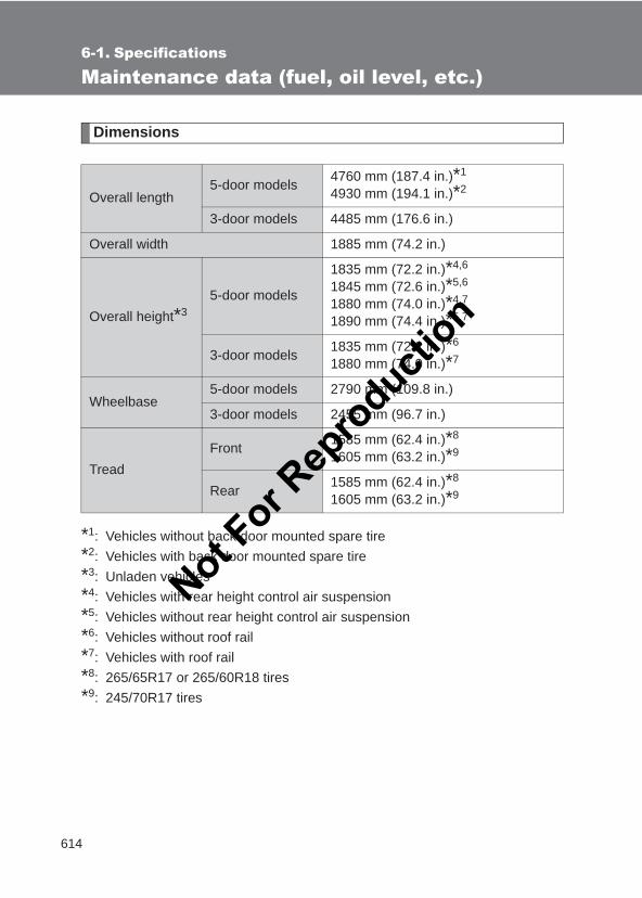
614
LC150_OM_OM60J77E_(AE)
6-1. Specifications
Maintenance data (fuel, oil level, etc.)
Dimensions
*1: Vehicles without back door mounted spare tire*2: Vehicles with back door mounted spare tire*3: Unladen vehicles*4: Vehicles with rear height control air suspension*5: Vehicles without rear height control air suspension*6: Vehicles without roof rail*7: Vehicles with roof rail*8: 265/65R17 or 265/60R18 tires*9: 245/70R17 tires
Overall length5-door models 4760 mm (187.4 in.)*1
4930 mm (194.1 in.)*2
3-door models 4485 mm (176.6 in.)
Overall width 1885 mm (74.2 in.)
Overall height*35-door models
1835 mm (72.2 in.)*4,6
1845 mm (72.6 in.)*5,6
1880 mm (74.0 in.)*4,7
1890 mm (74.4 in.)*5,7
3-door models 1835 mm (72.2 in.)*6
1880 mm (74.0 in.)*7
Wheelbase5-door models 2790 mm (109.8 in.)
3-door models 2455 mm (96.7 in.)
TreadFront 1585 mm (62.4 in.)*8
1605 mm (63.2 in.)*9
Rear 1585 mm (62.4 in.)*8
1605 mm (63.2 in.)*9
Not For R
epro
duction
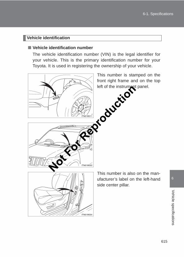
615
6-1. Specifications
6
Vehicle specifications
LC150_OM_OM60J77E_(AE)
Vehicle identification
■ Vehicle identification numberThe vehicle identification number (VIN) is the legal identifier foryour vehicle. This is the primary identification number for yourToyota. It is used in registering the ownership of your vehicle.
This number is stamped on thefront right frame and on the topleft of the instrument panel.
This number is also on the man-ufacturer’s label on the left-handside center pillar.
Not For R
epro
duction
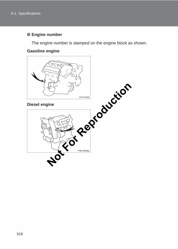
616
6-1. Specifications
LC150_OM_OM60J77E_(AE)
■ Engine number
The engine number is stamped on the engine block as shown.
Gasoline engine
Diesel engine
Not For R
epro
duction
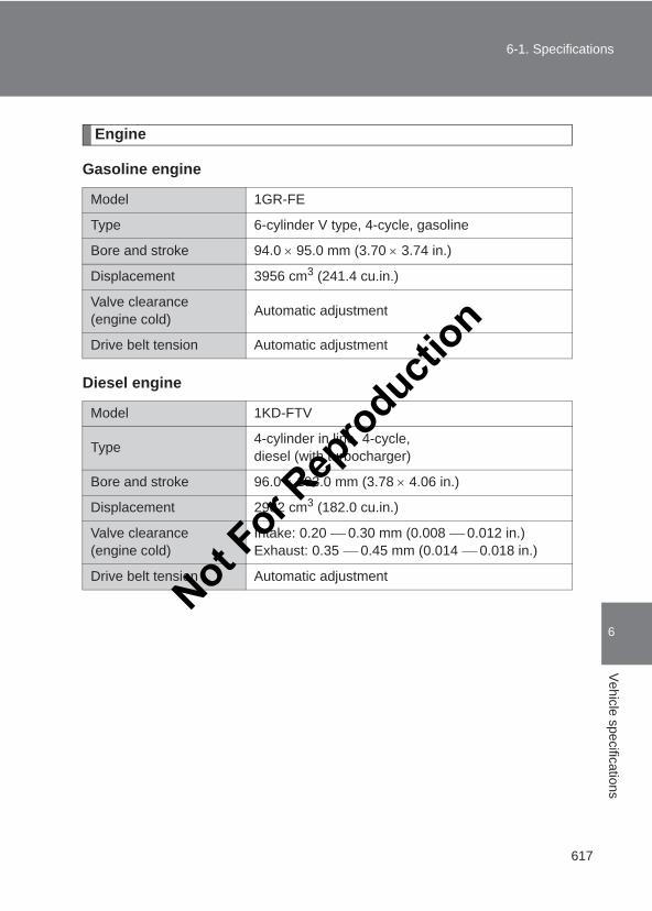
617
6-1. Specifications
6
Vehicle specifications
LC150_OM_OM60J77E_(AE)
Engine
Gasoline engine
Diesel engine
Model 1GR-FE
Type 6-cylinder V type, 4-cycle, gasoline
Bore and stroke 94.0 × 95.0 mm (3.70 × 3.74 in.)
Displacement 3956 cm3 (241.4 cu.in.)
Valve clearance (engine cold) Automatic adjustment
Drive belt tension Automatic adjustment
Model 1KD-FTV
Type 4-cylinder in line, 4-cycle, diesel (with turbocharger)
Bore and stroke 96.0 × 103.0 mm (3.78 × 4.06 in.)
Displacement 2982 cm3 (182.0 cu.in.)
Valve clearance (engine cold)
Intake: 0.20 0.30 mm (0.008 0.012 in.)Exhaust: 0.35 0.45 mm (0.014 0.018 in.)
Drive belt tension Automatic adjustment
Not For R
epro
duction
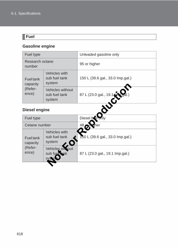
618
6-1. Specifications
LC150_OM_OM60J77E_(AE)
Fuel
Gasoline engine
Diesel engine
Fuel type Unleaded gasoline only
Research octane number 95 or higher
Fuel tank capacity(Refer-ence)
Vehicles with sub fuel tank system
150 L (39.6 gal., 33.0 Imp.gal.)
Vehicles without sub fuel tank system
87 L (23.0 gal., 19.1 Imp.gal.)
Fuel type Diesel fuel only
Cetane number 48 or higher
Fuel tank capacity(Refer-ence)
Vehicles with sub fuel tank system
150 L (39.6 gal., 33.0 Imp.gal.)
Vehicles without sub fuel tank system
87 L (23.0 gal., 19.1 Imp.gal.)
Not For R
epro
duction
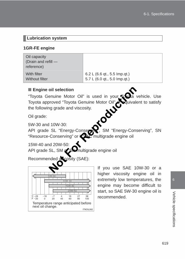
619
6-1. Specifications
6
Vehicle specifications
LC150_OM_OM60J77E_(AE)
Lubrication system
1GR-FE engine
■ Engine oil selection“Toyota Genuine Motor Oil” is used in your Toyota vehicle. UseToyota approved “Toyota Genuine Motor Oil” or equivalent to satisfythe following grade and viscosity.
Oil grade:
5W-30 and 10W-30:API grade SL “Energy-Conserving”, SM “Energy-Conserving”, SN“Resource-Conserving” or ILSAC multigrade engine oil
15W-40 and 20W-50:API grade SL, SM or SN multigrade engine oil
Recommended viscosity (SAE):
If you use SAE 10W-30 or ahigher viscosity engine oil inextremely low temperatures, theengine may become difficult tostart, so SAE 5W-30 engine oil isrecommended.
Oil capacity(Drain and refill — reference)
With filterWithout filter
6.2 L (6.6 qt., 5.5 Imp.qt.)5.7 L (6.0 qt., 5.0 Imp.qt.)
Temperature range anticipated before next oil change.
Not For R
epro
duction
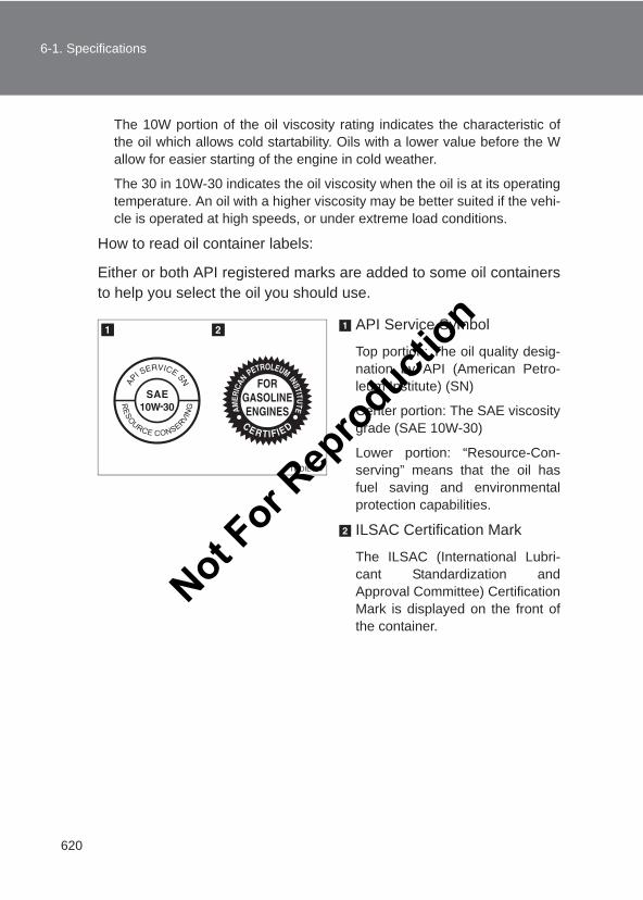
620
6-1. Specifications
LC150_OM_OM60J77E_(AE)
The 10W portion of the oil viscosity rating indicates the characteristic ofthe oil which allows cold startability. Oils with a lower value before the Wallow for easier starting of the engine in cold weather.
The 30 in 10W-30 indicates the oil viscosity when the oil is at its operatingtemperature. An oil with a higher viscosity may be better suited if the vehi-cle is operated at high speeds, or under extreme load conditions.
How to read oil container labels:
Either or both API registered marks are added to some oil containersto help you select the oil you should use.
API Service Symbol
Top portion: The oil quality desig-nation by API (American Petro-leum Institute) (SN)
Center portion: The SAE viscositygrade (SAE 10W-30)
Lower portion: “Resource-Con-serving” means that the oil hasfuel saving and environmentalprotection capabilities.
ILSAC Certification Mark
The ILSAC (International Lubri-cant Standardization andApproval Committee) CertificationMark is displayed on the front ofthe container.
Not For R
epro
duction
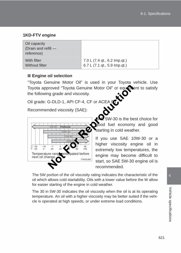
621
6-1. Specifications
6
Vehicle specifications
LC150_OM_OM60J77E_(AE)
1KD-FTV engine
■ Engine oil selection“Toyota Genuine Motor Oil” is used in your Toyota vehicle. UseToyota approved “Toyota Genuine Motor Oil” or equivalent to satisfythe following grade and viscosity.
Oil grade: G-DLD-1, API CF-4, CF or ACEA B1
Recommended viscosity (SAE):
SAE 5W-30 is the best choice forgood fuel economy and goodstarting in cold weather.
If you use SAE 10W-30 or ahigher viscosity engine oil inextremely low temperatures, theengine may become difficult tostart, so SAE 5W-30 engine oil isrecommended.
The 5W portion of the oil viscosity rating indicates the characteristic of theoil which allows cold startability. Oils with a lower value before the W allowfor easier starting of the engine in cold weather.
The 30 in 5W-30 indicates the oil viscosity when the oil is at its operatingtemperature. An oil with a higher viscosity may be better suited if the vehi-cle is operated at high speeds, or under extreme load conditions.
Oil capacity(Drain and refill — reference)
With filterWithout filter
7.0 L (7.4 qt., 6.2 Imp.qt.)6.7 L (7.1 qt., 5.9 Imp.qt.)
Temperature range anticipated before next oil change.
Preferred
Not For R
epro
duction
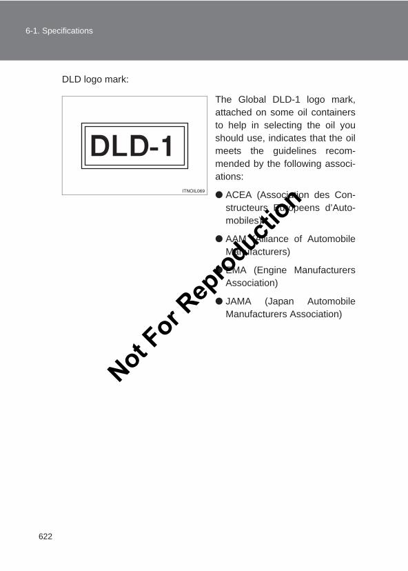
622
6-1. Specifications
LC150_OM_OM60J77E_(AE)
DLD logo mark:
The Global DLD-1 logo mark,attached on some oil containersto help in selecting the oil youshould use, indicates that the oilmeets the guidelines recom-mended by the following associ-ations:
● ACEA (Association des Con-structeurs Europeens d’Auto-mobiles)
● AAM (Alliance of AutomobileManufacturers)
● EMA (Engine ManufacturersAssociation)
● JAMA (Japan AutomobileManufacturers Association)
Not For R
epro
duction
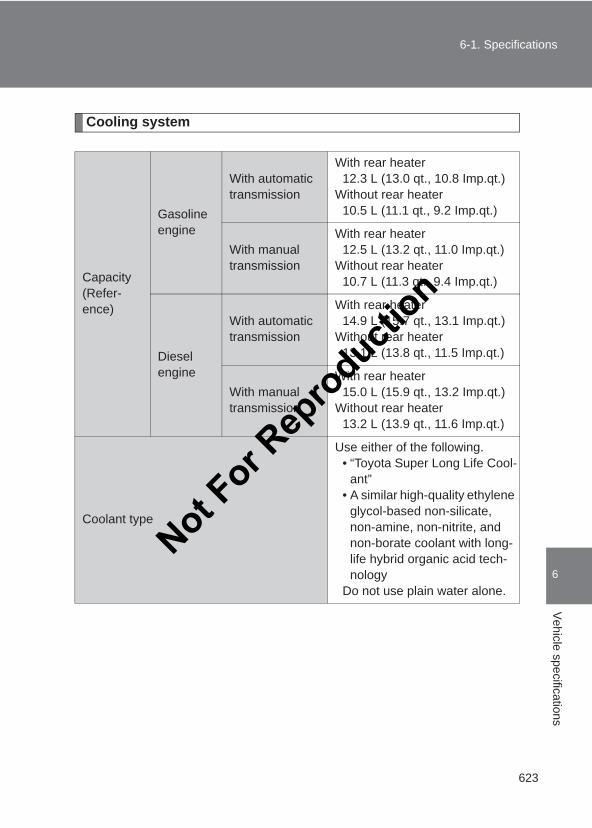
623
6-1. Specifications
6
Vehicle specifications
LC150_OM_OM60J77E_(AE)
Cooling system
Capacity(Refer-ence)
Gasoline engine
With automatic transmission
With rear heater12.3 L (13.0 qt., 10.8 Imp.qt.)
Without rear heater10.5 L (11.1 qt., 9.2 Imp.qt.)
With manual transmission
With rear heater12.5 L (13.2 qt., 11.0 Imp.qt.)
Without rear heater10.7 L (11.3 qt., 9.4 Imp.qt.)
Diesel engine
With automatic transmission
With rear heater14.9 L (15.7 qt., 13.1 Imp.qt.)
Without rear heater13.1 L (13.8 qt., 11.5 Imp.qt.)
With manual transmission
With rear heater15.0 L (15.9 qt., 13.2 Imp.qt.)
Without rear heater13.2 L (13.9 qt., 11.6 Imp.qt.)
Coolant type
Use either of the following.• “Toyota Super Long Life Cool-
ant” • A similar high-quality ethylene
glycol-based non-silicate, non-amine, non-nitrite, and non-borate coolant with long-life hybrid organic acid tech-nology
Do not use plain water alone.
Not For R
epro
duction
624
6-1. Specifications
LC150_OM_OM60J77E_(AE)
Ignition system (gasoline engine only)
Electrical system
Front differential
*: Your Toyota vehicle is filled with “Toyota Genuine Differential Gear Oil” at thefactory.Use Toyota approved “Toyota Genuine Differential Gear Oil” or an equivalentof matching quality to satisfy the above specification. Please contact yourToyota dealer for further details.
Spark plugMake DENSO SK20HR11
Gap 1.1 mm (0.043 in.)
NOTICE
■ Iridium-tipped spark plugsUse only iridium-tipped spark plugs. Do not adjust the spark plug gap.
Battery
Specific gravity reading at 20 °C (68 °F):
1.250 1.290 Fully charged1.160 1.200 Half charged1.060 1.100 Discharged
Charging rates
Quick chargeSlow charge
15 A max.5 A max.
Oil capacity 1.40 L (1.48 qt., 1.23 Imp.qt.)
Oil type and viscosity* Toyota Genuine Differential Gear Oil LT 75W-85 GL-5 or equivalent
Not For R
epro
duction
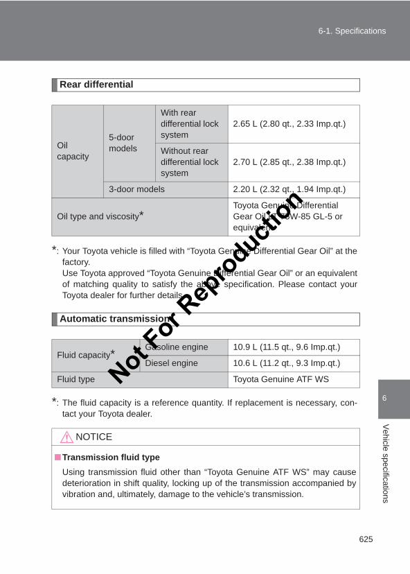
625
6-1. Specifications
6
Vehicle specifications
LC150_OM_OM60J77E_(AE)
Rear differential
*: Your Toyota vehicle is filled with “Toyota Genuine Differential Gear Oil” at thefactory.Use Toyota approved “Toyota Genuine Differential Gear Oil” or an equivalentof matching quality to satisfy the above specification. Please contact yourToyota dealer for further details.
Automatic transmission
*: The fluid capacity is a reference quantity. If replacement is necessary, con-tact your Toyota dealer.
Oil capacity
5-door models
With rear differential lock system
2.65 L (2.80 qt., 2.33 Imp.qt.)
Without rear differential lock system
2.70 L (2.85 qt., 2.38 Imp.qt.)
3-door models 2.20 L (2.32 qt., 1.94 Imp.qt.)
Oil type and viscosity*Toyota Genuine Differential Gear Oil LT 75W-85 GL-5 or equivalent
Fluid capacity*Gasoline engine 10.9 L (11.5 qt., 9.6 Imp.qt.)
Diesel engine 10.6 L (11.2 qt., 9.3 Imp.qt.)
Fluid type Toyota Genuine ATF WS
NOTICE
■Transmission fluid typeUsing transmission fluid other than “Toyota Genuine ATF WS” may causedeterioration in shift quality, locking up of the transmission accompanied byvibration and, ultimately, damage to the vehicle’s transmission.
Not For R
epro
duction
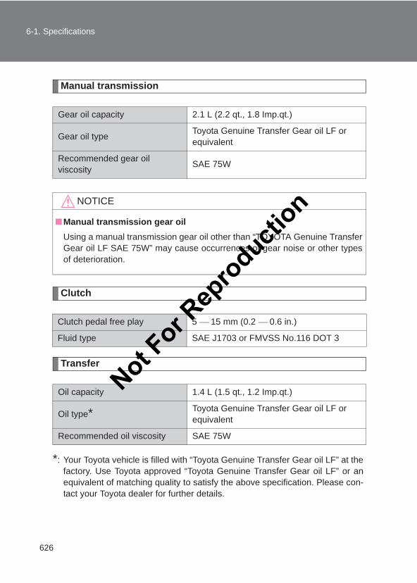
626
6-1. Specifications
LC150_OM_OM60J77E_(AE)
Manual transmission
Clutch
Transfer
*: Your Toyota vehicle is filled with “Toyota Genuine Transfer Gear oil LF” at thefactory. Use Toyota approved “Toyota Genuine Transfer Gear oil LF” or anequivalent of matching quality to satisfy the above specification. Please con-tact your Toyota dealer for further details.
Gear oil capacity 2.1 L (2.2 qt., 1.8 Imp.qt.)
Gear oil type Toyota Genuine Transfer Gear oil LF or equivalent
Recommended gear oil viscosity SAE 75W
NOTICE
■Manual transmission gear oilUsing a manual transmission gear oil other than “TOYOTA Genuine TransferGear oil LF SAE 75W” may cause occurrences of gear noise or other typesof deterioration.
Clutch pedal free play 5 15 mm (0.2 0.6 in.)
Fluid type SAE J1703 or FMVSS No.116 DOT 3
Oil capacity 1.4 L (1.5 qt., 1.2 Imp.qt.)
Oil type* Toyota Genuine Transfer Gear oil LF or equivalent
Recommended oil viscosity SAE 75W
Not For R
epro
duction
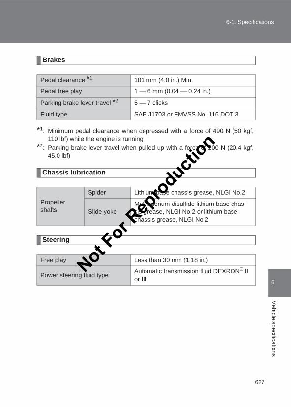
627
6-1. Specifications
6
Vehicle specifications
LC150_OM_OM60J77E_(AE)
Brakes
*1: Minimum pedal clearance when depressed with a force of 490 N (50 kgf,110 lbf) while the engine is running
*2: Parking brake lever travel when pulled up with a force of 200 N (20.4 kgf,45.0 lbf)
Chassis lubrication
Steering
Pedal clearance *1 101 mm (4.0 in.) Min.
Pedal free play 1 6 mm (0.04 0.24 in.)
Parking brake lever travel *2 5 7 clicks
Fluid type SAE J1703 or FMVSS No. 116 DOT 3
Propeller shafts
Spider Lithium base chassis grease, NLGI No.2
Slide yokeMolybdenum-disulfide lithium base chas-sis grease, NLGI No.2 or lithium base chassis grease, NLGI No.2
Free play Less than 30 mm (1.18 in.)
Power steering fluid type Automatic transmission fluid DEXRON® II or III
Not For R
epro
duction
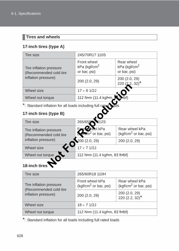
628
6-1. Specifications
LC150_OM_OM60J77E_(AE)
Tires and wheels
17-inch tires (type A)
*: Standard inflation for all loads including full rated loads
17-inch tires (type B)
18-inch tires
*: Standard inflation for all loads including full rated loads
Tire size 245/70R17 110S
Tire inflation pressure (Recommended cold tire inflation pressure)
Front wheel kPa (kgf/cm2 or bar, psi)
Rear wheel kPa (kgf/cm2 or bar, psi)
200 (2.0, 29) 200 (2.0, 29)220 (2.2, 32)*
Wheel size 17 × 6 1/2J
Wheel nut torque 112 N•m (11.4 kgf•m, 83 ft•lbf)
Tire size 265/65R17 112S
Tire inflation pressure (Recommended cold tire inflation pressure)
Front wheel kPa (kgf/cm2 or bar, psi)
Rear wheel kPa (kgf/cm2 or bar, psi)
200 (2.0, 29) 200 (2.0, 29)
Wheel size 17 × 7 1/2J
Wheel nut torque 112 N•m (11.4 kgf•m, 83 ft•lbf)
Tire size 265/60R18 110H
Tire inflation pressure (Recommended cold tire inflation pressure)
Front wheel kPa (kgf/cm2 or bar, psi)
Rear wheel kPa (kgf/cm2 or bar, psi)
200 (2.0, 29) 200 (2.0, 29)220 (2.2, 32)*
Wheel size 18 × 7 1/2J
Wheel nut torque 112 N•m (11.4 kgf•m, 83 ft•lbf)
Not For R
epro
duction
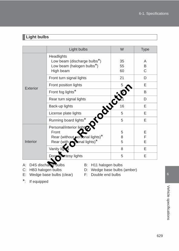
629
6-1. Specifications
6
Vehicle specifications
LC150_OM_OM60J77E_(AE)
Light bulbs
A: D4S discharge bulbs B: H11 halogen bulbsC: HB3 halogen bulbs D: Wedge base bulbs (amber)E: Wedge base bulbs (clear) F: Double end bulbs
*: If equipped
Light bulbs W Type
Exterior
HeadlightsLow beam (discharge bulbs*)Low beam (halogen bulbs*)High beam
355560
ABC
Front turn signal lights 21 D
Front position lights 5 E
Front fog lights* 55 B
Rear turn signal lights 21 D
Back-up lights 16 E
License plate lights 5 E
Running board lights* 5 E
Interior
Personal/interior lightsFrontRear (without personal lights)*Rear (with personal lights)*
585
EFE
Vanity lights 8 E
Door courtesy lights 5 E
Not For R
epro
duction
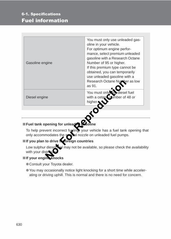
630
6-1. Specifications
LC150_OM_OM60J77E_(AE)
Fuel information
■Fuel tank opening for unleaded gasolineTo help prevent incorrect fueling, your vehicle has a fuel tank opening thatonly accommodates the special nozzle on unleaded fuel pumps.
■ If you plan to drive in foreign countriesLow sulphur diesel fuel may not be available, so please check the availabilitywith your distributor.
■ If your engine knocks●Consult your Toyota dealer.
●You may occasionally notice light knocking for a short time while acceler-ating or driving uphill. This is normal and there is no need for concern.
Gasoline engine
You must only use unleaded gas-oline in your vehicle.For optimum engine perfor-mance, select premium unleaded gasoline with a Research Octane Number of 95 or higher.If this premium type cannot be obtained, you can temporarily use unleaded gasoline with a Research Octane Number as low as 91.
Diesel engineYou must only use diesel fuel with a cetane number of 48 or higher.
Not For R
epro
duction
631
6-1. Specifications
6
Vehicle specifications
LC150_OM_OM60J77E_(AE)
NOTICE
■Notice on fuel quality●Do not use improper fuels. If improper fuels are used, the engine will be
damaged.
●Do not use leaded gasoline.Leaded gasoline will cause the three-way catalytic converter to lose itseffectiveness and the emission control system to function improperly.
Not For R
epro
duction
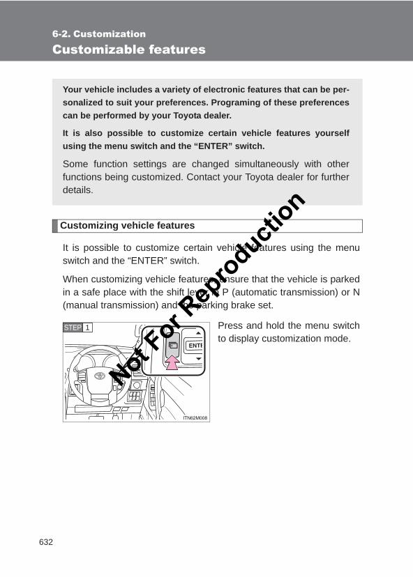
632
LC150_OM_OM60J77E_(AE)
6-2. Customization
Customizable features
Customizing vehicle features
It is possible to customize certain vehicle features using the menuswitch and the “ENTER” switch.
When customizing vehicle features, ensure that the vehicle is parkedin a safe place with the shift lever in P (automatic transmission) or N(manual transmission) and the parking brake set.
Press and hold the menu switchto display customization mode.
Your vehicle includes a variety of electronic features that can be per-sonalized to suit your preferences. Programing of these preferencescan be performed by your Toyota dealer.
It is also possible to customize certain vehicle features yourselfusing the menu switch and the “ENTER” switch.
Some function settings are changed simultaneously with otherfunctions being customized. Contact your Toyota dealer for furtherdetails.
STEP 1
Not For R
epro
duction
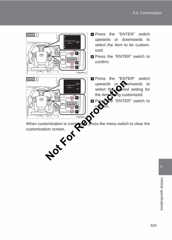
633
6-2. Customization
6
Vehicle specifications
LC150_OM_OM60J77E_(AE)
Press the “ENTER” switchupwards or downwards toselect the item to be custom-ized.Press the “ENTER” switch toconfirm.
Press the “ENTER” switchupwards or downwards toselect the desired setting forthe item being customized.Press the “ENTER” switch toconfirm.
When customization is completed, press the menu switch to clear thecustomization screen.
STEP 2
STEP 3
Not For R
epro
duction
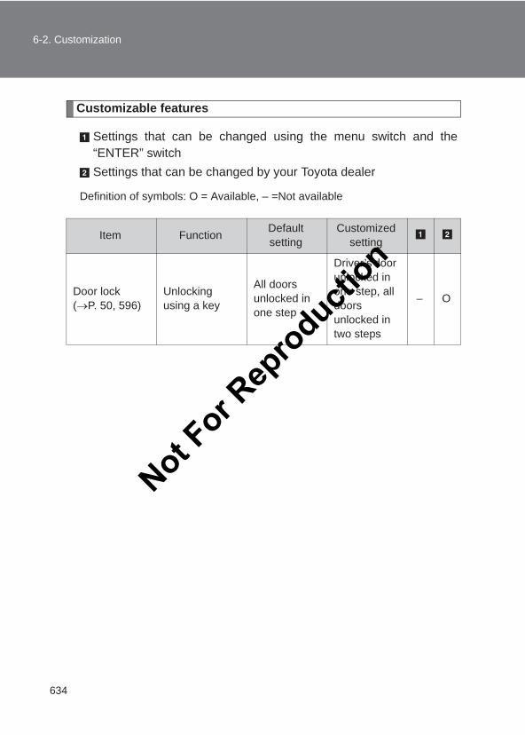
634
6-2. Customization
LC150_OM_OM60J77E_(AE)
Customizable features
Settings that can be changed using the menu switch and the“ENTER” switchSettings that can be changed by your Toyota dealer
Definition of symbols: O = Available, – =Not available
Item Function Default setting
Customized setting
Door lock (→P. 50, 596)
Unlocking using a key
All doors unlocked in one step
Driver’s door unlocked in one step, all doors unlocked in two steps
– O
Not For R
epro
duction
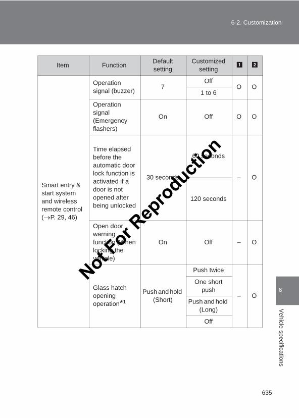
635
6-2. Customization
6
Vehicle specifications
LC150_OM_OM60J77E_(AE)
Smart entry & start system and wireless remote control(→P. 29, 46)
Operation signal (buzzer) 7
OffO O
1 to 6
Operation signal (Emergency flashers)
On Off O O
Time elapsed before the automatic door lock function is activated if a door is not opened after being unlocked
30 seconds
60 seconds
– O
120 seconds
Open door warning function (When locking the vehicle)
On Off – O
Glass hatch opening operation*1
Push and hold (Short)
Push twice
– O
One short push
Push and hold (Long)
Off
Item Function Default setting
Customized setting
Not For R
epro
duction
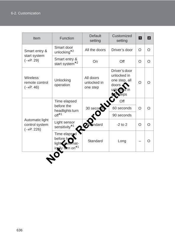
636
6-2. Customization
LC150_OM_OM60J77E_(AE)
Smart entry & start system (→P. 29)
Smart door unlocking*2 All the doors Driver’s door O O
Smart entry & start system*2 On Off O O
Wireless remote control (→P. 46)
Unlocking operation
All doors unlocked in one step
Driver’s door unlocked in one step, all doors unlocked in two steps
O O
Automatic light control system (→P. 226)
Time elapsed before the headlights turn off*1
30 seconds
Off
O O60 seconds
90 seconds
Light sensor sensitivity*1 Standard -2 to 2 O O
Time elapsed before head-lights automat-ically turn on*1
Standard Long – O
Item Function Default setting
Customized setting
Not For R
epro
duction
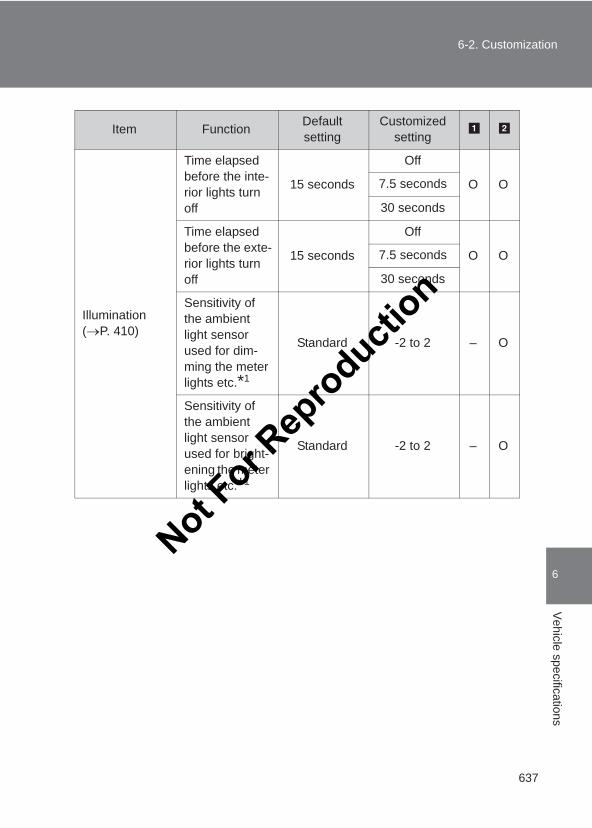
637
6-2. Customization
6
Vehicle specifications
LC150_OM_OM60J77E_(AE)
Illumination(→P. 410)
Time elapsed before the inte-rior lights turn off
15 seconds
Off
O O7.5 seconds
30 seconds
Time elapsed before the exte-rior lights turn off
15 seconds
Off
O O7.5 seconds
30 seconds
Sensitivity of the ambient light sensor used for dim-ming the meter lights etc.*1
Standard -2 to 2 – O
Sensitivity of the ambient light sensor used for bright-ening the meter lights etc.*1
Standard -2 to 2 – O
Item Function Default setting
Customized setting
Not For R
epro
duction
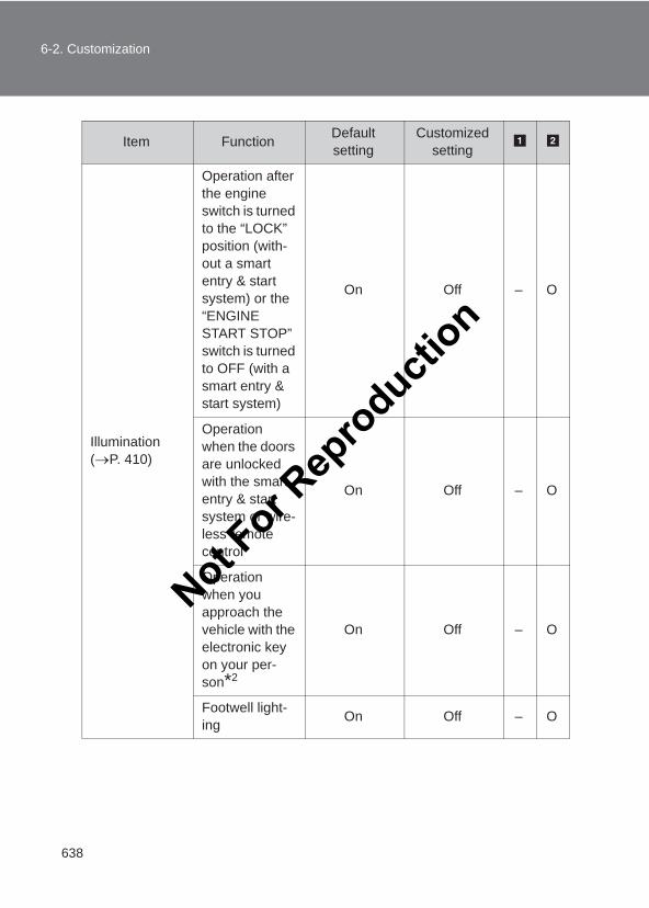
638
6-2. Customization
LC150_OM_OM60J77E_(AE)
Illumination(→P. 410)
Operation after the engine switch is turned to the “LOCK” position (with-out a smart entry & start system) or the “ENGINE START STOP” switch is turned to OFF (with a smart entry & start system)
On Off – O
Operation when the doors are unlocked with the smart entry & start system or wire-less remote control
On Off – O
Operation when you approach the vehicle with the electronic key on your per-son*2
On Off – O
Footwell light-ing On Off – O
Item Function Default setting
Customized setting
Not For R
epro
duction
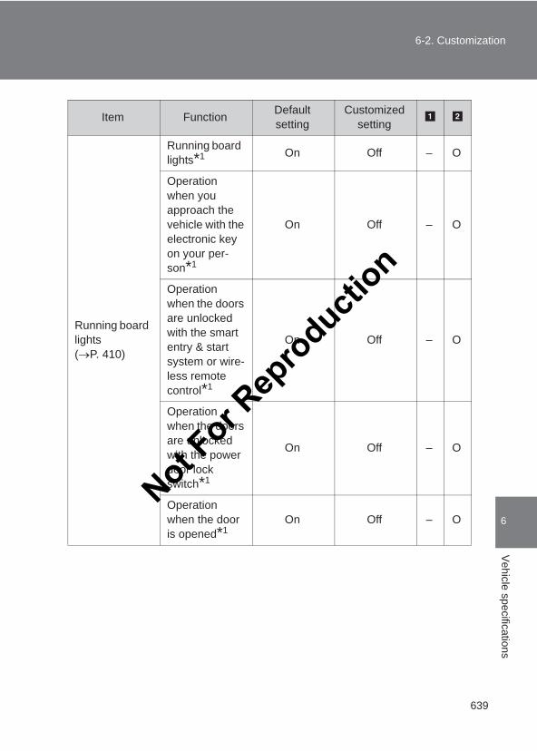
639
6-2. Customization
6
Vehicle specifications
LC150_OM_OM60J77E_(AE)
Running board lights (→P. 410)
Running board lights*1 On Off – O
Operation when you approach the vehicle with the electronic key on your per-son*1
On Off – O
Operation when the doors are unlocked with the smart entry & start system or wire-less remote control*1
On Off – O
Operation when the doors are unlocked with the power door lock switch*1
On Off – O
Operation when the door is opened*1
On Off – O
Item Function Default setting
Customized setting
Not For R
epro
duction
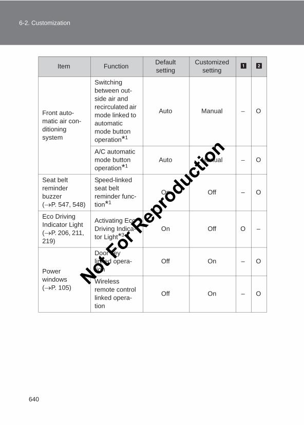
640
6-2. Customization
LC150_OM_OM60J77E_(AE)
Front auto-matic air con-ditioning system
Switching between out-side air and recirculated air mode linked to automatic mode button operation*1
Auto Manual – O
A/C automatic mode button operation*1
Auto Manual – O
Seat belt reminder buzzer (→P. 547, 548)
Speed-linked seat belt reminder func-tion*1
On Off – O
Eco Driving Indicator Light(→P. 206, 211, 219)
Activating Eco Driving Indica-tor Light*3
On Off O –
Power windows (→P. 105)
Door key linked opera-tion
Off On – O
Wireless remote control linked opera-tion
Off On – O
Item Function Default setting
Customized setting
Not For R
epro
duction
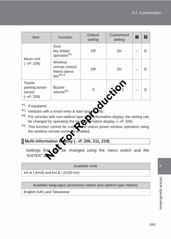
641
6-2. Customization
6
Vehicle specifications
LC150_OM_OM60J77E_(AE)
*1: If equipped.*2: Vehicles with a smart entry & start system only.*3: For vehicles with non-optitron type multi-information display, the setting can
be changed by operating the multi-information display. (→P. 206)*4: This function cannot be customized unless power window operation using
the wireless remote control is enabled.
Multi-information display (→P. 206, 211, 219)
Settings that can be changed using the menu switch and the“ENTER” switch.
Moon roof(→P. 108)
Door key linked operation*1
Off On – O
Wireless remote control linked opera-tion*1,4
Off On – O
Toyota parking assist-sensor (→P. 259)
Buzzer volume*1 3 1 to 5 – O
Available units
km & l (km/l) and km & l (l/100 km)
Available languages (accessory meters and optitron type meters)
English (UK) and Taiwanese
Item Function Default setting
Customized setting
Not For R
epro
duction
642
6-2. Customization
LC150_OM_OM60J77E_(AE)
■ In the following situations, customize mode will automatically beturned off.●A warning message appears after the customize mode screen is dis-
played.
●The “ENGINE START STOP” switch is turned to OFF.
●The vehicle begins to move while the customize mode screen is dis-played.
CAUTION
■Cautions during customizationAs the engine needs to be running during customization, ensure that thevehicle is parked in a place with adequate ventilation. In a closed area suchas a garage, exhaust gases including harmful carbon monoxide (CO) maycollect and enter the vehicle. This may lead to death or a serious health haz-ard.
NOTICE
■During customizationTo prevent battery discharge, ensure that the engine is running while cus-tomizing features.
Not For R
epro
duction
Index
643
LC150_OM_OM60J77E_(AE)
Abbreviation list ...................... 644
Alphabetical index................... 645
What to do if... ......................... 654
For vehicles with a navigation system, refer to the“Navigation System Owner’s Manual” for informationregarding the equipment listed below.
• Navigation system• Air conditioning• Hands-free system (for cellular phone)• Toyota parking assist monitor• Rear view monitor system• Rear seat entertainment system• Audio/video system• Toyota parking assist-sensor• Wide view front & side monitorFor details of information about off-road driving tech-niques and off-road assistance functions, refer to the“Off-road Driving Owner’s Manual”.
Not For R
epro
duction
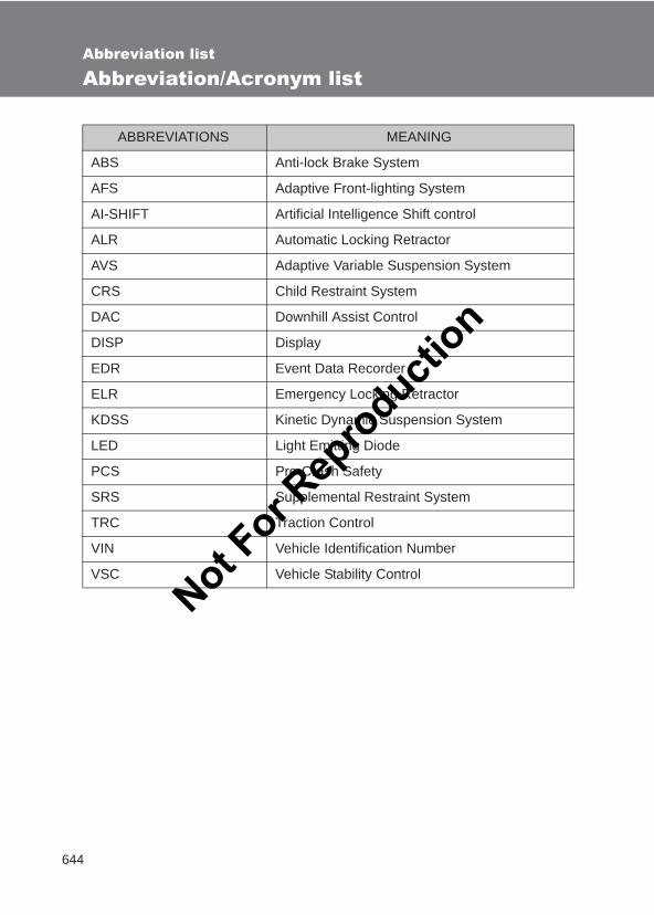
644
LC150_OM_OM60J77E_(AE)
Abbreviation list
Abbreviation/Acronym list
ABBREVIATIONS MEANING
ABS Anti-lock Brake System
AFS Adaptive Front-lighting System
AI-SHIFT Artificial Intelligence Shift control
ALR Automatic Locking Retractor
AVS Adaptive Variable Suspension System
CRS Child Restraint System
DAC Downhill Assist Control
DISP Display
EDR Event Data Recorder
ELR Emergency Locking Retractor
KDSS Kinetic Dynamic Suspension System
LED Light Emitting Diode
PCS Pre-Crash Safety
SRS Supplemental Restraint System
TRC Traction Control
VIN Vehicle Identification Number
VSC Vehicle Stability Control
Not For R
epro
duction
645
LC150_OM_OM60J77E_(AE)
Alphabetical index
Alphabetical index
A/C.....................................314, 320ABS ...........................................281Active head restraint ...........65, 67Active traction control*1.........281Adaptive Front-lighting
System....................................229Adaptive Variable
Suspension System*1
AFS............................................229Air conditioning filter ..............499Airbags
Airbag operating conditions ...........................126
Airbag precautions for your child ............................130
Airbag warning light ..............545General airbag precautions...130Locations of airbags..............123Modification and disposal of
airbags................................134Proper driving posture...121, 130Side and curtain
shield airbags operating conditions ...........................127
Side and curtain shield airbags precautions ............130
SRS airbags..........................123Air conditioning system
Air conditioning filter..............499Front automatic
air conditioning system.......320 Front manual
air conditioning system.......314Rear automatic
air conditioning system.......333Rear manual
air conditioning system.......330
Alarm ........................................ 118Antenna .................................... 343Anti-lock brake system .......... 281Armrest..................................... 445Ashtray ..................................... 436Assist grips .............................. 447Audio system
Antenna ................................ 343Audio input............................ 381AUX port ............................... 381CD player/changer................ 344iPod....................................... 361MP3/WMA disc ..................... 353Optimal use........................... 378Portable music player ........... 381Radio .................................... 341Steering wheel audio
switch ................................. 383Type...................................... 339USB memory ........................ 369
Automatic air conditioning system
Air conditioning filter ............. 499Front automatic
air conditioning system....... 320Rear automatic
air conditioning system....... 333Automatic headlight leveling
system.................................... 231Automatic light control
system.................................... 226Automatic transmission
Automatic transmission......... 187If the shift lever cannot be
shifted from P ..................... 594S mode ................................. 190
AUX port ................................... 381Auxiliary box .................... 425, 452Auxiliary tray............................ 452AVS*1
A
*1: Refer to the “Off-road Driving Owner’s Manual”.
Not For R
epro
duction
646
Alphabetical index
LC150_OM_OM60J77E_(AE)
Back doorBack door................................54Back door child-protector
lock .......................................55Wireless remote control ..........46
Back-up lightsReplacing light bulbs.............525Wattage.................................629
BatteryChecking ...............................483If the vehicle has discharged
battery.................................599Preparing and checking
before winter.......................297Bluetooth®
Mobile phone ........................386Bottle holders/door
pockets...................................420Brake
Fluid ......................................627Parking brake........................196
Brake assist..............................281Brightness control
Instrument panel light control 200Lounge illumination
control.................................413
CareExterior..................................458Interior...................................462Seat belts ..............................463
Card holder...............................417Cargo capacity .........................294Cargo hooks.............................450CD changer...............................344CD player ..................................344Center differential lock*1
Chains.......................................297Child restraint system
Baby seats, definition............135Baby seats, installation .........146
Child seats, definition............ 135Child seats, installation ......... 146Installing CRS with ISOFIX
rigid anchor......................... 153Installing CRS with seat
belts.................................... 147Installing CRS with top
straps.................................. 155Junior seats, definition .......... 135Junior seats, installation ....... 146
Child safetyAirbag precautions................ 130Back door precautions ............ 56Battery precautions....... 483, 603Child restraint system ........... 135Child-protectors ................ 52, 55Glass hatch precaution ........... 61How your child should wear
the seat belt.......................... 95Installing child restraints ....... 146Moon roof precautions .......... 112Power window lock switch .... 105Power window precautions ... 107Removed key battery
precautions......................... 504Seat belt precautions .............. 96Seat heater
precautions......................... 444Child-protectors................... 52, 55Cleaning
Exterior ................................. 458Interior................................... 462Seat belts.............................. 463
Clock......................................... 433Coat hooks ............................... 446Condenser................................ 482Console box ............................. 418Cool box ................................... 428Cooling system
Engine overheating............... 604Crawl Control*1
B
C Not For R
epro
duction
647
Alphabetical index
LC150_OM_OM60J77E_(AE)
Cruise controlCruise control........................242Dynamic radar
cruise control ......................246Cup holder................................421Curtain shield airbags.............123Customizable features ............632
DAC*1
Deck rail....................................450Defogger
Rear window .........................337Side mirrors...........................337
Dimension ................................614Display
Dynamic radar cruise control.................................246
Multi-information display ................206, 211, 219
Trip information .....206, 211, 219Toyota parking
assist-sensor ......................259Warning message.................553
Do-it-yourself maintenance ....468Door courtesy lights
Door courtesy lights ..............410Wattage.................................629
DoorsBack door................................54Back door child-protector
lock .......................................55Door glasses .........................105Door lock.....................29, 46, 50Double locking system..........117Rear door child-protector
lock .......................................52Side doors...............................50Side mirrors...........................102
Downhill Assist Control System*1
Driver’s seat belt reminder light......................................... 547
DrivingCorrect posture ..................... 121Off-road precautions*1
Procedures ........................... 162Winter driving tips ................. 297
Driving position memory .......... 85Dynamic radar cruise
control .................................... 246
EDR (Event data recorder)........ 22Electronic key
If the electronic key does not operate properly ................. 596
Emergency, in case ofIf the electronic key does not
operate properly ................. 596If the engine will not start ...... 592If the shift lever cannot be
shifted from P ..................... 594If the vehicle has discharged
battery ................................ 599If the warning buzzer
sounds................................ 543If the warning light turns on... 543If the warning message is
displayed ............................ 553If you have a flat tire ............ 573If you lose your keys ............. 595If you think something is
wrong.................................. 541If you run out of fuel and
the engine stalls ................. 607If your vehicle becomes
stuck ................................... 608If your vehicle has to be stopped
in an emergency................. 610
D
E
*1: Refer to the “Off-road Driving Owner’s Manual”.
Not For R
epro
duction
648
Alphabetical index
LC150_OM_OM60J77E_(AE)
If your vehicle needs to be towed..................................534
If your vehicle overheats .......604Emergency flashers
Switch ...................................532Engine
Compartment ........................473Engine switch........................179Hood .....................................472How to start the
engine.................................179Identification number.............615If the engine will not start ......592If you run out of fuel and
the engine stalls..................607Ignition switch .......................179Overheating ..........................604
Engine compartment cover ....475Engine coolant
Capacity ................................623Checking ...............................480Preparing and checking
before winter.......................297Engine coolant temperature
gauge......................................198Engine immobilizer system ....117Engine oil
Capacity ................................619Checking ...............................476Preparing and checking
before winter.......................297Engine switch...........................179Engine switch light ..................410Event data recorder (EDR) ........22
Floor mat ..................................448Fluid
Brake.....................................627Power steering ......................627Washer..................................488
Fog lightsReplacing light bulbs............. 521Switch ................................... 232Wattage ................................ 629
Foot well lighting ..................... 410Four-wheel drive system*1
Front fog lightsReplacing light bulbs............. 521Switch ................................... 232Wattage ................................ 629
Front passenger’s seat belt reminder light ........................ 548
Front position lightsReplacing light bulbs............. 522Switch ................................... 226Wattage ................................ 629
Front seatsAdjustment.............................. 64Driving position memory ......... 85
Front turn signal lightsReplacing light bulbs............. 523Switch ................................... 195Wattage ................................ 629
FuelCapacity................................ 618Fuel gauge............................ 198Fuel pump shut off system.... 542Gas station information......... 660If you run out of fuel and
the engine stalls ................. 607Information............................ 630Refueling............................... 113Type...................................... 630
Fuel door .................................. 113Fuel filler door.......................... 113Fuel pump shut off system..... 542Fuses ........................................ 505
Gas station information .......... 660Gauges ..................................... 198Glass hatch ................................ 59
F
G
Not For R
epro
duction

649
Alphabetical index
LC150_OM_OM60J77E_(AE)
Glove box .................................416Glove box light.........................417
Hands-free system (for mobile phone).................386
Head restraintsAdjusting ................................89
Headlight cleaner.....................240Headlights
Adaptive front lighting system ................................229
Discharge headlights precautions.........................529
Replacing light bulbs.....519, 520Switch ...................................226Wattage.................................629
HeatersSeat heaters..........................442Side mirror ............................337
Hill-start assist control*1 ........281Hood..........................................472Hooks
Cargo ....................................450Cargo net ..............................451Coat ......................................446
IdentificationEngine...................................615Vehicle ..................................615
Ignition switch..........................179Ignition switch light .................410Illuminated entry system.........414Inside door handle light ..........410Indicator lights .........................202Inside rear view mirror ............100Instrument panel light
control ....................................200Intercooler ................................482
JackVehicle-equipped jack........... 573
Jack handle .............................. 573
KDSS*1..................................... 281Keyless entry ............................. 46Keys
Electronic key ......................... 26Engine switch........................ 179If you lose your keys ............. 595If your electronic key does
not operate properly ........... 596Key number ............................ 26Keyless entry .......................... 46Keys........................................ 26Mechanical key ....................... 27Wireless remote control key ... 46
Kinetic dynamic suspension system*1 ................................ 281
Knee airbags............................ 123
License plate lightsReplacing light bulbs............. 527Wattage ................................ 629
Light bulbsReplacing.............................. 517Wattage ................................ 629
LightsDoor courtesy lights .............. 410Engine switch light ................ 410Fog light switch ..................... 232Headlights switch.................. 226Inside door handle lights....... 410Interior light list...................... 410Personal/interior light
switch ................................. 412Replacing light bulbs............. 517Running board lights............. 410Shift lever light ...................... 410
H
I
J
K
L
*1: Refer to the “Off-road Driving Owner’s Manual”.
Not For R
epro
duction
650
Alphabetical index
LC150_OM_OM60J77E_(AE)
Turn signal lever ...................195Vanity lights...........................432Wattage.................................629
Luggage cover .........................453
MaintenanceDo-it-yourself maintenance ...468Maintenance data .................614Maintenance requirements ...465
Manual headlight leveling dial ..........................................227
Manual transmission ...............193Meter
Instrument panel light control.................................200
Meters ...................................198Mirrors
Conversation mirror ..............437Inside rear view mirror ..........100Side mirror heater .................337Side mirrors...........................102Vanity mirrors........................432
Moon roof .................................108MP3 disc ...................................353Multi-information
display....................206, 211, 219Multi-terrain ABS*1
Multi-terrain Monitor*1
Multi-terrain Select*1
Odometer..................................198Off road precautions*1
OilEngine oil ..............................476
OpenerBack door................................54Fuel filler door .......................113Hood .....................................472
Outside rear view mirrorsAdjusting and folding.............102Driving position memory .........85
Outside temperature display.................................... 434
Overhead console ................... 425Overheating, Engine................ 604
Parking brake........................... 196PCS ........................................... 287Personal/interior lights
Personal/interior lights .......... 410Switch ................................... 412Wattage ................................ 629
Pollen removal mode .............. 327Power outlet ............................. 438Power steering
Fluid ...................................... 627Power windows........................ 105Pre-Crash Safety system ........ 287
Radiator .................................... 482Radio......................................... 341Rear air conditioning system
Automatic air conditioning system................................ 333
Manual air conditioning system................................ 330
Rear differential lock system*1
Rear height control air suspension*1
Rear seatAdjustment.............................. 68Folding down the second
seatbacks ....................... 73, 74Folding down the third
seats............................... 76, 78Tumbling seats ....................... 71
Rear seat entertainment system*2
Rear step bumper ...................... 56Rear turn signal lights
Replacing light bulbs............. 525Wattage ................................ 629
Rear view monitor system...... 269
M
O
P
R
Not For R
epro
duction
651
Alphabetical index
LC150_OM_OM60J77E_(AE)
Rear window defogger ............337Rear window wiper ..................238Replacing
Key battery............................501Fuses ....................................505Light bulbs.............................517Tires ......................................573
Roof luggage carrier................294
Seat beltsAdjusting the seat belt.............93Automatic Locking
Retractor...............................94Child restraint system
installation...........................146Cleaning and maintaining
the seat belts ......................463Emergency Locking
Retractor...............................94How to wear your seat belt .....92How your child should wear
the seat belt ..........................95Pre-crash seat belts ................94Pregnant women, proper seat
belt use.................................95Reminder light.......................547Seat belt pretensioners ...........93
Seat heaters .............................442Seats
Adjustment ..............................85Adjustment
precautions...........................67Child seats/child restraint
system installation ..............146Cleaning................................462Driver’s seat position
memory.................................85Front seat adjustment .............64Head restraint .........................89
Properly sitting in the seat .... 121Rear seat adjustment.............. 68Seat heaters ......................... 442
Service reminder indicators .............................. 202
Shift leverAutomatic transmission......... 187If the shift lever cannot
be shifted from “P”.............. 594Manual transmission............. 193
Shift lever lighting ................... 410Shift lock system..................... 594Side airbags ............................. 123Side mirror
Adjusting and folding ............ 102Mirror position memory ........... 85
Side turn signal lightsReplacing light bulbs............. 528
Smart entry & start systemAntenna location ..................... 33Entry function.......................... 29Starting the engine................ 179
Spare tireInflation pressure .................. 628Storage location.................... 573
Spark plug ................................ 624Specifications .......................... 614Speedometer............................ 198Steering
Column lock release ............. 184Fluid ...................................... 627
Steering wheelAdjustment.............................. 98Audio switches...................... 383Steering wheel position
memory ................................ 85Stop lights
Replacing light bulbs............. 528Storage compartment ............. 450
S
*1: Refer to the “Off-road Driving Owner’s Manual”.*2: Refer to the “Navigation System Owner’s Manual”.
Not For R
epro
duction
652
Alphabetical index
LC150_OM_OM60J77E_(AE)
Storage feature ........................415Storage precautions ................295Stuck
If your vehicle becomes stuck ...................................608
Sun visors ................................431Sunshade
Roof ......................................109Switch
Engine switch........................179“ENGINE START STOP”
switch..................................179Fog light switch .....................232Ignition switch .......................182Light switches .......................226Power door lock switch ...........50Power window switch............105Rear window wiper and
washer switch .....................238Window lock switch...............105Wipers and washer
switch..........................233, 238
Tachometer ..............................198Tail lights
Replacing light bulbs.............528Switch ...................................226
Talk switch*2............................392Telephone switch*2.................392Theft deterrent system
Alarm.....................................118Engine immobilizer system ...117
Tire inflation pressure .............495Tires
Chains...................................297Checking ...............................492If you have a flat tire..............573Inflation pressure ..................495Replacing ..............................573Rotating tires.........................492Size .......................................628
Snow tires ............................. 297Spare tire .............................. 573
Tools ......................................... 573Towing
Emergency towing ................ 534Trailer towing ........................ 300
Toyota parking assist-sensor ......................... 259
Traction control ....................... 281Trailer towing........................... 300TRC ........................................... 281Trip information
display.................... 206, 211, 219Trip meter ................................. 198
Vanity lightsVanity lights .......................... 432Wattage ................................ 629
Vanity mirrors .......................... 432Vehicle identification
number................................... 615Vehicle stability control .......... 281VSC ........................................... 281
Warning buzzersBrake system................ 543, 559Driver’s seat belt reminder.... 547Front passenger’s seat belt
reminder ............................. 548Fuel system .................. 546, 562Glass hatch........................... 559Open door..................... 547, 558Radar cruise control.............. 561Third power seat ..................... 78Toyota parking
assist-sensor ...................... 561
T
V
W
Not For R
epro
duction
653
Alphabetical index
LC150_OM_OM60J77E_(AE)
Warning lightsAutomatic transmission fluid
temperature ........................546Anti-lock brake system..........545Brake system ........................543Charging system...................544Driver’s seat belt reminder ....547Front passenger’s seat belt
reminder .............................548Fuel system...........................546KDSS ....................................546Low engine oil level...............548Low engine oil pressure ........544Low fuel level ........................547Malfunction indicator lamp ....545Master warning light..............548Open door .............................547Power steering system..........545Pre-crash safety system .......545Slip indicator light..................546Smart entry & start system....549SRS airbags..........................545Timing belt replacement........546
Warning messagesAutomatic transmission fluid
temperature ........................555Brake system ........................559Clutch switch system ............557Crawl control .........................572Engine oil level......................560Engine oil pressure ...............554Four-wheel drive system.......571Glass hatch ...........................559Low fuel level ........................562Moon roof..............................559Open door .............................558Pre-crash brake ....................562Pre-crash safety
system ........................556, 560
Radar cruise control system........................ 557, 561
Rear height control air suspension system............. 555
Smart entry & start system ... 563Steering lock system............. 555Timing belt replacement ....... 560Toyota parking assist.... 556, 561
Warning reflector holder......... 450Washer
Checking............................... 488Preparing and checking
before winter....................... 297Switch ........................... 233, 238
Washing and waxing ............... 458Wheels ...................................... 497Wide view front &
side monitor........................... 273Window glasses ...................... 105Window lock switch ................ 105Windows
Power windows..................... 105Rear window defogger.......... 337Washer ......................... 233, 238
Windshield wipers ................... 233Wireless remote control key
Locking/Unlocking................... 46Replacing the battery............ 501Wireless remote control key ... 46
WMA disc ................................. 353
*2: Refer to the “Navigation System Owner’s Manual”.
Not For R
epro
duction
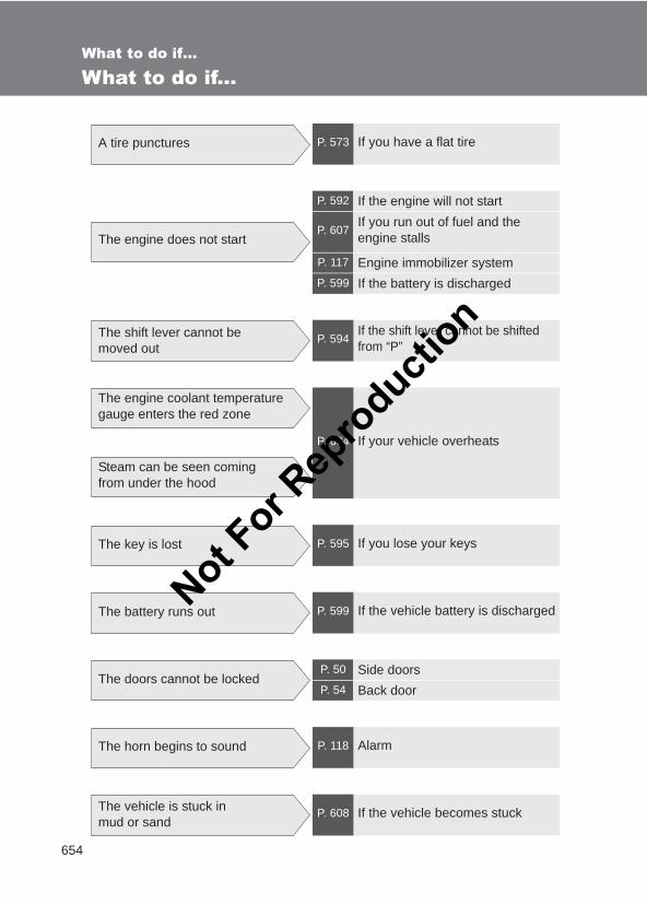
654
LC150_OM_OM60J77E_(AE)
What to do if...
What to do if...
A tire punctures P. 573 If you have a flat tire
The engine does not start
P. 592 If the engine will not start
P. 607If you run out of fuel and the engine stalls
P. 117 Engine immobilizer systemP. 599 If the battery is discharged
The shift lever cannot be moved out
P. 594If the shift lever cannot be shifted from “P”
The engine coolant temperature gauge enters the red zone
Steam can be seen coming from under the hood
P. 604 If your vehicle overheats
The key is lost P. 595 If you lose your keys
The battery runs out P. 599 If the vehicle battery is discharged
The doors cannot be lockedP. 50 Side doorsP. 54 Back door
The horn begins to sound P. 118 Alarm
The vehicle is stuck in mud or sand
P. 608 If the vehicle becomes stuck
Not For R
epro
duction

655
What to do if...
LC150_OM_OM60J77E_(AE)
The warning light or indicator light comes on
P. 543 If a warning light turns on
■ Instrument cluster
Non-Optitron type meters
Optitron type meters
Not For R
epro
duction
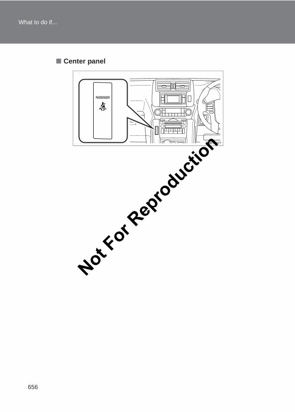
656
What to do if...
LC150_OM_OM60J77E_(AE)
■ Center panel
Not For R
epro
duction
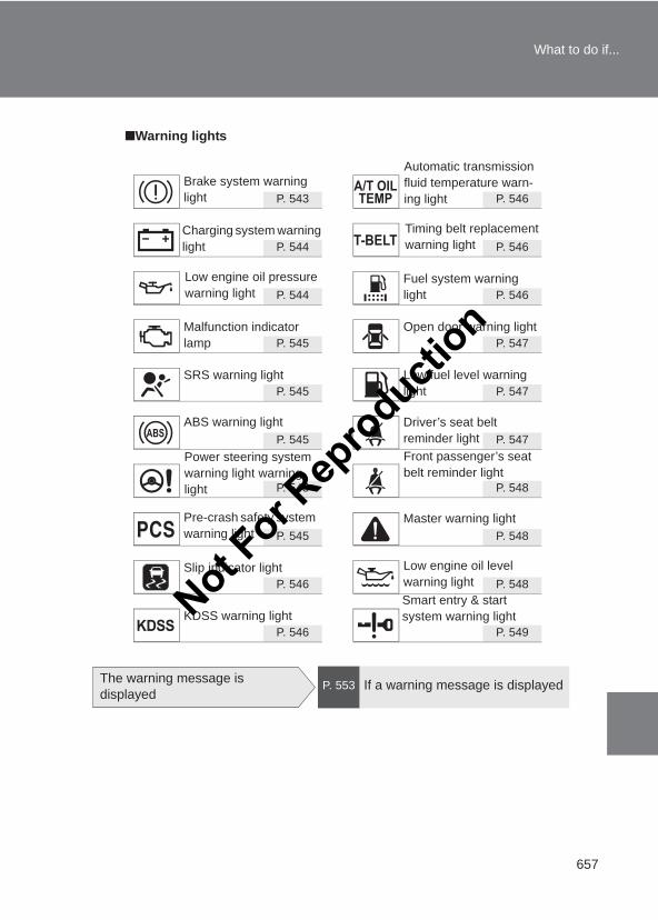
657
What to do if...
LC150_OM_OM60J77E_(AE)
■Warning lights
P. 543 P. 546
P. 544 P. 546
P. 544 P. 546
P. 545 P. 547
P. 545 P. 547
P. 545 P. 547
P. 545 P. 548
P. 545 P. 548
P. 546 P. 548
P. 546 P. 549
Brake system warning light
Charging system warning light
Fuel system warning light
Malfunction indicator lamp
Open door warning light
SRS warning light Low fuel level warning light
ABS warning light Driver’s seat belt reminder light
Master warning light
Slip indicator light Low engine oil level warning light
KDSS warning lightSmart entry & start system warning light
Low engine oil pressure warning light
Power steering system warning light warning light
Pre-crash safety system warning light
Front passenger’s seat belt reminder light
Timing belt replacement warning light
Automatic transmission fluid temperature warn-ing light
The warning message is displayed
P. 553 If a warning message is displayed
Not For R
epro
duction

658
What to do if...
LC150_OM_OM60J77E_(AE)
Not For R
epro
duction

659
What to do if...
LC150_OM_OM60J77E_(AE)
Not For R
epro
duction
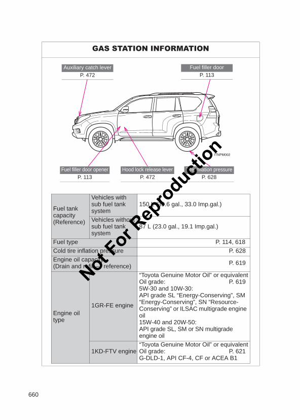
660
LC150_OM_OM60J77E_(AE)
GAS STATION INFORMATION
Fuel filler doorP. 113
Auxiliary catch leverP. 472
Tire inflation pressureP. 628
Fuel filler door openerP. 113
Hood lock release leverP. 472
Fuel tank capacity (Reference)
Vehicles with sub fuel tank system
150 L (39.6 gal., 33.0 Imp.gal.)
Vehicles without sub fuel tank system
87 L (23.0 gal., 19.1 Imp.gal.)
Fuel type P. 114, 618Cold tire inflation pressure P. 628Engine oil capacity (Drain and refill — reference) P. 619
Engine oil type
1GR-FE engine
“Toyota Genuine Motor Oil” or equivalentOil grade: P. 6195W-30 and 10W-30:API grade SL “Energy-Conserving”, SM “Energy-Conserving”, SN “Resource-Conserving” or ILSAC multigrade engine oil15W-40 and 20W-50:API grade SL, SM or SN multigrade engine oil
1KD-FTV engine“Toyota Genuine Motor Oil” or equivalentOil grade: P. 621G-DLD-1, API CF-4, CF or ACEA B1
Not For R
epro
duction
Not For R
epro
duction