pham dang khoa embedded virtualization of a hybrid arm
TRANSCRIPT
PHAM DANG KHOA
SCHOOL OF COMPUTER ENGINEERING
2014
EMBEDDED VIRTUALIZATION OF A HYBRID
ARM - FPGA COMPUTING PLATFORM
2014
A thesis submitted to the Nanyang Technological University
in partial fulfillment of the requirement for the degree of
Master of Engineering
School of Computer Engineering
PHAM DANG KHOA
EMBEDDED VIRTUALIZATION OF A HYBRID
ARM - FPGA COMPUTING PLATFORM
1
Abstract
Embedded virtualization is a promising solution for several big challenges in embedded systems,
such as ECU consolidation, real-time industrial control, software complexity, safety, security and
robustness. However, existing virtualization techniques for embedded systems only consider CPU-based
processing solutions. With the trend towards hybrid computing platforms, virtualizing the conventional
general purpose microprocessor (the software part) without considering the FPGA (the hardware part)
only addresses part of the problem.
This thesis aims to propose a new approach to embedded virtualization by applying the
microkernel-based hypervisor to a hybrid ARM – FPGA platform in order to virtualize both software and
hardware tasks. This work involves firstly porting a traditional microkernel-based hypervisor (in this case
CODEZERO) to an ARM-based dual core processor on a hybrid computing platform (the Xilinx Zynq
7000). We then examine the necessary modifications to the hypervisor’s driver and APIs in order to
support the FPGA hardware of the hybrid platform. An integrated hardware accelerator running on the
FPGA under hypervisor control is developed as a prototype to evaluate the ability and functionality of the
modified hypervisor. In order to compare the performance and hardware utilization of the hypervisor to
Embedded Linux, the context switch overhead and the idle time of the hardware module are examined.
Experimental results are presented that show CODEZERO is able to switch hardware contexts two to
three orders of magnitude faster than that of Embedded Linux.
2
Acknowledgement
I would like to express my deep gratitude to Assoc Prof Dr Douglas Leslie Maskell for his patient
guidance, enthusiastic support and strong encouragement. His widespread experience and strong technical
background helped to clarify my doubts and overcome the hurdles.
I highly appreciate all Asst Prof Dr Suhaib A Fahmy’s help, suggestions and recommendations.
His deep knowledge in reconfigurable computing is very useful for this project.
I would like to thank my friends Cui Jin and Abhishek Kumar Jain in CHiPES for their support
and their help to make me understand the concepts about virtualization, embedded hypervisor and
intermediate fabrics. Moreover, they also help me implement some parts of the hardware platform for this
project.
I also thank to the TUM CREATE for their partial support for this project.
Finally, I wish to thank my parents and my wife for their support and encouragement during my
study.
3
Table of Contents
Abstract ............................................................................................................................................... 1
Acknowledgement .............................................................................................................................. 2
Table of Contents ................................................................................................................................ 3
Table of Figures .................................................................................................................................. 8
Chapter 1 Introduction ................................................................................................................. 12
1.1 Motivation ........................................................................................................................... 12
1.2 Contribution ........................................................................................................................ 13
1.3 Organization ........................................................................................................................ 14
Chapter 2 Background ................................................................................................................. 15
2.1 Definitions and concepts ..................................................................................................... 15
2.1.1 Embedded virtualization ............................................................................................. 15
2.1.2 Hypervisor or virtual machine manager ...................................................................... 15
2.1.3 Para-virtualization versus full-virtualization ............................................................... 16
2.1.4 Microkernel ................................................................................................................. 17
2.1.5 Benefits of virtualization on embedded systems ......................................................... 18
2.1.6 Constraints for embedded virtualization ..................................................................... 22
2.2 Existing virtualization techniques ....................................................................................... 23
2.3 CODEZERO ....................................................................................................................... 26
4
2.3.1 System partitioning by using containers ..................................................................... 27
2.3.2 Communication by IPC and shared memory .............................................................. 29
2.3.3 Virtualization............................................................................................................... 30
2.4 Summary ............................................................................................................................. 31
Chapter 3 Porting CODEZERO on ZedBoard ............................................................................. 32
3.1 Virtualizing the Xilinx Zynq 7000 extensible processing platform .................................... 32
3.2 Booting CODEZERO on the ZedBoard .............................................................................. 35
3.2.1 The overall boot sequence ........................................................................................... 35
3.2.2 CODEZERO’s folder structure and final image layout .............................................. 37
3.2.3 CODEZERO loader porting ........................................................................................ 41
3.2.4 CODEZERO kernel initialization porting ................................................................... 42
3.3 CODEZERO port detail ...................................................................................................... 46
3.3.1 Zynq 7000 base address definitions ............................................................................ 46
3.3.2 Rewriting the drivers ................................................................................................... 46
3.3.3 Enabling the MMU ..................................................................................................... 49
3.3.4 Secondary CPU wake-up and FPGA clock initialization ............................................ 51
3.4 Summary ............................................................................................................................. 52
Chapter 4 SW-HW virtualization platform .................................................................................. 53
4.1 Platform framework ............................................................................................................ 53
4.1.1 Overview ..................................................................................................................... 53
4.1.2 The hybrid platform .................................................................................................... 54
5
4.1.2.1 Task communication .............................................................................................. 55
4.1.2.2 Context Frame Buffer ............................................................................................ 56
4.1.2.3 Context sequencer .................................................................................................. 56
4.1.2.4 Reconfigurable Fabric ............................................................................................ 57
4.1.2.4.1 Reconfigurable Intermediate Fabric [26] ........................................................ 57
4.1.2.4.2 DPR region ..................................................................................................... 60
4.1.3 The hypervisor support ............................................................................................... 60
4.2 The hybrid platform hypervisor .......................................................................................... 60
4.2.1 Device driver for the IF ............................................................................................... 61
4.2.2 API for task communication ....................................................................................... 61
4.2.3 Hardware task scheduling and context switching ....................................................... 62
4.2.3.1 Non-preemptive hardware context switching ........................................................ 62
4.2.3.2 Pre-emptive hardware context switching ............................................................... 63
4.3 Case study ........................................................................................................................... 64
4.3.1 Systolic FIR Filter ....................................................................................................... 64
4.3.2 Matrix Multiplication .................................................................................................. 65
4.3.3 Multiple SW-HW tasks on the ZedBoard ................................................................... 66
4.4 Experiment .......................................................................................................................... 67
4.4.1 Experiment 1 ............................................................................................................... 68
4.4.1.1 Purpose................................................................................................................... 68
4.4.1.2 Method ................................................................................................................... 68
6
4.4.1.3 Results and explanations ........................................................................................ 70
4.4.2 Experiment 2 ............................................................................................................... 71
4.4.2.1 Purpose................................................................................................................... 71
4.4.2.2 Method ................................................................................................................... 72
4.4.2.3 Results and explanations ........................................................................................ 73
4.5 Summary ............................................................................................................................. 74
Chapter 5 Conclusion and Future Work ...................................................................................... 75
5.1 Conclusion .......................................................................................................................... 75
5.2 Future work ......................................................................................................................... 76
Appendix A CODEZERO on PandaBoard .................................................................................... 78
A.1 Introduction to the PandaBoard ...................................................................................... 78
A.2 Compiling CODEZERO to the PandaBoard ................................................................... 79
A.3 CODEZERO’s boot sequence ......................................................................................... 82
A.4 Bare-metal applications on CODEZERO ....................................................................... 83
A.4.1 How to configure a bare-metal application on CODEZERO ...................................... 83
A.4.2 Hello-world application .............................................................................................. 84
A.4.3 Timer, interrupt & context switch: .............................................................................. 84
A.5 GPOS (Linux) implementation on CODEZERO ............................................................ 85
A.6 RTOS implementation on CODEZERO ......................................................................... 86
A.7 Multiple applications running on CODEZERO .............................................................. 88
A.7.1 Two hello-world applications ..................................................................................... 89
7
A.7.2 Context switch + Linux ............................................................................................... 89
A.7.3 Linux and Android ...................................................................................................... 90
A.8 Summary ......................................................................................................................... 93
References ......................................................................................................................................... 94
8
Table of Figures
Figure 1. Type 1 (bare-metal) and Type 2 (hosted) hypervisor ........................................................ 16
Figure 2. Para-virtualized Linux ....................................................................................................... 17
Figure 3. Monolithic-kernel based OS versus microkernel based OS .............................................. 18
Figure 4. Primary VM + Backup VM ............................................................................................... 19
Figure 5. Infotainment VM + Automotive VM ................................................................................ 20
Figure 6. General purpose VM + Legacy VM .................................................................................. 21
Figure 7. Personal VM + Enterprise VM .......................................................................................... 21
Figure 8. PikeOS's structure ............................................................................................................. 24
Figure 9. OKL4's structure ............................................................................................................... 24
Figure 10. NOVA's structure ............................................................................................................ 25
Figure 11. CODEZERO's structure [12] ........................................................................................... 27
Figure 12. CODEZERO's containers ................................................................................................ 28
Figure 13. Capabilities inside a container ......................................................................................... 29
Figure 14. Inter-process communication inside and between containers ......................................... 30
Figure 15. Para-virtualized Linux on CODEZERO .......................................................................... 31
Figure 16. Zynq 7000's organization [23] ......................................................................................... 33
Figure 17. Initial idea for SW-HW virtualization platform .............................................................. 34
Figure 18. Boot sequence of the ZedBoard ...................................................................................... 36
Figure 19. The stage 2 boot .............................................................................................................. 37

9
Figure 20. CODEZERO's boot sequence .......................................................................................... 38
Figure 21. CODEZERO’s shortened folder structure ....................................................................... 38
Figure 22. CODEZERO final image layout on ZedBoard ................................................................ 39
Figure 23. Kernel and Loader start addresses configuration ............................................................ 40
Figure 24. Container memory area configuration ............................................................................. 40
Figure 25. CODEZERO's detail folder and file structure ................................................................. 41
Figure 26. CODEZERO's platform initialization ............................................................................. 45
Figure 27. The UART starts on ZedBoard ....................................................................................... 48
Figure 28. MMU enable routine ....................................................................................................... 50
Figure 29. MMU enables on the ZedBoard ...................................................................................... 51
Figure 30. The CPU1 wakes up on ZedBoard .................................................................................. 52
Figure 31. Block Diagram of the Hybrid Computing Platform [26] ................................................ 54
Figure 32. Block Diagram of the Reconfigurable Region [26] ......................................................... 55
Figure 33. State machine based Context Sequencer [26].................................................................. 57
Figure 34. Block Diagram of the Intermediate Fabric [26] .............................................................. 58
Figure 35. The CB's organization ..................................................................................................... 58
Figure 36. The PE's organization ...................................................................................................... 59
Figure 37. Multiple Hardware and Software Task Scheduling [26] ................................................. 64
Figure 38. Systolic FIR filter and its mapping to the IF [26] ........................................................... 65
Figure 39. Matrix Multiplication and its mapping to the IF [26] ...................................................... 66
Figure 40. Pseudo-code for IF configuration [26] ............................................................................ 67
10
Figure 41. A Hardware Task's organization ..................................................................................... 68
Figure 42. 2 HW tasks on one core (Scenario 1) and 2 HW tasks on separated cores (Scenario 2) . 69
Figure 43. Lock with contention ....................................................................................................... 69
Figure 44. Hardware Tasks run on CODEZERO and Embedded Linux .......................................... 71
Figure 45. IF's Idle Time .................................................................................................................. 72
Figure 46. Hardware Tasks mapping on Linux ................................................................................ 73
Figure 47. Linux runs as a Guest OS on CODEZERO ..................................................................... 76
Figure 48. Pre-emptive hardware context switching ........................................................................ 77
Figure 49. PandaBoard ..................................................................................................................... 79
Figure 50. CODEZERO overall configuration ................................................................................. 80
Figure 51. CODEZERO kernel configuration .................................................................................. 80
Figure 52. CODEZERO "Linux" container configuration ................................................................ 81
Figure 53. CODEZERO configuration UI ........................................................................................ 81
Figure 54. CODEZERO boot sequence ............................................................................................ 82
Figure 55. CODEZERO boots on PandaBoard................................................................................. 83
Figure 56. Bare-metal's application configuration ............................................................................ 84
Figure 57. CODEZERO kernel starts and its container displays the messeage "Hello World!" ...... 84
Figure 58. The context switch application starts and runs ................................................................ 85
Figure 59. Linux starts running on CODEZERO ............................................................................. 86
Figure 60. The µC/OS-II application starts creating many tasks in different priorities .................... 87
Figure 61. Created tasks start executing ........................................................................................... 87
11
Figure 62. The µC/OS-II’s scheduler switches amongst running tasks. Task with higher priority
appears more frequently by pre-empting other lower tasks ........................................................................ 88
Figure 63. The overall configuration for two applications on CODEZERO .................................... 88
Figure 64. The container configuration for the first “Linux” application (physical area from
0x80000000 to 0x9d000000) ...................................................................................................................... 89
Figure 65. The container configuration for the second “Hello-world” application (physical area
from 0x9d000000 to 0xa0000000) .............................................................................................................. 89
Figure 66. Two different containers of CODEZERO can start and display messages ..................... 89
Figure 67. The “Linux” application is booting in one container while timer interrupts and context
switches happen in the other container ....................................................................................................... 90
Figure 68.The “Android” and “Linux” applications can start in two different containers of
CODEZERO ............................................................................................................................................... 91
Figure 69. The “Android” starts and is displayed on the HDMI screen ........................................... 91
Figure 70. The VNC application is used to switch between “Android” and “Linux” ...................... 92
Figure 71. The VNC application on “Android” ................................................................................ 92
Figure 72. The “Linux” appears on the HDMI screen after switching from “Android” .................. 93
12
Chapter 1
Introduction
1.1 Motivation
Motor vehicles today have a large number of electronic components, which control many parts of
the car, such as the engine, brake assist system, airbag system, suspension system, information system,
etc. Nowadays, more than 100 electronic control units (ECUs) are being used in a top end car. However,
those ECUs just share a 20% mix of the automotive control system, while the other 80% is in charge of
mechanical and hydraulic components and connections which link control components (e.g. gears, pedals
and steering wheels) to the steering column and drive shafts, etc. In order to reduce system costs, one of
the long term goals is to integrate many of the mechanical/hydraulic components to unified-
electrical/electronic ones. However, the complexity of the user’s requirements contributes to the increase
in the number of ECUs since implementing new and complex functions needs additional ECUs, causing a
cost increment, more power consumption, more heat dissipation, and more space consumption (e.g.
communication). The introduction of multicore and hybrid architectures, such as FPGA-based
reconfigurable computing, has resulted in the automobile industry proposing ECU consolidation [1-3] as
a means to reduce some of these detrimental effects. ECU consolidation uses a (or several) centralized
multicore processor(s) to replace many of the distributed ECUs.
ECU consolidation does have its own problems, in terms of robustness, determinism, predictability
and dependability, particularly when the centralized multi-core executes both real-time tasks and common
applications (such as entertainment or navigation) at the same time. To overcome this issue, the
virtualization technique is considered, so that both real-time and non-critical applications can run in an
isolated environment (i.e. separate operating systems (OS) with separate memory areas) on the same
physical centralized computing platform. Moreover, as more computational intensive applications (e.g.
intelligent driving, multi-media and network applications) are integrated into high end cars, the
computational requirements increase. As a result, hardware accelerators for these applications can be
adopted in the centralized platform to enhance the performance and processing abilities. Therefore, the
13
virtualization system should also be able to manage the reconfigurable logic to implement multiple
hardware accelerators by taking advantage of a software-hardware (SW-HW) hybrid computing platform
which contains a multi-core processor and an FPGA.
There are several existing embedded hypervisors or virtual machine managers on the market, some
of which are certified for hard real-time systems. However, all of those hypervisors only virtualize the
conventional general purpose microprocessor (the software part) without considering the FPGA (the
hardware part). Thus, FPGA virtualization (e.g. FPGA resource abstraction, the general hardware
accelerator interface, etc.) and its integration into a current hypervisor are important for ECU
consolidation using a hybrid computing platform, and are the focus of this research project.
In this project we examine existing virtualization techniques for both conventional microprocessor
based systems and for FPGA systems. Moreover, reliable and secure techniques for incorporating FPGA
reconfiguration for application acceleration into the virtualized computing space will need to be
developed. This includes both hardware designs on FPGA and software abstractions inside the
hypervisor. Analysis of hardware virtualization using various benchmarks will be used to examine the
hardware-dependent impact and to identify deficiencies, and hence develop approaches to further improve
the hardware virtualization.
1.2 Contribution
This thesis proposes a new approach to embedded virtualization by applying the microkernel-based
hypervisor to the hybrid ARM – FPGA platform. It includes a modification of the microkernel-based
hypervisor to the hybrid platform and support for an FPGA hardware accelerator for compute intensive
applications. Based on examining, evaluating and analyzing the basic functionalities of CODEZERO, a
specific hypervisor, we show how to manage the FPGA resources using a traditional hypervisor. That is
to schedule a hardware task and to perform hardware context switching. Moreover, an FPGA hardware
accelerator which can support the hardware context switch is developed. A prototype of the modified
hypervisor and some preliminary experiments are then presented.
Part of the work carried out in this thesis has been published in [26].
14
1.3 Organization
In Chapter 2, a review of technical terminologies is presented in terms of embedded virtualization,
microkernel, and hybrid platforms. Some user cases will be introduced to answer the question: why do we
need to use the embedded virtualization technique? Moreover, some existing embedded hypervisors will
be reviewed.
Chapter 3 describes the CODEZERO porting to the Xilinx Zynq 7000 platform (ZedBoard). The
boot sequence of CODEZERO on the ZedBoard and some highlights of the porting work are discussed
further.
The new hybrid platform for virtualizing both hardware and software components is presented in
Chapter 4. Further modifications to CODEZERO to support the FPGA part of the hybrid platform are
described. Experiments are performed to compare the performance between applications running on
CODEZERO and on Embedded Linux. These results are presented and discussed.
The conclusions and recommendations for future work are given in Chapter 5.
15
Chapter 2
Background
2.1 Definitions and concepts
2.1.1 Embedded virtualization
Virtualization on embedded systems has gained momentum since the appearance of the Motorola
Evoke [4] in April 2009. Although virtualization on desktops and servers is mature, virtualization on
embedded systems is not common, but is growing quickly. Due to their limited resources, virtualization
on embedded systems needs different approach techniques from virtualization on desktops or servers.
Embedded systems may use a real-time OS for embedded real-time applications, a general purpose OS for
user interfaces and non-critical computing, or have no operating system at all. A server or desktop system
just needs to run many virtual copies of the same or a similar OS, such as Linux or Windows [5].
Embedded virtualization is a more complex, but promising solution for more complex embedded systems,
such as ECU consolidation, real-time industrial control, software complexity, safety, security and
robustness, etc.
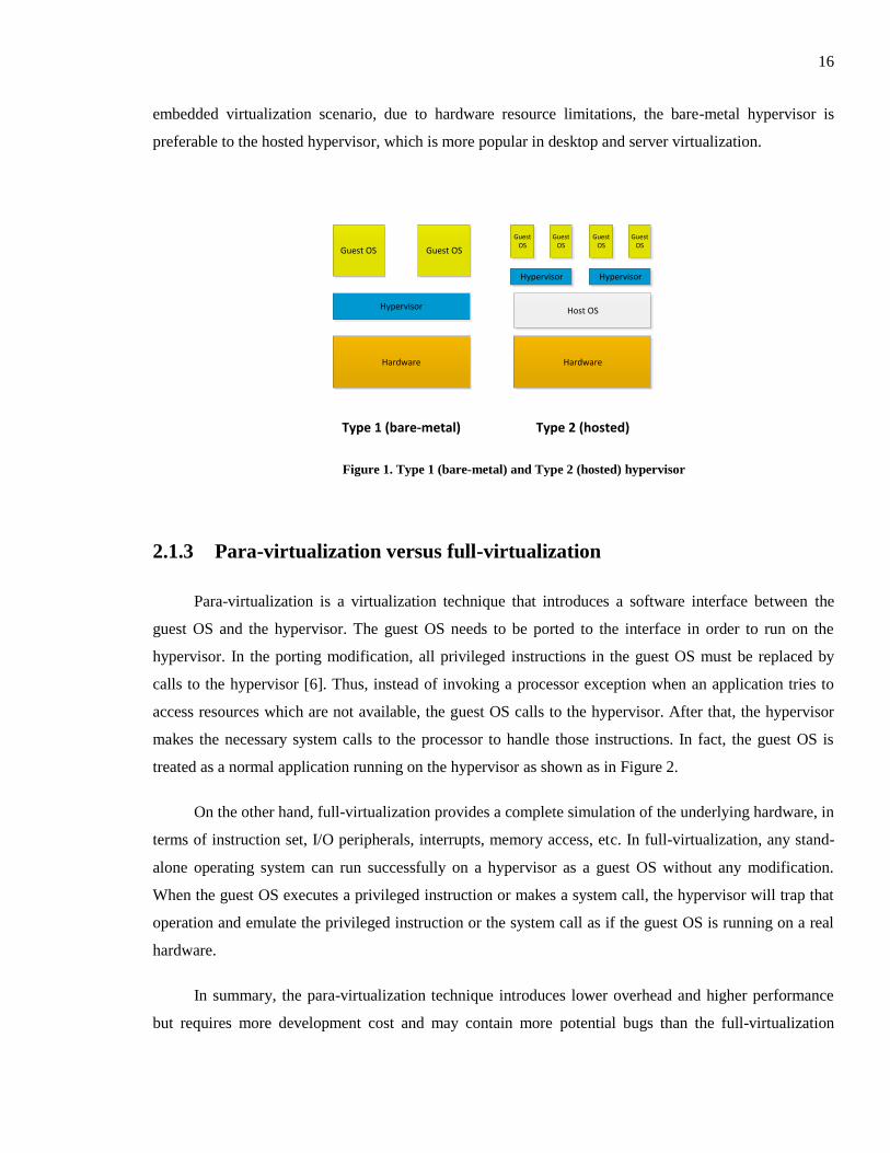
2.1.2 Hypervisor or virtual machine manager
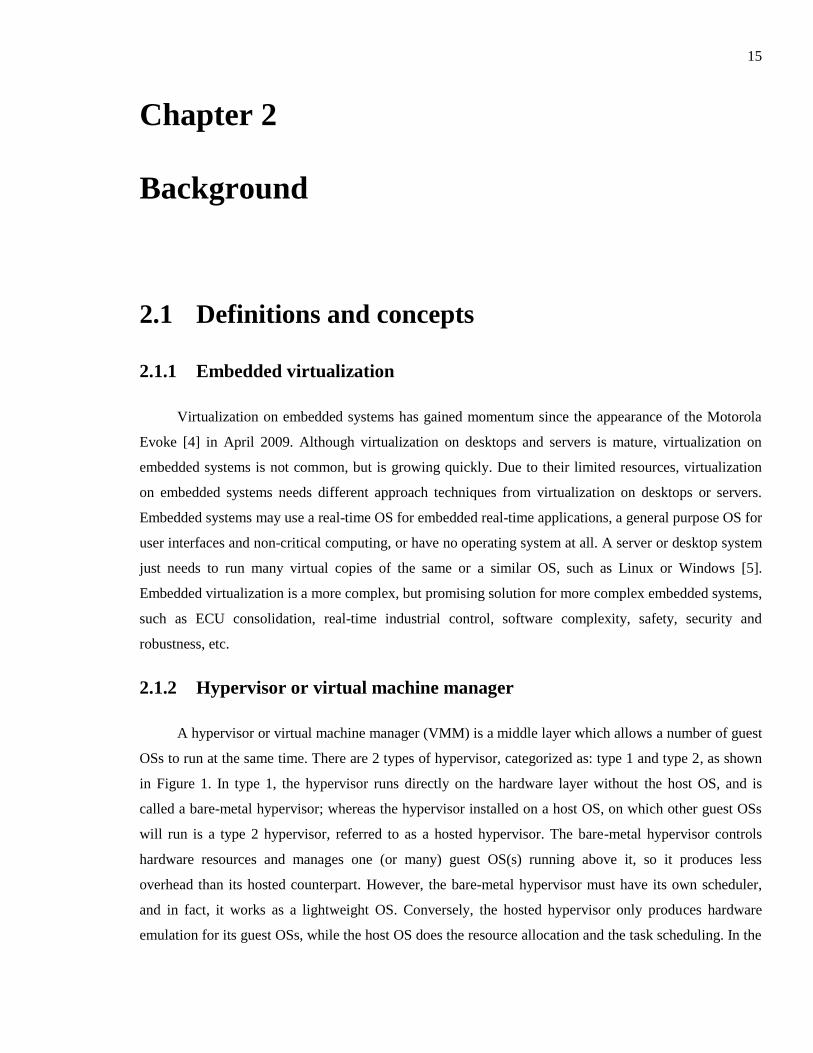
A hypervisor or virtual machine manager (VMM) is a middle layer which allows a number of guest
OSs to run at the same time. There are 2 types of hypervisor, categorized as: type 1 and type 2, as shown
in Figure 1. In type 1, the hypervisor runs directly on the hardware layer without the host OS, and is
called a bare-metal hypervisor; whereas the hypervisor installed on a host OS, on which other guest OSs
will run is a type 2 hypervisor, referred to as a hosted hypervisor. The bare-metal hypervisor controls
hardware resources and manages one (or many) guest OS(s) running above it, so it produces less
overhead than its hosted counterpart. However, the bare-metal hypervisor must have its own scheduler,
and in fact, it works as a lightweight OS. Conversely, the hosted hypervisor only produces hardware
emulation for its guest OSs, while the host OS does the resource allocation and the task scheduling. In the
16
embedded virtualization scenario, due to hardware resource limitations, the bare-metal hypervisor is
preferable to the hosted hypervisor, which is more popular in desktop and server virtualization.
Hardware
Hypervisor
Guest OSGuest OS
Hardware
Hypervisor
Guest OS
Guest OS
Host OS
Hypervisor
Guest OS
Guest OS
Type 1 (bare-metal) Type 2 (hosted)
Figure 1. Type 1 (bare-metal) and Type 2 (hosted) hypervisor
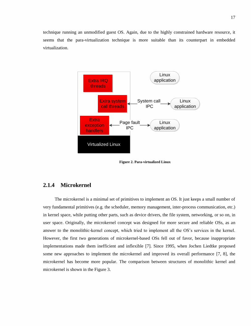
2.1.3 Para-virtualization versus full-virtualization
Para-virtualization is a virtualization technique that introduces a software interface between the
guest OS and the hypervisor. The guest OS needs to be ported to the interface in order to run on the
hypervisor. In the porting modification, all privileged instructions in the guest OS must be replaced by
calls to the hypervisor [6]. Thus, instead of invoking a processor exception when an application tries to
access resources which are not available, the guest OS calls to the hypervisor. After that, the hypervisor
makes the necessary system calls to the processor to handle those instructions. In fact, the guest OS is
treated as a normal application running on the hypervisor as shown as in Figure 2.
On the other hand, full-virtualization provides a complete simulation of the underlying hardware, in
terms of instruction set, I/O peripherals, interrupts, memory access, etc. In full-virtualization, any stand-
alone operating system can run successfully on a hypervisor as a guest OS without any modification.
When the guest OS executes a privileged instruction or makes a system call, the hypervisor will trap that
operation and emulate the privileged instruction or the system call as if the guest OS is running on a real
hardware.
In summary, the para-virtualization technique introduces lower overhead and higher performance
but requires more development cost and may contain more potential bugs than the full-virtualization
17
technique running an unmodified guest OS. Again, due to the highly constrained hardware resource, it
seems that the para-virtualization technique is more suitable than its counterpart in embedded
virtualization.
Virtualized Linux
Extra IRQ
threads
Extra system
call threads
Extra
exception
handlers
Linux
application
Linux
application
Linux
application
System call
IPC
Page fault
IPC
Figure 2. Para-virtualized Linux
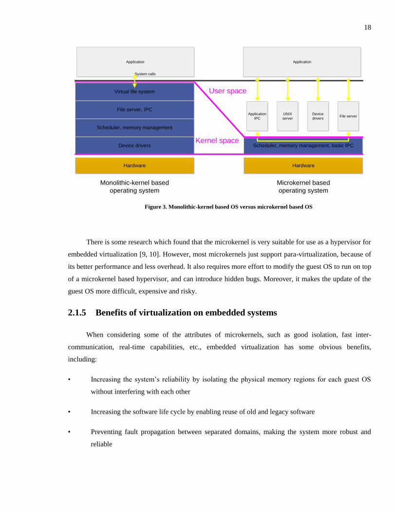
2.1.4 Microkernel
The microkernel is a minimal set of primitives to implement an OS. It just keeps a small number of
very fundamental primitives (e.g. the scheduler, memory management, inter-process communication, etc.)
in kernel space, while putting other parts, such as device drivers, the file system, networking, or so on, in
user space. Originally, the microkernel concept was designed for more secure and reliable OSs, as an
answer to the monolithic-kernel concept, which tried to implement all the OS’s services in the kernel.
However, the first two generations of microkernel-based OSs fell out of favor, because inappropriate
implementations made them inefficient and inflexible [7]. Since 1995, when Jochen Liedtke proposed
some new approaches to implement the microkernel and improved its overall performance [7, 8], the
microkernel has become more popular. The comparison between structures of monolithic kernel and
microkernel is shown in the Figure 3.
18
Hardware
Scheduler, memory management, basic IPC
Application
IPC
Device
driversFile server
UNIX
server
Hardware
Device drivers
Scheduler, memory management
File server, IPC
Virtual file system
Application
System calls
Kernel space
User space
Monolithic-kernel based
operating system
Microkernel based
operating system
Application
Figure 3. Monolithic-kernel based OS versus microkernel based OS
There is some research which found that the microkernel is very suitable for use as a hypervisor for
embedded virtualization [9, 10]. However, most microkernels just support para-virtualization, because of
its better performance and less overhead. It also requires more effort to modify the guest OS to run on top
of a microkernel based hypervisor, and can introduce hidden bugs. Moreover, it makes the update of the
guest OS more difficult, expensive and risky.
2.1.5 Benefits of virtualization on embedded systems
When considering some of the attributes of microkernels, such as good isolation, fast inter-
communication, real-time capabilities, etc., embedded virtualization has some obvious benefits,
including:
• Increasing the system’s reliability by isolating the physical memory regions for each guest OS
without interfering with each other
• Increasing the software life cycle by enabling reuse of old and legacy software
• Preventing fault propagation between separated domains, making the system more robust and
reliable
19
• Enabling efficient task scheduling and intercommunication between guest OSs
• Reducing hardware cost, software complexity and power consumption
Some of embedded virtualization’s practical examples are listed below.
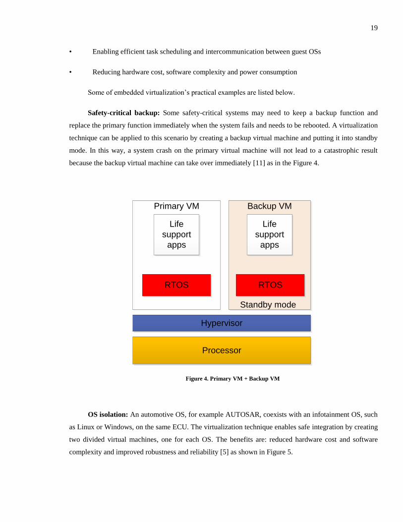
Safety-critical backup: Some safety-critical systems may need to keep a backup function and
replace the primary function immediately when the system fails and needs to be rebooted. A virtualization
technique can be applied to this scenario by creating a backup virtual machine and putting it into standby
mode. In this way, a system crash on the primary virtual machine will not lead to a catastrophic result
because the backup virtual machine can take over immediately [11] as in the Figure 4.
Processor
Hypervisor
RTOS
Life
support
apps
Primary VM Backup VM
RTOS
Life
support
apps
Standby mode
Figure 4. Primary VM + Backup VM
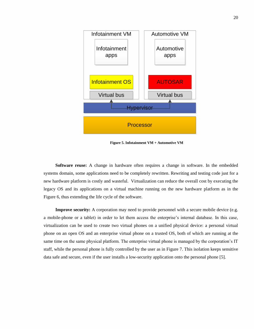
OS isolation: An automotive OS, for example AUTOSAR, coexists with an infotainment OS, such
as Linux or Windows, on the same ECU. The virtualization technique enables safe integration by creating
two divided virtual machines, one for each OS. The benefits are: reduced hardware cost and software
complexity and improved robustness and reliability [5] as shown in Figure 5.
20
Processor
Hypervisor
Infotainment OS AUTOSAR
Infotainment
apps
Automotive
apps
Infotainment VM Automotive VM
Virtual bus Virtual bus
Figure 5. Infotainment VM + Automotive VM
Software reuse: A change in hardware often requires a change in software. In the embedded
systems domain, some applications need to be completely rewritten. Rewriting and testing code just for a
new hardware platform is costly and wasteful. Virtualization can reduce the overall cost by executing the
legacy OS and its applications on a virtual machine running on the new hardware platform as in the
Figure 6, thus extending the life cycle of the software.
Improve security: A corporation may need to provide personnel with a secure mobile device (e.g.
a mobile-phone or a tablet) in order to let them access the enterprise’s internal database. In this case,
virtualization can be used to create two virtual phones on a unified physical device: a personal virtual
phone on an open OS and an enterprise virtual phone on a trusted OS, both of which are running at the
same time on the same physical platform. The enterprise virtual phone is managed by the corporation’s IT
staff, while the personal phone is fully controlled by the user as in Figure 7. This isolation keeps sensitive
data safe and secure, even if the user installs a low-security application onto the personal phone [5].

21
Processor
Hypervisor
GPOS Legacy RTOS
GUIsLegacy
apps
GP VM Legacy VM
Figure 6. General purpose VM + Legacy VM
Processor
Hypervisor
Open OS Trusted OS
Personal
apps
Enterprise
apps
Personal VM Enterprise VM
Figure 7. Personal VM + Enterprise VM
22
2.1.6 Constraints for embedded virtualization
There are a number of constraints imposed on an embedded hypervisor.
Code size: The code size of an embedded hypervisor must be small due to the limited memory in
most embedded systems. Some popular embedded hypervisors are only around ten thousand lines of code
[12]. A bigger size means the system needs more memory, leading to more hardware cost and more
power consumption. In addition, for safety-critical systems, which need to have every line of code
analyzed by experts, a bigger size means more expense and a bigger potential threat. Server hypervisors
usually have several million lines of code, and are not suitable for embedded systems. The code size
requirement is one of the most important reasons why the microkernel is preferable as an embedded
hypervisor.
Determinism and latency: Some applications running on an embedded hypervisor are real-time
applications. These applications not only need to be responded to quickly, but also within a bounded time.
Therefore, the embedded hypervisor must be able to handle an interrupt within a very short time, as well
as execute its internal operations within a deterministic time [13].
Security: With the small code size, an embedded hypervisor can easily be validated and shown to
be bug free [14]. Some hypervisor vendors have certifications to show that their products are bug free.
This is very important because some of the applications of embedded virtualization are safety-critical
systems that could cause catastrophic damage when a failure occurs. The microkernel approach is very
helpful in keeping the hypervisor simple and small, because it outsources most of the complex and less
trusted system parts to user space. Thus, the microkernel is the minimal portion running in privileged
mode, conducting processor and memory management, and serving as the trusted computing base (TCB).
Isolation: The ability to isolate a guest OS from another one is also essential for a microkernel-
based hypervisor. This way, it not only prevents fault propagation from one domain to another, but also
improves the security and reliability of the whole systems. In a microkernel-based hypervisor, each guest
OS will be allocated to a typical memory space and only privileged (kernel controlled) inter-process
communication (IPC) can be used to communicate cross-domain.
Communication: The isolation and security requirements for a microkernel-based hypervisor need
a secure and efficient mechanism to communicate between different domains or guest OSs residing in
divided memory spaces. Without this communication mechanism, the hypervisor cannot share or
synchronize data between multi-tasks, threads or guest OSs.

23
Scheduling: Embedded virtualization has two levels of scheduling. The first scheduling level is in
the guest OS to schedule tasks running on it. The second is in the microkernel to choose which virtual
machine or guest OS will be run. There are two commonly used algorithms for the microkernel’s
scheduler: round-robin and fixed priority. The later one is to support real-time capability, which allows a
critical task in a higher priority domain to run whenever it is available.
2.2 Existing virtualization techniques
There are a number of commercial embedded virtualization products currently available.
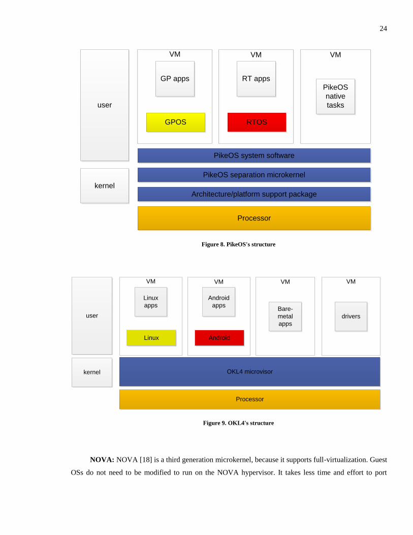
PikeOS: One of the most popular microkernel-based hypervisors is PikeOS [15], which is used
widely for some safety-critical applications in the avionics industry. The PikeOS’ structure is shown in
Figure 8. With embedded virtualization, old and legacy applications can coexist with later applications on
the same hardware platform, but in separated virtual machines. PikeOS supports a number of
architectures, including ARM, x86, PowerPC, SuperH, etc… A number of guest OSs, application
programming interfaces and runtime environments, for example PikeOS native interfaces, Linux,
Android, ARINC 653 APEX, POSIX, Real-time Java are supported by PikeOS. As PikeOS uses the
para-virtualization technique, guest OSs need to be modified from their original versions to run in a
PikeOS virtual machine. Although widely used in the avionics industry, PikeOS is actively targeting the
automobile industry. COQOS [16], which can virtualize both Android and AUTOSAR on the same
platform, is a commercial product based on the PikeOS structure.
OKL4: OKL4 [17] was developed by Open Kernel Labs (OK Labs). This product is very popular
in the consumer electronics area. It focuses on security applications to create more secure devices used in
business mobile phones, set-top-boxes or network routers. As with other products in the L4 family, OKL4
only supports the para-virtualization technique. It means that guest OSs such as Linux, Android, etc.,
must be adapted in order to run on top of OKL4. Many guest OSs have been released by OK Labs,
including, OK:Linux, OK:Android and OK:Symbian. However, till now, there is no industrial example
which uses the OKL4 microkernel for safety-critical applications. The structure of OKL4 is summarized
in Figure 9.
24
Processor
PikeOS system software
RTOS
RT appsPikeOS
native
tasks
VM VM
GPOS
GP apps
VM
PikeOS separation microkernel
Architecture/platform support package
user
kernel
Figure 8. PikeOS's structure
Processor
Android
Android
appsBare-
metal
apps
VM VM
Linux
Linux
apps
VM
OKL4 microvisor
user
kernel
drivers
VM
Figure 9. OKL4's structure
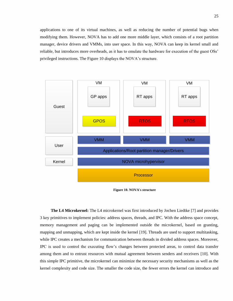
NOVA: NOVA [18] is a third generation microkernel, because it supports full-virtualization. Guest
OSs do not need to be modified to run on the NOVA hypervisor. It takes less time and effort to port
25
applications to one of its virtual machines, as well as reducing the number of potential bugs when
modifying them. However, NOVA has to add one more middle layer, which consists of a root partition
manager, device drivers and VMMs, into user space. In this way, NOVA can keep its kernel small and
reliable, but introduces more overheads, as it has to emulate the hardware for execution of the guest OSs’
privileged instructions. The Figure 10 displays the NOVA’s structure.
Processor
VMM
RTOS
RT apps
VM VM
GPOS
GP apps
VM
Applications/Root partition manager/Drivers
NOVA microhypervisor
Guest
User
RTOS
RT apps
VMM VMM
Kernel
Figure 10. NOVA's structure
The L4 Microkernel: The L4 microkernel was first introduced by Jochen Liedtke [7] and provides
3 key primitives to implement policies: address spaces, threads, and IPC. With the address space concept,
memory management and paging can be implemented outside the microkernel, based on granting,
mapping and unmapping, which are kept inside the kernel [19]. Threads are used to support multitasking,
while IPC creates a mechanism for communication between threads in divided address spaces. Moreover,
IPC is used to control the executing flow’s changes between protected areas, to control data transfer
among them and to entrust resources with mutual agreement between senders and receivers [10]. With
this simple IPC primitive, the microkernel can minimize the necessary security mechanisms as well as the
kernel complexity and code size. The smaller the code size, the fewer errors the kernel can introduce and
26
the smaller the cache footprint. This means that the system is cheaper, smaller and has less power-
consumption.
In order to achieve the necessary performance and flexibility, the microkernel has to be optimized
based on the processor’s architecture to take advantage of the specific hardware. Because one processor’s
architecture has some tradeoffs compared with another, the microkernel should be the lowest level of OS
on the hardware without any other abstraction. This means that the microkernel is hardware-dependent
and is inherently not portable [7].
The L4 microkernel can also support real-time applications concurrently with general-purpose
applications by using cache partitioning and the IPC model. Because real-time tasks need to meet their
deadlines, the required resources must always be allocated and scheduled. Cache partitioning means the
microkernel uses the main-memory manager (pager) to partition the second-level cache among various
real-time tasks and to isolate them from timesharing ones. This helps to avoid cache interference and
cache miss, thus improving the predictability and the performance for real-time tasks. With this IPC
model, a server can easily pre-allocate kernel and user resources, threads and stacks, dedicated to specific
applications [8].
2.3 CODEZERO
CODEZERO [12] is developed from the L4 microkernel, and follows the latest concept and
research principles on microkernel design [15]. The code size is about ten thousands of lines of C code,
and its APIs consist of twelve main system calls. Therefore, CODEZERO is simple, small and efficient,
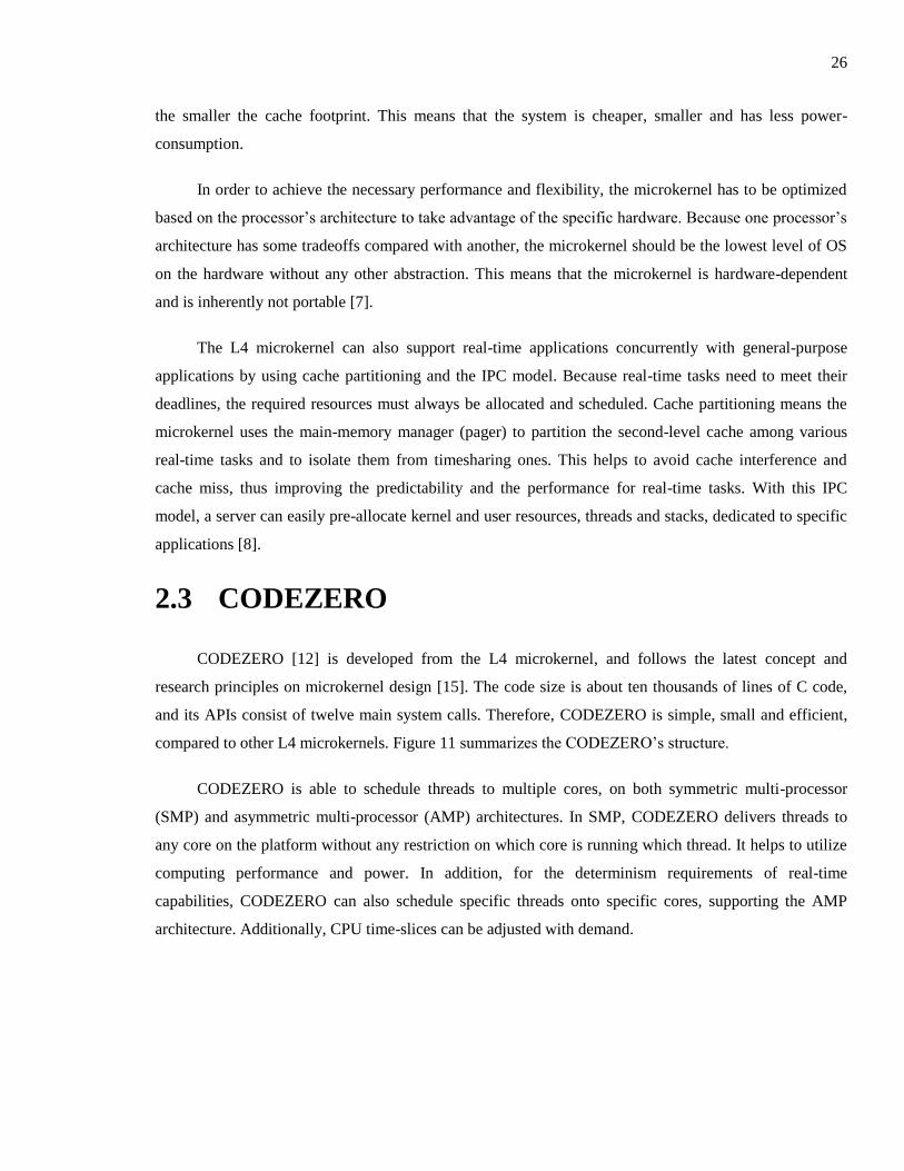
compared to other L4 microkernels. Figure 11 summarizes the CODEZERO’s structure.
CODEZERO is able to schedule threads to multiple cores, on both symmetric multi-processor
(SMP) and asymmetric multi-processor (AMP) architectures. In SMP, CODEZERO delivers threads to
any core on the platform without any restriction on which core is running which thread. It helps to utilize
computing performance and power. In addition, for the determinism requirements of real-time
capabilities, CODEZERO can also schedule specific threads onto specific cores, supporting the AMP
architecture. Additionally, CPU time-slices can be adjusted with demand.
27
Figure 11. CODEZERO's structure [12]
CODEZERO supports kernel preemption for real-time tasks. Moreover, CODEZERO keeps the
interrupt handler as small as possible. It just clears the interrupt flag and then calls the child thread to
handle the interrupt function. Thus, both the interrupt threads as well as the other threads can be
scheduled and pre-empted whenever another more critical event happens.
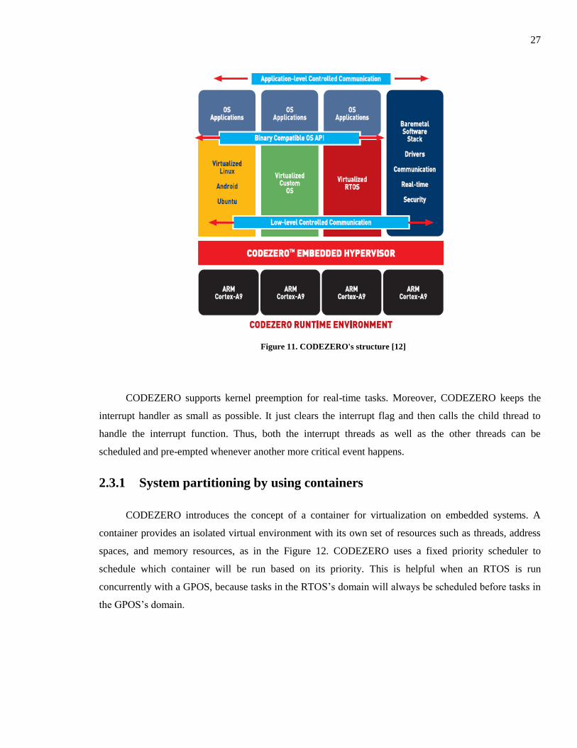
2.3.1 System partitioning by using containers
CODEZERO introduces the concept of a container for virtualization on embedded systems. A
container provides an isolated virtual environment with its own set of resources such as threads, address
spaces, and memory resources, as in the Figure 12. CODEZERO uses a fixed priority scheduler to
schedule which container will be run based on its priority. This is helpful when an RTOS is run
concurrently with a GPOS, because tasks in the RTOS’s domain will always be scheduled before tasks in
the GPOS’s domain.
28
Processor
Codezero microkernel
Pager
Pager
Child
task
Container 0 Container 1
Child thread
Child
task
Child
task
Figure 12. CODEZERO's containers
At the beginning, there is only one privileged task called a pager running in each container. The
pager then creates further children tasks running in their own virtual memory spaces to produce a
multitasking environment inside its container. This model is a typical setup for a virtualized guest OS. For
example in container 0 in Figure 12, the kernel acts as the pager and its applications are child tasks.
Another model is for a bare-metal or self-contained application, where the application is the pager
itself, as shown as in container 1 in Figure 12. The pager can create multiple children threads in the same
address space and then works as a standalone application on the hardware. Those standalone
multithreaded applications can be used to test hardware devices or to develop a lightweight RTOS.
The pager task possesses all privileged capabilities inside the container. It can create and manage
threads, because it owns the thread control, and exchange register capabilities. Moreover, a pager can map
a physical address to a virtual address for its own address space and the address space of its children
tasks, because it also has possession of both physical and virtual resources. Because the pager only has
rights to its own container, it is very easy and simple to manage isolation between containers.
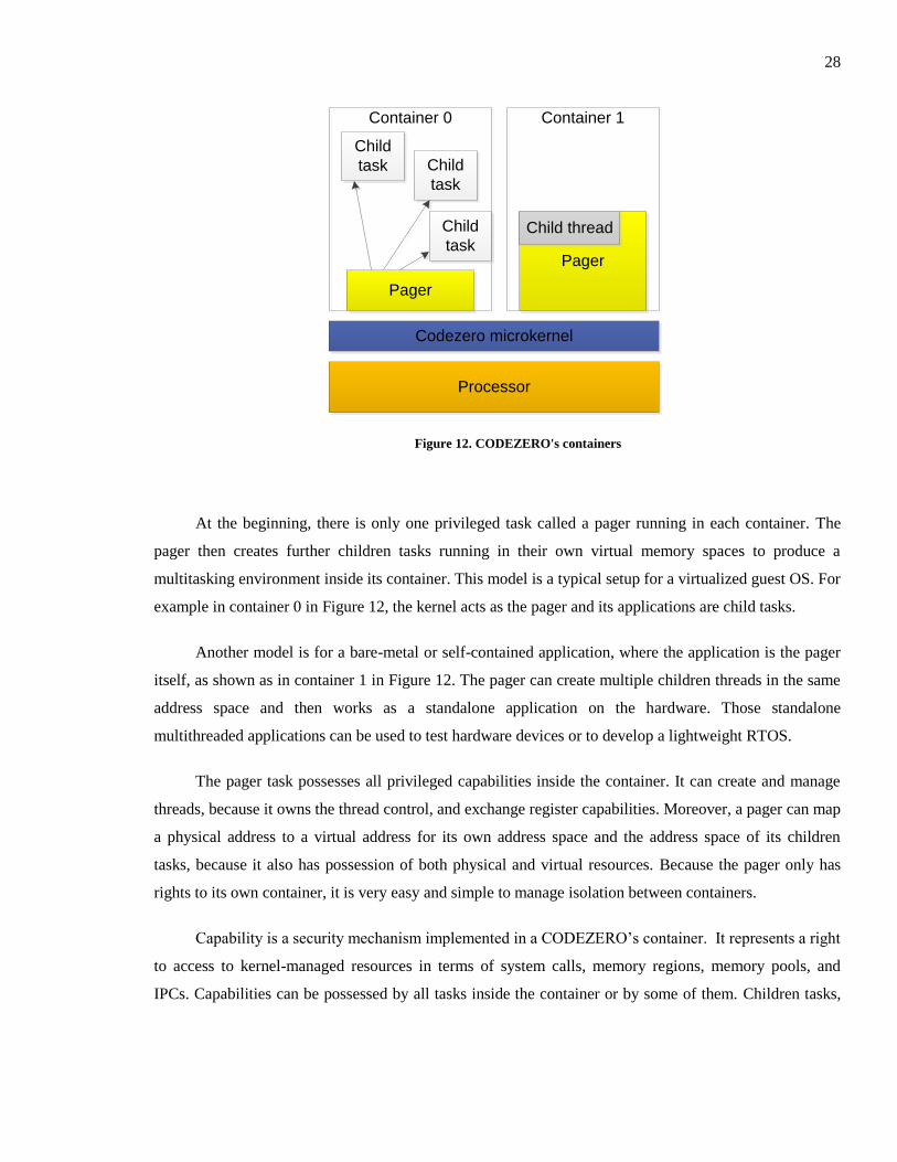
Capability is a security mechanism implemented in a CODEZERO’s container. It represents a right
to access to kernel-managed resources in terms of system calls, memory regions, memory pools, and
IPCs. Capabilities can be possessed by all tasks inside the container or by some of them. Children tasks,
29
as shown Figure 13, own a mutex pool capability, so they are allowed to communicate with any thread
inside the container via IPC.
Codezero microkernel
Container
Pager
Child
task
Child
task
Mutex pool
IPC to current
container
Thread control
Virtual mem 0..n
Physical mem
0..n
Space pool
Thread pool
Exchange
registers IPC to other
containers
All tasks may use
container caps
Caps owned by
pager only
Figure 13. Capabilities inside a container
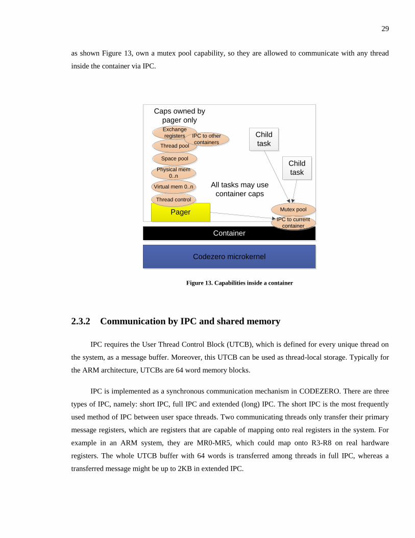
2.3.2 Communication by IPC and shared memory
IPC requires the User Thread Control Block (UTCB), which is defined for every unique thread on
the system, as a message buffer. Moreover, this UTCB can be used as thread-local storage. Typically for
the ARM architecture, UTCBs are 64 word memory blocks.
IPC is implemented as a synchronous communication mechanism in CODEZERO. There are three
types of IPC, namely: short IPC, full IPC and extended (long) IPC. The short IPC is the most frequently
used method of IPC between user space threads. Two communicating threads only transfer their primary
message registers, which are registers that are capable of mapping onto real registers in the system. For
example in an ARM system, they are MR0-MR5, which could map onto R3-R8 on real hardware
registers. The whole UTCB buffer with 64 words is transferred among threads in full IPC, whereas a
transferred message might be up to 2KB in extended IPC.
30
Processor
Codezero microkernel
Pager
Pager
Child
task
Container 0 Container 1
Child thread
Child
task
Child
task
IPC to
children
tasks Inte
r-
conta
iner
IPC
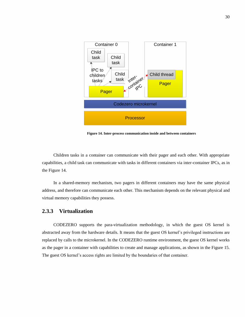
Figure 14. Inter-process communication inside and between containers
Children tasks in a container can communicate with their pager and each other. With appropriate
capabilities, a child task can communicate with tasks in different containers via inter-container IPCs, as in
the Figure 14.
In a shared-memory mechanism, two pagers in different containers may have the same physical
address, and therefore can communicate each other. This mechanism depends on the relevant physical and
virtual memory capabilities they possess.
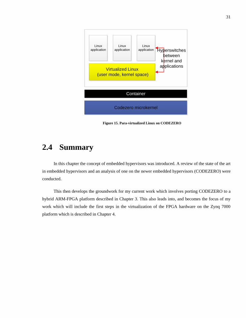
2.3.3 Virtualization
CODEZERO supports the para-virtualization methodology, in which the guest OS kernel is
abstracted away from the hardware details. It means that the guest OS kernel’s privileged instructions are
replaced by calls to the microkernel. In the CODEZERO runtime environment, the guest OS kernel works
as the pager in a container with capabilities to create and manage applications, as shown in the Figure 15.
The guest OS kernel’s access rights are limited by the boundaries of that container.
31
Codezero microkernel
Container
Virtualized Linux
(user mode, kernel space)
Linux
application
Linux
application
Linux
application Hyperswitches
between
kernel and
applications
Figure 15. Para-virtualized Linux on CODEZERO
2.4 Summary
In this chapter the concept of embedded hypervisors was introduced. A review of the state of the art
in embedded hypervisors and an analysis of one on the newer embedded hypervisors (CODEZERO) were
conducted.
This then develops the groundwork for my current work which involves porting CODEZERO to a
hybrid ARM-FPGA platform described in Chapter 3. This also leads into, and becomes the focus of my
work which will include the first steps in the virtualization of the FPGA hardware on the Zynq 7000
platform which is described in Chapter 4.
32
Chapter 3
Porting CODEZERO on ZedBoard
This chapter introduces the Xilinx Zynq 7000 extensible processing platform, and the possibility of
adding virtualization support for FPGA-based hardware tasks. It then goes on to describe the porting of
the B-Labs CODEZERO hypervisor to the Xilinx Zynq 7000 family of FPGAs. The starting point for the
CODEZERO Zynq 7000 port is CODEZERO version 0.5 for the Texas Instruments OMAP4430
processor on the PandaBoard platform [20]. The target platform is the ZedBoard [21] based on the
XC7Z020-1CLG484C, Zynq-7000 SoC [22]. Throughout this chapter we will use the terms “ZedBoard”
as well as “Zynq 7000 platform” interchangeably. The CODEZERO port to the ZedBoard was a joint
effort, with some of the initial work being done by author 3 of [26].
3.1 Virtualizing the Xilinx Zynq 7000 extensible
processing platform
The Zynq 7000 extensible processing platform (EPP) is a new system-on-chip (SoC) introduced by
Xilinx in 2012. It integrates a dual-core Cortex-A9 processor, a Xilinx 7000 series FPGA [23] and some
common peripherals onto a single die. The powerful dual-core Cortex-A9 processor is for general-
purpose applications, and the programmable logic is for users to develop new peripherals, hardware
accelerators or application specific processing units. Moreover, on a conventional two-chip platform
(processor + FPGA) which communicate each other via the I/O port, the performance is limited due to
communication latency, I/O bandwidth and power budget. However, the single chip Zynq 7000 is not
limited by these factors and is able to achieve a much higher computing performance. This approach
gives the Zynq 7000 chip a chance to become a very customized, flexible and powerful processing
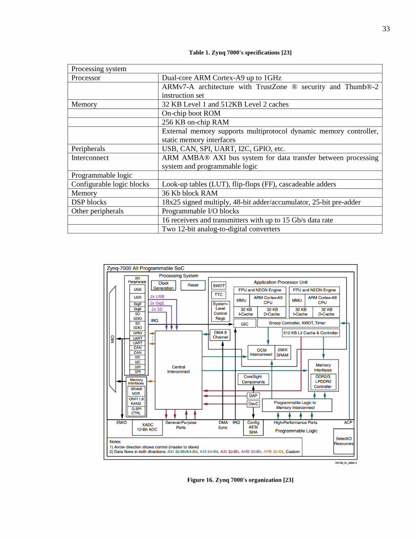
platform. The characteristics of the Zynq 7000 platform are given in Table 1 and Figure 16.
33
Table 1. Zynq 7000's specifications [23]
Processing system
Processor Dual-core ARM Cortex-A9 up to 1GHz
ARMv7-A architecture with TrustZone ® security and Thumb®-2
instruction set
Memory 32 KB Level 1 and 512KB Level 2 caches
On-chip boot ROM
256 KB on-chip RAM
External memory supports multiprotocol dynamic memory controller,
static memory interfaces
Peripherals USB, CAN, SPI, UART, I2C, GPIO, etc.
Interconnect ARM AMBA® AXI bus system for data transfer between processing
system and programmable logic
Programmable logic
Configurable logic blocks Look-up tables (LUT), flip-flops (FF), cascadeable adders
Memory 36 Kb block RAM
DSP blocks 18x25 signed multiply, 48-bit adder/accumulator, 25-bit pre-adder
Other peripherals Programmable I/O blocks
16 receivers and transmitters with up to 15 Gb/s data rate
Two 12-bit analog-to-digital converters
Figure 16. Zynq 7000's organization [23]
34
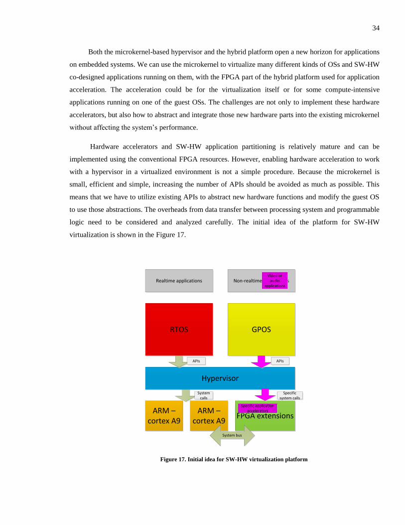
Both the microkernel-based hypervisor and the hybrid platform open a new horizon for applications
on embedded systems. We can use the microkernel to virtualize many different kinds of OSs and SW-HW
co-designed applications running on them, with the FPGA part of the hybrid platform used for application
acceleration. The acceleration could be for the virtualization itself or for some compute-intensive
applications running on one of the guest OSs. The challenges are not only to implement these hardware
accelerators, but also how to abstract and integrate those new hardware parts into the existing microkernel
without affecting the system’s performance.
Hardware accelerators and SW-HW application partitioning is relatively mature and can be
implemented using the conventional FPGA resources. However, enabling hardware acceleration to work
with a hypervisor in a virtualized environment is not a simple procedure. Because the microkernel is
small, efficient and simple, increasing the number of APIs should be avoided as much as possible. This
means that we have to utilize existing APIs to abstract new hardware functions and modify the guest OS
to use those abstractions. The overheads from data transfer between processing system and programmable
logic need to be considered and analyzed carefully. The initial idea of the platform for SW-HW
virtualization is shown in the Figure 17.
ARM – cortex A9
GPOS
Hypervisor
RTOS
ARM – cortex A9
FPGA extensions
System bus
Realtime applications Non-realtime applications
Specific application accelerators
APIs APIs
System calls
Video or audio
applications
Specific system calls
Figure 17. Initial idea for SW-HW virtualization platform
35
3.2 Booting CODEZERO on the ZedBoard
3.2.1 The overall boot sequence
In the ZedBoard, the NAND flash, NOR flash, SD card, Quad-SPI, and JTAG are five possible
boot sources. The master boot method uses one of the first four boot sources in order to load the external
boot image from non-volatile memory into the on-chip memory (OCM). In the slave boot mode, an
external host PC uses the JTAG connection to load the boot image into the processing system (PS) while
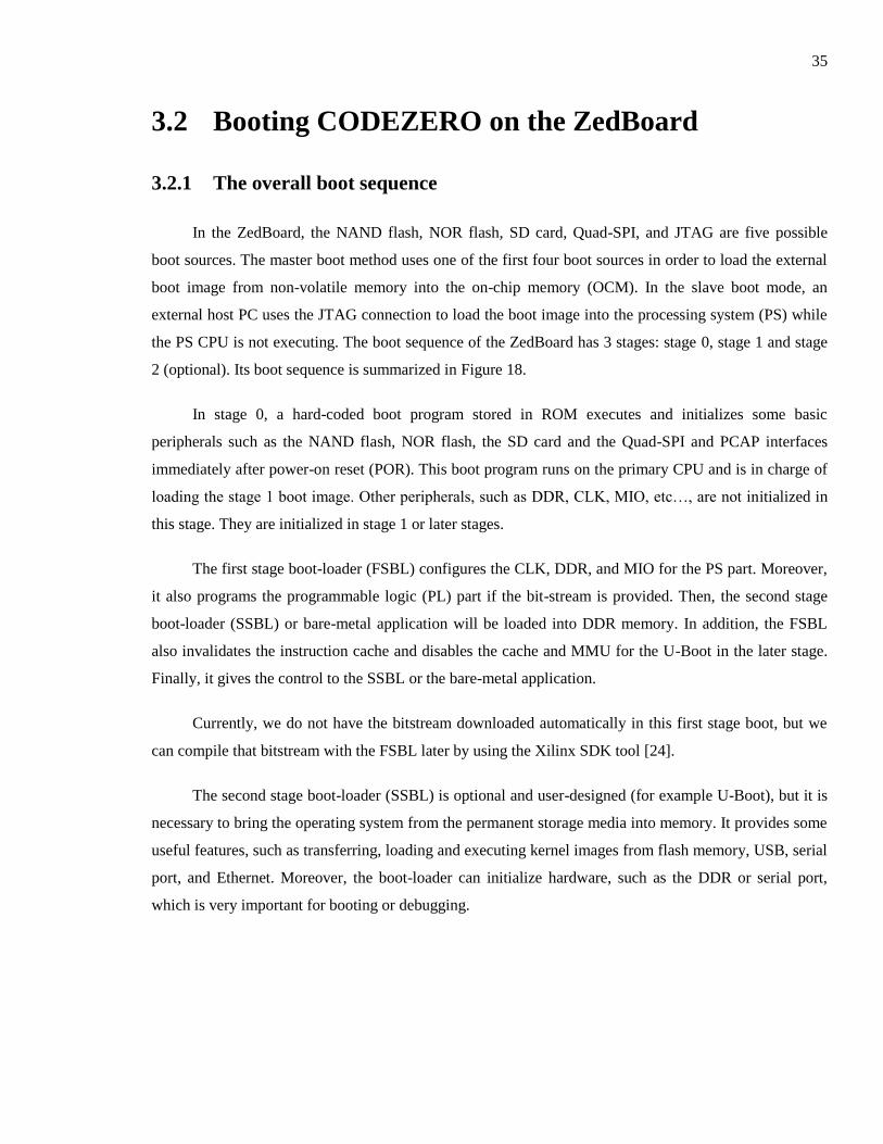
the PS CPU is not executing. The boot sequence of the ZedBoard has 3 stages: stage 0, stage 1 and stage
2 (optional). Its boot sequence is summarized in Figure 18.
In stage 0, a hard-coded boot program stored in ROM executes and initializes some basic
peripherals such as the NAND flash, NOR flash, the SD card and the Quad-SPI and PCAP interfaces
immediately after power-on reset (POR). This boot program runs on the primary CPU and is in charge of
loading the stage 1 boot image. Other peripherals, such as DDR, CLK, MIO, etc…, are not initialized in
this stage. They are initialized in stage 1 or later stages.
The first stage boot-loader (FSBL) configures the CLK, DDR, and MIO for the PS part. Moreover,
it also programs the programmable logic (PL) part if the bit-stream is provided. Then, the second stage
boot-loader (SSBL) or bare-metal application will be loaded into DDR memory. In addition, the FSBL
also invalidates the instruction cache and disables the cache and MMU for the U-Boot in the later stage.
Finally, it gives the control to the SSBL or the bare-metal application.
Currently, we do not have the bitstream downloaded automatically in this first stage boot, but we
can compile that bitstream with the FSBL later by using the Xilinx SDK tool [24].
The second stage boot-loader (SSBL) is optional and user-designed (for example U-Boot), but it is
necessary to bring the operating system from the permanent storage media into memory. It provides some
useful features, such as transferring, loading and executing kernel images from flash memory, USB, serial
port, and Ethernet. Moreover, the boot-loader can initialize hardware, such as the DDR or serial port,
which is very important for booting or debugging.
36
Stage 0
Boot ROM
Stage 1
FSBL
Stage 2
U-Boot
CODEZERO
Figure 18. Boot sequence of the ZedBoard
In the case of the CODEZERO boot on the ZedBoard, we use the same U-Boot as is used to boot
the Linux kernel on ZedBoard [25]. The U-Boot command mmcinfo is used to initialize the SD card.
./mmcinfo
After that, the fatload command is used to load the kernel image (the uImage file) from partition 0
of the SD card to the beginning of the main memory (the main memory starts from 0x0 in the ZedBoard).
./fatload mmc 0 0 uImage
Then, another command bootm is executed from the specified memory where the final image is
stored.
./bootm 0
U-Boot automatically decompress the final image file, re-allocates the CODEZERO loader image
in the final image to the address 0x02000000 which is the entry point address stored in the ELF file
header. Finally, the execution jumps to the entry point address of the CODEZERO loader to start
CODEZERO (the label _start in the file crt0.S). The CODEZERO kernel and loader start addresses are
configured by the user in the compilation step according to the Zynq 7000 hardware manual, because
37
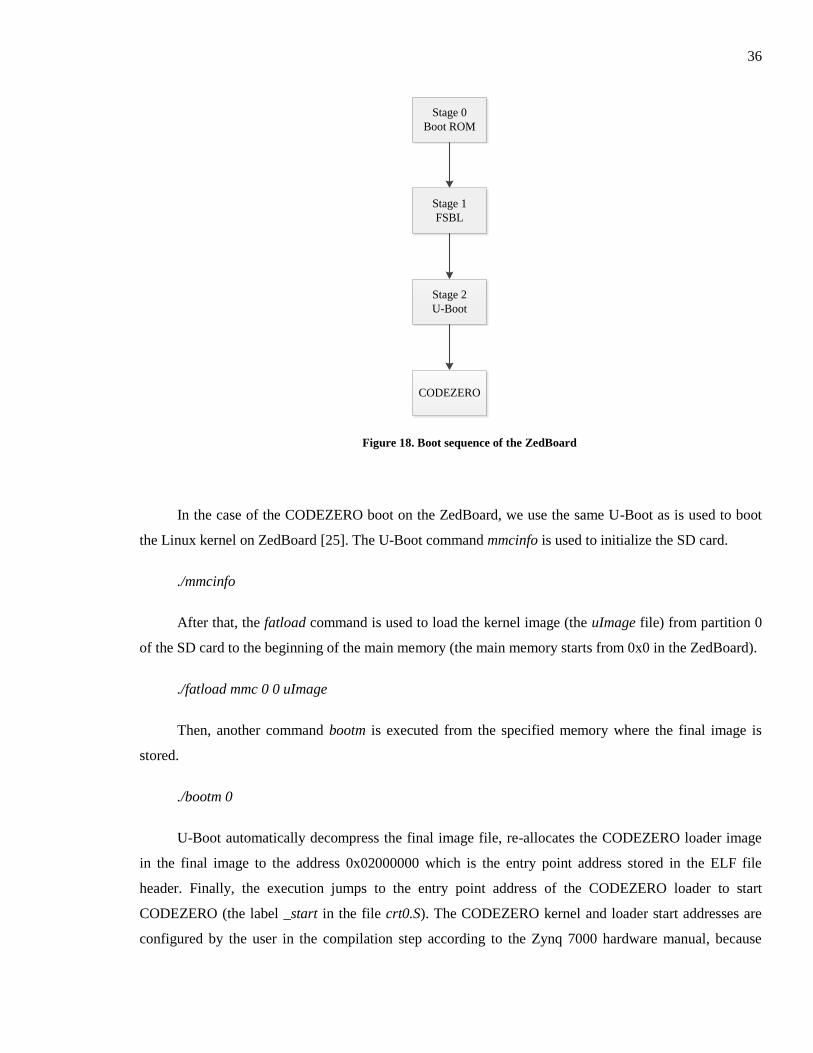
these addresses are different across various platforms. The configuration step and CODEZERO’s final
image layout will be described later. The stage 2 boot process is shown in Figure 19.
Figure 19. The stage 2 boot
CODEZERO starts after the U-Boot command bootm has executed. Its boot sequence is displayed
in the Figure 20. The CODEZERO loader will first start to load the CODEZERO kernel and user
container images, then the CODEZERO kernel initialization will continue.
3.2.2 CODEZERO’s folder structure and final image layout
CODEZERO’s folder structure is illustrated to provide a better understanding of CODEZERO’s
boot sequence and the necessary modifications. The entire CODEZERO source code consists of three
parts, as shown in Figure 21: the CODEZERO loader, the kernel, and the user containers. In this chapter,
we only describe the CODEZERO loader and CODEZERO kernel, as user containers are not affected
heavily by the target platform. The loader folder has the source code for the loader. CODEZERO’s kernel
source code is contained in the folder src and includes subfolders arch for architecture-specific functions,
drivers for peripherals’ device drivers, glue for architecture-generic function, and platform for platform-
specific functions. The include folder contains all related header files for drivers, architectures, platforms,
CODEZERO’s structures and APIs. The contents of these three folders are modified during the porting
process.

38
Loader starts
Kernel starts
Application
starts
Copy kernel and container’s
images from SD card to
memory
Initialize hardware such as
CPU, MMU, timer,
scheduler, FPGA clock
source...
Figure 20. CODEZERO's boot sequence
Figure 21. CODEZERO’s shortened folder structure
The CODEZERO loader, kernel and user containers are compiled independently to generate several
separated binary images (loader.elf for the CODEZERO loader, kernel.elf for the CODEZERO kernel and
39
contX.elf for the user containers). At the final stage of the entire CODEZERO compilation the separated
images are merged and compressed, if applicable, into the final image (the uImage file).
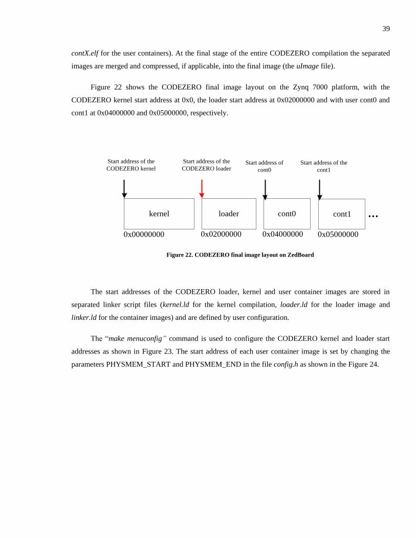
Figure 22 shows the CODEZERO final image layout on the Zynq 7000 platform, with the
CODEZERO kernel start address at 0x0, the loader start address at 0x02000000 and with user cont0 and
cont1 at 0x04000000 and 0x05000000, respectively.
kernel loader cont0 …
Start address of the
CODEZERO kernel
Start address of the
CODEZERO loader
0x00000000 0x02000000 0x04000000
cont1
0x05000000
Start address of
cont0
Start address of the
cont1
Figure 22. CODEZERO final image layout on ZedBoard
The start addresses of the CODEZERO loader, kernel and user container images are stored in
separated linker script files (kernel.ld for the kernel compilation, loader.ld for the loader image and
linker.ld for the container images) and are defined by user configuration.
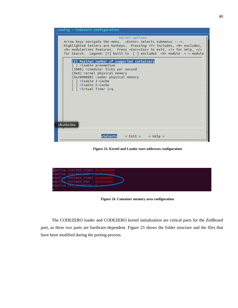
The “make menuconfig” command is used to configure the CODEZERO kernel and loader start
addresses as shown in Figure 23. The start address of each user container image is set by changing the
parameters PHYSMEM_START and PHYSMEM_END in the file config.h as shown in the Figure 24.
40
Figure 23. Kernel and Loader start addresses configuration
Figure 24. Container memory area configuration
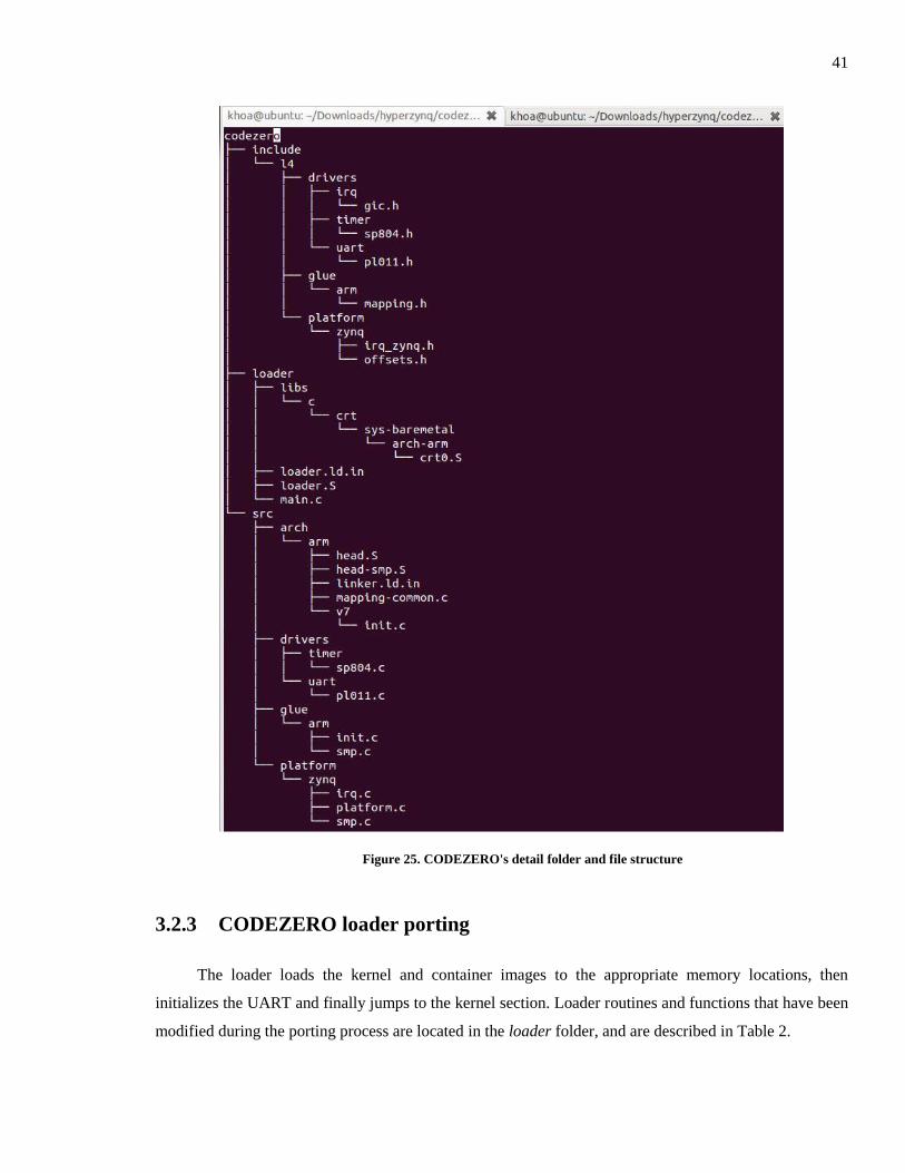
The CODEZERO loader and CODEZERO kernel initialization are critical parts for the ZedBoard
port, as these two parts are hardware-dependent. Figure 25 shows the folder structure and the files that
have been modified during the porting process.
41
Figure 25. CODEZERO's detail folder and file structure
3.2.3 CODEZERO loader porting
The loader loads the kernel and container images to the appropriate memory locations, then
initializes the UART and finally jumps to the kernel section. Loader routines and functions that have been
modified during the porting process are located in the loader folder, and are described in Table 2.
42
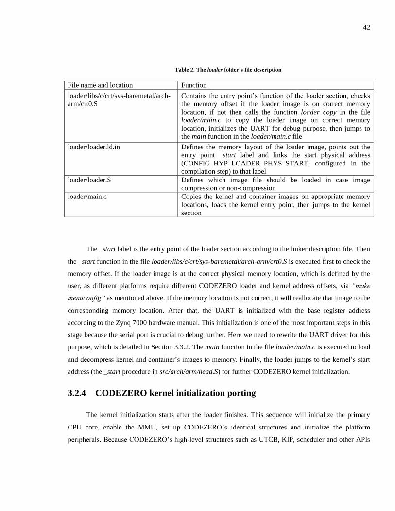
Table 2. The loader folder’s file description
File name and location Function
loader/libs/c/crt/sys-baremetal/arch-
arm/crt0.S
Contains the entry point’s function of the loader section, checks
the memory offset if the loader image is on correct memory
location, if not then calls the function loader_copy in the file
loader/main.c to copy the loader image on correct memory
location, initializes the UART for debug purpose, then jumps to
the main function in the loader/main.c file
loader/loader.ld.in Defines the memory layout of the loader image, points out the
entry point _start label and links the start physical address
(CONFIG_HYP_LOADER_PHYS_START, configured in the
compilation step) to that label
loader/loader.S Defines which image file should be loaded in case image
compression or non-compression
loader/main.c Copies the kernel and container images on appropriate memory
locations, loads the kernel entry point, then jumps to the kernel
section
The _start label is the entry point of the loader section according to the linker description file. Then
the _start function in the file loader/libs/c/crt/sys-baremetal/arch-arm/crt0.S is executed first to check the
memory offset. If the loader image is at the correct physical memory location, which is defined by the
user, as different platforms require different CODEZERO loader and kernel address offsets, via “make
menuconfig” as mentioned above. If the memory location is not correct, it will reallocate that image to the
corresponding memory location. After that, the UART is initialized with the base register address
according to the Zynq 7000 hardware manual. This initialization is one of the most important steps in this
stage because the serial port is crucial to debug further. Here we need to rewrite the UART driver for this
purpose, which is detailed in Section 3.3.2. The main function in the file loader/main.c is executed to load
and decompress kernel and container’s images to memory. Finally, the loader jumps to the kernel’s start
address (the _start procedure in src/arch/arm/head.S) for further CODEZERO kernel initialization.
3.2.4 CODEZERO kernel initialization porting
The kernel initialization starts after the loader finishes. This sequence will initialize the primary
CPU core, enable the MMU, set up CODEZERO’s identical structures and initialize the platform
peripherals. Because CODEZERO’s high-level structures such as UTCB, KIP, scheduler and other APIs
43
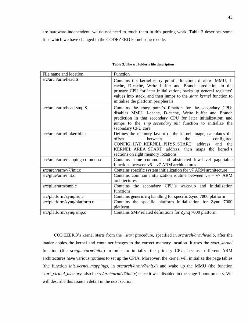
are hardware-independent, we do not need to touch them in this porting work. Table 3 describes some
files which we have changed in the CODEZERO kernel source code.
Table 3. The src folder's file description
File name and location Function
src/arch/arm/head.S Contains the kernel entry point’s function; disables MMU, I-
cache, D-cache, Write buffer and Branch prediction in the
primary CPU for later initialization; backs up general registers’
values into stack, and then jumps to the start_kernel function to
initialize the platform peripherals
src/arch/arm/head-smp.S Contains the entry point’s function for the secondary CPU;
disables MMU, I-cache, D-cache, Write buffer and Branch
prediction in that secondary CPU for later initialization; and
jumps to the smp_secondary_init function to initialize the
secondary CPU core
src/arch/arm/linker.ld.in Defines the memory layout of the kernel image, calculates the
offset between the configured
CONFIG_HYP_KERNEL_PHYS_START address and the
KERNEL_AREA_START address, then maps the kernel’s
sections on right memory locations
src/arch/arm/mapping-common.c Contains some common and abstracted low-level page-table
functions between v5 – v7 ARM architectures
src/arch/arm/v7/init.c Contains specific system initialization for v7 ARM architecture
src/glue/arm/init.c Contains common initialization routine between v5 – v7 ARM
architectures
src/glue/arm/smp.c Contains the secondary CPU’s wake-up and initialization
functions
src/platform/zynq/irq.c Contains generic irq handling for specific Zynq 7000 platform
src/platform/zynq/platform.c Contains the specific platform initialization for Zynq 7000
platform
src/platform/zynq/smp.c Contains SMP related definitions for Zynq 7000 platform
CODEZERO’s kernel starts from the _start procedure, specified in src/arch/arm/head.S, after the
loader copies the kernel and container images to the correct memory location. It uses the start_kernel
function (file src/glue/arm/init.c) in order to initialize the primary CPU, because different ARM
architectures have various routines to set up the CPUs. Moreover, the kernel will initialize the page tables
(the function init_kernel_mappings, in src/arch/arm/v7/init.c) and wake up the MMU (the function
start_virtual_memory, also in src/arch/arm/v7/init.c) since it was disabled in the stage 1 boot process. We
will describe this issue in detail in the next section.
44
Several CODEZERO structures need to be initialized and mapped into user-space in this stage for
further operations, for example the User-space Thread Control Block structure, l4_utcb, Kernel Interface
Page structure, l4_kip, guest’s shared memory page and system-call jump-table page. As this step is
hardware-independent, we will not discuss it further.
Other platform peripherals, such as the timer, scheduler, and interrupt controller, are set up and
mapped to the virtual address area by the function platform_init in src/platform/zynq/platform.c. The
timer and GIC device drivers need to be rewritten as described in the next section.
In the next step, if dual-core mode is configured, we need to wake up the second CPU core by
calling the function smp_start_cores in glue/arm/smp.c. This function needs to be changed as the Zynq
7000 secondary CPU wake-up procedure is different from the PandaBoard’s one. This issue will also be
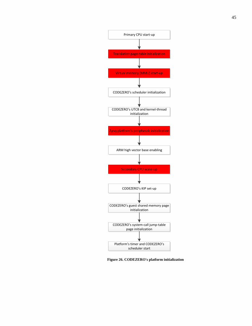
discussed further in the next section. After finishing the hardware and kernel’s initialization, the kernel
starts the timer and then enters the scheduler loop to run applications in the hypervisor containers. The
platform initialization routine is summarized in the Figure 26. The highlighted steps of the platform
initialization routine are discussed further in the next section.
45
Primary CPU start-up
Translation page-table initialization
Virtual memory (MMU) start-up
CODEZERO’s scheduler initialization
CODEZERO’s UTCB and kernel-thread initialization
Zynq platform’s peripherals initialization
ARM high vector base enabling
Secondary CPU wake-up
CODEZERO’s KIP set-up
CODEZERO’s guest shared memory page initialization
CODEZERO’s system-call jump-table page initialization
Platform’s timer and CODEZERO’s scheduler start
Figure 26. CODEZERO's platform initialization

46
3.3 CODEZERO port detail
3.3.1 Zynq 7000 base address definitions
For CODEZERO to run on the ZedBoard, we need to modify some parts of the original source
code for the Pandaboard. Firstly we need to change the register base addresses for all peripherals
according to the Zynq 7000 hardware manual [22]. The essential base addresses for the Zynq 7000
platform [22] are defined in the file include/l4/platform/zynq/offsets.h, as shown in the Table 4.
Table 4. ZedBoard's base addresses
Definition Description Physical address
PLATFORM_PHYS_MEM_START 0x0
PLATFORM_DEVICES1_START Base address for I/O peripheral registers 0xE0000000
PLATFORM_GIC0_BASE Base address for GIC 0 registers 0xF8F00100
PLATFORM_SYSCTRL_BASE Base address for system control registers 0xF8000000
PLATFORM_UART1_BASE Base address for console port 1 0xE0001000
PLATFORM_TIMER0_BASE Base address for triple timer 0 0xF8001000
PLATFORM_TIMER1_BASE Base address for triple timer 1 0xF8002000
CPU1_START_ADDR_BASE Start address for CPU1 core 0xFFFFFFF0
FPGA_CLOCK0_BASE Base address for clock 0 for FPGA 0xF8000170
FPGA_CLOCK1_BASE Base address for clock 1 for FPGA 0xF8000180
FPGA_CLOCK2_BASE Base address for clock 2 for FPGA 0xF8000190
FPGA_CLOCK3_BASE Base address for clock 3 for FPGA 0xF80001A0
3.3.2 Rewriting the drivers
The UART, timer and generic interrupt controller (GIC) are all essential for CODEZERO’s
operation. The UART is used for console display and debug, the timer is used by the CODEZERO
scheduler and the GIC is for hardware management. Other peripherals may be initialized and handle later
by CODEZERO’s guest OS (for example Linux or µC/OS). The drivers are in the src/drivers directory.
The modification to the GIC module is relatively trivial as there are no differences for platforms
using the ARMv7 architecture. We simply need to change the base address of the GIC0 register to
0xF8F00100 in offsets.h (located in folder include/l4/platform/zynq).
For the UART, we have to change the base address (the address 0xE0001000) as well as initializing
procedures due to changes in the register’s organization in the Zynq 7000 platform. Because the UART is
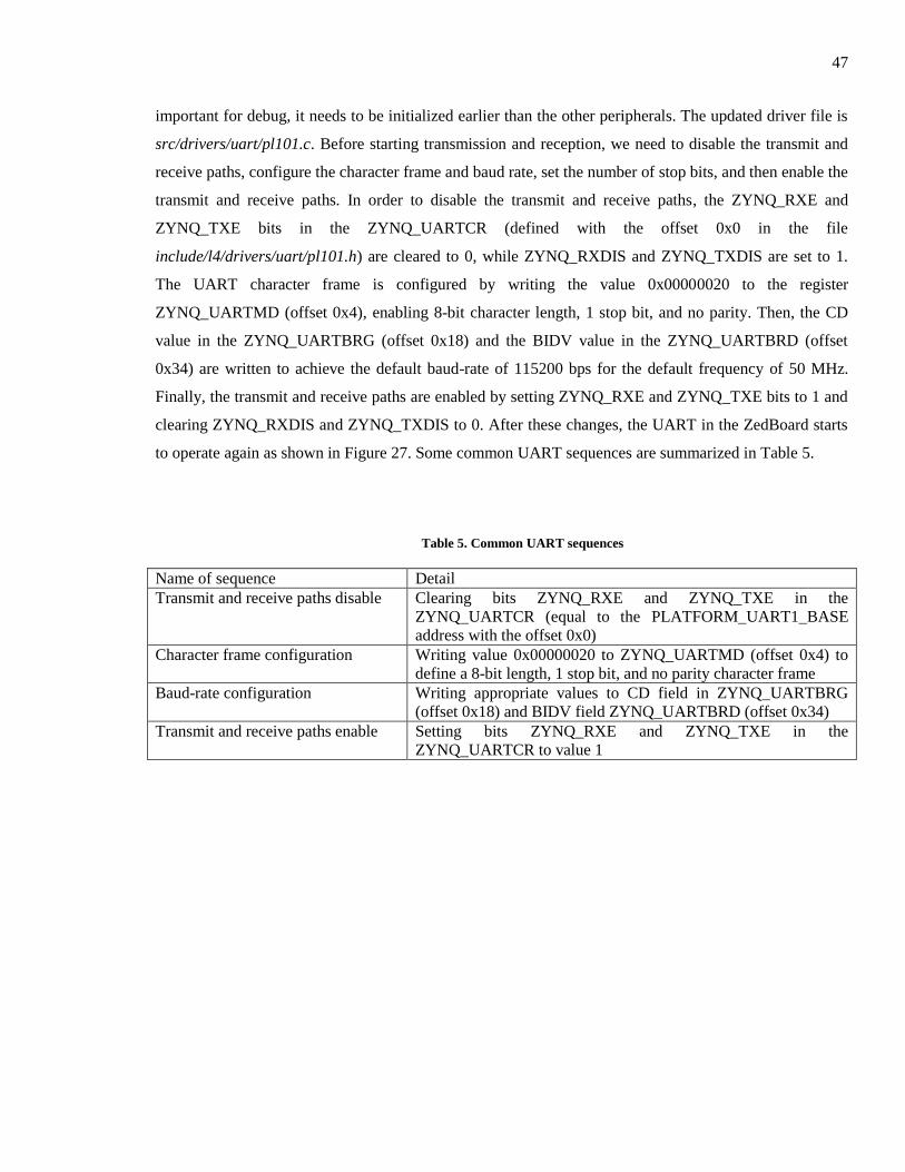
47
important for debug, it needs to be initialized earlier than the other peripherals. The updated driver file is
src/drivers/uart/pl101.c. Before starting transmission and reception, we need to disable the transmit and
receive paths, configure the character frame and baud rate, set the number of stop bits, and then enable the
transmit and receive paths. In order to disable the transmit and receive paths, the ZYNQ_RXE and
ZYNQ_TXE bits in the ZYNQ_UARTCR (defined with the offset 0x0 in the file
include/l4/drivers/uart/pl101.h) are cleared to 0, while ZYNQ_RXDIS and ZYNQ_TXDIS are set to 1.
The UART character frame is configured by writing the value 0x00000020 to the register
ZYNQ_UARTMD (offset 0x4), enabling 8-bit character length, 1 stop bit, and no parity. Then, the CD
value in the ZYNQ_UARTBRG (offset 0x18) and the BIDV value in the ZYNQ_UARTBRD (offset
0x34) are written to achieve the default baud-rate of 115200 bps for the default frequency of 50 MHz.
Finally, the transmit and receive paths are enabled by setting ZYNQ_RXE and ZYNQ_TXE bits to 1 and
clearing ZYNQ_RXDIS and ZYNQ_TXDIS to 0. After these changes, the UART in the ZedBoard starts
to operate again as shown in Figure 27. Some common UART sequences are summarized in Table 5.
Table 5. Common UART sequences
Name of sequence Detail
Transmit and receive paths disable Clearing bits ZYNQ_RXE and ZYNQ_TXE in the
ZYNQ_UARTCR (equal to the PLATFORM_UART1_BASE
address with the offset 0x0)
Character frame configuration Writing value 0x00000020 to ZYNQ_UARTMD (offset 0x4) to
define a 8-bit length, 1 stop bit, and no parity character frame
Baud-rate configuration Writing appropriate values to CD field in ZYNQ_UARTBRG
(offset 0x18) and BIDV field ZYNQ_UARTBRD (offset 0x34)
Transmit and receive paths enable Setting bits ZYNQ_RXE and ZYNQ_TXE in the
ZYNQ_UARTCR to value 1
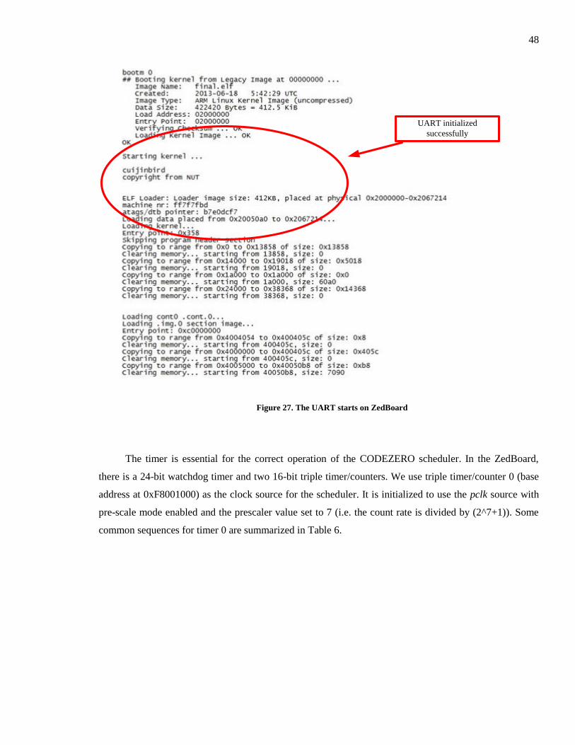
48
UART initialized
successfully
Figure 27. The UART starts on ZedBoard
The timer is essential for the correct operation of the CODEZERO scheduler. In the ZedBoard,
there is a 24-bit watchdog timer and two 16-bit triple timer/counters. We use triple timer/counter 0 (base
address at 0xF8001000) as the clock source for the scheduler. It is initialized to use the pclk source with
pre-scale mode enabled and the prescaler value set to 7 (i.e. the count rate is divided by (2^7+1)). Some
common sequences for timer 0 are summarized in Table 6.

49
Table 6. Common Timer sequences
Name of sequence Detail
Timer periodic initialization Disable the timer by setting the DIS bit in the
ZYNQ_TIMER0_CTRL (offset 0xC) register to high
Select the clock input source, and set the prescaler value in the
ZYNQ_TIMER0_CLKCTRL (offset 0x0)
Choose the interval mode for the timer by setting the INT bit in
the ZYNQ_TIMER0_CTRL register
Enable the timer interrupt by setting corresponding bit of the IEN
field in the ZYNQ_TIMER0_INTEN (offset 0x60) register
Set the match value by writing the value into the
ZYNQ_TIMER0_LOAD (offset 0x24) register
Timer start Read back the value of ZYNQ_TIMER0_CTRL register
Clear the DIS bit
Write back to the register
Timer stop Read back the value of ZYNQ_TIMER0_CTRL register
Set DIS bit to 1
Write back to the register
Timer restart Read back the value of ZYNQ_TIMER0_CTRL register
Set RST bit to 1
Write back to the register
Timer interrupt clear Read back the value of ZYNQ_TIMER0_INTREG (offset 0x54)
register, then the value of this register will be cleared
automatically
3.3.3 Enabling the MMU
The MMU enable routine is summarized in Figure 28. Functions for this routine are contained in
the file src/arch/arm/v7/init.c.
The MMU module was the most complicated as the values of registers such as program counter
(PC), link register (LR), system control register (SCTLR) and page-table address are essential to
determine where the program actually resides in memory. The MMU module was the most difficult
module to port and required considerable debugging effort, as initially, after the MMU started, the
program counter (PC) did not load the correct address to continue the boot sequence. As we needed the
UART for debugging this module, we decided to map the UART register to virtual memory before
enabling the MMU using the function add_boot_mapping_bf_mmu function in the file
src/arch/arm/mapping-common.c. The normal practice is to enable the MMU first and then map
peripheral registers to the virtual address later. By comparing the values displayed on the monitor with the
address in the assembly code, we were able to correct address mismatches.
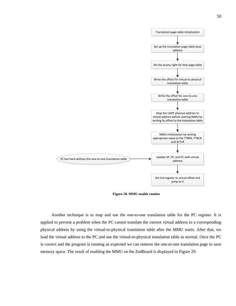
50
Translation page-table initialization
Set up the translation page-table base address
Set the access right for that page-table
Write the offset for virtual-to-physical translation table
Write the offset for one-to-one translation table
Map the UART physical address to virtual address before starting MMU by writing its offset to the translation table
MMU initialization by writing appropriate value to the TTBR0, TTBCR,
and SCTLR
Update SP, FP, and PC with virtual address
Set link register to virtual offset and jump to it
PC lost here without the one-to-one translation table
Figure 28. MMU enable routine
Another technique is to map and use the one-to-one translation table for the PC register. It is
applied to prevent a problem when the PC cannot translate the current virtual address to a corresponding
physical address by using the virtual-to-physical translation table after the MMU starts. After that, we
load the virtual address to the PC and use the virtual-to-physical translation table as normal. Once the PC
is correct and the program is running as expected we can remove the one-to-one translation page to save
memory space. The result of enabling the MMU on the ZedBoard is displayed in Figure 29.
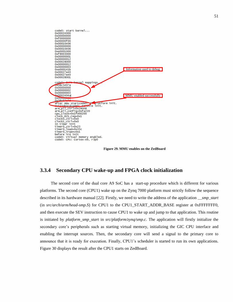
51
Information used to debug
MMU enabled successfully
Figure 29. MMU enables on the ZedBoard
3.3.4 Secondary CPU wake-up and FPGA clock initialization
The second core of the dual core A9 SoC has a start-up procedure which is different for various
platforms. The second core (CPU1) wake up on the Zynq 7000 platform must strictly follow the sequence
described in its hardware manual [22]. Firstly, we need to write the address of the application __smp_start
(in src/arch/arm/head-smp.S) for CPU1 to the CPU1_START_ADDR_BASE register at 0xFFFFFFF0,
and then execute the SEV instruction to cause CPU1 to wake up and jump to that application. This routine
is initiated by platform_smp_start in src/platform/zynq/smp.c. The application will firstly initialize the
secondary core’s peripherals such as starting virtual memory, initializing the GIC CPU interface and
enabling the interrupt sources. Then, the secondary core will send a signal to the primary core to
announce that it is ready for execution. Finally, CPU1’s scheduler is started to run its own applications.
Figure 30 displays the result after the CPU1 starts on ZedBoard.

52
CPU1 enabled successfully
Figure 30. The CPU1 wakes up on ZedBoard
Initializing the clock source and clock frequency for programmable logic (PL) is a specific stage
for the Zynq 7000 platform, and is not relevant for ARM CPU only platforms. We configure 4 clock
sources for the PL part with frequencies of 100 MHz (by writing value 0x00100A00 to the
FPGA_CLOCK0_BASE register at 0xF8000170), 175 MHz (value 0x00100600 to 0xF8000180), 200
MHz (value 0x00100500 to 0xF8000190), and 50 MHz (value 0x00101400 to 0xF80001A0),
respectively. This initialization is added to the function init_timer_source in src/platform/zynq/platform.c.
3.4 Summary
In this chapter, the CODEZERO porting on the ZedBoard is presented. This includes the
introduction of the Zynq 7000 extensible processing platform, the required boot sequence, the change to
the memory layout, the driver modifications, enabling the MMU, and the hardware-dependent peripheral
initialization.
This work is the first step to enable CODEZERO so that it can manage and virtualize hardware
tasks on the hybrid ARM – FPGA platform. We will describe the platform framework for the software
and hardware virtualization as well as the modification of CODEZERO in the next chapter.

53
Chapter 4
SW-HW virtualization platform
In this chapter, we propose a general framework for a microkernel based hypervisor to virtualize
the Xilinx Zynq 7000 hybrid computing platform. The CODEZERO hypervisor [12] is modified to
virtualize both the hardware and software components of this platform enabling the use of the CPU for
software tasks and the FPGA for hardware tasks in a relatively easy and efficient way. The reconfigurable
fabric of this framework is developed as a prototype to show how and what the modified CODEZERO
could do in SW-HW virtualization.
Parts of this chapter have been published in [26], and have been reproduced with permission.
Copyright on the reproduced portions is held by the IEEE.
4.1 Platform framework
4.1.1 Overview
In this framework, we are able to execute a number of operating systems (including µC/OS-II,
Linux and Android) as well as bare metal/real-time software, each in their own isolated container. By
modifying the CODEZERO hypervisor API (described in Section 4.2.2), support for hardware
acceleration can also be added, either as dedicated real-time bare metal hardware tasks, real-time SW-HW
bare metal applications or SW-HW applications running under OS control. This allows the time-
multiplexed execution of software and hardware tasks concurrently. In these scenarios, a hardware task
corresponds to FPGA resources configured to perform a particular acceleration operation, while a
software task corresponds to a traditional task running on the CPU. The framework treats the FPGA
region as a static reconfigurable region, a dynamic partial reconfiguration (DPR) region or a region of
intermediate fabric (IF) similar to those in [27, 28] or any combination of these. The hypervisor is able to
dynamically modify the behavior of the DPR and IF regions and carry out hardware and software task
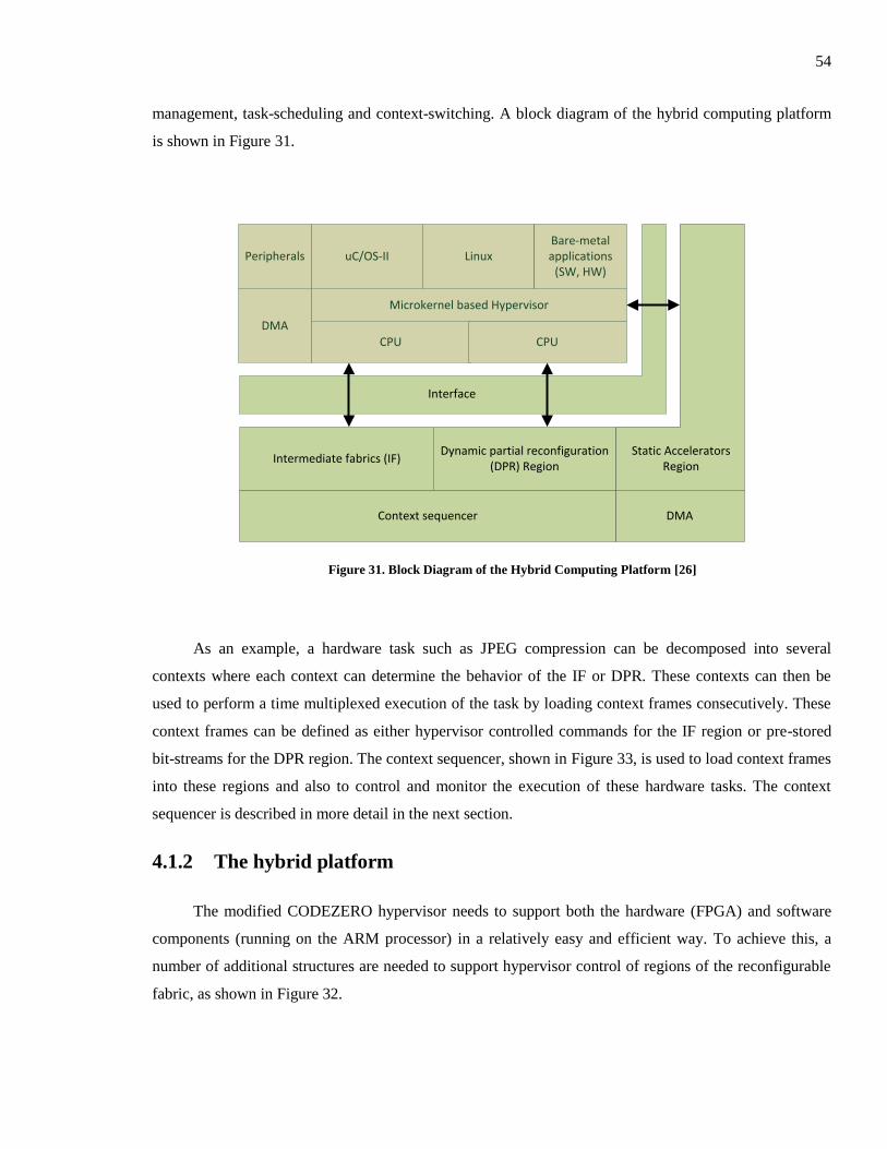
54
management, task-scheduling and context-switching. A block diagram of the hybrid computing platform
is shown in Figure 31.
CPU
Microkernel based Hypervisor
uC/OS-II LinuxBare-metal applications
(SW, HW)
CPU
DMA
Peripherals
Interface
Intermediate fabrics (IF)Dynamic partial reconfiguration
(DPR) Region
DMAContext sequencer
Static Accelerators Region
Figure 31. Block Diagram of the Hybrid Computing Platform [26]
As an example, a hardware task such as JPEG compression can be decomposed into several
contexts where each context can determine the behavior of the IF or DPR. These contexts can then be
used to perform a time multiplexed execution of the task by loading context frames consecutively. These
context frames can be defined as either hypervisor controlled commands for the IF region or pre-stored
bit-streams for the DPR region. The context sequencer, shown in Figure 33, is used to load context frames
into these regions and also to control and monitor the execution of these hardware tasks. The context
sequencer is described in more detail in the next section.
4.1.2 The hybrid platform
The modified CODEZERO hypervisor needs to support both the hardware (FPGA) and software
components (running on the ARM processor) in a relatively easy and efficient way. To achieve this, a
number of additional structures are needed to support hypervisor control of regions of the reconfigurable
fabric, as shown in Figure 32.
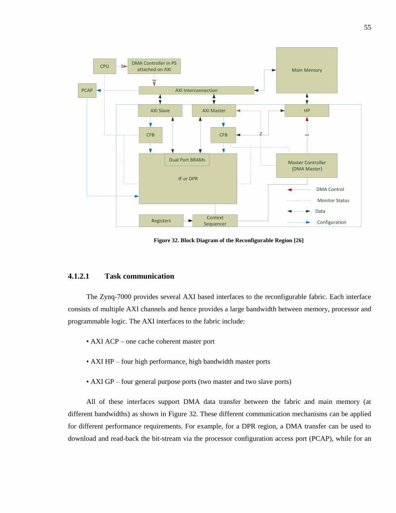
55
IF or DPR
Master Controller(DMA Master)
CFB
AXI Slave AXI Master HP
12
DMA Controller in PS attached on AXI Main Memory
CFB
CPU 3
Monitor Status
AXI Interconnection
3
DMA Control
Data
ConfigurationRegistersContext
Sequencer
Dual Port BRAMs
PCAP
Figure 32. Block Diagram of the Reconfigurable Region [26]
4.1.2.1 Task communication
The Zynq-7000 provides several AXI based interfaces to the reconfigurable fabric. Each interface
consists of multiple AXI channels and hence provides a large bandwidth between memory, processor and
programmable logic. The AXI interfaces to the fabric include:
• AXI ACP – one cache coherent master port
• AXI HP – four high performance, high bandwidth master ports
• AXI GP – four general purpose ports (two master and two slave ports)
All of these interfaces support DMA data transfer between the fabric and main memory (at
different bandwidths) as shown in Figure 32. These different communication mechanisms can be applied
for different performance requirements. For example, for a DPR region, a DMA transfer can be used to
download and read-back the bit-stream via the processor configuration access port (PCAP), while for an
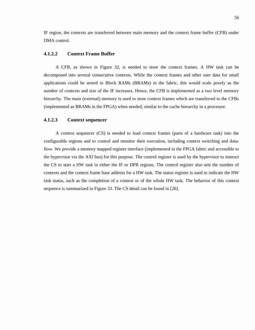
56
IF region, the contexts are transferred between main memory and the context frame buffer (CFB) under
DMA control.
4.1.2.2 Context Frame Buffer
A CFB, as shown in Figure 32, is needed to store the context frames. A HW task can be
decomposed into several consecutive contexts. While the context frames and other user data for small
applications could be stored in Block RAMs (BRAMs) in the fabric, this would scale poorly as the
number of contexts and size of the IF increases. Hence, the CFB is implemented as a two level memory
hierarchy. The main (external) memory is used to store context frames which are transferred to the CFBs
(implemented as BRAMs in the FPGA) when needed, similar to the cache hierarchy in a processor.
4.1.2.3 Context sequencer
A context sequencer (CS) is needed to load context frames (parts of a hardware task) into the
configurable regions and to control and monitor their execution, including context switching and data-
flow. We provide a memory mapped register interface (implemented in the FPGA fabric and accessible to
the hypervisor via the AXI bus) for this purpose. The control register is used by the hypervisor to instruct
the CS to start a HW task in either the IF or DPR regions. The control register also sets the number of
contexts and the context frame base address for a HW task. The status register is used to indicate the HW
task status, such as the completion of a context or of the whole HW task. The behavior of this context
sequence is summarized in Figure 33. The CS detail can be found in [26].
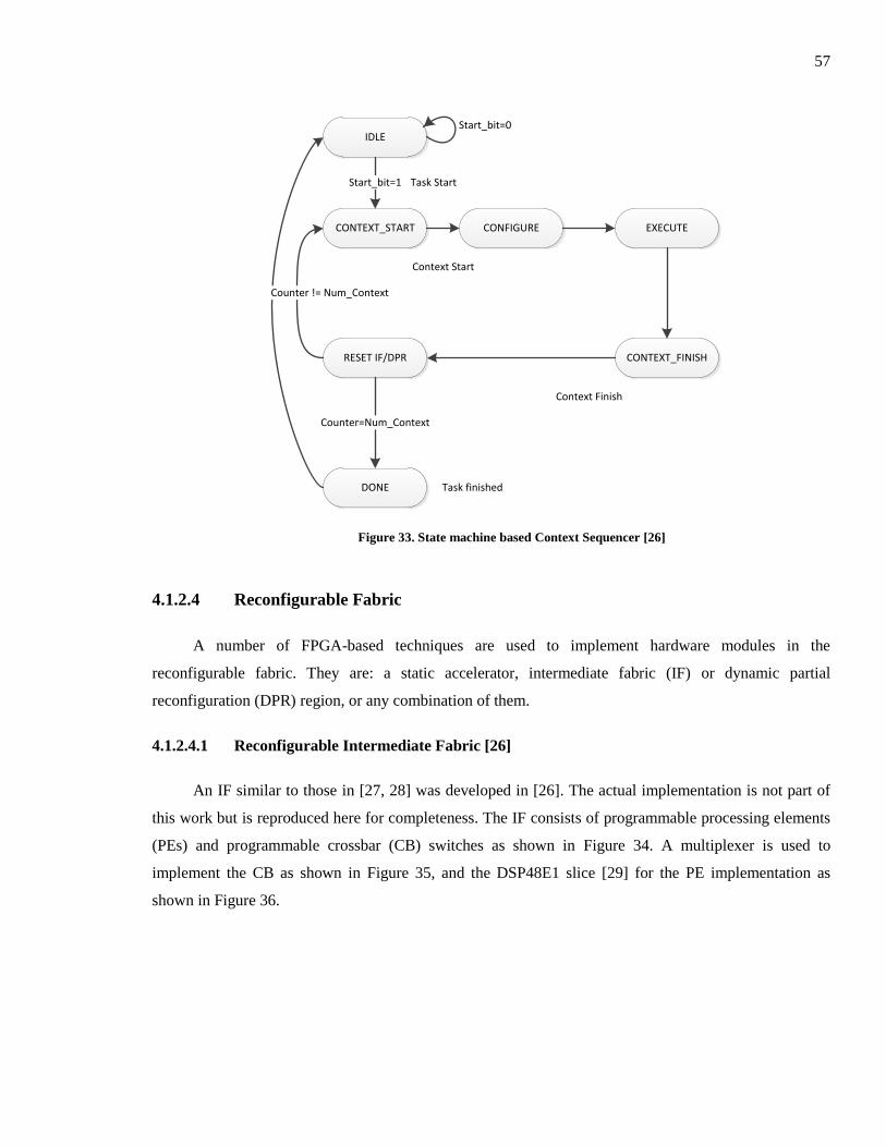
57
IDLE
CONTEXT_START
Start_bit=1
CONFIGURE
Start_bit=0
EXECUTE
CONTEXT_FINISHRESET IF/DPR
DONE
Counter=Num_Context
Counter != Num_Context
Task Start
Task finished
Context Start
Context Finish
Figure 33. State machine based Context Sequencer [26]
4.1.2.4 Reconfigurable Fabric
A number of FPGA-based techniques are used to implement hardware modules in the
reconfigurable fabric. They are: a static accelerator, intermediate fabric (IF) or dynamic partial
reconfiguration (DPR) region, or any combination of them.
4.1.2.4.1 Reconfigurable Intermediate Fabric [26]
An IF similar to those in [27, 28] was developed in [26]. The actual implementation is not part of
this work but is reproduced here for completeness. The IF consists of programmable processing elements
(PEs) and programmable crossbar (CB) switches as shown in Figure 34. A multiplexer is used to
implement the CB as shown in Figure 35, and the DSP48E1 slice [29] for the PE implementation as
shown in Figure 36.
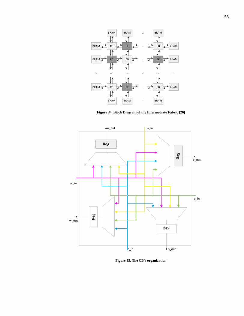
58
CB PE CB
PE CB PE
CB PE CB
BRAM
BRAM
BRAM
BRAM
BRAM
BRAM
BRAM BRAM BRAM
BRAM BRAM BRAM
... ... ...
...
...
...
... ...
...
...
...
Figure 34. Block Diagram of the Intermediate Fabric [26]
Reg
Reg
Reg
Reg
w_in
e_out
w_out
e_in
s_in s_out
n_out n_in
Figure 35. The CB's organization
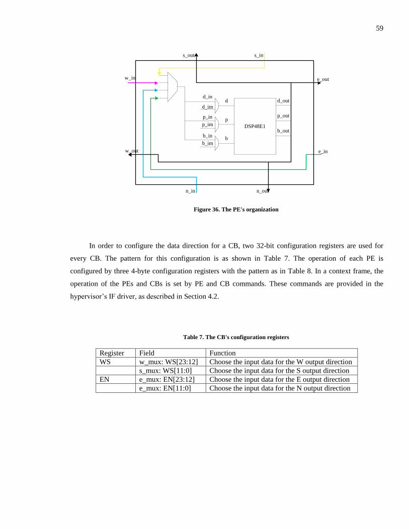
59
DSP48E1
d
p
b
d_out
p_out
b_out
d_in
d_im
p_in
p_im
b_in
b_im
w_in
w_out
e_out
e_in
n_in n_out
s_out s_in
Figure 36. The PE's organization
In order to configure the data direction for a CB, two 32-bit configuration registers are used for
every CB. The pattern for this configuration is as shown in Table 7. The operation of each PE is
configured by three 4-byte configuration registers with the pattern as in Table 8. In a context frame, the
operation of the PEs and CBs is set by PE and CB commands. These commands are provided in the
hypervisor’s IF driver, as described in Section 4.2.
Table 7. The CB's configuration registers
Register Field Function
WS w_mux: WS[23:12] Choose the input data for the W output direction
s_mux: WS[11:0] Choose the input data for the S output direction
EN e_mux: EN[23:12] Choose the input data for the E output direction
e_mux: EN[11:0] Choose the input data for the N output direction
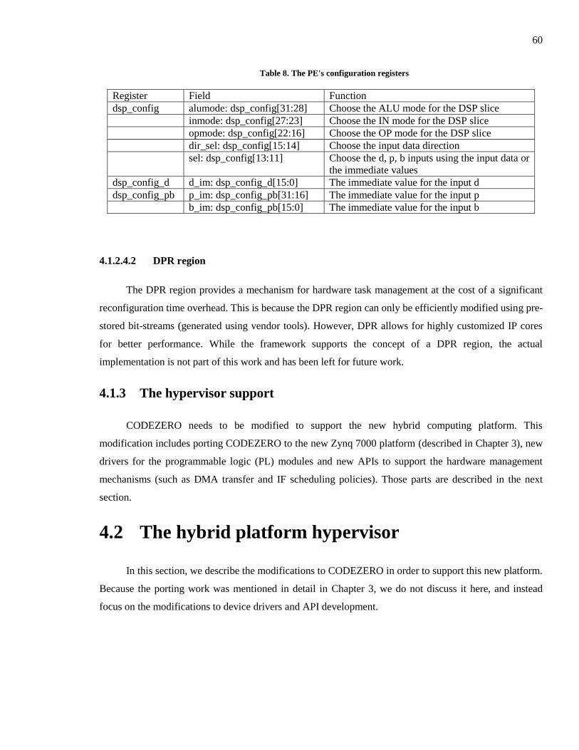
60
Table 8. The PE's configuration registers
Register Field Function
dsp_config alumode: dsp_config[31:28] Choose the ALU mode for the DSP slice
inmode: dsp_config[27:23] Choose the IN mode for the DSP slice
opmode: dsp_config[22:16] Choose the OP mode for the DSP slice
dir_sel: dsp_config[15:14] Choose the input data direction
sel: dsp_config[13:11] Choose the d, p, b inputs using the input data or
the immediate values
dsp_config_d d_im: dsp_config_d[15:0] The immediate value for the input d
dsp_config_pb p_im: dsp_config_pb[31:16] The immediate value for the input p
b_im: dsp_config_pb[15:0] The immediate value for the input b
4.1.2.4.2 DPR region
The DPR region provides a mechanism for hardware task management at the cost of a significant
reconfiguration time overhead. This is because the DPR region can only be efficiently modified using pre-
stored bit-streams (generated using vendor tools). However, DPR allows for highly customized IP cores
for better performance. While the framework supports the concept of a DPR region, the actual
implementation is not part of this work and has been left for future work.
4.1.3 The hypervisor support
CODEZERO needs to be modified to support the new hybrid computing platform. This
modification includes porting CODEZERO to the new Zynq 7000 platform (described in Chapter 3), new
drivers for the programmable logic (PL) modules and new APIs to support the hardware management
mechanisms (such as DMA transfer and IF scheduling policies). Those parts are described in the next
section.
4.2 The hybrid platform hypervisor
In this section, we describe the modifications to CODEZERO in order to support this new platform.
Because the porting work was mentioned in detail in Chapter 3, we do not discuss it here, and instead
focus on the modifications to device drivers and API development.
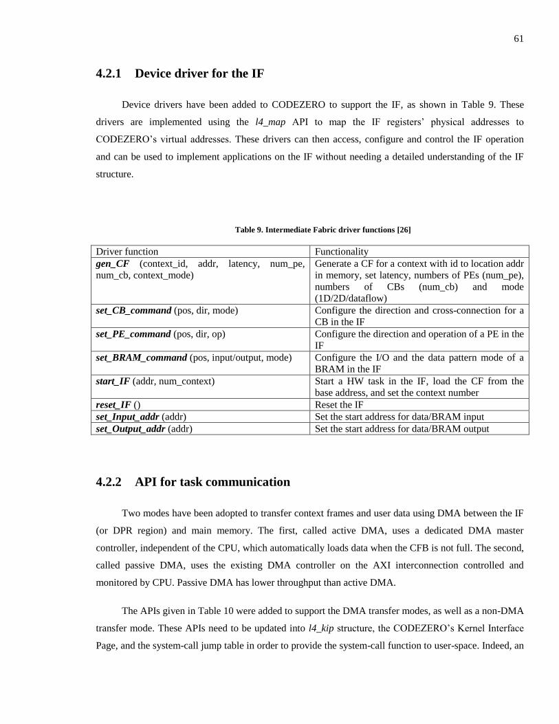
61
4.2.1 Device driver for the IF
Device drivers have been added to CODEZERO to support the IF, as shown in Table 9. These
drivers are implemented using the l4_map API to map the IF registers’ physical addresses to
CODEZERO’s virtual addresses. These drivers can then access, configure and control the IF operation
and can be used to implement applications on the IF without needing a detailed understanding of the IF
structure.
Table 9. Intermediate Fabric driver functions [26]
Driver function Functionality
gen_CF (context_id, addr, latency, num_pe,
num_cb, context_mode)
Generate a CF for a context with id to location addr
in memory, set latency, numbers of PEs (num_pe),
numbers of CBs (num_cb) and mode
(1D/2D/dataflow)
set_CB_command (pos, dir, mode) Configure the direction and cross-connection for a
CB in the IF
set_PE_command (pos, dir, op) Configure the direction and operation of a PE in the
IF
set_BRAM_command (pos, input/output, mode) Configure the I/O and the data pattern mode of a
BRAM in the IF
start_IF (addr, num_context) Start a HW task in the IF, load the CF from the
base address, and set the context number
reset_IF () Reset the IF
set_Input_addr (addr) Set the start address for data/BRAM input
set_Output_addr (addr) Set the start address for data/BRAM output
4.2.2 API for task communication
Two modes have been adopted to transfer context frames and user data using DMA between the IF
(or DPR region) and main memory. The first, called active DMA, uses a dedicated DMA master
controller, independent of the CPU, which automatically loads data when the CFB is not full. The second,
called passive DMA, uses the existing DMA controller on the AXI interconnection controlled and
monitored by CPU. Passive DMA has lower throughput than active DMA.
The APIs given in Table 10 were added to support the DMA transfer modes, as well as a non-DMA
transfer mode. These APIs need to be updated into l4_kip structure, the CODEZERO’s Kernel Interface
Page, and the system-call jump table in order to provide the system-call function to user-space. Indeed, an
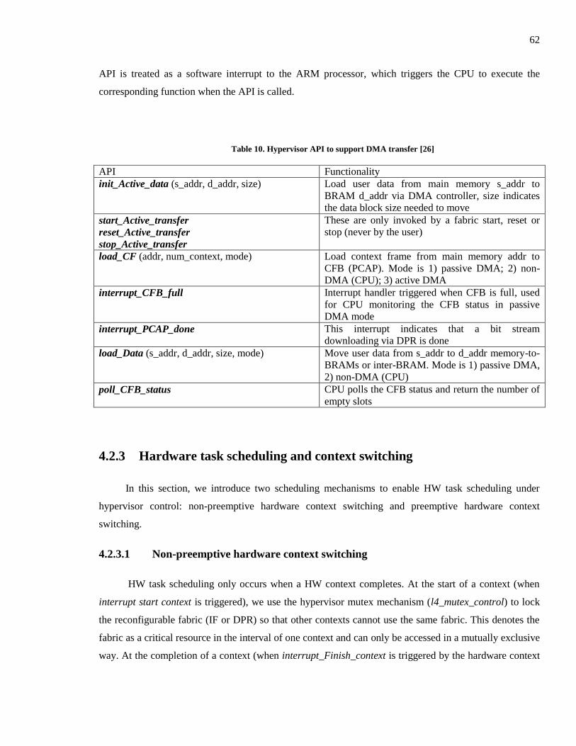
62
API is treated as a software interrupt to the ARM processor, which triggers the CPU to execute the
corresponding function when the API is called.
Table 10. Hypervisor API to support DMA transfer [26]
API Functionality
init_Active_data (s_addr, d_addr, size) Load user data from main memory s_addr to
BRAM d_addr via DMA controller, size indicates
the data block size needed to move
start_Active_transfer
reset_Active_transfer
stop_Active_transfer
These are only invoked by a fabric start, reset or
stop (never by the user)
load_CF (addr, num_context, mode) Load context frame from main memory addr to
CFB (PCAP). Mode is 1) passive DMA; 2) non-
DMA (CPU); 3) active DMA
interrupt_CFB_full Interrupt handler triggered when CFB is full, used
for CPU monitoring the CFB status in passive
DMA mode
interrupt_PCAP_done This interrupt indicates that a bit stream
downloading via DPR is done
load_Data (s_addr, d_addr, size, mode) Move user data from s_addr to d_addr memory-to-
BRAMs or inter-BRAM. Mode is 1) passive DMA,
2) non-DMA (CPU)
poll_CFB_status CPU polls the CFB status and return the number of
empty slots
4.2.3 Hardware task scheduling and context switching
In this section, we introduce two scheduling mechanisms to enable HW task scheduling under
hypervisor control: non-preemptive hardware context switching and preemptive hardware context
switching.
4.2.3.1 Non-preemptive hardware context switching
HW task scheduling only occurs when a HW context completes. At the start of a context (when
interrupt start context is triggered), we use the hypervisor mutex mechanism (l4_mutex_control) to lock
the reconfigurable fabric (IF or DPR) so that other contexts cannot use the same fabric. This denotes the
fabric as a critical resource in the interval of one context and can only be accessed in a mutually exclusive
way. At the completion of a context (when interrupt_Finish_context is triggered by the hardware context

63
sequencer), the reconfigurable fabric lock is released via l4_mutex_control. After that, a possible context
switch (l4_context_switch) among the HW tasks can happen. The advantage of non-preemptive hardware
context switching is that context saving or restoring is not necessary, as task scheduling occurs after a
context finishes. Thus minimal hypervisor modifications are required to add support for HW task
scheduling as the existing hypervisor scheduling policy and kernel scheme are satisfactory. The interrupt
handlers and API modifications added to CODEZERO to support this scheduling scheme are shown in
Table 11.
Table 11. Hypervisor API to support Hardware Task Scheduling [26]
API Functionality
interrupt_Start_context Triggered when every context starts. In the handler,
it locks IF or DPR
interrupt_Finish_context Triggered when every context finished. In the
interrupt handler, it should unlock IF
poll_Context_status
poll_Task_status
Poll the completion (task done) bit of a context
(HW task) in the status register. Also unlocks IF
(DPR) after a context finishes
4.2.3.2 Pre-emptive hardware context switching
CODEZERO can be extended to support pre-emptive hardware context switching. In this scenario,
it must be possible to save a context frame and restore it. Context-saving refers to a read-back mechanism
to record the current context counter (context id), the status, the DMA controller status and the internal
state (e.g. the bit-stream for DPR) into the thread/task control block (TCB), similar to saving the CPU
register set in a context switch. The TCB is a standard data structure used by an OS or microkernel-based
hypervisor. In CODEZERO this is called the User Thread Control Block (UTCB). A context frame
restore occurs when a HW task is swapped out, and an existing task resumes its operation. This approach
would provide a faster response, compared to non-preemptive context switching, but the overhead
(associated with saving and restoring the hardware state) is considerably higher. This requires
modification of the UTCB data structure and the hypervisor’s context switch (l4_context_switch)
mechanism, as well as requiring a number of additional APIs. While the framework supports the concept
of pre-emptive hardware context switching, the actual implementation is still very much “work in
progress” and its physical implementation has been left for future work.
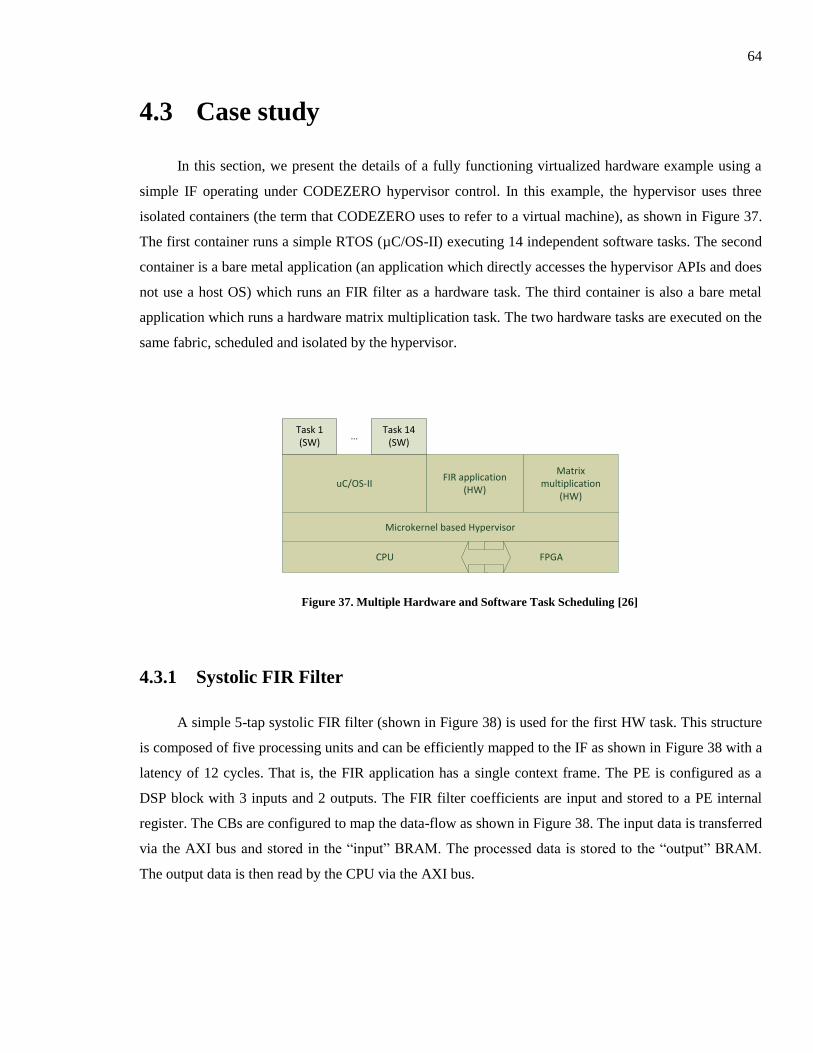
64
4.3 Case study
In this section, we present the details of a fully functioning virtualized hardware example using a
simple IF operating under CODEZERO hypervisor control. In this example, the hypervisor uses three
isolated containers (the term that CODEZERO uses to refer to a virtual machine), as shown in Figure 37.
The first container runs a simple RTOS (µC/OS-II) executing 14 independent software tasks. The second
container is a bare metal application (an application which directly accesses the hypervisor APIs and does
not use a host OS) which runs an FIR filter as a hardware task. The third container is also a bare metal
application which runs a hardware matrix multiplication task. The two hardware tasks are executed on the
same fabric, scheduled and isolated by the hypervisor.
CPU
Microkernel based Hypervisor
uC/OS-IIFIR application
(HW)
Matrix multiplication
(HW)
Task 1(SW)
Task 14(SW)
…
FPGA
Figure 37. Multiple Hardware and Software Task Scheduling [26]
4.3.1 Systolic FIR Filter
A simple 5-tap systolic FIR filter (shown in Figure 38) is used for the first HW task. This structure
is composed of five processing units and can be efficiently mapped to the IF as shown in Figure 38 with a
latency of 12 cycles. That is, the FIR application has a single context frame. The PE is configured as a
DSP block with 3 inputs and 2 outputs. The FIR filter coefficients are input and stored to a PE internal
register. The CBs are configured to map the data-flow as shown in Figure 38. The input data is transferred
via the AXI bus and stored in the “input” BRAM. The processed data is stored to the “output” BRAM.
The output data is then read by the CPU via the AXI bus.
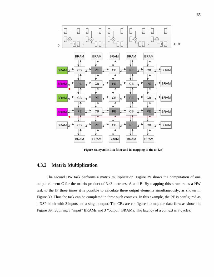
65
CB PE CB PE CB
PE CB PE CB PE
CB PE CB PE CB
PE CB PE CB PE
CB PE CB PE CB
BRAM
BRAM
BRAM
BRAM
BRAM
BRAM
BRAM
BRAM
BRAM
BRAM
BRAM BRAM BRAM BRAM BRAM
BRAM BRAM BRAM BRAM BRAM
OUT0
Figure 38. Systolic FIR filter and its mapping to the IF [26]
4.3.2 Matrix Multiplication
The second HW task performs a matrix multiplication. Figure 39 shows the computation of one
output element C for the matrix product of 3×3 matrices, A and B. By mapping this structure as a HW
task to the IF three times it is possible to calculate three output elements simultaneously, as shown in
Figure 39. Thus the task can be completed in three such contexts. In this example, the PE is configured as
a DSP block with 3 inputs and a single output. The CBs are configured to map the data-flow as shown in
Figure 39, requiring 3 “input” BRAMs and 3 “output” BRAMs. The latency of a context is 8 cycles.
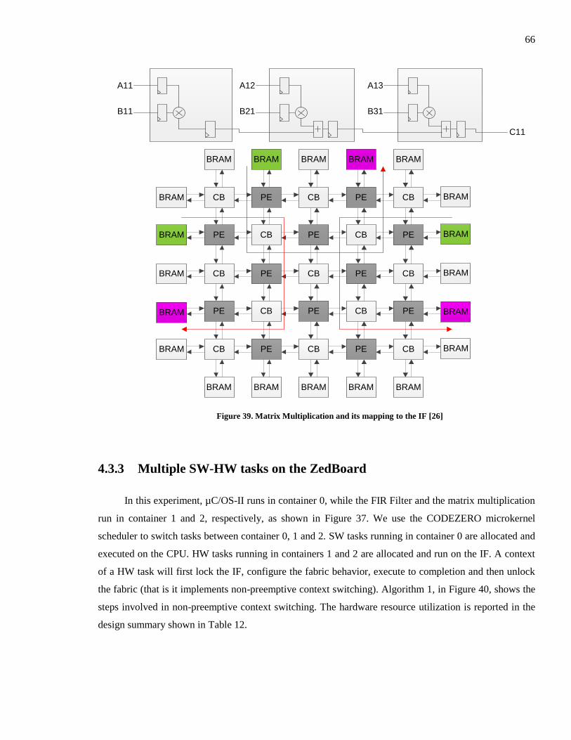
66
A11
C11
B11
A12
B21
A13
B31
CB PE CB PE CB
PE CB PE CB PE
CB PE CB PE CB
PE CB PE CB PE
CB PE CB PE CB
BRAM
BRAM
BRAM
BRAM
BRAM
BRAM
BRAM
BRAM
BRAM
BRAM
BRAM BRAM BRAM BRAM BRAM
BRAM BRAM BRAM BRAM BRAM
Figure 39. Matrix Multiplication and its mapping to the IF [26]
4.3.3 Multiple SW-HW tasks on the ZedBoard
In this experiment, µC/OS-II runs in container 0, while the FIR Filter and the matrix multiplication
run in container 1 and 2, respectively, as shown in Figure 37. We use the CODEZERO microkernel
scheduler to switch tasks between container 0, 1 and 2. SW tasks running in container 0 are allocated and
executed on the CPU. HW tasks running in containers 1 and 2 are allocated and run on the IF. A context
of a HW task will first lock the IF, configure the fabric behavior, execute to completion and then unlock
the fabric (that is it implements non-preemptive context switching). Algorithm 1, in Figure 40, shows the
steps involved in non-preemptive context switching. The hardware resource utilization is reported in the
design summary shown in Table 12.
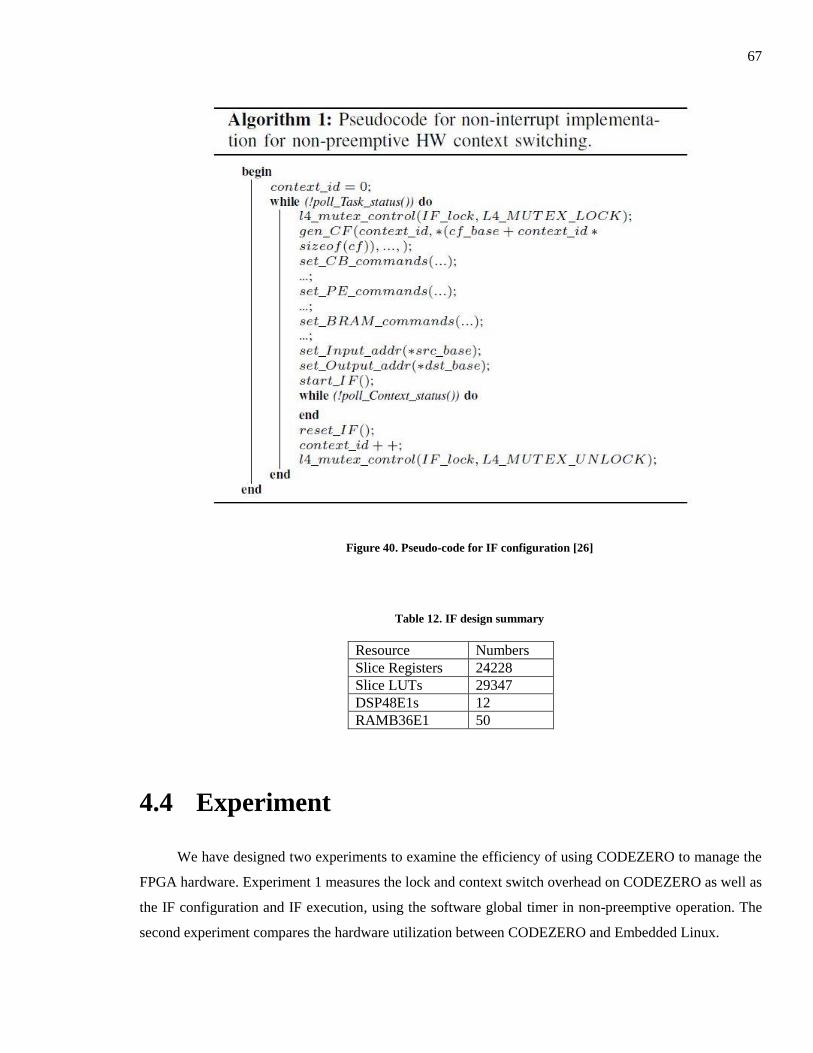
67
Figure 40. Pseudo-code for IF configuration [26]
Table 12. IF design summary
Resource Numbers
Slice Registers 24228
Slice LUTs 29347
DSP48E1s 12
RAMB36E1 50
4.4 Experiment
We have designed two experiments to examine the efficiency of using CODEZERO to manage the
FPGA hardware. Experiment 1 measures the lock and context switch overhead on CODEZERO as well as
the IF configuration and IF execution, using the software global timer in non-preemptive operation. The
second experiment compares the hardware utilization between CODEZERO and Embedded Linux.
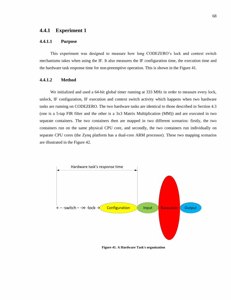
68
4.4.1 Experiment 1
4.4.1.1 Purpose
This experiment was designed to measure how long CODEZERO’s lock and context switch
mechanisms takes when using the IF. It also measures the IF configuration time, the execution time and
the hardware task response time for non-preemptive operation. This is shown in the Figure 41.
4.4.1.2 Method
We initialized and used a 64-bit global timer running at 333 MHz in order to measure every lock,
unlock, IF configuration, IF execution and context switch activity which happens when two hardware
tasks are running on CODEZERO. The two hardware tasks are identical to those described in Section 4.3
(one is a 5-tap FIR filter and the other is a 3x3 Matrix Multiplication (MM)) and are executed in two
separate containers. The two containers then are mapped in two different scenarios: firstly, the two
containers run on the same physical CPU core, and secondly, the two containers run individually on
separate CPU cores (the Zynq platform has a dual-core ARM processor). These two mapping scenarios
are illustrated in the Figure 42.
Configuration Input Execution Outputlock
Hardware task’s response time
switch
Figure 41. A Hardware Task's organization
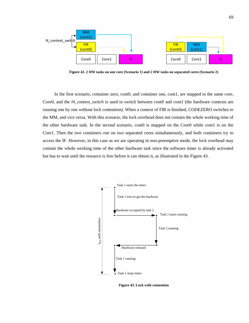
69
FIR(cont0)
MM(cont1)
Core0 Core1 IF
l4_context_switchFIR
(cont0)
Core0 Core1 IF
MM(cont1)
Figure 42. 2 HW tasks on one core (Scenario 1) and 2 HW tasks on separated cores (Scenario 2)
In the first scenario, container zero, cont0, and container one, cont1, are mapped to the same core,
Core0, and the l4_context_switch is used to switch between cont0 and cont1 (the hardware contexts are
running one by one without lock contention). When a context of FIR is finished, CODEZERO switches to
the MM, and vice versa. With this scenario, the lock overhead does not contain the whole working time of
the other hardware task. In the second scenario, cont0 is mapped on the Core0 while cont1 is on the
Core1. Then the two containers run on two separated cores simultaneously, and both containers try to
access the IF. However, in this case as we are operating in non-preemptive mode, the lock overhead may
contain the whole working time of the other hardware task since the software timer is already activated
but has to wait until the resource is free before it can obtain it, as illustrated in the Figure 43.
.
. Task 2 starts running
.
.
Task 2 running
Task 1 starts the timer
Task 1 tries to get the hardware
Hardware occupied by task 2
.
.Hardware released
Task 1 running
Task 1 stops timer
t lock
wit
h c
on
ten
tio
n
Figure 43. Lock with contention
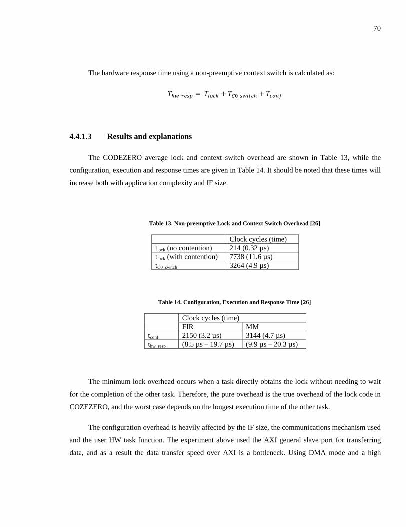
70
The hardware response time using a non-preemptive context switch is calculated as:
4.4.1.3 Results and explanations
The CODEZERO average lock and context switch overhead are shown in Table 13, while the
configuration, execution and response times are given in Table 14. It should be noted that these times will
increase both with application complexity and IF size.
Table 13. Non-preemptive Lock and Context Switch Overhead [26]
Clock cycles (time)
tlock (no contention) 214 (0.32 µs)
tlock (with contention) 7738 (11.6 µs)
tC0_switch 3264 (4.9 µs)
Table 14. Configuration, Execution and Response Time [26]
Clock cycles (time)
FIR MM
tconf 2150 (3.2 µs) 3144 (4.7 µs)
thw_resp (8.5 µs – 19.7 µs) (9.9 µs – 20.3 µs)
The minimum lock overhead occurs when a task directly obtains the lock without needing to wait
for the completion of the other task. Therefore, the pure overhead is the true overhead of the lock code in
COZEZERO, and the worst case depends on the longest execution time of the other task.
The configuration overhead is heavily affected by the IF size, the communications mechanism used
and the user HW task function. The experiment above used the AXI general slave port for transferring
data, and as a result the data transfer speed over AXI is a bottleneck. Using DMA mode and a high
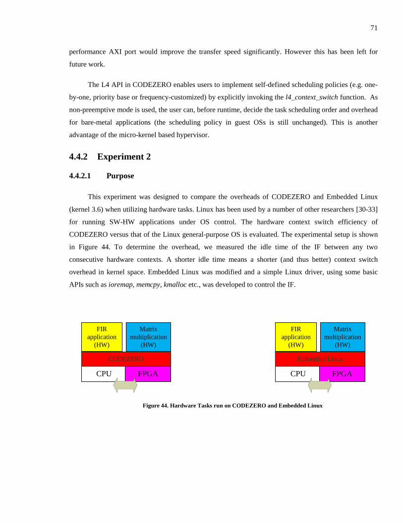
71
performance AXI port would improve the transfer speed significantly. However this has been left for
future work.
The L4 API in CODEZERO enables users to implement self-defined scheduling policies (e.g. one-
by-one, priority base or frequency-customized) by explicitly invoking the l4_context_switch function. As
non-preemptive mode is used, the user can, before runtime, decide the task scheduling order and overhead
for bare-metal applications (the scheduling policy in guest OSs is still unchanged). This is another
advantage of the micro-kernel based hypervisor.
4.4.2 Experiment 2
4.4.2.1 Purpose
This experiment was designed to compare the overheads of CODEZERO and Embedded Linux
(kernel 3.6) when utilizing hardware tasks. Linux has been used by a number of other researchers [30-33]
for running SW-HW applications under OS control. The hardware context switch efficiency of
CODEZERO versus that of the Linux general-purpose OS is evaluated. The experimental setup is shown
in Figure 44. To determine the overhead, we measured the idle time of the IF between any two
consecutive hardware contexts. A shorter idle time means a shorter (and thus better) context switch
overhead in kernel space. Embedded Linux was modified and a simple Linux driver, using some basic
APIs such as ioremap, memcpy, kmalloc etc., was developed to control the IF.
CPU
CODEZERO
FIR
application
(HW)
Matrix
multiplication
(HW)
FPGA CPU
Embedded Linux
FIR
application
(HW)
Matrix
multiplication
(HW)
FPGA
Figure 44. Hardware Tasks run on CODEZERO and Embedded Linux
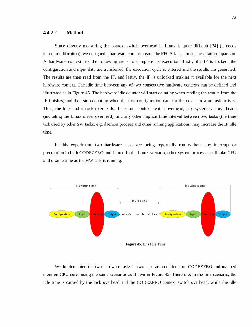
72
4.4.2.2 Method
Since directly measuring the context switch overhead in Linux is quite difficult [34] (it needs
kernel modification), we designed a hardware counter inside the FPGA fabric to ensure a fair comparison.
A hardware context has the following steps to complete its execution: firstly the IF is locked, the
configuration and input data are transferred, the execution cycle is entered and the results are generated.
The results are then read from the IF, and lastly, the IF is unlocked making it available for the next
hardware context. The idle time between any of two consecutive hardware contexts can be defined and
illustrated as in Figure 45. The hardware idle counter will start counting when reading the results from the
IF finishes, and then stop counting when the first configuration data for the next hardware task arrives.
Thus, the lock and unlock overheads, the kernel context switch overhead, any system call overheads
(including the Linux driver overhead), and any other implicit time interval between two tasks (the time
tick used by other SW tasks, e.g. daemon process and other running applications) may increase the IF idle
time.
In this experiment, two hardware tasks are being repeatedly run without any interrupt or
preemption in both CODEZERO and Linux. In the Linux scenario, other system processes still take CPU
at the same time as the HW task is running.
Configuration Input Execution Output Configuration Input Execution Outputunlock lockswitch
IF’s idle time
IF’s working time IF’s working time
Figure 45. IF's Idle Time
We implemented the two hardware tasks in two separate containers on CODEZERO and mapped
them on CPU cores using the same scenarios as shown in Figure 42. Therefore, in the first scenario, the
idle time is caused by the lock overhead and the CODEZERO context switch overhead, while the idle
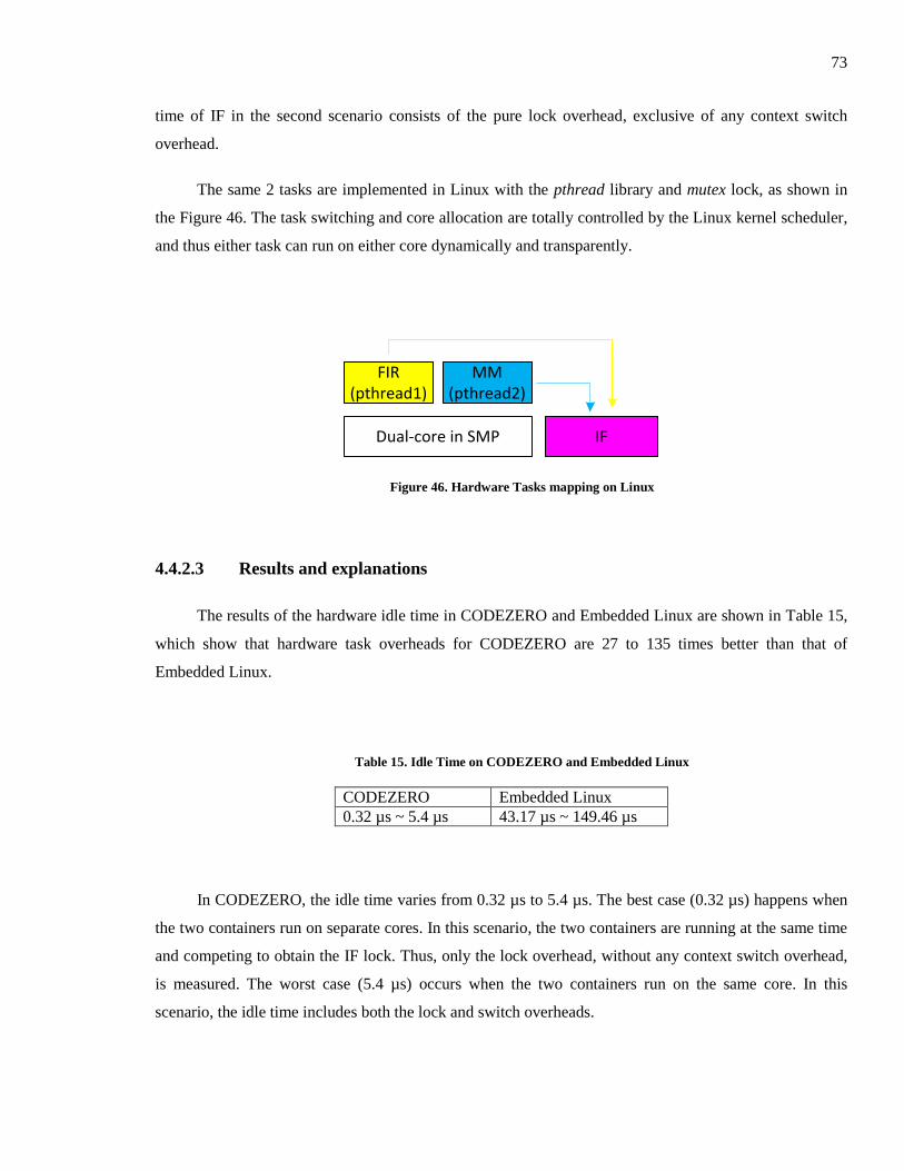
73
time of IF in the second scenario consists of the pure lock overhead, exclusive of any context switch
overhead.
The same 2 tasks are implemented in Linux with the pthread library and mutex lock, as shown in
the Figure 46. The task switching and core allocation are totally controlled by the Linux kernel scheduler,
and thus either task can run on either core dynamically and transparently.
FIR(pthread1)
Dual-core in SMP IF
MM(pthread2)
Figure 46. Hardware Tasks mapping on Linux
4.4.2.3 Results and explanations
The results of the hardware idle time in CODEZERO and Embedded Linux are shown in Table 15,
which show that hardware task overheads for CODEZERO are 27 to 135 times better than that of
Embedded Linux.
Table 15. Idle Time on CODEZERO and Embedded Linux
CODEZERO Embedded Linux
0.32 µs ~ 5.4 µs 43.17 µs ~ 149.46 µs
In CODEZERO, the idle time varies from 0.32 µs to 5.4 µs. The best case (0.32 µs) happens when
the two containers run on separate cores. In this scenario, the two containers are running at the same time
and competing to obtain the IF lock. Thus, only the lock overhead, without any context switch overhead,
is measured. The worst case (5.4 µs) occurs when the two containers run on the same core. In this
scenario, the idle time includes both the lock and switch overheads.
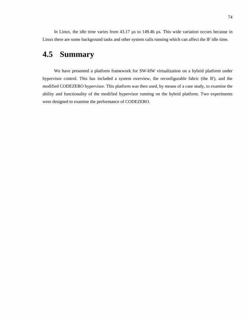
74
In Linux, the idle time varies from 43.17 µs to 149.46 µs. This wide variation occurs because in
Linux there are some background tasks and other system calls running which can affect the IF idle time.
4.5 Summary
We have presented a platform framework for SW-HW virtualization on a hybrid platform under
hypervisor control. This has included a system overview, the reconfigurable fabric (the IF), and the
modified CODEZERO hypervisor. This platform was then used, by means of a case study, to examine the
ability and functionality of the modified hypervisor running on the hybrid platform. Two experiments
were designed to examine the performance of CODEZERO.
75
Chapter 5
Conclusion and Future Work
5.1 Conclusion
In this thesis we have proposed a new approach to embedded virtualization by using a microkernel-
based hypervisor on a hybrid ARM – FPGA platform. This work included developing a deep
understanding of the embedded virtualization concept, terminologies and techniques, and a modification
of the state-of-the-art microkernel hypervisor, CODEZERO, to make it support hybrid SW-HW
virtualization on the Zynq 7000. A platform framework was developed to examine the ability and
functionality of the modified hypervisor. Case studies and experiments were designed to test the
performance of the modified hypervisor on a real platform.
Before we could begin developing a microkernel-based hypervisor for hybrid embedded
virtualization, an in-depth knowledge of the current trends in embedded virtualization techniques as well
as hypervisors needed to be obtained. As such, a review of concepts, terminologies, techniques and
theoretical abilities were given in Chapter 2. Moreover, the practical functionalities of the CODEZERO
hypervisor were examined on a real hardware platform (presented in Appendix A). Based on these
understandings, the CODEZERO hypervisor was ported to the Xilinx Zynq 7000 hybrid platform. This
work was discussed in detail in Chapter 3. Chapter 4 described additional modifications such as driver
and APIs development for the hypervisor.
A new platform framework for microkernel hypervisor based virtualization was also proposed in
Chapter 4. The framework accommodates execution of software tasks on CPUs, as either real-time (or
non-real-time) bare-metal applications or applications under OS control. By facilitating the use of static
hardware accelerators, partially reconfigure modules and intermediate fabrics, a wide range of approaches
to virtualization, to satisfy varied performance and programming needs, can be facilitated. A complete
SW-HW solution using a dual-core ARM processor and an IF implemented in FPGA, both operating
under hypervisor control was also demonstrated.
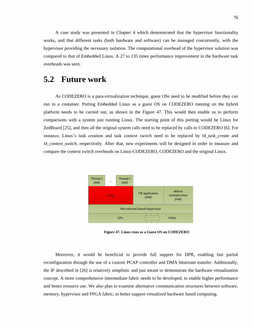
76
A case study was presented in Chapter 4 which demonstrated that the hypervisor functionality
works, and that different tasks (both hardware and software) can be managed concurrently, with the
hypervisor providing the necessary isolation. The computational overhead of the hypervisor solution was
compared to that of Embedded Linux. A 27 to 135 times performance improvement in the hardware task
overheads was seen.
5.2 Future work
As CODEZERO is a para-virtualization technique, guest OSs need to be modified before they can
run in a container. Porting Embedded Linux as a guest OS on CODEZERO running on the hybrid
platform needs to be carried out, as shown in the Figure 47. This would then enable us to perform
comparisons with a system just running Linux. The starting point of this porting would be Linux for
ZedBoard [25], and then all the original system calls need to be replaced by calls to CODEZERO [6]. For
instance, Linux’s task creation and task context switch need to be replaced by l4_task_create and
l4_context_switch, respectively. After that, new experiments will be designed in order to measure and
compare the context switch overheads on Linux-CODEZERO, CODEZERO and the original Linux.
CPU
Microkernel based Hypervisor
LinuxFIR application
(HW)
Matrix multiplication
(HW)
Thread 1(SW)
Thread n(SW)
…
FPGA
Figure 47. Linux runs as a Guest OS on CODEZERO
Moreover, it would be beneficial to provide full support for DPR, enabling fast partial
reconfiguration through the use of a custom PCAP controller and DMA bitstream transfer. Additionally,
the IF described in [26] is relatively simplistic and just meant to demonstrate the hardware virtualization
concept. A more comprehensive intermediate fabric needs to be developed, to enable higher performance
and better resource use. We also plan to examine alternative communication structures between software,
memory, hypervisor and FPGA fabric, to better support virtualized hardware based computing.

77
Finally, with these initiatives we hope to reduce the hardware context switching overhead,
particularly of the IF, with the aim of developing a competitive preemptive hardware context switching
approach, as displayed in the Figure 48. The read-back logic needs to be developed in order to pause and
resume a hardware task in the intermediate fabric. Moreover, the User-Thread Control Block structure,
the l4_utcb, in CODEZERO needs to be modified to store the current IF status (the current status in the
state machine), context sequence number and on-processing data of all PEs. This data will be used to
resume the preempted hardware task when the higher priority one finishes execution.
Input Configuration Ex
e
Input Configuration Exe Output
Output
Priority
Time
HW task 1
HW task 2
The HW task 1's read-back data will
be stored to the l4_utcb structure
Those stored data will be downloaded
to the IF when HW task 1 resumes
Figure 48. Pre-emptive hardware context switching

78
Appendix A
CODEZERO on PandaBoard
Chapter 2 presented some of the terminology relating to embedded virtualization, the novel
concepts and structure of microkernel-based embedded hypervisors. It then examined some existing
embedded hypervisors before introducing the CODEZERO hypervisor used in this work. In this
Appendix, we examine the operation and present some practical results of the CODEZERO hypervisor,
running on the conventional processor architecture, in order to understand its functionalities on a real
platform.
The PandaBoard [20] was chosen to test CODEZERO’s functionality as it has a similar dual-core
ARM Cortex-A9 CPU with almost the same processor architecture as that of the Zynq 7000 extensible
processing platform that we will be using later in this project. We believed that it would be easier and less
time-consuming to test CODEZERO on the PandaBoard and then port it to the Zynq board once we had
gained a better understanding of CODEZERO.
A.1 Introduction to the PandaBoard
The PandaBoard consists of the TI OMAP4430 SoC with dual-core ARM Cortex-A9, the 1GB
DDR2 RAM memory, and some common peripherals such as USB and UART [20]. The PandaBoard is
shown as in the Figure 49 and Table 16.
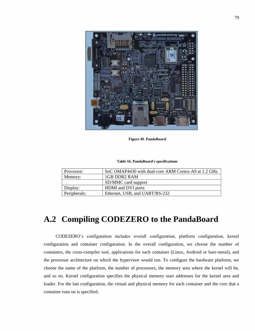
79
Figure 49. PandaBoard
Table 16. PandaBoard's specifications
Processor: SoC OMAP4430 with dual-core ARM Cortex-A9 at 1.2 GHz
Memory: 1GB DDR2 RAM
SD/MMC card support
Display: HDMI and DVI ports
Peripherals: Ethernet, USB, and UART/RS-232
A.2 Compiling CODEZERO to the PandaBoard
CODEZERO’s configuration includes overall configuration, platform configuration, kernel
configuration and container configuration. In the overall configuration, we choose the number of
containers, the cross-compiler tool, applications for each container (Linux, Android or bare-metal), and
the processor architecture on which the hypervisor would run. To configure the hardware platform, we
choose the name of the platform, the number of processors, the memory area where the kernel will be,
and so on. Kernel configuration specifies the physical memory start addresses for the kernel area and
loader. For the last configuration, the virtual and physical memory for each container and the core that a
container runs on is specified.
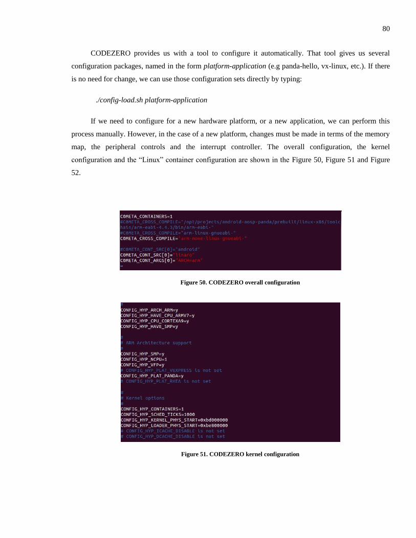
80
CODEZERO provides us with a tool to configure it automatically. That tool gives us several
configuration packages, named in the form platform-application (e.g panda-hello, vx-linux, etc.). If there
is no need for change, we can use those configuration sets directly by typing:
./config-load.sh platform-application
If we need to configure for a new hardware platform, or a new application, we can perform this
process manually. However, in the case of a new platform, changes must be made in terms of the memory
map, the peripheral controls and the interrupt controller. The overall configuration, the kernel
configuration and the “Linux” container configuration are shown in the Figure 50, Figure 51 and Figure
52.
Figure 50. CODEZERO overall configuration
Figure 51. CODEZERO kernel configuration
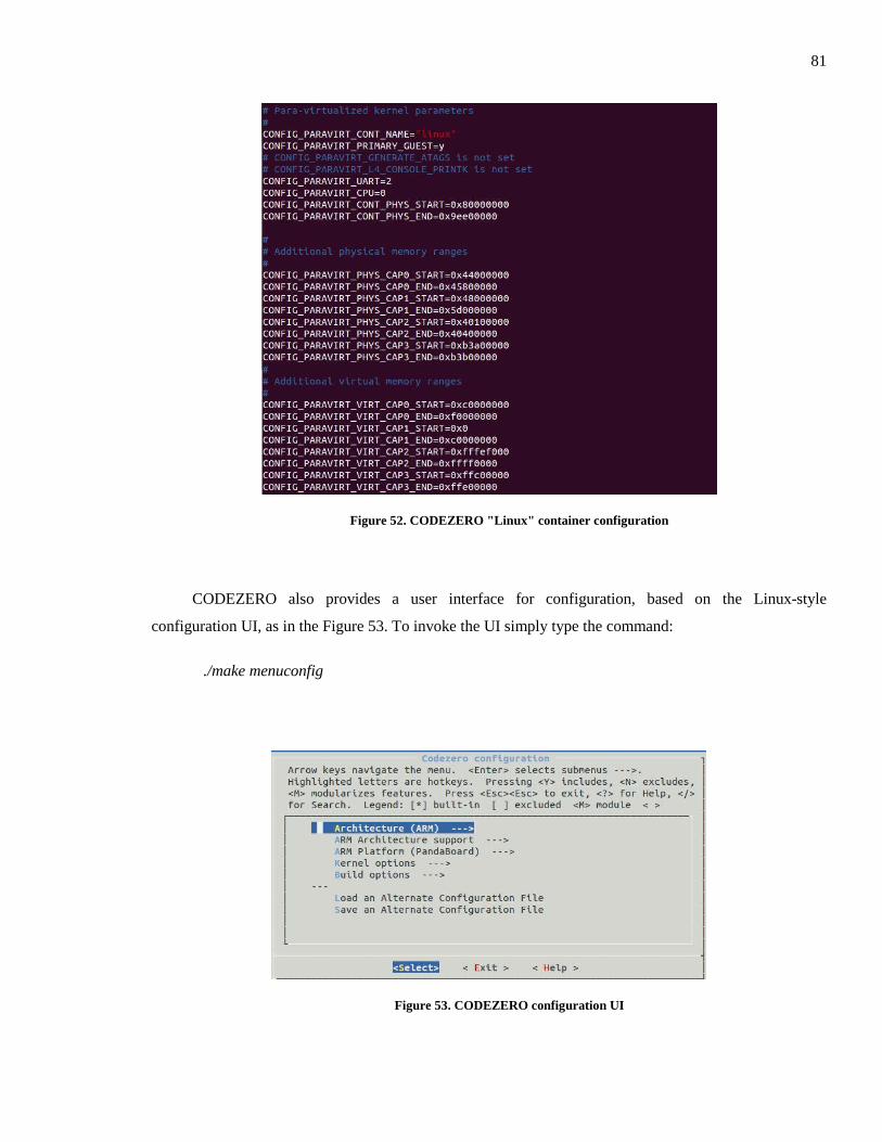
81
Figure 52. CODEZERO "Linux" container configuration
CODEZERO also provides a user interface for configuration, based on the Linux-style
configuration UI, as in the Figure 53. To invoke the UI simply type the command:
./make menuconfig
Figure 53. CODEZERO configuration UI
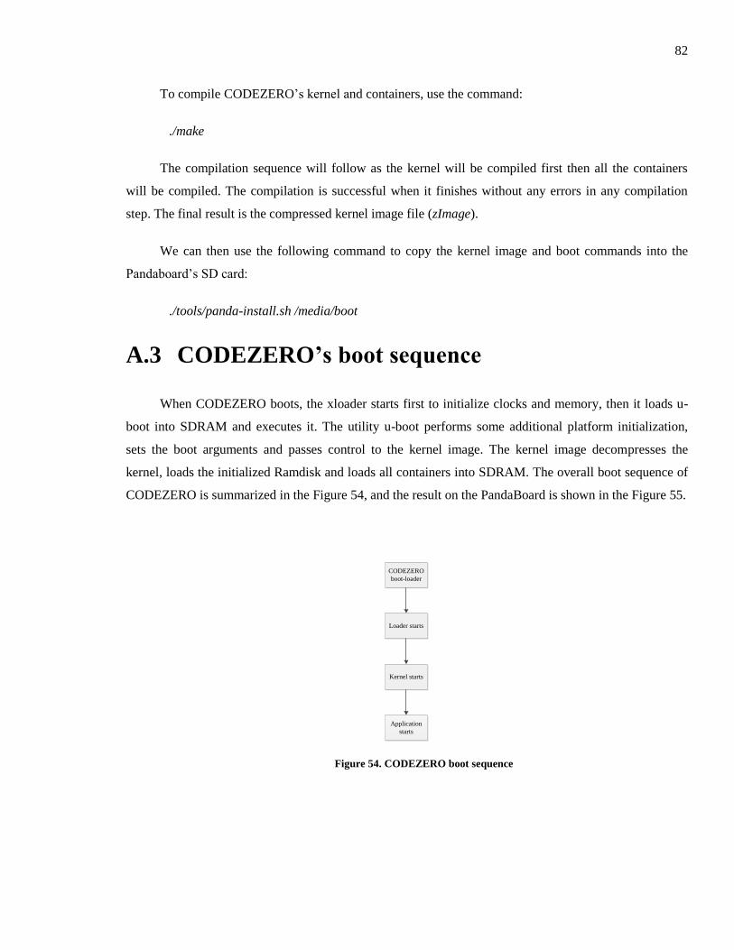
82
To compile CODEZERO’s kernel and containers, use the command:
./make
The compilation sequence will follow as the kernel will be compiled first then all the containers
will be compiled. The compilation is successful when it finishes without any errors in any compilation
step. The final result is the compressed kernel image file (zImage).
We can then use the following command to copy the kernel image and boot commands into the
Pandaboard’s SD card:
./tools/panda-install.sh /media/boot
A.3 CODEZERO’s boot sequence
When CODEZERO boots, the xloader starts first to initialize clocks and memory, then it loads u-
boot into SDRAM and executes it. The utility u-boot performs some additional platform initialization,
sets the boot arguments and passes control to the kernel image. The kernel image decompresses the
kernel, loads the initialized Ramdisk and loads all containers into SDRAM. The overall boot sequence of
CODEZERO is summarized in the Figure 54, and the result on the PandaBoard is shown in the Figure 55.
CODEZERO
boot-loader
Loader starts
Kernel starts
Application
starts
Figure 54. CODEZERO boot sequence
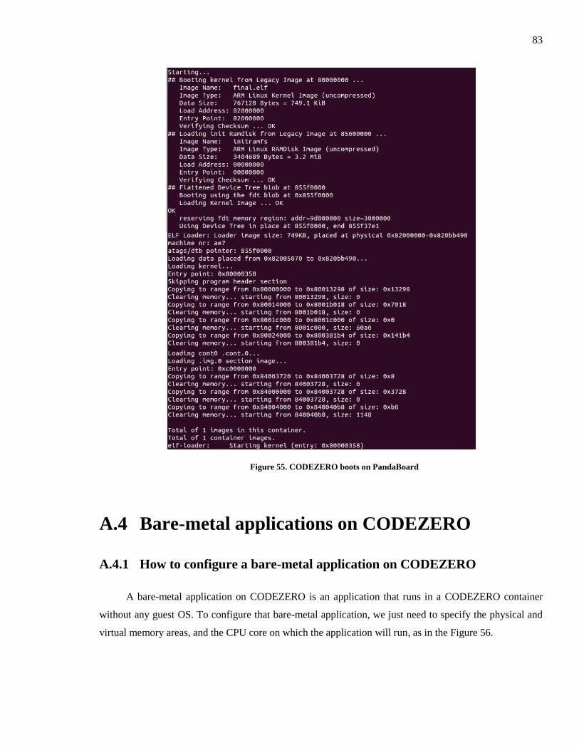
83
Figure 55. CODEZERO boots on PandaBoard
A.4 Bare-metal applications on CODEZERO
A.4.1 How to configure a bare-metal application on CODEZERO
A bare-metal application on CODEZERO is an application that runs in a CODEZERO container
without any guest OS. To configure that bare-metal application, we just need to specify the physical and
virtual memory areas, and the CPU core on which the application will run, as in the Figure 56.
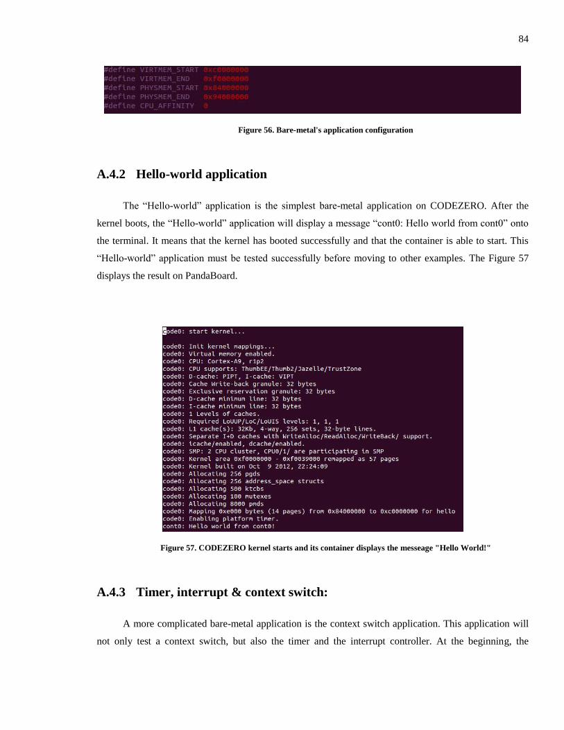
84
Figure 56. Bare-metal's application configuration
A.4.2 Hello-world application
The “Hello-world” application is the simplest bare-metal application on CODEZERO. After the
kernel boots, the “Hello-world” application will display a message “cont0: Hello world from cont0” onto
the terminal. It means that the kernel has booted successfully and that the container is able to start. This
“Hello-world” application must be tested successfully before moving to other examples. The Figure 57
displays the result on PandaBoard.
Figure 57. CODEZERO kernel starts and its container displays the messeage "Hello World!"
A.4.3 Timer, interrupt & context switch:
A more complicated bare-metal application is the context switch application. This application will
not only test a context switch, but also the timer and the interrupt controller. At the beginning, the

85
application will create a number of child threads, and then it will configure the timer and the interrupt
handler. When the application starts, child threads also start and display messages of the form “Tick X in
tid: Y” (X is a number from 1 to 10, and Y is the id of the child thread). Then the timer’s interrupt occurs,
the program jumps to the interrupt handler, clears the interrupt flag and displays the message “IRQ”.
After a number of timer’s interrupts, another child thread will be scheduled to run, and the current child
thread will be suspended, as in the Figure 58.
Figure 58. The context switch application starts and runs
A.5 GPOS (Linux) implementation on CODEZERO
Linux will run in a container of the CODEZERO hypervisor and will be treated as a CODEZERO
application. The CODEZERO kernel starts first, and then jumps to the container containing Linux to start
the Linux kernel. At the end of the boot sequence, the root file system will be mapped and the console
will be ready as shown in the Figure 59.
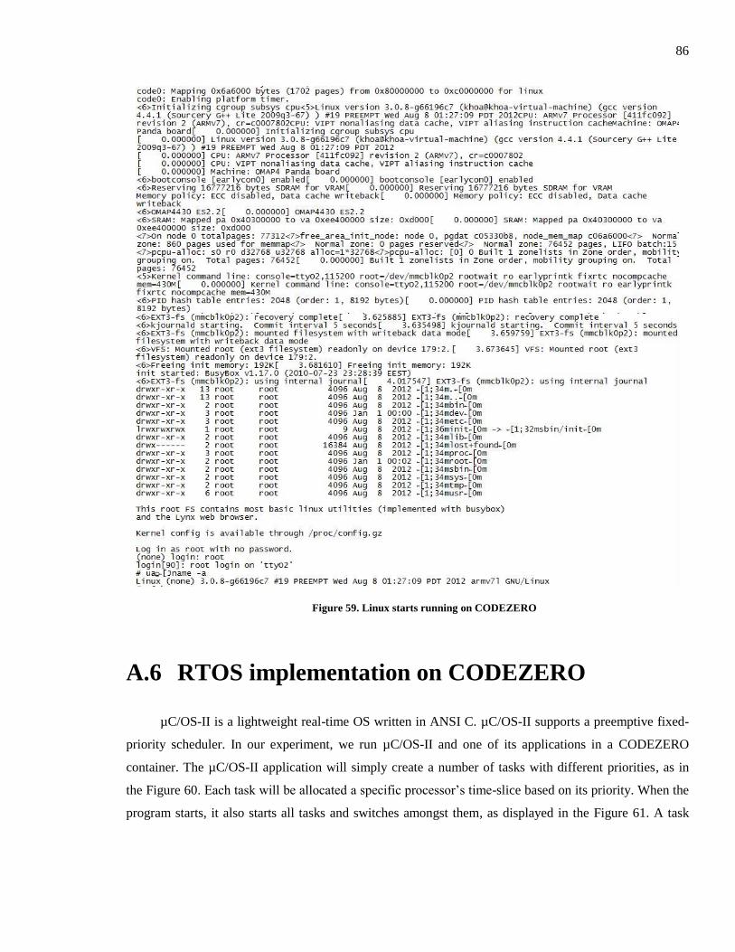
86
Figure 59. Linux starts running on CODEZERO
A.6 RTOS implementation on CODEZERO
µC/OS-II is a lightweight real-time OS written in ANSI C. µC/OS-II supports a preemptive fixed-
priority scheduler. In our experiment, we run µC/OS-II and one of its applications in a CODEZERO
container. The µC/OS-II application will simply create a number of tasks with different priorities, as in
the Figure 60. Each task will be allocated a specific processor’s time-slice based on its priority. When the
program starts, it also starts all tasks and switches amongst them, as displayed in the Figure 61. A task

87
with a higher priority will appear more times (by pre-empting other lower priority tasks) and finish in a
shorter time (more responsive), as shown in the Figure 62.
Figure 60. The µC/OS-II application starts creating many tasks in different priorities
Figure 61. Created tasks start executing
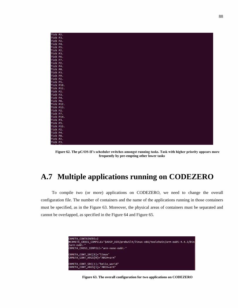
88
Figure 62. The µC/OS-II’s scheduler switches amongst running tasks. Task with higher priority appears more
frequently by pre-empting other lower tasks
A.7 Multiple applications running on CODEZERO
To compile two (or more) applications on CODEZERO, we need to change the overall
configuration file. The number of containers and the name of the applications running in those containers
must be specified, as in the Figure 63. Moreover, the physical areas of containers must be separated and
cannot be overlapped, as specified in the Figure 64 and Figure 65.
Figure 63. The overall configuration for two applications on CODEZERO
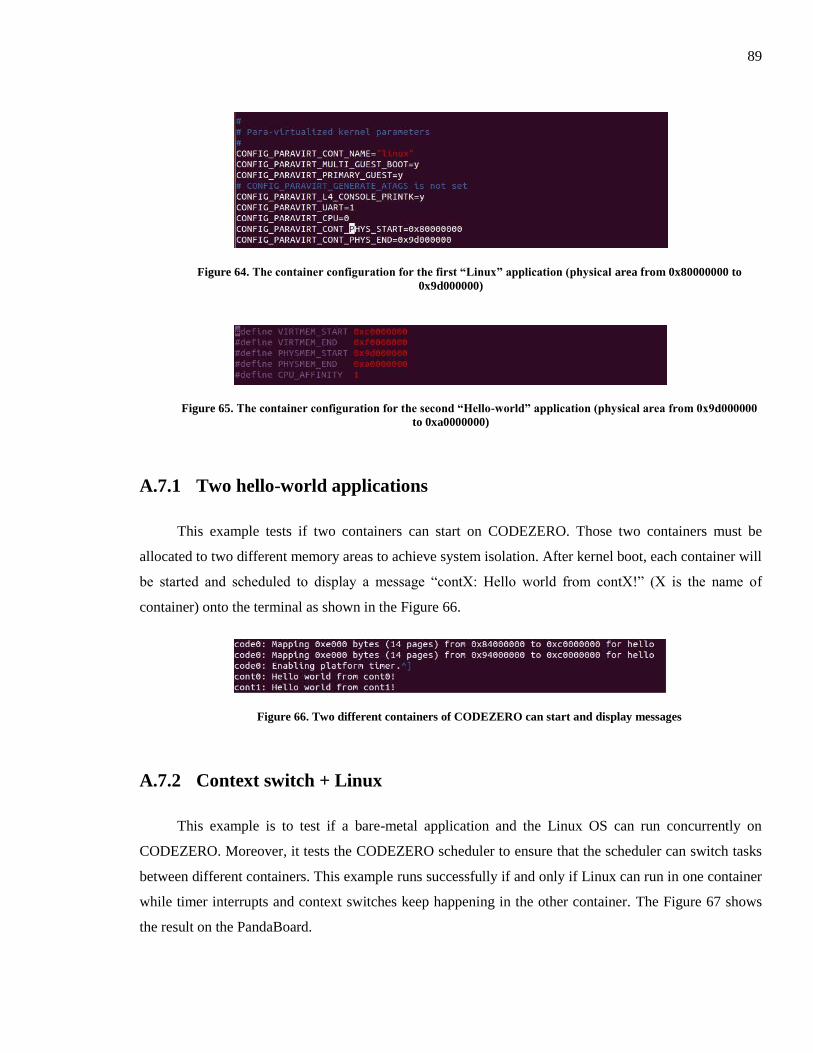
89
Figure 64. The container configuration for the first “Linux” application (physical area from 0x80000000 to
0x9d000000)
Figure 65. The container configuration for the second “Hello-world” application (physical area from 0x9d000000
to 0xa0000000)
A.7.1 Two hello-world applications
This example tests if two containers can start on CODEZERO. Those two containers must be
allocated to two different memory areas to achieve system isolation. After kernel boot, each container will
be started and scheduled to display a message “contX: Hello world from contX!” (X is the name of
container) onto the terminal as shown in the Figure 66.
Figure 66. Two different containers of CODEZERO can start and display messages
A.7.2 Context switch + Linux
This example is to test if a bare-metal application and the Linux OS can run concurrently on
CODEZERO. Moreover, it tests the CODEZERO scheduler to ensure that the scheduler can switch tasks
between different containers. This example runs successfully if and only if Linux can run in one container
while timer interrupts and context switches keep happening in the other container. The Figure 67 shows
the result on the PandaBoard.
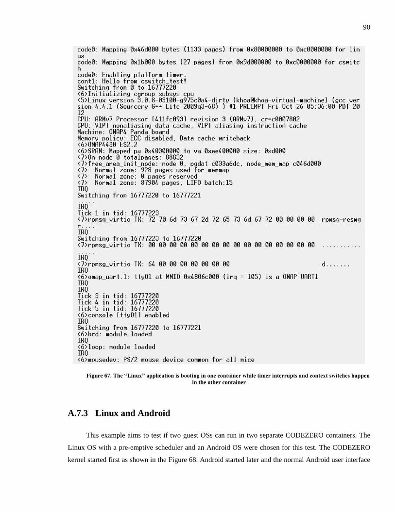
90
Figure 67. The “Linux” application is booting in one container while timer interrupts and context switches happen
in the other container
A.7.3 Linux and Android
This example aims to test if two guest OSs can run in two separate CODEZERO containers. The
Linux OS with a pre-emptive scheduler and an Android OS were chosen for this test. The CODEZERO
kernel started first as shown in the Figure 68. Android started later and the normal Android user interface
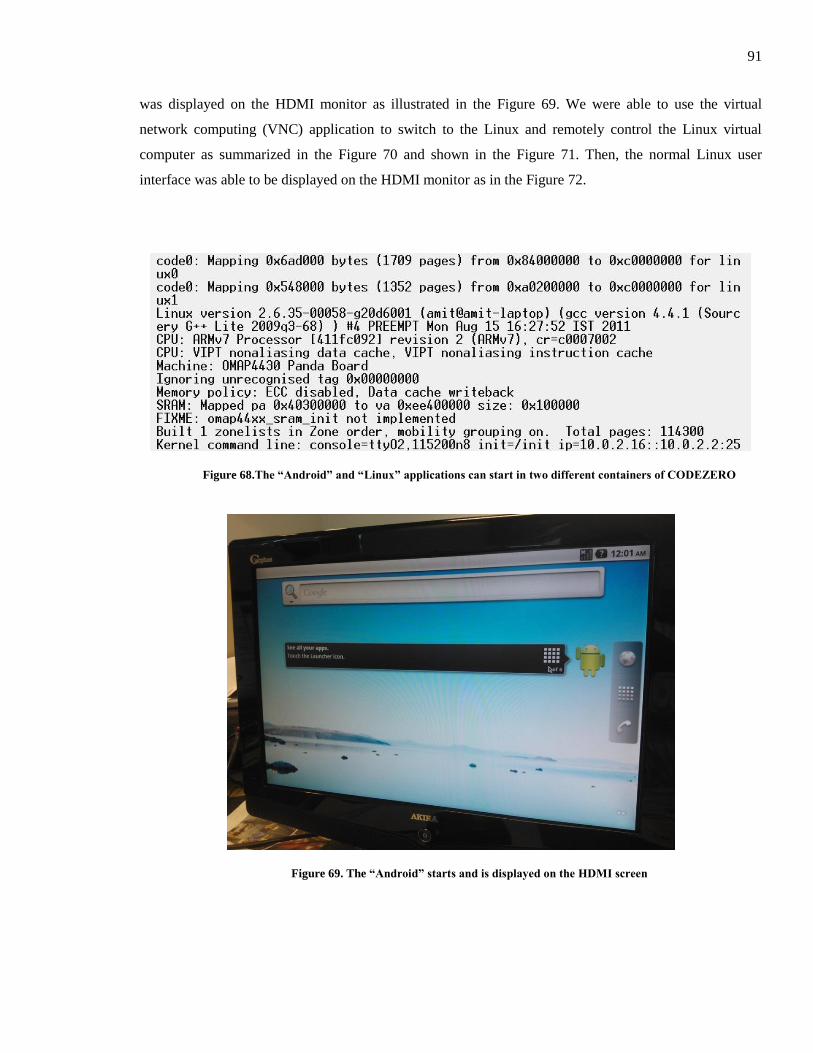
91
was displayed on the HDMI monitor as illustrated in the Figure 69. We were able to use the virtual
network computing (VNC) application to switch to the Linux and remotely control the Linux virtual
computer as summarized in the Figure 70 and shown in the Figure 71. Then, the normal Linux user
interface was able to be displayed on the HDMI monitor as in the Figure 72.
Figure 68.The “Android” and “Linux” applications can start in two different containers of CODEZERO
Figure 69. The “Android” starts and is displayed on the HDMI screen
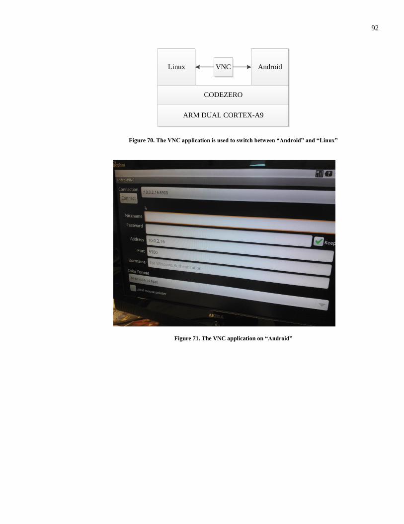
92
Linux AndroidVNC
CODEZERO
ARM DUAL CORTEX-A9
Figure 70. The VNC application is used to switch between “Android” and “Linux”
Figure 71. The VNC application on “Android”
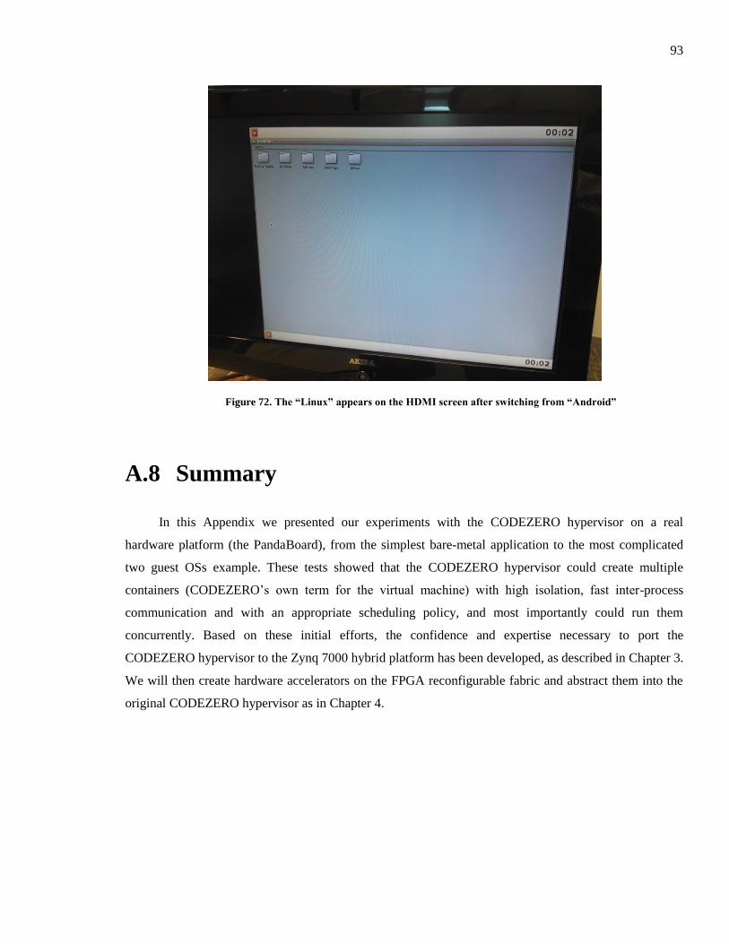
93
Figure 72. The “Linux” appears on the HDMI screen after switching from “Android”
A.8 Summary
In this Appendix we presented our experiments with the CODEZERO hypervisor on a real
hardware platform (the PandaBoard), from the simplest bare-metal application to the most complicated
two guest OSs example. These tests showed that the CODEZERO hypervisor could create multiple
containers (CODEZERO’s own term for the virtual machine) with high isolation, fast inter-process
communication and with an appropriate scheduling policy, and most importantly could run them
concurrently. Based on these initial efforts, the confidence and expertise necessary to port the
CODEZERO hypervisor to the Zynq 7000 hybrid platform has been developed, as described in Chapter 3.
We will then create hardware accelerators on the FPGA reconfigurable fabric and abstract them into the
original CODEZERO hypervisor as in Chapter 4.
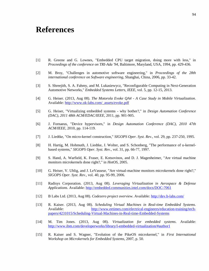
94
References
[1] R. Greene and G. Lownes, "Embedded CPU target migration, doing more with less," in
Proceedings of the conference on TRI-Ada '94, Baltimore, Maryland, USA, 1994, pp. 429-436.
[2] M. Broy, "Challenges in automotive software engineering," in Proceedings of the 28th
international conference on Software engineering, Shanghai, China, 2006, pp. 33-42.
[3] S. Shreejith, S. A. Fahmy, and M. Lukasiewycz, "Reconfigurable Computing in Next-Generation
Automotive Networks," Embedded Systems Letters, IEEE, vol. 5, pp. 12-15, 2013.
[4] G. Heiser. (2013, Aug 08). The Motorola Evoke QA4 - A Case Study in Mobile Virtualization.
Available: http://www.ok-labs.com/_assets/evoke.pdf
[5] G. Heiser, "Virtualizing embedded systems - why bother?," in Design Automation Conference
(DAC), 2011 48th ACM/EDAC/IEEE, 2011, pp. 901-905.
[6] J. Fornaeus, "Device hypervisors," in Design Automation Conference (DAC), 2010 47th
ACM/IEEE, 2010, pp. 114-119.
[7] J. Liedtke, "On micro-kernel construction," SIGOPS Oper. Syst. Rev., vol. 29, pp. 237-250, 1995.
[8] H. Hartig, M. Hohmuth, J. Liedtke, J. Wolter, and S. Schonberg, "The performance of u-kernel-
based systems," SIGOPS Oper. Syst. Rev., vol. 31, pp. 66-77, 1997.
[9] S. Hand, A. Warfield, K. Fraser, E. Kotsovinos, and D. J. Magenheimer, "Are virtual machine
monitors microkernels done right?," in HotOS, 2005.
[10] G. Heiser, V. Uhlig, and J. LeVasseur, "Are virtual-machine monitors microkernels done right?,"
SIGOPS Oper. Syst. Rev., vol. 40, pp. 95-99, 2006.
[11] Radisys Corporation. (2013, Aug 08). Leveraging Virtualization in Aerospace & Defense
Applications. Available: http://embedded.communities.intel.com/docs/DOC-7061
[12] B Labs Ltd. (2013, Aug 08). Codezero project overview. Available: http://dev.b-labs.com/
[13] R. Kaiser. (2013, Aug 08). Scheduling Virtual Machines in Real-time Embedded Systems.
Available: http://www.eetimes.com/electrical-engineers/education-training/tech-
papers/4231015/Scheduling-Virtual-Machines-in-Real-time-Embedded-Systems
[14] M. Tim Jones. (2013, Aug 08). Virtualization for embedded systems. Available:
http://www.ibm.com/developerworks/library/l-embedded-virtualization/#author1
[15] R. Kaiser and S. Wagner, "Evolution of the PikeOS microkernel," in First International
Workshop on Microkernels for Embedded Systems, 2007, p. 50.
95
[16] OpenSynergy GmbH. (2013, Aug 08). COQOS product information. Available:
http://www.opensynergy.com/en/Products/COQOS
[17] G. Heiser and B. Leslie, "The OKL4 microvisor: convergence point of microkernels and
hypervisors," in Proceedings of the first ACM asia-pacific workshop on Workshop on systems,
New Delhi, India, 2010, pp. 19-24.
[18] U. Steinberg and B. Kauer, "NOVA: a microhypervisor-based secure virtualization architecture,"
in Proceedings of the 5th European conference on Computer systems, Paris, France, 2010, pp.
209-222.
[19] J. Liedtke, "Toward real microkernels," Commun. ACM, vol. 39, pp. 70-77, 1996.
[20] PandaBoard Project. (2013, Aug 08). PandaBoard product information. Available:
http://pandaboard.org/content/resources/references
[21] ZedBoard Project. (2013, Aug 08). Zynq Evalualtion & Development Board. Available:
http://zedboard.org/content/overview
[22] Xilinx Ltd. (2013, Aug 08). Zynq-7000 Technical Reference Manual. Available:
http://www.xilinx.com/support/documentation/user_guides/ug585-Zynq-7000-TRM.pdf
[23] Xilinx Ltd. (2013, Aug 08). Zynq-7000 AP SoC Overview. Available:
http://www.xilinx.com/products/silicon-devices/soc/zynq-7000/index.htm
[24] Xilinx Ltd. (2013, Aug 08). Zynq-7000 All Programmable SoC: Concepts, Tools, and Techniques
(CTT). Available: http://www.xilinx.com/support/documentation/sw_manuals/xilinx14_3/ug873-
zynq-ctt.pdf
[25] Digilent Inc. (2013, Aug 08). Linux kernel for ZedBoard. Available:
http://www.digilentinc.com/Products/Detail.cfm?NavPath=2,400,1028&Prod=ZEDBOARD
[26] K. Dang Pham, A. K. Jain, J. Cui, S. A. Fahmy, and D. L. Maskell, "Microkernel hypervisor for a
hybrid ARM-FPGA platform," in Application-Specific Systems, Architectures and Processors
(ASAP), 2013 IEEE 24th International Conference on, 2013, pp. 219-226.
[27] J. Coole and G. Stitt, "Intermediate fabrics: virtual architectures for circuit portability and fast
placement and routing," in Proceedings of the eighth IEEE/ACM/IFIP international conference
on Hardware/software codesign and system synthesis, Scottsdale, Arizona, USA, 2010, pp. 13-
22.
[28] G. Stitt and J. Coole, "Intermediate Fabrics: Virtual Architectures for Near-Instant FPGA
Compilation," Embedded Systems Letters, IEEE, vol. 3, pp. 81-84, 2011.
[29] Xilinx Ltd. (2013, Aug 08). Virtex-6 FPGA DSP48E1 Slice User Guide. Available:
http://www.xilinx.com/support/documentation/user_guides/ug369.pdf
[30] M. Vuletic, L. Righetti, L. Pozzi, and P. Ienne, "Operating system support for interface
virtualisation of reconfigurable coprocessors," in Design, Automation and Test in Europe
Conference and Exhibition, 2004. Proceedings, 2004, pp. 748-749 Vol.1.
96
[31] R. Brodersen, A. Tkachenko, and H. Kwok-Hay So, "A unified hardware/software runtime
environment for FPGA-based reconfigurable computers using BORPH," in Hardware/Software
Codesign and System Synthesis, 2006. CODES+ISSS '06. Proceedings of the 4th International
Conference, 2006, pp. 259-264.
[32] K. Kosciuszkiewicz, F. Morgan, and K. Kepa, "Run-Time Management of Reconfigurable
Hardware Tasks Using Embedded Linux," in Field-Programmable Technology, 2007. ICFPT
2007. International Conference on, 2007, pp. 209-215.
[33] K. Rupnow, F. Wenyin, and K. Compton, "Block, Drop or Roll(back): Alternative Preemption
Methods for RH Multi-Tasking," in Field Programmable Custom Computing Machines, 2009.
FCCM '09. 17th IEEE Symposium on, 2009, pp. 63-70.
[34] F. M. David, J. C. Carlyle, and R. H. Campbell, "Context switch overheads for Linux on ARM
platforms," in Proceedings of the 2007 workshop on Experimental computer science, San Diego,
California, 2007, p. 3.