personas 77 atm - installation manual
TRANSCRIPT
Personas 77 ATM
Installation Manual
Publication ID: B006-6209-D000
Date: 0804
BOOK.BK Page 1 Monday, August 16, 2004 11:15 AM

NOTICE
The product described in this book is a licensed product of NCR Corporation.
It is the policy of NCR Corporation (NCR) to improve products as new technology, components, software, and firmware become available. NCR, therefore, reserves the right to change specifications without prior notice.
All features, functions, and operations described herein may not be marketed by NCR in all parts of the world. In some instances, photographs are of equipment prototypes. Therefore, before using this document, consult with your NCR representative or NCR office for information that is applicable and current.
To maintain the quality of our publications, we need your comments on the accuracy, clarity, organization, and value of this book.
Address correspondence to:
NCR Financial Solutions Group Ltd.Information SolutionsDiscovery Centre3 Fulton RoadDundee, ScotlandDD2 4SW
© 2002, 2003, 2004By NCR CorporationDayton, Ohio U.S.A.All Rights Reserved
BOOK.BK Page 2 Monday, August 16, 2004 11:15 AM
BOOK.BK Page iii Monday, August 16, 2004 11:15 AM
NCR Personas 77 ATM Installation Manual
iiiFederal Communications Commission (FCC) Radio Frequency Interference Statement
Note: This equipment has been tested and found to comply with the limits for a Class A digital device, pursuant to Part 15 of the FCC Rules. These limits are designed to provide reasonable protection against harmful interference when the equipment is operated in a commercial environment. This equipment generates, uses, and can radiate radio frequency energy and, if not installed and used in accordance with the instruction manual, may cause harmful interference to radio communications. Operation of this equipment in a residential area is likely to cause harmful interference in which case the user will be required to correct the interference at his own expense.
Canadian Class A Device Declaration
This digital apparatus does not exceed the Class A limits for radio noise emissions from digital apparatus set out in the Radio Interference Regulations of the Canadian Department of Communications.
Le présent appareil numérique n’émet pas de bruits radioélectriques dépassant les limites applicables aux appareils numériques de la classe A prescrites dans le Réglement sur le brouillage radioélectrique édicté par le ministère des Communications du Canada.
BOOK.BK Page iv Monday, August 16, 2004 11:15 AM
Information to UserThis equipment must be installed and used in strict accordance with the manufacturer’s instructions. However, there is no guarantee that interference to radio communications will not occur in a particular commercial installation. If this equipment does cause interference, which can be determined by turning the equipment off and on, the user is encouraged to consult an NCR service representative immediately.
Caution NCR Corporation is not responsible for any radio or television interference caused by unauthorised modifications of this equipment or the substitution or attachment of connecting cables and equipment other than those specified by NCR. Such unauthorized modifications, substitutions, or attachments may void the user’s authority to operate the equipment. The correction of interference caused by such unauthorized modifications, substitutions, or attachments will be the responsibility of the user.
iv NCR Personas 77 ATM Installation Manual
BOOK.BK Page v Monday, August 16, 2004 11:15 AM
NCR Personas 77 ATM Installation Manual
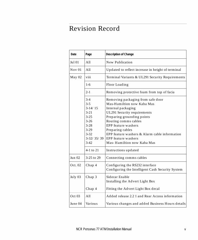
vRevision Record
Date Page Description of Change
Jul 01 All New Publication
Nov 01 All Updated to reflect increase in height of terminal
May 02 viii Terminal Variants & UL291 Security Requirements
1-6 Floor Loading
2-1 Removing protective foam from top of facia
3-43-53-14/153-213-253-263-283-293-323-32/35/393-42
Removing packaging from safe doorMas-Hamiltion now Kaba MasInternal packagingUL291 Security requirementsPreparing grounding pointsRouting comms cablesEPP feature washersPreparing cablesEPP feature washers & Alarm cable information EPP feature washersMas- Hamiltion now Kaba Mas
4-1 to 21 Instructions updated
Jun 02 3-25 to 29 Connecting comms cables
Oct. 02 Chap 4 Configuring the RS232 interfaceConfiguring the Intelligent Cash Security System
July 03 Chap 3 Sidecar EnableInstalling the Advert Light Box
Chap 4 Fitting the Advert Light Box decal
Oct 03 All Added release 2.2 1 and Rear Access information
June 04 Various Various changes and added Business Hours details

BOOK.BK Page vi Monday, August 16, 2004 11:15 AM
vi NCR Personas 77 ATM Installation Manual
Preface
BOOK.BK Page vii Monday, August 16, 2004 11:15 AM
NCR Personas 77 ATM Installation Manual
viiAbout This Document
Preface
This manual is intended for NCR personnel, or NCR customer personnel who are required to install an NCR Personas 77 ATM.
The purpose of this manual is to describe how to take the ATM from its point of delivery and install it in the required location.
This manual is divided into five chapters:
● Chapter 1, Installation Procedures: This chapter lists the steps and tools required to install a Personas 77, and details how to move the ATM.
● Chapter 2, Unpacking the Personas 77: This chapter describes how to unpack the ATM and remove it from its pallet.
● Chapter 3, Installing the Personas 77: This chapter describes the procedures for installing the ATM.
● Chapter 4, Configuring the Personas 77: This chapter describes the configuration procedure for the ATM.
● Chapter 5, Fitting Decals to the Personas 77: This chapter describes how to apply decals to the front of the ATM.
To install the ATM, you must follow the procedures given in each chapter, starting at Chapter 1 and working through to Chapter 4. The procedures in Chapter 5 can be followed at any time, before or after the installation of the ATM.
Warning The Personas 77 is top heavy, do not rack out the top cabinet while the dispenser is racked out.
About This DocumentPreface
BOOK.BK Page viii Monday, August 16, 2004 11:15 AM
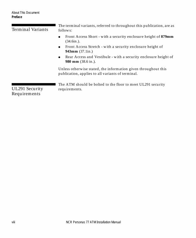
Terminal Variants 0
The terminal variants, referred to throughout this publication, are as follows:
● Front Access Short - with a security enclosure height of 879mm (34.6in.).
● Front Access Stretch - with a security enclosure height of 943mm (37.1in.)
● Rear Access and Vestibule - with a security enclosure height of 980 mm (38.6 in.).
Unless otherwise stated, the information given throughout this publication, applies to all variants of terminal.
UL291 Security Requirements
The ATM should be bolted to the floor to meet UL291 security requirements.
viii NCR Personas 77 ATM Installation Manual
Contents
Table of Contents
ix
BOOK.BK Page ix Monday, August 16, 2004 11:15 AM
NCR Personas 77 ATM Installation Manual
About This Document
Preface.................................................................................................. 1-viiTerminal Variants ......................................................................... 1-viiiUL291 Security Requirements .................................................... 1-viii
Chapter 1Installation Procedures
Introduction............................................................................................ 1-1Site Preparation................................................................................. 1-1
Tools Required for Installation of the Personas 77 ...........................1-2Moving the Personas 77........................................................................ 1-3
Packaging Dimensions..................................................................... 1-4Weights .............................................................................................. 1-7
Chapter 2Unpacking the Personas 77
Removing the External Packaging...................................................... 2-1Air/Sea Packaging ........................................................................... 2-1Road Packaging ................................................................................ 2-1
Inspecting for Damage.......................................................................... 2-2Installation Report Form ................................................................. 2-2
Removing From the Pallet....................................................................2-3Air/Sea Pallet (Using a Fork-Lift).................................................. 2-3Road Pallet (Using Lifting Trolleys) .............................................. 2-5
Table of Contents
BOOK.BK Page x Monday, August 16, 2004 11:15 AM
Conforming to AFA Regulations...................................................... 2-10Front Access Short.......................................................................... 2-10Front Access Stretch....................................................................... 2-10Rear Access and Vestibule ............................................................ 2-10
Chapter 3Installing the Personas 77
Opening the Exterior of the Personas 77 ........................................... 3-1Front Access ...................................................................................... 3-1Rear Access........................................................................................ 3-6
How to Operate the Security Enclosure Locks ................................. 3-8Keylocks........................................................................................... 3-10Combination Locks ........................................................................ 3-10
Controlled Access Electronic Lock ................................................... 3-13Activating the Controlled Access Electronic Lock ......................... 3-15
Controlled Access Electronic Lock (Type 1)............................... 3-18Controlled Access Electronic Lock (Type 2)............................... 3-20
LG Combogard 33e Electronic Lock................................................. 3-24How to Unlock the Electronic Lock............................................. 3-24How to Lock the Electronic Lock ................................................. 3-25How to Change the Combination ................................................ 3-25Emergency Opening Procedure ................................................... 3-26
LG Audit 66e Electronic Lock ........................................................... 3-27How to Unlock the Electronic Lock............................................. 3-27How to Lock the Electronic Lock ................................................. 3-28Silent Alarm Operation ................................................................. 3-28How to Change the Combination ................................................ 3-28Emergency Opening Procedure ................................................... 3-28
Removing the Internal Packaging .................................................... 3-30Front Access .................................................................................... 3-31Rear Access...................................................................................... 3-38
How to Install a Vestibule ATM ....................................................... 3-39Bolting the ATM to the Floor ............................................................ 3-48
Security Bolts Specifications ......................................................... 3-48Bolting to the Floor ........................................................................ 3-50
x NCR Personas 77 ATM Installation Manual
Table of Contents
BOOK.BK Page xi Monday, August 16, 2004 11:15 AM
Connecting Cables............................................................................... 3-51Top Cabinet ..................................................................................... 3-52Video Camera.................................................................................. 3-60Front Access Short Security Enclosure ........................................ 3-61Front Access Stretch and CEN Security Enclosure....................3-68Rear Access Security Enclosure.................................................... 3-76
Sidecar Enable...................................................................................... 3-79Advert Light Box .................................................................................3-80
Chapter 4Configuring the Personas 77
Introduction............................................................................................ 4-1Application Software ....................................................................... 4-1Communications Configuration..................................................... 4-2
Currency Cassette.................................................................................. 4-3OS/2 Application .................................................................................. 4-4
Initial Configuration - Product ID.................................................. 4-4Configuring Modules/Devices ...................................................... 4-4
APTRA Application ............................................................................4-15Initial Configuration - Product ID................................................ 4-15Configuring Modules/Devices .................................................... 4-15Configuring Communications ......................................................4-19
Thermal Printers .................................................................................. 4-24Receipt Printer.................................................................................4-25Journal Printer.................................................................................4-26Basic Configuration ........................................................................ 4-27Advanced Configuration and Calibration .................................. 4-28
Intelligent Cash Security System....................................................... 4-32Fitting the Containment Mat ........................................................ 4-32Verifying the System...................................................................... 4-33Making the System Live ................................................................ 4-37
NCR Personas 77 ATM Installation Manual xi
Table of Contents
BOOK.BK Page xii Monday, August 16, 2004 11:15 AM
Chapter 5Applying Decals to the ATM
Introduction ........................................................................................... 5-1Applying Decals.................................................................................... 5-2
Card Orientation Window.............................................................. 5-2Card Accept Window ...................................................................... 5-3Bar Code Reader Card Accept Decal............................................. 5-4Exit/Entry Slots ................................................................................ 5-4Advert Light Box.............................................................................. 5-4
IndexIndex ...........................................................................................................1
User Feedback Form
xii NCR Personas 77 ATM Installation Manual
Table of ContentsInstallation Procedures
BOOK.BK Page xiii Monday, August 16, 2004 11:15 AM
NCR Personas 77 ATM Installation Manual
Chapter 1
Installation Procedures
Introduction 1-1Site Preparation 1-1
Tools Required for Installation of the Personas 77 1-2
Moving the Personas 77 1-3Packaging Dimensions 1-4
Front Access Short, Business Hours, German Standard, CEN 3 and CEN 4 Security 1-4
Front Access Stretch and Rear Access 1-5Vestibule 1-6
Weights 1-7Front Access Stretch with Standard Security 1-7Front Access Short with CEN 3 or CEN 4 Security 1-7Front Access Short with German Standard or Standard Security 1-7Front Access Short with Business Hours Security 1-7Rear Access with Standard Security 1-7Rear Access with German Standard Security 1-7Rear Access with CEN A3 Security 1-8Vestibule with Standard Security 1-9Vestibule with German Standard Security 1-9Vestibule with CEN A3 Security 1-9Advert Light 1-9

Table of ContentsInstallation Procedures
BOOK.BK Page xiv Monday, August 16, 2004 11:15 AM
NCR Personas 77 ATM Installation Manual
Introduction
BOOK.BK Page 1 Monday, August 16, 2004 11:15 AM
NCR Personas 77 ATM Installation Manual
-11Installation Procedures A
Introduction 1
The installation of the terminal can be divided into several steps:
● Moving the ATM● Unpacking the ATM● Inspecting the ATM for damage● Removing the shipping pallet● Removing the internal packaging● Bolting the ATM to the floor● Connecting cables to the ATM● Configuring the ATM (if necessary)● Applying decals to the ATM.
These steps are described in detail in the chapters that follow.
Site Preparation 1
Before installing the ATM make sure that the proposed installation site conforms with the specifications given in the NCR Personas 77 ATM Site Preparation (B006-6208). If the ATM is being installed into a site with less space than recommended, it may be necessary to install cables before the unit is moved into its final location.
Installation ProceduresTools Required for Installation of the Personas 77
BOOK.BK Page 2 Monday, August 16, 2004 11:15 AM
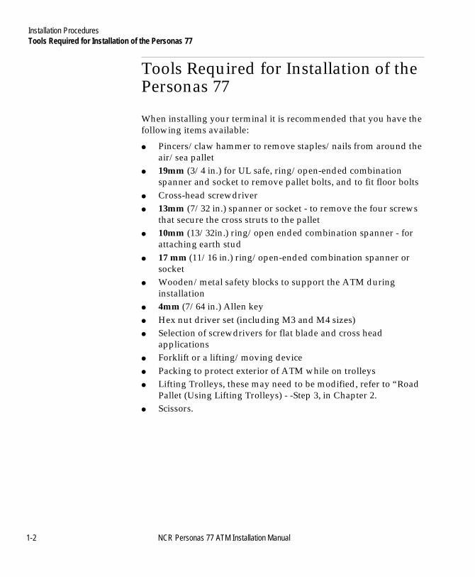
Tools Required for Installation of the Personas 77 1
When installing your terminal it is recommended that you have the following items available:
● Pincers/claw hammer to remove staples/nails from around the air/sea pallet
● 19mm (3/4 in.) for UL safe, ring/open-ended combination spanner and socket to remove pallet bolts, and to fit floor bolts
● Cross-head screwdriver● 13mm (7/32 in.) spanner or socket - to remove the four screws
that secure the cross struts to the pallet● 10mm (13/32in.) ring/open ended combination spanner - for
attaching earth stud● 17 mm (11/16 in.) ring/open-ended combination spanner or
socket● Wooden/metal safety blocks to support the ATM during
installation● 4mm (7/64 in.) Allen key● Hex nut driver set (including M3 and M4 sizes)● Selection of screwdrivers for flat blade and cross head
applications● Forklift or a lifting/moving device● Packing to protect exterior of ATM while on trolleys● Lifting Trolleys, these may need to be modified, refer to “Road
Pallet (Using Lifting Trolleys) - -Step 3, in Chapter 2.● Scissors.
1-2 NCR Personas 77 ATM Installation Manual
Installation ProceduresMoving the Personas 77
BOOK.BK Page 3 Monday, August 16, 2004 11:15 AM
Moving the Personas 77 1
To reduce the chance of damaging the ATM, and/or the premises, the ATM should be moved with its packaging intact.
Move the ATM to its approximate installation site using either a fork-lift truck or a moving trolley.
There are two types of pallet and external packaging used on the Personas 77:
● Air/Sea Pallet with the ATM protected by a Cardboard Container - Used when the ATM has been shipped by air/sea.
● Road Pallet with the ATM protected by a Plastic Covering - Used when the ATM is delivered straight from the factory.
NCR Personas 77 ATM Installation Manual 1-3
Installation ProceduresMoving the Personas 77
BOOK.BK Page 4 Monday, August 16, 2004 11:15 AM
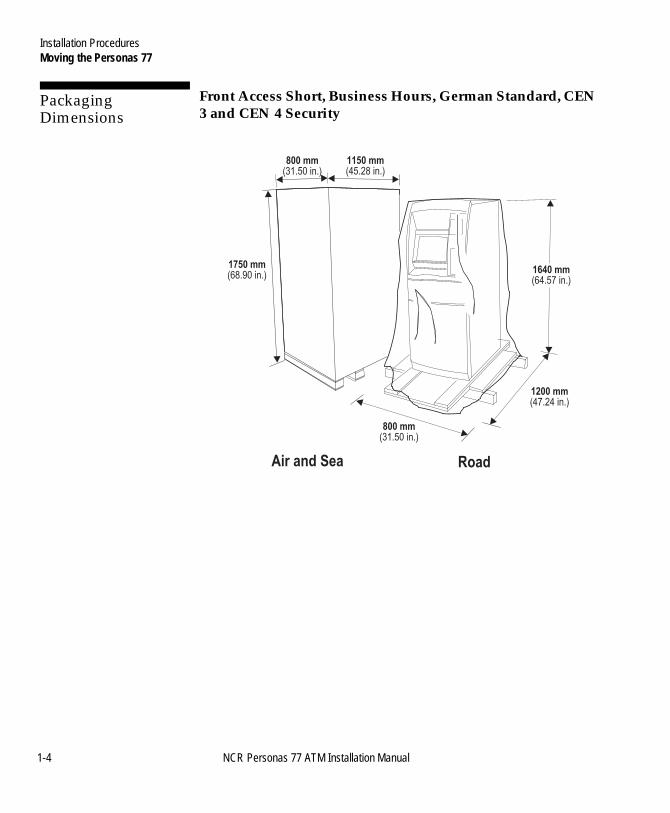
Packaging Dimensions 1
Front Access Short, Business Hours, German Standard, CEN 3 and CEN 4 Security 1
Air and Sea Road
1750 mm
(68.90 in.)
800 mm
(31.50 in.)
1150 mm
(45.28 in.)
1200 mm
(47.24 in.)
800 mm
(31.50 in.)
1640 mm
(64.57 in.)
1-4 NCR Personas 77 ATM Installation Manual
Installation ProceduresMoving the Personas 77
BOOK.BK Page 5 Monday, August 16, 2004 11:15 AM
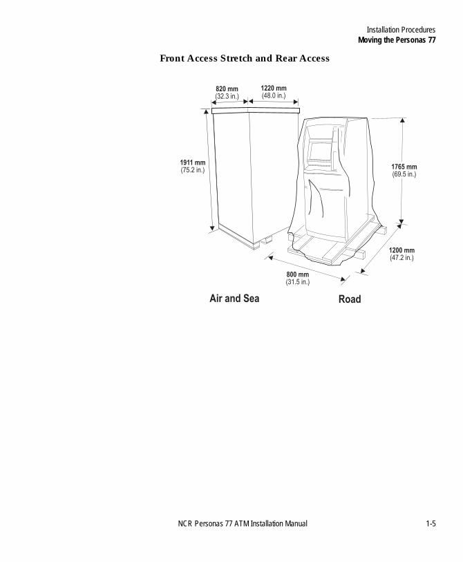
Front Access Stretch and Rear Access 1
Air and Sea Road
1911 mm
(75.2 in.)
800 mm
(31.5 in.)
1220 mm
(48.0 in.)
1200 mm
(47.2 in.)
820 mm
(32.3 in.)
1765 mm
(69.5 in.)
NCR Personas 77 ATM Installation Manual 1-5
Installation ProceduresMoving the Personas 77
BOOK.BK Page 6 Monday, August 16, 2004 11:15 AM
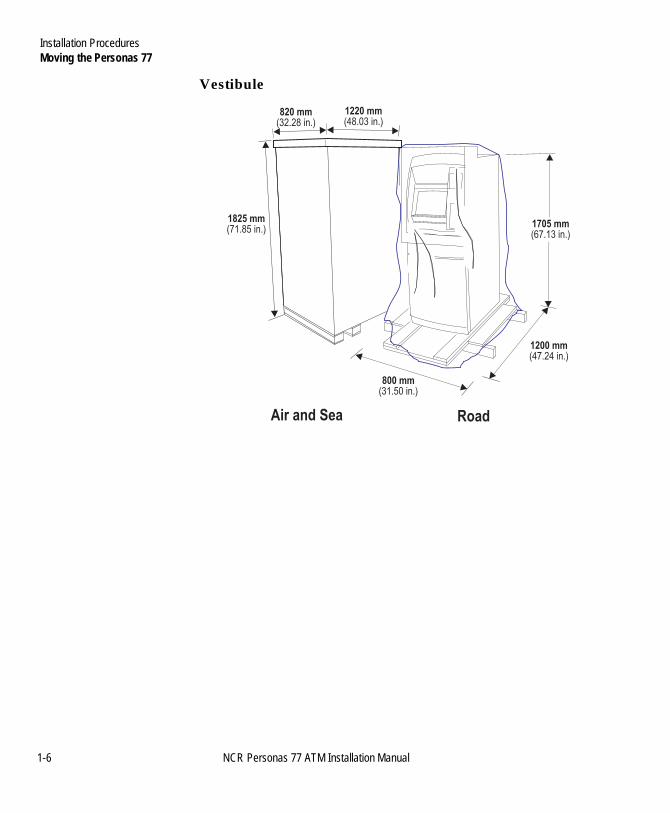
Vestibule 1
Air and Sea Road
1825 mm
(71.85 in.)
800 mm
(31.50 in.)
1220 mm
(48.03 in.)
1200 mm
(47.24 in.)
820 mm
(32.28 in.)
1705 mm
(67.13 in.)
1-6 NCR Personas 77 ATM Installation Manual
Installation ProceduresMoving the Personas 77
BOOK.BK Page 7 Monday, August 16, 2004 11:15 AM
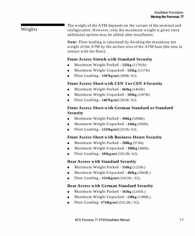
Weights 1
The weight of the ATM depends on the variant of the terminal and configuration. However, only the maximum weight is given since additional options may be added after installation.
Note: Floor loading is calculated by dividing the maximum net weight of the ATM by the surface area of the ATM base (the area in contact with the floor).
Front Access Stretch with Standard Security 1
● Maximum Weight Packed - 535kg (11791lb)
● Maximum Weight Unpacked - 525kg (1157lb)
● Floor Loading - 1507kg/m2 (309lb/ft2).
Front Access Short with CEN 3 or CEN 4 Security 1
● Maximum Weight Packed - 663kg (1462lb)
● Maximum Weight Unpacked - 593kg (1307lb)
● Floor Loading - 1467kg/m2 (301lb/ft2).
Front Access Short with German Standard or Standard Security 1
● Maximum Weight Packed - 496kg (1094lb)
● Maximum Weight Unpacked - 426kg (939lb)
● Floor Loading - 1223kg/m2 (251lb/ft2).
Front Access Short with Business Hours Security 1
● Maximum Weight Packed - 260kg (573lb)
● Maximum Weight Unpacked - 166kg (366lb)
● Floor Loading - 505kg/m2 (103.3lb/ft2).
Rear Access with Standard Security 1
● Maximum Weight Packed - 510kg (1125lb.)
● Maximum Weight Unpacked - 482kg (1063lb.)
● Floor Loading - 1554kg/m2 (318.2lb./ft2).
Rear Access with German Standard Security 1
● Maximum Weight Packed - 563kg (1241lb.)
● Maximum Weight Unpacked - 538kg (1186lb.)
● Floor Loading -1734kg/m2 (355.2lb./ft2).
NCR Personas 77 ATM Installation Manual 1-7
Installation ProceduresMoving the Personas 77
BOOK.BK Page 8 Monday, August 16, 2004 11:15 AM
Rear Access with CEN A3 Security 1
● Maximum Weight Packed - 619kg (1365lb.)
● Maximum Weight Unpacked - 594kg (1310lb.)
● Floor Loading - 1554kg/m2 (318.3lb./ft2).
1-8 NCR Personas 77 ATM Installation Manual
Installation ProceduresMoving the Personas 77
BOOK.BK Page 9 Monday, August 16, 2004 11:15 AM
Vestibule with Standard Security 1
● Maximum Weight Packed - 570kg (1257lb.)
● Maximum Weight Unpacked - 545kg (1202lb.)
● Floor Loading -1757kg/m2 (359.8lb./ft2).
Vestibule with German Standard Security 1
● Maximum Weight Packed - 598kg (1319lb.)
● Maximum Weight Unpacked - 573kg (1263lb.)
● Floor Loading - 1847kg/m2 (378.3lb./ft2).
Vestibule with CEN A3 Security 1
● Maximum Weight Packed - 654kg (1442lb.)
● Maximum Weight Unpacked - 629kg (1387lb.)
● Floor Loading -1646kg/m2 (337.0lb./ft2).
Advert Light 1
● Maximum Weight Packed - 7kg (16lb)
● Maximum Weight Unpacked - 6kg (13lb).
NCR Personas 77 ATM Installation Manual 1-9
Installation ProceduresMoving the Personas 77
BOOK.BK Page 10 Monday, August 16, 2004 11:15 AM
1-10 NCR Personas 77 ATM Installation Manual
Table of ContentsUnpacking the Personas 77
BOOK.BK Page 11 Monday, August 16, 2004 11:15 AM
NCR Personas 77 ATM Installation Manual
Chapter 2
Unpacking the Personas 77
Removing the External Packaging 2-1Air/Sea Packaging 2-1Road Packaging 2-1
Inspecting for Damage 2-2Installation Report Form 2-2
Removing From the Pallet 2-3Air/Sea Pallet (Using a Fork-Lift) 2-3Road Pallet (Using Lifting Trolleys) 2-5
Conforming to AFA Regulations 2-10Front Access Short 2-10Front Access Stretch 2-10Rear Access and Vestibule 2-10

Table of ContentsUnpacking the Personas 77
BOOK.BK Page 12 Monday, August 16, 2004 11:15 AM
NCR Personas 77 ATM Installation Manual
Removing the External Packaging
BOOK.BK Page 1 Monday, August 16, 2004 11:15 AM
NCR Personas 77 ATM Installation Manual
-12Unpacking the Personas 77 B
Removing the External Packaging 2
Before removing the external packaging, examine the packaging for signs of damage which may have occurred during transit. TILTWATCH® indicators attached to the outside of the packaging show if the ATM has been badly handled. Make a note of any external signs of damage for inclusion in a damage report. Refer “Installation Report Form” for details on reporting damage.
With the ATM approximately in its final installation position, remove the external packaging as follows:
Air/Sea Packaging 2
Remove the air/packaging as follows:
1 Lever out the staples from around the base of the cardboard carton.
2 Remove strapping and lift the carton from the pallet.
3 Remove the plastic dust cover.
4 Remove the foam from the top of the facia.
5 Remove Remote Status Indicator box (if supplied).
Road Packaging 2
Remove the road packaging as follows:
1 Remove the strapping/tape.
2 Remove the plastic dust cover.
3 Remove the foam from the top of the facia.
4 Remove the Remote Status indicator box (if supplied).
Unpacking the Personas 77Inspecting for Damage
BOOK.BK Page 2 Monday, August 16, 2004 11:15 AM
Inspecting for Damage 2
After unpacking the ATM, inspect it for any visible signs of damage.
If the ATM is damaged, report the damage on the Installation Report Form which is delivered with the ATM.
● Customers who are required to arrange their insurance locally should have the claim processed locally. A separate report of damage should be made to Inventory Return Control, Dayton
● Customers who have insurance arranged by NCR Insurance Department, Dayton, must report the damage on Form F-2100 (Notice of Damage) to NCR Insurance Department and send a copy to Inventory Return Control.
The addresses for NCR Insurance and Inventory Return Control are:
● Risk Management and Insurance, NCR Corporation, Dayton, Ohio 45479, U.S.A.
● Inventory Return Control, International Field Engineering. Support, NCR Corporation, Dayton, Ohio 45479, U.S.A.
Installation Report Form 2
The Installation Report Form which is delivered with the ATM must be completed and returned. Make sure that you detail any problems in the following areas:
● Functionality of the ATM or any of its devices.● Internal or external defects arising as a result of handling or
transit damage.● Missing or damaged accessories. All the ATM accessories are
fitted at the appropriate feature inside the ATM.
2-2 NCR Personas 77 ATM Installation Manual
Unpacking the Personas 77Removing From the Pallet
BOOK.BK Page 3 Monday, August 16, 2004 11:15 AM
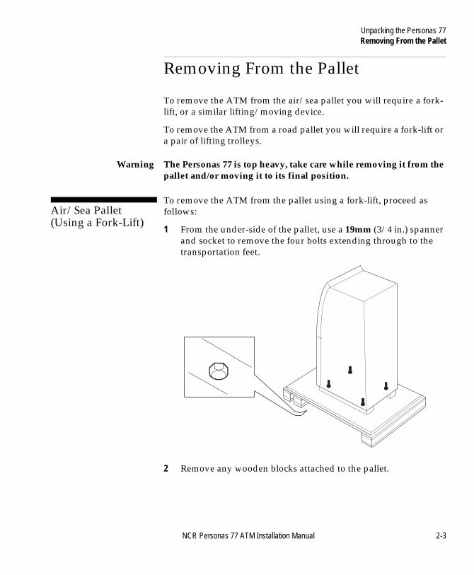
Removing From the Pallet 2
To remove the ATM from the air/sea pallet you will require a fork-lift, or a similar lifting/moving device.
To remove the ATM from a road pallet you will require a fork-lift or a pair of lifting trolleys.
Warning The Personas 77 is top heavy, take care while removing it from the pallet and/or moving it to its final position.
Air/Sea Pallet (Using a Fork-Lift) 2
To remove the ATM from the pallet using a fork-lift, proceed as follows:
1 From the under-side of the pallet, use a 19mm (3/4 in.) spanner and socket to remove the four bolts extending through to the transportation feet.
2 Remove any wooden blocks attached to the pallet.
NCR Personas 77 ATM Installation Manual 2-3
Unpacking the Personas 77Removing From the Pallet
BOOK.BK Page 4 Monday, August 16, 2004 11:15 AM
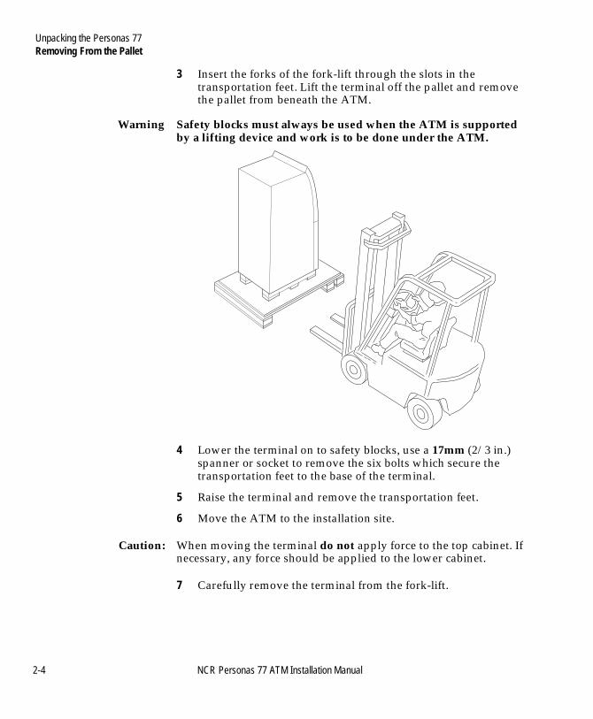
3 Insert the forks of the fork-lift through the slots in the transportation feet. Lift the terminal off the pallet and remove the pallet from beneath the ATM.
Warning Safety blocks must always be used when the ATM is supported by a lifting device and work is to be done under the ATM.
4 Lower the terminal on to safety blocks, use a 17mm (2/3 in.) spanner or socket to remove the six bolts which secure the transportation feet to the base of the terminal.
5 Raise the terminal and remove the transportation feet.
6 Move the ATM to the installation site.
Caution: When moving the terminal do not apply force to the top cabinet. If necessary, any force should be applied to the lower cabinet.
7 Carefully remove the terminal from the fork-lift.
2-4 NCR Personas 77 ATM Installation Manual
Unpacking the Personas 77Removing From the Pallet
BOOK.BK Page 5 Monday, August 16, 2004 11:15 AM
Road Pallet (Using Lifting Trolleys) 2
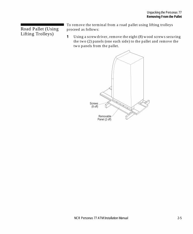
To remove the terminal from a road pallet using lifting trolleys proceed as follows:
1 Using a screwdriver, remove the eight (8) wood screws securing the two (2) panels (one each side) to the pallet and remove the two panels from the pallet.
Screws(8 off)
RemovablePanel (2 off)
NCR Personas 77 ATM Installation Manual 2-5
Unpacking the Personas 77Removing From the Pallet
BOOK.BK Page 6 Monday, August 16, 2004 11:15 AM
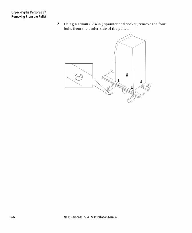
2 Using a 19mm (3/4 in.) spanner and socket, remove the four bolts from the under-side of the pallet.
2-6 NCR Personas 77 ATM Installation Manual
Unpacking the Personas 77Removing From the Pallet
BOOK.BK Page 7 Monday, August 16, 2004 11:15 AM
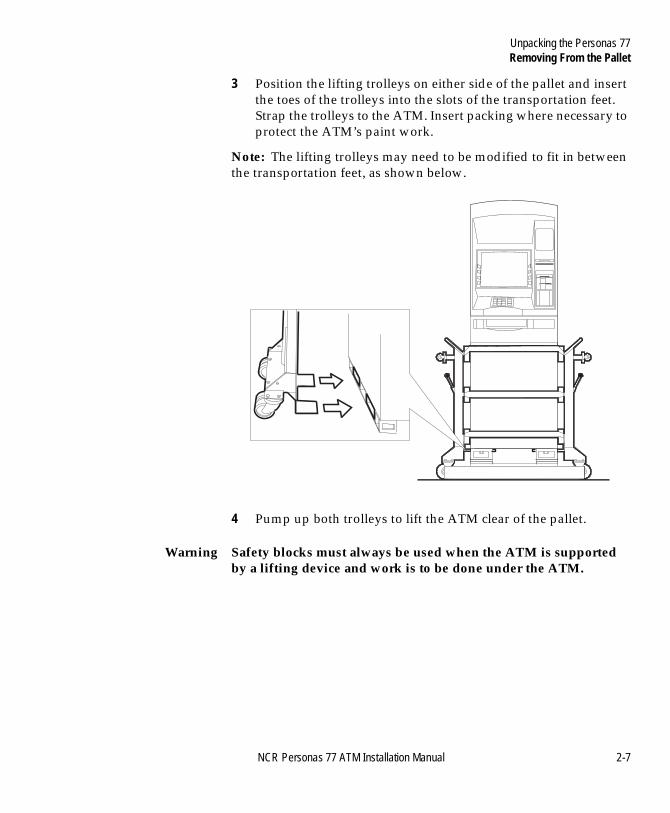
3 Position the lifting trolleys on either side of the pallet and insert the toes of the trolleys into the slots of the transportation feet. Strap the trolleys to the ATM. Insert packing where necessary to protect the ATM’s paint work.
Note: The lifting trolleys may need to be modified to fit in between the transportation feet, as shown below.
4 Pump up both trolleys to lift the ATM clear of the pallet.
Warning Safety blocks must always be used when the ATM is supported by a lifting device and work is to be done under the ATM.
NCR Personas 77 ATM Installation Manual 2-7
Unpacking the Personas 77Removing From the Pallet
BOOK.BK Page 8 Monday, August 16, 2004 11:15 AM
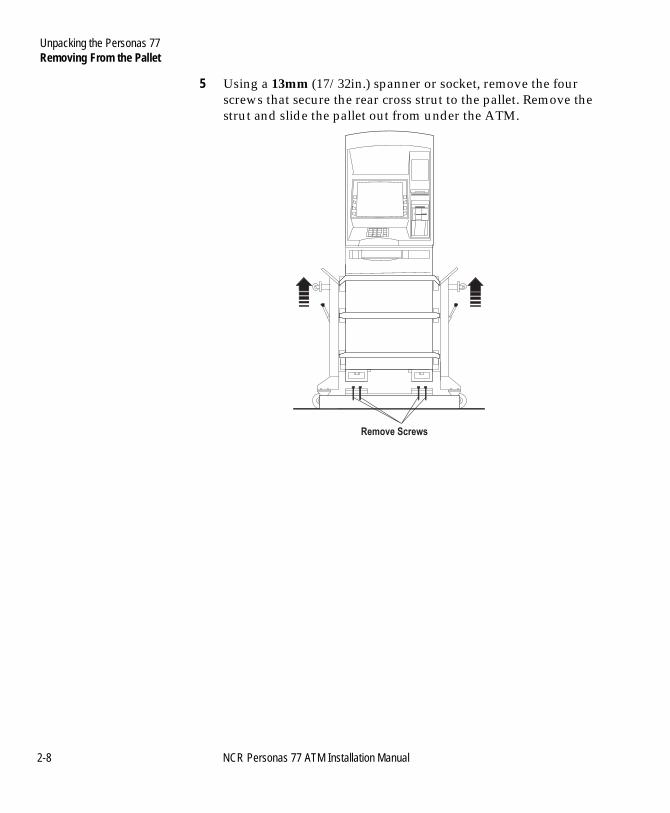
5 Using a 13mm (17/32in.) spanner or socket, remove the four screws that secure the rear cross strut to the pallet. Remove the strut and slide the pallet out from under the ATM.
Remove Screws
2-8 NCR Personas 77 ATM Installation Manual
Unpacking the Personas 77Removing From the Pallet
BOOK.BK Page 9 Monday, August 16, 2004 11:15 AM
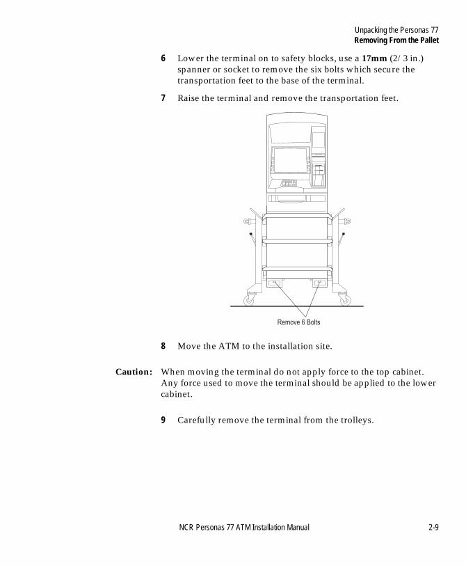
6 Lower the terminal on to safety blocks, use a 17mm (2/3 in.) spanner or socket to remove the six bolts which secure the transportation feet to the base of the terminal.
7 Raise the terminal and remove the transportation feet.
8 Move the ATM to the installation site.
Caution: When moving the terminal do not apply force to the top cabinet. Any force used to move the terminal should be applied to the lower cabinet.
9 Carefully remove the terminal from the trolleys.
Remove 6 Bolts
NCR Personas 77 ATM Installation Manual 2-9
Unpacking the Personas 77Conforming to AFA Regulations
BOOK.BK Page 10 Monday, August 16, 2004 11:15 AM
Conforming to AFA Regulations 2
To ensure conformance with the height and reach requirements of the Americans with Disabilities Act (ADA) and/or the Canadian Standards Authority (CSA) Access For All (AFA) regulations, the transportation feet must be removed to allow the base of the ATM to sit directly on the floor surface.
Front Access Short 2
The Front Access Short, German Standard, CEN 3 and CEN 4 variants comply with the height and reach requirements of the Canadian Standards Association (CSA) Barrier Free Access and the Americans with Disabilities Act (ADA).
Front Access Stretch 2
The Front Access Stretch variant complies with the height and reach requirements of the Americans with Disabilities Act (ADA).
Rear Access and Vestibule 2
The Rear Access Lobby and Vestibule variants do not comply with some accessibility requirements for UK, USA, Canada, Australia and New Zealand. For this reason these variants are not offered for sale in these countries.
2-10 NCR Personas 77 ATM Installation Manual
Table of ContentsInstalling the Personas 77
BOOK.BK Page 11 Monday, August 16, 2004 11:15 AM
NCR Personas 77 ATM Installation Manual
Chapter 3
Installing the Personas 77
Opening the Exterior of the Personas 77 3-1Front Access 3-1
Opening the Top Cabinet 3-1Closing the Top Cabinet 3-3Opening the Security Enclosure 3-4
Rear Access 3-6Top Cabinet - Opening 3-6Top Cabinet - Closing 3-6Security Enclosure - Opening 3-6Security Enclosure - Closing 3-7
How to Operate the Security Enclosure Locks 3-8Keylocks 3-10
How to Unlock a Keylock 3-10How to Lock a Keylock 3-10
Combination Locks 3-10Factory Setting 3-11Customer Setting Combination 3-12How to Operate the Silent Alarm 3-12How to Lock the Combination Lock 3-12How to Change the Combination 3-12
Controlled Access Electronic Lock 3-13
Table of ContentsInstalling the Personas 77
BOOK.BK Page 12 Monday, August 16, 2004 11:15 AM
Activating the Controlled Access Electronic Lock 3-15Controlled Access Electronic Lock (Type 1) 3-18
Unlocking 3-18Locking 3-19
Controlled Access Electronic Lock (Type 2) 3-20Unlocking 3-20Locking 3-23
LG Combogard 33e Electronic Lock 3-24How to Unlock the Electronic Lock 3-24How to Lock the Electronic Lock 3-25How to Change the Combination 3-25Emergency Opening Procedure 3-26
LG Audit 66e Electronic Lock 3-27How to Unlock the Electronic Lock 3-27How to Lock the Electronic Lock 3-28Silent Alarm Operation 3-28How to Change the Combination 3-28Emergency Opening Procedure 3-28
Removing the Internal Packaging 3-30Front Access 3-31
Top Cabinet 3-31Security Enclosure 3-33
Rear Access 3-38
How to Install a Vestibule ATM 3-39
Bolting the ATM to the Floor 3-48Security Bolts Specifications 3-48Bolting to the Floor 3-50
Connecting Cables 3-51
NCR Personas 77 ATM Installation Manual
Table of ContentsInstalling the Personas 77
BOOK.BK Page 13 Monday, August 16, 2004 11:15 AM
Top Cabinet 3-52Routing Communications Cables - Front Access 3-52Routing Communications Cables - Rear Access 3-56
Video Camera 3-60Front Access Short Security Enclosure 3-61Front Access Stretch and CEN Security Enclosure 3-68Rear Access Security Enclosure 3-76
Sidecar Enable 3-79
Advert Light Box 3-80
NCR Personas 77 ATM Installation Manual
Table of ContentsInstalling the Personas 77
BOOK.BK Page 14 Monday, August 16, 2004 11:15 AM
NCR Personas 77 ATM Installation Manual
Opening the Exterior of the Personas 77
BOOK.BK Page 1 Monday, August 16, 2004 11:15 AM
NCR Personas 77 ATM Installation Manual 3
-1Installing the Personas 77C
Opening the Exterior of the Personas 77 3
The top cabinet and security enclosure can be opened independently of each other.
Note: Different keys are provided for the top cabinet and lower cabinet door.
Front Access 3
Opening the Top Cabinet 3
To open the to cabinet of the ATM, proceed as follows:
1 If necessary, locate and retrieve the facia key from the document bag secured to the outside of the unit.
Note: The safe door cosmetic cover keys and any additional keys are in a Brown Manila envelope which is taped to the top of the monitor inside the top cabinet.
2 Insert the key, in the facia lock.
3 Turn (in either direction) and hold the key to open the lock.
4 Using one hand, pull the facia forwards.
Installing the Personas 77Opening the Exterior of the Personas 77
BOOK.BK Page 2 Monday, August 16, 2004 11:15 AM
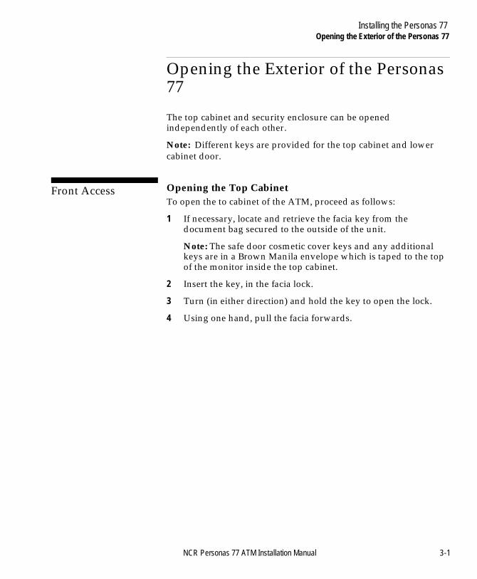
5 Release the key.
3-2 NCR Personas 77 ATM Installation Manual
Installing the Personas 77Opening the Exterior of the Personas 77
BOOK.BK Page 3 Monday, August 16, 2004 11:15 AM
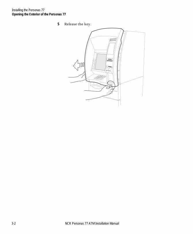
6 Using both hands, carefully pull the facia out of the top cabinet until the slides are fully extended.
Closing the Top Cabinet 3
Close the top cabinet as follows:
Caution Do not grip the sides of the facia when closing the top cabinet.
NCR Personas 77 ATM Installation Manual 3-3
Installing the Personas 77Opening the Exterior of the Personas 77
BOOK.BK Page 4 Monday, August 16, 2004 11:15 AM
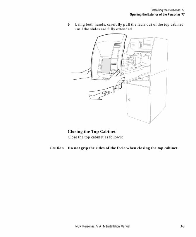
1 With your hands flat, either side of the keypad, push the facia into the top cabinet until the lock locks.
2 Remove the key.
Opening the Security Enclosure 3
To open the security enclosure, proceed as follows:
1 Inset the key into the lower cabinet door, and turn it clockwise.
2 Open the cabinet door.
3 Remove the tape from the safe door, and the foam from under the safe handle.
3-4 NCR Personas 77 ATM Installation Manual
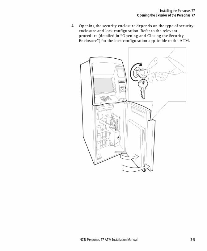
Installing the Personas 77Opening the Exterior of the Personas 77
BOOK.BK Page 5 Monday, August 16, 2004 11:15 AM
4 Opening the security enclosure depends on the type of security enclosure and lock configuration. Refer to the relevant procedure (detailed in “Opening and Closing the Security Enclosure”) for the lock configuration applicable to the ATM.
NCR Personas 77 ATM Installation Manual 3-5
Installing the Personas 77Opening the Exterior of the Personas 77
BOOK.BK Page 6 Monday, August 16, 2004 11:15 AM
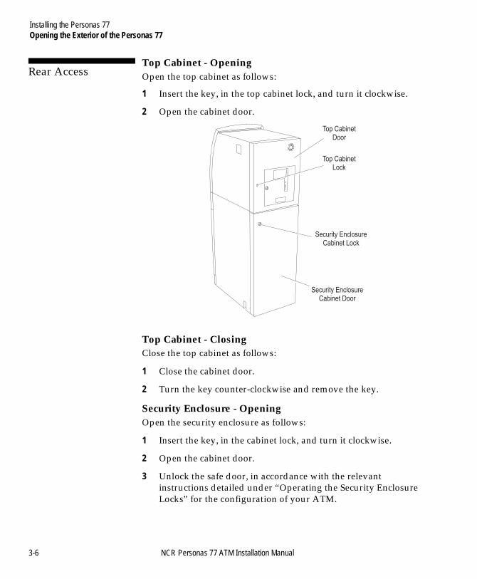
Rear Access 3
Top Cabinet - Opening 3
Open the top cabinet as follows:
1 Insert the key, in the top cabinet lock, and turn it clockwise.
2 Open the cabinet door.
Top Cabinet - Closing 3
Close the top cabinet as follows:
1 Close the cabinet door.
2 Turn the key counter-clockwise and remove the key.
Security Enclosure - Opening 3
Open the security enclosure as follows:
1 Insert the key, in the cabinet lock, and turn it clockwise.
2 Open the cabinet door.
3 Unlock the safe door, in accordance with the relevant instructions detailed under “Operating the Security Enclosure Locks” for the configuration of your ATM.
Top CabinetDoor
Top CabinetLock
Security EnclosureCabinet Door
Security EnclosureCabinet Lock
3-6 NCR Personas 77 ATM Installation Manual
Installing the Personas 77Opening the Exterior of the Personas 77
BOOK.BK Page 7 Monday, August 16, 2004 11:15 AM
4 Open the safe door.
Security Enclosure - Closing 3
Closing the security enclosure as follows:
1 Close and lock the security enclosure door in accordance with the relevant instructions detailed under “Operating the Security Enclosure Locks” for the configuration of your ATM.
2 Close the cabinet door.
3 Turn the key counter-clockwise and remove the key.
NCR Personas 77 ATM Installation Manual 3-7
Installing the Personas 77How to Operate the Security Enclosure Locks
BOOK.BK Page 8 Monday, August 16, 2004 11:15 AM
How to Operate the Security Enclosure Locks 3
The security enclosure of your ATM will have a locking handle plus either no locks, one lock (a primary lock), or two locks (a primary and a secondary lock). The possible lock types for primary and secondary locks are as follows:
● Primary lock types:● Keylock● Combination lock● Combination lock with silent alarm● Combination lock with integral keylock
● Secondary lock types:● Keylock● Combination lock● Combination lock with silent alarm.
Note: The make of lock fitted (Standard or Sargent and Greenleaf) depends on the configuration of the ATM. The procedures for opening and closing the locks are the same for both makes.
3-8 NCR Personas 77 ATM Installation Manual
Installing the Personas 77How to Operate the Security Enclosure Locks
BOOK.BK Page 9 Monday, August 16, 2004 11:15 AM
Depending on the configuration of the ATM, primary and secondary locks are positioned either one above the other or side-by-side. When positioned one above the other the primary lock is the uppermost lock. When positioned side-by-side the primary lock is the left hand lock.
If you have a primary and a secondary lock fitted to your ATM they must be unlocked in the following order:
1 Unlock the secondary lock.
2 Unlock the primary lock.
3 Use the handle to retract the bolt and open the door.
The primary and secondary locks must be locked in the following sequence:
1 Close the door and use the handle to operate the bolt.
2 Lock the primary lock.
3 Lock the secondary lock.
NCR Personas 77 ATM Installation Manual 3-9
Installing the Personas 77How to Operate the Security Enclosure Locks
BOOK.BK Page 10 Monday, August 16, 2004 11:15 AM
Keylocks 3
The pair of keylock keys supplied with your ATM have been pre-cut to a random factory-set combination. If one key should get lost, then you should get a new pair of keys and then change the keylock setting. Refer to NCR publication, ATM Field Service Information (SAMM) FM0547, Chapter 20, for details.
How to Unlock a Keylock 3
To unlock a keylock, insert the key into the lock and turn it clockwise as far as it will turn.
How to Lock a Keylock 3
To lock a keylock, turn the key counter clockwise as far as it will turn and then remove the key.
Combination Locks 3
Three variants of combination lock may be fitted to your ATM:
● Basic combination lock ● Combination lock with integral keylock● Combination lock with a silent alarm option.
All the variants of the combination lock are three-number combination locks.
The locks are precision locks, therefore, extreme care must be taken to align combination numbers with the index.
Turn the dial slowly and steadily. If, after turning the dial the correct number of revolutions, any number is turned beyond the index, the entire series of combination numbers must be re-dialled.
Do not turn the dial back to regain a proper alignment of the number and index, because each time a selected number is aligned with the index a revolution is counted.
3-10 NCR Personas 77 ATM Installation Manual
Installing the Personas 77How to Operate the Security Enclosure Locks
BOOK.BK Page 11 Monday, August 16, 2004 11:15 AM
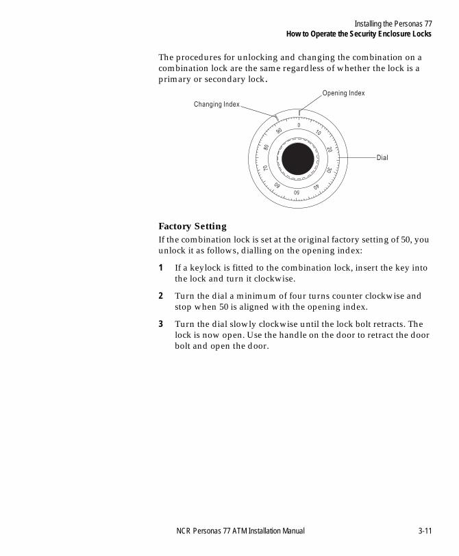
The procedures for unlocking and changing the combination on a combination lock are the same regardless of whether the lock is a primary or secondary lock.
Factory Setting 3
If the combination lock is set at the original factory setting of 50, you unlock it as follows, dialling on the opening index:
1 If a keylock is fitted to the combination lock, insert the key into the lock and turn it clockwise.
2 Turn the dial a minimum of four turns counter clockwise and stop when 50 is aligned with the opening index.
3 Turn the dial slowly clockwise until the lock bolt retracts. The lock is now open. Use the handle on the door to retract the door bolt and open the door.
Changing Index
Opening Index
Dial
0
90
80
70
60
50
40
30
20
10
NCR Personas 77 ATM Installation Manual 3-11
Installing the Personas 77How to Operate the Security Enclosure Locks
BOOK.BK Page 12 Monday, August 16, 2004 11:15 AM
Customer Setting Combination 3
If the combination has been set at a three-number combination, for example 36-82-44, unlock it as follows:
1 If a keylock is fitted to the combination lock, insert the key into the lock and turn it clockwise.
2 Turn the dial counter clockwise, passing the first number (36) three times, stop on the first number (36) the FOURTH time.
3 Turn the dial clockwise, passing the second number (82) twice, stop on the second number (82) the THIRD time.
4 Turn the dial counter clockwise, passing the third number (44) once, stop on the third number (44) the SECOND time.
5 Turn the dial slowly clockwise until the lock bolt retracts. The lock is now open. Use the handle on the door to retract the door bolt and open the door.
How to Operate the Silent Alarm 3
The silent alarm is triggered, if fitted, by adding 10 to the first number of the combination. For example if the first number was 34, dial 44 to trigger the silent alarm. Dial the next two numbers of the combination as normal, the combination lock will open as normal but the alarm will have been triggered.
How to Lock the Combination Lock 3
To lock the combination lock, turn the dial at least four complete turns counter clockwise. If a keylock is fitted to the combination lock, turn the dial until 0 is in line with the opening index and then turn the key counter clockwise and remove it from the lock.
How to Change the Combination 3
Detailed instructions on how to change the combination of a lock are inside the security enclosure.
3-12 NCR Personas 77 ATM Installation Manual
Installing the Personas 77Controlled Access Electronic Lock
BOOK.BK Page 13 Monday, August 16, 2004 11:15 AM
Controlled Access Electronic Lock 3
Note: For ATMs with security enclosures fitted with a Kaba Mas (Mas-Hamilton) controlled access electronic lock, refer to the following Kaba Mas Corporation publications for details of how to set up and manage the operations of the lock:● CENCON System 2000 Access Control System● Getting Started Guide● Supervisor Guide● Special Supervisor Guide● FLM Dispatcher Guide● Route Dispatcher Guide● CENCON 2000 System Guide.These publications can be purchased from the following Order Point:
Kaba Mas Corporation749, W.Short StreetLEXINGTONKentucky40508Tel: (1) 859 253 4744Toll Free: (1) 888 959 4715Fax: (1) 859 225 2655
Note: For the attention of Customer Service Manager.
NCR Personas 77 ATM Installation Manual 3-13
Installing the Personas 77Controlled Access Electronic Lock
BOOK.BK Page 14 Monday, August 16, 2004 11:15 AM
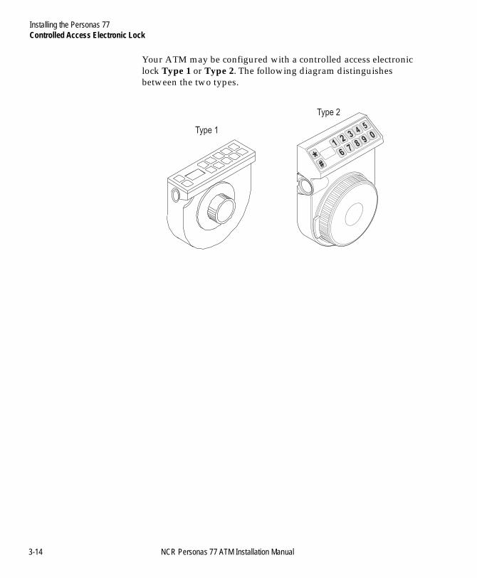
Your ATM may be configured with a controlled access electronic lock Type 1 or Type 2. The following diagram distinguishes between the two types.
23
45
1
*6
#
78
90
Type 1
Type 2
3-14 NCR Personas 77 ATM Installation Manual
Installing the Personas 77Activating the Controlled Access Electronic Lock
BOOK.BK Page 15 Monday, August 16, 2004 11:15 AM
Activating the Controlled Access Electronic Lock 3
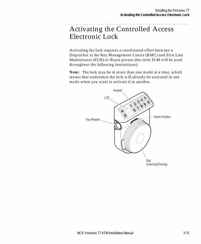
Activating the lock requires a coordinated effort between a Dispatcher at the Key Management Centre (KMC) and First Line Maintenance (FLM) or Route person (the term FLM will be used throughout the following instructions).
Note: The lock may be in more than one mode at a time, which means that sometimes the lock will already be activated in one mode when you want to activate it in another.
C
23
45
1
*6
#
78
90
LCD
Keypad
Dial(Opening/Closing)
Key ReaderHome Position
NCR Personas 77 ATM Installation Manual 3-15
Installing the Personas 77Activating the Controlled Access Electronic Lock
BOOK.BK Page 16 Monday, August 16, 2004 11:15 AM
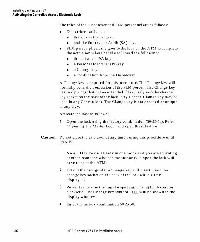
The roles of the Dispatcher and FLM personnel are as follows:
● Dispatcher - activates:● the lock in the program● and the Supervisor Audit (SA) key.
● FLM person physically goes to the lock on the ATM to complete the activation where he/she will need the following:● the initialized SA key● a Personal Identifier (PI) key● a Change key ● a combination from the Dispatcher.
A Change key is required for this procedure. The Change key will normally be in the possession of the FLM person. The Change key has two prongs that, when extended, fit securely into the change key socket on the back of the lock. Any Cencon Change key may be used in any Cencon lock. The Change key is not encoded or unique in any way.
Activate the lock as follows:
1 Open the lock using the factory combination (50-25-50). Refer “Opening The Master Lock” and open the safe door.
Caution Do not close the safe door at any time during this procedure until Step 15.
Note: If the lock is already in one mode and you are activating another, someone who has the authority to open the lock will have to be at the ATM.
2 Extend the prongs of the Change key and insert it into the change key socket on the back of the lock while OPr is displayed.
3 Power the lock by turning the opening/closing knob counter clockwise. The Change key symbol will be shown in the display window.
4 Enter the factory combination 50 25 50.
3-16 NCR Personas 77 ATM Installation Manual
Installing the Personas 77Activating the Controlled Access Electronic Lock
BOOK.BK Page 17 Monday, August 16, 2004 11:15 AM
5 After the factory combination has been correctly entered, the ISA symbol will be displayed. Hold the SA key against the lock’s key reader until POC is displayed.
Note: The InI symbol will be temporarily displayed before POC is displayed.
6 Remove the Change key (from the lock’s socket) and SA key (from the lock’s key reader).
7 OPr should be displayed. Turn the opening/closing knob clockwise to retract the bolt of the lock.
8 Open the safe door.
9 Keeping the safe door open, close the lock.
10 Turn the opening/closing knob counter clockwise, to activate the bolt and charge the lock, until EC is displayed.
11 Turn the opening/closing knob to the home position.
12 Enter the dispatched combination.
13 IPI should be displayed. Insert the FLM key (PI key)
14 OPr should be displayed. Turn the opening/closing knob clockwise to retract the bolt of the lock.
15 Close the safe door and lock it by turning the opening/closing knob counter clockwise.
16 Power the lock by turning the opening/closing knob counter clockwise.
17 When the display prompts, IPI, insert the FLM key (PI key) that was used to open the lock when you started the activation procedure.
18 The display will then show the Close Seal Number (* cxx then xx) for the first opening, which must be relayed back to the Dispatcher.
Note: * Where x is a number. Take note of the two sets of 2-digits that will be displayed.
NCR Personas 77 ATM Installation Manual 3-17
Installing the Personas 77Activating the Controlled Access Electronic Lock
BOOK.BK Page 18 Monday, August 16, 2004 11:15 AM
Controlled Access Electronic Lock (Type 1) 3
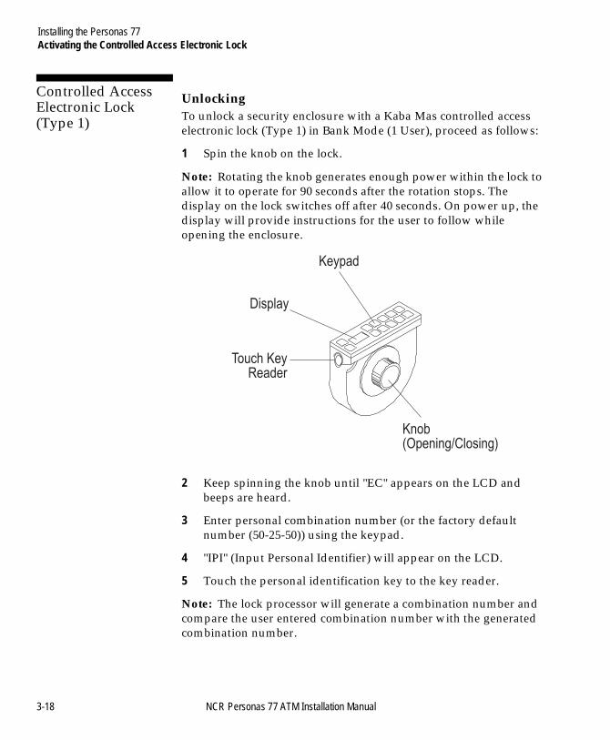
Unlocking 3
To unlock a security enclosure with a Kaba Mas controlled access electronic lock (Type 1) in Bank Mode (1 User), proceed as follows:
1 Spin the knob on the lock.
Note: Rotating the knob generates enough power within the lock to allow it to operate for 90 seconds after the rotation stops. The display on the lock switches off after 40 seconds. On power up, the display will provide instructions for the user to follow while opening the enclosure.
2 Keep spinning the knob until "EC" appears on the LCD and beeps are heard.
3 Enter personal combination number (or the factory default number (50-25-50)) using the keypad.
4 "IPI" (Input Personal Identifier) will appear on the LCD.
5 Touch the personal identification key to the key reader.
Note: The lock processor will generate a combination number and compare the user entered combination number with the generated combination number.
Keypad
Display
Touch KeyReader
Knob(Opening/Closing)
3-18 NCR Personas 77 ATM Installation Manual
Installing the Personas 77Activating the Controlled Access Electronic Lock
BOOK.BK Page 19 Monday, August 16, 2004 11:15 AM
6 If the combination number and the generated combination number match the LCD will display "Opr" and beeps will be heard. Turn the knob clockwise to open the lock and retract the locking bolt. The security enclosure door can now be opened.
If the combination numbers do not match, a lightning bolt symbol will appear on the LCD (to indicate a security violation). If this occurs, follow your in-house security procedures for this condition.
Locking 3
To lock a security enclosure with a Kaba Mas controlled access electronic lock without sub-locks, proceed as follows:
1 Close the security enclosure door.
2 Turn the electronic lock knob counter clockwise to close.
3 Spin knob (to power up the electronic lock) until beeps are heard.
4 "IPI" will appear on the LCD.
5 Touch the personal identification key to the key reader.
6 "EOP" (End of Operation) will appear on the LCD.
NCR Personas 77 ATM Installation Manual 3-19
Installing the Personas 77Activating the Controlled Access Electronic Lock
BOOK.BK Page 20 Monday, August 16, 2004 11:15 AM
Controlled Access Electronic Lock (Type 2) 3
To unlock a security enclosure with a Kaba Mas controlled access electronic lock you require the following:
● Personal Identifier key (PI key) - issued by the Key Management Centre (KMC).
● Six-digit access code - obtained from the KMC.
Unlocking 3
To open the lock, proceed as follows:
1 Contact the KMC.
2 Give requested details to verify your identity to the KMC.
3 Specify which areas on the ATM you want to access.
4 Take note of the six-digit access code (three pairs of two), allocated by the KMC.
5 Unlock and open the exterior of the ATM.
3-20 NCR Personas 77 ATM Installation Manual
Installing the Personas 77Activating the Controlled Access Electronic Lock
BOOK.BK Page 21 Monday, August 16, 2004 11:15 AM
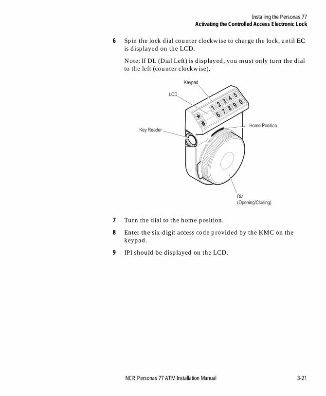
6 Spin the lock dial counter clockwise to charge the lock, until EC is displayed on the LCD.
Note: If DL (Dial Left) is displayed, you must only turn the dial to the left (counter clockwise).
7 Turn the dial to the home position.
8 Enter the six-digit access code provided by the KMC on the keypad.
9 IPI should be displayed on the LCD.
23
45
1
*6
#
78
90
LCD
Keypad
Dial(Opening/Closing)
Key ReaderHome Position
NCR Personas 77 ATM Installation Manual 3-21
Installing the Personas 77Activating the Controlled Access Electronic Lock
BOOK.BK Page 22 Monday, August 16, 2004 11:15 AM
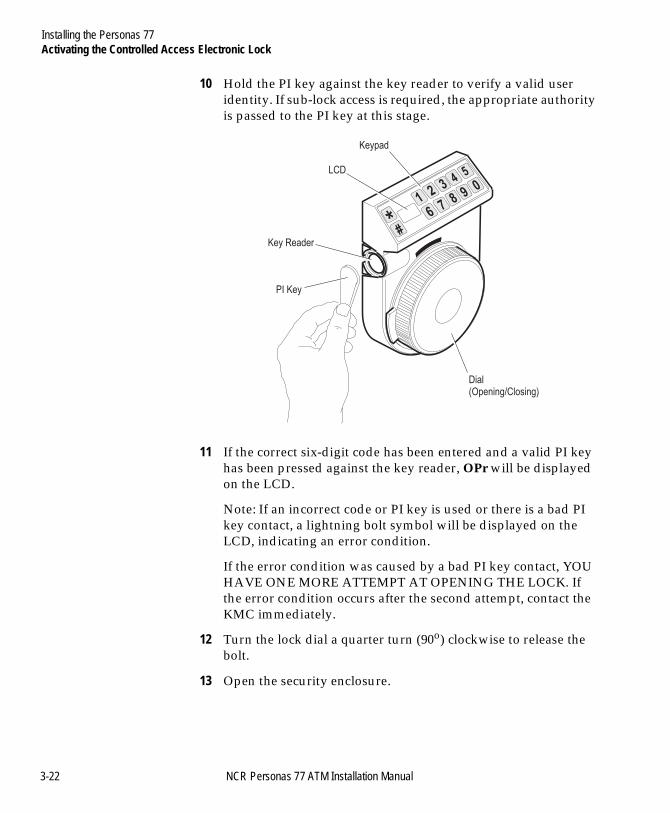
10 Hold the PI key against the key reader to verify a valid user identity. If sub-lock access is required, the appropriate authority is passed to the PI key at this stage.
11 If the correct six-digit code has been entered and a valid PI key has been pressed against the key reader, OPr will be displayed on the LCD.
Note: If an incorrect code or PI key is used or there is a bad PI key contact, a lightning bolt symbol will be displayed on the LCD, indicating an error condition.
If the error condition was caused by a bad PI key contact, YOU HAVE ONE MORE ATTEMPT AT OPENING THE LOCK. If the error condition occurs after the second attempt, contact the KMC immediately.
12 Turn the lock dial a quarter turn (90o) clockwise to release the bolt.
13 Open the security enclosure.
23
45
1
*6
#
78
90
LCD
Keypad
Dial(Opening/Closing)
Key Reader
PI Key
3-22 NCR Personas 77 ATM Installation Manual
Installing the Personas 77Activating the Controlled Access Electronic Lock
BOOK.BK Page 23 Monday, August 16, 2004 11:15 AM
Locking 3
To lock the lock, proceed as follows:
1 Close the security enclosure.
2 Turn the lock dial counter clockwise to activate the bolt and charge the lock until IPI is displayed on the LCD.
3 Hold the PI key against the key reader.
4 Take a note of the unique four-digit close code that is displayed, as it will be required by the KMC.
5 Close the exterior of the ATM.
6 Contact the KMC.
Note: Ensure that all the locks and doors on the ATM are closed and locked before contacting the KMC.
7 Verify identification.
8 Provide the four-digit close code to the KMC.
9 The KMC will inform you that either the code is correct or give you the correct procedure to follow if the close code is wrong.
NCR Personas 77 ATM Installation Manual 3-23
Installing the Personas 77LG Combogard 33e Electronic Lock
BOOK.BK Page 24 Monday, August 16, 2004 11:15 AM
LG Combogard 33e Electronic Lock 3
How to Unlock the Electronic Lock 3
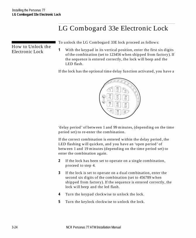
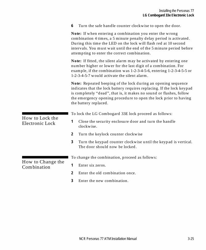
To unlock the LG Combogard 33E lock proceed as follows:
1 With the keypad in its vertical position, enter the first six digits of the combination (set to 123456 when shipped from factory). If the sequence is entered correctly, the lock will beep and the LED flash.
If the lock has the optional time delay function activated, you have a
‘delay period’ of between 1 and 99 minutes, (depending on the time period set) to re-enter the combination.
If the correct combination is entered within the delay period, the LED flashing will quicken, and you have an ‘open period’ of between 1 and 19 minutes (depending on the time period set) to enter the combination again.
2 If the lock has been set to operate on a single combination, proceed to step 4.
3 If the lock is set to operate on a dual combination, enter the second six digits of the combination (set to 456789 when shipped from factory). If the sequence is entered correctly, the lock will beep and the led flash.
4 Turn the keypad clockwise to unlock the lock.
5 Turn the keylock clockwise to unlock the lock.
3-24 NCR Personas 77 ATM Installation Manual
Installing the Personas 77LG Combogard 33e Electronic Lock
BOOK.BK Page 25 Monday, August 16, 2004 11:15 AM
6 Turn the safe handle counter clockwise to open the door.
Note: If when entering a combination you enter the wrong combination 4 times, a 5 minute penalty delay period is activated. During this time the LED on the lock will flash red at 10 second intervals. You must wait until the end of the 5 minute period before attempting to enter the correct combination.
Note: If fitted, the silent alarm may be activated by entering one number higher or lower for the last digit of a combination. For example, if the combination was 1-2-3-4-5-6, entering 1-2-3-4-5-5 or 1-2-3-4-5-7 would activate the silent alarm.
Note: Repeated beeping of the lock during an opening sequence indicates that the lock battery requires replacing. If the lock keypad is completely “dead”, that is, it makes no sound or flashes, follow the emergency opening procedure to open the lock prior to having the battery replaced.
How to Lock the Electronic Lock 3
To lock the LG Combogard 33E lock proceed as follows:
1 Close the security enclosure door and turn the handle clockwise.
2 Turn the keylock counter clockwise
3 Turn the keypad counter clockwise until the keypad is vertical. The door should now be locked.
How to Change the Combination 3
To change the combination, proceed as follows:
1 Enter six zeros.
2 Enter the old combination once.
3 Enter the new combination.
NCR Personas 77 ATM Installation Manual 3-25
Installing the Personas 77LG Combogard 33e Electronic Lock
BOOK.BK Page 26 Monday, August 16, 2004 11:15 AM
4 Enter the new combination again to confirm it. If the wrong combination is entered, the lock will beep three times, and the old combination will still be valid.
Note: After each valid entry, the lock will beep twice.
Emergency Opening Procedure 3
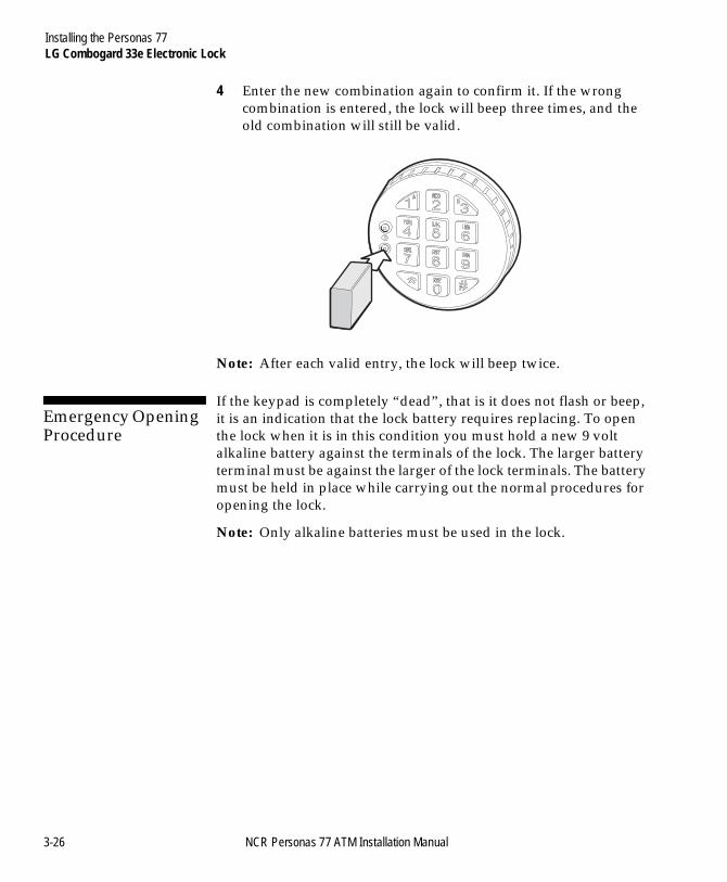
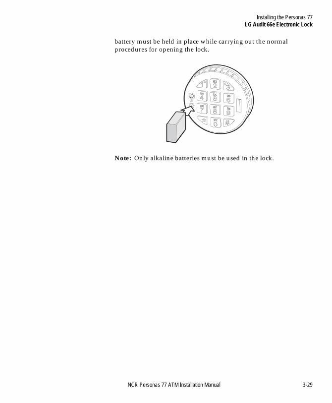
If the keypad is completely “dead”, that is it does not flash or beep, it is an indication that the lock battery requires replacing. To open the lock when it is in this condition you must hold a new 9 volt alkaline battery against the terminals of the lock. The larger battery terminal must be against the larger of the lock terminals. The battery must be held in place while carrying out the normal procedures for opening the lock.
Note: Only alkaline batteries must be used in the lock.
3-26 NCR Personas 77 ATM Installation Manual
Installing the Personas 77LG Audit 66e Electronic Lock
BOOK.BK Page 27 Monday, August 16, 2004 11:15 AM
LG Audit 66e Electronic Lock 3
How to Unlock the Electronic Lock 3
To unlock the LG Audit 66E lock proceed as follows:
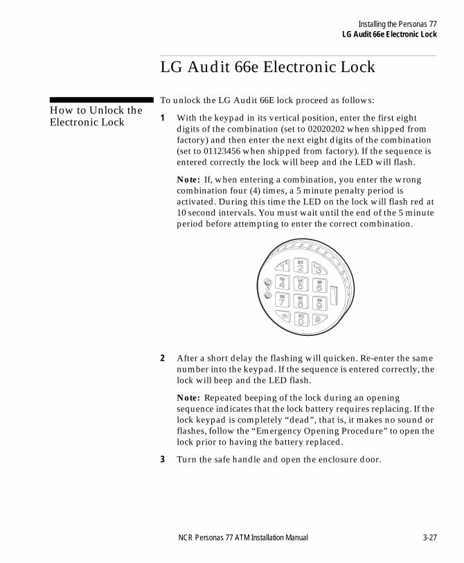
1 With the keypad in its vertical position, enter the first eight digits of the combination (set to 02020202 when shipped from factory) and then enter the next eight digits of the combination (set to 01123456 when shipped from factory). If the sequence is entered correctly the lock will beep and the LED will flash.
Note: If, when entering a combination, you enter the wrong combination four (4) times, a 5 minute penalty period is activated. During this time the LED on the lock will flash red at 10 second intervals. You must wait until the end of the 5 minute period before attempting to enter the correct combination.
2 After a short delay the flashing will quicken. Re-enter the same number into the keypad. If the sequence is entered correctly, the lock will beep and the LED flash.
Note: Repeated beeping of the lock during an opening sequence indicates that the lock battery requires replacing. If the lock keypad is completely “dead”, that is, it makes no sound or flashes, follow the “Emergency Opening Procedure” to open the lock prior to having the battery replaced.
3 Turn the safe handle and open the enclosure door.
NCR Personas 77 ATM Installation Manual 3-27
Installing the Personas 77LG Audit 66e Electronic Lock
BOOK.BK Page 28 Monday, August 16, 2004 11:15 AM
How to Lock the Electronic Lock 3
To lock the LG Audit 66E lock, close the door and return the handle to its vertical position.
Silent Alarm Operation 3
If fitted, the silent alarm may be activated by entering one number higher or lower for the last digit of a combination. For example if the combination was 1-2-3-4-5-6, entering 1-2-3-4-5-5 or 1-2-3-4-5-7 would activate the silent alarm.
How to Change the Combination 3
To change the combination proceed as follows:
1 Enter the current combination and hold down the last digit.
2 The lock will beep twice and the LED will remain on.
3 Press ‘0’.
4 Enter the new code.
5 Enter the new code again to confirm. If the wrong combination is entered, the lock will beep three times, and the old combination will still be valid. Wait 20 seconds before repeating these steps.
Note After each valid entry, the lock will beep twice.
Emergency Opening Procedure 3
If the keypad is completely “dead”, that is, it does not flash or beep, it is an indication that the lock battery requires replacing.
To open the lock when it is in this condition you must hold a new 9-volt alkaline battery against the terminals of the lock. The larger battery terminal must be against the larger of the lock terminals. The
3-28 NCR Personas 77 ATM Installation Manual
Installing the Personas 77LG Audit 66e Electronic Lock
BOOK.BK Page 29 Monday, August 16, 2004 11:15 AM
battery must be held in place while carrying out the normal procedures for opening the lock.
Note: Only alkaline batteries must be used in the lock.
NCR Personas 77 ATM Installation Manual 3-29
Installing the Personas 77Removing the Internal Packaging
BOOK.BK Page 30 Monday, August 16, 2004 11:15 AM
Removing the Internal Packaging 3
This section details how to remove the internal packaging from the ATM.
Note: The amounts and types of packing may be subject to change without notice. Ignore those steps which apply to modules not installed in the ATM.
3-30 NCR Personas 77 ATM Installation Manual
Installing the Personas 77Removing the Internal Packaging
BOOK.BK Page 31 Monday, August 16, 2004 11:15 AM
Front Access 3
Top Cabinet 3
The amount and type of internal packaging in the top cabinet depends on the variant of terminal.
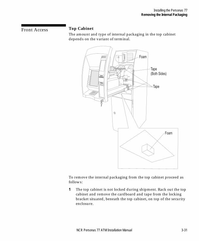
To remove the internal packaging from the top cabinet proceed as follows:
1 The top cabinet is not locked during shipment. Rack out the top cabinet and remove the cardboard and tape from the locking bracket situated, beneath the top cabinet, on top of the security enclosure.
Tape
Tape(Both Sides)
Foam
Foam
NCR Personas 77 ATM Installation Manual 3-31
Installing the Personas 77Removing the Internal Packaging
BOOK.BK Page 32 Monday, August 16, 2004 11:15 AM
2 If necessary, remove the Brown Manila envelope taped to the top of the monitor.
3 Remove the tape, foam and packaging from the following modules and areas:
● Module tray latch bracket● Receipt printer● Receipt printer mounting - locking knob● Between the receipt printer and the monitor● Journal printer● Underside of the module tray● Bar Code Reader● Camera.
4 Close and lock the top cabinet.
3-32 NCR Personas 77 ATM Installation Manual
Installing the Personas 77Removing the Internal Packaging
BOOK.BK Page 33 Monday, August 16, 2004 11:15 AM
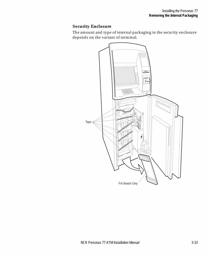
Security Enclosure 3
The amount and type of internal packaging in the security enclosure depends on the variant of terminal.
Tape
F/A Stretch Only
NCR Personas 77 ATM Installation Manual 3-33
Installing the Personas 77Removing the Internal Packaging
BOOK.BK Page 34 Monday, August 16, 2004 11:15 AM
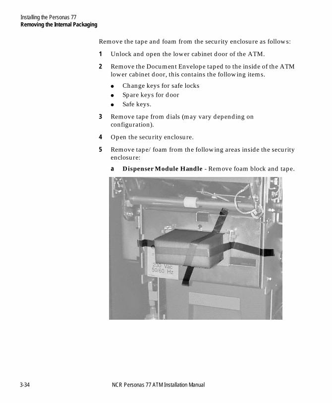
Remove the tape and foam from the security enclosure as follows:
1 Unlock and open the lower cabinet door of the ATM.
2 Remove the Document Envelope taped to the inside of the ATM lower cabinet door, this contains the following items.
● Change keys for safe locks● Spare keys for door● Safe keys.
3 Remove tape from dials (may vary depending on configuration).
4 Open the security enclosure.
5 Remove tape/foam from the following areas inside the security enclosure:
a Dispenser Module Handle - Remove foam block and tape.
3-34 NCR Personas 77 ATM Installation Manual
Installing the Personas 77Removing the Internal Packaging
BOOK.BK Page 35 Monday, August 16, 2004 11:15 AM
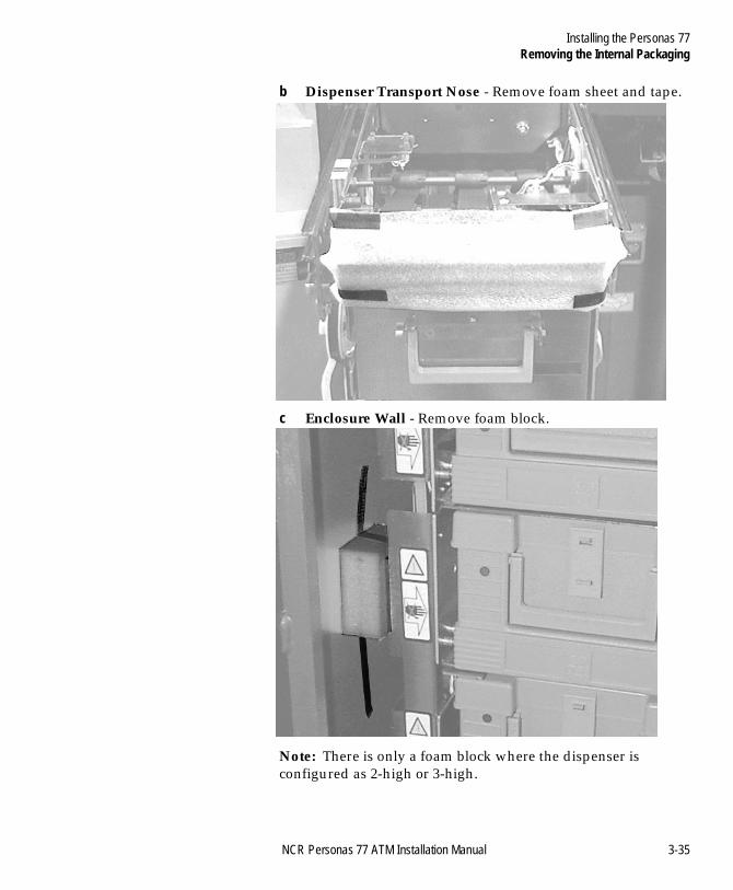
b Dispenser Transport Nose - Remove foam sheet and tape.
c Enclosure Wall - Remove foam block.
Note: There is only a foam block where the dispenser is configured as 2-high or 3-high.
NCR Personas 77 ATM Installation Manual 3-35
Installing the Personas 77Removing the Internal Packaging
BOOK.BK Page 36 Monday, August 16, 2004 11:15 AM
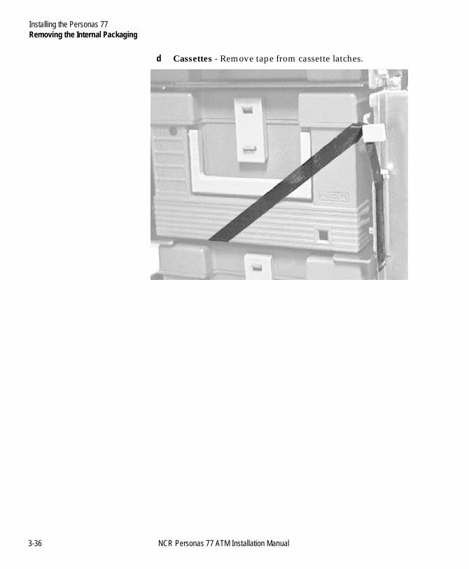
d Cassettes - Remove tape from cassette latches.
3-36 NCR Personas 77 ATM Installation Manual
Installing the Personas 77Removing the Internal Packaging
BOOK.BK Page 37 Monday, August 16, 2004 11:15 AM
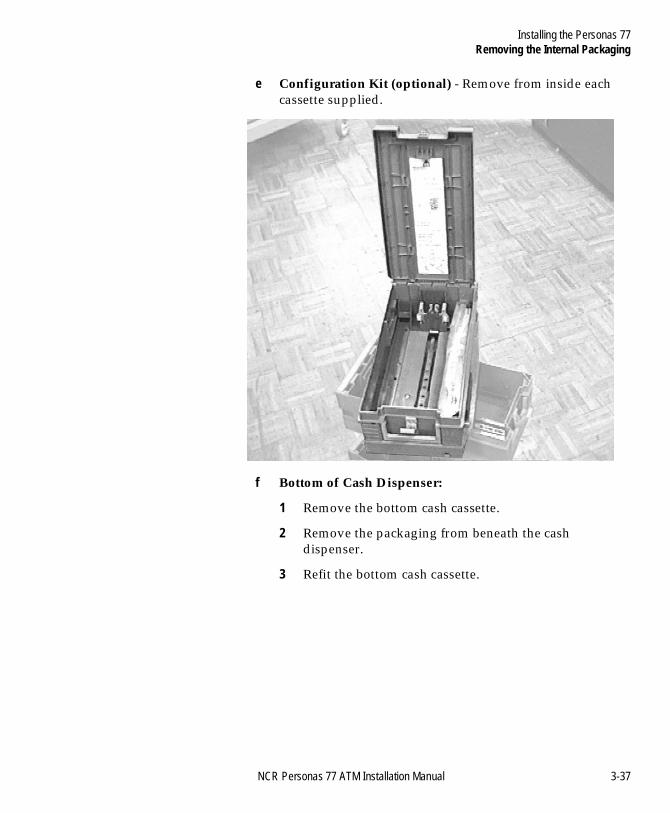
e Configuration Kit (optional) - Remove from inside each cassette supplied.
f Bottom of Cash Dispenser:
1 Remove the bottom cash cassette.
2 Remove the packaging from beneath the cash dispenser.
3 Refit the bottom cash cassette.
NCR Personas 77 ATM Installation Manual 3-37
Installing the Personas 77Removing the Internal Packaging
BOOK.BK Page 38 Monday, August 16, 2004 11:15 AM
Rear Access 3
For rear access terminals, follow the instructions in the previous section for details of how to remove packaging, then remove the additional packaging as described below:
1 Remove the packing material from the following areas:
a foam block above the PC Core
b foam block from inside the operator panel cover
c Cable tie from the disk security cover.
3-38 NCR Personas 77 ATM Installation Manual
Installing the Personas 77How to Install a Vestibule ATM
BOOK.BK Page 39 Monday, August 16, 2004 11:15 AM
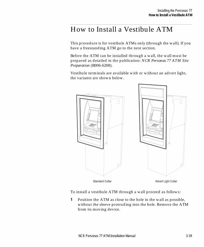
How to Install a Vestibule ATM 3
This procedure is for vestibule ATMs only (through the wall). If you have a freestanding ATM go to the next section.
Before the ATM can be installed through a wall, the wall must be prepared as detailed in the publication: NCR Personas 77 ATM Site Preparation (B006-6208).
Vestibule terminals are available with or without an advert light, the variants are shown below.
To install a vestibule ATM through a wall proceed as follows:
1 Position the ATM as close to the hole in the wall as possible, without the sleeve protruding into the hole. Remove the ATM from its moving device.
Advert Light CollarStandard Collar
NCR Personas 77 ATM Installation Manual 3-39
Installing the Personas 77How to Install a Vestibule ATM
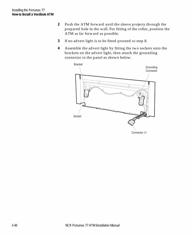
BOOK.BK Page 40 Monday, August 16, 2004 11:15 AM
2 Push the ATM forward until the sleeve projects through the prepared hole in the wall. For fitting of the collar, position the ATM as far forward as possible.
3 If no advert light is to be fitted proceed to step 8.
4 Assemble the advert light by fitting the two sockets onto the brackets on the advert light, then attach the grounding connector to the panel as shown below.
Bracket
Connector J1
GroundingConnector
Socket
3-40 NCR Personas 77 ATM Installation Manual
Installing the Personas 77How to Install a Vestibule ATM
BOOK.BK Page 41 Monday, August 16, 2004 11:15 AM
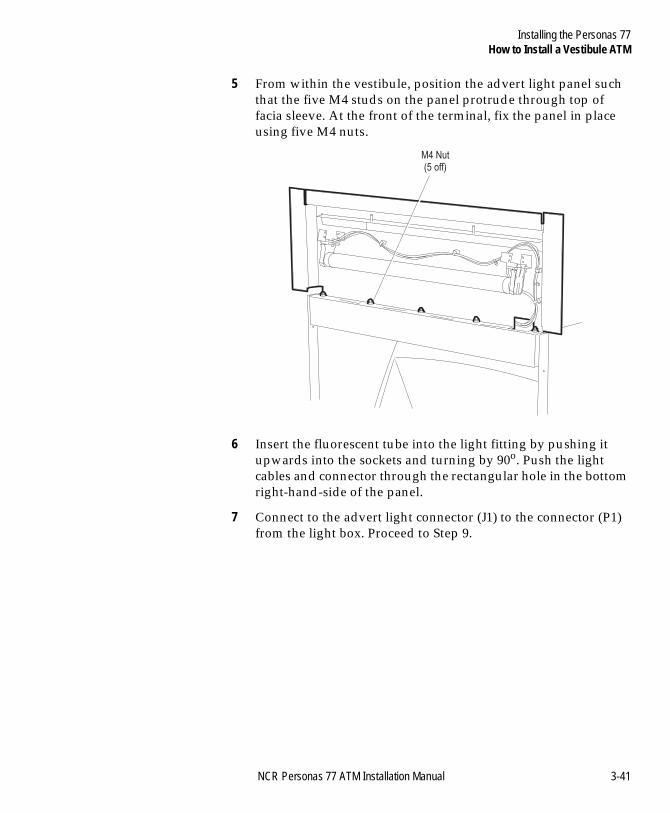
5 From within the vestibule, position the advert light panel such that the five M4 studs on the panel protrude through top of facia sleeve. At the front of the terminal, fix the panel in place using five M4 nuts.
6 Insert the fluorescent tube into the light fitting by pushing it upwards into the sockets and turning by 90o. Push the light cables and connector through the rectangular hole in the bottom right-hand-side of the panel.
7 Connect to the advert light connector (J1) to the connector (P1) from the light box. Proceed to Step 9.
M4 Nut(5 off)
NCR Personas 77 ATM Installation Manual 3-41
Installing the Personas 77How to Install a Vestibule ATM
BOOK.BK Page 42 Monday, August 16, 2004 11:15 AM
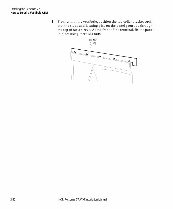
8 From within the vestibule, position the top collar bracket such that the studs and locating pins on the panel protrude through the top of facia sleeve. At the front of the terminal, fix the panel in place using three M4 nuts.
M4 Nut(5 off)
3-42 NCR Personas 77 ATM Installation Manual
Installing the Personas 77How to Install a Vestibule ATM
BOOK.BK Page 43 Monday, August 16, 2004 11:15 AM
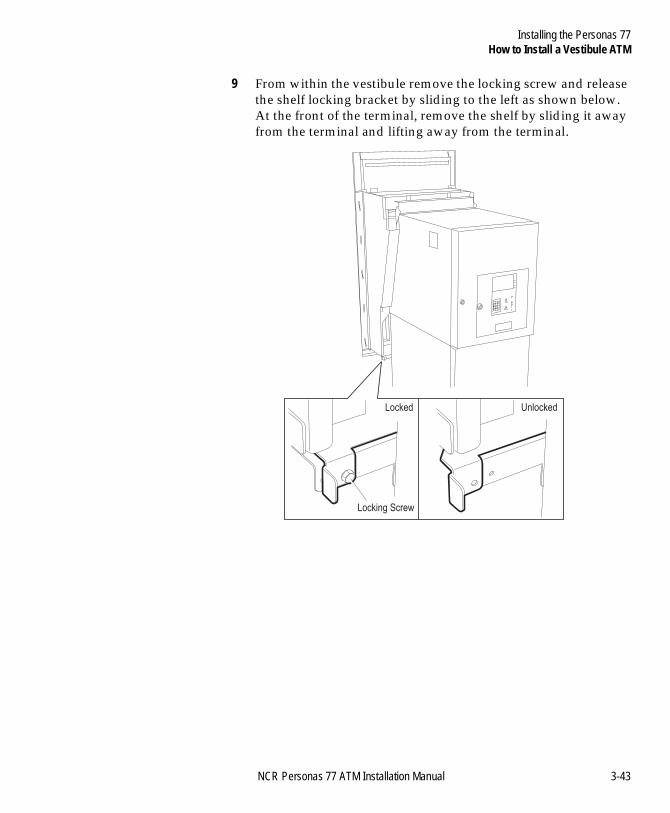
9 From within the vestibule remove the locking screw and release the shelf locking bracket by sliding to the left as shown below. At the front of the terminal, remove the shelf by sliding it away from the terminal and lifting away from the terminal.
Locking Screw
Locked Unlocked
NCR Personas 77 ATM Installation Manual 3-43
Installing the Personas 77How to Install a Vestibule ATM
BOOK.BK Page 44 Monday, August 16, 2004 11:15 AM
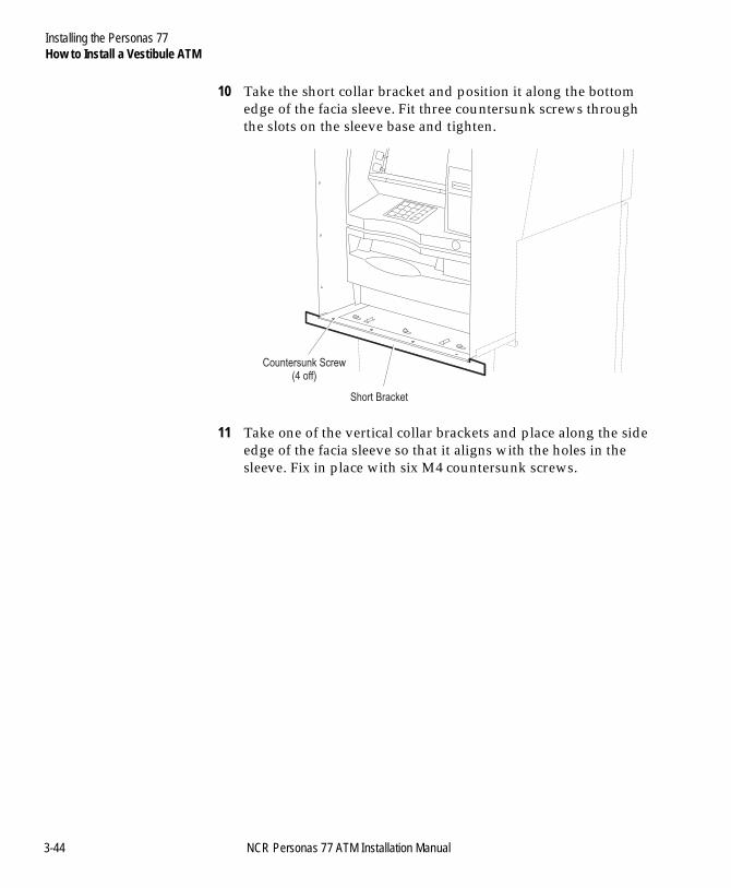
10 Take the short collar bracket and position it along the bottom edge of the facia sleeve. Fit three countersunk screws through the slots on the sleeve base and tighten.
11 Take one of the vertical collar brackets and place along the side edge of the facia sleeve so that it aligns with the holes in the sleeve. Fix in place with six M4 countersunk screws.
Countersunk Screw(4 off)
Short Bracket
3-44 NCR Personas 77 ATM Installation Manual
Installing the Personas 77How to Install a Vestibule ATM
BOOK.BK Page 45 Monday, August 16, 2004 11:15 AM
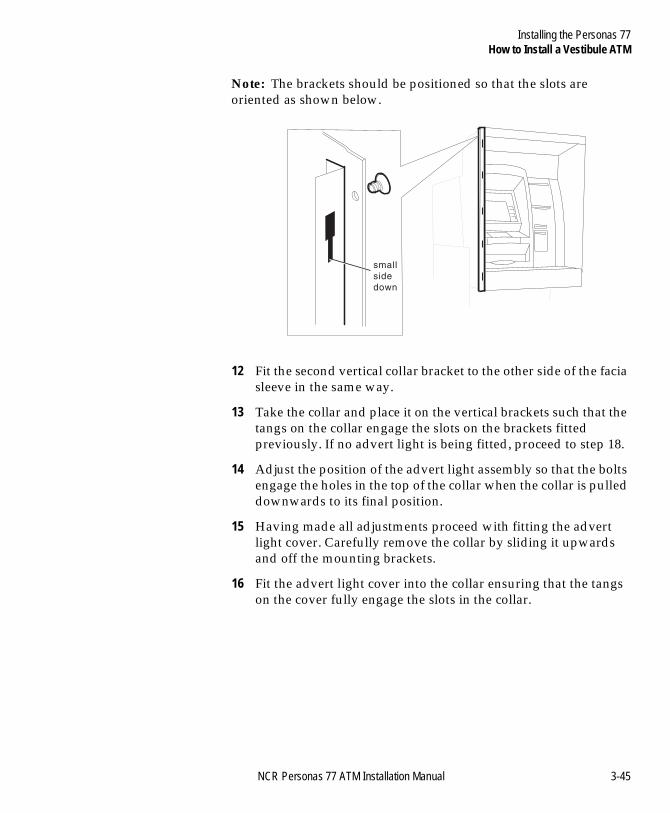
Note: The brackets should be positioned so that the slots are oriented as shown below.
12 Fit the second vertical collar bracket to the other side of the facia sleeve in the same way.
13 Take the collar and place it on the vertical brackets such that the tangs on the collar engage the slots on the brackets fitted previously. If no advert light is being fitted, proceed to step 18.
14 Adjust the position of the advert light assembly so that the bolts engage the holes in the top of the collar when the collar is pulled downwards to its final position.
15 Having made all adjustments proceed with fitting the advert light cover. Carefully remove the collar by sliding it upwards and off the mounting brackets.
16 Fit the advert light cover into the collar ensuring that the tangs on the cover fully engage the slots in the collar.
small
side
down
NCR Personas 77 ATM Installation Manual 3-45
Installing the Personas 77How to Install a Vestibule ATM
BOOK.BK Page 46 Monday, August 16, 2004 11:15 AM
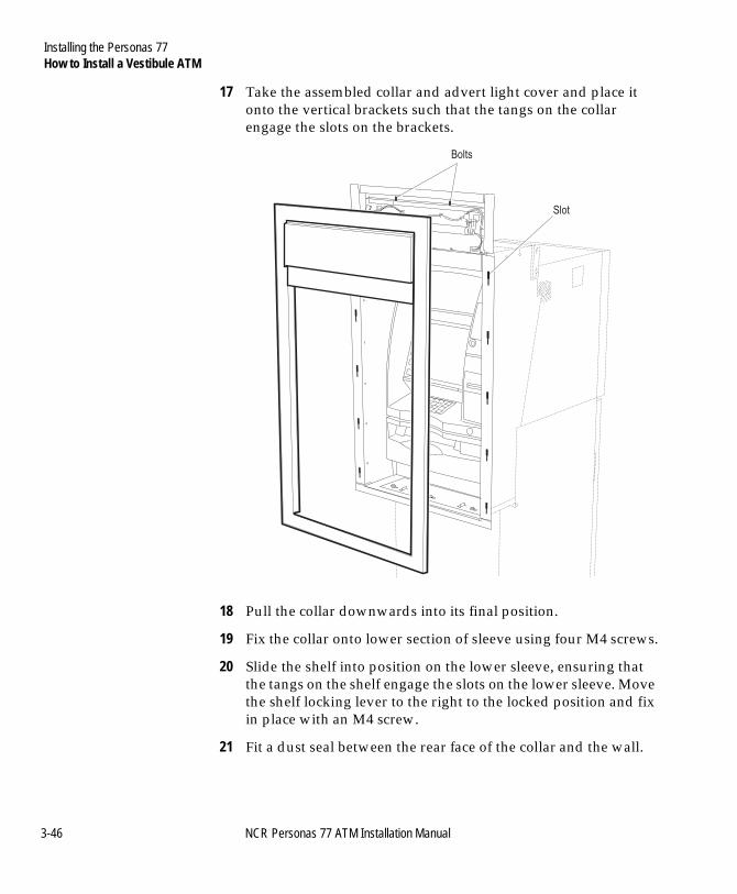
17 Take the assembled collar and advert light cover and place it onto the vertical brackets such that the tangs on the collar engage the slots on the brackets.
18 Pull the collar downwards into its final position.
19 Fix the collar onto lower section of sleeve using four M4 screws.
20 Slide the shelf into position on the lower sleeve, ensuring that the tangs on the shelf engage the slots on the lower sleeve. Move the shelf locking lever to the right to the locked position and fix in place with an M4 screw.
21 Fit a dust seal between the rear face of the collar and the wall.
Bolts
Slot
3-46 NCR Personas 77 ATM Installation Manual
Installing the Personas 77How to Install a Vestibule ATM
BOOK.BK Page 47 Monday, August 16, 2004 11:15 AM
22 Carefully move the ATM back until the collar brackets and seals sit firmly against the wall. Ensure that the holes in the base of the safe align with the holes drilled in the floor.
NCR Personas 77 ATM Installation Manual 3-47
Installing the Personas 77Bolting the ATM to the Floor
BOOK.BK Page 48 Monday, August 16, 2004 11:15 AM
Bolting the ATM to the Floor 3
Note The ATM should be bolted to the floor in order to meet UL291 security requirements.
The floor must be prepared as detailed in the NCR Personas 77 ATM Site Preparation Manual (B006-6208).
Bolt holes must be drilled prior to final siting of the ATM. The above site preparation manual provides dimensions for bolt hole locations.
Security Bolts Specifications 3
The ATM must be bolted to the floor using the correct number of security bolts. The number of bolts is as follows:
● Standard, Front Access German Standard, Business Hours, CEN 3 and CEN 4 Security - four bolts
● Rear Access German Standard Security - two bolts.
Note: The ATM must be bolted to the floor to meet UL291 security requirements.
Note: The securing bolts, anchors and appropriate washers must be supplied by the owning organisation.
The floor must be capable of taking the anchor points for the bolts.
The minimum specification for bolts to secure the ATM to a plinth or a stone/concrete floor is:
● For Business Hours - M12 Rawlbolt - 12mm (0.47 in.) diameter x 38mm (1.5 in.) minimum length
● Standard Security and German Standard Security - M16 Rawlbolt - 16mm (0.6 in.) diameter x 100mm (4.0 in.) minimum length
● For CEN 3 and CEN 4 - M16 Rawlbolt - 16mm (0.6 in.) diameter x 120mm (4.7 in.) minimum length.
3-48 NCR Personas 77 ATM Installation Manual
Installing the Personas 77Bolting the ATM to the Floor
BOOK.BK Page 49 Monday, August 16, 2004 11:15 AM
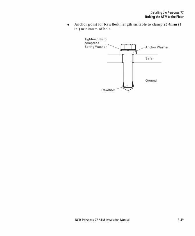
● Anchor point for Rawlbolt, length suitable to clamp 25.4mm (1 in.) minimum of bolt.
Tighten only to
compress
Spring Washer
Rawlbolt
Ground
Safe
Anchor Washer
NCR Personas 77 ATM Installation Manual 3-49
Installing the Personas 77Bolting the ATM to the Floor
BOOK.BK Page 50 Monday, August 16, 2004 11:15 AM
Bolting to the Floor 3
To bolt the ATM to the floor proceed as follows:
1 Open the lower cabinet door.
2 Open the security enclosure.
3 To get sufficient access to the bolt holes inside the security enclosure, it is necessary to temporarily remove several pick modules from the dispenser. Referring to the publication, NCR 56xx/Personas Service Aids Mini Manual (FM-0547), remove pick modules from the dispenser, as required, to give sufficient access to the interior of the security enclosure.
4 Locate the holes in the base of safe, position washers and insert bolts through the holes. Tighten the bolts fully.
5 Replace previously removed pick modules following instructions in NCR 56xx/Personas Service Aids Mini Manual (FM-0547).
6 Push the dispenser back into the ATM.
7 Close and lock the security enclosure. Proceed to “Connecting Cables”.
3-50 NCR Personas 77 ATM Installation Manual
Installing the Personas 77Connecting Cables
BOOK.BK Page 51 Monday, August 16, 2004 11:15 AM
Connecting Cables 3
The cables used to make connections to the ATM must be prepared in accordance with the information detailed in the NCR Personas 77 ATM Site Preparation Manual (B006-6208).
Caution To ensure the ATM meets EMC requirements, cables must be grounded where indicated and any paint under a grounding point or grounding screw must be removed.
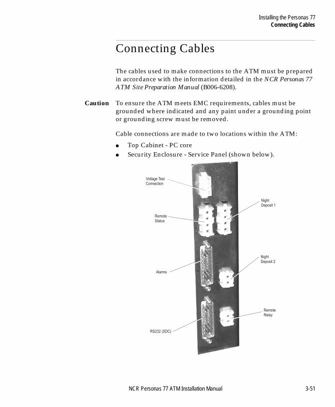
Cable connections are made to two locations within the ATM:
● Top Cabinet - PC core● Security Enclosure - Service Panel (shown below).
Voltage TestConnection
RemoteStatus
NightDeposit 1
NightDeposit 2
RemoteRelay
Alarms
RS232 (SDC)
NCR Personas 77 ATM Installation Manual 3-51
Installing the Personas 77Connecting Cables
BOOK.BK Page 52 Monday, August 16, 2004 11:15 AM
Top Cabinet 3
All communications (comms) cables for the ATM are connected to the PC core which is located in the top cabinet.
Routing Communications Cables - Front Access 3
Route the comms cables as follows:
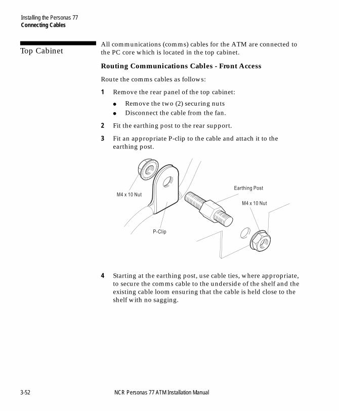
1 Remove the rear panel of the top cabinet:
● Remove the two (2) securing nuts● Disconnect the cable from the fan.
2 Fit the earthing post to the rear support.
3 Fit an appropriate P-clip to the cable and attach it to the earthing post.
4 Starting at the earthing post, use cable ties, where appropriate, to secure the comms cable to the underside of the shelf and the existing cable loom ensuring that the cable is held close to the shelf with no sagging.
M4 x 10 Nut
M4 x 10 Nut
Earthing Post
P-Clip
3-52 NCR Personas 77 ATM Installation Manual
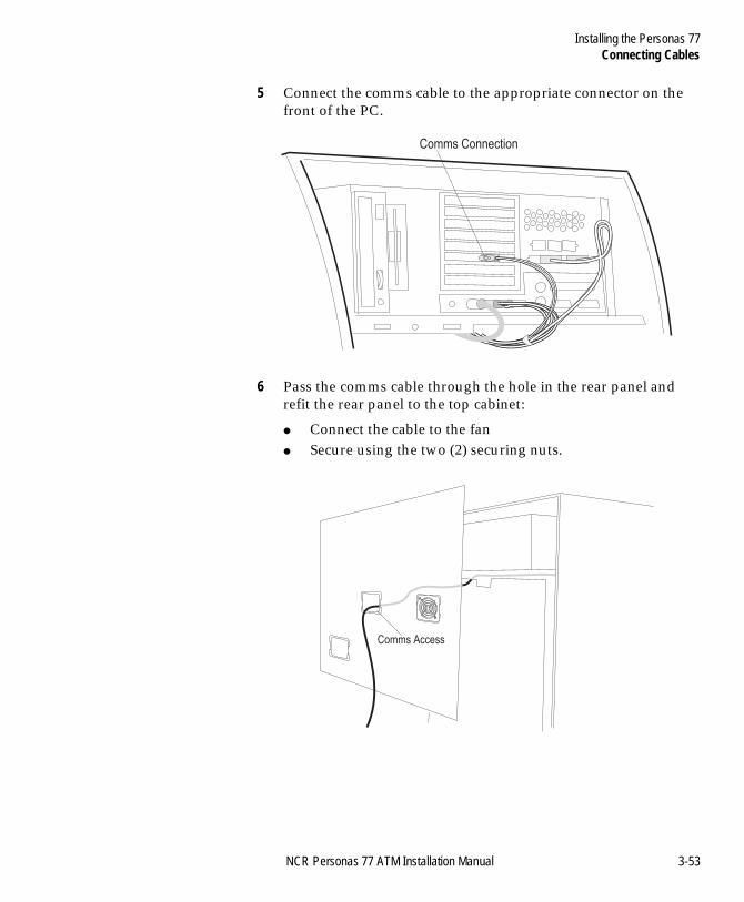
Installing the Personas 77Connecting Cables
BOOK.BK Page 53 Monday, August 16, 2004 11:15 AM
5 Connect the comms cable to the appropriate connector on the front of the PC.
6 Pass the comms cable through the hole in the rear panel and refit the rear panel to the top cabinet:
● Connect the cable to the fan● Secure using the two (2) securing nuts.
Comms Connection
Comms Access
NCR Personas 77 ATM Installation Manual 3-53
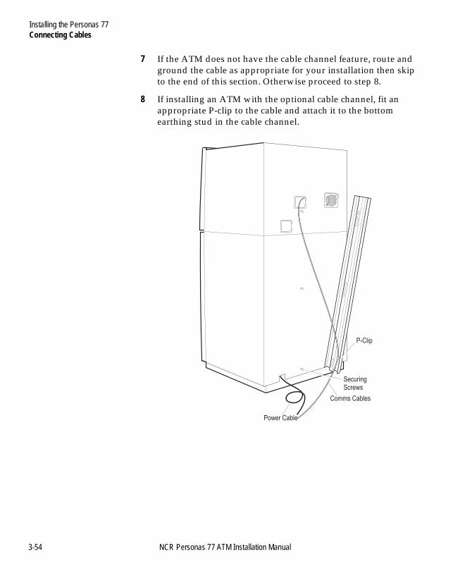
Installing the Personas 77Connecting Cables
BOOK.BK Page 54 Monday, August 16, 2004 11:15 AM
7 If the ATM does not have the cable channel feature, route and ground the cable as appropriate for your installation then skip to the end of this section. Otherwise proceed to step 8.
8 If installing an ATM with the optional cable channel, fit an appropriate P-clip to the cable and attach it to the bottom earthing stud in the cable channel.
Comms Cables
SecuringScrews
P-Clip
Power Cable
3-54 NCR Personas 77 ATM Installation Manual
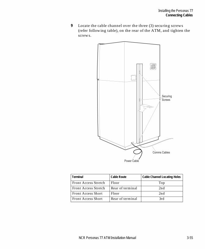
Installing the Personas 77Connecting Cables
BOOK.BK Page 55 Monday, August 16, 2004 11:15 AM
9 Locate the cable channel over the three (3) securing screws (refer following table), on the rear of the ATM, and tighten the screws.
Terminal Cable Route Cable Channel Locating Holes
Front Access Stretch Floor TopFront Access Stretch Rear of terminal 2ndFront Access Short Floor 2ndFront Access Short Rear of terminal 3rd
Comms Cables
Power Cable
SecuringScrews
NCR Personas 77 ATM Installation Manual 3-55
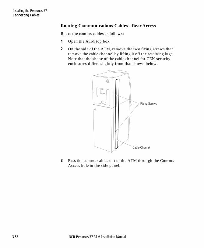
Installing the Personas 77Connecting Cables
BOOK.BK Page 56 Monday, August 16, 2004 11:15 AM
Routing Communications Cables - Rear Access 3
Route the comms cables as follows:
1 Open the ATM top box.
2 On the side of the ATM, remove the two fixing screws then remove the cable channel by lifting it off the retaining lugs. Note that the shape of the cable channel for CEN security enclosures differs slightly from that shown below.
3 Pass the comms cables out of the ATM through the Comms Access hole in the side panel.
Cable Channel
Fixing Screws
3-56 NCR Personas 77 ATM Installation Manual
Installing the Personas 77Connecting Cables
BOOK.BK Page 57 Monday, August 16, 2004 11:15 AM
4 Connect the comms cables to the appropriate connectors on the front of the PC Core.
Comms Connection
Comms Access Hole
CommsCables
NCR Personas 77 ATM Installation Manual 3-57
Installing the Personas 77Connecting Cables
BOOK.BK Page 58 Monday, August 16, 2004 11:15 AM
5 On the outside of the terminal, fit P-clamps to the cables and attach them to the upper fixing screws on the upper comms channel retaining bracket. Fit the clamps such that the cables run on the inside of the fixing screws
6 Fit additional P-clamps further down the cables and attach these to the lower fixing screw on the lower comms channel retaining bracket. Fit the clamps such that the cables run on the inside the fixing screws.
Cable ChannelRetaining Bracket
(2 off)
P-clamp
P-clamp
3-58 NCR Personas 77 ATM Installation Manual
Installing the Personas 77Connecting Cables
BOOK.BK Page 59 Monday, August 16, 2004 11:15 AM
7 Place the cable channel onto the retaining brackets and lock in place by sliding downwards. Fix in position with three retaining screws.
Cable Channel
Fixing Screws
NCR Personas 77 ATM Installation Manual 3-59
Installing the Personas 77Connecting Cables
BOOK.BK Page 60 Monday, August 16, 2004 11:15 AM
Video Camera 3
The video camera is a constant stream variety and must to be connected to a monitor. To do this proceed as follows:
1 If necessary, remove the cable channel as described previously.
2 Attach the monitor BNC connector to the BNC Video plug.
3 If no further connections are required, replace the cable channel.
3-60 NCR Personas 77 ATM Installation Manual

Installing the Personas 77Connecting Cables
BOOK.BK Page 61 Monday, August 16, 2004 11:15 AM
Front Access Short Security Enclosure 3
All the cables that have to be connected to the power supply unit and the service panel are routed through the bottom of the security enclosure to the service panel.
Warning Make sure that the power supply cable is not connected to the mains power supply while you are connecting it to the ATM.
1 Switch OFF the ATM power supply (press in at the “0” side) and open the security enclosure.
2 Disconnect the power supply cable from the power supply unit, loosen the two M6 screws which secure the metal ducting and if fitted remove the two (2) washers.
Note: Washers may be fitted under the M6 screws, between the safe floor and the metal ducting, depending on whether or not the EPP feature has been fitted to the ATM.
Plate
M6 Screws
Screw
Washer
Ducting
Safe
NCR Personas 77 ATM Installation Manual 3-61
Installing the Personas 77Connecting Cables
BOOK.BK Page 62 Monday, August 16, 2004 11:15 AM
3 If necessary, rack the currency dispenser out of the terminal until its slides are fully extended.
4 Slide the metal ducting forwards and lift it clear into the space between the currency dispenser and the power supply.
Note: Ensure that the two end strips (if fitted to ducting) are not dislodged during this operation.
3-62 NCR Personas 77 ATM Installation Manual
Installing the Personas 77Connecting Cables
BOOK.BK Page 63 Monday, August 16, 2004 11:15 AM
5 Pass the ends of all cables to be installed through the hole in the rear of the ATM. Pull the cables through the hole.
6 There are three (3) earth studs at both ends of the metal ducting with P-clips attached to them, as shown below. Remove the clamps from the metal ducting.
Note: It may be easier to remove the clamps by turning the metal ducting upside down.
7 Select and fit the appropriate P-clips to each cable as required. Refer to the following table to select the correct clamp.
System/Device Cable P-clip Size
RS232 6.0mm (0.24in.)
Remote Status Indicator/Alarm Interface 4.5mm (0.18in.)
Remote Relay/Night Depository 3.38mm (0.13in.)
ClampM4 Nut
Earth Stud
NCR Personas 77 ATM Installation Manual 3-63
Installing the Personas 77Connecting Cables
BOOK.BK Page 64 Monday, August 16, 2004 11:15 AM
8 Attach each clamped cable to two earth studs, one at each end of the metal ducting. Use the M4 nuts supplied.
Note: Leave any unused P-clips attached to the metal ducting as they may be required at a later date.
9 Connect the power supply cable to the filter.
10 Refit the metal ducting ensuring that:
M4 Nut securing
cable clamp
3.38mm
4.5mm
6.0mm
(0.13in.)
Clamp
or
(0.18in.)
Clamp
or
(0.24in.)
Clamp
Earth Stud
Metal Plate
Power Supply
CableFilter
3-64 NCR Personas 77 ATM Installation Manual
Installing the Personas 77Connecting Cables
BOOK.BK Page 65 Monday, August 16, 2004 11:15 AM
● all the cables are routed underneath it, and secure by tightening the two M6 screws.
● the two edge strips (if originally fitted to ducting) are in position.
Note: If previously removed, refit the two (2) washers between the metal ducting and the safe floor.
NCR Personas 77 ATM Installation Manual 3-65
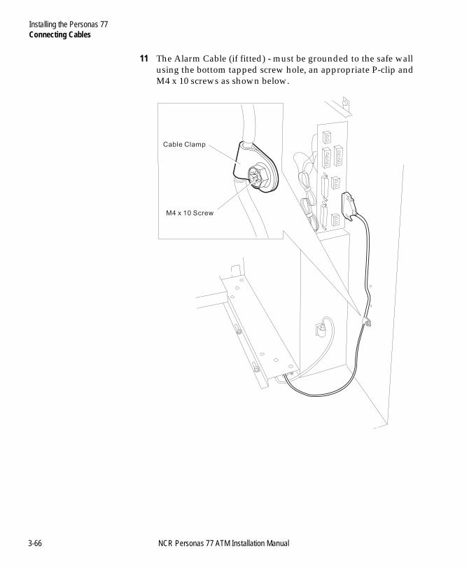
Installing the Personas 77Connecting Cables
BOOK.BK Page 66 Monday, August 16, 2004 11:15 AM
11 The Alarm Cable (if fitted) - must be grounded to the safe wall using the bottom tapped screw hole, an appropriate P-clip and M4 x 10 screws as shown below.
M4 x 10 Screw
Cable Clamp
3-66 NCR Personas 77 ATM Installation Manual
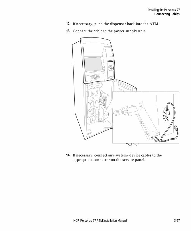
Installing the Personas 77Connecting Cables
BOOK.BK Page 67 Monday, August 16, 2004 11:15 AM
12 If necessary, push the dispenser back into the ATM.
13 Connect the cable to the power supply unit.
14 If necessary, connect any system/device cables to the appropriate connector on the service panel.
NCR Personas 77 ATM Installation Manual 3-67
Installing the Personas 77Connecting Cables
BOOK.BK Page 68 Monday, August 16, 2004 11:15 AM
Front Access Stretch and CEN Security Enclosure 3
All the cables that have to be connected to the power supply unit and the service panel are routed through the bottom of the security enclosure to the service panel.
Note: The illustrations in this section show a Stretch security enclosure. Although some CEN security enclosure components differ in appearance from those shown, the procedures for installing cables in Stretch, CEN 3 and CEN 4 security enclosures is the same.
Warning Make sure that the power supply cable is not connected to the mains power supply while you are connecting it to the ATM.
1 Switch OFF the ATM power supply (press in at the “0” side) and open the security enclosure.
2 Disconnect the power supply cable from the power supply unit.
3 Rack the currency dispenser out of the terminal until its slides are fully extended.
3-68 NCR Personas 77 ATM Installation Manual
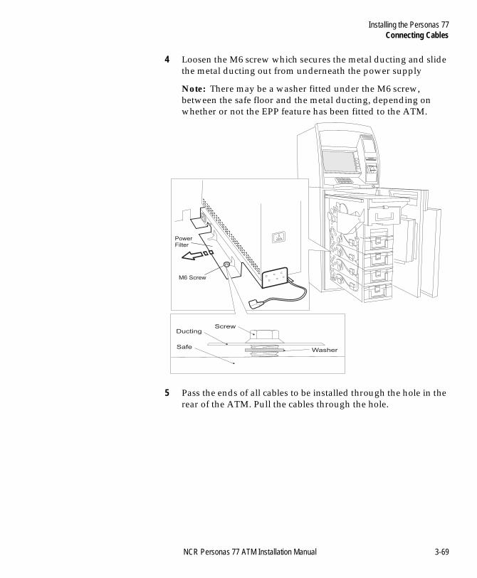
Installing the Personas 77Connecting Cables
BOOK.BK Page 69 Monday, August 16, 2004 11:15 AM
4 Loosen the M6 screw which secures the metal ducting and slide the metal ducting out from underneath the power supply
Note: There may be a washer fitted under the M6 screw, between the safe floor and the metal ducting, depending on whether or not the EPP feature has been fitted to the ATM.
5 Pass the ends of all cables to be installed through the hole in the rear of the ATM. Pull the cables through the hole.
M6 Screw
PowerFilter
Screw
Washer
Ducting
Safe
NCR Personas 77 ATM Installation Manual 3-69
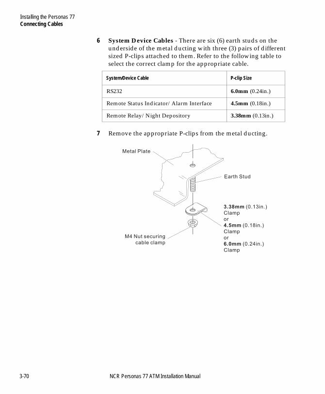
Installing the Personas 77Connecting Cables
BOOK.BK Page 70 Monday, August 16, 2004 11:15 AM
6 System Device Cables - There are six (6) earth studs on the underside of the metal ducting with three (3) pairs of different sized P-clips attached to them. Refer to the following table to select the correct clamp for the appropriate cable.
7 Remove the appropriate P-clips from the metal ducting.
System/Device Cable P-clip Size
RS232 6.0mm (0.24in.)
Remote Status Indicator/Alarm Interface 4.5mm (0.18in.)
Remote Relay/Night Depository 3.38mm (0.13in.)
M4 Nut securing
cable clamp
3.38mm
4.5mm
6.0mm
(0.13in.)
Clamp
or
(0.18in.)
Clamp
or
(0.24in.)
Clamp
Earth Stud
Metal Plate
3-70 NCR Personas 77 ATM Installation Manual
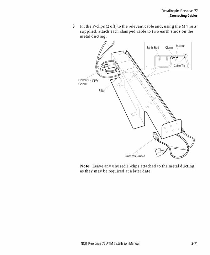
Installing the Personas 77Connecting Cables
BOOK.BK Page 71 Monday, August 16, 2004 11:15 AM
8 Fit the P-clips (2 off) to the relevant cable and, using the M4 nuts supplied, attach each clamped cable to two earth studs on the metal ducting.
Note: Leave any unused P-clips attached to the metal ducting as they may be required at a later date.
Power Supply
Cable
Comms Cable
Filter
Clamp
Cable Tie
M4 NutEarth Stud
NCR Personas 77 ATM Installation Manual 3-71
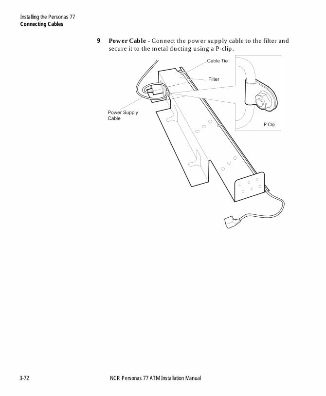
Installing the Personas 77Connecting Cables
BOOK.BK Page 72 Monday, August 16, 2004 11:15 AM
9 Power Cable - Connect the power supply cable to the filter and secure it to the metal ducting using a P-clip.
Power Supply
Cable
Filter
Cable Tie
P-Clip
3-72 NCR Personas 77 ATM Installation Manual
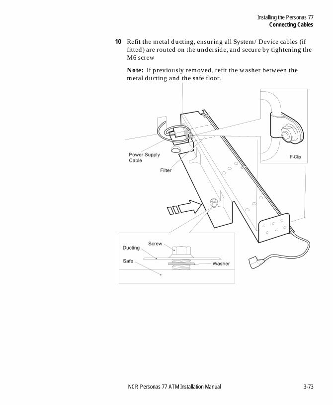
Installing the Personas 77Connecting Cables
BOOK.BK Page 73 Monday, August 16, 2004 11:15 AM
10 Refit the metal ducting, ensuring all System/Device cables (if fitted) are routed on the underside, and secure by tightening the M6 screw
Note: If previously removed, refit the washer between the metal ducting and the safe floor.
Power Supply
Cable
Filter
P-Clip
Screw
Washer
Ducting
Safe
NCR Personas 77 ATM Installation Manual 3-73
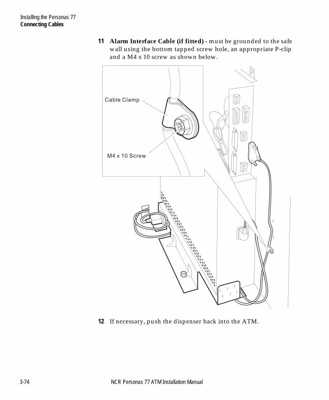
Installing the Personas 77Connecting Cables
BOOK.BK Page 74 Monday, August 16, 2004 11:15 AM
11 Alarm Interface Cable (if fitted) - must be grounded to the safe wall using the bottom tapped screw hole, an appropriate P-clip and a M4 x 10 screw as shown below.
12 If necessary, push the dispenser back into the ATM.
M4 x 10 Screw
Cable Clamp
3-74 NCR Personas 77 ATM Installation Manual
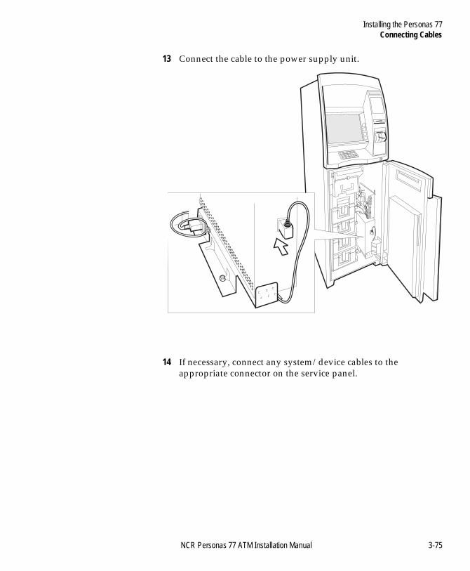
Installing the Personas 77Connecting Cables
BOOK.BK Page 75 Monday, August 16, 2004 11:15 AM
13 Connect the cable to the power supply unit.
14 If necessary, connect any system/device cables to the appropriate connector on the service panel.
NCR Personas 77 ATM Installation Manual 3-75
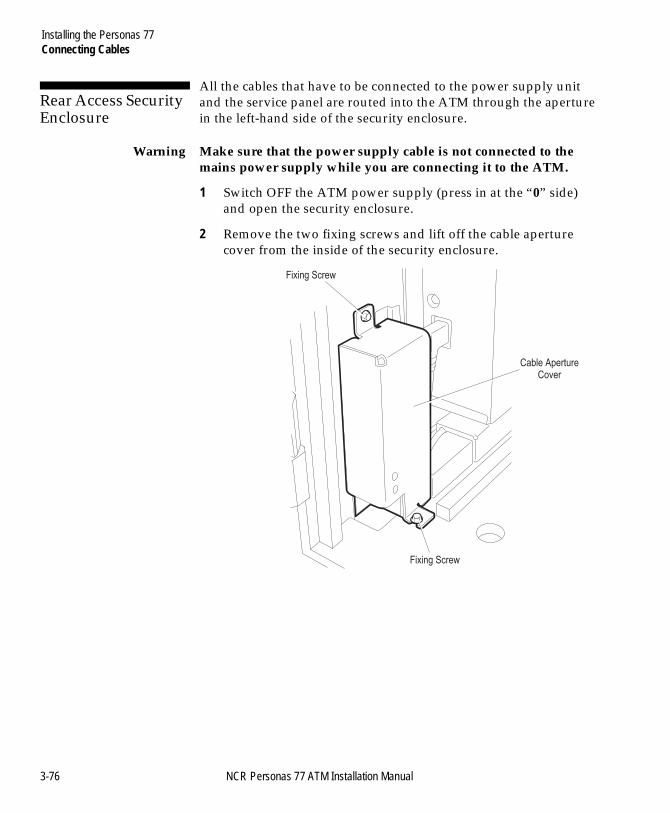
Installing the Personas 77Connecting Cables
BOOK.BK Page 76 Monday, August 16, 2004 11:15 AM
Rear Access Security Enclosure 3
All the cables that have to be connected to the power supply unit and the service panel are routed into the ATM through the aperture in the left-hand side of the security enclosure.
Warning Make sure that the power supply cable is not connected to the mains power supply while you are connecting it to the ATM.
1 Switch OFF the ATM power supply (press in at the “0” side) and open the security enclosure.
2 Remove the two fixing screws and lift off the cable aperture cover from the inside of the security enclosure.
Cable ApertureCover
Fixing Screw
Fixing Screw
3-76 NCR Personas 77 ATM Installation Manual
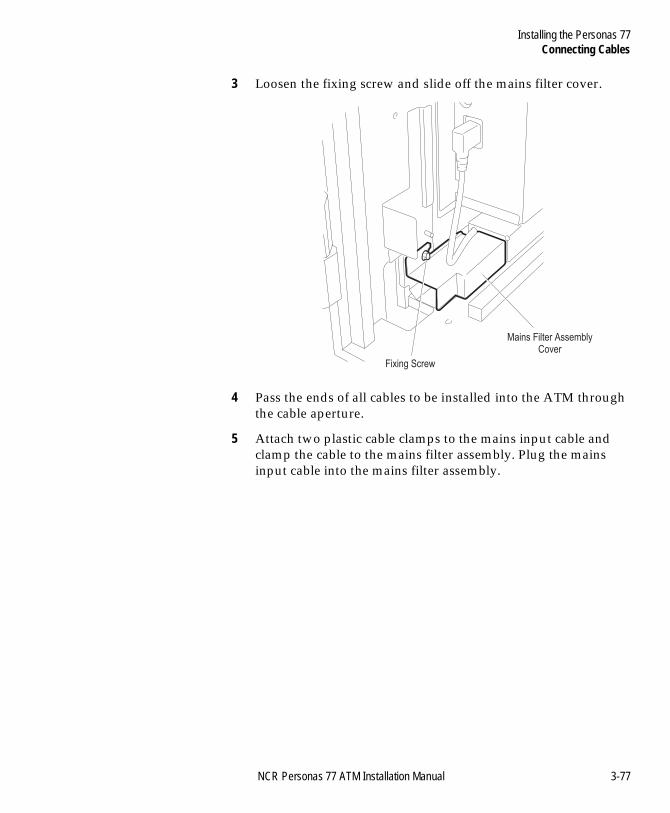
Installing the Personas 77Connecting Cables
BOOK.BK Page 77 Monday, August 16, 2004 11:15 AM
3 Loosen the fixing screw and slide off the mains filter cover.
4 Pass the ends of all cables to be installed into the ATM through the cable aperture.
5 Attach two plastic cable clamps to the mains input cable and clamp the cable to the mains filter assembly. Plug the mains input cable into the mains filter assembly.
Fixing Screw
Mains Filter AssemblyCover
NCR Personas 77 ATM Installation Manual 3-77
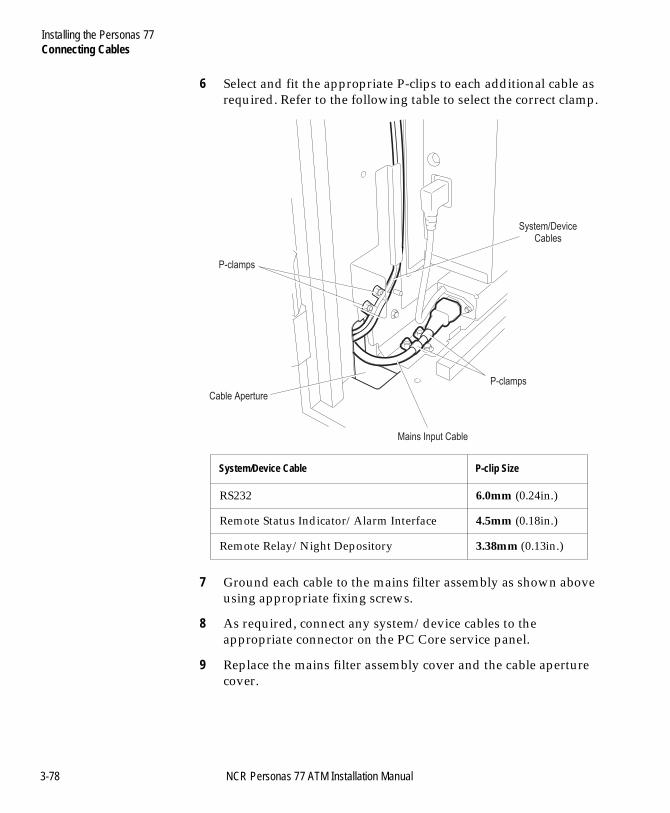
Installing the Personas 77Connecting Cables
BOOK.BK Page 78 Monday, August 16, 2004 11:15 AM
6 Select and fit the appropriate P-clips to each additional cable as required. Refer to the following table to select the correct clamp.
7 Ground each cable to the mains filter assembly as shown above using appropriate fixing screws.
8 As required, connect any system/device cables to the appropriate connector on the PC Core service panel.
9 Replace the mains filter assembly cover and the cable aperture cover.
System/Device Cable P-clip Size
RS232 6.0mm (0.24in.)
Remote Status Indicator/Alarm Interface 4.5mm (0.18in.)
Remote Relay/Night Depository 3.38mm (0.13in.)
Cable Aperture
Mains Input Cable
P-clamps
P-clamps
System/DeviceCables
3-78 NCR Personas 77 ATM Installation Manual
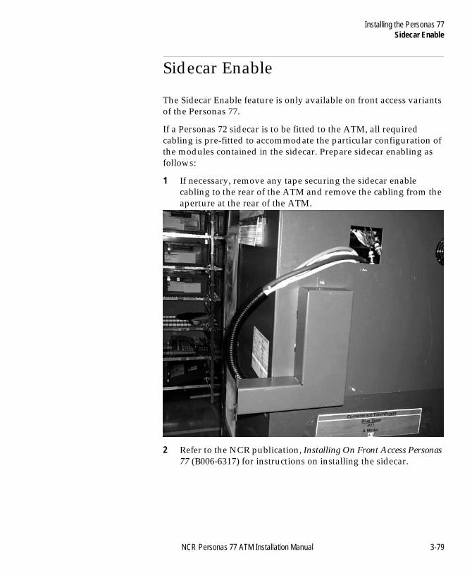
Installing the Personas 77Sidecar Enable
BOOK.BK Page 79 Monday, August 16, 2004 11:15 AM
Sidecar Enable 3
The Sidecar Enable feature is only available on front access variants of the Personas 77.
If a Personas 72 sidecar is to be fitted to the ATM, all required cabling is pre-fitted to accommodate the particular configuration of the modules contained in the sidecar. Prepare sidecar enabling as follows:
1 If necessary, remove any tape securing the sidecar enable cabling to the rear of the ATM and remove the cabling from the aperture at the rear of the ATM.
2 Refer to the NCR publication, Installing On Front Access Personas 77 (B006-6317) for instructions on installing the sidecar.
NCR Personas 77 ATM Installation Manual 3-79
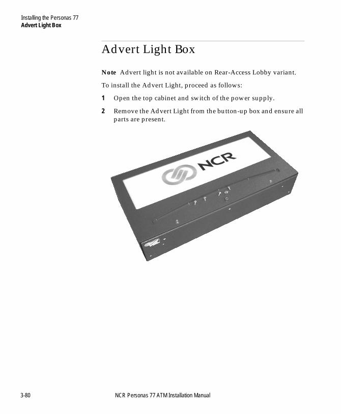
Installing the Personas 77Advert Light Box
BOOK.BK Page 80 Monday, August 16, 2004 11:15 AM
Advert Light Box 3
Note Advert light is not available on Rear-Access Lobby variant.
To install the Advert Light, proceed as follows:
1 Open the top cabinet and switch of the power supply.
2 Remove the Advert Light from the button-up box and ensure all parts are present.
3-80 NCR Personas 77 ATM Installation Manual
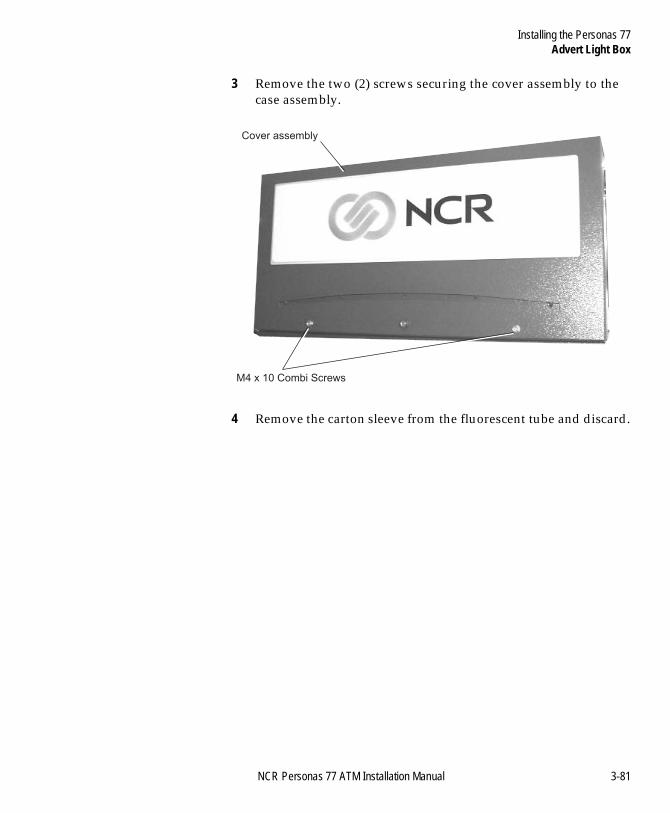
Installing the Personas 77Advert Light Box
BOOK.BK Page 81 Monday, August 16, 2004 11:15 AM
3 Remove the two (2) screws securing the cover assembly to the case assembly.
4 Remove the carton sleeve from the fluorescent tube and discard.
M4 x 10 Combi Screws
Cover assembly
NCR Personas 77 ATM Installation Manual 3-81
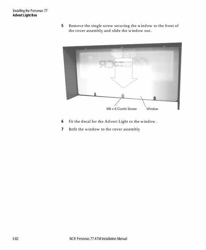
Installing the Personas 77Advert Light Box
BOOK.BK Page 82 Monday, August 16, 2004 11:15 AM
5 Remove the single screw securing the window to the front of the cover assembly and slide the window out.
6 Fit the decal for the Advert Light to the window.
7 Refit the window to the cover assembly
M6 x 8 Combi Screw Window
3-82 NCR Personas 77 ATM Installation Manual
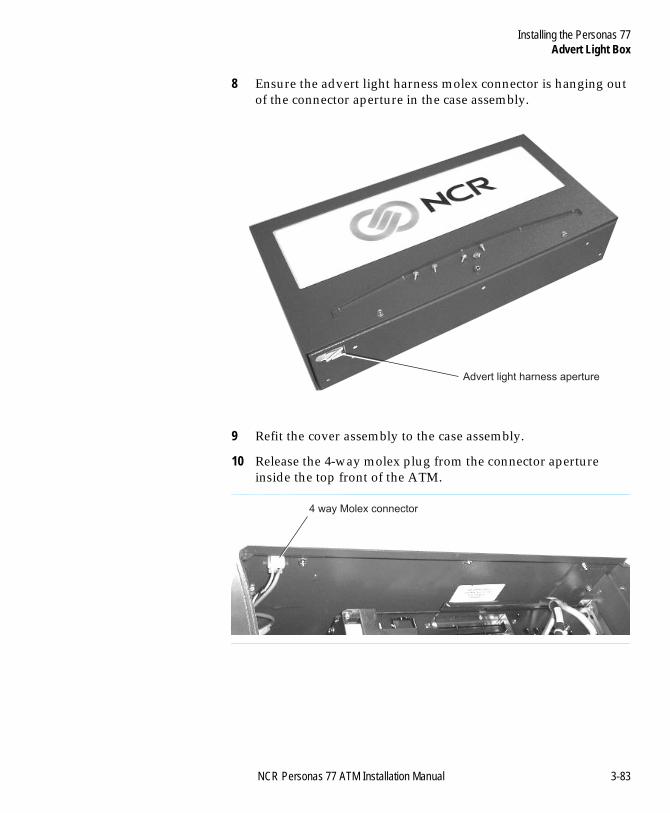
Installing the Personas 77Advert Light Box
BOOK.BK Page 83 Monday, August 16, 2004 11:15 AM
8 Ensure the advert light harness molex connector is hanging out of the connector aperture in the case assembly.
9 Refit the cover assembly to the case assembly.
10 Release the 4-way molex plug from the connector aperture inside the top front of the ATM.
Advert light harness aperture
4 way Molex connector
NCR Personas 77 ATM Installation Manual 3-83
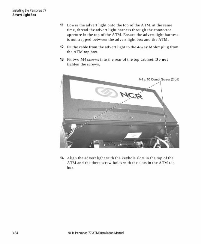
Installing the Personas 77Advert Light Box
BOOK.BK Page 84 Monday, August 16, 2004 11:15 AM
11 Lower the advert light onto the top of the ATM, at the same time, thread the advert light harness through the connector aperture in the top of the ATM. Ensure the advert light harness is not trapped between the advert light box and the ATM.
12 Fit the cable from the advert light to the 4-way Molex plug from the ATM top box.
13 Fit two M4 screws into the rear of the top cabinet. Do not tighten the screws.
14 Align the advert light with the keyhole slots in the top of the ATM and the three screw holes with the slots in the ATM top box.
M4 x 10 Combi Screw (2 off)
3-84 NCR Personas 77 ATM Installation Manual
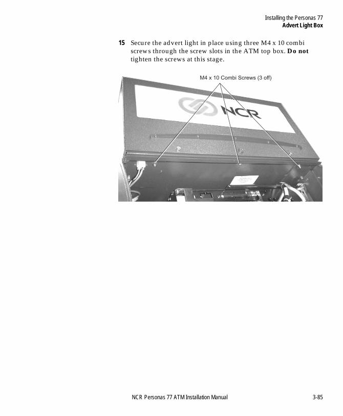
Installing the Personas 77Advert Light Box
BOOK.BK Page 85 Monday, August 16, 2004 11:15 AM
15 Secure the advert light in place using three M4 x 10 combi screws through the screw slots in the ATM top box. Do not tighten the screws at this stage.
M4 x 10 Combi Screws (3 off)
NCR Personas 77 ATM Installation Manual 3-85
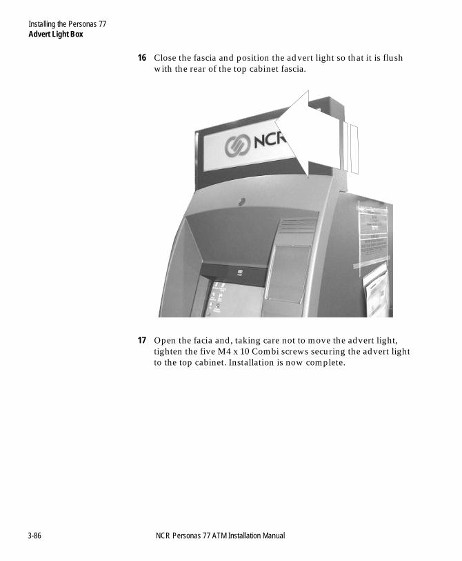
Installing the Personas 77Advert Light Box
BOOK.BK Page 86 Monday, August 16, 2004 11:15 AM
16 Close the fascia and position the advert light so that it is flush with the rear of the top cabinet fascia.
17 Open the facia and, taking care not to move the advert light, tighten the five M4 x 10 Combi screws securing the advert light to the top cabinet. Installation is now complete.
3-86 NCR Personas 77 ATM Installation Manual
Table of ContentsConfiguring the Personas 77
BOOK.BK Page 87 Monday, August 16, 2004 11:15 AM
NCR Personas 77 ATM Installation Manual
Chapter 4
Configuring the Personas 77
Introduction 4-1Application Software 4-1Communications Configuration 4-2
Currency Cassette 4-3
OS/2 Application 4-4Initial Configuration - Product ID 4-4Configuring Modules/Devices 4-4
APTRA Application 4-15Initial Configuration - Product ID 4-15Configuring Modules/Devices 4-15Configuring Communications 4-19
Thermal Printers 4-24Receipt Printer 4-25Journal Printer 4-26Basic Configuration 4-27Advanced Configuration and Calibration 4-28
Receipt Form Length 4-28Character Set 4-29Black Mark Calibration 4-29
Table of ContentsConfiguring the Personas 77
BOOK.BK Page 88 Monday, August 16, 2004 11:15 AM
Intelligent Cash Security System 4-32Fitting the Containment Mat 4-32Verifying the System 4-33
Checking the System is Fault-free 4-33Checking the System is Functioning 4-35
Making the System Live 4-37
NCR Personas 77 ATM Installation Manual
Introduction
BOOK.BK Page 1 Monday, August 16, 2004 11:15 AM
NCR Personas 77 ATM Installation Manual
-14Configuring the Personas 77D
Introduction 4
After you have completed the hardware installation and unpacking of the ATM, there are certain procedures which must be carried out, depending on the configuration of the ATM.
Refer to the NCR Personas77 ATM, Operator Manual (B006-6210) for details of how to load media.
The features which may require configuration are:
● Currency cassette - set cassette for local currency● Touch Screen (if fitted)● Miscellaneous Interface - configure for any attached devices● RS-232 Interface(s) - set external device if necessary● Communications protocols● Printers
● 40-Column printers - test factory settings● Intelligent Cash Security (ICS) system - test and make live.
After completing the installation and configuration of the terminal, refer to the NCR 5877 Personas ATM, Operator Manual (B006-6210) for details of how to initialise the ATM. On completion of installation and testing, complete and return the Installation Report form which is delivered with the ATM.
Application Software 4
Before you can configure communications in the ATM, you must load the application software onto the ATM in accordance with the instructions in the relevant publication for your application:
● S4i - Building A Load Disk (BD10-1797)● NT - APTRA Self Service Support, Installation and Configuration
Guide (B006-6197).
Configuring the Personas 77Introduction
BOOK.BK Page 2 Monday, August 16, 2004 11:15 AM
Communications Configuration 4
To configure communications, you will require the:
● protocol identification code for the communications protocol to be used. These codes are detailed in the NCR publication Quick Reference Guide To Communications Manuals (BD10-2215-0000)
● the communications common and connection parameters. These must be supplied by the owning organisation.
4-2 NCR Personas 77 ATM Installation Manual
Configuring the Personas 77Currency Cassette
BOOK.BK Page 3 Monday, August 16, 2004 11:15 AM
Currency Cassette 4
The currency cassettes must be configured as described in publication NCR H-8015-STD1-01/02-08 Currency Cassette Owner’s Manual (B006-1297-v000).
NCR Personas 77 ATM Installation Manual 4-3
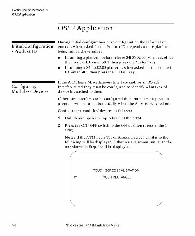
Configuring the Personas 77OS/2 Application
BOOK.BK Page 4 Monday, August 16, 2004 11:15 AM
OS/2 Application 4
Initial Configuration - Product ID 4
During initial configuration or re-configuration the information entered, when asked for the Product ID, depends on the platform being run on the terminal:
● If running a platform before release S4i 05.02.00, when asked for the Product ID, enter 5870 then press the “Enter” key.
● If running a S4i 05.02.00 platform, when asked for the Product ID, enter 5877 then press the “Enter” key.
Configuring Modules/Devices 4
If the ATM has a Miscellaneous Interface and/or an RS-232 Interface fitted they must be configured to identify what type of device is attached to them.
If there are interfaces to be configured the terminal configuration program will be run automatically when the ATM is switched on,
Configure the modules/devices as follows:
1 Unlock and open the top cabinet of the ATM.
2 Press the ON/OFF switch to the ON position (press at the 1 side).
Note: If the ATM has a Touch Screen, a screen similar to the following will be displayed. Other wise, a screen similar to the one shown in Step 4 will be displayed.
TOUCH SCREEN CALIBRATION
TOUCH RECTANGLE
4-4 NCR Personas 77 ATM Installation Manual
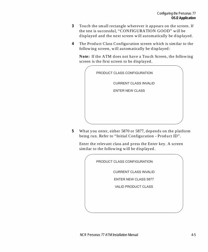
Configuring the Personas 77OS/2 Application
BOOK.BK Page 5 Monday, August 16, 2004 11:15 AM
3 Touch the small rectangle wherever it appears on the screen. If the test is successful, “CONFIGURATION GOOD” will be displayed and the next screen will automatically be displayed.
4 The Product Class Configuration screen which is similar to the following screen, will automatically be displayed:
Note: If the ATM does not have a Touch Screen, the following screen is the first screen to be displayed.
5 What you enter, either 5870 or 5877, depends on the platform being run. Refer to “Initial Configuration - Product ID”.
Enter the relevant class and press the Enter key. A screen similar to the following will be displayed.
PRODUCT CLASS CONFIGURATION
CURRENT CLASS INVALID
ENTER NEW CLASS
PRODUCT CLASS CONFIGURATION
CURRENT CLASS INVALID
ENTER NEW CLASS 5877
VALID PRODUCT CLASS
NCR Personas 77 ATM Installation Manual 4-5
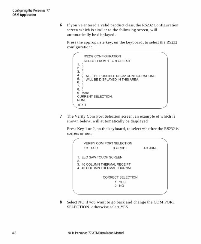
Configuring the Personas 77OS/2 Application
BOOK.BK Page 6 Monday, August 16, 2004 11:15 AM
6 If you’ve entered a valid product class, the RS232 Configuration screen which is similar to the following screen, will automatically be displayed.
Press the appropriate key, on the keyboard, to select the RS232 configuration:
7 The Verify Com Port Selection screen, an example of which is shown below, will automatically be displayed
Press Key 1 or 2, on the keyboard, to select whether the RS232 is correct or not:
8 Select NO if you want to go back and change the COM PORT SELECTION, otherwise select YES.
RS232 CONFIGURATION
SELECT FROM 1 TO 9 OR EXIT1. (2. (3. (4. (5. (6. (7. (8. (9. MoreCURRENT SELECTION:NONE
<EXIT
ALL THE POSSIBLE RS232 CONFIGURATIONSWILL BE DISPLAYED IN THIS AREA.
VERIFY COM PORT SELECTION
1 = TSCR
1. ELO SAW TOUCH SCREEN2.3. 40 COLUMN THERMAL RECEIPT4. 40 COLUMN THERMAL JOURNAL
3 = RCPT 4 = JRNL
CORRECT SELECTION
1. YES2. NO
4-6 NCR Personas 77 ATM Installation Manual
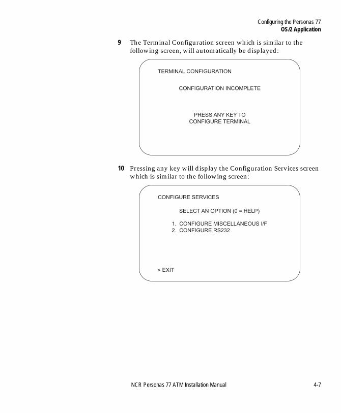
Configuring the Personas 77OS/2 Application
BOOK.BK Page 7 Monday, August 16, 2004 11:15 AM
9 The Terminal Configuration screen which is similar to the following screen, will automatically be displayed:
10 Pressing any key will display the Configuration Services screen which is similar to the following screen:
TERMINAL CONFIGURATION
CONFIGURATION INCOMPLETE
PRESS ANY KEY TO
CONFIGURE TERMINAL
CONFIGURE SERVICES
1. CONFIGURE MISCELLANEOUS I/F
2. CONFIGURE RS232
< EXIT
SELECT AN OPTION (0 = HELP)
NCR Personas 77 ATM Installation Manual 4-7
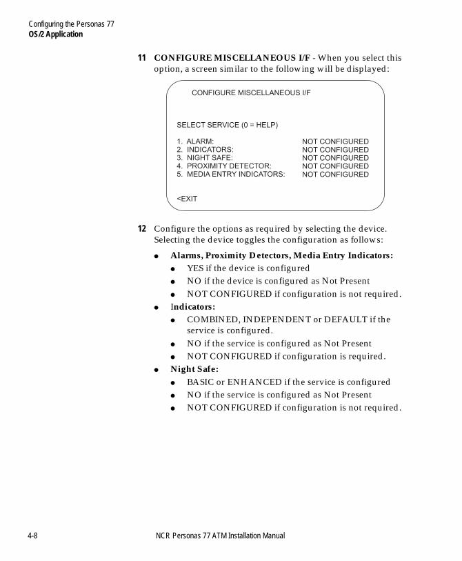
Configuring the Personas 77OS/2 Application
BOOK.BK Page 8 Monday, August 16, 2004 11:15 AM
11 CONFIGURE MISCELLANEOUS I/F - When you select this option, a screen similar to the following will be displayed:
12 Configure the options as required by selecting the device. Selecting the device toggles the configuration as follows:
● Alarms, Proximity Detectors, Media Entry Indicators:● YES if the device is configured● NO if the device is configured as Not Present● NOT CONFIGURED if configuration is not required.
● Indicators:● COMBINED, INDEPENDENT or DEFAULT if the
service is configured.● NO if the service is configured as Not Present● NOT CONFIGURED if configuration is required.
● Night Safe:● BASIC or ENHANCED if the service is configured● NO if the service is configured as Not Present● NOT CONFIGURED if configuration is not required.
CONFIGURE MISCELLANEOUS I/F
SELECT SERVICE (0 = HELP)
1. ALARM:2. INDICATORS:3. NIGHT SAFE:4. PROXIMITY DETECTOR:5. MEDIA ENTRY INDICATORS:
<EXIT
NOT CONFIGUREDNOT CONFIGUREDNOT CONFIGUREDNOT CONFIGUREDNOT CONFIGURED
4-8 NCR Personas 77 ATM Installation Manual
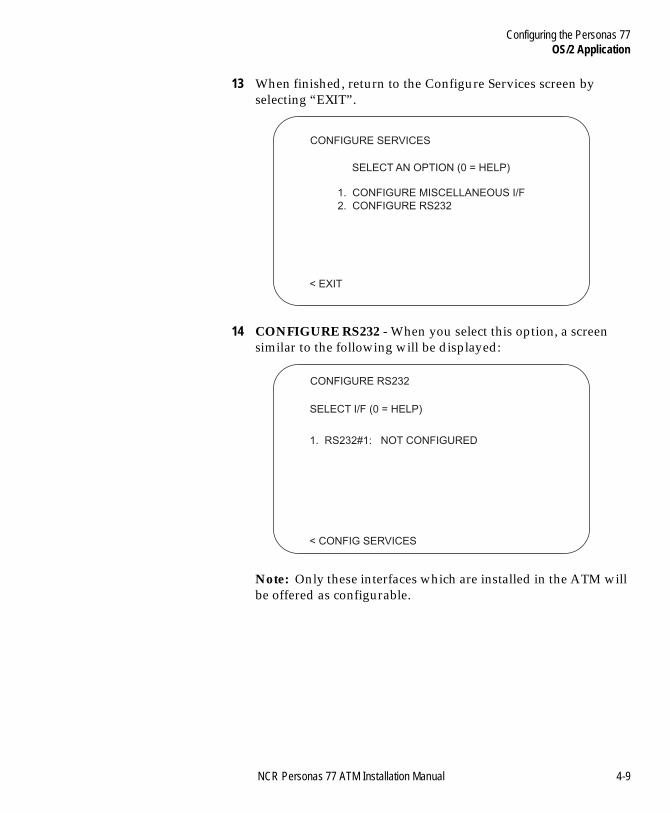
Configuring the Personas 77OS/2 Application
BOOK.BK Page 9 Monday, August 16, 2004 11:15 AM
13 When finished, return to the Configure Services screen by selecting “EXIT”.
14 CONFIGURE RS232 - When you select this option, a screen similar to the following will be displayed:
Note: Only these interfaces which are installed in the ATM will be offered as configurable.
CONFIGURE SERVICES
1. CONFIGURE MISCELLANEOUS I/F
2. CONFIGURE RS232
< EXIT
SELECT AN OPTION (0 = HELP)
CONFIGURE RS232
1. RS232#1: NOT CONFIGURED
< CONFIG SERVICES
SELECT I/F (0 = HELP)
NCR Personas 77 ATM Installation Manual 4-9
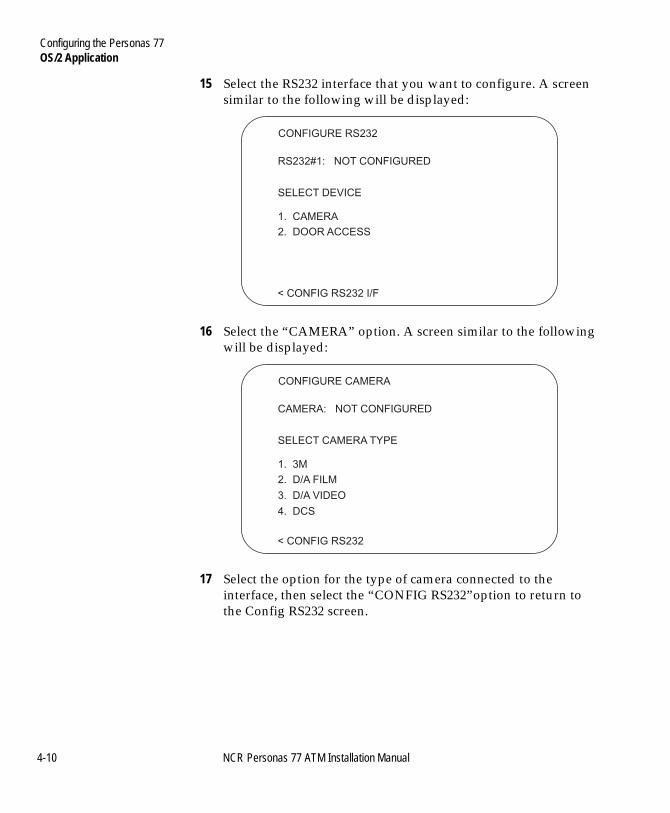
Configuring the Personas 77OS/2 Application
BOOK.BK Page 10 Monday, August 16, 2004 11:15 AM
15 Select the RS232 interface that you want to configure. A screen similar to the following will be displayed:
16 Select the “CAMERA” option. A screen similar to the following will be displayed:
17 Select the option for the type of camera connected to the interface, then select the “CONFIG RS232”option to return to the Config RS232 screen.
CONFIGURE RS232
< CONFIG RS232 I/F
SELECT DEVICE
1. CAMERA
RS232#1: NOT CONFIGURED
2. DOOR ACCESS
CONFIGURE CAMERA
< CONFIG RS232
SELECT CAMERA TYPE
1. 3M
CAMERA: NOT CONFIGURED
2. D/A FILM
3. D/A VIDEO
4. DCS
4-10 NCR Personas 77 ATM Installation Manual
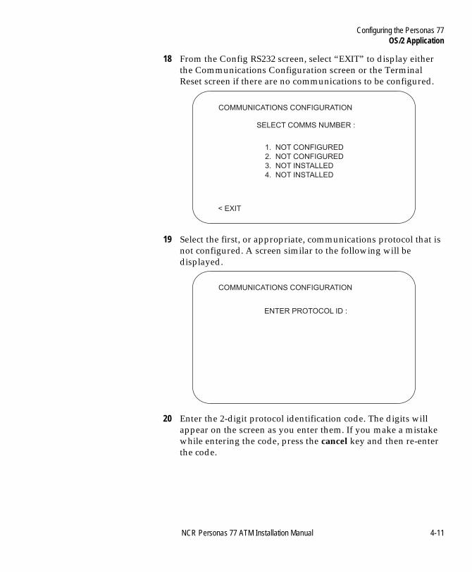
Configuring the Personas 77OS/2 Application
BOOK.BK Page 11 Monday, August 16, 2004 11:15 AM
18 From the Config RS232 screen, select “EXIT” to display either the Communications Configuration screen or the Terminal Reset screen if there are no communications to be configured.
19 Select the first, or appropriate, communications protocol that is not configured. A screen similar to the following will be displayed.
20 Enter the 2-digit protocol identification code. The digits will appear on the screen as you enter them. If you make a mistake while entering the code, press the cancel key and then re-enter the code.
COMMUNICATIONS CONFIGURATION
1. NOT CONFIGURED
2. NOT CONFIGURED
3. NOT INSTALLED
4. NOT INSTALLED
< EXIT
SELECT COMMS NUMBER :
COMMUNICATIONS CONFIGURATION
ENTER PROTOCOL ID :
NCR Personas 77 ATM Installation Manual 4-11
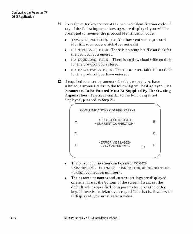
Configuring the Personas 77OS/2 Application
BOOK.BK Page 12 Monday, August 16, 2004 11:15 AM
21 Press the enter key to accept the protocol identification code. If any of the following error messages are displayed you will be prompted to re-enter the protocol identification code:
● INVALID PROTOCOL ID - You have entered a protocol identification code which does not exist
● NO TEMPLATE FILE - There is no template file on disk for the protocol you entered
● NO DOWNLOAD FILE - There is no download+ file on disk for the protocol you entered
● NO EXECUTABLE FILE - There is no executable file on disk for the protocol you have entered.
22 If required to enter parameters for the protocol you have selected, a screen similar to the following will be displayed. The Parameters To Be Entered Must Be Supplied By The Owning Organization. If a screen similar to the following is not displayed, proceed to Step 21.
● The current connection can be either COMMON PARAMETERS, PRIMARY CONNECTION, or CONNECTION <3-digit connection number>.
● The parameter names and current settings are displayed one at a time at the bottom of the screen. To accept the default values specified for a parameter, press the enter key. If there is no default value specified, that is, if NO DATA is displayed, you must enter a value.
COMMUNICATIONS CONFIGURATION
<PROTOCOL ID TEXT>
<CURRENT CONNECTION>
<ERROR MESSAGES>
<PARAMETER TXT>
A
C
E
B
D
F(*)
4-12 NCR Personas 77 ATM Installation Manual
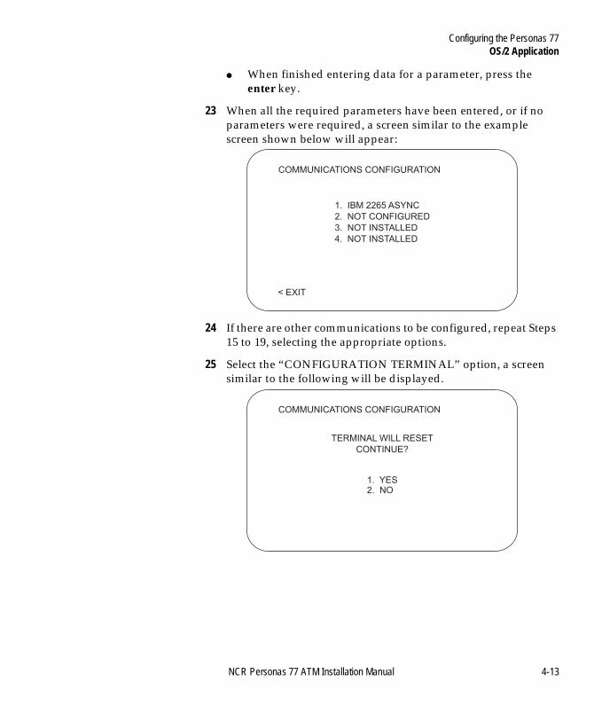
Configuring the Personas 77OS/2 Application
BOOK.BK Page 13 Monday, August 16, 2004 11:15 AM
● When finished entering data for a parameter, press the enter key.
23 When all the required parameters have been entered, or if no parameters were required, a screen similar to the example screen shown below will appear:
24 If there are other communications to be configured, repeat Steps 15 to 19, selecting the appropriate options.
25 Select the “CONFIGURATION TERMINAL” option, a screen similar to the following will be displayed.
COMMUNICATIONS CONFIGURATION
1. IBM 2265 ASYNC
2. NOT CONFIGURED
3. NOT INSTALLED
4. NOT INSTALLED
< EXIT
COMMUNICATIONS CONFIGURATION
TERMINAL WILL RESET
CONTINUE?
1. YES2. NO
NCR Personas 77 ATM Installation Manual 4-13
Configuring the Personas 77OS/2 Application
BOOK.BK Page 14 Monday, August 16, 2004 11:15 AM
26 Select:
● YES - a system reset will be carried out and the new services are configured
● NO - no changes are made to the Communications Configuration menu and the Communications Configuration screen is displayed.
27 Close the exterior of the ATM.
4-14 NCR Personas 77 ATM Installation Manual
Configuring the Personas 77APTRA Application
BOOK.BK Page 15 Monday, August 16, 2004 11:15 AM
APTRA Application 4
Initial Configuration - Product ID 4
During initial configuration or re-configuration of the ATM running an APTRA Application, when asked for the Product ID, enter 5877 then press the “Enter” key.
Configuring Modules/Devices 4
Configure a module /device on a ATM running an APTRA application, through the System Application option as follows:
1 Unlock and open the top cabinet of the ATM.
2 Press the ON/OFF switch to the ON position (press at the 1 side).
3 Select the System Application option.
NCR Personas 77 ATM Installation Manual 4-15
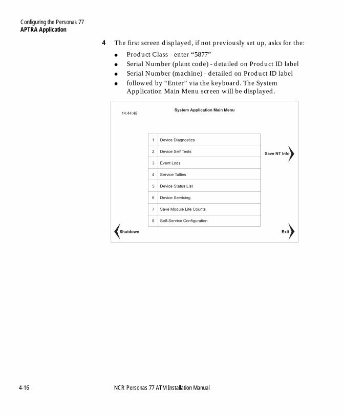
Configuring the Personas 77APTRA Application
BOOK.BK Page 16 Monday, August 16, 2004 11:15 AM
4 The first screen displayed, if not previously set up, asks for the:
● Product Class - enter “5877” ● Serial Number (plant code) - detailed on Product ID label● Serial Number (machine) - detailed on Product ID label● followed by “Enter” via the keyboard. The System
Application Main Menu screen will be displayed.
1 Device Diagnostics
2 Device Self Tests
3 Event Logs
4 Service Tallies
5 Device Status List
6 Device Servicing
7 Save Module Life Counts
8 Self-Service Configuration
System Application Main Menu14:44:48
Save NT Info
ExitShutdown
4-16 NCR Personas 77 ATM Installation Manual
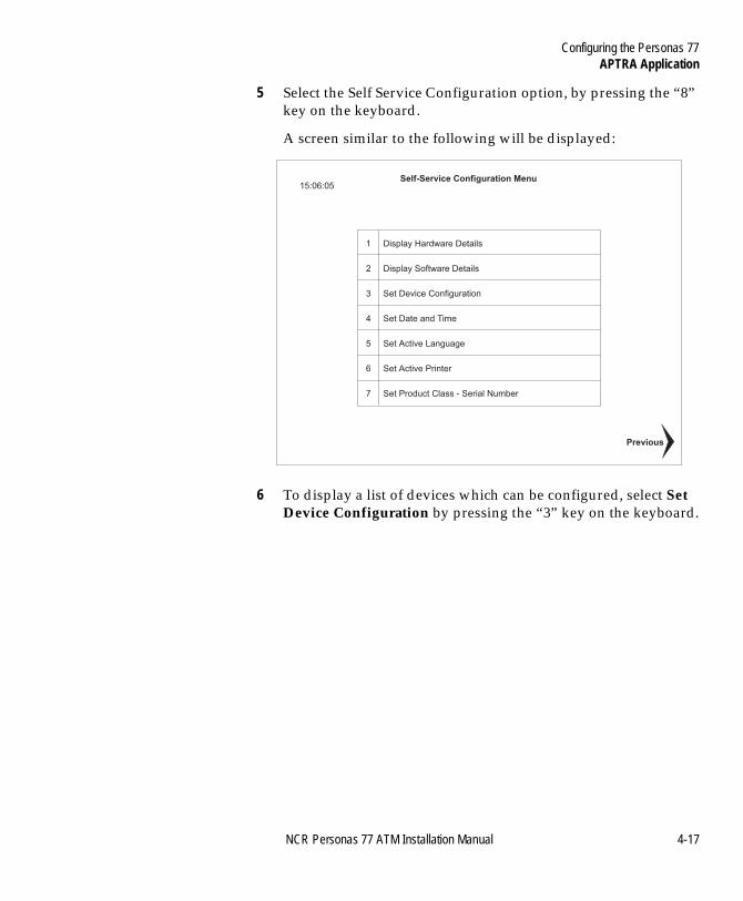
Configuring the Personas 77APTRA Application
BOOK.BK Page 17 Monday, August 16, 2004 11:15 AM
5 Select the Self Service Configuration option, by pressing the “8” key on the keyboard.
A screen similar to the following will be displayed:
6 To display a list of devices which can be configured, select Set Device Configuration by pressing the “3” key on the keyboard.
1 Display Hardware Details
2 Display Software Details
3 Set Device Configuration
4 Set Date and Time
5 Set Active Language
6 Set Active Printer
7 Set Product Class - Serial Number
Self-Service Configuration Menu15:06:05
Previous
NCR Personas 77 ATM Installation Manual 4-17
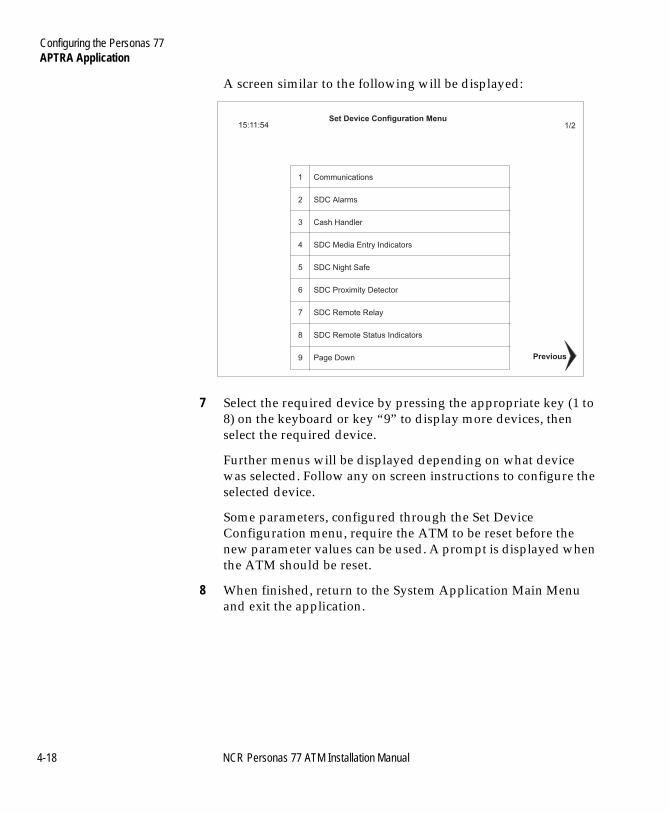
Configuring the Personas 77APTRA Application
BOOK.BK Page 18 Monday, August 16, 2004 11:15 AM
A screen similar to the following will be displayed:
7 Select the required device by pressing the appropriate key (1 to 8) on the keyboard or key “9” to display more devices, then select the required device.
Further menus will be displayed depending on what device was selected. Follow any on screen instructions to configure the selected device.
Some parameters, configured through the Set Device Configuration menu, require the ATM to be reset before the new parameter values can be used. A prompt is displayed when the ATM should be reset.
8 When finished, return to the System Application Main Menu and exit the application.
1 Communications
2 SDC Alarms
3 Cash Handler
4 SDC Media Entry Indicators
5 SDC Night Safe
6 SDC Proximity Detector
7 SDC Remote Relay
8 SDC Remote Status Indicators
9 Page Down
Set Device Configuration Menu15:11:54 1/2
Previous
4-18 NCR Personas 77 ATM Installation Manual
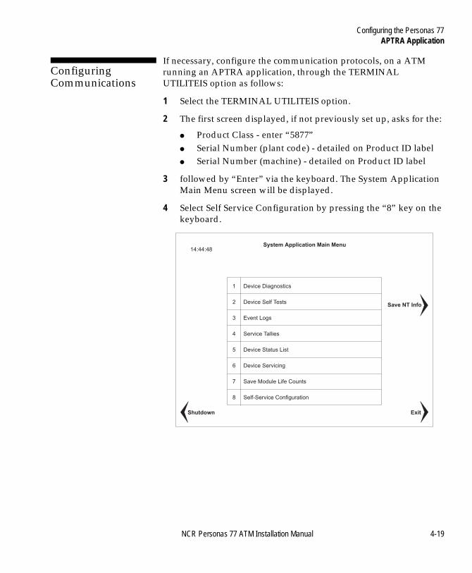
Configuring the Personas 77APTRA Application
BOOK.BK Page 19 Monday, August 16, 2004 11:15 AM
Configuring Communications 4
If necessary, configure the communication protocols, on a ATM running an APTRA application, through the TERMINAL UTILITEIS option as follows:
1 Select the TERMINAL UTILITEIS option.
2 The first screen displayed, if not previously set up, asks for the:
● Product Class - enter “5877” ● Serial Number (plant code) - detailed on Product ID label● Serial Number (machine) - detailed on Product ID label
3 followed by “Enter” via the keyboard. The System Application Main Menu screen will be displayed.
4 Select Self Service Configuration by pressing the “8” key on the keyboard.
1 Device Diagnostics
2 Device Self Tests
3 Event Logs
4 Service Tallies
5 Device Status List
6 Device Servicing
7 Save Module Life Counts
8 Self-Service Configuration
System Application Main Menu14:44:48
Save NT Info
ExitShutdown
NCR Personas 77 ATM Installation Manual 4-19
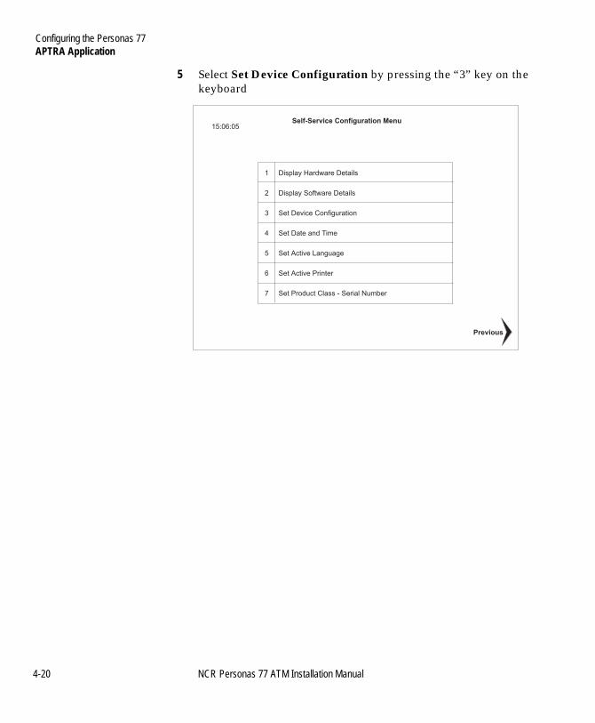
Configuring the Personas 77APTRA Application
BOOK.BK Page 20 Monday, August 16, 2004 11:15 AM
5 Select Set Device Configuration by pressing the “3” key on the keyboard
1 Display Hardware Details
2 Display Software Details
3 Set Device Configuration
4 Set Date and Time
5 Set Active Language
6 Set Active Printer
7 Set Product Class - Serial Number
Self-Service Configuration Menu15:06:05
Previous
4-20 NCR Personas 77 ATM Installation Manual
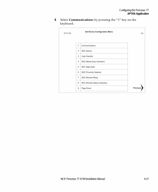
Configuring the Personas 77APTRA Application
BOOK.BK Page 21 Monday, August 16, 2004 11:15 AM
6 Select Communications by pressing the “1” key on the keyboard.
1 Communications
2 SDC Alarms
3 Cash Handler
4 SDC Media Entry Indicators
5 SDC Night Safe
6 SDC Proximity Detector
7 SDC Remote Relay
8 SDC Remote Status Indicators
9 Page Down
Set Device Configuration Menu15:11:54 1/2
Previous
NCR Personas 77 ATM Installation Manual 4-21
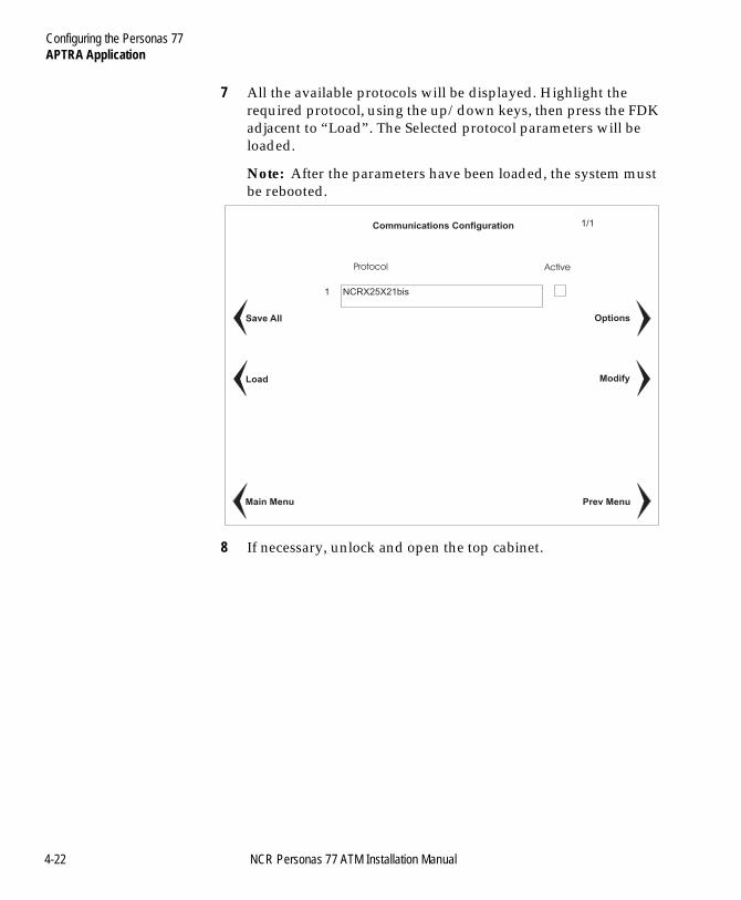
Configuring the Personas 77APTRA Application
BOOK.BK Page 22 Monday, August 16, 2004 11:15 AM
7 All the available protocols will be displayed. Highlight the required protocol, using the up/down keys, then press the FDK adjacent to “Load”. The Selected protocol parameters will be loaded.
Note: After the parameters have been loaded, the system must be rebooted.
8 If necessary, unlock and open the top cabinet.
1 NCRX25X21bis
Communications Configuration
Modify
Options
Prev MenuMain Menu
Load
Save All
Protocol Active
1/1
4-22 NCR Personas 77 ATM Installation Manual
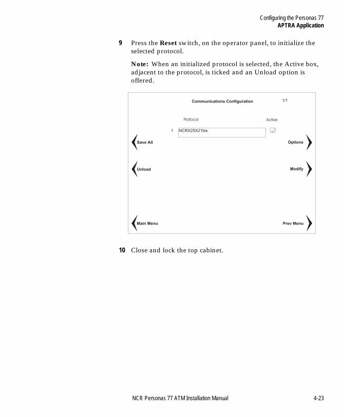
Configuring the Personas 77APTRA Application
BOOK.BK Page 23 Monday, August 16, 2004 11:15 AM
9 Press the Reset switch, on the operator panel, to initialize the selected protocol.
Note: When an initialized protocol is selected, the Active box, adjacent to the protocol, is ticked and an Unload option is offered.
10 Close and lock the top cabinet.
1 NCRX25X21bis
Communications Configuration
Modify
Options
Prev MenuMain Menu
Unload
Save All
Protocol Active
1/1
NCR Personas 77 ATM Installation Manual 4-23
Configuring the Personas 77Thermal Printers
BOOK.BK Page 24 Monday, August 16, 2004 11:15 AM
Thermal Printers 4
The ATM contains two variants of the 40-column printer - Receipt and Journal.
The thermal printers are configured using DIP switches, RESET and ENTER (SET) buttons and feedback from status LEDs. An EEPROM on the interface PCB stores most configuration data.
Note: Full details of all configuration options can be found in chapter 13 of the NCR publication “Service Aids Mini-Manual”, BFM0-0547-A000.
Adjusting the DIP switch settings must be performed by a field service engineer.
4-24 NCR Personas 77 ATM Installation Manual
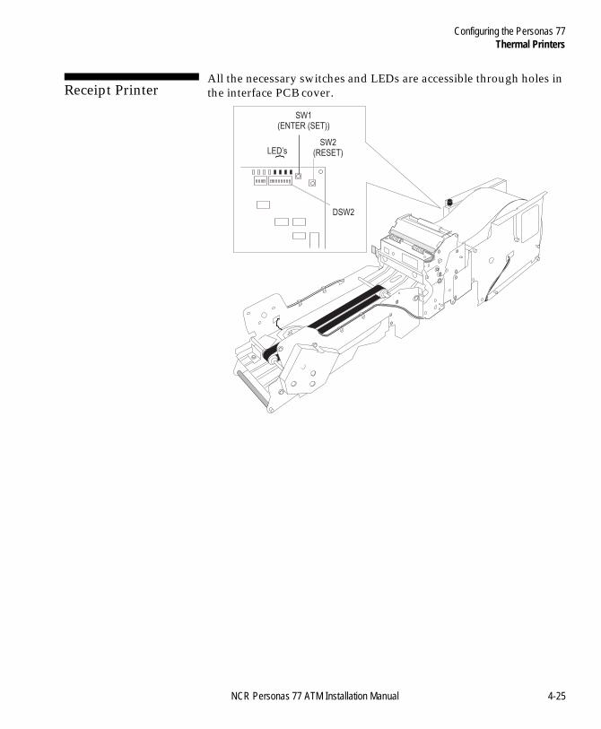
Configuring the Personas 77Thermal Printers
BOOK.BK Page 25 Monday, August 16, 2004 11:15 AM
Receipt Printer 4
All the necessary switches and LEDs are accessible through holes in the interface PCB cover.
{LED’s
SW1(ENTER (SET))
SW2(RESET)
DSW2
NCR Personas 77 ATM Installation Manual 4-25
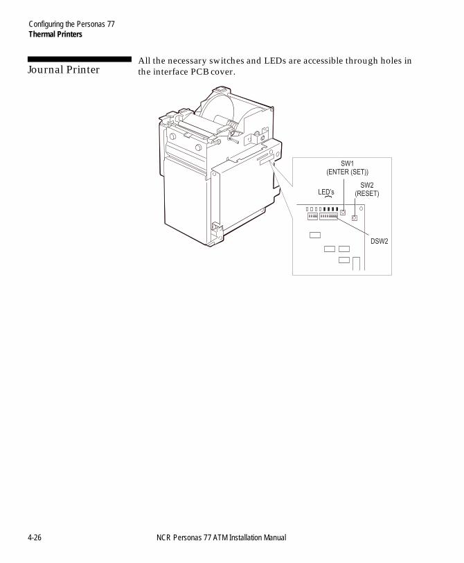
Configuring the Personas 77Thermal Printers
BOOK.BK Page 26 Monday, August 16, 2004 11:15 AM
Journal Printer 4
All the necessary switches and LEDs are accessible through holes in the interface PCB cover.
{LED’s
SW1(ENTER (SET))
SW2(RESET)
DSW2
4-26 NCR Personas 77 ATM Installation Manual
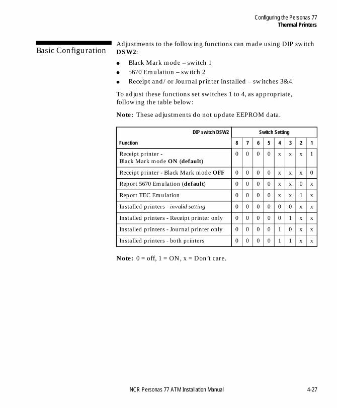
Configuring the Personas 77Thermal Printers
BOOK.BK Page 27 Monday, August 16, 2004 11:15 AM
Basic Configuration 4
Adjustments to the following functions can made using DIP switch DSW2:
● Black Mark mode – switch 1● 5670 Emulation – switch 2● Receipt and/or Journal printer installed – switches 3&4.
To adjust these functions set switches 1 to 4, as appropriate, following the table below:
Note: These adjustments do not update EEPROM data.
Note: 0 = off, 1 = ON, x = Don’t care.
DIP switch DSW2 Switch Setting
Function 8 7 6 5 4 3 2 1
Receipt printer - Black Mark mode ON (default)
0 0 0 0 x x x 1
Receipt printer - Black Mark mode OFF 0 0 0 0 x x x 0
Report 5670 Emulation (default) 0 0 0 0 x x 0 x
Report TEC Emulation 0 0 0 0 x x 1 x
Installed printers - invalid setting 0 0 0 0 0 0 x x
Installed printers - Receipt printer only 0 0 0 0 0 1 x x
Installed printers - Journal printer only 0 0 0 0 1 0 x x
Installed printers - both printers 0 0 0 0 1 1 x x
NCR Personas 77 ATM Installation Manual 4-27
Configuring the Personas 77Thermal Printers
BOOK.BK Page 28 Monday, August 16, 2004 11:15 AM
Advanced Configuration and Calibration 4
Receipt Form Length setting, Character Set selection and Black Mark Calibration involve updating the EEPROM data. Configuration of these functions is made using DIP switch DSW2.
Configuration is carried out as follows:
Receipt Form Length 4
The Receipt Form length can be set to any number of lines between 24 (default) and the maximum of 55.
1 Make a note of the current DSW2 DIP switch settings.
2 Set DSW2 switch 6 to ON.
3 Set DSW2 switches 1 to 5 to add the required number of lines to the default value of 24.
switch 1 = ON: adds 1 lineswitch 2 = ON: adds another 2 linesswitch 3 = ON: adds another 4 linesswitch 4 = ON: adds another 8 linesswitch 5 = ON: adds another 16 lines
For example – to make the form length 35, set the switches like this:
default:......................... 24switch 1 = ON adds ..... 1switch 2 = ON adds ..... 2switch 3 = OFF adds .... 0switch 4 = ON adds ..... 8switch 5 = OFF adds .... 0
TOTAL: ....................... 35
4 Press the RESET button SW2.
5 Press and hold the ENTER (SET) button SW1 until the four LEDs blink. The new form length is now stored in the EEPROM.
6 Restore the previously noted DSW2 DIP switch settings and press the RESET button SW2.
4-28 NCR Personas 77 ATM Installation Manual
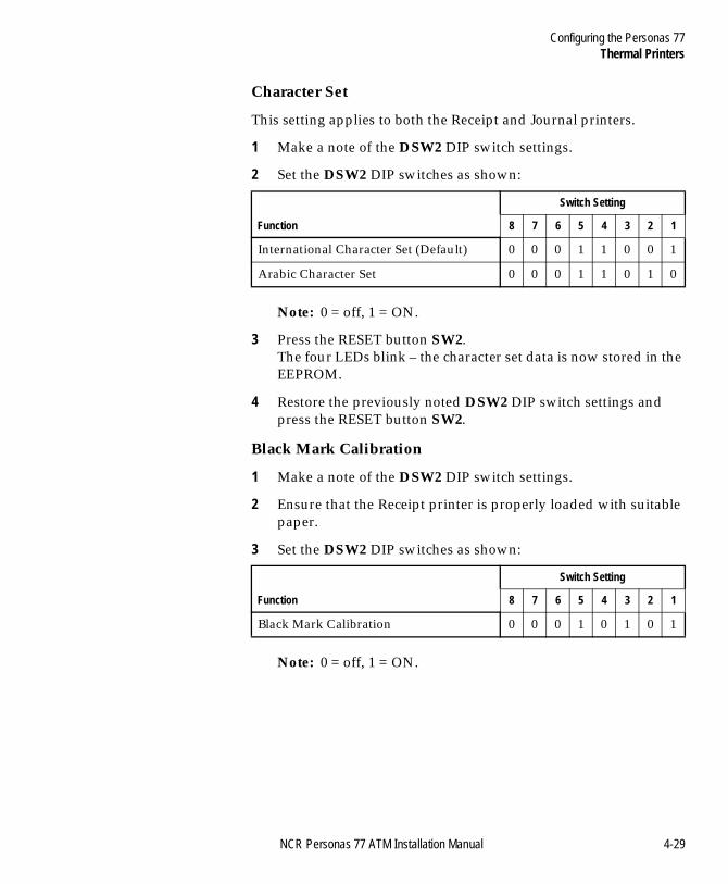
Configuring the Personas 77Thermal Printers
BOOK.BK Page 29 Monday, August 16, 2004 11:15 AM
Character Set 4
This setting applies to both the Receipt and Journal printers.
1 Make a note of the DSW2 DIP switch settings.
2 Set the DSW2 DIP switches as shown:
Note: 0 = off, 1 = ON.
3 Press the RESET button SW2.The four LEDs blink – the character set data is now stored in the EEPROM.
4 Restore the previously noted DSW2 DIP switch settings and press the RESET button SW2.
Black Mark Calibration 4
1 Make a note of the DSW2 DIP switch settings.
2 Ensure that the Receipt printer is properly loaded with suitable paper.
3 Set the DSW2 DIP switches as shown:
Note: 0 = off, 1 = ON.
Switch Setting
Function 8 7 6 5 4 3 2 1
International Character Set (Default) 0 0 0 1 1 0 0 1
Arabic Character Set 0 0 0 1 1 0 1 0
Switch Setting
Function 8 7 6 5 4 3 2 1
Black Mark Calibration 0 0 0 1 0 1 0 1
NCR Personas 77 ATM Installation Manual 4-29
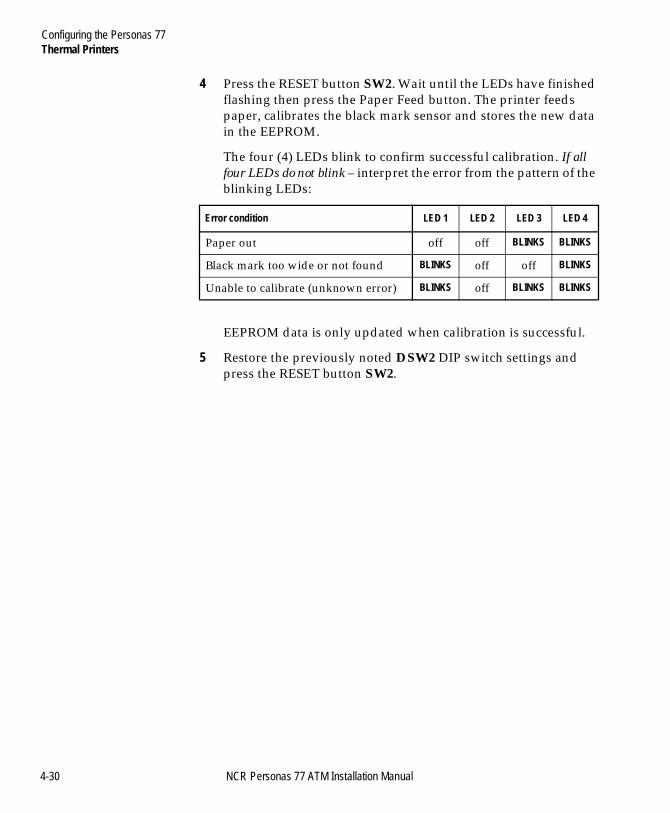
Configuring the Personas 77Thermal Printers
BOOK.BK Page 30 Monday, August 16, 2004 11:15 AM
4 Press the RESET button SW2. Wait until the LEDs have finished flashing then press the Paper Feed button. The printer feeds paper, calibrates the black mark sensor and stores the new data in the EEPROM.
The four (4) LEDs blink to confirm successful calibration. If all four LEDs do not blink – interpret the error from the pattern of the blinking LEDs:
EEPROM data is only updated when calibration is successful.
5 Restore the previously noted DSW2 DIP switch settings and press the RESET button SW2.
Error condition LED 1 LED 2 LED 3 LED 4
Paper out off off BLINKS BLINKS
Black mark too wide or not found BLINKS off off BLINKS
Unable to calibrate (unknown error) BLINKS off BLINKS BLINKS
4-30 NCR Personas 77 ATM Installation Manual
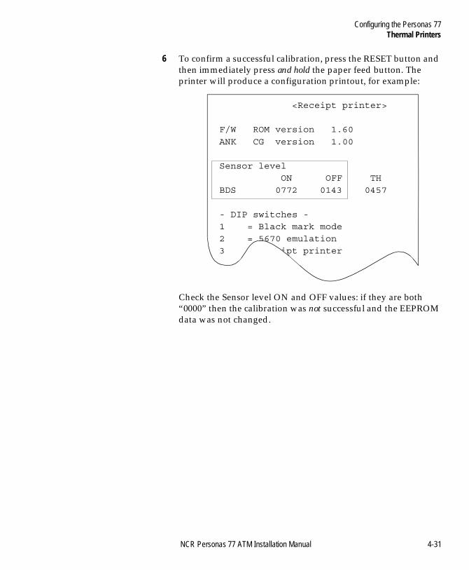
Configuring the Personas 77Thermal Printers
BOOK.BK Page 31 Monday, August 16, 2004 11:15 AM
6 To confirm a successful calibration, press the RESET button and then immediately press and hold the paper feed button. The printer will produce a configuration printout, for example:
Check the Sensor level ON and OFF values: if they are both “0000” then the calibration was not successful and the EEPROM data was not changed.
<Receipt printer>
F/W ROM version 1.60
ANK CG version 1.00
Sensor level ON OFF THBDS 0772 0143 0457
- DIP switches -1 = Black mark mode2 = 5670 emulation3 = Receipt printer
NCR Personas 77 ATM Installation Manual 4-31
Configuring the Personas 77Intelligent Cash Security System
BOOK.BK Page 32 Monday, August 16, 2004 11:15 AM
Intelligent Cash Security System 4
All other work necessary to install and configure the ATM should be completed before starting to set-up the Intelligent Cash Security (ICS) system.
Refer to the NCR Intelligent Cash Security System, User Guide (B006-6127) for more information.
Fitting the Containment Mat 4
If the dispenser has a sump tray with an internal containment mat. A separate containment map is not required.
The first action required is to fit the ink containment mat, (NCR part number 445-065976), as follows:
1 Open the security enclosure.
2 Rack out the currency dispenser until its slides are fully extended.
3 Position the mat on the safe floor, roughly where the dispenser would be when racked in, with the surface with the patterned cut-outs facing upwards.
4 Push dispenser back into the ATM.
5 Now fine tune the mat position so that the front edge of the mat is in line with the front of the pickframe, and that the pick is central (left to right) to the mat.
6 Ensure that the mat encompasses any bolts or harnessing in the area.
7 Mark the position of the mat on the safe floor.
8 Rack out the currency dispenser until its slides are fully extended.
9 Remove the mat and fix a strip of double-sided tape to each end of the underside of the mat.
4-32 NCR Personas 77 ATM Installation Manual
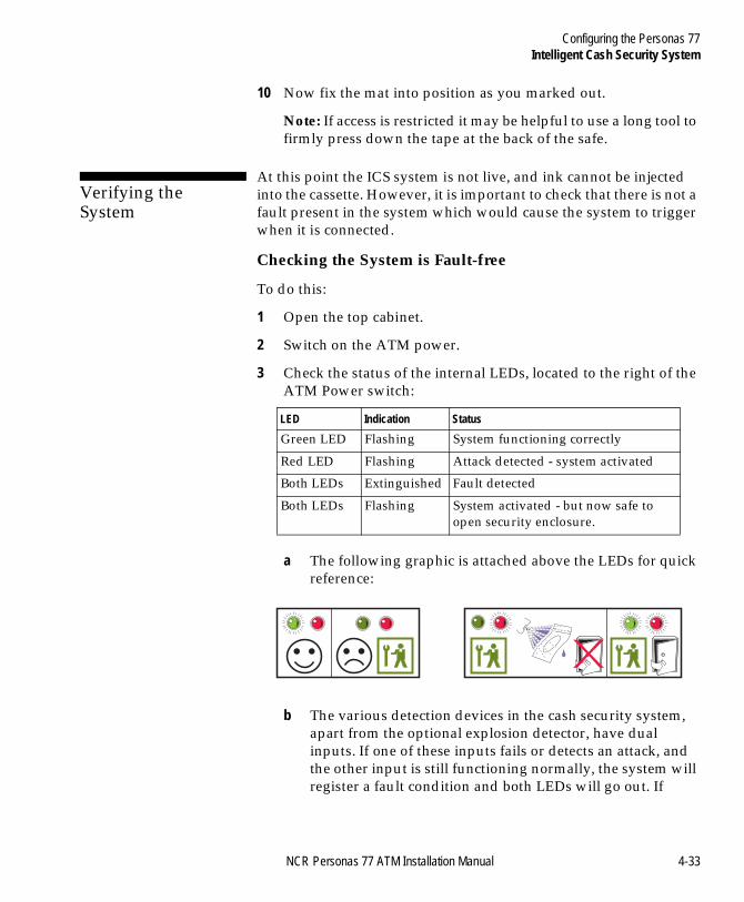
Configuring the Personas 77Intelligent Cash Security System
BOOK.BK Page 33 Monday, August 16, 2004 11:15 AM
10 Now fix the mat into position as you marked out.
Note: If access is restricted it may be helpful to use a long tool to firmly press down the tape at the back of the safe.
Verifying the System 4
At this point the ICS system is not live, and ink cannot be injected into the cassette. However, it is important to check that there is not a fault present in the system which would cause the system to trigger when it is connected.
Checking the System is Fault-free 4
To do this:
1 Open the top cabinet.
2 Switch on the ATM power.
3 Check the status of the internal LEDs, located to the right of the ATM Power switch:
a The following graphic is attached above the LEDs for quick reference:
b The various detection devices in the cash security system, apart from the optional explosion detector, have dual inputs. If one of these inputs fails or detects an attack, and the other input is still functioning normally, the system will register a fault condition and both LEDs will go out. If
LED Indication Status
Green LED Flashing System functioning correctly
Red LED Flashing Attack detected - system activated
Both LEDs Extinguished Fault detected
Both LEDs Flashing System activated - but now safe to open security enclosure.
NCR Personas 77 ATM Installation Manual 4-33
Configuring the Personas 77Intelligent Cash Security System
BOOK.BK Page 34 Monday, August 16, 2004 11:15 AM
however, both inputs detect an attack the system will be triggered and the red LED will flash. After 3 hours both the red and the green LED will flash to indicate that it is safe to open the security enclosure after the activation.
c If the green LED only is flashing you can proceed with the set-up procedure. If the red LED is flashing, the system would trigger when connected and so the system must be de-bugged. Similarly, if neither LED is lit then a fault has been detected, and although the system will not trigger, it must be de-bugged before continuing with the set-up.
4-34 NCR Personas 77 ATM Installation Manual
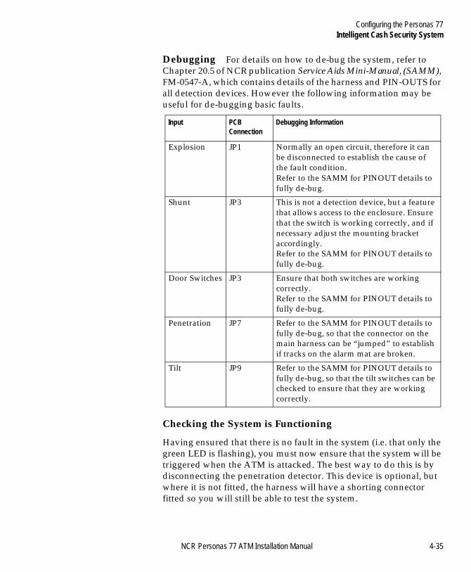
Configuring the Personas 77Intelligent Cash Security System
BOOK.BK Page 35 Monday, August 16, 2004 11:15 AM
Debugging 4For details on how to de-bug the system, refer to Chapter 20.5 of NCR publication Service Aids Mini-Manual, (SAMM), FM-0547-A, which contains details of the harness and PIN-OUTS for all detection devices. However the following information may be useful for de-bugging basic faults.
Checking the System is Functioning 4
Having ensured that there is no fault in the system (i.e. that only the green LED is flashing), you must now ensure that the system will be triggered when the ATM is attacked. The best way to do this is by disconnecting the penetration detector. This device is optional, but where it is not fitted, the harness will have a shorting connector fitted so you will still be able to test the system.
Input PCB Connection
Debugging Information
Explosion JP1 Normally an open circuit, therefore it can be disconnected to establish the cause of the fault condition.Refer to the SAMM for PINOUT details to fully de-bug.
Shunt JP3 This is not a detection device, but a feature that allows access to the enclosure. Ensure that the switch is working correctly, and if necessary adjust the mounting bracket accordingly.Refer to the SAMM for PINOUT details to fully de-bug.
Door Switches JP3 Ensure that both switches are working correctly.Refer to the SAMM for PINOUT details to fully de-bug.
Penetration JP7 Refer to the SAMM for PINOUT details to fully de-bug, so that the connector on the main harness can be “jumped” to establish if tracks on the alarm mat are broken.
Tilt JP9 Refer to the SAMM for PINOUT details to fully de-bug, so that the tilt switches can be checked to ensure that they are working correctly.
NCR Personas 77 ATM Installation Manual 4-35
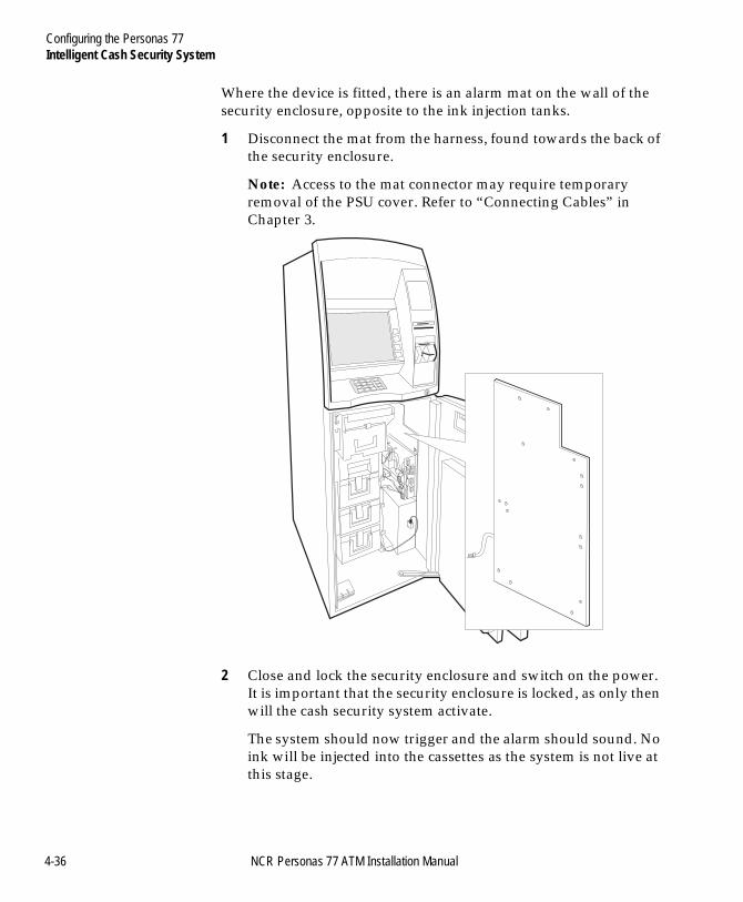
Configuring the Personas 77Intelligent Cash Security System
BOOK.BK Page 36 Monday, August 16, 2004 11:15 AM
Where the device is fitted, there is an alarm mat on the wall of the security enclosure, opposite to the ink injection tanks.
1 Disconnect the mat from the harness, found towards the back of the security enclosure.
Note: Access to the mat connector may require temporary removal of the PSU cover. Refer to “Connecting Cables” in Chapter 3.
2 Close and lock the security enclosure and switch on the power. It is important that the security enclosure is locked, as only then will the cash security system activate.
The system should now trigger and the alarm should sound. No ink will be injected into the cassettes as the system is not live at this stage.
4-36 NCR Personas 77 ATM Installation Manual
Configuring the Personas 77Intelligent Cash Security System
BOOK.BK Page 37 Monday, August 16, 2004 11:15 AM
3 Open the security enclosure to de-activate the alarm.
The red LED should be flashing to indicate that the system has been triggered.
a If the alarm sounded and the red LED is flashing, you should now re-connect the harness to the alarm mat (or to the shorting connector if the penetration detection device is not fitted on your ATM).
b If either the alarm did not sound or the red LED did not flash, you should re-connect the harness as above, but then de-bug the system to remove the fault, and re-test the system.
Making the System Live 4
Only proceed to make the system live if you have verified that it is fault -free and operational as described in the tests above. Failure to do so could result in an accidental activation when the system is made live, or in a failure to activate when the system is attacked.
Make sure that the alarm mat or shorting connector that you disconnected from the harness during the activation test has been re-connected correctly. Failure to do so could result in an accidental activation when the system is made live.
You can now proceed with the set-up procedure.
1 Check that the green LED only is flashing.
2 Switch off power to the ATM.
3 Lift the latch on the dispenser module and using the green handle, pull it out of the ATM until its slides are fully extended.
4 Remove the harness protection metalwork from above and from the left hand side of the ink injection tanks, as shown the diagram on the next page, by loosening the screws slightly.
Note: On single pick modules the left hand metal bracket also protects the pick PCB and so you will need to remove the screw nearest to the front of the pick.
NCR Personas 77 ATM Installation Manual 4-37
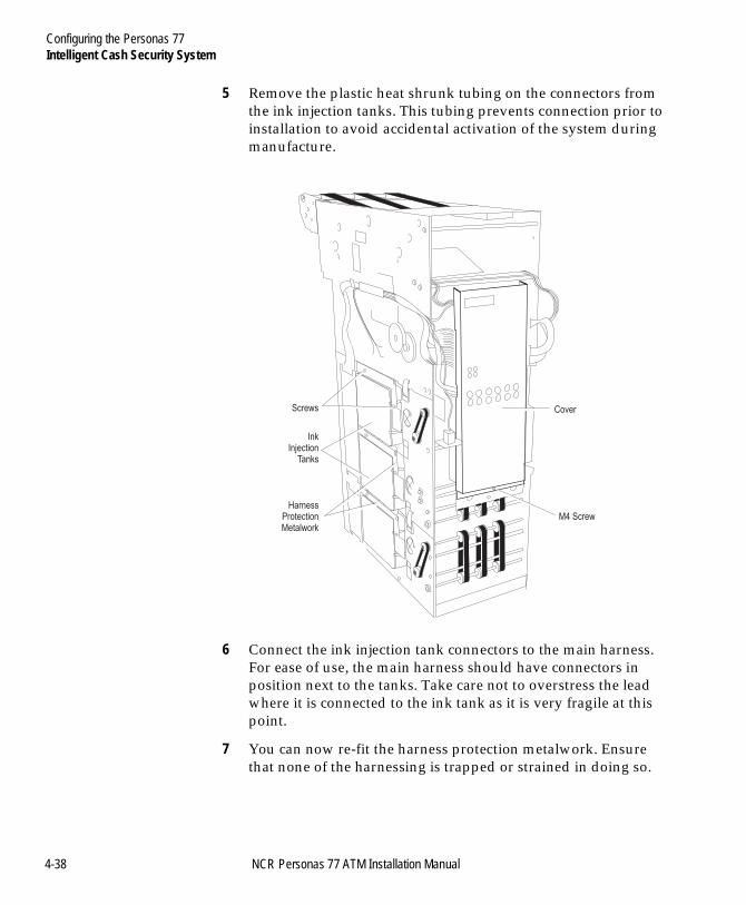
Configuring the Personas 77Intelligent Cash Security System
BOOK.BK Page 38 Monday, August 16, 2004 11:15 AM
5 Remove the plastic heat shrunk tubing on the connectors from the ink injection tanks. This tubing prevents connection prior to installation to avoid accidental activation of the system during manufacture.
6 Connect the ink injection tank connectors to the main harness. For ease of use, the main harness should have connectors in position next to the tanks. Take care not to overstress the lead where it is connected to the ink tank as it is very fragile at this point.
7 You can now re-fit the harness protection metalwork. Ensure that none of the harnessing is trapped or strained in doing so.
Screws Cover
M4 ScrewHarness
ProtectionMetalwork
InkInjection
Tanks
4-38 NCR Personas 77 ATM Installation Manual
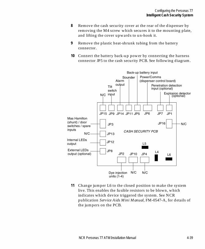
Configuring the Personas 77Intelligent Cash Security System
BOOK.BK Page 39 Monday, August 16, 2004 11:15 AM
8 Remove the cash security cover at the rear of the dispenser by removing the M4 screw which secures it to the mounting plate, and lifting the cover upwards to un-hook it.
9 Remove the plastic heat-shrunk tubing from the battery connector.
10 Connect the battery back-up power by connecting the harness connector JP5 to the cash security PCB. See following diagram.
11 Change jumper L6 to the closed position to make the system live. This enables the fusible resistors to be blown, which indicates which device triggered the system. See NCR publication Service Aids Mini Manual, FM-0547-A, for details of the jumpers on the PCB.
JP15 JP9 JP14 JP11 JP5 JP6 JP7 JP1
JP3
JP13
JP12
JP8JP2 JP10 JP4
L5
L4L6
JP16
N/C
Tiltswitchinput
Alarmoutput
Sounder
Back-up battery inputPower/Comms(dispenser control board)
Explosion detector(optional)
N/C
Mas Hamilton(shunt) / doorswitches / spareinputs
N/C
Internal LEDsoutput
External LEDsoutput (optional)
N/CN/CDye injectionunits (1-4)
Penetration detectioninput (optional)
CASH SECURITY PCB
NCR Personas 77 ATM Installation Manual 4-39
Configuring the Personas 77Intelligent Cash Security System
BOOK.BK Page 40 Monday, August 16, 2004 11:15 AM
12 Replace the cover on the cash security system, and secure it with the M4 screw.
13 Push the dispenser module back into the ATM.
14 Keep the security enclosure door open. While the door is open the system is dis-armed and cannot be activated.
15 Insert the cassettes into the dispenser. These must be cash security cassette variant only.
16 Switch on power to the ATM. The green LED should still be flashing.
17 If the green LED is not flashing then disconnect the battery power and the ink injection tanks, and change jumper L6 back to safe mode (OPEN). You must now de-bug the system to remove the fault and re-test the system, before recommencing the set-up procedure.
Note Rather than having to remove the harness protection metalwork to de-activate the system, you can disconnect connector JP2 on the cash security PCB. However, you must re-connect it after de-bugging to ensure the system will activate.
18 Close and lock the security enclosure and the ATM.
19 The cash security system is now operational.
4-40 NCR Personas 77 ATM Installation Manual
Table of ContentsApplying Decals to the ATM
BOOK.BK Page 41 Monday, August 16, 2004 11:15 AM
NCR Personas 77 ATM Installation Manual
Chapter 5
Applying Decals to the ATM
Introduction 5-1
Applying Decals 5-2Card Orientation Window 5-2Card Accept Window 5-3Bar Code Reader Card Accept Decal 5-4Exit/Entry Slots 5-4Advert Light Box 5-4

Table of ContentsApplying Decals to the ATM
BOOK.BK Page 42 Monday, August 16, 2004 11:15 AM
NCR Personas 77 ATM Installation Manual
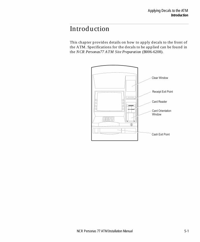
Introduction
BOOK.BK Page 1 Monday, August 16, 2004 11:15 AM
NCR Personas 77 ATM Installation Manual 5
-1Applying Decals to the ATME
Introduction 5
This chapter provides details on how to apply decals to the front of the ATM. Specifications for the decals to be applied can be found in the NCR Personas77 ATM Site Preparation (B006-6208).
Cash Exit Point
Card Reader
Clear Window
Receipt Exit Point
Card OrientationWindow
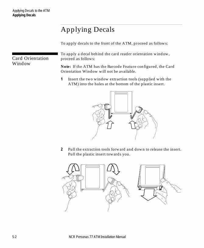
Applying Decals to the ATMApplying Decals
BOOK.BK Page 2 Monday, August 16, 2004 11:15 AM
Applying Decals 5
To apply decals to the front of the ATM, proceed as follows:
Card Orientation Window 5
To apply a decal behind the card reader orientation window, proceed as follows:
Note: If the ATM has the Barcode Feature configured, the Card Orientation Window will not be available.
1 Insert the two window extraction tools (supplied with the ATM) into the holes at the bottom of the plastic insert.
2 Pull the extraction tools forward and down to release the insert. Pull the plastic insert towards you.
5-2 NCR Personas 77 ATM Installation Manual
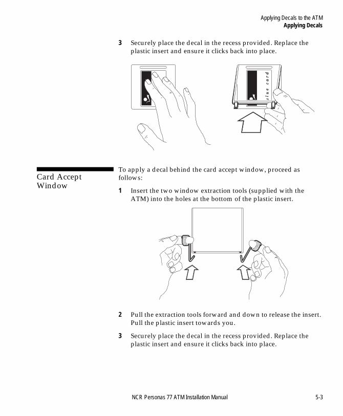
Applying Decals to the ATMApplying Decals
BOOK.BK Page 3 Monday, August 16, 2004 11:15 AM
3 Securely place the decal in the recess provided. Replace the plastic insert and ensure it clicks back into place.
Card Accept Window 5
To apply a decal behind the card accept window, proceed as follows:
1 Insert the two window extraction tools (supplied with the ATM) into the holes at the bottom of the plastic insert.
2 Pull the extraction tools forward and down to release the insert. Pull the plastic insert towards you.
3 Securely place the decal in the recess provided. Replace the plastic insert and ensure it clicks back into place.
NCR Personas 77 ATM Installation Manual 5-3
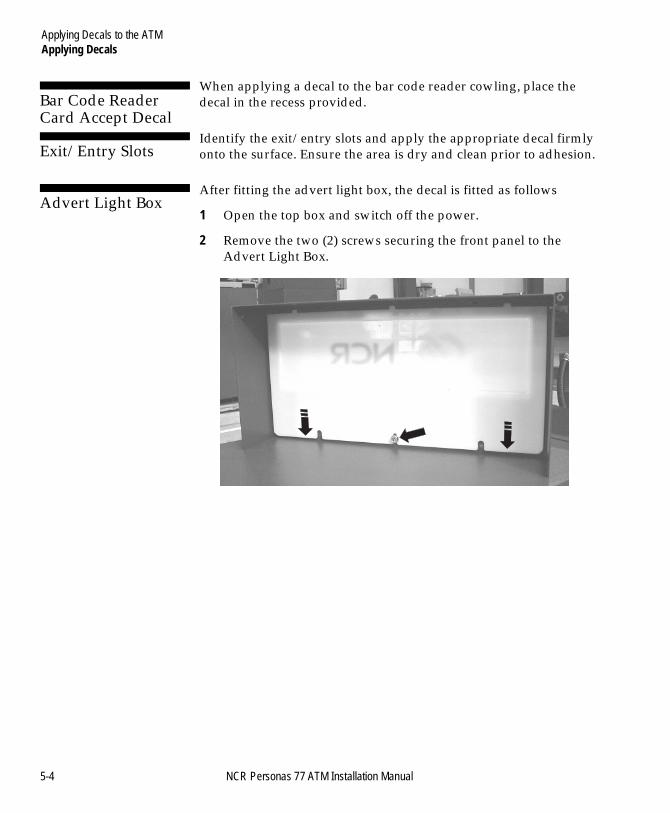
Applying Decals to the ATMApplying Decals
BOOK.BK Page 4 Monday, August 16, 2004 11:15 AM
Bar Code Reader Card Accept Decal 5
When applying a decal to the bar code reader cowling, place the decal in the recess provided.
Exit/Entry Slots 5
Identify the exit/entry slots and apply the appropriate decal firmly onto the surface. Ensure the area is dry and clean prior to adhesion.
Advert Light Box 5
After fitting the advert light box, the decal is fitted as follows
1 Open the top box and switch off the power.
2 Remove the two (2) screws securing the front panel to the Advert Light Box.
5-4 NCR Personas 77 ATM Installation Manual
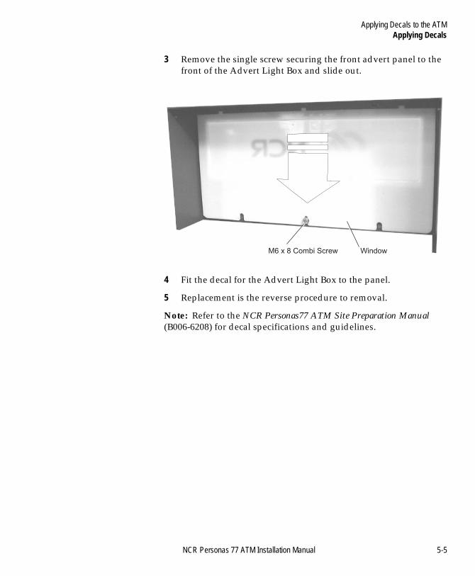
Applying Decals to the ATMApplying Decals
BOOK.BK Page 5 Monday, August 16, 2004 11:15 AM
3 Remove the single screw securing the front advert panel to the front of the Advert Light Box and slide out.
4 Fit the decal for the Advert Light Box to the panel.
5 Replacement is the reverse procedure to removal.
Note: Refer to the NCR Personas77 ATM Site Preparation Manual (B006-6208) for decal specifications and guidelines.
M6 x 8 Combi Screw Window
NCR Personas 77 ATM Installation Manual 5-5
Applying Decals to the ATMApplying Decals
BOOK.BK Page 6 Monday, August 16, 2004 11:15 AM
5-6 NCR Personas 77 ATM Installation Manual
Index
BOOK.BK Page 1 Monday, August 16, 2004 11:15 AM
NCR Personas 77 ATM Installation Manual
-1IndexIndex 0
AAbout this Document 1-viiActivating
The Kaba Mas Lock 3-15ADA Conformance
Removal of Transportation Feet 2-10Air/Sea Pallet
Removing 2-3Americans with Disabilities Act (ADA) 2-10Application Software 4-1APTRA Application
Product Class 4-16, 4-19Product ID 4-15Serial Number 4-16, 4-19
BBolting To The Floor 3-48
CCanadian Standards Association (CSA) 2-10Card Reader Entry/Exit Slot
Fitting Decals 5-2Closing
Security EnclosureRear Access 3-7
The Top Cabinet 3-3Top Cabinet
Rear Access 3-6Combination locks
customer setting combination 3-12factory setting 3-11
Communications CablesRouting 3-52, 3-56
Configure Communications 4-2Configuring Communications
APTRA Application 4-19Configuring Modules/Devices
APTRA Application 4-15Configuring the P77
Application Software 4-1Configure Communications 4-2
Index
BOOK.BK Page 2 Monday, August 16, 2004 11:15 AM
Currency Cassette 4-3Intelligent Cash Security System 4-32Introduction 4-1Miscellaneous Interface 4-4OS/2 Application 4-4Product ID (APTRA Application) 4-15Product ID (OS/2 Application) 4-4RS-232 Interface 4-4Thermal Printers 4-24
Connecting Cables 3-51Communications Cables 3-52, 3-56F/A Short Security Enclosure 3-61, 3-76F/A Stretch Security Enclosure 3-68Top Cabinet 3-52
Controlled 3-13Controlled Access Electronic Lock 3-13CSA Conformance
Removal of Transportation Feet 2-10Currency Cassette
Configuring 4-3Customer setting combination 3-12
EElectronic 3-24Exterior
Opening 3-1
FF/A Short
Security EnclosureConnecting Cables 3-61, 3-76
F/A StretchSecurity Enclosure
Connecting Cables 3-68Factory setting 3-11FCC Statement 1-iii
Canadian Class A Device Declaration 1-iiiInformation to User 1-iv
Fitting DecalsCard Acceptance Window 5-3Card Reader Entry/Exit Slot 5-2Introduction 5-1Receipt And Cash Exit 5-4
Floor Loading 1-7
GGetting Started
Activating The Kaba Mas Lock 3-15
Index-2 NCR Personas 77 ATM Installation Manual

Index
BOOK.BK Page 3 Monday, August 16, 2004 11:15 AM
Closing The Security EnclosureRear Access 3-7
Closing The Top Cabinet 3-3Rear Access 3-6
Opening The Security EnclosureRear Access 3-6
Opening The Top CabinetRear Access 3-6
IICS System 4-32
Fitting the Containment Mat 4-32Making the System Live 4-37Verifying the System 4-33
Checking the System is Fault-free 4-33Checking the System is Functioning 4-35
Initial configurationProduct ID 4-4, 4-15
Inspecting For DamageInstallation Report Form 2-2
Installation ProceduresFloor Loading 1-7Introduction 1-1Moving the P77 1-3Packaging Dimensions 1-4Site Preparation 1-1Tools Required 1-2Weights 1-7
Installation Report Form 2-2Installing the P77
Bolting To The Floor 3-48Connecting Cables 3-51Opening The Exterior 3-1Removing Internal Packaging 3-30
Internal PackagingRemoving 3-30
JJournal Printer 4-26
KKaba Mas Lock
Activating 3-15
LLocks
Controlled Access Electronic Lock 3-13
NCR Personas 77 ATM Installation Manual Index-3
Index
BOOK.BK Page 4 Monday, August 16, 2004 11:15 AM
controlled access electronic lock 3-18controlled access electronic lock with a sub-lock 3-20
MMiscellaneous Interface
Configuring 4-4Moving the P77 1-3
OOpening
Security Enclosure 3-4Rear Access 3-6
The Exterior 3-1Top Cabinet 3-1
Rear Access 3-6Opening / closing
security enclosure 3-8OS/2 Application
Product ID 4-4
PPackaging Dimensions 1-4
CEN 1-4Front Access Short 1-4Front Access Stretch and Rear Access 1-5German Standard Security 1-4Vestibule 1-6
Preface 1-viiProduct Class (APTRA Application)
Initial Configuration 4-16, 4-19Re-configuration 4-16, 4-19
Product ID (APTRA Application)Initial Configuration 4-15Re-configuration 4-15
Product ID (OS/2 Application)Initial Configuration 4-4Re-configuration 4-4
RReceipt Printer 4-25Removal of Transportation Feet
ADA Conformance 2-10CSA Conformance 2-10
Removing Air/Sea PalletUsing a Fork-Lift 2-3
Removing External Packaging 2-1Removing Internal Packaging 3-30
Index-4 NCR Personas 77 ATM Installation Manual
Index
BOOK.BK Page 5 Monday, August 16, 2004 11:15 AM
Security Enclosure 3-33Top Cabinet 3-31
Removing Road PalletUsing Lifting Trolleys 2-5
Revision Record 1-vRoad Pallet
Removing 2-5RS-232 Interface
Configuring 4-4
SSecurity Bolt Specifications 3-48Security Enclosure
Opening 3-4Rear Access
Closing 3-7Opening 3-6
Removing Internal Packaging 3-33Security enclosure
combination locks 3-10keylocks 3-10Opening 3-8silent alarm 3-12with controlled access electronic lock 3-13with LG Audit 66e electronic lock 3-27with LG Combogard 33e electronic lock 3-24
Self Service Configuration 4-17, 4-19Serial Number (APTRA Application)
Initial Configuration 4-16, 4-19Re-configuration 4-16, 4-19
Set Device Configuration 4-17, 4-20Silent alarm 3-25Site Preparation 1-1
TTerminal Variants 1-viiiThermal Printers
Advanced Configuration And Calibration 4-28Basic Configuration 4-27Configuring 4-24Journal Printer 4-26Receipt Printer 4-25
Tools Required 1-2Top Cabinet
Connecting Cables 3-52
NCR Personas 77 ATM Installation Manual Index-5
Index
BOOK.BK Page 6 Monday, August 16, 2004 11:15 AM
Opening 3-1Rear Access
Closing 3-6Opening 3-6
Removing Internal Packaging 3-31Transportation Feet
Removal 2-10
UUL291 Security Requirements 1-viii, 3-48Unlocking / locking
security enclosure with controlled access electronic lock 3-13security enclosure with LG Audit 66e electronic lock 3-27security enclosure with LG Combogard 33e electronic lock 3-24
Unpacking the P77Inspecting For Damage 2-2Removing External Packaging 2-1Removing From The Pallet 2-3
WWeights 1-7
Index-6 NCR Personas 77 ATM Installation Manual

Index
BOOK.BK Page 7 Monday, August 16, 2004 11:15 AM
NCR Personas 77 ATM Installation Manual Index-7

Index
BOOK.BK Page 8 Monday, August 16, 2004 11:15 AM
Index-8 NCR Personas 77 ATM Installation Manual
NCR welcomes your feedback on this publication. Your comments can be of great value in helping us improve our information products.
You may send your comments, electronically, to the Information Solutions Department at Dundee. See over for details.
Indicate the ways you feel we could improve this publication.
Circle the numbers below that best represent your opinion of this publication.
Ease of use 5 4 3 2 1 0 5 = Excellent
Accuracy 5 4 3 2 1 0 4 = Good
Clarity 5 4 3 2 1 0 3 = Adequate
Completeness 5 4 3 2 1 0 2 = Fair
Organization 5 4 3 2 1 0 1 = Poor
Appearance 5 4 3 2 1 0 0 = Not Applicable
Examples 5 4 3 2 1 0
Illustrations 5 4 3 2 1 0
Job performance 5 4 3 2 1 0
Question resolution 5 4 3 2 1 0
Overall satisfaction 5 4 3 2 1 0
❑ Improve the table of contents ❑ Add more/better quick reference aids
❑ Improve the overview/introduction ❑ Add more examples
❑ Improve the organization ❑ Add more illustrations
❑ Improve the index ❑ Add more step-by-step procedures
❑ Make it less technical ❑ Add more troubleshooting information
❑ Make it more concise/brief ❑ Add more detail
Cut
User Feedback Form
Title: NCR 5877 Personas ATM - Installation Manual
Number: B006-6209-D000 Date: August 2004
BOOK.BK Page 9 Monday, August 16, 2004 11:15 AM
Cut
Fold
AffixPostage Stamp Here
Write any additional comments you may have below and on additional sheets, if necessary. Includepage numbers where applicable.
Use the following address to send your comments, electronically, to the Information SolutionsDepartment at Dundee:e-mail - [email protected]
If we may contact you concerning your comments, please fill in the information below:
Thank you for your evaluation of this publication. Fold the form where indicated, tape (please do notstaple), affix stamp and drop in the mail.
F 8763-0695
Name
Organisation:
Company:
Address:
Phone: Fax:
NCR Financial Solutions Group Ltd.Information SolutionsDiscovery Centre3 Fulton RoadDundee, ScotlandDD2 4SW
BOOK.BK Page 10 Monday, August 16, 2004 11:15 AM

BOOK.BK Page 11 Monday, August 16, 2004 11:15 AM

BOOK.BK Page 12 Monday, August 16, 2004 11:15 AM
B006-6209-D000 0804