performances of low temperature radiant heating systems
TRANSCRIPT

Topic 14. Retrofit and optimal operation of the building energy systems
Performances of Low Temperature Radiant Heating Systems
Milorad Bojić1*,
Dragan Cvetković1, Jasmina Skerlić
1, Danijela Nikolić
1, Harry Boyer
2
1Faculty of Engineering, University of Kragujevac, Serbia
2Department PIMENT Lab., University of Réunion Island, France
*Corresponding email: [email protected]
Keywords: Low temperature heating, wall heating, floor heating, ceiling heating, EnergyPlus
SUMMARY
Low temperature heating panel systems offer distinctive advantages in terms of thermal
comfort and energy consumption, allowing work with low exergy sources. The purpose of
this paper is to compare floor, wall, ceiling, and floor-ceiling panel heating systems in terms
of energy, exergy and CO2 emissions.
Simulation results for each of the analyzed panel system are given by its energy (the
consumption of gas for heating, electricity for pumps and primary energy) and exergy
consumption, the price of heating, and its carbon dioxide emission. Then, the values of the air
temperatures of rooms are investigated and that of the surrounding walls and floors.
It is found that the floor-ceiling heating system has the lowest energy, exergy, CO2 emissions,
operating costs, and uses boiler of the lowest power. The worst system by all these parameters
is the classical ceiling heating.
INTRODUCTION
In Europe today, low-temperature panel heating and cooling systems for residential buildings
are increasingly used. According to some studies, this figure exceeds 50% (Kilkis et al. 1994).
According to some studies, energy saving by panel systems is more than 30% than that by the
ordinary heating systems (Stetiu 1999; Yost et al. 1995).
The low temperature radiant systems are very complex because they involve different
mechanisms of heat transfer: heat conduction through the walls, heat convection between the
heating panel and the indoor air, heat radiation between the heating panel and the surrounding
areas, and the heat conduction between the floor and the ground. The main essence of the
low-temperature air systems is to provide adequate thermal comfort at significantly lower
temperatures.
A large number of studies is devoted to laboratory tests of panel systems in terms of heat
transfer research and development of new calculation methods. However, in terms of heat
transfer modelling, there are several analytical studies on thermal characteristics of panel
systems. The earliest model by Kollmar and Liese (1957) showed that heat loss is mainly
from the upper surface of the floor panel board. Zhang and Pate (1987) developed a two-
dimensional finite element method for the ceiling panel heating, which is used to model low-
temperature heating systems. Kilkis et al. (1995) developed the so-called stationary composite
model for modelling of radiant systems for heating and cooling. After that, Kilkis and Coley

(1995) used this model and developed the software for design of floor heating and cooling
systems. Maloney et al. (1988) developed a model for radiant heating panels for BLAST
software. Strand and Pedersen (1997, 2002) used the method of transfer by heat conduction
and developed a model for radiant heating and cooling within the EnergyPlus. Miriel et al.
(1999) used TRNSYS software for modelling the ceiling panels for heating and cooling.
Laouadi (2004) developed one-dimensional numerical software with two-dimensional
analytical model of floor/ceiling heating systems. Compared to earlier works, based on one-
dimensional numerical models, this work provides better prediction of the temperature
between the concrete and the pipes. This leads to more accurate calculation of other necessary
parameters (thermal comfort, capacity boilers, heating control, the minimum and maximum
floor temperature). So far, no published papers are found devoted to the comparison of larger
number of the panel heating systems from different points of view: energy, exergy, and
environmental protection.
This paper presents research with an objective to compare the heating effects of several panel
heating systems: floor, wall, ceiling, and floor-ceiling. These low-temperature heating
systems are simulated for the same residential house by using simulation models of
EnergyPlus. The obtained parameters of energy and exergy consumption and that of CO2
emission are mutually compared for the simulated cases and different conclusions are
obtained.
MATHEMATICAL MODEL
Building description
The analyzed building is a residential family house shown in Figure 1. The house is designed
for one family and has a living area of 190 m2. The envelope of the house is made of 190 mm
porous brick, 50 mm thermal insulating layer and 20 mm lime mortar. The U-value is 0,57W/
(m2K). The windows are double glazed with U-value of 2.72 W/ (m
2K). The overall ratio of
glass to the exterior walls is 7.32%, where the total area of exterior walls is 264 m2 and area
of windows 19 m2.
Figure 1 Analyzed building
The analyzed house is located in Kragujevac, Serbia. The elevation of Kragujevac is 209 m,
and its latitude and longitude are 44oN and 20
o55E. The city has a continental temperate
climate with four different seasons (summer, autumn, winter, and spring). As part of the
EnergyPlus, weather file used as an epw file generated by the Meteonorm (World weather,
2011). The heating season runs in Kragujevac from 15 October to 15 April (Bogner 2002).

Description of panel systems
The panel heaters may be the floor heating panels, wall heating panels, ceiling heating panels,
and floor-ceiling heating panels. The floor heating panel has the total surface area of 190 m2.
The wall heating panel is located at the external wall. Its total surface area is 210 m2. The
ceiling heating panel is located at the ceiling of the first and second storey of the house. Its
total surface area is 190 m2. The floor-ceiling heating panel operates as a ceiling heating of
the lower story, and as a floor heating of the upper story. Its total surface area is 95 m2.
The main component of the heating panels is the pipe where the hot water flows. The hot
water inlet temperature has the same value of 37oC for all heating systems.
For all heating panels, the classic non-condensing boilers are used to generate heat by using
natural gas. The water circulation pump uses electricity to operate. This is taken into account
to calculate the primary energy consumption.
Table 2 gives the length of the pipes in the panel heating systems. These lengths directly
depend of the architecture of the house.
Table 2 The pipe length in the panels
The panel heating systems The pipe length, m
Floor 1267
Wall 1007
Ceiling 1068
Floor-ceiling 634
Four systems are investigated. The first heating system represents the floor heating. The
second heating system represents the wall panel heating. The third heating system represents
the ceiling heating. The fourth heating system represents the floor-ceiling heating.
Primary energy consumption of heating system
The primary energy consumption per heating season of the analyzed house is calculated by
using the following equation:
Esys=Eng + R Eel (1)
Here, Eng stands for the consumption of natural gas per heating season, Eel stands for the
consumption of electricity per heating season and R stands for the primary energy
consumption coefficient. This coefficient defined as the ratio of the total input energy of
energy resources (hydro, coal, oil and natural gas) and the finally produced electric energy. Its
value for the Serbian energy mix for electrical energy production is R = 3.61 (The energy
balance, 2011).
Consumed exergy for heating
The consumed exergy per heating season of analyzed house is calculated by using the
following equation:
(2)
Here, n stands number of heating rooms, To stands for reference temperature, Tini and Treti
stands for inlet and return temperatures of heating emission systems for observed room.
Carbon dioxide emission
The total carbon dioxide emission of heating system during a system operation is calculated
by using the following equation:
Ssys = gng Eng + gel Eel (3)
Here, gng stands for specific carbon dioxide emission factor of natural gas (kg/GJ), gel stands
for specific carbon dioxide emission factor of electrical energy (kg/GJ). The stands for
emission factors gng and gel are 56.1 and 206.53 respectively (The energy balance, 2011).
Operating cost The totally operating costs to run a system are calculated by using the following equation:
CTOT=fng Eng + k m1 fel Eel (4)
here, fng stands for the specific cost of consumption of natural gas with energy value of 33338
kJ/m3 (in €/GJ), and fel stands for the specific cost of consumption of electrical energy (in
€/GJ), k stands for the coefficient of correction quantity of consumed gas k=1.068 and m1
stands fixed monthly cost for meter reading (Interklima, method of calculation, 2011). In this
equation we don’t include fixed monthly cost for meter reading of electricity energy because
we have more electricity consumer which is a much larger part. The cost factors are given in
Table 1.
Table 1.The price of energy in Serbia in May 2011 (Interklima, the price of natural gas, 2011;
Interklima, method of calculation, 2011)
Final energy Class of consumption Price
Electric energy fel for green tariff (<350 kWh)1 0.059 €/kWh
fel for blue tariff (351-1600 kWh) 0.089 €/kWh
fel for red tariff (>1601 kWh) 0.177 €/kWh
Natural gas fng 0.41 €/m3
fixed monthly cost for meter reading 0.012 €/month 1Monthly electricity consumption per house
RESULTS AND DISCUSSION
Results
Simulation results for each of the analyzed panel system are expressed through its energy and
exergy consumption, the price of heating (calculated according to current tariffs in Serbia for
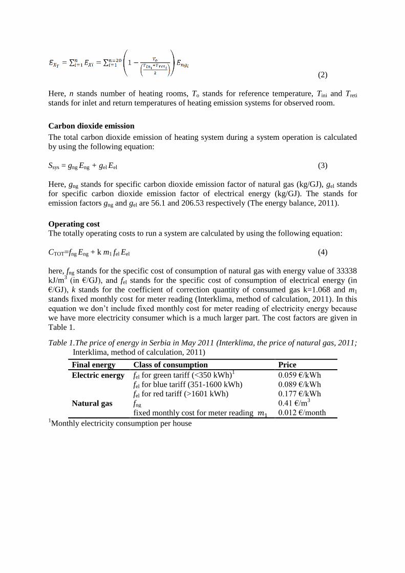
2011), and its carbon dioxide emission. Figure 2 shows the consumption of gas, electricity for
pumps, and primary energy during heating season. Figure 3 shows the price of heating.
Figure 2. Energy consumption per heating
season
Figure 3. Heating costs per heating season
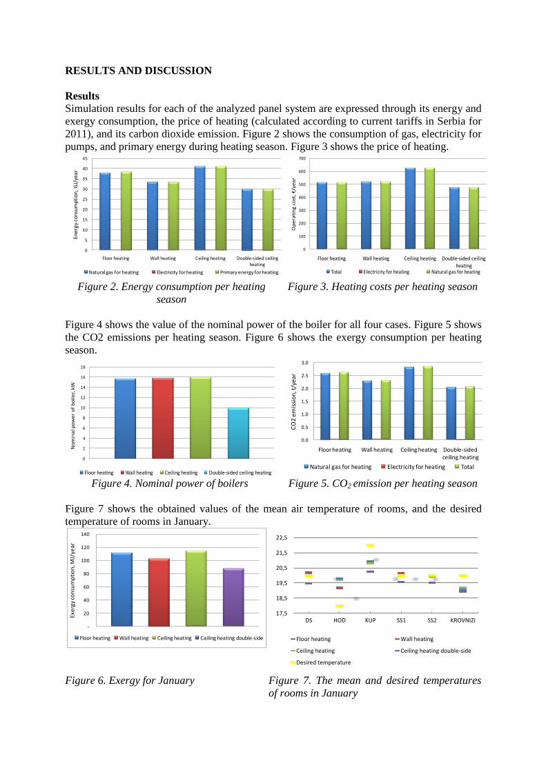
Figure 4 shows the value of the nominal power of the boiler for all four cases. Figure 5 shows
the CO2 emissions per heating season. Figure 6 shows the exergy consumption per heating
season.
Figure 4. Nominal power of boilers Figure 5. CO2 emission per heating season
Figure 7 shows the obtained values of the mean air temperature of rooms, and the desired
temperature of rooms in January.
Figure 6. Exergy for January Figure 7. The mean and desired temperatures
of rooms in January
0
5
10
15
20
25
30
35
40
45
Floor heating Wall heating Ceiling heating Double-sided ceiling heating
Ener
gy c
onsu
mpt
ion,
GJ/
year
Natural gas for heating Electricity for heating Primary energy for heating
0
100
200
300
400
500
600
700
Floor heating Wall heating Ceiling heating Double-sided ceiling heating
Op
era
tin
g c
ost
, €
/ye
ar
Total Electricity for heating Natural gas for heating
0
2
4
6
8
10
12
14
16
18
No
min
al p
ow
er
of
bo
ile
r, k
W
Floor heating Wall heating Ceiling heating Double-sided ceiling heating
0.0
0.5
1.0
1.5
2.0
2.5
3.0
Floor heating Wall heating Ceiling heating Double-sided ceiling heating
CO
2 e
mis
sio
n, t
/yea
r
Natural gas for heating Electricity for heating Total
-
20
40
60
80
100
120
140
Exe
rgy
con
sum
pti
on
, MJ/
year
Floor heating Wall heating Ceiling heating Ceiling heating double-side
17,5
18,5
19,5
20,5
21,5
22,5
DS HOD KUP SS1 SS2 KROVNIZI
Floor heating Wall heating
Ceiling heating Ceiling heating double-side
Desired temperature
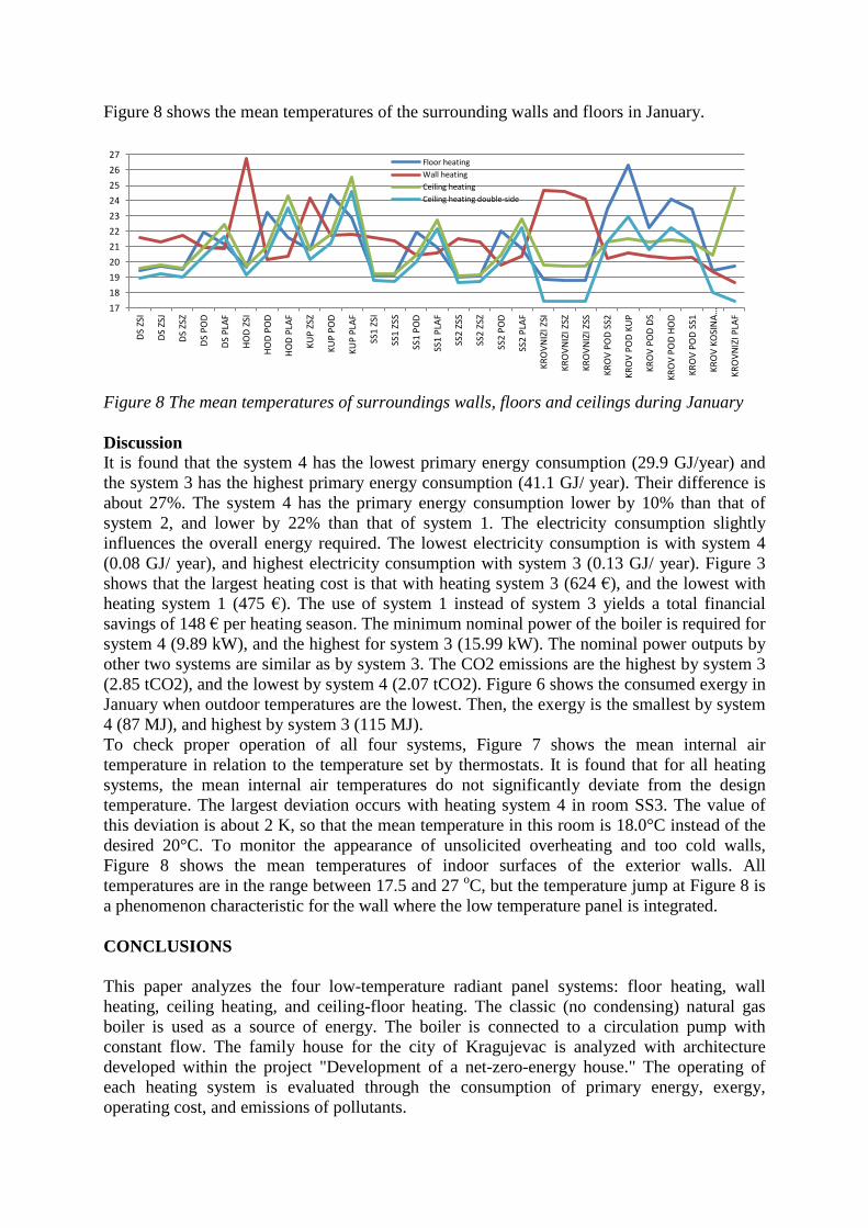
Figure 8 shows the mean temperatures of the surrounding walls and floors in January.
Figure 8 The mean temperatures of surroundings walls, floors and ceilings during January
Discussion
It is found that the system 4 has the lowest primary energy consumption (29.9 GJ/year) and
the system 3 has the highest primary energy consumption (41.1 GJ/ year). Their difference is
about 27%. The system 4 has the primary energy consumption lower by 10% than that of
system 2, and lower by 22% than that of system 1. The electricity consumption slightly
influences the overall energy required. The lowest electricity consumption is with system 4
(0.08 GJ/ year), and highest electricity consumption with system 3 (0.13 GJ/ year). Figure 3
shows that the largest heating cost is that with heating system 3 (624 €), and the lowest with
heating system 1 (475 €). The use of system 1 instead of system 3 yields a total financial
savings of 148 € per heating season. The minimum nominal power of the boiler is required for
system 4 (9.89 kW), and the highest for system 3 (15.99 kW). The nominal power outputs by
other two systems are similar as by system 3. The CO2 emissions are the highest by system 3
(2.85 tCO2), and the lowest by system 4 (2.07 tCO2). Figure 6 shows the consumed exergy in
January when outdoor temperatures are the lowest. Then, the exergy is the smallest by system
4 (87 MJ), and highest by system 3 (115 MJ).
To check proper operation of all four systems, Figure 7 shows the mean internal air
temperature in relation to the temperature set by thermostats. It is found that for all heating
systems, the mean internal air temperatures do not significantly deviate from the design
temperature. The largest deviation occurs with heating system 4 in room SS3. The value of
this deviation is about 2 K, so that the mean temperature in this room is 18.0°C instead of the
desired 20°C. To monitor the appearance of unsolicited overheating and too cold walls,
Figure 8 shows the mean temperatures of indoor surfaces of the exterior walls. All
temperatures are in the range between 17.5 and 27 oC, but the temperature jump at Figure 8 is
a phenomenon characteristic for the wall where the low temperature panel is integrated.
CONCLUSIONS
This paper analyzes the four low-temperature radiant panel systems: floor heating, wall
heating, ceiling heating, and ceiling-floor heating. The classic (no condensing) natural gas
boiler is used as a source of energy. The boiler is connected to a circulation pump with
constant flow. The family house for the city of Kragujevac is analyzed with architecture
developed within the project "Development of a net-zero-energy house." The operating of
each heating system is evaluated through the consumption of primary energy, exergy,
operating cost, and emissions of pollutants.
17
18
19
20
21
22
23
24
25
26
27
DS
ZSI
DS
ZSJ
DS
ZSZ
DS
PO
D
DS
PLA
F
HO
D Z
SI
HO
D P
OD
HO
D P
LAF
KU
P Z
SZ
KU
P P
OD
KU
P P
LAF
SS1
ZSI
SS1
ZSS
SS1
PO
D
SS1
PLA
F
SS2
ZSS
SS2
ZSZ
SS2
PO
D
SS2
PLA
F
KR
OV
NIZ
I ZSI
KR
OV
NIZ
I ZSZ
KR
OV
NIZ
I ZSS
KR
OV
PO
D S
S2
KR
OV
PO
D K
UP
KR
OV
PO
D D
S
KR
OV
PO
D H
OD
KR
OV
PO
D S
S1
KR
OV
KO
SIN
A…
KR
OV
NIZ
I PLA
F
Floor heating
Wall heating
Ceiling heating
Ceiling heating double-side

It is found that the floor-ceiling heating system has the lowest energy, exergy, CO2 emissions,
operating costs, and the nominal power of the boiler. The worst system by all these
parameters is the classical ceiling heating. Also, it is important to note that the next better
system is system 2 (wall heating panel).
The comparison of the room air temperatures and the design temperatures shows that all
systems give satisfactory results without significant deviations. The largest deviation is found
with two-sided ceiling panel system 4 and the temperature in this room is 18.9 oC. However,
it have in mind that the using of the radiation heaters may achieve thermal comfort with up to
2°C lower temperature of internal air than that required by the design. The surrounding inner
surfaces of the exterior walls have the lowest temperature at 17.5 oC that occurs with the
floor-ceiling panel system in room SS3 at the first floor.
ACKNOWLEDGMENT
This paper is a result of two investigations: (1) project TR33015 of Technological
Development of Republic of Serbia, and (2) project III 42006 of Integral and Interdisciplinary
investigations of Republic of Serbia. The first project is titled “Investigation and development
of Serbian zero-net energy house”, and the second project is titled “Investigation and
development of energy and ecological highly effective systems of poly-generation based on
renewable energy sources. We would like to thank to the Ministry of Education and Science
of Republic of Serbia for their financial support during these investigations.
REFERENCES
Bogner M. (2002). Technical regulations about heating, cooling and air conditioning (in
Serbian). Belgrade: SMEITS.
Interklima, The price of natural gas, http://www.interklima.rs/03_01cena_pg.html, Retrieved
May 5, 2011
Interklima, The method of calculation, http://www.interklima.rs/01_14nacin_obracuna.html,
Retrieved May 5, 2011
Kilkis I., Sager S., Uludag M. 1994. A simplified model for radiant heating and cooling
panels, Simulation Practice and Theory, 2, 61–76;
Kilkis I., Eltez M., Sager S. 1995. A simpliIed model for the design of radiant in-slab heating
panels. ASHRAE Transactions 99(2), 210–6.
Kilkis I., Coley M. 1995. Development of a complete software for hydronic floor heating of
buildings, ASHRAE Transactions 99(2), 1201–13.
Kollmar A., Liese W. 1957. Die strahlungsheizung, 4th ed. Munchen, R. Oldenbourg,
Laouadi A. 2004. Development of a radiant heating and cooling model for building energy
simulation software, Building and Environment 39, 421 – 431
Maloney M., Pederson O., Witte J. Development of a radiant heating system model for
BLAST, ASHRAE Transactions, 94(1), 1795–808.
Meteonorm,Global Meteorological Database for Engineers, Planners and Education:
http://www.meteonorm.com, Retrieved May 2011
Miriel J., Serres L., Trombe A. 2002. Radiant ceiling panel heating–cooling systems:
experimental and simulated study of the performances, thermal comfort and energy
consumptions, Applied Thermal Engineering 22, 1861-1873
Stetiu C. 1999. Energy and peak power potential of radiant cooling systems in US commercial
buildings, Energy and Buildings, 30, 127–38.

Strand K. and Pederson O. 1997. Implementation of a radiant heating and cooling model into
an integrated building energy analysis program, ASHRAE Transactions, 103(1), 949–58
Strand K. and Pederson O. 2002. Modeling radiant systems in an integrated heat balance
based energy simulation program, ASHRAE Transactions 108(2), 1–9.
The energy balance, http://www.ssllink.com/mre/cms/mestoZaUploadFajlove/ ENERGETSKI
_BILANS_PLAN_ZA_2008, Retrieved, May 5, 2011.
Yost A., Barbour E., Watson R. 1995. An evaluation of thermal comfort and energy
consumption for a surface mounted ceiling radiant panel heating system, ASHRAE
Transactions, 101(1), 1221–35.
Zhang Z., Pate B. 1987. A semi-analytical formulation of heat transfer from structures with
embedded tubes, Heat transfer in buildings and structures, 78, 17–25.