performance of engineered structures in the mw 9.0 tohoku
TRANSCRIPT
1
EERI Special Earthquake Report — January 2012
Learning from Earthquakes
Performance of Engineered Structures in the Mw 9.0 Tohoku, Japan, Earthquake of March 11, 2011The EERI reconnaissance team deployed to evaluate damage to engineered structures, with John Wallace of UCLA as team leader, was split into three groups: rein-forced concrete buildings, structural steel buildings, and buildings with protective systems. This report discusses the building types in that order. Reinforced Concrete Team members included Mark Aschheim, Santa Clara University (group lead- er); John Wallace, UCLA; Toshimi Kabeyasawa, University of Tokyo; Masaki Maeda, Tohoku University; and Hitoshi Shiohara, University of Tokyo. The Steel Structures Group was comprised James M. Ricles (group leader), Lehigh University; Dimitrios G. Lignos, McGill Uni-versity; R. Jay Love, Degenkolb Engineers; Mitsumasa Midorikawa, Hokkaido University, and Taichiro Okazaki, Hokkaido University. The Protective Systems Team included Geoff Bomba, Forell/Elsesser Engi- neers (group leader); Andrew Tay- lor, KPFF Consulting Engineers; Kazuhiko Kasai, Tokyo Institute of Technology; Kazuhiro Matsuda, Tokyo Institute of Technology; Troy Morgan, Tokyo Institute of Technol-ogy; and Wuchuan Pu, Tokyo In- stitute of Technology.
Unless otherwise indicated, photos in this report were taken by team members.
The research, publication, and distri-bution of this report were partiallyfunded by National Science Founda-tion grant #CMMI-1142058. Additional support was provided by EERI and the organizations affiliated with each team member.
Introduction
Damage from the Mw 9.0 earthquake resulted from both strong ground shaking and the huge tsunami that followed. The earthquake struck at 2:46 pm local time and ruptured a 300 km-long off-shore fault extend-ing from near the southern end of Ibaraki Prefecture to central Iwate Prefecture. It was the largest-magni-tude earthquake recorded in Japan in historic times, and the combined impacts of the earthquake and tsu-nami left at least 15,703 people dead, 4,647 missing, 5,314 injured, 130,927 displaced, and at least 332,395 build-ings, 2,126 roads, 56 bridges, and 26 railways destroyed or damaged from Chiba to Aomori. Casualties and damages were focused in Iwate, Miyagi and Fukushima prefectures, and the total economic loss in Japan is estimated at US$ 309 billion (USGS, 2012).
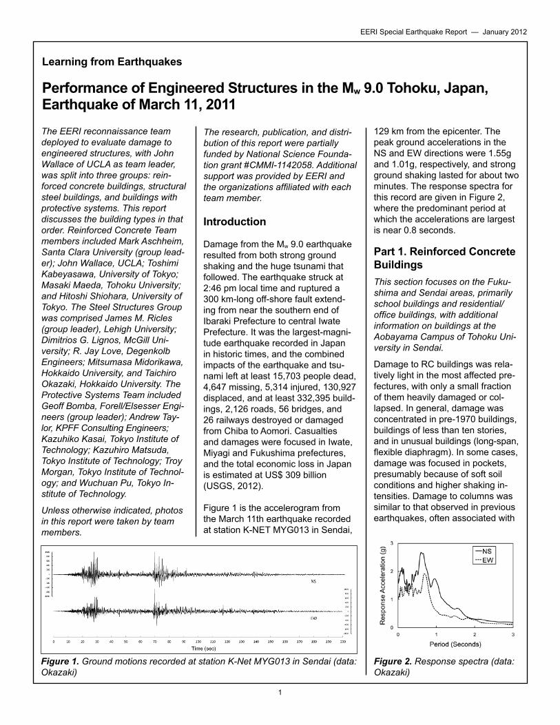
Figure 1 is the accelerogram from the March 11th earthquake recorded at station K-NET MYG013 in Sendai,
129 km from the epicenter. The peak ground accelerations in the NS and EW directions were 1.55g and 1.01g, respectively, and strong ground shaking lasted for about two minutes. The response spectra for this record are given in Figure 2, where the predominant period at which the accelerations are largest is near 0.8 seconds.
Part 1. Reinforced Concrete BuildingsThis section focuses on the Fuku-shima and Sendai areas, primarily school buildings and residential/office buildings, with additional information on buildings at the Aobayama Campus of Tohoku Uni-versity in Sendai.
Damage to RC buildings was rela- tively light in the most affected pre- fectures, with only a small fraction of them heavily damaged or col-lapsed. In general, damage was concentrated in pre-1970 buildings, buildings of less than ten stories, and in unusual buildings (long-span, flexible diaphragm). In some cases, damage was focused in pockets, presumably because of soft soil conditions and higher shaking in- tensities. Damage to columns was similar to that observed in previous earthquakes, often associated with
Figure 1. Ground motions recorded at station K-Net MYG013 in Sendai (data: Okazaki)
Figure 2. Response spectra (data: Okazaki)
2
EERI Special Earthquake Report — January 2012
short or captive columns develop-ing shear failure. The presence of reinforced concrete wing walls on one or both sides of a column often induced diagonal cracking that pen- etrated through the column. Other column failures were associated with discontinued shear walls above. Significant damage, typically diag- onal cracking, was observed in reinforced concrete partition walls that were used as nonstructural walls. Mid-rise multistory buildings did not show evidence of damage due to higher modes of vibration, although damage was concentrated at vertical structural discontinuities. Retrofits with infilled steel bracing or shear walls proved to be effec-tive, while those with viscous dam- pers presumably reduced deforma-tion demand but not sufficiently to preclude damage to stiff concrete elements.
Japanese Code Provisions for RC Buildings. From 1950-1971, column cross-section dimensions D were required to exceed H/15, where H is the column clear height, and column transverse reinforce-ment consisted of single perimeter
hoops with spacing not to exceed 300 mm or 15db (Otani, 2000). Following the 1968 Tokachi-oki earthquake, new provisions were introduced in 1971 to prevent column shear failures and improve ductility. A capacity design approach was taken for column shear, and more stringent requirements were laid down for transverse reinforce-ment. At the top and bottom of col- umns, over a height of 2D, spacing of hoops was limited to 100 mm, whereas within the middle portion of the column, hoop spacing was lim-ited to 150 mm. Additional changes included requiring 135º (or more) bends on hoops and the consider-ation of reinforced concrete nonstruc-tural walls in the design process.
The 1978 Miyagi-ken oki earthquake was a major factor in the code changes introduced in 1981. These changes included a minimum shear reinforcement ratio, consideration of torsional eccentricity in design, and limits on story drift.
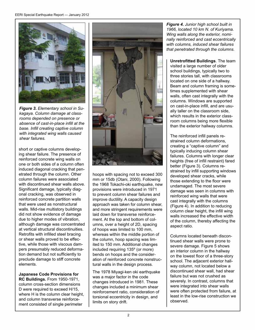
Unretrofitted Buildings. The team visited a large number of older school buildings, typically two to three stories tall, with classrooms located on one side of a hallway. Beam and column framing is some-times supplemented with shear walls, often cast integrally with the columns. Windows are supported on cast-in-place infill, and are usu-ally taller on the classroom side, which results in the exterior class-room columns being more flexible than the exterior hallway columns.
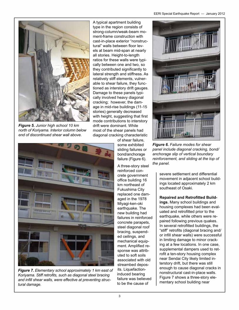
The reinforced infill panels re- strained column deformations, creating a “captive column” and typically inducing column shear failures. Columns with longer clear heights (free of infill restraint) fared better (Figure 3). Columns re- strained by infill supporting windows developed shear cracks, while those extending to the floor were undamaged. The most severe damage was seen in columns with reinforced wing walls that were cast integrally with the columns (Figure 4). In addition to reducing column clear height, the infill wing walls increased the effective width of the column, thereby affecting the aspect ratio.
Columns located beneath discon-tinued shear walls were prone to severe damage. Figure 5 shows an interior column in the hallway on the lowest floor of a three-story school. The adjacent exterior hall-way column, not located below a discontinued shear wall, had shear failure but was not crushed as severely. In contrast, columns that were integrated into shear walls were often protected from failure, at least in the low-rise construction we observed.
Figure 3. Elementary school in Su- kagaya. Column damage at class-rooms depended on presence or absence of cast-in-place infill at the base. Infill creating captive column with integrated wing walls caused shear failures.
Figure 4. Junior high school built in 1966, located 10 km N. of Kuriyama. Wing walls along the exterior, nomi-nally reinforced and cast eccentrically with columns, induced shear failures that penetrated through the columns.
3
EERI Special Earthquake Report — January 2012
A typical apartment building type in the region consists of strong-column/weak-beam mo- ment-frame construction with cast-in-place exterior “nonstruc- tural” walls between floor lev- els at beam mid-span at nearly all stories. Height-to-length ratios for these walls were typi-cally between one and two, so they contributed significantly to lateral strength and stiffness. As relatively stiff elements, vulner- able to shear failure, they func-tioned as interstory drift gauges. Damage to these panels typi-cally involved heavy diagonal cracking; however, the dam- age in mid-rise buildings (11-15 stories) generally decreased with height, suggesting that first mode contributions to interstory drift were dominant. While most of the shear panels had diagonal cracking characteristic
of shear failure, some exhibited sliding failures or bond/anchorage failure (Figure 6).
A three-story steel reinforced con-crete government office building 16 km northeast of Fukushima City replaced one dam-aged in the 1978 Miyagi-ken-oki earthquake. The new building had failures in reinforced concrete parapets, steel diagonal roof bracing, suspend- ed ceilings, and mechanical equip-ment. Amplified re- sponse was attrib-uted to soft soils associated with old streambed depos-its. Liquefaction-induced bearing failure was believed to be the cause of
severe settlement and differential movement in adjacent school build-ings located approximately 2 km southeast of Osaki.
Repaired and Retrofitted Build-ings. Many school buildings and housing complexes had been eval- uated and retrofitted prior to the earthquake, while others were re- paired following previous quakes. In several retrofitted buildings, the “stiff” retrofits (diagonal bracing and/ or infill shear walls) were successful in limiting damage to minor crack-ing at a few locations. In one case, supplemental dampers used to ret- rofit a ten-story housing complex near Sendai City likely limited in- terstory drift, but there was still enough to cause diagonal cracks in nonstructural cast-in-place walls. Figure 7 shows a three-story ele- mentary school building near
Figure 5. Junior high school 10 km north of Koriyama. Interior column below end of discontinued shear wall above.
Figure 6. Failure modes for shear panel include diagonal cracking, bond/anchorage slip of vertical boundary reinforcement, and sliding at the top of the panel.
Figure 7. Elementary school approximately 1 km east of Koriyama. Stiff retrofits, such as diagonal steel bracing and infill shear walls, were effective at preventing struc-tural damage.
4
EERI Special Earthquake Report — January 2012
Kuriyama that had been retrofitted with infill shear walls and diagonal bracing.
Tohoku University Campus. At the Science and Engineering Aobayama Campus of Tohoku University, some buildings were severely damaged, possibly due to topographic amplification of ground motion, as the campus sits atop a hill 2 km west of Sendai City. Four buildings on the campus were so damaged that they were deemed irreparable (Motosaka et al. 2011), and there was serious damage to other buildings. The total damage estimate of $400 million includes the replacement of the four build-ings. The campus has had multiple damaging earthquakes over the past 30 years (Ms7.7 in 1978, M7.0 in 2003, Mw7.2 in 2005, Mw6.9 in 2008).
The Civil Engineering & Architec-ture Building, constructed in 1969, was badly damaged. This building, damaged during the 1978 Miyagi-ken-oki earthquake, had been seis-mically strengthened in two phases
prior to the 2011 quake (Motosaka et al., 2002; Motosaka, Sato and Yamamoto, 2004). The building is a steel-reinforced concrete building (in which the damaged columns were constructed of lattice steel sections encased in reinforced concrete) with three podium levels and seven tower stories above; this created a vertical irregularity in the mass, stiffness, and strength of the building at the transi-tion level between the podium and tower.
After the Miyagi-ken-oki earthquake, the deflection angle of the building was on the order of 10-2 rad. The transverse end concrete walls of the tower were strengthened by addi-tional concrete thickness during 2000 (Motosaka, Sato and Yamamoto, 2004). The concrete floor diaphragms at each end of the tower were also strengthened with additional concrete thickness. After an earthquake in 2003, additional steel braced frames were added to the south exterior to provide additional torsional stiffness to that side of the building, counter-acting the stiffness of the original concrete core walls located on the
north half of the floors. The univer-sity installed continuous monitoring equipment after the 2008 earth-quake, which provided a detailed history of the building’s response in micro-tremors and larger earth-quakes (Motosaka et al., 2011).
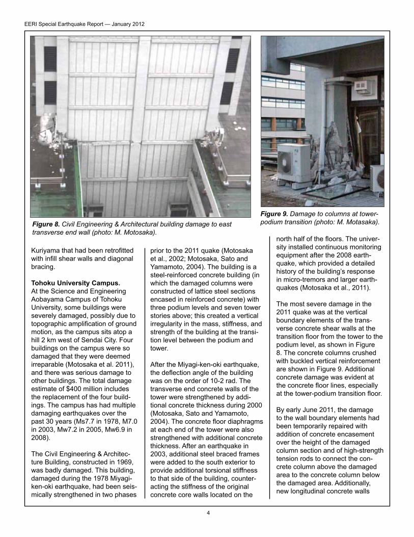
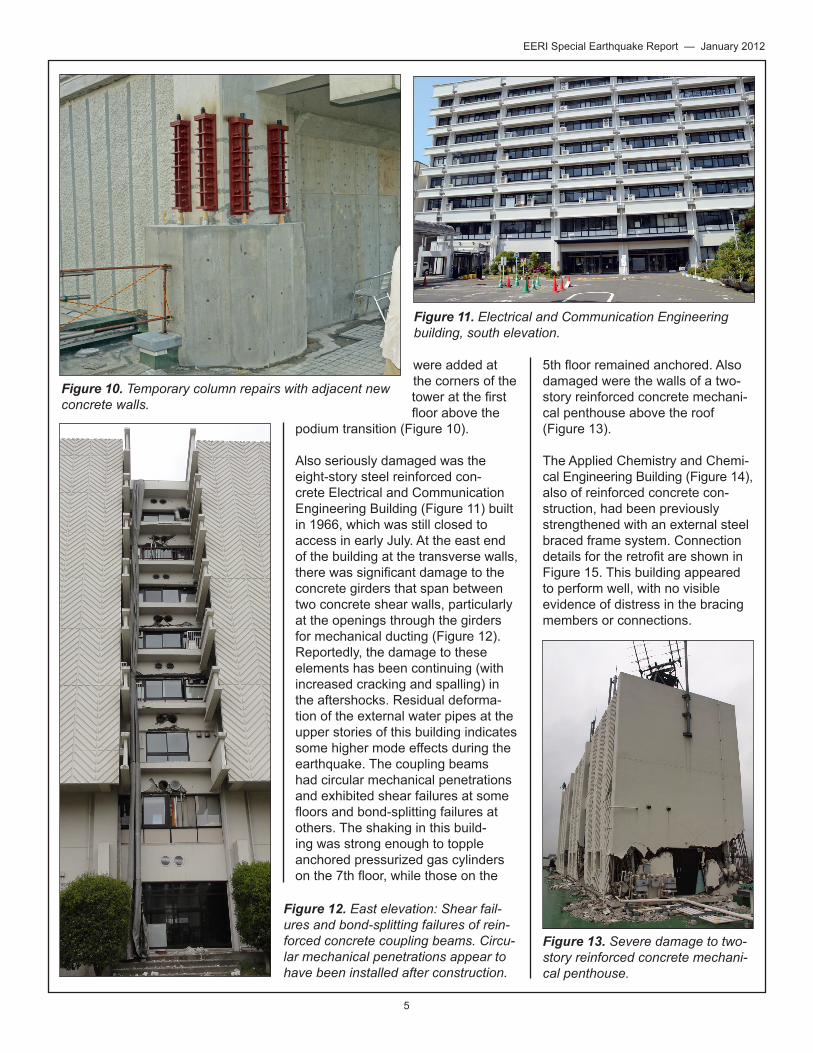
The most severe damage in the 2011 quake was at the vertical boundary elements of the trans-verse concrete shear walls at the transition floor from the tower to the podium level, as shown in Figure 8. The concrete columns crushed with buckled vertical reinforcement are shown in Figure 9. Additional concrete damage was evident at the concrete floor lines, especially at the tower-podium transition floor.
By early June 2011, the damage to the wall boundary elements had been temporarily repaired with addition of concrete encasement over the height of the damaged column section and of high-strength tension rods to connect the con-crete column above the damaged area to the concrete column below the damaged area. Additionally, new longitudinal concrete walls
Figure 8. Civil Engineering & Architectural building damage to east transverse end wall (photo: M. Motosaka).
Figure 9. Damage to columns at tower-podium transition (photo: M. Motasaka).
5
EERI Special Earthquake Report — January 2012
were added at the corners of the tower at the first floor above the
podium transition (Figure 10).
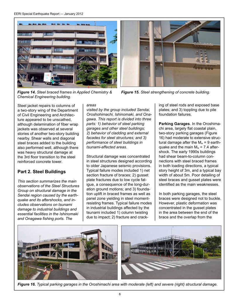
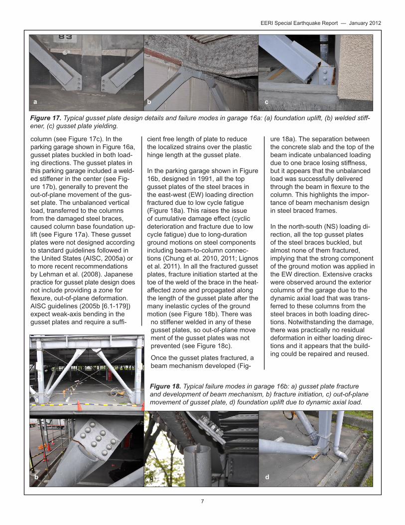
Also seriously damaged was the eight-story steel reinforced con-crete Electrical and Communication Engineering Building (Figure 11) built in 1966, which was still closed to access in early July. At the east end of the building at the transverse walls, there was significant damage to the concrete girders that span between two concrete shear walls, particularly at the openings through the girders for mechanical ducting (Figure 12). Reportedly, the damage to these elements has been continuing (with increased cracking and spalling) in the aftershocks. Residual deforma-tion of the external water pipes at the upper stories of this building indicates some higher mode effects during the earthquake. The coupling beams had circular mechanical penetrations and exhibited shear failures at some floors and bond-splitting failures at others. The shaking in this build-ing was strong enough to topple anchored pressurized gas cylinders on the 7th floor, while those on the
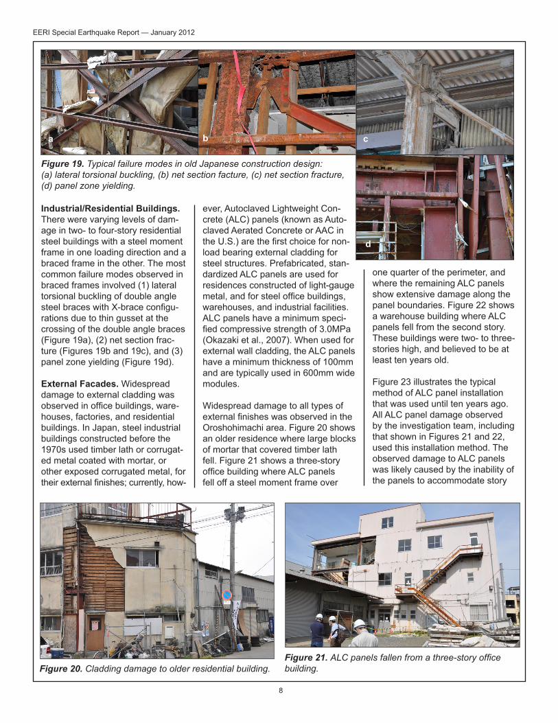
5th floor remained anchored. Also damaged were the walls of a two-story reinforced concrete mechani-cal penthouse above the roof (Figure 13).
The Applied Chemistry and Chemi-cal Engineering Building (Figure 14), also of reinforced concrete con-struction, had been previously strengthened with an external steel braced frame system. Connection details for the retrofit are shown in Figure 15. This building appeared to perform well, with no visible evidence of distress in the bracing members or connections.
Figure 12. East elevation: Shear fail- ures and bond-splitting failures of rein-forced concrete coupling beams. Circu-lar mechanical penetrations appear to have been installed after construction.
Figure 13. Severe damage to two-story reinforced concrete mechani-cal penthouse.
Figure 10. Temporary column repairs with adjacent new concrete walls.
Figure 11. Electrical and Communication Engineering building, south elevation.
6
EERI Special Earthquake Report — January 2012
Steel jacket repairs to columns of a two-story wing of the Department of Civil Engineering and Architec-ture appeared to be unscathed, although delamination of fiber wrap jackets was observed at several stories of another two-story building nearby. Shear walls and diagonal steel braces added to the building also performed well, although there was heavy structural damage at the 3rd floor transition to the steel reinforced concrete tower.
Part 2. Steel Buildings
This section summarizes the main observations of the Steel Structures Group on structural damage in the Sendai region caused by the earth- quake and its aftershocks, and in- cludes observations on tsunami damage to industrial buildings and essential facilities in the Ishinomaki and Onagawa fishing ports. The
areas visited by the group included Sendai, Oroshohimachi, Ishinomaki, and Ona- gawa. This report is divided into three parts: 1) behavior of steel parking garages and other steel buildings; 2) behavior of cladding and external facades for steel structures; and 3) performance of steel buildings in tsunami-affected areas.
Structural damage was concentrated in steel structures designed according to older Japanese seismic provisions. Typical failure modes included 1) net section fracture of braces; 2) gusset plate fractures due to low cycle fat- igue, a consequence of the long-dur- ation ground motions; and 3) founda-tion uplift in braced frames as well as panel zone yielding in steel moment-resisting frames. Typical failure modes in industrial buildings affected by the tsunami included 1) column twisting due to impact; 2) fracture and crack-
ing of steel rods and exposed base plates; and 3) toppling due to pile foundation failures.
Parking Garages. In the Oroshima-chi area, largely flat coastal plain, two-story parking garages (Figure 16) had moderate to extensive struc- tural damage after the Mw = 9 earth-quake and the main Mw = 7.4 after-shock. The early 1990s buildings had shear beam-to-column con-nections with steel braced frames in both loading directions, a typical story height of 3m, and a typical bay width of about 5m. Poor detailing of steel braces and gusset plates were identified as the main weaknesses.
In both parking garages, the steel braces were designed not to buckle. However, plastic deformation was concentrated in the gusset plates in the area between the end of the brace and the overlap from the
Figure 16. Typical parking garages in the Oroshimachi area with moderate (left) and severe (right) structural damage.
Figure 14. Steel braced frames in Applied Chemistry & Chemical Engineering building.
Figure 15. Steel strengthening of concrete building.
7
EERI Special Earthquake Report — January 2012
column (see Figure 17c). In the parking garage shown in Figure 16a, gusset plates buckled in both load-ing directions. The gusset plates in this parking garage included a weld- ed stiffener in the center (see Fig- ure 17b), generally to prevent the out-of-plane movement of the gus- set plate. The unbalanced vertical load, transferred to the columns from the damaged steel braces, caused column base foundation up-lift (see Figure 17a). These gusset plates were not designed according to standard guidelines followed in the United States (AISC, 2005a) or to more recent recommendations by Lehman et al. (2008). Japanese practice for gusset plate design does not include providing a zone for flexure, out-of-plane deformation. AISC guidelines (2005b [6.1-179]) expect weak-axis bending in the gusset plates and require a suffi-
cient free length of plate to reduce the localized strains over the plastic hinge length at the gusset plate.
In the parking garage shown in Figure 16b, designed in 1991, all the top gusset plates of the steel braces in the east-west (EW) loading direction fractured due to low cycle fatigue (Figure 18a). This raises the issue of cumulative damage effect (cyclic deterioration and fracture due to low cycle fatigue) due to long-duration ground motions on steel components including beam-to-column connec-tions (Chung et al. 2010, 2011; Lignos et al. 2011). In all the fractured gusset plates, fracture initiation started at the toe of the weld of the brace in the heat- affected zone and propagated along the length of the gusset plate after the many inelastic cycles of the ground motion (see Figure 18b). There was no stiffener welded in any of these gusset plates, so out-of-plane move ment of the gusset plates was not prevented (see Figure 18c).
Once the gusset plates fractured, a beam mechanism developed (Fig-
ure 18a). The separation between the concrete slab and the top of the beam indicate unbalanced loading due to one brace losing stiffness, but it appears that the unbalanced load was successfully delivered through the beam in flexure to the column. This highlights the impor-tance of beam mechanism design in steel braced frames.
In the north-south (NS) loading di- rection, all the top gusset plates of the steel braces buckled, but almost none of them fractured, implying that the strong component of the ground motion was applied in the EW direction. Extensive cracks were observed around the exterior columns of the garage due to the dynamic axial load that was trans-ferred to these columns from the steel braces in both loading direc-tions. Notwithstanding the damage, there was practically no residual deformation in either loading direc-tions and it appears that the build-ing could be repaired and reused.
Figure 18. Typical failure modes in garage 16b: a) gusset plate fracture and development of beam mechanism, b) fracture initiation, c) out-of-plane movement of gusset plate, d) foundation uplift due to dynamic axial load.
Figure 17. Typical gusset plate design details and failure modes in garage 16a: (a) foundation uplift, (b) welded stiff-ener, (c) gusset plate yielding.
a b c
b c d
a
8
EERI Special Earthquake Report — January 2012
Industrial/Residential Buildings. There were varying levels of dam- age in two- to four-story residential steel buildings with a steel moment frame in one loading direction and a braced frame in the other. The most common failure modes observed in braced frames involved (1) lateral torsional buckling of double angle steel braces with X-brace configu-rations due to thin gusset at the crossing of the double angle braces (Figure 19a), (2) net section frac-ture (Figures 19b and 19c), and (3) panel zone yielding (Figure 19d).
External Facades. Widespread damage to external cladding was observed in office buildings, ware-houses, factories, and residential buildings. In Japan, steel industrial buildings constructed before the 1970s used timber lath or corrugat- ed metal coated with mortar, or other exposed corrugated metal, for their external finishes; currently, how-
ever, Autoclaved Lightweight Con-crete (ALC) panels (known as Auto-claved Aerated Concrete or AAC in the U.S.) are the first choice for non- load bearing external cladding for steel structures. Prefabricated, stan-dardized ALC panels are used for residences constructed of light-gauge metal, and for steel office buildings, warehouses, and industrial facilities. ALC panels have a minimum speci-fied compressive strength of 3.0MPa (Okazaki et al., 2007). When used for external wall cladding, the ALC panels have a minimum thickness of 100mm and are typically used in 600mm wide modules.
Widespread damage to all types of external finishes was observed in the Oroshohimachi area. Figure 20 shows an older residence where large blocks of mortar that covered timber lath fell. Figure 21 shows a three-story office building where ALC panels fell off a steel moment frame over
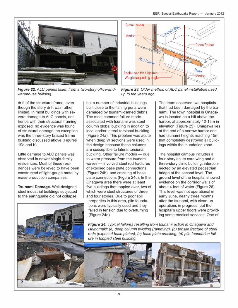
one quarter of the perimeter, and where the remaining ALC panels show extensive damage along the panel boundaries. Figure 22 shows a warehouse building where ALC panels fell from the second story. These buildings were two- to three-stories high, and believed to be at least ten years old.
Figure 23 illustrates the typical method of ALC panel installation that was used until ten years ago. All ALC panel damage observed by the investigation team, including that shown in Figures 21 and 22, used this installation method. The observed damage to ALC panels was likely caused by the inability of the panels to accommodate story
Figure 19. Typical failure modes in old Japanese construction design: (a) lateral torsional buckling, (b) net section facture, (c) net section fracture, (d) panel zone yielding.
Figure 20. Cladding damage to older residential building. Figure 21. ALC panels fallen from a three-story office building.
a b c
d
9
EERI Special Earthquake Report — January 2012
drift of the structural frame, even though the story drift was rather limited. In most buildings with se- vere damage to ALC panels, and hence with their structural framing exposed, no evidence was found of structural damage; an exception was the three-story braced frame building discussed above (Figures 19a and b).
Little damage to ALC panels was observed in newer single-family residences. Most of these resi-dences were believed to have been constructed of light-gauge metal by mass-production companies.
Tsunami Damage. Well-designed steel industrial buildings subjected to the earthquake did not collapse,
but a number of industrial buildings built close to the fishing ports were damaged by tsunami-carried debris. The most common failure mode associated with tsunami was steel column global buckling in addition to local and/or lateral torsional buckling (Figure 24a). This problem was acute when deep W sections were used in the design because these columns are susceptible to lateral torsional buckling. Other failure modes — due to water pressure from the tsunami waves — involved steel rod fractures of exposed base plate connections (Figure 24b), and cracking of base plate connections (Figure 24c). In the Onagawa area there were at least five buildings that toppled over, two of which were steel structures of three and four stories. Due to poor soil properties in this area, pile founda- tions were typically used and they failed in tension due to overturning (Figure 24d).
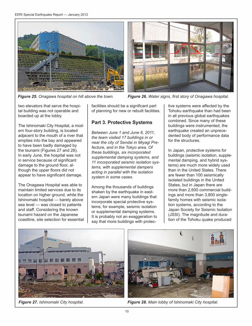
The team observed two hospitals that had been damaged by the tsu- nami. The town hospital in Onaga- wa is located on a hill above the harbor, at approximately 12-13m in elevation (Figure 25). Onagawa lies at the end of a narrow harbor and had tsunami heights reaching 15m that completely destroyed all build-ings within the inundation zone.
The hospital campus includes a four-story acute care wing and a three-story clinic building, intercon-nected by an elevated pedestrian bridge at the second level. The ground level of the hospital showed evidence on the corridor walls of about 4 feet of water (Figure 26). This level was not operational in early June, nearly three months after the tsunami, with clean-up operations in progress, but the hospital’s upper floors were provid-ing some medical services. One of
Figure 22. ALC panels fallen from a two-story office-and-warehouse building.
Figure 23. Older method of ALC panel installation used up to ten years ago.
Figure 24. Typical failures resulting from tsunami action in Onagawa and Ishinomaki: (a) deep column twisting (ramming), (b) tensile fracture of steel rods (exposed base plates), (c) base plate cracking, (d) pile foundation fail-ure in toppled steel building.
a
b c d
10
EERI Special Earthquake Report — January 2012
two elevators that serve the hospi-tal building was not operable and boarded up at the lobby.
The Ishinomaki City Hospital, a mod- ern four-story building, is located adjacent to the mouth of a river that empties into the bay and appeared to have been badly damaged by the tsunami (Figures 27 and 28). In early June, the hospital was not in service because of significant damage to the ground floor, al- though the upper floors did not appear to have significant damage.
The Onagawa Hospital was able to maintain limited services due to its location on higher ground, while the Ishinomaki hospital — barely above sea level — was closed to patients and staff. Considering the known tsunami hazard on the Japanese coastline, site selection for essential
facilities should be a significant part of planning for new or rebuilt facilities.
Part 3. Protective Systems
Between June 1 and June 6, 2011, the team visited 17 buildings in or near the city of Sendai in Miyagi Pre- fecture, and in the Tokyo area. Of these buildings, six incorporated supplemental damping systems, and 11 incorporated seismic isolation sys- tems, with supplemental dampers acting in parallel with the isolation system in some cases.
Among the thousands of buildings shaken by the earthquake in east-ern Japan were many buildings that incorporate special protective sys-tems; for example, seismic isolation or supplemental damping systems. It is probably not an exaggeration to say that more buildings with protec-
tive systems were affected by the Tohoku earthquake than had been in all previous global earthquakes combined. Since many of these buildings were instrumented, the earthquake created an unprece- dented body of performance data for the structures.
In Japan, protective systems for buildings (seismic isolation, supple- mental damping, and hybrid sys- tems) are much more widely used than in the United States. There are fewer than 100 seismically isolated buildings in the United States, but in Japan there are more than 2,600 commercial build- ings and more than 3,800 single-family homes with seismic isola-tion systems, according to the Japan Society for Seismic Isolation (JSSI). The magnitude and dura-tion of the Tohoku quake produced
Figure 27. Ishinomaki City hospital. Figure 28. Main lobby of Ishinomaki City hospital.
Figure 25. Onagawa hospital on hill above the town. Figure 26. Water signs, first story of Onagawa hospital.
11
EERI Special Earthquake Report — January 2012
movements in some systems that far exceed responses measured in any previous quake. In the United States, we have based design of earthquake protection systems on the results of advanced analysis and shake table testing; however, the Tohoku earthquake has allowed us to observe the performance of full-scale structures subject to long-duration, low-frequency, high-ampli-tude ground shaking.
Instrumentation and Sensors. Real-time monitoring of structural parameters is prevalent in struc-tures with protective systems, and the instruments provide engineers and owners with valuable informa-tion about the structural health of buildings after major earthquakes. Universities have typically been forthcoming with data on the per-formance of structures they own or have instrumented; in contrast, private corporations and construc-tion companies have been reticent about releasing the data gathered in their structures.
Electronic instrumentation data is typically reported in the form of acceleration and displacement records. For seismically isolated structures, scratch plates are often installed, and serve as a simple
method for obtaining information about maximum displace-ment and its direc-tion. The scratch plate data also assist with calibra-tion of displacement records. Raw accel-eration records are processed through double integration to create uncorrected displacement rec-ords. In a parallel effort, the structure’s modal properties — vibration periods, damping ratios, and participation vec- tors — are extracted from the proc- essed acceleration records to create an analytical model of the structure (using modal superposition). This model is used to check the displace-ment records obtained through double integration of acceleration records, and maximum displacements are also compared with scratch plate data. Free vibration data from micro trem-ors or aftershock shaking also allow researchers to extract the structure’s damping properties.
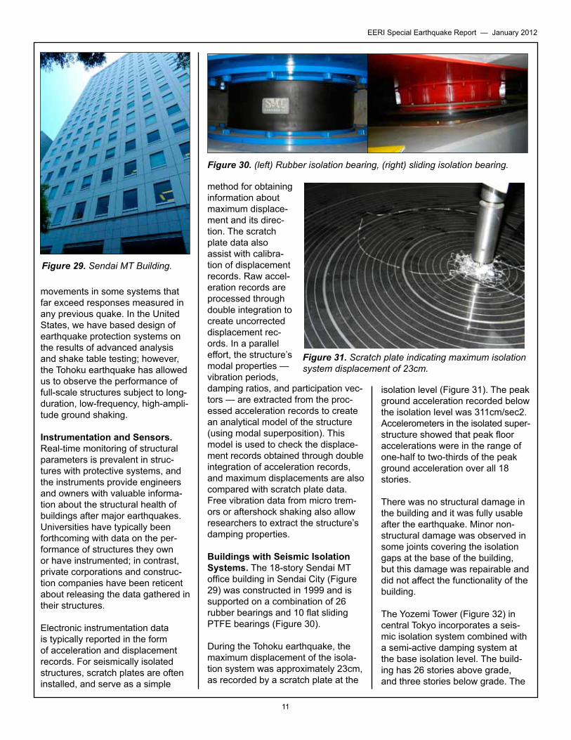
Buildings with Seismic Isolation Systems. The 18-story Sendai MT office building in Sendai City (Figure 29) was constructed in 1999 and is supported on a combination of 26 rubber bearings and 10 flat sliding PTFE bearings (Figure 30).
During the Tohoku earthquake, the maximum displacement of the isola-tion system was approximately 23cm, as recorded by a scratch plate at the
isolation level (Figure 31). The peak ground acceleration recorded below the isolation level was 311cm/sec2. Accelerometers in the isolated super- structure showed that peak floor accelerations were in the range of one-half to two-thirds of the peak ground acceleration over all 18 stories.
There was no structural damage in the building and it was fully usable after the earthquake. Minor non-structural damage was observed in some joints covering the isolation gaps at the base of the building, but this damage was repairable and did not affect the functionality of the building.
The Yozemi Tower (Figure 32) in central Tokyo incorporates a seis-mic isolation system combined with a semi-active damping system at the base isolation level. The build-ing has 26 stories above grade, and three stories below grade. The
Figure 30. (left) Rubber isolation bearing, (right) sliding isolation bearing.
Figure 29. Sendai MT Building.
Figure 31. Scratch plate indicating maximum isolation system displacement of 23cm.
12
EERI Special Earthquake Report — January 2012
isolation level is between the 1st and 2nd stories of the basement so that the total height of the isolated structure is 27 stories.
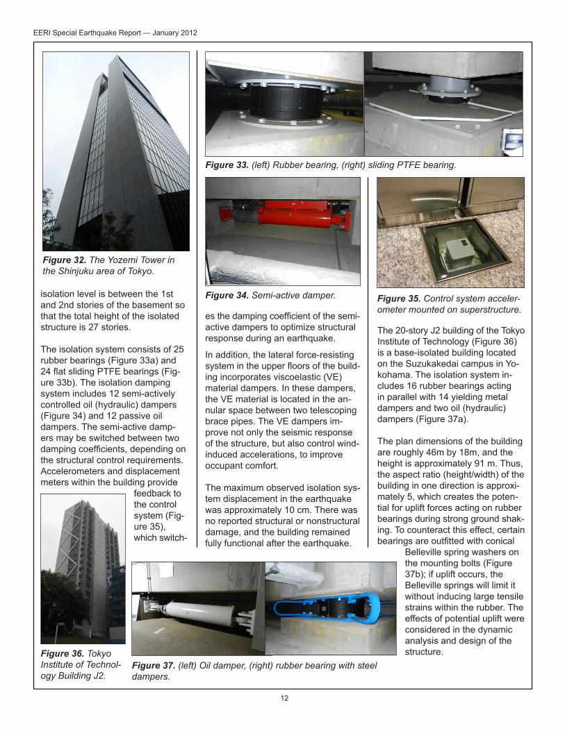
The isolation system consists of 25 rubber bearings (Figure 33a) and 24 flat sliding PTFE bearings (Fig- ure 33b). The isolation damping system includes 12 semi-actively controlled oil (hydraulic) dampers (Figure 34) and 12 passive oil dampers. The semi-active damp-ers may be switched between two damping coefficients, depending on the structural control requirements. Accelerometers and displacement meters within the building provide
feedback to the control system (Fig- ure 35), which switch-
es the damping coefficient of the semi- active dampers to optimize structural response during an earthquake.
In addition, the lateral force-resisting system in the upper floors of the build- ing incorporates viscoelastic (VE) material dampers. In these dampers, the VE material is located in the an- nular space between two telescoping brace pipes. The VE dampers im- prove not only the seismic response of the structure, but also control wind-induced accelerations, to improve occupant comfort. The maximum observed isolation sys- tem displacement in the earthquake was approximately 10 cm. There was no reported structural or nonstructural damage, and the building remained fully functional after the earthquake.
The 20-story J2 building of the Tokyo Institute of Technology (Figure 36) is a base-isolated building located on the Suzukakedai campus in Yo- kohama. The isolation system in- cludes 16 rubber bearings acting in parallel with 14 yielding metal dampers and two oil (hydraulic) dampers (Figure 37a).
The plan dimensions of the building are roughly 46m by 18m, and the height is approximately 91 m. Thus, the aspect ratio (height/width) of the building in one direction is approxi-mately 5, which creates the poten- tial for uplift forces acting on rubber bearings during strong ground shak- ing. To counteract this effect, certain bearings are outfitted with conical
Belleville spring washers on the mounting bolts (Figure 37b); if uplift occurs, the Belleville springs will limit it without inducing large tensile strains within the rubber. The effects of potential uplift were considered in the dynamic analysis and design of the structure.
Figure 32. The Yozemi Tower in the Shinjuku area of Tokyo.
Figure 35. Control system acceler-ometer mounted on superstructure.
Figure 33. (left) Rubber bearing, (right) sliding PTFE bearing.
Figure 34. Semi-active damper.
Figure 36. Tokyo Institute of Technol-ogy Building J2.
Figure 37. (left) Oil damper, (right) rubber bearing with steel dampers.
13
EERI Special Earthquake Report — January 2012
During the earthquake, the maxi-mum measured radial displace-ment of the isolation system was approximately 12.5 cm (9.5 cm in the NE-SW direction). It is not known at this time whether there was uplift at any of the rubber bear-ings. The peak ground acceleration measured below the isolation plane was 69.0 cm/sec2 in the NE-SW direction. At the first level above the isolation plane, the maximum ac- celeration in the NE-SW direction was 69.6 cm/sec2. The maximum acceleration at the 20th floor in the NE-SW direction was 116.2 cm/sec2. Comparing the peak ground acceleration and the peak acceler- ation at the 20th floor, it can be seen that the isolation system was highly effective at minimizing dynamic amplification of ground motions over the height of the building.
It is interesting to note that a second base-isolated tower is currently un- der construction approximately 10 m southeast of this building (visible on the right in Figure 36). The sec- ond tower will also be 20 stories tall, and it will be base-isolated. The towers will share a common base level, so that they will act together as a single base isolated structure.
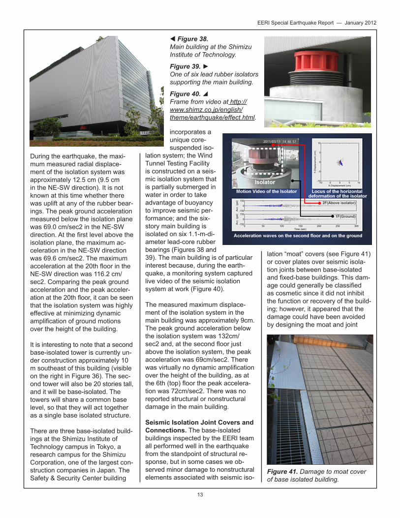
There are three base-isolated build- ings at the Shimizu Institute of Technology campus in Tokyo, a research campus for the Shimizu Corporation, one of the largest con- struction companies in Japan. The Safety & Security Center building
incorporates a unique core- suspended iso-
lation system; the Wind Tunnel Testing Facility is constructed on a seis-mic isolation system that is partially submerged in water in order to take advantage of buoyancy to improve seismic per- formance; and the six- story main building is isolated on six 1.1-m-di-ameter lead-core rubber bearings (Figures 38 and 39). The main building is of particular interest because, during the earth-quake, a monitoring system captured live video of the seismic isolation system at work (Figure 40). The measured maximum displace-ment of the isolation system in the main building was approximately 9cm. The peak ground acceleration below the isolation system was 132cm/sec2 and, at the second floor just above the isolation system, the peak acceleration was 69cm/sec2. There was virtually no dynamic amplification over the height of the building, as at the 6th (top) floor the peak accelera-tion was 72cm/sec2. There was no reported structural or nonstructural damage in the main building.
Seismic Isolation Joint Covers and Connections. The base-isolated buildings inspected by the EERI team all performed well in the earthquake from the standpoint of structural re- sponse, but in some cases we ob- served minor damage to nonstructural elements associated with seismic iso-
lation “moat” covers (see Figure 41) or cover plates over seismic isola-tion joints between base-isolated and fixed-base buildings. This dam- age could generally be classified as cosmetic since it did not inhibit the function or recovery of the build- ing; however, it appeared that the damage could have been avoided by designing the moat and joint
Figure 38. Main building at the Shimizu Institute of Technology.
Figure 39. ►One of six lead rubber isolators supporting the main building.
Figure 40. Frame from video at http://www.shimz.co.jp/english/theme/earthquake/effect.html.
Figure 41. Damage to moat cover of base isolated building.
14
EERI Special Earthquake Report — January 2012
covers for larger ranges of motion. In Japan, as in the United States, seismic moat covers and joint covers are often not designed by the struc- tural engineer, but by the architect. The architect may not have the same detailed understanding as the engineer about the expected ranges of motion in the base-isolated build-ing. Therefore, it is important that both the architect and engineer participate in the design of seismic moat and joint covers, to assure that the full range of potential mo- tion is provided for.
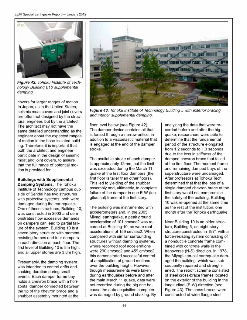
Buildings with Supplemental Damping Systems. The Tohoku Institute of Technology campus out-side of Sendai has two structures with protective systems; both were damaged during the earthquake. One of these structures, Building 10, was constructed in 2003 and dem-onstrates how excessive demands on dampers can lead to partial fail-ure of the system. Building 10 is a seven-story structure with moment-resisting frames and four dampers in each direction at each floor. The first level of Building 10 is 8m high, and all upper stories are 3.8m high.
Presumably, the damping system was intended to control drifts and shaking duration during small events. Each damper frame bay holds a chevron brace with a hori-zontal damper connected between the tip of the chevron brace and a snubber assembly mounted at the
floor level below (see Figure 42). The damper device contains oil that is forced through a narrow orifice, in addition to a viscoelastic material that is engaged at the end of the damper stroke.
The available stroke of each damper is approximately 12mm, but the limit was exceeded during the March 11 quake at the first floor dampers (the first floor is taller than other floors). This led to yielding of the snubber assembly and, ultimately, to complete failure of the damper in one E-W (lon-gitudinal) frame at the first story.
The building was instrumented with accelerometers and, in the 2005 Miyagi earthquake, a peak ground acceleration of 101 cm/sec2 was re- corded at Building 10, as were roof accelerations of 159 cm/sec2. When compared with similar surrounding structures without damping systems, where recorded roof accelerations were 290 cm/sec2 and 459 cm/sec2, this demonstrated successful control of amplification of ground motions over the building height. However, though measurements were taken during earthquakes before and after the main March 11 quake, data were not recorded during the big one be- cause the data acquisition computer was damaged by ground shaking. By
analyzing the data that were re- corded before and after the big quake, researchers were able to determine that the fundamental period of the structure elongated from 1.2 seconds to 1.3 seconds due to the loss in stiffness of the damped chevron brace that failed at the first floor. The moment frame and remaining damped bays of the superstructure were undamaged. After professors at Tohoku Tech determined that that the loss of a single damped chevron brace at the first story would not compromise the safety of the building, Building 10 was re-opened at the same time as the rest of the institution, one month after the Tohoku earthquake.
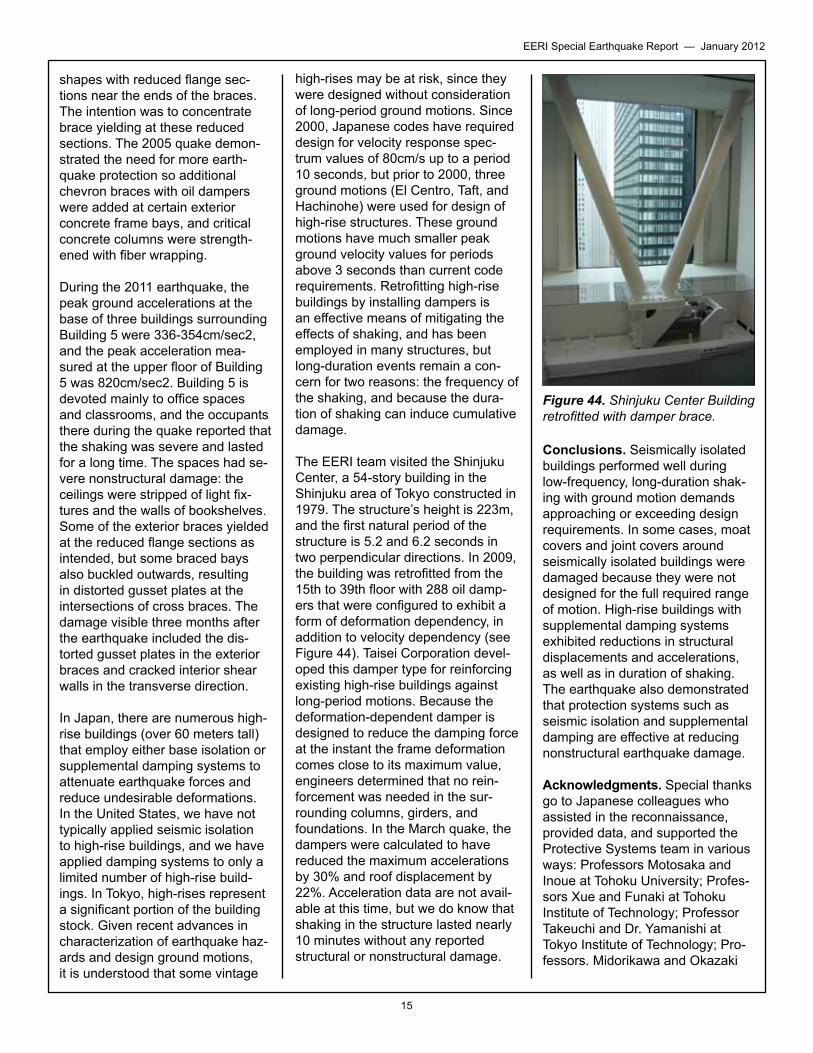
Near Building 10 is an older struc-ture, Building 5, an eight-story structure constructed in 1971 with a force-resisting system consisting of a nonductile concrete frame com- bined with concrete walls in the transverse (N-S) direction. In 1978, the Miyagi-ken-oki earthquake dam-aged the building, which was sub- sequently repaired and strength-ened. The retrofit scheme consisted of steel cross-brace frames located on the exterior of the building in the longitudinal (E-W) direction (see Figure 43). The cross braces were constructed of wide flange steel
Figure 42. Tohoku Institute of Tech-nology Building B10 supplemental damping.
Figure 43. Tohoku Institute of Technology Building 5 with exterior bracing and interior supplemental damping.
15
EERI Special Earthquake Report — January 2012
shapes with reduced flange sec-tions near the ends of the braces. The intention was to concentrate brace yielding at these reduced sections. The 2005 quake demon-strated the need for more earth-quake protection so additional chevron braces with oil dampers were added at certain exterior concrete frame bays, and critical concrete columns were strength-ened with fiber wrapping.
During the 2011 earthquake, the peak ground accelerations at the base of three buildings surrounding Building 5 were 336-354cm/sec2, and the peak acceleration mea-sured at the upper floor of Building 5 was 820cm/sec2. Building 5 is devoted mainly to office spaces and classrooms, and the occupants there during the quake reported that the shaking was severe and lasted for a long time. The spaces had se- vere nonstructural damage: the ceilings were stripped of light fix-tures and the walls of bookshelves. Some of the exterior braces yielded at the reduced flange sections as intended, but some braced bays also buckled outwards, resulting in distorted gusset plates at the intersections of cross braces. The damage visible three months after the earthquake included the dis-torted gusset plates in the exterior braces and cracked interior shear walls in the transverse direction.
In Japan, there are numerous high-rise buildings (over 60 meters tall) that employ either base isolation or supplemental damping systems to attenuate earthquake forces and reduce undesirable deformations. In the United States, we have not typically applied seismic isolation to high-rise buildings, and we have applied damping systems to only a limited number of high-rise build-ings. In Tokyo, high-rises represent a significant portion of the building stock. Given recent advances in characterization of earthquake haz-ards and design ground motions, it is understood that some vintage
high-rises may be at risk, since they were designed without consideration of long-period ground motions. Since 2000, Japanese codes have required design for velocity response spec-trum values of 80cm/s up to a period 10 seconds, but prior to 2000, three ground motions (El Centro, Taft, and Hachinohe) were used for design of high-rise structures. These ground motions have much smaller peak ground velocity values for periods above 3 seconds than current code requirements. Retrofitting high-rise buildings by installing dampers is an effective means of mitigating the effects of shaking, and has been employed in many structures, but long-duration events remain a con-cern for two reasons: the frequency of the shaking, and because the dura-tion of shaking can induce cumulative damage.
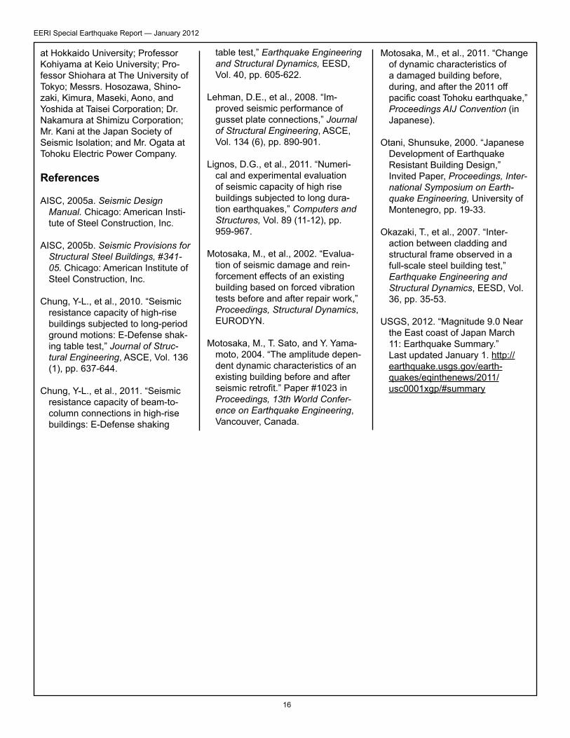
The EERI team visited the Shinjuku Center, a 54-story building in the Shinjuku area of Tokyo constructed in 1979. The structure’s height is 223m, and the first natural period of the structure is 5.2 and 6.2 seconds in two perpendicular directions. In 2009, the building was retrofitted from the 15th to 39th floor with 288 oil damp-ers that were configured to exhibit a form of deformation dependency, in addition to velocity dependency (see Figure 44). Taisei Corporation devel-oped this damper type for reinforcing existing high-rise buildings against long-period motions. Because the deformation-dependent damper is designed to reduce the damping force at the instant the frame deformation comes close to its maximum value, engineers determined that no rein- forcement was needed in the sur-rounding columns, girders, and foundations. In the March quake, the dampers were calculated to have reduced the maximum accelerations by 30% and roof displacement by 22%. Acceleration data are not avail-able at this time, but we do know that shaking in the structure lasted nearly 10 minutes without any reported structural or nonstructural damage.
Conclusions. Seismically isolated buildings performed well during low-frequency, long-duration shak-ing with ground motion demands approaching or exceeding design requirements. In some cases, moat covers and joint covers around seismically isolated buildings were damaged because they were not designed for the full required range of motion. High-rise buildings with supplemental damping systems exhibited reductions in structural displacements and accelerations, as well as in duration of shaking. The earthquake also demonstrated that protection systems such as seismic isolation and supplemental damping are effective at reducing nonstructural earthquake damage.
Acknowledgments. Special thanks go to Japanese colleagues who assisted in the reconnaissance, provided data, and supported the Protective Systems team in various ways: Professors Motosaka and Inoue at Tohoku University; Profes-sors Xue and Funaki at Tohoku Institute of Technology; Professor Takeuchi and Dr. Yamanishi at Tokyo Institute of Technology; Pro-fessors. Midorikawa and Okazaki
Figure 44. Shinjuku Center Building retrofitted with damper brace.
16
EERI Special Earthquake Report — January 2012
at Hokkaido University; Professor Kohiyama at Keio University; Pro-fessor Shiohara at The University of Tokyo; Messrs. Hosozawa, Shino-zaki, Kimura, Maseki, Aono, and Yoshida at Taisei Corporation; Dr. Nakamura at Shimizu Corporation; Mr. Kani at the Japan Society of Seismic Isolation; and Mr. Ogata at Tohoku Electric Power Company.
References
AISC, 2005a. Seismic Design Manual. Chicago: American Insti-tute of Steel Construction, Inc.
AISC, 2005b. Seismic Provisions for
Structural Steel Buildings, #341-05. Chicago: American Institute of Steel Construction, Inc.
Chung, Y-L., et al., 2010. “Seismic resistance capacity of high-rise buildings subjected to long-period ground motions: E-Defense shak-ing table test,” Journal of Struc-tural Engineering, ASCE, Vol. 136 (1), pp. 637-644.
Chung, Y-L., et al., 2011. “Seismic resistance capacity of beam-to-column connections in high-rise buildings: E-Defense shaking
table test,” Earthquake Engineering and Structural Dynamics, EESD, Vol. 40, pp. 605-622.
Lehman, D.E., et al., 2008. “Im- proved seismic performance of gusset plate connections,” Journal of Structural Engineering, ASCE, Vol. 134 (6), pp. 890-901.
Lignos, D.G., et al., 2011. “Numeri-cal and experimental evaluation of seismic capacity of high rise buildings subjected to long dura-tion earthquakes,” Computers and Structures, Vol. 89 (11-12), pp. 959-967.
Motosaka, M., et al., 2002. “Evalua-tion of seismic damage and rein-forcement effects of an existing building based on forced vibration tests before and after repair work,” Proceedings, Structural Dynamics, EURODYN.
Motosaka, M., T. Sato, and Y. Yama-moto, 2004. “The amplitude depen-dent dynamic characteristics of an existing building before and after seismic retrofit.” Paper #1023 in Proceedings, 13th World Confer-ence on Earthquake Engineering, Vancouver, Canada.
Motosaka, M., et al., 2011. “Change of dynamic characteristics of a damaged building before, during, and after the 2011 off pacific coast Tohoku earthquake,” Proceedings AIJ Convention (in Japanese).
Otani, Shunsuke, 2000. “Japanese Development of Earthquake Resistant Building Design,” Invited Paper, Proceedings, Inter-national Symposium on Earth-quake Engineering, University of Montenegro, pp. 19-33.
Okazaki, T., et al., 2007. “Inter-action between cladding and structural frame observed in a full-scale steel building test,” Earthquake Engineering and Structural Dynamics, EESD, Vol. 36, pp. 35-53.
USGS, 2012. “Magnitude 9.0 Near the East coast of Japan March 11: Earthquake Summary.” Last updated January 1. http://earthquake.usgs.gov/earth-quakes/eqinthenews/2011/usc0001xgp/#summary