performance analysis of different haze removal algorithms
TRANSCRIPT
1
Performance Analysis of Different Haze RemovalAlgorithms
V.VENUBABU, M.V. RAGHUNADHDepartment of E and CE, NIT Warangal, INDIA 506004
[email protected], [email protected]
Abstract: Most of the outdoor images are degraded due to bad weather such as strong depth of fog, haze or smoke effects.In such climatic conditions, the captured image will become white and partial gray, due to atmospheric scattering effects.This conditions bring a great deal of inconvenience to the Military and Defence surveillance systems, so the study of hazeremoval algorithm is important. In this paper a modified new haze removal algorithm is proposed using colour resolutionfunction and luminance component of an image. Color resolution function depends upon the YCbCr colour space and variesautomatically based on input haze image and it eliminates the color shift problem present in the luminance component basedhaze removal algorithm. The performance of the proposed method is verified against the other haze removal algorithms usingobjective and subjective quality measures of an image. The applications of different haze removal algorithms are analysedbased on the performance measures.Keyword- Atmospheric scattering model, haze removal algorithms and objective quality measures.
I. INTRODUCTION
Most of the time the quality of the outdoor image isdegraded due to atmospheric weather conditions and scatteringof large number fog, dust or water particles suspended abovethe ground. This fog or haze conditions cause a great deal ofinconvenience to Military and Defence surveillance systems.This conditions directly effect the high level image processingapplications such as face detection, recognition system andoutdoor transportation systems. In order to improve the sta-bility and robustness of a visual system, we require effectivehaze removal algorithms. The depth of the haze is unknownin haze image and it is a challenging problem for removalof an unknown haze depth. Haze removal algorithm is usedto recover a better image from bad weather image and it ishighly desired in computational photography applications. Theair-light is used to recover image from colour shifts after firstlevel of haze removal.There are different techniques for haze removal among whichone is based on image enhancement [1] and the other oneis based on image restoration. There are different image en-hancement techniques for haze removal from the image such ascontrast enhancement, histogram equalization and logarithmictransformation. But, these techniques are independent of hazepresent in the image and results a loss of information afterhaze removal. The physical process of the image was studiedusing image restoration techniques and form a degradationmodel. The haze free image is recovered after inverting thedegradation model without any information loss. Therefore,haze removal based on image restoration is one of the researchfocus over a decade.
The rest of the paper is organized as follows: The de-tailed literature survey is discussed in section II, the basicatmospheric scattering model is discussed in section III , andsection IV explains different haze removal algorithms. Andthen, the results and conclusions were discussed in section
V,VI respectively.
II. LITERATURE SURVEY
To solve the problem of atmospheric illumination effects onoutdoor captured images, haze removal algorithms were stud-ied from decades. The main aim of haze removal algorithmsis to recover better image from atmospherically degraded badhaze image. There are different ways to recover a better imagefrom bad haze image and they are mainly divided into visiblespectrum based analysis [2], [3], polarization of light [4], [5],statistical analysis [6], [7] and dark channel priori [8], [9].Based on the previous work, haze is removed by finding thecolor variations of an image under various weather conditionsproposed in [2] using atmospheric scattering model [10]. Theclear day image was recovered from a set of two or morebad haze images by considering 3D structure of an image andscene colour variations [3]. However, these methods are usedfor fog and dense haze images based on the assumption thatatmospheric light is independent of wavelength over a visiblespectrum. But, in some haze conditions the scattering stronglydepends on the wavelength of received light. Furthermore,this methods result in saturated images when scene and hazecolor are same using dichromatic scattering model. The hazeis removed from the image by taking polarization as a clueproposed in [4]. According to this method haze due to lightpolarization is removed and this method is based on polarizedand un-polarized properties of object radiation and naturalillumination of scattered light respectively. Based on manyworks [5], the image is recovered by assuming the objectradiation as un-polarized and scattering light as partially polar-ized. Based on un-polarized properties of object radiance, mostof the photo enhancement software’s use polarized filters forreducing haze from the landscape and sky images. Accordingto [4], [5] only polarized filters will not provide good resultsfor haze images and this method is limited to mist with skyillumination and dense fog conditions. Based on statistical
2
assumption of maximizing the local contrast of an image forhaze removal is proposed in [6]. According to this methodthe haze free image has higher contrast than haze image.But, increasing the contrast of haze image results in saturatedimages and this method doesn’t consider atmospheric lightcomponent. A haze removal algorithm is proposed in [7] basedon the statistical, correlation property of transmission rateof light and surface shading. This method is based on theassumption of uncorrelated property of target surface shadingand propagation of light and derive the transmission map oflight using the reflectivity of the scene. This method willprovide better results for less haze images and it requires colorinformation of an image. Basically haze image is loss of colourinformation.A new haze removal algorithm is proposed in [8] based onthe assumption of dark channel color priori. According to thisalgorithm the dark channel which contains dark or very smallpixel intensity is estimated. The haze free image is obtainedby combining the optical model of an image and transmissionmap with median filter and this method produce invalid resultswhen object and sky are of same colour. Improved dark chan-nel priori algorithm is proposed in [11] for eliminating the ef-fects of He’s algorithm [8]. This algorithm produces improvedresults by replacing median or soft matting filter with bilateralfilter. An improved transmission formula and weaker methodis used to eliminate the effect of dark channel priori algorithm.Haze removal algorithm based on luminance component of animage is proposed in [12]. According to this algorithm RGBimage is converted into YCbCr colour space and a Multi-ScaleRetinex on luminance component of an image is applied . Thetransmission map is obtained by using luminance componentand median filter. This algorithm is suitable for gray scaleimages and produce color shifts for RGB images. In thispaper a new haze removal algorithm is proposed by usingthe colour resolution function and luminance component of animage. The proposed method effectively eliminates the hazefrom image and colour shifts using colour resolution function.The colour resolution function is calculated based on YCbCrcolour space and this method results a better Peak Signal toNoise Ratio (PSNR).
III. ATMOSPHERIC SCATTERING MODEL
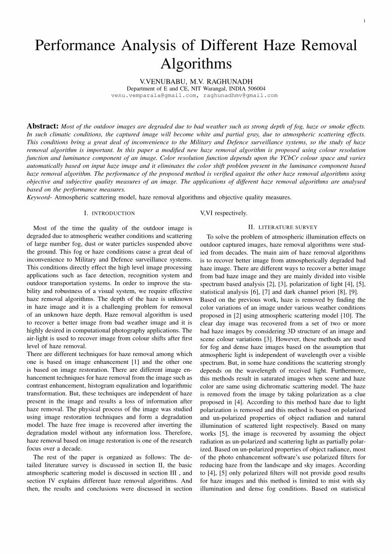
Basically all work in computer vision is based on trans-parent medium such as air. According to this the light raysreflected from the object are received to the observer withoutany attenuation or scattering. The brightness of the imagedepends on the brightness of the actual object. Based on this,present vision systems and algorithms only work for clearday images. A study of atmospheric optics is needed forentire weather conditions such as fog, haze, rain and snowfor recovering the haze free image from haze image. In thissection, a lower order restoration model for haze images isdiscussed. According to Fig.1 the radiance received to theobserver from the scene is divided into direct transmissionand air-light due to water or dust particle suspended abovethe ground. The lower order restoration model shown in Eq.1.
J (x, y) = R (x, y) t (x, y) + (1− (t (x, y)))A (x, y) (1)
Fig. 1. Atmospheric Model of an image
According to the scattering model,image J (x, y) re-ceived by camera sensor is a combination of direct trans-mission R (x, y) t (x, y) and air-light due to scattering(1− (t (x, y)))A (x, y). The maximum radiance of the objectis 1, then the homogeneous atmospheric transmission co-efficient t (x, y) = e−βd(x,y) is transmitted along the directtransmission and remaining radiance is transmitted along theatmospheric global light A (x, y). In atmospheric transmissionco-efficient t (x, y), β is called as atmospheric attenuation co-efficient and d (x, y) is the distance between the object and theobserver. R (x, y) is called as surface radiance vector. If thedistance between the observer and the object is infinity, thenthe image received by the observer is only atmospheric globallight (t (x, y) = e−βd = 0) and distance is very small, thenthe image received by the observer is absolute object radiance(t (x, y) = e−βd = 1).
IV. HAZE REMOVAL ALGORITHMS
In this paper different haze removal algorithms are dis-cussed and along with their flow model. Most of the outdoorimages are degraded due to bad weather conditions. In thisweather conditions the image is partially gray and white,due to atmospheric scattering effects. This conditions bringa great deal of inconvenience to the Military and Defencesurveillance systems, so the study of haze removal algorithmis very important. The main aim of haze removal algorithms isestimating the depth of transmission map. The haze free imageis recovered using transmission map and global air-light.
A. He’s Algorithm
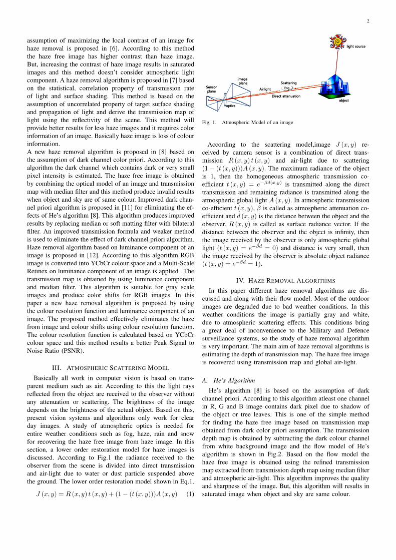
He’s algorithm [8] is based on the assumption of darkchannel priori. According to this algorithm atleast one channelin R, G and B image contains dark pixel due to shadow ofthe object or tree leaves. This is one of the simple methodfor finding the haze free image based on transmission mapobtained from dark color priori assumption. The transmissiondepth map is obtained by subtracting the dark colour channelfrom white background image and the flow model of He’salgorithm is shown in Fig.2. Based on the flow model thehaze free image is obtained using the refined transmissionmap extracted from transmission depth map using median filterand atmospheric air-light. This algorithm improves the qualityand sharpness of the image. But, this algorithm will results insaturated image when object and sky are same colour.
3
Fig. 2. Flow Model of He’s Algorithm
Fig. 3. Flow Model of Improved Dark Channel Priori Algorithm
B. Improved Dark Channel Priori Algorithm
Improved dark channel priori [11] is little modification ofHe’s algorithm. It is also based on the concept of dark channelpriori. This algorithm will eliminate effects present in the He’salgorithm such as when object and sky are same color and itrecover the strong edges by using bilateral filter. Accordingto this haze removal algorithm is a combination of bilateralfilter and dark channel prior. By using atmospheric model anddark channel priori, transmission map of image was derived,and then combining with gray scale image. The refined trans-mission map is extracted from transmission map using fastbilateral filter. The flow model of improved dark channel prioriis shown in Fig.3. This algorithm greatly improves the He’salgorithm [8] in Haze free regions. A improved transmissionformula is used to eliminate dim present in the image. Thisalgorithm greatly restores contrast and colour of the sceneand increase the visual effects of the image. This algorithmworks well for images contain a large sky region with out anydistortions. To increase the adaptability and weaking the skyregions of an image weaker’s method is used.
C. Haze removal algorithm based on Luminance Component
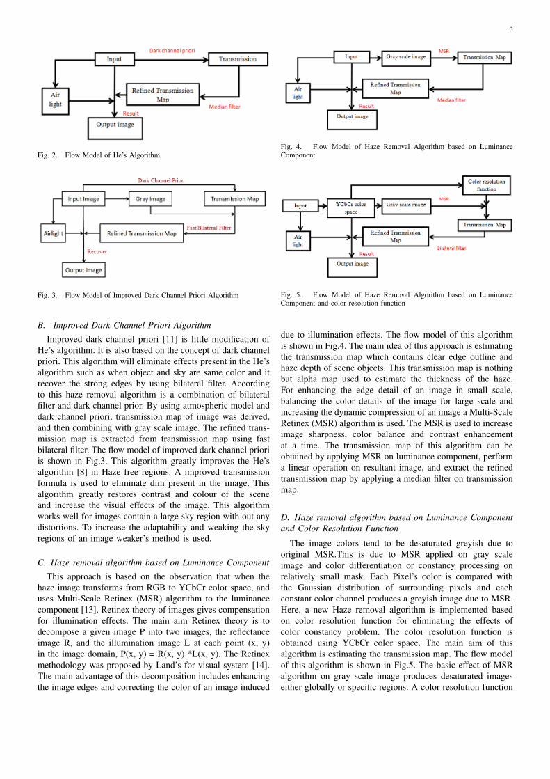
This approach is based on the observation that when thehaze image transforms from RGB to YCbCr color space, anduses Multi-Scale Retinex (MSR) algorithm to the luminancecomponent [13]. Retinex theory of images gives compensationfor illumination effects. The main aim Retinex theory is todecompose a given image P into two images, the reflectanceimage R, and the illumination image L at each point (x, y)in the image domain, P(x, y) = R(x, y) *L(x, y). The Retinexmethodology was proposed by Land’s for visual system [14].The main advantage of this decomposition includes enhancingthe image edges and correcting the color of an image induced
Fig. 4. Flow Model of Haze Removal Algorithm based on LuminanceComponent
Fig. 5. Flow Model of Haze Removal Algorithm based on LuminanceComponent and color resolution function
due to illumination effects. The flow model of this algorithmis shown in Fig.4. The main idea of this approach is estimatingthe transmission map which contains clear edge outline andhaze depth of scene objects. This transmission map is nothingbut alpha map used to estimate the thickness of the haze.For enhancing the edge detail of an image in small scale,balancing the color details of the image for large scale andincreasing the dynamic compression of an image a Multi-ScaleRetinex (MSR) algorithm is used. The MSR is used to increaseimage sharpness, color balance and contrast enhancementat a time. The transmission map of this algorithm can beobtained by applying MSR on luminance component, performa linear operation on resultant image, and extract the refinedtransmission map by applying a median filter on transmissionmap.
D. Haze removal algorithm based on Luminance Componentand Color Resolution Function
The image colors tend to be desaturated greyish due tooriginal MSR.This is due to MSR applied on gray scaleimage and color differentiation or constancy processing onrelatively small mask. Each Pixel’s color is compared withthe Gaussian distribution of surrounding pixels and eachconstant color channel produces a greyish image due to MSR.Here, a new Haze removal algorithm is implemented basedon color resolution function for eliminating the effects ofcolor constancy problem. The color resolution function isobtained using YCbCr color space. The main aim of thisalgorithm is estimating the transmission map. The flow modelof this algorithm is shown in Fig.5. The basic effect of MSRalgorithm on gray scale image produces desaturated imageseither globally or specific regions. A color resolution function
4
is used to recover a good images from desaturated images byproviding color rendition. The algorithm for color resolutionmethod is given below,
Rimcf (x, y) = G ((Ci (x, y) ∗Rmsr) + b) (2)
where
Rmsr =
N∑n=1
Wn (log(Y (x, y))− log[Fn (x, y) ∗ Y (x, y)])
(3)Ci (x, y) = f
[Y
′
i (x, y)]
(4)
is the ith band of color resolution function and Rimcf (x, y)is ith spectral band of MSR. The color resolution function iscombination of Y, Cb and Cr components shown below,
Ci (x, y) = D ∗ Log((H ∗ a1)) (5)
whereD =
(255
Log (a2)
)(6)
H =1
3max
M−1∑i=0
N−1∑j=0
Y (i, j)
(7)
a1 =1
MN
M−1∑i=0
N−1∑j=0
Y (i, j)
(8)
a2 =1
2
M−1∑i=0
N−1∑j=0
Cb (i, j) + Cr (i, j)
(9)
Here the color resolution function is depended on the YCbCrcolour space and varies automatically based on input hazeimage. After applying the color resolution function on MSRimage results greyish image. In order to display the imageproperly with out any logarithmic effects a gain G and offsetb is used. The Haze free image was recovered from air-light of the image and refined transmission map extractedfrom the combination of color resolution function along withMSR on luminance component. This algorithm results betterPeak Signal to Noise Ratio (PSNR) then compared to othermethods and this method is effectively eliminating the colorshifts problem present in the previous algorithm [13].
V. RESULTS AND DISCUSSIONS
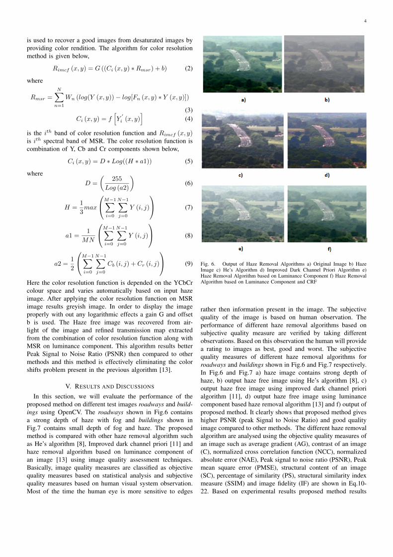
In this section, we will evaluate the performance of theproposed method on different test images roadways and build-ings using OpenCV. The roadways shown in Fig.6 containsa strong depth of haze with fog and buildings shown inFig.7 contains small depth of fog and haze. The proposedmethod is compared with other haze removal algorithm suchas He’s algorithm [8], Improved dark channel priori [11] andhaze removal algorithm based on luminance component ofan image [13] using image quality assessment techniques.Basically, image quality measures are classified as objectivequality measures based on statistical analysis and subjectivequality measures based on human visual system observation.Most of the time the human eye is more sensitive to edges
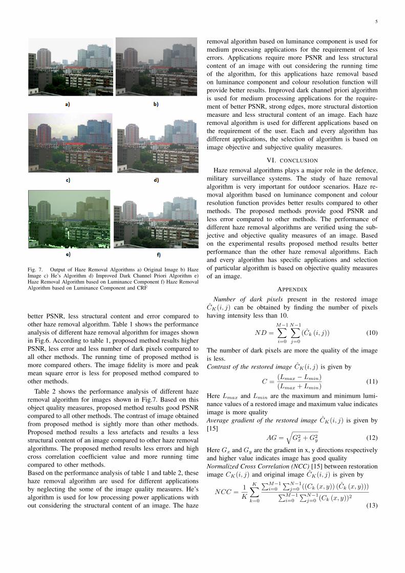
Fig. 6. Output of Haze Removal Algorithms a) Original Image b) HazeImage c) He’s Algorithm d) Improved Dark Channel Priori Algorithm e)Haze Removal Algorithm based on Luminance Component f) Haze RemovalAlgorithm based on Luminance Component and CRF
rather then information present in the image. The subjectivequality of the image is based on human observation. Theperformance of different haze removal algorithms based onsubjective quality measure are verified by taking differentobservations. Based on this observation the human will providea rating to images as best, good and worst. The subjectivequality measures of different haze removal algorithms forroadways and buildings shown in Fig.6 and Fig.7 respectively.In Fig.6 and Fig.7 a) haze image contains strong depth ofhaze, b) output haze free image using He’s algorithm [8], c)output haze free image using improved dark channel priorialgorithm [11], d) output haze free image using luminancecomponent based haze removal algorithm [13] and f) output ofproposed method. It clearly shows that proposed method giveshigher PSNR (peak Signal to Noise Ratio) and good qualityimage compared to other methods. The different haze removalalgorithm are analysed using the objective quality measures ofan image such as average gradient (AG), contrast of an image(C), normalized cross correlation function (NCC), normalizedabsolute error (NAE), Peak signal to noise ratio (PSNR), Peakmean square error (PMSE), structural content of an image(SC), percentage of similarity (PS), structural similarity indexmeasure (SSIM) and image fidelity (IF) are shown in Eq.10-22. Based on experimental results proposed method results
5
Fig. 7. Output of Haze Removal Algorithms a) Original Image b) HazeImage c) He’s Algorithm d) Improved Dark Channel Priori Algorithm e)Haze Removal Algorithm based on Luminance Component f) Haze RemovalAlgorithm based on Luminance Component and CRF
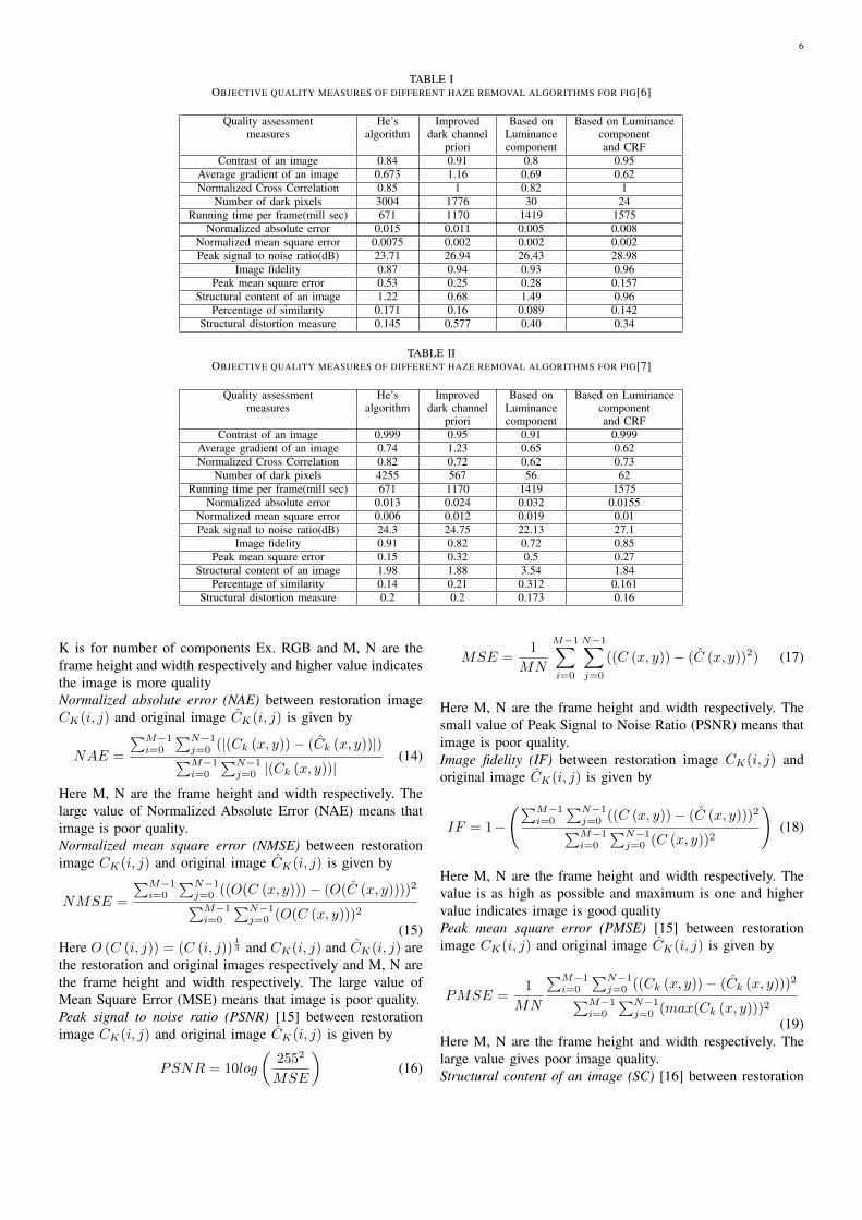
better PSNR, less structural content and error compared toother haze removal algorithm. Table 1 shows the performanceanalysis of different haze removal algorithm for images shownin Fig.6. According to table 1, proposed method results higherPSNR, less error and less number of dark pixels compared toall other methods. The running time of proposed method ismore compared others. The image fidelity is more and peakmean square error is less for proposed method compared toother methods.
Table 2 shows the performance analysis of different hazeremoval algorithm for images shown in Fig.7. Based on thisobject quality measures, proposed method results good PSNRcompared to all other methods. The contrast of image obtainedfrom proposed method is sightly more than other methods.Proposed method results a less artefacts and results a lessstructural content of an image compared to other haze removalalgorithms. The proposed method results less errors and highcross correlation coefficient value and more running timecompared to other methods.Based on the performance analysis of table 1 and table 2, thesehaze removal algorithm are used for different applicationsby neglecting the some of the image quality measures. He’salgorithm is used for low processing power applications without considering the structural content of an image. The haze
removal algorithm based on luminance component is used formedium processing applications for the requirement of lesserrors. Applications require more PSNR and less structuralcontent of an image with out considering the running timeof the algorithm, for this applications haze removal basedon luminance component and colour resolution function willprovide better results. Improved dark channel priori algorithmis used for medium processing applications for the require-ment of better PSNR, strong edges, more structural distortionmeasure and less structural content of an image. Each hazeremoval algorithm is used for different applications based onthe requirement of the user. Each and every algorithm hasdifferent applications, the selection of algorithm is based onimage objective and subjective quality measures.
VI. CONCLUSION
Haze removal algorithms plays a major role in the defence,military surveillance systems. The study of haze removalalgorithm is very important for outdoor scenarios. Haze re-moval algorithm based on luminance component and colourresolution function provides better results compared to othermethods. The proposed methods provide good PSNR andless error compared to other methods. The performance ofdifferent haze removal algorithms are verified using the sub-jective and objective quality measures of an image. Basedon the experimental results proposed method results betterperformance than the other haze removal algorithms. Eachand every algorithm has specific applications and selectionof particular algorithm is based on objective quality measuresof an image.
APPENDIX
Number of dark pixels present in the restored imageCK(i, j) can be obtained by finding the number of pixelshaving intensity less than 10.
ND =
M−1∑i=0
N−1∑j=0
(Ck (i, j)) (10)
The number of dark pixels are more the quality of the imageis less.Contrast of the restored image CK(i, j) is given by
C =(Lmax − Lmin)
(Lmax + Lmin)(11)
Here Lmax and Lmin are the maximum and minimum lumi-nance values of a restored image and maximum value indicatesimage is more qualityAverage gradient of the restored image CK(i, j) is given by[15]
AG =√G2x +G2
y (12)
Here Gx and Gy are the gradient in x, y directions respectivelyand higher value indicates image has good qualityNormalized Cross Correlation (NCC) [15] between restorationimage CK(i, j) and original image CK(i, j) is given by
NCC =1
K
K∑k=0
∑M−1i=0
∑N−1j=0 ((Ck (x, y)) (Ck (x, y)))∑M−1
i=0
∑N−1j=0 (Ck (x, y))2
(13)
6
TABLE IOBJECTIVE QUALITY MEASURES OF DIFFERENT HAZE REMOVAL ALGORITHMS FOR FIG[6]
Quality assessment He’s Improved Based on Based on Luminancemeasures algorithm dark channel Luminance component
priori component and CRFContrast of an image 0.84 0.91 0.8 0.95
Average gradient of an image 0.673 1.16 0.69 0.62Normalized Cross Correlation 0.85 1 0.82 1
Number of dark pixels 3004 1776 30 24Running time per frame(mill sec) 671 1170 1419 1575
Normalized absolute error 0.015 0.011 0.005 0.008Normalized mean square error 0.0075 0.002 0.002 0.002Peak signal to noise ratio(dB) 23.71 26.94 26.43 28.98
Image fidelity 0.87 0.94 0.93 0.96Peak mean square error 0.53 0.25 0.28 0.157
Structural content of an image 1.22 0.68 1.49 0.96Percentage of similarity 0.171 0.16 0.089 0.142
Structural distortion measure 0.145 0.577 0.40 0.34
TABLE IIOBJECTIVE QUALITY MEASURES OF DIFFERENT HAZE REMOVAL ALGORITHMS FOR FIG[7]
Quality assessment He’s Improved Based on Based on Luminancemeasures algorithm dark channel Luminance component
priori component and CRFContrast of an image 0.999 0.95 0.91 0.999
Average gradient of an image 0.74 1.23 0.65 0.62Normalized Cross Correlation 0.82 0.72 0.62 0.73
Number of dark pixels 4255 567 56 62Running time per frame(mill sec) 671 1170 1419 1575
Normalized absolute error 0.013 0.024 0.032 0.0155Normalized mean square error 0.006 0.012 0.019 0.01Peak signal to noise ratio(dB) 24.3 24.75 22.13 27.1
Image fidelity 0.91 0.82 0.72 0.85Peak mean square error 0.15 0.32 0.5 0.27
Structural content of an image 1.98 1.88 3.54 1.84Percentage of similarity 0.14 0.21 0.312 0.161
Structural distortion measure 0.2 0.2 0.173 0.16
K is for number of components Ex. RGB and M, N are theframe height and width respectively and higher value indicatesthe image is more qualityNormalized absolute error (NAE) between restoration imageCK(i, j) and original image CK(i, j) is given by
NAE =
∑M−1i=0
∑N−1j=0 (|(Ck (x, y))− (Ck (x, y))|)∑M−1i=0
∑N−1j=0 |(Ck (x, y))|
(14)
Here M, N are the frame height and width respectively. Thelarge value of Normalized Absolute Error (NAE) means thatimage is poor quality.Normalized mean square error (NMSE) between restorationimage CK(i, j) and original image CK(i, j) is given by
NMSE =
∑M−1i=0
∑N−1j=0 ((O(C (x, y)))− (O(C (x, y))))2∑M−1i=0
∑N−1j=0 (O(C (x, y)))2
(15)Here O (C (i, j)) = (C (i, j))
13 and CK(i, j) and CK(i, j) are
the restoration and original images respectively and M, N arethe frame height and width respectively. The large value ofMean Square Error (MSE) means that image is poor quality.Peak signal to noise ratio (PSNR) [15] between restorationimage CK(i, j) and original image CK(i, j) is given by
PSNR = 10log
(2552
MSE
)(16)
MSE =1
MN
M−1∑i=0
N−1∑j=0
((C (x, y))− (C (x, y))2) (17)
Here M, N are the frame height and width respectively. Thesmall value of Peak Signal to Noise Ratio (PSNR) means thatimage is poor quality.Image fidelity (IF) between restoration image CK(i, j) andoriginal image CK(i, j) is given by
IF = 1−
(∑M−1i=0
∑N−1j=0 ((C (x, y))− (C (x, y)))2∑M−1i=0
∑N−1j=0 (C (x, y))2
)(18)
Here M, N are the frame height and width respectively. Thevalue is as high as possible and maximum is one and highervalue indicates image is good qualityPeak mean square error (PMSE) [15] between restorationimage CK(i, j) and original image CK(i, j) is given by
PMSE =1
MN
∑M−1i=0
∑N−1j=0 ((Ck (x, y))− (Ck (x, y)))2∑M−1
i=0
∑N−1j=0 (max(Ck (x, y)))2
(19)Here M, N are the frame height and width respectively. Thelarge value gives poor image quality.Structural content of an image (SC) [16] between restoration
7
image CK(i, j) and original image CK(i, j) is given by
SC =1
K
K∑k=0
∑M−1i=0
∑N−1j=0 ((Ck (x, y)))2∑M−1
i=0
∑N−1j=0 (Ck (x, y))2
(20)
Here K is for number of components Ex. RGB and M, N arethe frame height and width respectively. The large value ofStructural Content (SC) means that image is poor quality.Percentage of similarity (PS) [17] between restoration imageCK(i, j) and original image CK(i, j) is given by
PS =1
MN
M−1∑i=0
N−1∑j=0
1−2∑Kk=0min
((Ck(i, j)), (Ck(i, j))
)∑Kk=0
((Ck(i, j)) + (Ck(i, j))
)
(21)Here K is for number of components Ex. RGB and M, N arethe frame height and width respectively. This value is as highas possible and higher value indicates image is good qualityStructural distortion measure (Q) or (SSIM) [18] betweenrestoration image CK(i, j) and original image CK(i, j) isgiven by
Q =4σxyxy(
σ2x + σ2
y
)(x2 + y2)
(22)
Here x, y are the mean of original and restoration imagesand σxy is the co-variance between original and restorationimages and σ2
x, σ2y are the variance of original and restoration
images. The maximum value is one and less value of indexwill give poor result.
REFERENCES
[1] R. Gonzalez and E. Richard, “Woods, digital image processing,” ed:Prentice Hall Press, ISBN 0-201-18075-8, 2002.
[2] S. Narasimhan and S. Nayar, “Chromatic framework for vision in badweather,” in Computer Vision and Pattern Recognition, 2000. Proceed-ings. IEEE Conference on, vol. 1. IEEE, 2000, pp. 598–605.
[3] ——, “Vision and the atmosphere,” International Journal of ComputerVision, vol. 48, no. 3, pp. 233–254, 2002.
[4] Y. Schechner, S. Narasimhan, and S. Nayar, “Polarization-based visionthrough haze,” Applied Optics, vol. 42, no. 3, pp. 511–525, 2003.
[5] ——, “Instant dehazing of images using polarization,” in ComputerVision and Pattern Recognition, 2001. CVPR 2001. Proceedings of the2001 IEEE Computer Society Conference on, vol. 1. IEEE, 2001, pp.I–325.
[6] R. Tan, “Visibility in bad weather from a single image,” in ComputerVision and Pattern Recognition, 2008. CVPR 2008. IEEE Conferenceon. IEEE, 2008, pp. 1–8.
[7] R. Fattal, “Single image dehazing,” in ACM Transactions on Graphics(TOG), vol. 27, no. 3. ACM, 2008, p. 72.
[8] K. He, J. Sun, and X. Tang, “Single image haze removal using darkchannel prior,” in Computer Vision and Pattern Recognition, 2009.CVPR 2009. IEEE Conference on. IEEE, 2009, pp. 1956–1963.
[9] M. Chen, A. Men, P. Fan, and B. Yang, “Single image defogging,” inNetwork Infrastructure and Digital Content, 2009. IC-NIDC 2009. IEEEInternational Conference on. IEEE, 2009, pp. 675–679.
[10] S. Nayar and S. Narasimhan, “Vision in bad weather,” in ComputerVision, 1999. The Proceedings of the Seventh IEEE International Con-ference on, vol. 2. IEEE, 1999, pp. 820–827.
[11] H. Xu, J. Guo, Q. Liu, and L. Ye, “Fast image dehazing using improveddark channel prior,” in Information Science and Technology (ICIST),2012 International Conference on. IEEE, 2012, pp. 663–667.
[12] F. Xie and J. Tang, “Automatic image haze removal based on luminancecomponent,” 2010.
[13] K. Barnard, B. Funt et al., “Analysis and improvement of multi-scale retinex,” in Proceedings of the IS&T/SID Fifth Color ImagingConference: Color Science, Systems and Applications, 1997, pp. 221–226.
[14] E. Land, The retinex theory of color vision. Science Center, HarvardUniversity, 1974.
[15] V. Vora, A. Suthar, Y. Makwana, and S. Davda, “Analysis of compressedimage quality assessments.”
[16] N. Rawashdeh, S. Love, and K. Donohue, “Hierarchical image segmen-tation by structural content,” Journal of Software, vol. 3, no. 2, pp.41–51, 2008.
[17] K. Sayood et al., “Statistical evaluation of image quality measures,”Journal of Electronic imaging, vol. 11, no. 2, pp. 206–223, 2002.
[18] N. Damera-Venkata, T. Kite, W. Geisler, B. Evans, and A. Bovik, “Imagequality assessment based on a degradation model,” Image Processing,IEEE Transactions on, vol. 9, no. 4, pp. 636–650, 2000.