pb610-b panel builder 600 | abb
TRANSCRIPT

PB610-B Panel Builder 600Programming Software forCP600-eCo Control Panels
Manual

1 Getting started 1
Assumptions 2
What´s new in comparison to V2.0.0 2
Installing the application 2
2 Runtime 5
Runtimemodes 6
HMI device basic settings 6
Context menu options 7
Built-in SNTP service 10
3 My first project 11
The workspace 12
Creating a project 12
Communication protocols 14
Designing a page 15
TheWidget Gallery 17
Adding tags 19
Exporting tags 21
Importing tags 21
Attaching widget to tags 24
Dialog pages 26
4 Programming concepts 27
Data types 28
"Attach to" parameters 28
Events 32
Widgets positioning 35
Managing overlapping widgets 36
Grouping widgets 37
Changingmultiple widgets properties 38
5 Project properties 39
Project properties pane 40
Developer tools 42
FreeType font rendering 45
Behavior 45
Events 48
6 The HMI simulator 49
Data simulationmethods 50
Simulator settings 50
Launching and stopping the simulator 51
7 Transferring the project to HMI device 53
Download to HMI device 54
Update package 57
The Runtime loader 59
Upload projects 60
8 System Variables 63
Alarms variables 65
Buzzer variables 65
Communication variables 66
Daylight Saving Time variables 66
Device variables 67
Dump information variables 68
Keypad variables 69
Network variables 69
Printing variables 70
Remote Client variables 70
Version variables 71
Screen variables 71
SD card variables 71
Server variables 72
Time variables 72
Touch screen variables 73
Contents
Copyright © 2015-2016 ABB. All rights reserved. Documentation Revision 2.00 - Date of issue: 2016-07-19 I
USB drive variables 74
User management variables 74
9 Actions 77
Alarm actions 78
Event actions 78
MultiLanguage actions 79
Keyboard actions 79
Page actions 81
Print actions 84
Recipe actions 86
Remote Client actions 89
System actions 90
Tag actions 96
Trend actions 98
User management actions 101
Widget actions 103
10 Using the Client application 107
The Client application toolbar 108
Workspace 108
Settings and time zone options 108
Transferring files to a remote HMI device 109
11 Using the integrated FTP server 111
FTP settings 111
12 Alarms 113
Alarms Editor 114
Remote alarms acknowledge 116
Alarm statemachine 116
Setting events 117
Active Alarms widget 119
Alarms History widget 123
Managing alarms at run time 123
Enable/disable alarms at run time 123
Displaying live alarm data 124
Exporting alarm buffers to .csv files 125
Exporting alarm configuration 125
13 Recipes 129
Managing recipes 129
Configuring a recipe widget 132
Recipe status 133
Uploading/downloading a recipe 133
Backup and restore recipes data 134
14 Trends 135
Data logging 136
Exporting trend buffer data 137
Trend widgets 138
History trends 140
Trend widget properties 141
Values outside range or invalid 142
Showing trend values 143
Scatter diagram widget 144
15 Data transfer 147
Data transfer editor 148
Exporting data to .csv files 150
Data transfer limitations and suggestions 150
16 Offline node management 153
Offline nodemanagement process 154
Manual offline nodemanagement process 154
Manual offline configuration 154
Automatic offline node detection 155
17 Multi-language 157
TheMulti-language editor 159
Changing language 160
Multi-language widgets 160
Exporting/importingmulti-language strings 162
Changing language at run time 164
Limitations in Unicode support 164
II Copyright © 2015-2016 ABB. All rights reserved. Documentation Revision 2.00 - Date of issue: 2016-07-19
18 Scheduler 167
Creating a schedule 168
HighResolution schedule 168
Recurring schedule 168
Configuring location for schedules 170
Configuring the Scheduler widget 171
Scheduling events at run time 172
19 User management and passwords 175
Enable/disable security management 176
Configuring groups and authorizations 176
Modifying access permissions 177
Assigning widget permissions from pageview 181
Configuring users 182
Default user 183
Managing users at run time 183
Force remote login 184
20 Audit trails 185
Enable/disable audit trail 186
Configure audit events 186
Configure tags for audit trail 187
Configure alarms for audit trail 188
Configure recipes for audit trail 188
Configure login/logout details 189
Exporting audit trail as .csv files 189
Viewing audit trails 190
21 Reports 191
Adding a report 192
Configuring text reports 192
Configuring graphic reports 193
Print triggering events 194
Default printer 195
22 Screen saver 199
23 Backup/restore of Runtime and project 201
24 Keypads 203
Creating and using custom keypads 204
Deleting or renaming custom keypads 206
Keypad type 206
Keypad position 207
25 External keyboards 209
Search and filter 211
Displayed keys 211
Removing action associations 211
Keyboard layout 212
Enable/disable keyboard 212
Associating actions to keys 212
26 Tag cross reference 215
Updating data in the Tag Cross Referencepane 216
27 Indexed addressing 219
Creating an indexed addressing set 220
Using indexed tag set in pages 223
28 Special widgets 225
DateTimewidget 226
Multistate Image widget 226
Multistate ImageMultilayer widget 227
Combo Box widget 229
ConsumptionMeter widget 230
RSS Feed widget 232
Scrolling RSS Feed widget 233
IPCamera widgets 233
Browser widget 236
Control list widgets 237
Variables widget 239
29 Custom widgets 243
Creating a custom widget 244
Copyright © 2015-2016 ABB. All rights reserved. Documentation Revision 2.00 - Date of issue: 2016-07-19 III
Adding properties to a custom widget 244
Editing custom widgets properties 246
User's Gallery 247
30 Sending an email message 249
Configuring the email server 250
Configure emails 250
31 JavaScript 253
JavaScript editor 255
Execution of JavaScript functions 255
Events 257
Widget events 258
Page events 260
System events 261
Objects 263
Widget class objects 263
Widget properties 264
Widget methods 266
Page object 268
Page object properties 268
Page object methods 269
Group object 271
Group object methods 271
Project object 272
Project object properties 272
Project object methods 272
State object 281
State object methods 282
Keywords 283
Global functions 283
Handling read/write files 284
Limitations in working with widgets inJavaScript 286
Debugging of JavaScript 287
32 System Settings tool 291
UserMode 291
SystemMode 292
33 Updating system components in HMIdevices 295
Display information on connected devices 296
List of upgradable components 296
Update of system components from theapplication 297
Update system components via USB 299
34 Protecting access to HMI devices 301
Changing password 302
Changing password on HMI device 302
Ports and firewalls 303
35 Factory restore 305
36 Tips and tricks to improve performance 307
Static Optimization 308
FAQ on Static Optimization 311
Page caching 312
Image DB 312
Precaching 312
FAQ on precaching 312
37 FAQ 315
Changing fill color property according to tagvalues 315
38 CP600-eCo products 317
The Runtime loader 318
Limitations 320
Converting projects between different HMItypes 323
39 Communication protocols 325
ABB CODESYS Ethernet 326
ABB CODESYS Serial 336
ABB Mint Controller HCP 342
IV Copyright © 2015-2016 ABB. All rights reserved. Documentation Revision 2.00 - Date of issue: 2016-07-19
ABB Modbus RTU 351
ABB Modbus TCP 358
ABB Pluto 364
BACnet 370
CODESYS V2 Ethernet 389
Ethernet/IP CIP 403
Modbus RTU 421
Modbus RTU Server 438
Modbus TCP 455
Modbus TCP Server 472
Simatic S7 Ethernet 483
Copyright © 2015-2016 ABB. All rights reserved. Documentation Revision 2.00 - Date of issue: 2016-07-19 V

VI Copyright © 2015-2016 ABB. All rights reserved. Documentation Revision 2.00 - Date of issue: 2016-07-19
1 Getting startedPB610-B Panel Builder 600 is a software application designed to create graphical HMI pages. PB610-B Panel Builder 600has a drag-and-drop interface that makes it easy to create complex pages. Many of the features found in commonWindowsapplications are also available in PB610-B Panel Builder 600.
This document is divided into chapters that describe the key functions of PB610-B Panel Builder 600 and explain how touse them. Each chapter is presented in a standalonemanner, allowing you to jump from chapter to chapter, depending onthe task at hand.
Assumptions 2
What´s new in comparison to V2.0.0 2
Installing the application 2
Copyright © 2015-2016 ABB. All rights reserved. Documentation Revision 2.00 - Date of issue: 2016-07-19 1
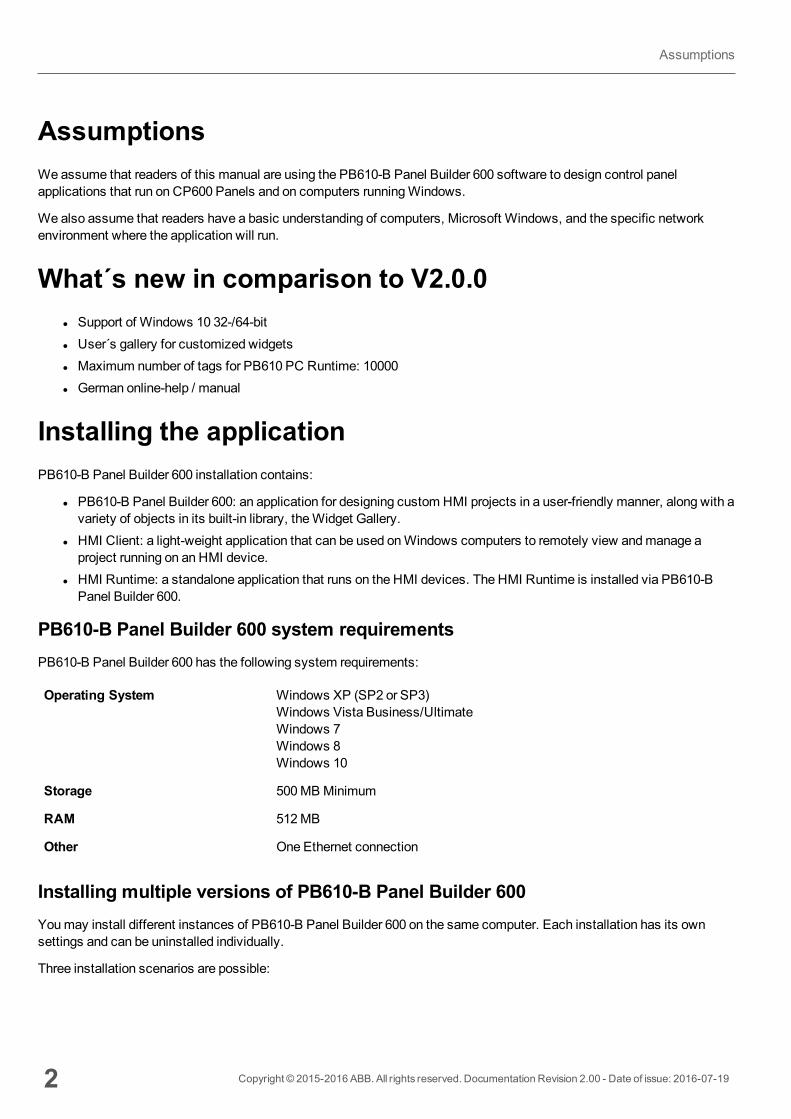
AssumptionsWeassume that readers of this manual are using the PB610-B Panel Builder 600 software to design control panelapplications that run on CP600 Panels and on computers runningWindows.
We also assume that readers have a basic understanding of computers, Microsoft Windows, and the specific networkenvironment where the application will run.
What´s new in comparison to V2.0.0l Support of Windows 10 32-/64-bitl User´s gallery for customized widgetsl Maximum number of tags for PB610 PC Runtime: 10000l German online-help / manual
Installing the applicationPB610-B Panel Builder 600 installation contains:
l PB610-B Panel Builder 600: an application for designing custom HMI projects in a user-friendly manner, along with avariety of objects in its built-in library, theWidget Gallery.
l HMI Client: a light-weight application that can be used onWindows computers to remotely view andmanage aproject running on an HMI device.
l HMI Runtime: a standalone application that runs on the HMI devices. The HMI Runtime is installed via PB610-BPanel Builder 600.
PB610-B Panel Builder 600 system requirementsPB610-B Panel Builder 600 has the following system requirements:
Operating System Windows XP (SP2 or SP3)Windows Vista Business/UltimateWindows 7Windows 8Windows 10
Storage 500MB Minimum
RAM 512MB
Other One Ethernet connection
Installing multiple versions of PB610-B Panel Builder 600Youmay install different instances of PB610-B Panel Builder 600 on the same computer. Each installation has its ownsettings and can be uninstalled individually.
Three installation scenarios are possible:
2 Copyright © 2015-2016 ABB. All rights reserved. Documentation Revision 2.00 - Date of issue: 2016-07-19
Assumptions
Installation scenario Results
First installation of PB610-B Panel Builder 600 in the system Software is installed in the specifieddestination folder
System with only one instance of PB610-B Panel Builder 600already installed
Current version can be replaced ormaintained.
System with multiple instances of PB610-B Panel Builder 600already installed
Last version installed can be replaced ormaintained.
If you try to install a second instance of an already installed version of PB610-B Panel Builder 600, a warningmessage isdisplayed.
Multiple PB610-B Panel Builder 600 installations share a commonworkspace folder, each sub-folder includes the versionnumber, for exampleC:\Program Files\ABB\Panel Builder 600 Basic Suite1.90. Each installed version has its ID and cantherefore be removed individually.
Each installation is listed separately in theWindows Startmenu.
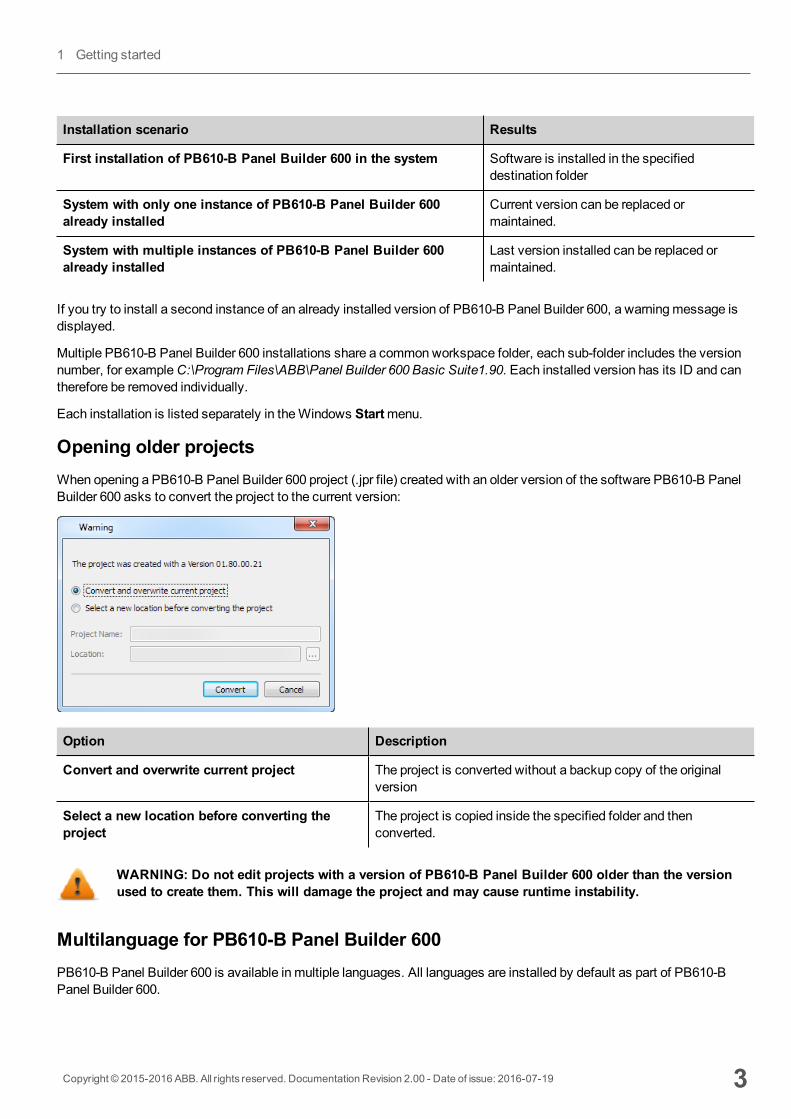
Opening older projectsWhen opening a PB610-B Panel Builder 600 project (.jpr file) created with an older version of the software PB610-B PanelBuilder 600 asks to convert the project to the current version:
Option Description
Convert and overwrite current project The project is converted without a backup copy of the originalversion
Select a new location before converting theproject
The project is copied inside the specified folder and thenconverted.
WARNING: Do not edit projects with a version of PB610-B Panel Builder 600 older than the versionused to create them. This will damage the project and may cause runtime instability.
Multilanguage for PB610-B Panel Builder 600PB610-B Panel Builder 600 is available in multiple languages. All languages are installed by default as part of PB610-BPanel Builder 600.
Copyright © 2015-2016 ABB. All rights reserved. Documentation Revision 2.00 - Date of issue: 2016-07-19 3
1 Getting started

The default language is English. To change it go toHelp > Change Language.
Crash reportsA crash report dialog appears whenever PB610-B Panel Builder 600 freezes or crashs.
Important: Always save crash report files since they may contain useful information for technicalsupport.
Note: Crash reports are unavailable inWindows XP.
4 Copyright © 2015-2016 ABB. All rights reserved. Documentation Revision 2.00 - Date of issue: 2016-07-19
Installing the application
2 RuntimeHMI Runtime is designed to support different platforms and different operating systems.
Runtime modes 6
HMI device basic settings 6
Context menu options 7
Built-in SNTP service 10
Copyright © 2015-2016 ABB. All rights reserved. Documentation Revision 2.00 - Date of issue: 2016-07-19 5
Runtime modesThe HMI Runtime is composed of two logic units:
l Server: runs communication protocols, collects data, monitors alarms, drives trend buffer sampling.l Client: displays data collected by server.
The server unit is responsible for handling the HMI services such as the communication protocols, performing dataacquisition, driving trend buffer sampling activities, monitoring alarms, and so on.
The client unit is the part which is responsible for the visualization process: use the data collected by the server to render iton the display as graphical information.
The server unit works in two operatingmodes:
l Configuration mode: server is idle (for example when no project is loaded on the device or some system files aremissing).
l Operation mode: server is operating according to the settings defined by the system files and by the loadedapplication project.
Note: Data on client may be displayed even if no activity is running on the server.
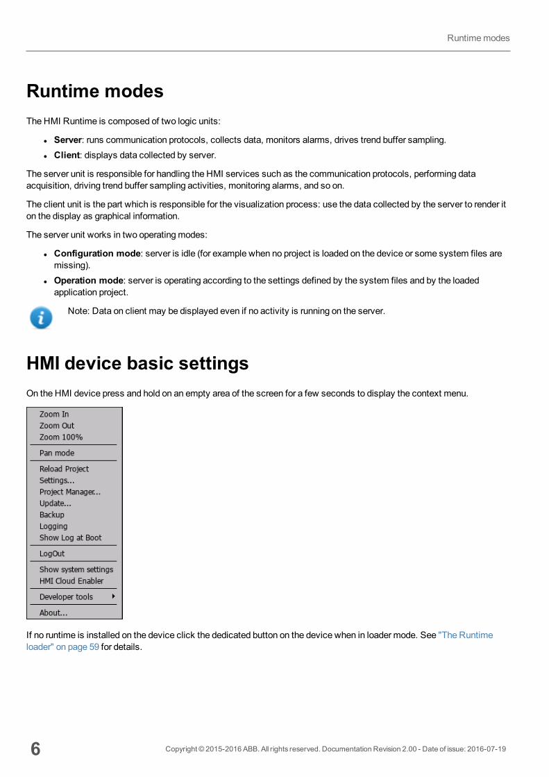
HMI device basic settingsOn the HMI device press and hold on an empty area of the screen for a few seconds to display the context menu.
If no runtime is installed on the device click the dedicated button on the device when in loader mode. See "The Runtimeloader" on page 59 for details.
6 Copyright © 2015-2016 ABB. All rights reserved. Documentation Revision 2.00 - Date of issue: 2016-07-19
Runtimemodes
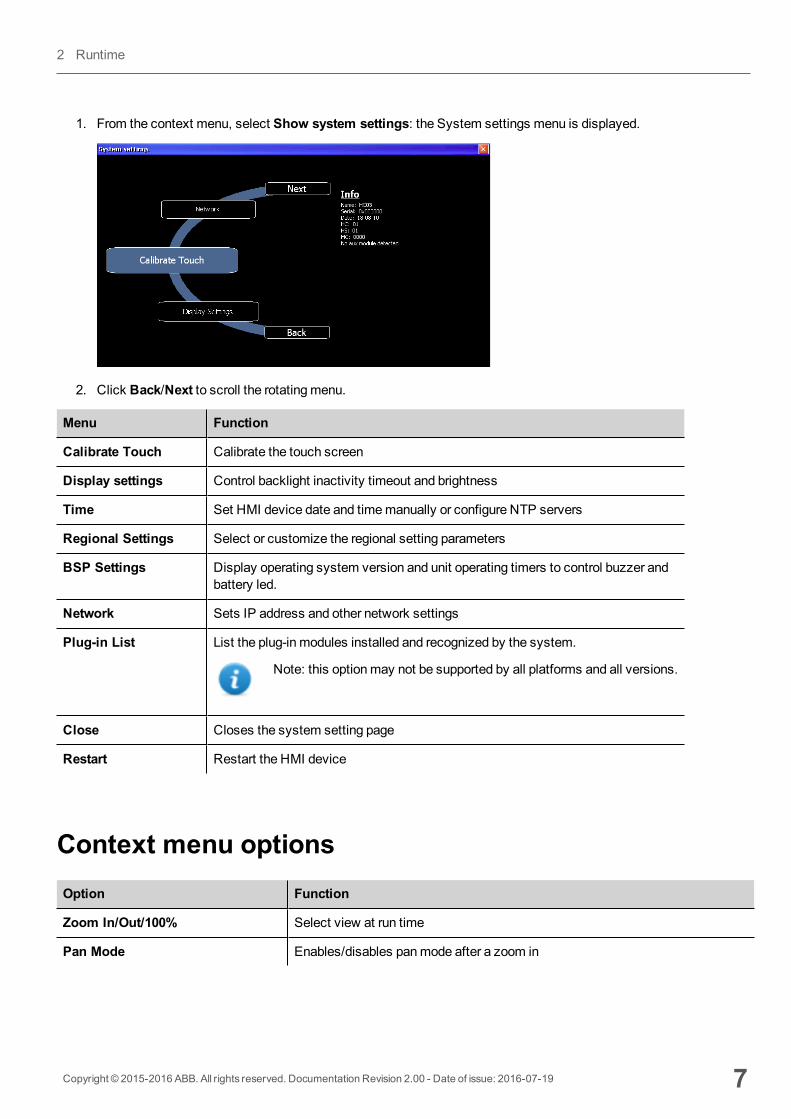
1. From the context menu, select Show system settings: the System settings menu is displayed.
2. Click Back/Next to scroll the rotatingmenu.
Menu Function
Calibrate Touch Calibrate the touch screen
Display settings Control backlight inactivity timeout and brightness
Time Set HMI device date and timemanually or configure NTP servers
Regional Settings Select or customize the regional setting parameters
BSP Settings Display operating system version and unit operating timers to control buzzer andbattery led.
Network Sets IP address and other network settings
Plug-in List List the plug-in modules installed and recognized by the system.
Note: this optionmay not be supported by all platforms and all versions.
Close Closes the system setting page
Restart Restart the HMI device
Context menu optionsOption Function
Zoom In/Out/100% Select view at run time
Pan Mode Enables/disables panmode after a zoom in
Copyright © 2015-2016 ABB. All rights reserved. Documentation Revision 2.00 - Date of issue: 2016-07-19 7
2 Runtime
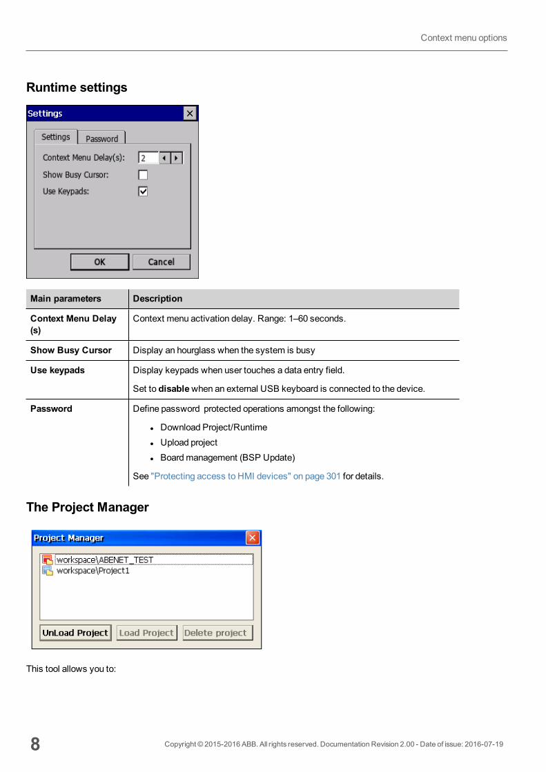
Runtime settings
Main parameters Description
Context Menu Delay(s)
Context menu activation delay. Range: 1–60 seconds.
Show Busy Cursor Display an hourglass when the system is busy
Use keypads Display keypads when user touches a data entry field.
Set to disablewhen an external USB keyboard is connected to the device.
Password Define password protected operations amongst the following:
l Download Project/Runtimel Upload projectl Boardmanagement (BSP Update)
See "Protecting access to HMI devices" on page 301 for details.
The Project Manager
This tool allows you to:
8 Copyright © 2015-2016 ABB. All rights reserved. Documentation Revision 2.00 - Date of issue: 2016-07-19
Context menu options
l unload the current projectl load another projectl delete a project.
When you load a new project, the current project is automatically unloaded. Youmust unload a project before you candelete it.
UpdateThis function loads update packages from an external USB drive. See "Update system components via USB" on page 299for details.
BackupYou can create a backup copy of the Runtime and of the project.
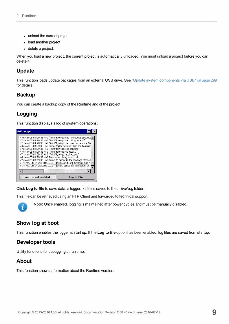
LoggingThis function displays a log of system operations.
Click Log to file to save data: a logger.txt file is saved to the ...\var\log folder.
This file can be retrieved using an FTP Client and forwarded to technical support.
Note: Once enabled, logging is maintained after power cycles andmust bemanually disabled.
Show log at bootThis function enables the logger at start up. If the Log to file option has been enabled, log files are saved from startup.
Developer toolsUtility functions for debugging at run time.
AboutThis function shows information about the Runtime version.
Copyright © 2015-2016 ABB. All rights reserved. Documentation Revision 2.00 - Date of issue: 2016-07-19 9
2 Runtime
WARNING: Context Menu action has no effect if executed from a dialog page.
Built-in SNTP serviceThe HMI device features an integrated SNTP that synchronizes the internal real-time clock panel whenever the predefinedserver is available.
The system searches for the following servers when turned on, or once a week if the HMI device is not turned off:
l time.windows.coml tock.usno.navy.mil
Important: Server addresses are hard-coded and cannot be changed by the user.
Customizing SNTP serversPath: from the context menu > System Settings> Time> SNTP
Availability: BSP v1.76 ARM / 2.79MIPS or higher
You can customize up to two SNTP servers.
Note: This function is not available in ConfigurationMode (ConfigOS).
10 Copyright © 2015-2016 ABB. All rights reserved. Documentation Revision 2.00 - Date of issue: 2016-07-19
Built-in SNTP service
3 My first projectThis section describes how to create a simple PB610-B Panel Builder 600 project.
The workspace 12
Creating a project 12
Communication protocols 14
Designing a page 15
The Widget Gallery 17
Adding tags 19
Exporting tags 21
Importing tags 21
Attaching widget to tags 24
Dialog pages 26
Copyright © 2015-2016 ABB. All rights reserved. Documentation Revision 2.00 - Date of issue: 2016-07-19 11

The workspaceWorkspace areasPB610-B Panel Builder 600 workspace is divided into the followingmain areas:
Area Description
Project View Project elements in hierarchical project tree.
Object View Tree view of widgets organized by page.
Working Area Space where pages are edited. Tabs at the top of the area show all open pages.
Properties Properties of selected object.
Widget Gallery Library of graphic objects and symbols.
Tag cross reference List of locations where a given tag is referenced.
Note: The workspace layout can be changed at any time, changes are saved andmaintained through workingsessions.
Resetting the workspace layoutTo restore the default layout, use the File > Reset and Restart function.
Creating a projectPath: File> New Project
12 Copyright © 2015-2016 ABB. All rights reserved. Documentation Revision 2.00 - Date of issue: 2016-07-19
The workspace
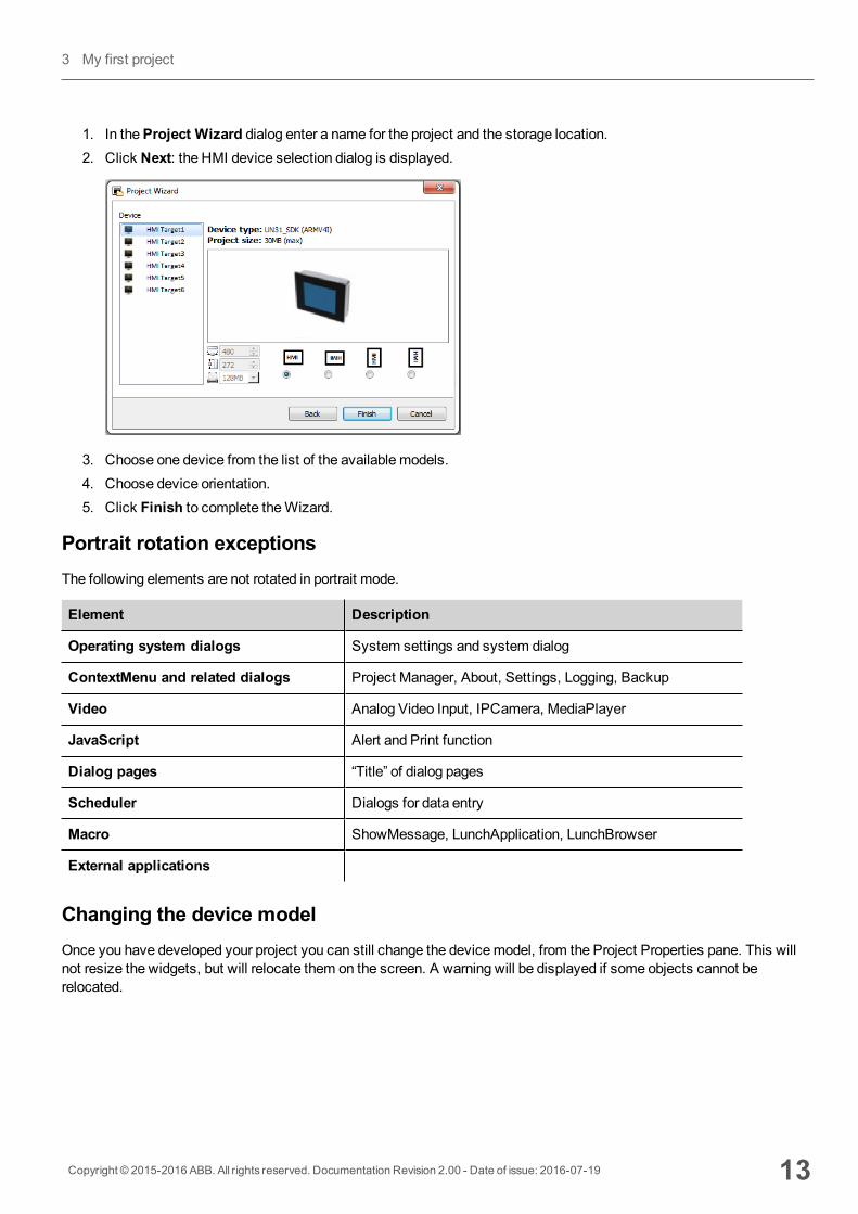
1. In theProject Wizard dialog enter a name for the project and the storage location.2. Click Next: the HMI device selection dialog is displayed.
3. Choose one device from the list of the available models.4. Choose device orientation.5. Click Finish to complete theWizard.
Portrait rotation exceptionsThe following elements are not rotated in portrait mode.
Element Description
Operating system dialogs System settings and system dialog
ContextMenu and related dialogs Project Manager, About, Settings, Logging, Backup
Video Analog Video Input, IPCamera, MediaPlayer
JavaScript Alert and Print function
Dialog pages “Title” of dialog pages
Scheduler Dialogs for data entry
Macro ShowMessage, LunchApplication, LunchBrowser
External applications
Changing the device modelOnce you have developed your project you can still change the devicemodel, from the Project Properties pane. This willnot resize the widgets, but will relocate them on the screen. A warning will be displayed if some objects cannot berelocated.
Copyright © 2015-2016 ABB. All rights reserved. Documentation Revision 2.00 - Date of issue: 2016-07-19 13
3 My first project
Copying, moving, renaming a projectPB610-B Panel Builder 600 projects folder contain all the files of the project: to move, copy or backup a project, move orcopy the project folder to the desired location.
To rename a project use the File > Save Project As function: this operationmight take a few minutes.
WARNING: Do not rename the project folders manually.
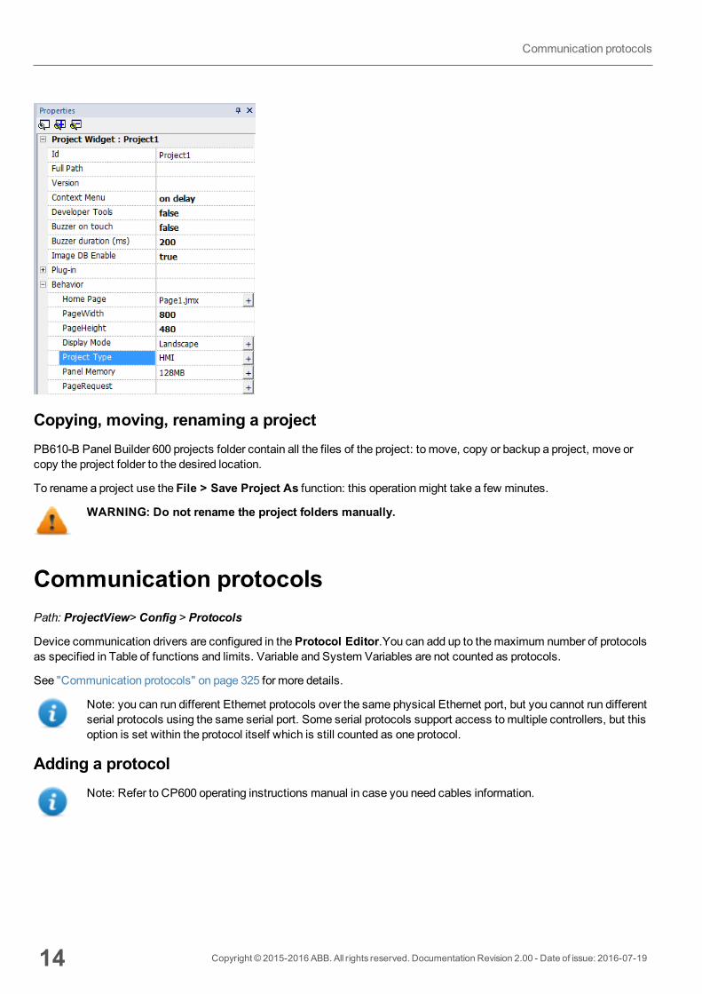
Communication protocolsPath: ProjectView> Config > Protocols
Device communication drivers are configured in theProtocol Editor.You can add up to themaximum number of protocolsas specified in Table of functions and limits. Variable and System Variables are not counted as protocols.
See "Communication protocols" on page 325 for more details.
Note: you can run different Ethernet protocols over the same physical Ethernet port, but you cannot run differentserial protocols using the same serial port. Some serial protocols support access tomultiple controllers, but thisoption is set within the protocol itself which is still counted as one protocol.
Adding a protocolNote: Refer to CP600 operating instructions manual in case you need cables information.
14 Copyright © 2015-2016 ABB. All rights reserved. Documentation Revision 2.00 - Date of issue: 2016-07-19
Communication protocols
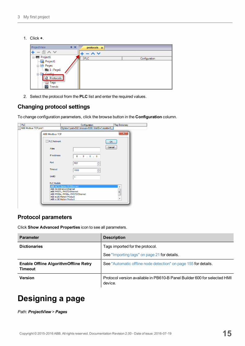
1. Click +.
2. Select the protocol from thePLC list and enter the required values.
Changing protocol settingsTo change configuration parameters, click the browse button in theConfiguration column.
Protocol parametersClick Show Advanced Properties icon to see all parameters.
Parameter Description
Dictionaries Tags imported for the protocol.
See "Importing tags" on page 21 for details.
Enable Offline AlgorithmOffline RetryTimeout
See "Automatic offline node detection" on page 155 for details.
Version Protocol version available in PB610-B Panel Builder 600 for selected HMIdevice.
Designing a pagePath: ProjectView > Pages
Copyright © 2015-2016 ABB. All rights reserved. Documentation Revision 2.00 - Date of issue: 2016-07-19 15
3 My first project
When a project is created, the first page is automatically added and shown in thePage Editor.
Adding objects to a pageDrag and drop objects fromWidget Gallery to the page.
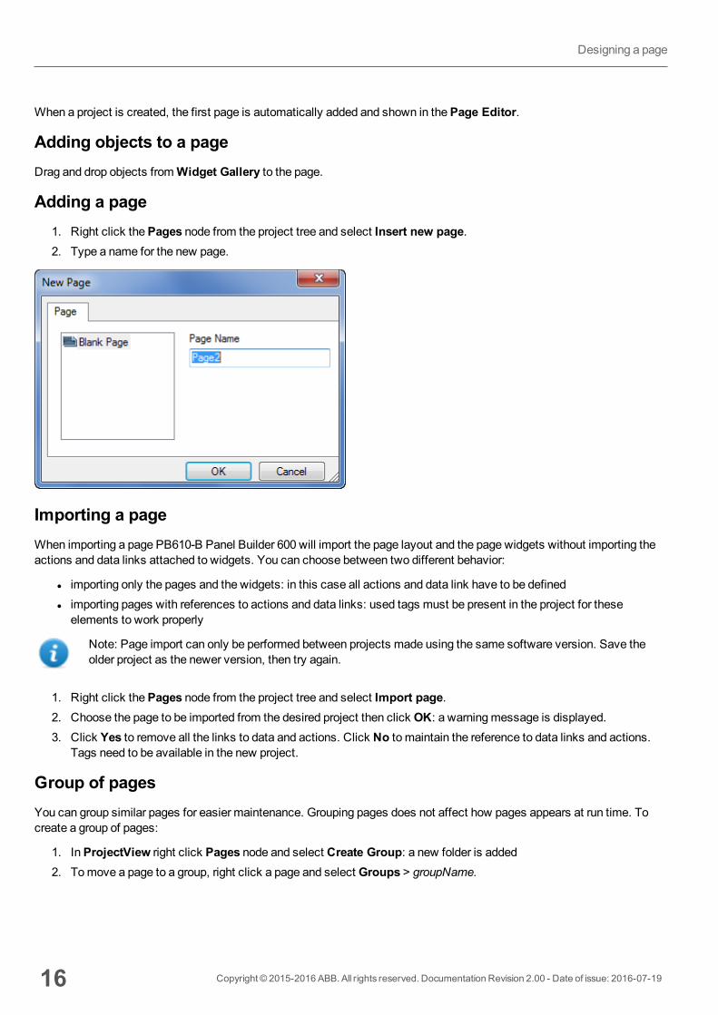
Adding a page1. Right click thePages node from the project tree and select Insert new page.2. Type a name for the new page.
Importing a pageWhen importing a page PB610-B Panel Builder 600 will import the page layout and the page widgets without importing theactions and data links attached to widgets. You can choose between two different behavior:
l importing only the pages and the widgets: in this case all actions and data link have to be definedl importing pages with references to actions and data links: used tags must be present in the project for theseelements to work properly
Note: Page import can only be performed between projects made using the same software version. Save theolder project as the newer version, then try again.
1. Right click thePages node from the project tree and select Import page.2. Choose the page to be imported from the desired project then click OK: a warningmessage is displayed.3. Click Yes to remove all the links to data and actions. Click No to maintain the reference to data links and actions.
Tags need to be available in the new project.
Group of pagesYou can group similar pages for easier maintenance. Grouping pages does not affect how pages appears at run time. Tocreate a group of pages:
1. InProjectView right click Pages node and select Create Group: a new folder is added2. Tomove a page to a group, right click a page and select Groups > groupName.
16 Copyright © 2015-2016 ABB. All rights reserved. Documentation Revision 2.00 - Date of issue: 2016-07-19
Designing a page
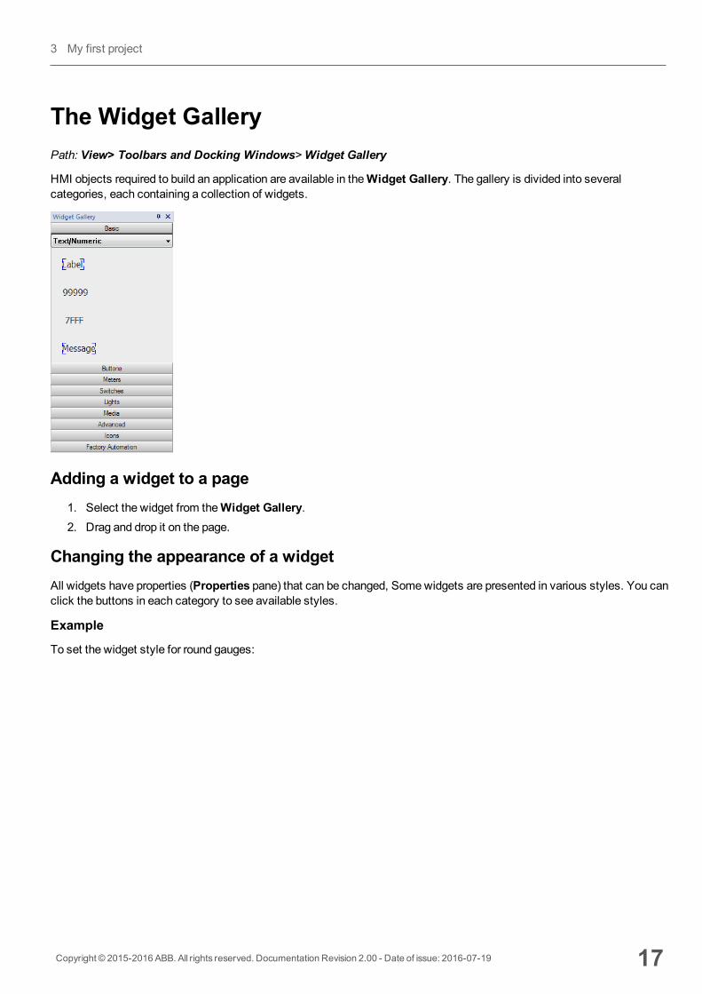
The Widget GalleryPath: View> Toolbars and Docking Windows>Widget Gallery
HMI objects required to build an application are available in theWidget Gallery. The gallery is divided into severalcategories, each containing a collection of widgets.
Adding a widget to a page1. Select the widget from theWidget Gallery.2. Drag and drop it on the page.
Changing the appearance of a widgetAll widgets have properties (Properties pane) that can be changed, Somewidgets are presented in various styles. You canclick the buttons in each category to see available styles.
Example
To set the widget style for round gauges:
Copyright © 2015-2016 ABB. All rights reserved. Documentation Revision 2.00 - Date of issue: 2016-07-19 17
3 My first project
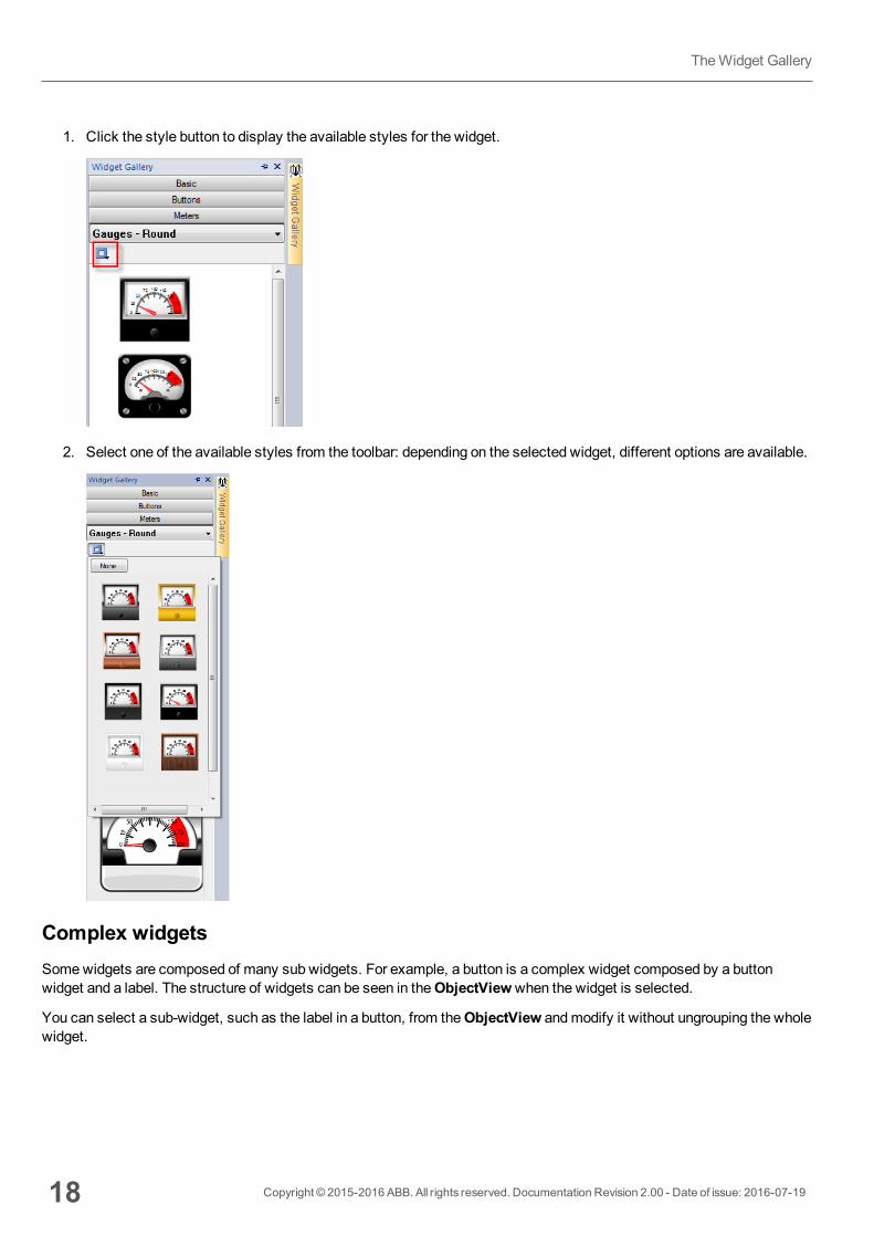
1. Click the style button to display the available styles for the widget.
2. Select one of the available styles from the toolbar: depending on the selected widget, different options are available.
Complex widgetsSomewidgets are composed of many sub widgets. For example, a button is a complex widget composed by a buttonwidget and a label. The structure of widgets can be seen in theObjectViewwhen the widget is selected.
You can select a sub-widget, such as the label in a button, from theObjectView andmodify it without ungrouping the wholewidget.
18 Copyright © 2015-2016 ABB. All rights reserved. Documentation Revision 2.00 - Date of issue: 2016-07-19
TheWidget Gallery
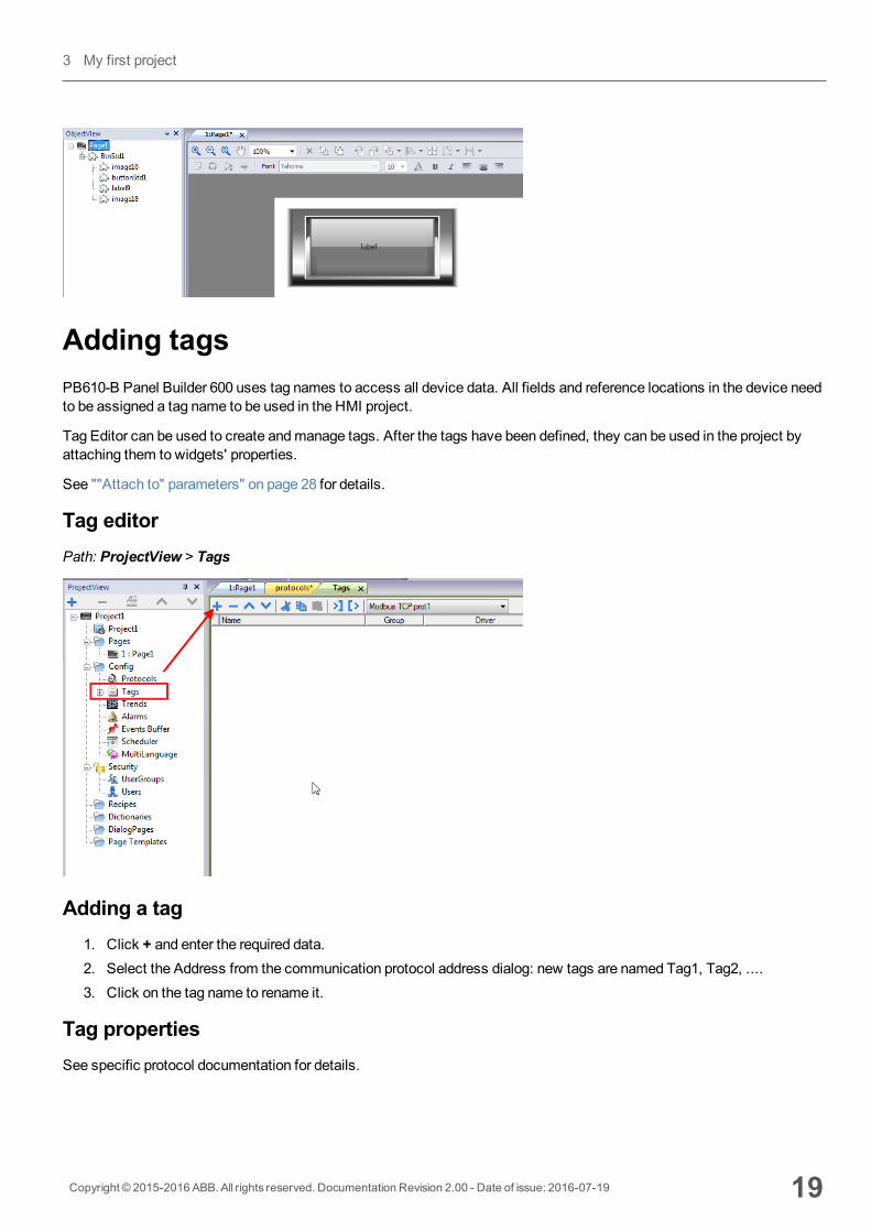
Adding tagsPB610-B Panel Builder 600 uses tag names to access all device data. All fields and reference locations in the device needto be assigned a tag name to be used in the HMI project.
Tag Editor can be used to create andmanage tags. After the tags have been defined, they can be used in the project byattaching them to widgets' properties.
See ""Attach to" parameters" on page 28 for details.
Tag editorPath: ProjectView > Tags
Adding a tag1. Click + and enter the required data.2. Select the Address from the communication protocol address dialog: new tags are named Tag1, Tag2, ....3. Click on the tag name to rename it.
Tag propertiesSee specific protocol documentation for details.
Copyright © 2015-2016 ABB. All rights reserved. Documentation Revision 2.00 - Date of issue: 2016-07-19 19
3 My first project

Property Description
Name Unique tag name at project level. Primary key to identify information in the runtime tag database.
WARNING: Duplicate tag names are not allowed.
Groups Group names associated to a tag
Driver Communication protocol
Address Controller memory address.
To edit click on the right side of the column to get the dialog box where you can enter the addressinformation.
Encoding Encoding type for string data type (UTF-8, Latin1, UTF-2 and UTF-16)
Comment Tag description
Simulator Tag behavior during simulation. Several profiles are available.
Scaling Conversion applied to tag before database storage.
By formula = defined as a linear transformation.
By range = defined as a range conversion.
The below properties will be visible only after select the “Show Advance Columns” mode from the tag editor tollbar..
Property Description
PLCTagName
Original PLC tag name, used tomatch tags used by HMI application (Tag Name) and tags exported from PLC
R/W only in advanced view to allow for adjustments in case tag import errors.
Rate(ms)
Tag refresh time. Default: 500ms.
WARNING: Tags refresh rate is the maximum refresh rate. Actual refresh rate depends on:communication type (serial, fieldbus, Ethernet), protocol, amount of data exchanged.
R/W R/W tag attribute (R/W, R orW).
Note: The content of Write Only tags is always written and never read. When communication is notactive, the content of these tags may not be available in widgets.
Active Updatemode.
false = tags are read from controller only when required by the HMI device.
true = tags are continuously read even if not required by the displayed page.
Important: Leave this value set to false for higher communication performance.
20 Copyright © 2015-2016 ABB. All rights reserved. Documentation Revision 2.00 - Date of issue: 2016-07-19
Adding tags
Managing tag namesTag names must be unique at project level. If the same tags, from the same symbol file have to be used for two differentcontrollers, use the “Alias” feature to add a prefix to the imported tags andmake them unique at project level.
Note: Not all protocols support the “Alias” feature.
See "Communication protocols" on page 325 for details.
Managing tag groupsTags used in each page are identified as part of a group, so that requests made by the communication protocol to theconnected controller(s) can be processed faster: only the tags included in the displayed page are polled from the controller.
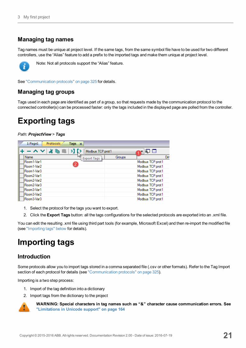
Exporting tagsPath: ProjectView > Tags
1. Select the protocol for the tags you want to export.2. Click theExport Tags button: all the tags configurations for the selected protocols are exported into an .xml file.
You can edit the resulting .xml file using third part tools (for example, Microsoft Excel) and then re-import themodified file(see "Importing tags" below for details).
Importing tagsIntroductionSome protocols allow you to import tags stored in a comma separated file (.csv or other formats). Refer to the Tag Importsection of each protocol for details (see "Communication protocols" on page 325).
Importing is a two step process:
1. Import of the tag definition into a dictionary2. Import tags from the dictionary to the project
WARNING: Special characters in tag names such as “&” character cause communication errors. See"Limitations in Unicode support" on page 164
Copyright © 2015-2016 ABB. All rights reserved. Documentation Revision 2.00 - Date of issue: 2016-07-19 21
3 My first project
Note: When importing tags, character "." in tag names is replaced with "/" . The protocol will use the correctsyntax when communicating to the PLC.
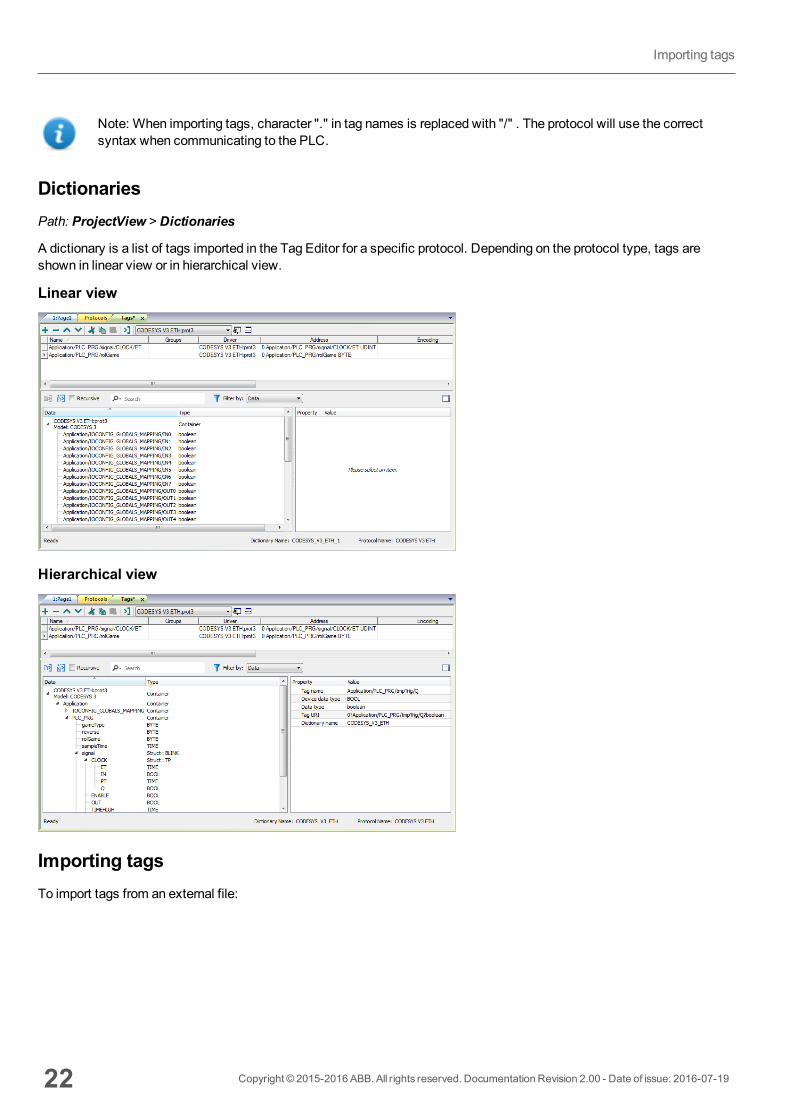
DictionariesPath: ProjectView > Dictionaries
A dictionary is a list of tags imported in the Tag Editor for a specific protocol. Depending on the protocol type, tags areshown in linear view or in hierarchical view.
Linear view
Hierarchical view
Importing tagsTo import tags from an external file:
22 Copyright © 2015-2016 ABB. All rights reserved. Documentation Revision 2.00 - Date of issue: 2016-07-19
Importing tags
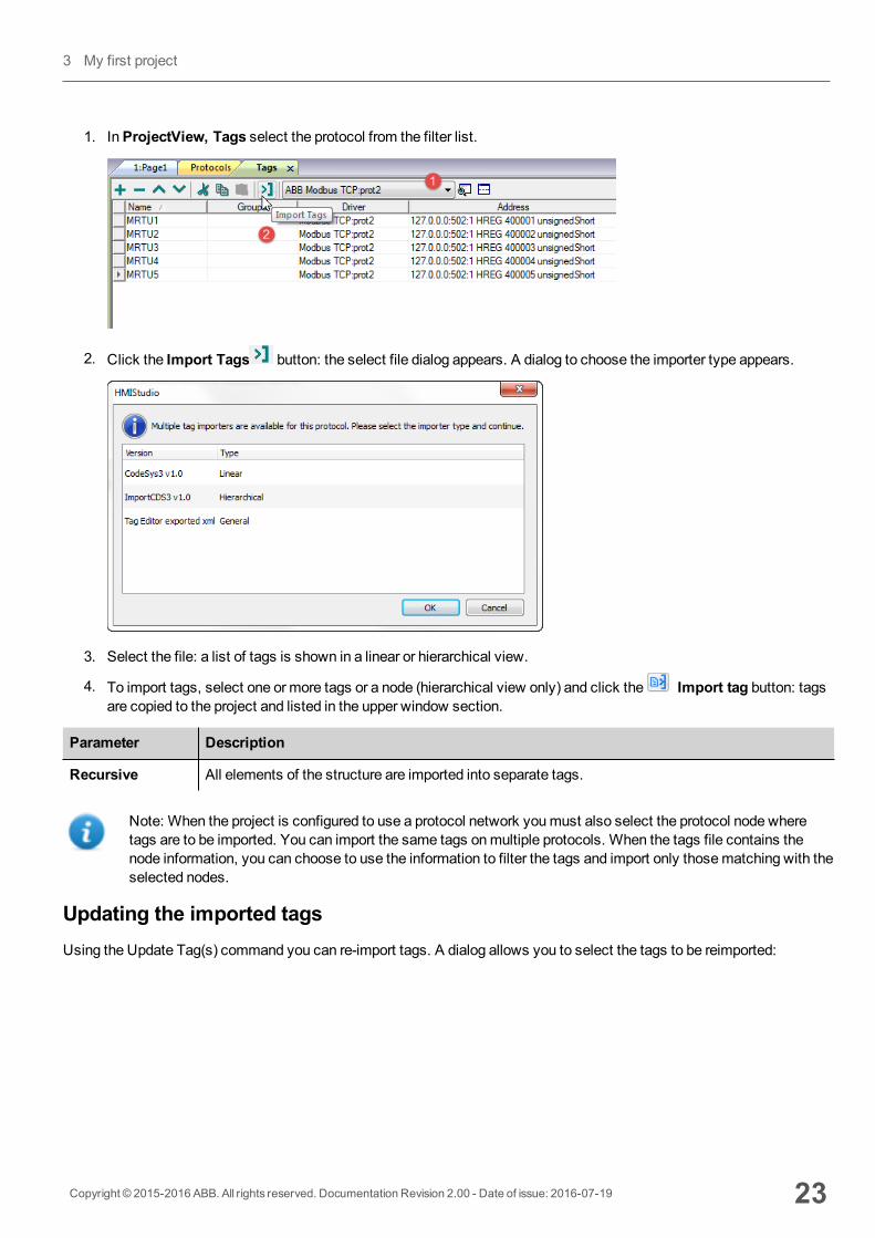
1. InProjectView, Tags select the protocol from the filter list.
2. Click the Import Tags button: the select file dialog appears. A dialog to choose the importer type appears.
3. Select the file: a list of tags is shown in a linear or hierarchical view.
4. To import tags, select one or more tags or a node (hierarchical view only) and click the Import tag button: tagsare copied to the project and listed in the upper window section.
Parameter Description
Recursive All elements of the structure are imported into separate tags.
Note: When the project is configured to use a protocol network youmust also select the protocol node wheretags are to be imported. You can import the same tags onmultiple protocols. When the tags file contains thenode information, you can choose to use the information to filter the tags and import only thosematching with theselected nodes.
Updating the imported tagsUsing the Update Tag(s) command you can re-import tags. A dialog allows you to select the tags to be reimported:
Copyright © 2015-2016 ABB. All rights reserved. Documentation Revision 2.00 - Date of issue: 2016-07-19 23
3 My first project
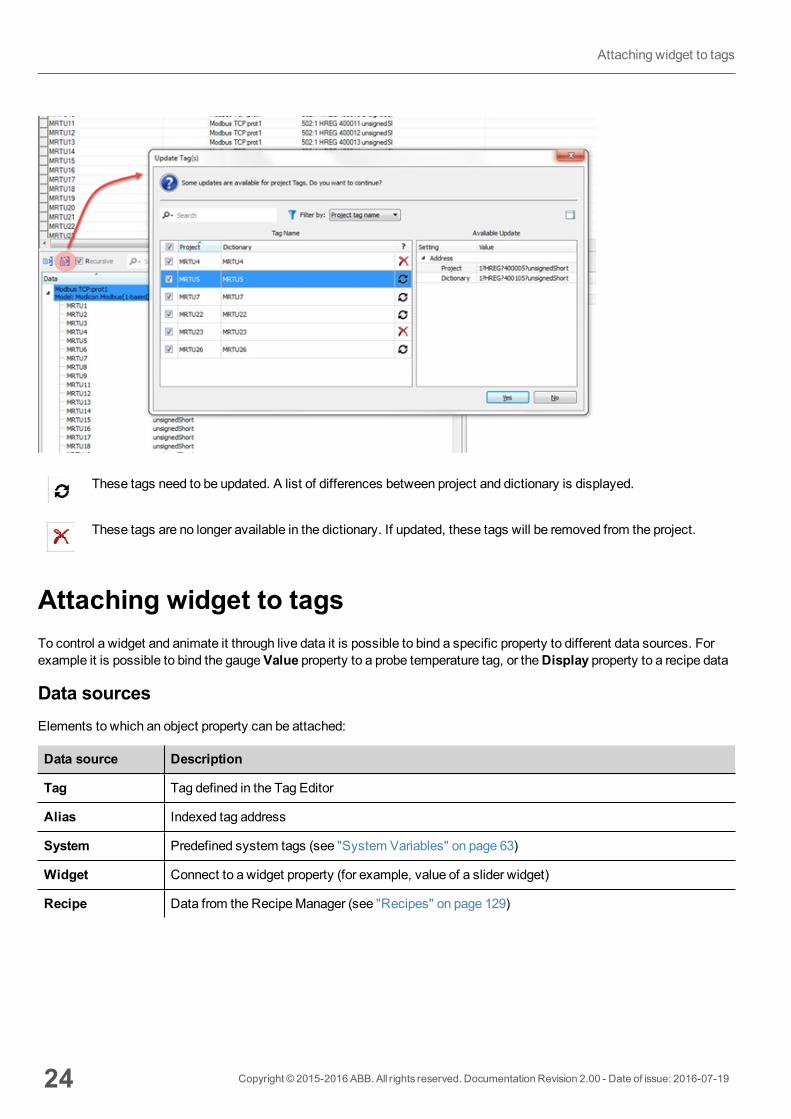
These tags need to be updated. A list of differences between project and dictionary is displayed.
These tags are no longer available in the dictionary. If updated, these tags will be removed from the project.
Attaching widget to tagsTo control a widget and animate it through live data it is possible to bind a specific property to different data sources. Forexample it is possible to bind the gaugeValue property to a probe temperature tag, or theDisplay property to a recipe data
Data sourcesElements to which an object property can be attached:
Data source Description
Tag Tag defined in the Tag Editor
Alias Indexed tag address
System Predefined system tags (see "System Variables" on page 63)
Widget Connect to a widget property (for example, value of a slider widget)
Recipe Data from the RecipeManager (see "Recipes" on page 129)
24 Copyright © 2015-2016 ABB. All rights reserved. Documentation Revision 2.00 - Date of issue: 2016-07-19
Attaching widget to tags

Attaching a property to a tag1. Click + in theProperties pane.2. InSource choose the data source, in the list choose a protocol and the tag. Use theSearch box to filter tags.
3. Set the access type (for exampleRead Only). TheArray Index field appears when the selected tag is an array toidentify the element of the array to use. The indirect index mode, through an additional tag, is supported.
4. Click OK to confirm.
The icons adjacent to the tag name highlight when a definition does not match the tag definition in the dictionary, or whenmissing. If theShow all tags is selected, all the dictionary tags are shown also if not imported within the application. Adouble-click will import the tags from the dictionary.
See ""Attach to" parameters" on page 28 for details.
Communication ErrorTwo icons may appear close to widgets that have an attached tag.
Copyright © 2015-2016 ABB. All rights reserved. Documentation Revision 2.00 - Date of issue: 2016-07-19 25
3 My first project
l : communication error
l : data not yet available (slow communication protocol)
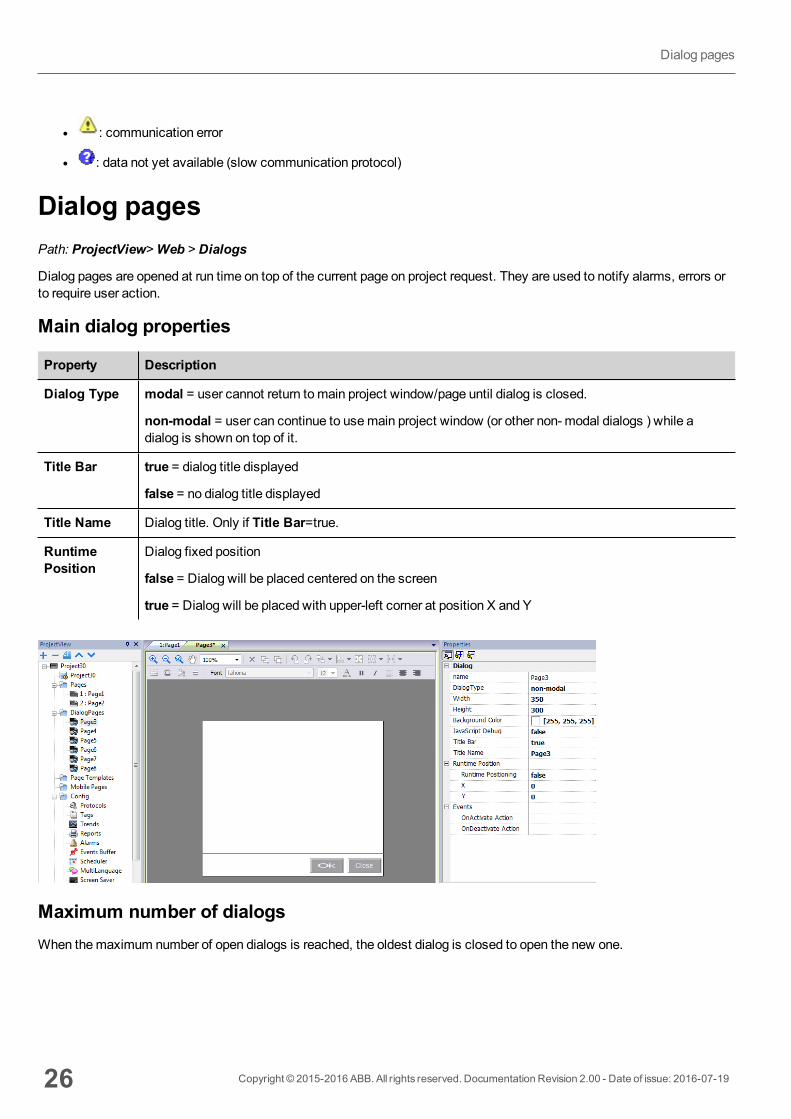
Dialog pagesPath: ProjectView>Web > Dialogs
Dialog pages are opened at run time on top of the current page on project request. They are used to notify alarms, errors orto require user action.
Main dialog properties
Property Description
Dialog Type modal = user cannot return tomain project window/page until dialog is closed.
non-modal = user can continue to usemain project window (or other non- modal dialogs ) while adialog is shown on top of it.
Title Bar true = dialog title displayed
false = no dialog title displayed
Title Name Dialog title. Only if Title Bar=true.
RuntimePosition
Dialog fixed position
false = Dialog will be placed centered on the screen
true = Dialog will be placed with upper-left corner at position X and Y
Maximum number of dialogsWhen themaximum number of open dialogs is reached, the oldest dialog is closed to open the new one.
26 Copyright © 2015-2016 ABB. All rights reserved. Documentation Revision 2.00 - Date of issue: 2016-07-19
Dialog pages
4 Programming conceptsProgramming for PB610-B Panel Builder 600 is based on a few basic concepts and behaviors.
Data types 28
"Attach to" parameters 28
Events 32
Widgets positioning 35
Managing overlapping widgets 36
Grouping widgets 37
Changing multiple widgets properties 38
Copyright © 2015-2016 ABB. All rights reserved. Documentation Revision 2.00 - Date of issue: 2016-07-19 27
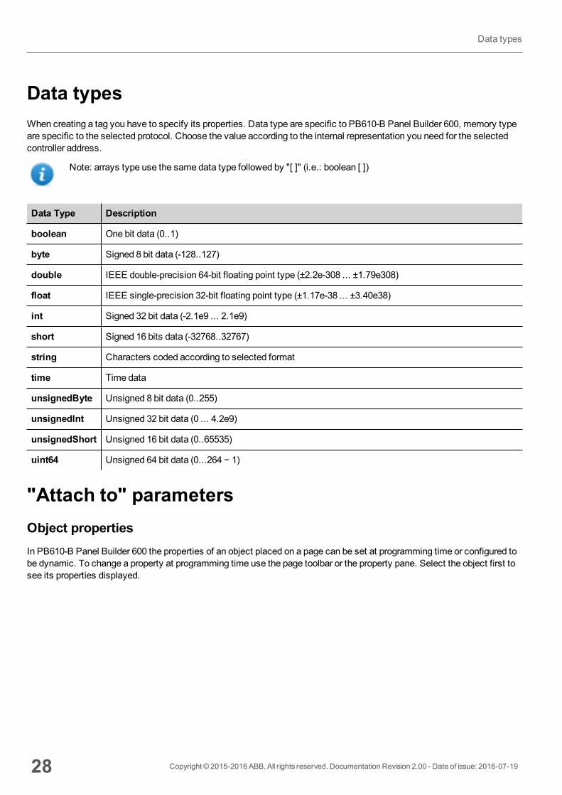
Data typesWhen creating a tag you have to specify its properties. Data type are specific to PB610-B Panel Builder 600, memory typeare specific to the selected protocol. Choose the value according to the internal representation you need for the selectedcontroller address.
Note: arrays type use the same data type followed by "[ ]" (i.e.: boolean [ ])
Data Type Description
boolean One bit data (0..1)
byte Signed 8 bit data (-128..127)
double IEEE double-precision 64-bit floating point type (±2.2e-308 ... ±1.79e308)
float IEEE single-precision 32-bit floating point type (±1.17e-38 ... ±3.40e38)
int Signed 32 bit data (-2.1e9 ... 2.1e9)
short Signed 16 bits data (-32768..32767)
string Characters coded according to selected format
time Time data
unsignedByte Unsigned 8 bit data (0..255)
unsignedInt Unsigned 32 bit data (0 ... 4.2e9)
unsignedShort Unsigned 16 bit data (0..65535)
uint64 Unsigned 64 bit data (0...264 − 1)
"Attach to" parametersObject propertiesIn PB610-B Panel Builder 600 the properties of an object placed on a page can be set at programming time or configured tobe dynamic. To change a property at programming time use the page toolbar or the property pane. Select the object first tosee its properties displayed.
28 Copyright © 2015-2016 ABB. All rights reserved. Documentation Revision 2.00 - Date of issue: 2016-07-19
Data types
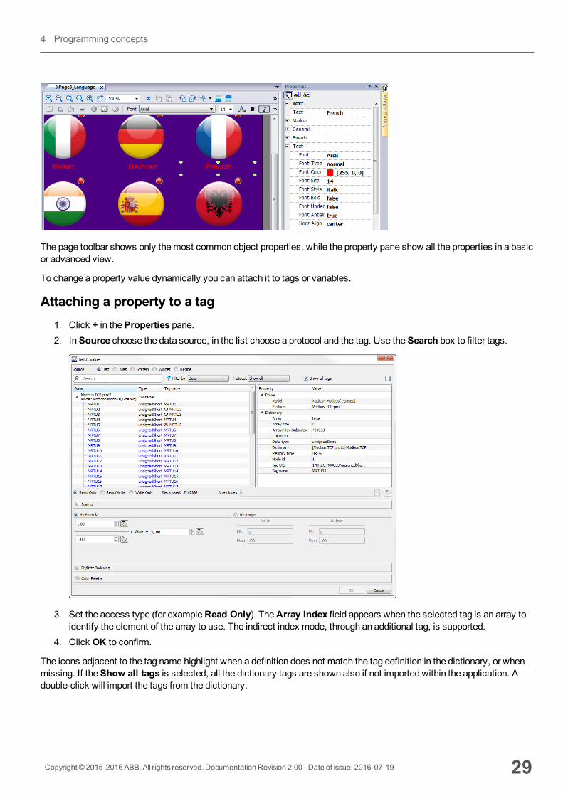
The page toolbar shows only themost common object properties, while the property pane show all the properties in a basicor advanced view.
To change a property value dynamically you can attach it to tags or variables.
Attaching a property to a tag1. Click + in theProperties pane.2. InSource choose the data source, in the list choose a protocol and the tag. Use theSearch box to filter tags.
3. Set the access type (for exampleRead Only). TheArray Index field appears when the selected tag is an array toidentify the element of the array to use. The indirect index mode, through an additional tag, is supported.
4. Click OK to confirm.
The icons adjacent to the tag name highlight when a definition does not match the tag definition in the dictionary, or whenmissing. If theShow all tags is selected, all the dictionary tags are shown also if not imported within the application. Adouble-click will import the tags from the dictionary.
Copyright © 2015-2016 ABB. All rights reserved. Documentation Revision 2.00 - Date of issue: 2016-07-19 29
4 Programming concepts
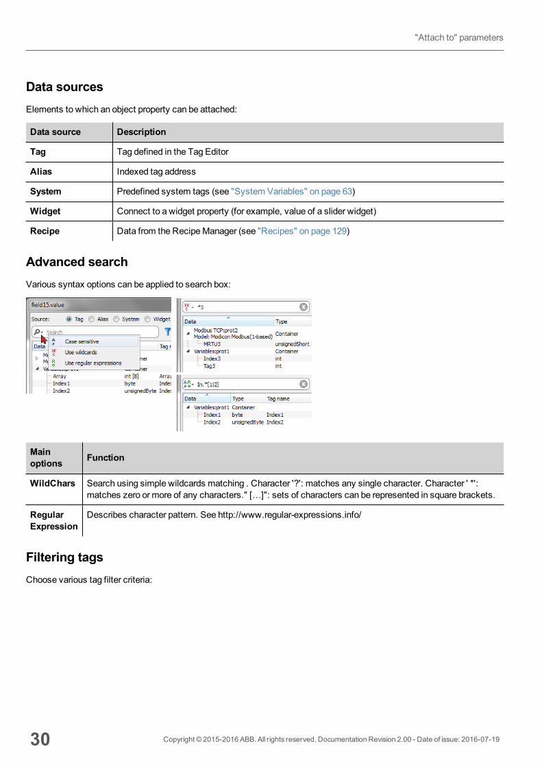
Data sourcesElements to which an object property can be attached:
Data source Description
Tag Tag defined in the Tag Editor
Alias Indexed tag address
System Predefined system tags (see "System Variables" on page 63)
Widget Connect to a widget property (for example, value of a slider widget)
Recipe Data from the RecipeManager (see "Recipes" on page 129)
Advanced searchVarious syntax options can be applied to search box:
Mainoptions Function
WildChars Search using simple wildcards matching . Character '?': matches any single character. Character ' *':matches zero or more of any characters." […]": sets of characters can be represented in square brackets.
RegularExpression
Describes character pattern. See http://www.regular-expressions.info/
Filtering tagsChoose various tag filter criteria:
30 Copyright © 2015-2016 ABB. All rights reserved. Documentation Revision 2.00 - Date of issue: 2016-07-19
"Attach to" parameters
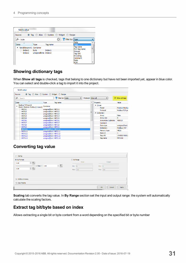
Showing dictionary tagsWhenShow all tags is checked, tags that belong to one dictionary but have not been imported yet, appear in blue color.You can select and double-click a tag to import it into the project.
Converting tag value
Scaling tab converts the tag value. InBy Range section set the input and output range: the system will automaticallycalculate the scaling factors.
Extract tag bit/byte based on indexAllows extracting a single bit or byte content from aword depending on the specified bit or byte number
Copyright © 2015-2016 ABB. All rights reserved. Documentation Revision 2.00 - Date of issue: 2016-07-19 31
4 Programming concepts
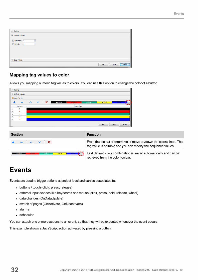
Mapping tag values to colorAllows youmapping numeric tag values to colors. You can use this option to change the color of a button.
Section Function
From the toolbar add/remove or move up/down the colors lines. Thetag value is editable and you canmodify the sequence values.
Last defined color combination is saved automatically and can beretrieved from the color toolbar.
EventsEvents are used to trigger actions at project level and can be associated to:
l buttons / touch (click, press, release)l external input devices like keyboards andmouse (click, press, hold, release, wheel)l data changes (OnDataUpdate)l switch of pages (OnActivate, OnDeactivate)l alarmsl scheduler
You can attach one or more actions to an event, so that they will be executed whenever the event occurs.
This example shows a JavaScript action activated by pressing a button.
32 Copyright © 2015-2016 ABB. All rights reserved. Documentation Revision 2.00 - Date of issue: 2016-07-19
Events
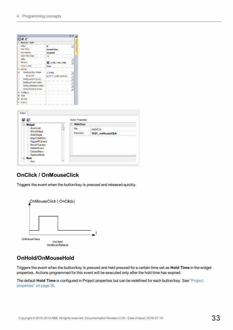
OnClick / OnMouseClickTriggers the event when the button/key is pressed and released quickly.
OnHold/OnMouseHoldTriggers the event when the button/key is pressed and held pressed for a certain time set as Hold Time in the widgetproperties. Actions programmed for this event will be executed only after the hold time has expired.
The default Hold Time is configured in Project properties but can be redefined for each button/key. See "Projectproperties" on page 39.
Copyright © 2015-2016 ABB. All rights reserved. Documentation Revision 2.00 - Date of issue: 2016-07-19 33
4 Programming concepts
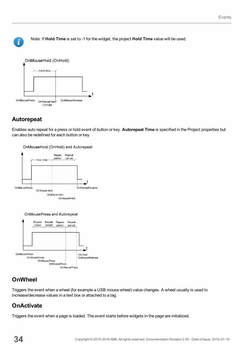
Note: If Hold Time is set to -1 for the widget, the project Hold Time value will be used.
AutorepeatEnables auto repeat for a press or hold event of button or key. Autorepeat Time is specified in the Project properties butcan also be redefined for each button or key
OnWheelTriggers the event when a wheel (for example a USB mouse wheel) value changes. A wheel usually is used toincrease/decrease values in a text box or attached to a tag.
OnActivateTriggers the event when a page is loaded. The event starts before widgets in the page are initialized.
34 Copyright © 2015-2016 ABB. All rights reserved. Documentation Revision 2.00 - Date of issue: 2016-07-19
Events
OnDataUpdateTriggers the event when the tag value changes. The updatemoment depend on the time needed by the protocol to finish theupdate process. For example theOnDataUpdate event can be triggered or not, depending on whether data becomesavailable from protocol respectively after or before widgets being initialized for the first time. In particular, page changenotifications aremore likely to happen with slow protocols and remote clients.
Note: The value read duringOnActivate can be the same obtained from a subsequent OnDataUpdate event,sinceOnDataUpdate notifications are sent asynchronously.
Widgets positioningYou can position widgets in the page using twomethods:
l Snap to Gridl Snap to Object
To display the grid, on theViewmenu, click Show Grid.
Snap to GridPath: View> Snap to Grid
When youmove or re-size an object, its top left corner will align with the nearest intersection of lines in the grid, even if thegrid is not visible.
Setting grid propertiesPath: View> Properties
Parameter Description
Spacing X Space in pixel between two lines/dots on the X axis
Spacing Y Space in pixel between two lines/dots on the Y axis
Type Grid type (dot or line)
Color Grid color
Snap to ObjectPath: View> Snap to Object
When youmove an object, it will align with other objects on the page.
When you select an object, one of the following hot points is selected as the source of the snap point, depending on thearea you pressed: top, top left, top right, bottom, bottom left, bottom right, left, right, center:
Copyright © 2015-2016 ABB. All rights reserved. Documentation Revision 2.00 - Date of issue: 2016-07-19 35
4 Programming concepts
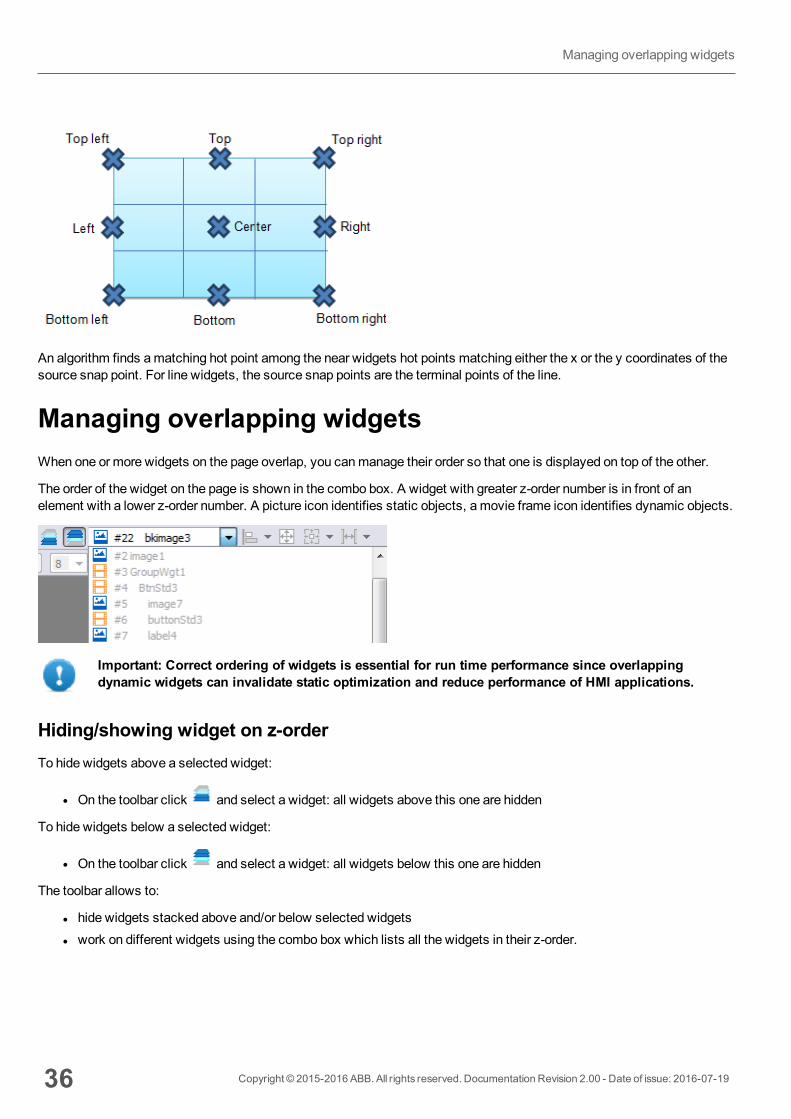
An algorithm finds amatching hot point among the near widgets hot points matching either the x or the y coordinates of thesource snap point. For line widgets, the source snap points are the terminal points of the line.
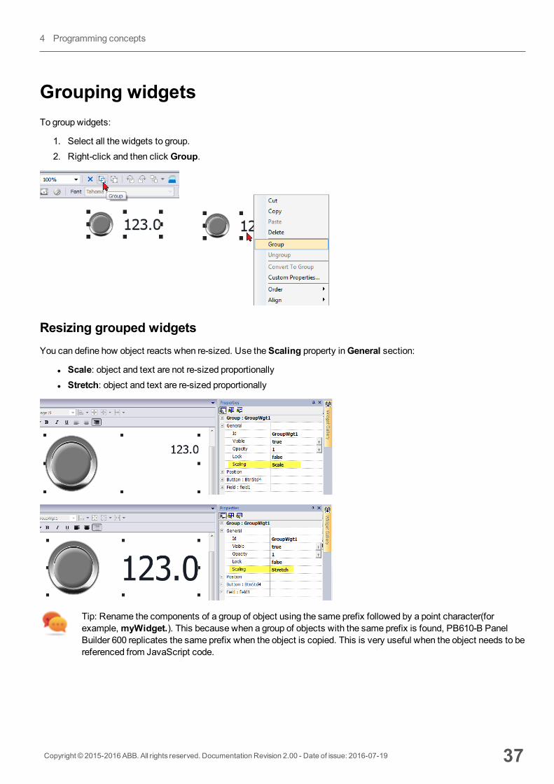
Managing overlapping widgetsWhen one or more widgets on the page overlap, you canmanage their order so that one is displayed on top of the other.
The order of the widget on the page is shown in the combo box. A widget with greater z-order number is in front of anelement with a lower z-order number. A picture icon identifies static objects, a movie frame icon identifies dynamic objects.
Important: Correct ordering of widgets is essential for run time performance since overlappingdynamic widgets can invalidate static optimization and reduce performance of HMI applications.
Hiding/showing widget on z-orderTo hide widgets above a selected widget:
l On the toolbar click and select a widget: all widgets above this one are hidden
To hide widgets below a selected widget:
l On the toolbar click and select a widget: all widgets below this one are hidden
The toolbar allows to:
l hide widgets stacked above and/or below selected widgetsl work on different widgets using the combo box which lists all the widgets in their z-order.
36 Copyright © 2015-2016 ABB. All rights reserved. Documentation Revision 2.00 - Date of issue: 2016-07-19
Managing overlapping widgets
Grouping widgetsTo group widgets:
1. Select all the widgets to group.2. Right-click and then click Group.
Resizing grouped widgetsYou can define how object reacts when re-sized. Use theScaling property inGeneral section:
l Scale: object and text are not re-sized proportionallyl Stretch: object and text are re-sized proportionally
Tip: Rename the components of a group of object using the same prefix followed by a point character(forexample,myWidget.). This because when a group of objects with the same prefix is found, PB610-B PanelBuilder 600 replicates the same prefix when the object is copied. This is very useful when the object needs to bereferenced from JavaScript code.
Copyright © 2015-2016 ABB. All rights reserved. Documentation Revision 2.00 - Date of issue: 2016-07-19 37
4 Programming concepts
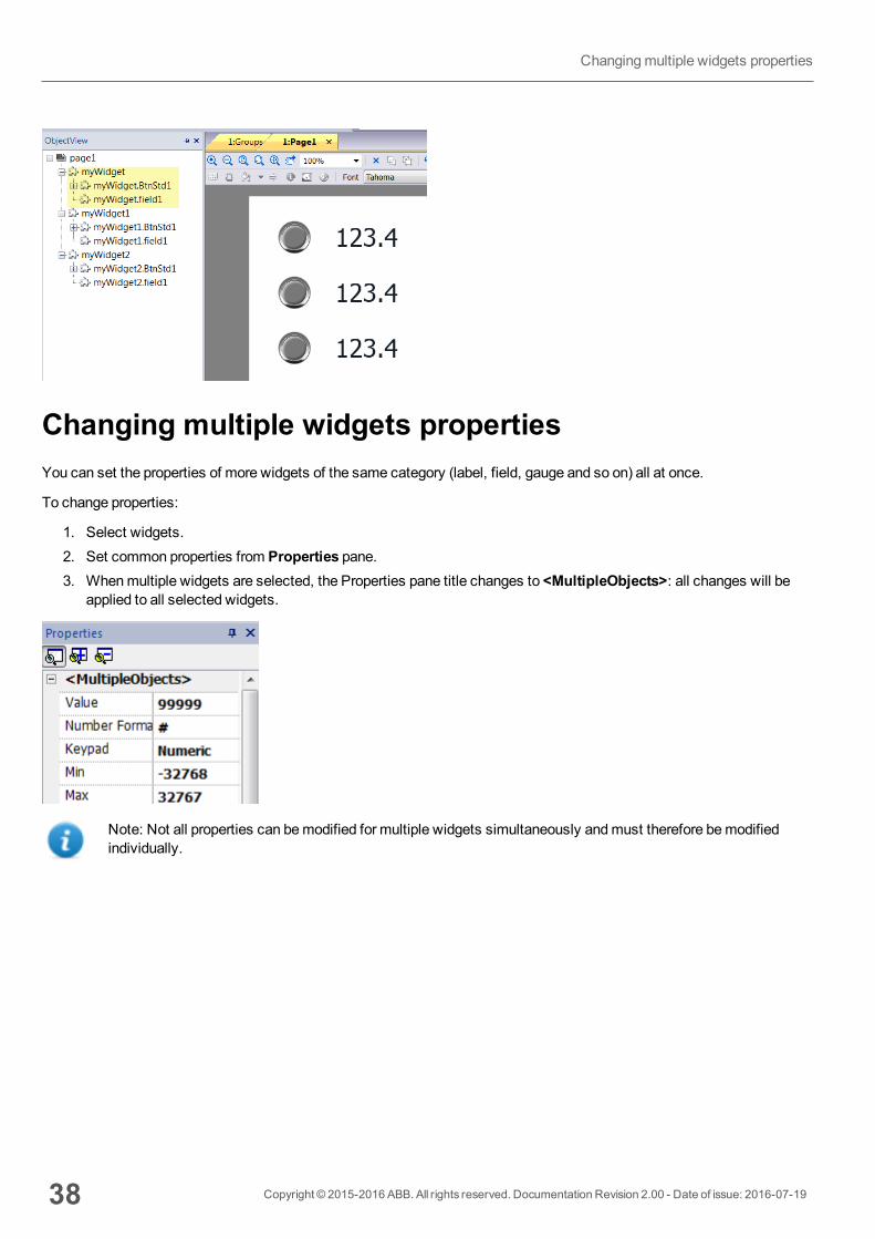
Changing multiple widgets propertiesYou can set the properties of more widgets of the same category (label, field, gauge and so on) all at once.
To change properties:
1. Select widgets.2. Set common properties from Properties pane.3. Whenmultiple widgets are selected, the Properties pane title changes to <MultipleObjects>: all changes will be
applied to all selected widgets.
Note: Not all properties can bemodified for multiple widgets simultaneously andmust therefore bemodifiedindividually.
38 Copyright © 2015-2016 ABB. All rights reserved. Documentation Revision 2.00 - Date of issue: 2016-07-19
Changingmultiple widgets properties
5 Project propertiesProject properties contain settings for the project.
Project properties pane 40
Developer tools 42
FreeType font rendering 45
Behavior 45
Events 48
Copyright © 2015-2016 ABB. All rights reserved. Documentation Revision 2.00 - Date of issue: 2016-07-19 39
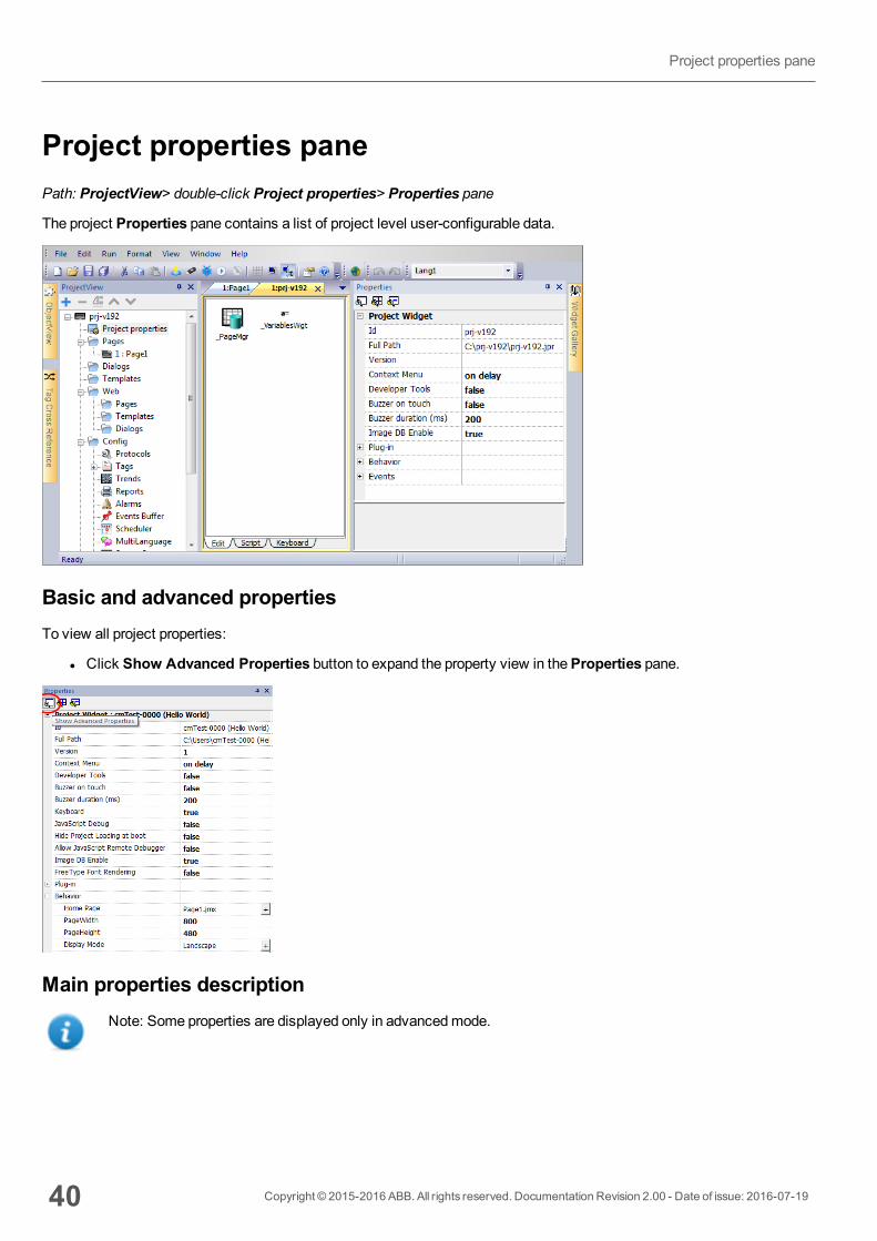
Project properties panePath: ProjectView> double-click Project properties> Properties pane
The project Properties pane contains a list of project level user-configurable data.
Basic and advanced propertiesTo view all project properties:
l Click Show Advanced Properties button to expand the property view in theProperties pane.
Main properties descriptionNote: Some properties are displayed only in advancedmode.
40 Copyright © 2015-2016 ABB. All rights reserved. Documentation Revision 2.00 - Date of issue: 2016-07-19
Project properties pane

Property Description
Version The Version field is available for users to report the project version.
ContextMenu
Define how context menu should appear in the HMI project.
on delay = context menu appears touching/pressing and holding for a few seconds an empty area of theruntime screen, or viaContext menu action
on macro command = context menu appears only viaContext menu action.
See "Widget actions" on page 103 for details.
DeveloperTool
Enable/disables a collection of runtime debugging utility tools.
Buzzer onTouch
Enables buzzer when touching the runtime screen. It can be used as an alternative to the touch buzzerfeature available inWindows CE side that gives feedback when the user touches anywhere on thetouchscreen. Buzzer on touch is supported also by Win32 Runtime.
Available forWindows CE from v1.76 ARM / 2.79MIPS.
Buzzerduration
Default 200ms
Keyboard Enables the use of keyboardmacros at run time when using external keyboards.
JavaScriptDebug
Enables the JavaScript debugger at run time for the current project.
Note: For UN20HMI devices (Windows CE MIPS HMI devices), local debugger is disabled.However, a remote JavaScript debugger is available to be used from a computer connected tothe HMI device via Ethernet.
Allow JSRemoteDebugger
Enables JavaScript remote debugger for current project.
Note: Remote debugging not supported on HMI Client.
Image DBenable
Activates an engine used by the Runtime to optimize project performance.
WARNING: This property should only be disabled by technical support for debuggingpurposes since this might reduce performance at run time.
FreeTypeFontRendering
Switches to FreeType the font rendering used by PB610-B Panel Builder 600 and runtime.
Behavior These properties define different aspects of page behavior. See "Behavior" on page 45
BuzzerA buzzer can be associated to the following widgets:
Copyright © 2015-2016 ABB. All rights reserved. Documentation Revision 2.00 - Date of issue: 2016-07-19 41
5 Project properties

l buttonsl hotspotsl needlesl fieldsl external keysl combo boxesl tables itemsl control list items
Developer toolsCollection of runtime debugging functions that can be enabled or disabled.
Enabling developer tools1. InProperties pane, set Developer Tools to true.2. Download the project.3. Open context menu.4. Select Developer tools.
Developer tool list
Tool Description
Show/Hideall
Shows a dialog containing information about device status like CPU load, memory usage, event queues.
CPUstatistics
Shows information on CPU load. See "CPU Statistics" on the facing page.
Memorystatistics
Shows information about system RAM . A negative value indicates that freememory is decreasing.
Eventqueues
Shows information on event queues (size, maximum achieved size, number of processed events, last andmaximum processing time). Timing statistics are only available for non-UI queue.
Timelogsummary
Show page loading time.
Embedwindow
Allows embedding in runtime the scene or leave the developer tool window as a standalone window(dialog).
Resetqueuestats
Resets statistical information on event queues.
Disablewatchdog
Disable the watchdog function and prevents system restart in case of freeze or crash of services.
Ignore Disables crash report function, exceptions are not saved in the crash report window.
42 Copyright © 2015-2016 ABB. All rights reserved. Documentation Revision 2.00 - Date of issue: 2016-07-19
Developer tools
Tool Description
exceptions
Profiling Measures the time spent for loading/rendering the active page. See "Profiling" on the next page
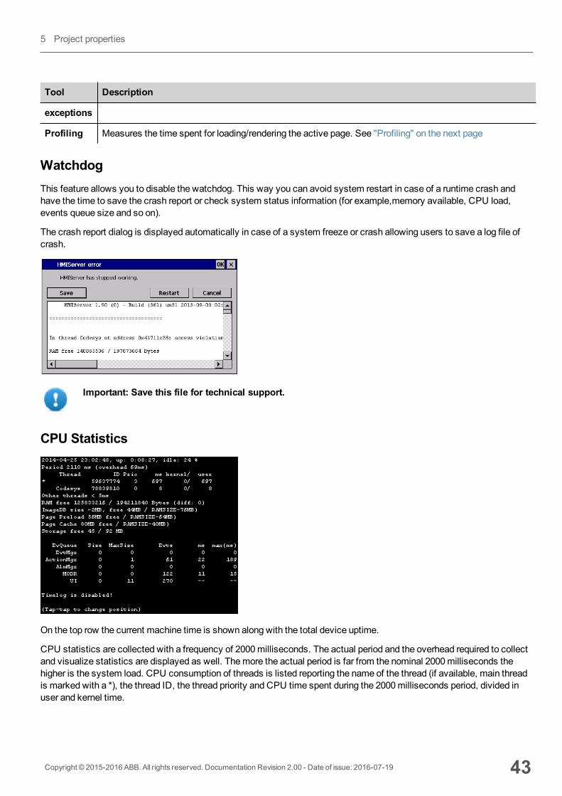
WatchdogThis feature allows you to disable the watchdog. This way you can avoid system restart in case of a runtime crash andhave the time to save the crash report or check system status information (for example,memory available, CPU load,events queue size and so on).
The crash report dialog is displayed automatically in case of a system freeze or crash allowing users to save a log file ofcrash.
Important: Save this file for technical support.
CPU Statistics
On the top row the current machine time is shown along with the total device uptime.
CPU statistics are collected with a frequency of 2000milliseconds. The actual period and the overhead required to collectand visualize statistics are displayed as well. Themore the actual period is far from the nominal 2000milliseconds thehigher is the system load. CPU consumption of threads is listed reporting the name of the thread (if available, main threadis marked with a *), the thread ID, the thread priority and CPU time spent during the 2000milliseconds period, divided inuser and kernel time.
Copyright © 2015-2016 ABB. All rights reserved. Documentation Revision 2.00 - Date of issue: 2016-07-19 43
5 Project properties
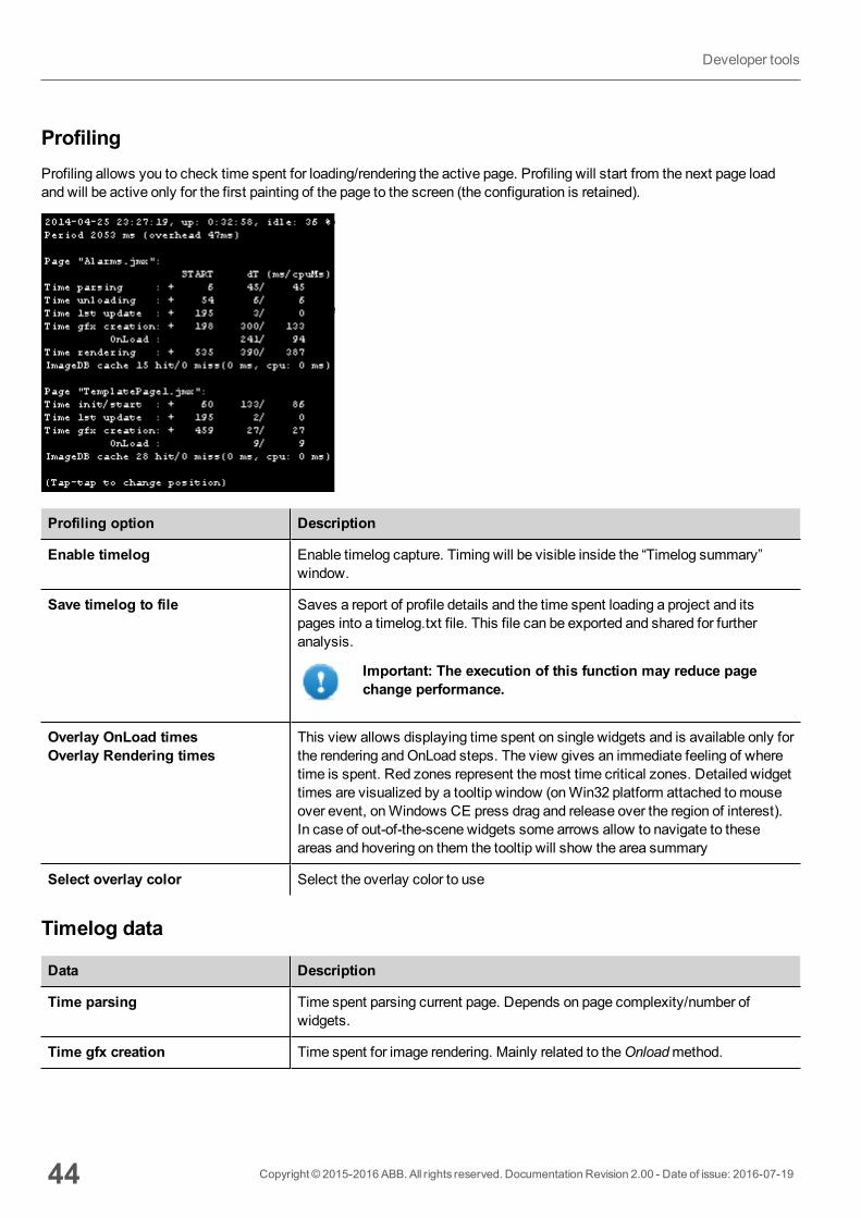
ProfilingProfiling allows you to check time spent for loading/rendering the active page. Profiling will start from the next page loadand will be active only for the first painting of the page to the screen (the configuration is retained).
Profiling option Description
Enable timelog Enable timelog capture. Timing will be visible inside the “Timelog summary”window.
Save timelog to file Saves a report of profile details and the time spent loading a project and itspages into a timelog.txt file. This file can be exported and shared for furtheranalysis.
Important: The execution of this function may reduce pagechange performance.
Overlay OnLoad timesOverlay Rendering times
This view allows displaying time spent on single widgets and is available only forthe rendering andOnLoad steps. The view gives an immediate feeling of wheretime is spent. Red zones represent themost time critical zones. Detailed widgettimes are visualized by a tooltip window (onWin32 platform attached tomouseover event, onWindows CE press drag and release over the region of interest).In case of out-of-the-scene widgets some arrows allow to navigate to theseareas and hovering on them the tooltip will show the area summary
Select overlay color Select the overlay color to use
Timelog data
Data Description
Time parsing Time spent parsing current page. Depends on page complexity/number ofwidgets.
Time gfx creation Time spent for image rendering. Mainly related to theOnloadmethod.
44 Copyright © 2015-2016 ABB. All rights reserved. Documentation Revision 2.00 - Date of issue: 2016-07-19
Developer tools
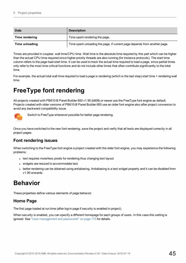
Data Description
Time rendering Time spent rendering the page.
Time unloading Time spent unloading the page, if current page depends from another page.
Times are provided in couples: wall time/CPU time. Wall time is the absolute time required by this part which can be higherthan the actual CPU time required since higher priority threads are also running (for instance protocols). The start timecolumn refers to the page load start time. It can be used to track the actual time required to load a page, since partial timesonly refer to themost time critical functions and do not include other times that often contribute significantly to the totaltime.
For example, the actual total wall time required to load a page is rendering (which is the last step) start time + rendering walltime.
FreeType font renderingAll projects created with PB610-B Panel Builder 600 v1.90 (b608) or newer use the FreeType font engine as default.Projects created with older versions of PB610-B Panel Builder 600 use an older font engine also after project conversion toavoid any backward compatibility issue.
Switch to FreeType whenever possible for better page rendering.
Once you have switched to the new font rendering, save the project and verify that all texts are displayed correctly in allproject pages.
Font rendering issuesWhen switching to the FreeType font engine a project created with the older font engine, youmay experience the followingproblems:
l text requires more/less pixels for rendering thus changing text layoutl widgets are resized to accommodate textl better rendering can be obtained using antialiasing. Antialiasing is a text widget property and it can be disabled fromv1.90 onwards.
BehaviorThese properties define various elements of page behavior.
Home PageThe first page loaded at run time (after log-in page if security is enabled in project).
When security is enabled, you can specify a different homepage for each groups of users. In this case this setting isignored. See "User management and passwords" on page 175 for details.
Copyright © 2015-2016 ABB. All rights reserved. Documentation Revision 2.00 - Date of issue: 2016-07-19 45
5 Project properties

Page Width/Page HeightDefines the default size in pixel of an HMI page. Default is the display resolution of the HMI devicemodel selected whencreating the project.
Display ModeDefines HMI device orientation.
Project TypeDefines HMI device type for the project. According to themodel, some project features and properties are automaticallyadjusted.
WARNING: Starting from v2, the HMI Runtime will check if the selected project type is matching withthe HMI device model and will advise with a message when the selected type is not matching: “HMIType mismatch. Convert project and download again.”
Panel MemorySize of the available internal panel memory.
PageRequest, CurrentPage and SyncOptionsIt is possible to have HMI Runtime exchange devices information on the page shown by the HMI. You can synchronizepages shown on the HMI device and on HMI Client or to control an HMI project from a controller such as a PLC.
The following properties can be customized:
Property Description
PageRequest Page to be shown on the HMI device and on HMI Client.Attached tagmust contain an integer value within the range of the available project pages andmust beavailable at least as a Read resource.
CurrentPage Page number displayed on the HMI device or on HMI Client or on both.Attached tagmust be available at least as aWrite resource andmust have integer data type.
SyncOptions Synchronization of project pages with the value contained into theCurrentPage property.
Options can be:
l disable: page number value is ignored,l local: page number displayed on HMI,l remote : page number displayed on HMI Client.l local + remote: page number displayed on HMI and on HMI Client, if different pages aredisplayed the last page loaded is considered.
Example: forced page change from controller/PLC to HMI device and HMI Client
Set properties as follows:
46 Copyright © 2015-2016 ABB. All rights reserved. Documentation Revision 2.00 - Date of issue: 2016-07-19
Behavior
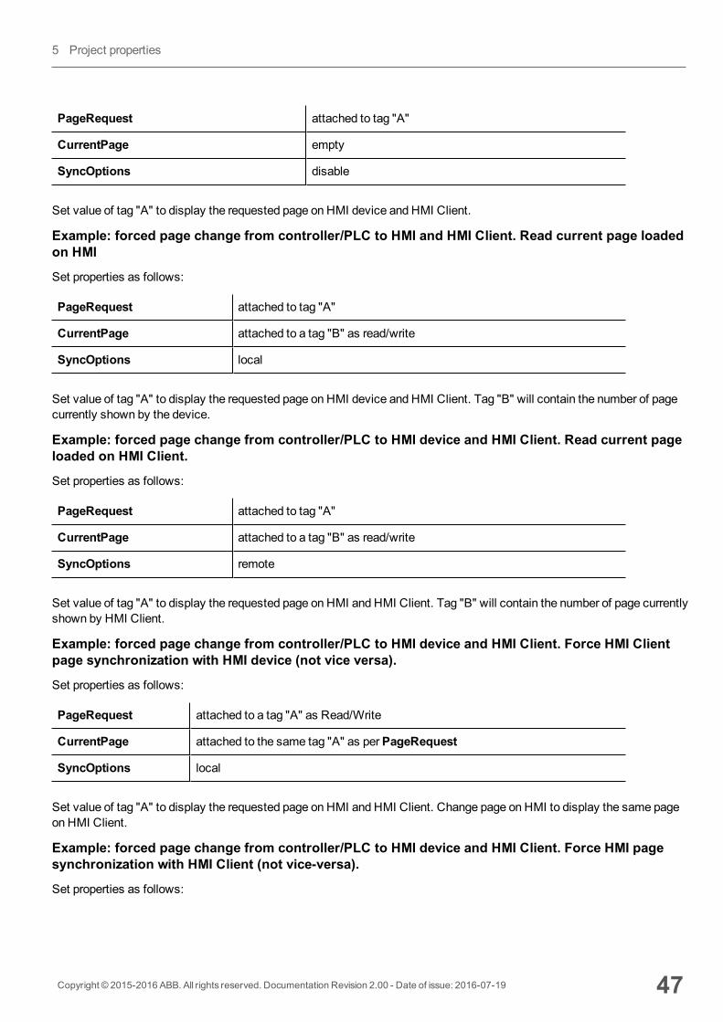
PageRequest attached to tag "A"
CurrentPage empty
SyncOptions disable
Set value of tag "A" to display the requested page on HMI device and HMI Client.
Example: forced page change from controller/PLC to HMI and HMI Client. Read current page loadedon HMI
Set properties as follows:
PageRequest attached to tag "A"
CurrentPage attached to a tag "B" as read/write
SyncOptions local
Set value of tag "A" to display the requested page on HMI device and HMI Client. Tag "B" will contain the number of pagecurrently shown by the device.
Example: forced page change from controller/PLC to HMI device and HMI Client. Read current pageloaded on HMI Client.
Set properties as follows:
PageRequest attached to tag "A"
CurrentPage attached to a tag "B" as read/write
SyncOptions remote
Set value of tag "A" to display the requested page on HMI and HMI Client. Tag "B" will contain the number of page currentlyshown by HMI Client.
Example: forced page change from controller/PLC to HMI device and HMI Client. Force HMI Clientpage synchronization with HMI device (not vice versa).
Set properties as follows:
PageRequest attached to a tag "A" as Read/Write
CurrentPage attached to the same tag "A" as perPageRequest
SyncOptions local
Set value of tag "A" to display the requested page on HMI and HMI Client. Change page on HMI to display the same pageon HMI Client.
Example: forced page change from controller/PLC to HMI device and HMI Client. Force HMI pagesynchronization with HMI Client (not vice-versa).
Set properties as follows:
Copyright © 2015-2016 ABB. All rights reserved. Documentation Revision 2.00 - Date of issue: 2016-07-19 47
5 Project properties

PageRequest attached to a tag "A" as read/write
CurrentPage attached to the same tag "A" as perPageRequest
SyncOptions remote
Change value of tag "A" to display the requested page on HMI and HMI Client. Change page on HMI Client to display thesame page on HMI.
Example: synchronize displayed page between HMI device and on HMI Client
Set properties as follows:
PageRequest attached to a tag "A" as read/write
CurrentPage attached to the same tag "A" as perPageRequest
SyncOptions local+remote
Changing page on HMI device, same page will be shown on HMI Client and vice-versa.
Hold Time/Autorepeat TimeDefines the values for hold time and autorepeat time for buttons and external keyboards.
Note: These properties can be redefined for each button or key in their widget property table.
HMI device Zoom FactorIt is the zoom factor of the HMI device that will be applied when project is loaded at run time.
Range 0.3–2.9
Default value 1 = no zoom
EventsOnWheelUsed only in conjunction with wheel input devices. Normally the wheel is used to increase/decrease the value of a tagwithout an external keyboard device.
Attach this property to a change of wheel event and use an action likeStepTag to increase/decrease a tag value.
48 Copyright © 2015-2016 ABB. All rights reserved. Documentation Revision 2.00 - Date of issue: 2016-07-19
Events
6 The HMI simulatorHMI simulator allows you testing projects before downloading it to the HMI device. It may be used to test the project whenno HMI device is available and to speed up development and debugging activities.
The HMI simulator supports:
l online simulation - in communication with real devices (only for protocols with Ethernet or RS-232 communication),l offline simulation - simulating tag behavior
The data simulationmethod is set in theSimulator column of the Tag Editor.
Data simulation methods 50
Simulator settings 50
Launching and stopping the simulator 51
Copyright © 2015-2016 ABB. All rights reserved. Documentation Revision 2.00 - Date of issue: 2016-07-19 49
Data simulation methodsSet tag simulation behavior in theSimulator field of Tag Editor.
Method Description
Variables Data is stored in a simulator variable. This variable holds the value of the tag so you can read and write thevalue.
SawTooth A count value is incremented fromOffset toAmplitude + Offset value with aPeriod of 60..3600 seconds.When the counter reaches Amplitude + Offset, the value is reset toOffset and the counter restarts.
SineWave
A sine wave value is generated and written to the tag value.Min, Max andPeriod values can be defined foreach tag.
TriangleWave
A triangle wave value is generated and written to the tag value.Min, Max andPeriod values can be definedfor each tag.
SquareWave
A square wave value is generated and written to the tag value.Min, Max andPeriod values can be definedfor each tag.
See "Adding tags" on page 19 for details.
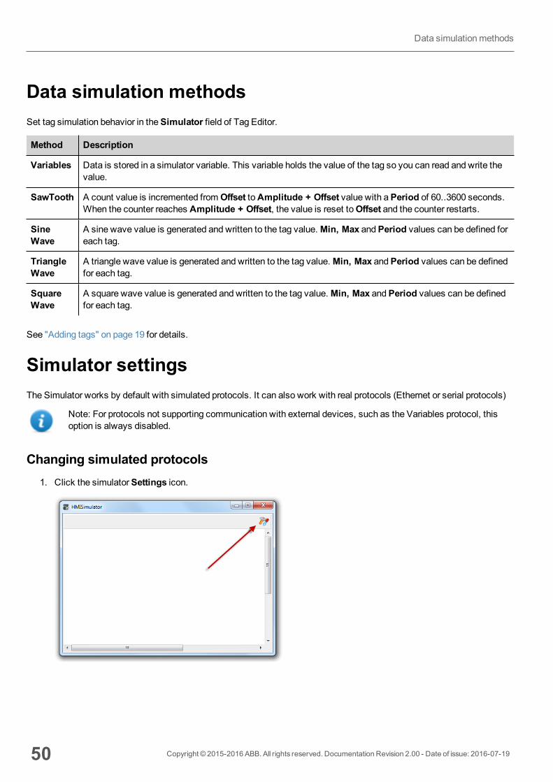
Simulator settingsThe Simulator works by default with simulated protocols. It can also work with real protocols (Ethernet or serial protocols)
Note: For protocols not supporting communication with external devices, such as the Variables protocol, thisoption is always disabled.
Changing simulated protocols1. Click the simulatorSettings icon.
50 Copyright © 2015-2016 ABB. All rights reserved. Documentation Revision 2.00 - Date of issue: 2016-07-19
Data simulationmethods
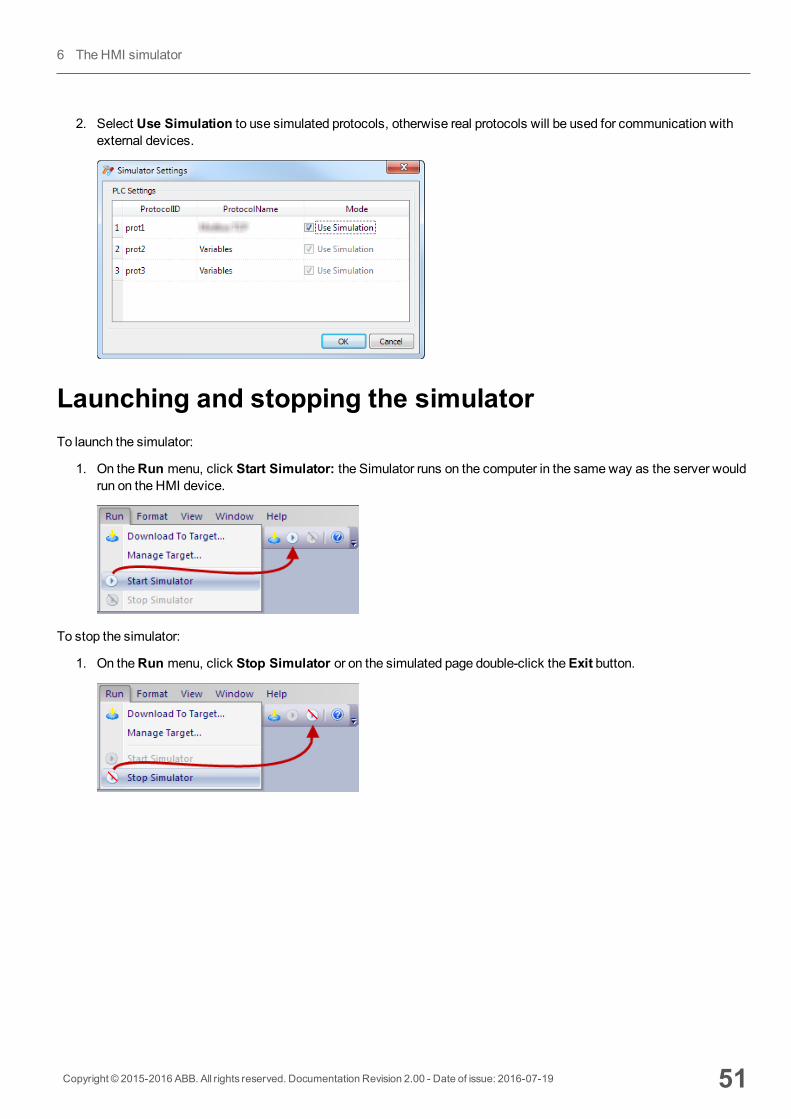
2. Select Use Simulation to use simulated protocols, otherwise real protocols will be used for communication withexternal devices.
Launching and stopping the simulatorTo launch the simulator:
1. On theRun menu, click Start Simulator: the Simulator runs on the computer in the sameway as the server wouldrun on the HMI device.
To stop the simulator:
1. On theRun menu, click Stop Simulator or on the simulated page double-click theExit button.
Copyright © 2015-2016 ABB. All rights reserved. Documentation Revision 2.00 - Date of issue: 2016-07-19 51
6 The HMI simulator

52 Copyright © 2015-2016 ABB. All rights reserved. Documentation Revision 2.00 - Date of issue: 2016-07-19
Launching and stopping the simulator
7 Transferring the project to HMIdeviceTo transfer the PB610-B Panel Builder 600 project to the target HMI device you can use:
l functionRun > Download to Targetl functionRun > Update Packagewith the use of a USB device
Download to HMI device 54
Update package 57
The Runtime loader 59
Upload projects 60
Copyright © 2015-2016 ABB. All rights reserved. Documentation Revision 2.00 - Date of issue: 2016-07-19 53
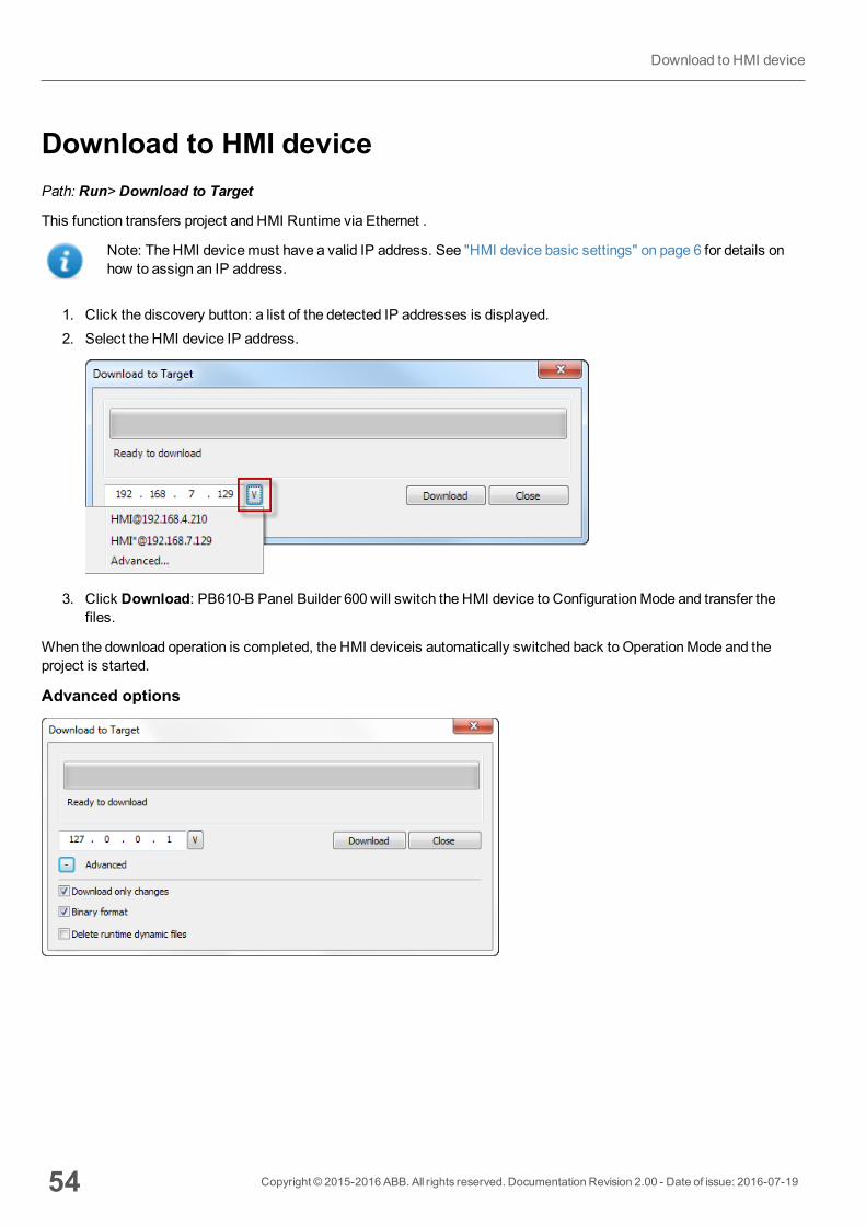
Download to HMI devicePath: Run> Download to Target
This function transfers project and HMI Runtime via Ethernet .
Note: The HMI devicemust have a valid IP address. See "HMI device basic settings" on page 6 for details onhow to assign an IP address.
1. Click the discovery button: a list of the detected IP addresses is displayed.2. Select the HMI device IP address.
3. Click Download: PB610-B Panel Builder 600 will switch the HMI device to ConfigurationMode and transfer thefiles.
When the download operation is completed, the HMI deviceis automatically switched back to OperationMode and theproject is started.
Advanced options
54 Copyright © 2015-2016 ABB. All rights reserved. Documentation Revision 2.00 - Date of issue: 2016-07-19
Download to HMI device
Option Description
Download onlychanges
Transfers to the HMI device only themodified project files.
Binary format Download files using binary format.
Delete runtimedynamic files
Modified configuration of recipes, users, schedulers, etc. done at run time will be deleted andoverwritten by the configuration defined in the project.
CAUTION: This operation cannot be undone, deleted dynamic files cannot berestored.
CAUTION: Dynamic files are not deleted if stored on external devices (USB orSD Cards).
When transferring a project, PB610-B Panel Builder 600 uses a combination of HTTP and FTP connections:
l HTTP connection - issues the commands to switch to transfer mode or to unload running project,l FTP session - transfers the files to the flashmemory in the HMI device.
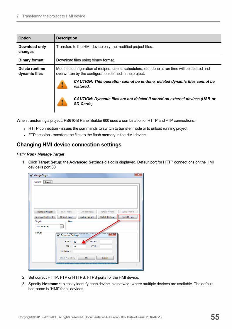
Changing HMI device connection settingsPath: Run>Manage Target
1. Click Target Setup: theAdvanced Settings dialog is displayed. Default port for HTTP connections on the HMIdevice is port 80.
2. Set correct HTTP, FTP or HTTPS, FTPS ports for the HMI device.3. Specify Hostname to easily identify each device in a network wheremultiple devices are available. The default
hostname is “HMI” for all devices.
Copyright © 2015-2016 ABB. All rights reserved. Documentation Revision 2.00 - Date of issue: 2016-07-19 55
7 Transferring the project to HMI device
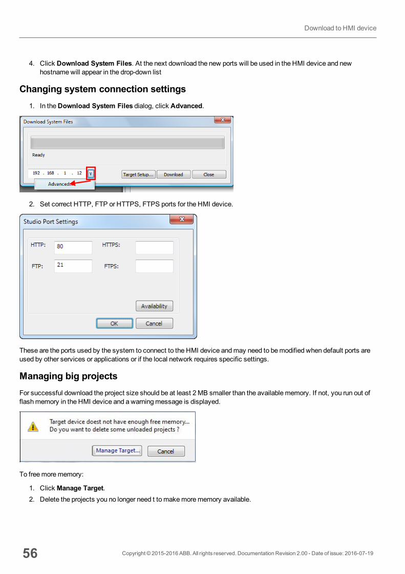
4. Click Download System Files. At the next download the new ports will be used in the HMI device and newhostnamewill appear in the drop-down list
Changing system connection settings1. In theDownload System Files dialog, click Advanced.
2. Set correct HTTP, FTP or HTTPS, FTPS ports for the HMI device.
These are the ports used by the system to connect to the HMI device andmay need to bemodified when default ports areused by other services or applications or if the local network requires specific settings.
Managing big projectsFor successful download the project size should be at least 2MB smaller than the available memory. If not, you run out offlashmemory in the HMI device and a warningmessage is displayed.
To freemorememory:
1. Click Manage Target.2. Delete the projects you no longer need t to makemorememory available.
56 Copyright © 2015-2016 ABB. All rights reserved. Documentation Revision 2.00 - Date of issue: 2016-07-19
Download to HMI device
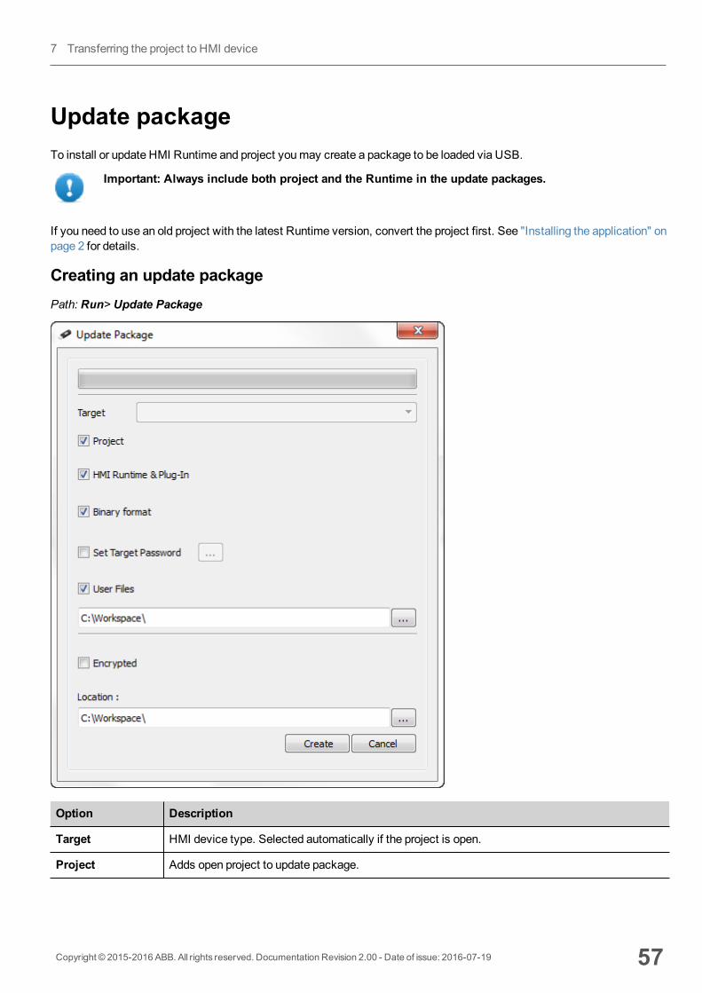
Update packageTo install or update HMI Runtime and project youmay create a package to be loaded via USB.
Important: Always include both project and the Runtime in the update packages.
If you need to use an old project with the latest Runtime version, convert the project first. See "Installing the application" onpage 2 for details.
Creating an update packagePath: Run> Update Package
Option Description
Target HMI device type. Selected automatically if the project is open.
Project Adds open project to update package.
Copyright © 2015-2016 ABB. All rights reserved. Documentation Revision 2.00 - Date of issue: 2016-07-19 57
7 Transferring the project to HMI device
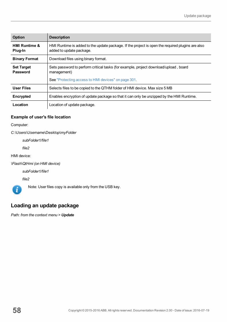
Option Description
HMI Runtime &Plug-In
HMI Runtime is added to the update package. If the project is open the required plugins are alsoadded to update package.
Binary Format Download files using binary format.
Set TargetPassword
Sets password to perform critical tasks (for example, project download/upload , boardmanagement)
See "Protecting access to HMI devices" on page 301.
User Files Selects files to be copied to the QTHM folder of HMI device. Max size 5MB
Encrypted Enables encryption of update package so that it can only be unzipped by the HMI Runtime.
Location Location of update package.
Example of user's file location
Computer:
C:\Users\Username\Desktop\myFolder
subFolder1/file1
file2
HMI device:
\Flash\QtHmi (on HMI device)
subFolder1/file1
file2
Note: User files copy is available only from the USB key.
Loading an update packagePath: from the context menu > Update
58 Copyright © 2015-2016 ABB. All rights reserved. Documentation Revision 2.00 - Date of issue: 2016-07-19
Update package

1. Assuming you have stored the package in the root folder of a USB drive, remove the drive from the computer, plug itin the HMI device, display the context menu by holding your finger for a few seconds on the screen and selectUpdate.
2. The system will check for the presence of the update package in the USB drive root and ask confirmation to proceedwith the update.
3. Select Auto select best match and click Next: the procedure is completed automatically
The Runtime loaderHMI devices are delivered from factory without Runtime.
When you power up the device for the first time, the Runtime Loader window is displayed.
The Runtime Loader presence depends on the device Operating System andmay not be available on all the units.
Important: Old versions of HMI devices may not include the Runtime Loader. Contact technical support if youneed further information.
Installing Runtime with a project1. Click System settings: theSystemmenu is activated in user mode.2. Enter the IP adress for the HMI device. See "System Settings tool" on page 291 for details.3. Download a project with PB610-B Panel Builder 600 to install the Runtime.
When you download a project the Runtime is automatically installed if needed.
Copyright © 2015-2016 ABB. All rights reserved. Documentation Revision 2.00 - Date of issue: 2016-07-19 59
7 Transferring the project to HMI device
See "Transferring the project to HMI device" on page 53 for details.
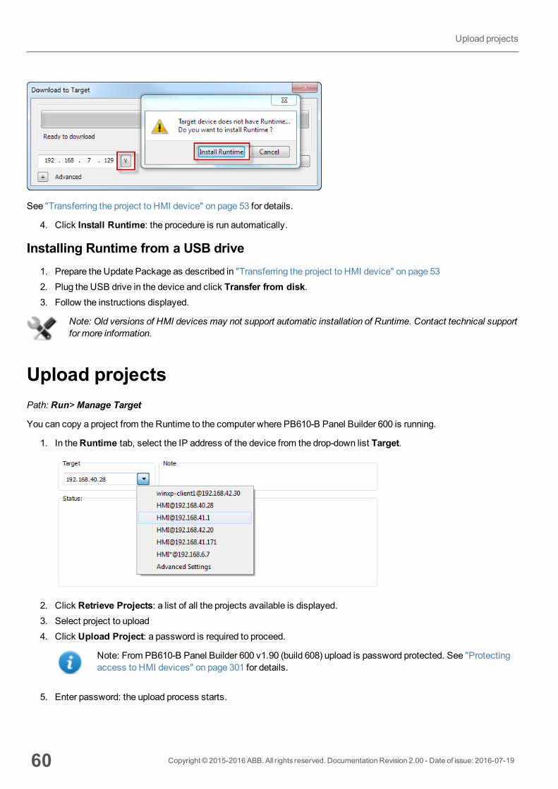
4. Click Install Runtime: the procedure is run automatically.
Installing Runtime from a USB drive1. Prepare the Update Package as described in "Transferring the project to HMI device" on page 532. Plug the USB drive in the device and click Transfer from disk.3. Follow the instructions displayed.
Note: Old versions of HMI devices may not support automatic installation of Runtime. Contact technical supportfor more information.
Upload projectsPath: Run>Manage Target
You can copy a project from the Runtime to the computer where PB610-B Panel Builder 600 is running.
1. In theRuntime tab, select the IP address of the device from the drop-down list Target.
2. Click Retrieve Projects: a list of all the projects available is displayed.3. Select project to upload4. Click Upload Project: a password is required to proceed.
Note: From PB610-B Panel Builder 600 v1.90 (build 608) upload is password protected. See "Protectingaccess to HMI devices" on page 301 for details.
5. Enter password: the upload process starts.
60 Copyright © 2015-2016 ABB. All rights reserved. Documentation Revision 2.00 - Date of issue: 2016-07-19
Upload projects

A copy of the project is saved in:
C:\Users\username\Documents\PB610-B Panel Builder600\workspace\Uploaded\RuntimeIPAddress\workspace\ProjectName
Note: If the upload operation fails, check firewall settings the computer where PB610-B Panel Builder 600 isrunning.
Copyright © 2015-2016 ABB. All rights reserved. Documentation Revision 2.00 - Date of issue: 2016-07-19 61
7 Transferring the project to HMI device

62 Copyright © 2015-2016 ABB. All rights reserved. Documentation Revision 2.00 - Date of issue: 2016-07-19
Upload projects
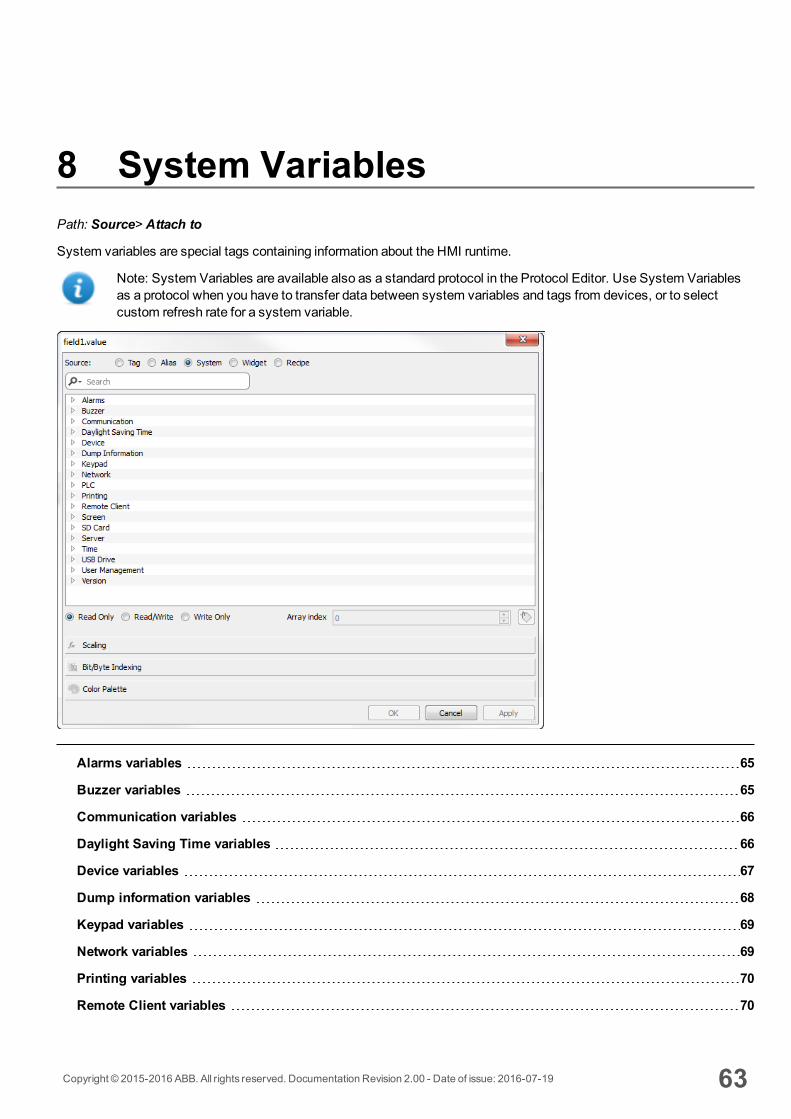
8 System VariablesPath: Source> Attach to
System variables are special tags containing information about the HMI runtime.
Note: System Variables are available also as a standard protocol in the Protocol Editor. Use System Variablesas a protocol when you have to transfer data between system variables and tags from devices, or to selectcustom refresh rate for a system variable.
Alarms variables 65
Buzzer variables 65
Communication variables 66
Daylight Saving Time variables 66
Device variables 67
Dump information variables 68
Keypad variables 69
Network variables 69
Printing variables 70
Remote Client variables 70
Copyright © 2015-2016 ABB. All rights reserved. Documentation Revision 2.00 - Date of issue: 2016-07-19 63
Version variables 71
Screen variables 71
SD card variables 71
Server variables 72
Time variables 72
Touch screen variables 73
USB drive variables 74
User management variables 74
64 Copyright © 2015-2016 ABB. All rights reserved. Documentation Revision 2.00 - Date of issue: 2016-07-19

Alarms variablesNumber of alarms of the requested type.
Variable Description Datatype
Not TriggeredAcknowledged
Alarm condition no longer active; alarms already acknowledged int
readonly
Not Triggered NotAcknowledged
Alarma condition no longer active; awaiting acknowledgment int
readonly
Number of missed alarmevents
Alarms exceeding the event queue. Queue length is defined in theengineconfig.xml file.
int
readonly
Triggered Acknowledged Alarm condition active; alarms already acknowledged int
readonly
Triggered Alarms Alarm active: aknowledgement not required int
readonly
Triggered NotAcknowledged
Alarm condition active; awaiting acknowledgment int
readonly
Buzzer variablesAdjust buzzer behavior.
Variable Description Datatype
Buzzer Setup 0 = disabled1 = enabled (buzzer sounds as audible on any touchscreen event)2 = buzzer status controlled by Buzzer Control system variable.
int
BuzzerControl
0 = buzzer off1 = buzzer on2 = buzzer blink
int
Copyright © 2015-2016 ABB. All rights reserved. Documentation Revision 2.00 - Date of issue: 2016-07-19 65
8 System Variables
Variable Description Datatype
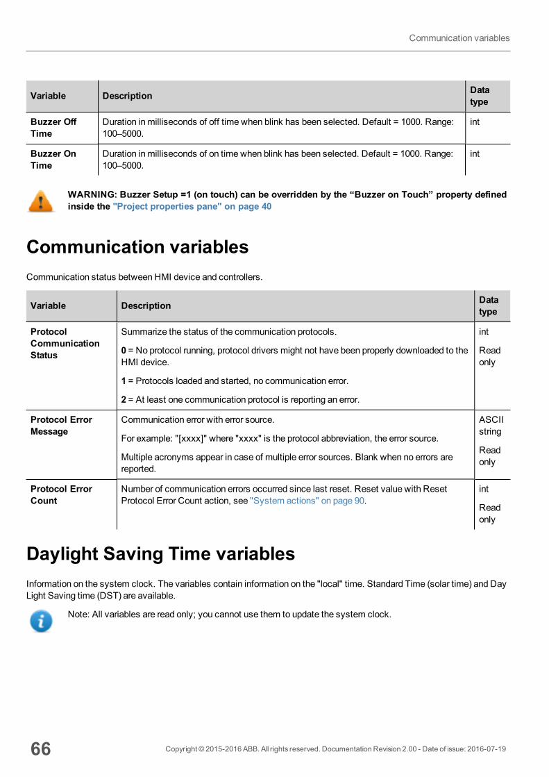
Buzzer OffTime
Duration in milliseconds of off time when blink has been selected. Default = 1000. Range:100–5000.
int
Buzzer OnTime
Duration in milliseconds of on time when blink has been selected. Default = 1000. Range:100–5000.
int
WARNING: Buzzer Setup =1 (on touch) can be overridden by the “Buzzer on Touch” property definedinside the "Project properties pane" on page 40
Communication variablesCommunication status between HMI device and controllers.
Variable Description Datatype
ProtocolCommunicationStatus
Summarize the status of the communication protocols.
0 = No protocol running, protocol drivers might not have been properly downloaded to theHMI device.
1 = Protocols loaded and started, no communication error.
2 = At least one communication protocol is reporting an error.
int
Readonly
Protocol ErrorMessage
Communication error with error source.
For example: "[xxxx]" where "xxxx" is the protocol abbreviation, the error source.
Multiple acronyms appear in case of multiple error sources. Blank when no errors arereported.
ASCIIstring
Readonly
Protocol ErrorCount
Number of communication errors occurred since last reset. Reset value with ResetProtocol Error Count action, see "System actions" on page 90.
int
Readonly
Daylight Saving Time variablesInformation on the system clock. The variables contain information on the "local" time. Standard Time (solar time) and DayLight Saving time (DST) are available.
Note: All variables are read only; you cannot use them to update the system clock.
66 Copyright © 2015-2016 ABB. All rights reserved. Documentation Revision 2.00 - Date of issue: 2016-07-19
Communication variables
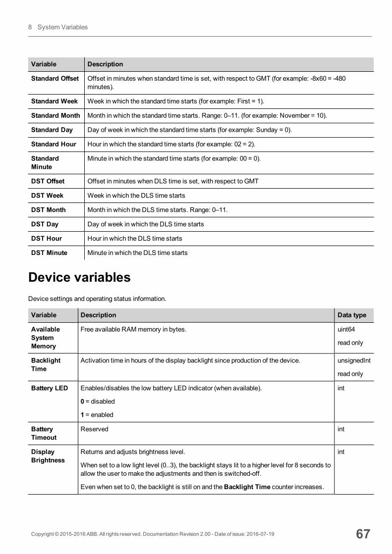
Variable Description
Standard Offset Offset in minutes when standard time is set, with respect to GMT (for example: -8x60 = -480minutes).
Standard Week Week in which the standard time starts (for example: First = 1).
Standard Month Month in which the standard time starts. Range: 0–11. (for example: November = 10).
Standard Day Day of week in which the standard time starts (for example: Sunday = 0).
Standard Hour Hour in which the standard time starts (for example: 02 = 2).
StandardMinute
Minute in which the standard time starts (for example: 00 = 0).
DST Offset Offset in minutes when DLS time is set, with respect to GMT
DST Week Week in which the DLS time starts
DST Month Month in which the DLS time starts. Range: 0–11.
DST Day Day of week in which the DLS time starts
DST Hour Hour in which the DLS time starts
DST Minute Minute in which the DLS time starts
Device variablesDevice settings and operating status information.
Variable Description Data type
AvailableSystemMemory
Free available RAMmemory in bytes. uint64
read only
BacklightTime
Activation time in hours of the display backlight since production of the device. unsignedInt
read only
Battery LED Enables/disables the low battery LED indicator (when available).
0 = disabled
1 = enabled
int
BatteryTimeout
Reserved int
DisplayBrightness
Returns and adjusts brightness level.
When set to a low light level (0..3), the backlight stays lit to a higher level for 8 seconds toallow the user to make the adjustments and then is switched-off.
Even when set to 0, the backlight is still on and theBacklight Time counter increases.
int
Copyright © 2015-2016 ABB. All rights reserved. Documentation Revision 2.00 - Date of issue: 2016-07-19 67
8 System Variables
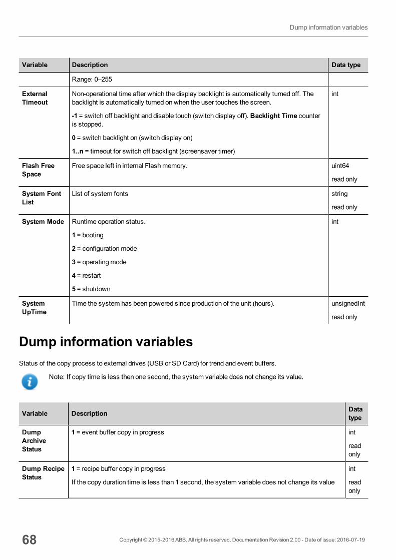
Variable Description Data type
Range: 0–255
ExternalTimeout
Non-operational time after which the display backlight is automatically turned off. Thebacklight is automatically turned on when the user touches the screen.
-1 = switch off backlight and disable touch (switch display off). Backlight Time counteris stopped.
0 = switch backlight on (switch display on)
1..n = timeout for switch off backlight (screensaver timer)
int
Flash FreeSpace
Free space left in internal Flashmemory. uint64
read only
System FontList
List of system fonts string
read only
System Mode Runtime operation status.
1 = booting
2 = configurationmode
3 = operatingmode
4 = restart
5 = shutdown
int
SystemUpTime
Time the system has been powered since production of the unit (hours). unsignedInt
read only
Dump information variablesStatus of the copy process to external drives (USB or SD Card) for trend and event buffers.
Note: If copy time is less then one second, the system variable does not change its value.
Variable Description Datatype
DumpArchiveStatus
1 = event buffer copy in progress int
readonly
Dump RecipeStatus
1 = recipe buffer copy in progress
If the copy duration time is less than 1 second, the system variable does not change its value
int
readonly
68 Copyright © 2015-2016 ABB. All rights reserved. Documentation Revision 2.00 - Date of issue: 2016-07-19
Dump information variables
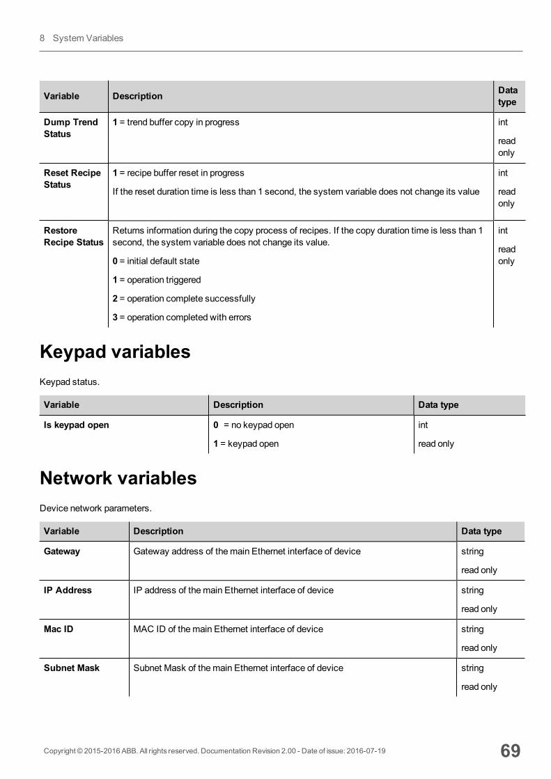
Variable Description Datatype
Dump TrendStatus
1 = trend buffer copy in progress int
readonly
Reset RecipeStatus
1 = recipe buffer reset in progress
If the reset duration time is less than 1 second, the system variable does not change its value
int
readonly
RestoreRecipe Status
Returns information during the copy process of recipes. If the copy duration time is less than 1second, the system variable does not change its value.
0 = initial default state
1 = operation triggered
2 = operation complete successfully
3 = operation completed with errors
int
readonly
Keypad variablesKeypad status.
Variable Description Data type
Is keypad open 0 = no keypad open
1 = keypad open
int
read only
Network variablesDevice network parameters.
Variable Description Data type
Gateway Gateway address of themain Ethernet interface of device string
read only
IP Address IP address of themain Ethernet interface of device string
read only
Mac ID MAC ID of themain Ethernet interface of device string
read only
Subnet Mask Subnet Mask of themain Ethernet interface of device string
read only
Copyright © 2015-2016 ABB. All rights reserved. Documentation Revision 2.00 - Date of issue: 2016-07-19 69
8 System Variables
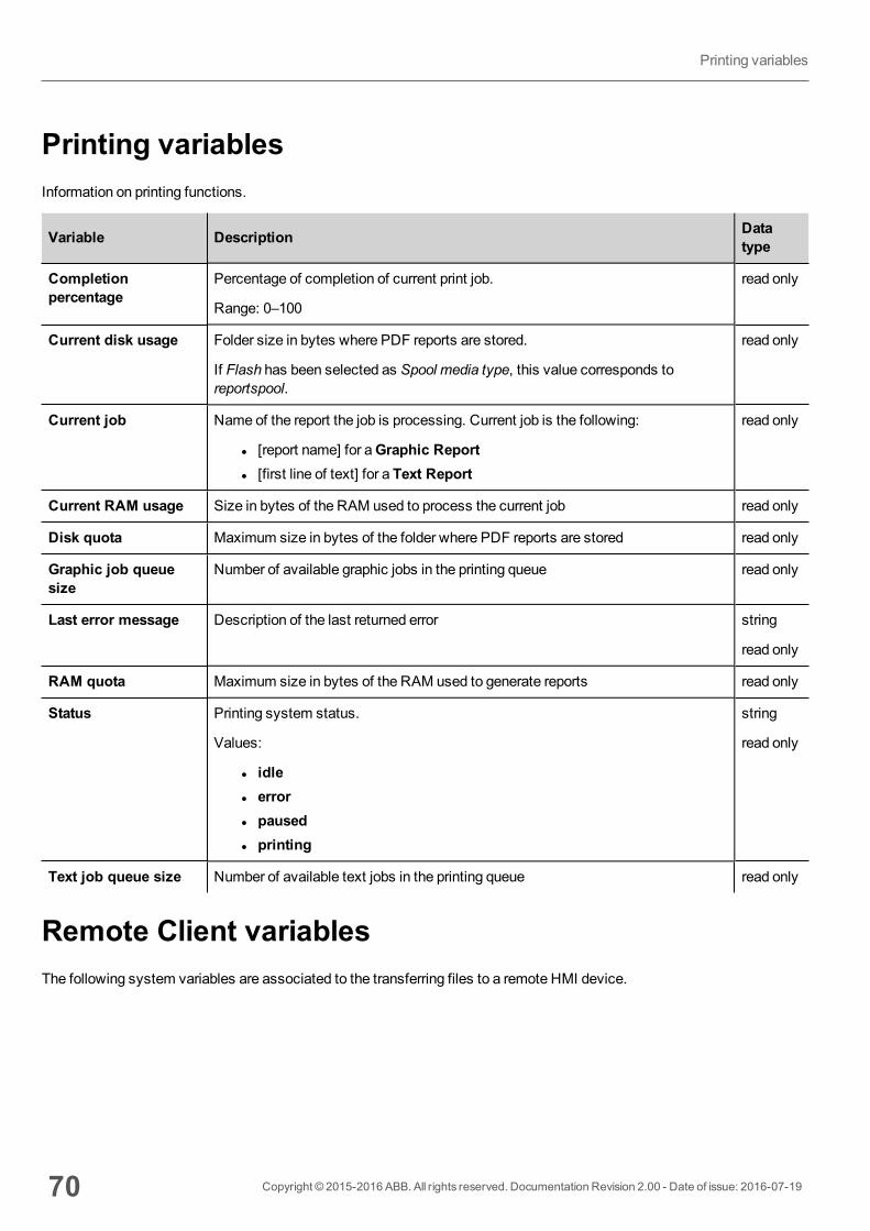
Printing variablesInformation on printing functions.
Variable Description Datatype
Completionpercentage
Percentage of completion of current print job.
Range: 0–100
read only
Current disk usage Folder size in bytes where PDF reports are stored.
If Flash has been selected as Spool media type, this value corresponds toreportspool.
read only
Current job Name of the report the job is processing. Current job is the following:
l [report name] for aGraphic Reportl [first line of text] for a Text Report
read only
Current RAM usage Size in bytes of the RAM used to process the current job read only
Disk quota Maximum size in bytes of the folder where PDF reports are stored read only
Graphic job queuesize
Number of available graphic jobs in the printing queue read only
Last error message Description of the last returned error string
read only
RAM quota Maximum size in bytes of the RAM used to generate reports read only
Status Printing system status.
Values:
l idlel errorl pausedl printing
string
read only
Text job queue size Number of available text jobs in the printing queue read only
Remote Client variablesThe following system variables are associated to the transferring files to a remote HMI device.
70 Copyright © 2015-2016 ABB. All rights reserved. Documentation Revision 2.00 - Date of issue: 2016-07-19
Printing variables
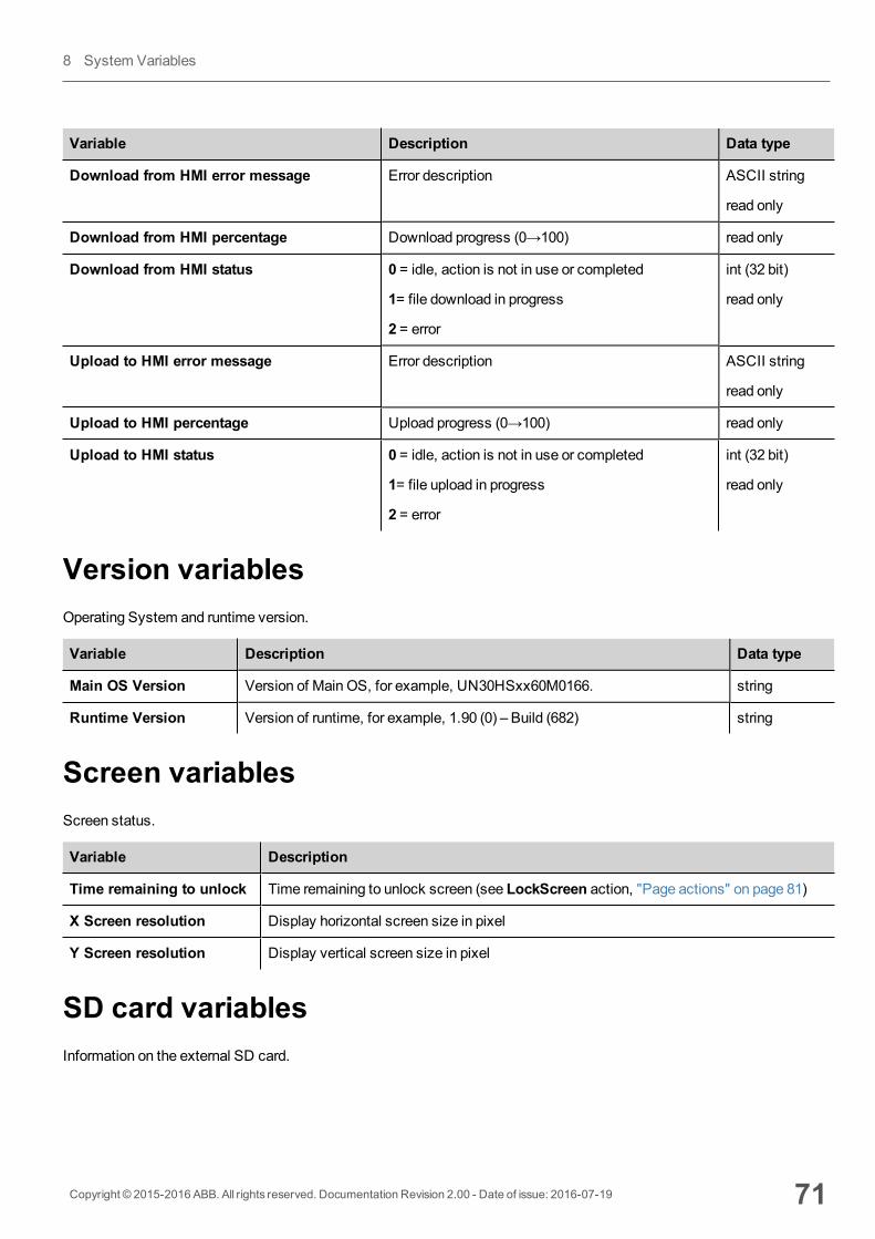
Variable Description Data type
Download from HMI error message Error description ASCII string
read only
Download from HMI percentage Download progress (0→100) read only
Download from HMI status 0 = idle, action is not in use or completed
1= file download in progress
2 = error
int (32 bit)
read only
Upload to HMI error message Error description ASCII string
read only
Upload to HMI percentage Upload progress (0→100) read only
Upload to HMI status 0 = idle, action is not in use or completed
1= file upload in progress
2 = error
int (32 bit)
read only
Version variablesOperating System and runtime version.
Variable Description Data type
Main OS Version Version of Main OS, for example, UN30HSxx60M0166. string
Runtime Version Version of runtime, for example, 1.90 (0) – Build (682) string
Screen variablesScreen status.
Variable Description
Time remaining to unlock Time remaining to unlock screen (see LockScreen action, "Page actions" on page 81)
X Screen resolution Display horizontal screen size in pixel
Y Screen resolution Display vertical screen size in pixel
SD card variablesInformation on the external SD card.
Copyright © 2015-2016 ABB. All rights reserved. Documentation Revision 2.00 - Date of issue: 2016-07-19 71
8 System Variables
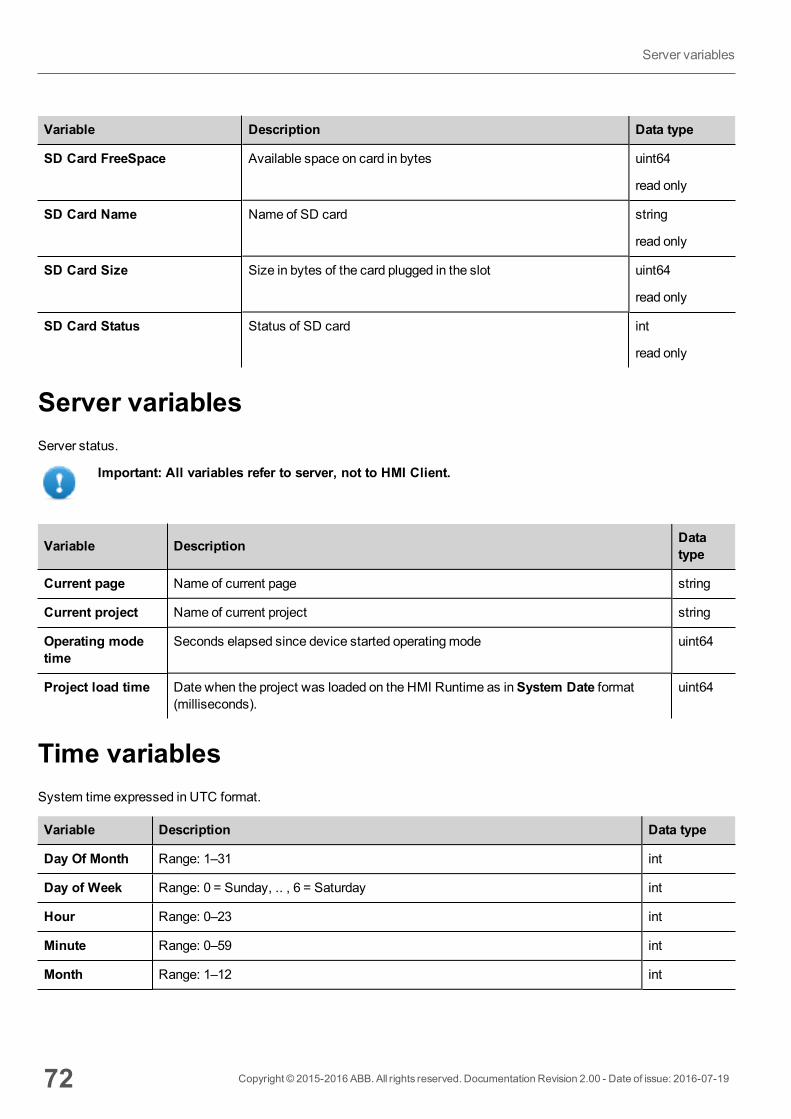
Variable Description Data type
SD Card FreeSpace Available space on card in bytes uint64
read only
SD Card Name Name of SD card string
read only
SD Card Size Size in bytes of the card plugged in the slot uint64
read only
SD Card Status Status of SD card int
read only
Server variablesServer status.
Important: All variables refer to server, not to HMI Client.
Variable Description Datatype
Current page Name of current page string
Current project Name of current project string
Operating modetime
Seconds elapsed since device started operatingmode uint64
Project load time Date when the project was loaded on the HMI Runtime as inSystem Date format(milliseconds).
uint64
Time variablesSystem time expressed in UTC format.
Variable Description Data type
Day Of Month Range: 1–31 int
Day of Week Range: 0 = Sunday, .. , 6 = Saturday int
Hour Range: 0–23 int
Minute Range: 0–59 int
Month Range: 1–12 int
72 Copyright © 2015-2016 ABB. All rights reserved. Documentation Revision 2.00 - Date of issue: 2016-07-19
Server variables
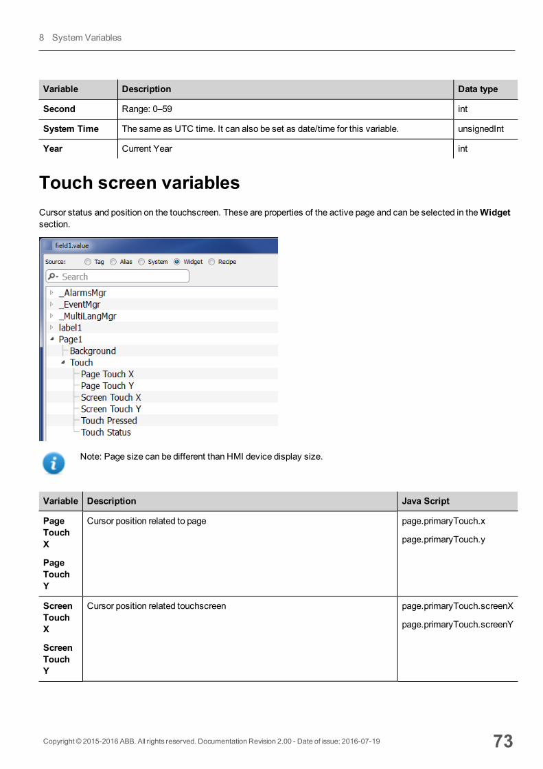
Variable Description Data type
Second Range: 0–59 int
System Time The same as UTC time. It can also be set as date/time for this variable. unsignedInt
Year Current Year int
Touch screen variablesCursor status and position on the touchscreen. These are properties of the active page and can be selected in theWidgetsection.
Note: Page size can be different than HMI device display size.
Variable Description Java Script
PageTouchX
PageTouchY
Cursor position related to page page.primaryTouch.x
page.primaryTouch.y
ScreenTouchX
ScreenTouchY
Cursor position related touchscreen page.primaryTouch.screenX
page.primaryTouch.screenY
Copyright © 2015-2016 ABB. All rights reserved. Documentation Revision 2.00 - Date of issue: 2016-07-19 73
8 System Variables
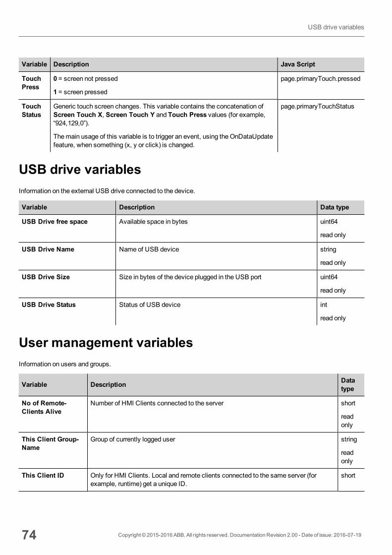
Variable Description Java Script
TouchPress
0 = screen not pressed
1 = screen pressed
page.primaryTouch.pressed
TouchStatus
Generic touch screen changes. This variable contains the concatenation ofScreen Touch X, Screen Touch Y and Touch Press values (for example,“924,129,0”).
Themain usage of this variable is to trigger an event, using the OnDataUpdatefeature, when something (x, y or click) is changed.
page.primaryTouchStatus
USB drive variablesInformation on the external USB drive connected to the device.
Variable Description Data type
USB Drive free space Available space in bytes uint64
read only
USB Drive Name Name of USB device string
read only
USB Drive Size Size in bytes of the device plugged in the USB port uint64
read only
USB Drive Status Status of USB device int
read only
User management variablesInformation on users and groups.
Variable Description Datatype
No of Remote-Clients Alive
Number of HMI Clients connected to the server short
readonly
This Client Group-Name
Group of currently logged user string
readonly
This Client ID Only for HMI Clients. Local and remote clients connected to the same server (forexample, runtime) get a unique ID.
short
74 Copyright © 2015-2016 ABB. All rights reserved. Documentation Revision 2.00 - Date of issue: 2016-07-19
USB drive variables

Variable Description Datatype
readonly
This Client User-Name
Name of the user logged to the client where the system variable is displayed. string
readonly
Copyright © 2015-2016 ABB. All rights reserved. Documentation Revision 2.00 - Date of issue: 2016-07-19 75
8 System Variables

76 Copyright © 2015-2016 ABB. All rights reserved. Documentation Revision 2.00 - Date of issue: 2016-07-19
Usermanagement variables
9 ActionsActions are functions used to interact with the system and are normally executed when events are triggered.
Events can be triggered by various widgets, for example on press and on release of a button. Not all actions are availablefor all the events of an object.
Actions are linked to widgets in theEvent section of the Property pane (Page Editor).
Alarm actions 78
Event actions 78
MultiLanguage actions 79
Keyboard actions 79
Page actions 81
Print actions 84
Recipe actions 86
Remote Client actions 89
System actions 90
Tag actions 96
Trend actions 98
User management actions 101
Widget actions 103
Copyright © 2015-2016 ABB. All rights reserved. Documentation Revision 2.00 - Date of issue: 2016-07-19 77
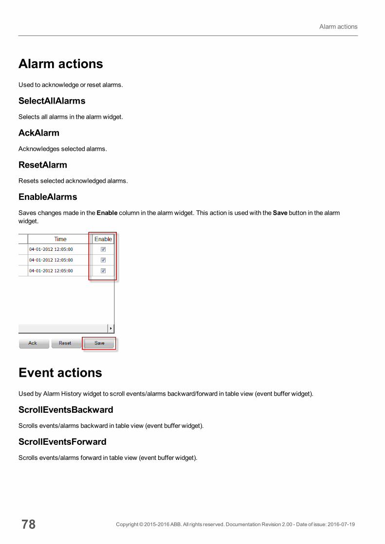
Alarm actionsUsed to acknowledge or reset alarms.
SelectAllAlarmsSelects all alarms in the alarm widget.
AckAlarmAcknowledges selected alarms.
ResetAlarmResets selected acknowledged alarms.
EnableAlarmsSaves changes made in theEnable column in the alarm widget. This action is used with theSave button in the alarmwidget.
Event actionsUsed by Alarm History widget to scroll events/alarms backward/forward in table view (event buffer widget).
ScrollEventsBackwardScrolls events/alarms backward in table view (event buffer widget).
ScrollEventsForwardScrolls events/alarms forward in table view (event buffer widget).
78 Copyright © 2015-2016 ABB. All rights reserved. Documentation Revision 2.00 - Date of issue: 2016-07-19
Alarm actions

MultiLanguage actionsSelects the application language.
SetLanguageSets the language used. The selected language will be applied at run time to all applicable widgets.
Keyboard actionsChanges the use of keypads.
SendKeySends one character to a numeric widget. TheKeypadType property of the numeric widget must be set as Macro.
SendKeyWidgetSends one character to a specific widget.
Example
TheUp andDown buttons use theSendKeyWidget action in association with theControl List Widget.
Copyright © 2015-2016 ABB. All rights reserved. Documentation Revision 2.00 - Date of issue: 2016-07-19 79
9 Actions
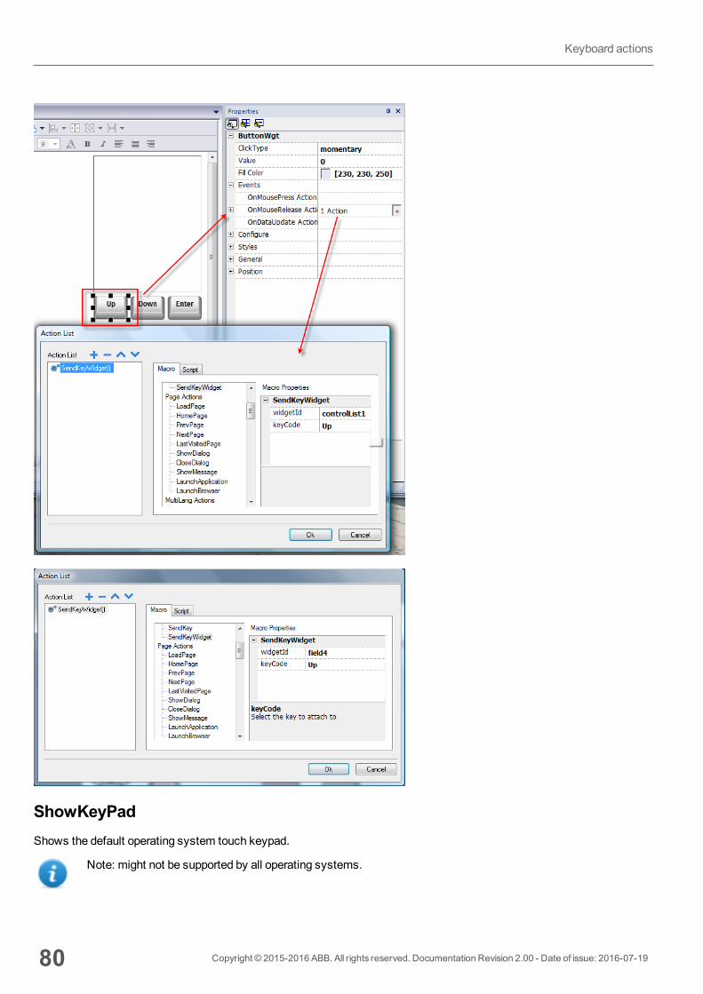
ShowKeyPadShows the default operating system touch keypad.
Note: might not be supported by all operating systems.
80 Copyright © 2015-2016 ABB. All rights reserved. Documentation Revision 2.00 - Date of issue: 2016-07-19
Keyboard actions

KeyboardEnables/disables the use of actions when using external keyboards. Action execution can be enabled/disabled both atproject and at page level.
The effect is equivalent to the use of the property Keyboard for project and page.
Page actionsPage navigation. Page actions can be used with the following events:
l OnMouseClick,l OnMouseRelease,l OnMouseHoldl OnActivatel OnDeactivatel Alarmsl Schedulers.
LoadPageGo to the selected page of the project.
HomePageGo to the home page.
You can set the home page in theBehavior section of theProject Widget, see "Behavior" on page 45
PrevPageGo to the previous page.
Copyright © 2015-2016 ABB. All rights reserved. Documentation Revision 2.00 - Date of issue: 2016-07-19 81
9 Actions
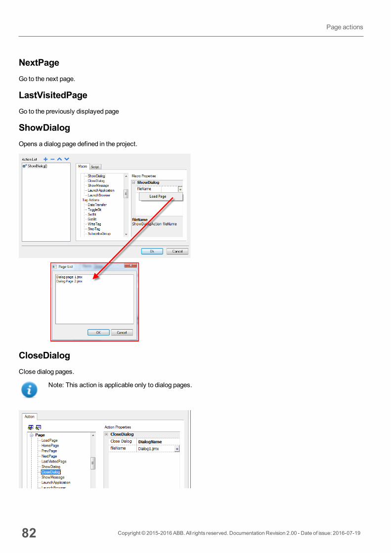
NextPageGo to the next page.
LastVisitedPageGo to the previously displayed page
ShowDialogOpens a dialog page defined in the project.
CloseDialogClose dialog pages.
Note: This action is applicable only to dialog pages.
82 Copyright © 2015-2016 ABB. All rights reserved. Documentation Revision 2.00 - Date of issue: 2016-07-19
Page actions
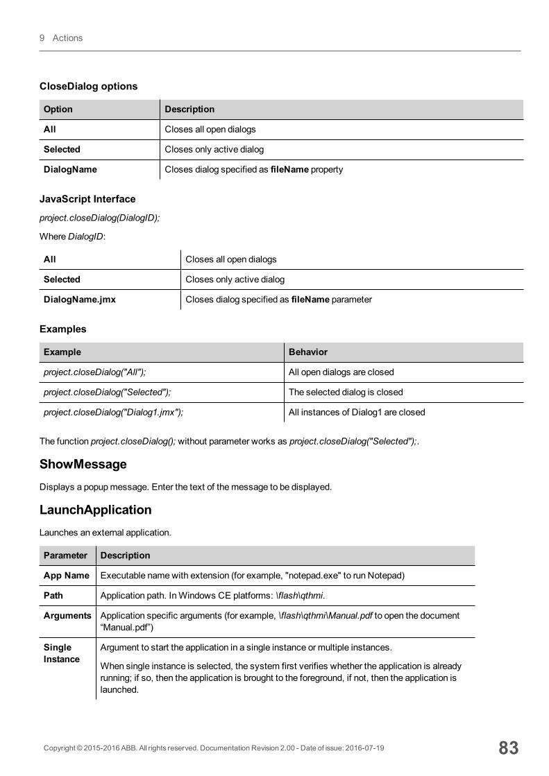
CloseDialog options
Option Description
All Closes all open dialogs
Selected Closes only active dialog
DialogName Closes dialog specified as fileName property
JavaScript Interface
project.closeDialog(DialogID);
WhereDialogID:
All Closes all open dialogs
Selected Closes only active dialog
DialogName.jmx Closes dialog specified as fileName parameter
Examples
Example Behavior
project.closeDialog("All"); All open dialogs are closed
project.closeDialog("Selected"); The selected dialog is closed
project.closeDialog("Dialog1.jmx"); All instances of Dialog1 are closed
The function project.closeDialog(); without parameter works as project.closeDialog("Selected");.
ShowMessageDisplays a popupmessage. Enter the text of themessage to be displayed.
LaunchApplicationLaunches an external application.
Parameter Description
App Name Executable namewith extension (for example, "notepad.exe" to run Notepad)
Path Application path. InWindows CE platforms: \flash\qthmi.
Arguments Application specific arguments (for example, \flash\qthmi\Manual.pdf to open the document“Manual.pdf”)
SingleInstance
Argument to start the application in a single instance or multiple instances.
When single instance is selected, the system first verifies whether the application is alreadyrunning; if so, then the application is brought to the foreground, if not, then the application islaunched.
Copyright © 2015-2016 ABB. All rights reserved. Documentation Revision 2.00 - Date of issue: 2016-07-19 83
9 Actions
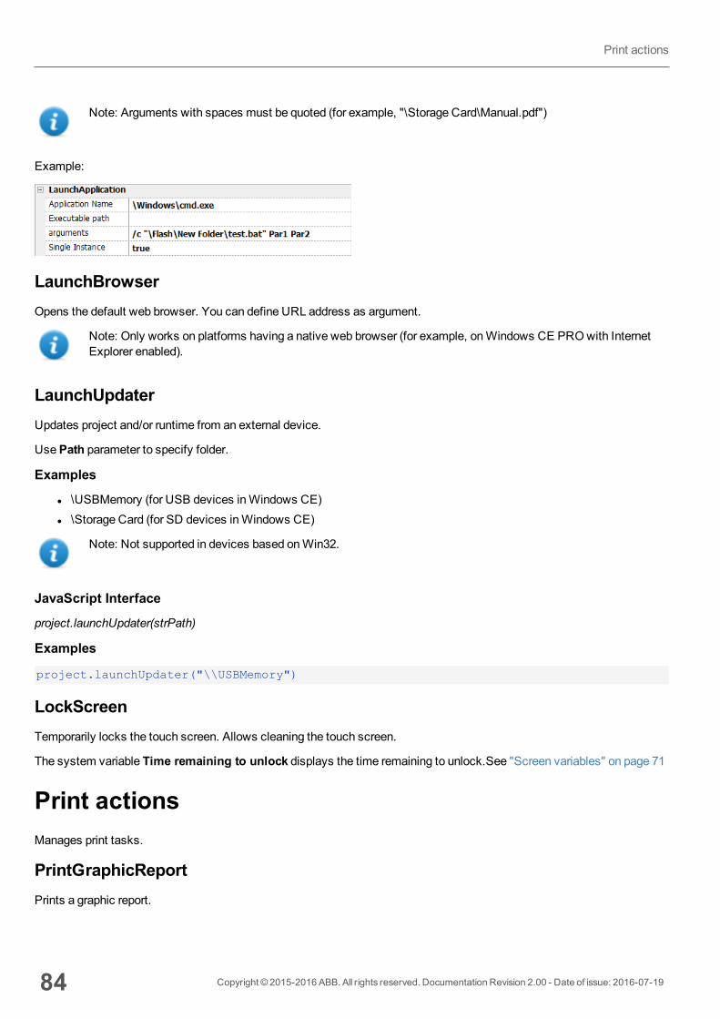
Note: Arguments with spaces must be quoted (for example, "\Storage Card\Manual.pdf")
Example:
LaunchBrowserOpens the default web browser. You can define URL address as argument.
Note: Only works on platforms having a native web browser (for example, onWindows CE PROwith InternetExplorer enabled).
LaunchUpdaterUpdates project and/or runtime from an external device.
UsePath parameter to specify folder.
Examples
l \USBMemory (for USB devices inWindows CE)l \Storage Card (for SD devices inWindows CE)
Note: Not supported in devices based onWin32.
JavaScript Interface
project.launchUpdater(strPath)
Examples
project.launchUpdater("\\USBMemory")
LockScreenTemporarily locks the touch screen. Allows cleaning the touch screen.
The system variable Time remaining to unlock displays the time remaining to unlock.See "Screen variables" on page 71
Print actionsManages print tasks.
PrintGraphicReportPrints a graphic report.
84 Copyright © 2015-2016 ABB. All rights reserved. Documentation Revision 2.00 - Date of issue: 2016-07-19
Print actions
Parameter Description
reportName Assigns a name to the report
silent false = allows to set printer properties at run time
PrintTextPrints a string.
Parameter Description
text String to be printed
silent false = allows to set printer properties at run time
This action works in line printingmode and uses a standard protocol common to all printers that support it. Text is printedimmediately line by line or after a timeout custom for each printer model.
Note: printing could a few minutes for models not designed for line printing.
No custom driver is required.
PrintBytesPrints an hexadecimal string representing data to print (for example, "1b30" to print < ESC 0 >.
Parameter Description
bytes Exadecimal string to print
silent false = allows to set printer properties at run time
This action works in line printingmode and uses a standard protocol common to all printers that support it. Text is printedimmediately line by line or after a timeout custom for each printer model.
Note: printing could a few minutes for models not designed for line printing.
No custom driver is required.
EmptyPrintQueueFlushes the current printing queue. If executed while executing a job, the queue is cleared at the end of the job.
PausePrintingPuts the current printing queue on hold. If executed while executing a job, the queue is paused at the end of the job.
ResumePrintingRestarts a queue previously put on hold.
Copyright © 2015-2016 ABB. All rights reserved. Documentation Revision 2.00 - Date of issue: 2016-07-19 85
9 Actions
AbortPrintingStop the execution of the current job and removes it from the queue. If the queue has another job, then, after aborting, thenext job starts.
Recipe actionsUsed to program recipemanagement.
DownLoadRecipeCopy recipe data from HMI device flashmemory to the controller (e.g. PLC, local variable, depending on the protocol).
Parameter Description
RecipeName Name of recipe to download
RecipeSet Number of recipe set to copy.
curSet = download currently selected recipe set
UpLoadRecipeSaves recipe data from the controller (e.g. PLC, local variable, depending on the protocol) to the device FlashMemory.
Parameter Description
RecipeName Name of recipe to upload
RecipeSet Number of recipe set to copy.
curSet = upload currently selected recipe set
WriteCurrentRecipeSetSets the selected recipe as current recipe set.
Parameter Description
RecipeName Name of recipe to set as current recipe
RecipeSet Recipe set to define as current recipe set
DownLoadCurRecipeDownloads current set of recipe data to the controller.
No parameter is required.
UploadCurRecipeUploads set of controller data to current recipe set.
No parameter is required
86 Copyright © 2015-2016 ABB. All rights reserved. Documentation Revision 2.00 - Date of issue: 2016-07-19
Recipe actions
ResetRecipeRestores factory settings for recipe data. Original recipe data will overwrite uploaded recipes
Select the recipe that you want to reset to factory data.
DumpRecipeDataDumps recipe data to internal or external storage. Data is saved in .csv format.
Define the location where to save the file.
Note: supported formats are FAT or FAT32. NTFS format is not supported.
Parameter Description
DateTimePrefixFileName true = the dumped file will have date and time as prefix to its name (for example D2012_01_01_T10_10_recipe1.csv)
TimeSpec Time format:
l Local = the time values exported are the time of the HMI device.l Global = the time values exported are in UTC format.
FileName Tag that specifies a filename.
RestoreRecipeDataRestores previously saved recipe data.
Enter the file full path of the Recipe files in any external storage like USB, SD or network paths.
Note: supported formats are FAT or FAT32. NTFS format is not supported.
Parameter Description
FileName Attached tag from which read the file name at run time.
BrowseForFile true = shows theOpen dialog to browse the file to read.
false = no dialog is shown,
AddRecipeDataSetAdds a new dataset to the selected recipe. The new dataset is appended at the end of the already defined datasets.
Copyright © 2015-2016 ABB. All rights reserved. Documentation Revision 2.00 - Date of issue: 2016-07-19 87
9 Actions
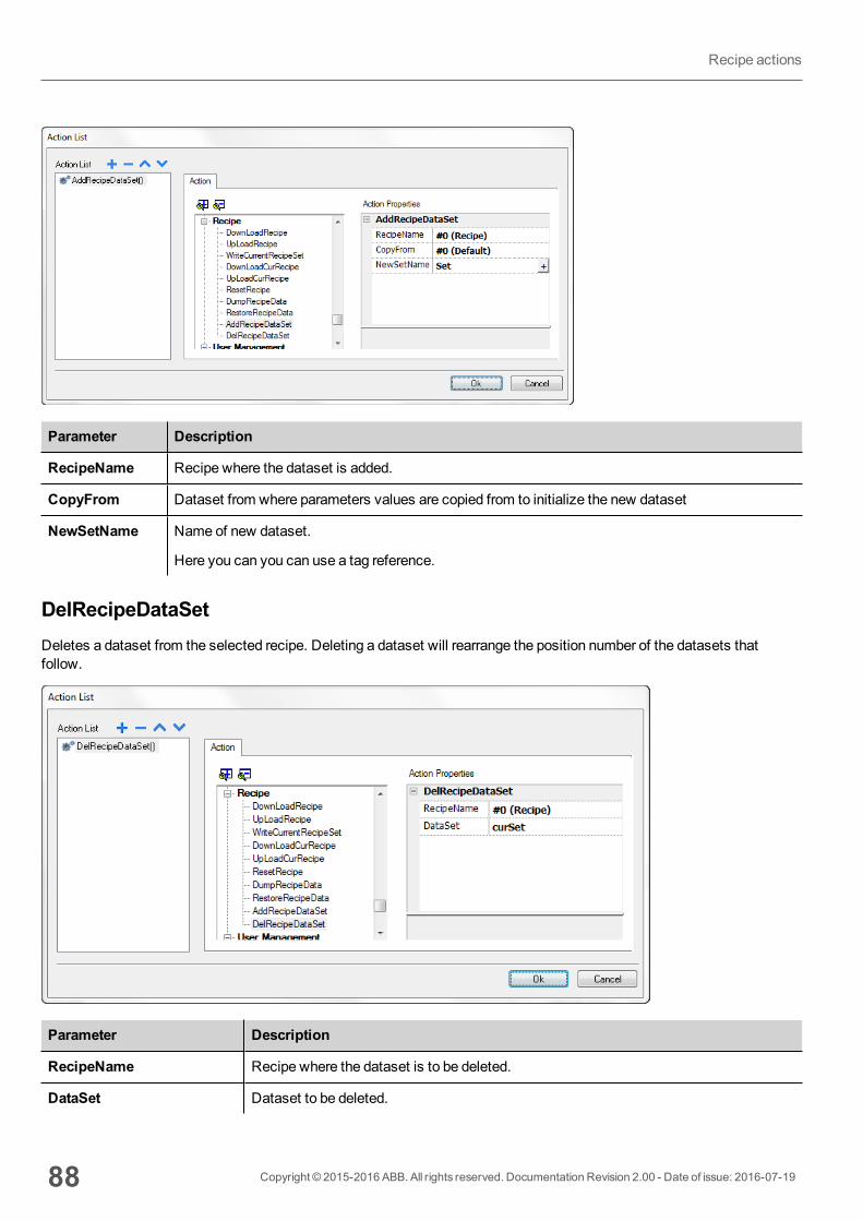
Parameter Description
RecipeName Recipe where the dataset is added.
CopyFrom Dataset from where parameters values are copied from to initialize the new dataset
NewSetName Name of new dataset.
Here you can you can use a tag reference.
DelRecipeDataSetDeletes a dataset from the selected recipe. Deleting a dataset will rearrange the position number of the datasets thatfollow.
Parameter Description
RecipeName Recipe where the dataset is to be deleted.
DataSet Dataset to be deleted.
88 Copyright © 2015-2016 ABB. All rights reserved. Documentation Revision 2.00 - Date of issue: 2016-07-19
Recipe actions
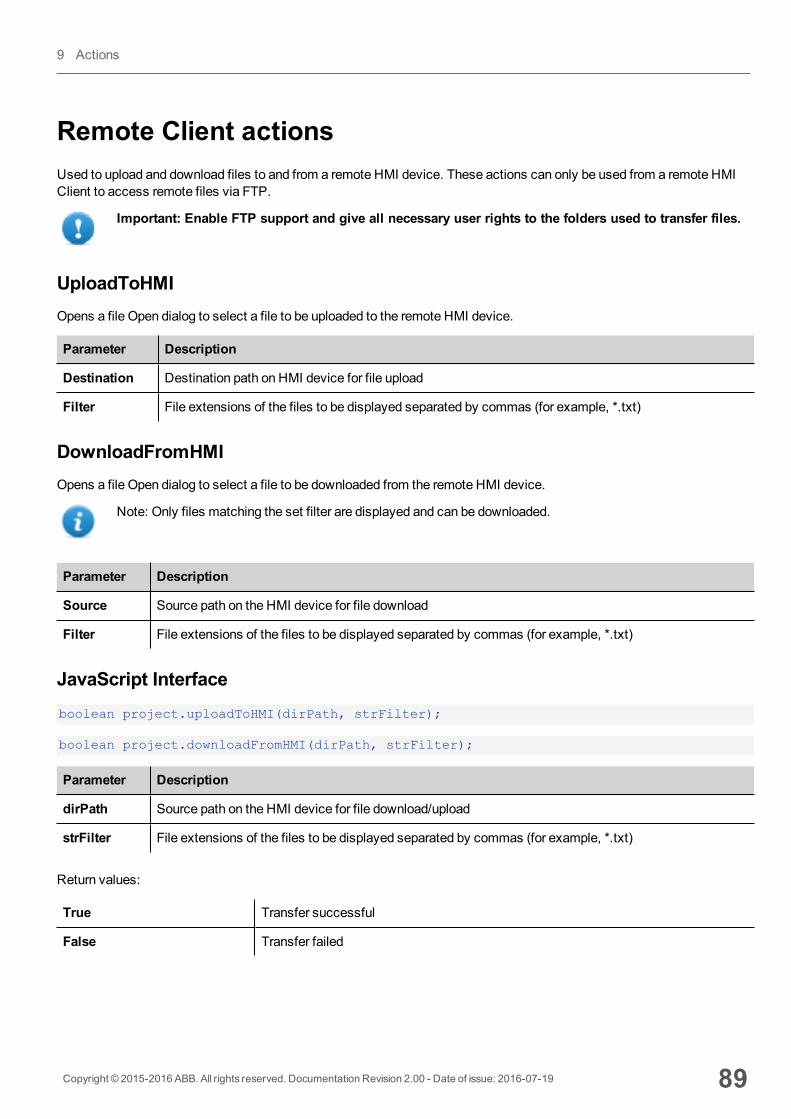
Remote Client actionsUsed to upload and download files to and from a remote HMI device. These actions can only be used from a remote HMIClient to access remote files via FTP.
Important: Enable FTP support and give all necessary user rights to the folders used to transfer files.
UploadToHMIOpens a file Open dialog to select a file to be uploaded to the remote HMI device.
Parameter Description
Destination Destination path on HMI device for file upload
Filter File extensions of the files to be displayed separated by commas (for example, *.txt)
DownloadFromHMIOpens a file Open dialog to select a file to be downloaded from the remote HMI device.
Note: Only files matching the set filter are displayed and can be downloaded.
Parameter Description
Source Source path on the HMI device for file download
Filter File extensions of the files to be displayed separated by commas (for example, *.txt)
JavaScript Interfaceboolean project.uploadToHMI(dirPath, strFilter);
boolean project.downloadFromHMI(dirPath, strFilter);
Parameter Description
dirPath Source path on the HMI device for file download/upload
strFilter File extensions of the files to be displayed separated by commas (for example, *.txt)
Return values:
True Transfer successful
False Transfer failed
Copyright © 2015-2016 ABB. All rights reserved. Documentation Revision 2.00 - Date of issue: 2016-07-19 89
9 Actions

Note: When transferred, system variables are updated with the status of ongoing operations.
System actionsUsed tomanage system properties.
RestartRestarts the runtime.
DumpTrendStores historical trend data to external drives (USB drive or SD card).
Parameter Description
TrendName Name of historical trend to store
FolderPath Destination folder:
USB drive = \USBMemory
SD Card = \Storage Card
FileFormat Binary = the buffer is dumped in binary format (a .dat file and .inf file). Both these files arethen required to convert data in .csv format by an external utility.
Compatibility CSV = the buffer is dumped to the specified location as a .csv file formatcompatible with versions 1.xx
Compact CSV = the buffer is dumped to the specified location as a .csv file using a newerformat
See "Exporting trend buffer data" on page 137
DateTimePrefixFileName true = the dumped file will have date and time as prefix to its name (for example D2012_01_01_T10_10_Trend1.csv)
90 Copyright © 2015-2016 ABB. All rights reserved. Documentation Revision 2.00 - Date of issue: 2016-07-19
System actions

Parameter Description
timeSpec Time format:
l Local = the time values exported are the time of the HMI device.l Global = the time values exported are in UTC format.
FileName Enabled when the DateTimePrefixFileName=true
The below wildcards are supported
l %n= Trend namel %y = Yearl %M = Monthl %d= Dayl %h= Hourl %m = Minutesl %s = Seconds
Example: \%n\%y%M%d\%h%m%s
Note: execution of the DumpTrend action will automatically force a flush to disk of the data temporarilymaintained in the RAMmemory. See "History trends" on page 140 for details on how to save sampled data todisk.
Note: external drives connected to USB port must have format FAT or FAT32. NTFS format is not supported.
WARNING: Be aware there are limits in the max number of files that can create inside a folder. Limitsare depending of different factors and are not simple to calculate, you can think as 999 the maxnumber of files that can be use inside a folder.
To convert binary dump files to .csv
The TrendBufferReader.exe tool is stored in theUtils folder of the PB610-B Panel Builder 600 installation folder.
Use the following syntax:
TrendBufferReader -r Trend1 Trend1.csv 1
where:
Trend1 = name of the trend buffer without extension resulting from the dump (original file name is trend1.dat)
Trend1.csv = name for the output file.
.csv file structure
The resulting .csv file has five columns
Copyright © 2015-2016 ABB. All rights reserved. Documentation Revision 2.00 - Date of issue: 2016-07-19 91
9 Actions
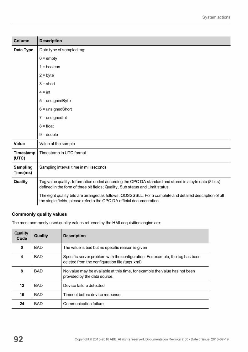
Column Description
Data Type Data type of sampled tag:
0 = empty
1 = boolean
2 = byte
3 = short
4 = int
5 = unsignedByte
6 = unsignedShort
7 = unsignedInt
8 = float
9 = double
Value Value of the sample
Timestamp(UTC)
Timestamp in UTC format
SamplingTime(ms)
Sampling interval time inmilliseconds
Quality Tag value quality. Information coded according the OPC DA standard and stored in a byte data (8 bits)defined in the form of three bit fields; Quality, Sub status and Limit status.
The eight quality bits are arranged as follows: QQSSSSLL. For a complete and detailed description of allthe single fields, please refer to the OPC DA official documentation.
Commonly quality values
Themost commonly used quality values returned by the HMI acquisition engine are:
QualityCode Quality Description
0 BAD The value is bad but no specific reason is given
4 BAD Specific server problem with the configuration. For example, the tag has beendeleted from the configuration file (tags.xml).
8 BAD No valuemay be available at this time, for example the value has not beenprovided by the data source.
12 BAD Device failure detected
16 BAD Timeout before device response.
24 BAD Communication failure
92 Copyright © 2015-2016 ABB. All rights reserved. Documentation Revision 2.00 - Date of issue: 2016-07-19
System actions
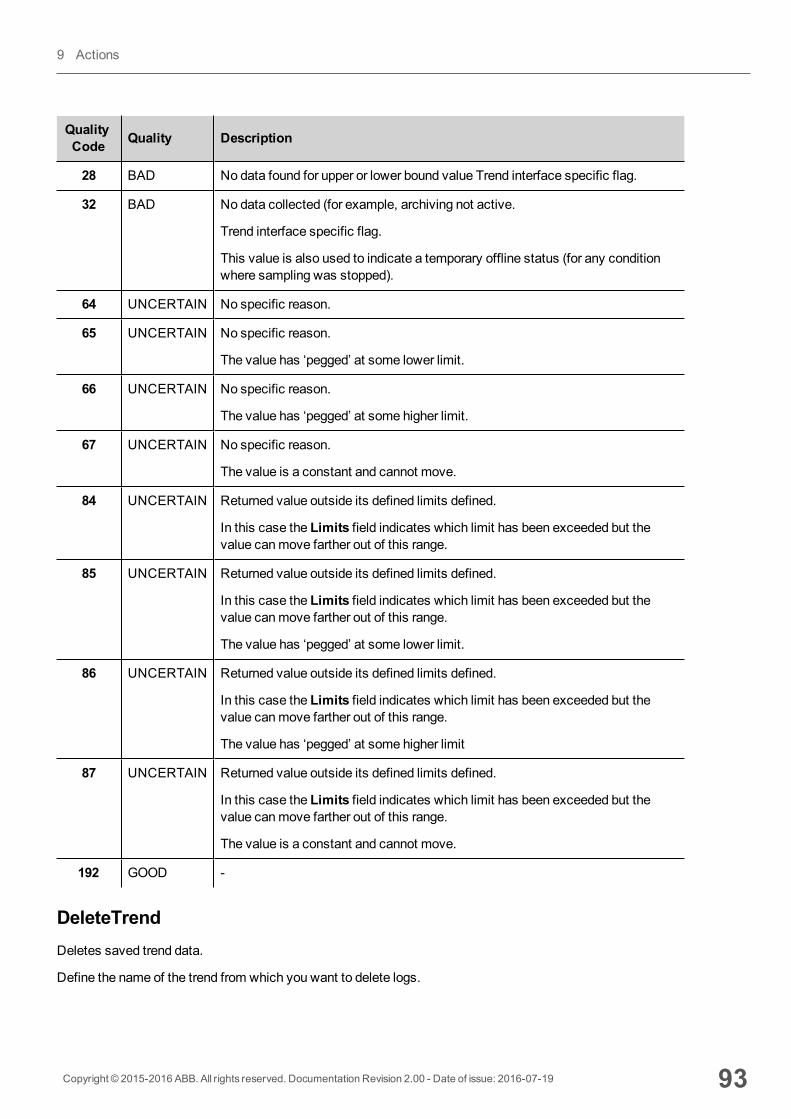
QualityCode Quality Description
28 BAD No data found for upper or lower bound value Trend interface specific flag.
32 BAD No data collected (for example, archiving not active.
Trend interface specific flag.
This value is also used to indicate a temporary offline status (for any conditionwhere sampling was stopped).
64 UNCERTAIN No specific reason.
65 UNCERTAIN No specific reason.
The value has ‘pegged’ at some lower limit.
66 UNCERTAIN No specific reason.
The value has ‘pegged’ at some higher limit.
67 UNCERTAIN No specific reason.
The value is a constant and cannot move.
84 UNCERTAIN Returned value outside its defined limits defined.
In this case the Limits field indicates which limit has been exceeded but thevalue canmove farther out of this range.
85 UNCERTAIN Returned value outside its defined limits defined.
In this case the Limits field indicates which limit has been exceeded but thevalue canmove farther out of this range.
The value has ‘pegged’ at some lower limit.
86 UNCERTAIN Returned value outside its defined limits defined.
In this case the Limits field indicates which limit has been exceeded but thevalue canmove farther out of this range.
The value has ‘pegged’ at some higher limit
87 UNCERTAIN Returned value outside its defined limits defined.
In this case the Limits field indicates which limit has been exceeded but thevalue canmove farther out of this range.
The value is a constant and cannot move.
192 GOOD -
DeleteTrendDeletes saved trend data.
Define the name of the trend from which you want to delete logs.
Copyright © 2015-2016 ABB. All rights reserved. Documentation Revision 2.00 - Date of issue: 2016-07-19 93
9 Actions

DumpEventArchiveStores historical alarm log and audit trail data to external drives, such as USB memory or SD card.
Parameter Description
EventArchive Name of buffer to dump data
FolderPath Destination folder:
l USB drive = \USBMemoryl SD Card = \Storage Card
Note: supported formats are FAT or FAT32. NTFS format is notsupported.
DumpConfigFile Enables conversion to .csv file
DumpAsCSV true = the buffer is dumped to the specified location as a .csv file
false = the buffer is dumped in binary format (a .dat file and .inf file). Both thesefiles are then required to convert data in .csv format by an external utility.
DateTimePrefixFileName true = the dumped file will have date and time as prefix to its name (for exampleD2012_01_01_T10_10_alarmBuffer1.csv)
Note: option only available when exporting directly in .csv format.
timeSpec Time format:
l Local = the time values exported are the time of the HMI device.l Global = the time values exported are in UTC format.
FileName Enabled when the DateTimePrefixFileName=true
The below wildcards are supported
l %n= Event archive namel %y = Yearl %M = Monthl %d= Dayl %h= Hourl %m = Minutesl %s = Seconds
Example: \%n\%y%M%d\%h%m%s
Example
When exporting Event buffers in binary format andDumpConfigFile is set to true (recommended settings), there are twofolders:
l data, containing data files,l config, containing configuration files for .csv conversion.
94 Copyright © 2015-2016 ABB. All rights reserved. Documentation Revision 2.00 - Date of issue: 2016-07-19
System actions
Once the two folders are copied from the USB drive to the computer disk, the folder structure will be:
\config\
alarms.xml
eventconfig.xml
\data\
AlarmBuffer1.dat
AlarmBuffer1.inf
\
AlarmBufferReader.exe
To convert dump files to .csv
The AlarmBufferReader.exe tool is stored in theUtils folder of the PB610-B Panel Builder 600 installation folder.
Use the following syntax:
AlarmBufferReader AlarmBuffer1 FILE ./AlarmBuffer1.csv
where:
AlarmBuffer1 = name of the dumped .dat without extension
AlarmBuffer1.csv = name for the output file.
The utility AuditTrailBufferReader.exe is available for Audit Trail buffers.
Note: set DumpConfigFile to true.
The result of the dump is a folder structure similar to the one generated for Events.
Use the following syntax:
AuditTrailBufferReader AuditTrail FILE ./AuditTrail.csv
where:
AuditTrail = name of the dumped buffer without extension and
AuditTrail1.csv = name for the output file.
csv Columns
Note: available only for Alarms buffers.
For Alarms buffers, additional columns can be included in the dump .csv file.
Copyright © 2015-2016 ABB. All rights reserved. Documentation Revision 2.00 - Date of issue: 2016-07-19 95
9 Actions
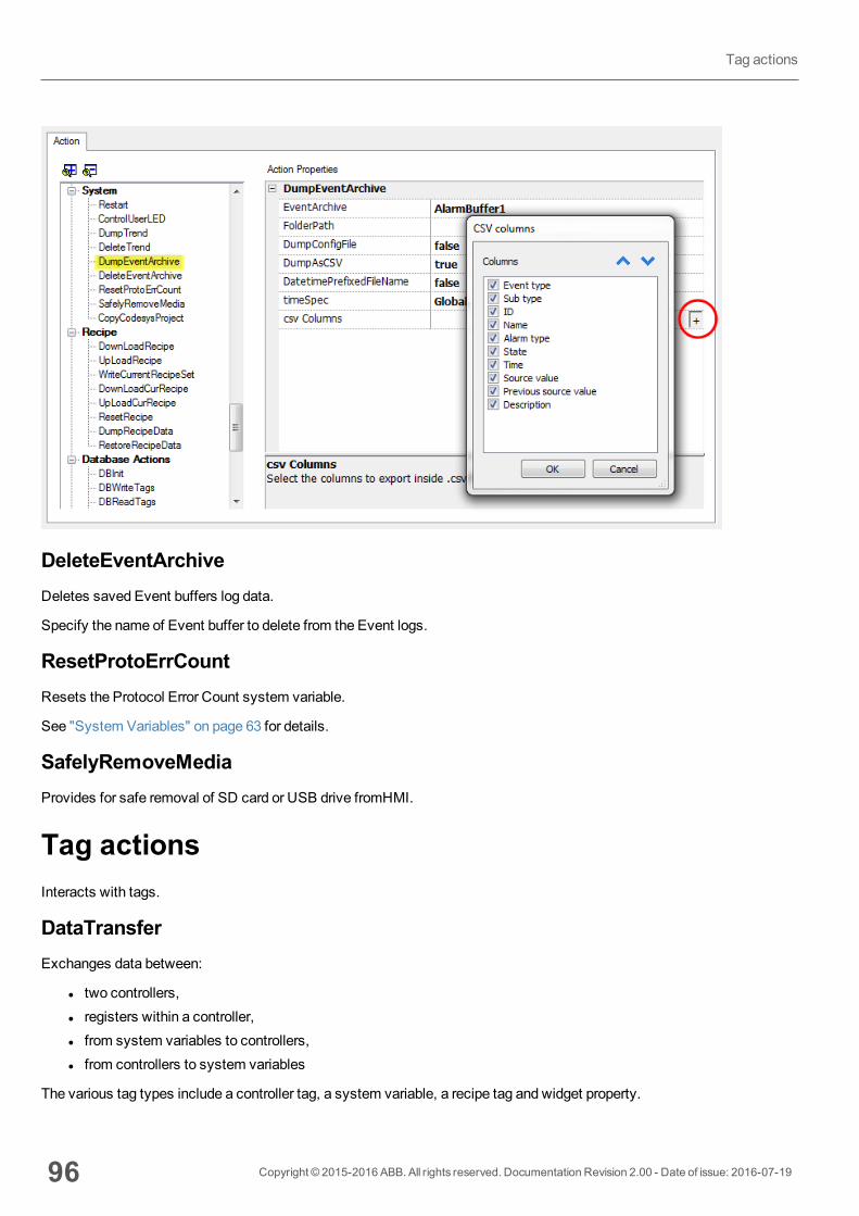
DeleteEventArchiveDeletes saved Event buffers log data.
Specify the name of Event buffer to delete from the Event logs.
ResetProtoErrCountResets the Protocol Error Count system variable.
See "System Variables" on page 63 for details.
SafelyRemoveMediaProvides for safe removal of SD card or USB drive fromHMI.
Tag actionsInteracts with tags.
DataTransferExchanges data between:
l two controllers,l registers within a controller,l from system variables to controllers,l from controllers to system variables
The various tag types include a controller tag, a system variable, a recipe tag and widget property.
96 Copyright © 2015-2016 ABB. All rights reserved. Documentation Revision 2.00 - Date of issue: 2016-07-19
Tag actions
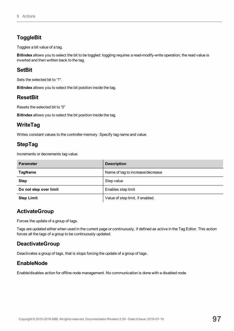
ToggleBitToggles a bit value of a tag.
BitIndex allows you to select the bit to be toggled: toggling requires a read-modify-write operation; the read value isinverted and then written back to the tag.
SetBitSets the selected bit to “1".
BitIndex allows you to select the bit position inside the tag.
ResetBitResets the selected bit to “0”
BitIndex allows you to select the bit position inside the tag.
WriteTagWrites constant values to the controller memory. Specify tag name and value.
StepTagIncrements or decrements tag value.
Parameter Description
TagName Name of tag to increase/decrease
Step Step value
Do not step over limit Enables step limit
Step Limit Value of step limit, if enabled.
ActivateGroupForces the update of a group of tags.
Tags are updated either when used in the current page or continuously, if defined as active in the Tag Editor. This actionforces all the tags of a group to be continuously updated.
DeactivateGroupDeactivates a group of tags, that is stops forcing the update of a group of tags.
EnableNodeEnable/disables action for offline nodemanagement. No communication is done with a disabled node.
Copyright © 2015-2016 ABB. All rights reserved. Documentation Revision 2.00 - Date of issue: 2016-07-19 97
9 Actions
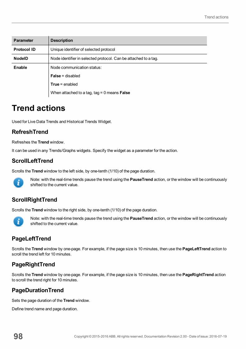
Parameter Description
Protocol ID Unique identifier of selected protocol
NodeID Node identifier in selected protocol. Can be attached to a tag.
Enable Node communication status:
False = disabled
True = enabled
When attached to a tag, tag = 0means False
Trend actionsUsed for Live Data Trends and Historical Trends Widget.
RefreshTrendRefreshes the Trendwindow.
It can be used in any Trends/Graphs widgets. Specify the widget as a parameter for the action.
ScrollLeftTrendScrolls the Trendwindow to the left side, by one-tenth (1/10) of the page duration.
Note: with the real-time trends pause the trend using thePauseTrend action, or the window will be continuouslyshifted to the current value.
ScrollRightTrendScrolls the Trendwindow to the right side, by one-tenth (1/10) of the page duration.
Note: with the real-time trends pause the trend using thePauseTrend action, or the window will be continuouslyshifted to the current value.
PageLeftTrendScrolls the Trendwindow by one-page. For example, if the page size is 10minutes, then use thePageLeftTrend action toscroll the trend left for 10minutes.
PageRightTrendScrolls the Trendwindow by one-page. For example, if the page size is 10minutes, then use thePageRightTrend actionto scroll the trend right for 10minutes.
PageDurationTrendSets the page duration of the Trendwindow.
Define trend name and page duration.
98 Copyright © 2015-2016 ABB. All rights reserved. Documentation Revision 2.00 - Date of issue: 2016-07-19
Trend actions

Note: you can set page duration at run time using a combo box widget.
ZoomInTrendReduces page duration.
ZoomOutTrendExtends page duration.
ZoomResetTrendReset the zoom level back to the original zoom level.
PauseTrendStops plotting the trend curves in the Trendwindow.
When used with real time trend the plotting stops when the curve reaches the right border of the graph. This action does notstop trend logging.
ResumeTrendResumes trend plotting if paused.
ShowTrendCursorShows value of the curve at a given point on the X axis.
It activates the trend cursor. A cursor (vertical line) will be displayed in the trend widget.
When the graphic cursor is enabled, the scrolling of the trend is stopped.
TheScrollCursor actionmoves the graphic cursor over the curves, or over the entire Trendwindow.
ScrollTrendCursorScrolls the trend cursor backward or forward.
The Y cursor value will display the trend value at the point of the cursor. Scrolling percentage can be set at 1% or 10%. Thepercentage is calculated on the trend window duration.
Copyright © 2015-2016 ABB. All rights reserved. Documentation Revision 2.00 - Date of issue: 2016-07-19 99
9 Actions
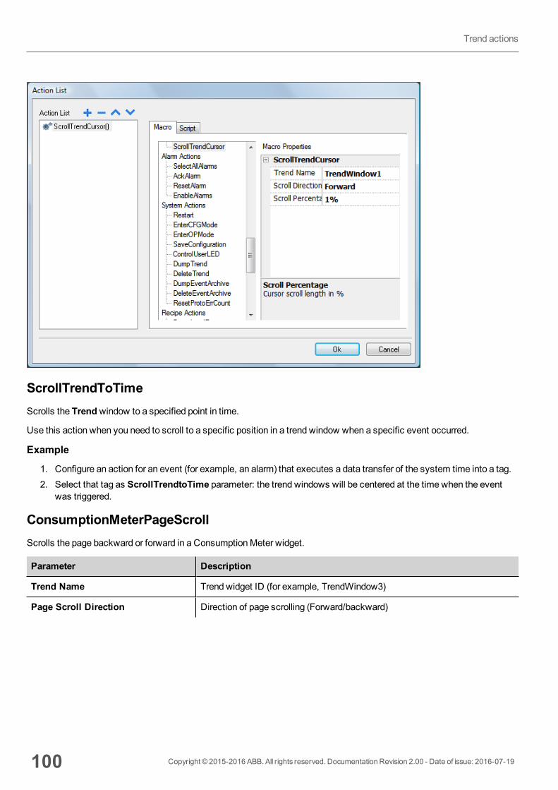
ScrollTrendToTimeScrolls the Trendwindow to a specified point in time.
Use this action when you need to scroll to a specific position in a trend window when a specific event occurred.
Example
1. Configure an action for an event (for example, an alarm) that executes a data transfer of the system time into a tag.2. Select that tag as ScrollTrendtoTime parameter: the trend windows will be centered at the time when the event
was triggered.
ConsumptionMeterPageScrollScrolls the page backward or forward in a ConsumptionMeter widget.
Parameter Description
Trend Name Trend widget ID (for example, TrendWindow3)
Page Scroll Direction Direction of page scrolling (Forward/backward)
100 Copyright © 2015-2016 ABB. All rights reserved. Documentation Revision 2.00 - Date of issue: 2016-07-19
Trend actions
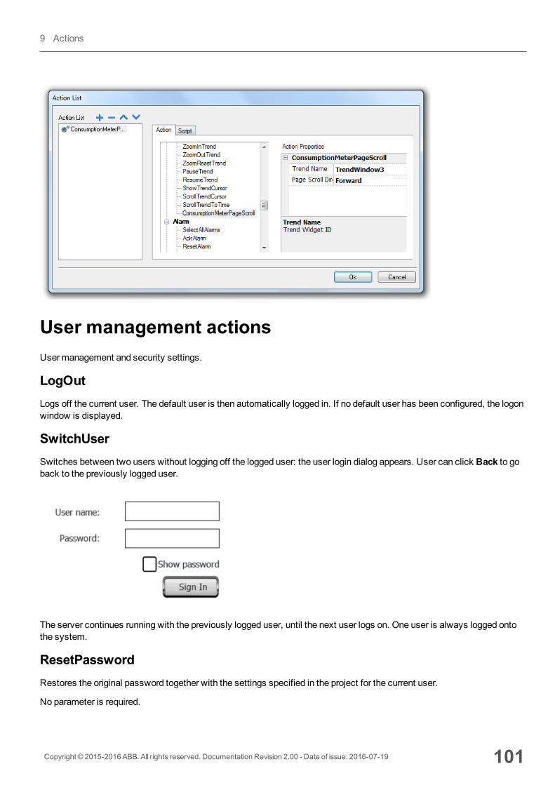
User management actionsUsermanagement and security settings.
LogOutLogs off the current user. The default user is then automatically logged in. If no default user has been configured, the logonwindow is displayed.
SwitchUserSwitches between two users without logging off the logged user: the user login dialog appears. User can click Back to goback to the previously logged user.
The server continues running with the previously logged user, until the next user logs on. One user is always logged ontothe system.
ResetPasswordRestores the original password together with the settings specified in the project for the current user.
No parameter is required.
Copyright © 2015-2016 ABB. All rights reserved. Documentation Revision 2.00 - Date of issue: 2016-07-19 101
9 Actions
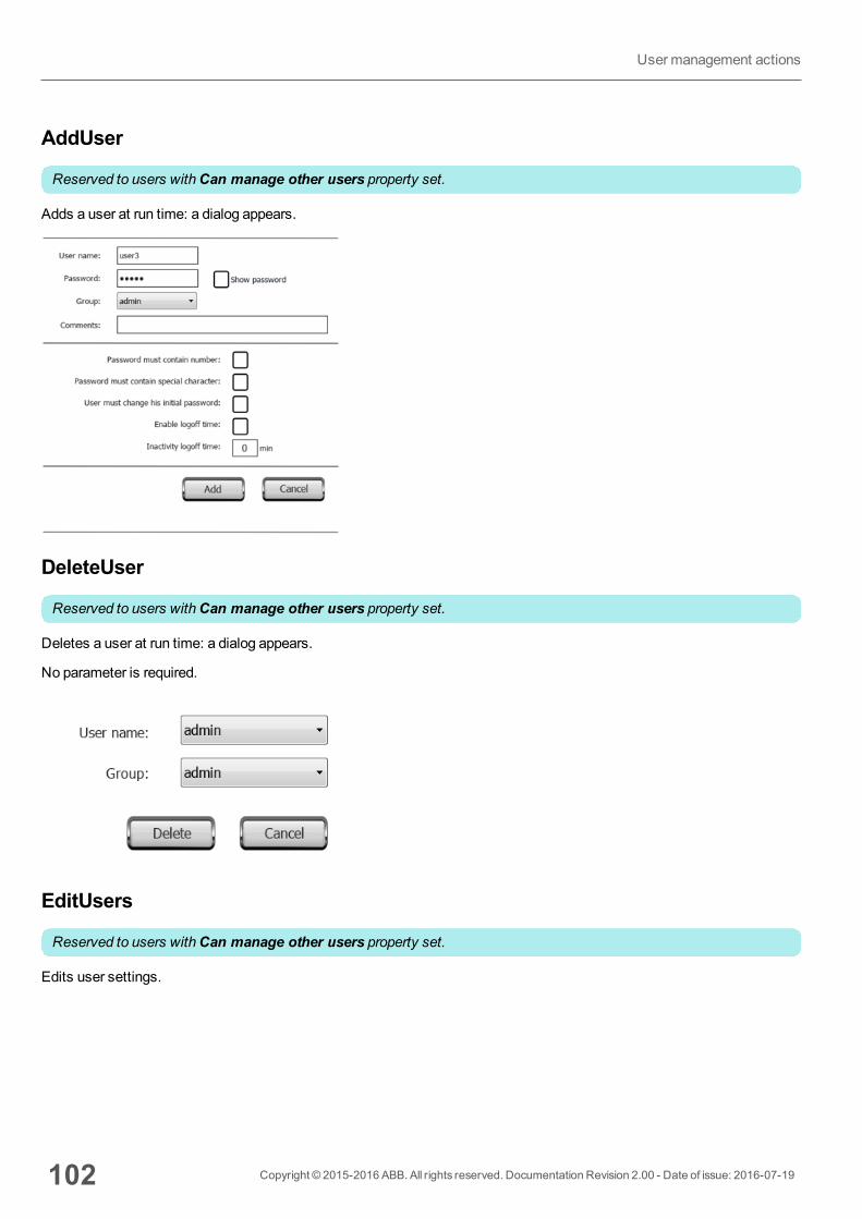
AddUser
Reserved to users withCan manage other users property set.
Adds a user at run time: a dialog appears.
DeleteUser
Reserved to users withCan manage other users property set.
Deletes a user at run time: a dialog appears.
No parameter is required.
EditUsers
Reserved to users withCan manage other users property set.
Edits user settings.
102 Copyright © 2015-2016 ABB. All rights reserved. Documentation Revision 2.00 - Date of issue: 2016-07-19
Usermanagement actions
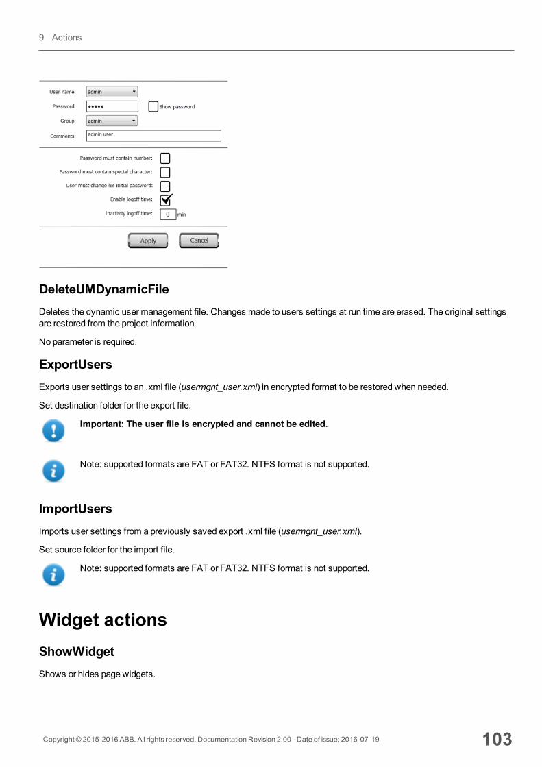
DeleteUMDynamicFileDeletes the dynamic user management file. Changes made to users settings at run time are erased. The original settingsare restored from the project information.
No parameter is required.
ExportUsersExports user settings to an .xml file (usermgnt_user.xml) in encrypted format to be restored when needed.
Set destination folder for the export file.
Important: The user file is encrypted and cannot be edited.
Note: supported formats are FAT or FAT32. NTFS format is not supported.
ImportUsersImports user settings from a previously saved export .xml file (usermgnt_user.xml).
Set source folder for the import file.
Note: supported formats are FAT or FAT32. NTFS format is not supported.
Widget actionsShowWidgetShows or hides page widgets.
Copyright © 2015-2016 ABB. All rights reserved. Documentation Revision 2.00 - Date of issue: 2016-07-19 103
9 Actions
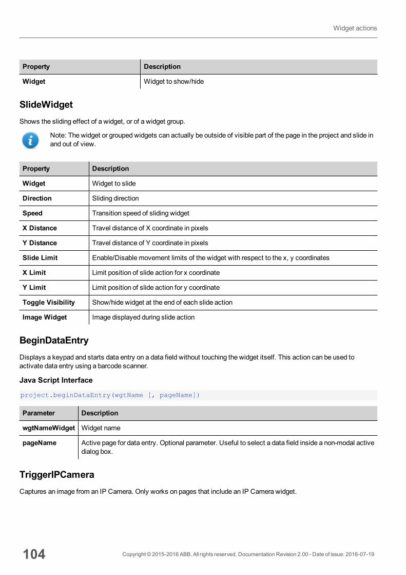
Property Description
Widget Widget to show/hide
SlideWidgetShows the sliding effect of a widget, or of a widget group.
Note: The widget or grouped widgets can actually be outside of visible part of the page in the project and slide inand out of view.
Property Description
Widget Widget to slide
Direction Sliding direction
Speed Transition speed of sliding widget
X Distance Travel distance of X coordinate in pixels
Y Distance Travel distance of Y coordinate in pixels
Slide Limit Enable/Disable movement limits of the widget with respect to the x, y coordinates
X Limit Limit position of slide action for x coordinate
Y Limit Limit position of slide action for y coordinate
Toggle Visibility Show/hide widget at the end of each slide action
Image Widget Image displayed during slide action
BeginDataEntryDisplays a keypad and starts data entry on a data field without touching the widget itself. This action can be used toactivate data entry using a barcode scanner.
Java Script Interface
project.beginDataEntry(wgtName [, pageName])
Parameter Description
wgtNameWidget Widget name
pageName Active page for data entry. Optional parameter. Useful to select a data field inside a non-modal activedialog box.
TriggerIPCameraCaptures an image from an IP Camera. Only works on pages that include an IP Camera widget.
104 Copyright © 2015-2016 ABB. All rights reserved. Documentation Revision 2.00 - Date of issue: 2016-07-19
Widget actions
MoveIPCameraSends remote commands to a camera that supports them. See "IPCamera widgets" on page 233 for details. Make surethat the IP Camera supports movement commands.
RefreshEventRefreshes the event buffer forAlarm Historywidget. See "Alarms History widget" on page 123 for details.
ContextMenuDisplays the context menu.
If Context Menu property of Project Widget has been set toOn delay context menu can appear also touching for a fewseconds the background area of the screen. See "Project properties pane" on page 40
ReplaceMediaReplaces existingmedia files with new files from USB/SD card. Can be used to replace video files of MediaPlayerwidgets, or images of project.
Note: New media files must have same name and format of the files to be replaced.
Parameter Description
Media Type Type of file to update
Device Device where new media files are supplied
sourcePath Folder where new media files are stored (for example, "\USBMemory")
Image Resize Resizes new images to the size of images to be replaced. Not applicable to video files.
Silent Replaces media automatically. As defau a dialog is displayed for the user to specify file location.
Java Script Interface
void replaceMedia(var sourcePath, var bSilent, var Device, var nMediaType, varbResize)
project.replaceMedia("Images", true, "\USBMemory", 1, true);
Copyright © 2015-2016 ABB. All rights reserved. Documentation Revision 2.00 - Date of issue: 2016-07-19 105
9 Actions

106 Copyright © 2015-2016 ABB. All rights reserved. Documentation Revision 2.00 - Date of issue: 2016-07-19
Widget actions
10 Using the Client applicationHMI Client is a standalone application which provides remote access to the HMI Runtime, and is included in the PB610-BPanel Builder 600. HMI Client uses the same graphic rendering system as the runtime in the HMI devices, it relies on aspecified HMI Runtime as server for live data.
To run the HMI Client application:
1. From theStartmenu > PB610-B Panel Builder 600 >HMI Client: the client opens in a browser-like style window.2. Type the server/device IP address in the address bar (for example: http://192.168.1.12): HMI Client will connect to
the server and the same graphical application running on the device will be loaded in the client window.
HMI Client acts as a remote client and communicates to the server, sharing the local visualization with the tag values thataremaintained or updated by the communication protocol.
HMI projects contain properties indicating which page is currently displayed on the HMI and can force the HMI to switch toa specific page. You can use these properties to synchronize pages showed on the HMI device and HMI Client or to controlan HMI device with a PLC.
See "Behavior" on page 45 for details.
The Client application toolbar 108
Workspace 108
Settings and time zone options 108
Transferring files to a remote HMI device 109
Copyright © 2015-2016 ABB. All rights reserved. Documentation Revision 2.00 - Date of issue: 2016-07-19 107
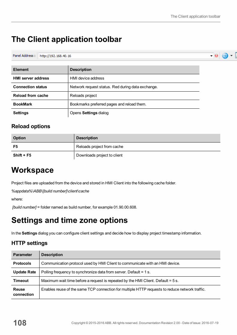
The Client application toolbar
Element Description
HMI server address HMI device address
Connection status Network request status. Red during data exchange.
Reload from cache Reloads project
BookMark Bookmarks preferred pages and reload them.
Settings Opens Settings dialog
Reload options
Option Description
F5 Reloads project from cache
Shift + F5 Downloads project to client
WorkspaceProject files are uploaded from the device and stored in HMI Client into the following cache folder.
%appdata%\ABB\[build number]\client\cache
where:
[build number] = folder named as build number, for example 01.90.00.608.
Settings and time zone optionsIn theSettings dialog you can configure client settings and decide how to display project timestamp information.
HTTP settings
Parameter Description
Protocols Communication protocol used by HMI Client to communicate with an HMI device.
Update Rate Polling frequency to synchronize data from server. Default = 1 s.
Timeout Maximum wait time before a request is repeated by the HMI Client. Default = 5 s.
Reuseconnection
Enables reuse of the same TCP connection for multiple HTTP requests to reduce network traffic.
108 Copyright © 2015-2016 ABB. All rights reserved. Documentation Revision 2.00 - Date of issue: 2016-07-19
The Client application toolbar
Parameter Description
Note: When enabled, this optionmay cause high latency if the proxy server does notimmediately terminate old requests thus saturating connection sockets. This is often the casewith 3G connections.
Enablecompression
Compresses data to reduce download times. Default = disabled.
CAUTION: enabling this option could causes excessive CPU overhead.
TimeSettings
Used by the client to adapt the widget time stamp information.
FTP settings
Parameter Description
Port FTP communication port
Time settings
Parameter Description
Use WidgetDefaults
Displays time information according to the widget settings.
Local Time Translates all timestamps in the project into the computer local time where the client isinstalled.
Global Time Translates all timestamps in the project into UTC format.
Server Time Translates all timestamps in the project into the same used by HMI device/server in orderto show the same time.
Important: Make sure you set the HMI RTC correct time zone and DST options.
Transferring files to a remote HMI deviceYou can upload and download files to and from a remote HMI device using two dedicated actions. These actions can onlybe used from a remote HMI Client and access remote files via FTP.
Important: Enable FTP support and give all necessary user rights to the folders used to transfer files.
See "Remote Client actions" on page 89.
See "Remote Client variables" on page 70.
Copyright © 2015-2016 ABB. All rights reserved. Documentation Revision 2.00 - Date of issue: 2016-07-19 109
10 Using the Client application

110 Copyright © 2015-2016 ABB. All rights reserved. Documentation Revision 2.00 - Date of issue: 2016-07-19
Transferring files to a remote HMI device

11 Using the integrated FTP serverHMI Runtime system uses an integrated FTP server.
Connect to the HMI device FTP server using any standard FTP client application. The FTP server responds on thestandard port 21 as default.
Important: The server supports only one connection at a time; if you are using a multiple connectionFTP client disable this feature on the client program or set the maximum number of connections persession to 1.
FTP settingsFTP default credentialsWhenUserManagement/Security is disabled use the following credentials for incoming connections:
User name admin
Password admin
Changing FTP settingsPath: ProjectView> Security> UserGroups > Authorization Settings
You can change FTP permissions and account information in the Ftp tab of the admin authorizations dialog.
See "Configuring groups and authorizations" on page 176 for details.
Copyright © 2015-2016 ABB. All rights reserved. Documentation Revision 2.00 - Date of issue: 2016-07-19 111

112 Copyright © 2015-2016 ABB. All rights reserved. Documentation Revision 2.00 - Date of issue: 2016-07-19
FTP settings
12 AlarmsThe alarms handling system has been designed to provide alerts through pop-upmessages, typically to display warningmessages indicating any abnormal condition or malfunction in the system under control.
Whenever a bit changes, or the value of a tag exceeds a threshold set in the alarm configuration, amessage is displayed.Specific actions can also be programmed to be executed when an alarm is triggered.
Important: No default action is associated with any alarm.
You can define how an alarm is displayed on the HMI device, if it requires user acknowledgment, and if and how it is loggedinto the event list.
Alarms are configured in the Alarms Configuration Editor and, thus, are available for all the pages of the project. An alarmwidget can display more than one alarm at a time, if sized appropriately. You can trigger the opening or closing of the Alarmwindow with an event.
You work with alarms in the sameway as you work with any other event. Youmay not want to display a dialog when analarm is triggered and you can associate to it any other available action.
Alarms Editor 114
Remote alarms acknowledge 116
Alarm state machine 116
Setting events 117
Active Alarms widget 119
Alarms History widget 123
Managing alarms at run time 123
Enable/disable alarms at run time 123
Displaying live alarm data 124
Exporting alarm buffers to .csv files 125
Exporting alarm configuration 125
Copyright © 2015-2016 ABB. All rights reserved. Documentation Revision 2.00 - Date of issue: 2016-07-19 113
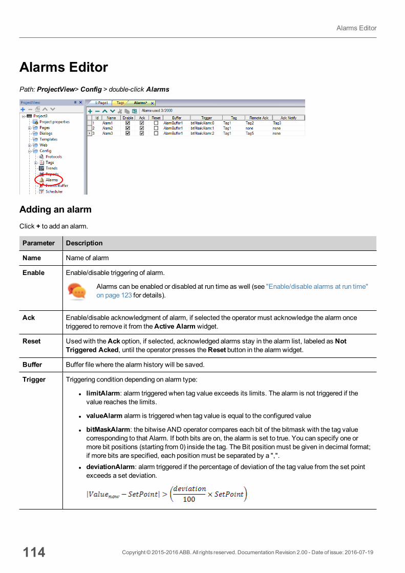
Alarms EditorPath: ProjectView> Config > double-click Alarms
Adding an alarmClick + to add an alarm.
Parameter Description
Name Name of alarm
Enable Enable/disable triggering of alarm.
Alarms can be enabled or disabled at run time as well (see "Enable/disable alarms at run time"on page 123 for details).
Ack Enable/disable acknowledgment of alarm, if selected the operator must acknowledge the alarm oncetriggered to remove it from theActive Alarm widget.
Reset Used with theAck option, if selected, acknowledged alarms stay in the alarm list, labeled as NotTriggered Acked, until the operator presses theReset button in the alarm widget.
Buffer Buffer file where the alarm history will be saved.
Trigger Triggering condition depending on alarm type:
l limitAlarm: alarm triggered when tag value exceeds its limits. The alarm is not triggered if thevalue reaches the limits.
l valueAlarm alarm is triggered when tag value is equal to the configured value
l bitMaskAlarm: the bitwise AND operator compares each bit of the bitmask with the tag valuecorresponding to that Alarm. If both bits are on, the alarm is set to true. You can specify one ormore bit positions (starting from 0) inside the tag. The Bit positionmust be given in decimal format;if more bits are specified, each positionmust be separated by a ",".
l deviationAlarm: alarm triggered if the percentage of deviation of the tag value from the set pointexceeds a set deviation.
114 Copyright © 2015-2016 ABB. All rights reserved. Documentation Revision 2.00 - Date of issue: 2016-07-19
Alarms Editor

Parameter Description
Tag Tag whose value will trigger the alarm when it exceeds the set limits.
The alarm can refer to the value of this tag, or to the state of a bit if bitMaskAlarm has been selected astrigger.
RemoteAck
Tag used by the PLC to acknowledge the alarm. A transition of this tag from 0 to a non zero value isconsidered an acknowledgment request.
Leave empty if remote acknowledgment is not required.
See "Remote alarms acknowledge" on the next page for details.
Ack Notify Tag used by the HMI device to notify when the alarm is acknowledged from the device or from the PLC.
0 = set to this value when alarm is triggered
1 = set to this value when alarm is acknowledged.
Actions Actions executed when the alarm is triggered. Additional conditions can be specified in theEventscolumn.
See "Setting events" on page 117 for details.
Description Alarm description. This text supports themultiple language features and can be a combination of staticand dynamic parts, where the dynamic portion includes one or more tag values.
See "Displaying live alarm data" on page 124 for details.
Color Foreground and background colors of alarm rows based on the status of alarm.
AckBlink Blinking for triggered alarms. If selected the alarm rows blinks until acknowledged. Only effective if Ack isselected.
Severity Severity of the alarm. If multiple alarms are triggered simultaneously, actions will be executed based onseverity settings.
0 = not important
1 = low
2 = below normal
3 = normal
4 = above normal
5 = high
6 = critical
Events Conditions in which the alarms are notified, logged or printed.
See "Setting events" on page 117 for details.
Copyright © 2015-2016 ABB. All rights reserved. Documentation Revision 2.00 - Date of issue: 2016-07-19 115
12 Alarms
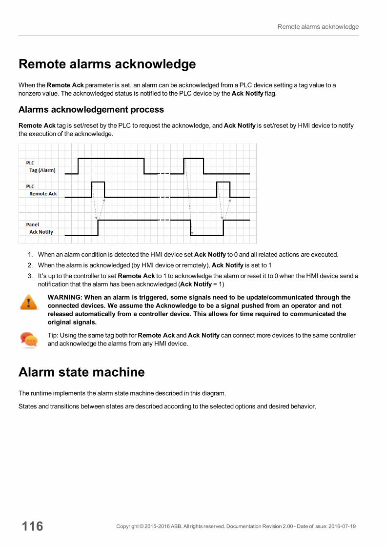
Remote alarms acknowledgeWhen theRemote Ack parameter is set, an alarm can be acknowledged from a PLC device setting a tag value to anonzero value. The acknowledged status is notified to the PLC device by theAck Notify flag.
Alarms acknowledgement processRemote Ack tag is set/reset by the PLC to request the acknowledge, andAck Notify is set/reset by HMI device to notifythe execution of the acknowledge.
1. When an alarm condition is detected the HMI device set Ack Notify to 0 and all related actions are executed.2. When the alarm is acknowledged (by HMI device or remotely), Ack Notify is set to 13. It's up to the controller to set Remote Ack to 1 to acknowledge the alarm or reset it to 0 when the HMI device send a
notification that the alarm has been acknowledged (Ack Notify = 1)
WARNING: When an alarm is triggered, some signals need to be update/communicated through theconnected devices. We assume the Acknowledge to be a signal pushed from an operator and notreleased automatically from a controller device. This allows for time required to communicated theoriginal signals.
Tip: Using the same tag both forRemote Ack andAck Notify can connect more devices to the same controllerand acknowledge the alarms from any HMI device.
Alarm state machineThe runtime implements the alarm statemachine described in this diagram.
States and transitions between states are described according to the selected options and desired behavior.
116 Copyright © 2015-2016 ABB. All rights reserved. Documentation Revision 2.00 - Date of issue: 2016-07-19
Remote alarms acknowledge
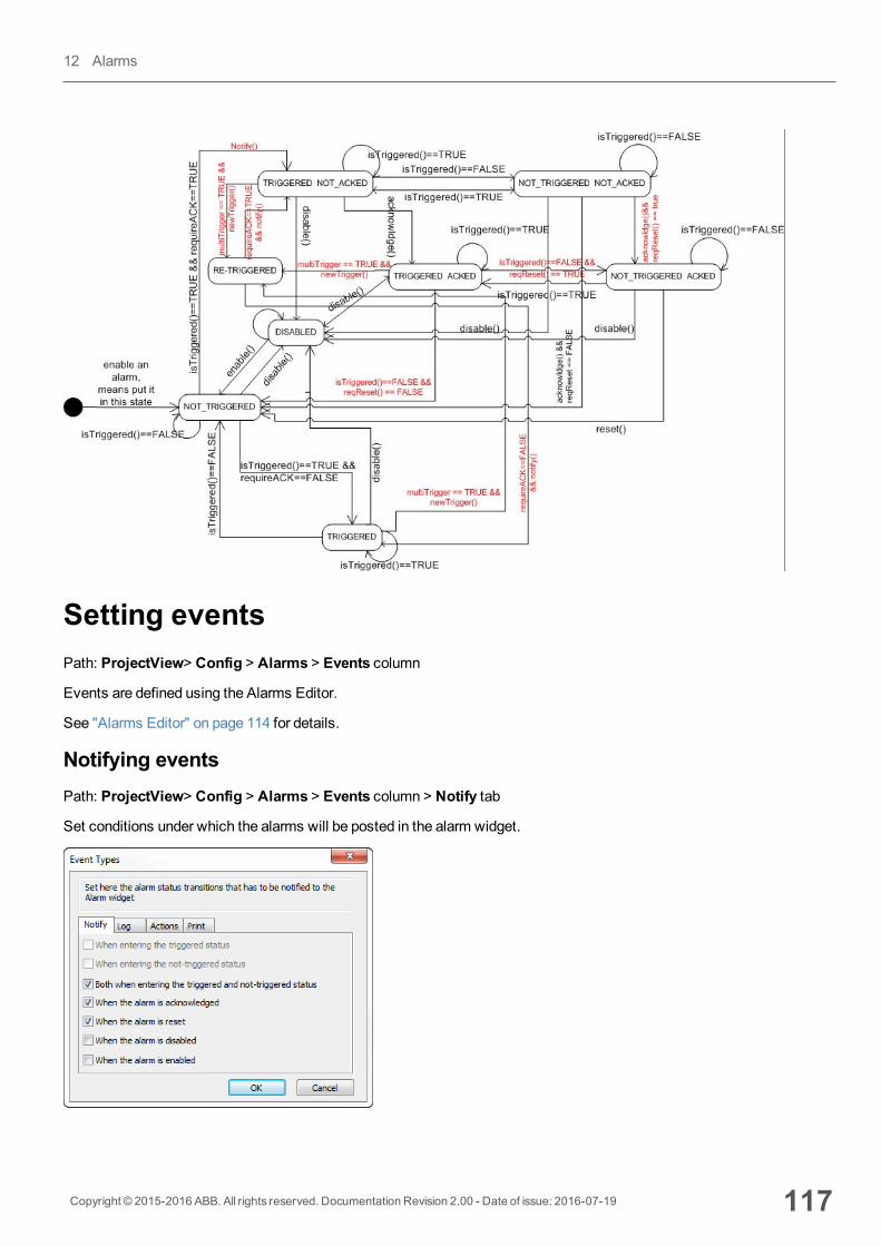
Setting eventsPath: ProjectView> Config > Alarms > Events column
Events are defined using the Alarms Editor.
See "Alarms Editor" on page 114 for details.
Notifying eventsPath: ProjectView> Config > Alarms > Events column > Notify tab
Set conditions under which the alarms will be posted in the alarm widget.
Copyright © 2015-2016 ABB. All rights reserved. Documentation Revision 2.00 - Date of issue: 2016-07-19 117
12 Alarms
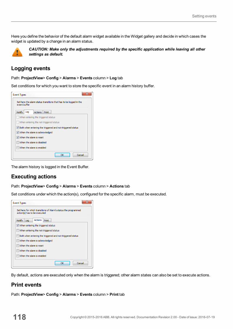
Here you define the behavior of the default alarm widget available in theWidget gallery and decide in which cases thewidget is updated by a change in an alarm status.
CAUTION: Make only the adjustments required by the specific application while leaving all othersettings as default.
Logging eventsPath: ProjectView> Config > Alarms > Events column > Log tab
Set conditions for which you want to store the specific event in an alarm history buffer.
The alarm history is logged in the Event Buffer.
Executing actionsPath: ProjectView> Config > Alarms > Events column > Actions tab
Set conditions under which the action(s), configured for the specific alarm, must be executed.
By default, actions are executed only when the alarm is triggered; other alarm states can also be set to execute actions.
Print eventsPath: ProjectView> Config > Alarms > Events column > Print tab
118 Copyright © 2015-2016 ABB. All rights reserved. Documentation Revision 2.00 - Date of issue: 2016-07-19
Setting events
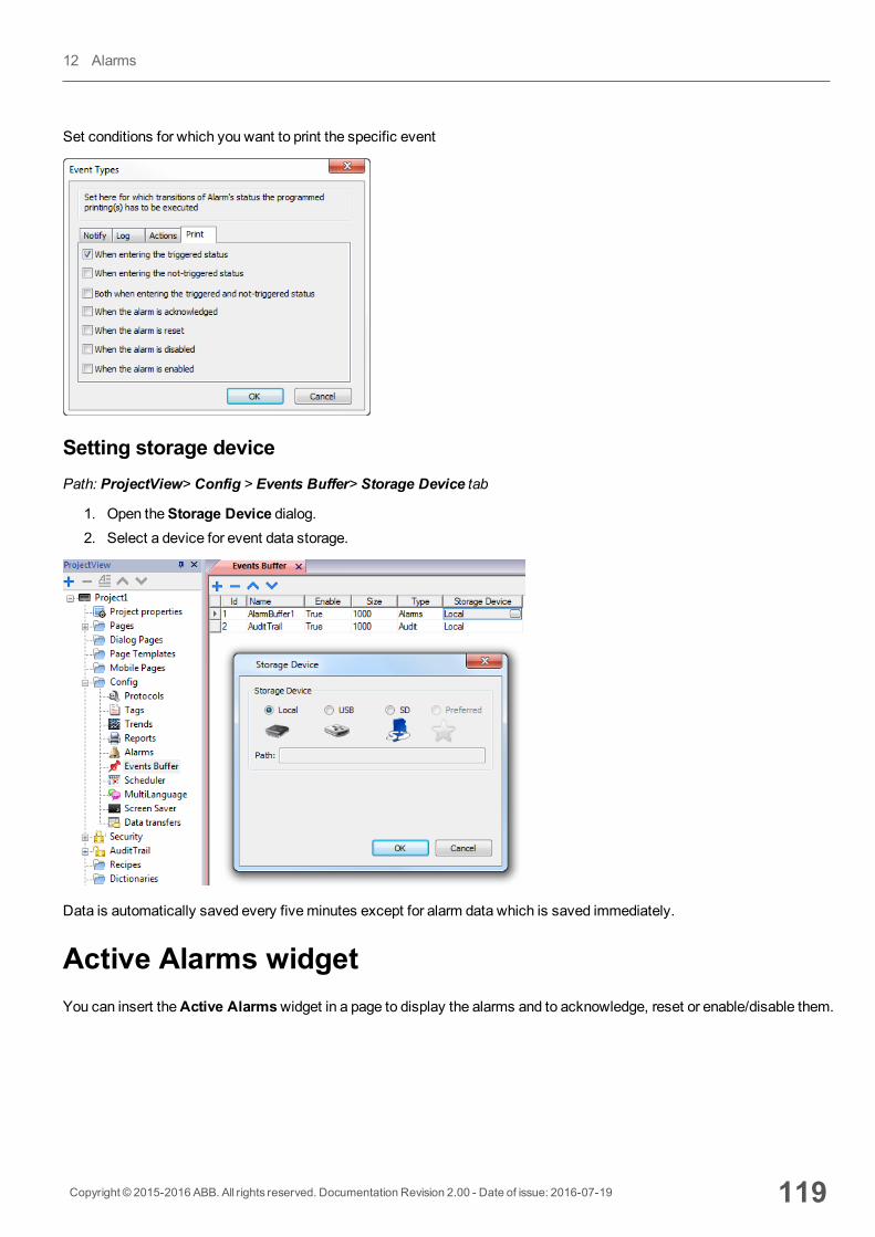
Set conditions for which you want to print the specific event
Setting storage devicePath: ProjectView> Config > Events Buffer> Storage Device tab
1. Open theStorage Device dialog.2. Select a device for event data storage.
Data is automatically saved every fiveminutes except for alarm data which is saved immediately.
Active Alarms widgetYou can insert theActive Alarmswidget in a page to display the alarms and to acknowledge, reset or enable/disable them.
Copyright © 2015-2016 ABB. All rights reserved. Documentation Revision 2.00 - Date of issue: 2016-07-19 119
12 Alarms
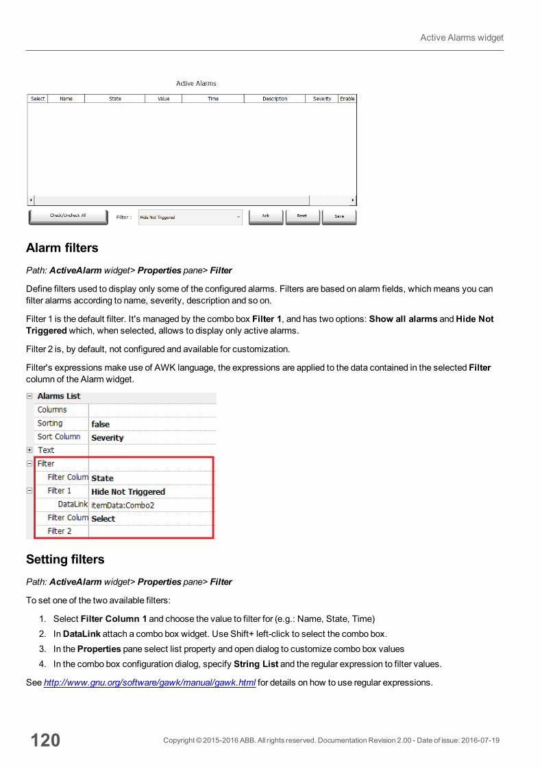
Alarm filtersPath: ActiveAlarm widget> Properties pane> Filter
Define filters used to display only some of the configured alarms. Filters are based on alarm fields, whichmeans you canfilter alarms according to name, severity, description and so on.
Filter 1 is the default filter. It's managed by the combo box Filter 1, and has two options: Show all alarms andHide NotTriggeredwhich, when selected, allows to display only active alarms.
Filter 2 is, by default, not configured and available for customization.
Filter's expressions make use of AWK language, the expressions are applied to the data contained in the selected Filtercolumn of the Alarm widget.
Setting filtersPath: ActiveAlarm widget> Properties pane> Filter
To set one of the two available filters:
1. Select Filter Column 1 and choose the value to filter for (e.g.: Name, State, Time)2. InDataLink attach a combo box widget. Use Shift+ left-click to select the combo box.3. In theProperties pane select list property and open dialog to customize combo box values4. In the combo box configuration dialog, specify String List and the regular expression to filter values.
See http://www.gnu.org/software/gawk/manual/gawk.html for details on how to use regular expressions.
120 Copyright © 2015-2016 ABB. All rights reserved. Documentation Revision 2.00 - Date of issue: 2016-07-19
Active Alarms widget
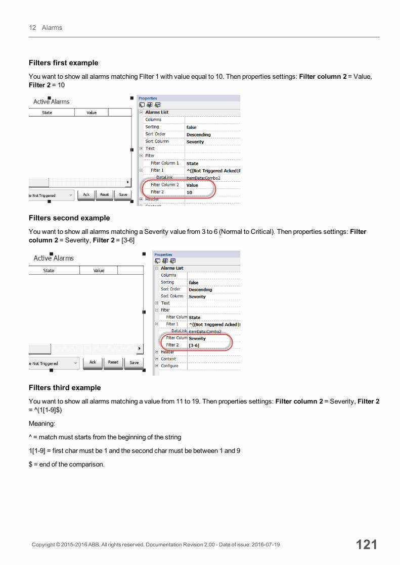
Filters first example
Youwant to show all alarms matching Filter 1 with value equal to 10. Then properties settings: Filter column 2 = Value,Filter 2 = 10
Filters second example
Youwant to show all alarms matching a Severity value from 3 to 6 (Normal to Critical). Then properties settings: Filtercolumn 2 = Severity, Filter 2 = [3-6]
Filters third example
Youwant to show all alarms matching a value from 11 to 19. Then properties settings: Filter column 2 = Severity, Filter 2= ^(1[1-9]$)
Meaning:
^ = matchmust starts from the beginning of the string
1[1-9] = first char must be 1 and the second char must be between 1 and 9
$ = end of the comparison.
Copyright © 2015-2016 ABB. All rights reserved. Documentation Revision 2.00 - Date of issue: 2016-07-19 121
12 Alarms
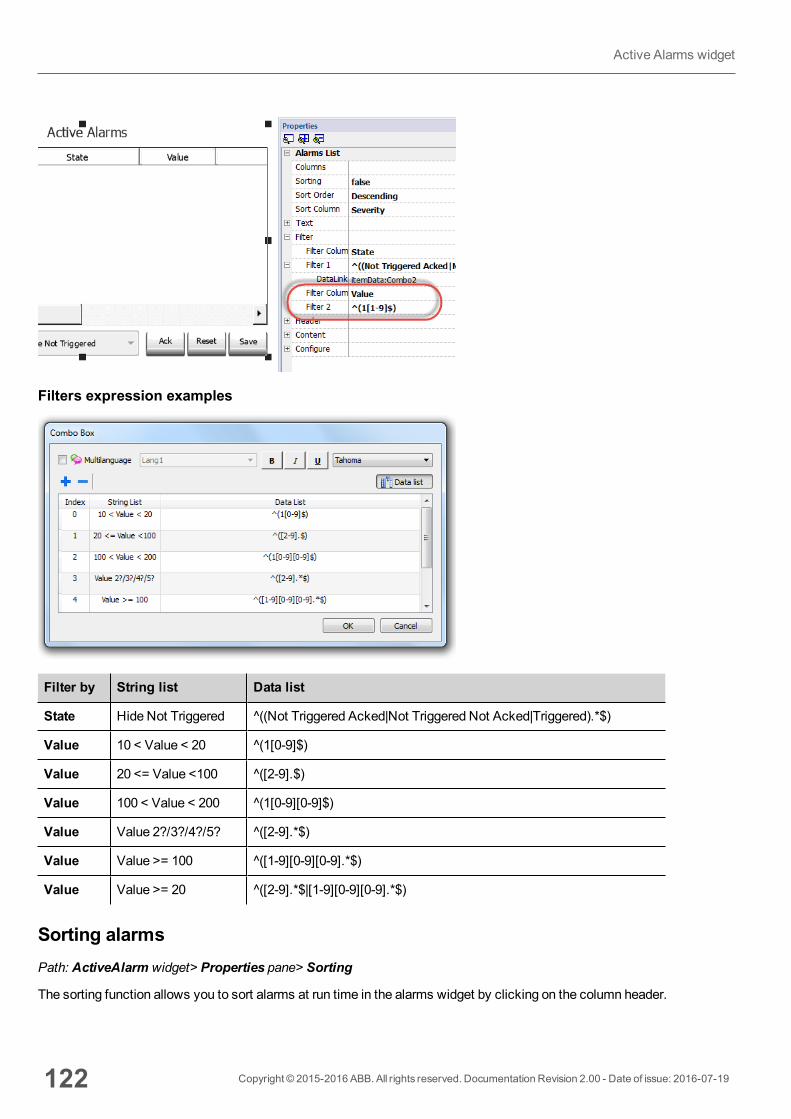
Filters expression examples
Filter by String list Data list
State Hide Not Triggered ^((Not Triggered Acked|Not Triggered Not Acked|Triggered).*$)
Value 10 < Value < 20 ^(1[0-9]$)
Value 20 <= Value <100 ^([2-9].$)
Value 100 < Value < 200 ^(1[0-9][0-9]$)
Value Value 2?/3?/4?/5? ^([2-9].*$)
Value Value >= 100 ^([1-9][0-9][0-9].*$)
Value Value >= 20 ^([2-9].*$|[1-9][0-9][0-9].*$)
Sorting alarmsPath: ActiveAlarm widget> Properties pane> Sorting
The sorting function allows you to sort alarms at run time in the alarms widget by clicking on the column header.
122 Copyright © 2015-2016 ABB. All rights reserved. Documentation Revision 2.00 - Date of issue: 2016-07-19
Active Alarms widget
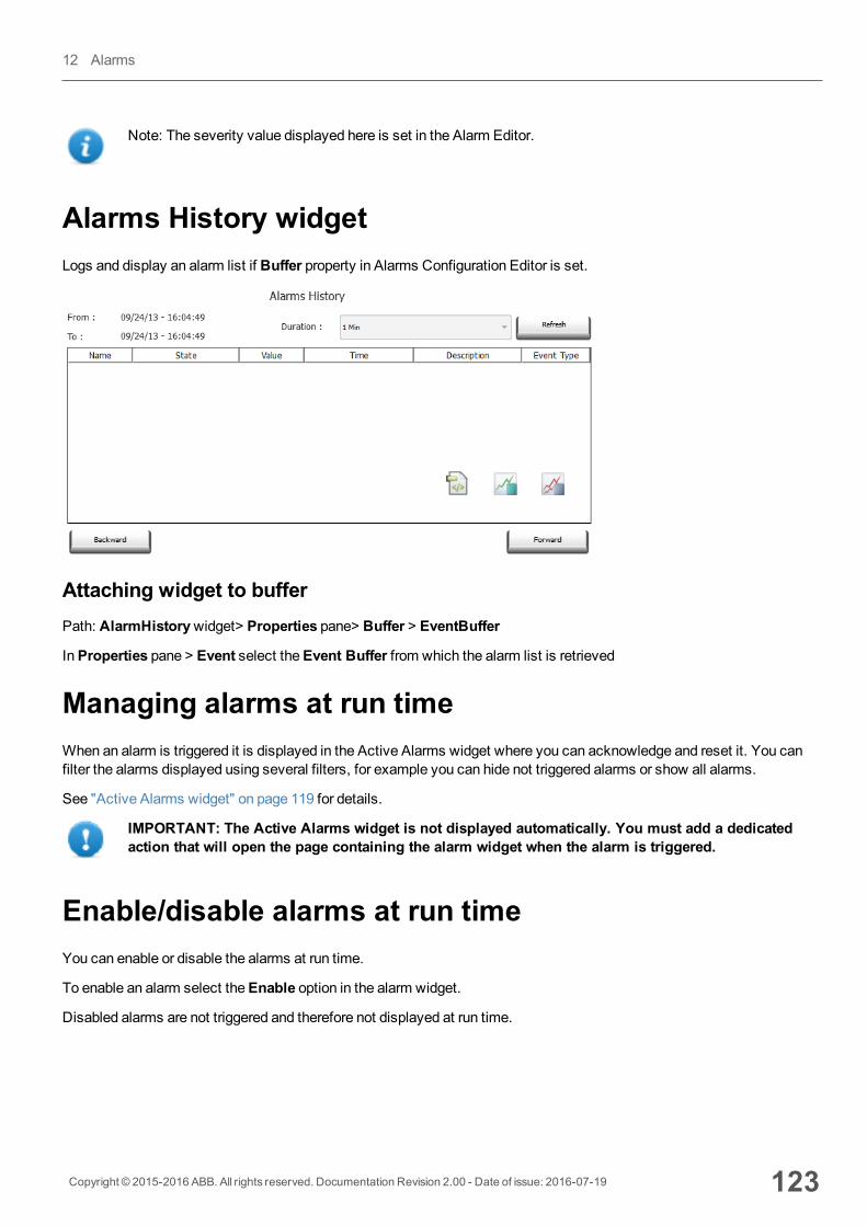
Note: The severity value displayed here is set in the Alarm Editor.
Alarms History widgetLogs and display an alarm list if Buffer property in Alarms Configuration Editor is set.
Attaching widget to bufferPath: AlarmHistorywidget> Properties pane> Buffer > EventBuffer
InProperties pane > Event select theEvent Buffer from which the alarm list is retrieved
Managing alarms at run timeWhen an alarm is triggered it is displayed in the Active Alarms widget where you can acknowledge and reset it. You canfilter the alarms displayed using several filters, for example you can hide not triggered alarms or show all alarms.
See "Active Alarms widget" on page 119 for details.
IMPORTANT: The Active Alarms widget is not displayed automatically. You must add a dedicatedaction that will open the page containing the alarm widget when the alarm is triggered.
Enable/disable alarms at run timeYou can enable or disable the alarms at run time.
To enable an alarm select theEnable option in the alarm widget.
Disabled alarms are not triggered and therefore not displayed at run time.
Copyright © 2015-2016 ABB. All rights reserved. Documentation Revision 2.00 - Date of issue: 2016-07-19 123
12 Alarms

Displaying live alarm dataTag values can be included in the alarm description of the event buffer only from version 1.80.
Path: ProjectView> Config > double-click Alarms
Both in the Active Alarms and in the History Alarms widget you can set the alarm description to display live tag data.
To show the tag value, set a placeholder inDescription entering the tag name in square brackets, for example "[Tag1]". Atrun time, inDescription column of Active Alarms widget the current value of the tag will be displayed. In History Alarmswidget or in .csv file the value at the time the alarm was triggered is displayed
Use '\' before '[ ]' if you want to show the '[ ]' in the description string, for example: \[Tag\[1\]\] will display thestring "[Tag[1]]".
Example of Alarm widget
Note: The csv file resulting from the dump of the alarm events list will also display the tag value in the descriptioncolumn.
124 Copyright © 2015-2016 ABB. All rights reserved. Documentation Revision 2.00 - Date of issue: 2016-07-19
Displaying live alarm data
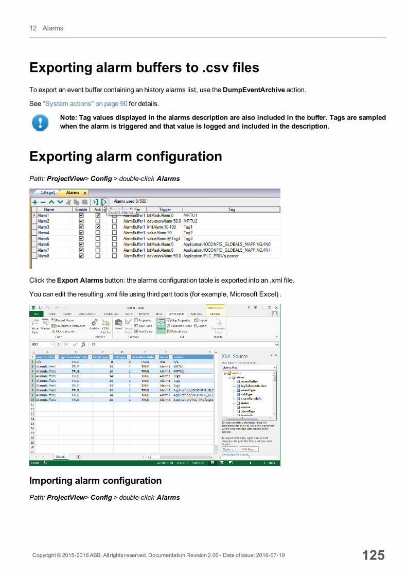
Exporting alarm buffers to .csv filesTo export an event buffer containing an history alarms list, use theDumpEventArchive action.
See "System actions" on page 90 for details.
Note: Tag values displayed in the alarms description are also included in the buffer. Tags are sampledwhen the alarm is triggered and that value is logged and included in the description.
Exporting alarm configurationPath: ProjectView> Config > double-click Alarms
Click theExport Alarms button: the alarms configuration table is exported into an .xml file.
You can edit the resulting .xml file using third part tools (for example, Microsoft Excel) .
Importing alarm configurationPath: ProjectView> Config > double-click Alarms
Copyright © 2015-2016 ABB. All rights reserved. Documentation Revision 2.00 - Date of issue: 2016-07-19 125
12 Alarms
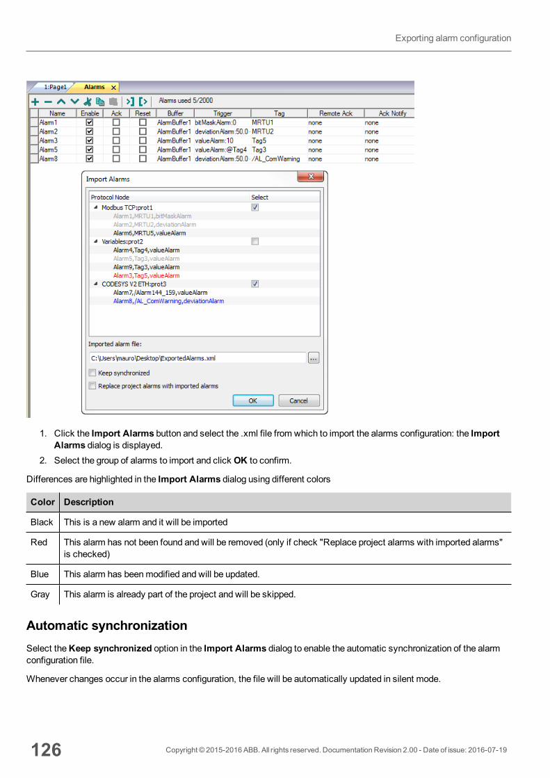
1. Click the Import Alarms button and select the .xml file from which to import the alarms configuration: the ImportAlarms dialog is displayed.
2. Select the group of alarms to import and click OK to confirm.
Differences are highlighted in the Import Alarms dialog using different colors
Color Description
Black This is a new alarm and it will be imported
Red This alarm has not been found and will be removed (only if check "Replace project alarms with imported alarms"is checked)
Blue This alarm has beenmodified and will be updated.
Gray This alarm is already part of the project and will be skipped.
Automatic synchronizationSelect theKeep synchronized option in the Import Alarms dialog to enable the automatic synchronization of the alarmconfiguration file.
Whenever changes occur in the alarms configuration, the file will be automatically updated in silent mode.
126 Copyright © 2015-2016 ABB. All rights reserved. Documentation Revision 2.00 - Date of issue: 2016-07-19
Exporting alarm configuration

Tip: Enable this function when the alarm file is managed by a different tool (for example, PLC programmingsoftware) as well as by PB610-B Panel Builder 600.
Copyright © 2015-2016 ABB. All rights reserved. Documentation Revision 2.00 - Date of issue: 2016-07-19 127
12 Alarms

128 Copyright © 2015-2016 ABB. All rights reserved. Documentation Revision 2.00 - Date of issue: 2016-07-19
Exporting alarm configuration
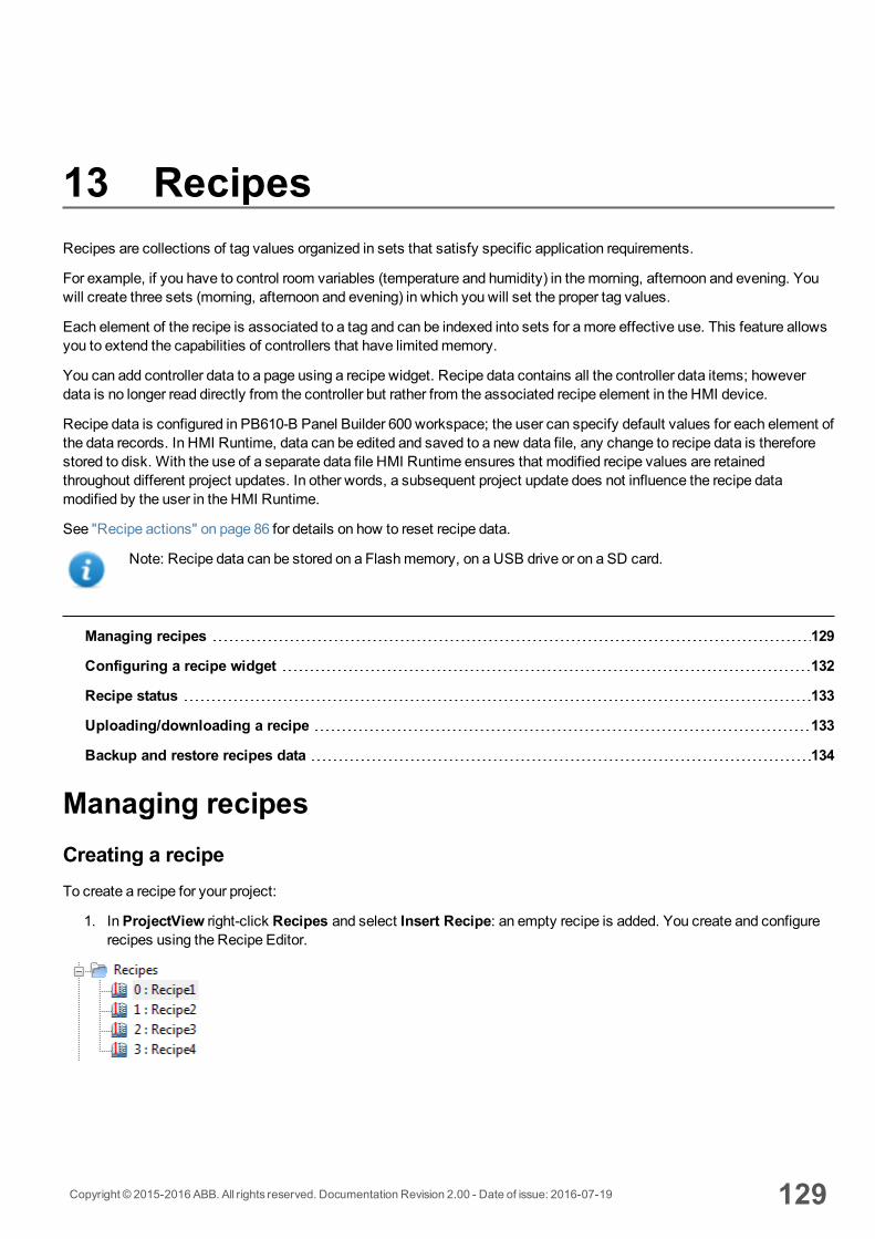
13 RecipesRecipes are collections of tag values organized in sets that satisfy specific application requirements.
For example, if you have to control room variables (temperature and humidity) in themorning, afternoon and evening. Youwill create three sets (morning, afternoon and evening) in which you will set the proper tag values.
Each element of the recipe is associated to a tag and can be indexed into sets for amore effective use. This feature allowsyou to extend the capabilities of controllers that have limitedmemory.
You can add controller data to a page using a recipe widget. Recipe data contains all the controller data items; howeverdata is no longer read directly from the controller but rather from the associated recipe element in the HMI device.
Recipe data is configured in PB610-B Panel Builder 600 workspace; the user can specify default values for each element ofthe data records. In HMI Runtime, data can be edited and saved to a new data file, any change to recipe data is thereforestored to disk. With the use of a separate data file HMI Runtime ensures that modified recipe values are retainedthroughout different project updates. In other words, a subsequent project update does not influence the recipe datamodified by the user in the HMI Runtime.
See "Recipe actions" on page 86 for details on how to reset recipe data.
Note: Recipe data can be stored on a Flashmemory, on a USB drive or on a SD card.
Managing recipes 129
Configuring a recipe widget 132
Recipe status 133
Uploading/downloading a recipe 133
Backup and restore recipes data 134
Managing recipesCreating a recipeTo create a recipe for your project:
1. InProjectView right-click Recipes and select Insert Recipe: an empty recipe is added. You create and configurerecipes using the Recipe Editor.
Copyright © 2015-2016 ABB. All rights reserved. Documentation Revision 2.00 - Date of issue: 2016-07-19 129

Recipe editorPath: ProjectView> Recipes > double-click RecipeName
Configuring recipe propertiesIn theProperties pane of each recipe you set the following parameters:
Parameter Description
Recipe Name Name of the recipe
Number of sets Number of values sets for each recipe element. Each set has a different configurable name.
Setting up a recipe1. Click + to add an element of the recipe.2. Link the tags to each recipe element.
Defining recipe fieldsCreate a recipe field in the page using a numeric widget and attaching it to a recipe item after selecting Recipe as theSource.
130 Copyright © 2015-2016 ABB. All rights reserved. Documentation Revision 2.00 - Date of issue: 2016-07-19
Managing recipes
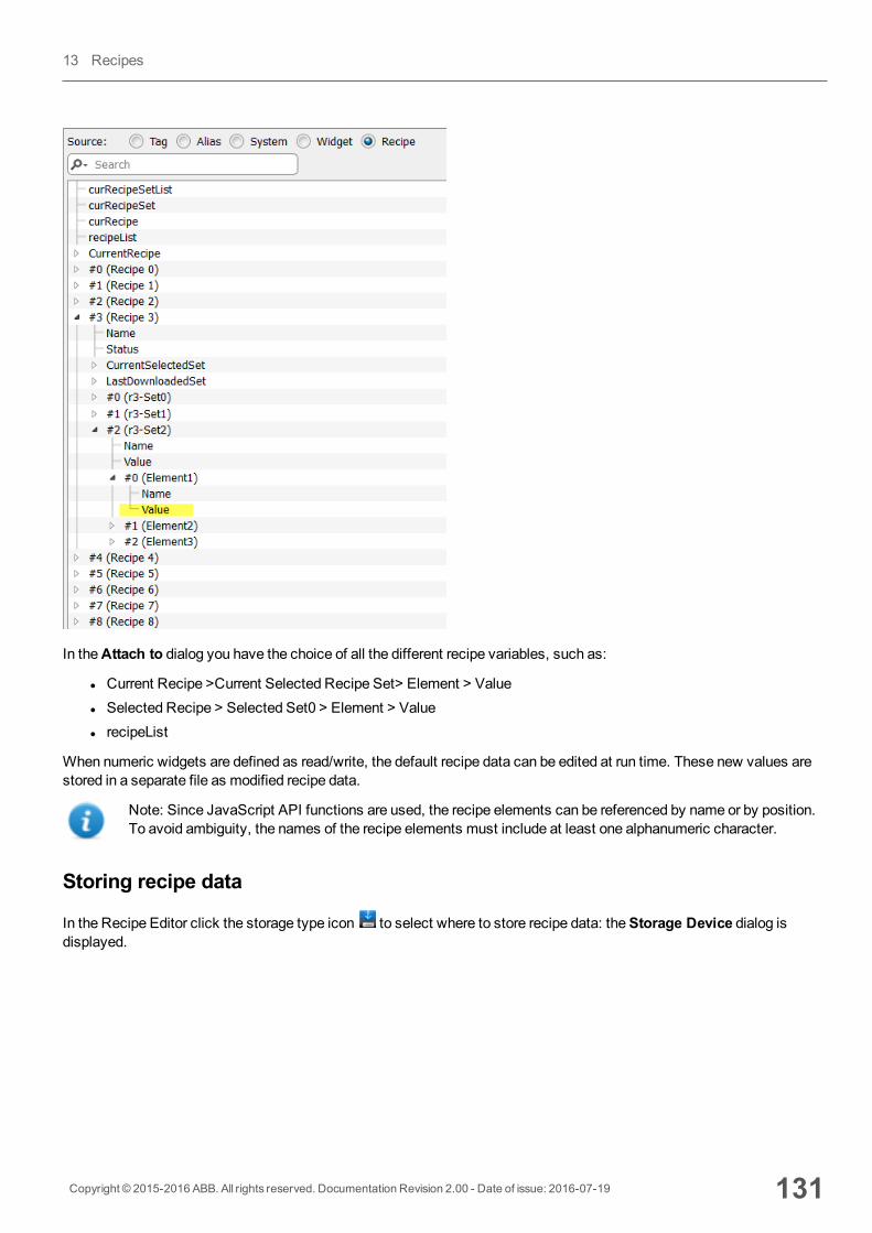
In theAttach to dialog you have the choice of all the different recipe variables, such as:
l Current Recipe >Current Selected Recipe Set> Element > Valuel Selected Recipe > Selected Set0 > Element > Valuel recipeList
When numeric widgets are defined as read/write, the default recipe data can be edited at run time. These new values arestored in a separate file as modified recipe data.
Note: Since JavaScript API functions are used, the recipe elements can be referenced by name or by position.To avoid ambiguity, the names of the recipe elements must include at least one alphanumeric character.
Storing recipe data
In the Recipe Editor click the storage type icon to select where to store recipe data: theStorage Device dialog isdisplayed.
Copyright © 2015-2016 ABB. All rights reserved. Documentation Revision 2.00 - Date of issue: 2016-07-19 131
13 Recipes
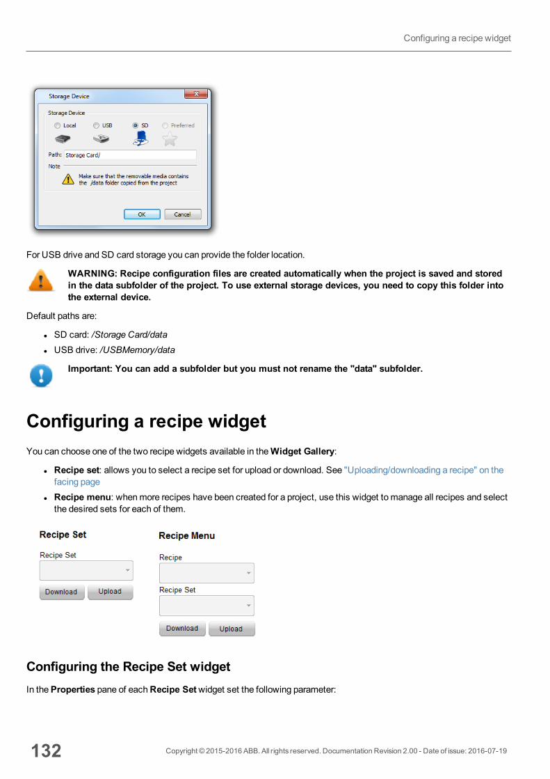
For USB drive and SD card storage you can provide the folder location.
WARNING: Recipe configuration files are created automatically when the project is saved and storedin the data subfolder of the project. To use external storage devices, you need to copy this folder intothe external device.
Default paths are:
l SD card: /Storage Card/datal USB drive: /USBMemory/data
Important: You can add a subfolder but you must not rename the "data" subfolder.
Configuring a recipe widgetYou can choose one of the two recipe widgets available in theWidget Gallery:
l Recipe set: allows you to select a recipe set for upload or download. See "Uploading/downloading a recipe" on thefacing page
l Recipe menu: whenmore recipes have been created for a project, use this widget to manage all recipes and selectthe desired sets for each of them.
Configuring the Recipe Set widgetIn theProperties pane of eachRecipe Setwidget set the following parameter:
132 Copyright © 2015-2016 ABB. All rights reserved. Documentation Revision 2.00 - Date of issue: 2016-07-19
Configuring a recipe widget
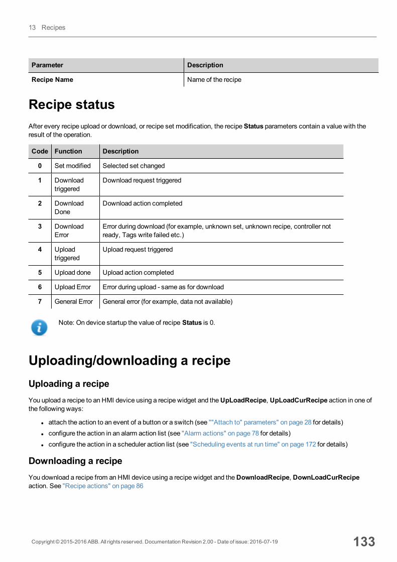
Parameter Description
Recipe Name Name of the recipe
Recipe statusAfter every recipe upload or download, or recipe set modification, the recipeStatus parameters contain a value with theresult of the operation.
Code Function Description
0 Set modified Selected set changed
1 Downloadtriggered
Download request triggered
2 DownloadDone
Download action completed
3 DownloadError
Error during download (for example, unknown set, unknown recipe, controller notready, Tags write failed etc.)
4 Uploadtriggered
Upload request triggered
5 Upload done Upload action completed
6 Upload Error Error during upload - same as for download
7 General Error General error (for example, data not available)
Note: On device startup the value of recipe Status is 0.
Uploading/downloading a recipeUploading a recipeYou upload a recipe to an HMI device using a recipe widget and theUpLoadRecipe, UpLoadCurRecipe action in one ofthe following ways:
l attach the action to an event of a button or a switch (see ""Attach to" parameters" on page 28 for details)l configure the action in an alarm action list (see "Alarm actions" on page 78 for details)l configure the action in a scheduler action list (see "Scheduling events at run time" on page 172 for details)
Downloading a recipeYou download a recipe from anHMI device using a recipe widget and theDownloadRecipe, DownLoadCurRecipeaction. See "Recipe actions" on page 86
Copyright © 2015-2016 ABB. All rights reserved. Documentation Revision 2.00 - Date of issue: 2016-07-19 133
13 Recipes

Backup and restore recipes dataThe recipe data stored in an HMI device can be exported for backup and later restored. This is done using theDumpRecipeData or theRestoreRecipeData actions.
See "Recipe actions" on page 86 for details.
134 Copyright © 2015-2016 ABB. All rights reserved. Documentation Revision 2.00 - Date of issue: 2016-07-19
Backup and restore recipes data
14 TrendsTrends allow you to sample and record the values of specified tags according to specific sampling conditions. The trendfunction includes trend acquisition and trend display.
Trend acquisition parameters are set in the Trend editor so that data can be stored. Stored data can then be displayed in agraphical format using a trend widget.
Data logging 136
Exporting trend buffer data 137
Trend widgets 138
History trends 140
Trend widget properties 141
Values outside range or invalid 142
Showing trend values 143
Scatter diagram widget 144
Copyright © 2015-2016 ABB. All rights reserved. Documentation Revision 2.00 - Date of issue: 2016-07-19 135
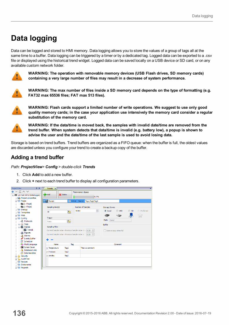
Data loggingData can be logged and stored to HMI memory. Data logging allows you to store the values of a group of tags all at thesame time to a buffer. Data logging can be triggered by a timer or by a dedicated tag. Logged data can be exported to a .csvfile or displayed using the historical trend widget. Logged data can be saved locally on a USB device or SD card, or on anyavailable custom network folder.
WARNING: The operation with removable memory devices (USB Flash drives, SD memory cards)containing a very large number of files may result in a decrease of system performance.
WARNING: The max number of files inside a SD memory card depends on the type of formatting (e.g.FAT32 max 65536 files; FAT max 513 files).
WARNING: Flash cards support a limited number of write operations. We suggest to use only goodquality memory cards; in the case your application use intensively the memory card consider a regularsubstitution of the memory card.
WARNING: If the data/time is moved back, the samples with invalid date/time are removed from thetrend buffer. When system detects that data/time is invalid (e.g. battery low), a popup is shown toadvise the user and the date/time of the last sample is used to avoid losing data.
Storage is based on trend buffers. Trend buffers are organized as a FIFO queue: when the buffer is full, the oldest valuesare discarded unless you configure your trend to create a backup copy of the buffer.
Adding a trend bufferPath: ProjectView> Config > double-click Trends
1. Click Add to add a new buffer.2. Click + next to each trend buffer to display all configuration parameters.
136 Copyright © 2015-2016 ABB. All rights reserved. Documentation Revision 2.00 - Date of issue: 2016-07-19
Data logging
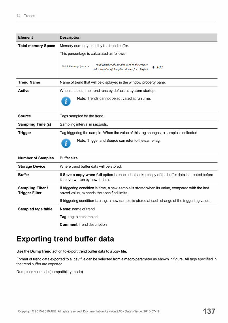
Element Description
Total memory Space Memory currently used by the trend buffer.
This percentage is calculated as follows:
Trend Name Name of trend that will be displayed in the window property pane.
Active When enabled, the trend runs by default at system startup.
Note: Trends cannot be activated at run time.
Source Tags sampled by the trend.
Sampling Time (s) Sampling interval in seconds.
Trigger Tag triggering the sample. When the value of this tag changes, a sample is collected.
Note: Trigger and Source can refer to the same tag.
Number of Samples Buffer size.
Storage Device Where trend buffer data will be stored.
Buffer If Save a copy when full option is enabled, a backup copy of the buffer data is created beforeit is overwritten by newer data.
Sampling Filter /Trigger Filter
If triggering condition is time, a new sample is stored when its value, compared with the lastsaved value, exceeds the specified limits.
If triggering condition is a tag, a new sample is stored at each change of the trigger tag value.
Sampled tags table Name: name of trend
Tag: tag to be sampled.
Comment: trend description
Exporting trend buffer dataUse theDumpTrend action to export trend buffer data to a .csv file.
Format of trend data exported to a .csv file can be selected from amacro parameter as shown in figure. All tags specified inthe trend buffer are exported
Dump normal mode (compatibility mode)
Copyright © 2015-2016 ABB. All rights reserved. Documentation Revision 2.00 - Date of issue: 2016-07-19 137
14 Trends
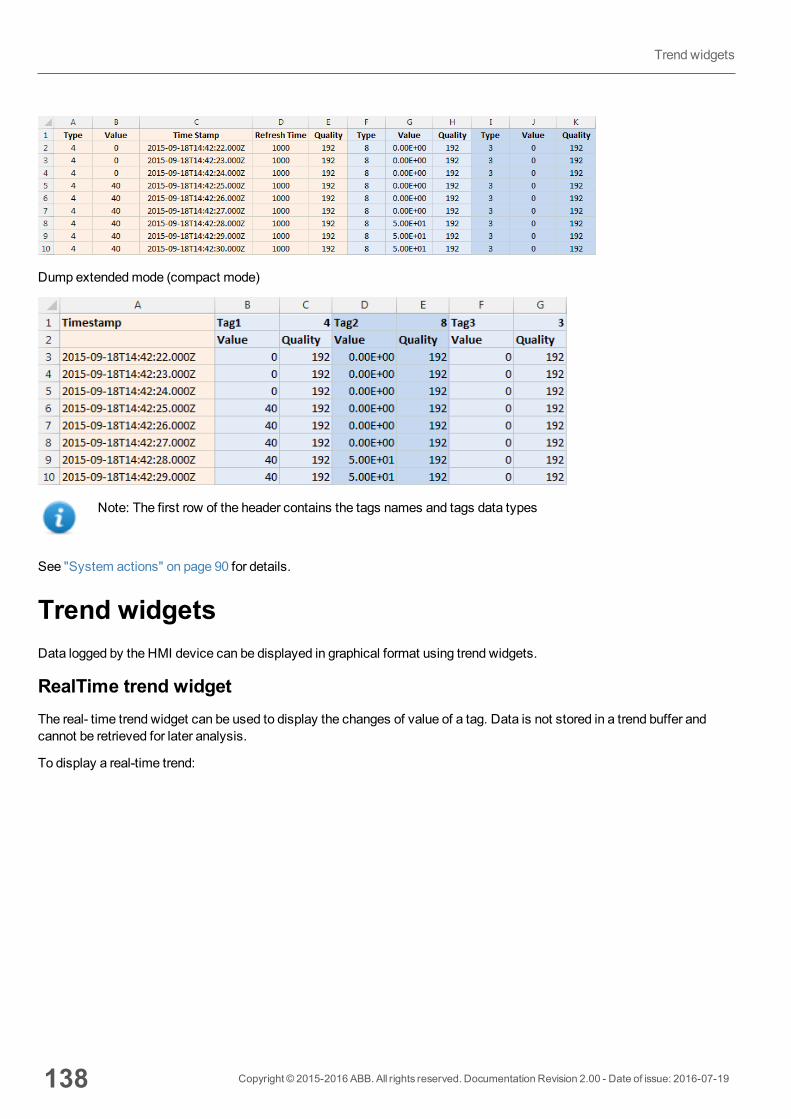
Dump extendedmode (compact mode)
Note: The first row of the header contains the tags names and tags data types
See "System actions" on page 90 for details.
Trend widgetsData logged by the HMI device can be displayed in graphical format using trend widgets.
RealTime trend widgetThe real- time trend widget can be used to display the changes of value of a tag. Data is not stored in a trend buffer andcannot be retrieved for later analysis.
To display a real-time trend:
138 Copyright © 2015-2016 ABB. All rights reserved. Documentation Revision 2.00 - Date of issue: 2016-07-19
Trend widgets

1. Drag and drop theRealTime Trendwidget from the widget gallery to the page.
2. Attach the tag that you want to sample to theCurve n Value. Data is always plotted against time.
RealTime trend widget properties
Property Description
NumCurves
Number of trend curves to be displayed (Max. 5)
PageDuration
Time range of the x-axis.
Tip: You can attach aDate Time combowidget to thePage Duration property anddynamically change page duration at run time.
StartingPosition
Specifies the starting point of the curve when the page is opened.
X Labels Number of ticks on the x-axis scale
Y Labels Number of ticks in the y-axis scale.
Text Trend title and font properties (font size, label, etc.)
Grid Properties of grid presentation (colors)
Cursor Properties of cursor presentation (enable and color)
X Scale Properties of X Scale presentation
Y Scale Properties of Y Scale presentation
Curve"n"
Tag that will be plotted in the trend widget. See "Trend widget properties" on page 141 for details.
You can set theminimum andmaximum of the curves (MinY,MaxY). You can attach a tag tominimum andmaximum properties. This enhances the ability to change theminimum andmaximum values dynamically at run time.
Copyright © 2015-2016 ABB. All rights reserved. Documentation Revision 2.00 - Date of issue: 2016-07-19 139
14 Trends

Scaling dataTag values can be scaled using the X Forms in theAttach to dialog. See ""Attach to" parameters" on page 28 for details.
History trendsTrend data stored in trend buffers can be analyzed using theHistory Trendwidget.
This is a two-step process:
l first you create a trend buffer to collect data for specified tags at specific points in time,l then you configure a History Trend widget to display the collected data in a graphical format.
See "Data logging" on page 136 for details on how to create a trend buffer.
History Trend widgetHistory Trend widget displays in graphical format the content of a trend buffer.
Start time is the current time and stop time will be the current time plus the duration of the window. The curve starts fromthe left and progresses to the right, data is automatically refreshed during a certain interval time, until the stop time.
When the curve reaches the stop time, the curve will scroll left and the update of the curve will continue until it againreaches the stop time. At that moment a new scroll is automatically performed and the process repeats.
History trends require a proper configuration of trend buffer.
See "Data logging" on page 136 for details on how to work in the Trend editor.
Configuring the History Trend widget1. From the Trends/Graphs section of theWidget Gallery, drag and drop theHistory Trendwidget to the page.
140 Copyright © 2015-2016 ABB. All rights reserved. Documentation Revision 2.00 - Date of issue: 2016-07-19
History trends
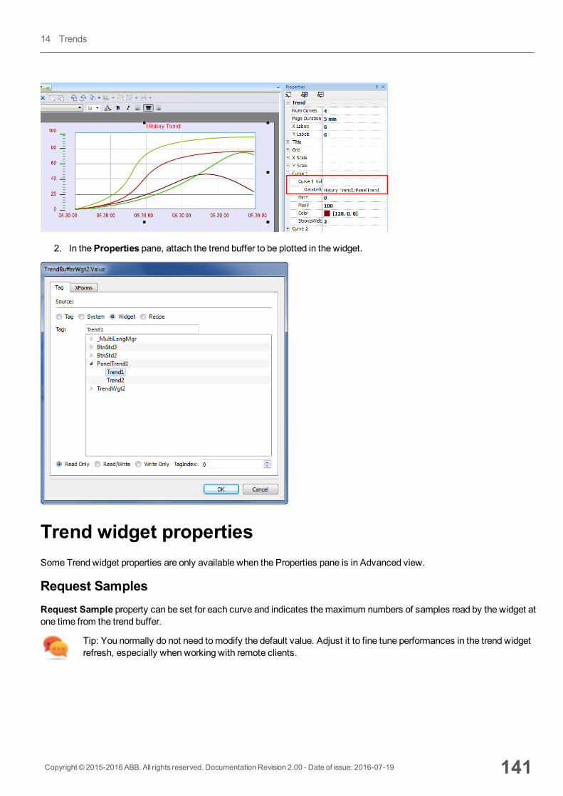
2. In theProperties pane, attach the trend buffer to be plotted in the widget.
Trend widget propertiesSome Trend widget properties are only available when the Properties pane is in Advanced view.
Request SamplesRequest Sample property can be set for each curve and indicates themaximum numbers of samples read by the widget atone time from the trend buffer.
Tip: You normally do not need tomodify the default value. Adjust it to fine tune performances in the trend widgetrefresh, especially when working with remote clients.
Copyright © 2015-2016 ABB. All rights reserved. Documentation Revision 2.00 - Date of issue: 2016-07-19 141
14 Trends
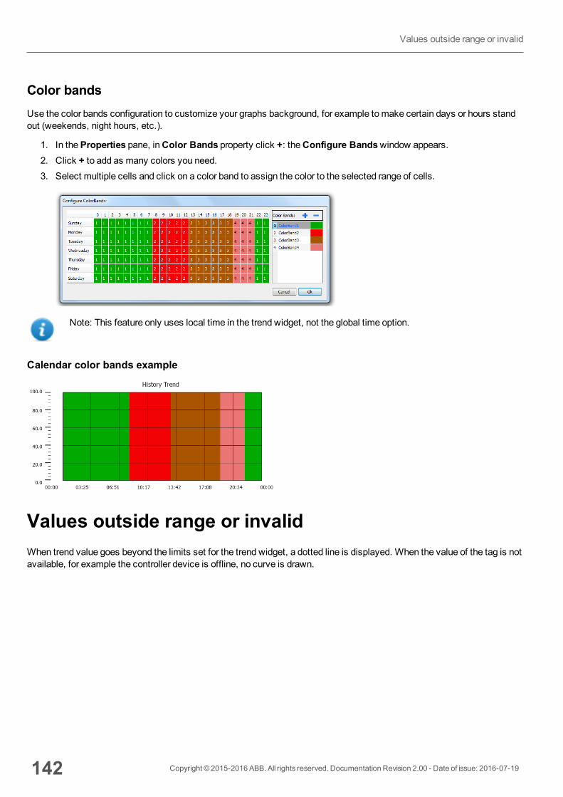
Color bandsUse the color bands configuration to customize your graphs background, for example tomake certain days or hours standout (weekends, night hours, etc.).
1. In theProperties pane, inColor Bands property click +: theConfigure Bandswindow appears.2. Click + to add as many colors you need.3. Select multiple cells and click on a color band to assign the color to the selected range of cells.
Note: This feature only uses local time in the trend widget, not the global time option.
Calendar color bands example
Values outside range or invalidWhen trend value goes beyond the limits set for the trend widget, a dotted line is displayed. When the value of the tag is notavailable, for example the controller device is offline, no curve is drawn.
142 Copyright © 2015-2016 ABB. All rights reserved. Documentation Revision 2.00 - Date of issue: 2016-07-19
Values outside range or invalid
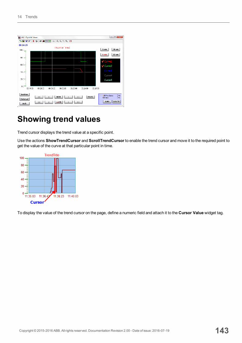
Showing trend valuesTrend cursor displays the trend value at a specific point.
Use the actions ShowTrendCursor andScrollTrendCursor to enable the trend cursor andmove it to the required point toget the value of the curve at that particular point in time.
To display the value of the trend cursor on the page, define a numeric field and attach it to theCursor Valuewidget tag.
Copyright © 2015-2016 ABB. All rights reserved. Documentation Revision 2.00 - Date of issue: 2016-07-19 143
14 Trends
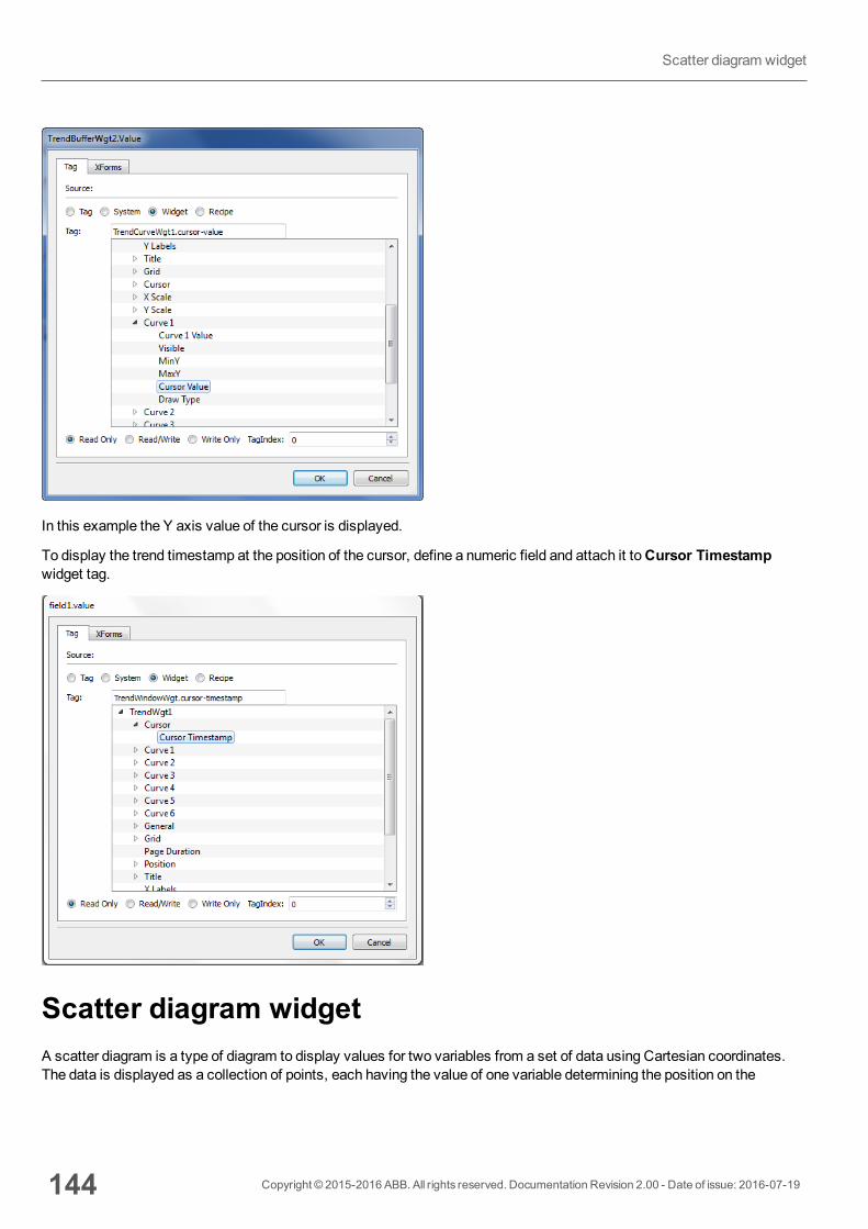
In this example the Y axis value of the cursor is displayed.
To display the trend timestamp at the position of the cursor, define a numeric field and attach it toCursor Timestampwidget tag.
Scatter diagram widgetA scatter diagram is a type of diagram to display values for two variables from a set of data using Cartesian coordinates.The data is displayed as a collection of points, each having the value of one variable determining the position on the
144 Copyright © 2015-2016 ABB. All rights reserved. Documentation Revision 2.00 - Date of issue: 2016-07-19
Scatter diagram widget
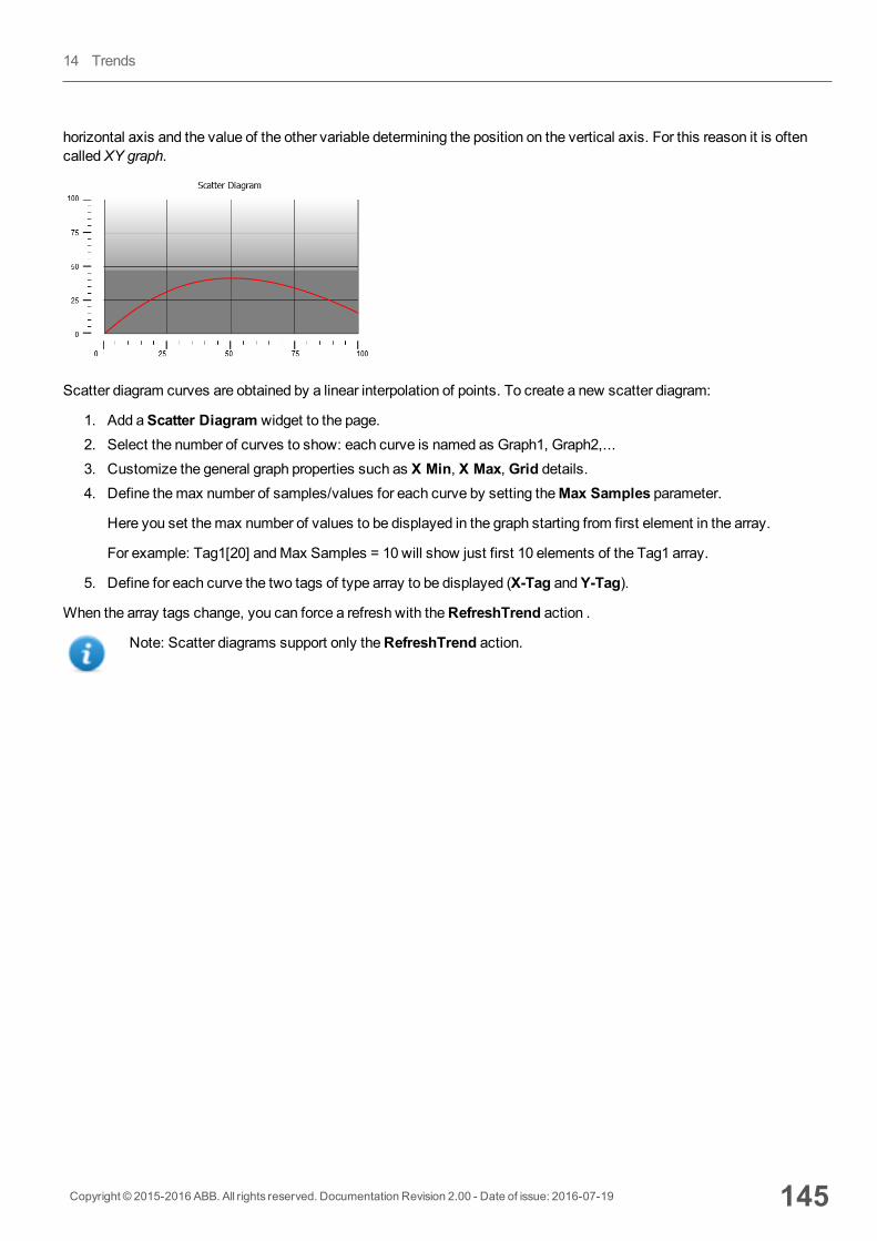
horizontal axis and the value of the other variable determining the position on the vertical axis. For this reason it is oftencalledXY graph.
Scatter diagram curves are obtained by a linear interpolation of points. To create a new scatter diagram:
1. Add aScatter Diagram widget to the page.2. Select the number of curves to show: each curve is named as Graph1, Graph2,...3. Customize the general graph properties such as X Min, X Max, Grid details.4. Define themax number of samples/values for each curve by setting theMax Samples parameter.
Here you set themax number of values to be displayed in the graph starting from first element in the array.
For example: Tag1[20] andMax Samples = 10 will show just first 10 elements of the Tag1 array.
5. Define for each curve the two tags of type array to be displayed (X-Tag andY-Tag).
When the array tags change, you can force a refresh with theRefreshTrend action .
Note: Scatter diagrams support only theRefreshTrend action.
Copyright © 2015-2016 ABB. All rights reserved. Documentation Revision 2.00 - Date of issue: 2016-07-19 145
14 Trends

146 Copyright © 2015-2016 ABB. All rights reserved. Documentation Revision 2.00 - Date of issue: 2016-07-19
Scatter diagram widget
15 Data transferData transfer allows you transferring variable data from one device to another. Using this feature an HMI device canoperate as a gateway between two devices, even if they do not use the same communication protocol.
Data transfer editor 148
Exporting data to .csv files 150
Data transfer limitations and suggestions 150
Copyright © 2015-2016 ABB. All rights reserved. Documentation Revision 2.00 - Date of issue: 2016-07-19 147

Data transfer editorPath: ProjectView> Config > double-click Data transfer
Use the Data transfer editor to map transfer rules.
Each line in the Data transfer editor defines amapping rule between two tags. Definemoremapping rules if you needdifferent direction, updatemethod or trigger.
To add a new rule, click +: a new tag line is added.
Data transfer toolbar
Prameter Description
Import/ Export Imports or exports data transfer settings from or to a .csv file.
Search Displays only rows containing the search keyword.
Filter by Display only rows matching filter and search field.
Data transfer parameters
Prameter Description
TAG A/ TAG B Pair of tags to bemapped for exchanging through the HMI device.
Direction Transfer direction.
A->B andB->A: Unidirectional transfers, values are always copied from one tag andsent to the other tag in the specified direction.
A<->B: Bidirectional transfer, values are transferred to and from both tags.
Update Method On trigger: Data transfer occurs when the value of the tag set as trigger changesabove or below the values set as boundaries. Limits are recalculated on the previoustag value, the same that triggered the update.
148 Copyright © 2015-2016 ABB. All rights reserved. Documentation Revision 2.00 - Date of issue: 2016-07-19
Data transfer editor
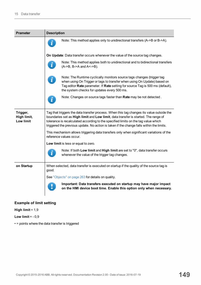
Prameter Description
Note: This method applies only to unidirectional transfers (A->B or B->A).
On Update: Data transfer occurs whenever the value of the source tag changes.
Note: This method applies both to unidirectional and to bidirectional transfers(A->B, B->A and A<->B).
Note: The Runtime cyclically monitors source tags changes (trigger tagwhen using On Trigger or tags to transfer when using OnUpdate) based onTag editorRate parameter. If Rate setting for source Tag is 500ms (default),the system checks for updates every 500ms.
Note: Changes on source tags faster thanRatemay be not detected .
Trigger,High limit,Low limit
Tag that triggers the data transfer process. When this tag changes its value outside theboundaries set as High limit and Low limit, data transfer is started. The range oftolerance is recalculated according to the specified limits on the tag value whichtriggered the previous update. No action is taken if the change falls within the limits.
This mechanism allows triggering data transfers only when significant variations of thereference values occur.
Low limit is less or equal to zero.
Note: If both Low limit andHigh limit are set to "0", data transfer occurswhenever the value of the trigger tag changes.
on Startup When selected, data transfer is executed on startup if the quality of the source tag isgood.
See "Objects" on page 263 for details on quality.
Important: Data transfers executed on startup may have major impacton the HMI device boot time. Enable this option only when necessary.
Example of limit setting
High limit = 1,9
Low limit = - 0,9
• = points where the data transfer is triggered
Copyright © 2015-2016 ABB. All rights reserved. Documentation Revision 2.00 - Date of issue: 2016-07-19 149
15 Data transfer
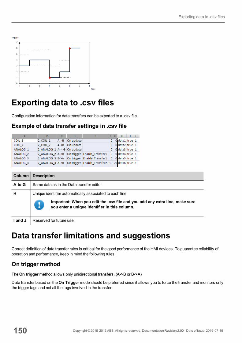
Exporting data to .csv filesConfiguration information for data transfers can be exported to a .csv file.
Example of data transfer settings in .csv file
Column Description
A to G Same data as in the Data transfer editor
H Unique identifier automatically associated to each line.
Important: When you edit the .csv file and you add any extra line, make sureyou enter a unique identifier in this column.
I and J Reserved for future use.
Data transfer limitations and suggestionsCorrect definition of data transfer rules is critical for the good performance of the HMI devices. To guarantee reliability ofoperation and performance, keep inmind the following rules.
On trigger methodTheOn triggermethod allows only unidirectional transfers, (A->B or B->A)
Data transfer based on theOn Triggermode should be preferred since it allows you to force the transfer andmonitors onlythe trigger tags and not all the tags involved in the transfer.
150 Copyright © 2015-2016 ABB. All rights reserved. Documentation Revision 2.00 - Date of issue: 2016-07-19
Exporting data to .csv files

On update methodTheOn updatemethod allows changing the values in accordance with the direction settings only when the source valuechanges.
Using theOn Updatemethod you force the system to continuously read all the defined source tags to check if there arechanges that need to be transferred. The default value of the update rate of each tag is 500ms and can bemodified withTag editor.
Performance observationsData transfer performance depends on:
l number of data transfers defined,l number of data transfers eventually occurring at the same time,l frequency of the changes of the PLC variables that aremonitored,
Important: Always test performance of operation during project development.
Important: If inappropriately set, data transfer tasks can lead to conditions where the tags involvedcreate loops. Identify and avoid such conditions.
Tip: Use the scheduler to calibrate the update rate based on the performance of your entire project.
Tip: Use array type tags to optimize data transfer and reduce workload.
Tip: Reduce the number of data transfers to reduce page change time and boot time.
Copyright © 2015-2016 ABB. All rights reserved. Documentation Revision 2.00 - Date of issue: 2016-07-19 151
15 Data transfer

152 Copyright © 2015-2016 ABB. All rights reserved. Documentation Revision 2.00 - Date of issue: 2016-07-19
Data transfer limitations and suggestions
16 Offline node managementWhen one of the controllers communicating with the HMI device goes offline, communication performance of the systemmay eventually decrease.
The offline nodemanagement feature recognizes offline controllers and removes them from communication until they comeback online.
Additionally, if you know that any of the controllers included in the installation is going to be offline for a certain time, youcanmanually disable it to maximize system performance.
Note: This feature is not supported by all communication protocols. Check protocol documentation to know if itis supported or not.
Offline node management process 154
Manual offline node management process 154
Manual offline configuration 154
Automatic offline node detection 155
Copyright © 2015-2016 ABB. All rights reserved. Documentation Revision 2.00 - Date of issue: 2016-07-19 153
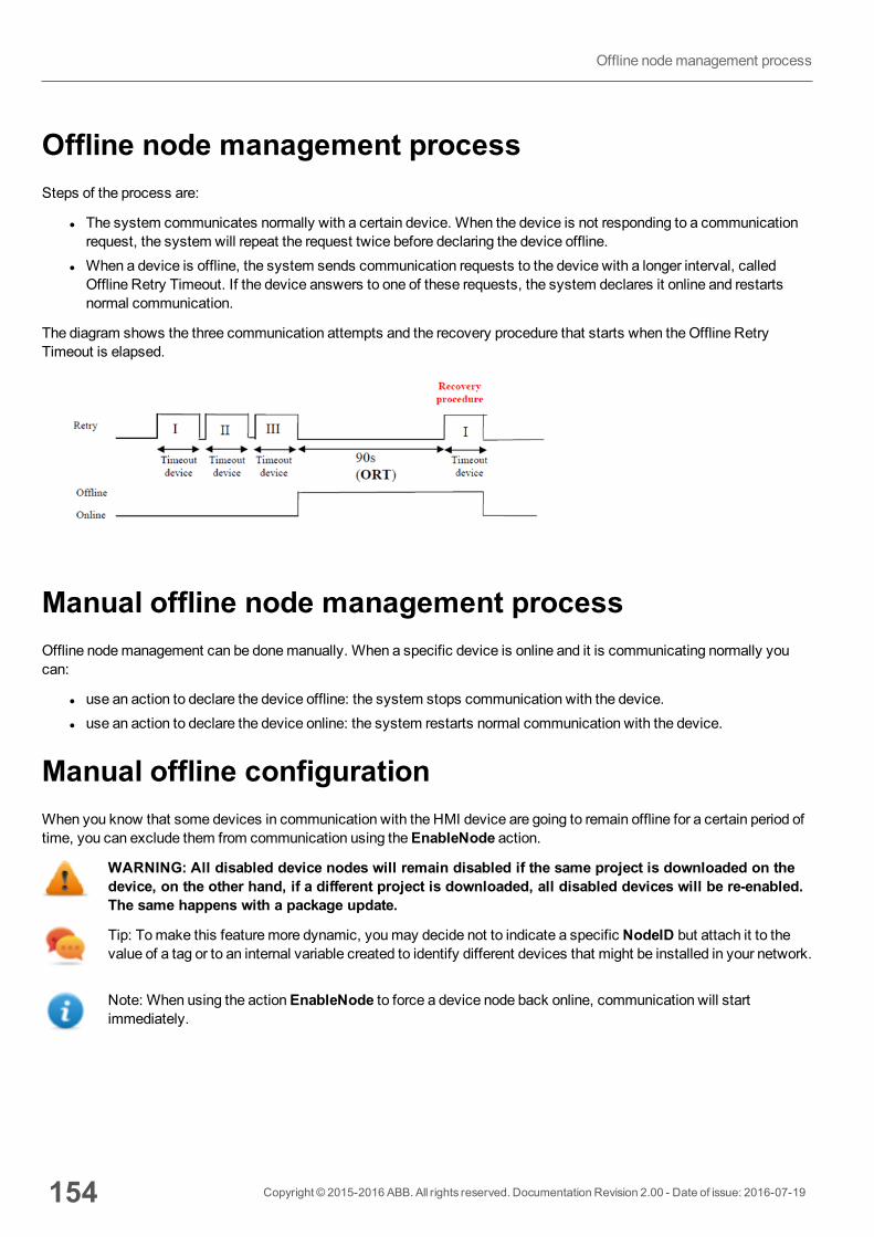
Offline node management processSteps of the process are:
l The system communicates normally with a certain device. When the device is not responding to a communicationrequest, the system will repeat the request twice before declaring the device offline.
l When a device is offline, the system sends communication requests to the device with a longer interval, calledOffline Retry Timeout. If the device answers to one of these requests, the system declares it online and restartsnormal communication.
The diagram shows the three communication attempts and the recovery procedure that starts when theOffline RetryTimeout is elapsed.
Manual offline node management processOffline nodemanagement can be donemanually. When a specific device is online and it is communicating normally youcan:
l use an action to declare the device offline: the system stops communication with the device.l use an action to declare the device online: the system restarts normal communication with the device.
Manual offline configurationWhen you know that some devices in communication with the HMI device are going to remain offline for a certain period oftime, you can exclude them from communication using theEnableNode action.
WARNING: All disabled device nodes will remain disabled if the same project is downloaded on thedevice, on the other hand, if a different project is downloaded, all disabled devices will be re-enabled.The same happens with a package update.
Tip: Tomake this featuremore dynamic, youmay decide not to indicate a specific NodeID but attach it to thevalue of a tag or to an internal variable created to identify different devices that might be installed in your network.
Note: When using the actionEnableNode to force a device node back online, communication will startimmediately.
154 Copyright © 2015-2016 ABB. All rights reserved. Documentation Revision 2.00 - Date of issue: 2016-07-19
Offline nodemanagement process
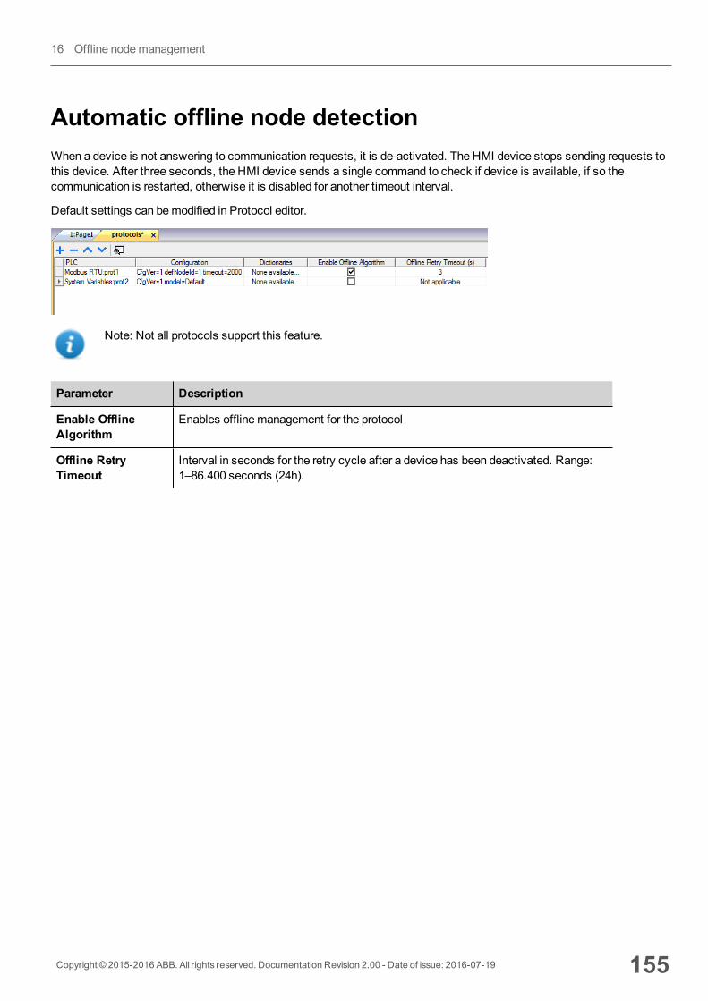
Automatic offline node detectionWhen a device is not answering to communication requests, it is de-activated. The HMI device stops sending requests tothis device. After three seconds, the HMI device sends a single command to check if device is available, if so thecommunication is restarted, otherwise it is disabled for another timeout interval.
Default settings can bemodified in Protocol editor.
Note: Not all protocols support this feature.
Parameter Description
Enable OfflineAlgorithm
Enables offlinemanagement for the protocol
Offline RetryTimeout
Interval in seconds for the retry cycle after a device has been deactivated. Range:1–86.400 seconds (24h).
Copyright © 2015-2016 ABB. All rights reserved. Documentation Revision 2.00 - Date of issue: 2016-07-19 155
16 Offline nodemanagement

156 Copyright © 2015-2016 ABB. All rights reserved. Documentation Revision 2.00 - Date of issue: 2016-07-19
Automatic offline node detection
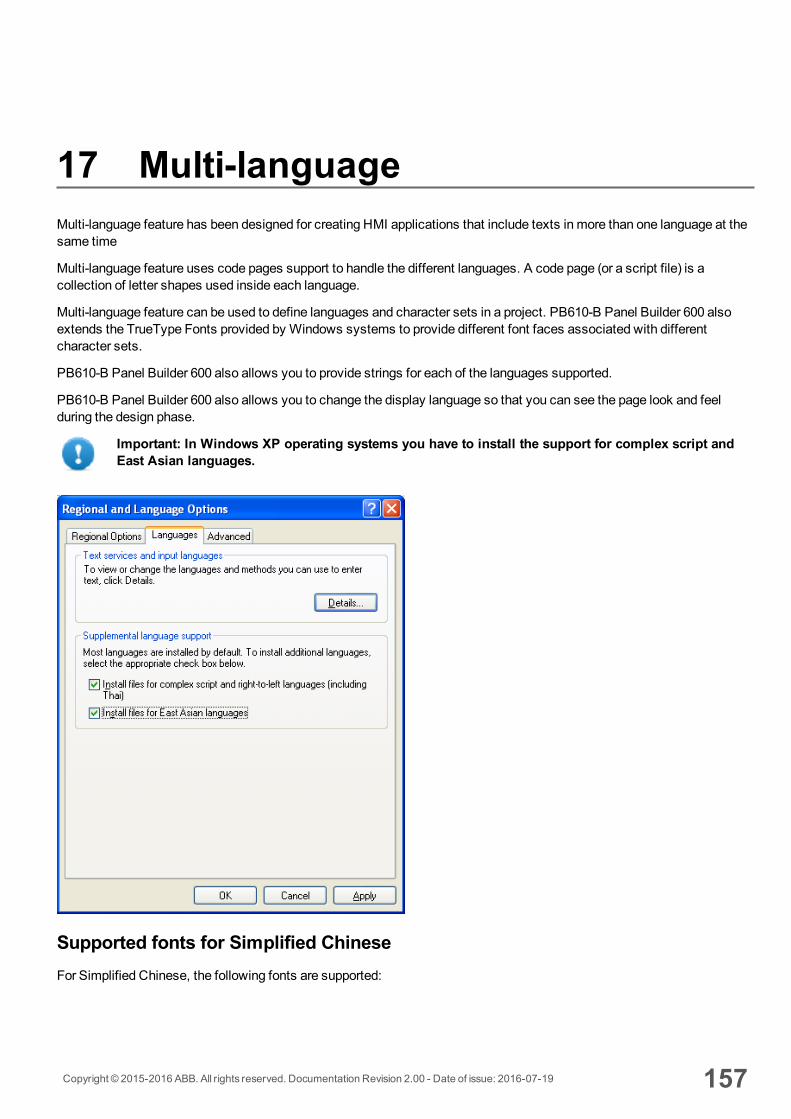
17 Multi-languageMulti-language feature has been designed for creating HMI applications that include texts in more than one language at thesame time
Multi-language feature uses code pages support to handle the different languages. A code page (or a script file) is acollection of letter shapes used inside each language.
Multi-language feature can be used to define languages and character sets in a project. PB610-B Panel Builder 600 alsoextends the TrueType Fonts provided by Windows systems to provide different font faces associated with differentcharacter sets.
PB610-B Panel Builder 600 also allows you to provide strings for each of the languages supported.
PB610-B Panel Builder 600 also allows you to change the display language so that you can see the page look and feelduring the design phase.
Important: In Windows XP operating systems you have to install the support for complex script andEast Asian languages.
Supported fonts for Simplified ChineseFor Simplified Chinese, the following fonts are supported:
Copyright © 2015-2016 ABB. All rights reserved. Documentation Revision 2.00 - Date of issue: 2016-07-19 157
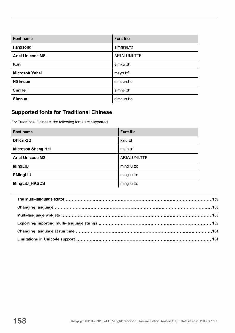
Font name Font file
Fangsong simfang.ttf
Arial Unicode MS ARIALUNI.TTF
Kaiti simkai.ttf
Microsoft Yahei msyh.ttf
NSImsun simsun.ttc
SimHei simhei.ttf
Simsun simsun.ttc
Supported fonts for Traditional ChineseFor Traditional Chinese, the following fonts are supported:
Font name Font file
DFKai-SB kaiu.ttf
Microsoft Sheng Hai msjh.ttf
Arial Unicode MS ARIALUNI.TTF
MingLiU mingliu.ttc
PMingLiU mingliu.ttc
MingLiU_HKSCS mingliu.ttc
The Multi-language editor 159
Changing language 160
Multi-language widgets 160
Exporting/importing multi-language strings 162
Changing language at run time 164
Limitations in Unicode support 164
158 Copyright © 2015-2016 ABB. All rights reserved. Documentation Revision 2.00 - Date of issue: 2016-07-19
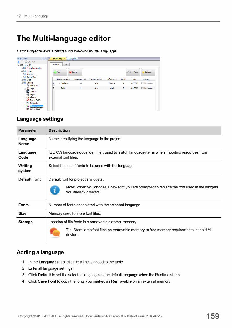
The Multi-language editorPath: ProjectView> Config > double-click MultiLanguage
Language settings
Parameter Description
LanguageName
Name identifying the language in the project.
LanguageCode
ISO 639 language code identifier, used tomatch language items when importing resources fromexternal xml files.
Writingsystem
Select the set of fonts to be used with the language
Default Font Default font for project's widgets.
Note: When you choose a new font you are prompted to replace the font used in the widgetsyou already created.
Fonts Number of fonts associated with the selected language.
Size Memory used to store font files.
Storage Location of file fonts is a removable external memory.
Tip: Store large font files on removablememory to freememory requirements in the HMIdevice.
Adding a language1. In the Languages tab, click +: a line is added to the table.2. Enter all language settings.3. Click Default to set the selected language as the default language when the Runtime starts.4. Click Save Font to copy the fonts youmarked as Removable on an external memory.
Copyright © 2015-2016 ABB. All rights reserved. Documentation Revision 2.00 - Date of issue: 2016-07-19 159
17 Multi-language
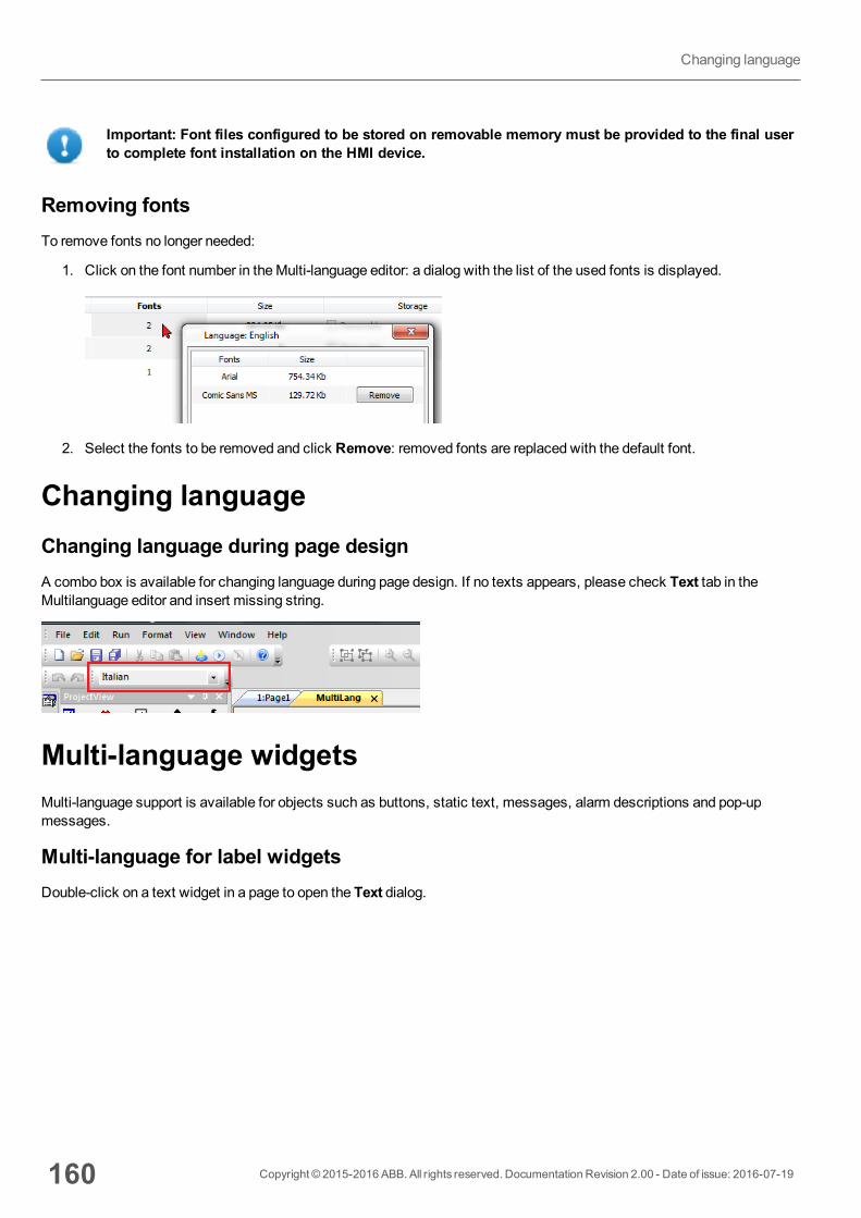
Important: Font files configured to be stored on removable memory must be provided to the final userto complete font installation on the HMI device.
Removing fontsTo remove fonts no longer needed:
1. Click on the font number in theMulti-language editor: a dialog with the list of the used fonts is displayed.
2. Select the fonts to be removed and click Remove: removed fonts are replaced with the default font.
Changing languageChanging language during page designA combo box is available for changing language during page design. If no texts appears, please check Text tab in theMultilanguage editor and insert missing string.
Multi-language widgetsMulti-language support is available for objects such as buttons, static text, messages, alarm descriptions and pop-upmessages.
Multi-language for label widgetsDouble-click on a text widget in a page to open the Text dialog.
160 Copyright © 2015-2016 ABB. All rights reserved. Documentation Revision 2.00 - Date of issue: 2016-07-19
Changing language
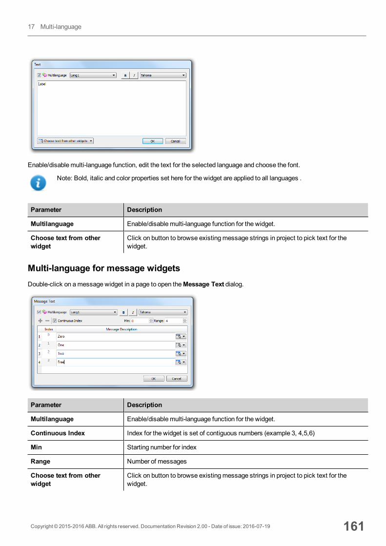
Enable/disable multi-language function, edit the text for the selected language and choose the font.
Note: Bold, italic and color properties set here for the widget are applied to all languages .
Parameter Description
Multilanguage Enable/disable multi-language function for the widget.
Choose text from otherwidget
Click on button to browse existingmessage strings in project to pick text for thewidget.
Multi-language for message widgetsDouble-click on amessage widget in a page to open theMessage Text dialog.
Parameter Description
Multilanguage Enable/disable multi-language function for the widget.
Continuous Index Index for the widget is set of contiguous numbers (example 3, 4,5,6)
Min Starting number for index
Range Number of messages
Choose text from otherwidget
Click on button to browse existingmessage strings in project to pick text for thewidget.
Copyright © 2015-2016 ABB. All rights reserved. Documentation Revision 2.00 - Date of issue: 2016-07-19 161
17 Multi-language
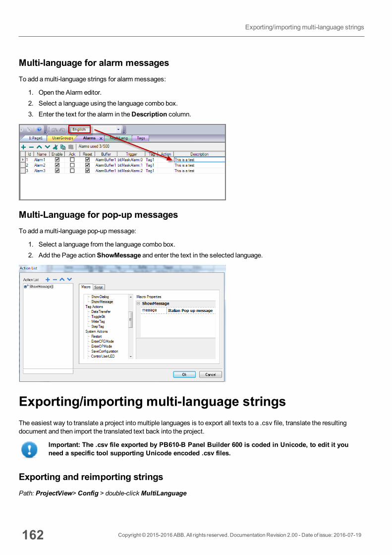
Multi-language for alarm messagesTo add amulti-language strings for alarm messages:
1. Open the Alarm editor.2. Select a language using the language combo box.3. Enter the text for the alarm in theDescription column.
Multi-Language for pop-up messagesTo add amulti-language pop-upmessage:
1. Select a language from the language combo box.2. Add the Page actionShowMessage and enter the text in the selected language.
Exporting/importing multi-language stringsThe easiest way to translate a project into multiple languages is to export all texts to a .csv file, translate the resultingdocument and then import the translated text back into the project.
Important: The .csv file exported by PB610-B Panel Builder 600 is coded in Unicode, to edit it youneed a specific tool supporting Unicode encoded .csv files.
Exporting and reimporting stringsPath: ProjectView> Config > double-click MultiLanguage
162 Copyright © 2015-2016 ABB. All rights reserved. Documentation Revision 2.00 - Date of issue: 2016-07-19
Exporting/importingmulti-language strings
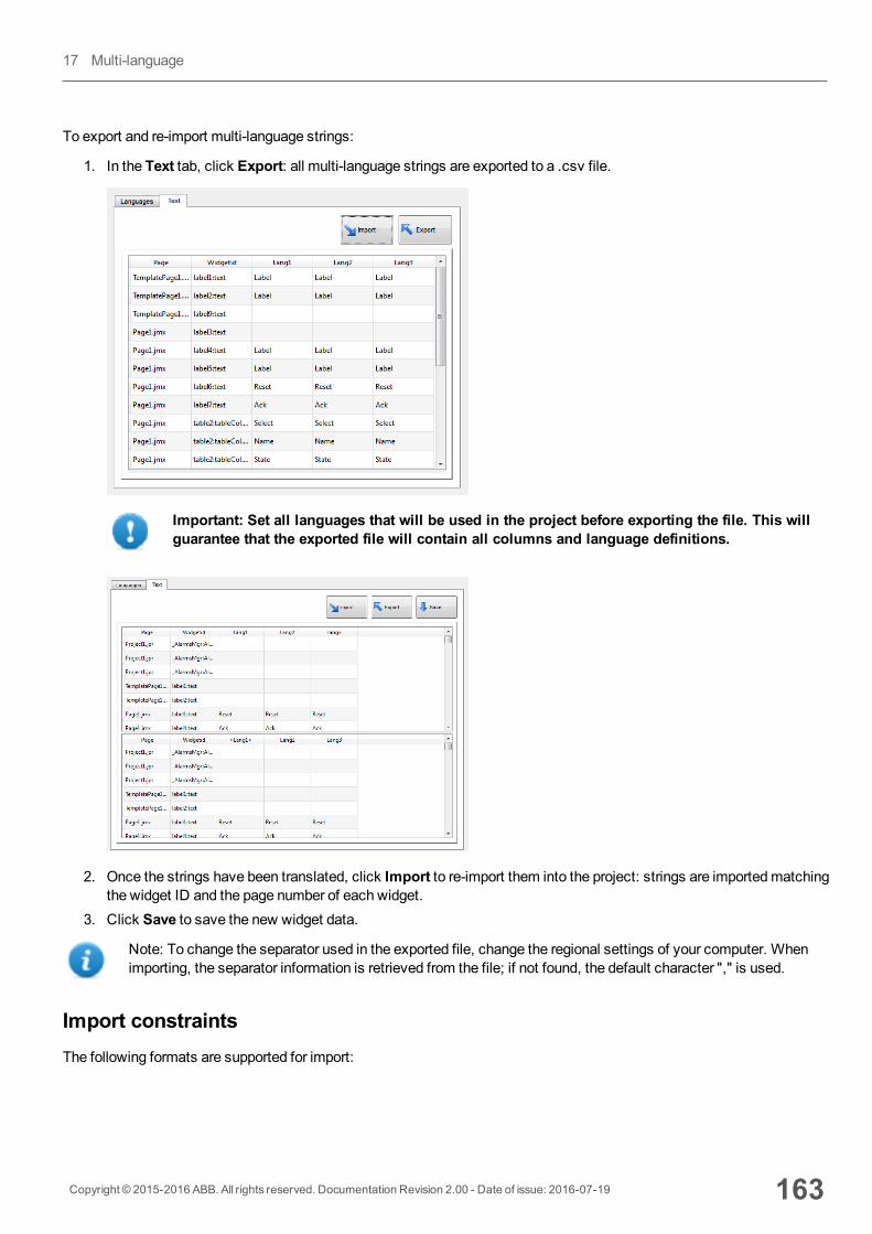
To export and re-import multi-language strings:
1. In the Text tab, click Export: all multi-language strings are exported to a .csv file.
Important: Set all languages that will be used in the project before exporting the file. This willguarantee that the exported file will contain all columns and language definitions.
2. Once the strings have been translated, click Import to re-import them into the project: strings are importedmatchingthe widget ID and the page number of each widget.
3. Click Save to save the new widget data.
Note: To change the separator used in the exported file, change the regional settings of your computer. Whenimporting, the separator information is retrieved from the file; if not found, the default character "," is used.
Import constraintsThe following formats are supported for import:
Copyright © 2015-2016 ABB. All rights reserved. Documentation Revision 2.00 - Date of issue: 2016-07-19 163
17 Multi-language
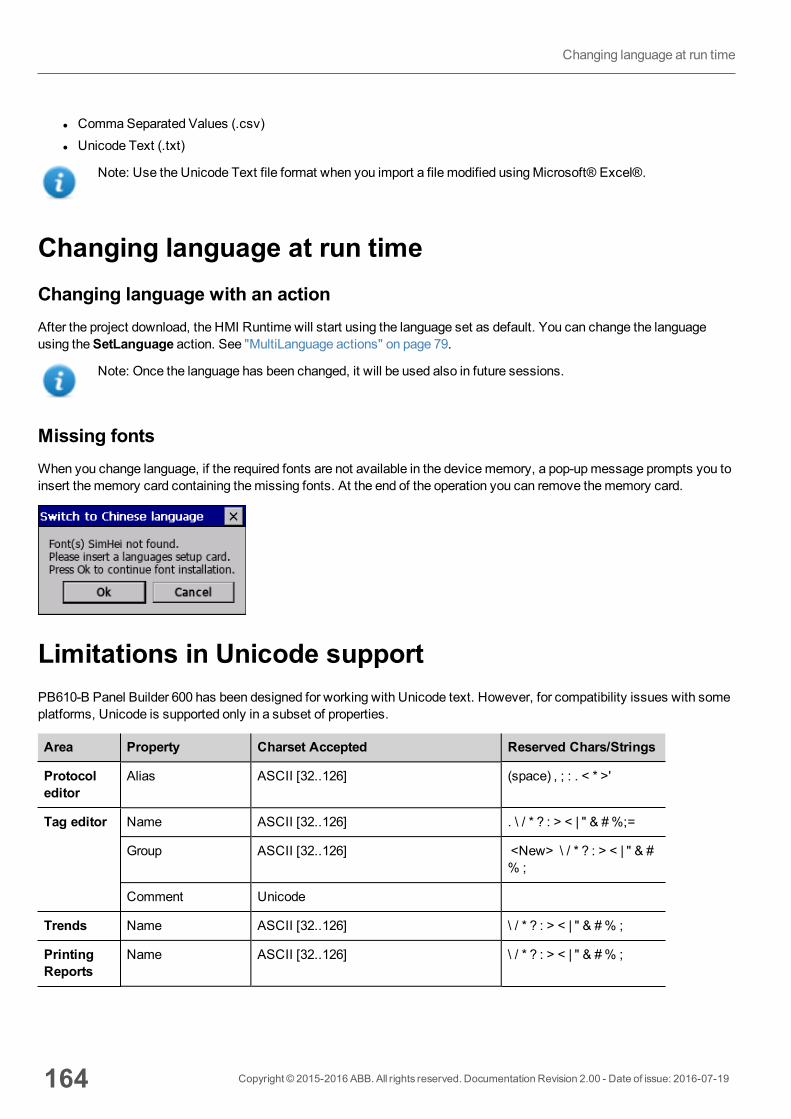
l CommaSeparated Values (.csv)l Unicode Text (.txt)
Note: Use the Unicode Text file format when you import a file modified usingMicrosoft® Excel®.
Changing language at run timeChanging language with an actionAfter the project download, the HMI Runtime will start using the language set as default. You can change the languageusing theSetLanguage action. See "MultiLanguage actions" on page 79.
Note: Once the language has been changed, it will be used also in future sessions.
Missing fontsWhen you change language, if the required fonts are not available in the devicememory, a pop-upmessage prompts you toinsert thememory card containing themissing fonts. At the end of the operation you can remove thememory card.
Limitations in Unicode supportPB610-B Panel Builder 600 has been designed for working with Unicode text. However, for compatibility issues with someplatforms, Unicode is supported only in a subset of properties.
Area Property Charset Accepted Reserved Chars/Strings
Protocoleditor
Alias ASCII [32..126] (space) , ; : . < * >'
Tag editor Name ASCII [32..126] . \ / * ? : > < | " & #%;=
Group ASCII [32..126] <New> \ / * ? : > < | " & #% ;
Comment Unicode
Trends Name ASCII [32..126] \ / * ? : > < | " & #% ;
PrintingReports
Name ASCII [32..126] \ / * ? : > < | " & #% ;
164 Copyright © 2015-2016 ABB. All rights reserved. Documentation Revision 2.00 - Date of issue: 2016-07-19
Changing language at run time
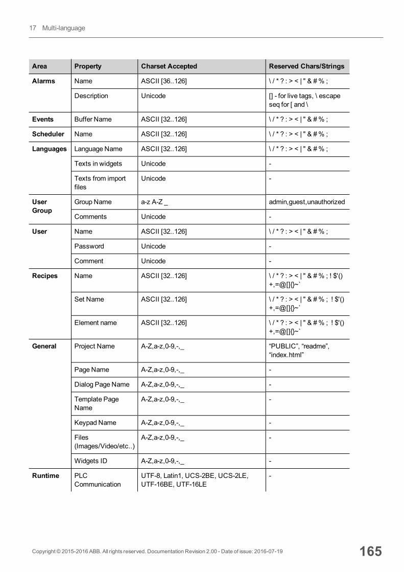
Area Property Charset Accepted Reserved Chars/Strings
Alarms Name ASCII [36..126] \ / * ? : > < | " & #% ;
Description Unicode [] - for live tags, \ escapeseq for [ and \
Events Buffer Name ASCII [32..126] \ / * ? : > < | " & #% ;
Scheduler Name ASCII [32..126] \ / * ? : > < | " & #% ;
Languages Language Name ASCII [32..126] \ / * ? : > < | " & #% ;
Texts in widgets Unicode -
Texts from importfiles
Unicode -
UserGroup
Group Name a-z A-Z _ admin,guest,unauthorized
Comments Unicode -
User Name ASCII [32..126] \ / * ? : > < | " & #% ;
Password Unicode -
Comment Unicode -
Recipes Name ASCII [32..126] \ / * ? : > < | " & #% ; ! $'()+,=@[]{}~`
Set Name ASCII [32..126] \ / * ? : > < | " & #% ; ! $'()+,=@[]{}~`
Element name ASCII [32..126] \ / * ? : > < | " & #% ; ! $'()+,=@[]{}~`
General Project Name A-Z,a-z,0-9,-,_ “PUBLIC”, “readme”,“index.html”
Page Name A-Z,a-z,0-9,-,_ -
Dialog Page Name A-Z,a-z,0-9,-,_ -
Template PageName
A-Z,a-z,0-9,-,_ -
Keypad Name A-Z,a-z,0-9,-,_ -
Files(Images/Video/etc..)
A-Z,a-z,0-9,-,_ -
Widgets ID A-Z,a-z,0-9,-,_ -
Runtime PLCCommunication
UTF-8, Latin1, UCS-2BE, UCS-2LE,UTF-16BE, UTF-16LE
-
Copyright © 2015-2016 ABB. All rights reserved. Documentation Revision 2.00 - Date of issue: 2016-07-19 165
17 Multi-language

166 Copyright © 2015-2016 ABB. All rights reserved. Documentation Revision 2.00 - Date of issue: 2016-07-19
Limitations in Unicode support

18 SchedulerPB610-B Panel Builder 600 provides a scheduler engine that can execute specific actions at set intervals, or on a timebasis.
Creating a schedule is typically a two-step process:
1. You create a schedule with a list of actions to be executed when the scheduled event occurs. You do this in theScheduler editor
2. You create a run-time user interface that allows the end-user to change settings for each schedule. You do thisadding aSchedulerwidget to a page of your project and configuring it to fit user scheduling needs.
Creating a schedule 168
HighResolution schedule 168
Recurring schedule 168
Configuring location for schedules 170
Configuring the Scheduler widget 171
Scheduling events at run time 172
Copyright © 2015-2016 ABB. All rights reserved. Documentation Revision 2.00 - Date of issue: 2016-07-19 167
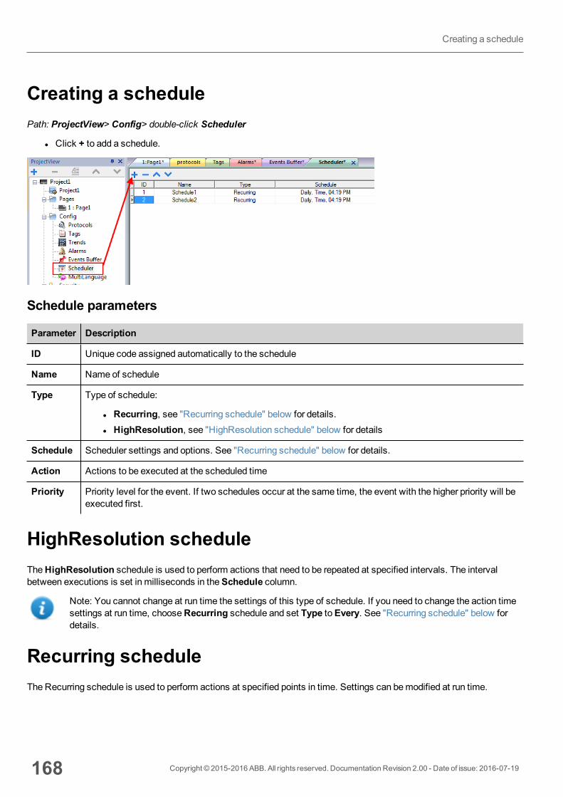
Creating a schedulePath: ProjectView> Config> double-click Scheduler
l Click + to add a schedule.
Schedule parameters
Parameter Description
ID Unique code assigned automatically to the schedule
Name Name of schedule
Type Type of schedule:
l Recurring, see "Recurring schedule" below for details.l HighResolution, see "HighResolution schedule" below for details
Schedule Scheduler settings and options. See "Recurring schedule" below for details.
Action Actions to be executed at the scheduled time
Priority Priority level for the event. If two schedules occur at the same time, the event with the higher priority will beexecuted first.
HighResolution scheduleTheHighResolution schedule is used to perform actions that need to be repeated at specified intervals. The intervalbetween executions is set in milliseconds in theSchedule column.
Note: You cannot change at run time the settings of this type of schedule. If you need to change the action timesettings at run time, chooseRecurring schedule and set Type toEvery. See "Recurring schedule" below fordetails.
Recurring scheduleThe Recurring schedule is used to perform actions at specified points in time. Settings can bemodified at run time.
168 Copyright © 2015-2016 ABB. All rights reserved. Documentation Revision 2.00 - Date of issue: 2016-07-19
Creating a schedule

Recurring scheduler parameters
Parameter Description
Type Frequency of the scheduled actions
Mode Specific settings required by each scheduler type
Condition Boolean tag (true/false) to activate the specified actions at themoment the timer is triggered. Actions willbe executed if tag = true. By default, actions are executed when the timer is triggered.
Note: Only tags attached to the Boolean data type are shown.
Actions Actions to be executed by the schedule.
Important: Actions and schedule parameters cannot be modified at run time
Date Date when the scheduled actions will be executed
Time/Offset This field display one of the following:
Time = when the scheduled actions will be executed
Offset= delay or advance with respect to the selectedmode.
Location Reference location to calculate sunset/sunrise time.
weekdays Days of the week in which the scheduled actions will be executed.
On startup Executes schedule at start up
Enableschedule
Enables/disables the schedule
Executeonly atstartup
Executes the schedule only once at start up
Schedule type options
Option Description
By Date Actions are executed on the specified date and time.
Daily Actions are executed daily at the specified time.
Every Actions are executed with the specified interval (Range: 1 s–1 day)
Hourly Actions are executed every hour at the specifiedminute.
Monthly Actions are executed every month at the specified date and time.
Copyright © 2015-2016 ABB. All rights reserved. Documentation Revision 2.00 - Date of issue: 2016-07-19 169
18 Scheduler
Option Description
Weekly Actions are executed every week on the specified weekday(s) and time.
Yearly Actions are executed every year at the specified date and time.
Schedule mode options
Option Description
Time Depends on the schedule type. Allows you to specify date/time/week data.
Random10 Actions are executed in the time interval of 10minutes before or after the set time.
For example, if set time is 10:30, actions are executed any time between 10:20 and 10:40.
Random20 Actions are executed in the time interval of 20minutes before or after the set time.
For example, if set time is 10:30, actions are executed any time between 10:10 and 10:50.
Sunrise+ Actions are executed with a specified delay after sunrise. The delay is set in minutes/hoursand sunrise time is location specific.
Sunrise- Actions are executed with a specified advance before sunrise. The advance is set inminutes/hours and sunrise time is location specific.
Sunset+ Actions are executed with a specified delay after sunset. The delay is set in minutes/hours andsunset time is location specific.
Sunset- Actions are executed with a specified advance before sunset. The advance is set inminutes/hours and sunset time is location specific.
See "Configuring location for schedules" below for details on sunset and sunrise settings.
Note:Mode options are not available for all schedule types.
Configuring location for schedulesScheduled actions can be configured to be executed at a specific time with respect to sunrise and/or sunset. To do this youneed to define the correct location, based on UTC information. The system will the automatically calculate the sunrise andsunset time.
Only a few locations are available by default. If your location is not listed, you can add it by entering latitude, longitude andUTC information in the Target_Location.xml file.
Important: Each platform has its own Target_Location.xml file.
170 Copyright © 2015-2016 ABB. All rights reserved. Documentation Revision 2.00 - Date of issue: 2016-07-19
Configuring location for schedules
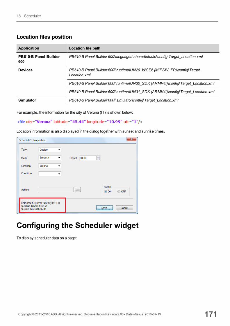
Location files position
Application Location file path
PB610-B Panel Builder600
PB610-B Panel Builder 600\languages\shared\studio\config\Target_Location.xml
Devices PB610-B Panel Builder 600\\runtime\UN20_WCE6 (MIPSIV_FP)\config\Target_Location.xml
PB610-B Panel Builder 600\\runtime\UN30_SDK (ARMV4I)\config\Target_Location.xml
PB610-B Panel Builder 600\\runtime\UN31_SDK (ARMV4I)\config\Target_Location.xml
Simulator PB610-B Panel Builder 600\\simulator\config\Target_Location.xml
For example, the information for the city of Verona (IT) is shown below:
Location information is also displayed in the dialog together with sunset and sunrise times.
Configuring the Scheduler widgetTo display scheduler data on a page:
Copyright © 2015-2016 ABB. All rights reserved. Documentation Revision 2.00 - Date of issue: 2016-07-19 171
18 Scheduler
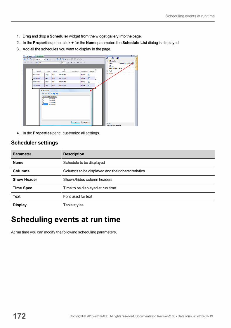
1. Drag and drop aSchedulerwidget from the widget gallery into the page.2. In theProperties pane, click + for theName parameter: theSchedule List dialog is displayed.3. Add all the schedules you want to display in the page.
4. In theProperties pane, customize all settings.
Scheduler settings
Parameter Description
Name Schedule to be displayed
Columns Columns to be displayed and their characteristics
Show Header Shows/hides column headers
Time Spec Time to be displayed at run time
Text Font used for text
Display Table styles
Scheduling events at run timeAt run time you canmodify the following scheduling parameters.
172 Copyright © 2015-2016 ABB. All rights reserved. Documentation Revision 2.00 - Date of issue: 2016-07-19
Scheduling events at run time
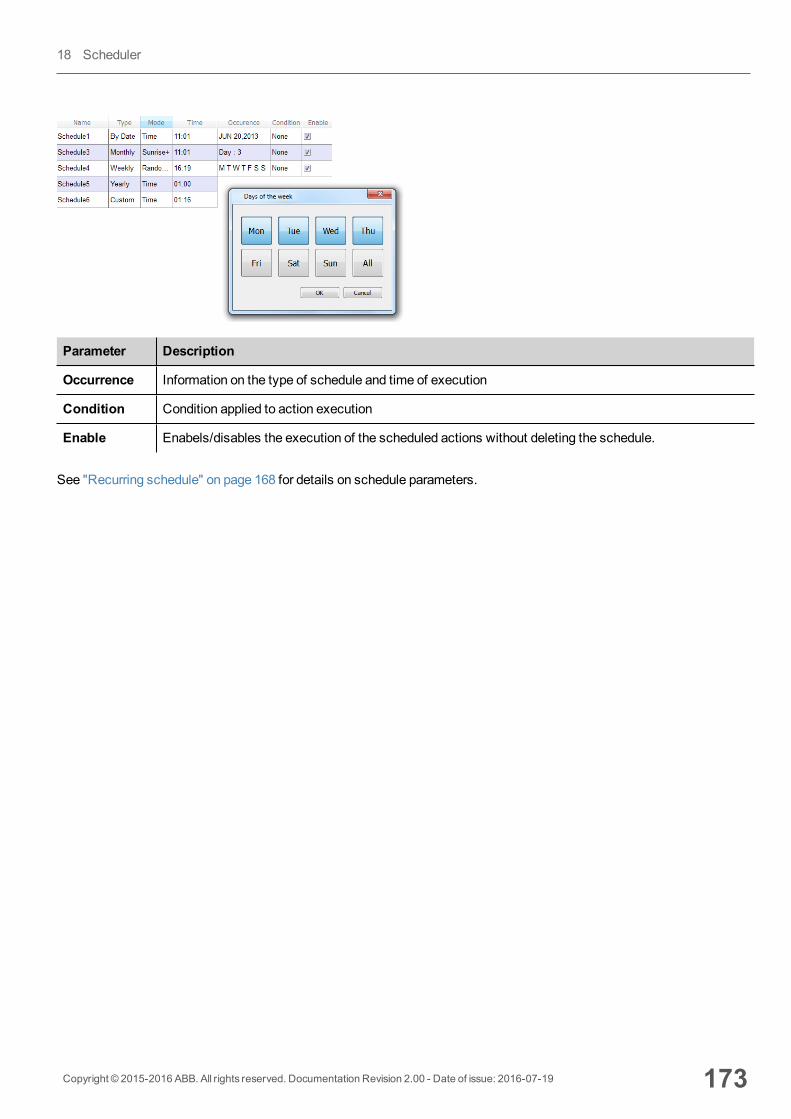
Parameter Description
Occurrence Information on the type of schedule and time of execution
Condition Condition applied to action execution
Enable Enabels/disables the execution of the scheduled actions without deleting the schedule.
See "Recurring schedule" on page 168 for details on schedule parameters.
Copyright © 2015-2016 ABB. All rights reserved. Documentation Revision 2.00 - Date of issue: 2016-07-19 173
18 Scheduler

174 Copyright © 2015-2016 ABB. All rights reserved. Documentation Revision 2.00 - Date of issue: 2016-07-19
Scheduling events at run time
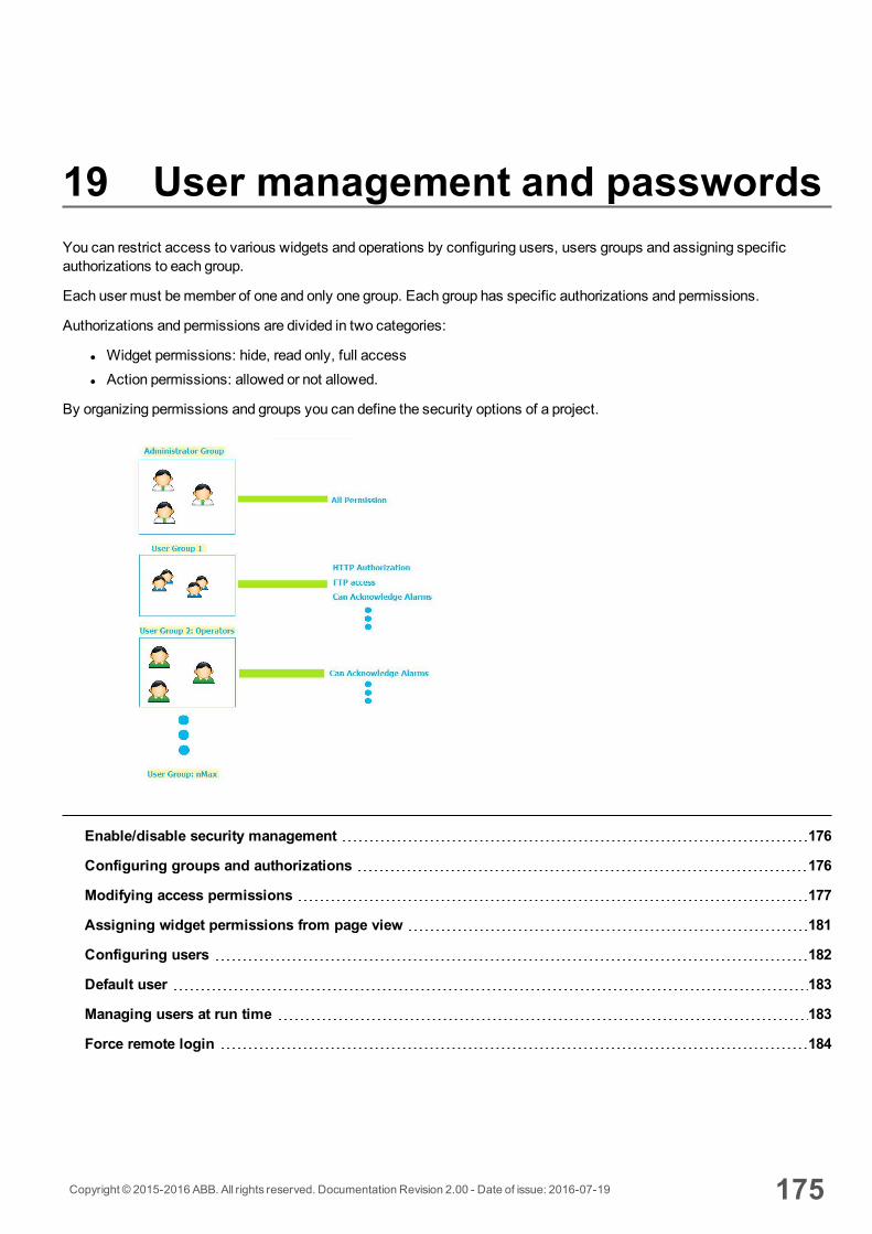
19 User management and passwordsYou can restrict access to various widgets and operations by configuring users, users groups and assigning specificauthorizations to each group.
Each user must bemember of one and only one group. Each group has specific authorizations and permissions.
Authorizations and permissions are divided in two categories:
l Widget permissions: hide, read only, full accessl Action permissions: allowed or not allowed.
By organizing permissions and groups you can define the security options of a project.
Enable/disable security management 176
Configuring groups and authorizations 176
Modifying access permissions 177
Assigning widget permissions from page view 181
Configuring users 182
Default user 183
Managing users at run time 183
Force remote login 184
Copyright © 2015-2016 ABB. All rights reserved. Documentation Revision 2.00 - Date of issue: 2016-07-19 175
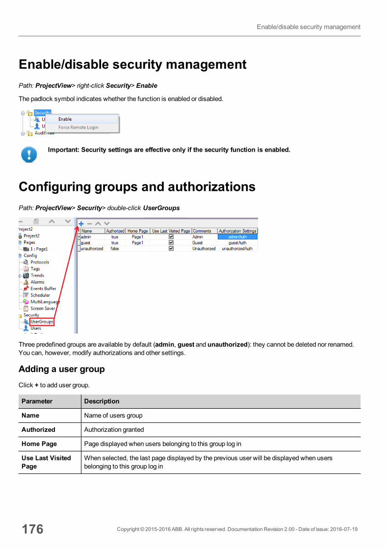
Enable/disable security managementPath: ProjectView> right-click Security> Enable
The padlock symbol indicates whether the function is enabled or disabled.
Important: Security settings are effective only if the security function is enabled.
Configuring groups and authorizationsPath: ProjectView> Security> double-click UserGroups
Three predefined groups are available by default (admin, guest and unauthorized): they cannot be deleted nor renamed.You can, however, modify authorizations and other settings.
Adding a user groupClick + to add user group.
Parameter Description
Name Name of users group
Authorized Authorization granted
Home Page Page displayed when users belonging to this group log in
Use Last VisitedPage
When selected, the last page displayed by the previous user will be displayed when usersbelonging to this group log in
176 Copyright © 2015-2016 ABB. All rights reserved. Documentation Revision 2.00 - Date of issue: 2016-07-19
Enable/disable security management
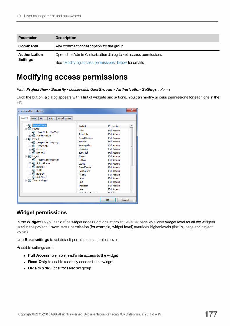
Parameter Description
Comments Any comment or description for the group
AuthorizationSettings
Opens the Admin Authorization dialog to set access permissions.
See "Modifying access permissions" below for details.
Modifying access permissionsPath: ProjectView> Security> double-click UserGroups > Authorization Settings column
Click the button: a dialog appears with a list of widgets and actions. You canmodify access permissions for each one in thelist.
Widget permissionsIn theWidget tab you can define widget access options at project level, at page level or at widget level for all the widgetsused in the project. Lower levels permission (for example, widget level) overrides higher levels (that is, page and projectlevels).
Use Base settings to set default permissions at project level.
Possible settings are:
l Full Access to enable read/write access to the widgetl Read Only to enable readonly access to the widgetl Hide to hide widget for selected group
Copyright © 2015-2016 ABB. All rights reserved. Documentation Revision 2.00 - Date of issue: 2016-07-19 177
19 User management and passwords
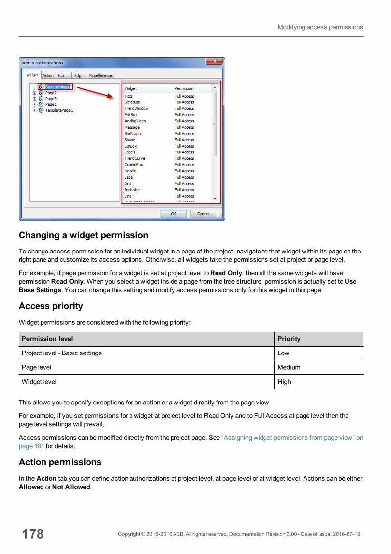
Changing a widget permissionTo change access permission for an individual widget in a page of the project, navigate to that widget within its page on theright pane and customize its access options. Otherwise, all widgets take the permissions set at project or page level.
For example, if page permission for a widget is set at project level toRead Only, then all the samewidgets will havepermissionRead Only. When you select a widget inside a page from the tree structure, permission is actually set toUseBase Settings. You can change this setting andmodify access permissions only for this widget in this page.
Access priorityWidget permissions are considered with the following priority:
Permission level Priority
Project level - Basic settings Low
Page level Medium
Widget level High
This allows you to specify exceptions for an action or a widget directly from the page view.
For example, if you set permissions for a widget at project level to ReadOnly and to Full Access at page level then thepage level settings will prevail.
Access permissions can bemodified directly from the project page. See "Assigning widget permissions from page view" onpage 181 for details.
Action permissionsIn the Action tab you can define action authorizations at project level, at page level or at widget level. Actions can be eitherAllowed orNot Allowed.
178 Copyright © 2015-2016 ABB. All rights reserved. Documentation Revision 2.00 - Date of issue: 2016-07-19
Modifying access permissions

Action permissions can bemodified directly from the project page. See "Assigning widget permissions from page view" onpage 181 for details.
FTP authorizationsIn the Ftp tab you can set specific authorizations for the FTP server.
Element Description
Enable FTP authorization Enables the FTP function for the specific group
Permission Type of permission:
l Read-Only
Copyright © 2015-2016 ABB. All rights reserved. Documentation Revision 2.00 - Date of issue: 2016-07-19 179
19 User management and passwords
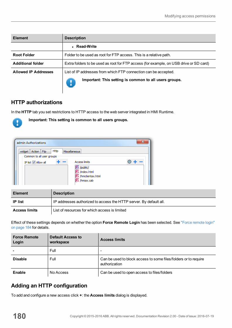
Element Description
l Read-Write
Root Folder Folder to be used as root for FTP access. This is a relative path.
Additional folder Extra folders to be used as root for FTP access (for example, on USB drive or SD card)
Allowed IP Addresses List of IP addresses from which FTP connection can be accepted.
Important: This setting is common to all users groups.
HTTP authorizationsIn theHTTP tab you set restrictions to HTTP access to the web server integrated in HMI Runtime.
Important: This setting is common to all users groups.
Element Description
IP list IP addresses authorized to access the HTTP server. By default all.
Access limits List of resources for which access is limited
Effect of these settings depends on whether the option Force Remote Login has been selected. See "Force remote login"on page 184 for details.
Force RemoteLogin
Default Access toworkspace Access limits
- Full -
Disable Full Can be used to block access to some files/folders or to requireauthorization
Enable NoAccess Can be used to open access to files/folders
Adding an HTTP configurationTo add and configure a new access click +: theAccess limits dialog is displayed.
180 Copyright © 2015-2016 ABB. All rights reserved. Documentation Revision 2.00 - Date of issue: 2016-07-19
Modifying access permissions
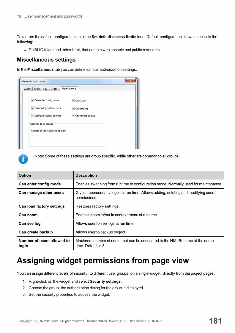
To restore the default configuration click theSet default access limits icon. Default configuration allows access to thefollowing:
l PUBLIC folder and Index.html, that contain web console and public resources
Miscellaneous settingsIn theMiscellaneous tab you can define various authorization settings.
Note: Some of these settings are group specific, while other are common to all groups.
Option Description
Can enter config mode Enables switching from runtime to configurationmode. Normally used for maintenance.
Can manage other users Gives superuser privileges at run time. Allows adding, deleting andmodifying users'permissions.
Can load factory settings Restores factory settings.
Can zoom Enables zoom in/out in context menu at run time
Can see log Allows user to see logs at run time
Can create backup Allows user to backup project.
Number of users allowed tologin
Maximum number of users that can be connected to the HMI Runtime at the sametime. Default is 3.
Assigning widget permissions from page viewYou can assign different levels of security, to different user groups, on a single widget, directly from the project pages.
1. Right-click on the widget and select Security settings.2. Choose the group: the authorization dialog for the group is displayed.3. Set the security properties to access the widget.
Copyright © 2015-2016 ABB. All rights reserved. Documentation Revision 2.00 - Date of issue: 2016-07-19 181
19 User management and passwords
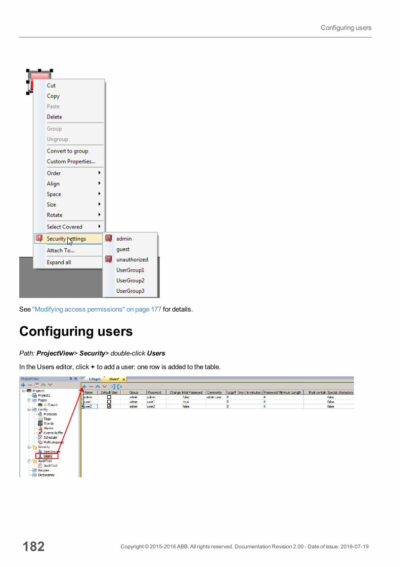
See "Modifying access permissions" on page 177 for details.
Configuring usersPath: ProjectView> Security> double-click Users
In the Users editor, click + to add a user: one row is added to the table.
182 Copyright © 2015-2016 ABB. All rights reserved. Documentation Revision 2.00 - Date of issue: 2016-07-19
Configuring users
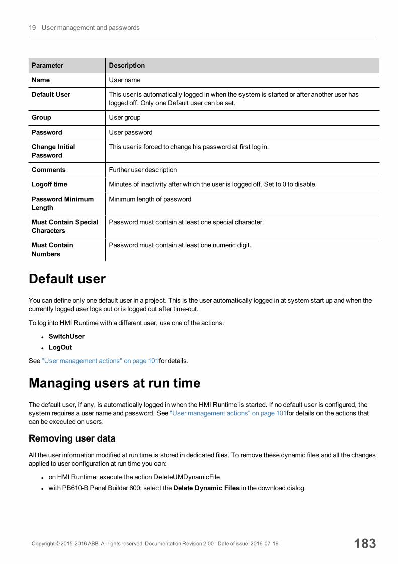
Parameter Description
Name User name
Default User This user is automatically logged in when the system is started or after another user haslogged off. Only one Default user can be set.
Group User group
Password User password
Change InitialPassword
This user is forced to change his password at first log in.
Comments Further user description
Logoff time Minutes of inactivity after which the user is logged off. Set to 0 to disable.
Password MinimumLength
Minimum length of password
Must Contain SpecialCharacters
Passwordmust contain at least one special character.
Must ContainNumbers
Passwordmust contain at least one numeric digit.
Default userYou can define only one default user in a project. This is the user automatically logged in at system start up and when thecurrently logged user logs out or is logged out after time-out.
To log into HMI Runtime with a different user, use one of the actions:
l SwitchUserl LogOut
See "User management actions" on page 101for details.
Managing users at run timeThe default user, if any, is automatically logged in when the HMI Runtime is started. If no default user is configured, thesystem requires a user name and password. See "User management actions" on page 101for details on the actions thatcan be executed on users.
Removing user dataAll the user informationmodified at run time is stored in dedicated files. To remove these dynamic files and all the changesapplied to user configuration at run time you can:
l on HMI Runtime: execute the action DeleteUMDynamicFilel with PB610-B Panel Builder 600: select theDelete Dynamic Files in the download dialog.
Copyright © 2015-2016 ABB. All rights reserved. Documentation Revision 2.00 - Date of issue: 2016-07-19 183
19 User management and passwords
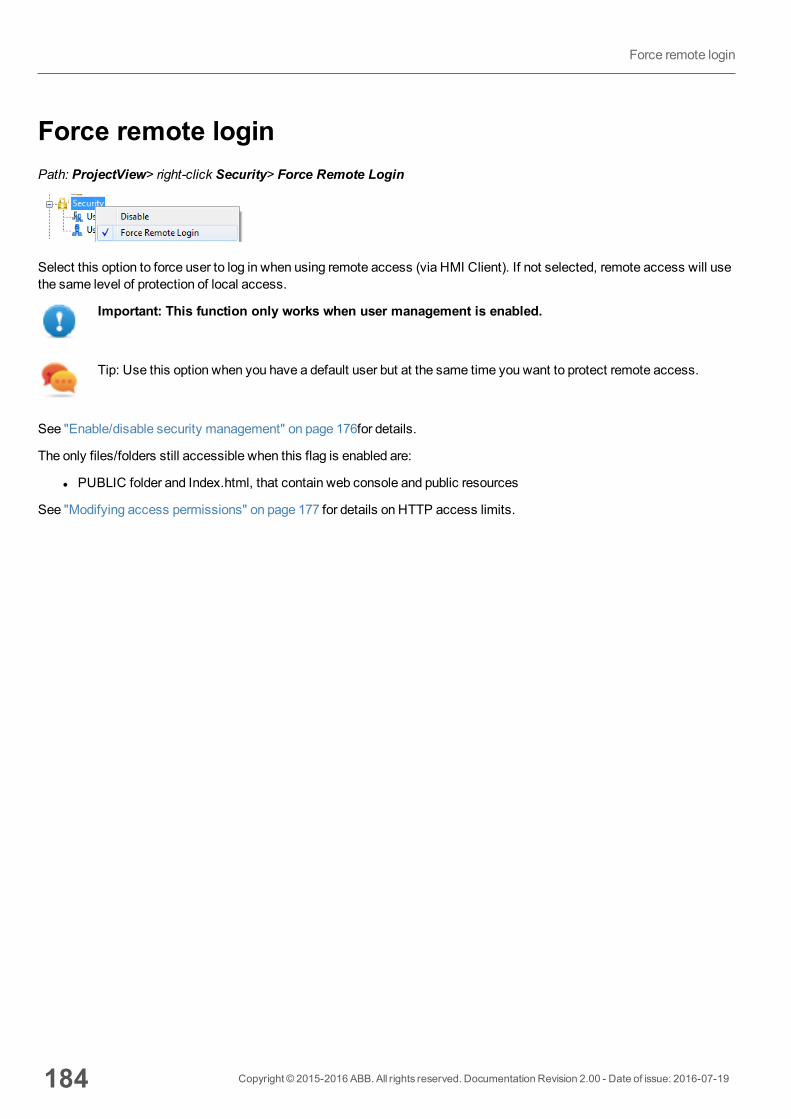
Force remote loginPath: ProjectView> right-click Security> Force Remote Login
Select this option to force user to log in when using remote access (via HMI Client). If not selected, remote access will usethe same level of protection of local access.
Important: This function only works when user management is enabled.
Tip: Use this option when you have a default user but at the same time you want to protect remote access.
See "Enable/disable security management" on page 176for details.
The only files/folders still accessible when this flag is enabled are:
l PUBLIC folder and Index.html, that contain web console and public resources
See "Modifying access permissions" on page 177 for details on HTTP access limits.
184 Copyright © 2015-2016 ABB. All rights reserved. Documentation Revision 2.00 - Date of issue: 2016-07-19
Force remote login
20 Audit trailsThe Audit trail is a chronological sequence of audit records. Each record contains information on the actions executed andthe user that performed them.
This function provides process tracking and user identification with time stamp for events.
If User Management is enabled, the actions are traced together with the name of the user. Only administrator user canmodify this setting.
Enable/disable audit trail 186
Configure audit events 186
Configure tags for audit trail 187
Configure alarms for audit trail 188
Configure recipes for audit trail 188
Configure login/logout details 189
Exporting audit trail as .csv files 189
Viewing audit trails 190
Copyright © 2015-2016 ABB. All rights reserved. Documentation Revision 2.00 - Date of issue: 2016-07-19 185
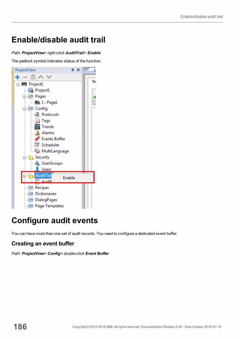
Enable/disable audit trailPath: ProjectView> right-click AuditTrail> Enable
The padlock symbol indicates status of the function.
Configure audit eventsYou can havemore than one set of audit records. You need to configure a dedicated event buffer.
Creating an event bufferPath: ProjectView> Config> double-click Event Buffer
186 Copyright © 2015-2016 ABB. All rights reserved. Documentation Revision 2.00 - Date of issue: 2016-07-19
Enable/disable audit trail
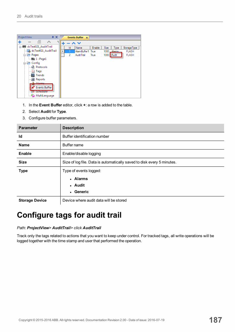
1. In theEvent Buffer editor, click +: a row is added to the table.2. Select Audit for Type.3. Configure buffer parameters.
Parameter Description
Id Buffer identification number
Name Buffer name
Enable Enable/disable logging
Size Size of log file. Data is automatically saved to disk every 5minutes.
Type Type of events logged:
l Alarmsl Auditl Generic
Storage Device Device where audit data will be stored
Configure tags for audit trailPath: ProjectView> AuditTrail> click AuditTrail
Track only the tags related to actions that you want to keep under control. For tracked tags, all write operations will belogged together with the time stamp and user that performed the operation.
Copyright © 2015-2016 ABB. All rights reserved. Documentation Revision 2.00 - Date of issue: 2016-07-19 187
20 Audit trails
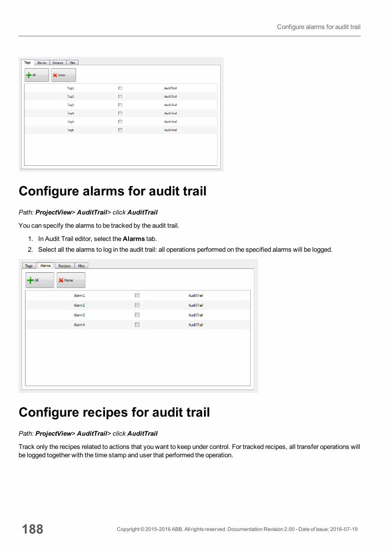
Configure alarms for audit trailPath: ProjectView> AuditTrail> click AuditTrail
You can specify the alarms to be tracked by the audit trail.
1. In Audit Trail editor, select theAlarms tab.2. Select all the alarms to log in the audit trail: all operations performed on the specified alarms will be logged.
Configure recipes for audit trailPath: ProjectView> AuditTrail> click AuditTrail
Track only the recipes related to actions that you want to keep under control. For tracked recipes, all transfer operations willbe logged together with the time stamp and user that performed the operation.
188 Copyright © 2015-2016 ABB. All rights reserved. Documentation Revision 2.00 - Date of issue: 2016-07-19
Configure alarms for audit trail
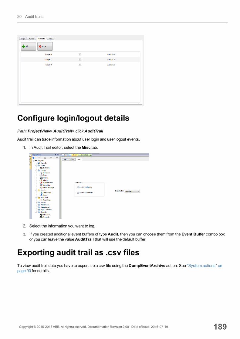
Configure login/logout detailsPath: ProjectView> AuditTrail> click AuditTrail
Audit trail can trace information about user login and user logout events.
1. In Audit Trail editor, select theMisc tab.
2. Select the information you want to log.
3. If you created additional event buffers of typeAudit, then you can choose them from theEvent Buffer combo boxor you can leave the valueAuditTrail that will use the default buffer.
Exporting audit trail as .csv filesTo view audit trail data you have to export it o a csv file using theDumpEventArchive action. See "System actions" onpage 90 for details.
Copyright © 2015-2016 ABB. All rights reserved. Documentation Revision 2.00 - Date of issue: 2016-07-19 189
20 Audit trails
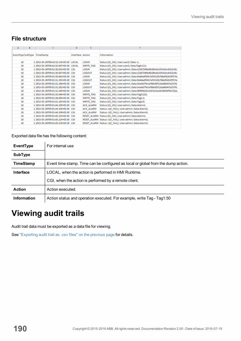
File structure
Exported data file has the following content:
EventType For internal use
SubType
TimeStamp Event time stamp. Time can be configured as local or global from the dump action.
Interface LOCAL, when the action is performed in HMI Runtime.
CGI, when the action is performed by a remote client.
Action Action executed.
Information Action status and operation executed. For example, write Tag - Tag1:50
Viewing audit trailsAudit trail datamust be exported as a data file for viewing.
See "Exporting audit trail as .csv files" on the previous page for details.
190 Copyright © 2015-2016 ABB. All rights reserved. Documentation Revision 2.00 - Date of issue: 2016-07-19
Viewing audit trails
21 ReportsA report is a collection of information that will be printed when triggered by an event. When the programmed event istriggered, the printing starts in background.
You can configure reports, their contents, trigger conditions and output printer in the Reports editor.
Not all widgets can be used in reports. When configuring reports, PB610-B Panel Builder 600 provides access to adedicated widget gallery featuring only widgets available for reports.
Reports format can be customized using predefined templates for page layout.
Note: Report printing is not supported by HMI Client.
Adding a report 192
Configuring text reports 192
Configuring graphic reports 193
Print triggering events 194
Default printer 195
Copyright © 2015-2016 ABB. All rights reserved. Documentation Revision 2.00 - Date of issue: 2016-07-19 191
Adding a reportPath: ProjectView> Config > double-click Reports
InReports editor, click Graphic Report or Text Report: one new row is added to the table.
Report types
Reporttype Description
TextReports
Use for line-by-line printing of alarms.
Only used for line printers.
Text is sent to the printer without using any special driver.
Important: This printing mode requires using a physical port and only works onWindows CE platforms.
GraphicReports
Contain graphical elements andmay include complex widgets such as screenshots or alarms.
Important: Each printer requires a specific printer driver. See "Configuring graphicreports" on the facing page for a list of supported printer drivers.
Configuring text reportsUse theReports editor . Paper Size in number of characters.
Setting printer optionsUse printer options to control flush of pages on printer.
Printing starts either immediately or after a timeout. In printer options you can force flush as soon as a specific conditionoccurs, after a specified number of events, lines or seconds.
Note: Text reports do not support PDF format.
Setting alarms layoutPaper Size is the width of paper in number of characters.
Adding fields to the reportTo add an item to the report, drag and drop it on the template page from theAvailable fields list.
192 Copyright © 2015-2016 ABB. All rights reserved. Documentation Revision 2.00 - Date of issue: 2016-07-19
Adding a report

Re-size the field using themouse, a tool tip shows the dimension in number of characters.
Note: If the text does not fit in the dedicated space, the auto wrap is applied.
Configuring graphic reportsUse theReport editor to configure graphic reports.
Adding a report pageClick + to add a new page to the report layout.
When themouse goes over a page, two icons are displayed and allow you to reorder or delete the pages.
Modifying report page content1. Double click on a page to edit its content: theGraphic Report editor appears.
Each page is divided in: header, footer and page body.
2. Double click on the area you want to edit: the edit area is shown in white, others are grayed out.
TheWidget Gallery is context-sensitive and displays only the widgets available for the area you are editing.
Widgets available for reportsWidgets that can be used for a graphic report:
Copyright © 2015-2016 ABB. All rights reserved. Documentation Revision 2.00 - Date of issue: 2016-07-19 193
21 Reports

Widget Function
PageNumber
Automatic page numbering
Screenshot Screen capture of the page currently displayed by the HMI device. The report page is automaticallyresized to fit the HMI device page.
Note: The full screen is printed, including all open dialogs.
Alarm Entire contents of the event buffer (default buffer is Alarm Buffer1).
Text Widgets such as labels and numeric fields
Print triggering eventsReport printing can be triggered by events.
Configuring alarm printingPath: ProjectView> Config > double-click Alarms
1. In the Alarms editor, open theEvent Types dialog from theEvents column.2. InPrint tab select all the conditions for which you want to trigger printing.
Important: Only one report can be set as Active alarm report in a project and it can be either a textreport or a graphic report.
194 Copyright © 2015-2016 ABB. All rights reserved. Documentation Revision 2.00 - Date of issue: 2016-07-19
Print triggering events
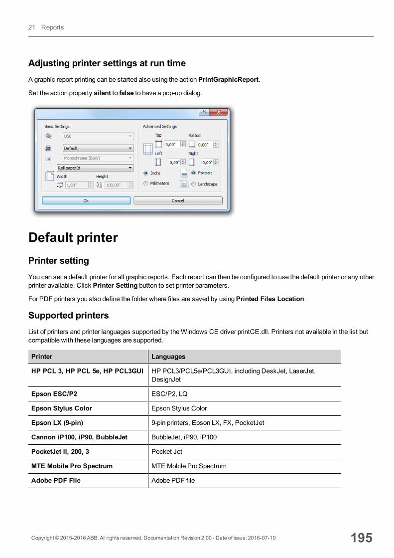
Adjusting printer settings at run timeA graphic report printing can be started also using the actionPrintGraphicReport.
Set the action property silent to false to have a pop-up dialog.
Default printerPrinter settingYou can set a default printer for all graphic reports. Each report can then be configured to use the default printer or any otherprinter available. Click Printer Setting button to set printer parameters.
For PDF printers you also define the folder where files are saved by usingPrinted Files Location.
Supported printersList of printers and printer languages supported by theWindows CE driver printCE.dll. Printers not available in the list butcompatible with these languages are supported.
Printer Languages
HP PCL 3, HP PCL 5e, HP PCL3GUI HP PCL3/PCL5e/PCL3GUI, including DeskJet, LaserJet,DesignJet
Epson ESC/P2 ESC/P2, LQ
Epson Stylus Color Epson Stylus Color
Epson LX (9-pin) 9-pin printers, Epson LX, FX, PocketJet
Cannon iP100, iP90, BubbleJet BubbleJet, iP90, iP100
PocketJet II, 200, 3 Pocket Jet
MTE Mobile Pro Spectrum MTE Mobile Pro Spectrum
Adobe PDF File Adobe PDF file
Copyright © 2015-2016 ABB. All rights reserved. Documentation Revision 2.00 - Date of issue: 2016-07-19 195
21 Reports
Printer Languages
SPT-8 SPT-8
M1POS M1POS
MP300 MP300
Zebra Zebra CPCL language
Intermec PB42, PB50, PB51, PB2,PB3
Intermect PB42/50/51/2/3 with ESC/P language
Datamax Apex Datamax Apex
Supported portsThe following ports are supported:
l LPT1 (USB printers)l File (PDF)
Note: OnWin32 platform, only PDF and default printers are supported. Default printer is the default OS printerand it can be connected with any kind of port (not only USB).
Tested printersThe following printers have been tested with printCE drivers inWindows CE HMI devices.
Driver Printer Model Graphic Line
Custom Plus 4 Kube II Yes Yes
EpsonESC/P 2
Epson AcuLaser M2310 Yes Simulate
Epson LX(9-pin)
Epson LX-300+II No Yes
HP PCL 3 HP LaserJet P2015dm
HP LaserJet 4700dtn
Yes
Yes
Simulate
Yes
HP PCL 3GUI
HP Deskjet 1010
HP Deskjet D5560
HP LaserJet 4700dtn
Yes
Yes
No
No
No
Yes
HP PCL 5e HP LaserJet P2015dm
HP LaserJet 4700dtn
Yes Simulate
INTERMEC Intermec PB50with ESC/P language with 4 inch roll paper.
Note: The HMI device crashes when trying to print on
Yes Yes
196 Copyright © 2015-2016 ABB. All rights reserved. Documentation Revision 2.00 - Date of issue: 2016-07-19
Default printer
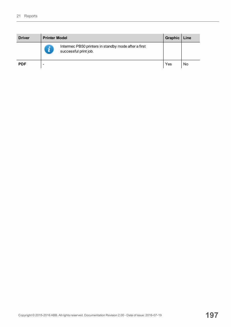
Driver Printer Model Graphic Line
Intermec PB50 printers in standby mode after a firstsuccessful print job.
PDF - Yes No
Copyright © 2015-2016 ABB. All rights reserved. Documentation Revision 2.00 - Date of issue: 2016-07-19 197
21 Reports

198 Copyright © 2015-2016 ABB. All rights reserved. Documentation Revision 2.00 - Date of issue: 2016-07-19
Default printer

22 Screen saverScreen saver can be used to display a slide show when the HMI device is not in use. The slide show starts after a timeout ifnone of the following events occur:
l touch of displayl mousemovementl external keyboard key pressed
Enabling the screen saver functionPath: ProjectView> Config > right-click Screen Saver> Enable
Important: You must enable the screen saver before you can configure it.
Configuring a screen saverPath: ProjectView> Config > double-click Screen Saver
Slide show parameters
Parameter Description
Timeout Time after which the slide show starts
SlideInterval
Interval between slides
Copyright © 2015-2016 ABB. All rights reserved. Documentation Revision 2.00 - Date of issue: 2016-07-19 199
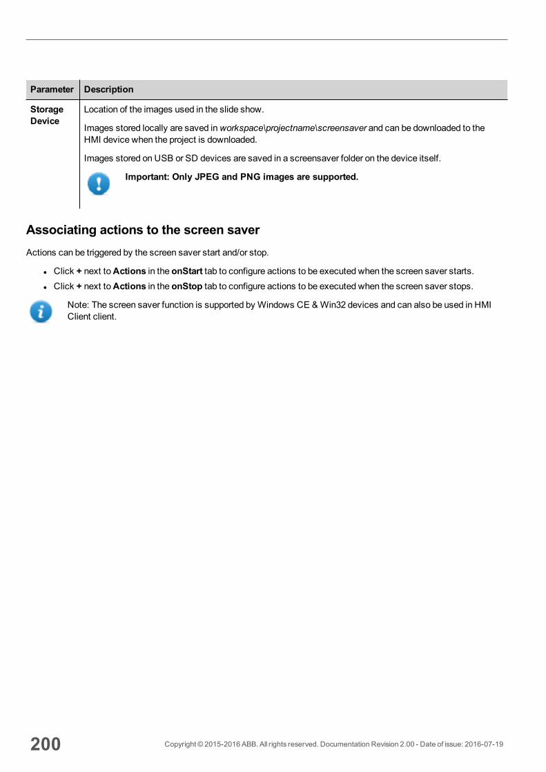
Parameter Description
StorageDevice
Location of the images used in the slide show.
Images stored locally are saved inworkspace\projectname\screensaver and can be downloaded to theHMI device when the project is downloaded.
Images stored on USB or SD devices are saved in a screensaver folder on the device itself.
Important: Only JPEG and PNG images are supported.
Associating actions to the screen saverActions can be triggered by the screen saver start and/or stop.
l Click + next toActions in the onStart tab to configure actions to be executed when the screen saver starts.l Click + next toActions in the onStop tab to configure actions to be executed when the screen saver stops.
Note: The screen saver function is supported by Windows CE &Win32 devices and can also be used in HMIClient client.
200 Copyright © 2015-2016 ABB. All rights reserved. Documentation Revision 2.00 - Date of issue: 2016-07-19
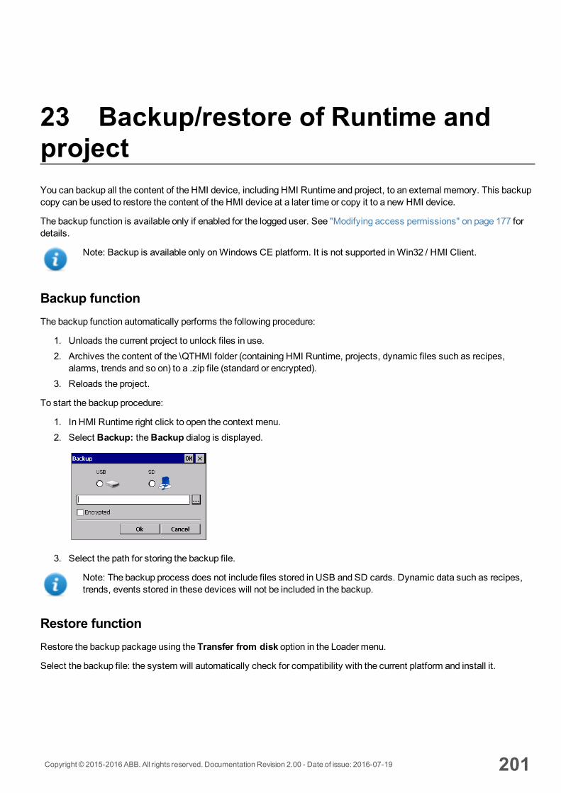
23 Backup/restore of Runtime andprojectYou can backup all the content of the HMI device, including HMI Runtime and project, to an external memory. This backupcopy can be used to restore the content of the HMI device at a later time or copy it to a new HMI device.
The backup function is available only if enabled for the logged user. See "Modifying access permissions" on page 177 fordetails.
Note: Backup is available only onWindows CE platform. It is not supported inWin32 / HMI Client.
Backup functionThe backup function automatically performs the following procedure:
1. Unloads the current project to unlock files in use.2. Archives the content of the \QTHMI folder (containing HMI Runtime, projects, dynamic files such as recipes,
alarms, trends and so on) to a .zip file (standard or encrypted).3. Reloads the project.
To start the backup procedure:
1. In HMI Runtime right click to open the context menu.2. Select Backup: theBackup dialog is displayed.
3. Select the path for storing the backup file.
Note: The backup process does not include files stored in USB and SD cards. Dynamic data such as recipes,trends, events stored in these devices will not be included in the backup.
Restore functionRestore the backup package using the Transfer from disk option in the Loader menu.
Select the backup file: the system will automatically check for compatibility with the current platform and install it.
Copyright © 2015-2016 ABB. All rights reserved. Documentation Revision 2.00 - Date of issue: 2016-07-19 201

202 Copyright © 2015-2016 ABB. All rights reserved. Documentation Revision 2.00 - Date of issue: 2016-07-19
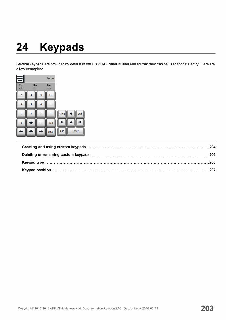
24 KeypadsSeveral keypads are provided by default in the PB610-B Panel Builder 600 so that they can be used for data entry. Here area few examples:
Creating and using custom keypads 204
Deleting or renaming custom keypads 206
Keypad type 206
Keypad position 207
Copyright © 2015-2016 ABB. All rights reserved. Documentation Revision 2.00 - Date of issue: 2016-07-19 203

Creating and using custom keypadsYou can either create a new keypad or customize an existing one.
Creating a keypad1. InProjectView, right-click Keypads and select Insert Keypad: theNew Keypad dialog is displayed.
2. Select one of the available keypads, orBlank to create a keypad from scratch. In this case a blank keypad isdisplayed.
3. Use theKeypad Widgets andKeypad Buttons from theWidget Gallery to create your custom keypad.
The keypad you create, as in this example, will be saved in the project folder.
204 Copyright © 2015-2016 ABB. All rights reserved. Documentation Revision 2.00 - Date of issue: 2016-07-19
Creating and using custom keypads
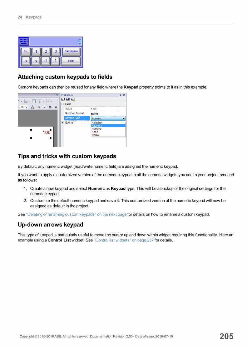
Attaching custom keypads to fieldsCustom keypads can then be reused for any field where theKeypad property points to it as in this example.
Tips and tricks with custom keypadsBy default, any numeric widget (read/write numeric field) are assigned the numeric keypad.
If you want to apply a customized version of the numeric keypad to all the numeric widgets you add to your project proceedas follows:
1. Create a new keypad and select Numeric as Keypad type. This will be a backup of the original settings for thenumeric keypad.
2. Customize the default numeric keypad and save it. This customized version of the numeric keypad will now beassigned as default in the project.
See "Deleting or renaming custom keypads" on the next page for details on how to rename a custom keypad.
Up-down arrows keypadThis type of keypad is particularly useful to move the cursor up and downwithin widget requiring this functionality. Here anexample using aControl Listwidget. See "Control list widgets" on page 237 for details.
Copyright © 2015-2016 ABB. All rights reserved. Documentation Revision 2.00 - Date of issue: 2016-07-19 205
24 Keypads
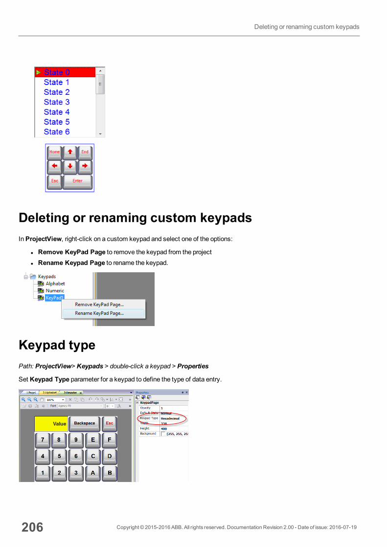
Deleting or renaming custom keypadsInProjectView, right-click on a custom keypad and select one of the options:
l Remove KeyPad Page to remove the keypad from the projectl Rename Keypad Page to rename the keypad.
Keypad typePath: ProjectView> Keypads > double-click a keypad > Properties
Set Keypad Type parameter for a keypad to define the type of data entry.
206 Copyright © 2015-2016 ABB. All rights reserved. Documentation Revision 2.00 - Date of issue: 2016-07-19
Deleting or renaming custom keypads
KeypadType Description
Auto Default setting
Decimal Only numeric keys are accepted. Entering 10, the keypad returns 10 that will be displayedas "10" if the attached field is numeric or ASCII, as 'A' if the attached filed is hexadecimal.
Hexadecimal Only hexadecimal keys are accepted. Entering 10, the keypad returns 16 that will bedisplayed as "16" if the attached field is numeric or ASCII, as "10" if the attached field ishexadecimal.
Ascii All keys are enabled. Entering 1A, the keypad returns 1A that will be displayed as '1' if theattached field is numeric, as "1A" if the attached field is ASCII or if the attached field ishexadecimal.
Keypad positionRuntime Positioning property of keypads can be used to define where keypads will appear in the screen.
Option Description
Automatic The best position is selected according to here data entry is required.
Absolute X,Y coordinates are entered to identify the exact position
Left-top
Left-center
Left-bottom
Center-top
Center-center
Center-bottom
Right-top
Right-cente
Right-bottom
Predefined screen positions
Select the Lock Keypad position option if you don't want the keypad to bemoved by dragging.
Copyright © 2015-2016 ABB. All rights reserved. Documentation Revision 2.00 - Date of issue: 2016-07-19 207
24 Keypads

208 Copyright © 2015-2016 ABB. All rights reserved. Documentation Revision 2.00 - Date of issue: 2016-07-19
Keypad position
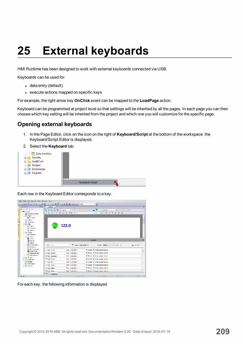
25 External keyboardsHMI Runtime has been designed to work with external keyboards connected via USB.
Keyboards can be used for:
l data entry (default)l execute actions mapped on specific keys
For example, the right arrow key OnClick event can bemapped to the LoadPage action.
Keyboard can be programmed at project level so that settings will be inherited by all the pages. In each page you can thenchoose which key setting will be inherited from the project and which one you will customize for the specific page.
Opening external keyboards1. In the Page Editor, click on the icon on the right of Keyboard/Script at the bottom of the workspace: the
Keyboard/Script Editor is displayed.2. Select theKeyboard tab.
Each row in the Keyboard Editor corresponds to a key.
For each key, the following information is displayed:
Copyright © 2015-2016 ABB. All rights reserved. Documentation Revision 2.00 - Date of issue: 2016-07-19 209
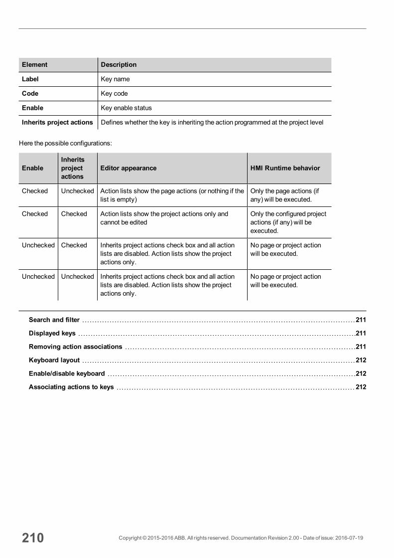
Element Description
Label Key name
Code Key code
Enable Key enable status
Inherits project actions Defines whether the key is inheriting the action programmed at the project level
Here the possible configurations:
EnableInheritsprojectactions
Editor appearance HMI Runtime behavior
Checked Unchecked Action lists show the page actions (or nothing if thelist is empty)
Only the page actions (ifany) will be executed.
Checked Checked Action lists show the project actions only andcannot be edited
Only the configured projectactions (if any) will beexecuted.
Unchecked Checked Inherits project actions check box and all actionlists are disabled. Action lists show the projectactions only.
No page or project actionwill be executed.
Unchecked Unchecked Inherits project actions check box and all actionlists are disabled. Action lists show the projectactions only.
No page or project actionwill be executed.
Search and filter 211
Displayed keys 211
Removing action associations 211
Keyboard layout 212
Enable/disable keyboard 212
Associating actions to keys 212
210 Copyright © 2015-2016 ABB. All rights reserved. Documentation Revision 2.00 - Date of issue: 2016-07-19
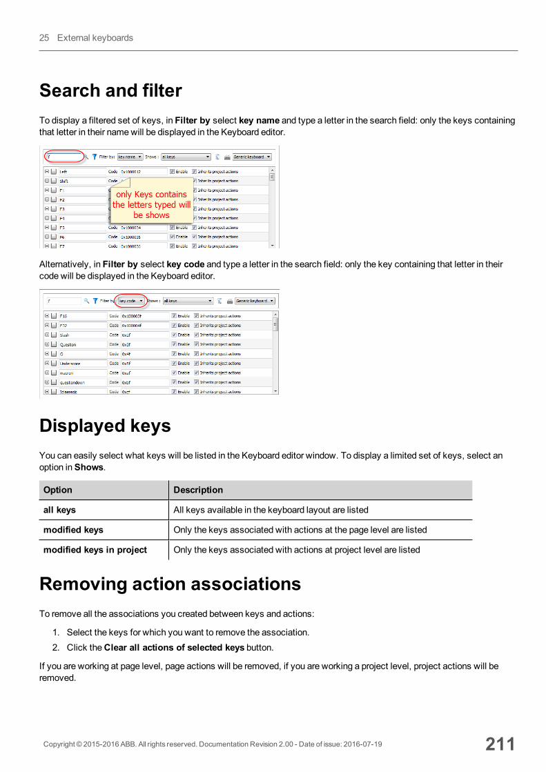
Search and filterTo display a filtered set of keys, in Filter by select key name and type a letter in the search field: only the keys containingthat letter in their namewill be displayed in the Keyboard editor.
Alternatively, in Filter by select key code and type a letter in the search field: only the key containing that letter in theircode will be displayed in the Keyboard editor.
Displayed keysYou can easily select what keys will be listed in the Keyboard editor window. To display a limited set of keys, select anoption inShows.
Option Description
all keys All keys available in the keyboard layout are listed
modified keys Only the keys associated with actions at the page level are listed
modified keys in project Only the keys associated with actions at project level are listed
Removing action associationsTo remove all the associations you created between keys and actions:
1. Select the keys for which you want to remove the association.2. Click theClear all actions of selected keys button.
If you are working at page level, page actions will be removed, if you are working a project level, project actions will beremoved.
Copyright © 2015-2016 ABB. All rights reserved. Documentation Revision 2.00 - Date of issue: 2016-07-19 211
25 External keyboards
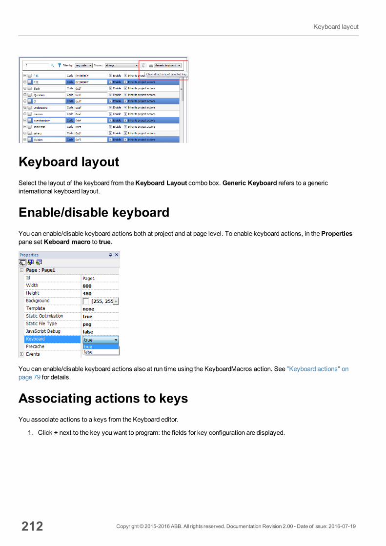
Keyboard layoutSelect the layout of the keyboard from theKeyboard Layout combo box. Generic Keyboard refers to a genericinternational keyboard layout.
Enable/disable keyboardYou can enable/disable keyboard actions both at project and at page level. To enable keyboard actions, in thePropertiespane set Keboard macro to true.
You can enable/disable keyboard actions also at run time using the KeyboardMacros action. See "Keyboard actions" onpage 79 for details.
Associating actions to keysYou associate actions to a keys from the Keyboard editor.
1. Click + next to the key you want to program: the fields for key configuration are displayed.
212 Copyright © 2015-2016 ABB. All rights reserved. Documentation Revision 2.00 - Date of issue: 2016-07-19
Keyboard layout
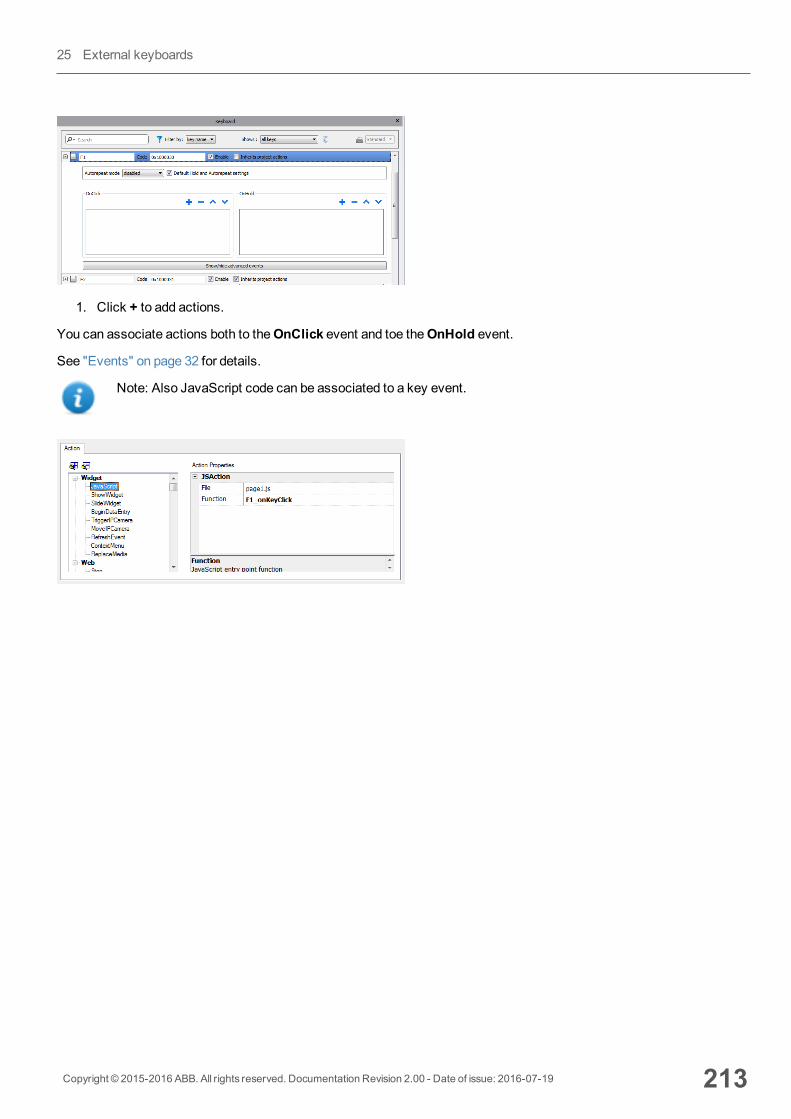
1. Click + to add actions.
You can associate actions both to theOnClick event and toe theOnHold event.
See "Events" on page 32 for details.
Note: Also JavaScript code can be associated to a key event.
Copyright © 2015-2016 ABB. All rights reserved. Documentation Revision 2.00 - Date of issue: 2016-07-19 213
25 External keyboards

214 Copyright © 2015-2016 ABB. All rights reserved. Documentation Revision 2.00 - Date of issue: 2016-07-19
Associating actions to keys
26 Tag cross referenceThe Tag Cross Reference pane displays a list of tag names used in current project organized according to their locationand use.
From this pane you can:
l verify where each tag is used (alarms, pages, recipes, schedulers, trends, and so on)l identify invalid tag references (references to tags not defined in the tag editor)l identify tags not used in the project
Note: The Tag Cross Reference pane does not list tags used in JavaScript code.
Updating data in the Tag Cross Reference pane 216
Copyright © 2015-2016 ABB. All rights reserved. Documentation Revision 2.00 - Date of issue: 2016-07-19 215
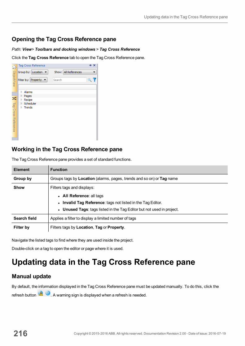
Opening the Tag Cross Reference panePath: View> Toolbars and docking windows > Tag Cross Reference
Click the Tag Cross Reference tab to open the Tag Cross Reference pane.
Working in the Tag Cross Reference paneThe Tag Cross Reference pane provides a set of standard functions.
Element Function
Group by Groups tags by Location (alarms, pages, trends and so on) or Tag name
Show Filters tags and displays:
l All Reference: all tagsl Invalid Tag Reference: tags not listed in the Tag Editor.l Unused Tags: tags listed in the Tag Editor but not used in project.
Search field Applies a filter to display a limited number of tags
Filter by Filters tags by Location, Tag orProperty.
Navigate the listed tags to find where they are used inside the project.
Double-click on a tag to open the editor or page where it is used.
Updating data in the Tag Cross Reference paneManual updateBy default, the information displayed in the Tag Cross Reference panemust be updatedmanually. To do this, click the
refresh button . A warning sign is displayed when a refresh is needed.
216 Copyright © 2015-2016 ABB. All rights reserved. Documentation Revision 2.00 - Date of issue: 2016-07-19
Updating data in the Tag Cross Reference pane
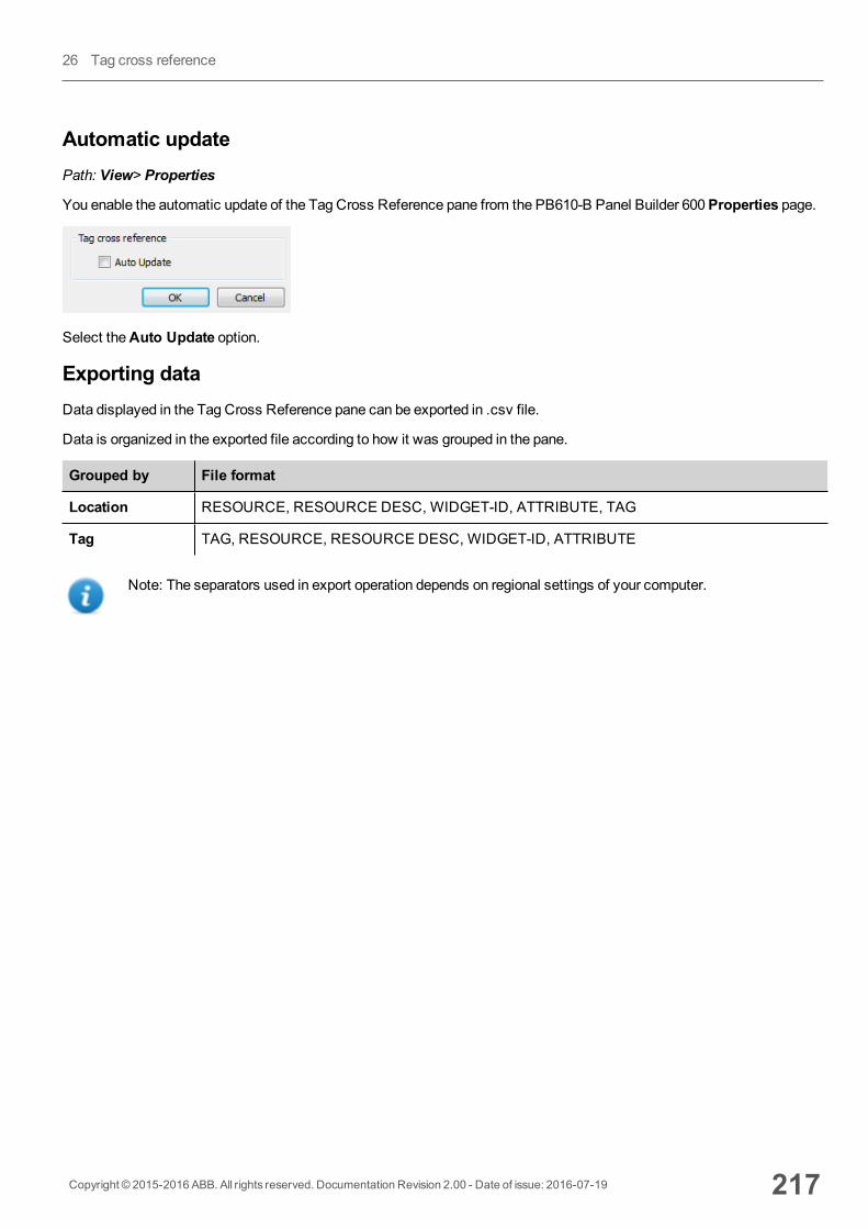
Automatic updatePath: View> Properties
You enable the automatic update of the Tag Cross Reference pane from the PB610-B Panel Builder 600Properties page.
Select theAuto Update option.
Exporting dataData displayed in the Tag Cross Reference pane can be exported in .csv file.
Data is organized in the exported file according to how it was grouped in the pane.
Grouped by File format
Location RESOURCE, RESOURCE DESC, WIDGET-ID, ATTRIBUTE, TAG
Tag TAG, RESOURCE, RESOURCE DESC, WIDGET-ID, ATTRIBUTE
Note: The separators used in export operation depends on regional settings of your computer.
Copyright © 2015-2016 ABB. All rights reserved. Documentation Revision 2.00 - Date of issue: 2016-07-19 217
26 Tag cross reference

218 Copyright © 2015-2016 ABB. All rights reserved. Documentation Revision 2.00 - Date of issue: 2016-07-19
Updating data in the Tag Cross Reference pane

27 Indexed addressingIndexed addressing allows you to select a set of tags depending on the value of another tag. This is very useful, forexample, to use the same graphics to visualize a set of data coming from different sources, all the user has to do is pick thesource tomonitor from a list.
Creating an indexed addressing set 220
Using indexed tag set in pages 223
Copyright © 2015-2016 ABB. All rights reserved. Documentation Revision 2.00 - Date of issue: 2016-07-19 219
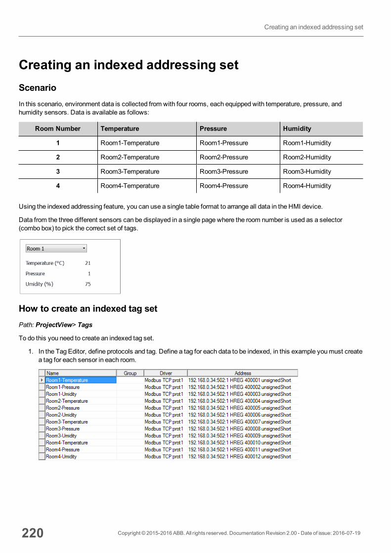
Creating an indexed addressing setScenarioIn this scenario, environment data is collected from with four rooms, each equipped with temperature, pressure, andhumidity sensors. Data is available as follows:
Room Number Temperature Pressure Humidity
1 Room1-Temperature Room1-Pressure Room1-Humidity
2 Room2-Temperature Room2-Pressure Room2-Humidity
3 Room3-Temperature Room3-Pressure Room3-Humidity
4 Room4-Temperature Room4-Pressure Room4-Humidity
Using the indexed addressing feature, you can use a single table format to arrange all data in the HMI device.
Data from the three different sensors can be displayed in a single page where the room number is used as a selector(combo box) to pick the correct set of tags.
How to create an indexed tag setPath: ProjectView> Tags
To do this you need to create an indexed tag set.
1. In the Tag Editor, define protocols and tag. Define a tag for each data to be indexed, in this example youmust createa tag for each sensor in each room.
220 Copyright © 2015-2016 ABB. All rights reserved. Documentation Revision 2.00 - Date of issue: 2016-07-19
Creating an indexed addressing set
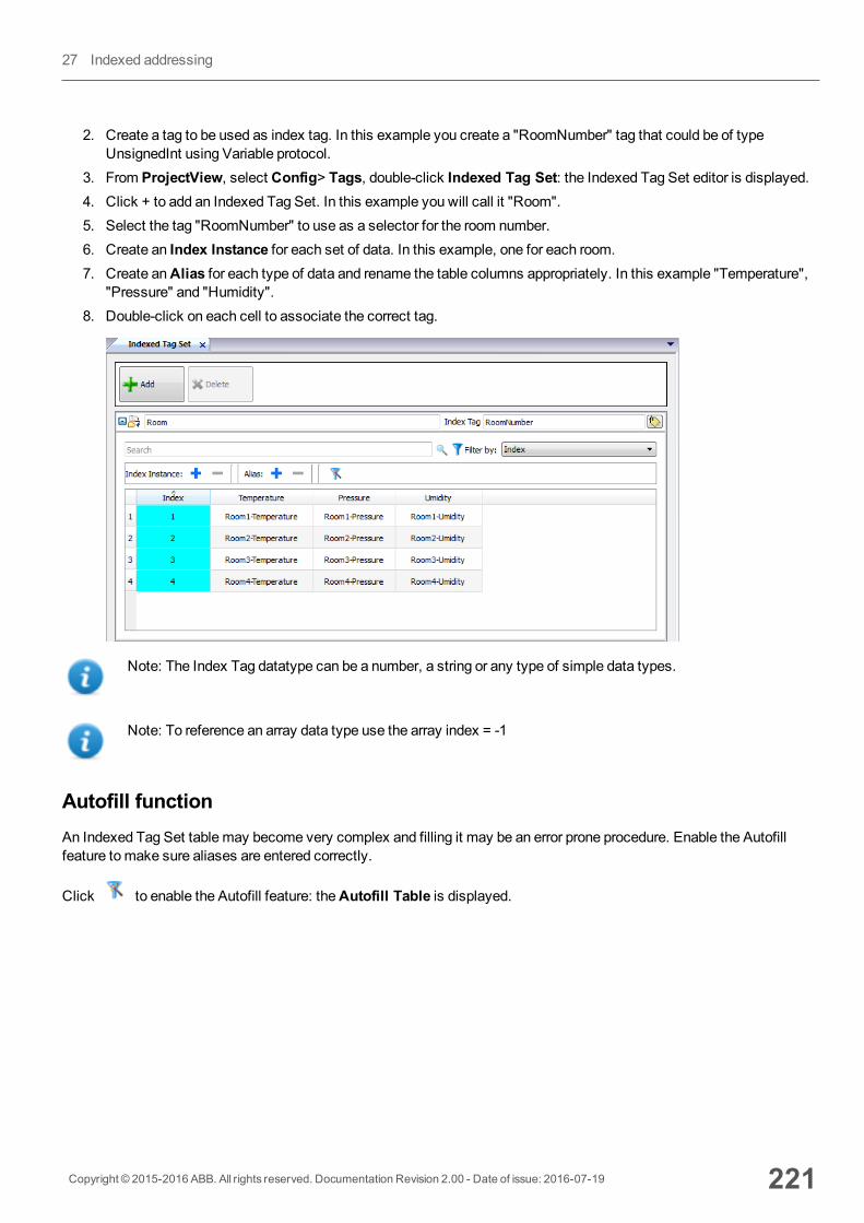
2. Create a tag to be used as index tag. In this example you create a "RoomNumber" tag that could be of typeUnsignedInt using Variable protocol.
3. From ProjectView, select Config> Tags, double-click Indexed Tag Set: the Indexed Tag Set editor is displayed.4. Click + to add an Indexed Tag Set. In this example you will call it "Room".5. Select the tag "RoomNumber" to use as a selector for the room number.6. Create an Index Instance for each set of data. In this example, one for each room.7. Create anAlias for each type of data and rename the table columns appropriately. In this example "Temperature",
"Pressure" and "Humidity".8. Double-click on each cell to associate the correct tag.
Note: The Index Tag datatype can be a number, a string or any type of simple data types.
Note: To reference an array data type use the array index = -1
Autofill functionAn Indexed Tag Set table may become very complex and filling it may be an error prone procedure. Enable the Autofillfeature tomake sure aliases are entered correctly.
Click to enable the Autofill feature: theAutofill Table is displayed.
Copyright © 2015-2016 ABB. All rights reserved. Documentation Revision 2.00 - Date of issue: 2016-07-19 221
27 Indexed addressing
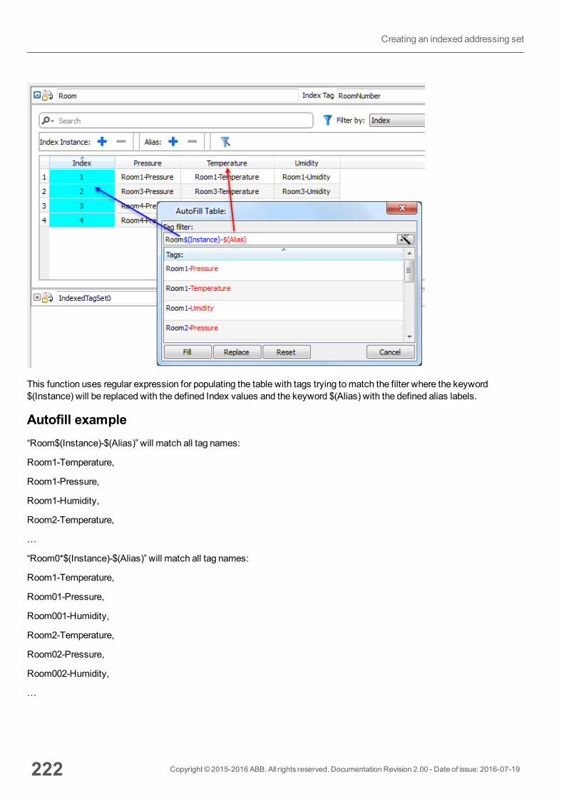
This function uses regular expression for populating the table with tags trying tomatch the filter where the keyword$(Instance) will be replaced with the defined Index values and the keyword $(Alias) with the defined alias labels.
Autofill example“Room$(Instance)-$(Alias)” will match all tag names:
Room1-Temperature,
Room1-Pressure,
Room1-Humidity,
Room2-Temperature,
…
“Room0*$(Instance)-$(Alias)” will match all tag names:
Room1-Temperature,
Room01-Pressure,
Room001-Humidity,
Room2-Temperature,
Room02-Pressure,
Room002-Humidity,
…
222 Copyright © 2015-2016 ABB. All rights reserved. Documentation Revision 2.00 - Date of issue: 2016-07-19
Creating an indexed addressing set
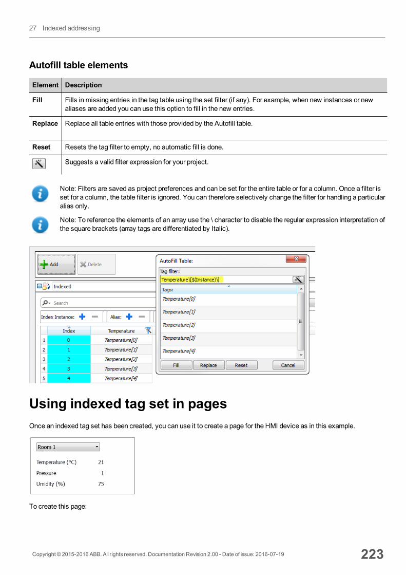
Autofill table elements
Element Description
Fill Fills in missing entries in the tag table using the set filter (if any). For example, when new instances or newaliases are added you can use this option to fill in the new entries.
Replace Replace all table entries with those provided by the Autofill table.
Reset Resets the tag filter to empty, no automatic fill is done.
Suggests a valid filter expression for your project.
Note: Filters are saved as project preferences and can be set for the entire table or for a column. Once a filter isset for a column, the table filter is ignored. You can therefore selectively change the filter for handling a particularalias only.
Note: To reference the elements of an array use the \ character to disable the regular expression interpretation ofthe square brackets (array tags are differentiated by Italic).
Using indexed tag set in pagesOnce an indexed tag set has been created, you can use it to create a page for the HMI device as in this example.
To create this page:
Copyright © 2015-2016 ABB. All rights reserved. Documentation Revision 2.00 - Date of issue: 2016-07-19 223
27 Indexed addressing
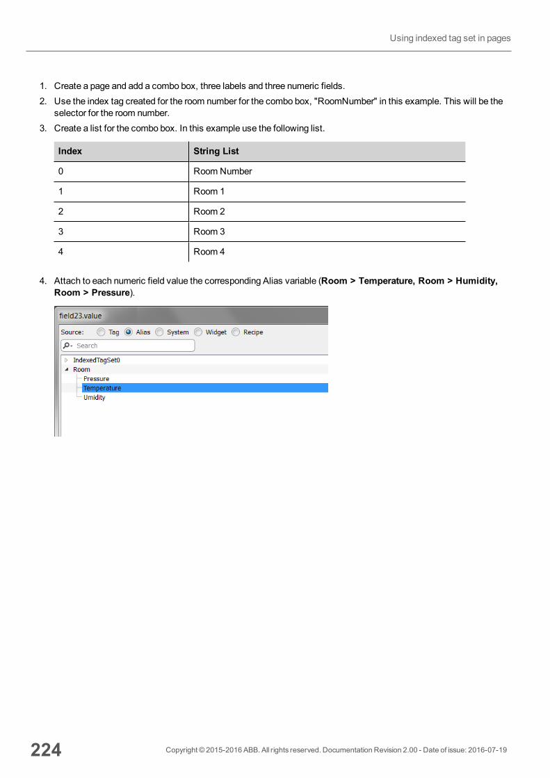
1. Create a page and add a combo box, three labels and three numeric fields.2. Use the index tag created for the room number for the combo box, "RoomNumber" in this example. This will be the
selector for the room number.3. Create a list for the combo box. In this example use the following list.
Index String List
0 Room Number
1 Room 1
2 Room 2
3 Room 3
4 Room 4
4. Attach to each numeric field value the corresponding Alias variable (Room > Temperature, Room > Humidity,Room > Pressure).
224 Copyright © 2015-2016 ABB. All rights reserved. Documentation Revision 2.00 - Date of issue: 2016-07-19
Using indexed tag set in pages
28 Special widgetsWidgets designed for special purposes are called special widgets and include control lists, date and time widgets, variablewidgets and so on.
DateTime widget 226
Multistate Image widget 226
Multistate Image Multilayer widget 227
Combo Box widget 229
Consumption Meter widget 230
RSS Feed widget 232
Scrolling RSS Feed widget 233
IPCamera widgets 233
Browser widget 236
Control list widgets 237
Variables widget 239
Copyright © 2015-2016 ABB. All rights reserved. Documentation Revision 2.00 - Date of issue: 2016-07-19 225
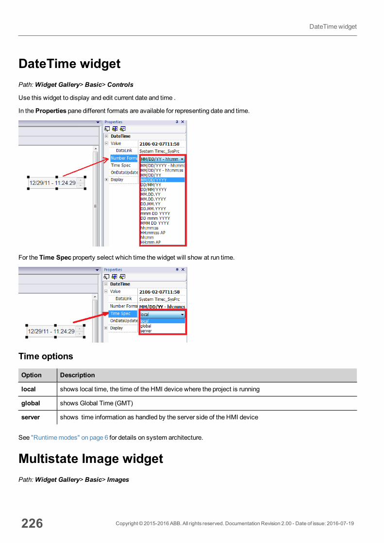
DateTime widgetPath:Widget Gallery> Basic> Controls
Use this widget to display and edit current date and time .
In theProperties pane different formats are available for representing date and time.
For the Time Spec property select which time the widget will show at run time.
Time options
Option Description
local shows local time, the time of the HMI device where the project is running
global shows Global Time (GMT)
server shows time information as handled by the server side of the HMI device
See "Runtimemodes" on page 6 for details on system architecture.
Multistate Image widgetPath:Widget Gallery> Basic> Images
226 Copyright © 2015-2016 ABB. All rights reserved. Documentation Revision 2.00 - Date of issue: 2016-07-19
DateTimewidget
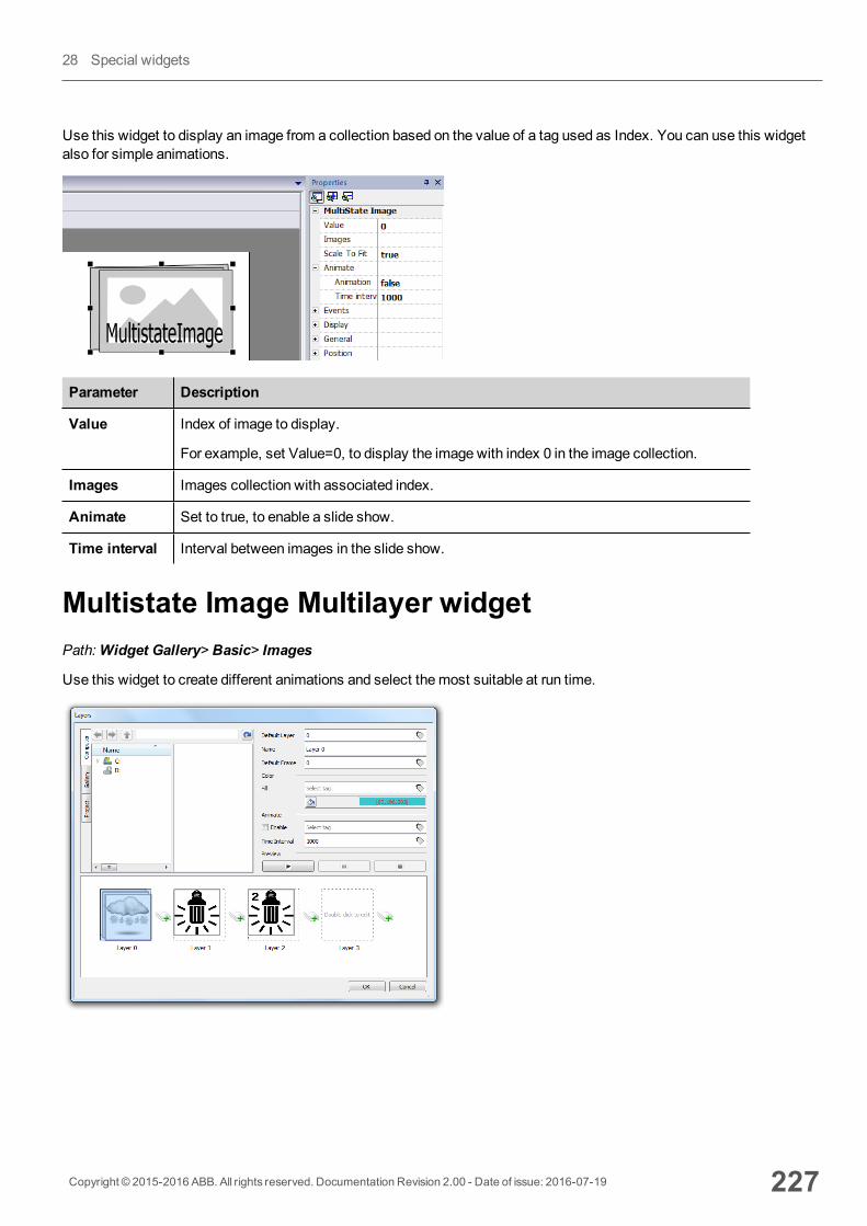
Use this widget to display an image from a collection based on the value of a tag used as Index. You can use this widgetalso for simple animations.
Parameter Description
Value Index of image to display.
For example, set Value=0, to display the image with index 0 in the image collection.
Images Images collection with associated index.
Animate Set to true, to enable a slide show.
Time interval Interval between images in the slide show.
Multistate Image Multilayer widgetPath:Widget Gallery> Basic> Images
Use this widget to create different animations and select themost suitable at run time.
Copyright © 2015-2016 ABB. All rights reserved. Documentation Revision 2.00 - Date of issue: 2016-07-19 227
28 Special widgets
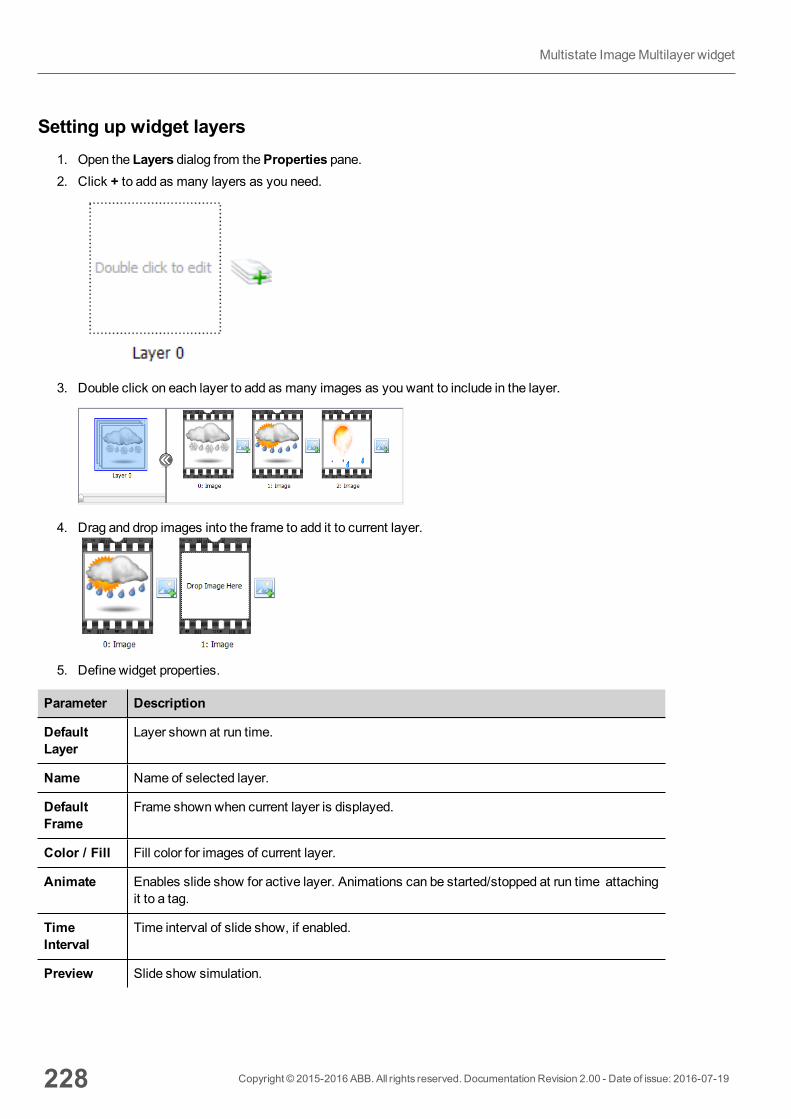
Setting up widget layers1. Open the Layers dialog from theProperties pane.2. Click + to add as many layers as you need.
3. Double click on each layer to add as many images as you want to include in the layer.
4. Drag and drop images into the frame to add it to current layer.
5. Define widget properties.
Parameter Description
DefaultLayer
Layer shown at run time.
Name Name of selected layer.
DefaultFrame
Frame shownwhen current layer is displayed.
Color / Fill Fill color for images of current layer.
Animate Enables slide show for active layer. Animations can be started/stopped at run time attachingit to a tag.
TimeInterval
Time interval of slide show, if enabled.
Preview Slide show simulation.
228 Copyright © 2015-2016 ABB. All rights reserved. Documentation Revision 2.00 - Date of issue: 2016-07-19
Multistate ImageMultilayer widget
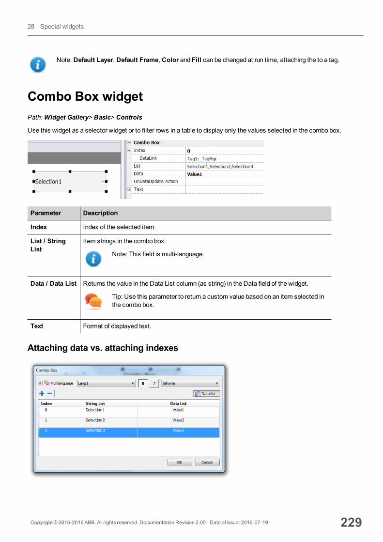
Note: Default Layer, Default Frame, Color and Fill can be changed at run time, attaching the to a tag.
Combo Box widgetPath:Widget Gallery> Basic> Controls
Use this widget as a selector widget or to filter rows in a table to display only the values selected in the combo box.
Parameter Description
Index Index of the selected item.
List / StringList
Item strings in the combo box.
Note: This field is multi-language.
Data / Data List Returns the value in the Data List column (as string) in the Data field of the widget.
Tip: Use this parameter to return a custom value based on an item selected inthe combo box.
Text Format of displayed text.
Attaching data vs. attaching indexes
Copyright © 2015-2016 ABB. All rights reserved. Documentation Revision 2.00 - Date of issue: 2016-07-19 229
28 Special widgets
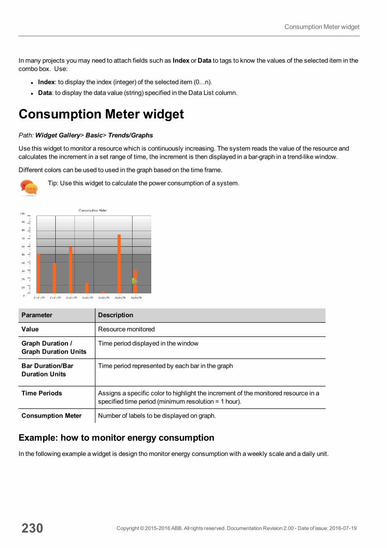
In many projects youmay need to attach fields such as Index orData to tags to know the values of the selected item in thecombo box. Use:
l Index: to display the index (integer) of the selected item (0...n).l Data: to display the data value (string) specified in the Data List column.
Consumption Meter widgetPath:Widget Gallery> Basic> Trends/Graphs
Use this widget to monitor a resource which is continuously increasing. The system reads the value of the resource andcalculates the increment in a set range of time, the increment is then displayed in a bar-graph in a trend-like window.
Different colors can be used to used in the graph based on the time frame.
Tip: Use this widget to calculate the power consumption of a system.
Parameter Description
Value Resourcemonitored
Graph Duration /Graph Duration Units
Time period displayed in the window
Bar Duration/BarDuration Units
Time period represented by each bar in the graph
Time Periods Assigns a specific color to highlight the increment of themonitored resource in aspecified time period (minimum resolution = 1 hour).
Consumption Meter Number of labels to be displayed on graph.
Example: how to monitor energy consumptionIn the following example a widget is design thomonitor energy consumption with a weekly scale and a daily unit.
230 Copyright © 2015-2016 ABB. All rights reserved. Documentation Revision 2.00 - Date of issue: 2016-07-19
ConsumptionMeter widget
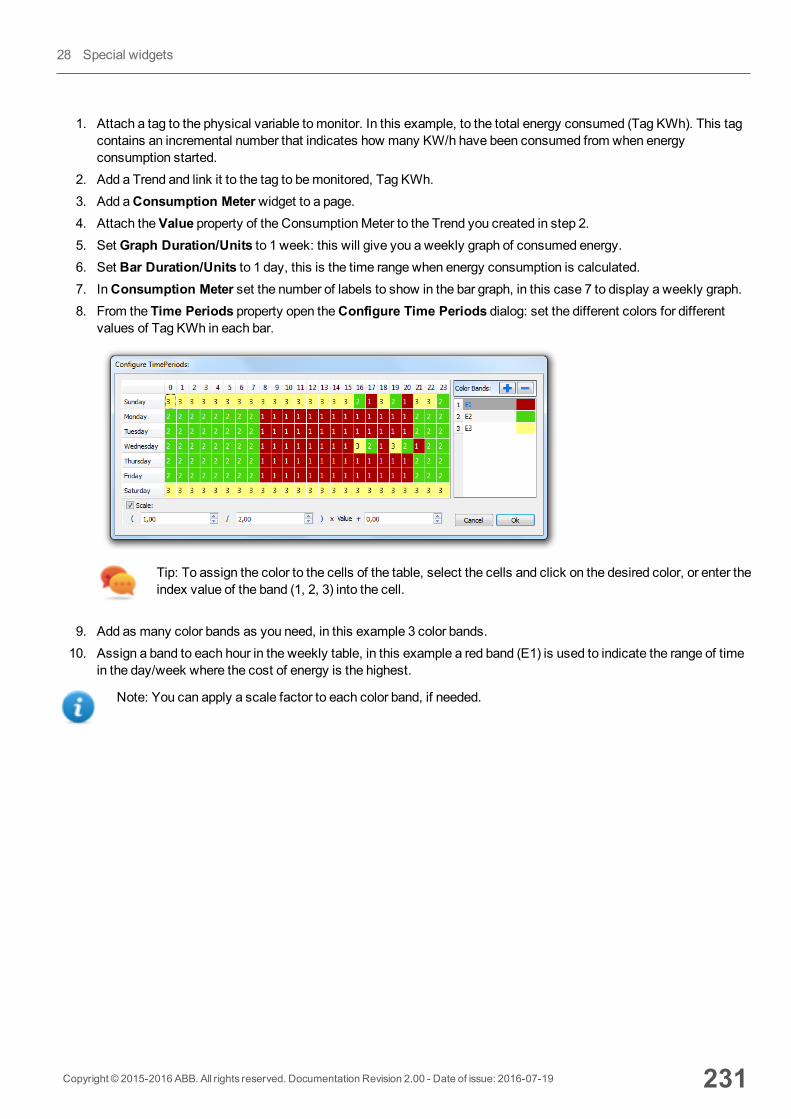
1. Attach a tag to the physical variable to monitor. In this example, to the total energy consumed (Tag KWh). This tagcontains an incremental number that indicates how many KW/h have been consumed from when energyconsumption started.
2. Add a Trend and link it to the tag to bemonitored, Tag KWh.3. Add aConsumption Meterwidget to a page.4. Attach theValue property of the ConsumptionMeter to the Trend you created in step 2.5. Set Graph Duration/Units to 1 week: this will give you a weekly graph of consumed energy.6. Set Bar Duration/Units to 1 day, this is the time range when energy consumption is calculated.7. InConsumption Meter set the number of labels to show in the bar graph, in this case 7 to display a weekly graph.8. From the Time Periods property open theConfigure Time Periods dialog: set the different colors for different
values of Tag KWh in each bar.
Tip: To assign the color to the cells of the table, select the cells and click on the desired color, or enter theindex value of the band (1, 2, 3) into the cell.
9. Add as many color bands as you need, in this example 3 color bands.10. Assign a band to each hour in the weekly table, in this example a red band (E1) is used to indicate the range of time
in the day/week where the cost of energy is the highest.
Note: You can apply a scale factor to each color band, if needed.
Copyright © 2015-2016 ABB. All rights reserved. Documentation Revision 2.00 - Date of issue: 2016-07-19 231
28 Special widgets

The result is a bar graph consumptionmeter showing daily consumption of energy in KW/h, with colors indicating thedifferent energy costs. The height of each bar represents the amount of energy in the time range considered, 1 day in thisexample.
Use the action ConsumptionMeterPageScroll to scroll the bar graph back and forth and the action RefreshTrend to refreshthe bar graph since data is not refreshed automatically.
Important: No other Trend action is currently supported by the Consumption Meter widget.
RSS Feed widgetPath:Widget Gallery>Media> RSSFeed Source
Use this widget to display on the HMI device your favorite RSS feeds directly from the Internet.
Parameter Description
RSS Source Feed URL
Note: Feed sources cannot bemodified at run time.
UpdateRate Refresh time
232 Copyright © 2015-2016 ABB. All rights reserved. Documentation Revision 2.00 - Date of issue: 2016-07-19
RSS Feed widget
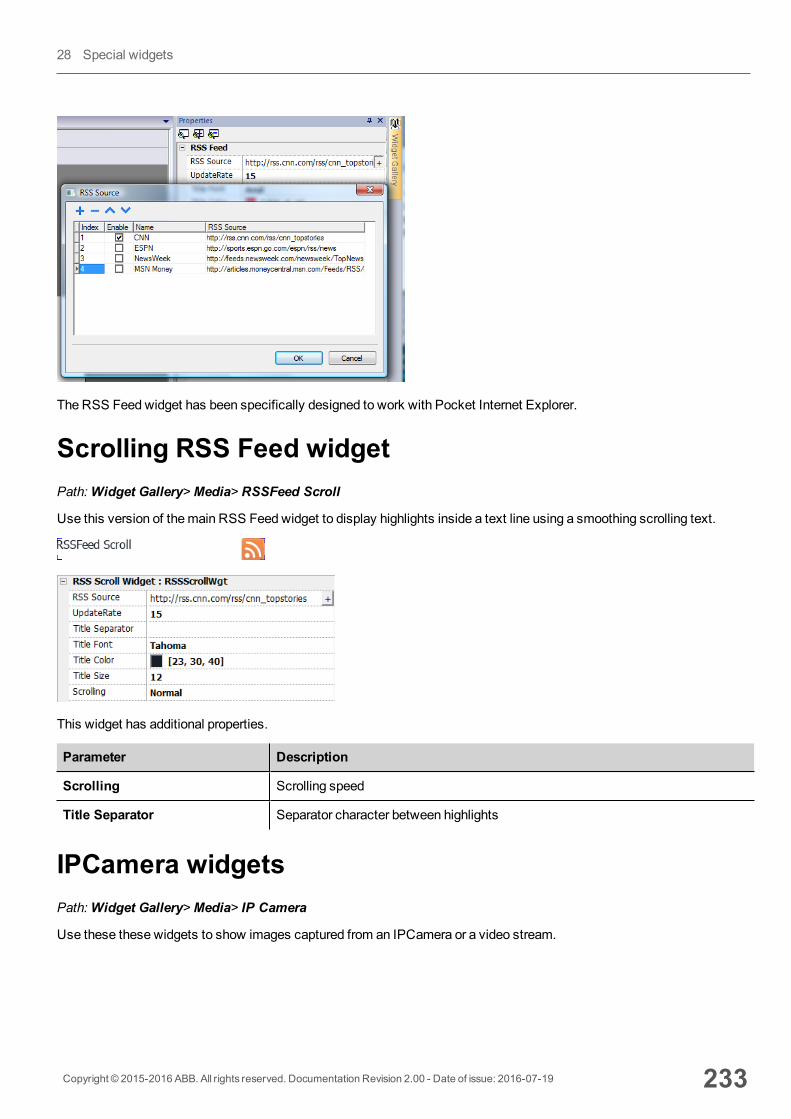
The RSS Feed widget has been specifically designed to work with Pocket Internet Explorer.
Scrolling RSS Feed widgetPath:Widget Gallery>Media> RSSFeed Scroll
Use this version of themain RSS Feed widget to display highlights inside a text line using a smoothing scrolling text.
This widget has additional properties.
Parameter Description
Scrolling Scrolling speed
Title Separator Separator character between highlights
IPCamera widgetsPath:Widget Gallery>Media> IP Camera
Use these these widgets to show images captured from an IPCamera or a video stream.
Copyright © 2015-2016 ABB. All rights reserved. Documentation Revision 2.00 - Date of issue: 2016-07-19 233
28 Special widgets

Parameter Description
Camera URL URL of the IPCamera when used in JPEG format.
Refresh Rate Number of JPEG images for second allowed. Max rate = 1 fps.
User Name Name of user allowed to access the camera.
Set this parameter when access to the camera is password protected.
Password Password to access the camera.
MJPEG Camera URL URL of MJPEG streaming (for example, http://192.168.0.1/video.cgi)
When this widget is used to stream HTTP MJPEG, Camera URL andRefresh Rate are ignored.
Performance of streaming is not fixed and depends onmany factors such as: frame size, frame compression level, CPU ofHMI device, quality of IPCamera. Based on these factors the widget can reach up to 25 fps.
You can addmultiple IPCamera widgets, but this will reduce the frame rate fore each widget.
Supported IPCamerasThe following IPCamers have been tested so far:
IPCamera Protocol URL
Apexis APM-J901-Z-WS PTZ IP Camera MJPEG
HTTP
http://{ip_address}/videostream.cgi
http://{ip_address}/snapshot.cgi
AXIS M3027-PVE Network Camera MJPEG
HTTP
http://{ip_address}/axis-cgi/mjpg/video.cgi
http://{ip_address}/axis-cgi/jpg/image.cgi
DAHUA DH-IPC-HD2100P-080B 1.3mpOutdoor Vandalproof
HTTP http://{ip_address}:9988/onvif/media_service/snapshot
D-Link DCS-5605 PTZ MJPEG http://{ip_address}/video/mjpg.cgi
D-Link DCS-900W IP Camera MJPEG http://{ip_address}/video.cgi
D-Link DCS-932L MJPEG http://{ip_address}/video.cgi
234 Copyright © 2015-2016 ABB. All rights reserved. Documentation Revision 2.00 - Date of issue: 2016-07-19
IPCamera widgets
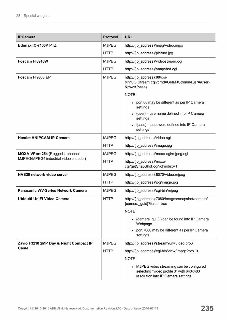
IPCamera Protocol URL
Edimax IC-7100P PTZ MJPEG
HTTP
http://{ip_address}/mjpg/video.mjpg
http://{ip_address}/picture.jpg
Foscam FI8916W MJPEG
HTTP
http://{ip_address}/videostream.cgi
http://{ip_address}/snapshot.cgi
Foscam FI9803 EP MJPEG http://{ip_address}:88/cgi-bin/CGIStream.cgi?cmd=GetMJStream&usr={user}&pwd={pass}
NOTE:
l port 88may be different as per IP Camerasettings
l {user} = username defined into IP Camerasettings
l {pass} = password defined into IP Camerasettings
Hamlet HNIPCAM IP Camera MJPEG
HTTP
http://{ip_address}/video.cgi
http://{ip_address}/image.jpg
MOXA VPort 254 (Rugged 4-channelMJPEG/MPEG4 industrial video encoder)
MJPEG
HTTP
http://{ip_address}/moxa-cgi/mjpeg.cgi
http://{ip_address}/moxa-cgi/getSnapShot.cgi?chindex=1
NVS30 network video server MJPEG
HTTP
http://{ip_address}:8070/video.mjpeg
http://{ip_address}/jpg/image.jpg
Panasonic WV-Series Network Camera MJPEG http://{ip_address}/cgi-bin/mjpeg
Ubiquiti UniFi Video Camera HTTP http://{ip_address}:7080/images/snapshot/camera/{camera_guid}?force=true
NOTE:
l {camera_guiID} can be found into IP CameraWebpage
l port 7080may be different as per IP Camerasettings
Zavio F3210 2MP Day & Night Compact IPCame
MJPEG
HTTP
http://{ip_address}/stream?uri=video.pro3
http://{ip_address}/cgi-bin/view/image?pro_0
NOTE:
l MJPEG video streaming can be configuredselecting "video profile 3" with 640x480resolution into IP Camera settings.
Copyright © 2015-2016 ABB. All rights reserved. Documentation Revision 2.00 - Date of issue: 2016-07-19 235
28 Special widgets
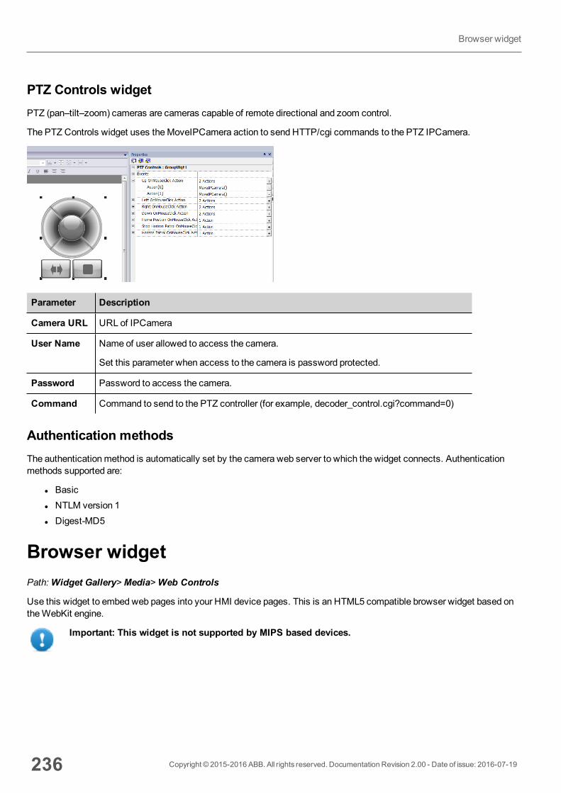
PTZ Controls widgetPTZ (pan–tilt–zoom) cameras are cameras capable of remote directional and zoom control.
The PTZ Controls widget uses theMoveIPCamera action to send HTTP/cgi commands to the PTZ IPCamera.
Parameter Description
Camera URL URL of IPCamera
User Name Name of user allowed to access the camera.
Set this parameter when access to the camera is password protected.
Password Password to access the camera.
Command Command to send to the PTZ controller (for example, decoder_control.cgi?command=0)
Authentication methodsThe authenticationmethod is automatically set by the camera web server to which the widget connects. Authenticationmethods supported are:
l Basicl NTLM version 1l Digest-MD5
Browser widgetPath:Widget Gallery>Media>Web Controls
Use this widget to embed web pages into your HMI device pages. This is an HTML5 compatible browser widget based ontheWebKit engine.
Important: This widget is not supported by MIPS based devices.
236 Copyright © 2015-2016 ABB. All rights reserved. Documentation Revision 2.00 - Date of issue: 2016-07-19
Browser widget
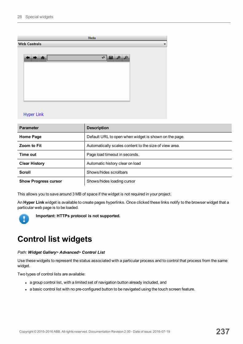
Parameter Description
Home Page Default URL to open when widget is shown on the page.
Zoom to Fit Automatically scales content to the size of view area.
Time out Page load timeout in seconds.
Clear History Automatic history clear on load
Scroll Shows/hides scrollbars
Show Progress cursor Shows/hides loading cursor
This allows you to save around 3MB of space if the widget is not required in your project.
AnHyper Linkwidget is available to create pages hyperlinks. Once clicked these links notify to the browser widget that aparticular web page is to be loaded.
Important: HTTPs protocol is not supported.
Control list widgetsPath:Widget Gallery> Advanced> Control List
Use these widgets to represent the status associated with a particular process and to control that process from the samewidget.
Two types of control lists are available:
l a group control list, with a limited set of navigation button already included, andl a basic control list with no pre-configured button to be navigated using the touch screen feature.
Copyright © 2015-2016 ABB. All rights reserved. Documentation Revision 2.00 - Date of issue: 2016-07-19 237
28 Special widgets
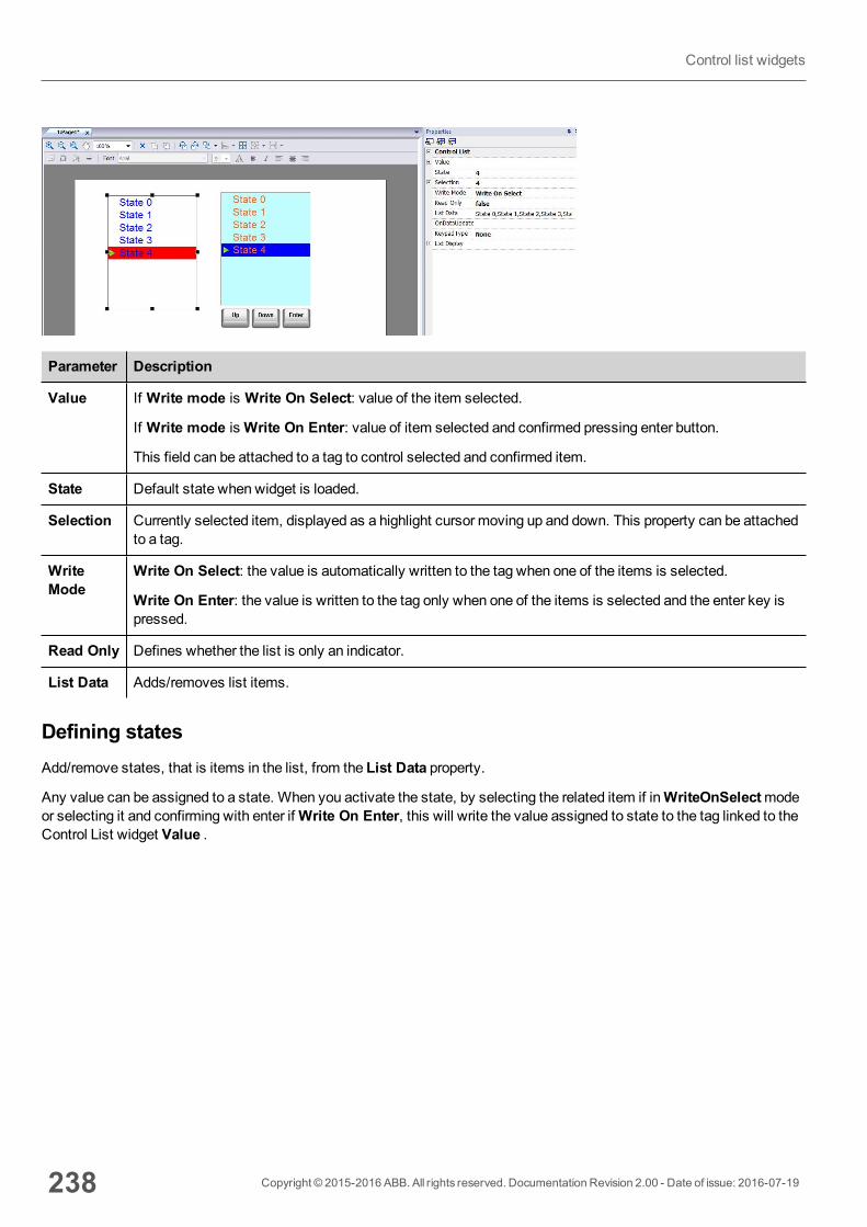
Parameter Description
Value If Write mode is Write On Select: value of the item selected.
If Write mode isWrite On Enter: value of item selected and confirmed pressing enter button.
This field can be attached to a tag to control selected and confirmed item.
State Default state when widget is loaded.
Selection Currently selected item, displayed as a highlight cursor moving up and down. This property can be attachedto a tag.
WriteMode
Write On Select: the value is automatically written to the tag when one of the items is selected.
Write On Enter: the value is written to the tag only when one of the items is selected and the enter key ispressed.
Read Only Defines whether the list is only an indicator.
List Data Adds/removes list items.
Defining statesAdd/remove states, that is items in the list, from the List Data property.
Any value can be assigned to a state. When you activate the state, by selecting the related item if inWriteOnSelectmodeor selecting it and confirming with enter ifWrite On Enter, this will write the value assigned to state to the tag linked to theControl List widget Value .
238 Copyright © 2015-2016 ABB. All rights reserved. Documentation Revision 2.00 - Date of issue: 2016-07-19
Control list widgets
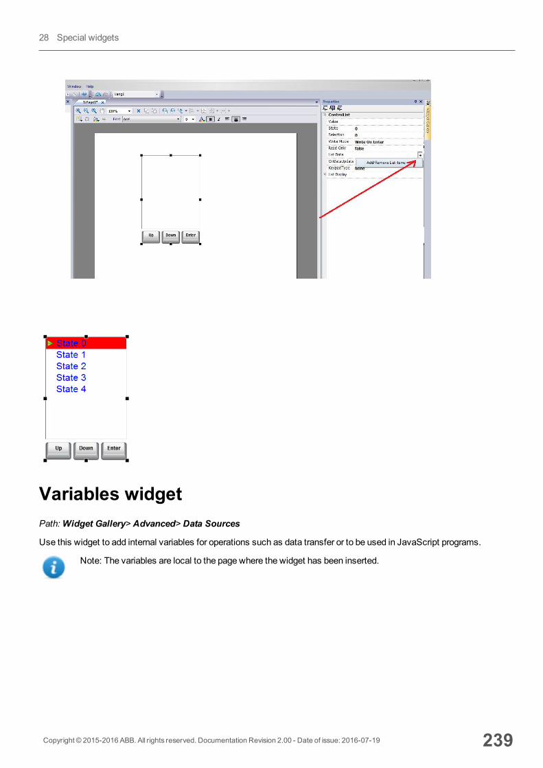
Variables widgetPath:Widget Gallery> Advanced> Data Sources
Use this widget to add internal variables for operations such as data transfer or to be used in JavaScript programs.
Note: The variables are local to the page where the widget has been inserted.
Copyright © 2015-2016 ABB. All rights reserved. Documentation Revision 2.00 - Date of issue: 2016-07-19 239
28 Special widgets
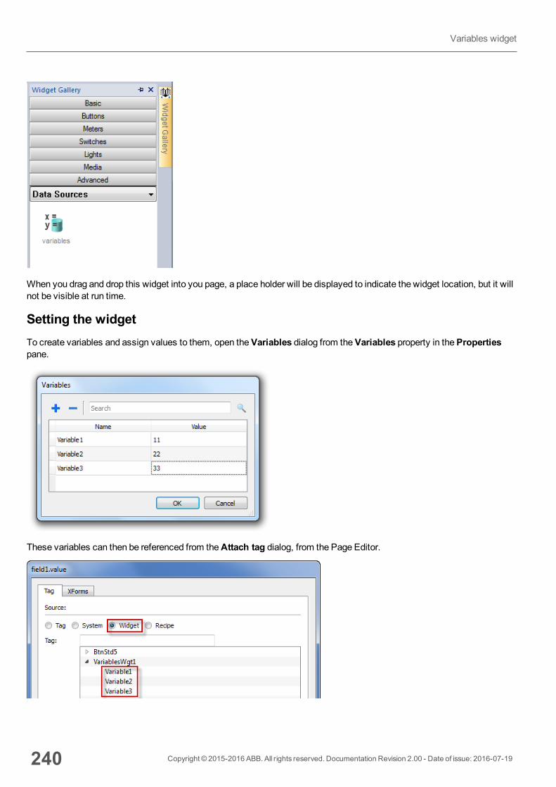
When you drag and drop this widget into you page, a place holder will be displayed to indicate the widget location, but it willnot be visible at run time.
Setting the widgetTo create variables and assign values to them, open theVariables dialog from theVariables property in thePropertiespane.
These variables can then be referenced from theAttach tag dialog, from the Page Editor.
240 Copyright © 2015-2016 ABB. All rights reserved. Documentation Revision 2.00 - Date of issue: 2016-07-19
Variables widget
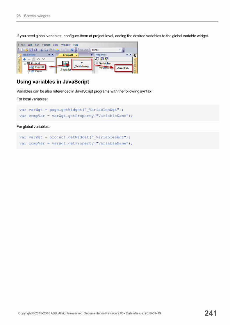
If you need global variables, configure them at project level, adding the desired variables to the global variable widget.
Using variables in JavaScriptVariables can be also referenced in JavaScript programs with the following syntax:
For local variables:
var varWgt = page.getWidget("_VariablesWgt");
var compVar = varWgt.getProperty("VariableName");
For global variables:
var varWgt = project.getWidget("_VariablesWgt");
var compVar = varWgt.getProperty("VariableName");
Copyright © 2015-2016 ABB. All rights reserved. Documentation Revision 2.00 - Date of issue: 2016-07-19 241
28 Special widgets

242 Copyright © 2015-2016 ABB. All rights reserved. Documentation Revision 2.00 - Date of issue: 2016-07-19
Variables widget
29 Custom widgetsPB610-B Panel Builder 600 has a large widget library which includes predefined dynamic widgets (buttons, lights, gauges,switches, trends, recipes, and dialog items), as well as static images (shapes, pipes, tanks, motors).
You can drag and drop an object from the gallery to the page, and then size, move, rotate or transform it. All widgets in thegallery are vector based, so they do not loose definition when resized.
You can, however, modify any of the pre-defined widgets to create your own custom widget. Custom widgets can bemadeup of several elements only including the properties needed to their purpose.
Creating a custom widget 244
Adding properties to a custom widget 244
Editing custom widgets properties 246
User's Gallery 247
Copyright © 2015-2016 ABB. All rights reserved. Documentation Revision 2.00 - Date of issue: 2016-07-19 243
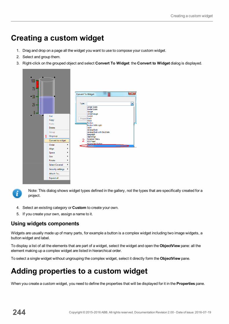
Creating a custom widget1. Drag and drop on a page all the widget you want to use to compose your custom widget.2. Select and group them.3. Right-click on the grouped object and select Convert To Widget: theConvert to Widget dialog is displayed.
Note: This dialog shows widget types defined in the gallery, not the types that are specifically created for aproject.
4. Select an existing category orCustom to create your own.5. If you create your own, assign a name to it.
Using widgets componentsWidgets are usually made up of many parts, for example a button is a complex widget including two image widgets, abutton widget and label.
To display a list of all the elements that are part of a widget, select the widget and open theObjectView pane: all theelement making up a complex widget are listed in hierarchical order.
To select a single widget without ungrouping the complex widget, select it directly form theObjectView pane.
Adding properties to a custom widgetWhen you create a custom widget, you need to define the properties that will be displayed for it in theProperties pane.
244 Copyright © 2015-2016 ABB. All rights reserved. Documentation Revision 2.00 - Date of issue: 2016-07-19
Creating a custom widget
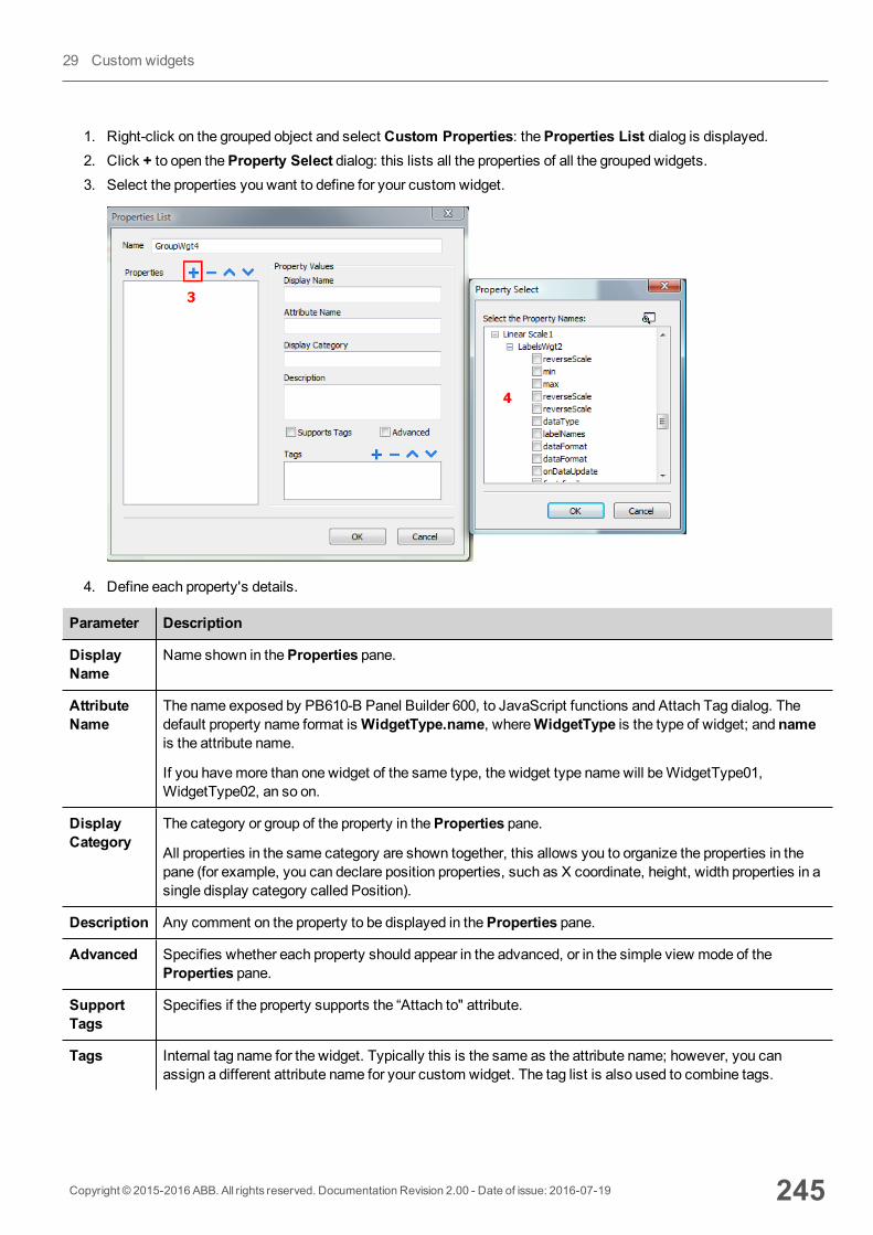
1. Right-click on the grouped object and select Custom Properties: theProperties List dialog is displayed.2. Click + to open theProperty Select dialog: this lists all the properties of all the grouped widgets.3. Select the properties you want to define for your custom widget.
4. Define each property's details.
Parameter Description
DisplayName
Name shown in theProperties pane.
AttributeName
The name exposed by PB610-B Panel Builder 600, to JavaScript functions and Attach Tag dialog. Thedefault property name format isWidgetType.name, whereWidgetType is the type of widget; and nameis the attribute name.
If you havemore than one widget of the same type, the widget type namewill beWidgetType01,WidgetType02, an so on.
DisplayCategory
The category or group of the property in theProperties pane.
All properties in the same category are shown together, this allows you to organize the properties in thepane (for example, you can declare position properties, such as X coordinate, height, width properties in asingle display category called Position).
Description Any comment on the property to be displayed in theProperties pane.
Advanced Specifies whether each property should appear in the advanced, or in the simple view mode of theProperties pane.
SupportTags
Specifies if the property supports the “Attach to" attribute.
Tags Internal tag name for the widget. Typically this is the same as the attribute name; however, you canassign a different attribute name for your custom widget. The tag list is also used to combine tags.
Copyright © 2015-2016 ABB. All rights reserved. Documentation Revision 2.00 - Date of issue: 2016-07-19 245
29 Custom widgets
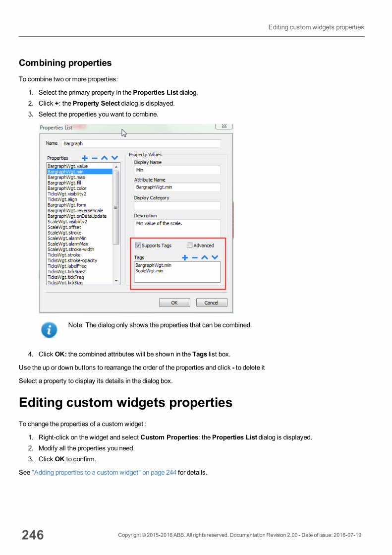
Combining propertiesTo combine two or more properties:
1. Select the primary property in theProperties List dialog.2. Click +: theProperty Select dialog is displayed.3. Select the properties you want to combine.
Note: The dialog only shows the properties that can be combined.
4. Click OK: the combined attributes will be shown in the Tags list box.
Use the up or down buttons to rearrange the order of the properties and click - to delete it
Select a property to display its details in the dialog box.
Editing custom widgets propertiesTo change the properties of a custom widget :
1. Right-click on the widget and select Custom Properties: theProperties List dialog is displayed.2. Modify all the properties you need.3. Click OK to confirm.
See "Adding properties to a custom widget" on page 244 for details.
246 Copyright © 2015-2016 ABB. All rights reserved. Documentation Revision 2.00 - Date of issue: 2016-07-19
Editing custom widgets properties
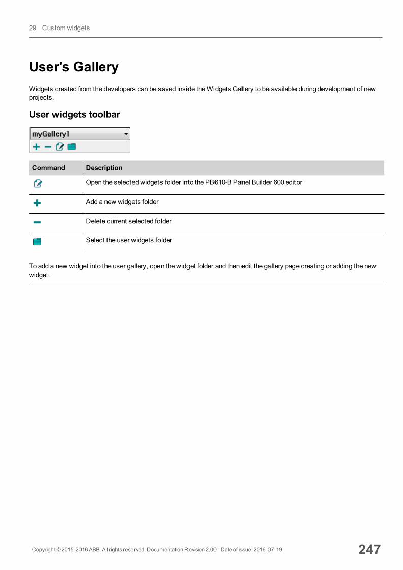
User's GalleryWidgets created from the developers can be saved inside theWidgets Gallery to be available during development of newprojects.
User widgets toolbar
Command Description
Open the selected widgets folder into the PB610-B Panel Builder 600 editor
Add a new widgets folder
Delete current selected folder
Select the user widgets folder
To add a new widget into the user gallery, open the widget folder and then edit the gallery page creating or adding the newwidget.
Copyright © 2015-2016 ABB. All rights reserved. Documentation Revision 2.00 - Date of issue: 2016-07-19 247
29 Custom widgets

248 Copyright © 2015-2016 ABB. All rights reserved. Documentation Revision 2.00 - Date of issue: 2016-07-19
User's Gallery
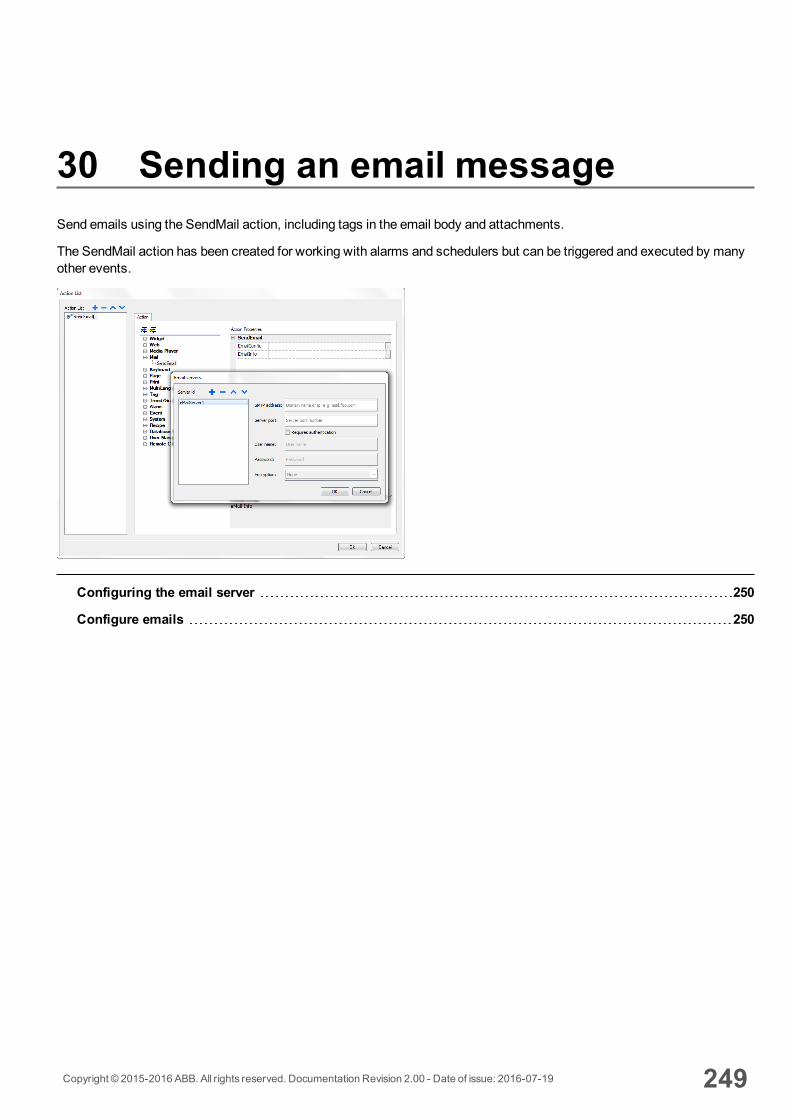
30 Sending an email messageSend emails using the SendMail action, including tags in the email body and attachments.
The SendMail action has been created for working with alarms and schedulers but can be triggered and executed by manyother events.
Configuring the email server 250
Configure emails 250
Copyright © 2015-2016 ABB. All rights reserved. Documentation Revision 2.00 - Date of issue: 2016-07-19 249
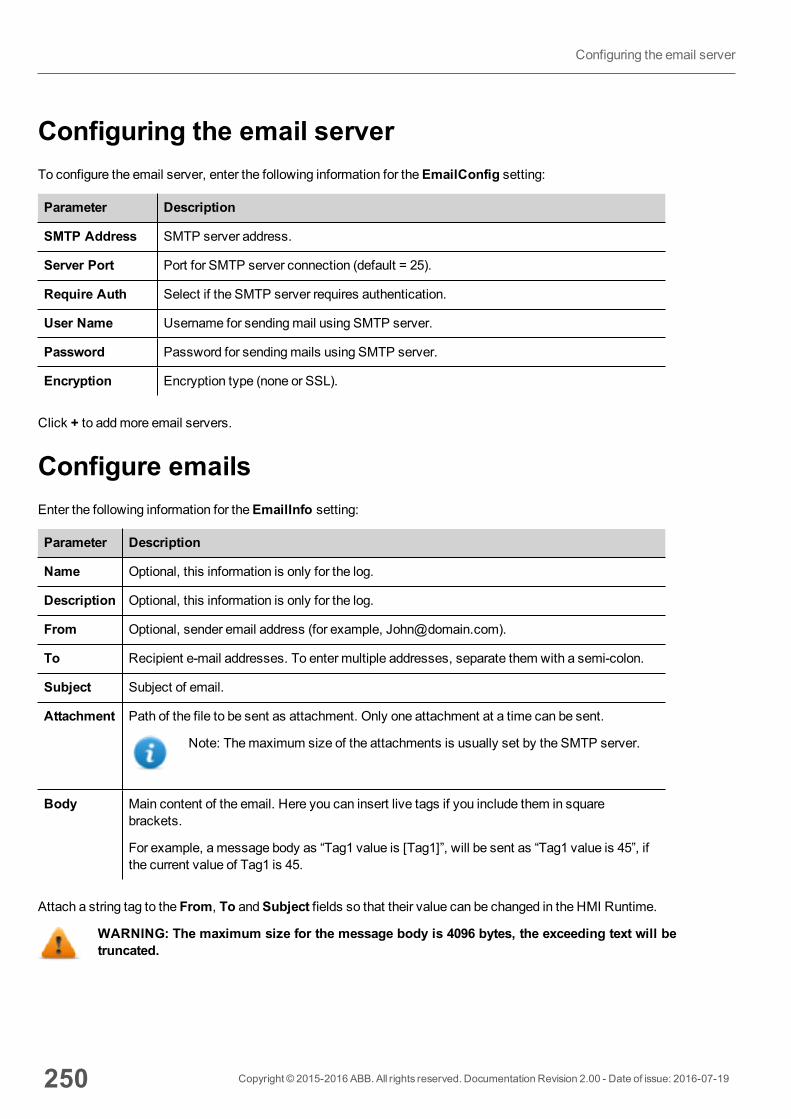
Configuring the email serverTo configure the email server, enter the following information for theEmailConfig setting:
Parameter Description
SMTP Address SMTP server address.
Server Port Port for SMTP server connection (default = 25).
Require Auth Select if the SMTP server requires authentication.
User Name Username for sendingmail using SMTP server.
Password Password for sendingmails using SMTP server.
Encryption Encryption type (none or SSL).
Click + to addmore email servers.
Configure emailsEnter the following information for theEmailInfo setting:
Parameter Description
Name Optional, this information is only for the log.
Description Optional, this information is only for the log.
From Optional, sender email address (for example, [email protected]).
To Recipient e-mail addresses. To enter multiple addresses, separate them with a semi-colon.
Subject Subject of email.
Attachment Path of the file to be sent as attachment. Only one attachment at a time can be sent.
Note: Themaximum size of the attachments is usually set by the SMTP server.
Body Main content of the email. Here you can insert live tags if you include them in squarebrackets.
For example, amessage body as “Tag1 value is [Tag1]”, will be sent as “Tag1 value is 45”, ifthe current value of Tag1 is 45.
Attach a string tag to the From, To andSubject fields so that their value can be changed in the HMI Runtime.
WARNING: The maximum size for the message body is 4096 bytes, the exceeding text will betruncated.
250 Copyright © 2015-2016 ABB. All rights reserved. Documentation Revision 2.00 - Date of issue: 2016-07-19
Configuring the email server
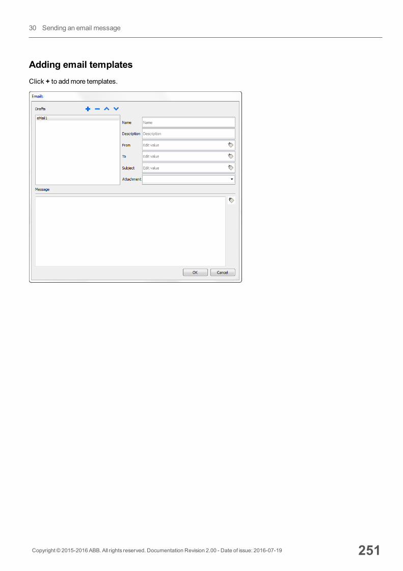
Adding email templatesClick + to addmore templates.
Copyright © 2015-2016 ABB. All rights reserved. Documentation Revision 2.00 - Date of issue: 2016-07-19 251
30 Sending an email message

252 Copyright © 2015-2016 ABB. All rights reserved. Documentation Revision 2.00 - Date of issue: 2016-07-19
Configure emails
31 JavaScriptThe purpose of this section is to describe how JavaScript is used in the PB610-B Panel Builder 600 applications, not toexplain the JavaScript language.
PB610-B Panel Builder 600 JavaScript is based on the ECMAScript programming language http://www.ecmascript.org , asdefined in standard ECMA-262.
If you are familiar with JavaScript, you can use the same type of commands in PB610-B Panel Builder 600 as you do in aweb browser. If you are not familiar with the ECMAScript language, refer to:
https://developer.mozilla.org/en/JavaScript
JavaScript editor 255
Execution of JavaScript functions 255
Events 257
Widget events 258
Page events 260
System events 261
Objects 263
Widget class objects 263
Widget properties 264
Widget methods 266
Page object 268
Page object properties 268
Page object methods 269
Group object 271
Group object methods 271
Project object 272
Project object properties 272
Project object methods 272
State object 281
State object methods 282
Keywords 283
Global functions 283
Handling read/write files 284
Copyright © 2015-2016 ABB. All rights reserved. Documentation Revision 2.00 - Date of issue: 2016-07-19 253

Limitations in working with widgets in JavaScript 286
Debugging of JavaScript 287
254 Copyright © 2015-2016 ABB. All rights reserved. Documentation Revision 2.00 - Date of issue: 2016-07-19
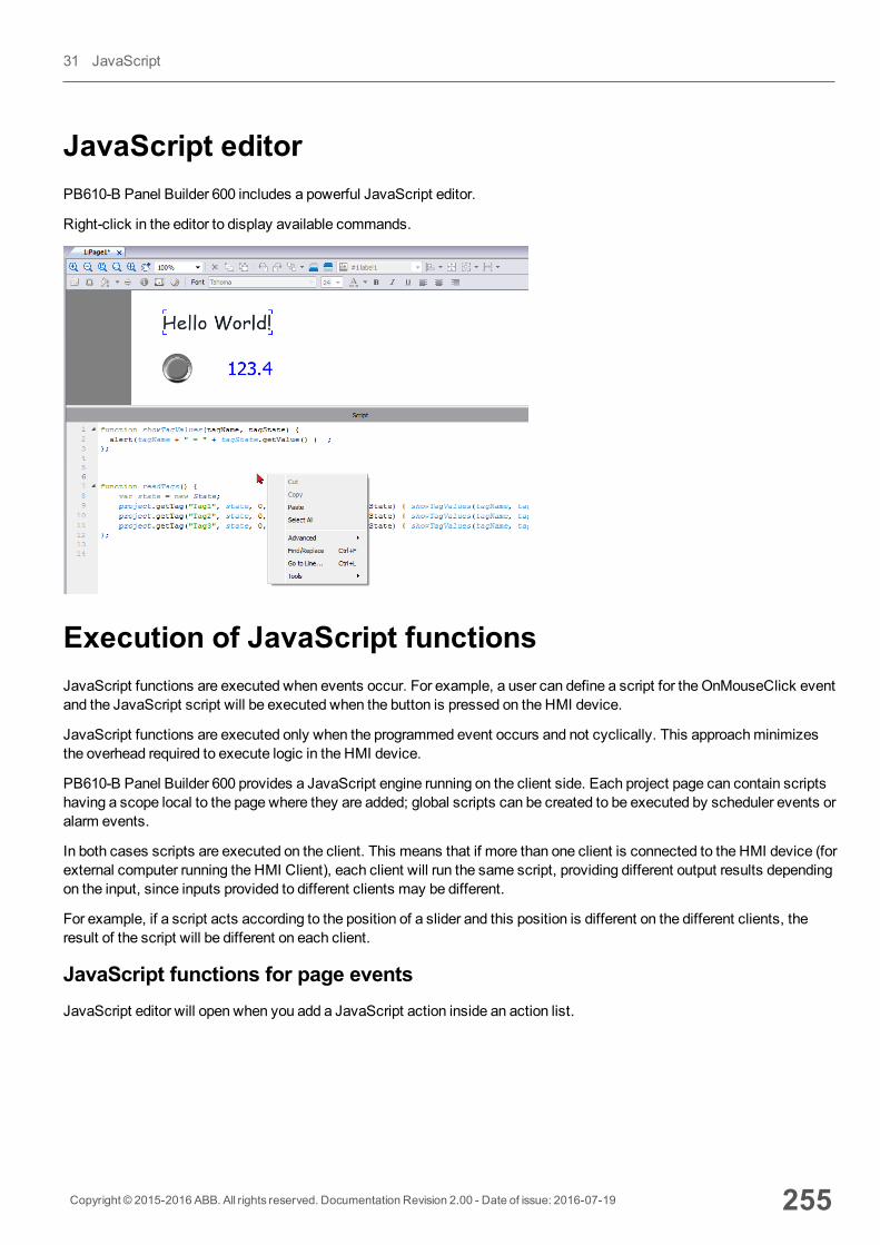
JavaScript editorPB610-B Panel Builder 600 includes a powerful JavaScript editor.
Right-click in the editor to display available commands.
Execution of JavaScript functionsJavaScript functions are executed when events occur. For example, a user can define a script for the OnMouseClick eventand the JavaScript script will be executed when the button is pressed on the HMI device.
JavaScript functions are executed only when the programmed event occurs and not cyclically. This approachminimizesthe overhead required to execute logic in the HMI device.
PB610-B Panel Builder 600 provides a JavaScript engine running on the client side. Each project page can contain scriptshaving a scope local to the page where they are added; global scripts can be created to be executed by scheduler events oralarm events.
In both cases scripts are executed on the client. This means that if more than one client is connected to the HMI device (forexternal computer running the HMI Client), each client will run the same script, providing different output results dependingon the input, since inputs provided to different clients may be different.
For example, if a script acts according to the position of a slider and this position is different on the different clients, theresult of the script will be different on each client.
JavaScript functions for page eventsJavaScript editor will open when you add a JavaScript action inside an action list.
Copyright © 2015-2016 ABB. All rights reserved. Documentation Revision 2.00 - Date of issue: 2016-07-19 255
31 JavaScript
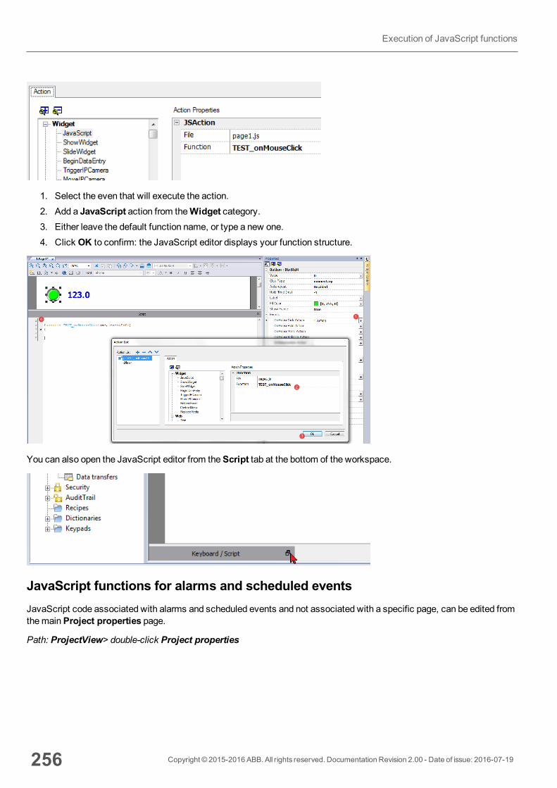
1. Select the even that will execute the action.2. Add a JavaScript action from theWidget category.3. Either leave the default function name, or type a new one.4. Click OK to confirm: the JavaScript editor displays your function structure.
You can also open the JavaScript editor from theScript tab at the bottom of the workspace.
JavaScript functions for alarms and scheduled eventsJavaScript code associated with alarms and scheduled events and not associated with a specific page, can be edited fromthemainProject properties page.
Path: ProjectView> double-click Project properties
256 Copyright © 2015-2016 ABB. All rights reserved. Documentation Revision 2.00 - Date of issue: 2016-07-19
Execution of JavaScript functions
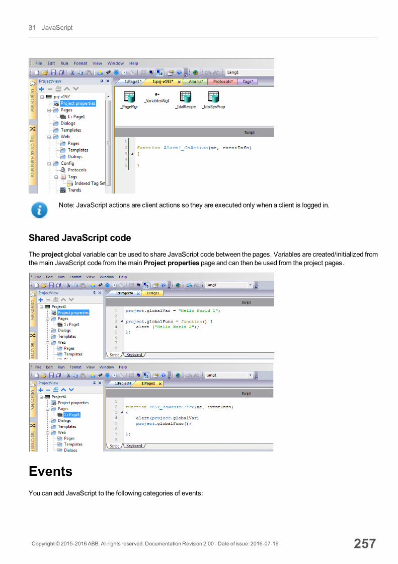
Note: JavaScript actions are client actions so they are executed only when a client is logged in.
Shared JavaScript codeThe project global variable can be used to share JavaScript code between the pages. Variables are created/initialized fromthemain JavaScript code from themainProject properties page and can then be used from the project pages.
EventsYou can add JavaScript to the following categories of events:
Copyright © 2015-2016 ABB. All rights reserved. Documentation Revision 2.00 - Date of issue: 2016-07-19 257
31 JavaScript
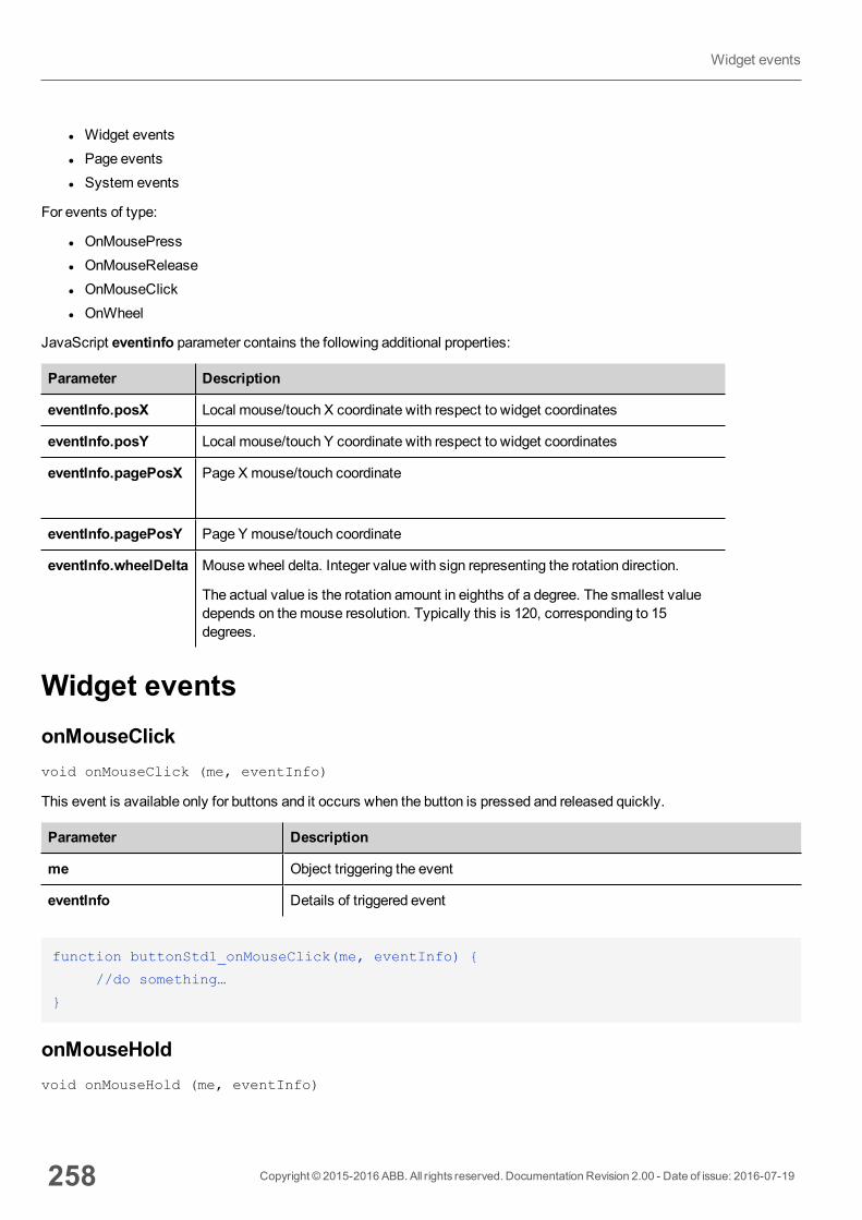
l Widget eventsl Page eventsl System events
For events of type:
l OnMousePressl OnMouseReleasel OnMouseClickl OnWheel
JavaScript eventinfo parameter contains the following additional properties:
Parameter Description
eventInfo.posX Local mouse/touch X coordinate with respect to widget coordinates
eventInfo.posY Local mouse/touch Y coordinate with respect to widget coordinates
eventInfo.pagePosX Page X mouse/touch coordinate
eventInfo.pagePosY Page Y mouse/touch coordinate
eventInfo.wheelDelta Mouse wheel delta. Integer value with sign representing the rotation direction.
The actual value is the rotation amount in eighths of a degree. The smallest valuedepends on themouse resolution. Typically this is 120, corresponding to 15degrees.
Widget eventsonMouseClickvoid onMouseClick (me, eventInfo)
This event is available only for buttons and it occurs when the button is pressed and released quickly.
Parameter Description
me Object triggering the event
eventInfo Details of triggered event
function buttonStd1_onMouseClick(me, eventInfo) {
//do something…
}
onMouseHoldvoid onMouseHold (me, eventInfo)
258 Copyright © 2015-2016 ABB. All rights reserved. Documentation Revision 2.00 - Date of issue: 2016-07-19
Widget events
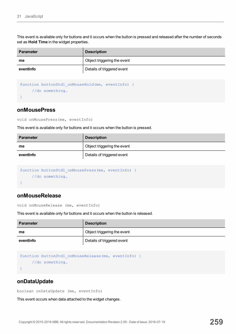
This event is available only for buttons and it occurs when the button is pressed and released after the number of secondsset as Hold Time in the widget properties.
Parameter Description
me Object triggering the event
eventInfo Details of triggered event
function buttonStd1_onMouseHold(me, eventInfo) {
//do something…
}
onMousePressvoid onMousePress(me, eventInfo)
This event is available only for buttons and it occurs when the button is pressed.
Parameter Description
me Object triggering the event
eventInfo Details of triggered event
function buttonStd1_onMousePress(me, eventInfo) {
//do something…
}
onMouseReleasevoid onMouseRelease (me, eventInfo)
This event is available only for buttons and it occurs when the button is released.
Parameter Description
me Object triggering the event
eventInfo Details of triggered event
function buttonStd1_onMouseRelease(me, eventInfo) {
//do something…
}
onDataUpdateboolean onDataUpdate (me, eventInfo)
This event occurs when data attached to the widget changes.
Copyright © 2015-2016 ABB. All rights reserved. Documentation Revision 2.00 - Date of issue: 2016-07-19 259
31 JavaScript
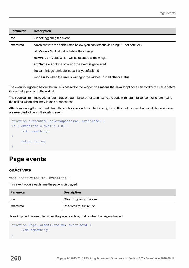
Parameter Description
me Object triggering the event
eventInfo An object with the fields listed below (you can refer fields using “.” - dot notation)
oldValue = Widget value before the change
newValue = Value which will be updated to the widget
attrName = Attribute on which the event is generated
index = Integer attribute index if any, default = 0
mode = W when the user is writing to the widget. R in all others status.
The event is triggered before the value is passed to the widget, this means the JavaScript code canmodify the value beforeit is actually passed to the widget.
The code can terminate with a return true or return false. After terminating the code with return false, control is returned tothe calling widget that may launch other actions.
After terminating the code with true, the control is not returned to the widget and this makes sure that no additional actionsare executed following the calling event.
function buttonStd1_onDataUpdate(me, eventInfo) {
if ( eventInfo.oldValue < 0) {
//do something…
}
return false;
}
Page eventsonActivatevoid onActivate( me, eventInfo )
This event occurs each time the page is displayed.
Parameter Description
me Object triggering the event
eventInfo Reserved for future use
JavaScript will be executed when the page is active, that is when the page is loaded.
function Page1_onActivate(me, eventInfo) {
//do something…
}
260 Copyright © 2015-2016 ABB. All rights reserved. Documentation Revision 2.00 - Date of issue: 2016-07-19
Page events
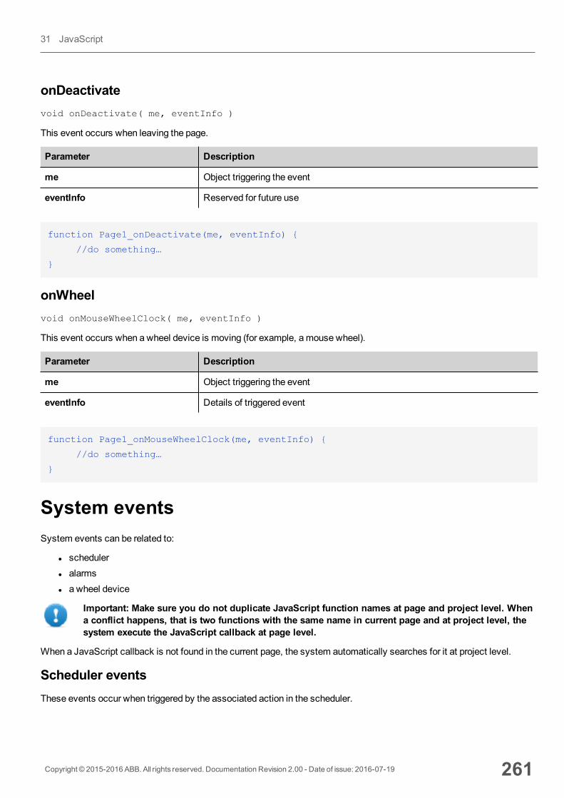
onDeactivatevoid onDeactivate( me, eventInfo )
This event occurs when leaving the page.
Parameter Description
me Object triggering the event
eventInfo Reserved for future use
function Page1_onDeactivate(me, eventInfo) {
//do something…
}
onWheelvoid onMouseWheelClock( me, eventInfo )
This event occurs when a wheel device is moving (for example, amouse wheel).
Parameter Description
me Object triggering the event
eventInfo Details of triggered event
function Page1_onMouseWheelClock(me, eventInfo) {
//do something…
}
System eventsSystem events can be related to:
l schedulerl alarmsl a wheel device
Important: Make sure you do not duplicate JavaScript function names at page and project level. Whena conflict happens, that is two functions with the same name in current page and at project level, thesystem execute the JavaScript callback at page level.
When a JavaScript callback is not found in the current page, the system automatically searches for it at project level.
Scheduler eventsThese events occur when triggered by the associated action in the scheduler.
Copyright © 2015-2016 ABB. All rights reserved. Documentation Revision 2.00 - Date of issue: 2016-07-19 261
31 JavaScript
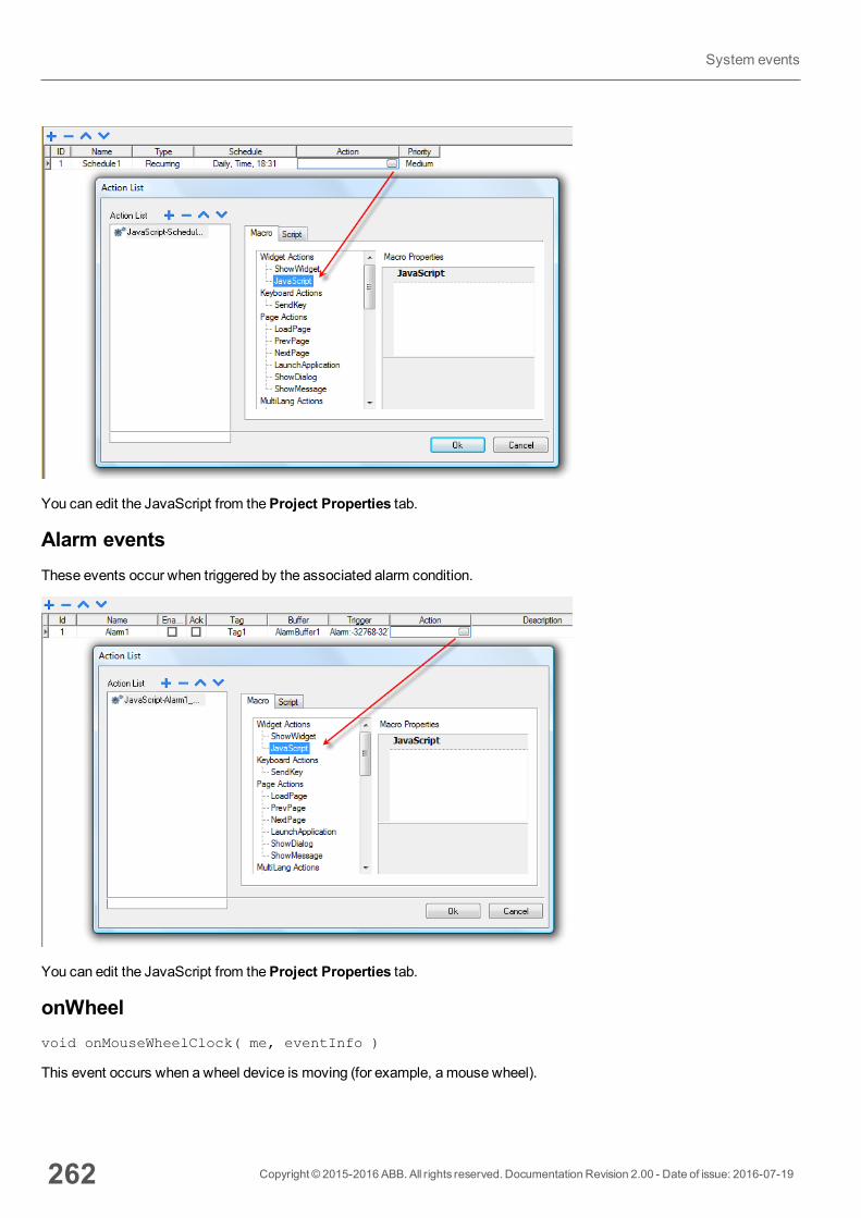
You can edit the JavaScript from theProject Properties tab.
Alarm eventsThese events occur when triggered by the associated alarm condition.
You can edit the JavaScript from theProject Properties tab.
onWheelvoid onMouseWheelClock( me, eventInfo )
This event occurs when a wheel device is moving (for example, amouse wheel).
262 Copyright © 2015-2016 ABB. All rights reserved. Documentation Revision 2.00 - Date of issue: 2016-07-19
System events
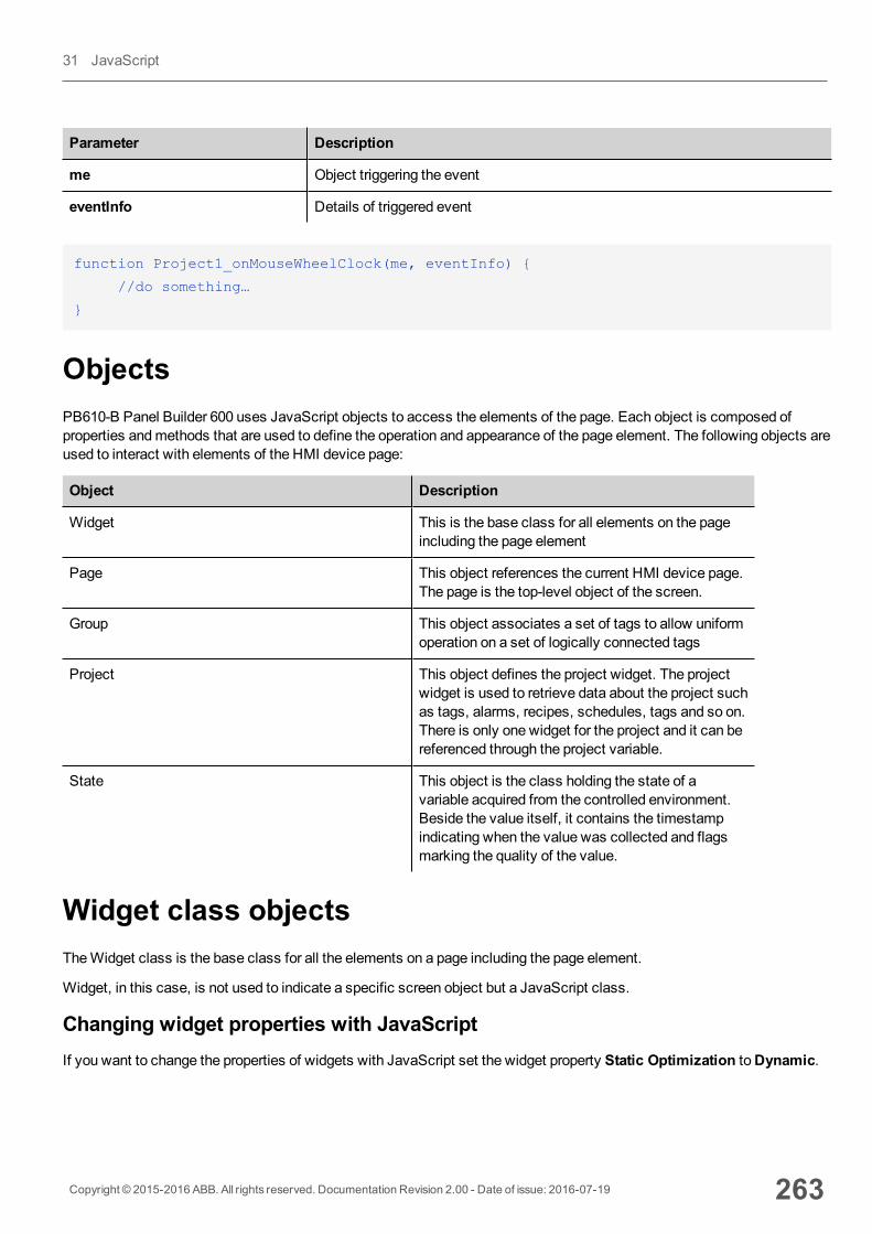
Parameter Description
me Object triggering the event
eventInfo Details of triggered event
function Project1_onMouseWheelClock(me, eventInfo) {
//do something…
}
ObjectsPB610-B Panel Builder 600 uses JavaScript objects to access the elements of the page. Each object is composed ofproperties andmethods that are used to define the operation and appearance of the page element. The following objects areused to interact with elements of the HMI device page:
Object Description
Widget This is the base class for all elements on the pageincluding the page element
Page This object references the current HMI device page.The page is the top-level object of the screen.
Group This object associates a set of tags to allow uniformoperation on a set of logically connected tags
Project This object defines the project widget. The projectwidget is used to retrieve data about the project suchas tags, alarms, recipes, schedules, tags and so on.There is only one widget for the project and it can bereferenced through the project variable.
State This object is the class holding the state of avariable acquired from the controlled environment.Beside the value itself, it contains the timestampindicating when the value was collected and flagsmarking the quality of the value.
Widget class objectsTheWidget class is the base class for all the elements on a page including the page element.
Widget, in this case, is not used to indicate a specific screen object but a JavaScript class.
Changing widget properties with JavaScriptIf you want to change the properties of widgets with JavaScript set the widget property Static Optimization toDynamic.
Copyright © 2015-2016 ABB. All rights reserved. Documentation Revision 2.00 - Date of issue: 2016-07-19 263
31 JavaScript
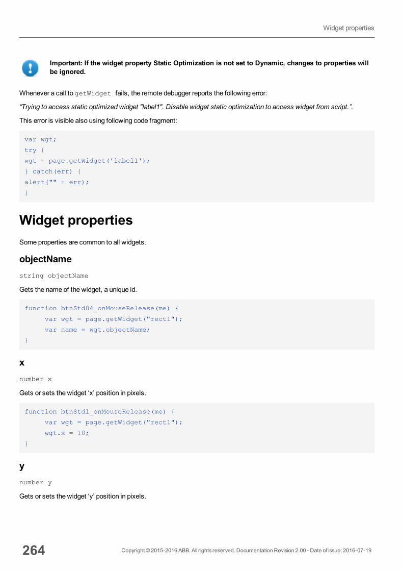
Important: If the widget property Static Optimization is not set to Dynamic, changes to properties willbe ignored.
Whenever a call to getWidget fails, the remote debugger reports the following error:
“Trying to access static optimized widget "label1". Disable widget static optimization to access widget from script.”.
This error is visible also using following code fragment:
var wgt;
try {
wgt = page.getWidget('label1');
} catch(err) {
alert("" + err);
}
Widget propertiesSome properties are common to all widgets.
objectNamestring objectName
Gets the name of the widget, a unique id.
function btnStd04_onMouseRelease(me) {
var wgt = page.getWidget("rect1");
var name = wgt.objectName;
}
xnumber x
Gets or sets the widget ‘x’ position in pixels.
function btnStd1_onMouseRelease(me) {
var wgt = page.getWidget("rect1");
wgt.x = 10;
}
ynumber y
Gets or sets the widget ‘y’ position in pixels.
264 Copyright © 2015-2016 ABB. All rights reserved. Documentation Revision 2.00 - Date of issue: 2016-07-19
Widget properties
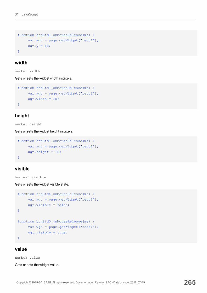
function btnStd1_onMouseRelease(me) {
var wgt = page.getWidget("rect1");
wgt.y = 10;
}
widthnumber width
Gets or sets the widget width in pixels.
function btnStd1_onMouseRelease(me) {
var wgt = page.getWidget("rect1");
wgt.width = 10;
}
heightnumber height
Gets or sets the widget height in pixels.
function btnStd1_onMouseRelease(me) {
var wgt = page.getWidget("rect1");
wgt.height = 10;
}
visibleboolean visible
Gets or sets the widget visible state.
function btnStd4_onMouseRelease(me) {
var wgt = page.getWidget("rect1");
wgt.visible = false;
}
function btnStd5_onMouseRelease(me) {
var wgt = page.getWidget("rect1");
wgt.visible = true;
}
valuenumber value
Gets or sets the widget value.
Copyright © 2015-2016 ABB. All rights reserved. Documentation Revision 2.00 - Date of issue: 2016-07-19 265
31 JavaScript
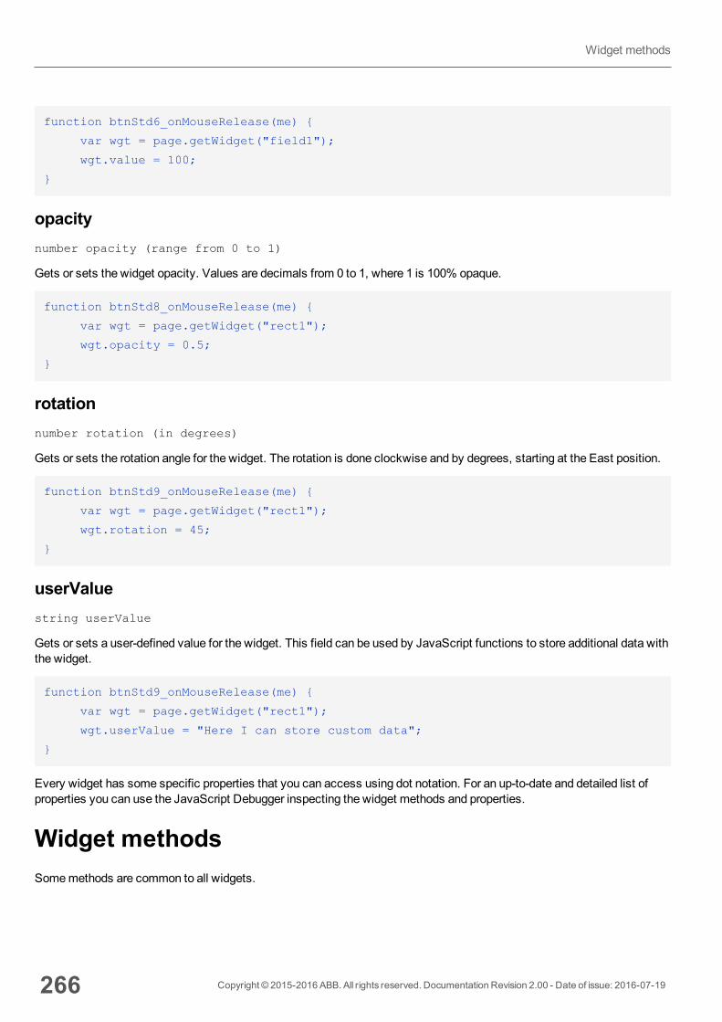
function btnStd6_onMouseRelease(me) {
var wgt = page.getWidget("field1");
wgt.value = 100;
}
opacitynumber opacity (range from 0 to 1)
Gets or sets the widget opacity. Values are decimals from 0 to 1, where 1 is 100% opaque.
function btnStd8_onMouseRelease(me) {
var wgt = page.getWidget("rect1");
wgt.opacity = 0.5;
}
rotationnumber rotation (in degrees)
Gets or sets the rotation angle for the widget. The rotation is done clockwise and by degrees, starting at the East position.
function btnStd9_onMouseRelease(me) {
var wgt = page.getWidget("rect1");
wgt.rotation = 45;
}
userValuestring userValue
Gets or sets a user-defined value for the widget. This field can be used by JavaScript functions to store additional data withthe widget.
function btnStd9_onMouseRelease(me) {
var wgt = page.getWidget("rect1");
wgt.userValue = "Here I can store custom data";
}
Every widget has some specific properties that you can access using dot notation. For an up-to-date and detailed list ofproperties you can use the JavaScript Debugger inspecting the widget methods and properties.
Widget methodsSomemethods are common to all widgets.
266 Copyright © 2015-2016 ABB. All rights reserved. Documentation Revision 2.00 - Date of issue: 2016-07-19
Widget methods
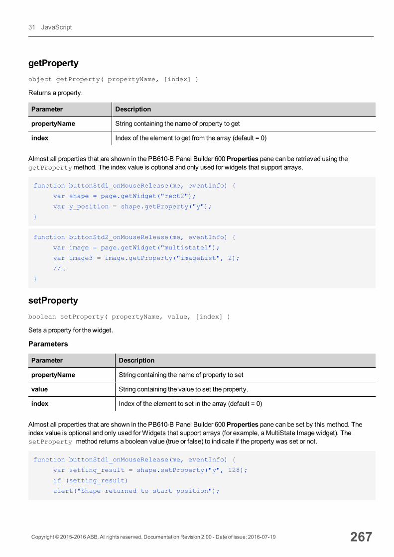
getPropertyobject getProperty( propertyName, [index] )
Returns a property.
Parameter Description
propertyName String containing the name of property to get
index Index of the element to get from the array (default = 0)
Almost all properties that are shown in the PB610-B Panel Builder 600Properties pane can be retrieved using thegetPropertymethod. The index value is optional and only used for widgets that support arrays.
function buttonStd1_onMouseRelease(me, eventInfo) {
var shape = page.getWidget("rect2");
var y_position = shape.getProperty("y");
}
function buttonStd2_onMouseRelease(me, eventInfo) {
var image = page.getWidget("multistate1");
var image3 = image.getProperty("imageList", 2);
//…
}
setPropertyboolean setProperty( propertyName, value, [index] )
Sets a property for the widget.
Parameters
Parameter Description
propertyName String containing the name of property to set
value String containing the value to set the property.
index Index of the element to set in the array (default = 0)
Almost all properties that are shown in the PB610-B Panel Builder 600Properties pane can be set by this method. Theindex value is optional and only used forWidgets that support arrays (for example, aMultiState Image widget). ThesetProperty method returns a boolean value (true or false) to indicate if the property was set or not.
function buttonStd1_onMouseRelease(me, eventInfo) {
var setting_result = shape.setProperty("y", 128);
if (setting_result)
alert("Shape returned to start position");
Copyright © 2015-2016 ABB. All rights reserved. Documentation Revision 2.00 - Date of issue: 2016-07-19 267
31 JavaScript
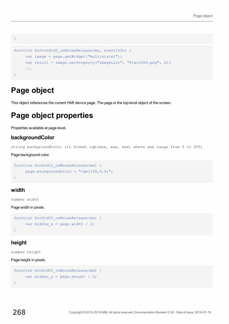
}
function buttonStd2_onMouseRelease(me, eventInfo) {
var image = page.getWidget("multistate1");
var result = image.setProperty("imageList", "Fract004.png", 2);
//…
}
Page objectThis object references the current HMI device page. The page is the top-level object of the screen.
Page object propertiesProperties available at page level.
backgroundColorstring backgroundColor (in format rgb(xxx, xxx, xxx) where xxx range from 0 to 255)
Page background color.
function btnStd11_onMouseRelease(me) {
page.backgroundColor = "rgb(128,0,0)";
}
widthnumber width
Page width in pixels.
function btnStd05_onMouseRelease(me) {
var middle_x = page.width / 2;
}
heightnumber height
Page height in pixels.
function btnStd05_onMouseRelease(me) {
var middle_y = page.height / 2;
}
268 Copyright © 2015-2016 ABB. All rights reserved. Documentation Revision 2.00 - Date of issue: 2016-07-19
Page object
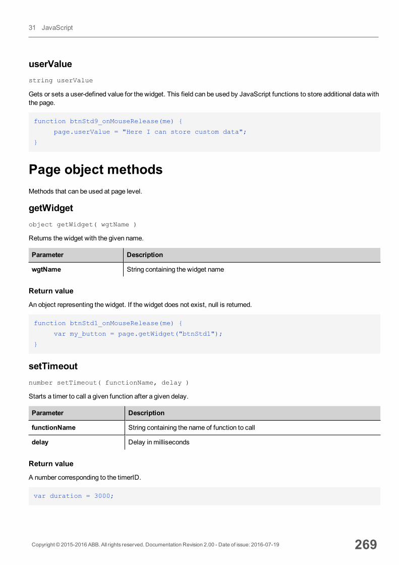
userValuestring userValue
Gets or sets a user-defined value for the widget. This field can be used by JavaScript functions to store additional data withthe page.
function btnStd9_onMouseRelease(me) {
page.userValue = "Here I can store custom data";
}
Page object methodsMethods that can be used at page level.
getWidgetobject getWidget( wgtName )
Returns the widget with the given name.
Parameter Description
wgtName String containing the widget name
Return value
An object representing the widget. If the widget does not exist, null is returned.
function btnStd1_onMouseRelease(me) {
var my_button = page.getWidget("btnStd1");
}
setTimeoutnumber setTimeout( functionName, delay )
Starts a timer to call a given function after a given delay.
Parameter Description
functionName String containing the name of function to call
delay Delay in milliseconds
Return value
A number corresponding to the timerID.
var duration = 3000;
Copyright © 2015-2016 ABB. All rights reserved. Documentation Revision 2.00 - Date of issue: 2016-07-19 269
31 JavaScript
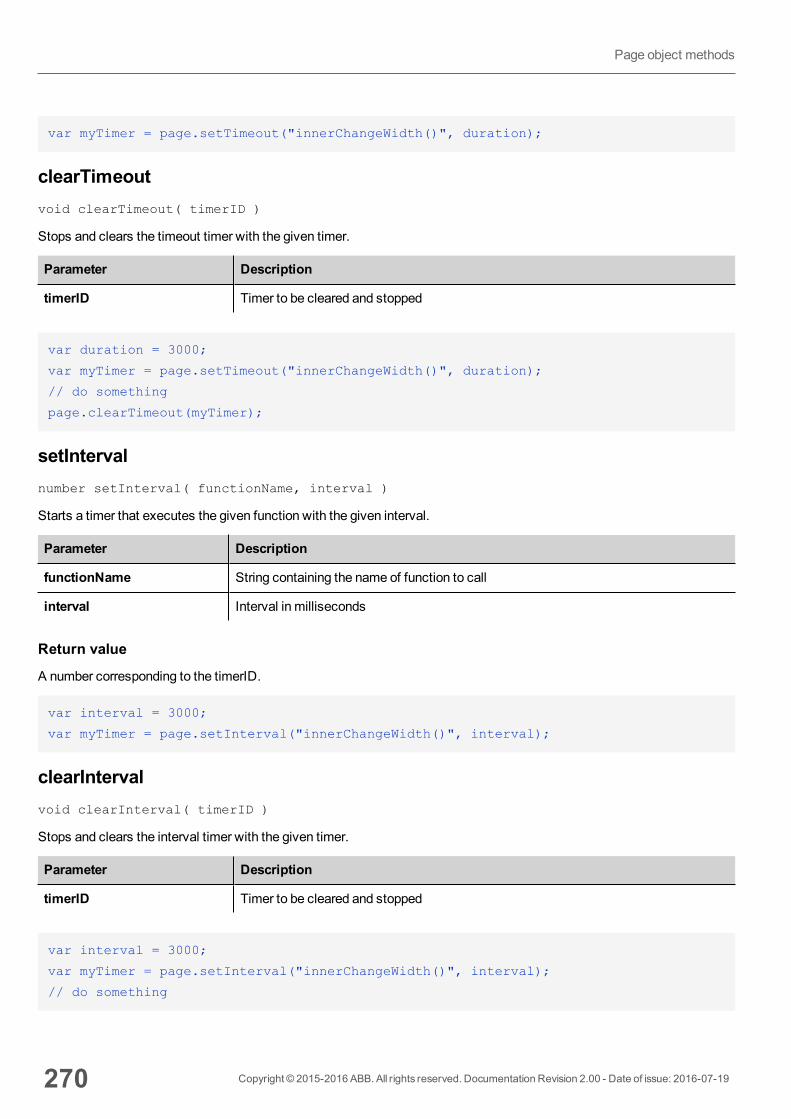
var myTimer = page.setTimeout("innerChangeWidth()", duration);
clearTimeoutvoid clearTimeout( timerID )
Stops and clears the timeout timer with the given timer.
Parameter Description
timerID Timer to be cleared and stopped
var duration = 3000;
var myTimer = page.setTimeout("innerChangeWidth()", duration);
// do something
page.clearTimeout(myTimer);
setIntervalnumber setInterval( functionName, interval )
Starts a timer that executes the given function with the given interval.
Parameter Description
functionName String containing the name of function to call
interval Interval in milliseconds
Return value
A number corresponding to the timerID.
var interval = 3000;
var myTimer = page.setInterval("innerChangeWidth()", interval);
clearIntervalvoid clearInterval( timerID )
Stops and clears the interval timer with the given timer.
Parameter Description
timerID Timer to be cleared and stopped
var interval = 3000;
var myTimer = page.setInterval("innerChangeWidth()", interval);
// do something
270 Copyright © 2015-2016 ABB. All rights reserved. Documentation Revision 2.00 - Date of issue: 2016-07-19
Page object methods
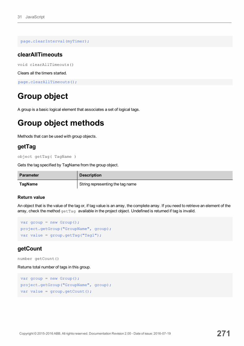
page.clearInterval(myTimer);
clearAllTimeoutsvoid clearAllTimeouts()
Clears all the timers started.
page.clearAllTimeouts();
Group objectA group is a basic logical element that associates a set of logical tags.
Group object methodsMethods that can be used with group objects.
getTagobject getTag( TagName )
Gets the tag specified by TagName from the group object.
Parameter Description
TagName String representing the tag name
Return value
An object that is the value of the tag or, if tag value is an array, the complete array. If you need to retrieve an element of thearray, check themethod getTag available in the project object. Undefined is returned if tag is invalid.
var group = new Group();
project.getGroup("GroupName", group);
var value = group.getTag("Tag1");
getCountnumber getCount()
Returns total number of tags in this group.
var group = new Group();
project.getGroup("GroupName", group);
var value = group.getCount();
Copyright © 2015-2016 ABB. All rights reserved. Documentation Revision 2.00 - Date of issue: 2016-07-19 271
31 JavaScript
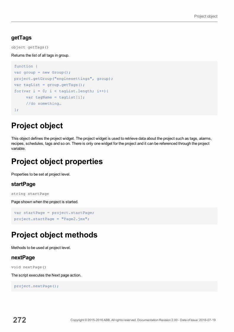
getTagsobject getTags()
Returns the list of all tags in group.
function {
var group = new Group();
project.getGroup("enginesettings", group);
var tagList = group.getTags();
for(var i = 0; i < tagList.length; i++){
var tagName = tagList[i];
//do something…
};
Project objectThis object defines the project widget. The project widget is used to retrieve data about the project such as tags, alarms,recipes, schedules, tags and so on. There is only one widget for the project and it can be referenced through the projectvariable.
Project object propertiesProperties to be set at project level.
startPagestring startPage
Page shownwhen the project is started.
var startPage = project.startPage;
project.startPage = "Page2.jmx";
Project object methodsMethods to be used at project level.
nextPagevoid nextPage()
The script executes the Next page action.
project.nextPage();
272 Copyright © 2015-2016 ABB. All rights reserved. Documentation Revision 2.00 - Date of issue: 2016-07-19
Project object
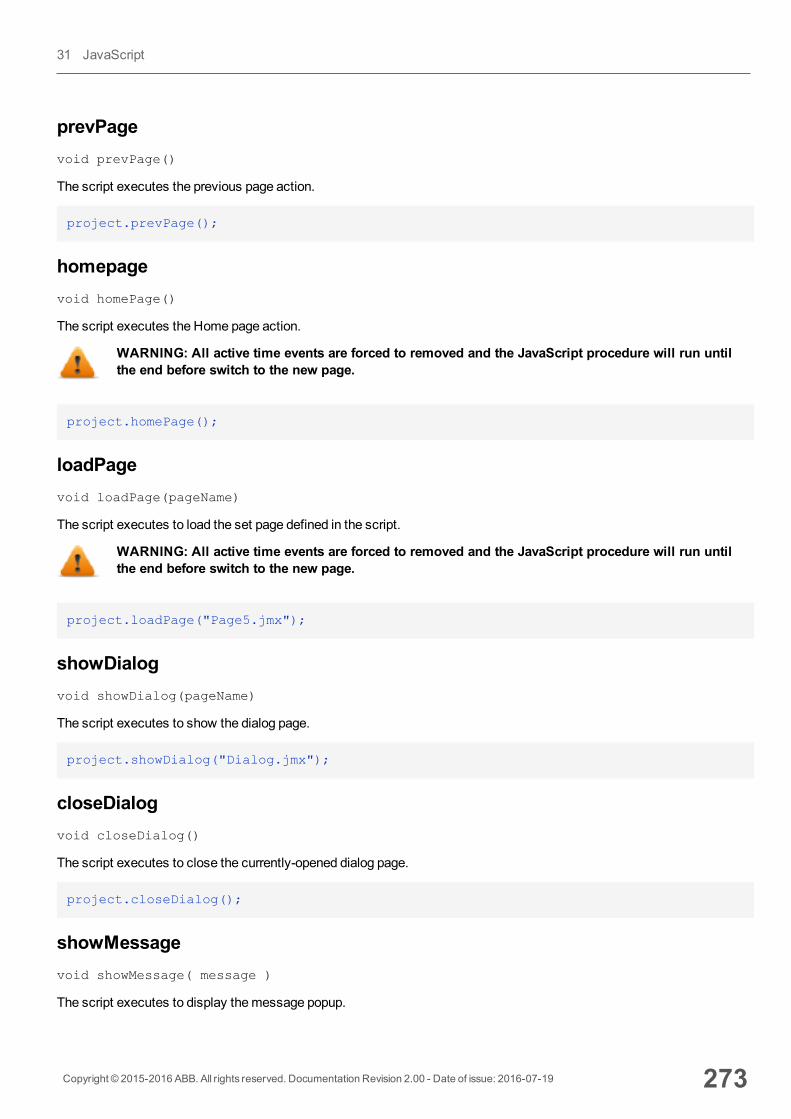
prevPagevoid prevPage()
The script executes the previous page action.
project.prevPage();
homepagevoid homePage()
The script executes the Home page action.
WARNING: All active time events are forced to removed and the JavaScript procedure will run untilthe end before switch to the new page.
project.homePage();
loadPagevoid loadPage(pageName)
The script executes to load the set page defined in the script.
WARNING: All active time events are forced to removed and the JavaScript procedure will run untilthe end before switch to the new page.
project.loadPage("Page5.jmx");
showDialogvoid showDialog(pageName)
The script executes to show the dialog page.
project.showDialog("Dialog.jmx");
closeDialogvoid closeDialog()
The script executes to close the currently-opened dialog page.
project.closeDialog();
showMessagevoid showMessage( message )
The script executes to display themessage popup.
Copyright © 2015-2016 ABB. All rights reserved. Documentation Revision 2.00 - Date of issue: 2016-07-19 273
31 JavaScript
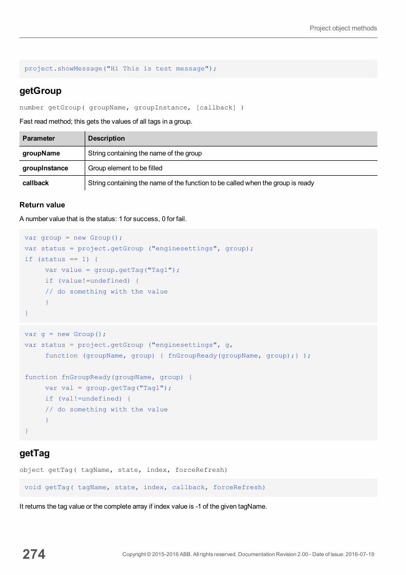
project.showMessage("Hi This is test message");
getGroupnumber getGroup( groupName, groupInstance, [callback] )
Fast readmethod; this gets the values of all tags in a group.
Parameter Description
groupName String containing the name of the group
groupInstance Group element to be filled
callback String containing the name of the function to be called when the group is ready
Return value
A number value that is the status: 1 for success, 0 for fail.
var group = new Group();
var status = project.getGroup ("enginesettings", group);
if (status == 1) {
var value = group.getTag("Tag1");
if (value!=undefined) {
// do something with the value
}
}
var g = new Group();
var status = project.getGroup ("enginesettings", g,
function (groupName, group) { fnGroupReady(groupName, group);} );
function fnGroupReady(groupName, group) {
var val = group.getTag("Tag1");
if (val!=undefined) {
// do something with the value
}
}
getTagobject getTag( tagName, state, index, forceRefresh)
void getTag( tagName, state, index, callback, forceRefresh)
It returns the tag value or the complete array if index value is -1 of the given tagName.
274 Copyright © 2015-2016 ABB. All rights reserved. Documentation Revision 2.00 - Date of issue: 2016-07-19
Project object methods
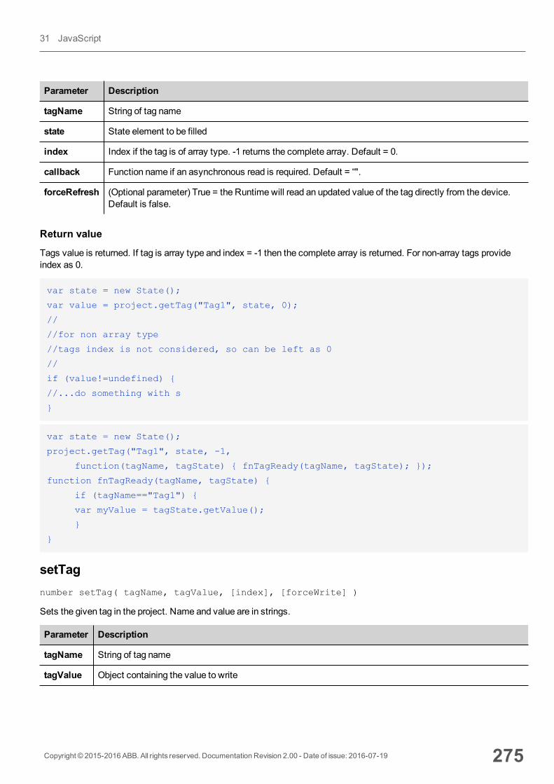
Parameter Description
tagName String of tag name
state State element to be filled
index Index if the tag is of array type. -1 returns the complete array. Default = 0.
callback Function name if an asynchronous read is required. Default = “".
forceRefresh (Optional parameter) True = the Runtime will read an updated value of the tag directly from the device.Default is false.
Return value
Tags value is returned. If tag is array type and index = -1 then the complete array is returned. For non-array tags provideindex as 0.
var state = new State();
var value = project.getTag("Tag1", state, 0);
//
//for non array type
//tags index is not considered, so can be left as 0
//
if (value!=undefined) {
//...do something with s
}
var state = new State();
project.getTag("Tag1", state, -1,
function(tagName, tagState) { fnTagReady(tagName, tagState); });
function fnTagReady(tagName, tagState) {
if (tagName=="Tag1") {
var myValue = tagState.getValue();
}
}
setTagnumber setTag( tagName, tagValue, [index], [forceWrite] )
Sets the given tag in the project. Name and value are in strings.
Parameter Description
tagName String of tag name
tagValue Object containing the value to write
Copyright © 2015-2016 ABB. All rights reserved. Documentation Revision 2.00 - Date of issue: 2016-07-19 275
31 JavaScript
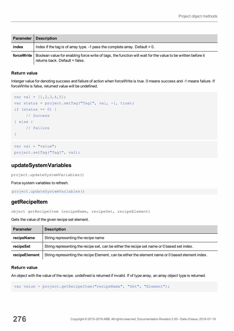
Parameter Description
index Index if the tag is of array type. -1 pass the complete array. Default = 0.
forceWrite Boolean value for enabling force write of tags, the function will wait for the value to be written before itreturns back. Default = false.
Return value
Interger value for denoting success and failure of action when forceWrite is true. 0means success and -1means failure. IfforceWrite is false, returned value will be undefined.
var val = [1,2,3,4,5];
var status = project.setTag("Tag1", val, -1, true);
if (status == 0) {
// Success
} else {
// Failure
}
var val = "value";
project.setTag("Tag1", val);
updateSystemVariablesproject.updateSystemVariables()
Force system variables to refresh.
project.updateSystemVariables()
getRecipeItemobject getRecipeItem (recipeName, recipeSet, recipeElement)
Gets the value of the given recipe set element.
Parameter Description
recipeName String representing the recipe name
recipeSet String representing the recipe set, can be either the recipe set name or 0 based set index.
recipeElement String representing the recipe Element, can be either the element name or 0 based element index.
Return value
An object with the value of the recipe. undefined is returned if invalid. If of type array, an array object type is returned.
var value = project.getRecipeItem("recipeName", "Set", "Element");
276 Copyright © 2015-2016 ABB. All rights reserved. Documentation Revision 2.00 - Date of issue: 2016-07-19
Project object methods

setRecipeItemnumber setRecipeItem (recipeName, recipeSet, recipeElement, value )
Gets the value of the given recipe set element.
Parameter Description
recipeName String representing the recipe name
recipeSet String representing the recipe set, can be either the recipe set name or 0 based set index.
recipeElement String representing the recipe Element, can be either the element name or 0 based element index.
value An object containing the value to store in the recipe. It can be an array type.
Return value
Interger value for denoting success and failure of action. A ‘0’ means success and ‘-1’ means failure.
var val = [2,3,4];
project.setRecipeItem("recipeName", "Set", "Element", val);
if (status == 0) {
// Success
} else {
// Failure
}
downloadRecipevoid downloadRecipe (recipeName, recipeSet )
Downloads the recipe set to the corresponding tag.
Parameter Description
recipeName String representing the recipe name
recipeSet String representing the recipe set, can be either the recipe set name or 0 based set index.
project.downloadRecipe("recipeName", "Set");
uploadRecipevoid uploadRecipe (recipeName, recipeSet )
Uploads the value of tags into the provided recipe set.
Parameter Description
recipeName String representing the recipe name
recipeSet String representing the recipe set, can be either the recipe set name or 0 based set index.
Copyright © 2015-2016 ABB. All rights reserved. Documentation Revision 2.00 - Date of issue: 2016-07-19 277
31 JavaScript
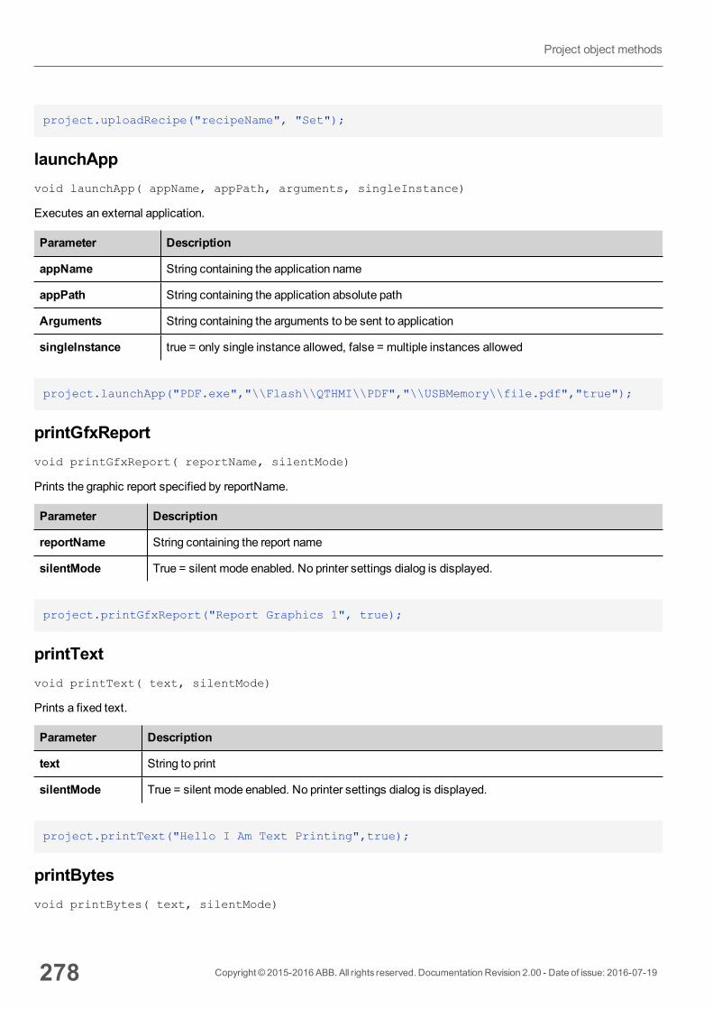
project.uploadRecipe("recipeName", "Set");
launchAppvoid launchApp( appName, appPath, arguments, singleInstance)
Executes an external application.
Parameter Description
appName String containing the application name
appPath String containing the application absolute path
Arguments String containing the arguments to be sent to application
singleInstance true = only single instance allowed, false = multiple instances allowed
project.launchApp("PDF.exe","\\Flash\\QTHMI\\PDF","\\USBMemory\\file.pdf","true");
printGfxReportvoid printGfxReport( reportName, silentMode)
Prints the graphic report specified by reportName.
Parameter Description
reportName String containing the report name
silentMode True = silent mode enabled. No printer settings dialog is displayed.
project.printGfxReport("Report Graphics 1", true);
printTextvoid printText( text, silentMode)
Prints a fixed text.
Parameter Description
text String to print
silentMode True = silent mode enabled. No printer settings dialog is displayed.
project.printText("Hello I Am Text Printing",true);
printBytesvoid printBytes( text, silentMode)
278 Copyright © 2015-2016 ABB. All rights reserved. Documentation Revision 2.00 - Date of issue: 2016-07-19
Project object methods
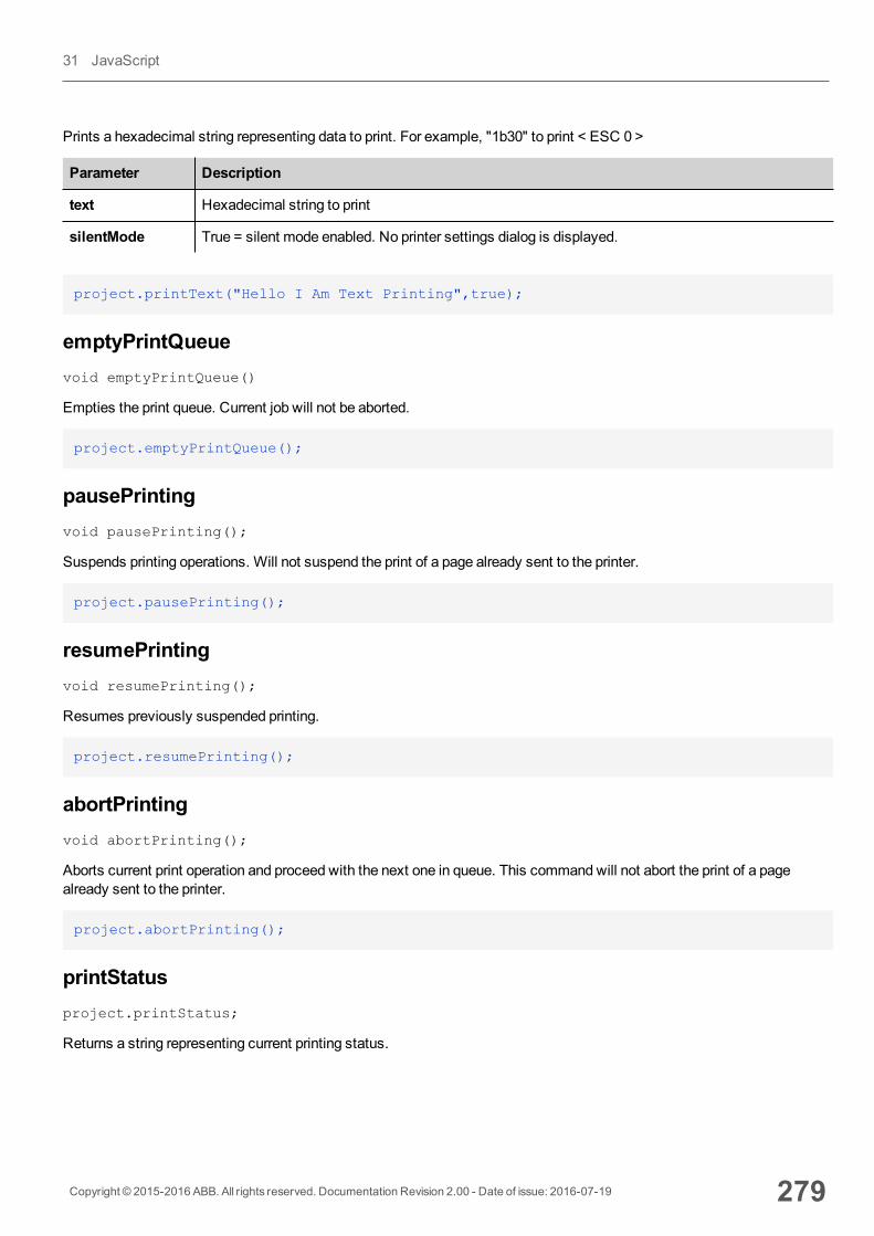
Prints a hexadecimal string representing data to print. For example, "1b30" to print < ESC 0 >
Parameter Description
text Hexadecimal string to print
silentMode True = silent mode enabled. No printer settings dialog is displayed.
project.printText("Hello I Am Text Printing",true);
emptyPrintQueuevoid emptyPrintQueue()
Empties the print queue. Current job will not be aborted.
project.emptyPrintQueue();
pausePrintingvoid pausePrinting();
Suspends printing operations. Will not suspend the print of a page already sent to the printer.
project.pausePrinting();
resumePrintingvoid resumePrinting();
Resumes previously suspended printing.
project.resumePrinting();
abortPrintingvoid abortPrinting();
Aborts current print operation and proceed with the next one in queue. This commandwill not abort the print of a pagealready sent to the printer.
project.abortPrinting();
printStatusproject.printStatus;
Returns a string representing current printing status.
Copyright © 2015-2016 ABB. All rights reserved. Documentation Revision 2.00 - Date of issue: 2016-07-19 279
31 JavaScript
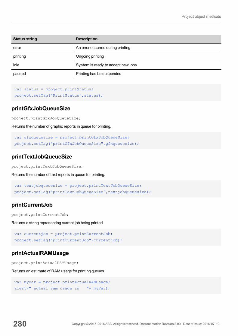
Status string Description
error An error occurred during printing
printing Ongoing printing
idle System is ready to accept new jobs
paused Printing has be suspended
var status = project.printStatus;
project.setTag("PrintStatus",status);
printGfxJobQueueSizeproject.printGfxJobQueueSize;
Returns the number of graphic reports in queue for printing.
var gfxqueuesize = project.printGfxJobQueueSize;
project.setTag("printGfxJobQueueSize",gfxqueuesize);
printTextJobQueueSizeproject.printTextJobQueueSize;
Returns the number of text reports in queue for printing.
var textjobqueuesize = project.printTextJobQueueSize;
project.setTag("printTextJobQueueSize",textjobqueuesize);
printCurrentJobproject.printCurrentJob;
Returns a string representing current job being printed
var currentjob = project.printCurrentJob;
project.setTag("printCurrentJob",currentjob);
printActualRAMUsageproject.printActualRAMUsage;
Returns an estimate of RAM usage for printing queues
var myVar = project.printActualRAMUsage;
alert(" actual ram usage is "+ myVar);
280 Copyright © 2015-2016 ABB. All rights reserved. Documentation Revision 2.00 - Date of issue: 2016-07-19
Project object methods

printRAMQuotaproject.printRAMQuota;
Returns themaximum allowed RAM usage for printing queues
var ramquota = project.printRAMQuota;
project.setTag("printRAMQuota",ramquota);
printActualDiskUsageproject.printActualDiskUsage;
Returns the spool folder disk usage (for PDF printouts)
var myVar1 = project.printActualDiskUsage;
alert(" actual disk usage is "+ myVar1);
printDiskQuotaproject.printDiskQuota;
Returns themaximum allowed size of spool folder (for PDF printouts).
var ramquota = project.printRAMQuota;
var diskquota = project.printDiskQuota;
printSpoolFolderproject.printSpoolFolder;
Returns current spool folder path (for PDF printouts).
var spoolfolder = project.printSpoolFolder;
project.setTag("printSpoolFolder",spoolfolder);
printPercentageproject.printPercentage;
Returns current job completion percentage (meaningful only for multipage graphic reports)
var percentage = project.printPercentage;
project.setTag("printPercentage",percentage);
State objectThis is the class holding the state of a tag acquired from the controlled environment.
Copyright © 2015-2016 ABB. All rights reserved. Documentation Revision 2.00 - Date of issue: 2016-07-19 281
31 JavaScript
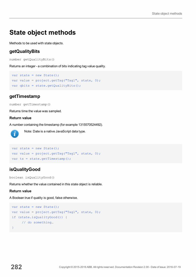
State object methodsMethods to be used with state objects.
getQualityBitsnumber getQualityBits()
Returns an integer - a combination of bits indicating tag value quality.
var state = new State();
var value = project.getTag("Tag1", state, 0);
var qbits = state.getQualityBits();
getTimestampnumber getTimestamp()
Returns time the value was sampled.
Return value
A number containing the timestamp (for example 1315570524492).
Note: Date is a native JavaScript data type.
var state = new State();
var value = project.getTag("Tag1", state, 0);
var ts = state.getTimestamp();
isQualityGoodboolean isQualityGood()
Returns whether the value contained in this state object is reliable.
Return value
A Boolean true if quality is good, false otherwise.
var state = new State();
var value = project.getTag("Tag1", state, 0);
if (state.isQualityGood()) {
// do something…
}
282 Copyright © 2015-2016 ABB. All rights reserved. Documentation Revision 2.00 - Date of issue: 2016-07-19
State object methods
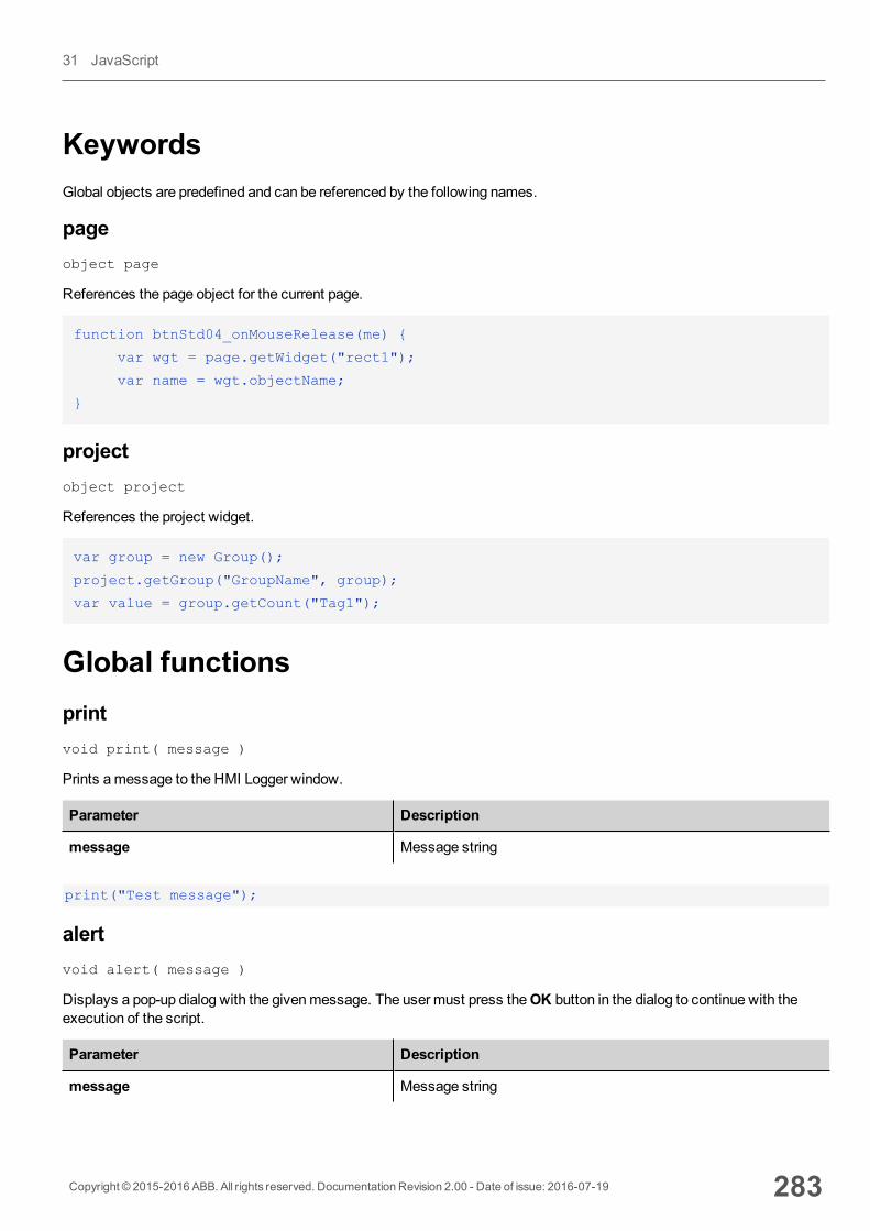
KeywordsGlobal objects are predefined and can be referenced by the following names.
pageobject page
References the page object for the current page.
function btnStd04_onMouseRelease(me) {
var wgt = page.getWidget("rect1");
var name = wgt.objectName;
}
projectobject project
References the project widget.
var group = new Group();
project.getGroup("GroupName", group);
var value = group.getCount("Tag1");
Global functionsprintvoid print( message )
Prints amessage to the HMI Logger window.
Parameter Description
message Message string
print("Test message");
alertvoid alert( message )
Displays a pop-up dialog with the givenmessage. The user must press theOK button in the dialog to continue with theexecution of the script.
Parameter Description
message Message string
Copyright © 2015-2016 ABB. All rights reserved. Documentation Revision 2.00 - Date of issue: 2016-07-19 283
31 JavaScript
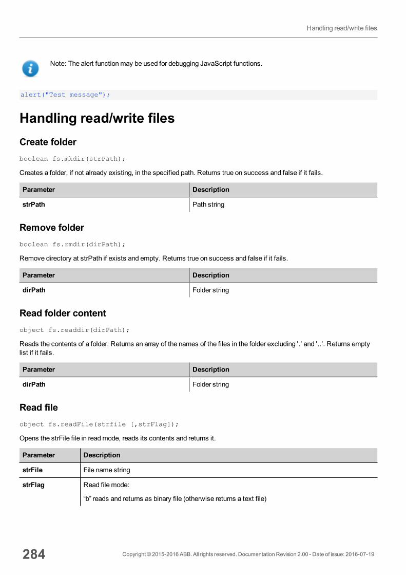
Note: The alert functionmay be used for debugging JavaScript functions.
alert("Test message");
Handling read/write filesCreate folderboolean fs.mkdir(strPath);
Creates a folder, if not already existing, in the specified path. Returns true on success and false if it fails.
Parameter Description
strPath Path string
Remove folderboolean fs.rmdir(dirPath);
Remove directory at strPath if exists and empty. Returns true on success and false if it fails.
Parameter Description
dirPath Folder string
Read folder contentobject fs.readdir(dirPath);
Reads the contents of a folder. Returns an array of the names of the files in the folder excluding '.' and '..'. Returns emptylist if it fails.
Parameter Description
dirPath Folder string
Read fileobject fs.readFile(strfile [,strFlag]);
Opens the strFile file in readmode, reads its contents and returns it.
Parameter Description
strFile File name string
strFlag Read file mode:
“b” reads and returns as binary file (otherwise returns a text file)
284 Copyright © 2015-2016 ABB. All rights reserved. Documentation Revision 2.00 - Date of issue: 2016-07-19
Handling read/write files
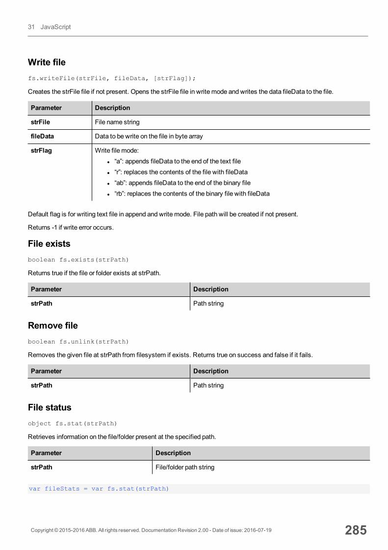
Write filefs.writeFile(strFile, fileData, [strFlag]);
Creates the strFile file if not present. Opens the strFile file in write mode and writes the data fileData to the file.
Parameter Description
strFile File name string
fileData Data to be write on the file in byte array
strFlag Write file mode:l “a”: appends fileData to the end of the text filel “r”: replaces the contents of the file with fileDatal “ab”: appends fileData to the end of the binary filel “rb”: replaces the contents of the binary file with fileData
Default flag is for writing text file in append and write mode. File path will be created if not present.
Returns -1 if write error occurs.
File existsboolean fs.exists(strPath)
Returns true if the file or folder exists at strPath.
Parameter Description
strPath Path string
Remove fileboolean fs.unlink(strPath)
Removes the given file at strPath from filesystem if exists. Returns true on success and false if it fails.
Parameter Description
strPath Path string
File statusobject fs.stat(strPath)
Retrieves information on the file/folder present at the specified path.
Parameter Description
strPath File/folder path string
var fileStats = var fs.stat(strPath)
Copyright © 2015-2016 ABB. All rights reserved. Documentation Revision 2.00 - Date of issue: 2016-07-19 285
31 JavaScript
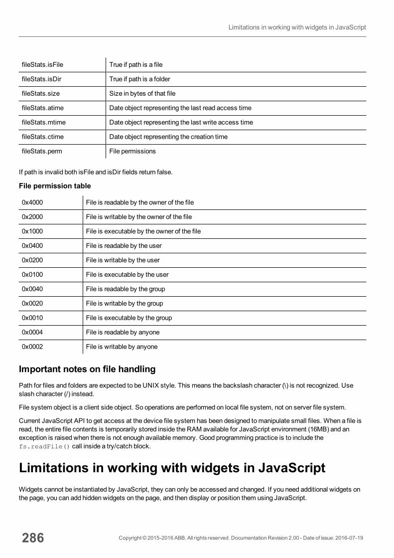
fileStats.isFile True if path is a file
fileStats.isDir True if path is a folder
fileStats.size Size in bytes of that file
fileStats.atime Date object representing the last read access time
fileStats.mtime Date object representing the last write access time
fileStats.ctime Date object representing the creation time
fileStats.perm File permissions
If path is invalid both isFile and isDir fields return false.
File permission table
0x4000 File is readable by the owner of the file
0x2000 File is writable by the owner of the file
0x1000 File is executable by the owner of the file
0x0400 File is readable by the user
0x0200 File is writable by the user
0x0100 File is executable by the user
0x0040 File is readable by the group
0x0020 File is writable by the group
0x0010 File is executable by the group
0x0004 File is readable by anyone
0x0002 File is writable by anyone
Important notes on file handlingPath for files and folders are expected to be UNIX style. This means the backslash character (\) is not recognized. Useslash character (/) instead.
File system object is a client side object. So operations are performed on local file system, not on server file system.
Current JavaScript API to get access at the device file system has been designed tomanipulate small files. When a file isread, the entire file contents is temporarily stored inside the RAM available for JavaScript environment (16MB) and anexception is raised when there is not enough available memory. Good programming practice is to include thefs.readFile() call inside a try/catch block.
Limitations in working with widgets in JavaScriptWidgets cannot be instantiated by JavaScript, they can only be accessed and changed. If you need additional widgets onthe page, you can add hidden widgets on the page, and then display or position them using JavaScript.
286 Copyright © 2015-2016 ABB. All rights reserved. Documentation Revision 2.00 - Date of issue: 2016-07-19
Limitations in working with widgets in JavaScript
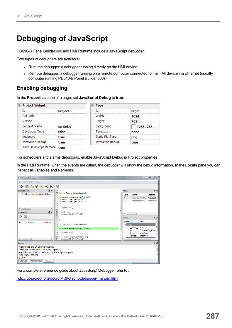
Debugging of JavaScriptPB610-B Panel Builder 600 and HMI Runtime include a JavaScript debugger.
Two types of debuggers are available:
l Runtime debugger: a debugger running directly on the HMI devicel Remote debugger: a debugger running on a remote computer connected to the HMI device via Ethernet (usuallycomputer running PB610-B Panel Builder 600)
Enabling debuggingIn theProperties pane of a page, set JavaScript Debug to true.
For schedulers and alarms debugging, enable JavaScript Debug in Project properties.
In the HMI Runtime, when the events are called, the debugger will show the debug information. In the Locals pane you caninspect all variables and elements.
For a complete reference guide about JavaScript Debugger refer to :
http://qt-project.org/doc/qt-4.8/qtscriptdebugger-manual.html
Copyright © 2015-2016 ABB. All rights reserved. Documentation Revision 2.00 - Date of issue: 2016-07-19 287
31 JavaScript
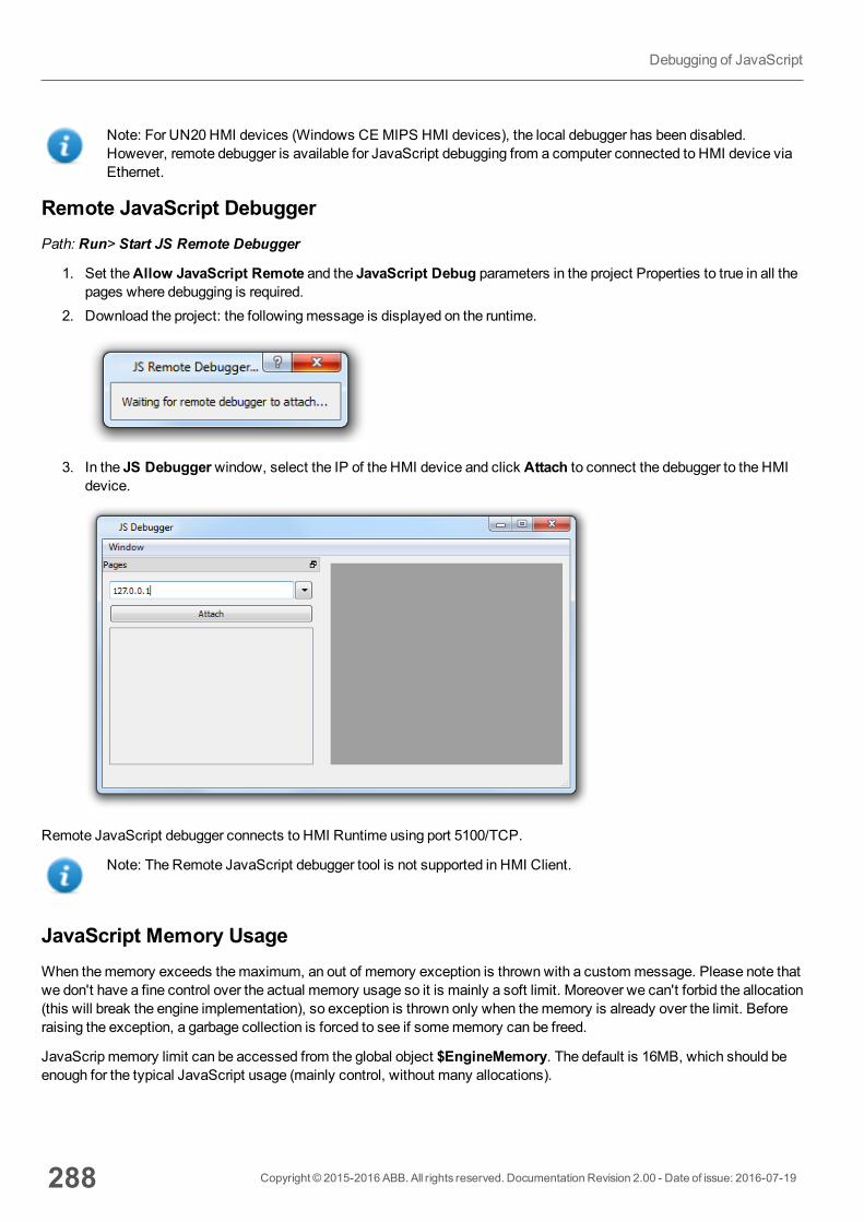
Note: For UN20HMI devices (Windows CE MIPS HMI devices), the local debugger has been disabled.However, remote debugger is available for JavaScript debugging from a computer connected to HMI device viaEthernet.
Remote JavaScript DebuggerPath: Run> Start JS Remote Debugger
1. Set theAllow JavaScript Remote and the JavaScript Debug parameters in the project Properties to true in all thepages where debugging is required.
2. Download the project: the followingmessage is displayed on the runtime.
3. In the JS Debuggerwindow, select the IP of the HMI device and click Attach to connect the debugger to the HMIdevice.
Remote JavaScript debugger connects to HMI Runtime using port 5100/TCP.
Note: The Remote JavaScript debugger tool is not supported in HMI Client.
JavaScript Memory UsageWhen thememory exceeds themaximum, an out of memory exception is thrownwith a custommessage. Please note thatwe don't have a fine control over the actual memory usage so it is mainly a soft limit. Moreover we can't forbid the allocation(this will break the engine implementation), so exception is thrown only when thememory is already over the limit. Beforeraising the exception, a garbage collection is forced to see if somememory can be freed.
JavaScrip memory limit can be accessed from the global object $EngineMemory. The default is 16MB, which should beenough for the typical JavaScript usage (mainly control, without many allocations).
288 Copyright © 2015-2016 ABB. All rights reserved. Documentation Revision 2.00 - Date of issue: 2016-07-19
Debugging of JavaScript
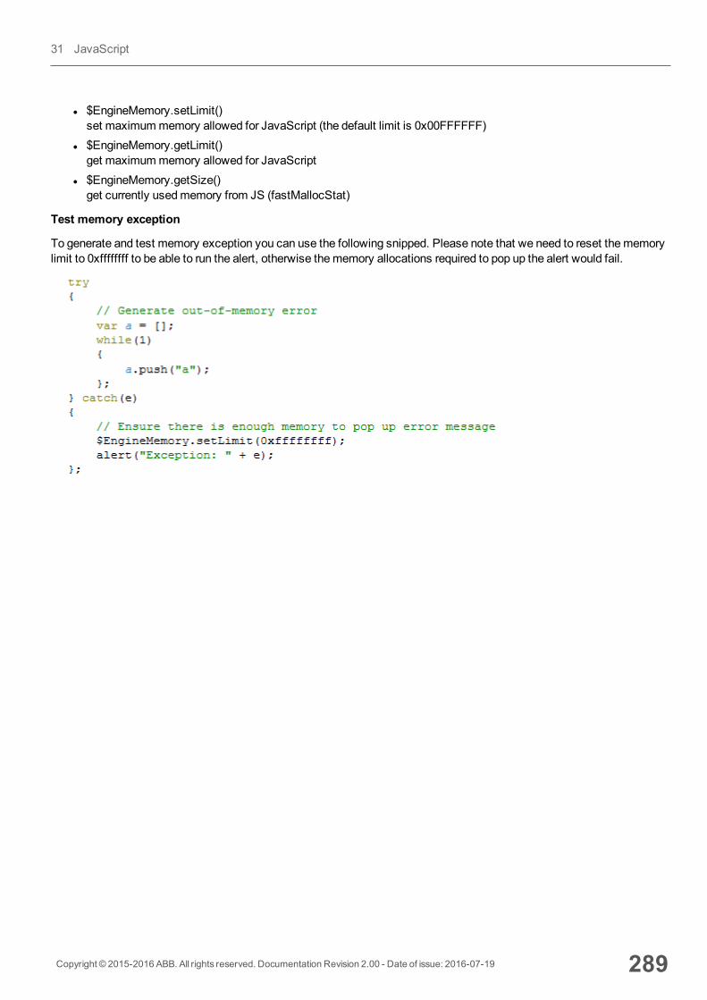
l $EngineMemory.setLimit()set maximummemory allowed for JavaScript (the default limit is 0x00FFFFFF)
l $EngineMemory.getLimit()get maximummemory allowed for JavaScript
l $EngineMemory.getSize()get currently usedmemory from JS (fastMallocStat)
Test memory exception
To generate and test memory exception you can use the following snipped. Please note that we need to reset thememorylimit to 0xffffffff to be able to run the alert, otherwise thememory allocations required to pop up the alert would fail.
Copyright © 2015-2016 ABB. All rights reserved. Documentation Revision 2.00 - Date of issue: 2016-07-19 289
31 JavaScript

290 Copyright © 2015-2016 ABB. All rights reserved. Documentation Revision 2.00 - Date of issue: 2016-07-19
Debugging of JavaScript
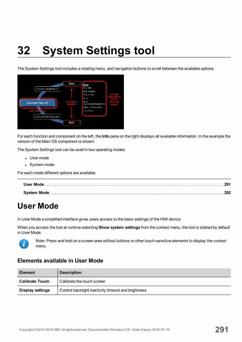
32 System Settings toolThe System Settings tool includes a rotatingmenu, and navigation buttons to scroll between the available options.
For each function and component on the left, the Info pane on the right displays all available information. In the example theversion of theMain OS component is shown.
The System Settings tool can be used in two operatingmodes:
l Usermodel Systemmode.
For eachmode different options are available.
User Mode 291
System Mode 292
User ModeIn User Mode a simplified interface gives users access to the basic settings of the HMI device.
When you access the tool at runtime selectingShow system settings from the context menu, the tool is started by defaultin User Mode.
Note: Press and hold on a screen area without buttons or other touch sensitive elements to display the contextmenu.
Elements available in User Mode
Element Description
Calibrate Touch Calibrate the touch screen
Display settings Control backlight inactivity timeout and brightness
Copyright © 2015-2016 ABB. All rights reserved. Documentation Revision 2.00 - Date of issue: 2016-07-19 291
Element Description
Time Set HMI device date and timemanually or configure NTP servers
Regional Settings Select or customize the regional setting parameters
BSP Settings Display operating system version and unit operating timers to control buzzer and battery led.
Network Sets IP address and other network settings
Plug-in List List the plug-in modules installed and recognized by the system.
Note: this optionmay not be supported by all platforms and all versions.
Close Closes the system setting page
Restart Restart the HMI device
System ModeIn SystemMode a full interface gives users access to all the tool's options.
A special procedure is required to start the tool in SystemMode, or when the standard access procedure cannot be used forsome reason. Once activated by this special procedure, the System Settings tool always starts in SystemMode.
To access SystemMode:
l Execute a tap sequence on the touch screen during the power-up phase. A tap sequence is a high frequencysequence of touch activations executed immediately after the device has been powered.
l From the System Setting page, restart the panel in Configuration OS mode
Elements available in System ModeIn addition to those available in User Mode, the following features are also available:
Element Description
Format Flash Formats the internal device flash disk. All projects and the HMI Runtime will beerased, returning the device to its factory settings.
Restore Factory Settings Restores factory settings as an alternative to Format Flash, in amore flexibleway. The following options are available:
Uninstall HMI: removes the HMI Runtime (entire qthmi folder) at the next startthe device will behave as a brand new unit. This command does not reset settingssuch as IP address, brightness or RTC.
Clear System Settings: resets system parameters (registry settings) anddeletes the following files:
\\Flash\\Documents and Settings\\system.hv
\\Flash\\Documents and Settings\\default\\user.hv
292 Copyright © 2015-2016 ABB. All rights reserved. Documentation Revision 2.00 - Date of issue: 2016-07-19
SystemMode
Element Description
\\Flash\\Documents and Settings\\default.mky
\\Flash\\Documents and Settings\\default.vol
SystemMode password is also reset.
Clear Controller Application: clears current folders used by CODESYS V2.3and CODESYS V3 internal controllers for applications:
l \Flash\QtHmi\RTS\APP\*.*l \Flash\QtHmi\RTS\VISU\*.*l \Flash\QtHmi\codesys\*l \Flash\$SysData$\codesys\*
Clear sysdata settings: clears \Flash\$SysData$ folder
Service call: To be used only by technical support to fix displayproblems.
Note: Not all these options are available for all HMI devices and BSPs.
Resize Image Area Resizes the flashmemory reserved to store the splash screen image displayed atpower up. Default settings are normally suitable for all units.
Download Configuration OS Checks and upgrades the current version of the operating system used in SystemMode(see "List of upgradable components" on page 296 for details)
Download Main OS Checks and upgrades the current version of themain operating system (see "Listof upgradable components" on page 296 for details)
Download Splash Image Loads a new file for the splash screen image displayed by the unit at power up.
Tip: Update the splash screen image directly from the PB610-B PanelBuilder 600 programming software.
See "Update of system components from the application" on page 297 for details.
Download Bootloader Checks and upgrades the current version of the system boot loader.
Download Main FPGA Checks and upgrades the current version of themain FPGA file. This functionmay not be available for all platforms and versions.
Download Safe FPGA Checks and upgrades the current version of the backup copy of the FPGA file.This functionmay not be available for all platforms and versions.
Copyright © 2015-2016 ABB. All rights reserved. Documentation Revision 2.00 - Date of issue: 2016-07-19 293
32 System Settings tool
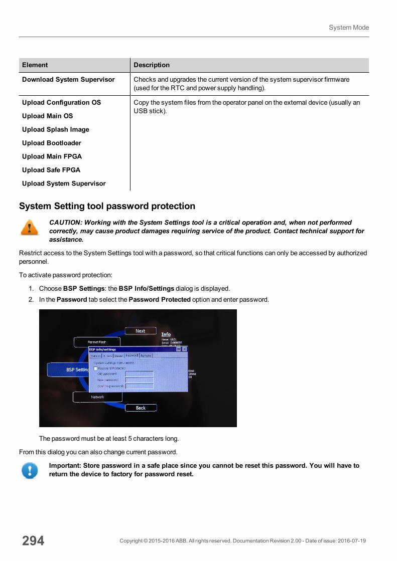
Element Description
Download System Supervisor Checks and upgrades the current version of the system supervisor firmware(used for the RTC and power supply handling).
Upload Configuration OS
Upload Main OS
Upload Splash Image
Upload Bootloader
Upload Main FPGA
Upload Safe FPGA
Upload System Supervisor
Copy the system files from the operator panel on the external device (usually anUSB stick).
System Setting tool password protectionCAUTION: Working with the System Settings tool is a critical operation and, when not performedcorrectly, may cause product damages requiring service of the product. Contact technical support forassistance.
Restrict access to the System Settings tool with a password, so that critical functions can only be accessed by authorizedpersonnel.
To activate password protection:
1. ChooseBSP Settings: theBSP Info/Settings dialog is displayed.2. In thePassword tab select thePassword Protected option and enter password.
The passwordmust be at least 5 characters long.
From this dialog you can also change current password.
Important: Store password in a safe place since you cannot be reset this password. You will have toreturn the device to factory for password reset.
294 Copyright © 2015-2016 ABB. All rights reserved. Documentation Revision 2.00 - Date of issue: 2016-07-19
SystemMode
33 Updating system components inHMI devicesMost of the system software components can be easily upgraded ensuring a high degree of flexibility in providing updatesand fixes to existing and running systems.
New softwaremodules can be uploaded using USB flash drives and following an upload procedure (see "Update systemcomponents via USB" on page 299 for details).
Each HMI device is labeled with a product code including all factory settings (hardware, software and firmwarecomponents). Refer to this label for information on your HMI device. The HMI device update tool also provides detail on thecomponents actually running on the device.
CAUTION: Make sure you use the correct upgrade files, since loading upgrade files unsuitable foryour device will cause serious system malfunction. Always check your device product code.
Note: Upgrade files are distributed upon request as a part of technical support activity.
Service call: Downgrade operations are complex tasks whichmight cause serious damage to your equipment ifnot performed correctly. These operations are reserved to technical support.
Display information on connected devices 296
List of upgradable components 296
Update of system components from the application 297
Update system components via USB 299
Copyright © 2015-2016 ABB. All rights reserved. Documentation Revision 2.00 - Date of issue: 2016-07-19 295
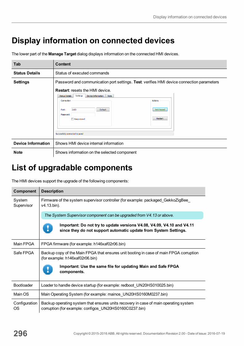
Display information on connected devicesThe lower part of theManage Target dialog displays information on the connected HMI devices.
Tab Content
Status Details Status of executed commands
Settings Password and communication port settings. Test: verifies HMI device connection parameters
Restart: resets the HMI device.
Device Information Shows HMI device internal information
Note Shows information on the selected component
List of upgradable componentsThe HMI devices support the upgrade of the following components:
Component Description
SystemSupervisor
Firmware of the system supervisor controller (for example: packaged_GekkoZigBee_v4.13.bin).
The System Supervisor component can be upgraded from V4.13 or above.
Important: Do not try to update versions V4.08, V4.09, V4.10 and V4.11since they do not support automatic update from System Settings.
Main FPGA FPGA firmware (for example: h146xaf02r06.bin)
Safe FPGA Backup copy of theMain FPGA that ensures unit booting in case of main FPGA corruption(for example: h146xaf02r06.bin)
Important: Use the same file for updating Main and Safe FPGAcomponents.
Bootloader Loader to handle device startup (for example: redboot_UN20HS010025.bin)
Main OS Main Operating System (for example: mainos_UN20HS0160M0237.bin)
ConfigurationOS
Backup operating system that ensures units recovery in case of main operating systemcorruption (for example: configos_UN20HS0160C0237.bin)
296 Copyright © 2015-2016 ABB. All rights reserved. Documentation Revision 2.00 - Date of issue: 2016-07-19
Display information on connected devices
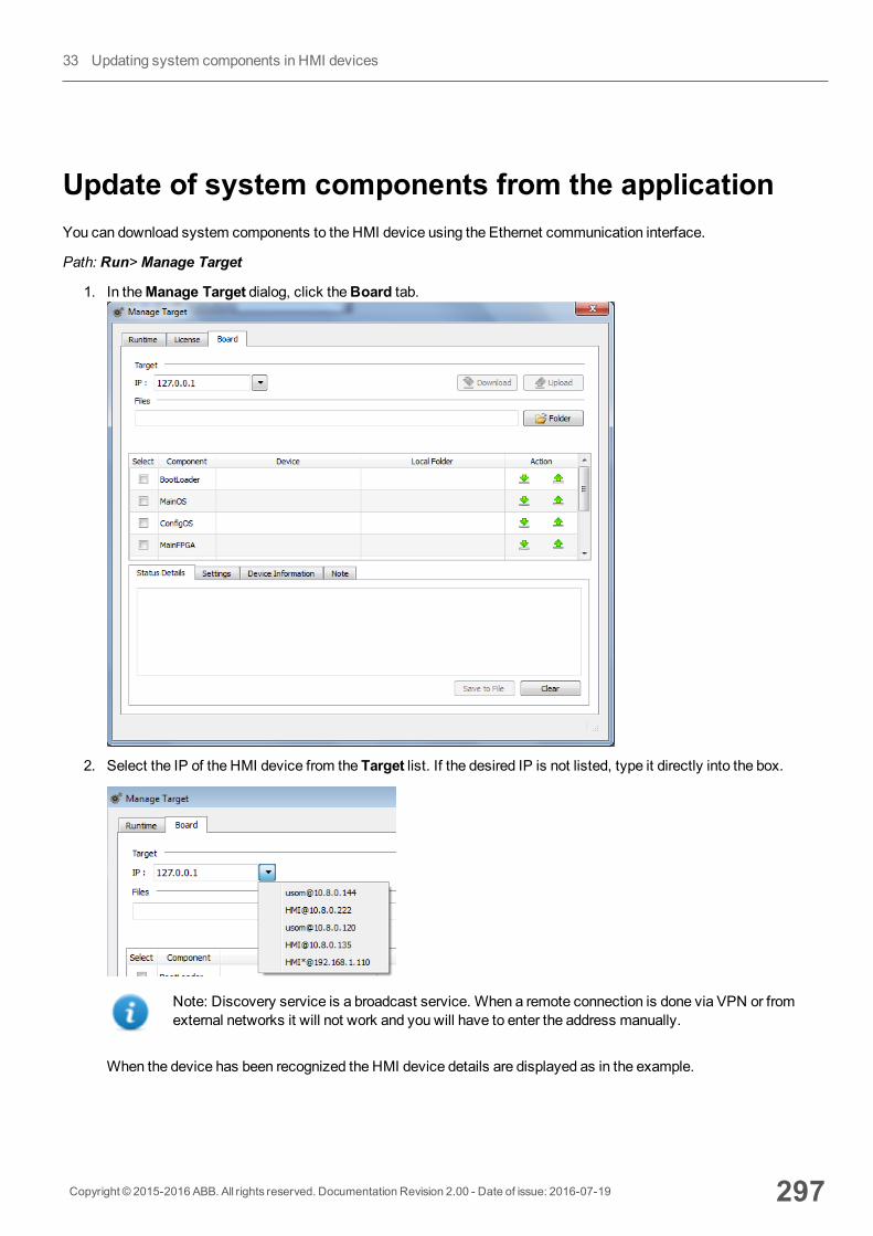
Update of system components from the applicationYou can download system components to the HMI device using the Ethernet communication interface.
Path: Run>Manage Target
1. In theManage Target dialog, click theBoard tab.
2. Select the IP of the HMI device from the Target list. If the desired IP is not listed, type it directly into the box.
Note: Discovery service is a broadcast service. When a remote connection is done via VPN or fromexternal networks it will not work and you will have to enter the address manually.
When the device has been recognized the HMI device details are displayed as in the example.
Copyright © 2015-2016 ABB. All rights reserved. Documentation Revision 2.00 - Date of issue: 2016-07-19 297
33 Updating system components in HMI devices
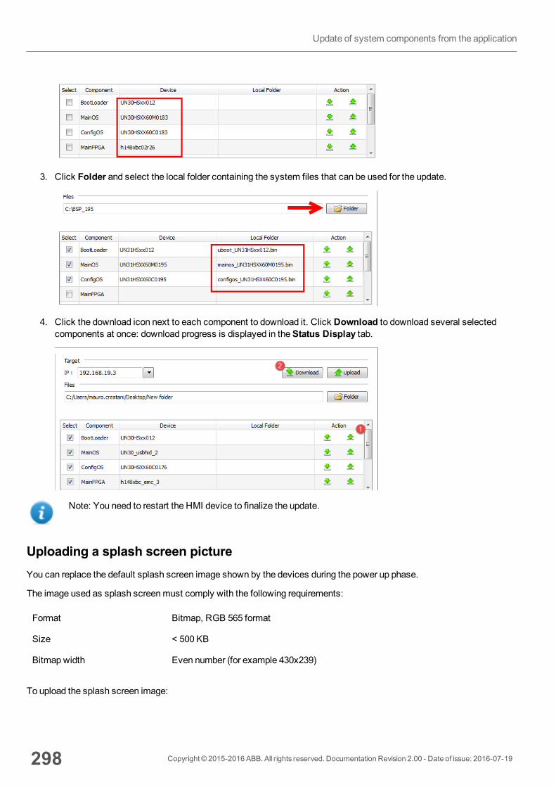
3. Click Folder and select the local folder containing the system files that can be used for the update.
4. Click the download icon next to each component to download it. Click Download to download several selectedcomponents at once: download progress is displayed in theStatus Display tab.
Note: You need to restart the HMI device to finalize the update.
Uploading a splash screen pictureYou can replace the default splash screen image shown by the devices during the power up phase.
The image used as splash screenmust comply with the following requirements:
Format Bitmap, RGB 565 format
Size < 500 KB
Bitmap width Even number (for example 430x239)
To upload the splash screen image:
298 Copyright © 2015-2016 ABB. All rights reserved. Documentation Revision 2.00 - Date of issue: 2016-07-19
Update of system components from the application
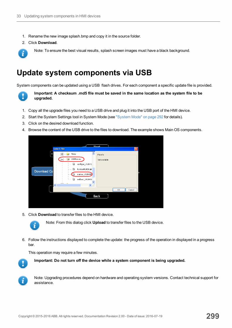
1. Rename the new image splash.bmp and copy it in the source folder.2. Click Download.
Note: To ensure the best visual results, splash screen images must have a black background.
Update system components via USBSystem components can be updated using a USB flash drives. For each component a specific update file is provided.
Important: A checksum .md5 file must be saved in the same location as the system file to beupgraded.
1. Copy all the upgrade files you need to a USB drive and plug it into the USB port of the HMI device.2. Start the System Settings tool in SystemMode (see "SystemMode" on page 292 for details).3. Click on the desired download function.4. Browse the content of the USB drive to the files to download. The example shows Main OS components.
5. Click Download to transfer files to the HMI device.
Note: From this dialog click Upload to transfer files to the USB device.
6. Follow the instructions displayed to complete the update: the progress of the operation in displayed in a progressbar.
This operationmay require a few minutes.
Important: Do not turn off the device while a system component is being upgraded.
Note: Upgrading procedures depend on hardware and operating system versions. Contact technical support forassistance.
Copyright © 2015-2016 ABB. All rights reserved. Documentation Revision 2.00 - Date of issue: 2016-07-19 299
33 Updating system components in HMI devices

300 Copyright © 2015-2016 ABB. All rights reserved. Documentation Revision 2.00 - Date of issue: 2016-07-19
Update system components via USB
34 Protecting access to HMI devicesThe following operations are password protected on the HMI device:
l HMI Runtimemanagement: install HMI Runtime and update HMI Runtimel Boardmanagement: replacemain BSP components such as Main OS, Configuration OS, Bootloader, and so onl Download and upload of project files
A default password is used HMI Runtime and PB610-B Panel Builder 600 to access the HMI device.
If you change your password on the HMI device you will need to change it also PB610-B Panel Builder 600 side.
Changing password 302
Changing password on HMI device 302
Ports and firewalls 303
Copyright © 2015-2016 ABB. All rights reserved. Documentation Revision 2.00 - Date of issue: 2016-07-19 301
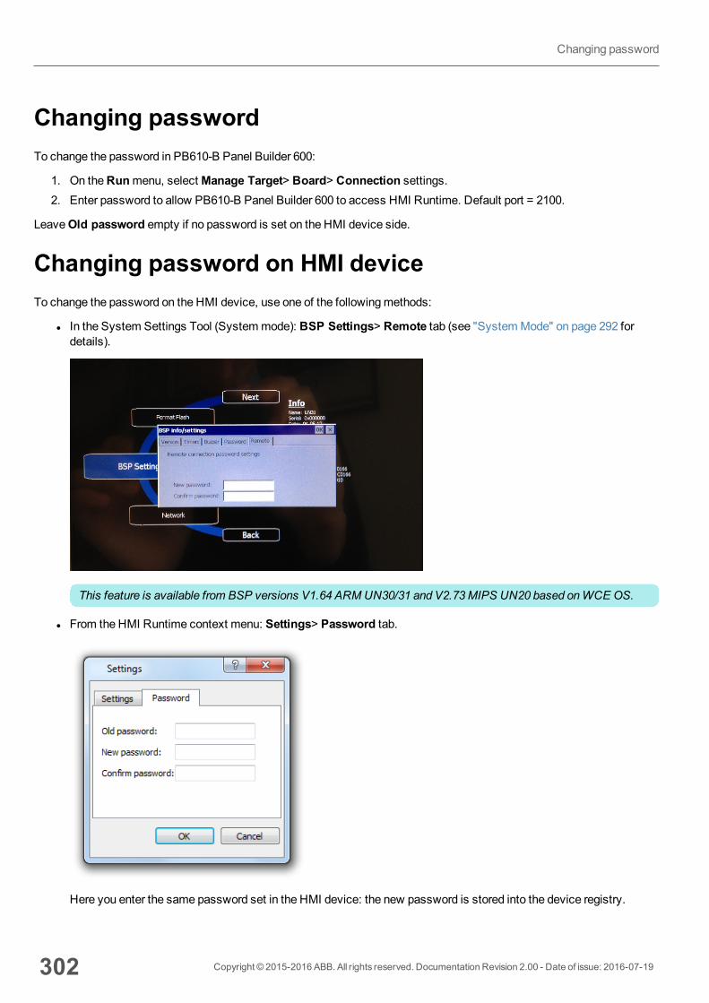
Changing passwordTo change the password in PB610-B Panel Builder 600:
1. On theRunmenu, selectManage Target> Board> Connection settings.2. Enter password to allow PB610-B Panel Builder 600 to access HMI Runtime. Default port = 2100.
LeaveOld password empty if no password is set on the HMI device side.
Changing password on HMI deviceTo change the password on the HMI device, use one of the followingmethods:
l In the System Settings Tool (Systemmode): BSP Settings> Remote tab (see "SystemMode" on page 292 fordetails).
This feature is available from BSP versions V1.64 ARMUN30/31 and V2.73MIPS UN20 based onWCE OS.
l From the HMI Runtime context menu: Settings> Password tab.
Here you enter the same password set in the HMI device: the new password is stored into the device registry.
302 Copyright © 2015-2016 ABB. All rights reserved. Documentation Revision 2.00 - Date of issue: 2016-07-19
Changing password
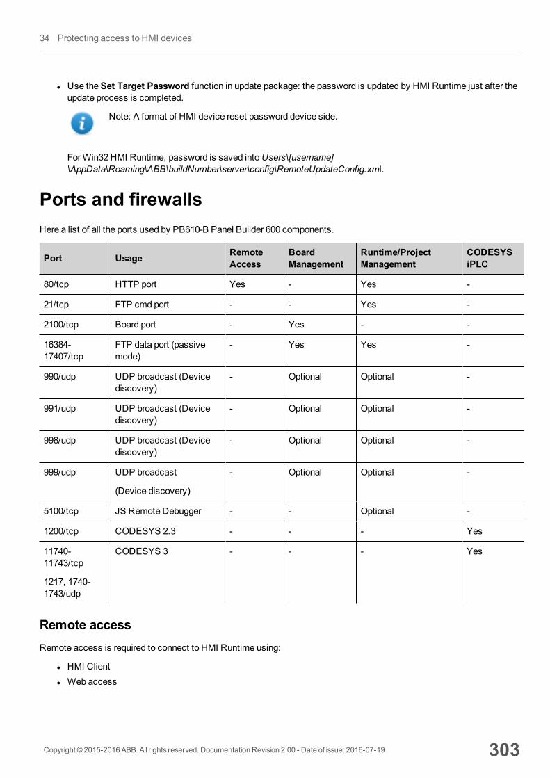
l Use theSet Target Password function in update package: the password is updated by HMI Runtime just after theupdate process is completed.
Note: A format of HMI device reset password device side.
ForWin32 HMI Runtime, password is saved intoUsers\[username]\AppData\Roaming\ABB\buildNumber\server\config\RemoteUpdateConfig.xml.
Ports and firewallsHere a list of all the ports used by PB610-B Panel Builder 600 components.
Port Usage RemoteAccess
BoardManagement
Runtime/ProjectManagement
CODESYSiPLC
80/tcp HTTP port Yes - Yes -
21/tcp FTP cmd port - - Yes -
2100/tcp Board port - Yes - -
16384-17407/tcp
FTP data port (passivemode)
- Yes Yes -
990/udp UDP broadcast (Devicediscovery)
- Optional Optional -
991/udp UDP broadcast (Devicediscovery)
- Optional Optional -
998/udp UDP broadcast (Devicediscovery)
- Optional Optional -
999/udp UDP broadcast
(Device discovery)
- Optional Optional -
5100/tcp JS Remote Debugger - - Optional -
1200/tcp CODESYS 2.3 - - - Yes
11740-11743/tcp
1217, 1740-1743/udp
CODESYS 3 - - - Yes
Remote accessRemote access is required to connect to HMI Runtime using:
l HMI Clientl Web access
Copyright © 2015-2016 ABB. All rights reserved. Documentation Revision 2.00 - Date of issue: 2016-07-19 303
34 Protecting access to HMI devices

Runtime and project management portsYou use these ports to connect to HMI Runtime for operations such as update, installation and project download.
Board management portsYou use these ports to connect to the HMI device for Board operations such as BSP update, splash image download andso on.
Note: When broadcast service is not available, for example in VPN networks, type in the exact IP address toconnect to the HMI device from PB610-B Panel Builder 600.
304 Copyright © 2015-2016 ABB. All rights reserved. Documentation Revision 2.00 - Date of issue: 2016-07-19
Ports and firewalls
35 Factory restoreIf you’re having problems with the HMI device, try and restore factory default settings from SystemMode.
1. EnterSystem Mode.2. Use one of the following operations available in rotatingmenu:
l Format Flash, to clean the flash drive and registry configuration.l Restore Factory Settings, to clean only the select components.
Note: Both operations do not involve firmware factory restore (MainOS, ConfigOS, Bootloader, FPGA images,etc).
See "SystemMode" on page 292 for details.
Copyright © 2015-2016 ABB. All rights reserved. Documentation Revision 2.00 - Date of issue: 2016-07-19 305

306 Copyright © 2015-2016 ABB. All rights reserved. Documentation Revision 2.00 - Date of issue: 2016-07-19
36 Tips and tricks to improveperformancePB610-B Panel Builder 600 allows great flexibility for a project designers.
Follow these guidelines to create projects that perform better in terms of boot time, page change and animations.
Static Optimization 308
FAQ on Static Optimization 311
Page caching 312
Image DB 312
Precaching 312
FAQ on precaching 312
Copyright © 2015-2016 ABB. All rights reserved. Documentation Revision 2.00 - Date of issue: 2016-07-19 307
Static OptimizationStatic optimization is a technique used in PB610-B Panel Builder 600 to improve run-time performance.
Using a lot of images and pictures in a project might degrade performances, static optimizationmerges several images intoa single background image thus reducing rendering and loading times. Using this method only one raster image needs to beloaded and rendered instead of many single raster and/or vector images.
When you create a project in PB610-B Panel Builder 600, the pages might contain widgets such as texts, images,background images, background colors and so on which can be classified as:
l Static: values or properties do not change at run time.l Dynamic: values or properties change at run time.
Note: Based on security settings, static parts of widgets could be not merged to background. This happenswhen a widget is configured as “hide” in security settings.
Important: When you change the properties of widgets with JavaScript set the widget StaticOptimization to Dynamic, otherwise changes to properties will be ignored.
When downloading or validating a project, PB610-B Panel Builder 600 identifies static components and renders them asbackground images to .png files. These background images are saved as a part of the project under the folder /opt.
Background images can be created as follows:
l full page background images, containing all widgets merged to page backgroundl group background images, containing a group of static widgets merged together to form a group background. Forexample, the Gauge group is normally composed by a background, a scale, a label and a needle, where backgroundscale and label can all bemerged to a single background image.
TheStatic Optimization page attribute enables and disables static optimization of the whole page. If it is set to false theoptimization is totally disabled.
Finer control can be achieved setting theStatic Optimization attribute of each single widget as follows:
l Normal: PB610-B Panel Builder 600 automatically detects if the widget can bemerged with the background. Thiscan be used if the widget is not a dynamic widget and does not overlap, that is it is not stacked above, a dynamicwidget.
l Static: The image is forced to bemerged with the background. This can be used when the static widget overlaps adynamic transparent widget.
Note: In this case the automatic optimization will fail because it does not make any assumption on invisibleareas whichmight be rendered at run time.
l Dynamic: The widget is not optimized at all. Use this flag when a static widget needs to be changed by Javascript.
308 Copyright © 2015-2016 ABB. All rights reserved. Documentation Revision 2.00 - Date of issue: 2016-07-19
Static Optimization

Tips for best performance1. First of all: avoid placing static widgets over a dynamic widget. The overlapping area is computed considering the
bounding rectangles of the widgets, that is the rectangles delimited by editing handles.
2. Don’t use static optimization if your pages contain almost only dynamic objects. Static optimization would savemany almost identical full size images for each page using up a lot of memory space that could bemore effectivelyused to improve project performance with other techniques (such as, for example, page caching).
3. Bounding rectangles can include transparent areas, minimize transparent areas (for example splitting the image inmultiple images) since they can be a waste of resources even when optimized.
4. Optimize image size. The image will be rendered at the size of the image widget containing the image. For bestperformances the widget needs to be the same size of the image.
5. Avoid usingScale to fit for image widgets, since this forces a rescaling at run time for dynamic images and “hides”the actual image size during editing.
6. UseSize to fit to make the widget to the real size of his contents.7. If overlapping cannot be avoidedmake sure to place the static widgets in the back, that is behind the dynamic
widget.8. Choose the image file format based on the HMI device you are connecting to.
Copyright © 2015-2016 ABB. All rights reserved. Documentation Revision 2.00 - Date of issue: 2016-07-19 309
36 Tips and tricks to improve performance
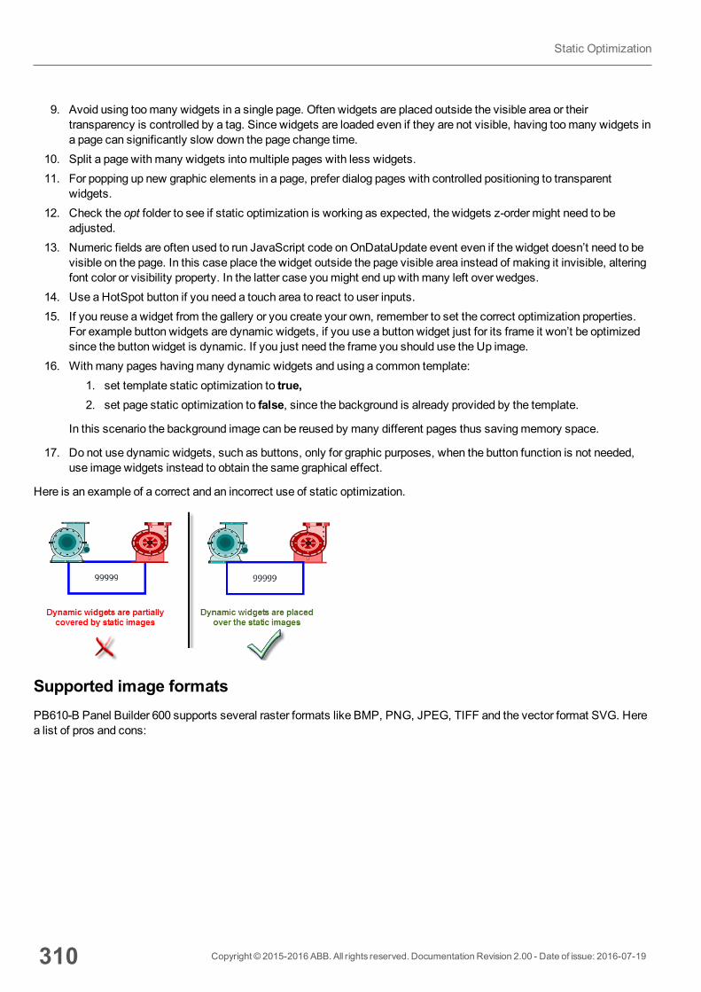
9. Avoid using toomany widgets in a single page. Often widgets are placed outside the visible area or theirtransparency is controlled by a tag. Since widgets are loaded even if they are not visible, having toomany widgets ina page can significantly slow down the page change time.
10. Split a page with many widgets into multiple pages with less widgets.11. For popping up new graphic elements in a page, prefer dialog pages with controlled positioning to transparent
widgets.12. Check the opt folder to see if static optimization is working as expected, the widgets z-order might need to be
adjusted.13. Numeric fields are often used to run JavaScript code onOnDataUpdate event even if the widget doesn’t need to be
visible on the page. In this case place the widget outside the page visible area instead of making it invisible, alteringfont color or visibility property. In the latter case youmight end up with many left over wedges.
14. Use a HotSpot button if you need a touch area to react to user inputs.15. If you reuse a widget from the gallery or you create your own, remember to set the correct optimization properties.
For example button widgets are dynamic widgets, if you use a button widget just for its frame it won’t be optimizedsince the button widget is dynamic. If you just need the frame you should use the Up image.
16. With many pages havingmany dynamic widgets and using a common template:1. set template static optimization to true,2. set page static optimization to false, since the background is already provided by the template.
In this scenario the background image can be reused by many different pages thus savingmemory space.
17. Do not use dynamic widgets, such as buttons, only for graphic purposes, when the button function is not needed,use image widgets instead to obtain the same graphical effect.
Here is an example of a correct and an incorrect use of static optimization.
Supported image formatsPB610-B Panel Builder 600 supports several raster formats like BMP, PNG, JPEG, TIFF and the vector format SVG. Herea list of pros and cons:
310 Copyright © 2015-2016 ABB. All rights reserved. Documentation Revision 2.00 - Date of issue: 2016-07-19
Static Optimization
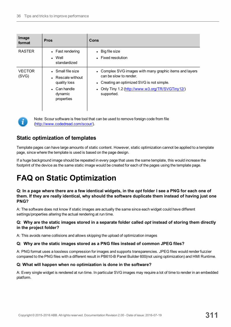
Imageformat Pros Cons
RASTER l Fast renderingl Wellstandardized
l Big file sizel Fixed resolution
VECTOR(SVG)
l Small file sizel Rescale withoutquality loss
l Can handledynamicproperties
l Complex SVG images with many graphic items and layerscan be slow to render.
l Creating an optimized SVG is not simple.l Only Tiny 1.2 (http://www.w3.org/TR/SVGTiny12/)supported.
Note: Scour software is free tool that can be used to remove foreign code from file(http://www.codedread.com/scour/).
Static optimization of templatesTemplate pages can have large amounts of static content. However, static optimization cannot be applied to a templatepage, since where the template is used is based on the page design.
If a huge background image should be repeated in every page that uses the same template, this would increase thefootprint of the device as the same static image would be created for each of the pages using the template page.
FAQ on Static OptimizationQ: In a page where there are a few identical widgets, in the opt folder I see a PNG for each one ofthem. If they are really identical, why should the software duplicate them instead of having just onePNG?
A: The software does not know if static images are actually the same since each widget could have differentsettings/properties altering the actual rendering at run time.
Q: Why are the static images stored in a separate folder called opt instead of storing them directlyin the project folder?
A: This avoids name collisions and allows skipping the upload of optimization images
Q: Why are the static images stored as a PNG files instead of common JPEG files?
A: PNG format uses a lossless compression for images and supports transparencies. JPEG files would render fuzziercompared to the PNG files with a different result in PB610-B Panel Builder 600(not using optimization) and HMI Runtime.
Q: What will happen when no optimization is done in the software?
A: Every single widget is rendered at run time. In particular SVG images may require a lot of time to render in an embeddedplatform.
Copyright © 2015-2016 ABB. All rights reserved. Documentation Revision 2.00 - Date of issue: 2016-07-19 311
36 Tips and tricks to improve performance
Page cachingOnce accessed all pages are kept in a RAM cache up to themaximum allowed cache size depending on the actualplatform’s available RAM. This allows amuch faster access since cached pages, once reloaded, only need to re-paint theircontent without reloading all page resources.
Image DBImage DB is a technique used to track the usage of image files and reduce the cost of image loading by cachingmostfrequently used images (example, Push Button images, Gauge needles, Slider thumbs and so on). The same image used inmany different places is therefore loaded just once.
The image DB function will preload the topmost used images at startup until memory limit is reached. This would furtherimprove the individual page loading times.
The file imagecachelist.xml is created in project/opt folder, containing relevant information:
l Fill color (in case of SVG images)l Size of SVG imagel Number of times an image is used in the projectl Number of different sizes for the same image
Tips for using the Image DB function1. Use uniform size of buttons, gauges and other widgets wherever possible.2. Use same color themes among widgets of the same kind.
PrecachingThe Precache attribute of pages can be used to notify HMI Runtime to preload some pages in RAM at boot time for quickeraccess. Precaching is useful for complex pages havingmany dynamic widgets.
When this function is enabled on a page, access to the page is faster, however it also slows down boot-time since thesystem is not ready until all pages to be precached are not saved into the RAM.
Tips to precaching1. Enable the precache function just for few pages havingmany dynamic widgets or for pages frequently used by
users.2. Do not enable the precache function for all the pages in the project since you would hìruno out of memory and have
no benefit at all.3. Disable static optimization for pages where the precache function is enabled to reducememory used.
FAQ on precachingPage limit for precachingBased on the size and complexity of a page, the space required for precaching can be from 1,5Mb to 3Mb.
312 Copyright © 2015-2016 ABB. All rights reserved. Documentation Revision 2.00 - Date of issue: 2016-07-19
Page caching

When a project is loaded, HMI Runtime proceeds as follows:
1. Page images are preloaded until 76MB of memory space is still available (imageDBLowMem)2. Pages where precache is set to true are preloaded untill 64MB of memory space is still available
(pageCacheLowMemMax). The images of these pages are loaded in the RAM (into the Image DB).
When the project is ready:
1. Any new page visited is saved in the cache (RAM) with all related images until 40MB of memory space is stillavailable(pageCacheLowMemMin)
2. When a page change happens and space in RAM is critical (<40MB), the HMI Runtime starts emptying the cache(RAM) removing pages and related images until 64MB of memory space is made available. HMI Runtime removesdata stored in the cache in the following order:
1. last visited pages and bigger and unused images (>320x240),2. if morememory is needed also the pages in precache and all images loaded in Image DB can be removed.
Copyright © 2015-2016 ABB. All rights reserved. Documentation Revision 2.00 - Date of issue: 2016-07-19 313
36 Tips and tricks to improve performance

314 Copyright © 2015-2016 ABB. All rights reserved. Documentation Revision 2.00 - Date of issue: 2016-07-19
FAQ on precaching
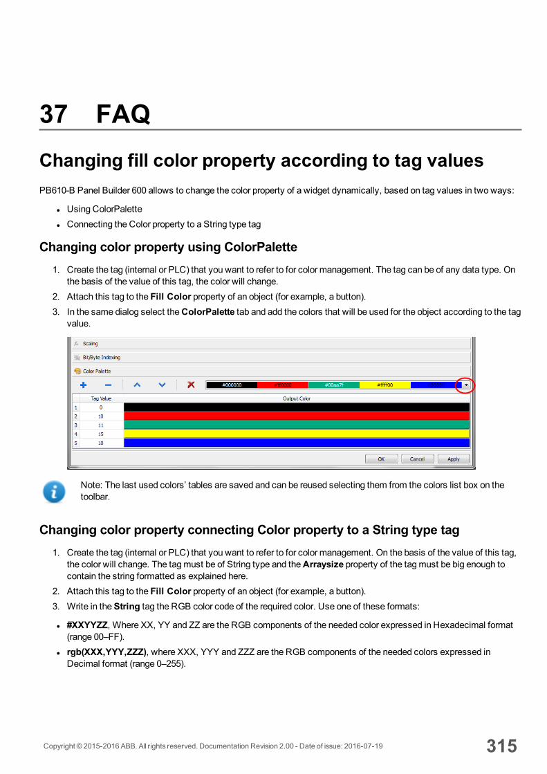
37 FAQChanging fill color property according to tag valuesPB610-B Panel Builder 600 allows to change the color property of a widget dynamically, based on tag values in two ways:
l Using ColorPalettel Connecting the Color property to a String type tag
Changing color property using ColorPalette1. Create the tag (internal or PLC) that you want to refer to for color management. The tag can be of any data type. On
the basis of the value of this tag, the color will change.2. Attach this tag to the Fill Color property of an object (for example, a button). 3. In the same dialog select theColorPalette tab and add the colors that will be used for the object according to the tag
value.
Note: The last used colors’ tables are saved and can be reused selecting them from the colors list box on thetoolbar.
Changing color property connecting Color property to a String type tag 1. Create the tag (internal or PLC) that you want to refer to for color management. On the basis of the value of this tag,
the color will change. The tagmust be of String type and theArraysize property of the tagmust be big enough tocontain the string formatted as explained here.
2. Attach this tag to the Fill Color property of an object (for example, a button). 3. Write in theString tag the RGB color code of the required color. Use one of these formats:
l #XXYYZZ, Where XX, YY and ZZ are the RGB components of the needed color expressed in Hexadecimal format(range 00–FF).
l rgb(XXX,YYY,ZZZ), where XXX, YYY and ZZZ are the RGB components of the needed colors expressed inDecimal format (range 0–255).
Copyright © 2015-2016 ABB. All rights reserved. Documentation Revision 2.00 - Date of issue: 2016-07-19 315

Note: This feature can be applied to all the objects available in theWidget gallery that have a color property. Therun-time change of the color is possible only thanks to the properties of the SVGs that are composing the object.This feature can not be applied to other image formats such as JPEG or BMP files.
316 Copyright © 2015-2016 ABB. All rights reserved. Documentation Revision 2.00 - Date of issue: 2016-07-19
Changing fill color property according to tag values

38 CP600-eCo productsThis section describes CP600-eCoHMI products and includes a description of themain features of this product family.
CP600-eCoHMI products must be programmed using PB610-B Panel Builder 600 V2.00 or higher.
The Runtime loader 318
Limitations 320
Converting projects between different HMI types 323
Copyright © 2015-2016 ABB. All rights reserved. Documentation Revision 2.00 - Date of issue: 2016-07-19 317

The Runtime loaderCP600-eCoHMI devices are delivered from factory without HMI Runtime.
When you power up the device for the first time, the Runtime Loader window is displayed.
System SettingsThe user interface of System Settings is based on HTML pages and can be accessed both locally on the HMI devicescreen and remotely using aWeb browser.
1. Click System Settings to configure system options.2. To access System Settings using aWeb browser, enter the IP address of the device, in the following format:
https://IP/machine_config
Administrator usernamewith full access right is "admin" with default password "admin". Generic username is “user” withdefault password “user”
WARNING: For security reasons, change the default passwords for both usernames (passwords canbe modified from the “System Settings -> Authentication” command)
Note: Remote access requires port 443.
318 Copyright © 2015-2016 ABB. All rights reserved. Documentation Revision 2.00 - Date of issue: 2016-07-19
The Runtime loader

3. Browse through the options available in themenu on the left: the active item is highlighted and related information isdisplayed on the right.
Default security protocols proposed by the HTTPS server in the CP600-eCoHMI device are:
l SSLv3 256 bits ECDHE-RSA-AES256-SHAl TLSv1 256 bits ECDHE-RSA-AES256-SHA
WARNING: We discourage usage of CBC cyber suites in the context of SSL3 or TLSv1.0 connectionssince potentially affected by some vulnerabilities.
See the CP600-eCo Series Operating Instructions manual for detailed information on how to set up system options.
Installing applications1. Click Startup sequence to install/uninstall applications (for example HMI Runtime).2. Click Install to install the application using an update package: the procedure is run automatically.
See "Transferring the project to HMI device" on page 53 for instructions on how to prepare the update package.
If you are using USB drives, the default path is /mnt/usbmemory.
Note: File systems supported are FAT16/32 and Linux Ext2, Ext3 and Ext4.
Uninstalling applicationsSelect one of the applications in the list and click Uninstall to remove it from HMI device.
Note: When uninstalling the runtime, you remove from the system not only the application but also all associateddata such as projects, dynamic data and settings.
To change the order of execution of installed applications, go toBoot Sequence and drag and drop applications to changetheir order.
Copyright © 2015-2016 ABB. All rights reserved. Documentation Revision 2.00 - Date of issue: 2016-07-19 319
38 CP600-eCo products
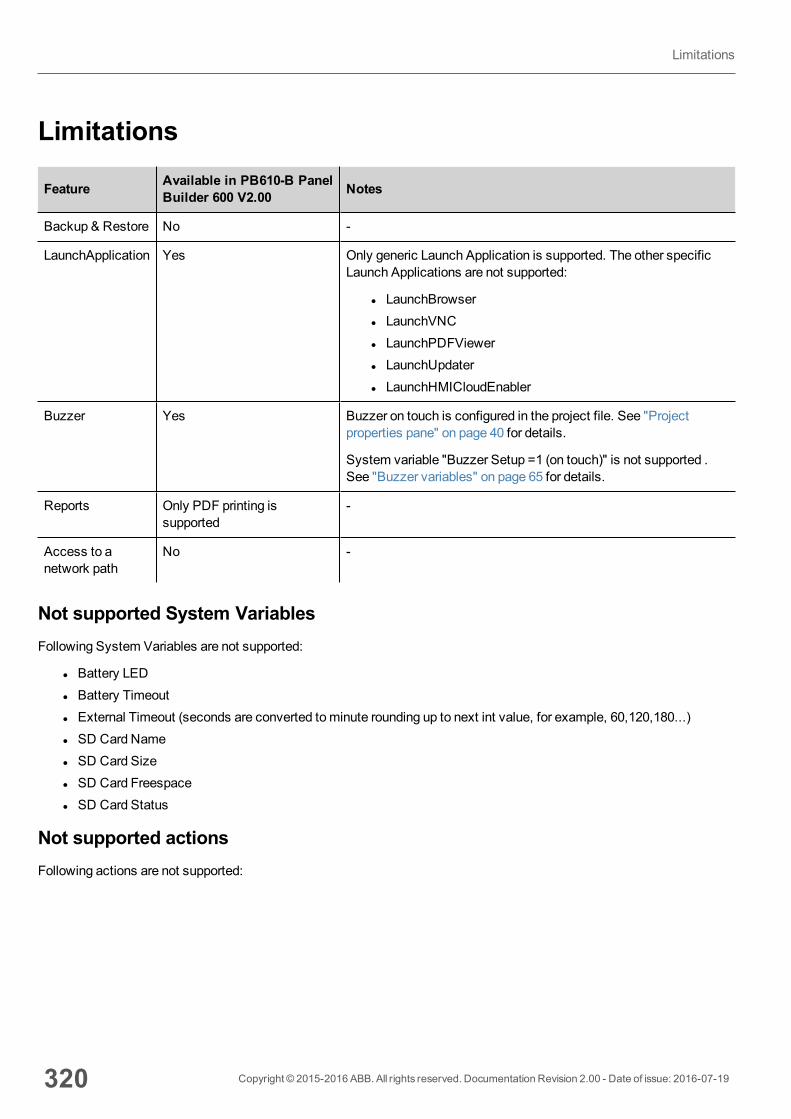
Limitations
Feature Available in PB610-B PanelBuilder 600 V2.00 Notes
Backup & Restore No -
LaunchApplication Yes Only generic Launch Application is supported. The other specificLaunch Applications are not supported:
l LaunchBrowserl LaunchVNCl LaunchPDFViewerl LaunchUpdaterl LaunchHMICloudEnabler
Buzzer Yes Buzzer on touch is configured in the project file. See "Projectproperties pane" on page 40 for details.
System variable "Buzzer Setup =1 (on touch)" is not supported .See "Buzzer variables" on page 65 for details.
Reports Only PDF printing issupported
-
Access to anetwork path
No -
Not supported System VariablesFollowing System Variables are not supported:
l Battery LEDl Battery Timeoutl External Timeout (seconds are converted tominute rounding up to next int value, for example, 60,120,180...)l SD Card Namel SD Card Sizel SD Card Freespacel SD Card Status
Not supported actionsFollowing actions are not supported:
320 Copyright © 2015-2016 ABB. All rights reserved. Documentation Revision 2.00 - Date of issue: 2016-07-19
Limitations
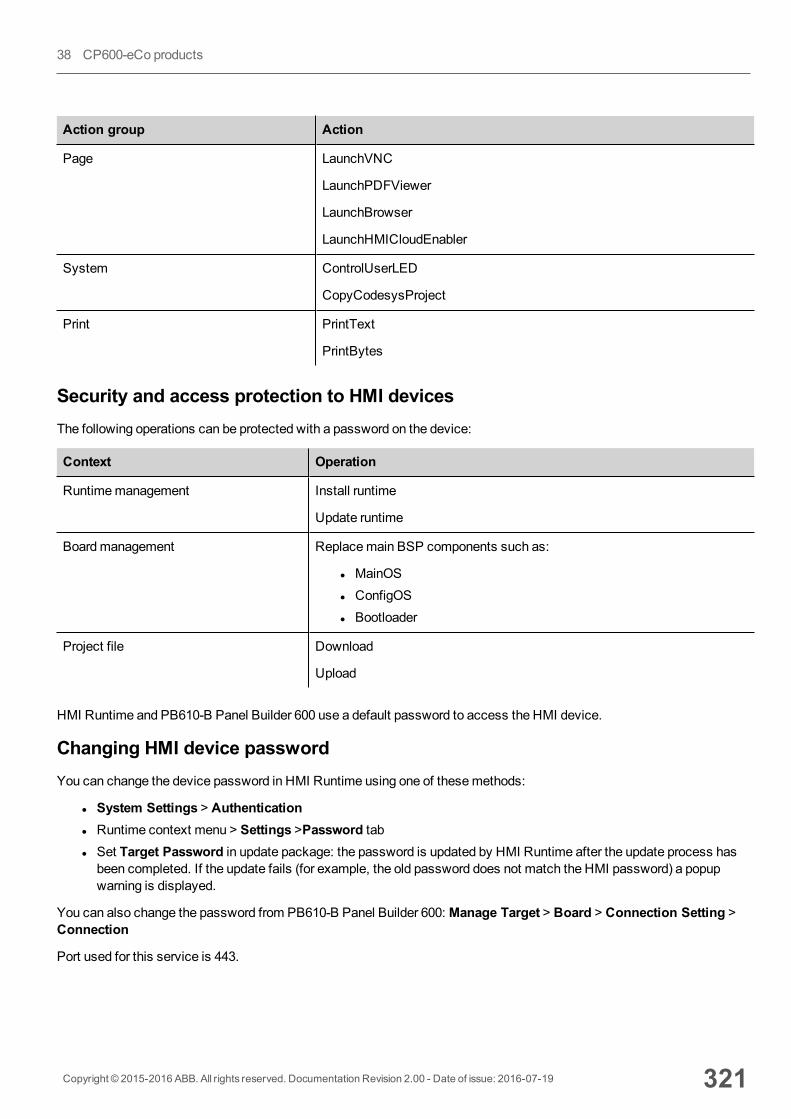
Action group Action
Page LaunchVNC
LaunchPDFViewer
LaunchBrowser
LaunchHMICloudEnabler
System ControlUserLED
CopyCodesysProject
Print PrintText
PrintBytes
Security and access protection to HMI devicesThe following operations can be protected with a password on the device:
Context Operation
Runtimemanagement Install runtime
Update runtime
Boardmanagement Replacemain BSP components such as:
l MainOSl ConfigOSl Bootloader
Project file Download
Upload
HMI Runtime and PB610-B Panel Builder 600 use a default password to access the HMI device.
Changing HMI device passwordYou can change the device password in HMI Runtime using one of thesemethods:
l System Settings > Authenticationl Runtime context menu > Settings >Password tabl Set Target Password in update package: the password is updated by HMI Runtime after the update process hasbeen completed. If the update fails (for example, the old password does not match the HMI password) a popupwarning is displayed.
You can also change the password from PB610-B Panel Builder 600:Manage Target > Board > Connection Setting >Connection
Port used for this service is 443.
Copyright © 2015-2016 ABB. All rights reserved. Documentation Revision 2.00 - Date of issue: 2016-07-19 321
38 CP600-eCo products
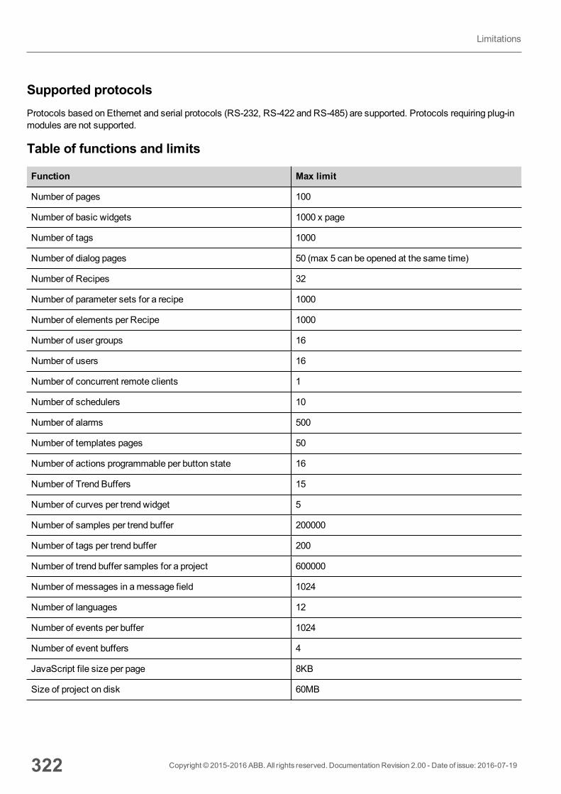
Supported protocolsProtocols based on Ethernet and serial protocols (RS-232, RS-422 and RS-485) are supported. Protocols requiring plug-inmodules are not supported.
Table of functions and limits
Function Max limit
Number of pages 100
Number of basic widgets 1000 x page
Number of tags 1000
Number of dialog pages 50 (max 5 can be opened at the same time)
Number of Recipes 32
Number of parameter sets for a recipe 1000
Number of elements per Recipe 1000
Number of user groups 16
Number of users 16
Number of concurrent remote clients 1
Number of schedulers 10
Number of alarms 500
Number of templates pages 50
Number of actions programmable per button state 16
Number of Trend Buffers 15
Number of curves per trend widget 5
Number of samples per trend buffer 200000
Number of tags per trend buffer 200
Number of trend buffer samples for a project 600000
Number of messages in amessage field 1024
Number of languages 12
Number of events per buffer 1024
Number of event buffers 4
JavaScript file size per page 8KB
Size of project on disk 60MB
322 Copyright © 2015-2016 ABB. All rights reserved. Documentation Revision 2.00 - Date of issue: 2016-07-19
Limitations
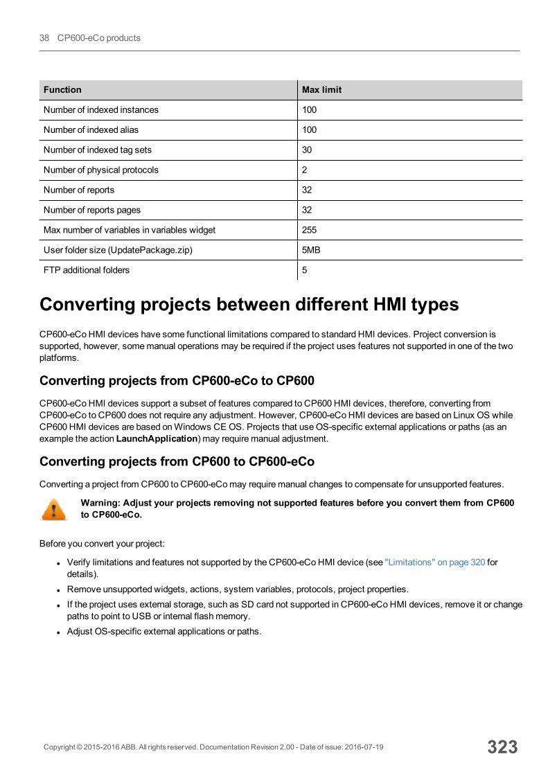
Function Max limit
Number of indexed instances 100
Number of indexed alias 100
Number of indexed tag sets 30
Number of physical protocols 2
Number of reports 32
Number of reports pages 32
Max number of variables in variables widget 255
User folder size (UpdatePackage.zip) 5MB
FTP additional folders 5
Converting projects between different HMI typesCP600-eCoHMI devices have some functional limitations compared to standard HMI devices. Project conversion issupported, however, somemanual operations may be required if the project uses features not supported in one of the twoplatforms.
Converting projects from CP600-eCo to CP600CP600-eCoHMI devices support a subset of features compared to CP600 HMI devices, therefore, converting fromCP600-eCo to CP600 does not require any adjustment. However, CP600-eCoHMI devices are based on Linux OS whileCP600 HMI devices are based onWindows CE OS. Projects that useOS-specific external applications or paths (as anexample the action LaunchApplication) may require manual adjustment.
Converting projects from CP600 to CP600-eCoConverting a project from CP600 to CP600-eComay require manual changes to compensate for unsupported features.
Warning: Adjust your projects removing not supported features before you convert them from CP600to CP600-eCo.
Before you convert your project:
l Verify limitations and features not supported by the CP600-eCoHMI device (see "Limitations" on page 320 fordetails).
l Remove unsupported widgets, actions, system variables, protocols, project properties.l If the project uses external storage, such as SD card not supported in CP600-eCoHMI devices, remove it or changepaths to point to USB or internal flashmemory.
l Adjust OS-specific external applications or paths.
Copyright © 2015-2016 ABB. All rights reserved. Documentation Revision 2.00 - Date of issue: 2016-07-19 323
38 CP600-eCo products

l Reduce project size according to the HMI device type limitations (see "Limitations" on page 320 for details).l Since CP600 and CP600-eCo devices are based on different hardware platforms with different CPU speed, RAMmemory size, cache size, make sure you check project boot time and page loading time for each page in the project
l If the project includes features such as Reports or Buzzer, make sure your applications are compatible with theavailable features
l Verify JavaScript code for OS-specific operations.
OS-specific featuresLinux is case sensitive, Windows CE is not. As a consequence, projects on CP600-eCoHMI devices, which are based onLinux OS, might have two different files named 'dump1.csv' and 'Dump1.csv'; this would not be possible on a CP600HMI device which is Windows CE based.
324 Copyright © 2015-2016 ABB. All rights reserved. Documentation Revision 2.00 - Date of issue: 2016-07-19
Converting projects between different HMI types
39 Communication protocolsThis section describes the available protocols.
Note: Changes in controller hardware or protocols may have occurred since this documentation was created.Always test and verify the functionality of the application. To accommodate developments in the controllerhardware and protocols, drivers are continuously updated. Accordingly, always ensure that the latest driver isused in the application.
Different physical media, gateways, routers and hubs can be used in the communication network. Also, other devices canindependently make simultaneous use of the network. However, it is important to ensure that the traffic generated by thesedevices does not degrade the communication speed (round-trip time) to an unacceptable level.
ABB CODESYS Ethernet 326
ABB CODESYS Serial 336
ABB Mint Controller HCP 342
ABB Modbus RTU 351
ABB Modbus TCP 358
ABB Pluto 364
BACnet 370
CODESYS V2 Ethernet 389
Ethernet/IP CIP 403
Modbus RTU 421
Modbus RTU Server 438
Modbus TCP 455
Modbus TCP Server 472
Simatic S7 Ethernet 483
Copyright © 2015-2016 ABB. All rights reserved. Documentation Revision 2.00 - Date of issue: 2016-07-19 325
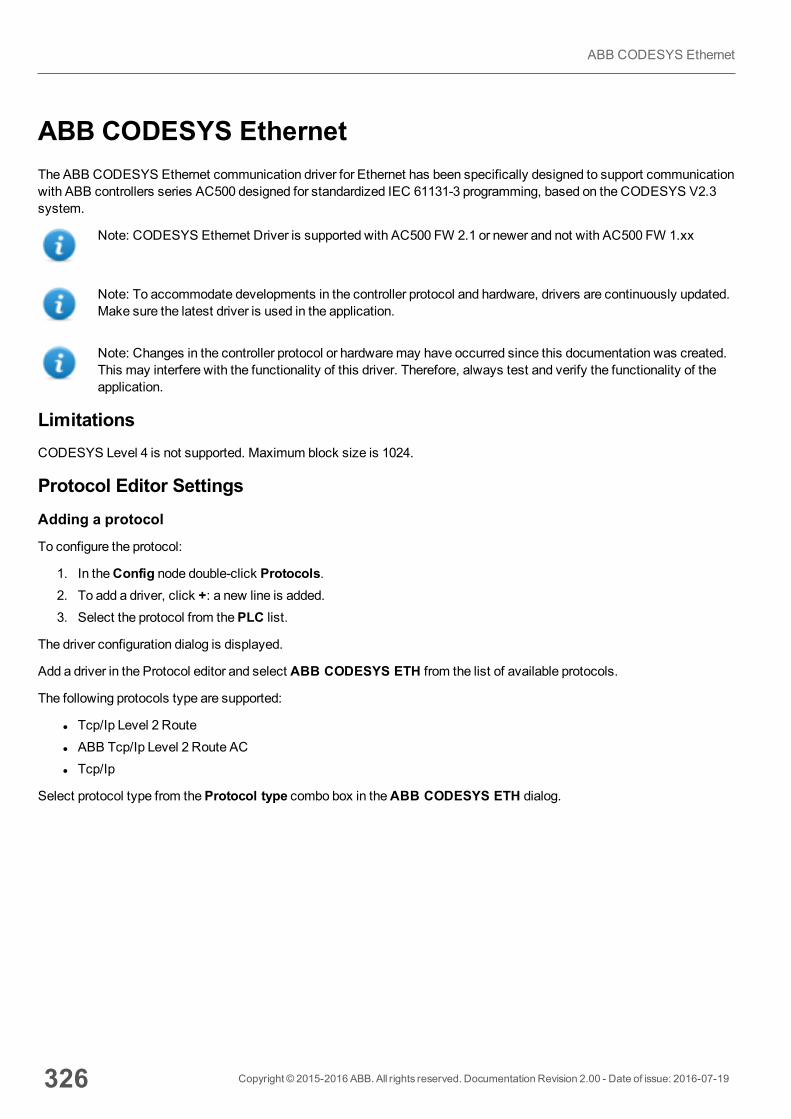
ABB CODESYS EthernetThe ABB CODESYS Ethernet communication driver for Ethernet has been specifically designed to support communicationwith ABB controllers series AC500 designed for standardized IEC 61131-3 programming, based on the CODESYS V2.3system.
Note: CODESYS Ethernet Driver is supported with AC500 FW 2.1 or newer and not with AC500 FW 1.xx
Note: To accommodate developments in the controller protocol and hardware, drivers are continuously updated.Make sure the latest driver is used in the application.
Note: Changes in the controller protocol or hardwaremay have occurred since this documentation was created.This may interfere with the functionality of this driver. Therefore, always test and verify the functionality of theapplication.
LimitationsCODESYS Level 4 is not supported. Maximum block size is 1024.
Protocol Editor SettingsAdding a protocol
To configure the protocol:
1. In theConfig node double-click Protocols.2. To add a driver, click +: a new line is added.3. Select the protocol from thePLC list.
The driver configuration dialog is displayed.
Add a driver in the Protocol editor and select ABB CODESYS ETH from the list of available protocols.
The following protocols type are supported:
l Tcp/Ip Level 2 Routel ABB Tcp/Ip Level 2 Route ACl Tcp/Ip
Select protocol type from theProtocol type combo box in theABB CODESYS ETH dialog.
326 Copyright © 2015-2016 ABB. All rights reserved. Documentation Revision 2.00 - Date of issue: 2016-07-19
ABB CODESYS Ethernet
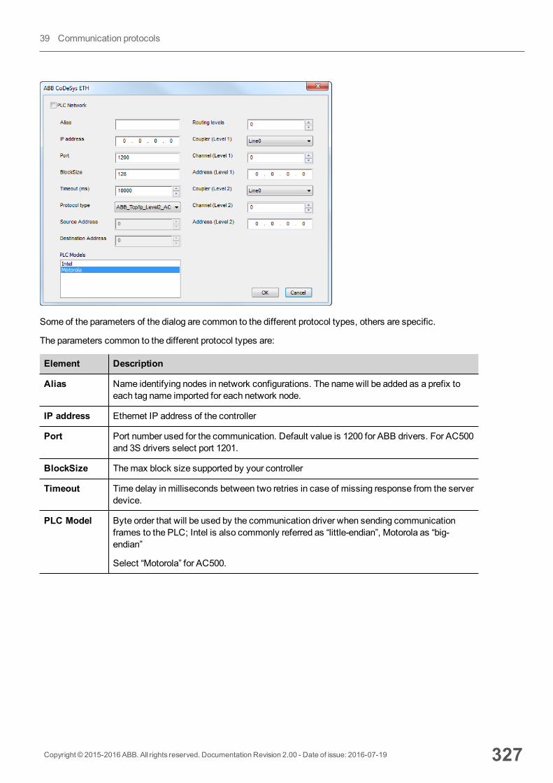
Some of the parameters of the dialog are common to the different protocol types, others are specific.
The parameters common to the different protocol types are:
Element Description
Alias Name identifying nodes in network configurations. The namewill be added as a prefix toeach tag name imported for each network node.
IP address Ethernet IP address of the controller
Port Port number used for the communication. Default value is 1200 for ABB drivers. For AC500and 3S drivers select port 1201.
BlockSize Themax block size supported by your controller
Timeout Time delay in milliseconds between two retries in case of missing response from the serverdevice.
PLC Model Byte order that will be used by the communication driver when sending communicationframes to the PLC; Intel is also commonly referred as “little-endian”, Motorola as “big-endian”
Select “Motorola” for AC500.
Copyright © 2015-2016 ABB. All rights reserved. Documentation Revision 2.00 - Date of issue: 2016-07-19 327
39 Communication protocols
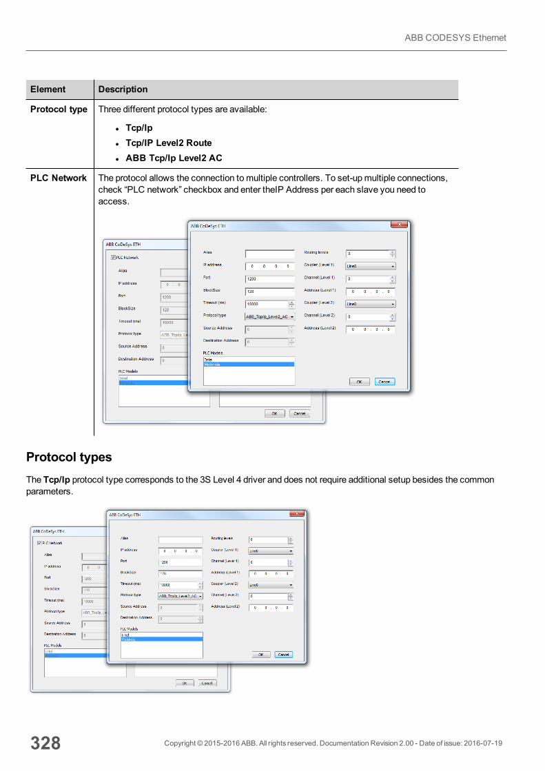
Element Description
Protocol type Three different protocol types are available:
l Tcp/Ipl Tcp/IP Level2 Routel ABB Tcp/Ip Level2 AC
PLC Network The protocol allows the connection tomultiple controllers. To set-upmultiple connections,check “PLC network” checkbox and enter theIP Address per each slave you need toaccess.
Protocol typesThe Tcp/Ip protocol type corresponds to the 3S Level 4 driver and does not require additional setup besides the commonparameters.
328 Copyright © 2015-2016 ABB. All rights reserved. Documentation Revision 2.00 - Date of issue: 2016-07-19
ABB CODESYS Ethernet
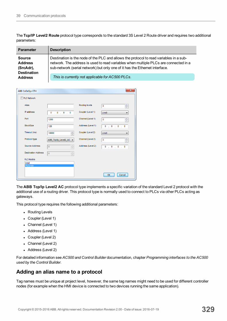
The Tcp/IP Level2 Route protocol type corresponds to the standard 3S Level 2 Route driver and requires two additionalparameters:
Parameter Description
SourceAddress(SrcAdr),DestinationAddress
Destination is the node of the PLC and allows the protocol to read variables in a sub-network. The address is used to read variables whenmultiple PLCs are connected in asub-network (serial network) but only one of it has the Ethernet interface.
This is currently not applicable for AC500 PLCs.
TheABB Tcp/Ip Level2 AC protocol type implements a specific variation of the standard Level 2 protocol with theadditional use of a routing driver. This protocol type is normally used to connect to PLCs via other PLCs acting asgateways.
This protocol type requires the following additional parameters:
l Routing Levelsl Coupler (Level 1)l Channel (Level 1)l Address (Level 1)l Coupler (Level 2)l Channel (Level 2)l Address (Level 2)
For detailed information seeAC500 and Control Builder documentation, chapterProgramming interfaces to the AC500used by the Control Builder.
Adding an alias name to a protocolTag names must be unique at project level, however, the same tag names might need to be used for different controllernodes (for example when the HMI device is connected to two devices running the same application).
Copyright © 2015-2016 ABB. All rights reserved. Documentation Revision 2.00 - Date of issue: 2016-07-19 329
39 Communication protocols

When creating a protocol you can add an alias name that will be added to tag names imported for this protocol.
In the example, the connection to a certain controller is assigned the nameNode1. When tags are imported for this node,all tag names will have the prefix Node1making each of them unique at the network/project level.
Note: Aliasing tag names is only available for imported tags. Tags which are addedmanually in the Tag Editor donot need to have the Alias prefix in the tag name.The Alias string is attached on the import. If youmodify the Alias string after the tag import has been completed,there will be no effect on the names already present in the dictionary. When the Alias string is changed and tagsare re-imported, all tags will be re-imported with the new prefix string.
CODESYS Software SettingsWhen you create the project in CODESYS V2, select Download symbol file (Target Settings > General).
330 Copyright © 2015-2016 ABB. All rights reserved. Documentation Revision 2.00 - Date of issue: 2016-07-19
ABB CODESYS Ethernet
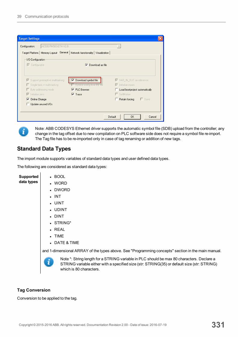
Note: ABB CODESYS Ethernet driver supports the automatic symbol file (SDB) upload from the controller; anychange in the tag offset due to new compilation on PLC software side does not require a symbol file re-import.The Tag file has to be re-imported only in case of tag renaming or addition of new tags.
Standard Data TypesThe import module supports variables of standard data types and user defined data types.
The following are considered as standard data types:
Supporteddata types
l BOOLl WORDl DWORDl INTl UINTl UDINTl DINTl STRING*l REALl TIMEl DATE & TIME
and 1-dimensional ARRAY of the types above. See "Programming concepts" section in themainmanual.
Note *: String length for a STRING variable in PLC should bemax 80 characters. Declare aSTRING variable either with a specified size (str: STRING(35) or default size (str: STRING)which is 80 characters.
Tag Conversion
Conversion to be applied to the tag.
Copyright © 2015-2016 ABB. All rights reserved. Documentation Revision 2.00 - Date of issue: 2016-07-19 331
39 Communication protocols
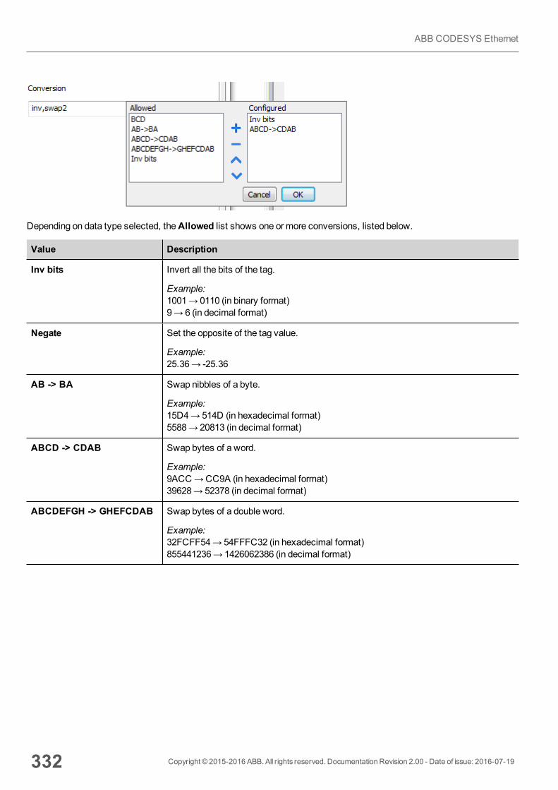
Depending on data type selected, theAllowed list shows one or more conversions, listed below.
Value Description
Inv bits Invert all the bits of the tag.
Example:1001→ 0110 (in binary format)9→ 6 (in decimal format)
Negate Set the opposite of the tag value.
Example:25.36→ -25.36
AB -> BA Swap nibbles of a byte.
Example:15D4→514D (in hexadecimal format)5588→ 20813 (in decimal format)
ABCD -> CDAB Swap bytes of a word.
Example:9ACC→CC9A (in hexadecimal format)39628→ 52378 (in decimal format)
ABCDEFGH -> GHEFCDAB Swap bytes of a double word.
Example:32FCFF54→54FFFC32 (in hexadecimal format)855441236→ 1426062386 (in decimal format)
332 Copyright © 2015-2016 ABB. All rights reserved. Documentation Revision 2.00 - Date of issue: 2016-07-19
ABB CODESYS Ethernet
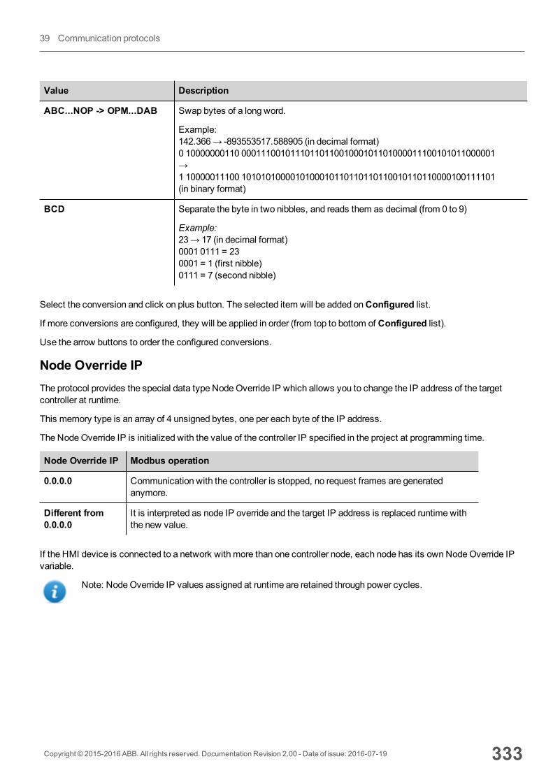
Value Description
ABC...NOP -> OPM...DAB Swap bytes of a long word.
Example:142.366→ -893553517.588905 (in decimal format)0 10000000110 0001110010111011011001000101101000011100101011000001→1 10000011100 1010101000010100010110110110110010110110000100111101(in binary format)
BCD Separate the byte in two nibbles, and reads them as decimal (from 0 to 9)
Example:23→ 17 (in decimal format)0001 0111 = 230001 = 1 (first nibble)0111 = 7 (second nibble)
Select the conversion and click on plus button. The selected item will be added onConfigured list.
If more conversions are configured, they will be applied in order (from top to bottom of Configured list).
Use the arrow buttons to order the configured conversions.
Node Override IPThe protocol provides the special data type NodeOverride IP which allows you to change the IP address of the targetcontroller at runtime.
This memory type is an array of 4 unsigned bytes, one per each byte of the IP address.
The NodeOverride IP is initialized with the value of the controller IP specified in the project at programming time.
Node Override IP Modbus operation
0.0.0.0 Communication with the controller is stopped, no request frames are generatedanymore.
Different from0.0.0.0
It is interpreted as node IP override and the target IP address is replaced runtime withthe new value.
If the HMI device is connected to a network with more than one controller node, each node has its ownNodeOverride IPvariable.
Note: NodeOverride IP values assigned at runtime are retained through power cycles.
Copyright © 2015-2016 ABB. All rights reserved. Documentation Revision 2.00 - Date of issue: 2016-07-19 333
39 Communication protocols
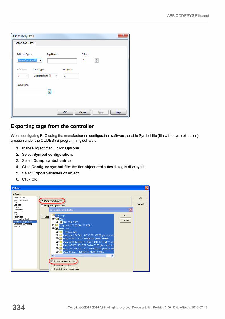
Exporting tags from the controllerWhen configuring PLC using themanufacturer’s configuration software, enable Symbol file (file with .sym extension)creation under the CODESYS programming software:
1. In theProjectmenu, click Options.2. Select Symbol configuration.3. Select Dump symbol entries.4. Click Configure symbol file: theSet object attributes dialog is displayed.5. Select Export variables of object.6. Click OK.
334 Copyright © 2015-2016 ABB. All rights reserved. Documentation Revision 2.00 - Date of issue: 2016-07-19
ABB CODESYS Ethernet
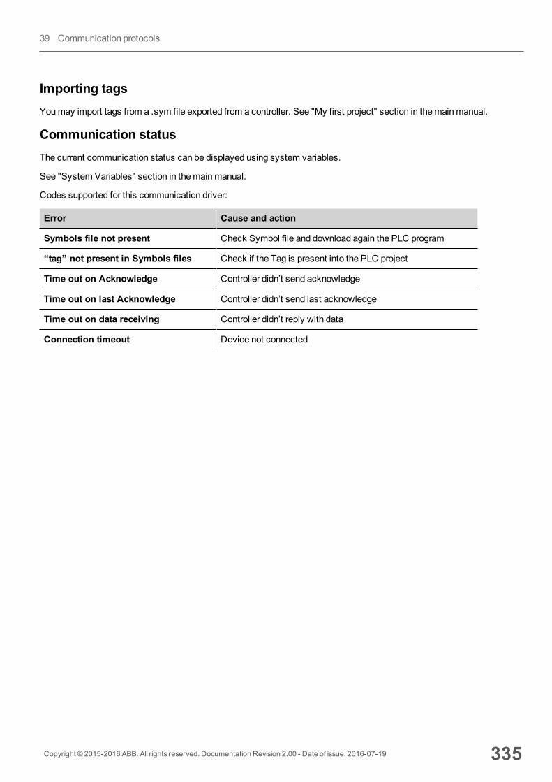
Importing tagsYoumay import tags from a .sym file exported from a controller. See "My first project" section in themainmanual.
Communication statusThe current communication status can be displayed using system variables.
See "System Variables" section in themainmanual.
Codes supported for this communication driver:
Error Cause and action
Symbols file not present Check Symbol file and download again the PLC program
“tag” not present in Symbols files Check if the Tag is present into the PLC project
Time out on Acknowledge Controller didn’t send acknowledge
Time out on last Acknowledge Controller didn’t send last acknowledge
Time out on data receiving Controller didn’t reply with data
Connection timeout Device not connected
Copyright © 2015-2016 ABB. All rights reserved. Documentation Revision 2.00 - Date of issue: 2016-07-19 335
39 Communication protocols
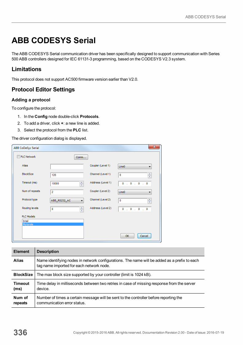
ABB CODESYS SerialThe ABB CODESYS Serial communication driver has been specifically designed to support communication with Series500 ABB controllers designed for IEC 61131-3 programming, based on the CODESYS V2.3 system.
LimitationsThis protocol does not support AC500 firmware version earlier than V2.0.
Protocol Editor SettingsAdding a protocol
To configure the protocol:
1. In theConfig node double-click Protocols.2. To add a driver, click +: a new line is added.3. Select the protocol from thePLC list.
The driver configuration dialog is displayed.
Element Description
Alias Name identifying nodes in network configurations. The namewill be added as a prefix to eachtag name imported for each network node.
BlockSize Themax block size supported by your controller (limit is 1024 kB).
Timeout(ms)
Time delay in milliseconds between two retries in case of missing response from the serverdevice.
Num ofrepeats
Number of times a certain message will be sent to the controller before reporting thecommunication error status.
336 Copyright © 2015-2016 ABB. All rights reserved. Documentation Revision 2.00 - Date of issue: 2016-07-19
ABB CODESYS Serial
Element Description
Protocoltype
Two different protocol types available:
l Serial_RS232: corresponds to the standard 3S driver.l ABB_RS232_AC: implements a specific variation of the standard Level 2 protocol withthe additional use of a routing driver. Normally used to connect to PLCs via other PLCsacting as gateways.
The ABB_RS232_AC protocol type requires the proper settings of the followingadditional parameters:
l Routing Levelsl Coupler (Level 1)l Channel (Level 1)l Address (Level 1)l Coupler (Level 2)l Channel (Level 2)l Address (Level 2)
For detailed information seeAC500 and Control Builder documentation, chapterProgramming interfaces to the AC500 used by the Control Builder.
PLCModels
The list allows selecting the PLC model you are going to connect to. The selection willinfluence the data range offset per each data type according to the specific PLC memoryresources.
Copyright © 2015-2016 ABB. All rights reserved. Documentation Revision 2.00 - Date of issue: 2016-07-19 337
39 Communication protocols
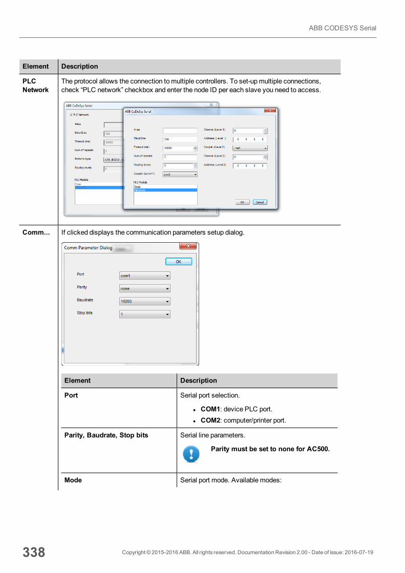
Element Description
PLCNetwork
The protocol allows the connection tomultiple controllers. To set-upmultiple connections,check “PLC network” checkbox and enter the node ID per each slave you need to access.
Comm... If clicked displays the communication parameters setup dialog.
Element Description
Port Serial port selection.
l COM1: device PLC port.l COM2: computer/printer port.
Parity, Baudrate, Stop bits Serial line parameters.
Parity must be set to none for AC500.
Mode Serial port mode. Available modes:
338 Copyright © 2015-2016 ABB. All rights reserved. Documentation Revision 2.00 - Date of issue: 2016-07-19
ABB CODESYS Serial
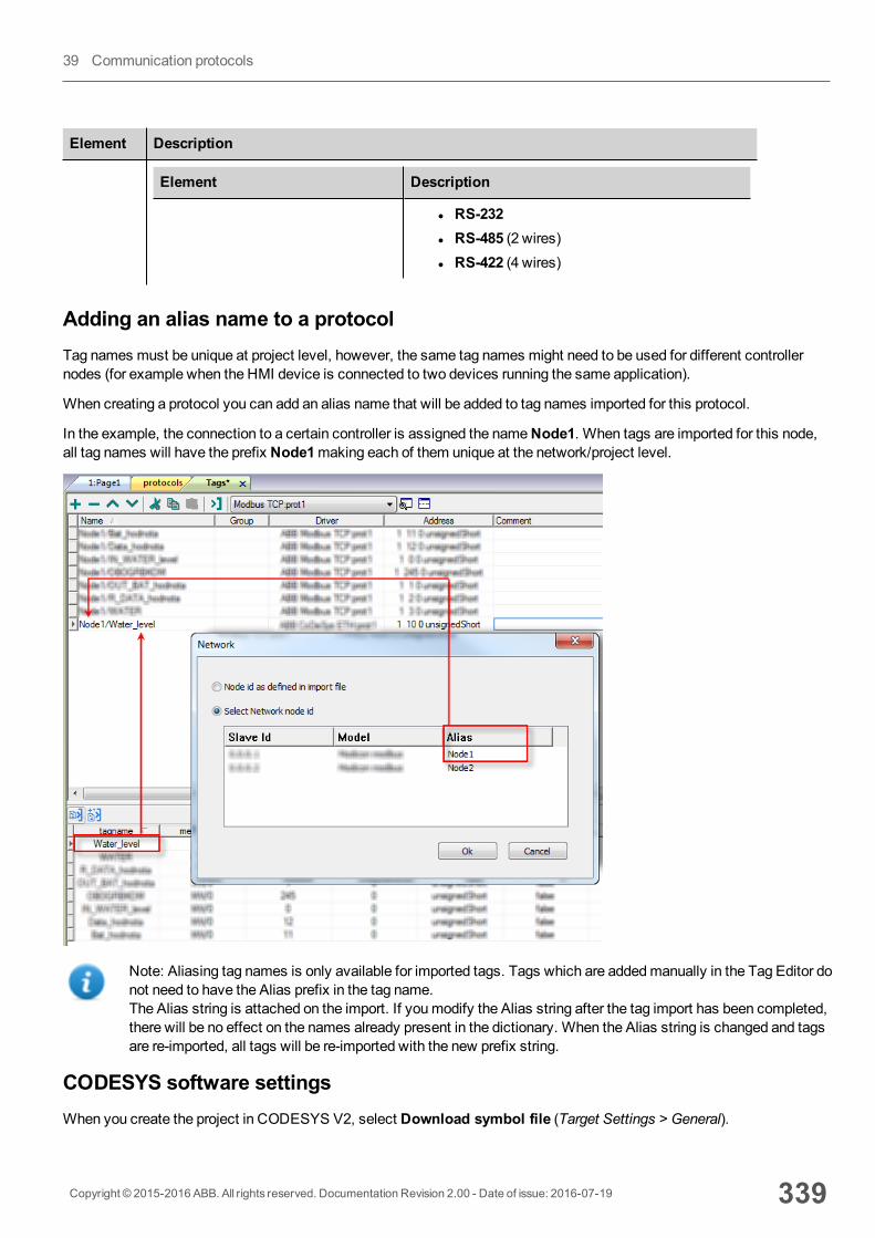
Element Description
Element Description
l RS-232l RS-485 (2 wires)l RS-422 (4 wires)
Adding an alias name to a protocolTag names must be unique at project level, however, the same tag names might need to be used for different controllernodes (for example when the HMI device is connected to two devices running the same application).
When creating a protocol you can add an alias name that will be added to tag names imported for this protocol.
In the example, the connection to a certain controller is assigned the nameNode1. When tags are imported for this node,all tag names will have the prefix Node1making each of them unique at the network/project level.
Note: Aliasing tag names is only available for imported tags. Tags which are addedmanually in the Tag Editor donot need to have the Alias prefix in the tag name.The Alias string is attached on the import. If youmodify the Alias string after the tag import has been completed,there will be no effect on the names already present in the dictionary. When the Alias string is changed and tagsare re-imported, all tags will be re-imported with the new prefix string.
CODESYS software settingsWhen you create the project in CODESYS V2, select Download symbol file (Target Settings > General).
Copyright © 2015-2016 ABB. All rights reserved. Documentation Revision 2.00 - Date of issue: 2016-07-19 339
39 Communication protocols
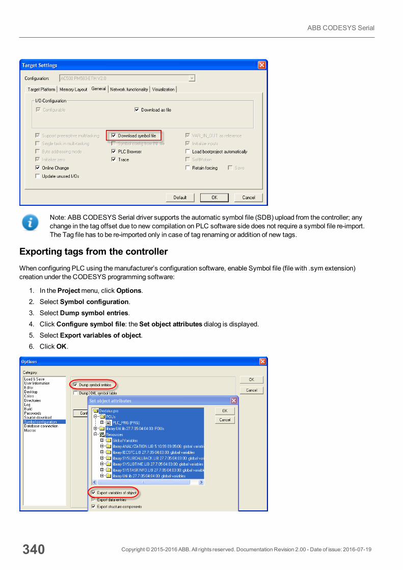
Note: ABB CODESYS Serial driver supports the automatic symbol file (SDB) upload from the controller; anychange in the tag offset due to new compilation on PLC software side does not require a symbol file re-import.The Tag file has to be re-imported only in case of tag renaming or addition of new tags.
Exporting tags from the controllerWhen configuring PLC using themanufacturer’s configuration software, enable Symbol file (file with .sym extension)creation under the CODESYS programming software:
1. In theProjectmenu, click Options.2. Select Symbol configuration.3. Select Dump symbol entries.4. Click Configure symbol file: theSet object attributes dialog is displayed.5. Select Export variables of object.6. Click OK.
340 Copyright © 2015-2016 ABB. All rights reserved. Documentation Revision 2.00 - Date of issue: 2016-07-19
ABB CODESYS Serial
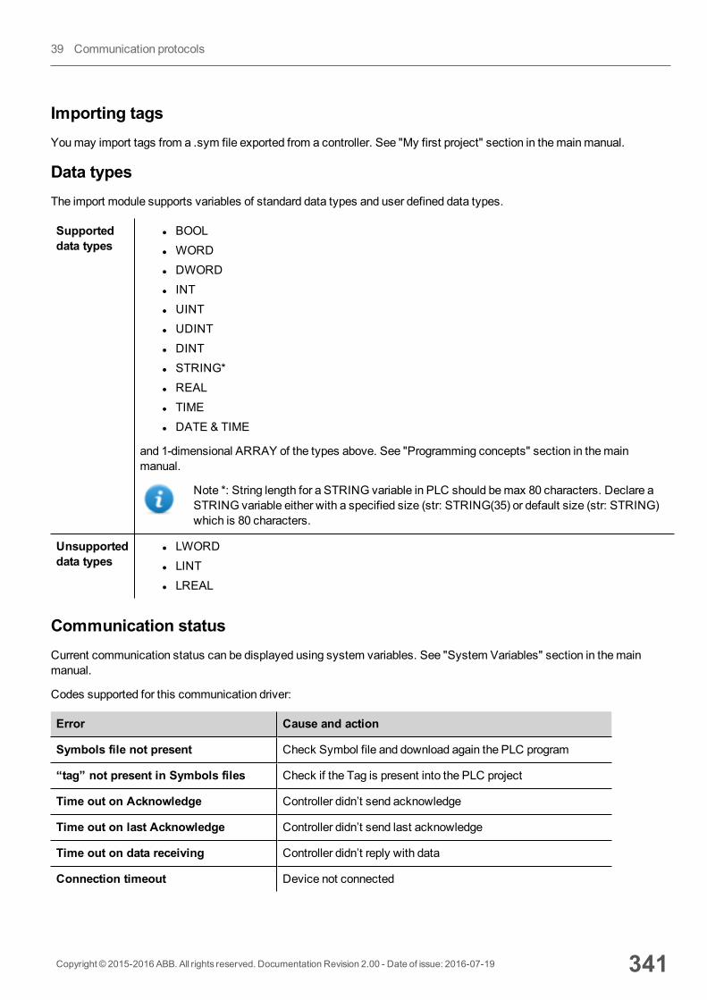
Importing tagsYoumay import tags from a .sym file exported from a controller. See "My first project" section in themainmanual.
Data typesThe import module supports variables of standard data types and user defined data types.
Supporteddata types
l BOOLl WORDl DWORDl INTl UINTl UDINTl DINTl STRING*l REALl TIMEl DATE & TIME
and 1-dimensional ARRAY of the types above. See "Programming concepts" section in themainmanual.
Note *: String length for a STRING variable in PLC should bemax 80 characters. Declare aSTRING variable either with a specified size (str: STRING(35) or default size (str: STRING)which is 80 characters.
Unsupporteddata types
l LWORDl LINTl LREAL
Communication statusCurrent communication status can be displayed using system variables. See "System Variables" section in themainmanual.
Codes supported for this communication driver:
Error Cause and action
Symbols file not present Check Symbol file and download again the PLC program
“tag” not present in Symbols files Check if the Tag is present into the PLC project
Time out on Acknowledge Controller didn’t send acknowledge
Time out on last Acknowledge Controller didn’t send last acknowledge
Time out on data receiving Controller didn’t reply with data
Connection timeout Device not connected
Copyright © 2015-2016 ABB. All rights reserved. Documentation Revision 2.00 - Date of issue: 2016-07-19 341
39 Communication protocols
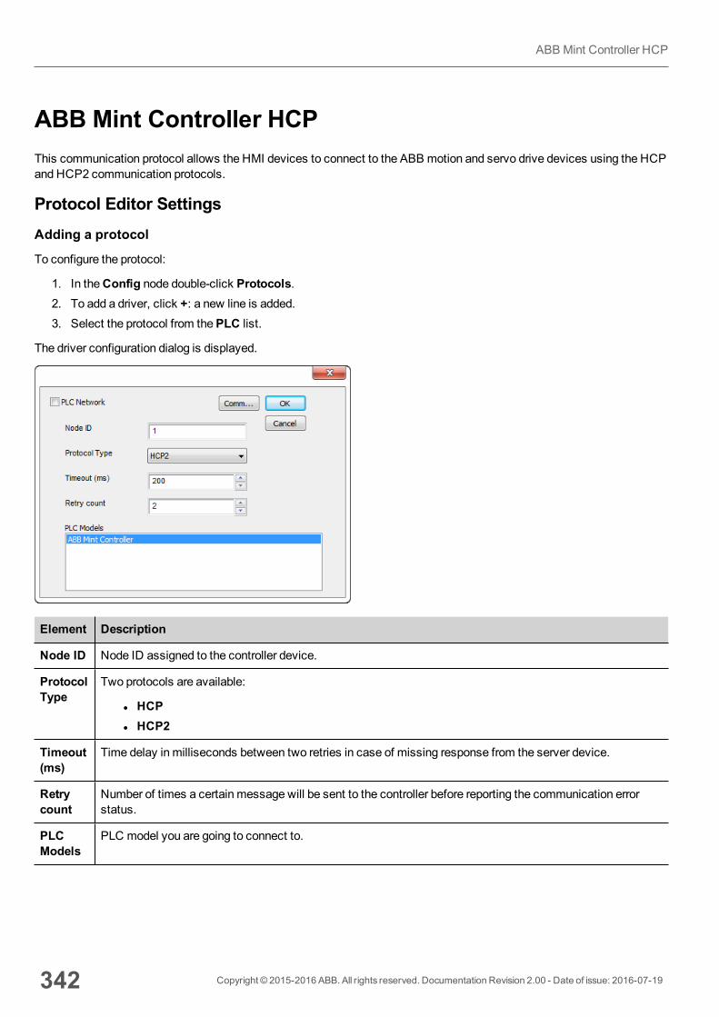
ABB Mint Controller HCPThis communication protocol allows the HMI devices to connect to the ABB motion and servo drive devices using the HCPand HCP2 communication protocols.
Protocol Editor SettingsAdding a protocol
To configure the protocol:
1. In theConfig node double-click Protocols.2. To add a driver, click +: a new line is added.3. Select the protocol from thePLC list.
The driver configuration dialog is displayed.
Element Description
Node ID Node ID assigned to the controller device.
ProtocolType
Two protocols are available:
l HCPl HCP2
Timeout(ms)
Time delay in milliseconds between two retries in case of missing response from the server device.
Retrycount
Number of times a certain message will be sent to the controller before reporting the communication errorstatus.
PLCModels
PLC model you are going to connect to.
342 Copyright © 2015-2016 ABB. All rights reserved. Documentation Revision 2.00 - Date of issue: 2016-07-19
ABB Mint Controller HCP
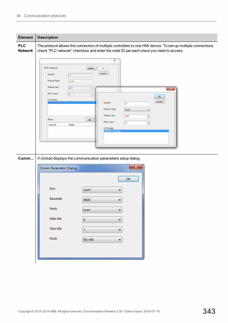
Element Description
PLCNetwork
The protocol allows the connection of multiple controllers to one HMI device. To set-upmultiple connections,check “PLC network” checkbox and enter the node ID per each slave you need to access.
Comm... If clicked displays the communication parameters setup dialog.
Copyright © 2015-2016 ABB. All rights reserved. Documentation Revision 2.00 - Date of issue: 2016-07-19 343
39 Communication protocols
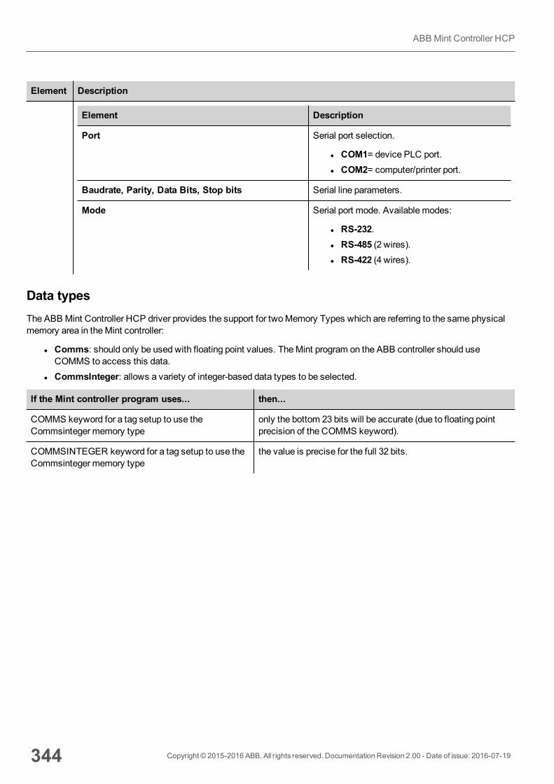
Element Description
Element Description
Port Serial port selection.
l COM1= device PLC port.l COM2= computer/printer port.
Baudrate, Parity, Data Bits, Stop bits Serial line parameters.
Mode Serial port mode. Available modes:
l RS-232.l RS-485 (2 wires).l RS-422 (4 wires).
Data typesThe ABB Mint Controller HCP driver provides the support for twoMemory Types which are referring to the same physicalmemory area in theMint controller:
l Comms: should only be used with floating point values. TheMint program on the ABB controller should useCOMMS to access this data.
l CommsInteger: allows a variety of integer-based data types to be selected.
If the Mint controller program uses... then...
COMMS keyword for a tag setup to use theCommsinteger memory type
only the bottom 23 bits will be accurate (due to floating pointprecision of the COMMS keyword).
COMMSINTEGER keyword for a tag setup to use theCommsinteger memory type
the value is precise for the full 32 bits.
344 Copyright © 2015-2016 ABB. All rights reserved. Documentation Revision 2.00 - Date of issue: 2016-07-19
ABB Mint Controller HCP
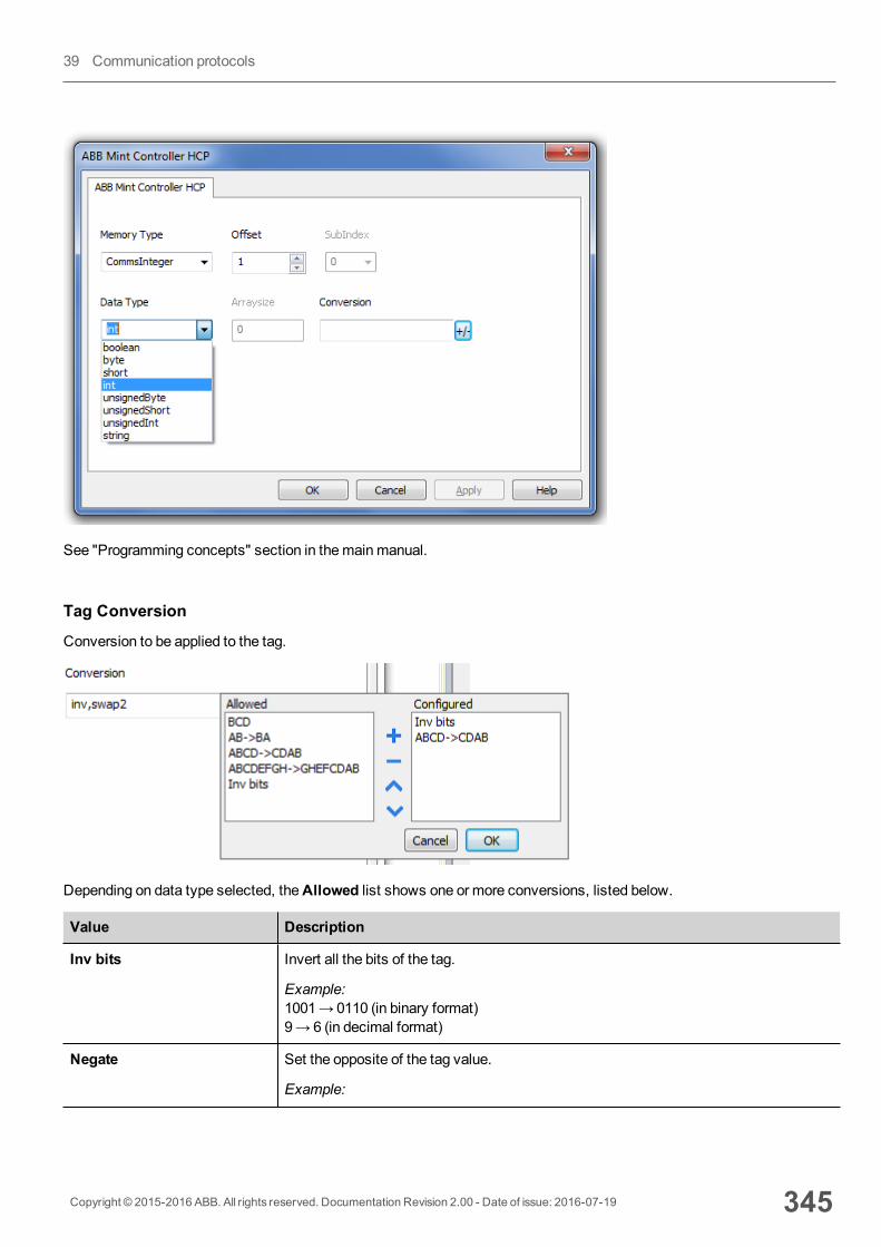
See "Programming concepts" section in themainmanual.
Tag Conversion
Conversion to be applied to the tag.
Depending on data type selected, theAllowed list shows one or more conversions, listed below.
Value Description
Inv bits Invert all the bits of the tag.
Example:1001→ 0110 (in binary format)9→ 6 (in decimal format)
Negate Set the opposite of the tag value.
Example:
Copyright © 2015-2016 ABB. All rights reserved. Documentation Revision 2.00 - Date of issue: 2016-07-19 345
39 Communication protocols

Value Description
25.36→ -25.36
AB -> BA Swap nibbles of a byte.
Example:15D4→514D (in hexadecimal format)5588→ 20813 (in decimal format)
ABCD -> CDAB Swap bytes of a word.
Example:9ACC→CC9A (in hexadecimal format)39628→ 52378 (in decimal format)
ABCDEFGH -> GHEFCDAB Swap bytes of a double word.
Example:32FCFF54→54FFFC32 (in hexadecimal format)855441236→ 1426062386 (in decimal format)
ABC...NOP -> OPM...DAB Swap bytes of a long word.
Example:142.366→ -893553517.588905 (in decimal format)0 10000000110 0001110010111011011001000101101000011100101011000001→1 10000011100 1010101000010100010110110110110010110110000100111101(in binary format)
BCD Separate the byte in two nibbles, and reads them as decimal (from 0 to 9)
Example:23→ 17 (in decimal format)0001 0111 = 230001 = 1 (first nibble)0111 = 7 (second nibble)
Select the conversion and click on plus button. The selected item will be added onConfigured list.
If more conversions are configured, they will be applied in order (from top to bottom of Configured list).
Use the arrow buttons to order the configured conversions.
Tag ImportSelect the driver in Tag Editor and click on the Import Tags button to start the importer.
Locate the .xml file exported from Tag Editor and click Open.
346 Copyright © 2015-2016 ABB. All rights reserved. Documentation Revision 2.00 - Date of issue: 2016-07-19
ABB Mint Controller HCP
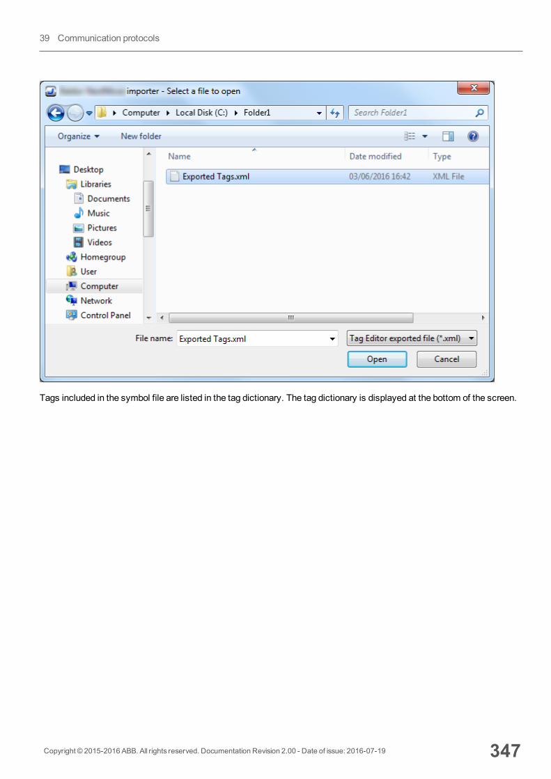
Tags included in the symbol file are listed in the tag dictionary. The tag dictionary is displayed at the bottom of the screen.
Copyright © 2015-2016 ABB. All rights reserved. Documentation Revision 2.00 - Date of issue: 2016-07-19 347
39 Communication protocols

Toolbar item Description
Import Tag(s).
Select tags to be imported and click on this icon to add tags fromtag dictionary to the project
Update Tag(s).
Click on this icon to update the tags in the project, due a newdictionary import.
Check this box to import all sub-elements of a tag.
Example of both checked and unchecked result:
348 Copyright © 2015-2016 ABB. All rights reserved. Documentation Revision 2.00 - Date of issue: 2016-07-19
ABB Mint Controller HCP
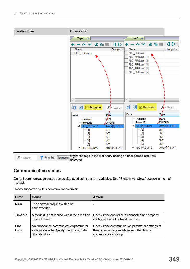
Toolbar item Description
Searches tags in the dictionary basing on filter combo-box itemselected.
Communication statusCurrent communication status can be displayed using system variables. See "System Variables" section in themainmanual.
Codes supported by this communication driver:
Error Cause Action
NAK The controller replies with a notacknowledge.
-
Timeout A request is not replied within the specifiedtimeout period.
Check if the controller is connected and properlyconfigured to get network access.
LineError
An error on the communication parametersetup is detected (parity, baud rate, databits, stop bits).
Check if the communication parameter settings ofthe controller is compatible with the devicecommunication setup.
Copyright © 2015-2016 ABB. All rights reserved. Documentation Revision 2.00 - Date of issue: 2016-07-19 349
39 Communication protocols

Error Cause Action
Invalidresponse
The device did received a response withinvalid format or contents from thecontroller.
Ensure the data programmed in the project areconsistent with the controller resources.
GeneralError
Unidentifiable error. Should never bereported.
Contact technical support.
350 Copyright © 2015-2016 ABB. All rights reserved. Documentation Revision 2.00 - Date of issue: 2016-07-19
ABB Mint Controller HCP
ABB Modbus RTUThe HMI devices can be connected to aModbus network as the network master using this driver.
This specific implementation of theModbus RTU driver provides easy handling of the connections to ABB controllersproviding specific support for PLC models and tag import facilities.
Implementation detailsThe ABB Modbus RTU implementation supports only a subset of theModbus standard RTU function codes.
Code Function Description
01 ReadCoil Status Reads multiple bits in the device Coil area
02 Read Input Status Read theON/OFF status of the discrete inputs (1x reference) in the slave
03 ReadHolding Registers Readmultiple Registers
04 Read Input Registers Reads the binary contents of input registers (3x reference) in the slave
05 Force Single Coil Forces a single Coil to either ON or OFF
06 Preset Single Register Presets a value in a Register
16 Preset Multiple Registers Presets value in multiple Registers
Note: Communication speed with controllers is supported up to 115200 baud.
Note: Floating point data format is IEEE standard compliant.
Protocol Editor SettingsAdding a protocol
To configure the protocol:
1. In theConfig node double-click Protocols.2. To add a driver, click +: a new line is added.3. Select the protocol from thePLC list.
The driver configuration dialog is displayed.
Copyright © 2015-2016 ABB. All rights reserved. Documentation Revision 2.00 - Date of issue: 2016-07-19 351
39 Communication protocols
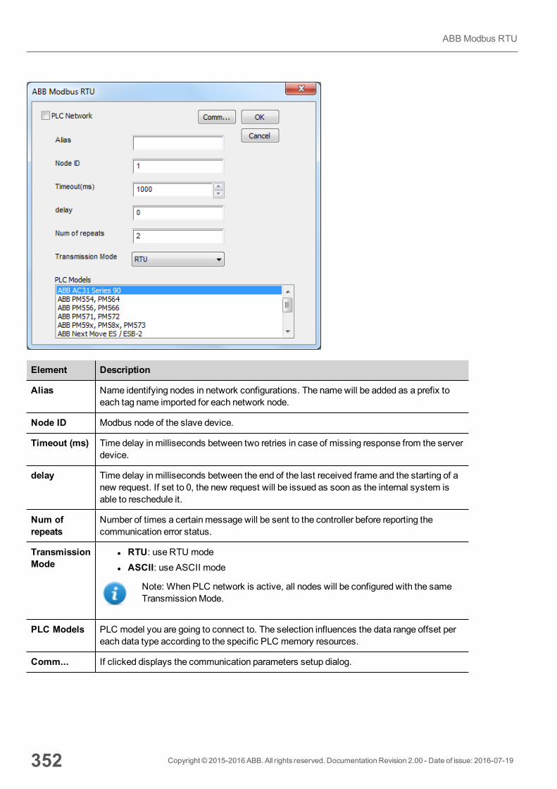
Element Description
Alias Name identifying nodes in network configurations. The namewill be added as a prefix toeach tag name imported for each network node.
Node ID Modbus node of the slave device.
Timeout (ms) Time delay in milliseconds between two retries in case of missing response from the serverdevice.
delay Time delay in milliseconds between the end of the last received frame and the starting of anew request. If set to 0, the new request will be issued as soon as the internal system isable to reschedule it.
Num ofrepeats
Number of times a certain message will be sent to the controller before reporting thecommunication error status.
TransmissionMode
l RTU: use RTU model ASCII: use ASCII mode
Note: When PLC network is active, all nodes will be configured with the sameTransmissionMode.
PLC Models PLC model you are going to connect to. The selection influences the data range offset pereach data type according to the specific PLC memory resources.
Comm... If clicked displays the communication parameters setup dialog.
352 Copyright © 2015-2016 ABB. All rights reserved. Documentation Revision 2.00 - Date of issue: 2016-07-19
ABB Modbus RTU
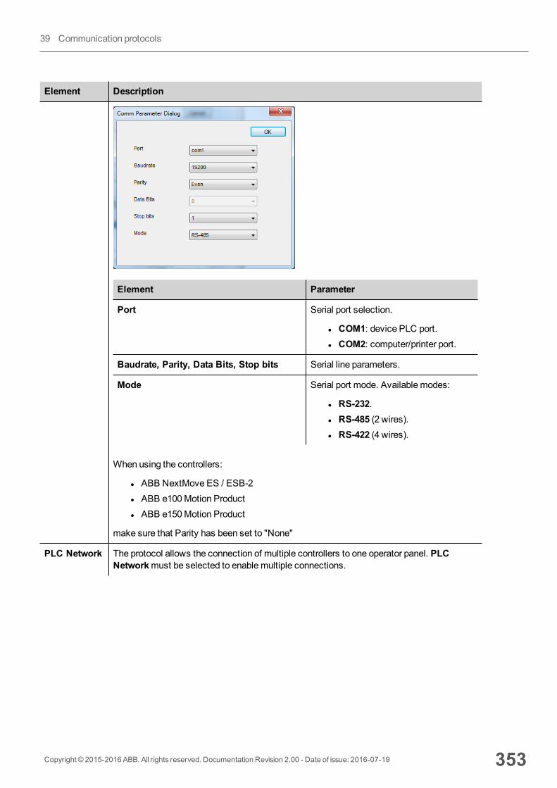
Element Description
Element Parameter
Port Serial port selection.
l COM1: device PLC port.l COM2: computer/printer port.
Baudrate, Parity, Data Bits, Stop bits Serial line parameters.
Mode Serial port mode. Available modes:
l RS-232.l RS-485 (2 wires).l RS-422 (4 wires).
When using the controllers:
l ABB NextMove ES / ESB-2l ABB e100Motion Productl ABB e150Motion Product
make sure that Parity has been set to "None"
PLC Network The protocol allows the connection of multiple controllers to one operator panel. PLCNetworkmust be selected to enablemultiple connections.
Copyright © 2015-2016 ABB. All rights reserved. Documentation Revision 2.00 - Date of issue: 2016-07-19 353
39 Communication protocols
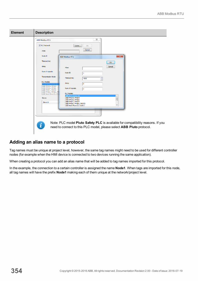
Element Description
Note: PLC model Pluto Safety PLC is available for compatibility reasons. If youneed to connect to this PLC model, please select ABB Pluto protocol.
Adding an alias name to a protocolTag names must be unique at project level, however, the same tag names might need to be used for different controllernodes (for example when the HMI device is connected to two devices running the same application).
When creating a protocol you can add an alias name that will be added to tag names imported for this protocol.
In the example, the connection to a certain controller is assigned the nameNode1. When tags are imported for this node,all tag names will have the prefix Node1making each of them unique at the network/project level.
354 Copyright © 2015-2016 ABB. All rights reserved. Documentation Revision 2.00 - Date of issue: 2016-07-19
ABB Modbus RTU
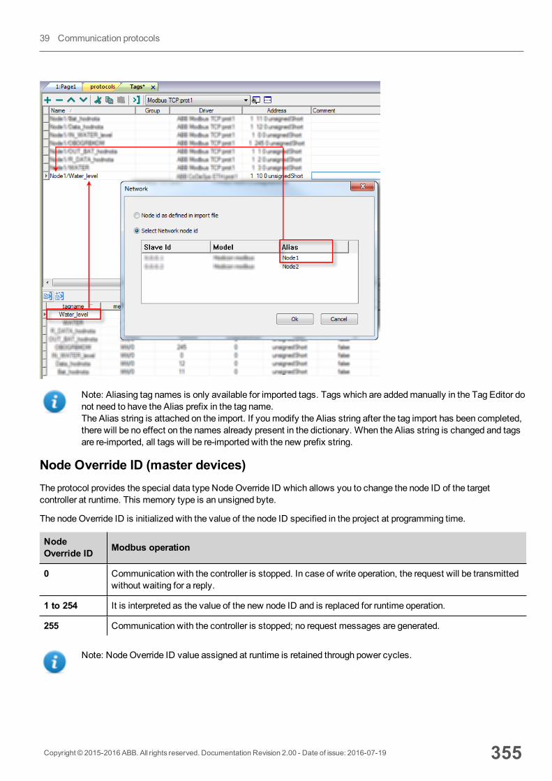
Note: Aliasing tag names is only available for imported tags. Tags which are addedmanually in the Tag Editor donot need to have the Alias prefix in the tag name.The Alias string is attached on the import. If youmodify the Alias string after the tag import has been completed,there will be no effect on the names already present in the dictionary. When the Alias string is changed and tagsare re-imported, all tags will be re-imported with the new prefix string.
Node Override ID (master devices)The protocol provides the special data type NodeOverride ID which allows you to change the node ID of the targetcontroller at runtime. This memory type is an unsigned byte.
The nodeOverride ID is initialized with the value of the node ID specified in the project at programming time.
NodeOverride ID Modbus operation
0 Communication with the controller is stopped. In case of write operation, the request will be transmittedwithout waiting for a reply.
1 to 254 It is interpreted as the value of the new node ID and is replaced for runtime operation.
255 Communication with the controller is stopped; no request messages are generated.
Note: NodeOverride ID value assigned at runtime is retained through power cycles.
Copyright © 2015-2016 ABB. All rights reserved. Documentation Revision 2.00 - Date of issue: 2016-07-19 355
39 Communication protocols
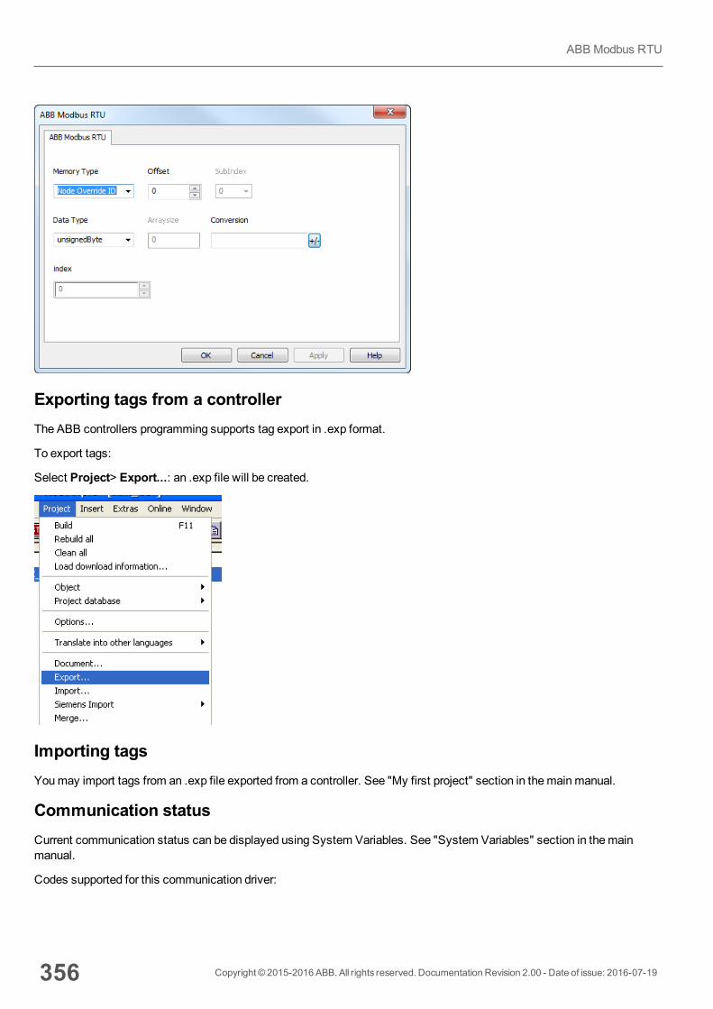
Exporting tags from a controllerThe ABB controllers programming supports tag export in .exp format.
To export tags:
Select Project> Export...: an .exp file will be created.
Importing tagsYoumay import tags from an .exp file exported from a controller. See "My first project" section in themainmanual.
Communication statusCurrent communication status can be displayed using System Variables. See "System Variables" section in themainmanual.
Codes supported for this communication driver:
356 Copyright © 2015-2016 ABB. All rights reserved. Documentation Revision 2.00 - Date of issue: 2016-07-19
ABB Modbus RTU
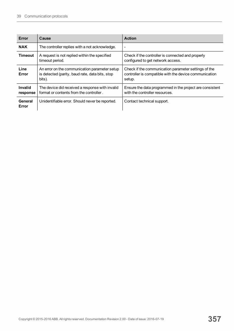
Error Cause Action
NAK The controller replies with a not acknowledge. -
Timeout A request is not replied within the specifiedtimeout period.
Check if the controller is connected and properlyconfigured to get network access.
LineError
An error on the communication parameter setupis detected (parity, baud rate, data bits, stopbits).
Check if the communication parameter settings of thecontroller is compatible with the device communicationsetup.
Invalidresponse
The device did received a response with invalidformat or contents from the controller .
Ensure the data programmed in the project are consistentwith the controller resources.
GeneralError
Unidentifiable error. Should never be reported. Contact technical support.
Copyright © 2015-2016 ABB. All rights reserved. Documentation Revision 2.00 - Date of issue: 2016-07-19 357
39 Communication protocols
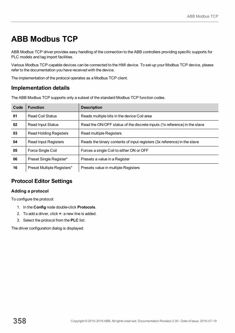
ABB Modbus TCPABB Modbus TCP driver provides easy handling of the connection to the ABB controllers providing specific supports forPLC models and tag import facilities.
Various Modbus TCP-capable devices can be connected to the HMI device. To set-up your Modbus TCP device, pleaserefer to the documentation you have received with the device.
The implementation of the protocol operates as aModbus TCP client.
Implementation detailsThe ABB Modbus TCP supports only a subset of the standardModbus TCP function codes.
Code Function Description
01 ReadCoil Status Reads multiple bits in the device Coil area
02 Read Input Status Read theON/OFF status of the discrete inputs (1x reference) in the slave
03 ReadHolding Registers Readmultiple Registers
04 Read Input Registers Reads the binary contents of input registers (3x reference) in the slave
05 Force Single Coil Forces a single Coil to either ON or OFF
06 Preset Single Register* Presets a value in a Register
16 Preset Multiple Registers* Presets value in multiple Registers
Protocol Editor SettingsAdding a protocol
To configure the protocol:
1. In theConfig node double-click Protocols.2. To add a driver, click +: a new line is added.3. Select the protocol from thePLC list.
The driver configuration dialog is displayed.
358 Copyright © 2015-2016 ABB. All rights reserved. Documentation Revision 2.00 - Date of issue: 2016-07-19
ABB Modbus TCP
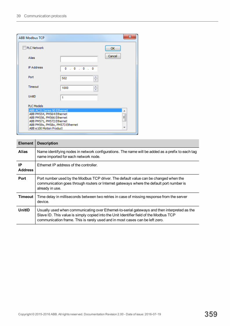
Element Description
Alias Name identifying nodes in network configurations. The namewill be added as a prefix to each tagname imported for each network node.
IPAddress
Ethernet IP address of the controller.
Port Port number used by theModbus TCP driver. The default value can be changed when thecommunication goes through routers or Internet gateways where the default port number isalready in use.
Timeout Time delay in milliseconds between two retries in case of missing response from the serverdevice.
UnitID Usually used when communicating over Ethernet-to-serial gateways and then interpreted as theSlave ID. This value is simply copied into the Unit Identifier field of theModbus TCPcommunication frame. This is rarely used and inmost cases can be left zero.
Copyright © 2015-2016 ABB. All rights reserved. Documentation Revision 2.00 - Date of issue: 2016-07-19 359
39 Communication protocols
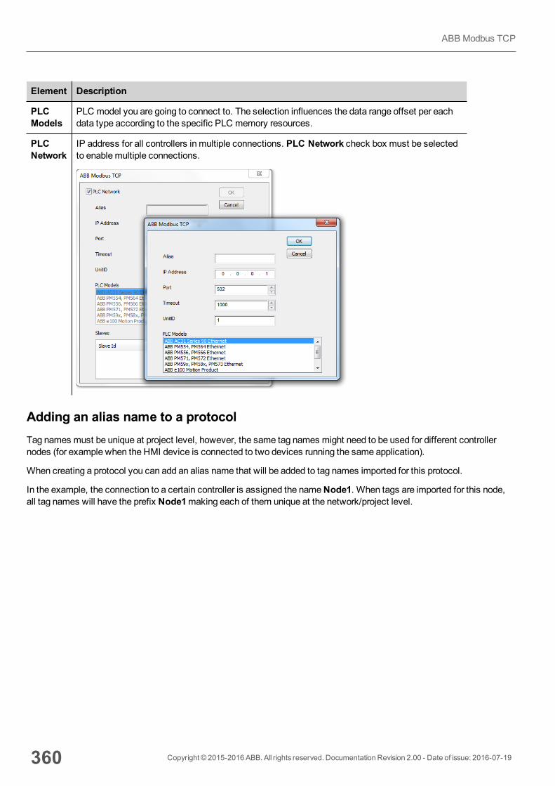
Element Description
PLCModels
PLC model you are going to connect to. The selection influences the data range offset per eachdata type according to the specific PLC memory resources.
PLCNetwork
IP address for all controllers in multiple connections. PLC Network check box must be selectedto enablemultiple connections.
Adding an alias name to a protocolTag names must be unique at project level, however, the same tag names might need to be used for different controllernodes (for example when the HMI device is connected to two devices running the same application).
When creating a protocol you can add an alias name that will be added to tag names imported for this protocol.
In the example, the connection to a certain controller is assigned the nameNode1. When tags are imported for this node,all tag names will have the prefix Node1making each of them unique at the network/project level.
360 Copyright © 2015-2016 ABB. All rights reserved. Documentation Revision 2.00 - Date of issue: 2016-07-19
ABB Modbus TCP
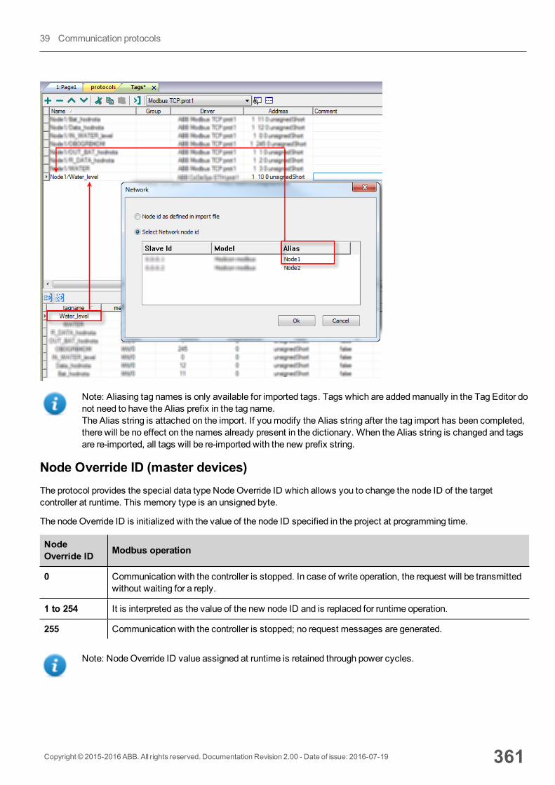
Note: Aliasing tag names is only available for imported tags. Tags which are addedmanually in the Tag Editor donot need to have the Alias prefix in the tag name.The Alias string is attached on the import. If youmodify the Alias string after the tag import has been completed,there will be no effect on the names already present in the dictionary. When the Alias string is changed and tagsare re-imported, all tags will be re-imported with the new prefix string.
Node Override ID (master devices)The protocol provides the special data type NodeOverride ID which allows you to change the node ID of the targetcontroller at runtime. This memory type is an unsigned byte.
The nodeOverride ID is initialized with the value of the node ID specified in the project at programming time.
NodeOverride ID Modbus operation
0 Communication with the controller is stopped. In case of write operation, the request will be transmittedwithout waiting for a reply.
1 to 254 It is interpreted as the value of the new node ID and is replaced for runtime operation.
255 Communication with the controller is stopped; no request messages are generated.
Note: NodeOverride ID value assigned at runtime is retained through power cycles.
Copyright © 2015-2016 ABB. All rights reserved. Documentation Revision 2.00 - Date of issue: 2016-07-19 361
39 Communication protocols
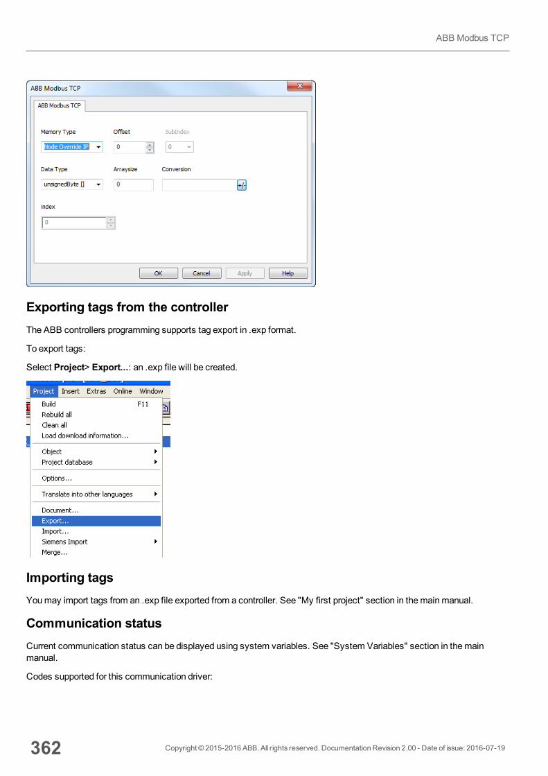
Exporting tags from the controllerThe ABB controllers programming supports tag export in .exp format.
To export tags:
Select Project> Export...: an .exp file will be created.
Importing tagsYoumay import tags from an .exp file exported from a controller. See "My first project" section in themainmanual.
Communication statusCurrent communication status can be displayed using system variables. See "System Variables" section in themainmanual.
Codes supported for this communication driver:
362 Copyright © 2015-2016 ABB. All rights reserved. Documentation Revision 2.00 - Date of issue: 2016-07-19
ABB Modbus TCP

Error Cause Action
NAK The controller replies with a not acknowledge. -
Timeout A request is not replied within the specified timeoutperiod.
Check if the controller is connected and properlyconfigured to get network access.
Invalidresponse
The device did received a response with invalidformat or contents from the controller.
Check if the data programmed in the project areconsistent with the controller resources.
GeneralError
Unidentifiable error. Contact technical support.
Copyright © 2015-2016 ABB. All rights reserved. Documentation Revision 2.00 - Date of issue: 2016-07-19 363
39 Communication protocols
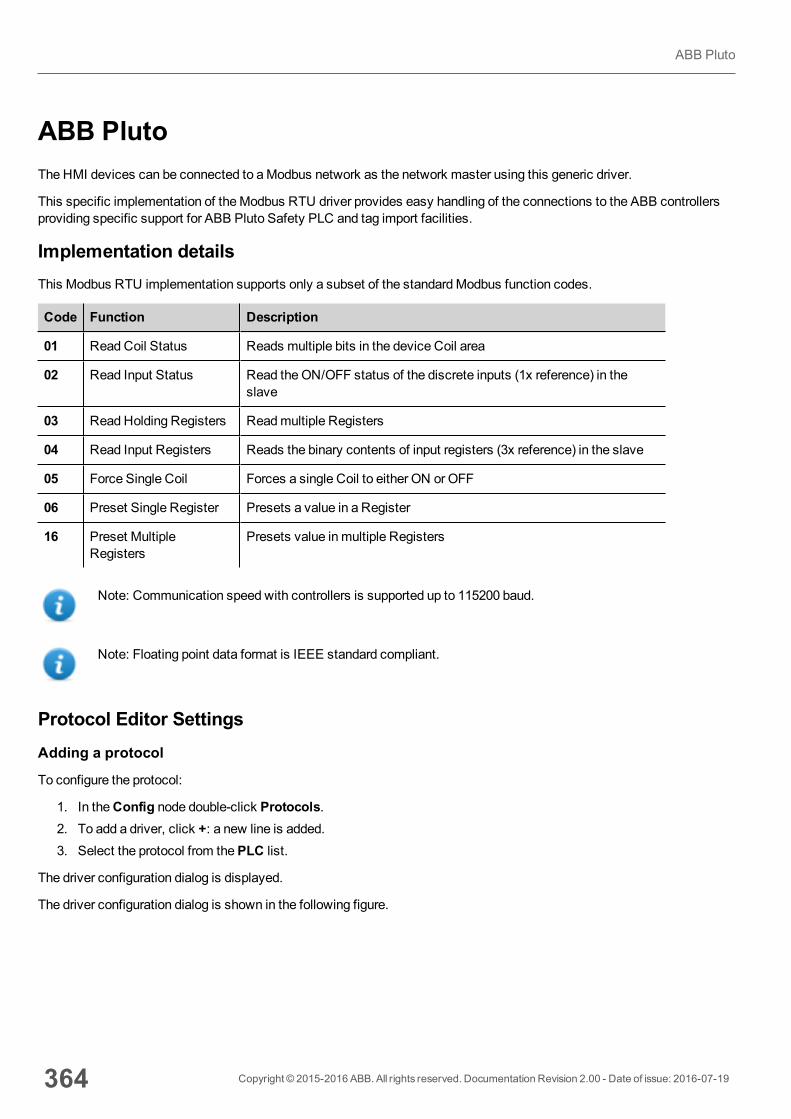
ABB PlutoThe HMI devices can be connected to aModbus network as the network master using this generic driver.
This specific implementation of theModbus RTU driver provides easy handling of the connections to the ABB controllersproviding specific support for ABB Pluto Safety PLC and tag import facilities.
Implementation detailsThis Modbus RTU implementation supports only a subset of the standardModbus function codes.
Code Function Description
01 ReadCoil Status Reads multiple bits in the device Coil area
02 Read Input Status Read theON/OFF status of the discrete inputs (1x reference) in theslave
03 ReadHolding Registers Readmultiple Registers
04 Read Input Registers Reads the binary contents of input registers (3x reference) in the slave
05 Force Single Coil Forces a single Coil to either ON or OFF
06 Preset Single Register Presets a value in a Register
16 Preset MultipleRegisters
Presets value in multiple Registers
Note: Communication speed with controllers is supported up to 115200 baud.
Note: Floating point data format is IEEE standard compliant.
Protocol Editor SettingsAdding a protocol
To configure the protocol:
1. In theConfig node double-click Protocols.2. To add a driver, click +: a new line is added.3. Select the protocol from thePLC list.
The driver configuration dialog is displayed.
The driver configuration dialog is shown in the following figure.
364 Copyright © 2015-2016 ABB. All rights reserved. Documentation Revision 2.00 - Date of issue: 2016-07-19
ABB Pluto
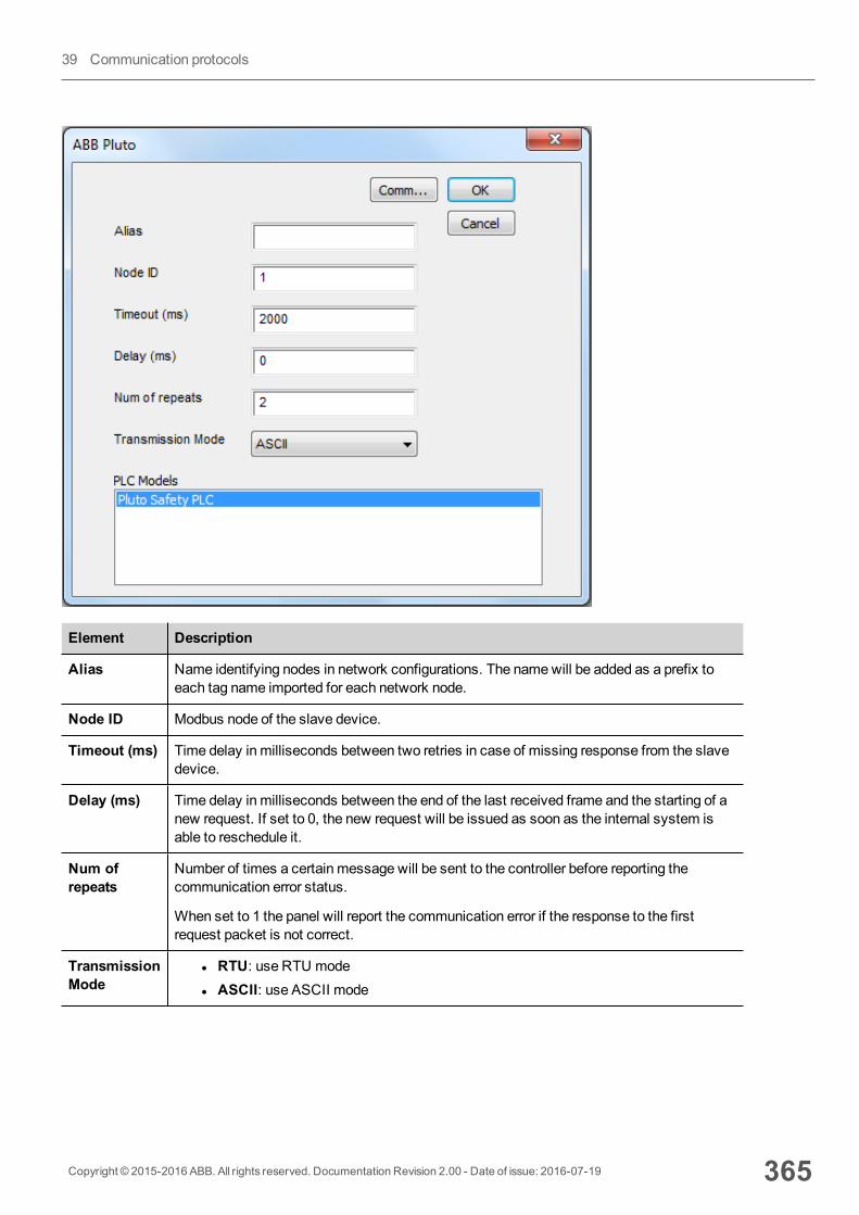
Element Description
Alias Name identifying nodes in network configurations. The namewill be added as a prefix toeach tag name imported for each network node.
Node ID Modbus node of the slave device.
Timeout (ms) Time delay in milliseconds between two retries in case of missing response from the slavedevice.
Delay (ms) Time delay in milliseconds between the end of the last received frame and the starting of anew request. If set to 0, the new request will be issued as soon as the internal system isable to reschedule it.
Num ofrepeats
Number of times a certain message will be sent to the controller before reporting thecommunication error status.
When set to 1 the panel will report the communication error if the response to the firstrequest packet is not correct.
TransmissionMode
l RTU: use RTU model ASCII: use ASCII mode
Copyright © 2015-2016 ABB. All rights reserved. Documentation Revision 2.00 - Date of issue: 2016-07-19 365
39 Communication protocols

Element Description
PLC Models PLC model you are going to connect to. The selection influences the data range offset pereach data type according to the specific PLC memory resources.
Comm… If clicked displays the communication parameters setup dialog.
Element Description
Port Serial port selection.
l COM1: device PLC port.l COM2: computer/printer port (ifavailable)
Baudrate, Parity, Data bits, Stopbits
Serial line parameters.
Mode Serial port mode. Available modes:
l RS-232.l RS-485 (2 wires).l RS-422 (4 wires).
Node Override ID (master devices)The protocol provides the special data type NodeOverride ID which allows you to change the node ID of the targetcontroller at runtime. This memory type is an unsigned byte.
The nodeOverride ID is initialized with the value of the node ID specified in the project at programming time.
366 Copyright © 2015-2016 ABB. All rights reserved. Documentation Revision 2.00 - Date of issue: 2016-07-19
ABB Pluto
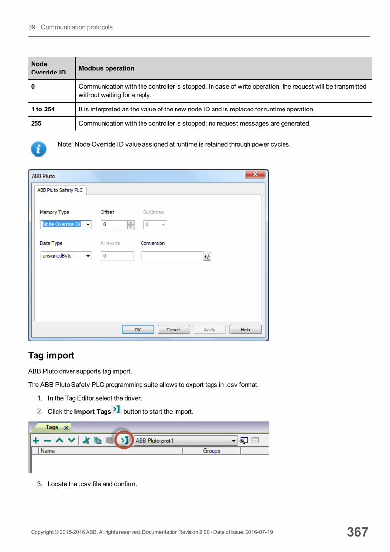
NodeOverride ID Modbus operation
0 Communication with the controller is stopped. In case of write operation, the request will be transmittedwithout waiting for a reply.
1 to 254 It is interpreted as the value of the new node ID and is replaced for runtime operation.
255 Communication with the controller is stopped; no request messages are generated.
Note: NodeOverride ID value assigned at runtime is retained through power cycles.
Tag importABB Pluto driver supports tag import.
The ABB Pluto Safety PLC programming suite allows to export tags in .csv format.
1. In the Tag Editor select the driver.
2. Click the Import Tags button to start the import.
3. Locate the .csv file and confirm.
Copyright © 2015-2016 ABB. All rights reserved. Documentation Revision 2.00 - Date of issue: 2016-07-19 367
39 Communication protocols
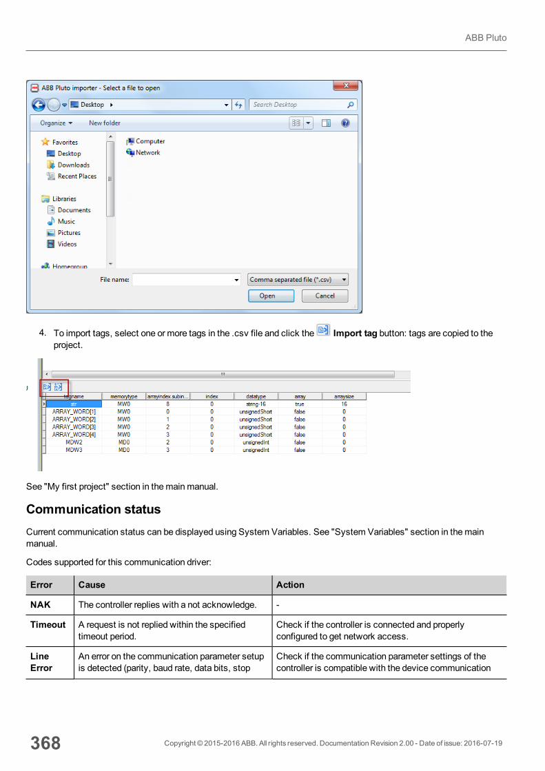
4. To import tags, select one or more tags in the .csv file and click the Import tag button: tags are copied to theproject.
See "My first project" section in themainmanual.
Communication statusCurrent communication status can be displayed using System Variables. See "System Variables" section in themainmanual.
Codes supported for this communication driver:
Error Cause Action
NAK The controller replies with a not acknowledge. -
Timeout A request is not replied within the specifiedtimeout period.
Check if the controller is connected and properlyconfigured to get network access.
LineError
An error on the communication parameter setupis detected (parity, baud rate, data bits, stop
Check if the communication parameter settings of thecontroller is compatible with the device communication
368 Copyright © 2015-2016 ABB. All rights reserved. Documentation Revision 2.00 - Date of issue: 2016-07-19
ABB Pluto

Error Cause Action
bits). setup.
Invalidresponse
The device did received a response with invalidformat or contents from the controller .
Ensure the data programmed in the project are consistentwith the controller resources.
GeneralError
Unidentifiable error. Should never be reported. Contact technical support.
Copyright © 2015-2016 ABB. All rights reserved. Documentation Revision 2.00 - Date of issue: 2016-07-19 369
39 Communication protocols
BACnetThe BACnet communication driver has been designed to connect HMI devices to BACnet networks and supports IP andMS/TP communication.
The HMI device operates as a BACnet device.
Protocol Editor SettingsAdding a protocol
To configure the protocol:
1. In theConfig node double-click Protocols.2. To add a driver, click +: a new line is added.3. Select the protocol from thePLC list.
The driver configuration dialog is displayed.
370 Copyright © 2015-2016 ABB. All rights reserved. Documentation Revision 2.00 - Date of issue: 2016-07-19
BACnet
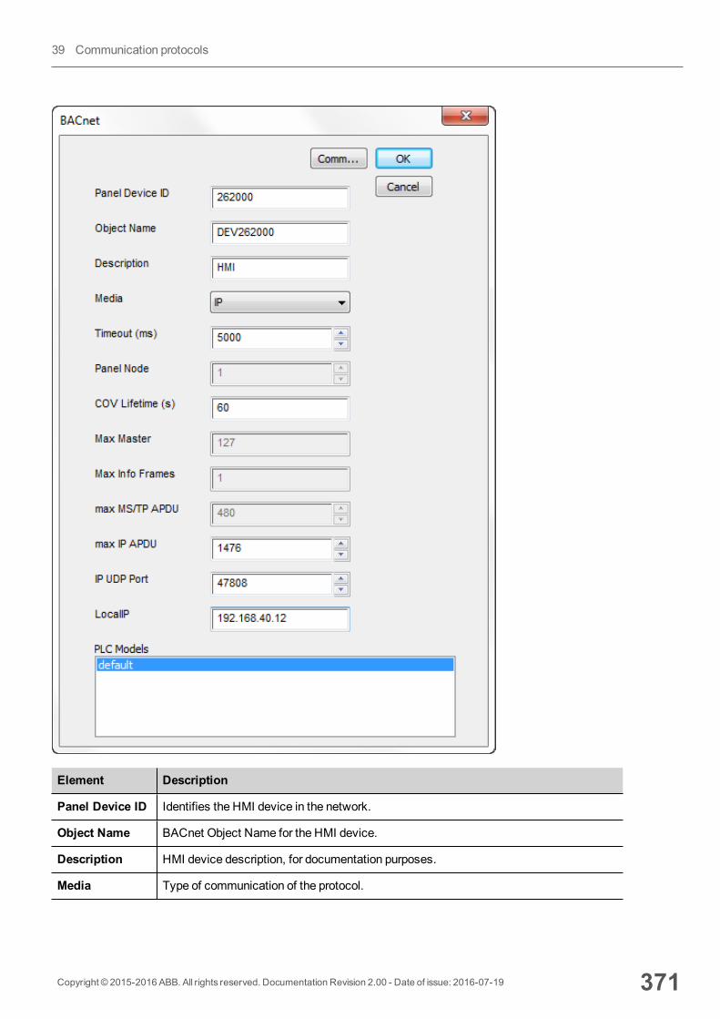
Element Description
Panel Device ID Identifies the HMI device in the network.
Object Name BACnet Object Name for the HMI device.
Description HMI device description, for documentation purposes.
Media Type of communication of the protocol.
Copyright © 2015-2016 ABB. All rights reserved. Documentation Revision 2.00 - Date of issue: 2016-07-19 371
39 Communication protocols

Element Description
l MS/TP: Master-Slave/Token-Passing communication (RS-485).l IP: based on standard UDP/IP communication.
Timeout (ms) Time delay in milliseconds between two retries in case of missing response from theBACnet device.
Panel Node * MS/TP address. Physical device address on the link; it is not passed through routers.
COV Lifetime (s) Desired lifetime of the subscription in seconds before the it shall be automaticallycancelled.. A value of zero indicates an indefinite lifetime, without automaticcancellation.
Max Master * Highest allowable address for master nodes. Must be less than or equal to 127.
Max Info Frames*
Maximum number of information frames the nodemay send before it must pass thetoken. Max Info Frames may have different values on different nodes andmay be usedto allocatemore or less of the available link bandwidth to particular nodes.
Max MS/TPAPDU *
Maximum length of APDU (Application Layer Protocol Data Unit), whichmeans theactual packet length on BACnet network. This value cannot exceed 480 (default value).
Max IP APDU ** Maximum length of APDU (Application Layer Protocol Data Unit), whichmeans theactual packet length on BACnet network. This value cannot exceed 1476 (defaultvalue).
IP UDP Port ** Port number for IP communication.
Local IP ** IP Address of the network adapter to use for protocol. Not required if the device has onlyone Ethernet adapter.
372 Copyright © 2015-2016 ABB. All rights reserved. Documentation Revision 2.00 - Date of issue: 2016-07-19
BACnet
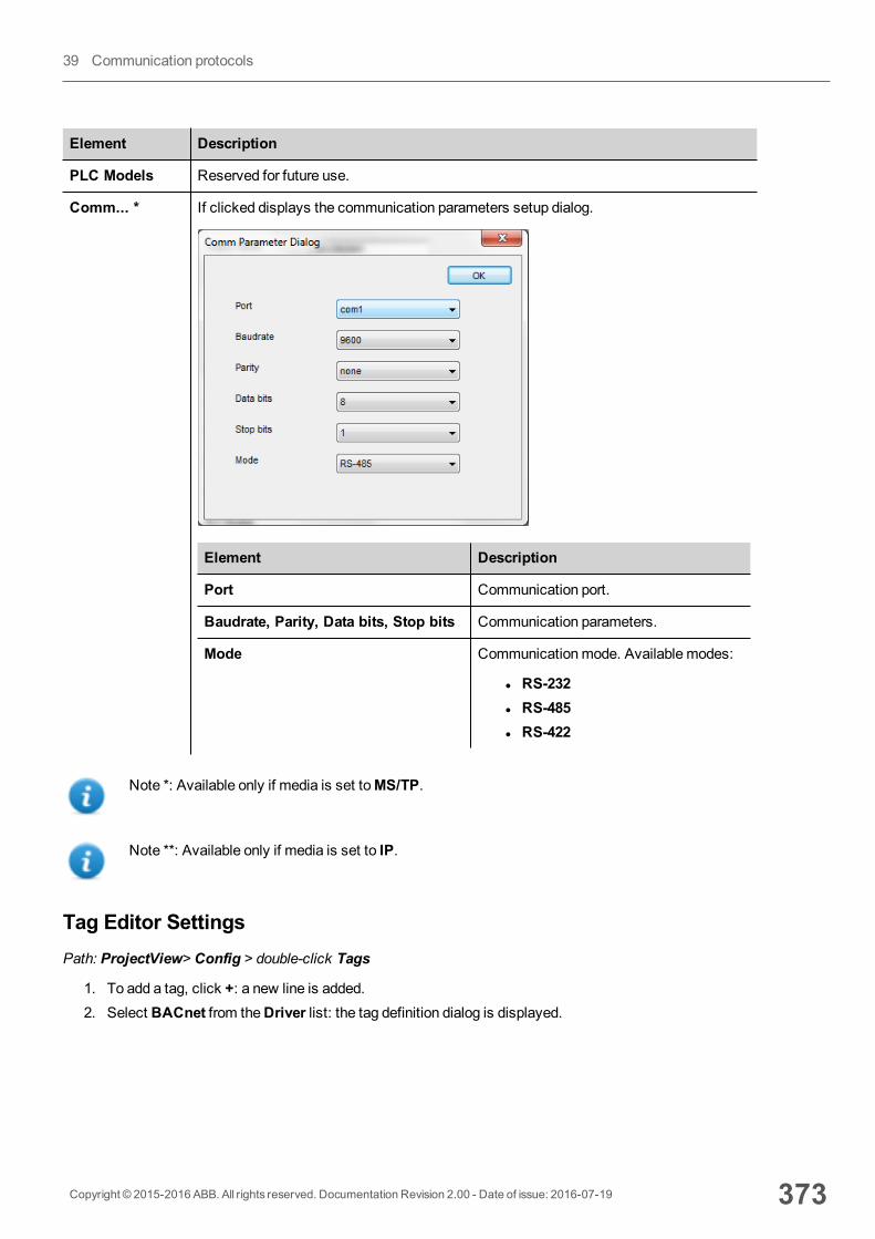
Element Description
PLC Models Reserved for future use.
Comm... * If clicked displays the communication parameters setup dialog.
Element Description
Port Communication port.
Baudrate, Parity, Data bits, Stop bits Communication parameters.
Mode Communicationmode. Available modes:
l RS-232l RS-485l RS-422
Note *: Available only if media is set toMS/TP.
Note **: Available only if media is set to IP.
Tag Editor SettingsPath: ProjectView> Config > double-click Tags
1. To add a tag, click +: a new line is added.2. Select BACnet from theDriver list: the tag definition dialog is displayed.
Copyright © 2015-2016 ABB. All rights reserved. Documentation Revision 2.00 - Date of issue: 2016-07-19 373
39 Communication protocols
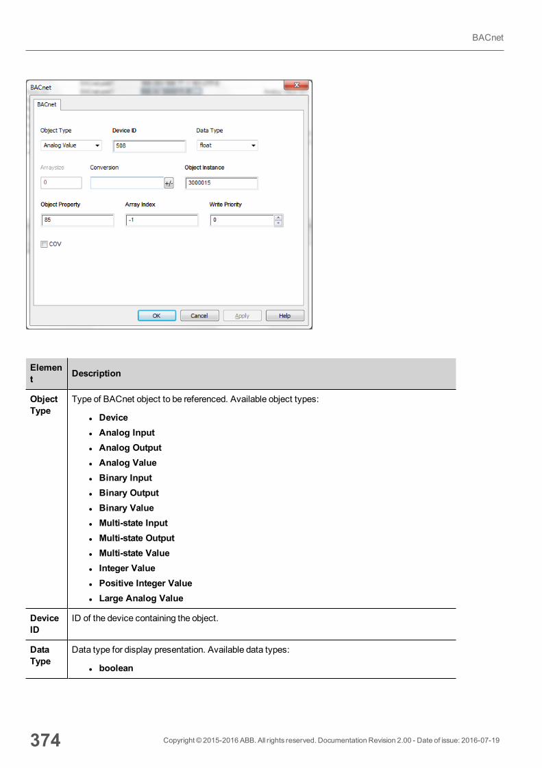
Element Description
ObjectType
Type of BACnet object to be referenced. Available object types:
l Devicel Analog Inputl Analog Outputl Analog Valuel Binary Inputl Binary Outputl Binary Valuel Multi-state Inputl Multi-state Outputl Multi-state Valuel Integer Valuel Positive Integer Valuel Large Analog Value
DeviceID
ID of the device containing the object.
DataType
Data type for display presentation. Available data types:
l boolean
374 Copyright © 2015-2016 ABB. All rights reserved. Documentation Revision 2.00 - Date of issue: 2016-07-19
BACnet
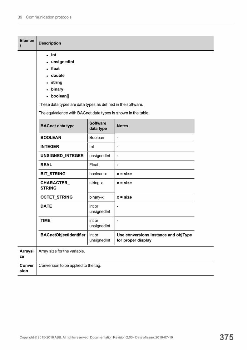
Element Description
l intl unsignedIntl floatl doublel stringl binaryl boolean[]
These data types are data types as defined in the software.
The equivalence with BACnet data types is shown in the table:
BACnet data type Softwaredata type Notes
BOOLEAN Boolean -
INTEGER Int -
UNSIGNED_INTEGER unsignedInt -
REAL Float -
BIT_STRING boolean-x x = size
CHARACTER_STRING
string-x x = size
OCTET_STRING binary-x x = size
DATE int orunsignedInt
-
TIME int orunsignedInt
-
BACnetObjectIdentifier int orunsignedInt
Use conversions instance and objTypefor proper display
Arraysize
Array size for the variable.
Conversion
Conversion to be applied to the tag.
Copyright © 2015-2016 ABB. All rights reserved. Documentation Revision 2.00 - Date of issue: 2016-07-19 375
39 Communication protocols
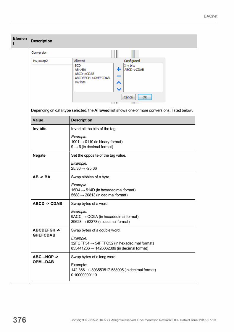
Element Description
Depending on data type selected, theAllowed list shows one or more conversions, listed below.
Value Description
Inv bits Invert all the bits of the tag.
Example:1001→ 0110 (in binary format)9→ 6 (in decimal format)
Negate Set the opposite of the tag value.
Example:25.36→ -25.36
AB -> BA Swap nibbles of a byte.
Example:15D4→514D (in hexadecimal format)5588→ 20813 (in decimal format)
ABCD -> CDAB Swap bytes of a word.
Example:9ACC→CC9A (in hexadecimal format)39628→ 52378 (in decimal format)
ABCDEFGH ->GHEFCDAB
Swap bytes of a double word.
Example:32FCFF54→54FFFC32 (in hexadecimal format)855441236→ 1426062386 (in decimal format)
ABC...NOP ->OPM...DAB
Swap bytes of a long word.
Example:142.366→ -893553517.588905 (in decimal format)0 10000000110
376 Copyright © 2015-2016 ABB. All rights reserved. Documentation Revision 2.00 - Date of issue: 2016-07-19
BACnet
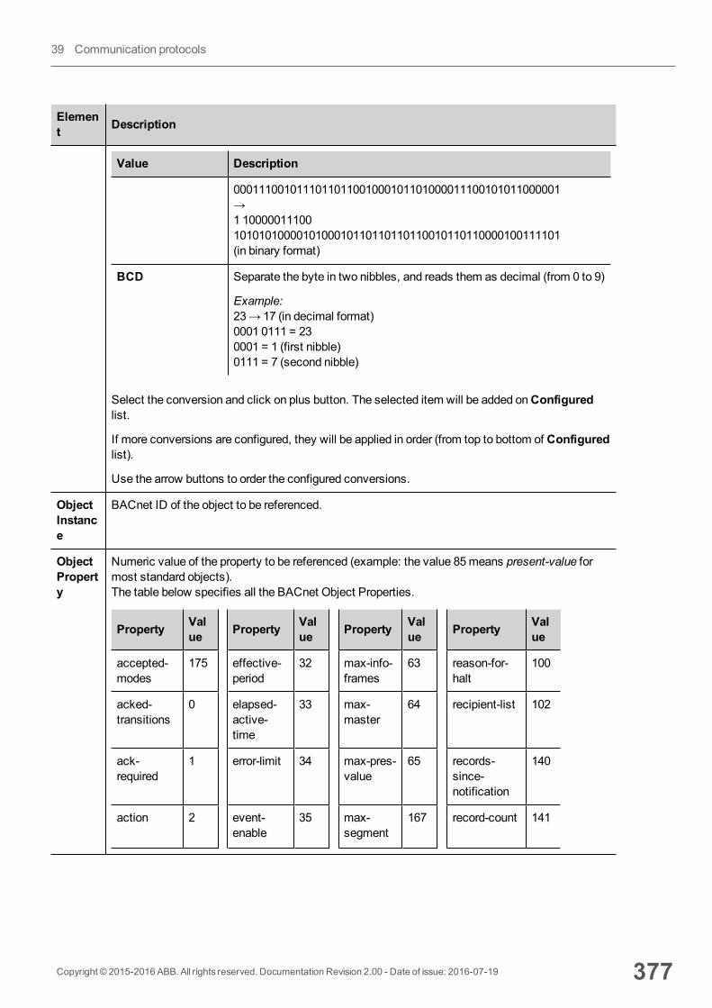
Element Description
Value Description
0001110010111011011001000101101000011100101011000001→1 100000111001010101000010100010110110110110010110110000100111101(in binary format)
BCD Separate the byte in two nibbles, and reads them as decimal (from 0 to 9)
Example:23→ 17 (in decimal format)0001 0111 = 230001 = 1 (first nibble)0111 = 7 (second nibble)
Select the conversion and click on plus button. The selected item will be added onConfiguredlist.
If more conversions are configured, they will be applied in order (from top to bottom of Configuredlist).
Use the arrow buttons to order the configured conversions.
ObjectInstance
BACnet ID of the object to be referenced.
ObjectProperty
Numeric value of the property to be referenced (example: the value 85means present-value formost standard objects).The table below specifies all the BACnet Object Properties.
Property Value Property Val
ue Property Value Property Val
ue
accepted-modes
175 effective-period
32 max-info-frames
63 reason-for-halt
100
acked-transitions
0 elapsed-active-time
33 max-master
64 recipient-list 102
ack-required
1 error-limit 34 max-pres-value
65 records-since-notification
140
action 2 event-enable
35 max-segment
167 record-count 141
Copyright © 2015-2016 ABB. All rights reserved. Documentation Revision 2.00 - Date of issue: 2016-07-19 377
39 Communication protocols
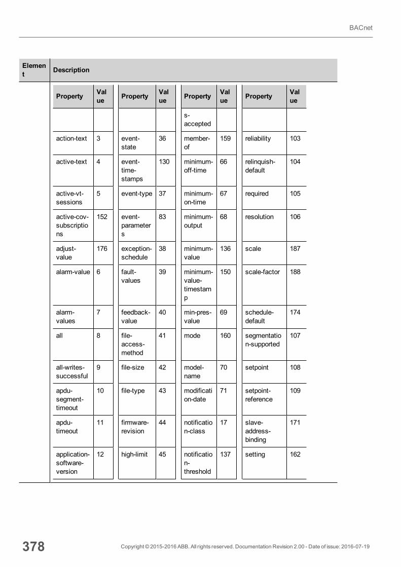
Element Description
Property Value Property Val
ue Property Value Property Val
ue
s-accepted
action-text 3 event-state
36 member-of
159 reliability 103
active-text 4 event-time-stamps
130 minimum-off-time
66 relinquish-default
104
active-vt-sessions
5 event-type 37 minimum-on-time
67 required 105
active-cov-subscriptions
152 event-parameters
83 minimum-output
68 resolution 106
adjust-value
176 exception-schedule
38 minimum-value
136 scale 187
alarm-value 6 fault-values
39 minimum-value-timestamp
150 scale-factor 188
alarm-values
7 feedback-value
40 min-pres-value
69 schedule-default
174
all 8 file-access-method
41 mode 160 segmentation-supported
107
all-writes-successful
9 file-size 42 model-name
70 setpoint 108
apdu-segment-timeout
10 file-type 43 modification-date
71 setpoint-reference
109
apdu-timeout
11 firmware-revision
44 notification-class
17 slave-address-binding
171
application-software-version
12 high-limit 45 notification-threshold
137 setting 162
378 Copyright © 2015-2016 ABB. All rights reserved. Documentation Revision 2.00 - Date of issue: 2016-07-19
BACnet
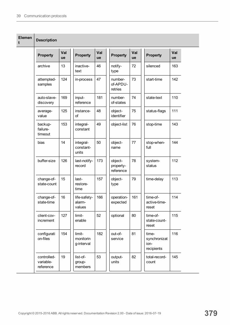
Element Description
Property Value Property Val
ue Property Value Property Val
ue
archive 13 inactive-text
46 notify-type
72 silenced 163
attempted-samples
124 in-process 47 number-of-APDU-retries
73 start-time 142
auto-slave-discovery
169 input-reference
181 number-of-states
74 state-text 110
average-value
125 instance-of
48 object-identifier
75 status-flags 111
backup-failure-timeout
153 integral-constant
49 object-list 76 stop-time 143
bias 14 integral-constant-units
50 object-name
77 stop-when-full
144
buffer-size 126 last-notify-record
173 object-property-reference
78 system-status
112
change-of-state-count
15 last-restore-time
157 object-type
79 time-delay 113
change-of-state-time
16 life-safety-alarm-values
166 operation-expected
161 time-of-active-time-reset
114
client-cov-increment
127 limit-enable
52 optional 80 time-of-state-count-reset
115
configuration-files
154 limit-monitoring-interval
182 out-of-service
81 time-synchronization-recipients
116
controlled-variable-reference
19 list-of-group-members
53 output-units
82 total-record-count
145
Copyright © 2015-2016 ABB. All rights reserved. Documentation Revision 2.00 - Date of issue: 2016-07-19 379
39 Communication protocols
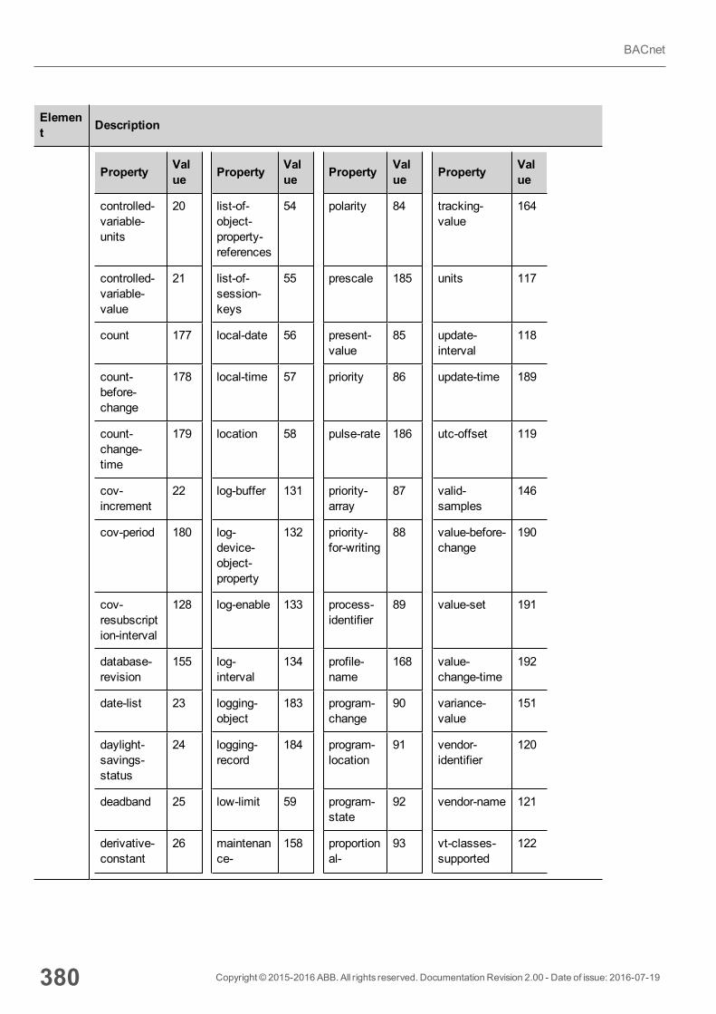
Element Description
Property Value Property Val
ue Property Value Property Val
ue
controlled-variable-units
20 list-of-object-property-references
54 polarity 84 tracking-value
164
controlled-variable-value
21 list-of-session-keys
55 prescale 185 units 117
count 177 local-date 56 present-value
85 update-interval
118
count-before-change
178 local-time 57 priority 86 update-time 189
count-change-time
179 location 58 pulse-rate 186 utc-offset 119
cov-increment
22 log-buffer 131 priority-array
87 valid-samples
146
cov-period 180 log-device-object-property
132 priority-for-writing
88 value-before-change
190
cov-resubscription-interval
128 log-enable 133 process-identifier
89 value-set 191
database-revision
155 log-interval
134 profile-name
168 value-change-time
192
date-list 23 logging-object
183 program-change
90 variance-value
151
daylight-savings-status
24 logging-record
184 program-location
91 vendor-identifier
120
deadband 25 low-limit 59 program-state
92 vendor-name 121
derivative-constant
26 maintenance-
158 proportional-
93 vt-classes-supported
122
380 Copyright © 2015-2016 ABB. All rights reserved. Documentation Revision 2.00 - Date of issue: 2016-07-19
BACnet

Element Description
Property Value Property Val
ue Property Value Property Val
ue
required constant
derivative-constant-units
27 manipulated-variable-reference
60 proportional-constant-units
94 weekly-schedule
123
description 28 manual-slave-address-binding
170 protocol-object-types-supported
96 window-interval
147
description-of-halt
29 maximum-output
61 protocol-revision
139 window-samples
148
device-address-binding
30 maximum-value
135 protocol-services-supported
97 zone-members
165
device-type 31 maximum-value-timestamp
149 protocol-version
98
direct-reading
156 max-apdu-length-accepted
62 read-only 99
ArrayIndex
Index for subscribing elements in BACnet arrays.
l -1 means read all elementsl 0 to nmeans read the specified element
Priority Array exampleTo read a priority array object it is necessary to set Object Property = 87 andArray Index has torefer to the priority item to be read.The following figure shows how to read the 16th item of a priority array.
Copyright © 2015-2016 ABB. All rights reserved. Documentation Revision 2.00 - Date of issue: 2016-07-19 381
39 Communication protocols
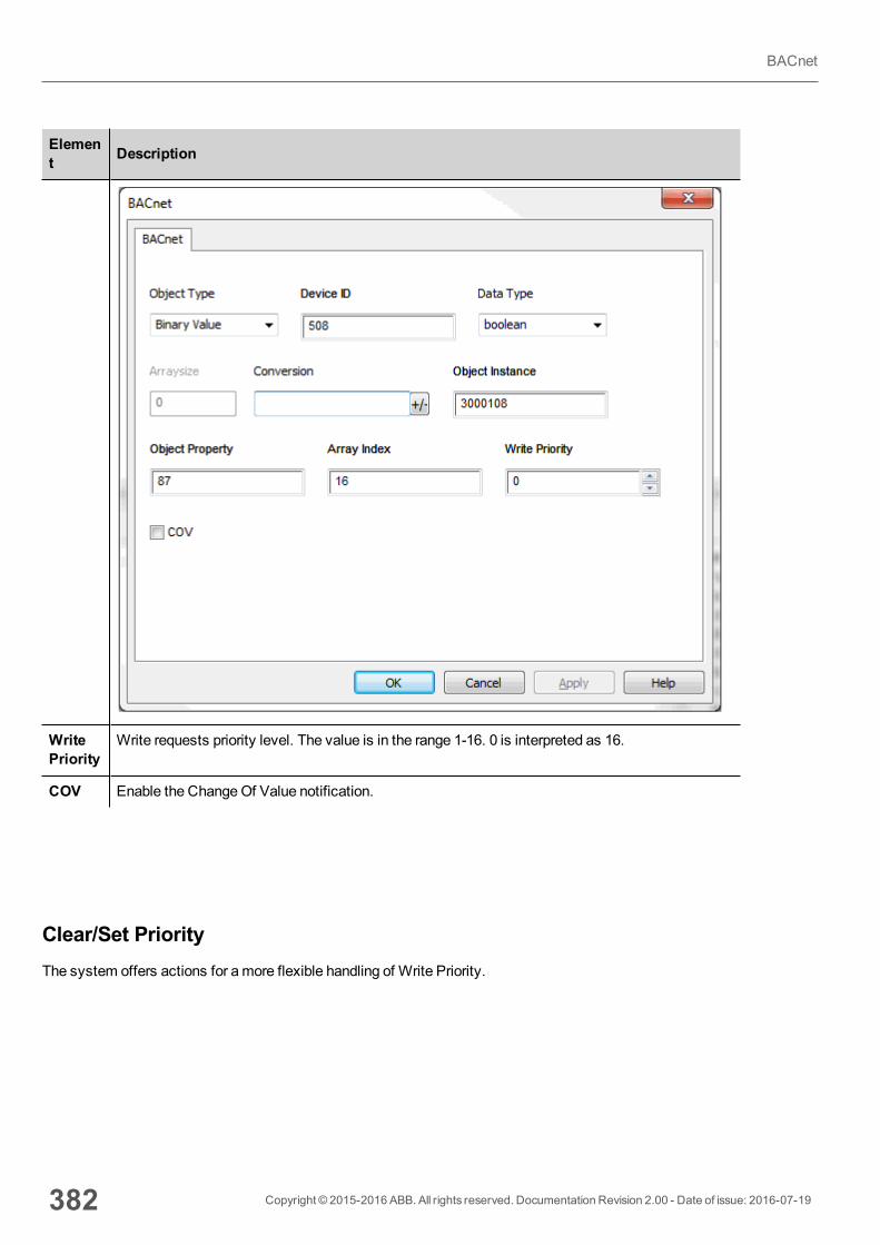
Element Description
WritePriority
Write requests priority level. The value is in the range 1-16. 0 is interpreted as 16.
COV Enable the ChangeOf Value notification.
Clear/Set PriorityThe system offers actions for amore flexible handling of Write Priority.
382 Copyright © 2015-2016 ABB. All rights reserved. Documentation Revision 2.00 - Date of issue: 2016-07-19
BACnet
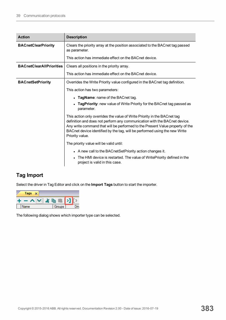
Action Description
BACnetClearPriority Clears the priority array at the position associated to the BACnet tag passedas parameter.
This action has immediate effect on the BACnet device.
BACnetClearAllPriorities Clears all positions in the priority array.
This action has immediate effect on the BACnet device.
BACnetSetPriority Overrides theWrite Priority value configured in the BACnet tag definition.
This action has two parameters:
l TagName: name of the BACnet tag.l TagPriority: new value of Write Priority for the BACnet tag passed asparameter.
This action only overrides the value of Write Priority in the BACnet tagdefinition and does not perform any communication with the BACnet device.Any write command that will be performed to the Present Value property of theBACnet device identified by the tag, will be performed using the new WritePriority value.
The priority value will be valid until:
l A new call to the BACnetSetPriority action changes it.l The HMI device is restarted. The value of WritePriority defined in theproject is valid in this case.
Tag ImportSelect the driver in Tag Editor and click on the Import Tags button to start the importer.
The following dialog shows which importer type can be selected.
Copyright © 2015-2016 ABB. All rights reserved. Documentation Revision 2.00 - Date of issue: 2016-07-19 383
39 Communication protocols
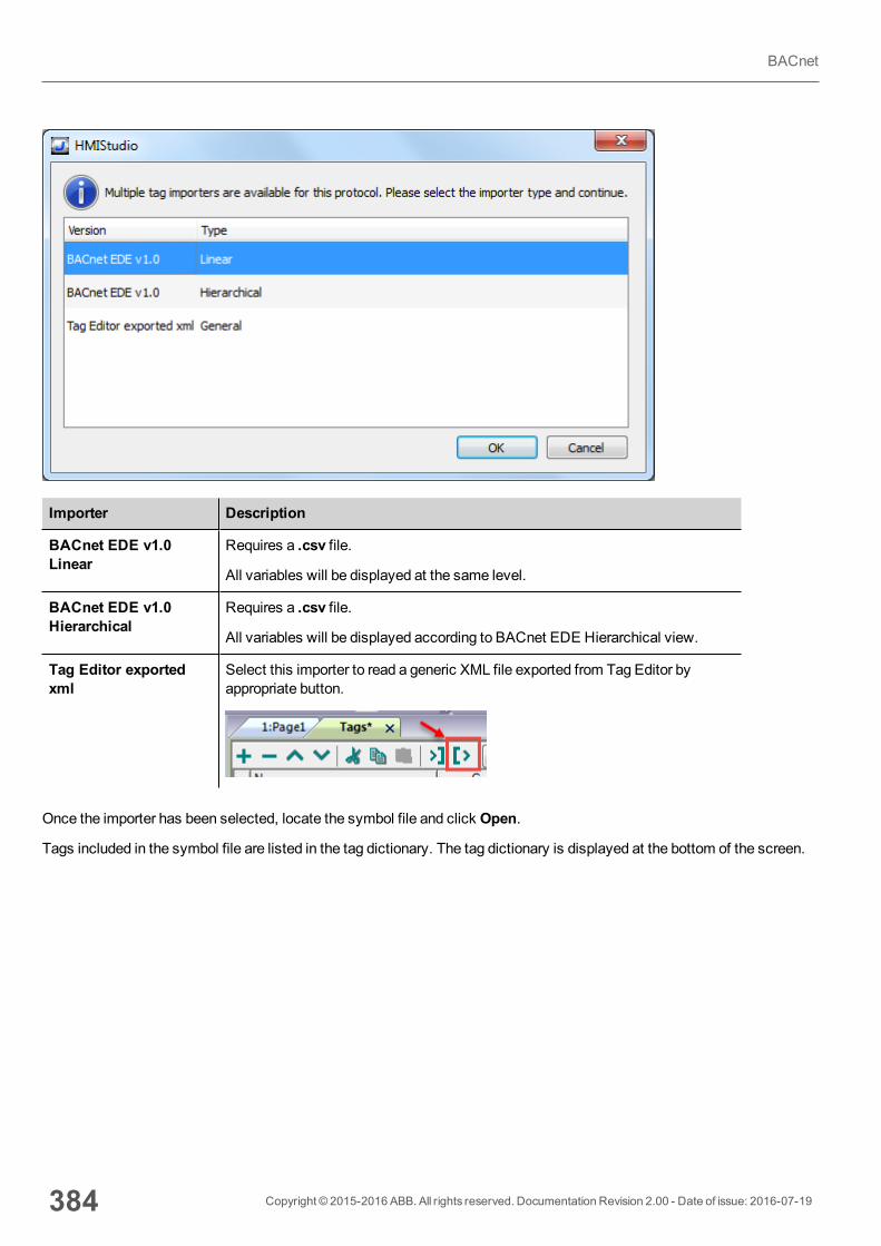
Importer Description
BACnet EDE v1.0Linear
Requires a .csv file.
All variables will be displayed at the same level.
BACnet EDE v1.0Hierarchical
Requires a .csv file.
All variables will be displayed according to BACnet EDE Hierarchical view.
Tag Editor exportedxml
Select this importer to read a generic XML file exported from Tag Editor byappropriate button.
Once the importer has been selected, locate the symbol file and click Open.
Tags included in the symbol file are listed in the tag dictionary. The tag dictionary is displayed at the bottom of the screen.
384 Copyright © 2015-2016 ABB. All rights reserved. Documentation Revision 2.00 - Date of issue: 2016-07-19
BACnet

Toolbar item Description
Import Tag(s).
Select tags to be imported and click on this icon to add tagsfrom tag dictionary to the project
Update Tag(s).
Click on this icon to update the tags in the project, due a newdictionary import.
Copyright © 2015-2016 ABB. All rights reserved. Documentation Revision 2.00 - Date of issue: 2016-07-19 385
39 Communication protocols
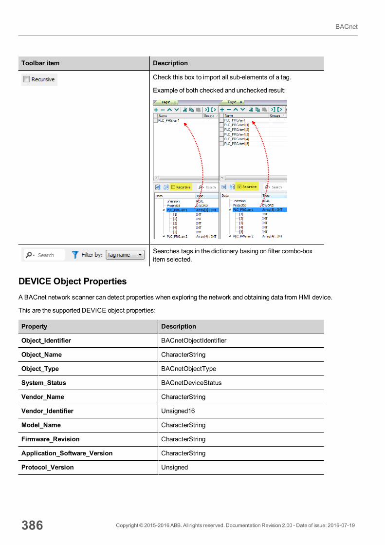
Toolbar item Description
Check this box to import all sub-elements of a tag.
Example of both checked and unchecked result:
Searches tags in the dictionary basing on filter combo-boxitem selected.
DEVICE Object PropertiesA BACnet network scanner can detect properties when exploring the network and obtaining data from HMI device.
This are the supported DEVICE object properties:
Property Description
Object_Identifier BACnetObjectIdentifier
Object_Name CharacterString
Object_Type BACnetObjectType
System_Status BACnetDeviceStatus
Vendor_Name CharacterString
Vendor_Identifier Unsigned16
Model_Name CharacterString
Firmware_Revision CharacterString
Application_Software_Version CharacterString
Protocol_Version Unsigned
386 Copyright © 2015-2016 ABB. All rights reserved. Documentation Revision 2.00 - Date of issue: 2016-07-19
BACnet
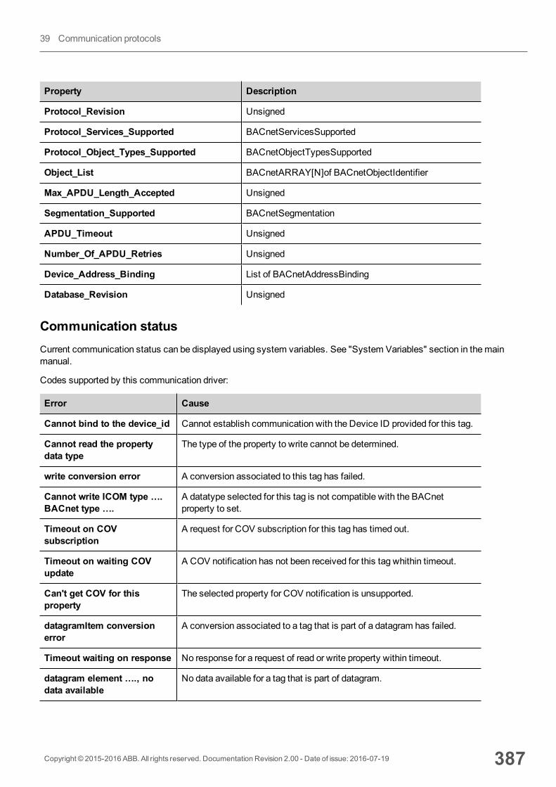
Property Description
Protocol_Revision Unsigned
Protocol_Services_Supported BACnetServicesSupported
Protocol_Object_Types_Supported BACnetObjectTypesSupported
Object_List BACnetARRAY[N]of BACnetObjectIdentifier
Max_APDU_Length_Accepted Unsigned
Segmentation_Supported BACnetSegmentation
APDU_Timeout Unsigned
Number_Of_APDU_Retries Unsigned
Device_Address_Binding List of BACnetAddressBinding
Database_Revision Unsigned
Communication statusCurrent communication status can be displayed using system variables. See "System Variables" section in themainmanual.
Codes supported by this communication driver:
Error Cause
Cannot bind to the device_id Cannot establish communication with the Device ID provided for this tag.
Cannot read the propertydata type
The type of the property to write cannot be determined.
write conversion error A conversion associated to this tag has failed.
Cannot write ICOM type ….BACnet type ….
A datatype selected for this tag is not compatible with the BACnetproperty to set.
Timeout on COVsubscription
A request for COV subscription for this tag has timed out.
Timeout on waiting COVupdate
A COV notification has not been received for this tag whithin timeout.
Can't get COV for thisproperty
The selected property for COV notification is unsupported.
datagramItem conversionerror
A conversion associated to a tag that is part of a datagram has failed.
Timeout waiting on response No response for a request of read or write property within timeout.
datagram element …., nodata available
No data available for a tag that is part of datagram.
Copyright © 2015-2016 ABB. All rights reserved. Documentation Revision 2.00 - Date of issue: 2016-07-19 387
39 Communication protocols
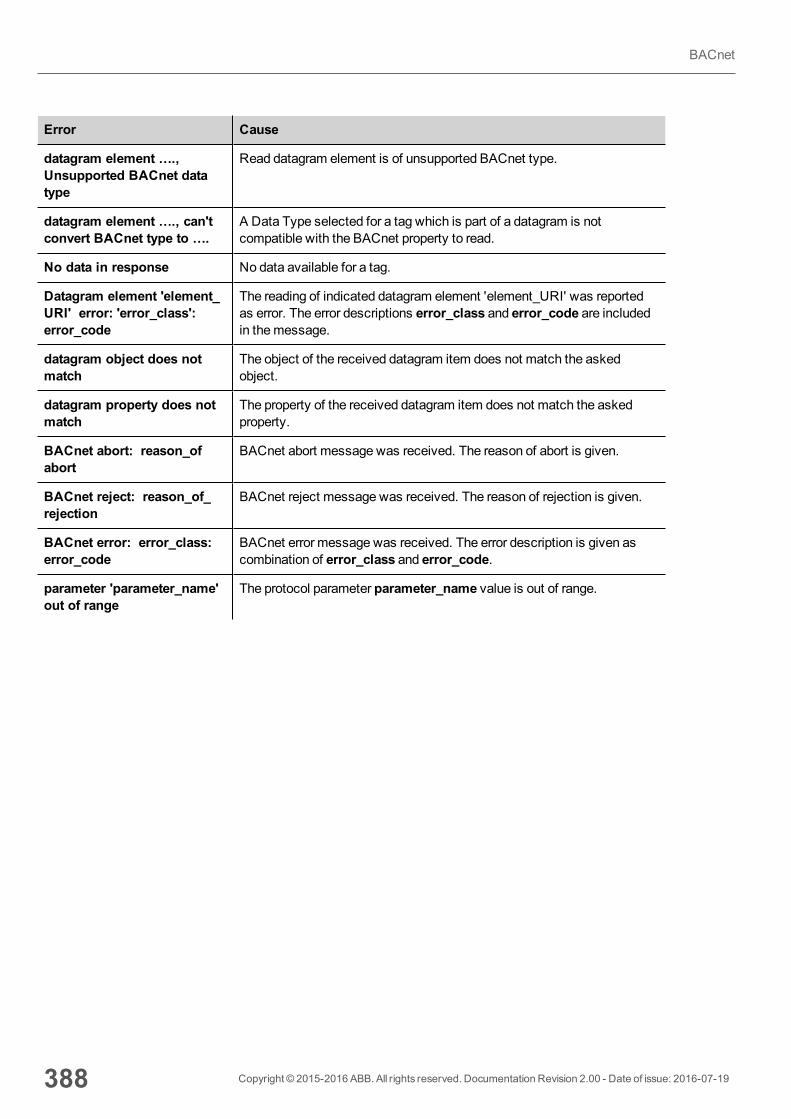
Error Cause
datagram element ….,Unsupported BACnet datatype
Read datagram element is of unsupported BACnet type.
datagram element …., can'tconvert BACnet type to ….
A Data Type selected for a tag which is part of a datagram is notcompatible with the BACnet property to read.
No data in response No data available for a tag.
Datagram element 'element_URI' error: 'error_class': error_code
The reading of indicated datagram element 'element_URI' was reportedas error. The error descriptions error_class and error_code are includedin themessage.
datagram object does notmatch
The object of the received datagram item does not match the askedobject.
datagram property does notmatch
The property of the received datagram item does not match the askedproperty.
BACnet abort: reason_ofabort
BACnet abort message was received. The reason of abort is given.
BACnet reject: reason_of_rejection
BACnet reject message was received. The reason of rejection is given.
BACnet error: error_class:error_code
BACnet error message was received. The error description is given ascombination of error_class and error_code.
parameter 'parameter_name'out of range
The protocol parameter parameter_name value is out of range.
388 Copyright © 2015-2016 ABB. All rights reserved. Documentation Revision 2.00 - Date of issue: 2016-07-19
BACnet
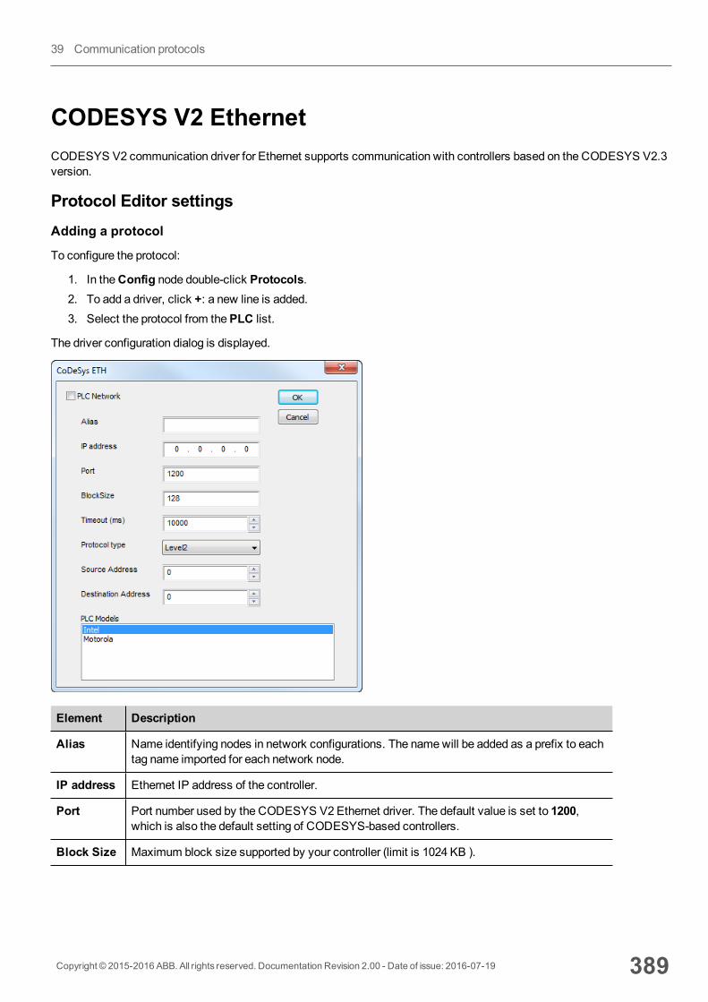
CODESYS V2 EthernetCODESYS V2 communication driver for Ethernet supports communication with controllers based on the CODESYS V2.3version.
Protocol Editor settingsAdding a protocol
To configure the protocol:
1. In theConfig node double-click Protocols.2. To add a driver, click +: a new line is added.3. Select the protocol from thePLC list.
The driver configuration dialog is displayed.
Element Description
Alias Name identifying nodes in network configurations. The namewill be added as a prefix to eachtag name imported for each network node.
IP address Ethernet IP address of the controller.
Port Port number used by the CODESYS V2 Ethernet driver. The default value is set to 1200,which is also the default setting of CODESYS-based controllers.
Block Size Maximum block size supported by your controller (limit is 1024 KB ).
Copyright © 2015-2016 ABB. All rights reserved. Documentation Revision 2.00 - Date of issue: 2016-07-19 389
39 Communication protocols
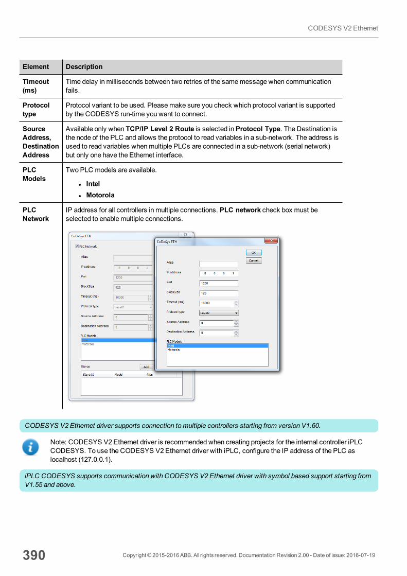
Element Description
Timeout(ms)
Time delay in milliseconds between two retries of the samemessage when communicationfails.
Protocoltype
Protocol variant to be used. Pleasemake sure you check which protocol variant is supportedby the CODESYS run-time you want to connect.
SourceAddress,DestinationAddress
Available only when TCP/IP Level 2 Route is selected inProtocol Type. The Destination isthe node of the PLC and allows the protocol to read variables in a sub-network. The address isused to read variables whenmultiple PLCs are connected in a sub-network (serial network)but only one have the Ethernet interface.
PLCModels
Two PLC models are available.
l Intell Motorola
PLCNetwork
IP address for all controllers in multiple connections. PLC network check box must beselected to enablemultiple connections.
CODESYS V2 Ethernet driver supports connection tomultiple controllers starting from version V1.60.
Note: CODESYS V2 Ethernet driver is recommended when creating projects for the internal controller iPLCCODESYS. To use the CODESYS V2 Ethernet driver with iPLC, configure the IP address of the PLC aslocalhost (127.0.0.1).
iPLC CODESYS supports communication with CODESYS V2 Ethernet driver with symbol based support starting fromV1.55 and above.
390 Copyright © 2015-2016 ABB. All rights reserved. Documentation Revision 2.00 - Date of issue: 2016-07-19
CODESYS V2 Ethernet
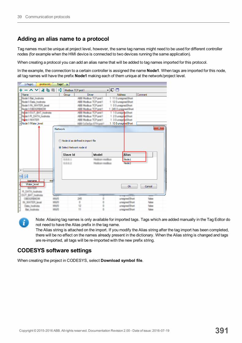
Adding an alias name to a protocolTag names must be unique at project level, however, the same tag names might need to be used for different controllernodes (for example when the HMI device is connected to two devices running the same application).
When creating a protocol you can add an alias name that will be added to tag names imported for this protocol.
In the example, the connection to a certain controller is assigned the nameNode1. When tags are imported for this node,all tag names will have the prefix Node1making each of them unique at the network/project level.
Note: Aliasing tag names is only available for imported tags. Tags which are addedmanually in the Tag Editor donot need to have the Alias prefix in the tag name.The Alias string is attached on the import. If youmodify the Alias string after the tag import has been completed,there will be no effect on the names already present in the dictionary. When the Alias string is changed and tagsare re-imported, all tags will be re-imported with the new prefix string.
CODESYS software settingsWhen creating the project in CODESYS, select Download symbol file.
Copyright © 2015-2016 ABB. All rights reserved. Documentation Revision 2.00 - Date of issue: 2016-07-19 391
39 Communication protocols

Note: CODESYS V2 Ethernet communication driver supports the automatic symbol file (SDB) upload from thePLC; any change in the tag offset due to new compilation of the PLC program does not require a symbol file re-import. Tag file has to be re-imported only in case of tag rename or definition of new tags.
When the optionDownload symbol file is not available or cleared, the protocol can work only if theProjectId tag isimported. If the tag offset changes because of a new compilation of the PLC program, the symbol file must be re-imported.
Data typesThe import module supports variables of standard data types and user defined data types.
392 Copyright © 2015-2016 ABB. All rights reserved. Documentation Revision 2.00 - Date of issue: 2016-07-19
CODESYS V2 Ethernet
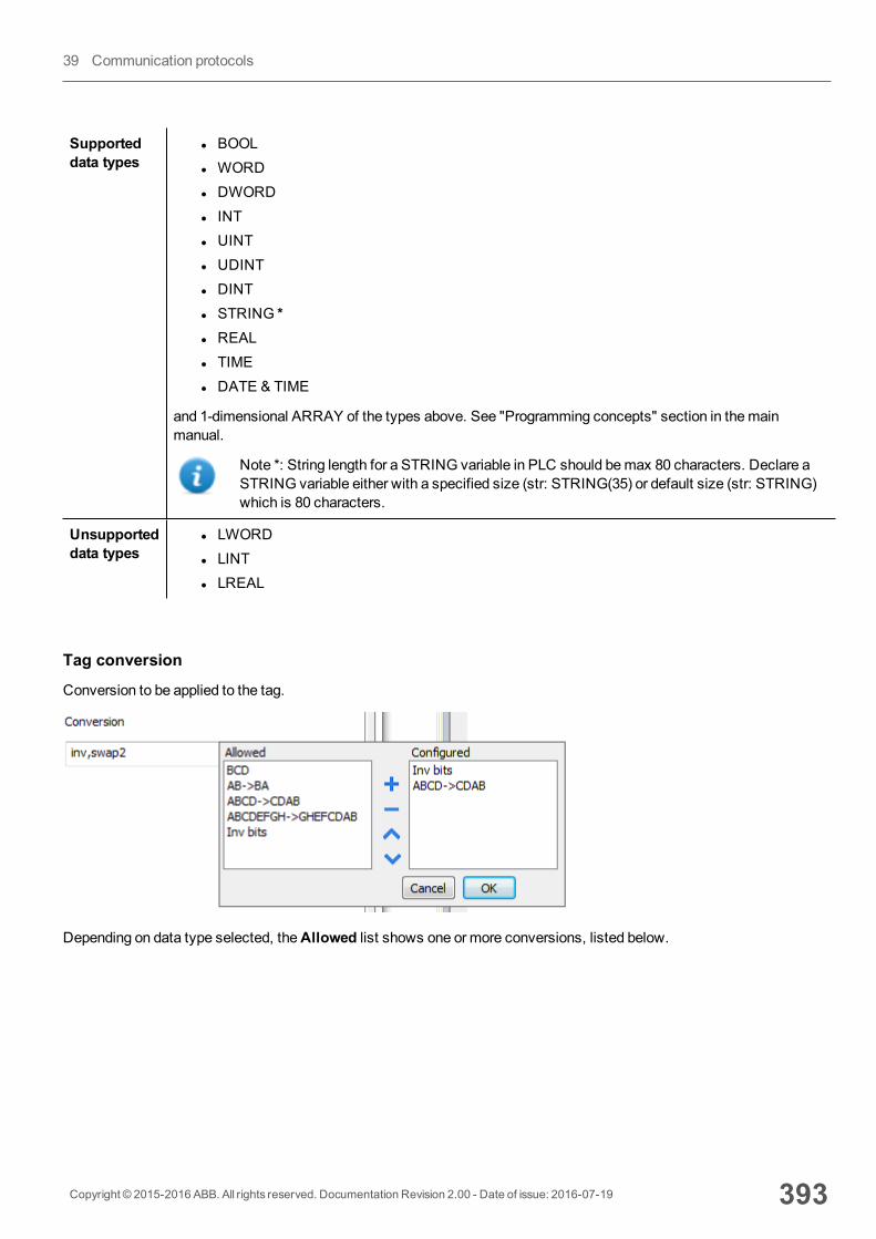
Supporteddata types
l BOOLl WORDl DWORDl INTl UINTl UDINTl DINTl STRING *l REALl TIMEl DATE & TIME
and 1-dimensional ARRAY of the types above. See "Programming concepts" section in themainmanual.
Note *: String length for a STRING variable in PLC should bemax 80 characters. Declare aSTRING variable either with a specified size (str: STRING(35) or default size (str: STRING)which is 80 characters.
Unsupporteddata types
l LWORDl LINTl LREAL
Tag conversion
Conversion to be applied to the tag.
Depending on data type selected, theAllowed list shows one or more conversions, listed below.
Copyright © 2015-2016 ABB. All rights reserved. Documentation Revision 2.00 - Date of issue: 2016-07-19 393
39 Communication protocols
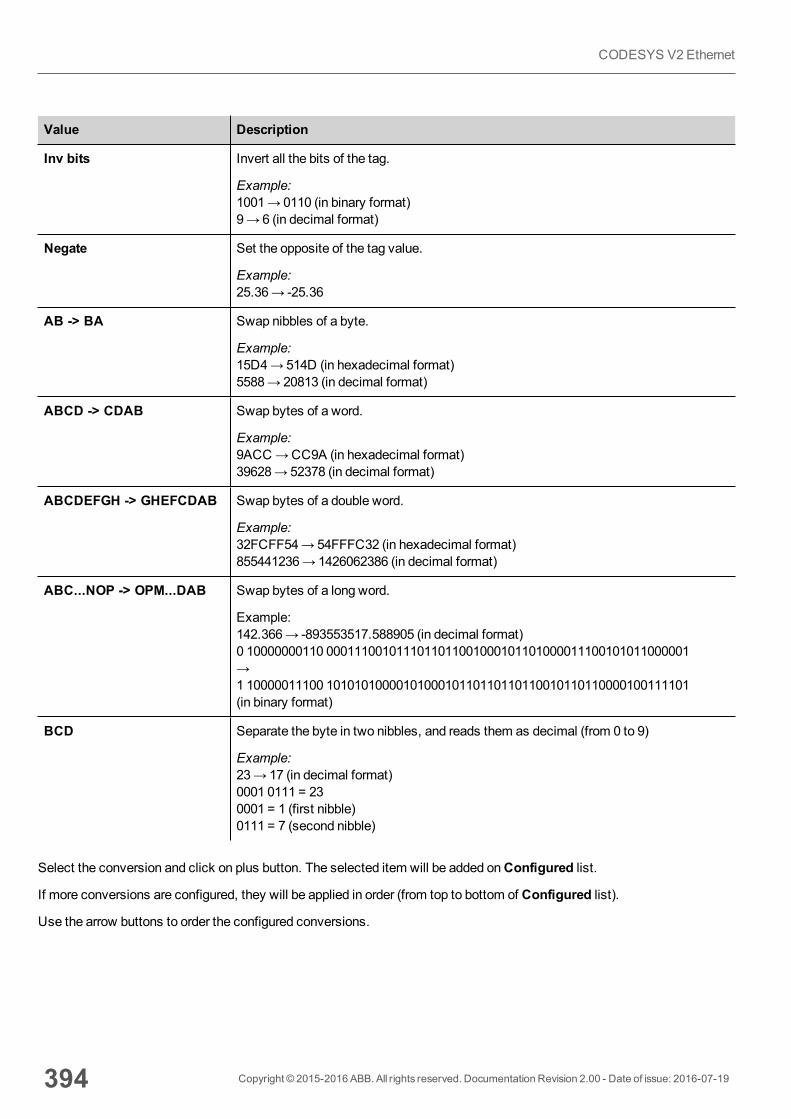
Value Description
Inv bits Invert all the bits of the tag.
Example:1001→ 0110 (in binary format)9→ 6 (in decimal format)
Negate Set the opposite of the tag value.
Example:25.36→ -25.36
AB -> BA Swap nibbles of a byte.
Example:15D4→514D (in hexadecimal format)5588→ 20813 (in decimal format)
ABCD -> CDAB Swap bytes of a word.
Example:9ACC→CC9A (in hexadecimal format)39628→ 52378 (in decimal format)
ABCDEFGH -> GHEFCDAB Swap bytes of a double word.
Example:32FCFF54→54FFFC32 (in hexadecimal format)855441236→ 1426062386 (in decimal format)
ABC...NOP -> OPM...DAB Swap bytes of a long word.
Example:142.366→ -893553517.588905 (in decimal format)0 10000000110 0001110010111011011001000101101000011100101011000001→1 10000011100 1010101000010100010110110110110010110110000100111101(in binary format)
BCD Separate the byte in two nibbles, and reads them as decimal (from 0 to 9)
Example:23→ 17 (in decimal format)0001 0111 = 230001 = 1 (first nibble)0111 = 7 (second nibble)
Select the conversion and click on plus button. The selected item will be added onConfigured list.
If more conversions are configured, they will be applied in order (from top to bottom of Configured list).
Use the arrow buttons to order the configured conversions.
394 Copyright © 2015-2016 ABB. All rights reserved. Documentation Revision 2.00 - Date of issue: 2016-07-19
CODESYS V2 Ethernet
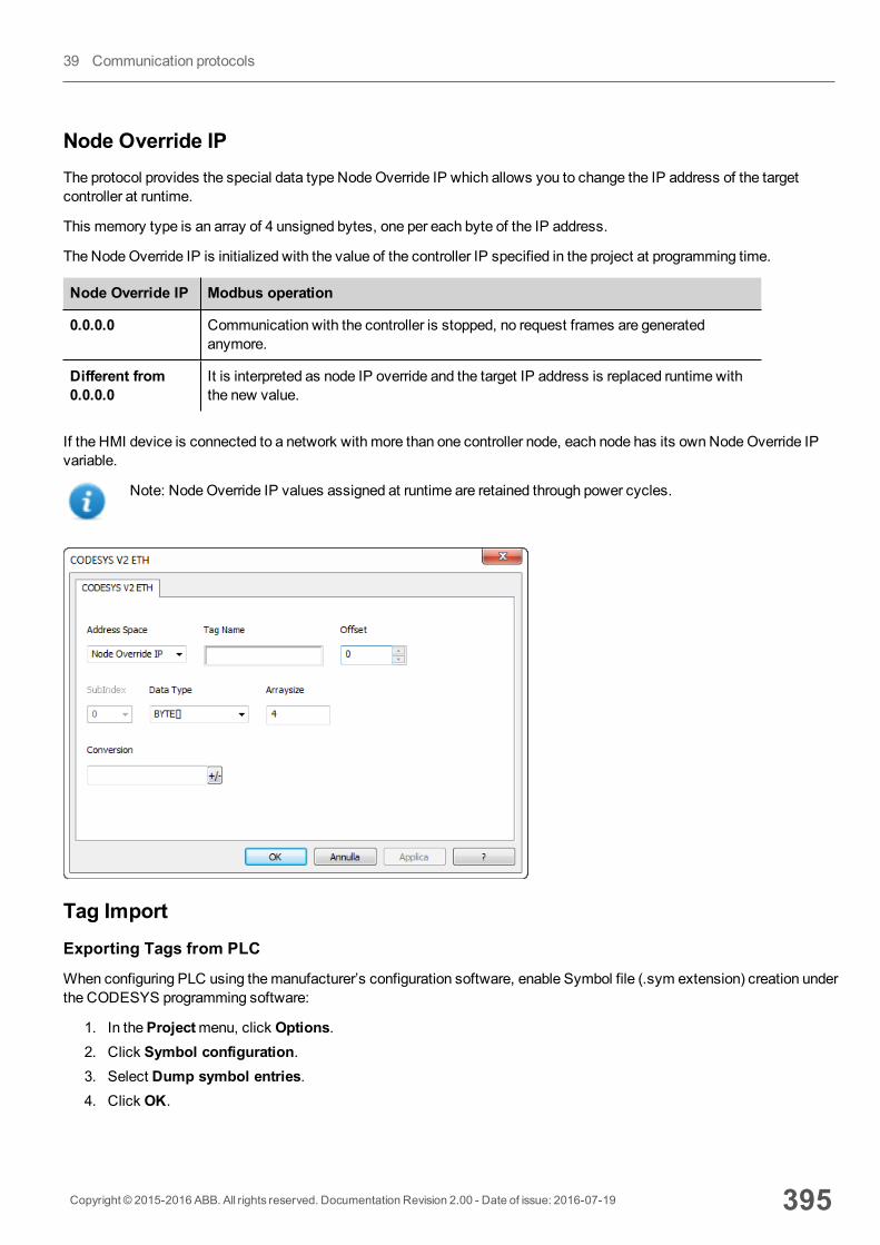
Node Override IPThe protocol provides the special data type NodeOverride IP which allows you to change the IP address of the targetcontroller at runtime.
This memory type is an array of 4 unsigned bytes, one per each byte of the IP address.
The NodeOverride IP is initialized with the value of the controller IP specified in the project at programming time.
Node Override IP Modbus operation
0.0.0.0 Communication with the controller is stopped, no request frames are generatedanymore.
Different from0.0.0.0
It is interpreted as node IP override and the target IP address is replaced runtime withthe new value.
If the HMI device is connected to a network with more than one controller node, each node has its ownNodeOverride IPvariable.
Note: NodeOverride IP values assigned at runtime are retained through power cycles.
Tag ImportExporting Tags from PLC
When configuring PLC using themanufacturer’s configuration software, enable Symbol file (.sym extension) creation underthe CODESYS programming software:
1. In theProjectmenu, click Options.2. Click Symbol configuration.3. Select Dump symbol entries.4. Click OK.
Copyright © 2015-2016 ABB. All rights reserved. Documentation Revision 2.00 - Date of issue: 2016-07-19 395
39 Communication protocols
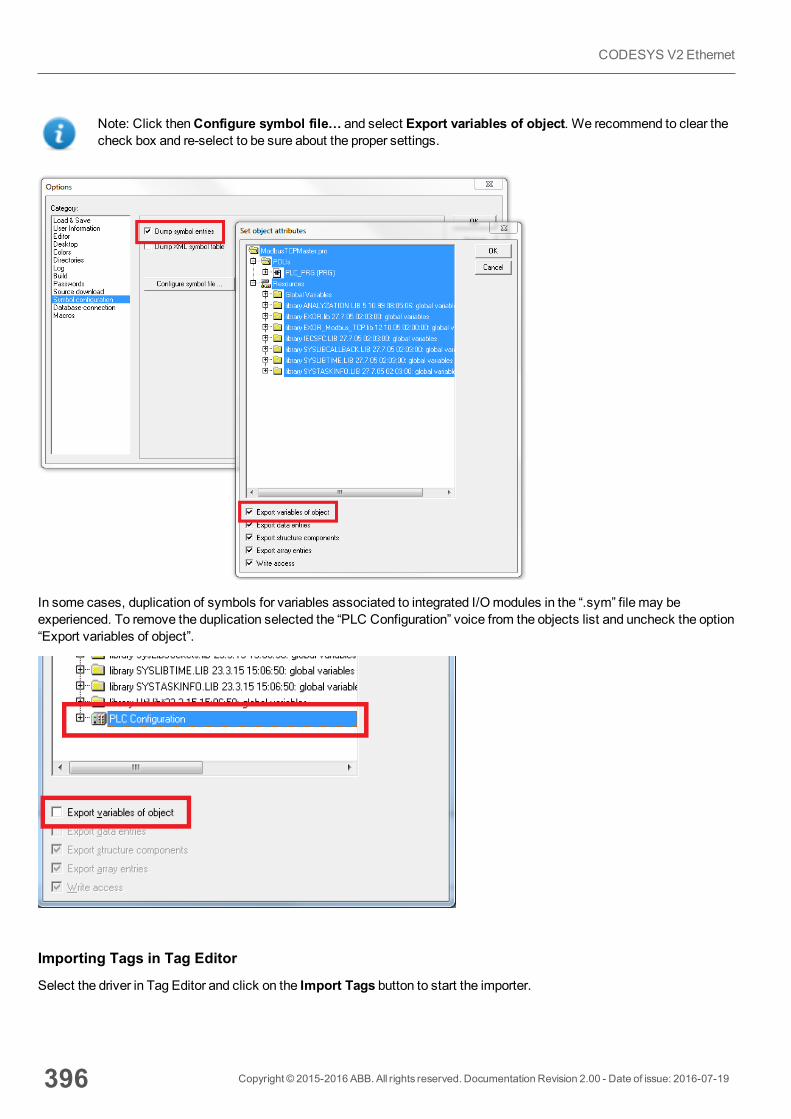
Note: Click thenConfigure symbol file… and select Export variables of object. We recommend to clear thecheck box and re-select to be sure about the proper settings.
In some cases, duplication of symbols for variables associated to integrated I/Omodules in the “.sym” file may beexperienced. To remove the duplication selected the “PLC Configuration” voice from the objects list and uncheck the option“Export variables of object”.
Importing Tags in Tag Editor
Select the driver in Tag Editor and click on the Import Tags button to start the importer.
396 Copyright © 2015-2016 ABB. All rights reserved. Documentation Revision 2.00 - Date of issue: 2016-07-19
CODESYS V2 Ethernet

The following dialog shows which importer type can be selected.
Importer Description
CODESYS2 sym v1.1Linear
Requires a .sym file.
All variables will be displayed at the same level.
CODESYS2 sym v1.1Hierarchical
Requires a .sym file.
All variables will be displayed according to CODESYS V2 Hierarchical view.
CODESYS2 sym_xmlv1.0Hierarchical
Requires a .sym_xml file.
All variables will be displayed according to CODESYS V2 Hierarchical view.
Tag Editor exportedxml
Select this importer to read a generic XML file exported from Tag Editor byappropriate button.
Once the importer has been selected, locate the symbol file and click Open.
Tags included in the symbol file are listed in the tag dictionary. The tag dictionary is displayed at the bottom of the screen.
Copyright © 2015-2016 ABB. All rights reserved. Documentation Revision 2.00 - Date of issue: 2016-07-19 397
39 Communication protocols

Toolbar item Description
Import Tag(s).
Select tags to be imported and click on this icon to add tagsfrom tag dictionary to the project
Update Tag(s).
Click on this icon to update the tags in the project, due a newdictionary import.
398 Copyright © 2015-2016 ABB. All rights reserved. Documentation Revision 2.00 - Date of issue: 2016-07-19
CODESYS V2 Ethernet
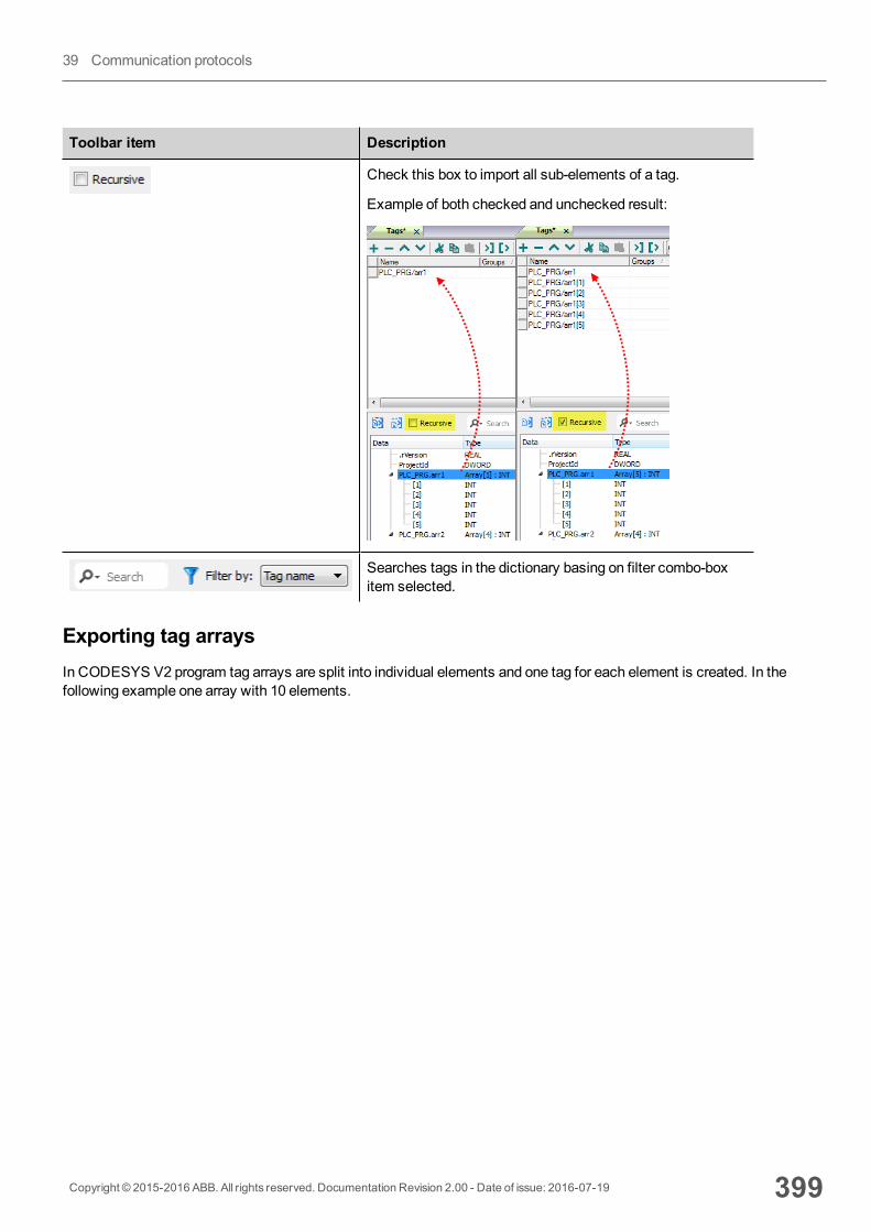
Toolbar item Description
Check this box to import all sub-elements of a tag.
Example of both checked and unchecked result:
Searches tags in the dictionary basing on filter combo-boxitem selected.
Exporting tag arraysIn CODESYS V2 program tag arrays are split into individual elements and one tag for each element is created. In thefollowing example one array with 10 elements.
Copyright © 2015-2016 ABB. All rights reserved. Documentation Revision 2.00 - Date of issue: 2016-07-19 399
39 Communication protocols
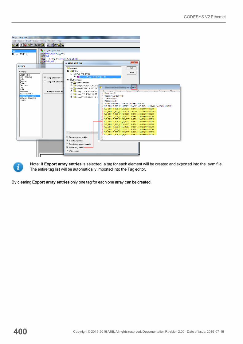
Note: If Export array entries is selected, a tag for each element will be created and exported into the .sym file.The entire tag list will be automatically imported into the Tag editor.
By clearingExport array entries only one tag for each one array can be created.
400 Copyright © 2015-2016 ABB. All rights reserved. Documentation Revision 2.00 - Date of issue: 2016-07-19
CODESYS V2 Ethernet
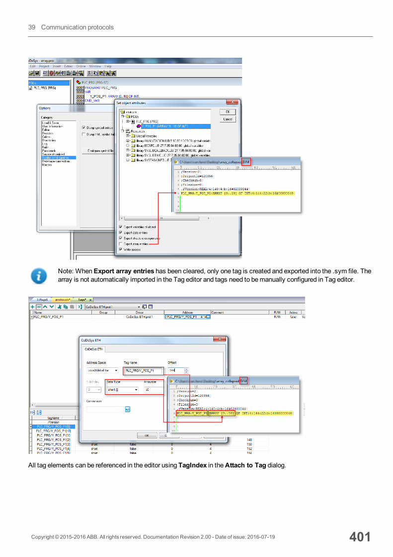
Note: WhenExport array entries has been cleared, only one tag is created and exported into the .sym file. Thearray is not automatically imported in the Tag editor and tags need to bemanually configured in Tag editor.
All tag elements can be referenced in the editor using TagIndex in theAttach to Tag dialog.
Copyright © 2015-2016 ABB. All rights reserved. Documentation Revision 2.00 - Date of issue: 2016-07-19 401
39 Communication protocols
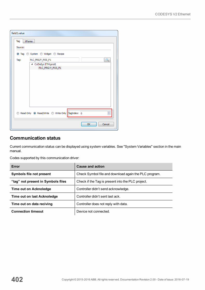
Communication statusCurrent communication status can be displayed using system variables. See "System Variables" section in themainmanual.
Codes supported by this communication driver:
Error Cause and action
Symbols file not present Check Symbol file and download again the PLC program.
“tag” not present in Symbols files Check if the Tag is present into the PLC project.
Time out on Acknoledge Controller didn’t send acknowledge.
Time out on last Acknoledge Controller didn’t sent last ack.
Time out on data reciving Controller does not reply with data.
Connection timeout Device not connected.
402 Copyright © 2015-2016 ABB. All rights reserved. Documentation Revision 2.00 - Date of issue: 2016-07-19
CODESYS V2 Ethernet
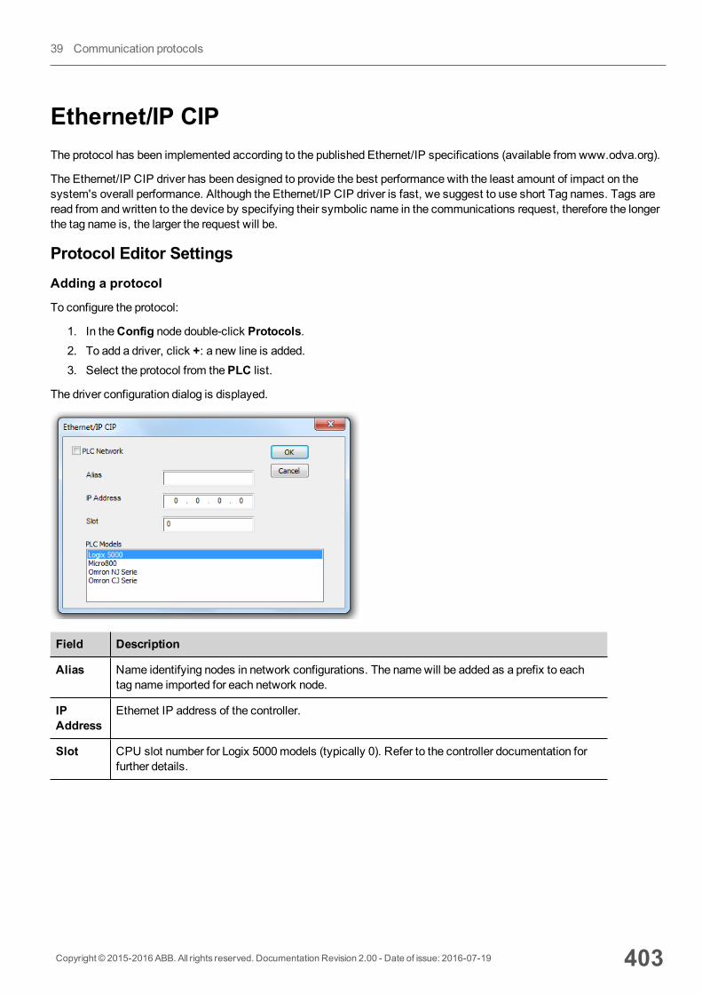
Ethernet/IP CIPThe protocol has been implemented according to the published Ethernet/IP specifications (available from www.odva.org).
The Ethernet/IP CIP driver has been designed to provide the best performance with the least amount of impact on thesystem's overall performance. Although the Ethernet/IP CIP driver is fast, we suggest to use short Tag names. Tags areread from and written to the device by specifying their symbolic name in the communications request, therefore the longerthe tag name is, the larger the request will be.
Protocol Editor SettingsAdding a protocol
To configure the protocol:
1. In theConfig node double-click Protocols.2. To add a driver, click +: a new line is added.3. Select the protocol from thePLC list.
The driver configuration dialog is displayed.
Field Description
Alias Name identifying nodes in network configurations. The namewill be added as a prefix to eachtag name imported for each network node.
IPAddress
Ethernet IP address of the controller.
Slot CPU slot number for Logix 5000models (typically 0). Refer to the controller documentation forfurther details.
Copyright © 2015-2016 ABB. All rights reserved. Documentation Revision 2.00 - Date of issue: 2016-07-19 403
39 Communication protocols
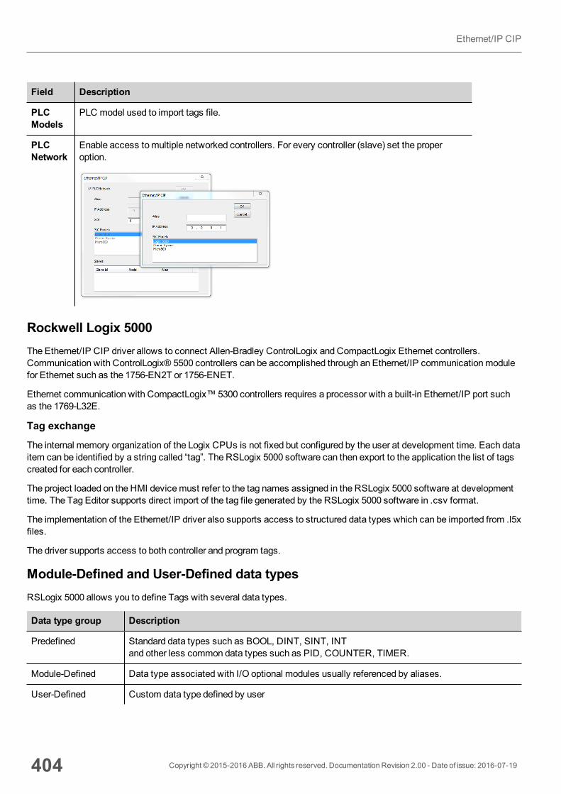
Field Description
PLCModels
PLC model used to import tags file.
PLCNetwork
Enable access tomultiple networked controllers. For every controller (slave) set the properoption.
Rockwell Logix 5000The Ethernet/IP CIP driver allows to connect Allen-Bradley ControlLogix and CompactLogix Ethernet controllers.Communication with ControlLogix® 5500 controllers can be accomplished through an Ethernet/IP communicationmodulefor Ethernet such as the 1756-EN2T or 1756-ENET.
Ethernet communication with CompactLogix™ 5300 controllers requires a processor with a built-in Ethernet/IP port suchas the 1769-L32E.
Tag exchange
The internal memory organization of the Logix CPUs is not fixed but configured by the user at development time. Each dataitem can be identified by a string called “tag”. The RSLogix 5000 software can then export to the application the list of tagscreated for each controller.
The project loaded on the HMI devicemust refer to the tag names assigned in the RSLogix 5000 software at developmenttime. The Tag Editor supports direct import of the tag file generated by the RSLogix 5000 software in .csv format.
The implementation of the Ethernet/IP driver also supports access to structured data types which can be imported from .l5xfiles.
The driver supports access to both controller and program tags.
Module-Defined and User-Defined data typesRSLogix 5000 allows you to define Tags with several data types.
Data type group Description
Predefined Standard data types such as BOOL, DINT, SINT, INTand other less common data types such as PID, COUNTER, TIMER.
Module-Defined Data type associated with I/O optional modules usually referenced by aliases.
User-Defined Custom data type defined by user
404 Copyright © 2015-2016 ABB. All rights reserved. Documentation Revision 2.00 - Date of issue: 2016-07-19
Ethernet/IP CIP
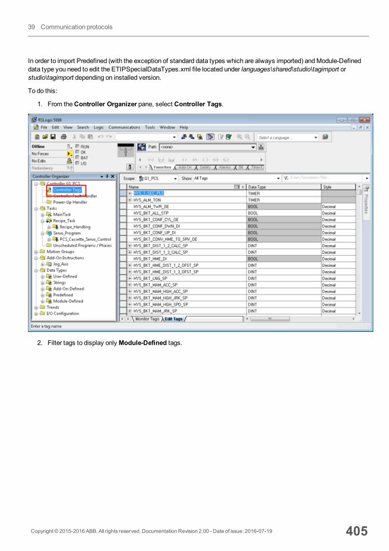
In order to import Predefined (with the exception of standard data types which are always imported) andModule-Defineddata type you need to edit the ETIPSpecialDataTypes.xml file located under languages\shared\studio\tagimport orstudio\tagimport depending on installed version.
To do this:
1. From theController Organizer pane, select Controller Tags.
2. Filter tags to display only Module-Defined tags.
Copyright © 2015-2016 ABB. All rights reserved. Documentation Revision 2.00 - Date of issue: 2016-07-19 405
39 Communication protocols
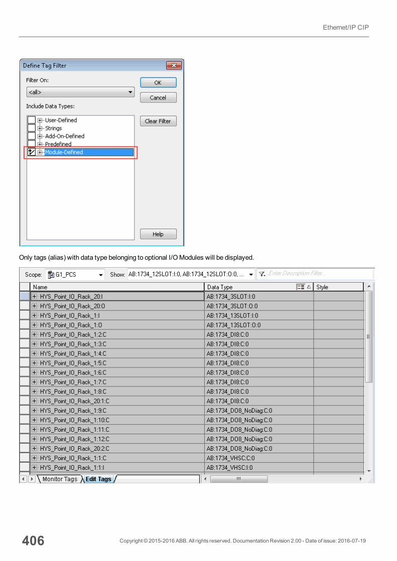
Only tags (alias) with data type belonging to optional I/OModules will be displayed.
406 Copyright © 2015-2016 ABB. All rights reserved. Documentation Revision 2.00 - Date of issue: 2016-07-19
Ethernet/IP CIP
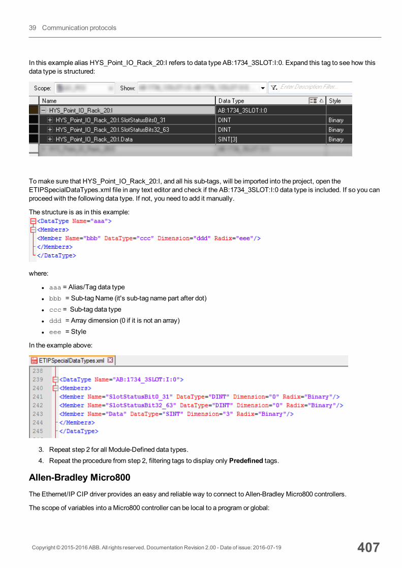
In this example alias HYS_Point_IO_Rack_20:I refers to data type AB:1734_3SLOT:I:0. Expand this tag to see how thisdata type is structured:
Tomake sure that HYS_Point_IO_Rack_20:I, and all his sub-tags, will be imported into the project, open theETIPSpecialDataTypes.xml file in any text editor and check if the AB:1734_3SLOT:I:0 data type is included. If so you canproceed with the following data type. If not, you need to add it manually.
The structure is as in this example:
where:
l aaa = Alias/Tag data typel bbb = Sub-tag Name (it's sub-tag name part after dot)l ccc = Sub-tag data typel ddd = Array dimension (0 if it is not an array)l eee = Style
In the example above:
3. Repeat step 2 for all Module-Defined data types.4. Repeat the procedure from step 2, filtering tags to display only Predefined tags.
Allen-Bradley Micro800The Ethernet/IP CIP driver provides an easy and reliable way to connect to Allen-Bradley Micro800 controllers.
The scope of variables into aMicro800 controller can be local to a program or global:
Copyright © 2015-2016 ABB. All rights reserved. Documentation Revision 2.00 - Date of issue: 2016-07-19 407
39 Communication protocols
l local variables (program-scoped tags) are assigned to a specific program in the project and available only to thatprogram. These tags are not supported within this driver.
l global variables (controller-scoped tags) belong to the controller in the project and are available to any program in theproject. These tags are supported within this driver.
Omron SysmacData in NJ and CJ controllers can be accessed via CIP protocol. Each data item can be identified by a string called “tag”.Use appropriate programming tools for controller to export the list of tags.
NJ series controller are programmed using Sysmac Studio:
l NJ301-xxxxl NJ501-xxxx
CJ series controller are programmed using CX-One:
l CJ2M CPU-3xl CJ2H CPU 6x-EIPl Any CPU with a CJ1W-EIP21 attached.
Tag exchange
The project loaded on the HMI devicemust refer to the tag names assigned in the programming software at developmenttime. The Tag Editor supports direct import of the tag file generated by the Sysmac Studio software in .njf format orgenerated by CX-One in the .cjf format.
All tags to be accessed by the HMI devicemust be declared as global variables.
Export CSV and L5X Files Using RSLogix5000To export the .csv tag file:
1. From theController Organizer pane, right-click onController Tags.2. Select Export Tags: theExport dialog is displayed.
408 Copyright © 2015-2016 ABB. All rights reserved. Documentation Revision 2.00 - Date of issue: 2016-07-19
Ethernet/IP CIP

3. ChooseAll from the Tags list to export all tags.4. Select theSave as type option to .csv.5. Click Export: all the tags are exported to an .csv file.
To export the .l5x data type file:
1. Choose File > Save As.2. Select theSave as type option to .l5x.3. Click Save: all the tags are exported to an .l5x file.
Copyright © 2015-2016 ABB. All rights reserved. Documentation Revision 2.00 - Date of issue: 2016-07-19 409
39 Communication protocols
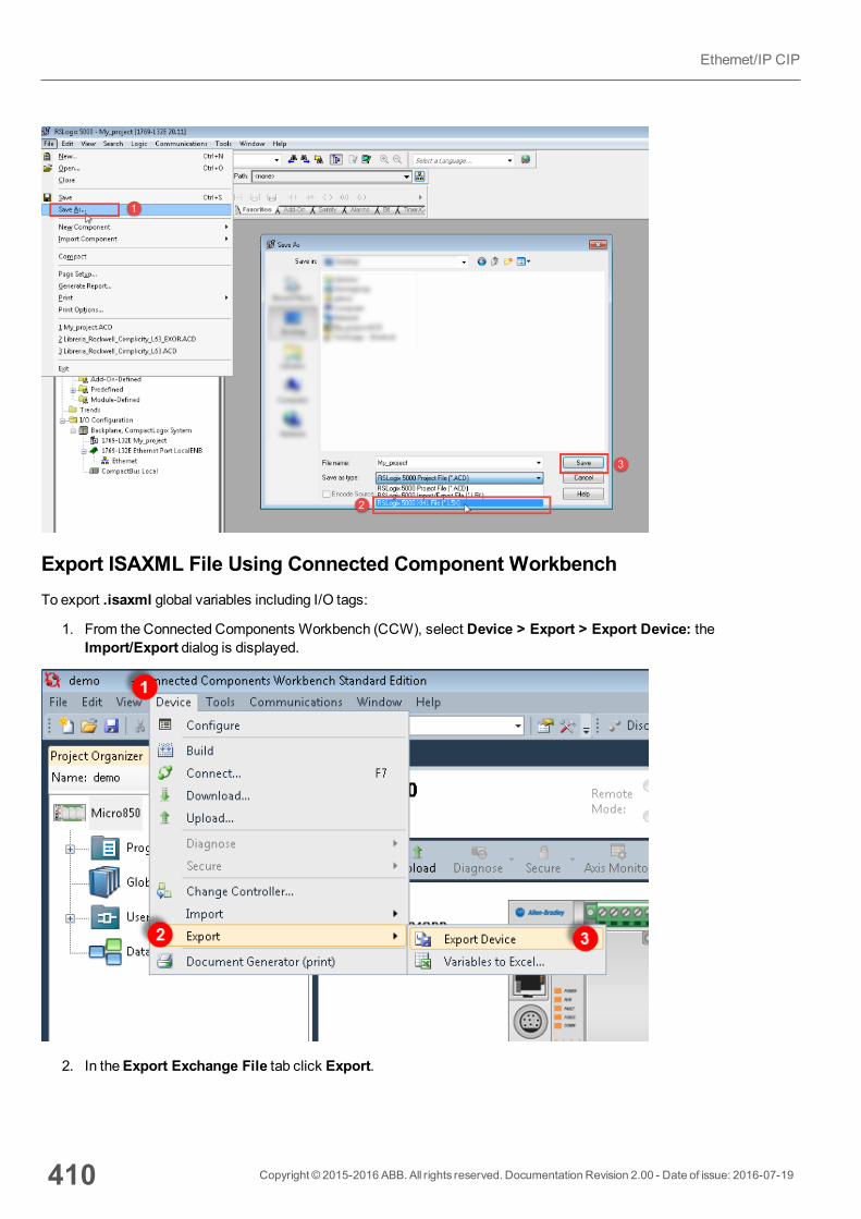
Export ISAXML File Using Connected Component WorkbenchTo export .isaxml global variables including I/O tags:
1. From the Connected Components Workbench (CCW), select Device > Export > Export Device: theImport/Export dialog is displayed.
2. In theExport Exchange File tab click Export.
410 Copyright © 2015-2016 ABB. All rights reserved. Documentation Revision 2.00 - Date of issue: 2016-07-19
Ethernet/IP CIP
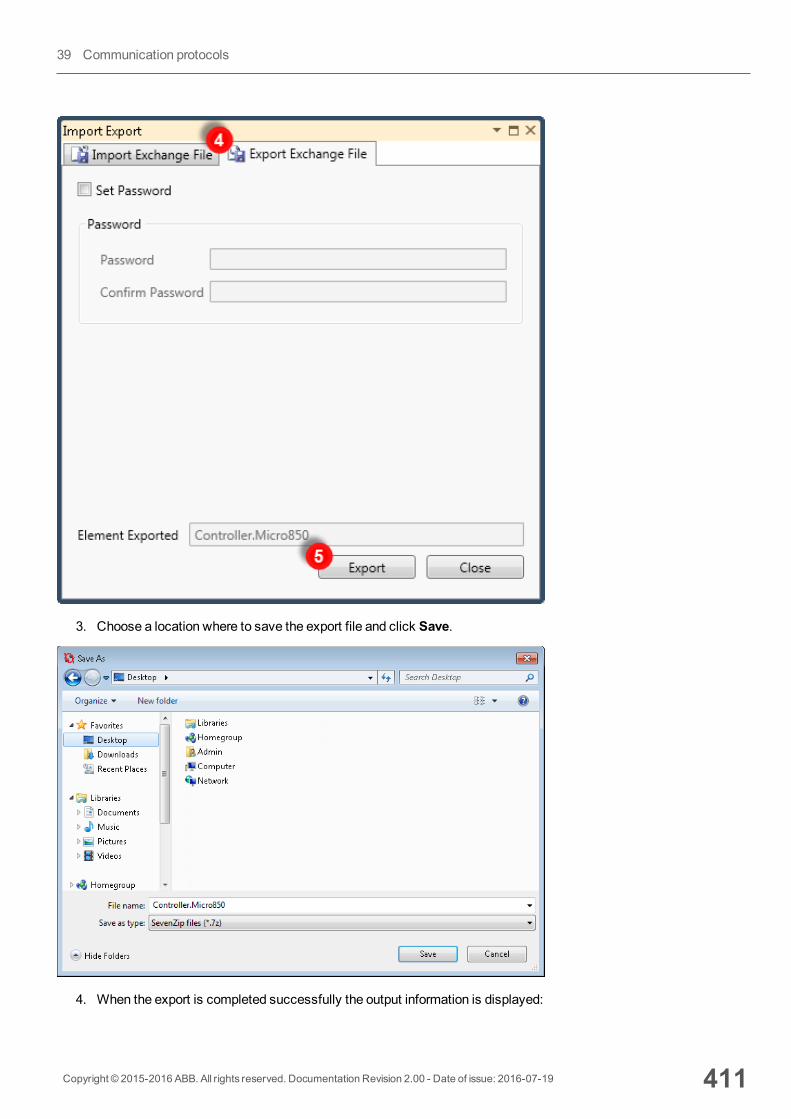
3. Choose a location where to save the export file and click Save.
4. When the export is completed successfully the output information is displayed:
Copyright © 2015-2016 ABB. All rights reserved. Documentation Revision 2.00 - Date of issue: 2016-07-19 411
39 Communication protocols
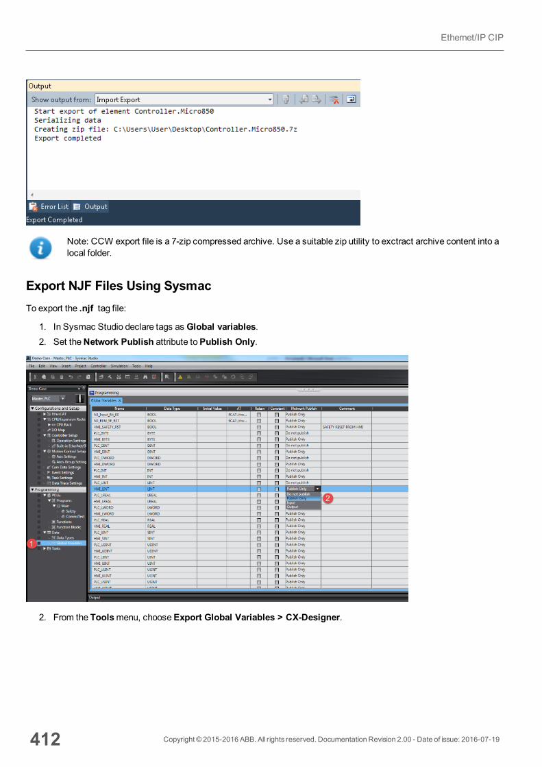
Note: CCW export file is a 7-zip compressed archive. Use a suitable zip utility to exctract archive content into alocal folder.
Export NJF Files Using SysmacTo export the .njf tag file:
1. In Sysmac Studio declare tags as Global variables.2. Set theNetwork Publish attribute toPublish Only.
2. From the Toolsmenu, chooseExport Global Variables > CX-Designer.
412 Copyright © 2015-2016 ABB. All rights reserved. Documentation Revision 2.00 - Date of issue: 2016-07-19
Ethernet/IP CIP

3. Click OK to confirm.4. Cut and paste the content of the clipboard in any text editor.
4. Save the file as .njf.
Note: Make sure you use theSave As function or the file will be named *.njf.txt and will not be visible from theimporter.
Export CJF and CJS Files Using CX-OneTo export the .cjf tag file:
1. In CX-One open the Symbols file in the project.2. In theEdit Symbol dialog set theNet. Variables attribute toPublication.
Copyright © 2015-2016 ABB. All rights reserved. Documentation Revision 2.00 - Date of issue: 2016-07-19 413
39 Communication protocols
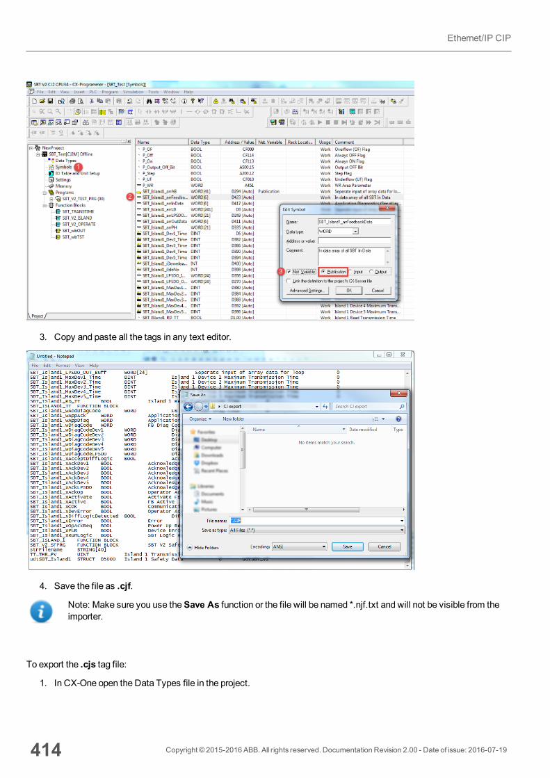
3. Copy and paste all the tags in any text editor.
4. Save the file as .cjf.
Note: Make sure you use theSave As function or the file will be named *.njf.txt and will not be visible from theimporter.
To export the .cjs tag file:
1. In CX-One open the Data Types file in the project.
414 Copyright © 2015-2016 ABB. All rights reserved. Documentation Revision 2.00 - Date of issue: 2016-07-19
Ethernet/IP CIP

2. Copy and paste all the tags in any text editor.
3. Save the file as .cjs.
Note: Make sure you use theSave As function or the file will be named *.cjs.txt and will not be visible from theimporter.
Copyright © 2015-2016 ABB. All rights reserved. Documentation Revision 2.00 - Date of issue: 2016-07-19 415
39 Communication protocols
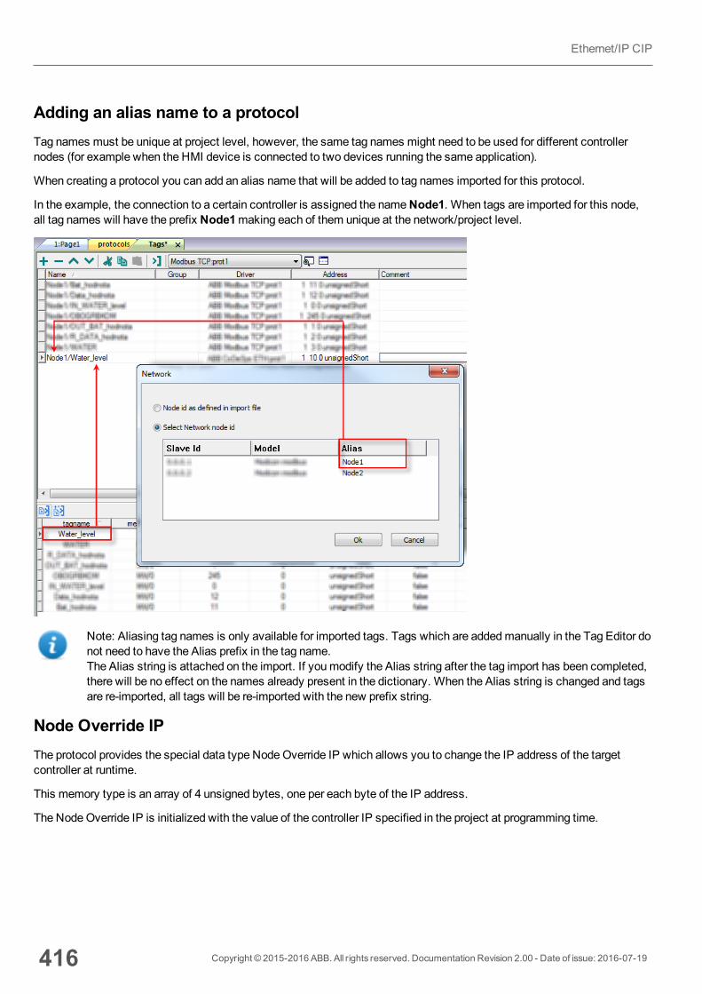
Adding an alias name to a protocolTag names must be unique at project level, however, the same tag names might need to be used for different controllernodes (for example when the HMI device is connected to two devices running the same application).
When creating a protocol you can add an alias name that will be added to tag names imported for this protocol.
In the example, the connection to a certain controller is assigned the nameNode1. When tags are imported for this node,all tag names will have the prefix Node1making each of them unique at the network/project level.
Note: Aliasing tag names is only available for imported tags. Tags which are addedmanually in the Tag Editor donot need to have the Alias prefix in the tag name.The Alias string is attached on the import. If youmodify the Alias string after the tag import has been completed,there will be no effect on the names already present in the dictionary. When the Alias string is changed and tagsare re-imported, all tags will be re-imported with the new prefix string.
Node Override IPThe protocol provides the special data type NodeOverride IP which allows you to change the IP address of the targetcontroller at runtime.
This memory type is an array of 4 unsigned bytes, one per each byte of the IP address.
The NodeOverride IP is initialized with the value of the controller IP specified in the project at programming time.
416 Copyright © 2015-2016 ABB. All rights reserved. Documentation Revision 2.00 - Date of issue: 2016-07-19
Ethernet/IP CIP

Node Override IP Modbus operation
0.0.0.0 Communication with the controller is stopped, no request frames are generatedanymore.
Different from0.0.0.0
It is interpreted as node IP override and the target IP address is replaced runtime withthe new value.
If the HMI device is connected to a network with more than one controller node, each node has its ownNodeOverride IPvariable.
Note: NodeOverride IP values assigned at runtime are retained through power cycles.
Tag ImportSelect the driver in Tag Editor and click on the Import Tags button to start the importer.
The following dialog shows which importer type can be selected.
Copyright © 2015-2016 ABB. All rights reserved. Documentation Revision 2.00 - Date of issue: 2016-07-19 417
39 Communication protocols
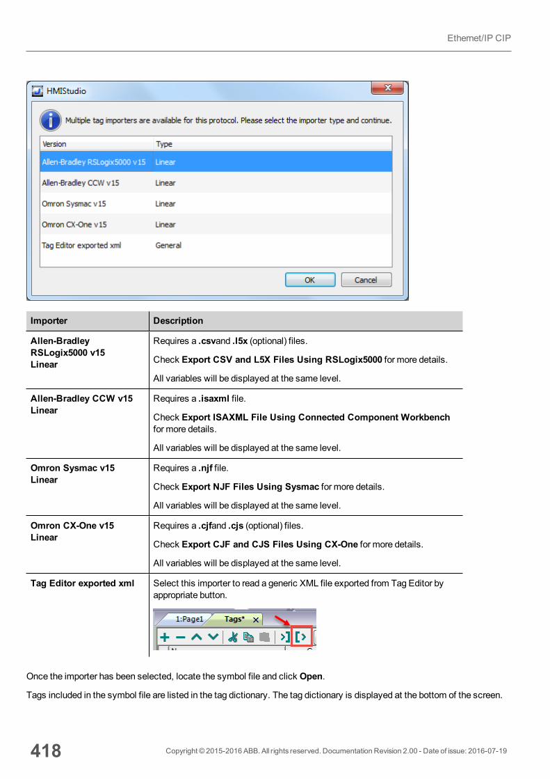
Importer Description
Allen-BradleyRSLogix5000 v15Linear
Requires a .csvand .l5x (optional) files.
Check Export CSV and L5X Files Using RSLogix5000 for more details.
All variables will be displayed at the same level.
Allen-Bradley CCW v15Linear
Requires a .isaxml file.
Check Export ISAXML File Using Connected Component Workbenchfor more details.
All variables will be displayed at the same level.
Omron Sysmac v15Linear
Requires a .njf file.
Check Export NJF Files Using Sysmac for more details.
All variables will be displayed at the same level.
Omron CX-One v15Linear
Requires a .cjfand .cjs (optional) files.
Check Export CJF and CJS Files Using CX-One for more details.
All variables will be displayed at the same level.
Tag Editor exported xml Select this importer to read a generic XML file exported from Tag Editor byappropriate button.
Once the importer has been selected, locate the symbol file and click Open.
Tags included in the symbol file are listed in the tag dictionary. The tag dictionary is displayed at the bottom of the screen.
418 Copyright © 2015-2016 ABB. All rights reserved. Documentation Revision 2.00 - Date of issue: 2016-07-19
Ethernet/IP CIP

Toolbar item Description
Import Tag(s).
Select tags to be imported and click on this icon to add tagsfrom tag dictionary to the project
Update Tag(s).
Click on this icon to update the tags in the project, due a newdictionary import.
Copyright © 2015-2016 ABB. All rights reserved. Documentation Revision 2.00 - Date of issue: 2016-07-19 419
39 Communication protocols

Toolbar item Description
Check this box to import all sub-elements of a tag.
Example of both checked and unchecked result:
Searches tags in the dictionary basing on filter combo-boxitem selected.
Communication statusCurrent communication status can be displayed using System Variables. See "System Variables" section in themainmanual.
Codes supported for this communication driver:
Error Cause Action
NAK The controller replies with a not acknowledge. -
Timeout A request is not replied within the specified timeoutperiod.
Check if the controller is connected and properlyconfigured to get network access.
Invalidresponse
The device did received a response with invalidformat or contents from the controller .
Ensure the data programmed in the project areconsistent with the controller resources.
GeneralError
Unidentifiable error. Should never be reported. Contact technical support.
420 Copyright © 2015-2016 ABB. All rights reserved. Documentation Revision 2.00 - Date of issue: 2016-07-19
Ethernet/IP CIP
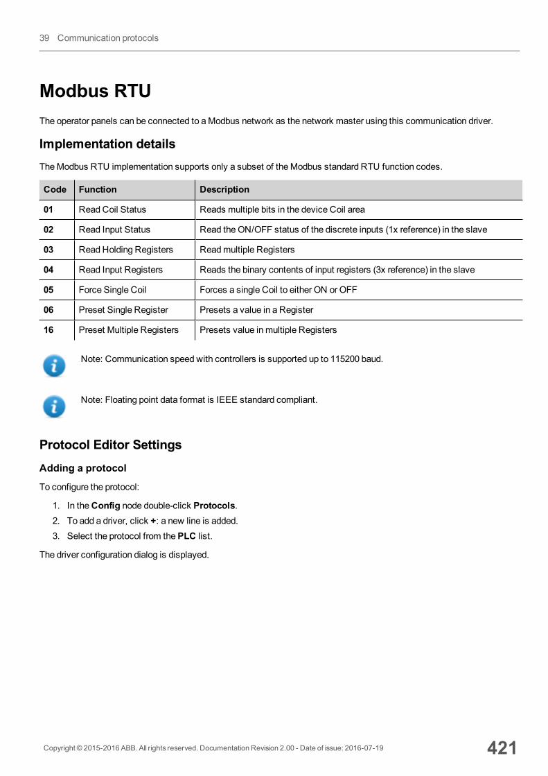
Modbus RTUThe operator panels can be connected to aModbus network as the network master using this communication driver.
Implementation detailsTheModbus RTU implementation supports only a subset of theModbus standard RTU function codes.
Code Function Description
01 ReadCoil Status Reads multiple bits in the device Coil area
02 Read Input Status Read theON/OFF status of the discrete inputs (1x reference) in the slave
03 ReadHolding Registers Readmultiple Registers
04 Read Input Registers Reads the binary contents of input registers (3x reference) in the slave
05 Force Single Coil Forces a single Coil to either ON or OFF
06 Preset Single Register Presets a value in a Register
16 Preset Multiple Registers Presets value in multiple Registers
Note: Communication speed with controllers is supported up to 115200 baud.
Note: Floating point data format is IEEE standard compliant.
Protocol Editor SettingsAdding a protocol
To configure the protocol:
1. In theConfig node double-click Protocols.2. To add a driver, click +: a new line is added.3. Select the protocol from thePLC list.
The driver configuration dialog is displayed.
Copyright © 2015-2016 ABB. All rights reserved. Documentation Revision 2.00 - Date of issue: 2016-07-19 421
39 Communication protocols
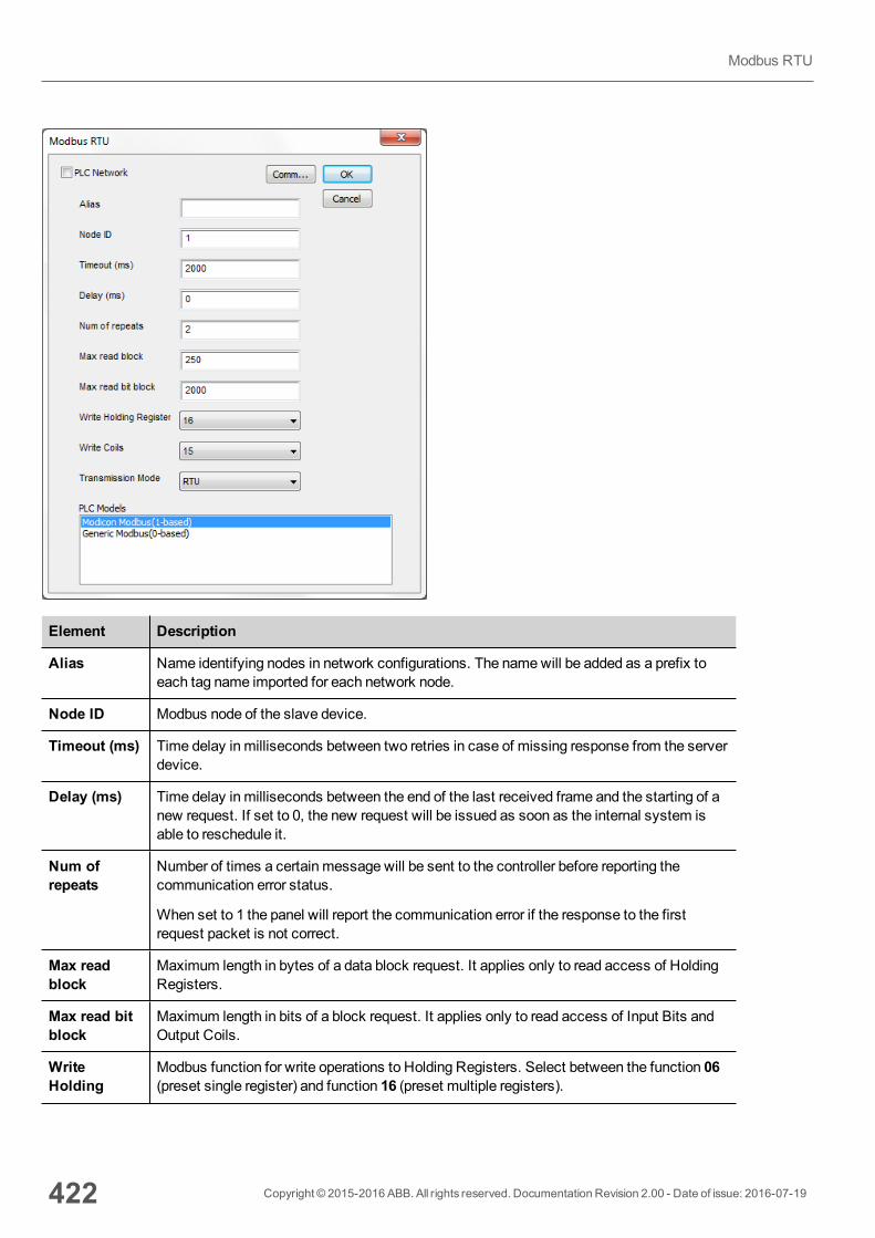
Element Description
Alias Name identifying nodes in network configurations. The namewill be added as a prefix toeach tag name imported for each network node.
Node ID Modbus node of the slave device.
Timeout (ms) Time delay in milliseconds between two retries in case of missing response from the serverdevice.
Delay (ms) Time delay in milliseconds between the end of the last received frame and the starting of anew request. If set to 0, the new request will be issued as soon as the internal system isable to reschedule it.
Num ofrepeats
Number of times a certain message will be sent to the controller before reporting thecommunication error status.
When set to 1 the panel will report the communication error if the response to the firstrequest packet is not correct.
Max readblock
Maximum length in bytes of a data block request. It applies only to read access of HoldingRegisters.
Max read bitblock
Maximum length in bits of a block request. It applies only to read access of Input Bits andOutput Coils.
WriteHolding
Modbus function for write operations to Holding Registers. Select between the function 06(preset single register) and function 16 (preset multiple registers).
422 Copyright © 2015-2016 ABB. All rights reserved. Documentation Revision 2.00 - Date of issue: 2016-07-19
Modbus RTU
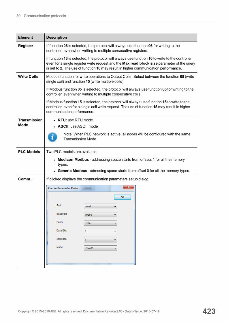
Element Description
Register If function 06 is selected, the protocol will always use function 06 for writing to thecontroller, even when writing tomultiple consecutive registers.
If function 16 is selected, the protocol will always use function 16 to write to the controller,even for a single register write request and theMax read block size parameter of the queryis set to 2. The use of function 16may result in higher communication performance.
Write Coils Modbus function for write operations to Output Coils. Select between the function 05 (writesingle coil) and function 15 (write multiple coils).
If Modbus function 05 is selected, the protocol will always use function 05 for writing to thecontroller, even when writing tomultiple consecutive coils.
If Modbus function 15 is selected, the protocol will always use function 15 to write to thecontroller, even for a single coil write request. The use of function 15may result in highercommunication performance.
TransmissionMode
l RTU: use RTU model ASCII: use ASCII mode
Note: When PLC network is active, all nodes will be configured with the sameTransmissionMode.
PLC Models Two PLC models are available:
l Modicon Modbus - addressing space starts from offsets 1 for all thememorytypes.
l Generic Modbus - adressing space starts from offset 0 for all thememory types.
Comm... If clicked displays the communication parameters setup dialog.
Copyright © 2015-2016 ABB. All rights reserved. Documentation Revision 2.00 - Date of issue: 2016-07-19 423
39 Communication protocols
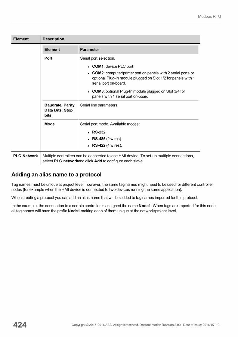
Element Description
Element Parameter
Port Serial port selection.
l COM1: device PLC port.l COM2: computer/printer port on panels with 2 serial ports oroptional Plug-In module plugged on Slot 1/2 for panels with 1serial port on-board.
l COM3: optional Plug-In module plugged on Slot 3/4 forpanels with 1 serial port on-board.
Baudrate, Parity,Data Bits, Stopbits
Serial line parameters.
Mode Serial port mode. Available modes:
l RS-232.l RS-485 (2 wires).l RS-422 (4 wires).
PLC Network Multiple controllers can be connected to one HMI device. To set-upmultiple connections,select PLC networkand click Add to configure each slave
Adding an alias name to a protocolTag names must be unique at project level, however, the same tag names might need to be used for different controllernodes (for example when the HMI device is connected to two devices running the same application).
When creating a protocol you can add an alias name that will be added to tag names imported for this protocol.
In the example, the connection to a certain controller is assigned the nameNode1. When tags are imported for this node,all tag names will have the prefix Node1making each of them unique at the network/project level.
424 Copyright © 2015-2016 ABB. All rights reserved. Documentation Revision 2.00 - Date of issue: 2016-07-19
Modbus RTU
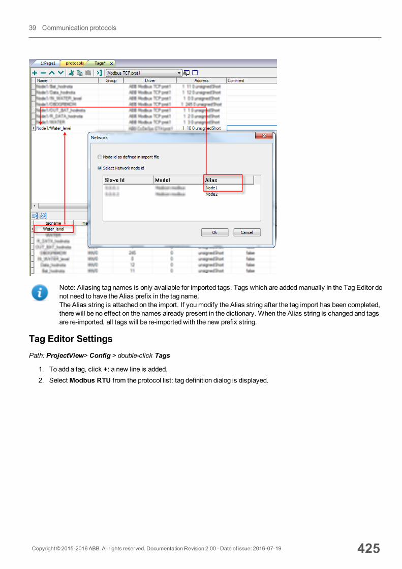
Note: Aliasing tag names is only available for imported tags. Tags which are addedmanually in the Tag Editor donot need to have the Alias prefix in the tag name.The Alias string is attached on the import. If youmodify the Alias string after the tag import has been completed,there will be no effect on the names already present in the dictionary. When the Alias string is changed and tagsare re-imported, all tags will be re-imported with the new prefix string.
Tag Editor SettingsPath: ProjectView> Config > double-click Tags
1. To add a tag, click +: a new line is added.2. SelectModbus RTU from the protocol list: tag definition dialog is displayed.
Copyright © 2015-2016 ABB. All rights reserved. Documentation Revision 2.00 - Date of issue: 2016-07-19 425
39 Communication protocols
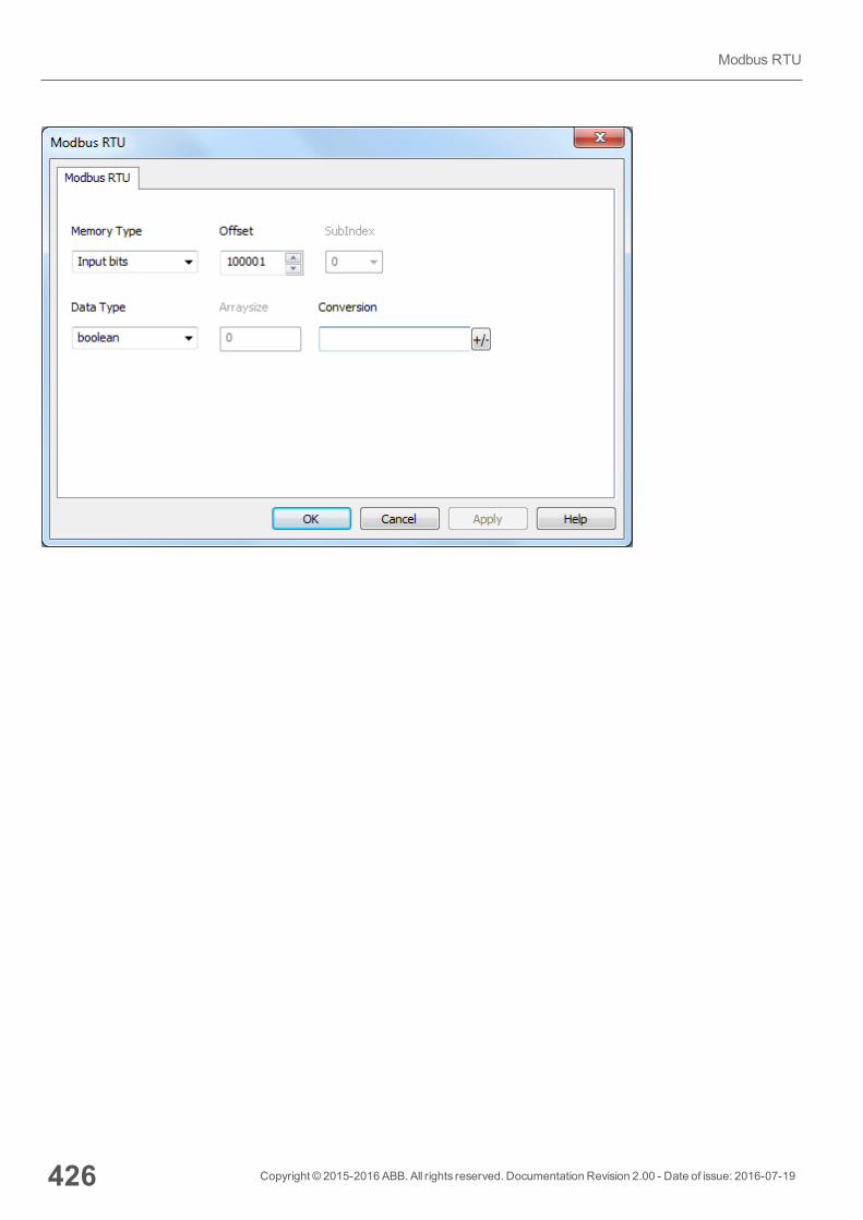
426 Copyright © 2015-2016 ABB. All rights reserved. Documentation Revision 2.00 - Date of issue: 2016-07-19
Modbus RTU
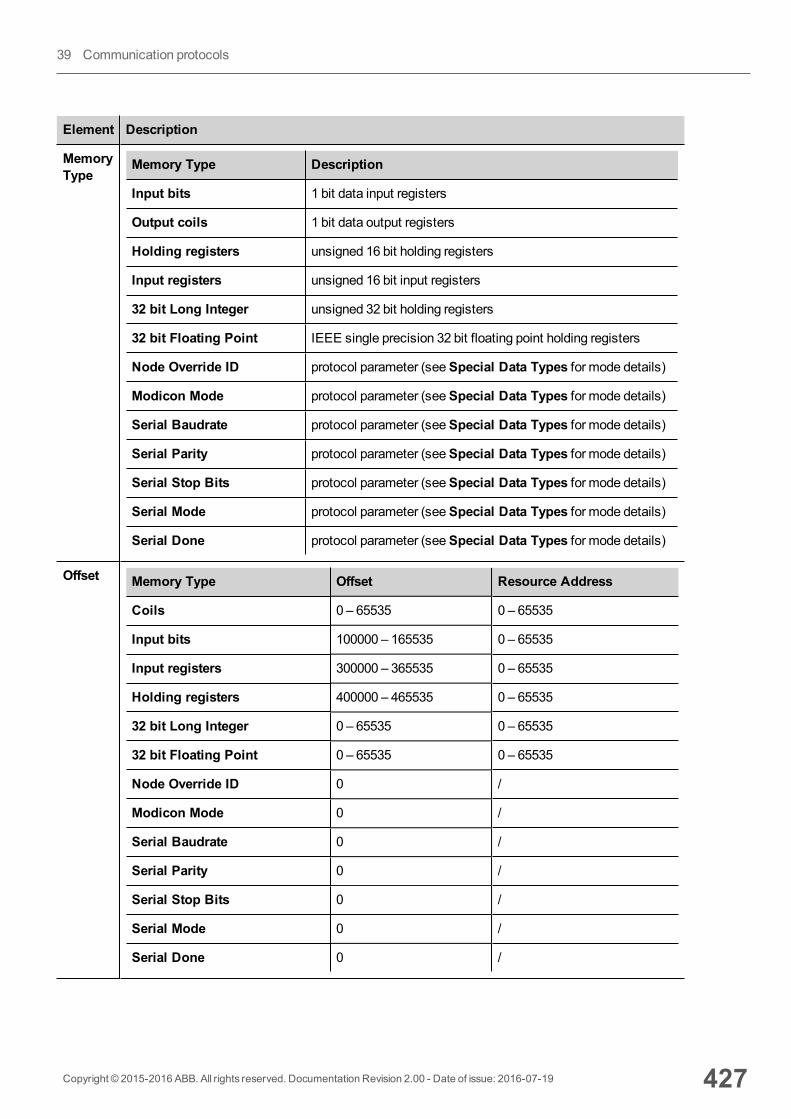
Element Description
MemoryType
Memory Type Description
Input bits 1 bit data input registers
Output coils 1 bit data output registers
Holding registers unsigned 16 bit holding registers
Input registers unsigned 16 bit input registers
32 bit Long Integer unsigned 32 bit holding registers
32 bit Floating Point IEEE single precision 32 bit floating point holding registers
Node Override ID protocol parameter (seeSpecial Data Types for mode details)
Modicon Mode protocol parameter (seeSpecial Data Types for mode details)
Serial Baudrate protocol parameter (seeSpecial Data Types for mode details)
Serial Parity protocol parameter (seeSpecial Data Types for mode details)
Serial Stop Bits protocol parameter (seeSpecial Data Types for mode details)
Serial Mode protocol parameter (seeSpecial Data Types for mode details)
Serial Done protocol parameter (seeSpecial Data Types for mode details)
Offset Memory Type Offset Resource Address
Coils 0 – 65535 0 – 65535
Input bits 100000 – 165535 0 – 65535
Input registers 300000 – 365535 0 – 65535
Holding registers 400000 – 465535 0 – 65535
32 bit Long Integer 0 – 65535 0 – 65535
32 bit Floating Point 0 – 65535 0 – 65535
Node Override ID 0 /
Modicon Mode 0 /
Serial Baudrate 0 /
Serial Parity 0 /
Serial Stop Bits 0 /
Serial Mode 0 /
Serial Done 0 /
Copyright © 2015-2016 ABB. All rights reserved. Documentation Revision 2.00 - Date of issue: 2016-07-19 427
39 Communication protocols
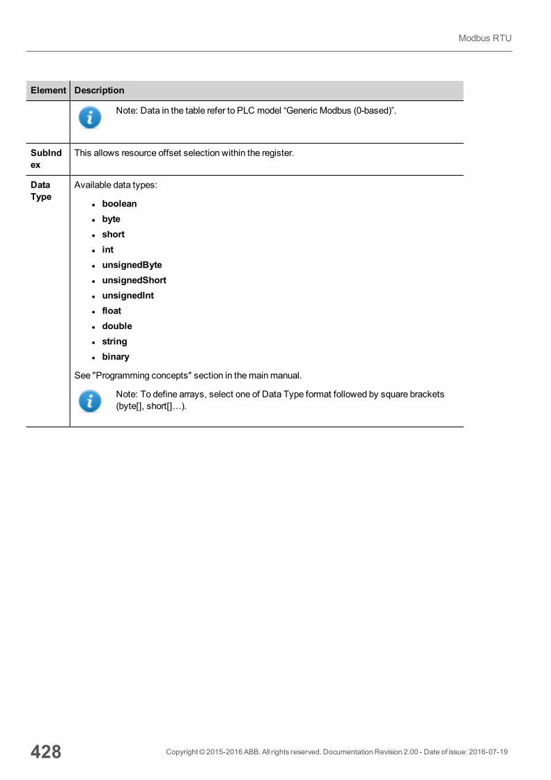
Element Description
Note: Data in the table refer to PLC model “Generic Modbus (0-based)”.
SubIndex
This allows resource offset selection within the register.
DataType
Available data types:
l booleanl bytel shortl intl unsignedBytel unsignedShortl unsignedIntl floatl doublel stringl binary
See "Programming concepts" section in themainmanual.
Note: To define arrays, select one of Data Type format followed by square brackets(byte[], short[]…).
428 Copyright © 2015-2016 ABB. All rights reserved. Documentation Revision 2.00 - Date of issue: 2016-07-19
Modbus RTU
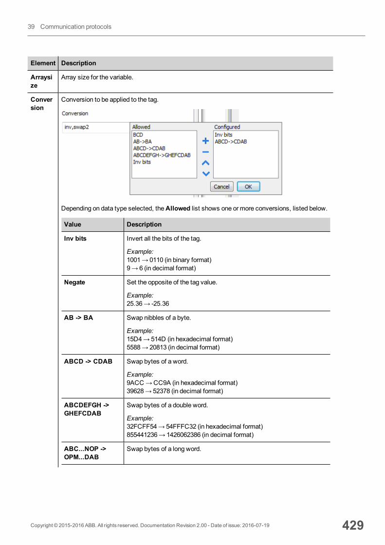
Element Description
Arraysize
Array size for the variable.
Conversion
Conversion to be applied to the tag.
Depending on data type selected, theAllowed list shows one or more conversions, listed below.
Value Description
Inv bits Invert all the bits of the tag.
Example:1001→ 0110 (in binary format)9→ 6 (in decimal format)
Negate Set the opposite of the tag value.
Example:25.36→ -25.36
AB -> BA Swap nibbles of a byte.
Example:15D4→514D (in hexadecimal format)5588→ 20813 (in decimal format)
ABCD -> CDAB Swap bytes of a word.
Example:9ACC→CC9A (in hexadecimal format)39628→ 52378 (in decimal format)
ABCDEFGH ->GHEFCDAB
Swap bytes of a double word.
Example:32FCFF54→54FFFC32 (in hexadecimal format)855441236→ 1426062386 (in decimal format)
ABC...NOP ->OPM...DAB
Swap bytes of a long word.
Copyright © 2015-2016 ABB. All rights reserved. Documentation Revision 2.00 - Date of issue: 2016-07-19 429
39 Communication protocols
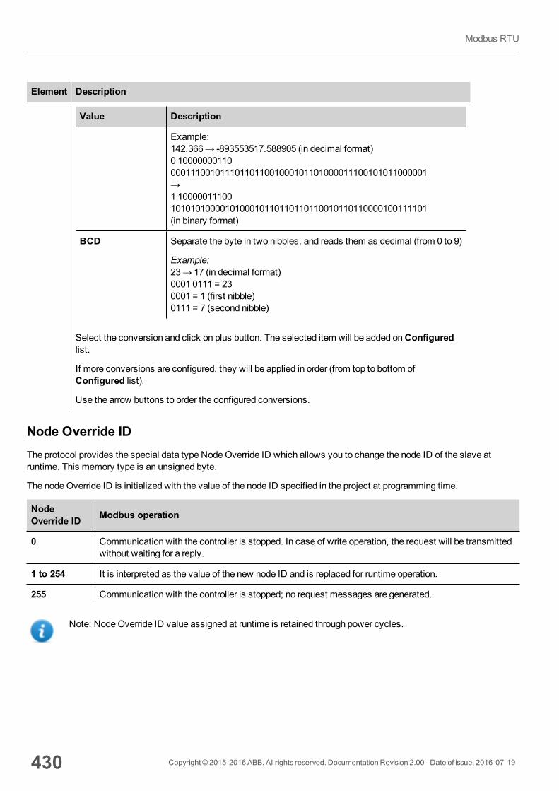
Element Description
Value Description
Example:142.366→ -893553517.588905 (in decimal format)0 100000001100001110010111011011001000101101000011100101011000001→1 100000111001010101000010100010110110110110010110110000100111101(in binary format)
BCD Separate the byte in two nibbles, and reads them as decimal (from 0 to 9)
Example:23→ 17 (in decimal format)0001 0111 = 230001 = 1 (first nibble)0111 = 7 (second nibble)
Select the conversion and click on plus button. The selected item will be added onConfiguredlist.
If more conversions are configured, they will be applied in order (from top to bottom ofConfigured list).
Use the arrow buttons to order the configured conversions.
Node Override IDThe protocol provides the special data type NodeOverride ID which allows you to change the node ID of the slave atruntime. This memory type is an unsigned byte.
The nodeOverride ID is initialized with the value of the node ID specified in the project at programming time.
NodeOverride ID Modbus operation
0 Communication with the controller is stopped. In case of write operation, the request will be transmittedwithout waiting for a reply.
1 to 254 It is interpreted as the value of the new node ID and is replaced for runtime operation.
255 Communication with the controller is stopped; no request messages are generated.
Note: NodeOverride ID value assigned at runtime is retained through power cycles.
430 Copyright © 2015-2016 ABB. All rights reserved. Documentation Revision 2.00 - Date of issue: 2016-07-19
Modbus RTU
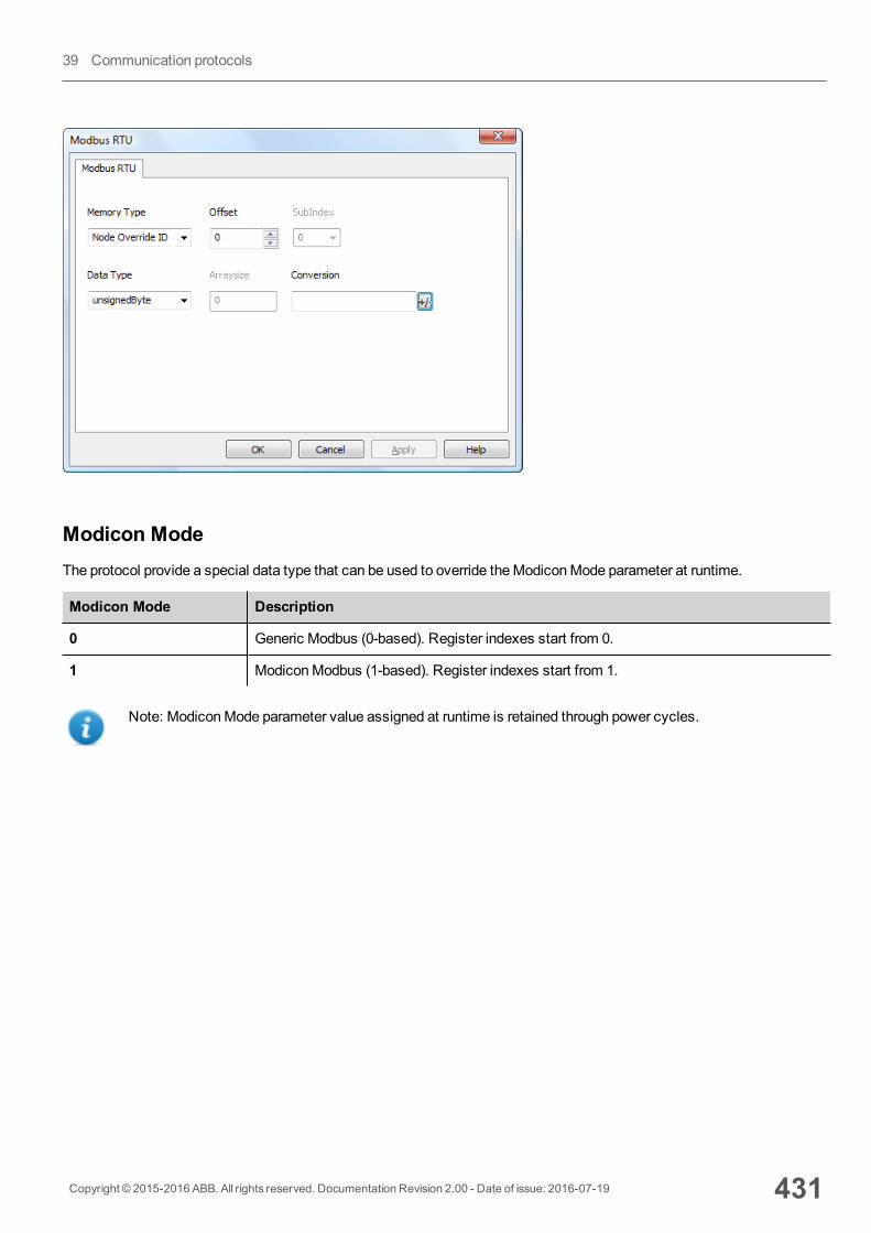
Modicon ModeThe protocol provide a special data type that can be used to override theModiconMode parameter at runtime.
Modicon Mode Description
0 Generic Modbus (0-based). Register indexes start from 0.
1 ModiconModbus (1-based). Register indexes start from 1.
Note: ModiconMode parameter value assigned at runtime is retained through power cycles.
Copyright © 2015-2016 ABB. All rights reserved. Documentation Revision 2.00 - Date of issue: 2016-07-19 431
39 Communication protocols
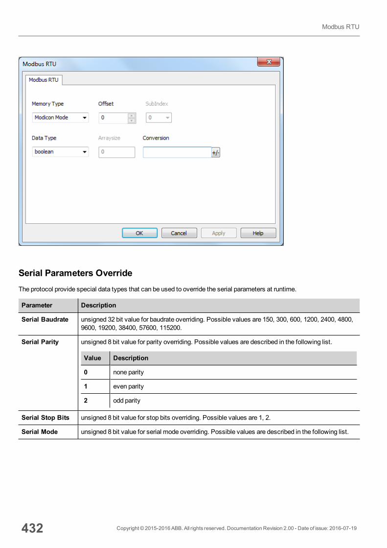
Serial Parameters OverrideThe protocol provide special data types that can be used to override the serial parameters at runtime.
Parameter Description
Serial Baudrate unsigned 32 bit value for baudrate overriding. Possible values are 150, 300, 600, 1200, 2400, 4800,9600, 19200, 38400, 57600, 115200.
Serial Parity unsigned 8 bit value for parity overriding. Possible values are described in the following list.
Value Description
0 none parity
1 even parity
2 odd parity
Serial Stop Bits unsigned 8 bit value for stop bits overriding. Possible values are 1, 2.
Serial Mode unsigned 8 bit value for serial mode overriding. Possible values are described in the following list.
432 Copyright © 2015-2016 ABB. All rights reserved. Documentation Revision 2.00 - Date of issue: 2016-07-19
Modbus RTU
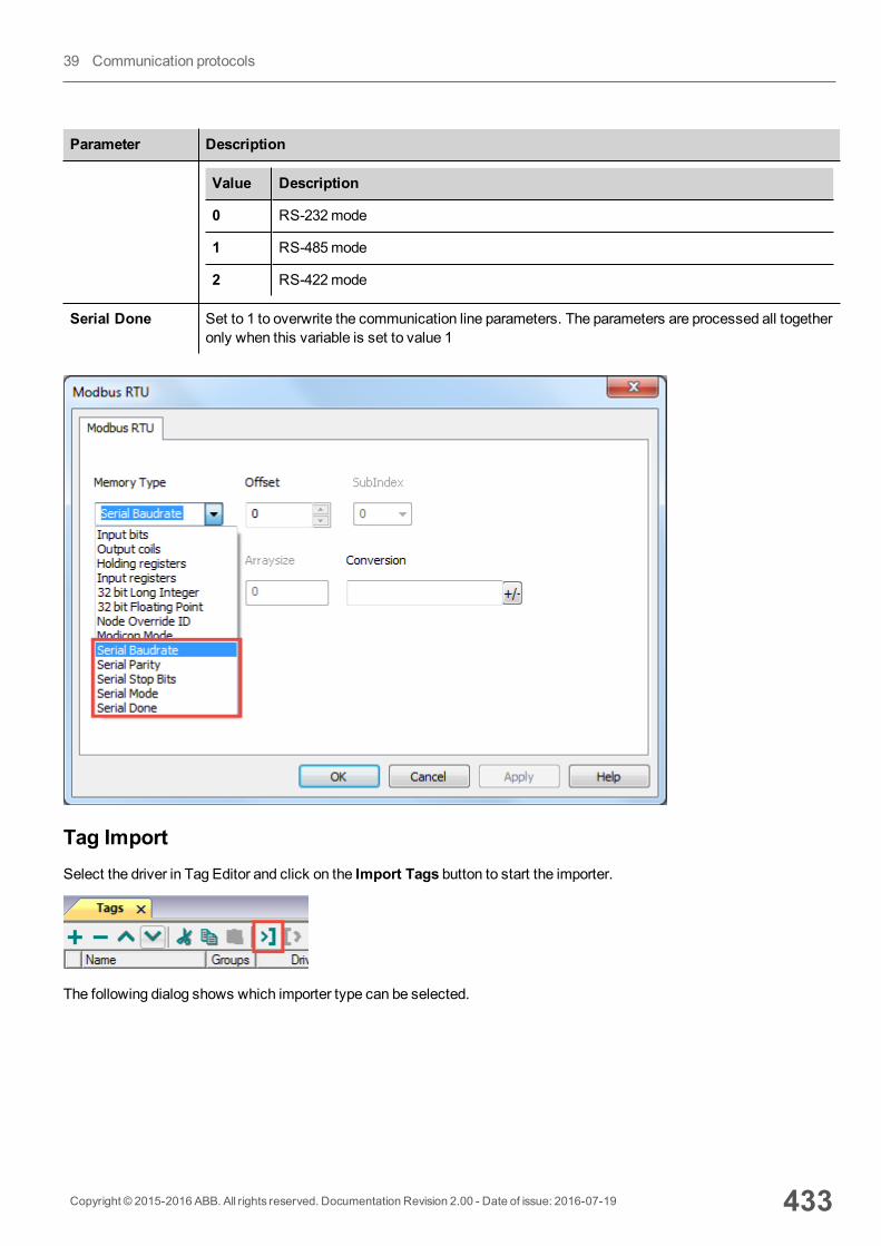
Parameter Description
Value Description
0 RS-232mode
1 RS-485mode
2 RS-422mode
Serial Done Set to 1 to overwrite the communication line parameters. The parameters are processed all togetheronly when this variable is set to value 1
Tag ImportSelect the driver in Tag Editor and click on the Import Tags button to start the importer.
The following dialog shows which importer type can be selected.
Copyright © 2015-2016 ABB. All rights reserved. Documentation Revision 2.00 - Date of issue: 2016-07-19 433
39 Communication protocols
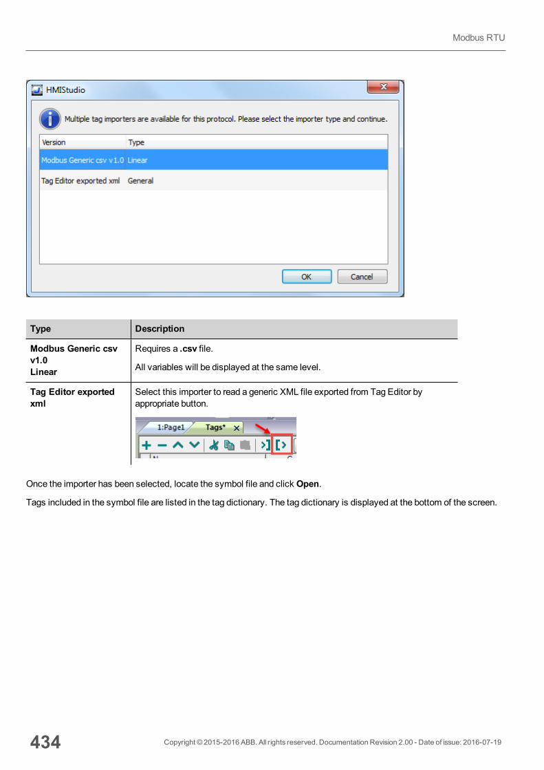
Type Description
Modbus Generic csvv1.0Linear
Requires a .csv file.
All variables will be displayed at the same level.
Tag Editor exportedxml
Select this importer to read a generic XML file exported from Tag Editor byappropriate button.
Once the importer has been selected, locate the symbol file and click Open.
Tags included in the symbol file are listed in the tag dictionary. The tag dictionary is displayed at the bottom of the screen.
434 Copyright © 2015-2016 ABB. All rights reserved. Documentation Revision 2.00 - Date of issue: 2016-07-19
Modbus RTU
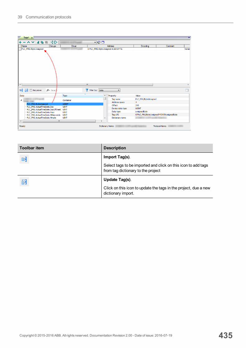
Toolbar item Description
Import Tag(s).
Select tags to be imported and click on this icon to add tagsfrom tag dictionary to the project
Update Tag(s).
Click on this icon to update the tags in the project, due a newdictionary import.
Copyright © 2015-2016 ABB. All rights reserved. Documentation Revision 2.00 - Date of issue: 2016-07-19 435
39 Communication protocols
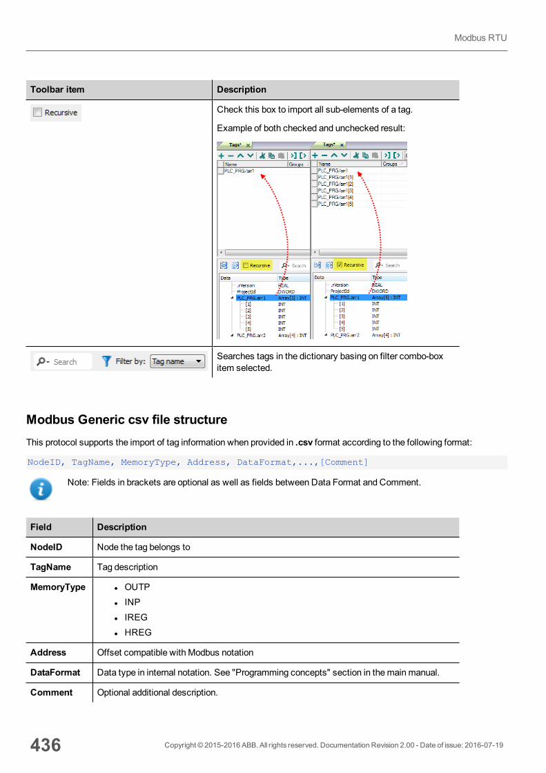
Toolbar item Description
Check this box to import all sub-elements of a tag.
Example of both checked and unchecked result:
Searches tags in the dictionary basing on filter combo-boxitem selected.
Modbus Generic csv file structureThis protocol supports the import of tag information when provided in .csv format according to the following format:
NodeID, TagName, MemoryType, Address, DataFormat,...,[Comment]
Note: Fields in brackets are optional as well as fields between Data Format and Comment.
Field Description
NodeID Node the tag belongs to
TagName Tag description
MemoryType l OUTPl INPl IREGl HREG
Address Offset compatible with Modbus notation
DataFormat Data type in internal notation. See "Programming concepts" section in themainmanual.
Comment Optional additional description.
436 Copyright © 2015-2016 ABB. All rights reserved. Documentation Revision 2.00 - Date of issue: 2016-07-19
Modbus RTU
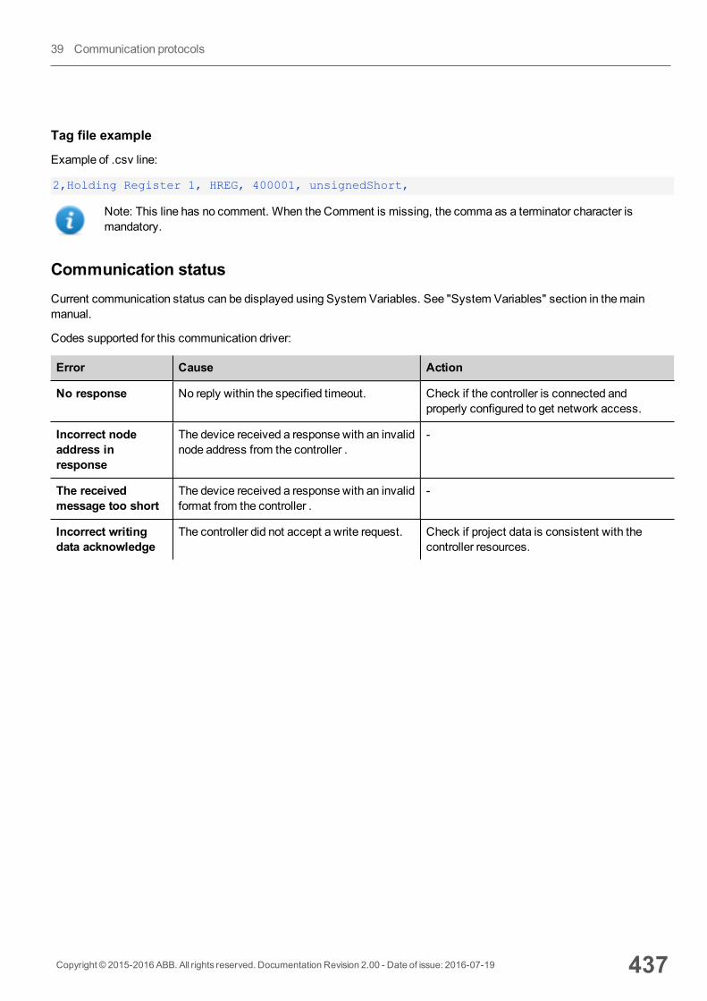
Tag file example
Example of .csv line:
2,Holding Register 1, HREG, 400001, unsignedShort,
Note: This line has no comment. When the Comment is missing, the comma as a terminator character ismandatory.
Communication statusCurrent communication status can be displayed using System Variables. See "System Variables" section in themainmanual.
Codes supported for this communication driver:
Error Cause Action
No response No reply within the specified timeout. Check if the controller is connected andproperly configured to get network access.
Incorrect nodeaddress inresponse
The device received a response with an invalidnode address from the controller .
-
The receivedmessage too short
The device received a response with an invalidformat from the controller .
-
Incorrect writingdata acknowledge
The controller did not accept a write request. Check if project data is consistent with thecontroller resources.
Copyright © 2015-2016 ABB. All rights reserved. Documentation Revision 2.00 - Date of issue: 2016-07-19 437
39 Communication protocols
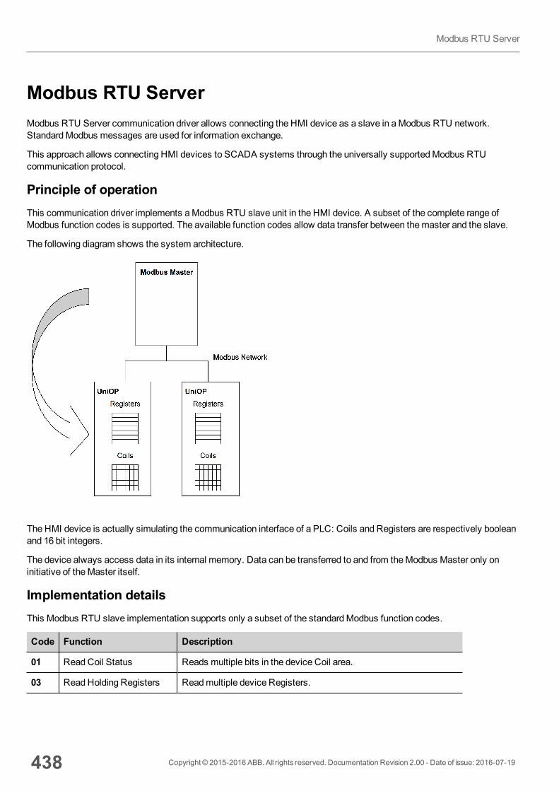
Modbus RTU ServerModbus RTU Server communication driver allows connecting the HMI device as a slave in aModbus RTU network.StandardModbus messages are used for information exchange.
This approach allows connecting HMI devices to SCADA systems through the universally supportedModbus RTUcommunication protocol.
Principle of operationThis communication driver implements aModbus RTU slave unit in the HMI device. A subset of the complete range ofModbus function codes is supported. The available function codes allow data transfer between themaster and the slave.
The following diagram shows the system architecture.
The HMI device is actually simulating the communication interface of a PLC: Coils and Registers are respectively booleanand 16 bit integers.
The device always access data in its internal memory. Data can be transferred to and from theModbus Master only oninitiative of theMaster itself.
Implementation detailsThis Modbus RTU slave implementation supports only a subset of the standardModbus function codes.
Code Function Description
01 ReadCoil Status Reads multiple bits in the device Coil area.
03 ReadHolding Registers Readmultiple device Registers.
438 Copyright © 2015-2016 ABB. All rights reserved. Documentation Revision 2.00 - Date of issue: 2016-07-19
Modbus RTU Server
Code Function Description
05 Force Single Coil Forces a single device Coil to either ON or OFF.
06 Preset Single Register Presets a value in a device Register.
08 Loopback Diagnostic Test Only sub function 00 (Return Query Data) is supported.
15 ForceMultiple Coils Forces multiple device Coils to either ON or OFF.
16 Preset Multiple Registers Presets value in multiple device Registers.
17 Report Slave ID Returns diagnostic information of the controller present at the slaveaddress.
23 ReadWrite MultipleRegisters
Read & presets values in multiple device Registers
Exception Codes
Code Description
01 Illegal Function. the function code received in the query is not supported
02 Illegal Data Address. Data Address received in the query exceeds the predefined data range (see Tag Definition for detailed ranges of all types).
03 Illegal Data Value. A sub function other than 00 is specified in Loopback Diagnostic Test (Code08).
Protocol Editor SettingsAdding a protocol
To configure the protocol:
1. In theConfig node double-click Protocols.2. To add a driver, click +: a new line is added.3. Select the protocol from thePLC list.
The driver configuration dialog is displayed.
Copyright © 2015-2016 ABB. All rights reserved. Documentation Revision 2.00 - Date of issue: 2016-07-19 439
39 Communication protocols
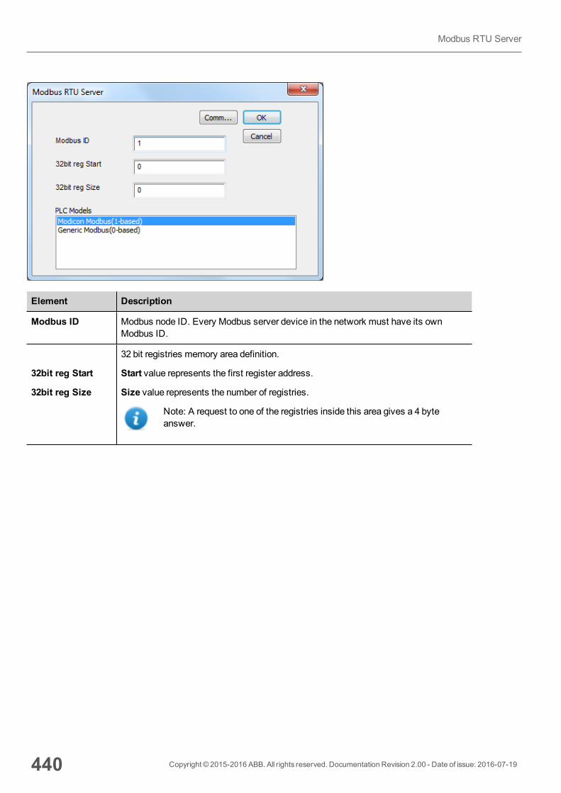
Element Description
Modbus ID Modbus node ID. Every Modbus server device in the network must have its ownModbus ID.
32bit reg Start
32bit reg Size
32 bit registries memory area definition.
Start value represents the first register address.
Size value represents the number of registries.
Note: A request to one of the registries inside this area gives a 4 byteanswer.
440 Copyright © 2015-2016 ABB. All rights reserved. Documentation Revision 2.00 - Date of issue: 2016-07-19
Modbus RTU Server
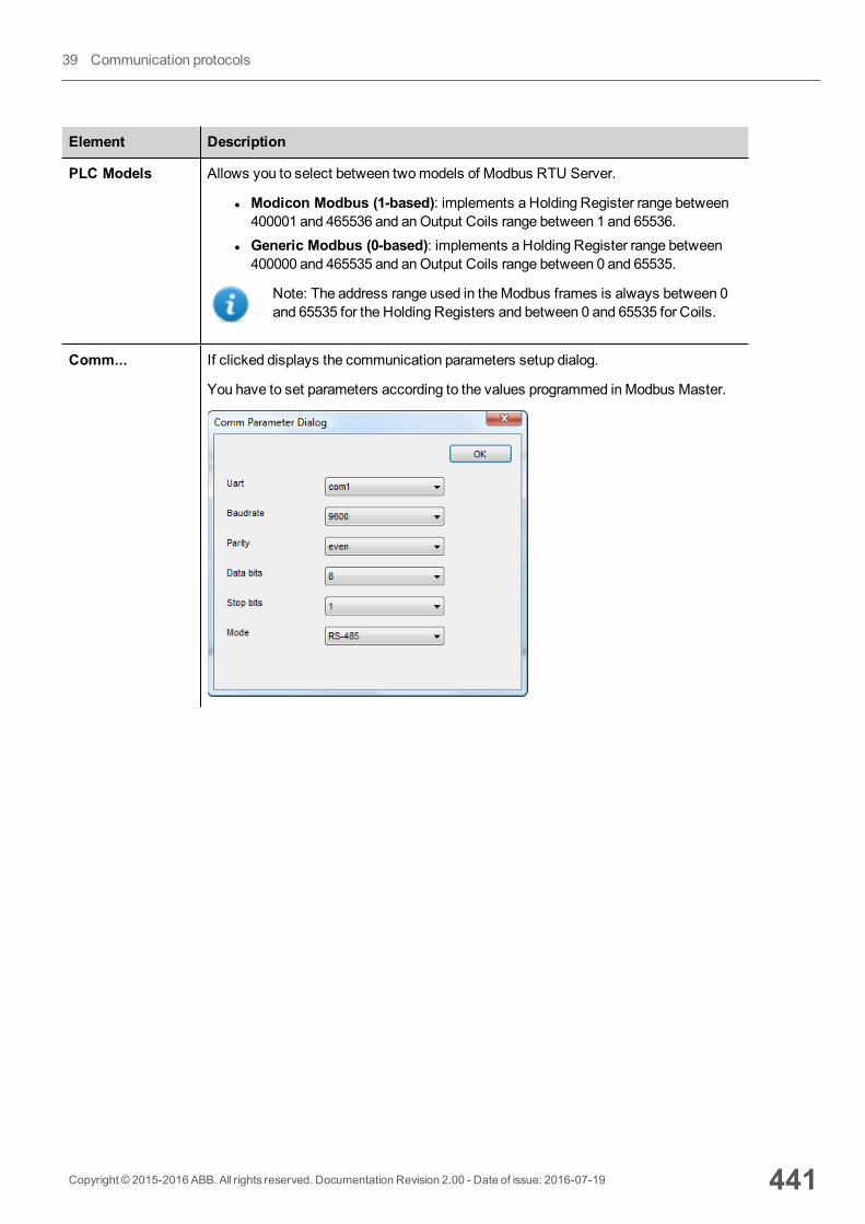
Element Description
PLC Models Allows you to select between twomodels of Modbus RTU Server.
l Modicon Modbus (1-based): implements a Holding Register range between400001 and 465536 and anOutput Coils range between 1 and 65536.
l Generic Modbus (0-based): implements a Holding Register range between400000 and 465535 and anOutput Coils range between 0 and 65535.
Note: The address range used in theModbus frames is always between 0and 65535 for the Holding Registers and between 0 and 65535 for Coils.
Comm... If clicked displays the communication parameters setup dialog.
You have to set parameters according to the values programmed inModbus Master.
Copyright © 2015-2016 ABB. All rights reserved. Documentation Revision 2.00 - Date of issue: 2016-07-19 441
39 Communication protocols
Element Description
Element Description
Uart Serial port selection.
On UN20 devices:
l com1 = device port labeledPLCl com2 = device port labeledPC/Printer
OnUN30 and UN31 devices:
l com1 = integrated serial portl com2 = add-onmodule plugged inSlot#1 or intoSlot#2
l com3 = add-onmodule plugged inSlot#3 or intoSlot#4
Baudrate, Parity, Data bits,Stop bits
Serial line parameters.
Mode Serial port mode. Available options:
l RS-232l RS-485 (2 wires)l RS-422 (4 wires)
Tag Editor SettingsPath: ProjectView> Config > double-click Tags
1. To add a tag, click +: a new line is added.2. SelectModbus RTU Server from the protocol list: tag definition dialog is displayed.
442 Copyright © 2015-2016 ABB. All rights reserved. Documentation Revision 2.00 - Date of issue: 2016-07-19
Modbus RTU Server
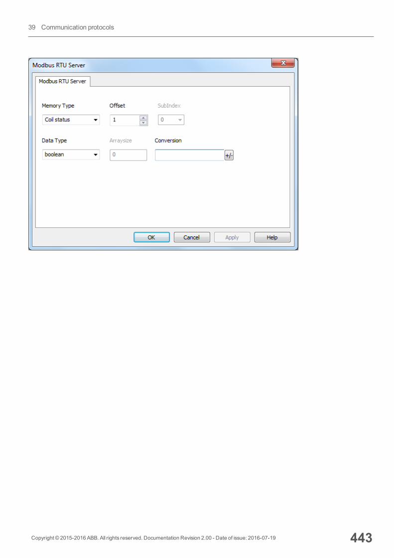
Copyright © 2015-2016 ABB. All rights reserved. Documentation Revision 2.00 - Date of issue: 2016-07-19 443
39 Communication protocols
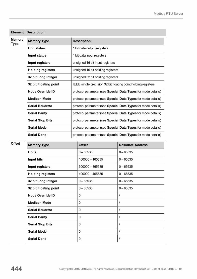
Element Description
MemoryType
Memory Type Description
Coil status 1 bit data output registers
Input status 1 bit data input registers
Input registers unsigned 16 bit input registers
Holding registers unsigned 16 bit holding registers
32 bit Long Integer unsigned 32 bit holding registers
32 bit Floating point IEEE single precision 32 bit floating point holding registers
Node Override ID protocol parameter (seeSpecial Data Types for mode details)
Modicon Mode protocol parameter (seeSpecial Data Types for mode details)
Serial Baudrate protocol parameter (seeSpecial Data Types for mode details)
Serial Parity protocol parameter (seeSpecial Data Types for mode details)
Serial Stop Bits protocol parameter (seeSpecial Data Types for mode details)
Serial Mode protocol parameter (seeSpecial Data Types for mode details)
Serial Done protocol parameter (seeSpecial Data Types for mode details)
Offset Memory Type Offset Resource Address
Coils 0 – 65535 0 – 65535
Input bits 100000 – 165535 0 – 65535
Input registers 300000 – 365535 0 – 65535
Holding registers 400000 – 465535 0 – 65535
32 bit Long Integer 0 – 65535 0 – 65535
32 bit Floating point 0 – 65535 0 – 65535
Node Override ID 0 /
Modicon Mode 0 /
Serial Baudrate 0 /
Serial Parity 0 /
Serial Stop Bits 0 /
Serial Mode 0 /
Serial Done 0 /
444 Copyright © 2015-2016 ABB. All rights reserved. Documentation Revision 2.00 - Date of issue: 2016-07-19
Modbus RTU Server
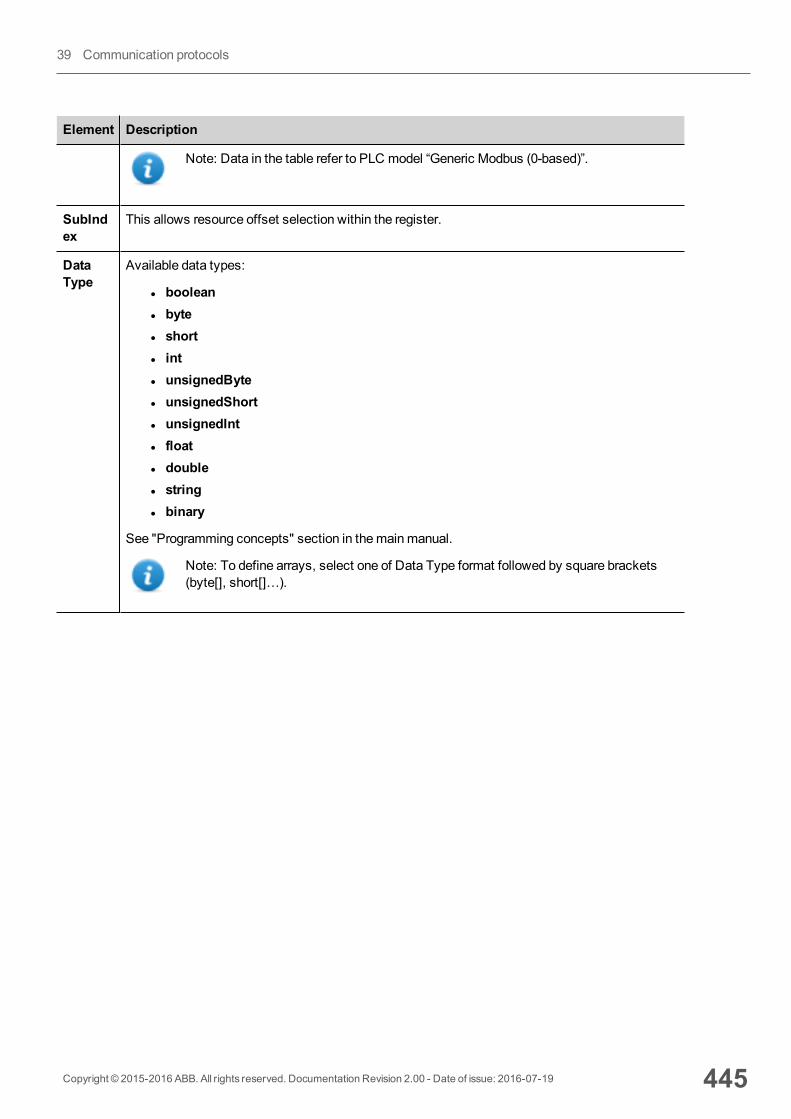
Element Description
Note: Data in the table refer to PLC model “Generic Modbus (0-based)”.
SubIndex
This allows resource offset selection within the register.
DataType
Available data types:
l booleanl bytel shortl intl unsignedBytel unsignedShortl unsignedIntl floatl doublel stringl binary
See "Programming concepts" section in themainmanual.
Note: To define arrays, select one of Data Type format followed by square brackets(byte[], short[]…).
Copyright © 2015-2016 ABB. All rights reserved. Documentation Revision 2.00 - Date of issue: 2016-07-19 445
39 Communication protocols
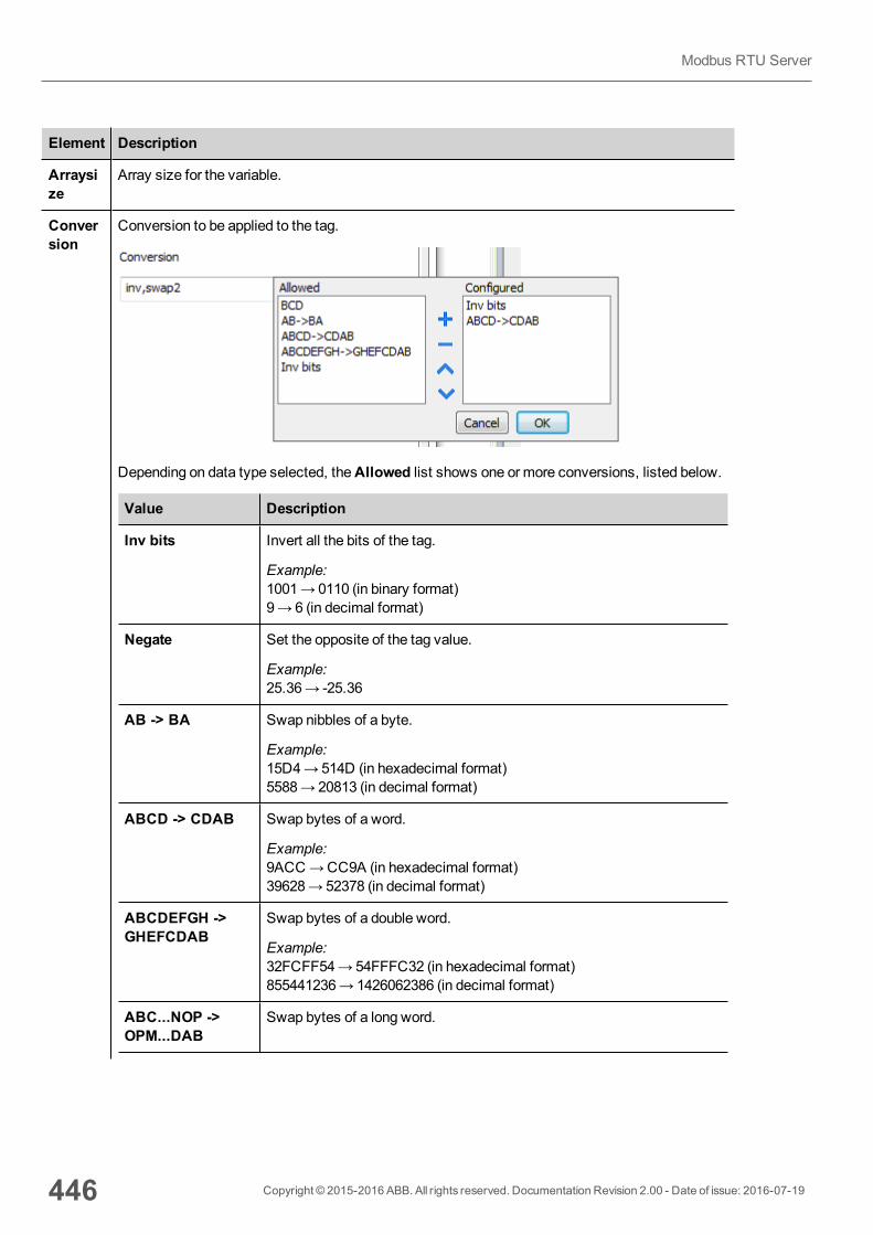
Element Description
Arraysize
Array size for the variable.
Conversion
Conversion to be applied to the tag.
Depending on data type selected, theAllowed list shows one or more conversions, listed below.
Value Description
Inv bits Invert all the bits of the tag.
Example:1001→ 0110 (in binary format)9→ 6 (in decimal format)
Negate Set the opposite of the tag value.
Example:25.36→ -25.36
AB -> BA Swap nibbles of a byte.
Example:15D4→514D (in hexadecimal format)5588→ 20813 (in decimal format)
ABCD -> CDAB Swap bytes of a word.
Example:9ACC→CC9A (in hexadecimal format)39628→ 52378 (in decimal format)
ABCDEFGH ->GHEFCDAB
Swap bytes of a double word.
Example:32FCFF54→54FFFC32 (in hexadecimal format)855441236→ 1426062386 (in decimal format)
ABC...NOP ->OPM...DAB
Swap bytes of a long word.
446 Copyright © 2015-2016 ABB. All rights reserved. Documentation Revision 2.00 - Date of issue: 2016-07-19
Modbus RTU Server
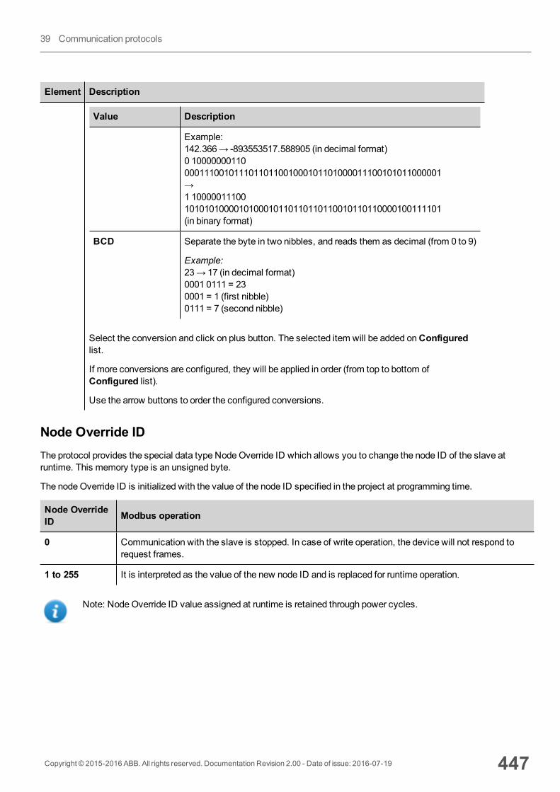
Element Description
Value Description
Example:142.366→ -893553517.588905 (in decimal format)0 100000001100001110010111011011001000101101000011100101011000001→1 100000111001010101000010100010110110110110010110110000100111101(in binary format)
BCD Separate the byte in two nibbles, and reads them as decimal (from 0 to 9)
Example:23→ 17 (in decimal format)0001 0111 = 230001 = 1 (first nibble)0111 = 7 (second nibble)
Select the conversion and click on plus button. The selected item will be added onConfiguredlist.
If more conversions are configured, they will be applied in order (from top to bottom ofConfigured list).
Use the arrow buttons to order the configured conversions.
Node Override IDThe protocol provides the special data type NodeOverride ID which allows you to change the node ID of the slave atruntime. This memory type is an unsigned byte.
The nodeOverride ID is initialized with the value of the node ID specified in the project at programming time.
Node OverrideID Modbus operation
0 Communication with the slave is stopped. In case of write operation, the device will not respond torequest frames.
1 to 255 It is interpreted as the value of the new node ID and is replaced for runtime operation.
Note: NodeOverride ID value assigned at runtime is retained through power cycles.
Copyright © 2015-2016 ABB. All rights reserved. Documentation Revision 2.00 - Date of issue: 2016-07-19 447
39 Communication protocols
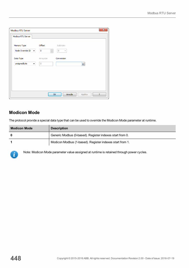
Modicon ModeThe protocol provide a special data type that can be used to override theModiconMode parameter at runtime.
Modicon Mode Description
0 Generic Modbus (0-based). Register indexes start from 0.
1 ModiconModbus (1-based). Register indexes start from 1.
Note: ModiconMode parameter value assigned at runtime is retained through power cycles.
448 Copyright © 2015-2016 ABB. All rights reserved. Documentation Revision 2.00 - Date of issue: 2016-07-19
Modbus RTU Server

Serial Parameters OverrideThe protocol provide special data types that can be used to override the serial parameters at runtime.
Parameter Description
Serial Baudrate unsigned 32 bit value for baudrate overriding. Possible values are 150, 300, 600, 1200, 2400, 4800,9600, 19200, 38400, 57600, 115200.
Serial Parity unsigned 8 bit value for parity overriding. Possible values are described in the following list.
Value Description
0 none parity
1 even parity
2 odd parity
Serial Stop Bits unsigned 8 bit value for stop bits overriding. Possible values are 1, 2.
Serial Mode unsigned 8 bit value for serial mode overriding. Possible values are described in the following list.
Copyright © 2015-2016 ABB. All rights reserved. Documentation Revision 2.00 - Date of issue: 2016-07-19 449
39 Communication protocols
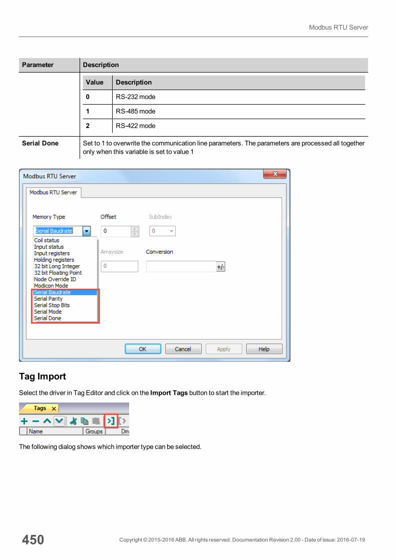
Parameter Description
Value Description
0 RS-232mode
1 RS-485mode
2 RS-422mode
Serial Done Set to 1 to overwrite the communication line parameters. The parameters are processed all togetheronly when this variable is set to value 1
Tag ImportSelect the driver in Tag Editor and click on the Import Tags button to start the importer.
The following dialog shows which importer type can be selected.
450 Copyright © 2015-2016 ABB. All rights reserved. Documentation Revision 2.00 - Date of issue: 2016-07-19
Modbus RTU Server

Type Description
Modbus Generic csvv1.0Linear
Requires a .csv file.
All variables will be displayed at the same level.
Tag Editor exportedxml
Select this importer to read a generic XML file exported from Tag Editor byappropriate button.
Once the importer has been selected, locate the symbol file and click Open.
Tags included in the symbol file are listed in the tag dictionary. The tag dictionary is displayed at the bottom of the screen.
Copyright © 2015-2016 ABB. All rights reserved. Documentation Revision 2.00 - Date of issue: 2016-07-19 451
39 Communication protocols
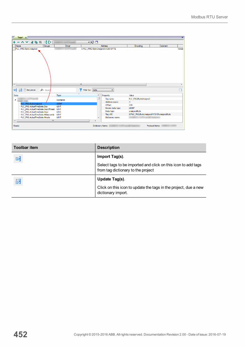
Toolbar item Description
Import Tag(s).
Select tags to be imported and click on this icon to add tagsfrom tag dictionary to the project
Update Tag(s).
Click on this icon to update the tags in the project, due a newdictionary import.
452 Copyright © 2015-2016 ABB. All rights reserved. Documentation Revision 2.00 - Date of issue: 2016-07-19
Modbus RTU Server
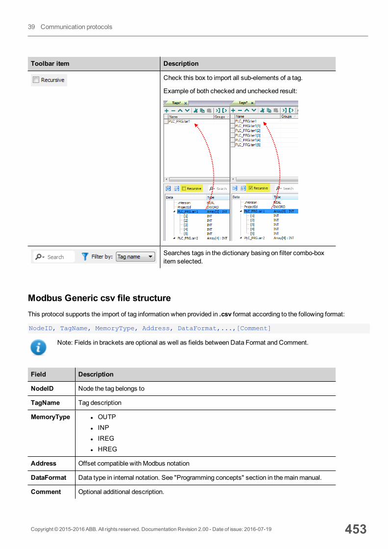
Toolbar item Description
Check this box to import all sub-elements of a tag.
Example of both checked and unchecked result:
Searches tags in the dictionary basing on filter combo-boxitem selected.
Modbus Generic csv file structureThis protocol supports the import of tag information when provided in .csv format according to the following format:
NodeID, TagName, MemoryType, Address, DataFormat,...,[Comment]
Note: Fields in brackets are optional as well as fields between Data Format and Comment.
Field Description
NodeID Node the tag belongs to
TagName Tag description
MemoryType l OUTPl INPl IREGl HREG
Address Offset compatible with Modbus notation
DataFormat Data type in internal notation. See "Programming concepts" section in themainmanual.
Comment Optional additional description.
Copyright © 2015-2016 ABB. All rights reserved. Documentation Revision 2.00 - Date of issue: 2016-07-19 453
39 Communication protocols
Tag file example
Example of .csv line:
2,Holding Register 1, HREG, 400001, unsignedShort,
Note: This line has no comment. When the Comment is missing, the comma as a terminator character ismandatory.
Communication statusCurrent communication status can be displayed using system variables. This communication protocol acts as server anddoesn't return any specific Protocol Error Message.
See "System Variables" section in themainmanual.
454 Copyright © 2015-2016 ABB. All rights reserved. Documentation Revision 2.00 - Date of issue: 2016-07-19
Modbus RTU Server
Modbus TCPVarious Modbus TCP-capable devices can be connected to HMI devices. To set-up your Modbus TCP device, please referto the documentation you have received with the device.
The implementation of the protocol operates as aModbus TCP client only.
Implementation detailsThis Modbus TCP implementation supports only a subset of theModbus TCP standard function codes.
Code Function Description
01 ReadCoil Status Reads multiple bits in the HMI device Coil area.
02 Read Input Status Reads the ON/OFF status of the discrete inputs (1x reference) in theslave.
03 ReadHolding Registers Reads multiple registers.
04 Read Input Registers Reads the binary contents of input registers (3x reference) in the slave.
05 Force Single Coil Forces a single coil to either ON or OFF.
06 Preset Single Register Writes a value to one register.
15 Write Multiple Coils Writes each coil in a sequence of coils to either ON or OFF.
16 Preset MultipleRegisters
Writes values to a block of registers in sequence.
Protocol Editor SettingsAdding a protocol
To configure the protocol:
1. In theConfig node double-click Protocols.2. To add a driver, click +: a new line is added.3. Select the protocol from thePLC list.
The driver configuration dialog is displayed.
Copyright © 2015-2016 ABB. All rights reserved. Documentation Revision 2.00 - Date of issue: 2016-07-19 455
39 Communication protocols
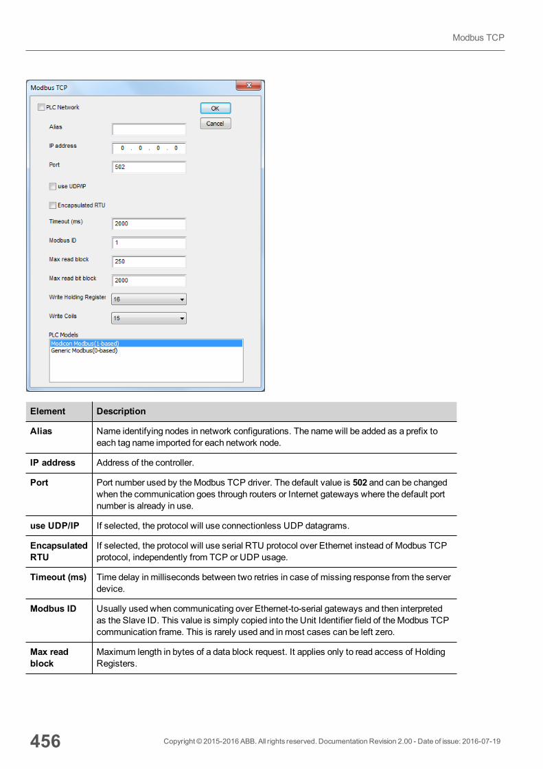
Element Description
Alias Name identifying nodes in network configurations. The namewill be added as a prefix toeach tag name imported for each network node.
IP address Address of the controller.
Port Port number used by theModbus TCP driver. The default value is 502 and can be changedwhen the communication goes through routers or Internet gateways where the default portnumber is already in use.
use UDP/IP If selected, the protocol will use connectionless UDP datagrams.
EncapsulatedRTU
If selected, the protocol will use serial RTU protocol over Ethernet instead of Modbus TCPprotocol, independently from TCP or UDP usage.
Timeout (ms) Time delay in milliseconds between two retries in case of missing response from the serverdevice.
Modbus ID Usually used when communicating over Ethernet-to-serial gateways and then interpretedas the Slave ID. This value is simply copied into the Unit Identifier field of theModbus TCPcommunication frame. This is rarely used and inmost cases can be left zero.
Max readblock
Maximum length in bytes of a data block request. It applies only to read access of HoldingRegisters.
456 Copyright © 2015-2016 ABB. All rights reserved. Documentation Revision 2.00 - Date of issue: 2016-07-19
Modbus TCP
Element Description
Max read bitblock
Maximum length in bits of a block request. It applies only to read access of Input Bits andOutput Coils.
WriteHoldingRegister
Modbus function for write operations to Holding Registers. Select between the function 06(preset single register) and function 16 (preset multiple registers).
If function 06 is selected, the protocol will always use function 06 for writing to thecontroller, even when writing tomultiple consecutive registers.
If function 16 is selected, the protocol will always use function 16 to write to the controller,even for a single register write request and theMax read block size parameter of the queryis set to 2. The use of function 16may result in higher communication performance.
Write Coils Modbus function for write operations to Output Coils. Select between the function 05 (writesingle coil) and function 15 (write multiple coils).
If Modbus function 05 is selected, the protocol will always use function 05 for writing to thecontroller, even when writing tomultiple consecutive coils.
If Modbus function 15 is selected, the protocol will always use function 15 to write to thecontroller, even for a single coil write request. The use of function 15may result in highercommunication performance.
Copyright © 2015-2016 ABB. All rights reserved. Documentation Revision 2.00 - Date of issue: 2016-07-19 457
39 Communication protocols
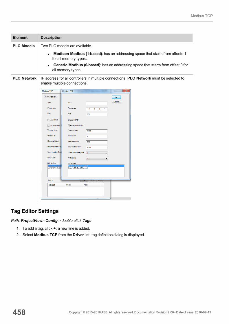
Element Description
PLC Models Two PLC models are available.
l Modicon Modbus (1-based): has an addressing space that starts from offsets 1for all memory types.
l Generic Modbus (0-based): has an addressing space that starts from offset 0 forall memory types.
PLC Network IP address for all controllers in multiple connections. PLC Networkmust be selected toenablemultiple connections.
Tag Editor SettingsPath: ProjectView> Config > double-click Tags
1. To add a tag, click +: a new line is added.2. SelectModbus TCP from theDriver list: tag definition dialog is displayed.
458 Copyright © 2015-2016 ABB. All rights reserved. Documentation Revision 2.00 - Date of issue: 2016-07-19
Modbus TCP
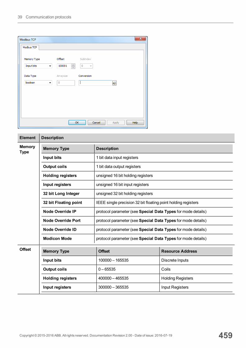
Element Description
MemoryType
Memory Type Description
Input bits 1 bit data input registers
Output coils 1 bit data output registers
Holding registers unsigned 16 bit holding registers
Input registers unsigned 16 bit input registers
32 bit Long Integer unsigned 32 bit holding registers
32 bit Floating point IEEE single precision 32 bit floating point holding registers
Node Override IP protocol parameter (seeSpecial Data Types for mode details)
Node Override Port protocol parameter (seeSpecial Data Types for mode details)
Node Override ID protocol parameter (seeSpecial Data Types for mode details)
Modicon Mode protocol parameter (seeSpecial Data Types for mode details)
Offset Memory Type Offset Resource Address
Input bits 100000 – 165535 Discrete Inputs
Output coils 0 – 65535 Coils
Holding registers 400000 – 465535 Holding Registers
Input registers 300000 – 365535 Input Registers
Copyright © 2015-2016 ABB. All rights reserved. Documentation Revision 2.00 - Date of issue: 2016-07-19 459
39 Communication protocols
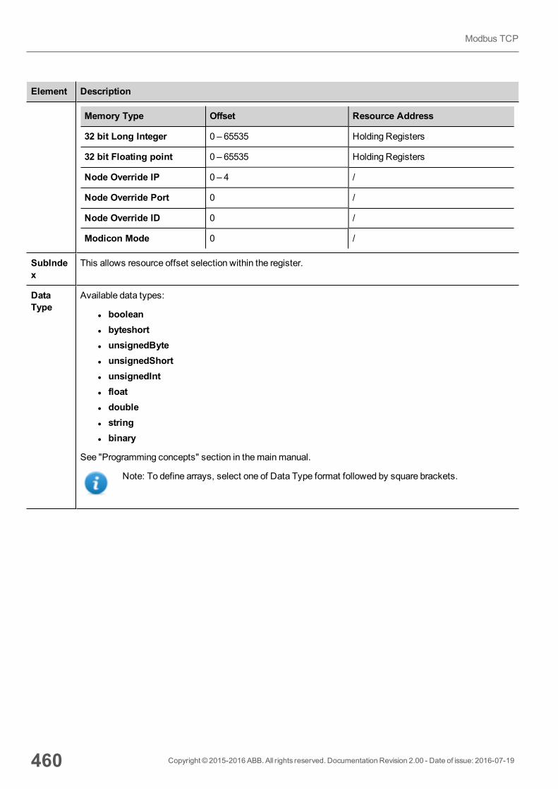
Element Description
Memory Type Offset Resource Address
32 bit Long Integer 0 – 65535 Holding Registers
32 bit Floating point 0 – 65535 Holding Registers
Node Override IP 0 – 4 /
Node Override Port 0 /
Node Override ID 0 /
Modicon Mode 0 /
SubIndex
This allows resource offset selection within the register.
DataType
Available data types:
l booleanl byteshortl unsignedBytel unsignedShortl unsignedIntl floatl doublel stringl binary
See "Programming concepts" section in themainmanual.
Note: To define arrays, select one of Data Type format followed by square brackets.
460 Copyright © 2015-2016 ABB. All rights reserved. Documentation Revision 2.00 - Date of issue: 2016-07-19
Modbus TCP
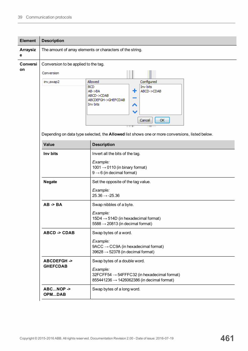
Element Description
Arraysize
The amount of array elements or characters of the string.
Conversion
Conversion to be applied to the tag.
Depending on data type selected, theAllowed list shows one or more conversions, listed below.
Value Description
Inv bits Invert all the bits of the tag.
Example:1001→ 0110 (in binary format)9→ 6 (in decimal format)
Negate Set the opposite of the tag value.
Example:25.36→ -25.36
AB -> BA Swap nibbles of a byte.
Example:15D4→514D (in hexadecimal format)5588→ 20813 (in decimal format)
ABCD -> CDAB Swap bytes of a word.
Example:9ACC→CC9A (in hexadecimal format)39628→ 52378 (in decimal format)
ABCDEFGH ->GHEFCDAB
Swap bytes of a double word.
Example:32FCFF54→54FFFC32 (in hexadecimal format)855441236→ 1426062386 (in decimal format)
ABC...NOP ->OPM...DAB
Swap bytes of a long word.
Copyright © 2015-2016 ABB. All rights reserved. Documentation Revision 2.00 - Date of issue: 2016-07-19 461
39 Communication protocols
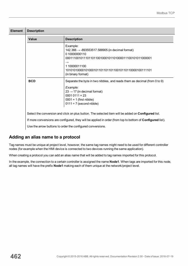
Element Description
Value Description
Example:142.366→ -893553517.588905 (in decimal format)0 100000001100001110010111011011001000101101000011100101011000001→1 100000111001010101000010100010110110110110010110110000100111101(in binary format)
BCD Separate the byte in two nibbles, and reads them as decimal (from 0 to 9)
Example:23→ 17 (in decimal format)0001 0111 = 230001 = 1 (first nibble)0111 = 7 (second nibble)
Select the conversion and click on plus button. The selected item will be added onConfigured list.
If more conversions are configured, they will be applied in order (from top to bottom of Configured list).
Use the arrow buttons to order the configured conversions.
Adding an alias name to a protocolTag names must be unique at project level, however, the same tag names might need to be used for different controllernodes (for example when the HMI device is connected to two devices running the same application).
When creating a protocol you can add an alias name that will be added to tag names imported for this protocol.
In the example, the connection to a certain controller is assigned the nameNode1. When tags are imported for this node,all tag names will have the prefix Node1making each of them unique at the network/project level.
462 Copyright © 2015-2016 ABB. All rights reserved. Documentation Revision 2.00 - Date of issue: 2016-07-19
Modbus TCP
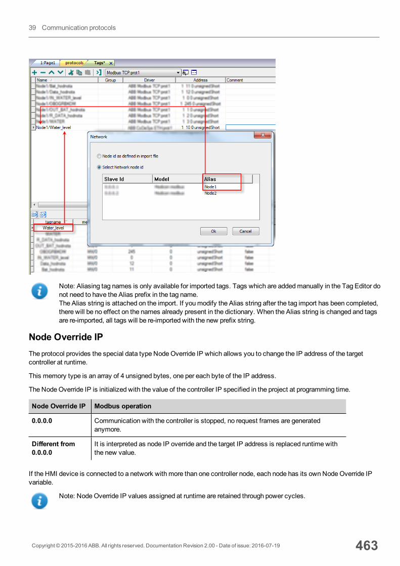
Note: Aliasing tag names is only available for imported tags. Tags which are addedmanually in the Tag Editor donot need to have the Alias prefix in the tag name.The Alias string is attached on the import. If youmodify the Alias string after the tag import has been completed,there will be no effect on the names already present in the dictionary. When the Alias string is changed and tagsare re-imported, all tags will be re-imported with the new prefix string.
Node Override IPThe protocol provides the special data type NodeOverride IP which allows you to change the IP address of the targetcontroller at runtime.
This memory type is an array of 4 unsigned bytes, one per each byte of the IP address.
The NodeOverride IP is initialized with the value of the controller IP specified in the project at programming time.
Node Override IP Modbus operation
0.0.0.0 Communication with the controller is stopped, no request frames are generatedanymore.
Different from0.0.0.0
It is interpreted as node IP override and the target IP address is replaced runtime withthe new value.
If the HMI device is connected to a network with more than one controller node, each node has its ownNodeOverride IPvariable.
Note: NodeOverride IP values assigned at runtime are retained through power cycles.
Copyright © 2015-2016 ABB. All rights reserved. Documentation Revision 2.00 - Date of issue: 2016-07-19 463
39 Communication protocols
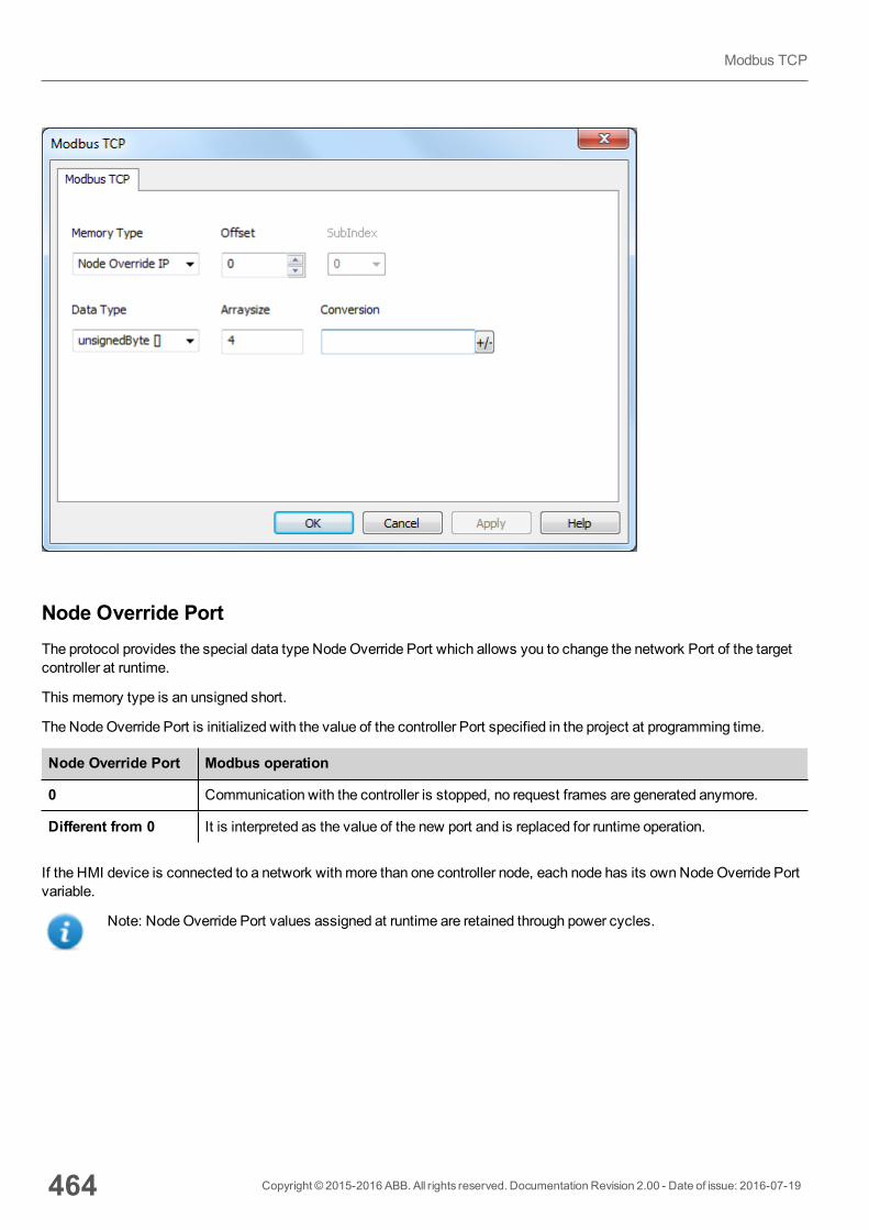
Node Override PortThe protocol provides the special data type NodeOverride Port which allows you to change the network Port of the targetcontroller at runtime.
This memory type is an unsigned short.
The NodeOverride Port is initialized with the value of the controller Port specified in the project at programming time.
Node Override Port Modbus operation
0 Communication with the controller is stopped, no request frames are generated anymore.
Different from 0 It is interpreted as the value of the new port and is replaced for runtime operation.
If the HMI device is connected to a network with more than one controller node, each node has its ownNodeOverride Portvariable.
Note: NodeOverride Port values assigned at runtime are retained through power cycles.
464 Copyright © 2015-2016 ABB. All rights reserved. Documentation Revision 2.00 - Date of issue: 2016-07-19
Modbus TCP
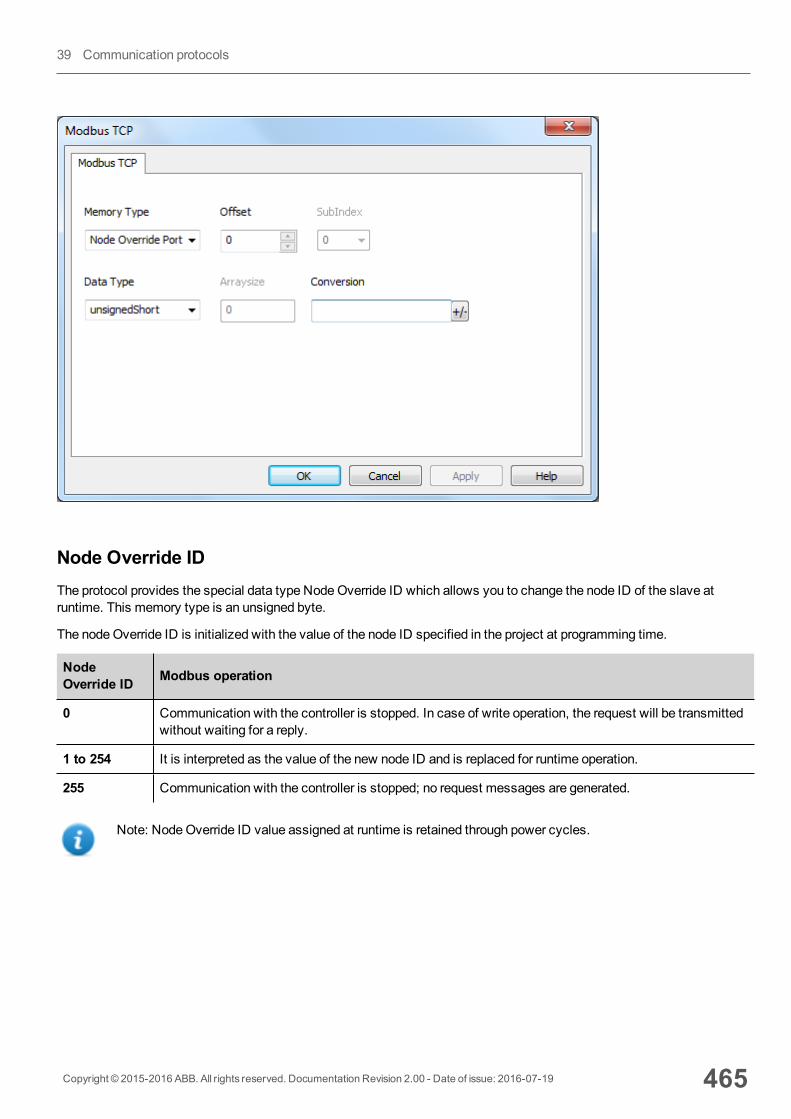
Node Override IDThe protocol provides the special data type NodeOverride ID which allows you to change the node ID of the slave atruntime. This memory type is an unsigned byte.
The nodeOverride ID is initialized with the value of the node ID specified in the project at programming time.
NodeOverride ID Modbus operation
0 Communication with the controller is stopped. In case of write operation, the request will be transmittedwithout waiting for a reply.
1 to 254 It is interpreted as the value of the new node ID and is replaced for runtime operation.
255 Communication with the controller is stopped; no request messages are generated.
Note: NodeOverride ID value assigned at runtime is retained through power cycles.
Copyright © 2015-2016 ABB. All rights reserved. Documentation Revision 2.00 - Date of issue: 2016-07-19 465
39 Communication protocols
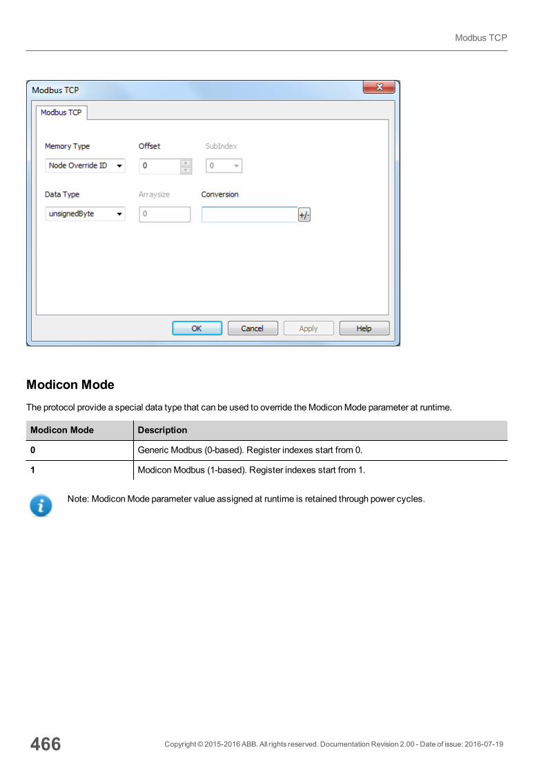
Modicon ModeThe protocol provide a special data type that can be used to override theModiconMode parameter at runtime.
Modicon Mode Description
0 Generic Modbus (0-based). Register indexes start from 0.
1 ModiconModbus (1-based). Register indexes start from 1.
Note: ModiconMode parameter value assigned at runtime is retained through power cycles.
466 Copyright © 2015-2016 ABB. All rights reserved. Documentation Revision 2.00 - Date of issue: 2016-07-19
Modbus TCP
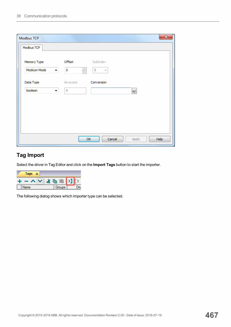
Tag ImportSelect the driver in Tag Editor and click on the Import Tags button to start the importer.
The following dialog shows which importer type can be selected.
Copyright © 2015-2016 ABB. All rights reserved. Documentation Revision 2.00 - Date of issue: 2016-07-19 467
39 Communication protocols
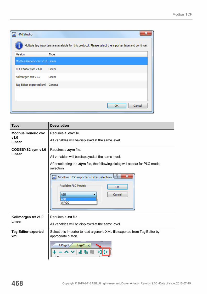
Type Description
Modbus Generic csvv1.0Linear
Requires a .csv file.
All variables will be displayed at the same level.
CODESYS2 sym v1.0Linear
Requires a .sym file.
All variables will be displayed at the same level.
After selecting the .sym file, the following dialog will appear for PLC modelselection.
Kollmorgen txt v1.0Linear
Requires a .txt file.
All variables will be displayed at the same level.
Tag Editor exportedxml
Select this importer to read a generic XML file exported from Tag Editor byappropriate button.
468 Copyright © 2015-2016 ABB. All rights reserved. Documentation Revision 2.00 - Date of issue: 2016-07-19
Modbus TCP
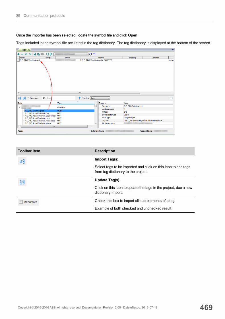
Once the importer has been selected, locate the symbol file and click Open.
Tags included in the symbol file are listed in the tag dictionary. The tag dictionary is displayed at the bottom of the screen.
Toolbar item Description
Import Tag(s).
Select tags to be imported and click on this icon to add tagsfrom tag dictionary to the project
Update Tag(s).
Click on this icon to update the tags in the project, due a newdictionary import.
Check this box to import all sub-elements of a tag.
Example of both checked and unchecked result:
Copyright © 2015-2016 ABB. All rights reserved. Documentation Revision 2.00 - Date of issue: 2016-07-19 469
39 Communication protocols

Toolbar item Description
Searches tags in the dictionary basing on filter combo-boxitem selected.
Modbus Generic csv file structureThis protocol supports the import of tag information when provided in .csv format according to the following format:
NodeID, TagName, MemoryType, Address, DataFormat,...,[Comment]
Note: Fields in brackets are optional as well as fields between Data Format and Comment.
Field Description
NodeID Node the tag belongs to
TagName Tag description
MemoryType l OUTPl INPl IREGl HREG
Address Offset compatible with Modbus notation
DataFormat Data type in internal notation. See "Programming concepts" section in themainmanual.
Comment Optional additional description.
470 Copyright © 2015-2016 ABB. All rights reserved. Documentation Revision 2.00 - Date of issue: 2016-07-19
Modbus TCP
Tag file example
Example of .csv line:
2,Holding Register 1, HREG, 400001, unsignedShort,
Note: This line has no comment. When the Comment is missing, the comma as a terminator character ismandatory.
Communication statusCurrent communication status can be displayed using system variables. See "System Variables" section in themainmanual.
Codes supported for this communication driver:
Error Cause Action
No response No reply within the specified timeout. Check if the controller is connected andproperly configured to get network access.
Incorrect nodeaddress inresponse
The device received a response with aninvalid node address from the controller .
-
The receivedmessage tooshort
The device received a response with aninvalid format from the controller .
-
Incorrect writingdata acknowledge
The controller did not accept a writerequest.
Check if project data is consistent with thecontroller resources.
Copyright © 2015-2016 ABB. All rights reserved. Documentation Revision 2.00 - Date of issue: 2016-07-19 471
39 Communication protocols
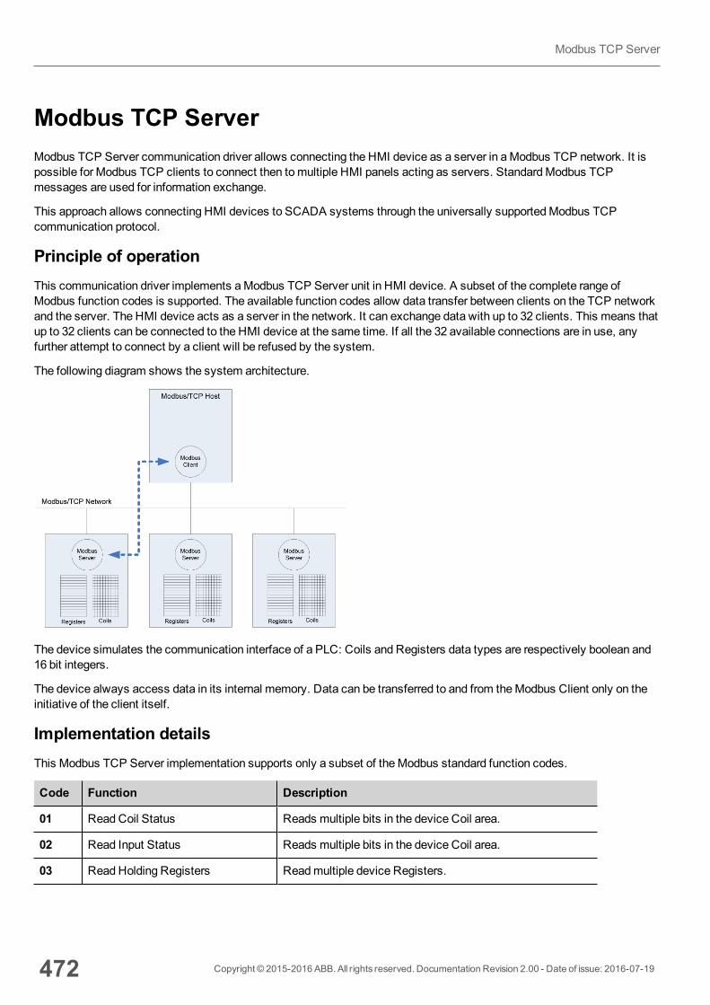
Modbus TCP ServerModbus TCP Server communication driver allows connecting the HMI device as a server in aModbus TCP network. It ispossible for Modbus TCP clients to connect then tomultiple HMI panels acting as servers. StandardModbus TCPmessages are used for information exchange.
This approach allows connecting HMI devices to SCADA systems through the universally supportedModbus TCPcommunication protocol.
Principle of operationThis communication driver implements aModbus TCP Server unit in HMI device. A subset of the complete range ofModbus function codes is supported. The available function codes allow data transfer between clients on the TCP networkand the server. The HMI device acts as a server in the network. It can exchange data with up to 32 clients. This means thatup to 32 clients can be connected to the HMI device at the same time. If all the 32 available connections are in use, anyfurther attempt to connect by a client will be refused by the system.
The following diagram shows the system architecture.
The device simulates the communication interface of a PLC: Coils and Registers data types are respectively boolean and16 bit integers.
The device always access data in its internal memory. Data can be transferred to and from theModbus Client only on theinitiative of the client itself.
Implementation detailsThis Modbus TCP Server implementation supports only a subset of theModbus standard function codes.
Code Function Description
01 ReadCoil Status Reads multiple bits in the device Coil area.
02 Read Input Status Reads multiple bits in the device Coil area.
03 ReadHolding Registers Readmultiple device Registers.
472 Copyright © 2015-2016 ABB. All rights reserved. Documentation Revision 2.00 - Date of issue: 2016-07-19
Modbus TCP Server
Code Function Description
04 Read Input Registers Readmultiple device Registers.
05 Force Single Coil Forces a single device Coil to either ON or OFF.
06 Preset Single Register Presets a value in a device Register.
15 ForceMultiple Coils Forces multiple device Coils to either ON or OFF.
16 Preset Multiple Registers Presets value in multiple device Registers.
23 ReadWrite Multiple Registers Read & presets values in multiple device Registers
Note: For both PLC models the Read Coil Status and Read Input Status function codes both access the sameCoil memory area in the HMI devicememory. The Read Holding Registers and Read Input Registers functioncodes both access the sameRegister area in the HMI devicememory.
Exception Codes
Code Description
01 Illegal Function. the function code received in the query is not supported
02 Illegal Data Address. Data Address received in the query exceeds the predefined datarange (see Tag Definition for detailed ranges of all types).
Protocol Editor SettingsAdding a protocol
To configure the protocol:
1. In theConfig node double-click Protocols.2. To add a driver, click +: a new line is added.3. Select the protocol from thePLC list.
The driver configuration dialog is displayed.
Copyright © 2015-2016 ABB. All rights reserved. Documentation Revision 2.00 - Date of issue: 2016-07-19 473
39 Communication protocols
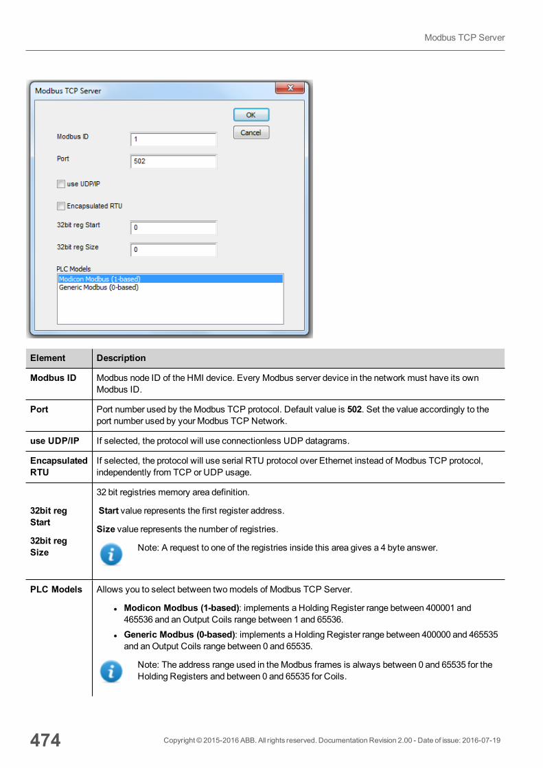
Element Description
Modbus ID Modbus node ID of the HMI device. Every Modbus server device in the network must have its ownModbus ID.
Port Port number used by theModbus TCP protocol. Default value is 502. Set the value accordingly to theport number used by your Modbus TCP Network.
use UDP/IP If selected, the protocol will use connectionless UDP datagrams.
EncapsulatedRTU
If selected, the protocol will use serial RTU protocol over Ethernet instead of Modbus TCP protocol,independently from TCP or UDP usage.
32bit regStart
32bit regSize
32 bit registries memory area definition.
Start value represents the first register address.
Size value represents the number of registries.
Note: A request to one of the registries inside this area gives a 4 byte answer.
PLC Models Allows you to select between twomodels of Modbus TCP Server.
l Modicon Modbus (1-based): implements a Holding Register range between 400001 and465536 and anOutput Coils range between 1 and 65536.
l Generic Modbus (0-based): implements a Holding Register range between 400000 and 465535and anOutput Coils range between 0 and 65535.
Note: The address range used in theModbus frames is always between 0 and 65535 for theHolding Registers and between 0 and 65535 for Coils.
474 Copyright © 2015-2016 ABB. All rights reserved. Documentation Revision 2.00 - Date of issue: 2016-07-19
Modbus TCP Server
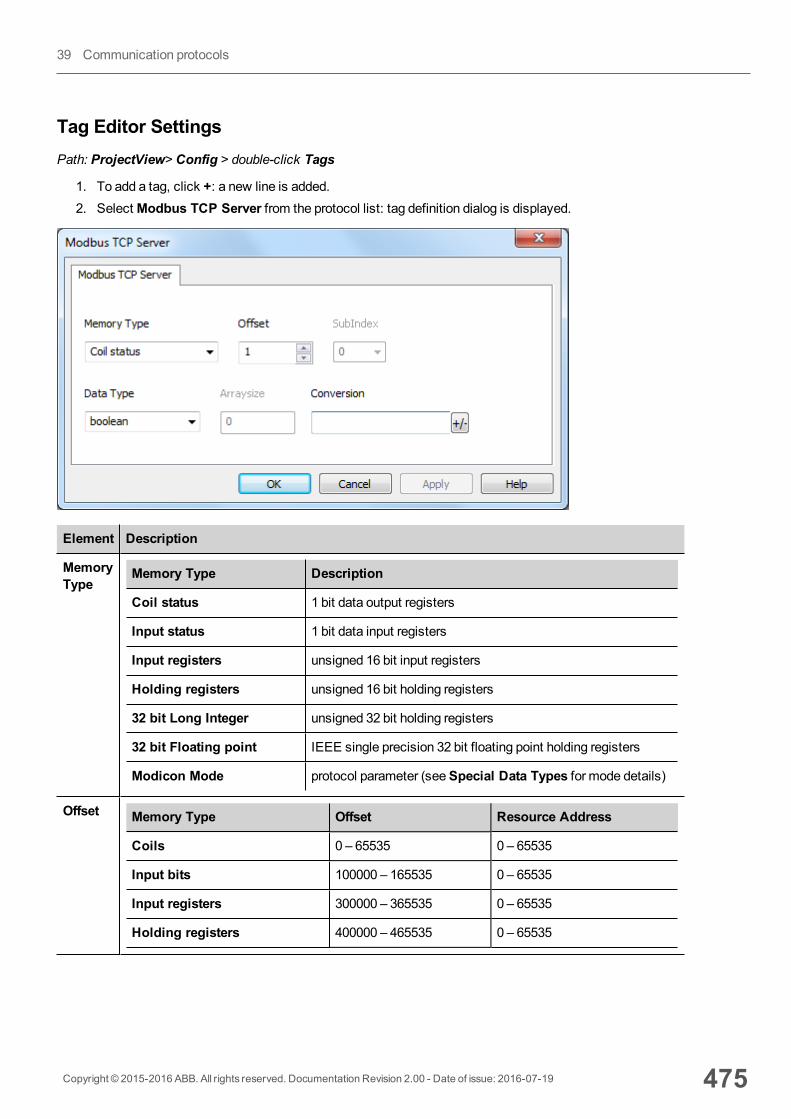
Tag Editor SettingsPath: ProjectView> Config > double-click Tags
1. To add a tag, click +: a new line is added.2. SelectModbus TCP Server from the protocol list: tag definition dialog is displayed.
Element Description
MemoryType
Memory Type Description
Coil status 1 bit data output registers
Input status 1 bit data input registers
Input registers unsigned 16 bit input registers
Holding registers unsigned 16 bit holding registers
32 bit Long Integer unsigned 32 bit holding registers
32 bit Floating point IEEE single precision 32 bit floating point holding registers
Modicon Mode protocol parameter (seeSpecial Data Types for mode details)
Offset Memory Type Offset Resource Address
Coils 0 – 65535 0 – 65535
Input bits 100000 – 165535 0 – 65535
Input registers 300000 – 365535 0 – 65535
Holding registers 400000 – 465535 0 – 65535
Copyright © 2015-2016 ABB. All rights reserved. Documentation Revision 2.00 - Date of issue: 2016-07-19 475
39 Communication protocols
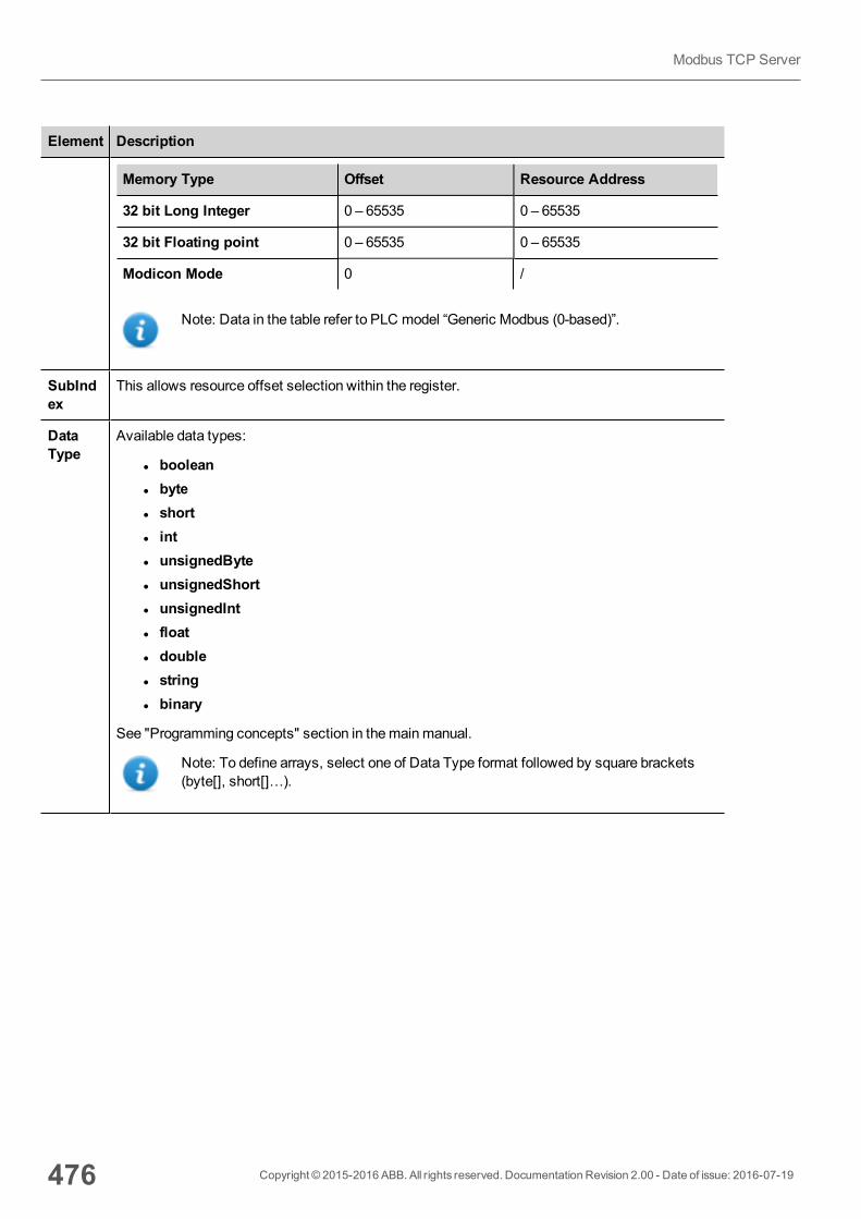
Element Description
Memory Type Offset Resource Address
32 bit Long Integer 0 – 65535 0 – 65535
32 bit Floating point 0 – 65535 0 – 65535
Modicon Mode 0 /
Note: Data in the table refer to PLC model “Generic Modbus (0-based)”.
SubIndex
This allows resource offset selection within the register.
DataType
Available data types:
l booleanl bytel shortl intl unsignedBytel unsignedShortl unsignedIntl floatl doublel stringl binary
See "Programming concepts" section in themainmanual.
Note: To define arrays, select one of Data Type format followed by square brackets(byte[], short[]…).
476 Copyright © 2015-2016 ABB. All rights reserved. Documentation Revision 2.00 - Date of issue: 2016-07-19
Modbus TCP Server

Element Description
Arraysize
Array size for the variable.
Conversion
Conversion to be applied to the tag.
Depending on data type selected, theAllowed list shows one or more conversions, listed below.
Value Description
Inv bits Invert all the bits of the tag.
Example:1001→ 0110 (in binary format)9→ 6 (in decimal format)
Negate Set the opposite of the tag value.
Example:25.36→ -25.36
AB -> BA Swap nibbles of a byte.
Example:15D4→514D (in hexadecimal format)5588→ 20813 (in decimal format)
ABCD -> CDAB Swap bytes of a word.
Example:9ACC→CC9A (in hexadecimal format)39628→ 52378 (in decimal format)
ABCDEFGH ->GHEFCDAB
Swap bytes of a double word.
Example:32FCFF54→54FFFC32 (in hexadecimal format)855441236→ 1426062386 (in decimal format)
ABC...NOP ->OPM...DAB
Swap bytes of a long word.
Copyright © 2015-2016 ABB. All rights reserved. Documentation Revision 2.00 - Date of issue: 2016-07-19 477
39 Communication protocols
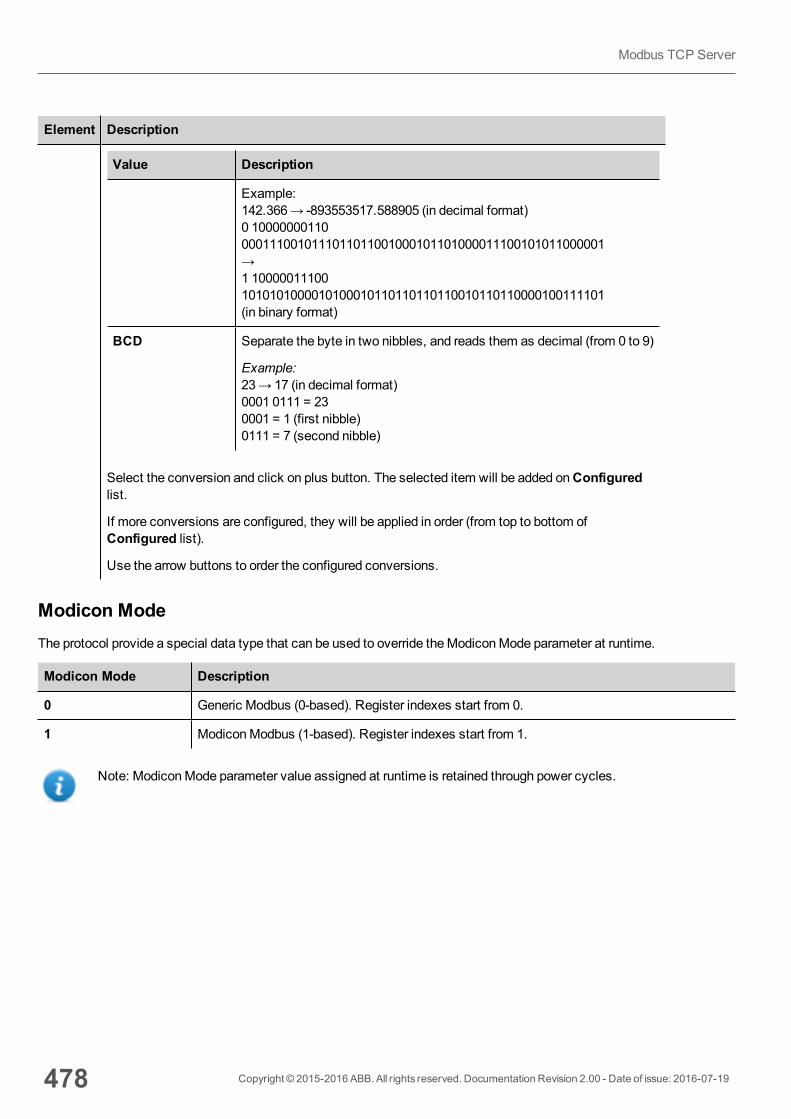
Element Description
Value Description
Example:142.366→ -893553517.588905 (in decimal format)0 100000001100001110010111011011001000101101000011100101011000001→1 100000111001010101000010100010110110110110010110110000100111101(in binary format)
BCD Separate the byte in two nibbles, and reads them as decimal (from 0 to 9)
Example:23→ 17 (in decimal format)0001 0111 = 230001 = 1 (first nibble)0111 = 7 (second nibble)
Select the conversion and click on plus button. The selected item will be added onConfiguredlist.
If more conversions are configured, they will be applied in order (from top to bottom ofConfigured list).
Use the arrow buttons to order the configured conversions.
Modicon ModeThe protocol provide a special data type that can be used to override theModiconMode parameter at runtime.
Modicon Mode Description
0 Generic Modbus (0-based). Register indexes start from 0.
1 ModiconModbus (1-based). Register indexes start from 1.
Note: ModiconMode parameter value assigned at runtime is retained through power cycles.
478 Copyright © 2015-2016 ABB. All rights reserved. Documentation Revision 2.00 - Date of issue: 2016-07-19
Modbus TCP Server
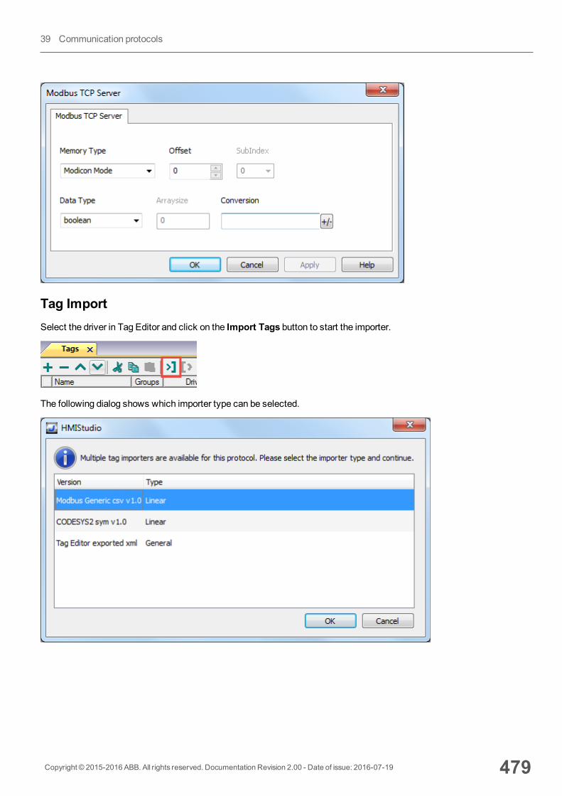
Tag ImportSelect the driver in Tag Editor and click on the Import Tags button to start the importer.
The following dialog shows which importer type can be selected.
Copyright © 2015-2016 ABB. All rights reserved. Documentation Revision 2.00 - Date of issue: 2016-07-19 479
39 Communication protocols
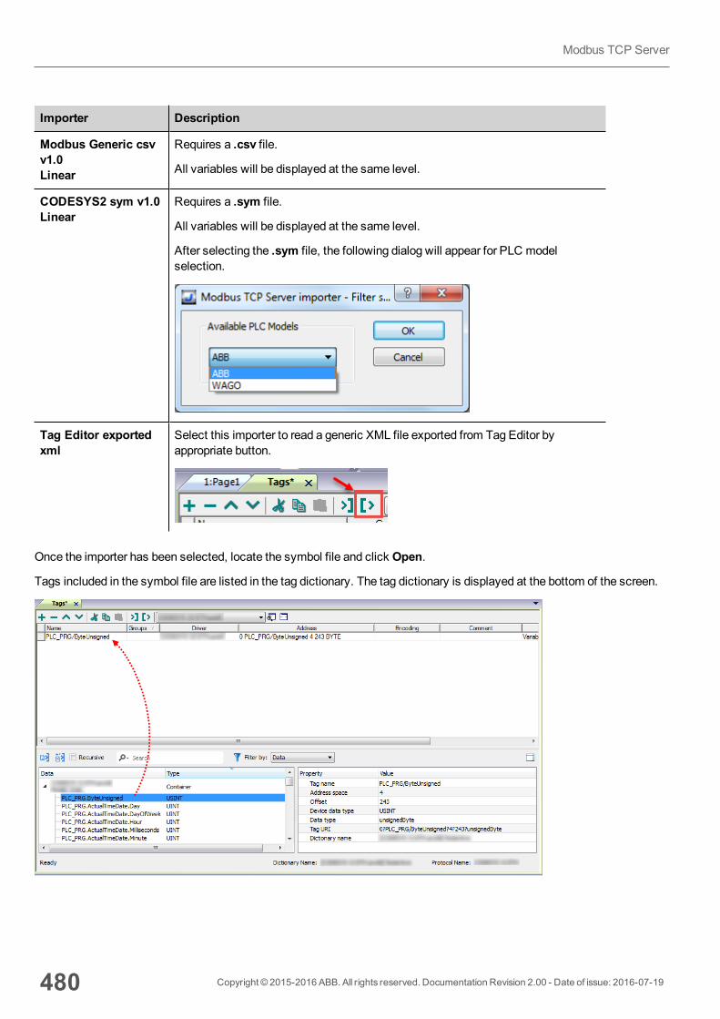
Importer Description
Modbus Generic csvv1.0Linear
Requires a .csv file.
All variables will be displayed at the same level.
CODESYS2 sym v1.0Linear
Requires a .sym file.
All variables will be displayed at the same level.
After selecting the .sym file, the following dialog will appear for PLC modelselection.
Tag Editor exportedxml
Select this importer to read a generic XML file exported from Tag Editor byappropriate button.
Once the importer has been selected, locate the symbol file and click Open.
Tags included in the symbol file are listed in the tag dictionary. The tag dictionary is displayed at the bottom of the screen.
480 Copyright © 2015-2016 ABB. All rights reserved. Documentation Revision 2.00 - Date of issue: 2016-07-19
Modbus TCP Server
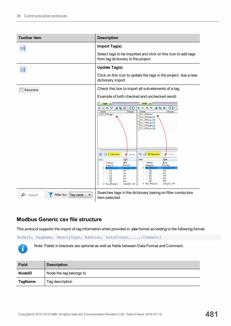
Toolbar item Description
Import Tag(s).
Select tags to be imported and click on this icon to add tagsfrom tag dictionary to the project
Update Tag(s).
Click on this icon to update the tags in the project, due a newdictionary import.
Check this box to import all sub-elements of a tag.
Example of both checked and unchecked result:
Searches tags in the dictionary basing on filter combo-boxitem selected.
Modbus Generic csv file structureThis protocol supports the import of tag information when provided in .csv format according to the following format:
NodeID, TagName, MemoryType, Address, DataFormat,...,[Comment]
Note: Fields in brackets are optional as well as fields between Data Format and Comment.
Field Description
NodeID Node the tag belongs to
TagName Tag description
Copyright © 2015-2016 ABB. All rights reserved. Documentation Revision 2.00 - Date of issue: 2016-07-19 481
39 Communication protocols
Field Description
MemoryType l OUTPl INPl IREGl HREG
Address Offset compatible with Modbus notation
DataFormat Data type in internal notation. See "Programming concepts" section in themainmanual.
Comment Optional additional description.
Tag file example
Example of .csv line:
2,Holding Register 1, HREG, 400001, unsignedShort,
Note: This line has no comment. When the Comment is missing, the comma as a terminator character ismandatory.
Communication statusThe HMI device is a server station in theModbus TCP network. The current implementation of the protocol doesn't reportany communication error code apart from standard communication error codes related to the proper driver loading.
See "System Variables" section in themainmanual.
482 Copyright © 2015-2016 ABB. All rights reserved. Documentation Revision 2.00 - Date of issue: 2016-07-19
Modbus TCP Server
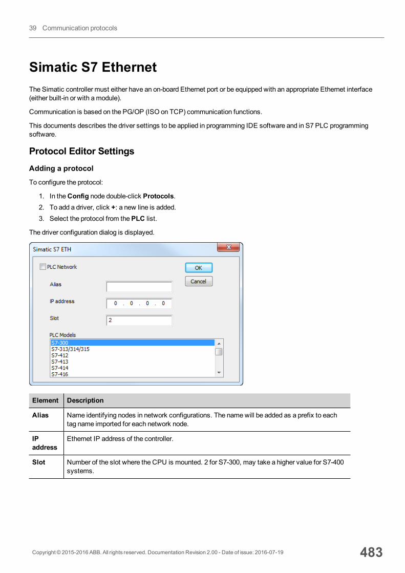
Simatic S7 EthernetThe Simatic controller must either have an on-board Ethernet port or be equipped with an appropriate Ethernet interface(either built-in or with amodule).
Communication is based on the PG/OP (ISO on TCP) communication functions.
This documents describes the driver settings to be applied in programming IDE software and in S7 PLC programmingsoftware.
Protocol Editor SettingsAdding a protocol
To configure the protocol:
1. In theConfig node double-click Protocols.2. To add a driver, click +: a new line is added.3. Select the protocol from thePLC list.
The driver configuration dialog is displayed.
Element Description
Alias Name identifying nodes in network configurations. The namewill be added as a prefix to eachtag name imported for each network node.
IPaddress
Ethernet IP address of the controller.
Slot Number of the slot where the CPU is mounted. 2 for S7-300, may take a higher value for S7-400systems.
Copyright © 2015-2016 ABB. All rights reserved. Documentation Revision 2.00 - Date of issue: 2016-07-19 483
39 Communication protocols
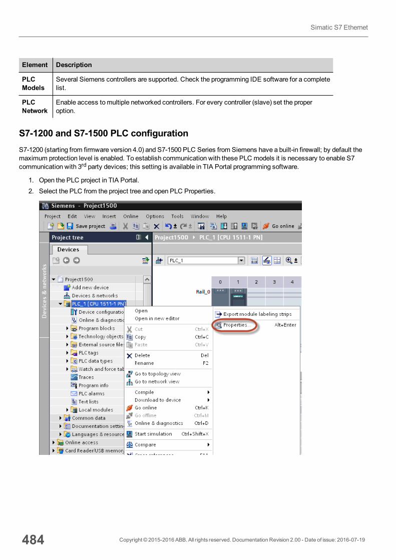
Element Description
PLCModels
Several Siemens controllers are supported. Check the programming IDE software for a completelist.
PLCNetwork
Enable access tomultiple networked controllers. For every controller (slave) set the properoption.
S7-1200 and S7-1500 PLC configurationS7-1200 (starting from firmware version 4.0) and S7-1500 PLC Series from Siemens have a built-in firewall; by default themaximum protection level is enabled. To establish communication with these PLC models it is necessary to enable S7communication with 3rd party devices; this setting is available in TIA Portal programming software.
1. Open the PLC project in TIA Portal.2. Select the PLC from the project tree and open PLC Properties.
484 Copyright © 2015-2016 ABB. All rights reserved. Documentation Revision 2.00 - Date of issue: 2016-07-19
Simatic S7 Ethernet

3. In General > Protectionmake sure that "Full access (no protection)" has been selected.
4. Scroll down the page and check "Permit access with PUT/GET communication from remote partner".
Note: If variables are defined in "Program blocks", DB must configured as "Not optimized".
To check or change DB optimization, open DB Properties:
Copyright © 2015-2016 ABB. All rights reserved. Documentation Revision 2.00 - Date of issue: 2016-07-19 485
39 Communication protocols
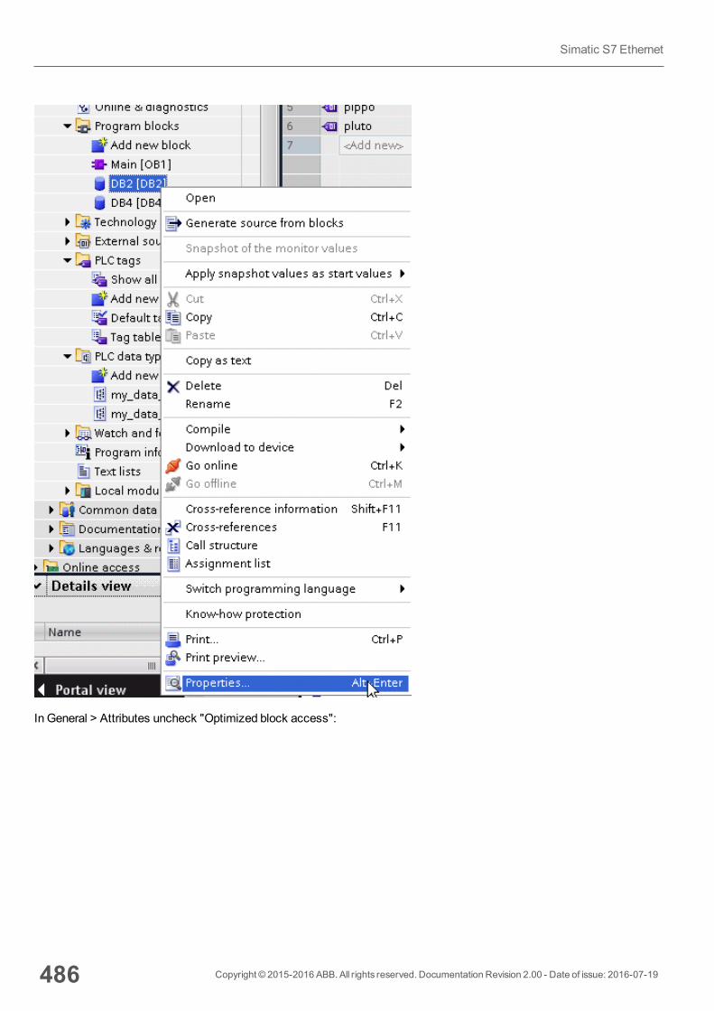
In General > Attributes uncheck "Optimized block access":
486 Copyright © 2015-2016 ABB. All rights reserved. Documentation Revision 2.00 - Date of issue: 2016-07-19
Simatic S7 Ethernet
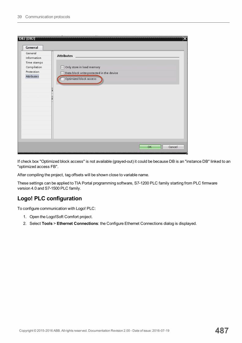
If check box "Optimized block access" is not available (grayed-out) it could be because DB is an "instance DB" linked to an"optimized access FB".
After compiling the project, tag offsets will be shown close to variable name.
These settings can be applied to TIA Portal programming software, S7-1200 PLC family starting from PLC firmwareversion 4.0 and S7-1500 PLC family.
Logo! PLC configurationTo configure communication with Logo! PLC:
1. Open the Logo!Soft Comfort project.2. Select Tools > Ethernet Connections: the Configure Ethernet Connections dialog is displayed.
Copyright © 2015-2016 ABB. All rights reserved. Documentation Revision 2.00 - Date of issue: 2016-07-19 487
39 Communication protocols
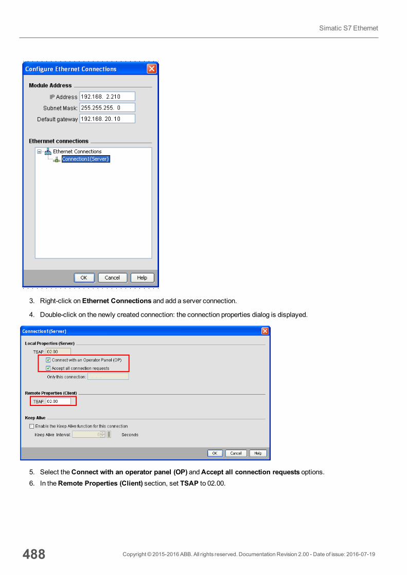
3. Right-click onEthernet Connections and add a server connection.
4. Double-click on the newly created connection: the connection properties dialog is displayed.
5. Select theConnect with an operator panel (OP) andAccept all connection requests options.6. In theRemote Properties (Client) section, set TSAP to 02.00.
488 Copyright © 2015-2016 ABB. All rights reserved. Documentation Revision 2.00 - Date of issue: 2016-07-19
Simatic S7 Ethernet
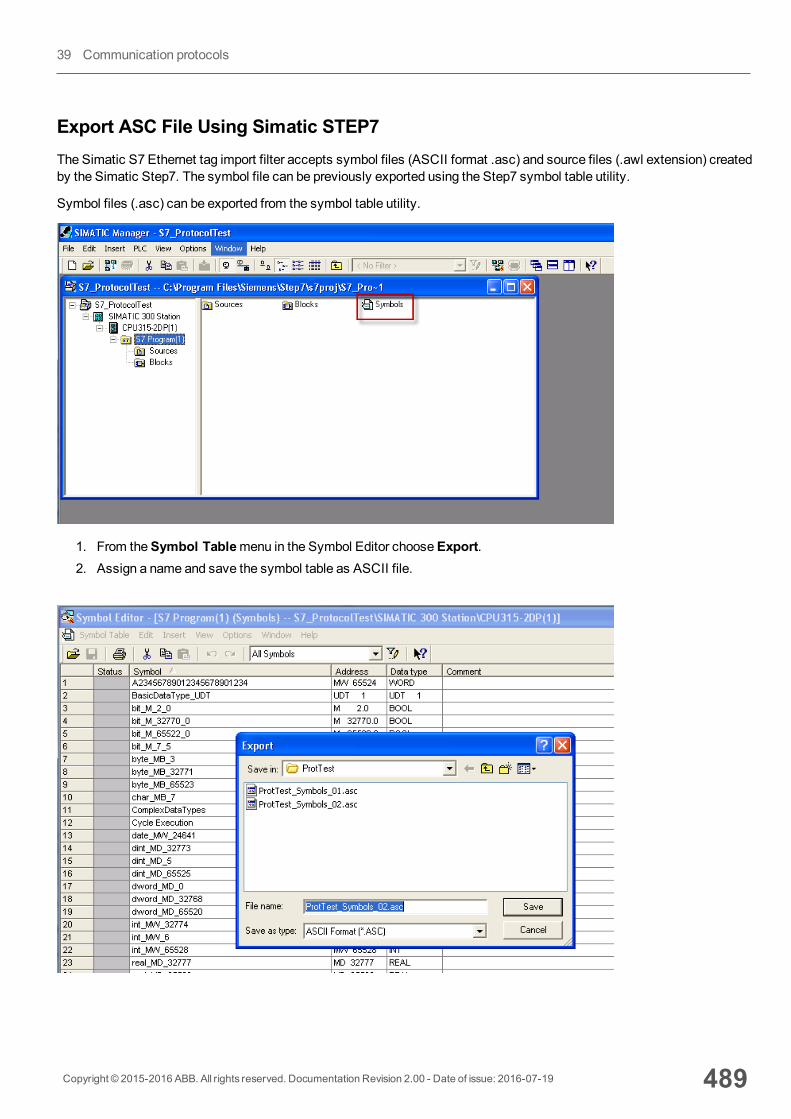
Export ASC File Using Simatic STEP7The Simatic S7 Ethernet tag import filter accepts symbol files (ASCII format .asc) and source files (.awl extension) createdby the Simatic Step7. The symbol file can be previously exported using the Step7 symbol table utility.
Symbol files (.asc) can be exported from the symbol table utility.
1. From theSymbol Tablemenu in the Symbol Editor chooseExport.2. Assign a name and save the symbol table as ASCII file.
Copyright © 2015-2016 ABB. All rights reserved. Documentation Revision 2.00 - Date of issue: 2016-07-19 489
39 Communication protocols
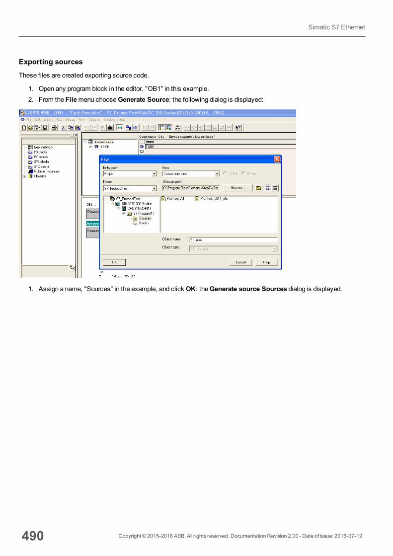
Exporting sources
These files are created exporting source code.
1. Open any program block in the editor, "OB1" in this example.2. From the Filemenu chooseGenerate Source: the following dialog is displayed:
1. Assign a name, "Sources" in the example, and click OK: theGenerate source Sources dialog is displayed.
490 Copyright © 2015-2016 ABB. All rights reserved. Documentation Revision 2.00 - Date of issue: 2016-07-19
Simatic S7 Ethernet
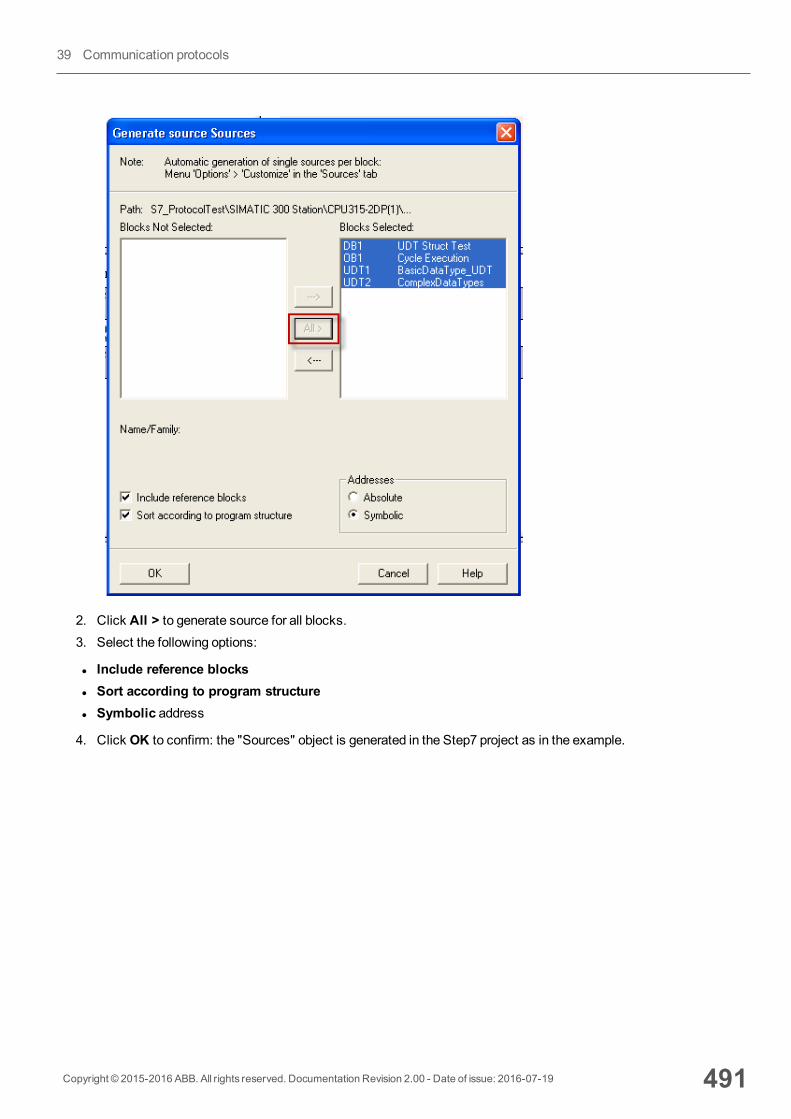
2. Click All > to generate source for all blocks.3. Select the following options:
l Include reference blocksl Sort according to program structurel Symbolic address
4. Click OK to confirm: the "Sources" object is generated in the Step7 project as in the example.
Copyright © 2015-2016 ABB. All rights reserved. Documentation Revision 2.00 - Date of issue: 2016-07-19 491
39 Communication protocols
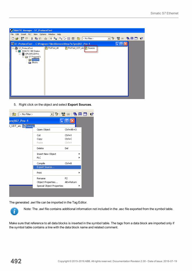
5. Right click on the object and select Export Sources.
The generated .awl file can be imported in the Tag Editor.
Note: The .awl file contains additional information not included in the .asc file exported from the symbol table.
Make sure that reference to all data blocks is inserted in the symbol table. The tags from a data block are imported only ifthe symbol table contains a line with the data block name and related comment.
492 Copyright © 2015-2016 ABB. All rights reserved. Documentation Revision 2.00 - Date of issue: 2016-07-19
Simatic S7 Ethernet
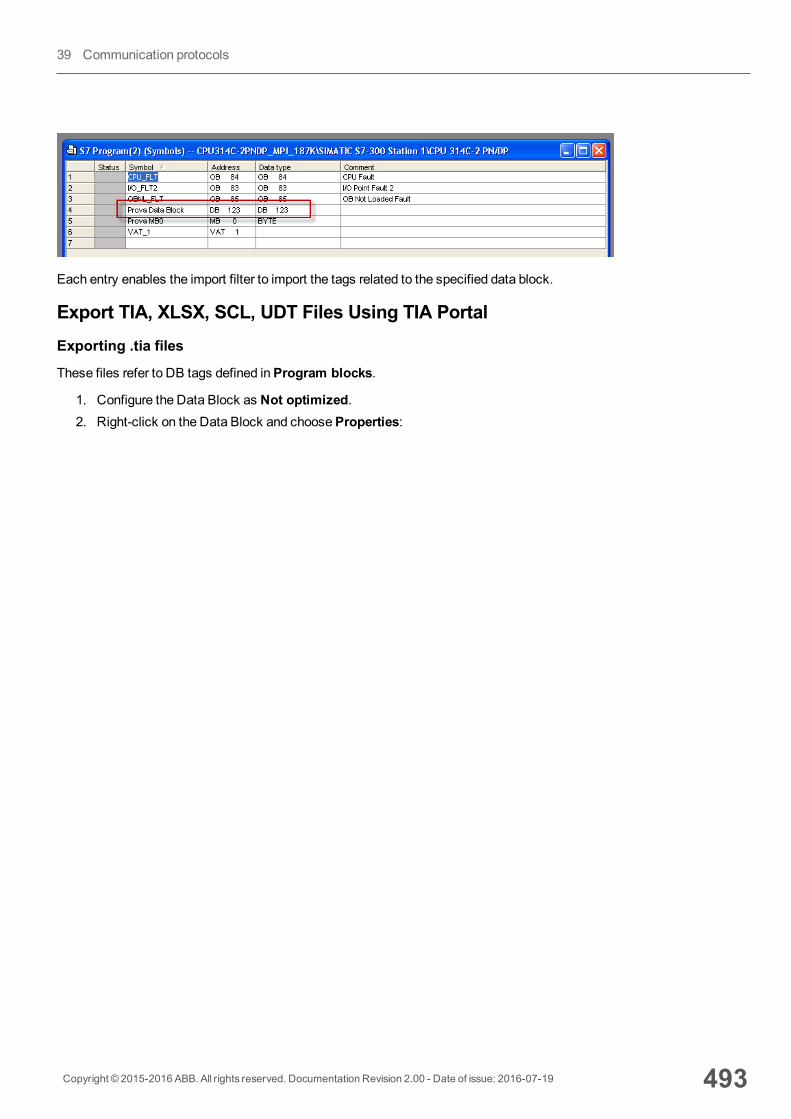
Each entry enables the import filter to import the tags related to the specified data block.
Export TIA, XLSX, SCL, UDT Files Using TIA PortalExporting .tia files
These files refer to DB tags defined inProgram blocks.
1. Configure the Data Block as Not optimized.2. Right-click on the Data Block and chooseProperties:
Copyright © 2015-2016 ABB. All rights reserved. Documentation Revision 2.00 - Date of issue: 2016-07-19 493
39 Communication protocols
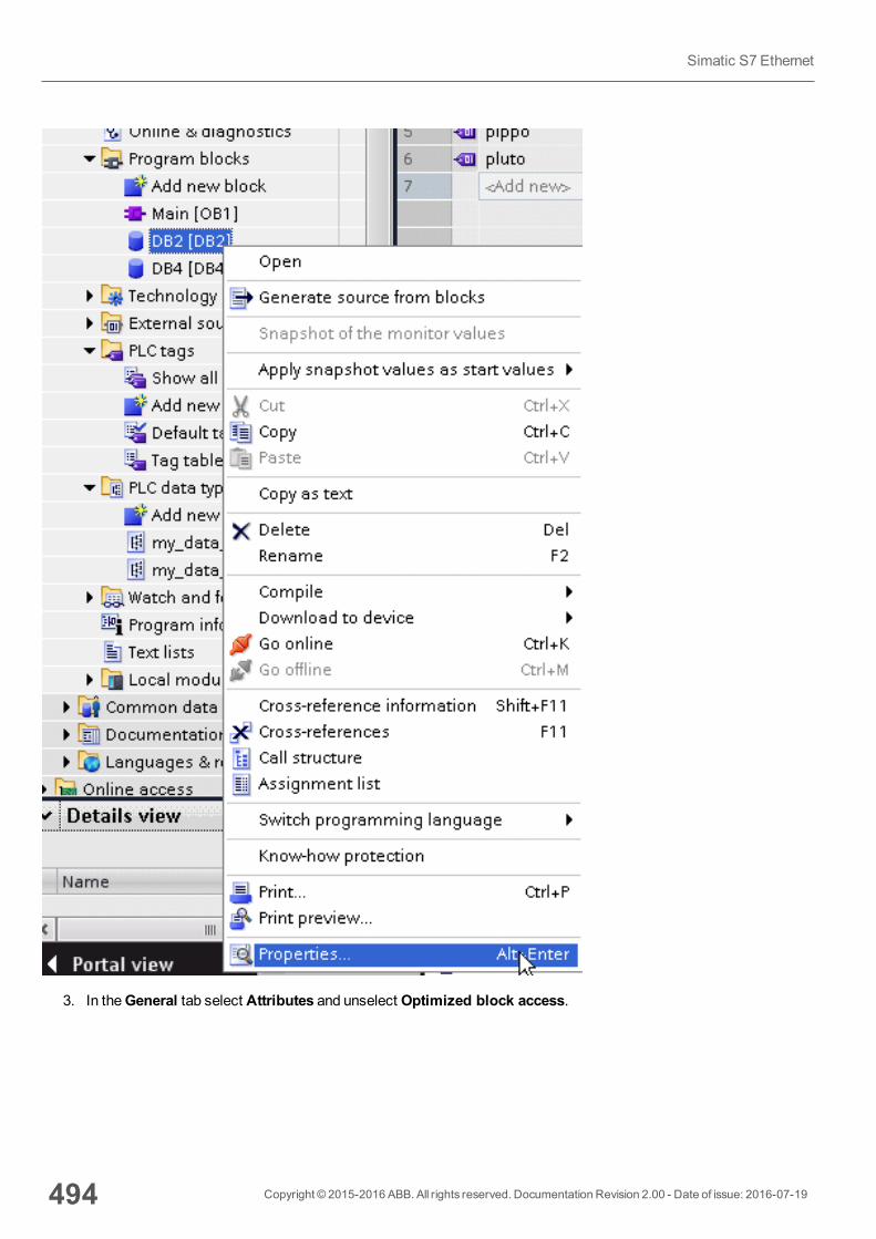
3. In theGeneral tab select Attributes and unselect Optimized block access.
494 Copyright © 2015-2016 ABB. All rights reserved. Documentation Revision 2.00 - Date of issue: 2016-07-19
Simatic S7 Ethernet
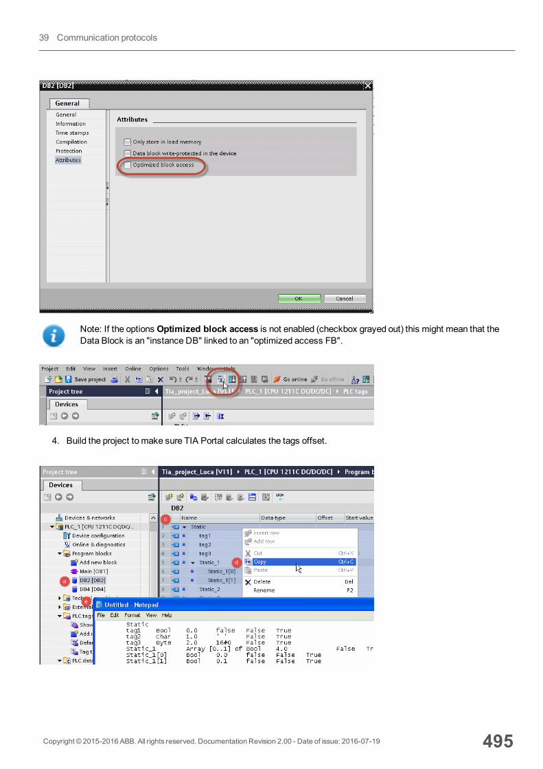
Note: If the options Optimized block access is not enabled (checkbox grayed out) this might mean that theData Block is an "instance DB" linked to an "optimized access FB".
4. Build the project to make sure TIA Portal calculates the tags offset.
Copyright © 2015-2016 ABB. All rights reserved. Documentation Revision 2.00 - Date of issue: 2016-07-19 495
39 Communication protocols
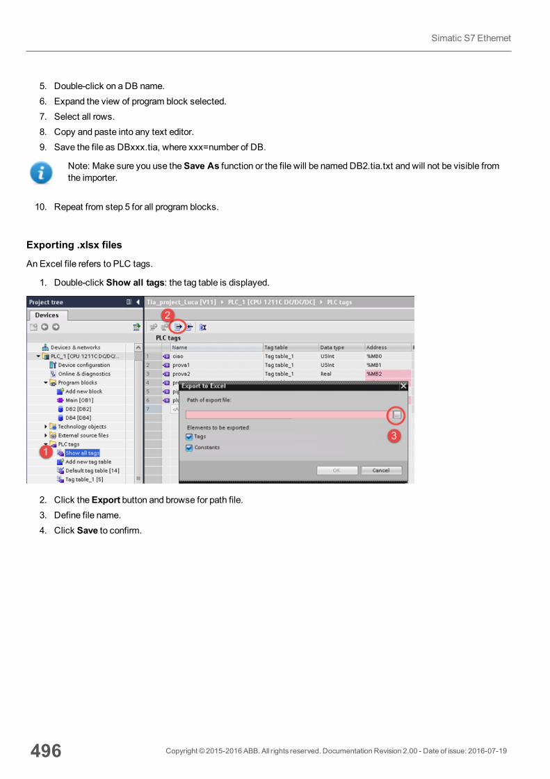
5. Double-click on a DB name.6. Expand the view of program block selected.7. Select all rows.8. Copy and paste into any text editor.9. Save the file as DBxxx.tia, where xxx=number of DB.
Note: Make sure you use theSave As function or the file will be namedDB2.tia.txt and will not be visible fromthe importer.
10. Repeat from step 5 for all program blocks.
Exporting .xlsx files
An Excel file refers to PLC tags.
1. Double-click Show all tags: the tag table is displayed.
2. Click theExport button and browse for path file.3. Define file name.4. Click Save to confirm.
496 Copyright © 2015-2016 ABB. All rights reserved. Documentation Revision 2.00 - Date of issue: 2016-07-19
Simatic S7 Ethernet
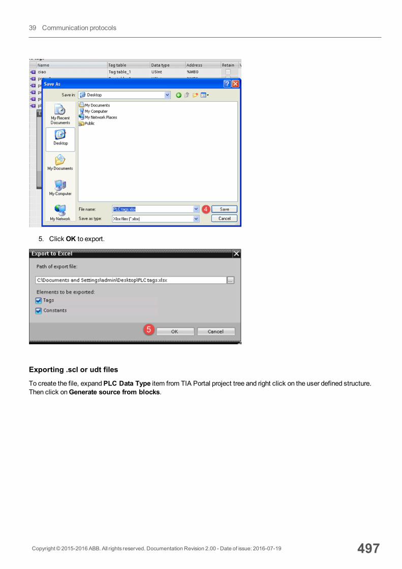
5. Click OK to export.
Exporting .scl or udt files
To create the file, expandPLC Data Type item from TIA Portal project tree and right click on the user defined structure.Then click onGenerate source from blocks.
Copyright © 2015-2016 ABB. All rights reserved. Documentation Revision 2.00 - Date of issue: 2016-07-19 497
39 Communication protocols
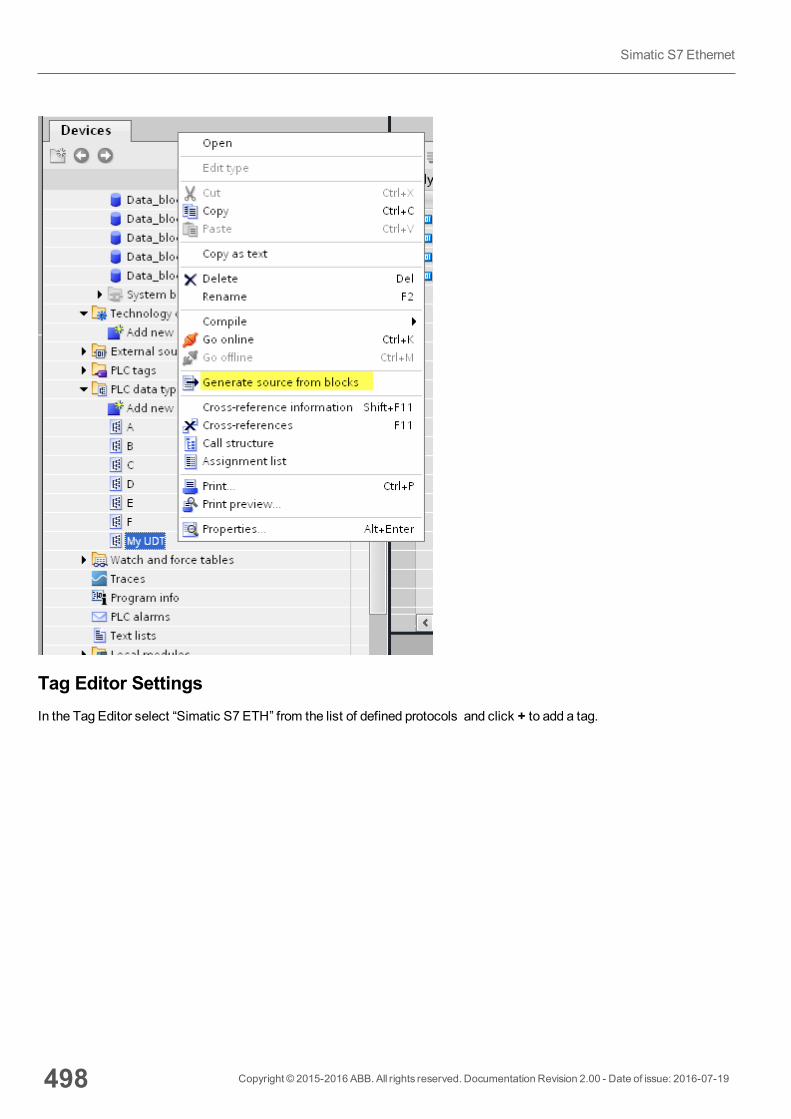
Tag Editor SettingsIn the Tag Editor select “Simatic S7 ETH” from the list of defined protocols and click + to add a tag.
498 Copyright © 2015-2016 ABB. All rights reserved. Documentation Revision 2.00 - Date of issue: 2016-07-19
Simatic S7 Ethernet
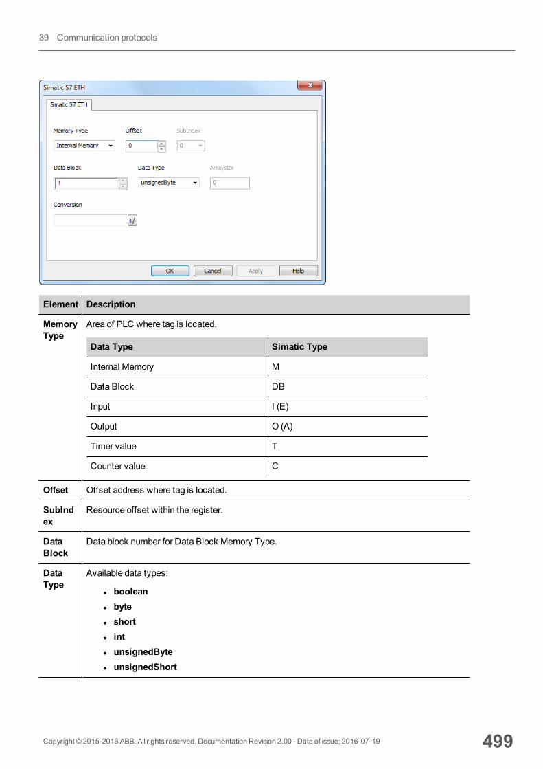
Element Description
MemoryType
Area of PLC where tag is located.
Data Type Simatic Type
Internal Memory M
Data Block DB
Input I (E)
Output O (A)
Timer value T
Counter value C
Offset Offset address where tag is located.
SubIndex
Resource offset within the register.
DataBlock
Data block number for Data Block Memory Type.
DataType
Available data types:
l booleanl bytel shortl intl unsignedBytel unsignedShort
Copyright © 2015-2016 ABB. All rights reserved. Documentation Revision 2.00 - Date of issue: 2016-07-19 499
39 Communication protocols
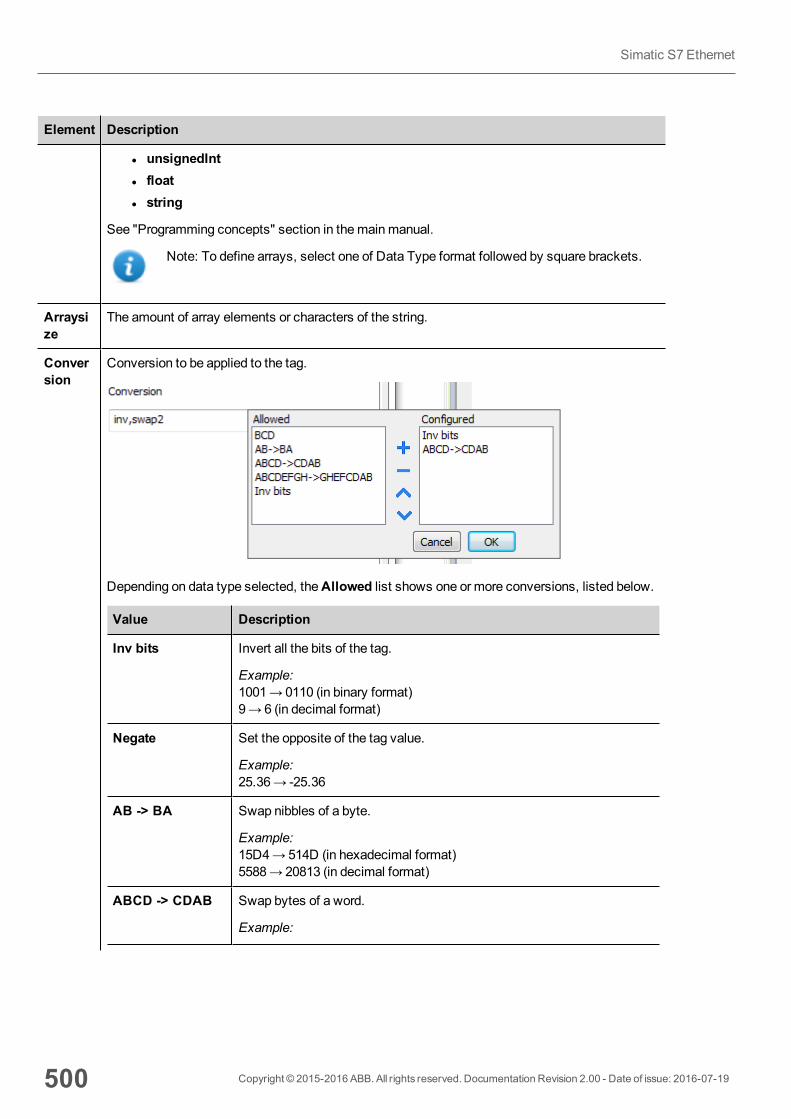
Element Description
l unsignedIntl floatl string
See "Programming concepts" section in themainmanual.
Note: To define arrays, select one of Data Type format followed by square brackets.
Arraysize
The amount of array elements or characters of the string.
Conversion
Conversion to be applied to the tag.
Depending on data type selected, theAllowed list shows one or more conversions, listed below.
Value Description
Inv bits Invert all the bits of the tag.
Example:1001→ 0110 (in binary format)9→ 6 (in decimal format)
Negate Set the opposite of the tag value.
Example:25.36→ -25.36
AB -> BA Swap nibbles of a byte.
Example:15D4→514D (in hexadecimal format)5588→ 20813 (in decimal format)
ABCD -> CDAB Swap bytes of a word.
Example:
500 Copyright © 2015-2016 ABB. All rights reserved. Documentation Revision 2.00 - Date of issue: 2016-07-19
Simatic S7 Ethernet
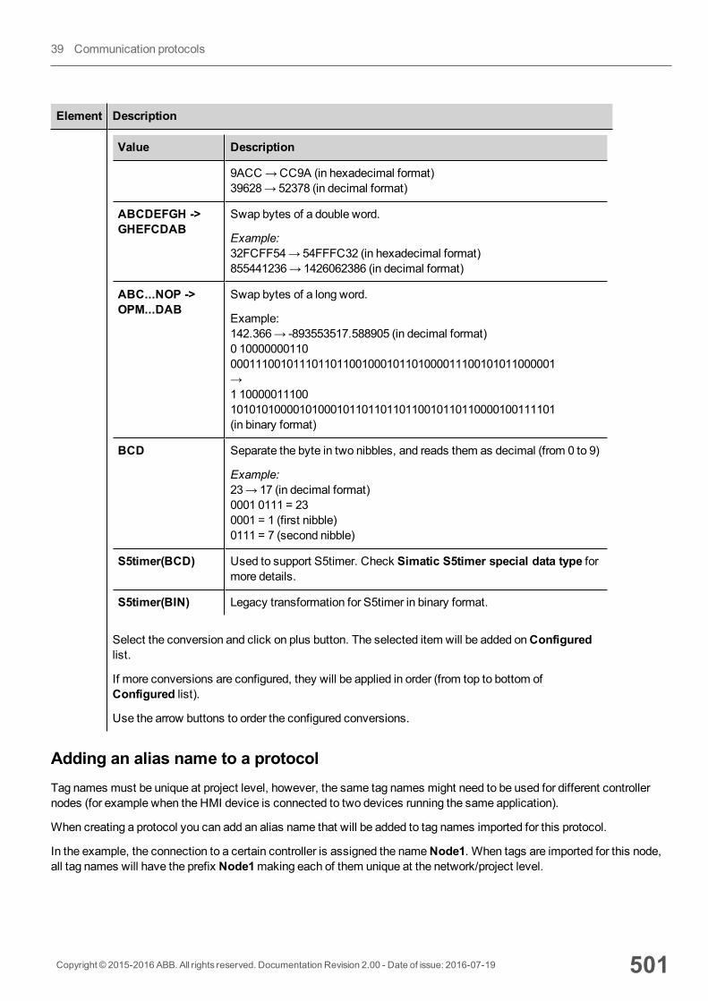
Element Description
Value Description
9ACC→CC9A (in hexadecimal format)39628→ 52378 (in decimal format)
ABCDEFGH ->GHEFCDAB
Swap bytes of a double word.
Example:32FCFF54→54FFFC32 (in hexadecimal format)855441236→ 1426062386 (in decimal format)
ABC...NOP ->OPM...DAB
Swap bytes of a long word.
Example:142.366→ -893553517.588905 (in decimal format)0 100000001100001110010111011011001000101101000011100101011000001→1 100000111001010101000010100010110110110110010110110000100111101(in binary format)
BCD Separate the byte in two nibbles, and reads them as decimal (from 0 to 9)
Example:23→ 17 (in decimal format)0001 0111 = 230001 = 1 (first nibble)0111 = 7 (second nibble)
S5timer(BCD) Used to support S5timer. Check Simatic S5timer special data type formore details.
S5timer(BIN) Legacy transformation for S5timer in binary format.
Select the conversion and click on plus button. The selected item will be added onConfiguredlist.
If more conversions are configured, they will be applied in order (from top to bottom ofConfigured list).
Use the arrow buttons to order the configured conversions.
Adding an alias name to a protocolTag names must be unique at project level, however, the same tag names might need to be used for different controllernodes (for example when the HMI device is connected to two devices running the same application).
When creating a protocol you can add an alias name that will be added to tag names imported for this protocol.
In the example, the connection to a certain controller is assigned the nameNode1. When tags are imported for this node,all tag names will have the prefix Node1making each of them unique at the network/project level.
Copyright © 2015-2016 ABB. All rights reserved. Documentation Revision 2.00 - Date of issue: 2016-07-19 501
39 Communication protocols
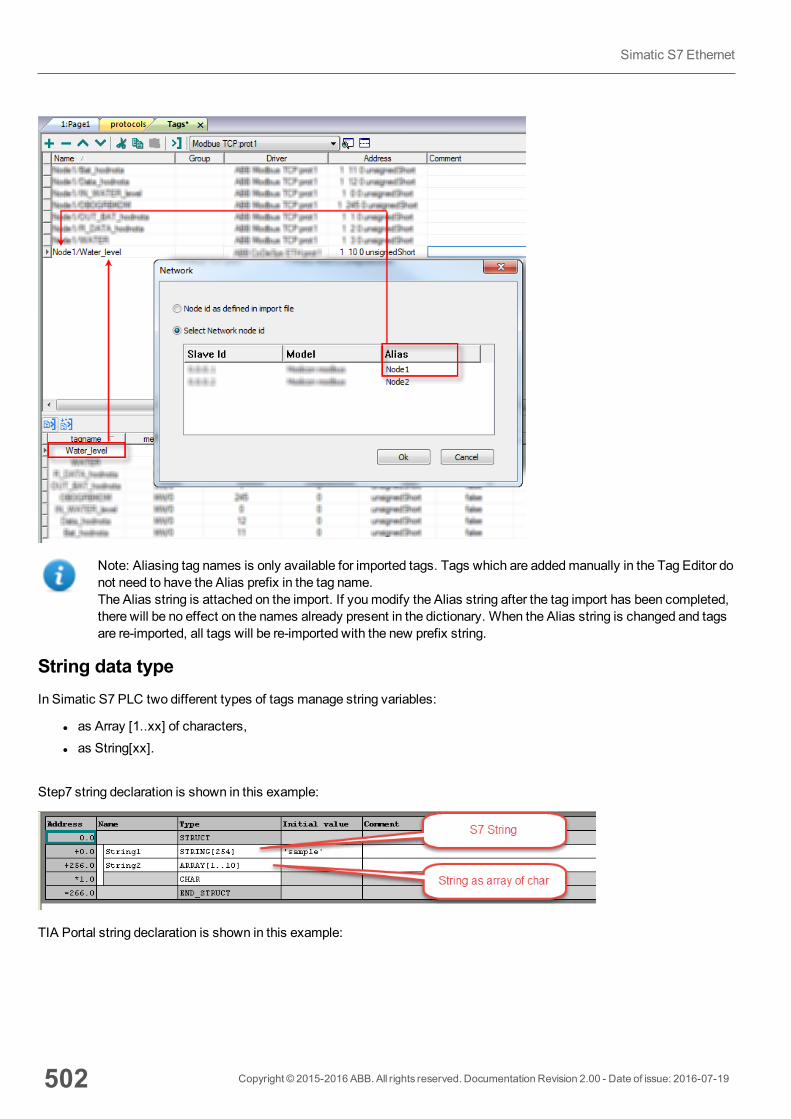
Note: Aliasing tag names is only available for imported tags. Tags which are addedmanually in the Tag Editor donot need to have the Alias prefix in the tag name.The Alias string is attached on the import. If youmodify the Alias string after the tag import has been completed,there will be no effect on the names already present in the dictionary. When the Alias string is changed and tagsare re-imported, all tags will be re-imported with the new prefix string.
String data typeIn Simatic S7 PLC two different types of tags manage string variables:
l as Array [1..xx] of characters,l as String[xx].
Step7 string declaration is shown in this example:
TIA Portal string declaration is shown in this example:
502 Copyright © 2015-2016 ABB. All rights reserved. Documentation Revision 2.00 - Date of issue: 2016-07-19
Simatic S7 Ethernet
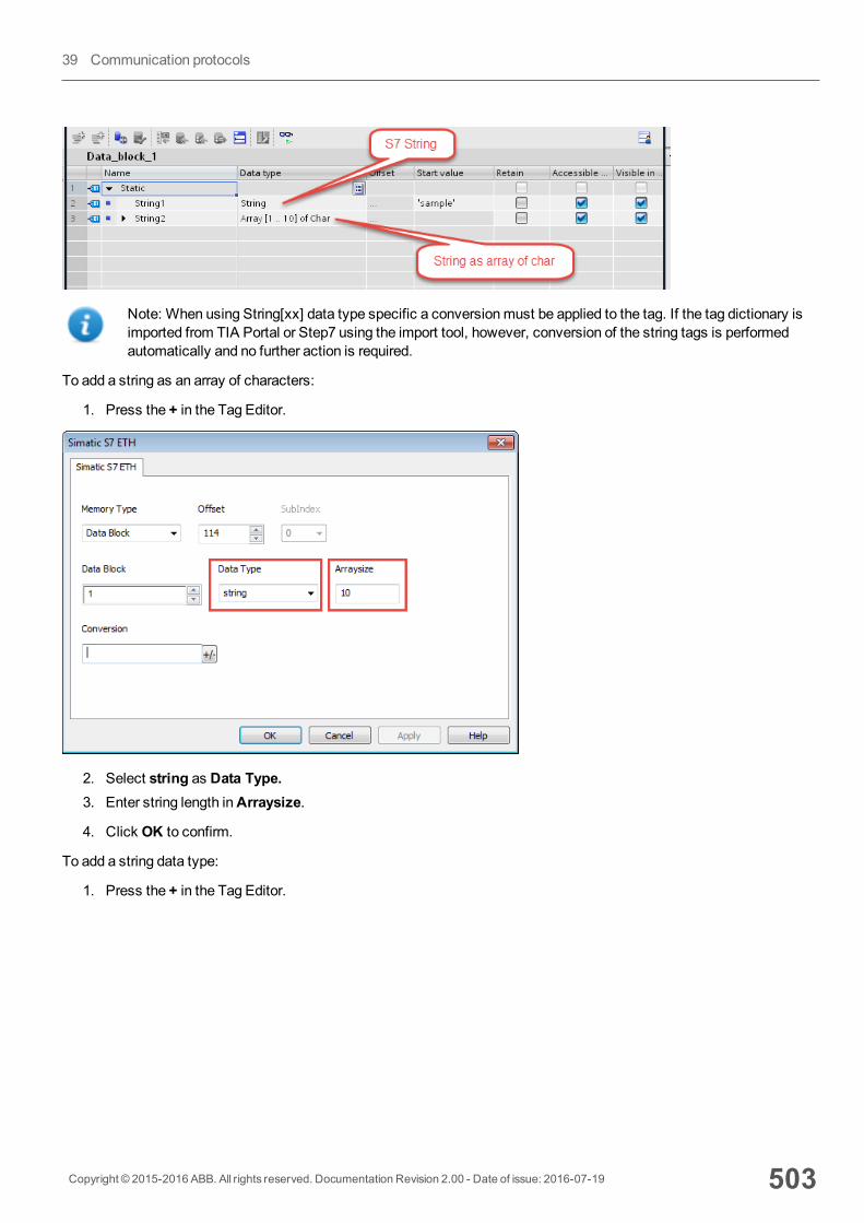
Note: When using String[xx] data type specific a conversionmust be applied to the tag. If the tag dictionary isimported from TIA Portal or Step7 using the import tool, however, conversion of the string tags is performedautomatically and no further action is required.
To add a string as an array of characters:
1. Press the + in the Tag Editor.
2. Select string as Data Type.3. Enter string length inArraysize.
4. Click OK to confirm.
To add a string data type:
1. Press the + in the Tag Editor.
Copyright © 2015-2016 ABB. All rights reserved. Documentation Revision 2.00 - Date of issue: 2016-07-19 503
39 Communication protocols
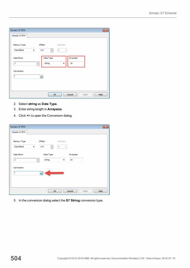
2. Select string as Data Type.3. Enter string length inArraysize.
4. Click +/- to open the Conversion dialog.
5. In the conversion dialog select theS7 String conversion type.
504 Copyright © 2015-2016 ABB. All rights reserved. Documentation Revision 2.00 - Date of issue: 2016-07-19
Simatic S7 Ethernet
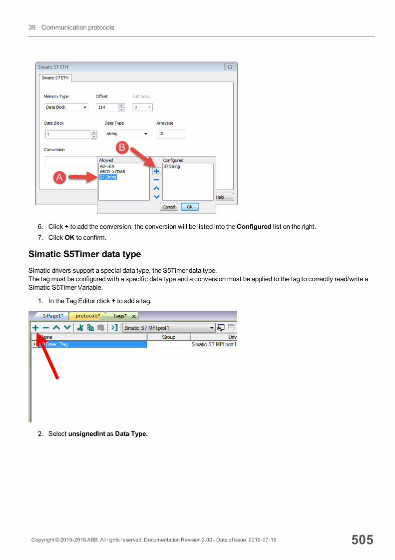
6. Click + to add the conversion: the conversion will be listed into theConfigured list on the right.7. Click OK to confirm.
Simatic S5Timer data typeSimatic drivers support a special data type, the S5Timer data type.The tagmust be configured with a specific data type and a conversionmust be applied to the tag to correctly read/write aSimatic S5Timer Variable.
1. In the Tag Editor click + to add a tag.
2. Select unsignedInt as Data Type.
Copyright © 2015-2016 ABB. All rights reserved. Documentation Revision 2.00 - Date of issue: 2016-07-19 505
39 Communication protocols
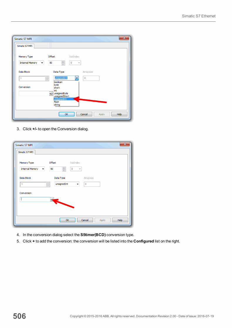
3. Click +/- to open the Conversion dialog.
4. In the conversion dialog select theS5timer(BCD) conversion type.5. Click + to add the conversion: the conversion will be listed into theConfigured list on the right.
506 Copyright © 2015-2016 ABB. All rights reserved. Documentation Revision 2.00 - Date of issue: 2016-07-19
Simatic S7 Ethernet
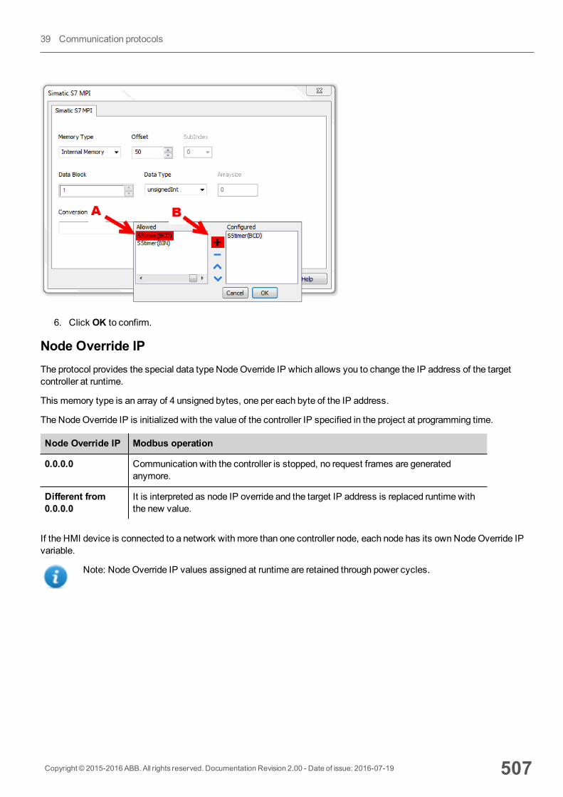
6. Click OK to confirm.
Node Override IPThe protocol provides the special data type NodeOverride IP which allows you to change the IP address of the targetcontroller at runtime.
This memory type is an array of 4 unsigned bytes, one per each byte of the IP address.
The NodeOverride IP is initialized with the value of the controller IP specified in the project at programming time.
Node Override IP Modbus operation
0.0.0.0 Communication with the controller is stopped, no request frames are generatedanymore.
Different from0.0.0.0
It is interpreted as node IP override and the target IP address is replaced runtime withthe new value.
If the HMI device is connected to a network with more than one controller node, each node has its ownNodeOverride IPvariable.
Note: NodeOverride IP values assigned at runtime are retained through power cycles.
Copyright © 2015-2016 ABB. All rights reserved. Documentation Revision 2.00 - Date of issue: 2016-07-19 507
39 Communication protocols

Tag ImportSelect the driver in Tag Editor and click on the Import Tags button to start the importer.
The following dialog shows which importer type can be selected.
508 Copyright © 2015-2016 ABB. All rights reserved. Documentation Revision 2.00 - Date of issue: 2016-07-19
Simatic S7 Ethernet
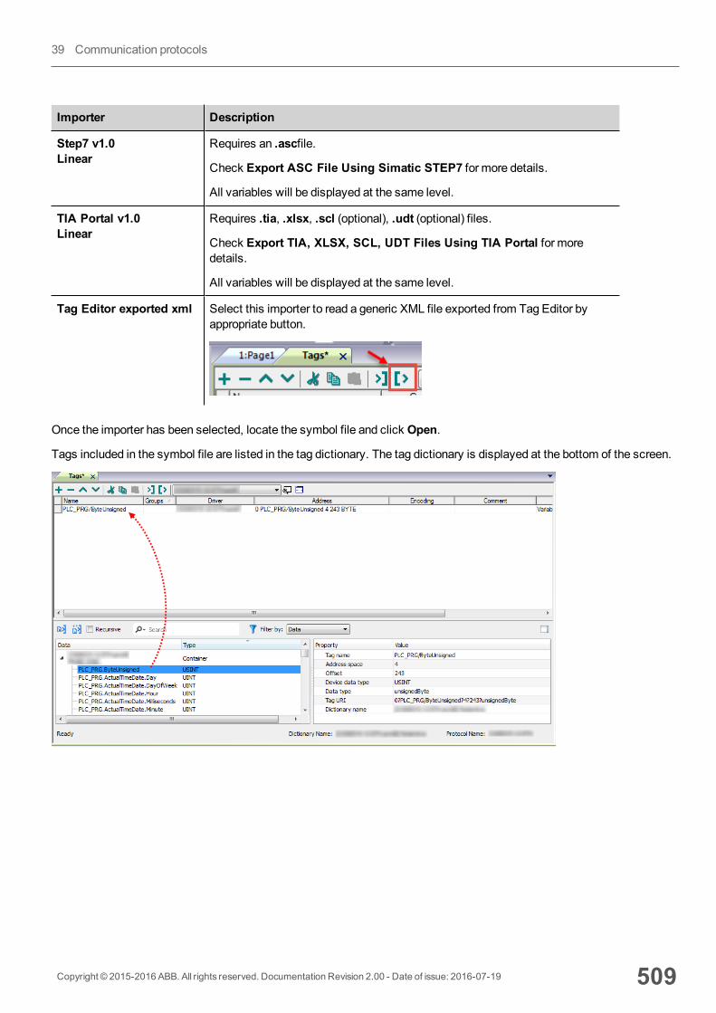
Importer Description
Step7 v1.0Linear
Requires an .ascfile.
Check Export ASC File Using Simatic STEP7 for more details.
All variables will be displayed at the same level.
TIA Portal v1.0Linear
Requires .tia, .xlsx, .scl (optional), .udt (optional) files.
Check Export TIA, XLSX, SCL, UDT Files Using TIA Portal for moredetails.
All variables will be displayed at the same level.
Tag Editor exported xml Select this importer to read a generic XML file exported from Tag Editor byappropriate button.
Once the importer has been selected, locate the symbol file and click Open.
Tags included in the symbol file are listed in the tag dictionary. The tag dictionary is displayed at the bottom of the screen.
Copyright © 2015-2016 ABB. All rights reserved. Documentation Revision 2.00 - Date of issue: 2016-07-19 509
39 Communication protocols
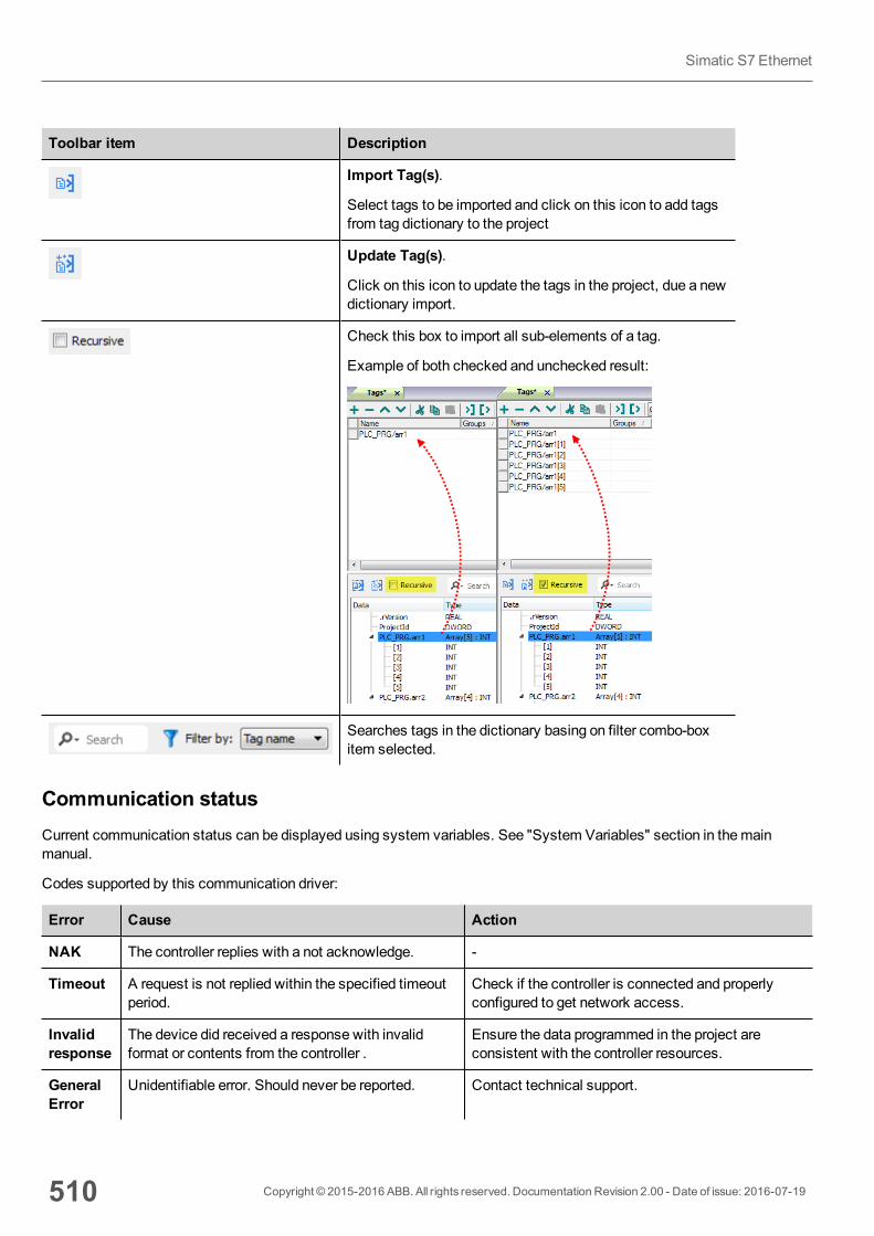
Toolbar item Description
Import Tag(s).
Select tags to be imported and click on this icon to add tagsfrom tag dictionary to the project
Update Tag(s).
Click on this icon to update the tags in the project, due a newdictionary import.
Check this box to import all sub-elements of a tag.
Example of both checked and unchecked result:
Searches tags in the dictionary basing on filter combo-boxitem selected.
Communication statusCurrent communication status can be displayed using system variables. See "System Variables" section in themainmanual.
Codes supported by this communication driver:
Error Cause Action
NAK The controller replies with a not acknowledge. -
Timeout A request is not replied within the specified timeoutperiod.
Check if the controller is connected and properlyconfigured to get network access.
Invalidresponse
The device did received a response with invalidformat or contents from the controller .
Ensure the data programmed in the project areconsistent with the controller resources.
GeneralError
Unidentifiable error. Should never be reported. Contact technical support.
510 Copyright © 2015-2016 ABB. All rights reserved. Documentation Revision 2.00 - Date of issue: 2016-07-19
Simatic S7 Ethernet

Contact us
3AD
R05
9056
M02
02ABB Automation Products GmbHWallstadter Str. 59 68526 Ladenburg, Germany Phone: +49 62 21 701 1444 Fax: +49 62 21 701 1382 E-Mail: [email protected]
www.abb.com/automationbuilder www.abb.com/plc
Note:We reserve the right to make technical changes or modify the contents of this document without prior notice. With regard to purchase orders, the agreed particulars shall prevail. ABB AG does not accept any responsibility whatsoever for potential errors or possible lack of information in this document.
We reserve all rights in this document and in the subject matter and illustrations contained therein. Any reproduction, disclosure to third parties or utilization of its contents – in whole or in parts – is forbidden without prior written consent of ABB AG.
Copyright© 2015 ABB All rights reserved