parts manual - northern lights generator
TRANSCRIPT
P673-4For Models: NL673L4 and NL673L4E
PARTS MANUAL
www.northern-lights.com
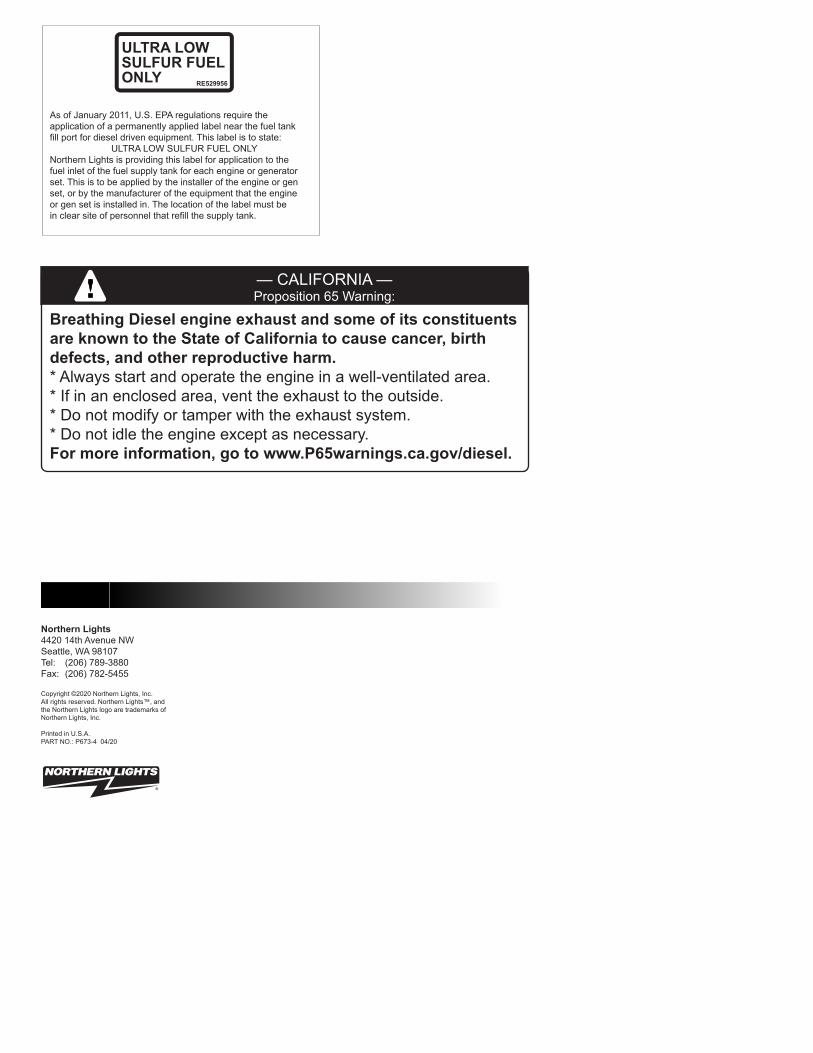
As of January 2011, U.S. EPA regulations require theapplication of a permanently applied label near the fuel tankfill port for diesel driven equipment. This label is to state:
ULTRA LOW SULFUR FUEL ONLYNorthern Lights is providing this label for application to thefuel inlet of the fuel supply tank for each engine or generatorset. This is to be applied by the installer of the engine or genset, or by the manufacturer of the equipment that the engineor gen set is installed in. The location of the label must bein clear site of personnel that refill the supply tank.
ULTRA LOW SULFUR FUEL ONLY RE529956
Breathing Diesel engine exhaust and some of its constituents are known to the State of California to cause cancer, birth defects, and other reproductive harm.* Always start and operate the engine in a well-ventilated area.* If in an enclosed area, vent the exhaust to the outside.* Do not modify or tamper with the exhaust system.* Do not idle the engine except as necessary.For more information, go to www.P65warnings.ca.gov/diesel.
— CALIFORNIA —Proposition 65 Warning:
Northern Lights4420 14th Avenue NWSeattle, WA 98107Tel: (206) 789-3880Fax: (206) 782-5455
Copyright ©2020 Northern Lights, Inc.All rights reserved. Northern Lights™, andthe Northern Lights logo are trademarks ofNorthern Lights, Inc.
Printed in U.S.A.PART NO.: P673-4 04/20
P673-4 4/20
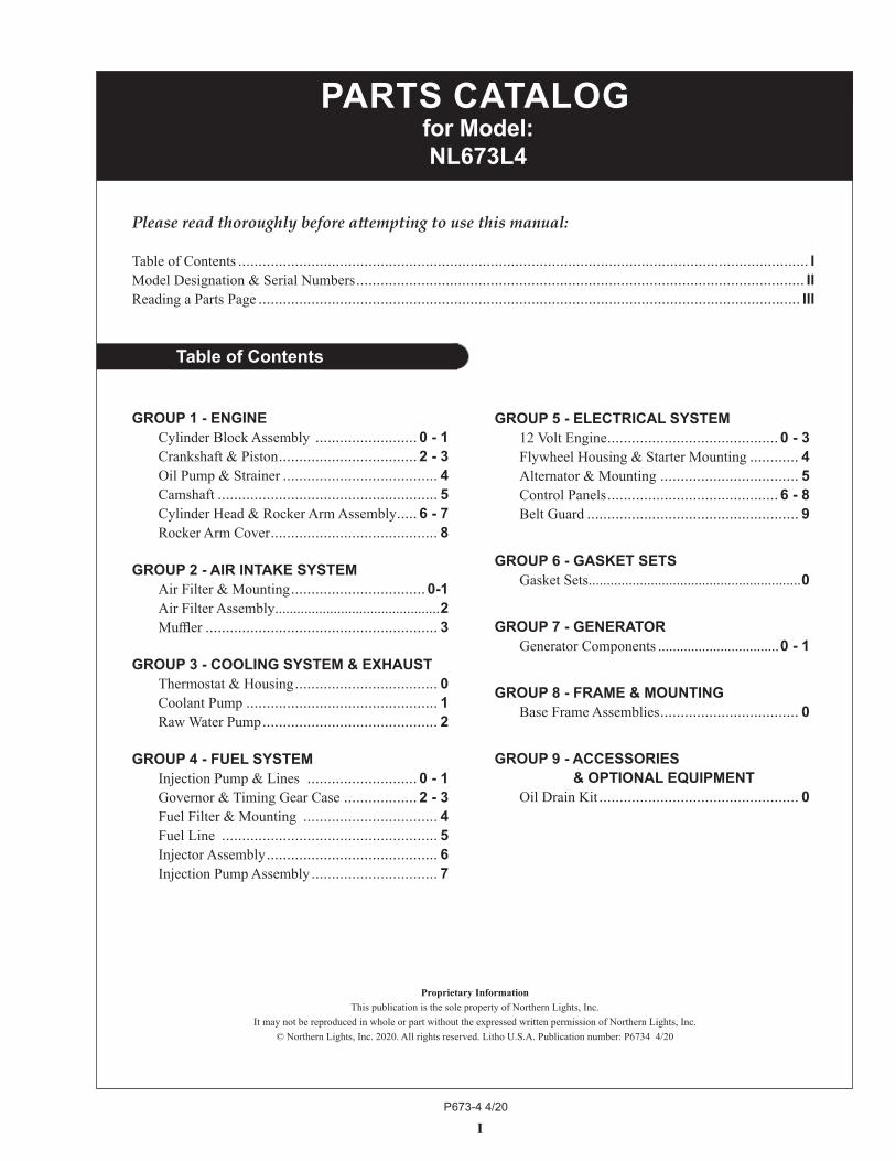
GROUP 5 - ELECTRICAL SYSTEM 12 Volt Engine .......................................... 0 - 3 Flywheel Housing & Starter Mounting ............ 4 Alternator & Mounting .................................. 5 Control Panels .......................................... 6 - 8 Belt Guard .................................................... 9
GROUP 6 - GASKET SETS Gasket Sets ..........................................................0
GROUP 7 - GENERATOR Generator Components .................................0 - 1
GROUP 8 - FRAME & MOUNTING Base Frame Assemblies .................................. 0
GROUP 9 - ACCESSORIESGROUP 9 - & OPTIONAL EQUIPMENT Oil Drain Kit ................................................. 0
GROUP 1 - ENGINE Cylinder Block Assembly ......................... 0 - 1 Crankshaft & Piston .................................. 2 - 3 Oil Pump & Strainer ...................................... 4 Camshaft ...................................................... 5 Cylinder Head & Rocker Arm Assembly ..... 6 - 7 Rocker Arm Cover ......................................... 8
GROUP 2 - AIR INTAKE SYSTEM Air Filter & Mounting ................................. 0-1 Air Filter Assembly .............................................2 Muffler ......................................................... 3
GROUP 3 - COOLING SYSTEM & EXHAUST Thermostat & Housing ................................... 0 Coolant Pump ............................................... 1 Raw Water Pump ........................................... 2
GROUP 4 - FUEL SYSTEM Injection Pump & Lines ........................... 0 - 1 Governor & Timing Gear Case .................. 2 - 3 Fuel Filter & Mounting ................................. 4 Fuel Line ..................................................... 5 Injector Assembly .......................................... 6 Injection Pump Assembly ............................... 7
Proprietary InformationThis publication is the sole property of Northern Lights, Inc.
It may not be reproduced in whole or part without the expressed written permission of Northern Lights, Inc.© Northern Lights, Inc. 2020. All rights reserved. Litho U.S.A. Publication number: P6734 4/20
I
Please read thoroughly before attempting to use this manual:
Table of Contents ............................................................................................................................................ IModel Designation & Serial Numbers .............................................................................................................. IIReading a Parts Page ..................................................................................................................................... III
Table of Contents
PARTS CATALOG for Model: NL673L4

P673-4 4/20
Model Designation
II
NL 673 L, 4, E
NL - Northern Lights industrial generator set
Model number of engine block Bore Cylinders 67 mm 3
Your set has three serial numbers: 1 an engine number stamped on the block, 2 a generator plate, and 3 a generator set plate. Use the serial number on the generator set plate when ordering parts or in correspondence. The generator set plate is found on the service side of the generator and resembles the drawing below.
MODELS INCLUDEDThis manual covers the parts and components used in: NL673L4 and NL673L4E which use the 673 engine.
Model Numbers
Model numbers give the unit's application, block model, aspiration, and RPM:
Serial Numbers
Generator Set Serial Number
L - Long Stroke4 - US EPA Tier IVE- Electronic controls
Northern Lights industrial diesel generator set with a 673 engine and a TF-276D generator, long stroke, Tier IV.
NL 673L4 =
Northern Lights industrial diesel generator set with a 673 engine and a TF-276D generator, long stroke, electronic controls,meeting Tier IV emissions.
NL 673L4E =
P673-4 4/20
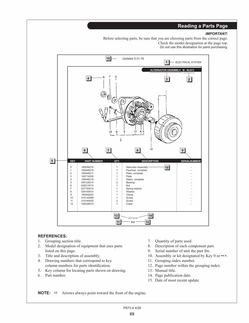
REFERENCES:1. Grouping section title. 7. Quantity of parts used.2. Model designation of equipment that uses parts 8. Description of each component part. listedonthispage. 9. Serialnumberofunitthepartfits.3. Title and description of assembly. 10. Assembly or kit designated by Key 0 or ••/•.4. Drawing numbers that correspond to key 11. Grouping index number. columnnumbersforpartsidentification. 12. Pagenumberwithinthegroupingindex.5. Key column for locating parts shown on drawing. 13. Manual title.6. Part number. 14. Page publication date. 15. Date of most recent update
NOTE: a Arrows always point toward the front of the engine.
III
ELECTRICAL SYSTEM1
Reading a Parts PageIMPORTANT:
Before selecting parts, be sure that you are choosing parts from the correct page.Check the model designation at the page top.Do not use this illustration for parts purchasing.
4 23
5
7 8 9
P673 06/96
5-2
0 185046210 1 Alternator Assembly -1 185446219 1 Flywheel, complete -2 185446217 1 Plate, complete -3 185716200 1 Plate -4 185446218 1 Stator, complete -5 040126210 2 Bearing -6 020210010 1 Nut -7 027100010 1 Spring washer -8 026100010 1 Washer -9 185446220 1 Clamp -10 015140408 1 Screw -11 015140425 2 Screw -12 199236510 1 Collar -
6
ALTERNATOR ASSEMBLY: M - NL673
14
1211
13
10
KEY PART NUMBER QTY. DESCRIPTION SERIALNUMBER
15 Updated 3-31-16
P673-4 4/20
GROUP 1 – ENGINE
1 - 0
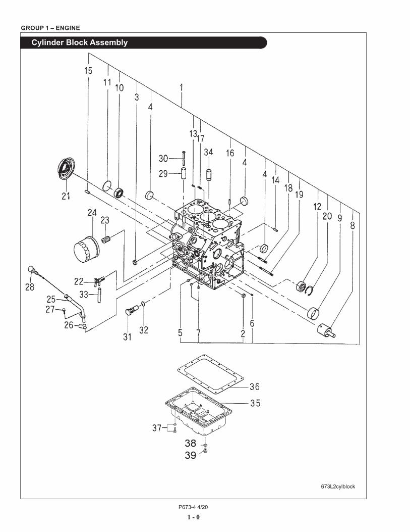
Cylinder Block Assembly
673L2cylblock

P673-4 4/20
GROUP 1 – ENGINE
1 - 1
Cylinder Block Assembly
KEY PART NUMBER QTY DESCRIPTION SERIAL NUMBER 1 110100730 1 Cylinder Block - (includes keys #2- 20) - 2 064210015 1 Expansion Plug 15 mm - 3 064210018 2 Expansion Plug 18 mm - 4 064210035 4 Expansion Plug 35 mm - 5 198466030 5 Blank Plug - 6 198466050 1 Blank Plug - 7 198466010 4 Blank Plug - 8 165296162 1 Idle Gear Shaft - 9 198517302 1 Bushing, standard - 198517306 1 Bushing, undersize 0.25 mm - 198517309 1 Bushing, undersize 0.50 mm - 10 040106203 1 Bearing - 11 064100045 1 Expansion Plug - 12 042303015 1 Bearing - 13 030500512 2 Dowel Pin - 14 030500616 2 Dowel Pin - 15 030500820 2 Dowel Pin - 16 030309005 2 Spring Pin - 17 012110620 2 Stud M6 x 1.0 x 20 mm - 18 012110635 1 Stud M6 x 1.0 x 35 mm - 19 012110660 1 Stud M6 x 1.0 x 60 mm - 20 036509005 1 Retaining Ring - 21 198636080 1 Oil Seal - 22 198736050 1 Drain Cock - 23 140546020 1 Adapter Union - 24 24-08001 1 Oil Filter - 25 110756070 1 Dipstick Tube - 26 052109113 2 O-ring - 27 011310612 1 Bolt - 28 198416350 1 Dipstick - 29 120116100 5 Tappet - 30 120456321 6 Push Rod - 31 140036220 1 Relief Valve Assembly - 32 052109078 1 O-ring - 33 068115200 1 Tube - 34 120116180 1 Tappet (#1 Exhaust only) - 35 110706691 1 Oil Pan - 36 110996760 1 Gasket - 37 010109235 18 Bolt - 38 025100012 1 Seal Washer - 39 010411212 1 Plug M12 x 1.25 -
Updated 4-28-20
P673-4 4/20
1 - 2
GROUP 1 – ENGINE
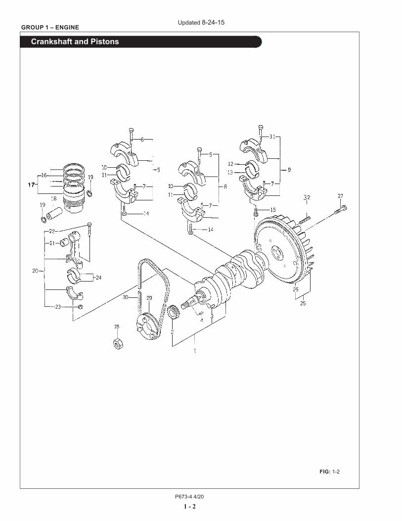
Crankshaft and Pistons
FIG: 1-2
Updated 8-24-15

P673-4 4/20
1 - 3
GROUP 1 – ENGINE
Crankshaft and Pistons
KEY PART NUMBER QTY DESCRIPTION SERIAL NUMBER
1 115256890 1 Crankshaft (includes keys #2- 3) - 2 115276210 1 Crankshaft Gear - 3 030509020 1 Dowel Pin - 4 034100508 1 Key - 5 110156440 1 Bearing Holder Assembly (includes keys #6- 7) - 6 010810845 4 Bolt - 7 030500612 6 Dowel Pin - 8 110156450 1 Bearing Holder Assembly (includes keys #6- 7) - 9 110156460 1 Bearing Holder Assembly (includes key #7 & 31) - 10 198517332 2 Bearing, Standard Upper - 198517336 2 Bearing, undersize 0.25 mm - 198517339 2 Bearing, undersize 0.50 mm - 11 198517342 2 Bearing, Standard Lower - 198517346 2 Bearing, undersize 0.25 mm - 198517349 2 Bearing, undersize 0.50 mm - 12 198517103 1 Bearing, Standard Upper - 198517107 1 Bearing, undersize 0.25 mm - 198517630 1 Bearing, undersize 0.50 mm - 13 198517112 1 Bearing, Standard Lower - 198517116 1 Bearing, undersize 0.25 mm - 198517119 1 Bearing, undersize 0.50 mm - 14 011510850 2 Bolt - 15 010700845 2 Bolt - 16 115104050 3 Ring Kit, standard - 17 115017630 3 Piston, standard (includes key #16) - 18 115326260 3 Piston Pin - 19 036500019 6 Snap Ring - 20 115026350 3 Connecting Rod Assembly (includes keys #21 - 23) - 21 198517325 3 Bushing - 22 115176130 6 Connecting Rod Bolt - 23 020109103 6 Nut - 24 198517312 6 Bearing, standard - 198517316 6 Bearing, undersize 0.25 mm - 198517319 6 Bearing, undersize 0.50 mm - 25 115356930 1 Flywheel, SAE #6 - 1/2 (includes key #26) - 26 115376040 1 Ring Gear, 109 Teeth - 27 010109330 4 Bolt - 28 020800018 1 Nut - 29 115396751 1 Crankshaft Pulley - 30 40-02002 1 Drive Belt - 31 010810850 2 Bolt - 32 012111025 4 Stud M10 x 1.5 x 25 mm (can use 13-05001) -
Updated 7-26-16

P673-4 4/20
1 - 4
GROUP 1 – ENGINE
Oil Pump and Pick-Up
KEY PART NUMBER QTY DESCRIPTION SERIAL NUMBER
1 165026380 1 Idle Gear Assembly (includes key #2) - 2 198216821 1 Spring - 3 199266180 1 Thrust Washer - 4 140166400 1 Rotor - 5 140116140 1 Oil Pump Cover - 6 199286150 1 Shim, t=0.10 - 199286160 1 Shim, t=0.15 - 199286170 1 Shim, t=0.20 - 199286180 1 Shim, t=0.50 - 7 198216720 1 Spring - 8 199236540 1 Collar - 9 036800010 1 Snap Ring - 10 165996490 1 Gasket - 11 165166270 1 Front Plate - 12 011310612 3 Bolt - 13 140986590 1 Oil Pipe - 14 052109076 1 O-ring - 15 140406570 1 Pick-Up with Screen - 16 011310612 2 Capscrew, Hex Head with Washer M6 x 1.0 x 12 mm -
673L2oilpump
Updated 4-28-20
P673-4 4/20
1 - 5
GROUP 1 – ENGINE
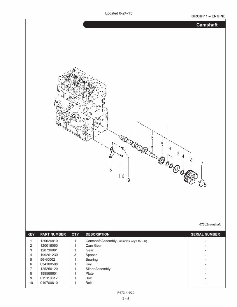
Camshaft
KEY PART NUMBER QTY DESCRIPTION SERIAL NUMBER
1 120026810 1 Camshaft Assembly (includes keys #2 - 6) - 2 120016060 1 Cam Gear - 3 120736081 1 Gear - 4 199261230 3 Spacer - 5 56-60002 1 Bearing - 6 034100508 1 Key - 7 125256120 1 Slider Assembly - 8 199566651 1 Plate - 9 011310612 1 Bolt - 10 010700610 1 Bolt -
673L2camshaft
Updated 8-24-15
P673-4 4/20
1 - 6
GROUP 1 – ENGINE
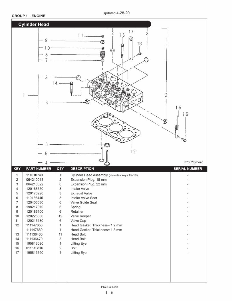
Cylinder Head
KEY PART NUMBER QTY DESCRIPTION SERIAL NUMBER
1 111010740 1 Cylinder Head Assembly (includes keys #2-10) - 2 064210018 2 Expansion Plug, 18 mm - 3 064210022 6 Expansion Plug, 22 mm - 4 120166370 3 Intake Valve - 5 120176290 3 Exhaust Valve - 6 110136445 3 Intake Valve Seat - 7 120406080 6 Valve Guide Seal - 8 198217070 6 Spring - 9 120186100 6 Retainer - 10 120226080 12 Valve Keeper - 11 120216130 6 Valve Cap - 12 111147650 1 Head Gasket, Thickness= 1.2 mm - 111147660 1 Head Gasket, Thickness= 1.3 mm - 13 111136460 11 Head Bolt - 14 111136470 3 Head Bolt - 15 195816030 1 Lifting Eye - 16 011510816 2 Bolt - 17 195816390 1 Lifting Eye -
673L2cylhead
Updated 4-28-20

P673-4 4/20
1 - 7
GROUP 1 – ENGINE
Rocker Arm Assembly
KEY PART NUMBER QTY DESCRIPTION SERIAL NUMBER
1 120037180 1 Rocker Arm Assembly (includes keys #2- 9,18, 21) - 2 120366330 3 Rocker Arm, Exhaust - 3 120366320 3 Rocker Arm, Intake - 4 198217650 2 Spring - 5 120316320 1 Rocker Arm Shaft - 6 199486220 6 Screw - 7 020109076 6 Nut - 8 198436370 1 Plug - 9 052100100 1 O-ring - 10 023100006 3 Nut - 11 120996200 1 Gasket - 12 1 Oil Pressure Switch (see Electrical System) - 13 140607410 1 Oil Pipe - 14 140996260 4 Sealing Washer M8 - 15 198486780 1 Banjo Bolt - 16 012109259 3 Stud Bolt - 17 011310625 3 Bolt - 18 030300416 2 Spring Pin - 19 198487590 1 Banjo Bolt (Tapped 1/8 NPT) - 20 21-00050 ** Plug - 21 012110620 2 Stud Bolt - ** As Required
673L2rockerarm
Updated 4-28-20
P673-4 4/20
1 - 8
GROUP 1 – ENGINE
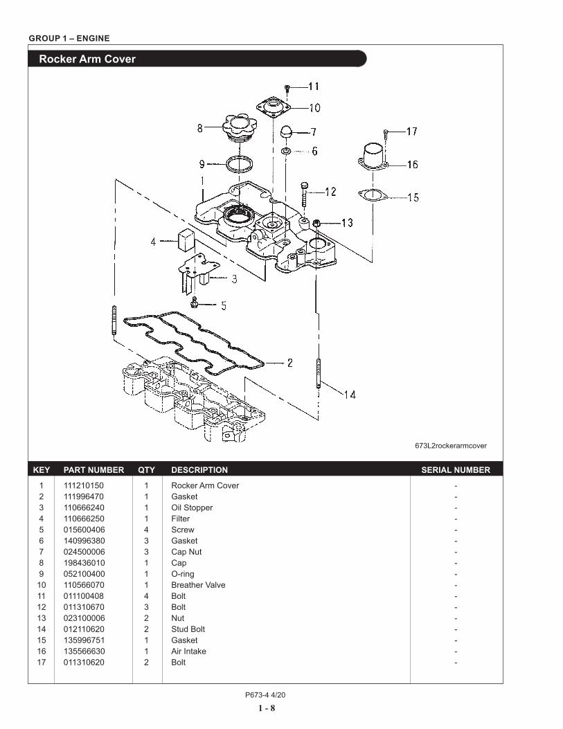
Rocker Arm Cover
673L2rockerarmcover
KEY PART NUMBER QTY DESCRIPTION SERIAL NUMBER
1 111210150 1 Rocker Arm Cover - 2 111996470 1 Gasket - 3 110666240 1 Oil Stopper - 4 110666250 1 Filter - 5 015600406 4 Screw - 6 140996380 3 Gasket - 7 024500006 3 Cap Nut - 8 198436010 1 Cap - 9 052100400 1 O-ring - 10 110566070 1 Breather Valve - 11 011100408 4 Bolt - 12 011310670 3 Bolt - 13 023100006 2 Nut - 14 012110620 2 Stud Bolt - 15 135996751 1 Gasket - 16 135566630 1 Air Intake - 17 011310620 2 Bolt -
P673-4 4/20
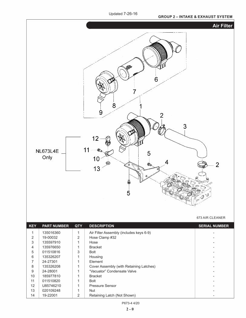
GROUP 2 – INTAKE & EXHAUST SYSTEM
2 - 0
Air Filter
KEY PART NUMBER QTY DESCRIPTION SERIAL NUMBER
1 135016360 1 Air Filter Assembly (includes keys 6-9) - 2 19-00032 2 Hose Clamp #32 - 3 135597910 1 Hose - 4 135976650 1 Bracket - 5 011510816 3 Bolt - 6 135326207 1 Housing - 7 24-27301 1 Element - 8 135326208 1 Cover Assembly (with Retaining Latches) - 9 24-28001 1 “Vacuator” Condensate Valve - 10 185977810 1 Bracket - 11 011510820 1 Bolt - 12 U85746210 1 Pressure Sensor - 13 020109248 1 Nut - 14 19-22001 2 Retaining Latch (Not Shown) -
673 AIR CLEANER
Updated 7-26-16
P673-4 4/20
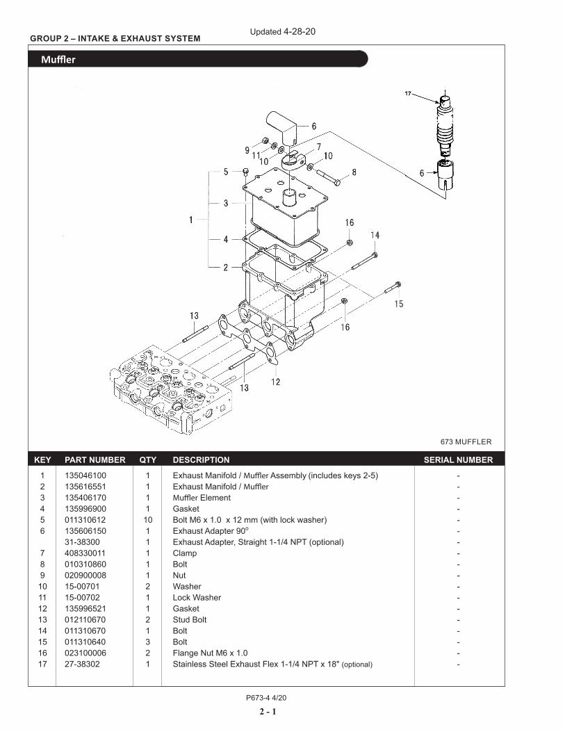
2 - 1
673 MUFFLER
KEY PART NUMBER QTY DESCRIPTION SERIAL NUMBER
1 135046100 1 Exhaust Manifold / Muffler Assembly (includes keys 2-5) - 2 135616551 1 Exhaust Manifold / Muffler - 3 135406170 1 Muffler Element - 4 135996900 1 Gasket - 5 011310612 10 Bolt M6 x 1.0 x 12 mm (with lock washer) - 6 135606150 1 Exhaust Adapter 90o - 31-38300 1 Exhaust Adapter, Straight 1-1/4 NPT (optional) - 7 408330011 1 Clamp - 8 010310860 1 Bolt - 9 020900008 1 Nut - 10 15-00701 2 Washer - 11 15-00702 1 Lock Washer - 12 135996521 1 Gasket - 13 012110670 2 Stud Bolt - 14 011310670 1 Bolt - 15 011310640 3 Bolt - 16 023100006 2 Flange Nut M6 x 1.0 - 17 27-38302 1 Stainless Steel Exhaust Flex 1-1/4 NPT x 18" (optional) -
GROUP 2 – INTAKE & EXHAUST SYSTEM
Muffler
Updated 4-28-20
P673-4 4/20
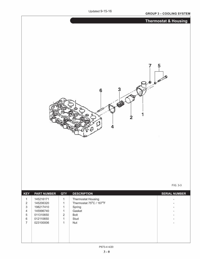
3 - 0
GROUP 3 – COOLING SYSTEM
Thermostat & Housing
KEY PART NUMBER QTY DESCRIPTION SERIAL NUMBER
1 145216171 1 Thermostat Housing - 2 145206320 1 Thermostat 75oC / 167oF - 3 198217410 1 Spring - 4 145996740 1 Gasket - 5 011310650 2 Bolt - 6 012110650 1 Stud - 7 023100006 1 Nut -
FIG. 3-3
Updated 9-15-16
P673-4 4/20
3 - 1
GROUP 3 – COOLING SYSTEM
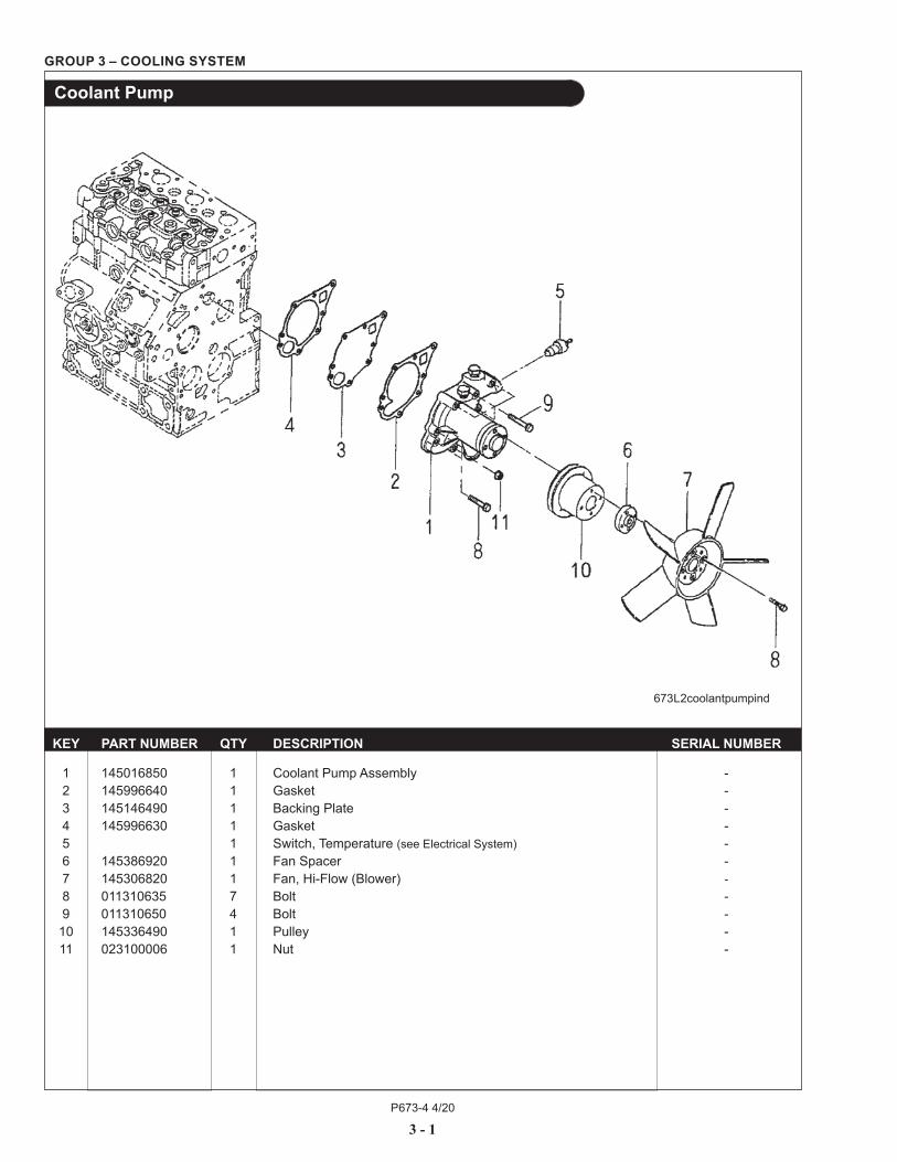
Coolant Pump
KEY PART NUMBER QTY DESCRIPTION SERIAL NUMBER 1 145016850 1 Coolant Pump Assembly - 2 145996640 1 Gasket - 3 145146490 1 Backing Plate - 4 145996630 1 Gasket - 5 1 Switch, Temperature (see Electrical System) - 6 145386920 1 Fan Spacer - 7 145306820 1 Fan, Hi-Flow (Blower) - 8 011310635 7 Bolt - 9 011310650 4 Bolt - 10 145336490 1 Pulley - 11 023100006 1 Nut -
673L2coolantpumpind

P673-4 4/20
3 - 2
GROUP 3 – COOLING SYSTEM
Radiator (Aluminum) & Mounting
KEY PART NUMBER QTY DESCRIPTION SERIAL NUMBER
1 00-18302 1 Grommet -
2 39-18302 1 Shroud Cover - 3 15-01132 10 Lock Washer M6 - 4 12-00097 10 Capscrew, Hex Head, M6 x 1.0 x 12 mm - 5 39-18001 1 Radiator Shroud - 7 12-00711 4 Capscrew, Hex Head M8 x 1.25 x 20 mm - 8 15-00702 4 Lock Washer, M8 - 9 14-00711 4 Nut M8 x 1.25 - 10 12-00809 2 Capscrew, Hex Head M10 x 1.25 x 25 mm - 11 15-00802 2 Lock Washer, M10 - 12 23-18004 1 Bracket, Radiator Support - 13 145306820 1 Fan, Blower 275 mm OD Hi-Flow - 14 145537190 1 Hose, Radiator Outlet - 15 19-00016 2 Hose Clamp #16 - 16 145537200 1 Hose, Radiator Inlet - 17 145506600 1 Radiator Assembly, Aluminum (includes keys #19 & #21 - #24) - 20-18003 1 Radiator Assembly, Heresite coated (optional) - 18 00-18304 1 Grommet - 19 310110200 1 Filler Cap 12.8 PSI - 20 19-00012 2 Hose Clamp #12 - 21 310130230 1 Drain Cock - 22 310190477 1 O-ring - 23 145546910 1 Fan Shroud with Guard - 24 310120170 1 Overflow Hose - 25 011150610 4 Capscrew, Hex Head M6 x 1.0 x 10mm (for fan shroud installation - not shown) - 26 15-00701 4 Flat Washer M8 - 27 15-00008 10 Flat Washer M6 -
/ C-1930
Updated 4-28-20
P673-4 4/20
4 - 0
GROUP 4 – FUEL SYSTEM
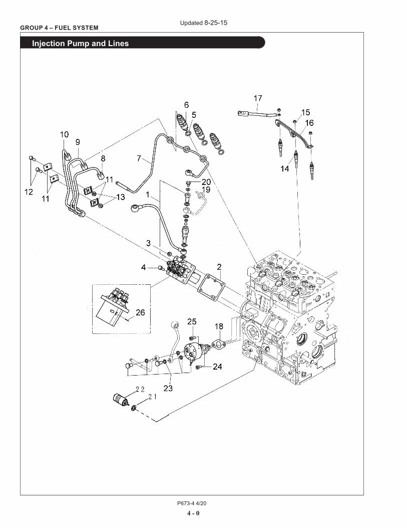
Injection Pump and Lines
Updated 8-25-15
P673-4 4/20
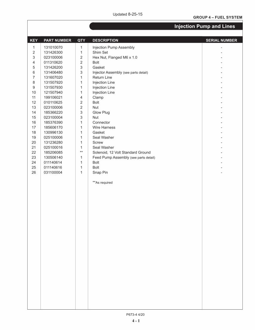
KEY PART NUMBER QTY DESCRIPTION SERIAL NUMBER
1 131010070 1 Injection Pump Assembly - 2 131426300 1 Shim Set - 3 023100006 2 Hex Nut, Flanged M6 x 1.0 - 4 011310620 2 Bolt - 5 131426200 3 Gasket - 6 131406480 3 Injector Assembly (see parts detail) - 7 131607020 1 Return Line - 8 131507920 1 Injection Line - 9 131507930 1 Injection Line - 10 121507940 1 Injection Line - 11 199106021 4 Clamp - 12 010110625 2 Bolt - 13 023100006 2 Nut - 14 185366220 3 Glow Plug - 15 023100004 3 Nut - 16 185376390 1 Connector - 17 185606170 1 Wire Harness - 18 130996130 1 Gasket - 19 025100006 1 Seal Washer - 20 131236280 1 Screw - 21 025100016 1 Seal Washer - 22 185206085 ** Solenoid, 12 Volt Standard Ground - 23 130506140 1 Feed Pump Assembly (see parts detail) - 24 011140614 1 Bolt - 25 011140616 1 Bolt - 26 031100004 1 Snap Pin -
**As required
4 - 1
GROUP 4 – FUEL SYSTEM
Injection Pump and Lines
Updated 8-25-15
P673-4 4/20
4 - 2
GROUP 4 – FUEL SYSTEM
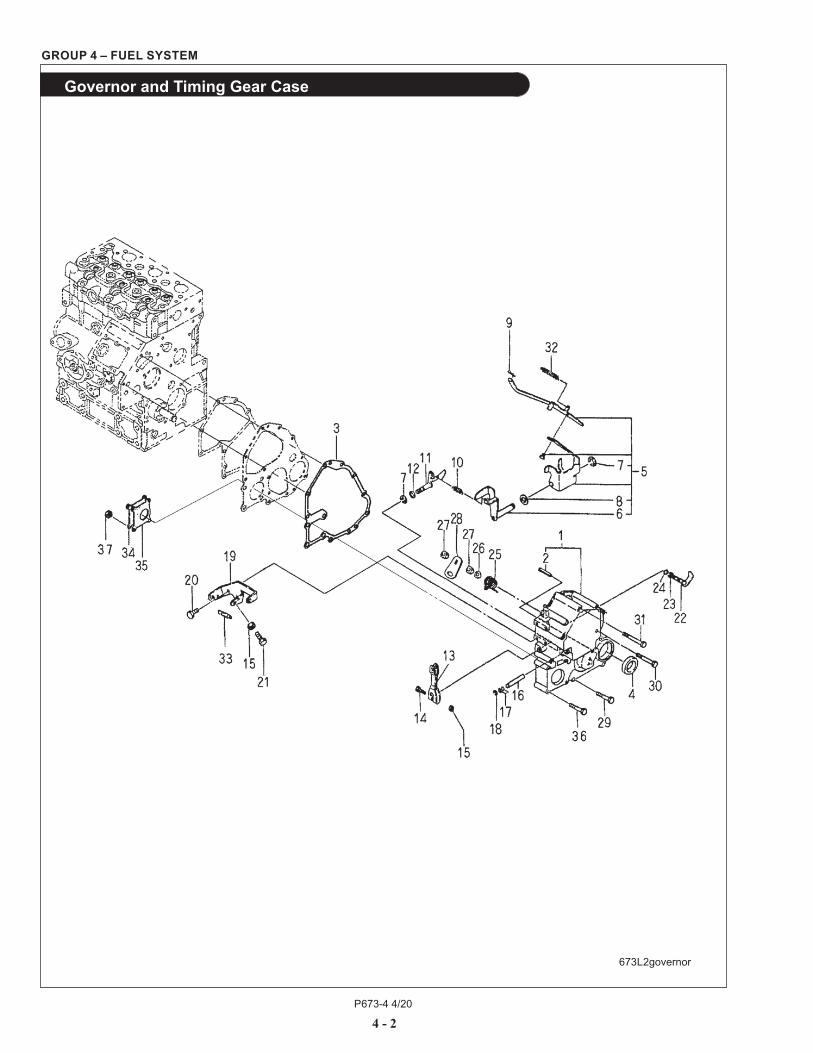
Governor and Timing Gear Case
673L2governor

P673-4 4/20
4 - 3
GROUP 4 – FUEL SYSTEM
Governor and Timing Gear Case
KEY PART NUMBER QTY DESCRIPTION SERIAL NUMBER
1 165106141 1 Timing Gear Case (includes key #2) - 2 030300410 1 Spring Pin - 3 165996500 1 Gasket - 4 198636140 1 Oil Seal - 5 125046250 1 Governor Lever Assembly (includes keys #6- 8) - 6 125406071 1 Tension Lever - 7 036800008 2 Snap Ring - 8 026200010 1 Washer - 9 031100004 1 Snap Pin - 10 198217131 1 Main Spring - 11 125156250 1 Governor Arm - 12 052109110 1 O-ring - 13 125416020 1 Governor Lever - 14 010110630 1 Bolt - 15 023100006 3 Nut - 16 125116131 1 Shaft - 17 052109108 2 O-ring - 18 036800005 1 Snap Ring - 19 125976120 1 Bracket - 20 011310614 2 Bolt - 21 010109264 1 Bolt - 22 125156180 1 Governor Arm - 23 036800006 1 Snap Ring - 24 052109109 1 O-ring - 25 198216760 1 Spring - 26 026200008 1 Washer - 27 020700008 2 Nut - 28 125176080 1 Stop Lever - 29 011310640 4 Bolt - 30 011310660 2 Bolt - 31 011310680 2 Bolt - 32 198217420 1 Start Spring - 33 398210070 1 Spring - 34 165206370 1 Cover - 35 165996510 1 Gasket - 36 010310850 4 Bolt - 37 023100008 4 Nut -
Updated 4-28-20

P673-4 4/20
4 - 4
GROUP 4 – FUEL SYSTEM
Fuel Filter and Mounting
KEY PART NUMBER QTY DESCRIPTION SERIAL NUMBER
1 130306190 1 Fuel Filter Assembly (includes keys #1, #2, #5, #6, and #7) - 2 24-52020 1 Fuel Filter - 3 15-00702 2 Lock Washer M8 - 4 14-00711 2 Hex Nut M8 x 1.25 - 5 130326051 5 Gasket - 6 130436011 2 Banjo Bolt - 7 130396030 1 Plug - 8 131236280 1 Screw - 9 025100006 1 Sealing Washer M6 - 10 131236190 1 Bolt - 11 140996270 4 Sealing Washer M10 - 12 131607020 1 Return Pipe - 13 140036141 1 Valve Assembly (includes keys #14 - #16) - 14 198116230 1 Rubber - 15 048100010 1 Ball - 16 140036141 1 Connector - 17 130556340 1 Pipe - 18 398113230 2 Rubber Grommet - 19 130506140 1 Feed Pump (includes keys #22 & #23 – see parts detail page) - 20 131976120 1 Mounting Bracket - 21 130556350 1 Tube - 22 130516069 4 Sealing Washer M8 - 23 130516092 2 Banjo Bolt M8 x 1.25 x 22mm - 24 130556361 1 Tube - 26 011510816 2 Bolt -
673L2fuelfilter
Updated 4-28-20
P673-4 4/20
4 - 5
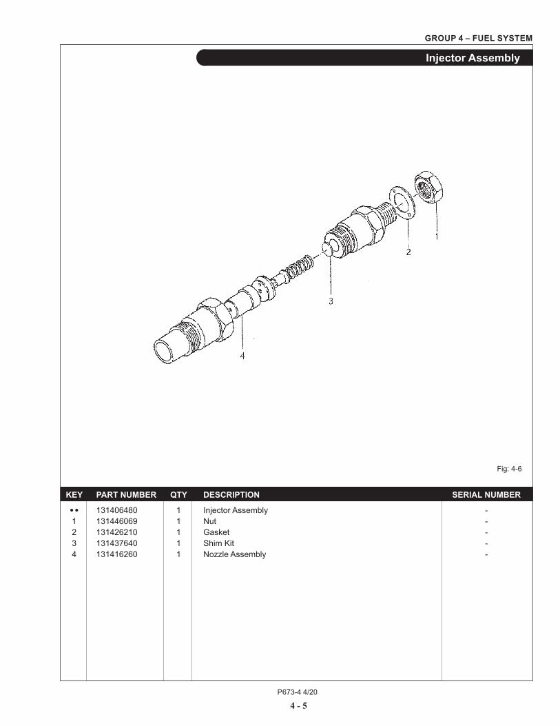
GROUP 4 – FUEL SYSTEM
Fig: 4-6
Injector Assembly
KEY PART NUMBER QTY DESCRIPTION SERIAL NUMBER
•• 131406480 1 Injector Assembly - 1 131446069 1 Nut - 2 131426210 1 Gasket - 3 131437640 1 Shim Kit - 4 131416260 1 Nozzle Assembly -
P673-4 4/20
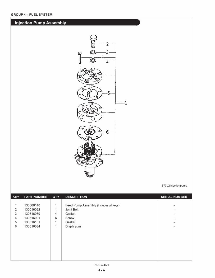
KEY PART NUMBER QTY DESCRIPTION SERIAL NUMBER 1 130506140 1 Feed Pump Assembly (includes all keys) - 2 130516092 1 Joint Bolt - 3 130516069 4 Gasket - 4 130516091 6 Screw - 5 130516101 1 Gasket - 6 130516084 1 Diaphragm -
GROUP 4 – FUEL SYSTEM
Injection Pump Assembly
673L2injectionpump
4 - 6

P673-4 4/20
GROUP 4 – FUEL SYSTEM
This page intentionally left blank
4 - 7
P673-4 4/20
5 - 0
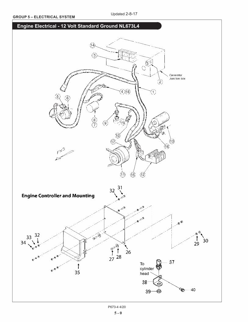
GROUP 5 – ELECTRICAL SYSTEM
Engine Electrical - 12 Volt Standard Ground NL673L4
Updated 2-8-17
P673-4 4/20
5 - 1
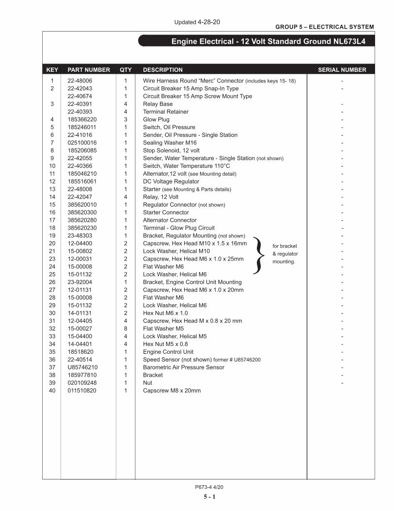
GROUP 5 – ELECTRICAL SYSTEM
Engine Electrical - 12 Volt Standard Ground NL673L4
KEY PART NUMBER QTY DESCRIPTION SERIAL NUMBER
1 22-48006 1 Wire Harness Round “Merc” Connector (includes keys 15- 18) - 2 22-42043 1 Circuit Breaker 15 Amp Snap-In Type - 22-40674 1 Circuit Breaker 15 Amp Screw Mount Type 3 22-40391 4 Relay Base - 22-40393 4 Terminal Retainer - 4 185366220 3 Glow Plug - 5 185246011 1 Switch, Oil Pressure - 6 22-41016 1 Sender, Oil Pressure - Single Station - 7 025100016 1 Sealing Washer M16 - 8 185206085 1 Stop Solenoid, 12 volt - 9 22-42055 1 Sender, Water Temperature - Single Station (not shown) - 10 22-40366 1 Switch, Water Temperature 110°C - 11 185046210 1 Alternator,12 volt (see Mounting detail) - 12 185516061 1 DC Voltage Regulator - 13 22-48008 1 Starter (see Mounting & Parts details) - 14 22-42047 4 Relay, 12 Volt - 15 385620010 1 Regulator Connector (not shown) - 16 385620300 1 Starter Connector - 17 385620280 1 Alternator Connector - 18 385620230 1 Terminal - Glow Plug Circuit - 19 23-48303 1 Bracket, Regulator Mounting (not shown) - 20 12-04400 2 Capscrew, Hex Head M10 x 1.5 x 16mm - 21 15-00802 2 Lock Washer, Helical M10 - 23 12-00031 2 Capscrew, Hex Head M6 x 1.0 x 25mm - 24 15-00008 2 Flat Washer M6 - 25 15-01132 2 Lock Washer, Helical M6 - 26 23-92004 1 Bracket, Engine Control Unit Mounting - 27 12-01131 2 Capscrew, Hex Head M6 x 1.0 x 20mm - 28 15-00008 2 Flat Washer M6 - 29 15-01132 2 Lock Washer, Helical M6 - 30 14-01131 2 Hex Nut M6 x 1.0 - 31 12-04405 4 Capscrew, Hex Head M x 0.8 x 20 mm - 32 15-00027 8 Flat Washer M5 - 33 15-04400 4 Lock Washer, Helical M5 - 34 14-04401 4 Hex Nut M5 x 0.8 - 35 18518620 1 Engine Control Unit - 36 22-40514 1 Speed Sensor (not shown) former # U85746200 - 37 U85746210 1 Barometric Air Pressure Sensor - 38 185977810 1 Bracket - 39 020109248 1 Nut - 40 011510820 1 Capscrew M8 x 20mm
} for bracket & regulator mounting.
Updated 4-28-20

P673-4 4/20
5 - 2
GROUP 5 – ELECTRICAL SYSTEM
Engine Electrical - 12 Volt Standard Ground NL673L4
A-3203A/ C-1925
B+ Electrical System
Updated 7-26-16
P673-4 4/20
5 - 3
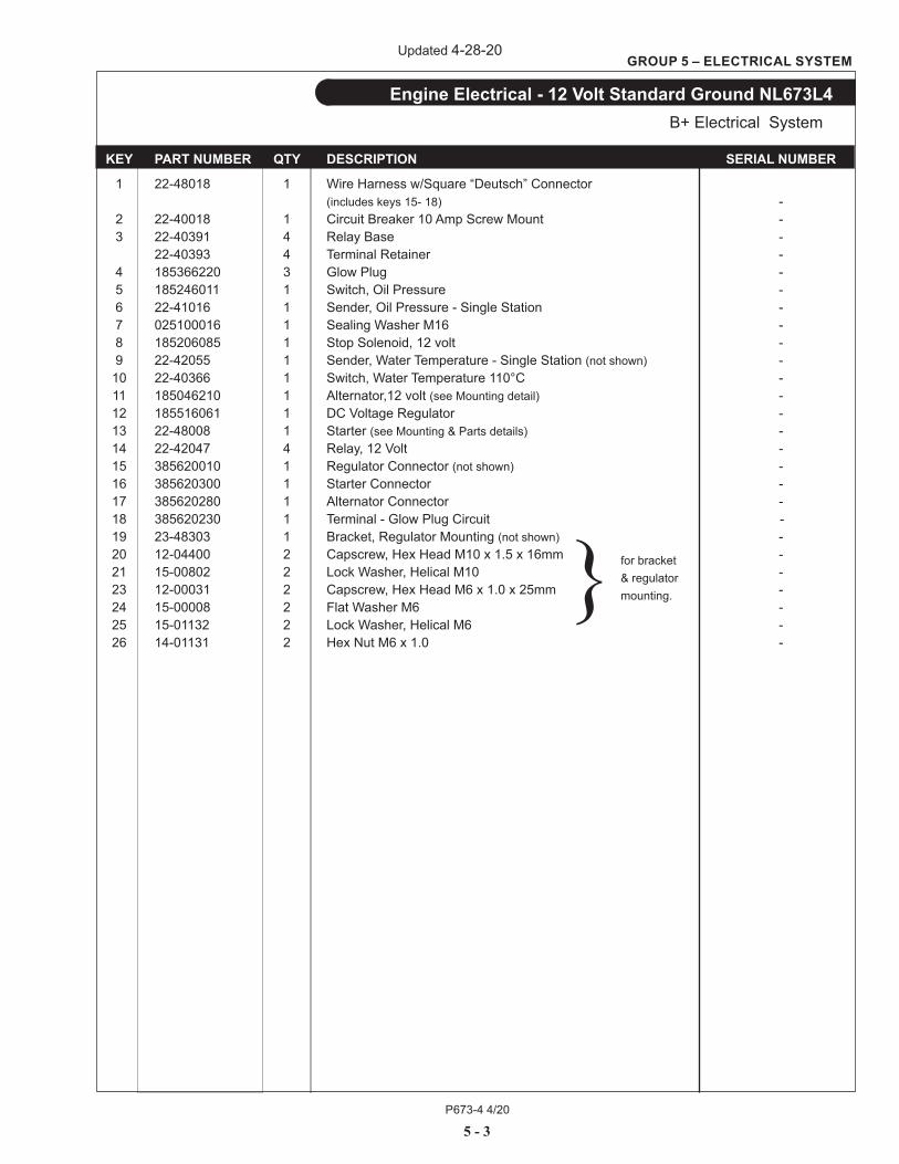
GROUP 5 – ELECTRICAL SYSTEM
Engine Electrical - 12 Volt Standard Ground NL673L4
KEY PART NUMBER QTY DESCRIPTION SERIAL NUMBER
1 22-48018 1 Wire Harness w/Square “Deutsch” Connector (includes keys 15- 18) - 2 22-40018 1 Circuit Breaker 10 Amp Screw Mount - 3 22-40391 4 Relay Base - 22-40393 4 Terminal Retainer - 4 185366220 3 Glow Plug - 5 185246011 1 Switch, Oil Pressure - 6 22-41016 1 Sender, Oil Pressure - Single Station - 7 025100016 1 Sealing Washer M16 - 8 185206085 1 Stop Solenoid, 12 volt - 9 22-42055 1 Sender, Water Temperature - Single Station (not shown) - 10 22-40366 1 Switch, Water Temperature 110°C - 11 185046210 1 Alternator,12 volt (see Mounting detail) - 12 185516061 1 DC Voltage Regulator - 13 22-48008 1 Starter (see Mounting & Parts details) - 14 22-42047 4 Relay, 12 Volt - 15 385620010 1 Regulator Connector (not shown) - 16 385620300 1 Starter Connector - 17 385620280 1 Alternator Connector - 18 385620230 1 Terminal - Glow Plug Circuit - 19 23-48303 1 Bracket, Regulator Mounting (not shown) - 20 12-04400 2 Capscrew, Hex Head M10 x 1.5 x 16mm - 21 15-00802 2 Lock Washer, Helical M10 - 23 12-00031 2 Capscrew, Hex Head M6 x 1.0 x 25mm - 24 15-00008 2 Flat Washer M6 - 25 15-01132 2 Lock Washer, Helical M6 - 26 14-01131 2 Hex Nut M6 x 1.0 -
} for bracket & regulator mounting.
B+ Electrical System
Updated 4-28-20
P673-4 4/205 - 4
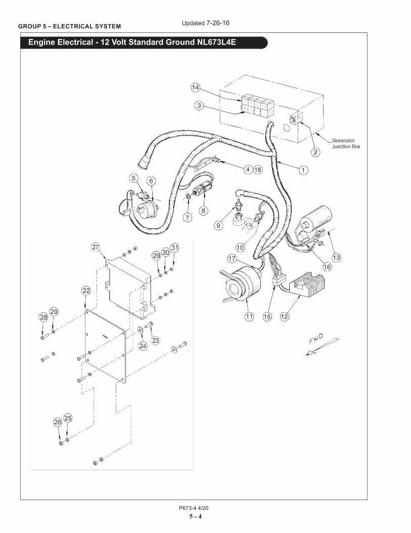
GROUP 5 – ELECTRICAL SYSTEM
Engine Electrical - 12 Volt Standard Ground NL673L4E
Updated 7-26-16
P673-4 4/205 - 5
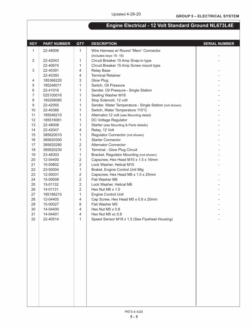
GROUP 5 – ELECTRICAL SYSTEM
Engine Electrical - 12 Volt Standard Ground NL673L4E
KEY PART NUMBER QTY DESCRIPTION SERIAL NUMBER
1 22-48006 1 Wire Harness w/ Round “Merc” Connector (includes keys 15- 18) - 2 22-42043 1 Circuit Breaker 15 Amp Snap-in type - 22-40674 1 Circuit Breaker 15 Amp Screw mount type 3 22-40391 4 Relay Base - 22-40393 4 Terminal Retainer - 4 185366220 3 Glow Plug - 5 185246011 1 Switch, Oil Pressure - 6 22-41016 1 Sender, Oil Pressure - Single Station - 7 025100016 1 Sealing Washer M16 - 8 185206085 1 Stop Solenoid, 12 volt - 9 22-42055 1 Sender, Water Temperature - Single Station (not shown) - 10 22-40366 1 Switch, Water Temperature 110°C - 11 185046210 1 Alternator,12 volt (see Mounting detail) - 12 185516061 1 DC Voltage Regulator - 13 22-48008 1 Starter (see Mounting & Parts details) - 14 22-42047 4 Relay, 12 Volt - 15 385620010 1 Regulator Connector (not shown) - 16 385620300 1 Starter Connector - 17 385620280 2 Alternator Connector - 18 385620230 1 Terminal - Glow Plug Circuit - 19 23-48303 1 Bracket, Regulator Mounting (not shown) - 20 12-04400 2 Capscrew, Hex Head M10 x 1.5 x 16mm - 21 15-00802 2 Lock Washer, Helical M10 - 22 23-92004 1 Braket, Engine Control Unit Mtg 23 12-00031 2 Capscrew, Hex Head M6 x 1.0 x 25mm - 24 15-00008 2 Flat Washer M6 - 25 15-01132 2 Lock Washer, Helical M6 - 26 14-01131 2 Hex Nut M6 x 1.0 - 27 185186210 1 Engine Control Unit - 28 12-04405 4 Cap Screw, Hex Head M5 x 0.8 x 20mm - 29 15-00027 8 Flat Washer M5 - 30 14-04400 4 Hex Nut M5 x 0.8 - 31 14-04401 4 Hex Nut M5 xc 0.8 - 32 22-40514 1 Speed Sensor M18 x 1.5 (See Flywheel Housing) -
Updated 4-28-20

P673-4 4/20
5 - 6
GROUP 5 – ELECTRICAL SYSTEM
Engine Electrical - 12 Volt Standard Ground NL673L4EB+ Electrical System
Updated 7-26-16

P673-4 4/20
5 - 7
GROUP 5 – ELECTRICAL SYSTEM
Engine Electrical - 12 Volt Standard Ground NL673L4E
KEY PART NUMBER QTY DESCRIPTION SERIAL NUMBER
1 22-48018 1 Wire Harness w/Square “Deutsch” Connector (includes keys 15- 18) - 2 22-40018 1 Circuit Breaker 10 Amp Screw mount type 3 22-40391 4 Relay Base - 22-40393 4 Terminal Retainer - 4 185366220 3 Glow Plug - 5 185246011 1 Switch, Oil Pressure - 6 22-41016 1 Sender, Oil Pressure - Single Station - 7 025100016 1 Sealing Washer M16 - 8 185206085 1 Stop Solenoid, 12 volt - 9 22-42055 1 Sender, Water Temperature - Single Station (not shown) - 10 22-40366 1 Switch, Water Temperature 110°C - 11 185046210 1 Alternator,12 volt (see Mounting detail) - 12 185516061 1 DC Voltage Regulator - 13 22-48008 1 Starter (see Mounting & Parts details) - 14 22-42047 4 Relay, 12 Volt - 15 385620010 1 Regulator Connector (not shown) - 16 385620300 1 Starter Connector - 17 385620280 2 Alternator Connector - 18 385620230 1 Terminal - Glow Plug Circuit - 19 23-48303 1 Bracket, Regulator Mounting (not shown) - 20 12-04400 2 Capscrew, Hex Head M10 x 1.5 x 16mm - 21 15-00802 2 Lock Washer, Helical M10 - 22 23-92004 1 Braket, Engine Control Unit Mtg 23 12-00031 2 Capscrew, Hex Head M6 x 1.0 x 25mm - 24 15-00008 2 Flat Washer M6 - 25 15-01132 2 Lock Washer, Helical M6 - 26 14-01131 2 Hex Nut M6 x 1.0 - 27 185186210 1 Engine Control Unit - 28 12-04405 4 Cap Screw, Hex Head M5 x 0.8 x 20mm - 29 15-00027 8 Flat Washer M5 - 30 14-04400 4 Hex Nut M5 x 0.8 - 31 14-04401 4 Hex Nut M5 xc 0.8 - 32 22-40514 1 Speed Sensor M18 x 1.5 (See Flywheel Housing) -
B+ Electrical System
Updated 4-28-20
P673-4 4/20
5 - 8
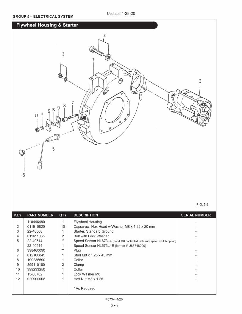
GROUP 5 – ELECTRICAL SYSTEM
Flywheel Housing & Starter
KEY PART NUMBER QTY DESCRIPTION SERIAL NUMBER
1 110446480 1 Flywheel Housing - 2 011510820 10 Capscrew, Hex Head w/Washer M8 x 1.25 x 20 mm - 3 22-48008 1 Starter, Standard Ground - 4 011611035 2 Bolt with Lock Washer - 5 22-40514 ** Speed Sensor NL673L4 (non-ECU controlled units with speed switch option) - 22-40514 1 Speed Sensor NL673L4E (former # U85746200) 6 398460090 ** Plug - 7 012100845 1 Stud M8 x 1.25 x 45 mm - 8 199236690 1 Collar - 9 399110160 2 Clamp - 10 399233250 1 Collar - 11 15-00702 1 Lock Washer M8 - 12 020900008 1 Hex Nut M8 x 1.25 - * As Required
FIG. 5-2
Updated 4-28-20
P673-4 4/20
GROUP 5 – ELECTRICAL SYSTEM
5 - 9
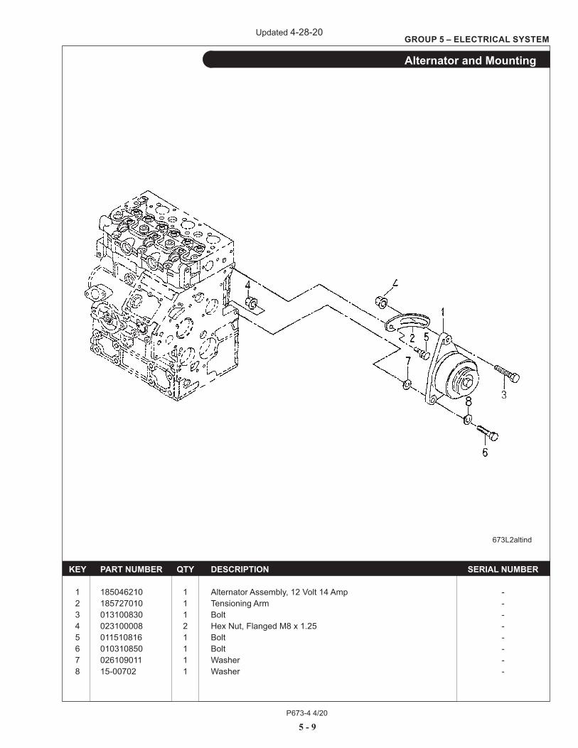
Alternator and Mounting
673L2altind
KEY PART NUMBER QTY DESCRIPTION SERIAL NUMBER 1 185046210 1 Alternator Assembly, 12 Volt 14 Amp - 2 185727010 1 Tensioning Arm - 3 013100830 1 Bolt - 4 023100008 2 Hex Nut, Flanged M8 x 1.25 - 5 011510816 1 Bolt - 6 010310850 1 Bolt - 7 026109011 1 Washer - 8 15-00702 1 Washer -
Updated 4-28-20
P673-4 4/20
5 - 10
GROUP 5 – ELECTRICAL SYSTEM
KEY PART NUMBER QTY DESCRIPTION SERIAL NUMBER
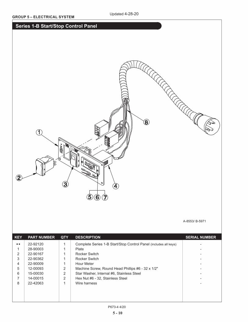
•• 22-92120 1 Complete Series 1-B Start/Stop Control Panel (includes all keys) - 1 28-90003 1 Plate - 2 22-90167 1 Rocker Switch - 3 22-90362 1 Rocker Switch - 4 22-90009 1 Hour Meter - 5 12-00093 2 Machine Screw, Round Head Phillips #6 - 32 x 1/2" - 6 15-00030 2 Star Washer, Internal #6, Stainless Steel - 7 14-00015 2 Hex Nut #6 - 32, Stainless Steel - 8 22-42063 1 Wire harness -
Series 1-B Start/Stop Control Panel
A-8553/ B-5971
Updated 4-28-20
P673-4 4/20
5 - 11
GROUP 5 – ELECTRICAL SYSTEM
KEY PART NUMBER QTY DESCRIPTION SERIAL NUMBER
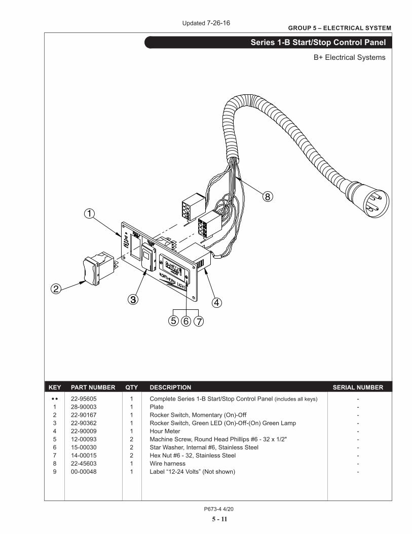
•• 22-95605 1 Complete Series 1-B Start/Stop Control Panel (includes all keys) - 1 28-90003 1 Plate - 2 22-90167 1 Rocker Switch, Momentary (On)-Off - 3 22-90362 1 Rocker Switch, Green LED (On)-Off-(On) Green Lamp - 4 22-90009 1 Hour Meter - 5 12-00093 2 Machine Screw, Round Head Phillips #6 - 32 x 1/2" - 6 15-00030 2 Star Washer, Internal #6, Stainless Steel - 7 14-00015 2 Hex Nut #6 - 32, Stainless Steel - 8 22-45603 1 Wire harness - 9 00-00048 1 Label “12-24 Volts” (Not shown) -
Series 1-B Start/Stop Control Panel
B+ Electrical Systems
Updated 7-26-16
P673-4 4/20
5 - 12
GROUP 5 – ELECTRICAL SYSTEM
KEY PART NUMBER QTY DESCRIPTION SERIAL NUMBER
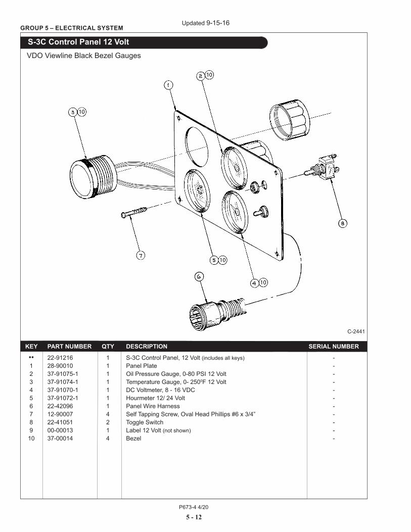
•• 22-91216 1 S-3C Control Panel, 12 Volt (includes all keys) - 1 28-90010 1 Panel Plate - 2 37-91075-1 1 Oil Pressure Gauge, 0-80 PSI 12 Volt - 3 37-91074-1 1 Temperature Gauge, 0- 2500F 12 Volt - 4 37-91070-1 1 DC Voltmeter, 8 - 16 VDC - 5 37-91072-1 1 Hourmeter 12/ 24 Volt - 6 22-42096 1 Panel Wire Harness - 7 12-90007 4 Self Tapping Screw, Oval Head Phillips #6 x 3/4” - 8 22-41051 2 Toggle Switch - 9 00-00013 1 Label 12 Volt (not shown) - 10 37-00014 4 Bezel -
S-3C Control Panel 12 Volt VDO Viewline Black Bezel Gauges
C-2441
Updated 9-15-16
P673-4 4/20
5 - 13
GROUP 5 – ELECTRICAL SYSTEM
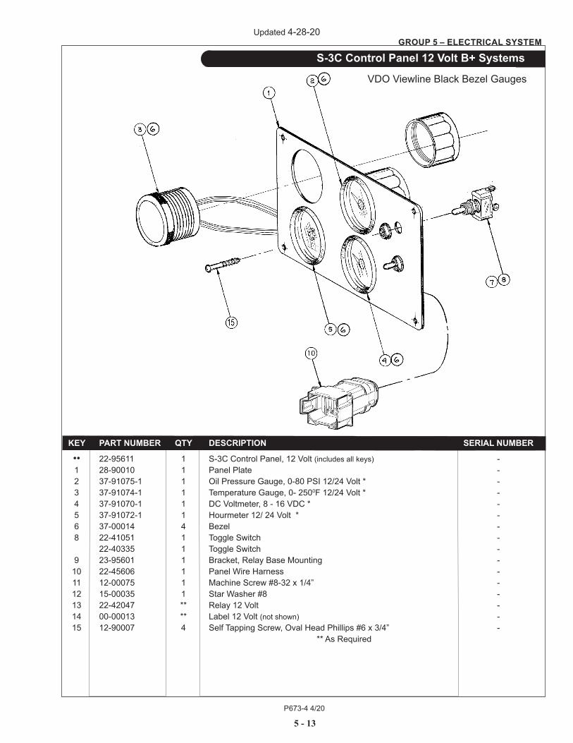
KEY PART NUMBER QTY DESCRIPTION SERIAL NUMBER
•• 22-95611 1 S-3C Control Panel, 12 Volt (includes all keys) - 1 28-90010 1 Panel Plate - 2 37-91075-1 1 Oil Pressure Gauge, 0-80 PSI 12/24 Volt * - 3 37-91074-1 1 Temperature Gauge, 0- 2500F 12/24 Volt * - 4 37-91070-1 1 DC Voltmeter, 8 - 16 VDC * - 5 37-91072-1 1 Hourmeter 12/ 24 Volt * - 6 37-00014 4 Bezel - 8 22-41051 1 Toggle Switch - 22-40335 1 Toggle Switch - 9 23-95601 1 Bracket, Relay Base Mounting - 10 22-45606 1 Panel Wire Harness - 11 12-00075 1 Machine Screw #8-32 x 1/4” - 12 15-00035 1 Star Washer #8 - 13 22-42047 ** Relay 12 Volt - 14 00-00013 ** Label 12 Volt (not shown) - 15 12-90007 4 Self Tapping Screw, Oval Head Phillips #6 x 3/4” - ** As Required
S-3C Control Panel 12 Volt B+ Systems
VDO Viewline Black Bezel Gauges
Updated 4-28-20
P673-4 4/20
5 - 14
GROUP 5 – ELECTRICAL SYSTEM
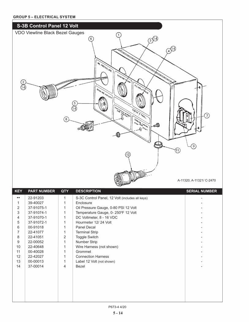
KEY PART NUMBER QTY DESCRIPTION SERIAL NUMBER
•• 22-91203 1 S-3C Control Panel, 12 Volt (includes all keys) - 1 39-40027 1 Enclosure - 2 37-91075-1 1 Oil Pressure Gauge, 0-80 PSI 12 Volt - 3 37-91074-1 1 Temperature Gauge, 0- 2500F 12 Volt - 4 37-91070-1 1 DC Voltmeter, 8 - 16 VDC - 5 37-91072-1 1 Hourmeter 12/ 24 Volt - 6 00-91018 1 Panel Decal - 7 22-41077 1 Terminal Strip - 8 22-41051 2 Toggle Switch - 9 22-00052 1 Number Strip - 10 22-40648 1 Wire Harness (not shown) - 11 00-40028 1 Grommet - 12 22-42027 1 Connection Harness - 13 00-00013 1 Label 12 Volt (not shown) - 14 37-00014 4 Bezel -
S-3B Control Panel 12 Volt
A-11320, A-11321/ C-2470
VDO Viewline Black Bezel Gauges

P673-4 4/20
5 - 15
GROUP 5 – ELECTRICAL SYSTEM
This page intentionally left blank.
P673-4 4/205 - 16
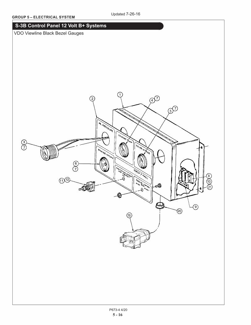
GROUP 5 – ELECTRICAL SYSTEM
S-3B Control Panel 12 Volt B+ SystemsVDO Viewline Black Bezel Gauges
Updated 7-26-16

P673-4 4/20
GROUP 5 – ELECTRICAL SYSTEM
5 - 17
S-3B Control Panel 12 Volt B+ SystemsVDO Viewline Black Bezel Gauges
KEY PART NUMBER QTY DESCRIPTION SERIAL NUMBER
•• 22-95601 1 S-3C Control Panel, 12 Volt (includes all keys) - 1 39-40027 1 Enclosure - 2 00-91018 1 Decal - 3 37-91075-1 1 Oil Pressure Gauge, 0-80 PSI 12/24 Volt * - 4 37-91074-1 1 Temperature Gauge, 0- 2500F 12/24 Volt * - 5 37-91070-1 1 Voltmeter, 8 - 16 VDC * - 6 37-91072-1 1 Hourmeter 12/ 24 Volt - 7 37-00014 4 Bezel - 8 22-41077 1 Terminal Strip - 9 22-00052 1 Number Strip - 10 14-09021 2 Jam Nut, Nylock #8-32 S/S - 11 22-41051 1 Toggle Switch - 12 22-40335 1 Toggle Switch - 13 23-95602 1 Bracket, Relay Mounting - 14 22-45604 1 Wire Harness (not shown) (Includes keys 22-23) - 15 12-00075 1 Machine Screw, Phillips #8-32 x 1/4” S/S - 16 15-00035 1 Star Washer #8 S/S - 17 22-42047 ** Relay 12 Volt - 22-40710 ** Relay 24 Volt - 18 22-45607 1 Connection Harness - 19 00-00013 ** Label 12 Volt (not shown) - 00-00014 ** Label 24 Volt - 20 00-40028 1 Grommet - 21 12-42103 2 Machine Screw, Pan Head, Phillips #8-32 x 5/8” S/S - 22 22-40931 1 Relay Base - 23 22-40393 1 Retainer - * Note Bezel 37-00014 supplied separately
Updated 4-28-20

P673-4 4/205 - 18
GROUP 5 – ELECTRICAL SYSTEM
Belt Guard
Updated 7-26-16
P673-4 4/20
GROUP 5 – ELECTRICAL SYSTEM
5 - 19
Belt Guard
KEY PART NUMBER QTY DESCRIPTION SERIAL NUMBER
1 00-08001 1 Belt Guard Right Hand - 2 00-08002 1 Belt Guard Left Hand - 3 00-08003 1 Belt Guard Bottom - 4 12-00097 7 Capscrew, Hex Head M6 x 1.0 x 12mm - 5 15-01132 9 Lock Washer, Helical M6 - 6 15-00008 9 Flat Washer M6 - 7 14-01131 2 Hex Nut M6 x 1.0 x 16mm - 8 12-00030 2 Capscrew, Hex Head M6 x 1.0 x 16 mm -
Updated 7-26-16
P673-4 4/20
6 - 0
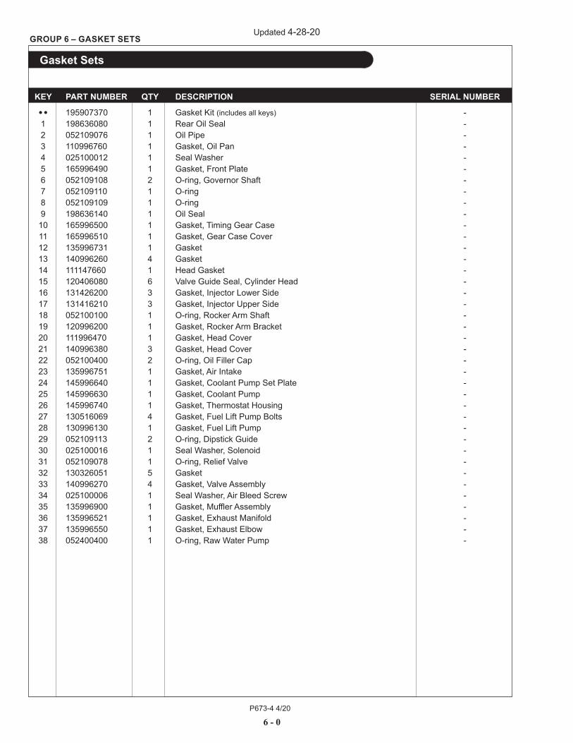
GROUP 6 – GASKET SETS
Gasket Sets
KEY PART NUMBER QTY DESCRIPTION SERIAL NUMBER
•• 195907370 1 Gasket Kit (includes all keys) - 1 198636080 1 Rear Oil Seal - 2 052109076 1 Oil Pipe - 3 110996760 1 Gasket, Oil Pan - 4 025100012 1 Seal Washer - 5 165996490 1 Gasket, Front Plate - 6 052109108 2 O-ring, Governor Shaft - 7 052109110 1 O-ring - 8 052109109 1 O-ring - 9 198636140 1 Oil Seal - 10 165996500 1 Gasket, Timing Gear Case - 11 165996510 1 Gasket, Gear Case Cover - 12 135996731 1 Gasket - 13 140996260 4 Gasket - 14 111147660 1 Head Gasket - 15 120406080 6 Valve Guide Seal, Cylinder Head - 16 131426200 3 Gasket, Injector Lower Side - 17 131416210 3 Gasket, Injector Upper Side - 18 052100100 1 O-ring, Rocker Arm Shaft - 19 120996200 1 Gasket, Rocker Arm Bracket - 20 111996470 1 Gasket, Head Cover - 21 140996380 3 Gasket, Head Cover - 22 052100400 2 O-ring, Oil Filler Cap - 23 135996751 1 Gasket, Air Intake - 24 145996640 1 Gasket, Coolant Pump Set Plate - 25 145996630 1 Gasket, Coolant Pump - 26 145996740 1 Gasket, Thermostat Housing - 27 130516069 4 Gasket, Fuel Lift Pump Bolts - 28 130996130 1 Gasket, Fuel Lift Pump - 29 052109113 2 O-ring, Dipstick Guide - 30 025100016 1 Seal Washer, Solenoid - 31 052109078 1 O-ring, Relief Valve - 32 130326051 5 Gasket - 33 140996270 4 Gasket, Valve Assembly - 34 025100006 1 Seal Washer, Air Bleed Screw - 35 135996900 1 Gasket, Muffler Assembly - 36 135996521 1 Gasket, Exhaust Manifold - 37 135996550 1 Gasket, Exhaust Elbow - 38 052400400 1 O-ring, Raw Water Pump -
Updated 4-28-20
P673-4 4/20
This page intentionally left blank.
P673-4 4/20
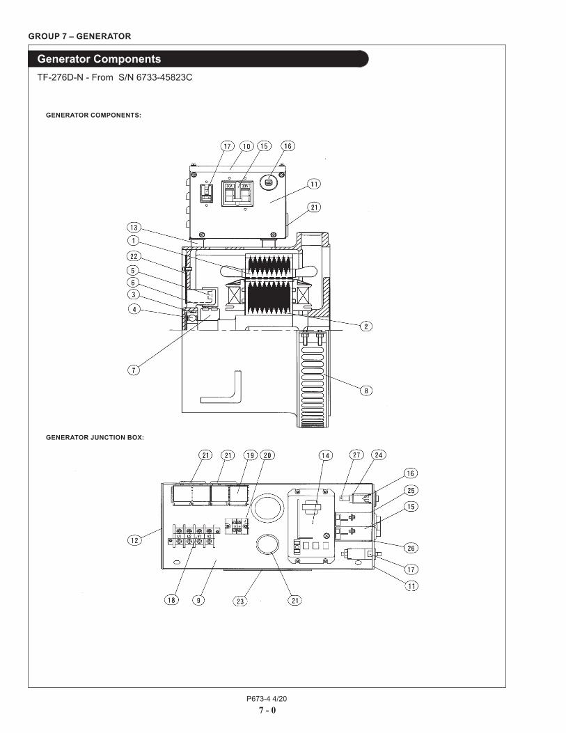
GROUP 7 – GENERATOR
Generator ComponentsTF-276D-N - From S/N 6733-45823C
7 - 0
GENERATOR JUNCTION BOX:
GENERATOR COMPONENTS:
P673-4 4/207 - 1
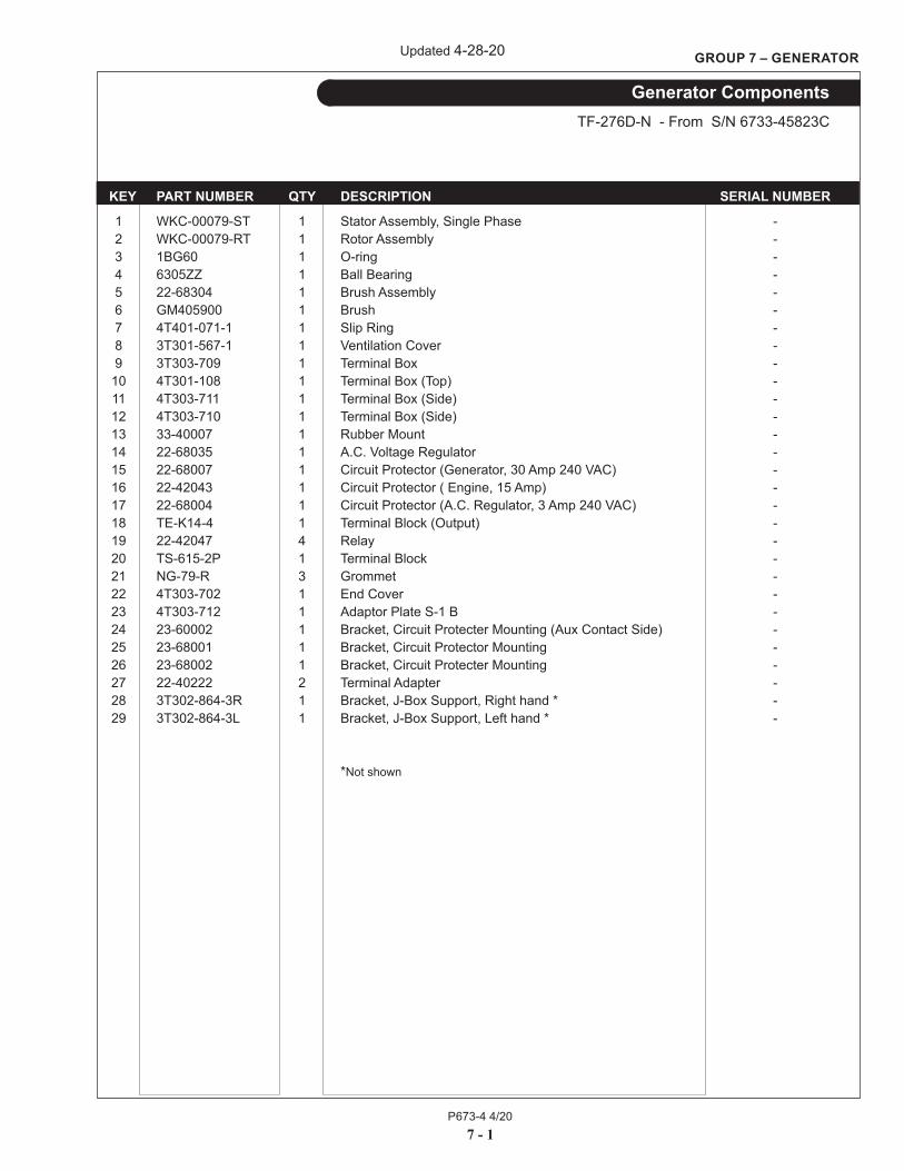
GROUP 7 – GENERATOR
KEY PART NUMBER QTY DESCRIPTION SERIAL NUMBER
1 WKC-00079-ST 1 Stator Assembly, Single Phase - 2 WKC-00079-RT 1 Rotor Assembly - 3 1BG60 1 O-ring - 4 6305ZZ 1 Ball Bearing - 5 22-68304 1 Brush Assembly - 6 GM405900 1 Brush - 7 4T401-071-1 1 Slip Ring - 8 3T301-567-1 1 Ventilation Cover - 9 3T303-709 1 Terminal Box - 10 4T301-108 1 Terminal Box (Top) - 11 4T303-711 1 Terminal Box (Side) - 12 4T303-710 1 Terminal Box (Side) - 13 33-40007 1 Rubber Mount - 14 22-68035 1 A.C. Voltage Regulator - 15 22-68007 1 Circuit Protector (Generator, 30 Amp 240 VAC) - 16 22-42043 1 Circuit Protector ( Engine, 15 Amp) - 17 22-68004 1 Circuit Protector (A.C. Regulator, 3 Amp 240 VAC) - 18 TE-K14-4 1 Terminal Block (Output) - 19 22-42047 4 Relay - 20 TS-615-2P 1 Terminal Block - 21 NG-79-R 3 Grommet - 22 4T303-702 1 End Cover - 23 4T303-712 1 Adaptor Plate S-1 B - 24 23-60002 1 Bracket, Circuit Protecter Mounting (Aux Contact Side) - 25 23-68001 1 Bracket, Circuit Protector Mounting - 26 23-68002 1 Bracket, Circuit Protecter Mounting - 27 22-40222 2 Terminal Adapter - 28 3T302-864-3R 1 Bracket, J-Box Support, Right hand * - 29 3T302-864-3L 1 Bracket, J-Box Support, Left hand * -
*Not shown
Generator ComponentsTF-276D-N - From S/N 6733-45823C
Updated 4-28-20
P673-4 4/20
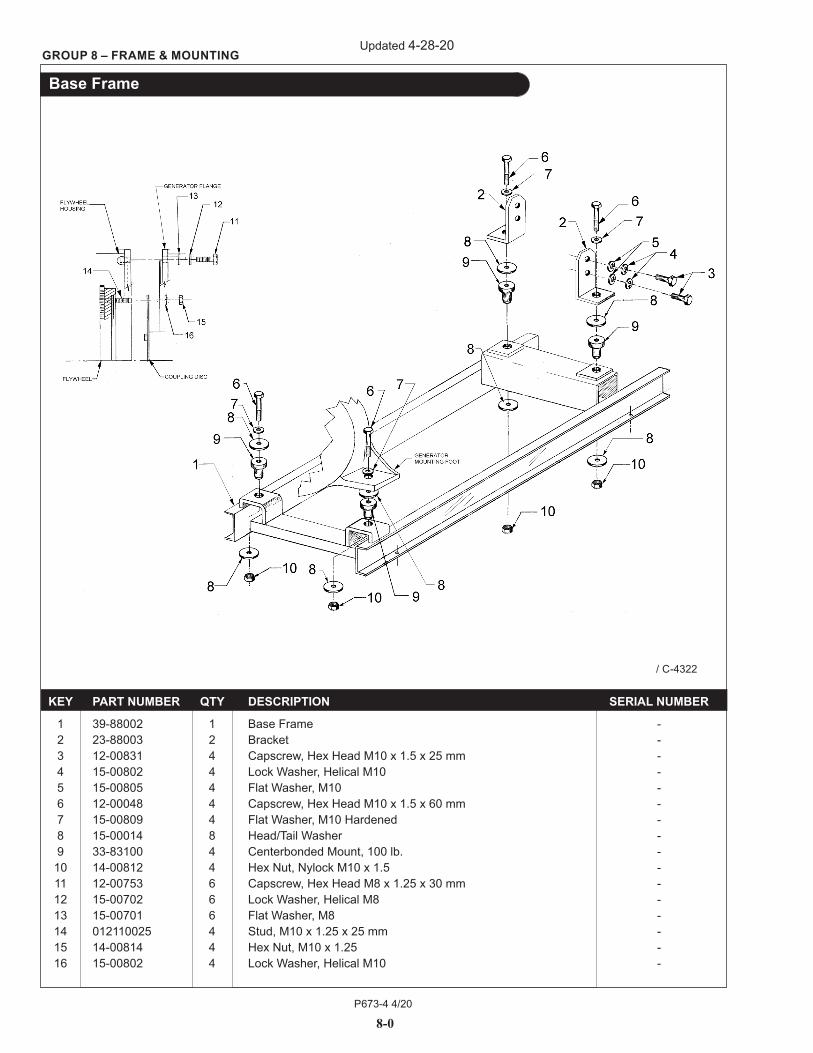
8-0
GROUP 8 – FRAME & MOUNTING
Base Frame
KEY PART NUMBER QTY DESCRIPTION SERIAL NUMBER
1 39-88002 1 Base Frame - 2 23-88003 2 Bracket - 3 12-00831 4 Capscrew, Hex Head M10 x 1.5 x 25 mm - 4 15-00802 4 Lock Washer, Helical M10 - 5 15-00805 4 Flat Washer, M10 - 6 12-00048 4 Capscrew, Hex Head M10 x 1.5 x 60 mm - 7 15-00809 4 Flat Washer, M10 Hardened - 8 15-00014 8 Head/Tail Washer - 9 33-83100 4 Centerbonded Mount, 100 lb. - 10 14-00812 4 Hex Nut, Nylock M10 x 1.5 - 11 12-00753 6 Capscrew, Hex Head M8 x 1.25 x 30 mm - 12 15-00702 6 Lock Washer, Helical M8 - 13 15-00701 6 Flat Washer, M8 - 14 012110025 4 Stud, M10 x 1.25 x 25 mm - 15 14-00814 4 Hex Nut, M10 x 1.25 - 16 15-00802 4 Lock Washer, Helical M10 -
/ C-4322
Updated 4-28-20
P673-4 4/20
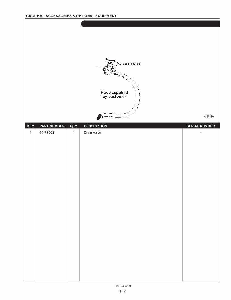
GROUP 9 – ACCESSORIES & OPTIONAL EQUIPMENT
9 - 0
Oil Drain Kit
KEY PART NUMBER QTY DESCRIPTION SERIAL NUMBER
1 36-72003 1 Drain Valve -
A-6480


4420 14th Ave. NW., Seattle WA 98107 Tel: (206) 789-3880 • 1-800-762-0165 • www.northern-lights.comNorthern Lights and Lugger are registered trademarks of Northern Lights, Inc. © 2020 All rights reserved. Litho USA.