partner in the process industry
TRANSCRIPT

IC 2
0-1
5.0
00.L
3
Pri
nte
d in G
erm
any
MN
R 5
2004450/0
1.0
5.2
015-0
3
© P
HO
EN
IX C
ON
TA
CT
2015
Always up-to-date, always available to you. Here
you'll find everything on our products, solutions
and service:
phoenixcontact.com
Product range
• Cables and wires
• Connectors
• Controllers
• Electronics housings
• Electronic switchgear andmotor control
• Fieldbus components and systems
• Functional safety
• HMIs and industrial PCs
• I/O systems
• Industrial communication technology
• Industrial Ethernet
• Installation and mounting material
• Lighting and signaling
• Marking and labeling
• Measurement and control technology
• Modular terminal blocks
• Monitoring
• PCB terminal blocks andPCB connectors
• Power supply units and UPS
• Protective devices
• Relay modules
• Sensor/actuator cabling
• Software
• Surge protection and interference filters
• System cabling for controllers
• Tools
• Wireless data communication
PHOENIX CONTACT GmbH & Co. KG
Flachsmarktstraße 8
32825 Blomberg, Germany
Phone: + 49 5235 3-00
Fax: + 49 5235 3-41200
E-mail: [email protected]
phoenixcontact.com
Partner in the process industryComponents and solutions
for your success
Partner in the process industry
Co
mpo
nents an
d so
lutio
ns fo
r your su
ccess

2 PHOENIX CONTACT PHOENIX CONTACT 189
Global player with personal customer contact
Company independence is an integral part of our corporate policy. Phoenix Contact therefore relies on in-house competence and expertise in a range of contexts: the design and development departments constantly come up with innovative product ideas, developing special solutions to meet customer requirements. Numerous patents emphasize the fact that many of Phoenix Contact's products have been developed in-house.
Phoenix Contact is a global market leader in the field of electrical engineering, electronics, and automation. Founded in 1923, the family-owned company now employs around 14,000 people worldwide. A sales network with over 50 sales subsidiaries and more than 30 additional global sales partners guarantees customer proximity directly on site, anywhere in the world.
Our range of services consists of all kinds of products with a wide range of electrotechnical applications. This includes numerous connection technologies for device manufacturers and machine building, components for modern control cabinets, and tailor-made solutions for many applications and industries, such as the automotive industry, wind energy, solar energy, the process industry or applications in the field of water supply, power transmission and distribution, and transportation infrastructure.
PHOENIX CONTACT –in dialog with customers and partners worldwide
Temperature influence according to DIN EN 60352 T4
Industrial atmosphere according to DIN 50018
As mentioned earlier, rapid changes in temperature frequently occur near process-related sources of heat and cold in process engineering. This test verifies that the contact quality of the terminal points remains consistently high even with rapid temperature changes. For testing purposes, five terminal blocks are mounted on the support and wired to a conductor with the rated cross section.
The structure is subjected to rapid temperature changes using a two-chamber method.
The temperatures lie close to the upper and lower limiting temperatures of the terminal block. This is generally a temperature range of -55°C to +100°C.
The dwell time in each climatic chamber is 45 minutes, whereby the change takes place within a few seconds. This change is performed for 100 cycles.
The requirements are met if, after the test, the individual parts are undamaged and they can still be used.
After the terminal block has cooled down to room temperature, it must undergo a voltage-drop test.
Phoenix Contact terminal blocks exhibit consistently good temperature behavior, thanks to high-quality materials.
The key role of the metal parts of electrical connections becomes apparent especially in aggressive environments. Corrosion-free contact areas are a prerequisite for low-resistance and therefore high-performance connections.
This test method describes a corrosion test in condensation climates with an atmosphere that contains sulfur dioxide. Acidic compounds < Ph 7 form during the test and attack the metal surfaces.
Two liters of distilled water and one liter of SO2 gas are introduced into the test chamber. At a test temperature of +40°C, sulfurous acid forms during the test.
After eight hours of testing, the test objects are left to dry for 16 hours with the door open. At the end of the test, the test objects are visually inspected,
and the contact resistance is measured in order to show the influence of this corrosion test on the contact point in more detail.
Phoenix Contact terminal blocks create high-quality, gas-tight connections that cannot be impaired even by aggressive substances.
Contact area of a screw terminal block after testing
Temperature shock test

PHOENIX CONTACT 3
Phoenix Contact - partner in the process industry
Pages 2 – 5 Trends in the process industry
Pages 6 – 13 Overview - from the field to the control system
Pages 14 – 15 Products and solutions for the process industry• Network components• Power supplies• Connection technology and
marking• Signal connection (Ex, non-Ex,
relays, SIL, etc.)• Device circuit breakers and surge
protection• Energy and motor management• System cabling• Digital fieldbus (FF, PROFIBUS PA,
HART)• Remote control solutions -
communication infrastructurePages 16 – 141
Services and support • Terminal boxes
(empty and equipped)• Configuration software
Pages 142 – 155 Basic principles of the process industry
Pages 156 – 189

4 PHOENIX CONTACT
Phoenix Contact offers comprehensive,
innovative solutions for process technology
and process engineering. In addition to
conventional point-to-point connections
and the latest fieldbus and Ethernet
communication, modern wireless networks
can also be created. Phoenix Contact
supplies products and solutions for a wide
range of applications, from the field to the
control room.
Thanks to our marked expertise in this
field, as well as in energy supply, device
manufacturing, machine building, and
systems manufacturing, in addition to
standard solutions we are particularly adept
at producing future-oriented crossover
solutions for process technology and
process engineering.
The special requirements for process
technology are met and this is documented
by comprehensive global approval packages.
Easy-to-understand training and technology
seminars covering all process engineering
applications and solutions complete our
range of services.
We connect the field to the control room
Your advantages at a glance• Concept supplier and solution
provider for the entire system (one-stop shopping)
• Large range of components with extensive manufacturing capability
• Global standards and technologies
• Training and training program, service, and support

PHOENIX CONTACT 5
Our range of services for you
• Terminal blocks with screw, spring-cage, IDC, and push-in technology
• System cabling and marshalling modules for all leading process control systems
• Relays, optocouplers, and solid-state contactors, including for safety applications
• Signal converters and signal isolators up to SIL 3
• Power supplies, redundancy modules, and UPS solutions
• Surge and EMC protective elements for digital and analog field signals up to Ex i
• Fieldbus infrastructure for FOUNDATION Fieldbus, PROFIBUS DP, and PROFIBUS PA
• Components for wired and WirelessHART communication
• Solutions for industrial modem and wireless communication, as well as for secure remote maintenance
• Infrastructure components for Ethernet, PROFINET, and EtherNet/IP™
• Ready-for-assembly junction boxes and marshalling cabinets
• Marking solutions for practically all applications in the system

6 PHOENIX CONTACT
Standardization of products and solutions (point-to-point)
Distributed systemsIn the process industry and process engineering, systems are required that are tailored exactly to the customer's needs. They should be configurable for future use, mobile, and also support on-site installation. Container modules used in the fine chemicals industry are just one example of these distributed systems.
Modular systemsIn addition to distributed systems, as in machine building, the trend towards modular design continues to grow, beginning above all in chemical and pharmaceutical systems. It is now even possible to lease entire system parts. This not only has the advantage of reducing configuration costs considerably (especially for global projects), but also reduces the time spent on system revamps, migrations or system expansions significantly.
MiniaturizationAbove all in European process systems, the trend towards miniaturization continues. The main reason for this is the increasing lack of space in control cabinets caused by ever-growing signal density (increased system availability).
Operators of large process systems are
constantly presented with new challenges
that must be met in addition to ensuring
system availability. In order to respond
quickly and flexibly to the individual
needs of their customers, various system
concepts are popular solutions.
With our comprehensive technical and
industry-specific expertise and the reliable
components and future-oriented solutions
that we offer, we are here to help you deal
with these demands.
PHOENIX CONTACT 7
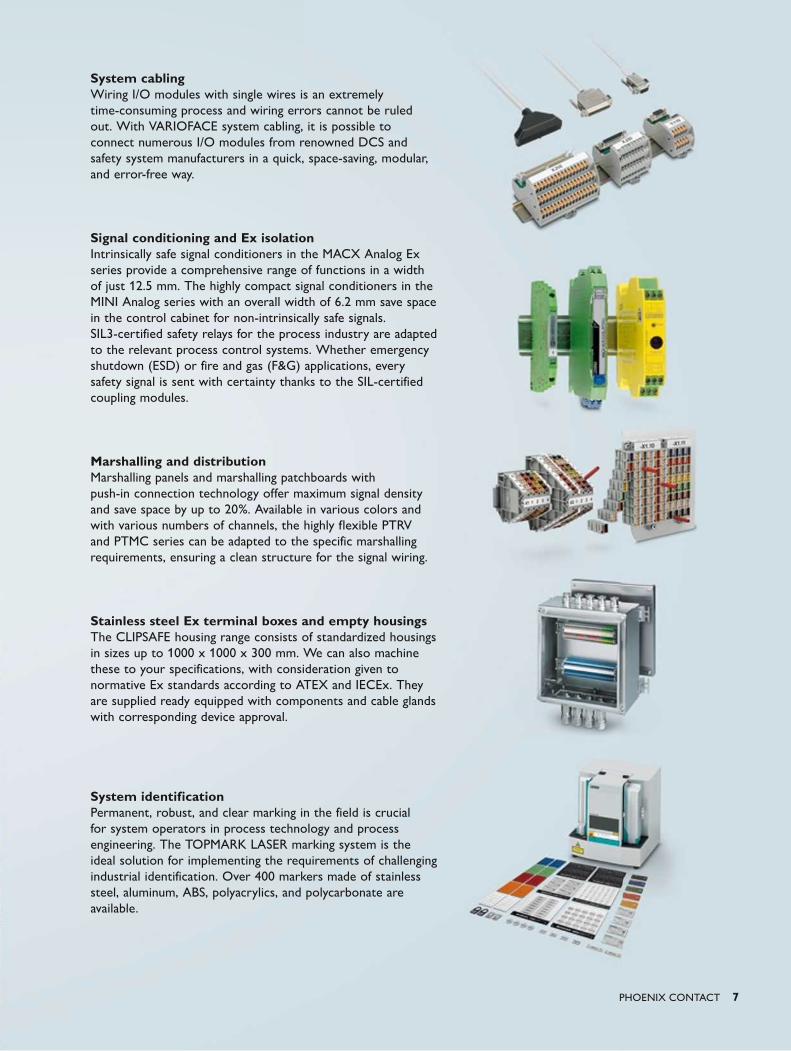
System cablingWiring I/O modules with single wires is an extremely time-consuming process and wiring errors cannot be ruled out. With VARIOFACE system cabling, it is possible to connect numerous I/O modules from renowned DCS and safety system manufacturers in a quick, space-saving, modular, and error-free way.
Signal conditioning and Ex isolationIntrinsically safe signal conditioners in the MACX Analog Ex series provide a comprehensive range of functions in a width of just 12.5 mm. The highly compact signal conditioners in the MINI Analog series with an overall width of 6.2 mm save space in the control cabinet for non-intrinsically safe signals.SIL3-certified safety relays for the process industry are adapted to the relevant process control systems. Whether emergency shutdown (ESD) or fire and gas (F&G) applications, every safety signal is sent with certainty thanks to the SIL-certified coupling modules.
Marshalling and distributionMarshalling panels and marshalling patchboards with push-in connection technology offer maximum signal density and save space by up to 20%. Available in various colors and with various numbers of channels, the highly flexible PTRV and PTMC series can be adapted to the specific marshalling requirements, ensuring a clean structure for the signal wiring.
Stainless steel Ex terminal boxes and empty housingsThe CLIPSAFE housing range consists of standardized housings in sizes up to 1000 x 1000 x 300 mm. We can also machine these to your specifications, with consideration given to normative Ex standards according to ATEX and IECEx. They are supplied ready equipped with components and cable glands with corresponding device approval.
System identificationPermanent, robust, and clear marking in the field is crucial for system operators in process technology and process engineering. The TOPMARK LASER marking system is the ideal solution for implementing the requirements of challenging industrial identification. Over 400 markers made of stainless steel, aluminum, ABS, polyacrylics, and polycarbonate are available.

8 PHOENIX CONTACT
Standardization of processes and communication (bus)
Process communication in large process
systems is becoming ever more complex.
In order to meet customer requirements
and make process sequences more clear
and more transparent, various options
are available. We have helped shape the
following trends and offer components and
solutions that enable us to support you
when facing these particular challenges.
Linking to modern communication media Due to the complexity of modern-day systems, it is often no longer possible for end customers to carry out maintenance and diagnostics. As a result, maintenance and system upgrades can only be performed by suppliers. In order to make this process more customer friendly, there is a growing need to find systems that are clearer and easier to use. Apps & Co. or Windows-based systems offer new opportunities here.
Asset management (predictive maintenance)Unplanned system downtimes result in high costs and can be life-threatening. The early detection of errors and critical system states is therefore crucial in the process industry. In order to increase system availability and keep maintenance costs as low as possible, there is a growing trend towards permanent diagnostics for system control. In the event of an error message, maintenance can then be performed quickly and reliably.
Industrial securityPipelines or distributed systems sometimes have to be controlled, diagnosed, and maintained remotely over long distances. The security of the signals provided must be ensured in order to avoid failures, for example, due to sabotage. Industrial security is therefore a trend topic.
PHOENIX CONTACT 9
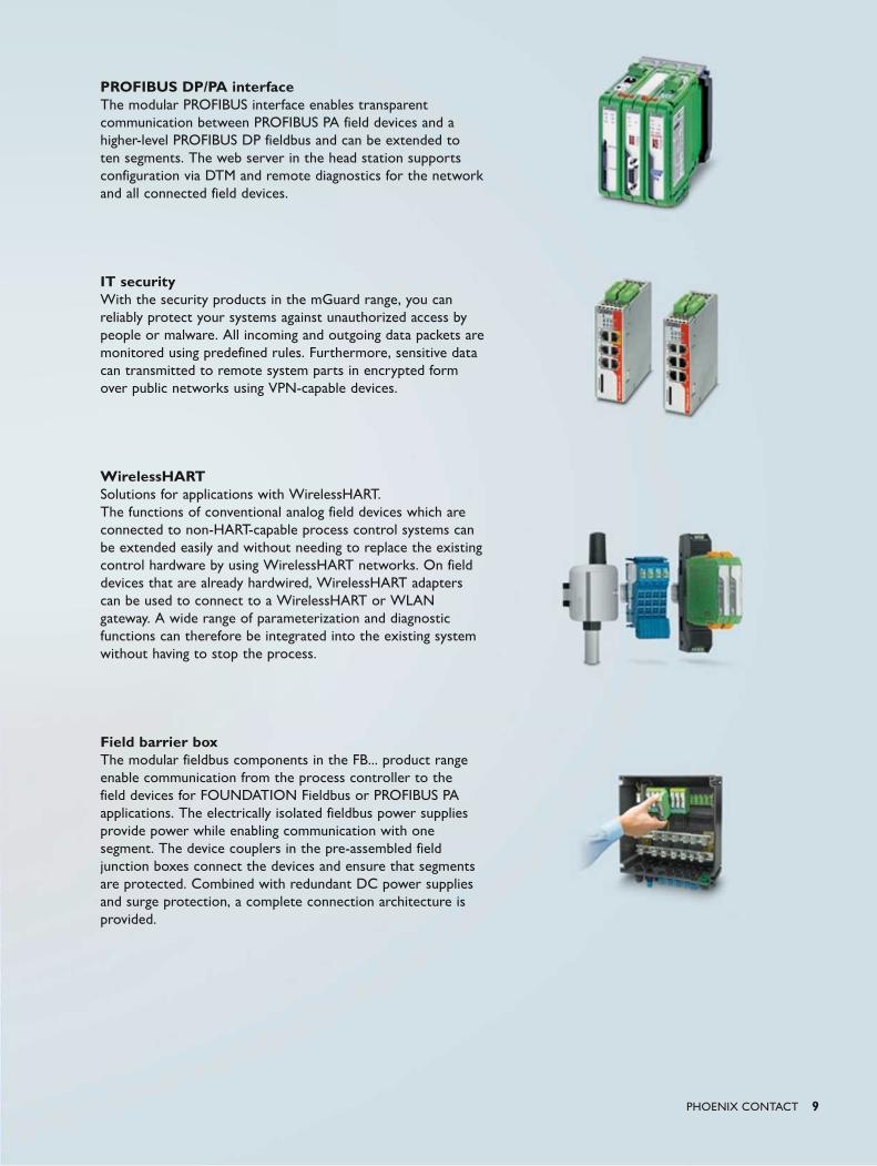
PROFIBUS DP/PA interfaceThe modular PROFIBUS interface enables transparent communication between PROFIBUS PA field devices and a higher-level PROFIBUS DP fieldbus and can be extended to ten segments. The web server in the head station supports configuration via DTM and remote diagnostics for the network and all connected field devices.
IT securityWith the security products in the mGuard range, you can reliably protect your systems against unauthorized access by people or malware. All incoming and outgoing data packets are monitored using predefined rules. Furthermore, sensitive data can transmitted to remote system parts in encrypted form over public networks using VPN-capable devices.
WirelessHARTSolutions for applications with WirelessHART. The functions of conventional analog field devices which are connected to non-HART-capable process control systems can be extended easily and without needing to replace the existing control hardware by using WirelessHART networks. On field devices that are already hardwired, WirelessHART adapters can be used to connect to a WirelessHART or WLAN gateway. A wide range of parameterization and diagnostic functions can therefore be integrated into the existing system without having to stop the process.
Field barrier boxThe modular fieldbus components in the FB... product range enable communication from the process controller to the field devices for FOUNDATION Fieldbus or PROFIBUS PA applications. The electrically isolated fieldbus power supplies provide power while enabling communication with one segment. The device couplers in the pre-assembled field junction boxes connect the devices and ensure that segments are protected. Combined with redundant DC power supplies and surge protection, a complete connection architecture is provided.

10 PHOENIX CONTACT
Energy efficiency
Climate protection programs and increasing
environmental requirements imposed by
countries also affect the process industry.
In future, system revamps and expansions
will have to observe these requirements
and laws. Recycling and energy efficiency
are also becoming an increasingly important
area of focus for system operators. They
play an important role, particularly for large
system operators. The aim is to analyze
which systems use the most energy, to
monitor these systems constantly, and to
minimize usage through new technologies
such as heat use, waste heat recovery or
alternative energies. The use of the right
form of energy at the right time and the
comparison of energy costs with planned
figures is key. At Phoenix Contact, we
have helped shape these requirements and
trends and offer components and solutions
that enable us to support you as a partner
when facing these particular challenges.
PHOENIX CONTACT 11
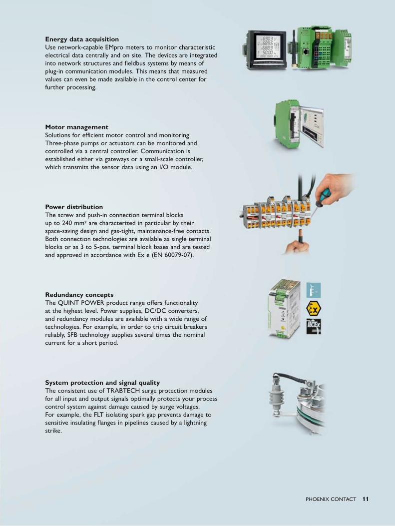
Energy data acquisitionUse network-capable EMpro meters to monitor characteristic electrical data centrally and on site. The devices are integrated into network structures and fieldbus systems by means of plug-in communication modules. This means that measured values can even be made available in the control center for further processing.
Motor managementSolutions for efficient motor control and monitoring Three-phase pumps or actuators can be monitored and controlled via a central controller. Communication is established either via gateways or a small-scale controller, which transmits the sensor data using an I/O module.
Power distributionThe screw and push-in connection terminal blocks up to 240 mm2 are characterized in particular by their space-saving design and gas-tight, maintenance-free contacts. Both connection technologies are available as single terminal blocks or as 3 to 5-pos. terminal block bases and are tested and approved in accordance with Ex e (EN 60079-07).
Redundancy conceptsThe QUINT POWER product range offers functionality at the highest level. Power supplies, DC/DC converters, and redundancy modules are available with a wide range of technologies. For example, in order to trip circuit breakers reliably, SFB technology supplies several times the nominal current for a short period.
System protection and signal qualityThe consistent use of TRABTECH surge protection modules for all input and output signals optimally protects your process control system against damage caused by surge voltages. For example, the FLT isolating spark gap prevents damage to sensitive insulating flanges in pipelines caused by a lightning strike.

12 PHOENIX CONTACT
A lack of personnel or poorly trained
personnel often leads to failures in process
engineering systems. In order to guarantee
system availability, system operators
are increasingly focusing on education
and training for their staff. In addition
to explosion protection and functional
safety, the proper handling of products,
technologies, and systems, including in the
event of an error, is taught. In addition to
face-to-face presentations, virtual training
is also available online, via Webex or
on simulators. At Phoenix Contact, we
have helped shape this trend and offer
training covering all aspects of standards
and technologies, as well as products and
solutions that enable us to support you
when facing these particular challenges.
Training

PHOENIX CONTACT 13
Ex protection and intrinsic safetyExplosion protection is an important topic for a growing number of systems. However, the requirements of the Ex directive present a real challenge for many operators and users. Our seminar on the basics, which is aimed at beginners, provides you with the necessary knowledge required for explosion protection and intrinsic safety.
Functional safetyDo you require specialist knowledge about a specific topic in the field of functional safety? And do you want to set the place and time for the seminar? Then contact us for more information. We are, of course, happy to offer advanced seminars on machine safety and the safety lifecycle on an individual basis.
Secure remote maintenance via the InternetThe practical workshop provides an easy introduction to remote maintenance via the Internet. In our full-day workshop, you will get a detailed overview of the basic principles with the aid of practical examples and exercises. Step by step you work on the basic functions of an item of safety equipment and find out about secure remote maintenance using VPN connections. A connection is established between a service technician and a remote station as an example. This connection is established via the UMTS mobile communication network and the Internet. We use mobile communication and mGuard VPN routers in practical exercises. Afterwards, you will receive the configuration files that were developed during the workshop and you can use these files and adapt them to your environment.
Additional seminarsBenefit from our knowledge – from the basic principles to specialist know-how. We will give you the skills you need in a variety of additional seminars.
14 PHOENIX CONTACT
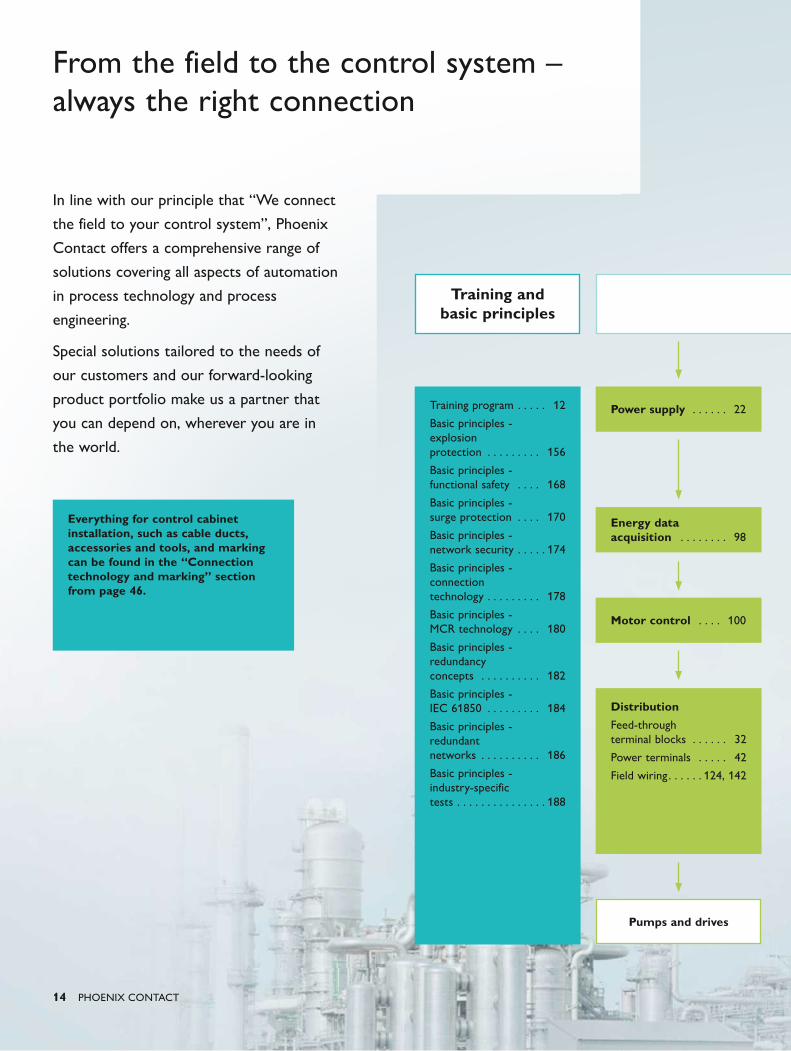
In line with our principle that “We connect
the field to your control system”, Phoenix
Contact offers a comprehensive range of
solutions covering all aspects of automation
in process technology and process
engineering.
Special solutions tailored to the needs of
our customers and our forward-looking
product portfolio make us a partner that
you can depend on, wherever you are in
the world.
From the field to the control system – always the right connection
Everything for control cabinet installation, such as cable ducts, accessories and tools, and marking can be found in the “Connection technology and marking” section from page 46.
Training andbasic principles
Training program . . . . . 12
Basic principles - explosion protection . . . . . . . . . 156
Basic principles - functional safety . . . . 168
Basic principles - surge protection . . . . 170
Basic principles - network security . . . . . 174
Basic principles - connection technology . . . . . . . . . 178
Basic principles - MCR technology . . . . 180
Basic principles - redundancy concepts . . . . . . . . . . 182
Basic principles - IEC 61850 . . . . . . . . . 184
Basic principles - redundant networks . . . . . . . . . . 186
Basic principles - industry-specific tests . . . . . . . . . . . . . . . 188
Distribution
Feed-through terminal blocks . . . . . . 32
Power terminals . . . . . 42
Field wiring . . . . . . 124, 142
Energy data acquisition . . . . . . . . 98
Power supply . . . . . . 22
Motor control . . . . 100
Pumps and drives
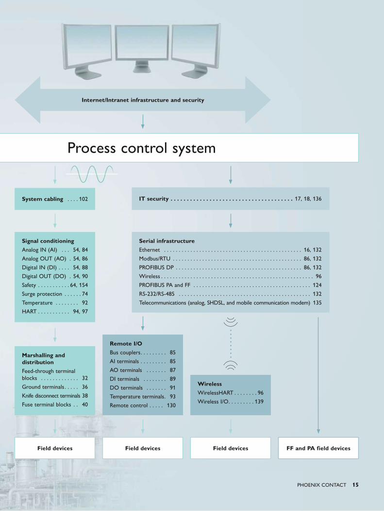
PHOENIX CONTACT 15
Internet/Intranet infrastructure and security
Process control system
System cabling . . . . 102 IT security . . . . . . . . . . . . . . . . . . . . . . . . . . . . . . . . . . . . . . 17, 18, 136
Signal conditioning
Analog IN (AI) . . . 54, 84
Analog OUT (AO) . 54, 86
Digital IN (DI) . . . . 54, 88
Digital OUT (DO) . 54, 90
Safety . . . . . . . . . . . 64, 154
Surge protection . . . . . . 74
Temperature . . . . . . . . 92
HART . . . . . . . . . . . 94, 97
Serial infrastructure
Ethernet . . . . . . . . . . . . . . . . . . . . . . . . . . . . . . . . . . . . . . . . . . . . . . . 16, 132
Modbus/RTU . . . . . . . . . . . . . . . . . . . . . . . . . . . . . . . . . . . . . . . . . . . . 86, 132
PROFIBUS DP . . . . . . . . . . . . . . . . . . . . . . . . . . . . . . . . . . . . . . . . . . . 86, 132
Wireless . . . . . . . . . . . . . . . . . . . . . . . . . . . . . . . . . . . . . . . . . . . . . . . . . . . . 96
PROFIBUS PA and FF . . . . . . . . . . . . . . . . . . . . . . . . . . . . . . . . . . . . . . . . 124
RS-232/RS-485 . . . . . . . . . . . . . . . . . . . . . . . . . . . . . . . . . . . . . . . . . . . . . 132
Telecommunications (analog, SHDSL, and mobile communication modem) 135
Marshalling and distribution
Feed-through terminal blocks . . . . . . . . . . . . . 32
Ground terminals . . . . . 36
Knife disconnect terminals 38
Fuse terminal blocks . . 40
Remote I/O
Bus couplers . . . . . . . . . 85
AI terminals . . . . . . . . . 85
AO terminals . . . . . . . 87
DI terminals . . . . . . . . 89
DO terminals . . . . . . . 91
Temperature terminals . 93
Remote control . . . . . 130
Wireless
WirelessHART . . . . . . . . 96
Wireless I/O . . . . . . . . . 139
Field devicesField devices FF and PA field devicesField devices

16 PHOENIX CONTACT
In order to be able to make well-founded
decisions, you need all the relevant
information at your fingertips. This
necessitates a company-wide uniform
communication system, from the Production
Department to the Company Management.
Furthermore, it has never been more
important to ensure that you have adequate
protection against unauthorized access by
people or malware across the entire
network. Phoenix Contact provides an
infrastructure suitable for industrial
applications and with the required approvals
for the stringent requirements of the
process industry. In addition to the TCP/IP
protocol, PROFINET, Fieldbus FF HSE, and
EtherNet/IP™ are also used as industrial
communication protocols today.
Industrial Ethernet Consistent communication increases productivity
Suitable for industrial applicationsOur hardware and software components combine the network functions of the IT world with the special requirements of industrial automation. They are characterized by the following features:
• Easy, automation-typical handling
• Support of various topologies and transmission media
• Optimum time response with high data throughput
• Comprehensive diagnostic features
• High immunity to mechanical strain, electromagnetic interference, vibration, and shock
• Extended temperature range
PHOENIX CONTACT 17
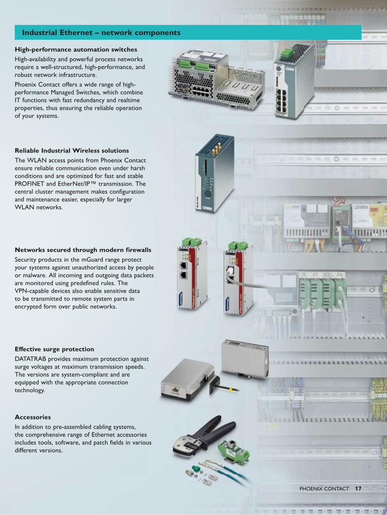
High-performance automation switchesHigh-availability and powerful process networks require a well-structured, high-performance, and robust network infrastructure.
Phoenix Contact offers a wide range of high-performance Managed Switches, which combine IT functions with fast redundancy and realtime properties, thus ensuring the reliable operation of your systems.
Reliable Industrial Wireless solutionsThe WLAN access points from Phoenix Contact ensure reliable communication even under harsh conditions and are optimized for fast and stable PROFINET and EtherNet/IP™ transmission. The central cluster management makes configuration and maintenance easier, especially for larger WLAN networks.
Networks secured through modern firewallsSecurity products in the mGuard range protect your systems against unauthorized access by people or malware. All incoming and outgoing data packets are monitored using predefined rules. The VPN-capable devices also enable sensitive data to be transmitted to remote system parts in encrypted form over public networks.
Effective surge protectionDATATRAB provides maximum protection against surge voltages at maximum transmission speeds. The versions are system-compliant and are equipped with the appropriate connection technology.
AccessoriesIn addition to pre-assembled cabling systems, the comprehensive range of Ethernet accessories includes tools, software, and patch fields in various different versions.
Industrial Ethernet – network components
18 PHOENIX CONTACT
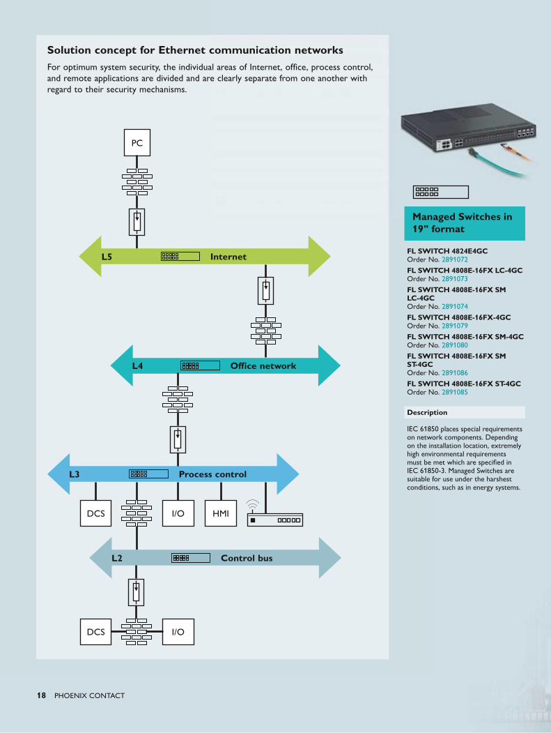
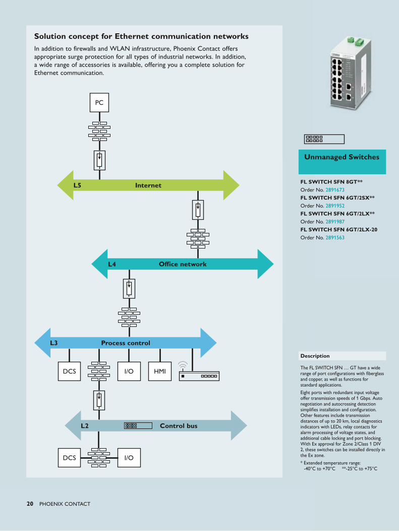
Solution concept for Ethernet communication networksFor optimum system security, the individual areas of Internet, office, process control, and remote applications are divided and are clearly separate from one another with regard to their security mechanisms.
PC
L5 Internet
L4 Office network
L3 Process control
L2 Control bus
DCS
DCS
I/O
I/O
HMI
Managed Switches in 19" format
FL SWITCH 4824E4GC Order No. 2891072
FL SWITCH 4808E-16FX LC-4GC Order No. 2891073
FL SWITCH 4808E-16FX SM LC-4GC Order No. 2891074
FL SWITCH 4808E-16FX-4GC Order No. 2891079
FL SWITCH 4808E-16FX SM-4GC Order No. 2891080
FL SWITCH 4808E-16FX SM ST-4GC Order No. 2891086
FL SWITCH 4808E-16FX ST-4GC Order No. 2891085
Description
IEC 61850 places special requirements on network components. Depending on the installation location, extremely high environmental requirements must be met which are specified in IEC 61850-3. Managed Switches are suitable for use under the harshest conditions, such as in energy systems.
PHOENIX CONTACT 19
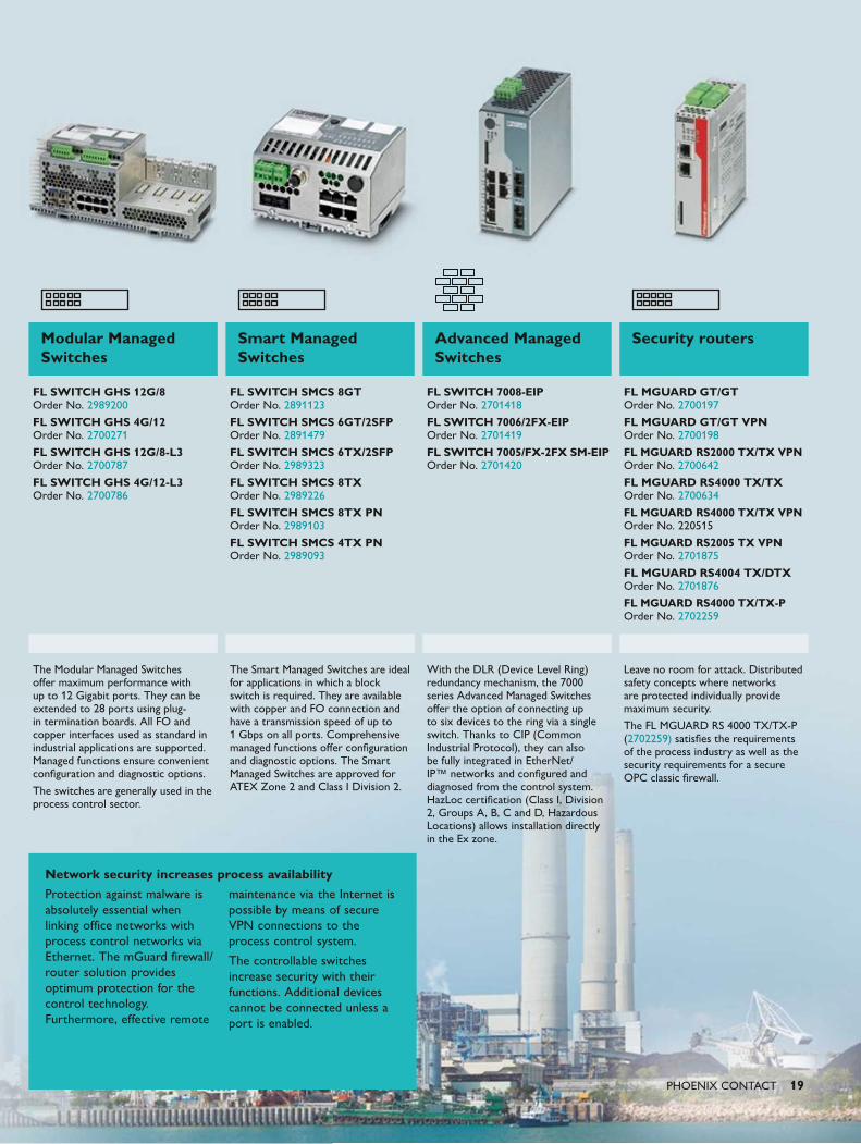
Modular Managed Switches
Smart Managed Switches
Advanced Managed Switches
Security routers
FL SWITCH GHS 12G/8 Order No. 2989200
FL SWITCH GHS 4G/12 Order No. 2700271
FL SWITCH GHS 12G/8-L3 Order No. 2700787
FL SWITCH GHS 4G/12-L3 Order No. 2700786
FL SWITCH SMCS 8GT Order No. 2891123
FL SWITCH SMCS 6GT/2SFP Order No. 2891479
FL SWITCH SMCS 6TX/2SFP Order No. 2989323
FL SWITCH SMCS 8TX Order No. 2989226
FL SWITCH SMCS 8TX PN Order No. 2989103
FL SWITCH SMCS 4TX PN Order No. 2989093
FL SWITCH 7008-EIP Order No. 2701418
FL SWITCH 7006/2FX-EIP Order No. 2701419
FL SWITCH 7005/FX-2FX SM-EIP Order No. 2701420
FL MGUARD GT/GT Order No. 2700197
FL MGUARD GT/GT VPN Order No. 2700198
FL MGUARD RS2000 TX/TX VPN Order No. 2700642
FL MGUARD RS4000 TX/TX Order No. 2700634
FL MGUARD RS4000 TX/TX VPN Order No. 220515
FL MGUARD RS2005 TX VPN Order No. 2701875
FL MGUARD RS4004 TX/DTX Order No. 2701876
FL MGUARD RS4000 TX/TX-P Order No. 2702259
The Modular Managed Switches offer maximum performance with up to 12 Gigabit ports. They can be extended to 28 ports using plug-in termination boards. All FO and copper interfaces used as standard in industrial applications are supported. Managed functions ensure convenient configuration and diagnostic options.
The switches are generally used in the process control sector.
The Smart Managed Switches are ideal for applications in which a block switch is required. They are available with copper and FO connection and have a transmission speed of up to 1 Gbps on all ports. Comprehensive managed functions offer configuration and diagnostic options. The Smart Managed Switches are approved for ATEX Zone 2 and Class I Division 2.
With the DLR (Device Level Ring) redundancy mechanism, the 7000 series Advanced Managed Switches offer the option of connecting up to six devices to the ring via a single switch. Thanks to CIP (Common Industrial Protocol), they can also be fully integrated in EtherNet/IP™ networks and configured and diagnosed from the control system. HazLoc certification (Class I, Division 2, Groups A, B, C and D, Hazardous Locations) allows installation directly in the Ex zone.
Leave no room for attack. Distributed safety concepts where networks are protected individually provide maximum security.
The FL MGUARD RS 4000 TX/TX-P (2702259) satisfies the requirements of the process industry as well as the security requirements for a secure OPC classic firewall.
Network security increases process availability
Protection against malware is absolutely essential when linking office networks with process control networks via Ethernet. The mGuard firewall/router solution provides optimum protection for the control technology. Furthermore, effective remote
maintenance via the Internet is possible by means of secure VPN connections to the process control system.
The controllable switches increase security with their functions. Additional devices cannot be connected unless a port is enabled.
20 PHOENIX CONTACT
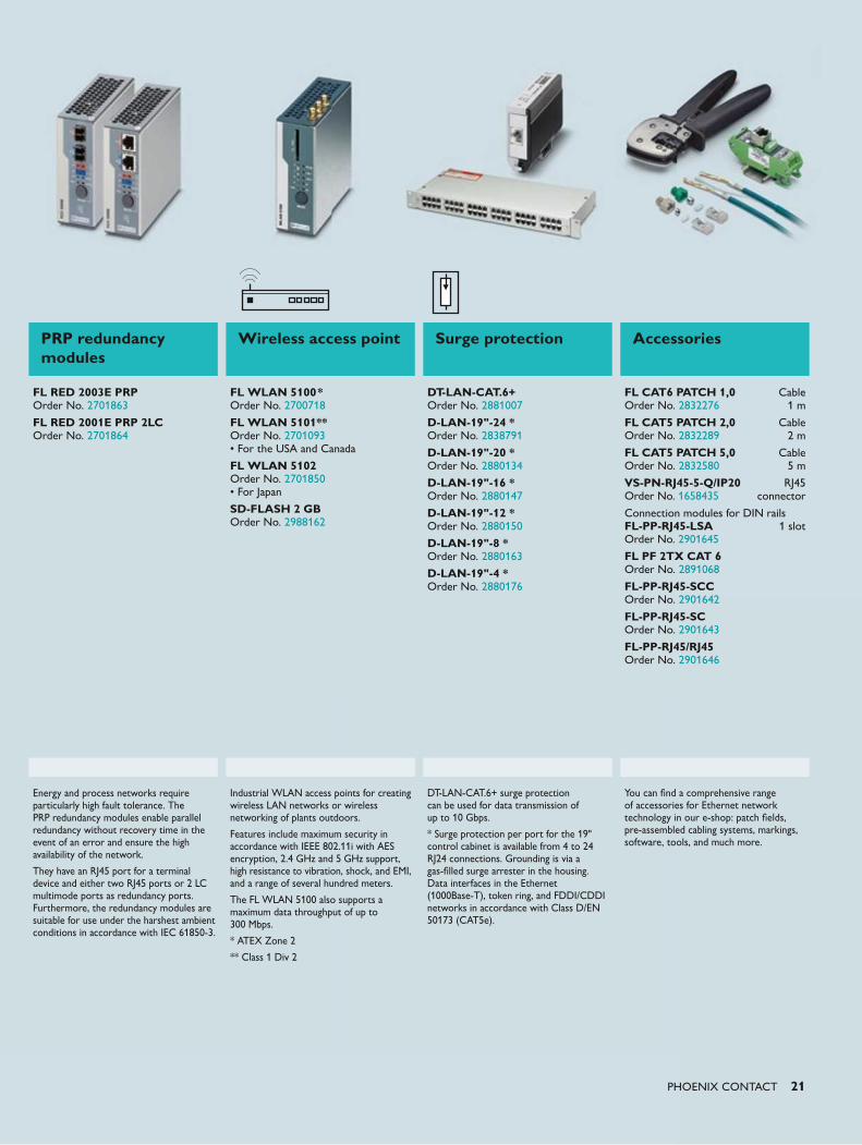
Solution concept for Ethernet communication networksIn addition to firewalls and WLAN infrastructure, Phoenix Contact offers appropriate surge protection for all types of industrial networks. In addition, a wide range of accessories is available, offering you a complete solution for Ethernet communication.
PC
L5
L4
L3
Internet
Office network
Process control
DCS I/O HMI
DCS I/O
L2 Control bus
Unmanaged Switches
FL SWITCH SFN 8GT**Order No. 2891673
FL SWITCH SFN 6GT/2SX**Order No. 2891952
FL SWITCH SFN 6GT/2LX**Order No. 2891987
FL SWITCH SFN 6GT/2LX-20Order No. 2891563
Description
The FL SWITCH SFN … GT have a wide range of port configurations with fiberglass and copper, as well as functions for standard applications.
Eight ports with redundant input voltage offer transmission speeds of 1 Gbps. Auto negotiation and autocrossing detection simplifies installation and configuration. Other features include transmission distances of up to 20 km, local diagnostics indicators with LEDs, relay contacts for alarm processing of voltage states, and additional cable locking and port blocking. With Ex approval for Zone 2/Class 1 DIV 2, these switches can be installed directly in the Ex zone.
* Extended temperature range: -40°C to +70°C **-25°C to +75°C
PHOENIX CONTACT 21
PRP redundancy modules
Wireless access point Surge protection Accessories
FL RED 2003E PRP Order No. 2701863
FL RED 2001E PRP 2LC Order No. 2701864
FL WLAN 5100* Order No. 2700718
FL WLAN 5101** Order No. 2701093 • For the USA and Canada
FL WLAN 5102 Order No. 2701850 • For Japan
SD-FLASH 2 GB Order No. 2988162
DT-LAN-CAT.6+ Order No. 2881007
D-LAN-19"-24 * Order No. 2838791
D-LAN-19"-20 * Order No. 2880134
D-LAN-19"-16 * Order No. 2880147
D-LAN-19"-12 * Order No. 2880150
D-LAN-19"-8 * Order No. 2880163
D-LAN-19"-4 * Order No. 2880176
FL CAT6 PATCH 1,0 Cable Order No. 2832276 1 m
FL CAT5 PATCH 2,0 Cable Order No. 2832289 2 m
FL CAT5 PATCH 5,0 Cable Order No. 2832580 5 m
VS-PN-RJ45-5-Q/IP20 RJ45 Order No. 1658435 connector
Connection modules for DIN rails FL-PP-RJ45-LSA 1 slot Order No. 2901645
FL PF 2TX CAT 6 Order No. 2891068
FL-PP-RJ45-SCC Order No. 2901642
FL-PP-RJ45-SC Order No. 2901643
FL-PP-RJ45/RJ45 Order No. 2901646
Energy and process networks require particularly high fault tolerance. The PRP redundancy modules enable parallel redundancy without recovery time in the event of an error and ensure the high availability of the network.
They have an RJ45 port for a terminal device and either two RJ45 ports or 2 LC multimode ports as redundancy ports. Furthermore, the redundancy modules are suitable for use under the harshest ambient conditions in accordance with IEC 61850-3.
Industrial WLAN access points for creating wireless LAN networks or wireless networking of plants outdoors.
Features include maximum security in accordance with IEEE 802.11i with AES encryption, 2.4 GHz and 5 GHz support, high resistance to vibration, shock, and EMI, and a range of several hundred meters.
The FL WLAN 5100 also supports a maximum data throughput of up to 300 Mbps.
* ATEX Zone 2
** Class 1 Div 2
DT-LAN-CAT.6+ surge protection can be used for data transmission of up to 10 Gbps.
* Surge protection per port for the 19" control cabinet is available from 4 to 24 RJ24 connections. Grounding is via a gas-filled surge arrester in the housing. Data interfaces in the Ethernet (1000Base-T), token ring, and FDDI/CDDI networks in accordance with Class D/EN 50173 (CAT5e).
You can find a comprehensive range of accessories for Ethernet network technology in our e-shop: patch fields, pre-assembled cabling systems, markings, software, tools, and much more.

22 PHOENIX CONTACT
The QUINT POWER product range offers
functionality at the highest level:
Power supplies and DC/DC converters with
SFB technology reliably switch off faulty
current paths in the event of a short circuit.
Other loads continue to be supplied without
any interruption.
Uninterruptible power supplies with
IQ technology calculate the current life
expectancy of the power storage and
supply the loads with optimum utilization of
battery.
Redundancy modules with ACB technology
double the service life of a redundant power
supply.
Power supplies Groundbreaking technology for superior system availability
The reliability of the power supply is becoming increasingly important since the loads supplied in the process industry are particularly sensitive and downtimes are costly. With this in mind, Phoenix Contact offers a consistent product range for maximum availability:
• Reliable supply and cost-effective selective protection with QUINT POWER
• Use intelligent UPS in the control cabinet with QUINT UPS and optimally supply the PC/IPC with power in the event of mains failure, since IQ technology detects, optimizes, and provides information about the power storage
• Reliably monitor the load current of redundant power supplies with QUINT ORING
• Smart combination: two QUINT POWER power supplies combined with a QUINT ORING module limit any surge voltages that occur to 32 V
Push-in TechnologyDesigned by PHOENIX CONTACT
PHOENIX CONTACT 23
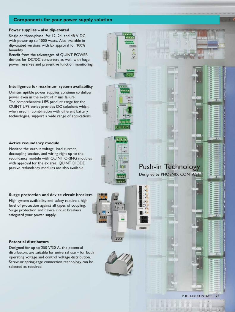
Power supplies – also dip-coatedSingle or three-phase, for 12, 24, and 48 V DC with power up to 1000 watts. Also available in dip-coated versions with Ex approval for 100% humidity. Benefit from the advantages of QUINT POWER devices for DC/DC converters as well: with huge power reserves and preventive function monitoring.
Intelligence for maximum system availabilityUninterruptible power supplies continue to deliver power even in the event of mains failure. The comprehensive UPS product range for the QUINT UPS series provides DC solutions which, when used in combination with different battery technologies, support a wide range of applications.
Active redundancy module Monitor the output voltage, load current, decoupling section, and wiring right up to the redundancy module with QUINT ORING modules with approval for the ex area. QUINT DIODE passive redundancy modules are also available.
Surge protection and device circuit breakersHigh system availability and safety require a high level of protection against all types of coupling. Surge protection and device circuit breakers safeguard your power supply.
Potential distributorsDesigned for up to 250 V/30 A, the potential distributors are suitable for universal use – for both operating voltage and control voltage distribution. Screw or spring-cage connection technology can be selected as required.
Components for your power supply solution
24 PHOENIX CONTACT
Increased availability thanks to parallel operation
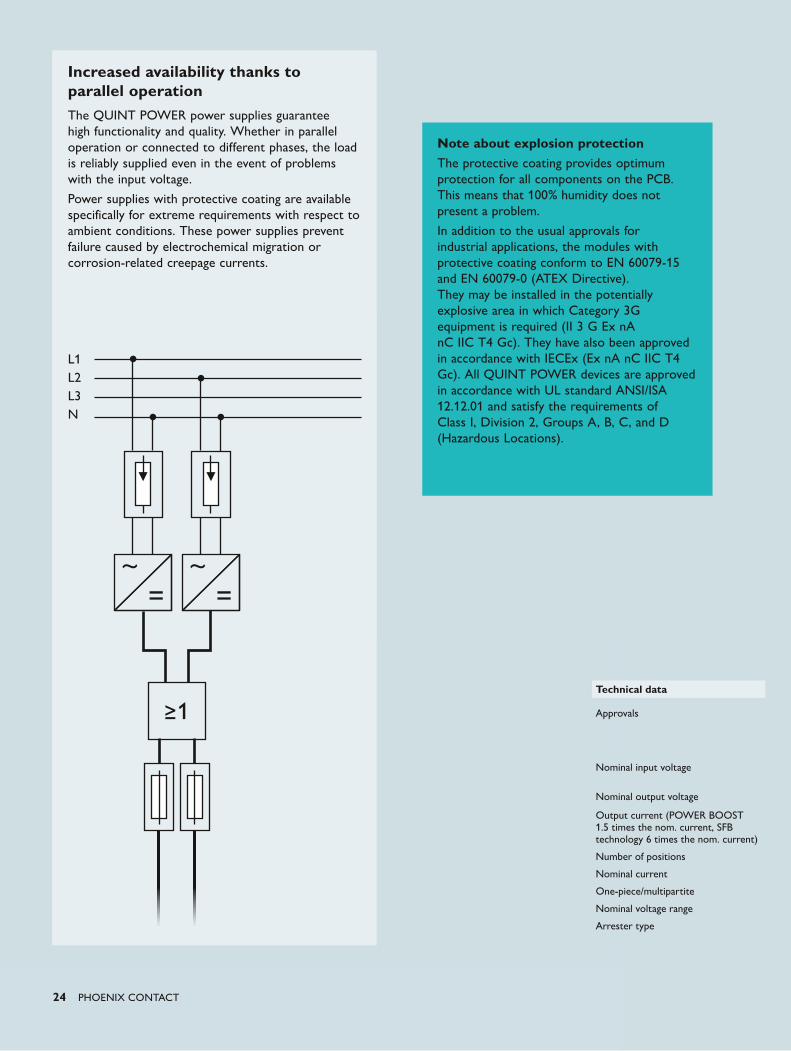
The QUINT POWER power supplies guarantee high functionality and quality. Whether in parallel operation or connected to different phases, the load is reliably supplied even in the event of problems with the input voltage.
Power supplies with protective coating are available specifically for extreme requirements with respect to ambient conditions. These power supplies prevent failure caused by electrochemical migration or corrosion-related creepage currents.
L1L2L3N
≥1
Note about explosion protectionThe protective coating provides optimum protection for all components on the PCB. This means that 100% humidity does not present a problem.
In addition to the usual approvals for industrial applications, the modules with protective coating conform to EN 60079-15 and EN 60079-0 (ATEX Directive). They may be installed in the potentially explosive area in which Category 3G equipment is required (II 3 G Ex nA nC IIC T4 Gc). They have also been approved in accordance with IECEx (Ex nA nC IIC T4 Gc). All QUINT POWER devices are approved in accordance with UL standard ANSI/ISA 12.12.01 and satisfy the requirements of Class I, Division 2, Groups A, B, C, and D (Hazardous Locations).
Technical data
Approvals
Nominal input voltage
Nominal output voltage
Output current (POWER BOOST 1.5 times the nom. current, SFB technology 6 times the nom. current)
Number of positions
Nominal current
One-piece/multipartite
Nominal voltage range
Arrester type
PHOENIX CONTACT 25
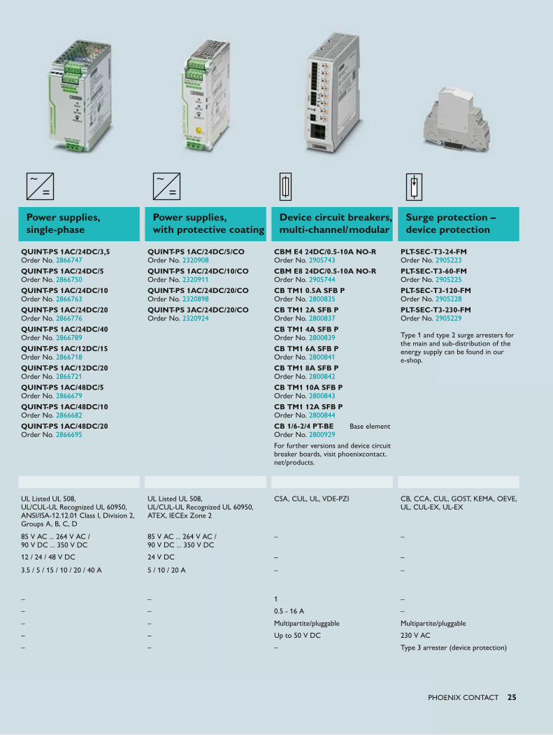
Power supplies, single-phase
Power supplies, with protective coating
Device circuit breakers, multi-channel/modular
Surge protection – device protection
QUINT-PS 1AC/24DC/3,5 Order No. 2866747
QUINT-PS 1AC/24DC/5 Order No. 2866750
QUINT-PS 1AC/24DC/10 Order No. 2866763
QUINT-PS 1AC/24DC/20 Order No. 2866776
QUINT-PS 1AC/24DC/40 Order No. 2866789
QUINT-PS 1AC/12DC/15 Order No. 2866718
QUINT-PS 1AC/12DC/20 Order No. 2866721
QUINT-PS 1AC/48DC/5 Order No. 2866679
QUINT-PS 1AC/48DC/10 Order No. 2866682
QUINT-PS 1AC/48DC/20 Order No. 2866695
QUINT-PS 1AC/24DC/5/CO Order No. 2320908
QUINT-PS 1AC/24DC/10/CO Order No. 2320911
QUINT-PS 1AC/24DC/20/CO Order No. 2320898
QUINT-PS 3AC/24DC/20/CO Order No. 2320924
CBM E4 24DC/0.5-10A NO-R Order No. 2905743
CBM E8 24DC/0.5-10A NO-R Order No. 2905744
CB TM1 0.5A SFB P Order No. 2800835
CB TM1 2A SFB P Order No. 2800837
CB TM1 4A SFB P Order No. 2800839
CB TM1 6A SFB P Order No. 2800841
CB TM1 8A SFB P Order No. 2800842
CB TM1 10A SFB P Order No. 2800843
CB TM1 12A SFB P Order No. 2800844
CB 1/6-2/4 PT-BE Base element Order No. 2800929
For further versions and device circuit breaker boards, visit phoenixcontact.net/products.
PLT-SEC-T3-24-FM Order No. 2905223
PLT-SEC-T3-60-FM Order No. 2905225
PLT-SEC-T3-120-FM Order No. 2905228
PLT-SEC-T3-230-FM Order No. 2905229 Type 1 and type 2 surge arresters for the main and sub-distribution of the energy supply can be found in our e-shop.
UL Listed UL 508, UL/CUL-UL Recognized UL 60950, ANSI/ISA-12.12.01 Class I, Division 2, Groups A, B, C, D
UL Listed UL 508, UL/CUL-UL Recognized UL 60950, ATEX, IECEx Zone 2
CSA, CUL, UL, VDE-PZI
CB, CCA, CUL, GOST, KEMA, OEVE, UL, CUL-EX, UL-EX
85 V AC ... 264 V AC / 90 V DC ... 350 V DC
85 V AC ... 264 V AC / 90 V DC ... 350 V DC
– –
12 / 24 / 48 V DC 24 V DC – –
3.5 / 5 / 15 / 10 / 20 / 40 A
5 / 10 / 20 A
–
–
– – 1 –
– – 0.5 - 16 A –
– – Multipartite/pluggable Multipartite/pluggable
– – Up to 50 V DC 230 V AC
– – – Type 3 arrester (device protection)
26 PHOENIX CONTACT
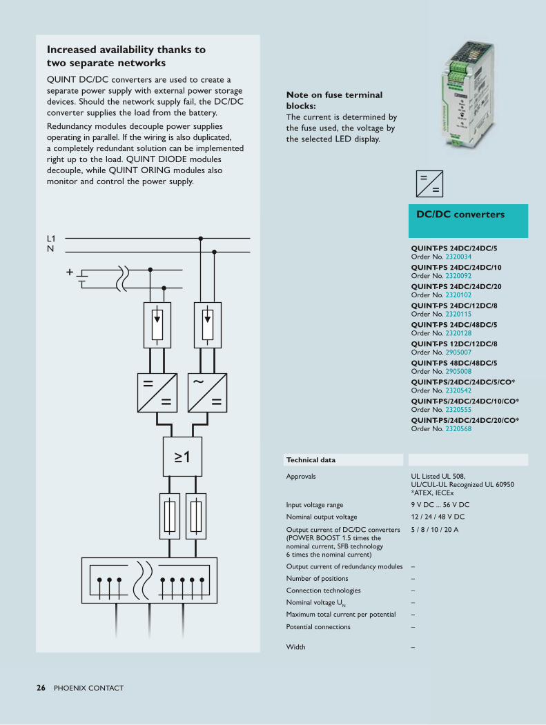
Increased availability thanks to two separate networksQUINT DC/DC converters are used to create a separate power supply with external power storage devices. Should the network supply fail, the DC/DC converter supplies the load from the battery.
Redundancy modules decouple power supplies operating in parallel. If the wiring is also duplicated, a completely redundant solution can be implemented right up to the load. QUINT DIODE modules decouple, while QUINT ORING modules also monitor and control the power supply.
L1N
≥1
DC/DC converters
QUINT-PS 24DC/24DC/5 Order No. 2320034
QUINT-PS 24DC/24DC/10 Order No. 2320092
QUINT-PS 24DC/24DC/20 Order No. 2320102
QUINT-PS 24DC/12DC/8 Order No. 2320115
QUINT-PS 24DC/48DC/5 Order No. 2320128
QUINT-PS 12DC/12DC/8Order No. 2905007
QUINT-PS 48DC/48DC/5Order No. 2905008
QUINT-PS/24DC/24DC/5/CO* Order No. 2320542
QUINT-PS/24DC/24DC/10/CO* Order No. 2320555
QUINT-PS/24DC/24DC/20/CO* Order No. 2320568
Technical data
Approvals
UL Listed UL 508, UL/CUL-UL Recognized UL 60950 *ATEX, IECEx
Input voltage range 9 V DC ... 56 V DC
Nominal output voltage 12 / 24 / 48 V DC
Output current of DC/DC converters (POWER BOOST 1.5 times the nominal current, SFB technology 6 times the nominal current)
5 / 8 / 10 / 20 A
Output current of redundancy modules –
Number of positions –
Connection technologies –
Nominal voltage UN –
Maximum total current per potential –
Potential connections –
Width –
Note on fuse terminal blocks:The current is determined by the fuse used, the voltage by the selected LED display.
PHOENIX CONTACT 27
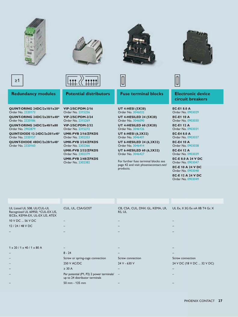
Redundancy modules Potential distributors Fuse terminal blocks Electronic device circuit breakers
QUINT-ORING 24DC/2x10/1x20* Order No. 2320173
QUINT-ORING 24DC/2x20/1x40* Order No. 2320186
QUINT-ORING 24DC/2x40/1x80 Order No. 2902879
QUINT-DIODE 12-24DC/2x20/1x40* Order No. 2320157
QUINT-DIODE 48DC/2x20/1x40* Order No. 2320160
VIP-2/SC/PDM-2/16 Order No. 2315256
VIP-2/SC/PDM-2/24 Order No. 2315269
VIP-2/SC/PDM-2/32 Order No. 2315272
UMK-PVB 2/16/ZFKDS Order No. 2302353
UMK-PVB 2/24/ZFKDS Order No. 2302366
UMK-PVB 2/32/ZFKDS Order No. 2302379
UMK-PVB 2/48/ZFKDS Order No. 2302382
UT 4-HESI (5X20) Order No. 3046032 UT 4-HESILED 24 (5X20) Order No. 3046090 UT 4-HESILED 60 (5X20) Order No. 3046126 UT 6-HESI (6,3X32) Order No. 3046401 UT 6-HESILED 24 (6,3X32) Order No. 3046414 UT 6-HESILED 60 (6,3X32) Order No. 3046427 For further fuse terminal blocks see page 42 and visit phoenixcontact.net/products.
EC-E1 8.0 A Order No. 0903029 EC-E1 10 A Order No. 0903030 EC-E1 12 A Order No. 0903031 EC-E4 8.0 A Order No. 0903037 EC-E4 10 A Order No. 0903038 EC-E4 12 A Order No. 0903039 EC-E 8.0 A 24 V DC Order No. 0903047 EC-E 10 A 24 V DC Order No. 0903048
EC-E 12 A 24 V DC Order No. 0903049
UL Listed UL 508, UL/CUL-UL Recognized UL 60950, *CUL-EX LIS, IECEx, KEMA-EX, UL-EX LIS, ATEX
CUL, UL, CSA/GOST
CB, CSA, CUL, DNV, GL, KEMA, LR, RS, UL
UL Ex, II 3G Ex nA IIB T4 Gc X
10 V DC ... 56 V DC – – –
12 / 24 / 48 V DC – – –
–
–
–
–
1 x 20 / 1 x 40 / 1 x 80 A – – –
– 8 - 24 – –
– Screw or spring-cage connection Screw connection Screw connection
– 250 V AC/DC 24 V - 630 V 24 V DC (18 V DC ... 32 V DC)
– ≥ 30 A – –
– Per potential (P1, P2) 2 power terminals/ up to 24 distributor terminals
– –
– 50 mm - 135 mm – –
1+11+1 1+1
1+1 1+11+1
1+1 1+11+1 1+1 1+1
1+1 1+1 1+1 1+11+1 1+1 1+1 1+1
Service lifeat 20 °C
Buffer time(typical)
Service lifeat 50 °C
h
28 PHOENIX CONTACT
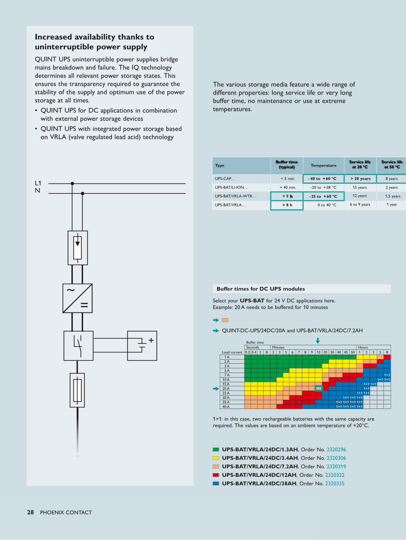
Increased availability thanks to uninterruptible power supplyQUINT UPS uninterruptible power supplies bridge mains breakdown and failure. The IQ technology determines all relevant power storage states. This ensures the transparency required to guarantee the stability of the supply and optimum use of the power storage at all times.
• QUINT UPS for DC applications in combination with external power storage devices
• QUINT UPS with integrated power storage based on VRLA (valve regulated lead acid) technology
L1N
Buffer times for DC UPS modules
Select your UPS-BAT for 24 V DC applications here. Example: 20 A needs to be buffered for 10 minutes
QUINT-DC-UPS/24DC/20A and UPS-BAT/VRLA/24DC/7.2AH
1+1: in this case, two rechargeable batteries with the same capacity are required. The values are based on an ambient temperature of +20°C.
Buffer timeSeconds Minutes Hours
Load current 0.2 0.4 2 8 2 3 5 6 7 8 9 10 20 30 40 45 50 1 2 3 5 81 A2 A3 A5 A7 A
10 A15 A20 A25 A30 A35 A40 A
UPS-BAT/VRLA/24DC/1.3AH, Order No. 2320296
UPS-BAT/VRLA/24DC/3.4AH, Order No. 2320306
UPS-BAT/VRLA/24DC/7.2AH, Order No. 2320319
UPS-BAT/VRLA/24DC/12AH, Order No. 2320322
UPS-BAT/VRLA/24DC/38AH, Order No. 2320335
The various storage media feature a wide range of different properties: long service life or very long buffer time, no maintenance or use at extreme temperatures.
Type
Temperature
UPS-CAP… < 5 min. - 40 to + 60 °C > 20 years
UPS-BAT/LI-ION… > 40 min. - 20 to + 58 °C
15 years
UPS-BAT/VRLA-WTR… > 5 1,5 years
UPS-BAT/VRLA… > 8 h 0 to 40 °C
Service lifeat 20 °C
Buffer time(typical)
Service lifeat 50 °C
6 to 9 years 1 year
2 years
8 years
- 25 to + 60 °C 12 yearsh
Chargingcycles
at 20 °C
Weight(standardized)
PHOENIX CONTACT 29
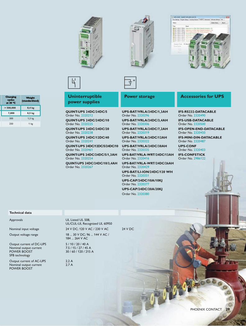
Uninterruptible power supplies
Power storage Accessories for UPS
QUINT-UPS 24DC/24DC/5 Order No. 2320212
QUINT-UPS 24DC/24DC/10 Order No. 2320225 QUINT-UPS 24DC/24DC/20 Order No. 2320238
QUINT-UPS 24DC/12DC/40 Order No. 2320241
QUINT-UPS 24DC/12DC/5/24DC/10 Order No. 2320461
QUINT-UPS 24DC/24DC/5/1,3AH Order No. 2320254
QUINT-UPS 24DC/24DC/10/3,4AH Order No. 2320267
UPS-BAT/VRLA/24DC/1,3AH Order No. 2320296
UPS-BAT/VRLA/24DC/3,4AH Order No. 2320306 UPS-BAT/VRLA/24DC/7,2AH Order No. 2320319
UPS-BAT/VRLA/24DC/12AH Order No. 2320322
UPS-BAT/VRLA/24DC/38AH Order No. 2320335
UPS-BAT/VRLA-WRT/24DC/13AH Order No. 2320416
UPS-BAT/VRLA-WRT/24DC/26AH Order No. 2320429
UPS-BAT/LI-ION/24DC/120 WH Order No. 2320351
UPS-CAP/24DC/10A/10KJ Order No. 2320377
UPS-CAP/24DC/20A/20KJOrder No. 2320380
IFS-RS232-DATACABLE Order No. 2320490
IFS-USB-DATACABLE Order No. 2320500
IFS-OPEN-END-DATACABLE Order No. 2320450
IFS-MINI-DIN-DATACABLE Order No. 2320487 UPS-CONF Order No. 2320403
IFS-CONFSTICK Order No. 2986122
Technical data
Approvals UL Listed UL 508, UL/CUL-UL Recognized UL 60950
Nominal input voltage 24 V DC; 120 V AC / 230 V AC 24 V DC
Output voltage range 18 ... 30 V DC; 96 ... 144 V AC / 184 ... 264 V AC
Output current of DC-UPS Nominal output current POWER BOOST SFB technology
5 / 10 / 20 / 40 A 7.5 / 15 / 27 / 45 A 30 / 60 / 120 / 215 A
Output current of AC-UPS Nominal output current POWER BOOST
2.2 A 2.7 A
> 500,000 0,4 kg
7,000 0,5 kg
300 1,3 kg
250 1 kg
Chargingcycles
at 20 °C
Weight(standardized)
Push-in TechnologyDesigned by PHOENIX CONTACT
30 PHOENIX CONTACT
With the unique terminal block system
from Phoenix Contact, the user is free to
choose the connection technology. Whether
you opt for screw, spring-cage, push-in or
fast connection technology, all of these
connection technologies can be freely
combined with each other using the same
accessories thanks to the double bridge shaft
and are tested in accordance with NE 95.
Optimize all of the processes involved in the
setup, installation, and maintenance of your
control cabinets and systems in the field.
We can help you achieve this with optimally
coordinated products from our marking,
tool, and mounting material ranges.
Connection technology and marking
CLIP PROJECTFor detailed information on CLIP PROJECT planning and marking software as well as our value added services, see from page 142.
PHOENIX CONTACT 31
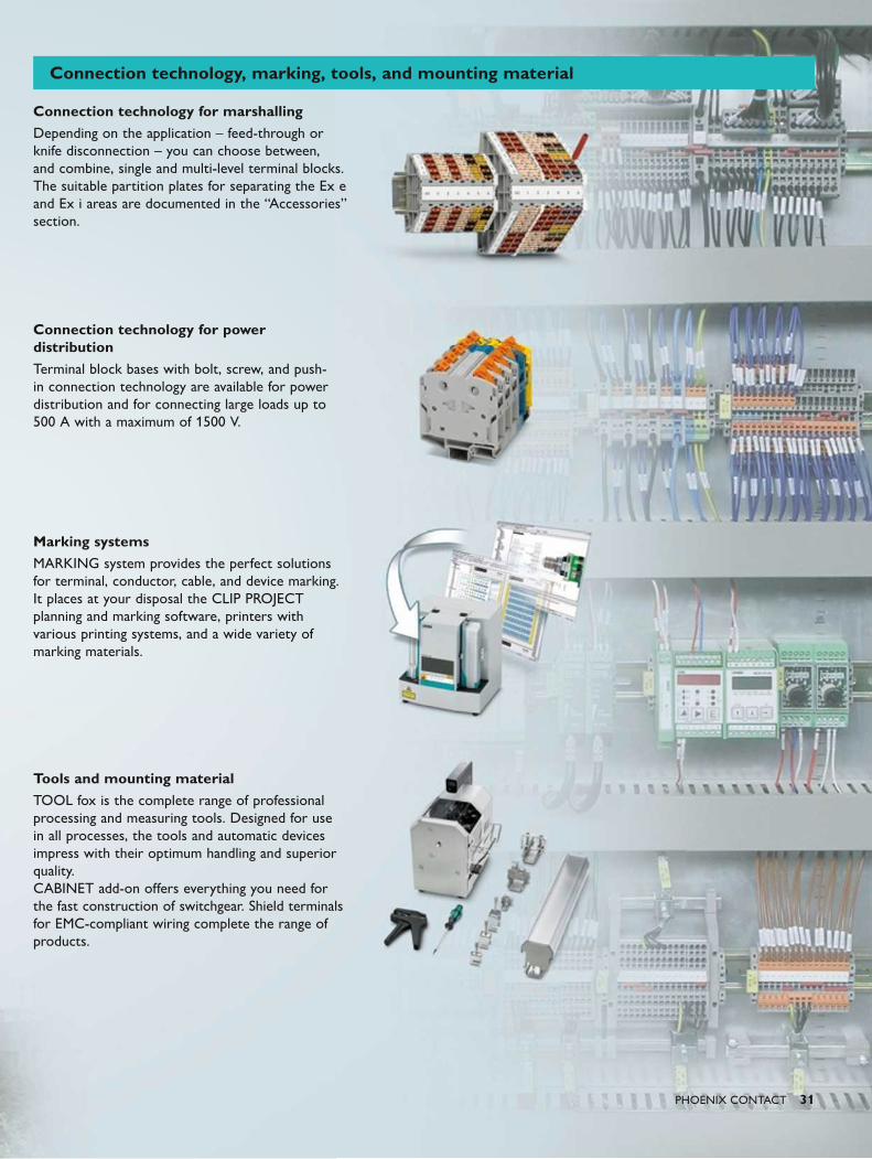
Connection technology for marshallingDepending on the application – feed-through or knife disconnection – you can choose between, and combine, single and multi-level terminal blocks. The suitable partition plates for separating the Ex e and Ex i areas are documented in the “Accessories” section.
Connection technology for power distributionTerminal block bases with bolt, screw, and push-in connection technology are available for power distribution and for connecting large loads up to 500 A with a maximum of 1500 V.
Marking systemsMARKING system provides the perfect solutions for terminal, conductor, cable, and device marking. It places at your disposal the CLIP PROJECT planning and marking software, printers with various printing systems, and a wide variety of marking materials.
Tools and mounting materialTOOL fox is the complete range of professional processing and measuring tools. Designed for use in all processes, the tools and automatic devices impress with their optimum handling and superior quality. CABINET add-on offers everything you need for the fast construction of switchgear. Shield terminals for EMC-compliant wiring complete the range of products.
Connection technology, marking, tools, and mounting material
32 PHOENIX CONTACT
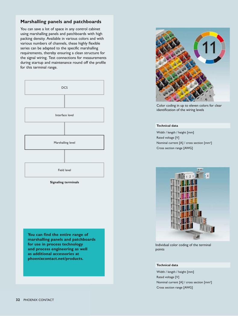
DCS
Interface level
Signaling terminals
Marshalling level
Field level
Individual color coding of the terminal points
Technical data
Width / length / height [mm]
Rated voltage [V]
Nominal current [A] / cross section [mm2]
Cross section range [AWG]
Color coding in up to eleven colors for clear identification of the wiring levels
Technical data
Width / length / height [mm]
Rated voltage [V]
Nominal current [A] / cross section [mm2]
Cross section range [AWG]
Marshalling panels and patchboardsYou can save a lot of space in any control cabinet using marshalling panels and patchboards with high packing density. Available in various colors and with various numbers of channels, these highly flexible series can be adapted to the specific marshalling requirements, thereby ensuring a clean structure for the signal wiring. Test connections for measurements during startup and maintenance round off the profile for this terminal range.
You can find the entire range of marshalling panels and patchboards for use in process technology and process engineering as well as additional accessories at phoenixcontact.net/products.
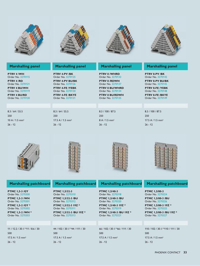
PHOENIX CONTACT 33
Marshalling patchboard Marshalling patchboard Marshalling patchboard Marshalling patchboard
PTMC 1,5-3 /GY Order No. 3270300
PTMC 1,5-3 /WH Order No. 3270301
PTMC 1,5-2 /GY * Order No. 3270302
PTMC 1,5-2 /WH * Order No. 3270303
PTMC 1,5/32-3 Order No. 3270310
PTMC 1,5/32-3 /BU Order No. 3270312
PTMC 1,5/32-3 19Z * Order No. 3270311
PTMC 1,5/32-3 /BU 19Z * Order No. 3270313
PTMC 1,5/48-3 Order No. 3270318
PTMC 1,5/48-3 /BU Order No. 3270320
PTMC 1,5/48-3 19Z * Order No. 3270319
PTMC 1,5/48-3 /BU 19Z * Order No. 3270321
PTMC 1,5/80-3 Order No. 3270324
PTMC 1,5/80-3 /BU Order No. 3270326
PTMC 1,5/80-3 19Z * Order No. 3270325
PTMC 1,5/80-3 /BU 19Z * Order No. 3270327
11 / 12.2 / 30 // *11 / 8.6 / 30 44 / 102 / 30 // *44 / 111 / 30 66 / 102 / 30 // *66 / 111 / 30 110 / 102 / 30 // *110 / 111 / 30
500 500 500 500
17.5 A / 1.5 mm2 17.5 A / 1.5 mm2 17.5 A / 1.5 mm2 17.5 A / 1.5 mm2
26 - 12 26 - 12 26 - 12 26 - 12
Marshalling panel Marshalling panel Marshalling panel Marshalling panel
PTRV 4 /WH Order No. 3270115
PTRV 4 /RD Order No. 3270121
PTRV 4 BU/WH Order No. 3270119
PTRV 4 BU/RD Order No. 3270120
PTRV 4-PV /BK Order No. 3270125
PTRV 4-PV BU/BK Order No. 3270126
PTRV 4-FE /YEBK Order No. 3270130
PTRV 4-FE /BKYE Order No. 3270131
PTRV 8 /WHRD Order No. 3270133
PTRV 8 /RDWH Order No. 3270137
PTRV 8 BU/WHRD Order No. 3270134
PTRV 8 BU/RDWH Order No. 3270135
PTRV 8-PV /BK Order No. 3270142
PTRV 8-PV BU/BK Order No. 3270145
PTRV 8-FE /YEBK Order No. 3270148
PTRV 8-FE /BKYE Order No. 3270149
8.3 / 64 / 55.5 8.3 / 64 / 55.5 8.3 / 100 / 87.5 8.3 / 100 / 87.5
250 250 250 250
10 A / 1.5 mm2 17.5 A / 1.5 mm2 8 A / 1.5 mm2 17.5 A / 1.5 mm2
26 - 12 26 - 12 26 - 12 26 - 12
34 PHOENIX CONTACT
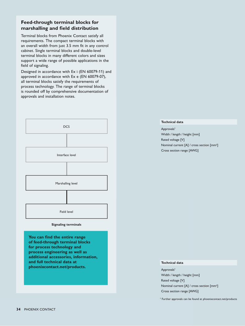
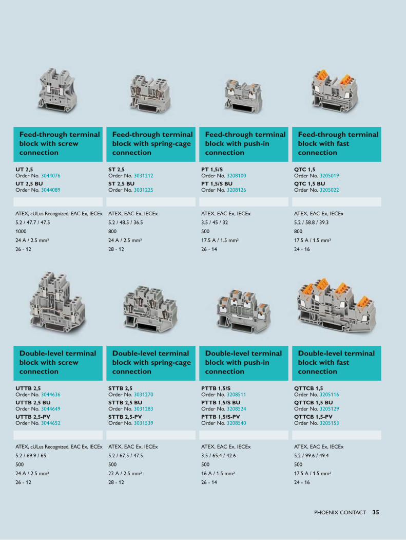
Feed-through terminal blocks for marshalling and field distributionTerminal blocks from Phoenix Contact satisfy all requirements. The compact terminal blocks with an overall width from just 3.5 mm fit in any control cabinet. Single terminal blocks and double-level terminal blocks in many different colors and sizes support a wide range of possible applications in the field of signaling.
Designed in accordance with Ex i (EN 60079-11) and approved in accordance with Ex e (EN 60079-07), all terminal blocks satisfy the requirements of process technology. The range of terminal blocks is rounded off by comprehensive documentation of approvals and installation notes.
DCS
Interface level
Signaling terminals
Marshalling level
Field level
Technical data
Approvals1
Width / length / height [mm]
Rated voltage [V]
Nominal current [A] / cross section [mm2]
Cross section range [AWG]
Technical data
Approvals1
Width / length / height [mm]
Rated voltage [V]
Nominal current [A] / cross section [mm2]
Cross section range [AWG]
You can find the entire range of feed-through terminal blocks for process technology and process engineering as well as additional accessories, information, and full technical data at phoenixcontact.net/products.
1 Further approvals can be found at phoenixcontact.net/products
PHOENIX CONTACT 35
Double-level terminal block with screw connection
Double-level terminal block with spring-cage connection
Double-level terminal block with push-in connection
Double-level terminal block with fast connection
UTTB 2,5 Order No. 3044636
UTTB 2,5 BU Order No. 3044649
UTTB 2,5-PV Order No. 3044652
STTB 2,5 Order No. 3031270
STTB 2,5 BU Order No. 3031283
STTB 2,5-PV Order No. 3031539
PTTB 1,5/S Order No. 3208511
PTTB 1,5/S BU Order No. 3208524
PTTB 1,5/S-PVOrder No. 3208540
QTTCB 1,5 Order No. 3205116
QTTCB 1,5 BU Order No. 3205129
QTTCB 1,5-PV Order No. 3205153
ATEX, cULus Recognized, EAC Ex, IECEx ATEX, EAC Ex, IECEx ATEX, EAC Ex, IECEx ATEX, EAC Ex, IECEx
5.2 / 69.9 / 65 5.2 / 67.5 / 47.5 3.5 / 65.4 / 42.6 5.2 / 99.6 / 49.4
500 500 500 500
24 A / 2.5 mm2 22 A / 2.5 mm2 16 A / 1.5 mm2 17.5 A / 1.5 mm2
26 - 12 28 - 12 26 - 14 24 - 16
Feed-through terminal block with screw connection
Feed-through terminal block with spring-cage connection
Feed-through terminal block with push-in connection
Feed-through terminal block with fast connection
UT 2,5 Order No. 3044076
UT 2,5 BU Order No. 3044089
ST 2,5 Order No. 3031212
ST 2,5 BU Order No. 3031225
PT 1,5/S Order No. 3208100
PT 1,5/S BU Order No. 3208126
QTC 1,5 Order No. 3205019
QTC 1,5 BU Order No. 3205022
ATEX, cULus Recognized, EAC Ex, IECEx ATEX, EAC Ex, IECEx ATEX, EAC Ex, IECEx ATEX, EAC Ex, IECEx
5.2 / 47.7 / 47.5 5.2 / 48.5 / 36.5 3.5 / 45 / 32 5.2 / 58.8 / 39.3
1000 800 500 800
24 A / 2.5 mm2 24 A / 2.5 mm2 17.5 A / 1.5 mm2 17.5 A / 1.5 mm2
26 - 12 28 - 12 26 - 14 24 - 16
36 PHOENIX CONTACT
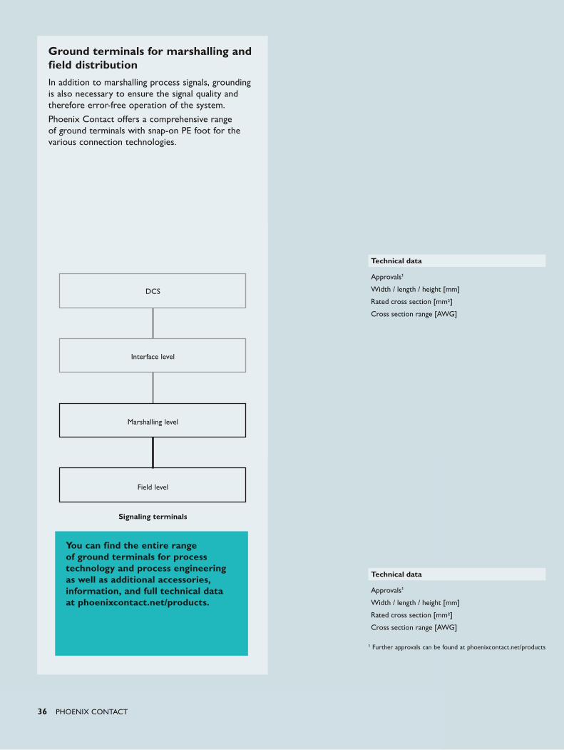
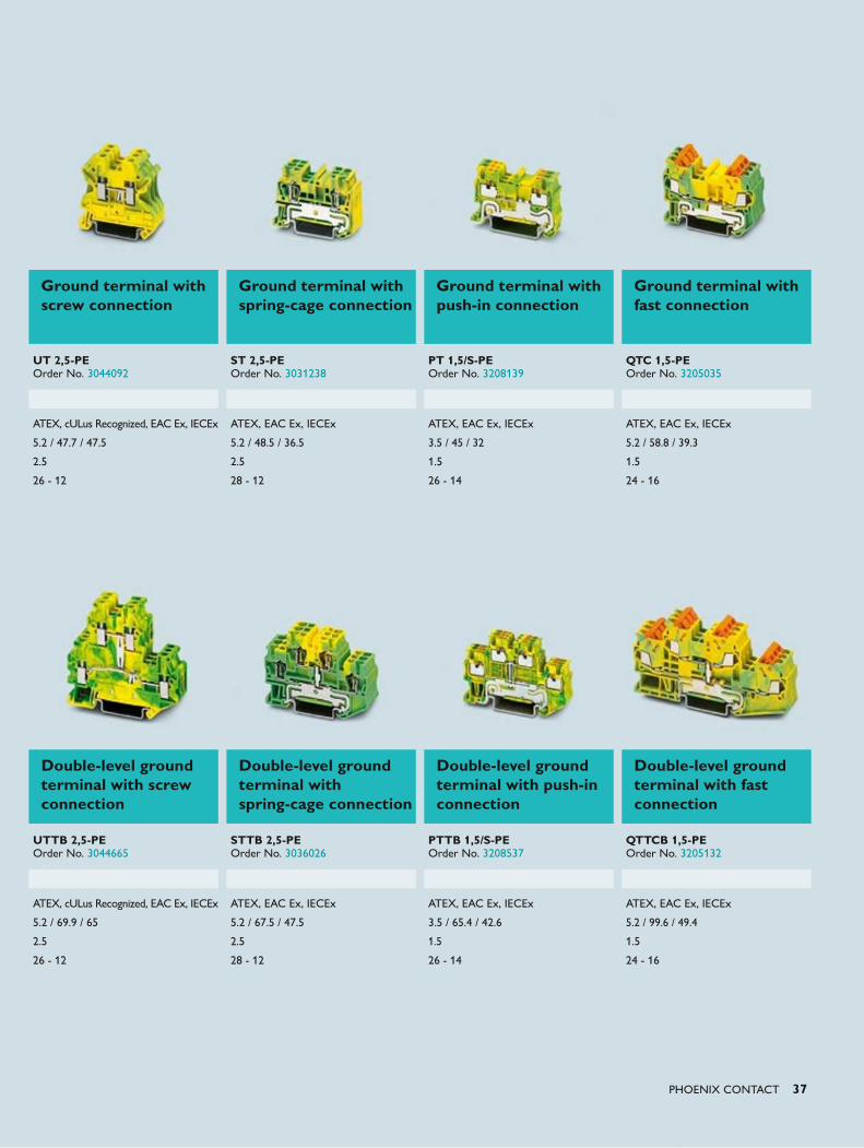
Ground terminals for marshalling and field distributionIn addition to marshalling process signals, grounding is also necessary to ensure the signal quality and therefore error-free operation of the system.
Phoenix Contact offers a comprehensive range of ground terminals with snap-on PE foot for the various connection technologies.
DCS
Interface level
Signaling terminals
Marshalling level
Field level
Technical data
Approvals1
Width / length / height [mm]
Rated cross section [mm2]
Cross section range [AWG]
Technical data
Approvals1
Width / length / height [mm]
Rated cross section [mm2]
Cross section range [AWG]
You can find the entire range of ground terminals for process technology and process engineering as well as additional accessories, information, and full technical data at phoenixcontact.net/products.
1 Further approvals can be found at phoenixcontact.net/products
PHOENIX CONTACT 37
Ground terminal with screw connection
Ground terminal with spring-cage connection
Ground terminal with push-in connection
Ground terminal with fast connection
UT 2,5-PE Order No. 3044092
ST 2,5-PE Order No. 3031238
PT 1,5/S-PE Order No. 3208139
QTC 1,5-PE Order No. 3205035
ATEX, cULus Recognized, EAC Ex, IECEx ATEX, EAC Ex, IECEx ATEX, EAC Ex, IECEx ATEX, EAC Ex, IECEx
5.2 / 47.7 / 47.5 5.2 / 48.5 / 36.5 3.5 / 45 / 32 5.2 / 58.8 / 39.3
2.5 2.5 1.5 1.5
26 - 12 28 - 12 26 - 14 24 - 16
Double-level ground terminal with screw connection
Double-level ground terminal with spring-cage connection
Double-level ground terminal with push-in connection
Double-level ground terminal with fast connection
UTTB 2,5-PE Order No. 3044665
STTB 2,5-PE Order No. 3036026
PTTB 1,5/S-PE Order No. 3208537
QTTCB 1,5-PE Order No. 3205132
ATEX, cULus Recognized, EAC Ex, IECEx ATEX, EAC Ex, IECEx ATEX, EAC Ex, IECEx ATEX, EAC Ex, IECEx
5.2 / 69.9 / 65 5.2 / 67.5 / 47.5 3.5 / 65.4 / 42.6 5.2 / 99.6 / 49.4
2.5 2.5 1.5 1.5
26 - 12 28 - 12 26 - 14 24 - 16
38 PHOENIX CONTACT
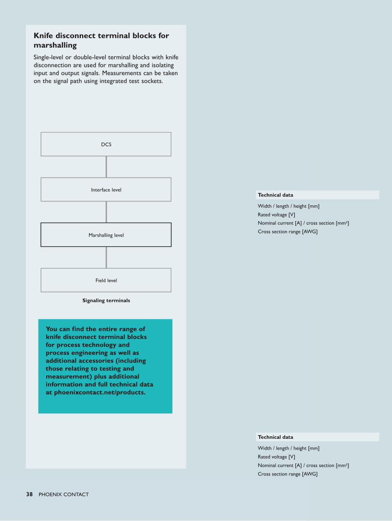
Knife disconnect terminal blocks for marshallingSingle-level or double-level terminal blocks with knife disconnection are used for marshalling and isolating input and output signals. Measurements can be taken on the signal path using integrated test sockets.
DCS
Interface level
Signaling terminals
Marshalling level
Field level
Technical data
Width / length / height [mm]
Rated voltage [V]
Nominal current [A] / cross section [mm2]
Cross section range [AWG]
Technical data
Width / length / height [mm]
Rated voltage [V]
Nominal current [A] / cross section [mm2]
Cross section range [AWG]
You can find the entire range of knife disconnect terminal blocks for process technology and process engineering as well as additional accessories (including those relating to testing and measurement) plus additional information and full technical data at phoenixcontact.net/products.
PHOENIX CONTACT 39
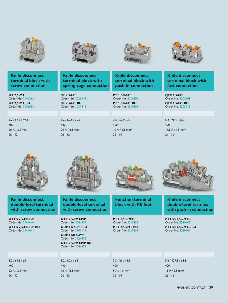
Knife disconnect double-level terminal with screw connection
Knife disconnect double-level terminal with screw connection
Function terminal block with PE foot
Knife disconnect double-level terminal with push-in connection
UTTB 2,5-MT-P/P Order No. 3044640
UTTB 2,5-MT-P/P BU Order No. 3044641
UTT 2,5-2MT-P/P Order No. 3044670
UDMTK 5-P/P BU Order No. 3101113
UDMTKB 5-P/P Order No. 3024478
UTT 2,5-2MT-P/P BU Order No. 3044671
PTT 1,5/S-2MT Order No. 3210351
PTT 2,5-2MT BU Order No. 3210265
PTTBS 2,5-2MTB Order No. 3210400
PTTBS 2,5-2MTB BU Order No. 3210401
5.2 / 69.9 / 65 5.2 / 80.1 / 65 3.5 / 86 / 42.6 5.2 / 127.5 / 64.3
400 400 400 400
22 A / 2.5 mm2 16 A / 2.5 mm2 9 A / 1.5 mm2 16 A / 2.5 mm2
26 - 12 26 - 12 26 - 14 26 - 12
Knife disconnect terminal block with screw connection
Knife disconnect terminal block with spring-cage connection
Knife disconnect terminal block with push-in connection
Knife disconnect terminal block with fast connection
UT 2,5-MT Order No. 3046362
UT 2,5-MT BU Order No. 3046553
ST 2,5-MT Order No. 3036343
ST 2,5-MT BU Order No. 3037818
PT 1,5/S-MT Order No. 3210301
PT 1,5/S-MT BU Order No. 3210302
QTC 1,5-MT Order No. 3205103
QTC 1,5-MT BU Order No. 3205213
5.2 / 57.8 / 49.1 5.2 / 60.5 / 36.5 3.5 / 58.9 / 32 5.2 / 76.4 / 39.3
400 400 400 400
20 A / 2.5 mm2 20 A / 2.5 mm2 10 A / 1.5 mm2 17.5 A / 1.5 mm2
26 - 12 28 - 12 26 - 14 24 - 16
40 PHOENIX CONTACT
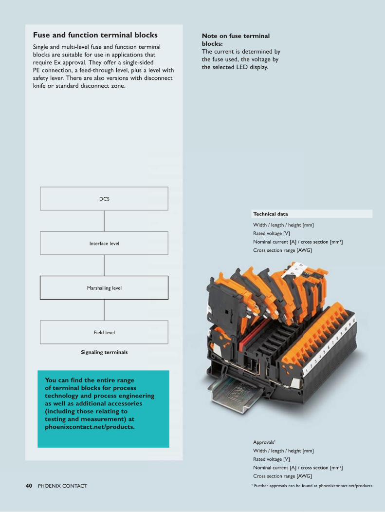
Fuse and function terminal blocksSingle and multi-level fuse and function terminal blocks are suitable for use in applications that require Ex approval. They offer a single-sided PE connection, a feed-through level, plus a level with safety lever. There are also versions with disconnect knife or standard disconnect zone.
DCS
Interface level
Signaling terminals
Marshalling level
Field level
Technical data
Width / length / height [mm]
Rated voltage [V]
Nominal current [A] / cross section [mm2]
Cross section range [AWG]
Approvals1
Width / length / height [mm]
Rated voltage [V]
Nominal current [A] / cross section [mm2]
Cross section range [AWG]
You can find the entire range of terminal blocks for process technology and process engineering as well as additional accessories (including those relating to testing and measurement) at phoenixcontact.net/products.
Note on fuse terminal blocks:The current is determined by the fuse used, the voltage by the selected LED display.
1 Further approvals can be found at phoenixcontact.net/products
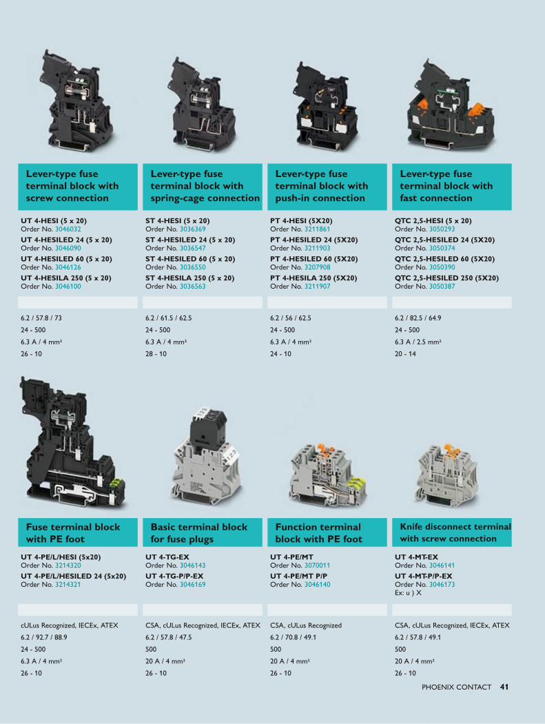
PHOENIX CONTACT 41
Lever-type fuse terminal block with screw connection
Lever-type fuse terminal block with spring-cage connection
Lever-type fuse terminal block with push-in connection
Lever-type fuse terminal block with fast connection
UT 4-HESI (5 x 20) Order No. 3046032
UT 4-HESILED 24 (5 x 20) Order No. 3046090
UT 4-HESILED 60 (5 x 20) Order No. 3046126
UT 4-HESILA 250 (5 x 20) Order No. 3046100
ST 4-HESI (5 x 20) Order No. 3036369
ST 4-HESILED 24 (5 x 20) Order No. 3036547
ST 4-HESILED 60 (5 x 20) Order No. 3036550
ST 4-HESILA 250 (5 x 20) Order No. 3036563
PT 4-HESI (5X20) Order No. 3211861
PT 4-HESILED 24 (5X20) Order No. 3211903
PT 4-HESILED 60 (5X20) Order No. 3207908
PT 4-HESILA 250 (5X20) Order No. 3211907
QTC 2,5-HESI (5 x 20) Order No. 3050293
QTC 2,5-HESILED 24 (5X20) Order No. 3050374
QTC 2,5-HESILED 60 (5X20) Order No. 3050390
QTC 2,5-HESILED 250 (5X20) Order No. 3050387
6.2 / 57.8 / 73 6.2 / 61.5 / 62.5 6.2 / 56 / 62.5 6.2 / 82.5 / 64.9
24 - 500 24 - 500 24 - 500 24 - 500
6.3 A / 4 mm2 6.3 A / 4 mm2 6.3 A / 4 mm2 6.3 A / 2.5 mm2
26 - 10 28 - 10 24 - 10 20 - 14
Fuse terminal block with PE foot
Basic terminal block for fuse plugs
Function terminal block with PE foot
Knife disconnect terminal with screw connection
UT 4-PE/L/HESI (5x20) Order No. 3214320
UT 4-PE/L/HESILED 24 (5x20) Order No. 3214321
UT 4-TG-EX Order No. 3046143
UT 4-TG-P/P-EX Order No. 3046169
UT 4-PE/MT Order No. 3070011
UT 4-PE/MT P/P Order No. 3046140
UT 4-MT-EX Order No. 3046141
UT 4-MT-P/P-EX Order No. 3046173Ex: u ) X
cULus Recognized, IECEx, ATEX CSA, cULus Recognized, IECEx, ATEX CSA, cULus Recognized CSA, cULus Recognized, IECEx, ATEX
6.2 / 92.7 / 88.9 6.2 / 57.8 / 47.5 6.2 / 70.8 / 49.1 6.2 / 57.8 / 49.1
24 - 500 500 500 500
6.3 A / 4 mm2 20 A / 4 mm2 20 A / 4 mm2 20 A / 4 mm2
26 - 10 26 - 10 26 - 10 26 - 10
Push-in TechnologyDesigned by PHOENIX CONTACT
42 PHOENIX CONTACT
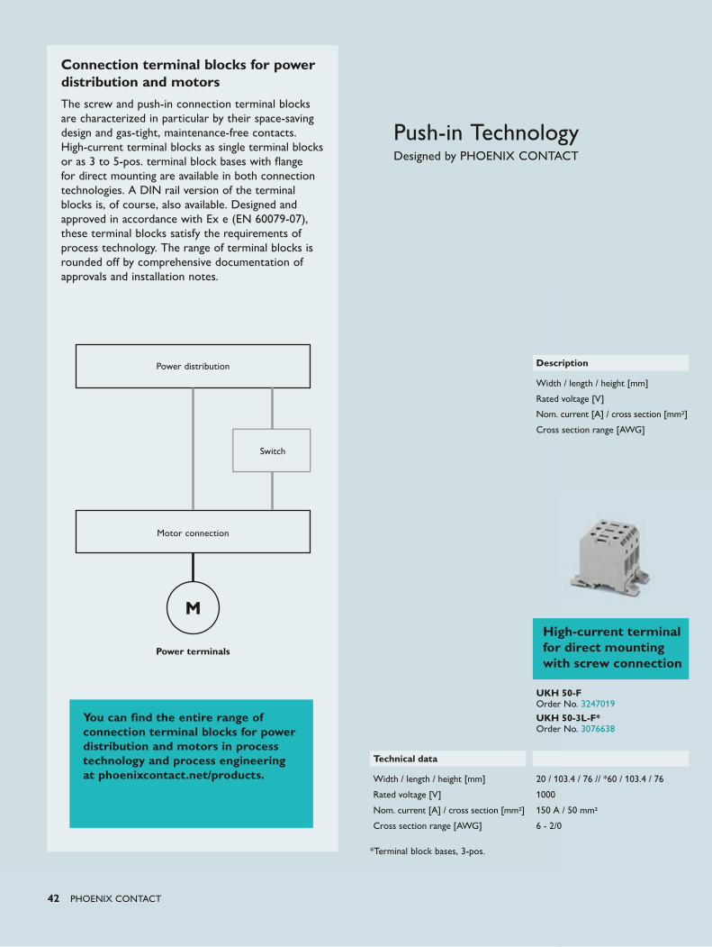
Connection terminal blocks for power distribution and motors The screw and push-in connection terminal blocks are characterized in particular by their space-saving design and gas-tight, maintenance-free contacts. High-current terminal blocks as single terminal blocks or as 3 to 5-pos. terminal block bases with flange for direct mounting are available in both connection technologies. A DIN rail version of the terminal blocks is, of course, also available. Designed and approved in accordance with Ex e (EN 60079-07), these terminal blocks satisfy the requirements of process technology. The range of terminal blocks is rounded off by comprehensive documentation of approvals and installation notes.
Power terminals
Power distribution
Switch
Motor connection
High-current terminal for direct mounting with screw connection
UKH 50-F Order No. 3247019
UKH 50-3L-F* Order No. 3076638
Technical data
Width / length / height [mm] 20 / 103.4 / 76 // *60 / 103.4 / 76
Rated voltage [V] 1000
Nom. current [A] / cross section [mm2] 150 A / 50 mm2
Cross section range [AWG] 6 - 2/0
Description
Width / length / height [mm]
Rated voltage [V]
Nom. current [A] / cross section [mm2]
Cross section range [AWG]
You can find the entire range of connection terminal blocks for power distribution and motors in process technology and process engineering at phoenixcontact.net/products.
*Terminal block bases, 3-pos.
PHOENIX CONTACT 43
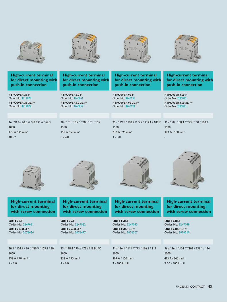
High-current terminal for direct mounting with screw connection
High-current terminal for direct mounting with screw connection
High-current terminal for direct mounting with screw connection
High-current terminal for direct mounting with screw connection
UKH 70-F Order No. 3247051
UKH 70-3L-F* Order No. 3076484
UKH 95-F Order No. 3247022
UKH 95-3L-F* Order No. 3076497
UKH 150-F Order No. 3247035
UKH 150-3L-F* Order No. 3076507
UKH 240-F Order No. 3247048
UKH 240-3L-F* Order No. 3076510
20.3 / 103.4 / 80 // *60.9 / 103.4 / 80 25 / 118.8 / 90 // *75 / 118.8 / 90 31 / 136.1 / 111 // *93 / 136.1 / 111 36 / 136.1 / 124 // *108 / 136.1 / 124
1000 1000 1000 1000
192 A / 70 mm2 232 A / 95 mm2 309 A / 150 mm2 415 A / 240 mm2
4 - 3/0 4 - 3/0 2 - 300 kcmil 2 / 0 - 500 kcmil
High-current terminal for direct mounting with push-in connection
High-current terminal for direct mounting with push-in connection
High-current terminal for direct mounting with push-in connection
High-current terminal for direct mounting with push-in connection
PTPOWER 35-F Order No. 3212078
PTPOWER 35-3L-F* Order No. 3212072
PTPOWER 50-F Order No. 3260061
PTPOWER 50-3L-F* Order No. 3260057
PTPOWER 95-F Order No. 3260133
PTPOWER 95-3L-F* Order No. 3260121
PTPOWER 150-F Order No. 3215030
PTPOWER 150-3L-F* Order No. 3215033
16 / 91.6 / 62.3 // *48 / 91.6 / 62.3 20 / 101 / 105 // *60 / 101 / 105 25 / 139.1 / 108.7 // *75 / 139.1 / 108.7 31 / 150 / 108.3 // *93 / 150 / 108.3
1000 1500 1500 1500
125 A / 35 mm2 150 A / 50 mm2 232 A / 95 mm2 309 A / 150 mm2
10 - 2 8 - 2/0 4 - 3/0 -
44 PHOENIX CONTACT
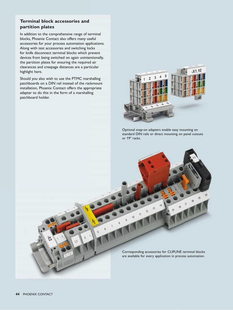
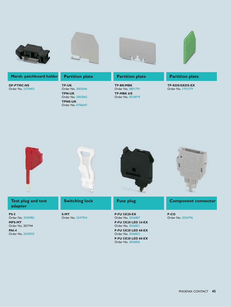
Terminal block accessories and partition platesIn addition to the comprehensive range of terminal blocks, Phoenix Contact also offers many useful accessories for your process automation applications. Along with test accessories and switching locks for knife disconnect terminal blocks which prevent devices from being switched on again unintentionally, the partition plates for ensuring the required air clearances and creepage distances are a particular highlight here.
Should you also wish to use the PTMC marshalling patchboards on a DIN rail instead of the rackmount installation, Phoenix Contact offers the appropriate adapter to do this in the form of a marshalling patchboard holder.
Optional snap-on adapters enable easy mounting on standard DIN rails or direct mounting on panel cutouts or 19" racks.
Corresponding accessories for CLIPLINE terminal blocks are available for every application in process automation.
PHOENIX CONTACT 45
Test plug and test adapter
Switching lock Fuse plug Component connector
PS-5 Order No. 3030983
MPS-MT Order No. 201744
PAI-4 Order No. 3030925
S-MT Order No. 3247954
P-FU 5X20-EX Order No. 3036807
P-FU 5X20 LED 24-EX Order No. 3036821
P-FU 5X20 LED 60-EX Order No. 3036823
P-FU 5X20 LED 60-EX Order No. 3036836
P-CO Order No. 3036796
Marsh. patchboard holder Partition plate Partition plate Partition plate
DF-PTMC-NS Order No. 3270403
TP-UK Order No. 3003046
TPN-UK Order No. 3003062
TPNS-UK Order No. 0706647
TP-BK/MBK Order No. 0801791
TP-MBK 6/E Order No. 0554019
TP-KDS/GKDS-EX Order No. 1701379
46 PHOENIX CONTACT
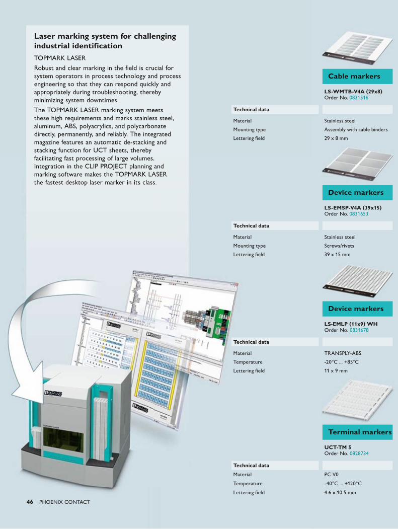
Laser marking system for challenging industrial identification TOPMARK LASER
Robust and clear marking in the field is crucial for system operators in process technology and process engineering so that they can respond quickly and appropriately during troubleshooting, thereby minimizing system downtimes.
The TOPMARK LASER marking system meets these high requirements and marks stainless steel, aluminum, ABS, polyacrylics, and polycarbonate directly, permanently, and reliably. The integrated magazine features an automatic de-stacking and stacking function for UCT sheets, thereby facilitating fast processing of large volumes. Integration in the CLIP PROJECT planning and marking software makes the TOPMARK LASER the fastest desktop laser marker in its class.
Cable markers
LS-WMTB-V4A (29x8) Order No. 0831516
Technical data
Material Stainless steel
Mounting type Assembly with cable binders
Lettering field 29 x 8 mm
Device markers
LS-EMSP-V4A (39x15) Order No. 0831653
Technical data
Material Stainless steel
Mounting type Screws/rivets
Lettering field 39 x 15 mm
Device markers
LS-EMLP (11x9) WH Order No. 0831678
Technical data
Material TRANSPLY-ABS
Temperature -20°C ... +85°C
Lettering field 11 x 9 mm
Terminal markers
UCT-TM 5 Order No. 0828734
Technical data
Material PC V0
Temperature -40°C ... +120°C
Lettering field 4.6 x 10.5 mm
PHOENIX CONTACT 47
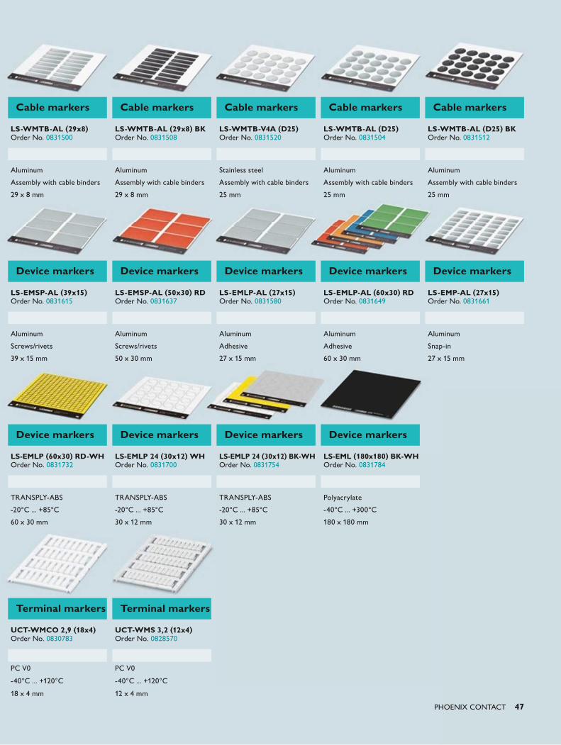
Cable markers Cable markers Cable markers Cable markers Cable markers
LS-WMTB-AL (29x8) Order No. 0831500
LS-WMTB-AL (29x8) BK Order No. 0831508
LS-WMTB-V4A (D25) Order No. 0831520
LS-WMTB-AL (D25) Order No. 0831504
LS-WMTB-AL (D25) BK Order No. 0831512
Aluminum Aluminum Stainless steel Aluminum Aluminum
Assembly with cable binders Assembly with cable binders Assembly with cable binders Assembly with cable binders Assembly with cable binders
29 x 8 mm 29 x 8 mm 25 mm 25 mm 25 mm
Device markers Device markers Device markers Device markers Device markers
LS-EMSP-AL (39x15) Order No. 0831615
LS-EMSP-AL (50x30) RD Order No. 0831637
LS-EMLP-AL (27x15) Order No. 0831580
LS-EMLP-AL (60x30) RD Order No. 0831649
LS-EMP-AL (27x15) Order No. 0831661
Aluminum Aluminum Aluminum Aluminum Aluminum
Screws/rivets Screws/rivets Adhesive Adhesive Snap-in
39 x 15 mm 50 x 30 mm 27 x 15 mm 60 x 30 mm 27 x 15 mm
Device markers Device markers Device markers Device markers
LS-EMLP (60x30) RD-WH Order No. 0831732
LS-EMLP 24 (30x12) WH Order No. 0831700
LS-EMLP 24 (30x12) BK-WH Order No. 0831754
LS-EML (180x180) BK-WH Order No. 0831784
TRANSPLY-ABS TRANSPLY-ABS TRANSPLY-ABS Polyacrylate
-20°C ... +85°C -20°C ... +85°C -20°C ... +85°C -40°C ... +300°C
60 x 30 mm 30 x 12 mm 30 x 12 mm 180 x 180 mm
Terminal markers Terminal markers
UCT-WMCO 2,9 (18x4) Order No. 0830783
UCT-WMS 3,2 (12x4) Order No. 0828570
PC V0 PC V0
-40°C ... +120°C -40°C ... +120°C
18 x 4 mm 12 x 4 mm
48 PHOENIX CONTACT
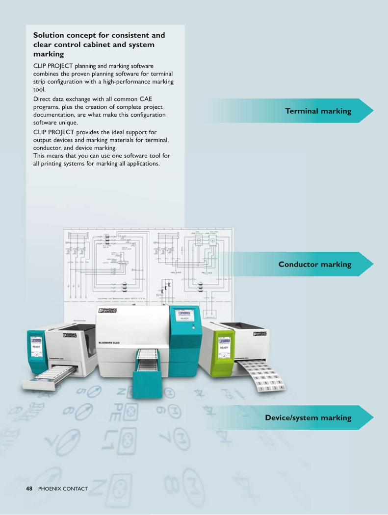
Solution concept for consistent and clear control cabinet and system markingCLIP PROJECT planning and marking software combines the proven planning software for terminal strip configuration with a high-performance marking tool.
Direct data exchange with all common CAE programs, plus the creation of complete project documentation, are what make this configuration software unique.
CLIP PROJECT provides the ideal support for output devices and marking materials for terminal, conductor, and device marking. This means that you can use one software tool for all printing systems for marking all applications.
Device/system marking
Terminal marking
Conductor marking
PHOENIX CONTACT 49
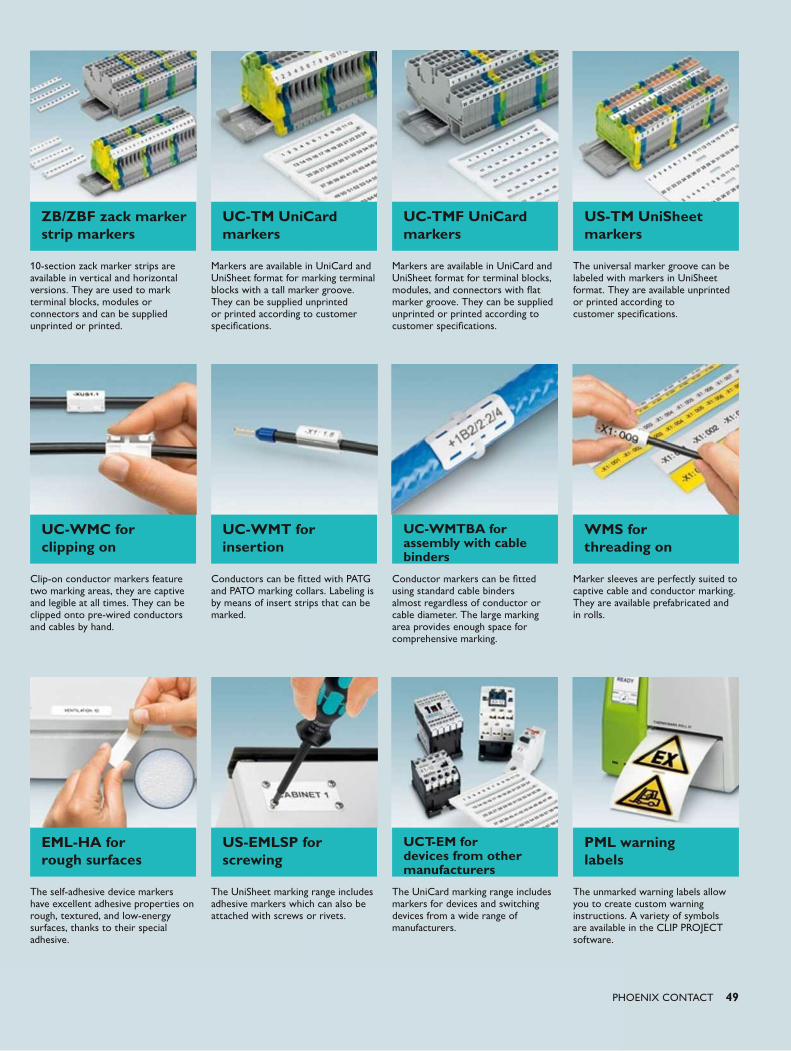
ZB/ZBF zack marker strip markers
UC-TM UniCard markers
UC-TMF UniCard markers
US-TM UniSheet markers
10-section zack marker strips are available in vertical and horizontal versions. They are used to mark terminal blocks, modules or connectors and can be supplied unprinted or printed.
Markers are available in UniCard and UniSheet format for marking terminal blocks with a tall marker groove. They can be supplied unprinted or printed according to customer specifications.
Markers are available in UniCard and UniSheet format for terminal blocks, modules, and connectors with flat marker groove. They can be supplied unprinted or printed according to customer specifications.
The universal marker groove can be labeled with markers in UniSheet format. They are available unprinted or printed according to customer specifications.
UC-WMC for clipping on
UC-WMT for insertion
UC-WMTBA for assembly with cable binders
WMS for threading on
Clip-on conductor markers feature two marking areas, they are captive and legible at all times. They can be clipped onto pre-wired conductors and cables by hand.
Conductors can be fitted with PATG and PATO marking collars. Labeling is by means of insert strips that can be marked.
Conductor markers can be fitted using standard cable binders almost regardless of conductor or cable diameter. The large marking area provides enough space for comprehensive marking.
Marker sleeves are perfectly suited to captive cable and conductor marking. They are available prefabricated and in rolls.
EML-HA for rough surfaces
US-EMLSP for screwing
UCT-EM for devices from other manufacturers
PML warning labels
The self-adhesive device markers have excellent adhesive properties on rough, textured, and low-energy surfaces, thanks to their special adhesive.
The UniSheet marking range includes adhesive markers which can also be attached with screws or rivets.
The UniCard marking range includes markers for devices and switching devices from a wide range of manufacturers.
The unmarked warning labels allow you to create custom warning instructions. A variety of symbols are available in the CLIP PROJECT software.
50 PHOENIX CONTACT
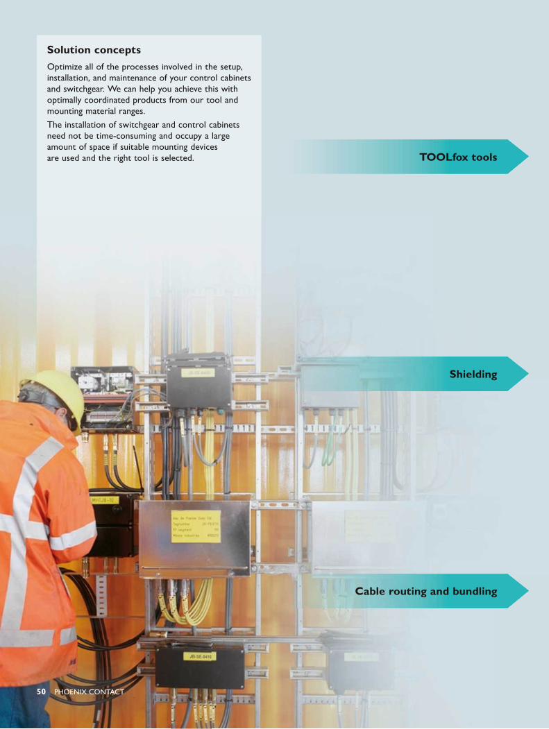
Solution conceptsOptimize all of the processes involved in the setup, installation, and maintenance of your control cabinets and switchgear. We can help you achieve this with optimally coordinated products from our tool and mounting material ranges.
The installation of switchgear and control cabinets need not be time-consuming and occupy a large amount of space if suitable mounting devices are used and the right tool is selected.
Cable routing and bundling
TOOLfox tools
Shielding
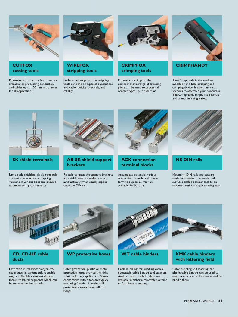
PHOENIX CONTACT 51
CUTFOX cutting tools
WIREFOX stripping tools
CRIMPFOX crimping tools
CRIMPHANDY
Professional cutting: cable cutters are available for processing conductors and cables up to 100 mm in diameter for all applications.
Professional stripping: the stripping tools can strip all types of conductors and cables quickly, precisely, and reliably.
Professional crimping: the comprehensive range of crimping pliers can be used to process all contact types up to 120 mm2.
The Crimphandy is the smallest available hand-held stripping and crimping device. It takes just two seconds to assemble your conductors. The Crimphandy strips, fits a ferrule, and crimps in a single step.
SK shield terminals AB-SK shield support brackets
AGK connection terminal blocks
NS DIN rails
Large-scale shielding: shield terminals are available as screw and spring versions in various sizes and provide optimum wiring convenience.
Reliable contact: the support brackets for shield terminals make contact automatically when simply clipped onto the DIN rail.
Accumulate potential: various connection, branch, and power terminals up to 35 mm2 are available for busbars.
Mounting: DIN rails and busbars made from various materials and surfaces enable components to be mounted easily in a space-saving way.
CD, CD-HF cable ducts
WP protective hoses WT cable binders KMK cable binders with lettering field
Easy cable installation: halogen-free cable ducts in various colors enable easy and flexible cable installation, thanks to lateral segments which can be removed without tools.
Cable protection: plastic or metal protective hoses provide the right solution for any application. Screw connections with a tool-free quick mounting function in various IP protection classes round off the range.
Cable bundling: for bundling cables, detectable cable binders and stainless steel or plastic cable binders are available in either a removable version or for direct mounting.
Cable bundling and marking: the plastic cable binders can be used to mark conductors and cables as well as bundle them.
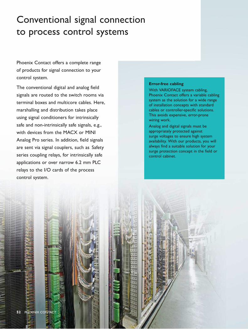
52 PHOENIX CONTACT
Phoenix Contact offers a complete range
of products for signal connection to your
control system.
The conventional digital and analog field
signals are routed to the switch rooms via
terminal boxes and multicore cables. Here,
marshalling and distribution takes place
using signal conditioners for intrinsically
safe and non-intrinsically safe signals, e.g.,
with devices from the MACX or MINI
Analog Pro series. In addition, field signals
are sent via signal couplers, such as Safety
series coupling relays, for intrinsically safe
applications or over narrow 6.2 mm PLC
relays to the I/O cards of the process
control system.
Conventional signal connection to process control systems
Error-free cabling With VARIOFACE system cabling, Phoenix Contact offers a variable cabling system as the solution for a wide range of installation concepts with standard cables or controller-specific solutions. This avoids expensive, error-prone wiring work.
Analog and digital signals must be appropriately protected against surge voltages to ensure high system availability. With our products, you will always find a suitable solution for your surge protection concept in the field or control cabinet.
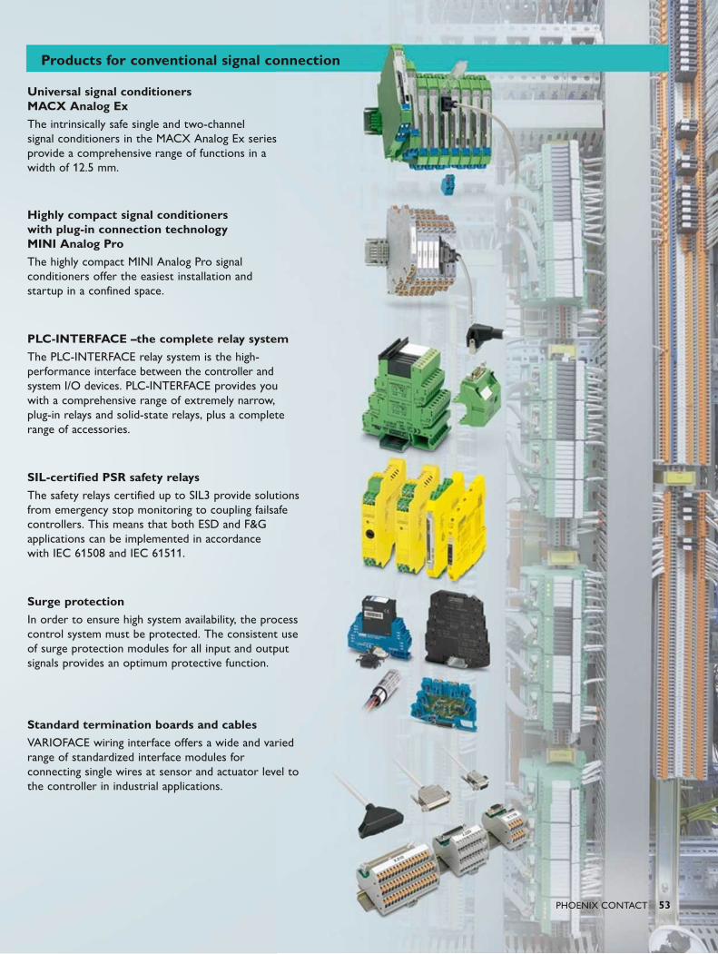
PHOENIX CONTACT 53
Universal signal conditioners MACX Analog ExThe intrinsically safe single and two-channel signal conditioners in the MACX Analog Ex series provide a comprehensive range of functions in a width of 12.5 mm.
Highly compact signal conditioners with plug-in connection technology MINI Analog ProThe highly compact MINI Analog Pro signal conditioners offer the easiest installation and startup in a confined space.
PLC-INTERFACE –the complete relay systemThe PLC-INTERFACE relay system is the high-performance interface between the controller and system I/O devices. PLC-INTERFACE provides you with a comprehensive range of extremely narrow, plug-in relays and solid-state relays, plus a complete range of accessories.
SIL-certified PSR safety relaysThe safety relays certified up to SIL3 provide solutions from emergency stop monitoring to coupling failsafe controllers. This means that both ESD and F&G applications can be implemented in accordance with IEC 61508 and IEC 61511.
Surge protectionIn order to ensure high system availability, the process control system must be protected. The consistent use of surge protection modules for all input and output signals provides an optimum protective function.
Standard termination boards and cablesVARIOFACE wiring interface offers a wide and varied range of standardized interface modules for connecting single wires at sensor and actuator level to the controller in industrial applications.
Products for conventional signal connection
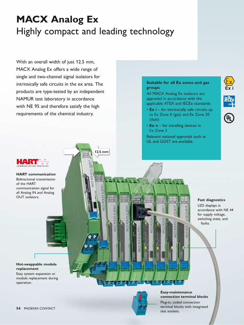
54 PHOENIX CONTACT
MACX Analog Ex Highly compact and leading technology
Suitable for all Ex zones and gas groupsAll MACX Analog Ex isolators are approved in accordance with the applicable ATEX and IECEx standards:
• Ex i – for intrinsically safe circuits up to Ex Zone 0 (gas) and Ex Zone 20 (dust)
• Ex n – for installing devices in Ex Zone 2
Relevant national approvals such as UL and GOST are available.
With an overall width of just 12.5 mm,
MACX Analog Ex offers a wide range of
single and two-channel signal isolators for
intrinsically safe circuits in the ex area. The
products are type-tested by an independent
NAMUR test laboratory in accordance
with NE 95 and therefore satisfy the high
requirements of the chemical industry.
Hot-swappable module replacementEasy system expansion or module replacement during operation.
Fast diagnostics
LED displays in accordance with NE 44 for supply voltage, switching state, and
faults.
HART communicationBidirectional transmission of the HART communication signal for all Analog IN and Analog OUT isolators.
Easy-maintenance connection terminal blocks
Plug-in, coded connection terminal blocks with integrated test sockets.
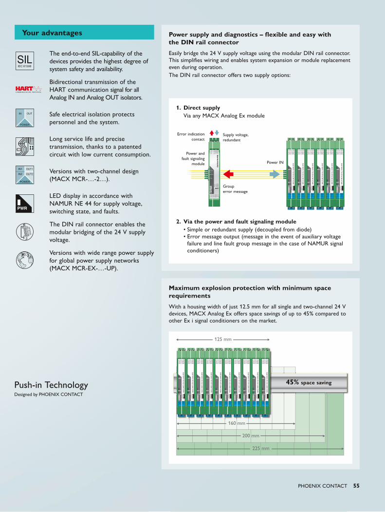
PWR
160 mm
125 mm
200 mm
225 mm
3.1 3.2 3.3
1.1 1.22.1 2.23.1 3.2
N.C.N.C.3.3
PWR1
PWR2
ERR
MA
CX
MC
R-P
TB
ON OFF
1
2
PWR1PWR1
PWR2
ERR
1234
I II
1.1 1.22.1 2.23.1 3.2
4.1 4.25.1 5.2
PWR
OUT1
OUT2
MACX
MCR
-EX-
SL-N
AM-2
RO
1234
I II
1.1 1.22.1 2.23.1 3.2
4.1 4.25.1 5.2
PWR
OUT1
OUT2
MACX
MCR
-EX-
SL-N
AM-2
RO
1234
I II
1.1 1.22.1 2.23.1 3.2
4.1 4.25.1 5.2
PWR
OUT1
OUT2
MACX
MCR
-EX-
SL-N
AM-2
RO
1234
I II
1.1 1.22.1 2.23.1 3.2
4.1 4.25.1 5.2
PWR
OUT1
OUT2
MACX
MCR
-EX-
SL-N
AM-2
RO
1234
I II
1.1 1.22.1 2.23.1 3.2
4.1 4.25.1 5.2
PWR
OUT1
OUT2
MACX
MCR
-EX-
SL-N
AM-2
RO
1234
I II
1.1 1.22.1 2.23.1 3.2
4.1 4.25.1 5.2
PWR
OUT1
OUT2
MACX
MCR
-EX-
SL-N
AM-2
RO
PHOENIX CONTACT 55
The end-to-end SIL-capability of the devices provides the highest degree of system safety and availability.
Bidirectional transmission of the HART communication signal for all Analog IN and Analog OUT isolators.
Safe electrical isolation protects personnel and the system.
Long service life and precise transmission, thanks to a patented circuit with low current consumption.
Versions with two-channel design (MACX MCR-…-2…).
LED display in accordance with NAMUR NE 44 for supply voltage, switching state, and faults.
The DIN rail connector enables the modular bridging of the 24 V supply voltage.
Versions with wide range power supply for global power supply networks (MACX MCR-EX-…-UP).
Your advantages
Maximum explosion protection with minimum space requirements
With a housing width of just 12.5 mm for all single and two-channel 24 V devices, MACX Analog Ex offers space savings of up to 45% compared to other Ex i signal conditioners on the market.
Power supply and diagnostics – flexible and easy with the DIN rail connector
Easily bridge the 24 V supply voltage using the modular DIN rail connector. This simplifies wiring and enables system expansion or module replacement even during operation. The DIN rail connector offers two supply options:
1. Direct supply Via any MACX Analog Ex module
2. Via the power and fault signaling module• Simple or redundant supply (decoupled from diode)• Error message output (message in the event of auxiliary voltage
failure and line fault group message in the case of NAMUR signal conditioners)
Power and fault signaling
module Power IN
Error indication contact
Supply voltage, redundant
Group error message
45% space saving
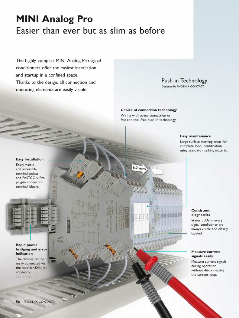
56 PHOENIX CONTACT
The highly compact MINI Analog Pro signal
conditioners offer the easiest installation
and startup in a confined space.
Thanks to the design, all connection and
operating elements are easily visible.
MINI Analog ProEasier than ever but as slim as before
Consistent diagnostics
Status LEDs in every signal conditioner are always visible and clearly labeled.
Easy maintenance
Large-surface marking areas for complete loop identification using standard marking material.
Choice of connection technology
Wiring with screw connection or fast and tool-free push-in technology.
Measure current signals easily
Measure current signals during operation without disconnecting the current loop.
Rapid power bridging and error indication
The devices can be easily connected via the modular DIN rail connector.
Easy installation
Easily visible and accessible terminal points and FASTCON Pro plug-in connection terminal blocks.
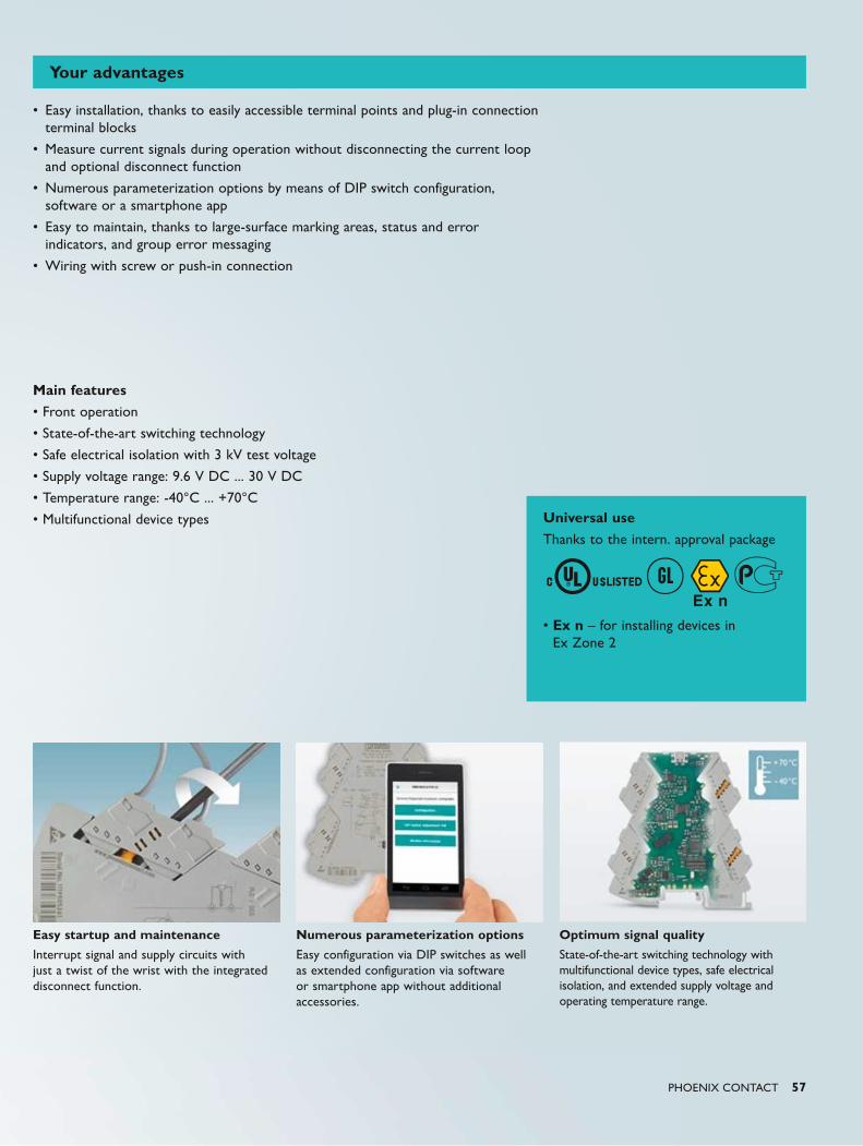
ULISTED
n
PHOENIX CONTACT 57
Universal useThanks to the intern. approval package
• Ex n – for installing devices in Ex Zone 2
Main features• Front operation
• State-of-the-art switching technology
• Safe electrical isolation with 3 kV test voltage
• Supply voltage range: 9.6 V DC ... 30 V DC
• Temperature range: -40°C ... +70°C
• Multifunctional device types
Easy startup and maintenance
Interrupt signal and supply circuits with just a twist of the wrist with the integrated disconnect function.
Numerous parameterization options
Easy configuration via DIP switches as well as extended configuration via software or smartphone app without additional accessories.
Optimum signal quality
State-of-the-art switching technology with multifunctional device types, safe electrical isolation, and extended supply voltage and operating temperature range.
Your advantages
• Easy installation, thanks to easily accessible terminal points and plug-in connection terminal blocks
• Measure current signals during operation without disconnecting the current loop and optional disconnect function
• Numerous parameterization options by means of DIP switch configuration, software or a smartphone app
• Easy to maintain, thanks to large-surface marking areas, status and error indicators, and group error messaging
• Wiring with screw or push-in connection
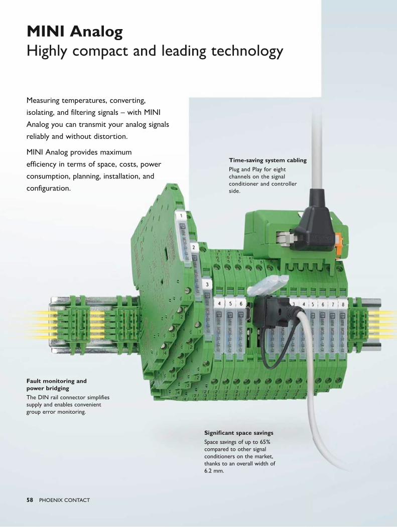
58 PHOENIX CONTACT
MINI AnalogHighly compact and leading technology
Measuring temperatures, converting,
isolating, and filtering signals – with MINI
Analog you can transmit your analog signals
reliably and without distortion.
MINI Analog provides maximum
efficiency in terms of space, costs, power
consumption, planning, installation, and
configuration.
Time-saving system cabling
Plug and Play for eight channels on the signal conditioner and controller side.
Significant space savings
Space savings of up to 65% compared to other signal conditioners on the market, thanks to an overall width of 6.2 mm.
Fault monitoring and power bridging
The DIN rail connector simplifies supply and enables convenient group error monitoring.
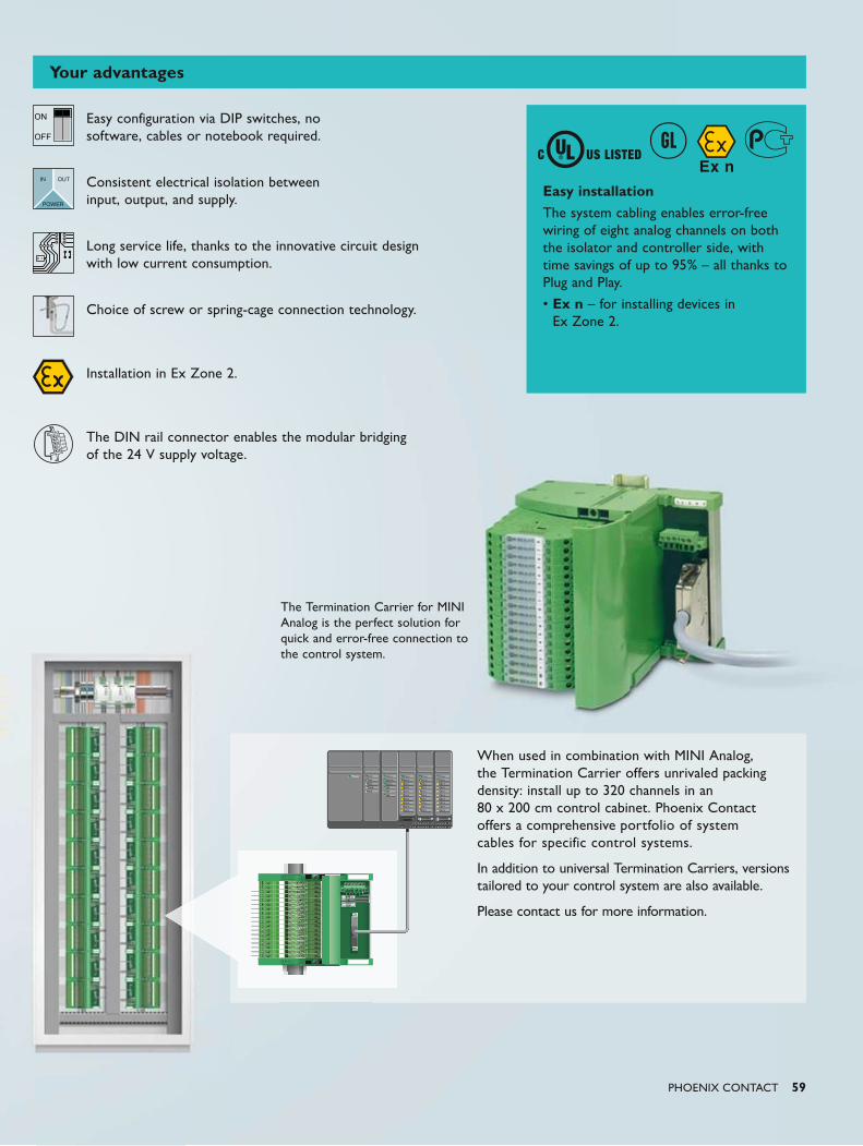
ON
OFF
n
MINI MCR-SL-PTBMCRMI MMINI M CRMINI MCR-SL-PTB
MINI MCR-SL-TBMCRMI MMINI M CRMINI MCR-SL-TB
PTBPTBRRR BBBTBBTBR-R-RR-SLSL-L-SS PTPTPSL-PTSSSS
TBTBRRR BBR-R-RR-SLSL-L-SS TBTBTSL-TBSSSS
PHOENIX CONTACT 59
The Termination Carrier for MINI Analog is the perfect solution for quick and error-free connection to the control system.
Easy installationThe system cabling enables error-free wiring of eight analog channels on both the isolator and controller side, with time savings of up to 95% – all thanks to Plug and Play.
• Ex n – for installing devices in Ex Zone 2.
Easy configuration via DIP switches, no software, cables or notebook required.
Consistent electrical isolation between input, output, and supply.
Long service life, thanks to the innovative circuit design with low current consumption.
Choice of screw or spring-cage connection technology.
Installation in Ex Zone 2.
The DIN rail connector enables the modular bridging of the 24 V supply voltage.
When used in combination with MINI Analog, the Termination Carrier offers unrivaled packing density: install up to 320 channels in an 80 x 200 cm control cabinet. Phoenix Contact offers a comprehensive portfolio of system cables for specific control systems.
In addition to universal Termination Carriers, versions tailored to your control system are also available.
Please contact us for more information.
Your advantages
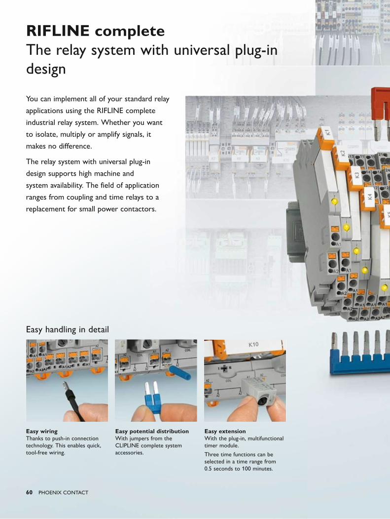
60 PHOENIX CONTACT
You can implement all of your standard relay
applications using the RIFLINE complete
industrial relay system. Whether you want
to isolate, multiply or amplify signals, it
makes no difference.
The relay system with universal plug-in
design supports high machine and
system availability. The field of application
ranges from coupling and time relays to a
replacement for small power contactors.
RIFLINE completeThe relay system with universal plug-in design
Easy wiring Thanks to push-in connection technology. This enables quick, tool-free wiring.
Easy potential distribution With jumpers from the CLIPLINE complete system accessories.
Easy extension With the plug-in, multifunctional timer module.
Three time functions can be selected in a time range from 0.5 seconds to 100 minutes.
Easy handling in detail
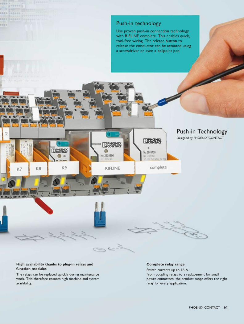
PHOENIX CONTACT 61
Complete relay range
Switch currents up to 16 A. From coupling relays to a replacement for small power contactors, the product range offers the right relay for every application.
High availability thanks to plug-in relays and function modules
The relays can be replaced quickly during maintenance work. This therefore ensures high machine and system availability.
Push-in technologyUse proven push-in connection technology with RIFLINE complete. This enables quick, tool-free wiring. The release button to release the conductor can be actuated using a screwdriver or even a ballpoint pen.
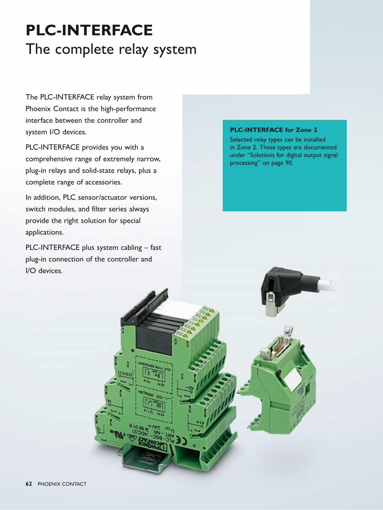
62 PHOENIX CONTACT
PLC-INTERFACE for Zone 2Selected relay types can be installed in Zone 2. These types are documented under “Solutions for digital output signal processing” on page 90.
PLC-INTERFACE The complete relay system
The PLC-INTERFACE relay system from
Phoenix Contact is the high-performance
interface between the controller and
system I/O devices.
PLC-INTERFACE provides you with a
comprehensive range of extremely narrow,
plug-in relays and solid-state relays, plus a
complete range of accessories.
In addition, PLC sensor/actuator versions,
switch modules, and filter series always
provide the right solution for special
applications.
PLC-INTERFACE plus system cabling – fast
plug-in connection of the controller and
I/O devices.
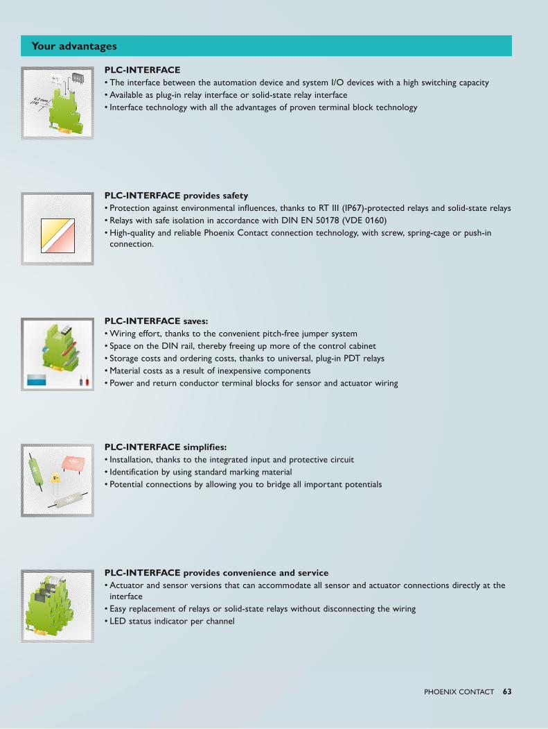
PHOENIX CONTACT 63
PLC-INTERFACE• The interface between the automation device and system I/O devices with a high switching capacity• Available as plug-in relay interface or solid-state relay interface• Interface technology with all the advantages of proven terminal block technology
PLC-INTERFACE provides safety• Protection against environmental influences, thanks to RT III (IP67)-protected relays and solid-state relays• Relays with safe isolation in accordance with DIN EN 50178 (VDE 0160)• High-quality and reliable Phoenix Contact connection technology, with screw, spring-cage or push-in
connection.
PLC-INTERFACE saves:• Wiring effort, thanks to the convenient pitch-free jumper system• Space on the DIN rail, thereby freeing up more of the control cabinet• Storage costs and ordering costs, thanks to universal, plug-in PDT relays• Material costs as a result of inexpensive components• Power and return conductor terminal blocks for sensor and actuator wiring
PLC-INTERFACE simplifies:• Installation, thanks to the integrated input and protective circuit• Identification by using standard marking material• Potential connections by allowing you to bridge all important potentials
PLC-INTERFACE provides convenience and service• Actuator and sensor versions that can accommodate all sensor and actuator connections directly at the
interface• Easy replacement of relays or solid-state relays without disconnecting the wiring• LED status indicator per channel
Your advantages
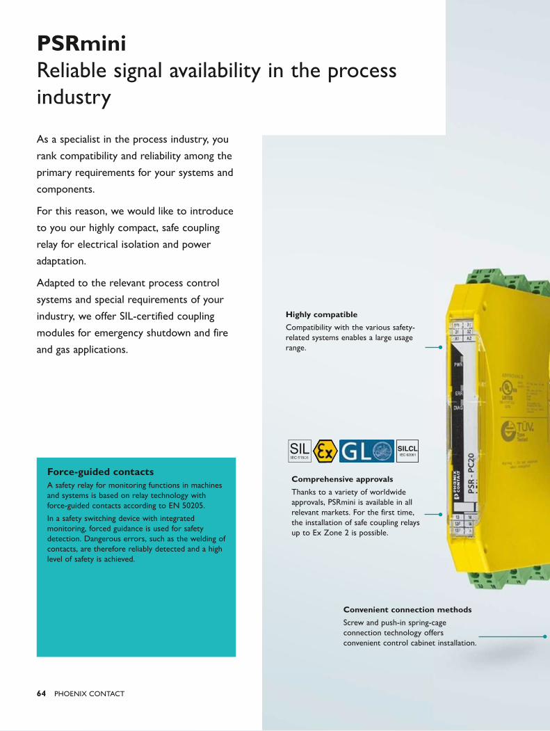
IEC 62061
SILCL
64 PHOENIX CONTACT
Force-guided contactsA safety relay for monitoring functions in machines and systems is based on relay technology with force-guided contacts according to EN 50205.
In a safety switching device with integrated monitoring, forced guidance is used for safety detection. Dangerous errors, such as the welding of contacts, are therefore reliably detected and a high level of safety is achieved.
Convenient connection methods
Screw and push-in spring-cage connection technology offers convenient control cabinet installation.
Highly compatible
Compatibility with the various safety-related systems enables a large usage range.
Comprehensive approvals
Thanks to a variety of worldwide approvals, PSRmini is available in all relevant markets. For the first time, the installation of safe coupling relays up to Ex Zone 2 is possible.
PSRmini Reliable signal availability in the process industry
As a specialist in the process industry, you
rank compatibility and reliability among the
primary requirements for your systems and
components.
For this reason, we would like to introduce
to you our highly compact, safe coupling
relay for electrical isolation and power
adaptation.
Adapted to the relevant process control
systems and special requirements of your
industry, we offer SIL-certified coupling
modules for emergency shutdown and fire
and gas applications.
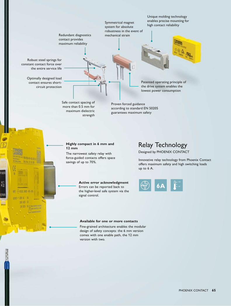
Relay Technology Designed by PHOENIX CONTACT
PHOENIX CONTACT 65
Available for one or more contacts
Fine-grained architecture enables the modular design of safety concepts: the 6 mm version comes with one enable path, the 12 mm version with two.
Innovative relay technology from Phoenix Contact offers maximum safety and high switching loads up to 6 A.
Active error acknowledgment Errors can be reported back to the higher-level safe system via the signal control.
Highly compact in 6 mm and 12 mm
The narrowest safety relay with force-guided contacts offers space savings of up to 70%.
Redundant diagnostics contact provides maximum reliability
Proven forced guidance according to standard EN 50205 guarantees maximum safety
Patented operating principle of the drive system enables the lowest power consumption
Robust steel springs for constant contact force over
the entire service life
Optimally designed load contact ensures short-
circuit protection
Unique molding technology enables precise mounting for high contact reliability
Symmetrical magnet system for absolute robustness in the event of mechanical strain
Safe contact spacing of more than 0.5 mm for
maximum dielectric strength

66 PHOENIX CONTACT
PSRmini Highly compact safety and coupling relays
Phoenix Contact has been a partner of the
process industry for many years. The new,
safe PSRmini coupling relays are the result
of this close cooperation and boast unique
product features:
• Minimal space requirements and high
scalability
• Easy diagnostics directly on the device and
controller thanks to forced guidance
• Comprehensive approval package and
extended temperature range across the
entire device series
• Customer-specific Termination Carriers
with system cabling
Your benefitsWe strive to contribute to the safety of your system and to minimize downtimes. We also reduce space and material requirements. For you, this means:
• Fewer control cabinets required, as up to 70% less space is required
• Shorter downtimes during scheduled maintenance phases, thanks to quick and easy diagnostics
• The safe coupling relays can be used up to potentially explosive areas, thereby simplifying the design of distributed concepts for the first time
• Shorter installation times and quick and easy startup
When used in combination with PSRmini, the Termination Carrier offers unrivaled packing density in the control cabinet.
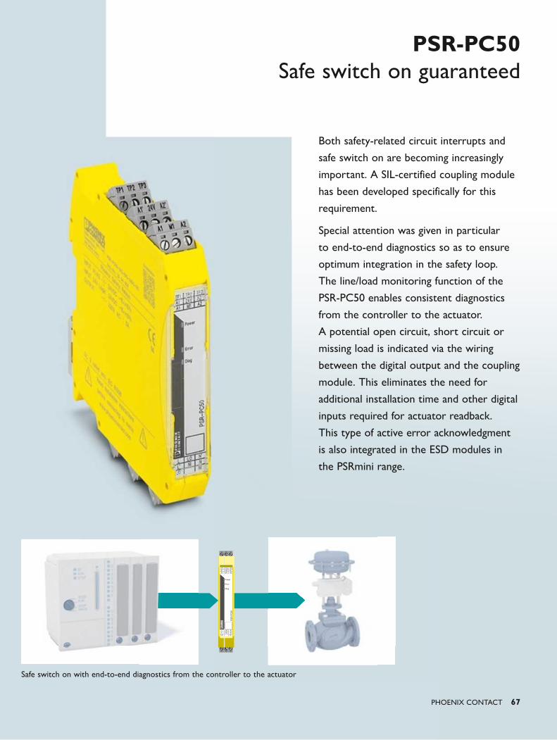
PSR-
PC50
Power
Error
Diag
TP1A1`A1
TP224VM1
TP3A2`A2
LL`
LO`
LONI
NN
NI`
PHOENIX CONTACT 67
PSR-PC50Safe switch on guaranteed
Both safety-related circuit interrupts and
safe switch on are becoming increasingly
important. A SIL-certified coupling module
has been developed specifically for this
requirement.
Special attention was given in particular
to end-to-end diagnostics so as to ensure
optimum integration in the safety loop.
The line/load monitoring function of the
PSR-PC50 enables consistent diagnostics
from the controller to the actuator.
A potential open circuit, short circuit or
missing load is indicated via the wiring
between the digital output and the coupling
module. This eliminates the need for
additional installation time and other digital
inputs required for actuator readback.
This type of active error acknowledgment
is also integrated in the ESD modules in
the PSRmini range.
Safe switch on with end-to-end diagnostics from the controller to the actuator
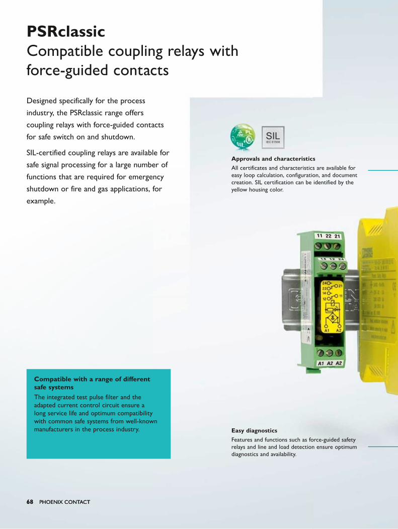
IEC 61508SIL
68 PHOENIX CONTACT68 PHOENIX CONTACT
Designed specifically for the process
industry, the PSRclassic range offers
coupling relays with force-guided contacts
for safe switch on and shutdown.
SIL-certified coupling relays are available for
safe signal processing for a large number of
functions that are required for emergency
shutdown or fire and gas applications, for
example.
PSRclassic Compatible coupling relays with force-guided contacts
Compatible with a range of different safe systems The integrated test pulse filter and the adapted current control circuit ensure a long service life and optimum compatibility with common safe systems from well-known manufacturers in the process industry. Easy diagnostics
Features and functions such as force-guided safety relays and line and load detection ensure optimum diagnostics and availability.
Approvals and characteristics
All certificates and characteristics are available for easy loop calculation, configuration, and document creation. SIL certification can be identified by the yellow housing color.
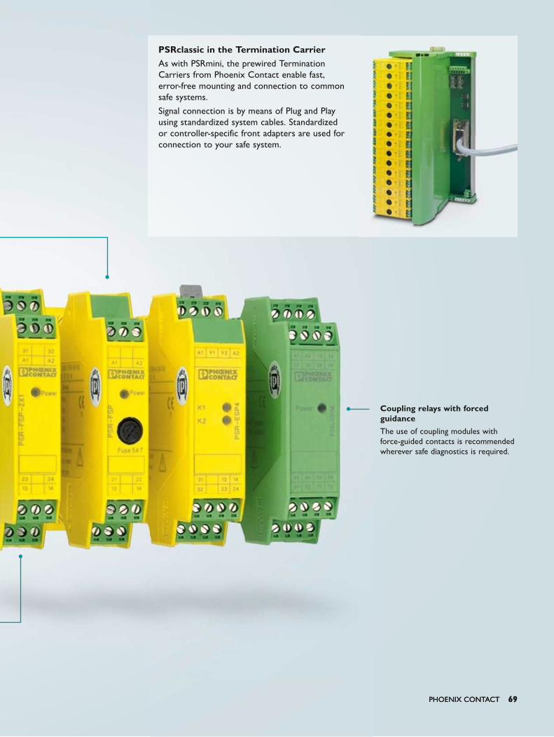
PHOENIX CONTACT 69PHOENIX CONTACT 69
PSRclassic in the Termination CarrierAs with PSRmini, the prewired Termination Carriers from Phoenix Contact enable fast, error-free mounting and connection to common safe systems.
Signal connection is by means of Plug and Play using standardized system cables. Standardized or controller-specific front adapters are used for connection to your safe system.
Coupling relays with forced guidance
The use of coupling modules with force-guided contacts is recommended wherever safe diagnostics is required.

70 PHOENIX CONTACT
PSRmini and PSRclassic Product overview
Selection matrix for applications
If you need one device with one function,
PSR safety switching devices are the
perfect solution. Our devices operate
with force-guided contacts according to
EN 50205.
You will find the corresponding coupling
relay for your application in the tables
below.
PSRmini – highly compact safe coupling relays for the process industry
Applications Output contacts Diagnostics/proof test Safety approvals Overall width
Connection method
Type
Highly compact, safe coupling relays for failsafe controllers… V
isua
l via
LED
Act
ive
erro
r
ackn
owle
dgm
ent
via
A1
Mea
sure
men
t on
the
de
vice
Self-
mon
itori
ng w
ith
inte
grat
ed lo
ck
SIL
IE
C 6
1508
/615
11
SIL
IEC
501
56
ATEX
/ IE
CEx
/C
lass
I Z
one
2
G3
AN
SI /
ISA
-S71
.04
GL
Scre
w,
plug
-in
Push
-in s
prin
g-ca
ge,
plug
-inPSR-PS20
… for safety-related shutdown (ESD)
1 1 NC / 1 DO X X X – 3 3 X X X 6.8 mm 2700356 –
PSR-PS21 1 1 NC / 1 DO X X X – 2 2 X X X 6.8 mm 2700357 –
PSR-PS40 1 1 DO X – – X 3 3 X X X 6.8 mm 2700398 –
PSR-PC20 1 1 NC / 1 DO X X X – 3 3 X X X 12.5 mm 2700577 2700578
PSR-PC40 2 1 DO X X – X 3 3 X X X 12.5 mm 2700588 2700589
PSR-PC50 …for safety-related switch on (F&G) 1 1 DO – X X – 31) – X – X 17.5 mm 2904664 2904665
1) Low demand, NC = N/C contact, DO = Digital signal outputCustomer-specific Termination Carriers are available on request
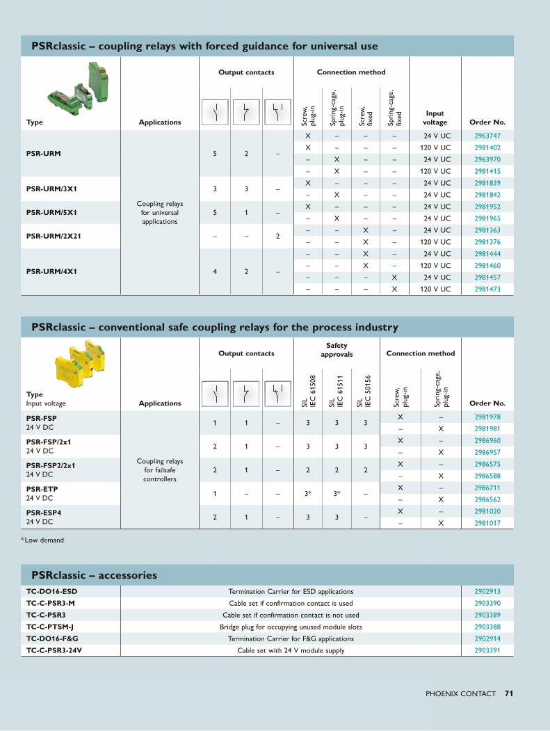
PHOENIX CONTACT 71
Type Applications
Output contacts Connection method
Input voltage Order No.
PSR-URM
Coupling relays for universal applications
5 2 –
X – – – 24 V UC 2963747
X – – – 120 V UC 2981402
– X – – 24 V UC 2963970
– X – – 120 V UC 2981415
PSR-URM/3X1 3 3 –X – – – 24 V UC 2981839
– X – – 24 V UC 2981842
PSR-URM/5X1 5 1 –X – – – 24 V UC 2981952
– X – – 24 V UC 2981965
PSR-URM/2X21 – – 2– – X – 24 V UC 2981363
– – X – 120 V UC 2981376
PSR-URM/4X1 4 2 –
– – X – 24 V UC 2981444
– – X – 120 V UC 2981460
– – – X 24 V UC 2981457
– – – X 120 V UC 2981473
Type Input voltage Applications
Output contactsSafety
approvals Connection method
Order No.
PSR-FSP 24 V DC
Coupling relays for failsafe controllers
1 1 – 3 3 3X – 2981978
– X 2981981
PSR-FSP/2x1 24 V DC
2 1 – 3 3 3X – 2986960
– X 2986957
PSR-FSP2/2x1 24 V DC
2 1 – 2 2 2X – 2986575
– X 2986588
PSR-ETP 24 V DC
1 – – 3* 3* –X – 2986711
– X 2986562
PSR-ESP4 24 V DC
2 1 – 3 3 –X – 2981020
– X 2981017
PSRclassic – accessoriesTC-DO16-ESD Termination Carrier for ESD applications 2902913
TC-C-PSR3-M Cable set if confirmation contact is used 2903390
TC-C-PSR3 Cable set if confirmation contact is not used 2903389
TC-C-PTSM-J Bridge plug for occupying unused module slots 2903388
TC-DO16-F&G Termination Carrier for F&G applications 2902914
TC-C-PSR3-24V Cable set with 24 V module supply 2903391
PSRclassic – coupling relays with forced guidance for universal use
PSRclassic – conventional safe coupling relays for the process industry
*Low demand
SIL
IEC
501
56
SIL
IEC
615
11
Spri
ng-c
age,
pl
ug-in
SIL
IEC
615
08
Scre
w,
plug
-in
Scre
w,
plug
-in
Spri
ng-c
age,
pl
ug-in
Scre
w,
fixed
Spri
ng-c
age,
fix
ed
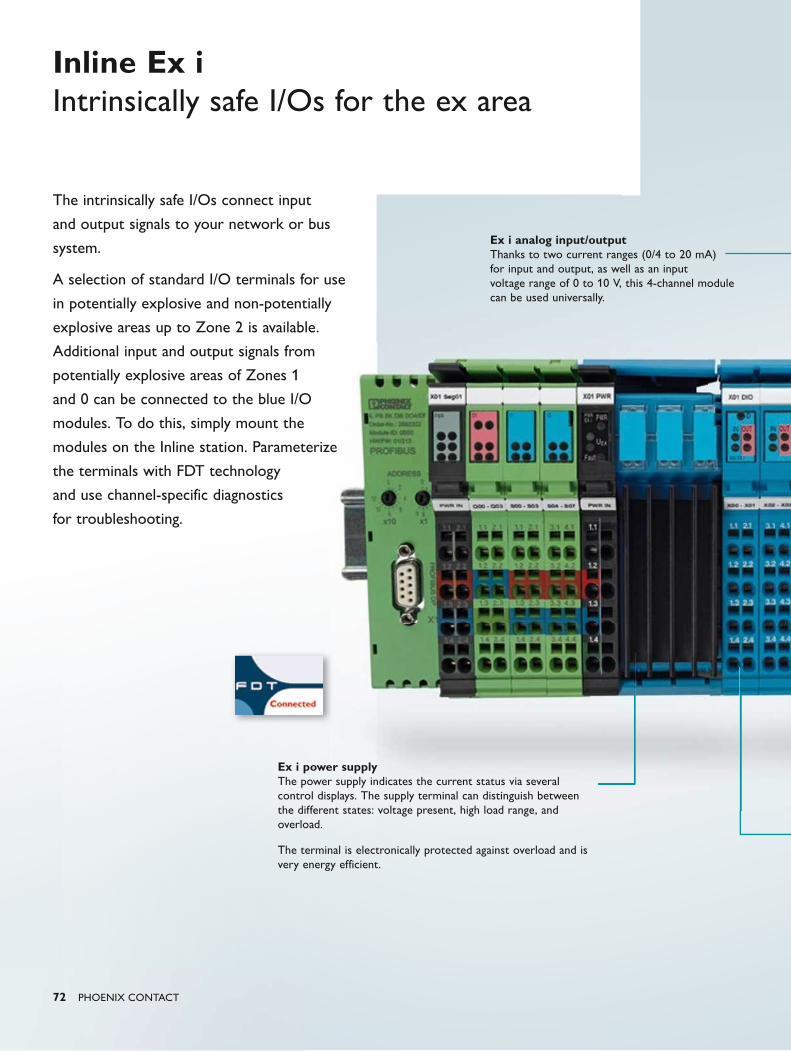
72 PHOENIX CONTACT
The intrinsically safe I/Os connect input
and output signals to your network or bus
system.
A selection of standard I/O terminals for use
in potentially explosive and non-potentially
explosive areas up to Zone 2 is available.
Additional input and output signals from
potentially explosive areas of Zones 1
and 0 can be connected to the blue I/O
modules. To do this, simply mount the
modules on the Inline station. Parameterize
the terminals with FDT technology
and use channel-specific diagnostics
for troubleshooting.
Inline Ex i Intrinsically safe I/Os for the ex area
Ex i analog input/output Thanks to two current ranges (0/4 to 20 mA) for input and output, as well as an input voltage range of 0 to 10 V, this 4-channel module can be used universally.
Ex i power supply The power supply indicates the current status via several control displays. The supply terminal can distinguish between the different states: voltage present, high load range, and overload.
The terminal is electronically protected against overload and is very energy efficient.
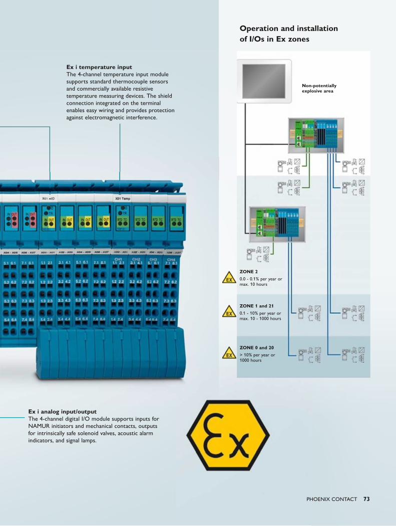
PHOENIX CONTACT 73
Ex i analog input/output The 4-channel digital I/O module supports inputs for NAMUR initiators and mechanical contacts, outputs for intrinsically safe solenoid valves, acoustic alarm indicators, and signal lamps.
Ex i temperature input The 4-channel temperature input module supports standard thermocouple sensors and commercially available resistive temperature measuring devices. The shield connection integrated on the terminal enables easy wiring and provides protection against electromagnetic interference.
Operation and installation of I/Os in Ex zones
ZONE 2
0.0 - 0.1% per year or max. 10 hours
Non-potentially explosive area
ZONE 1 and 21
0.1 - 10% per year or max. 10 - 1000 hours
ZONE 0 and 20
> 10% per year or 1000 hours
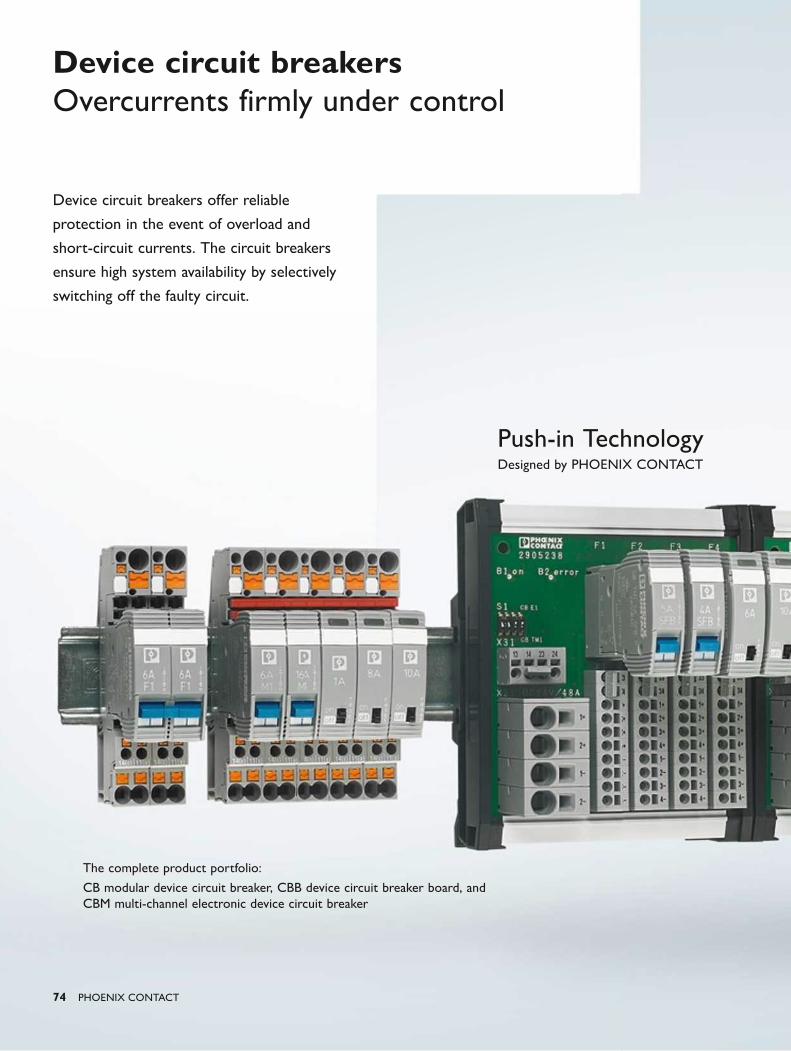
Push-in TechnologyDesigned by PHOENIX CONTACT
74 PHOENIX CONTACT
Device circuit breakers Overcurrents firmly under control
The complete product portfolio:
CB modular device circuit breaker, CBB device circuit breaker board, and CBM multi-channel electronic device circuit breaker
Device circuit breakers offer reliable
protection in the event of overload and
short-circuit currents. The circuit breakers
ensure high system availability by selectively
switching off the faulty circuit.
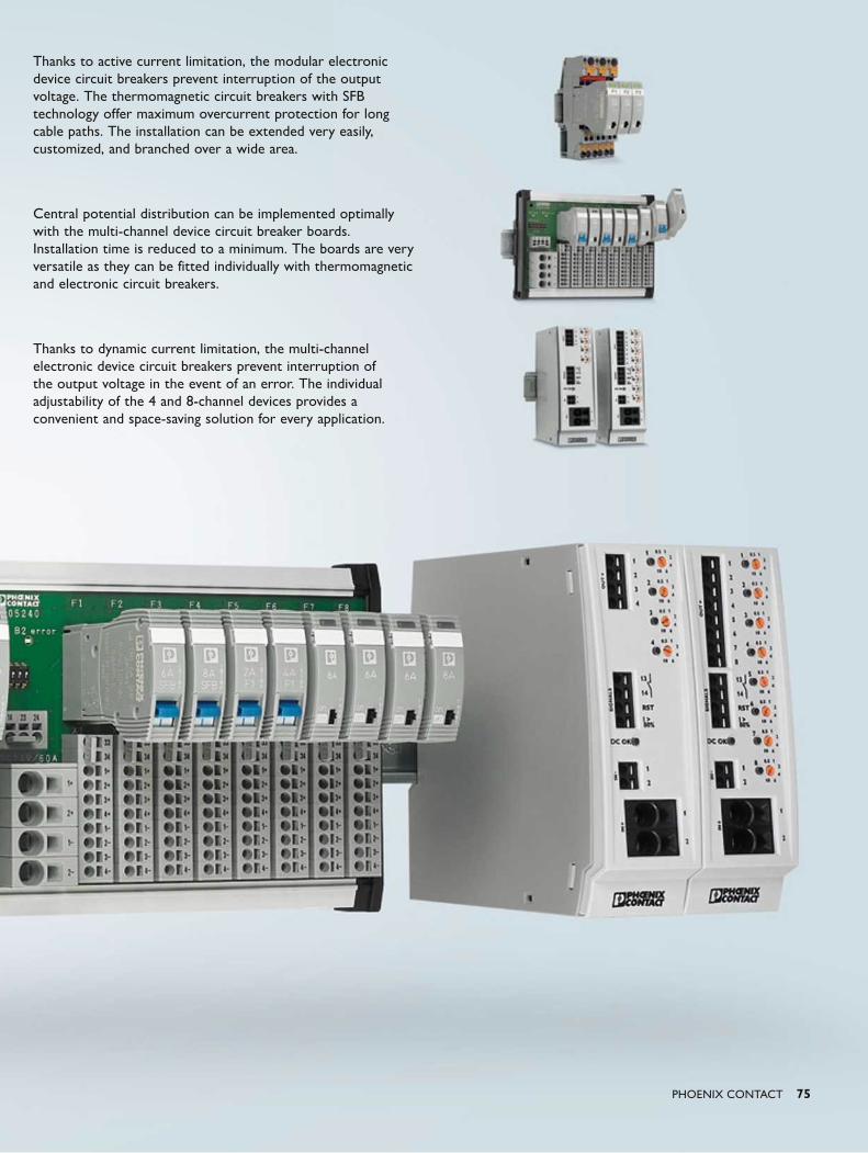
PHOENIX CONTACT 75
Thanks to active current limitation, the modular electronic device circuit breakers prevent interruption of the output voltage. The thermomagnetic circuit breakers with SFB technology offer maximum overcurrent protection for long cable paths. The installation can be extended very easily, customized, and branched over a wide area.
Central potential distribution can be implemented optimally with the multi-channel device circuit breaker boards. Installation time is reduced to a minimum. The boards are very versatile as they can be fitted individually with thermomagnetic and electronic circuit breakers.
Thanks to dynamic current limitation, the multi-channel electronic device circuit breakers prevent interruption of the output voltage in the event of an error. The individual adjustability of the 4 and 8-channel devices provides a convenient and space-saving solution for every application.
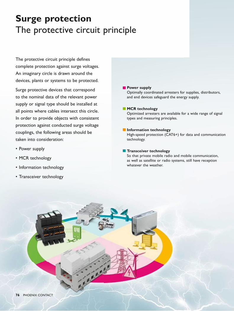
76 PHOENIX CONTACT
Surge protectionThe protective circuit principle
The protective circuit principle defines
complete protection against surge voltages.
An imaginary circle is drawn around the
devices, plants or systems to be protected.
Surge protective devices that correspond
to the nominal data of the relevant power
supply or signal type should be installed at
all points where cables intersect this circle.
In order to provide objects with consistent
protection against conducted surge voltage
couplings, the following areas should be
taken into consideration:
• Power supply
• MCR technology
• Information technology
• Transceiver technology
Power supply Optimally coordinated arresters for supplies, distributors, and end devices safeguard the energy supply.
MCR technology Optimized arresters are available for a wide range of signal types and measuring principles.
Information technology High-speed protection (CAT6+) for data and communication technology.
Transceiver technology So that private mobile radio and mobile communication, as well as satellite or radio systems, still have reception whatever the weather.
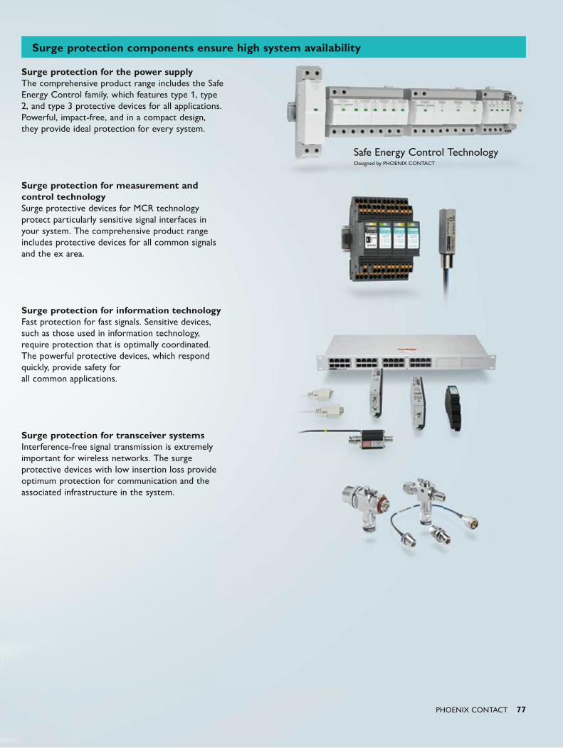
Safe Energy Control TechnologyDesigned by PHOENIX CONTACT
PHOENIX CONTACT 77
Surge protection for the power supplyThe comprehensive product range includes the Safe Energy Control family, which features type 1, type 2, and type 3 protective devices for all applications.Powerful, impact-free, and in a compact design, they provide ideal protection for every system.
Surge protection for measurement and control technologySurge protective devices for MCR technology protect particularly sensitive signal interfaces in your system. The comprehensive product range includes protective devices for all common signals and the ex area.
Surge protection for information technologyFast protection for fast signals. Sensitive devices, such as those used in information technology, require protection that is optimally coordinated. The powerful protective devices, which respond quickly, provide safety for all common applications.
Surge protection for transceiver systemsInterference-free signal transmission is extremely important for wireless networks. The surge protective devices with low insertion loss provide optimum protection for communication and the associated infrastructure in the system.
Surge protection components ensure high system availability
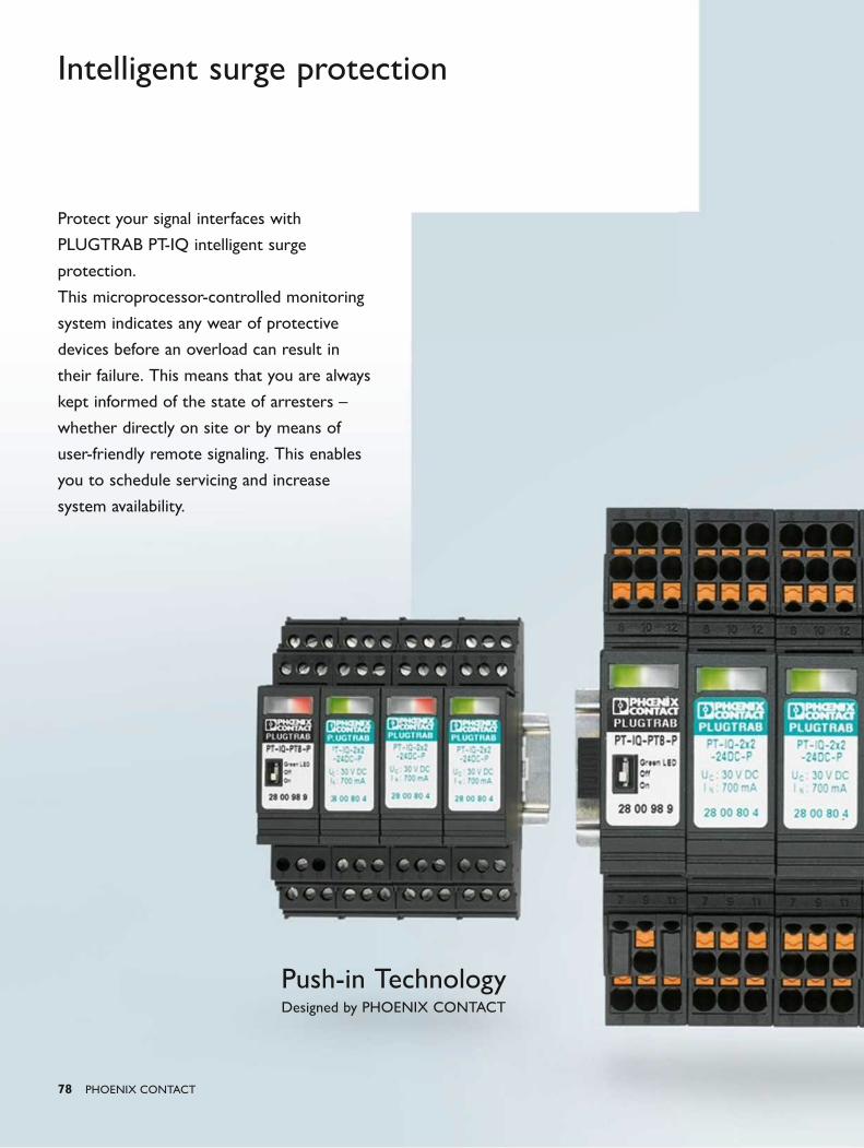
Push-in TechnologyDesigned by PHOENIX CONTACT
78 PHOENIX CONTACT
Intelligent surge protection
Protect your signal interfaces with
PLUGTRAB PT-IQ intelligent surge
protection.
This microprocessor-controlled monitoring
system indicates any wear of protective
devices before an overload can result in
their failure. This means that you are always
kept informed of the state of arresters –
whether directly on site or by means of
user-friendly remote signaling. This enables
you to schedule servicing and increase
system availability.
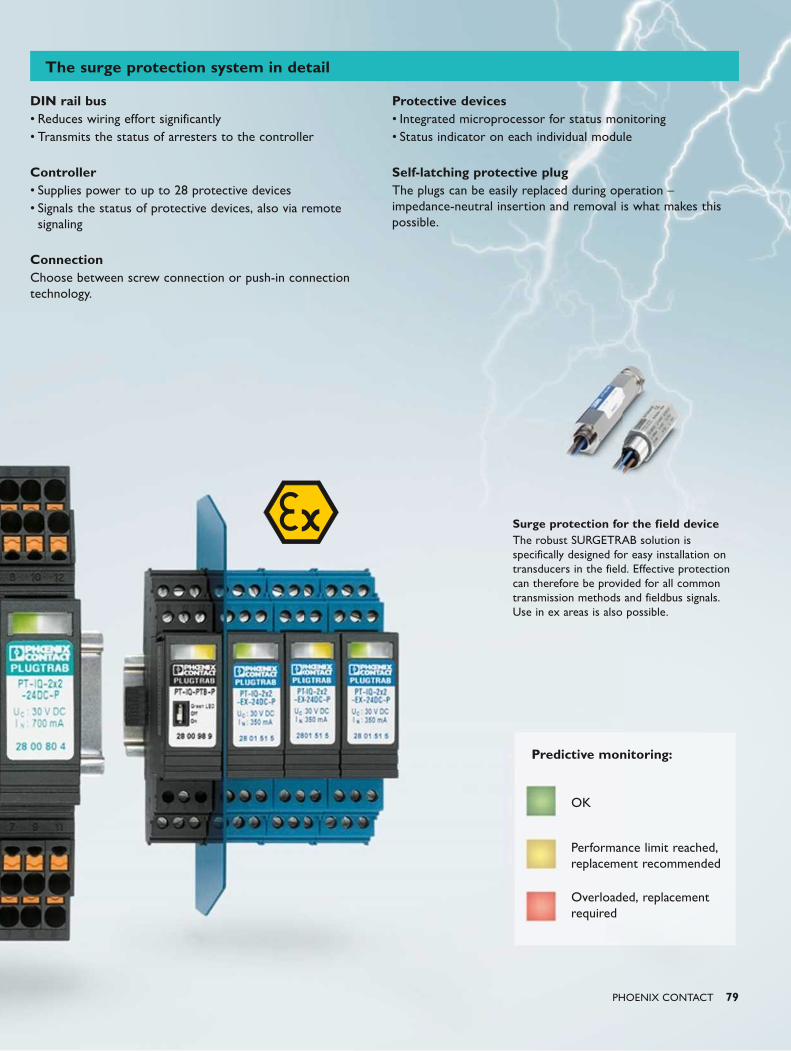
PHOENIX CONTACT 79
Surge protection for the field deviceThe robust SURGETRAB solution is specifically designed for easy installation on transducers in the field. Effective protection can therefore be provided for all common transmission methods and fieldbus signals. Use in ex areas is also possible.
DIN rail bus• Reduces wiring effort significantly• Transmits the status of arresters to the controller
Controller• Supplies power to up to 28 protective devices• Signals the status of protective devices, also via remote
signaling
ConnectionChoose between screw connection or push-in connection technology.
Protective devices• Integrated microprocessor for status monitoring• Status indicator on each individual module
Self-latching protective plugThe plugs can be easily replaced during operation – impedance-neutral insertion and removal is what makes this possible.
OK
Performance limit reached, replacement recommended
Overloaded, replacement required
Predictive monitoring:
The surge protection system in detail

80 PHOENIX CONTACT
Isolating spark gap Lightning protection equipotential bonding for pipelines
The FLT isolating spark gap protects the
sensitive insulating flanges and the coating
of a pipeline against damage caused by
surge voltages. Voltage peaks which are
caused by lightning strikes can damage or
even destroy the insulation of flanges. The
isolating spark gap limits surge voltages to
the extent that no damage is caused to
the insulation. Cost-intensive failure times
and possible environmental pollution from
leakages are avoided from the outset. The
isolating spark gap is approved for use in
potentially explosive areas.
Your advantages at a glance:• High discharge capacity of 100 kA• Maximum category H in accordance
with IEC 62561-3• Low response voltage ≤ 1250 V
(1.2/50 μѕ)• Rated power-frequency withstand
voltage of 250 V AC• Suitable for use in harsh ambient
conditions• For installation in Ex Zone 1 and 2
(ATEX, IECEx)
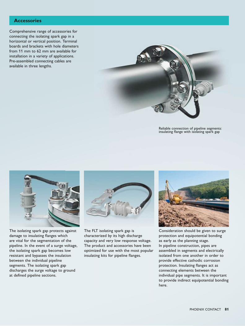
PHOENIX CONTACT 81
Comprehensive range of accessories for connecting the isolating spark gap in a horizontal or vertical position. Terminal boards and brackets with hole diameters from 11 mm to 62 mm are available for installation in a variety of applications. Pre-assembled connecting cables are available in three lengths.
The isolating spark gap protects against damage to insulating flanges which are vital for the segmentation of the pipeline. In the event of a surge voltage, the isolating spark gap becomes low resistant and bypasses the insulation between the individual pipeline segments. The isolating spark gap discharges the surge voltage to ground at defined pipeline sections.
The FLT isolating spark gap is characterized by its high discharge capacity and very low response voltage. The product and accessories have been optimized for use with the most popular insulating kits for pipeline flanges.
Consideration should be given to surge protection and equipotential bonding as early as the planning stage. In pipeline construction, pipes are assembled in segments and electrically isolated from one another in order to provide effective cathodic corrosion protection. Insulating flanges act as connecting elements between the individual pipe segments. It is important to provide indirect equipotential bonding here.
Reliable connection of pipeline segments: insulating flange with isolating spark gap
Accessories
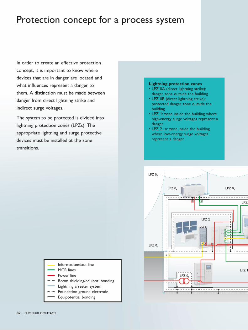
LPZ 0A
LPZ 1
LPZ 0B
5
52
5545
3 2
1
4
4
LPZ 0B
LPZ 0B
LPZ 2
LPZ 3
LPZ 0B
LPZ
82 PHOENIX CONTACT
Protection concept for a process system
In order to create an effective protection
concept, it is important to know where
devices that are in danger are located and
what influences represent a danger to
them. A distinction must be made between
danger from direct lightning strike and
indirect surge voltages.
The system to be protected is divided into
lightning protection zones (LPZs). The
appropriate lightning and surge protective
devices must be installed at the zone
transitions.
Information/data lineMCR linesPower lineRoom shielding/equipot. bondingLightning arrester systemFoundation ground electrodeEquipotential bonding
Lightning protection zones• LPZ 0A (direct lightning strike):
danger zone outside the building• LPZ 0B (direct lightning strike):
protected danger zone outside the building
• LPZ 1: zone inside the building where high-energy surge voltages represent a danger
• LPZ 2...n: zone inside the building where low-energy surge voltages represent a danger
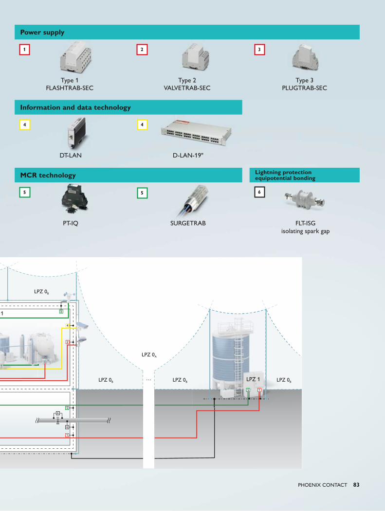
…
LPZ 0B
LPZ 0A
5
4
2
5
6
5 1
1
LPZ 0B LPZ 0B LPZ 0B
1
LPZ 1
6
PHOENIX CONTACT 83
Power supply
Type 1 FLASHTRAB-SEC
Type 2 VALVETRAB-SEC
Type 3 PLUGTRAB-SEC
Information and data technology
DT-LAN D-LAN-19"
MCR technology Lightning protection equipotential bonding
PT-IQ SURGETRAB FLT-ISG isolating spark gap
1 2 3
4 4
5 5 6
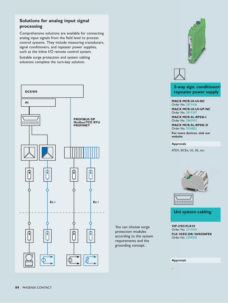
84 PHOENIX CONTACT
Solutions for analog input signal processingComprehensive solutions are available for connecting analog input signals from the field level to process control systems. They include measuring transducers, signal conditioners, and repeater power supplies, such as the Inline I/O remote control system.
Suitable surge protection and system cabling solutions complete the turn-key solution.
DCS/SIS
AI
PROFIBUS DP Modbus/TCP, RTUPROFINET
Ex i Ex i
You can choose surge protection modules according to the system requirements and the grounding concept.
Uni system cabling
VIP-2/SC/FLK10 Order No. 2315010 FLK 10/EZ-DR/ 50/KONFEK Order No. 2299204
Approvals
–
3-way sign. conditioner/repeater power supply
MACX MCR-UI-UI-NC Order No. 2811446
MACX MCR-UI-UI-UP-NC Order No. 2811297
MACX MCR-SL-RPSSI-I Order No. 2865955
MACX MCR-SL-RPSSI-2I Order No. 2924825
For more devices, visit our website
Approvals
ATEX, IECEx, UL, SIL, etc.
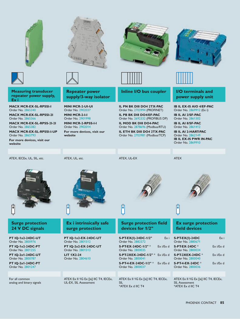
PHOENIX CONTACT 85
Surge protection 24 V DC signals
Ex i intrinsically safe surge protection
Surge protection field devices for 1/2"
Ex surge protection field devices
PT IQ-1x2-24DC-UT Order No. 2800976
PT IQ-1x2-24DC-PT Order No. 2801255
PT IQ-2x1-24DC-UT Order No. 2800787
PT IQ-2x1-24DC-PT Order No. 2801247
PT IQ-1x2-EX-24DC-UT Order No. 2801512
PT IQ-2x2-EX-24DC-UT Order No. 2801513
LIT 1X2-24 Order No. 2804610
S-PT-EX(I)-24DC-1/2" Ex i Order No. 2882572
S-PT-EX-24DC-1/2" * Ex i/Ex d Order No. 2800035
S-PT-2XEX-24DC-1/2" * Ex i/Ex d Order No. 2800041
S-PT-4-EX-24DC-1/2" * Ex i/Ex d Order No. 2800037
S-PT-EX(I)-24DC Ex i Order No. 2880671
S-PT-EX-24DC * Ex i/Ex d Order No. 2800034
S-PT-2XEX-24DC * Ex i/Ex d Order No. 2800040
S-PT-4-EX-24DC * Ex i/Ex d Order No. 2800036
For all common analog and binary signals
ATEX Ex II 1G Ex [ia] IIC T4, IECEx, UL-EX, SIL Assessment
ATEX Ex II 1G Ex [ia] IIC T4, IECEx, SIL *ATEX Ex d IIC T4
ATEX Ex II 1G Ex [ia] IIC T4, IECEx, SIL Assessment *ATEX Ex d IIC T4
Measuring transducer repeater power supply, Ex i
Repeater power supply/3-way isolator
Inline I/O bus coupler I/O terminals and power supply unit
MACX MCR-EX-SL-RPSSI-I Order No. 2865340
MACX MCR-EX-SL-RPSSI-2I Order No. 2865366
MACX MCR-EX-SL-RPSS-2I-2I Order No. 2865382
MACX MCR-EX-SL-RPSSI-I-UP Order No. 2865793
For more devices, visit our website
MINI MCR-2-UI-UI Order No. 2902037
MINI MCR-2-I-I Order No. 2901998
MINI MCR-2-RPSS-I-I Order No. 2902014
For more devices, visit our website
IL PN BK DI8 DO4 2TX-PAC Order No. 2703994 (PROFINET)
IL PB BK DI8 DO4/EF-PAC Order No. 2692332 (PROFIBUS DP)
IL MOD BK DI8 DO4-PAC Order No. 2878696 (Modbus/RTU)
IL ETH BK DI8 DO4 2TX-PAC Order No. 2703981 (Modbus/TCP)
IB IL EX-IS AIO 4/EF-PAC Order No. 2869912 (Ex i) IB IL AI 2/SF-PAC Order No. 2861302
IB IL AI 8/SF-PAC Order No. 2861412
IB IL AI 2-HART-PAC Order No. 2862149 IB IL EX-IS PWR IN-PAC Order No. 2869910
ATEX, IECEx, UL, SIL, etc. ATEX, UL, etc. ATEX, UL-EX ATEX
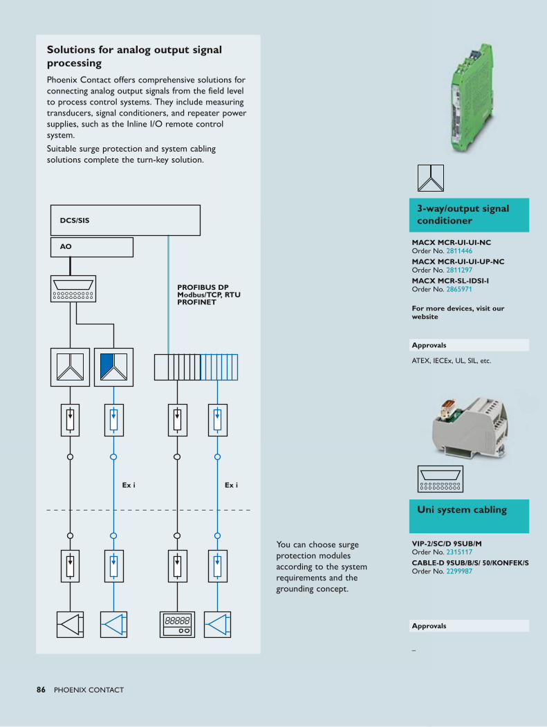
86 PHOENIX CONTACT
Solutions for analog output signal processingPhoenix Contact offers comprehensive solutions for connecting analog output signals from the field level to process control systems. They include measuring transducers, signal conditioners, and repeater power supplies, such as the Inline I/O remote control system.
Suitable surge protection and system cabling solutions complete the turn-key solution.
DCS/SIS
AO
PROFIBUS DP Modbus/TCP, RTUPROFINET
You can choose surge protection modules according to the system requirements and the grounding concept.
Ex i Ex i
Uni system cabling
VIP-2/SC/D 9SUB/M Order No. 2315117 CABLE-D 9SUB/B/S/ 50/KONFEK/S Order No. 2299987
Approvals
–
3-way/output signal conditioner
MACX MCR-UI-UI-NC Order No. 2811446
MACX MCR-UI-UI-UP-NC Order No. 2811297
MACX MCR-SL-IDSI-I Order No. 2865971
For more devices, visit our website
Approvals
ATEX, IECEx, UL, SIL, etc.
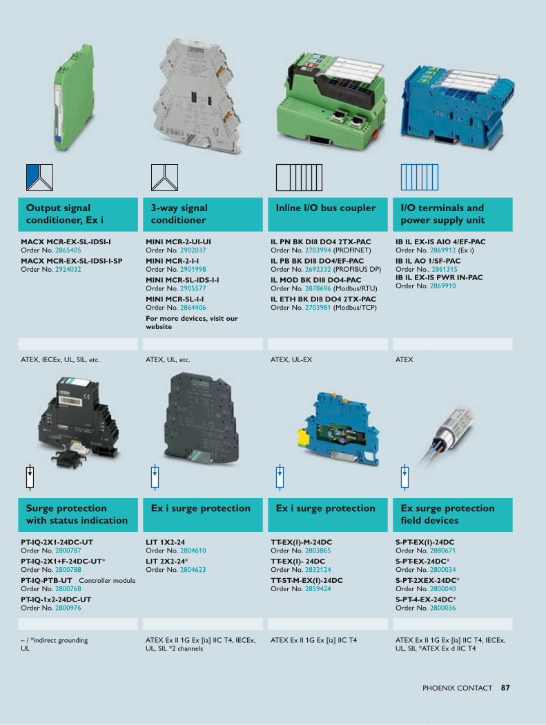
PHOENIX CONTACT 87
Surge protection with status indication
Ex i surge protection Ex i surge protection Ex surge protection field devices
PT-IQ-2X1-24DC-UT Order No. 2800787
PT-IQ-2X1+F-24DC-UT* Order No. 2800788 PT-IQ-PTB-UT Controller module Order No. 2800768 PT-IQ-1x2-24DC-UT Order No. 2800976
LIT 1X2-24 Order No. 2804610 LIT 2X2-24* Order No. 2804623
TT-EX(I)-M-24DC Order No. 2803865
TT-EX(I)- 24DC Order No. 2832124
TT-ST-M-EX(I)-24DC Order No. 2859424
S-PT-EX(I)-24DC Order No. 2880671
S-PT-EX-24DC* Order No. 2800034
S-PT-2XEX-24DC* Order No. 2800040
S-PT-4-EX-24DC* Order No. 2800036
– / *indirect grounding UL
ATEX Ex II 1G Ex [ia] IIC T4, IECEx, UL, SIL *2 channels
ATEX Ex II 1G Ex [ia] IIC T4 ATEX Ex II 1G Ex [ia] IIC T4, IECEx, UL, SIL *ATEX Ex d IIC T4
Output signal conditioner, Ex i
3-way signal conditioner
Inline I/O bus coupler I/O terminals and power supply unit
MACX MCR-EX-SL-IDSI-I Order No. 2865405
MACX MCR-EX-SL-IDSI-I-SP Order No. 2924032
MINI MCR-2-UI-UI Order No. 2902037
MINI MCR-2-I-I Order No. 2901998
MINI MCR-SL-IDS-I-I Order No. 2905577
MINI MCR-SL-I-I Order No. 2864406
For more devices, visit our website
IL PN BK DI8 DO4 2TX-PAC Order No. 2703994 (PROFINET)
IL PB BK DI8 DO4/EF-PAC Order No. 2692332 (PROFIBUS DP)
IL MOD BK DI8 DO4-PAC Order No. 2878696 (Modbus/RTU)
IL ETH BK DI8 DO4 2TX-PAC Order No. 2703981 (Modbus/TCP)
IB IL EX-IS AIO 4/EF-PAC Order No. 2869912 (Ex i) IB IL AO 1/SF-PAC Order No.. 2861315 IB IL EX-IS PWR IN-PAC Order No. 2869910
ATEX, IECEx, UL, SIL, etc. ATEX, UL, etc. ATEX, UL-EX ATEX
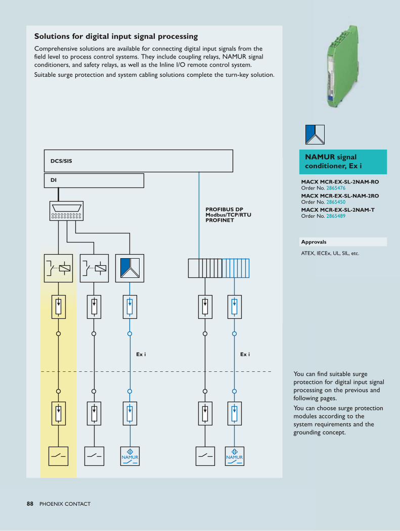
88 PHOENIX CONTACT
Solutions for digital input signal processingComprehensive solutions are available for connecting digital input signals from the field level to process control systems. They include coupling relays, NAMUR signal conditioners, and safety relays, as well as the Inline I/O remote control system.
Suitable surge protection and system cabling solutions complete the turn-key solution.
DI
PROFIBUS DP Modbus/TCP/RTUPROFINET
Ex i Ex i
You can find suitable surge protection for digital input signal processing on the previous and following pages.
You can choose surge protection modules according to the system requirements and the grounding concept.
DCS/SISNAMUR signal conditioner, Ex i
MACX MCR-EX-SL-2NAM-RO Order No. 2865476
MACX MCR-EX-SL-NAM-2RO Order No. 2865450
MACX MCR-EX-SL-2NAM-T Order No. 2865489
Approvals
ATEX, IECEx, UL, SIL, etc.
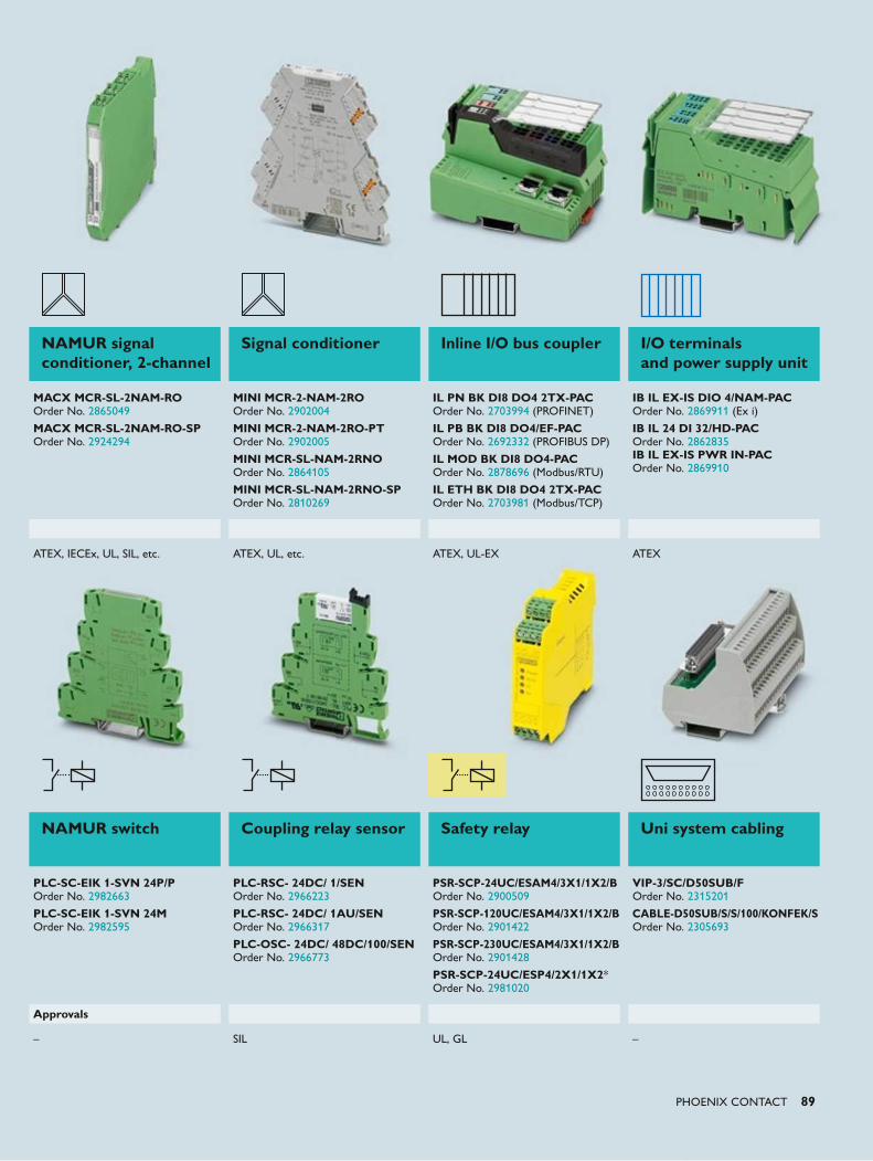
PHOENIX CONTACT 89
NAMUR switch Coupling relay sensor Safety relay Uni system cabling
PLC-SC-EIK 1-SVN 24P/P Order No. 2982663 PLC-SC-EIK 1-SVN 24M Order No. 2982595
PLC-RSC- 24DC/ 1/SEN Order No. 2966223 PLC-RSC- 24DC/ 1AU/SEN Order No. 2966317 PLC-OSC- 24DC/ 48DC/100/SEN Order No. 2966773
PSR-SCP-24UC/ESAM4/3X1/1X2/B Order No. 2900509
PSR-SCP-120UC/ESAM4/3X1/1X2/B Order No. 2901422
PSR-SCP-230UC/ESAM4/3X1/1X2/B Order No. 2901428
PSR-SCP-24UC/ESP4/2X1/1X2* Order No. 2981020
VIP-3/SC/D50SUB/F Order No. 2315201 CABLE-D50SUB/S/S/100/KONFEK/S Order No. 2305693
Approvals
– SIL UL, GL –
NAMUR signal conditioner, 2-channel
Signal conditioner Inline I/O bus coupler I/O terminals and power supply unit
MACX MCR-SL-2NAM-RO Order No. 2865049
MACX MCR-SL-2NAM-RO-SP Order No. 2924294
MINI MCR-2-NAM-2RO Order No. 2902004
MINI MCR-2-NAM-2RO-PT Order No. 2902005
MINI MCR-SL-NAM-2RNO Order No. 2864105
MINI MCR-SL-NAM-2RNO-SP Order No. 2810269
IL PN BK DI8 DO4 2TX-PAC Order No. 2703994 (PROFINET)
IL PB BK DI8 DO4/EF-PAC Order No. 2692332 (PROFIBUS DP)
IL MOD BK DI8 DO4-PAC Order No. 2878696 (Modbus/RTU)
IL ETH BK DI8 DO4 2TX-PAC Order No. 2703981 (Modbus/TCP)
IB IL EX-IS DIO 4/NAM-PAC Order No. 2869911 (Ex i) IB IL 24 DI 32/HD-PAC Order No. 2862835 IB IL EX-IS PWR IN-PAC Order No. 2869910
ATEX, IECEx, UL, SIL, etc. ATEX, UL, etc. ATEX, UL-EX ATEX
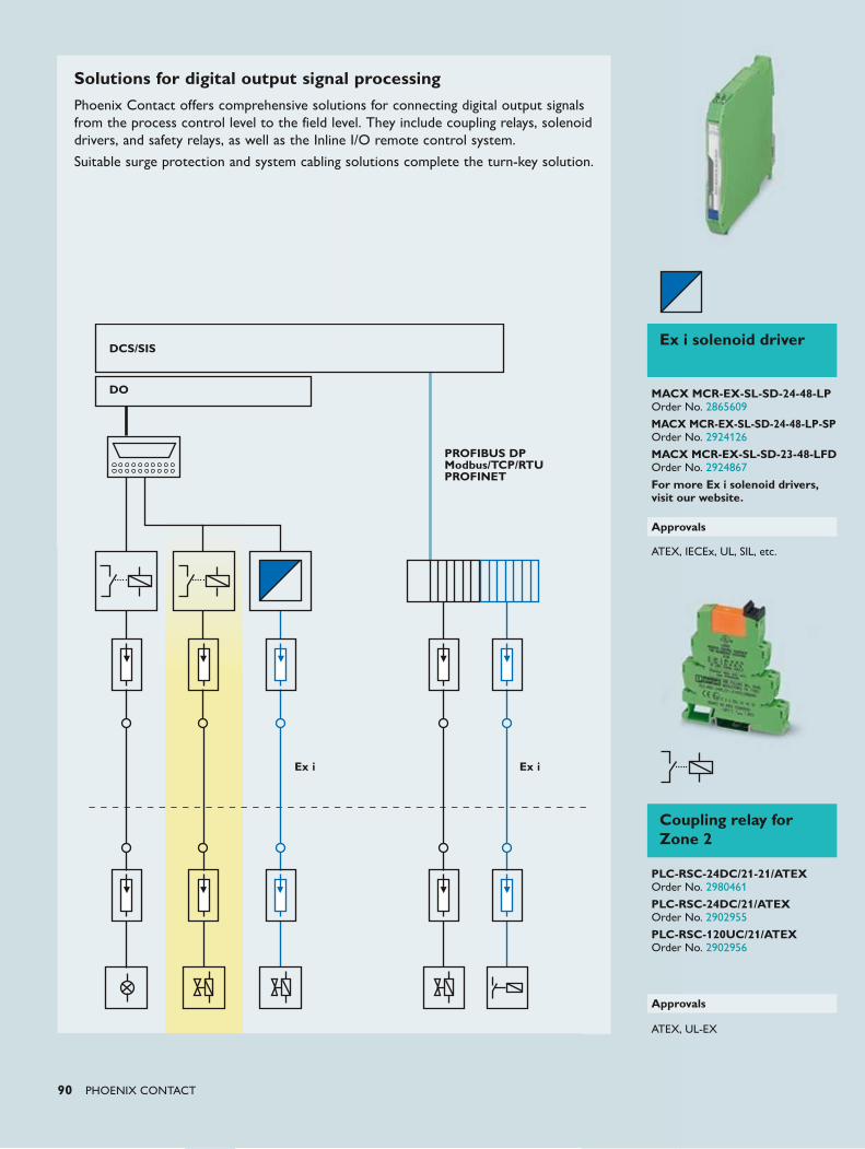
90 PHOENIX CONTACT
Solutions for digital output signal processingPhoenix Contact offers comprehensive solutions for connecting digital output signals from the process control level to the field level. They include coupling relays, solenoid drivers, and safety relays, as well as the Inline I/O remote control system.
Suitable surge protection and system cabling solutions complete the turn-key solution.
DO
DCS/SIS
PROFIBUS DP Modbus/TCP/RTUPROFINET
Ex i Ex i
Coupling relay for Zone 2
PLC-RSC-24DC/21-21/ATEX Order No. 2980461
PLC-RSC-24DC/21/ATEX Order No. 2902955
PLC-RSC-120UC/21/ATEX Order No. 2902956
Approvals
ATEX, UL-EX
Ex i solenoid driver
MACX MCR-EX-SL-SD-24-48-LP Order No. 2865609
MACX MCR-EX-SL-SD-24-48-LP-SP Order No. 2924126
MACX MCR-EX-SL-SD-23-48-LFD Order No. 2924867
For more Ex i solenoid drivers, visit our website.
Approvals
ATEX, IECEx, UL, SIL, etc.
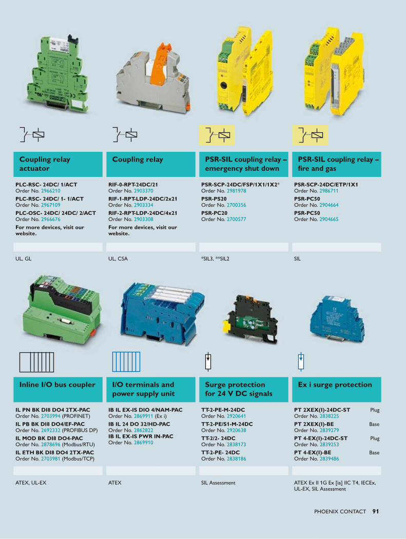
PHOENIX CONTACT 91
Inline I/O bus coupler I/O terminals and power supply unit
Surge protection for 24 V DC signals
Ex i surge protection
IL PN BK DI8 DO4 2TX-PAC Order No. 2703994 (PROFINET)
IL PB BK DI8 DO4/EF-PAC Order No. 2692332 (PROFIBUS DP)
IL MOD BK DI8 DO4-PAC Order No. 2878696 (Modbus/RTU)
IL ETH BK DI8 DO4 2TX-PAC Order No. 2703981 (Modbus/TCP)
IB IL EX-IS DIO 4/NAM-PAC Order No. 2869911 (Ex i) IB IL 24 DO 32/HD-PAC Order No. 2862822 IB IL EX-IS PWR IN-PAC Order No. 2869910
TT-2-PE-M-24DC Order No. 2920641
TT-2-PE/S1-M-24DC Order No. 2920638
TT-2/2- 24DC Order No. 2838173
TT-2-PE- 24DC Order No. 2838186
PT 2XEX(I)-24DC-ST Plug Order No. 2838225
PT 2XEX(I)-BE Base Order No. 2839279
PT 4-EX(I)-24DC-ST Plug Order No. 2839253
PT 4-EX(I)-BE Base Order No. 2839486
ATEX, UL-EX ATEX SIL Assessment ATEX Ex II 1G Ex [ia] IIC T4, IECEx, UL-EX, SIL Assessment
Coupling relay actuator
Coupling relay PSR-SIL coupling relay – emergency shut down
PSR-SIL coupling relay – fire and gas
PLC-RSC- 24DC/ 1/ACT Order No. 2966210 PLC-RSC- 24DC/ 1- 1/ACT Order No. 2967109 PLC-OSC- 24DC/ 24DC/ 2/ACT Order No. 2966676
For more devices, visit our website.
RIF-0-RPT-24DC/21 Order No. 2903370
RIF-1-RPT-LDP-24DC/2x21 Order No. 2903334
RIF-2-RPT-LDP-24DC/4x21 Order No. 2903308
For more devices, visit our website.
PSR-SCP-24DC/FSP/1X1/1X2* Order No. 2981978
PSR-PS20 Order No. 2700356
PSR-PC20 Order No. 2700577
PSR-SCP-24DC/ETP/1X1 Order No. 2986711 PSR-PC50 Order No. 2904664
PSR-PC50 Order No. 2904665
UL, GL UL, CSA *SIL3, **SIL2 SIL
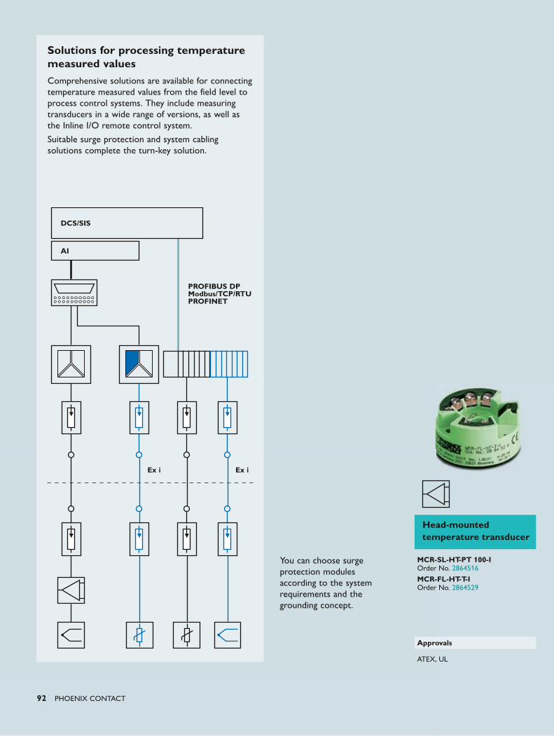
92 PHOENIX CONTACT
Solutions for processing temperature measured valuesComprehensive solutions are available for connecting temperature measured values from the field level to process control systems. They include measuring transducers in a wide range of versions, as well as the Inline I/O remote control system.
Suitable surge protection and system cabling solutions complete the turn-key solution.
DCS/SIS
AI
Ex i Ex i
PROFIBUS DP Modbus/TCP/RTUPROFINET
You can choose surge protection modules according to the system requirements and the grounding concept.
Head-mounted temperature transducer
MCR-SL-HT-PT 100-I Order No. 2864516
MCR-FL-HT-T-I Order No. 2864529
Approvals
ATEX, UL
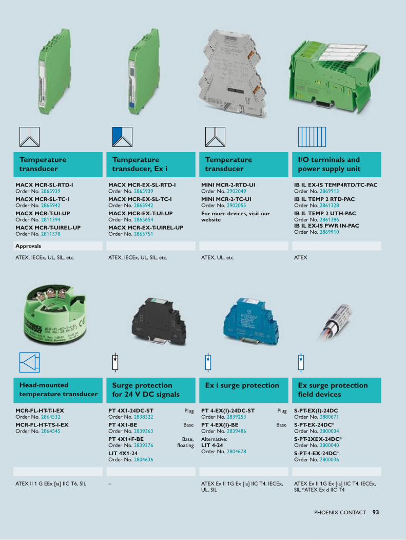
PHOENIX CONTACT 93
Temperature transducer
Temperature transducer, Ex i
Temperature transducer
I/O terminals and power supply unit
MACX MCR-SL-RTD-I Order No. 2865939
MACX MCR-SL-TC-I Order No. 2865942 MACX MCR-T-UI-UP Order No. 2811394
MACX MCR-T-UIREL-UP Order No. 2811378
MACX MCR-EX-SL-RTD-I Order No. 2865939
MACX MCR-EX-SL-TC-I Order No. 2865942
MACX MCR-EX-T-UI-UP Order No. 2865654
MACX MCR-EX-T-UIREL-UP Order No. 2865751
MINI MCR-2-RTD-UI Order No. 2902049
MINI MCR-2-TC-UI Order No. 2902055
For more devices, visit our website
IB IL EX-IS TEMP4RTD/TC-PAC Order No. 2869913
IB IL TEMP 2 RTD-PAC Order No. 2861328 IB IL TEMP 2 UTH-PAC Order No. 2861386 IB IL EX-IS PWR IN-PAC Order No. 2869910
Approvals
ATEX, IECEx, UL, SIL, etc. ATEX, IECEx, UL, SIL, etc. ATEX, UL, etc. ATEX
Head-mounted temperature transducer
Surge protection for 24 V DC signals
Ex i surge protection Ex surge protection field devices
MCR-FL-HT-T-I-EX Order No. 2864532
MCR-FL-HT-TS-I-EX Order No. 2864545
PT 4X1-24DC-ST Plug Order No. 2838322
PT 4X1-BE Base Order No. 2839363
PT 4X1+F-BE Base, Order No. 2839376 floating
LIT 4X1-24 Order No. 2804636
PT 4-EX(I)-24DC-ST Plug Order No. 2839253
PT 4-EX(I)-BE Base Order No. 2839486
Alternative: LIT 4-24 Order No. 2804678
S-PT-EX(I)-24DC Order No. 2880671
S-PT-EX-24DC* Order No. 2800034
S-PT-2XEX-24DC* Order No. 2800040
S-PT-4-EX-24DC* Order No. 2800036
ATEX II 1 G EEx [ia] IIC T6, SIL – ATEX Ex II 1G Ex [ia] IIC T4, IECEx, UL, SIL
ATEX Ex II 1G Ex [ia] IIC T4, IECEx, SIL *ATEX Ex d IIC T4
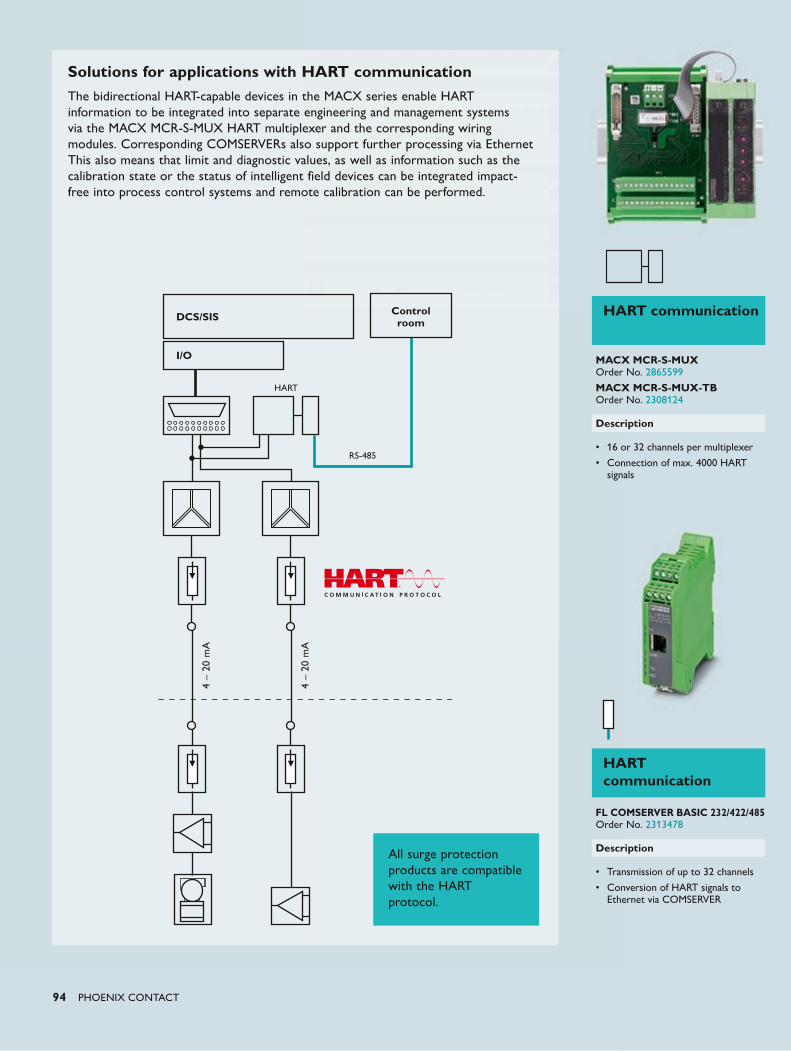
94 PHOENIX CONTACT
DCS/SIS Control room
I/O
4 –
20 m
A
4 –
20 m
A
HART
RS-485
Solutions for applications with HART communicationThe bidirectional HART-capable devices in the MACX series enable HART information to be integrated into separate engineering and management systems via the MACX MCR-S-MUX HART multiplexer and the corresponding wiring modules. Corresponding COMSERVERs also support further processing via Ethernet This also means that limit and diagnostic values, as well as information such as the calibration state or the status of intelligent field devices can be integrated impact-free into process control systems and remote calibration can be performed.
All surge protection products are compatible with the HART protocol.
HART communication
MACX MCR-S-MUX Order No. 2865599
MACX MCR-S-MUX-TB Order No. 2308124
Description
• 16 or 32 channels per multiplexer
• Connection of max. 4000 HART signals
HART communication
FL COMSERVER BASIC 232/422/485 Order No. 2313478
Description
• Transmission of up to 32 channels
• Conversion of HART signals to Ethernet via COMSERVER
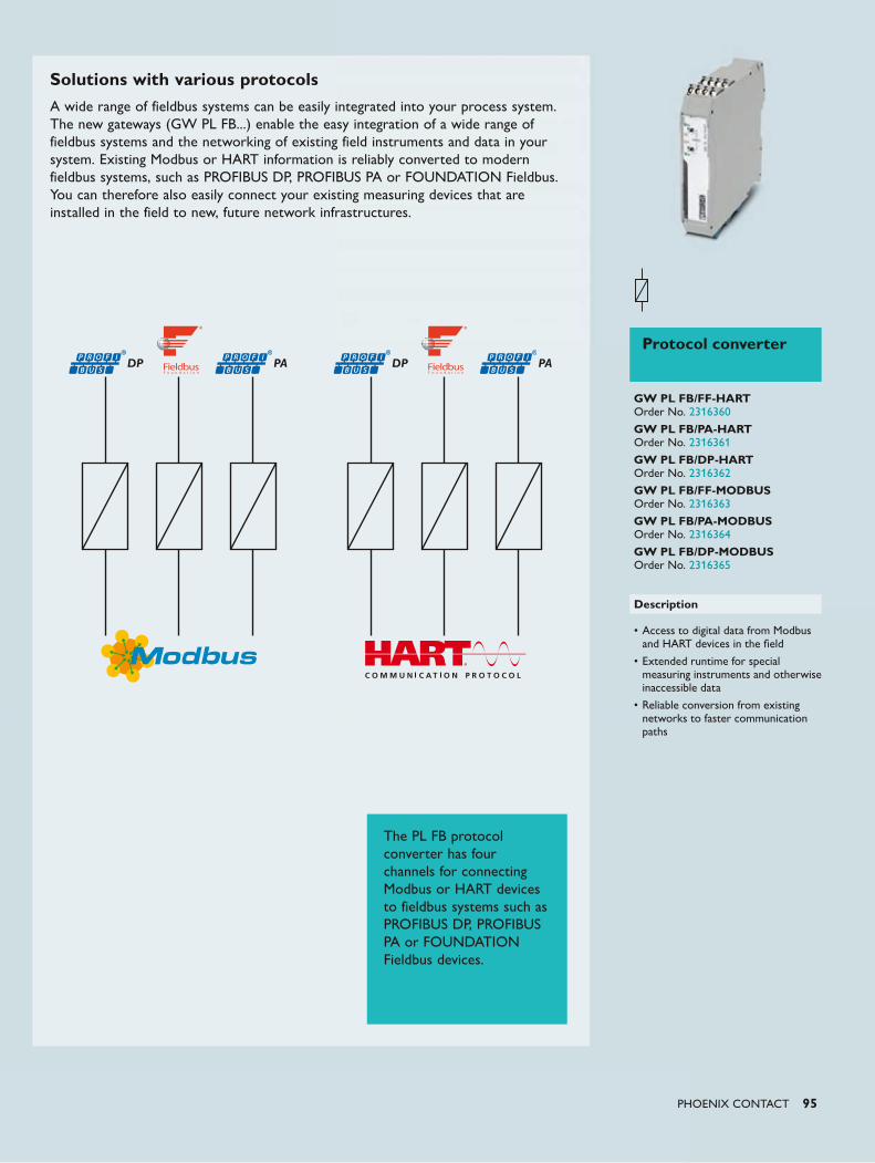
PHOENIX CONTACT 95
Solutions with various protocolsA wide range of fieldbus systems can be easily integrated into your process system. The new gateways (GW PL FB...) enable the easy integration of a wide range of fieldbus systems and the networking of existing field instruments and data in your system. Existing Modbus or HART information is reliably converted to modern fieldbus systems, such as PROFIBUS DP, PROFIBUS PA or FOUNDATION Fieldbus. You can therefore also easily connect your existing measuring devices that are installed in the field to new, future network infrastructures.
The PL FB protocol converter has four channels for connecting Modbus or HART devices to fieldbus systems such as PROFIBUS DP, PROFIBUS PA or FOUNDATION Fieldbus devices.
Protocol converter
GW PL FB/FF-HART Order No. 2316360
GW PL FB/PA-HART Order No. 2316361
GW PL FB/DP-HART Order No. 2316362
GW PL FB/FF-MODBUS Order No. 2316363
GW PL FB/PA-MODBUS Order No. 2316364
GW PL FB/DP-MODBUS Order No. 2316365
Description
• Access to digital data from Modbus and HART devices in the field
• Extended runtime for special measuring instruments and otherwise inaccessible data
• Reliable conversion from existing networks to faster communication paths
DP DPPA PA
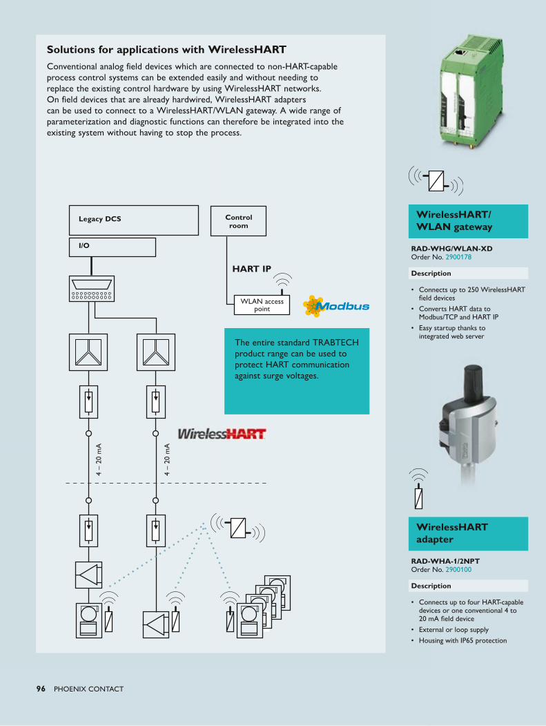
96 PHOENIX CONTACT
4 –
20 m
A
4 –
20 m
A
Legacy DCS Control room
I/O
WLAN access point
Solutions for applications with WirelessHARTConventional analog field devices which are connected to non-HART-capable process control systems can be extended easily and without needing to replace the existing control hardware by using WirelessHART networks. On field devices that are already hardwired, WirelessHART adapters can be used to connect to a WirelessHART/WLAN gateway. A wide range of parameterization and diagnostic functions can therefore be integrated into the existing system without having to stop the process.
WirelessHART/ WLAN gateway
RAD-WHG/WLAN-XD Order No. 2900178
Description
• Connects up to 250 WirelessHART field devices
• Converts HART data to Modbus/TCP and HART IP
• Easy startup thanks to integrated web server
WirelessHART adapter
RAD-WHA-1/2NPT Order No. 2900100
Description
• Connects up to four HART-capable devices or one conventional 4 to 20 mA field device
• External or loop supply
• Housing with IP65 protection
The entire standard TRABTECH product range can be used to protect HART communication against surge voltages.
HART IP
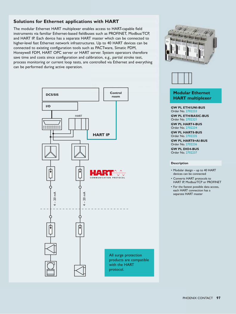
PHOENIX CONTACT 97
Modular Ethernet HART multiplexer
GW PL ETH/UNI-BUS Order No. 2702233
GW PL ETH/BASIC-BUS Order No. 2702321
GW PL HART4-BUS Order No. 2702234
GW PL HART8-BUS Order No. 2702235
GW PL HART8+AI-BUS Order No. 2702236
GW PL DIO4-BUS Order No. 2702237
Description
• Modular design – up to 40 HART devices can be connected
• Converts HART protocols to HART IP, Modbus/TCP or PROFINET
• For the fastest possible data access, each HART connection has a separate HART master
DCS/SIS Control room
I/O
4 –
20 m
A
4 –
20 m
A
HART
All surge protection products are compatible with the HART protocol.
Solutions for Ethernet applications with HARTThe modular Ethernet HART multiplexer enables access to HART-capable field instruments via familiar Ethernet-based fieldbuses such as PROFINET, Modbus/TCP, and HART IP. Each device has a separate HART master which can be connected to higher-level fast Ethernet network infrastructures. Up to 40 HART devices can be connected to existing configuration tools such as PACTware, Simatic PDM, Honeywell FDM, HART OPC server or HART server. System operators therefore save time and costs since configuration and calibration, e.g., partial stroke test, process monitoring or current loop tests, are controlled via Ethernet and everything can be performed during active operation.
HART IP
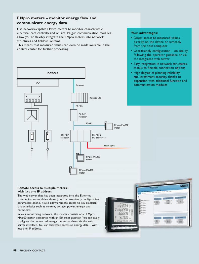
98 PHOENIX CONTACT
EMpro meters – monitor energy flow and communicate energy dataUse network-capable EMpro meters to monitor characteristic electrical data centrally and on site. Plug-in communication modules allow you to flexibly integrate the EMpro meters into network structures and fieldbus systems. This means that measured values can even be made available in the control center for further processing.
DCS/SIS
I/O
Remote I/O
PSI-REP repeater
PSI-REP repeater
PSI-MOS FO converter
EMpro MA400 meter
EMpro MA250 meter
EMpro MA400 meter
RS-485
Fiber optic
RS-485
Ethernet
Remote access to multiple meters – with just one IP addressThe web server that has been integrated into the Ethernet communication modules allows you to conveniently configure key parameters online. It also allows remote access to key electrical characteristics such as current, voltage, power, energy, and harmonics.In your monitoring network, the master consists of an EMpro MA600 meter, combined with an Ethernet gateway. You can easily configure the connected energy meters as slaves via the web server interface. You can therefore access all energy data – with just one IP address.
Your advantages:• Direct access to measured values –
directly on the device or remotely from the host computer
• User-friendly configuration – on site by following the operator guidance or via the integrated web server
• Easy integration in network structures, thanks to flexible connection options
• High degree of planning reliability and investment security, thanks to expansion with additional function and communication modules
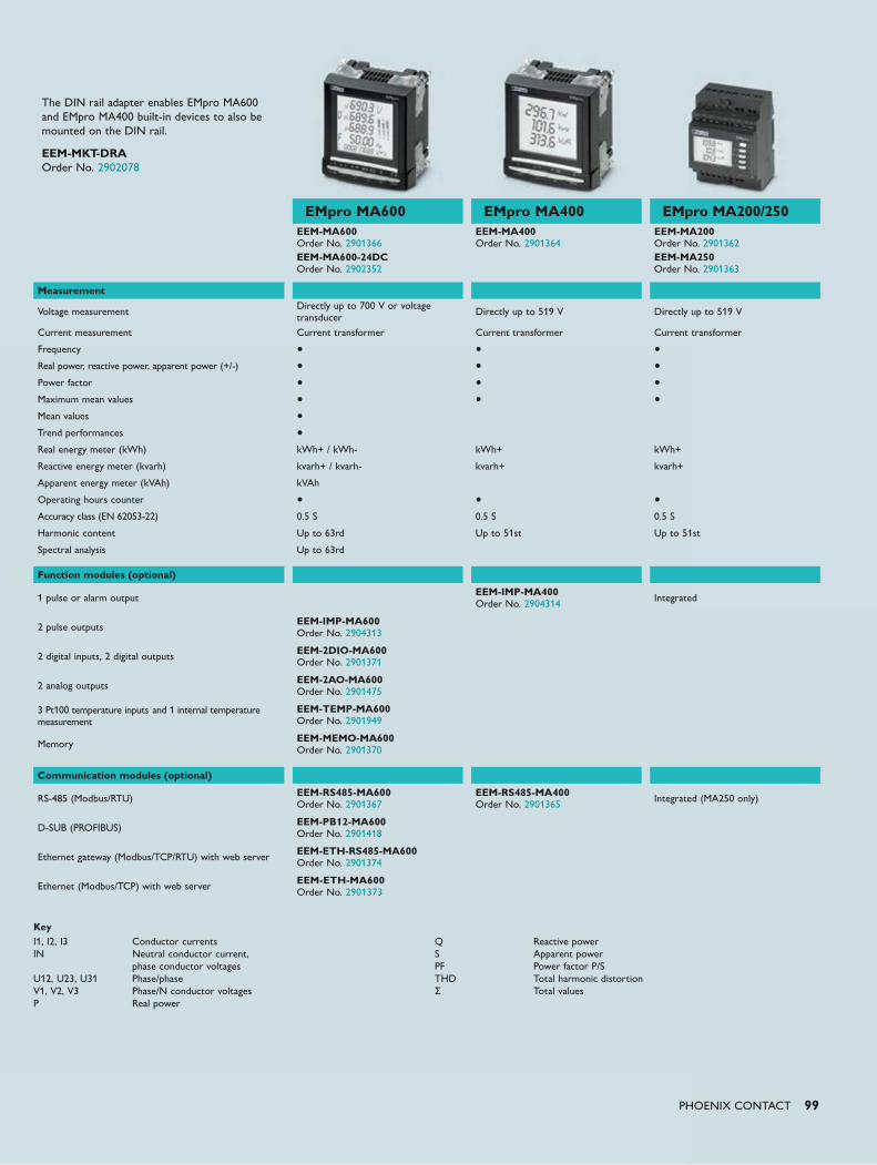
PHOENIX CONTACT 99
KeyI1, I2, I3 Conductor currents IN Neutral conductor current, phase conductor voltages U12, U23, U31 Phase/phase V1, V2, V3 Phase/N conductor voltages P Real power
Q Reactive power S Apparent power PF Power factor P/S THD Total harmonic distortion Σ Total values
The DIN rail adapter enables EMpro MA600 and EMpro MA400 built-in devices to also be mounted on the DIN rail.
EEM-MKT-DRA Order No. 2902078
EMpro MA600 EMpro MA400 EMpro MA200/250EEM-MA600 Order No. 2901366EEM-MA600-24DC Order No. 2902352
EEM-MA400 Order No. 2901364
EEM-MA200 Order No. 2901362EEM-MA250 Order No. 2901363
Measurement
Voltage measurement Directly up to 700 V or voltage transducer Directly up to 519 V Directly up to 519 V
Current measurement Current transformer Current transformer Current transformer
Frequency • • •Real power, reactive power, apparent power (+/-) • • •Power factor • • •Maximum mean values • • •Mean values •Trend performances •Real energy meter (kWh) kWh+ / kWh- kWh+ kWh+
Reactive energy meter (kvarh) kvarh+ / kvarh- kvarh+ kvarh+
Apparent energy meter (kVAh) kVAh
Operating hours counter • • •Accuracy class (EN 62053-22) 0.5 S 0.5 S 0.5 S
Harmonic content Up to 63rd Up to 51st Up to 51st
Spectral analysis Up to 63rd
Function modules (optional)
1 pulse or alarm output EEM-IMP-MA400 Order No. 2904314 Integrated
2 pulse outputs EEM-IMP-MA600 Order No. 2904313
2 digital inputs, 2 digital outputs EEM-2DIO-MA600 Order No. 2901371
2 analog outputs EEM-2AO-MA600 Order No. 2901475
3 Pt100 temperature inputs and 1 internal temperature measurement
EEM-TEMP-MA600 Order No. 2901949
Memory EEM-MEMO-MA600 Order No. 2901370
Communication modules (optional)
RS-485 (Modbus/RTU) EEM-RS485-MA600 Order No. 2901367
EEM-RS485-MA400 Order No. 2901365 Integrated (MA250 only)
D-SUB (PROFIBUS) EEM-PB12-MA600 Order No. 2901418
Ethernet gateway (Modbus/TCP/RTU) with web server EEM-ETH-RS485-MA600 Order No. 2901374
Ethernet (Modbus/TCP) with web server EEM-ETH-MA600 Order No. 2901373
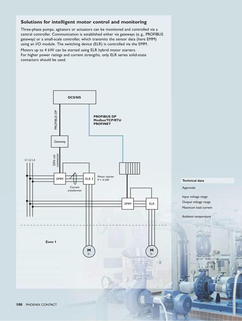
100 PHOENIX CONTACT
Solutions for intelligent motor control and monitoringThree-phase pumps, agitators or actuators can be monitored and controlled via a central controller. Communication is established either via gateways (e. g., PROFIBUS gateway) or a small-scale controller, which transmits the sensor data (here EMM) using an I/O module. The switching device (ELR) is controlled via the EMM.
Motors up to 4 kW can be started using ELR hybrid motor starters. For higher power ratings and current strengths, only ELR series solid-state contactors should be used.
DCS/SIS
PRO
FIBU
S D
PD
IN r
ail
conn
ecto
r
Gateway
EMM
EMM
ELR 3
ELR
PROFIBUS DP Modbus/TCP/RTU PROFINET
Zone 1
L1 L2 L3
Current transformer
Motor starter P > 4 kW Technical data
Approvals
Input voltage range
Output voltage range
Maximum load current
Ambient temperature
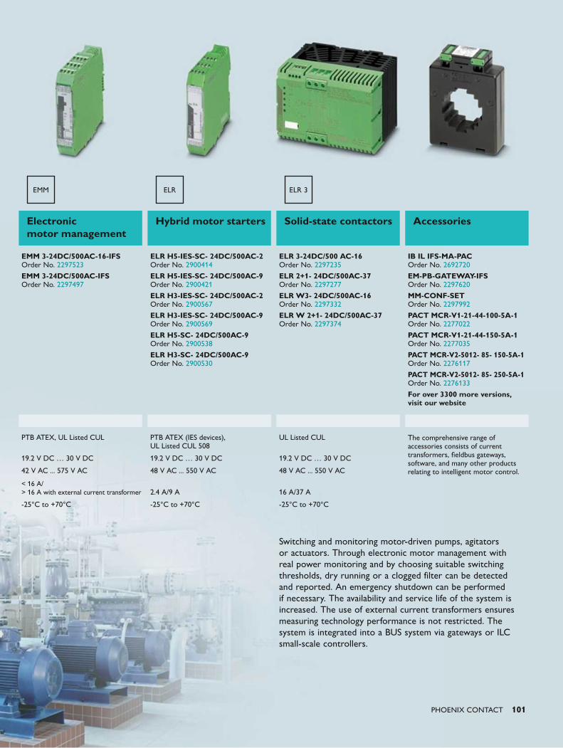
PHOENIX CONTACT 101
Switching and monitoring motor-driven pumps, agitators or actuators. Through electronic motor management with real power monitoring and by choosing suitable switching thresholds, dry running or a clogged filter can be detected and reported. An emergency shutdown can be performed if necessary. The availability and service life of the system is increased. The use of external current transformers ensures measuring technology performance is not restricted. The system is integrated into a BUS system via gateways or ILC small-scale controllers.
Electronic motor management
Hybrid motor starters Solid-state contactors Accessories
EMM 3-24DC/500AC-16-IFS Order No. 2297523
EMM 3-24DC/500AC-IFS Order No. 2297497
ELR H5-IES-SC- 24DC/500AC-2 Order No. 2900414
ELR H5-IES-SC- 24DC/500AC-9 Order No. 2900421 ELR H3-IES-SC- 24DC/500AC-2 Order No. 2900567 ELR H3-IES-SC- 24DC/500AC-9 Order No. 2900569 ELR H5-SC- 24DC/500AC-9 Order No. 2900538
ELR H3-SC- 24DC/500AC-9 Order No. 2900530
ELR 3-24DC/500 AC-16 Order No. 2297235
ELR 2+1- 24DC/500AC-37 Order No. 2297277
ELR W3- 24DC/500AC-16 Order No. 2297332
ELR W 2+1- 24DC/500AC-37 Order No. 2297374
IB IL IFS-MA-PAC Order No. 2692720
EM-PB-GATEWAY-IFS Order No. 2297620
MM-CONF-SET Order No. 2297992
PACT MCR-V1-21-44-100-5A-1 Order No. 2277022 PACT MCR-V1-21-44-150-5A-1 Order No. 2277035 PACT MCR-V2-5012- 85- 150-5A-1 Order No. 2276117
PACT MCR-V2-5012- 85- 250-5A-1 Order No. 2276133
For over 3300 more versions, visit our website
PTB ATEX, UL Listed CUL PTB ATEX (IES devices), UL Listed CUL 508
UL Listed CUL The comprehensive range of accessories consists of current transformers, fieldbus gateways, software, and many other products relating to intelligent motor control.
19.2 V DC … 30 V DC 19.2 V DC … 30 V DC 19.2 V DC … 30 V DC
42 V AC ... 575 V AC 48 V AC ... 550 V AC 48 V AC ... 550 V AC
< 16 A/ > 16 A with external current transformer 2.4 A/9 A 16 A/37 A
-25°C to +70°C -25°C to +70°C -25°C to +70°C
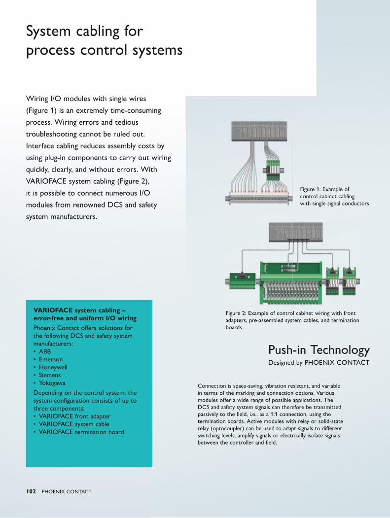
Push-in TechnologyDesigned by PHOENIX CONTACT
102 PHOENIX CONTACT
System cabling for process control systems
Connection is space-saving, vibration resistant, and variable in terms of the marking and connection options. Various modules offer a wide range of possible applications. The DCS and safety system signals can therefore be transmitted passively to the field, i.e., as a 1:1 connection, using the termination boards. Active modules with relay or solid-state relay (optocoupler) can be used to adapt signals to different switching levels, amplify signals or electrically isolate signals between the controller and field.
VARIOFACE system cabling – error-free and uniform I/O wiringPhoenix Contact offers solutions for the following DCS and safety system manufacturers: • ABB • Emerson • Honeywell • Siemens • Yokogawa
Depending on the control system, the system configuration consists of up to three components: • VARIOFACE front adapter • VARIOFACE system cable • VARIOFACE termination board
Wiring I/O modules with single wires
(Figure 1) is an extremely time-consuming
process. Wiring errors and tedious
troubleshooting cannot be ruled out.
Interface cabling reduces assembly costs by
using plug-in components to carry out wiring
quickly, clearly, and without errors. With
VARIOFACE system cabling (Figure 2),
it is possible to connect numerous I/O
modules from renowned DCS and safety
system manufacturers.
Figure 1: Example of control cabinet cabling with single signal conductors
Figure 2: Example of control cabinet wiring with front adapters, pre-assembled system cables, and termination boards
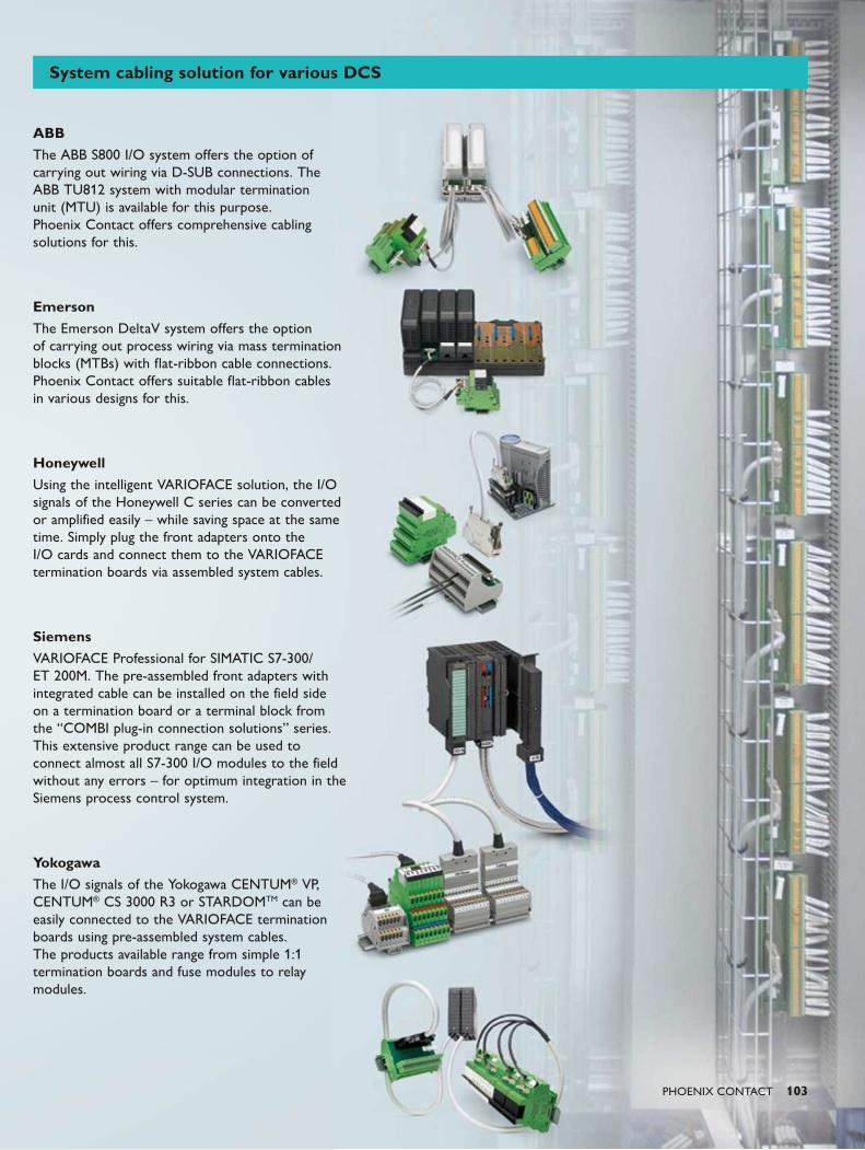
PHOENIX CONTACT 103
ABBThe ABB S800 I/O system offers the option of carrying out wiring via D-SUB connections. The ABB TU812 system with modular termination unit (MTU) is available for this purpose. Phoenix Contact offers comprehensive cabling solutions for this.
EmersonThe Emerson DeltaV system offers the option of carrying out process wiring via mass termination blocks (MTBs) with flat-ribbon cable connections. Phoenix Contact offers suitable flat-ribbon cables in various designs for this.
HoneywellUsing the intelligent VARIOFACE solution, the I/O signals of the Honeywell C series can be converted or amplified easily – while saving space at the same time. Simply plug the front adapters onto the I/O cards and connect them to the VARIOFACE termination boards via assembled system cables.
SiemensVARIOFACE Professional for SIMATIC S7-300/ET 200M. The pre-assembled front adapters with integrated cable can be installed on the field side on a termination board or a terminal block from the “COMBI plug-in connection solutions” series. This extensive product range can be used to connect almost all S7-300 I/O modules to the field without any errors – for optimum integration in the Siemens process control system.
YokogawaThe I/O signals of the Yokogawa CENTUM® VP, CENTUM® CS 3000 R3 or STARDOMTM can be easily connected to the VARIOFACE termination boards using pre-assembled system cables. The products available range from simple 1:1 termination boards and fuse modules to relay modules.
System cabling solution for various DCS
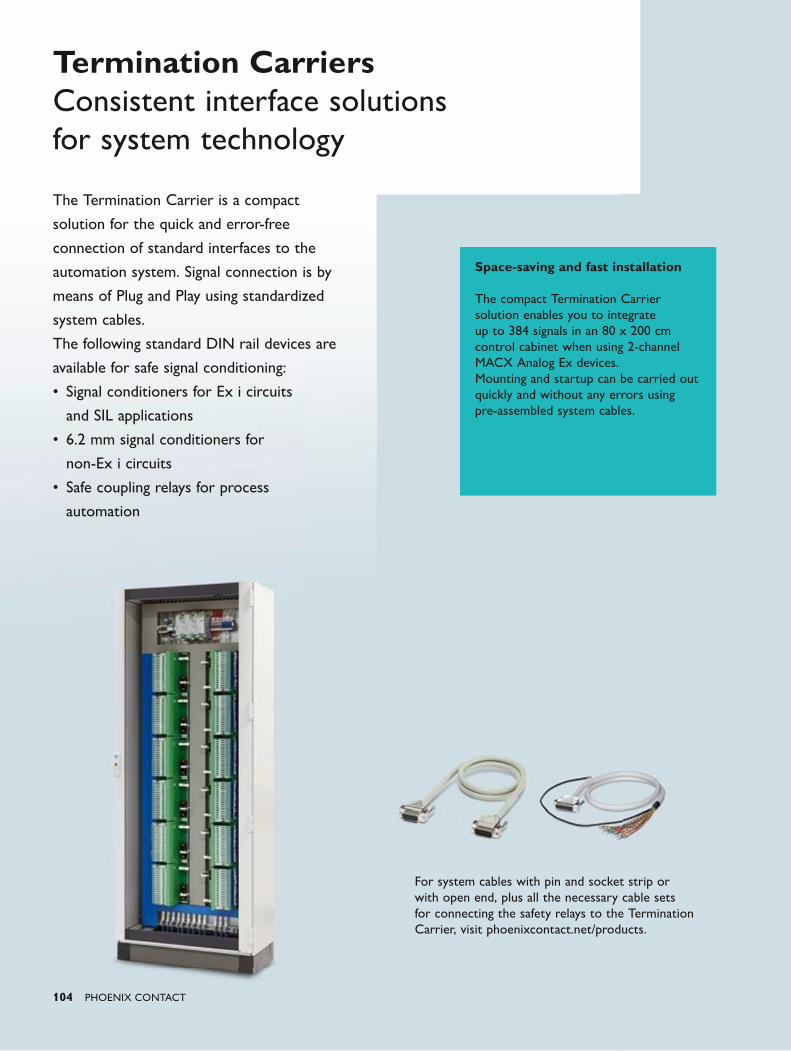
104 PHOENIX CONTACT
Termination CarriersConsistent interface solutions for system technology
For system cables with pin and socket strip or with open end, plus all the necessary cable sets for connecting the safety relays to the Termination Carrier, visit phoenixcontact.net/products.
The Termination Carrier is a compact
solution for the quick and error-free
connection of standard interfaces to the
automation system. Signal connection is by
means of Plug and Play using standardized
system cables.
The following standard DIN rail devices are
available for safe signal conditioning:
• Signal conditioners for Ex i circuits
and SIL applications
• 6.2 mm signal conditioners for
non-Ex i circuits
• Safe coupling relays for process
automation
Space-saving and fast installation
The compact Termination Carrier solution enables you to integrate up to 384 signals in an 80 x 200 cm control cabinet when using 2-channel MACX Analog Ex devices.Mounting and startup can be carried out quickly and without any errors using pre-assembled system cables.
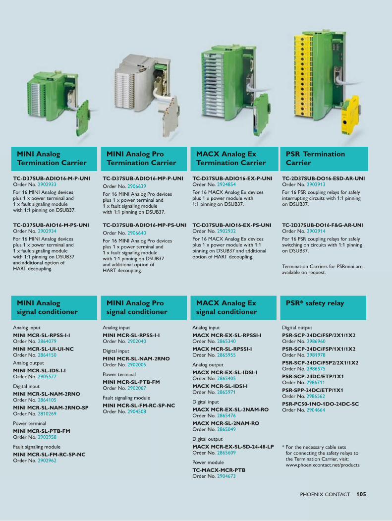
PHOENIX CONTACT 105
MINI Analog Termination Carrier
MINI Analog Pro Termination Carrier
MACX Analog Ex Termination Carrier
PSR Termination Carrier
TC-D37SUB-ADIO16-M-P-UNI Order No. 2902933
For 16 MINI Analog devices plus 1 x power terminal and 1 x fault signaling module with 1:1 pinning on DSUB37.
TC-D37SUB-ADIO16-MP-P-UNIOrder No. 2906639
For 16 MINI Analog Pro devices plus 1 x power terminal and 1 x fault signaling module with 1:1 pinning on DSUB37.
TC-D37SUB-ADIO16-EX-P-UNI Order No. 2924854
For 16 MACX Analog Ex devices plus 1 x power module with 1:1 pinning on DSUB37.
TC-2D37SUB-DO16-ESD-AR-UNI Order No. 2902913
For 16 PSR coupling relays for safely interrupting circuits with 1:1 pinning on DSUB37.
TC-D37SUB-AIO16-M-PS-UNI Order No. 2902934
For 16 MINI Analog devices plus 1 x power terminal and 1 x fault signaling module with 1:1 pinning on DSUB37 and additional option of HART decoupling.
TC-D37SUB-ADIO16-MP-PS-UNIOrder No. 2906640
For 16 MINI Analog Pro devices plus 1 x power terminal and 1 x fault signaling module with 1:1 pinning on DSUB37 and additional option of HART decoupling.
TC-D37SUB-AIO16-EX-PS-UNI Order No. 2902932
For 16 MACX Analog Ex devices plus 1 x power module with 1:1 pinning on DSUB37 and additional option of HART decoupling.
TC-2D37SUB-DO16-F&G-AR-UNI Order No. 2902914
For 16 PSR coupling relays for safely switching on circuits with 1:1 pinning on DSUB37.
Termination Carriers for PSRmini are available on request.
MINI Analog signal conditioner
MINI Analog Pro signal conditioner
MACX Analog Ex signal conditioner
PSR* safety relay
Analog input
MINI MCR-SL-RPSS-I-I Order No. 2864079
MINI MCR-SL-UI-UI-NC Order No. 2864150
Analog output
MINI MCR-SL-IDS-I-I Order No. 2905577
Digital input
MINI MCR-SL-NAM-2RNO Order No. 2864105
MINI MCR-SL-NAM-2RNO-SP Order No. 2810269
Power terminal
MINI MCR-SL-PTB-FM Order No. 2902958
Fault signaling module
MINI MCR-SL-FM-RC-SP-NC Order No. 2902962
Analog input
MINI MCR-SL-RPSS-I-I Order No. 2902040
Digital input
MINI MCR-SL-NAM-2RNO Order No. 2902005
Power terminal
MINI MCR-SL-PTB-FM Order No. 2902067
Fault signaling module
MINI MCR-SL-FM-RC-SP-NC Order No. 2904508
Analog input
MACX MCR-EX-SL-RPSSI-I Order No. 2865340
MACX MCR-SL-RPSSI-I Order No. 2865955
Analog output
MACX MCR-EX-SL-IDSI-I Order No. 2865405
MACX MCR-SL-IDSI-I Order No. 2865971
Digital input
MACX MCR-EX-SL-2NAM-RO Order No. 2865476
MACX MCR-SL-2NAM-RO Order No. 2865049
Digital output
MACX MCR-EX-SL-SD-24-48-LP Order No. 2865609
Power module
TC-MACX-MCR-PTB Order No. 2904673
Digital output
PSR-SCP-24DC/FSP/2X1/1X2 Order No. 2986960
PSR-SCP-24DC/FSP/1X1/1X2 Order No. 2981978
PSR-SCP-24DC/FSP2/2X1/1X2 Order No. 2986575
PSR-SCP-24DC/ETP/1X1 Order No. 2986711
PSR-SPP-24DC/ETP/1X1 Order No. 2986562
PSR-PC50-1NO-1DO-24DC-SC Order No. 2904664
* For the necessary cable sets
for connecting the safety relays to the Termination Carrier, visit: www.phoenixcontact.net/products
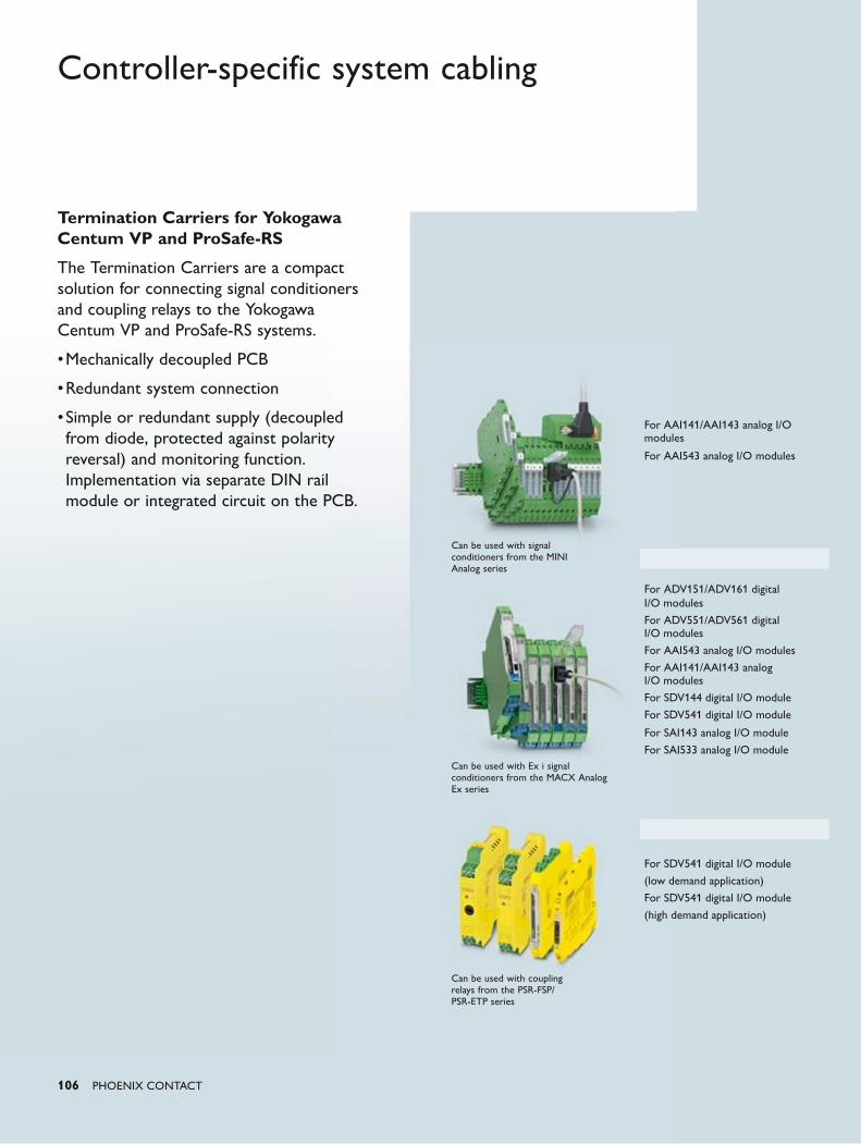
106 PHOENIX CONTACT
Controller-specific system cabling
Termination Carriers for Yokogawa Centum VP and ProSafe-RS
The Termination Carriers are a compact solution for connecting signal conditioners and coupling relays to the Yokogawa Centum VP and ProSafe-RS systems.
• Mechanically decoupled PCB
• Redundant system connection
• Simple or redundant supply (decoupled from diode, protected against polarity reversal) and monitoring function. Implementation via separate DIN rail module or integrated circuit on the PCB.
For AAI141/AAI143 analog I/O modules
For AAI543 analog I/O modules
For ADV151/ADV161 digital I/O modules
For ADV551/ADV561 digital I/O modules
For AAI543 analog I/O modules
For AAI141/AAI143 analog I/O modules
For SDV144 digital I/O module
For SDV541 digital I/O module
For SAI143 analog I/O module
For SAI533 analog I/O module
For SDV541 digital I/O module
(low demand application)
For SDV541 digital I/O module
(high demand application)
Can be used with signal conditioners from the MINI Analog series
Can be used with Ex i signal conditioners from the MACX Analog Ex series
Can be used with coupling relays from the PSR-FSP/PSR-ETP series
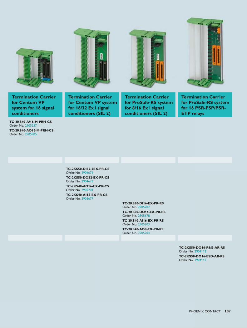
PHOENIX CONTACT 107
Termination Carrier for Centum VP system for 16 signal conditioners
Termination Carrier for Centum VP system for 16/32 Ex i signal conditioners (SIL 2)
Termination Carrier for ProSafe-RS system for 8/16 Ex i signal conditioners (SIL 2)
Termination Carrier for ProSafe-RS system for 16 PSR-FSP/PSR-ETP relays
TC-2KS40-A/16-M-PRH-CS Order No. 2905257
TC-2KS40-AO16-M-PRH-CS Order No. 2905905
TC-2KS50-DI32-2EX-PR-CS Order No. 2904676
TC-2KS50-DO32-EX-PR-CS Order No. 2904676
TC-2KS40-AO16-EX-PR-CS Order No. 2905201
TC-2KS40-AI16-EX-PR-CS Order No. 2905677
TC-2KS50-DI16-EX-PR-RS Order No. 2905202
TC-2KS50-DO16-EX-PR-RS Order No. 2905678
TC-2KS40-AI16-EX-PR-RS Order No. 2905203
TC-2KS40-AO8-EX-PR-RS Order No. 2905204
TC-2KS50-DO16-F&G-AR-RS Order No. 2904112
TC-2KS50-DO16-ESD-AR-RS Order No. 2904113
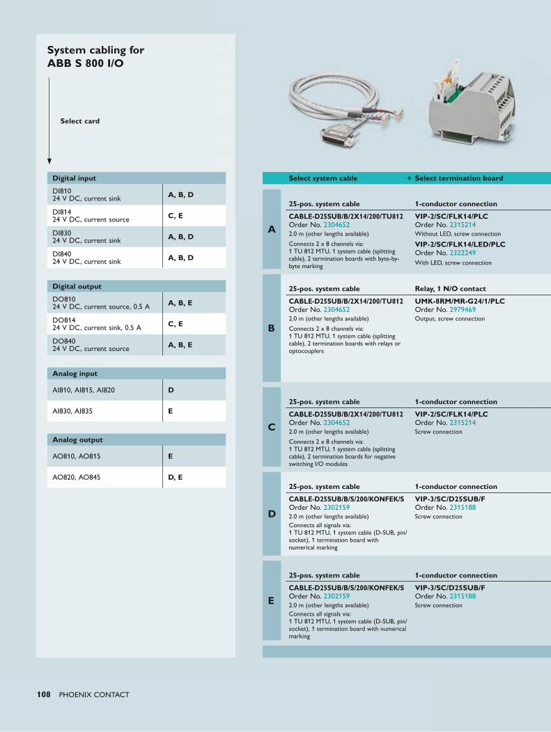
108 PHOENIX CONTACT
System cabling for ABB S 800 I/O
Select card
Digital input
DI81024 V DC, current sink A, B, D
DI81424 V DC, current source C, E
DI83024 V DC, current sink A, B, D
DI84024 V DC, current sink A, B, D
Digital output
DO81024 V DC, current source, 0.5 A A, B, E
DO81424 V DC, current sink, 0.5 A C, E
DO84024 V DC, current source A, B, E
Analog input
AI810, AI815, AI820 D
AI830, AI835 E
Analog output
AO810, AO815 E
AO820, AO845 D, E
Select system cable + Select termination board
A
25-pos. system cable
1-conductor connection
CABLE-D25SUB/B/2X14/200/TU812 Order No. 23046522.0 m (other lengths available)
Connects 2 x 8 channels via: 1 TU 812 MTU, 1 system cable (splitting cable), 2 termination boards with byte-by-byte marking
VIP-2/SC/FLK14/PLC Order No. 2315214Without LED, screw connection
VIP-2/SC/FLK14/LED/PLC Order No. 2322249With LED, screw connection
B
25-pos. system cable
Relay, 1 N/O contact
CABLE-D25SUB/B/2X14/200/TU812 Order No. 23046522.0 m (other lengths available)
Connects 2 x 8 channels via: 1 TU 812 MTU, 1 system cable (splitting cable), 2 termination boards with relays or optocouplers
UMK-8RM/MR-G24/1/PLC Order No. 2979469Output, screw connection
C
25-pos. system cable
1-conductor connection
CABLE-D25SUB/B/2X14/200/TU812 Order No. 23046522.0 m (other lengths available)
Connects 2 x 8 channels via: 1 TU 812 MTU, 1 system cable (splitting cable), 2 termination boards for negative switching I/O modules
VIP-2/SC/FLK14/PLC Order No. 2315214Screw connection
D
25-pos. system cable
1-conductor connection
CABLE-D25SUB/B/S/200/KONFEK/S Order No. 23021592.0 m (other lengths available)Connects all signals via: 1 TU 812 MTU, 1 system cable (D-SUB, pin/socket), 1 termination board with numerical marking
VIP-3/SC/D25SUB/F Order No. 2315188Screw connection
E
25-pos. system cable
1-conductor connection
CABLE-D25SUB/B/S/200/KONFEK/S Order No. 23021592.0 m (other lengths available)Connects all signals via: 1 TU 812 MTU, 1 system cable (D-SUB, pin/socket), 1 termination board with numerical marking
VIP-3/SC/D25SUB/F Order No. 2315188Screw connection
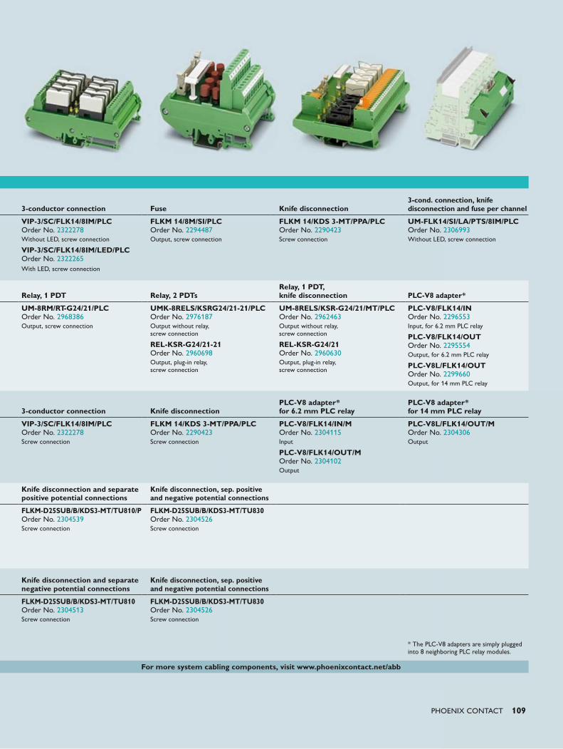
PHOENIX CONTACT 109
3-conductor connection
Fuse
Knife disconnection
3-cond. connection, knife disconnection and fuse per channel
VIP-3/SC/FLK14/8IM/PLC Order No. 2322278Without LED, screw connection
VIP-3/SC/FLK14/8IM/LED/PLC Order No. 2322265With LED, screw connection
FLKM 14/8M/SI/PLC Order No. 2294487Output, screw connection
FLKM 14/KDS 3-MT/PPA/PLC Order No. 2290423Screw connection
UM-FLK14/SI/LA/PTS/8IM/PLC Order No. 2306993Without LED, screw connection
Relay, 1 PDT
Relay, 2 PDTs
Relay, 1 PDT, knife disconnection
PLC-V8 adapter*
UM-8RM/RT-G24/21/PLC Order No. 2968386Output, screw connection
UMK-8RELS/KSRG24/21-21/PLC Order No. 2976187Output without relay, screw connection
REL-KSR-G24/21-21 Order No. 2960698Output, plug-in relay, screw connection
UM-8RELS/KSR-G24/21/MT/PLC Order No. 2962463Output without relay, screw connection
REL-KSR-G24/21 Order No. 2960630Output, plug-in relay, screw connection
PLC-V8/FLK14/IN Order No. 2296553Input, for 6.2 mm PLC relay
PLC-V8/FLK14/OUT Order No. 2295554Output, for 6.2 mm PLC relay
PLC-V8L/FLK14/OUT Order No. 2299660Output, for 14 mm PLC relay
3-conductor connection
Knife disconnection
PLC-V8 adapter* for 6.2 mm PLC relay
PLC-V8 adapter* for 14 mm PLC relay
VIP-3/SC/FLK14/8IM/PLC Order No. 2322278Screw connection
FLKM 14/KDS 3-MT/PPA/PLC Order No. 2290423Screw connection
PLC-V8/FLK14/IN/M Order No. 2304115Input
PLC-V8/FLK14/OUT/M Order No. 2304102Output
PLC-V8L/FLK14/OUT/M Order No. 2304306Output
Knife disconnection and separate positive potential connections
Knife disconnection, sep. positive and negative potential connections
FLKM-D25SUB/B/KDS3-MT/TU810/P Order No. 2304539Screw connection
FLKM-D25SUB/B/KDS3-MT/TU830 Order No. 2304526Screw connection
Knife disconnection and separate negative potential connections
Knife disconnection, sep. positive and negative potential connections
FLKM-D25SUB/B/KDS3-MT/TU810 Order No. 2304513Screw connection
FLKM-D25SUB/B/KDS3-MT/TU830 Order No. 2304526Screw connection
* The PLC-V8 adapters are simply plugged into 8 neighboring PLC relay modules.
For more system cabling components, visit www.phoenixcontact.net/abb
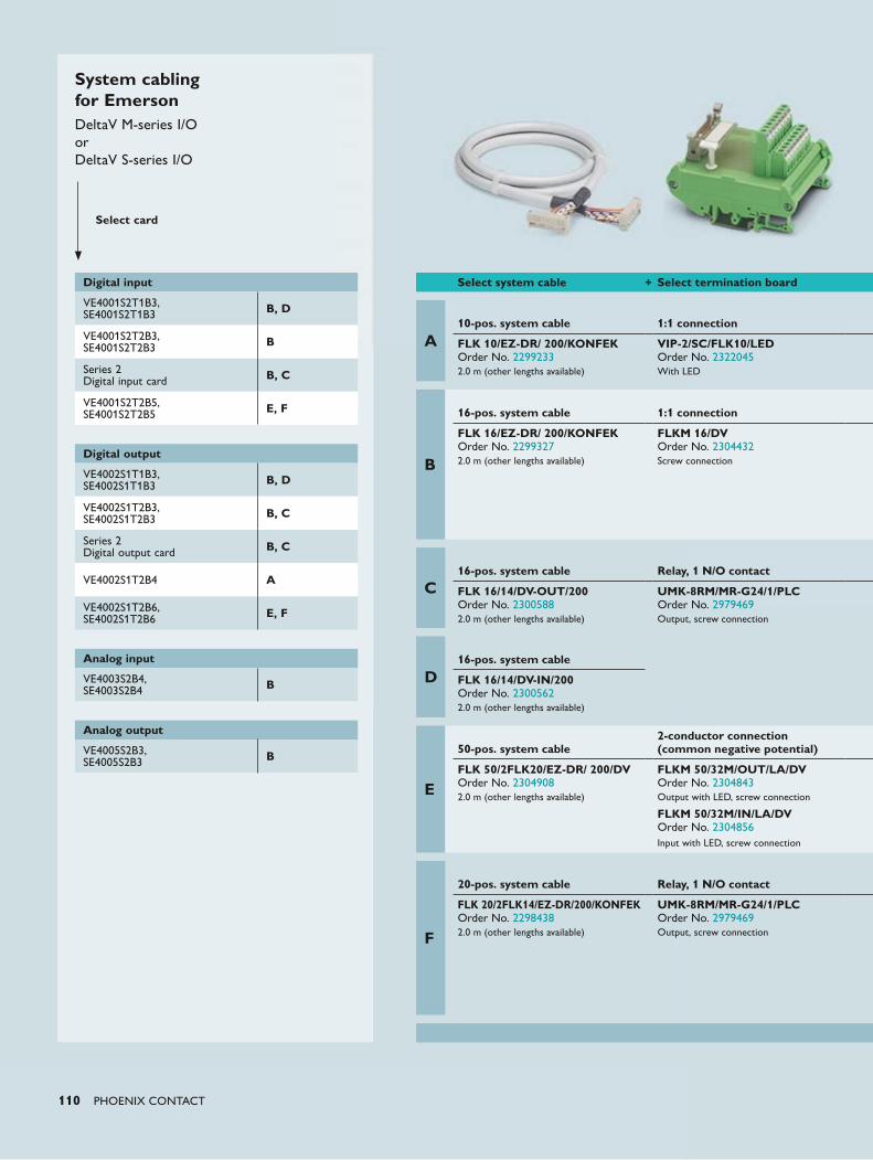
110 PHOENIX CONTACT
System cabling for EmersonDeltaV M-series I/O or DeltaV S-series I/O
Select card
Digital input
VE4001S2T1B3,SE4001S2T1B3 B, D
VE4001S2T2B3,SE4001S2T2B3 B
Series 2Digital input card B, C
VE4001S2T2B5,SE4001S2T2B5 E, F
Digital output
VE4002S1T1B3,SE4002S1T1B3 B, D
VE4002S1T2B3,SE4002S1T2B3 B, C
Series 2Digital output card B, C
VE4002S1T2B4 A
VE4002S1T2B6,SE4002S1T2B6 E, F
Analog input
VE4003S2B4,SE4003S2B4 B
Analog output
VE4005S2B3,SE4005S2B3 B
Select system cable + Select termination board
A
10-pos. system cable
1:1 connection
FLK 10/EZ-DR/ 200/KONFEK Order No. 22992332.0 m (other lengths available)
VIP-2/SC/FLK10/LED Order No. 2322045With LED
B
16-pos. system cable
1:1 connection
FLK 16/EZ-DR/ 200/KONFEK Order No. 22993272.0 m (other lengths available)
FLKM 16/DV Order No. 2304432Screw connection
C
16-pos. system cable
Relay, 1 N/O contact
FLK 16/14/DV-OUT/200 Order No. 23005882.0 m (other lengths available)
UMK-8RM/MR-G24/1/PLC Order No. 2979469Output, screw connection
D
16-pos. system cable
FLK 16/14/DV-IN/200 Order No. 23005622.0 m (other lengths available)
E
50-pos. system cable
2-conductor connection (common negative potential)
FLK 50/2FLK20/EZ-DR/ 200/DV Order No. 23049082.0 m (other lengths available)
FLKM 50/32M/OUT/LA/DV Order No. 2304843Output with LED, screw connection
FLKM 50/32M/IN/LA/DV Order No. 2304856Input with LED, screw connection
F
20-pos. system cable
Relay, 1 N/O contact
FLK 20/2FLK14/EZ-DR/200/KONFEK Order No. 22984382.0 m (other lengths available)
UMK-8RM/MR-G24/1/PLC Order No. 2979469Output, screw connection
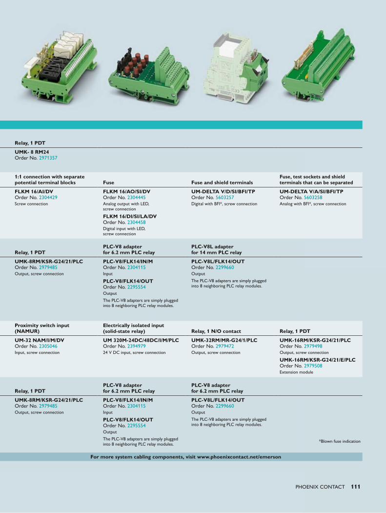
PHOENIX CONTACT 111
Relay, 1 PDT
UMK- 8 RM24 Order No. 2971357
1:1 connection with separate potential terminal blocks
Fuse Fuse and shield terminals
Fuse, test sockets and shield terminals that can be separated
FLKM 16/AI/DV Order No. 2304429Screw connection
FLKM 16/AO/SI/DV Order No. 2304445Analog output with LED, screw connection
FLKM 16/DI/SI/LA/DV Order No. 2304458Digital input with LED, screw connection
UM-DELTA V/D/SI/BFI/TP Order No. 5603257Digital with BFI*, screw connection
UM-DELTA V/A/SI/BFI/TP Order No. 5603258Analog with BFI*, screw connection
Relay, 1 PDT
PLC-V8 adapterfor 6.2 mm PLC relay
PLC-V8L adapterfor 14 mm PLC relay
UMK-8RM/KSR-G24/21/PLC Order No. 2979485Output, screw connection
PLC-V8/FLK14/IN/M Order No. 2304115Input
PLC-V8/FLK14/OUT Order No. 2295554Output
The PLC-V8 adapters are simply plugged into 8 neighboring PLC relay modules.
PLC-V8L/FLK14/OUT Order No. 2299660Output
The PLC-V8 adapters are simply plugged into 8 neighboring PLC relay modules.
Proximity switch input(NAMUR)
Electrically isolated input(solid-state relay)
Relay, 1 N/O contact
Relay, 1 PDT
UM-32 NAM/I/M/DV Order No. 2305046Input, screw connection
UM 320M-24DC/48DC/I/M/PLC Order No. 239497924 V DC input, screw connection
UMK-32RM/MR-G24/1/PLC Order No. 2979472Output, screw connection
UMK-16RM/KSR-G24/21/PLC Order No. 2979498Output, screw connection
UMK-16RM/KSR-G24/21/E/PLC Order No. 2979508Extension module
Relay, 1 PDT
PLC-V8 adapterfor 6.2 mm PLC relay
PLC-V8 adapterfor 6.2 mm PLC relay
UMK-8RM/KSR-G24/21/PLC Order No. 2979485Output, screw connection
PLC-V8/FLK14/IN/M Order No. 2304115Input
PLC-V8/FLK14/OUT Order No. 2295554Output
The PLC-V8 adapters are simply plugged into 8 neighboring PLC relay modules.
PLC-V8L/FLK14/OUT Order No. 2299660Output
The PLC-V8 adapters are simply plugged into 8 neighboring PLC relay modules.
*Blown fuse indication
For more system cabling components, visit www.phoenixcontact.net/emerson
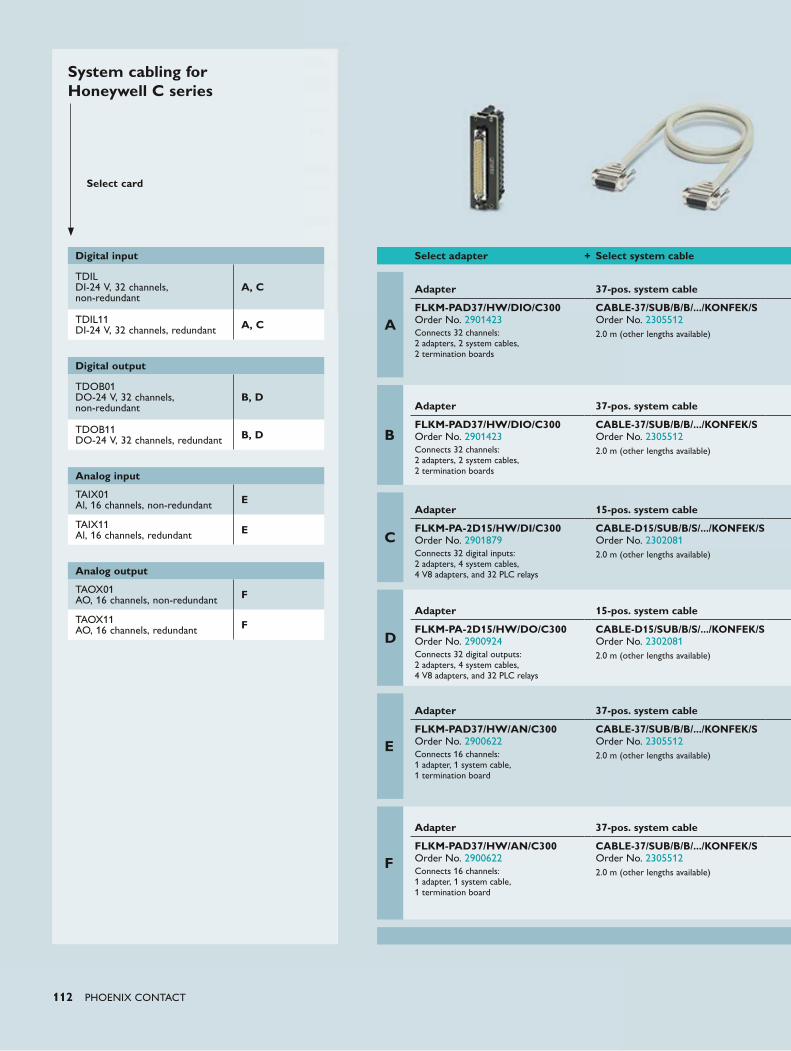
112 PHOENIX CONTACT
System cabling for Honeywell C series
Select card
Digital input
TDILDI-24 V, 32 channels, non-redundant
A, C
TDIL11DI-24 V, 32 channels, redundant A, C
Digital output
TDOB01DO-24 V, 32 channels, non-redundant
B, D
TDOB11DO-24 V, 32 channels, redundant B, D
Analog input
TAIX01Al, 16 channels, non-redundant E
TAIX11 Al, 16 channels, redundant E
Analog output
TAOX01AO, 16 channels, non-redundant F
TAOX11AO, 16 channels, redundant F
Select adapter + Select system cable
A
Adapter
37-pos. system cable
FLKM-PAD37/HW/DIO/C300 Order No. 2901423Connects 32 channels: 2 adapters, 2 system cables, 2 termination boards
CABLE-37/SUB/B/B/.../KONFEK/S Order No. 23055122.0 m (other lengths available)
B
Adapter
37-pos. system cable
FLKM-PAD37/HW/DIO/C300 Order No. 2901423Connects 32 channels: 2 adapters, 2 system cables, 2 termination boards
CABLE-37/SUB/B/B/.../KONFEK/S Order No. 23055122.0 m (other lengths available)
C
Adapter 15-pos. system cable
FLKM-PA-2D15/HW/DI/C300 Order No. 2901879Connects 32 digital inputs: 2 adapters, 4 system cables, 4 V8 adapters, and 32 PLC relays
CABLE-D15/SUB/B/S/.../KONFEK/S Order No. 23020812.0 m (other lengths available)
D
Adapter 15-pos. system cable
FLKM-PA-2D15/HW/DO/C300 Order No. 2900924Connects 32 digital outputs: 2 adapters, 4 system cables, 4 V8 adapters, and 32 PLC relays
CABLE-D15/SUB/B/S/.../KONFEK/S Order No. 23020812.0 m (other lengths available)
E
Adapter 37-pos. system cable
FLKM-PAD37/HW/AN/C300 Order No. 2900622Connects 16 channels: 1 adapter, 1 system cable, 1 termination board
CABLE-37/SUB/B/B/.../KONFEK/S Order No. 23055122.0 m (other lengths available)
F
Adapter 37-pos. system cable
FLKM-PAD37/HW/AN/C300 Order No. 2900622Connects 16 channels: 1 adapter, 1 system cable, 1 termination board
CABLE-37/SUB/B/B/.../KONFEK/S Order No. 23055122.0 m (other lengths available)
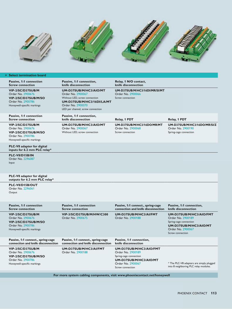
PHOENIX CONTACT 113
+ Select termination board
Passive, 1:1 connectionScrew connection
Passive, 1:1 connection, knife disconnection
Relay, 1 N/O contact, knife disconnection
VIP-2/SC/D37SUB/M Order No. 2900676VIP-2/SC/D37SUB/M/SO Order No. 2900786Honeywell-specific markings
UM-D37SUB/M/HC3/AIO/MT Order No. 2900067Without LED, screw connection
UM-D37SUB/M/HC3/16DI/LA/MT Order No. 2900070LED per channel, screw connection
UM-D37SUB/M/HC3/16DI/MR/SI/MT Order No. 2900066Screw connection
Passive, 1:1 connectionScrew connection
Passive, 1:1 connection, knife disconnection
Relay, 1 PDT
Relay, 1 PDT
VIP-2/SC/D37SUB/M Order No. 2900676VIP-2/SC/D37SUB/M/SO Order No. 2900786Honeywell-specific markings
UM-D37SUB/M/HC3/AIO/MT Order No. 2900067Without LED, screw connection
UM-D37SUB/M/HC3/16DO/MR/MT Order No. 2900068Screw connection
UM-D37SUB/M/HC3/16DO/MR/SI/Z Order No. 2900190Spring-cage connection
PLC-V8 adapter for digital inputs for 6.2 mm PLC relay*
PLC-V8/D15B/IN Order No. 2296087Input
PLC-V8 adapter for digital outputs for 6.2 mm PLC relay*
PLC-V8/D15B/OUT Order No. 2296061Output
Passive, 1:1 connectionScrew connection
Passive, 1:1 connectionScrew connection
Passive, 1:1 connect., spring-cage connection and knife disconnection
Passive, 1:1 connection, knife disconnection
VIP-2/SC/D37SUB/M Order No. 2900676VIP-2/SC/D37SUB/M/SO Order No. 2900786Honeywell-specific markings
VIP-3/SC/D37SUB/M/HW/C300 Order No. 2900675
UM-D37SUB/M/HC3/AI/FMT Order No. 2900188
UM-D37SUB/M/HC3/AIO/FMT Order No. 2900189Spring-cage connection
UM-D37SUB/M/HC3/AIO/MT Order No. 2900067Screw connection
Passive, 1:1 connect., spring-cage connection and knife disconnection
Passive, 1:1 connect., spring-cage connection and knife disconnection
Passive, 1:1 connection, knife disconnection
VIP-2/SC/D37SUB/M Order No. 2900676VIP-2/SC/D37SUB/M/SO Order No. 2900786Honeywell-specific markings
UM-D37SUB/M/HC3/AI/FMT Order No. 2900188
UM-D37SUB/M/HC3/AIO/FMT Order No. 2900189Spring-cage connection
UM-D37SUB/M/HC3/AIO/MT Order No. 2900067Screw connection
* The PLC-V8 adapters are simply plugged into 8 neighboring PLC relay modules.
For more system cabling components, visit www.phoenixcontact.net/honeywell
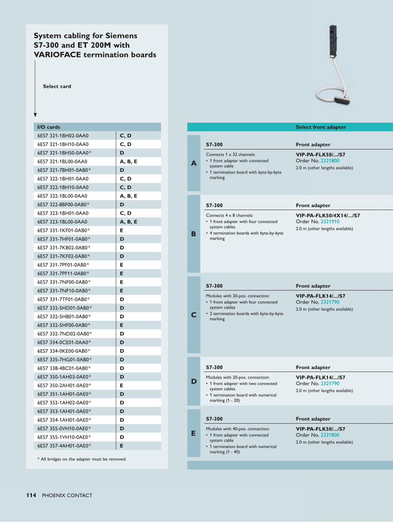
114 PHOENIX CONTACT
System cabling for Siemens S7-300 and ET 200M with VARIOFACE termination boards
Select card
I/O cards
6ES7 321-1BH02-0AA0 C, D
6ES7 321-1BH10-0AA0 C, D
6ES7 321-1BH50-0AA0* D
6ES7 321-1BL00-0AA0 A, B, E
6ES7 321-7BH01-0AB0* D
6ES7 322-1BH01-0AA0 C, D
6ES7 322-1BH10-0AA0 C, D
6ES7 322-1BL00-0AA0 A, B, E
6ES7 322-8BF00-0AB0* D
6ES7 323-1BH01-0AA0 C, D
6ES7 323-1BL00-0AA0 A, B, E
6ES7 331-1KF01-0AB0* E
6ES7 331-7HF01-0AB0* D
6ES7 331-7KB02-0AB0* D
6ES7 331-7KF02-0AB0* D
6ES7 331-7PF01-0AB0* E
6ES7 331-7PF11-0AB0* E
6ES7 331-7NF00-0AB0* E
6ES7 331-7NF10-0AB0* E
6ES7 331-7TF01-0AB0* D
6ES7 332-5HD01-0AB0* D
6ES7 332-5HB01-0AB0* D
6ES7 332-5HF00-0AB0* E
6ES7 332-7ND02-0AB0* D
6ES7 334-0CE01-0AA0* D
6ES7 334-0KE00-0AB0* D
6ES7 335-7HG01-0AB0* D
6ES7 338-4BC01-0AB0* D
6ES7 350-1AH03-0AE0* D
6ES7 350-2AH01-0AE0* E
6ES7 351-1AH01-0AE0* D
6ES7 352-1AH02-0AE0* D
6ES7 353-1AH01-0AE0* D
6ES7 354-1AH01-0AE0* D
6ES7 355-0VH10-0AE0* D
6ES7 355-1VH10-0AE0* D
6ES7 357-4AH01-0AE0* E
* All bridges on the adapter must be removed.
Select front adapter
A
S7-300
Front adapter
Connects 1 x 32 channels:• 1 front adapter with connected system cable• 1 termination board with byte-by-byte marking
VIP-PA-FLK50/.../S7 Order No. 23218002.0 m (other lengths available)
B
S7-300
Front adapter
Connects 4 x 8 channels:• 1 front adapter with four connected system cables• 4 termination boards with byte-by-byte marking
VIP-PA-FLK50/4X14/.../S7 Order No. 23219102.0 m (other lengths available)
C
S7-300
Front adapter
Modules with 20-pos. connection:• 1 front adapter with four connected system cables• 2 termination boards with byte-by-byte marking
VIP-PA-FLK14/.../S7 Order No. 23217902.0 m (other lengths available)
D
S7-300
Front adapter
Modules with 20-pos. connection:• 1 front adapter with two connected system cables• 1 termination board with numerical marking (1 - 20)
VIP-PA-FLK14/.../S7 Order No. 23217902.0 m (other lengths available)
E
S7-300
Front adapter
Modules with 40-pos. connection:• 1 front adapter with connected system cable• 1 termination board with numerical marking (1 - 40)
VIP-PA-FLK50/.../S7 Order No. 23218002.0 m (other lengths available)
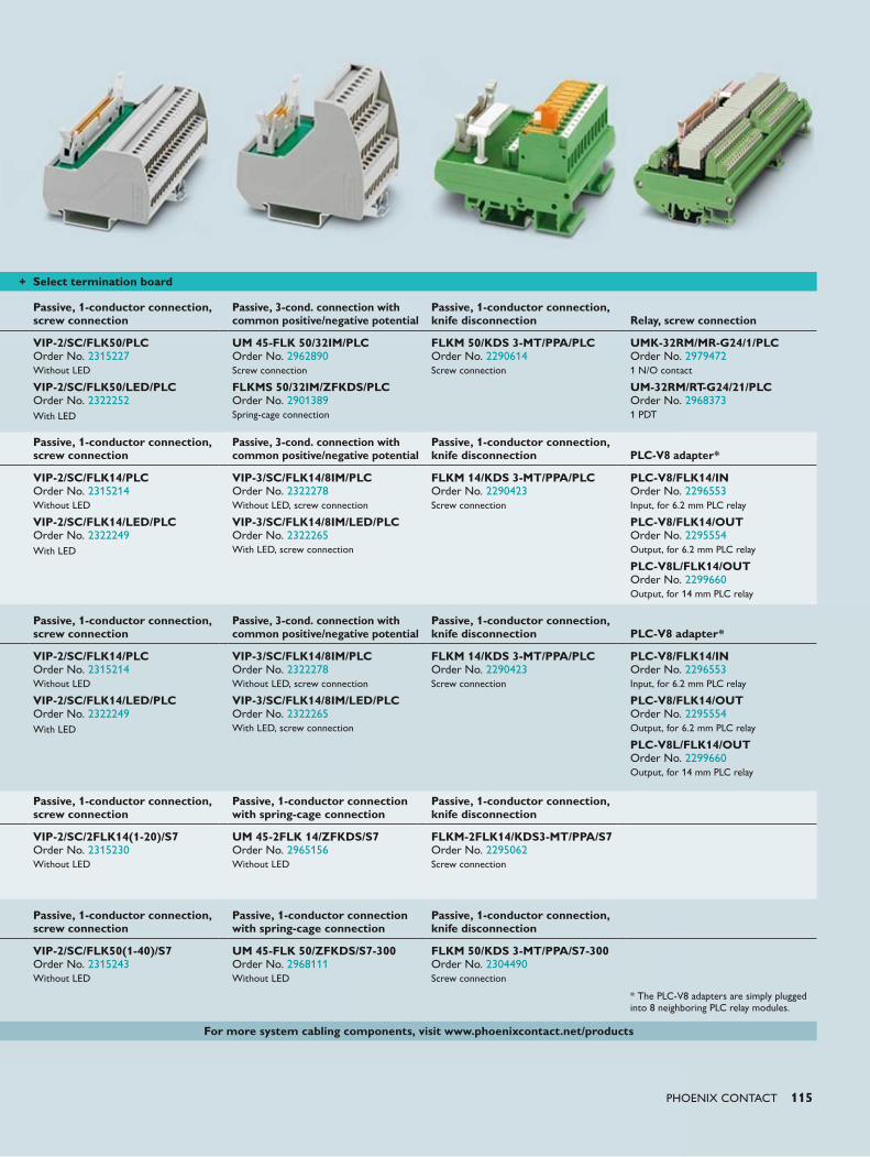
PHOENIX CONTACT 115
+ Select termination board
Passive, 1-conductor connection, screw connection
Passive, 3-cond. connection with common positive/negative potential
Passive, 1-conductor connection, knife disconnection
Relay, screw connection
VIP-2/SC/FLK50/PLC Order No. 2315227Without LED
VIP-2/SC/FLK50/LED/PLC Order No. 2322252With LED
UM 45-FLK 50/32IM/PLC Order No. 2962890Screw connection
FLKMS 50/32IM/ZFKDS/PLC Order No. 2901389Spring-cage connection
FLKM 50/KDS 3-MT/PPA/PLC Order No. 2290614Screw connection
UMK-32RM/MR-G24/1/PLC Order No. 29794721 N/O contact
UM-32RM/RT-G24/21/PLC Order No. 29683731 PDT
Passive, 1-conductor connection, screw connection
Passive, 3-cond. connection with common positive/negative potential
Passive, 1-conductor connection, knife disconnection
PLC-V8 adapter*
VIP-2/SC/FLK14/PLC Order No. 2315214Without LED
VIP-2/SC/FLK14/LED/PLC Order No. 2322249With LED
VIP-3/SC/FLK14/8IM/PLC Order No. 2322278Without LED, screw connection
VIP-3/SC/FLK14/8IM/LED/PLC Order No. 2322265With LED, screw connection
FLKM 14/KDS 3-MT/PPA/PLC Order No. 2290423Screw connection
PLC-V8/FLK14/IN Order No. 2296553Input, for 6.2 mm PLC relay
PLC-V8/FLK14/OUT Order No. 2295554Output, for 6.2 mm PLC relay
PLC-V8L/FLK14/OUT Order No. 2299660Output, for 14 mm PLC relay
Passive, 1-conductor connection, screw connection
Passive, 1-conductor connection with spring-cage connection
Passive, 1-conductor connection, knife disconnection
VIP-2/SC/2FLK14(1-20)/S7 Order No. 2315230Without LED
UM 45-2FLK 14/ZFKDS/S7 Order No. 2965156Without LED
FLKM-2FLK14/KDS3-MT/PPA/S7 Order No. 2295062Screw connection
Passive, 1-conductor connection, screw connection
Passive, 1-conductor connection with spring-cage connection
Passive, 1-conductor connection, knife disconnection
VIP-2/SC/FLK50(1-40)/S7 Order No. 2315243Without LED
UM 45-FLK 50/ZFKDS/S7-300 Order No. 2968111Without LED
FLKM 50/KDS 3-MT/PPA/S7-300 Order No. 2304490Screw connection
* The PLC-V8 adapters are simply plugged into 8 neighboring PLC relay modules.
For more system cabling components, visit www.phoenixcontact.net/products
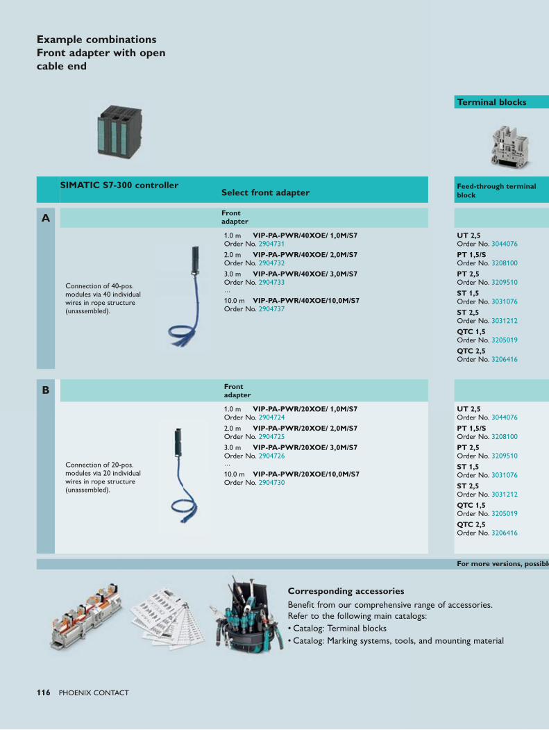
116 PHOENIX CONTACT
Terminal blocks
SIMATIC S7-300 controllerSelect front adapter
Feed-through terminal block
A Front adapter
Connection of 40-pos. modules via 40 individual wires in rope structure (unassembled).
1.0 m VIP-PA-PWR/40XOE/ 1,0M/S7 Order No. 2904731
2.0 m VIP-PA-PWR/40XOE/ 2,0M/S7 Order No. 2904732
3.0 m VIP-PA-PWR/40XOE/ 3,0M/S7 Order No. 2904733…
10.0 m VIP-PA-PWR/40XOE/10,0M/S7 Order No. 2904737
UT 2,5 Order No. 3044076
PT 1,5/S Order No. 3208100
PT 2,5 Order No. 3209510
ST 1,5 Order No. 3031076
ST 2,5 Order No. 3031212
QTC 1,5 Order No. 3205019
QTC 2,5 Order No. 3206416
B Front adapter
Connection of 20-pos. modules via 20 individual wires in rope structure (unassembled).
1.0 m VIP-PA-PWR/20XOE/ 1,0M/S7 Order No. 2904724
2.0 m VIP-PA-PWR/20XOE/ 2,0M/S7 Order No. 2904725
3.0 m VIP-PA-PWR/20XOE/ 3,0M/S7 Order No. 2904726…
10.0 m VIP-PA-PWR/20XOE/10,0M/S7 Order No. 2904730
UT 2,5 Order No. 3044076
PT 1,5/S Order No. 3208100
PT 2,5 Order No. 3209510
ST 1,5 Order No. 3031076
ST 2,5 Order No. 3031212
QTC 1,5 Order No. 3205019
QTC 2,5 Order No. 3206416
For more versions, possible
Corresponding accessoriesBenefit from our comprehensive range of accessories. Refer to the following main catalogs:• Catalog: Terminal blocks• Catalog: Marking systems, tools, and mounting material
Example combinations Front adapter with open cable end
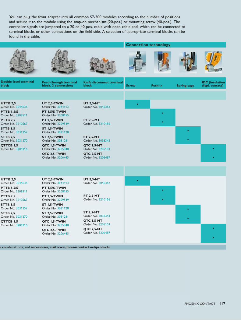
PHOENIX CONTACT 117
Connection technology
Double-level terminal block
Feed-through terminal block, 3 connections
Knife disconnect terminal block Screw Push-in Spring-cage
IDC (insulation displ. contact)
UTTB 2,5 Order No. 3044636
PTTB 1,5/S Order No. 3208511
PTTB 2,5 Order No. 3210567
STTB 1,5 Order No. 3031157
STTB 2,5 Order No. 3031270
QTTCB 1,5 Order No. 3205116
UT 2,5-TWIN Order No. 3044513
PT 1,5/S-TWIN Order No. 3208155
PT 2,5-TWIN Order No. 3209549
ST 1,5-TWIN Order No. 3031128
ST 2,5-TWIN Order No. 3031241
QTC 1,5-TWIN Order No. 3205048
QTC 2,5-TWIN Order No. 3206445
UT 2,5-MT Order No. 3046362
PT 2,5-MT Order No. 3210156
ST 2,5-MT Order No. 3036343
QTC 1,5-MT Order No. 3205103
QTC 2,5-MT Order No. 3206487
•
•
•
•
•
•
•
e combinations, and accessories, visit www.phoenixcontact.net/products
You can plug the front adapter into all common S7-300 modules according to the number of positions and secure it to the module using the snap-on mechanism (20-pos.) or mounting screw (40-pos.). The controller signals are jumpered to a 20 or 40-pos. cable with open cable end, which can be connected to terminal blocks or other connections on the field side. A selection of appropriate terminal blocks can be found in the table.
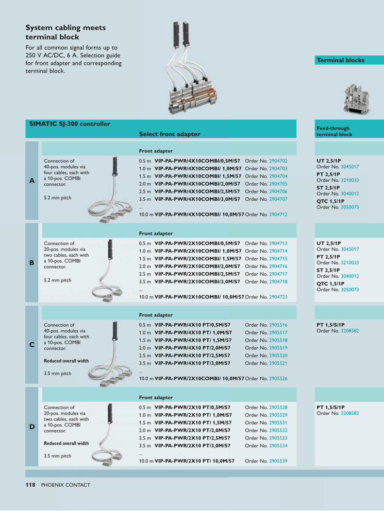
118 PHOENIX CONTACT
System cabling meets terminal blockFor all common signal forms up to 250 V AC/DC, 6 A. Selection guide for front adapter and corresponding terminal block.
Terminal blocks
SIMATIC SJ-300 controller
Select front adapter
Feed-through terminal block
A
Front adapter
Connection of 40-pos. modules via four cables, each with a 10-pos. COMBI connector.
5.2 mm pitch
0.5 m VIP-PA-PWR/4X10COMBI/0,5M/S7 Order No. 2904702
1.0 m VIP-PA-PWR/4X10COMBI/ 1,0M/S7 Order No. 2904703
1.5 m VIP-PA-PWR/4X10COMBI/ 1,5M/57 Order No. 2904704
2.0 m VIP-PA-PWR/4X10COMBI/2,0M/S7 Order No. 2904705
2.5 m VIP-PA-PWR/4X10COMBI/2,5M/57 Order No. 2904706
3.5 m VIP-PA-PWR/4X10COMBI/3,0M/S7 Order No. 2904707
... 10.0 m VIP-PA-PWR/4X10COMBI/ 10,0M/57 Order No. 2904712
UT 2,5/1P Order No. 3045017
PT 2,5/1P Order No. 3210033
ST 2,5/1P Order No. 3040012
QTC 1,5/1P Order No. 3050073
B
Front adapter
Connection of 20-pos. modules via two cables, each with a 10-pos. COMBI connector.
5.2 mm pitch
0.5 m VIP-PA-PWR/2X10COMBI/0,5M/S7 Order No. 2904713
1.0 m VIP-PA-PWR/2X10COMBI/ 1,0M/S7 Order No. 2904714
1.5 m VIP-PA-PWR/2X10COMBI/ 1,5M/57 Order No. 2904715
2.0 m VIP-PA-PWR/2X10COMBI/2,0M/S7 Order No. 2904716
2.5 m VIP-PA-PWR/2X10COMBI/2,5M/57 Order No. 2904717
3.5 m VIP-PA-PWR/2X10COMBI/3,0M/S7 Order No. 2904718
... 10.0 m VIP-PA-PWR/2X10COMBI/ 10,0M/57 Order No. 2904723
UT 2,5/1P Order No. 3045017
PT 2,5/1P Order No. 3210033
ST 2,5/1P Order No. 3040012
QTC 1,5/1P Order No. 3050073
C
Front adapter
Connection of 40-pos. modules via four cables, each with a 10-pos. COMBI connector. Reduced overall width
3.5 mm pitch
0.5 m VIP-PA-PWR/4X10 PT/0,5M/S7 Order No. 2905516
1.0 m VIP-PA-PWR/4X10 PT/ 1,0M/S7 Order No. 2905517
1.5 m VIP-PA-PWR/4X10 PT/ 1,5M/57 Order No. 2905518
2.0 m VIP-PA-PWR/4X10 PT/2,0M/S7 Order No. 2905519
2.5 m VIP-PA-PWR/4X10 PT/2,5M/57 Order No. 2905520
3.5 m VIP-PA-PWR/4X10 PT/3,0M/S7 Order No. 2905521
... 10.0 m VIP-PA-PWR/2X10COMBI/ 10,0M/57 Order No. 2905526
PT 1,5/S/1P Order No. 3208582
D
Front adapter
Connection of 20-pos. modules via two cables, each with a 10-pos. COMBI connector. Reduced overall width
3.5 mm pitch
0.5 m VIP-PA-PWR/2X10 PT/0,5M/S7 Order No. 2905528
1.0 m VIP-PA-PWR/2X10 PT/ 1,0M/S7 Order No. 2905529
1.5 m VIP-PA-PWR/2X10 PT/ 1,5M/57 Order No. 2905531
2.0 m VIP-PA-PWR/2X10 PT/2,0M/S7 Order No. 2905532
2.5 m VIP-PA-PWR/2X10 PT/2,5M/57 Order No. 2905533
3.5 m VIP-PA-PWR/2X10 PT/3,0M/S7 Order No. 2905534
... 10.0 m VIP-PA-PWR/2X10 PT/ 10,0M/57 Order No. 2905539
PT 1,5/S/1P Order No. 3208582
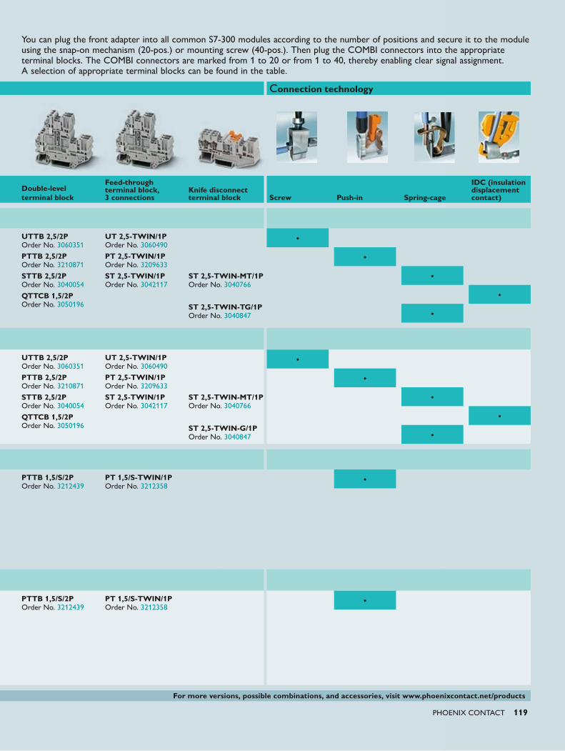
PHOENIX CONTACT 119
Connection technology
Double-level terminal block
Feed-through terminal block, 3 connections
Knife disconnect terminal block
IDC (insulation displacement contact)Screw Push-in Spring-cage
UTTB 2,5/2P Order No. 3060351
PTTB 2,5/2P Order No. 3210871
STTB 2,5/2P Order No. 3040054
QTTCB 1,5/2P Order No. 3050196
UT 2,5-TWIN/1P Order No. 3060490
PT 2,5-TWIN/1P Order No. 3209633
ST 2,5-TWIN/1P Order No. 3042117
ST 2,5-TWIN-MT/1P Order No. 3040766
ST 2,5-TWIN-TG/1P Order No. 3040847
•
•
•
•
•
UTTB 2,5/2P Order No. 3060351
PTTB 2,5/2P Order No. 3210871
STTB 2,5/2P Order No. 3040054
QTTCB 1,5/2P Order No. 3050196
UT 2,5-TWIN/1P Order No. 3060490
PT 2,5-TWIN/1P Order No. 3209633
ST 2,5-TWIN/1P Order No. 3042117
ST 2,5-TWIN-MT/1P Order No. 3040766
ST 2,5-TWIN-G/1P Order No. 3040847
•
•
•
•
•
PTTB 1,5/S/2P Order No. 3212439
PT 1,5/S-TWIN/1P Order No. 3212358
•
PTTB 1,5/S/2P Order No. 3212439
PT 1,5/S-TWIN/1P Order No. 3212358
•
For more versions, possible combinations, and accessories, visit www.phoenixcontact.net/products
You can plug the front adapter into all common S7-300 modules according to the number of positions and secure it to the module using the snap-on mechanism (20-pos.) or mounting screw (40-pos.). Then plug the COMBI connectors into the appropriate terminal blocks. The COMBI connectors are marked from 1 to 20 or from 1 to 40, thereby enabling clear signal assignment. A selection of appropriate terminal blocks can be found in the table.
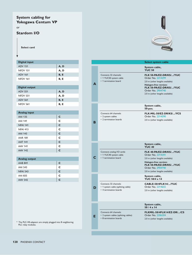
120 PHOENIX CONTACT
System cabling for Yokogawa Centum VPor
Stardom I/O
* The PLC-V8 adapters are simply plugged into 8 neighboring PLC relay modules.
Select card
Digital input
ADV 151 A, D
NFDV 151 A, D
ADV 161 B, E
NFDV 161 B, E
Digital output
ADV 551 A, D
NFDV 551 A, D
ADV 561 B, E
NFDV 561 B, E
Analog input
AAI 135 C
AAI 141 C
NFAI 141 C
NFAI 413 C
AAI 143 C
AAR 181 C
AAT 141 C
AAV 141 C
AAV 142 C
Analog output
AAB 841 C
AAI 543 C
NFAI 543 C
AAI 835 C
AAV 542 C
Select system cable
A
System cable, YUC 50
Connects 32 channels:• 1 YUC50 system cable• 1 termination board
FLK 50-PA/EZ-DR/KS/.../YUC Order No. 23142992.0 m (other lengths available)
Halogen-free version: FLK 50-PA/EZ-DR/KS/.../YUC Order No. 29047402.0 m (other lengths available)
B
System cable,50-pos.
Connects 64 channels:• 2 system cables• 2 termination boards
FLK-MIL-50/EZ-DR/KS/.../YCS Order No. 23145902.0 m (other lengths available)
C
System cable, YUC 40
Connects analog I/O cards:• 1 YUC40 system cable• 1 termination board
FLK 40-PA/EZ-DR/KS/.../YUC Order No. 23143412.0 m (other lengths available)
Halogen-free version: FLK 50-PA/EZ-DR/KS/.../YUC Order No. 29047402.0 m (other lengths available)
D
System cable, YUC 50/4 x 14
Connects 32 channels:• 1 system cable (splitting cable)• 4 termination boards
CABLE-50/4FLK14/.../YUC Order No. 23146552.0 m (other lengths available)
E
System cable,50 / 4 x 14
Connects 64 channels:• 2 system cables (splitting cables)• 8 termination boards
FLKMIL-50/4FLK14/EZ-DR/.../CS Order No. 23063042.0 m (other lengths available)
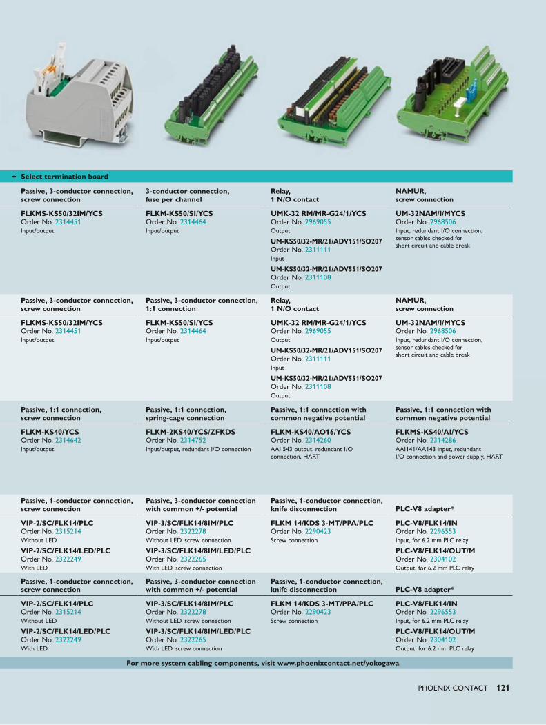
PHOENIX CONTACT 121
+ Select termination board
Passive, 3-conductor connection, screw connection
3-conductor connection, fuse per channel
Relay, 1 N/O contact
NAMUR, screw connection
FLKMS-KS50/32IM/YCS Order No. 2314451Input/output
FLKM-KS50/SI/YCS Order No. 2314464Input/output
UMK-32 RM/MR-G24/1/YCS Order No. 2969055Output
UM-KS50/32-MR/21/ADV151/SO207 Order No. 2311111Input
UM-KS50/32-MR/21/ADV551/SO207 Order No. 2311108Output
UM-32NAM/I/MYCS Order No. 2968506Input, redundant I/O connection, sensor cables checked for short circuit and cable break
Passive, 3-conductor connection, screw connection
Passive, 3-conductor connection, 1:1 connection
Relay, 1 N/O contact
NAMUR, screw connection
FLKMS-KS50/32IM/YCS Order No. 2314451Input/output
FLKM-KS50/SI/YCS Order No. 2314464Input/output
UMK-32 RM/MR-G24/1/YCS Order No. 2969055Output
UM-KS50/32-MR/21/ADV151/SO207 Order No. 2311111Input
UM-KS50/32-MR/21/ADV551/SO207 Order No. 2311108Output
UM-32NAM/I/MYCS Order No. 2968506Input, redundant I/O connection, sensor cables checked for short circuit and cable break
Passive, 1:1 connection, screw connection
Passive, 1:1 connection, spring-cage connection
Passive, 1:1 connection with common negative potential
Passive, 1:1 connection with common negative potential
FLKM-KS40/YCS Order No. 2314642Input/output
FLKM-2KS40/YCS/ZFKDS Order No. 2314752Input/output, redundant I/O connection
FLKM-KS40/AO16/YCS Order No. 2314260AAI 543 output, redundant I/O connection, HART
FLKMS-KS40/AI/YCS Order No. 2314286AAI141/AA143 input, redundant I/O connection and power supply, HART
Passive, 1-conductor connection, screw connection
Passive, 3-conductor connection with common +/- potential
Passive, 1-conductor connection, knife disconnection
PLC-V8 adapter*
VIP-2/SC/FLK14/PLC Order No. 2315214Without LED
VIP-2/SC/FLK14/LED/PLC Order No. 2322249With LED
VIP-3/SC/FLK14/8IM/PLC Order No. 2322278Without LED, screw connection
VIP-3/SC/FLK14/8IM/LED/PLC Order No. 2322265With LED, screw connection
FLKM 14/KDS 3-MT/PPA/PLC Order No. 2290423Screw connection
PLC-V8/FLK14/IN Order No. 2296553Input, for 6.2 mm PLC relay
PLC-V8/FLK14/OUT/M Order No. 2304102Output, for 6.2 mm PLC relay
For more system cabling components, visit www.phoenixcontact.net/yokogawa
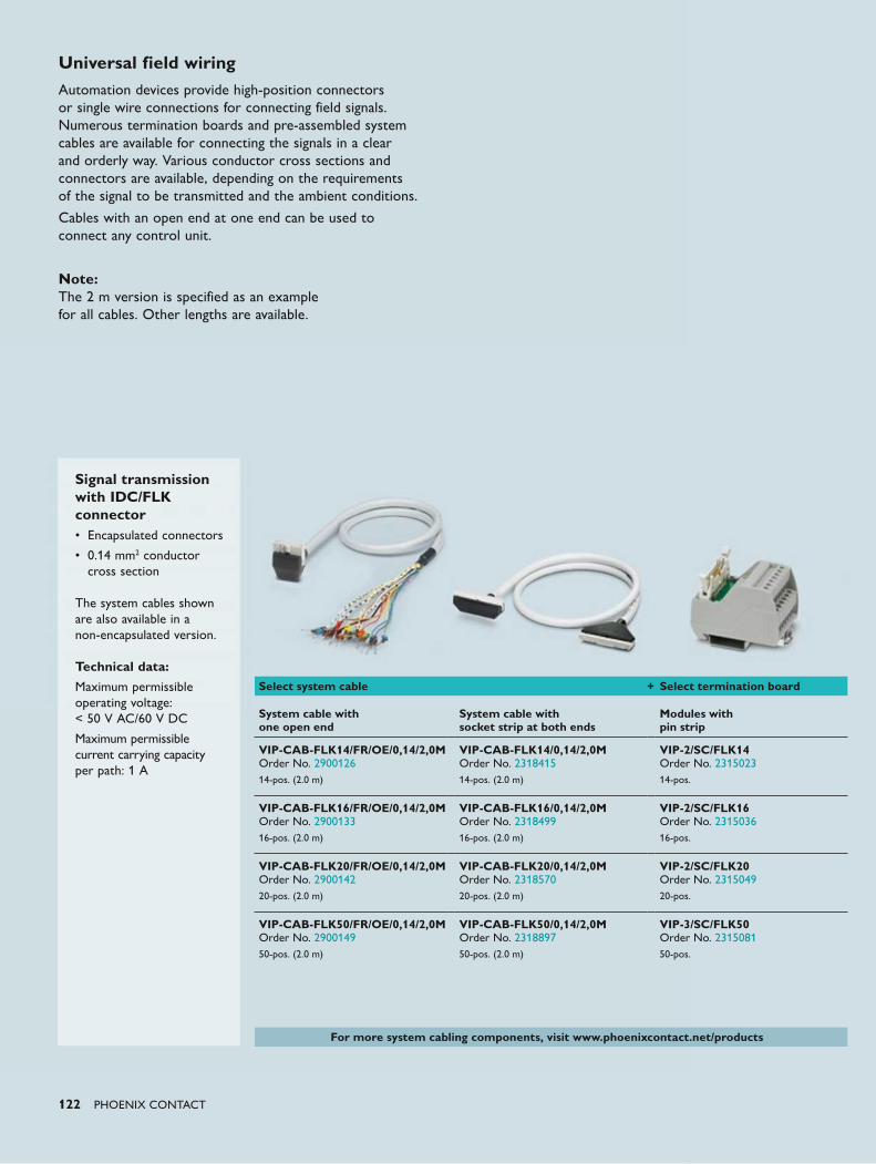
122 PHOENIX CONTACT
Universal field wiringAutomation devices provide high-position connectors or single wire connections for connecting field signals. Numerous termination boards and pre-assembled system cables are available for connecting the signals in a clear and orderly way. Various conductor cross sections and connectors are available, depending on the requirements of the signal to be transmitted and the ambient conditions.
Cables with an open end at one end can be used to connect any control unit.
Note: The 2 m version is specified as an example for all cables. Other lengths are available.
Signal transmission with IDC/FLK connector• Encapsulated connectors
• 0.14 mm2 conductor cross section The system cables shown are also available in a non-encapsulated version. Technical data:
Maximum permissible operating voltage: < 50 V AC/60 V DC
Maximum permissible current carrying capacity per path: 1 A
Select system cable + Select termination board
System cable with one open end
System cable with socket strip at both ends
Modules with pin strip
VIP-CAB-FLK14/FR/OE/0,14/2,0M Order No. 290012614-pos. (2.0 m)
VIP-CAB-FLK14/0,14/2,0M Order No. 231841514-pos. (2.0 m)
VIP-2/SC/FLK14 Order No. 231502314-pos.
VIP-CAB-FLK16/FR/OE/0,14/2,0M Order No. 290013316-pos. (2.0 m)
VIP-CAB-FLK16/0,14/2,0M Order No. 231849916-pos. (2.0 m)
VIP-2/SC/FLK16 Order No. 231503616-pos.
VIP-CAB-FLK20/FR/OE/0,14/2,0M Order No. 290014220-pos. (2.0 m)
VIP-CAB-FLK20/0,14/2,0M Order No. 231857020-pos. (2.0 m)
VIP-2/SC/FLK20 Order No. 231504920-pos.
VIP-CAB-FLK50/FR/OE/0,14/2,0M Order No. 290014950-pos. (2.0 m)
VIP-CAB-FLK50/0,14/2,0M Order No. 231889750-pos. (2.0 m)
VIP-3/SC/FLK50 Order No. 231508150-pos.
For more system cabling components, visit www.phoenixcontact.net/products
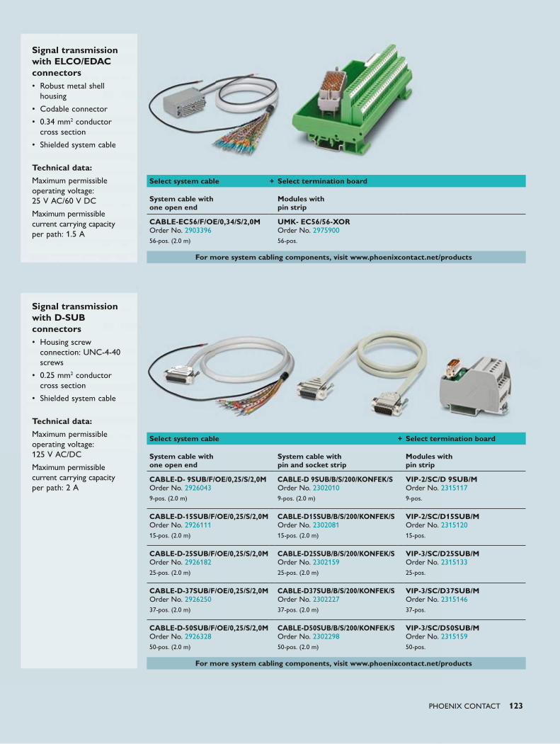
PHOENIX CONTACT 123
Signal transmission with ELCO/EDAC connectors• Robust metal shell
housing
• Codable connector
• 0.34 mm2 conductor cross section
• Shielded system cable
Technical data:
Maximum permissible operating voltage: 25 V AC/60 V DC
Maximum permissible current carrying capacity per path: 1.5 A
Signal transmission with D-SUB connectors• Housing screw
connection: UNC-4-40 screws
• 0.25 mm2 conductor cross section
• Shielded system cable
Technical data:
Maximum permissible operating voltage: 125 V AC/DC
Maximum permissible current carrying capacity per path: 2 A
Select system cable + Select termination board
System cable with one open end
System cable with pin and socket strip
Modules with pin strip
CABLE-D- 9SUB/F/OE/0,25/S/2,0M Order No. 29260439-pos. (2.0 m)
CABLE-D 9SUB/B/S/200/KONFEK/S Order No. 23020109-pos. (2.0 m)
VIP-2/SC/D 9SUB/M Order No. 23151179-pos.
CABLE-D-15SUB/F/OE/0,25/S/2,0M Order No. 292611115-pos. (2.0 m)
CABLE-D15SUB/B/S/200/KONFEK/S Order No. 230208115-pos. (2.0 m)
VIP-2/SC/D15SUB/M Order No. 231512015-pos.
CABLE-D-25SUB/F/OE/0,25/S/2,0M Order No. 292618225-pos. (2.0 m)
CABLE-D25SUB/B/S/200/KONFEK/S Order No. 230215925-pos. (2.0 m)
VIP-3/SC/D25SUB/M Order No. 231513325-pos.
CABLE-D-37SUB/F/OE/0,25/S/2,0M Order No. 292625037-pos. (2.0 m)
CABLE-D37SUB/B/S/200/KONFEK/S Order No. 230222737-pos. (2.0 m)
VIP-3/SC/D37SUB/M Order No. 231514637-pos.
CABLE-D-50SUB/F/OE/0,25/S/2,0M Order No. 292632850-pos. (2.0 m)
CABLE-D50SUB/B/S/200/KONFEK/S Order No. 230229850-pos. (2.0 m)
VIP-3/SC/D50SUB/M Order No. 231515950-pos.
For more system cabling components, visit www.phoenixcontact.net/products
Select system cable + Select termination board
System cable with one open end
Modules with pin strip
CABLE-EC56/F/OE/0,34/S/2,0M Order No. 290339656-pos. (2.0 m)
UMK- EC56/56-XOR Order No. 297590056-pos.
For more system cabling components, visit www.phoenixcontact.net/products
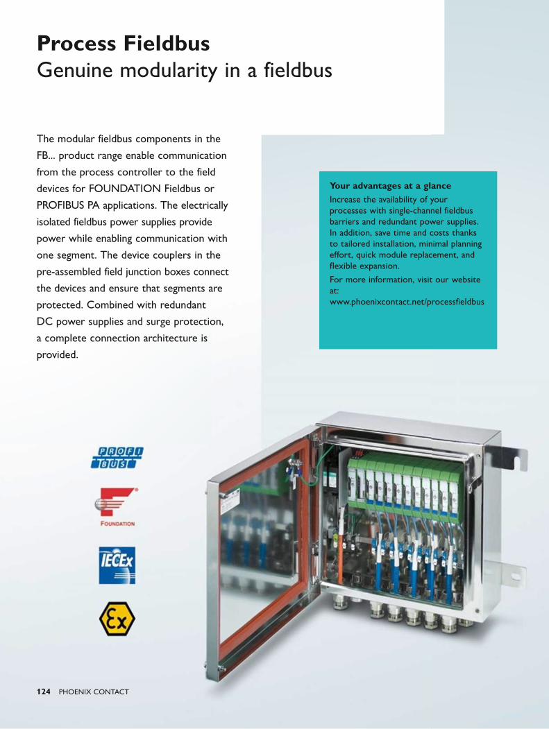
124 PHOENIX CONTACT
The modular fieldbus components in the
FB... product range enable communication
from the process controller to the field
devices for FOUNDATION Fieldbus or
PROFIBUS PA applications. The electrically
isolated fieldbus power supplies provide
power while enabling communication with
one segment. The device couplers in the
pre-assembled field junction boxes connect
the devices and ensure that segments are
protected. Combined with redundant
DC power supplies and surge protection,
a complete connection architecture is
provided.
Process Fieldbus Genuine modularity in a fieldbus
Your advantages at a glanceIncrease the availability of your processes with single-channel fieldbus barriers and redundant power supplies. In addition, save time and costs thanks to tailored installation, minimal planning effort, quick module replacement, and flexible expansion.
For more information, visit our website at: www.phoenixcontact.net/processfieldbus
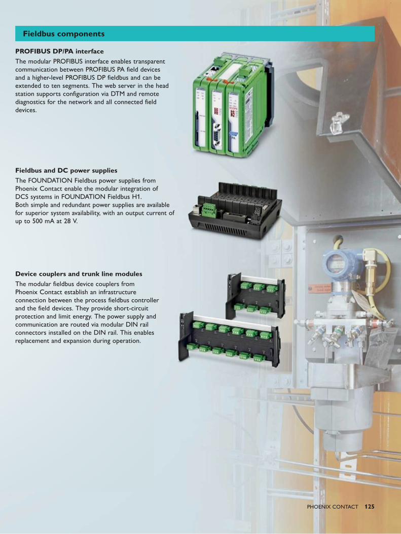
PHOENIX CONTACT 125
Fieldbus components
PROFIBUS DP/PA interfaceThe modular PROFIBUS interface enables transparent communication between PROFIBUS PA field devices and a higher-level PROFIBUS DP fieldbus and can be extended to ten segments. The web server in the head station supports configuration via DTM and remote diagnostics for the network and all connected field devices.
Fieldbus and DC power suppliesThe FOUNDATION Fieldbus power supplies from Phoenix Contact enable the modular integration of DCS systems in FOUNDATION Fieldbus H1. Both simple and redundant power supplies are available for superior system availability, with an output current of up to 500 mA at 28 V.
Device couplers and trunk line modulesThe modular fieldbus device couplers from Phoenix Contact establish an infrastructure connection between the process fieldbus controller and the field devices. They provide short-circuit protection and limit energy. The power supply and communication are routed via modular DIN rail connectors installed on the DIN rail. This enables replacement and expansion during operation.
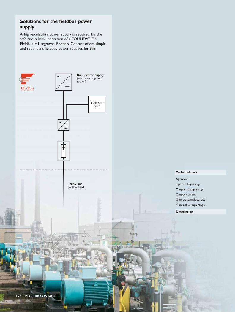
126 PHOENIX CONTACT
Bulk power supply (see “Power supplies” section)
Trunk line to the field
Fieldbus host
Solutions for the fieldbus power supplyA high-availability power supply is required for the safe and reliable operation of a FOUNDATION Fieldbus H1 segment. Phoenix Contact offers simple and redundant fieldbus power supplies for this.
Technical data
Approvals
Input voltage range
Output voltage range
Output current
One-piece/multipartite
Nominal voltage range
Description
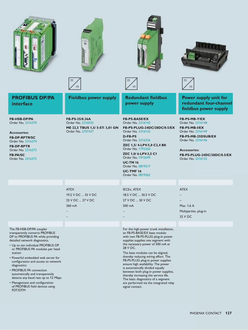
PHOENIX CONTACT 127
PROFIBUS DP/PA interface
Fieldbus power supply Redundant fieldbus power supply
Power supply unit for redundant four-channel fieldbus power supply
FB-HSB-DP/PA Order No. 2316370
Accessories:FB-DP-RPTR/SC Order No. 2316374
FB-DP-RPTR Order No. 2316373
FB-PA/SC Order No. 2316375
FB-PS-25/0.36A Order No. 2316035
ME 22,5 TBUS 1,5/ 5-ST- 3,81 GN Order No. 2707437
FB-PS-BASE/EX Order No. 2316145
FB-PS-PLUG-24DC/28DC/0.5/EX Order No. 2316132
D-FB-PS Order No. 2316226
ZEC 1,5/ 4-LPV-5,0 C2,4 BK Order No. 1793260
ZEC 1,0/ 6-LPV-3,5 C1 Order No. 1915699
UC-TM 16 Order No. 0819217
UC-TMF 16 Order No. 0819262
FB-PS-MB-Y/EX Order No. 2316148
FB-PS-MB-I/EX Order No. 2316149
FB-PS-MB-25DSUB/EX Order No. 2316146
Accessories:FB-PS-PLUG-24DC/28DC/0.5/EX Order No. 2316132
ATEX IECEx, ATEX ATEX
19.2 V DC ... 35 V DC 18.5 V DC ... 30.5 V DC –
25 V DC ... 27 V DC 27 V DC ... 30 V DC –
360 mA 500 mA Max. 1.6 A
– – Multipartite, plug-in
– – 32 V DC
The FB-HSB-DP/PA coupler transparently converts PROFIBUS DP to PROFIBUS PA while providing detailed network diagnostics.
• Up to ten individual PROFIBUS DP or PROFIBUS PA modules per head station
• Powerful embedded web server for configuration and access to network diagnostics
• PROFIBUS PA connection automatically and transparently detects any baud rate up to 12 Mbps
• Management and configuration of PROFIBUS field devices using FDT/DTM
For the high-power trunk installation, an FB-PS-BASE/EX base module with two FB-PS-PLUG plug-in power supplies supplies one segment with the necessary power of 500 mA at 28 V DC.
The base modules can be aligned, thereby reducing wiring effort. The FB-PS-PLUG plug-in power supplies ensure high availability. The power is automatically divided equally between both plug-in power supplies, thereby increasing the service life. The basic diagnostics of a segment are performed via the integrated relay signal contact.
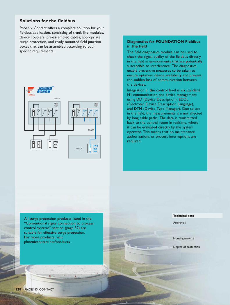
128 PHOENIX CONTACT
Zone 1, 0
FISCO
Zone 2
Solutions for the fieldbusPhoenix Contact offers a complete solution for your fieldbus application, consisting of trunk line modules, device couplers, pre-assembled cables, appropriate surge protection, and ready-mounted field junction boxes that can be assembled according to your specific requirements.
Technical data
Approvals
Housing material
Degree of protection
Diagnostics for FOUNDATION Fieldbus in the fieldThe field diagnostics module can be used to check the signal quality of the fieldbus directly in the field in environments that are potentially susceptible to interference. The diagnostics enable preventive measures to be taken to ensure optimum device availability and prevent the sudden loss of communication between the devices.
Integration in the control level is via standard H1 communication and device management using DD (Device Description), EDDL (Electronic Device Description Language), and DTM (Device Type Manager). Due to use in the field, the measurements are not affected by long cable paths. The data is transmitted back to the control room in realtime, where it can be evaluated directly by the system operator. This means that no maintenance authorizations or process interruptions are required.
All surge protection products listed in the “Conventional signal connection to process control systems” section (page 52) are suitable for effective surge protection. For more products, visit phoenixcontact.net/products.
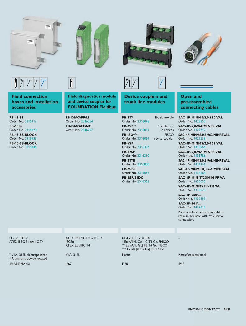
PHOENIX CONTACT 129
Field connection boxes and installation accessories
Field diagnostics module and device coupler for FOUNDATION Fieldbus
Device couplers and trunk line modules
Open and pre-assembled connecting cables
FB-16 SS Order No. 2316417
FB-10SS Order No. 2316420
FB-16-SS-BLOCK Order No. 2316433
FB-10-SS-BLOCK Order No. 2316446
FB-DIAG/FF/LI Order No. 2316284
FB-DIAG/FF/NC Order No. 2316297
FB-ET* Trunk module Order No. 2316048
FB-2SP** Coupler for Order No. 2316051 2 devices
FB-ISO*** FISCO Order No. 2316064 device coupler
FB-6SP Order No. 2316307
FB-12SP Order No. 2316310
FB-ET/E Order No. 2316050
FB-2SP/E Order No. 2316052
FB-2SP/24DC Order No. 2316352
SAC-4P-MINMS/2,0-960 VAL Order No. 1429350
SAC-4P-2,0-960/MINFS VAL Order No. 1429712
SAC-4P-MINMS/0,3-960/MINFSVAL Order No. 1429538
SAC-4P-MINMS/2,0-961 VAL Order No. 1433964
SAC-4P-2,0-961/MINFS VAL Order No. 1433786
SAC-4P-MINMS/0,3-961/MINFSVAL Order No. 1434141
SAC-4P-MINMR/0,3-961/MINFSVAL Order No. 1434264
SAC-4P-MIN-T/2XMIN FF VA Order No. 1430035
SAC-4P-MINMS FF-TR VA Order No. 1430023
SAC-2P-960/... Order No. 1432389
SAC-2P-961/... Order No. 1434620
Pre-assembled connecting cables are also available with M12 screw connection.
UL-Ex, IECEx, ATEX II 3G Ex nA IIC T4
ATEX Ex II 1G Ex ia IIC T4 IECEx ATEX Ex d IIC T4
UL-Ex, IECEx, ATEX * Ex nA[nL Gc] IIC T4 Gc, FNICO ** Ex nA[ic Gc] IIB T4 Gc, FISCO *** Ex nA [ia Ga Da] IIC T4 Gc
–
1) V4A, 316L electropolished 2) Aluminum, powder-coated
V4A, 316L Plastic Plastic/stainless steel
IP66/NEMA 4X IP67 IP20 IP67
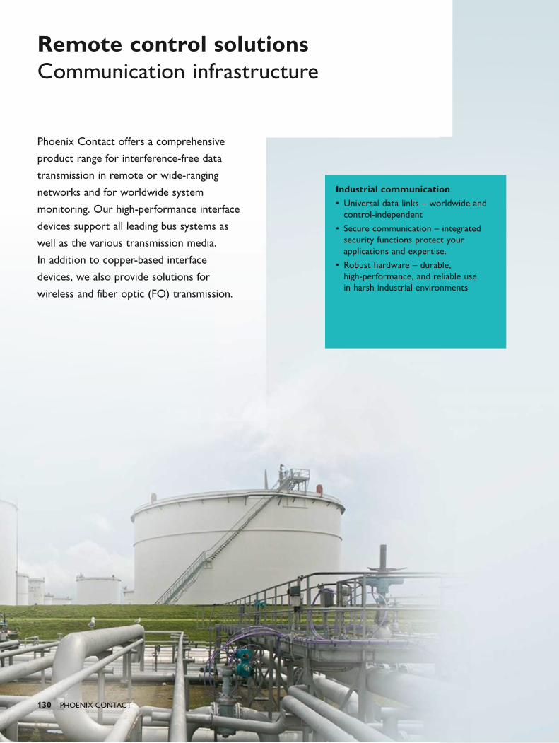
130 PHOENIX CONTACT
Phoenix Contact offers a comprehensive
product range for interference-free data
transmission in remote or wide-ranging
networks and for worldwide system
monitoring. Our high-performance interface
devices support all leading bus systems as
well as the various transmission media.
In addition to copper-based interface
devices, we also provide solutions for
wireless and fiber optic (FO) transmission.
Remote control solutions Communication infrastructure
Industrial communication• Universal data links – worldwide and
control-independent
• Secure communication – integrated security functions protect your applications and expertise.
• Robust hardware – durable, high-performance, and reliable use in harsh industrial environments
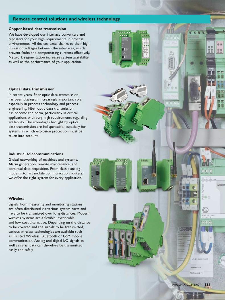
PHOENIX CONTACT 131
Copper-based data transmissionWe have developed our interface converters and repeaters for your high requirements in process environments. All devices excel thanks to their high insulation voltages between the interfaces, which prevent faults and compensating currents effectively. Network segmentation increases system availability as well as the performance of your application.
Optical data transmissionIn recent years, fiber optic data transmission has been playing an increasingly important role, especially in process technology and process engineering. Fiber optic data transmission has become the norm, particularly in critical applications with very high requirements regarding availability. The advantages brought by optical data transmission are indispensable, especially for systems in which explosion protection must be taken into account.
Industrial telecommunicationsGlobal networking of machines and systems. Alarm generation, remote maintenance, and continual data acquisition. From classic analog modems to fast mobile communication routers: we offer the right system for every application.
WirelessSignals from measuring and monitoring stations are often distributed via various system parts and have to be transmitted over long distances. Modern wireless systems are a flexible, extendable, and low-cost alternative. Depending on the distance to be covered and the signals to be transmitted, various wireless technologies are available such as Trusted Wireless, Bluetooth or GSM mobile communication. Analog and digital I/O signals as well as serial data can therefore be transmitted easily and safely.
Remote control solutions and wireless technology
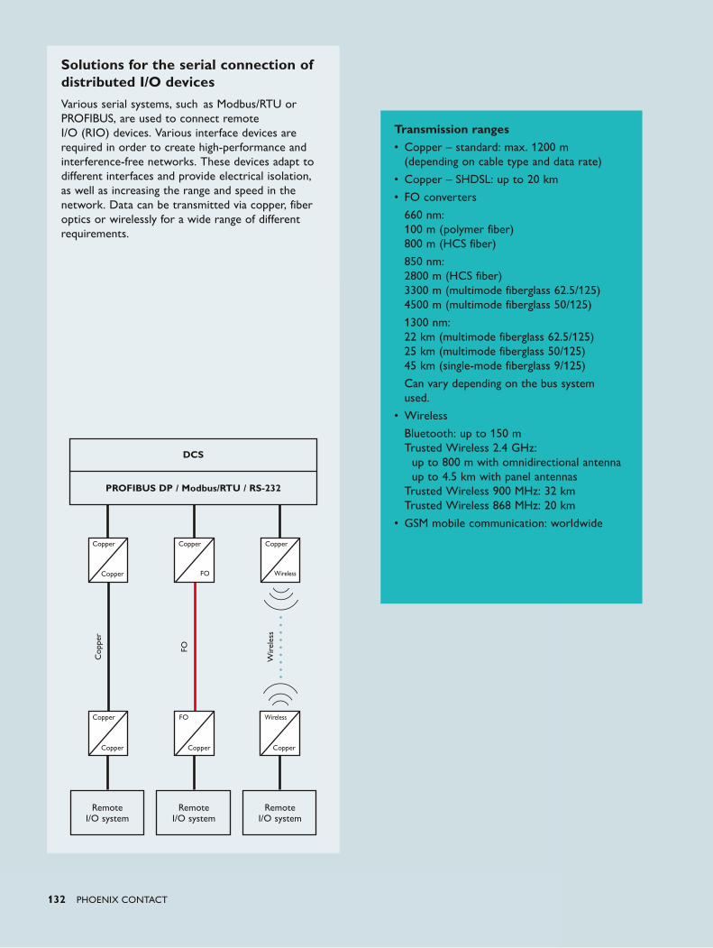
132 PHOENIX CONTACT
Solutions for the serial connection of distributed I/O devicesVarious serial systems, such as Modbus/RTU or PROFIBUS, are used to connect remote I/O (RIO) devices. Various interface devices are required in order to create high-performance and interference-free networks. These devices adapt to different interfaces and provide electrical isolation, as well as increasing the range and speed in the network. Data can be transmitted via copper, fiber optics or wirelessly for a wide range of different requirements.
DCS
PROFIBUS DP / Modbus/RTU / RS-232
Cop
per
Wir
eles
s
FO
Copper
Copper
Copper Copper Copper
Wireless
Copper FO Wireless
Copper
Remote I/O system
Remote I/O system
Remote I/O system
Copper
FO
Transmission ranges• Copper – standard: max. 1200 m (depending on cable type and data rate)
• Copper – SHDSL: up to 20 km
• FO converters
660 nm: 100 m (polymer fiber) 800 m (HCS fiber)
850 nm: 2800 m (HCS fiber) 3300 m (multimode fiberglass 62.5/125) 4500 m (multimode fiberglass 50/125)
1300 nm: 22 km (multimode fiberglass 62.5/125) 25 km (multimode fiberglass 50/125) 45 km (single-mode fiberglass 9/125)
Can vary depending on the bus system used.
• Wireless
Bluetooth: up to 150 m Trusted Wireless 2.4 GHz: up to 800 m with omnidirectional antenna up to 4.5 km with panel antennas Trusted Wireless 900 MHz: 32 km Trusted Wireless 868 MHz: 20 km
• GSM mobile communication: worldwide
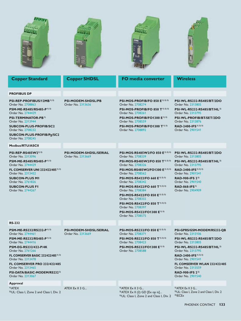
PHOENIX CONTACT 133
Copper Standard Copper SHDSL FO media converter Wireless
PROFIBUS DP
PSI-REP-PROFIBUS/12MB1) 2) Order No. 2708863
PSM-ME-RS485/RS485-P1) 2) Order No. 2744429
PSI-TERMINATOR-PB1) Order No. 2313944
SUBCON-PLUS-PROFIB/SC2 Order No. 2708232
SUBCON-PLUS-PROFIB/Pg/SC2 Order No. 2708245
PSI-MODEM-SHDSL/PB Order No. 2313656
PSI-MOS-PROFIB/FO 850 E1) 2) 3) Order No. 2708274
PSI-MOS-PROFIB/FO 850 T1) 2) 3) Order No. 2708261
PSI-MOS-PROFIB/FO1300 E1) 3) Order No. 2708559
PSI-MOS-PROFIB/FO1300 T1) 3) Order No. 2708892
PSI-WL-RS232-RS485/BT/2DO Order No. 2313805
PSI-WL-RS232-RS485/BT/HL2) Order No. 2313795
PSI-WL-PROFIB/BT-SET/2DO Order No. 2313876
RAD-2400-IFS1) 2) 3) Order No. 2901541
Modbus/RTU/ASCII
PSI-REP-RS485W21) 2) Order No. 2313096
PSM-ME-RS485/RS485-P1) 2) Order No. 2744429
FL COMSERVER UNI 232/422/4851) 2) Order No. 2313452
SUBCON-PLUS M1 Order No. 2761826
SUBCON-PLUS F1 Order No. 2744267
PSI-MODEM-SHDSL/SERIAL Order No. 2313669
PSI-MOS-RS485W2/FO 850 E1) 2) 3) Order No. 2708339
PSI-MOS-RS485W2/FO 850 T1) 2) 3) Order No. 2708326
PSI-MOS-RS485W2/FO1300 E1) 2) 3) Order No. 2708562
PSI-MOS-RS422/FO 660 E1) 2) 3) Order No. 2708342
PSI-MOS-RS422/FO 660 T1) 2) 3) Order No. 2708384
PSI-MOS-RS422/FO 850 E1) 2) 3) Order No. 2708355
PSI-MOS-RS422/FO 850 T1) 2) 3) Order No. 2708397
PSI-MOS-RS422/FO1300 E1) 3) Order No. 2708575
PSI-WL-RS232-RS485/BT/2DO Order No. 2313805
PSI-WL-RS232-RS485/BT/HL2) Order No. 2313795
RAD-2400-IFS1) 2) 3) Order No. 2901541
RAD-900-IFS 22) Order No. 2901540
RAD-868-IFS1) Order No. 2904909
RS-232
PSM-ME-RS232/RS232-P1) 2) Order No. 2744461
PSM-ME-RS232/RS485-P1) 2) Order No. 2744416
PSM-EG-RS232/422-P/4K Order No. 2761266
FL COMSERVER BASIC 232/422/4851) 2) Order No. 2313478
FL COMSERVER PRO 232/422/485 Order No. 2313465
PSI-DATA/BASIC-MODEM/RS2322)
Order No. 2313067
PSI-MODEM-SHDSL/SERIAL Order No. 2313669
PSI-MOS-RS232/FO 850 E1) 2) 3) Order No. 2708371
PSI-MOS-RS232/FO 850 T1) 2) 3) Order No. 2708423
PSI-MOS-RS232/FO1300 E1) 3) Order No. 2708588
PSI-GPRS/GSM-MODEM/RS232-QB Order No. 2313106
PSI-WL-RS232-RS485/BT/2DO Order No. 2313805 PSI-WL-RS232-RS485/BT/HL2) Order No. 2313795 RAD-2400-IFS1) 2) 3) Order No. 2901541 FL COMSERVER WLAN 232/422/485 Order No. 2313559
RAD-900-IFS 22) Order No. 2901540
Approval1)ATEX 2)UL: Class I, Zone 2 and Class I, Div. 2
ATEX Ex II 3 G...
1)ATEX Ex II 3 G... 2)ATEX Ex II (2) GD [Ex op is]... 3)UL: Class I, Zone 2 and Class I, Div. 2
1)ATEX Ex II 3 G... 2)UL: Class I, Zone 2 and Class I, Div. 2 3)IECEx

134 PHOENIX CONTACT
Solutions for creating distributed Ethernet networksIn the past, Ethernet was used exclusively for communication at SCADA level. However, Ethernet is now increasingly being used to transmit video and I/O information for the field level. The physical limitations require alternative solutions for covering large distances. SHDSL technology allows simple two-wire lines, such as existing phone lines, to be used for transmissions up to 20 km. In contrast, fiber optic technology can cover distances of up to 40 km and is also completely immune to electromagnetic interference. At the same time, the fiber optic paths provide high-quality electrical isolation between the connected system parts.
The COMSERVER is available for solutions to retrofit tasks in the vicinity of Modbus systems. The gateway supports easy conversion between Modbus/RTU/ASCII systems and Modbus/TCP controllers.
SCADA
FF HSE / Modbus/TCP / PROFINET
Cop
per
FO
Remote I/O system
Remote I/O system
Copper
Copper
Copper
Copper
FO
Copper
Copper
FO
Transmission ranges• Copper – standard: 100 m
• Copper – SHDSL: up to 20 km
• FO converters:
660 nm: 50 m (polymer fiber 980/1000) 100 m (HCS standard fiber 200/230) 300 m (HCS-GI broadband fiber 200/230)
1300 nm: 2 km (HCS-GI broadband fiber 200/230) 10 km (multimode fiberglass) 36 km (single-mode fiberglass)
Modbus/TCPPROFINETHSE FOUNDATION Fieldbus
Approvals
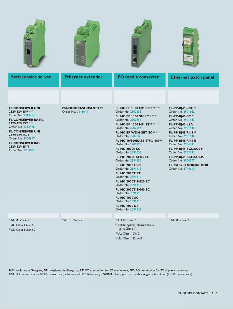
PHOENIX CONTACT 135
Serial device server Ethernet extender FO media converter Ethernet patch panel
FL COMSERVER UNI 232/422/485a) c) d) Order No. 2313452
FL COMSERVER BASIC 232/422/485a) c) d) Order No. 2313478
FL COMSERVER UNI 232/422/485-T Order No. 2904817
FL COMSERVER BAS 232/422/485-T Order No. 2904681
PSI-MODEM-SHDSL/ETHa) Order No. 2313643
FL MC EF 1300 MM SC a) b) c) d) Order No. 2902853
FL MC EF 1300 SM SC a) c) d)
Order No. 2902856
FL MC EF 1300 MM ST a) b) c) d) Order No. 2902854 FL MC EF WDM-SET SC a) c) d)
Order No. 2902660
FL MC 10/100BASE-T/FO-660 a) Order No. 2708193
FL MC 2000E LC Order No. 2891056
FL MC 2000E SM40 LC Order No. 2891156
FL MC 2000T SC Order No. 2891315
FL MC 2000T ST Order No. 2891316
FL MC 2000T SM20 SC Order No. 2891317
FL MC 2000T SM40 SC Order No. 2891318
FL MC 1000 SC Order No. 2891320
FL MC 1000 ST Order No. 2891321
FL-PP-RJ45-SCC a) Order No. 2901642
FL-PP-RJ45-SC a) Order No. 2901643
FL-PP-RJ45-LSA Order No. 2901645
FL-PP-RJ45/RJ45 a) Order No. 2901646
FL-PP-RJ45/RJ45-B Order No. 2904933
FL-PP-RJ45-SCC/SC041 Order No. 2903532
FL-PP-RJ45-SCC/SC045 Order No. 2904577
FL CAT5 TERMINAL BOX Order No. 2744610
a) ATEX: Zone 2c) UL: Class 1 Div 2d) UL: Class 1 Zone 2
a) ATEX: Zone 2 a) ATEX: Zone 2b) ATEX: optical intrinsic safety
(up to Zone 1)c) UL: Class 1 Div 2d) UL: Class 1 Zone 2
a) ATEX: Zone 2
MM: multimode fiberglass, SM: single-mode fiberglass, ST: FO connection for ST connectors, SC: FO connection for SC duplex connectors, 660: FO connection for SCRJ connectors (polymer and HCS fibers only), WDM: fiber optic path with a single optical fiber (for SC connectors)
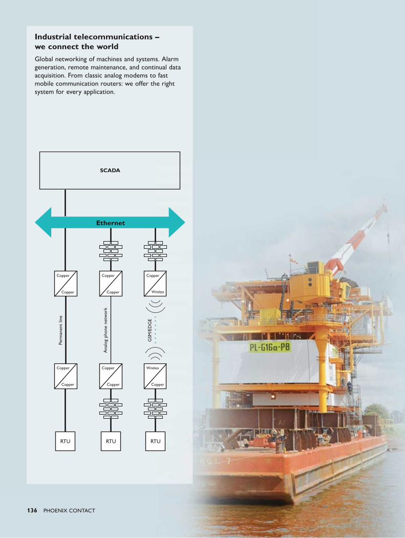
136 PHOENIX CONTACT
Industrial telecommunications – we connect the worldGlobal networking of machines and systems. Alarm generation, remote maintenance, and continual data acquisition. From classic analog modems to fast mobile communication routers: we offer the right system for every application.
Perm
anen
t lin
e
Ana
log
phon
e ne
twor
k
GSM
/ED
GE
Ethernet
Copper Copper Copper
Copper Copper Wireless
Copper Copper Wireless
Copper Copper Copper
SCADA
RTURTU RTU
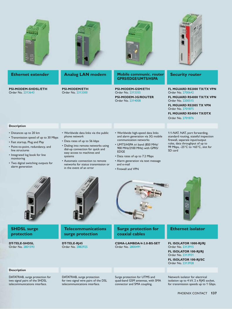
PHOENIX CONTACT 137
Ethernet extender Analog LAN modem Mobile communic. router GPRS/EDGE/UMTS/HSPA
Security router
PSI-MODEM-SHDSL/ETH Order No. 2313643
PSI-MODEM/ETH Order No. 2313300
PSI-MODEM-GSM/ETH Order No. 2313355
PSI-MODEM-3G/ROUTER Order No. 2314008
FL MGUARD RS2000 TX/TX VPN Order No. 2700642
FL MGUARD RS4000 TX/TX VPN Order No. 2200515
FL MGUARD RS2005 TX VPN Order No. 2701875
FL MGUARD RS4004 TX/DTXOrder No. 2701876
Description
• Distances up to 20 km
• Transmission speed of up to 30 Mbps
• Fast startup, Plug and Play
• Point-to-point, redundancy, and line structures
• Integrated log book for line monitoring
• Two digital switching outputs for alarm generation
• Worldwide data links via the public phone network
• Data rates of up to 56 kbps
• Dialing into remote networks using dial-up connection for quick and easy access to machines and systems
• Automatic connection to remote networks for status transmission or in the event of an error
• Worldwide high-speed data links and alarm generation via 3G mobile communication networks
• UMTS/HSPA tri band (850 MHz/ 900 MHz/2100 MHz) with GPRS/EDGE
• Data rates of up to 7.2 Mbps
• Alarm generation via text message and e-mail
• Firewall and VPN
1:1-NAT, NAT, port forwarding, standard routing, stateful inspection firewall, separate input/output rules, data throughput of up to 99 Mbps, -25°C to +65°C, slot for SD card
SHDSL surge protection
Telecommunications surge protection
Surge protection for coaxial cables
Ethernet isolator
DT-TELE-SHDSL Order No. 2801593
DT-TELE-RJ45 Order No. 2882925
CSMA-LAMBDA/4-2.0-BS-SET Order No. 2800491
FL ISOLATOR 1000-RJ/RJ Order No. 2313915
FL ISOLATOR 100-RJ/RJ Order No. 2313931
FL ISOLATOR 100-RJ/SC Order No. 2313928
Description
DATATRAB, surge protection for two signal pairs of the SHDSL telecommunications interface.
DATATRAB, surge protection for two signal wire pairs of the DSL telecommunications interface.
Surge protection for UTMS and quad-band GSM antennas, with SMA connector and SMA coupling.
Network isolator for electrical isolation up to 4 kV, 2 x RJ45 socket, for transmission speeds up to 1 Gbps.
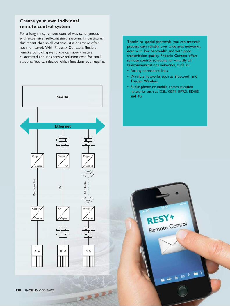
138 PHOENIX CONTACT
Create your own individual remote control systemFor a long time, remote control was synonymous with expensive, self-contained systems. In particular, this meant that small external stations were often not monitored. With Phoenix Contact's flexible remote control system, you can now create a customized and inexpensive solution even for small stations. You can decide which functions you require.
SCADA
Ethernet
Perm
anen
t lin
e
FO
GSM
/ED
GE
Copper Copper Copper
Copper FO Wireless
Copper FO Wireless
Copper Copper Copper
RTURTURTU
Thanks to special protocols, you can transmit process data reliably over wide area networks, even with low bandwidth and with poor transmission quality. Phoenix Contact offers remote control solutions for virtually all telecommunications networks, such as:
• Analog permanent lines
• Wireless networks such as Bluetooth and Trusted Wireless
• Public phone or mobile communication networks such as DSL, GSM, GPRS, EDGE, and 3G
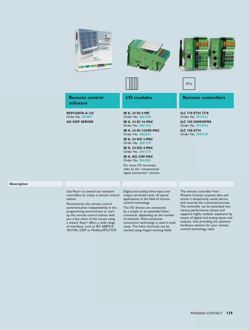
PHOENIX CONTACT 139
Remote control software
I/O modules Remote controllers
RESY-DATA-A LIC Order No. 2876847
AX ODP SERVER
IB IL 24 DI 4-ME Order No. 2863928
IB IL 24 DI 16-PAC Order No. 2861250
IB IL 24 DI 32/HD-PAC Order No. 2862835
IB IL 24 DO 2-PAC Order No. 2861470
IB IL 24 DO 4-PAC Order No. 2861276
IB IL AO 2/SF-PAC Order No. 2863083
For more I/O terminals, refer to the “conventional signal connection” section.
ILC 170 ETH 2TX Order No. 2916532
ILC 150 GSM/GPRS Order No. 2916545
ILC 150 ETH Order No. 2985330
Use Resy+ to extend our standard controllers to create a remote control station.
Parameterize the remote control communication independently in the programming environment or start up the remote control station with just a few clicks of the mouse using a wizard. Resy+ offers a wide range of interfaces, such as IEC 60870-5-101/104, ODP or Modbus/RTU/TCP.
Digital and analog Inline input and output terminals cover all typical applications in the field of remote control technology.
The I/O devices are connected by a simple or an extended Inline connector, depending on the number of channels. Multi-conductor connection technology is used in both cases. The Inline terminals can be marked using hinged marking fields.
The remote controller from Phoenix Contact acquires data and stores it temporarily, sends alarms, and controls the connected process. The controller can be extended into various performance classes and supports highly modular expansion by means of digital and analog inputs and outputs, thus providing the optimum hardware solution for your remote control technology tasks.
Description
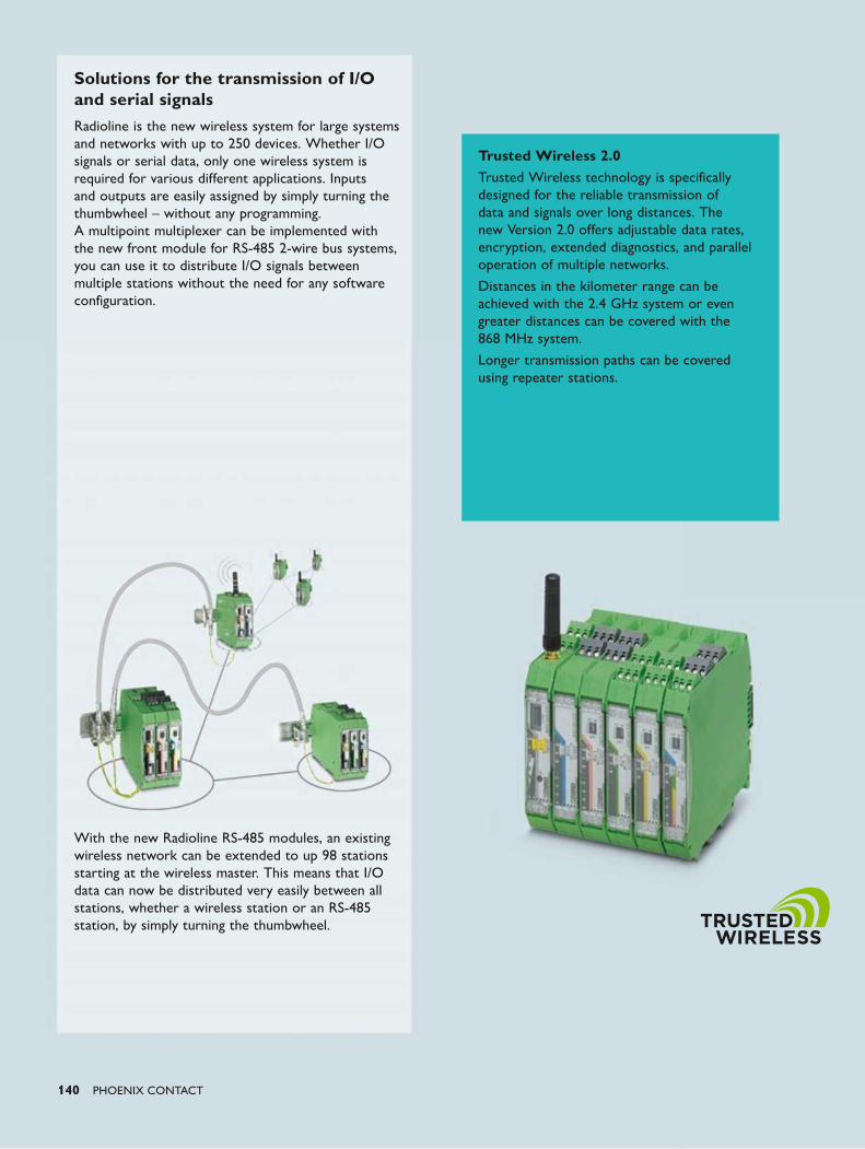
140 PHOENIX CONTACT
Solutions for the transmission of I/O and serial signalsRadioline is the new wireless system for large systems and networks with up to 250 devices. Whether I/O signals or serial data, only one wireless system is required for various different applications. Inputs and outputs are easily assigned by simply turning the thumbwheel – without any programming. A multipoint multiplexer can be implemented with the new front module for RS-485 2-wire bus systems, you can use it to distribute I/O signals between multiple stations without the need for any software configuration.
With the new Radioline RS-485 modules, an existing wireless network can be extended to up 98 stations starting at the wireless master. This means that I/O data can now be distributed very easily between all stations, whether a wireless station or an RS-485 station, by simply turning the thumbwheel.
Trusted Wireless 2.0Trusted Wireless technology is specifically designed for the reliable transmission of data and signals over long distances. The new Version 2.0 offers adjustable data rates, encryption, extended diagnostics, and parallel operation of multiple networks.
Distances in the kilometer range can be achieved with the 2.4 GHz system or even greater distances can be covered with the 868 MHz system.
Longer transmission paths can be covered using repeater stations.
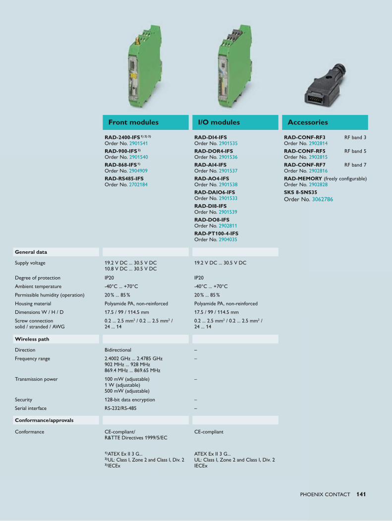
PHOENIX CONTACT 141
Front modules I/O modules Accessories
RAD-2400-IFS1) 2) 3) Order No. 2901541
RAD-900-IFS2) Order No. 2901540
RAD-868-IFS1) Order No. 2904909
RAD-RS485-IFS Order No. 2702184
RAD-DI4-IFS Order No. 2901535
RAD-DOR4-IFS Order No. 2901536
RAD-AI4-IFS Order No. 2901537
RAD-AO4-IFS Order No. 2901538
RAD-DAIO6-IFS Order No. 2901533
RAD-DI8-IFS Order No. 2901539
RAD-DO8-IFS Order No. 2902811
RAD-PT100-4-IFS Order No. 2904035
RAD-CONF-RF3 RF band 3 Order No. 2902814
RAD-CONF-RF5 RF band 5 Order No. 2902815
RAD-CONF-RF7 RF band 7 Order No. 2902816
RAD-MEMORY (freely configurable) Order No. 2902828
SKS 8-SNS35 Order No. 3062786
General data
Supply voltage 19.2 V DC ... 30.5 V DC 10.8 V DC ... 30.5 V DC
19.2 V DC ... 30.5 V DC
Degree of protection IP20 IP20
Ambient temperature -40°C ... +70°C -40°C ... +70°C
Permissible humidity (operation) 20% ... 85% 20% ... 85%
Housing material Polyamide PA, non-reinforced Polyamide PA, non-reinforced
Dimensions W / H / D 17.5 / 99 / 114.5 mm 17.5 / 99 / 114.5 mm
Screw connection solid / stranded / AWG
0.2 ... 2.5 mm2 / 0.2 ... 2.5 mm2 / 24 ... 14
0.2 ... 2.5 mm2 / 0.2 ... 2.5 mm2 / 24 ... 14
Wireless path
Direction Bidirectional –
Frequency range 2.4002 GHz ... 2.4785 GHz 902 MHz ... 928 MHz 869.4 MHz ... 869.65 MHz
–
Transmission power 100 mW (adjustable) 1 W (adjustable) 500 mW (adjustable)
–
Security 128-bit data encryption –
Serial interface RS-232/RS-485 –
Conformance/approvals
Conformance CE-compliant/ R&TTE Directives 1999/5/EC
CE-compliant
1)ATEX Ex II 3 G... 2)UL: Class I, Zone 2 and Class I, Div. 2 3)IECEx
ATEX Ex II 3 G... UL: Class I, Zone 2 and Class I, Div. 2 IECEx

142 PHOENIX CONTACT
Wherever you are in the world, our global
network means that you can rely on our
service. Being at home all over the world
and speaking the language of the user is
what we understand by customer proximity.
We live up to this with more than
50 Phoenix Contact subsidiaries and
in excess of 30 representatives in
other countries.
Services and support In addition to future-oriented products, Phoenix Contact offers a comprehensive range of services
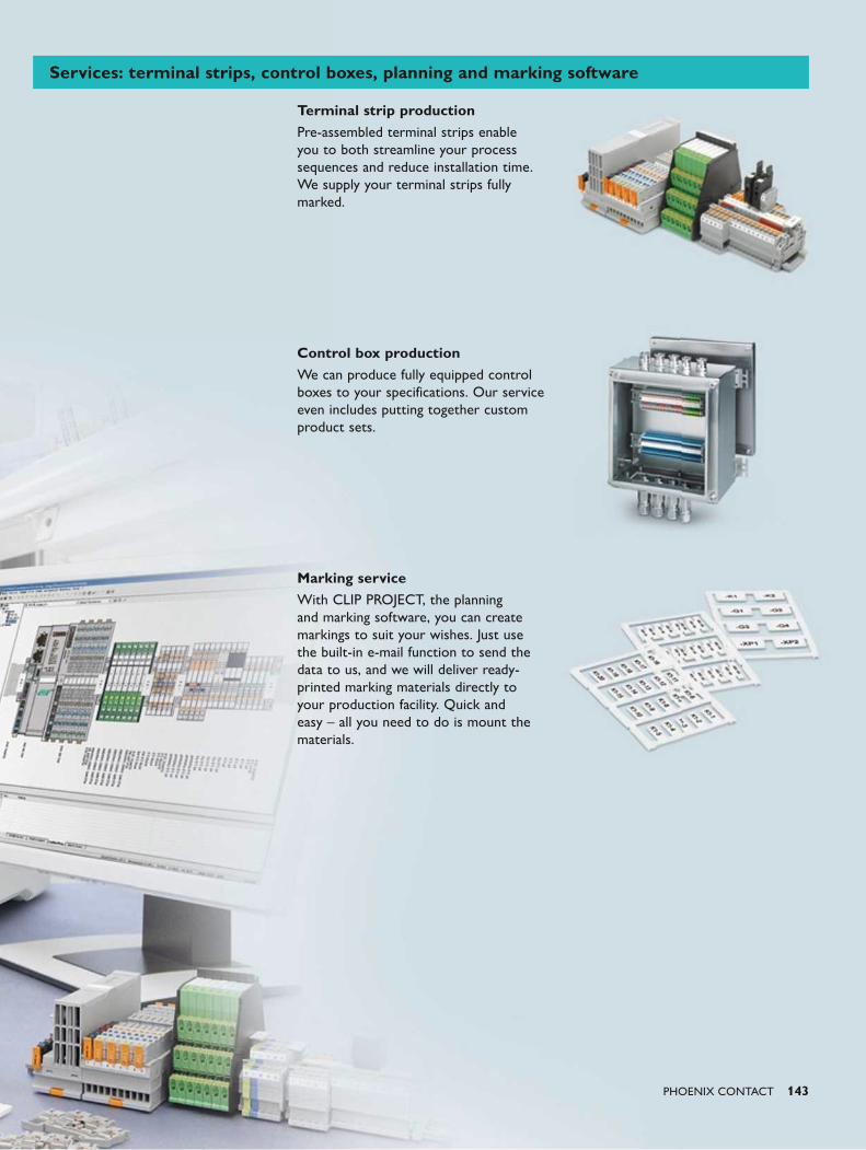
PHOENIX CONTACT 143
Terminal strip productionPre-assembled terminal strips enable you to both streamline your process sequences and reduce installation time. We supply your terminal strips fully marked.
Control box productionWe can produce fully equipped control boxes to your specifications. Our service even includes putting together custom product sets.
Marking serviceWith CLIP PROJECT, the planning and marking software, you can create markings to suit your wishes. Just use the built-in e-mail function to send the data to us, and we will deliver ready-printed marking materials directly to your production facility. Quick and easy – all you need to do is mount the materials.
Services: terminal strips, control boxes, planning and marking software

144 PHOENIX CONTACT
Reduce your assembly and approval
costs. With your input, we can design
and develop the right solution for your
application using the wide range of
CLIPSAFE empty housings.
Just call us or send us an e-mail, and we
will deliver exactly what you need.
Empty Ex housingsChoose the right stainless steel housing for your application from 140 Ex-approved versions. Custom dimensions and surface treatments are available on request. The housings are supplied with corresponding component approval in accordance with ATEX and IECEx.
Empty Ex housings processed according to customer specificationsWe can customize the housings according to your specifications with threads, bore holes, and rectangular cutouts, taking Ex standards according to ATEX and IECEx into consideration. The housings are supplied with corresponding component approval.
CLIPSAFE Everything from a single source
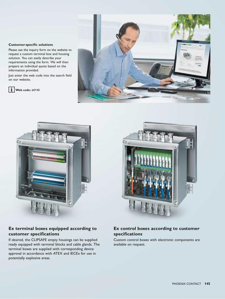
PHOENIX CONTACT 145
Ex terminal boxes equipped according to customer specificationsIf desired, the CLIPSAFE empty housings can be supplied ready equipped with terminal blocks and cable glands. The terminal boxes are supplied with corresponding device approval in accordance with ATEX and IECEx for use in potentially explosive areas.
Ex control boxes according to customer specificationsCustom control boxes with electronic components are available on request.
Customer-specific solutions
Please use the inquiry form on the website to request a custom terminal box and housing solution. You can easily describe your requirements using the form. We will then prepare an individual quote based on the information provided.
Just enter the web code into the search field on our website.
Web code: #0140

146 PHOENIX CONTACT
Phoenix Contact has many years of
experience developing reliable products for
the ex area.
Close contact with our customers,
knowledge of your requirements, our design
capabilities and expertise in production are
important features of the new CLIPSAFE
stainless steel housing series.
A housing concept – made for real-life
applications.
CLIPSAFE Innovative housing concept
Comprehensive product range
The housings are available as door or cover versions in nine different depths and sizes up to 1000 mm x 1000 mm x 300 mm. The robust housings made from up to 2 mm thick high-grade 1.4404 (V4A), AISI 316L stainless steel are ideal for use under extreme conditions.
Design data and equipment tables
CAD drawings in STEP, IGES, and DXF format can be downloaded directly from the website in the product area for the respective empty housing.
You can find equipment information regarding the maximum permissible number of Ex terminal block screw connections and cable glands that can be installed in the download area for the empty housings.
The marking label is fitted outside the seal area
Surface brushed, 240 grain, electropolished on request
Flexible door stop
The door stop can be easily changed according to your individual requirements or the installation situation. The 135° opening angle of the door guarantees comfortable work during maintenance and servicing. The special door and cover seal guarantees a reliable seal even after it has been opened multiple times.
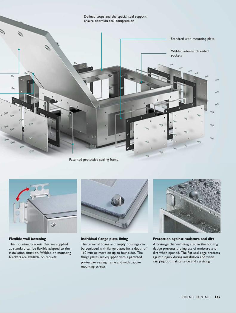
PHOENIX CONTACT 147
Flexible wall fastening
The mounting brackets that are supplied as standard can be flexibly adapted to the installation situation. Welded-on mounting brackets are available on request.
Individual flange plate fixing
The terminal boxes and empty housings can be equipped with flange plates for a depth of 160 mm or more on up to four sides. The flange plates are equipped with a patented
protective sealing frame and with captive mounting screws.
Protection against moisture and dirt
A drainage channel integrated in the housing design prevents the ingress of moisture and dirt when opened. The flat seal edge protects against injury during installation and when carrying out maintenance and servicing.
Patented protective sealing frame
Standard with mounting plate
Defined stops and the special seal support ensure optimum seal compression
Welded internal threaded sockets

148 PHOENIX CONTACT
CLIPSAFEStainless steel empty housings for the ex area
The new CLIPSAFE stainless steel housings
provide comprehensive protection for your
applications in industrial environments and in
process engineering.
The housing range consists of 140
standardized housings in sizes up to
1000 x 1000 x 300 mm. We can machine
these to your specifications if desired. The
housings have ATEX and IEC Ex approval
and are designed for a temperature range
from -55°C to +135°C. The door opening
can be opened up to 135° and the stop
can be changed. Various different door and
cover versions are also available.
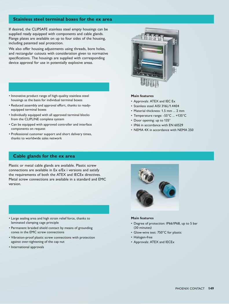
PHOENIX CONTACT 149
Stainless steel terminal boxes for the ex area
Cable glands for the ex area
If desired, the CLIPSAFE stainless steel empty housings can be supplied ready equipped with components and cable glands. Flange plates are available on up to four sides of the housing, including patented seal protection.
We also offer housing adjustments using threads, bore holes, and rectangular cutouts with consideration given to normative specifications. The housings are supplied with corresponding device approval for use in potentially explosive areas.
Plastic or metal cable glands are available. Plastic screw connections are available in Ex e/Ex i versions and satisfy the requirements of both the ATEX and IECEx directives. Metal screw connections are available in a standard and EMC version.
• Innovative product range of high-quality stainless steel housings as the basis for individual terminal boxes
• Reduced assembly and approval effort, thanks to ready-equipped terminal boxes
• Individually equipped with all approved terminal blocks from the CLIPLINE complete system
• Can be equipped with approved controller and interface components on request
• Professional customer support and short delivery times, thanks to worldwide sales network
Main features
• Approvals: ATEX and IEC Ex• Stainless steel AISI 316L/1.4404• Material thickness: 1.5 mm ... 2 mm • Temperature range: -55°C ... +135°C• Door opening: up to 135°• IP66 in accordance with EN 60529• NEMA 4X in accordance with NEMA 250
• Large sealing area and high strain relief force, thanks to laminated clamping cage principle
• Permanent braided shield contact by means of grounding cones in the EMC screw connections
• Vibration-proof plastic screw connections with protection against over-tightening of the cap nut
• International approvals
Main features
• Degree of protection: IP66/IP68, up to 5 bar (30 minutes)
• Glow-wire test: 750°C for plastic• Halogen-free• Approvals: ATEX and IECEx
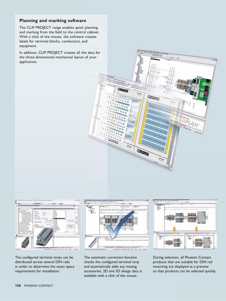
150 PHOENIX CONTACT
Planning and marking softwareThe CLIP PROJECT range enables quick planning and marking from the field to the control cabinet. With a click of the mouse, the software creates labels for terminal blocks, conductors, and equipment.
In addition, CLIP PROJECT creates all the data for the three-dimensional mechanical layout of your application.
The configured terminal strips can be distributed across several DIN rails in order to determine the exact space requirements for installation.
The automatic correction function checks the configured terminal strip and automatically adds any missing accessories. 2D and 3D design data is available with a click of the mouse.
During selection, all Phoenix Contact products that are suitable for DIN rail mounting are displayed as a preview so that products can be selected quickly.
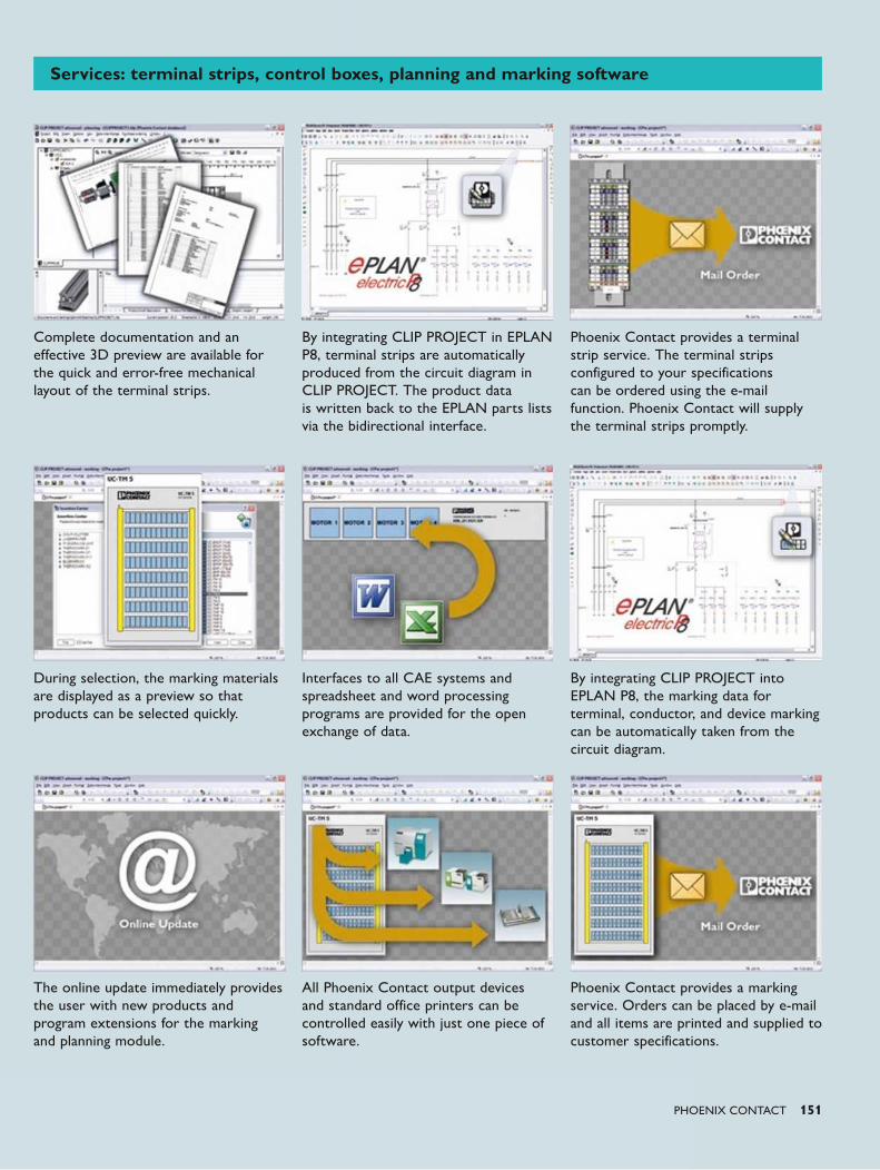
PHOENIX CONTACT 151
During selection, the marking materials are displayed as a preview so that products can be selected quickly.
Interfaces to all CAE systems and spreadsheet and word processing programs are provided for the open exchange of data.
The online update immediately provides the user with new products and program extensions for the marking and planning module.
All Phoenix Contact output devices and standard office printers can be controlled easily with just one piece of software.
Complete documentation and an effective 3D preview are available for the quick and error-free mechanical layout of the terminal strips.
By integrating CLIP PROJECT in EPLAN P8, terminal strips are automatically produced from the circuit diagram in CLIP PROJECT. The product data is written back to the EPLAN parts lists via the bidirectional interface.
Phoenix Contact provides a terminal strip service. The terminal strips configured to your specifications can be ordered using the e-mail function. Phoenix Contact will supply the terminal strips promptly.
By integrating CLIP PROJECT into EPLAN P8, the marking data for terminal, conductor, and device marking can be automatically taken from the circuit diagram.
Phoenix Contact provides a marking service. Orders can be placed by e-mail and all items are printed and supplied to customer specifications.
Services: terminal strips, control boxes, planning and marking software
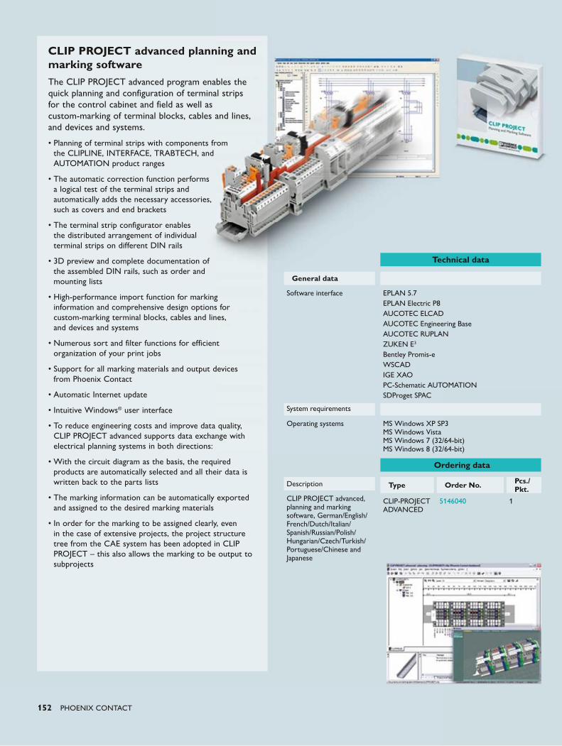
152 PHOENIX CONTACT
CLIP PROJECT advanced planning and marking softwareThe CLIP PROJECT advanced program enables the quick planning and configuration of terminal strips for the control cabinet and field as well as custom-marking of terminal blocks, cables and lines, and devices and systems.
• Planning of terminal strips with components from the CLIPLINE, INTERFACE, TRABTECH, and AUTOMATION product ranges
• The automatic correction function performs a logical test of the terminal strips and automatically adds the necessary accessories, such as covers and end brackets
• The terminal strip configurator enables the distributed arrangement of individual terminal strips on different DIN rails
• 3D preview and complete documentation of the assembled DIN rails, such as order and mounting lists
• High-performance import function for marking information and comprehensive design options for custom-marking terminal blocks, cables and lines, and devices and systems
• Numerous sort and filter functions for efficient organization of your print jobs
• Support for all marking materials and output devices from Phoenix Contact
• Automatic Internet update
• Intuitive Windows® user interface
• To reduce engineering costs and improve data quality, CLIP PROJECT advanced supports data exchange with electrical planning systems in both directions:
• With the circuit diagram as the basis, the required products are automatically selected and all their data is written back to the parts lists
• The marking information can be automatically exported and assigned to the desired marking materials
• In order for the marking to be assigned clearly, even in the case of extensive projects, the project structure tree from the CAE system has been adopted in CLIP PROJECT – this also allows the marking to be output to subprojects
Technical data
General data
Software interface EPLAN 5.7EPLAN Electric P8AUCOTEC ELCADAUCOTEC Engineering BaseAUCOTEC RUPLANZUKEN E3
Bentley Promis-eWSCADIGE XAOPC-Schematic AUTOMATIONSDProget SPAC
System requirements
Operating systems MS Windows XP SP3 MS Windows Vista MS Windows 7 (32/64-bit) MS Windows 8 (32/64-bit)
Ordering data
Description Type Order No. Pcs./Pkt.
CLIP-PROJECT ADVANCED
5146040 1CLIP PROJECT advanced, planning and marking software, German/English/French/Dutch/Italian/Spanish/Russian/Polish/Hungarian/Czech/Turkish/Portuguese/Chinese and Japanese
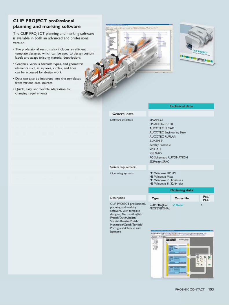
PHOENIX CONTACT 153
Technical data
General data
Software interface EPLAN 5.7EPLAN Electric P8AUCOTEC ELCADAUCOTEC Engineering BaseAUCOTEC RUPLANZUKEN E3Bentley Promis-eWSCADIGE XAOPC-Schematic AUTOMATIONSDProget SPAC
System requirements
Operating systems MS Windows XP SP3 MS Windows Vista MS Windows 7 (32/64-bit) MS Windows 8 (32/64-bit)
Ordering data
Description Type Order No. Pcs./Pkt.
CLIP-PROJECT PROFESSIONAL
5146053 1CLIP PROJECT professional, planning and marking software, with template designer, German/English/French/Dutch/Italian/Spanish/Russian/Polish/Hungarian/Czech/Turkish/Portuguese/Chinese and Japanese
CLIP PROJECT professional planning and marking softwareThe CLIP PROJECT planning and marking software is available in both an advanced and professional version.
• The professional version also includes an efficient template designer, which can be used to design custom labels and adapt existing material descriptions
• Graphics, various barcode types, and geometric elements such as squares, circles, and lines can be accessed for design work
• Data can also be imported into the templates from various data sources
• Quick, easy, and flexible adaptation to changing requirements

154 PHOENIX CONTACT
Services for functional safety
In addition to components for functional
safety, we support you with individual
services for safe operation in process
engineering systems. Whatever the product,
our industry experts help you plan and
implement the safety lifecycle in accordance
with EN 61511 as well as PLT safety
equipment. Furthermore, the integration of
machines in process systems may require the
Machinery Directive to be applied. With our
services in accordance with EN 13849, we
are on hand to assist you with this.
Your advantages:
• Comprehensive support from industry professionals
• Flexible help during all project phases• Time savings, thanks to outsourcing• Building competence through employee
qualification
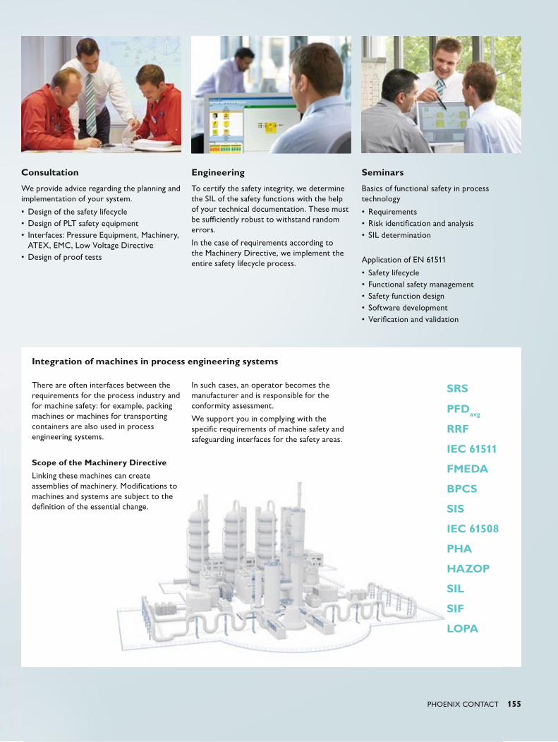
SRS
PFDavg
RRF
IEC 61511
FMEDA
BPCS
SIS
IEC 61508
PHA
HAZOP
SIL
SIF
LOPA
PHOENIX CONTACT 155
Engineering
To certify the safety integrity, we determine the SIL of the safety functions with the help of your technical documentation. These must be sufficiently robust to withstand random errors.
In the case of requirements according to the Machinery Directive, we implement the entire safety lifecycle process.
Seminars
Basics of functional safety in process technology
• Requirements• Risk identification and analysis • SIL determination
Application of EN 61511
• Safety lifecycle• Functional safety management• Safety function design• Software development• Verification and validation
Consultation
We provide advice regarding the planning and implementation of your system.
• Design of the safety lifecycle• Design of PLT safety equipment• Interfaces: Pressure Equipment, Machinery,
ATEX, EMC, Low Voltage Directive• Design of proof tests
Integration of machines in process engineering systems
There are often interfaces between the requirements for the process industry and for machine safety: for example, packing machines or machines for transporting containers are also used in process engineering systems.
Scope of the Machinery Directive
Linking these machines can create assemblies of machinery. Modifications to machines and systems are subject to the definition of the essential change.
In such cases, an operator becomes the manufacturer and is responsible for the conformity assessment.
We support you in complying with the specific requirements of machine safety and safeguarding interfaces for the safety areas.
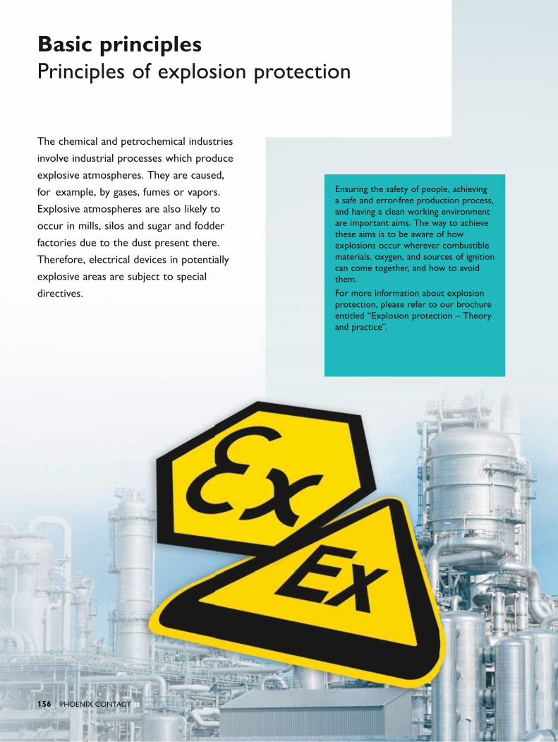
156 PHOENIX CONTACT
The chemical and petrochemical industries
involve industrial processes which produce
explosive atmospheres. They are caused,
for example, by gases, fumes or vapors.
Explosive atmospheres are also likely to
occur in mills, silos and sugar and fodder
factories due to the dust present there.
Therefore, electrical devices in potentially
explosive areas are subject to special
directives.
Basic principles Principles of explosion protection
Ensuring the safety of people, achieving a safe and error-free production process, and having a clean working environment are important aims. The way to achieve these aims is to be aware of how explosions occur wherever combustible materials, oxygen, and sources of ignition can come together, and how to avoid them.
For more information about explosion protection, please refer to our brochure entitled “Explosion protection – Theory and practice”.
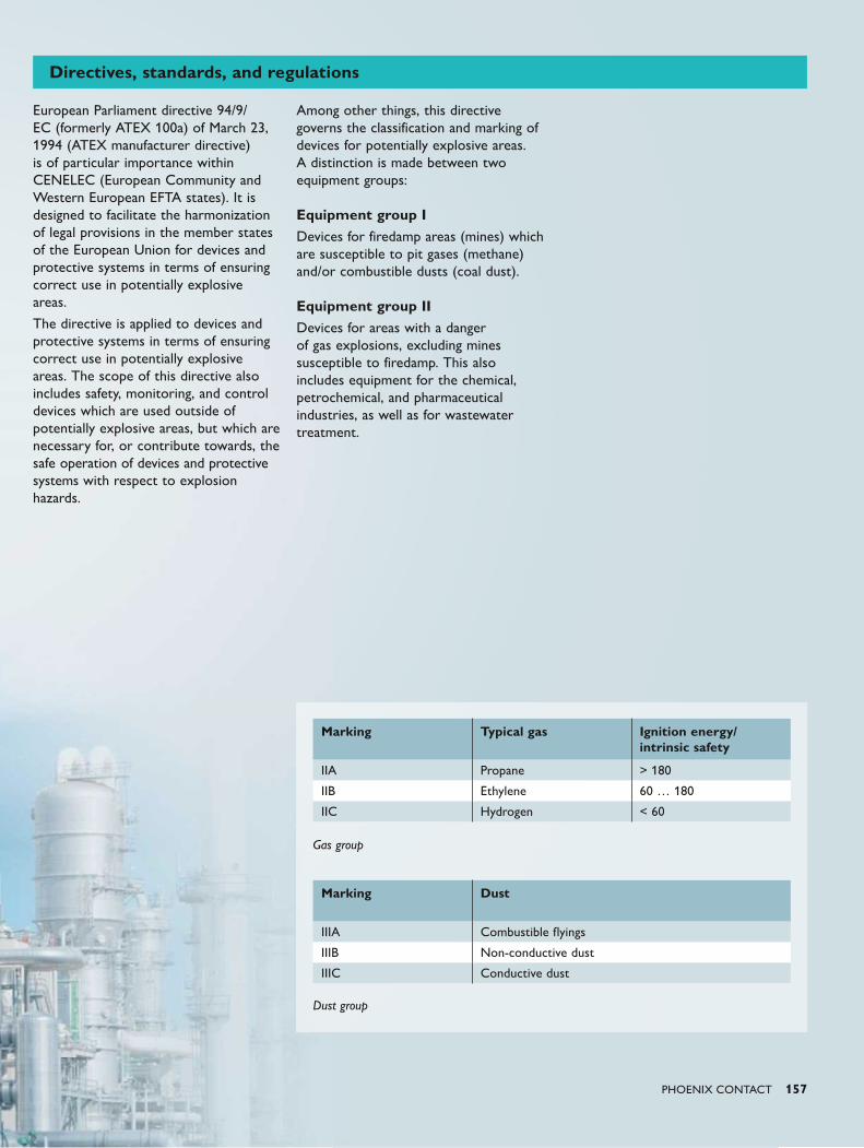
PHOENIX CONTACT 157
Gas group
Dust group
Directives, standards, and regulations
European Parliament directive 94/9/EC (formerly ATEX 100a) of March 23, 1994 (ATEX manufacturer directive) is of particular importance within CENELEC (European Community and Western European EFTA states). It is designed to facilitate the harmonization of legal provisions in the member states of the European Union for devices and protective systems in terms of ensuring correct use in potentially explosive areas.
The directive is applied to devices and protective systems in terms of ensuring correct use in potentially explosive areas. The scope of this directive also includes safety, monitoring, and control devices which are used outside of potentially explosive areas, but which are necessary for, or contribute towards, the safe operation of devices and protective systems with respect to explosion hazards.
Among other things, this directive governs the classification and marking of devices for potentially explosive areas. A distinction is made between two equipment groups: Equipment group IDevices for firedamp areas (mines) which are susceptible to pit gases (methane) and/or combustible dusts (coal dust). Equipment group IIDevices for areas with a danger of gas explosions, excluding mines susceptible to firedamp. This also includes equipment for the chemical, petrochemical, and pharmaceutical industries, as well as for wastewater treatment.
Marking Typical gas Ignition energy/ intrinsic safety
IIA Propane > 180
IIB Ethylene 60 … 180
IIC Hydrogen < 60
Marking Dust
IIIA Combustible flyings
IIIB Non-conductive dust
IIIC Conductive dust
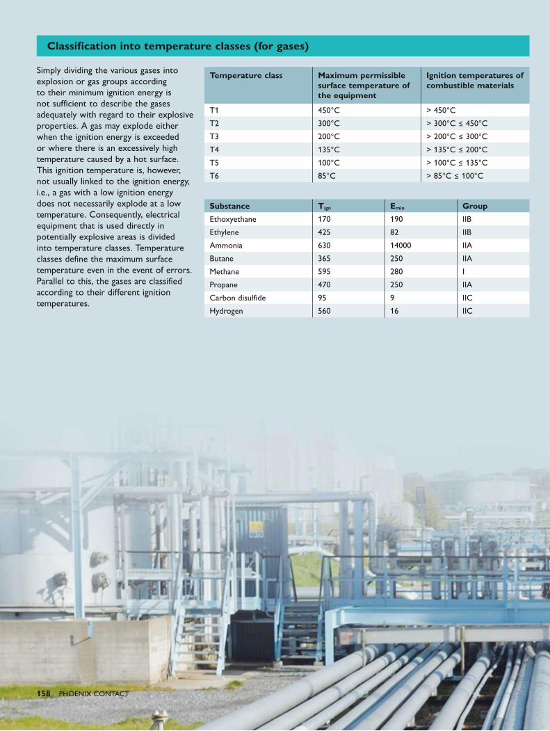
158 PHOENIX CONTACT
Classification into temperature classes (for gases)
Simply dividing the various gases into explosion or gas groups according to their minimum ignition energy is not sufficient to describe the gases adequately with regard to their explosive properties. A gas may explode either when the ignition energy is exceeded or where there is an excessively high temperature caused by a hot surface. This ignition temperature is, however, not usually linked to the ignition energy, i.e., a gas with a low ignition energy does not necessarily explode at a low temperature. Consequently, electrical equipment that is used directly in potentially explosive areas is divided into temperature classes. Temperature classes define the maximum surface temperature even in the event of errors. Parallel to this, the gases are classified according to their different ignition temperatures.
Temperature class
Maximum permissible surface temperature of the equipment
Ignition temperatures of combustible materials
T1 450°C > 450°C
T2 300°C > 300°C ≤ 450°C
T3 200°C > 200°C ≤ 300°C
T4 135°C > 135°C ≤ 200°C
T5 100°C > 100°C ≤ 135°C
T6 85°C > 85°C ≤ 100°C
Substance Tign Emin Group
Ethoxyethane 170 190 IIB
Ethylene 425 82 IIB
Ammonia 630 14000 IIA
Butane 365 250 IIA
Methane 595 280 I
Propane 470 250 IIA
Carbon disulfide 95 9 IIC
Hydrogen 560 16 IIC
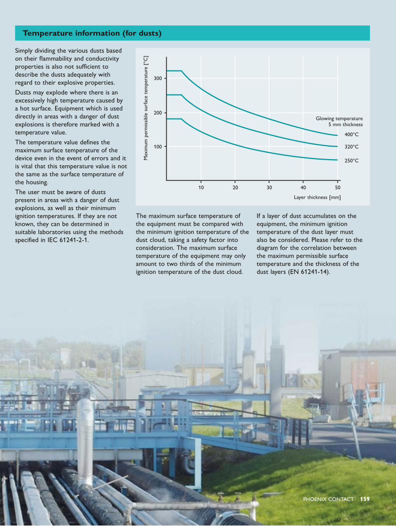
PHOENIX CONTACT 159
Max
imum
per
mis
sibl
e su
rfac
e te
mpe
ratu
re [
°C]
300
400°C
Glowing temperature 5 mm thickness
320°C
250°C
200
100
10 20 30 40 50
Layer thickness [mm]
Temperature information (for dusts)
Simply dividing the various dusts based on their flammability and conductivity properties is also not sufficient to describe the dusts adequately with regard to their explosive properties.
Dusts may explode where there is an excessively high temperature caused by a hot surface. Equipment which is used directly in areas with a danger of dust explosions is therefore marked with a temperature value.
The temperature value defines the maximum surface temperature of the device even in the event of errors and it is vital that this temperature value is not the same as the surface temperature of the housing.
The user must be aware of dusts present in areas with a danger of dust explosions, as well as their minimum ignition temperatures. If they are not known, they can be determined in suitable laboratories using the methods specified in IEC 61241-2-1.
The maximum surface temperature of the equipment must be compared with the minimum ignition temperature of the dust cloud, taking a safety factor into consideration. The maximum surface temperature of the equipment may only amount to two thirds of the minimum ignition temperature of the dust cloud.
If a layer of dust accumulates on the equipment, the minimum ignition temperature of the dust layer must also be considered. Please refer to the diagram for the correlation between the maximum permissible surface temperature and the thickness of the dust layers (EN 61241-14).
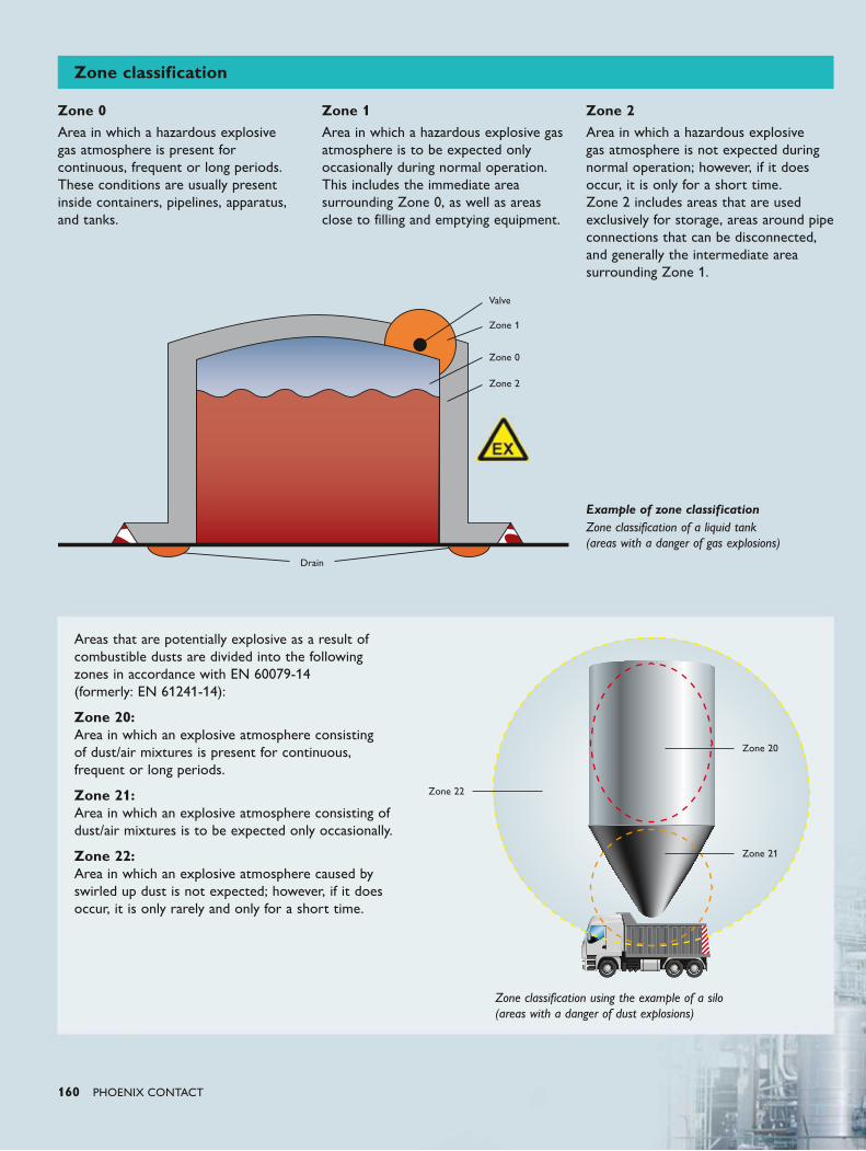
160 PHOENIX CONTACT
Areas that are potentially explosive as a result of combustible dusts are divided into the following zones in accordance with EN 60079-14 (formerly: EN 61241-14):
Zone 20: Area in which an explosive atmosphere consisting of dust/air mixtures is present for continuous, frequent or long periods.
Zone 21: Area in which an explosive atmosphere consisting of dust/air mixtures is to be expected only occasionally.
Zone 22: Area in which an explosive atmosphere caused by swirled up dust is not expected; however, if it does occur, it is only rarely and only for a short time.
Zone 20
Zone 22
Zone 21
Zone classification using the example of a silo (areas with a danger of dust explosions)
Zone classification
Zone 0Area in which a hazardous explosive gas atmosphere is present for continuous, frequent or long periods. These conditions are usually present inside containers, pipelines, apparatus, and tanks.
Zone 1Area in which a hazardous explosive gas atmosphere is to be expected only occasionally during normal operation. This includes the immediate area surrounding Zone 0, as well as areas close to filling and emptying equipment.
Zone 2Area in which a hazardous explosive gas atmosphere is not expected during normal operation; however, if it does occur, it is only for a short time. Zone 2 includes areas that are used exclusively for storage, areas around pipe connections that can be disconnected, and generally the intermediate area surrounding Zone 1.
Example of zone classificationZone classification of a liquid tank (areas with a danger of gas explosions)
Valve
Zone 1
Zone 0
Zone 2
Drain
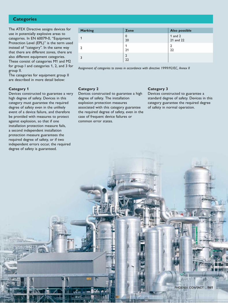
PHOENIX CONTACT 161
Categories
The ATEX Directive assigns devices for use in potentially explosive areas to categories. In EN 60079-0, “Equipment Protection Level (EPL)” is the term used instead of “category”. In the same way that there are different zones, there are also different equipment categories. These consist of categories M1 and M2 for group I and categories 1, 2, and 3 for group II. The categories for equipment group II are described in more detail below: Category 1 Devices constructed to guarantee a very high degree of safety. Devices in this category must guarantee the required degree of safety even in the unlikely event of a device failure, and therefore be provided with measures to protect against explosion, so that if one installation protection measure fails, a second independent installation protection measure guarantees the required degree of safety, or if two independent errors occur, the required degree of safety is guaranteed.
Category 2 Devices constructed to guarantee a high degree of safety. The installation explosion protection measures associated with this category guarantee the required degree of safety, even in the case of frequent device failures or common error states.
Category 3 Devices constructed to guarantee a standard degree of safety. Devices in this category guarantee the required degree of safety in normal operation.
Assignment of categories to zones in accordance with directive 1999/92/EC, Annex II
Marking Zone Also possible
10 20
1 and 2 21 and 22
21 21
2 22
32 22
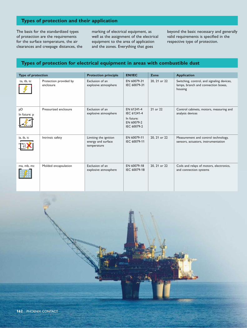
162 PHOENIX CONTACT
Types of protection and their application
The basis for the standardized types of protection are the requirements for the surface temperature, the air clearances and creepage distances, the
marking of electrical equipment, as well as the assignment of the electrical equipment to the area of application and the zones. Everything that goes
beyond the basic necessary and generally valid requirements is specified in the respective type of protection.
Type of protection Protection principle EN/IEC Zone Application
ta, tb, tc Protection provided by enclosure
Exclusion of an explosive atmosphere
EN 60079-31 IEC 60079-31
20, 21 or 22 Switching, control, and signaling devices, lamps, branch and connection boxes, housing
pD
In future: p
Pressurized enclosure Exclusion of an explosive atmosphere
EN 61241-4 IEC 61241-4
In future: EN 60079-2 IEC 60079-2
21 or 22 Control cabinets, motors, measuring and analysis devices
ia, ib, ic Intrinsic safety Limiting the ignition energy and surface temperature
EN 60079-11 IEC 60079-11
20, 21 or 22 Measurement and control technology, sensors, actuators, instrumentation
ma, mb, mc Molded encapsulation Exclusion of an explosive atmosphere
EN 60079-18 IEC 60079-18
20, 21 or 22 Coils and relays of motors, electronics, and connection systems
Types of protection for electrical equipment in areas with combustible dust
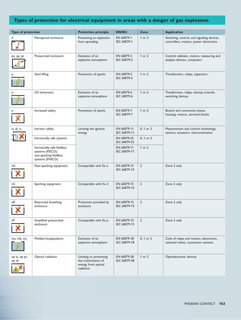
PHOENIX CONTACT 163
Types of protection for electrical equipment in areas with a danger of gas explosions
Type of protection Protection principle EN/IEC Zone Application
d Flameproof enclosure Preventing an explosion from spreading
EN 60079-1 IEC 60079-1
1 or 2 Switching, control, and signaling devices, controllers, motors, power electronics
px, py, pz Pressurized enclosure Exclusion of an explosive atmosphere
EN 60079-2 IEC 60079-2
1 or 2 Control cabinets, motors, measuring and analysis devices, computers
q Sand filling Prevention of sparks EN 60079-5 IEC 60079-5
1 or 2 Transformers, relays, capacitors
o Oil immersion Exclusion of an explosive atmosphere
EN 60079-6 IEC 60079-6
1 or 2 Transformers, relays, startup controls, switching devices
e Increased safety Prevention of sparks EN 60079-7 IEC 60079-7
1 or 2 Branch and connection boxes, housing, motors, terminal blocks
ia, ib, ic Intrinsic safety Limiting the ignition energy
EN 60079-11 IEC 60079-11
0, 1 or 2 Measurement and control technology, sensors, actuators, instrumentation Intrinsically safe systems EN 60079-25
IEC 60079-250, 1 or 2
Intrinsically safe fieldbus systems (FISCO), non-sparking fieldbus systems (FNICO)
EN 60079-11 IEC 60079-11
1 or 2
nA Non-sparking equipment Comparable with Ex e EN 60079-15 IEC 60079-15
2 Zone 2 only
nC
Sparking equipment Comparable with Ex d EN 60079-15 IEC 60079-15
2 Zone 2 only
nR Restricted breathing enclosure
Protection provided by enclosure
EN 60079-15 IEC 60079-15
2 Zone 2 only
nP Simplified pressurized enclosure
Comparable with Ex p EN 60079-15 IEC 60079-15
2 Zone 2 only
ma, mb, mc Molded encapsulation Exclusion of an explosive atmosphere
EN 60079-18 IEC 60079-18
0, 1 or 2 Coils of relays and motors, electronics, solenoid valves, connection systems
op is, op pr, op sh
Optical radiation Limiting or preventing the transmission of energy from optical radiation
EN 60079-28 IEC 60079-28
1 or 2 Optoelectronic devices

164 PHOENIX CONTACT
Marking according to EN 60079-0
Electrical equipment
Equipment protection level, EPL (Ga, Gb, Gc, Da, Db, Dc)
Ex ia IIC T6 Ga
Temperature class (for equipment used directly in the ex area) (T1 … T6)
Gas group (IIA, IIB, IIC) or dust group (IIIA, IIIB, IIIC)
Type of protection (ia, ib, ic, e, d, etc.)
Explosion-proof
EC-type examination certificate
TÜV 01 ATEX 1750
Certificate number
Type-tested according to 94/9/EC (ATEX)
Year of EC-type examination certificate
Notified body
Marking according to ATEX Directive
Current year of manufacture
Conformity assessment according to 94/9/EC (ATEX)
Electrical equipment
10 II 1 G
Atmosphere (G = gas, D = dust)
Equipment category (1, 2, 3)
Equipment group (I, II)
Notified body, production monitoring (e. g., KEMA)
Example: terminal blockTerminal blocks are designed for use in temperature class T6. Information about other temperature classes and the operating temperature range can be found on the EC-type examination certificate and in the installation instructions. If terminal blocks are used, the installation instructions regarding the use of accessories must also be observed.
Marking of Ex products
0344
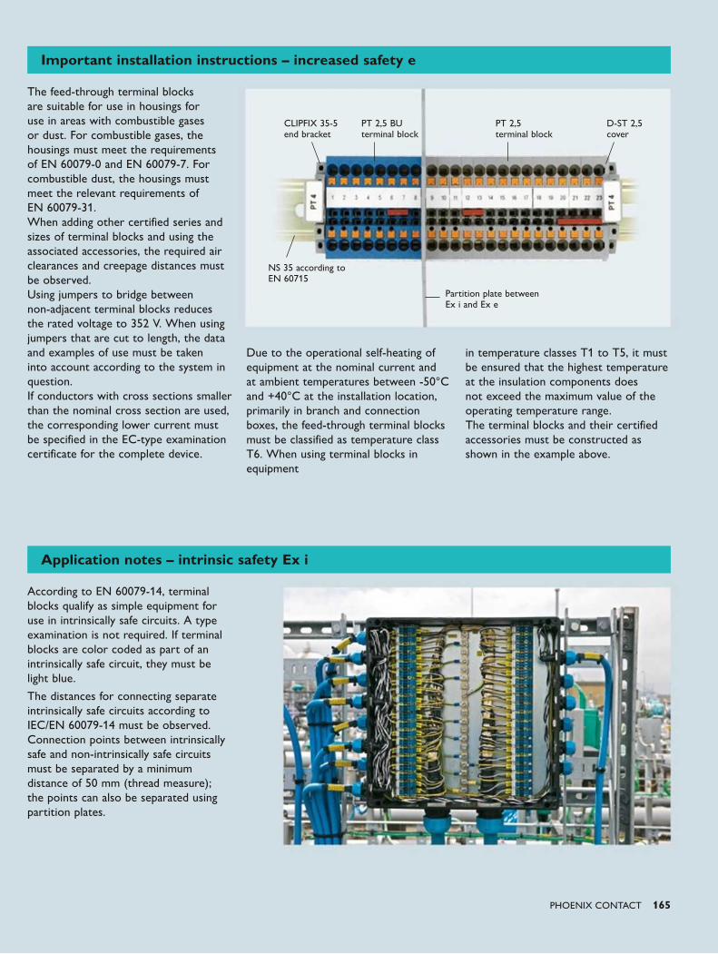
PHOENIX CONTACT 165
Important installation instructions – increased safety e
The feed-through terminal blocks are suitable for use in housings for use in areas with combustible gases or dust. For combustible gases, the housings must meet the requirements of EN 60079-0 and EN 60079-7. For combustible dust, the housings must meet the relevant requirements of EN 60079-31. When adding other certified series and sizes of terminal blocks and using the associated accessories, the required air clearances and creepage distances must be observed. Using jumpers to bridge between non-adjacent terminal blocks reduces the rated voltage to 352 V. When using jumpers that are cut to length, the data and examples of use must be taken into account according to the system in question. If conductors with cross sections smaller than the nominal cross section are used, the corresponding lower current must be specified in the EC-type examination certificate for the complete device.
Due to the operational self-heating of equipment at the nominal current and at ambient temperatures between -50°C and +40°C at the installation location, primarily in branch and connection boxes, the feed-through terminal blocks must be classified as temperature class T6. When using terminal blocks in equipment
in temperature classes T1 to T5, it must be ensured that the highest temperature at the insulation components does not exceed the maximum value of the operating temperature range. The terminal blocks and their certified accessories must be constructed as shown in the example above.
Partition plate between Ex i and Ex e
D-ST 2,5 cover
PT 2,5 terminal block
PT 2,5 BU terminal block
CLIPFIX 35-5 end bracket
NS 35 according toEN 60715
Application notes – intrinsic safety Ex i
According to EN 60079-14, terminal blocks qualify as simple equipment for use in intrinsically safe circuits. A type examination is not required. If terminal blocks are color coded as part of an intrinsically safe circuit, they must be light blue.
The distances for connecting separate intrinsically safe circuits according to IEC/EN 60079-14 must be observed. Connection points between intrinsically safe and non-intrinsically safe circuits must be separated by a minimum distance of 50 mm (thread measure); the points can also be separated using partition plates.
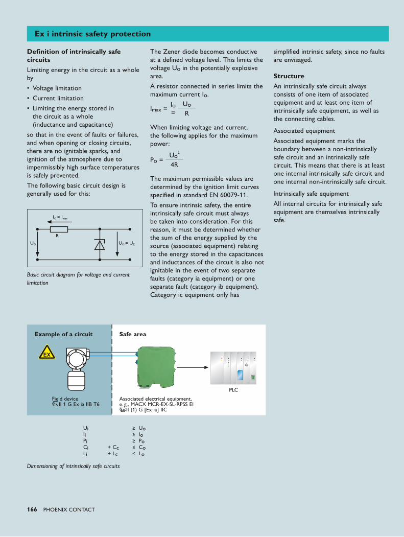
166 PHOENIX CONTACT
Definition of intrinsically safe circuits
Limiting energy in the circuit as a whole by
• Voltage limitation
• Current limitation
• Limiting the energy stored in the circuit as a whole (inductance and capacitance)
so that in the event of faults or failures, and when opening or closing circuits, there are no ignitable sparks, and ignition of the atmosphere due to impermissibly high surface temperatures is safely prevented.
The following basic circuit design is generally used for this:
IO = Imax
UO UO = UZ
R
Basic circuit diagram for voltage and current limitation
The Zener diode becomes conductive at a defined voltage level. This limits the voltage Uo in the potentially explosive area.
A resistor connected in series limits the maximum current Io.
Imax =Io =
UoR
When limiting voltage and current, the following applies for the maximum power:
Po =Uo
2
4R
The maximum permissible values are determined by the ignition limit curves specified in standard EN 60079-11.
To ensure intrinsic safety, the entire intrinsically safe circuit must always be taken into consideration. For this reason, it must be determined whether the sum of the energy supplied by the source (associated equipment) relating to the energy stored in the capacitances and inductances of the circuit is also not ignitable in the event of two separate faults (category ia equipment) or one separate fault (category ib equipment). Category ic equipment only has
simplified intrinsic safety, since no faults are envisaged. StructureAn intrinsically safe circuit always consists of one item of associated equipment and at least one item of intrinsically safe equipment, as well as the connecting cables.
Associated equipment
Associated equipment marks the boundary between a non-intrinsically safe circuit and an intrinsically safe circuit. This means that there is at least one internal intrinsically safe circuit and one internal non-intrinsically safe circuit.
Intrinsically safe equipment
All internal circuits for intrinsically safe equipment are themselves intrinsically safe.
Dimensioning of intrinsically safe circuits
Safe areaExample of a circuit
Field device II 1 G Ex ia IIB T6
Associated electrical equipment, e. g., MACX MCR-EX-SL-RPSS EI II (1) G [Ex ia] IIC
PLC
Ui ≥ UoIi ≥ IoPi ≥ PoCi + Cc ≤ CoLi + Lc ≤ Lo
Ex i intrinsic safety protection
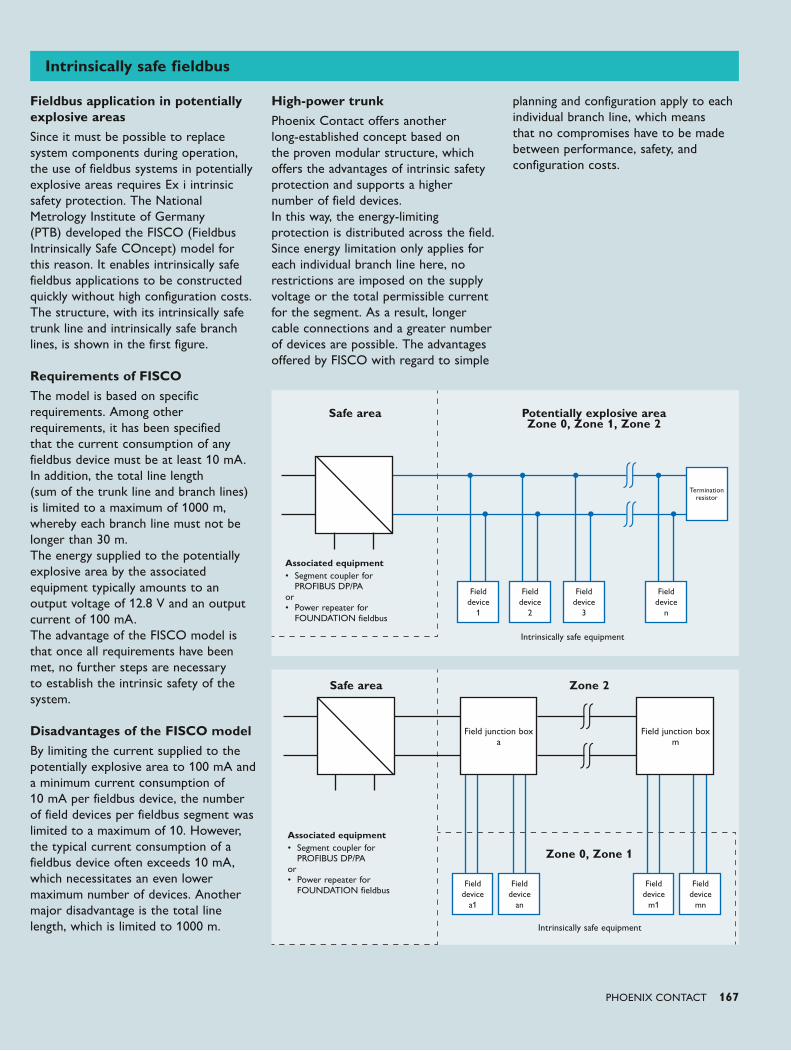
PHOENIX CONTACT 167
Fieldbus application in potentially explosive areasSince it must be possible to replace system components during operation, the use of fieldbus systems in potentially explosive areas requires Ex i intrinsic safety protection. The National Metrology Institute of Germany (PTB) developed the FISCO (Fieldbus Intrinsically Safe COncept) model for this reason. It enables intrinsically safe fieldbus applications to be constructed quickly without high configuration costs. The structure, with its intrinsically safe trunk line and intrinsically safe branch lines, is shown in the first figure. Requirements of FISCOThe model is based on specific requirements. Among other requirements, it has been specified that the current consumption of any fieldbus device must be at least 10 mA. In addition, the total line length (sum of the trunk line and branch lines) is limited to a maximum of 1000 m, whereby each branch line must not be longer than 30 m. The energy supplied to the potentially explosive area by the associated equipment typically amounts to an output voltage of 12.8 V and an output current of 100 mA. The advantage of the FISCO model is that once all requirements have been met, no further steps are necessary to establish the intrinsic safety of the system. Disadvantages of the FISCO modelBy limiting the current supplied to the potentially explosive area to 100 mA and a minimum current consumption of 10 mA per fieldbus device, the number of field devices per fieldbus segment was limited to a maximum of 10. However, the typical current consumption of a fieldbus device often exceeds 10 mA, which necessitates an even lower maximum number of devices. Another major disadvantage is the total line length, which is limited to 1000 m.
High-power trunkPhoenix Contact offers another long-established concept based on the proven modular structure, which offers the advantages of intrinsic safety protection and supports a higher number of field devices. In this way, the energy-limiting protection is distributed across the field. Since energy limitation only applies for each individual branch line here, no restrictions are imposed on the supply voltage or the total permissible current for the segment. As a result, longer cable connections and a greater number of devices are possible. The advantages offered by FISCO with regard to simple
planning and configuration apply to each individual branch line, which means that no compromises have to be made between performance, safety, and configuration costs.
Intrinsically safe fieldbus
Safe area Potentially explosive area Zone 0, Zone 1, Zone 2
Field device
1
Field device
2
Field device
3
Field device
n
Termination resistor
Associated equipment• Segment coupler for PROFIBUS DP/PA or • Power repeater for FOUNDATION fieldbus
Intrinsically safe equipment
Safe area Zone 2
Zone 0, Zone 1
Field device
m1
Field device
a1
Field device
mn
Field device
an
Associated equipment• Segment coupler for PROFIBUS DP/PA or • Power repeater for FOUNDATION fieldbus
Intrinsically safe equipment
Field junction box a
Field junction box m
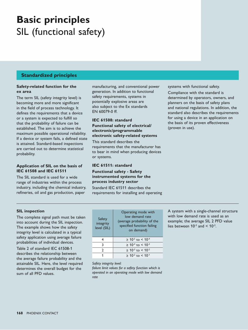
168 PHOENIX CONTACT
Standardized principles
Basic principlesSIL (functional safety)
Safety-related function for the ex area
The term SIL (safety integrity level) is becoming more and more significant in the field of process technology. It defines the requirements that a device or a system is expected to fulfill so that the probability of failure can be established. The aim is to achieve the maximum possible operational reliability. If a device or system fails, a defined state is attained. Standard-based inspections are carried out to determine statistical probability.
Application of SIL on the basis of IEC 61508 and IEC 61511
The SIL standard is used for a wide range of industries within the process industry, including the chemical industry, refineries, oil and gas production, paper
manufacturing, and conventional power generation. In addition to functional safety requirements, systems in potentially explosive areas are also subject to the Ex standards EN 60079-0 ff.
IEC 61508: standardFunctional safety of electrical/electronic/programmable electronic safety-related systemsThis standard describes the requirements that the manufacturer has to bear in mind when producing devices or systems.
IEC 61511: standardFunctional safety - Safety instrumented systems for the process industry sectorStandard IEC 61511 describes the requirements for installing and operating
systems with functional safety.
Compliance with the standard is determined by operators, owners, and planners on the basis of safety plans and national regulations. In addition, the standard also describes the requirements for using a device in an application on the basis of its proven effectiveness (proven in use).
SIL inspectionThe complete signal path must be taken into account during the SIL inspection. The example shows how the safety integrity level is calculated in a typical safety application using average failure probabilities of individual devices.
Table 2 of standard IEC 61508-1 describes the relationship between the average failure probability and the attainable SIL. Here, the level required determines the overall budget for the sum of all PFD values.
Safety integrity level: failure limit values for a safety function which is operated in an operating mode with low demand rate
A system with a single-channel structure with low demand rate is used as an example; the average SIL 2 PFD value lies between 10-3 and < 10-2.
Safety integrity
level (SIL)
Operating mode with low demand rate
(average probability of the specified function failing
on demand)
4 ≥ 10-5 to < 10-4
3 ≥ 10-4 to < 10-3
2 ≥ 10-3 to < 10-2
1 ≥ 10-2 to < 10-1
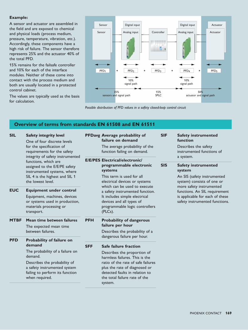
PHOENIX CONTACT 169
Example:A sensor and actuator are assembled in the field and are exposed to chemical and physical loads (process medium, pressure, temperature, vibration, etc.). Accordingly, these components have a high risk of failure. The sensor therefore represents 25% and the actuator 40% of the total PFD.
15% remains for the failsafe controller and 10% for each of the interface modules. Neither of these come into contact with the process medium and both are usually located in a protected control cabinet.
The values are typically used as the basis for calculation.
Possible distribution of PFD values in a safety closed-loop control circuit
Digital inputSensor ActuatorDigital input
Analog inputSensor
PFD1 PFD2
10% signal path
35% sensors and signal path
50% actuator and signal path
15% SPLC
10% signal path
PFD3 PFD4 PFD5
ActuatorAnalog inputController
Overview of terms from standards EN 61508 and EN 61511
SIL Safety integrity level One of four discrete levels for the specification of requirements for the safety integrity of safety instrumented functions, which are assigned to the E/E/PE safety instrumented systems, where SIL 4 is the highest and SIL 1 the lowest level.
EUC Equipment under controlEquipment, machines, devices or systems used in production, materials processing or transport.
MTBF Mean time between failuresThe expected mean time between failures.
PFD Probability of failure on demandThe probability of a failure on demand.
Describes the probability of a safety instrumented system failing to perform its function when required.
PFDavg Average probability of failure on demandThe average probability of the function failing on demand.
E/E/PES Electrical/electronic/programmable electronic systemsThis term is used for all electrical devices or systems which can be used to execute a safety instrumented function. It includes simple electrical devices and all types of programmable logic controllers (PLCs).
PFH Probability of dangerous failure per hourDescribes the probability of a dangerous failure per hour.
SFF Safe failure fractionDescribes the proportion of harmless failures. This is the ratio of the rate of safe failures plus the rate of diagnosed or detected faults in relation to the total failure rate of the system.
SIF Safety instrumented functionDescribes the safety instrumented functions of a system.
SIS Safety instrumented systemAn SIS (safety instrumented system) consists of one or more safety instrumented functions. An SIL requirement is applicable for each of these safety instrumented functions.
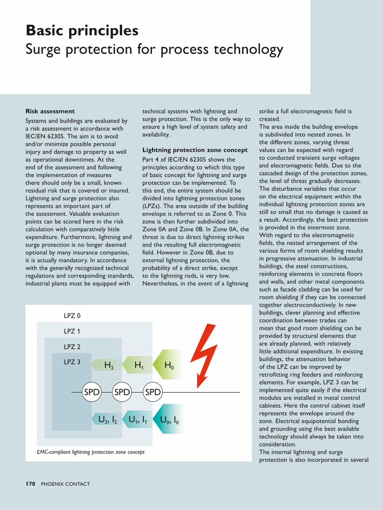
LPZ 0
LPZ 1
LPZ 2
LPZ 3
SPD SPD SPD
170 PHOENIX CONTACT
Risk assessmentSystems and buildings are evaluated by a risk assessment in accordance with IEC/EN 62305. The aim is to avoid and/or minimize possible personal injury and damage to property as well as operational downtimes. At the end of the assessment and following the implementation of measures there should only be a small, known residual risk that is covered or insured. Lightning and surge protection also represents an important part of the assessment. Valuable evaluation points can be scored here in the risk calculation with comparatively little expenditure. Furthermore, lightning and surge protection is no longer deemed optional by many insurance companies, it is actually mandatory. In accordance with the generally recognized technical regulations and corresponding standards, industrial plants must be equipped with
technical systems with lightning and surge protection. This is the only way to ensure a high level of system safety and availability. Lightning protection zone concept Part 4 of IEC/EN 62305 shows the principles according to which this type of basic concept for lightning and surge protection can be implemented. To this end, the entire system should be divided into lightning protection zones (LPZs). The area outside of the building envelope is referred to as Zone 0. This zone is then further subdivided into Zone 0A and Zone 0B. In Zone 0A, the threat is due to direct lightning strikes and the resulting full electromagnetic field. However in Zone 0B, due to external lightning protection, the probability of a direct strike, except to the lightning rods, is very low. Nevertheless, in the event of a lightning
strike a full electromagnetic field is created. The area inside the building envelope is subdivided into nested zones. In the different zones, varying threat values can be expected with regard to conducted transient surge voltages and electromagnetic fields. Due to the cascaded design of the protection zones, the level of threat gradually decreases. The disturbance variables that occur on the electrical equipment within the individual lightning protection zones are still so small that no damage is caused as a result. Accordingly, the best protection is provided in the innermost zone. With regard to the electromagnetic fields, the nested arrangement of the various forms of room shielding results in progressive attenuation. In industrial buildings, the steel constructions, reinforcing elements in concrete floors and walls, and other metal components such as facade cladding can be used for room shielding if they can be connected together electroconductively. In new buildings, clever planning and effective coordination between trades can mean that good room shielding can be provided by structural elements that are already planned, with relatively little additional expenditure. In existing buildings, the attenuation behavior of the LPZ can be improved by retrofitting ring feeders and reinforcing elements. For example, LPZ 3 can be implemented quite easily if the electrical modules are installed in metal control cabinets. Here the control cabinet itself represents the envelope around the zone. Electrical equipotential bonding and grounding using the best available technology should always be taken into consideration. The internal lightning and surge protection is also incorporated in several
Basic principlesSurge protection for process technology
EMC-compliant lightning protection zone concept
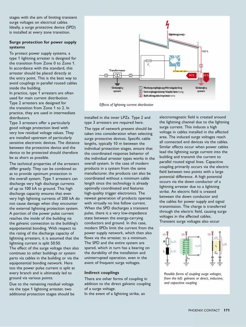
1 2
F1
100 %
50 %50 %
3
Transformator
Erdungs-system
Erdungs-system
Blitzfangstange
1 Versorgungsleitung Mittelspannung2 Versorgungsleitung Niederspannung3 Aufteilung des Impulsstroms
PHOENIX CONTACT 171
Transformator
Grounding system
Grounding system
Lightning rod
1 Medium voltage power supply line2 Low voltage power supply line3 Split of impulse current
stages with the aim of limiting transient surge voltages on electrical cables. Ideally, a surge protective device (SPD) is installed at every zone transition. Surge protection for power supply systemsTo protect power supply systems, a type 1 lightning arrester is designed for the transition from Zone 0 to Zone 1. In accordance with the standard, this arrester should be placed directly at the entry point. This is the best way to avoid couplings in parallel routed cables inside the building. In practice, type 1 arresters are often used for main current distribution. Type 2 arresters are designed for the transition from Zone 1 to 2. In practice, they are used in intermediate distributors. Type 3 arresters offer a particularly good voltage protection level with very low residual voltage values. They are installed upstream of particularly sensitive electronic devices. The distance between the protective device and the device to be protected should therefore be as short as possible.
The technical properties of the arresters differ greatly. They can be combined so as to provide optimum protection in the overall system. Type 1 arresters can discharge very high discharge currents of up to 100 kA to ground. This high discharge capacity ensures that even very high lightning currents of 200 kA do not cause damage when they encounter the external lightning protection system. A portion of the power pulse current reaches the inside of the building via the galvanic connection to the building's equipotential bonding. With respect to the rating of the discharge capacity of lightning arresters, it is assumed that the lightning current is split 50:50. The effect of the surge voltage then also continues to other buildings or system parts via cables in the building or via the equipotential bonding network. Here too the power pulse current is split at every branch and is ultimately led to ground via various points.
Due to the remaining residual voltage via the type 1 lightning arrester, two additional protection stages should be
installed in the inner LPZs. Type 2 and type 3 arresters are required here.
The type of network present should be taken into consideration when selecting surge protective devices. Specific cable lengths, typically 10 m between the individual protection stages, ensure that the coordinated response behavior of the individual arrester types works in the overall system. In the case of modern products in a system from the same manufacturer, the products can also be coordinated without a minimum cable length since the technology is already optimally coordinated and features high-quality trigger electronics. The newest generation of products operate with virtually no line follow current. When the SPD discharges a transient pulse, there is a very low-impedance state between the energy-carrying conductors and ground. In this case, modern SPDs limit the current from the power supply network, which then also flows via the arrester, to a minimum. The SPD and the entire system are spared, which in turn has a bearing on the durability of the installation and uninterrupted operation, even in the event of frequent surge voltages. Indirect couplingsThere are other forms of coupling in addition to the direct galvanic coupling of a surge voltage. In the event of a lightning strike, an
electromagnetic field is created around the lightning channel due to the lightning surge current. This induces a high voltage in cables installed in the affected area. The induced surge voltages reach all connected end devices via the cables. Similar effects occur when power cables lead the lightning surge current into the building and transmit the current to parallel routed signal lines. Capacitive coupling primarily occurs via the electric field between two points with a large potential difference. A high potential occurs via the down conductor of a lightning arrester due to a lightning strike. An electric field is created between the down conductor and the cables for power supply and signal transmission. The charge is transferred through the electric field, causing surge voltages in the affected cables. Transient surge voltages also occur
Effects of lightning current distribution
Possible forms of coupling surge voltages, from the left: galvanic or direct, inductive, and capacitive coupling
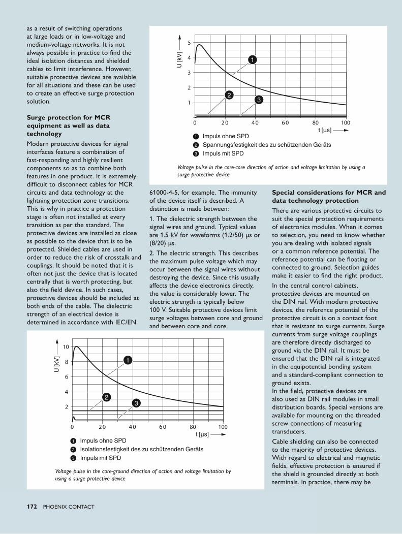
800 2 0 4 0 6 0 100
2
1
3
4
5
U [kV
]
t [μs]
800 2 0 4 0 6 0 100
4
2
6
8
10
U [kV
]
t [μs]
172 PHOENIX CONTACT
as a result of switching operations at large loads or in low-voltage and medium-voltage networks. It is not always possible in practice to find the ideal isolation distances and shielded cables to limit interference. However, suitable protective devices are available for all situations and these can be used to create an effective surge protection solution. Surge protection for MCR equipment as well as data technologyModern protective devices for signal interfaces feature a combination of fast-responding and highly resilient components so as to combine both features in one product. It is extremely difficult to disconnect cables for MCR circuits and data technology at the lightning protection zone transitions. This is why in practice a protection stage is often not installed at every transition as per the standard. The protective devices are installed as close as possible to the device that is to be protected. Shielded cables are used in order to reduce the risk of crosstalk and couplings. It should be noted that it is often not just the device that is located centrally that is worth protecting, but also the field device. In such cases, protective devices should be included at both ends of the cable. The dielectric strength of an electrical device is determined in accordance with IEC/EN
61000-4-5, for example. The immunity of the device itself is described. A distinction is made between:
1. The dielectric strength between the signal wires and ground. Typical values are 1.5 kV for waveforms (1.2/50) μs or (8/20) μs.
2. The electric strength. This describes the maximum pulse voltage which may occur between the signal wires without destroying the device. Since this usually affects the device electronics directly, the value is considerably lower. The electric strength is typically below 100 V. Suitable protective devices limit surge voltages between core and ground and between core and core.
Special considerations for MCR and data technology protectionThere are various protective circuits to suit the special protection requirements of electronics modules. When it comes to selection, you need to know whether you are dealing with isolated signals or a common reference potential. The reference potential can be floating or connected to ground. Selection guides make it easier to find the right product.
In the central control cabinets, protective devices are mounted on the DIN rail. With modern protective devices, the reference potential of the protective circuit is on a contact foot that is resistant to surge currents. Surge currents from surge voltage couplings are therefore directly discharged to ground via the DIN rail. It must be ensured that the DIN rail is integrated in the equipotential bonding system and a standard-compliant connection to ground exists. In the field, protective devices are also used as DIN rail modules in small distribution boards. Special versions are available for mounting on the threaded screw connections of measuring transducers.
Cable shielding can also be connected to the majority of protective devices. With regard to electrical and magnetic fields, effective protection is ensured if the shield is grounded directly at both terminals. In practice, there may be
Impuls ohne SPDSpannungsfestigkeit des zu schützenden GerätsImpuls mit SPD
Voltage pulse in the core-core direction of action and voltage limitation by using a surge protective device
Voltage pulse in the core-ground direction of action and voltage limitation by using a surge protective device
Impuls ohne SPDIsolationsfestigkeit des zu schützenden GerätsImpuls mit SPD
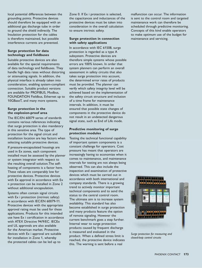
PHOENIX CONTACT 173
local potential differences between the grounding points. Protective devices should therefore be equipped with an additional gas discharge tube in order to ground the shield indirectly. The Insulation protection for the cables is therefore maintained, but possible interference currents are prevented. Surge protection for data technology and fieldbusesSuitable protective devices are also available for the special requirements of data technology and fieldbuses. They handle high data rates without distorting or attenuating signals. In addition, the physical interface is already taken into consideration, enabling system-compliant connection. Suitable product versions are available for PROFIBUS, Modbus, FOUNDATION Fieldbus, Ethernet up to 10GBaseT, and many more systems. Surge protection in the the explosion-proof areaThe IEC/EN 60079 series of standards contains various references indicating that surge protection is also mandatory in this sensitive area. The type of protection for the signal circuit and installation location are key factors when selecting suitable protective devices.
If pressure-encapsulated housings are used in Ex zones, each component installed must be assessed by the planner or system integrator with respect to the resulting overall solution.The self-heating of components is a factor here. These values are comparably low for protective devices. Protective devices with Ex approval in accordance with Ex n protection can be installed in Zone 2 without additional encapsulation.
Systems often contain signal circuits with Ex i protection (intrinsic safety) in accordance with IEC/EN 60079-11. Protective devices with the appropriate approval rating must be used for these applications. Products for this intended use have Ex i certification in accordance with ATEX Directive 94/9/EC. IECEx and UL approvals are also available for the American market. Protective devices with Ex i approval are suitable for installation in Zone 1, whereby the protected cables can be led up to
Zone 0. If Ex i protection is selected, the capacitances and inductances of the protective devices must be taken into consideration in the overall calculation to ensure intrinsic safety. Surge protection in connection with safety applicationsIn accordance with IEC 61508, surge protection is regarded as a type A subsystem. Protective devices are therefore simple systems whose possible errors are 100% known. In order that system planners can perform an overall assessment in safety circuits that also takes surge protection into account, the determined error rates of products must be provided. The planner can verify which safety integrity level will be achieved based on the implementation of the safety circuit structure and inclusion of a time frame for maintenance intervals. In addition, it must be ensured that possible state changes of components in the protective device do not result in an undetected dangerous signal state, such as End of Life mode. Predictive monitoring of surge protection modulesTesting the technical functional capability of important system components is a constant challenge for operators. Cost pressure has meant that operators are increasingly having to economize when it comes to maintenance, and maintenance intervals for testing are not always being observed. This can also include the inspection and examination of protective devices which must be carried out in accordance with both international and company standards. There is a growing trend to actively monitor important technical components and to send the status to the central control room. The ultimate aim is to increase system availability. This standard has also become established in surge protection and many products feature the option of remote signaling. However the current benchmark goes a step further. Internal wear to surge protection products caused by frequent discharge is measured and evaluated in the product. When a defined stress limit is reached, the protective device indicates this. The warning is sent before a real
malfunction can occur. The information is sent to the control room and targeted maintenance work can therefore be scheduled through predictive monitoring. Concepts of this kind enable operators to make optimum use of the budget for maintenance and servicing.
Surge protection for measuring and closed-loop control circuits

174 PHOENIX CONTACT174 PHOENIX CONTACT
Basic principlesNetwork security
Computers and controllers in industrial networks must feature fuse protection and be protected against attacks, malware, and unauthorized access. This section explains which basic dangers exist for industrial networks and what safeguarding should be implemented to protect against them.
Networked industrial PCs are threatened by constant newly emerging security flaws and a growing number of malicious programs. In general, security concepts which are used in classic office IT cannot be used efficiently in industrial systems, meaning that special protective measures are required for industrial networks.
Ever since the Stuxnet worm that attracted the world's attention and sabotaged tens of thousands of engineering and visualization PCs and controllers in industrial systems, the dangers posed by malware to automation networks can no longer be overlooked.
Solutions provide protection for industrial network security, preventing unauthorized manipulation and external network access.
PHOENIX CONTACT 175
Unpatchable systemsVirus scanners are generally used on office PCs to protect them against malware. Security updates for operating systems and applications are also installed regularly and in good time. These measures cannot usually be applied to industrial systems. In an industrial environment, operating systems and applications are used for which manufacturers no longer have any security updates available to them. Furthermore, for financial reasons, it would not be efficient to carry out testing measures before every operating system, application or antivirus software on industrial computers is updated. Nevertheless, by using special industrial firewalls [1], these so-called “unpatchable systems” can be protected against network attacks. To this end, hardware-based firewall appliances are geared towards industrial PCs. These external firewalls can be integrated transparently into the network in such a way that no configuration changes are required. The firewalls can be configured so that users can select through which protocols and ports the systems to be protected may be accessed. Attempts by attackers to connect to insecure ports can therefore be prevented or limited. Outsourcing the security functionality to external hardware has the added advantage that resources intended for the system to be protected do not have to be used up for security functions. Unauthorized accessCompany networks are usually connected to multi-level firewall systems over the Internet, and are therefore protected against unauthorized external access. However, in the context of industrial networks, these protective measures are not sufficient, since unauthorized access to industrial systems can also be obtained from the internal company network. This means, for example, that external service providers or service technicians of suppliers, who are connected to the company network through their notebooks, may
have unauthorized access to machine controllers. Unauthorized access can lead to faulty configurations of the systems affected. This in turn can lead to production losses and industrial accidents. Sensitive production and configuration data may also be viewed and stolen by unauthorized individuals. Using distributed firewalls can prevent unauthorized network access. Each machine or system is equipped with its own firewall. This allows authorized access to protected systems by authorized personnel, while effectively preventing unauthorized access. Although conventional firewalls cannot provide effective protection for OPC Classic data traffic, the mGuard OPC Inspector provides a suitable solution here. Deep packet inspection of OPC Classic data packets means that they can be filtered precisely by mGuard. The stateful inspection principle is also applied to OPC Classic data. OPC connections between individual network devices can be permitted or prohibited using firewall rules. The port changes negotiated in the OPC protocol are detected by the firewall and dynamically permitted. The firewall checks that a port opened by OPC Classic is used within a timeout and that the data traffic via this port corresponds to the OPC protocol. Separate networks for external usersAs an additional protective measure, external employees and suppliers should not be directly connected to the production networks, but instead should have access to separate service networks. At the transition between service networks and production or company networks, gateways can be used to control and configure access to internal resources. In such a scenario, it is also possible to allow external employees to access internal networks only after successful authentication at the gateway, which can be logged accordingly.
WormsMalicious programs such as worms and trojans can spread across networks by themselves, and can infect new systems by taking advantage of security loopholes in operating systems and applications. Existing malware always presents a huge danger to production networks, since security updates cannot usually be implemented on production computers. This means that worms, which may for example enter the system from the office network or from notebooks belonging to external service technicians, may attack controllers and may put industrial PCs, machines, and entire systems out of service. This can lead to severe production downtimes, and in the worst case, may present a risk of death or injury to production workers.
Even when company networks are protected against Internet worms by central protective systems such as firewalls or proxy servers, it must be taken into consideration that malicious software can enter the production network by other means. Examples of this include a virus-infected USB stick being inserted into an office computer or an infected notebook accessing the network. It is therefore necessary to protect unprotected production systems before worms can spread over the network. The use of distributed security appliances, which are connected upstream of the systems, enables data packets and data connections to be blocked, which would otherwise be used by worms to spread infections. This ensures that connections established for monitoring and configuration purposes are not exploited by worms to access security loopholes in the protected systems. Modern security appliances can be installed transparently upstream of the systems that are to be protected; it is therefore not necessary to reconfigure machines and systems. Viruses, trojans, and sabotageClassic viruses and trojans also present a danger to production networks. Although they cannot spread
Dangers to industrial networks
176 PHOENIX CONTACT
autonomously over networks, they still pose a danger to industrial computers due to infected configuration files, applications, and data carriers. For example, if an update for a piece of control software is installed onto a control computer from an infected USB stick, this computer may in turn be infected with viruses. By deleting or modifying data on the affected computer, the viruses may be able to manipulate the system, triggering errors and the failure of the corresponding machines and systems. This is how the Stuxnet worm, discovered in June 2010, was spread. As well as spreading across networks, it also infected non-networked Windows PCs by means of USB storage media. In this way, Stuxnet infected over 10,000 computers and was able to manipulate visualization and configuration components and plant malicious code in controllers. It should be assumed that mutations of Stuxnet and other malware will be used in the future for the targeted sabotage of industrial and production systems.
Conventional virus protection solutions do not allow users to fight these dangers in industrial environments. For reasons of stability and performance, virus scanners often cannot be installed on industrial PCs, and up-to-date antivirus programs or signatures often do not even exist for older operating systems. Furthermore, unknown malware for which no signatures exist may not be detected by conventional virus scanners. For example, this is how Stuxnet evaded antivirus software for at least twelve months before it was discovered. Solutions do exist for detecting viruses, trojans, and manipulations on industrial computers; these solutions can be implemented through so-called integrity monitoring. This means that file systems on the computers being protected are continually monitored for changes. First, signatures for all files and programs to be monitored are computed and saved. The file systems are then periodically checked for any changes, based on these signatures. If any unexpected changes arise in the file system (e. g., in programs, system libraries, executable code or
configuration files), a message is sent to the administrators responsible (e. g., by e-mail) and to the monitoring systems (e. g., network management systems). In contrast to virus scanners, this solution does not require any signatures which need permanent updating, and can also detect unauthorized system changes originating from unknown malware. Systems used for implementing integrity monitoring can be installed as external appliances outside of the computer being protected. In this case, resource usage for integrity testing on the protected devices can be kept at a low level. Unauthorized network accessMalware such as worms and trojans not only inflict damage on the systems affected, but also usually attempt to communicate with servers on the Internet which are operated by the attackers. This means on the one hand that (confidential) data, such as production and configuration data of machines and systems, is sent from the affected systems to external servers, and on the other hand that program routines are downloaded for further attacks. The protection of machines and systems should therefore not be limited to blocking external, unauthorized data links. External data links that are established using protected systems should also be limited using firewalls. We recommend adopting a minimal approach. Only data links that are necessary for operation, monitoring, and configuration should be permitted. Remote maintenanceWhen carrying out maintenance on machines and systems, and when rectifying malfunctions, it is often necessary to grant service technicians access to the control computer. This is because it is generally neither financially viable nor fast for technicians to travel to the site each time they carry out maintenance or repairs to machines. This problem is usually solved by granting service technicians remote access to machines and systems over data links.
In the past, expensive and slow modem connections were used. Some years ago, these modem connections were replaced
by cheaper and higher-performance data links over the Internet. Carrying out remote maintenance via unsecured Internet access presents a danger for machine operators, which must be countered by appropriate measures.
Data exchanged via public Internet access can be viewed by any attacker if no additional protective measures are taken. This jeopardizes the confidentiality of sensitive data, such as production statistics and machine configurations. To guarantee secure remote maintenance, it must therefore be ensured that the data being exchanged is protected against unauthorized access.
The same applies for the authenticity of communication partners. The machine operator must be sure that only the service technicians of the relevant operator have remote maintenance access to machines and systems. It must be ensured by suitable means that unauthorized third parties cannot engage in the communication.
The integrity of transmitted data must also be ensured. This means that changes made to the data by unauthorized third parties while in transit are detected. This is the only way to ensure that no manipulated configurations are installed on machine controllers, for example.
Virtual Private Networks (VPNs) are used to ensure that these fundamental security objectives are adhered to during remote maintenance over the Internet. VPNs allow users to exchange sensitive data securely over an unsecured, public network (such as the Internet). Within the scope of remote maintenance, an encrypted connection (VPN tunnel) is established between the machine in the operator's network and the machine manufacturer's service network. Encryption ensures that sensitive maintenance and configuration data cannot be viewed on the Internet by unauthorized third parties. The communication partners are authenticated by means of electronic certificates when the VPN tunnel is established. This means that machine operators can ensure that only authorized service technicians employed
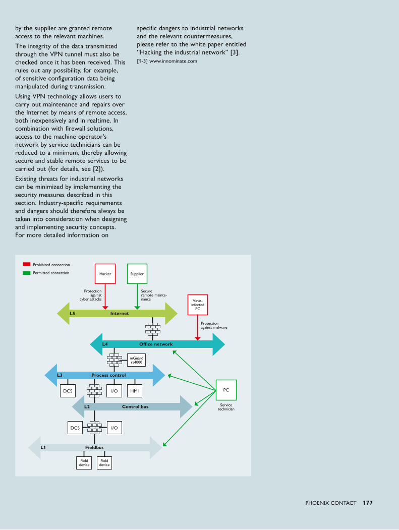
PHOENIX CONTACT 177
Virus-infected
PC
PCDCS
DCS
I/O
Field device
I/O
HMI
Field device
Internet
Control bus
Fieldbus
Office network
Process control
L5
L4
L3
L2
L1
Service technician
Hacker Supplier
Protection against
cyber attacks
Secure remote mainte-nance
Protection against malware
mGuard rs4000
Prohibited connection
Permitted connection
by the supplier are granted remote access to the relevant machines.
The integrity of the data transmitted through the VPN tunnel must also be checked once it has been received. This rules out any possibility, for example, of sensitive configuration data being manipulated during transmission.
Using VPN technology allows users to carry out maintenance and repairs over the Internet by means of remote access, both inexpensively and in realtime. In combination with firewall solutions, access to the machine operator's network by service technicians can be reduced to a minimum, thereby allowing secure and stable remote services to be carried out (for details, see [2]).
Existing threats for industrial networks can be minimized by implementing the security measures described in this section. Industry-specific requirements and dangers should therefore always be taken into consideration when designing and implementing security concepts. For more detailed information on
specific dangers to industrial networks and the relevant countermeasures, please refer to the white paper entitled “Hacking the industrial network” [3].[1-3] www.innominate.com
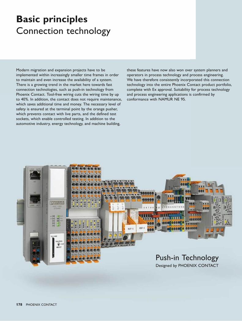
Push-in TechnologyDesigned by PHOENIX CONTACT
178 PHOENIX CONTACT
Basic principles Connection technology
Modern migration and expansion projects have to be implemented within increasingly smaller time frames in order to maintain and even increase the availability of a system. There is a growing trend in the market here towards fast connection technologies, such as push-in technology from Phoenix Contact. Tool-free wiring cuts the wiring time by up to 40%. In addition, the contact does not require maintenance, which saves additional time and money. The necessary level of safety is ensured at the terminal point by the orange pusher, which prevents contact with live parts, and the defined test sockets, which enable controlled testing. In addition to the automotive industry, energy technology, and machine building,
these features have now also won over system planners and operators in process technology and process engineering. We have therefore consistently incorporated this connection technology into the entire Phoenix Contact product portfolio, complete with Ex approval. Suitability for process technology and process engineering applications is confirmed by conformance with NAMUR NE 95.
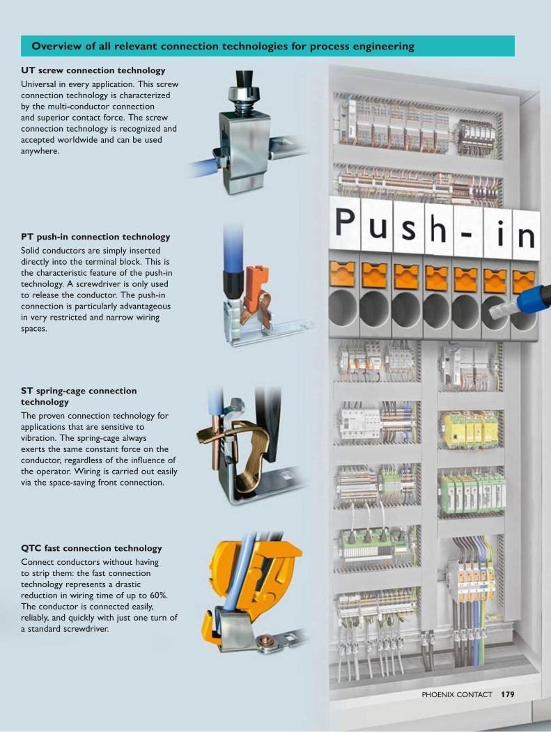
PHOENIX CONTACT 179
UT screw connection technologyUniversal in every application. This screw connection technology is characterized by the multi-conductor connection and superior contact force. The screw connection technology is recognized and accepted worldwide and can be used anywhere.
PT push-in connection technologySolid conductors are simply inserted directly into the terminal block. This is the characteristic feature of the push-in technology. A screwdriver is only used to release the conductor. The push-in connection is particularly advantageous in very restricted and narrow wiring spaces.
ST spring-cage connection technologyThe proven connection technology for applications that are sensitive to vibration. The spring-cage always exerts the same constant force on the conductor, regardless of the influence of the operator. Wiring is carried out easily via the space-saving front connection.
QTC fast connection technologyConnect conductors without having to strip them: the fast connection technology represents a drastic reduction in wiring time of up to 60%. The conductor is connected easily, reliably, and quickly with just one turn of a standard screwdriver.
Overview of all relevant connection technologies for process engineering
180 PHOENIX CONTACT
Basic principles Signal conditioning in MCR technology
In the field of MCR technology, an analog measuring signal generally passes through the following stations:
1. A sensor reacts to a physical variable and converts it to a signal that can be evaluated electrically. Either the sensor generates a voltage in the circuit or changes the circuit to which it is connected and that is supplied by a current source or it changes the voltage drop that occurs along the electrical circuit supplied with constant current. Sensors converting physical variables to electrical variables for measurement reasons are often referred to as measuring transducers or transmitters. Sensors are typically used to measure the following physical variables:
• Temperature
• Pressure
• Concentrations of substances
• Frequency (e.g., speed, flow rate)
• Electromagnetic and electrical properties (e.g., light, high-energy radiation, conductivity)
2. In general, the sensor is connected to an interface module used for signal conditioning. It is an electronic module which can have one or more of the following functions:
• Electrical amplification, filtering, and standardization of the measuring signal
• Electrical isolation of the measuring circuit from the device output circuit
• Electrical power supply of the sensor, if required
• The sensor and the interface module can be installed together in the same housing. A device integrated in this way is sometimes referred to as transmitter.
3. The conditioned measured value signal is forwarded to a device or system which evaluates and further processes the measured value information. This can either be a display device or a control system with a very simple or highly complex structure. Depending on the characteristics, the following designations are commonly used for control systems:
• PLC (Programmable Logic Controller)
• DDC (Direct Digital Control)
• DCS (Distributed Control System/process control system)
In simple MCR systems, it is possible to combine interface modules and the control system in a single device. A sensor may also be added, if required.
4. In industrial control systems, information is usually transmitted via communication bus systems. These systems enable a variety of information to be transmitted using only a limited number of electrical cable connections. An analog sensor signal needs to be conditioned in order to be transmitted on a bus system. Conditioning takes place in an interface module and generally covers the following points:
• Digitization of the analog signal
• Signal integration into the bus access protocol (including addressing)
5. More extensive bus systems are used for transmission on the bus to the control system. If required, several subsections can be used which compensate signal losses with repeater modules. The electrosensory acquisition, conditioning, and evaluation of status data referring to the environment or an industrial system are
considered to be the fundamental and core areas in the field of MCR technology. The figure provides a schematic view of these three areas:
• Signal generation in the field, as the monitored area to be controlled is called.
• Signal conditioning by means of electronic components for amplification, conversion, and protection against interference on the signal path.
• Analog and/or digital signal processing in an evaluation and control unit.
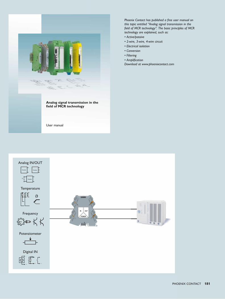
Analog IN/OUT
Digital IN
Temperature
Frequency
Potenziometer
PHOENIX CONTACT 181
Phoenix Contact has published a free user manual on this topic entitled “Analog signal transmission in the field of MCR technology”. The basic principles of MCR technology are explained, such as:• Active/passive• 2-wire, 3-wire, 4-wire circuit• Electrical isolation• Conversion• Filtering• Amplification Download at www.phoenixcontact.com
Analog signal transmission in the field of MCR technology
User manual
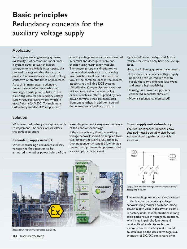
U1 U2
Netz 1
Netz 2
AC
DC
AC
DC
182 PHOENIX CONTACT
Redundancy monitoring increases availability
Supply from two low-voltage networks upstream of decoupling modules
Application
In many process engineering systems, availability is of paramount importance. If system parts or even individual components are briefly interrupted, this can lead to long and therefore costly production downtimes as a result of long shutdown or startup times of processes.
As such, in many cases, redundant systems are an effective method of avoiding a “single point of failure”. This is also the case for the auxiliary voltage supply required everywhere, which in most fields is 24 V DC. To implement redundancy for the 24 V supply, two
auxiliary voltage networks are connected in parallel and decoupled from one another using redundancy modules. The outgoing supply is distributed to the individual loads via corresponding fuse distributors. If one takes a closer look at the common loads in the process industry, you will find DCS systems (Distribution Control Systems), remote I/O stations, and active marshalling panels, which are often supplied by two power terminals that are decoupled from one another. In addition, you will find numerous other loads such as
signal conditioners, relays, and 4-wire transmitters which only have one voltage input.
Here, the following questions are posed:
• How does the auxiliary voltage supply need to be structured in order to supply these two different load types and ensure high availability?
• Is using two power supply units connected in parallel sufficient?
• How is redundancy monitored?
Solution
Whichever redundancy concept you wish to implement, Phoenix Contact offers the perfect solution:
Redundant supply networkWhen considering a redundant auxiliary voltage, the first question to be answered is whether power failure of the
low-voltage network may result in failure of the control technology.If the answer is no, then the auxiliary voltage network should be supplied from two different networks, i.e., either by two independently supplied low-voltage systems or by a low-voltage system and, for example, a battery unit.
Power supply unit redundancyThe two independent networks now obtained must be suitably distributed and combined together at the right locations.
The low-voltage networks are converted to the level of the auxiliary voltage network using modern switched-mode power supply units in the switch rooms.In battery units, load fluctuations in long cable paths result in voltage fluctuations, which may impair the function and service life of loads. As such, the voltage from the battery units should be stabilized to the desired voltage level by means of DC/DC converters prior
Basic principlesRedundancy concepts for the auxiliary voltage supply
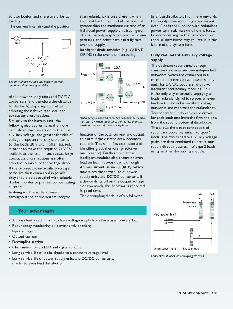
U1 U2
Verbraucher-Typ 1Output DC 20A
QU
INT
OR
ING
Input DC 24V 2x10AIN1 IN2
OK
OK
Redundancy
I<In
10A
20A5A
In
13 14 23 24
Output DC 20A
QU
INT
OR
ING
Input DC 24V 2x10AIN1 IN2
OK
OK
Redundancy
I<In
10A
20A5A
In
13 14 23 24
Verbraucher-Typ 2 Diodenmodul
Redundanz-module
Input DC
2 x 5 A
ST
EP
DIO
DE
Output DC
10 A
U1 U2
Netz
Batterie
AC
DC
DC
DC
+ -
Imax = 5 A
IIN1 = 2,5 A
IIN2 = 2,5 A
IOUT = 5 A
Imax = 5 A
Output DC 20A
QU
INT
OR
ING
Input DC 24V 2x10AIN1 IN2
OK
OK
Redundancy
I<In
10A
20A5A
In
13 14 23 24
Redundancy OK
DC OK
Redundancy
DC OK
DC OK
PHOENIX CONTACT 183
Connection of loads via decoupling modules
Supply from low-voltage and battery network upstream of decoupling modules
Redundancy is ensured here. The redundancy module indicates OK when the total current is less than the maximum current of a power supply unit.
to distribution and therefore prior to loading.The current intensity and the position
of the power supply units and DC/DC converters (and therefore the distance to the loads) play a key role when selecting the right voltage level and conductor cross sections.Similarly to the battery unit, the following also applies here: the more centralized the conversion to the final auxiliary voltage, the greater the risk of voltage drops on the long cable paths to the loads. 28 V DC is often applied, in order to make the required 24 V DC available at the load. In such cases, large conductor cross sections are often selected to minimize the voltage drop.If the two redundant auxiliary voltage paths are then connected in parallel, they should be decoupled with suitable diodes in order to prevent compensating currents.In doing so, it must be ensured throughout the entire system lifecycle
that redundancy is only present when the total load current of all loads is not greater than the maximum current of an individual power supply unit (see figure). This is the only way to ensure that if one path fails, the other path can fully take over the supply.Intelligent diode modules (e.g., QUINT ORING) take over the monitoring
function of the total current and output an alarm if the current draw becomes too high. This simplifies expansion and identifies gradual errors (predictive maintenance). Furthermore, these intelligent modules also ensure an even load on both network paths through Active Current Balancing (ACB), which maximizes the service life of power supply units and DC/DC converters. If a device drifts off on the output voltage side too much, this behavior is reported in good time.The decoupling diode is often followed
by a fuse distributor. From here onwards, the supply chain is no longer redundant, even if loads are supplied with redundant power terminals via two different fuses. Errors occurring on the network or on the fuse distributor may still result in the failure of the system here.
Fully redundant auxiliary voltage supplyThe optimum redundancy concept consistently comprises two independent networks, which are connected in a cascaded manner via two power supply units (or DC/DC couplers) with two intelligent redundancy modules. This is the only way of actually supplying all loads redundantly, which places an even load on the individual auxiliary voltage networks and monitors the redundancy.Two separate supply cables are drawn for each load: one from the first and one from the second potential distributor.This allows the direct connection of redundant power terminals to type 1 loads. The two separate auxiliary voltage paths are then combined to create one supply directly upstream of type 2 loads using another decoupling module.
Your advantages
• A consistently redundant auxiliary voltage supply from the mains to every load• Redundancy monitoring by permanently checking:• Input voltage• Output current• Decoupling section• Clear indication via LED and signal contact• Long service life of loads, thanks to a constant voltage level
• Long service life of power supply units and DC/DC converters, thanks to even load distribution

184 PHOENIX CONTACT
Basic principles IEC 61850
In modern industrial and process technology systems, the networks for power distribution and process control are still separated. Process technology systems and power distribution will be more closely linked in future. Ethernet networks will be used as the basis for communication.
As Ethernet-based protocols such as PROFINET, EtherNet/IP™, Modbus/TCP, and other protocols have become more widely used in industrial factory automation, this has also increasingly been the case in the field of process technology. However, the process technology systems are still separated from the control level of the power distribution by a separate control level. System providers are giving more and more consideration to a uniform Ethernet infrastructure for these two areas. The advantages of
linking the systems are a uniform infrastructure and the interaction with energy-efficient systems.
The cost and time involved in the engineering process and operation of a system can only be minimized if devices from different manufacturers work together smoothly. This goal is within reach thanks to the object-oriented approach of the new IEC 61850 standard, with its standardized data models, defined interfaces, and uniform configuration language.
Thanks to the IEC 61850 standard, communication and the engineering process are now being standardized. This means that users are no longer dependent on a single manufacturer, and
the variety of interfaces
is decreasing. Furthermore, through the use of Internet technologies, all authorized persons can access information at any time and from any location. Intelligent electronic devices (IEDs) are used for this and they communicate with one another via Ethernet. Due to high transmission speeds, more realtime data and functions are available to the user. If all components conform to the standard, consistent communication is possible from the process, field, and station levels all the way to the power supply level. Thanks to the interoperability, compatibility, and reliability, money is safely invested in IEC 61850-compliant devices and the systems are also well-equipped for the future.
PHOENIX CONTACT 185
Linking the automation network and power gridWith energy costs set to continue rising and regional generation growing steadily, remote areas also require information from the increasingly automated power grid. This means that the classic automation network of manufacturing companies needs to be linked to the power grid. In addition, users are becoming increasingly aware of the cost benefits of using energy that is cheaply available. The classic automation of the factory level therefore has to be connected to power grids using the common language of IEC 61850.
In the future, smart energy supply will only work if all relevant components can communicate data between one another so that supply and demand can be adjusted automatically. In continuous production processes, it is extremely important that up-to-date information is exchanged with the coordinating controller or control level. In the power grid, autonomous devices monitor high-voltage switches, transformers, and measuring equipment. They forward their information – such as lists of members of a predefined community – on to the network. Guidelines for protection and control technology for electrical switchgearThe IEC 61850 standard devised by the International Electrotechnical Commission is divided into ten parts. It describes the requirements for the devices and communication used in systems for protection and control technology for electrical switchgear. The standard primarily defines:
• General specifications for switchgear
• The most important information for functions and devices
• Information exchange for the protection, monitoring, control, and measurement of switchgear
• The communication interface and the configuration language
The aim of IEC 61850 is to describe all function units within standardized
switchgear using manufacturer-neutral object models. Network structureFor data transmission in IEC 61850, TCP/IP and MMS (Manufacturing Messaging Specification) are primarily used for client/server communication. Since technologies that are already familiar from information technology and Industrial Ethernet are used, so are their respective structures. A key feature is that essentially every device used in the network can communicate directly with every other device. It is therefore possible to exchange information directly between the different areas, e.g., network control center, primary and ancillary equipment, protective devices or the operator. High communication securityIf time-critical data needs to be exchanged in the switchgear, this can be done using GOOSE (Generic Object Oriented System Events) messages. In order to satisfy realtime requirements, the generic events are sent across the entire system cyclically in defined time intervals via broadcast or multicast. A value change is immediately forwarded with an increasing time interval (a few milliseconds). Regardless of whether communication is unconfirmed, a high degree of communication security is ensured by cyclical transmission, and the respective actual state of a device is known throughout the system. Reduced system engineering effortThe object-oriented, hierarchically structured data model is the basis for simplified system engineering. Since predefined function units are used, there is no need to document the systems extensively. Thanks to the plain text description of measured values and status values, including the unit and multiplicator, the current system state can be determined immediately and unequivocally.
The communication can be easily integrated into switchgear using IEC 61850-capable I/O devices with the
corresponding required functionality. Due to the long service life of the systems within a station, this not only enables use in initial installations but also allows older systems to be migrated to an IEC 61850-compliant system. Design of an Ethernet infrastructureA robust and reliable network is an essential requirement for fast data transmission. Ethernet switches for industrial applications, which satisfy the high environmental requirements of IEC 61850-3 in switchgear, allow data to be forwarded to all areas of the switchgear and substations.
Ethernet technology is already established in industry on a large scale. The IEC 61850 standard is also based on this proven technology, which supports transmission via various media such as copper, fiber optics or wireless. TCP/IP connections are available for status requests – referred to as reports. For fast messages, the predefined connections are used via Layer 2 of the OSI model and the messages are sent to the local network via multicast. The station bus described in IEC 61850-8-1, which connects IEDs together, enables the creation of redundant networks. GOOSE messages, which are transmitted with priority, ensure a fast response in the network.
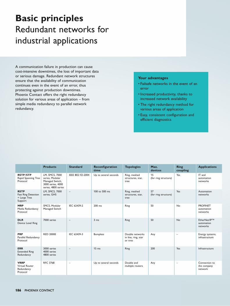
186 PHOENIX CONTACT186 PHOENIX CONTACT186 PHOENIX CONTACT
A communication failure in production can cause cost-intensive downtimes, the loss of important data or serious damage. Redundant network structures ensure that the availability of communication continues even in the event of an error, thus protecting against production downtimes. Phoenix Contact offers the right redundancy solution for various areas of application – from simple media redundancy to parallel network redundancy.
Basic principles Redundant networks for industrial applications
Products Standard Reconfiguration time
Topologies Max. devices
Ring coupling
Applications
RSTP/STPRapid Spanning Tree Protocol
LM, SMCS, 7000 series, Modular Managed Switch, 3000 series, 4000 series, 4800 series
IEEE 802.1D-2004 Up to several seconds Ring, meshed structures, star, tree
15 (for ring structure)
Yes IT and automation networks
RSTPFast Ring Detection + Large Tree Support
LM, SMCS, 7000 series, GHS
– 100 to 500 ms Ring, meshed structures, star, tree
57 (for ring structure)
Yes Automation networks
MRPMedia Redundancy Protocol
SMCS, Modular Managed Switch
IEC 62439-2 200 ms Ring 50 No PROFINET automation networks
DLRDevice Level Ring
7000 series – 3 ms Ring 50 No EtherNet/IP™ automation networks
PRPParallel Redundancy Protocol
RED 2000E IEC 62439-3 Bumpless Double networks in line, ring, star or tree
Any – Energy systems, infrastructure
ERRExtended Ring Redundancy
3000 series4000 series4800 series
– 15 ms Ring 200 Yes Infrastructure
VRRPVirtual Router Redundancy Protocol
RFC 3768 – Up to several seconds Double and multiple routers
Any – Connection to the company network
Your advantages• Failsafe networks in the event of an
error
• Increased productivity, thanks to increased network availability
• The right redundancy method for various areas of application
• Easy, consistent configuration and efficient diagnostics
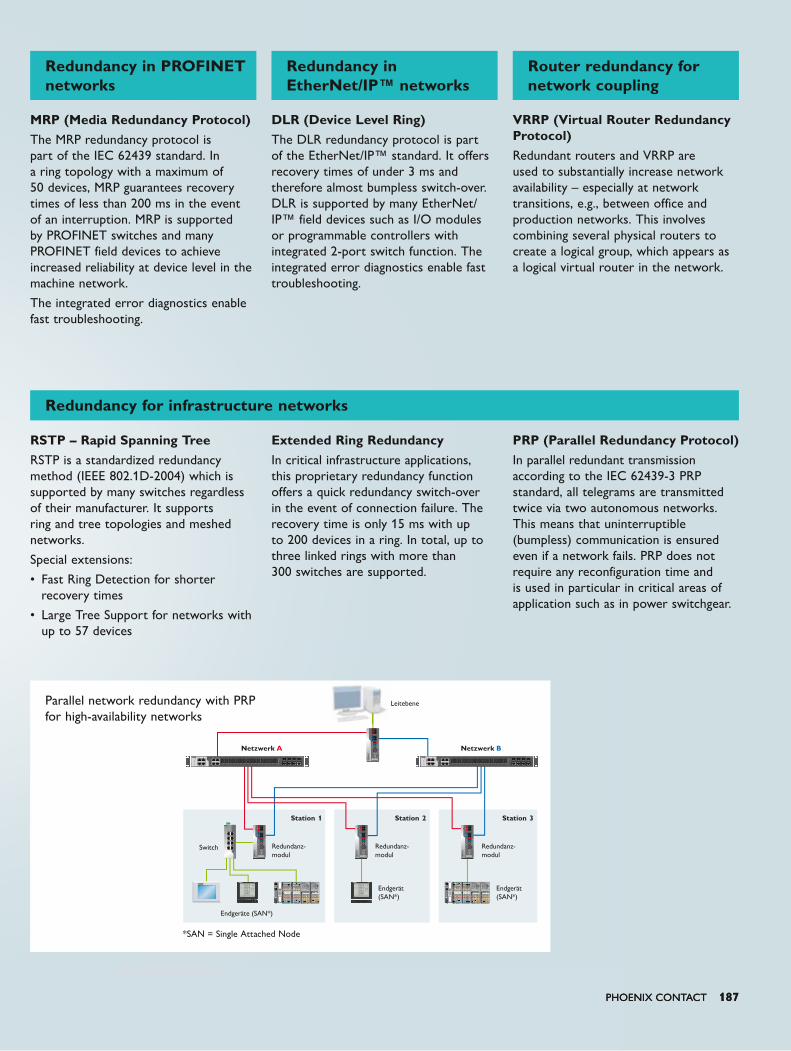
PHOENIX CONTACT 187
SWIT
CH
100
0E
US2 US1
X1
X3
X5
X7
US2
X2
X4
X6
X8
X2X1
X4X3
X6X5
X8X7
Link/ACT
100 Link/ACT
100
X3
X1
PRP
A
X2
PRP
B
X1 –
X2 –
X3
MODE
RED
200
0E
US1
FAIL US2
D
C
B
A
PRP
APR
PA
PRP
APR
P A
PRP
BPR
PB
PRP
BPR
P B
X3
X1
PRP
A
X2
PRP
B
X1 –
X2 –
X3
MODE
RED
200
0E
US1
FAIL US2
D
C
B
A
PRP
APR
PA
PRP
APR
PB
PRP
BPR
P B
X3
X1
PRP
A
X2
PRP
B
X1 –
X2 –
X3
MODE
RED
200
0E
US1
FAIL US2
D
C
B
A
PRP
APR
PA
PRP
APR
P A
PRP
BPR
PB
PRP
BPR
P B
X25 X26 X27 X28
X7X5X1 X3
X4X2 X6 X8
SWITCH 4800E
X9 X10 X11 X12 X13 X14 X15 X16 X17 X18 X19 X20 X21 X22 X23 X24
X1
X2
X3
X4
X5
X6
X7
X8
LINK/ACT SFP
LINK/ACT
US1
US2
LINK/ACT
LINK/ACT
25
26
27
28
X
X25 X26 X27 X28
X7X5X1 X3
X4X2 X6 X8
SWITCH 4800E
X9 X10 X11 X12 X13 X14 X15 X16 X17 X18 X19 X20 X21 X22 X23 X24
X1
X2
X3
X4
X5
X6
X7
X8
LINK/ACT SFP
LINK/ACT
US1
US2
LINK/ACT
LINK/ACT
25
26
27
28
X
X3
X1
PRP
A
X2
PRP
B
X1 –
X2 –
X3
MODE
RED
200
0E
US1
FAIL US2
D
C
B
A
PRP
APR
PA
PRP
APR
PB
PRP
BPR
P B
RDY
DE
BFSF
BK PN2701815
LINK
X1
X2
ACT
LINK ACT
X3
a1UL
a2
b1
b2
X1
X2
ACT
ACT
X3
bb11
bb22
RDY
DE
BFSF
BK PN2701815
LINK
X1
X2
ACT
LINK ACT
X3
a1UL
a2
b1
b2
X1
X2
ACT
ACT
X3
bb11
bb22
A B
PHOENIX CONTACT 187
MRP (Media Redundancy Protocol) The MRP redundancy protocol is part of the IEC 62439 standard. In a ring topology with a maximum of 50 devices, MRP guarantees recovery times of less than 200 ms in the event of an interruption. MRP is supported by PROFINET switches and many PROFINET field devices to achieve increased reliability at device level in the machine network.
The integrated error diagnostics enable fast troubleshooting.
RSTP – Rapid Spanning TreeRSTP is a standardized redundancy method (IEEE 802.1D-2004) which is supported by many switches regardless of their manufacturer. It supports ring and tree topologies and meshed networks.
Special extensions:
• Fast Ring Detection for shorter recovery times
• Large Tree Support for networks with up to 57 devices
DLR (Device Level Ring) The DLR redundancy protocol is part of the EtherNet/IP™ standard. It offers recovery times of under 3 ms and therefore almost bumpless switch-over. DLR is supported by many EtherNet/IP™ field devices such as I/O modules or programmable controllers with integrated 2-port switch function. The integrated error diagnostics enable fast troubleshooting.
Extended Ring Redundancy In critical infrastructure applications, this proprietary redundancy function offers a quick redundancy switch-over in the event of connection failure. The recovery time is only 15 ms with up to 200 devices in a ring. In total, up to three linked rings with more than 300 switches are supported.
VRRP (Virtual Router Redundancy Protocol) Redundant routers and VRRP are used to substantially increase network availability – especially at network transitions, e.g., between office and production networks. This involves combining several physical routers to create a logical group, which appears as a logical virtual router in the network.
PRP (Parallel Redundancy Protocol)In parallel redundant transmission according to the IEC 62439-3 PRP standard, all telegrams are transmitted twice via two autonomous networks. This means that uninterruptible (bumpless) communication is ensured even if a network fails. PRP does not require any reconfiguration time and is used in particular in critical areas of application such as in power switchgear.
Redundancy in PROFINET networks
Redundancy in EtherNet/IP™ networks
Router redundancy for network coupling
Redundancy for infrastructure networks
Leitebene
Redundanz-modul
Redundanz-modul
Redundanz-modul
Station 1 Station 2 Station 3
Switch
Netzwerk Netzwerk
Endgerät (SAN*)
Endgerät (SAN*)
Endgeräte (SAN*)
*SAN = Single Attached Node
Parallel network redundancy with PRPfor high-availability networks
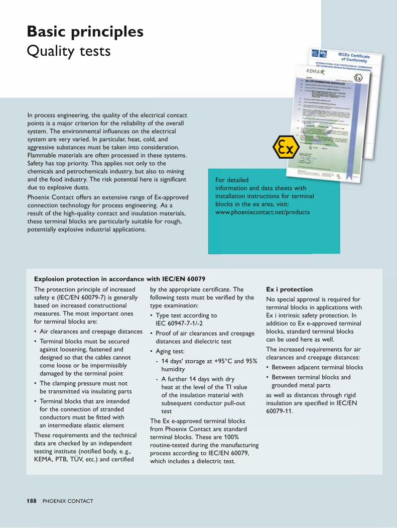
188 PHOENIX CONTACT
Explosion protection in accordance with IEC/EN 60079
The protection principle of increased safety e (IEC/EN 60079-7) is generally based on increased constructional measures. The most important ones for terminal blocks are:
• Air clearances and creepage distances
• Terminal blocks must be secured against loosening, fastened and designed so that the cables cannot come loose or be impermissibly damaged by the terminal point
• The clamping pressure must not be transmitted via insulating parts
• Terminal blocks that are intended for the connection of stranded conductors must be fitted with an intermediate elastic element
These requirements and the technical data are checked by an independent testing institute (notified body, e. g., KEMA, PTB, TÜV, etc.) and certified
by the appropriate certificate. The following tests must be verified by the type examination:
• Type test according to IEC 60947-7-1/-2
• Proof of air clearances and creepage distances and dielectric test
• Aging test:
- 14 days' storage at +95°C and 95% humidity
- A further 14 days with dry heat at the level of the TI value of the insulation material with subsequent conductor pull-out test
The Ex e-approved terminal blocks from Phoenix Contact are standard terminal blocks. These are 100% routine-tested during the manufacturing process according to IEC/EN 60079, which includes a dielectric test.
Ex i protectionNo special approval is required for terminal blocks in applications with Ex i intrinsic safety protection. In addition to Ex e-approved terminal blocks, standard terminal blocks can be used here as well.
The increased requirements for air clearances and creepage distances:
• Between adjacent terminal blocks
• Between terminal blocks and grounded metal parts
as well as distances through rigid insulation are specified in IEC/EN 60079-11.
Basic principlesQuality tests
For detailed information and data sheets with installation instructions for terminal blocks in the ex area, visit: www.phoenixcontact.net/products
In process engineering, the quality of the electrical contact points is a major criterion for the reliability of the overall system. The environmental influences on the electrical system are very varied. In particular, heat, cold, and aggressive substances must be taken into consideration. Flammable materials are often processed in these systems. Safety has top priority. This applies not only to the chemicals and petrochemicals industry, but also to mining and the food industry. The risk potential here is significant due to explosive dusts.
Phoenix Contact offers an extensive range of Ex-approved connection technology for process engineering. As a result of the high-quality contact and insulation materials, these terminal blocks are particularly suitable for rough, potentially explosive industrial applications.
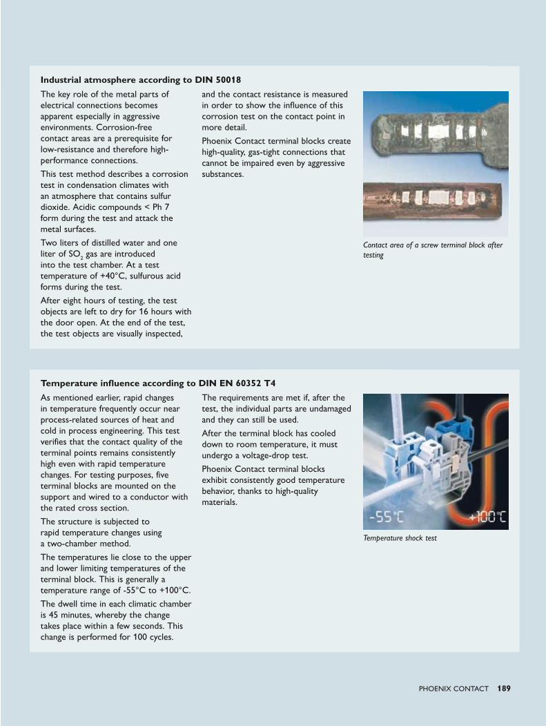
2 PHOENIX CONTACT PHOENIX CONTACT 189
Global player with personal customer contact
Company independence is an integral part of our corporate policy. Phoenix Contact therefore relies on in-house competence and expertise in a range of contexts: the design and development departments constantly come up with innovative product ideas, developing special solutions to meet customer requirements. Numerous patents emphasize the fact that many of Phoenix Contact's products have been developed in-house.
Phoenix Contact is a global market leader in the field of electrical engineering, electronics, and automation. Founded in 1923, the family-owned company now employs around 14,000 people worldwide. A sales network with over 50 sales subsidiaries and more than 30 additional global sales partners guarantees customer proximity directly on site, anywhere in the world.
Our range of services consists of all kinds of products with a wide range of electrotechnical applications. This includes numerous connection technologies for device manufacturers and machine building, components for modern control cabinets, and tailor-made solutions for many applications and industries, such as the automotive industry, wind energy, solar energy, the process industry or applications in the field of water supply, power transmission and distribution, and transportation infrastructure.
PHOENIX CONTACT –in dialog with customers and partners worldwide
Temperature influence according to DIN EN 60352 T4
Industrial atmosphere according to DIN 50018
As mentioned earlier, rapid changes in temperature frequently occur near process-related sources of heat and cold in process engineering. This test verifies that the contact quality of the terminal points remains consistently high even with rapid temperature changes. For testing purposes, five terminal blocks are mounted on the support and wired to a conductor with the rated cross section.
The structure is subjected to rapid temperature changes using a two-chamber method.
The temperatures lie close to the upper and lower limiting temperatures of the terminal block. This is generally a temperature range of -55°C to +100°C.
The dwell time in each climatic chamber is 45 minutes, whereby the change takes place within a few seconds. This change is performed for 100 cycles.
The requirements are met if, after the test, the individual parts are undamaged and they can still be used.
After the terminal block has cooled down to room temperature, it must undergo a voltage-drop test.
Phoenix Contact terminal blocks exhibit consistently good temperature behavior, thanks to high-quality materials.
The key role of the metal parts of electrical connections becomes apparent especially in aggressive environments. Corrosion-free contact areas are a prerequisite for low-resistance and therefore high-performance connections.
This test method describes a corrosion test in condensation climates with an atmosphere that contains sulfur dioxide. Acidic compounds < Ph 7 form during the test and attack the metal surfaces.
Two liters of distilled water and one liter of SO2 gas are introduced into the test chamber. At a test temperature of +40°C, sulfurous acid forms during the test.
After eight hours of testing, the test objects are left to dry for 16 hours with the door open. At the end of the test, the test objects are visually inspected,
and the contact resistance is measured in order to show the influence of this corrosion test on the contact point in more detail.
Phoenix Contact terminal blocks create high-quality, gas-tight connections that cannot be impaired even by aggressive substances.
Contact area of a screw terminal block after testing
Temperature shock test

IC 2
0-1
5.0
00.L
3
Pri
nte
d in G
erm
any
MN
R 5
2004450/0
1.0
5.2
015-0
3
© P
HO
EN
IX C
ON
TA
CT
2015
Always up-to-date, always available to you. Here
you'll find everything on our products, solutions
and service:
phoenixcontact.com
Product range
• Cables and wires
• Connectors
• Controllers
• Electronics housings
• Electronic switchgear andmotor control
• Fieldbus components and systems
• Functional safety
• HMIs and industrial PCs
• I/O systems
• Industrial communication technology
• Industrial Ethernet
• Installation and mounting material
• Lighting and signaling
• Marking and labeling
• Measurement and control technology
• Modular terminal blocks
• Monitoring
• PCB terminal blocks andPCB connectors
• Power supply units and UPS
• Protective devices
• Relay modules
• Sensor/actuator cabling
• Software
• Surge protection and interference filters
• System cabling for controllers
• Tools
• Wireless data communication
PHOENIX CONTACT GmbH & Co. KG
Flachsmarktstraße 8
32825 Blomberg, Germany
Phone: + 49 5235 3-00
Fax: + 49 5235 3-41200
E-mail: [email protected]
phoenixcontact.com
Partner in the process industryComponents and solutions
for your success
Partner in the process industry
Co
mpo
nents an
d so
lutio
ns fo
r your su
ccess