pac report (engineering) march 1990
TRANSCRIPT

PROJECT ADVISORYCOMMITTEE
Subcommittee on
Engineering
IPC STAFF STATUS REPORTSThis information represents a review of on-going research for useby the Project Advisory Subcommittees. The information is notintended to be a definitive progress report on any of the projectsand should not be cited or referenced in any paper or correspon-dence external to your company.
Your advice and suggestions on any of the projects will be most welcome.
FOR MEMBER COMPANIES ONLY

The Institute of Paper Chemistry (IPC) has provided a high standard of professional service and has exerted its best effortswithin the time and funds available for this project. The information and conclusions are advisory and are intended only forthe internal use by any company who may receive this report. Each company must decide for itself the best approach to solv-ing any problems it may have and how, or whether, this reported information should be considered in its approach.
IPC does not recommend particular products, procedures, materials, or services. These are included only in the interest ofcompleteness within a laboratory context and budgetary constraint. Actual products, procedures, materials, and services usedmay differ and are peculiar to the operations of each company.
In no event shall IPC or its employees and agents have any obligation or liability for damages, including, but not limited to,consequential damages, arising out of or in connection with any company's use of, or inability to use, the reported informa- I
tion. IPC provides no warranty or guaranty of results. IIIIIIIIIIII
NOTICE & DISCLAIMER
The Institute of Paper Chemistry (IPC) has provided a high standard of professional service and has exerted its best effortswithin the time and funds available for this project. The information and conclusions are advisory and are intended only for Ithe internal use by any company who may receive this report. Each company must decide for itself the best approach to solv-ing any problems it may have and how, or whether, this reported information should be considered in its approach.
IPC does not recommend particular products, procedures, materials, or services. These are included only in the interest ofcompleteness within a laboratory context and budgetary constraint. Actual products, procedures, materials, and services used Imay differ and are peculiar to the operations of each company.
In no event shall IPC or its employees and agents have any obligation or liability for damages, including, but not limited to,consequential damages, arising out of or in connection with any company's use of, or inability to use, the reported informa- Ition. IPC provides no warranty or guaranty of results.
This information represents a review of on-going research for use by the Project Advisory Committees. The information is notintended to be a definitive progress report on any of the projects and should not be cited or referenced in any paper or cor- Irespondence external to your company.
Your advice and suggestions on any of the projects will be most welcome.
I

.~' )<^Wt~ lTHE INSTITUTE OF PAPER CHEMISTRY^^^%.. ;i:2~~~'.E~,l~ . Post Office Box 1039
Appleton, Wisconsin 54912Phone: 414/734-9251
Telex: 469289
March 4, 1988
TO: Members of the Engineering Project Advisory Committee
Enclosed is advance reading material for the March 29-30 meeting of theEngineering Project Advisory Committee. Included are status reports for activeprojects, an agenda, and a current committee membership list.
Rooms have been reserved in the Continuing Education Center, and meals will beprovided as stated on the agenda. If you haven't already indicated your atten-dance, please do so at your earliest convenience by returning your registrationform or calling Jennifer Schuh at 414/738-3320. Also enclosed is the SecurityCard with the number to gain entrance into the Continuing Education Center.
For all Project Advisory Committee meetings, the Institute invites its membercompanies to send one or more representatives to attend the review sessions(first day) of any or all of the meetings. These invitations were mailed inFebruary. PAC members from member companies are also welcome to attend theother meetings, and may stay in the CEC and attend meetings and meals of theirchoice, at no cost. If you wish to attend any of the other meetings, buthaven't registered, please call Jennifer Schuh to do so. A meeting schedule isenclosed for your information.
We look forward to meeting with you on March 29-30.
Sincerely,
Clyde H. Sprague, DirectorEngineering Division
CHS/lmsEnclosures
1043 East South River Street

THE INSTITUTE OF PAPER CHEMISTRY
Project Advisory Committee Spring MeetingsMember Dues - Funded Research Reviews
March 22, 23, 24, 29, and 30
1988
Continuing Education CenterAppleton, Wisconsin
(414) 734-9251
Committee
Pulping Processes
Paper Properties
Review Schedule
Tuesday, March 228:30 AM - 5:30 PM
Dinner at 6:00 PM
Wednesday, March 238:30 AM - 5:30 PM
Dinner at 6:00 PM
Research Area*
Chemical Recovery:Recovery Furnace Processes
Bleached Chemical Pulp:PulpingOxygen Bleaching
High Lignin Pulps:Strength Development
Microstructure of Wood FibersAnalytical Techniques
Board Properties and PerformanceProcess, Properties, ProductRelationships
Internal Strength EnhancementStrength Improvement andFailure Mechanisms
On-line Measurement of PaperMechanical Properties
Systems Analysis Thursday, March 241:00 PM - 5:30 PM
Dinner at 6:00 PM
MAPPS Simulator DevelopmentContinuing Module DevelopmentPerformance Attribute ModelingOptimization with MAPPS
MAPPS Applications andField Experience
THE INSTITUTE OF PAPER CHEMISTRY
*NOT IN ORDER OF AGENDA

-2-
Committee
Engineering
Forest Genetics
Review Schedule
Tuesday, March 2910:00 AM - 5:30 PM
Dinner at 6:00 PM
Wednesday, March 301:00 PM - 5:00 PM
Dinner at 6:00 PM
Research Area*
Corrosion:Kraft Liquor CorrosivityCorrosion Control in Paper MillsCorrosion-Resistant Coatings
Papermaking:Higher Consistency ProcessingWet PressingImpulse Drying
Somatic EmbryogenesisInitiation of Embryogenic CallusTissue CultureBiochemistry
Somatic Embryo DevelopmentTissue CultureBiochemistry
THE INSTITUTE OF PAPER CHEMISTRY
IIIIII
IIIIIIIIIIIII

-i-
TABLE OF CONTENTS
TABLE OF CONTENTS ....................
AGENDA . . . . . .. . .. . . . . .. . .. .. . . ..
COMMITTEE LIST .... . ........
STATUS REPORTS
Project 3628: Recovery Boiler Fireside Corrosion . . . .
Project 3309: Fundamentals of Corrosion Control in Paper
Project 3556: Fundamentals of Kraft Liquor Corrosivity
Project 3470: Fundamentals of Drying ..........
Project 3480: Displacement Dewatering .........
Project 3479: Medium Consistency Processing ......
Page
i
ii
iv
1
17
22
46
56
61
Mills
. . .
. . .

-ii-
PRELIMINARY AGENDA
ENGINEERINGPROJECT ADVISORY COMMITTEE
March 29-30, 1988
Continuing Education Center (CEC)The Institute of Paper Chemistry
Appleton, Wisconsin
Tuesday, March 29, 1988
11:00am --
11:15 --
INTRODUCTION
CORROSION AND MATERIALS ENGINEERING GROUP
- Recovery Boiler Corrosion
Sprague/Chairman
Crowe
12:00 LUNCH
- Fundamentals of Corrosion Control in1:00pm Paper Mills- Fundamentals of Kraft Liquor Corrosivity
2:00 -- PAPERMAKING PROCESSES GROUP
- Impulse Drying
2:45 -- BREAK
3:00 - Fundamentals of Wet Pressing
3:45 - Medium Consistency Processing
4:00 - Fiber and Paper Performance Attributesin Process Simulation (MAPPS)
5:30 -- COCKTAILS
6:00 -- DINNER - CEC DINING ROOM
Staff
Crowe
Sprague
Lindsay
Staff
Jones

-iii-
Wednesday, March 30, 1988
7:15am -- BREAKFAST - CEC DINING ROOM
COMMITTEE ACTIVITIES
8:00am
9:30
9:45
10:30
11:00
Committee and Staff-- Project Reviews
BREAK
-- Continued Discussion
-- Report Preparation
-- Adjourn
-- LUNCH - CEC DINING ROOM
NOTE: The fall Engineering PAC meeting is scheduled for October 20-21, 1988.
Committee

-iv-
ENGINEERING
Project Advisory Committee
Dr. Robert Rounsley (Chairman) - 6/89*Research FellowMead Corporation8th & Hickory StreetChillicothe, OH 45601(614) 772-3581
Mr. Sven S. Arenander - 6/90Group LeaderUnion Camp CorporationP.O. Box 3301Princeton, NJ 08543-3301(609) 896-1200
Dr. William C. Bliesner - 6/90Technical DirectorThilmany Pulp & Paper CompanyP.O. Box 600Kaukauna, WI 54130(414) 766-4611
Mr. Percy E. Brooks - 6/90Manager, Pulp & Paper EngineeringGeorgia-Pacific Corporation133 Peachtree Street, N.E.P.O. Box 105605Atlanta, GA 30348-5605(404) 521-4618
Mr. LeRoy H. Busker - 6/88Director, Research & PlanningBeloit CorporationRockton R & D Center1165 Prairie Hill RoadRockton, IL 61072(608) 364-7961
Mr. Max D. Moskal - 6/88Project ManagerStone Container Corporation616 Executive DriveWillowbrook, IL 60521(312) 655-6949
Mr. M. Thomas Neill - 6/88Vice President R&DAbitibi-Price Inc.Research CentreSheridan ParkMississauga, Ontario L5K 1A9CANADA(416) 822-4770
Dr. W.B.A. Sharp - 6/90Group LeaderWestvaco CorporationLaurel Research Center11101 Johns Hopkins RoadLaurel, MD 20707(301) 792-9100
Dr. John Smuk - 6/89Manager of Process EngineeringResearch and Development CenterPotlatch CorporationP.O. Box 510Cloquet, MN 55720(218) 879-2393
Mr. Benjamin Thorp - 6/89Senior Vice PresidentResearch and EngineeringJames River CorporationP.O. Box 2218Richmond, VA 23217(804) 644-5411
Dr. Jerry Wallace - 6/89Mill ManagerAppleton Papers Inc.East Main StreetRoaring Spring, PA 16673-1480(814) 224-2131
Dr. Yung Duk Woo - 6/89Senior EngineerPapermaking R&D DepartmentWeyerhaeuser Paper CompanyTacoma, WA 98477(206) 924-6428
*date of retirement2/18/88

STATUS REPORTS
To The
Engineering Project Advisory Committee
March 29-30, 1988The Institute of Paper Chemistry
Continuing Education CenterAppleton, Wisconsin

Status Report
THE INSTITUTE OF PAPER CHEMISTRY
Appleton, Wisconsin
Status Report
to the
ENGINEERING PROJECT ADVISORY COMMITTEE
Project 3628
RECOVERY BOILER FIRESIDE CORROSION
March 29,1988
Project 3628 -1-

Status Report
PROJECT SUMMARY FORM
DATE: March 29,1988
PROJECT NO.: 3628 - Recovery Boiler Fireside Corrosion
PROJECT LEADER: D.C. Crowe
IPC GOAL:
Improve safety and increase the operating life of equipment by proper
selection of materials of construction and by identifying suitable process
conditions.
OBJECTIVE:
To understand the causes of corrosion in the kraft recovery boiler, as a basisfor devising methods of reducing corrosion damage.
CURRENT FISCAL BUDGET: $ 75,000.
SUMMARY OF RESULTS SINCE LAST REPORT: (September 1987 - March 1988)Experimental equipment consisting of two tube furnaces has been started uip.
Preliminary runs have been completed and described. A new mechanism for air
port corrosion has been proposed and an experimental plan for its investigation
and comparison with other theories is presented for review. Study of probe
designs has been initiated for in-situ air port corrosion studies, and some of this
work is described.
INTRODUCTION
Fireside corrosion of recovery boiler components in the lower furnace is a
chronic and costly problem. The major concern is the possibility of a smelt
explosion if the water should leak from the tubes or smelt spouts, with the
possibility of injury to personnel and loss of production. Operating costs include
periodic inspection and repairs, plus downtime. Recently, the cost of insurance
has increased due to the large number of recovery boiler accidents.
Project 3628 -2-

Project 3628 -3- Status Report
Corrosion of recovery boilers is a many-faceted problem. Some of the history
of studies of lower furnace problems was summarized in the last PAC report.
Corrosion of the lower furnace has been of special concern. Current repair or protection schemes such as thermal spray coatings, composite tubing, and pin
studding are costly and sometimes not entirely successful. Relationships between |
corrosion of boiler tubes, furnace conditions, and operating practices are
unknown. The mechanisms of corrosion are not well understood, in large part I
because the environments in problem areas are poorly characterized.
ICorrosion can be severe around air ports, smelt spouts and at the liquid level
line of the molten smelt. This research program will focus on problem areas in I
the boiler. One of these problems, addressed in this report, is air port corrosion.
Wastage of stainless steel from composite air ports exposes the underlying carbon 3steel, leaving it unprotected. This is a serious concern to the industry. The
corrosion has been attributed to NaOH condensation, but NaOH is unstable in the
boiler and often has not been detected in corrosion deposits. Doubts about this
theory remain in the minds of many corrosion engineers. An alternative
mechanism for this corrosion is proposed and a test program to investigate it is
outlined for review. By obtaining a better understanding of the corrosion
mechanism, remedial measures may be devised, and conditions which stimulate I
corrosion may be avoided. The proposed mechanism should be considered to be
speculative until experimental evidence in support of it can be obtained. I
IAN ALTERNATIVE MECHANISM OF RECOVERY BOILER AIR PORT
CORROSION |by David C. Crowe and John H. Cameron
AbstractLocalized corrosion at recovery boiler air ports has been attributed to I
condensed sodium hydroxide but the role of NaOH has not been proved. An
alternative mechanism, described here, involves corrosion by chloride and
pyrosulfate. I
I

Project 3628 -4- Status Report
I IntroductionCorrosion of air ports has been an enduring problem of recovery boilers. In
| the 1960s, Plumley, Lewis and Tallentl concluded after field and lab studies, that
wastage of carbon steel observed near air ports might be due to a gas-solid
reaction, perhaps involving the localized concentration of oxygen, carbon dioxide
and sulfur-containing gases. They thought metal wastage around air ports was
I not due to excessive metal temperatures resulting from high heat transfer rates.
Some localized corrosion in recovery boilers has been attributed to conden-
sation of sodium hydroxide at lower temperatures. Clement, investigating3I corrosion on the windbox side of flat stud boilers, argued that corrosion was due to
reaction of iron, condensed NaOH and 02 to form Fe20 3 and then non-protective3 NaFeO2 . Hydroxide condensation was further implicated by Bruno3 .
Moberg summarized gas phase research carried out in Scandinavia to look
at various steels over a range of temperatures and gas composition. They
concluded that chromium steels possessed superior resistance to corrosion. In
I fact, stainless steels used for composite tubes have successfully reduced general:
corrosion rates in kraft recovery boilers.
More recently, localized wastage of stainless steel from composite tubes3 primarily near air ports of high pressure boilers was reported at a meeting of the
National Association of Corrosion Engineers . This has become a great concern3 to the industry. Corrosion and cracking was described further by Wensley6 and
was attributed to the condensation of hydroxide.
I!7 Barna and Rogan7 have reported on the appearance and occurrence of
corrosion of composite tubes at port openings. They considered that the corrosion
process depends on formation of crevices that have the capability of accumulating
deposits and that form a non gas-tight seal between the furnace and casing side of
the tubing. They suggested that hydroxide vapors condense at deposits and form a
molten phase at the deposit/substrate interface.
Wensley8 reported that tube cladding wastage and the preferential corrosion
| of the stainless cladding from flat studs often occurred together. He also noted
that those openings which evidently experienced higher temperature conditions
I
__

Project 3628 -5- Status Report
in service, resulting in both flat stud burn-back and flat stud notch cracking, were Iless likely to exhibit pronounced stainless cladding wastage. Conversely, areas of
cladding wastage experienced less flat stud burn-back and notch cracking. This I
suggests that stainless steel removal is a low temperature phenomenon. Wensley
also reported measurements of the waterwall tube temperatures between the |
primary and secondary air ports which were between 300 and 350 C, as measured
by chordal thermocouples, confirming that the temperatures of the tubes are |
fairly low.
IIn contrast, in a failure analysis of a cracked composite recovery boiler tube,
Odelstam 9 determined that the tube had reached temperatures as high as 500-550
C. Perhaps these temperatures should be considered to be the top of the operating
range for tube temperatures. In explaining the preferential corrosion of stainless
steel, he referenced work by Rahmel which indicated that carbon steel is more
resistant to molten hydroxide than are Cr and CrNi steels. The corrosion rate I
depends on the Na 2 0 2 content in the pure NaOH melt which in turn depends on
oxygen and steam partial pressure in the gas above the melt. The chromium is
especially reactive to form chromate (Na2CrO4) via:
4 NaOH + Cr 20 3 + 3/2 02 -> 2 Na2CrO4 + 2 H 2 0 (1) |
This reaction would remove the protective chromium oxide passive layer from the 3stainless steel, causing rapid corrosion.
The NaOH condensation mechanism has been recently summarized by
Odelstam et al. 10 According to that theory, the NaOH may condense if the hot 3furnace gas is cooled rapidly and then placed in contact with low (<lppm) CO2
air. Laboratory results were described in which severe corrosion of 304L SS -
occurred at the interface between molten NaOH/Na 2 CO 3 and air. Compared to the
'304 SS, type 310 stainless steel corroded less and carbon steel less than either
stainless steel. In areas in contact with the furnace gas with high CO2
concentration, the NaOH would react to form harmless carbonates and sulfates.
They also reported tests confirming that NaOH and Cr203 react to form Na 2Cr0 4, Iand presented analysis of corrosion deposits containing high NaOH
concentrations. I
I

Status Report
There is some uncertainty about the extent to which carbon steel is attackedbut it is generally considered to be attacked more slowly than stainless steel. Thisobservation, based on damage of composite tubes, would be consistent withcorrosion caused by NaOH, in which stainless steel may be corroded more quickly
than carbon steel.
The conditions under deposits where the corrosion occurs are poorlyunderstood. Bruno3 had perhaps the most to report regarding deposits (formedon carbon steel in lower pressure boilers). Sulfur content of these deposits wasvery low. He reported that deposits from the Iggesund recovery boiler began to
melt at 250 C. Deposits containing 12% NaOH were encountered in a boiler (280 C,64 bar) near the primary and secondary air ports. Sodium sulfide (2.1%) and
sodium sulfate (2.8%) were very low, although other analyses of deposits fromaround air ports showed higher sulfate concentrations. Clement2 described
chemical accumulations at air ports, with a black and red deposit (NaFeO 2) nextto the tube, yellow and green layers outside that, and extending into a gray layer of
unreacted "Hydrochrome" refractory material. The pH was about 12 and sulfur
(as S0 3) was less than 2%. The temperature in the area was about 315 C (600 F).
Odelstam et al.1 0 have provided analyses of deposits showing high NaOHcomposition. No analysis for NaCI or Na2 S 20 3 was reported and the method ofanalysis for NaOH was not described. The high NaOH levels may form by the
reverse of reaction (1) during an analytical titration procedure. Other analyses ofcorrosion deposits from air ports have not provided evidence of NaOHcondensation. Retrieval of representative corrosion deposits is very difficult,especially because corrosion is localized and unpredictable.
Reservations regarding the condensation of NaOH remain based on the
difficulty of producing NaOH fume in the recovery boiler, as described by
Cameron 1 . Pejryd and Hupa1 2 have made equilibrium calculations for the gascomposition in the kraft furnace. These calculations show that NaOH vapor is astable species only at temperatures above 800 C. In the temperature range from
800 to 1300 C, the equilibrium C02 concentration is several orders of magnitudegreater than the equilibrium NaOH concentration. It is unlikely that NaOH could
condense in such an atmosphere without reacting with the C02 to form Na2 C0 3.
Project 3628 -6-

Project 3628 -7- Status Report
Alternative Mechanism IRecent research by Cameron 1 l indicates that KC1 and NaCI are major
volatile species from melts similar to those found within the recovery furnace and that very little NaOH vapor is produced. Liden and Pejryd 13 have noted that KCI
(g) and NaCl (g) may be emitted in about equal amounts, even though potassium |is a minor constituent of the liquor. These salts may deposit on cooler surfaces
within the furnace. On exposure to SO3 or SO2, they would be expected to form 3pyrosulfates Na 2 S 2 0 7 and K 2 S 2 0 7 via the equations:
2 NaCl (s)+ 2 SO3 (g) + 1/2 02---> Na 2S20 7 (1) + Cl2 (g) (2)2 NaCl (s) + 2 S0 2 (g) + 3/2 02 --- > Na2S 20 7 (1) + C12 (g) (3) |
Therefore, pyrosulfate should be considered as a possible corrosive agent within 3the recovery boiler.
Although pyrosulfate is known to be a corrosive agent 14 ' 15,16, it has not
been considered as a potential agent for the corrosion observed with composite
tubes. This appears to be -a result of equilibrium studies by Backman and Hupa1 Iwhich show that Na 2 S 2 0 7 is unstable at the SO2 levels and temperatures foundwithin a recovery boiler. Backman and Hupa concluded that Na2 S 2 0 7 could only |
occur if the SOx concentration exceeds 5000 ppm. Since the S0 2 concentration in
kraft furnaces is in the range of 50 to 500 ppm, Na2 S 2 0 7 would be expected to be 3unstable and therefore, was eliminated from consideration as a corrosive agent.
These conclusions differ from the findings of Coats, Dear and Penfold.1 8 They 3have measured the relation between the partial pressure of SO3 and melting point
temperatures of alkali pyrosulfates. For example, at 425 C (800 F) about 3000 ppm 3of SO3 is necessary to form Na 2S 20 7 or about 200 ppm SO3 to form K 2S 20 7 .
While Na 2S20 7 may be unstable at the SOx levels in the recovery furnace, -there are conditions under which it will occur. Fielder et al.1 9 and Anderson andHung20 have shown that NaCl will react rapidly with SO02 or SO 3 at 400 C and SOx
level less than 1000 ppm to form Na2 S 2 0 7 via equation 2. Fielder et al.1 9 found
that on exposure to SO02 -SO3-0 2 , a NaCl sample was essentially molten Na2 S 2 0 7
after 10 min. at 401 C. By raising the temperature to 500 C in a stream of 02, the
Na2 S20 7 slowly converted to a non-adhering film of Na 2 SO4 . They proposed that for the temperature range 401 to 450 C (750 to 840 F), molten Na2 S 20 7 is the

Status Report
principal film product that is formed when NaCI is exposed to the oxides of sulfur.Reid has noted that, below 482 C (900 F) equilibrium favors SO3 over SO2 . Thus asfurnace gas cools, SO3 may be more stable and it may react via equation 2.
The corrosion in the area of the air ports in the recovery boiler may resultfrom pyrosulfate. Based on the work of Fielder et al.13, and the conclusions ofCameron 11 that NaCl and KCl are the major volatile species in the recoveryboiler, production of pyrosulfate appears to be possible. This would occur in areaswhere the temperature is in the range 400 to 450 C (750 to 840 F) and chloride, SO3
and 02 are present. On the cold side of the waterwall, and in areas in contact withair these conditions may be present. The molten nature of the pyrosulfate wouldaccount for the appearance of the tube wastage where it is suggestive of erosion bya liquid phase. Backman, Hupa, and Hyoty1 7 have noted that Na2 S 2 0 7 - K2S2 0 7
mixtures might have a low eutectic temperature (down to 280 C). This is withinthe region of temperatures anticipated on recovery boiler waterwall tubes.
The role of pyrosulfates in corrosion has been reviewed by Reid 14. Work byCorey, Cross and Reid 5 has indicated that at tube-metal temperatures of 425 C(800 F), pyrosulfates probably contribute to metal loss.
3 Na2 S20 7 + Fe2 0 3 -> 3 Na2 SO4 + Fe2(S0 4)3 (4)
4 Na2 S 20 7 + Fe3 0 4 ->4 Na2SO4 + FeSO4 + Fe2 (SO4 )3 (5)
3 Na2S20 7 + Fe20 3 -> 2 Na3 Fe(S04) 3 -> 3 Na2 SO4 + Fe20 3 + 3 SO3 (6)
Removal of the oxide layers would expose the underlying steel to rapid oxidationand sulfidation. Nevertheless, pyrosulfates have not been found in corrosionproducts of recovery boiler in concentrations high enough to be identified by X-raydiffraction. However, they may decompose prior to analysis. Corrosion bypyrosulfates would be restricted to a range from 750-900 F (400- 480 C). This rangeagrees closely with the results of Fielder et al.19 for pyrosulfate formation andmay occur on recovery boiler waterwall tubes.
Besides forming pyrosulfate, chlorides may increase the oxidation
appreciably above 400 C (750 F) by destroying the protective spinel layer on
Pr-oJect 3628 -8-

Project 3628 -9- Status Report
austenitic stainless steels. When alkalies are also present, chromium is lost from
the surface as volatile chromic chloride, increasing the oxidation rate to replacethe normal chromium oxide film 14. This may account for the severe attack of stainless steel alloys. Reaction of chloride and chromium oxide spinel may
generate hydroxide. A possible reaction, involving oxidation and formation of high pH is:
I4 KC + Cr2 0 3 + H 2 0 + 2 e- -> 2 CrC12 + 2 K 2 0 + 2 OH' (7)
The hydroxide may then react via equation (1) to produce chromate and the CrC12may react elsewhere in the deposit where P 0 2 is higher, forming chromate or
Cr20 3. Chiang et al.21 have suggested a similar process involving Cr2 (S0 3) 3 inNi - Cr alloys instead of CrC12. In that process, Cr2 03 reacts to form Cr2(S0 3 )3which migrates outward and reprecipitates where P 0 2 is higher. Chlorideconcentrations in the corrosion deposit were low according to Bruno 3' Thiswould be consistent with volatilization to C12 via equation 2. Further detailedanalysis of deposits would be useful to determine the presence and distribution ofchloride. |
Alexander 2 2 found that the effect of increasing chloride concentration in 3mixtures of sulfates and chlorides was more marked with austenitic than withferritic steels at temperatures of 400 - 700 C (750 to 1290 F). Apparently, the 3chloride destroyed the normally protective spinel oxide layer. They observed that
when chromium-containing steels were heated with coatings rich in chloride, a 3green deposit, strongly resembling chromic oxide, Cr 2 0 3 , was formed. Thisdeposit could have been formed only by the volatilization of chromium. Theythought that the volatile chromium compound was CrO2 Cl2 , CrCl3 or CrO3 .Work by Pickering, Beck and Fontana was quoted in which results were attributed
to corrosion via:
24 KC1 + 10 Cr203 + 9 0 2 -> 12 K 2 CrO4 + 8 CrC13 (8) 1
This reaction commenced at about 400 C (750 F). This reaction might account for |the observation of chromate in smelt deposits and the greenish yellow colorobserved in deposits from corroded areas of boilers. 3
I

Status Report
Shinata et al. 23 have studied NaCl induced hot corrosion of stainless steels,and concluded that, in the range 650-900 C (1200-1650 F), chromium is oxidized
selectively, leaving a non-protective Cr 2O 3 scale. Corrosion losses increased withincreasing chromium content. This raises the question whether a similar process
takes place in the recovery boiler at lower temperatures, to preferentially attack
chromium alloys. If this is the case, then the accelerated wastage of stainless
steel from composite tubes may be rationalized in terms of a mechanism involving:
chloride. Vaughan et al.1 6 determined that chloride produced during refuse
firing is responsible for serious corrosion. They noted that low temperature
corrosion could be attributed to chlorine formed by oxidation of HC1 or by
conversion of alkali chlorides to sulfates and pyrosulfate. Resistance to chloride
may be very important in preventing recovery boiler corrosion. This question
needs to be resolved, and may provide the key to improved performance of air
ports.
Chromates may arise for many reasons, not necessarily due to reaction of
chromium with hydroxides. At higher temperature (975 C), Fryburg et al.2 4, 2 5
have indicated that chromium oxide may react to form chromate via:
Cr 2 03 + 2 Na2SO4 (1) + 3/2 02 -> 2 Na2CrO4 (1) + 2 SO3 (g) (9)
Although temperatures are too low on the tube surface, the reaction may occur in
the deposit. This could account for the presence of chromate in the corrosion
deposit.
A mechanism of lower temperature corrosion relevant to the recovery boiler
may share some features with a mechanism described by Luthra and Shores26
for corrosion at 600-900 C (1110-1650 F). It involves formation of a liquid sulfate
phase and sulfidation of the surface, thereby retarding formation of a protective
Cr20 3 scale. In a study of corrosion of cobalt alloys, Luthra 27 has suggested thatthe major oxidant is SO3. It diffuses in via counter transport of S 2 0 7
2 and S0 42 .
Oxygen (from SO3 ) is consumed at the scale surface to form SO2 . The SO2 (or
S032-) will diffuse away from the surface. Low P02 at the metal surface willensure that the Cr20 3 film is non-protective
Project 3628 -10-

Project 3628 -11- Status Report
Conclusions IResults described in the literature to date do not provide unequivocal evidence
of NaOH condensation and may be based on false premises regarding the |presence of NaOH in recovery boilers. The published information on corrosion of
air ports is consistent with an alternative corrosion process involving chloride
and pyrosulfate. Work is underway at the Institute of Paper Chemistry to
examine ways in which chloride and pyrosulfate might accelerate corrosion of
stainless steel near recovery boiler air ports.
References
1. A.L.Plumley, E.C.Lewis and R.G.Tallent, TAPPI 49(1):72A- 81A (1966).
2. J.L.Clement, TAPPI 53(2): 269 (1970).
3. F.Bruno, PulpPap.Ind.Corr.Prob. 4: 68 (1983), Swedish Corrosion Institute,
Stockholm (1983).
4. O.Moberg, PulpPap.Ind.Corr.Prob. 1: 125-136 (1974). I5. NACE T-5H-1 Task Group on Recovery Boiler Fireside Corrosion, Minutes of
Meeting, Atlanta, Sept 19,1985. |6. D.A.Wensley, Corrosion and Cracking of Composite Boiler Tubes, p.231-245 in
1986 Kraft Recovery Operations Seminar, TAPPI, Atlanta (1986). 37. J.L.Barna and J.B.Rogan, Proc.TAPPI 1986 Engineering Conf. pp.377-385
(1986).8. D.A.Wensley, Matl. Perf. 26(11): 53-55 (1987).
9. T.Odelstam, pp.277-288 in Proc. 1987 Kraft Recovery Operations (Orlando)TAPPI Press, Atlanta (1987).
10. T. Odelstam, H.N.Tran, D.Barham, D.W.Reeve, M.Hupa and R.Backman,
pp.585-590 in TAPPI 1987 Engineering Conference Proceedings, TAPPI, Atlanta(1987).
11. J.H.Cameron, "Vaporization from Alkali Carbonate Melts", Institute of Paper
Chemistry Technical Paper Series No. 237 (April 1987) accepted by Pulp and Paper
Science.12. L.Pejryd and M.Hupa, TAPPI 1984 Pulping Conf., San Francisco, TAPPI,
Atlanta (1984).13. J.Liden and L.Pejryd, Nord.PulpPap.Res.J. 1(1): 22 -25 (1986).
14. W.T.Reid, External Corrosion and Deposits, American Elsevier, New York 3(1971).
I

Status Report
15. R.C.Corey, B.J.Cross and W.T.Reid, Trans ASME 67: 289 - 302 (1945).
16. D.A.Vaughan, H.H.Krause and W.K.Boyd, pp.473-493 in Ash Deposits and
Corrosion Due to Impurities in Combustion Gases, ed. R.W.Bryers, Hemisphere
Pub.Co./ McGraw Hill, New York, 1978.
17. R.Backman, M.Hupa and P.Hyoty, PulpPap.Ind.Corr.Prob. 4: 76-81 (1983).
18. A.W.Coats, D.J.A.Dear and D.Penfold, J.Inst.Fuel, 41:129 (1968).
19. W.L Fielder, C.A.Stearns and F.J.Kohl, Proc.Electrochem.Soc. 83: 251-265
(1983) and J.Electrochem.Soc. 131: 2414-2417 (1984).
20. A.B.Anderson and S.C.Hung, J.Am.Chem.Soc. 105: 7541 (1983).
21. K.Y.Chiang, F.S.Pettit and G.H.Meier, pp. 519 - 530 in High Temperature
Corrosion, ed. R.A.Rapp, NACE, Houston (1983).
22. P.A.Alexander, pp.571 - 582 in The Mechanism of Corrosion by Fuel
Impurities, Proc. Int'l Conf. Marchwood Eng. Labs, Butterworths, London, 1963.
23. Y. Shinata, F.Takahashi and K.Hashiura, Mat.Sci.Eng. 87: 399 - 405 (1987).
24. G.C.Fryburg, F.J.Kohl and C.A.Stearns, J.Electrochem.Soc. 131: 2985-2987
(1984).
25. G.C.Fryburg, F.J.Kohl, C.A.Stearns and W.L.Fielder, J.Electrochem.Soc. 129:
571-585(1982).
26. K.L.Luthra and D.A.Shores, J.Electrochem.Soc. 127(10): 2202-2210 (1980).
27. K.L.Luthra, pp. 507 - 512 in High Temperature Corrosion ed. R.A.Rapp,
NACE, Houston (1983).
PROGRESS:
1. Some preliminary corrosion tests have been completed. The primary
objective of these tests has been to commission laboratory equipment which can be
used for studies of recovery boiler corrosion, and to gain experience in conducting
these experiments. The results should provide some baseline data for subsequent
testing of steels in powdered smelt using tube furnaces. One furnace is an
electrical tube furnace (110 V, 5A) with temperature controller, chromel alumel
thermocouple and variable transformer as the main pieces of equipment. The
second furnace (220 V) has a temperature controller, thermocouples and over-
temperature shut-off. The furnace tubes are alumina, fitted with universal seals.
Metal samples are contained in smelt-filled alumina combustion boats.
Results of corrosion measurements for 1018 carbon steel and 304 stainless
steel showed similar corrosion rates for both materials of about 0.2 mpy after 2
.Project 3628 -12-

Project 3628 -13- Status Report
week exposure at 300 C. The smelt composition was 80 % Na2 CO 3, 12 % Na2SO4 Iand 8 % Na 2S, and an oxygen free nitrogen atmosphere was used. At 300 C, the
carbon steel coupons and one of the stainless steel coupons were covered with a
black film. One of the stainless steel samples had a green colored film on its
surface. At higher temperature, the green deposit was observed on all coupons. |
The weight loss results are listed in Table 1.
Table 1
Corrosion rates of 1018 and 304 steels.
Temperature 1018 Carbon Steel 304 Stainless300 0.19, 0.21 mpy 0.27,0.23 500 0.57,3.92 0.62,1.72400 0.42,0.42 0.40,0.27600 0.84,1.88 11.73,1.35 |
2. The gas metering systems have been designed and partly constructed. A
system for adding H 2 0 to the flue gas has been designed. A nitrogen/CO 2/O 2 gas
stream will be saturated with H 20 at a controlled temperature to obtain the
desired final H20 content.
3. Conceptual design is complete for a corrosion probe for use in the recovery !boiler air port. It will be inserted through the primary windbox of a boiler so that
the tip of the probe is located at the upper crotch of an air port, where corrosion
has been observed. The probe will be oriented at approximately a 45 degree anglepointing downward. The probe will be comprised of a stainless steel outer tube |enclosing an aluminum or kanthal inner tube. The inner tube will contain
molten sulfur (mp 113 C, bp 445 C). The use of sulfur is based on a suggestion by |
W. T. Reid in "External Corrosion and Deposits", American Elsevier, NY (1971).
The sulfur pool will be heated by a cartridge heater immersed in it. Cooling will be |
provided by a cooling coil located outside the windbox. The cartridge heater will be
controlled by a temperature controller using a thermocouple located between the |
aluminum internal tube and the external stainless steel tube. At the tip of the
probe will be a small cup which will fill with smelt or be filled prior to the test. 3This cup will also serve as the corrosion coupon. This design will help to
maintain the corrosion deposit on the corroded surface after withdrawal from the 3furnace. Molten sulfur will be used to maintain the temperature of the probe
because it will not pose an explosion hazard if it leaks into the boiler, and it is

Status Report
molten throughout the range of temperatures of interest. Uniform temperature
inside the probe should be attained by thermal convection of the sulfur.
PLANS FOR NEXT PERIOD:
Experimental Plan for Laboratory Study
This study will focus on obtaining information on the effects of potentially
corrosive species in simulated kraft smelts to aid in identifying the relevant
mechanisms of corrosion under smelt deposits.
Simulated smelts
1. 80 % Na 2C0 3, 12 % Na2SO4, 8 % Na2S.
2. Smelt 1 with 10 % NaOH addition.
3. Smelt 1 with 5 % NaCl addition.
4. Smelt 1 with 5 % Na2S 207 addition.
5. Smelt 1 with 5 % KC1 addition.
6. Smelt 1 with 5 % Na2 S 2 0 3 addition.
7. Smelt 1 with 5 % S addition.
8. Smelt 1 with 5 % Na 2SO3 addition.
The Na2 S used in the smelt is formed from Na 2S . 9H 20 in a vacuum
furnace under nitrogen atmosphere at approximately 190 C. The temperature is
brought up slowly to prevent flashing. After cooling, the smelt is then ground to a
fine powder within a nitrogen filled glove bag, placed in a jar and sealed. Mixing
with Na2C0 3 and Na 2SO4 is also done under a nitrogen atmosphere, and again is
ground to a fine powder. Care is taken to exclude air from the smelt until placed
in the furnace. Smelt analysis will be performed on smelts used in initial tests to
determine smelt stability at these temperatures.
Materials
1. 1018 Carbon Steel.
2. A210 Carbon Steel.
2. 304 Stainless Steel.
Gas Atmosphere
1.1.0% H 2 S, 1.0 % 02,2 % H 2 0, 10 % C0 2 , balance N2 .
2. Additions of 0.1 % SO2 and S03 to Gas 1.
Project 3628 -14-

Project 3628 -15- Status Report
The gas will be metered into the furnace and after exiting the furnace will be
passed through an NaOH solution to remove the H 2 S before venting into the fumehood. Gas analysis will be performed to determine gas stability at the test tem- |
peratures. A system to produce and introduce the SO2/SO 3 mixture needs to bedevised.
Temperatures I1. 300 C
2. 400 C
3. 500 C
Air Port Corrosion Probe Detailed design of the corrosion probe will be done. Construction and bench
testing will then commence.
IOther Plans
1. Document corrosion problems in smelt spouts and relevant corrosion |
mechanisms as a first step in designing a research program to study smelt spout
corrosion problems. |
2. Obtain samples of smelt and flue gases withdrawn from the vicinity of air
ports and smelt spouts of operating boilers and perform chemical analyses to |
obtain a better knowledge of local conditions in the boiler.
3. Establish the range of gas environment conditions for use in gas phase Ioxidation/sulfidation tests.
Related Experimental Plans of John Cameron. Chemical Recovery Group
Experiments are proposed in the Chemical Recovery Group to support the 3concept that Na2 S 2 0 7 is an active agent for composite tube corrosion near air Iports. Earlier experiments have shown that NaCl is more volatile than NaOH Ufrom Na2 CO3 - Na 2 S melts. The present experiments will determine the deposit
composition on a cooled probe above a Na2 CO3 - Na2 S melt and any change in |composition through reaction with furnace gases ( specifically SO2 ). Theexperiments will be conducted in a reactor system using a probe at 300 to 500 C
(the temperature range for air port corrosion). The deposit could be exposed to SO2
I

Status Report
or could be formed in an SO2 environment. If the initial deposit is mainly NaCI,
SO2 may convert this deposit to Na2 S 207. Pyrosulfate is known to be a highlycorrosive agent and if it can be shown that the deposit contains Na 2S 2 0 7 , then this
must be considered to be an active agent in composite tube corrosion.
POTENTIAL FUTURE ACTIVITIES1. Devise an apparatus for investigation of lower furnace corrosion. The
apparatus should continuously replenish molten smelt at the corroding steel
surface, with the steel cooled to form a layer of frozen smelt.
2. Develop and validate real-time corrosion testing methods for use in
operating boilers.
SIGNIFICANCE TO THE INDUSTRY:An improved knowledge of corrosion mechanisms in recovery boilers will aid
in the design of remedial measures which will extend the operating life and
improve safety.
Project 3628 -16

Status Report
THE INSTITUTE OF PAPER CHEMISTRY
Appleton, Wisconsin
ENGINEERING
Status Report
to the
PROJECT ADVISORY COMMITTEE
Project 3309
FUNDAMENTALS OF CORROSION CONTROL IN PAPER MILLS
March 29, 1988
Project 3309 -17-

Status Report
PROJECT SUMMARY FORM
DATE: March 29, 1988
PROJECT NO.: 3309 - Fundamentals of Corrosion Control in Paper Mills
PROJECT LEADER: Staff
IPC GOAL:
Increase the useful life of equipment by proper selection of construc-
tion materials and by identifying suitable process conditions.
OBJECTIVE:
To improve the life of paper machine suction rolls through corrosion
and corrosion fatigue studies to establish mechanisms that limit lifetime and to
identify failure preventive measures.
CURRENT FISCAL BUDGET: $150,000
SUMMARY OF RESULTS SINCE LAST REPORT: (October 1987 - February 1988)
Near threshold fatigue crack growth testing in aggressive environments
has been conducted on 1N Bronze suction roll material using compact tension
specimens. The test environment contained 3000 ppm C1- with pH 1. The test was
conducted to compare the resistance of this alloy to that of the cast CA15 and
duplex stainless steel materials. The crack growth rate of the 1N Bronze was
significantly increased in this environment, relative to a less harsh environ-
ment, as were the crack growth rates of the duplex stainless steels. The
threshold stress intensity for 1N bronze is approximately 1.5 ksi- T. The
duplex stainless steels have threshold stress intensities of about 4 ksi- T.
with the exception of the wrought 3RE60 material which has a threshold stress
Project 3309 -18-

Project 3309 -19- Status Report
intensity of about 1.7 ksi- in. Thus, the performance of the 1N bronze
material is inferior to the cast duplex stainless steels in all environments
tested.
Crack initiation studies via rotating bar bending tests in several dif-
ferent environments with pH levels above 3 have not differentiated between
alloys 63 and 75, in contrast to their difference in service performance.
Testing has been continued in order to determine if changes in the test environ-
ment can produce differences in the performance of these two alloys. Results of
recent tests completed in Environment I (10,000 ppm Cl-, pH 1) and Environment J
(10,000 ppm C1-, 50 ppm S203, pH 1) again indicate a slight reduction in the
108 cycle fatigue strength for both alloys, but no difference between the fa-
tigue resistance of the two alloys is evident. Although additional S-N tests
remain to be done, it is clear that increasingly severe environments will have
a deleterious effect on the fatigue strength, but the increased severity of the
environment still fails to discriminate between alloys with vastly different
service performance. None of the environments tested so far would have pre-
dicted the different service performance of these two suction roll alloys.
Exposures of ring weld coupons with high residual stresses have been
made in a 10,000 ppm Cl-, pH 3 environment to observe if stress corrosion
cracking would occur. Ring weld coupons were processed in three different ways:
1) no ring weld condition, 2) ring weld applied and, 3) ring welded and stress
relieved. The stress relief heat treatment was as follows; two hours at 550°C,
followed by a slow cool to 425°C, followed by air cooling to room temperature.
Accelerated corrosion and SCC of the weld area was observed on all welded non-
stress-relieved coupons (case 2), with the exception of Alloy 63. Coupons in
the as-received and ring weld stress relieved condition exhibited no accelerated
or abnormal corrosion characteristics.
IIIIIIIIIIIIIIIIIII

Status Report
Metallographic studies (fractographic, microstructural, compositional)
have been initiated to determine the influence of microstructure on crack propa-
gation. Differences have been observed in the metallography of the suction roll
alloys which may cause differences in service performance.
PLANS FOR NEXT PERIOD:
1. Extend near-threshold fatigue crack growth testing to include a
newly developed roll material, Alloy 86. Continue near threshold fatigue
testing of all current test materials using an environment which simulates the
composition of the electrolyte in a pit or crevice.
2. Investigate the effect of superimposed mean stresses on the long-
lifetime crack initiation resistance of suction roll alloys in simulated white
waters, to simulate residual stress effects. Because of the cost of equipment
for conducting these tests, they will be initiated under contract in an outside
laboratory.
3. Continue the rotating bending fatigue testing and alternating
testing of Alloys 63 and 75 in a simulated pit environment containing saturated
amounts of ferric chloride and chromic chlorides with the pH adjusted to 1 with
HC1.
4. Solicit vendor cooperation to investigate the magnitude of residual
stresses present in partially machined suction rolls or rolls that have had
cosmetic welding done on them.
5. Extend the investigation of crack path through the suction roll
microstructures in an effort to identify those metallurgical phases which are
responsible for rapid cracking and those which may be responsible for crack
retardation in the materials tested in near threshold fatigue studies.
Project 3309 -20-

Project 3309 -21- Status Report
6. Investigate corrosion current transients of suction roll materials
with different simulated white waters utilizing tests that permit a quantitative
evaluation of the dissolution rates occurring at the crack tip.
7. Investigate the effects of notches and surface roughness on fatigue
crack growth initiation behavior in suction roll alloys exposed to simulated
white water environments.
SIGNIFICANCE TO THE INDUSTRY:
The near-threshold crack growth behavior of two additional classes of
suction roll alloys (CA15, 1N Bronze) is consistent with their service perfor-
mance records, lending additional credence to this test method as a predictor of l
service performance of suction rolls.
The crack initiation behavior of suction rolls, as determined by fully
reversed loading S-N tests, continues to be of little value in differentiating
between suction roll alloys.
Observation of SCC, which occurred in most of the alloys which had
autogenous cosmetic ring weld applied and no subsequent heat treatment
annealling, indicates the need for proper annealing of rolls with cosmetic
welds.
I
IIII

Status Report
THE INSTITUTE OF PAPER CHEMISTRY
Appleton, Wisconsin
Status Report
to the
ENGINEERING PROJECT ADVISORY COMMITTEE
Project 3556
FUNDAMENTALS OF KRAFT LIQUOR CORROSIVITY
March 29, 1988
Project 3556 -22-

Status Report
PROJECT SUMMARY
DATE: March 29,1988
PROJECT NO.: 3556 - Fundamentals of Kraft Liquor Corrosivity
PROJECT LEADER: D.C. Crowe
IPC GOAL:
Increase the useful life of equipment by proper selection of materials of
construction and by identifying suitable process conditions.
OBJECTIVE:
To understand the causes of corrosion and corrosion-assisted cracking of
carbon steels exposed to kraft liquor as a basis for developing methods for reducing
corrosion damage in kraft process streams.
CURRENT FISCAL BUDGET: $ 75,000
SUMMARY OF RESULTS SINCE LAST REPORT: (September 1987 - March 1988)
Bench testing of modifications to the microprocessor-based corrosion
monitoring system is almost complete and field testing will commence in the next
period. Investigation of the effects of velocity on corrosion of carbon steel in kraft
white liquor is in progress; initial results have shown dramatic increases in
corrosion rate due to flow. Tests to determine stress corrosion cracking
susceptibility of carbon steel in actual mill digester liquors have been completed.
INTRODUCTION
This project has comprised an extensive study of corrosion and stress
corrosion cracking in kraft liquor. The effects of liquor composition have been
investigated, reference electrodes have been demonstrated and corrosion rate
Project 3556 -23-

Status Report
measurement techniques have been applied in mill studies. Current activities Iinclude development of a corrosion monitoring system, study of velocity effects, and
investigation of stress corrosion cracking of carbon steel in kraft digester liquor.
CORROSION MONITORING SYSTEM
Introduction
The objective of the development of this system is to provide a reliable tool for I
on-line monitoring in kraft white liquor, and to demonstrate and promote its
application. The microprocessor-based corrosion monitoring system has been built 3to measure corrosion rates via the linear polarization resistance technique, and to
collect and store the data. The instrument and stored data may be monitored I
remotely by telephone when installed at the mill.
Progress
Some improvements and minor corrections to the software have been made Iduring the last period. Laboratory testing has been performed to assure the reliable
and accurate operation of the entire system.
Plans for Next Period
The monitoring system will be field tested for approximately a month. A
report describing the system will be prepared.
IVELOCITY EFFECTS IIntroduction
Corrosion rates in kraft white liquor increase dramatically as the velocity of Ithe liquor is increased. This effect is especially pronounced in piping. An improved I
understanding of the relationship between the corrosion rate and the velocity will
assist equipment designers in sizing equipment or choosing materials to minimize
I
Project 3556 -24-

Status Report
the costs of corrosion. The objective of this work is to provide data to pipe designers
which relates corrosion rate to flow parameters such as velocity in pipes. :
Testing of the effects of velocity conducted using pipe loops is cumbersome and
slow. The rotating cylinder electrode (RCE) is an alternative which will allow
systematic and relatively rapid investigation of the effects of velocity. Smaller
quantities of liquor may be used compared to flow loops, providing better control of
liquor conditions. Work is in progress to confirm that the RCE may be used
successfully to model the flow in pipes or other geometries in kraft white liquor.
Corrosion rates in a pipe loop will be compared with rates measured using a
rotating cylinder electrode.
Rotating Cylinder Electrode
Introduction
The rotating cylinder electrode (RCE) permits the application of methods of
hydrodynamics and mass transfer in analogy to service conditions in different
geometries. The electrode geometry is useful for simulating turbulent conditions.
The rotating cylinder also has the advantages of uniform current density and
uniform diffusion layer thickness. The fluid mechanics of the rotating cylinder are
described in the Appendix to this report. Correlation of corrosion with other
geometries is also described.
Experimental Approach
1) Kinematic viscosity of simulated white liquor will be measured so that
Reynolds numbers (Re) can be calculated for various rotational rates of the RCE.
[Complete] These values of kinematic viscosity will be used also in the pipe loop
study.
2) Corrosion rate will be determined at various potentials via weight loss tests.
This will illustrate how the potential influences the corrosion rate in flowing liquor
and will determine the potential at which to conduct tests. If potential is
Project 3556 -25-

Project 3556 -26- Status Report
uncontrolled, its changes will confound observed variation in corrosion rate due to |
velocity changes. Polarization curves at a range of rotation rates will be obtained as
part of this task, to assist in selecting test potentials. [Complete] I3) Data relating corrosion rate to velocity will be collected. The corrosion rate I
will be related to shear stress, Re and mass transfer coefficient for the RCE and
compared with relations between corrosion rate, Re, shear and mass transfer in
the flow loop to determine if they are similar. If they are, the RCE may be used to
study velocity effects. I
4) Convert RCE corrosion rate data to pipe corrosion rate data to produce
information needed by pipe designers. A variety of liquor compositions and |
materials would be tested.
5) Verify the validity of the polarization resistance technique in the flow I
situation so that it may be used for corrosion rate measurement or for on-line
monitoring. I
Progress I
The rotating cylinder electrode apparatus is illustrated schematically in
Fig.l. The working electrode is composed of a stainless steel shaft surrounded by a
tightly fitting Teflon sleeve in the portion exposed to liquor. This shaft fits'directly
into the motor-generator to minimize vibration. The test electrode is cylindrical
and is drilled and tapped on both ends. One end fits onto the bottom of the shaft, the I
other end has a Teflon and Delrin cap to maintain uniform flow below the working
electrode. The rotation speed is controlled using a Servodyne controller. The speed I
was checked with a tachometer. An automatic temperature controller maintains
the temperature within 2 C. A Princeton Applied Research Model 350 corrosion Isystem was used to perform the polarization studies.
Preliminary weight loss tests were performed in 100 g/L NaOH + 30 g/L Na 2S I
at 1000 rpm over a range of exposure time and temperature. The results are
summarized in Table 1. The corrosion potential was measured periodically during
the test. It varied during the test, so that electrodes passivated at different times.

Project 3556 -27- Status Report
Because of these differences in the potential, the measured corrosion rates varied
from test to test, confounding any effect of velocity on corrosion rate.
Motor Generator
I i Working Electrode_ I _ Connection
I I - 3 C/Ag BrushesI I -- Contact Shaft
Orr I __ Acrylic
.Stainless Steel Shaft
-_-----Rubber Gaskets
_____-KKynar TubeTo Condenser
"-" Nit- -Nitrogen Inlet
l ,- - -.-Teflon Cell
--- A -- Reference Electrode
- Teflon Shaft Sleeve
Working Electrode
Teflon & Delrin Cap
GraphiteCounterElectrodes
Figure 1. Schematic drawing of the rotating cylinder electrode apparatus.
The kinematic viscosity of simulated liquor at 90 C was measured for use in
calculating Reynolds number, friction factor and shear stress on the rotating
electrodes. The viscosity was measured using a Cannon-Fenske Routine
Viscometer tube calibrated at 90 C using distilled water. The kinematic viscosity
(dynamic viscosity divided by the density) was measured as 0.5256 cSt +/-1.2%. The
liquor velocity at 1000 rpm is (od/2) = 0.478 m/s so that the Reynolds number at 1000
rpm is approximately 8350 for the electrodes used in this study. The Schmidt

Status Report
Inumber, y/D, was estimated to be 5256, assuming a diffusion constant of 10 6
cm 2 /s. The friction factor calculated from equation 6 (in the Appendix) was 0.0105.
A shear stress of approximately 1.35 N/m2 was calculated using equation 13 (in the
Appendix). These conditions will be duplicated as closely as possible in the flow
loop for comparison.
Exposure time, h24
48
72
Table 1
Results of Preliminary TestsTemperature, C Weight loss, mpy
60 47.870 14.080 44.790 119.160 45.670 31.980 77.490 65.960 94.470 53.880 33.590 284.7
A second series of weight loss tests was conducted at 90 C and 1000 rpm with
controlled potentials, and the results are shown in Table 2. These results illustrate
the strong effect of potential on corrosion rates. The corrosion rate of 1786 mpy is
the highest ever measured in this laboratory in white liquor.
Table 2
Corrosion Rate vs. PotentialCorrosion Potential Corrosion rate100 mV(SSSE) 7.8 mpy50 30.50 118.0
- 50 1786.1-100 1761.8-150 196.4-200 57.5-250 23.2
IIIIIIIIIIIIIIIII
Project 3556 -28-

Project 3556 -29- Status Report
The polarization behavior at a range of rotational speeds is shown in Fig. 2.
The active/passive peak increased in size with rotation rate and was shifted to
higher potential. Work is in progress to measure corrosion rate as a function of
rotation rate at the potential where corrosion rates are highest.
0.750- .............. Orpm
------- 10rpm-..--.. 100rpm
0.500- -- - -500rpm ''
.-- 1000rpm
0.250- , .
rates, 90 C, 1 mV/s scan rate..Z -0.250- -------------------- - --
Plans for Next Period
1) Continue with the experimental plan described above to compare the
corrosion rates measured in the RCE and pipe loops. Collect corrosion rate data for
various rotation rates (velocities) and liquor compositions using the RCE.
2) Perform preliminary tests with stainless steels used in white liquor pipe
systems. :.', .-

Project 3556 -30- Status Report
FlowLoop
Introduction
The flow loop will be used to reproduce flow conditions encountered in pipes in
mills. It will be used in comparisons of the corrosion rate for similar
hydrodynamic conditions in pipes and for the RCE. I
Progress I
Construction of the flow loop has been completed. It has a heated liquor
storage tank, a pump, flow detector, piping and probes. The finished set up is I
illustrated in Fig. 3. Figure 4 shows a close up view of the test section with four
steel pipe sections separated from each other, and from the inlet and outlet 3sections by Teflon spacers. These are shown disassembled in Fig. 5. The central
teflon spacer has a silver reference electrode inserted into it for making I
measurements of the corrosion potential. The inlet and outlet sections of the pipe
may be used as the counter electrodes. This assembly is tightened together using I
the threaded tie rods. The inside of the pipe sections are machined to match the
Teflon spacers and so maintain undisturbed flow past the test sections. I
i; ' IT . . I! +, \i_ / I
Figure 3. Construction of the flow loop has been completed. I
I

I
48Cd
04OD
9.
to9(D
--
.., �s
-,, I00
I'll (DQ4)
.'a4aGo
4)4-D
4)
-Sbuo0
.'R0-9a0I-VQ0G
o.
-64Go
4(R
(1)
9
lt'� '�
li ,
,-'! , N
?�,,"'12m
orAl
r ,I
---
t II
II �
.0�
'-4a)a)
000C.)
C)
-orlz0C.)
a)a)Q
- Ua)
a).0
-m
m
-
m
mm
m
"m
m
Mm
0 .
''I, 1 -14�",-I
flat
I , -,I
I

IProject 3556 -32- Status Report
Plans for Next Period I
1. Weight loss tests will be performed in the flow loop at a range of flow rates
and correlated with Re, shear and mass transfer for comparison with the RCE.
2. Polarization curves obtained in the flow loop at a range of flow rates will be 3compared with curves obtained on the rotating cylinder electrode.
ISTRESS CORROSION CRACKING OF CARBON STEEL IN ACTUAL DIGESTER 3LIQUORS
Introduction
The extent of stress corrosion cracking in kraft continuous digesters is
observed to vary from vessel to vessel, but the reasons for this variation are
unknown. Slow strain rate tests of A516 Gr. 70 digester steel have been performed
in real mill liquors to determine susceptibility to stress corrosion cracking for I
comparison purposes. Additional tests were performed in simulated liquors with
the same major inorganic species as in the mill liquors to determine whether the
behavior could be attributed to these species alone.
Previous reports have outlined progress on investigation of stress corrosion 3susceptibility in mill liquors. Liquor samples were obtained from top separator/ top
circulation lines of four Kamyr continuous digesters. Slow strain rate tests have |
been completed in the liquor from these mills plus simulated liquors with the same '
concentrations of inorganic constituents as the mill E9 and mill P6 liquors. The Iobjective of testing with this simulated liquor was to determine whether the major ,
inorganic species control stress corrosion susceptibility, or whether organic
species and trace inorganics have a significant effect. Liquor analyses are '
summarized in Table 3.

Status Report
Table 3
DIGESTER LIQUOR COMPOSITION
Mill M5 Mill P6 Mill E9 Mill H10NaOH, g/L 14.1 39.5 50.7 25.4Na 2S, g/L 11.1 18.9 21.6 14.5Na2 CO 3, g/L 30.7 16.6 26.6 17.3Na2 S 2 0 3, g/L 2.5 2.5 6.8 2.8Na2 SO3, g/L 1.3 2.6 4.8 1.5Na2 SO4, g/L 3.4 2.2 7.7 3.3NaCI, g/L 1.2 1.5 0.5 0.4Na 2S x, g/L 0.7 0.2 - 0.6
Data from slow strain rate tests in mill liquors and the simulated liquors are
plotted in Fig. 6 - 11. Cracking susceptibility is measured by the percent reduction
in diameter of the test specimen. If a specimen does not experience stress
corrosion cracking (SCC), it will elongate, neck and finally fail in a ductile mode.
The % reduction in its diameter will be large. On the other hand, if cracking
occurs during the test, the specimen will fail early in the test at a primary crack in
its surface. The fracture surface will be brittle and many secondary cracks will be
present. The specimen will not have necked down, so its diameter will be closer to
the original, that is the % reduction in diameter will be a low value. Thus the
percent reduction in diameter will provide a measure of susceptibility to SCC. The
number of cracks in the failed specimens will also provide a measure of SCC
susceptibility.
The polarization curves differed in shape in the various mill liquors. In mill
M5 and H10 liquors low current peaks were observed, as would be expected for
relatively weak liquors. Curves for steel in liquor from mills P6 and E9 had large
active/passive peaks typically found in stronger liquors. The peak was smaller in
the simulated E9 liquor, indicating some difference between the real and
simulated liquors. The polarization curve in the simulated P6 liquor was similar
in shape and size to the real liquor.
-33-Project 3556

Project 3556
0.330
UZU)
-i4
a-
I-0O.
-34-
% REDUCTION IN DIAMETER20 30 40 50
0.190C
0.0501
-0.090-
-0.230
3 4LOGARITHM
5 6 7 VOF CURRENT DENSITY, nA/cm2
0 50 100
NUMBER OF CRACKS
Status Report
Figure 6. Polarization curve and percent reduction in diameter of stress cracks intest samples as a function of potential for mild steel in mill M5 liquor, illustratingthe susceptibility to stress corrosion in the active/ passive range.
% REDUCTION IN DIAMETER20 30 40 50
0.330
Ul
U)
I-ZwI-0a.
0.1901
0.050r
-0.090i
-0.230
3 4 5 6 7LOGARITHM OF CURRENT DENSITY,
r
nA/cm20 50 100NUMBER OF CRACKS
Figure 7. Polarization curve, percent reduction in diameter and number of cracksin test samples as a function of potential for mild steel in mill P6 liquor.
I
MILL MSTop Circulation Liquor
K
I K~
K/1
x/
I I a A
IIIIIIII
MILL P6
Top Seporolor Liquor
,t-K~
, ,\ .x-
I~~~~ I
IIIIIIIIII

Project 3556 -35- Status Report
% REDUCTION IN DIAMETER
0 10 20 30 40 50
3 4 5- 6 7 8 'V
LOG OF CURRENT DENSITY. nA/cm2
0 20 40
NO. OF CRACKS
Figure 8. Polarization curve, percent reduction in diameter and number of cracksin test samples as a function of potential for mild steel in mill E9 liquor.
R~~~~~~~~ ~ ~~~~~~~~~~~ .
.,~~~ ~ ~ ~~~~~~~~~~~~~~~~~~ .,,
% REDUCTION IN DIAMETER
20 30 40 50A . .
0.3-
MILL HIOTop Circulation Liquor
t -
----- !
"'S, - A
3 4 5 6LOG OF CURRENT DENSITY, nA/cm2
7 0 50 100NUMBER OF CRACKS
Figure 9. Polarization curve, percent reduction in diameter and number of cracksin test samples as a function of potential for mild steel in mill H10 liquor.
0:33
0.261
n ia LLu(/)) 0.12
c)
0.05
- -0.02I-ZLU -0.09
0I. -0.16
-0.23-
-0.30
MILL E9Top Circulation Liquor
l
I-
i/
0.4-
(/U)0 0.1-
- o.0-<F- :z -0.1-LuJI-02. -0.2-
-0.3-
^ A_
1_
I
I

Project 3556 -36- Status Report
I0.5
0.4
LUW 0.3-
0.2
. 0.1
- 0-.J[ -0.1-
-0.2
O -0.3-a.
-0.4-
.n R.
% REDUCTION IN DIAMETER10 20 30 40
3 4 5 6 7
log CURRENT DENSITY (i), nA/cm2
Figure 10. Polarization curve, percent reduction in diameter in test samples insimulated E9 liquor containing the major inorganic species of the E9 liquor.
% REDUCTION IN DIAMETER
10 20 30 40
5 6 7 O . 50 100
LOG OF CURRENT DENSITY, nA/cm2 NUMBER OF CRACKS
Figure 11. Polarization curve, percent reduction in diameter and number of cracksin test samples in simulated P6 liquor containing the major inorganic species ofthe P6 liquor.
SIMULATED E9 LIQUORInorganics only
I x
IIIIIII
LU(0u,
-J
z
I--0a.
IIIIIIIIII
-v

Status Report
The number of cracks in failed specimens, and the % reduction in diameter
were used to indicate the zone of SCC. In mill M5 liquor, a large numbers of cracks
in the specimens were associated with the SCC range, as measured by % reduction
in diameter, Fig. 6. In mill P6 liquor, fewer cracks were observed at potentials
where the % reduction in diameter indicated SCC susceptibility. The cracking zone
measured at mill H10 was very disctinct, spanning -20 to -55 mV, with the %
reduction in diameter and number of cracks in good agreement. The range and
severity of cracking were similar at mill M5 which had relatively similar liquor
composition. Simulated P6 liquor caused more severe cracking than the real mill
liquor. The number of cracks was low in real mill E9 liquor, Fig. 8. However,
innumerable cracks were observed on the samples in the simulated E9 liquor,
suggesting that organics in the real liquor may have inhibited crack initiation. The
other simulated liquor, P6, caused fewer cracks than simulated E9 liquor. That
liquor had less thiosulfate, carbonate and hydroxide.
The range for cracking varied from mill to mill. For mill M5 liquor, cracking
occurred in the range from +10 to -i00 mV(SSSE). For mill P6 liquor, cracking was
not severe, as judged by relatively high % reduction in diameter measurements but
the range was wide; cracking was most severe at -40 mV(SSSE) with cracking at
potentials below 20 mV(SSSE). In mill E9 liquor, the cracking range spanned +20
to -40 mV(SSSE) and was severe as measured by % reduction in diameter. A
similar range was observed with the simulated E9 liquor. The lack of organics in
the simulated E9 liquor did not appear to have a strong influence on the range for
stress corrosion. This suggests that the major inorganic species determine the
range for cracking, but not necessarily the severity. The differences between mills
may be related to different concentrations of inorganic species mainly NaOH and
Na2S. The Na 2S concentration was high at mill P6, but the NaOH and Na 2S 2 0 3
were lower, which may have reduced SCC. At mill H10, the cracking zone was
from +20 to -80 mV, very similar to mill M5. In these weaker liquors at mills M5
and H10, the cracking zone was wider. The E9 liquor had a high thiosulfate
concentration which may have caused severe SCC. The cracking zone correlates
-37-Project 3556

Project 3556 -38- Status Report
with the active/passive peak of the polarization curve. This peak was in the region
of 0 mV(SSSE). The variation in cracking zone appears to be related to the liquor
composition through its effect on the polarization curve.
Conclusion
This concludes work investigating stress corrosion cracking of kraft liquor.
Differences in kraft liquor compositions in real mill liquors have been shown to
affect the susceptibility to SCC considerably. It appears that the organics or trace
inorganics in real liquor are beneficial; they reduce the severity of SCC. Liquors
with higher NaOH, Na 2 S and Na 2 S 203 concentration increase SCC susceptibility
and narrow the cracking range.
SIGNIFICANCE TO THE INDUSTRY
Modern corrosion measurement techniques and equipment have been
developed and demonstrated for use in kraft liquor systems. Some operating
parameters which increase corrosion rates have been identified. The effects of
major liquor constituents on corrosivity of white liquors have been determined.

Status Report
APPENDIX - Fluid Mechanics of the Rotating Cylinder Electrode
There are three regimes of flow on the rotating electrode: laminar, vortex, and
turbulent. The hydrodynamics in each regime is described below. Correlations
with other geometries, and application to corrosion studies are described also.
Laminar Regime
For the rotating cylinder, the critical Reynolds number, Recrit, is about 200,
that is, below the critical Reynolds number, the flow is laminar. In the laminar
region there is very little mass transfer. Flow within storage tanks or clarifiers
would be laminar. For the rotating electrode, the flow is laminar at < -10 rpm.
According to Gabe (4), Comet and Kappesser found that in the range 5 < Re < 200,
for a Schmidt number equal to 460, the Sherwood number was 37. This suggested
that the fluid was rotating with the inner cylinder and not contributing to mass
transfer, thus resulting in a constant Sherwood number. Gabe (4) documented
other mass transport equations for the laminar region.
[Note. The Reynolds number, Re = Vd/y where V is the peripheral velocity
(m/s), d is the specific diameter (m), and y is the kinematic viscosity (m 2 /s). Re is
essentially the ratio of velocity and viscous forces. The Schmidt number, Sc = y/D
where D is the diffusivity (cm 2/s). The higher the Schmidt number, the thinner the
diffusion layer. The Sherwood number, Sh = kd/D where k is the mass transfer
coefficient. The Sherwood number is a dimensionless mass transfer coefficient.]
Vortex Regime
Taylor vortices develop above a critical Taylor number, Ta. The flow is
laminar but the vortices give superimposed radial and axial motion. Gabe (4)
noted that others had found that instability occurs when:
Ta = 29.3, where Ta = Re ((R 2 - d)/(R2 + d))0-5 (1)
-39-iProject 3556

Project 3556 -40- Status Report
and where R 2 is the cell diameter and d is the rotating cylinder diameter. For Ta >
400, true turbulent flow develops.
Turbulent Regime
The Reynolds, Schmidt and Sherwood numbers can be related in the
turbulent regime.
For a smooth cylinder:
According to Eisenberg, Tobias and Wilke (3),
Sh = 0.079 Re0 -7 Sc0 3 56 (2)
This means that the mass transfer coefficient, k, may be related to the velocity and 3the rates of diffusion of corrosion reaction products and reactants. The mass
transfer coefficient is related to the limiting current density via: |
iL = knFC (3)
where iL is the limiting corrosion current, n is the number of electrons, F is I
Faraday's number and C is the bulk concentration. Combining equations 2 and 3
and rearranging:
iL = 0.0791zFCV0 7 (d/y)'0 3 (y)- 0 .64 4 (4)
This can also be expressed as:
(ki/V) Sc 0'644 = 0.0791 Re' 0-3 (5)
where kL is the mass transfer coefficient at the limiting current density, that is,
the reaction is diffusion controlled. This relation was confirmed by plotting the Ilogarithm of both sides, at limiting current for a known reaction on a rotating
electrode (3). Thus mass transfer rates may be predicted based on the velocity and 3other physical properties.
Friction factor on the rotating electrode may also be predicted using the
Reynolds number (3). In the turbulent regime, 10 < Re < 10 , It2 ~ 0.079 Re' 0-3 (6)
For a rough cylinder, the relationship between the non-dimensional constants is 3different:
I

Status Report
On rough cylinders, the friction factor will be slightly different, as affected by
the surface. Kappesser et al. (2) quoted work by Makrides and Hackerman
estimating that above Recrit, where the friction factor, f, is independent of angular
velocity.
f/2 = (1.25 + 5.76 log d/e)' 2 (7)
where e is the characteristic roughness dimension and d is the cylinder diameter.
Thus a roughness factor is incorporated into the friction factor. For a smooth
rotating cylinder and 600 < Re < 250,000 they found that for both rough and smooth
cylinders:
Sh = (f2) Re Sc0 356 (8)
which may be obtained from equations 2 and 5.
The shear stress is given by:
= l (dV/dy) (9)
where y is the distance from the surface and i1 is the viscosity. According to
Silverman (10), the shear stress in the fluid at the surface of the RCE is given by:
= (f2)p 2 r 2 (10)
where r is the RCE radius.
Correlations with Other Geometries
Historically, investigators have related corrosion in two geometries (e.g. pipe
and cylinder) by equating the mass transfer rates. The pipe velocity is then
expressed in terms of the corresponding rotation rate of the rotating electrode.
This assumes there is a direct quantitative relationship between the mass transfer
rates and the corresponding product of Re and Sc.
Wranglen et al. (5) equated equation 4 with a similar expression for tubes to
get, for turbulent conditions:
log Retube = 0.67 + 0.833 log Recyl (11)
They claimed that, using this, experimental results for the rotating electrode could
be recalculated to apply to tube flow.
-41-Project 3556

Project 3556 -42- Status Report
IEquation 2 was used by Ellison and Schmeal (9) for carbon steel corrosion of
rotating cylinders in H2SO4. They used the Harriot-Hamilton equation:
Sh = 0.0096 Re0.9 13 Sc0 346 (12)
for pipes, for a range of mass transfer coefficients used for the rotating electrode.
Their model of the corrosion reaction assumed mass transfer to be controlling, and
their results supported that assumption for both rotating electrode and pipes, so
that they thought the corrosion rates measured in one geometry could be applied in I
other geometries with the same mass transfer coefficient.
ISilverman (10) has criticized this approach of directly equating the mass
transfer relations in two geometries because velocity profiles and the friction factor 3dependencies on Re are different in the two geometries. Furthermore, equating
mass transfer is invalid if the fluid velocity effect is caused by erosion rather than |
convective mass transfer. Instead, he suggests that the shear forces must be
equivalent in the two geometries to predict behavior. For the rotating cylinder: Ircyl = (f/2) p o2 r 2 = 0.079 Re' 0-3 p co2 r 2 (13)
where co is the rotation rate and p is the density. A similar expression is available
for pipes.
T = (0.079/2) Re-0. 2 5 r V2 (14)
Using the Harriot-Hamilton relation, equation 12, to estimate mass transfer and 3C.R. = Sh (Cw - C b ) (D/d) (15)
where C.R. is the corrosion rate, he predicted corrosion rates in pipe at a given |
shear stress. A similar approach is proposed for our study in white liquor.
IApplication to Corrosion Studies
Corrosion processes are not always diffusion controlled. Furthermore, anodic
and cathodic reactions may occur, often on separate areas. Thus, corrosion rate is
not proportional to mass transfer or other hydrodynamic parameter. The situation
must be appraised for each system being studied. Erosion of the surface film may
be another problem.
I

Status Report
Ellison and Wen (1) noted that mass transfer corrosion may be distinguished
from corrosion erosion. With direct erosion, metal loss rate varies as velocity to the
2nd to 6th power. With convective mass transfer, the corrosion rate varies as
velocity to the nth power where n is always less than 1.5. Furthermore for erosion
corrosion, an induction period exists. An investigation of similar relationships
may determine the importance of spalling to corrosion in white liquor.
Efird (7) plotted r vs. velocity. Then he determined critical velocity for
breakaway corrosion on Cu/Ni alloys in seawater and from the plots he obtained a
critical shear stress (N/m2). [Determination of a critical shear stress for spalling
in white liquor should be of value to equipment engineers.]
Mahato et al. (8) were concerned that buildup of corrosion products would
significantly affect mass transfer in steel pipe. In their work, the mass transfer
coefficient in the turbulence layer controlled the overall mass transfer process.
Overall, mass transfer was almost independent of Re for long exposures.
Silverman chose a rotation rate to obtain the T anticipated in a pipe. Using
equation 2 for the RCE, and comparing with a time averaged Sherwood number
calculated from weight loss data:
Sh = (Aw/ M t) (1/A) (1/(Cwall-Cbulk) (d/D) (16)
where Aw is weight loss, M is molecular weight, t is time, A is area, C is the
concentration of diffusing species, d is the diameter of the cylinder and D is the
diffusivity. From equations 2 and 16, he obtained two similar values for mass
transfer coefficient, k. Kinematic viscosity was obtained from tables, D was
assumed. He then used his calculated k values to predict corrosion rates in pipes,
which unfortunately he did not confirm.
Cameron and Chiu (11) have used the RCE to study inhibitors for use in
pipelines; they equated shear stresses in the two geometries.
··Project 3556 -43-

Project 3556 -44- Status Report
ISilverman and Zerr (12) used a RCE to investigate use of Alloy 26-1 in
concentrated H 2 S0 4. They concluded that practical and rapid velocity testing is I
possible using the polarization scans generated with the rotating cylinder
electrode.
The use of the RCE and comparison with pipe flow and annular pipe flow has
been studied by Chen et al. (15) The polarization resistance technique was also 3evaluated for use with the RCE, and was found to be accurate and reliable.
Guanti and Hack (13) used the RCE to model in the laboratory the flow
conditions in service on a cathodically polarized surface or on anodically polarized 3zinc, relevant to flow on the hull of a ship.
Kalishek (14) determined that mass transfer to the rotating cylinder electrode
surface was rate controlling in kraft white liquor. I
Conclusion
The rotating cylinder electrode testing technique is based on well established 5hydrodynamic theory and has been demonstrated to be useful for study of flow
effects on corrosion. Its relevance in kraft white liquor should be confirmed by I
performing parallel tests with a flow loop at similar conditions. Then the method
may be used with confidence to systematically investigate velocity effects. 3References
1. B.T.Ellison and C.J.Wen, Lectures in Electrochemical Eng, AIChE Symposium I
Series, 77(204) 161-169.
2. R.Kappesser, I.Cornet, R.Greif, J.Electrochem.Soc. 118:1957-1959 (1971). I
3. M.Eisenberg, C.W.Tobias and C.R.Wilke, J.Electrochem.Soc. 101: 306-319 (1954). 34. D.R.Gabe, J.Appl.Electrochem. 4: 91-108 (1974).
!

Status Report
5. G.Wranglen, J.Berendson and G.Karlberg, p.461-473 in Physiochemical
Hydrodynamics, ed. B.Spalding, Advance Publishers, London (1977).
7. K.D.Efird, Corrosion 33: 3-8 (1977).
8. B.K.Mahato, C.Y.Cha and L.W.Shemilt, Cor.Sci. 20: 421-441 (1980).
9. B.T.Ellison and W.R.Schmeal, J.Electrochem.Soc. 125(4): 524-531 (1978).
10. D.C.Silverman, Corrosion 40 (5): 220-226 (1984).
11. G.R.Cameron and A.S.Chiu, Paper 86, Corrosion 85, NACE, Houston (1985).
12. D.C.Silverman and M.E.Zerr, Corrosion 42(11): 633-640 (1986).
13. R.J.Guanti and H.P.Hack, Paper 267, Corrosion 87, NACE, Houston (1987).
14. R.Kalishek, M.Sc. A190 Report, Institute of Paper Chemistry, Appleton, 1987.
15. T.-Y. Chen, A.Moccari and D.D.Macdonald, MTI Publication No. 23, Project
15, RF Project No. 712720, Materials Technology Institute, Columbus, Ohio, May
15,1986.
-45-Project 3556

Status Report
THE INSTITUTE OF PAPER CHEMISTRY
Appleton, Wisconsin
Status Report
to the
ENGINEERING PROJECT ADVISORY COMMITTEE
Project 3470
FUNDAMENTALS OF DRYING
March 29, 1988
-46-Project 3470

Status Report
PROJECT SUMMARY FORM
3 DATE: February 10, 1988
) ~ PROJECT NO.: 3470 - Fundamentals of Drying
PROJECT LEADER: Clyde Sprague
I IPC GOAL:Reduction of the "necessary minimum" complexity in number and/or sophistica-
l| ~ tion of process steps.
OBJECTIVE:To develop an understanding and a database sufficient for the commercialization
of advanced water removal systems, based on high-intensity drying principles. Thisnew technology will reduce capital costs, increase machine productivity, reduce theamount of energy used, and improve paper properties.
CURRENT FISCAL BUDGET:
| $150,000 from Institute funds, plus $350,000 through a Department of Energygrant (as Project 3595). This grant is for a total amount of $1.5 million over four years;3 1988 is the third grant year for the project.
The Fourdrinier Kraft Board Group has funded part of the work on linerboard andI m ~medium issues in impulse drying with grants for $30,000 in 1987 and $100,000 in 1988.
3 SUMMARY OF RESULTS SINCE LAST REPORT: (October '87 - February '88)
3 Project 3470 has continued to emphasize research on impulse drying, with theobjective of gathering data to support development of the process to the point of com-3 mercialization. Impulse drying may be defined as drying a wet sheet under short time,high pressure and high temperature conditions.
* Previous work on the project has demonstrated that impulse drying producesvery high drying rates at low drying energy requirements, offering the potential for
| smaller dryer sections and improved energy use. Furthermore, impulse drying en-
II
Project 3470 -47-

Project 3470 -48- Status Report
hances a wide variety of paper properties, with the potential for improved products, Ibetter property control, and the substitution of lower cost furnishes at equal product
strength.
An Annual Report for the project, covering the period between September, 1986 and November, 1987 has been completed and should be available by the end of March,1988. This report contains a summary of previous work on property development, plus recent work on the mechanisms of impulse drying and early results from the pilot rollimpulse dryer.
The major project activity over the past six months has been the design andequipment procurement for a second nip for the pilot roll impulse dryer. The second nip will be very similar to the first, but in a reversed position to treat the opposite side of thesheet. The second nip will allow the Institute to evaluate the effects of impulse drying |alternate sides of the sheet on two-sidedness of newsprint and fine papers webs. Thegeneral arrangement of the second nip is illustrated in Figure 1. I
PILOT ROLL IMPULSE DRYER .....
I- d At I ml ...... ......... Ib- unheatodo i
e -fortgueoikio ^ S '^G ^S S IlGD mt * fut tonslio muil
u -vacuum box tll o be |xw- water showed 198r)
Geat"m for seod noP
p- unwind drmo ,
+ i +
df~ ~~~~~~l : IB ...............
Figure 1. Final design of the pilot roll impulse dryer, showing the configuration of thesecond nip which will be built during 1988. 3
I

Status Report
Most design details of the second nip are similar to those of the first nip, whichwere discussed with the PAC in previous meetings. However, the second nip will beheated using an electrical induction heating system manufactured by Inductoheat andprovided to the Institute as a partial donation. This system will allow the heat supply tothe hot roll to be controlled in much narrower bands than is possible with the infraredheaters used on the first nip. We will be able to selectively heat portions of the rollsurface as narrow as three inches wide. These fine adjustments will allow us to investi-gate the potential of impulse drying to remove wet streaks from wet paper webs.
The design and construction of the second nip are proceeding on schedule, withstartup anticipated in time for the Executives' Conference meeting in May, 1988.
Most of the experimental time on the project recently has been consumed bycontract research, particularly by activities on the major Fourdrinier Kraft Board Groupstudy of the effects of impulse drying on the convertability of linerboard and medium.The detailed results of this program cannot be reported here. However, the effects ofimpulse drying were found to be generally positive on the conversion process to com-bined board.
The limited project-funded experimentation recently has been concerned withde-veloping a better understanding of delamination phenomena, which may represent theprincipal obstacle to the commercial development of impulse drying. The phenomenonof delamination during intense impulse drying of moderate to heavy basis weight sheetswas reported in earlier work at the Institute of Paper Chemistry. Burton (1) observeddelamination in an unbleached softwood kraft pulp beaten to 550 ml CSF at basisweights of 100 grams per square meter and heavier. Lower basis weight sheets (40 to50 grams per square meter) of this furnish did not exhibit blistering or delamination.These observations are consistent with the probable mechanisms of impulse drying.Very thick or highly refined sheets will exhibit greater resistance to the flow of vapor andliquid than thin or coarse webs. If the flow resistance of the web becomes so large thatthe high pressure steam produced during impulse drying cannot dissipate before themechanical restraint on the sheet is relieved, the sheet may not be strong enough tosustain the pressurized vapor. Blistering or delamination may then result.
Project 3470 -49-

Project 3470 -50- Status Report
IMore recent project work (2) indicated that several commercially important
grades, including southern pine linerboard, lightweight coating rawstock, writing papers and newsprint showed excellent resistance to delamination. None of these materialsdelaminated at commercially useful temperatures (below 700°F), although delamination could be produced in all of these furnishes if severe enough conditions were applied. The sheets used for this study were all produced from realistic furnish samples obtainedfrom commercial mills, and so should reasonably predict performance of these materials in practice. It is probable, however, that commercially important furnishes exist whichare more susceptible to delamination than those previously studied. At present, there isno way to predict the delamination potential of a furnish without impulse drying actualsamples of the material.
An improved understanding of delamination will be essential so that the impulsedrying process can accommodate as many furnish types and as wide a range of im-pulse drying conditions as possible. Work on the mechanisms of delamination is cur-rently underway in three Master's research problems at the Institute, supported byincreased emphasis on delamination in the funded research work.
The work on delamination to date involved a limited study to determine whetherincreasing the flow resistance of southern pine kraft linerboard by refining would pro-duce delamination and, if so, how much refining would be required to induce the prob- lem. A secondary objective of the study was to determine which laboratory test would'best detect the onset of delamination, as visual examination is not always reliable as small blisters can heal during subsequent drying. Some preliminary results were pre-sented at the October 1987 PAC meeting; the completed results will be reviewed below.
For this experiment, a sample of the southern pine unbleached kraft pulp used inearlier work on this project was refined in a Valley beater. Samples were extracted overtime to achieve a series of samples separated by 50 ml intervals in Canadian StandardFreeness. The pulp samples were then made up at 200 grams per square meter basis weight, pre-pressed to 35% solids, and impulse dried without preheating at 700°F and400 psi peak pressure for 30 milliseconds. Delamination was noted visually below 600 ml CSF, and later confirmed by z-direction tensile strength tests.
II
I

-51-Project 3470 Status Report
The increasing flow resistance of the web with refining is suggested by Figure 2.Previous work was done at a refining level of 650 ml CSF, at which impulse dryingunder these conditions would produce a final sheet solids of about 41% solids. Reduc-ing refining towards 750 ml CSF improves the final solids level by about three percent-age points; increasing refining towards 350 ml CSF produces only a minor reduction inwater removal. Sheets of this furnish produced from 650 ml CSF pulp do not delami-nate, but a 50 ml decrease in freeness will produce delamination. The change in finalsolids level between these refining levels is minimal. The problem is therefore probablynot produced by flow resistance alone, but may also involve changes in the amount ofheat released to the sheet. Changing the sheet pore structure and pore size distribu-tions by refining might influence both the boiling and water resupply mechanisms ofimpulse drying, resulting in increased steam production. This question requires furtherstudy in the coming year.
REFINING EFFECTS ON WATER REMOVAL46 ' '
I-
0a)0
0
zUJ0.ocQM
44
42
40
38
36 1 * · I ·i I · I
200 300 400 500 600 700 800CANADIAN STANDARD FREENESS, ml
Figure 2. Water removal observed during a web delamination study on 200 gram persquare meter linerboard initially at 35% solids. All impulse drying was done at 7000F,400 psi peak pressure and 30 milliseconds. Delamination was observed for all samplesrefined below 600 ml CSF.

~~Project 3470 ~-52-Project 3470 Status Report
The effects of delamination on internal bond strength or z-direction tensilestrength is shown in Figure 3. Internal bonding improves with refining down to 600 mlCSF, after which delamination begins to reduce bonding. Impulse drying increasesinternal bonding by almost 20 percent when compared with a pressed and convention-ally dried sample at 650 ml CSF, which suggests that no "incipient" delamination wasunderway at that condition.
80
I-
zu 60
.I-W a- 40
M N
< 20Zoc1J
z 0
REFINING EFFECTS ON ZDT
200 300 400 500 600 700 800CANADIAN STANDARD FREENESS, ml
Figure 3. Internal bond strength measurements indicating web delamination in 200gram per square meter linerboard initially at 35% solids. All impulse drying was done at7000F, 400 psi peak pressure and 30 milliseconds. Delamination was observed for allsamples refined below 600 ml CSF.
Apparent density (Figure 4) followed similar trends, but does not give as clear apicture of the onset of delamination as the internal bond strength test. The density datawould suggest that no loss in average density occurred down to 550 ml CSF, well belowthe actual delamination limit. Density changes are thus not an adequate diagnostic fordelamination.
IIIIImIIIIIIIIIIIIII

Status Report
REFINING EFFECTS ON DENSIFICATION0.7
Figure 4. Changes in apparent IPC softplaten density indicating web delamination in 200 gram per square meter linerboard initially 0. at 35% solids. All impulse drying was done at \E700PF, 400 psi peak pressure and 30 millisec- (prBed pr ) \onds. Delamination was observed for all samples refined below 600 ml CSF. 0.5
zWCA
0.4200 300 400 500 600 700 800
CANADIAN STANDARD FREENESS, ml
However, STFI (Figure 5) is sensitive to loss of sheet internal bonding, and cangive a clear indication of the start of delamination. As STFI is considerably faster andeasier to run than the ZDT internal bonding test, it appears to be a very good means todetect delamination.
REFINING EFFECTS ON STFIFigure 5. STFI compressive test results for 30200 gram per square meter linerboardinitially at 35% solids refined to induce delamination. All impulse drying was done . \at 700°F, 400 psi peak pressure and 30 E ontrmilliseconds. Delamination was observed Z 20for all samples refined below 600 ml CSF. u \
co
200 300 400 500 600 700 800CANADIAN STANDARD FREENESS, ml
-53-Project 3470

Project 3470 -54- Status Report
This preliminary study has thus demonstrated that delamination can be induced by refining. Further work is necessary to understand the heat release, flow resistance,and wet web strength phenomena which appear to govern delamination.
Several student research projects are now underway which are related to Project 3470. W. Bartz' MS project on modelling the whole-mill energy effects of impulse dryingwill be completed by mid-March, 1988 and should provide the groundwork for more detailed future studies of the economic consequences of impulse drying. D. Arnold'sMasters work on developing density gradient measurement techniques will also be Icomplete by mid-March. Newly initiated Masters projects include J. Burkhead's work onbulk development in impulse drying, R. Santkuyl's project on delamination mechanisms,and a program by J. Zavaglia to apply flash x-ray visualization to detecting the develop- |ment of vapor layers in wet paper webs during impulse drying. Gary Rudemiller iscontinuing to make good progress in a PhD program to define the heat transfer phe- nomena which drive impulse drying.
PLANS FOR NEXT PERIOD:
Construction of the second nip of the roll impulse dryer will be expedited to meetan early May, 1988 startup date. Once the construction is complete, a series of experi-ments will be run to identify combinations of impulse drying conditions which minimize |two-sidedness in typical newsprint, light-weight coating rawstock and writing paperfurnishes. Once good sheets can be produced, the conversion performance of these grades will be tested. Printing quality in particular will be evaluated using acceptedmethods suitable to each grade. These experiments will answer the principal questions about the suitability of impulse dried sheets for use in the production of a wide range ofimportant grades. I
Further mechanistic work on delamination phenomenawill be performed in thefunded research project to supplement student work which is already underway. The heat flux and sheet internal deformation and temperature measurement techniquesdeveloped in earlier work on impulse drying will be applied to over-refined southern kraft linerboard to understand what changes in heat and water transport accompany theonset of delamination. Once the mechanistic changes which accompany the visible
II

Project 3470 -55- Status Report
effects of delamination are identified, work will continue to learn how to modify theimpulse drying process to eliminate delamination in sensitive grades.
A timeline for these activities is presented in Figure 7.
SIGNIFICANCE TO THE INDUSTRY
Impulse drying is a new technology which offers the potential for reduced capitalcosts, increased machine productivity, reduced energy use, and improved paper proper-ties. Commercialization of impulse drying could produce fundamental changes in thepulp and papermaking process as a whole, as equivalent products can be made fromless costly furnishes with lower capital and energy costs.
I OCT I NOV I DEC I JAN I FEB I MAR I APR I MAY I JUNE I JULY I AUG | SEPT |
TECHNICALPERFORMANCE [TESTS
ANNUALREPORT
SECOND NIP
COMPLETE INITIAL EVALUATION OFrXW\\%..~V \SURFACE QUALITY ISSUES
AND ROLL IMPULSE DRYER PERFORMANCE
I ,\\\\\\\\\\\\\\\ AISSUE ANNUAL DOE REPORT
DESIGN
C
]A COMPLETE DETAILED DESIGN
I FABRICATE E_
I INSTALL ~A INSTALLATION COMPLETE
I STARTUP SECOND NIP AVAILABLE
TWO-SIDED EXPERIMENTS
GRADE-SPECIFICEXPERIMENTS ANDFUNDAMENTALSTUDIES, WITH EMPHASISON DELAMINATION
I INITIAL TWO-NIP EXPERIMENTS A
(TO BE RUN AS TIME PERMITS)77Z
Figure 6. Timeline for project activities during 1988.
REFERENCES
1. Burton, S.W., A Dynamic simulation of impulse drying, Master's Problem, The Insti-tute of Paper Chemistry, May, 1983
2. Lavery, H.P., High-Intensity Drying Processes-Impulse Drying, Report 2 for Depart-ment of Energy Contract FG02-85CE40738, DOE/CE/40738-T2, February 1987
ANNUALDOE
REPORT

Status Report
THE INSTITUTE OF PAPER CHEMISTRY
Appleton, Wisconsin
Status Report
to the
ENGINEERING PROJECT ADVISORY COMMITTEE
Project 3480
DISPLACEMENT DEWATERING
March 29, 1988
Project 3480 -56-

I Project 3480 -57- Status Report
PROJECT SUMMARY FORM
DATE: Feb. 15,1988
PROJECT NO.: 3480 - DISPLACEMENT DEWATERING
PROJECT LEADER: Jeff Lindsay
IPC GOAL:
Develop novel processes for efficient water removal with enhanced
control over paper properties.
CURRENT FISCAL BUDGET: $150,000
OBJECTIVE:
Develop a pilot-scale displacement device which demonstrates that
high water removal rates can be achieved while maintaining control over
paper properties such as bulk.
SUMMARY OF RECENT PROGRESS:
Experimental equipment for investigating displacement processes
has been designed and constructed, as shown in Figure 1. Using the
existing MTS hydraulic press, the equipment allows mechanical pressure
and gas pressure to be simultaneously applied to a paper sheet in a
specified, transient manner. A pressure chamber has been designed to
allow superheated steam as well as heated air to be applied to the sheet.

Status Report-58-
Mounts to MTS hydraulic pressL/
Gas in
O-ri
Gas Pressure
Flow Out
LIFH
IGas in
Felt
IFigure 1. Displacement dewatering equipment (gassupply valves and pressure chamber not shown). I
Testing has been delayed because of extreme demands on the MTS
hydraulic press for impulse drying research, but some preliminary tests
have been made and time has been scheduled for extensive testing begin-
ning in March. Early work will aim at finding operating conditions (nip
residence time, mechanical loading, gas pressure, gas temperature) which
allow efficient gas-phase displacement of water in several types of paper.
II
Project 3480

Status Report
A numerical model, for displacement processes, MIPPS (Moving
Interface Problems in Porous Systems), has been developed and is under-
going further refinement. Predictions of vapor pressure development,
during impulse drying events have been made in order to understand
possible delamination mechanisms as well as heat transfer processes.
MIPPS is now being modified to deal with direct displacement dewatering
in which the gas is applied rather than generated by phase change.
The issue of anisotropic permeability is of interest in displacement
dewatering and wet pressing. Simple measurements of the lateral and
transverse permeabilities in linerboard were reported in the last PAC
report. The previous method permitted measurements only at low com-
pression. The new displacement apparatus provides additional means to
measure lateral and transverse permeabilities under various compressive
loads. The key to lateral measurements is using a solid plate in place of the
lower drilled plate in Figure 1, and replacing the upper plate with a plate
having a single small hole in the center. The upper chamber of Figure 1
will then be filled with colored water that will be maintained at a known,
constant pressure using compressed gas above the liquid. The colored
water will be forced to move in the plane of the initially saturated sheet (the
0-ring seals must be removed to permit flow out the sides of the sheet). The
theory has recently been developed to determine the permeabilities in the x
and y directions as a function of the size and shape of the resulting colored
zone in the paper after a specified time. Measurements of the normal per-
meability can also be made with the apparatus using the original drilled
plates, again with pressurized fluid being forced through the sheet. Knowl-
edge of the x, y, and z direction permeabilities as a function of mechanical
Project 3480 -59-

Project 3480 -60- Status Report'
compression will be valuable for future pressing and displacement work.
Surprisingly, there appear to be no previous measurements of lateral
permeability in paper.
PLANS FOR NEXT PERIOD:
1. Begin experimental displacement work with the new apparatus.
2. Continue refinement of MIPPS. Apply it to displacement dewa-
tering using applied steam and air.
3. Measure lateral permeability (x and y directions) and normal
permeability in a variety of papers under compressive stress.
SIGNIFICANCE TO THE INDUSTRY:
Displacement dewatering offers the potential of efficient water
removal as well as enhanced control over physical properties such as bulk.
Developments in the' science of displacement phenomena may also lead to
improvements in the proven technology of impulse drying.
_ ____ ··

Status Report
THE INSTITUTE OF PAPER CHEMISTRY
Appleton, Wisconsin
Status Report
to the
ENGINEERING PROJECT ADVISORY COMMITTEE
Project 3479
MEDIUM CONSISTENCY PROCESSING
March 29, 1988
Project 3479 -61-

Project 3479 -62- Status Report
U PROJECT SUMMARY FORM
| DATE: February 17, 1988
| PROJECT NO.: 3479 - Medium Consistency Processing
* PROJECT LEADER: Staff
IPC GOAL: Reduction in complexity of forming systems
OBJECTIVE:
To develop experimental and computational techniques necessary to
|* better understand the behavior of fiber suspensions over a range of consisten-
cies encompassing both current and potential future operations.
m|1 ~To apply a better knowledge of fiber suspension microrheology to
|I increase paper machine wet-end consistencies from current levels of 0.1-1.5% to
2.0-10.0%, depending on grade without loss of machine speed or paper physical
I properties.
3 Ultimately, to apply any new knowledge or techniques developed in this
area to other high speed multiphase flow problems of interest to the industry.
CURRENT FISCAL BUDGET: $150,000
SUMMARY OF RESULTS SINCE LAST REPORT: (October, 1987 - February, 1988)
| Background
Medium consistency forming has the potential of reducing both capital
I and energy costs, and improving formation and physical properties control.
XI Previous attempts have produced paper which appeared felted, with inferior in-
plane properties. This can be traced to lack of control of out-of-plane fiber
1 ~ orientation in the sheet. Without the ability to measure fiber orientation at

Project 3479 -63-
actual process conditions, process development must proceed by trial and error.
The initial objective of this project has been to develop some means for
measuring the fiber orientation distribution in concentrated fiber suspensions
during high speed flows.
Flash x-ray radiography (FXR) will be used to study fiber orientation
distribution in both idealized and practical flow situations. The objective of
any idealized flow experiments will be to assess to what extent fiber orien-
tation distribution can be controlled under the best of conditions. If signifi-
cant results cannot be realized here, it would be unlikely that any improvement
can be made in practical flows.
To evaluate the idealized flow, a four element test was designed, see
Table 1, using convergent flow test sections. Initial testing was done with the
H-P 300 KV FXR system. To properly image the tracer, Kodak AA film with an X-
omatic fine screen was used. However, after evaluating the H-P 150 KV at a
thinner test section cross-section, it was determined that this unit performed
better. Silver wire of 35 micron diameter coated with nylon was selected for
the tracer fiber. The tracers will be disbursed throughout a slurry of 50
micron nylon fibers that constitute a model flow system.
Table 1. Experimental plan.
Quadrant # Consistency, % Velocity Imaging
1 High High FXR
2 Low High Optical
3 Low Low Optical
4 High Low FXR
Status Report

Project 3479 -64- Status Report
Computational studies are important in modeling different con-
figurations in fluid flow studies. Initial work in this area was done with an
early version of the code FLUENT, through an agreement with Lawrence University
on their VAX computer.
Progress
A key element for the evaluation of the data generated is the acquisi-
tion of an image analyzer. With the recent awarding of a DOE proposal to IPC,
we will now have this capability. The image analysis system includes a MicroVAX
computer, which can also be used for computational work. We now have the source
code of FLUENT, which will allow expansion of the total number of nodes beyond
10,000 - a requirement for simulating three-dimensional flows. In addition, a
revised version of FLUENT will be soon available which has the capability of
body-fitted coordinates in models of fluid flows.
The necessary equipment to cut the tracer fibers to the proper lengths
needed for the tests is in operation. Although somewhat slow, it allows us to
do this in-house.
Current Activities
The high concentration-high speed element of the test design has been
run with the 1 mm and 2 mm fibers. The 1 mm fibers were run at a volumetric
consistency of 9.8% and 6.5%, while the 2 mm fibers were run at volumetric con-
sistencies of 2.5% and 3.7%. Exit velocities for both lengths were 7.5 m/s and
15 m/s. Because we varied the conditions of the experiment within the test
quadrant, we can look at the data from these conditions to see if any pattern is
developing in flow orientation.
IIIIIIIIIIIIIIIIIII

Status Report
To maximize the performance of the image analysis equipment, we decided
to reverse the radiographs to positive prints. This process will allow us to
increase the contrast of the tracer fibers and allow easier identification. At
this point we are optimizing this process.
Images for the test element that has been completed have been digitized
and data files have been written. These data are being evaluated to see if
there is any fiber orientation occurring, under the different conditions, as the
flow converges in a planer converging duct.
PLANS FOR THE NEXT PERIOD
1. To complete the other elements of the test design with 1 and 2 mm
fibers.
2. Repeat the tests with a circular convergent duct.
3. Investigate longer model fibers, 3-3.5 mm.
4. To form a sheet using a high consistency headbox.
SIGNIFICANCE TO THE INDUSTRY
Higher consistency forming has the potential to reduce both capital and
energy costs. Perhaps more important is the potential to obtain novel three
dimensional sheet properties.
Flash x-ray radiography has demonstrated the ability to provide unique
information regarding several multiphase flow problems of interest to the
industry. Current applications include black liquor sprays, coating flows, and
impulse drying.
-65-Project 3479

THE INSTITUTE OF PAPER CHEMISTRY, APPLETON, WISCONSIN
S L I D E M A T E R I A L
To The
Engineering Project Advisory Committee
March 29-30, 1988The Institute of Paper Chemistry
Continuing Education CenterAppleton, Wisconsin

NOTICE & DISCLAIMER
The Institute of Paper Chemistry (IPC) has provided a high standard of professional service and has exerted its best effortswithin the time and funds available for this project. The information and conclusions are advisory and are intended only forthe internal use by any company who may receive this report. Each company must decide for itself the best approach to solv-ing any problems it may have and how, or whether, this reported information should be considered in its approach.
IPC does not recommend particular products, procedures, materials, or services. These are included only in the interest ofcompleteness within a laboratory context and budgetary constraint. Actual products, procedures, materials, and services usedmay differ and are peculiar to the operations of each company.
In no event shall IPC or its employees and agents have any obligation or liability for damages, including, but not limited to,consequential damages, arising out of or in connection with any company's use of, or inability to use, the reported informa-tion. IPC provides no warranty or guaranty of results.
This information represents a review of on-going research for use by the Project Advisory Committees. The information is notintended to be a definitive progress report on any of the projects and should not be cited or referenced in any paper or cor-respondence external to your company.
Your advice and suggestions on any of the projects will be most welcome.

TABLE OF CONTENTS
Project 3628:
Project 3309:
Project 3556:
Project 3470:
Project 3480:
Project 3479:
Project 3471:
Recovery Boiler Fireside Corrosion . . . .
Molten Smelt Corrosion ..........
Fundamentals of Corrosion Control in Paper
Fundamentals of Kraft Liquor Corrosivity .
Fundamentals of Drying ..........
Displacement Dewatering .........
Medium Consistency Processing ......
Process Modeling and Simulation . . . . .
Mills
Page
1
7
13
33
49
71
82
93
IIIIIIIIIIIIIIIIIII
. . .

Slide Material
Project 3628
RECOVERY BOILER CORROSION
David Crowe
March 29, 1988
Project 3628 -1-

Slide Material
PROJECT 3628
RECOVERY BOILER CORROSION
David C. Crowe
OBJECTIVE
Understand the mechanism of high temperaturecorrosion in the recovery boiler so thatcorrosion control options may be identified.
Costs of Recovery Boiler Corrosion:
- Possible Explosion: Injuries, Fatalities,Loss of Production.
- Inspection, Repairs and Downtime.
- Increasing Insurance Premiums.
Project 3628 -2-

Project 3628 -3- Slide Material II
Results Since Last Report:
1. Start-up of two tube furnaces andcompletion of preliminary runs.
2. Experimental plan for air portcorrosion study.
3. Conceptual design of an air portcorrosion probe.
Lower Furnace Corrosion Problems
1. Composite Tube at Air Ports
2. Smelt Spouts, Liquid Level
3. Oxidation/Sulfidation of Waterwall.
ISodium Hydroxide Attack
4 Fe + 3 02 + 4 NaOH -> 4 NaFeO 2 + 2 H 20
2 Fe + 2 H 20 + 2 NaOH -> 2 NaFeO 2 + 3 H2
2 NaOH + Fe20 3 -> 2 NaFeO 2 + H20
4 NaOH + Cr 20 3 + 3/2 02 -> 2 Na2CrO 4 + 2 H 20
IIIIII

Slide., Material.
NaFeO2 and high pH may be due to:
Na2CO 3 + Fe20 3 -> 2 NaFeO2 + CO2 (>820 C)
2 NaFeO2 + H2O -> 2 NaOH + Fe2 0 3
Alternative Theories
2 NaCI + 2 SO 3 + 1/2 02 -> Na2S 207 (I) + CI2
3 Na2S207 + Fe20 3 -> 3 Na2SO 4 + Fe2(SO 4 )3
Na2S207 + Fe20 3 -> 2 NaFeO2 + 2 SO3 (?)
24 KCI + 10 Cr203 + 9 02 -> 12 K 2CrO4 + 8 CrCI 3
PROGRESS:
1. Commissioning of the tube furnace.
2. Preliminary tests of 1018 & 304 steels.
3. Design and construction of gasmetering system.
4. Conceptual design of a corrosionprobe for use in the air port.
-. heated with molten sulfur.
Project. 3628, -4-

Slide Material
Experimental Plan
Simulated Smelt80 % Na2CO 3,12 % Na2SO4, 8 % Na2Swith NaOH, NaCI, Na2S207, KCI,
K 2S 20 7 NaS, , Na, S Na 2SO3.
1 % 1%0% H 2S, 1% 2 % H, 10 % CO, Nwith SO2 & SO3300, 400, 500 C
Materials1018, A210, 304 steel
Related Plans of John Cameron
- Determine the deposit composition on acooled probe above a Na2CO 3 - Na2S melt.NaCI may be more volatile than NaOH.
- What happens to this deposit whenexposed to SO2 ?
Future Activities:
1. Sample smelt and flue gas near air ports andsmelt spouts.
2. Document smelt spout problems and relevantcorrosion mechanisms.
3. Develop an experimental plan for gas phaseoxidation/ sulfidation tests.
Project 3628 -5-

Slide Material
Table 1Corrosion rates of 1018 and 304 steels.
1018 Carbon Steel0.19, 0.21 mpy0.57, 3.920.42, 0.420.84, 1.88
304 Stainless0.27, 0.230.62, 1.720.40, 0.2711.73, 1.35
Other Potential Activities:
1. Devise a test apparatus which willcontinuously replenish molten smelt atthe corroding steel surface.
2. Develop methods for in-situ corrosiontesting.
SIGNIFICANCE TO THE INDUSTRY:
An improved knowledge of corrosionmechanisms in recovery boilers will aidin the design of remedial measureswhich will extend the operating life andimprove safety.
Temp., C300500400600
Project 3628 -6-

Student Research
MOLTEN SMELT CORROSION
Greg Kulas
March 29, 1988
-7- Slide Material

Student Research
FIRESIDEAN INVESTIGATION OF THESULPHIDATION OF KRAFT RECOVERYBOILER WATERWALL TUBES
Gregory S. Kulas
THESIS OBJECTIVES
1) Construct an apparatus for investigating thecorrosion of a metal sample covered with afrozen smelt layer and exposed to a molten smelt
2) Develop a fundamental understanding of themechanism of the corrosion reaction occurringunder these conditions- identify the sulfur species participating in
the corrosion reaction- identify the rate limiting step in this reaction
Si 1iide Mat eriial-8-

Student Research
-- - corrosion probe
F -ATS tubular furn
molten salts
-- C COORS alumina
I 4- -stainless steel riW l-- -crucible support
I _U
air temperature stabilizer
Hastings massflow meter a
valve[-u
pressure regulator
pressed air
air supply tube
stainless steel tube
retort cover
retort
-ceramic
-sample
I -ceramic
-- nsulation
II
N2tank
M_ _ _
iace
crucible
tort
I
III
II
i
'i
-
IMLLt
.I
Slide Raterial, -9-
T=S�;Er

Student Research
Alumina sheathing
-10-
Insulation
S1 ide. Mater i.al
Thermocouple
Corrosion sample
DELTA T VS. HEAT FLUXNITROGEN EXPOSURE TESTS
~.·. -·
m.~~~ , *~~*
:.I Ua :
l-I
2600
HEAT FLUX
U0
0.
I
U.
I-;J
62
60
58
56
54
52
50
48
46
44
42
40
38
36
34
32i 800 22002200 3000
(BTU/HR-FT2)
3400 3800 4200

Student Research Slide Material' I
Alumina sheathing
Insulation
Thermocouple
Corrosion sample
RESULTS
1). An experimental system has been developedand tested
2). A method of measuring the temperature of thecorroding metal surface has been developed
3). Corrosion tests have been conducted usingsulfide/carbonate smelt and sulfide/sulfate/carbonate smelt
4). Very little corrosion observed at metal temperature< 1000 F
III
I
IIIIIIII
II
-11-

Student Research Slide Material
Smelt Ionic speciesin smelt
-_ Fe++
+ X--.X=
S=S04=C05 =
Anodic reaction
Fe -- Fe++ + 2 e-
Possible cathodic reactions
S + 2 e-- S =
S 2 +2 e---2 S =2
IIII
Steel
2 e -
-12-

Slide Material
Project 3309
FUNDAMENTALS OF CORROSION CONTROLIN PAPER MILLS
Mark Revall
March 29, 1988
Project 3309 -13-

-14-
PROJECT 3309
FUNDAMENTALS OF CORROSION CONTROL
IN PAPERMAKING APPLICATIONS
L'ONG TERM OBJECTIVE
ELIMINATE COSTLY SUCTION ROLL FAILURES
SHORT TERM OBJECTIVE
DEVELOP A LABORATORY TEST THAT PREDICTS
SERVICE PERFORMANCE
* ALLOY RANKING
* MECHANISM OF FAILURE
* ALLOY DEVELOPMENT
Project 3309. Slide Material

Project 3309 ~~~~~~~~~~~Slide -Material I-15-
7 810 10
CYCLES
to,AK , MVPGaVmii
MWa300 -
200 -
ksi
A 63-30
-20
-10
U)CO
U)100 -
06
109
I0
10
C.-6-1I0
I-c4I-
3 -70
IC-
I.0
Project 3309

Project 3309 Slide Material
PREDICTIVE TEST DEVELOPMENT
INITIATION VS. PROPAGATION
NEAR-THRESHOLD FATIGUE CRACK GROWTH
. STRESS INTENSITY CONCEPT
NOMINAL STRESS
DRIVING FORCEFOR GROWTH ~ CRACK LENGTH
GEOMETRY
AK = (STRESS RANGE) (CRACK LENGTH)* (GEOMETRY)
= SR(a)O fn (a/w)
-16-

Project 3309 -17- Slide Material.
SPECIMENDIMENSION C-T AST OP 1I C
TRANSITIONTO RAPID GROWTH
CRACKADVANCEPERCYCLE STAGE n GROWTH
(da'/n/
STAGE I GROWTH
INTERATOMICSPACING * THRESHOLO STRESS INTENSITY
STRESS INTENSITY RANGE, AK
Schematic diagram showing the dependence ofcrack growth rates on the cyclic stress intensity.
AKth DETERMINATION
* CRACK SHARPNESS
* LOAD SHEDDING
* COMPRESSIVE RESIDUAL STRESSES
IIIIIIIIIIIIIIIIII
I

Slide Material -18-
SIMULATED WHITE WATERS
C1- S04- S203 -ENVT ppm ppm ppm pH
A 1000 0 0 4.7
B* 100 1000 0 3.5
C** 1000 1000 0 3.5
D 200 500 50 4.0
E 1000 0 0 3.5
F 200 500 10 4.0
G 3000 0 0 1.0
H 200 500 50 1.0
I 10000 0 0 1.0
J 10000 0 50 1.0
* TAPPI 1** TAPPI 2
RESULTS FOR 1-N BRONZE
THRESHOLDS IN AIR ONLY HALF THAT OFDUPLEX
SIGNIFICANT ENVIRONMENTAL EFFECT INSOLUTION (pH 3.5, 1000 ppm C1-)
A LARGE ENVIRONMENTAL EFFECT INHIGHLY AGGRESSIVE SOLUTIONS
CONSISTENT WITH SERVICE PERFORMANCE
Project 3309:

Gro
wth
Rat
e, In
/cycle
Gro
wth
F
late
. in
/cycle
a,O
N
m
*00 3 E
DM
a
B, (I
n
I I
I I
1111
1 I
I I
I 11
111
II 1
1 I
I IIj
4 4
0 .4
1
...
a 4
4.9j
4 4
0~~
~~
0
4 4
l
+
a 4
04
m.
a*a
+040
4.
--
I
I,--;
i
P'
!-'
31 M
I 30
U
01
--I
o-J'
-A
S*
*.1
I a
I em
ma1
4
0 a-
.R. 4
I II
m l
mm
cm I
I
I I
[til
0)I'
Og
.ko
0La
r
A
0, -4 CD to a 1E
-,
00
010~
0,u'
-1--
-1II
i 111
11
I I
I111
I I
I11
11
4
4
4 +
44
.4
4
4
-%
4
4
o 00
o 4 4
*.Ih
E:
40
% i
0t
**oo
0p
*
a 0?
a-
OIIA
>>
4
0
W 0 z N lil 0
0-'
0:
"I 0. 90
m
m
m
m
m
-m
m
m
-
m
m~
~~
~~
~~
~~
~~
~~
~~
~~
~~
~~
~~
~~
~~
~~
~~
~~
C
Og C
DO
-J4
Ul
-bJ
It) T
(n ED
En
En
ED
En
-0 CI
0 (~.A
0
I C
)
-C
.rs
En -0
0.0
S 0'
Gro
wth
R
alti3
. m
m/c
ycle
0
I Im
ml i
I I
I I
I fi
t I
I
0 U'1
1
0)
Gro
wth
Rat
e,
mm
/cyc
le
II
I I
I I
M I
I
I I
I 11
111
-+
t
II ID I
0
4
Ir')
t0
I
31,H
ills

Project 3309 -20- Slide -Material
Environment+
+
+*1.
+
*1*4-
-t-�'* +
a1
to I
Stress
Ga
a
0
0
MA 0
0
0
+ 0 *U 0 .+ A
+ 0 0a 0
4. a
+ ~I I a I I
I00
%0
0
* BROI4-* A75-
* oVKA17
O3REOQOCA15-
I I II -
2 3 5 6 78933
Intensity Range (K), ksi -yin
METALLOGRAPHY
* TRANSGRANULAR GROWTH
* IMPORTANCE OF MICROBRANCHING
* GRAIN COMPOSITION
* GRAIN SIZE
id.,
0z
NC
i
0
-6I0
-7I0
iI.-86
1 4
0
.r-5 S.-
"' EE
00
E 0
I...
a

Project 3309 -21-- Slide Material
III
I. A.
'ITUI
I II v I , � ".4 4 � I -. Ik � 4-4 'N' ,
IY I - 4 'f - , � j i
II
II
I

0I.0).4-I0S0)
,�J
�4
2 A
k
/6
'Nfl'
'9
',
'KI
/
4 0
�1
r%"�,
4"'''
*
:97%
'c,.J
N
-,
Nt
,,>
7
'6
4
I I,
4
A
A
4
.�
/ <
9
A>
/ '9
9,
/
'6•
'3' A
4'N
'<
K
0(V)
SS
/
' '9
4-IU0)01-0-
m
-m
m
m
m
m
m
m
m
m
m
-
a a
a a
a a

Project 3309 -2-Slide: MaterialI
IRON
100- ~~~~~~~~~Ferrite ---- 1Austenite 3
0~
E0
70 -
603
50- 0 VKA!378 3RE60 Alloy 63 VKA71 Alloy 75
ALLOY3
CHROMIUM
so ~~~~~~~~~Ferrite ----
45 -Austenite 3C 40-
0
E00 I
30 -
.. 25 --
20 -
15- 30 V~KA378 3RE60 Alloy 63 VKA71 Alloy 75
ALLOY

m Project 3309-Project3309 24- Slide Material
IMOLYBDENUM
14 - Ferrite|~~~- ~Austenite
12-
0' 10
o0
a. 4 -
2- - -- ^
0 VKA378 3RE60 Alloy 63 VKA71 Alloy 75
| ALLOY
| SILICON
14- Ferrite ----Austenite--
0*i~ 10-0
c -6S 6-.4
_
4-
0 .... a_ .. m-------.------.-------.2
0 VKA378 3RE60 Alloy 63 VKA71 Alloy 75ALLOY
IIIII
I

Project 3309 -25- SieMtra
NICKEL .
14 -
12 -
0tr; 10 -
0-0.E 8 -0
U
L
0~
2 -
0 -
12 -
10
8
6
4
2
0
Ferrite --Austenite~
, -.-. 1+
-I/
I I - I a
) VKA378 3RE60 Alloy 63
ALLOY
0 VKA378 3RE60 Alloy 63ALLOY
-4
I IVKA71 Alloy 75
VKA71 Alloy 75
I
I
C:0
.t~0~
0
.4-iCa)U
L..a)ci.
IIIIIIII
Slide Material .- I

Slide Material
CORROSION FATIGUE LIFETIME
S - N TESTS
* SMOOTH SPECIMEN, ROTATING BENDING
* NOTCHED SPECIMEN, ALTERNATING BENDING
S-N TESTING
* CONTINUE TO FIND NO DIFFERENCE
BETWEEN ALLOYS 63 AND 75
Project 3309 -26--

Slide Material.,
610 1
Cycles to Failure
CORROSION FATIGUE LIFETIME
* REDUCTION IN 108 CYCLE
WITH pH DECREASE
* NO RELATION TO SERVICE
DETECTED
ENDURANCE LIMIT
PERFORMANCE YET
STRESS CORROSION CRACKING
* RESIDUAL STRESSES
* WELDED COUPON EXPOSURE
100
75
50
25
0*DE
tE
u0
U)
ROTATING BAR BENDING
* A75ENV. I A3
ENV. J * A750 A63
* t
0
o° *
-. a
o » * 0° 4
I 11111 I I I 1111111 I I 1111111 I 1 111111,J0.?OL0410
510
710 108
III
-27-Project '3309

Slide Material
RESIDUAL STRESS MEASUREMENTS
· HOLE DRILLING METHOD
· RING WELD MORPHOLOGY
* HIGH TENSILE RESIDUAL STRESSES NEARWELDS
* EXPOSURE OF WELD COUPONS TO SIMULATEDWHITE WATERS -
WELDED COUPONS
HIGH RESIDUAL STRESS IN ALLWELDED COUPONS (90 ksi)
* SIGNIFICANT RELAXATION BY STRESSRELIEF ANNEAL
SIGNIFICANT REDUCTION IN CORROSIONBY STRESS RELIEF ANNEAL
0M Weld
_ -^ 2i As received
_ a- eld + H.T.
[ .T I *^ I U
-e S. . IW
Distance from Weld Center (mm)
Project 3309

Project 3309-29-
Slide Material III
EFFECTS OF WELDS AND POST WELD ANNEALING ON CORROSION
Alloy No Weld Weld Weld + Anneal
VK-AI71 X/
VK-A171 X/
VK-A378 X
VK-A378 X X
VK-A378 X
35E60 X
3RE60 X X
3RE60 X
A 75 X
A 75 X X
A 75 X
A 63 X
A 63 1XII
-A63 1XI I
Corrosion
IIIIIIIIIIIIIIII

0~
~~
~~
~~
~~
~~
~~
~~
~~
~~
~~
~~
~~
~~
~~
~~
~~
4-,0S-

0 C-.
.C
D0 (A
)
44
AT
;.
c
~
mm
m
m
m
m
m
m
m
m
m
m
m
m
m
m
-m
-
I.I1
�I 4-

-32-
PLANS FOR NEXT PERIOD
· CONTINUED METALLOGRAPHY
* CONTINUED S-N TESTING - OTHER ENVIRONMENTS- MEAN STRESS
RESIDUAL STRESS MEASUREMENTS ON ACTUALSUCTION ROLLS
CONTINUE NEAR THRESHOLD FATIGUE TESTINGUSING A TEST ENVIRONMENT THAT SIMULATESTHE ELECTROLYTE IN CREVICE
SIGNIFICANCE TO THE INDUSTRY
* PROGRESS IN IDENTIFYING A PREDICTIVE
LABORATORY TEST
* RESOLUTION OF CONCERNS OVER COSMETIC
WELDING
* CONFIRMATION OF INADEQUACY OF S-N
TESTING AS A PREDICTIVE TECHNIQUE
Project 3309 Slide Material

Slide Material-33-
Project 3556
FUNDAMENTALS OF KRAFT LIQUOR CORROSIVITY
David Crowe
March 29, 1988
Project 3556

Project 3556 34
PROJECT 3556
FUNDAMENTALS OF KRAFT LIQUOR CORROSIVITY
David C. Crowe
OBJECTIVE
UNDERSTAND CAUSES OF CORROSION OF CARBON STEELIN KRAFT LIQUOR, AS THE BASIS FOR DEVELOPINGMETHODS FOR REDUCING CORROSION DAMAGE.
PREVIOUS RESULTS
QUALIFICATION OF MONITORING METHODSDEVELOPMENT OF MICROPROCESSOR BASED DATAACQUISITION SYSTEMLIQUOR CORROSIVITY IS MORE IMPORTANT THANGRADE OF CARBON STEEL
*FLUCTUATION OF CORROSION RATE COULD NOT BECORRELATED WITH LIQUOR COMPOSITION CHANGES
*LIQUOR LEVEL CYCLING INCREASED CORROSION RATES*EFFECTS OF VARIOUS WHITE LIQUOR CONSTITUENTS
Results Since Last Report:
1. Further investigation of effect of velocity using
the rotating cylinder electrode and flow loop.
2. Bench testing of improvements to the corrosion
monitoring system.
3. Finalization of study of stress corrosion
susceptibility of steel in real mill liquor.
Slide Material

Project 3556 -35- Slide Material
CORROSION MONITORING SYSTEM
Objective: ReliabilityEase of OperationRemote Control
Technique: Microprocessor-basedLinear Polarization Resistance Method
Previous Work: System was designed and used tocollect data.
Recently: New hardware and programming havebeen added so that the system canmake measurements, too.
Presently: The system is being tested in the lab.
111111II I I I I
iiii
7 Channel
CorrosionMonitoring
SystemAnalog DevicesMicroMac 5000
Battery I Modem
IIIIIIIIIIIIIIIIIII
wUuUcR

Project 3556
Estimate of Cost for CommercializedCorrosion Monitoring Systems.
Hardware: 7 channel system including MicroMac
hardware, modem, card cage, external batteries &
NEMA enclosure. $5,000.
Assembly, Software, Initial Support: $10,000.
Total Cost: $15,000.
LIQUOR VELOCITY EFFECTS
Objective: To relate corrosion rates tohydrodynamic factors eg. shear,Reynolds number.
Technique: Measure corrosion rates undercontrolled conditions.
Rotating Cylindrical Electrode
''uniform velocity at surface- has been demonstrated in corrosion studies- fluid dynamics established
7
-36- Slide 'Mat eriial'

Project 3556. -37-
To
Re = Vd/y
Sc = y/D
Sh = kd/D
A ratio of velocity & viscous forces.
Diffusion layer thickness.
Dimensionless mass transfer.
ISlide Material

Slide Material
Correlation of Rotating Cylinderand Pipe Loop.
log Retube = 0.67 + 0.833, log RecyI
Equate the shear, T
Equate the mass transfer.L I
Applications to Corrosion Studies
Problems:- may not be diffusion
controlled.- erosion
Previous Applications:- inhibitors for pipelines- steels in sulfuric acid- Cu/Ni in seawater- corrosion of ships' hulls
Fluid Mechanics of the Rotating Cylinder
Three regimes:
Laminar: Very little mass transfer.
Vortex: Intermediate.
Turbulent: Sh = 0.079 Re0 7 Sc°0 356
X = (f/2) p (2 r2-
Project 3556 -38-

Project 3556' -39- Slide Material
Rotating Cylinder- Electrode
Experimental Approach:
1. Measure kinematic viscosity (y). Calculate Re, T
2. Measure corrosion rates over a range of
potentials.
3.Determine repeatability of tests.
4.Relate corrosion rates to velocity. -
5.Compare results with the flow loop.
II
Results Since Last Report:
1. Tests were performed in 100 g/L NaOH + |
30 g/L Na2S at 1000 rpm over a range of
exposure time and temperature. Variations in Ithe corrosion potential confounded the effects
of velocity, temperature and time.
I
Table 1 IResults of Preliminary Tests
Exposure time, h Temperature, C Wt loss, mpy24 . 60 47.8
70 14.0 |80 44.790 119.1
48 60 45.670 31.980 77.490 65.9
72 60 94.470 .. 53..880 33.5 |90 284.7

Project 3556 -40- Slide Material
Results Since Last Report (cont'd):2.Corrosion rates at 1000 rpm, at a range
of control potentials, showed a dramaticeffect of corrosion potential.
Table 2Corrosion Rate vs. Potential
Corrosion Potential Corrosion rate
100 mV(SSSE)50
0-50
-100-150-200-250
0.750-
0.500-
zuU,UJ'
0 -0.250-
-0.500-0.250-
-0.500-
7.8 mpy30.5
118.01786.11761.8196.4
57.523.2
5 6 7LOG of CURRENT DENSITY nA/cm2
1
.............. Orpm----- 10rpm
---------- 100rpm .*/
---- 500rpm
'100Orpm ,, ;,'
C-
..-.-.-.....-......... -----_.~*...._.....
,, , 2c~ s~'^.,
4I T ·~I
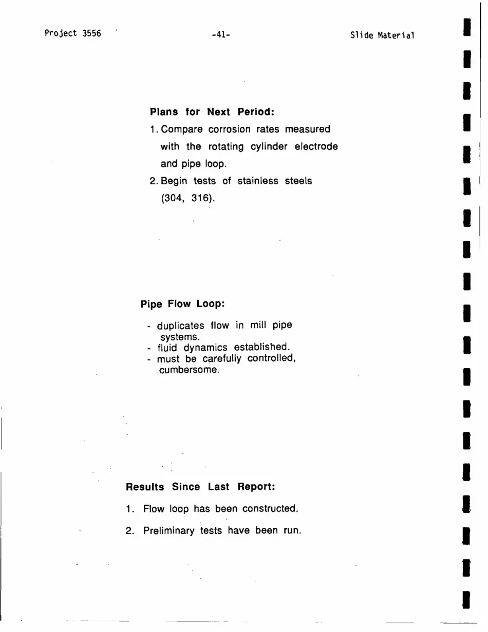
Slide Material
Plans for Next Period:
1.Compare corrosion rates measured
with the rotating cylinder electrode
and pipe loop.
2. Begin tests of stainless steels
(304, 316).
Pipe Flow Loop:
- duplicates flow in mill pipesystems.
- fluid dynamics established.-must be carefully controlled,
cumbersome.
Results Since Last Report:
1. Flow loop has been constructed.
2. Preliminary tests have been run.
Project 3556 -41-

Slide Material
Construction of the flow loop has been completed.
Project 35,56 -42-

Project 3556
I r
-43-
U·;L-r '· i¼
f~j4·
Slide
i.A
''. . J
atm
The test section showing the test pieces and the Teflon space
Short pipe sections will be used in the flow loop to measure corrates by weight loss.
e Material mII
III1I
'rs. I
III
A\gA,2E, . II
Irosion
I

Project 3556 -
Pipe Flow Loop
Future Work
Determine whether-corrosion on rotatingcylindrical electrodes correlates withpipe flow corrosion.
Objective:
Technique:
STRESS CORROSION CRACKING
To determine the reasons for differencesin susceptibility to stress corrosioncracking between digesters.
Slow strain rate tests of carbon steelinliquors sampled from mills.
The slow strain rate technique:
- Waisted cylindrical tensile specimens are pulledslowly to failure in the environment of interest
- The result:Cracking: short test; little reduction in
X-section, extensive cracking
No cracking: long test, ductile failure
The susceptibility to cracking dependson the corrosion potential.
Result - The potential range for crackingvaried from mill to mill.
Slide Material-44-

Project '3556
0.330
w;U)I
-j
I.-zI-
a. -
0.190
0.050
0.090
-0.230
-45-
% REDUCTION IN DIAMETER20 30~ 40 s0
3 4 5 6 7 vLOGARITHM OF CURRENT DENSITY, nA/cm2
0 50 100NUMBER OF CRACKS
S 1i ide%: Mat er ial1
%.REDUCTION IN DIAMETER20 30 40 50
To1
>2--
K- K
Kxx 2~
4 5 6 7 -LOGARITHM OF CURRENT DENSITY, nA/cm2
MILL P6p Separator Liquor
0 50 100NUMBER OF CRACKS
MILL M5Top Circulation Liquor
K
K x
-K---
/-zz-K
IIIIIIIIIIIIIIIIIII
0.330
0.190w
4
zI.-0a.
0.05q1
-0.090
-0.230

Project 3556 -6
% REDUCTION IN DIAMETER
-.0 10 . 20 . 30 40
3 4 5 6 7 -8 V-
LOG OF CURRENT DENSITY. n'A/cM 2
50
0 20 40
NO. OF CRACKS
% REDUCTION IN DIAMETER
20 30 40 50
4 5 6 7LOG OF CURRENT DENSITY. nA/cm2
IAV
0 50 100NUMBER OF CRACKS
Slide Material
0.33
0.26
- 0.19
(A 0.12
> O....-002
I-
zWu -0.09
0a. *0.16
-0.23
-0.30
MILL E9Top Circulation Liquor
S
5/,,
a 0.2~(A)
s 0.11
-j 01.4I-Z -0.1wu
I-0IL -0.2
-0.4
MILL HIO1Top Circulation Liquor

Project 3556 -47- Slide M
% REDUCTION IN DIAMETER
10 20 30 40
LOG OF CURRENT DENSITY. nA/cm2 NUMBER OF CRAC*?
% REDUCTION IN DIAMETER10 20 30 40
3 4 5 6 7
log CURRENT DENSITY (i), nA/cm2
later ial INIIIIII
U:KS I
IIIIII
IIIII
u,
wn
-
pzI-uJ
0a.
U)0.
0.
< -O.
-0.I-0 -0.:CL

Project 3556 Slide Material
SLOW STRAIN RATE TESTS:
- Organics in real liquor may have
inhibited SC crack initiation.
- Major inorganic species determine the
range for cracking, but not necessarily
the severity.
- Higher NaOH, Na2S and Na2S203 concen-
trations increase SCC susceptibility and
narrow the cracking range.
SIGNIFICANCE TO THE INDUSTRY
* CORROSION MONITORING METHODS MAY BE APPLIEDRELIABLY IN WHITE LIQUOR SYSTEMS.
* EFFECTS OF MAJOR LIQUOR CONSTITUENTS ONCORROSIVITY OF WHITE LIQUOR HAVE BEENDETERMINED.
* SOME OPERATING PARAMETERS WHICH INCREASECORROSION RATE HAVE BEEN IDENTIFIED.
-48-

Project 3470
Project 3470
FUNDAMENTALS OF DRYING
Clyde Sprague
March 29, 1988
Slide Material-49-

Slide ;Material
Fundamentals of Drying
IMPULSE DRYING
Project 3470Project 3595
Clyde Sprague
IMPULSEDRYER
_Sheet
-Felt
PRESS SHOE
Proj~ct-3470 -50-

Project 3470
DISCUSSION
-51-
TOPICS
Slide Material
- OVERALL PROJECT PLANI- STUDENT WORK- ROLL DRYER START UP I- ROLL DRYER - 2ND NIP- CONTRACT WORK- CONVERSION ISSUES- FUNDAMENTALS - DELAMINATION
EXPLORATORY STUDIESEXPLORATORY STUDIES
BENCH-SCALE PERFORMANCEEVALUATION
FUNDAMENTALS OFMECHANISMS
PRELIMINARY ENGINEERINGCONCEPTS
PRELIMINARY ECONOMICANALYSIS
LABORATORY-SCALEPILOT EVALUATION
DETAILED TECHNICAL &ECONOMIC ASSESSMENT
I .!L,
III
r--------- .tI DETAILED GRADE-
SPECIFIC EVALUATIONS I II (By Individual CompaniesII or Groups [FKBG]) L -______ ___._-J
IMPULSE DRYING PROJECT PLAN
II
II
COMMERCIALIZATION(BY OTHERS)
I
I
I
I
i
I

Project 3470
STUDENT CONTRIBUTIONS
- RUDEMILLER - BOILING HEATTRANSFER
- BURNS-- EXPANSION PROCESSES
- BARTZ - ECONOMICS- ARNOLD - DENSITY PROFILES
- SANTKUYL - DELAMINATION- WADSWORTH - TWO-SIDEDNESS- ZAVAGLIA - FLASH X-RAYS
-52- SIA6,~ Mat eriial-

Project ,3470 -53-
PURPOSES
* DEMONSTRATE CONTINUOUS OPERATION
* ADDRESS ENGINEERING ISSUES
* REALISTIC TWO-SIDED DRYING
* DRYING UNDER TENSION
* MORE REALISTIC SAMPLES FOR PROPERTY TESTS
The laboratory pilot impulse dryer, the next major step in this project,will operate on a continuous basis to provide confidence and valuableinformation for the commercialization step.
Slide, Material IIIIIIIIIIIIIIIIIIm

Slide Material
FLOWSPREADER
SHOWERPICK-UP FELT L
SUCTION LBOX
V 1 i--
REEL
DOCTORPRESS _ BLADE s ROLL y" BACKIN
'~ bULL /l _ROLL
TURNINGROLL
SHOWER
WIRE
IMPULSE DRYER
a -heated roll
b -unheated roll
c- Infrared heaters
d - felt drive roll
s - felt guide roll
t - felt tension roll
u -vacuum box
w -water shower
x -paper test sample roll
r-reel
p -unwind drive roll
sl -slitterwt -web tension sensing rollsc -sheet sample catch tray
Si
N §rb% MdW
FURNISH
PILOT ROLL
r
I
Project 3470 -54-

S1 ide, Material
IMPULSE DRYINGOF LINERBOARD AND MEDIUM
FKBG PROJECT 2926-11
Project 3470 -55-

Project 3470. Slide Material
EVALUATION OFCONVERTEDPRODUCTS
ALTERNATIVE FURNISHESWITH GOOD PERFORMANCEAND ECONOMICS
DIRECT EVALUATION EVALUATION OFOF IMPULSE DRIED CONVERTINGCONTAINERBOARD PROCESS
FKBG PROJECT: PHASE II
EVALUATION OFCONVERTEDPRODUCTS
DIRECT EVALUATION EVALUATION OF IMPULSE DRIED CONVERTINGCONTAINERBOARD PROCESS
FKBG PROJECT: PHASE I
-56-

Slide Material I
II
MEDIUM
50 ms NRT
X
XLINER 50 msNRT
100 ms NRT
X
X
X100ms NRT X
FUTURE SURFACE QUALITYRELATED EXPERIMENTS
MEDIUM: GLUEABILITY
NEWSPRINT: PRINTING QUALITY TESTS
UNCOATED PRINTING PAPER: PRINTING QUALITY
LIGHTWEIGHT COATING RAWSTOCK:COATING PERFORMANCE
PRINTING QUALITY
(All grades will have water removal,strength performance evaluation
as in previous studies)
II
Control
Control X
IIIII
Project 3470- -57-

Project 3470Slide Material-58-
DELAMINATION
HISTORY OF DELAMINATIONOBSERVATIONS
- BURTON'S MS WORK- ARENANDER - WAHREN
- BURTON'S PhD WORK- DEVLIN'S PhD WORK
- IPC BENCH-SCALE WORK- IPC ROLL PRESS WORK
- CONTRACT WORK
IIIII
IIII
I

Project 3470 -59- ~~~~~~~~Slide Material
IMPLEMENTATION
External Momt source
Long Nip Press
MECHANISMS IN NIP
.HIGH-TEMPERATUREDENSIFICATION4
wEB
IFELT
III
Project 3470 -59-

Slide Material ';
POSSIBLE CONTRIBUTINGMECHANISMS
- FLASHING- ADHESION
- CENTRIFUGAL FORCES
c(0.
2wW.
uJ
a.
TIME (MSEC)
-
Project' 3470 -60-

moaNIM NOI.LVNIWiV13Ca V =10 .ld33NOO3 HL
MVI1 ~3N3Uis~bi dIN
U
MOGNIM~~~~~~~~~NOIIVNIV4V-13(1- 3~~~
%% % % % % %% %
...............~
........
* ~~~~....... m.z
-09,0Ld~~~~~~~~~~~~~~~~~~~S
I1131 09,0
cd~~~~~~~o
----td~fl LOH
I Ve'Aa~eW 2P!AS -9 L .~OA OLVE 43BCOJd -T9-

P-ro627 4Slide Material
GRADES TESTED TO DATE
LIGHTWEIGHT COATING
WRITING
NEWSPRINT
TISSUE
CORRUGATING MEDIUM
LINERBOARD-- VIRGIN KRAFT
- RECYCLED FIBER (100%)
- CMP (74 & 88% YIELD)
HEAT FLUX CONTROL
- HOT SURFACE TREATMENTS- HOT SURFACE TEMPERATURE- HOT SURFACE MATERIAL
- HOMOGENEOUS- LAYERED- BLENDED- GRADIENT
Project 3470,

Project 3470 -3S i de Mater ial-
200- . Ii.
J 590
IL570I.-
HEAT FLUX COPUATON
5s0 l430-20-10 0 10 2C
TIME. MLIBUECOND
Assume-Constant inital
temperatureinstW
* Semi-infinite slab
I1200WG
I 1-
-20-10 0 10 20 30 4MALUSECONDS
400
300
200
100
0-50 0 50 100 150
MIL.LISECONDS
'1500000
x-1250000 D
LL O-1000000 0
0U _wo2750000
0~~L -25000 <I--
U')-250000 3
200 250 300
III
600
500
II
0.a
LIL
Cl)w0.
IUIIIIIIII
-63-

Project 3470 -6-Sld atra
I-0
OilZI
zo
0 -a
z
2 -
0 -
-1-30 -20 -10 0 10 20 30
MILLISECONDS
1200000--
1000000-
800000-
600000-
400000-
200000-
0
-200000 --
-20E- J - -u -
-10 0 10 20MILLISECONDS
DROP TESTER
ELECTROHYDRAULIC PRESS
THERMODYNAMIC LIMITS(PRESSURE, TEMPERATURE)
INITIAL WATER SUPPLY AT SURFACE
x-jU..
0w0~00L.
0
I-
30 40
Slide Material-64-
I

Slide Material I
I
1500000
1250000
1000000
750000
500000
250000
0
-250000*-25 0 25
MILLISECONDS
VAPOR
- VENTING
RELEASE
- SURFACE
o35
I ui -
Z o
So
Z m
IIIIIII
50
RELEASE
IIIIII
TREATMENTS- ONE SHOT- CONTINUOUS
IIII
Project 347O.. -65-

Project 3470 -66Slide. Material
Porous Med~ium __'
FURNISH EFFECTS
ON
DELAMINATION'
IIII
-m-
x' I 4L
114'44411

Slide Material I
REFINING EFFECTS ON WATER REMOVAL46 1 / I
44
42
40
38
36 .I
200 300CANADIAN
400 500STANDARD
600 700FREENESS,
II800
ml
REFINING EFFECTS ON DENSIFICATION0.7 1 I
0.4 I -*200 300
CANADIAN400 500 600 700
STANDARD FREENESS,800ml
0V)
0n)
z
0us
m
I
o0
0.
L-E
U)CDZwa
0.6
0.5
IIII
II
IL
Project 3470 -67-

Prjc 40-68- SSlide Material
REFINING EFFECTS ON ZDT80
60-
40
20 -
0200 300
CANADIAN400 500
STANDARD600 700
FREENESS,
REFINING EFFECTS ON STFI30
20
10200 300
CANADIAN400 500
STANDARD600 700 800
FREENESS, ml
zwI-
O am N
zLUm NI-uJ
Z
800ml
EZ
I-Un
I
Project 3470

Project 3470
FACTORS TO BE INVESTIGATED
- HEAT FLUX CONTROL - VAPOR RELEASE- ADHESION - RELEASE- FURNISH ISSUES
- FURNISH TYPE- FURNISH CHARACTERIZATION- REFINING - FINES RETENTION- BASIS WEIGHT
-OPERATING CONDITIONS
II
MEASUREMENTS
- STFI - AS A DETECTOR- OTHER SHEET PROPERTIES - WATER REMOVAL- HEAT FLUX I- INTERNAL TEMPERATURES- INTERNAL COMPRESSION |- X-RAY RADIOGRAPHY- PERMEABILITIES |- WRV
II
-69- Slide Material

Slide Material
PLANS FOR NEXT SIX MONTHS
-CONCENTRATE ON DELAMINATION- FINISH SECOND NIP-BEGIN TWO-SIDED TESTS- CONTINUE CONVERSION TESTS- REDUCE CONTRACT LOAD
Project 3470 -70-

Slide Material
Project 3480
DISPLACEMENT DEWATERING
Jeff Lindsay
March 29, 1988
Project 3480 -71-

Project 3480-72- Slide Material
/Hot metl surface
-------- -x=L^^^^^ ^A A^^^^^^^^^^*A * ^ ^f'^f'^^f^^^^^ ^ ^^
..............Displacement in paper during impulse drying.........
Unusual FSteatures:I temp ., pressure, and velocity are unknown Wkng allowed to our: heat ppe mehansm
- MIPP$ -
Interface location changes with each time step
Interface temp ., pressure, and velocity are unknownWicking allowed to occur: heat pipe mechanism
III
I

Project 3480-73- Slide Material
Moving Interface Problems in Porous Systems- MIPPS -
Numerical Approach:
*Fully implicit
*Staggered grid structure
*Moving, nonuniform grids (denser near interface)
* Cubic spline interpolation
* Compressible form of SIMPLE pressure corrections
*Under-relaxation on variables and interface conditions
* Gas and liquid phases solved sequentially
* Coupling achieved iteratively
*Interface equilibrium maintained at each time step
IIIIIIIIIIIIIIIIIII

Project 3480-74-
II
MODIFICATIONS TO MIPPS:REVIEW OF THE SHARP FRONT APPROXIMATION
1. While often used in displacement studies, theI|~ ~sharp front approximation is not rigorously correct.
Smooth curves of variable saturation exist.
C /
Distance -
2. For phase-change processes in porous media, thesharp front approximation becomes realistic at highvalues of heat flux.
1.0
Dimensionless heat flux
Dimensionless height of two-phase zone versusheat flux. From experimental data of Udell, 1983.
3. For displacement with low rates of heat transfer,MIPPS must account for a broad two-phase regionwithout a sharp moving boundary. This is now being done.
Slide Material
1

Project 3480
0o
0)
a)QEI--
180
160
140
120
100
80
60
40
0
-75-.
5 10 15
Slide Material
20
Distance from the top (cm)
Temperature profile of 65-100 mesh Ottawa sand:porosity of 0.38, average saturation on 0.51, heat fluxof 1510 W/m2. From K. S. Udell, J. Heat Transfer, 105:485-492 (1983).
Heat in
4UU4vapor out
liquid in---- ^
Udell's experimental apparatus showingvarious zones.
II
I I I I25
IIIIIIIIIIIIIIIII

-76-Project 3480
MIPPS Predictions
1.0
EE
0ocF0co0(00
c)0
%I-.
0)CO
0.8
0.6
0.4
0.2
0
Slide Material
Time, sec.
Interface movement in three MIPPS predictions withdifferent permeabilities. Each case used a surfacetemperature of 600°K, an effective pore radius of 5.Oum,a sheet thickness of 1 mm, and a water resupply rate of0.5 kg/sm.
0 5 10 15 20 25
Time, ms
Effect of water resupply rate to surface oninterface motion in MIPPS predictions.Permeability was 1.0x10 -1 5m2; surfacetemperature was 600°K; and the effectivepore radius was 5.0 rm.
EE
0CJO
(00O
a)0C0It0)
4-C
0.4
0.3
0.2
0.1
0

Project 3480Slide Material
C
U
(J
LC
3.0
-- 2.0
0° 1.0 Q =1. x10 140 0.01 0.02 0.03 0.04 0.05
Time, sec.
Effect of permeability on gas-phase pressuredevelopment. Reflux ratio was 0.5 kg/smn andthe effective pore radius was 5gm.
6 5
Applied Pressure5 - ...... 4
Measured /' 41 Heat Flux / Y l MIPPS heat flux
4 rns= 1.0 kg/sm2 -3 >
3. Ii' ^^. m.S1L /1 MIPPS heat flux I \ uj
.1 mS= 0.5 ka/sm2 \ I1
0
-0.02 -0.01 0 0.01I
0.02 0.03
Time, sec.
Comparison of experimental heat flux data fromBurton [2] with two MIPPS predictions. MIPPSpredictions used K=1.0x10 '5m2 and waterresupply rates of 0.5 to 1.0 kg/sm?
I
IIII
IIII
III
-77-

-78-
Mounts to MTS hydraulic press
Gas in Gas in
Gas Pressure
Paper
FeltO-rin
Flow Out
Figure 1. Displacement dewatering equipment (gassupply valves and pressure chamber not shown).
Quickreleasevalve
MTS hydraulic/ system
Pressurerelief valve
Thermocouple -
Steam chamber
Heated upperchamber of'displacement dryer
Unheated lower/chamber
'Outlet\ \
Bleedline \
Support block
Schematic of the experimental displacementdevice operating with steam
Slide MaterialProject 3480

Project 348079-79- Slide Material I
ANISOTROPIC PERMEABILITY IN PAPER
The new displacement device can be adapted tomeasure both the x and y components of lateralpermeability in paper. The degree of compression canalso be controlled.
A round sheet of paper with upper and lowersurfaces sealed by contact with platen heads will beused. Dyed fluid will be injected at constant pressureinto the center of the sheet. The fluid will moveoutward towards the edge of the paper. After aspecified time, the process is stopped and the shape ofthe dyed region in the sheet is recorded. The size andshape of the dyed region gives the x and y componentsof lateral permeability.
4--=Outwardflow
Compressed air at constant pressure
Dyed fluid
IIIIIII
-I a
Outwardflow I
IAdaptation of MTS displacement head for measurementof lateral permeability in paper. I
I
r,

Project 3480 -do- Slide Material
90
2180 120 010
240 0L3300
270
Predicted boundaries of dye after 30 sec.of injection into the center of a saturatedsheet with strong anisotropy: K /Kx =3. Theboundaries of the sheet (r = 0.05m) exceedthe outer circle shown. (Test problem fromA247.)
RESEARCH OF A190 STUDENTS
Joseph Zavaglia - interface motion in impulse drying
James Burkhead - sheet density in impulse drying
Toshihiko Fukushima - felt flows

Project 3480 Slide Material-81-
RESEARCH OF DOCTORAL CANDIDATES
James Burns: wet pressing dynamics
Gary Rudemiller: boiling heat transfer in porous media
John McKibben: free-surface black liquor flows
Nick Triantafillopoulos: instabilities in a short dwell coater
FLUENTAS A TOOL FOR THE PULP
AND PAPER INDUSTRY
FLUENT, a computaional fluid mechanics codeby Creare, Inc., has been used extensively during thelast six months to solve a variety of fluid flow problemsrelated to the paper and pulp industry. It has also beenhelpful in the recent course "Flow Through PorousMedia" (A247).
RECENT APPLICATIONS OF FLUENT AT THE IPC:
* Study of flows in lateral permeability measure-ments in paper.
* Extensive analysis of flows in a short dwell coater(Nick Triantafillopoulos and Gary Rudemiller)
* Free surface flows in black liquor sprays (researchin progress: John McKibben)
* Reacting flows in a recovery boiler (DanSumnicht, Allan Walsh, Andy Jones)
* Heat conduction in an experimental device forthe study of impulse drying mechanisms (GaryRudemiller)

Slide Material-82-
Project 3479
MEDIUM CONSISTENCY PROCESSING
Dennis Spencer
March 29, 1988
Project 3479

Project 3 r.lal-83- 'iae MatE
OBJECTIVES
* TO DETERMINE TO WHAT EXTENT THE FIBER ORIENTATION CAN-
BE ACHIEVED DURING HIGH SPEED FLOW OF A CONCENTRATED
FIBER SUSPENSION IN'CERTAIN CONVERGING FLOWS
* TO COMPARE THE RESULTS OBTAINED IN THIS CASE WITH THE
BEST POSSIBLE, BOTH EXPERIMENTALLY AND THEORETICALLY
* TO ASCERTAIN THE RELATIVE IMPORTANCE OF FIBER-FIBER
INTERACTIONS AND TURBULENT FLUCTUATIONS IN DETERMINING
FIBER ORIENTATION DISTRIBUTION
lA170 - , . .. . ..

Project 3479 -84-Sl-ide Mateiri~l
EXPERIMENTAL PLAN
I
4.zcc
Csl
z
(i)
(+1+)
U
4I(+-)
INCREASING CONCENTRATION
*(CONCENTRAT ION/SPEED)
I
4:YIIIIIIIIIIIIIIII
I
a
i

Slide Material
EXPERIMENTAL PLAN
QUADRANT(Fig. 2) % CONSISTENCY
1 HIGH
2 LOW
3 LOW
4 HIGH
VELOCITY
HIGH
HIGH
LOW
LOW
FIBER-FIBERINTERACTION
+
+
Re # IMAGING
+ FXR
+ OPTICAL
- 'OPTICAL
- FXR
Project 3479. -85-

Ait)
(V)Y a
69'
rin
dA~ ON~
dAMOST
(dAlOST)
d-H
d-H
1II1
b31VM HonfblOR S3I9MN3 iN31VAiflO3
(%) HJ.9N31 3AVM
0'L LI 91 £1 If El
Le.L.AaWW RP [LS-9R -6LVC P38PO~d
I
iI.
IN'D I
9
I to'7
9.I
V31VM-H9nm1H1
S319V3N3 3AII33JJ3

(V) H1ON313AVM 0
SMI33V"JJ V1V3W 40 3ONVMOIOJd3d
~t[RIA,3jW apL LS -L
S .I VSt'.
0 L
0S
OL 'z I-.
00
aO
I
IIIIIIIIIIIIIIIIIII
6LVC'0COJ -IR-

Project 3479Sle.Meia
.5" DEPTH
1 to
TEST SECTION
~ ...X . - ., .25". .5',
IIIIIIIII
SI i de';, Mated al --88-

S/W SI 22 5L % 91V~LJ
S/W 1.I 9
S/W 91I 22 9L
S/W SI L v 9L
AUN=LLbNNUU 'JUldV'JflOAHiUN31 8391IJ
II
sIxv-x
'SIXV-A
I.
S3'JOZ
16LVC 1.D~COJdI
% 89TVNimeJ
% 9*9
% 9'6
Iv*, VI
AJJOO13A
IINN LI
(0' I.z v)(Lzv'o)
% St"ZVIVIZ
�JP Wa4PW�.ap� LS -6R-

Project 3479 Slide Material-90-
IIIII
TRACER FIBER
STREAMLINE
I

Project 3479
so0
so
4 .0
W20
0
460
30
r
mI
AI0w
±0
0
24
20
5I ± 2
U
4
0
20
is
r
ZIIIwI
la
e
4
0
-91-
F . - . HI atoerain -
-'-I ~ ~ ~ ~~Z
0 2 4 6020±0z zz z~~~ S2HCS. ..ts.
0 ~~20 40o6 SO ±00
ZZ -Z~~~~~~~~~~~~~~~~~~~~-
15
f
5
I
Iw
.3
2
I
a40 60 0A.DSGMCH82..C.+p,.+
Slide Material
ZI
ZIZZ::ZZ
I
I
SO0

Project 3479 Slide
SEPARATION ANGLE1MM FIBER LENGTHUELOCITIES
U1l 15 m/s
U2- 7.5 m/s
50 40 30 20 10 0
ANGLE TO STREAMLINE
SEPARATION ANGLE2MM FIBER LENGTHUELOCITIES
IU= 15 m/s
U2= 7.5 m/s
UV
U2 \
\4 /
/11111 \I I I I I I I I I I50 40 30 20 10
ANGLE TO STREAMLINE
Material I
IIIIIIIIIIIIIII
III
-92-
ZONES
1
K 2
/
3
//

-93-
Project 3471
PROCESS MODELING AND SIMULATION
Gary Jones
March 29, 1988
Project 3471 Slide Material

Slide Material-94-
PERFORMANCE ATTRIBUTE
* MODEL DEVELOPMENT- DATA ANALYSIS- MODELS
* MODEL VALIDATION
* IMPLEMENTATION
DATA ANALYSIS
ALEXANDER & MARTON
TMP MILL
WMU
SETTERHOLM,FLEISCHMAN
KIBBLEWHITE,CLARK, ETC.
YIELD, CWT, REFINING (CSF), WET PRESSING
YIELD, REFINING, SCREENING, CLEANING
CALENDERING, SPECIES MIXTURES, MACHINECONDITIONS
ORIENTATION ANGLE, WET STRETCHING
MODEL VALIDATION
Project 3471

Project 3471 -95- Slide Material
ALEXANDER AND MARTON DATA
CONSTANTS SPECIES, PULPING TYPE, KAPPA NO., BLEACHING
INDEPENDENT VARIABLESCELL WALL THICKENESS (1.8, 3.5 p) CWTYIELD (48-60%) YREFINING (30-700 CSF) CSFWET PRESSING PRESSURE (0-9200 psi) P
I
IDEPENDENT VARIABLES
SHEET PROPERTIES |
DENSITY
MODULUS
BREAKING LENGTH 3BURST, TEAR
RUPTURE ENERGY 3ELONGATION AT BREAK
SCATTERING COEFFICIENT |
SINGLE FIBER PROPERTIES |
MODULUS
BREAKING LENGTH
FIBRIL ANGLE
SWELLING
CROSS SECTIONAL AREA I

Slide Material
MODELS DEVELOPED FROM A&M DATA
HANDSHEET PROPERTIES:
DENSITY (JONES)MODULUS (PAGE)BREAKING LENGTH (PAGE)BURST (JONES, VANDENAKKER)TEAR,
RUPTURE ENERGY (JONES)STRAIN AT BREAK (JONES)SCATTERING COEFFICIENT (MALMBERG)
FIBER PROPERTIES:
EFFECTIVE FIBERMODULUSTENSILE
(JONES)(JONES)
PROCESS:
SURFACE AREA VS. CSFBONDING COEFFICIENTRELATIVE BONDED AREACOMPRESSIBILITY COEFFICIENTS
-96-Project 3471

(% AA t7S9001 -tELO' = T
t4s = q5
VJ3IV 9NIfIWO2
(6/2w) dSj 21' -L'S6 =
(qs) ~Vj~fs~ 3idjioJdff OIWVNAGO~1cAH
oo/6 E2 ol go, -L
03/5 T1T 04 8' -
StaSSaA P9[[Pm)J3O44 6Uissa.id jam MOl 'JS) 46iL4 IP Ti
(8tV A) ZOO' + (9' -1M)) SO- =wL
ZWEVC1 + A £RLO0 + 1S3 998S0' -TT
(S'T-IMO) 9VT'1 + A&9 LLV700 + '9L' = n
qs (d Ld nd d
(d) AIISN3O 133HS
-L6-ILVE~ l3afOJd
I
-Ld
LeLJ84PW 9P�LS

Slide Material
WET PRESSING EFFECTS
Sb = Sbo f(P)
f(P) = 1 + MPN
M = e. 144 + .00177 CSF
N = .0003 CSF - .000515 Y
SHEET MODULUS
- CUNFIRMED PAGE MODEL
EfE:(- ) ( P k
) ( 1- -k )If B- (Page/Nissan)
k W Efk = PuG
P- PiRBA = -
PU - Pi
-98-Project 3471

iNVJSNOO iM~ndE
43
vivo sninaow b39Iu 319NIS IN~ ION 010
iMOSTT' + ASOLLVOOO' + 9VL' =-nd 03]C= 13
.LNViSNOO = 03 = n 43
WROJ bV3NIINON ( t -d- T ) 9C1 = 3
0~) (R39WIvw) RNO bV3NII (6T' -d) 90OT = 3
( 9 ) ( In ) ( Ld -nd) + Ld = O
43 -3
( 0d -d ) 03 =3
(paLJ~pOW)( V 8 -T ) ( nW -d ) 4 =j
sninoow 199R5
LetiaewN aptjsILt7E P.DfO-ld -66-
(96' = )
(96' =

Slide'Material
FIBER MODULUS
Ef = 172.4 + 0.55 (CWT * Pu -9)Kg
mm2(R2 = .89)
EFFECTIVE FIBER MODULUS IN SHEET Ef*
Ef* 58 (Ef - 172.4)Ef CWT g
Ef*
3Pu= 10.6 = Eo
BREAKING LENGTH (Z)
- PAGE MODEL CONFIRMED
12APugRBA b p L
P1(P-P 3)Zf = ( + P2 )
P1P2P3
(R2 = .85)
= 24.51 + .414 Y - 3.5 CWT= 3.37= .086
FIBER TENSILE (Zf)
Zf = 8 P1 = 9 (24.5 + .414 Y - 3.5 CWT)8 8
-Zf does not fit single fiber data well
1 9
Z = 8Zf(PAGE)
Project 3471 -100-

Project 3471 ~~~~~~~~~~Slide MaterialI-101- '
IBURST *(B)
VAN DEN AKKER MODEL
B = C (EI)i (TO +Trj
B = 5.1 (El)f Z
III(R2 = 0. 90)
ILINEAR MODEL
B = -15.1 + 10.175 Z (R2 = .92)
C = 5.6 - .127 CWT (1 + .0015 CSF)
STRAIN AT BREAK, (El)
El= 0.85 + .02677 Z - .177 E I(R2 = .85)
R.E. = 392 - 3O8E1(I - .237 Z) (R2 = .95)
ITEAR.
Tear =- 296 - 14 E -~B - 20.7p
IIII
IRUPTURE ENERGY (R.E.) I
I
(R2 = .8)
IIII
Project 3471 ,

Project 3471 -102-
SCATTERING COEFFICIENT (SL)
SLU SL = SLk (P- Pl) (R2 = .94)
SLu = 874 + .04 CSF - 77.5 CWT
SLK = 928 - 98 CWT - 6.6 Y
POROSITY (POR)
POR = A1 + A2/CSF
A1 = 0
A2 = 12000
OTHER EFFECTS
- APPARENT FIBER CRUSHING, DAMAGE AT HIGH PRESSURE
- REDUCED DENSITY, MODULUS, TENSILE
- NOT ADEQUATELY ACCOUNTED FOR
FLEISCHMAN DATA (IPC)
- SHEET ANISOTROPY (WET STRETCH, ORIENTATION)
- MODULUS (Ex, Ey, Ez)
- TENSILE (Zx, Zy, Zz)
- COMPRESSIVE STRENGTH (Cx, Cy)
- SINGLE SPECIES
Slide Material

(26 = b
.(96" = 8
.Z3 SL'x3 9L17 + Wt7 = 4
sz* Zj SL.X3 TS-S + SU = 03
(S1300W ilLISIIHM '~3939VH)
HIUN]~1S 3AISS3~dWOO
(EW7 = Z8 3 981 + QZZ* = ZZ
(L6- = *4aOD UO03 V6- = z8J) '3 EV'S + 99'E = R
(96- = *4DOO UOD 06- = z~) X399'9 + L6'9 = XZ
'AO0
k3 'X3 04 J[L~WLS 'kZ 4XZ
31ISN31
Zd (SM TVZO0 -~0 9C6ZO' 6CUT) +
d (90TVT -SM VZT') + LS?- = Z
d PUP bJO 'SM uaamlaq SUOL~joejUL -z
(86' = 3) SM*bO98Z'- bO 8Tt'V -6L'VT =dt3
(96' = 3b O-SMZ6'0 + bO 69-9 + V8-9 = dx
(S6' = b
Zb0SE9O + bo*SM ROL0 + SM E8S' -SEE' +3/ 3
sninaow
PLJ~e!~ W ap~tS -O-IV D~~ ILVE 438COJd -COT-

Slide Material
OTHER MODELS UNDER DEVELOPMENT
* IPC DATA (BRIAN BURGER)- EFFECTS OF REFINING, SPECIES- ANISOTROPY, MODULUS, TENSILE
* WMU DATA- CALENDERING MACHINE EFFECTS- PAUL ROZIK (A190 WORK)
BRIGHTNESS
CK = CLigXLig + CcellXcell + CextXext (cm2 /g)
Ccell = 7.5
Cext = 1.0
CLig = 250 to 350
Brightness =CKSK
+ 2(CK ) )iTK
OTHER MODELS
* OTHER COMPRESSIVE PROPERTIES (RING CRUSH, ETC.)
* FORMATION (GRABER & GOTTSCHING)
* LAMINATES
* EFFECTS OF UNUSUAL PULPING CONDITIONS
Project 3471 -104-
- CK )TK

Slide Material-105-
DENSITY MODEL VALIDATION
- FITS DATA OF
KIBBLEWHITE - KRAFT 4 NEW ZEALAND BEECH FPEICES (RANDOM)
FLEISCHMAN - BLEACHED KRAFT - DOUGLAS FIR, SPRUCE MIXTURES
TMP MILL (ASSUMED 100% YIELD, SPECIES UNKNOWN)
CLARK BLEACHED SULFITE (SPECIES UNKNOWN)
PERFORMANCE ATTRIBUTES
YIELD
KAPPA
L
o L
°w
K-FACTOR
CK ABSORPTION COEFFICIENT
R ANISOTROPY RATIO
Pv COEFFICIENT OF VARIATION INSHEET DENSITY
Pf
CWT
Ef
Zf
Pf
I
I
Project 3471

-106-
DATABASE DEVELOPMENT
SOURCES:
*ISENBERG DATA
* IPC DATA SUPPLEMENT
* FPL
* LITERATURE
REQUIRE:
SPECIES
Ef
Zf
Pf
BENDING MODULUS
CWT
COARSENESS
COMPOSITION:LIGNINCELLULOSEHEMICELLULOSE
MODEL VALIDATION
TMP MILL DATA
FLOWSHEET DEVELOPED
MODELS VALIDATED
Project 3471 Slide Material

Slide Material
PROCESS MODELS
A1 A1= A + (Lin - A ) e-A1ZPA2 A2
°l = A3 - A4/L
ZP = 10(NSP-Ap)/Bp
(similar for W)
Sh = 1 - Xj In ( )1 K 1=1 2.4
K = KoeK2'NSP
k2 = f(NSP, Consistency, Ko)
Sh = a In (CSF) + b (high yield)
SCREENING AND CLEANING-SEPARATION EFFICIENCIES
HANDSHEET MODELS - VENKATESH
PROPERTY = f(long fibers, shives, CSF)
IIII
II
Project 3471 -107-,

Slide Material-108-
PROPERTY
BULK
BREAKING LENGTH
BURST
TEAR
SCATTERING
OPACITY
GURLEY POROSITY
ELONGATION ATBREAK
RUPTURE ENERGY
DRAINAGE TIME
WET WEBSTRENGTH
ABSORPTIONCOEFFICIENT
Z-D TENSILE
VENKATESH
10-20% LOWTOO SENSITIVE TOSHIVES
TOO SENSITIVE TOSHIVES
50% LOW
REASONABLE
REASONABLE
CLOSE
INACCURATE
NM
ND
, ND
ND
NM
NM
JONES*
CLOSENOT ASSENSITIVE
NOT ASSENSITIVE
CLOSE
2 X TOO HIGH
2 X TOO LOW
NM
REASONABLE
REASONABLE
ND
ND
ND
NM
REASONABLE+
MM NO MODELND NO DATA* EXTRAPOLATION TO 100% YIELD+ 8% SHRINKAGE
Project 3471

Slide Material
PROCESS MODELS
CSF
FIBER LENGTHDISTRIBUTION
SHIVES
L-FACTOR
SEPARATIONS
CONSISTENCIES
REASONABLE
REQUIRED MINOR MODIFICATION
GOOD MATCH
GOUD MATCH
REASONABLE EXCEPT AFTER MANY STAGES
REASONABLE EXCEPT AFTER MANY STAGES
IMODIFICATIONS
ALTER LOG NORMAL DISTRIBUTION (HYRFN1)
LOCAL REVERSIBILITY IN SEPARATIONS (HYFRAC)
FINES LEAKAGE OPTION (HYFRAC)
I
I
-109-Project 3471

Project 3471 -110- Slide MaterialSHEET MODULUS - DENSITY AND FREENESS
CWT 3.8p Wet Pressing Pressure 30psiYield 60% Norwegian Spruce
1
800
8
6
4
2
0

Project 3471 -111- Slide Material
400 600
I
0.5
0.4
0.3
0.2
0.1
II
I
0
0 200 800

Slide Material
-112-
density, g/cm3
Project 3471

Slide Material-113-
0.82 0.92
180
150
120
90
60
30
0
Project 3471
0.62 ·. 0.720. 42 0. 52

Slide Material-114-
8 112
24
20
16
12
8
Project 3471
16 20 24

3Slide Material
200
-115-
400 600 800
CSF
1
0.8
0.6
0.4
0.2
0
II
I
I0
Project 3471

Slide Material-116-
200 400
CSF
600 800
120
100
80
60
40
20
0
0
Project 3471

Project 3471 Slide Material-117-
200 400oo
CSF, mL
600 800
I
180
150
120
90
60
30
0
I
IIIIIIII
0

Slide Material
-118-
VARIATION IN MEASURED FIBER COMPONENTSTHROUGHOUT PROCESS
POSITION
1 SECONDARY REFINER DISCHARGE
2 PRIMARY SCREEN FEED
3 PRIMARY SCREEN ACCEPTS
4 PRIMARY SCREEN REJECTS
5 SECONDARY SCREEN ACCEPTS
6 REJECT REFINER DISCHARGE
7 PRIMARY REJECT CLEANER ACCEPTS
8 THICKENER DISCHARGE
Project 3471

U)
~~0o~0z
0~~~~~~~~~~~~
04 qt
I-~ ~ ~ ~
~ ~
~ ~
~ ~
~ ~
~ ~~~~~~~~~~~I
0'~~
~~
~~
~~
~~
~~
~~
~~
~~
~~
~~
~~
~~
~~
~~
~~
~~
~~
~~
~~
~~
~~
~~
~~
~~
~~
~~
~~
~~
~~
L
-4j
NO
IIOV
UA
IH9I3M
~
~ ~
~0~~~~~~~~~~~~~~~~~~~~~~~~~~~~~~~~~~~~~~0

z Z
Z
X
U)
U)
) U
) U
) L
LU
w w
w
2 0
02
N
q2
0 N
LL
E u
N q
r 1 U
U
.
06-4
t-0
--i C
0 0
0 0
0 0
0N
0
co (0
N*C
*V
- V
- ~~~~~~~~~NOI.LOllA
JIH9I3M
0
m
--
m -
m
m
m -
m
m -
-
4-)
C3)
4-A
-0
-4
0*00.
E00004.'
'O
*
-- -
I V
J-T
1-U
-
I -A
I L
.
-I-I I
I
1-4
(w-
.4-)0)
01-0-
I
-40
II

Project 3471 Sl idE-12 1-
0 2 ~~~~~~~~~46
Material IIIIIIIIIIIIIII
* II
-4 Ii-i-I8
50
40
30
20
10
0
0 2 6

Project 3471
0 2
79
69
59
49
39
Slide Material-122-
6 8

-123- Project 3471 ~~~~~~~~~~~Slide Materie
400
300
200
100
0
0 2 4 6
lIIIIIIIIIIIIIIIIIII8
Project 3471

Slide Material-124-
2 4
0.51
0.48
0.45
0.42
0.39
0.36
Project 3471
0 6 8

Project 3471 -125- Slide Mate
0
'rial
f m
I
II
Ii , I,.
I
I
8 1
5.3
5.1
4.9
4.7
4.5
4.3
I2 4

Slide MaterialProject 3471
4
106
86
66
46
26
-126-

Project 3471 Slide Material
0 2
-127-
4 6 8

project 34/ -128- Slide Material
2.8 ... .... ................
ELONGATION AT BREAKPROFILE
Pressure 60 psiaCWT 3.8 p
2.6 W
""Measured
- Simulation (Model Extrapolated / \to 100% yield)
2 .4 _...... ......................................... .......................... ..... .................................................... .......... ............................................ .................................................................2.4 . - . -.-
............................... ........................................................................ ....................................................................
'' + -\~ .'..- /' .--2 _ ........ ............ ................... ................. .
% /i //»
)
........... ........ . .. . ........ .. ........._............ .............. .......... ..... ........ . .... ............................ ........... ....
6 8
n ot __L NA7
0 2 4