p1-101 sludge dewatering & odor control at plant no. 1
TRANSCRIPT

P.O. Box 85298 • San Diego, CA 92186�5298 • (858) 535�0505 • FAX (858) 535�0757
6795 Flanders Drive • San Diego, CA 92121�2903
P1�101 Sludge Dewatering & Odor Control
At Plant No. 1
Orange County Sanitation District
HEI Project No. 181301
HEI Submittal #16139�01�01
OCSD Submittal #16139�001B
Submittal Data Regarding:
SPECIFICATION SECTION 16139
Cable Trays
It is hereby certified that the equipment/material shown and Helix Electric, Inc. marked in this submittal is that proposed to be incorporated Project No. 181301
into the project. It is in compliance with the contract drawings July 22, 2013
and specifications and can be installed in the allocated spaces. Revision 0
Dan Thomas – Project Engineer

P.O. Box 85298 • San Diego, CA 92186�5298 • (858) 535�0505 • FAX (858) 535�0757
6795 Flanders Drive • San Diego, CA 92121�2903
16139�001A – Cable Trays Submittal
Comments per Orange County Sanitation District Transmittal No. 00243
Engineer’s Remark #1: All tray mounting and support hardware shall be 316 stainless
steel.
HEI Response: Acknowledged.
Engineer’s Remark #2: Submittals shall have equipment provided clearly marked and
items not being provided clearly noted or crossed out.
HEI Response: Acknowledged.
Engineer’s Remark #3: Submittal contains steel ladder type T and steel ladder type cross
which shall not be used.
HEI Response: Acknowledged, both steel ladder type T’s and steel ladder type X’s have
been removed from the submittal.
Helix respectfully requests OCSD to review HEI’s comments and return submittal 16139�001B
“RNR”.
Regards,
Dan Thomas
Project Engineer
1
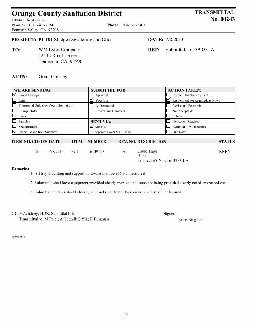
Orange County Sanitation District
Fountain Valley, CA 92708Plant No. 1, Division 76010844 Ellis Avenue
Phone: 714-593-7307
TRANSMITTALNo. 00243
Remarks:
PROJECT: P1-101 Sludge Dewatering and Odor DATE: 7/8/2013
TO: WM Lyles Company REF: Submittal: 16139-001-A42142 Roick DriveTemecula, CA 92590
ATTN: Grant Gourley
WE ARE SENDING:ü
SUBMITTED FOR: ACTION TAKEN:Shop Drawings Resubmittal Not RequiredLetter ü
ApprovalüYour Use Resubmittal not Required, as Noted
Transmittal Only (For Your Information) Revise and ResubmitAs RequestedChange Order Review and Comment Not AcceptablePlans SubmitSamples SENT VIA:
üNo Action Required
Specifications Attached Returned for Corrections
ü Other: Made from Submittal Separate Cover Via: Mail Due Date:
ITEM NO. STATUSITEM NUMBER REV. NO. DESCRIPTIONCOPIES DATE
RNRNSUT 16139-001 A Cable TraysHelixContractor's No.: 16139.001.A
2 7/8/2013
1. All tray mounting and support hardware shall be 316 stainless steel.
2. Submittals shall have equipment provided clearly marked and items not being provided clearly noted or crossed out.
3. Submittal contains steel ladder type T and steel ladder type cross which shall not be used.
CC:M.Whitney; HDR; Submittal FileTransmittal to: M.Patel; A.Coghill; S.Yin; B.Bingman)
Signed:Brian Bingman
Expedition
2
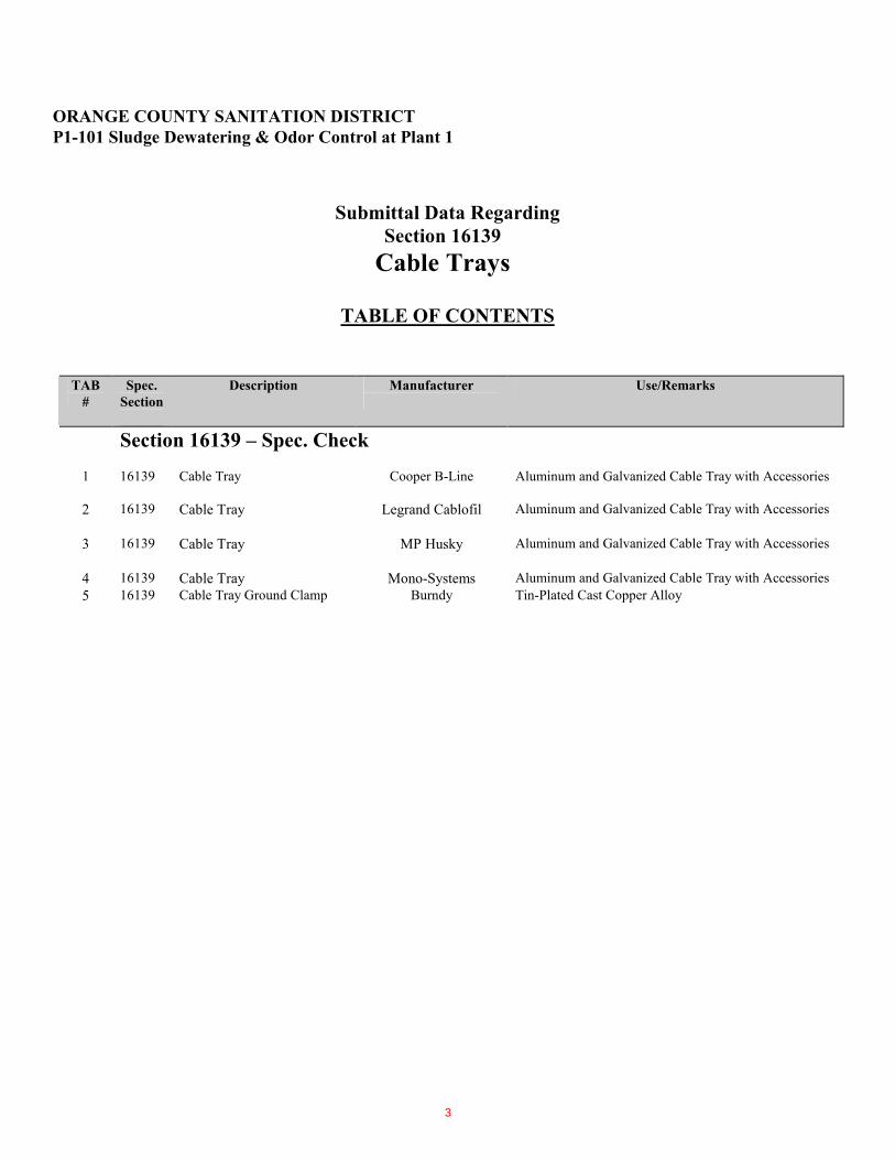
ORANGE COUNTY SANITATION DISTRICT
P1�101 Sludge Dewatering & Odor Control at Plant 1
Submittal Data Regarding
Section 16139
Cable Trays
TABLE OF CONTENTS
TAB
#
Spec.
Section
Description Manufacturer
Use/Remarks
Section 16139 – Spec. Check
1 16139 Cable Tray
Cooper B�Line
Aluminum and Galvanized Cable Tray with Accessories
2 16139 Cable Tray Legrand Cablofil
Aluminum and Galvanized Cable Tray with Accessories
3 16139 Cable Tray MP Husky
Aluminum and Galvanized Cable Tray with Accessories
4 16139 Cable Tray Mono�Systems Aluminum and Galvanized Cable Tray with Accessories
5 16139 Cable Tray Ground Clamp Burndy Tin�Plated Cast Copper Alloy
3

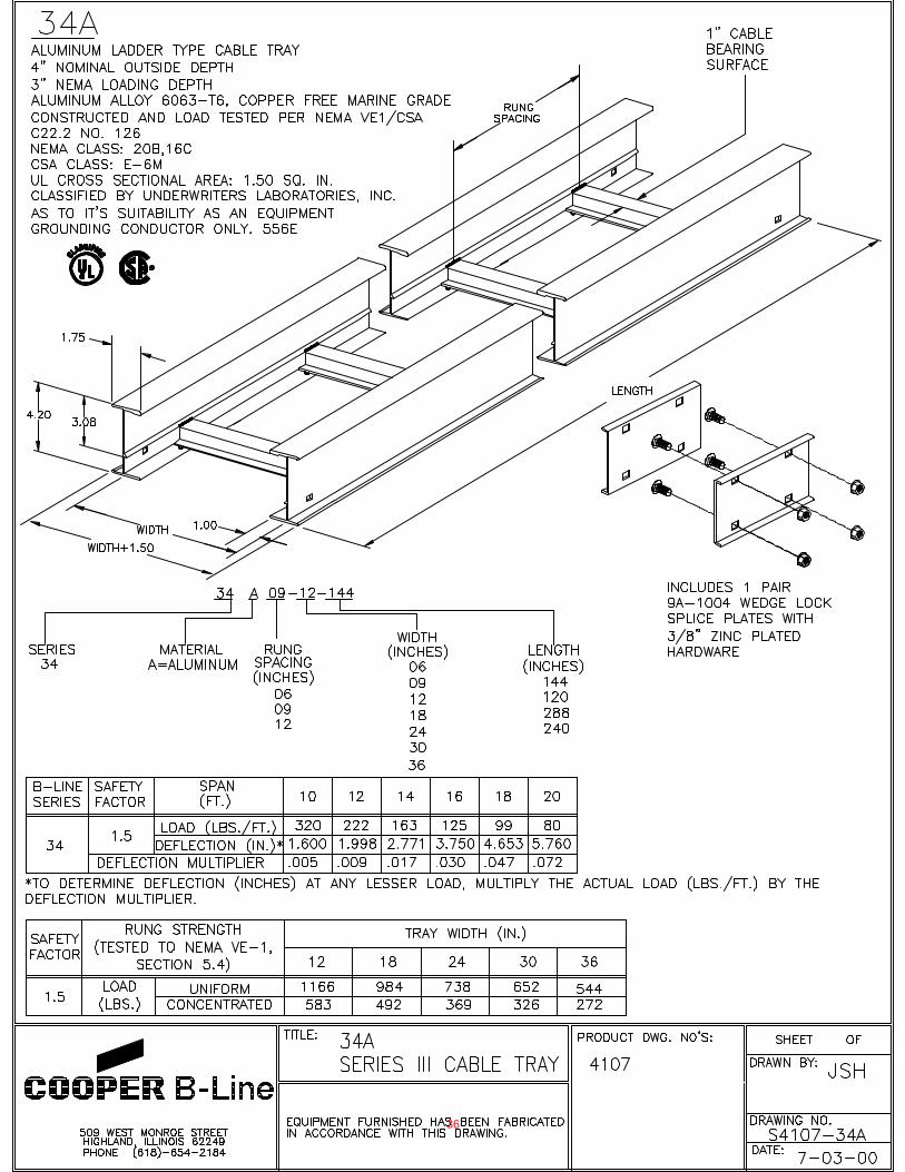
Sludge Dewatering and Odor Control at Plant 1 CABLE TRAYS Project No. P1-101 CONFORMED 16139-1
Section 16139
CABLE TRAYS
PART 1 - GENERAL
1.1 THE REQUIREMENT
A. The CONTRACTOR shall furnish all labor, tools, equipment, materials, and supplies to complete the Work as indicated on the Drawings and specified herein.
B. Cable tray systems shall include straight sections of cable trays, tray fittings, accessories, supports, and hardware.
C. Separate systems shall be required for power/control cables and instrumentation/signal cables.
1.2 RELATED WORK SPECIFIED ELSEWHERE
A. The requirements of the following sections and divisions apply to the Work of this section. Other sections and divisions of the Specifications, not referenced below, shall also apply to the extent required for proper performance of this Work.
1. Section 01332, Seismic Design Data
2. Section 16060, Grounding and Bonding
3. Section 16075, Electrical Identification Nameplates and Warning Signs
4. Section 16130, Raceway Systems and Pull Boxes
5. Division 16, Electrical, other applicable sections
1.3 REFERENCE SPECIFICATIONS, CODES AND STANDARDS
A. All Work specified herein shall conform to or exceed the applicable requirements of the referenced portions of the following publications to the extent that the provisions thereof are not in conflict with other provisions of these Specifications.
B. Comply with the applicable editions of the following codes, regulations, and standards:
1. Codes and Regulations:
29 CFR 1910 Code of Federal Regulations, Title 29, Part 1910, U.S. Occupational Safety and Health Standards (OSHA)
CCR California Code of Regulations, Title 8, Industrial Relations (Cal/OSHA)
CCR California Code of Regulations, Title 24, Part 2, California Building Code (CBC)
4

CABLE TRAYS Sludge Dewatering and Odor Control at Plant 1 Project No. P1-101 16139-2 CONFORMED
CCR California Code of Regulations, Title 24, Part 3, California Electrical Code
NFPA 70 National Electrical Code (NEC)
2. Industrial Standards:
NEMA VE 1 Metal Cable Tray Systems
NEMA VE 2 Cable Tray Installation Guidelines
3. Other Standards:
UL Underwriters Laboratories
C. Comply with the applicable reference Specifications as directed in the General Requirements and the Additional Requirements.
1.4 DRAWINGS
A. The Drawings show the general routing of the cable tray systems. Exact routing, locations, distance, and elevation shall be governed by actual field condition and equipment selected. The CONTRACTOR shall field-verify all dimensions, routing, etc. as part of the Work prior to construction.
1.5 CONTRACTOR SUBMITTALS
A. Submittals shall be in accordance with the General Requirements, Additional General Requirements, and as specified herein.
B. Product Data: Submit catalog cuts, bulletins, and brochures on the cable tray, fittings, accessories, supports, and hardware.
C. Layout: Submit cable tray system layout sketches if the CONTRACTOR proposes any changes in the routing.
D. Electrical Calculations: Submit cable tray fill calculations for each segment of the tray system if the CONTRACTOR proposes any changes in the routing of cables.
E. Structural Calculations: Submit structural calculations if the CONTRACTOR proposes any changes to the spacing or arrangement of the tray supports. Apply CBC requirements. Structural and seismic calculations shall be prepared, stamped, and signed by a state of California Registered Structural Engineer.
1.6 QUALITY ASSURANCE
A. Comply with the requirements specified herein and the applicable reference Specifications of the General Requirements and the Additional General Requirements.
5

Sludge Dewatering and Odor Control at Plant 1 CABLE TRAYS Project No. P1-101 CONFORMED 16139-3
1.7 DELIVERY, STORAGE, AND HANDLING
A. Deliver and handle cable tray components carefully to avoid damage and scoring finishes.
B. Store cable trays and accessories in clean dry space; protect from weather, damage, and construction.
PART 2 - PRODUCTS
2.1 MANUFACTURERS
A. Manufacturer: Subject to compliance with these Specifications, cable tray systems shall be as manufactured by Cooper B-Line, PW Industries, Or Equal.
2.2 CABLE TRAY SECTIONS AND COMPONENTS
A. General:
1. All cable tray material shall be listed by UL and bear the UL label or by an OSHA-recognized testing laboratory acceptable to the ENGINEER.
2. Provide complete metal cable tray systems as indicated; with straight sections, fittings, accessories, supports, and hardware. Construct units with rounded edges and smooth surfaces in the inside of trays.
3. Fiberglass trays, fiberglass covers and components shall be used only in locations to replace existing tray sections, covers and components as indicated on the Drawings.
B. Power/Control Trays: Provide ladder type tray sections and fittings made of structural grade copper-free aluminum. Side rails shall be “I” shape or “C” shape beams. Transverse members (rungs) shall be welded to the side rails. Rungs shall be spaced 9 inches on center. Spacing in radiused fittings shall be 9 inches and measured at the center of the tray's width. Rungs shall have a minimum cable bearing surface of 7/8 inch with radiused edges. Cable tray cover shall not be required.
C. Instrument/Signal Trays: Provide solid bottom cable trays and fittings constructed of hot-dip galvanized 10-gauge steel after fabrication. Cable tray cover shall not be required unless the cable tray is positioned directly below a power cable tray for more than 20 feet. This is to prevent spurious signals induced on the signal-level cables in the tray. Cable tray cover shall be hot dipped galvanized steel after fabrication. Secure cover to the cable tray with minimum of two heavy-duty, wrap-around type cover clamps for each 10-foot cover section. Fitting cover clamps shall also be provided.
D. Trays shall have 6-inch minimum usable load depth.
E. All straight sections shall be supplied in standard 24-foot lengths, except where shorter lengths are permitted to facilitate tray assembly lengths as shown on the Drawings.
F. Tray widths shall be 12, 18, 24, 30, or 36 inches, as shown on the Drawings.
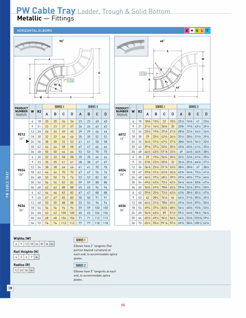
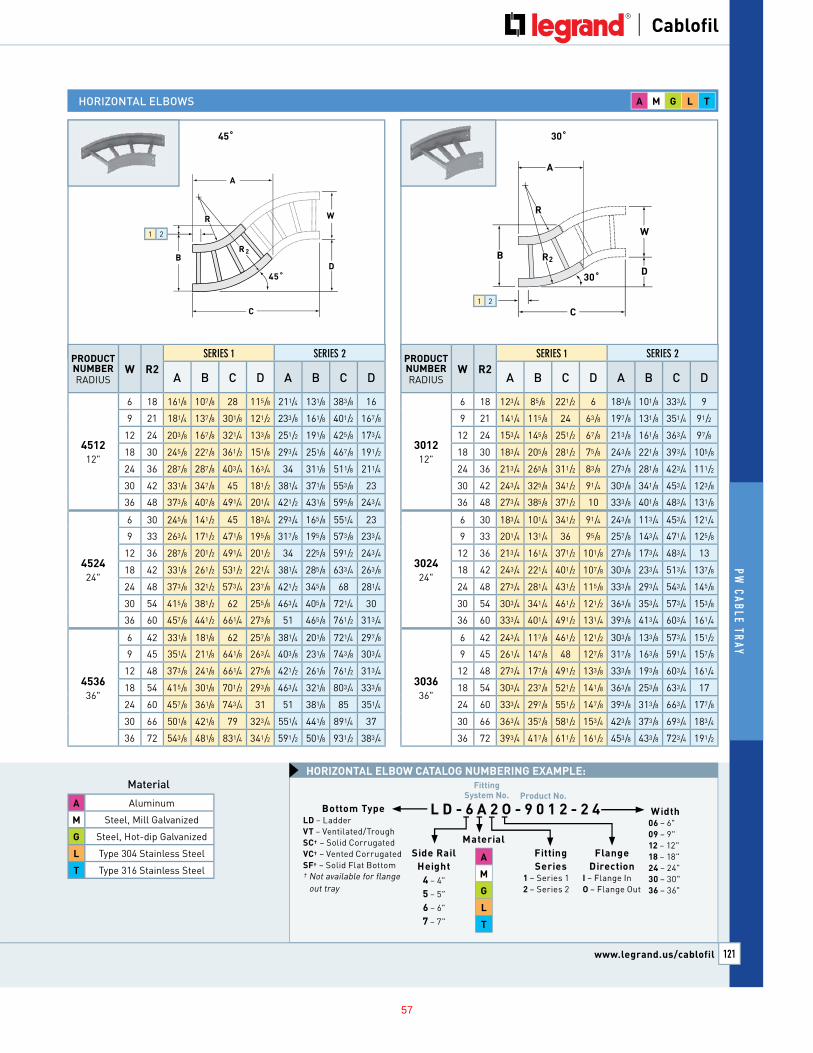
G. All fittings shall have a minimum radius of 12 inches.
6

CABLE TRAYS Sludge Dewatering and Odor Control at Plant 1 Project No. P1-101 16139-4 CONFORMED
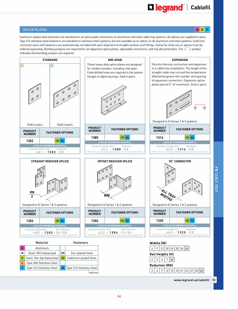
H. Splice plates shall be made of the same material as the straight section. The resistance of fixed splice connections between adjacent sections of tray shall not exceed 0.00033 Ohm. Splice plate construction shall be such that a splice may be located anywhere within the support span without diminishing rated loading capacity of the cable tray.
I. Each splice plate shall be attached with minimum of four ribbed neck carriage bolts with serrated flange locknuts.
J. Barrier strips shall be placed when required to separate power cable from control cable or as specified on the Drawings and be fastened into the tray with stainless steel hardware. Barrier material shall be the same material and thickness as the side rails.
K. Provide cable tray suitable for use as a grounding conductor in accordance with the NEC, California Electrical Code, and UL.
L. Provide minimum one Burndy Type GC-CT, Thomas & Betts, Or Equal, cable tray ground clamp for each section and each fitting. Ground clamp shall be tin-plated cast copper alloy to accommodate one or two conductors. Clamp shall be suitable for 4/0 AWG stranded copper conductor.
M. Cable tray support channels, wall brackets, tie-rods (threaded-rods), and support system hardware shall be in accordance with OCSD Standard Drawing S-420.
N. All cable tray mounting and support hardware shall be Type 316 stainless steel.
O. Cable trays shall meet NEMA class designation 20C.
PART 3 - EXECUTION
3.1 INSTALLATION
A. Provide cable trays as shown on the Drawings. Installation shall be in accordance with NEMA VE 2, manufacturer's instructions, and recognized industry practices to ensure that cable tray systems comply with requirements of NEC and California Electrical Code.
B. Coordinate cable tray installation with other electrical work as necessary for proper work sequence.
C. Span between cable tray supports shall be 10 feet maximum. Place no more than one splice between supports. Assemble cable trays so that joints are not made directly on support brackets. Cable tray fitting supports shall be located such that they meet the strength requirements of straight sections. Install fitting supports per NEMA VE 2 guidelines and in accordance with manufacturer's instructions.
D. Coat any scratches or cuts in the hot-dip galvanized coating with galvanizing paint that meets the manufacturer’s recommendations for repair.
E. Install trays so as to be level, straight and true to line or grade within plus or minus 1/8 inch in 10 feet and within an accumulative maximum of 1/2 inch. Make vertical structures plumb within a tolerance of 1/8 inch.
F. Install cable trays to leave no exposed raw edges to damage the cable jacket/insulation.
7
Sludge Dewatering and Odor Control at Plant 1 CABLE TRAYS Project No. P1-101 CONFORMED 16139-5
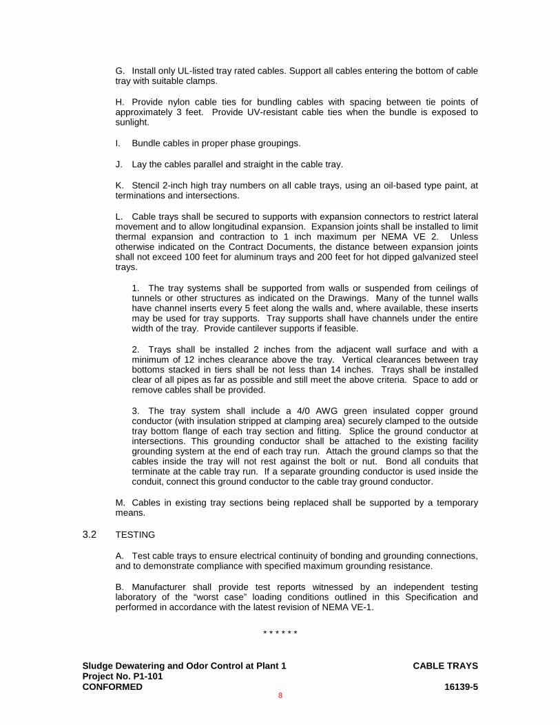
G. Install only UL-listed tray rated cables. Support all cables entering the bottom of cable tray with suitable clamps.
H. Provide nylon cable ties for bundling cables with spacing between tie points of approximately 3 feet. Provide UV-resistant cable ties when the bundle is exposed to sunlight.
I. Bundle cables in proper phase groupings.
J. Lay the cables parallel and straight in the cable tray.
K. Stencil 2-inch high tray numbers on all cable trays, using an oil-based type paint, at terminations and intersections.
L. Cable trays shall be secured to supports with expansion connectors to restrict lateral movement and to allow longitudinal expansion. Expansion joints shall be installed to limit thermal expansion and contraction to 1 inch maximum per NEMA VE 2. Unless otherwise indicated on the Contract Documents, the distance between expansion joints shall not exceed 100 feet for aluminum trays and 200 feet for hot dipped galvanized steel trays.
1. The tray systems shall be supported from walls or suspended from ceilings of tunnels or other structures as indicated on the Drawings. Many of the tunnel walls have channel inserts every 5 feet along the walls and, where available, these inserts may be used for tray supports. Tray supports shall have channels under the entire width of the tray. Provide cantilever supports if feasible.
2. Trays shall be installed 2 inches from the adjacent wall surface and with a minimum of 12 inches clearance above the tray. Vertical clearances between tray bottoms stacked in tiers shall be not less than 14 inches. Trays shall be installed clear of all pipes as far as possible and still meet the above criteria. Space to add or remove cables shall be provided.
3. The tray system shall include a 4/0 AWG green insulated copper ground conductor (with insulation stripped at clamping area) securely clamped to the outside tray bottom flange of each tray section and fitting. Splice the ground conductor at intersections. This grounding conductor shall be attached to the existing facility grounding system at the end of each tray run. Attach the ground clamps so that the cables inside the tray will not rest against the bolt or nut. Bond all conduits that terminate at the cable tray run. If a separate grounding conductor is used inside the conduit, connect this ground conductor to the cable tray ground conductor.
M. Cables in existing tray sections being replaced shall be supported by a temporary means.
3.2 TESTING
A. Test cable trays to ensure electrical continuity of bonding and grounding connections, and to demonstrate compliance with specified maximum grounding resistance.
B. Manufacturer shall provide test reports witnessed by an independent testing laboratory of the “worst case” loading conditions outlined in this Specification and performed in accordance with the latest revision of NEMA VE-1.
* * * * * *
8
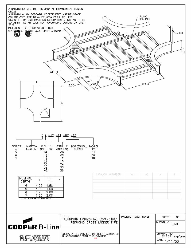
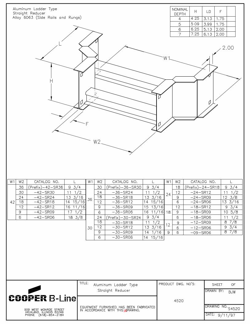
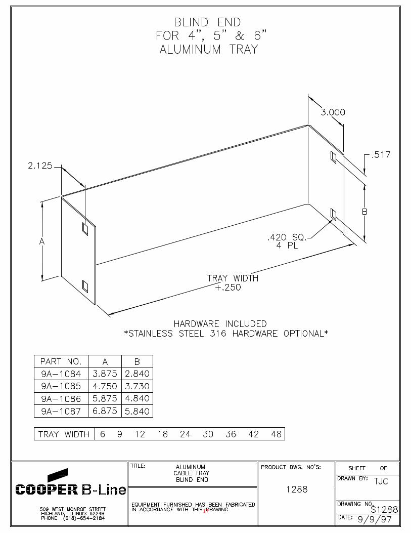
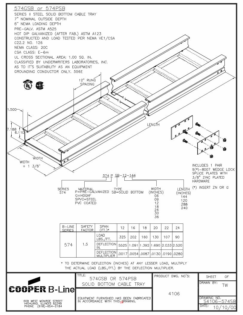
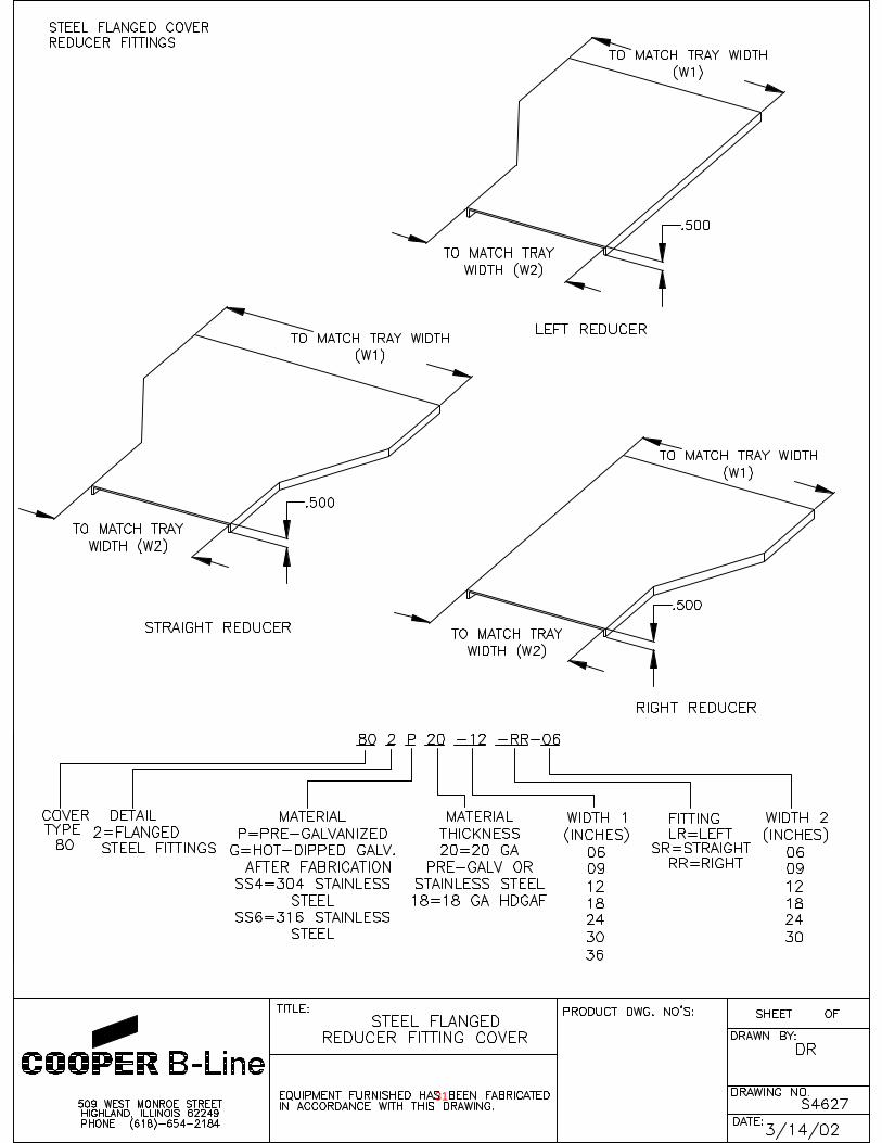
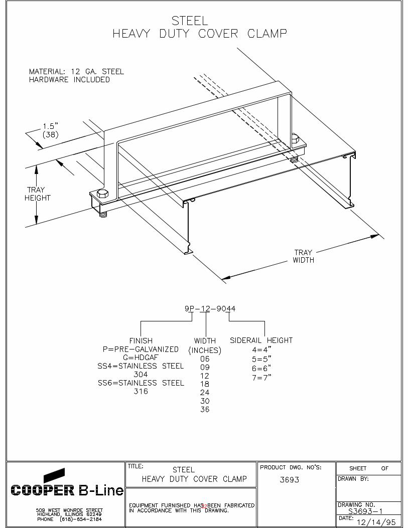
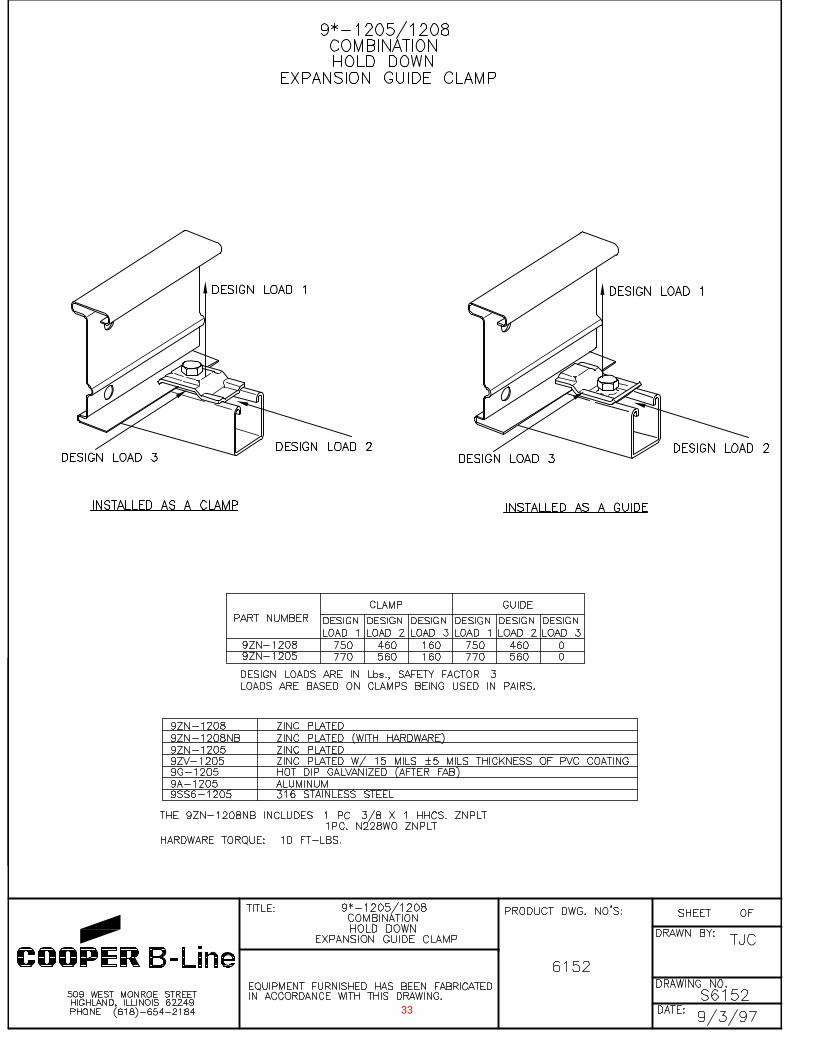
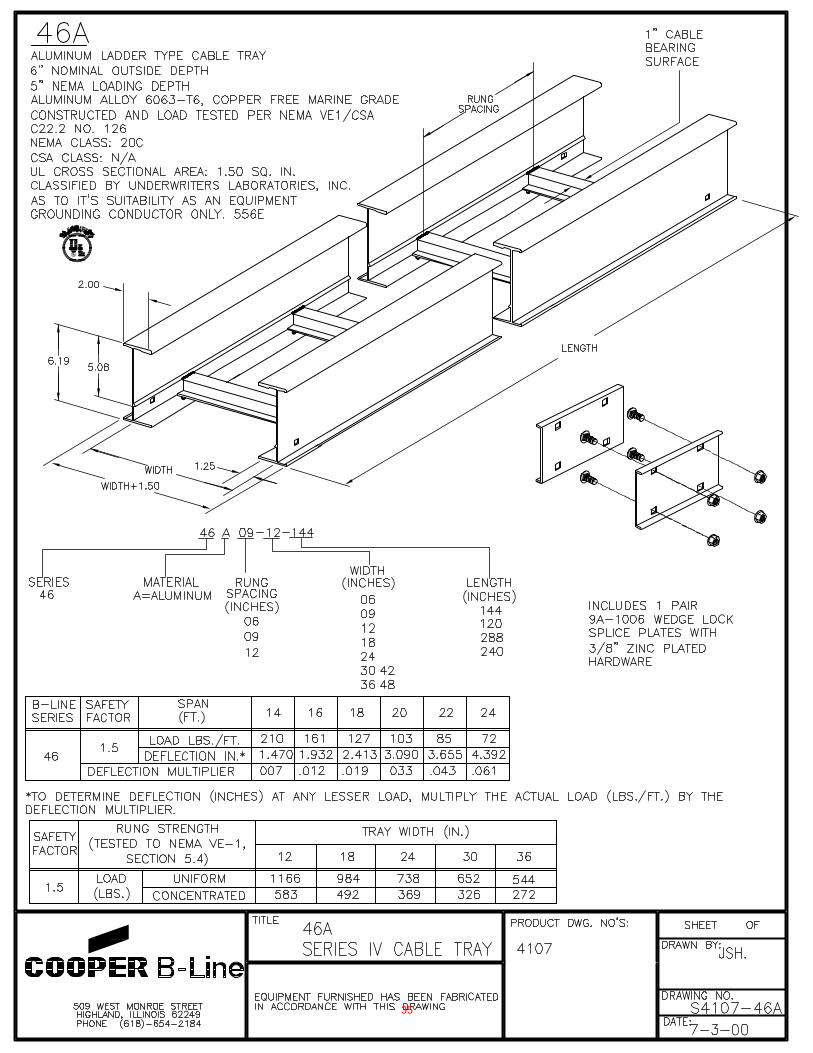
Tab #1
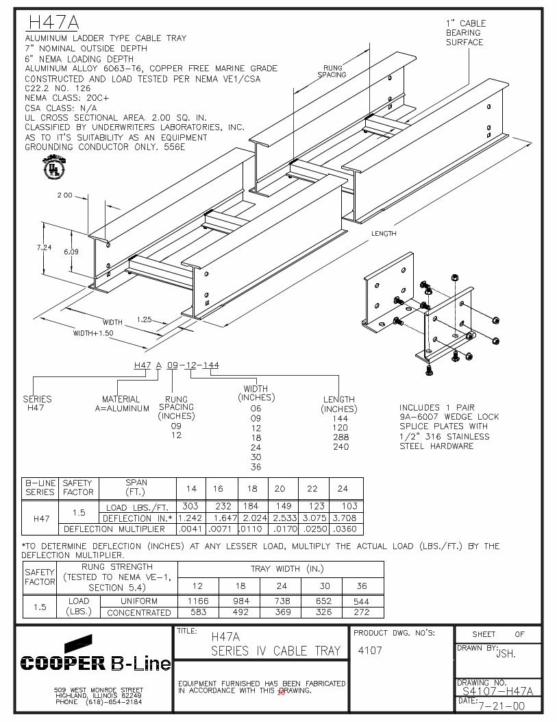
ORANGE COUNTY SANITATION DISTRICT (P1-101)
SUBMITTAL DATA REGARDING:
Cable Trays
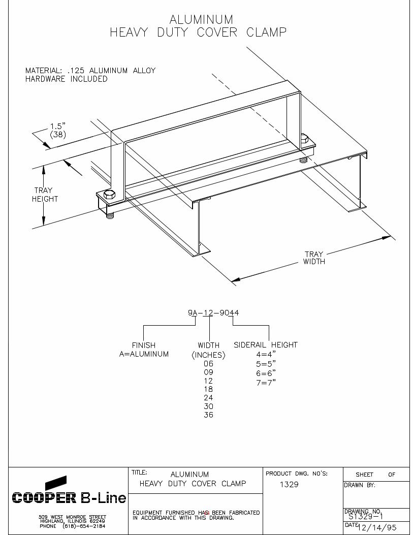
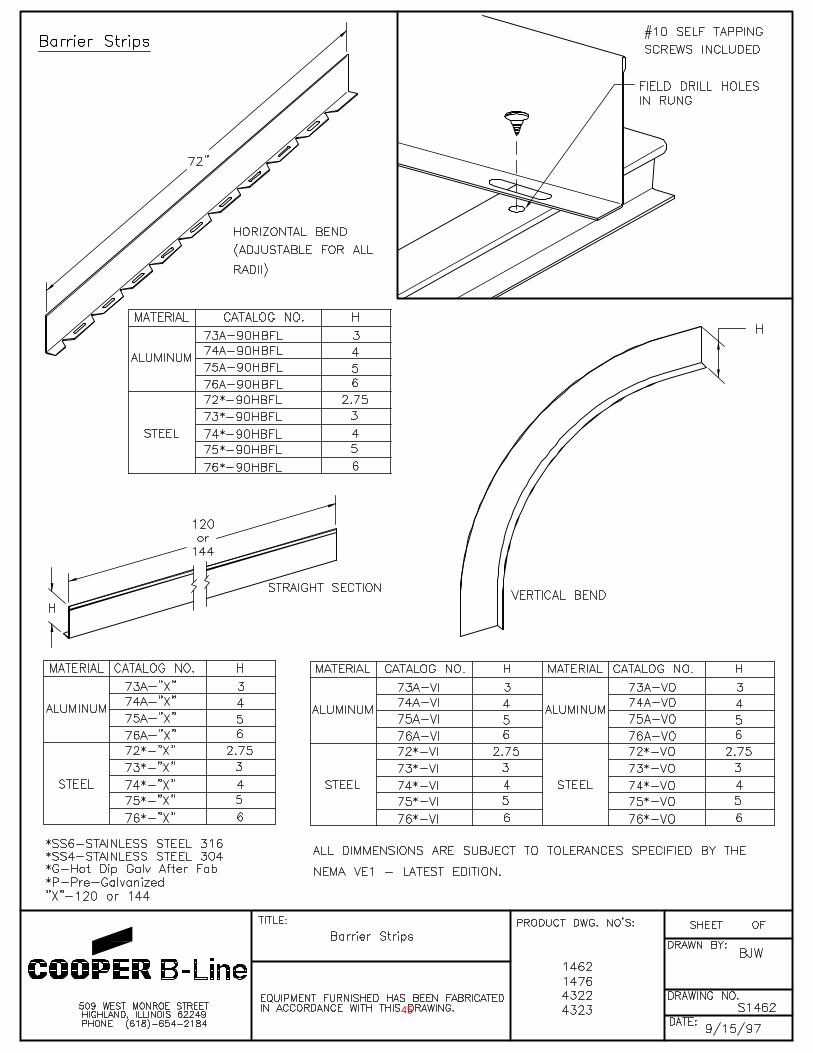
Cooper B-Line
9
10
11

12
13
14
15
16
17
18
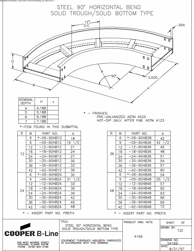
DRAWING S4169.DWG VALID FOR 14 DAYS FROM May 30, 200314:25:11
19
20
21
22
23
24
25
26
DRAWING S4104.DWG VALID FOR 14 DAYS FROM May 30, 200316:42:56
27
28
29
30
31
32
33

EXISTING TUNNEL WORK
34
35
36
37
38
39
40
41
42
43
44
45
Tab #2
ORANGE COUNTY SANITATION DISTRICT (P1-101)
SUBMITTAL DATA REGARDING:
Cable Trays
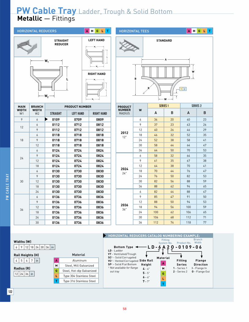
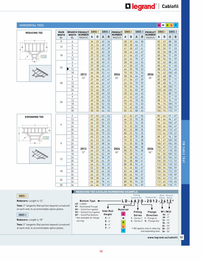
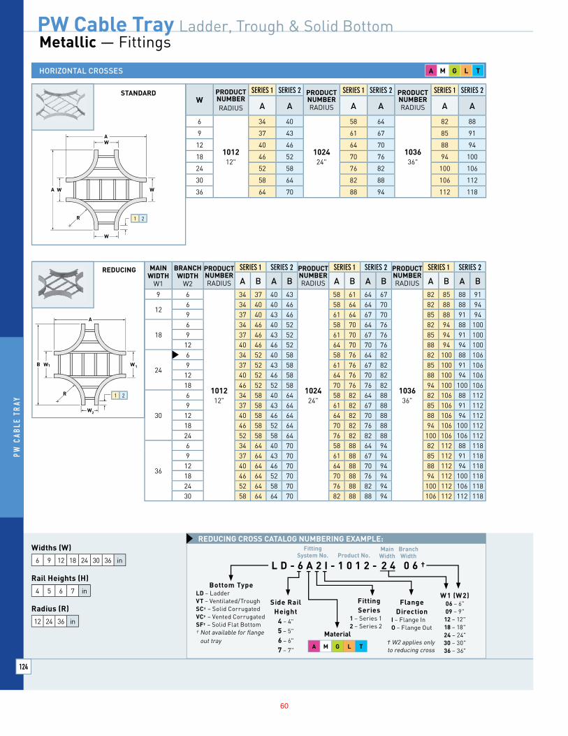
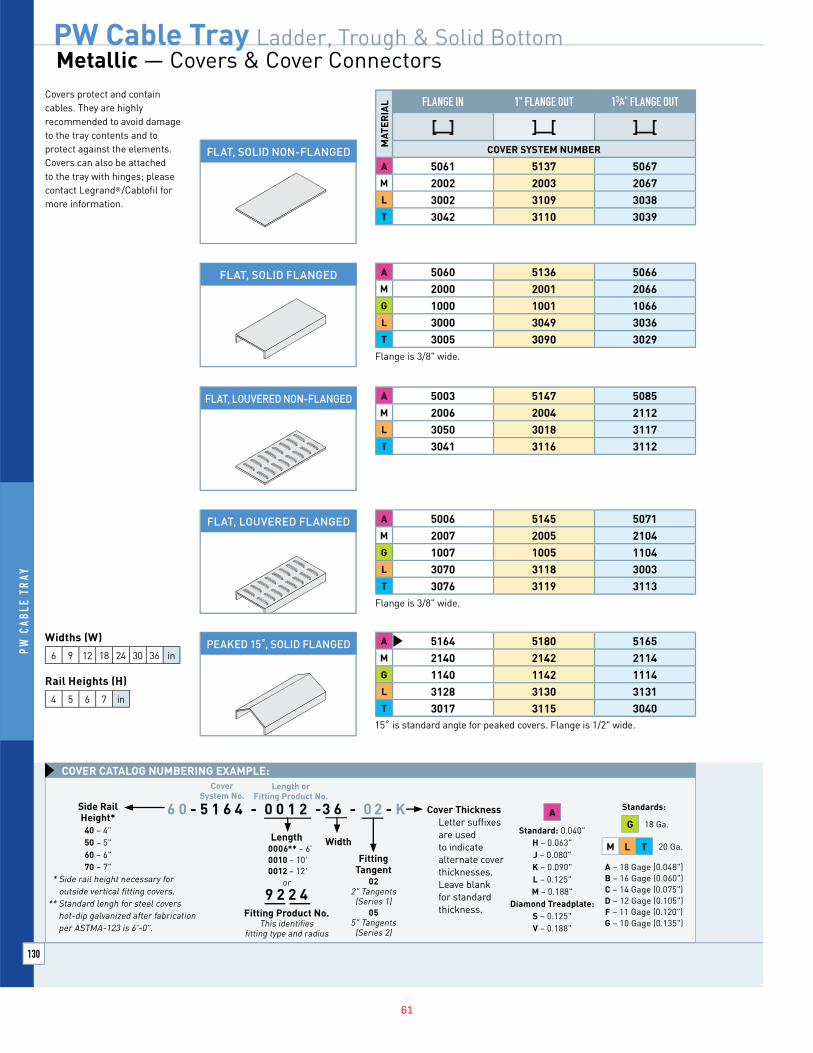
Legrand Cablofil (Formerly PW)
46
TRAY WIDTH(IN.)
TRAY WEIGHT* (LBS./FT.)
6 2.93
9 3.00
12 3.08
18 3.23
24 3.38
30 3.53
36 3.68
*Based on 9" rung spacing
SAFE LOAD DATAA ATT (LBS./FT.) / SUPPORT SPAN (FT.) / DEFLECTION (IN.)
6 8 10 12 14 16 18 20 22 24 26 28 30
526 0.30 400 0.55 278 0.78 204 1.07 156 1.40 123 1.77 100 2.18 81 2.57 66 3.00
Tray
System
Number
Length0010 – 10'-0"
0012 – 12'-0"
0020* – 20'-0"
0024 – 24'-0"* Standard
for Series 2
Width06 – 6"
09 – 9"
12 – 12"
18 – 18"
24 – 24"
30 – 30"
36 – 36"
CATALOG NUMBERING EXAMPLE:
0 9 - 4 7 3 2 - 0 0 2 0 - 3 6
1.00"
0.97"
0.28"0.28"
6"
13/4"
7" RUNGSIDE RAIL
FLANGE
TRAYAA SYSTEM NUMBER 4732RS
GENERAL INFORMATAA ION
NEMA TRAY TYPE: Two Rail Ladder
NEMA CLASS: 20C
CSA CLASS: E, 6M
MATERIAL: Extruded aluminum alloy 6063-T6
SIDE RAIL: 7" high with 1 3/4" top flange
LOAD DEPTH: 6"
BOTTOM: 1" wide box rung
FINISH: Plain
CONSTRUCTION: Arc welded
TRAY SERIES: Series 2 (5" tangent)
ENGINEERING INFORMATAA ION
TRAY DESIGN: Construction and markings are per the latest edition of NEMAStandards Pub. VE1, CSA C22.2 No. 126.
TRAY GROUNDING CAPABILITY: Classified as an equipment grounding conductor per N.E.C. 392.7 with a maximum 1600 ampere rating. UL Cross Sectional area: 1.50 in2
CONNECTORS: Supplied in pairs with hardware. Splice resistance is less than 0.00033 ohms. Standard hardware: 3/8 in.cadmium-plated with yellow zinc topcoat.Stainless steel hardware is available uponrequest.
MECHANICAL PROPERTIES:One rail: I x-x = 8.2632in3 S x-x = 2.5692in4
Bottom Type06 – 6" Rung Spacing
09 – 9" Rung Spacing*
12 – 12" Rung Spacing
18 – 18" Rung Spacing**
* Standard rung spacing
** Not CUL Classified
Aluminum A
RUNG CROSS SECTION
RAIL CROSS SECTION
CONNECTOR
Classified by UL
as equipment
grounding
conductors per
NEC 392.7. (UL File
No. E60796)
Legrand/Cablofil
trays marked with
CSA load class
have been tested
(loading, finish and
electrical) by UL to
CSA standard
126 22.2 .
PW Cable Tray
Legrand/Cablofil
Phone 800-658-4641
618-566-3230
Fax 618-566-3250
8319 State Route 4
Mascoutah, IL 62258 USA
Publication Date: 3/10
Copyright © 2010 Legrand/Cablofil47

48

49

50

51

52

53
54
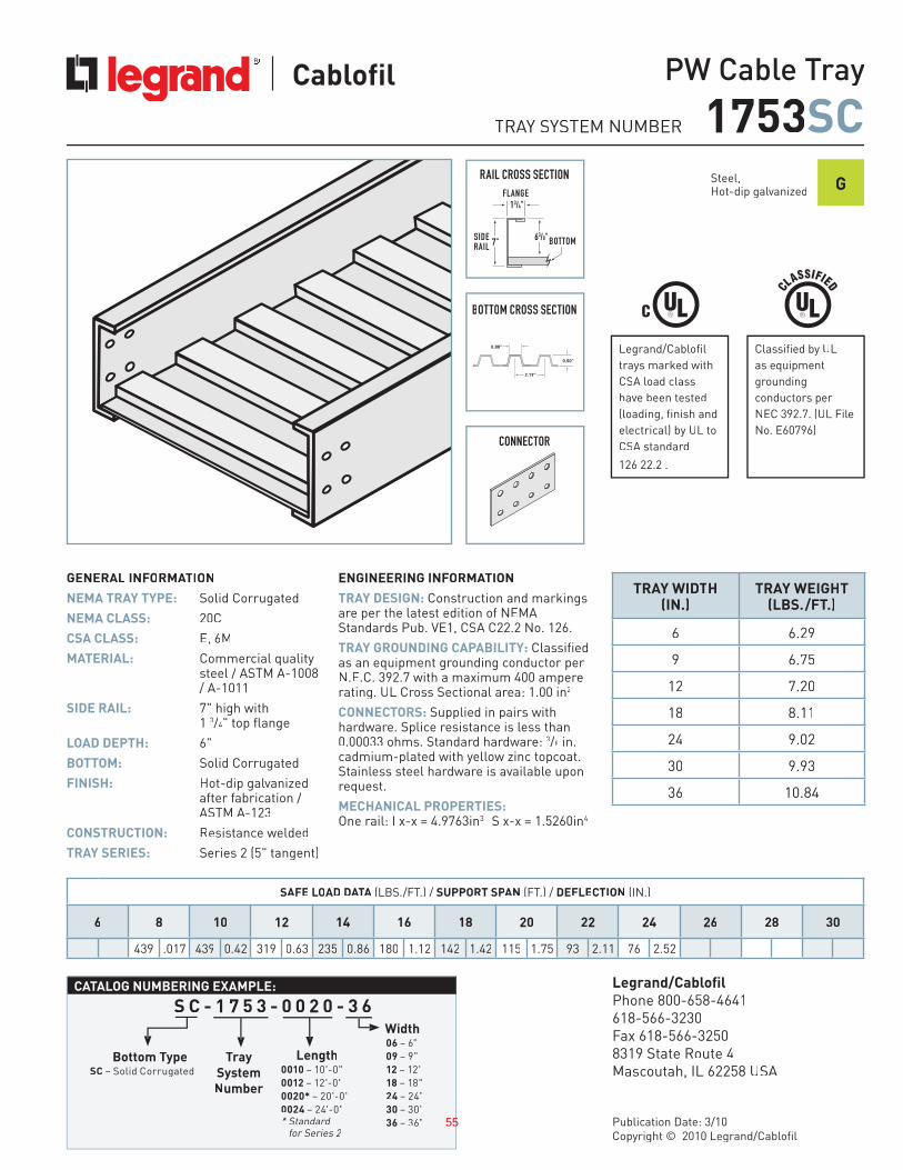
SAFE LOAD DATAA ATT (LBS./FT.) / SUPPORT SPANPP (FT.) / DEFLECTION (IN.)
6 8 10 12 14 16 18 20 22 24 26 28 30
439 .017 439 0.42 319 0.63 235 0.86 180 1.12 142 1.42 115 1.75 93 2.11 76 2.52
Tray
System
Number
Length0010 – 10'-0"
0012 – 12'-0"
0020* – 20'-0"
0024 – 24'-0"* Standard
for Series 2
Width06 – 6"
09 – 9"
12 – 12"
18 – 18"
24 – 24"
30 – 30"
36 – 36"
CATALOG NUMBERING EXAMPLE:
TRAY WIDTH(IN.)
TRAY WEIGHT(LBS./FT.)
6 6.29
9 6.75
12 7.20
18 8.11
24 9.02
30 9.93
36 10.84
Bottom TypeSC – Solid Corrugated
GENERAL INFORMATAA ION
NEMA TRAY TYPE: Solid Corrugated
NEMA CLASS: 20C
CSA CLASS: E, 6M
MATERIAL: Commercial qualitysteel / ASTM A-1008 / A-1011
SIDE RAIL: 7" high with 1 3/4" top flange
LOAD DEPTH: 6"
BOTTOM: Solid Corrugated
FINISH: Hot-dip galvanizedafter fabrication / ASTM A-123
CONSTRUCTION: Resistance welded
TRAY SERIES: Series 2 (5" tangent)
ENGINEERING INFORMATAA ION
TRAY DESIGN: Construction and markings are per the latest edition of NEMAStandards Pub. VE1, CSA C22.2 No. 126.
TRAY GROUNDING CAPABILITY: Classified as an equipment grounding conductor per N.E.C. 392.7 with a maximum 400 ampere rating. UL Cross Sectional area: 1.00 in2
CONNECTORS: Supplied in pairs with hardware. Splice resistance is less than 0.00033 ohms. Standard hardware: 3/8 in. cadmium-plated with yellow zinc topcoat.Stainless steel hardware is available uponrequest.
MECHANICAL PROPERTIES:One rail: I x-x = 4.9763in3 S x-x = 1.5260in4
63/8"7" BOTTOMSIDE RAIL
FLANGE13/4"
2.19"
0.50"
0.88"
S C - 1 7 5 3 - 0 0 2 0 - 3 6
TRAY SYSTEM NUMBER 1753SCRAIL CROSS SECTION
CONNECTOR
Steel,Hot-dip galvanized G
PW Cable Tray
Legrand/Cablofil
Phone 800-658-4641
618-566-3230
Fax 618-566-3250
8319 State Route 4
Mascoutah, IL 62258 USA
Publication Date: 3/10
Copyright © 2010 Legrand/Cablofil
BOTTOM CROSS SECTION
Classified by UL
as equipment
grounding
conductors per
NEC 392.7. (UL File
No. E60796)
Legrand/Cablofil
trays marked with
CSA load class
have been tested
(loading, finish and
electrical) by UL to
CSA standard
126 22.2 .
55
56
57
58
59
60
61
62

63

Tab #3
ORANGE COUNTY SANITATION DISTRICT (P1-101)
SUBMITTAL DATA REGARDING:
Cable Trays
MP Husky
64
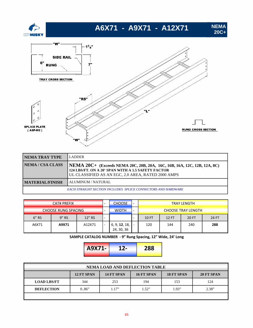
A6X71 - A9X71 - A12X71
CAT# PREFIX ‐ CHOOSE ‐ TRAY LENGTH
CHOOSE RUNG SPACING ‐ WIDTH ‐ CHOOSE TRAY LENGTH
6” RS 9” RS 12” RS ‐ ‐ 10 FT 12 FT 20 FT 24 FT
A6X71 A9X71 A12X71 ‐ 6, 9, 12, 18, 24, 30, 36
‐ 120 144 240 288
A9X71‐ 12‐ 288
SAMPLE CATALOG NUMBER ‐ 9” Rung Spacing, 12” Wide, 24’ Long
NEMA 20C+
NEMA TRAY TYPE LADDER
NEMA / CSA CLASS NEMA 20C+ (Exceeds NEMA 20C, 20B, 20A, 16C, 16B, 16A, 12C, 12B, 12A, 8C) 124 LBS/FT. ON A 20’ SPAN WITH A 1.5 SAFETY FACTOR UL CLASSIFIED AS AN EGC, 2.0 AREA, RATED 2000 AMPS
MATERIAL/FINISH ALUMINUM / NATURAL
EACH STRAIGHT SECTION INCLUDES SPLICE CONNECTORS AND HARDWARE
NEMA LOAD AND DEFLECTION TABLE
12 FT SPAN 14 FT SPAN 16 FT SPAN 18 FT SPAN 20 FT SPAN
LOAD LBS/FT 344 253 194 153 124
DEFLECTION 0..86” 1.17” 1.52” 1.93” 2.38”
65
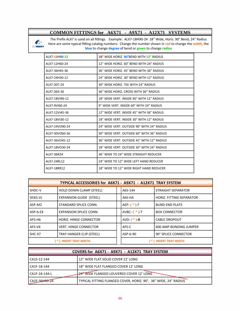
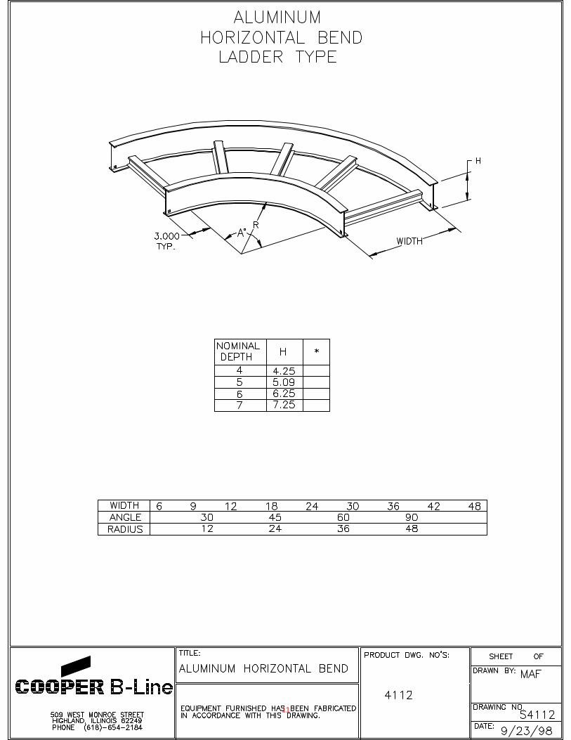
The Prefix ALX7 is used on all fi ngs. Example: ALX7‐18H90‐24 18” Wide, Horiz. 90° Bend, 24” Radius Here are some typical fi ng catalog numbers: Change the number shown in red to change the width, the
blue to change degree of bend or green to change radius
ALX7‐18H90‐12 18” WIDE HORIZ. 90°BEND WITH 12” RADIUS
ALX7‐12H60‐24 12” WIDE HORIZ. 60° BEND WITH 24” RADIUS
ALX7‐36H45‐36 36” WIDE HORIZ. 45° BEND WITH 36” RADIUS
ALX7‐24H30‐12 24” WIDE HORIZ. 30° BEND WITH 12” RADIUS
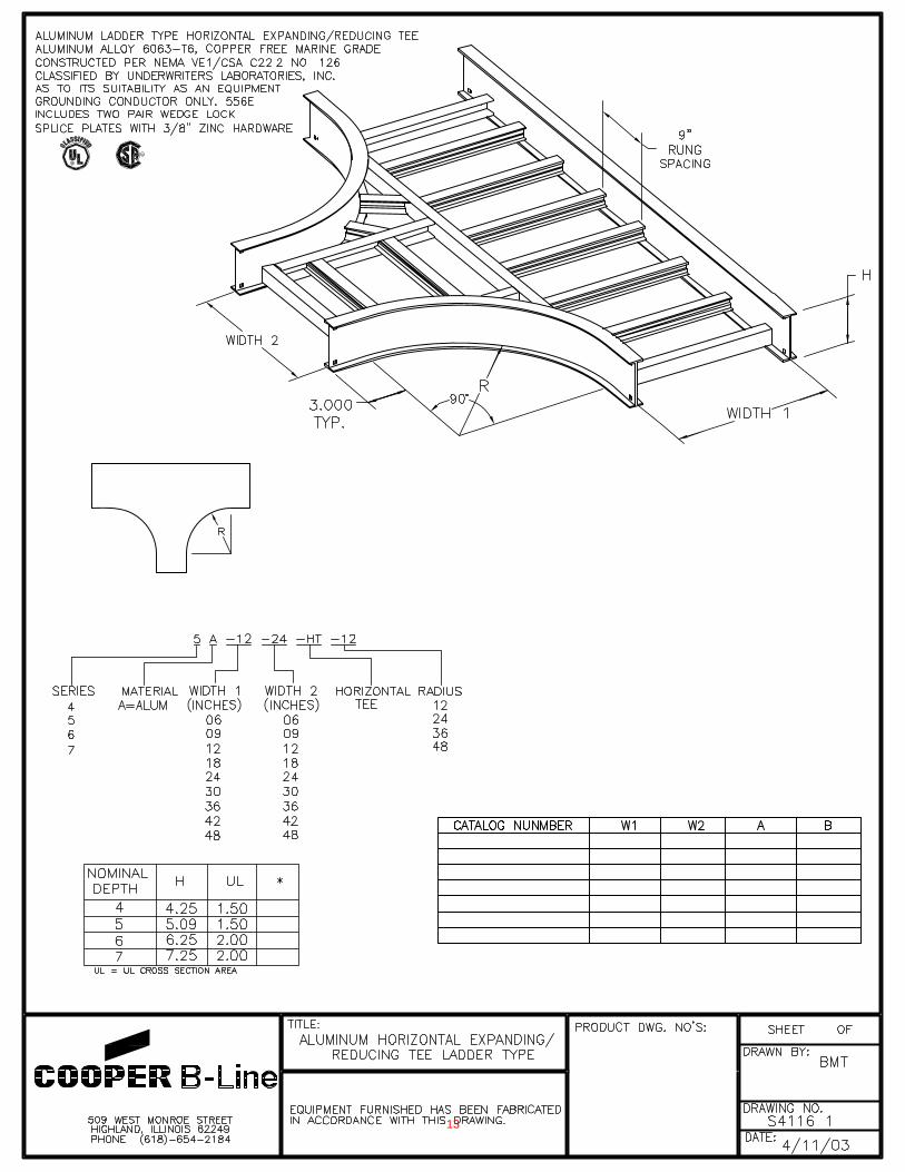
ALX7‐30T‐24 30” WIDE HORIZ. TEE WITH 24” RADIUS
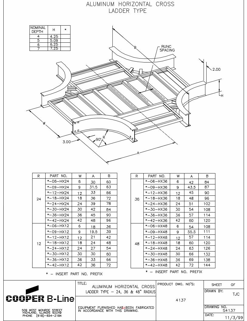
ALX7‐36X‐36 36” WIDE HORIZ. CROSS WITH 36” RADIUS
ALX7‐18VI90‐12 18” WIDE VERT. INSIDE 90° WITH 12” RADIUS
ALX7‐9VI60‐24 9” WIDE VERT. INSIDE 60° WITH 24” RADIUS
ALX7‐12VI45‐36 12” WIDE VERT. INSIDE 45° WITH 36” RADIUS
ALX7‐18VI30‐12 18” WIDE VERT. INSIDE 30° WITH 12” RADIUS
ALX7‐24VO90‐24 24” WIDE VERT. OUTSIDE 90° WITH 24” RADIUS
ALX7‐30VO60‐36 30” WIDE VERT. OUTSIDE 60° WITH 36” RADIUS
ALX7‐36VO45‐12 36” WIDE VERT. OUTSIDE 45° WITH 12” RADIUS
ALX7‐18VO30‐24 18” WIDE VERT. OUTSIDE 30° WITH 24” RADIUS
ALX7‐36R24 36” WIDE TO 24” WIDE STRAIGHT REDUCER
ALX7‐24RL12 24” WIDE TO 12” WIDE LEFT HAND REDUCER
ALX7‐18RR12 18” WIDE TO 12” WIDE RIGHT HAND REDUCER
TYPICAL ACCESSORIES for A6X71 ‐ A9X71 ‐ A12X71 TRAY SYSTEM
SHDC‐V HOLD DOWN CLAMP (STEEL) A6S‐144 STRAIGHT SEPARATOR
SEXG‐VL EXPANSION GUIDE (STEEL) A6S‐HA HORIZ. FITTING SEPARATOR
ASP‐M2 STANDARD SPLICE CONN. AEP‐ ( * )‐7 BLIND END PLATE
ASP‐6‐EX EXPANSION SPLICE CONN. AVBC‐ ( * )‐7 BOX CONNECTOR
AFS‐H6 HORIZ. HINGE CONNECTOR AVD‐ ( * )‐X CABLE DROPOUT
AFS‐V6 VERT. HINGE CONNECTOR AFS‐C 600 AMP BONDING JUMPER
SHC‐X7 TRAY HANGER CLIP (STEEL) ASP‐6‐90 90° SPLICE CONNECTOR
( * ) INSERT TRAY WIDTH ( * ) INSERT TRAY WIDTH
CA1S‐12‐144 12” WIDE FLAT SOLID COVER 12’ LONG
CA1F‐18‐144 18” WIDE FLAT FLANGED COVER 12’ LONG
CA1F‐24‐144‐L 24” WIDE FLANGED LOUVERED COVER 12’ LONG
COVERS for A6X71 ‐ A9X71 ‐ A12X71 TRAY SYSTEM
CA1F‐36H90‐24 TYPICAL FITTING FLANGED COVER, HORIZ. 90°, 36” WIDE, 24” RADIUS
COMMON FITTINGS for A6X71 - A9X71 - A12X71 SYSTEMS
66

CABLE TRAY
8 6 4 . 2 3 4 . 4 8 0 0m p h u s k y . c o m
Copyright 2010 MP Husky. All rights reserved.
117
10-FITTIN
GS
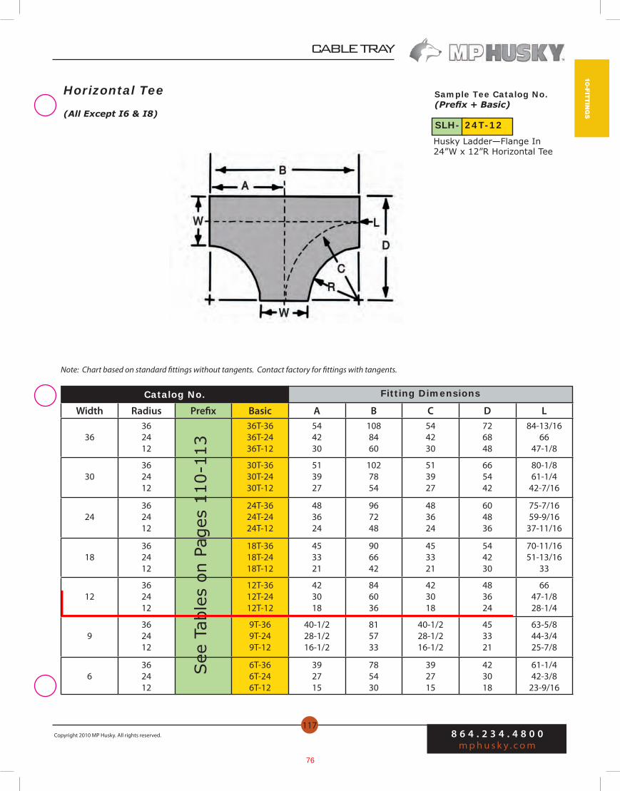
Horizontal Tee
Width Radius Prefix Basic A B C D L
36362412
36T-3636T-2436T-12
544230
1088460
544230
726848
84-13/1666
47-1/8
30362412
30T-3630T-2430T-12
513927
1027854
513927
665442
80-1/861-1/4
42-7/16
24362412
24T-3624T-2424T-12
483624
967248
483624
604836
75-7/1659-9/16
37-11/16
18362412
18T-3618T-2418T-12
453321
906642
453321
544230
70-11/1651-13/16
33
12362412
12T-3612T-2412T-12
423018
846036
423018
483624
6647-1/828-1/4
9362412
9T-369T-249T-12
40-1/228-1/216-1/2
815733
40-1/228-1/216-1/2
453321
63-5/844-3/425-7/8
6362412
6T-366T-246T-12
392715
785430
392715
423018
61-1/442-3/8
23-9/16
Catalog No.
See
Tab
les
on P
ages
110
-113
Husky Ladder—Flange In24”W x 12”R Horizontal Tee
Sample Tee Catalog No.(Prefix + Basic)
(All Except I6 & I8)SLH- 24T-12
Note: Chart based on standard fittings without tangents. Contact factory for fittings with tangents.
Fitting Dimensions
67

8 6 4 . 2 3 4 . 4 8 0 0m p h u s k y . c o m
Copyright 2010 MP Husky. All rights reserved.
CABLE TRAY
122
10-F
ITTI
NG
S
Width Radius Prefix Basic A B C L
36362412
36H90-3636H90-2436H90-12
544230
544230
544230
84-13/1666
47-1/8
30362412
30H90-3630H90-2430H90-12
513927
513927
513927
80-1/861-1/442-7/16
24362412
24H90-3624H90-2424H90-12
483624
483624
483624
75-7/1656-9/1637-11/16
18362412
18H90-3618H90-2418H90-12
453321
453321
453321
70-11/1651-13/16
33
12362412
12H90-3612H90-2412H90-12
423018
423018
423018
6647-1/828-1/4
9362412
9H90-369H90-249H90-12
40-1/228-1/216-1/2
40-1/228-1/216-1/2
40-1/228-1/216-1/2
63-5/844-3/425-7/8
6362412
6H90-366H90-246H90-12
392715
392715
392715
61-1/442-3/423-9/16
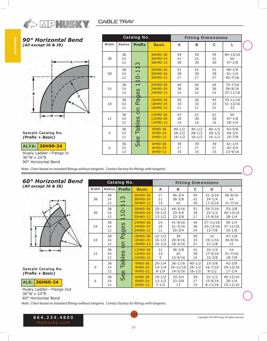
90° Horizontal Bend(All except I6 & I8)
Catalog No.
60° Horizontal Bend(All except I6 & I8)
See
Tab
les
on P
ages
110
-113
Sample Catalog No.(Prefix + Basic)
Husky Ladder—Flange In36”W x 24”R 90° Horizontal Bend
Sample Catalog No.(Prefix + Basic)
Husky Ladder—Flange Out36”W x 24”R 60° Horizontal Bend
ALYA- 36H90-24
ALE- 36H60-24
Catalog No.
Note: Chart based on standard fittings without tangents. Contact factory for fittings with tangents.
Note: Chart based on standard fittings without tangents. Contact factory for fittings with tangents.
Fitting DimensionsWidth Radius Prefix Basic A B C D L
36362412
36H60-3636H60-2436H60-12
272115
46-3/436-3/8
26
544230
31-3/1624-1/417-5/16
56-9/1644
31-7/16
30362412
30H60-3630H60-2430H60-12
25-1/219-1/213-1/2
44-3/1633-3/423-3/8
513927
29-7/1622-1/215-9/16
53-3/840-13/1628-1/4
24362412
24H60-3624H60-2424H60-12
241812
41-9/1631-3/1620-3/4
483624
27-11/1620-13/1613-7/8
50-1/437-11/1625-1/8
18362412
18H60-3618H60-2418H60-12
22-1/216-1/210-1/2
3928-9/1618-3/16
453321
2619-1/1612-1/8
47-1/834-9/16
22
12362412
12H60-3612H60-2412H60-12
21159
36-3/826
15-9/16
423018
24-1/417-5/1610-3/8
4431-7/1618-7/8
9362412
9H60-369H60-249H60-12
20-1/414-1/48-1/4
36-1/1624-11/1614-5/16
40-1/228-1/216-1/2
23-3/816-7/169-1/2
42-3/829-13/1617-1/4
6362412
6H60-366H60-246H60-12
19-1/213-1/27-1/2
33-3/423-3/8
13
392715
22-1/215-9/168-11/16
40-13/1628-1/4
15-11/16
Fitting Dimensions
See
Tab
les
on P
ages
110
-113
68
CABLE TRAY
8 6 4 . 2 3 4 . 4 8 0 0m p h u s k y . c o m
Copyright 2010 MP Husky. All rights reserved.
123
10-FITTIN
GS
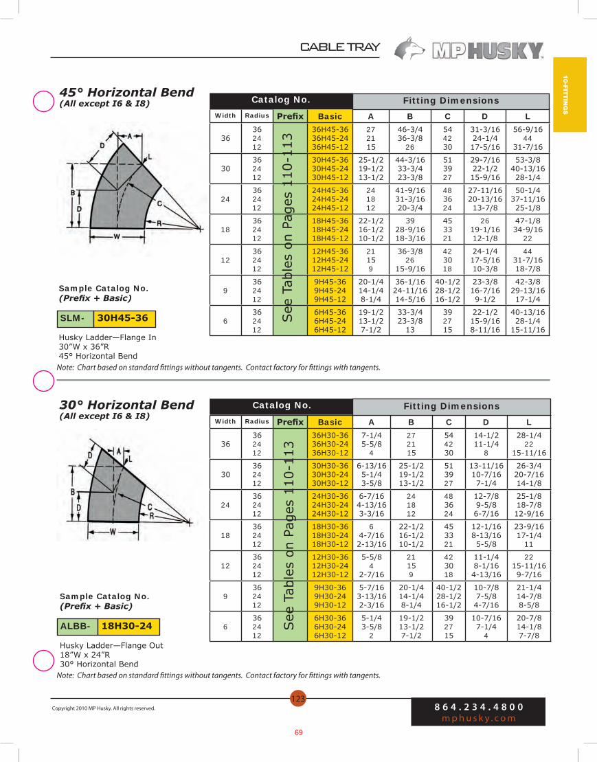
Catalog No.30° Horizontal Bend(All except I6 & I8)
45° Horizontal Bend(All except I6 & I8) Catalog No.
Sample Catalog No.(Prefix + Basic)
Husky Ladder—Flange In30”W x 36”R 45° Horizontal Bend
Sample Catalog No.(Prefix + Basic)
Husky Ladder—Flange Out18”W x 24”R 30° Horizontal Bend
ALBB- 18H30-24
SLM- 30H45-36
Width Radius Prefix Basic A B C D L
36362412
36H45-3636H45-2436H45-12
272115
46-3/436-3/8
26
544230
31-3/1624-1/417-5/16
56-9/1644
31-7/16
30362412
30H45-3630H45-2430H45-12
25-1/219-1/213-1/2
44-3/1633-3/423-3/8
513927
29-7/1622-1/215-9/16
53-3/840-13/1628-1/4
24362412
24H45-3624H45-2424H45-12
241812
41-9/1631-3/1620-3/4
483624
27-11/1620-13/1613-7/8
50-1/437-11/1625-1/8
18362412
18H45-3618H45-2418H45-12
22-1/216-1/210-1/2
3928-9/1618-3/16
453321
2619-1/1612-1/8
47-1/834-9/16
22
12362412
12H45-3612H45-2412H45-12
21159
36-3/826
15-9/16
423018
24-1/417-5/1610-3/8
4431-7/1618-7/8
9362412
9H45-369H45-249H45-12
20-1/414-1/48-1/4
36-1/1624-11/1614-5/16
40-1/228-1/216-1/2
23-3/816-7/169-1/2
42-3/829-13/1617-1/4
6362412
6H45-366H45-246H45-12
19-1/213-1/27-1/2
33-3/423-3/8
13
392715
22-1/215-9/168-11/16
40-13/1628-1/4
15-11/16
See
Tab
les
on P
ages
110
-113
Width Radius Prefix Basic A B C D L
36362412
36H30-3636H30-2436H30-12
7-1/45-5/8
4
272115
544230
14-1/211-1/4
8
28-1/422
15-11/16
30362412
30H30-3630H30-2430H30-12
6-13/165-1/43-5/8
25-1/219-1/213-1/2
513927
13-11/1610-7/167-1/4
26-3/420-7/1614-1/8
24362412
24H30-3624H30-2424H30-12
6-7/164-13/163-3/16
241812
483624
12-7/89-5/86-7/16
25-1/818-7/812-9/16
18362412
18H30-3618H30-2418H30-12
64-7/162-13/16
22-1/216-1/210-1/2
453321
12-1/168-13/165-5/8
23-9/1617-1/4
11
12362412
12H30-3612H30-2412H30-12
5-5/84
2-7/16
21159
423018
11-1/48-1/164-13/16
2215-11/169-7/16
9362412
9H30-369H30-249H30-12
5-7/163-13/162-3/16
20-1/414-1/48-1/4
40-1/228-1/216-1/2
10-7/87-5/84-7/16
21-1/414-7/88-5/8
6362412
6H30-366H30-246H30-12
5-1/43-5/8
2
19-1/213-1/27-1/2
392715
10-7/167-1/4
4
20-7/814-1/87-7/8
See
Tab
les
on P
ages
110
-113
Note: Chart based on standard fittings without tangents. Contact factory for fittings with tangents.
Note: Chart based on standard fittings without tangents. Contact factory for fittings with tangents.
Fitting Dimensions
Fitting Dimensions
69

8 6 4 . 2 3 4 . 4 8 0 0m p h u s k y . c o m
Copyright 2010 MP Husky. All rights reserved.
CABLE TRAY
134
10-F
ITTI
NG
S
WidthRight HandCatalog No.
ConcentricCatalog No.
Left HandCatalog No.
Electray, Ventray/Ventrib Reducers
Husky Ladder Reducer—Flange In Husky Ladder Reducer—Flange Out
W W1 Prefix Basic Prefix Basic Prefix Basic A/B C
36
3024181296
36R3036R2436R1836R1236R936R6
36RL3036RL2436RL1836RL1236RL936RL6
36RR3036RR2436RR1836RR1236RR936RR6
36912
13-1/215
61218242730
30
24181296
30R2430R1830R1230R930R6
30RL2430RL1830RL1230RL930RL6
30RR2430RR1830RR1230RR930RR6
369
10-1/212
612182124
24181296
24R1824R1224R924R6
24RL1824RL1224RL924RL6
24RR1824RR1224RR924RR6
36
7-1/29
6121518
181296
18R1218R918R6
18RL1218RL918RL6
18RR1218RR918RR6
34-1/2
6
6912
12 96
12R912R6
12RL912RL6
12RR912RR6
1-1/23
36
9 6 9R6 9RL6 9RR6 1-1/2 3
Reducers for Husky Ladder Trays
See
Tab
les
on P
ages
110
-113
See
Tab
les
on P
ages
110
-113
See
Tab
les
on P
ages
110
-113
Note: Chart based on standard fittings without tangents. Contact factory for fittings with tangents.
70
8 6 4 . 2 3 4 . 4 8 0 0m p h u s k y . c o m
Copyright 2010 MP Husky. All rights reserved.
CABLE TRAY
110
10-F
ITTI
NG
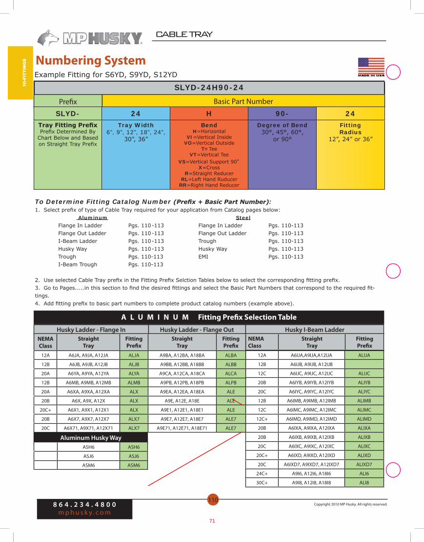
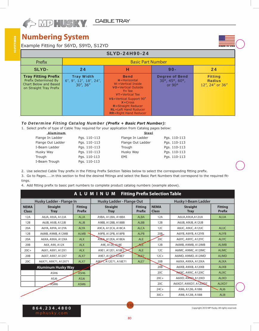
S Numbering System
SLYD-24H90-24
Husky Ladder - Flange In Husky Ladder - Flange Out
To Determine Fitting Catalog Number (Prefix + Basic Part Number):1. Select prefix of type of Cable Tray required for your application from Catalog pages below: Aluminum Steel Flange In Ladder Pgs. 110 -113 Flange In Ladder Pgs. 110-113 Flange Out Ladder Pgs. 110 -113 Flange Out Ladder Pgs. 110-113 I-Beam Ladder Pgs. 110 -113 Trough Pgs. 110-113 Husky Way Pgs. 110 -113 Husky Way Pgs. 110-113 Trough Pgs. 110-113 EMI Pgs. 110-113 I-Beam Trough Pgs. 110-113
2. Use selected Cable Tray prefix in the Fitting Prefix Selction Tables below to select the corresponding fitting prefix.3. Go to Pages.....in this section to find the desired fittings and select the Basic Part Numbers that correspond to the required fit-tings.4. Add fitting prefix to basic part numbers to complete product catalog numbers (example above).
12A A6IJA,A9IJA,A12IJA ALIJA
12B A6IJB, A9IJB, A12IJB
12C A6IJC, A9IJC, A12IJC ALIJC
20B A6IYB, A9IYB, A12IYB ALIYB
20C A6IYC, A9IYC, A12IYC ALIYC
12B A6IMB, A9IMB, A12IMB ALIMB
12C A6IMC, A9IMC, A12IMC ALIMC
12C+ A6IMD, A9IMD, A12IMD ALIMD
20B A6IXA, A9IXA, A12IXA ALIXA
20B A6IXB, A9IXB, A12IXB ALIXB
20C A6IXC, A9IXC, A12IXC ALIXC
20C+ A6IXD, A9IXD, A12IXD ALIXD
20C A6IXD7, A9IXD7, A12IXD7 ALIXD7
24C+ A9I6, A12I6, A18I6 ALI6
30C+ A9I8, A12I8, A18I8 ALI8
Husky I-Beam LadderNEMAClass
StraightTray
Fitting Prefix
Aluminum Husky Way
A L U M I N U M Fitting Prefix Selection Table
Prefix Basic Part Number
SLYD- 24 H 90- 24Tray Fitting PrefixPrefix Determined By
Chart Below and Based on Straight Tray Prefix
Tray Width6”, 9”, 12”, 18”, 24”,
30”, 36”
BendH=Horizontal
VI=Vertical InsideVO=Vertical Outside
T=TeeVT=Vertical Tee
VS=Vertical Support 90°X=Cross
R=Straight ReducerRL=Left Hand Ruducer
RR=Right Hand Reducer
Degree of Bend30°, 45°, 60°,
or 90°
Fitting Radius
12”, 24” or 36”
Example Fitting for S6YD, S9YD, S12YD
NEMAClass
StraightTray
Fitting Prefix
StraightTray
Fitting Prefix
12A A6JA, A9JA, A12JA ALJA A9BA, A12BA, A18BA ALBA
12B A6JB, A9JB, A12JB ALJB A9BB, A12BB, A18BB ALBB
20A A6YA, A9YA, A12YA ALYA A9CA, A12CA, A18CA ALCA
12B A6MB, A9MB, A12MB ALMB A9PB, A12PB, A18PB ALPB
20A A6XA, A9XA, A12XA ALX A9EA, A12EA, A18EA ALE
20B A6X, A9X, A12X ALX A9E, A12E, A18E ALE
20C+ A6X1, A9X1, A12X1 ALX A9E1, A12E1, A18E1 ALE
20B A6X7, A9X7, A12X7 ALX7 A9E7, A12E7, A18E7 ALE7
20C A6X71, A9X71, A12X71 ALX7 A9E71, A12E71, A18E71 ALE7
ASH6 ASH6
ASJ6 ASJ6
ASM6 ASM6
71
11-a
cc
ess
or
ies
8 6 4 . 2 3 4 . 4 8 0 0m p h u s k y . c o m
Copyright 2010 MP Husky. All rights reserved.
CABLE TRAY
142
Splices and Connectors
Wall Penetration SleeveThe wall penetration sleeve is a 24” long pan with wall flanges, cover & cover screws, that allows tray to be connected on both sides of the wall. Gaskets and sealants (not included), may be applied in the field.
(W)=insert Width(D)=insert Depth
End PlatesBlind end plates are available for all tray types and are furnished with mounting hard-ware.( ) = Insert Tray Width Hardware included.
Siderail Heightt Alum.
Mill-Galv.
SS304
SS316
HDGAF Galvan. (Husky Way)
3-3/8” AEP-( )-3-3/8 SEP-( )-3-3/8 4EP-( )-3-3/8 6EP-( )-3-3/8 GEP-( )-3-3/8 NEP-( )-3-3/8
4” AEP-( )-4 SEP-( )-4 4EP-( )-4 6EP-( )-4 GEP-( )-4 NEP-( )-4
4-1/2” AEP-( )-4-1/2 SEP-( )-4-1/2 4EP-( )-4-1/2 6EP-( )-4-1/2 GEP-( )-4-1/2 ——
6”, I6 AEP-( )-6 SEP-( )-6 4EP-( )-6 6EP-( )-6 GEP-( )-6 NEP-( )-6
6-1/4” AEP-( )-6-1/4 SEP-( )-6-1/4 4EP-( )-6-1/4 6EP-( )-6-1/4 GEP-( )-6-1/4 ——
7” AEP-( )-7 SEP-( )-7 4EP-( )-7 6EP-( )-7 GEP-( )-7 ——
I8 AEP-( )-8 —— —— —— —— ——
Hardware for Splice ConnectorsSplice hardware is offered in standard zinc plated steel finish, or in 316 stainless steel to withstand corrosive attack under many atmospheric conditions.
HardwareItem
Plated Steel
SS316
3/8” Splice Bolt B-100 B-100-6S
Splice Nut/Washer Comb. N-100 N-100-6S
ChannelType Alum.
Mill-Galv. HDGAF
SS304
SS316
Galvannealed (Husky Way)
All Trays AWPS-(W)-(D) PWPS-(W)-(D) SWPS-(W)-(D) 4WPS-(W)-(D) 6WPS-(W)-(D) NWPS-(W)-(D)
Splices and Connectors
72

11-a
cc
ess
or
ies
8 6 4 . 2 3 4 . 4 8 0 0m p h u s k y . c o m
Copyright 2010 MP Husky. All rights reserved.
CABLE TRAY
146
Horizontal Bends: Standard length is 6 feet. Each piece is punched and slotted for easy field adjustment to any degree of radius curvature. Sections may be field cut or continued along a straight run. One (CSS) seperator splice included with each.
SepHgt Alum.
Mill- Galv.
SS 304
SS316 HDGAF
Galvannealed(Husky Way)
2-3/4” A3S-HA S3S-HA 43S-HA 63S-HA G3S-HA N3S-HA
4-3/4” A5S-HA S5S-HA 45S-HA 65S-HA G5S-HA N5S-HA
5-3/4” A6S-HA S6S-HA 46S-HA 66S-HA G6S-HA ——
6-3/4” A7S-HA —— —— —— —— ——
Grounding Clamp (NEW)Ground Clamp for fastening ground wire to Cable Tray or Cable Bus. Clamp is tin plated extruded aluminum with Zinc Electroplated Steel hardware. Use for aluminum or copper conductors. Clamp has serrations to bite through insulating oxides on aluminum tray and grip the tray. Screws tighten with 1/4” hex wrench. For 1/2” max straight rail or 1/4” 90 degree tray rail.
Third Party Certification:UL Listed E-24264CSA Certified LR9795 (for copper conductors only)
Applicable Third Party standards:UL Standard 467CSA Standard C22.2 No. 41NEC 250.77 and 392.6
Conductor Catalog No.#6, #4, #3, #2, #1, 1/0, 2/0, 3/0, 4/0 AWG to 250KCMIL HP-CTGC
Cable Separators / Divider StripsCable separators (divider strips) are available for all tray types in aluminum, mill-galva-nized, galvannealed and 304 or 316 stainless steel. Separators come in either 3”, 5”, 6” or 7” heights and are slotted at regular intervals for ease of installation without field drill-ing. Each separator is furnished with all necessary splice clips and the required num-ber of nuts, bolts, and captive lock washers. Separator Rung Fasteners must be ordered separately for attachment to Ladder rungs without drilling. One (CSS) seperator splice included with each.
SepHgt
TrayHgt Alum.
Mill- Galv.
SS 304
SS316 HDGAF
Galvann.(Husky Way)
2-3/4” 3-3/8”-4-1/2” A3S-144 S3S-144 43S-144 63S-144 G3S-144 N3S-144
4-3/4” 6”-6-1/4” A5S-144 S5S-144 45S-144 65S-144 G5S-144 N5S-144
5-3/4” 7” A6S-144 S6S-144 46S-144 66S-144 G6S-144 ——
6-3/4” 8” A7S-144 —— —— —— —— ——
Straight Lengths: Standard length is 10 or 12 feet. The grouping of slots is designed to fit the hole pattern of MP Husky corrugated ventilated Troughs and Ladder Rungs.
For 10 ft lengths, change the –144 to –120 on the end of the part number.
Accessories Accessories
73
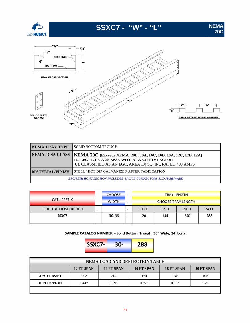
SSXC7 - “W” - “L”
‐ CHOOSE ‐ TRAY LENGTH
‐ WIDTH ‐ CHOOSE TRAY LENGTH
SOLID BOTTOM TROUGH ‐ ‐ 10 FT 12 FT 20 FT 24 FT
SSXC7 ‐ 30, 36 ‐ 120 144
240 288
CAT# PREFIX
SSXC7‐ 30‐ 288
SAMPLE CATALOG NUMBER ‐ Solid Bo om Trough, 30” Wide, 24’ Long
NEMA 20C
NEMA TRAY TYPE SOLID BOTTOM TROUGH
NEMA / CSA CLASS NEMA 20C (Exceeds NEMA 20B, 20A, 16C, 16B, 16A, 12C, 12B, 12A) 105 LBS/FT. ON A 20’ SPAN WITH A 1.5 SAFETY FACTOR UL CLASSIFIED AS AN EGC, AREA 1.0 SQ. IN., RATED 400 AMPS
MATERIAL/FINISH STEEL / HOT DIP GALVANIZED AFTER FABRICATION
EACH STRAIGHT SECTION INCLUDES SPLICE CONNECTORS AND HARDWARE
NEMA LOAD AND DEFLECTION TABLE
12 FT SPAN 14 FT SPAN 16 FT SPAN 18 FT SPAN 20 FT SPAN
LOAD LBS/FT 2.92 214 164 130 105
DEFLECTION 0.44” 0.59” 0.77” 0.98” 1.21
74
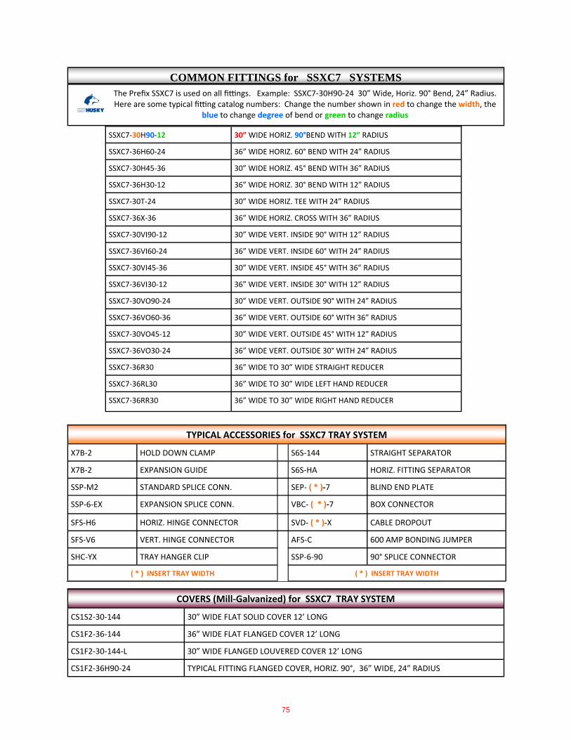
The Prefix SSXC7 is used on all fi ngs. Example: SSXC7‐30H90‐24 30” Wide, Horiz. 90° Bend, 24” Radius. Here are some typical fi ng catalog numbers: Change the number shown in red to change the width, the
blue to change degree of bend or green to change radius
SSXC7‐30H90‐12 30” WIDE HORIZ. 90°BEND WITH 12” RADIUS
SSXC7‐36H60‐24 36” WIDE HORIZ. 60° BEND WITH 24” RADIUS
SSXC7‐30H45‐36 30” WIDE HORIZ. 45° BEND WITH 36” RADIUS
SSXC7‐36H30‐12 36” WIDE HORIZ. 30° BEND WITH 12” RADIUS
SSXC7‐30T‐24 30” WIDE HORIZ. TEE WITH 24” RADIUS
SSXC7‐36X‐36 36” WIDE HORIZ. CROSS WITH 36” RADIUS
SSXC7‐30VI90‐12 30” WIDE VERT. INSIDE 90° WITH 12” RADIUS
SSXC7‐36VI60‐24 36” WIDE VERT. INSIDE 60° WITH 24” RADIUS
SSXC7‐30VI45‐36 30” WIDE VERT. INSIDE 45° WITH 36” RADIUS
SSXC7‐36VI30‐12 36” WIDE VERT. INSIDE 30° WITH 12” RADIUS
SSXC7‐30VO90‐24 30” WIDE VERT. OUTSIDE 90° WITH 24” RADIUS
SSXC7‐36VO60‐36 36” WIDE VERT. OUTSIDE 60° WITH 36” RADIUS
SSXC7‐30VO45‐12 30” WIDE VERT. OUTSIDE 45° WITH 12” RADIUS
SSXC7‐36VO30‐24 36” WIDE VERT. OUTSIDE 30° WITH 24” RADIUS
SSXC7‐36R30 36” WIDE TO 30” WIDE STRAIGHT REDUCER
SSXC7‐36RL30 36” WIDE TO 30” WIDE LEFT HAND REDUCER
SSXC7‐36RR30 36” WIDE TO 30” WIDE RIGHT HAND REDUCER
TYPICAL ACCESSORIES for SSXC7 TRAY SYSTEM
X7B‐2 HOLD DOWN CLAMP S6S‐144 STRAIGHT SEPARATOR
X7B‐2 EXPANSION GUIDE S6S‐HA HORIZ. FITTING SEPARATOR
SSP‐M2 STANDARD SPLICE CONN. SEP‐ ( * )‐7 BLIND END PLATE
SSP‐6‐EX EXPANSION SPLICE CONN. VBC‐ ( * )‐7 BOX CONNECTOR
SFS‐H6 HORIZ. HINGE CONNECTOR SVD‐ ( * )‐X CABLE DROPOUT
SFS‐V6 VERT. HINGE CONNECTOR AFS‐C 600 AMP BONDING JUMPER
SHC‐YX TRAY HANGER CLIP SSP‐6‐90 90° SPLICE CONNECTOR
( * ) INSERT TRAY WIDTH ( * ) INSERT TRAY WIDTH
CS1S2‐30‐144 30” WIDE FLAT SOLID COVER 12’ LONG
CS1F2‐36‐144 36” WIDE FLAT FLANGED COVER 12’ LONG
CS1F2‐30‐144‐L 30” WIDE FLANGED LOUVERED COVER 12’ LONG
COVERS (Mill‐Galvanized) for SSXC7 TRAY SYSTEM
CS1F2‐36H90‐24 TYPICAL FITTING FLANGED COVER, HORIZ. 90°, 36” WIDE, 24” RADIUS
COMMON FITTINGS for SSXC7 SYSTEMS
75
CABLE TRAY
8 6 4 . 2 3 4 . 4 8 0 0m p h u s k y . c o m
Copyright 2010 MP Husky. All rights reserved.
117
10-FITTIN
GS
Horizontal Tee
Width Radius Prefix Basic A B C D L
36362412
36T-3636T-2436T-12
544230
1088460
544230
726848
84-13/1666
47-1/8
30362412
30T-3630T-2430T-12
513927
1027854
513927
665442
80-1/861-1/4
42-7/16
24362412
24T-3624T-2424T-12
483624
967248
483624
604836
75-7/1659-9/16
37-11/16
18362412
18T-3618T-2418T-12
453321
906642
453321
544230
70-11/1651-13/16
33
12362412
12T-3612T-2412T-12
423018
846036
423018
483624
6647-1/828-1/4
9362412
9T-369T-249T-12
40-1/228-1/216-1/2
815733
40-1/228-1/216-1/2
453321
63-5/844-3/425-7/8
6362412
6T-366T-246T-12
392715
785430
392715
423018
61-1/442-3/8
23-9/16
Catalog No.
See
Tab
les
on P
ages
110
-113
Husky Ladder—Flange In24”W x 12”R Horizontal Tee
Sample Tee Catalog No.(Prefix + Basic)
(All Except I6 & I8)SLH- 24T-12
Note: Chart based on standard fittings without tangents. Contact factory for fittings with tangents.
Fitting Dimensions
76
8 6 4 . 2 3 4 . 4 8 0 0m p h u s k y . c o m
Copyright 2010 MP Husky. All rights reserved.
CABLE TRAY
122
10-F
ITTI
NG
S
Width Radius Prefix Basic A B C L
36362412
36H90-3636H90-2436H90-12
544230
544230
544230
84-13/1666
47-1/8
30362412
30H90-3630H90-2430H90-12
513927
513927
513927
80-1/861-1/442-7/16
24362412
24H90-3624H90-2424H90-12
483624
483624
483624
75-7/1656-9/1637-11/16
18362412
18H90-3618H90-2418H90-12
453321
453321
453321
70-11/1651-13/16
33
12362412
12H90-3612H90-2412H90-12
423018
423018
423018
6647-1/828-1/4
9362412
9H90-369H90-249H90-12
40-1/228-1/216-1/2
40-1/228-1/216-1/2
40-1/228-1/216-1/2
63-5/844-3/425-7/8
6362412
6H90-366H90-246H90-12
392715
392715
392715
61-1/442-3/423-9/16
90° Horizontal Bend(All except I6 & I8)
Catalog No.
60° Horizontal Bend(All except I6 & I8)
See
Tab
les
on P
ages
110
-113
Sample Catalog No.(Prefix + Basic)
Husky Ladder—Flange In36”W x 24”R 90° Horizontal Bend
Sample Catalog No.(Prefix + Basic)
Husky Ladder—Flange Out36”W x 24”R 60° Horizontal Bend
ALYA- 36H90-24
ALE- 36H60-24
Catalog No.
Note: Chart based on standard fittings without tangents. Contact factory for fittings with tangents.
Note: Chart based on standard fittings without tangents. Contact factory for fittings with tangents.
Fitting DimensionsWidth Radius Prefix Basic A B C D L
36362412
36H60-3636H60-2436H60-12
272115
46-3/436-3/8
26
544230
31-3/1624-1/417-5/16
56-9/1644
31-7/16
30362412
30H60-3630H60-2430H60-12
25-1/219-1/213-1/2
44-3/1633-3/423-3/8
513927
29-7/1622-1/215-9/16
53-3/840-13/1628-1/4
24362412
24H60-3624H60-2424H60-12
241812
41-9/1631-3/1620-3/4
483624
27-11/1620-13/1613-7/8
50-1/437-11/1625-1/8
18362412
18H60-3618H60-2418H60-12
22-1/216-1/210-1/2
3928-9/1618-3/16
453321
2619-1/1612-1/8
47-1/834-9/16
22
12362412
12H60-3612H60-2412H60-12
21159
36-3/826
15-9/16
423018
24-1/417-5/1610-3/8
4431-7/1618-7/8
9362412
9H60-369H60-249H60-12
20-1/414-1/48-1/4
36-1/1624-11/1614-5/16
40-1/228-1/216-1/2
23-3/816-7/169-1/2
42-3/829-13/1617-1/4
6362412
6H60-366H60-246H60-12
19-1/213-1/27-1/2
33-3/423-3/8
13
392715
22-1/215-9/168-11/16
40-13/1628-1/4
15-11/16
Fitting Dimensions
See
Tab
les
on P
ages
110
-113
77

CABLE TRAY
8 6 4 . 2 3 4 . 4 8 0 0m p h u s k y . c o m
Copyright 2010 MP Husky. All rights reserved.
123
10-FITTIN
GS
Catalog No.30° Horizontal Bend(All except I6 & I8)
45° Horizontal Bend(All except I6 & I8) Catalog No.
Sample Catalog No.(Prefix + Basic)
Husky Ladder—Flange In30”W x 36”R 45° Horizontal Bend
Sample Catalog No.(Prefix + Basic)
Husky Ladder—Flange Out18”W x 24”R 30° Horizontal Bend
ALBB- 18H30-24
SLM- 30H45-36
Width Radius Prefix Basic A B C D L
36362412
36H45-3636H45-2436H45-12
272115
46-3/436-3/8
26
544230
31-3/1624-1/417-5/16
56-9/1644
31-7/16
30362412
30H45-3630H45-2430H45-12
25-1/219-1/213-1/2
44-3/1633-3/423-3/8
513927
29-7/1622-1/215-9/16
53-3/840-13/1628-1/4
24362412
24H45-3624H45-2424H45-12
241812
41-9/1631-3/1620-3/4
483624
27-11/1620-13/1613-7/8
50-1/437-11/1625-1/8
18362412
18H45-3618H45-2418H45-12
22-1/216-1/210-1/2
3928-9/1618-3/16
453321
2619-1/1612-1/8
47-1/834-9/16
22
12362412
12H45-3612H45-2412H45-12
21159
36-3/826
15-9/16
423018
24-1/417-5/1610-3/8
4431-7/1618-7/8
9362412
9H45-369H45-249H45-12
20-1/414-1/48-1/4
36-1/1624-11/1614-5/16
40-1/228-1/216-1/2
23-3/816-7/169-1/2
42-3/829-13/1617-1/4
6362412
6H45-366H45-246H45-12
19-1/213-1/27-1/2
33-3/423-3/8
13
392715
22-1/215-9/168-11/16
40-13/1628-1/4
15-11/16
See
Tab
les
on P
ages
110
-113
Width Radius Prefix Basic A B C D L
36362412
36H30-3636H30-2436H30-12
7-1/45-5/8
4
272115
544230
14-1/211-1/4
8
28-1/422
15-11/16
30362412
30H30-3630H30-2430H30-12
6-13/165-1/43-5/8
25-1/219-1/213-1/2
513927
13-11/1610-7/167-1/4
26-3/420-7/1614-1/8
24362412
24H30-3624H30-2424H30-12
6-7/164-13/163-3/16
241812
483624
12-7/89-5/86-7/16
25-1/818-7/812-9/16
18362412
18H30-3618H30-2418H30-12
64-7/162-13/16
22-1/216-1/210-1/2
453321
12-1/168-13/165-5/8
23-9/1617-1/4
11
12362412
12H30-3612H30-2412H30-12
5-5/84
2-7/16
21159
423018
11-1/48-1/164-13/16
2215-11/169-7/16
9362412
9H30-369H30-249H30-12
5-7/163-13/162-3/16
20-1/414-1/48-1/4
40-1/228-1/216-1/2
10-7/87-5/84-7/16
21-1/414-7/88-5/8
6362412
6H30-366H30-246H30-12
5-1/43-5/8
2
19-1/213-1/27-1/2
392715
10-7/167-1/4
4
20-7/814-1/87-7/8
See
Tab
les
on P
ages
110
-113
Note: Chart based on standard fittings without tangents. Contact factory for fittings with tangents.
Note: Chart based on standard fittings without tangents. Contact factory for fittings with tangents.
Fitting Dimensions
Fitting Dimensions
78
8 6 4 . 2 3 4 . 4 8 0 0m p h u s k y . c o m
Copyright 2010 MP Husky. All rights reserved.
CABLE TRAY
134
10-F
ITTI
NG
S
WidthRight HandCatalog No.
ConcentricCatalog No.
Left HandCatalog No.
Electray, Ventray/Ventrib Reducers
Husky Ladder Reducer—Flange In Husky Ladder Reducer—Flange Out
W W1 Prefix Basic Prefix Basic Prefix Basic A/B C
36
3024181296
36R3036R2436R1836R1236R936R6
36RL3036RL2436RL1836RL1236RL936RL6
36RR3036RR2436RR1836RR1236RR936RR6
36912
13-1/215
61218242730
30
24181296
30R2430R1830R1230R930R6
30RL2430RL1830RL1230RL930RL6
30RR2430RR1830RR1230RR930RR6
369
10-1/212
612182124
24181296
24R1824R1224R924R6
24RL1824RL1224RL924RL6
24RR1824RR1224RR924RR6
36
7-1/29
6121518
181296
18R1218R918R6
18RL1218RL918RL6
18RR1218RR918RR6
34-1/2
6
6912
12 96
12R912R6
12RL912RL6
12RR912RR6
1-1/23
36
9 6 9R6 9RL6 9RR6 1-1/2 3
Reducers for Husky Ladder Trays
See
Tab
les
on P
ages
110
-113
See
Tab
les
on P
ages
110
-113
See
Tab
les
on P
ages
110
-113
Note: Chart based on standard fittings without tangents. Contact factory for fittings with tangents.
79
8 6 4 . 2 3 4 . 4 8 0 0m p h u s k y . c o m
Copyright 2010 MP Husky. All rights reserved.
CABLE TRAY
110
10-F
ITTI
NG
S Numbering System
SLYD-24H90-24
Husky Ladder - Flange In Husky Ladder - Flange Out
To Determine Fitting Catalog Number (Prefix + Basic Part Number):1. Select prefix of type of Cable Tray required for your application from Catalog pages below: Aluminum Steel Flange In Ladder Pgs. 110 -113 Flange In Ladder Pgs. 110-113 Flange Out Ladder Pgs. 110 -113 Flange Out Ladder Pgs. 110-113 I-Beam Ladder Pgs. 110 -113 Trough Pgs. 110-113 Husky Way Pgs. 110 -113 Husky Way Pgs. 110-113 Trough Pgs. 110-113 EMI Pgs. 110-113 I-Beam Trough Pgs. 110-113
2. Use selected Cable Tray prefix in the Fitting Prefix Selction Tables below to select the corresponding fitting prefix.3. Go to Pages.....in this section to find the desired fittings and select the Basic Part Numbers that correspond to the required fit-tings.4. Add fitting prefix to basic part numbers to complete product catalog numbers (example above).
12A A6IJA,A9IJA,A12IJA ALIJA
12B A6IJB, A9IJB, A12IJB
12C A6IJC, A9IJC, A12IJC ALIJC
20B A6IYB, A9IYB, A12IYB ALIYB
20C A6IYC, A9IYC, A12IYC ALIYC
12B A6IMB, A9IMB, A12IMB ALIMB
12C A6IMC, A9IMC, A12IMC ALIMC
12C+ A6IMD, A9IMD, A12IMD ALIMD
20B A6IXA, A9IXA, A12IXA ALIXA
20B A6IXB, A9IXB, A12IXB ALIXB
20C A6IXC, A9IXC, A12IXC ALIXC
20C+ A6IXD, A9IXD, A12IXD ALIXD
20C A6IXD7, A9IXD7, A12IXD7 ALIXD7
24C+ A9I6, A12I6, A18I6 ALI6
30C+ A9I8, A12I8, A18I8 ALI8
Husky I-Beam LadderNEMAClass
StraightTray
Fitting Prefix
Aluminum Husky Way
A L U M I N U M Fitting Prefix Selection Table
Prefix Basic Part Number
SLYD- 24 H 90- 24Tray Fitting PrefixPrefix Determined By
Chart Below and Based on Straight Tray Prefix
Tray Width6”, 9”, 12”, 18”, 24”,
30”, 36”
BendH=Horizontal
VI=Vertical InsideVO=Vertical Outside
T=TeeVT=Vertical Tee
VS=Vertical Support 90°X=Cross
R=Straight ReducerRL=Left Hand Ruducer
RR=Right Hand Reducer
Degree of Bend30°, 45°, 60°,
or 90°
Fitting Radius
12”, 24” or 36”
Example Fitting for S6YD, S9YD, S12YD
NEMAClass
StraightTray
Fitting Prefix
StraightTray
Fitting Prefix
12A A6JA, A9JA, A12JA ALJA A9BA, A12BA, A18BA ALBA
12B A6JB, A9JB, A12JB ALJB A9BB, A12BB, A18BB ALBB
20A A6YA, A9YA, A12YA ALYA A9CA, A12CA, A18CA ALCA
12B A6MB, A9MB, A12MB ALMB A9PB, A12PB, A18PB ALPB
20A A6XA, A9XA, A12XA ALX A9EA, A12EA, A18EA ALE
20B A6X, A9X, A12X ALX A9E, A12E, A18E ALE
20C+ A6X1, A9X1, A12X1 ALX A9E1, A12E1, A18E1 ALE
20B A6X7, A9X7, A12X7 ALX7 A9E7, A12E7, A18E7 ALE7
20C A6X71, A9X71, A12X71 ALX7 A9E71, A12E71, A18E71 ALE7
ASH6 ASH6
ASJ6 ASJ6
ASM6 ASM6
80

CABLE TRAY
8 6 4 . 2 3 4 . 4 8 0 0m p h u s k y . c o m
Copyright 2010 MP Husky. All rights reserved.
113
10-FITTIN
GS
Numbering System (cont’d)
S T E E L Fitting Prefix Selection Table
Numbering System Insert the Fitting Prefix—Each cable tray has a corresponding prefix which is used to determine the complete fitting part num-ber. Use this table to locate the correct prefix. To assemble the part number select prefix and then add Basic number from charts on following pages.
Husky Trough Husky Ladder - Flange In Husky Ladder - Flange Out
NEMAClass
Straight Tray
Ventilated Fitting Prefix
Solid Fitting Prefix
StraightTray
Fitting Prefix
StraightTray
Fitting Prefix
12C SMD7/SSMD7 SMD7 SSMD7 S6MD7, S9MD7, S12MD7 SLMD7 S9PD7, S12PD7, S18PD7 SLPD7
12C S4MD7 S4MD7
12C PMD7/PSMD7 PMD7 PSMD7 P6MD7, P9MD7, P12MD7 PLMD7 ————— ——-
12C P4MD7 P4MD7
12C+ SMD74/SSMD74 SMD74 SSMD74 S6MD74, S9MD74, S12MD74 SLMD74 S9PD74,S12PD74,S18PD74 SLPD74
12C+ S4MD74 S4MD74
12C+ PMD74/PSMD74 PMD74 PSMD74 P6MD74,P9MD74,P12MD74 PLMD74
12C+ P4MD74 P4MD74
20B SXB7/SSXB7 SXB7 SSXB7 S6Xb7, S9XB7, S12XB7 SLXB7 S9EB7, S12EB7, S18EB7 SLEB7
20B S4XB7 S4XB7
20B PXB7/PSXB7 PXB7 PSXB7 P6XB7,P9XB7,P12XB7 PLXB7
20B P4XB7 P4XB7
20C SXC7/SSXC7 SXC7 SSXC7 S6XC7,S9XC7,S12XC7 SLXC7 S9EC7,S12EC7,S18EC7 SLEC7
20C S4XC7
20C PXC7/PSXC7 PXC7 PSXC7 P6XC7,P9XC7,P12XC7 PLXC7
20C P4XC7 P4XC7
Steel Husky Way10C PSH0 PSH0
10C PSJ0 PSJ0
10C PSM0 PSM0
10C NSH0 NSH0
10C NSJ0 NSJ0
10C NSM0 NSM0
10C 4SH0 4SH0
10C 4SJ0 4SJ0
10C 4SM0 4SM0
10C 6SH0 6SH0
10C 6SJ0 6SJ0
10C 6SM0 6SM0
EM4 EM4
EM6 EM6
Steel EMI Tray
81
13-C
ove
rs
CABLE TRAY
8 6 4 . 2 3 4 . 4 8 0 0m p h u s k y . c o m
Copyright 2010 MP Husky. All rights reserved.162
COP-A2S( )-W-144-15
CS2F( )-24-144
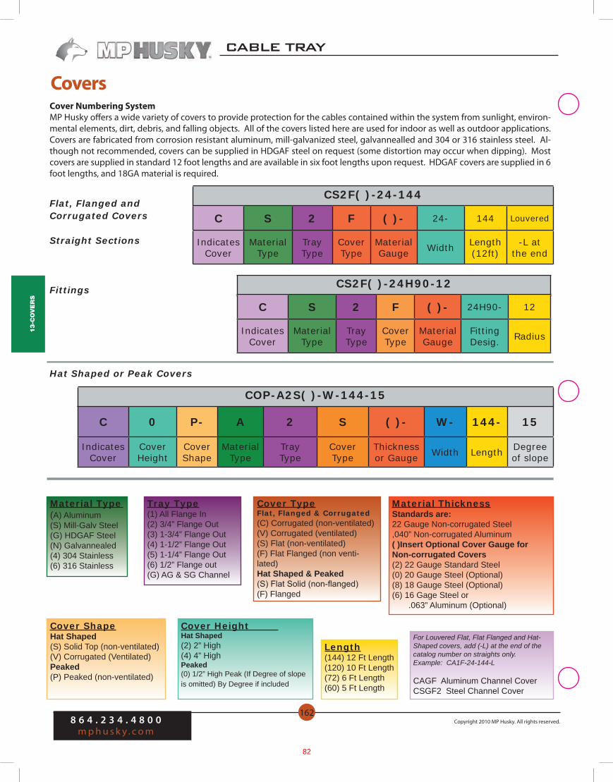
CoversCover Numbering SystemMP Husky offers a wide variety of covers to provide protection for the cables contained within the system from sunlight, environ-mental elements, dirt, debris, and falling objects. All of the covers listed here are used for indoor as well as outdoor applications. Covers are fabricated from corrosion resistant aluminum, mill-galvanized steel, galvannealled and 304 or 316 stainless steel. Al-though not recommended, covers can be supplied in HDGAF steel on request (some distortion may occur when dipping). Most covers are supplied in standard 12 foot lengths and are available in six foot lengths upon request. HDGAF covers are supplied in 6 foot lengths, and 18GA material is required.
C 0 P- A 2 S ( )- W- 144- 15
IndicatesCover
CoverHeight
CoverShape
MaterialType
TrayType
CoverType
Thicknessor Gauge Width Length Degree
of slope
For Louvered Flat, Flat Flanged and Hat-Shaped covers, add (-L) at the end of the catalog number on straights only.Example: CA1F-24-144-L
CAGF Aluminum Channel CoverCSGF2 Steel Channel Cover
C S 2 F ( )- 24- 144 Louvered
Indicates Cover
MaterialType
TrayType
CoverType
MaterialGauge Width Length
(12ft)-L at
the end
Material Type (A) Aluminum (S) Mill-Galv Steel(G) HDGAF Steel(N) Galvannealed (4) 304 Stainless(6) 316 Stainless
Tray Type(1) All Flange In(2) 3/4” Flange Out(3) 1-3/4” Flange Out(4) 1-1/2” Flange Out(5) 1-1/4” Flange Out(6) 1/2” Flange out(G) AG & SG Channel
Cover TypeFlat, Flanged & Corrugated(C) Corrugated (non-ventilated)(V) Corrugated (ventilated)(S) Flat (non-ventilated)(F) Flat Flanged (non venti-lated)Hat Shaped & Peaked(S) Flat Solid (non-flanged)(F) Flanged
Material ThicknessStandards are:22 Gauge Non-corrugated Steel,040” Non-corrugated Aluminum( )Insert Optional Cover Gauge forNon-corrugated Covers(2) 22 Gauge Standard Steel(0) 20 Gauge Steel (Optional)(8) 18 Gauge Steel (Optional)(6) 16 Gage Steel or .063” Aluminum (Optional)
Cover ShapeHat Shaped(S) Solid Top (non-ventilated)(V) Corrugated (Ventilated)Peaked(P) Peaked (non-ventilated)
Cover Height Hat Shaped(2) 2” High(4) 4” HighPeaked(0) 1/2” High Peak (If Degree of slope is omitted) By Degree if included
Length(144) 12 Ft Length(120) 10 Ft Length(72) 6 Ft Length(60) 5 Ft Length
Flat, Flanged and Corrugated Covers
Straight Sections
Fittings CS2F( )-24H90-12
C S 2 F ( )- 24H90- 12
Indicates Cover
MaterialType
TrayType
CoverType
MaterialGauge
FittingDesig. Radius
Hat Shaped or Peak Covers
82
13-C
ove
rs
8 6 4 . 2 3 4 . 4 8 0 0m p h u s k y . c o m
Copyright 2010 MP Husky. All rights reserved.
CABLE BUSCABLE TRAY
163
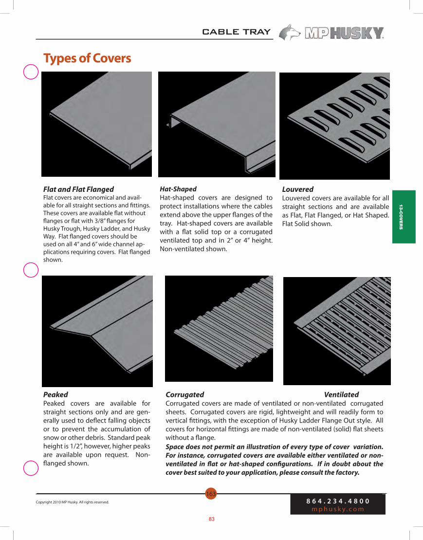
Types of Covers
Flat and Flat FlangedFlat covers are economical and avail-able for all straight sections and fittings. These covers are available flat without flanges or flat with 3/8” flanges for Husky Trough, Husky Ladder, and Husky Way. Flat flanged covers should be used on all 4” and 6” wide channel ap-plications requiring covers. Flat flanged shown.
Hat-ShapedHat-shaped covers are designed to protect installations where the cables extend above the upper flanges of the tray. Hat-shaped covers are available with a flat solid top or a corrugated ventilated top and in 2” or 4” height. Non-ventilated shown.
LouveredLouvered covers are available for all straight sections and are available as Flat, Flat Flanged, or Hat Shaped. Flat Solid shown.
PeakedPeaked covers are available for straight sections only and are gen-erally used to deflect falling objects or to prevent the accumulation of snow or other debris. Standard peak height is 1/2”, however, higher peaks are available upon request. Non-flanged shown.
Corrugated VentilatedCorrugated covers are made of ventilated or non-ventilated corrugated sheets. Corrugated covers are rigid, lightweight and will readily form to vertical fittings, with the exception of Husky Ladder Flange Out style. All covers for horizontal fittings are made of non-ventilated (solid) flat sheets without a flange.Space does not permit an illustration of every type of cover variation. For instance, corrugated covers are available either ventilated or non-ventilated in flat or hat-shaped configurations. If in doubt about the cover best suited to your application, please consult the factory.
83
13-C
ove
rs
CABLE TRAY
8 6 4 . 2 3 4 . 4 8 0 0m p h u s k y . c o m
Copyright 2010 MP Husky. All rights reserved.164
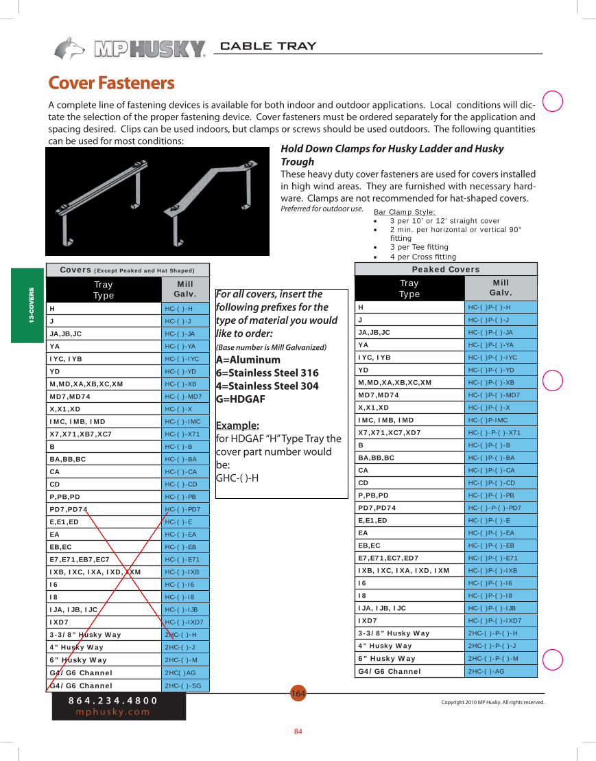
A complete line of fastening devices is available for both indoor and outdoor applications. Local conditions will dic-tate the selection of the proper fastening device. Cover fasteners must be ordered separately for the application and spacing desired. Clips can be used indoors, but clamps or screws should be used outdoors. The following quantities can be used for most conditions:
Bar Clamp Style: • 3 per 10’ or 12’ straight cover • 2 min. per horizontal or vertical 90°
fitting • 3 per Tee fitting • 4 per Cross fitting
Peaked Covers
Hold Down Clamps for Husky Ladder and Husky TroughThese heavy duty cover fasteners are used for covers installed in high wind areas. They are furnished with necessary hard-ware. Clamps are not recommended for hat-shaped covers. Preferred for outdoor use.
Cover Fasteners
Covers (Except Peaked and Hat Shaped)
Tray Type
MillGalv.
H HC-( )-H
J HC-( )-J
JA,JB,JC HC-( )-JA
YA HC-( )-YA
IYC, IYB HC-( )-IYC
YD HC-( )-YD
M,MD,XA,XB,XC,XM HC-( )-XB
MD7,MD74 HC-( )-MD7
X,X1,XD HC-( )-X
IMC, IMB, IMD HC-( )-IMC
X7,X71,XB7,XC7 HC-( )-X71
B HC-( )-B
BA,BB,BC HC-( )-BA
CA HC-( )-CA
CD HC-( )-CD
P,PB,PD HC-( )-PB
PD7,PD74 HC-( )-PD7
E,E1,ED HC-( )-E
EA HC-( )-EA
EB,EC HC-( )-EB
E7,E71,EB7,EC7 HC-( )-E71
IXB, IXC, IXA, IXD, IXM HC-( )-IXB
I6 HC-( )-I6
I8 HC-( )-I8
IJA, IJB, IJC HC-( )-IJB
IXD7 HC-( )-IXD7
3-3/8” Husky Way 2HC-( )-H
4” Husky Way 2HC-( )-J
6” Husky Way 2HC-( )-M
G4/G6 Channel 2HC( )AG
G4/G6 Channel 2HC-( )-SG
Tray Type
MillGalv.
H HC-( )P-( )-H
J HC-( )P-( )-J
JA,JB,JC HC-( )P-( )-JA
YA HC-( )P-( )-YA
IYC, IYB HC-( )P-( )-IYC
YD HC-( )P-( )-YD
M,MD,XA,XB,XC,XM HC-( )P-( )-XB
MD7,MD74 HC-( )P-( )-MD7
X,X1,XD HC-( )P-( )-X
IMC, IMB, IMD HC-( )P-IMC
X7,X71,XC7,XD7 HC-( )-P-( )-X71
B HC-( )P-( )-B
BA,BB,BC HC-( )P-( )-BA
CA HC-( )P-( )-CA
CD HC-( )P-( )-CD
P,PB,PD HC-( )P-( )-PB
PD7,PD74 HC-( )-P-( )-PD7
E,E1,ED HC-( )P-( )-E
EA HC-( )P-( )-EA
EB,EC HC-( )P-( )-EB
E7,E71,EC7,ED7 HC-( )P-( )-E71
IXB, IXC, IXA, IXD, IXM HC-( )P-( )-IXB
I6 HC-( )P-( )-I6
I8 HC-( )P-( )-I8
IJA, IJB, IJC HC-( )P-( )-IJB
IXD7 HC-( )P-( )-IXD7
3-3/8” Husky Way 2HC-( )-P-( )-H
4” Husky Way 2HC-( )-P-( )-J
6” Husky Way 2HC-( )-P-( )-M
G4/G6 Channel 2HC-( )-AG
For all covers, insert the following prefixes for the type of material you would like to order:(Base number is Mill Galvanized)
A=Aluminum6=Stainless Steel 3164=Stainless Steel 304G=HDGAF
Example:for HDGAF “H” Type Tray the cover part number would be:GHC-( )-H
84
12-S
up
po
rt
Mat
er
ial
8 6 4 . 2 3 4 . 4 8 0 0m p h u s k y . c o m
Copyright 2010 MP Husky. All rights reserved.
CABLE TRAY
148
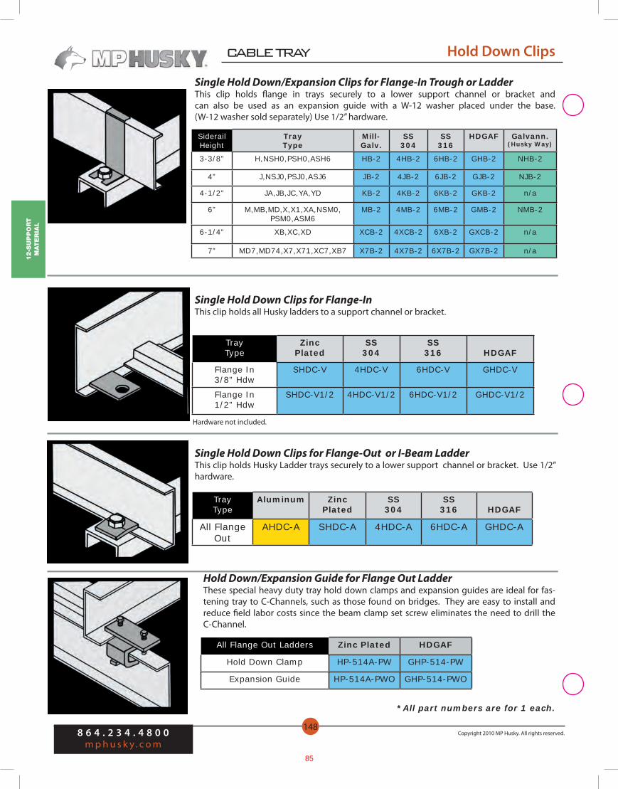
Hold Down Clips
Single Hold Down/Expansion Clips for Flange-In Trough or LadderThis clip holds flange in trays securely to a lower support channel or bracket and can also be used as an expansion guide with a W-12 washer placed under the base. (W-12 washer sold separately) Use 1/2” hardware.
SiderailHeight
TrayType
Mill-Galv.
SS304
SS316
HDGAF Galvann.(Husky Way)
3-3/8” H,NSH0,PSH0,ASH6 HB-2 4HB-2 6HB-2 GHB-2 NHB-2
4” J,NSJ0,PSJ0,ASJ6 JB-2 4JB-2 6JB-2 GJB-2 NJB-2
4-1/2” JA,JB,JC,YA,YD KB-2 4KB-2 6KB-2 GKB-2 n/a
6” M,MB,MD,X,X1,XA,NSM0, PSM0,ASM6
MB-2 4MB-2 6MB-2 GMB-2 NMB-2
6-1/4” XB,XC,XD XCB-2 4XCB-2 6XB-2 GXCB-2 n/a
7” MD7,MD74,X7,X71,XC7,XB7 X7B-2 4X7B-2 6X7B-2 GX7B-2 n/a
Single Hold Down Clips for Flange-In This clip holds all Husky ladders to a support channel or bracket.
TrayType
ZincPlated
SS304
SS316 HDGAF
Flange In3/8” Hdw
SHDC-V 4HDC-V 6HDC-V GHDC-V
Flange In1/2” Hdw
SHDC-V1/2 4HDC-V1/2 6HDC-V1/2 GHDC-V1/2
*All part numbers are for 1 each.
Single Hold Down Clips for Flange-Out or I-Beam LadderThis clip holds Husky Ladder trays securely to a lower support channel or bracket. Use 1/2” hardware.
Hold Down/Expansion Guide for Flange Out LadderThese special heavy duty tray hold down clamps and expansion guides are ideal for fas-tening tray to C-Channels, such as those found on bridges. They are easy to install and reduce field labor costs since the beam clamp set screw eliminates the need to drill the C-Channel.
All Flange Out Ladders Zinc Plated HDGAF
Hold Down Clamp HP-514A-PW GHP-514-PW
Expansion Guide HP-514A-PWO GHP-514-PWO
TrayType
Aluminum ZincPlated
SS304
SS316 HDGAF
All Flange Out
AHDC-A SHDC-A 4HDC-A 6HDC-A GHDC-A
Hardware not included.
85

11-a
cc
ess
or
ies
8 6 4 . 2 3 4 . 4 8 0 0m p h u s k y . c o m
Copyright 2010 MP Husky. All rights reserved.
CABLE TRAY
142
Splices and Connectors
Wall Penetration SleeveThe wall penetration sleeve is a 24” long pan with wall flanges, cover & cover screws, that allows tray to be connected on both sides of the wall. Gaskets and sealants (not included), may be applied in the field.
(W)=insert Width(D)=insert Depth
End PlatesBlind end plates are available for all tray types and are furnished with mounting hard-ware.( ) = Insert Tray Width Hardware included.
Siderail Heightt Alum.
Mill-Galv.
SS304
SS316
HDGAF Galvan. (Husky Way)
3-3/8” AEP-( )-3-3/8 SEP-( )-3-3/8 4EP-( )-3-3/8 6EP-( )-3-3/8 GEP-( )-3-3/8 NEP-( )-3-3/8
4” AEP-( )-4 SEP-( )-4 4EP-( )-4 6EP-( )-4 GEP-( )-4 NEP-( )-4
4-1/2” AEP-( )-4-1/2 SEP-( )-4-1/2 4EP-( )-4-1/2 6EP-( )-4-1/2 GEP-( )-4-1/2 ——
6”, I6 AEP-( )-6 SEP-( )-6 4EP-( )-6 6EP-( )-6 GEP-( )-6 NEP-( )-6
6-1/4” AEP-( )-6-1/4 SEP-( )-6-1/4 4EP-( )-6-1/4 6EP-( )-6-1/4 GEP-( )-6-1/4 ——
7” AEP-( )-7 SEP-( )-7 4EP-( )-7 6EP-( )-7 GEP-( )-7 ——
I8 AEP-( )-8 —— —— —— —— ——
Hardware for Splice ConnectorsSplice hardware is offered in standard zinc plated steel finish, or in 316 stainless steel to withstand corrosive attack under many atmospheric conditions.
HardwareItem
Plated Steel
SS316
3/8” Splice Bolt B-100 B-100-6S
Splice Nut/Washer Comb. N-100 N-100-6S
ChannelType Alum.
Mill-Galv. HDGAF
SS304
SS316
Galvannealed (Husky Way)
All Trays AWPS-(W)-(D) PWPS-(W)-(D) SWPS-(W)-(D) 4WPS-(W)-(D) 6WPS-(W)-(D) NWPS-(W)-(D)
Splices and Connectors
86

11-a
cc
ess
or
ies
8 6 4 . 2 3 4 . 4 8 0 0m p h u s k y . c o m
Copyright 2010 MP Husky. All rights reserved.
CABLE TRAY
146
Horizontal Bends: Standard length is 6 feet. Each piece is punched and slotted for easy field adjustment to any degree of radius curvature. Sections may be field cut or continued along a straight run. One (CSS) seperator splice included with each.
SepHgt Alum.
Mill- Galv.
SS 304
SS316 HDGAF
Galvannealed(Husky Way)
2-3/4” A3S-HA S3S-HA 43S-HA 63S-HA G3S-HA N3S-HA
4-3/4” A5S-HA S5S-HA 45S-HA 65S-HA G5S-HA N5S-HA
5-3/4” A6S-HA S6S-HA 46S-HA 66S-HA G6S-HA ——
6-3/4” A7S-HA —— —— —— —— ——
Grounding Clamp (NEW)Ground Clamp for fastening ground wire to Cable Tray or Cable Bus. Clamp is tin plated extruded aluminum with Zinc Electroplated Steel hardware. Use for aluminum or copper conductors. Clamp has serrations to bite through insulating oxides on aluminum tray and grip the tray. Screws tighten with 1/4” hex wrench. For 1/2” max straight rail or 1/4” 90 degree tray rail.
Third Party Certification:UL Listed E-24264CSA Certified LR9795 (for copper conductors only)
Applicable Third Party standards:UL Standard 467CSA Standard C22.2 No. 41NEC 250.77 and 392.6
Conductor Catalog No.#6, #4, #3, #2, #1, 1/0, 2/0, 3/0, 4/0 AWG to 250KCMIL HP-CTGC
Cable Separators / Divider StripsCable separators (divider strips) are available for all tray types in aluminum, mill-galva-nized, galvannealed and 304 or 316 stainless steel. Separators come in either 3”, 5”, 6” or 7” heights and are slotted at regular intervals for ease of installation without field drill-ing. Each separator is furnished with all necessary splice clips and the required num-ber of nuts, bolts, and captive lock washers. Separator Rung Fasteners must be ordered separately for attachment to Ladder rungs without drilling. One (CSS) seperator splice included with each.
SepHgt
TrayHgt Alum.
Mill- Galv.
SS 304
SS316 HDGAF
Galvann.(Husky Way)
2-3/4” 3-3/8”-4-1/2” A3S-144 S3S-144 43S-144 63S-144 G3S-144 N3S-144
4-3/4” 6”-6-1/4” A5S-144 S5S-144 45S-144 65S-144 G5S-144 N5S-144
5-3/4” 7” A6S-144 S6S-144 46S-144 66S-144 G6S-144 ——
6-3/4” 8” A7S-144 —— —— —— —— ——
Straight Lengths: Standard length is 10 or 12 feet. The grouping of slots is designed to fit the hole pattern of MP Husky corrugated ventilated Troughs and Ladder Rungs.
For 10 ft lengths, change the –144 to –120 on the end of the part number.
Accessories Accessories
87

EXISTING TUNNEL WORK
88
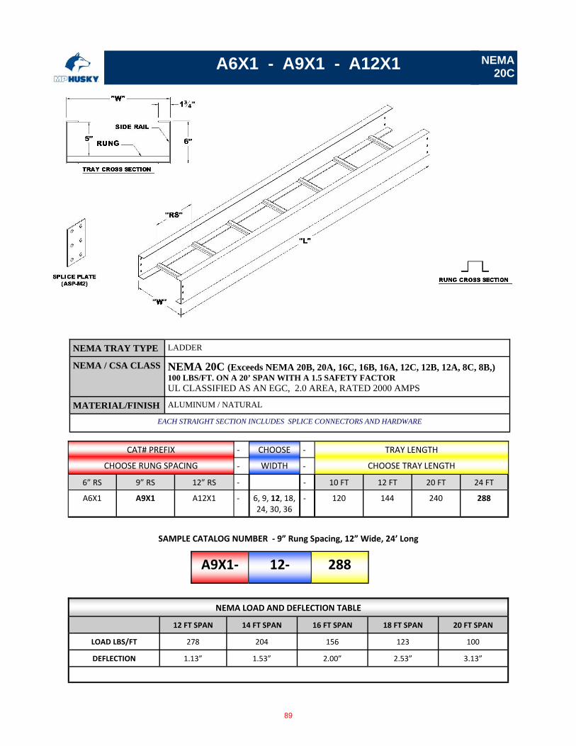
A6X1 - A9X1 - A12X1
CAT# PREFIX ‐ CHOOSE ‐ TRAY LENGTH
CHOOSE RUNG SPACING ‐ WIDTH ‐ CHOOSE TRAY LENGTH
6” RS 9” RS 12” RS ‐ ‐ 10 FT 12 FT 20 FT 24 FT
A6X1 A9X1 A12X1 ‐ 6, 9, 12, 18, 24, 30, 36
‐ 120 144 240 288
NEMA LOAD AND DEFLECTION TABLE
12 FT SPAN 14 FT SPAN 16 FT SPAN 18 FT SPAN 20 FT SPAN
LOAD LBS/FT 278 204 156 123 100
DEFLECTION 1.13” 1.53” 2.00” 2.53” 3.13”
A9X1‐ 12‐ 288
SAMPLE CATALOG NUMBER ‐ 9” Rung Spacing, 12” Wide, 24’ Long
NEMA 20C
NEMA TRAY TYPE LADDER
NEMA / CSA CLASS NEMA 20C (Exceeds NEMA 20B, 20A, 16C, 16B, 16A, 12C, 12B, 12A, 8C, 8B,) 100 LBS/FT. ON A 20’ SPAN WITH A 1.5 SAFETY FACTOR UL CLASSIFIED AS AN EGC, 2.0 AREA, RATED 2000 AMPS
MATERIAL/FINISH ALUMINUM / NATURAL
EACH STRAIGHT SECTION INCLUDES SPLICE CONNECTORS AND HARDWARE
89
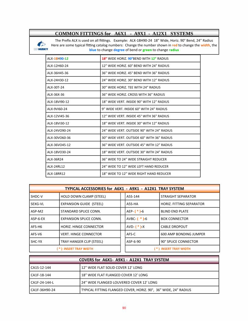
The Prefix ALX is used on all fi ngs. Example: ALX‐18H90‐24 18” Wide, Horiz. 90° Bend, 24” Radius Here are some typical fi ng catalog numbers: Change the number shown in red to change the width, the
blue to change degree of bend or green to change radius
ALX‐18H90‐12 18” WIDE HORIZ. 90°BEND WITH 12” RADIUS
ALX‐12H60‐24 12” WIDE HORIZ. 60° BEND WITH 24” RADIUS
ALX‐36H45‐36 36” WIDE HORIZ. 45° BEND WITH 36” RADIUS
ALX‐24H30‐12 24” WIDE HORIZ. 30° BEND WITH 12” RADIUS
ALX‐30T‐24 30” WIDE HORIZ. TEE WITH 24” RADIUS
ALX‐36X‐36 36” WIDE HORIZ. CROSS WITH 36” RADIUS
ALX‐18VI90‐12 18” WIDE VERT. INSIDE 90° WITH 12” RADIUS
ALX‐9VI60‐24 9” WIDE VERT. INSIDE 60° WITH 24” RADIUS
ALX‐12VI45‐36 12” WIDE VERT. INSIDE 45° WITH 36” RADIUS
ALX‐18VI30‐12 18” WIDE VERT. INSIDE 30° WITH 12” RADIUS
ALX‐24VO90‐24 24” WIDE VERT. OUTSIDE 90° WITH 24” RADIUS
ALX‐30VO60‐36 30” WIDE VERT. OUTSIDE 60° WITH 36” RADIUS
ALX‐36VO45‐12 36” WIDE VERT. OUTSIDE 45° WITH 12” RADIUS
ALX‐18VO30‐24 18” WIDE VERT. OUTSIDE 30° WITH 24” RADIUS
ALX‐36R24 36” WIDE TO 24” WIDE STRAIGHT REDUCER
ALX‐24RL12 24” WIDE TO 12” WIDE LEFT HAND REDUCER
ALX‐18RR12 18” WIDE TO 12” WIDE RIGHT HAND REDUCER
TYPICAL ACCESSORIES for A6X1 ‐ A9X1 ‐ A12X1 TRAY SYSTEM
SHDC‐V HOLD DOWN CLAMP (STEEL) A5S‐144 STRAIGHT SEPARATOR
SEXG‐VL EXPANSION GUIDE (STEEL) A5S‐HA HORIZ. FITTING SEPARATOR
ASP‐M2 STANDARD SPLICE CONN. AEP‐ ( * )‐6 BLIND END PLATE
ASP‐6‐EX EXPANSION SPLICE CONN. AVBC‐ ( * )‐6 BOX CONNECTOR
AFS‐H6 HORIZ. HINGE CONNECTOR AVD‐ ( * )‐X CABLE DROPOUT
AFS‐V6 VERT. HINGE CONNECTOR AFS‐C 600 AMP BONDING JUMPER
SHC‐YX TRAY HANGER CLIP (STEEL) ASP‐6‐90 90° SPLICE CONNECTOR
( * ) INSERT TRAY WIDTH ( * ) INSERT TRAY WIDTH
CA1S‐12‐144 12” WIDE FLAT SOLID COVER 12’ LONG
CA1F‐18‐144 18” WIDE FLAT FLANGED COVER 12’ LONG
CA1F‐24‐144‐L 24” WIDE FLANGED LOUVERED COVER 12’ LONG
COVERS for A6X1‐ A9X1 ‐ A12X1 TRAY SYSTEM
CA1F‐36H90‐24 TYPICAL FITTING FLANGED COVER, HORIZ. 90°, 36” WIDE, 24” RADIUS
COMMON FITTINGS for A6X1 - A9X1 - A12X1 SYSTEMS
90
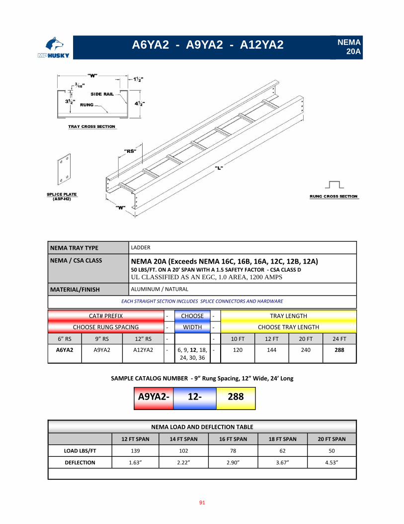
A6YA2 - A9YA2 - A12YA2
CAT# PREFIX ‐ CHOOSE ‐ TRAY LENGTH
CHOOSE RUNG SPACING ‐ WIDTH ‐ CHOOSE TRAY LENGTH
6” RS 9” RS 12” RS ‐ ‐ 10 FT 12 FT 20 FT 24 FT
A6YA2 A9YA2 A12YA2 ‐ 6, 9, 12, 18, 24, 30, 36
‐ 120 144 240 288
NEMA LOAD AND DEFLECTION TABLE
12 FT SPAN 14 FT SPAN 16 FT SPAN 18 FT SPAN 20 FT SPAN
LOAD LBS/FT 139 102 78 62 50
DEFLECTION 1.63” 2.22” 2.90” 3.67” 4.53”
A9YA2‐ 12‐ 288
SAMPLE CATALOG NUMBER ‐ 9” Rung Spacing, 12” Wide, 24’ Long
NEMA 20A
NEMA TRAY TYPE LADDER
NEMA / CSA CLASS NEMA 20A (Exceeds NEMA 16C, 16B, 16A, 12C, 12B, 12A) 50 LBS/FT. ON A 20’ SPAN WITH A 1.5 SAFETY FACTOR ‐ CSA CLASS D
UL CLASSIFIED AS AN EGC, 1.0 AREA, 1200 AMPS
MATERIAL/FINISH ALUMINUM / NATURAL
EACH STRAIGHT SECTION INCLUDES SPLICE CONNECTORS AND HARDWARE
91
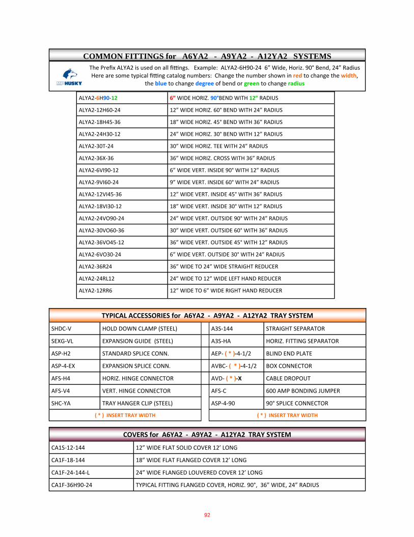
The Prefix ALYA2 is used on all fi ngs. Example: ALYA2‐6H90‐24 6” Wide, Horiz. 90° Bend, 24” Radius Here are some typical fi ng catalog numbers: Change the number shown in red to change the width,
the blue to change degree of bend or green to change radius
ALYA2‐6H90‐12 6” WIDE HORIZ. 90°BEND WITH 12” RADIUS
ALYA2‐12H60‐24 12” WIDE HORIZ. 60° BEND WITH 24” RADIUS
ALYA2‐18H45‐36 18” WIDE HORIZ. 45° BEND WITH 36” RADIUS
ALYA2‐24H30‐12 24” WIDE HORIZ. 30° BEND WITH 12” RADIUS
ALYA2‐30T‐24 30” WIDE HORIZ. TEE WITH 24” RADIUS
ALYA2‐36X‐36 36” WIDE HORIZ. CROSS WITH 36” RADIUS
ALYA2‐6VI90‐12 6” WIDE VERT. INSIDE 90° WITH 12” RADIUS
ALYA2‐9VI60‐24 9” WIDE VERT. INSIDE 60° WITH 24” RADIUS
ALYA2‐12VI45‐36 12” WIDE VERT. INSIDE 45° WITH 36” RADIUS
ALYA2‐18VI30‐12 18” WIDE VERT. INSIDE 30° WITH 12” RADIUS
ALYA2‐24VO90‐24 24” WIDE VERT. OUTSIDE 90° WITH 24” RADIUS
ALYA2‐30VO60‐36 30” WIDE VERT. OUTSIDE 60° WITH 36” RADIUS
ALYA2‐36VO45‐12 36” WIDE VERT. OUTSIDE 45° WITH 12” RADIUS
ALYA2‐6VO30‐24 6” WIDE VERT. OUTSIDE 30° WITH 24” RADIUS
ALYA2‐36R24 36” WIDE TO 24” WIDE STRAIGHT REDUCER
ALYA2‐24RL12 24” WIDE TO 12” WIDE LEFT HAND REDUCER
ALYA2‐12RR6 12” WIDE TO 6” WIDE RIGHT HAND REDUCER
TYPICAL ACCESSORIES for A6YA2 ‐ A9YA2 ‐ A12YA2 TRAY SYSTEM
SHDC‐V HOLD DOWN CLAMP (STEEL) A3S‐144 STRAIGHT SEPARATOR
SEXG‐VL EXPANSION GUIDE (STEEL) A3S‐HA HORIZ. FITTING SEPARATOR
ASP‐H2 STANDARD SPLICE CONN. AEP‐ ( * )‐4‐1/2 BLIND END PLATE
ASP‐4‐EX EXPANSION SPLICE CONN. AVBC‐ ( * )‐4‐1/2 BOX CONNECTOR
AFS‐H4 HORIZ. HINGE CONNECTOR AVD‐ ( * )‐X CABLE DROPOUT
AFS‐V4 VERT. HINGE CONNECTOR AFS‐C 600 AMP BONDING JUMPER
SHC‐YA TRAY HANGER CLIP (STEEL) ASP‐4‐90 90° SPLICE CONNECTOR
( * ) INSERT TRAY WIDTH ( * ) INSERT TRAY WIDTH
CA1S‐12‐144 12” WIDE FLAT SOLID COVER 12’ LONG
CA1F‐18‐144 18” WIDE FLAT FLANGED COVER 12’ LONG
CA1F‐24‐144‐L 24” WIDE FLANGED LOUVERED COVER 12’ LONG
COVERS for A6YA2 ‐ A9YA2 ‐ A12YA2 TRAY SYSTEM
CA1F‐36H90‐24 TYPICAL FITTING FLANGED COVER, HORIZ. 90°, 36” WIDE, 24” RADIUS
COMMON FITTINGS for A6YA2 - A9YA2 - A12YA2 SYSTEMS
92

13-C
ove
rs
CABLE TRAY
8 6 4 . 2 3 4 . 4 8 0 0m p h u s k y . c o m
Copyright 2010 MP Husky. All rights reserved.162
COP-A2S( )-W-144-15
CS2F( )-24-144
CoversCover Numbering SystemMP Husky offers a wide variety of covers to provide protection for the cables contained within the system from sunlight, environ-mental elements, dirt, debris, and falling objects. All of the covers listed here are used for indoor as well as outdoor applications. Covers are fabricated from corrosion resistant aluminum, mill-galvanized steel, galvannealled and 304 or 316 stainless steel. Al-though not recommended, covers can be supplied in HDGAF steel on request (some distortion may occur when dipping). Most covers are supplied in standard 12 foot lengths and are available in six foot lengths upon request. HDGAF covers are supplied in 6 foot lengths, and 18GA material is required.
C 0 P- A 2 S ( )- W- 144- 15
IndicatesCover
CoverHeight
CoverShape
MaterialType
TrayType
CoverType
Thicknessor Gauge Width Length Degree
of slope
For Louvered Flat, Flat Flanged and Hat-Shaped covers, add (-L) at the end of the catalog number on straights only.Example: CA1F-24-144-L
CAGF Aluminum Channel CoverCSGF2 Steel Channel Cover
C S 2 F ( )- 24- 144 Louvered
Indicates Cover
MaterialType
TrayType
CoverType
MaterialGauge Width Length
(12ft)-L at
the end
Material Type (A) Aluminum (S) Mill-Galv Steel(G) HDGAF Steel(N) Galvannealed (4) 304 Stainless(6) 316 Stainless
Tray Type(1) All Flange In(2) 3/4” Flange Out(3) 1-3/4” Flange Out(4) 1-1/2” Flange Out(5) 1-1/4” Flange Out(6) 1/2” Flange out(G) AG & SG Channel
Cover TypeFlat, Flanged & Corrugated(C) Corrugated (non-ventilated)(V) Corrugated (ventilated)(S) Flat (non-ventilated)(F) Flat Flanged (non venti-lated)Hat Shaped & Peaked(S) Flat Solid (non-flanged)(F) Flanged
Material ThicknessStandards are:22 Gauge Non-corrugated Steel,040” Non-corrugated Aluminum( )Insert Optional Cover Gauge forNon-corrugated Covers(2) 22 Gauge Standard Steel(0) 20 Gauge Steel (Optional)(8) 18 Gauge Steel (Optional)(6) 16 Gage Steel or .063” Aluminum (Optional)
Cover ShapeHat Shaped(S) Solid Top (non-ventilated)(V) Corrugated (Ventilated)Peaked(P) Peaked (non-ventilated)
Cover Height Hat Shaped(2) 2” High(4) 4” HighPeaked(0) 1/2” High Peak (If Degree of slope is omitted) By Degree if included
Length(144) 12 Ft Length(120) 10 Ft Length(72) 6 Ft Length(60) 5 Ft Length
Flat, Flanged and Corrugated Covers
Straight Sections
Fittings CS2F( )-24H90-12
C S 2 F ( )- 24H90- 12
Indicates Cover
MaterialType
TrayType
CoverType
MaterialGauge
FittingDesig. Radius
Hat Shaped or Peak Covers
93

13-C
ove
rs
8 6 4 . 2 3 4 . 4 8 0 0m p h u s k y . c o m
Copyright 2010 MP Husky. All rights reserved.
CABLE BUSCABLE TRAY
163
Types of Covers
Flat and Flat FlangedFlat covers are economical and avail-able for all straight sections and fittings. These covers are available flat without flanges or flat with 3/8” flanges for Husky Trough, Husky Ladder, and Husky Way. Flat flanged covers should be used on all 4” and 6” wide channel ap-plications requiring covers. Flat flanged shown.
Hat-ShapedHat-shaped covers are designed to protect installations where the cables extend above the upper flanges of the tray. Hat-shaped covers are available with a flat solid top or a corrugated ventilated top and in 2” or 4” height. Non-ventilated shown.
LouveredLouvered covers are available for all straight sections and are available as Flat, Flat Flanged, or Hat Shaped. Flat Solid shown.
PeakedPeaked covers are available for straight sections only and are gen-erally used to deflect falling objects or to prevent the accumulation of snow or other debris. Standard peak height is 1/2”, however, higher peaks are available upon request. Non-flanged shown.
Corrugated VentilatedCorrugated covers are made of ventilated or non-ventilated corrugated sheets. Corrugated covers are rigid, lightweight and will readily form to vertical fittings, with the exception of Husky Ladder Flange Out style. All covers for horizontal fittings are made of non-ventilated (solid) flat sheets without a flange.Space does not permit an illustration of every type of cover variation. For instance, corrugated covers are available either ventilated or non-ventilated in flat or hat-shaped configurations. If in doubt about the cover best suited to your application, please consult the factory.
94
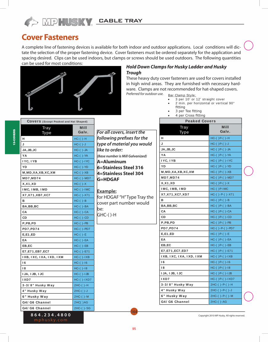
13-C
ove
rs
CABLE TRAY
8 6 4 . 2 3 4 . 4 8 0 0m p h u s k y . c o m
Copyright 2010 MP Husky. All rights reserved.164
A complete line of fastening devices is available for both indoor and outdoor applications. Local conditions will dic-tate the selection of the proper fastening device. Cover fasteners must be ordered separately for the application and spacing desired. Clips can be used indoors, but clamps or screws should be used outdoors. The following quantities can be used for most conditions:
Bar Clamp Style: • 3 per 10’ or 12’ straight cover • 2 min. per horizontal or vertical 90°
fitting • 3 per Tee fitting • 4 per Cross fitting
Peaked Covers
Hold Down Clamps for Husky Ladder and Husky TroughThese heavy duty cover fasteners are used for covers installed in high wind areas. They are furnished with necessary hard-ware. Clamps are not recommended for hat-shaped covers. Preferred for outdoor use.
Cover Fasteners
Covers (Except Peaked and Hat Shaped)
Tray Type
MillGalv.
H HC-( )-H
J HC-( )-J
JA,JB,JC HC-( )-JA
YA HC-( )-YA
IYC, IYB HC-( )-IYC
YD HC-( )-YD
M,MD,XA,XB,XC,XM HC-( )-XB
MD7,MD74 HC-( )-MD7
X,X1,XD HC-( )-X
IMC, IMB, IMD HC-( )-IMC
X7,X71,XB7,XC7 HC-( )-X71
B HC-( )-B
BA,BB,BC HC-( )-BA
CA HC-( )-CA
CD HC-( )-CD
P,PB,PD HC-( )-PB
PD7,PD74 HC-( )-PD7
E,E1,ED HC-( )-E
EA HC-( )-EA
EB,EC HC-( )-EB
E7,E71,EB7,EC7 HC-( )-E71
IXB, IXC, IXA, IXD, IXM HC-( )-IXB
I6 HC-( )-I6
I8 HC-( )-I8
IJA, IJB, IJC HC-( )-IJB
IXD7 HC-( )-IXD7
3-3/8” Husky Way 2HC-( )-H
4” Husky Way 2HC-( )-J
6” Husky Way 2HC-( )-M
G4/G6 Channel 2HC( )AG
G4/G6 Channel 2HC-( )-SG
Tray Type
MillGalv.
H HC-( )P-( )-H
J HC-( )P-( )-J
JA,JB,JC HC-( )P-( )-JA
YA HC-( )P-( )-YA
IYC, IYB HC-( )P-( )-IYC
YD HC-( )P-( )-YD
M,MD,XA,XB,XC,XM HC-( )P-( )-XB
MD7,MD74 HC-( )P-( )-MD7
X,X1,XD HC-( )P-( )-X
IMC, IMB, IMD HC-( )P-IMC
X7,X71,XC7,XD7 HC-( )-P-( )-X71
B HC-( )P-( )-B
BA,BB,BC HC-( )P-( )-BA
CA HC-( )P-( )-CA
CD HC-( )P-( )-CD
P,PB,PD HC-( )P-( )-PB
PD7,PD74 HC-( )-P-( )-PD7
E,E1,ED HC-( )P-( )-E
EA HC-( )P-( )-EA
EB,EC HC-( )P-( )-EB
E7,E71,EC7,ED7 HC-( )P-( )-E71
IXB, IXC, IXA, IXD, IXM HC-( )P-( )-IXB
I6 HC-( )P-( )-I6
I8 HC-( )P-( )-I8
IJA, IJB, IJC HC-( )P-( )-IJB
IXD7 HC-( )P-( )-IXD7
3-3/8” Husky Way 2HC-( )-P-( )-H
4” Husky Way 2HC-( )-P-( )-J
6” Husky Way 2HC-( )-P-( )-M
G4/G6 Channel 2HC-( )-AG
For all covers, insert the following prefixes for the type of material you would like to order:(Base number is Mill Galvanized)
A=Aluminum6=Stainless Steel 3164=Stainless Steel 304G=HDGAF
Example:for HDGAF “H” Type Tray the cover part number would be:GHC-( )-H
95

8 6 4 . 2 3 4 . 4 8 0 0m p h u s k y . c o m
Copyright 2010 MP Husky. All rights reserved.
CABLE TRAY
110
10-F
ITTI
NG
S Numbering System
SLYD-24H90-24
Husky Ladder - Flange In Husky Ladder - Flange Out
To Determine Fitting Catalog Number (Prefix + Basic Part Number):1. Select prefix of type of Cable Tray required for your application from Catalog pages below: Aluminum Steel Flange In Ladder Pgs. 110 -113 Flange In Ladder Pgs. 110-113 Flange Out Ladder Pgs. 110 -113 Flange Out Ladder Pgs. 110-113 I-Beam Ladder Pgs. 110 -113 Trough Pgs. 110-113 Husky Way Pgs. 110 -113 Husky Way Pgs. 110-113 Trough Pgs. 110-113 EMI Pgs. 110-113 I-Beam Trough Pgs. 110-113
2. Use selected Cable Tray prefix in the Fitting Prefix Selction Tables below to select the corresponding fitting prefix.3. Go to Pages.....in this section to find the desired fittings and select the Basic Part Numbers that correspond to the required fit-tings.4. Add fitting prefix to basic part numbers to complete product catalog numbers (example above).
12A A6IJA,A9IJA,A12IJA ALIJA
12B A6IJB, A9IJB, A12IJB
12C A6IJC, A9IJC, A12IJC ALIJC
20B A6IYB, A9IYB, A12IYB ALIYB
20C A6IYC, A9IYC, A12IYC ALIYC
12B A6IMB, A9IMB, A12IMB ALIMB
12C A6IMC, A9IMC, A12IMC ALIMC
12C+ A6IMD, A9IMD, A12IMD ALIMD
20B A6IXA, A9IXA, A12IXA ALIXA
20B A6IXB, A9IXB, A12IXB ALIXB
20C A6IXC, A9IXC, A12IXC ALIXC
20C+ A6IXD, A9IXD, A12IXD ALIXD
20C A6IXD7, A9IXD7, A12IXD7 ALIXD7
24C+ A9I6, A12I6, A18I6 ALI6
30C+ A9I8, A12I8, A18I8 ALI8
Husky I-Beam LadderNEMAClass
StraightTray
Fitting Prefix
Aluminum Husky Way
A L U M I N U M Fitting Prefix Selection Table
Prefix Basic Part Number
SLYD- 24 H 90- 24Tray Fitting PrefixPrefix Determined By
Chart Below and Based on Straight Tray Prefix
Tray Width6”, 9”, 12”, 18”, 24”,
30”, 36”
BendH=Horizontal
VI=Vertical InsideVO=Vertical Outside
T=TeeVT=Vertical Tee
VS=Vertical Support 90°X=Cross
R=Straight ReducerRL=Left Hand Ruducer
RR=Right Hand Reducer
Degree of Bend30°, 45°, 60°,
or 90°
Fitting Radius
12”, 24” or 36”
Example Fitting for S6YD, S9YD, S12YD
NEMAClass
StraightTray
Fitting Prefix
StraightTray
Fitting Prefix
12A A6JA, A9JA, A12JA ALJA A9BA, A12BA, A18BA ALBA
12B A6JB, A9JB, A12JB ALJB A9BB, A12BB, A18BB ALBB
20A A6YA, A9YA, A12YA ALYA A9CA, A12CA, A18CA ALCA
12B A6MB, A9MB, A12MB ALMB A9PB, A12PB, A18PB ALPB
20A A6XA, A9XA, A12XA ALX A9EA, A12EA, A18EA ALE
20B A6X, A9X, A12X ALX A9E, A12E, A18E ALE
20C+ A6X1, A9X1, A12X1 ALX A9E1, A12E1, A18E1 ALE
20B A6X7, A9X7, A12X7 ALX7 A9E7, A12E7, A18E7 ALE7
20C A6X71, A9X71, A12X71 ALX7 A9E71, A12E71, A18E71 ALE7
ASH6 ASH6
ASJ6 ASJ6
ASM6 ASM6
96
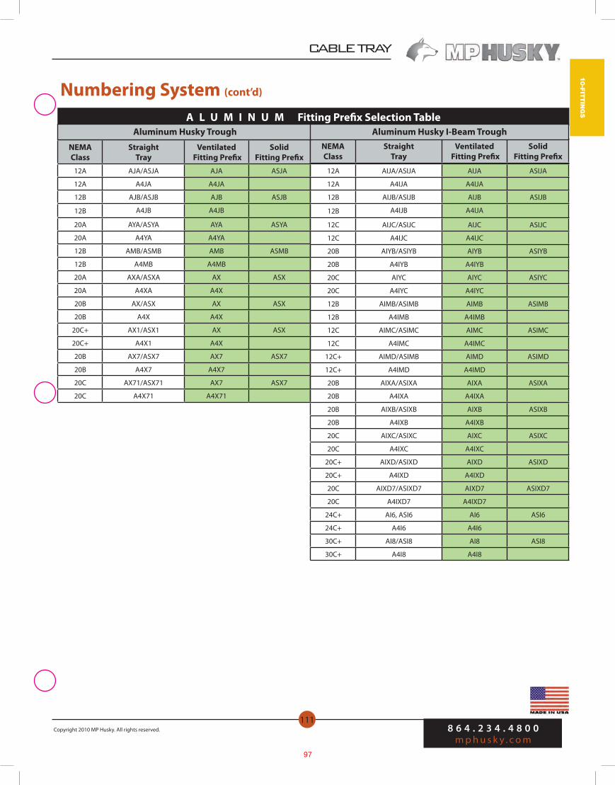
CABLE TRAY
8 6 4 . 2 3 4 . 4 8 0 0m p h u s k y . c o m
Copyright 2010 MP Husky. All rights reserved.
111
10-FITTIN
GS
Numbering System (cont’d)
A L U M I N U M Fitting Prefix Selection Table
NEMAClass
Straight Tray
Ventilated Fitting Prefix
Solid Fitting Prefix
12A AJA/ASJA AJA ASJA
12A A4JA A4JA
12B AJB/ASJB AJB ASJB
12B A4JB A4JB
20A AYA/ASYA AYA ASYA
20A A4YA A4YA
12B AMB/ASMB AMB ASMB
12B A4MB A4MB
20A AXA/ASXA AX ASX
20A A4XA A4X
20B AX/ASX AX ASX
20B A4X A4X
20C+ AX1/ASX1 AX ASX
20C+ A4X1 A4X
20B AX7/ASX7 AX7 ASX7
20B A4X7 A4X7
20C AX71/ASX71 AX7 ASX7
20C A4X71 A4X71
NEMA Class
Straight Tray
Ventilated Fitting Prefix
Solid Fitting Prefix
Aluminum Husky Trough Aluminum Husky I-Beam Trough
12A AIJA/ASIJA AIJA ASIJA
12A A4IJA A4IJA
12B AIJB/ASIJB AIJB ASIJB
12B A4IJB A4IJA
12C AIJC/ASIJC AIJC ASIJC
12C A4IJC A4IJC
20B AIYB/ASIYB AIYB ASIYB
20B A4IYB A4IYB
20C AIYC AIYC ASIYC
20C A4IYC A4IYC
12B AIMB/ASIMB AIMB ASIMB
12B A4IMB A4IMB
12C AIMC/ASIMC AIMC ASIMC
12C A4IMC A4IMC
12C+ AIMD/ASIMB AIMD ASIMD
12C+ A4IMD A4IMD
20B AIXA/ASIXA AIXA ASIXA
20B A4IXA A4IXA
20B AIXB/ASIXB AIXB ASIXB
20B A4IXB A4IXB
20C AIXC/ASIXC AIXC ASIXC
20C A4IXC A4IXC
20C+ AIXD/ASIXD AIXD ASIXD
20C+ A4IXD A4IXD
20C AIXD7/ASIXD7 AIXD7 ASIXD7
20C A4IXD7 A4IXD7
24C+ AI6, ASI6 AI6 ASI6
24C+ A4I6 A4I6
30C+ AI8/ASI8 AI8 ASI8
30C+ A4I8 A4I8
97
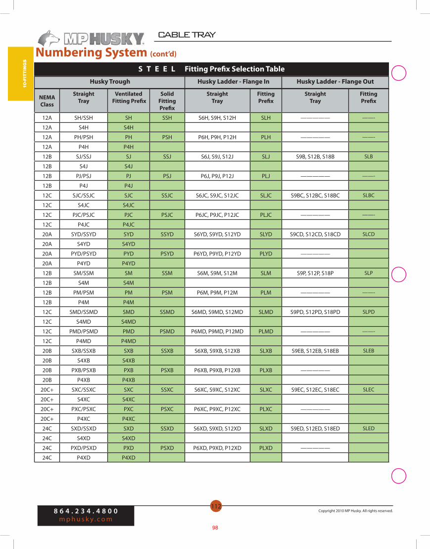
8 6 4 . 2 3 4 . 4 8 0 0m p h u s k y . c o m
Copyright 2010 MP Husky. All rights reserved.
CABLE TRAY
112
10-F
ITTI
NG
S
NEMAClass
Straight Tray
Ventilated Fitting Prefix
Solid Fitting Prefix
StraightTray
Fitting Prefix
StraightTray
Fitting Prefix
12A SH/SSH SH SSH S6H, S9H, S12H SLH ————— ——-
12A S4H S4H
12A PH/PSH PH PSH P6H, P9H, P12H PLH ————— ——-
12A P4H P4H
12B SJ/SSJ SJ SSJ S6J, S9J, S12J SLJ S9B, S12B, S18B SLB
12B S4J S4J
12B PJ/PSJ PJ PSJ P6J, P9J, P12J PLJ ————— ——-
12B P4J P4J
12C SJC/SSJC SJC SSJC S6JC, S9JC, S12JC SLJC S9BC, S12BC, S18BC SLBC
12C S4JC S4JC
12C PJC/PSJC PJC PSJC P6JC, P9JC, P12JC PLJC ————— ——-
12C P4JC P4JC
20A SYD/SSYD SYD SSYD S6YD, S9YD, S12YD SLYD S9CD, S12CD, S18CD SLCD
20A S4YD S4YD
20A PYD/PSYD PYD PSYD P6YD, P9YD, P12YD PLYD —————
20A P4YD P4YD
12B SM/SSM SM SSM S6M, S9M, S12M SLM S9P, S12P, S18P SLP
12B S4M S4M
12B PM/PSM PM PSM P6M, P9M, P12M PLM ————— ——-
12B P4M P4M
12C SMD/SSMD SMD SSMD S6MD, S9MD, S12MD SLMD S9PD, S12PD, S18PD SLPD
12C S4MD S4MD
12C PMD/PSMD PMD PSMD P6MD, P9MD, P12MD PLMD ————— ——-
12C P4MD P4MD
20B SXB/SSXB SXB SSXB S6XB, S9XB, S12XB SLXB S9EB, S12EB, S18EB SLEB
20B S4XB S4XB
20B PXB/PSXB PXB PSXB P6XB, P9XB, P12XB PLXB —————
20B P4XB P4XB
20C+ SXC/SSXC SXC SSXC S6XC, S9XC, S12XC SLXC S9EC, S12EC, S18EC SLEC
20C+ S4XC S4XC
20C+ PXC/PSXC PXC PSXC P6XC, P9XC, P12XC PLXC —————
20C+ P4XC P4XC
24C SXD/SSXD SXD SSXD S6XD, S9XD, S12XD SLXD S9ED, S12ED, S18ED SLED
24C S4XD S4XD
24C PXD/PSXD PXD PSXD P6XD, P9XD, P12XD PLXD —————
24C P4XD P4XD
Husky Trough Husky Ladder - Flange In Husky Ladder - Flange Out
S T E E L Fitting Prefix Selection Table
Numbering System (cont’d)
98
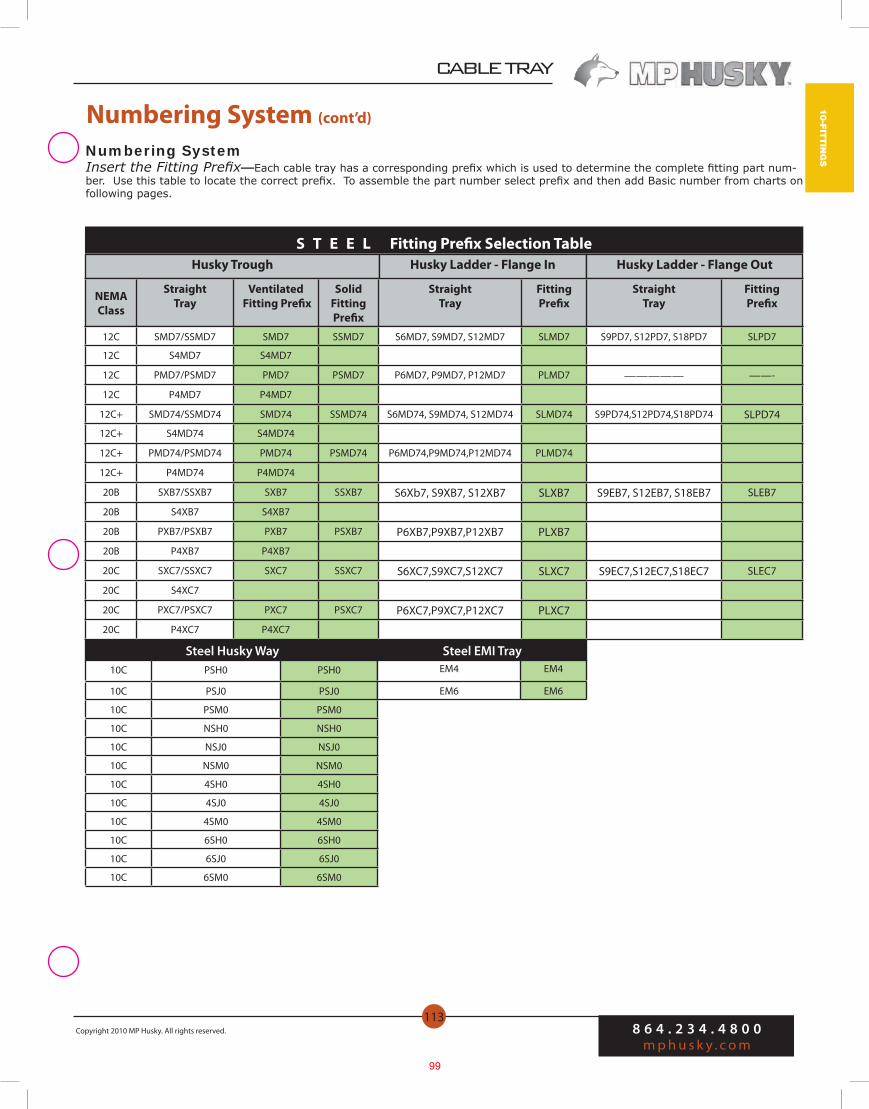
CABLE TRAY
8 6 4 . 2 3 4 . 4 8 0 0m p h u s k y . c o m
Copyright 2010 MP Husky. All rights reserved.
113
10-FITTIN
GS
Numbering System (cont’d)
S T E E L Fitting Prefix Selection Table
Numbering System Insert the Fitting Prefix—Each cable tray has a corresponding prefix which is used to determine the complete fitting part num-ber. Use this table to locate the correct prefix. To assemble the part number select prefix and then add Basic number from charts on following pages.
Husky Trough Husky Ladder - Flange In Husky Ladder - Flange Out
NEMAClass
Straight Tray
Ventilated Fitting Prefix
Solid Fitting Prefix
StraightTray
Fitting Prefix
StraightTray
Fitting Prefix
12C SMD7/SSMD7 SMD7 SSMD7 S6MD7, S9MD7, S12MD7 SLMD7 S9PD7, S12PD7, S18PD7 SLPD7
12C S4MD7 S4MD7
12C PMD7/PSMD7 PMD7 PSMD7 P6MD7, P9MD7, P12MD7 PLMD7 ————— ——-
12C P4MD7 P4MD7
12C+ SMD74/SSMD74 SMD74 SSMD74 S6MD74, S9MD74, S12MD74 SLMD74 S9PD74,S12PD74,S18PD74 SLPD74
12C+ S4MD74 S4MD74
12C+ PMD74/PSMD74 PMD74 PSMD74 P6MD74,P9MD74,P12MD74 PLMD74
12C+ P4MD74 P4MD74
20B SXB7/SSXB7 SXB7 SSXB7 S6Xb7, S9XB7, S12XB7 SLXB7 S9EB7, S12EB7, S18EB7 SLEB7
20B S4XB7 S4XB7
20B PXB7/PSXB7 PXB7 PSXB7 P6XB7,P9XB7,P12XB7 PLXB7
20B P4XB7 P4XB7
20C SXC7/SSXC7 SXC7 SSXC7 S6XC7,S9XC7,S12XC7 SLXC7 S9EC7,S12EC7,S18EC7 SLEC7
20C S4XC7
20C PXC7/PSXC7 PXC7 PSXC7 P6XC7,P9XC7,P12XC7 PLXC7
20C P4XC7 P4XC7
Steel Husky Way10C PSH0 PSH0
10C PSJ0 PSJ0
10C PSM0 PSM0
10C NSH0 NSH0
10C NSJ0 NSJ0
10C NSM0 NSM0
10C 4SH0 4SH0
10C 4SJ0 4SJ0
10C 4SM0 4SM0
10C 6SH0 6SH0
10C 6SJ0 6SJ0
10C 6SM0 6SM0
EM4 EM4
EM6 EM6
Steel EMI Tray
99

CABLE TRAY
8 6 4 . 2 3 4 . 4 8 0 0m p h u s k y . c o m
Copyright 2010 MP Husky. All rights reserved.
117
10-FITTIN
GS
Horizontal Tee
Width Radius Prefix Basic A B C D L
36362412
36T-3636T-2436T-12
544230
1088460
544230
726848
84-13/1666
47-1/8
30362412
30T-3630T-2430T-12
513927
1027854
513927
665442
80-1/861-1/4
42-7/16
24362412
24T-3624T-2424T-12
483624
967248
483624
604836
75-7/1659-9/16
37-11/16
18362412
18T-3618T-2418T-12
453321
906642
453321
544230
70-11/1651-13/16
33
12362412
12T-3612T-2412T-12
423018
846036
423018
483624
6647-1/828-1/4
9362412
9T-369T-249T-12
40-1/228-1/216-1/2
815733
40-1/228-1/216-1/2
453321
63-5/844-3/425-7/8
6362412
6T-366T-246T-12
392715
785430
392715
423018
61-1/442-3/8
23-9/16
Catalog No.
See
Tab
les
on P
ages
110
-113
Husky Ladder—Flange In24”W x 12”R Horizontal Tee
Sample Tee Catalog No.(Prefix + Basic)
(All Except I6 & I8)SLH- 24T-12
Note: Chart based on standard fittings without tangents. Contact factory for fittings with tangents.
Fitting Dimensions
100

8 6 4 . 2 3 4 . 4 8 0 0m p h u s k y . c o m
Copyright 2010 MP Husky. All rights reserved.
CABLE TRAY
122
10-F
ITTI
NG
S
Width Radius Prefix Basic A B C L
36362412
36H90-3636H90-2436H90-12
544230
544230
544230
84-13/1666
47-1/8
30362412
30H90-3630H90-2430H90-12
513927
513927
513927
80-1/861-1/442-7/16
24362412
24H90-3624H90-2424H90-12
483624
483624
483624
75-7/1656-9/1637-11/16
18362412
18H90-3618H90-2418H90-12
453321
453321
453321
70-11/1651-13/16
33
12362412
12H90-3612H90-2412H90-12
423018
423018
423018
6647-1/828-1/4
9362412
9H90-369H90-249H90-12
40-1/228-1/216-1/2
40-1/228-1/216-1/2
40-1/228-1/216-1/2
63-5/844-3/425-7/8
6362412
6H90-366H90-246H90-12
392715
392715
392715
61-1/442-3/423-9/16
90° Horizontal Bend(All except I6 & I8)
Catalog No.
60° Horizontal Bend(All except I6 & I8)
See
Tab
les
on P
ages
110
-113
Sample Catalog No.(Prefix + Basic)
Husky Ladder—Flange In36”W x 24”R 90° Horizontal Bend
Sample Catalog No.(Prefix + Basic)
Husky Ladder—Flange Out36”W x 24”R 60° Horizontal Bend
ALYA- 36H90-24
ALE- 36H60-24
Catalog No.
Note: Chart based on standard fittings without tangents. Contact factory for fittings with tangents.
Note: Chart based on standard fittings without tangents. Contact factory for fittings with tangents.
Fitting DimensionsWidth Radius Prefix Basic A B C D L
36362412
36H60-3636H60-2436H60-12
272115
46-3/436-3/8
26
544230
31-3/1624-1/417-5/16
56-9/1644
31-7/16
30362412
30H60-3630H60-2430H60-12
25-1/219-1/213-1/2
44-3/1633-3/423-3/8
513927
29-7/1622-1/215-9/16
53-3/840-13/1628-1/4
24362412
24H60-3624H60-2424H60-12
241812
41-9/1631-3/1620-3/4
483624
27-11/1620-13/1613-7/8
50-1/437-11/1625-1/8
18362412
18H60-3618H60-2418H60-12
22-1/216-1/210-1/2
3928-9/1618-3/16
453321
2619-1/1612-1/8
47-1/834-9/16
22
12362412
12H60-3612H60-2412H60-12
21159
36-3/826
15-9/16
423018
24-1/417-5/1610-3/8
4431-7/1618-7/8
9362412
9H60-369H60-249H60-12
20-1/414-1/48-1/4
36-1/1624-11/1614-5/16
40-1/228-1/216-1/2
23-3/816-7/169-1/2
42-3/829-13/1617-1/4
6362412
6H60-366H60-246H60-12
19-1/213-1/27-1/2
33-3/423-3/8
13
392715
22-1/215-9/168-11/16
40-13/1628-1/4
15-11/16
Fitting Dimensions
See
Tab
les
on P
ages
110
-113
101

CABLE TRAY
8 6 4 . 2 3 4 . 4 8 0 0m p h u s k y . c o m
Copyright 2010 MP Husky. All rights reserved.
123
10-FITTIN
GS
Catalog No.30° Horizontal Bend(All except I6 & I8)
45° Horizontal Bend(All except I6 & I8) Catalog No.
Sample Catalog No.(Prefix + Basic)
Husky Ladder—Flange In30”W x 36”R 45° Horizontal Bend
Sample Catalog No.(Prefix + Basic)
Husky Ladder—Flange Out18”W x 24”R 30° Horizontal Bend
ALBB- 18H30-24
SLM- 30H45-36
Width Radius Prefix Basic A B C D L
36362412
36H45-3636H45-2436H45-12
272115
46-3/436-3/8
26
544230
31-3/1624-1/417-5/16
56-9/1644
31-7/16
30362412
30H45-3630H45-2430H45-12
25-1/219-1/213-1/2
44-3/1633-3/423-3/8
513927
29-7/1622-1/215-9/16
53-3/840-13/1628-1/4
24362412
24H45-3624H45-2424H45-12
241812
41-9/1631-3/1620-3/4
483624
27-11/1620-13/1613-7/8
50-1/437-11/1625-1/8
18362412
18H45-3618H45-2418H45-12
22-1/216-1/210-1/2
3928-9/1618-3/16
453321
2619-1/1612-1/8
47-1/834-9/16
22
12362412
12H45-3612H45-2412H45-12
21159
36-3/826
15-9/16
423018
24-1/417-5/1610-3/8
4431-7/1618-7/8
9362412
9H45-369H45-249H45-12
20-1/414-1/48-1/4
36-1/1624-11/1614-5/16
40-1/228-1/216-1/2
23-3/816-7/169-1/2
42-3/829-13/1617-1/4
6362412
6H45-366H45-246H45-12
19-1/213-1/27-1/2
33-3/423-3/8
13
392715
22-1/215-9/168-11/16
40-13/1628-1/4
15-11/16
See
Tab
les
on P
ages
110
-113
Width Radius Prefix Basic A B C D L
36362412
36H30-3636H30-2436H30-12
7-1/45-5/8
4
272115
544230
14-1/211-1/4
8
28-1/422
15-11/16
30362412
30H30-3630H30-2430H30-12
6-13/165-1/43-5/8
25-1/219-1/213-1/2
513927
13-11/1610-7/167-1/4
26-3/420-7/1614-1/8
24362412
24H30-3624H30-2424H30-12
6-7/164-13/163-3/16
241812
483624
12-7/89-5/86-7/16
25-1/818-7/812-9/16
18362412
18H30-3618H30-2418H30-12
64-7/162-13/16
22-1/216-1/210-1/2
453321
12-1/168-13/165-5/8
23-9/1617-1/4
11
12362412
12H30-3612H30-2412H30-12
5-5/84
2-7/16
21159
423018
11-1/48-1/164-13/16
2215-11/169-7/16
9362412
9H30-369H30-249H30-12
5-7/163-13/162-3/16
20-1/414-1/48-1/4
40-1/228-1/216-1/2
10-7/87-5/84-7/16
21-1/414-7/88-5/8
6362412
6H30-366H30-246H30-12
5-1/43-5/8
2
19-1/213-1/27-1/2
392715
10-7/167-1/4
4
20-7/814-1/87-7/8
See
Tab
les
on P
ages
110
-113
Note: Chart based on standard fittings without tangents. Contact factory for fittings with tangents.
Note: Chart based on standard fittings without tangents. Contact factory for fittings with tangents.
Fitting Dimensions
Fitting Dimensions
102

8 6 4 . 2 3 4 . 4 8 0 0m p h u s k y . c o m
Copyright 2010 MP Husky. All rights reserved.
CABLE TRAY
134
10-F
ITTI
NG
S
WidthRight HandCatalog No.
ConcentricCatalog No.
Left HandCatalog No.
Electray, Ventray/Ventrib Reducers
Husky Ladder Reducer—Flange In Husky Ladder Reducer—Flange Out
W W1 Prefix Basic Prefix Basic Prefix Basic A/B C
36
3024181296
36R3036R2436R1836R1236R936R6
36RL3036RL2436RL1836RL1236RL936RL6
36RR3036RR2436RR1836RR1236RR936RR6
36912
13-1/215
61218242730
30
24181296
30R2430R1830R1230R930R6
30RL2430RL1830RL1230RL930RL6
30RR2430RR1830RR1230RR930RR6
369
10-1/212
612182124
24181296
24R1824R1224R924R6
24RL1824RL1224RL924RL6
24RR1824RR1224RR924RR6
36
7-1/29
6121518
181296
18R1218R918R6
18RL1218RL918RL6
18RR1218RR918RR6
34-1/2
6
6912
12 96
12R912R6
12RL912RL6
12RR912RR6
1-1/23
36
9 6 9R6 9RL6 9RR6 1-1/2 3
Reducers for Husky Ladder Trays
See
Tab
les
on P
ages
110
-113
See
Tab
les
on P
ages
110
-113
See
Tab
les
on P
ages
110
-113
Note: Chart based on standard fittings without tangents. Contact factory for fittings with tangents.
103
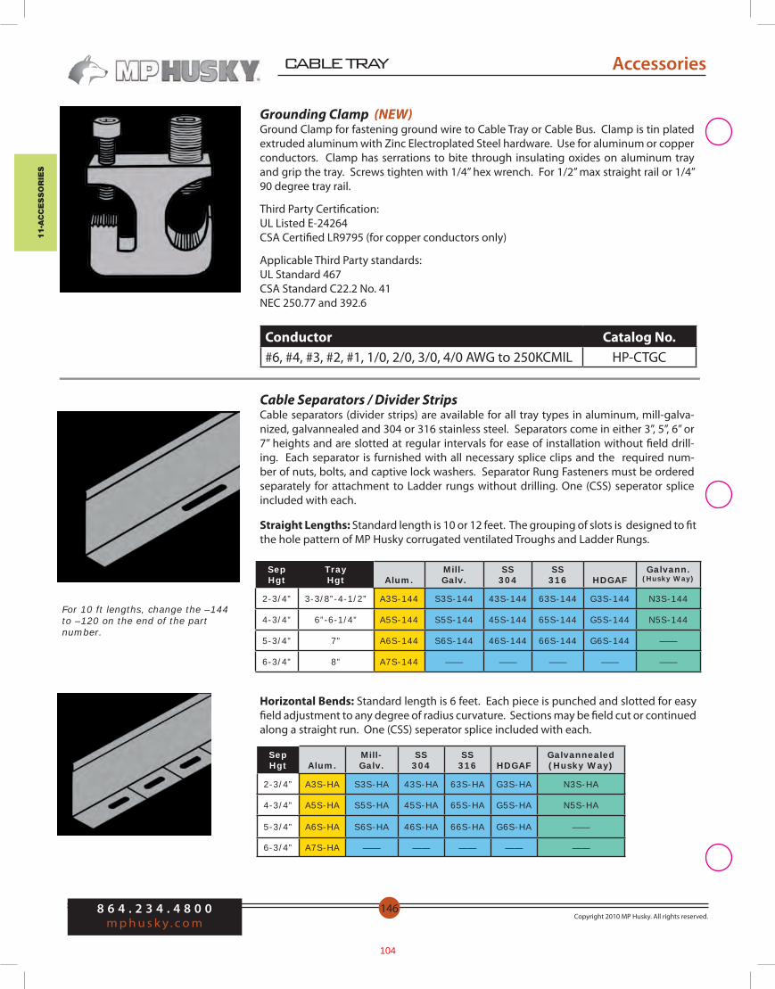
11-a
cc
ess
or
ies
8 6 4 . 2 3 4 . 4 8 0 0m p h u s k y . c o m
Copyright 2010 MP Husky. All rights reserved.
CABLE TRAY
146
Horizontal Bends: Standard length is 6 feet. Each piece is punched and slotted for easy field adjustment to any degree of radius curvature. Sections may be field cut or continued along a straight run. One (CSS) seperator splice included with each.
SepHgt Alum.
Mill- Galv.
SS 304
SS316 HDGAF
Galvannealed(Husky Way)
2-3/4” A3S-HA S3S-HA 43S-HA 63S-HA G3S-HA N3S-HA
4-3/4” A5S-HA S5S-HA 45S-HA 65S-HA G5S-HA N5S-HA
5-3/4” A6S-HA S6S-HA 46S-HA 66S-HA G6S-HA ——
6-3/4” A7S-HA —— —— —— —— ——
Grounding Clamp (NEW)Ground Clamp for fastening ground wire to Cable Tray or Cable Bus. Clamp is tin plated extruded aluminum with Zinc Electroplated Steel hardware. Use for aluminum or copper conductors. Clamp has serrations to bite through insulating oxides on aluminum tray and grip the tray. Screws tighten with 1/4” hex wrench. For 1/2” max straight rail or 1/4” 90 degree tray rail.
Third Party Certification:UL Listed E-24264CSA Certified LR9795 (for copper conductors only)
Applicable Third Party standards:UL Standard 467CSA Standard C22.2 No. 41NEC 250.77 and 392.6
Conductor Catalog No.#6, #4, #3, #2, #1, 1/0, 2/0, 3/0, 4/0 AWG to 250KCMIL HP-CTGC
Cable Separators / Divider StripsCable separators (divider strips) are available for all tray types in aluminum, mill-galva-nized, galvannealed and 304 or 316 stainless steel. Separators come in either 3”, 5”, 6” or 7” heights and are slotted at regular intervals for ease of installation without field drill-ing. Each separator is furnished with all necessary splice clips and the required num-ber of nuts, bolts, and captive lock washers. Separator Rung Fasteners must be ordered separately for attachment to Ladder rungs without drilling. One (CSS) seperator splice included with each.
SepHgt
TrayHgt Alum.
Mill- Galv.
SS 304
SS316 HDGAF
Galvann.(Husky Way)
2-3/4” 3-3/8”-4-1/2” A3S-144 S3S-144 43S-144 63S-144 G3S-144 N3S-144
4-3/4” 6”-6-1/4” A5S-144 S5S-144 45S-144 65S-144 G5S-144 N5S-144
5-3/4” 7” A6S-144 S6S-144 46S-144 66S-144 G6S-144 ——
6-3/4” 8” A7S-144 —— —— —— —— ——
Straight Lengths: Standard length is 10 or 12 feet. The grouping of slots is designed to fit the hole pattern of MP Husky corrugated ventilated Troughs and Ladder Rungs.
For 10 ft lengths, change the –144 to –120 on the end of the part number.
Accessories Accessories
104
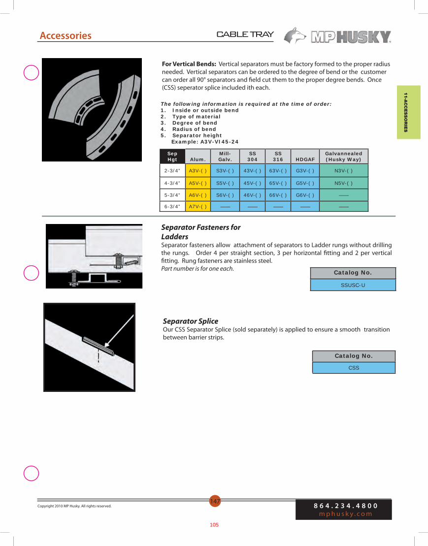
11-ac
ce
ssor
ies
CABLE TRAY
8 6 4 . 2 3 4 . 4 8 0 0m p h u s k y . c o m
Copyright 2010 MP Husky. All rights reserved.147
Accessories
For Vertical Bends: Vertical separators must be factory formed to the proper radius needed. Vertical separators can be ordered to the degree of bend or the customer can order all 90° separators and field cut them to the proper degree bends. Once (CSS) seperator splice included ith each.
Separator Fasteners for LaddersSeparator fasteners allow attachment of separators to Ladder rungs without drilling the rungs. Order 4 per straight section, 3 per horizontal fitting and 2 per vertical fitting. Rung fasteners are stainless steel. Part number is for one each. Catalog No.
SSUSC-U
Catalog No.
CSS
Separator SpliceOur CSS Separator Splice (sold separately) is applied to ensure a smooth transition between barrier strips.
Accessories
The following information is required at the time of order:1. Inside or outside bend2. Type of material3. Degree of bend4. Radius of bend5. Separator height Example: A3V-VI45-24
SepHgt Alum.
Mill- Galv.
SS 304
SS316 HDGAF
Galvannealed(Husky Way)
2-3/4” A3V-( ) S3V-( ) 43V-( ) 63V-( ) G3V-( ) N3V-( )
4-3/4” A5V-( ) S5V-( ) 45V-( ) 65V-( ) G5V-( ) N5V-( )
5-3/4” A6V-( ) S6V-( ) 46V-( ) 66V-( ) G6V-( ) ——
6-3/4” A7V-( ) —— —— —— —— ——
105

Tab #4
ORANGE COUNTY SANITATION DISTRICT (P1-101)
SUBMITTAL DATA REGARDING:
Cable Trays
Mono-Systems
106
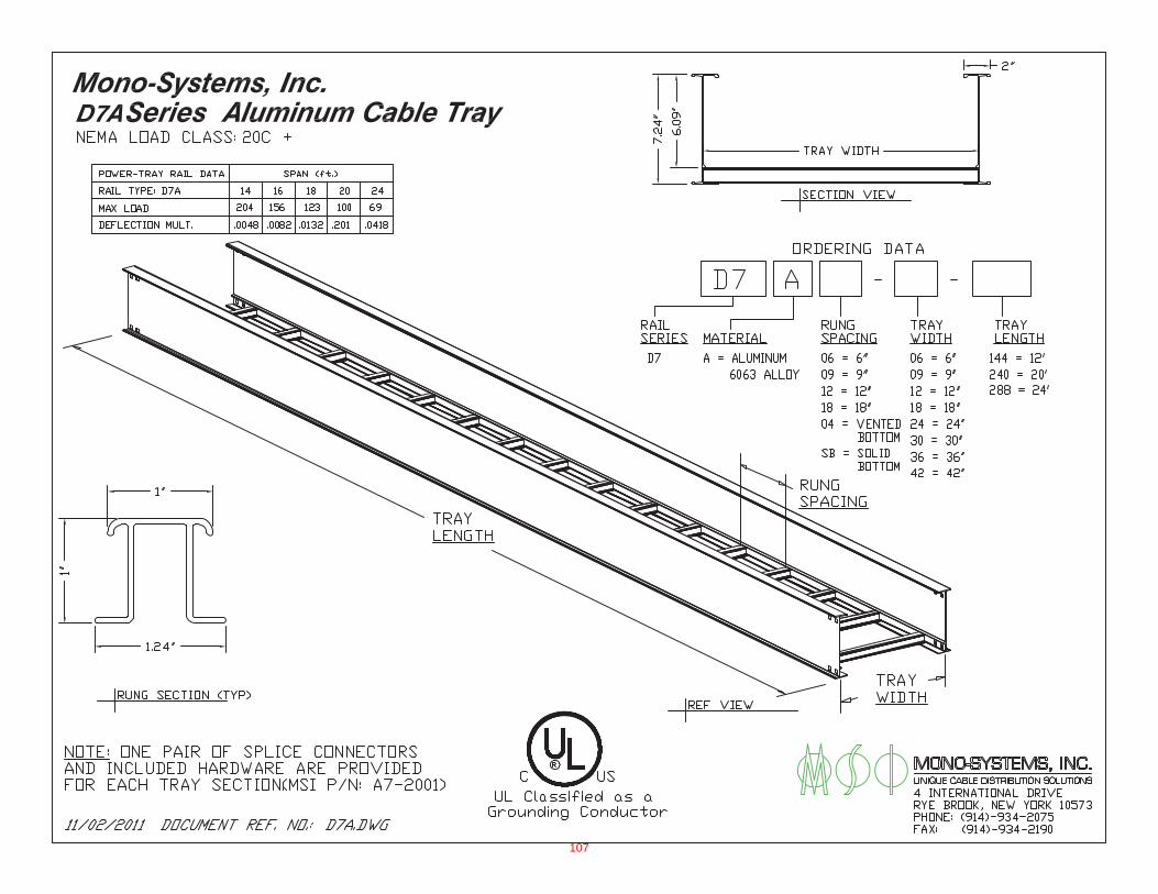
107

108
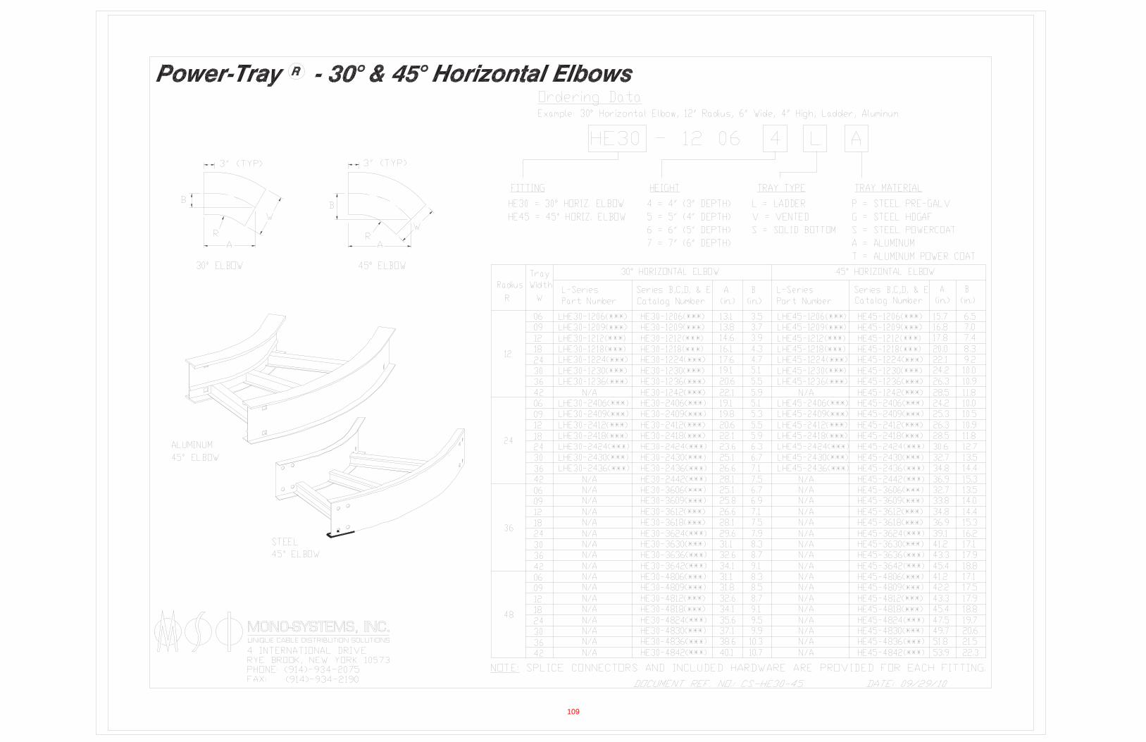
109

110
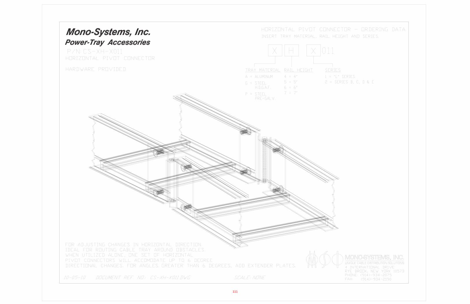
111
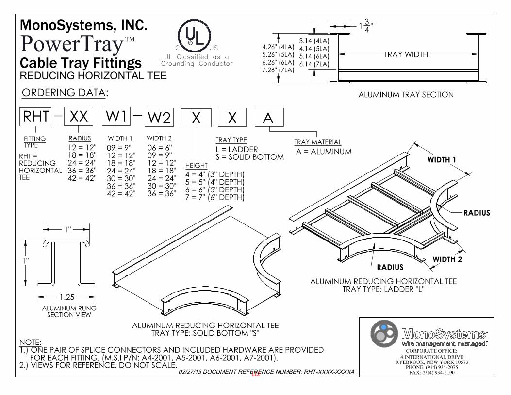
CORPORATE OFFICE:4 INTERNATIONAL DRIVE
RYEBROOK, NEW YORK 10573PHONE: (914) 934-2075
FAX: (914) 934-2190
C USR
UL Classified as aGrounding Conductor
1"
1"
1.25 ALUMINUM RUNG
SECTION VIEW
TRAY WIDTH
1 34 "
4.26" (4LA)5.26" (5LA)6.26" (6LA)7.26" (7LA)
3.14 (4LA)4.14 (5LA)5.14 (6LA)6.14 (7LA)
ALUMINUM TRAY SECTION
WIDTH 1
WIDTH 2 RADIUS
RADIUS
ALUMINUM REDUCING HORIZONTAL TEETRAY TYPE: LADDER "L"
NOTE: 1.) ONE PAIR OF SPLICE CONNECTORS AND INCLUDED HARDWARE ARE PROVIDED FOR EACH FITTING. (M.S.I P/N: A4-2001, A5-2001, A6-2001, A7-2001).2.) VIEWS FOR REFERENCE, DO NOT SCALE.
ORDERING DATA:
FITTINGTYPE
WIDTH 1 WIDTH 2
HEIGHT
TRAY TYPE09 = 9"12 = 12"18 = 18"24 = 24"30 = 30"36 = 36"42 = 42"
4 = 4" (3" DEPTH)5 = 5" (4" DEPTH)6 = 6" (5" DEPTH)7 = 7" (6" DEPTH)
L = LADDERS = SOLID BOTTOMRHT =
REDUCINGHORIZONTALTEE
RHT
06 = 6"09 = 9"12 = 12"18 = 18"24 = 24"30 = 30"36 = 36"
A = ALUMINUMTRAY MATERIAL
XX W1 X X AW2
12 = 12"18 = 18"24 = 24"36 = 36"42 = 42"
RADIUS
ALUMINUM REDUCING HORIZONTAL TEETRAY TYPE: SOLID BOTTOM "S"
MonoSystems, INC.
02/27/13 DOCUMENT REFERENCE NUMBER: RHT-XXXX-XXXXA
PowerTrayTM
Cable Tray FittingsREDUCING HORIZONTAL TEE
112
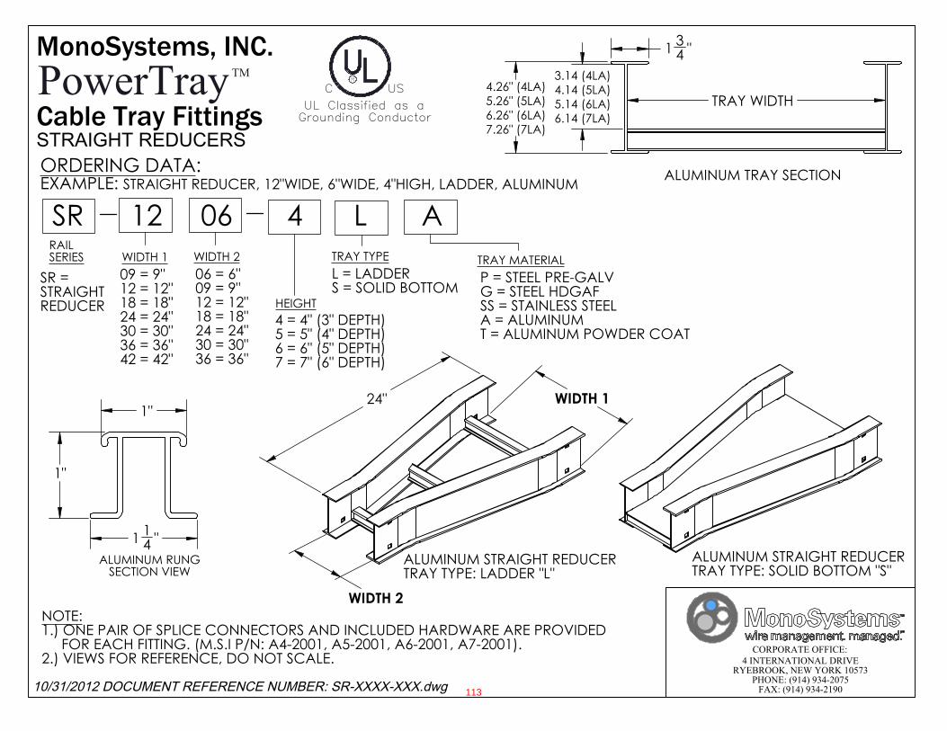
CORPORATE OFFICE:4 INTERNATIONAL DRIVE
RYEBROOK, NEW YORK 10573PHONE: (914) 934-2075
FAX: (914) 934-2190
C USR
UL Classified as aGrounding Conductor
WIDTH 2
WIDTH 1 24"
ALUMINUM STRAIGHT REDUCERTRAY TYPE: LADDER "L"
ALUMINUM STRAIGHT REDUCERTRAY TYPE: SOLID BOTTOM "S"
1"
1"
1 14 "
ALUMINUM RUNGSECTION VIEW
TRAY WIDTH
1 34 "
4.26" (4LA)5.26" (5LA)6.26" (6LA)7.26" (7LA)
3.14 (4LA)4.14 (5LA)5.14 (6LA)6.14 (7LA)
ALUMINUM TRAY SECTION
NOTE: 1.) ONE PAIR OF SPLICE CONNECTORS AND INCLUDED HARDWARE ARE PROVIDED FOR EACH FITTING. (M.S.I P/N: A4-2001, A5-2001, A6-2001, A7-2001).2.) VIEWS FOR REFERENCE, DO NOT SCALE.
ORDERING DATA:EXAMPLE: STRAIGHT REDUCER, 12"WIDE, 6"WIDE, 4"HIGH, LADDER, ALUMINUM
RAILSERIES WIDTH 1 WIDTH 2
HEIGHT
TRAY TYPE09 = 9"12 = 12"18 = 18"24 = 24"30 = 30"36 = 36"42 = 42"
4 = 4" (3" DEPTH)5 = 5" (4" DEPTH)6 = 6" (5" DEPTH)7 = 7" (6" DEPTH)
L = LADDERS = SOLID BOTTOM
SR = STRAIGHTREDUCER
SR
06 = 6"09 = 9"12 = 12"18 = 18"24 = 24"30 = 30"36 = 36"
P = STEEL PRE-GALVG = STEEL HDGAFSS = STAINLESS STEELA = ALUMINUMT = ALUMINUM POWDER COAT
TRAY MATERIAL
12 06 4 L A
MonoSystems, INC.
10/31/2012 DOCUMENT REFERENCE NUMBER: SR-XXXX-XXX.dwg
PowerTrayTM
Cable Tray FittingsSTRAIGHT REDUCERS
113

114

115
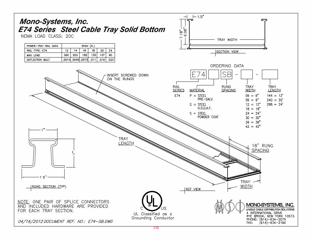
116
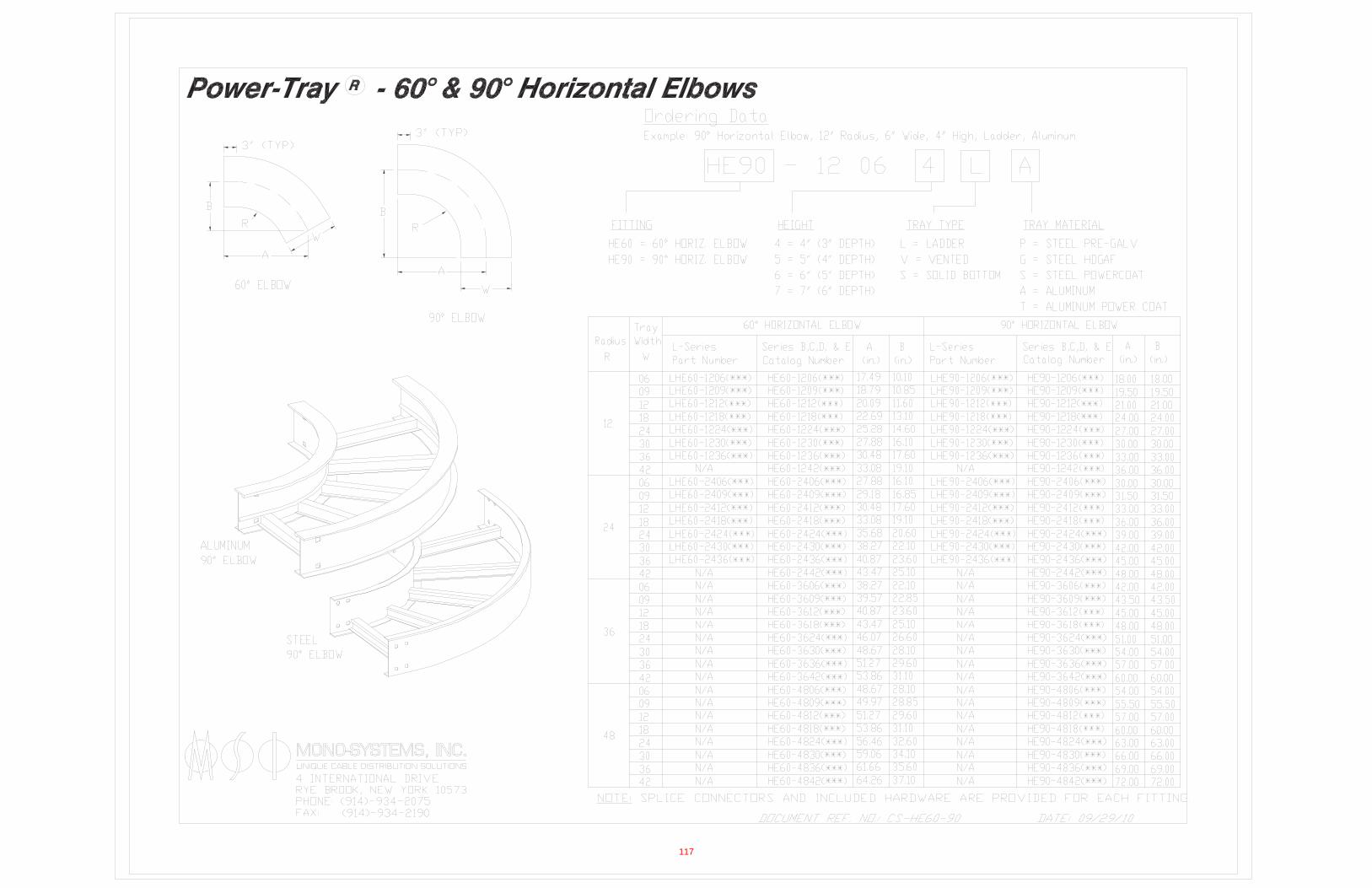
117
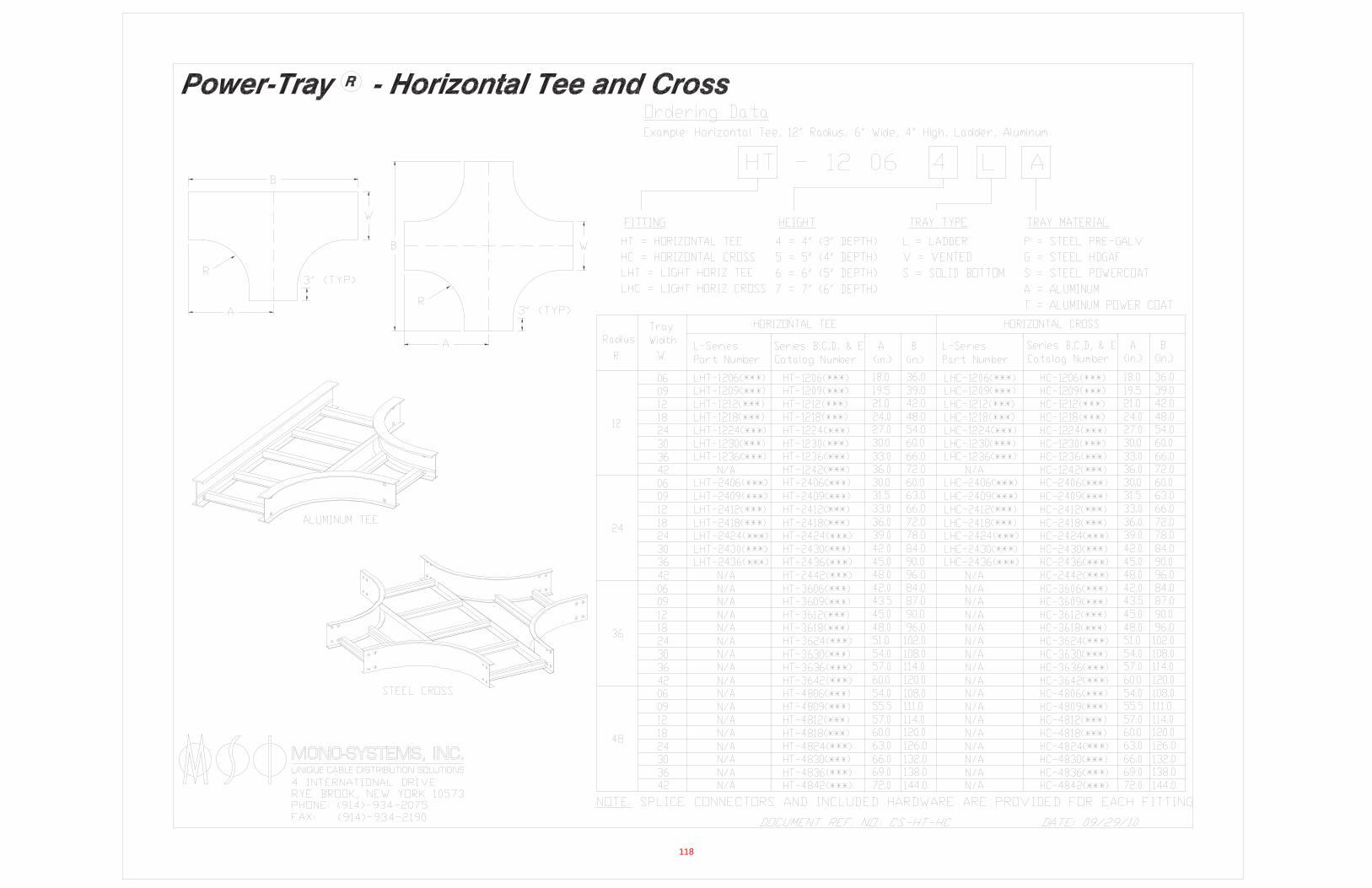
118

119
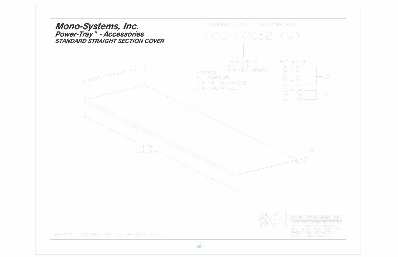
120
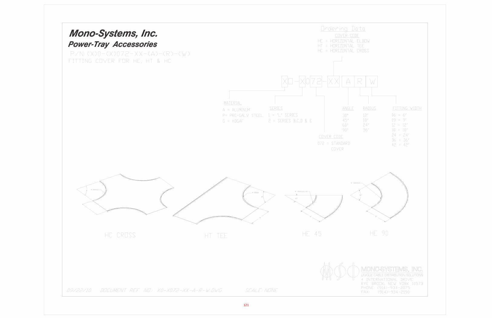
121
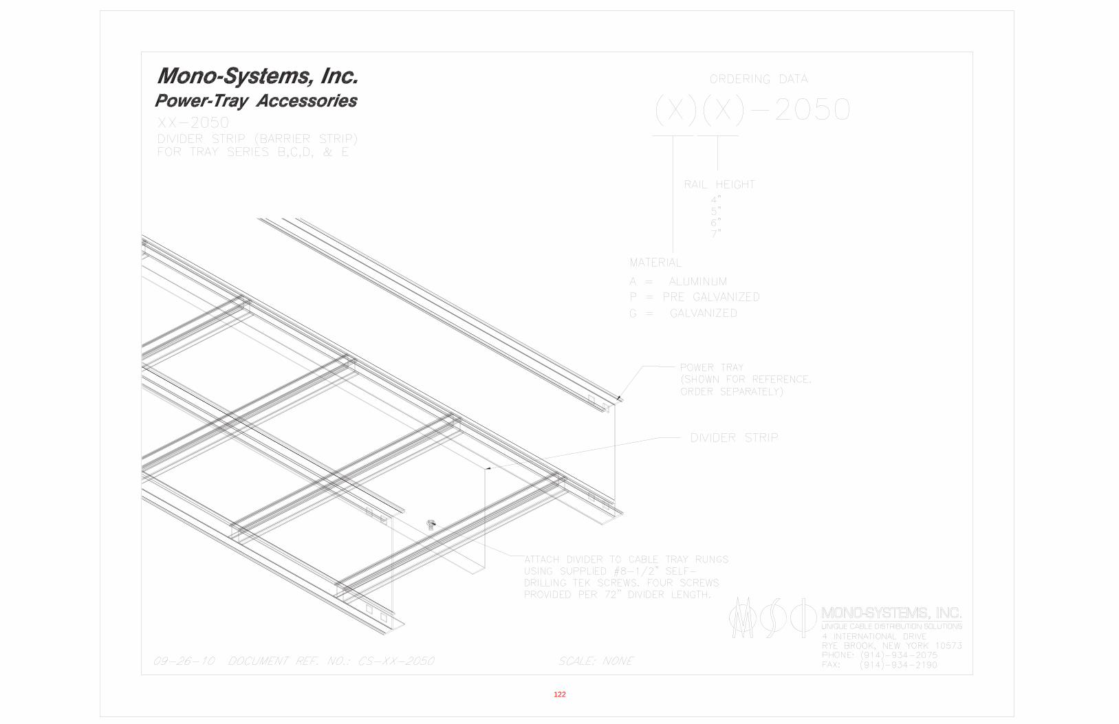
122
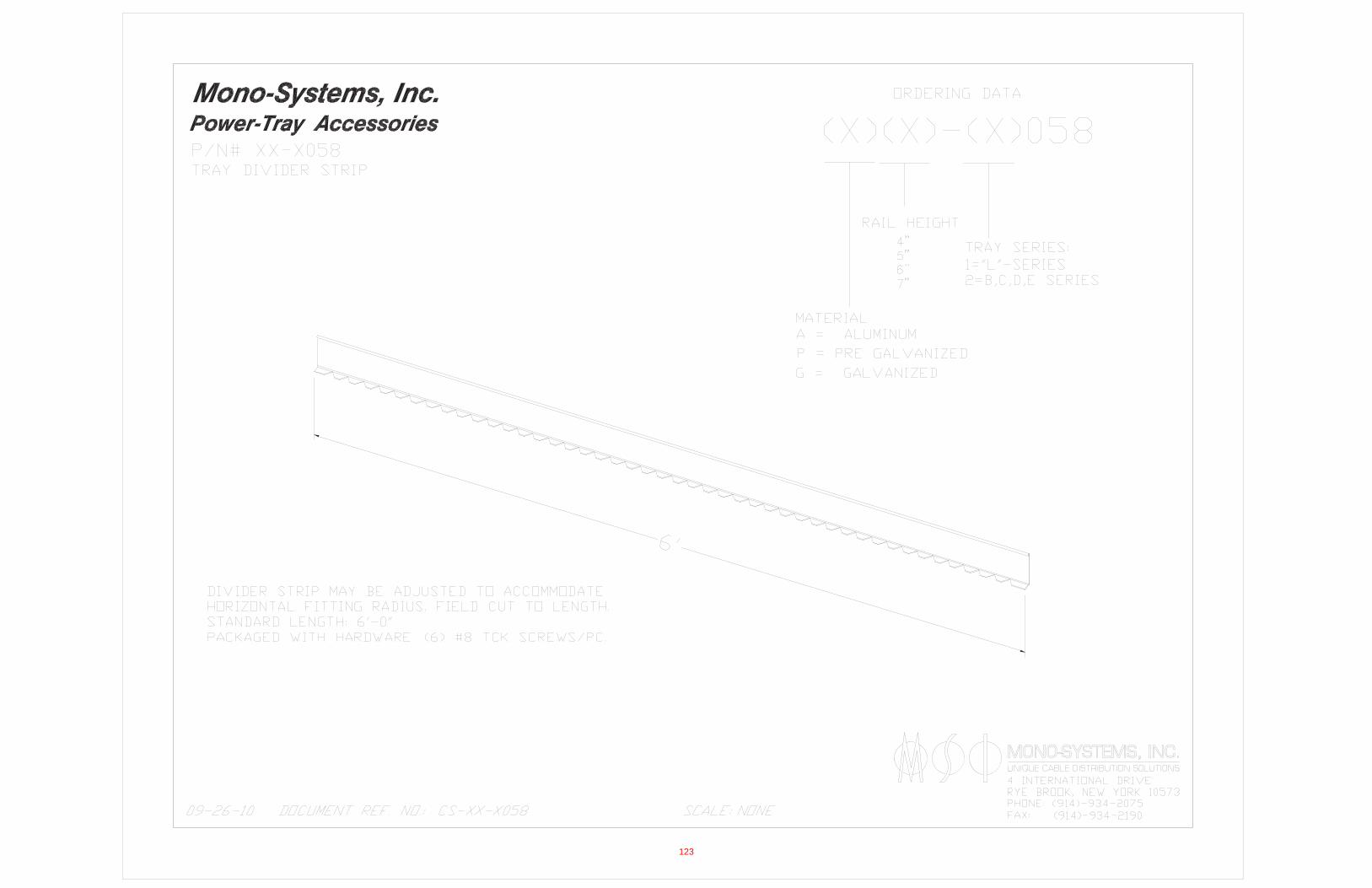
123

Tab #5
ORANGE COUNTY SANITATION DISTRICT (P1�101)
SUBMITTAL DATA REGARDING:
Cable Tray Ground Clamp
Burndy
124
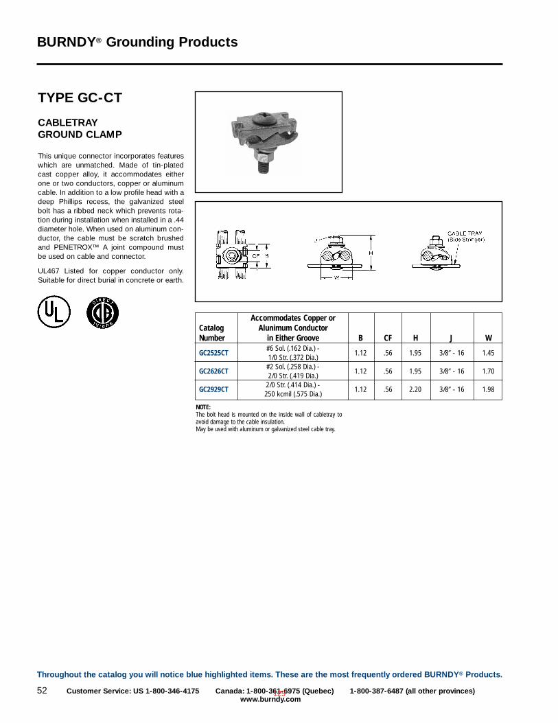
BURNDY® Grounding Products
52 Customer Service: US 1-800-346-4175 Canada: 1-800-361-6975 (Quebec) 1-800-387-6487 (all other provinces)www.burndy.com
TYPE GC-CT
CABLETRAY GROUND CLAMP
This unique connector incorporates featureswhich are unmatched. Made of tin-platedcast copper alloy, it accommodates eitherone or two conductors, copper or aluminumcable. In addition to a low profile head with adeep Phillips recess, the galvanized steelbolt has a ribbed neck which prevents rota-tion during installation when installed in a .44diameter hole. When used on aluminum con-ductor, the cable must be scratch brushedand PENETROX™ A joint compound mustbe used on cable and connector.
UL467 Listed for copper conductor only.Suitable for direct burial in concrete or earth.
NOTE:The bolt head is mounted on the inside wall of cabletray toavoid damage to the cable insulation.May be used with aluminum or galvanized steel cable tray.
Accommodates Copper orCatalog Alunimum ConductorNumber in Either Groove B CF H J W
#6 Sol. (.162 Dia.) -GC2525CT
1/0 Str. (.372 Dia.)1.12 .56 1.95 3/8� - 16 1.45
#2 Sol. (.258 Dia.) -GC2626CT
2/0 Str. (.419 Dia.)1.12 .56 1.95 3/8� - 16 1.70
2/0 Str. (.414 Dia.) -GC2929CT
250 kcmil (.575 Dia.)1.12 .56 2.20 3/8� - 16 1.98
Throughout the catalog you will notice blue highlighted items. These are the most frequently ordered BURNDY® Products.
125