ormocers (organic–inorganic hybrid copolymers)-zeolite beta (bea) nanocomposite membranes for gas...
TRANSCRIPT

On
Sa
b
a
ARR2AA
KOHZM
1
hMam(htlpAzss[bzo[M
fF
0d
Journal of Membrane Science 347 (2010) 132–140
Contents lists available at ScienceDirect
Journal of Membrane Science
journa l homepage: www.e lsev ier .com/ locate /memsci
RMOCERs (organic–inorganic hybrid copolymers)-zeolite Beta (BEA)anocomposite membranes for gas separation applications
uresh M. Kumbara,b,∗, T. Selvama, C. Gellermanna, W. Storcha, T. Ballwega, J. Breub, G. Sextl a
Fraunhofer-Institut für Silicatforschung (ISC), Neunerplatz 2, D-97082 Würzburg, GermanyLehrstuhl für Anorganische Chemie I, Universität Bayreuth, D-95440 Bayreuth, Germany
r t i c l e i n f o
rticle history:eceived 15 May 2009eceived in revised form3 September 2009ccepted 10 October 2009
a b s t r a c t
The applicability of glycerinedimethacrylaturethanetriethoxysilane (GUS)-based ORMOCER(organic–inorganic hybrid copolymers) resin for the fabrication of free-standing ORMOCER-zeoliteBeta (BEA) nanocomposite membrane was studied in detail. A series of ORMOCER/zeolite Beta nanocom-posite membranes having different zeolite loadings (20–40 wt.%) were prepared by solution casting
vailable online 20 October 2009
eywords:RMOCERsybrid copolymers
method followed by UV-curing, and characterized by thermal analysis (TG/DSC), scanning electronmicroscopy (SEM) and N2 sorption and single gas (H2, He and N2) permeation measurements. The SEMstudies revealed that zeolite Beta crystallites were homogeneously distributed within the ORMOCERmatrix. There were no visible voids or defects between the ORMOCER matrix and the zeolite Betacrystallites, even at a very high zeolite loading (40 wt.%), as revealed by the high resolution SEM images.
eta nnd H
eolite Beta (BEA)ixed matrix membranes
The ORMOCER-zeolite B16-times increase in H2 a
. Introduction
The past decade has witnessed an intense research effort onybrid organic–inorganic membranes (mixed matrix membranes,MMs) owing to their wide range of potential applications such
s gas separation [1–5], pervaporation [6–8], polymer electrolyteembrane fuel cells (PEMFC) [9,10] and direct methanol fuel cells
DMFC) [11,12] applications. In particular, zeolite-based MMMsave become an important class of hybrid membranes given thathey combine the inherent characteristics of both zeolites (molecu-ar sieving capabilities and hydrophobicity/hydrophilicity etc.) andolymers (low capital investment and easy processing capabilities).lthough, the fabrication of MMMs using various combinations ofeolites and polymers is well documented in the literature, thecientific community still faces ongoing challenges such as proces-ibility, flux, selective gas separation and durability of the MMMs13]. The reduction or elimination of voids within MMMs coulde achieved through (a) chemical modification of the surface of
eolite crystals using desired silanes [14,15] and polymers [16,17];r (b) introduction of a combatibilizer (2-4-6-triaminopyrimidine)18,19]. Recently, layered silicates with nanoporous layers such asCM-22 (P) [20] and AMH-3 [21,22], which are showing excel-
∗ Corresponding author at: Nanoparticle and Nanocomposite, Fraunhofer-Institutür Silicatforschung (ISC), Neunerplatz 2, D-97082 Würzburg, Germany.ax: +49 (0) 931 41 00 39.
E-mail address: [email protected] (S.M. Kumbar).
376-7388/$ – see front matter © 2009 Elsevier B.V. All rights reserved.oi:10.1016/j.memsci.2009.10.014
anocomposite membrane with 40 wt.% zeolite loading showed a nearlye permeabilities in comparison to the pure ORMOCER membrane.
© 2009 Elsevier B.V. All rights reserved.
lent intercalation and delamination/exfoliation properties, havealso been used as precursors for the fabrication of nanocompositemembranes. This approach especially leads to MMMs with excel-lent H2/CO2 separation performance [21,22] owing to their uniquecombination of mechanical strength (polymer-layered silicate) andmolecular sieving (zeolite-like) properties. Indeed, zeolite-filledmicroporous mixed matrix (ZeoTIPS) membranes [23], in whichzeolite particles are supported in a microporous polymer matrix bythermally induced phase separation (TIPS) process, offer significantbenefits for the separation of gas (O2/N2) mixtures in comparisonto dense MMMs.
The use of hollow fiber MMMs has seen tremendous growthin gas and vapour separation processes because of their excel-lent performances (high permeation area per volume ratio). Anenhancement in the selectivity for gas separation (He/N2 and O2/N2etc.) by hollow fiber membranes incorporated with zeolites suchas zeolite Beta [24,25] and SSZ-13 [26] is known. Li et al. [24] sug-gested that high processing temperature close to glass transitiontemperature (Tg) of the polymeric materials allows the fabricationof void-free hollow fiber MMMs.
During the last two decades, ORMOCERs [27–29], whichare a class of highly cross-linked, transparent and hybridinorganic–organic copolymers that are derived from more
than one species of monomer, each having a different role[glass-like (transparency, chemical, mechanical and thermal)and polymer-like (toughness, functionalization and low pro-cessing temperature)], have been extensively studied in theFraunhofer ISC (Institut für Silicatforschung). The versatility of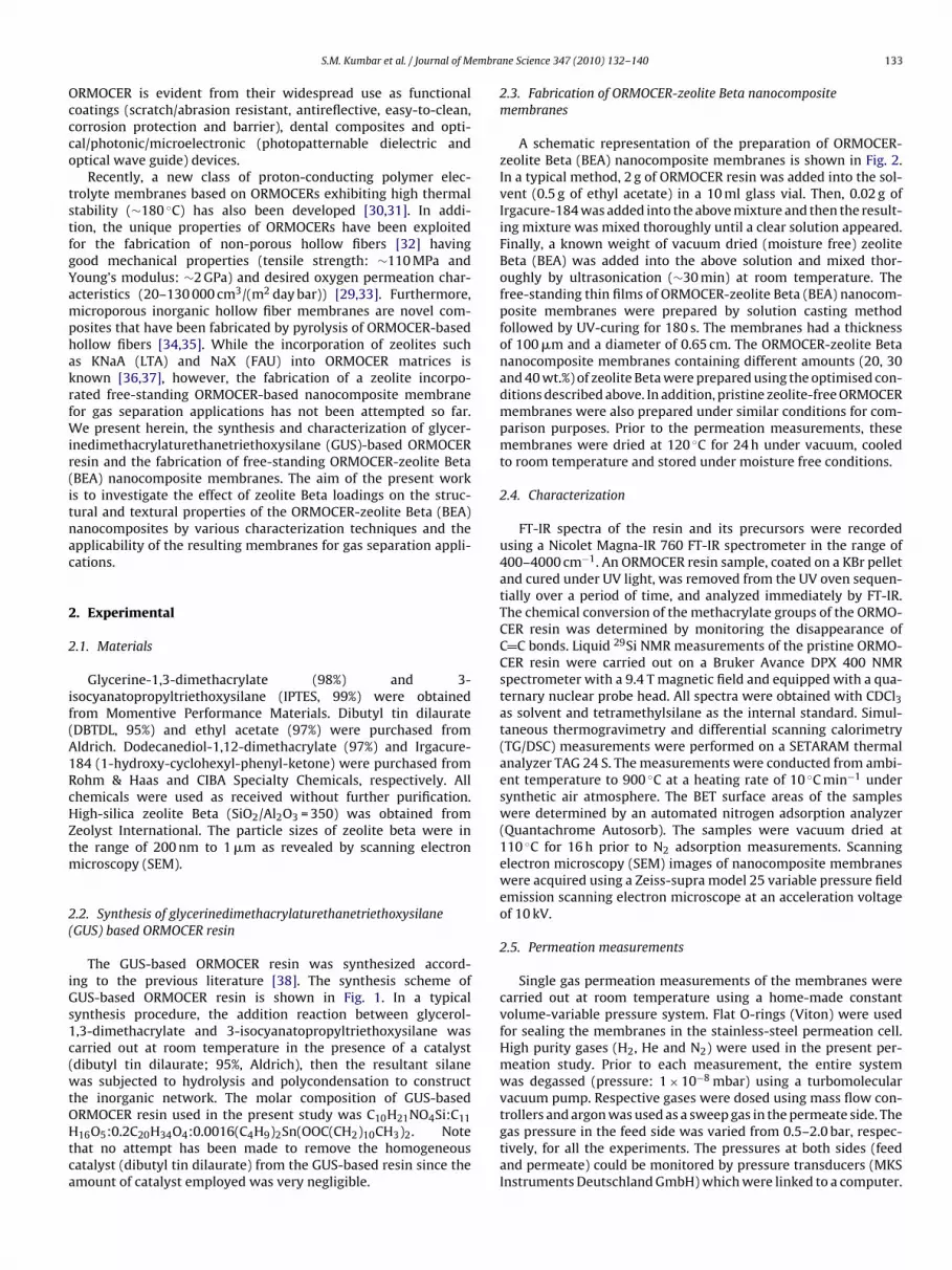
embra
Occco
tstfgYamphakrfWir(itnac
2
2
if(A1RcHZtm
2(
iGs1c(wtOHtca
S.M. Kumbar et al. / Journal of M
RMOCER is evident from their widespread use as functionaloatings (scratch/abrasion resistant, antireflective, easy-to-clean,orrosion protection and barrier), dental composites and opti-al/photonic/microelectronic (photopatternable dielectric andptical wave guide) devices.
Recently, a new class of proton-conducting polymer elec-rolyte membranes based on ORMOCERs exhibiting high thermaltability (∼180 ◦C) has also been developed [30,31]. In addi-ion, the unique properties of ORMOCERs have been exploitedor the fabrication of non-porous hollow fibers [32] havingood mechanical properties (tensile strength: ∼110 MPa andoung’s modulus: ∼2 GPa) and desired oxygen permeation char-cteristics (20–130 000 cm3/(m2 day bar)) [29,33]. Furthermore,icroporous inorganic hollow fiber membranes are novel com-
osites that have been fabricated by pyrolysis of ORMOCER-basedollow fibers [34,35]. While the incorporation of zeolites suchs KNaA (LTA) and NaX (FAU) into ORMOCER matrices isnown [36,37], however, the fabrication of a zeolite incorpo-ated free-standing ORMOCER-based nanocomposite membraneor gas separation applications has not been attempted so far.
e present herein, the synthesis and characterization of glycer-nedimethacrylaturethanetriethoxysilane (GUS)-based ORMOCEResin and the fabrication of free-standing ORMOCER-zeolite BetaBEA) nanocomposite membranes. The aim of the present works to investigate the effect of zeolite Beta loadings on the struc-ural and textural properties of the ORMOCER-zeolite Beta (BEA)anocomposites by various characterization techniques and thepplicability of the resulting membranes for gas separation appli-ations.
. Experimental
.1. Materials
Glycerine-1,3-dimethacrylate (98%) and 3-socyanatopropyltriethoxysilane (IPTES, 99%) were obtainedrom Momentive Performance Materials. Dibutyl tin dilaurateDBTDL, 95%) and ethyl acetate (97%) were purchased fromldrich. Dodecanediol-1,12-dimethacrylate (97%) and Irgacure-84 (1-hydroxy-cyclohexyl-phenyl-ketone) were purchased fromohm & Haas and CIBA Specialty Chemicals, respectively. Allhemicals were used as received without further purification.igh-silica zeolite Beta (SiO2/Al2O3 = 350) was obtained fromeolyst International. The particle sizes of zeolite beta were inhe range of 200 nm to 1 �m as revealed by scanning electron
icroscopy (SEM).
.2. Synthesis of glycerinedimethacrylaturethanetriethoxysilaneGUS) based ORMOCER resin
The GUS-based ORMOCER resin was synthesized accord-ng to the previous literature [38]. The synthesis scheme ofUS-based ORMOCER resin is shown in Fig. 1. In a typicalynthesis procedure, the addition reaction between glycerol-,3-dimethacrylate and 3-isocyanatopropyltriethoxysilane wasarried out at room temperature in the presence of a catalystdibutyl tin dilaurate; 95%, Aldrich), then the resultant silane
as subjected to hydrolysis and polycondensation to constructhe inorganic network. The molar composition of GUS-basedRMOCER resin used in the present study was C10H21NO4Si:C11
16O5:0.2C20H34O4:0.0016(C4H9)2Sn(OOC(CH2)10CH3)2. Notehat no attempt has been made to remove the homogeneousatalyst (dibutyl tin dilaurate) from the GUS-based resin since themount of catalyst employed was very negligible.
ne Science 347 (2010) 132–140 133
2.3. Fabrication of ORMOCER-zeolite Beta nanocompositemembranes
A schematic representation of the preparation of ORMOCER-zeolite Beta (BEA) nanocomposite membranes is shown in Fig. 2.In a typical method, 2 g of ORMOCER resin was added into the sol-vent (0.5 g of ethyl acetate) in a 10 ml glass vial. Then, 0.02 g ofIrgacure-184 was added into the above mixture and then the result-ing mixture was mixed thoroughly until a clear solution appeared.Finally, a known weight of vacuum dried (moisture free) zeoliteBeta (BEA) was added into the above solution and mixed thor-oughly by ultrasonication (∼30 min) at room temperature. Thefree-standing thin films of ORMOCER-zeolite Beta (BEA) nanocom-posite membranes were prepared by solution casting methodfollowed by UV-curing for 180 s. The membranes had a thicknessof 100 �m and a diameter of 0.65 cm. The ORMOCER-zeolite Betananocomposite membranes containing different amounts (20, 30and 40 wt.%) of zeolite Beta were prepared using the optimised con-ditions described above. In addition, pristine zeolite-free ORMOCERmembranes were also prepared under similar conditions for com-parison purposes. Prior to the permeation measurements, thesemembranes were dried at 120 ◦C for 24 h under vacuum, cooledto room temperature and stored under moisture free conditions.
2.4. Characterization
FT-IR spectra of the resin and its precursors were recordedusing a Nicolet Magna-IR 760 FT-IR spectrometer in the range of400–4000 cm−1. An ORMOCER resin sample, coated on a KBr pelletand cured under UV light, was removed from the UV oven sequen-tially over a period of time, and analyzed immediately by FT-IR.The chemical conversion of the methacrylate groups of the ORMO-CER resin was determined by monitoring the disappearance ofC C bonds. Liquid 29Si NMR measurements of the pristine ORMO-CER resin were carried out on a Bruker Avance DPX 400 NMRspectrometer with a 9.4 T magnetic field and equipped with a qua-ternary nuclear probe head. All spectra were obtained with CDCl3as solvent and tetramethylsilane as the internal standard. Simul-taneous thermogravimetry and differential scanning calorimetry(TG/DSC) measurements were performed on a SETARAM thermalanalyzer TAG 24 S. The measurements were conducted from ambi-ent temperature to 900 ◦C at a heating rate of 10 ◦C min−1 undersynthetic air atmosphere. The BET surface areas of the sampleswere determined by an automated nitrogen adsorption analyzer(Quantachrome Autosorb). The samples were vacuum dried at110 ◦C for 16 h prior to N2 adsorption measurements. Scanningelectron microscopy (SEM) images of nanocomposite membraneswere acquired using a Zeiss-supra model 25 variable pressure fieldemission scanning electron microscope at an acceleration voltageof 10 kV.
2.5. Permeation measurements
Single gas permeation measurements of the membranes werecarried out at room temperature using a home-made constantvolume-variable pressure system. Flat O-rings (Viton) were usedfor sealing the membranes in the stainless-steel permeation cell.High purity gases (H2, He and N2) were used in the present per-meation study. Prior to each measurement, the entire systemwas degassed (pressure: 1 × 10⁻⁸ mbar) using a turbomolecularvacuum pump. Respective gases were dosed using mass flow con-
trollers and argon was used as a sweep gas in the permeate side. Thegas pressure in the feed side was varied from 0.5–2.0 bar, respec-tively, for all the experiments. The pressures at both sides (feedand permeate) could be monitored by pressure transducers (MKSInstruments Deutschland GmbH) which were linked to a computer.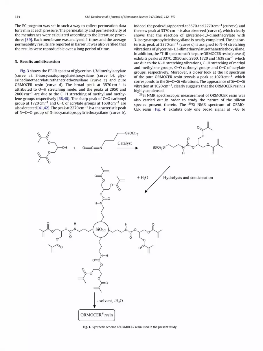
1 embra
Tftdpt
3
(eOa2lgao
34 S.M. Kumbar et al. / Journal of M
he PC program was set in such a way to collect permeation dataor 3 min at each pressure. The permeability and permselectivity ofhe membranes were calculated according to the literature proce-ures [39]. Each membrane was analyzed 4-times and the averageermeability results are reported in Barrer. It was also verified thathe results were reproducible over a long period of time.
. Results and discussion
Fig. 3 shows the FT-IR spectra of glycerine-1,3dimethylacrylatecurve a), 3-isocyanatopropyltriethoxysilane (curve b), glyc-rinedimethacrylaturethanetriethoxysilane (curve c) and pureRMOCER resin (curve d). The broad peak at 3570 cm−1 isttributed to O H stretching mode; and the peaks at 2950 and
860 cm−1 are due to the C H stretching of methyl and methy-ene groups respectively [38,40]. The sharp peak of C O carbonylroup at 1720 cm−1 and C C of acrylate groups at 1638 cm−1 arelso detected [41,42]. The peak at 2270 cm−1 is a characteristic peakf N C O group of 3-isocyanatopropyltriethoxysilane (curve b).
Fig. 1. Synthetic scheme of ORMOCER
ne Science 347 (2010) 132–140
Indeed, the peaks disappeared at 3570 and 2270 cm−1 (curve c), andthe new peak at 3370 cm−1 is also observed (curve c), which clearlyshows that the reaction of glycerine-1,3-dimethacrylate with3-isocynatopropyltriethoxysilane is nearly completed. The charac-teristic peak at 3370 cm−1 (curve c) is assigned to N–H stretchingvibrations of glycerine-1,3-dimethacrylaturethanetriethoxysilane.In addition, the FT-IR spectrum of the pure ORMOCER resin (curve d)exhibits peaks at 3370, 2950 and 2860, 1720 and 1638 cm−1 whichare due to the N–H stretching vibrations, C H stretching of methyland methylene groups, C O carbonyl groups and C C of acrylategroups, respectively. Moreover, a closer look at the IR spectrumof the pure ORMOCER resin reveals a peak at 1020 cm−1, whichcorresponds to the Si O Si vibrations. The appearance of Si O Sivibration at 1020 cm−1, clearly suggests that the ORMOCER resin ishighly condensed.
29Si NMR spectroscopic measurement of ORMOCER resin wasalso carried out in order to study the nature of the siliconspecies present therein. The 29Si NMR spectrum of ORMO-CER resin (Fig. 4) exhibits only one broad signal at −66 to
resin used in the present study.

S.M. Kumbar et al. / Journal of Membrane Science 347 (2010) 132–140 135
Fn
−[TgOo−
Fg1
ig. 2. Flow chart of the preparation methodology of ORMOCER-zeolite Betaanocomposite membranes.
70 ppm. The signal at −66 to −70 ppm is attributed to the T3
RSi(OSi)3] units [43–45]. There were no signals corresponding to1 [RSi(OSi)(OH)2] and T2 [RSi(OSi)2(OH)] units indicating that the
lycerine-1,3-dimethacrylaturethanetriethoxysilane (GUS)-basedRMOCER resin possesses a highly condensed and/or cross-linkedrganic–inorganic network. The broad signal in the range of −80 to140 ppm is an artefact from the glass tube.ig. 3. FT-IR spectra of precursors used in the preparation of ORMOCER resin: (a)lycerine-1,3-dimethacrylate, (b) 3-isocynatopropyltriethoxysilane, (c) glycerine-,3-dimethacrylaturethanetriethoxysilane and (d) ORMOCER resin.
Fig. 4. 29Si NMR of pure ORMOCER resin.
Before carrying out the preparation of free-standing ORMOCERthin films, the change in the chemical structure of ORMOCER resinduring UV-curing over a period of time was monitored by FT-IRabsorption spectroscopy. Fig. 5 shows the FT-IR spectra of pureORMOCER resin (curve a) and UV-cured ORMOCER samples overa period of time, 30 s (curve b), 60 s (curve c) and 180 s (curved). The peaks at 1638 and 810 cm−1 are attributed to the n(C C)stretching vibrations of methacrylate groups and the alkene C–Hstretching in the acrylate group of the ORMOCER resin, respectively.The intensity of the 1638 cm−1 peak is gradually decreased withincreasing the UV exposure time, as depicted in Fig. 5(curves b–d).The sharp decrease in the intensity of methacrylate n(C C) peaksafter UV-curing over a period of time (30–180 s) clearly suggests themaximum consumption of n(C C) double bonds during the poly-merisation process; while the integrated area of the n(C O) peaks(1720 cm−1) remains constant. Whereas, the alkene C–H stretch-ing (810 cm−1) in the acrylate group of ORMOCER resin becamealmost negligible after UV-curing for 180 s [38,40–42]. The above-
mentioned results clearly suggest that the UV-curing process fora period of 180 s is sufficient to fabricate highly polymerised free-standing ORMOCER thin films.Fig. 5. FT-IR spectra of pure ORMOCER resin (a) and after UV-curing over a periodof time, (b) 30 s, (c) 60 s and (d) 180 s.

136 S.M. Kumbar et al. / Journal of Membrane Science 347 (2010) 132–140
Fn(
C(rNmpldsfabarmacw(os
Fih
Table 1Degradation temperatures of pure ORMOCER and ORMOCER-zeolite Betananocompositesa.
Zeolite Beta loading (wt.%) T1 max (◦C) T2 max (◦C) T3 max (◦C) T4 max (◦C)
0 169 391 457 59720 172 415 495 600
300–440 and 440–540 C; Figs. 6 and 7) and the exothermic peaks
ig. 6. Thermal analysis curves of pure ORMOCER (a) and ORMOCER-zeolite Betaanocomposites with different zeolite loadings, 20 wt.% (b), 30 wt.% (c) and 40 wt.%d), at a heating rate of 10 ◦C min−1 under air atmosphere.
TG and DSC curves of the pure ORMOCER and the ORMO-ER/zeolite Beta nanocomposites containing different amounts20, 30, and 40 wt.%) of zeolite Beta crystallites (at a heatingate of 10 ◦C min−1) are shown in Figs. 6 and 7, respectively.ote that the following conclusions on the specific degradationechanisms of ORMOCER and ORMOCER-zeolite Beta nanocom-
osites were drawn by the combination of results from TG (weightoss) and DSC (enthalpy change). As the trends in the thermalecomposition of the pure ORMOCER and its nanocomposites areimilar (Fig. 6), for simplicity, the discussion will be restricted toour different stages of weight losses at <300, 300–440, 440–540nd 540–700 ◦C, respectively. All the samples exhibit a negligi-le weight loss (∼7 wt.%) in the first stage (<300 ◦C in Fig. 6 andweak exothermic peak in Fig. 7) which might be due to the
emoval of residual solvent (ethyl acetate), water and C2H5OHolecules resulting from the polycondensation process of Si–OH
nd Si–OC2H5 groups from the ORMOCER matrix [46]. Such pro-
esses generally lead to the enhancement of Si–O–Si bondingithin the ORMOCER matrix; and indeed it may lead to free volumespace) to a certain extent within the ORMOCER matrix (betweenrganic and inorganic phase) which will be discussed in a sub-equent paragraph. The second stage (300–440 ◦C in Fig. 6 and a
ig. 7. DSC curves of pure ORMOCER (a) and ORMOCER-zeolite Beta nanocompos-tes with different zeolite loadings, 20 wt.% (b), 30 wt.% (c) and 40 wt.% (d), at aeating rate of 10 ◦C min−1 under air atmosphere.
30 172 427 493 58540 170 413 – 582
a DSC analysis.
broad exothermic peak in Fig. 7) exhibits a relatively high weightloss (∼30–35 wt.%) which is attributed to the decomposition ofrandom session of methacrylic groups (oxidative degradation ofsoft segments) of the ORMOCER backbone chains as described inthe literature [47,48]. The release of CO2 generally occurs duringthe thermal decomposition of methacrylic groups (oxidation ofsoft segments) of the ORMOCERs. However, the anhydride forma-tion dominates the minor decarboxylation reaction. The third stage(440–540 ◦C in Fig. 6 and sharp exothermic peaks in Fig. 7) weightloss (∼5–17 wt.%) may be due to the fragmentation of anhydridering structures followed by release of CO2, CO, propene, isobutyleneetc. [49]. The fourth stage (540–700 ◦C in Fig. 6 and a broad exother-mic peak in Fig. 7) weight loss (∼11–24 wt.%) can be attributed tothe thermo-oxidative degradation of urethane groups (hard seg-ments) of the ORMOCER resins. As can be seen from Fig. 6 (curvesa–d) that the amount of inorganic residue increased with increasingthe amount of zeolite Beta (20–40 wt.%). The amounts of inorganicresidue present in the pure ORMOCER and its nanocomposites are15 wt.% (pure ORMOCER), 33 wt.% (20 wt.% zeolite Beta), 40 wt.%(30 wt.% zeolite Beta) and 45 wt.% (40 wt.% zeolite Beta), respec-tively.
As expected, the ORMOCER-zeolite Beta nanocomposites(curves b–d in Fig. 6) exhibit higher thermal decomposition tem-peratures as compared to the pure ORMOCER (curve a in Fig. 6).These results indicate that the introduction of zeolite Beta crystal-lites into the ORMOCER matrix enhances the thermal stability of theORMOCER-zeolite Beta (20–40 wt.%) nanocomposites. A significantshift in the decomposition temperatures (especially in the range of
◦
of the nanocomposites to the high temperature regions clearly sug-gest that the zeolite Beta crystallites act as fillers or cross linkingagents within the ORMOCER matrix. Nevertheless, the decrease inexothermicity at 440–540 ◦C (Fig. 7) may be correlated to increasing
Fig. 8. N2 adsorption–desorption isotherms of pure ORMOCER (�) and ORMOCER-zeolite Beta nanocomposites with different zeolite loadings, 20 wt.% (H), 30 wt.% (J)and 40 wt.% (�) (filled symbols: adsorption; blank symbols: desorption).

S.M. Kumbar et al. / Journal of Membrane Science 347 (2010) 132–140 137
F OCERw d h).
spnr
Ticp4cptr
ig. 9. Surface and polished cross-sectional views of the SEM images of the pure ORMith different zeolite loadings, 20 wt.% (c and d), 30 wt.% (e and f) and 40 wt.% (g an
tiffness and toughness of the zeolite Beta incorporated nanocom-osites and slow release of adsorbed gas, respectively. However,o clear trend can be observed in the decomposition temperatureange of 540–700 ◦C (Figs. 6 and 7).
The peak decomposition temperatures (T1 max, T2 max, T3 max and4 max) of pure ORMOCER and ORMOCER-zeolite Beta nanocompos-tes obtained from DSC curves (Fig. 7) are summarized in Table 1. Itan be seen from Table 1 that the decomposition temperatures ofure ORMOCER exhibited a peak at 169 ◦C (T1 max), 391 ◦C (T2 max),
57 (T3 max) and 597 ◦C (T4 max), respectively. As the zeolite Betaontent in the ORMOCER system increased from 20 to 30 wt.%, theeak decomposition temperatures increased gradually from 169o 172 ◦C (T1 max), 391 to 427 ◦C (T2 max) and 457 to 493 ◦C (T3 max),espectively. These results indicate that zeolite Beta crystallites actmembranes (a and b); and the ORMOCER-zeolite Beta nanocomposite membranes
as inorganic filler within the ORMOCER matrix. Most probably, theinteraction between the zeolite Beta crystallites with the ORMO-CER matrix might be higher for 30 wt.% zeolite Beta containingORMOCER system. However, further increase of the zeolite Betacontent (40 wt.%) in the ORMOCER system led, in turn, to a slightdecrease in the peak decomposition temperatures [T1 max (170 ◦C),T2 max (413 ◦C) and T4 max (582 ◦C)]. This could be due to the lessamount of ORMOCER matrix present in this system which con-tributes to the decrease in the peak decomposition temperatures.
Further investigations are necessary (e.g., thermogravimetry cou-pled with mass spectrometry; TG/MS) to understand the nature ofdecomposition of ORMOCER-zeolite Beta nanocomposites.The N2 adsorption–desorption isotherms of pure ORMOCER andthe ORMOCER-zeolite Beta nanocomposites containing different
138 S.M. Kumbar et al. / Journal of Membrane Science 347 (2010) 132–140
F ne (a)l
aAporptthtmzwacsst
ig. 10. SEM images of unpolished cross-sectional views of pure ORMOCER membraoadings, 20 wt.% (b), 30 wt.% (c) and 40 wt.% (d).
mounts of zeolite Beta (20, 30 and 40 wt.%) are shown in Fig. 8.s can be seen from Fig. 8, there was no significant uptake of N2 inure ORMOCER and the nanocomposites containing 20 and 30 wt.%f zeolite Beta at low relative pressures (P/P0 = 0.5–0.30). Theseesults clearly indicate that the zeolitic pores of the nanocom-osites are completely blocked by the ORMOCER matrices, andhereby rendering them inaccessible to N2-molecules. However,he nanocomposite containing 40 wt.% of zeolite Beta exhibitsigher N2 uptake than the other nanocomposite samples, indicatinghe presence of zeolite pores/crystallites that are accessible for N2-
olecules. The BET plots (figure not shown) of the 20 and 30 wt.%eolite loaded samples did not exhibit any linear regression linesithin the P/P0 range of 0.05–0.30. Therefore, the BET plots of 20
nd 30 wt.% zeolite loaded samples were not considered for thealculation of their surface areas. Whereas, the BET plot (figure nothown) of 40 wt.% zeolite loaded sample exhibited a linear regres-ion line in the above mentioned P/P0 range. The BET surface area ofhe nanocomposite containing 40 wt.% zeolite Beta was calculated
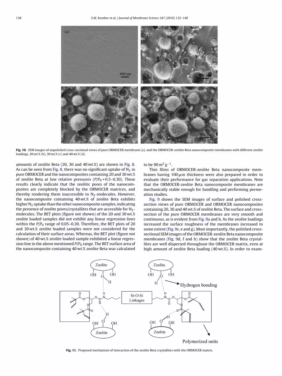
Fig. 11. Proposed mechanism of interaction of the zeo
; and the ORMOCER-zeolite Beta nanocomposite membranes with different zeolite
to be 90 m2 g−1.Thin films of ORMOCER-zeolite Beta nanocomposite mem-
branes having 100 �m thickness were also prepared in order toevaluate their performance for gas separation applications. Notethat the ORMOCER-zeolite Beta nanocomposite membranes aremechanically stable enough for handling and performing perme-ation studies.
Fig. 9 shows the SEM images of surface and polished cross-section views of pure ORMOCER and ORMOCER nanocompositescontaining 20, 30 and 40 wt.% of zeolite Beta. The surface and cross-section of the pure ORMOCER membranes are very smooth andcontinuous, as is evident from Fig. 9a and b. As the zeolite loadingsincreased the surface roughness of the membranes increased to
some extent (Fig. 9c, e and g). Most importantly, the polished cross-sectional SEM images of the ORMOCER-zeolite Beta nanocompositemembranes (Fig. 9d, f and h) show that the zeolite Beta crystal-lites are well dispersed throughout the ORMOCER matrix, even athigh amount of zeolite Beta loading (40 wt.%). In order to exam-lite Beta crystallites with the ORMOCER matrix.
S.M. Kumbar et al. / Journal of Membrane Science 347 (2010) 132–140 139
Table 2H2 and He permeabilities of the pure ORMOCER membranes activated (ex situ) atdifferent temperatures under vacuuma.
Pre-activation temperature (◦C) Permeability (Barrer)b
H2 He
120 3.4 4.5170 11.7 14.7200 3.6 4.2
izctpubowlTtvoOhfttdlztc
ssaTtouOaSbgmotHtactfdfs
lnt
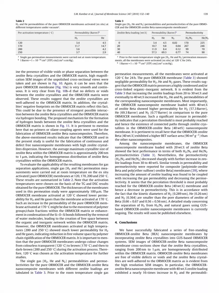
Table 3Single gas (H2, He and N2) permeabilities and permselectivities of the pure ORMO-CER and the ORMOCER-zeolite Beta nanocomposite membranesa.
Zeolite Beta loading (wt.%) Permeability (Barrer)b Permselectivity
H2 He N2 H2/N2 He/N2
0 3.4 4.5 0,02 170 22520 10.7 9.8 0.04 267 24630 11.9 8.4 0.12 99 7040 57.3 69.3 0.77 74 90
250 3.7 2.9a Single gas permeation measurements were carried out at room temperature.b 1 Barrer = 1 × 10⁻¹⁰ cm3 (STP) cm/(cm2 s cm Hg).
ne the presence of visible voids or phase separation between theeolite Beta crystallites and the ORMOCER matrix, high magnifi-ation SEM images of the unpolished cross-sectional views wereaken and are shown in Fig. 10. Again, it can be seen that theure ORMOCER membrane (Fig. 10a) is very smooth and contin-ous. It is very clear from Fig. 10b–d that no defects or voidsetween the zeolite crystallites and the ORMCOER matrix werebserved. These results suggest that the zeolite crystallites areell-adhered to the ORMOCER matrix. In addition, the crystal-
ites’ negative footprints on the ORMOCER matrix reflect this fact.his could be due to the presence of strongest possible interac-ion between the zeolite Beta crystallites and the ORMOCER matrixia hydrogen bonding. The proposed mechanism for the formationf hydrogen bonds between the zeolite Beta crystallites and theRMOCER matrix is shown in Fig. 11. It is pertinent to mentionere that no primers or silane-coupling agents were used for the
abrication of ORMOCER-zeolite Beta nanocomposites. Therefore,he above-mentioned results indicate that the ORMOCER used inhe present study is useful for the fabrication of continuous andefect free nanocomposite membranes with high zeolite crystal-
ites dispersion. However, the average maximum crystallite size ofeolite Beta within the ORMOCER matrix is approximately 200 nmo 1 �m, indicating the homogeneous distribution of zeolite Betarystallites within the ORMOCER matrix.
To evaluate the applicability of the resulting membranes for gaseparation applications, single gas (H2 and He) permeation mea-urements were carried out at room temperature on the ex situctivated (pure ORMOCER) membranes at 120, 170, 200 and 250 ◦C.hese results are summarized in Table 2. Note that the activationemperatures were chosen on the basis of the TG and DSC resultsbtained for the pure ORMOCER. The thicknesses of the membranessed in this permeation study were approximately 100 �m. TheRMOCER membrane activated at 120 ◦C showed lower perme-bility for H2 and He gases than the membrane activated at 170 ◦C.uch an increase in the permeability of the pure ORMOCER mem-rane activated at 170 ◦C might be due to the movement of polymerroups/chain fractions within the ORMOCER matrix or enhance-ent in condensation of the Si–O–Si bonds followed by the removal
f water molecules, leading to the creation of free space betweenhe organic and inorganic network within the ORMOCER matrix.owever, the ORMOCER membranes activated at high tempera-
ures (200 and 250 ◦C) showed much lower permeability for H2nd He gases, indicating reduction in free volume space by polymerhain rigidification of the ORMOCER matrix. It is important to men-ion that the pure ORMOCER membranes undergo colour changesrom colourless transparent (120 ◦C) to brown (170 ◦C) and then toark-brown (200 and 250 ◦C) during the activation process. There-ore, 120 ◦C was chosen as the activation temperature for furthertudies.
The single gas (H2, He and N2) permeabilities and permse-ectivities for the pure ORMOCER and the ORMOCER-zeolite Betaanocomposite membranes with different zeolite loadings areabulated in Table 3. Prior to the room temperature single gas
a Prior to the room temperature single gas (H2, He and N2) permeation measure-ments, all the membranes were activated (ex situ) at 120 ◦C for 24 h.
b 1 Barrer = 1 × 10⁻¹⁰ cm3 (STP) cm/(cm2 s cm Hg).
permeation measurements, all the membranes were activated at120 ◦C for 24 h. The pure ORMOCER membrane (Table 3) showednegligible permeability for H2, He and N2 gases. These results sug-gest that the ORMOCER matrix possesses a highly condensed and/orcross-linked organic–inorganic network. It is evident from theTable 3 that increasing the zeolite loadings from 20 to 30 wt.% andeventually to 40 wt.% increased the H2, He and N2 permeabilities ofthe corresponding nanocomposite membranes. Most importantly,the ORMOCER nanocomposite membrane loaded with 40 wt.%of zeolite Beta showed higher permeability for H2 (57.3 Barrer),He (69.3 Barrer) and N2 (0.77 Barrer) in comparison to the pureORMOCER membrane. Such a significant increase in permeabil-ity indicates that a percolation threshold is most probably reachedand hence the existence of connected paths through zeolite crys-tallites in the ORMOCER-zeolite Beta (40 wt%) nanocompositemembrane. It is pertinent to recall here that the ORMOCER-zeoliteBeta (40 wt.%) exhibited a higher BET surface area (90 m2 g−1) thanthe other nanocomposites.
Among the nanocomposite membranes, the ORMOCERnanocomposite membrane loaded with 20 wt.% of zeolite Betashowed the best performance in terms of both H2/N2 and He/N2permselectivities (Table 3). Nevertheless, the permselectivity(H2/N2 and He/N2) decreased sharply with further increase in zeo-lite loadings from 30 to 40 wt%. Similar trends in permeability andpermselectivity were reported for composite [polyimide-zeoliteBeta and poly(ether sulfone)-zeolite Beta] membranes [39], whereincreasing the amount of zeolite loading was found to be coupledwith increasing the gas permeability and decreasing the permse-lectivity. It seems that the percolation threshold is most probablyreached for the ORMOCER-zeolite Beta (40 wt.%) membrane andhence a decrease in permselectivity. This is in accordance withthe fact that the kinetic diameters of H2 (0.289 nm), He (0.26 nm)and N2 (0.364) are smaller than the pore diameters of zeolite ofBeta (0.66 × 0.67 and 0.56 × 0.56 nm). A detailed study concerningthe separation of H2 from H2/N2 and natural gases using GUS-based ORMOCER-zeolite nanocomposite membranes is currentlyongoing. The results will soon be published elsewhere.
4. Conclusions
We have successfully fabricated a series of free-standingORMOCER-zeolite Beta (BEA) nanocomposite membranes byincorporating zeolite Beta crystallites into GUS-based ORMOCERsystems. SEM images of ORMOCER-zeolite Beta nanocompositemembrane cross-sections show that the zeolite Beta crystallites,ranging from 200 nm to 1 �m, are homogeneously distributedwithin the ORMOCER matrix. ORMOCER-zeolite Beta membranesare free of visible defects or voids and the zeolite Beta crystal-
lites are well-adhered to the ORMOCER matrix as is evident fromthe high resolution SEM images. In particular, the ORMOCER-zeolite Beta nanocomposite membrane with 40 wt.% zeolite loadingexhibited a nearly 16-times increase in H2 and He permeabili-
1 embra
tapGobOmH
A
naa
R
[
[
[
[
[
[
[
[
[
[
[
[
[
[
[
[
[
[
[
[
[
[
[
[
[
[
[
[
[
[
[
[
[
[
[
[
[
[
mers based on various diisocyanates, J. Mater. Sci. 37 (2002) 1247.
40 S.M. Kumbar et al. / Journal of M
ies in comparison to the pure ORMOCER membrane. However,ll the membranes showed negligible N2 permeability, exem-lifying the highly condensed and/or cross-linked nature of theUS-based ORMOCER matrix. The addition of a sufficient amountf dimethyldiethoxysilane (DMDES), during the synthesis of GUS-ased ORMOCER resin, might increase the free volume within theRMOCER matrix, which may lead to the development of high-fluxixed matrix membranes for the separation of H2 and He from2/He/N2 gas mixtures and natural gases.
cknowledgements
We gratefully acknowledge the financial support from ELITEetwork of Bavaria, University of Bayreuth and Fraunhofer ISC. Theuthors would like to thank Ms. Hanselmann, Fraunhofer ISC, forssisting in single gas permeation measurements.
eferences
[1] R. Mahajan, D.Q. Vu, W.J. Koros, Mixed matrix membrane materials: an answerto the challenges faced by membrane based gas separations today? J. Chin. Inst.Chem. Eng. 33 (2002) 77–86.
[2] A.F. Ismail, N. Ridzuan, S.A. Rahman, Latest development on the membraneformation for gas separation, Songklanakarin J. Sci. Technol. 24 (2002) 1025.
[3] T.-S. Chung, L.Y. Jiang, Y. Li, S. Kulprathipanja, Mixed matrix membranes(MMMs) comprising organic polymers with dispersed inorganic fillers for gasseparation, Progr. Polym Sci. 32 (2007) 483.
[4] S.P. Nunes, Organic–inorganic membranes for gas separation, Ann. Chim. 32(2007) 119.
[5] S. Choi, J. Coronas, Z. Lai, D. Yust, F. Onorato, M. Tsapatsis, Fabrication and gasseparation properties of polybenzimidazole (PBI)/nanoporous silicates hybridmembranes, J. Membr. Sci. 316 (2008) 145.
[6] B. Liu, Y. Cao, T. Wang, Q. Yuan, Preparation of novel ZSM-5 zeolite-filledchitosan membranes for pervaporation separation of dimethyl carbon-ate/methanol mixtures, J. Appl. Polym. Sci. 106 (2007) 2117.
[7] M.B. Patil, T.M. Aminabhavi, Pervaporation separation of toluene/alcohol mix-tures using silicalite zeolite embedded chitosan mixed matrix membranes, Sep.Purif. Technol. 62 (2008) 128.
[8] L.M. Vane, V.V. Namboodiri, T.C. Bowen, Hydrophobic zeolite–silicone rubbermixed matrix membranes for ethanol–water separation: effect of zeolite andsilicone component selection on pervaporation performance, J. Membr. Sci. 308(2008) 230.
[9] D.-H. Son, R.K. Sharma, Y.-G. Shul, H. Kim, Preparation of Pt/zeolite–nafion com-posite membranes for self-humidifying polymer electrolyte fuel cells, J. PowerSources 165 (2007) 733.
10] T. Sancho, J. Soler, M.P. Pina, Conductivity in zeolite–polymer composite mem-branes for PEMFCs, J. Power Sources 169 (2007) 92.
11] B. Libby, W.H. Smyrl, E.L. Cussler, Polymer–zeolite composite membranes fordirect methanol fuel cells, AIChE J. 49 (2003) 991.
12] W. Yuan, H. Wu, B. Zheng, X. Zheng, Z. Jiang, X. Hao, B. Wang, Sorbitol-plasticized chitosan/zeolite hybrid membrane for direct methanol fuel cell, J.Power Sources 172 (2007) 604.
13] T.T. Moore, W.J. Koros, Non-ideal effects in organic–inorganic materials for gasseparation membranes, J. Mol. Struct. 739 (2005) 87.
14] Y. Li, H.-M. Guan, T.-S. Chung, S. Kulprathipanja, Effects of novel silane modifica-tion of zeolite surface on polymer chain rigidification and partial pore blockagein polyethersulfone (PES)–zeolite A mixed matrix membranes, J. Membr. Sci.275 (2006) 17.
15] H. Sun, L. Lu, X. Chen, Z. Jiang, Surface-modified zeolite filled chitosan mem-branes for pervaporation dehydration of ethanol, Appl. Surf. Sci. 254 (2008)5367.
16] R. Mahajan, W.J. Koros, Mixed matrix membrane materials with glassy poly-mers. Part 2, Polym. Eng. Sci. 42 (2002) 1432.
17] A.M.W. Hillock, S.J. Miller, W.J. Koros, Crosslinked mixed matrix membranes forthe purification of natural gas: effects of sieve surface modification, J. Membr.Sci. 314 (2008) 193.
18] H.H. Yong, H.C. Park, Y.S. Kang, J. Won, W.N. Kim, Zeolite-filled polyimide mem-brane containing 2,4,6-triaminopyrimidine, J. Membr. Sci. 188 (2001) 151.
19] Q.-L. Liu, J. Xiao, Silicalite-filled poly(siloxane imide) membranes for removalof VOCs from water by pervaporation, J. Membr. Sci. 230 (2004) 121.
20] S. Maheshwari, E. Jordan, S. Kumar, F.S. Bates, R.L. Penn, D.F. Shantz, M. Tsapat-sis, Layer structure preservation during swelling, pillaring, and exfoliation of azeolite precursor, J. Am. Chem. Soc. 130 (2008) 1507.
21] S. Choi, J. Coronas, E. Jordan, W. Oh, S. Nair, F. Onorato, D.F. Shantz, M. Tsapatsis(Eds.), Layered silicates by swelling of AMH-3 and nanocomposite membranes,Angew. Chem. Int. 47 (2008) 552.
[
[
ne Science 347 (2010) 132–140
22] S. Choi, J. Coronas, Z. Lai, D. Yust, F. Onorato, M. Tsapatsis, Fabrication and gasseparation properties of polybenzimidazole (PBI)/nanoporous silicates hybridmembranes, J. Membr. Sci. 316 (1+2) (2008) 145.
23] C.V. Funk, D.R. Lloyd, Zeolite-filled microporous mixed matrix (ZeoTIPS) mem-branes: prediction of gas separation performance, J. Membr. Sci. 313 (2008)224.
24] Y. Li, T.-S. Chung, Z. Huang, S. Kulprathipanja, Dual-layer polyethersulfone(PES)/BTDA-TDI/MDI co-polyimide (P84) hollow fiber membranes with a sub-micron PES-zeolite beta mixed matrix dense-selective layer for gas separation,J. Membr. Sci. 277 (2006) 28.
25] L.Y. Jiang, T.S. Chung, S. Kulprathipanja, An investigation to revitalize the sep-aration performance of hollow fibers with a thin mixed matrix composite skinfor gas separation, J. Membr. Sci. 276 (2006) 113.
26] S. Husain, W.J. Koros, Mixed matrix hollow fiber membranes made with mod-ified H-SSZ-13 zeolite in polyetherimide polymer matrix for gas separation, J.Membr. Sci. 288 (2007) 195.
27] K.-H. Haas, K. Rose, Hybrid inorganic/organic polymers with nanoscale buildingblocks: precursors, processing, properties and applications, Rev. Adv. Mater. Sci.5 (2003) 47.
28] G. Schottner, Hybrid sol–gel-derived polymers: applications of multifunctionalmaterials, Chem. Mater. 13 (2001) 3422.
29] K.-H. Haas, Hybrid inorganic–organic polymers based on organically modifiedSi-alkoxides, Adv. Eng. Mater. 2 (2000) 571.
30] S. Jacob, S. Cochet, C. Poinsignon, M. Popall, Proton conductinginorganic–organic matrices based on sulfonyl- and styrene derivativesfunctionalized polycondensates via sol–gel processing, Electrochim. Acta 48(2003) 2181.
31] S. Jacob, C. Poinsignon, M. Popall, Inorganic–organic hybrid protonic polymericmaterials for fuel cells based on polycondensed and organically cross-linked sulfonyl- and styrene-functionalized alkoxysilanes, Electrochim. Acta50 (2005) 4022.
32] K.-H. Haas, S. Amberg-Schwab, T. Ballweg, Synthesis and properties of hybridinorganic-organic polymers based on organically modified Si-alkoxides andtheir use for permeation control, Adv. Sci. Technol. 31 (2003) 581.
33] H. Wolter, T. Ballweg, W. Storch, Membrane for oxygenator, Eur. Patent, EP0985442 (2000).
34] T. Ballweg, H. Wolter, W. Storch, Ormocer- and derived microporous inorganichollow fibers, Keramische Zeitschrift 53 (2001) 678.
35] T. Ballweg, H. Wolter, Hollow fibers from hybrid polymers, Gummi FasernKunststoffe 53 (2000) 277.
36] R.W. Thompson, B.E. Libby, M.B. Berry, K. Rose, K.-H. Haas, Incorporation ofzeolites into hybrid polymer matrices, US Patent, US 6, 248, 682 (2001).
37] M.B. Berry, B.E. Libby, K. Rose, K.-H. Haas, R.W. Thompson, Incorporation ofzeolites into composite matrices, Micropor. Mesopor. Mater. 39 (2000) 205.
38] H. Wolter, W. Storch, Urethane (meth)acrylate alkoxysilane, a new typeof reactive polymers for the preparation of inorganic–organic copolymers(ORMOCER®s), in: Polymer & Materials Research Symposium, Bayreuth, 1993,p. 14.
39] Z. Huang, J.-F. Su, X.-Q. Su, Y.-H. Guo, L.-J. Teng, C.M. Yang, Preparation andpermeation characterization of �-zeolite-incorporated composite membranes,J. Appl. Polym. Sci. 112 (2009) 9.
40] H. Wolter, W. Storch, C. Gellermann, Novel carboxy functionalized sol–gel pre-cursors, Mat. Res. Soc. Symp. Proc. 435 (1996) 67.
41] L. Armelao, C. Eisenmenger-Sittner, M. Groenewolt, S. Gross, C. Sada, U. Schu-bert, E. Tondello, A. Zattin, Zirconium and hafnium oxoclusters as molecularbuilding blocks for highly dispersed ZrO2 or HfO2 nanoparticles in silica thinfilms, J. Mater. Chem. 15 (2005) 1838.
42] R. Houbertz, G. Domann, J. Schulz, B. Olsowski, L. Fröhlich, Impact ofphotoinitiators on the photopolymerization and the optical properties ofinorganic–organic hybrid polymers, Appl. Phys. Lett. 84 (2004) 1105.
43] Y. Kaneka, N. Iyi, T. Mastsumoto, K. Fujii, K. Kurashima, T. Fujita, Synthe-sis of ion-exchangeable layered polysiloxane by sol–gel method reaction ofaminoalkytri-alkoxysilane: a new preparation method for layered polysiloxanematerials, J. Mater. Chem. 13 (2003) 2058.
44] N. Moszner, T. Völkel, S. Cramer von Clausbruch, E. Geiter, N. Batliner, V. Rhein-berger, Macromol. Mater. Eng. 287 (2002) 339.
45] F. Brunet, Polymerization reactions in methyltriethoxysilane studied through29Si NMR with polarization transfer, J. Non-Cryst. Solids 231 (1998) 58.
46] C.K. Chan, I.M. Chu, W. Lee, W.-K. Chin, Preparation and properties oforganic–inorganic hybrid materials based on poly{(butyl methacrylate)-co-[(3-methacryloxy-propyl)trimethoxysilane]}, Macromol. Chem. Phys. 202 (2001)911.
47] C. Ma, Y. Du, F. Wang, Thermal degradation behaviors ofpoly(dimethylsiloxane)-urethane-graft-poly(methylmethacrylate) copoly-
48] J. Zhang, A. Li, A. Wang, Synthesis and characterization of multifunctionalpoly(acrylicacid-co-acrylamide)/sodium humate superabsorbent composite,React. Funct. Polym. 66 (2006) 747.
49] H.G. Schild, Thermal degradation of poly(methacrylic acid): further studiesapplying TGA/FTIR, J. Polym. Sci. Part A: Polym. Chem. 31 (1993) 2403.