optoacoustic imaging of the prostate: development toward image-guided biopsy
TRANSCRIPT

Ot
MSHRAF7H
MS3S
BMCUG
AF7H
1
Pcnmftt
rdtdttcidia
†
s*TT
Journal of Biomedical Optics 15�2�, 021310 �March/April 2010�
J
ptoacoustic imaging of the prostate: developmentoward image-guided biopsy
ohammad A. Yaseen†
ergey A. Ermilovans-Peter Brechtichard Sundré Conjusteau
airway Medical Technologies Inc.10 North Post Oak Road, Suite 204ouston, Texas 77024
atthew Fronheisereno Medical Instruments, Inc.838 Medical Drive, Suite 101an Antonio, Texas 78229
rent A. Bellassoud Motamedi
enter for Biomedical Engineeringniversity of Texas, Medical Branchalveston, Texas 77555
lexander A. Oraevsky*airway Medical Technologies Inc.10 North Post Oak Road, Suite 204ouston, Texas 77024
Abstract. Optoacoustic �OA� tomography has demonstrated utility inidentifying blood-rich malignancies in breast tissue. We describe thedevelopment and characterization of a laser OA imaging system forthe prostate �LOIS-P�. The system consists of a fiber-coupledQ-switched laser operating at 757 nm, a commercial 128-channelultrasonic probe, a digital signal processor, and software that uses thefiltered radial back-projection algorithm for image reconstruction. Thesystem is used to reconstruct OA images of a blood-rich lesion in-duced in vivo in a canine prostate. OA images obtained in vivo arecompared to images acquired using ultrasound, the current gold stan-dard for guiding biopsy of the prostate. Although key structural fea-tures such as the urethra could be identified with both imaging tech-niques, a bloody lesion representing a highly vascularized tumorcould only be clearly identified in OA images. The advantages andlimitations of both forward and backward illumination modes are alsoevaluated by collecting OA images of phantoms simulating blood ves-sels within tissue. System resolution is estimated to be 0.2 mm in theradial direction of the acoustic array. The minimum detectable pres-sure signal is 1.83 Pa. Our results encourage further developmenttoward a dual-modality OA/ultrasonic system for prostate imaging andimage-guided biopsy. © 2010 Society of Photo-Optical Instrumentation Engineers.
�DOI: 10.1117/1.3333548�
Keywords: image reconstruction; optoacoustic tomography; prostate cancer; tran-srectal ultrasound imaging; tumor imaging.Paper 09360SSR received Aug. 14, 2009; revised manuscript received Oct. 14,2009; accepted for publication Oct. 26, 2009; published online Mar. 12, 2010.
Introduction
rostate cancer is the most frequently diagnosed type of can-er in men in the United States, with approximately 200,000ew cases of prostate cancer identified each year. It is esti-ated that in 2009, 27,360 men in the United States will die
rom prostate cancer. In the United States, prostate cancer ishe leading cause of cancer fatalities among men, and it is thehird leading cause worldwide.1,2
Several methods exist to screen for prostate cancer. Cur-ently, blood screening for prostate-specific antigen �PSA�,igital rectal examination �DRE�, and tissue biopsy guided byransrectal ultrasound �TRUS� are the most widely acceptediagnostic methods for prostate cancer in clinics.3,4 However,hese techniques all have limited ability to resolve malignantissue from benign enlarged prostate tissue.5,6 Physicians typi-ally overcome their limited sensitivity and specificity by us-ng combinations of these methods to perform more accurateiagnoses.7,8 Although the entire prostate anatomy can be eas-ly visualized by traditional TRUS imaging, malignant lesionsre difficult to identify using TRUS. Frequently, evaluating
Current affiliation: Athinoula A. Martinos Center for Biomedical Imaging, Mas-achusetts General Hospital, Building 149, 13th Street, Charlestown, MA 02129Address all correspondence to: Alexander A. Oraevsky, PhD, Fairway Medicalechnologies Inc., 710 North Post Oak Road, Suite 204, Houston, TX 77024.el: 713-772-7867; Fax: 832-201-9192; E-mail: [email protected]
ournal of Biomedical Optics 021310-
other image factors such as prostate asymmetry and capsulardistortion serve as the only indicator of cancer in TRUS im-ages. Although 60 to 75% of prostate malignancies are hypo-echoic, they are known to vary in echogenicity, depending onthe tumor stage, size, and location.8 Particularly, TRUS is notsuitable for imaging early stage tumors that provide weakecho contrast from normal tissue. In addition to TRUS, anumber of imaging techniques exist that provide spatial infor-mation of prostate tissue, including magnetic resonance imag-ing �MRI� and computed tomography �CT�.7–10 All prostateimaging methods currently lack the necessary contrast andsensitivity to independently perform detailed evaluation andstaging of malignant tissue. Instead, these techniques serveprimarily either to provide complementary spatial informationabout prostate dimensions or for guidance during needlebiopsy.10 Improved identification of suspicious regions forneedle biopsy could potentially enhance chances for early di-agnosis and successful therapy. One approach to facilitateimage-guided biopsy of the prostate involves combination ofTRUS and near-infrared �NIR� diffuse optical tomography.11
Initial results proved that prostate tumors can be visualizedoptically due to substantial absorption contrast of the blood-rich tumors, however, the image resolution was suboptimal.12
Another technology, which is also based on optical contrast of
1083-3668/2010/15�2�/021310/8/$25.00 © 2010 SPIE
March/April 2010 � Vol. 15�2�1

ttrvla
nantltvOtsenocnmtis
ttdtoTotucafiiicq
FfMe
Yaseen et al.: Optoacoustic imaging of the prostate: development toward image-guided biopsy
J
he prostate tumors, but could potentially provide better spa-ial resolution, is optoacoustic imaging.13,14 In addition to theesolution advantage, optoacoustic imaging can be more con-eniently combined with TRUS, because it requires only extraight delivery, and can use the commercial ultrasonic sensorrray to receive the generated optoacoustic �OA� signals.
OA images are reconstructed from transient acoustic sig-als generated by thermal expansion of tissue following thebsorption of a short laser pulse.14 Image resolution orthogo-al to the surface of the acoustic probe is determined by theemporal resolution of an individual ultrasonic transducer, andateral resolution is determined by the angular aperture of theransducer array.15 The image contrast is provided by theariation in optical absorption within the interrogated tissue.A cancer imaging takes advantage of the enhanced absorp-
ion contrast of blood-rich malignant tissue relative to normalurrounding tissue.16 To increase beyond 2 to 3 mm in diam-ter, tumor tissue undergoes angiogenesis, in which a complexetwork of new microvasculature forms to supply necessaryxygen and nutrients to proliferating tumor cells.17,18 Prostatearcinomas can, therefore, be distinguished from nonmalig-ant tissues by elevated density of microvessels.19 The abnor-ally high vascular content provides enhanced optical con-
rast of malignant tumor tissue relative to that of normal tissuen the NIR range, where water and most biomolecules do notubstantially absorb light.20–22
The utility of OA imaging for detection and characteriza-ion of breast tumors has been explored extensively,16,23–27 andhe principles that make OA imaging viable for breast canceretection offer potential for its utility in detection and charac-erization of prostate malignancies. Here we report the devel-pment of a laser OA system for prostate imaging �LOIS-P�.he system utilizes a fiber-coupled NIR laser for maximalptical penetration depth and contrast of blood-rich malignantissue. Ultrasonic transients are collected using a commercialltrasound probe containing an array of 128 wide band piezo-eramic transducers. Two-dimensional tomographic OA im-ges are constructed from the acquired OA signals using theltered radial back-projection �RBP� algorithm.14 As combin-
ng OA imaging with ultrasound can provide complementarynformation regarding the location and vascularity of suspi-ious lesions,28 we use both techniques to present images ac-uired from test phantoms and from in vivo canine prostate
ig. 1 �a� Commercial 128-channel endocavity ultrasound probe �EC7or OA imaging. The piezoceramic detectors are oriented as a conv
easured OA impulse response of a single detector in the endocavitstimation of the radial resolution �see text� and �c� the correspondin
ournal of Biomedical Optics 021310-
tissue with mechanically induced blood-filled lesion. Using athree-step computer modeling procedure, we also constructedOA images from simulated in vivo conditions to determine theinfluence of various prostate anatomical features on the OAimage.
2 Materials and Methods2.1 LOIS-P System Description and TestingThe potential of OA imaging for detecting prostate malignan-cies was evaluated by imaging surgically exposed canineprostate, illuminated orthogonally, and also blood vesselphantoms imaged in both forward and backward modes.Samples were illuminated with a Q-switched alexandrite laser�Ta2, Light Age Inc., Somerset, New Jersey� producing 75-nslaser pulses of 757-nm wavelength at a 10-Hz repetition rate.The laser light was delivered via a bifurcating optical fiberbundle �Dolan-Jenner, Boxborough, Massachusetts� with flu-ence at the sample surface about 10 mJ /cm2. The fiber bundlewas comprised of 50-�m glass fibers, and the terminalbundles measured 4.5 mm in diameter. The laser-generatedacoustic transients were collected with a commercial TRUSprobe �EC7ART, Scanhead Corp., San Jose, California�, pic-tured in Fig. 1�a�. The probe contains an array of 128 piezo-ceramic transducer elements measure 6�0.2 mm each with apitch of 0.21 mm. The transducers line the edge of a convexcircular arc segment with a radius of 10 mm and total arcangle of 154 deg, as seen in the enlarged section of Fig. 1�a�.The probe also contains an acoustic lens situated directly infront of the transducer array. The lens focuses inside the tissueonto an arc-shaped line with radius of 35 mm located in theimaging plane.
The OA signals acquired from the ultrasonic probe wereamplified in two stages and digitized by a 128-channel elec-tronics system. Both analog and digital components were de-veloped by Fairway Medical Technologies �Houston, Texas�for the breast cancer detection system, and were described ina previous publication.26 Briefly, the first stage consisted of acustom-built charge amplifier with a 30-dB gain for low-noiseamplification of capacitive sources. The second amplifierstage was a standard signal amplifier stage with a 30-dB gain.The signals were then digitized by a 12-bit analog-to-digitalconverter with a maximum sampling rate of 41 MHz.
anhead Corp., San Jose, California� used to collect acoustic transientsy lining the edge of the probe, as seen in the enlarged section. �b�, where the dashed line indicates envelope-detected signal used for
ency response.
ART, Scex array probeg frequ
March/April 2010 � Vol. 15�2�2
h�iawicrsdtp
sgpcda
ttbpj
2
Twtiastpbmltldeiabmtsdcip
2Us�i
Yaseen et al.: Optoacoustic imaging of the prostate: development toward image-guided biopsy
J
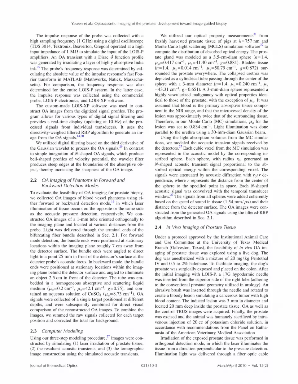
The impulse response of the probe was collected with aigh sampling frequency �1 GHz� using a digital oscilloscopeTDS 3014, Tektronix, Beaverton, Oregon� operated at a highnput impedance of 1 M� to simulate the input of the LOIS-Pmplifiers. An OA transient with a Dirac � function profileas generated by irradiating a layer of highly absorptive India
nk.29 The probe’s frequency response was determined by cal-ulating the absolute value of the impulse response’s fast Fou-ier transform in MATLAB �Mathworks, Natick, Massachu-etts�. For comparison, the frequency response was alsoetermined for the entire LOIS-P system. In the latter case,he impulse response was collected using the commercialrobe, LOIS-P electronics, and LOIS-XP software.
The custom-made LOIS-XP software was used to con-truct OA images from the digitized signal profiles. The pro-ram allows for various types of digital signal filtering androvides a real-time display �updating at 10 Hz� of the pro-essed signals from individual transducers. It uses theirectivity-weighed filtered RBP algorithm to generate an im-ge from the OA signals.14,30
We utilized digital filtering based on the third derivative ofhe Gaussian wavelet to process the OA signals.29 In contrasto simple integration of N-shaped OA signals, which produceell-shaped profiles of velocity potential, the wavelet filterroduces steep edges at the boundaries of the absorptive ob-ect, thereby increasing the sharpness of the OA image.
.2 OA Imaging of Phantoms in Forward andBackward Detection Modes
o evaluate the feasibility of OA imaging for prostate biopsy,e collected OA images of blood vessel phantoms using ei-
her forward or backward detection mode,16 in which laserllumination of tissue occurs on the opposite or the same sides the acoustic pressure detection, respectively. We con-tructed OA images of a 1-mm tube oriented orthogonally tohe imaging plane and located at various distances from therobe. Light was delivered through the terminal ends of theifurcating fiber bundle described in Sec. 2.1. For forwardode detection, the bundle ends were positioned at stationary
ocations within the imaging plane roughly 7 cm away fromhe detector surface. The bundle ends were angled to directight to a point 25 mm in front of the detector’s surface at theetector probe’s acoustic focus. In backward mode, the bundlends were positioned at stationary locations within the imag-ng plane behind the detector surface and angled to illuminaten object 2.5 cm in front of the detector. The tube was em-edded in a homogeneous absorptive and scattering liquidedium ��a=0.2 cm−1, �s=42.1 cm−1, g=0.75�, and con-
ained an aqueous solution of CuSO4 ��a=8.73 cm−1�. OAignals were collected of a single target positioned at differentepths, and were subsequently combined for direct visualomparison of the reconstructed OA images. To combine themages, we summed the raw signals collected for each targetosition and corrected the total for background.
.3 Computer Modelingsing our three-step modeling procedure,27 images were con-
tructed by simulating �1� laser irradiation of prostate tissue,2� the resultant acoustic transients, and �3� the tomographicmage construction using the simulated acoustic transients.
ournal of Biomedical Optics 021310-
We utilized our optical property measurements31 fromfreshly harvested prostate tissue of pigs at �=757 nm andMonte Carlo light scattering �MCLS� simulation software32 tocompute the distribution of absorbed optical energy. The pros-tate gland was modeled as a 3.5-cm-diam sphere �n=1.4,�a=0.417 cm−1, �s=41.40 cm−1, g=0.881�. Bladder tissue�n=1.4, �a=0.014 cm−1, �s=50.79 cm−1, g=0.872� sur-rounded the prostate everywhere. The collapsed urethra wasdepicted as a cylindrical tube passing through the center of thesphere with a 3-mm diameter �n=1.4, �a=0.240 cm−1, �s=43.31 cm−1, g=0.651�. A 3-mm-diam sphere represented ahighly vascularized malignancy with optical properties iden-tical to those of the prostate, with the exception of �a. It wasassumed that blood is the primary absorptive tissue compo-nent in the NIR range, and that the microvessel density of thelesion was approximately twice that of the surrounding tissue.Therefore, in our Monte Carlo �MC� simulations, �a for thelesion was set to 0.834 cm−1. Light illumination was doneparallel to the urethra using a 30-mm-diam Gaussian beam.
Using the light absorption volumes from the MC simula-tions, we modeled the acoustic transient signals received bythe detectors.27 Each cubic voxel from the MC simulation wasrepresented in the acoustic model by the corresponding in-scribed sphere. Each sphere, with radius r0, generated anN-shaped acoustic transient signal proportional to the ab-sorbed optical energy within the corresponding voxel. Thesignals were attenuated by acoustic diffraction with r0 /r de-pendence, where r represents the distance from the center ofthe sphere to the specified point in space. Each N-shapedacoustic signal was convolved with the temporal transducerwindow.27 The signals from all spheres were added coherentlybased on the speed of sound in tissue �1.54 mm /�s� and theirdistance from the detector surface. The OA images were con-structed from the generated OA signals using the filtered-RBPalgorithm described in Sec. 2.1.
2.4 In Vivo Imaging of Prostate Tissue
Under a protocol approved by the Institutional Animal Careand Use Committee at the University of Texas MedicalBranch �Galveston, Texas�, the feasibility of in vivo OA im-aging of prostate tissue was explored using a live dog. Thedog was anesthetized with a mixture of 20 mg /kg PentothalIV and 0.5 to 2% halothane. To facilitate imaging, the dog’sprostate was surgically exposed and placed on the colon. Afterthe initial imaging with LOIS-P, a 17G hypodermic needlewas inserted from the superior side of the right lobe �adheringto the conventional prostate geometry utilized in urology�. Anabrasive brush was inserted through the needle and rotated tocreate a bloody lesion simulating a cancerous tumor with highblood content. The induced lesion was 3 mm in diameter andlocated 20 mm deep inside the prostate tissue. OA as well asthe control TRUS images were acquired. Finally, the prostatewas excised and the animal was humanely sacrificed by intra-venous injection of 20 cc of potassium chloride solution, inaccordance with recommendations from the Panel on Eutha-nasia of the American Veterinary Medical Association.
Irradiation of the exposed prostate tissue was performed inorthogonal detection mode, in which the laser illuminates thetissue from a direction perpendicular to the pressure detection.Illumination light was delivered through a fiber optic cable
March/April 2010 � Vol. 15�2�3

aaogtwss
gttcppaauHp8
33Faqt3stm
Fdfi
Yaseen et al.: Optoacoustic imaging of the prostate: development toward image-guided biopsy
J
nd a dispersing lens, while the OA probe was pressed firmlygainst the prostate from the anterior end of the animal. Theptical fiber and dispersing lens provided a relatively homo-eneous distribution of light within the imaging slice and,herefore, allowed to minimize the image artifacts associatedith attenuation of light in the prostate. In this feasibility
tudy, the orthogonal OA mode represented the “best-casecenario” for OA imaging of prostate.
Though TRUS currently lacks the ability to reliably distin-uish malignant lesions from benign tissue, it provides de-ailed spatial information about the prostate. Combining thewo imaging techniques has the potential to form high-ontrast, high-resolution images, reliably yielding more com-rehensive information of the prostate gland and the possibleresence of tumors. Therefore, for comparison with OA im-ges and to yield complementary information, ultrasonic im-ges were collected during our in vivo imaging experimentsing a commercial ultrasound system �3535, BK Medical,erlev, Denmark� with a 30-mm, 7.5-MHz curved arrayrobe. The system acquired ultrasound images at a rate of4 frames /s.
Results.1 System Characteristicsigures 1�b� and 1�c� display the detected impulse responsend corresponding frequency response, respectively. The fre-uency response, determined by the fast Fourier transform ofhe impulse response, shows the probe sensitivity within a- to 9-MHz bandwidth �−6 dB criterion�. The frequency re-ponse also shows an undesirable sensitivity band present inhe low-frequency range ��1 MHz�, known to contain large-
agnitude acoustic artifacts.29 Because the LOIS-P amplifier
ig. 2 Images of combined OA signals for 1-mm cylindrical tube �withepths within the aqueous medium simulating optical properties oforward OA mode. OA signals were acquired using a single target, andndividual acquisition. The images are displayed using the standard 8
ournal of Biomedical Optics 021310-
was designed to operate in wideband mode, the frequencyresponse of the entire LOIS-P system was found to be similarto that of the probe alone �data not shown�.
Using the Rayleigh criterion, the minimal distance resolv-able in the radial direction of the probe �orthogonal to thearray of transducers� was estimated as amin
r =cs�0.5�0.2 mm,where cs denotes the speed of sound in tissue �1.54 mm /�s�,and �0.5 is the width of the impulse response, transformed to amonopolar waveform using the envelope detection, at thehalf-max amplitude level �measured to be 115 ns�. The maxi-mum sensitivity of the system was measured using acalibrated29 acoustic emitter �NP/OA90-3, Dapco Industries,Ridgefield, Connecticut� at 5 MHz to be S=2.1 mV /Pa. Weassume that the minimum pressure that can be detected withour system occurs when the signal-to-noise ratio �SNR� is 1.Noise data were evaluated for the frequency range between30 kHz and 10 MHz by collecting and processing recordingswith the LOIS-P system in the absence of laser irradiation.The measured root mean squared �rms� noise was Urms=3.84�0.42 mV. Further analysis revealed that the noisewas comprised primarily of white thermoelectric noise, withcalculated spectral density of 0.558�0.093 �V /Hz1/2. Theminimum detectable pressure signal for the system can there-fore be estimated as pmin=Urms /S=1.83 Pa.
3.2 Phantoms Imaged in Forward and BackwardDetection Modes
Figure 2 shows OA images of a 1-mm blood vessel phantomlocated at various distances from the probe. As seen in Fig.2�a�, when the tube is positioned close to the probe��15 mm�, the cross section of the tube can be easily seen asa small 1-mm circular source when using the backward OA
e axis oriented orthogonal to the imaging plane� positioned at variousund tissues, and illuminated using �a� backward OA mode and �b�
ages were subsequently created after combining the signals from eachy-scale palette. The axes are scaled in millimeters.
the tubbackgrothe im-bit gra
March/April 2010 � Vol. 15�2�4

maasfldbflOtmefF
asosloaadaiulpia
3WdscaOlt
Fetcal8
Yaseen et al.: Optoacoustic imaging of the prostate: development toward image-guided biopsy
J
ode. The deeper vessels in the image cannot be visualized atll. Also, in backward mode imaging, large low-frequencyrtifacts arise in the OA profiles from nonspecific light ab-orption in the subsurface volume of tissue and light that re-ects back from the illuminated tissue and strikes theetector.27 These artifacts were reduced in our further studiesy proper signal processing and shielding the transducer sur-ace with an optically opaque and acoustically thin polymerayer. In backward OA mode, the magnitudes of the detectedA signals decrease at farther distances from the probe, due
o both the attenuation of light as it penetrates within theedium and acoustic diffraction. This combined attenuation
ffect limits the ability to visualize targets at far distancesrom the probe with backward mode imaging, as seen inig. 2�a�.
In forward mode, targets located farther from the probend closer to the light source produce larger OA signals, aseen in Fig. 2�b�. These signals are received by more elementsf the detector array, resulting in better contrast in the con-tructed image. The targets located closer to the probe appearess bright with forward mode imaging also due to attenuationf excitation light. The images are shown in their unprocessedppearance with arc-shaped artifacts caused by the limitedperture of the array of ultrasound transducers. Our group haseveloped an iterative algorithm based on maximum angularmplitude probability for removal of arc-shaped artifacts andmprove contrast and resolution of optoacoustic images.33 Fig-re 2, however, is intended to demonstrate gradual loss ofateral resolution with increasing distance from the ultrasonicrobe shaped as a convex arc. The dynamic range of the OAmage in forward mode is greater than that in backward mode,nd was sufficient to visualize all the tubes �Fig. 2�b��.
.3 Computer-Modeled Imagese simulated the OA image of malignant prostate tissue un-
er conditions similar to our in vivo experiment. Figure 3�a�hows the imaging slice of the absorbed optical energy in thease of the orthogonal OA mode. The lesion is clearly seen asbright circle implying that it represents a strong OA source.n the other hand, the cross section of the collapsed urethra
ooks dark, indicating that it is a weak OA source compared tohe surrounding prostate tissue. This is further verified by the
ig. 3 Comparison of the modeled OA image with the image acquirenergy in a prostate model with spherical malignant lesion, determineransients and the RBP algorithm; and �c� OA image of the dog prostaan be delineated in the OA images. The urethra and the lesion cabsorption difference between the lesion and surrounding tissue resulow OA signals. On each image, arrows indicate the prostate capsule �-bit gray-scale palette.
ournal of Biomedical Optics 021310-
reconstructed OA image �Fig. 3�b��, which has major featuresof the model �the edges of illuminated part of the prostate,urethra, and blood-containing lesion� visible. The OA imageconstructed from the simulated acoustic transients �Fig. 3�b��strongly resembles the one constructed from in vivo canineprostate �Fig. 3�c��. The distances of the urethra and lesionfrom the surface are different between the modeled and ex-perimental images. Furthermore, the portion of the prostatecapsule proximal to the probe can be distinguished only in themodeled image. Once more, these differences most likelyarise from the fact that tissue compression, which deforms thetissue, is required in the experimental case to achieve acousticcontact.
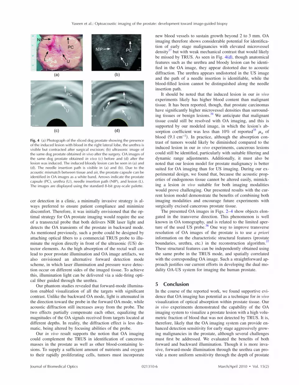
3.4 In Vivo Images of Prostate TissueFigure 4�a� displays a photograph of the surgically excisedprostate sliced through the imaging plane containing the in-duced lesion, representative of a malignant mass. Upon surgi-cal exposure and without compression, the prostate measuredapproximately 35 mm along the dorsoventral axis and 50 mmalong the dextrosinistral axis. Figure 4�b� shows an imageacquired with a commercial ultrasound system. The urethraand the needle insertion path appear in the image as dark,hypoechoic regions. The prostate capsule can also be seen.However, the blood-containing lesion itself does not stand outon the image. Figures 4�c� and 4�d� display OA images of theprostate before and after the lesion was made. In both OAimages, the prostate capsule and the urethra can be delineated.The different distances of those objects from the surface ofthe ultrasonic probe are likely due to slightly higher compres-sion used to achieve acoustic contact in the case of the in-duced lesion �Fig. 4�d��. The blood-filled lesion can be re-solved in Fig. 4�d� as the bright white area that is absent fromFig. 4�c�. The needle insertion path is not visible in both OAimages.
4 DiscussionAlthough OA imaging has much potential for diagnosis andtreatment monitoring of prostate cancer, a number of factorscurrently limit its utility. In particular, the delivery of light toprostate tissue presents a challenge for OA imaging. For can-
vo: �a� imaging slice showing the distribution of the absorbed opticalC simulation; �b� OA image constructed using the simulated acousticined in vivo after inducing a blood-rich lesion. The prostate capsule
een in the OA images as a dark and bright spots, respectively. Theh contrast of the OA image. The low absorption in the urethra yieldsethra �U�, and lesion �L�. The images are displayed using the standard
d in vid by Mte obtan be sts in higPC�, ur
March/April 2010 � Vol. 15�2�5
cwdtodAamtlasttc
tctatmdm
cmst
Fovttl�aicT
Yaseen et al.: Optoacoustic imaging of the prostate: development toward image-guided biopsy
J
er detection in a clinic, a minimally invasive strategy is al-ays preferred to ensure patient compliance and minimizeiscomfort. Therefore, it was initially envisioned that the op-imal strategy for OA prostate imaging would require the usef a transrectal probe that both delivers NIR laser light andetects the OA transients of the prostate in backward mode.s mentioned previously, such a probe could be designed by
ttaching optical fibers to a commercial TRUS probe to illu-inate the region directly in front of the ultrasonic �US� de-
ector elements. As the high absorption of the rectal wall canead to poor prostate illumination and OA image artifacts, welso envisioned an alternative forward detection modecheme, in which laser illumination and pressure wave detec-ion occur on different sides of the imaged tissue. To achievehis, illumination light can be delivered via a side-firing opti-al fiber guided through the urethra.
Our phantom studies revealed that forward-mode illumina-ion enabled visualization of all the targets with significantontrast. Unlike the backward OA mode, light is attenuated inhe direction toward the probe in the forward OA mode, whilecoustic diffraction still increases away from the probe. Thewo effects partially compensate each other, equalizing the
agnitudes of the OA signals received from targets located atifferent depths. In reality, the diffraction effect is less dra-atic, being altered by focusing abilities of the probe.Our in vivo result supports the notion that OA imaging
ould complement the TRUS in identification of cancerousasses in the prostate as well as other blood-containing le-
ions. To supply a sufficient amount of nutrients and oxygeno their rapidly proliferating cells, tumors must incorporate
ig. 4 �a� Photograph of the sliced dog prostate showing the presencef the induced lesion with blood in the right lateral lobe, the urethra isisible but contracted after surgical excision; �b� ultrasonic image ofhe same dog prostate obtained in vivo after the surgery. OA images ofhe same dog prostate obtained in vivo �c� before and �d� after theesion was induced. The induced bloody lesion can be seen in �a� andd�. The needle insertion path is visible in �a� and �b�. Due to thecoustic mismatch between tissue and air, the prostate capsule can bedentified in OA images as a white band. Arrows indicate the prostateapsule �PC�, urethra �U�, needle insertion path �NIP�, and lesion �L�.he images are displayed using the standard 8-bit gray-scale palette.
ournal of Biomedical Optics 021310-
new blood vessels to sustain growth beyond 2 to 3 mm. OAimaging therefore shows considerable potential for identifica-tion of early stage malignancies with elevated microvesseldensity17 but with weak mechanical contrast that would likelybe missed by TRUS. As seen in Fig. 4�d�, though anatomicalfeatures such as the urethra and bloody lesion can be identi-fied in the OA image, they appear distorted due to acousticdiffraction. The urethra appears undistorted in the US imageand the path of a needle insertion is identifiable, while theblood-filled lesion cannot be distinguished along the needleinsertion path.
It should be noted that the induced lesion in our in vivoexperiments likely has higher blood content than malignanttissue. It has been reported, though, that prostate carcinomashave significantly higher microvessel densities than surround-ing tissues or benign lesions.34 We anticipate that malignanttissue could still be resolved with OA imaging, and this issupported by our modeled image, in which the lesion’s ab-sorption coefficient was less than 10% of reported35 �a ofblood �9.1 cm−1�. In practice, although the absorption con-trast of tumors would likely be diminished compared to theinduced lesion in our in vivo experiments, cancerous lesionscould still be identified, particularly with suitable filtering anddynamic range adjustments. Additionally, it must also benoted that our lesion model for prostate malignancy is bettersuited for OA imaging than for US imaging. During our ex-perimental design, we found that, because the acoustic prop-erties of endogenous tissue cannot be altered easily, mimick-ing a lesion in vivo suitable for both imaging modalitieswould prove challenging. Our presented results with the cur-rent lesion model demonstrate the benefits of combining bothimaging modalities and encourage future experiments withsurgically excised cancerous prostate tissue.
The presented OA images in Figs. 2–4 show objects elon-gated in the transverse direction. This phenomenon is wellknown in OA tomography, and is related to the limited aper-ture of the used US probe.36 One way to improve transverseresolution of OA images of the prostate is to use a prioriinformation on the characteristic structural features �prostateboundaries, urethra, etc.� in the reconstruction algorithm.37
These structural features can be independently obtained usingthe same probe in the TRUS mode, and spatially correlatedwith the corresponding OA image. Such a straightforward ap-proach justifies our current efforts in developing the dual mo-dality OA-US system for imaging the human prostate.
5 ConclusionIn the course of the reported work, we found supportive evi-dence that OA imaging has potential as a technique for in vivovisualization of optical absorption within prostate tissue. Ourin vivo experiments demonstrated the capability of the OAimaging system to visualize a prostate lesion with a high volu-metric fraction of blood that was not detected by TRUS. It is,therefore, likely that the OA imaging system can provide en-hanced detection sensitivity for early stage aggressively grow-ing malignancies in the prostate, although several challengesmust first be addressed. We evaluated the benefits of bothforward and backward illumination. Though it is more inva-sive, forward-mode illumination through the urethra can pro-vide a more uniform sensitivity through the depth of prostate
March/April 2010 � Vol. 15�2�6

ga
bpirisa
ATGLtd
R
1
1
1
1
1
1
Yaseen et al.: Optoacoustic imaging of the prostate: development toward image-guided biopsy
J
land due to the fact that factors such as acoustic diffractionnd light attenuation affect the image in opposite directions.
We are currently developing a hybrid system that acquiresoth OA and US images in real time with a single TRUSrobe for prostate diagnosis. Additionally, we are refining ourmage reconstruction algorithms to allow for improved lateralesolution of OA images. In future studies, the OA and USmages will be coregistered to yield images with detailedtructural information that emphasize areas with a high prob-bility of malignancies.
cknowledgmentshis research was supported by the National Cancer Institute,rant No. R44CA096153. The authors wish to thank Ronacewell and Ketan Mehta for their help with the experimen-
al design and data acquisition, electronics design, softwareevelopment, and hardware maintenance.
eferences1. Cancer Facts & Figures 2009, American Cancer Society, Atlanta
�2009�.2. A. Jemal, R. Siegel, E. Ward, Y. Hao, J. Xu, and M. J. Thun, “Cancer
statistics, 2009,” Ca-Cancer J. Clin. 59, 225–249 �2009�.3. S. Bracarda, O. d. Cobelli, C. Greco, T. Prayer-Galetti, R. Valdagni,
G. Gatta, F. d. Braud, and G. Bartsch, “Cancer of the prostate,” Crit.Rev. Oncol. Hematol. 56, 379–396 �2005�.
4. M. H. Wink, J. J. M. M. C. d. l. Rosette, C. A. Grimbergen, and H.Wijkstra, “Transrectal contrast enhanced ultrasound for diagnosis ofprostate cancer,” World J. Urol. 25, 367–373 �2007�.
5. R. G. Aarnink, H. P. Beerlage, J. J. M. C. H. D. L. Rosette, F. M. J.Debruyne, and H. Wijkstra, “Transrectal ultrasound of the prostate:innovations and future applications,” J. Urol. 159, 1568–1579�1998�.
6. T. Steuber, P. Helo, and H. Lilja, “Circulating biomarkers for prostatecancer,” World J. Urol. 25, 111–119 �2007�.
7. E. Kuligowska, M. A. Barish, H. M. Fenlon, and M. Blake, “Predic-tors of prostate carcinoma: accuracy of gray-scale and color DopplerUS and serum markers,” Radiology 220, 757–764 �2001�.
8. K. E. E. Din and J. J. M. C. H. D. L. Rosette, “Transrectal ultrasonog-raphy of the prostate,” Br. J. Urol. 78, 2–9 �1996�.
9. W. L. Smith, C. Lewis, G. Bauman, G. Rodrigues, D. D’Souza, R.Ash, D. Ho, V. Venkatesan, D. Downey, and A. Fenster, “Prostatevolume contouring: a 3D analysis of segmentation using 3DTRUS,CT, and MR,” Int. J. Radiat. Oncol., Biol., Phys. 67, 1238–1247�2007�.
0. H. Hricak, P. L. Choyke, S. C. Eberhardt, S. A. Leibel, and P. T.Scardino, “Imaging prostate cancer: a multidisciplinary perspective,”Radiology 243, 28–53 �2007�.
1. Z. Jiang, D. Piao, G. Xu, J. W. Ritchey, G. R. Holyoak, K. E. Bartels,C. F. Bunting, G. Slobodov, and J. S. Krasinki, “Trans-rectalultrasound-coupled near-infrared optical tomography of the prostatepart II: experimental demonstration,” Opt. Express 16, 17505–17520�2008�.
2. Z. Jiang, G. Reed Holyoak, K. E. Bartels, J. W. Ritchey, G. Xu, C. F.Bunting, G. Slobodov, J. S. Krasinki, and D. Piao, “In vivo trans-rectal ultrasound coupled trans-rectal near-infrared optical tomogra-phy of canine prostate bearing transmissible venereal tumor,” in Op-tical Tomography and Spectroscopy of Tissue VIII, B. J. Tromberg, A.G. Yodh, M. Tamura, E. M. Sevick-Muraca, and R. R. Alfano, Proc.SPIE 7174, 71741U �2009�.
3. A. A. Oraevsky, S. L. Jacques, R. O. Esenaliev, and F. K. Tittel,“Time-resolved optoacoustic imaging in layered biological tissues,”in OSA Proc. on Advances in Optical Imaging and Photon Migration,R. R. Alfano, Ed., Vol. 21, pp. 161–165 �1994�.
4. A. A. Oraevsky and A. A. Karabutov, “Optoacoustic tomography,” inBiomedical Photonics Handbook, T. Vo-Dinh, Ed., pp. 34-31—34-34,CRC Press, Boca Raton, FL �2003�.
5. V. G. Andreev, A. A. Karabutov, and A. A. Oraevsky, “Detection ofultrawide-band ultrasound pulses in optoacoustic tomography,” IEEETrans. Ultrason. Ferroelectr. Freq. Control 50, 1383–1390 �2003�.
ournal of Biomedical Optics 021310-
16. R. O. Esenaliev, A. A. Karabutov, and A. A. Oraevsky, “Sensitivityof laser opto-acoustic imaging in detection of small deeply embeddedtumors,” IEEE J. Sel. Top. Quantum Electron. 5, 981–988 �1999�.
17. B. Nicholson, G. Shaefer, and D. Theodorescu, “Angiogenesis inprostate cancer: Biology and therapeutic opportunities,” Cancer Me-tastasis Rev. 20, 297–319 �2001�.
18. M. Choy and S. Rafii, “Role of angiogenesis in the progression andtreatment of prostate cancer,” Cancer Invest 19, 181–191 �2001�.
19. M. Çetinkaya, S. Günçe, E. Ulusoy, F. Aksoy, Ö. Yildiz, Ö. Adsan,and C. Özden, “Relationship between prostate specific antigen den-sity, microvessel density, and prostatic volume in benign prostatichyperplasia and advanced prostatic carcinoma,” Int. Urol. Nephrol.30, 581–585 �1998�.
20. W. H. Nau, R. J. Roselli, and D. F. Milam, “Measurement of thermaleffects on the optical properties of prostate tissue at wavelengths of1,064 and 633 nm,” Lasers Surg. Med. 24, 38–47 �1999�.
21. T. Svensson, S. Andersson-Engels, M. Einarsdóttír, and K. Svanberg,“In vivo optical characterization of human prostate tissue using near-infrared time-resolved spectroscopy,” J. Biomed. Opt. 12, 014022�2007�.
22. M. R. Arnfield, J. D. Chapman, J. Tulip, M. C. Fenning. and M. S.McPhee, “Optical properties of experimental prostate tumors invivo,” Photochem. Photobiol. 57, 306–311 �1993�.
23. T. D. Khokhlova, I. M. Pelivanov, V. V. Kozhushko, A. N. Zharinov,V. S. Solomatin, and A. A. Karabutov, “Optoacoustic imaging ofabsorbing objects in a turbid medium: ultimate sensitivity and appli-cation to breast cancer diagnostics,” Appl. Opt. 46, 262–272 �2007�.
24. S. Manohar, A. Kharine, J. C. G. v. Hespen, W. Steenbergen, and T.G. v. Leeuwen, “Photoacoustic mammography laboratory prototype:imaging of breast tissue phantoms,” J. Biomed. Opt. 9, 1172–1181�2004�.
25. S. Manohar, A. Kharine, J. C. G. v. Hespen, W. Steenbergen, and T.G. v. Leeuwen, “The Twente photoacoustic mammoscope: systemoverview and performance,” Phys. Med. Biol. 50, 2543–2557 �2005�.
26. S. A. Ermilov, A. Conjusteau, K. Mehta, R. Lacewell, P. M. Hen-richs, and A. A. Oraevsky, “128-channel laser optoacoustic imagingsystem �LOIS-128� for breast cancer diagnostics,” in Photons PlusUltrasound: Imaging and Sensing 2006: The 7th Conf. on BiomedicalThermoacoustics, Optoacoustics, and Acousto-optics, A. A. Orae-vsky, Ed., 6086, 68–79 �2006�.
27. S. A. Ermilov, M. P. Fronheiser, H.-P. F. Brecht, R. Su, A. Conjust-eau, K. Mehta, P. Otto, and A. A. Oraevsky, “Development of laseroptoacoustic and ultrasonic imaging system for breast cancer utilizinghandheld array probes,” in Photons Plus Ultrasound, Photonics West,A. A. Oraevsky and L. V. Wang, Eds., Proc. SPIE 7177, 717703�2009�.
28. J. J. Niederhauser, M. Jaeger, R. Lemor, P. Weber, and M. Frenz,“Combined ultrasound and optoacoustic system for real-time high-contrast and vascular imaging in vivo,” IEEE Trans. Med. Imaging24, 436–440 �2005�.
29. S. A. Ermilov, T. Khamapirad, A. Conjusteau, M. H. Leonard, R.Lacewell, K. Mehta, T. Miller, and A. A. Oraevsky, “Laser optoa-coustic imaging system for detection of breast cancer,” J. Biomed.Opt. 14, 024007 �2009�.
30. A. A. Oraevsky, V. G. Andreev, A. A. Karabutov, and R. O. Es-enaliev, “Two-dimensional optoacoustic tomography: transducer ar-ray and image reconstruction algorithm,” in Laser-Tissue InteractionX: Photochemical, Photothermal, and Photomechanical, S. L.Jacques, G. J. Mueller, A. Roggan, and D. J. Sliney, Eds., Proc. SPIE3601, 256–267 �1999�.
31. M. A. Yaseen, H. P.-F. Brecht, S. A. Ermilov, R. Gharieb, A. Con-justeau, and A. A. Oraevsky, “Hybrid optoacoustic and ultrasonicimaging system for detection of prostate malignancies,” in PhotonsPlus Ultrasound: Imaging and Sensing, A. A. Oraevsky and L. V.Wang, Eds., Proc. SPIE 6856, 68560T �2008�.
32. L. Wang, S. L. Jaques, and L. Zheng, “MCML—Monte Carlo mod-eling of light transport in multi-layered tissues,” Comput. MethodsPrograms Biomed. 47, 131–146 �1995�.
33. A. A. Oraevsky, S. A. Ermilov, K. Mehta, T. Miller, B. A. Bell, E.Orihuela, and M. Motamedi, “In vivo testing of laser optoacousticsystem for image-guided biopsy of prostate,” in Photons Plus Ultra-sound, Photonics West, A. A. Oraevsky and L. V. Wang, Eds., Proc.SPIE 6086, 80–90 �2006�.
34. M. K. Brawer, R. E. Deering, M. Brown, S. D. Preston, and S. A.Bigler, “Predictors of pathologic stage in prostatic carcinoma: the
March/April 2010 � Vol. 15�2�7
3
3
Yaseen et al.: Optoacoustic imaging of the prostate: development toward image-guided biopsy
J
role of neovascularity,” Cancer 73, 678–687 �1994�.5. A. Roggan, M. Friebel, K. Doerschel, A. Hahn, and G. J. Mueller,
“Optical properties of circulating human blood in the wavelengthrange 400–2500 nm.,” J. Biomed. Opt. 4, 36–46 �1999�.
6. M. Xu and L. V. Wang, “Analytic explanation of spatial resolutionrelated to bandwidth and detector aperture size in thermoacoustic orphotoacoustic reconstruction,” Phys. Rev. E Stat. Phys. Plas. Fluids
ournal of Biomedical Optics 021310-
Rel. Interdiscipl. Top. 67, 056605 �2003�.37. J. Gamelin, A. Aguirre, A. Maurudis, L. V. Wang, and Q. Zhu, “Im-
provements in time resolution of tomographic photoacoustic imagingusing a priori information for multiplexed systems,” in Photons PlusUltrasound: Imaging and Sensing, A. A. Oraevsky and L. V. Wang,Eds., Proc. SPIE 7177, 71771C �2009�.
March/April 2010 � Vol. 15�2�8