optical properties of polarization-dependent geometric phase elements with partially polarized light
TRANSCRIPT

www.elsevier.com/locate/optcom
Optics Communications 266 (2006) 365–375
Optical properties of polarization-dependent geometric phaseelements with partially polarized light
Yuri Gorodetski, Gabriel Biener, Avi Niv, Vladimir Kleiner, Erez Hasman *
Optical Engineering Laboratory, Faculty of Mechanical Engineering, Technion-Israel Institute of Technology, Technion City, Haifa 32000, Israel
Received 19 December 2005; received in revised form 23 March 2006; accepted 28 April 2006
Abstract
The behavior of geometric phase elements illuminated with partially polarized monochromatic beams is investigated both theoreticallyand experimentally. The element discussed in this paper is composed of wave plates with p-retardation and a space-variant orientation angle.We found that a beam emerging from such an element comprises two polarization orders; right-and left-handed circularly polarized stateswith conjugate geometric phase modification. This phase equals twice the orientation angle of the space-variant wave plate comprising theelement. Apart from the two polarization orders, the emerging beam coherence polarization matrix includes a ‘‘vectorial interferencematrix’’ which contains information concerning the correlation between the two orthogonal, circularly polarized portions of the incidentbeam. In this paper we measure this correlation by a simple interference experiment. In addition, we found that the equivalent mutual inten-sity of the emerging beam is modulated according to the geometric phase induced by the element. Other interesting phenomena concerningpropagation will be discussed theoretically and demonstrated experimentally. The experiment made use of a spherical geometric phase ele-ment that was realized by use of a space-variant subwavelength grating illuminated with CO2 laser radiation of 10.6 lm wavelength.� 2006 Elsevier B.V. All rights reserved.
Keywords: Subwavelength gratings; Partial polarization; Polarization-dependent lens; Geometric phase
1. Introduction
When the polarization state of a beam traverses a closeloop on the Poincare sphere, the beam acquires a phaseequal to half the area enclosed by the loop. This phasemodification, which is described as a geometric phase, wasinvestigated by Pancharatnam in the 1950s [1–3] and lateron by Berry in the 1980s in the context of quantum systems[3,4]. Most of the papers which investigated the geometricphase considered the evolution of the phase over time [1–5].The phase was initially generated by placing polarizationelements, such as wave plates or polarizers, in sequence;the phase was then detected by the interference of theresulting beam with the incident beam. However, the polar-ization state of the manipulated beam is considered tobe space-invariant. Geometric phase in the space domain
0030-4018/$ - see front matter � 2006 Elsevier B.V. All rights reserved.
doi:10.1016/j.optcom.2006.04.044
* Corresponding author. Tel.: +972 48292916; fax: +972 48295711.E-mail address: [email protected] (E. Hasman).
has been theoretically investigated. Bhandari, for example,proposed the formation of a quadratic geometric phase byuse of spatially rotating wave plates [6]. This phase wasalso demonstrated experimentally using different realiza-tion methods. Frins et al. and Zhen et al. proposed formingspace-variant geometric phase elements by joining birefrin-gent plates in different spatial orientations [7,8]. Such ele-ments were also designed utilizing polarization recordingmedia (e.g., bacteriorhodopsin) [9]. Recently, we proposedgenerating a geometric phase front based on a space-vari-ant subwavelength dielectric grating [1,10–18]. Subwave-length gratings have opened new methods for formingbeams with sophisticated phase and polarization distribu-tions [19–21]. Using the above methods, elements with spa-tially varying wave plate orientations and of constantretardation were realized [22–24]. These elements formspace-variant polarization state manipulation, which even-tually leads to the geometric phase modification. Such ele-ments are referred to as Pancharatnam–Berry phase optical
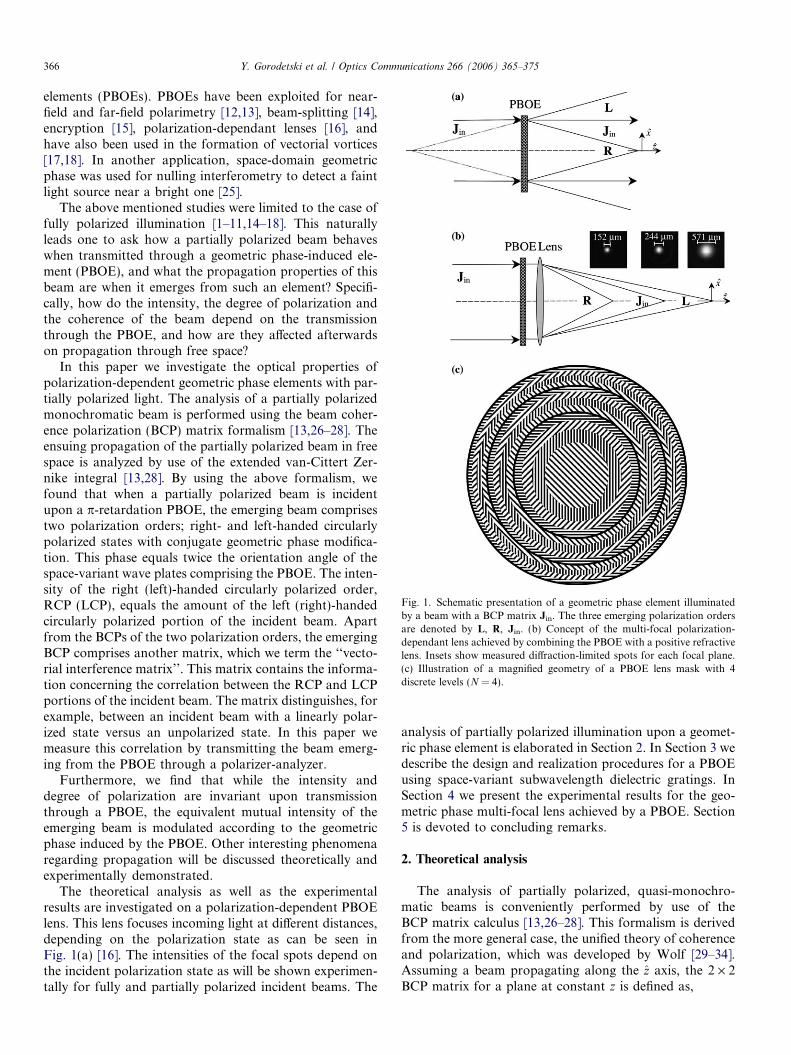
Fig. 1. Schematic presentation of a geometric phase element illuminatedby a beam with a BCP matrix Jin. The three emerging polarization ordersare denoted by L, R, Jin. (b) Concept of the multi-focal polarization-dependant lens achieved by combining the PBOE with a positive refractivelens. Insets show measured diffraction-limited spots for each focal plane.(c) Illustration of a magnified geometry of a PBOE lens mask with 4discrete levels (N = 4).
366 Y. Gorodetski et al. / Optics Communications 266 (2006) 365–375
elements (PBOEs). PBOEs have been exploited for near-field and far-field polarimetry [12,13], beam-splitting [14],encryption [15], polarization-dependant lenses [16], andhave also been used in the formation of vectorial vortices[17,18]. In another application, space-domain geometricphase was used for nulling interferometry to detect a faintlight source near a bright one [25].
The above mentioned studies were limited to the case offully polarized illumination [1–11,14–18]. This naturallyleads one to ask how a partially polarized beam behaveswhen transmitted through a geometric phase-induced ele-ment (PBOE), and what the propagation properties of thisbeam are when it emerges from such an element? Specifi-cally, how do the intensity, the degree of polarization andthe coherence of the beam depend on the transmissionthrough the PBOE, and how are they affected afterwardson propagation through free space?
In this paper we investigate the optical properties ofpolarization-dependent geometric phase elements with par-tially polarized light. The analysis of a partially polarizedmonochromatic beam is performed using the beam coher-ence polarization (BCP) matrix formalism [13,26–28]. Theensuing propagation of the partially polarized beam in freespace is analyzed by use of the extended van-Cittert Zer-nike integral [13,28]. By using the above formalism, wefound that when a partially polarized beam is incidentupon a p-retardation PBOE, the emerging beam comprisestwo polarization orders; right- and left-handed circularlypolarized states with conjugate geometric phase modifica-tion. This phase equals twice the orientation angle of thespace-variant wave plates comprising the PBOE. The inten-sity of the right (left)-handed circularly polarized order,RCP (LCP), equals the amount of the left (right)-handedcircularly polarized portion of the incident beam. Apartfrom the BCPs of the two polarization orders, the emergingBCP comprises another matrix, which we term the ‘‘vecto-rial interference matrix’’. This matrix contains the informa-tion concerning the correlation between the RCP and LCPportions of the incident beam. The matrix distinguishes, forexample, between an incident beam with a linearly polar-ized state versus an unpolarized state. In this paper wemeasure this correlation by transmitting the beam emerg-ing from the PBOE through a polarizer-analyzer.
Furthermore, we find that while the intensity anddegree of polarization are invariant upon transmissionthrough a PBOE, the equivalent mutual intensity of theemerging beam is modulated according to the geometricphase induced by the PBOE. Other interesting phenomenaregarding propagation will be discussed theoretically andexperimentally demonstrated.
The theoretical analysis as well as the experimentalresults are investigated on a polarization-dependent PBOElens. This lens focuses incoming light at different distances,depending on the polarization state as can be seen inFig. 1(a) [16]. The intensities of the focal spots depend onthe incident polarization state as will be shown experimen-tally for fully and partially polarized incident beams. The
analysis of partially polarized illumination upon a geomet-ric phase element is elaborated in Section 2. In Section 3 wedescribe the design and realization procedures for a PBOEusing space-variant subwavelength dielectric gratings. InSection 4 we present the experimental results for the geo-metric phase multi-focal lens achieved by a PBOE. Section5 is devoted to concluding remarks.
2. Theoretical analysis
The analysis of partially polarized, quasi-monochro-matic beams is conveniently performed by use of theBCP matrix calculus [13,26–28]. This formalism is derivedfrom the more general case, the unified theory of coherenceand polarization, which was developed by Wolf [29–34].Assuming a beam propagating along the z axis, the 2 · 2BCP matrix for a plane at constant z is defined as,
Y. Gorodetski et al. / Optics Communications 266 (2006) 365–375 367
Jðq1; q2; zÞ ¼jRRðq1; q2; zÞ jRLðq1; q2; zÞjLRðq1; q2; zÞ jLLðq1; q2; zÞ
� �; ð1Þ
where jabðq1; q2; zÞ ¼ hE�aðq1; zÞEbðq2; zÞi, a, b = R, L andq1, q2 are the transverse position vectors. The angle brack-ets denote time average, Ea(q,z) is the helical basis compo-nent of the electric field, and R and L denote the RCP andLCP states, respectively. The intensity of the beam, I, andthe degree of polarization (DOP), P, can be calculated di-rectly from this matrix [13,26–28,30–34]:
Iðq; zÞ ¼ trfJðq; q; zÞg;
P ðq; zÞ ¼ffiffiffiffiffiffiffiffiffiffiffiffiffiffiffiffiffiffiffiffiffiffiffiffiffiffiffiffiffiffiffiffiffiffiffiffiffiffiffiffiffi1� 4 detfJðq; q; zÞg½trfJðq; q; zÞg�2
s;
ð2Þ
where tr{} and det{} are the trace and the determinant ofthe matrix within the curl brackets. The DOP representsthe ratio of the intensity of the polarized fraction’s beamto the total intensity. It ranges from 1, when the beam isfully polarized, to 0 when the beam is unpolarized. Weare interested in investigating beams emerging from aPBOE that are partially polarized.
PBOE is a rotating wave plate with a constant retarda-tion /, and a space-variant orientation function, h(q). Thetransmission Jones matrix of a non-absorbing, non-scatter-ing PBOE is given by
T ¼ expði/=2Þ cosð/=2Þ1 0
0 1
� ��
�i sinð/=2Þ0 exp½i2hðqÞ�
exp½�i2hðqÞ� 0
� ��: ð3Þ
The calculation of this transmission matrix is given inAppendix A. When a partially polarized beam is incidenton the PBOE, the BCP matrix of the emerging beam is cal-culated as [13,26–28]
Joutðq1; q2; z ¼ 0Þ ¼ Tþðq1ÞJinTðq2Þ; ð4Þwhere Jin is the incident BCP matrix defined by Eq. (1). Bysubstituting the Jones matrix from Eq. (3) into Eq. (4), theemerging BCP matrix obtained is
Jout ¼ g0Jin þ g1jLLef2i½hðq1Þ�hðq2Þ�gR
þ g1jRRef�2i½hðq1Þ�hðq2Þ�gLþ C; ð5Þ
where g0 = cos2(//2), g1 = sin2(//2) and R ¼ 1 00 0
� �;
L ¼ 0 00 1
� �are the BCP matrices for RCP and LCP
states, and the matrix, C, is provided in Appendix B. FromEq. (5) it is evident that the emerging BCP matrix com-prises three polarization orders. The first order maintainsthe BCP matrix of the incident beam, the second order isa RCP beam with a space-variant phase modification,whereas the third order has a polarization direction andspatial phase dependence opposite in sign to that of the sec-ond one. The efficiency of the polarization orders dependson the PBOE transmission properties (g0,g1) and on theincident polarization state (jLL, jRR). Apart from the three
orders, the emerging BCP matrix in Eq. (5) also comprisesa matrix denoted by C. This matrix, which we denote as thevectorial interference matrix, contains the informationabout the correlation between the right and left-handed cir-cularly polarized components of the incident beam. Thematrix C and its properties are discussed in Appendix B.We choose to limit our discussion to a PBOE having retar-dation / = p. In this case g0 = 0, g1 = 1 and Eq. (5) degen-erates to,
Jout ¼ jLLef2i½hðq1Þ�hðq2Þ�gRþ jRRef�2i½hðq1Þ�hðq2Þ�gLþ Cp; ð6Þwhere Cp is given by (see Appendix B),
Cp ¼0 jLRei2h½ðq1Þþhðq2Þ�
jRLe�i2h½ðq1Þþhðq2Þ� 0
!: ð7Þ
It is evident from Eq. (6) that the first polarization orderdisappears and the above expression then comprises onlytwo polarization orders with the corresponding phase mod-ification. As this phase is created by a polarization manip-ulation by the element, it is geometric in nature [1,2]. Toconfirm this, we introduce the specific case of a plane wavewith a RCP state (i.e., Jin = R) incident on our PBOE. Forsuch illumination, the matrix Cp is zero, and the resultingBCP is
Jout ¼ expf�2i½hðq1Þ � hðq2Þ�gL: ð8ÞIn this case, the polarization of the incident beam is sub-jected to complete polarization state conversion, i.e., theright-handed circularly polarized incident beam becomesa left-handed circularly polarized. An important featureof Eq. (8) is the added phase factor, 2[h(q1) � h(q2)], thatis determined by the difference between two local orienta-tions of the rotating wave plate composing the PBOE. Thisdependence originates solely from the local changes in thepolarization state of the emerging beam. In order to verifythis dependence, we choose to employ the Poincare spherepresentation. The Poincare sphere is a unit sphere with theStokes parameters S1, S2 and S3 as its three axes (see Fig. 2)[35]. In this presentation, a polarization state can bemapped to a specific point on the sphere [1–6,10,11],whereas polarization state manipulation is represented bya path connecting the initial and final polarization states(points). When the polarization state of a beam traversesa close loop on the Poincare sphere, a phase that equalshalf of the enclosed area is added to the beam [35]. There-fore, this phase can be regarded as a geometric phase[1,2,6,10,11]. In the described example, the polarizationstate of the emerging beam at two distinct points on the ele-ment travel along two geodesic lines, as depicted in Fig. 2.The separation of these lines equals the angle difference be-tween the wave plates’ orientations at these two points.Particularly for polarization state changes at q1 and q2,the angular separation of the related geodesic lines andconsequently, half the area enclosed by them will be2[h(q1) � h(q2)], which is exactly the phase modificationas described in Eq. (8). The relation between the enclosedarea and the angular separation can be derived by simple

ρ r z
ρ1
ρ2
z =0 z =z 0
zρ1
ρ2
z =0
ρ r
z =z 0
Fig. 3. Illustration of the Young interference experiment for a space-variant polarization field. The visibility of the fringes varies as a functionof the two points selected in the transverse plane.
S1
2 ρ
ρ
θ ( 1)
2θ ( 2)
Ω
S2
S3R
L
Fig. 2. Illustration of the principle of PBOEs using a Poincare sphere.
368 Y. Gorodetski et al. / Optics Communications 266 (2006) 365–375
geometric calculations [35]. Note that the geometric phaseis not dependent on the incident wavelength. Illuminatingthe same element with Jin = L will result in a RCP emerg-ing beam with a phase modification opposite in sign to theone written in Eq. (8).
The above discussion regarding the geometric phaseconsiders two specific cases of fully polarized light. How-ever, we need to know how unpolarized light behaves whentransmitted through a geometric phase element. In thiscase, Jin is a unit matrix, and the emerging BCP matrix iscalculated from Eq. (6) to yield,
JUNPout ¼ ef2i½hðq1Þ�hðq2Þ�gRþ ef�2i½hðq1Þ�hðq2Þ�gL: ð9Þ
Note that the polarization orders R and L result in equalefficiencies and conjugate geometric phase modifications.It is known that the unpolarized light can be generatedby combining two uncorrelated beams with any orthogonalpolarization states. However, the above outcome indicatesthat the PBOE acts on an unpolarized incident paraxialbeam as if it were an incoherent superposition of RCPand LCP beams particularly. The general case of partiallypolarized beam with intensity I (see Eq. (2)) can be repre-sented as a weighted sum of fully polarized and unpolar-ized light [35], i.e.,
Jin ¼I2½PJP
in þ ð1� P ÞJUNPin �; ð10Þ
where JUNPin ¼ 1 0
0 1
� �is the unpolarized fraction of the
beam, JPin ¼
jRRP jRL
P
jLRP jLL
P
� �is denoted as the polarized frac-
tion, and,
jabP ¼
2I�P jab for a 6¼ b;
2I �P jab � 1�P
P for a ¼ b:
(ð11Þ
The BCP of the beam immediately after the element can bealso decomposed into its polarized and unpolarized frac-
tions. It can be shown that by applying JPin and JUNP
in sepa-
rately into Eq. (6), result in JPout and JUNP
out , which are thepolarized and the unpolarized fractions of the emergingbeam. Therefore, the transmission of each fraction throughthe element can be treated separately, i.e. the PBOE is a lin-ear system as expected. The resulting BCP will have theform of,
Jout ¼I2½PJP
out þ ð1� P ÞJUNPout �; ð12Þ
where the BCP of the polarized fraction is given by,
JPout ¼ jLL
P ef2i½hðq1Þ�hðq2Þ�gRþ jRRP ef�2i½hðq1Þ�hðq2Þ�gLþ 2
I � P C:
ð13ÞThis result indicates that the polarized fraction of a beam isdivided into polarization orders according to its RCP andLCP components, as can be seen from Eq. (13), and ac-quires conjugate geometric phase modifications. However,the unpolarized fraction is equally divided into RCP andLCP states with the appropriate geometric phases (seeEq. (9)).
Calculating the DOP and the intensity of a beam emerg-ing from a p-retardation PBOE is carried out using Eq. (2).From this equation we find that these properties are equalto those of the incident beam, as was expected. This resultis obvious when considering a non-polarizing and non-absorbing element. Another physical property which canbe studied is the equivalent mutual intensity [26,27,30,31],l. This property can be obtained from a Young interfer-ence experiment (see Fig. 3) and is calculated from theBCP matrix of the beam as,
lðq1; q2; zÞ ¼trfJðq1; q2; zÞg
½trfJðq1; q1; zÞgtrfJðq2; q2; zÞg�1=2: ð14Þ
The absolute value of this quantity is proportional to thefringe visibility resulting from the experiment; hence, it be-comes unity when the visibility is maximal and zero whenthe fringes disappear. The equivalent mutual intensity ascalculated in Eq. (14) for partially polarized plane waveillumination results in,
l ¼ A expðiwÞ; ð15aÞwhere

Y. Gorodetski et al. / Optics Communications 266 (2006) 365–375 369
A¼ffiffiffiffiffiffiffiffiffiffiffiffiffiffiffiffiffiffiffiffiffiffiffiffiffiffiffiffiffiffiffiffiffiffiffiffiffiffiffiffiffiffiffiffiffiffiffiffiffiffiffiffiffiffiffiffiffiffiffiffiffiffiffiffiffiffiffiffiffiffiffiffiffiffiffiffiffiffiffiffiffiffiffiffiffiffiffiffiffiffiðjRRÞ2þðjLLÞ2þ2jRRjLL cos½4hðq1Þ�4hðq2Þ�
q; ð15bÞ
and
w ¼ a tanjRR � jLL
jRR þ jLLtan½2hðq1Þ � 2hðq2Þ�
� �: ð15cÞ
As can be seen from Eq. (15), in contrast to the DOP andthe intensity, the normalized equivalent mutual intensity, l,is not conserved upon transmission. For example, unpolar-ized or partially polarized light in which the polarized frac-tion is in a linear state will result in,
lðq1; q2; zÞ ¼ cos½2hðq1Þ � 2hðq2Þ�: ð16ÞFrom Eq. (16) we see that the equivalent mutual intensity isa cosine function of the distance between two chosenpoints. This observation is not intuitive when consideringtransmission through a non-absorbing non-scattering ele-ment. Nevertheless, this phenomenon can be explainedstraightforwardly when conducting a Young interferenceexperiment with a spatially varying polarized beam. Thus,as shown in Fig. 3, the interference of two points on thetransverse plane with orthogonal polarization states,although totally correlated, will result in zero fringe visibil-ity. On the other hand, two points with the same polariza-tion state will result in maximum fringe visibility. Anotherinteresting example would be the illumination of thep-retardation PBOE with a fully circularly polarized beam.In this case l is given by
lðq1; q2; zÞ ¼ exp½i2hðq1Þ � i2hðq2Þ�: ð17ÞEq. (17) indicates that the visibility of the fringes is alwaysmaximal while their position depends on the distance of thetwo points chosen for the Young experiment. In the generalcase of partially polarized illumination, l will have bothamplitude and phase oscillations. This means that the vis-ibility and the position of the fringes resulting from theYoung interference experiment will depend on the choiceof the distance between the two points. Note that theequivalent mutual intensity in both cases is being modu-lated according to the geometric phase of the element.
Up to this point we have analyzed the properties of thebeam in the plane immediately after the element. However,we are also interested in investigating the above propertiesthroughout propagation. The propagation of a partiallypolarized beam’s BCP matrix in a linear and isotropicmedia is performed using the extended van-Cittert Zerniketheorem [13,28]. Thus, the resulting BCP matrix elementsare given by,
jabz ðr1;r2;zÞ¼
Z 1
�1jab
outðq1;q2;0ÞK�ðr1;q1;zÞKðr2;q2;zÞd2q1d2q2;
ð18Þ
where a and b equal R or L and Kðr; q; zÞ ¼ �i expðikzÞk z exp
ik2z ðr� qÞ2h i
is the paraxial propagation kernel. k = 2p/k
is the wavenumber and r is the transverse position vectorin the output plane. The intensity at the distance z is calcu-
lated by tracing the resulting BCP matrix (see Eq. (2)).Therefore the intensity distribution of the propagatingbeam is given by,
Iðr; zÞ ¼ 1
ðkzÞ2Z 1
�1½jLLe2i½hðq1Þ�hðq2Þ� þ jRRe�2i½hðq1Þ�hðq2Þ��
�
� eikðq2
2�q2
1Þ
2z K�f 1Kf 2d2q1d2q2
�r2¼r1
; ð19Þ
where Kfiðri; qiÞ ¼ exp � ikz ðri � qiÞ
and i = 1, 2. Note that
the expression in the square brackets is the sum of twointensity terms which correspond to the polarization orderterms found in Eq. (6). As is evident from Eq. (7), the diag-onal elements of matrix Cp are zero; therefore, none of theCp matrix elements is apparent in Eq. (19). For the samereason we can expect that this matrix will not influencethe equivalent mutual intensity of the propagating beam.This, however, will not be true for propagation in a polar-ization-dependant media such as uniaxial crystals or polar-izers in which a coupling between the BCP matrix elementstakes place.
To demonstrate our analysis of the propagation of par-tially polarized light, illuminating a geometric phase ele-ment, we chose a PBOE with a quadratic wave plateorientation function, i.e.,
hðqÞ ¼ pq2
2kf
����mod 2pi
; ð20Þ
where f is the focal length and k is the wavelength. Substitut-ing Eq. (20) into Eq. (19) leads to cancellation of the qua-dratic phase factor of the first term for z = f and of thesecond term for z = �f. Thus, for the case of the RCP planewave illumination, the intensity at z = f is found to be,
Iðr1; r2; f Þ ¼1
ðkf Þ2dðr1Þdðr2Þ; ð21Þ
where d is the Dirac delta function. Hence, this elementacts like a converging lens for RCP light. Using the sameequation for a LCP incident beam results in diverging lensbehavior. In the case of a finite aperture, the output inten-sity distribution will be calculated from the convolution ofthe far-field with the Fourier transform of the aperturefunction.
The focal plane of the PBOE lens is of special interestwhen considering the equivalent mutual intensity and thedegree of polarization of the beam. The calculation of theBCP matrix in this plane is done by substituting Eq. (6) intoEq. (18) using the quadratic geometric phase written in Eq.(20). The resulting DOP, which is calculated by Eq. (2) fromthis BCP matrix equals unity throughout the focal plane(z = f). Similarly, the amplitude of the equivalent mutualintensity equals unity for every pair of points on this planeexcluding the point r = 0. The results are the same regard-less of the polarization state of the incident beam. Theseresults are remarkable if one keeps in mind that the equiv-alent mutual intensity in the plane immediately after thePBOE lens is space-variant, as indicated by Eqs. (15)–

370 Y. Gorodetski et al. / Optics Communications 266 (2006) 365–375
(17). The explanation of this phenomenon is contained inthe BCP matrix resulting from Eq. (18). The calculationsshow that the beam is split into both a converging RCPand diverging LCP- state beam for any incident polariza-tion state. The converging beam is focused in a spot thatleaves the area of the focal plane illuminated by a coherentfully polarized LCP beam. This splitting yields a plane offully polarized light with an equivalent mutual intensity ofunit amplitude.
3. Design and realization of the PBOE lens
PBOEs can be realized by use of space-variant subwave-length dielectric gratings. When the period of the grating ismuch smaller than the incident wavelength, the gratingbehaves as a uniaxial crystal [1,36]. Therefore, we can formany desired PBOE by correctly determining the depth,structure, and orientation of the grating. Our objective isto design an element that when illuminated with a circu-larly polarized beam produces a spherical geometric phasedistribution. The PBOE is required to add a phase, ud,which is given by,
ud ¼ 2h ¼ 2pk
ffiffiffiffiffiffiffiffiffiffiffiffiffiffiffiffiffiffijqj2 þ f 2
q� �: ð22Þ
In our approach, a continuous desired phase function,ud(q), is approximated by using discrete steps. The connec-tion between the desired phase function and the discreteorientation function is given by
hðx; yÞjmodpi ¼ �F N ðudðx; yÞÞ=2; ð23Þ
where FN( ) denotes a process that divides the desiredphase, ud, into N equal levels. This division process is de-picted in Fig. 4(a). In the scalar approximation an incidentbeam is multiplied by the phase function of the discretephase element resulting in diffraction of the emergingbeam. Quantification of this diffraction is obtained by Fou-rier expansion of the actual phase,
Fig. 4. (a) Illustration of the discrete phase of a PBOE with N = 4. (b andc) Scanning electron microscope (SEM) images taken from a small regionof a PBOE lens that was realized on GaAs wafer. Note the rectangularshape of the subwavelength grooves and the space-variant grooveorientation. (d) Measured phase of the emerging beam.
expðiF N ðudÞÞ ¼X
m
Cm expðimudÞ; ð24Þ
where Cm is the mth order coefficient of the Fourier expan-sion. The diffraction efficiency of the mth diffracted order isgiven by jCmj2. The first diffraction order represents an ex-act replica of the desired phase, ud. Consequently, the dif-fraction efficiency, jC1j2, for the first diffracted order isrelated to the number of discrete levels N by
jC1j2 ¼Np
sinpN
� � �2
: ð25Þ
This equation indicates that for 2, 4, 8, and 16 discretephase levels, the diffraction efficiency will be 40.5%,81.1%, 95.0%, and 98.7%, respectively. The connection be-tween the first order diffraction efficiency and the numberof discrete levels was verified experimentally in Refs. [1,16].
We formed a binary chrome mask using high-resolutionlaser lithography. The amplitude transmission, t(x,y), ofthe mask is derived from
tðx;yÞ¼U s cos2pKðxcoshðx;yÞþ y sinhðx;yÞÞ
� �� cosðpqÞ
� �;
ð26Þwhere K and q are the period and fill factor of the subwave-length grating, respectively, x, y are the transverse planeCartesian coordinates, and Us is the unit step functiondefined by
UsðnÞ ¼1; n P 0;
0; n < 0:
�ð27Þ
The mask was 10 mm in diameter and h(x,y) was calcu-lated from Eqs. (22) and (23) where k = 10.6 lm, f =200 mm and the number of discrete levels N = 8. Accord-ing to Eq. (25), we expected to obtain more than a 94%diffraction efficiency into the first order. A subwavelengthperiod of K = 2 lm was selected together with a fill fac-tor q = 0.5 for use with CO2 laser radiation of a 10.6 lmwavelength. Fig. 1(c) shows a magnified geometry of themask. The mask was transferred by contact lithographyto 500 lm- thick GaAs wafers onto which had been pre-deposited a 2000 A layer of SiNx. The SiNx depositionwas achieved by enhanced chemical vapor deposition(PECVD) at 900 mTorr and 300 �C. At this stage, a700 A Ni adhesion layer was used for the lift-off process.Next, the SiNx layer was etched through the Ni strips,which served as a mask. The etching was performed byreactive ion etching (RIE – Plasma-Therm 790) for 30 sat room temperature with CF4 and O2 at gas flow ratesof 35 sccm and 14 sccm, respectively, and at a pressure of80 mTorr. The GaAs was then etched by electron cycloneresonance (ECR – Plasma-Therm SLR) for about eightminutes, with the etched SiNx layer serving as a mask.The ECR conditions were: 20 sccm of Cl2, 5 sccm of Ar,75 W RF power and 600 W microwave power, at 100 �C.The remaining SiNx was removed using HF acid resultingin a grating of 5 lm nominal depth for a / = p retardation

Y. Gorodetski et al. / Optics Communications 266 (2006) 365–375 371
element. The final step in fabricating the desired PBOE in-volved depositing an anti-reflection coating on the backsideof the elements. Fig. 4(b) and (c) shows scanning electronmicroscope (SEM) images of a small area of the / = p ele-ment. Note the high aspect ratio (�1/5) and the rectangularshape of the grooves. In order to confirm the formation ofthe desired phase, we used an experimental procedure de-scribed in Section 4 of Ref. [17]. The measured geometricphase added by the PBOE is presented in Fig. 4(d). Thetransmission coefficients of the PBOEs were also measuredand resulted in tx = 0.96 and ty = 0.94 for light polarizedparallel and perpendicular to the grating grooves respec-tively, while the retardation of the element was found tobe / = 0.9p. The measured values were close to the theoret-ical predictions of tx = 0.959, ty = 0.936 and / = p, ob-tained by using rigorous coupled wave analysis.
4. Experimental results
In order to investigate the behavior of the element withpartially polarized illumination, we formed an incidentbeam by combining two orthogonally polarized CO2 laser
Fig. 5. (a) Setup for combining the two lasers to generate partially polarizedistributions of the beam emerging from the PBOE followed by an analyzer witIntensity distribution of the beam emerging from the PBOE when illuminated bdistribution cross-sections measured, along the white line depicted in (b–e), forthe polarizer (dotted line), linearly polarized illumination (dashed-doted line) anDOP distribution over the beam beyond the PBOE when illuminated by a cir
beams with a polarizing beam combiner (see Fig. 5(a)).The resultant DOP, as calculated by Eq. (2), is given by
P ¼ I2 � I1
I1 þ I2
��������; ð28Þ
where I1 and I2 are the intensities of the lasers. By settingone of the lasers’ intensities to zero, a fully polarized beamwas achieved. To produce unpolarized light we used laserbeams with equal intensities, i.e., I1 = I2. First, we testedthe correlation between the RCP and the LCP portionsof the incident beam. This correlation is expressed by theoff-diagonal elements of the vectorial interference matrix,C, and can be measured by placing a linear analyzer-pola-rizer behind the PBOE. The use of an analyzer imposes acoupling between the BCP matrix elements of the beamemerging from the PBOE, as can be seen in the calculationsincluded in Appendix B. The intensity distribution behinda p-retardation PBOE followed by the analyzer, illumi-nated with a plane-wave of partial polarization is calcu-lated using Eq. (B.3) and yields,
Ip ¼1
2I in þ jjRLj cos½4hðqÞ � argðjRLÞ�: ð29Þ
d light: PBS – a polarization beam-splitter, M – mirror. (b, c) Intensityh (b) linearly polarized illumination and (c) unpolarized illumination. (d,e)y (d) linearly polarized light, (e) unpolarized light. (f) Normalized intensitythe unpolarized illumination (dashed line), unpolarized illumination withd linearly polarized illumination with a polarizer (solid line). (g) Measured
cularly polarized light.

0
0 45 90 135 180
0.2
0.4
0.6
0.8
1
Nor
mal
ized
Int
ensi
ty
QWP Angle [deg]
R L
Jin
Fig. 6. Normalized intensity at different focuses of a composite element asa function of QWP orientation. Triangles are the measurements in the R
focal plane, circles in the L focal plane and diamonds are the measure-ments in the focal plane of the Jin order. The dotted, dash-dotted anddashed lines are the theoretical calculations for each order respectively.
372 Y. Gorodetski et al. / Optics Communications 266 (2006) 365–375
This equation makes evident the periodic behavior of theintensity with the inclusion of the mean value of Iin/2,and with a modulation equal to the absolute value ofjRL. More explicitly, when jjRLj = 1, i.e., there is completecorrelation between the RCP and LCP states and the visi-bility of the fringes is unity. This case is depicted inFig. 5(b) in which the PBOE was illuminated by linearlypolarized light, and the near-field intensity was capturedby a Spiricon Pyrocam III camera. The high visibility ofthe fringes can be observed in this figure. However, whenRCP and LCP portions of the incident beam are uncorre-lated (jjRLj = 0), the visibility of the fringes is zero. Wedemonstrated this case by illuminating the PBOE withunpolarized light. The resulting intensity distribution ispresented in Fig. 5(c), in which no fringes are observed.Note that the combination of the PBOE with a linear ana-lyzer can be exploited to measure the degree of correlationbetween the RCP and LCP components of a partiallypolarized beam. Next, the analyzer was removed, and theintensity distribution behind the element was captured.This result is presented in Fig. 5(d) for linearly polarizedillumination and 5(e) for unpolarized illumination. Nomodulation can be seen in these figures, because the matrixC does not affect the intensity. To visualize the modulationdepth of the mentioned intensity distributions, we presentcross-sections of these measurements in Fig. 5(f). Withthe use of the analyzer, it can be clearly observed that thefully polarized incident beam results in a high intensitymodulation, (typically of 0.9), but that when the elementis illuminated with an unpolarized beam, very low intensitymodulation is seen, (typically of 0.08). These values areclose to the theoretical ones, which are 1 for the polarizedillumination and 0 for the unpolarized illumination. Wealso measured the DOP in the plane behind the elementilluminated by a RCP beam using a four-measurementtechnique [35]. This measurement is shown in Fig. 5(g)and demonstrates almost complete uniformity in thebehavior of the DOP in the output plane. We have calcu-lated the mean value of the DOP within the square area de-picted in Fig. 5(g) to be 0.98 with standard deviation of0.003 compared to 2% non-uniformity of the quarter waveplate (QWP) used for the measurement. These results provethat our PBOE is a non-polarizing element as required.
Section 2 provides the explanation for the dependence ofa geometric phase induced by a PBOE on the incidentpolarization state. We devised the scheme depicted inFig. 1(b) to experimentally confirm this dependence. Forthis purpose we used the element designed and realized inSection 3, i.e., a p-retardation spherical-phase PBOE.Our element acts as a polarization-dependant lens with afocal length f = 200 mm for RCP light and �f for LCPlight (see Fig. 1(a)). The third polarization order, Jin,appears as a result of an etching error of the element whichcauses a deviation from the p-retardation. The appearanceof this polarization order can be calculated from Eq. (5)using the measured retardation phase of / = 0.9p to beg0 = 0.024. To focus the three polarization orders along
the positive direction of the z-axis, a refractive lens wasinserted behind the element. The focal length of the refrac-tive lens was fr = 127 mm. The phase induced by theresulting composite element is the sum of the polariza-tion-dependent geometric phase obtained by the PBOEand the dynamic phase obtained by the refractive lens.We illuminated the combined element with a linearly polar-ized light. A rotating QWP was used as a polarization stategenerator. Fig. 6 shows the measured and predicted effi-ciencies of the three polarization orders’ intensities as afunction of the QWP orientation angle. Three examplesof such spots are shown in the insets of Fig. 1(b). Thesespots were experimentally found to be diffraction limited.The polarization orders denoted by R, L and Jin corre-spond to the three orders depicted in Fig. 1(b). As can beseen from Fig. 6, the efficiencies of the three polarizationorders depend on the RCP and LCP portions in the inci-dent beam. For example, when the PBOE is illuminatedby RCP light, most of the beam intensity is being focusedto the L plane according to Eq. (21). This example corre-sponds to the QWP orientation of 135� (see Fig. 6). Fromthis figure it is evident that the intensity of the L polariza-tion order is close to unity while the intensity of the R
polarization orders is zero. Note the low efficiency of theJin order which indicates that the analyzed PBOEs retarda-tion is close to p. The curves of the R and the L orders coin-cide for a linearly polarized incident beam which isachieved by orienting the QWP at 90�. This figure indicatesthat our composite element behaves as a multi-focal polar-ization-dependent lens.
We also experimentally investigated the behavior of thiselement with partially polarized illumination. The DOP ofthe incident beam has been controlled by adjusting theintensity of one of the lasers while keeping the secondone constant. We considered the superposition of twoorthogonal linearly polarized as well as circularly polarized
0.5
0140 160 180 200 220 240 260
1
DO
P an
d N
orm
aliz
ed I
nten
sity
z [mm]
I(z)DOP(z)
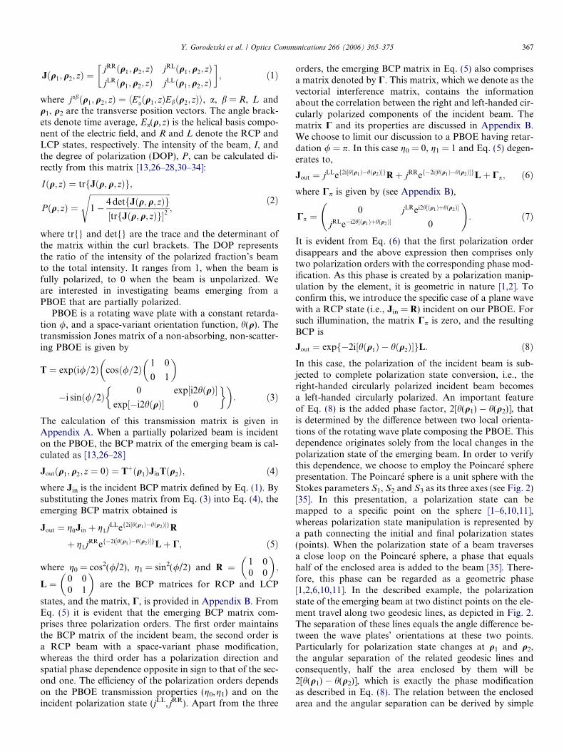
Fig. 8. Predicted and measured DOP and intensity on-axis distributionsalong z-axis in the vicinity of the R polarization order focus. Solid anddashed lines indicate the calculated DOP and the intensity respectively onthe z-axis. Experimental measurements for the DOP and the intensity areplotted by circles and diamonds, respectively.
Y. Gorodetski et al. / Optics Communications 266 (2006) 365–375 373
lasers. The BCP matrix for orthogonal linearly polarizeduncorrelated beams combining is,
Jin ¼ðI1 þ I2Þ
2
1 P � sgnðI2 � I1ÞP � sgnðI2 � I1Þ 1
� �; ð30Þ
where sgn is a sign function. The combining of two uncor-related orthogonal circularly polarized beams is repre-sented by the BCP matrix,
Jin¼I1þ I2
2
1þP �sgnðI1� I2Þ 0
0 1�P � sgnðI1� I2Þ
� �: ð31Þ
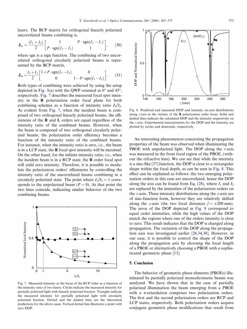
Both types of combining were achieved by using the setupdepicted in Fig. 5(a) with the QWP oriented at 0� and 45�,respectively. Fig. 7 describes the measured focal spot inten-sity in the R polarization order focal plane for bothcombining schemes as a function of intensity ratio I1/I2.As evident from Fig. 7, when the incident beam is com-posed of two orthogonal linearly polarized beams, the effi-ciencies of the R and L orders are equal regardless of theintensity ratio of the combined beams. However, whenthe beam is composed of two orthogonal circularly polar-ized beams, the polarization order efficiency becomes afunction of the intensity ratio of the combined beams.For instance, when the intensity ratio is zero, i.e., the beamis in a LCP state, the R focal spot intensity will be maximal.On the other hand, for the infinite intensity ratio, i.e., whenthe incident beam is in a RCP state, the R order focal spotwill yield zero intensity. Therefore, it is possible to modu-late the polarization orders’ efficiencies by controlling theintensity ratio of the uncorrelated beams combining in acircularly polarized state. The point where I1/I2 = 1 corre-sponds to the unpolarized beam (P = 0). At that point thetwo lines coincide, indicating similar behavior of the twocombining beams.
0.5
1
00
Nor
mal
ized
foc
al I
nten
sity
I1/I2
TE
TM
RCP
LCP
1 5 10
Fig. 7. Measured intensity at the focus of the RCP order as a function ofthe intensity ratio of two lasers. Circles indicate the measured intensity forpartially polarized light with linearly polarized fraction. Triangles indicatethe measured intensity for partially polarized light with circularlypolarized fraction. Dotted and the dashed lines are the theoreticalpredictions for the above cases. Vertical dotted line illustrates a point withzero DOP.
An interesting phenomenon concerning the propagationproperties of the beam was observed when illuminating thePBOE with unpolarized light. The DOP along the z-axiswas measured in the front focal region of the PBOE, (with-out the refractive lens). We can see that while the intensityis a sinc-like [37] function, the DOP is close to a rectangularshape within the focal depth, as can be seen in Fig. 8. Thiseffect can be explained as follows: the two emerging polar-ization orders in this case are uncorrelated, hence the DOPalong the axis can be found from Eq. (28), where I1 and I2
are replaced by the intensities of the polarization orders onthe z-axis. These intensity distributions along the z-axis areof sinc-function form, however they are relatively shiftedalong the z-axis (the two focal distances f = ±200 mm).The zeros of the DOP depicted in Fig. 8 correspond toequal order intensities, while the high values of the DOPmatch the regions where one of the orders intensity is closeto zero. This result indicates that the DOP is changed alongpropagation. The variation of the DOP along the propaga-tion axis was investigated earlier [28,34,38]. However, inour case, it is possible to control the shape of the DOPalong the propagation axis by choosing the focal lengthof a PBOE or alternatively choosing a PBOE with a sophis-ticated geometric phase [13].
5. Conclusion
The behavior of geometric phase elements (PBOEs) illu-minated by partially polarized monochromatic beams wasanalyzed. We have shown that in the case of partiallypolarized illumination the beam emerging from a PBOEwith a p-retardation comprises two polarization orders.The first and the second polarization orders are RCP andLCP states, respectively. Both polarization orders acquireconjugate geometric phase modifications that result from

374 Y. Gorodetski et al. / Optics Communications 266 (2006) 365–375
a polarization state manipulation created by the element.The intensity of the RCP (LCP) polarization order is equalto the amount of the LCP (RCP) portion in the incidentbeam. Apart from the two polarization orders, the emergingBCP comprises a matrix termed the ‘‘vectorial interferencematrix’’. This matrix contains the information concerningthe correlation between the RCP and the LCP portionsof the incident beam. We suggested a simple interferenceexperiment to measure the degree of this correlation byplacing a polarizer behind the PBOE and measuring theemerging intensity. We have shown experimentally thatthe vectorial interference matrix distinguishes between thecases of linearly polarized and unpolarized illumination.The PBOE used for the experimental demonstration wasa spherical geometric phase PBOE designed for CO2 laserradiation and realized on a GaAs wafer with a subwave-length grating. We have shown that this PBOE followedby a refractive lens behaves as a multi-focal polarization-dependent lens. Such a lens can be implemented in a varietyof applications, such as multi-layer data storage and polar-ization imaging [39,24]. We also studied the intensity, thenormalized equivalent mutual intensity, and the DOPimmediately after the element and upon propagation infree-space. We found that the equivalent mutual intensitywas modulated according to the geometric phase inducedby the element. Moreover, we showed that in the focalplane of the PBOE lens, the DOP and the amplitude ofthe equivalent mutual intensity become unity regardlessof the incident polarization state. This property can be usedin applications such as a polarizer or a polarizing beam-splitter by placing a spatial filter in this plane.
Appendix A
A PBOE behaves as a space-variant wave plate elementwith constant retardation, /, and a space-varying fast axis,h(q), along the q coordinate [1,10,11,15–17]. The Jonesmatrix of such an element is written as,
Tc ¼M�1ðhÞWð/ÞMðhÞ; ðA:1Þ
where M and W represent the rotation matrix and the ma-trix of a non-polarizing wave plate oriented in the x direc-tion. Explicitly, these matrices are given by,
M ¼cosðhÞ sinðhÞ� sinðhÞ cosðhÞ
� �; W ¼
1 0
0 expði/Þ
� �: ðA:2Þ
In the case of a PBOE, it is convenient to transform theJones matrix to a helicity basis in which the vector basesare the right and left-handed circularly polarized states,i.e. RCP = (1 0)T and LCP = (0 1)T. The conversionof Tc to the helicity basis results in a transmission matrix of
T ¼ U�1TcU; ðA:3Þwhere U is the unitary transformation matrix, written as
U ¼ 1ffiffiffi2p
1 1
�i i
� �: ðA:4Þ
Accordingly, the PBOE transmission matrix is writtenexplicitly as,
T ¼ expði/=2Þ(
cosð/=2Þ1 0
0 1
� �:
�i sinð/=2Þ 0 ei2hðqÞ
e�i2hðqÞ 0
" #): ðA:5Þ
Appendix B
The expression for the BCP matrix emerging from aPBOE (Eq. (5)) contains a matrix denoted by C. Thismatrix is defined as,
C ¼c1;1 c1;2
c2;1 c2;2
!; ðB:1Þ
where the C matrix elements are given by,
c1;1¼ iffiffiffiffiffiffiffiffiffig0g1
p ðjLRei2hðq1Þ � jRLe�i2hðq2ÞÞ;c1;2¼ i
ffiffiffiffiffiffiffiffiffig0g1
p ðjLLei2hðq1Þ � jRRei2hðq2ÞÞþg1ðjLRei2h½ðq1Þþhðq2Þ�Þ;c2;1¼ i
ffiffiffiffiffiffiffiffiffig0g1
p ðjRRe�i2hðq1Þ � jLLe�i2hðq2ÞÞþg1ðjRLe�i2h½ðq1Þþhðq2Þ�Þ;c2;2¼ i
ffiffiffiffiffiffiffiffiffig0g1
p ðjRLe�i2hðq1Þ �jLRei2hðq2ÞÞ:ðB:2Þ
Note, that the trace of C is zero at q1 = q2, thus, the inten-sity of the emerging beam, presented by Eq. (5), is notaffected by this matrix. However, the off-diagonal elementsare of great importance since they bear the informationon the correlation of the polarization components, i.e.,jRL and jLR. One can measure the degree of correlation bytransmitting the emerging beam through a polarizer. Thecalculation of the resulting intensity can be found from:Ip = tr{P+JoutP}, where the transmission matrix of a pola-
rizer is P ¼ 12
1 11 1
� �and Jout is the beam’s BCP matrix as
calculated by Eq. (5). The resulting intensity would be,
Ip ¼1
2I in þ cos2 /
2
� �jjRLj cos½argðjRLÞ�
þ sin2 /2
� �jjRLj cos½4hðqÞ � argðjRLÞ�
þ 1
2sin / sin 2hðjRR � jLLÞ; ðB:3Þ
where Iin is the incoming intensity. Note that Ip is modu-lated according to the off-diagonal elements of the C ma-trix, and thus, by Fourier analysis we can extract thecorrelation values, jRL and jLR.
References
[1] E. Hasman, G. Biener, A. Niv, V. Kleiner, Space-variant polarizationmanipulation, in: E. Wolf (Ed.), Progress in Optics, 47, Elsvier,Amsterdam, 2005.
[2] S. Pancharatnam, Proc. Ind. Acad. Sci. 44 (1956) 247.[3] M.V. Berry, J. Mod. Opt. 34 (1987) 1401.

Y. Gorodetski et al. / Optics Communications 266 (2006) 365–375 375
[4] M.V. Berry, Proc. Roy. Soc. London A 392 (1984) 45.[5] R. Bhandari, J. Samuel, Phys. Rev. Lett. 60 (1988) 1211.[6] R. Bhandari, Phys. Rep. 281 (1997) 1.[7] E.M. Frins, J.A. Ferrari, A. Dubra, D. Perciante, Opt. Lett. 25 (2000)
284.[8] Q. Zhan, J.R. Leger, Opt. Commun. 213 (2002) 241.[9] J.A. Ferrari, E. Garbusi, E.M. Frins, Opt. Lett. 29 (2004) 1138.
[10] Z. Bomzon, V. Kleiner, E. Hasman, Opt. Lett. 26 (2001) 1424.[11] Z. Bomzon, G. Biener, V. Kleiner, E. Hasman, Opt. Lett. 27 (2002)
1141.[12] G. Biener, A. Niv, V. Kleiner, E. Hasman, J. Opt. Soc. Am. A 20
(2003) 1940.[13] Y. Gorodetski, G. Biener, A. Niv, V. Kleiner, E. Hasman, Opt. Lett.
30 (2005) 2245.[14] E. Hasman, Z. Bomzon, A. Niv, G. Biener, V. Kleiner, Opt. Commun
209 (2002) 45.[15] G. Biener, A. Niv, V. Kleiner, E. Hasman, Opt Lett. 30 (2005) 1096.[16] E. Hasman, V. Kleiner, G. Biener, A. Niv, Appl. Phys. Lett. 82 (2003)
328.[17] A. Niv, G. Biener, V. Kleiner, E. Hasman, Opt. Commun. 251 (2005)
306.[18] A. Niv, G. Biener, V. Kleiner, E. Hasman, Opt. Lett. 30 (2005) 2933.[19] F. Xu, R.C. Tian, P.C. Sun, Y. Fainman, C.C. Cheng, A. Scherer,
Opt. Lett. 20 (1995) 2457.[20] F. Xu, R.C. Tian, P.C. Sun, Y. Fainman, C.C. Cheng, A. Scherer,
Opt. Lett. 21 (1996) 1513.[21] P. Lalanne, S. Astilean, P. Chavel, E. Cambril, H. Launois, J. Opt.
Soc. Am. A 16 (1999) 1143.
[22] J. Tervo, J. Turunen, Opt. Lett. 25 (2000) 785.[23] J. Tervo, V. Kettunen, M. Honkanen, J. Turunen, J. Opt. Soc. Am. A
20 (2003) 282.[24] G.P. Nordin, J.T. Meier, P.C. Deguzman, M.W. Jones, J. Opt. Soc.
Am. A 16 (1999) 1168.[25] N. Baba, N. Murakami, T. Ishigaki, Opt. Lett. 26 (2001) 1167.[26] F. Gori, Opt. Lett. 23 (1998) 241.[27] F. Gori, M. Santarsiero, S. Vicalvi, R. Borghi, G. Guattari, Pure
Appl. Opt. 7 (1998) 941.[28] F. Gori, M. Santarsiero, R. Borghi, G. Piquero, Opt. Lett. 25 (2000)
1291.[29] L. Mandel, E. Wolf, Optical Coherence and Quantum Optics,
Cambridge University Press, USA, 1995.[30] E. Wolf, Opt. Lett. 28 (2003) 1078.[31] E. Wolf, Phys. Lett. A 312 (2003) 263.[32] T. Shirai, E. Wolf, J. Opt. Soc. Am. A 21 (2004) 1907.[33] G.S. Agarwal, A. Dogariu, T.D. Visser, E. Wolf, Opt. Lett. 30 (2005)
120.[34] O. Korotkova, E. Wolf, Opt. Commun. 246 (2005) 35.[35] C. Brosseau, Fundamentals of Polarized Light; A Statistical Optics
Approach, John Wiley & Sons, USA, 1998.[36] M. Born, E. Wolf, Principles of Optics, Cambridge University Press,
UK, 1999.[37] J.W. Goodman, Introduction to Fourier Optics, McGraw-Hill,
Singapore, 1996.[38] D.F.V. James, J. Opt. Soc. Am. A 11 (1994) 1641.[39] K. Kinnstatter, M. Ojima, S. Yonezawa, Appl. Opt. 29 (1990)
4408.