enhanced contrast and depth resolution in polarization imaging using elliptically polarized light...
TRANSCRIPT
Enhanced contrast and depthresolution in polarization imagingusing elliptically polarized light
Susmita SridharAnabela Da Silva

Enhanced contrast and depth resolution inpolarization imaging using elliptically polarized light
Susmita Sridhara,b,* and Anabela Da Silvaa
aAix–Marseille Université, CNRS, Centrale Marseille, Institut Fresnel, UMR 7249, 13013 Marseille, FrancebInstitut de Ciències Fotòniques, Universitat Politècnica de Catalunya, 08860 Castelldefels, Barcelona, Spain
Abstract. Polarization gating is a popular and widely used technique in biomedical optics to sense superficialtissues (colinear detection), deeper volumes (crosslinear detection), and also selectively probe subsuperficialvolumes (using elliptically polarized light). As opposed to the conventional linearly polarized illumination, wepropose a new protocol of polarization gating that combines coelliptical and counter-elliptical measurementsto selectively enhance the contrast of the images. This new method of eliminating multiple-scattered compo-nents from the images shows that it is possible to retrieve a greater signal and a better contrast for subsurfacestructures. In vivo experiments were performed on skin abnormalities of volunteers to confirm the results of thesubtraction method and access subsurface information. © The Authors. Published by SPIE under a Creative Commons Attribution
3.0 Unported License. Distribution or reproduction of this work in whole or in part requires full attribution of the original publication, including its DOI. [DOI:
10.1117/1.JBO.21.7.071107]
Keywords: elliptically polarized light; light propagation in tissues; turbid media; medical and biological imaging.
Paper 150648SSR received Oct. 4, 2015; accepted for publication Jan. 8, 2016; published online Feb. 11, 2016.
1 IntroductionDriven by its biomedical potential, polarimetry and the use ofits approaches for biological tissue assessment have receivedconsiderable attention. The interest in this type of imaginghas grown due to the fact that, unlike conventional techniquesbased mainly on the exploitation of attenuating contrasts, polari-metric methods are very sensitive to the structure of the envi-ronment, operate by excluding light that is multiply-scatteredand use the light that has kept its initial polarization.1 The effectof scattering on the polarization state of light has been foundvery useful for the imaging of surface or subsurface structuresin scattering media, and for transmission imaging of deepstructures.2 It has also been shown that the optical propertiesof turbid tissue, including the reduced scattering coefficient,can be determined from diffusely scattered polarized light.3
The incorporation of polarimetric imaging in more conventionaltechniques such as microscopy or optical coherence tomographyhelps in the extraction of precise information such as on collag-enous tissue structure (eye,4 skin,5 and cervix6). Promising stud-ies of polarimetric examination of tissues were carried out indermatology,7–13 where melanomas or other lesions (lupus)were characterized by various polarimetric indicators (depolari-zation and birefringence). However, in a complex randommedium-like tissue, numerous complexities due to multiplescattering and simultaneous occurrences of many scatteringand polarization events present formidable challenges both interms of accurate measurements and in terms of analysis ofthe tissue polarimetry signal.
These techniques are based on the fact that the polarization islost depending on the tissue’s scattering properties. The back-scattered light thus contains a mixture of polarized photons thathave undergone a limited number of scattering events and
depolarized light. Polarized light can be extracted by a simpleimage subtraction method14 (a) for moving beyond the specularand probing more deeply (e.g., using crossed linear polarizers);or (b) for selecting the specular photons (e.g., using colinearpolarizers). For tissue examination, a widely used techniqueis the detection via the crosslinear imaging channel to get ridof the mirror reflections.15 Linear polarization gating1,7,16 is lim-ited to the surface examination of tissues. The underlying prin-ciple for linear polarization gating as a depth selective techniquecan be summarized as: the photons which are scattered (or re-emitted) from deeper tissue layers undergo multiple scatteringevents and are depolarized to a larger extent. For examining tis-sues deeper, the use of circular polarization was introduced byMorgan and Stockford17 and they demonstrated that subtractionof images taken in cocircular illumination/detection configura-tion and crosslinear illumination/detection allowed for theextraction of circular polarization maintaining light and theelimination of specular-reflected photons. Due to the effect of“polarization memory,”18,19 the depth probed by circular polari-zation is larger than that with linear polarization because thepolarization of circularly polarized light is indeed maintainedthrough a larger number of scattering events than that of linearlypolarized light in Mie scatterers such as biological tissues. Thiseffect was further investigated and verified by Monte Carlo sim-ulations in a semi-infinite medium.20 The simulation results con-cluded that the mean visitation depth for linearly polarized light[∼2 mean free paths (MFPs)] is smaller than that of circularlypolarized light (∼10 MFPs). They also found that ellipticalpolarization can be tuned between linear and circular polariza-tion to reach different penetration depths. It has been demon-strated that the average depth into which elliptically polarizedlight can penetrate is between that of linearly and circularlypolarized light.21,22 This technique allows screening the tissueat specific depths ranging between the surface and a maximumdepth defined by the maximum penetration depth of the circu-larly polarized photons.
*Address all correspondence to: Susmita Sridhar, E-mail: [email protected]
Journal of Biomedical Optics 071107-1 July 2016 • Vol. 21(7)
Journal of Biomedical Optics 21(7), 071107 (July 2016)

In this paper, we have chosen to develop this approachbecause it allows for noncontact tissue examination over alarge (wide-field) region of interest (ROI) with low-cost instru-mentation. In addition and in comparison to practiced tech-niques, we introduce a subtraction method involving the co- andcounter-elliptically polarized light to probe subsurface volumes.The principle is demonstrated with phantom experiments onIntralipid® and ex vivo tissue. The extent of this method is alsosubstantiated with in vivo experiments on human skin.
2 Polarization Gating with EllipticallyPolarized Light
Elliptical polarization has seldom been used in polarization gat-ing but has been catching up especially in the field of opticalbiopsy.23 This form of polarization gating has two reasonableadvantages over linear polarization gating (see Fig. 1): (a) itundergoes a change in helicity by reflection, which eliminatesthe specular reflection through co-elliptical detection; (b) also,elliptically polarized light retains its polarization state for alarger number of scattering events than that of linearly polarizedlight.
Figure 1 shows the types of photons acquired when polarizedlight is illuminated linearly or elliptically. Based on previousworks,17,19,22,24 we adapted the polarization scheme of illumina-tion/detection with four different imaging channels as shown inTable 1.
Note that some recent studies have demonstrated that circu-larly polarized light is more depolarized in Intralipid®25 and tis-sue samples26 than linearly polarized light. The depolarizationfactor, that is the ratio between the intensity of detected polar-ized light to intensity of illuminated polarized light, has not beenconsidered for our studies and only the signal containing polari-zation maintaining volume is taken into consideration. The rawsignal collected through a given polarization gate, after subtrac-tion of a proper amount of depolarized light, is related to a well-defined probing depth, no matter the amount of polarized sig-nal left.
Polarization gating methods concentrate on subtracting thebackground from the images to improve the polarized signal.In practice, a simple subtraction between colinear and crosslin-ear imaging channels, C1 − C2, allows the separation of the sur-face contribution from the multiple-scattered part (coming fromdeeper volumes), MSL, resulting in an enhancement of thesurface image (SL þ PL). However, linear polarization gatingalone does not allow simultaneous filtering of mirror reflectionsand multiple-scattered light. To overcome this problem, theuse of circularly polarized light was adopted,17,19 wherein the
crosslinear fraction was subtracted from the co-elliptical images,C3 − C2, to access subsurface volumes (with the assumptionthat the subtraction nullifies the multiple-scattered photonsfrom both channels and gives only elliptical polarization main-taining photons, PE
27). This method, referred to as subtractionmethod 1 in this paper, however, removes an amount of linearlymultiple-scattered photons much greater than elliptically multi-ple-scattered photons. This over-subtraction leads to the loss ofsome valuable information at the subsuperficial layers.
To overcome this problem and to account for the fact that themultiple-scattered photons arising from linear polarization gat-ing and circular polarization gating are different from each otherin fraction, we have devised a new method (referred to as sub-traction method 2 in this paper) to equate and eliminate thebackground by subtraction. To obtain the polarization maintain-ing photons from the elliptical channels, a subtraction betweenthe elliptical channels is performed (C3 − C4) to eliminate theelliptically multiple-scattered photons. After this subtraction,a mixture of backscattered elliptical polarization maintainingphotons and the elliptical surface-reflected photons is obtained.To preserve only the polarization maintaining photons, we cancombine the residuals of linear polarization gating, C1 − C2,and that of elliptical channels, C3 − C4. This gives us a mixtureof the surface reflected and polarization maintaining photonsfrom linear and elliptical polarizations (PE − SE þ PL þ SL).At non-normal incidence, the quantities of surface-reflectedphotons from linear and elliptical polarization are different fromeach other, with a larger contribution from the former (whichcan be measured theoretically and experimentally). This can
(a) Linear Illumintation (b) Elliptical Illumination
Surface reflectedphotons
Polarization maintainingphotons
Depolarized photons
Surface reflectedphotons
Depolarized photons
Polarization maintainingphotons
Helicity-flippedphotons
Fig. 1 Schematic representation of (a) linear illumination and (b) elliptical illumination.
Table 1 Back-scattered photon characteristics measured in differentimaging channels.
Channel Illumination Detection Light characteristics
C1 Linear Linear Surface-reflected (SL) + polarizationmaintaining (PL) + multiple-scatteredphotons (MSL)
C2 Linear Cross-linear
Multiple-scattered photons (MSL)
C3 Elliptical Co-elliptical
Polarization-maintaining (PE) +multiple-scattered photons (MSE)
C4 Elliptical Counter-elliptical
Surface-reflected (SE) + multiple-scattered photons (MSE)
Journal of Biomedical Optics 071107-2 July 2016 • Vol. 21(7)
Sridhar and Da Silva: Enhanced contrast and depth resolution in polarization imaging. . .
be verified by the fact that as we go from colinear channel tocounter-elliptical channels, we are not only increasing theangle of elliptical polarization, but also changing the amountof reflected light projected in the plane of incidence (parallelor P-polarized) to that perpendicular to the plane of incidence(perpendicular or S-polarized). This change in the specularportion of the elliptical channels can be normalized to that ofthe linear channel by a factor, α, such that SE ¼ αSL. This αvalue is calculated as the ratio of surface-reflected componentsof counter-elliptical to colinear images, and it is computedexperimentally on an ROI containing mostly the identifiedspecular-reflection spot. Therefore, to eliminate these specularportions from the images, we can reduce the equation as
EQ-TARGET;temp:intralink-;e001;63;609ðC3 − C4Þ þ αðC1 − C2Þ ¼ PE þ αPL: (1)
This method allows us to obtain only the polarization maintain-ing photons with the elimination of background in terms ofspecular and multiple-scattered photons. In this paper, thetwo mentioned subtraction methods 1 and 2 are compared andillustrated with experiments on different types of samples.
3 Materials and Methods
3.1 Instrumentation
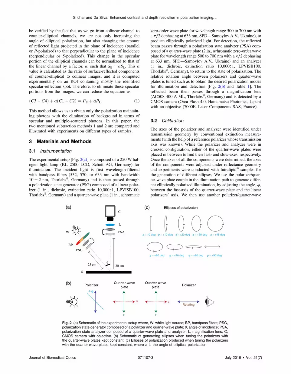
The experimental setup [Fig. 2(a)] is composed of a 250 W hal-ogen light lamp (KL 2500 LCD, Schott AG, Germany) forillumination. The incident light is first wavelength-filteredwith bandpass filters (532, 570, or 633 nm with bandwidth10� 2 nm, Thorlabs®, Germany) and is then passed througha polarization state generator (PSG) composed of a linear polar-izer (1 in., dichroic, extinction ratio 10;000∶1, LPVISB100,Thorlabs®, Germany) and a quarter-wave plate (1 in., achromatic
zero-order wave plate for wavelength range 500 to 700 nm witha π∕2 dephasing at 633 nm, SPD—Samoylov A.V., Ukraine), toproduce elliptically polarized light. For detection, the reflectedbeam passes through a polarization state analyzer (PSA) com-posed of a quarter-wave plate (2 in., achromatic zero-order waveplate for wavelength range 500 to 700 nm with a π∕2 dephasingat 633 nm, SPD—Samoylov A.V., Ukraine) and an analyzer(1 in., dichroic, extinction ratio 10;000∶1, LPVISB100,Thorlabs®, Germany), to return to the state of polarization. Therelative rotation angle between polarizers and quarter-waveplates is tuned such as to obtain the desired polarization modesfor illumination and detection [Fig. 2(b) and Table 1]. Thereflected beam then passes through a magnification lens(AC508-400 A-ML, Thorlabs®, Germany) and is detected by aCMOS camera (Orca Flash 4.0, Hamamatsu Photonics, Japan)with an objective (7000E, Laser Components SAS, France).
3.2 Calibration
The axes of the polarizer and analyzer were identified undertransmission geometry by conventional extinction measure-ments (with the help of a reference polarizer whose transmissionaxis was known). While the polarizer and analyzer were incrossed configuration, either of the quarter-wave plates wereplaced in between to find their fast- and slow-axes, respectively.Once the axes of all the components were determined, the axesof the components were adjusted under reflectance geometryand experiments were conducted with Intralipid® samples forthe generation of different ellipses. We use the polarizer/quar-ter-wave plate couple in the illumination path to generate differ-ent elliptically polarized illumination, by adjusting the angle, φ,between the fast-axis of the quarter-wave plate and the linearpolarizers’ axis. We then use another polarizer/quarter-wave
(a) (c)
(b)
W
BP
PSG
PSA
L
C
23 cm 30 cmq
S
Ellipses of polarizaton
PolarizerQuarter-wave
plateQuarter-wave
plate Polarizer
Rotating
= +0 deg = +10 deg = +20 deg = +30 deg = +45 deg
= +60 deg = +70 deg = +80 deg = +90 deg
Fig. 2 (a) Schematic of the experimental setup where, W, white light source; BP, bandpass filters; PSG,polarization state generator composed of a polarizer and quarter-wave plate; θ, angle of incidence; PSA,polarization state analyzer composed of a quarter-wave plate and analyzer; L, magnification lens; C,CMOS camera with objective. (b) Schematic of generating ellipses when tuning the polarizers withthe quarter-wave plates kept constant. (c) Ellipses of polarization produced when tuning the polarizerswith the quarter-wave plates kept constant, where φ is the angle of elliptical polarization.
Journal of Biomedical Optics 071107-3 July 2016 • Vol. 21(7)
Sridhar and Da Silva: Enhanced contrast and depth resolution in polarization imaging. . .

plate couple for detection and the ellipticity “φ” in the detectionpath is set to correspond to the same as in the illumination path.So for each measurement, we need to tune the two polarizer/quarter-wave plate couples to obtain the desired state of polari-zation for illumination and detection. Two different modes oftuning the polarizer/quarter-wave plate couple can be employed:(a) tuning just the polarizers with the quarter-wave plates keptconstant and (b) tuning the polarizers and quarter-wave plates.The shape and orientation of the ellipses totally depend on theposition of the quarter-wave plate. In this paper, all the experi-ments described have been performed using the first method,where only the polarizers are tuned and the quarter-wave platesare kept unchanged and is shown in Figs. 2(a) and2(b). It is evident that the intensity and behavior of signalsare very different depending on the shape of the ellipse forthe two modes of tuning the polarizer/quarter-wave plate couple.
3.3 Samples and Medium
Different types of samples were used for calibration and valida-tion of measurements illustrated in this paper. All the experi-ments were conducted in compliance with the directions ofthe local ethics committee. All procedures were in agreementwith NIH guidelines.
i Liquid phantom: Intralipid®
The liquid phantom was composed of an aqueousIntralipid® (20%, Sigma-Aldrich, France) at adequate con-centrations. The concentration of Intralipid® was adaptedto match the optical properties of biological tissues, butwith a scaling in size of the sample for macroscopic meas-urement of depth. The optical properties of Intralipid® 1%was determined by the integral reflectance method:28 theabsorption coefficient (μa) was considered negligible anda reduced scattering coefficient value of μs 0 ð1%Þ ¼ 10.3�0.5 cm−1 was estimated. According to the accuracy ofour optical (magnification) and mechanical components,a 0.1% diluted solution was adopted, corresponding toμs 0 ð0.1%Þ ¼ 0.95� 0.05 cm−1, allowing depth measure-ments at a millimetric scale. The anisotropy factor ofIntralipid® was estimated to a value of g ¼ 0.73,29 leadingto a reduced scattering mean free path MFP 0 ¼ ð1 − gÞ∕μs 0 ∼ 2.8 mm (that is ∼10 times longer than in biologicaltissues).
ii ex vivo: Neck of chickenTo check for biological tissue feasibility, a piece of
chicken neck (bought from the supermarket, used as a bio-logical phantom) pinned to a sample holder was used.The neck in particular was chosen due to the prominenceof a blood vessel in the region. The superficial tissue wassufficiently hydrated with glycerin to track the mirrorreflections.
iii in vivo: Human skinThe dorsal side of the hand (showing a mole/nevus) of a
volunteer was illuminated under the given experimentalconditions. A glass cover-slip was placed on the skin totrack the specular reflections at the surface. The exposuredose was much below the maximum permissible exposurevalues in the visible wavelength range (∼0.065 W∕cm−2)(Laser Institute of America 2000) and an informed consentwas obtained from all subjects.
3.4 Image Processing
Images were acquired using HCImageLive Software (providedby Hamamatsu for CMOS camera ORCA Flash 4.0). The SNRwas calculated as the ratio of the desired signal intensity to thebackground intensity [SNR ¼ 10 logðIs∕InÞ]. A sequence of 20images were taken with an adapted exposure time per measure-ment in order to preserve a high SNR (35 dB) for each meas-urement. The noise was reduced by averaging these images.However, for need of comparison of different measurements,the data are expressed per unit exposure time. An image regis-tration, which corrected translational and rigid body movementsin the images, was carried out using imregister and imreconfigfunctions in MATLAB® R2015a. After correcting for move-ment, the images were averaged to a single mean-image.These mean-images were then subtracted based on one of themethods described in Sec. 2.
4 Results and DiscussionThe different phantoms were examined under the imagingchannels described, and the images were then processed andcompared for the two subtraction methods in question. The rela-tion between the image contrast and the state of polarization wasexamined and analyzed.
(a) (b) (c) 3000
2500
1500
2000
1000
500
0
Ruler
43 mm
115 mm
123 mm
Intra-lipid
Fig 3 Results of the Intralipid® experiments: (a) ruler placed obliquelyin a tank containing Intralipid® solution, (b) elliptical channel image at45 deg after subtraction method 1, (c) elliptical channel image at45 deg after subtraction method 2. (b) and (c) have a common color-bar represented at the right edge of the figure. Yellow-dotted line rep-resents the Intralipid®–air interface. Each graduation on the ruler (i.e.,1 mm) corresponds to 0.35 mm in actual depth. Wavelength: 633 nm.
Fig. 4 Trend of α factor as a function of ellipticity for 0.1% Intralipid®
experiments.
Journal of Biomedical Optics 071107-4 July 2016 • Vol. 21(7)
Sridhar and Da Silva: Enhanced contrast and depth resolution in polarization imaging. . .

4.1 Intralipid®
Experiments on the Intralipid® were conducted to compare thetwo background subtraction methods and served as a sample forcalibrating the setup. A plastic ruler had been placed obliquelyin a tank containing the diluted Intralipid® as shown in Fig. 3(a)and imaged at different ellipticities to observe the signal comingfrom different depths.
The α factor for removing the specular component was cal-culated experimentally as follows: a series of 100 images weretaken at channel C1 and channel C4 (which contain the respec-tive linear and elliptical specularly reflected components). TheROI containing an identified specular spot was averaged to get amean value in both C1 and C4. αwas then calculated as the ratioof the mean specular values of elliptical to linear channels. Thisvalue was found to decrease with the increase in the angle of theelliptical channel. The value and range of α depend on the sam-ple used. Figure 4 shows that, for Intralipid® 0.1% measure-ments, α was found in the range 1.01 to 0.78, for ellipticities0 to 90 deg.
The mean intensity of images with subtraction methods 1 and2 is shown in Fig. 5. It shows that with subtraction method 2,there was a higher signal intensity, especially for larger angles ofelliptical polarization (a 110% increase in angles 30 and 40 deg)in the imaging channels. The signal intensity showed an increasefrom linear to 40 deg elliptical polarization, reaching a plateauafter 40 deg (close to circular polarization).
Figure 6 shows the contrast as a function of depth probed(in mm) for the two subtraction methods. The contrast was mea-sured using the ratio ðImax − IminÞ∕ðImax þ IminÞ, where I rep-resents the mean value of intensity. In terms of depth,subtraction method 1 allowed us to have a reasonable contrastup to 13 graduations (i.e., 4.55 mm), as compared to subtractionmethod 2, which allowed a good contrast up to 20 graduations (i.e., 7 mm). This clearly shows that there is a substantial increasein percentage of signal intensity and in the reachable depth whenbackground subtraction is achieved using subtraction method 2.This is also very evident visually when comparing Figs. 3(b) and3(c), where 3(c) appears to have a better contrast than 3(b).
This experiment shows that polarized light can be collectedup to 7 mm in depth (corresponding to 0.7 mm in biologicaltissues).
Fig. 5 Signal intensity of 0.1% Intralipid® when performing subtractionwith (a) method 1 (squares) and (b) method 2 (circles). Standarddeviation bars are also shown. Image exposure time: 1000 ms.
Fig. 6 Depth probed with elliptic channel at 45 deg for 0.1% Intralipid®
when performing subtraction with (a) method 1 (squares) and(b) method 2 (circles). Standard deviation bars are also shown.Image exposure time: 1000 ms.
(a)
(b) (c)
Fig. 7 Ex vivo sample of neck tissue of a chicken: (a) Top view of the sample. (b) Crosslinear image of apart of the neck under study. (c) Zoom-out (crosslinear) of a section containing a vessel indicated by thered arrow. Images taken in white light. Thickness of epidermis: ∼0.5 to 0.8 mm (determined by dissectionpostimaging).
Journal of Biomedical Optics 071107-5 July 2016 • Vol. 21(7)
Sridhar and Da Silva: Enhanced contrast and depth resolution in polarization imaging. . .

4.2 Ex Vivo Tissue
The ex vivo experiments were conducted on a piece of neck of achicken (see Fig. 7) and illustrated the feasibility of this study inother kinds of tissues. In the ROI projected in Figs. 7(c) and 8,there is evidence of a vessel appearing diagonally in the cross-linear image. This vessel, which is not visible in the colinearimage, (i.e., it lies in the subsurface) can only be seen in thecontrasts of elliptic channels at 10, 20, 30, 40, 45, and 50 deg[in Figs. 8(d)–8(i)]. The presence of wrinkles (caused due to theattachment of the tissue with metallic pins) can also be seenpronounced in Figs. 8(e)–8(h). Validating our statements,elliptic channels up to 45 deg show the presence of deeperlying structures, whereas smaller angles, i.e., smaller elliptic
channels, show superficial structures or structures close to thesurface.
4.3 In Vivo Tissue
4.3.1 Human skin
A mole on the dorsal side of a volunteer’s hand was observed(see Fig. 9). Figure 10 shows the contrast of subtraction method2 performed on skin images. It can be observed that the mole isquite clearly outlined in the elliptic channels [Figs. 10(c)–10(l)],but it is negative and depicts the depolarized photons. On theother hand, it can be seen that the intensity of a polarizing struc-ture (seen toward the right edge of each figure) increases from
(a)
104
1
1.2
1.4
1.6
1.8(b)
104
1
1.2
1.4
1.6
1.8
2
2.2
(c)
(d) (e) (f)
(g) (h)
0
1000
2000
3000
4000
5000
6000
(i)
(j) (k) (l)
Fig. 8 Contrast for linear and elliptic channels for ex vivo measurements on neck tissue of a chicken.(a) The cross-linear image. (b) The contrast of the subtraction of linear (co and cross) channels. (c) to (l)The contrasts for the subtraction of elliptic (co and counter) channels 0, 10, 20, 30, 40, 45, 50, 60, 70, 80,and 90 deg, respectively. Scale bar: (a) 2 mm. Wavelength: 633� 10 nm. Image exposure time:1000 ms. Behavior of the polarized light (linear/elliptical) is represented at the bottom-right corner ofeach figure. (a) and (b) are raw images and have their own colorbar. (c) to (l) have a common colorbarrepresented at the right border of the image. Green arrow in (c) indicates the presence of the vessel.
Journal of Biomedical Optics 071107-6 July 2016 • Vol. 21(7)
Sridhar and Da Silva: Enhanced contrast and depth resolution in polarization imaging. . .

Figs. 10(c) to 10(f). Inversely, the intensity of this structure isobserved to be decreasing from Figs. 10(h) to 10(l). There is alsothe appearance of different structures within the space of themole from Figs. 10(h) to 10(l), indicating that these structuresare polarizing in a direction different from the colinear direction(vertical) and horizontal to the polarization at 90 deg (back tolinearly polarized light, but in the opposite direction). Thisbehavior conforms with that of the ellipses shown in Fig. 2(c).Due to the effects of image subtraction, the SNR of the resultingchannel images is smaller than that of the measured images.Using basic image processing should allow to reduce thenoise content of the images. The depolarization/negativity ofdeeper lying structures could be mainly due to very high specu-lar components from the elliptical channels. This can be avoidedby improvization of the setup with the addition of a telecentric
Fig. 9 Dorsal side of a hand along with a zoom-out of the mole whichwas studied for the in vivo experiments. A ruler with graduations in milli-meters is seen at the bottom of the image. Images taken in white light.
(a)
5000
5500
6000
6500
7000
7500
8000(b)
5000
6000
7000
8000
9000
10000(c)
(d) (e) (f)
0
100
200
300
400
500
600
700
800
900
1000
(g) (h) (i)
(j) (k) (l)
Fig. 10 Contrast for linear and elliptic channels for in vivo measurements on dorsal side of a humanhand. (a) Histogram of the crosslinear channel tracing the shape of the mole. (b) Contrast of the sub-traction of linear (co and cross) channels. (c) to (l) The contrasts for the subtraction of elliptic (co andcounter) channels 0, 10, 20, 30, 40, 45, 50, 60, 70, 80, and 90 deg, respectively. Scale bar: (a) 0.5 mm.Wavelength: 633� 10 nm. Image exposure time: 1500 ms. Behavior of the polarized light (linear/ellip-tical) is represented at the bottom-right corner of each figure. (a) and (b) are raw images and have theirown colorbar. (c) to (l) have a common colorbar represented at the right border of the image.
Journal of Biomedical Optics 071107-7 July 2016 • Vol. 21(7)
Sridhar and Da Silva: Enhanced contrast and depth resolution in polarization imaging. . .

objective that converges the illumination beam and providesa more homogeneous illumination.
5 ConclusionsIn this paper, we test the feasibility of depth examination bytuning the state of polarization in four imaging channels, andcompare two systems of image subtraction with experimentson calibrated Intralipid® phantoms, ex vivo, and in vivo tissues.Intralipid® measurements confirm that subtraction method 2involving all the four imaging channels is superior to subtractionmethod 1 because: (a) there is higher signal intensity, (b) there isa higher contrast in surface structures, and (c) it allows probing adepth of 7 mm. Our phantom experiments show that this methodcan be used to probe tissues in depth up to at least 0.7 mm,which offers the possibility of screening a variety of layeredbiological tissues such as the skin as tested here.
Ex vivo experiments on chicken neck and human skin experi-ments conform with the above conclusions, and show highersignal intensity and higher contrast of some structures with ellip-tic channels (from 0 to 45 deg) probing subsurface structures.
Further work includes removal of the specular reflection atthe surface using better and more adapted optical clearingagents. This could lead to a more efficient isolation of the polari-zation maintaining photons. In addition, the crosslinear channelhas the highest SNR, and this needs to be improved for the ellip-tic channels to get a better contrast of the subsurface structures.
Depending on optical properties of the medium, the exactdepth and extent of these subsurface volumes can be calculated.With advancements in the setup and better signal processing,this method should allow for imaging deeper volumes at spe-cific/user-defined depths. This method could be very valuablein the field of noninvasive blood flow-sensing, detection oflow-lying tumors, or other skin abnormalities.
AcknowledgmentsThis work was supported by the European Commission throughthe Erasmus Mundus Joint Doctorate Programme Europhoton-ics (Grant No. 159224-1-2009-1-FR-ERA MUNDUS-EMJD).
References1. J. M. Schmitt, A. H. Gandjbakhche, and R. F. Bonner, “Use of polar-
ized-light to discriminate short-path photons in a multiply scatteringmedium,” Appl. Opt. 31(30), 6535–6546 (1992).
2. M. P. Rowe et al., “Polarization-difference imaging—a biologicallyinspired technique for observation through scattering media,” Opt. Lett.20(6), 608–610 (1995).
3. A. H. Hielscher, J. R. Mourant, and I. J. Bigio, “Influence of particlesize and concentration on the diffuse backscattering of polarized lightfrom tissue phantoms and biological cell suspensions,” Appl. Opt. 36,125–135 (1997).
4. M. G. Ducros et al., “Primate retina imaging with polarization-sensitiveoptical coherence tomography,” J. Opt. Soc. Am. A 18(12), 2945–2956(2001).
5. T. Yasui, Y. Tohno, and T. Araki, “Characterization of collagen orien-tation in human dermis by two-dimensional second-harmonic-genera-tion polarimetry,” J. Biomed. Opt. 9(2), 259–264 (2004).
6. S. Bancelin et al., “Determination of collagen fiber orientation in his-tological slides using Mueller microscopy and validation by second har-monic generation imaging,” Opt. Express 22(19), 22561–22574 (2014).
7. S. G. Demos and R. R. Alfano, “Optical polarization imaging,” Appl.Opt. 36, 150–155 (1997).
8. S. L. Jacques, J. C. Ramella-Roman, and K. Lee, “Imaging skin path-ology with polarized light,” J. Biomed. Opt. 7(3), 329–340 (2002).
9. I. M. Stockford et al., “Analysis of the spatial distribution of polarizedlight backscattered from layered scattering media,” J. Biomed. Opt. 7(3),313–320 (2002).
10. I. M. Stockford and S. P. Morgan, “Application of a look-up table topolarized light imaging for characterising skin,” presented at SaratovFall Meeting 2004: Optical Technologies in Biophysics andMedicine VI, Vol. 5771, pp. 151–158 (2005).
11. S. P. Morgan et al., “Modelling and instrumentation for polarized lightimaging and spectroscopy of scattering media—art. no. 604712,” inFourth Int. Conf. on Photonics and Imaging in Biology and Medicine,Pts 1 and 2, Vol. 6047, pp. 4712 (2006).
12. D. Kapsokalyvas et al., “Spectral morphological analysis of skin lesionswith a polarization multispectral dermoscope,” Opt. Express 21(4),4826–4440 (2013).
13. A. Pierangelo et al., “Polarimetric imaging of uterine cervix: a casestudy,” Opt. Express 21(12), 14120 (2013).
14. S. L. Jacques, J. R. Roman, and K. Lee, “Imaging superficial tissueswith polarized light,” Lasers Surg. Med. 26(2), 119–129 (2000).
15. R. R. Anderson, “Polarized-light examination and photography of theskin,” Arch. Dermatol. 127(7), 1000–1005 (1991).
16. S. G. Demos, H. B. Radousky, and R. R. Alfano, “Deep subsurface im-aging in tissues using spectral and polarization filtering,” Opt. Express7(1), 23–28 (2000).
17. S. P. Morgan and I. M. Stockford, “Surface-reflection elimination inpolarization imaging of superficial tissue,” Opt. Lett. 28(2), 114–116(2003).
18. F. C. MacKintosh et al., “Polarization memory of multiply scatteredlight,” Phys. Rev. B 40, 9342–9345 (1989).
19. S. P. Morgan and M. Ridgway, “Polarization properties of light back-scattered from a two layer scattering medium,”Opt. Express 7(12), 395–402 (2000).
20. S. Rehn et al., “Depth probing of diffuse tissues controlled with ellip-tically polarized light,” J. Biomed. Opt. 18, 016007 (2013).
21. A. Da Silva et al., “Depth selectivity in biological tissues by polarizationanalysis of backscattered light,” Proc. SPIE 8172, 817205 (2011).
22. A. Da Silva, C. Deumié, and I. Vanzetta, “Elliptically polarized light fordepth resolved optical imaging,” Biomed. Opt. Express 3(11), 2907(2012).
23. B. Kunnen et al., “Application of circularly polarized light for non-inva-sive diagnosis of cancerous tissues and turbid tissue-like scatteringmedia,” J. Biophotonics 8(4), 317–323 (2015).
24. X. Feng, L. Sun, and E. Zhang, “Depth selectivity for the assessment ofmicrostructure by polarization studies,” Biomed. Opt. Express 4(6),958–966 (2013).
25. M. K. Swami et al., “Effect of gold nanoparticles on depolarization char-acteristics of intralipid tissue phantom,” Opt. Lett. 38(15), 2855–2857(2013).
26. M. K. Swami et al., “Size-dependent patterns in depolarization mapsfrom turbid medium and tissue,” Appl. Opt. 53(27), 6133 (2014).
27. S. L. Jacques, “Corrigendum: optical properties of biological tissues:a review,” Phys. Med. Biol. 58, 5007–5008 (2013).
28. L. Gobin, L. Blanchot, and H. Saint-Jalmes, “Integrating the digitizedbackscattered image to measure absorption and reduced-scatteringcoefficients in vivo,” Appl. Opt. 38(19), 4217–4227 (1999).
29. H. J. Van Staveren et al., “Light scattering in intralipid-10% in the wave-length range of 400–1100 nm,” Appl. Opt. 30(31), 4507–4514 (1991).
Susmita Sridhar is currently pursuing her doctoral studies as part ofthe Europhotonics Erasmus Mundus Joint PhD Program at InstitutFresnel, Marseille and ICFO, Barcelona (Expected graduationSeptember 2016). Her research interests are focused in biomedicaloptics, more specifically on polarization gating imaging for depth res-olution in biological tissues. She has a joint MSc degree in biomedicalengineering from Lübeck University of Applied Sciences andUniversity of Lübeck, Germany.
Anabela Da Silvas main research field is biomedical optics, with aspecial focus on diffuse optical tomography, polarization gating imag-ing, and photoacoustic imaging. She holds a PhD in optics and pho-tonics (Pierre and Marie Curie University, Paris, France). After a post-doc at Harvard Medical School/Massachusetts General Hospital, sheworked as a researcher at CEA-LETI (Grenoble, France). Since 2008she is a senior researcher at French National Research Center.
Journal of Biomedical Optics 071107-8 July 2016 • Vol. 21(7)
Sridhar and Da Silva: Enhanced contrast and depth resolution in polarization imaging. . .