optical collection efficiency and orientation of a solar trough medium-power plant installed in...
TRANSCRIPT
lable at ScienceDirect
Renewable Energy 36 (2011) 2341e2347
Contents lists avai
Renewable Energy
journal homepage: www.elsevier .com/locate/renene
Optical collection efficiency and orientation of a solar trough medium-powerplant installed in Italy
P. Sansoni*, D. Fontani, F. Francini, A. Giannuzzi, E. Sani, L. Mercatelli, D. JafrancescoCNR-INO National Institute of Optics, Largo E. Fermi, 6, 50125 Firenze, Italy
a r t i c l e i n f o
Article history:Received 21 April 2010Accepted 2 February 2011Available online 11 March 2011
Keywords:Optical designSolar energyConcentratorsNon-imaging optical systems
* Corresponding author. Tel.: þ39 055 23081; fax:E-mail address: [email protected] (P. Sansoni).
0960-1481/$ e see front matter � 2011 Elsevier Ltd.doi:10.1016/j.renene.2011.02.004
a b s t r a c t
Parabolic trough collectors were investigated, applying the study results to a plant prototype installed inFlorence (Italy) for residential supply. Ray tracing simulations examined optical characteristics andcollection performance on the base of prototype geometry and functionality. The purpose was to controlthe realisation errors and overcome the difficulties arising in the development of the solar trough plant.The paper summarises the results of several studies analysing the interactions between collection effi-ciency, angular misalignments, mirror deformations, sun tracking and trough placement. The mirrordeformations are reproduced introducing an original procedure. The unusual subject of imprecision intrough axis placement is discussed.
� 2011 Elsevier Ltd. All rights reserved.
1. State of the art
In the solar thermal applications the energy is opticallyconcentrated before being converted into heat. The optical collec-tion can be obtained by reflection or refraction of solar radiationemploying reflectors, refractive optics or combinations of mirrorsand lenses. The sunlight is concentrated in the focal plane, with theaim of maximising the energy flux on the absorber surface.
At present the Parabolic Trough Collector (PTC) can be consid-ered as the most advanced solar thermal technology. It representsthe most mature solar technology to generate heat at temperaturesup to 400 �C for solar thermal electricity generation or process heatapplications. The reasons are extensive experimentation on theseoptical systems and industrial development to realise andcommercialise PTC systems. The PTCs are typically manufactured inmodules and mounted on suitably located supports [1].
In the 80s, exploiting the research results and the successiveindustrial PTC development, several companies appeared on themarked realising one-axis tracking PTCs for temperatures from 50to 300 �C. They included the Industrial Solar Technology (IST)Corporation that built several process heat plants in the UnitedStates, up to 2700 m2 of collector aperture area. The plant wassystematically tested by Sandia and the German Aerospace Centre(DLR) for efficiency and durability [2].
In Europe numerous PTC systems were developed during thelast years for either research or commercial purposes. At the Solar
þ39 055 2337755.
All rights reserved.
Platform of Almería (PSA), the Spanish centre of energeticresearches CIEMAT realised PTC applications mainly for experi-mental aims, with a total installed capacity of 1.2 MW. This researchincluded the “FASOL” PTC systemworking at 130e300 �C with heattransfer bywater [3,4]. The Institute for Technical Thermodynamicsof the DLR realised two different systems: the “SOLITEM PTC 1800”was a water system for temperatures of 100e200 �C, while the “FixFocus Trough” operated at 100e200 �C, employing water, steam, airor thermal oil [4,5]. Still in Germany the Solar-Institut Jülichdeveloped a modular PTC collector called “PTC 1000” that workedat 80e300 �C using water. In Austria the Institute for SustainableTechnologies (INTEC) of the Austrian Energy & Environment Group(AEE) realised the “PARASOL”, which was a PTC system working at100e200 �C with water or steam [4]. Besides, in southern Europeancountries such as Spain, Italy and Greece the growing opportunitieswere improving scientific research and technological developmentof various applications for sunlight exploitation.
In the framework of the Italian research, the Archimede Projectrepresented the first application worldwide that integrated a gas-burned combine cycle power plant and a thermodynamic solarenergy system. The Archimede system was a 5 MW solar powerplant located in Sicily (Italy). It was an installation of parabolicmirrors concentrating the sunlight on pipes, through which rana saline liquid that stored heat up to 550 �C and retained it forhours. The project was realised in collaboration between twonational institutions for energy: ENEL and ENEA [6].
In México the major Investigation Centre on renewable Energies(CIE) in collaboration with the Autonomous University of Mexico(UNAM)realisedPTCsystemsusingwaterasheat transfermedium[9].

Notations
c mirror curvatured absorber defocus (absorber centre displacement
from F)D external diameter of the metal pipe (within the
absorber)dz vertical displacement of mirror extreme
(quantifying the mirror deformation)f focal length of the parabolic mirrorF focal point of the parabolic mirrorG external diameter of the glass tube (within the
absorber)IABS light received by the absorberIIN light entering in the PTC apertureK conic constantPTC parabolic trough collectorR curvature radius of the parabolic mirrorT thickness of the glass tube (within the absorber)a altitude of the sun over the horizonb angle between trough axis and NortheSouth
terrestrial axisg acceptance angle of the trough collectorh collection efficiency of the PTC systemhmax collection efficiency maximumq angular misalignment (by a rigid rotation of mirror
and absorber)
P. Sansoni et al. / Renewable Energy 36 (2011) 2341e23472342
However, the largest solar energy generating facility in theworld is represented by the Solar Energy Generating Systems(SEGS). It consists of nine solar power plants in California’s MojaveDesert, where insolation is among the best available in the UnitedStates. Next Era Energy Resources operates and partially owns theplants producing a total of 365 MW of power subdivided in threeinstallations: SEGS IIIeVII of 150 MW, SEGS VIIIeIX of 160 MWandSEGS IeII of 44MW [7,8]. The linear absorber is filled with syntheticoil, which heats to over 400 �C, and then the oil transfers its heat towater, which boils and drives a Rankine cycle steam turbine,thereby generating electricity. The use of synthetic oil keeps thepressure within manageable parameters [1,8].
The most recent developments in the PTC research areaddressed to cost reduction and technology progress. For example,the collector can be automatically washed to reduce maintenancecosts. The optical performance improvements [10,11] can optimisethe incident angle and increase the collection efficiency [12].
Fig. 1. The prototype of solar trough collector.
2. Studies of parabolic trough collectors
Our laboratory carried out an extensive research [13,14] tooptimise the PTC optical configuration, with the aim of enhancingthe system collection efficiency h. Concerning the parabolic mirror,we examined the efficiency dependence from mirror width, lengthand focal length; the effects of mirror deformations and surfacefinishing. Regarding the absorber, we analysed the h dependencefrom metal pipe diameter and shape, glass tube diameter andthickness. Besides, the research studied the consequences ofabsorber defocus and angular misalignments between thecomponents. All mentioned effects were simulated considering thesun tracking, thus reproducing the system operative conditions.
The paper presents the most significant results of this extensiveresearch, illustrating an innovative methodology to reproduce therigid deformations of a real parabolic mirror. The interactions
between angles, collected light,mirror deformations and sun trackingare discussed.
For sunlight exploitation the most critical features are collectionefficiency (h), acceptance angle (g) andmisalignments. h is the ratiobetween light focusedon theabsorberand light receivedbycollectorentrance aperture; g is the limit aperture to keep h maximum.
3. Prototype of a solar plant
The initial theoretical results were applied to develop a plantprototype; then our PTC research proceeded referring to plantinstallation requirements and functioning optimisation. A solarcooling systemwas realised and installed in Florence (Italy): it wasa 20 KW solar PTC plant addressed to residential supply. Thismedium-power plant was tested and analysed in operative condi-tions. It contains 20 m of linear parabolic reflectors, coupled toa metal pipe surrounded by a glass tube. The collectors aremounted, subdivided in 5 m-length modules, along the absorberline. Fig. 1 shows a prototype module. For supporting and movingthe concentrators, they are mounted on a mechanical frame, whosemain components are a vertical grid structure and a curved metalplate welded to the vertical grid. Electronic and mechanicalsystems for sun tracking are located in the frame centre. Thetroughs dimensions were dictated by mechanical manufacturingrequirements and metal plate availability.
Different reflecting surfaceswereexperimentedontheprototype:
M1: optical glass aluminized on the back face;M2a: metallic reflecting surface obtained gluing a thin layer ofmetal sheet over the opaque support (curved steel plate of theframe);M2b: metallic mirror obtained curving an aluminium plate withan optically worked surface (the plate has an inner corrugatedstructure to improve its rigidity).
M1 performs higher reflection, having a more uniform surfacewith respect to M2a. The drawbacks of M1 are fragility and highercost in comparison to M2a. A trade-off between M1 and M2a isrepresented by M2b. The 5 m-length module was covered byjuxtaposed mirrors: 6 for M1, 6 or 12 for M2a, 4 for M2b. The M2asurface presents local faults; but they can be limited improvingdeposition uniformity and reducing sheet size. M1 and M2bbehaviours of are similar and their deformations can be modelledusing the methodology illustrated in Section 4.

P. Sansoni et al. / Renewable Energy 36 (2011) 2341e2347 2343
The plant structure was constructed with a vertical tolerance of2 mm, between parabola vertexes and supporting frame heights.Placement, alignment and orientation of the system were alwaysperformed considering astronomical references. The NortheSouth(NeS) axis alignment of the plant was executed referring to thedirection of solar shadows at noon. Following the ground confor-mation, the PTC plant axis was placed to form an angle b of 8� withthe NeS terrestrial axis; but b can be compensated by the correc-tion procedure of Section 8.
On the prototype the correct orientation was automaticallyactuated using a sun pointer, which regulated the tracking to alignthe collector axis in the solar rays’ direction [15,16]. Having realisedan accurate sun tracking, the plant prototype approached theexpected performance in collection efficiency. The sun pointer isvisible in the right upper corner of Fig. 1.
Fig. 2. Border profiles of parabolic and deformed mirrors.
Fig. 3. Angular misalignment (a), for different focal lengths (b).
4. Rigid deformations of the parabolic mirror
The practical experimentation evidenced that PTCs are typicallyaffected by rigid deformations of the parabolic profile, almostuniformly distributed along the trough axis [13,17]. Small localizeddeformations can occur on the reflecting surface and sometimesthe whole structure can experience a torsion effect mainly causedby the mechanical support. This section presents an originalmethodology to reproduce the rigid deformations of PTCs, assess-ing their effect on collection efficiency. Then Section 6 will analysethe interactions between mirror deformation and angularmisalignment. Similar mathematical models were used to analyselocal surface faults and collector torsion. The consequences oflocalised faults essentially depend on absorber size and shape. Themechanical torsion effects are analogous to the case of NeS axismisalignments of the parabolic mirror (see Section 7): the focusedimage appears tilted with respect to the absorber [14].
The mathematical representation used to reproduce rigiddeformations [13] employs conic constant K and conic equation (Eq.(1)), to represent the mirrors profiles, as follows:
z ¼ cr
1þffiffiffiffiffiffiffiffiffiffiffiffiffiffiffiffiffiffiffiffiffiffiffiffiffiffiffiffiffiffiffiffiffi1� ð1þ kÞc2r2
p (1)
where K is the conic constant and c is the mirror curvature, definedin Eq. (2) from the curvature radius R of the parabolic mirror.
c ¼ 1R
(2)
The reference value K ¼ �1 pertains to the parabolic curve;while all other K values correspond to deformations of the para-bolic mirror, as shown in Fig. 2 comparing the mirror borderprofiles. The length of all deformed curves corresponds to theparabola extent, since they represent deformations of a real solarcollector. For �1 < K < 0 the profile is elliptic and the deformedmirror has a reduced entrance aperture with respect to the para-bolic collector. For K < �1 the profile becomes hyperbolic and thedeformed mirror presents a larger entrance aperture.
Simplicity and efficacy are the advantages of the proposedtechnique; however the most significant result is that it seems toreproduce the flexibility of a real PTC. In practice, consideringa reflecting surface, laying over a vertical grid and centrally bonded,the major deformations appear at the borders (Fig. 2).
Such deformations were then applied to the mirror profilemonitoring the PTC collection efficiency h. The rigid deformation isquantified referring to the vertical displacement of mirror extremedz. The sampling is based on dz, calculating the corresponding Kvalues. The sign of dz is in agreement with Fig. 2 : dz > 0 in theelliptic case and dz < 0 in the hyperbolic case. The layout
parameters are: f ¼ 800 mm, D ¼ 50 mm, G ¼ 60 mm, T ¼ 3 mm.Some examples of K values are:
�1.182233721 (for dz ¼ �3 mm);�1.07867288 (for dz ¼ �1 mm);�0.95044868 (for dz ¼ 1 mm);�0.8500401 (for dz ¼ 3 mm).

Fig. 4. Angular misalignment for various pipe positions (a) and pipe sizes (b).
Fig. 6. Acceptance angle vs vertical edge displacement. hmax (%) in labels.
P. Sansoni et al. / Renewable Energy 36 (2011) 2341e23472344
For mirror deformations with �3 mm < dz < 3 mm, h keeps itsmaximum value (86%), indicating that the corresponding mirrordeformations cause only negligible losses in the collected energy.
5. Angular misalignments of the PTC system components
A crucial aspect for sunlight collection is represented by theangularmisalignment, simulated tilting the PTCwith a rigid rotation
Fig. 5. Power distribution over the absorber.
q of parabolic mirror and absorber around the axis of parabolicvertexes. The q effect was evaluated considering the collection effi-ciencyh: Fig. 3a presents the results for tilt�1.5� < q<1.5�. In case off¼ 800mm, D¼ 50mm, G¼ 60mm, T¼ 3mm considerable energylosses appear for q>1.1�: this represents thePTCacceptance angleg.Angular misalignments and acceptance angle are the fundamentalquantities for solar trough orientation and sun tracking, discussed inSections 7 and 8. The misalignment effect mainly depends on thePTC geometrical characteristics. For example Fig. 3b shows how thecurve of Fig. 3a changes for different focal lengths of the mirror. Theabsorber parameters are D ¼ 50 mm,G ¼ 60 mm,T ¼ 3 mm. Thecurves show how g reduces increasing f: gw1.2� for f ¼ 700 mm,gw1.1� for f ¼ 800 mm and gw1� for f ¼ 900 mm.
Since the respective positions of absorber and mirror affect thecollection performance, it is essential to examine the absorberdefocus (longitudinal displacement along the parabola axis). Con-tradicting an instinctive supposition, the best position of absorbercentre does not correspond to the focal point F. Often the h
maximum is obtained fewmillimetres over the parabola focus, dueto the effect of absorber size and shape. The defocus is quantified bythe displacement d from F:d> 0 for points over F,d< 0 for positionsunder F. The parameters are: f ¼ 800 mm, D ¼ 50 mm, G ¼ 60 mm,T¼ 3mm. The combined effect of absorber defocus and PTC angularmisalignment is illustrated in Fig. 4a. The curve for d ¼ 0 corre-sponds to the plot in Fig. 3a, with absorber centre in F. The othercurves, for positions over or under F, present analogous behaviour,with reduced acceptance angle with respect to d ¼ 0.
Fig. 7. Acceptance angle vs absorber defocus. hmax (%) in labels.
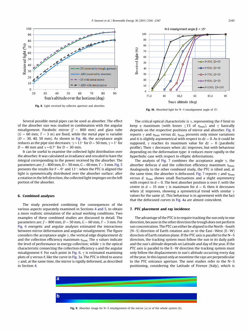
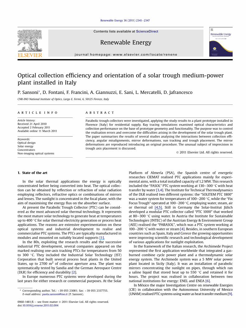
Fig. 8. Light received by collector aperture and absorber.Fig. 10. Absorbed light for NeS misalignment angle of 15� .
P. Sansoni et al. / Renewable Energy 36 (2011) 2341e2347 2345
Several possible metal pipes can be used as absorber. The effectof the absorber size was studied in combination with the angularmisalignment. Parabolic mirror (f ¼ 800 mm) and glass tube(G ¼ 60 mm; T ¼ 3 m) are fixed, while the metal pipe is variable(D ¼ 30, 40, 50 mm). As shown in Fig. 4b, the acceptance anglereduces as the pipe size decreases: gw1.1� for D¼ 50mm, gw1� forD ¼ 40 mm and gw0.7� for D ¼ 30 mm.
It can be useful to examine the collected light distribution overthe absorber. It was calculated as irradiance and rescaled to have theintegral corresponding to the power received by the absorber. Theparameters are: f¼800mm,D¼50mm,G¼60mm, T¼3mm. Fig. 5presents the results for q ¼ 0� and 1.1�: when the PTC is aligned thelight is symmetrically distributed over the absorber surface; aftera rotation in the left direction, the collected light impinges on the leftportion of the absorber.
6. Combined analyses
The study proceeded combining the consequences of thevarious aspects separately examined in Sections 4 and 5, to obtaina more realistic simulation of the actual working conditions. Twoexamples of these combined studies are discussed in detail. Theparameters are: f¼ 800mm, D¼ 50mm, G¼ 60mm, T¼ 3mm. ForFig. 6 energetic and angular analyses estimated the interactionsbetween mirror deformation and angular misalignment. The figureconsiders the acceptance angle g, the vertical edge displacement dzand the collection efficiency maximum hmax. The h values indicatethe level of performance in energy collection; while g is the opticalcharacteristic connecting the collection efficiency h and the angularmisalignment q. For each point in Fig. 6, g is estimated examiningplots of h versus q, like the curve in Fig. 3a. The PTC is tilted to assessg and, at the same time, the mirror is rigidly deformed, as describedin Section 4.
Fig. 9. Absorber image for NeS misalignment o
The critical optical characteristic is g, representing the q limit tokeep h maximum (with losses �1% of hmax), and g basicallydepends on the respective positions of mirror and absorber. Fig. 6reports g and hmax versus dz. hmax presents only minor variationsand it is slightly asymmetrical with respect to dz ¼ 0. As it could besupposed, g reaches its maximum value for dz ¼ 0 (parabolicprofile). Then g decreases when jdzj improves, but with behaviourdepending on the deformation type: it reduces more rapidly in thehyperbolic case with respect to elliptic deformations.
The analysis of Fig. 7 combines the acceptance angle g, theabsorber defocus d and the collection efficiency maximum hmax.Analogously to the other combined study, the PTC is tilted and, atthe same time, the absorber is defocused. Fig. 7 reports g and hmaxversus d. hmax shows small fluctuations and a slight asymmetrywith respect to d ¼ 0. The best absorber position is over F, with thecentre in d ¼ 15 mm g is maximum for d ¼ 0, then it decreaseswhen jdj improves, showing a symmetrical trend with similar g
values for the same jdj. This behaviour is in agreement with the factthat the defocused curves in Fig. 4a are almost coincident.
7. PTC placement and ray incidence
Theadvantage of thePTC is to require tracking the sunonly in onedirection, because in theotherdirection the troughdoesnotperformsunconcentration. ThePTCcaneither bealigned to theNortheSouth(NeS) direction of Earth rotation axis or to the EasteWest (EeW)direction of Earth rotationplane. If the PTC axis is parallel to theNeSdirection, the tracking system must follow the sun in its daily pathand the sun’s altitude depends on Latitude and day of the year. If thePTC axis is parallel to the EeW direction the tracking system mustonly follow the displacements in sun’s altitude occurring every dayof theyear. In this layoutonlyat noontime the rays areperpendicularto the PTC entrance aperture. The next studies refer to the NeSpositioning, considering the Latitude of Firenze (Italy), which is
f the mirror (a) or of the whole system (b).

Fig. 11. a,beAbsorbed light for two layouts (a, b) and three NeS misalignments.
P. Sansoni et al. / Renewable Energy 36 (2011) 2341e23472346
43.75�N. Insteadof considering thedifferentmonths, all calculationsare performed taking as reference the sun’s altitude a over thehorizon. So the results can be associated to the daily solar path, forNeS positioning, or to the different sun’s positions determined byLatitude and time, for EeW placement.
The interactions between sun’s altitude, collected light and PTCaxis placement were investigated [14]. The parameters are:f ¼ 800 mm, D ¼ 50 mm, G ¼ 60 mm, T ¼ 3 mm. For Firenze, thesolar rays incidence varies from a ¼ 23� in December to a ¼ 69� inJune. It is useful to separate the twomain causes of energetic losses:outside and inside the PTC. So the study examines the light enteringin the PTC aperture (IIN) and the light received by the absorber(IABS). An additional mirror can be introduced at the PTC extreme topartially recover the lost energy: Fig. 8 presents IIN and IABS. Somevalues, normalized to the incoming light, are:
Table 1Recovering procedure applied for NeS axis misalignment b ¼ 10� .
Sun’saltitude a (deg)
Reference parameter:light received by the absorber (%)
Angular correctio
90 36.586 080 34.749 1.370 32.229 3.160 28.458 4.650 23.942 6.440 18.560 7.730 12.682 8.720 6.427 9.4
IIN ¼ 37% and IABS ¼ 16% for a ¼ 23�;IIN ¼ 40% and IABS ¼ 20% for a ¼ 23�, with lateral mirror;IIN ¼ 89% and IABS ¼ 72% for a ¼ 69�;IIN ¼ 90% and IABS ¼ 74% for a ¼ 69�, with lateral mirror.
The a dependence is then combined to the effect of axismisalignment, parameterised by the angle b between the hori-zontal PTC axis and the NeS direction. The resulting effect is visibleon the absorber image, partially shown in Fig. 9, for a ¼ 23�. InFig. 9a the absorber is aligned to the NeS axis, but mirror and NeSaxes form 1� angle: the focused image results inclined. For Fig. 9bboth parabolic mirror and absorber are rigidly rotated at b ¼ 0.5�:the image is parallel to the absorber, but transversally and longi-tudinally shifted. In both cases a large amount of rays are missedand the focused image is only partially received by the absorber.
8. Placement errors and recovering method
The PTC axis, instead of being perfectly aligned to the NeSdirection, can form a few degrees of angle b. The main effect of thisNeS misalignment is collected energy loss, whose amount alwaysdepends on the sun’s altitude a [14]. The study examined angles upto b¼ 15�, analysing the interactions between collected light, b anda for different PTC layouts. It considered five focal lengths(500 mm < f < 1000 mm) and two absorbers (D ¼ 50 mm,G ¼ 60 mm and D ¼ 100 mm, G ¼ 116 mm): Fig. 10 reports someresults for b ¼ 15�. The light received by the absorber in Figs. 9 and10 is expressed in percentage with respect to the ideal case ofa ¼ 90�. Fig. 11a,b examines three b values: 5�, 10�, 15�. All curvesshow a significant dependence on a and b, but the PTC withf ¼ 1000 mm and D ¼ 100 mm (Fig. 11b) has lower energetic lossesthen for f ¼ 800 mm and D ¼ 50 mm (Fig. 11a).
In conclusion the energy loss is considerable and depends ona and b, but the missed light can be recovered using the trackingsystem rotation to compensate the b error. The proposed techniqueis completely empirical: for each case (a, b values), a rotation angleis applied and the lost light is minimized. For the NeS positioningthe compensation rotation axis is the PTC horizontal axis and theangular correction corresponds to the daily tracking. Table 1 pres-ents an example of application for f ¼ 800 mm, D ¼ 50 mm,G¼ 60 mm, T¼ 3 mm and b¼ 10�. For every a, the correction angleis experimentally determined maximizing the received light(expressed in percentage with respect to the impinging light). So inTable 1 the values in column 4, for b ¼ 10� with angular correctionshould reach the values in column 2, for b ¼ 0 and no angularcorrection. It was verified that the procedure can be successfullyapplied to the PTC under study for b up to 15�, recovering over 95%of energy. For b ¼ 10� Table 1 shows that it recuperates 98e100% oflost light.
n (deg) Light received bythe absorber for b ¼ 10� withangular correction (%)
Light recovered applyingthe correction
36.586 100.00%34.884 100.39%32.209 99.94%28.37 99.69%23.715 99.05%18.297 98.58%12.561 99.05%6.272 97.59%

P. Sansoni et al. / Renewable Energy 36 (2011) 2341e2347 2347
9. Conclusions
Starting from the experimentation on a PTC prototype, energeticand angular analyses were performed using ray tracing simula-tions. Most of them refer to the PTC collection efficiency h and tothe effect of angular misalignment q, obtained as rigid tilt of mirrorand absorber. A crucial optical characteristic is the PTC acceptanceangle g, representing the q limit keeping hmaximum: g depends onmirror deformations, parabola features and respective positions ofmirror and absorber. The q effect was examined in combinationwith mirror deformations, absorber defocus, parabola focal lengthandmetal pipe size: all these aspects contribute to reduce h, but theangular misalignment is the main cause of energetic losses.
An innovative method to reproduce rigid deformations of PTCswas illustrated. It employs conic constant K and conic equation torepresent the mirror profiles. The deformation can be of two types:elliptic, for �1 < K < 0 or hyperbolic, for K < �1. While for K ¼ �1the conic equation represents a parabola. Thismethod is simple andefficient, providing a good reproduction of the behaviour of a realsolar collector.
Precision of PTC placement and sun tracking should be matchedto optimise the collection performance. The error in collectorpositioning is an unusual subject, not often treated in scientificpapers, even though it represents a critical feature for the systemfunctionality. In NeS positioning the tracking system follows thesun movement during the day; while in EeW placement it followsthe sun’s altitude variations during the year. Referring to NeSpositioning, the studies indicate that the energy loss can besignificant and depends on sun’s altitude and NeS placement error.An empirical correction procedure is proposed and applied to theprototype, recovering most of lost energy using the daily trackingsystem to compensate the NeS positioning error.
Acknowledgements
The work was developed within the S.A.L.TO. (Solar AssistedCooling Toscana) research integrated project POR Ob.3 Toscana2000/2006MisuraD4, partiallyfinancedby theREGIONETOSCANAe
settore Promozionee sostegnodella Ricerca. Thanks aredue toCREAR
andDept. of Engineeringof the FlorenceUniversity for the realizationof solar cooling systems, in collaborationwith the industrial partners,FAIT group and CEVIT.
References
[1] Kalogirou SA. Solar thermal collectors and applications. Progress in Energyand Combustion Science 2004;30:231e95.
[2] Kearney DW. Parabolic trough collector overview. Golden, CO: ParabolicTrough Workshop at the National Renewable Energy Laboratory; 2007.
[3] Plataforma Solar de Almerìa. CIEMAT; 2007. Annual Report.[4] Weiss WM, Rommel M. Solar heat for industrial process: state of the art e
medium temperature collectors. IEA; 2005. SHC Task 33/IV.[5] Krüger D, Pandian Y, Hennecke K, Schmitz M. Parabolic trough collector
testing in the frame of the REACt project. Desalination 2008;220(1e3):612e8.[6] High temperature heat from solar energy. Rome, Italy: ENEA Press; 2004.[7] Bakos GC, Ioannidis I, Tsagas NF, Seftelis I. Design, optimisation and conver-
sion-efficiency determination of a line-focus parabolic-trough solar-collector(PTC). Applied Energy 2000;68(1):43e50.
[8] Price H, Lüpfert E, Kearney D, Zarza E, Cohen G, Gee R, et al. Advances inparabolic trough solar power technology. Journal of Solar Energy Engineering2002;124(2):109e25.
[9] Klapp J, Cervantes-Cota JL, Alcalá Chávez JF. Towards a cleaner planet: energyfor the future. Berlin, Germany: Springer; 2007.
[10] Prapas DE, Norton B, Probert SD. Optics of parabolic-trough, solar-energycollectors, possessing small concentration ratios. Solar Energy 1987;39(6):541e50.
[11] Winston R, Miñano JC, Benítez P, Shatz N, Bortz JC. Nonimaging optics.Amsterdam, Holland: Elsevier Academic Press; 2005.
[12] Kandpal TC, Mathur SS, Singhal AK. Optical performance of a compositeparabolic trough. Applied Energy 1985;19(3):231e9.
[13] Fontani D, Sansoni P, Francini F, Jafrancesco D, Chiani G, De Lucia M. Efficiencyof a linear parabolic mirror for geometrical deformations. In: EUROSUN 2008international conference on solar heating, cooling and buildings. Lisbon,Portugal; 2008.
[14] Sansoni P, Fontani D, Francini F, Mercatelli L, Chiani G, De Lucia M. Placementand orientation of solar linear troughs. EUROSUN 2008 international confer-ence on solar heating, cooling and buildings. Lisbon, Portugal; 2008.
[15] Fontani D, Sansoni P, Francini F, Mercatelli L, Jafrancesco D. A pinhole camerato track the sun position. ISES Solar World Congress 2007, Beijing, China;2007.
[16] Fontani D, Sansoni P, Francini F, Jafrancesco D, Mercatelli L. Sensors for sunpointing. World Renewable Energy Congress/Network 2008 (WREC/WREN).Glasgow, UK; 2008.
[17] Güven HM, Bannerot RB. Determination of error tolerances for the opticaldesign of parabolic troughs for developing countries. Solar Energy 1986;36(6):535e50.