operating manual - sunny tripower 3.0 / 4.0 / 5.0 / 6.0
TRANSCRIPT
SUNNY TRIPOWER
STP3-6-3AV-40-BE-en-12 | Version 1.2ENGLISH
Operating manualSUNNY TRIPOWER 3.0 / 4.0 / 5.0 / 6.0
Legal Provisions SMA Solar Technology AG
Operating manualSTP3-6-3AV-40-BE-en-122
Legal ProvisionsThe information contained in these documents is the property of SMA Solar Technology AG. Nopart of this document may be reproduced, stored in a retrieval system, or transmitted, in any form orby any means, be it electronic, mechanical, photographic, magnetic or otherwise, without the priorwritten permission of SMA Solar Technology AG. Internal reproduction used solely for the purposeof product evaluation or other proper use is allowed and does not require prior approval.SMA Solar Technology AG makes no representations or warranties, express or implied, withrespect to this documentation or any of the equipment and/or software it may describe, including(with no limitation) any implied warranties of utility, merchantability, or fitness for any particularpurpose. All such representations or warranties are expressly disclaimed. Neither SMA SolarTechnology AG nor its distributors or dealers shall be liable for any indirect, incidental, orconsequential damages under any circumstances.The exclusion of implied warranties may not apply in all cases under some statutes, and thus theabove exclusion may not apply.Specifications are subject to change without notice. Every attempt has been made to make thisdocument complete, accurate and up-to-date. Readers are cautioned, however, that productimprovements and field usage experience may cause SMA Solar Technology AG to make changesto these specifications without advance notice, or per contract provisions in those cases where asupply agreement requires advance notice. SMA Solar Technology AG shall not be responsible forany damages, including indirect, incidental or consequential damages, caused by reliance on thematerial presented, including, but not limited to, omissions, typographical errors, arithmetical errorsor listing errors in the content material.
SMA WarrantyYou can download the current warranty conditions from the Internet at www.SMA-Solar.com.
Software licensesThe licenses for the used software modules can be called up on the user interface of the product.
TrademarksAll trademarks are recognized, even if not explicitly identified as such. Missing designations do notmean that a product or brand is not a registered trademark.
SMA Solar Technology AGSonnenallee 134266 NiestetalGermanyTel. +49 561 9522-0Fax +49 561 9522-100www.SMA.deEmail: [email protected]: 9/5/2018Copyright © 2018 SMA Solar Technology AG. All rights reserved.
Table of ContentsSMA Solar Technology AG
Operating manual STP3-6-3AV-40-BE-en-12 3
Table of Contents1 Information on this Document................................................. 6
1.1 Validity ........................................................................................................................ 61.2 Target Group.............................................................................................................. 61.3 Content and Structure of this Document ................................................................... 61.4 Levels of warning messages ...................................................................................... 61.5 Symbols in the Document .......................................................................................... 71.6 Typographies in the document .................................................................................. 71.7 Designation in the document ..................................................................................... 71.8 Additional Information ............................................................................................... 8
2 Safety ........................................................................................ 92.1 Intended Use .............................................................................................................. 92.2 IMPORTANT SAFETY INSTRUCTIONS.................................................................... 9
3 Scope of Delivery ..................................................................... 12
4 Product Overview .................................................................... 134.1 Product Description .................................................................................................... 134.2 Symbols on the Product ............................................................................................. 144.3 Interfaces and Functions ............................................................................................ 154.4 LED Signals ................................................................................................................. 16
5 Mounting................................................................................... 185.1 Requirements for Mounting ....................................................................................... 185.2 Mounting the Inverter................................................................................................. 20
6 Electrical Connection ................................................................ 226.1 Overview of the Connection Area ............................................................................ 226.2 AC Connection........................................................................................................... 22
6.2.1 Requirements for the AC Connection .................................................... 226.2.2 Connecting the Inverter to the Utility Grid ............................................ 246.2.3 Connecting Additional Grounding ........................................................ 25
6.3 Connecting the Network Cables............................................................................... 266.4 Connecting RS485 Devices....................................................................................... 286.5 Mounting the WLAN Antenna .................................................................................. 296.6 DC Connection........................................................................................................... 29
6.6.1 Requirements for the DC Connection .................................................... 296.6.2 Assembling the DC Connectors ............................................................. 316.6.3 Connecting the PV Array........................................................................ 336.6.4 Disassembling the DC Connectors ........................................................ 35
Table of Contents SMA Solar Technology AG
Operating manualSTP3-6-3AV-40-BE-en-124
7 Commissioning ......................................................................... 377.1 Commissioning Procedure ......................................................................................... 377.2 Commissioning the Inverter........................................................................................ 377.3 Selecting a configuration option ............................................................................... 397.4 Starting the Self-Test (for Italy and Dubai)................................................................ 41
8 Operation ................................................................................. 438.1 Establishing a connection to the user interface ........................................................ 43
8.1.1 Establishing a Direct Connection via Ethernet ...................................... 438.1.2 Establishing a direct connection via WLAN ......................................... 438.1.3 Establishing a Connection via Ethernet in the local network ............... 458.1.4 Establishing a Connection via WLAN in the Local Network ............... 46
8.2 Logging In and Out of the User Interface................................................................. 478.3 Start Page Design of the User Interface.................................................................... 498.4 Activating the Smart Inverter Screen......................................................................... 518.5 Starting the Installation Assistant ............................................................................... 528.6 Activate WPS Function............................................................................................... 538.7 Switching WLAN On and Off................................................................................... 538.8 Switching the Dynamic Power Display Off............................................................... 548.9 Changing the Password............................................................................................. 558.10 Changing Operating Parameters.............................................................................. 558.11 Configuring the Country Data Set............................................................................. 568.12 Configuring Feed-In Management............................................................................ 578.13 Configuring the Modbus Function............................................................................. 588.14 Activating the Receipt of Control Signals (Only for Italy)........................................ 598.15 Deactivating Grounding Conductor Monitoring...................................................... 598.16 Setting the Tripping Threshold of the Residual-Current Device................................ 608.17 Saving the Configuration in a File............................................................................. 608.18 Adopting a Configuration from a File....................................................................... 608.19 Updating the Firmware .............................................................................................. 61
9 Disconnecting the Inverter from Voltage Sources ................. 62
10 Cleaning the Inverter ............................................................... 64
11 Troubleshooting........................................................................ 6511.1 Forgotten Password.................................................................................................... 6511.2 Event Messages ......................................................................................................... 6611.3 Checking the PV System for Ground Faults .............................................................. 82
12 Decommissioning the Inverter................................................. 86
Table of ContentsSMA Solar Technology AG
Operating manual STP3-6-3AV-40-BE-en-12 5
13 Technical Data .......................................................................... 8913.1 DC/AC ....................................................................................................................... 89
13.1.1 Sunny Tripower 3.0 / 4.0...................................................................... 8913.1.2 Sunny Tripower 5.0 / 6.0...................................................................... 91
13.2 General Data ............................................................................................................. 9213.3 Climatic Conditions .................................................................................................... 9413.4 Protective Devices ...................................................................................................... 9413.5 Equipment ................................................................................................................... 9413.6 Torques ....................................................................................................................... 9413.7 Data Storage Capacity.............................................................................................. 94
14 Contact ...................................................................................... 96
15 EU Declaration of Conformity ................................................. 98
1 Information on this Document SMA Solar Technology AG
Operating manualSTP3-6-3AV-40-BE-en-126
1 Information on this Document
1.1 ValidityThis document is valid for:
• STP3.0-3AV-40 (Sunny Tripower 3.0)• STP4.0-3AV-40 (Sunny Tripower 4.0)• STP5.0-3AV-40 (Sunny Tripower 5.0)• STP6.0-3AV-40 (Sunny Tripower 6.0)
1.2 Target GroupThis document is intended for qualified persons and end users. Only qualified persons are allowedto perform the activities marked in this document with a warning symbol and the caption"Qualified person". Tasks that do not require any particular qualification are not marked and canalso be performed by end users. Qualified persons must have the following skills:
• Knowledge of how an inverter works and is operated• Training in how to deal with the dangers and risks associated with installing, repairing and
using electrical devices and installations• Training in the installation and commissioning of electrical devices and installations• Knowledge of all applicable laws, standards and directives• Knowledge of and compliance with this document and all safety information
1.3 Content and Structure of this DocumentThis document describes the mounting, installation, commissioning, configuration, operation,troubleshooting and decommissioning of the product as well as the operation of the product userinterface.You will find the latest version of this document and further information on the product in PDF formatand as eManual at www.SMA-Solar.com. You can also call up the eManual via the user interfaceof the product.Illustrations in this document are reduced to the essential information and may deviate from the realproduct.
1.4 Levels of warning messagesThe following levels of warning messages may occur when handling the product.
DANGERIndicates a hazardous situation which, if not avoided, will result in death or serious injury.
WARNINGIndicates a hazardous situation which, if not avoided, could result in death or serious injury.
1 Information on this DocumentSMA Solar Technology AG
Operating manual STP3-6-3AV-40-BE-en-12 7
CAUTIONIndicates a hazardous situation which, if not avoided, could result in minor or moderate injury.
NOTICEIndicates a situation which, if not avoided, can result in property damage.
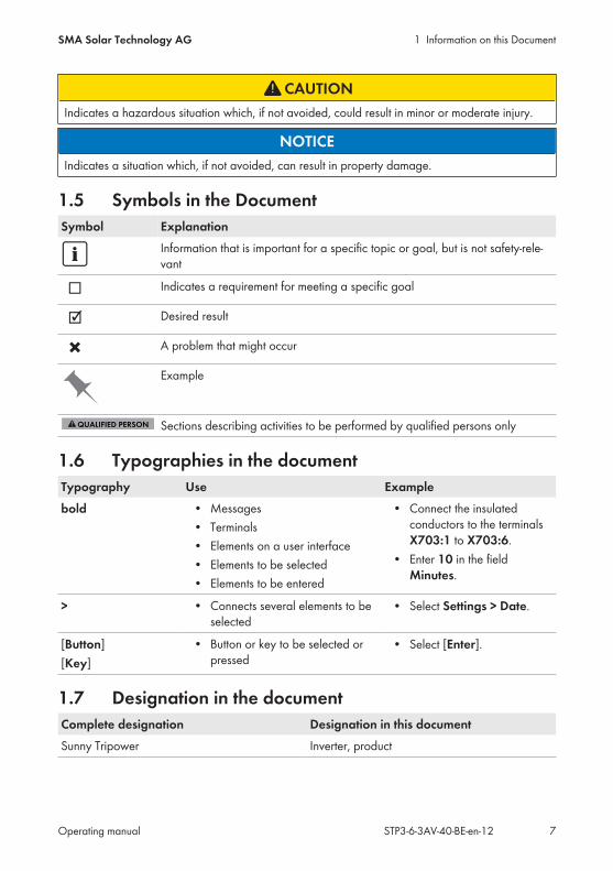
1.5 Symbols in the DocumentSymbol Explanation
Information that is important for a specific topic or goal, but is not safety-rele-vant
Indicates a requirement for meeting a specific goal
Desired result
A problem that might occur
Example
Sections describing activities to be performed by qualified persons only
1.6 Typographies in the documentTypography Use Examplebold • Messages
• Terminals• Elements on a user interface• Elements to be selected• Elements to be entered
• Connect the insulatedconductors to the terminalsX703:1 to X703:6.
• Enter 10 in the fieldMinutes.
> • Connects several elements to beselected
• Select Settings > Date.
[Button][Key]
• Button or key to be selected orpressed
• Select [Enter].
1.7 Designation in the documentComplete designation Designation in this documentSunny Tripower Inverter, product

1 Information on this Document SMA Solar Technology AG
Operating manualSTP3-6-3AV-40-BE-en-128
1.8 Additional InformationFor more information, please go to www.SMA-Solar.com.
Title and information content Type of information"Application for SMA Grid Guard Code" Form
"PUBLIC CYBER SECURITY - Guidelines for a Secure PV SystemCommunication"
Technical information
"Efficiency and Derating"Efficiency and derating behavior of the SMA inverters
Technical Information
"Parameters and Measured Values"Overview of all inverter operating parameters and their configura-tion options
Technical Information
"SMA and SunSpec Modbus® Interface"Information on the Modbus interface
Technical Information
"Modbus® parameters and measured values"Device-specific register HTML file
Technical Information
"Temperature Derating" Technical Information

2 SafetySMA Solar Technology AG
Operating manual STP3-6-3AV-40-BE-en-12 9
2 Safety
2.1 Intended UseThe Sunny Tripower is a transformerless PV inverter which converts the direct current of the PV arrayto grid-compliant three-phase current and feeds it into the utility grid.The product is suitable for indoor and outdoor use.The product must only be operated with PV modules of protection class II in accordance withIEC 61730, application class A. The PV modules must be compatible with this product.The product is not equipped with a transformer and therefore has no galvanic isolation. Theproduct must not be operated with PV modules whose outputs are grounded. This can cause theproduct to be destroyed. The product may be operated with PV modules whose frame is grounded.PV modules with a high capacity to ground must only be used if their coupling capacity does notexceed 2.25 μF (for information on how to calculate the coupling capacity, see the TechnicalInformation "Leading Leakage Currents" at www.SMA-Solar.com).All components must remain within their permitted operating ranges and their installationrequirements at all times.The product must only be used in countries for which it is approved or released by SMA SolarTechnology AG and the grid operator.Use this product only in accordance with the information provided in the enclosed documentationand with the locally applicable laws, regulations, standards and directives. Any other applicationmay cause personal injury or property damage.Alterations to the product, e.g. changes or modifications, are only permitted with the express writtenpermission of SMA Solar Technology AG. Unauthorized alterations will void guarantee andwarranty claims and in most cases terminate the operating license. SMA Solar Technology AGshall not be held liable for any damage caused by such changes.Any use of the product other than that described in the Intended Use section does not qualify as theintended use.The enclosed documentation is an integral part of this product. Keep the documentation in aconvenient place for future reference and observe all instructions contained therein.This document does not replace and is not intended to replace any local, state, provincial, federalor national laws, regulations or codes applicable to the installation, electrical safety and use of theproduct. SMA Solar Technology AG assumes no responsibility for the compliance or non-compliance with such laws or codes in connection with the installation of the product.The type label must remain permanently attached to the product.
2.2 IMPORTANT SAFETY INSTRUCTIONSSAVE THESE INSTRUCTIONSThis section contains safety information that must be observed at all times when working on or withthe product.
2 Safety SMA Solar Technology AG
Operating manualSTP3-6-3AV-40-BE-en-1210
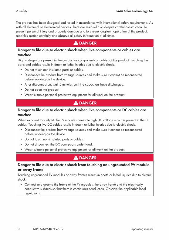
The product has been designed and tested in accordance with international safety requirements. Aswith all electrical or electronical devices, there are residual risks despite careful construction. Toprevent personal injury and property damage and to ensure long-term operation of the product,read this section carefully and observe all safety information at all times.
DANGERDanger to life due to electric shock when live components or cables aretouchedHigh voltages are present in the conductive components or cables of the product. Touching liveparts and cables results in death or lethal injuries due to electric shock.
• Do not touch non-insulated parts or cables.• Disconnect the product from voltage sources and make sure it cannot be reconnected
before working on the device.• After disconnection, wait 5 minutes until the capacitors have discharged.• Do not open the product.• Wear suitable personal protective equipment for all work on the product.
DANGERDanger to life due to electric shock when live components or DC cables aretouchedWhen exposed to sunlight, the PV modules generate high DC voltage which is present in the DCcables. Touching live DC cables results in death or lethal injuries due to electric shock.
• Disconnect the product from voltage sources and make sure it cannot be reconnectedbefore working on the device.
• Do not touch non-insulated parts or cables.• Do not disconnect the DC connectors under load.• Wear suitable personal protective equipment for all work on the product.
DANGERDanger to life due to electric shock from touching an ungrounded PV moduleor array frameTouching ungrounded PV modules or array frames results in death or lethal injuries due to electricshock.
• Connect and ground the frame of the PV modules, the array frame and the electricallyconductive surfaces so that there is continuous conduction. Observe the applicable localregulations.
2 SafetySMA Solar Technology AG
Operating manual STP3-6-3AV-40-BE-en-12 11
DANGERDanger to life due to electric shock when touching live system components incase of a ground faultIf a ground fault occurs, parts of the system may still be live. Touching live parts and cablesresults in death or lethal injuries due to electric shock.
• Disconnect the product from voltage sources and make sure it cannot be reconnectedbefore working on the device.
• Touch the cables of the PV array on the insulation only.• Do not touch any parts of the substructure or frame of the PV array.• Do not connect PV strings with ground faults to the inverter.
CAUTIONRisk of burns due to hot enclosure partsSome parts of the enclosure can get hot during operation.
• During operation, do not touch any parts other than the enclosure lid of the inverter.
NOTICEDamage due to cleaning agentsThe use of cleaning agents may cause damage to the product and its components.
• Clean the product and all its components only with a cloth moistened with clear water.

3 Scope of Delivery SMA Solar Technology AG
Operating manualSTP3-6-3AV-40-BE-en-1212
3 Scope of DeliveryCheck the scope of delivery for completeness and any externally visible damage. Contact yourdistributor if the scope of delivery is incomplete or damaged.
B C
+
D
_
E F
IH JG
A
Figure 1: Components included in the scope of delivery
Position Quantity DesignationA 1 Inverter
B 1 Wall mounting bracket
C 3 Pan head screw M5x12
D 2 Positive DC connector
E 2 Negative DC connector
F 4 Sealing plug
G 1 AC connector
H 1 RJ45 protective sleeve: swivel nut, cable support sleeve, threadedsleeve
I 1 WLAN antenna
J 1 Quick reference guide with password label on the rear sideThe label contains the following information:
• PIC (Product Identification Code) identification key forregistering the system in Sunny Portal
• RID (Registration Identifier) registration ID for registering thesystem in Sunny Portal
• WLAN password WPA2-PSK (WiFi Protected Access 2 -Preshared Key) for direct connection to the inverter via WLAN
4 Product OverviewSMA Solar Technology AG
Operating manual STP3-6-3AV-40-BE-en-12 13
4 Product Overview
4.1 Product Description
SUNNY BOY
B
C
A
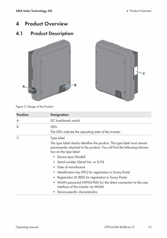
Figure 2: Design of the Product
Position DesignationA DC load-break switch
B LEDsThe LEDs indicate the operating state of the inverter.
C Type labelThe type label clearly identifies the product. The type label must remainpermanently attached to the product. You will find the following informa-tion on the type label:
• Device type (Model)• Serial number (Serial No. or S/N)• Date of manufacture• Identification key (PIC) for registration in Sunny Portal• Registration ID (RID) for registration in Sunny Portal• WLAN password (WPA2-PSK) for the direct connection to the user
interface of the inverter via WLAN• Device-specific characteristics
4 Product Overview SMA Solar Technology AG
Operating manualSTP3-6-3AV-40-BE-en-1214
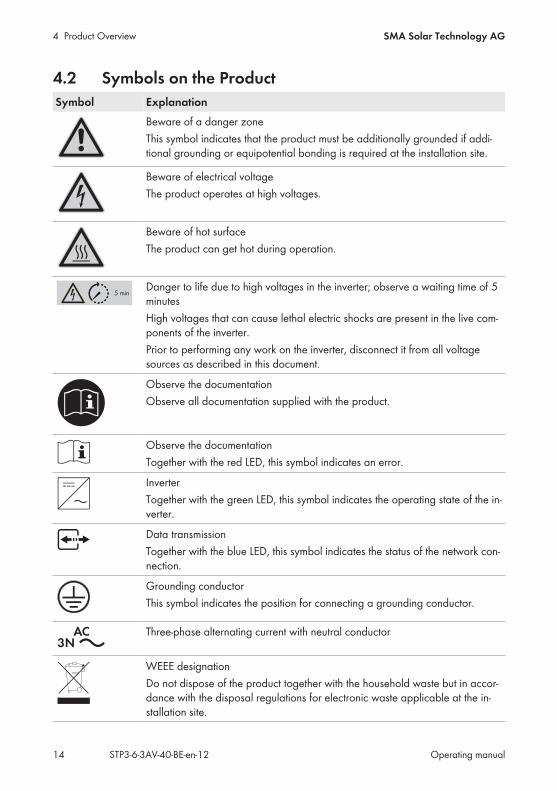
4.2 Symbols on the ProductSymbol Explanation
Beware of a danger zoneThis symbol indicates that the product must be additionally grounded if addi-tional grounding or equipotential bonding is required at the installation site.
Beware of electrical voltageThe product operates at high voltages.
Beware of hot surfaceThe product can get hot during operation.
5 minDanger to life due to high voltages in the inverter; observe a waiting time of 5minutesHigh voltages that can cause lethal electric shocks are present in the live com-ponents of the inverter.Prior to performing any work on the inverter, disconnect it from all voltagesources as described in this document.
Observe the documentationObserve all documentation supplied with the product.
Observe the documentationTogether with the red LED, this symbol indicates an error.
InverterTogether with the green LED, this symbol indicates the operating state of the in-verter.
Data transmissionTogether with the blue LED, this symbol indicates the status of the network con-nection.
Grounding conductorThis symbol indicates the position for connecting a grounding conductor.
Three-phase alternating current with neutral conductor
WEEE designationDo not dispose of the product together with the household waste but in accor-dance with the disposal regulations for electronic waste applicable at the in-stallation site.
4 Product OverviewSMA Solar Technology AG
Operating manual STP3-6-3AV-40-BE-en-12 15
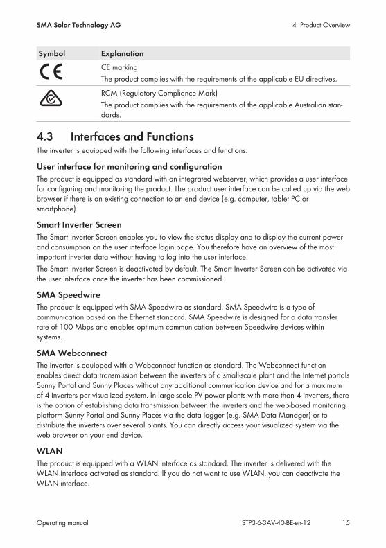
Symbol ExplanationCE markingThe product complies with the requirements of the applicable EU directives.
RCM (Regulatory Compliance Mark)The product complies with the requirements of the applicable Australian stan-dards.
4.3 Interfaces and FunctionsThe inverter is equipped with the following interfaces and functions:
User interface for monitoring and configurationThe product is equipped as standard with an integrated webserver, which provides a user interfacefor configuring and monitoring the product. The product user interface can be called up via the webbrowser if there is an existing connection to an end device (e.g. computer, tablet PC orsmartphone).
Smart Inverter ScreenThe Smart Inverter Screen enables you to view the status display and to display the current powerand consumption on the user interface login page. You therefore have an overview of the mostimportant inverter data without having to log into the user interface.The Smart Inverter Screen is deactivated by default. The Smart Inverter Screen can be activated viathe user interface once the inverter has been commissioned.
SMA SpeedwireThe product is equipped with SMA Speedwire as standard. SMA Speedwire is a type ofcommunication based on the Ethernet standard. SMA Speedwire is designed for a data transferrate of 100 Mbps and enables optimum communication between Speedwire devices withinsystems.
SMA WebconnectThe inverter is equipped with a Webconnect function as standard. The Webconnect functionenables direct data transmission between the inverters of a small-scale plant and the Internet portalsSunny Portal and Sunny Places without any additional communication device and for a maximumof 4 inverters per visualized system. In large-scale PV power plants with more than 4 inverters, thereis the option of establishing data transmission between the inverters and the web-based monitoringplatform Sunny Portal and Sunny Places via the data logger (e.g. SMA Data Manager) or todistribute the inverters over several plants. You can directly access your visualized system via theweb browser on your end device.
WLANThe product is equipped with a WLAN interface as standard. The inverter is delivered with theWLAN interface activated as standard. If you do not want to use WLAN, you can deactivate theWLAN interface.
4 Product Overview SMA Solar Technology AG
Operating manualSTP3-6-3AV-40-BE-en-1216
ModbusThe product is equipped with a Modbus interface. The Modbus interface is deactivated by defaultand must be configured as needed.The Modbus interface of the supported SMA products is designed for industrial use – via SCADAsystems, for example – and has the following tasks:
• Remote query of measured values• Remote setting of operating parameters• Setpoint specifications for system control
Grid management servicesThe product is equipped with service functions for grid management.Depending on the requirements of the grid operator, you can activate and configure the functions(e.g. active power limitation) via operating parameters.
Parallel Operation of the DC Inputs A and BYou have the option of operating the inverter DC inputs A and B in parallel. As a result, and asopposed to normal operation, several parallel-connected strings can be connected to the inverter.The inverter automatically detects the parallel operation of the DC inputs A and B.
SMA OptiTrac Global PeakSMA OptiTrac Global Peak is an advancement of SMA OptiTrac and allows the operating point ofthe inverter to follow the optimal operating point of the PV array (MPP) precisely at all times. Inaddition, with the aid of SMA OptiTrac Global Peak, the inverter detects several maximum powerpoints in the available operating range, such as may occur particularly with partially shadedstrings. SMA OptiTrac Global Peak is enabled by default.
All-pole sensitive residual-current monitoring unitThe all-pole sensitive residual-current monitoring unit detects alternating and direct differentialcurrents. In single-phase and three-phase inverters, the integrated differential current sensor detectsthe current difference between the neutral conductor and the line conductor(s). If the currentdifference increases suddenly, the inverter disconnects from the utility grid.
SMA Smart ConnectedSMA Smart Connected is the free monitoring of the inverter via the SMA Sunny Portal. Thanks toSMA Smart Connected, the PV system operator and qualified person will be informed automaticallyand proactively about inverter events that occur.SMA Smart Connected is activated during registration in Sunny Portal. In order to use SMA SmartConnected, it is necessary that the inverter is permanently connected to Sunny Portal and the dataof the PV system operator and qualified person is stored in Sunny Portal and up-to-date.
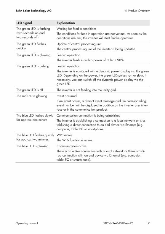
4.4 LED SignalsThe LEDs indicate the operating state of the inverter.
4 Product OverviewSMA Solar Technology AG
Operating manual STP3-6-3AV-40-BE-en-12 17
LED signal ExplanationThe green LED is flashing(two seconds on andtwo seconds off)
Waiting for feed-in conditionsThe conditions for feed-in operation are not yet met. As soon as theconditions are met, the inverter will start feed-in operation.
The green LED flashesquickly
Update of central processing unitThe central processing unit of the inverter is being updated.
The green LED is glowing Feed-in operationThe inverter feeds in with a power of at least 90%.
The green LED is pulsing Feed-in operationThe inverter is equipped with a dynamic power display via the greenLED. Depending on the power, the green LED pulses fast or slow. Ifnecessary, you can switch off the dynamic power display via thegreen LED.
The green LED is off The inverter is not feeding into the utility grid.
The red LED is glowing Event occurredIf an event occurs, a distinct event message and the correspondingevent number will be displayed in addition on the inverter user inter-face or in the communication product.
The blue LED flashes slowlyfor approx. one minute
Communication connection is being establishedThe inverter is establishing a connection to a local network or is es-tablishing a direct connection to an end device via Ethernet (e.g.computer, tablet PC or smartphone).
The blue LED flashes quicklyfor approx. two minutes.
WPS activeThe WPS function is active.
The blue LED is glowing Communication activeThere is an active connection with a local network or there is a di-rect connection with an end device via Ethernet (e.g. computer,tablet PC or smartphone).
5 Mounting SMA Solar Technology AG
Operating manualSTP3-6-3AV-40-BE-en-1218
5 Mounting
5.1 Requirements for MountingRequirements for the Mounting Location:
WARNINGDanger to life due to fire or explosionDespite careful construction, electrical devices can cause fires.
• Do not mount the product in areas containing highly flammable materials or gases.• Do not mount the product in potentially explosive atmospheres.
A solid support surface must be available (e.g., concrete or masonry). When mounted ondrywall or similar materials, the product emits audible vibrations during operation which couldbe perceived as annoying.
The mounting location must be inaccessible to children. The mounting location must be suitable for the weight and dimensions of the product (see
Section 13 "Technical Data", page 89). The mounting location must not be exposed to direct solar irradiation. If the product is
exposed to direct solar irradiation, the exterior plastic parts might age prematurely andoverheating might occur. When becoming too hot, the product reduces its power output toavoid overheating.
The mounting location should be freely and safely accessible at all times without the need forany auxiliary equipment (such as scaffolding or lifting platforms). Non-fulfillment of thesecriteria may restrict servicing.
All ambient conditions must be met (see Section 13, page 89). To ensure optimum operation, the ambient temperature should be between -25°C and
+40°C.
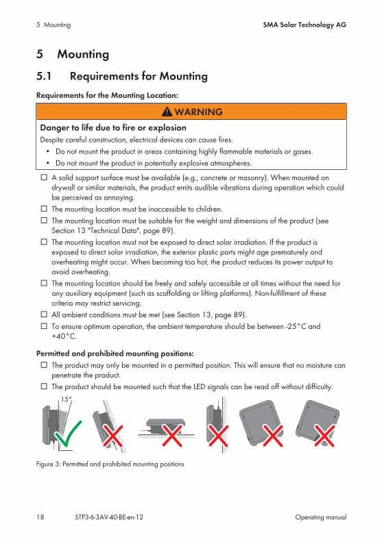
Permitted and prohibited mounting positions: The product may only be mounted in a permitted position. This will ensure that no moisture can
penetrate the product. The product should be mounted such that the LED signals can be read off without difficulty.
15°
Figure 3: Permitted and prohibited mounting positions
5 MountingSMA Solar Technology AG
Operating manual STP3-6-3AV-40-BE-en-12 19
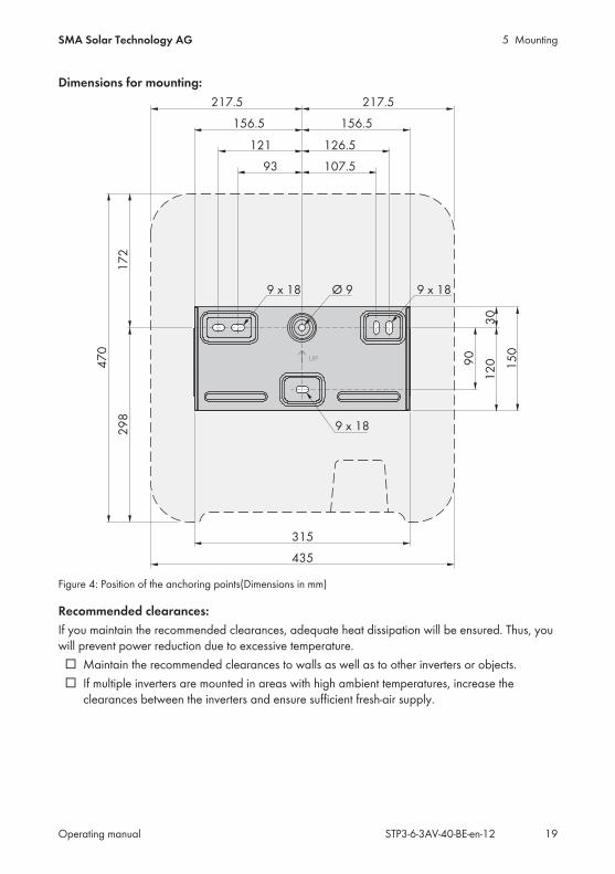
Dimensions for mounting:
UP 90
12
0 15
0
30
17
22
98
47
0
121
9 x 18 Ø 9 9 x 18
315
435
9 x 18
107.5
126.5
93
156.5 156.5
217.5 217.5
Figure 4: Position of the anchoring points(Dimensions in mm)
Recommended clearances:If you maintain the recommended clearances, adequate heat dissipation will be ensured. Thus, youwill prevent power reduction due to excessive temperature.
Maintain the recommended clearances to walls as well as to other inverters or objects. If multiple inverters are mounted in areas with high ambient temperatures, increase the
clearances between the inverters and ensure sufficient fresh-air supply.
5 Mounting SMA Solar Technology AG
Operating manualSTP3-6-3AV-40-BE-en-1220
210 270 210 100
430
430
430
450
450
450
450
450
450
430
430
430
150
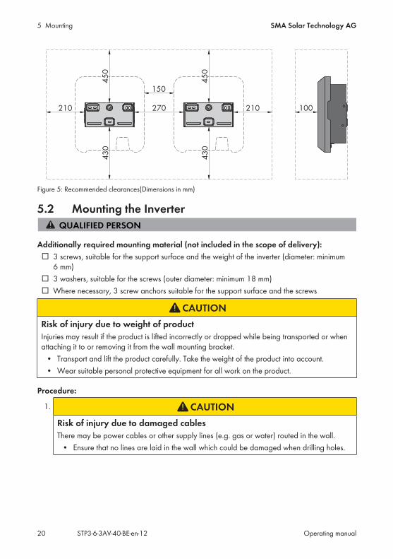
Figure 5: Recommended clearances(Dimensions in mm)
5.2 Mounting the Inverter
Additionally required mounting material (not included in the scope of delivery): 3 screws, suitable for the support surface and the weight of the inverter (diameter: minimum
6 mm) 3 washers, suitable for the screws (outer diameter: minimum 18 mm) Where necessary, 3 screw anchors suitable for the support surface and the screws
CAUTIONRisk of injury due to weight of productInjuries may result if the product is lifted incorrectly or dropped while being transported or whenattaching it to or removing it from the wall mounting bracket.
• Transport and lift the product carefully. Take the weight of the product into account.• Wear suitable personal protective equipment for all work on the product.
Procedure:
1. CAUTIONRisk of injury due to damaged cablesThere may be power cables or other supply lines (e.g. gas or water) routed in the wall.
• Ensure that no lines are laid in the wall which could be damaged when drilling holes.
5 MountingSMA Solar Technology AG
Operating manual STP3-6-3AV-40-BE-en-12 21
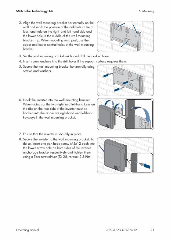
2. Align the wall mounting bracket horizontally on thewall and mark the position of the drill holes. Use atleast one hole on the right- and left-hand side andthe lower hole in the middle of the wall mountingbracket. Tip: When mounting on a post, use theupper and lower central holes of the wall mountingbracket.
UP
3. Set the wall mounting bracket aside and drill the marked holes.4. Insert screw anchors into the drill holes if the support surface requires them.5. Secure the wall mounting bracket horizontally using
screws and washers.
UP
6. Hook the inverter into the wall mounting bracket.When doing so, the two right- and left-hand keys onthe ribs on the rear side of the inverter must behooked into the respective right-hand and left-handkeyways in the wall mounting bracket.
UP
7. Ensure that the inverter is securely in place.8. Secure the inverter to the wall mounting bracket. To
do so, insert one pan head screw M5x12 each intothe lower screw hole on both sides of the inverteranchorage bracket respectively and tighten themusing a Torx screwdriver (TX 25, torque: 2.5 Nm).
6 Electrical Connection SMA Solar Technology AG
Operating manualSTP3-6-3AV-40-BE-en-1222
6 Electrical Connection
6.1 Overview of the Connection Area
RS485
A B
+
−
+
−
AC
FA CB ED G
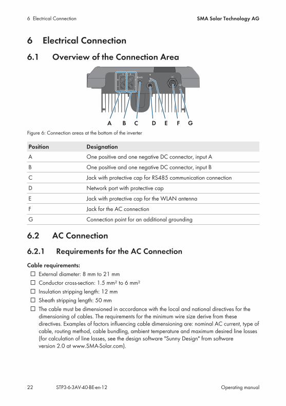
Figure 6: Connection areas at the bottom of the inverter
Position DesignationA One positive and one negative DC connector, input A
B One positive and one negative DC connector, input B
C Jack with protective cap for RS485 communication connection
D Network port with protective cap
E Jack with protective cap for the WLAN antenna
F Jack for the AC connection
G Connection point for an additional grounding
6.2 AC Connection
6.2.1 Requirements for the AC ConnectionCable requirements:
External diameter: 8 mm to 21 mm Conductor cross-section: 1.5 mm² to 6 mm² Insulation stripping length: 12 mm Sheath stripping length: 50 mm The cable must be dimensioned in accordance with the local and national directives for the
dimensioning of cables. The requirements for the minimum wire size derive from thesedirectives. Examples of factors influencing cable dimensioning are: nominal AC current, type ofcable, routing method, cable bundling, ambient temperature and maximum desired line losses(for calculation of line losses, see the design software "Sunny Design" from softwareversion 2.0 at www.SMA-Solar.com).
6 Electrical ConnectionSMA Solar Technology AG
Operating manual STP3-6-3AV-40-BE-en-12 23
Load-break switch and cable protection:
NOTICEDamage to the inverter due to the use of screw-type fuses as load-breakswitchesScrew-type fuses (e.g. DIAZED fuse or NEOZED fuse) are not load-break switches.
• Do not use screw-type fuses as load-break switches.• Use a load-break switch or circuit breaker as a load disconnection unit (for information and
design examples, see the Technical Information "Circuit Breaker" at www.SMA-Solar.com).
In PV systems with multiple inverters, protect each inverter with a separate circuit breaker.Make sure to observe the maximum permissible fuse protection (see Section 13 "TechnicalData", page 89). This will prevent residual voltage being present at the corresponding cableafter disconnection.
Loads installed between the inverter and the circuit breaker must be fused separately.
Residual-current monitoring unit: If an external residual-current device is required, install a residual-current device which trips at
a residual current of 100 mA or higher (for details on selecting a residual-current device, seethe Technical Information "Criteria for Selecting a Residual-Current Device" at www.SMA-Solar.com).
If a residual-current device with a tripping threshold of 30 mA is required and used, you mustset the tripping threshold of the residual-current device in the inverter to 30 mA (seeSection 8.16, page 60).
Overvoltage category:The inverter can be used in grids of overvoltage category III or lower in accordance withIEC 60664-1. That means that the inverter can be permanently connected to the grid-connectionpoint of a building. In case of installations with long outdoor cabling routes, additional measures toreduce overvoltage category IV to overvoltage category III are required (see the TechnicalInformation "Overvoltage Protection" at www.SMA-Solar.com).
Grounding conductor monitoring:The inverter is equipped with a grounding conductor monitoring device. This grounding conductormonitoring device detects when there is no grounding conductor connected and disconnects theinverter from the utility grid if this is the case. Depending on the installation site and gridconfiguration, it may be advisable to deactivate the grounding conductor monitoring. This isnecessary, for example, in an IT system if there is no neutral conductor present and you intend toinstall the inverter between two line conductors. If you are uncertain about this, contact your gridoperator or SMA Solar Technology AG.
• Grounding conductor monitoring must be deactivated after initial start-up depending on thegrid configuration (see Section 8.15, page 59).
6 Electrical Connection SMA Solar Technology AG
Operating manualSTP3-6-3AV-40-BE-en-1224
Safety in accordance with IEC 62109 when the grounding conductormonitoring is deactivatedIn order to guarantee safety in accordance with IEC 62109 when the grounding conductormonitoring is deactivated, you have to connect an additional grounding conductor to theinverter.
• Connect an additional grounding conductor that has an cross-section of at least 10 mm(see Section 6.2.3, page 25). This prevents touch current in the event of the groundingconductor on the AC connector bush insert failing.
Connection of an additional grounding conductorIn some countries, an additional grounding conductor is generally required. In each case,observe the locally applicable regulations.
• If an additional grounding conductor is required, connect the one that has an cross-section of at least 10 mm (see Section 6.2.3, page 25). This prevents touch current inthe event of the grounding conductor on the AC connector bush insert failing.
6.2.2 Connecting the Inverter to the Utility Grid
Requirements: The connection requirements of the grid operator must be met. The grid voltage must be within the permissible range. The exact operating range of the
inverter is specified in the operating parameters.
Procedure:1. Disconnect the circuit breaker and secure it against reconnection.2. Dismantle the AC cable by 50 mm.3. Shorten L1, L2, L3 and N by 8 mm each so that the grounding conductor is 8 mm longer. This
ensures that the grounding conductor is the last to be pulled from the screw terminal in theevent of tensile strain.
4. Strip the insulation of L1, L2, L3, N and the grounding conductor by 12 mm.5. In the case of fine stranded wire, L1, L2, L3, N and the grounding conductor are to be fitted
with bootlace ferrules.6. Assemble the AC connector and connect the conductor to the AC connector (see manual of
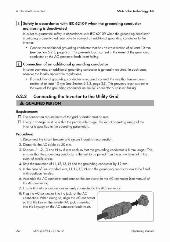
the AC connector).7. Ensure that all conductors are securely connected to the AC connector.8. Plug the AC connector into the jack for the AC
connection. When doing so, align the AC connectorso that the key on the inverter AC jack is insertedinto the keyway on the AC connector bush insert.
6 Electrical ConnectionSMA Solar Technology AG
Operating manual STP3-6-3AV-40-BE-en-12 25
6.2.3 Connecting Additional Grounding
If additional grounding or equipotential bonding is required locally, you can connect additionalgrounding to the inverter. This prevents touch current if the grounding conductor on the ACconnector fails. The necessary ring terminal lug and the screw are included in the scope of deliveryof the inverter.
Additionally required material (not included in the scope of delivery): 1 grounding cable
Cable requirement:
Use of fine-stranded conductorsYou can use an inflexible or a flexible, fine-stranded conductor.
• When using a fine-stranded conductor, it has to be double crimped by a ring terminal lug.Make sure that no insulated conductor is visible when pulling or bending. This will ensuresufficient strain relief by means of the ring terminal lug.
Grounding cable cross-section: max. 10 mm²
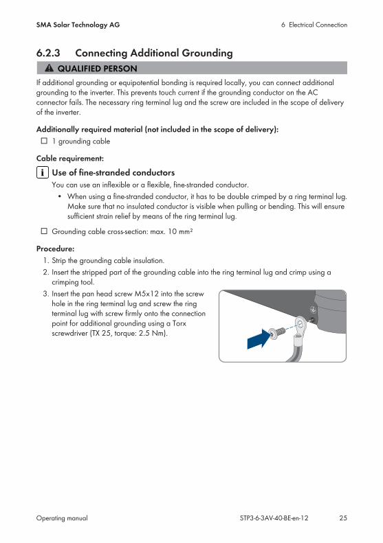
Procedure:1. Strip the grounding cable insulation.2. Insert the stripped part of the grounding cable into the ring terminal lug and crimp using a
crimping tool.3. Insert the pan head screw M5x12 into the screw
hole in the ring terminal lug and screw the ringterminal lug with screw firmly onto the connectionpoint for additional grounding using a Torxscrewdriver (TX 25, torque: 2.5 Nm).
6 Electrical Connection SMA Solar Technology AG
Operating manualSTP3-6-3AV-40-BE-en-1226
6.3 Connecting the Network Cables
DANGERDanger to life due to electric shock in case of overvoltages and if surgeprotection is missingOvervoltages (e. g. in the event of a flash of lightning) can be further conducted into the buildingand to other connected devices in the same network via the network cables or other data cablesif there is no surge protection. Touching live parts and cables results in death or lethal injuries dueto electric shock.
• Ensure that all devices in the same network are integrated in the existing overvoltageprotection.
• When laying the network cable outdoors, ensure that there is suitable surge protection atthe network cable transition from the product outdoors to the network inside the building.
• The Ethernet interface of the inverter is classified as "TNV-1" and offers protection againstovervoltages of up to 1.5 kV.
Additionally required material (not included in the scope of delivery): 1 network cable
Cable requirements:The cable length and quality affect the quality of the signal. Observe the following cablerequirements.
Cable type: 100BaseTx Cable category: Cat5, Cat5e, Cat6, Cat6a or Cat7 Plug type: RJ45 of Cat5, Cat5e, Cat6 or Cat6a Shielding: SF/UTP, S/UTP, SF/FTP or S/FTP Number of insulated conductor pairs and insulated conductor cross-section: at least 2 x 2 x
0.22 mm² Maximum cable length between two nodes when using patch cables: 50 m Maximum cable length between two nodes when using installation cables: 100 m UV-resistant for outdoor use
NOTICEDamage to the inverter due to moisture ingressMoisture penetration can damage the inverter and impair its functionality.
• Connect the network cable with the supplied RJ45 protective sleeve to the inverter.
6 Electrical ConnectionSMA Solar Technology AG
Operating manual STP3-6-3AV-40-BE-en-12 27
Procedure:
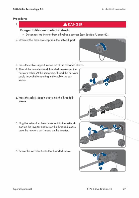
1. DANGERDanger to life due to electric shock
• Disconnect the inverter from all voltage sources (see Section 9, page 62).
2. Unscrew the protective cap from the network port.
3. Press the cable support sleeve out of the threaded sleeve.4. Thread the swivel nut and threaded sleeve over the
network cable. At the same time, thread the networkcable through the opening in the cable supportsleeve. 1
2
5. Press the cable support sleeve into the threadedsleeve.
6. Plug the network cable connector into the networkport on the inverter and screw the threaded sleeveonto the network port thread on the inverter. 3
12
7. Screw the swivel nut onto the threaded sleeve.
1
2

6 Electrical Connection SMA Solar Technology AG
Operating manualSTP3-6-3AV-40-BE-en-1228
8. If you would like to establish a direct connection, connect the other end of the network cabledirectly to the end device.
9. If you would like to integrate the inverter into a local network, connect the other end of thenetwork cable to the local network (e.g. via a router).
6.4 Connecting RS485 Devices
Additionally required material (not included in the scope of delivery): One communication cable for RS485 communication One M12 plug, 4-pole
Signal assignment:
Pin connector Signal TS4 Gateway Insulated con-ductor color
4 3
1 2
1 GND -
2 +12 V +
3 Data- B
4 Data+ A
Procedure:
1. DANGERDanger to life due to electric shock
• Disconnect the inverter from all voltage sources (see Section 9, page 62).
2. Assemble the M12 plug and connect the RS485 cable to the plug (see manual of the M12connector).
3. Ensure that all conductors are correctly connected to the M12 plug.4. Unscrew the protective cap from the jack for the
RS485 communication connection.RS485
6 Electrical ConnectionSMA Solar Technology AG
Operating manual STP3-6-3AV-40-BE-en-12 29
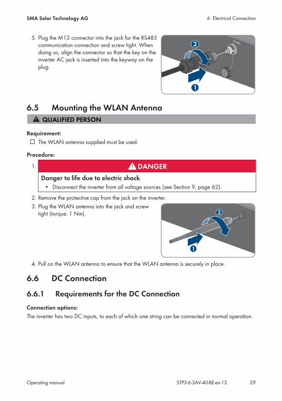
5. Plug the M12 connector into the jack for the RS485communication connection and screw tight. Whendoing so, align the connector so that the key on theinverter AC jack is inserted into the keyway on theplug.
RS485
1
2
6.5 Mounting the WLAN Antenna
Requirement: The WLAN antenna supplied must be used.
Procedure:
1. DANGERDanger to life due to electric shock
• Disconnect the inverter from all voltage sources (see Section 9, page 62).
2. Remove the protective cap from the jack on the inverter.3. Plug the WLAN antenna into the jack and screw
tight (torque: 1 Nm).
1
2
4. Pull on the WLAN antenna to ensure that the WLAN antenna is securely in place.
6.6 DC Connection
6.6.1 Requirements for the DC ConnectionConnection options:The inverter has two DC inputs, to each of which one string can be connected in normal operation.
6 Electrical Connection SMA Solar Technology AG
Operating manualSTP3-6-3AV-40-BE-en-1230
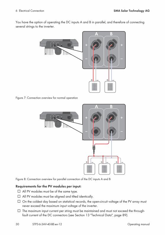
You have the option of operating the DC inputs A and B in parallel, and therefore of connectingseveral strings to the inverter.
RS485
A B
+
−
+
−
AC
+
A B
−
+
−
+ _+ _
Figure 7: Connection overview for normal operation
RS485
A B
+
−
+
−
AC
+
A B
−
+
−
+ _ + _ + _
Figure 8: Connection overview for parallel connection of the DC inputs A and B
Requirements for the PV modules per input: All PV modules must be of the same type. All PV modules must be aligned and tilted identically. On the coldest day based on statistical records, the open-circuit voltage of the PV array must
never exceed the maximum input voltage of the inverter. The maximum input current per string must be maintained and must not exceed the through-
fault current of the DC connectors (see Section 13 "Technical Data", page 89).
6 Electrical ConnectionSMA Solar Technology AG
Operating manual STP3-6-3AV-40-BE-en-12 31
The thresholds for the input voltage and the input current of the inverter must be adhered to(see Section 13 "Technical Data", page 89).
The positive connection cables of the PV modules must be equipped with positive DCconnectors (see Section 6.6.2, page 31).
The negative connection cables of the PV modules must be equipped with the negative DCconnectors (see Section 6.6.2, page 31).
Use of Y adapters for parallel connection of stringsThe Y adapters must not be used to interrupt the DC circuit.
• Do not use the Y adapters in the immediate vicinity of the inverter. The adapters must notbe visible or freely accessible.
• In order to interrupt the DC circuit, always disconnect the inverter as described in thisdocument (see Section 9, page 62).
6.6.2 Assembling the DC Connectors
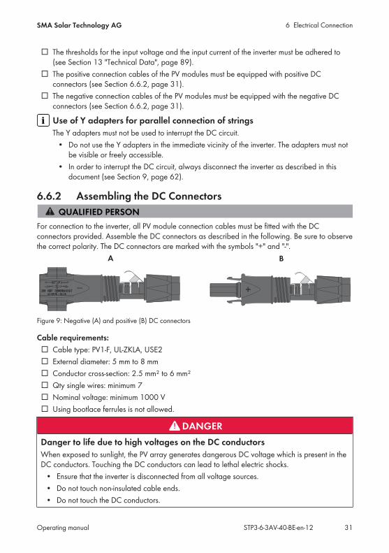
For connection to the inverter, all PV module connection cables must be fitted with the DCconnectors provided. Assemble the DC connectors as described in the following. Be sure to observethe correct polarity. The DC connectors are marked with the symbols "+" and "-".
Figure 9: Negative (A) and positive (B) DC connectors
Cable requirements: Cable type: PV1-F, UL-ZKLA, USE2 External diameter: 5 mm to 8 mm Conductor cross-section: 2.5 mm² to 6 mm² Qty single wires: minimum 7 Nominal voltage: minimum 1000 V Using bootlace ferrules is not allowed.
DANGERDanger to life due to high voltages on the DC conductorsWhen exposed to sunlight, the PV array generates dangerous DC voltage which is present in theDC conductors. Touching the DC conductors can lead to lethal electric shocks.
• Ensure that the inverter is disconnected from all voltage sources.• Do not touch non-insulated cable ends.• Do not touch the DC conductors.
6 Electrical Connection SMA Solar Technology AG
Operating manualSTP3-6-3AV-40-BE-en-1232
NOTICEDestruction of the inverter due to overvoltageIf the open-circuit voltage of the PV modules exceeds the maximum input voltage of the inverter,the inverter can be destroyed due to overvoltage.
• If the open-circuit voltage of the PV modules exceeds the maximum input voltage of theinverter, do not connect any strings to the inverter and check the design of the PV system.
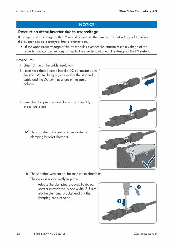
Procedure:1. Strip 12 mm of the cable insulation.2. Insert the stripped cable into the DC connector up to
the stop. When doing so, ensure that the strippedcable and the DC connector are of the samepolarity.
+
3. Press the clamping bracket down until it audiblysnaps into place.
+
The stranded wire can be seen inside theclamping bracket chamber.
+
The stranded wire cannot be seen in the chamber?The cable is not correctly in place.
• Release the clamping bracket. To do so,insert a screwdriver (blade width: 3.5 mm)into the clamping bracket and pry theclamping bracket open.
2
+
1

6 Electrical ConnectionSMA Solar Technology AG
Operating manual STP3-6-3AV-40-BE-en-12 33
• Remove the cable and go back to step 2.4. Push the swivel nut up to the thread and tighten
(torque: 2 Nm).
+
1
2
6.6.3 Connecting the PV Array
NOTICEDestruction of the inverter due to overvoltageIf the open-circuit voltage of the PV modules exceeds the maximum input voltage of the inverter,the inverter can be destroyed due to overvoltage.
• If the open-circuit voltage of the PV modules exceeds the maximum input voltage of theinverter, do not connect any strings to the inverter and check the design of the PV system.
NOTICEDestruction of the measuring device due to overvoltage
• Only use measuring devices with a DC input voltage range of 1000 V or higher.
NOTICEDamage to the DC connectors due to the use of contact cleaner of othercleaning agentsSome contact cleaners or other cleaning agents may contain substances that decompose theplastic of the DC connectors.
• Do not use contact cleaners or other cleaning agents for cleaning the DC connectors.
NOTICEDamage to the inverter due to ground fault on DC side during operationDue to the transformerless topology of the product, the occurance of ground faults on DC sideduring operation can lead to irreparable damage. Damages to the product due to a faulty ordamaged DC installation are not covered by warranty. The product is equipped with a protectivedevice that checks whether a ground fault is present during the starting sequence. The product isnot protected during operation.
• Ensure that the DC installation is carried out correctly and no ground fault occurs duringoperation.
Procedure:1. Ensure that the circuit breaker is switched off and that it cannot be reconnected.
6 Electrical Connection SMA Solar Technology AG
Operating manualSTP3-6-3AV-40-BE-en-1234
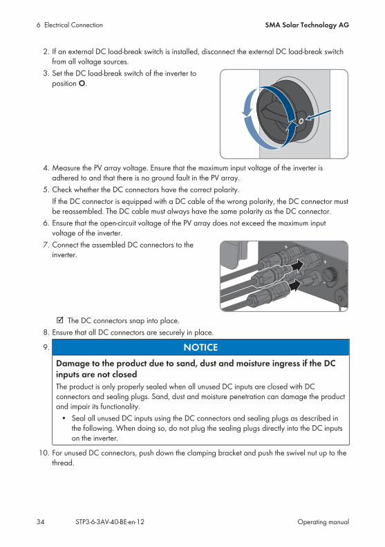
2. If an external DC load-break switch is installed, disconnect the external DC load-break switchfrom all voltage sources.
3. Set the DC load-break switch of the inverter toposition O.
4. Measure the PV array voltage. Ensure that the maximum input voltage of the inverter isadhered to and that there is no ground fault in the PV array.
5. Check whether the DC connectors have the correct polarity.If the DC connector is equipped with a DC cable of the wrong polarity, the DC connector mustbe reassembled. The DC cable must always have the same polarity as the DC connector.
6. Ensure that the open-circuit voltage of the PV array does not exceed the maximum inputvoltage of the inverter.
7. Connect the assembled DC connectors to theinverter.
+
+
_
The DC connectors snap into place.8. Ensure that all DC connectors are securely in place.
9. NOTICEDamage to the product due to sand, dust and moisture ingress if the DCinputs are not closedThe product is only properly sealed when all unused DC inputs are closed with DCconnectors and sealing plugs. Sand, dust and moisture penetration can damage the productand impair its functionality.
• Seal all unused DC inputs using the DC connectors and sealing plugs as described inthe following. When doing so, do not plug the sealing plugs directly into the DC inputson the inverter.
10. For unused DC connectors, push down the clamping bracket and push the swivel nut up to thethread.
6 Electrical ConnectionSMA Solar Technology AG
Operating manual STP3-6-3AV-40-BE-en-12 35
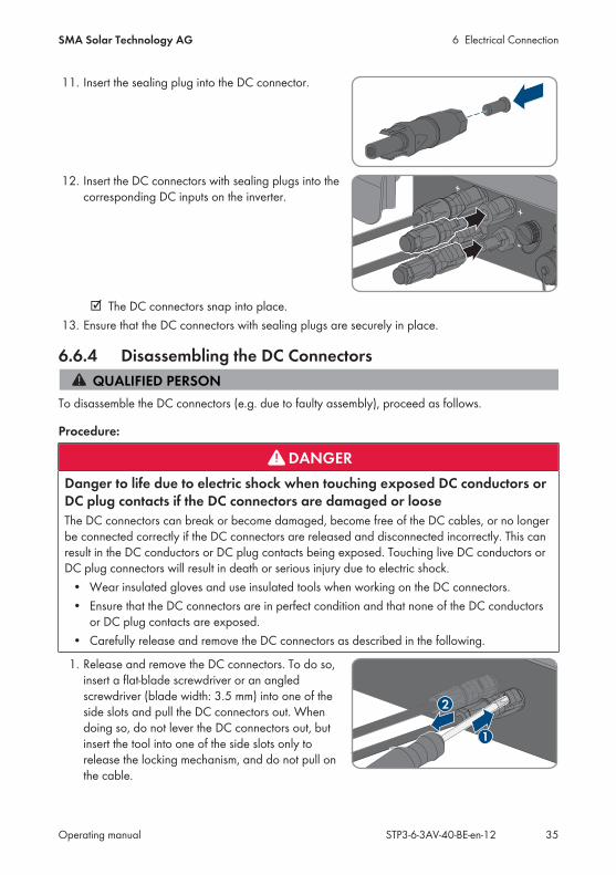
11. Insert the sealing plug into the DC connector.
+
12. Insert the DC connectors with sealing plugs into thecorresponding DC inputs on the inverter.
+
+
_
The DC connectors snap into place.13. Ensure that the DC connectors with sealing plugs are securely in place.
6.6.4 Disassembling the DC Connectors
To disassemble the DC connectors (e.g. due to faulty assembly), proceed as follows.
Procedure:
DANGERDanger to life due to electric shock when touching exposed DC conductors orDC plug contacts if the DC connectors are damaged or looseThe DC connectors can break or become damaged, become free of the DC cables, or no longerbe connected correctly if the DC connectors are released and disconnected incorrectly. This canresult in the DC conductors or DC plug contacts being exposed. Touching live DC conductors orDC plug connectors will result in death or serious injury due to electric shock.
• Wear insulated gloves and use insulated tools when working on the DC connectors.• Ensure that the DC connectors are in perfect condition and that none of the DC conductors
or DC plug contacts are exposed.• Carefully release and remove the DC connectors as described in the following.
1. Release and remove the DC connectors. To do so,insert a flat-blade screwdriver or an angledscrewdriver (blade width: 3.5 mm) into one of theside slots and pull the DC connectors out. Whendoing so, do not lever the DC connectors out, butinsert the tool into one of the side slots only torelease the locking mechanism, and do not pull onthe cable.
2
1
6 Electrical Connection SMA Solar Technology AG
Operating manualSTP3-6-3AV-40-BE-en-1236
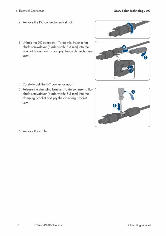
2. Remove the DC connector swivel nut.
+
3. Unlock the DC connector. To do this, insert a flat-blade screwdriver (blade width: 3.5 mm) into theside catch mechanism and pry the catch mechanismopen. +
2
3
1
4. Carefully pull the DC connector apart.5. Release the clamping bracket. To do so, insert a flat-
blade screwdriver (blade width: 3.5 mm) into theclamping bracket and pry the clamping bracketopen.
2
+
1
6. Remove the cable.
7 CommissioningSMA Solar Technology AG
Operating manual STP3-6-3AV-40-BE-en-12 37
7 Commissioning
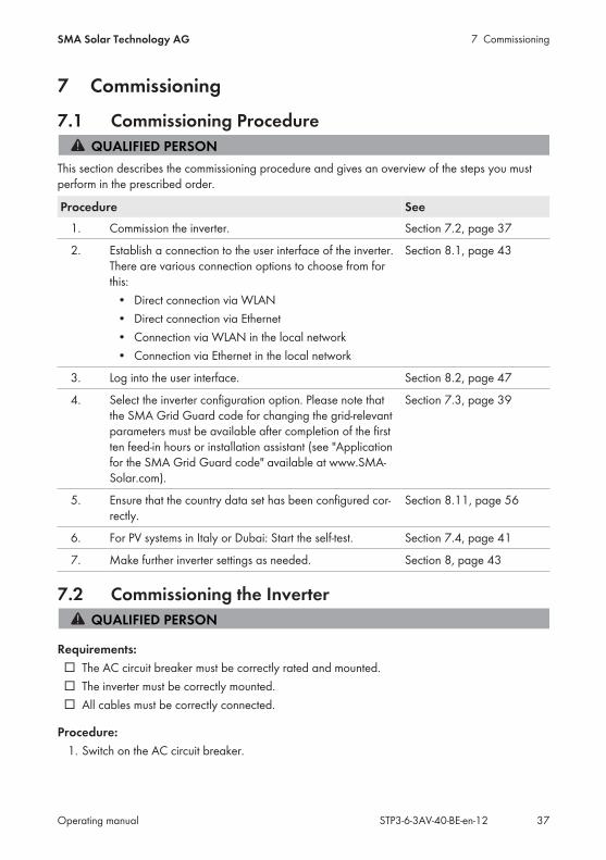
7.1 Commissioning Procedure
This section describes the commissioning procedure and gives an overview of the steps you mustperform in the prescribed order.
Procedure See1. Commission the inverter. Section 7.2, page 37
2. Establish a connection to the user interface of the inverter.There are various connection options to choose from forthis:
• Direct connection via WLAN• Direct connection via Ethernet• Connection via WLAN in the local network• Connection via Ethernet in the local network
Section 8.1, page 43
3. Log into the user interface. Section 8.2, page 47
4. Select the inverter configuration option. Please note thatthe SMA Grid Guard code for changing the grid-relevantparameters must be available after completion of the firstten feed-in hours or installation assistant (see "Applicationfor the SMA Grid Guard code" available at www.SMA-Solar.com).
Section 7.3, page 39
5. Ensure that the country data set has been configured cor-rectly.
Section 8.11, page 56
6. For PV systems in Italy or Dubai: Start the self-test. Section 7.4, page 41
7. Make further inverter settings as needed. Section 8, page 43
7.2 Commissioning the Inverter
Requirements: The AC circuit breaker must be correctly rated and mounted. The inverter must be correctly mounted. All cables must be correctly connected.
Procedure:1. Switch on the AC circuit breaker.
7 Commissioning SMA Solar Technology AG
Operating manualSTP3-6-3AV-40-BE-en-1238
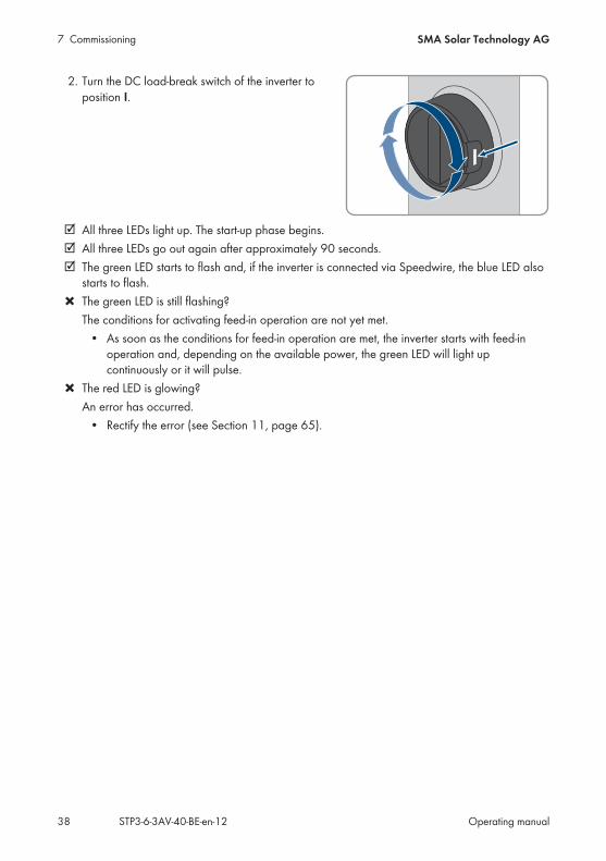
2. Turn the DC load-break switch of the inverter toposition I.
All three LEDs light up. The start-up phase begins. All three LEDs go out again after approximately 90 seconds. The green LED starts to flash and, if the inverter is connected via Speedwire, the blue LED also
starts to flash. The green LED is still flashing?
The conditions for activating feed-in operation are not yet met.• As soon as the conditions for feed-in operation are met, the inverter starts with feed-in
operation and, depending on the available power, the green LED will light upcontinuously or it will pulse.
The red LED is glowing?An error has occurred.
• Rectify the error (see Section 11, page 65).
7 CommissioningSMA Solar Technology AG
Operating manual STP3-6-3AV-40-BE-en-12 39
7.3 Selecting a configuration option
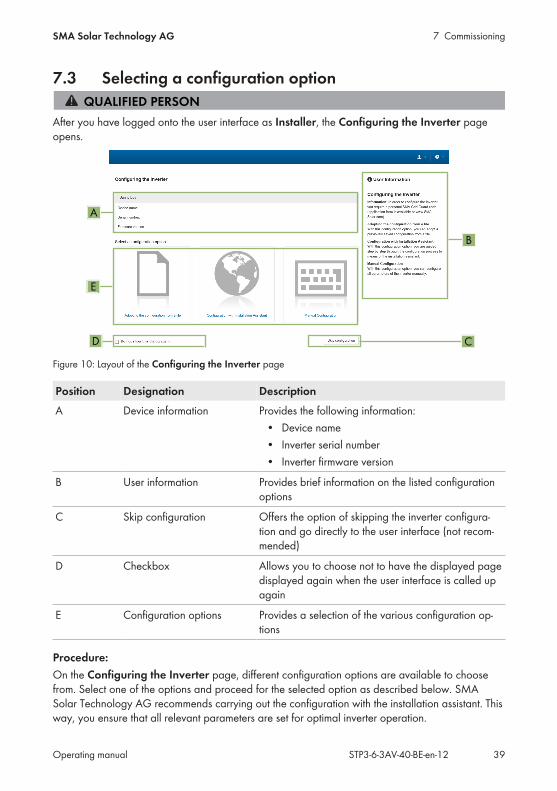
After you have logged onto the user interface as Installer, the Configuring the Inverter pageopens.
A
E
B
D C
Figure 10: Layout of the Configuring the Inverter page
Position Designation DescriptionA Device information Provides the following information:
• Device name• Inverter serial number• Inverter firmware version
B User information Provides brief information on the listed configurationoptions
C Skip configuration Offers the option of skipping the inverter configura-tion and go directly to the user interface (not recom-mended)
D Checkbox Allows you to choose not to have the displayed pagedisplayed again when the user interface is called upagain
E Configuration options Provides a selection of the various configuration op-tions
Procedure:On the Configuring the Inverter page, different configuration options are available to choosefrom. Select one of the options and proceed for the selected option as described below. SMASolar Technology AG recommends carrying out the configuration with the installation assistant. Thisway, you ensure that all relevant parameters are set for optimal inverter operation.
7 Commissioning SMA Solar Technology AG
Operating manualSTP3-6-3AV-40-BE-en-1240
• Adoption of configuration from a file• Configuration with the installation assistant (recommended)• Manual configuration
Accepting the settingsSaving the made settings is indicated by an hourglass symbol on the user interface. If the DCvoltage is sufficient, the data is transferred directly to the inverter and accepted. If the DCvoltage is too low (e. g. in the evening), the settings are saved, but they cannot be directlytransferred to or accepted by the inverter. As long as the inverter has not yet received andaccepted the settings, the hourglass symbol will continue to be displayed on the user interface.The settings will be accepted when there is sufficient DC voltage applied and the inverterrestarts. As soon as the hourglass symbol appears on the user interface, the settings have beensaved. The settings will not be lost. You can log off of the user interface and leave the system.
Adopting the Configuration from a FileYou can adopt the inverter configuration from a file. To do this, there must be an inverterconfiguration saved to a file.
Procedure:1. Select the configuration option Adopting configuration from a file.2. Select [Browse...] and select the desired file.3. Select [Import file].
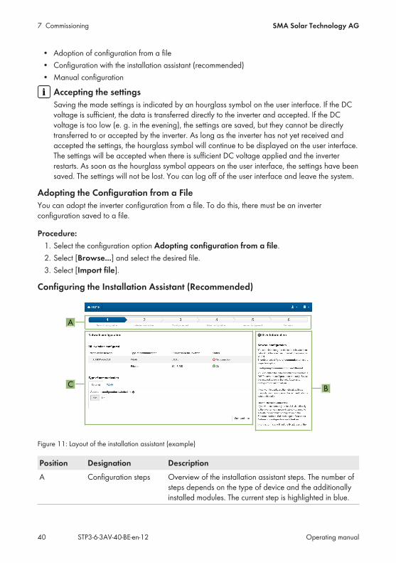
Configuring the Installation Assistant (Recommended)
A
C B
Figure 11: Layout of the installation assistant (example)
Position Designation DescriptionA Configuration steps Overview of the installation assistant steps. The number of
steps depends on the type of device and the additionallyinstalled modules. The current step is highlighted in blue.
7 CommissioningSMA Solar Technology AG
Operating manual STP3-6-3AV-40-BE-en-12 41
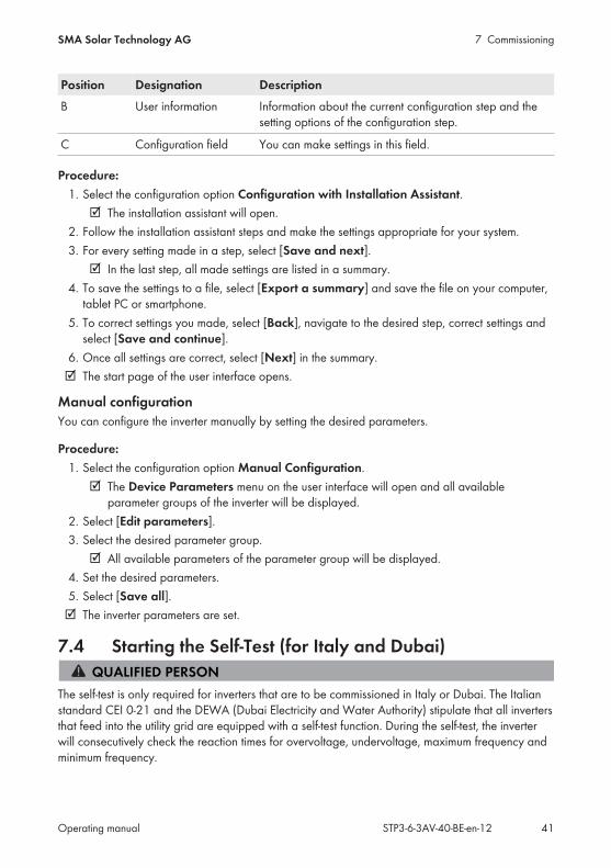
Position Designation DescriptionB User information Information about the current configuration step and the
setting options of the configuration step.
C Configuration field You can make settings in this field.
Procedure:1. Select the configuration option Configuration with Installation Assistant.
The installation assistant will open.2. Follow the installation assistant steps and make the settings appropriate for your system.3. For every setting made in a step, select [Save and next].
In the last step, all made settings are listed in a summary.4. To save the settings to a file, select [Export a summary] and save the file on your computer,
tablet PC or smartphone.5. To correct settings you made, select [Back], navigate to the desired step, correct settings and
select [Save and continue].6. Once all settings are correct, select [Next] in the summary.
The start page of the user interface opens.
Manual configurationYou can configure the inverter manually by setting the desired parameters.
Procedure:1. Select the configuration option Manual Configuration.
The Device Parameters menu on the user interface will open and all availableparameter groups of the inverter will be displayed.
2. Select [Edit parameters].3. Select the desired parameter group.
All available parameters of the parameter group will be displayed.4. Set the desired parameters.5. Select [Save all].
The inverter parameters are set.
7.4 Starting the Self-Test (for Italy and Dubai)
The self-test is only required for inverters that are to be commissioned in Italy or Dubai. The Italianstandard CEI 0-21 and the DEWA (Dubai Electricity and Water Authority) stipulate that all invertersthat feed into the utility grid are equipped with a self-test function. During the self-test, the inverterwill consecutively check the reaction times for overvoltage, undervoltage, maximum frequency andminimum frequency.
7 Commissioning SMA Solar Technology AG
Operating manualSTP3-6-3AV-40-BE-en-1242
The self-test changes the upper and lower disconnection values for each protective function on alinear basis for frequency monitoring and voltage monitoring. As soon as the measured valueexceeds the permitted disconnection threshold, the inverter disconnects from the utility grid. In thisway, the inverter determines the reaction time and checks itself.After the self-test has been completed, the inverter automatically switches back to feed-in operation,resets the original disconnection conditions and connects to the utility grid. The test takesapproximately three minutes.
Requirements: The country data set of the inverter must be set to CEI 0-21 internal or DEWA 2016
internal.
Procedure:1. Select the menu Device Configuration.2. Select [Settings].3. Select [Starting the Self-Test] in the subsequent context menu.4. Follow the instructions appearing in the dialog and save the report of the self-test where
necessary.
8 OperationSMA Solar Technology AG
Operating manual STP3-6-3AV-40-BE-en-12 43
8 Operation
8.1 Establishing a connection to the user interface
8.1.1 Establishing a Direct Connection via EthernetRequirements:
The product must be commissioned. An end device (e.g. computer) with an Ethernet interface must be available. The product must be connected directly to the end device. The respective latest version of one of the following web browsers must be installed: Chrome,
Edge, Firefox, Internet Explorer or Safari. The SMA Grid Guard code of the Installer must be available for the changing of grid-relevant
settings after completion of the first ten feed-in hours or installation assistant (see "Applicationfor SMA Grid Guard Code" at www.SMA-Solar.com).
Procedure:1. Open the web browser of your device, enter the IP address 169.254.12.3 in the address line
and press the enter key.2. Web browser signals a security vulnerability
After the IP address has been confirmed by pressing the enter key, a message mightappear indicating that the connection to the user interface of the inverter is not secure.SMA Solar Technology AG guarantees that calling up the user interface is secure.
• Continue loading the user interface. The login page of the user interface opens.
8.1.2 Establishing a direct connection via WLANRequirements:
The product must be commissioned. An end device (e.g. computer, tablet PC or smartphone) must be available. The respective latest version of one of the following web browsers must be installed: Chrome,
Edge, Firefox, Internet Explorer or Safari. JavaScript must be enabled in the web browser of the end device. The SMA Grid Guard code of the Installer must be available for the changing of grid-relevant
settings after completion of the first ten feed-in hours or installation assistant (see "Applicationfor SMA Grid Guard Code" at www.SMA-Solar.com).
8 Operation SMA Solar Technology AG
Operating manualSTP3-6-3AV-40-BE-en-1244
SSID, IP address and necessary passwords• SSID in WLAN: SMA[serial number] (e.g. SMA0123456789)• Standard WLAN password (usable until completion of the configuration by means of the
installation assistant or prior to the end of the first ten feed-in hours): SMA12345• Device-specific WLAN password (usable for initial configuration to completion of the first
ten feed-in hours): see WPA2-PSK on the type label of the inverter or on the back of themanual included in the delivery
• Standard IP address for a direct connection via WLAN outside of a local network:192.168.12.3
Importing and exporting files with end devices having an iOS operatingsystem is not possible.For technical reasons, importing and exporting files (e.g. importing an inverter configuration,saving the current inverter configuration or exporting events) is not possible with mobile enddevices having an iOS operating system.
• Use an end device that does not have an iOS operating system for importing andexporting files.
The procedure can be different depending on the end devices. If the procedure described does notapply to your end device, establish the direct connection via WLAN as described in the manual ofyour end device.
Procedure:1. If your end device has a WPS function:
• Activate the WPS function on the inverter. To do this, tap on the enclosure lid of theinverter twice.
The blue LED flashes quickly for approx. two minutes. The WPS function is activeduring this time.
• Activate the WPS on your end device. The connection with your end device will be established automatically. It can take
up to 20 seconds for this connection to be established.2. If your end device has not a WPS function:
• Search for WLAN networks with your end device.• Select the SSID of the inverter SMA[serial number] in the list with the found WLAN
networks.• Enter the inverter WLAN password. Within the first ten feed-in hours and prior to
completing the configuration by means of the installation assistant, you must use thestandard WLAN password SMA12345. After the first ten feed-in hours or aftercompleting the configuration by means of the installation assistant, you must use thedevice-specific WLAN password (WPA2-PSK) of the inverter. You find the WLANpassword (WPA2-PSK) on the type label.
3. Enter the IP address 192.168.12.3 or, if your device supports mDNS services, SMA[serialnumber].local or https://SMA[serial number] in the address bar of the web browser andpress the enter key.
8 OperationSMA Solar Technology AG
Operating manual STP3-6-3AV-40-BE-en-12 45
4. Web browser signals a security vulnerabilityAfter the IP address has been confirmed by pressing the enter key, a message mightappear indicating that the connection to the user interface of the inverter is not secure.SMA Solar Technology AG guarantees that calling up the user interface is secure.
• Continue loading the user interface. The login page of the user interface opens.
8.1.3 Establishing a Connection via Ethernet in the localnetwork
New IP address for connecting with a local networkIf the product is connected to a local network (e.g. via a router), the product will receive a newIP address. Depending on the type of configuration, the new IP address will be assignedautomatically by the DHCP server (router) or manually by you. Upon completion of theconfiguration, the product can only be reached via the following access addresses:
• Generally applicable access address: IP address manually assigned or assigned by theDHCP server (router) (identification via network scanner software or networkconfiguration of the router).
• Access address for Apple and Linux systems: SMA[serial number].local (e.g.SMA0123456789.local)
• Access address for Windows and Android systems: https://SMA[serial number] (e.g.http://SMA0123456789)
Requirements: The product must be connected to the local network via a network cable (e.g. via a router). The product must be integrated into the local network. Tip: There are various methods of
integrating the product into the local network with the aid of the installation assistant. An end device (e.g. computer, tablet PC or smartphone) must be available. The end device must be in the same local network as the product. The respective latest version of one of the following web browsers must be installed: Chrome,
Edge, Firefox, Internet Explorer or Safari. The SMA Grid Guard code of the Installer must be available for the changing of grid-relevant
settings after completion of the first ten feed-in hours or installation assistant (see "Applicationfor SMA Grid Guard Code" at www.SMA-Solar.com).
Procedure:1. Open the web browser of your end device, enter the IP address of the inverter in the address
line of the web browser and press the enter key.
8 Operation SMA Solar Technology AG
Operating manualSTP3-6-3AV-40-BE-en-1246
2. Web browser signals a security vulnerabilityAfter the IP address has been confirmed by pressing the enter key, a message mightappear indicating that the connection to the user interface of the inverter is not secure.SMA Solar Technology AG guarantees that calling up the user interface is secure.
• Continue loading the user interface. The login page of the user interface opens.
8.1.4 Establishing a Connection via WLAN in the Local NetworkNew IP address for connecting with a local networkIf the product is connected to a local network (e.g. via a router), the product will receive a newIP address. Depending on the type of configuration, the new IP address will be assignedautomatically by the DHCP server (router) or manually by you. Upon completion of theconfiguration, the product can only be reached via the following access addresses:
• Generally applicable access address: IP address manually assigned or assigned by theDHCP server (router) (identification via network scanner software or networkconfiguration of the router).
• Access address for Apple and Linux systems: SMA[serial number].local (e.g.SMA0123456789.local)
• Access address for Windows and Android systems: https://SMA[serial number] (e.g.http://SMA0123456789)
Requirements: The product must be commissioned. The product must be integrated into the local network. Tip: There are various methods of
integrating the product into the local network with the aid of the installation assistant. The end device must be in the same local network as the product. An end device (e.g. computer, tablet PC or smartphone) must be available. JavaScript must be enabled in the web browser of the end device. The respective latest version of one of the following web browsers must be installed: Chrome,
Edge, Firefox, Internet Explorer or Safari. The SMA Grid Guard code of the Installer must be available for the changing of grid-relevant
settings after completion of the first ten feed-in hours or installation assistant (see "Applicationfor SMA Grid Guard Code" at www.SMA-Solar.com).
Importing and exporting files with end devices having an iOS operatingsystem is not possible.For technical reasons, importing and exporting files (e.g. importing an inverter configuration,saving the current inverter configuration or exporting events) is not possible with mobile enddevices having an iOS operating system.
• Use an end device that does not have an iOS operating system for importing andexporting files.

8 OperationSMA Solar Technology AG
Operating manual STP3-6-3AV-40-BE-en-12 47
Procedure:1. Enter the IP address of the inverter in the address bar of the web browser.2. Web browser signals a security vulnerability
After the IP address has been confirmed by pressing the enter key, a message mightappear indicating that the connection to the user interface of the inverter is not secure.SMA Solar Technology AG guarantees that calling up the user interface is secure.
• Continue loading the user interface. The login page of the user interface opens.
8.2 Logging In and Out of the User InterfaceAfter a connection to the user interface of the inverter has been established, the login page opens.Log onto the user interface as described below.
Usage of cookiesFor the correct display of the user interface, cookies are required. The cookies are used forconvenience only. By using this user interface you agree to the placement of cookies.
Log in as Installer or User for the First TimePassword for PV systems that are registered in a communication productThe password for the user group Installer is also the system password. If you assign apassword for the user group Installer via the user interface of the inverter, the password mustmatch the PV system password. If the new password for logging onto the user interface doesnot match the system password in the communication product, the inverter cannot be reachedby the communication product.
• A uniform password is assigned for all Speedwire devices in the PV system.
Procedure:1. In the drop-down list Language, select the desired language.2. In the User group drop-down list, select the entry Installer or User.3. In the New password field, enter a new password for the selected user group.4. In the Repeat password field, enter the new password again.5. Select Login.
The Configuring the Inverter page opens.
Log in as the User or Installer1. In the drop-down list Language, select the desired language.2. In the User group drop-down list, select the entry Installer or User.3. Enter the password in the field Password.4. Select Login.
The start page of the user interface opens.
8 Operation SMA Solar Technology AG
Operating manualSTP3-6-3AV-40-BE-en-1248
Log Out as the User or Installer1. On the right-hand side of the menu bar, select the menu User Settings.2. In the subsequent context menu, select [Logout].
The login page of the user interface opens. The logout was successful.
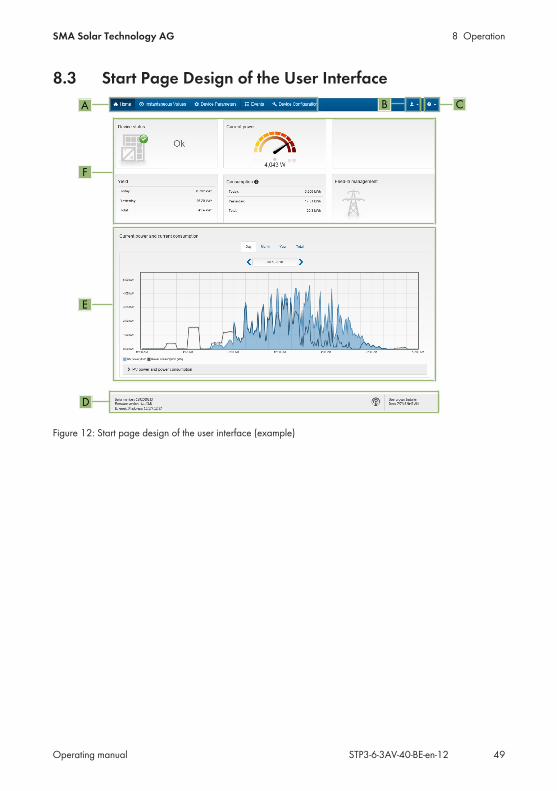
8 OperationSMA Solar Technology AG
Operating manual STP3-6-3AV-40-BE-en-12 49
8.3 Start Page Design of the User InterfaceCB
E
F
D
A
Figure 12: Start page design of the user interface (example)
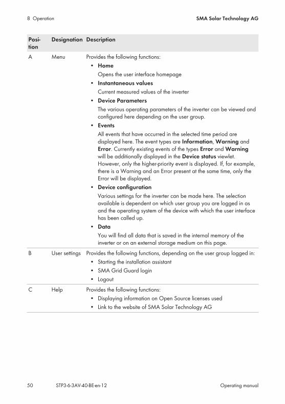
8 Operation SMA Solar Technology AG
Operating manualSTP3-6-3AV-40-BE-en-1250
Posi-tion
Designation Description
A Menu Provides the following functions:• Home
Opens the user interface homepage• Instantaneous values
Current measured values of the inverter• Device Parameters
The various operating parameters of the inverter can be viewed andconfigured here depending on the user group.
• EventsAll events that have occurred in the selected time period aredisplayed here. The event types are Information, Warning andError. Currently existing events of the types Error and Warningwill be additionally displayed in the Device status viewlet.However, only the higher-priority event is displayed. If, for example,there is a Warning and an Error present at the same time, only theError will be displayed.
• Device configurationVarious settings for the inverter can be made here. The selectionavailable is dependent on which user group you are logged in asand the operating system of the device with which the user interfacehas been called up.
• DataYou will find all data that is saved in the internal memory of theinverter or on an external storage medium on this page.
B User settings Provides the following functions, depending on the user group logged in:• Starting the installation assistant• SMA Grid Guard login• Logout
C Help Provides the following functions:• Displaying information on Open Source licenses used• Link to the website of SMA Solar Technology AG

8 OperationSMA Solar Technology AG
Operating manual STP3-6-3AV-40-BE-en-12 51
Posi-tion
Designation Description
D Status bar Displays the following information:• Inverter serial number• Inverter firmware version• IP address of the inverter within the local network and/or IP address
of the inverter during WLAN connection• With WLAN connection: Signal strength of WLAN connection• User group logged in• Date and device time of the inverter
E Currentpower andcurrent con-sumption
Temporal progression of the PV power and the power consumption of thehousehold over the selected time period. Please note, the power con-sumption will only be displayed if an energy meter is installed in the PVsystem.
F Status dis-play
The various areas display information on the current status of the PV sys-tem.
• Device statusDisplays whether the inverter is currently in a fault-free operatingstate or whether there is an Error or Warning present.
• Current powerDisplays the power currently being generated by the inverter.
• Current consumptionDisplays the current consumption of the household if an energymeter is installed in the PV system.
• YieldDisplays the energy yield of the inverter.
• ConsumptionDisplays the energy consumption of the household if an energymeter is installed in the PV system.
• Feed-in managementDisplays whether the inverter is currently limiting its active power.
8.4 Activating the Smart Inverter ScreenWith the Smart Inverter Screen, the most important inverter data is displayed directly on the userinterface login page. To activate the Smart Inverter Screen, proceed as listed in the following.
Procedure:1. Activate the user interface (see Section 8.1, page 43).2. Log in as Installer or User.

8 Operation SMA Solar Technology AG
Operating manualSTP3-6-3AV-40-BE-en-1252
3. Select the menu User Settings (see Section 8.3, page 49) on the start page of the userinterface.
4. Select [Smart Inverter Screen]. The Smart Inverter Screen has been activated.
8.5 Starting the Installation Assistant
The installation assistant leads you step-by-step through the steps necessary for the initialconfiguration of the inverter.
Layout of the installation assistant
A
C B
Figure 13: Layout of the installation assistant (example)
Position Designation DescriptionA Configuration steps Overview of the installation assistant steps. The number of
steps depends on the type of device and the additionallyinstalled modules. The current step is highlighted in blue.
B User information Information about the current configuration step and thesetting options of the configuration step.
C Configuration field You can make settings in this field.
Requirement: When configuring after completion of the first ten feed-in hours or after exiting the installation
assistant, the SMA Grid Guard code must be available in order to change the grid-relevantparameters (see "Application for SMA Grid Guard Code" at www.SMA-Solar.com).
Procedure:1. Activate the user interface (see Section 8.1, page 43).2. Log in as Installer.
8 OperationSMA Solar Technology AG
Operating manual STP3-6-3AV-40-BE-en-12 53
3. Select the menu User Settings (see Section 8.3, page 49) on the start page of the userinterface.
4. In the context menu, select [Start the installation assistant]. The installation assistant will open.
8.6 Activate WPS FunctionThe WPS function can be used for different purposes:
• Automatic connection to a network (e.g. via router)• Direct connection between the product and an end device
Depending on the intended application of the WPS function, the procedure for activation will vary.
Activating WPS function for automatic connection to a networkRequirements:
WLAN must be activated in the product. WPS must be activated on the router.
Procedure:1. Activate the user interface (see Section 8.1, page 43).2. Log in as Installer.3. Start the installation assistant (see Section 8.5, page 52).4. Select Network configuration.5. Select WPS for WLAN network button in the WLAN tab.6. Select Activate WPS.7. Select Save and next and exit the installation assistant.
The WPS function is activated and the automatic connection to the network can beestablished.
Activating the WPS function for direct connection to the end device.• Activate the WPS function on the inverter. To do this, tap on the enclosure lid of the inverter
twice. The blue LED flashes quickly for approx. two minutes. The WPS function is active during
this time.
8.7 Switching WLAN On and OffThe inverter is equipped with an activated WLAN interface as standard. If you do not want to useWLAN, you can switch the WLAN function off and switch it on again whenever needed. In doingso, you can switch the WLAN direct connection and the WLAN connection in the local network onindependently of each other.
Switching on the WLAN function only possible via Ethernet connectionIf you switch off both the WLAN function for the direct connection and for the connection inthe local network, access to the inverter user interface and therefore reactivation of the WLANinterface is only possible via an Ethernet connection.

8 Operation SMA Solar Technology AG
Operating manualSTP3-6-3AV-40-BE-en-1254
The basic procedure for changing operating parameters is explained in another section (seeSection 8.10 "Changing Operating Parameters", page 55).
Switching WLAN OffIf you would like to switch the WLAN function off completely, you must switch off both the directconnection and the connection in the local network.
Procedure:• To switch off the direct connection in the parameter group PV system communication >
WLAN, select the parameter Soft-access-point is turned on and set this to No.• To switch off the connection in the local network in the parameter group PV system
communication > WLAN, select the parameter WLAN is turned on and set this to No.
Switching WLAN OnIf you have switched the WLAN function for direct connection or for connection in the local networkoff, you can switch the WLAN function back on in accordance with the following procedure.
Requirement: If the WLAN function was previously switched off completely, the inverter must be connected
to a computer or router via Ethernet.
Procedure:• To switch on the WLAN direct connection, in the parameter group PV system
communication > WLAN, select the parameter Soft-access-point is turned on and set thisto Yes.
• To switch on the WLAN connection in the local network, in the parameter group Systemcommunication > WLAN, select the parameter WLAN is turned on and set this to Yes.
8.8 Switching the Dynamic Power Display OffAs standard, the inverter signals its power dynamically via the pulsing of the green LED. Whendoing so, the LED flashes on and off uniformly or is permanently lit at full power. The variousgradations are related here to the set active power limit of the inverter. If this display is not desired,switch this function off in accordance with the following procedure. Once this has been done, thegreen LED is lit permanently to signalize feed-in operation.The basic procedure for changing operating parameters is explained in another section (seeSection 8.10 "Changing Operating Parameters", page 55).
Procedure:• In the parameter group Device > Operation, select the parameter Dynamic power
display via green LED and set this to Off.
8 OperationSMA Solar Technology AG
Operating manual STP3-6-3AV-40-BE-en-12 55
8.9 Changing the PasswordThe password for the inverter can be changed for both user groups. Furthermore, the user groupInstaller can change the password for the user group User as well as its own password.
PV systems registered in a communication productWith PV systems that are registered in a communication product (e.g. Sunny Portal,Cluster Controller), you can also assign a new password for the user group Installer via thecommunication product. The password for the user group Installer is also the systempassword. If you assign a password for the user group Installer via the user interface of theinverter that does not correspond to the system password in the communication product, theinverter can no longer be reached by the communication product.
• Ensure that the password for the user group Installer is the same as the system passwordin the communication product.
Procedure:1. Activate the user interface (see Section 8.1, page 43).2. Log into the user interface (see Section 8.2, page 47).3. Call up the menu Device Parameters.4. Select [Edit parameters].5. In the parameter group User Rights > Access Control change the password of the desired
user group.6. Select [Save all] to save the changes.
8.10 Changing Operating ParametersThe operating parameters of the inverter are set to certain values by default. You can change theoperating parameters to optimize the performance of the inverter.This section describes the basic procedure for changing operating parameters. Always changeoperating parameters as described in this section. Some function-sensitive parameters can only beviewed by qualified persons and can only be changed by qualified persons by entering thepersonal SMA Grid Guard code.
No configuration via Sunny ExplorerSunny Explorer does not support the configuration of inverters with their own user interface.The inverter can be detected via Sunny Explorer, however it is expressly not recommended touse Sunny Explorer to configure this inverter. SMA Solar Technology AG does not acceptliability for missing or incorrect data and possibly resulting yield losses.
• Use the user interface for the configuration of the inverter.
Requirements: The SMA Grid Guard code of the Installer must be available for the changing of grid-relevant
settings after completion of the first ten feed-in hours or installation assistant (see "Applicationfor SMA Grid Guard Code" at www.SMA-Solar.com).
Changes to grid-relevant parameters must be approved by the responsible grid operator.
8 Operation SMA Solar Technology AG
Operating manualSTP3-6-3AV-40-BE-en-1256
Procedure:1. Activate the user interface (see Section 8.1, page 43).2. Log into the user interface (see Section 8.2, page 47).3. Call up the menu Device Parameters.4. Select [Edit parameters].5. Log in using the SMA Grid Guard code to change those parameters designated by a lock
(only for installers):• Select the menu User Settings (see Section 8.3, page 49).• In the subsequent context menu, select [SMA Grid Guard login].• Enter the SMA Grid Guard code and select [Login].
6. Expand the parameter group that contains the parameter which is to be configured.7. Change the desired parameters.8. Select [Save all] to save the changes.
The inverter parameters are set.
Accepting the settingsSaving the made settings is indicated by an hourglass symbol on the user interface. If the DCvoltage is sufficient, the data is transferred directly to the inverter and accepted. If the DCvoltage is too low (e. g. in the evening), the settings are saved, but they cannot be directlytransferred to or accepted by the inverter. As long as the inverter has not yet received andaccepted the settings, the hourglass symbol will continue to be displayed on the user interface.The settings will be accepted when there is sufficient DC voltage applied and the inverterrestarts. As soon as the hourglass symbol appears on the user interface, the settings have beensaved. The settings will not be lost. You can log off of the user interface and leave the system.
8.11 Configuring the Country Data Set
By default, the inverter is set to a universally valid country data set. You must adjust the countrydata set for the installation site.
The country data set must be set correctly.If you select a country data set which is not valid for your country and purpose, it can cause adisturbance in the PV system and lead to problems with the grid operator. When selecting thecountry data set, you must always observe the locally applicable standards and directives aswell as the properties of the PV system (e.g. PV system size, grid-connection point).
• If you are not sure which country data set is valid for your country or purpose, contactyour grid operator for information on which country data set is to be configured.
The basic procedure for changing operating parameters is explained in another section (seeSection 8.10 "Changing Operating Parameters", page 55).
Procedure:• In the parameter group Grid monitoring > Grid monitoring select the parameter Set
country standard and set the required country data set.
8 OperationSMA Solar Technology AG
Operating manual STP3-6-3AV-40-BE-en-12 57
8.12 Configuring Feed-In Management
Starting the installation assistant1. Activate the user interface (see Section 8.1, page 43).2. Log in as Installer.3. Start the installation assistant (see Section 8.5, page 52).4. Select [Save and continue] after each step up until the step Configure grid management
service.5. Make the settings as described in the following.
Setting the connected line conductors• In the tab Feed-in management, select the line conductor to which the inverter is connected
from the drop-down list Connected line conductors.
Making settings for systems with a higher unit (e.g. Sunny Home Manager)1. Set Feed-in management at the grid-connection point to [Off].2. Set System control and power limitation to [On].3. In the drop-down list Operating mode active power, select the entry Active power
limitation P via system control.4. In the drop-down list Operating mode for absent system control, select the entry Use
fallback setting.5. In the field Fallback active power P enter the value to which the inverter is to limit its
nominal power in case of a communication failure to the higher unit at the end of the timeouttime.
6. In the field Timeout, enter the time that the inverter is to wait before it limits its nominal powerto the set fallback value.
7. If, in the event of a 0% or 0 W specification, the inverter is not permitted to feed small amountsof active power into the utility grid, select the entry Yes in the drop-down list Griddisconnection for 0% feeding. This ensures that in the event of a 0% or 0 W specification,the inverter disconnects from the utility grid and does not feed in active power.
Making settings for systems without higher-level unit (e.g.Sunny Home Manager).
1. Set Feed-in management at the grid-connection point to [On].2. Enter the total PV array power in the field Nominal PV system power.3. In the drop-down list Operating mode of active power limitation at the grid-connection
point, select whether active power limitation is to be performed via a fixed specification inpercent or in watts.
4. In the field Set active power limit at the grid-connection point, enter the value to whichthe active power at the grid-connection point is to be limited. The value must be set to 0 forzero export.
5. Set System control and power limitation to [On].
8 Operation SMA Solar Technology AG
Operating manualSTP3-6-3AV-40-BE-en-1258
6. For system control and power limitation based on set default values, select the entry Act.power lim. as % of Pmax or Active power limitation P in W and enter the respectivedefault value.
7. If the inverter itself is to limit the active power limitation to the grid-connection point, performthe following steps:
• In the dropdown list Operating mode Active power, select Act. power lim. via PVsystem ctrl.
• In the drop-down list Operating mode for absent system control, select the entryValues maintained.
• In the drop-down list Grid disconnection for 0% feeding select the entry No.
8.13 Configuring the Modbus Function
The Modbus interface is deactivated by default and the communication ports 502 set.In order to access SMA invertes with SMA Modbus® or SunSpec® Modbus®, the Modbus interfacemust be activated. After activating the interface, the communication ports of both IP protocols canbe changed. For information on commissioning and configuration of the Modbus interface, see theTechnical Information "SMA Modbus® Interface" or in the Technical Information "SunSpec®Modbus® Interface" at www.SMA-Solar.com.For information on which Modbus registers are supported, see the Technical Descriptions "SMAModbus® Interface" or "SunSpec® Modbus® Interface" at www.SMA-Solar.com.
Data security during activated Modbus interfaceIf you activate the Modbus interface, there is a risk that unauthorized users may access andmanipulate the data or devices in your PV system.
• Take appropriate protective measures, such as:– Set up a firewall.– Close unnecessary network ports.– Only enable remote access via VPN tunnel.– Do not set up port forwarding at the communication port in use.– In order to deactivate the Modbus interface, reset the inverter to default settings or
deactivate the activated parameter again.
Procedure:• Activate the Modbus interface and adjust the communication ports if necessary (see the
technical information "SMA Modbus® Interface" or "SunSpec® Modbus® Interface" atwww.SMA-Solar.com).
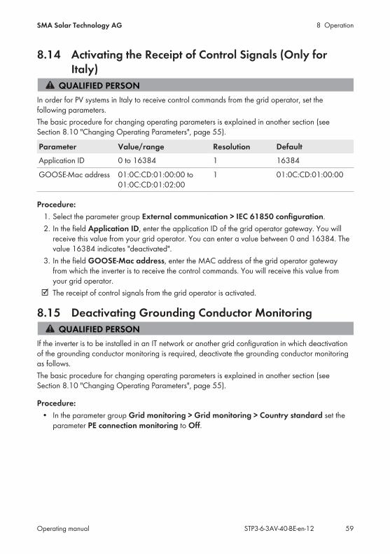
8 OperationSMA Solar Technology AG
Operating manual STP3-6-3AV-40-BE-en-12 59
8.14 Activating the Receipt of Control Signals (Only forItaly)
In order for PV systems in Italy to receive control commands from the grid operator, set thefollowing parameters.The basic procedure for changing operating parameters is explained in another section (seeSection 8.10 "Changing Operating Parameters", page 55).
Parameter Value/range Resolution DefaultApplication ID 0 to 16384 1 16384
GOOSE-Mac address 01:0C:CD:01:00:00 to01:0C:CD:01:02:00
1 01:0C:CD:01:00:00
Procedure:1. Select the parameter group External communication > IEC 61850 configuration.2. In the field Application ID, enter the application ID of the grid operator gateway. You will
receive this value from your grid operator. You can enter a value between 0 and 16384. Thevalue 16384 indicates "deactivated".
3. In the field GOOSE-Mac address, enter the MAC address of the grid operator gatewayfrom which the inverter is to receive the control commands. You will receive this value fromyour grid operator.
The receipt of control signals from the grid operator is activated.
8.15 Deactivating Grounding Conductor Monitoring
If the inverter is to be installed in an IT network or another grid configuration in which deactivationof the grounding conductor monitoring is required, deactivate the grounding conductor monitoringas follows.The basic procedure for changing operating parameters is explained in another section (seeSection 8.10 "Changing Operating Parameters", page 55).
Procedure:• In the parameter group Grid monitoring > Grid monitoring > Country standard set the
parameter PE connection monitoring to Off.
8 Operation SMA Solar Technology AG
Operating manualSTP3-6-3AV-40-BE-en-1260
8.16 Setting the Tripping Threshold of the Residual-CurrentDevice
If a residual-current device with a tripping threshold of 30 mA is specified and installed, you mustset the parameter RCD adjustment to 30 mA (for further information, see the TechnicalInformation "Leading Leakage Currents" at www.SMA-Solar.com).The basic procedure for changing operating parameters is explained in another section (seeSection 8.10 "Changing Operating Parameters", page 55).
• Select the parameter RCD adjustment and set it to 30 mA.
8.17 Saving the Configuration in a FileYou can save the current configuration of the inverter in a file. You can use this file as a databackup for this inverter and then import this file into this inverter again or another inverter from thesame type or device family to configure the inverter. When saving, only the device parameters willbe saved, not any passwords.
Procedure:1. Activate the user interface (see Section 8.1, page 43).2. Log into the user interface (see Section 8.2, page 47).3. Select the menu Device Configuration.4. Select [Settings].5. In the context menu, select [Saving the configuration in a file].6. Follow the instructions in the dialog.
8.18 Adopting a Configuration from a File
To configure the inverter, you can adopt the configuration from a file. To be able to do this, youmust first save the configuration of another inverter from the same type or device family in a file (seeSection 8.17 "Saving the Configuration in a File", page 60). When saving, only the deviceparameters will be adopted, not any passwords.
Requirements: The SMA Grid Guard code must be available (see "Application for SMA Grid Guard Code"
at www.SMA-Solar.com). Changes to grid-relevant parameters must be approved by the responsible grid operator.
Procedure:1. Activate the user interface (see Section 8.1, page 43).2. Log into the user interface as an Installer.3. Select the menu Device Configuration.4. Select [Settings].
8 OperationSMA Solar Technology AG
Operating manual STP3-6-3AV-40-BE-en-12 61
5. In the context menu, select [Adopting the configuration from a file].6. Follow the instructions in the dialog.
8.19 Updating the Firmware
If there is not an automatic update enabled for the inverter in the communication product (e.g.Sunny Home Manager) or in Sunny Portal, you can update the inverter firmware as described inthe following.
Requirements: An update file with the desired inverter firmware must be available. The update file is, for
example, available for download on the product page of the inverter at www.SMA-Solar.com.
Procedure:1. Activate the user interface (see Section 8.1, page 43).2. Log into the user interface (see Section 8.2, page 47).3. Select the menu Device Configuration.4. Select [Settings].5. In the subsequent context menu, select [Updating the firmware].6. Follow the instructions in the dialog.
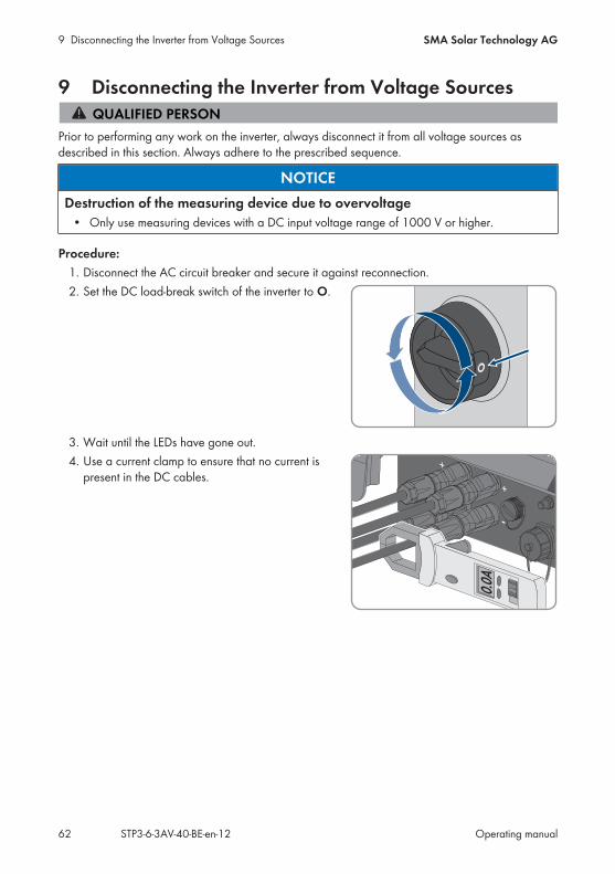
9 Disconnecting the Inverter from Voltage Sources SMA Solar Technology AG
Operating manualSTP3-6-3AV-40-BE-en-1262
9 Disconnecting the Inverter from Voltage Sources
Prior to performing any work on the inverter, always disconnect it from all voltage sources asdescribed in this section. Always adhere to the prescribed sequence.
NOTICEDestruction of the measuring device due to overvoltage
• Only use measuring devices with a DC input voltage range of 1000 V or higher.
Procedure:1. Disconnect the AC circuit breaker and secure it against reconnection.2. Set the DC load-break switch of the inverter to O.
3. Wait until the LEDs have gone out.4. Use a current clamp to ensure that no current is
present in the DC cables.+
+
_
0.0A
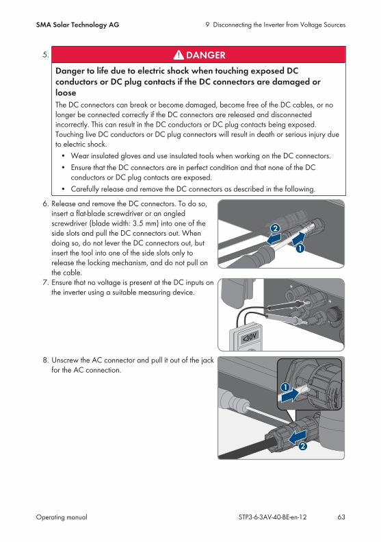
9 Disconnecting the Inverter from Voltage SourcesSMA Solar Technology AG
Operating manual STP3-6-3AV-40-BE-en-12 63
5. DANGERDanger to life due to electric shock when touching exposed DCconductors or DC plug contacts if the DC connectors are damaged orlooseThe DC connectors can break or become damaged, become free of the DC cables, or nolonger be connected correctly if the DC connectors are released and disconnectedincorrectly. This can result in the DC conductors or DC plug contacts being exposed.Touching live DC conductors or DC plug connectors will result in death or serious injury dueto electric shock.
• Wear insulated gloves and use insulated tools when working on the DC connectors.• Ensure that the DC connectors are in perfect condition and that none of the DC
conductors or DC plug contacts are exposed.• Carefully release and remove the DC connectors as described in the following.
6. Release and remove the DC connectors. To do so,insert a flat-blade screwdriver or an angledscrewdriver (blade width: 3.5 mm) into one of theside slots and pull the DC connectors out. Whendoing so, do not lever the DC connectors out, butinsert the tool into one of the side slots only torelease the locking mechanism, and do not pull onthe cable.
2
1
7. Ensure that no voltage is present at the DC inputs onthe inverter using a suitable measuring device.
+
+
_
_
<30V<30V
8. Unscrew the AC connector and pull it out of the jackfor the AC connection.
2
1

10 Cleaning the Inverter SMA Solar Technology AG
Operating manualSTP3-6-3AV-40-BE-en-1264
10 Cleaning the InverterNOTICE
Damage due to cleaning agentsThe use of cleaning agents may cause damage to the product and its components.
• Clean the product and all its components only with a cloth moistened with clear water.
• Ensure that the inverter is free of dust, foliage and other dirt.

11 TroubleshootingSMA Solar Technology AG
Operating manual STP3-6-3AV-40-BE-en-12 65
11 Troubleshooting
11.1 Forgotten PasswordIf you have forgotten the password for the inverter, you can unlock the inverter with a PersonalUnlocking Key (PUK). For each inverter, there is one PUK for each user group (User and Installer).Tip: With PV systems in Sunny Portal, you can also assign a new password via Sunny Portal for theuser group Installer. The password for the user group Installer is the same as the systempassword in Sunny Portal.
Procedure:1. Request PUK (application form available at www.SMA-Solar.com).2. Activate the user interface (see Section 8.1, page 43).3. Enter the PUK instead of the password into the field Password.4. Select Login.5. Call up the menu Device Parameters.6. Select [Edit parameters].7. In the parameter group User Rights > Access Control change the password of the desired
user group.8. Select [Save all] to save the changes.
PV Systems in Sunny PortalThe password for the user group Installer is also the system password for the PV system inSunny Portal. Changing the password of the user group Installer can lead to the inverter nolonger being able to be reached by Sunny Portal.
• Assign the changed password of the user group Installer as the new system password inSunny Portal (see the Sunny Portal user manual at www.SMA-Solar.com).
11 Troubleshooting SMA Solar Technology AG
Operating manualSTP3-6-3AV-40-BE-en-1266
11.2 Event MessagesEvent number Message, cause and corrective measures101
Grid faultThe grid voltage or grid impedance at the connection point of the inverter istoo high. The inverter has disconnected from the utility grid.Corrective measures:
• Check whether the grid voltage at the connection point of the inverter ispermanently in the permissible range.If the grid voltage is outside the permissible range due to local gridconditions, contact the grid operator. The grid operator must agree withan adjustment of the voltage at the feed-in point or with a change of themonitored operating limits.If the grid voltage is permanently within the permissible range and thismessage is still displayed, contact the Service (see Section 14,page 96).
301
Grid faultThe ten-minute average value of the grid voltage is no longer within the per-missible range. The grid voltage or grid impedance at the connection point istoo high. The inverter disconnects from the utility grid to maintain power qual-ity.Corrective measures:
• During the feed-in operation, check whether the grid voltage at theconnection point of the inverter is permanently in the permissible range.If the grid voltage is outside the permissible range due to local gridconditions, contact the grid operator. The grid operator must agree withan adjustment of the voltage at the feed-in point or with a change of themonitored operating limits.If the grid voltage is permanently within the permissible range and thismessage is still displayed, contact the Service (see Section 14,page 96).
401
Grid faultThe inverter has disconnected from the utility grid. A stand-alone grid or a verylarge change in the power frequency was detected.Corrective measures:
• Check the grid connection for significant short-term frequency fluctuations.
11 TroubleshootingSMA Solar Technology AG
Operating manual STP3-6-3AV-40-BE-en-12 67
Event number Message, cause and corrective measures501
Grid faultThe power frequency is not within the permissible range. The inverter has dis-connected from the utility grid.Corrective measures:
• If possible, check the power frequency and observe how oftenfluctuations occur.If fluctuations occur frequently and this message is displayed often,contact the grid operator and request approval to change the operatingparameters of the inverter.If the grid operator gives his approval, discuss any changes to theoperating parameters with Service (see Section 14, page 96).
601
Grid faultThe inverter has detected an excessively high proportion of direct current inthe grid current.Corrective measures:
• Check the grid connection for direct current.• If this message is displayed frequently, contact the grid operator and
check whether the monitoring threshold on the inverter can be raised.
801
Waiting for grid voltage > Grid failure > Check AC circuit breakerThe AC cable is not correctly connected or the country data set is not correctlyconfigured.Corrective measures:
• Make sure that the circuit breaker is switched on.• Ensure that the AC cable is not damaged and that it is connected
correctly.• Ensure that the country data set has been configured correctly.• Check whether the grid voltage at the connection point of the inverter is
permanently in the permissible range.If the grid voltage is outside the permissible range due to local gridconditions, contact the grid operator. The grid operator must agree withan adjustment of the voltage at the feed-in point or with a change of themonitored operating limits.If the grid voltage is permanently within the permissible range and thismessage is still displayed, contact the Service (see Section 14,page 96).
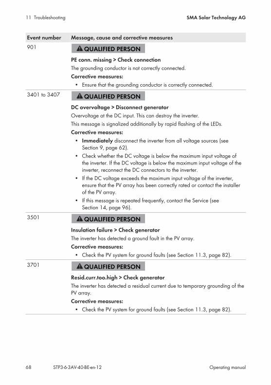
11 Troubleshooting SMA Solar Technology AG
Operating manualSTP3-6-3AV-40-BE-en-1268
Event number Message, cause and corrective measures901
PE conn. missing > Check connectionThe grounding conductor is not correctly connected.Corrective measures:
• Ensure that the grounding conductor is correctly connected.
3401 to 3407
DC overvoltage > Disconnect generatorOvervoltage at the DC input. This can destroy the inverter.This message is signalized additionally by rapid flashing of the LEDs.Corrective measures:
• Immediately disconnect the inverter from all voltage sources (seeSection 9, page 62).
• Check whether the DC voltage is below the maximum input voltage ofthe inverter. If the DC voltage is below the maximum input voltage of theinverter, reconnect the DC connectors to the inverter.
• If the DC voltage exceeds the maximum input voltage of the inverter,ensure that the PV array has been correctly rated or contact the installerof the PV array.
• If this message is repeated frequently, contact the Service (seeSection 14, page 96).
3501
Insulation failure > Check generatorThe inverter has detected a ground fault in the PV array.Corrective measures:
• Check the PV system for ground faults (see Section 11.3, page 82).
3701
Resid.curr.too.high > Check generatorThe inverter has detected a residual current due to temporary grounding of thePV array.Corrective measures:
• Check the PV system for ground faults (see Section 11.3, page 82).
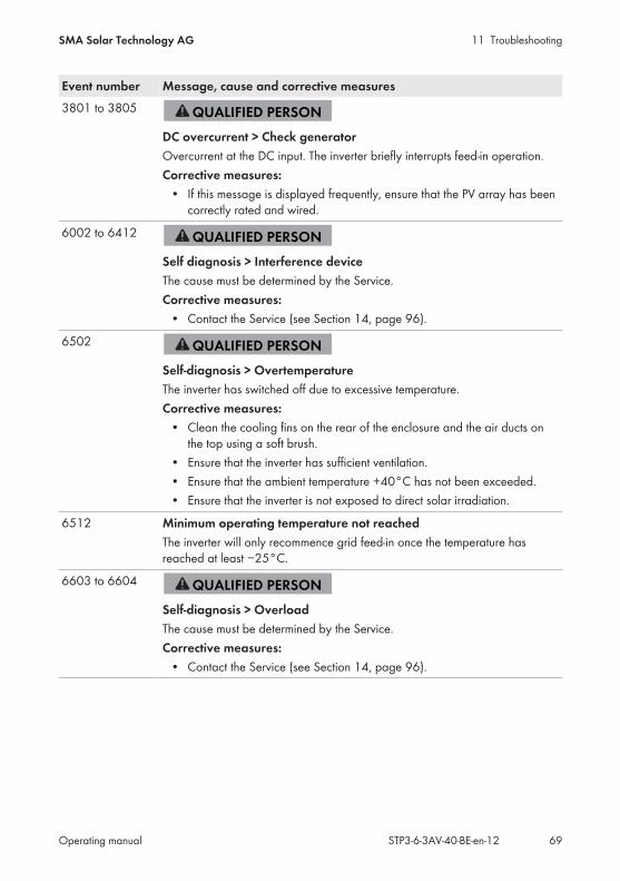
11 TroubleshootingSMA Solar Technology AG
Operating manual STP3-6-3AV-40-BE-en-12 69
Event number Message, cause and corrective measures3801 to 3805
DC overcurrent > Check generatorOvercurrent at the DC input. The inverter briefly interrupts feed-in operation.Corrective measures:
• If this message is displayed frequently, ensure that the PV array has beencorrectly rated and wired.
6002 to 6412
Self diagnosis > Interference deviceThe cause must be determined by the Service.Corrective measures:
• Contact the Service (see Section 14, page 96).
6502
Self-diagnosis > OvertemperatureThe inverter has switched off due to excessive temperature.Corrective measures:
• Clean the cooling fins on the rear of the enclosure and the air ducts onthe top using a soft brush.
• Ensure that the inverter has sufficient ventilation.• Ensure that the ambient temperature +40°C has not been exceeded.• Ensure that the inverter is not exposed to direct solar irradiation.
6512 Minimum operating temperature not reachedThe inverter will only recommence grid feed-in once the temperature hasreached at least −25°C.
6603 to 6604
Self-diagnosis > OverloadThe cause must be determined by the Service.Corrective measures:
• Contact the Service (see Section 14, page 96).

11 Troubleshooting SMA Solar Technology AG
Operating manualSTP3-6-3AV-40-BE-en-1270
Event number Message, cause and corrective measures6701 to 6702
Communication disturbedError in the communication processor, the inverter continues feeding in, how-ever. The cause must be determined by the Service.Corrective measures:
• If this message is displayed frequently, contact the Service (seeSection 14, page 96).
7102
Parameter file not found or defectiveThe parameter file was not found or is defective. The update failed. The in-verter continues to feed in.Corrective measures:
• Copy the parameter file to the correct folder again.
7105
Param. setting failedParameters could not be set using the memory card. The inverter continues tofeed in.Corrective measures:
• Ensure that the parameters are set correctly.• Ensure that the SMA Grid Guard code is available.
7106 Update file defect.The update file is defective. The update failed. The inverter continues to feedin.
7110 No update file foundNo new update file was found on the SD memory card. The update failed.The inverter continues to feed in.
7112 Update file successfully copied
7113 The memory card is full or write-protected
7201 to 7202 Data storage not possible
7303
Update main CPU failedThe cause must be determined by the Service.Corrective measures:
• Contact the Service (see Section 14, page 96).
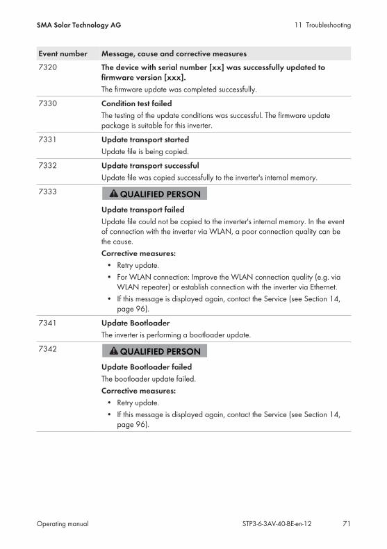
11 TroubleshootingSMA Solar Technology AG
Operating manual STP3-6-3AV-40-BE-en-12 71
Event number Message, cause and corrective measures7320 The device with serial number [xx] was successfully updated to
firmware version [xxx].The firmware update was completed successfully.
7330 Condition test failedThe testing of the update conditions was successful. The firmware updatepackage is suitable for this inverter.
7331 Update transport startedUpdate file is being copied.
7332 Update transport successfulUpdate file was copied successfully to the inverter's internal memory.
7333
Update transport failedUpdate file could not be copied to the inverter's internal memory. In the eventof connection with the inverter via WLAN, a poor connection quality can bethe cause.Corrective measures:
• Retry update.• For WLAN connection: Improve the WLAN connection quality (e.g. via
WLAN repeater) or establish connection with the inverter via Ethernet.• If this message is displayed again, contact the Service (see Section 14,
page 96).
7341 Update BootloaderThe inverter is performing a bootloader update.
7342
Update Bootloader failedThe bootloader update failed.Corrective measures:
• Retry update.• If this message is displayed again, contact the Service (see Section 14,
page 96).

11 Troubleshooting SMA Solar Technology AG
Operating manualSTP3-6-3AV-40-BE-en-1272
Event number Message, cause and corrective measures7347
Incompatible fileThe configuration file is not suitable for this inverter.Corrective measures:
• Ensure that the selected configuration file is suitable for this inverter.• Retry import.
7348
Incorrect file formatThe configuration file is not of the required format or is damaged.Corrective measures:
• Ensure that the selected configuration file is of the required format and isnot damaged.
• Retry import.
7349 Incorrect login rights for configuration fileThe user group logged in does not have the user rights necessary to be ableto import a configuration.Corrective measures:
• Log in as Installer.• Import configuration file again.
7350 Transfer of a configuration file has startedThe configuration file is being transferred.
7351 Update WLANThe inverter is updating the WLAN module.
7352 Update of WLAN not successfulThe update of the WLAN module failed.Corrective measures:
• Retry update.• If this message is displayed again, contact the Service (see Section 14,
page 96).
7353 Update time zone databaseThe inverter is updating the time zone database.
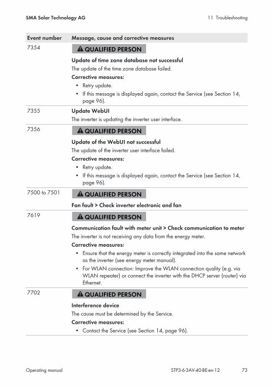
11 TroubleshootingSMA Solar Technology AG
Operating manual STP3-6-3AV-40-BE-en-12 73
Event number Message, cause and corrective measures7354
Update of time zone database not successfulThe update of the time zone database failed.Corrective measures:
• Retry update.• If this message is displayed again, contact the Service (see Section 14,
page 96).
7355 Update WebUIThe inverter is updating the inverter user interface.
7356
Update of the WebUI not successfulThe update of the inverter user interface failed.Corrective measures:
• Retry update.• If this message is displayed again, contact the Service (see Section 14,
page 96).
7500 to 7501
Fan fault > Check inverter electronic and fan
7619
Communication fault with meter unit > Check communication to meterThe inverter is not receiving any data from the energy meter.Corrective measures:
• Ensure that the energy meter is correctly integrated into the same networkas the inverter (see energy meter manual).
• For WLAN connection: Improve the WLAN connection quality (e.g. viaWLAN repeater) or connect the inverter with the DHCP server (router) viaEthernet.
7702
Interference deviceThe cause must be determined by the Service.Corrective measures:
• Contact the Service (see Section 14, page 96).
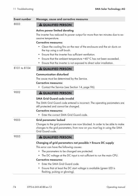
11 Troubleshooting SMA Solar Technology AG
Operating manualSTP3-6-3AV-40-BE-en-1274
Event number Message, cause and corrective measures8003
Active power limited deratingThe inverter has reduced its power output for more than ten minutes due to ex-cessive temperature.Corrective measures:
• Clean the cooling fins on the rear of the enclosure and the air ducts onthe top using a soft brush.
• Ensure that the inverter has sufficient ventilation.• Ensure that the ambient temperature +40°C has not been exceeded.• Ensure that the inverter is not exposed to direct solar irradiation.
8101 to 8104
Communication disturbedThe cause must be determined by the Service.Corrective measures:
• Contact the Service (see Section 14, page 96).
9002
SMA Grid Guard code invalidThe SMA Grid Guard code entered is incorrect. The operating parameters arestill protected and cannot be changed.Corrective measures:
• Enter the correct SMA Grid Guard code.
9003 Grid parameter lockedChanges to the grid parameters are now blocked. In order to be able to makechanges to the grid parameters, from now on you must log in using the SMAGrid Guard code.
9005
Changing of grid parameters not possible > Ensure DC supplyThis error can have the following causes:
• The parameters to be changed are protected.• The DC voltage at the DC input is not sufficient to run the main CPU.
Corrective measures:• Enter the SMA Grid Guard code.• Ensure that at least the DC start voltage is available (green LED is
flashing, pulsing or glowing).
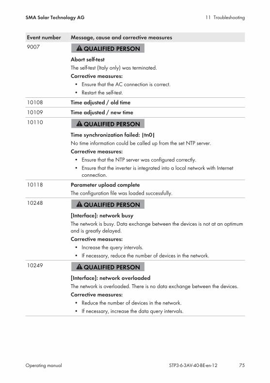
11 TroubleshootingSMA Solar Technology AG
Operating manual STP3-6-3AV-40-BE-en-12 75
Event number Message, cause and corrective measures9007
Abort self-testThe self-test (Italy only) was terminated.Corrective measures:
• Ensure that the AC connection is correct.• Restart the self-test.
10108 Time adjusted / old time
10109 Time adjusted / new time
10110
Time synchronization failed: |tn0|No time information could be called up from the set NTP server.Corrective measures:
• Ensure that the NTP server was configured correctly.• Ensure that the inverter is integrated into a local network with Internet
connection.
10118 Parameter upload completeThe configuration file was loaded successfully.
10248
[Interface]: network busyThe network is busy. Data exchange between the devices is not at an optimumand is greatly delayed.Corrective measures:
• Increase the query intervals.• If necessary, reduce the number of devices in the network.
10249
[Interface]: network overloadedThe network is overloaded. There is no data exchange between the devices.Corrective measures:
• Reduce the number of devices in the network.• If necessary, increase the data query intervals.
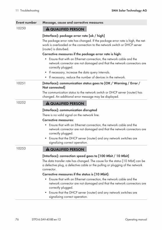
11 Troubleshooting SMA Solar Technology AG
Operating manualSTP3-6-3AV-40-BE-en-1276
Event number Message, cause and corrective measures10250
[Interface]: package error rate [ok / high]The package error rate has changed. If the package error rate is high, the net-work is overloaded or the connection to the network switch or DHCP server(router) is disturbed.Corrective measures if the package error rate is high:
• Ensure that with an Ethernet connection, the network cable and thenetwork connector are not damaged and that the network connectors arecorrectly plugged.
• If necessary, increase the data query intervals.• If necessary, reduce the number of devices in the network.
10251 [Interface]: communication status goes to [OK / Warning / Error /Not connected]The communication status to the network switch or DHCP server (router) haschanged. An additional error message may be displayed.
10252
[Interface]: communication disruptedThere is no valid signal on the network line.Corrective measures:
• Ensure that with an Ethernet connection, the network cable and thenetwork connector are not damaged and that the network connectors arecorrectly plugged.
• Ensure that the DHCP server (router) and any network switches aresignalizing correct operation.
10253
[Interface]: connection speed goes to [100 Mbit / 10 Mbit]The data transfer rate has changed. The cause for the status [10 Mbit] can bea defective plug, a defective cable or the pulling or plugging of the networkconnector.Corrective measures if the status is [10 Mbit]:
• Ensure that with an Ethernet connection, the network cable and thenetwork connector are not damaged and that the network connectors arecorrectly plugged.
• Ensure that the DHCP server (router) and any network switches aresignalizing correct operation.
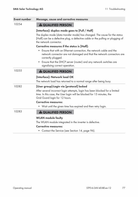
11 TroubleshootingSMA Solar Technology AG
Operating manual STP3-6-3AV-40-BE-en-12 77
Event number Message, cause and corrective measures10254
[Interface]: duplex mode goes to [Full / Half]The duplex mode (data transfer mode) has changed. The cause for the status[Half] can be a defective plug, a defective cable or the pulling or plugging ofthe network connector.Corrective measures if the status is [Half]:
• Ensure that with an Ethernet connection, the network cable and thenetwork connector are not damaged and that the network connectors arecorrectly plugged.
• Ensure that the DHCP server (router) and any network switches aresignalizing correct operation.
10255
[Interface]: Network load OKThe network load has returned to a normal range after being busy.
10282 [User group]-Login via [protocol] lockedAfter several incorrect login attempts, login has been blocked for a limitedtime. In this case, the User login will be blocked for 15 minutes, theGrid Guard login for 12 hours.Corrective measures:
• Wait until the given time has expired and then retry login.
10283
WLAN module faultyThe WLAN module integrated in the inverter is defective.Corrective measures:
• Contact the Service (see Section 14, page 96).
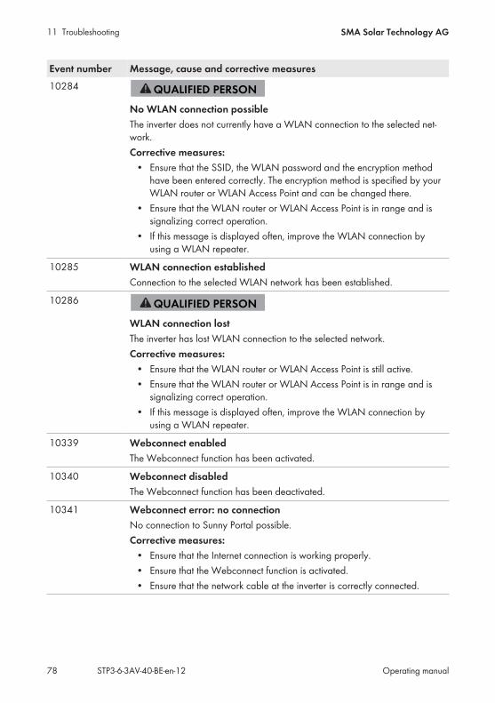
11 Troubleshooting SMA Solar Technology AG
Operating manualSTP3-6-3AV-40-BE-en-1278
Event number Message, cause and corrective measures10284
No WLAN connection possibleThe inverter does not currently have a WLAN connection to the selected net-work.Corrective measures:
• Ensure that the SSID, the WLAN password and the encryption methodhave been entered correctly. The encryption method is specified by yourWLAN router or WLAN Access Point and can be changed there.
• Ensure that the WLAN router or WLAN Access Point is in range and issignalizing correct operation.
• If this message is displayed often, improve the WLAN connection byusing a WLAN repeater.
10285 WLAN connection establishedConnection to the selected WLAN network has been established.
10286
WLAN connection lostThe inverter has lost WLAN connection to the selected network.Corrective measures:
• Ensure that the WLAN router or WLAN Access Point is still active.• Ensure that the WLAN router or WLAN Access Point is in range and is
signalizing correct operation.• If this message is displayed often, improve the WLAN connection by
using a WLAN repeater.
10339 Webconnect enabledThe Webconnect function has been activated.
10340 Webconnect disabledThe Webconnect function has been deactivated.
10341 Webconnect error: no connectionNo connection to Sunny Portal possible.Corrective measures:
• Ensure that the Internet connection is working properly.• Ensure that the Webconnect function is activated.• Ensure that the network cable at the inverter is correctly connected.

11 TroubleshootingSMA Solar Technology AG
Operating manual STP3-6-3AV-40-BE-en-12 79
Event number Message, cause and corrective measures10343 Webconnect error: Default gateway not configured
The standard gateway was not configured.Corrective measures:
• Configure the standard gateway.
10344 Webconnect error: DNS server not configuredDNS server was not configured.Corrective measures:
• Configure DNS server.
10345 Webconnect error: No reply to DNS request |xx|DNS server not availableCorrective measures:
• Ensure that the address of the DNS server has been entered correctly.• Ensure that the network cable at the inverter is correctly connected.
10346 Webconnect error: Unknown SIP proxy |xx|SIP-Proxy not available.Corrective measures:
• Ensure that the network cable at the inverter is correctly connected.
10347 Webconnect error: Unknown STUN server [xx]STUN server not available.Corrective measures:
• Ensure that the network cable at the inverter is correctly connected.
10348 Webconnect error: No reply to request to STUN serverSTUN server not available.Corrective measures:
• Ensure that the network cable at the inverter is correctly connected.• Check the configuration of the router.
10349 Webconnect error: No reply to SIP option packsSIP server not available.Corrective measures:
• Check the configuration of the router.
10350 Webconnect error: Registration rejected by SIP registrarThe inverter is not registered in Sunny Portal.Corrective measures:
• Contact the Service (see Section 14, page 96).
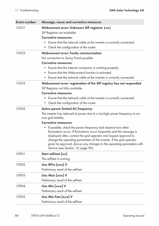
11 Troubleshooting SMA Solar Technology AG
Operating manualSTP3-6-3AV-40-BE-en-1280
Event number Message, cause and corrective measures10351 Webconnect error: Unknown SIP registrar |xx|
SIP Registrar not available.Corrective measures:
• Ensure that the network cable at the inverter is correctly connected.• Check the configuration of the router.
10352 Webconnect error: Faulty communicationNo connection to Sunny Portal possible.Corrective measures:
• Ensure that the Internet connection is working properly.• Ensure that the Webconnect function is activated.• Ensure that the network cable at the inverter is correctly connected.
10353 Webconnect error: registration of the SIP registry has not respondedSIP Registrar not fully available.Corrective measures:
• Ensure that the network cable at the inverter is correctly connected.• Check the configuration of the router.
10502 Active power limited AC frequencyThe inverter has reduced its power due to a too-high power frequency to en-sure grid stability.Corrective measures:
• If possible, check the power frequency and observe how oftenfluctuations occur. If fluctuations occur frequently and this message isdisplayed often, contact the grid operator and request approval tochange the operating parameters of the inverter. If the grid operatorgives his approval, discuss any changes to the operating parameters withService (see Section 14, page 96).
10901 Start self-test [xx]The self-test is running.
10902 Uac RPro [xxx] VPreliminary result of the self-test
10903 Uac Max [xxx] VPreliminary result of the self-test
10904 Uac Min [xxx] VPreliminary result of the self-test
10905 Uac Min Fast [xxx] VPreliminary result of the self-test
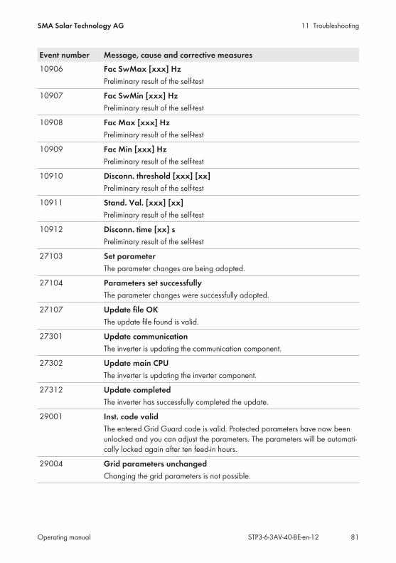
11 TroubleshootingSMA Solar Technology AG
Operating manual STP3-6-3AV-40-BE-en-12 81
Event number Message, cause and corrective measures10906 Fac SwMax [xxx] Hz
Preliminary result of the self-test
10907 Fac SwMin [xxx] HzPreliminary result of the self-test
10908 Fac Max [xxx] HzPreliminary result of the self-test
10909 Fac Min [xxx] HzPreliminary result of the self-test
10910 Disconn. threshold [xxx] [xx]Preliminary result of the self-test
10911 Stand. Val. [xxx] [xx]Preliminary result of the self-test
10912 Disconn. time [xx] sPreliminary result of the self-test
27103 Set parameterThe parameter changes are being adopted.
27104 Parameters set successfullyThe parameter changes were successfully adopted.
27107 Update file OKThe update file found is valid.
27301 Update communicationThe inverter is updating the communication component.
27302 Update main CPUThe inverter is updating the inverter component.
27312 Update completedThe inverter has successfully completed the update.
29001 Inst. code validThe entered Grid Guard code is valid. Protected parameters have now beenunlocked and you can adjust the parameters. The parameters will be automati-cally locked again after ten feed-in hours.
29004 Grid parameters unchangedChanging the grid parameters is not possible.
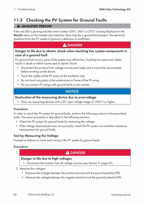
11 Troubleshooting SMA Solar Technology AG
Operating manualSTP3-6-3AV-40-BE-en-1282
11.3 Checking the PV System for Ground Faults
If the red LED is glowing and the event number 3501, 3601 or 3701 is being displayed in theResults menu on the inverter user interface, there may be a ground fault present. The electricalinsulation from the PV system to ground is defective or insufficient.
DANGERDanger to life due to electric shock when touching live system components incase of a ground faultIf a ground fault occurs, parts of the system may still be live. Touching live parts and cablesresults in death or lethal injuries due to electric shock.
• Disconnect the product from voltage sources and make sure it cannot be reconnectedbefore working on the device.
• Touch the cables of the PV array on the insulation only.• Do not touch any parts of the substructure or frame of the PV array.• Do not connect PV strings with ground faults to the inverter.
NOTICEDestruction of the measuring device due to overvoltage
• Only use measuring devices with a DC input voltage range of 1000 V or higher.
Procedure:In order to check the PV system for ground faults, perform the following actions in the prescribedorder. The exact procedure is described in the following sections.
• Check the PV system for ground faults by measuring the voltage.• If the voltage measurement was not successful, check the PV system via insulation resistance
measurement for ground faults.
Test by Measuring the VoltageProceed as follows to check each string in the PV system for ground faults.
Procedure:
1. DANGERDanger to life due to high voltages
• Disconnect the inverter from all voltage sources (see Section 9, page 62).
2. Measure the voltages:• Measure the voltage between the positive terminal and the ground potential (PE).• Measure the voltage between the negative terminal and the ground potential (PE).

11 TroubleshootingSMA Solar Technology AG
Operating manual STP3-6-3AV-40-BE-en-12 83
• Measure the voltage between the positive and negative terminals. If the following results are present at the same time, there is a ground fault in the PVsystem:
All measured voltages are stable. The sum of the two voltages to ground potential is approximately equal to the
voltage between the positive and negative terminals.3. If a ground fault is present, determine the location of the ground fault via the ratio of the two
measured voltages and eliminate the ground fault.4. If a definite ground fault cannot be measured and the message is still displayed, measure the
insulation resistance.5. Reconnect the strings without ground faults to the inverter and recommission the inverter (see
inverter installation inverter).Location of the ground fault
The example shows a ground fault between the second and third PV module.
+
100 V 100 V 100 V 100 V 100 V
V = 200 V1 V = 300 V2
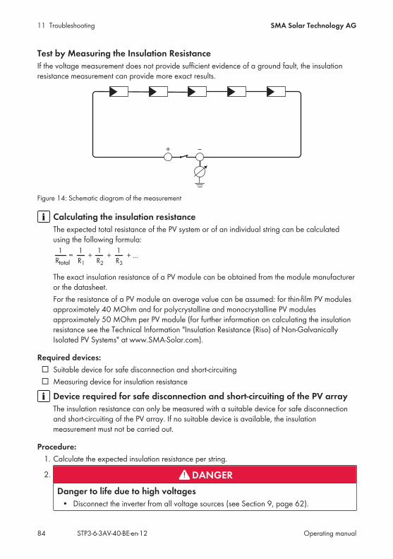
11 Troubleshooting SMA Solar Technology AG
Operating manualSTP3-6-3AV-40-BE-en-1284
Test by Measuring the Insulation ResistanceIf the voltage measurement does not provide sufficient evidence of a ground fault, the insulationresistance measurement can provide more exact results.
+
Figure 14: Schematic diagram of the measurement
Calculating the insulation resistanceThe expected total resistance of the PV system or of an individual string can be calculatedusing the following formula:
total
The exact insulation resistance of a PV module can be obtained from the module manufactureror the datasheet.For the resistance of a PV module an average value can be assumed: for thin-film PV modulesapproximately 40 MOhm and for polycrystalline and monocrystalline PV modulesapproximately 50 MOhm per PV module (for further information on calculating the insulationresistance see the Technical Information "Insulation Resistance (Riso) of Non-GalvanicallyIsolated PV Systems" at www.SMA-Solar.com).
Required devices: Suitable device for safe disconnection and short-circuiting Measuring device for insulation resistance
Device required for safe disconnection and short-circuiting of the PV arrayThe insulation resistance can only be measured with a suitable device for safe disconnectionand short-circuiting of the PV array. If no suitable device is available, the insulationmeasurement must not be carried out.
Procedure:1. Calculate the expected insulation resistance per string.
2. DANGERDanger to life due to high voltages
• Disconnect the inverter from all voltage sources (see Section 9, page 62).
11 TroubleshootingSMA Solar Technology AG
Operating manual STP3-6-3AV-40-BE-en-12 85
3. Install the short circuit device.4. Connect the measuring device for insulation resistance.5. Short-circuit the first string.6. Set the test voltage. The test voltage should be as close as possible to the maximum system
voltage of the PV modules but must not exceed it (see datasheet of the PV modules).7. Measure the insulation resistance.8. Eliminate the short circuit.9. Measure the remaining strings in the same manner.
If the insulation resistance of a string deviates considerably from the theoreticallycalculated value, there is a ground fault present in that string.
10. Reconnect to the inverter only those strings from which the ground fault has been eliminated.11. Reconnect all other strings to the inverter.12. Recommission the inverter.13. If the inverter still displays an insulation error, contact the Service (see Section 14, page 96).
The PV modules might not be suitable for the inverter in the present quantity.
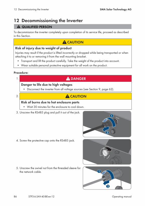
12 Decommissioning the Inverter SMA Solar Technology AG
Operating manualSTP3-6-3AV-40-BE-en-1286
12 Decommissioning the Inverter
To decommission the inverter completely upon completion of its service life, proceed as describedin this Section.
CAUTIONRisk of injury due to weight of productInjuries may result if the product is lifted incorrectly or dropped while being transported or whenattaching it to or removing it from the wall mounting bracket.
• Transport and lift the product carefully. Take the weight of the product into account.• Wear suitable personal protective equipment for all work on the product.
Procedure:
1. DANGERDanger to life due to high voltages
• Disconnect the inverter from all voltage sources (see Section 9, page 62).
2. CAUTIONRisk of burns due to hot enclosure parts
• Wait 30 minutes for the enclosure to cool down.
3. Unscrew the RS485 plug and pull it out of the jack.
2
1RS485
4. Screw the protective cap onto the RS485 jack.
5. Unscrew the swivel nut from the threaded sleeve forthe network cable.
2
1
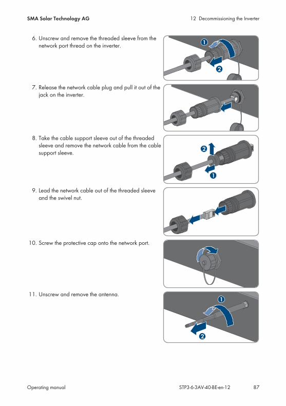
12 Decommissioning the InverterSMA Solar Technology AG
Operating manual STP3-6-3AV-40-BE-en-12 87
6. Unscrew and remove the threaded sleeve from thenetwork port thread on the inverter.
2
1
7. Release the network cable plug and pull it out of thejack on the inverter.
8. Take the cable support sleeve out of the threadedsleeve and remove the network cable from the cablesupport sleeve. 2
1
9. Lead the network cable out of the threaded sleeveand the swivel nut.
10. Screw the protective cap onto the network port.
11. Unscrew and remove the antenna.1
2
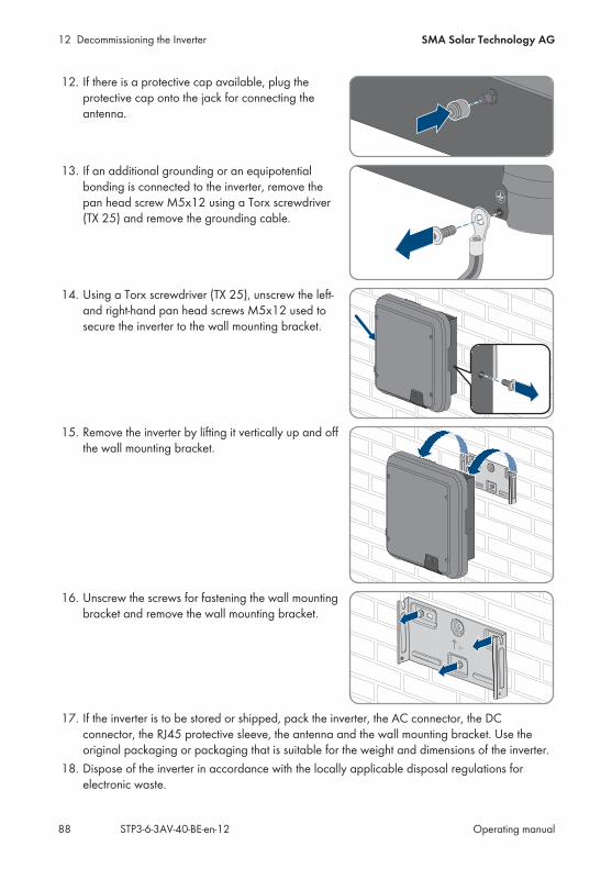
12 Decommissioning the Inverter SMA Solar Technology AG
Operating manualSTP3-6-3AV-40-BE-en-1288
12. If there is a protective cap available, plug theprotective cap onto the jack for connecting theantenna.
13. If an additional grounding or an equipotentialbonding is connected to the inverter, remove thepan head screw M5x12 using a Torx screwdriver(TX 25) and remove the grounding cable.
14. Using a Torx screwdriver (TX 25), unscrew the left-and right-hand pan head screws M5x12 used tosecure the inverter to the wall mounting bracket.
15. Remove the inverter by lifting it vertically up and offthe wall mounting bracket.
16. Unscrew the screws for fastening the wall mountingbracket and remove the wall mounting bracket.
UP
17. If the inverter is to be stored or shipped, pack the inverter, the AC connector, the DCconnector, the RJ45 protective sleeve, the antenna and the wall mounting bracket. Use theoriginal packaging or packaging that is suitable for the weight and dimensions of the inverter.
18. Dispose of the inverter in accordance with the locally applicable disposal regulations forelectronic waste.
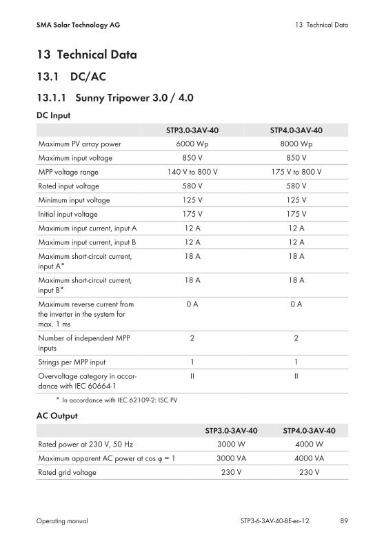
13 Technical DataSMA Solar Technology AG
Operating manual STP3-6-3AV-40-BE-en-12 89
13 Technical Data
13.1 DC/AC
13.1.1 Sunny Tripower 3.0 / 4.0DC Input
STP3.0-3AV-40 STP4.0-3AV-40Maximum PV array power 6000 Wp 8000 Wp
Maximum input voltage 850 V 850 V
MPP voltage range 140 V to 800 V 175 V to 800 V
Rated input voltage 580 V 580 V
Minimum input voltage 125 V 125 V
Initial input voltage 175 V 175 V
Maximum input current, input A 12 A 12 A
Maximum input current, input B 12 A 12 A
Maximum short-circuit current,input A*
18 A 18 A
Maximum short-circuit current,input B*
18 A 18 A
Maximum reverse current fromthe inverter in the system formax. 1 ms
0 A 0 A
Number of independent MPPinputs
2 2
Strings per MPP input 1 1
Overvoltage category in accor-dance with IEC 60664-1
II II
* In accordance with IEC 62109-2: ISC PV
AC OutputSTP3.0-3AV-40 STP4.0-3AV-40
Rated power at 230 V, 50 Hz 3000 W 4000 W
Maximum apparent AC power at cos φ = 1 3000 VA 4000 VA
Rated grid voltage 230 V 230 V
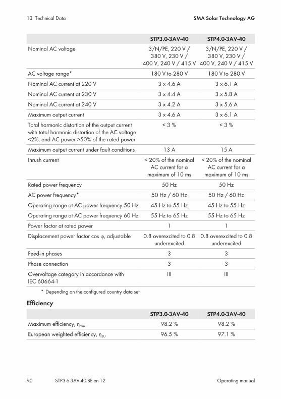
13 Technical Data SMA Solar Technology AG
Operating manualSTP3-6-3AV-40-BE-en-1290
STP3.0-3AV-40 STP4.0-3AV-40Nominal AC voltage 3/N/PE, 220 V /
380 V, 230 V /400 V, 240 V / 415 V
3/N/PE, 220 V /380 V, 230 V /
400 V, 240 V / 415 V
AC voltage range* 180 V to 280 V 180 V to 280 V
Nominal AC current at 220 V 3 x 4.6 A 3 x 6.1 A
Nominal AC current at 230 V 3 x 4.4 A 3 x 5.8 A
Nominal AC current at 240 V 3 x 4.2 A 3 x 5.6 A
Maximum output current 3 x 4.6 A 3 x 6.1 A
Total harmonic distortion of the output currentwith total harmonic distortion of the AC voltage<2%, and AC power >50% of the rated power
< 3 % < 3 %
Maximum output current under fault conditions 13 A 15 A
Inrush current < 20% of the nominalAC current for a
maximum of 10 ms
< 20% of the nominalAC current for a
maximum of 10 ms
Rated power frequency 50 Hz 50 Hz
AC power frequency* 50 Hz / 60 Hz 50 Hz / 60 Hz
Operating range at AC power frequency 50 Hz 45 Hz to 55 Hz 45 Hz to 55 Hz
Operating range at AC power frequency 60 Hz 55 Hz to 65 Hz 55 Hz to 65 Hz
Power factor at rated power 1 1
Displacement power factor cos φ, adjustable 0.8 overexcited to 0.8underexcited
0.8 overexcited to 0.8underexcited
Feed-in phases 3 3
Phase connection 3 3
Overvoltage category in accordance withIEC 60664-1
III III
* Depending on the configured country data set
EfficiencySTP3.0-3AV-40 STP4.0-3AV-40
Maximum efficiency, ηmax 98.2 % 98.2 %
European weighted efficiency, ηEU 96.5 % 97.1 %
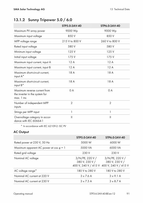
13 Technical DataSMA Solar Technology AG
Operating manual STP3-6-3AV-40-BE-en-12 91
13.1.2 Sunny Tripower 5.0 / 6.0STP5.0-3AV-40 STP6.0-3AV-40
Maximum PV array power 9000 Wp 9000 Wp
Maximum input voltage 850 V 850 V
MPP voltage range 215 V to 800 V 260 V to 800 V
Rated input voltage 580 V 580 V
Minimum input voltage 125 V 125 V
Initial input voltage 175 V 175 V
Maximum input current, input A 12 A 12 A
Maximum input current, input B 12 A 12 A
Maximum short-circuit current,input A*
18 A 18 A
Maximum short-circuit current,input B*
18 A 18 A
Maximum reverse current fromthe inverter in the system formax. 1 ms
0 A 0 A
Number of independent MPPinputs
2 2
Strings per MPP input 1 1
Overvoltage category in accor-dance with IEC 60664-1
II II
* In accordance with IEC 62109-2: ISC PV
AC OutputSTP5.0-3AV-40 STP6.0-3AV-40
Rated power at 230 V, 50 Hz 5000 W 6000 W
Maximum apparent AC power at cos φ = 1 5000 VA 6000 VA
Rated grid voltage 230 V 230 V
Nominal AC voltage 3/N/PE, 220 V /380 V, 230 V /
400 V, 240 V / 415 V
3/N/PE, 220 V /380 V, 230 V /
400 V, 240 V / 415 V
AC voltage range* 180 V to 280 V 180 V to 280 V
Nominal AC current at 220 V 3 x 7.6 A 3 x 9.1 A
Nominal AC current at 230 V 3 x 7.3 A 3 x 8.7 A
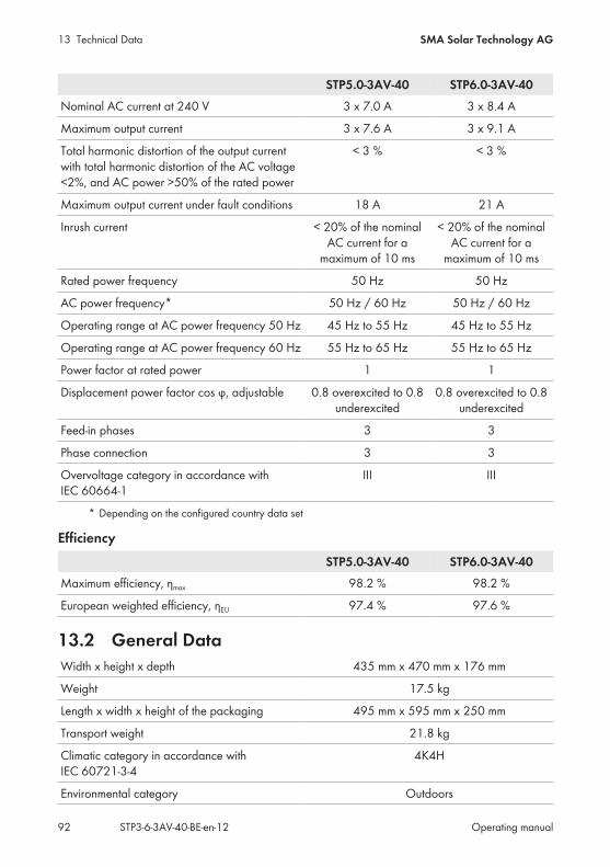
13 Technical Data SMA Solar Technology AG
Operating manualSTP3-6-3AV-40-BE-en-1292
STP5.0-3AV-40 STP6.0-3AV-40Nominal AC current at 240 V 3 x 7.0 A 3 x 8.4 A
Maximum output current 3 x 7.6 A 3 x 9.1 A
Total harmonic distortion of the output currentwith total harmonic distortion of the AC voltage<2%, and AC power >50% of the rated power
< 3 % < 3 %
Maximum output current under fault conditions 18 A 21 A
Inrush current < 20% of the nominalAC current for a
maximum of 10 ms
< 20% of the nominalAC current for a
maximum of 10 ms
Rated power frequency 50 Hz 50 Hz
AC power frequency* 50 Hz / 60 Hz 50 Hz / 60 Hz
Operating range at AC power frequency 50 Hz 45 Hz to 55 Hz 45 Hz to 55 Hz
Operating range at AC power frequency 60 Hz 55 Hz to 65 Hz 55 Hz to 65 Hz
Power factor at rated power 1 1
Displacement power factor cos φ, adjustable 0.8 overexcited to 0.8underexcited
0.8 overexcited to 0.8underexcited
Feed-in phases 3 3
Phase connection 3 3
Overvoltage category in accordance withIEC 60664-1
III III
* Depending on the configured country data set
EfficiencySTP5.0-3AV-40 STP6.0-3AV-40
Maximum efficiency, ηmax 98.2 % 98.2 %
European weighted efficiency, ηEU 97.4 % 97.6 %
13.2 General DataWidth x height x depth 435 mm x 470 mm x 176 mm
Weight 17.5 kg
Length x width x height of the packaging 495 mm x 595 mm x 250 mm
Transport weight 21.8 kg
Climatic category in accordance withIEC 60721-3-4
4K4H
Environmental category Outdoors
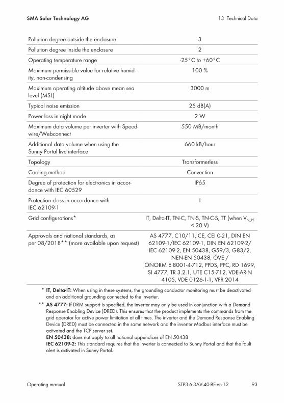
13 Technical DataSMA Solar Technology AG
Operating manual STP3-6-3AV-40-BE-en-12 93
Pollution degree outside the enclosure 3
Pollution degree inside the enclosure 2
Operating temperature range -25°C to +60°C
Maximum permissible value for relative humid-ity, non-condensing
100 %
Maximum operating altitude above mean sealevel (MSL)
3000 m
Typical noise emission 25 dB(A)
Power loss in night mode 2 W
Maximum data volume per inverter with Speed-wire/Webconnect
550 MB/month
Additional data volume when using theSunny Portal live interface
660 kB/hour
Topology Transformerless
Cooling method Convection
Degree of protection for electronics in accor-dance with IEC 60529
IP65
Protection class in accordance withIEC 62109-1
I
Grid configurations* IT, Delta-IT, TN-C, TN-S, TN-C-S, TT (when VN_PE
< 20 V)
Approvals and national standards, asper 08/2018** (more available upon request)
AS 4777, C10/11, CE, CEI 0-21, DIN EN62109-1/IEC 62109-1, DIN EN 62109-2/IEC 62109-2, EN 50438, G59/3, G83/2,
NEN-EN 50438, ÖVE /ÖNORM E 8001-4-712, PPDS, PPC, RD 1699,
SI 4777, TR 3.2.1, UTE C15-712, VDE-AR-N4105, VDE 0126-1-1, VFR 2014
* IT, Delta-IT: When using in these systems, the grounding conductor monitoring must be deactivatedand an additional grounding connected to the inverter.
** AS 4777: If DRM support is specified, the inverter may only be used in conjunction with a DemandResponse Enabling Device (DRED). This ensures that the product implements the commands from thegrid operator for active power limitation at all times. The inverter and the Demand Response EnablingDevice (DRED) must be connected in the same network and the inverter Modbus interface must beactivated and the TCP server set.EN 50438: does not apply to all national appendices of EN 50438IEC 62109-2: This standard requires that the inverter is connected to Sunny Portal and that the faultalert is activated in Sunny Portal.

13 Technical Data SMA Solar Technology AG
Operating manualSTP3-6-3AV-40-BE-en-1294
13.3 Climatic ConditionsInstallation in accordance with IEC 60721-3-3, Class 4K4HExtended temperature range -25°C to +60°C
Extended humidity range 0% to 100%
Extended air pressure range 79.5 kPa to 106 kPa
Transport in accordance with IEC 60721-3-2, Class 2K3Temperature range -25°C to +70°C
13.4 Protective DevicesDC reverse polarity protection Short-circuit diode
Input-side disconnection point DC load-break switch
AC short-circuit current capability Current control
Grid monitoring SMA Grid Guard 6
Maximum permissible fuse protection 32 A
Ground fault monitoring Insulation monitoring: Riso > 200 kΩ
All-pole sensitive residual-current monitoring unit Available
13.5 EquipmentDC connection SUNCLIX DC connector
AC connection AC connector
WLAN As standard
SMA Speedwire/Webconnect As standard
RS485 As standard
13.6 TorquesScrews for securing the inverter to the wallmounting bracket
2.5 Nm
Additional grounding 2.5 Nm
SUNCLIX swivel nut 2.0 Nm
13.7 Data Storage CapacityEnergy yields in the course of the day 63 days
Daily yields 30 years
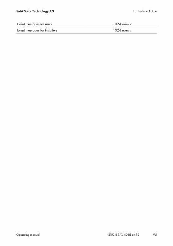
13 Technical DataSMA Solar Technology AG
Operating manual STP3-6-3AV-40-BE-en-12 95
Event messages for users 1024 events
Event messages for installers 1024 events
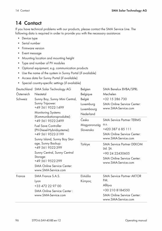
14 Contact SMA Solar Technology AG
Operating manualSTP3-6-3AV-40-BE-en-1296
14 ContactIf you have technical problems with our products, please contact the SMA Service Line. Thefollowing data is required in order to provide you with the necessary assistance:
• Device type• Serial number• Firmware version• Event message• Mounting location and mounting height• Type and number of PV modules• Optional equipment, e.g. communication products• Use the name of the system in Sunny Portal (if available)• Access data for Sunny Portal (if available)• Special country-specific settings (if available)
DeutschlandÖsterreichSchweiz
SMA Solar Technology AGNiestetalSunny Boy, Sunny Mini Central,Sunny Tripower:+49 561 9522‑1499Monitoring Systems(Kommunikationsprodukte):+49 561 9522‑2499Fuel Save Controller(PV-Diesel-Hybridsysteme):+49 561 9522-3199Sunny Island, Sunny Boy Stor-age, Sunny Backup:+49 561 9522-399Sunny Central, Sunny CentralStorage: +49 561 9522-299SMA Online Service Center:www.SMA-Service.com
BelgienBelgiqueBelgiëLuxemburgLuxembourgNederland
SMA Benelux BVBA/SPRLMechelen+32 15 286 730SMA Online Service Center:www.SMA-Service.com
ČeskoMagyarországSlovensko
SMA Service Partner TERMSa.s.+420 387 6 85 111SMA Online Service Center:www.SMA-Service.com
Türkiye SMA Service Partner DEKOMLtd. Şti.+90 24 22430605SMA Online Service Center:www.SMA-Service.com
France SMA France S.A.S.Lyon+33 472 22 97 00SMA Online Service Center :www.SMA-Service.com
ΕλλάδαΚύπρος
SMA Service Partner AKTORFM.Αθήνα+30 210 8184550SMA Online Service Center:www.SMA-Service.com
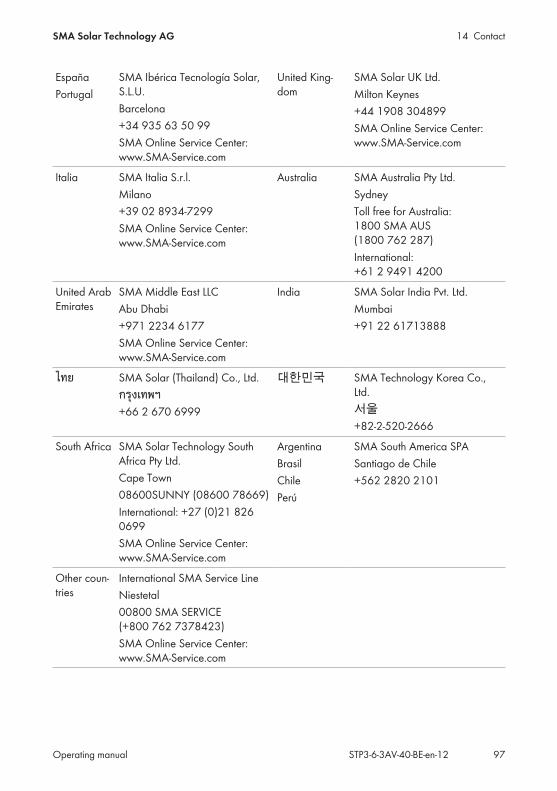
14 ContactSMA Solar Technology AG
Operating manual STP3-6-3AV-40-BE-en-12 97
EspañaPortugal
SMA Ibérica Tecnología Solar,S.L.U.Barcelona+34 935 63 50 99SMA Online Service Center:www.SMA-Service.com
United King-dom
SMA Solar UK Ltd.Milton Keynes+44 1908 304899SMA Online Service Center:www.SMA-Service.com
Italia SMA Italia S.r.l.Milano+39 02 8934-7299SMA Online Service Center:www.SMA-Service.com
Australia SMA Australia Pty Ltd.SydneyToll free for Australia:1800 SMA AUS(1800 762 287)International:+61 2 9491 4200
United ArabEmirates
SMA Middle East LLCAbu Dhabi+971 2234 6177SMA Online Service Center:www.SMA-Service.com
India SMA Solar India Pvt. Ltd.Mumbai+91 22 61713888
ไทย SMA Solar (Thailand) Co., Ltd.กรงเทพฯ+66 2 670 6999
대한민국 SMA Technology Korea Co.,Ltd.서울+82-2-520-2666
South Africa SMA Solar Technology SouthAfrica Pty Ltd.Cape Town08600SUNNY (08600 78669)International: +27 (0)21 8260699SMA Online Service Center:www.SMA-Service.com
ArgentinaBrasilChilePerú
SMA South America SPASantiago de Chile+562 2820 2101
Other coun-tries
International SMA Service LineNiestetal00800 SMA SERVICE(+800 762 7378423)SMA Online Service Center:www.SMA-Service.com
15 EU Declaration of Conformity SMA Solar Technology AG
Operating manualSTP3-6-3AV-40-BE-en-1298
15 EU Declaration of Conformitywithin the scope of the EU directives
• Electromagnetic compatibility 2014/30/EU (29.3.2014 L 96/79-106)(EMC)
• Low Voltage Directive 2014/35/EU (29.3.2014 L 96/357-374) (LVD)• Radio Equipment Directive 2014/53/EU (22.5.2014 L 153/62) (RED)
SMA Solar Technology AG confirms herewith that the products described in this document are incompliance with the fundamental requirements and other relevant provisions of the above-mentioned directives. The entire EU Declaration of Conformity can be found at www.SMA-Solar.com.


www.SMA-Solar.com