operating manual | bedienungsanleitung - لودسل | load cell
TRANSCRIPT

Operating Manual | Bedienungsanleitung |Manuel d'emploi
English Deutsch Français
Z6…

Hottinger Baldwin Messtechnik GmbHIm Tiefen See 45D-64239 DarmstadtTel. +49 6151 803-0Fax +49 6151 [email protected]
Mat.: 7-2001.5001DVS: A1027-4.1 HBM: public12.2016
� Hottinger Baldwin Messtechnik GmbH.
Subject to modifications.All product descriptions are for general information only.They are not to be understood as a guarantee of quality ordurability.
Änderungen vorbehalten.Alle Angaben beschreiben unsere Produkte in allgemeinerForm. Sie stellen keine Beschaffenheits- oder Haltbarkeitsgarantie dar.
Sous réserve de modifications.Les caractéristiques indiquées ne décrivent nos produitsque sous une forme générale. Elles n'impliquent aucunegarantie de qualité ou de durablilité.

Operating Manual | Bedienungsanleitung |Manuel d'emploi
English Deutsch Français
Z6…

2 A1027-4.1 HBM: public Z6…
English
1 Safety instructions 4. . . . . . . . . . . . . . . . . . . . . . . . . . . . . . . . . . . . . . . .
2 Markings used 8. . . . . . . . . . . . . . . . . . . . . . . . . . . . . . . . . . . . . . . . . . . .2.1 Symbols on the device 8. . . . . . . . . . . . . . . . . . . . . . . . . . . . . . . . . . . . . .
2.2 The markings used in this document 8. . . . . . . . . . . . . . . . . . . . . . . . . .
3 Conditions on site 9. . . . . . . . . . . . . . . . . . . . . . . . . . . . . . . . . . . . . . . .
4 Mechanical installation 10. . . . . . . . . . . . . . . . . . . . . . . . . . . . . . . . . . . .4.1 Important precautions during installation 10. . . . . . . . . . . . . . . . . . . . . .
4.2 Mounting and load application 11. . . . . . . . . . . . . . . . . . . . . . . . . . . . . . .
5 Electrical connection 13. . . . . . . . . . . . . . . . . . . . . . . . . . . . . . . . . . . . . .5.1 Connection in six-wire configuration 13. . . . . . . . . . . . . . . . . . . . . . . . . .
5.2 Connection in four-wire configuration 14. . . . . . . . . . . . . . . . . . . . . . . . .
5.3 Shortening the cable 14. . . . . . . . . . . . . . . . . . . . . . . . . . . . . . . . . . . . . . .
5.4 Cable extension 15. . . . . . . . . . . . . . . . . . . . . . . . . . . . . . . . . . . . . . . . . . .
5.5 Parallel connection 15. . . . . . . . . . . . . . . . . . . . . . . . . . . . . . . . . . . . . . . . .
5.6 EMC protection 16. . . . . . . . . . . . . . . . . . . . . . . . . . . . . . . . . . . . . . . . . . . .
6 Waste disposal and environmental protection 17. . . . . . . . . . . . . .
7 Specifications 18. . . . . . . . . . . . . . . . . . . . . . . . . . . . . . . . . . . . . . . . . . . .7.1 Z6FD1 and Z6FC3 18. . . . . . . . . . . . . . . . . . . . . . . . . . . . . . . . . . . . . . . . .
7.2 Z6FC3MI, Z6FC4 and Z6FC6 20. . . . . . . . . . . . . . . . . . . . . . . . . . . . . . . .
7.3 Specifications for all versions 21. . . . . . . . . . . . . . . . . . . . . . . . . . . . . . . .
8 Dimensions 22. . . . . . . . . . . . . . . . . . . . . . . . . . . . . . . . . . . . . . . . . . . . . .8.1 Z6…/5�kg … 500�kg 22. . . . . . . . . . . . . . . . . . . . . . . . . . . . . . . . . . . . . . . .
8.2 Z6…/1�t 23. . . . . . . . . . . . . . . . . . . . . . . . . . . . . . . . . . . . . . . . . . . . . . . . . . .
9 Accessories 24. . . . . . . . . . . . . . . . . . . . . . . . . . . . . . . . . . . . . . . . . . . . . .9.1 ZPL pendulum bearing, Emax = 5�kg … 1�t 24. . . . . . . . . . . . . . . . . . . .
9.2 Knuckle eye ZGWR 25. . . . . . . . . . . . . . . . . . . . . . . . . . . . . . . . . . . . . . . .

Z6… A1027-4.1 HBM: public 3
9.3 Force feedback ZRR 26. . . . . . . . . . . . . . . . . . . . . . . . . . . . . . . . . . . . . . .
9.4 Rubber-metal bearing ZEL 27. . . . . . . . . . . . . . . . . . . . . . . . . . . . . . . . . .
9.5 Cone, conical pan ZK 30. . . . . . . . . . . . . . . . . . . . . . . . . . . . . . . . . . . . . . .
9.6 Oscillating loading foot ZFP and ZKP 31. . . . . . . . . . . . . . . . . . . . . . . . .
9.7 Oscillating loading foot PCX 32. . . . . . . . . . . . . . . . . . . . . . . . . . . . . . . . .
9.8 Mounting base / mounting kit 33. . . . . . . . . . . . . . . . . . . . . . . . . . . . . . . .
Safety instructions
4 A1027-4.1 HBM: public Z6…
1 Safety instructions
Appropriate use
Transducers of the Z6... type series are designed solelyfor technical weighing applications within the applicationlimits detailed in the specifications. Any other use is notappropriate.
Any person instructed to carry out installation, commissioning or operation of the transducer must have readand understood the Operating Manual and in particularthe technical safety instructions.
In the interests of safety, the transducer should only beoperated by qualified personnel and as described in theOperating Manual. It is also essential to comply with thelegal and safety requirements for the application concerned during use. The same applies to the use ofaccessories.
The transducer is not intended for use as a safety component. Please also refer to the section: "Additionalsafety precautions". Proper and safe operation requiresproper transportation, correct storage, siting and mounting, and careful operation.
Operating conditions
� Please observe the permissible maximum valuesstated in the specifications for:
- Limit load
- Limit load at max. eccentricity
- Limit lateral loading
- Breaking loads
- Temperature limits

Safety instructions
Z6… A1027-4.1 HBM: public 5
- Limits of electrical loading capacity
� Note, that when several transducers are installed in ascale, there is not always an even distribution of loadon the individual transducers.
� The transducers can be used as machine elements.When used in this manner, it must be noted that, tofavor greater sensitivity, the transducer is notdesigned with the safety factors usual in mechanicalengineering.
� The transducer must not be modified from the designor safety engineering point of view except with ourexpress agreement.
� The transducer is maintenance-free.
� In accordance with national and local environmentalprotection and material recovery and recycling regulations, old transducers that can no longer be usedmust be disposed of separately and not with normalhousehold garbage, see Chapter 6, Page 17.
Explosion protection version option
� Comply with the relevant code of practice duringinstallation.
� Comply with the installation conditions cited in theCertificate of Conformity and/or the Type Certificate.
Qualified personnel
Qualified persons means persons entrusted with theinstallation, fitting, commissioning and operation of theproduct who possess the appropriate qualifications fortheir function.
This includes people who meet at least one of the threefollowing requirements:

Safety instructions
6 A1027-4.1 HBM: public Z6…
� Knowledge of the safety concepts of measurementand automation technology is a requirement and asproject personnel, they must be familiar with theseconcepts.
� As measurement or automation plant operating personnel, they have been instructed how to handle themachinery. They are familiar with the operation of theequipment and technologies described in this documentation.
� As commissioning engineers or service engineers,they have successfully completed the training to qualify them to repair the automation systems. They arealso authorized to activate, ground and label circuitsand equipment in accordance with safety engineeringstandards.
Additional safety precautions
Additional safety precautions to meet the requirements ofthe relevant national and local accident prevention regulations must be taken in plants where malfunctions couldcause major damage, loss of data or even personalinjury.
The scope of supply and performance of the transducercovers only a small area of measurement technology.Before starting up the transducer in a system, a projectplanning and risk analysis must first be implemented,taking into account all the safety aspects of measurement and automation technology so that residual risksare minimized. This particularly concerns personal andmachine protection. The transducers function passivelyand cannot implement any (safety-relevant) cutoffs. Inthe event of a fault, the relevant precautions must establish safe operating conditions.

Safety instructions
Z6… A1027-4.1 HBM: public 7
General dangers of failing to follow the safetyinstructions
The transducer corresponds to the state of the art and isfailsafe. The transducer may give rise to residual dangersif it is inappropriately installed or operated.

Markings used
8 A1027-4.1 HBM: public Z6…
2 Markings used
2.1 Symbols on the device
CE certification
The CE mark enables the manufacturer to guarantee thatthe product complies with the requirements of the relevant EC directives (the Declaration of Conformity can befound on the HBM website (www.hbm.com) underHBMdoc).
2.2 The markings used in this document
Important instructions for your safety are specificallyidentified. It is essential to follow these instructions inorder to prevent accidents and damage to property.
Symbol Significance
WARNINGThis marking warns of a potentially dangerous situation in which failure to comply with safety requirements can result in death or serious physical injury.
NoteThis marking draws your attention to a situation inwhich failure to comply with safety requirementscould lead to damage to property.
Important
This marking draws your attention to important information about the product or about handling theproduct.
EmphasisSee …
Italics are used to emphasize and highlight text andidentify references to sections, diagrams, or externaldocuments and files.

Conditions on site
Z6… A1027-4.1 HBM: public 9
3 Conditions on site
Series Z6... load cells are hermetically encapsulated andare therefore not at all sensitive to the influence of moisture and humidity. The transducers achieve protectionclass IP68 (test conditions: 100 hours under 1 m watercolumn) as per DIN EN60529. Nevertheless, the loadcells must be protected against constant humidity andmoisture.
Protection against corrosion
The load cell must be protected against chemicals thatcould attack the transducer body steel, or the cable.
Notice
Acids and all substances that release ions also attackstainless steels and their welded seams.Should there be any corrosion, this could cause thetransducer to fail. If this is the case, you must provideappropriate means of protection.
Explosion protection version option
The ambient temperature range specified on the transducer must not be exceeded.
Deposits
Dust, dirt and other foreign matter must not be allowed toaccumulate sufficiently to divert some of the measuringforce onto the housing, thus invalidating the measuredvalue (force shunt).

Mechanical installation
10 A1027-4.1 HBM: public Z6…
4 Mechanical installation
4.1 Important precautions duringinstallation
� Handle the transducer with care.
� The bellows material is very thin and can therefore beeasily damaged.
� Welding currents must not be allowed to flow over thetransducer. If there is a risk that this might happen,you must provide a suitable low-ohm connection toelectrically bypass the transducer. HBM, for example,provides the highly flexible EEK ground cable, whichcan be screwed on above and below the transducer.
� Make sure that the transducer cannot be overloaded.
WARNING
There is a danger of the transducer breaking if it is overloaded. This can cause danger for the operating personnel of the system in which the transducer is installed.
Implement appropriate safety measures to avoid overloads or to protect against the resulting dangers.
Mechanical installation
Z6… A1027-4.1 HBM: public 11
Notice
Load cells are precision measuring elements and need tobe handled carefully. Dropping or knocking the transducer may cause permanent damage. Make sure that thetransducer cannot be overloaded, including while it isbeing mounted.
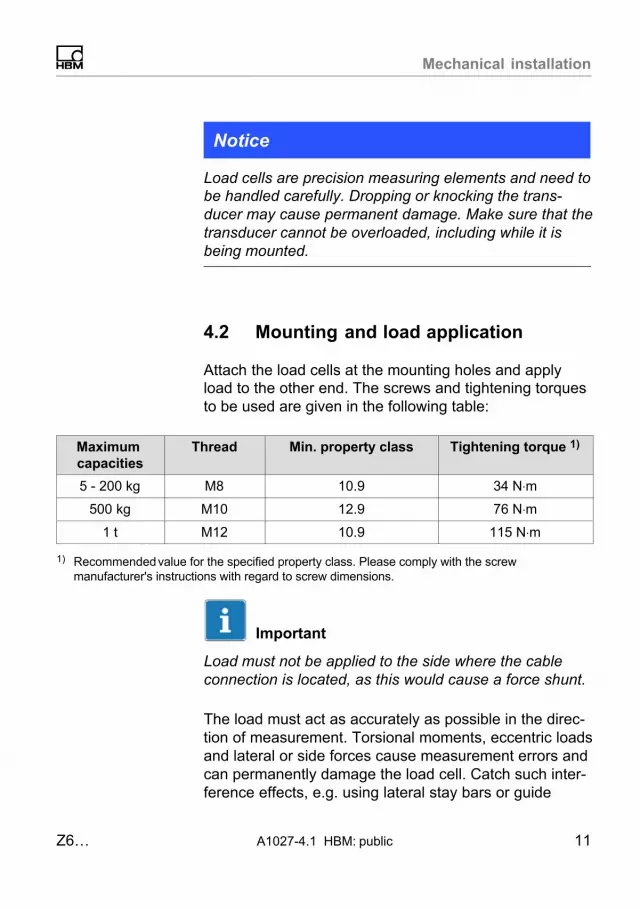
4.2 Mounting and load application
Attach the load cells at the mounting holes and applyload to the other end. The screws and tightening torquesto be used are given in the following table:
Maximum capacities
Thread Min. property class Tightening torque 1)
5 - 200 kg M8 10.9 34 N⋅m
500 kg M10 12.9 76 N⋅m
1 t M12 10.9 115 N⋅m
1) Recommended value for the specified property class. Please comply with the screwmanufacturer's instructions with regard to screw dimensions.
Important
Load must not be applied to the side where the cableconnection is located, as this would cause a force shunt.
The load must act as accurately as possible in the direction of measurement. Torsional moments, eccentric loadsand lateral or side forces cause measurement errors andcan permanently damage the load cell. Catch such interference effects, e.g. using lateral stay bars or guide
Mechanical installation
12 A1027-4.1 HBM: public Z6…
rollers, but ensure that these elements do not absorb anyload or force components in the direction of measurement (force shunt which will in turn lead to measurementerrors).
To minimize error effects from load application, HBMoffers different load application elements, according tothe mounting conditions:
� Pendulum bearing ZPL
� Knuckle eyes ZGWR
� Force feedback ZRR (for maximum capacities 5kg … 200�kg)
� Rubber-metal bearing ZEL
� Cone/conical pan ZK
� Oscillating loading foot PCX (for maximum capacities5kg … 500�kg)
� Oscillating loading foot ZFP (for maximum capacities5kg … 200�kg)
� Oscillating loading foot ZKP (for maximum capacities5kg … 200�kg)
� Mounting base / mounting kit ZPUZ6/ZPU/200KG (for maximum capacities 5�kg … 200�kg)Z6/ZPU/500KG (for maximum capacity 500 kg)

Electrical connection
Z6… A1027-4.1 HBM: public 13
5 Electrical connection
The following can be connected for measurement signalconditioning:
� carrier-frequency amplifiers
� DC amplifiers
designed for strain gauge measurement systems.
The load cells are delivered with a six-wire configuration.
5.1 Connection in six-wire configuration
white
blackgray
Excitation voltage (+)green
red
Shielding/drain wire, connected to housing
Excitation voltage (-)Sense lead (-)
Measurement signal (+)
blueSense lead (+)
Measurement signal (-)
Fig. 5.1 Pin Assignment
With this connector pin assignment, the output voltage atthe measuring amplifier is positive when the transducer isloaded.

Electrical connection
14 A1027-4.1 HBM: public Z6…
5.2 Connection in four-wire configuration
When transducers in a six-wire configuration are connected to amplifiers in a four-wire configuration, thesense leads of the transducer must be connected to thecorresponding excitation voltage leads: Marking (+) with(+) and marking (-) with (-), see Fig. 5.1. This measurealso reduces the cable resistance of the excitation voltage leads. However, there will be a voltage loss on thesupply leads due to the cable resistance that is stillpresent and not compensated for by the six-wire configuration. A large part of this loss can be eliminated by acalibration, however, the temperature-dependent partremains.
Important
The TCs value given in the specifications for the transducer therefore does not apply for the cable and transducer combination when connection is in a four-wire configuration, where the cable percentage must be added.
The following deviations occur in the case of an uncutcable (3 m):
� Sensitivity approx. -0.2%
� TCS approx. -0.01% per 10 K.
5.3 Shortening the cable
If the transducer is connected to an amplifier in a six-wireconfiguration, the transducer cable can be shortened asrequired, without adversely affecting the measurementaccuracy.

Electrical connection
Z6… A1027-4.1 HBM: public 15
5.4 Cable extension
Only use shielded, low-capacitance measurement cablesfor extending. Ensure that connection is perfect, with alow contact resistance.
The cable of a six-wire transducer can be extended witha cable of the same type.
Cable types recommended by HBM:
� KAB7.5/00‐2/2/2 (by the meter, Order No.4‐3301.0071 for gray or 4‐3301.0082 for blue version)
� CABA1 (cable roll, Order No. CABA1/20 = 20 m orCABA1/100 = 100�m long)
5.5 Parallel connection
Only load cells with an aligned output (nominal (rated)sensitivity and output resistance) are suitable for parallelconnection. The load cells can be wired in parallel byjoining the load cell cable core ends of the same color.The type VKK terminal boxes or the VKK2R-8 Ex versionfor potentially explosive areas are available in the HBMproduct line for this purpose. The output signal is thenthe average of the individual output signals.
Important
Overloading in an individual load cell cannot then bedetected from the output signal after load cells have beenconnected in parallel.

Electrical connection
16 A1027-4.1 HBM: public Z6…
5.6 EMC protection
Background information
Electrical and magnetic fields often induce interferencevoltages in the measuring circuit. For reliable measurements, signal differences of less than 1μV must be transmitted without interference from the transducer to theevaluation electronics.
Planning of the shielding concept
Due to the numerous application options and the differentlocal constraints, we can only provide you with information for correct connection. The shielding concept suitable for your application must be planned locally by anappropriate specialist.
The load cells with shielded, round cables are EMC-tested in accordance with EC directives and identified byCE certification.
Points to be observed
� Use shielded, low-capacitance measurement cablesonly (HBM cables fulfill both conditions).
� Do not route the measurement cables parallel topower lines and control circuits. If this is not possible,protect the measurement cable with e.�g. steel conduit.
� Avoid stray fields from transformers, motors and contact switches.
� Connect the shield of the connection cable extensively on the shielding electronics housing. Whenusing several load cells, connect the shield extensively to the junction box (combination of transducersignals, e.g. type VKK2 from HBM). From there, con
Waste disposal and environmental protection
Z6… A1027-4.1 HBM: public 17
nect the measurement cable for the electronics extensively to the junction box and extensively to theshielding electronics housing.
� The shield of the connection cable must not be usedfor discharging potential differences within the system.You must therefore lay sufficiently dimensionedpotential equalization lines to compensate for possiblepotential differences.
Important
Potential equalization is specified for applications inpotentially explosive atmospheres.
6 Waste disposal and environmental protection
The correct disposal of old equipment prevents ecological damage and health hazards.
As waste disposal regulations may differ from country tocountry, we ask that you contact your supplier to determine what type of disposal or recycling is legally applicable in your country.
Packaging
The original HBM packaging is made from recyclablematerial and can be sent for recycling. Store the packaging for at least the duration of the warranty.
For ecological reasons, empty packaging should not bereturned to us.

Specifications
18 A1027-4.1 HBM: public Z6…
7 Specifications
7.1 Z6FD1 and Z6FC3
Type Z6FD1 Z6FC3
Accuracy class 1) D1 C3
Number of load cellverification intervals
nLC 1000 3000
Maximum capacity Emax kg5; 10; 20; 30;50; 100; 200;
500; 1000
10; 20; 30; 50;100; 200; 500;
1000
Minimum load cellverification interval
vmin% ofEmax
0.03600.0090
0.0083 (for 30 kg)
Temperature coefficient ofzero signal per 10K
TC0% ofCn
±0.0500±0.0126
±0.0116 (for 30 kg)
Nominal (rated) sensitivity Cn mV/V 2.0
Sensitivity tolerance % +1; -0.1 ±0.05 2)
Temperature coefficient ofthe sensitivity 3) per 10 K
TCS
% ofCn
±0.0500 0.0080
Linearity deviation 3) dlin ±0.0500 ±0.0180
Relative reversibility error3) dhy ±0.0500
±0.0170
Load creep in 30 minutes dDR ±0.0490 ±0.0166
Input resistance RLCΩ
350 … 480
Output resistance R0 356 ±0.2 356 ±0.12
Reference excitationvoltage
Uref
V
5
Nominal (rated) range ofthe excitation voltage
BU 0.5 … 12
Insulation resistance at100 VDC
Ris GΩ > 5

Specifications
Z6… A1027-4.1 HBM: public 19
Z6FC3Z6FD1Type
Nominal temperature range BT
°C
-10 … +40
Operating temperaturerange
Btu -30 … +70
Storage temperature range Btl -50 … +85
Limit load EL % ofEmax
150
Breaking load Ed �300
Cable length, six-wireconfiguration
m 3
Degree of protection per DINEN60529 (IEC529)
IP68 (test conditions 1 m water column /100h);
Material:Measuring bodyBellowsCable inlet glandCable sheath
Stainless steel 4)
Stainless steel 4)
Stainless steel / Viton®
PVC
1) As per OIML R60, with PLC = 0.7.2) For Z6FC3/10kg: ��0.1%.3) The values for non-linearity (dlin), relative reversibility error (dhy) and temperature coefficient of
sensitivity (TCS) are recommended values. The sum of these values is within the cumulated errorlimit laid down by OIML R60.
4) As per EN 10088-1.
Specifications
20 A1027-4.1 HBM: public Z6…
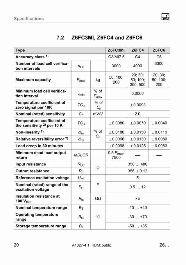
7.2 Z6FC3MI, Z6FC4 and Z6FC6
Type Z6FC3MI Z6FC4 Z6FC6
Accuracy class 1) C3/MI7.5 C4 C6
Number of load cell verification intervals
nLC 3000 40006000
Maximum capacity Emax kg50; 100;
200
20; 30;50; 100;200; 500
20; 30;50; 100;
200
Minimum load cell verification interval
vmin% ofEmax
0.0066
Temperature coefficient ofzero signal per 10K
TC0% ofCn
�0.0093
Nominal (rated) sensitivity Cn mV/V 2.0
Temperature coefficient ofthe sensitivity 2) per 10 K
TCS
% ofCn
�0.0080 �0.0070 �0.0040
Non-linearity 2) dlin �0.0180 �0.0150 �0.0110
Relative reversibility error 2) dhy �0.0066 �0.0130 �0.0080
Load creep in 30 minutes �0.0098 �0.0125 �0.0083
Minimum dead load outputreturn
MDLOR0.5 Emax/
7500 — —
Input resistance RLCΩ
350 … 480
Output resistance R0 356 �0.12
Reference excitation voltage Uref
V
5
Nominal (rated) range of theexcitation voltage
BU 0.5 … 12
Insulation resistance at100 VDC
Ris GΩ > 5
Nominal temperature range BT
°C
-10 … +40
Operating temperaturerange
Btu -30 … +70
Storage temperature range Btl -50 … +85

Specifications
Z6… A1027-4.1 HBM: public 21
Z6FC6Z6FC4Z6FC3MIType
Limit load EL % ofEmax
150
Breaking load Ed > 300
Cable length, six-wire configuration
m 3
Degree of protection per DIN EN60529(IEC529)
IP68 (test conditions 1 m water column /100h);
Material:Measuring bodyBellowsCable inlet glandCable sheath
Stainless steel 4)
Stainless steel 4)
Stainless steel / Viton®
PVC
1) As per OIML R60, with PLC = 0.7.2) For Z6FC3/10kg: ��0.1%.3) The values for non-linearity (dlin), relative reversibility error (dhy) and temperature coefficient of
sensitivity (TCS) are recommended values. The sum of these values is within the cumulated errorlimit laid down by OIML R60.
4) As per EN 10088-1.
7.3 Specifications for all versions
Maximumcapacity
kg 5 10 20 30 50 100 200 500 1000
Relativepermissiblevibrationalstress
Fsrel% ofEmax
100 70 100
Nominal(rated) displacement,approx.
snom mm 0.24 0.3 0.29 0.28 0.27 0.31 0.39 0.6 0.55
Weight,approx.
G kg 0.5 2.3

Dimensions
22 A1027-4.1 HBM: public Z6…
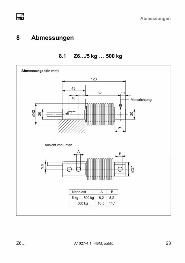
8 Dimensions
8.1 Z6…/5�kg � 500�kg
Dimensions (in mm; 1 mm = 0.03937 inches)
View from below
Measurement direction
123
45
18
82 10
21
AB
∅42 20 20
∅279.
9
8.2 8.2
BAMax. capacity
10.5 11.1500 kg
5�kg … 500�kg

Dimensions
Z6… A1027-4.1 HBM: public 23
8.2 Z6…/1�t
Dimensions (in mm; 1 mm = 0.03937 inches)
34
210
133±0.140
44
22±0.1
13
11.1+0.1
84
∅60
40 25∅
38‐0
.1
15
Measurement direction
70
∅58
View from below

Accessories
24 A1027-4.1 HBM: public Z6…
9 Accessories
9.1 ZPL pendulum bearing,Emax = 5�kg � 1�t
Dimensions (in mm; 1 mm = 0.03937 inches)
Measurement direction
Z6/200kg/ZPLZ6/500kg/ZPLZ17/2t/ZPL (for 500 kgand 1t maximum capacity)
2 dust protection rings included inZPL scope of delivery
Fastening screw included inZPL scope of delivery
M
D∅U∅O
H
E FT
∅ C
Emax ZPL � C D H M �O T E
5�kg … 200�kg Z6/200KG/ZPL 20‐0.2 45 89 +0.6
‐0.8M8 30 6.5 17
500�kg Z6/500KG/ZPL 20‐0.2 45 89 +0.6
‐0.8M8 30 6.5 17
1�t Z17/2T/ZPL 30‐0.1 60 126.5 M10 46 8 22
Emax ZPL F �U FR1) smax
2)
5�kg … 200�kg Z6/200KG/ZPL 9 20D10 2.8 3.5
500�kg Z6/1T/ZPL 9 20D10 2.8 3.5
1�t Z6/1T/ZPL 14 30D10 2 7.5
1) FR: Force feedback in N with 1mm lateral displacement2) smax: Maximum permissible lateral displacement with maximum capacity

Accessories
Z6… A1027-4.1 HBM: public 25
9.2 Knuckle eye ZGWR
Dimensions (in mm; 1 mm = 0.03937 inches)
Screw and washer are included inthe scope of delivery
Z6/.../ZGWR
A
Z
H
W
M
F
∅K
∅JAF
L
G
BD
Emax ZGWR A B D F G H � J
5�kg … 200�kg Z6/200KG/ZGWR 16 8H7 24 36 48 9 12.5
500�kg Z6/1T/ZGWR 20 10H7 28 43 57 10.5 15
1 t Z6/1T/ZGWR 20 10H7 28 43 57 10.5 15
Emax ZGWR �K L M SW W Z
5�kg … 200�kg Z6/200KG/ZGWR 16 5 M8 14 12 46
500�kg Z6/1T/ZGWR 19 6.5 M10 17 14 53
1 t Z6/1T/ZGWR 19 6.5 M10 17 14 55.5

Accessories
26 A1027-4.1 HBM: public Z6…
9.3 Force feedback ZRR
Dimensions (in mm; 1 mm = 0.03937 inches)
Depth: 15�mm F1
G1
E1
a
G2
F2b
E2
M1
M1
H
D
D
H
Measurement direction
Emax ZRR a b D E1 E2 F1
5�kg … 200�kg Z6/200KG/ZRR 80 ±1.1 123 16 30 30 65
Emax ZRR F2 G1 G2 H M1 M2
5�kg … 200�kg Z6/200KG/ZRR 85 46 77 M8 M8x30 M8x30
Accessories
Z6… A1027-4.1 HBM: public 27
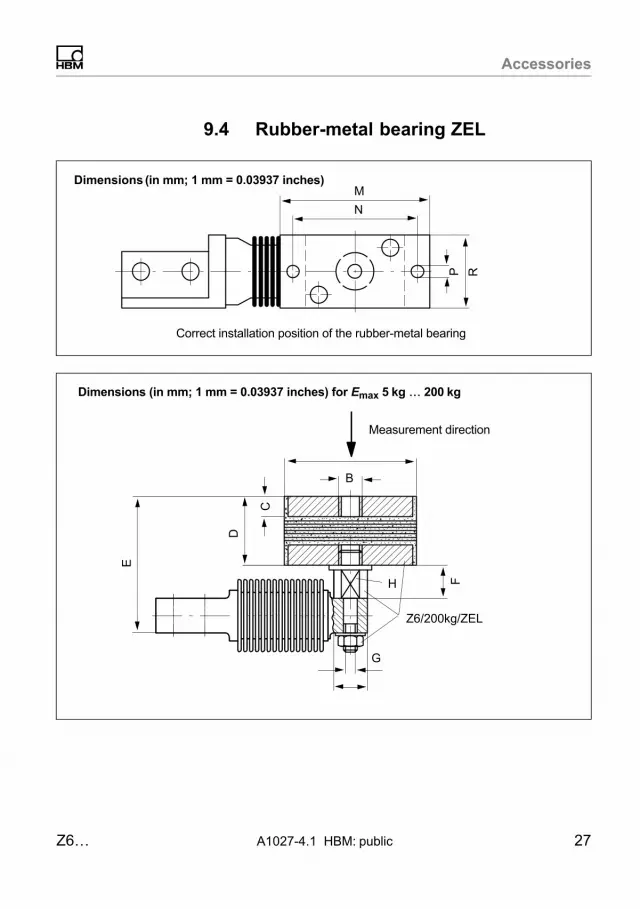
9.4 Rubber-metal bearing ZEL
Dimensions (in mm; 1 mm = 0.03937 inches)M
N
Correct installation position of the rubber-metal bearing
P RB
FH
Z6/200kg/ZEL
C
D
E
G
Dimensions (in mm; 1 mm = 0.03937 inches) for Emax 5�kg � 200�kg
Measurement direction

Accessories
28 A1027-4.1 HBM: public Z6…
Measurement direction
Dimensions (in mm; 1 mm = 0.03937 inches) for Emax 500�kg
H
F
Z6/1t/ZEL
C
DL
E
A
B
Measurement direction
Dimensions (in mm; 1 mm = 0.03937 inches) for Emax 1�t
Z6/1t/ZEL
A
F
CD
L
E
H
B
Screws offset by 35°
Accessories
Z6… A1027-4.1 HBM: public 29
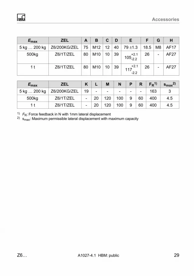
Emax ZEL A B C D E F G H
5�kg … 200�kg Z6/200KG/ZEL 75 M12 12 40 79 ±1.3 18.5 M8 AF17
500�kg Z6/1T/ZEL 80 M10 10 39105
+2.1
-2.226 - AF27
1�t Z6/1T/ZEL 80 M10 10 39117
+2.1
‐2.2
26 - AF27
Emax ZEL K L M N P R FR1) smax
2)
5�kg … 200�kg Z6/200KG/ZEL 19 - - - - - 163 3
500�kg Z6/1T/ZEL - 20 120 100 9 60 400 4.5
1 t Z6/1T/ZEL - 20 120 100 9 60 400 4.5
1) FR: Force feedback in N with 1mm lateral displacement2) smax: Maximum permissible lateral displacement with maximum capacity

Accessories
30 A1027-4.1 HBM: public Z6…
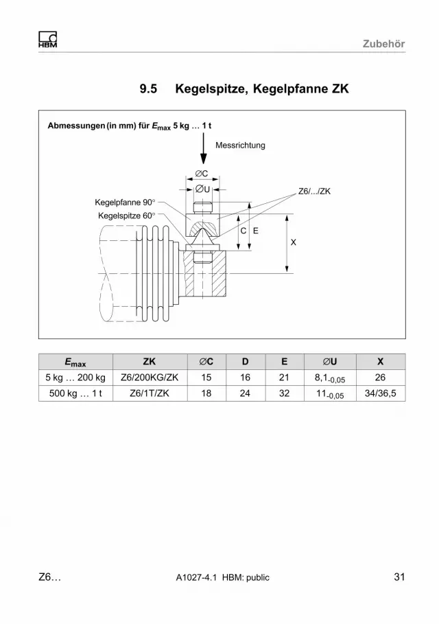
9.5 Cone, conical pan ZK
Dimensions (in mm; 1 mm = 0.03937 inches) for Emax 5�kg � 1�t
Measurement direction
Z6/.../ZK
ECX
Conical pan 90°Cone 60°
∅U
∅ C
Emax ZK � C D E �U X
5�kg … 200�kg Z6/200KG/ZK 15 16 21 8.1‐0.05 26
500�kg … 1�t Z6/1T/ZK 18 24 32 11‐0.05 34/36.5
Accessories
Z6… A1027-4.1 HBM: public 31
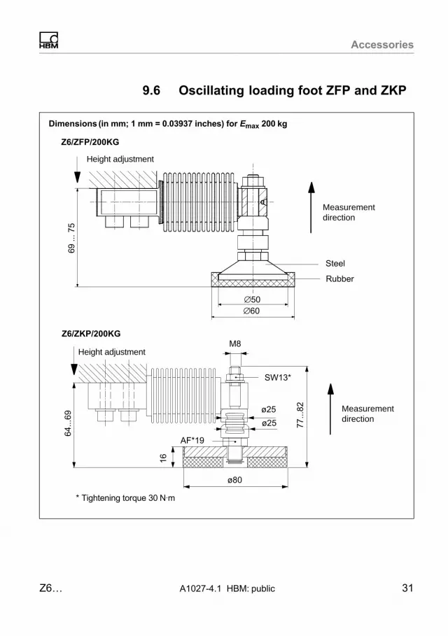
9.6 Oscillating loading foot ZFP and ZKP
Dimensions (in mm; 1 mm = 0.03937 inches) for Emax 200�kg
Z6/ZFP/200KG
Height adjustment
Measurementdirection
Steel
∅60
69 ..
. 75
∅50
Rubber
M8
77...
82
ø80
16
ø25
ø25
64...
69
SW13*
AF*19
* Tightening torque 30�N⋅m
Z6/ZKP/200KG
Measurementdirection
Height adjustment

Accessories
32 A1027-4.1 HBM: public Z6…
9.7 Oscillating loading foot PCX
Dimensions (in mm; 1 mm = 0.03937 inches) for Emax 5�kg � 500�kg
AF = Across Flats
Ø60Ø50
69 ..
. 75
Pos. 1, AF13
Pos. 2, AF17
64 ..
. 70
Pos. 3, AF17
10
1 set comprising 4 pieces Z6/PCX/500kg
Accessories
Z6… A1027-4.1 HBM: public 33
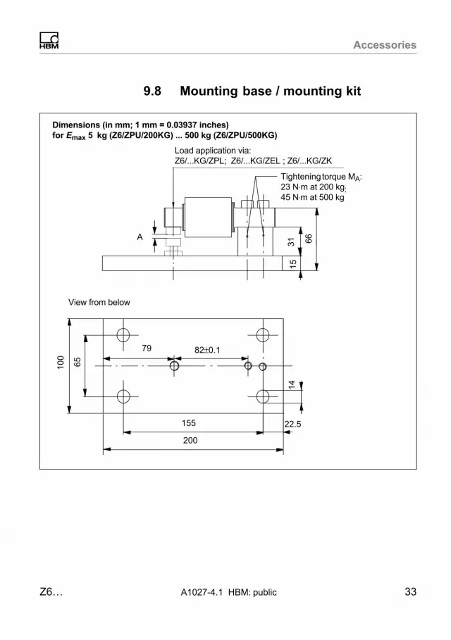
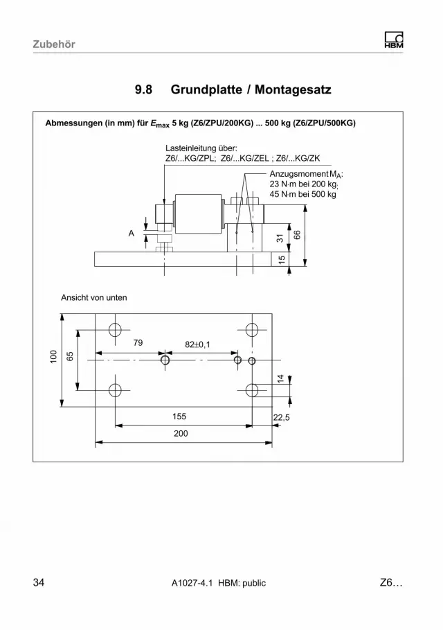
9.8 Mounting base / mounting kit
Tightening torque MA:23 N⋅m at 200 kg;45�N⋅m at 500 kg
1531 66
Load application via:Z6/...KG/ZPL; Z6/...KG/ZEL ; Z6/...KG/ZK
A
Dimensions (in mm; 1 mm = 0.03937 inches) for Emax 5� kg (Z6/ZPU/200KG) ... 500 kg (Z6/ZPU/500KG)
100
65
14
155
200
22.5
79 82±0.1
View from below

Accessories
34 A1027-4.1 HBM: public Z6…
Setting the gap width of the overload stop
The screw length of the overload stop is designed for theuse of a ZEL or ZPL. With an optimal gap width, sufficient screw-in depth into the base plate (�10 mm) isensured. Depending on the load application parts used,you may need to select different screw lengths, e.�g. forZ6/...KG/ZK M10x35 (DIN�931).
► Set the gap width of the overload stop using a feelergage.
► Fix the height setting by locking the screw with thesupplied nut.
Maximum capacity in kg
Gap A1) (overload stop) in mm Limit load
50 �0.35 200�kg
100 �0.40 400�kg
200 �0.50 800�kg
500 �0.85 2.5�t
1) The gap width of the overload stop may vary dependent on the installation situation. Check thefunction of the overload stop after installation and before commissioning. A gap width of 0.05mmshould be present for a load cell loaded with the maximum capacity.

Operating Manual | Bedienungsanleitung |Manuel d'emploi
English Deutsch Français
Z6…

2 A1027-4.1 HBM: public Z6…
Deutsch
1 Sicherheitshinweise 4. . . . . . . . . . . . . . . . . . . . . . . . . . . . . . . . . . . . . .
2 Verwendete Kennzeichnungen 8. . . . . . . . . . . . . . . . . . . . . . . . . . . . .2.1 Auf dem Gerät angebrachte Symbole 8. . . . . . . . . . . . . . . . . . . . . . . . .
2.2 In dieser Anleitung verwendete Kennzeichnungen 8. . . . . . . . . . . . . .
3 Bedingungen am Einbauort 9. . . . . . . . . . . . . . . . . . . . . . . . . . . . . . .
4 Mechanischer Einbau 10. . . . . . . . . . . . . . . . . . . . . . . . . . . . . . . . . . . . .4.1 Wichtige Vorkehrungen beim Einbau 10. . . . . . . . . . . . . . . . . . . . . . . . .
4.2 Montage und Lasteinleitung 11. . . . . . . . . . . . . . . . . . . . . . . . . . . . . . . . .
5 Elektrischer Anschluss 13. . . . . . . . . . . . . . . . . . . . . . . . . . . . . . . . . . . .5.1 Anschluss in Sechsleiter‐Technik 13. . . . . . . . . . . . . . . . . . . . . . . . . . . . .
5.2 Anschluss in Vierleiter‐Technik 14. . . . . . . . . . . . . . . . . . . . . . . . . . . . . . .
5.3 Kabelkürzung 14. . . . . . . . . . . . . . . . . . . . . . . . . . . . . . . . . . . . . . . . . . . . . .
5.4 Kabelverlängerung 15. . . . . . . . . . . . . . . . . . . . . . . . . . . . . . . . . . . . . . . . .
5.5 Parallelschaltung 15. . . . . . . . . . . . . . . . . . . . . . . . . . . . . . . . . . . . . . . . . . .
5.6 EMV‐Schutz 16. . . . . . . . . . . . . . . . . . . . . . . . . . . . . . . . . . . . . . . . . . . . . . .
6 Entsorgung und Umweltschutz 18. . . . . . . . . . . . . . . . . . . . . . . . . . . .
7 Technische Daten 19. . . . . . . . . . . . . . . . . . . . . . . . . . . . . . . . . . . . . . . . .7.1 Z6FD1 und Z6FC3 19. . . . . . . . . . . . . . . . . . . . . . . . . . . . . . . . . . . . . . . . .
7.2 Z6FC3MI, Z6FC4 und Z6FC6 21. . . . . . . . . . . . . . . . . . . . . . . . . . . . . . . .
7.3 Technische Daten für alle Ausführungen 22. . . . . . . . . . . . . . . . . . . . . .
8 Abmessungen 23. . . . . . . . . . . . . . . . . . . . . . . . . . . . . . . . . . . . . . . . . . . .8.1 Z6…/5�kg … 500�kg 23. . . . . . . . . . . . . . . . . . . . . . . . . . . . . . . . . . . . . . . .
8.2 Z6…/1�t 24. . . . . . . . . . . . . . . . . . . . . . . . . . . . . . . . . . . . . . . . . . . . . . . . . . .
9 Zubehör 25. . . . . . . . . . . . . . . . . . . . . . . . . . . . . . . . . . . . . . . . . . . . . . . . . .9.1 ZPL-Pendellager, Emax = 5�kg … 1�t 25. . . . . . . . . . . . . . . . . . . . . . . . .
9.2 Gelenköse ZGWR 26. . . . . . . . . . . . . . . . . . . . . . . . . . . . . . . . . . . . . . . . .

Z6… A1027-4.1 HBM: public 3
9.3 Kraftrückführung ZRR 27. . . . . . . . . . . . . . . . . . . . . . . . . . . . . . . . . . . . . .
9.4 Gummi-Metall-Lager ZEL 28. . . . . . . . . . . . . . . . . . . . . . . . . . . . . . . . . . .
9.5 Kegelspitze, Kegelpfanne ZK 31. . . . . . . . . . . . . . . . . . . . . . . . . . . . . . . .
9.6 Pendel-Lastfuß ZFP und ZKP 32. . . . . . . . . . . . . . . . . . . . . . . . . . . . . . .
9.7 Pendel-Lastfuß PCX 33. . . . . . . . . . . . . . . . . . . . . . . . . . . . . . . . . . . . . . . .
9.8 Grundplatte / Montagesatz 34. . . . . . . . . . . . . . . . . . . . . . . . . . . . . . . . . .

Sicherheitshinweise
4 A1027-4.1 HBM: public Z6…
1 Sicherheitshinweise
Bestimmungsgemäße Verwendung
Die Aufnehmer der Typenreihe Z6... dürfen ausschließlich für wägetechnische Anwendungen im Rahmen derdurch die technischen Daten spezifizierten Einsatzgrenzen verwendet werden. Jeder andere Gebrauch ist nichtbestimmungsgemäß.
Jede Person, die mit Aufstellung, Inbetriebnahme oderBetrieb des Aufnehmers beauftragt ist, muss dieBedienungsanleitung und insbesondere die sicherheitstechnischen Hinweise gelesen und verstanden haben.
Zur Gewährleistung eines sicheren Betriebes darf derAufnehmer nur von qualifiziertem Personal und nach denAngaben in der Bedienungsanleitung betrieben werden.Bei der Verwendung sind zusätzlich die für den jeweiligenAnwendungsfall erforderlichen Rechts‐ und Sicherheitsvorschriften zu beachten. Sinngemäß gilt dies auch beider Verwendung von Zubehör.
Der Aufnehmer ist nicht zum Einsatz als Sicherheitskomponente bestimmt. Bitte beachten Sie hierzu denAbschnitt „Zusätzliche Sicherheitsvorkehrungen“. Dereinwandfreie und sichere Betrieb setzt sachgemäßenTransport, fachgerechte Lagerung, Aufstellung undMontage sowie sorgfältige Bedienung voraus.
Betriebsbedingungen
� Beachten Sie insbesondere die in den technischenDaten angegebenen maximal zulässigen Werte für:
- Grenzlast
- Grenzlast bei max. Exzentrizität
- Grenzquerbelastung

Sicherheitshinweise
Z6… A1027-4.1 HBM: public 5
- Bruchlasten
- Temperaturgrenzen
- Grenzen der elektrischen Belastbarkeit
� Beachten Sie, dass beim Einbau mehrerer Aufnehmerin eine Waage die Lastverteilung auf die einzelnenAufnehmer nicht immer gleichmäßig ist.
� Die Aufnehmer können als Maschinenelemente eingesetzt werden. Beachten Sie bei dieser Verwendung,dass die Aufnehmer zu Gunsten einer hohen Messempfindlichkeit nicht mit den im Maschinenbau üblichen Sicherheitsfaktoren konstruiert wurden.
� Der Aufnehmer darf ohne unsere ausdrückliche Zustimmung weder konstruktiv noch sicherheitstechnisch verändert werden.
� Der Aufnehmer ist wartungsfrei.
� Nicht mehr gebrauchsfähige Aufnehmer sind gemäßden nationalen und örtlichen Vorschriften für Umweltschutz und Rohstoffrückgewinnung getrennt von regulärem Hausmüll zu entsorgen, siehe Kapitel 6,Seite 18.
Option Explosionsschutzausführung
� Beachten Sie bei der Installation die einschlägigenErrichtungsbestimmungen.
� Die Installationsbedingungen, die in der Konformitätsbescheinigung und/oder Baumusterbescheinigungaufgeführt sind, müssen eingehalten werden.
Qualifiziertes Personal
Qualifizierte Personen sind Personen, die mit Aufstellung, Montage, Inbetriebsetzung und Betrieb des Produk

Sicherheitshinweise
6 A1027-4.1 HBM: public Z6…
tes vertraut sind und über die ihrer Tätigkeit entsprechende Qualifikationen verfügen.
Dazu zählen Personen, die mindestens eine der drei folgenden Voraussetzungen erfüllen:
� Ihnen sind die Sicherheitskonzepte der Mess‐ undAutomatisierungstechnik bekannt und sie sind alsProjektpersonal damit vertraut.
� Sie sind Bedienpersonal der Mess‐ oder Automatisierungsanlagen und sind im Umgang mit den Anlagenunterwiesen. Sie sind mit der Bedienung der in dieserDokumentation beschriebenen Geräte und Technologien vertraut.
� Sie sind Inbetriebnehmer oder für den Service eingesetzt und haben eine Ausbildung absolviert, die siezur Reparatur der Automatisierungsanlagen befähigt.Außerdem haben sie die Berechtigung, Stromkreiseund Geräte gemäß den Normen der Sicherheitstechnik in Betrieb zu nehmen, zu erden und zu kennzeichnen.
Zusätzliche Sicherheitsvorkehrungen
Bei Anlagen, die aufgrund einer Fehlfunktion größereSchäden, Datenverlust oder sogar Personenschädenverursachen können, müssen zusätzliche Sicherheitsvorkehrungen getroffen werden, die den Anforderungen derentsprechenden nationalen und örtlichen Unfallverhütungsvorschriften genügen.
Der Leistungs‐ und Lieferumfang des Aufnehmers decktnur einen Teilbereich der Messtechnik ab. Vor der Inbetriebnahme des Aufnehmers in einer Anlage ist dahereine Projektierung und Risikoanalyse vorzunehmen, diealle Sicherheitsaspekte der Mess‐ und Automatisierungstechnik berücksichtigt, so dass Restgefahren minimiertwerden. Insbesonders betrifft dies den Personen‐ und

Sicherheitshinweise
Z6… A1027-4.1 HBM: public 7
Anlagenschutz. Die Aufnehmer arbeiten passiv undkönnen keine (sicherheitsrelevanten) Abschaltungen vornehmen. Im Fehlerfall müssen entsprechende Vorkehrungen einen sicheren Betriebszustand herstellen.
Allgemeine Gefahren bei Nichtbeachten derSicherheitshinweise
Der Aufnehmer entspricht dem Stand der Technik und istbetriebssicher. Von dem Aufnehmer können Restgefahren ausgehen, wenn er unsachgemäß eingesetzt oderbedient wird.

Verwendete Kennzeichnungen
8 A1027-4.1 HBM: public Z6…
2 Verwendete Kennzeichnungen
2.1 Auf dem Gerät angebrachte Symbole
CE-Kennzeichnung
Mit der CE‐Kennzeichnung garantiert der Hersteller, dasssein Produkt den Anforderungen der relevantenEG‐Richtlinien entspricht (die Konformitätserklärungfinden Sie auf der Website von HBM (www.hbm.com)unter HBMdoc).
2.2 In dieser Anleitung verwendeteKennzeichnungen
Wichtige Hinweise für Ihre Sicherheit sind besonders gekennzeichnet. Beachten Sie diese Hinweise unbedingt,um Unfälle und Sachschäden zu vermeiden.
Symbol Bedeutung
WARNUNGDiese Kennzeichnung weist auf eine möglichegefährliche Situation hin, die – wenn die Sicherheitsbestimmungen nicht beachtet werden – Tod oderschwere Körperverletzung zur Folge haben kann.
HinweisDiese Kennzeichnung weist auf eine Situation hin,die – wenn die Sicherheitsbestimmungen nichtbeachtet werden – Sachschäden zur Folge habenkann.
Wichtig
Diese Kennzeichnung weist auf wichtige Informationen zum Produkt oder zur Handhabung des Produktes hin.
HervorhebungSiehe …
Kursive Schrift kennzeichnet Hervorhebungen imText und kennzeichnet Verweise auf Kapitel, Bilderoder externe Dokumente und Dateien.
Bedingungen am Einbauort
Z6… A1027-4.1 HBM: public 9
3 Bedingungen am Einbauort
Die Wägezellen der Serie Z6... sind hermetisch gekapselt und deshalb sehr unempfindlich gegen Feuchteeinwirkung. Die Aufnehmer erreichen die Schutzklasse IP68(Prüfbedingungen: 100 Stunden unter 1�m Wassersäule)nach DIN EN�60529. Trotzdem sollten die Wägezellengegen dauerhafte Feuchteeinwirkung geschützt werden.
Korrosionsschutz
Die Wägezelle muss gegen Chemikalien geschütztwerden, die den Stahl des Aufnehmerkörpers oder dasKabel angreifen.
Hinweis
Säuren und alle Stoffe, die Ionen freisetzen, greifen auchnichtrostende Stähle und deren Schweißnähte an.Die dadurch auftretende Korrosion kann zum Ausfall desAufnehmers führen. Sehen Sie in diesem Fall entsprechende Schutzmaßnahmen vor.
Option Explosionsschutzausführung
Der auf dem Aufnehmer angegebene Umgebungstemperaturbereich darf nicht überschritten werden.
Ablagerungen
Staub, Schmutz und andere Fremdkörper dürfen sichnicht so ansammeln, dass sie einen Teil der Messkraftauf das Gehäuse umleiten und dadurch den Messwertverfälschen (Kraftnebenschluss).

Mechanischer Einbau
10 A1027-4.1 HBM: public Z6…
4 Mechanischer Einbau
4.1 Wichtige Vorkehrungen beim Einbau
� Behandeln Sie den Aufnehmer schonend.
� Der Faltenbalg ist sehr dünnwandig und kann daherleicht beschädigt werden.
� Es dürfen keine Schweißströme über den Aufnehmerfließen. Sollte diese Gefahr bestehen, so müssen Sieden Aufnehmer mit einer geeigneten niederohmigenVerbindung elektrisch überbrücken. Hierzu bietet z.�B.HBM das hochflexible Erdungskabel EEK an, dasoberhalb und unterhalb des Aufnehmers angeschraubt wird.
� Stellen Sie sicher, dass der Aufnehmer nichtüberlastet werden kann.
WARNUNG
Bei einer Überlastung des Aufnehmers besteht dieGefahr, dass der Aufnehmer bricht. Dadurch könnenGefahren für das Bedienpersonal der Anlage auftreten, indie der Aufnehmer eingebaut ist.
Treffen Sie geeignete Sicherungsmaßnahmen zurVermeidung einer Überlastung oder zur Sicherung gegensich daraus ergebende Gefahren.

Mechanischer Einbau
Z6… A1027-4.1 HBM: public 11
Hinweis
Wägezellen sind Präzisions‐Messelemente undverlangen daher eine umsichtige Handhabung. Stößeoder Stürze können zu permanenten Schäden am Aufnehmer führen. Sorgen Sie dafür, dass auch bei derMontage keine Überlastung des Aufnehmers auftretenkann.
4.2 Montage und Lasteinleitung
Befestigen Sie die Wägezellen an den Montagebohrungen und bringen Sie die Last am anderen Ende auf.Die folgende Tabelle enthält die zu verwendendenSchrauben und Anzugsmomente:
Nennlasten Gewinde Min.‐Festigkeitsklasse Anzugsmoment 2)
5...200 kg M8 10.9 34 N⋅m
500 kg M10 12.9 76 N⋅m
1 t M12 10.9 115 N⋅m
2) Richtwert für die angegebene Festigkeitsklasse. Zur Auslegung von Schrauben beachten Sie bitteentsprechende Informationen der Schraubenhersteller.
Wichtig
Die Lasteinleitung darf nicht auf der Seite des Kabelanschlusses erfolgen, dies führt zu einem Kraftnebenschluss.
Die Last muss möglichst genau in Messrichtung wirken.Torsionsmomente, außermittige Belastungen sowie

Mechanischer Einbau
12 A1027-4.1 HBM: public Z6…
Quer‐ bzw. Seitenkräfte verursachen Messfehler undkönnen die Wägezelle bleibend schädigen. Fangen Siesolche Störeinflüsse z.�B. durch Querlenker oder Führungsrollen ab, wobei diese Elemente keinerlei Last bzw.Kraftkomponenten in Messrichtung aufnehmen dürfen(Kraftnebenschluss, der wiederum zu Messfehlern führt).
Um Fehlereinflüsse durch die Lasteinleitung zu minimieren, bietet HBM je nach Einbausituation verschiedeneLasteinleitungen an:
� Pendellager ZPL
� Gelenkösen ZGWR
� Kraftrückführung ZRR (für Nennlasten 5�kg … 200�kg)
� Gummi‐Metall‐Lager ZEL
� Kegelspitze/‐pfanne ZK
� Pendel‐Lastfuß PCX (für Nennlasten 5�kg … 500�kg)
� Pendel‐Lastfuß ZFP (für Nennlasten 5�kg … 200�kg)
� Pendel‐Lastfuß ZKP (für Nennlasten 5�kg … 200�kg)
� Grundplatte / Montagesatz ZPUZ6/ZPU/200KG (für Nennlasten 5�kg … 200�kg)Z6/ZPU/500KG (für Nennlast 500 kg)

Elektrischer Anschluss
Z6… A1027-4.1 HBM: public 13
5 Elektrischer Anschluss
Zur Messsignalverarbeitung können angeschlossen werden:
� Trägerfrequenz‐Messverstärker
� Gleichspannungs‐Messverstärker
die für DMS‐Messsysteme ausgelegt sind.
Die Wägezellen werden in Sechsleiter‐Technik ausgeliefert.
5.1 Anschluss in Sechsleiter‐Technik
weiß
schwarzgrau
Speisespannung (+)grün
rot
Schirm / Beilauflitze an Gehäuse
Speisespannung (-)Fühlerleitung (-)
Messsignal (+)
blauFühlerleitung (+)
Messsignal (-)
Abb. 5.1 Anschlussbelegung
Bei dieser Steckerbelegung ist bei Belastung des Aufnehmers die Ausgangsspannung am Messverstärkerpositiv.

Elektrischer Anschluss
14 A1027-4.1 HBM: public Z6…
5.2 Anschluss in Vierleiter‐Technik
Wenn Sie Aufnehmer, die in Sechsleiter‐Technik ausgeführt sind, an Verstärker mit Vierleiter‐Technikanschließen, müssen Sie die Fühlerleitungen der Aufnehmer mit den entsprechenden Speisespannungsleitungen verbinden: Kennzeichnung (+) mit (+) und Kennzeichnung (-) mit (-), siehe Abb. 5.1. Diese Maßnahmeverkleinert unter anderem den Kabelwiderstand derSpeisespannungsleitungen. Es entsteht jedoch durchden immer noch vorhandenen und nicht durch die Sechsleiter‐Technik kompensierten Kabelwiderstand einSpannungsverlust auf den Speiseleitungen. Ein Großteildieses Verlustes kann durch eine Kalibrierung eliminiertwerden, es verbleibt jedoch der temperaturabhängigeAnteil.
Wichtig
Der in den technischen Daten für den Aufnehmerangegebene TKc gilt daher bei Anschluss in Vierleiter‐Technik nicht für die Kombination aus Kabel und Aufnehmer, hier kommt der Anteil des Kabels hinzu.
Folgende Abweichungen treten bei ungekürztem Kabel(3 m) auf:
� Kennwert ca. -0,2%
� TKC ca. -0,01% pro 10 K.
5.3 Kabelkürzung
Bei einem Anschluss des Aufnehmers an Verstärker inSechsleiter‐Technik können Sie das Kabel des Auf
Elektrischer Anschluss
Z6… A1027-4.1 HBM: public 15
nehmers bei Bedarf kürzen, ohne dass dadurch dieMessgenauigkeit beeinträchtigt wird.
5.4 Kabelverlängerung
Verwenden Sie nur abgeschirmte, kapazitätsarme Messkabel zur Verlängerung. Achten Sie auf eine einwandfreie Verbindung mit geringem Übergangswiderstand.
Das Kabel eines Sechsleiter‐Aufnehmers kann mit einemgleichartigen Kabel verlängert werden.
Empfohlene Kabeltypen von HBM:
� KAB7.5/00‐2/2/2 (Meterware, Best.‐Nr. 4‐3301.0071für graue oder 4‐3301.0082 für blaue Ausführung)
� CABA1 (Kabelrolle, Best.‐Nr. CABA1/20 = 20 m oderCABA1/100 = 100�m lang)
5.5 Parallelschaltung
Nur Wägezellen mit abgeglichenen Ausgang (Nennkennwert und Ausgangswiderstand) sind zur Parallelschaltunggeeignet. Sie schalten die Wägezellen elektrisch parallel,indem Sie die gleichfarbigen Aderenden der Wägezellenanschlusskabel miteinander verbinden. Dafür stehen dieKlemmenkästen des Typs VKK oder im Ex-Bereich dieVersion VKK2R-8 Ex aus dem HBM-Programm zur Verfügung. Das Ausgangssignal ist dann der Mittelwert dereinzelnen Ausgangssignale.

Elektrischer Anschluss
16 A1027-4.1 HBM: public Z6…
Wichtig
Nach der Parallelschaltung von Wägezellen kann dieÜberlastung einer einzelnen Wägezelle nicht mehr amAusgangssignal erkannt werden.
5.6 EMV‐Schutz
Hintergrundinformation
Elektrische und magnetische Felder verursachen oft eineEinkopplung von Störspannungen in den Messkreis. Füreine zuverlässige Messung müssen jedoch Signalunterschiede von weniger als 1�μV vom Aufnehmer zur Auswerteelektronik störungsfrei übertragen werden können.
Planung des Schirmungskonzepts
Aufgrund der vielfältigen Einsatzmöglichkeiten und derunterschiedlichen Randbedingungen vor Ort können wirIhnen nur Hinweise für einen sachgerechten Anschlussgeben. Das für Ihre Anwendung passende Schirmungskonzept muss vor Ort von einer entsprechenden Fachkraft geplant werden.
HBM-Wägezellen mit geschirmtem Rundkabel sindgemäß EG-Richtlinien EMV-geprüft und mit einer CE-Zertifizierung gekennzeichnet.
Zu beachtende Punkte
� Verwenden Sie nur abgeschirmte, kapazitätsarmeMesskabel (HBM‐Kabel erfüllen diese Bedingungen).
� Legen Sie die Messkabel nicht parallel zu Starkstrom‐und Steuerleitungen. Falls das nicht möglich ist,

Elektrischer Anschluss
Z6… A1027-4.1 HBM: public 17
schützen Sie das Messkabel, z.�B. durch Stahlpanzerrohre.
� Meiden Sie Streufelder von Trafos, Motoren undSchützen.
� Schließen Sie den Schirm des Anschlusskabels flächig am schirmenden Gehäuse der Elektronik an.Schließen Sie bei der Verwendung von mehrerenWägezellen die Schirme flächig am Klemmenkasten(Zusammenführung der Aufnehmersignale, z.�B. TypVKK2 von HBM) an. Schließen Sie von dort aus dasMesskabel zur Elektronik sowohl flächig amKlemmenkasten als auch flächig am schirmendenGehäuse der Elektronik an.
� Der Schirm der Anschlusskabel darf nicht alsAbleitung von Potenzialunterschieden innerhalb desSystems dienen. Verlegen Sie deshalb ausreichenddimensionierte Potenzialausgleichsleitungen, ummögliche Potenzialunterschiede auszugleichen.
Wichtig
Bei Anwendungen in explosionsgefährdeten Bereichenist ein Potenzialausgleich vorgeschrieben.

Entsorgung und Umweltschutz
18 A1027-4.1 HBM: public Z6…
6 Entsorgung und Umweltschutz
Die ordnungsgemäße Entsorgung von Altgeräten beugtUmweltschäden und Gesundheitsgefahren vor.
Da die Entsorgungsvorschriften von Land zu Land unterschiedlich sind, bitten wir Sie, im Bedarfsfall Ihren Lieferanten anzusprechen, welche Art von Entsorgung oderRecycling in Ihrem Land vorgeschrieben ist.
Verpackungen
Die Originalverpackung von HBM besteht aus recyclebarem Material und kann der Wiederverwertung zugeführt werden. Bewahren Sie die Verpackung jedochmindestens für den Zeitraum der Gewährleistung auf.
Aus ökologischen Gründen sollte auf den Rücktransportder leeren Verpackungen an uns verzichtet werden.

Technische Daten
Z6… A1027-4.1 HBM: public 19
7 Technische Daten
7.1 Z6FD1 und Z6FC3
Typ Z6FD1 Z6FC3
Genauigkeitsklasse1) D1 C3
Anzahl der Teilungswerte nLC 1000 3000
Nennlast Emax kg5; 10; 20; 30;50; 100; 200;
500; 1000
10; 20; 30; 50;100; 200; 500;
1000
Mindestteilungswert vmin% v.Emax
0,03600,0090
0,0083 (für 30 kg)
Temperaturkoeffizient desNullsignals pro 10�K
TK0% v.Cn
±0,0500±0,0126
±0,0116 (für 30 kg)
Nennkennwert Cn mV/V 2,0
Kennwerttoleranz % +1; -0,1 ±0,052)
Temperaturkoeffizient desKennwertes3) pro 10�K
TKC
% v.Cn
±0,0500 0,0080
Linearitätsabweichung3) dlin ±0,0500 ±0,0180
Relative Umkehrspanne3) dhy ±0,0500 ±0,0170
Belastungskriechen über30 Minuten
dDR ±0,0490 ±0,0166
Eingangswiderstand RLCΩ
350 … 480
Ausgangswiderstand R0 356 ±0,2 356 ±0,12
Referenzspeisespannung Uref
V
5
Nennbereich der Speisespannung
BU 0,5 … 12
Isolationswiderstand bei100 VDC
Ris GΩ > 5

Technische Daten
20 A1027-4.1 HBM: public Z6…
Z6FC3Z6FD1Typ
Nenntemperaturbereich BT
°C
-10 … +40
Gebrauchstemperaturbereich
Btu -30 … +70
Lagerungstemperaturbereich
Btl -50 … +85
Grenzlast EL % v.Emax
150
Bruchlast Ed �300
Kabellänge, Sechsleiter‐Technik
m 3
Schutzart nach DIN EN�60529(IEC�529)
IP68 (Prüfbedingungen 1�m Wassersäule /100�h);
Material:MesskörperFaltenbalgKabeleinführungKabelmantel
nichtrostender Stahl4)
nichtrostender Stahl4)
nichtrostender Stahl / Viton®
PVC
1) Nach OIML R60 mit PLC = 0,7.2) Bei Z6FC3/10kg: ��0,1%.3) Die Werte für Linearitätsabweichung (dlin), Relative Umkehrspanne (dhy) und
Temperaturkoeffizient des Kennwertes (TKC) sind Richtwerte. Die Summe dieser Werte liegtinnerhalb der Summenfehlergrenze nach OIML R60.
4) Nach EN 10088‐1.

Technische Daten
Z6… A1027-4.1 HBM: public 21
7.2 Z6FC3MI, Z6FC4 und Z6FC6
Typ Z6FC3MI Z6FC4 Z6FC6
Genauigkeitsklasse1) C3/MI7.5 C4 C6
Anzahl der Teilungswerte nLC 3000 4000 6000
Nennlast Emax kg50; 100;
200
20; 30;50; 100;200; 500
20; 30;50; 100;
200
Mindestteilungswert vmin% v.Emax
0,0066
Temperaturkoeffizient desNullsignals pro 10�K
TK0% v.Cn
�0,0093
Nennkennwert Cn mV/V 2,0
Temperaturkoeffizient desKennwertes2) pro 10�K
TKC
% v.Cn
±0,0080 ±0,0070 ±0,0040
Linearitätsabweichung2) dlin ±0,0180 ±0,0150 ±0,0110
Relative Umkehrspanne2) dhy ±0,0066 ±0,0130 ±0,0080
Belastungskriechen über30 Minuten
±0,0098 ±0,0125 ±0,0083
Mindestvorlastsignalrückkehr
MDLOR0,5 Emax/
7500— —
Eingangswiderstand RLC Ω350 … 480
Ausgangswiderstand R0 356 ±0,12
Referenzspeisespannung Uref
V
5
Nennbereich der Speisespannung
BU 0,5 … 12
Isolationswiderstand bei100 VDC
Ris GΩ > 5
Nenntemperaturbereich BT
°C
-10 … +40
Gebrauchstemperaturbereich
Btu -30 … +70
Lagerungstemperaturbereich
Btl -50 … +85

Technische Daten
22 A1027-4.1 HBM: public Z6…
Z6FC6Z6FC4Z6FC3MITyp
Grenzlast EL % v.Emax
150
Bruchlast Ed > 300
Kabellänge,Sechsleiter‐Technik
m 3
Schutzart nach DIN EN�60529 (IEC�529)IP68 (Prüfbedingungen 1�m Wassersäule /
100�h);
Material:MesskörperFaltenbalgKabeleinführungKabelmantel
nichtrostender Stahl4)
nichtrostender Stahl4)
nichtrostender Stahl / Viton®
PVC
1) Nach OIML R60 mit PLC = 0,7.2) Bei Z6FC3/10kg: ��0,1%.3) Die Werte für Linearitätsabweichung (dlin), Relative Umkehrspanne (dhy) und
Temperaturkoeffizient des Kennwertes (TKC) sind Richtwerte. Die Summe dieser Werte liegtinnerhalb der Summenfehlergrenze nach OIML R60.
4) Nach EN 10088‐1.
7.3 Technische Daten für alleAusführungen
Nennlast kg 5 10 20 30 50 100 200 500 1000
Relative zul.Schwingbeanspruchung
Fsrel% v.Emax
100 70 100
Nennmessweg,ca.
snom mm 0,24 0,3 0,29 0,28 0,27 0,31 0,39 0,6 0,55
Gewicht, ca. G kg 0,5 2,3
Abmessungen
Z6… A1027-4.1 HBM: public 23
8 Abmessungen
8.1 Z6…/5�kg � 500�kg
Abmessungen (in mm)
Ansicht von unten
Messrichtung
123
45
18
82 10
21
AB
∅42 20 20
∅279,
9
8,2 8,2
BANennlast
10,5 11,1500 kg
5�kg … 500�kg

Abmessungen
24 A1027-4.1 HBM: public Z6…
8.2 Z6…/1�t
Abmessungen (in mm)
34
210
133±0,140
44
22±0,1
13
11,1+0,1
84
∅60
40 25∅
38‐0
,1
15
Messrichtung
70
∅58
Ansicht von unten

Zubehör
Z6… A1027-4.1 HBM: public 25
9 Zubehör
9.1 ZPL-Pendellager, Emax = 5�kg � 1�t
Abmessungen (in mm)
Messrichtung
Z6/200kg/ZPLZ6/500kg/ZPLZ17/2t/ZPL (für 500�kg und1�t Nennlast)
2 Staubschutzringe im Lieferumfang der ZPL enthalten
Befestigungsschraube im Lieferumfang der ZPL enthalten
M
D∅U∅O
H
E FT
∅C
Emax ZPL �C D H M �O T E
5�kg … 200�kg Z6/200KG/ZPL 20‐0,2 45 89 +0,6
‐0,8M8 30 6,5 17
500�kg Z6/500KG/ZPL 20‐0,2 45 89 +0,6
‐0,8M8 30 6,5 17
1�t Z17/2T/ZPL 30‐0,1 60 126,5 M10 46 8 22
Emax ZPL F �U FR1) smax
2)
5�kg … 200�kg Z6/200KG/ZPL 9 20D10 2,8 3,5
500�kg Z6/1T/ZPL 9 20D10 2,8 3,5
1�t Z6/1T/ZPL 14 30D10 2 7,5
1) FR: Rückstellkraft in N bei 1�mm seitlicher Verschiebung2) smax: Maximal zulässige seitliche Verschiebung bei Belastung mit Nennlast

Zubehör
26 A1027-4.1 HBM: public Z6…
9.2 Gelenköse ZGWR
Abmessungen (in mm)
Schraube und Unterlegscheibe sindim Lieferumfang enthalten
Z6/.../ZGWR
A
Z
H
W
M
F
∅K
∅JSW
L
G
BD
Emax ZGWR A B D F G H �J
5�kg … 200�kg Z6/200KG/ZGWR 16 8H7 24 36 48 9 12,5
500�kg Z6/1T/ZGWR 20 10H7 28 43 57 10,5 15
1 t Z6/1T/ZGWR 20 10H7 28 43 57 10,5 15
Emax ZGWR �K L M SW W Z
5�kg … 200�kg Z6/200KG/ZGWR 16 5 M8 14 12 46
500�kg Z6/1T/ZGWR 19 6,5 M10 17 14 53
1 t Z6/1T/ZGWR 19 6,5 M10 17 14 55,5

Zubehör
Z6… A1027-4.1 HBM: public 27
9.3 Kraftrückführung ZRR
Abmessungen (in mm)
Tiefe: 15�mm F1
G1
E1
a
G2
F2b
E2
M1
M1
H
D
D
H
Messrichtung
Emax ZRR a b D E1 E2 F1
5�kg … 200�kg Z6/200KG/ZRR 80 ±1,1 123 16 30 30 65
Emax ZRR F2 G1 G2 H M1 M2
5�kg … 200�kg Z6/200KG/ZRR 85 46 77 M8 M8x30 M8x30

Zubehör
28 A1027-4.1 HBM: public Z6…
9.4 Gummi-Metall-Lager ZEL
Abmessungen (in mm)M
N
Korrekte Einbaulage des Gummi‐Metall‐Lagers
P RB
FH
Z6/200kg/ZEL
C
D
E
G
Abmessungen (in mm) für Emax 5�kg � 200�kg
Messrichtung

Zubehör
Z6… A1027-4.1 HBM: public 29
Messrichtung
Abmessungen (in mm) für Emax 500�kg
H
F
Z6/1t/ZEL
C
DL
E
A
B
Messrichtung
Abmessungen (in mm) für Emax 1�t
Z6/1t/ZEL
A
F
CD
L
E
H
B
Schrauben um35° versetzt

Zubehör
30 A1027-4.1 HBM: public Z6…
Emax ZEL A B C D E F G H
5�kg … 200�kg Z6/200KG/ZEL 75 M12 12 40 79 ±1,3 18,5 M8 SW17
500�kg Z6/1T/ZEL 80 M10 10 39105
+2,1
-2,226 - SW27
1�t Z6/1T/ZEL 80 M10 10 39117
+2,1
‐2,2
26 - SW27
Emax ZEL K L M N P R FR1) smax
2)
5�kg … 200�kg Z6/200KG/ZEL 19 - - - - - 163 3
500�kg Z6/1T/ZEL - 20 120 100 9 60 400 4,5
1 t Z6/1T/ZEL - 20 120 100 9 60 400 4,5
1) FR: Rückstellkraft in N bei 1�mm seitlicher Verschiebung2) smax: Maximal zulässige seitliche Verschiebung bei Belastung mit Nennlast
Zubehör
Z6… A1027-4.1 HBM: public 31
9.5 Kegelspitze, Kegelpfanne ZK
Abmessungen (in mm) für Emax 5�kg � 1�t
Messrichtung
Z6/.../ZK
ECX
Kegelpfanne 90°Kegelspitze 60°
∅U
∅C
Emax ZK �C D E �U X
5�kg … 200�kg Z6/200KG/ZK 15 16 21 8,1‐0,05 26
500�kg … 1�t Z6/1T/ZK 18 24 32 11‐0,05 34/36,5

Zubehör
32 A1027-4.1 HBM: public Z6…
9.6 Pendel-Lastfuß ZFP und ZKP
Abmessungen (in mm) für Emax 200�kg
Z6/ZFP/200KG
Höhenverstellung
Messrichtung
Stahl
∅60
69 ..
. 75
∅50
Gummi
M8
77...
82
ø80
16
ø25
ø25
64...
69
SW13*
SW*19
* Anzugsdrehmoment 30�N⋅m
Z6/ZKP/200KG
Messrichtung
Höhenverstellung

Zubehör
Z6… A1027-4.1 HBM: public 33
9.7 Pendel-Lastfuß PCX
Abmessungen (in mm) für Emax 5�kg � 500�kg
SW = Schlüsselweite
Ø60Ø50
69 ..
. 75
Pos. 1, SW13
Pos. 2, SW17
64 ..
. 70
Pos. 3, SW17
10
1 Set besteht aus 4 Stück Z6/PCX/500kg
Zubehör
34 A1027-4.1 HBM: public Z6…
9.8 Grundplatte / Montagesatz
Anzugsmoment MA:23 N⋅m bei 200 kg;45�N⋅m bei 500 kg
1531 66
Lasteinleitung über:Z6/...KG/ZPL; Z6/...KG/ZEL ; Z6/...KG/ZK
A
Abmessungen (in mm) für Emax 5 kg (Z6/ZPU/200KG) ... 500 kg (Z6/ZPU/500KG)
100
65
14
155
200
22,5
79 82±0,1
Ansicht von unten

Zubehör
Z6… A1027-4.1 HBM: public 35
Einstellung der Spaltbreite des Überlastanschlages
Die Schraubenlänge des Überlastanschlages ist auf dieAnwendung eines ZEL oder ZPL ausgelegt. Bei optimalerSpaltbreite ist eine ausreichende Einschraublänge(�10 mm) in der Grundplatte gegeben. Wählen Sie jenach den verwendeten Lasteinleitungsteilen ggf. eineandere Schraubenlänge, z.�B. bei Z6/...KG/ZK M10x35(DIN�931).
► Stellen Sie die Spaltbreite des Überlastanschlages miteiner Fühlerlehre ein.
► Fixieren Sie die Höheneinstellung, indem Sie dieSchraube mit der beigelegten Mutter kontern.
Nennlast in kg Spalt A1) (Überlastanschlag) in mm Grenzlast
50 �0,35 200�kg
100 �0,40 400�kg
200 �0,50 800�kg
500 �0,85 2,5�t
1) In Abhängigkeit der Einbausituation kann die Spaltbreite des Überlastanschlages variieren.Überprüfen Sie daher die Funktion des Überlastanschlages nach dem Einbau und vor derInbetriebnahme. Bei einer mit Nennlast belasteten Wägezelle sollte sich eine Spaltbreite von0,05�mm ergeben.

Zubehör
36 A1027-4.1 HBM: public Z6…

Operating Manual | Bedienungsanleitung |Manuel d'emploi
English Deutsch Français
Z6…
2 A1027-4.1 HBM: public Z6…
Français
1 Consignes de sécurité 4. . . . . . . . . . . . . . . . . . . . . . . . . . . . . . . . . . . .
2 Marquages utilisés 8. . . . . . . . . . . . . . . . . . . . . . . . . . . . . . . . . . . . . . . .2.1 Symboles apposés sur l'appareil 8. . . . . . . . . . . . . . . . . . . . . . . . . . . . .
2.2 Marquages utilisés dans le présent document 8. . . . . . . . . . . . . . . . . .
3 Conditions environnantes à respecter 9. . . . . . . . . . . . . . . . . . . . . .
4 Montage mécanique 10. . . . . . . . . . . . . . . . . . . . . . . . . . . . . . . . . . . . . .4.1 Précautions importantes lors du montage 10. . . . . . . . . . . . . . . . . . . . .
4.2 Montage et application de charge 11. . . . . . . . . . . . . . . . . . . . . . . . . . . .
5 Raccordement électrique 13. . . . . . . . . . . . . . . . . . . . . . . . . . . . . . . . . .5.1 Raccordement en technique six fils 13. . . . . . . . . . . . . . . . . . . . . . . . . . .
5.2 Raccordement en technique quatre fils 14. . . . . . . . . . . . . . . . . . . . . . . .
5.3 Raccourcissement de câble 14. . . . . . . . . . . . . . . . . . . . . . . . . . . . . . . . .
5.4 Rallonge de câble 15. . . . . . . . . . . . . . . . . . . . . . . . . . . . . . . . . . . . . . . . . .
5.5 Branchement en parallèle 15. . . . . . . . . . . . . . . . . . . . . . . . . . . . . . . . . . .
5.6 Protection CEM 16. . . . . . . . . . . . . . . . . . . . . . . . . . . . . . . . . . . . . . . . . . . .
6 Élimination des déchets et protection de l'environnement 18. . .
7 Caractéristiques techniques 19. . . . . . . . . . . . . . . . . . . . . . . . . . . . . . .7.1 Z6FD1 et Z6FC3 19. . . . . . . . . . . . . . . . . . . . . . . . . . . . . . . . . . . . . . . . . . .
7.2 Z6FC3MI, Z6FC4 et Z6FC6 21. . . . . . . . . . . . . . . . . . . . . . . . . . . . . . . . .
7.3 Caractéristiques techniques pour toutes les versions 22. . . . . . . . . . . .
8 Dimensions 23. . . . . . . . . . . . . . . . . . . . . . . . . . . . . . . . . . . . . . . . . . . . . .8.1 Z6…/5�kg … 500�kg 23. . . . . . . . . . . . . . . . . . . . . . . . . . . . . . . . . . . . . . . .
8.2 Z6…/1�t 24. . . . . . . . . . . . . . . . . . . . . . . . . . . . . . . . . . . . . . . . . . . . . . . . . . .
9 Accessoires 25. . . . . . . . . . . . . . . . . . . . . . . . . . . . . . . . . . . . . . . . . . . . . .9.1 Palier oscillant ZPL, Emax = 5�kg … 1�t 25. . . . . . . . . . . . . . . . . . . . . . .
9.2 Anneau à rotule ZGWR 26. . . . . . . . . . . . . . . . . . . . . . . . . . . . . . . . . . . . .

Z6… A1027-4.1 HBM: public 3
9.3 Retour de prise d'effort ZRR 27. . . . . . . . . . . . . . . . . . . . . . . . . . . . . . . . .
9.4 Palier élastomère ZEL 28. . . . . . . . . . . . . . . . . . . . . . . . . . . . . . . . . . . . . .
9.5 Pointeau, coupelle ZK 31. . . . . . . . . . . . . . . . . . . . . . . . . . . . . . . . . . . . . .
9.6 Pieds de charge pendulaires
ZFP et ZKP 32. . . . . . . . . . . . . . . . . . . . . . . . . . . . . . . . . . . . . . . . . . . . . . .
9.7 Pied de charge pendulaire PCX 33. . . . . . . . . . . . . . . . . . . . . . . . . . . . . .
9.8 Plaque support / kit de montage 34. . . . . . . . . . . . . . . . . . . . . . . . . . . . . .

Consignes de sécurité
4 A1027-4.1 HBM: public Z6…
1 Consignes de sécurité
Utilisation conforme
Les capteurs de la série Z6... ne doivent être utilisés quepour des applications de pesage dans le cadre deslimites d'utilisation spécifiées dans les caractéristiquestechniques. Toute autre utilisation est considérée commenon conforme.
Toute personne chargée de l'installation, de la mise enservice ou de l'exploitation du capteur doit impérativement avoir lu et compris le manuel d'emploi etnotamment les informations relatives à la sécurité.
Pour garantir un fonctionnement du capteur en toutesécurité, celui-ci doit uniquement être utilisé par dupersonnel qualifié conformément aux instructions dumanuel d'emploi. De plus, il convient, pour chaque casparticulier, de respecter les règlements et consignes desécurité correspondants. Ceci s'applique également àl'utilisation des accessoires.
Le capteur n'est pas destiné à être mis en œuvre commeélément de sécurité. Reportez-vous à ce sujet au paragraphe “Mesures de sécurité supplémentaires“. Afin degarantir un fonctionnement parfait et en toute sécurité, ilconvient de veiller à un transport, un stockage, uneinstallation et un montage appropriés et d'assurer unmaniement scrupuleux.
Conditions de fonctionnement
� Respecter notamment les valeurs maximalesadmissibles indiquées dans les caractéristiquestechniques pour :
- la charge limite,
- la charge limite pour l'excentricité maxi.,

Consignes de sécurité
Z6… A1027-4.1 HBM: public 5
- la charge transversale limite,
- les charges de rupture,
- les limites de température,
- les limites de charge électrique.
� En cas de montage de plusieurs capteurs dans unebalance, notez que la charge n'est pas toujoursrépartie de façon homogène sur les différents capteurs.
� Les capteurs peuvent être utilisés en tant qu'élémentsde machine. Dans ce type d'utilisation, notez que lescapteurs ne peuvent pas présenter les facteurs desécurité habituels en construction mécanique car l'accent est mis sur la sensibilité élevée.
� Il est interdit de modifier le capteur sur le plan conceptuel ou celui de la sécurité sans accord explicite denotre part.
� Le capteur est sans entretien.
� Les capteurs devenus inutilisables ne doivent pas êtremis au rebut avec les déchets ménagers usuelsconformément aux directives nationales et localespour la protection de l'environnement et la valorisationdes matières premières, voir chapitre 6, page 18.
Option antidéflagration
� Lors de l'installation, il faut tenir compte des directivesd'édification en vigueur.
� Les conditions d'installation indiquées dans la déclaration de conformité et/ou l'attestation du type doiventêtre respectées.
Consignes de sécurité
6 A1027-4.1 HBM: public Z6…
Personnel qualifié
Sont considérées comme personnel qualifié lespersonnes familiarisées avec l'installation, le montage, lamise en service et l'exploitation du produit, et disposantdes qualifications correspondantes.
En font partie les personnes remplissant au moins unedes trois conditions suivantes :
� Elles connaissent les concepts de sécurité de latechnique de mesure et d'automatisation et les maîtrisent en tant que chargés de projet.
� Elles sont opérateurs des installations de mesure oud'automatisation et ont été formées pour pouvoir utiliser les installations. Elles savent comment utiliser lesappareils et technologies décrits dans le présentdocument.
� En tant que personne chargée de la mise en serviceou de la maintenance, elles disposent d'une formationles autorisant à réparer les installations d'automatisation. Elles sont en outre autorisées à mettre enservice, mettre à la terre et marquer des circuitsélectriques et appareils conformément aux normes dela technique de sécurité.
Mesures de sécurité supplémentaires
Des mesures de sécurité supplémentaires satisfaisantaux exigences des directives nationales et locales pour laprévention des accidents du travail doivent être prisespour les installations risquant de causer des dommagesplus importants, une perte de données ou même despréjudices corporels, en cas de dysfonctionnement.
Les performances du capteur et l'étendue de la livraisonne couvrent qu'une partie des techniques de mesure.Avant la mise en service du capteur dans une instal
Consignes de sécurité
Z6… A1027-4.1 HBM: public 7
lation, une configuration et une analyse de risque tenantcompte de tous les aspects de sécurité de la techniquede mesure et d'automatisation doivent être réalisées defaçon à minimiser les dangers résiduels. Cela concernenotamment la protection des personnes et des installations. Les capteurs sont passifs et ne peuvent déclencher aucun arrêt (relatif à la sécurité). En cas d'erreur, desmesures appropriées doivent permettre d'obtenir un étatde fonctionnement sûr.
Risques généraux en cas de non-respect desconsignes de sécurité
Le capteur est conforme au niveau de développementtechnologique actuel et présente une parfaite sécurité defonctionnement. Le capteur peut présenter des dangersrésiduels s'il est utilisé de manière non conforme.

Marquages utilisés
8 A1027-4.1 HBM: public Z6…
2 Marquages utilisés
2.1 Symboles apposés sur l'appareil
Marquage CE
Le marquage CE permet au constructeur de garantir queson produit est conforme aux exigences des directiveseuropéennes correspondantes (la déclaration deconformité est disponible sur le site Internet de HBM(www.hbm.com) sous HBMdoc).
2.2 Marquages utilisés dans le présentdocument
Les remarques importantes pour votre sécurité sontrepérées d'une manière particulière. Respectez impérativement ces consignes pour éviter tout accident et/oudommage matériel.
Symbole Signification
AVERTISSEMENTCe marquage signale un risque potentiel qui - si lesdispositions relatives à la sécurité ne sont pas respectées - peut avoir pour conséquence de gravesblessures corporelles, voire la mort.
NoteCe marquage signale une situation qui - si les dispositions relatives à la sécurité ne sont pas respectées -peut avoir pour conséquence des dégâts matériels.
Important
Ce marquage signale que des informationsimportantes concernant le produit ou sa manipulationsont fournies.
Mise en valeurVoir …
Les caractères en italique mettent le texte en valeuret signalent des renvois à des chapitres, des illustrations ou des documents et fichiers externes.
Conditions environnantes à respecter
Z6… A1027-4.1 HBM: public 9
3 Conditions environnantes à respecter
Les pesons de la série Z6... sont fermés hermétiquementet sont donc particulièrement insensibles à l'humidité.Les capteurs atteignent la classe de protection IP68(conditions d'essai : 100 heures sous 1�m de colonned'eau) selon EN�60529. Les pesons doivent toutefois êtreprotégés contre une présence permanente d'humidité.
Protection contre la corrosion
Le peson doit être protégé contre les produits chimiquessusceptibles d'attaquer l'acier du corps du capteur ou lecâble.
Note
Les acides et toutes les substances libérant des ionsattaquent également les aciers inoxydables et leurscordons de soudure.La corrosion éventuelle qui peut en résulter est susceptible d'entraîner la défaillance du capteur. Dans ce cas, ilfaut prévoir des mesures de protection appropriées.
Option antidéflagration
La plage de température ambiante indiquée sur lecapteur ne doit pas être dépassée.
Dépôts
La poussière, l'encrassement et autres corps étrangersne doivent pas s'accumuler sous peine de dévier unepartie de la force de mesure sur le boîtier et ainsi defausser la valeur de mesure (shunt).
Montage mécanique
10 A1027-4.1 HBM: public Z6…
4 Montage mécanique
4.1 Précautions importantes lors dumontage
� Manipuler le capteur avec précaution.
� Le soufflet a des parois très fines et peut donc êtrefacilement endommagé.
� Aucun courant de soudage ne doit traverser lecapteur. Si cela risque de se produire, le capteur doitêtre shunté électriquement à l'aide d'une liaison debasse impédance appropriée. À cet effet, HBMpropose par�ex. le câble de mise à la terre très soupleEEK vissé au-dessus et au-dessous du capteur.
� S'assurer que le capteur ne peut pas être surchargé.
AVERTISSEMENT
En cas de surcharge du capteur, ce dernier risque de sebriser. Cela peut être dangereux pour les opérateurs del'installation dans laquelle le capteur est monté.
Prendre des mesures de protection appropriées pouréviter toute surcharge ou pour se protéger des risquesqui pourraient en découler.

Montage mécanique
Z6… A1027-4.1 HBM: public 11
Note
Les pesons sont des éléments sensibles de précision etdoivent donc être maniés avec précaution. Les chocs etles chutes risquent de provoquer un endommagementirréversible du capteur. Veiller à ce que le capteur nepuisse pas être surchargé lors du montage également.
4.2 Montage et application de charge
Fixer les pesons au niveau des orifices de montage etappliquer la charge à l'autre extrémité. Le tableauci-dessous indique les vis et couples de serrage àutiliser :
Chargesnominales
Filetage Classe de dureté mini. Couple de serrage 2)
5...200 kg M8 10.9 34 N⋅m
500 kg M10 12.9 76 N⋅m
1 t M12 10.9 115 N⋅m
2) Valeur recommandée pour la classe de dureté indiquée. Pour le dimensionnement des vis,respecter les informations correspondantes fournies par le fabricant des vis.
Important
La charge ne doit pas être appliquée du côté du raccordement du câble afin d'éviter tout shunt de force.
La charge doit être appliquée aussi précisément quepossible dans la direction de mesure. Les moments detorsion, les charges excentrées et les forces transversesou latérales entraînent des erreurs de mesure et risquent

Montage mécanique
12 A1027-4.1 HBM: public Z6…
d'endommager le peson de manière irréversible.Capturer ces influences parasites au moyen de barres destabilisation ou de galets de guidage par exemple, ceséléments ne devant absorber aucune charge oucomposante de force dans la direction de mesure (shuntqui entraîne à son tour des erreurs de mesure).
Pour réduire les influences parasites dues à l'applicationde charge, HBM propose diverse éléments de mise encharge selon les conditions de montage :
� Palier oscillant ZPL
� Anneaux à rotule ZGWR
� Retour de prise d'effort ZRR (pour charges nominales 5�kg … 200�kg)
� Palier élastomère ZEL
� Pointeau / coupelle ZK
� Pied de charge pendulaire PCX (pour charges nominales 5�kg … 500�kg)
� Pied de charge pendulaire ZFP (pour charges nominales 5�kg … 200�kg)
� Pied de charge pendulaire ZKP (pour charges nominales 5�kg … 200�kg)
� Plaque support / kit de montage ZPUZ6/ZPU/200KG (pour charges nominales 5�kg … 200�kg)Z6/ZPU/500KG (pour charge nominale 500 kg)

Raccordement électrique
Z6… A1027-4.1 HBM: public 13
5 Raccordement électrique
Pour traiter les signaux de mesure, il est possible deraccorder :
� des amplificateurs à fréquence porteuse,
� des amplificateurs à courant continu,
convenant aux systèmes de mesure à jaugesd'extensométrie.
Les pesons sont livrés en technique six fils.
5.1 Raccordement en technique six fils
blanc
noirgris
Tension d'alimentation (+)vert
rouge
Blindage / fil de repère sur le boîtier
Tension d'alimentation (-)Fil de contre-réaction (-)
Signal de mesure (+)
bleuFil de contre-réaction (+)
Signal de mesure (-)
Fig. 5.1 Code de raccordement
Avec ce code de câblage, la tension de sortie del'amplificateur de mesure est positive lorsque le capteurest sollicité.

Raccordement électrique
14 A1027-4.1 HBM: public Z6…
5.2 Raccordement en technique quatre fils
Lors du raccordement de capteurs en technique six fils àun amplificateur en technique quatre fils, il est nécessairede relier les fils de contre-réaction des capteurs aux filsde tension d'alimentation correspondants : (+) avec (+) et(-) avec (-), voir Fig. 5.1. Cette mesure réduit entreautres la résistance intrinsèque des fils de tensiond'alimentation. Toutefois, une perte de tension, liée à larésistance intrinsèque encore présente et noncompensée par la technique six fils, se produit sur tousles fils d'alimentation. La majeure partie de cette pertepeut être éliminée par un calibrage, cependant la partiedépendant de la température reste.
Important
Le TKc indiqué dans les caractéristiques techniques ducapteur n'est donc pas valable, lors d'un raccordementen technique quatre fils, pour la combinaison câble/capteur. Dans ce cadre, la partie du câble doit être ajoutée àcela.
Les écarts suivants apparaissent lorsque le câble n'estpas raccourci (3 m) :
� Sensibilité env. -0,2 %
� TKC env. -0,01 % par 10 K.
5.3 Raccourcissement de câble
Lors d'un raccordement du capteur à l'amplificateur entechnique six fils, le câble du capteur peut être raccourci,le cas échéant, sans nuire à l'exactitude de mesure.
Raccordement électrique
Z6… A1027-4.1 HBM: public 15
5.4 Rallonge de câble
Utiliser uniquement des câbles de mesure blindés defaible capacité comme rallonges. Veiller à obtenir uneconnexion parfaite avec une faible résistance de contact.
Le câble d'un capteur à six fils peut être rallongé avec uncâble de même type.
Types de câble HBM recommandés :
� KAB7.5/00‐2/2/2 (au mètre, n° de commande4‐3301.0071 pour la version grise ou 4‐3301.0082pour la version bleue)
� CABA1 (rouleau de câble, n° de commandeCABA1/20 = 20 m ou CABA1/100 = 100 m de long)
5.5 Branchement en parallèle
Seuls les pesons avec sortie ajustée (sensibiliténominale et résistance de sortie) sont adaptés pour unbranchement en parallèle. Pour brancher les pesons enparallèle, relier les extrémités de conducteur de mêmecouleur des câbles de raccordement des pesons. HBMpropose à cet effet les boîtiers de raccordement VKK ou,en zone Ex, la version VKK2R-8 Ex. Le signal de sortiecorrespond alors à la valeur moyenne des différentssignaux de sortie.
Important
Lorsque les pesons sont branchés en parallèle, il n'estplus possible de détecter la surcharge d'un peson individuel au moyen du signal de sortie.

Raccordement électrique
16 A1027-4.1 HBM: public Z6…
5.6 Protection CEM
Informations de base
Les champs électriques et magnétiques provoquentsouvent le couplage de tensions parasites dans le circuitde mesure. Pour une mesure fiable, le système doitpouvoir transmettre sans parasitage des écarts designaux inférieurs à 1�μV du capteur à l'électroniqued'exploitation.
Planification du concept de blindage
En raison de la multitude de possibilités d'utilisation et deconditions sur site, nous pouvons uniquement vousdonner des indications pour un raccordement correct. Leconcept de blindage adapté à votre application doit êtreplanifié sur place par un spécialiste compétent.
Les pesons HBM avec câble rond blindé sont éprouvésCEM conformément aux directives européennes etportent une certification CE.
Points à observer
� Utiliser uniquement des câbles de mesure blindés defaible capacité (les câbles HBM satisfont à cesconditions).
� Ne pas poser les câbles de mesure en parallèle avecdes lignes de puissance et de contrôle. Si cela n'estpas possible, protéger le câble de mesure, par�ex. àl'aide de tubes d'acier blindés.
� Éviter les champs de dispersion des transformateurs,moteurs et vannes.
� Raccorder le blindage du câble de liaison en nappe auboîtier blindé de l'électronique. En cas d'utilisation deplusieurs pesons, raccorder les blindages en nappe

Raccordement électrique
Z6… A1027-4.1 HBM: public 17
au boîtier de raccordement (regroupement dessignaux de capteurs, par ex. type VKK2 de HBM). Delà, raccorder le câble de mesure menant àl'électronique aussi bien en nappe au niveau duboîtier de raccordement qu'en nappe au niveau duboîtier blindé de l'électronique.
� Le blindage du câble de liaison ne doit pas servir dedérivation pour les différences de potentiel au sein dusystème. Poser plutôt des lignes d'équipotentialité dedimension suffisante pour compenser les différencesde potentiel éventuelles.
Important
Pour les applications en atmosphère explosible, il fautimpérativement avoir une liaison équipotentielle.

Élimination des déchets et protection de l'environnement
18 A1027-4.1 HBM: public Z6…
6 Élimination des déchets et protection del'environnement
L'élimination correcte d'appareils usagés permet d'éviterles dommages écologiques et les risques pour la santé.
Comme les instructions d'élimination des déchetsdiffèrent d'un pays à l'autre, nous vous prions, le caséchéant, de demander à votre fournisseur quel typed'élimination des déchets ou de recyclage est mis enœuvre dans votre pays.
Emballages
L'emballage d'origine HBM se compose de matériauxrecyclables et peut donc être recyclé. Conservertoutefois l'emballage au moins durant la période degarantie.
Pour des raisons écologiques, il est préférable de ne pasnous renvoyer les emballages vides.

Caractéristiques techniques
Z6… A1027-4.1 HBM: public 19
7 Caractéristiques techniques
7.1 Z6FD1 et Z6FC3
Type Z6FD1 Z6FC3
Classe de précision1) D1 C3
Nombre d'échelons devérification
nLC 1000 3000
Charge nominale Emax kg
5 ; 10 ; 20 ;30 ; 50 ; 100 ;
200 ; 500 ;1000
10 ; 20 ; 30 ; 50 ; 100; 200 ; 500 ; 1000
Valeur minimale d'unéchelon
vmin% deEmax
0,03600,0090
0,0083 (pour 30 kg)
Coefficient detempérature du signalzéro par 10 K
TK0% deCn
±0,0500±0,0125
±0,0116 (pour 30 kg)
Sensibilité nominale Cn mV/V 2,0
Tolérance de sensibilité % +1 ; -0,1 ±0,052)
Coefficient detempérature de la sensibilité3) par 10 K
TKC
% deCn
±0,0500 0,0080
Erreur de linéarité3) dlin ±0,0500 ±0,0180
Erreur de réversibilitérelative3) dhy ±0,0500
±0,0170
Fluage sous chargesupérieure à 30 minutes
dDR ±0,0490 ±0,0166
Résistance d'entrée RLCΩ
350 … 480
Résistance de sortie R0 356 ±0,2 356 ±0,12

Caractéristiques techniques
20 A1027-4.1 HBM: public Z6…
Z6FC3Z6FD1Type
Tension d'alim. deréférence
Uref
V
5
Plage nominale detension d'alimentation
BU 0,5 … 12
Résistance d'isolementpour 100 VC.C.
Ris GΩ > 5
Plage nominale detempérature
BT
°C
-10 … +40
Plage utile detempérature
Btu -30 … +70
Plage de température destockage
Btl -50 … +85
Charge limite EL % deEmax
150
Charge de rupture Ed �300
Longueur de câble,technique 6 fils
m 3
Degré de protection selonEN�60529 (IEC 529)
IP68 (conditions d'essai : 1 m de colonned'eau / 100 h)
Matériau :Élément de mesureSouffletEntrée de câbleGaine de câble
Acier inoxydable4)
Acier inoxydable4)
Acier inoxydable / Viton®
PVC
1) Selon OIML R60 avec PLC = 0,7.2) Pour Z6FC3/10kg : ��0,1 %.3) Les valeurs d'erreur de linéarité (dlin), d'erreur de réversibilité relative (dhy) et de coefficient de
température de la sensibilité (TKC) sont des valeurs recommandées. Le total de ces valeurs sesitue dans la limite d'erreurs cumulées de la recommandation internationale OIML R60.
4) Selon EN 10088‐1.

Caractéristiques techniques
Z6… A1027-4.1 HBM: public 21
7.2 Z6FC3MI, Z6FC4 et Z6FC6
Type Z6FC3MI Z6FC4 Z6FC6
Classe de précision1) C3/MI7.5 C4 C6
Nombre d'échelons de vérification
nLC 3000 40006000
Charge nominale Emax kg50 ; 100 ;
200
20 ; 30 ;50 ; 100 ;200 ; 500
20 ; 30 ;50 ; 100 ;
200
Valeur minimale d'unéchelon
vmin% deEmax
0,0066
Coefficient de températuredu signal zéro par 10 K
TK0% deCn
�0,0093
Sensibilité nominale Cn mV/V 2,0
Coefficient de températurede la sensibilité2) par 10 K
TKC
% deCn
�0,0080 �0,0070 �0,0040
Erreur de linéarité2) dlin �0,0180 �0,0150 �0,0110
Erreur de réversibilitérelative2) dhy �0,0066 �0,0130 �0,0080
Fluage sous charge supérieure à 30 minutes
�0,0098 �0,0125 �0,0083
Retour du signal de sortie àla charge morte minimale
MDLOR0,5 Emax/
7500 — —
Résistance d'entrée RLC Ω350 … 480
Résistance de sortie R0 356 �0,12
Tension d'alim. de référence Uref
V
5
Plage nominale de tensiond'alimentation
BU 0,5 … 12
Résistance d'isolement pour100 VC.C.
Ris GΩ > 5

Caractéristiques techniques
22 A1027-4.1 HBM: public Z6…
Z6FC6Z6FC4Z6FC3MIType
Plage nominale detempérature
BT
°C
-10 … +40
Plage utile de température Btu -30 … +70
Plage de température destockage
Btl -50 … +85
Charge limite EL % deEmax
150
Charge de rupture Ed > 300
Longueur de câble,technique 6 fils
m 3
Degré de protection selon EN�60529(IEC 529)
IP68 (conditions d'essai : 1 m de colonned'eau / 100 h)
Matériau : Élément de mesureSouffletEntrée de câbleGaine de câble
Acier inoxydable4)
Acier inoxydable4)
Acier inoxydable / Viton®
PVC
1) Selon OIML R60 avec PLC = 0,7.2) Pour Z6FC3/10kg : ��0,1 %.3) Les valeurs d'erreur de linéarité (dlin), d'erreur de réversibilité relative (dhy) et de coefficient de
température de la sensibilité (TKC) sont des valeurs recommandées. Le total de ces valeurs sesitue dans la limite d'erreurs cumulées de la recommandation internationale OIML R60.
4) Selon EN 10088‐1.
7.3 Caractéristiques techniques pourtoutes les versions
Charge nom. kg 5 10 20 30 50 100 200 500 1000
Charge dynamiqueadmissible
Fsrel
%de
Emax
100 70 100
Déplacementnom. approx.
snom mm 0,24 0,3 0,29 0,28 0,27 0,31 0,39 0,6 0,55
Poids approx. G kg 0,5 2,3

Dimensions
Z6… A1027-4.1 HBM: public 23
8 Dimensions
8.1 Z6…/5�kg � 500�kg
Dimensions (en mm)
Vue de dessous
Direction de mesure
123
45
18
82 10
21
AB
∅42 20 20
∅279,
9
8,2 8,2
BACharge nom.
10,5 11,1500 kg
5�kg … 500�kg

Dimensions
24 A1027-4.1 HBM: public Z6…
8.2 Z6…/1�t
Dimensions (en mm)
34
210
133±0,140
44
22±0,1
13
11,1+0,1
84
∅60
40 25∅
38‐0
,1
15
Direction de mesure
70
∅58
Vue de dessous

Accessoires
Z6… A1027-4.1 HBM: public 25
9 Accessoires
9.1 Palier oscillant ZPL, Emax = 5�kg � 1�t
Dimensions (en mm)
Direction de mesure
Z6/200kg/ZPLZ6/500kg/ZPLZ17/2t/ZPL (pour chargenom. 500�kg et 1�t)
2 anneaux pare-poussière fournisavec le ZPL
Vis de fixation fournie avec leZPL
M
D∅U∅O
H
E FT
∅C
Emax ZPL �C D H M �O T E
5�kg … 200�kg Z6/200KG/ZPL 20‐0,2 45 89 +0,6
‐0,8M8 30 6,5 17
500�kg Z6/500KG/ZPL 20‐0,2 45 89 +0,6
‐0,8M8 30 6,5 17
1�t Z17/2T/ZPL 30‐0,1 60 126,5 M10 46 8 22
Emax ZPL F �U FR1) smax
2)
5�kg … 200�kg Z6/200KG/ZPL 9 20D10 2,8 3,5
500�kg Z6/1T/ZPL 9 20D10 2,8 3,5
1�t Z6/1T/ZPL 14 30D10 2 7,5
1) FR : force de rappel en N pour un déplacement latéral de 1�mm2) smax : déplacement latéral maximal admissible sous charge nominale

Accessoires
26 A1027-4.1 HBM: public Z6…
9.2 Anneau à rotule ZGWR
Dimensions (en mm)
Vis et rondelle fournies
Z6/.../ZGWR
A
Z
H
W
M
F
∅K
∅Js.p.
L
G
BD
Emax ZGWR A B D F G H �J
5�kg … 200�kg Z6/200KG/ZGWR 16 8H7 24 36 48 9 12,5
500 �kg Z6/1T/ZGWR 20 10H7 28 43 57 10,5 15
1 t Z6/1T/ZGWR 20 10H7 28 43 57 10,5 15
Emax ZGWR �K L M s.p. W Z
5�kg … 200�kg Z6/200KG/ZGWR 16 5 M8 14 12 46
500 �kg Z6/1T/ZGWR 19 6,5 M10 17 14 53
1 t Z6/1T/ZGWR 19 6,5 M10 17 14 55,5
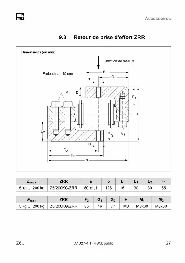
Accessoires
Z6… A1027-4.1 HBM: public 27
9.3 Retour de prise d'effort ZRR
Dimensions (en mm)
Profondeur : 15�mm F1
G1
E1
a
G2
F2b
E2
M1
M1
H
D
D
H
Direction de mesure
Emax ZRR a b D E1 E2 F1
5�kg … 200�kg Z6/200KG/ZRR 80 ±1,1 123 16 30 30 65
Emax ZRR F2 G1 G2 H M1 M2
5�kg … 200�kg Z6/200KG/ZRR 85 46 77 M8 M8x30 M8x30
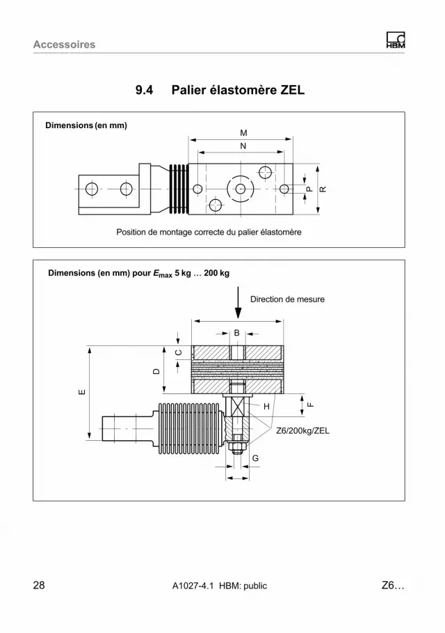
Accessoires
28 A1027-4.1 HBM: public Z6…
9.4 Palier élastomère ZEL
Dimensions (en mm)M
N
Position de montage correcte du palier élastomère
P RB
FH
Z6/200kg/ZEL
C
D
E
G
Dimensions (en mm) pour Emax 5�kg � 200�kg
Direction de mesure

Accessoires
Z6… A1027-4.1 HBM: public 29
Direction de mesure
Dimensions (en mm) pour Emax 500�kg
H
F
Z6/1t/ZEL
C
DL
E
A
B
Direction de mesure
Dimensions (en mm) pour Emax 1�t
Z6/1t/ZEL
A
F
CD
L
E
H
B
Vis décalées de 35°

Accessoires
30 A1027-4.1 HBM: public Z6…
Emax ZEL A B C D E F G H
5�kg … 200�kg Z6/200KG/ZEL 75 M12 12 40 79 ±1,3 18,5 M8 s.p.17
500 �kg Z6/1T/ZEL 80 M10 10 39105
+2,1
-2,226 - s.p.
27
1�t Z6/1T/ZEL 80 M10 10 39117
+2,1
‐2,2
26 - s.p.27
Emax ZEL K L M N P R FR1) smax
2)
5�kg … 200�kg Z6/200KG/ZEL 19 - - - - - 163 3
500 �kg Z6/1T/ZEL - 20 120 100 9 60 400 4,5
1 t Z6/1T/ZEL - 20 120 100 9 60 400 4,5
1) FR : force de rappel en N pour un déplacement latéral de 1�mm2) smax : déplacement latéral maximal admissible sous charge nominale

Accessoires
Z6… A1027-4.1 HBM: public 31
9.5 Pointeau, coupelle ZK
Dimensions (en mm) pour Emax 5�kg � 1�t
Direction de mesure
Z6/.../ZK
ECX
Coupelle 90°Pointeau 60°
∅U
∅C
Emax ZK �C D E �U X
5�kg … 200�kg Z6/200KG/ZK 15 16 21 8,1‐0,05 26
500�kg … 1�t Z6/1T/ZK 18 24 32 11‐0,05 34/36,5
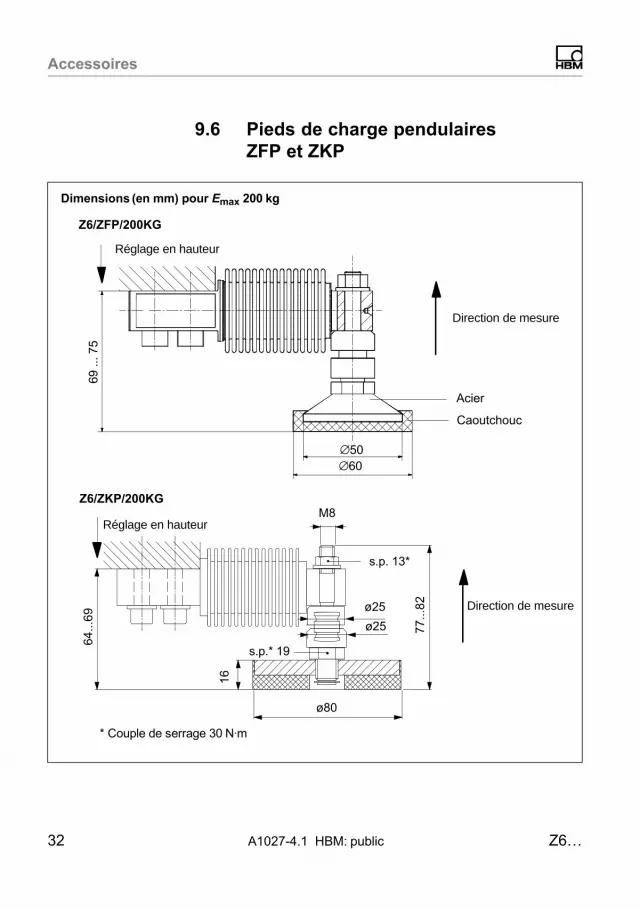
Accessoires
32 A1027-4.1 HBM: public Z6…
9.6 Pieds de charge pendulaires ZFP et ZKP
Dimensions (en mm) pour Emax 200�kg
Z6/ZFP/200KG
Réglage en hauteur
Direction de mesure
Acier
∅60
69 ..
. 75
∅50
Caoutchouc
M8
77...
82
ø80
16
ø25
ø25
64...
69
s.p. 13*
s.p.* 19
* Couple de serrage 30�N⋅m
Z6/ZKP/200KG
Direction de mesure
Réglage en hauteur

Accessoires
Z6… A1027-4.1 HBM: public 33
9.7 Pied de charge pendulaire PCX
Dimensions (en mm) pour Emax 5�kg � 500�kg
s.p. = sur plats
Ø60Ø50
69 ..
. 75
Pos. 1, s.p. 13
Pos. 2, s.p. 17
64 ..
. 70
Pos. 3, s.p. 17
10
1 ensemble se compose de 4 Z6/PCX/500kg

Accessoires
34 A1027-4.1 HBM: public Z6…
9.8 Plaque support / kit de montage
Couple de serrage MA :23 N⋅m pour 200 kg ;45�N⋅m pour 500 kg
1531 66
Application de charge via :Z6/...KG/ZPL ; Z6/...KG/ZEL ; Z6/...KG/ZK
A
Dimensions (en mm) pour Emax 5 kg (Z6/ZPU/200KG) ... 500 kg (Z6/ZPU/500KG)
100
65
14
155
200
22,5
79 82±0,1
Vue de dessous
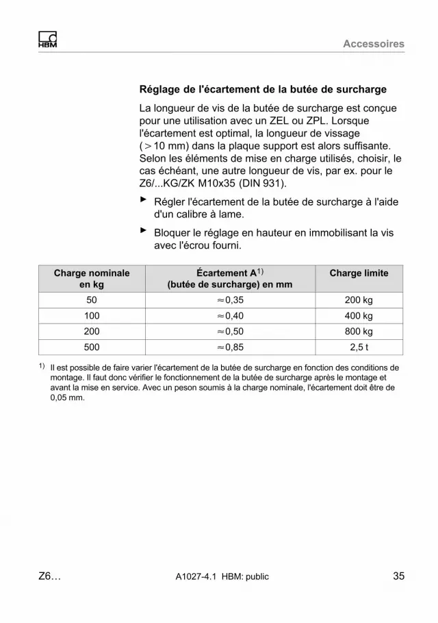
Accessoires
Z6… A1027-4.1 HBM: public 35
Réglage de l'écartement de la butée de surcharge
La longueur de vis de la butée de surcharge est conçuepour une utilisation avec un ZEL ou ZPL. Lorsquel'écartement est optimal, la longueur de vissage(�10 mm) dans la plaque support est alors suffisante.Selon les éléments de mise en charge utilisés, choisir, lecas échéant, une autre longueur de vis, par ex. pour leZ6/...KG/ZK M10x35 (DIN�931).
► Régler l'écartement de la butée de surcharge à l'aided'un calibre à lame.
► Bloquer le réglage en hauteur en immobilisant la visavec l'écrou fourni.
Charge nominaleen kg
Écartement A1)
(butée de surcharge) en mmCharge limite
50 �0,35 200�kg
100 �0,40 400�kg
200 �0,50 800�kg
500 �0,85 2,5�t
1) Il est possible de faire varier l'écartement de la butée de surcharge en fonction des conditions demontage. Il faut donc vérifier le fonctionnement de la butée de surcharge après le montage etavant la mise en service. Avec un peson soumis à la charge nominale, l'écartement doit être de0,05�mm.

ww
w.h
bm
.co
m
HBM Test and Measurement
Tel. +49 6151 803-0
Fax +49 6151 803-9100
measure and predict with confidence A10
27-4
.1 7
-200
1.50
01 H
BM
: pub
lic