onload changeover switch - net
TRANSCRIPT
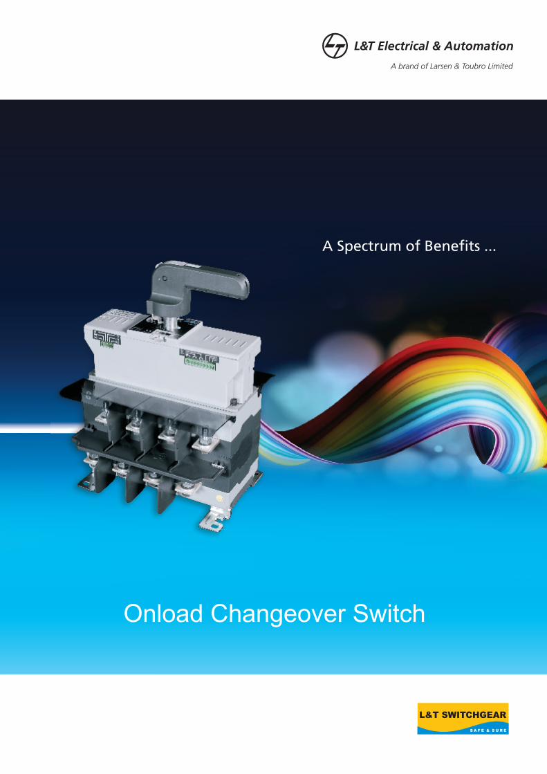
Onload Changeover Switch
A Spectrum of Benefits ...
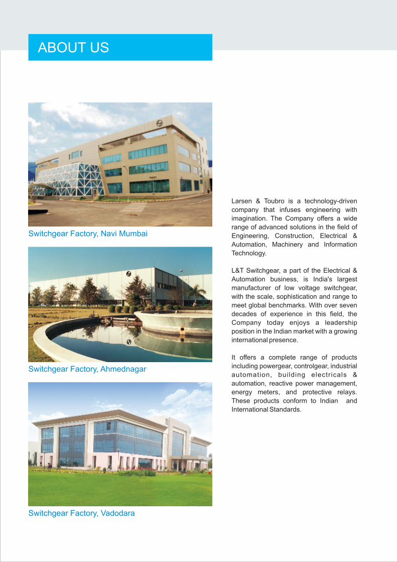
Larsen & Toubro is a technology-driven
company that infuses engineering with
imagination. The Company offers a wide
range of advanced solutions in the field of
Engineering, Construction, Electrical &
Automation, Machinery and Information
Technology.
L&T Switchgear, a part of the Electrical &
Automation business, is India's largest
manufacturer of low voltage switchgear,
with the scale, sophistication and range to
meet global benchmarks. With over seven
decades of experience in this field, the
Company today enjoys a leadership
position in the Indian market with a growing
international presence.
It offers a complete range of products
including powergear, controlgear, industrial
automation, building electricals &
automation, reactive power management,
energy meters, and protective relays.
These products conform to Indian and
International Standards.
Switchgear Factory, Ahmednagar
Switchgear Factory, Navi Mumbai
Switchgear Factory, Vadodara
ABOUT US

27 - 29
30 - 33
34 - 52
6 - 26
INDEX
Overview
Product Data
Characteristic Curves
Wiring Diagrams
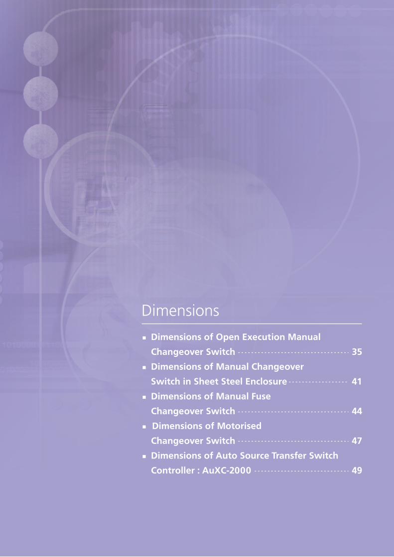
Dimensions
2 - 5
Standards & Approvals
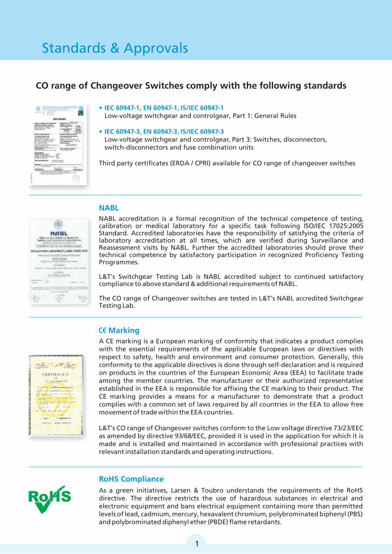
• IEC 60947-1, EN 60947-1, IS/IEC 60947-1
• IEC 60947-3, EN 60947-3, IS/IEC 60947-3
Low-voltage switchgear and controlgear, Part 1: General Rules
Low-voltage switchgear and controlgear, Part 3: Switches, disconnectors,switch-disconnectors and fuse combination units
Third party certificates (ERDA / CPRI) available for CO range of changeover switches
A CE marking is a European marking of conformity that indicates a product complieswith the essential requirements of the applicable European laws or directives withrespect to safety, health and environment and consumer protection. Generally, thisconformity to the applicable directives is done through self-declaration and is requiredon products in the countries of the European Economic Area (EEA) to facilitate tradeamong the member countries. The manufacturer or their authorized representativeestablished in the EEA is responsible for affixing the CE marking to their product. TheCE marking provides a means for a manufacturer to demonstrate that a productcomplies with a common set of laws required by all countries in the EEA to allow freemovement of trade within the EEA countries.
L&T’s CO range of Changeover switches conform to the Low voltage directive 73/23/EEC as amended by directive 93/68/EEC, provided it is used in the application for which it is made and is installed and maintained in accordance with professional practices with relevant installation standards and operating instructions.
Marking
NABL accreditation is a formal recognition of the technical competence of testing,calibration or medical laboratory for a specific task following ISO/IEC 17025:2005Standard. Accredited laboratories have the responsibility of satisfying the criteria oflaboratory accreditation at all times, which are verified during Surveillance and Reassessment visits by NABL. Further the accredited laboratories should prove theirtechnical competence by satisfactory participation in recognized Proficiency TestingProgrammes.
L&T’s Switchgear Testing Lab is NABL accredited subject to continued satisfactorycompliance to above standard & additional requirements of NABL.
The CO range of Changeover switches are tested in L&T's NABL accredited Switchgear Testing Lab.
NABL
CO range of Changeover Switches comply with the following standards
As a green initiatives, Larsen & Toubro understands the requirements of the RoHS directive. The directive restricts the use of hazardous substances in electrical and electronic equipment and bans electrical equipment containing more than permitted levels of lead, cadmium, mercury, hexavalent chromium, polybrominated biphenyl (PBS) and polybrominated diphenyl ether (PBDE) flame retardants.
1
RoHS Compliance
Overview
¾ Basic Function 03
04¾ Superior Performance
¾ Product Range 05
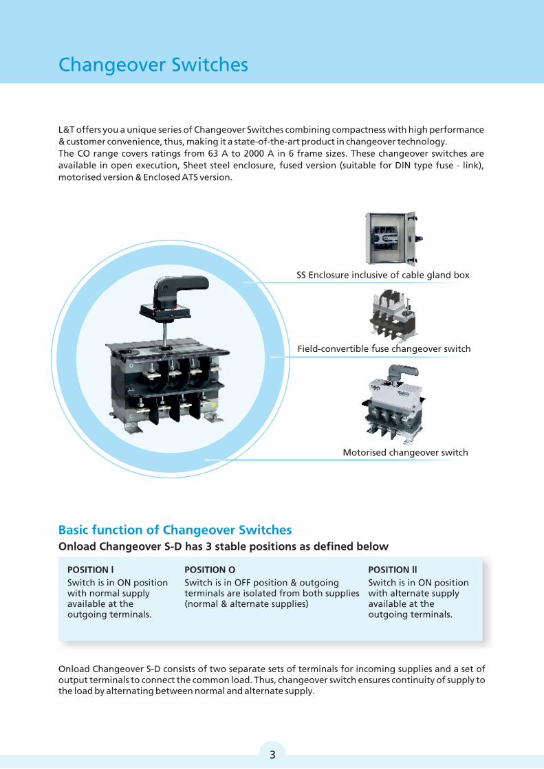
L&T offers you a unique series of Changeover Switches combining compactness with high performance & customer convenience, thus, making it a state-of-the-art product in changeover technology. The CO range covers ratings from 63 A to 2000 A in 6 frame sizes. These changeover switches are available in open execution, Sheet steel enclosure, fused version (suitable for DIN type fuse - link), motorised version & Enclosed ATS version.
Changeover Switches
SS Enclosure inclusive of cable gland box
Motorised changeover switch
Field-convertible fuse changeover switch
Onload Changeover S-D consists of two separate sets of terminals for incoming supplies and a set of output terminals to connect the common load. Thus, changeover switch ensures continuity of supply to the load by alternating between normal and alternate supply.
Switch is in ON positionwith normal supply available at the outgoing terminals.
Switch is in ON position with alternate supply available at the outgoing terminals.
POSITION llPOSITION OPOSITION l
Onload Changeover S-D has 3 stable positions as defined below
Switch is in OFF position & outgoing terminals are isolated from both supplies(normal & alternate supplies)
3
Basic function of Changeover Switches
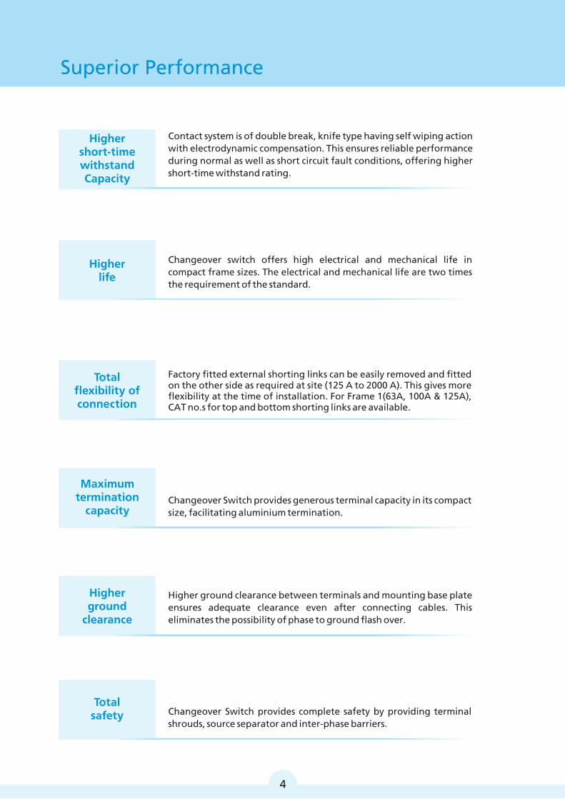
Superior Performance
Changeover switch offers high electrical and mechanical life in compact frame sizes. The electrical and mechanical life are two times the requirement of the standard.
Contact system is of double break, knife type having self wiping action with electrodynamic compensation. This ensures reliable performance during normal as well as short circuit fault conditions, offering higher short-time withstand rating.
Higherlife
Factory fitted external shorting links can be easily removed and fitted on the other side as required at site (125 A to 2000 A). This gives more flexibility at the time of installation. For Frame 1(63A, 100A & 125A), CAT no.s for top and bottom shorting links are available.
Total flexibility of connection
Maximum termination
capacity
Higher ground clearance between terminals and mounting base plate ensures adequate clearance even after connecting cables. This eliminates the possibility of phase to ground flash over.
Higher ground
clearance
Total safety Changeover Switch provides complete safety by providing terminal
shrouds, source separator and inter-phase barriers.
Higher short-time withstandCapacity
Changeover Switch provides generous terminal capacity in its compact size, facilitating aluminium termination.
4
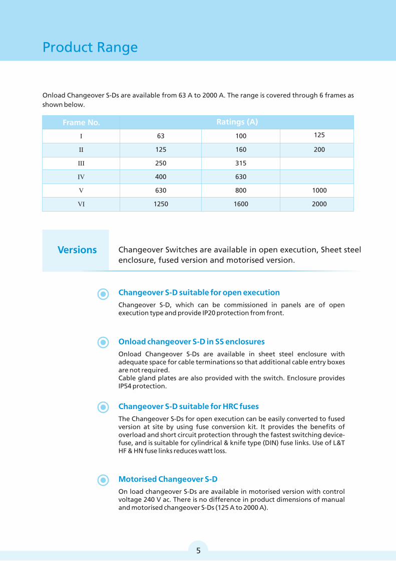
Product Range
Onload Changeover S-Ds are available from 63 A to 2000 A. The range is covered through 6 frames as shown below.
Changeover Switches are available in open execution, Sheet steel enclosure, fused version and motorised version.
Changeover S-D suitable for open execution
Changeover S-D, which can be commissioned in panels are of open execution type and provide IP20 protection from front.
Onload changeover S-D in SS enclosures
Onload Changeover S-Ds are available in sheet steel enclosure with adequate space for cable terminations so that additional cable entry boxes are not required.Cable gland plates are also provided with the switch. Enclosure provides IP54 protection.
Changeover S-D suitable for HRC fuses
The Changeover S-Ds for open execution can be easily converted to fused version at site by using fuse conversion kit. It provides the benefits of overload and short circuit protection through the fastest switching device-fuse, and is suitable for cylindrical & knife type (DIN) fuse links. Use of L&T HF & HN fuse links reduces watt loss.
Motorised Changeover S-D
On load changeover S-Ds are available in motorised version with control voltage 240 V ac. There is no difference in product dimensions of manual and motorised changeover S-Ds (125 A to 2000 A).
Frame No.
63
125
250
400
630
1250
100
160
315
630
800
1600
Ratings (A)
Versions
I
II
III
IV
V
VI
5
200
1000
2000
125
Product Data
¾ Manual Changeover Product Feature 07
¾ Technical Specifications of
Manual Changeover 11
¾ Motorised Changeover Product Features 13
¾Universal Mounting for
Manual Changeover Range 15
¾Automatic Source Transfer Solution 16
¾ASTS with AST Controller 17
¾ASTS with AuXC 2000 Controller 19
¾ Technical Specifications of
Motorised Kit 21
¾Enclosed ATS 23
¾ Ordering Information 26
2 6
3
8
7
9
5
1
4
7
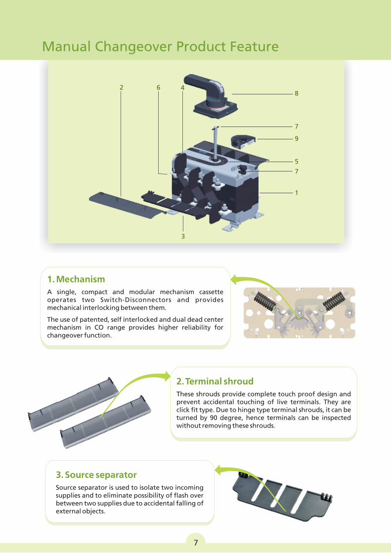
3. Source separator
Source separator is used to isolate two incoming supplies and to eliminate possibility of flash over between two supplies due to accidental falling of external objects.
Manual Changeover Product Feature
1. Mechanism
A single, compact and modular mechanism cassette operates two Switch-Disconnectors and provides mechanical interlocking between them.
The use of patented, self interlocked and dual dead center mechanism in CO range provides higher reliability for changeover function.
7
2. Terminal shroud
These shrouds provide complete touch proof design and prevent accidental touching of live terminals. They are click fit type. Due to hinge type terminal shrouds, it can be turned by 90 degree, hence terminals can be inspected without removing these shrouds.
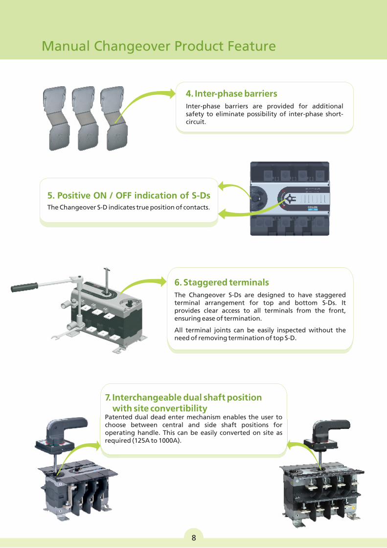
4. Inter-phase barriers
Inter-phase barriers are provided for additional safety to eliminate possibility of inter-phase short-circuit.
6. Staggered terminals
The Changeover S-Ds are designed to have staggered terminal arrangement for top and bottom S-Ds. It provides clear access to all terminals from the front, ensuring ease of termination.
All terminal joints can be easily inspected without the need of removing termination of top S-D.
5. Positive ON / OFF indication of S-DsThe Changeover S-D indicates true position of contacts.
ON
7. Interchangeable dual shaft position with site convertibility
Patented dual dead enter mechanism enables the user to choose between central and side shaft positions for operating handle. This can be easily converted on site as required (125A to 1000A).
Manual Changeover Product Feature
8
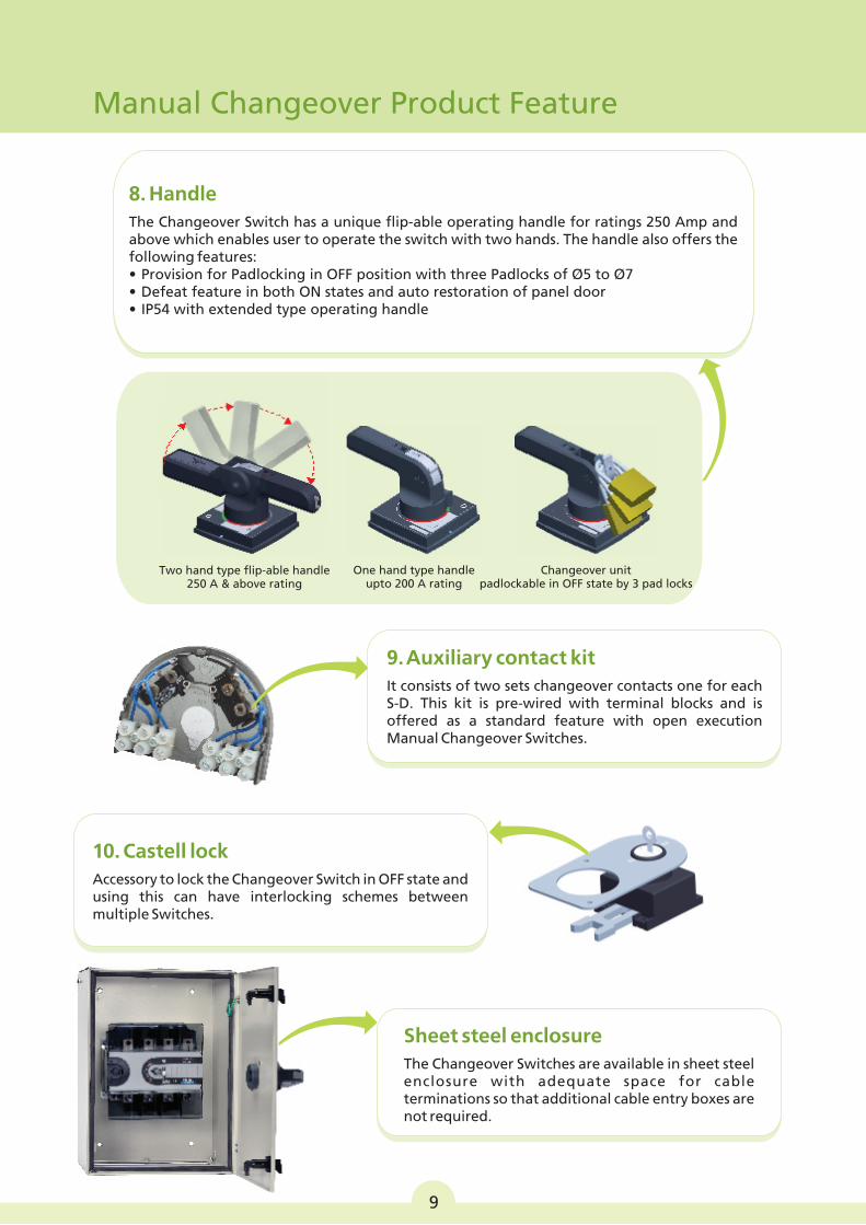
8. Handle
The Changeover Switch has a unique flip-able operating handle for ratings 250 Amp and above which enables user to operate the switch with two hands. The handle also offers the following features:• Provision for Padlocking in OFF position with three Padlocks of Ø5 to Ø7• Defeat feature in both ON states and auto restoration of panel door• IP54 with extended type operating handle
Sheet steel enclosure
The Changeover Switches are available in sheet steel enclosure with adequate space for cable terminations so that additional cable entry boxes are not required.
9. Auxiliary contact kit
It consists of two sets changeover contacts one for each S-D. This kit is pre-wired with terminal blocks and is offered as a standard feature with open execution Manual Changeover Switches.
One hand type handle upto 200 A rating
Two hand type flip-able handle250 A & above rating
Changeover unit padlockable in OFF state by 3 pad locks
Manual Changeover Product Feature
9
10. Castell lock
Accessory to lock the Changeover Switch in OFF state and using this can have interlocking schemes between multiple Switches.
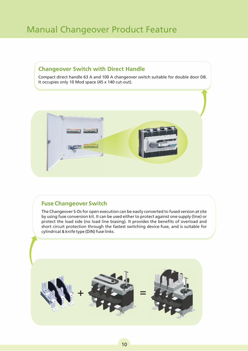
Fuse Changeover Switch
The Changeover S-Ds for open execution can be easily converted to fused version at site by using fuse conversion kit. It can be used either to protect against one supply (line) or protect the load side (no load line biasing). It provides the benefits of overload and short circuit protection through the fastest switching device-fuse, and is suitable for cylindrical & knife type (DIN) fuse links.
Manual Changeover Product Feature
+ =
10
Changeover Switch with Direct Handle
Compact direct handle 63 A and 100 A changeover switch suitable for double door DB.It occupies only 10 Mod space (45 x 140 cut-out).
Type designation
No. of Poles
Rated operational voltage (U )e
Rated frequency
Rated impulse withstand voltage (U )imp
Pollution degree0Conventional free air thermal current, l at 40 Cth
0Conventional enclosed thermal current, l at 40 Cthe
# #Rated operational current, l AC-21A / AC-22A / AC-23Ae
Rated operational power for AC-23A*
Rated breaking capacity for AC-23A
Rated making capacity for AC-23A
Short-circuit making capacity, lcm
Rated fused short-circuit current at 415 V, 50/60 Hz
Maximum Al. cable with lug
Maximum link width
Maximum link thickness
Termination tightening torque
Operating torque center / side operating
Weight (without accessories)
Rated insulation voltage (U)i
Reference Standards
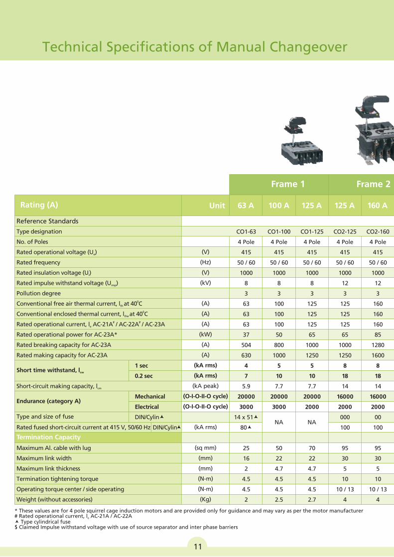
Rating (A)
Short time withstand, lcw
Endurance (category A)
Type and size of fuse
1 sec
0.2 sec
Mechanical
Electrical
DIN/Cylinæ
DIN/Cylinæ
(V)
(Hz)
(kV)
(A)
(A)
(A)
(kW)
(A)
(A)
(kA rms)
(kA rms)
(kA peak)
(O-I-O-II-O cycle)
(O-I-O-II-O cycle)
(kA rms)
(sq mm)
(mm)
(mm)
(N-m)
(N-m)
(Kg)
(V)
Unit 63 A
CO1-63
4 Pole
415
50 / 60
1000
8
3
63
63
63
37
504
630
4
7
5.9
20000
3000
14 x 51æ
80æ
25
16
2
4.5
4.5
2
100 A 125 A
CO1-100
4 Pole
415
50 / 60
1000
8
3
100
100
100
50
800
1000
5
10
7.7
20000
3000
50
22
4.7
4.5
4.5
2.5
CO1-125
4 Pole
415
50 / 60
1000
8
3
125
125
125
65
1000
1250
5
10
7.7
20000
2000
70
22
4.7
4.5
4.5
2.7
NA NA
160 A
CO2-125
4 Pole
415
50 / 60
1000
12
3
125
125
125
65
1000
1250
8
18
14
16000
2000
000
100
95
30
5
10
10 / 13
4
CO2-160
4 Pole
415
50 / 60
1000
12
3
160
160
160
85
1280
1600
8
18
14
16000
2000
00
100
95
30
5
10
10 / 13
4
125 A
Frame 1 Frame 2
Termination Capacity
* These values are for 4 pole squirrel cage induction motors and are provided only for guidance and may vary as per the motor manufacturer# Rated operational current, l AC-21A / AC-22Ae
æ Type cylindrical fuse$ Claimed Impulse withstand voltage with use of source separator and inter phase barriers
Technical Specifications of Manual Changeover
11
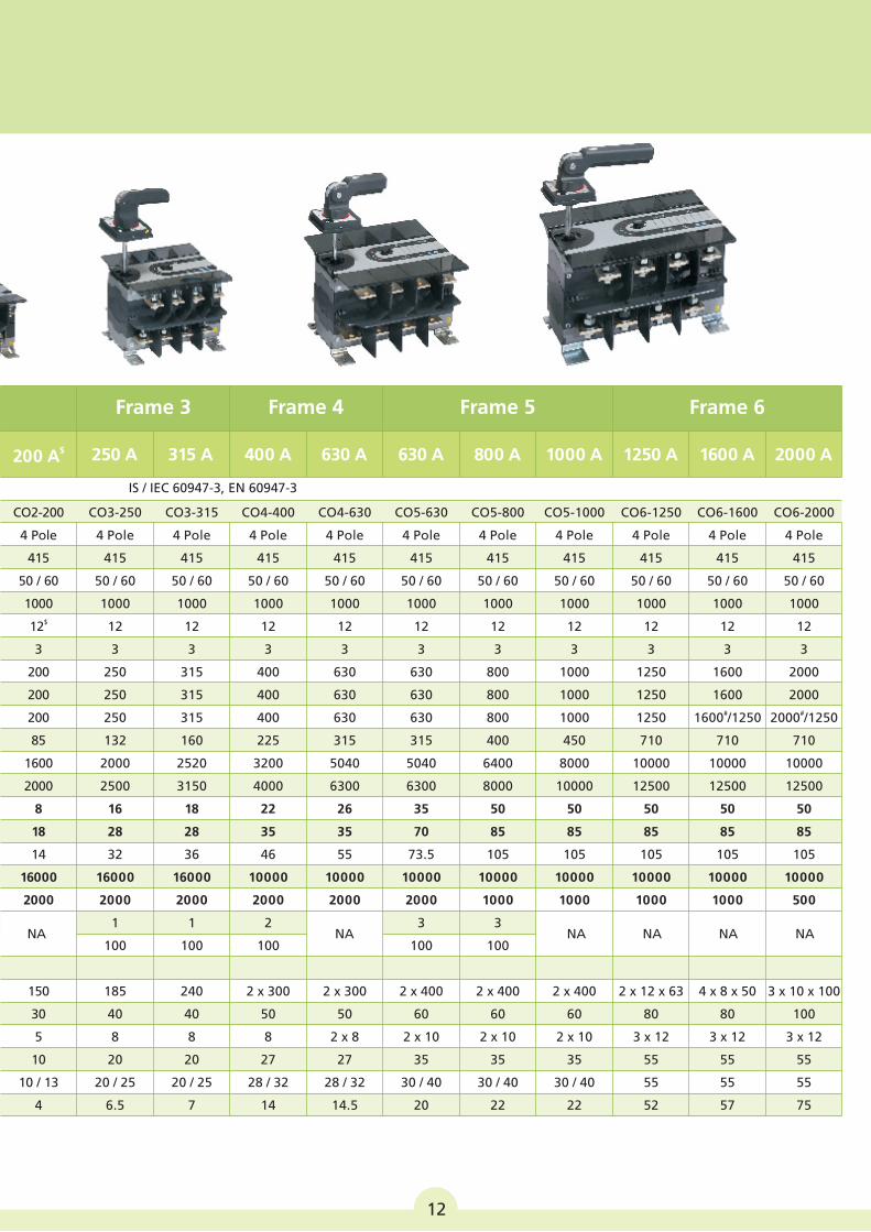
250 A 315 A 400 A 630 A 630 A 800 A 1000 A 1250 A 1600 A 2000 A$200 A
Frame 3 Frame 4 Frame 5 Frame 6
IS / IEC 60947-3, EN 60947-3
12
CO3-250
4 Pole
415
50 / 60
1000
12
3
250
250
250
132
2000
2500
16
28
32
16000
2000
1
100
185
40
8
20
20 / 25
6.5
CO3-315
4 Pole
415
50 / 60
1000
12
3
315
315
315
160
2520
3150
18
28
36
16000
2000
1
100
240
40
8
20
20 / 25
7
CO4-400
4 Pole
415
50 / 60
1000
12
3
400
400
400
225
3200
4000
22
35
46
10000
2000
2
100
2 x 300
50
8
27
28 / 32
14
CO4-630
4 Pole
415
50 / 60
1000
12
3
630
630
630
315
5040
6300
26
35
55
10000
2000
2 x 300
50
2 x 8
27
28 / 32
14.5
CO5-630
4 Pole
415
50 / 60
1000
12
3
630
630
630
315
5040
6300
35
70
73.5
10000
2000
3
100
2 x 400
60
2 x 10
35
30 / 40
20
CO5-800
4 Pole
415
50 / 60
1000
12
3
800
800
800
400
6400
8000
50
85
105
10000
1000
3
100
2 x 400
60
2 x 10
35
30 / 40
22
CO5-1000
4 Pole
415
50 / 60
1000
12
3
1000
1000
1000
450
8000
10000
50
85
105
10000
1000
2 x 400
60
2 x 10
35
30 / 40
22
CO6-1250
4 Pole
415
50 / 60
1000
12
3
1250
1250
1250
710
10000
12500
50
85
105
10000
1000
2 x 12 x 63
80
3 x 12
55
55
52
CO6-1600
4 Pole
415
50 / 60
1000
12
3
1600
1600#1600 /1250
710
10000
12500
50
85
105
10000
1000
4 x 8 x 50
80
3 x 12
55
55
57
CO6-2000
4 Pole
415
50 / 60
1000
12
3
2000
2000#2000 /1250
710
10000
12500
50
85
105
10000
500
3 x 10 x 100
100
3 x 12
55
55
75
CO2-200
4 Pole
415
50 / 60
1000$12
3
200
200
200
85
1600
2000
8
18
14
16000
2000
150
30
5
10
10 / 13
4
NA NA NA NA NANA
1
2
3
4
5
67
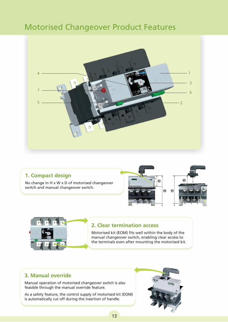
Motorised Changeover Product Features
1. Compact design
No change in H x W x D of motorised changeover switch and manual changeover switch.
3. Manual override
Manual operation of motorised changeover switch is also feasible through the manual override feature.
As a safety feature, the control supply of motorised kit (EOM) is automatically cut off during the insertion of handle.
2. Clear termination access
Motorised kit (EOM) fits well within the body of the manual changeover switch, enabling clear access to the terminals even after mounting the motorised kit.
13
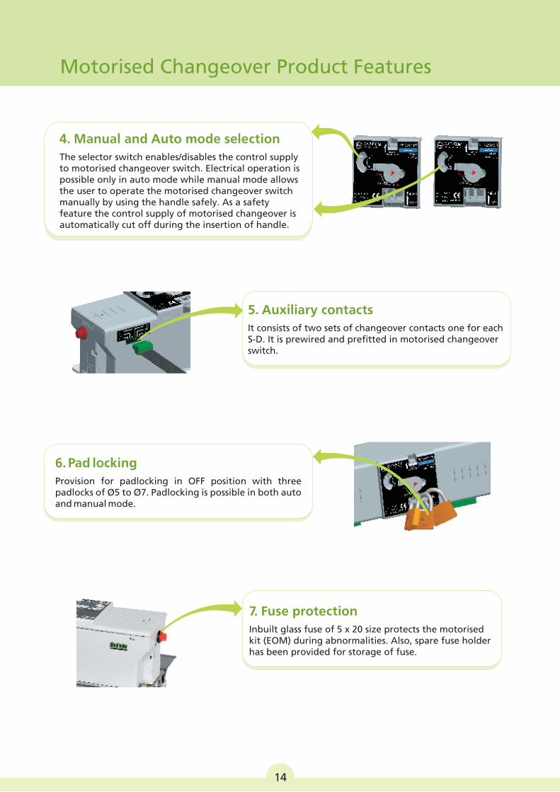
6. Pad locking
Provision for padlocking in OFF position with three padlocks of Ø5 to Ø7. Padlocking is possible in both auto and manual mode.
4. Manual and Auto mode selection
The selector switch enables/disables the control supply to motorised changeover switch. Electrical operation is possible only in auto mode while manual mode allows the user to operate the motorised changeover switch manually by using the handle safely. As a safety feature the control supply of motorised changeover is automatically cut off during the insertion of handle.
5. Auxiliary contacts
It consists of two sets of changeover contacts one for each S-D. It is prewired and prefitted in motorised changeover switch.
7. Fuse protection
Inbuilt glass fuse of 5 x 20 size protects the motorised kit (EOM) during abnormalities. Also, spare fuse holder has been provided for storage of fuse.
Motorised Changeover Product Features
14
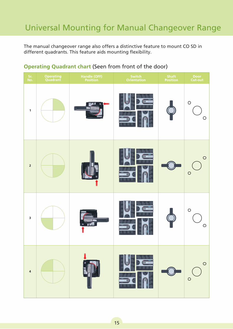
Switch Orientation
NO
ON
ON
ON
NO
ON
ON
ON
NO
ON
ON
ON
NO
ON
ON
ON
Shaft Position
15
The manual changeover range also offers a distinctive feature to mount CO SD in different quadrants. This feature aids mounting flexibility.
Operating Quadrant chart (Seen from front of the door)
1
2
3
4
DoorCut-out
Handle (OFF) Position
Operating Quadrant
Sr.No.
Universal Mounting for Manual Changeover Range
16
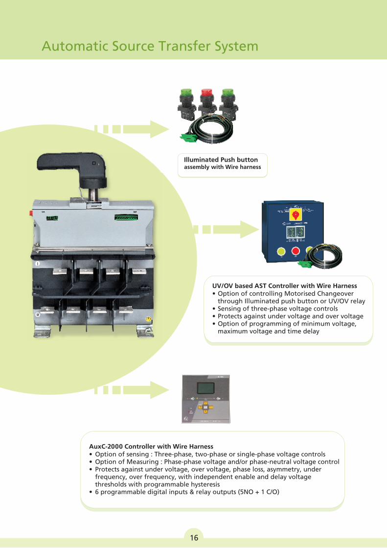
UV/OV based AST Controller with Wire Harness• Option of controlling Motorised Changeover
through Illuminated push button or UV/OV relay• Sensing of three-phase voltage controls• Protects against under voltage and over voltage• Option of programming of minimum voltage,
maximum voltage and time delay
Illuminated Push button assembly with Wire harness
Automatic Source Transfer System
AuxC-2000 Controller with Wire Harness •• Option of Measuring : Phase-phase voltage and/or phase-neutral voltage control• Protects against under voltage, over voltage, phase loss, asymmetry, under
frequency, over frequency, with independent enable and delay voltagethresholds with programmable hysteresis
• 6 programmable digital inputs & relay outputs (5NO + 1 C/O)
Option of sensing : Three-phase, two-phase or single-phase voltage controls
17
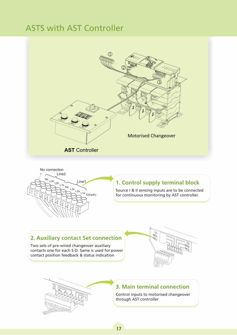
ASTS with AST Controller
AST Controller
Motorised Changeover
1. Control supply terminal block
Source I & II sensing inputs are to be connected for continuous monitoring by AST controller.
NbL3b
L2bL1b
NaL3a
L2aL1a
Line1
Line2No connection
E(Earth)
2. Auxiliary contact Set connection
Two sets of pre-wired changeover auxiliary contacts one for each S-D. Same is used for power contact position feedback & status indication
3. Main terminal connection
Control inputs to motorised changeover through AST controller
C2O2
N
C2N
C1O1
N
C1N
ON-1OFF
-ON II
ENP
18
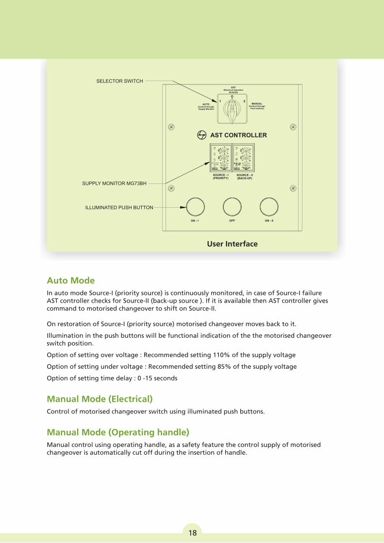
SUPPLY MONITOR MG73BH
SELECTOR SWITCH
ILLUMINATED PUSH BUTTON
ON - I OFF ON - II
MANUAL(Control through Push buttons)
AUTO(Control through Supply Monitor)
OFF(Electrical Operation
disabled)
SOURCE - I(PRIORITY)
SOURCE - II(BACK-UP)
AST CONTROLLER
O
1 2
ON ON
UV UV
OV
BLINK:ASYON:REV
User Interface
Auto Mode
Manual Mode (Electrical)
Manual Mode (Operating handle)
In auto mode Source-I (priority source) is continuously monitored, in case of Source-I failure AST controller checks for Source-II (back-up source ). If it is available then AST controller gives command to motorised changeover to shift on Source-II.
On restoration of Source-I (priority source) motorised changeover moves back to it.
Illumination in the push buttons will be functional indication of the the motorised changeover switch position.
Option of setting over voltage : Recommended setting 110% of the supply voltage
Option of setting under voltage : Recommended setting 85% of the supply voltage
Option of setting time delay : 0 -15 seconds
Control of motorised changeover switch using illuminated push buttons.
Manual control using operating handle, as a safety feature the control supply of motorised changeover is automatically cut off during the insertion of handle.
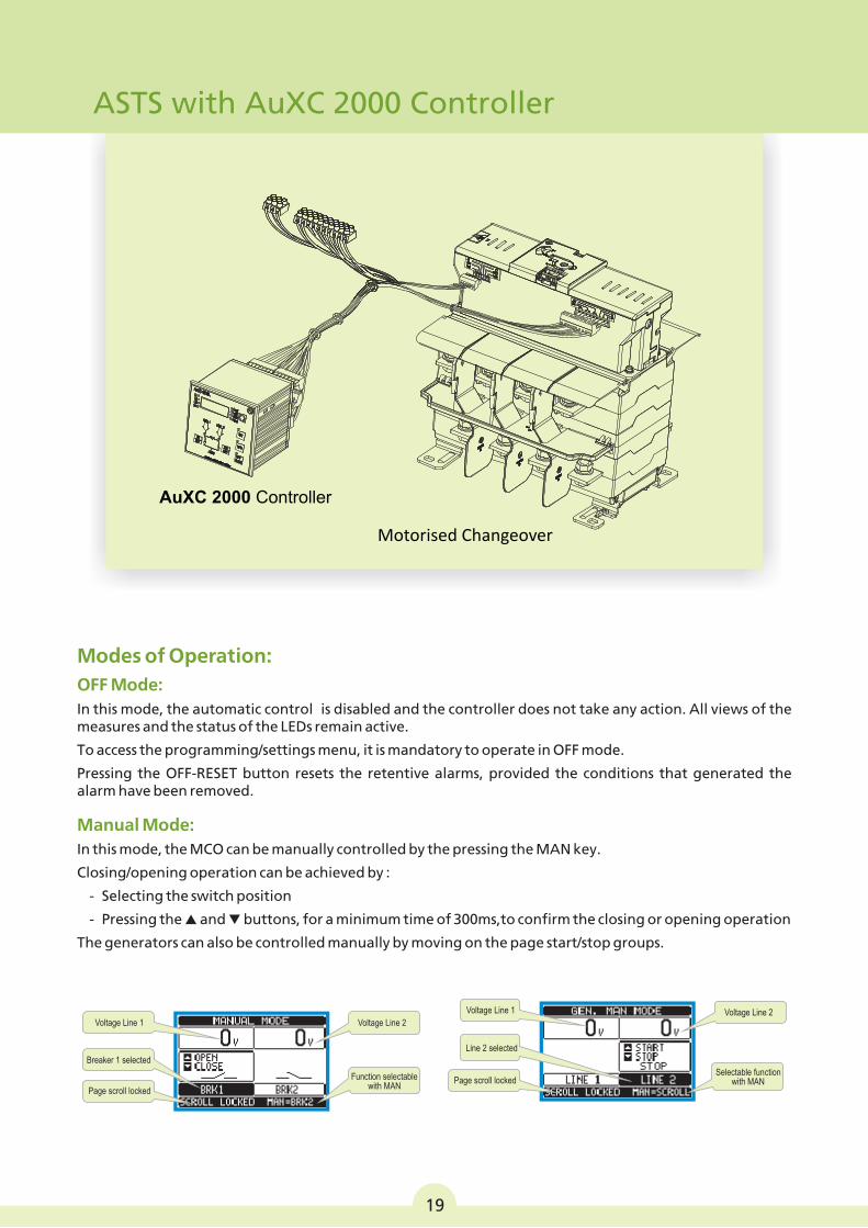
ASTS with AuXC 2000 Controller
AuXC 2000 Controller
Motorised Changeover
Voltage Line 1
Breaker 1 selected
Page scroll locked
Voltage Line 2
Function selectablewith MAN
Voltage Line 1
Line 2 selected
Page scroll locked
Voltage Line 2
Selectable functionwith MAN
Modes of Operation:
OFF Mode:
In this mode, the automatic control is disabled and the controller does not take any action. All views of the measures and the status of the LEDs remain active.
To access the programming/settings menu, it is mandatory to operate in OFF mode.
Pressing the OFF-RESET button resets the retentive alarms, provided the conditions that generated the alarm have been removed.
Manual Mode:
In this mode, the MCO can be manually controlled by the pressing the MAN key.
Closing/opening operation can be achieved by :
- Selecting the switch position
- Pressing the p and q buttons, for a minimum time of 300ms,to confirm the closing or opening operation
The generators can also be controlled manually by moving on the page start/stop groups.
19
AuxC-2000 Controller
20
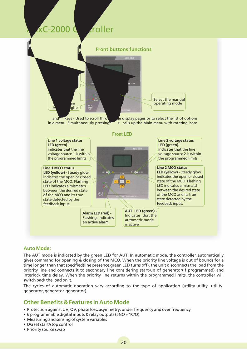
Front buttons functions
Selects the OFF operating mode
Selects the automatic mode. Green AUT LED lights
▲ and ▼ keys - Used to scroll through the display pages or to select the list of options in a menu. Simultaneously pressing ▼ + ▲ calls up the Main menu with rotating icons
Select the manual operating mode
Front LED
AUT LED (green) - Indicates that the automatic mode is active
Alarm LED (red) - Flashing, indicates an active alarm
Line 1 voltage status LED (green) - indicates that the line voltage source 1 is within the programmed limits
Line 2 voltage status LED (green) - indicates that the line voltage source 2 is within the programmed limits.
Line 2 MCO status LED (yellow) - Steady glow indicates the open or closed state of the MCO. Flashing LED indicates a mismatch between the desired state of the MCO and its true state detected by the feedback input.
Line 1 MCO status LED (yellow) - Steady glow indicates the open or closed state of the MCO. Flashing LED indicates a mismatch between the desired state of the MCO and its true state detected by the feedback input.
Auto Mode:
The AUT mode is indicated by the green LED for AUT. In automatic mode, the controller automatically gives command for opening & closing of the MCO. When the priority line voltage is out of bounds for a time longer than that specified(line presence green LED turns off), the unit disconnects the load from the priority line and connects it to secondary line considering start-up of generator(if programmed) and interlock time delay. When the priority line returns within the programmed limits, the controller will switch back the load on it.The cycles of automatic operation vary according to the type of application (utility-utility, utility-generator, generator-generator).
Other Benefits & Features in Auto Mode• Protection against UV, OV, phase loss, asymmetry, under frequency and over frequency• 6 programmable digital inputs & relay outputs (5NO + 1C/O)• Measuring and sensing of system variables• DG set start/stop control• Priority source swap
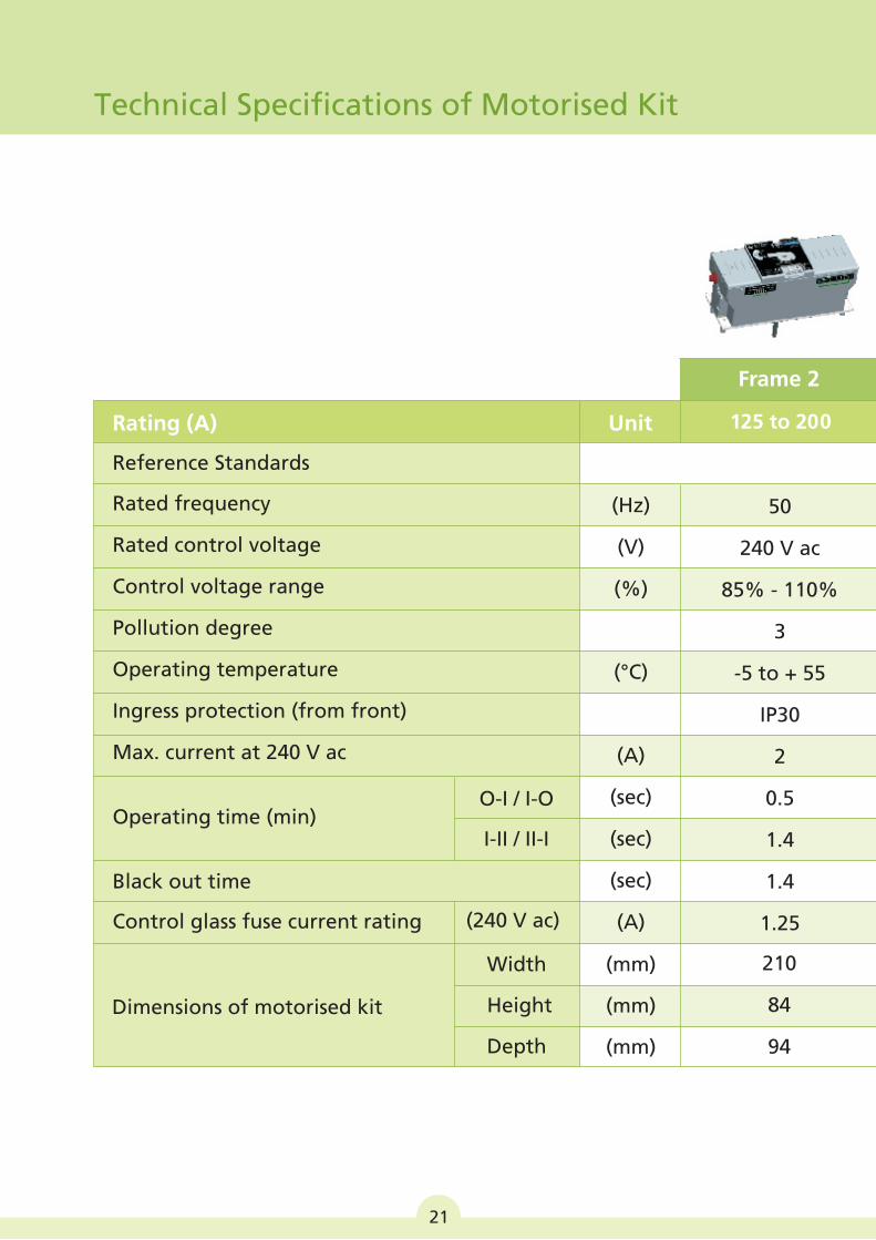
Technical Specifications of Motorised Kit
125 to 200
Rated frequency
Rated control voltage
Control voltage range
Pollution degree
Operating temperature
Ingress protection (from front)
Max. current at 240 V ac
Reference Standards
(Hz)
(V)
(%)
(°C)
(A)
(sec)
(sec)
(sec)
(A)
50
240 V ac
85% - 110%
3
-5 to + 55
IP30
2
0.5
1.4
1.4
1.25
Frame 2
Rating (A) Unit
Operating time (min)
Black out time
Control glass fuse current rating
Dimensions of motorised kit
O-I / I-O
I-II / II-I
Width
Height
Depth
(mm)
(mm)
(mm)
210
84
94
(240 V ac)
21
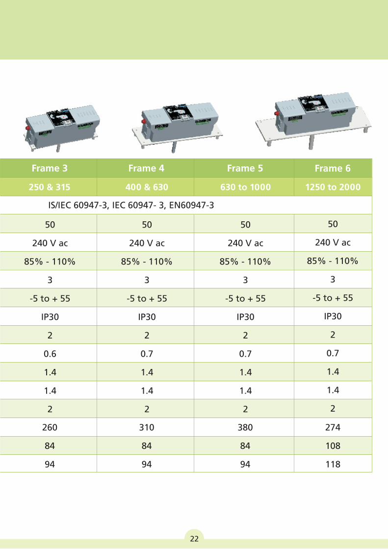
22
250 & 315 400 & 630 630 to 1000
50
240 V ac
85% - 110%
3
-5 to + 55
IP30
2
0.6
1.4
1.4
2
50
240 V ac
85% - 110%
3
-5 to + 55
IP30
2
0.7
1.4
1.4
2
50
240 V ac
85% - 110%
3
-5 to + 55
IP30
2
0.7
1.4
1.4
2
260
84
94
310
84
94
380
84
94
IS/IEC 60947-3, IEC 60947- 3, EN60947-3
Frame 3 Frame 4 Frame 5 Frame 6
50
240 V ac
85% - 110%
3
-5 to + 55
IP30
2
0.7
1.4
1.4
2
1250 to 2000
274
108
118
23
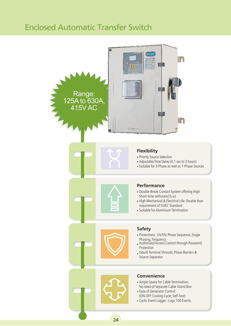
Enclosed Automatic Transfer Switch
Rapid industrialization and urbanization are leading to ever-rising demand for reliable electricity.
Technological advancement and changing lifestyles have given rise to many applications which demand 24 X7 uninterruptible power supply. In some industries, power outages for even short duration may lead to considerable commercial losses.
L&T’s Enclosed Automatic Transfer Switch(ATS) constantly monitors the incoming power sources and seamlessly switches the load to the ‘back-up’ supply when it senses variation or abnormality in the main supply. Once main supply is restored, the load is automatically shifted to the main supply.
Option of priority source selection and swapping gives additional flexibility to suit different site requirements.
These switches are very convenient to use as one does not have to manually operate the switch.
The typical applications are in critical processes in various industries and also in growing residential, commercial & infrastructure segments.
Enclosed Automatic Transfer Switch(ATS):
L&T’s C-Line Motorised Changeover switch alongwith AuxC 2000 controller is completely pre-programmed and pre-wired Automatic Source Transfer Solution.
What’s more is that the complete ensemble is mounted in a smart engineered SS enclosure providing a ready, convenient -to-use solution.
Automatic Solution | Pre-wired | Flexible Settings
Enclosed Automatic Transfer Switch
24
Range: 125A to 630A,
415V AC
Flexibility• Priority Source Selection• Adjustable Time Delay (0.1 sec to 3 hours)• Suitable for 3-Phase as well as 1-Phase Sources
Performance• Double-Break Contact System offering High
Short-time withstand (ICW)• High Mechanical & Electrical Life: Double than
requirement of IS/IEC Standard• Suitable for Aluminium Termination
Safety• Protections : UV/OV, Phase Sequence, Single
Phasing, FrequencyAuthorized Access Control through Password•
ProtectionInbuilt Terminal Shrouds, Phase Barriers &•
Source Separator
Convenience• Ample Space for Cable Termination,
No need of Separate Cable Gland Box• Ease of Generator Control
(ON-OFF Cooling Cycle, Self-Test)• Cyclic Event Logger : Logs 100 Events
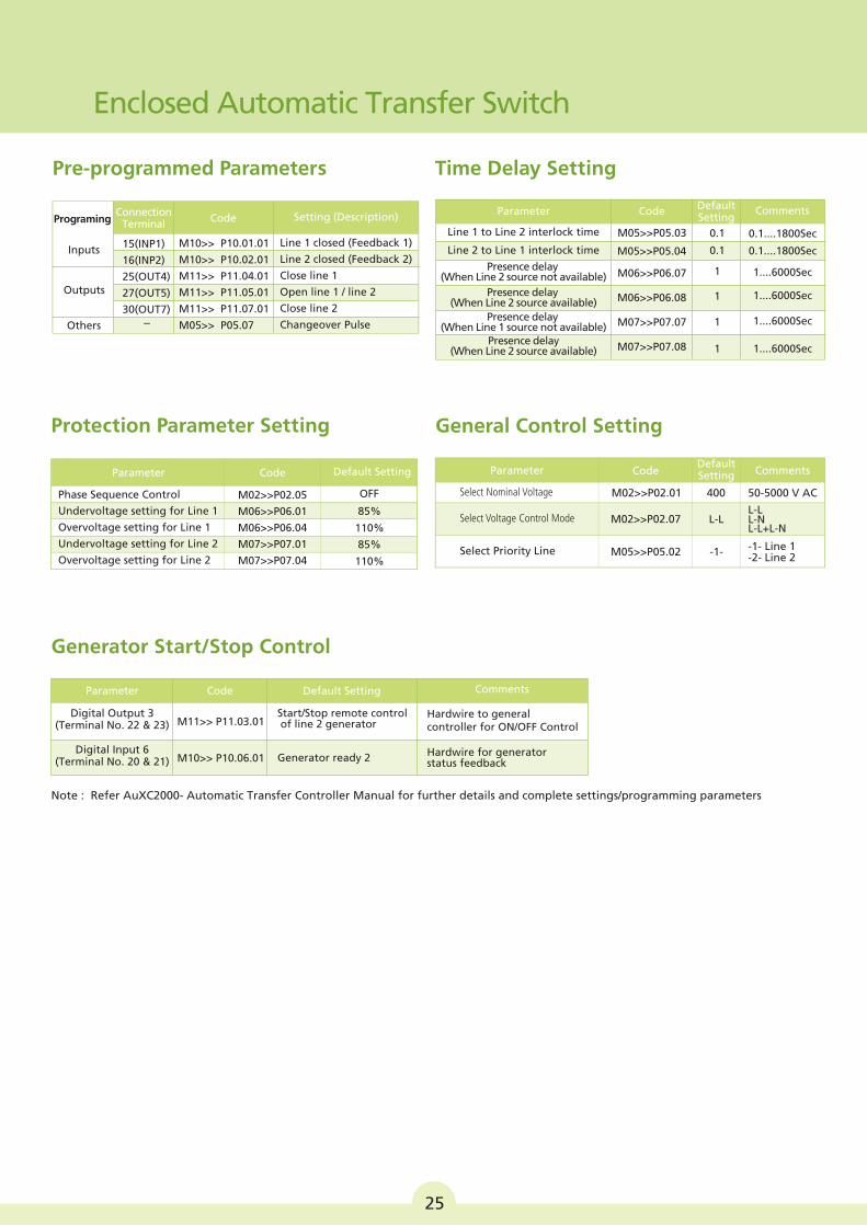
Time Delay Setting
Default Setting
Comments
0.1....1800Sec
0.1....1800Sec
1....6000Sec
1....6000Sec
1....6000Sec
1....6000Sec
0.1
0.1
1
1
1
1
Code
M05>>P05.03
M05>>P05.04
M06>>P06.07
M06>>P06.08
M07>>P07.07
M07>>P07.08
Line 1 to Line 2 interlock time
Parameter
Line 2 to Line 1 interlock time
Presence delay (When Line 2 source not available)
Presence delay (When Line 1 source not available)
Presence delay (When Line 2 source available)
Presence delay (When Line 2 source available)
Pre-programmed Parameters
Programing
InputsLine 1 closed (Feedback 1)
Line 2 closed (Feedback 2)
Close line 1
Open line 1 / line 2
Close line 2
Changeover Pulse
M10>> P10.01.01
M10>> P10.02.01
M11>> P11.04.01
M11>> P11.05.01
M11>> P11.07.01
M05>> P05.07
15(INP1)
16(INP2)
25(OUT4)
27(OUT5)
30(OUT7)-
Outputs
Others
Connection Terminal
Setting (Description)Code
Note : Refer AuXC2000- Automatic Transfer Controller Manual for further details and complete settings/programming parameters
Generator Start/Stop Control
Start/Stop remote control of line 2 generator
Generator ready 2
Hardwire to general controller for ON/OFF Control
Hardwire for generator status feedback
M11>> P11.03.01
M10>> P10.06.01
Digital Output 3(Terminal No. 22 & 23)
Digital Input 6(Terminal No. 20 & 21)
Default Setting CommentsCodeParameter
General Control Setting
Comments
400
-1-
M02>>P02.01
M05>>P05.02
L-L
50-5000 V AC
-1- Line 1-2- Line 2
L-L
L-L+L-N L-N M02>>P02.07
Select Nominal Voltage
Select Voltage Control Mode
Select Priority Line
CodeParameter
85%
85%
110%
110%
OFFM02>>P02.05
M06>>P06.01
M06>>P06.04
M07>>P07.01
M07>>P07.04
Phase Sequence Control
Undervoltage setting for Line 1
Overvoltage setting for Line 1
Undervoltage setting for Line 2
Overvoltage setting for Line 2
Default SettingCodeParameter
Protection Parameter Setting
25
Enclosed Automatic Transfer Switch
Default Setting
III
IV
V
VI
–
–
–
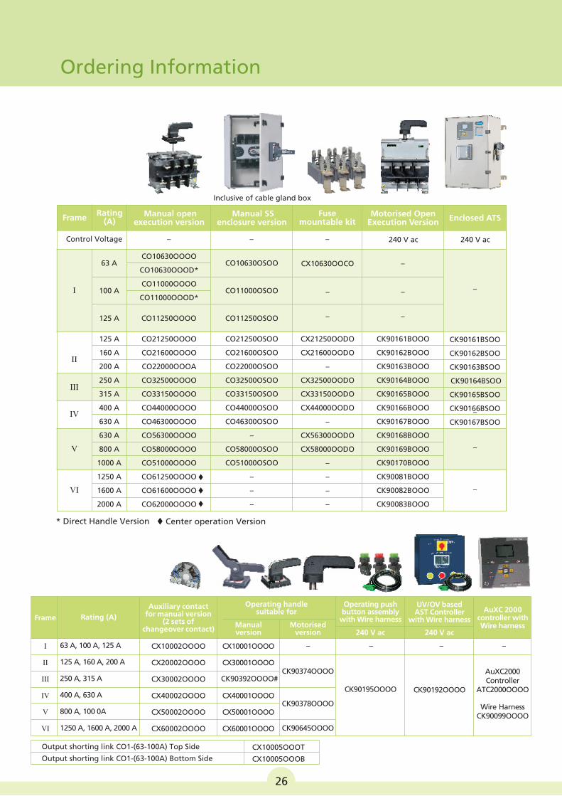
Ordering Information
26
Inclusive of cable gland box
FrameRating
(A) Manual open
execution version Manual SS
enclosure version Fuse
mountable kit
I
CO10630OOOO
CO10630OOOD*
CO11000OOOO
CO11000OOOD*
CO21250OOOO
CO21600OOOO
CO22000OOOA
CO32500OOOO
CO33150OOOO
CO44000OOOO
CO46300OOOO
CO56300OOOO
CO58000OOOO
CO51000OOOO
CO61250OOOO
CO61600OOOO
CO62000OOOO
CX10630OOCO
–
Motorised OpenExecution Version
Control Voltage – – – 240 V ac
CO10630OSOO
CO11000OSOO
63 A
100 A
–
–
Enclosed ATS
240 V ac
–
* Direct Handle Version t Center operation Version
125 A
160 A
200 A
250 A
315 A
400 A
630 A
630 A
800 A
1000 A
1250 A
1600 A
2000 A
II
CO21250OSOO
CO21600OSOO
CO22000OSOO
CO32500OSOO
CO33150OSOO
CO44000OSOO
CO46300OSOO
–
CO58000OSOO
CO51000OSOO
–
–
–
CX21250OODO
CX21600OODO
–
CX32500OODO
CX33150OODO
CX44000OODO
–
CX56300OODO
CX58000OODO
–
–
–
–
CK90161BOOO
CK90162BOOO
CK90163BOOO
CK90164BOOO
CK90165BOOO
CK90166BOOO
CK90167BOOO
CK90168BOOO
CK90169BOOO
CK90170BOOO
CK90081BOOO
CK90082BOOO
CK90083BOOO
125 A – – CO11250OOOO CO11250OSOO
Frame
Operating handle suitable for
Rating (A)
Auxiliary contact for manual version
(2 sets of changeover contact)
I
II
III
IV
V
VI
63 A, 100 A, 125 A
125 A, 160 A, 200 A
250 A, 315 A
400 A, 630 A
800 A, 100 0A
1250 A, 1600 A, 2000 A
CX10001OOOO
CX30001OOOO
CX40001OOOO
CX50001OOOO
CX60001OOOO
–CX10002OOOO
CX20002OOOO
CX30002OOOO
CX40002OOOO
CX50002OOOO
CX60002OOOO
Manual version
Motorised version
Operating push button assembly
with Wire harness
240 V ac
– – –
CK90195OOOO
AuXC 2000controller with Wire harness
UV/OV based AST Controller
with Wire harness
240 V ac
CK90192OOOO
AuXC2000 Controller
ATC2000OOOO
Wire HarnessCK90099OOOO
CK90374OOOO
CK90378OOOO
CK90645OOOO
Output shorting link CO1-(63-100A) Top Side
Output shorting link CO1-(63-100A) Bottom Side
CX10005OOOT
CX10005OOOB
CK90392OOOO#
CK90161BSOO
CK90162BSOO
CK90163BSOO
CK90164BSOO
CK90165BSOO
CK90166BSOO
CK90167BSOO
+ _ _
P N E ON-I OFF ON-II NC-II NO-II C-II C-I NC-INO-I
Wiring Diagrams
¾Motorised Changeover Switch 28
¾Motorised Changeover Switch Control
through Supply Monitor - MG73BH 28
¾Motorised Changeover Switch Control
through AuXC-2000 29
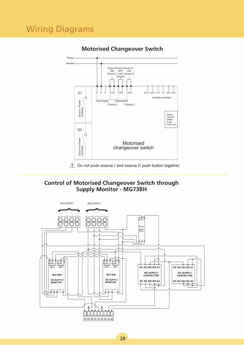
Control of Motorised Changeover Switch through Supply Monitor - MG73BH
Q1
Q2
Power Supply
Closing 1
Opening All
Closing 2
Motorised changeover switch
P N E ON-I OFF ON-II NC-II NO-II C-II C-I NC-INO-I
Auxiliary Contact
So
urc
e I
Po
we
r C
on
tact
sS
ou
rce
II
Po
we
r C
on
tact
s
Push toON
Source I
Push toON
Source II
Push toOFF both
Source
Phase
Neutral
SpareControlGlassFuse 5x20 mm
Motorised Changeover Switch
! Do not push source I and source II push button together
28
18 16 15 28 26 25 NO NC C NO NC C
SET 2 SET 1
MG73BH
DG SUPPLY MONITOR
N L3 L2 P L1
18 16 15 28 26 25 NO NC C NO NC C
SET 2 SET 1
MG73BH
EB SUPPLY MONITOR
N L3 L2 P L1
NC NC NO NO A1
EB SUPPLY CONTACTOR
NC NC NO NO A2
NC NC NO NO A1
DG SUPPLY CONTACTOR
NC NC NO NO A2
DG SUPPLY EB SUPPLY
18 16 15 NO NC C
MD21DF
INCOMING SUPPLY MONITOR
L3 L2 L1
Wiring Diagrams
Wiring Diagrams
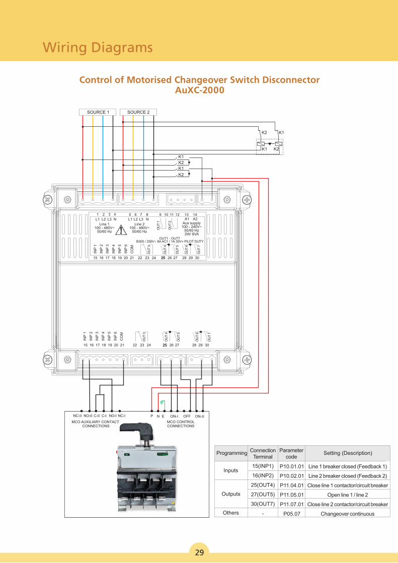
Control of Motorised Changeover Switch Disconnector AuXC-2000
29
Programming ConnectionTerminal
Parametercode
Setting (Description)
Others
Inputs
Outputs
15(INP1)
16(INP2)
25(OUT4)
27(OUT5)
30(OUT7)
-
P10.01.01
P10.02.01
P11.04.01
P11.05.01
P11.07.01
P05.07
Line 1 breaker closed (Feedback 1)
Line 2 breaker closed (Feedback 2)
Close line 1 contactor/circuit breaker
Open line 1 / line 2
Close line 2 contactor/circuit breaker
Changeover continuous
OU
T 1
INP
1
INP
2
INP
3
INP
4
INP
5
INP
6
CO
M
OU
T 3
OU
T 4
OU
T 5
OU
T 6
OU
T 7
B300 / 250V~ 8A AC1 / 1A 30V= PILOT DUTY OUT1 - OUT7
INP
1
INP
2
INP
3
INP
4
INP
5
INP
6
CO
M
OU
T 3
OU
T 4
OU
T 5
OU
T 6
OU
T 7
SOURCE 1 SOURCE 2
K2 K1
K1 K2
K2
K2
K1
K1
P N ENC-II NO-II C-II C-I NC-INO-I
MCO AUXILIARY CONTACT CONNECTIONS
ON-I OFF ON-II
MCO CONTROL CONNECTIONS
1 2 3 4 5 6 7 8 9 10 11 12 13 14L1 L2 L3 N
Line 1100 - 480V~
50/60 Hz
Line 2100 - 480V~
50/60 Hz
L1 L2 L3 N
OU
T 2
A1 A2Aux supply
100 - 240V~50/60 Hz3W/ 8VA
15 16 17 18 19 20 21 22 23 24 2525 26 27 28 29 30
15 16 17 18 19 20 21 22 23 24 2525 26 27 28 29 30
Characteristic Curves
¾HRC Fuse-link Details 31
¾ Time-Current Characteristics of Type
HF Fuse-links 32
¾Cut-off Current Characteristics of Type
HF Fuse-links 32
¾Time-Current Characteristics of Type
HN Fuse-links 33
¾Cut-off Current Characteristics of Type
HN Fuse-links 33
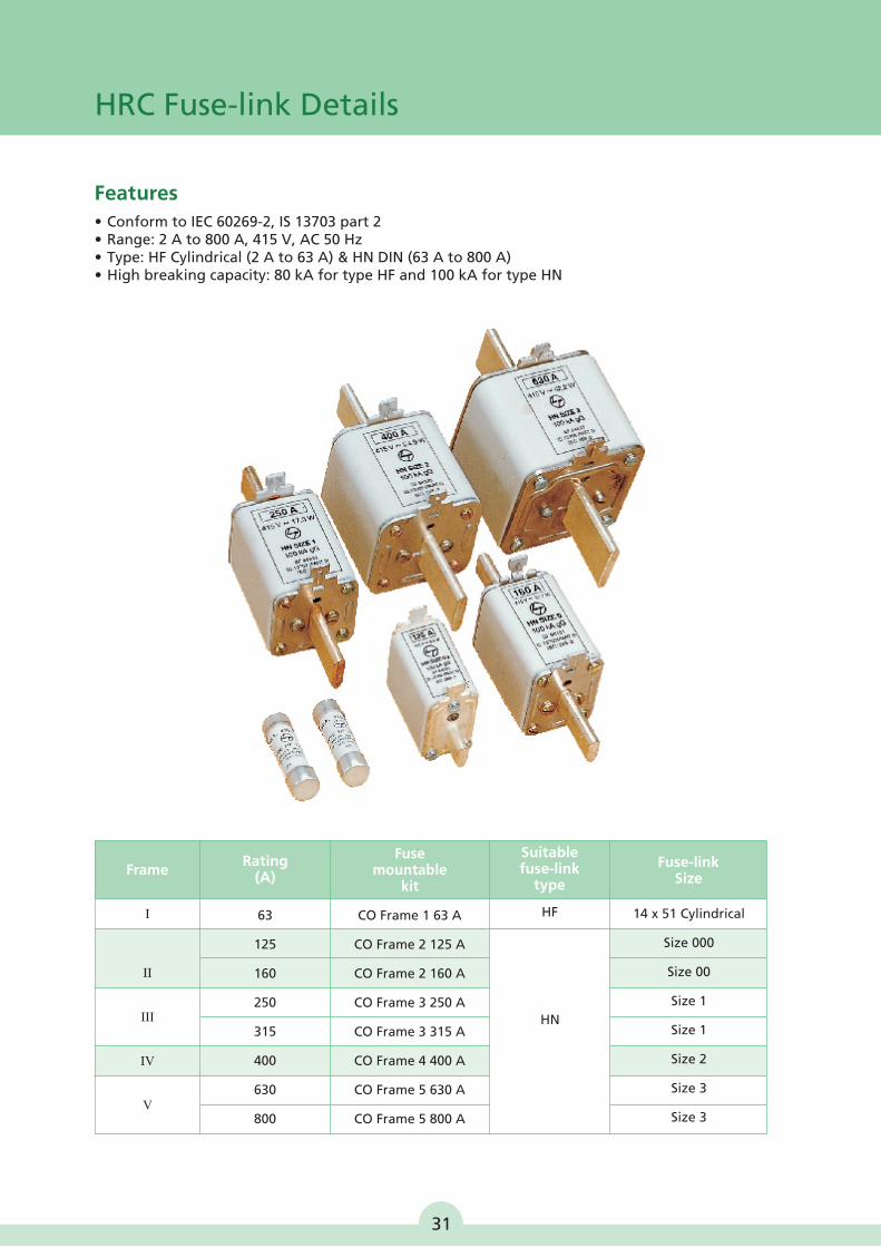
HRC Fuse-link Details
Features
• Conform to IEC 60269-2, IS 13703 part 2• Range: 2 A to 800 A, 415 V, AC 50 Hz• Type: HF Cylindrical (2 A to 63 A) & HN DIN (63 A to 800 A) • High breaking capacity: 80 kA for type HF and 100 kA for type HN
Rating(A)
I
FrameFuse
mountable kit
Suitable fuse-link
type
Fuse-link Size
63
125
160
250
315
400
630
800
CO Frame 1 63 A
CO Frame 2 125 A
CO Frame 2 160 A
CO Frame 3 250 A
CO Frame 3 315 A
CO Frame 4 400 A
CO Frame 5 630 A
CO Frame 5 800 A
14 x 51 Cylindrical
Size 000
Size 00
Size 1
Size 1
Size 2
Size 3
Size 3
II
III
IV
V
HF
HN
31
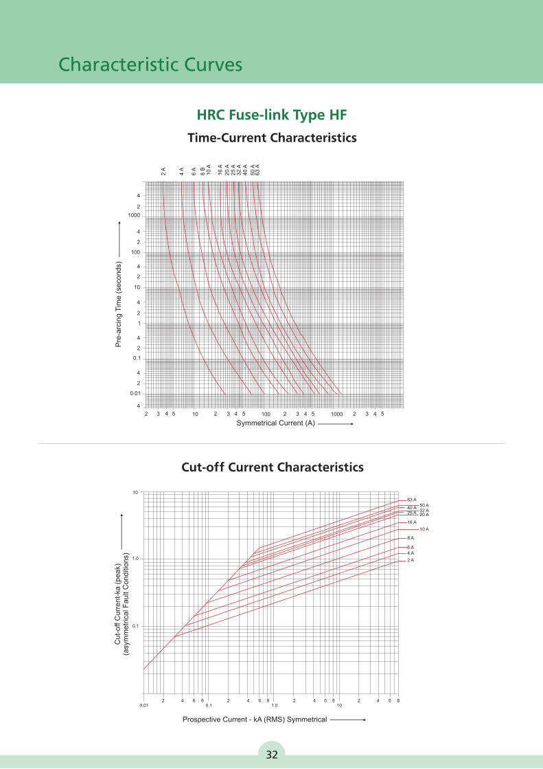
HRC Fuse-link Type HF
Characteristic Curves
Time-Current Characteristics
Symmetrical Current (A)
Pre
-arc
ing
Tim
e (
seco
nd
s)
4
4
2
2
4
2
4
2
4
2
4
2
4
0.01
0.1
1
10
100
1000
2 3 4 5 2 3 4 5 2 3 4 5 2 3 4 510 100 1000
2 A
4 A
6 A
8 B
10
A
16
A
20
A2
5 A
32
A4
0 A
50
A6
3 A
Cut-off Current Characteristics
Prospective Current - kA (RMS) Symmetrical
Cu
t-o
ff C
urr
en
t-ka
(p
ea
k)(a
sym
me
tric
al F
au
lt C
on
diti
on
s)
63 A50 A32 A20 A
40 A25 A
16 A
8 A
6 A4 A
2 A
10 A
10
1.0
0.1
0.01 0.1 1.0 1082 4 6 8 2 4 6 8 2 4 6 8 2 4 6
32
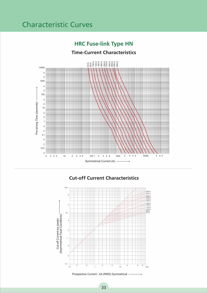
Cut-off Current Characteristics
800 A630 A
500 A600 A315 A250 A
200 A160 A
125 A100 A80 A63 A
20.1
51
2 510
2 5 8100
100
5
2
10
5
2
1
5
2
0.1
Prospective Current - kA (RMS) Symmetrical
Cu
t-o
ff C
urr
en
t-ka
(p
ea
k)(A
sym
me
tric
al F
au
lt C
on
diti
on
s)
HRC Fuse-link Type HN
Time-Current Characteristics
4
0.01
2
4
0.1
2
4
1
2
4
10
2
4
100
2
4
1000
2
4
10000
2 3 4 5 10 2 3 4 5 100 1 2 3 4 5 1000 2 3 4 5 10000 3 4 5
63
A8
0 A
10
0 A
12
5 A
16
0 A
20
0 A
25
0 A
31
5 A
40
0 A
50
0 A
63
0 A
80
0 A
Pre
-arc
ing
Tim
e (
seco
nd
s)
Symmetrical Current (A)
Characteristic Curves
33
Dimensions
¾ Dimensions of Open Execution Manual
Changeover Switch 35
¾Dimensions of Manual Changeover
Switch in Sheet Steel Enclosure 41
¾Dimensions of Manual Fuse
Changeover Switch 44
¾Dimensions of Motorised
Changeover Switch 47
¾Dimensions of Auto Source Transfer Switch
Controller : AuXC-2000 49
Dimensions
* Bushes
16 (Terminal with)
A3
4.9
75
.1
17
.3
5.7
59
.1
68
.1
Panel Door
14
0.6
16
3.6
A
2
2.5
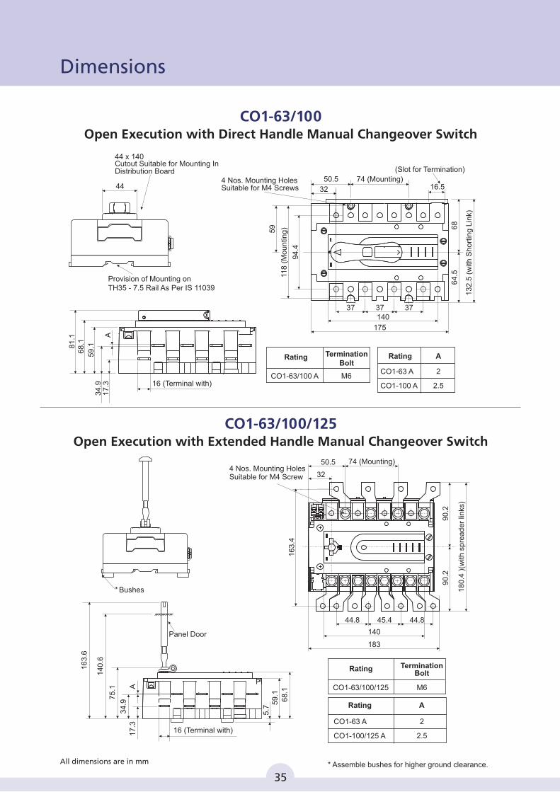
Rating
CO1-63 A
CO1-100/125 A
TerminationBolt
M6
Rating
CO1-63/100/125
44
44 x 140Cutout Suitable for Mounting InDistribution Board
Provision of Mounting onTH35 - 7.5 Rail As Per IS 11039
81
.16
8.1
17
.3
59
.1
A
34
.9 16 (Terminal with)
TerminationBolt
M6
Rating
CO1-63/100 A
A
2
2.5
Rating
CO1-63 A
CO1-100 A
4 Nos. Mounting HolesSuitable for M4 Screws
175
94
.4
37 37 37
50.5
32
68
64
.5
59
140
16.5
13
2.5
(w
ith S
ho
rtin
g L
ink)
74 (Mounting)
(Slot for Termination)
118
(M
ou
ntin
g)
* Assemble bushes for higher ground clearance.
CO1-63/100Open Execution with Direct Handle Manual Changeover Switch
CO1-63/100/125Open Execution with Extended Handle Manual Changeover Switch
35
All dimensions are in mm
90
.29
0.2
183
140
44.8 44.845.4
16
3.4
50.5
32
74 (Mounting)1
80
.4 )
(with
sp
rea
de
r lin
ks)
4 Nos. Mounting HolesSuitable for M4 Screw
190 Mounting
210
444444
4 Nos. MountingHoles Suitablefor M6 Screws
12
0 (
Mo
un
ting
)
D
Au
xilia
ryC
on
tact
Blo
ck
M4 Screws for Earthing
(2 Nos.)
211
with
Acc
ess
orie
s
C
L&
TL
&T
15
49
B
Phase Barrier
Panel Door
88
A
26
7
7
112
30
42
Ma
inta
in D
ista
nce
In
sid
e o
fC
ub
icle
to
be
24
1 ±
1
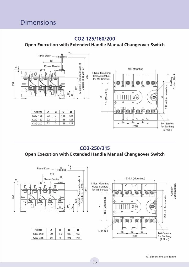
CO2-125
CO2-160
CO2-200
A
22
22
22
B
3
3
3
C
138
138
138
D
121
121
121
Rating
19
311
Phase Barrier
113
A
B
30
1
7
13
8
39
54
Panel Door
Ma
inta
in D
ista
nce
In
sid
e o
fC
ub
icle
to
be
27
6 ±
1
CO3-250
CO3-315
A
29
35
B
4.5
5
C
182
198
D
156
164
Rating
235.4 (Mounting)
260
565656M10 Bolt
15
9 (
Mo
un
ting
)
D
23
9 w
ith A
cce
sso
rie
s
C
4 Nos. MountingHoles Suitablefor M8 Screws
M4 Screws for Earthing
(2 Nos.)
Au
xilia
ryC
on
tact
Blo
ck
L&
TL
&T
CO3-250/315 Open Execution with Extended Handle Manual Changeover Switch
CO2-125/160/200 Open Execution with Extended Handle Manual Changeover Switch
36
All dimensions are in mm
Dimensions
Ma
inta
in D
ista
nce
In
sid
e o
fC
ub
icle
to
be
29
0 ±
1
21
0
12 Phase Barrier
130
40
31
6
7
15
1
42
58
Panel Door
A
286 (Mounting)
310
707070M12 Bolt
20
0 (
Mo
un
tin
g)
20
2
32
9 w
ith A
cce
sso
rie
s
22
8
Au
xilia
ryC
on
tact
Blo
ck
M4 Screws for Earthing
(2 Nos.)
4 Nos. MountingHoles Suitablefor M8 Screws
L&
TL
&T
A
5
6
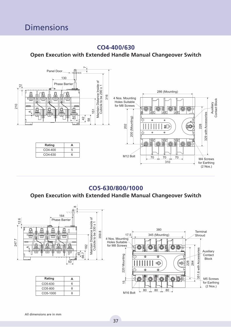
Rating
CO4-400
CO4-630
380
80 80 80
345 (Mounting)
M16 Bolt
17.5
22
0 M
ou
ntin
g
Terminal Shroud
35
1.6
with
Acc
ess
orie
s
22
8
26
4
15
4 Nos. MountingHoles Suitablefor M8 Screws
AuxiliaryContact Block
M5 Screws for Earthing
(2 Nos.)
L&T
L&
T
24
7.7
A
12
.6 Phase Barrier
164
8
35
9.8
18
26
6.745
50
Ma
inta
in D
ista
nce
In
sid
e o
fC
ub
icle
to
be
33
0 ±
1
CO5-630
CO5-800
CO5-1000
A
6
8
8
Rating
CO4-400/630 Open Execution with Extended Handle Manual Changeover Switch
CO5-630/800/1000 Open Execution with Extended Handle Manual Changeover Switch
37
All dimensions are in mm
Dimensions
CO
M N
C N
O
NC
N
O
CO
M
27
1 32
5
B
Ma
xim
um
:50
0M
inim
um
:40
0
540
E
F
C
10
Ma
xim
um
:48
2M
inim
um
:38
2
Tapped Hole Suitable for M5 Screw for Earthing (25 Sq. mm Cable Lug)
PanelDoor
20
0
A
26
5 (
mo
un
tin
g)
105 105
540
105
D (
with
Acce
sso
rie
s)
315 (mounting) 104.3
372.9
4 Nos. Mounting Holes
Suitable forM10 Hardware
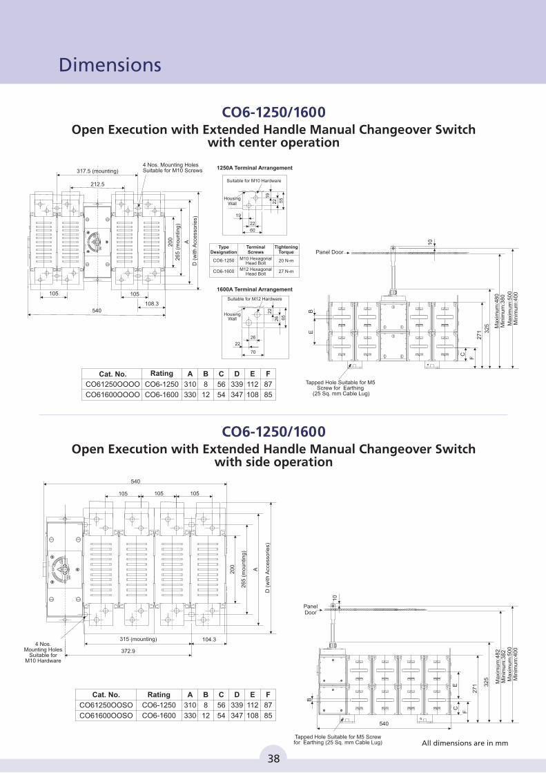
1250A Terminal Arrangement
1600A Terminal Arrangement
26
5 (
mo
un
ting
)
20
0
i h
cc
ess
ori
D(w
tA
es)
A
540
317.5 (mounting)
212.5
105 105
108.3
4 Nos. Mounting HolesSuitable for M10 Screws
19
22
Suitable for M10 Hardware
22
19
55
60
HousingWall
Suitable for M12 Hardware
26
26
22
65
22
70
HousingWall
TypeDesignation
TerminalScrews
TighteningTorque
CO6-1600
CO6-1250 M10 HexagonalHead Bolt
M12 HexagonalHead Bolt
20 N-m
27 N-m
Panel Door
F
C
27
1 32
5 Ma
xim
um
:50
0M
inim
um
:40
0
BE
10
Ma
xim
um
:48
0M
inim
um
:38
0
Tapped Hole Suitable for M5 Screw for Earthing
(25 Sq. mm Cable Lug)
CO6-1250/1600
Open Execution with Extended Handle Manual Changeover Switch
with center operation
CO6-1250/1600Open Execution with Extended Handle Manual Changeover Switch
with side operation
F
87
85
E
112
108
D
339
347
B
8
12
C
56
54
A
310
330
Cat. No.
CO61250OOSO
CO61600OOSO
Rating
CO6-1250
CO6-1600
F
87
85
E
112
108
D
339
347
B
8
12
C
56
54
A
310
330
CO61250OOOO
CO61600OOOO
CO6-1250
CO6-1600
Cat. No. Rating
CO
M N
C N
O
NC
N
O
CO
M
38
All dimensions are in mm
Dimensions
39
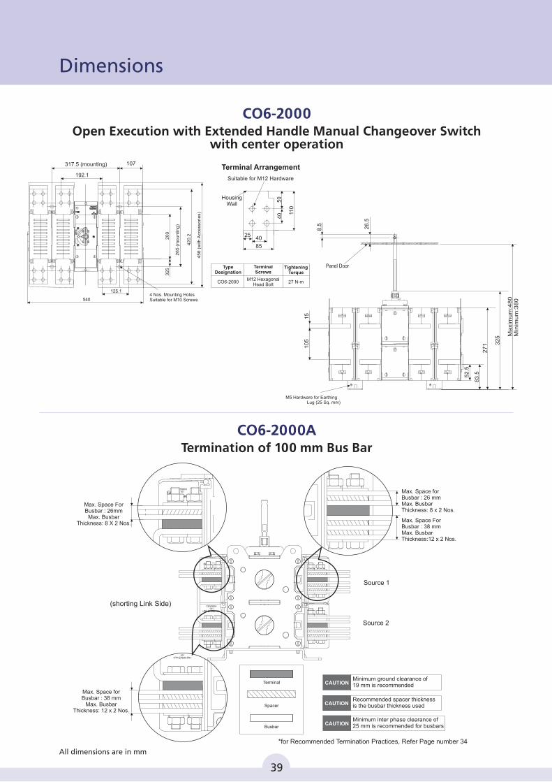
M5 Hardware for Earthing Lug (25 Sq. mm)
Panel Door
8.5 26
.5
27
1 32
5 Ma
xim
um
:48
0M
inim
um
:38
0
15
10
5
52
.5
83
.5
317.5 (mounting)2
00
26
5 (
mo
un
tin
g)
42
0.2
45
6 (
with
Acce
sso
rie
s)
192.1
125.1
5404 Nos. Mounting HolesSuitable for M10 Screws
Suitable for M12 Hardware
HousingWall
50
40 11
0
85
4025
Terminal Arrangement
Type Designation
TerminalScrews
Tightening Torque
CO6-2000M12 Hexagonal
Head Bolt27 N-m
107
Max. Space ForBusbar : 26mm
Max. BusbarThickness: 8 X 2 Nos.
Max. Space forBusbar : 38 mm
Max. BusbarThickness: 12 x 2 Nos.
Max. Space forBusbar : 26 mmMax. BusbarThickness: 8 x 2 Nos.
Max. Space ForBusbar : 38 mmMax. BusbarThickness:12 x 2 Nos.
Source 2
*for Recommended Termination Practices, Refer Page number 34
Source 1
(shorting Link Side)
Recommended spacer thickness is the busbar thickness used
Terminal
Spacer
Busbar
Minimum inter phase clearance of 25 mm is recommended for busbars
Minimum ground clearance of 19 mm is recommended
CO6-2000
Open Execution with Extended Handle Manual Changeover Switch
with center operation
CO6-2000ATermination of 100 mm Bus Bar
32
5
All dimensions are in mm
50604101
101>PP-EPDM-FR<
CK50604101
>PP-EPDM-FR<
CK50604101
>PP-EPDM-FR<
Dimensions
40
All dimensions are in mm
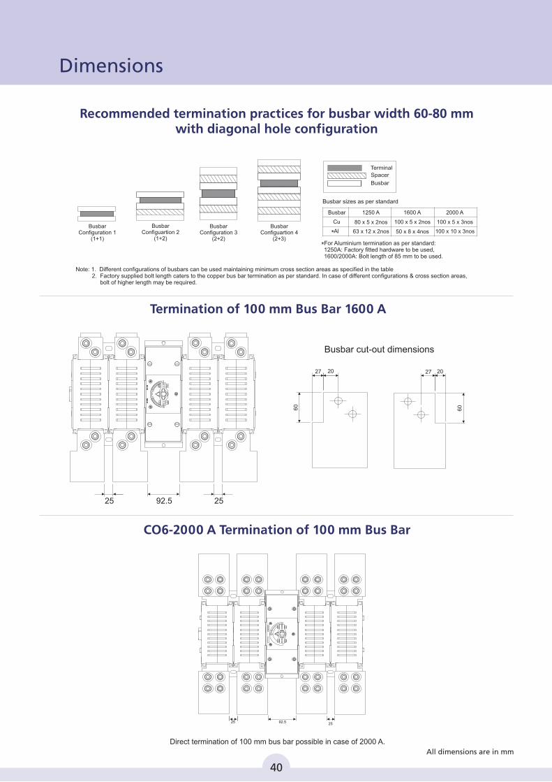
Busbar sizes as per standard
Busbar cut-out dimensions
80 x 5 x 2nos
63 x 12 x 2nos 50 x 8 x 4nos 100 x 10 x 3nos
100 x 5 x 2nos 100 x 5 x 3nosCu
1250 ABusbar 1600 A 2000 A
Al
Terminal
Spacer
Busbar
BusbarConfiguration 1
(1+1)
BusbarConfiguration 3
(2+2)
BusbarConfiguartion 4
(2+3)
BusbarConfiguartion 2
(1+2)
Termination of 100 mm Bus Bar 1600 A
Note: 1. Different configurations of busbars can be used maintaining minimum cross section areas as specified in the table 2. Factory supplied bolt length caters to the copper bus bar termination as per standard. In case of different configurations & cross section areas, bolt of higher length may be required.
*
*For Aluminium termination as per standard:1250A: Factory fitted hardware to be used,1600/2000A: Bolt length of 85 mm to be used.
Direct termination of 100 mm bus bar possible in case of 2000 A.
Recommended termination practices for busbar width 60-80 mm with diagonal hole configuration
CO6-2000 A Termination of 100 mm Bus Bar
2027 2027
09 09
25 92.5 25
Dimensions
25 2592.5
CO
M N
O N
C
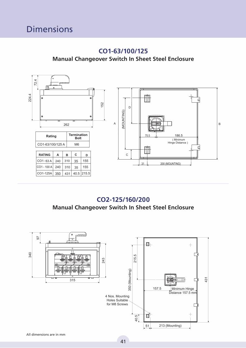
CO1-63/100/125Manual Changeover Switch In Sheet Steel Enclosure
262
22
4.4
15
2
72
.4
24
3
34
0
97
315
35
0 (
Mo
un
ting
)
213 (Mounting)
4 Nos. MountingHoles Suitablefor M8 Screws
Minimum HingeDistance 157.5 mm
21
5.5
40
.5
51
43
1
157.5
CO2-125/160/200Manual Changeover Switch In Sheet Steel Enclosure
M6
Rating
CO1-63/100/125 A
TerminationBolt
Ø5.7
41
All dimensions are in mm
Dimensions
B
C
D
B C
CO1-125A
A
240
240
350
310
310
431
35
35
40.5
D
215.5
155
155
A
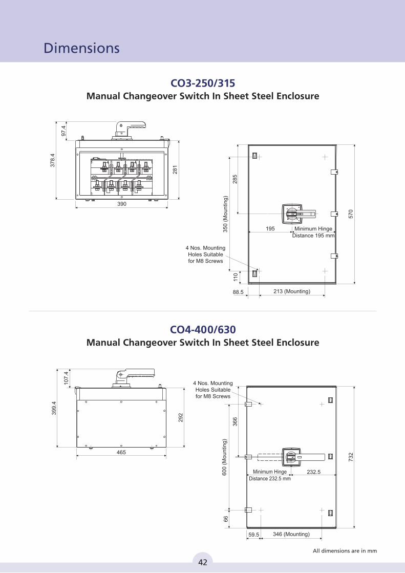
CO3-250/315Manual Changeover Switch In Sheet Steel Enclosure
28
137
8.4
390
97
.4
35
0 (
Mo
un
ting
)
110
213 (Mounting)88.5
28
5
57
0
195
4 Nos. MountingHoles Suitablefor M8 Screws
Minimum HingeDistance 195 mm
39
9.4
29
2
10
7.4
465
73
2
60
0 (
Mo
un
ting
)
36
6
232.5
66
346 (Mounting)59.5
4 Nos. MountingHoles Suitablefor M8 Screws
Minimum Hinge
Distance 232.5 mm
CO4-400/630Manual Changeover Switch In Sheet Steel Enclosure
Ø5.7
Ø5.7
42
All dimensions are in mm
Dimensions
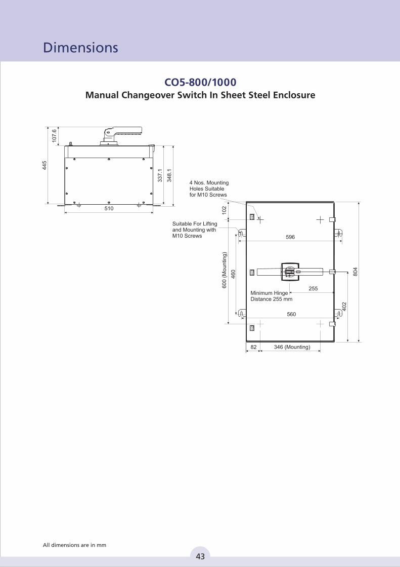
CO5-800/1000Manual Changeover Switch In Sheet Steel Enclosure
34
8.1
33
7.1
10
7.6
44
5
510
80
4
40
2
596
255
560
82 346 (Mounting)
46
0
10
26
00
(M
ou
ntin
g)
4 Nos. MountingHoles Suitablefor M10 Screws
Suitable For Liftingand Mounting withM10 Screws
Minimum HingeDistance 255 mm
Ø5.7
43
All dimensions are in mm
Dimensions
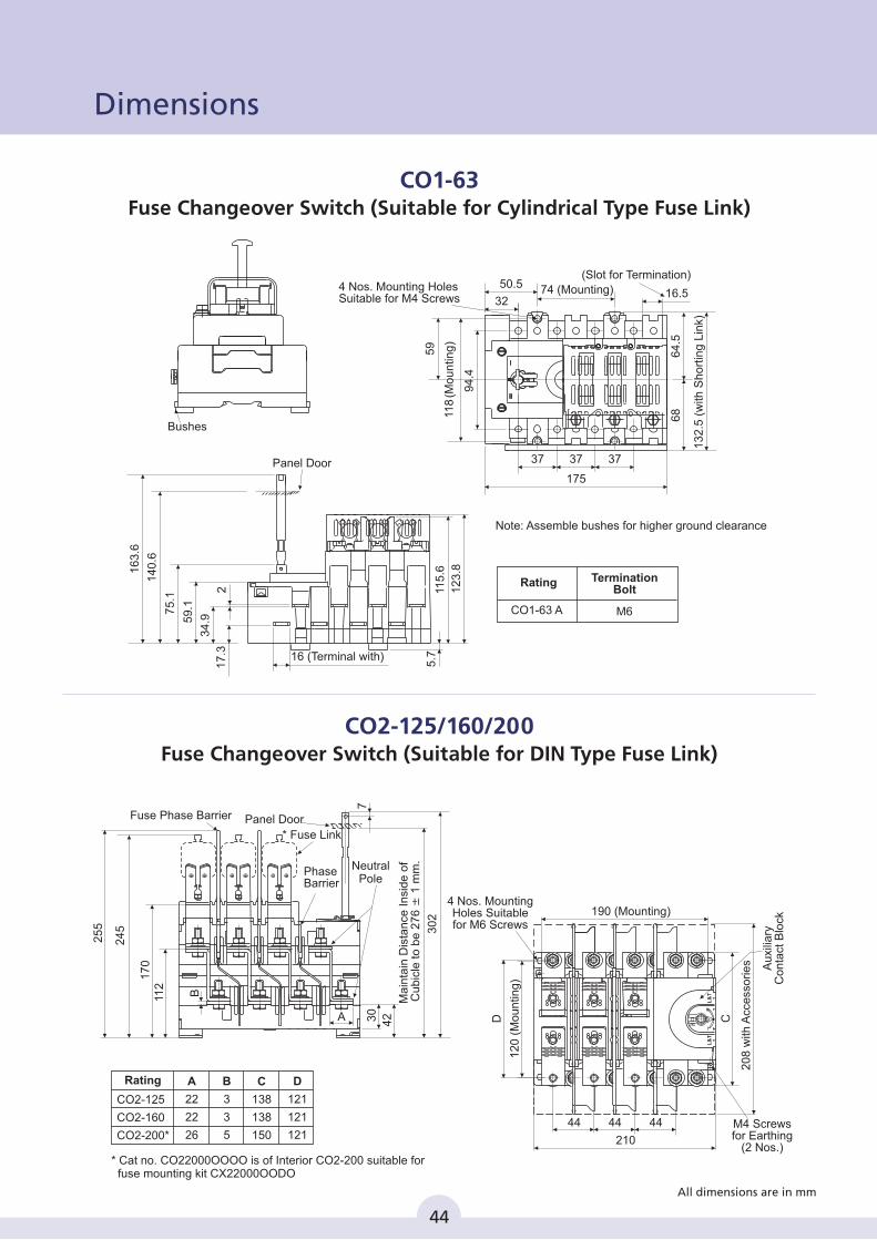
CO1-63Fuse Changeover Switch (Suitable for Cylindrical Type Fuse Link)
D C
44 44
210
44
190 (Mounting)4 Nos. MountingHoles Suitablefor M6 Screws
12
0 (
Mo
un
ting
)
Au
xilia
ryC
on
tact
Blo
ck
M4 Screws for Earthing
(2 Nos.)
20
8 w
ith A
cce
sso
rie
s
Panel DoorFuse Phase Barrier
PhaseBarrier
* Fuse Link
25
5
24
5
112
17
0
B
42
30
2
Ma
inta
in D
ista
nce
In
sid
e o
f C
ub
icle
to
be
27
6 ±
1 m
m.
7
A 30
Neutral Pole
Bushes
59
.1
34
.9
17
.3
75
.1
12
3.8
5.7
2 115
.6
Panel Door
14
0.6
16
3.6
16 (Terminal with)
4 Nos. Mounting HolesSuitable for M4 Screws
175
37 37 37
64
.56
8
32
50.5
94
.4
59
16.5
13
2.5
(w
ith S
ho
rtin
g L
ink)
118
(Mo
un
ting
)
(Slot for Termination)
74 (Mounting)
Note: Assemble bushes for higher ground clearance
CO1-63 A M6
Rating TerminationBolt
CO2-125/160/200Fuse Changeover Switch (Suitable for DIN Type Fuse Link)
L&
TL
&T
44
All dimensions are in mm
Dimensions
CO2-125
CO2-160
CO2-200*
A
22
22
26
B
3
3
5
C
138
138
150
D
121
121
121
Rating
* suitable for fuse mounting kit CX22000OODO
Cat no. CO22000OOOO is of Interior CO2-200
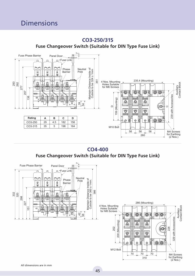
CO3-250/315Fuse Changeover Switch (Suitable for DIN Type Fuse Link)
20
2
22
8
M12 Bolt
70 70
310
70
286 (Mounting)
20
0 (
Mo
un
ting
)
32
9 w
ith A
cce
sso
rie
s
4 Nos. MountingHoles Suitablefor M8 Screws
M4 Screws for Earthing
(2 Nos.)
Au
xilia
ryC
on
tact
Blo
ck
Fuse Phase Barrier
Fuse Link*
33
2
32
0
29
8
15
1
22
7
5
58
38
6
7
40 42
Neutral Pole
Panel Door
Phase Barrier
Ma
inta
in D
ista
nce
In
sid
e o
fC
ub
icle
to
be
36
0 ±
1m
m.
Fuse Phase Barrier
Fuse Link*
29
3
29
2
27
7
13
8
20
7
B
54
35
1
7
A 39
Neutral Pole
Panel Door
Phase Barrier
Ma
inta
in D
ista
nce
In
sid
e o
fC
ub
icle
to
be
32
4 ±
1m
m
D C
M10 Bolt
56 56
260
56
235.4 (Mounting)
15
9 (
Mo
un
ting
)
23
9 w
ith A
cce
sso
rie
s
M4 Screws for Earthing
(2 Nos.)
Au
xilia
ryC
on
tact
Blo
ck
4 Nos. MountingHoles Suitablefor M6 Screws
L&
TL
&T
L&
TL
&T
CO4-400Fuse Changeover Switch (Suitable for DIN Type Fuse Link)
45
All dimensions are in mm
Dimensions
CO3-250
CO3-315
A
29
35
B
4.5
5
C
182
198
D
156
164
Rating
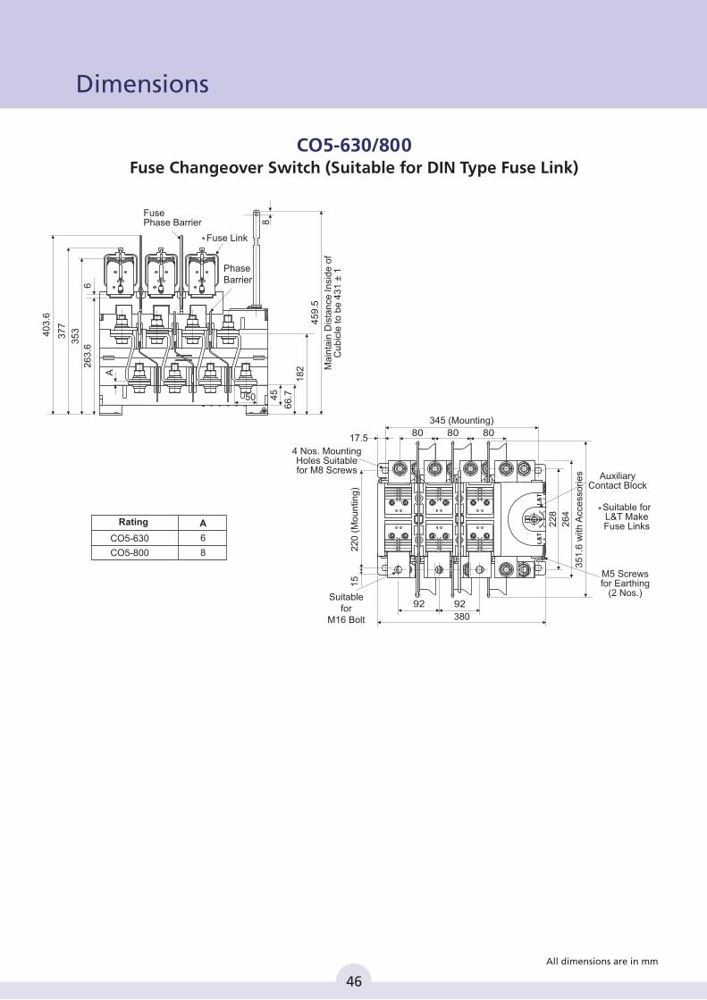
CO5-630/800Fuse Changeover Switch (Suitable for DIN Type Fuse Link)
A
Fuse Phase Barrier
PhaseBarrier
Fuse Link*
8
45
9.5
18
2
66
.745
35
3
26
3.6
6
37
7
40
3.6
50
Ma
inta
in D
ista
nce
In
sid
e o
fC
ub
icle
to
be
43
1 ±
1
345 (Mounting)
9292
80 8080
380
*
17.5
22
0 (
Mo
un
ting
)
26
4
35
1.6
with
Acc
ess
orie
s
22
8
15
4 Nos. MountingHoles Suitablefor M8 Screws
M5 Screws for Earthing
(2 Nos.)
AuxiliaryContact Block
Suitable forL&T MakeFuse Links
Suitablefor
M16 Bolt
L&
TL
&T
46
All dimensions are in mm
Dimensions
CO5-630
CO5-800
A
6
8
Rating
CO
CO2
CO3
CO4
CO5
EOM
CX2
CX3
CX4
CX5
240.3
277.2
293.7
330.9
234.3
271.2
287.7
324.9
30
39
42
45
42
54
58
66.7
112
138
151
182
M6
M8
M8
M8
M4
M4
M4
M5
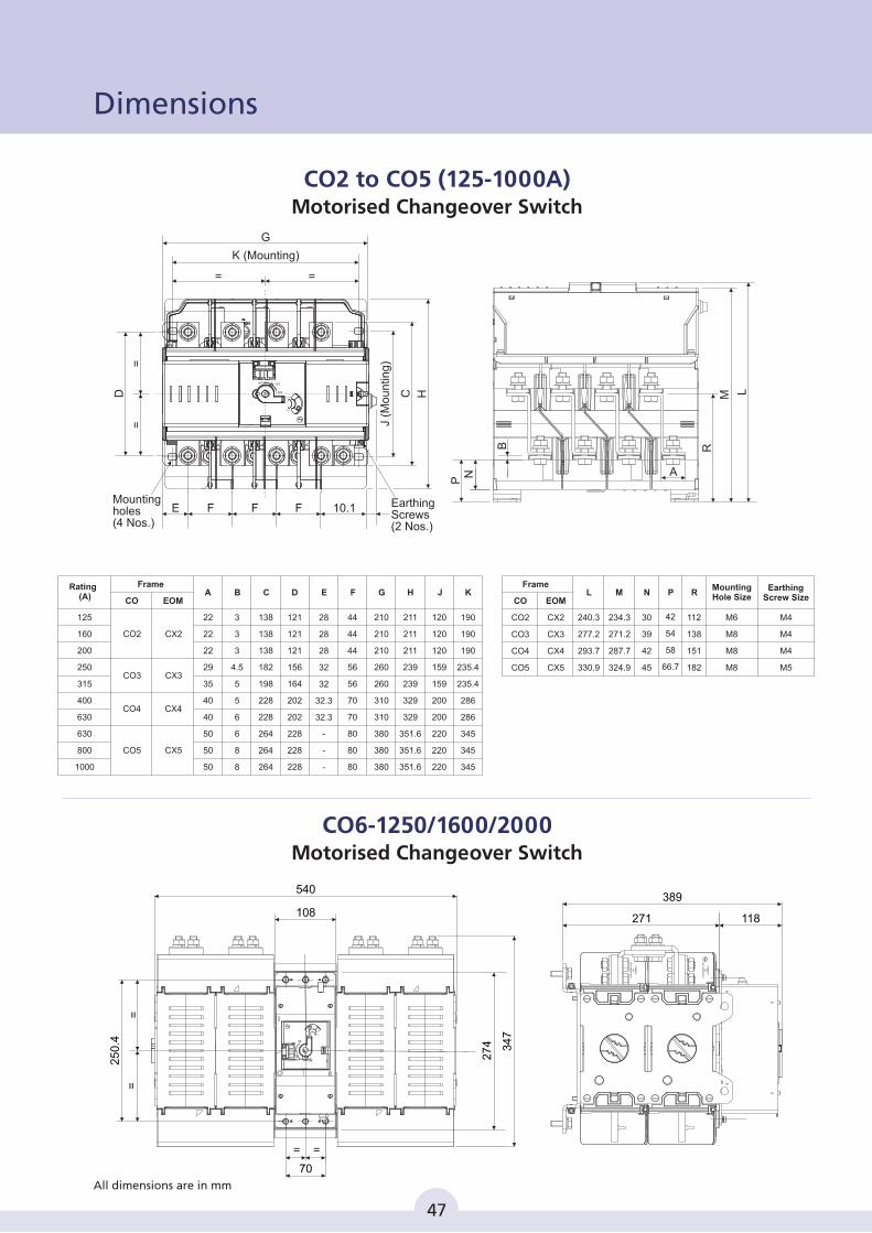
M N P R L MountingHole Size
EarthingScrew Size
Frame
190
190
190
235.4
235.4
286
286
345
345
345
120
120
120
159
159
200
200
220
220
220
211
211
211
239
239
329
329
351.6
351.6
351.6
44
44
44
56
56
70
70
80
80
80
210
210
210
260
260
310
310
380
380
380
28
28
28
32
32
32.3
32.3
-
-
-
121
121
121
156
164
202
202
228
228
228
3
3
3
4.5
5
5
6
6
8
8
138
138
138
182
198
228
228
264
264
264
22
22
22
29
35
40
40
50
50
50
Rating (A)
125
160
200
250
315
400
630
630
800
1000
Frame
CO EOM
CO2
CO3
CO4
CO5
CX2
CX3
CX4
CX5
A B C D E F G H J K
118
389
271
Ck5
060
41
01
>P
P-E
PD
M-F
R<
Ck5
060
41
01
>P
P-E
PD
M-F
R<
540
108
25
0.4
=
34
7
27
4
=
70
==
MANUAL AUTO
ONI
IIONOFF
CO2 to CO5 (125-1000A)Motorised Changeover Switch
CO6-1250/1600/2000Motorised Changeover Switch
47
All dimensions are in mm
==
D
K (Mounting)
= =
G
H
J (M
ou
ntin
g)
C
FFF 10.1EMountingholes (4 Nos.)
EarthingScrews (2 Nos.)
NOII OFF
I NO
AUTO
MANUAL
P
LM
R
AN
B
Dimensions
48
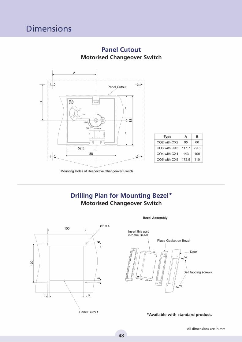
Panel CutoutMotorised Changeover Switch
Drilling Plan for Mounting Bezel*Motorised Changeover Switch
All dimensions are in mm
95
117.7
143
172.5
A B
CO2 with CX2
CO3
CO4 with CX4
CO5 with CX5
with CX3
Type
60
79.5
100
110
Panel Cutout
Mounting Holes of Respective Changeover Switch
88
88
B
A
52.5
==
ON I
NO IIOFF
AUTO
MANUAL
Bezel Assembly
Insert this part into the Bezel
Place Gasket on Bezel
Door
Panel Cutout
Ø3 x 4
Self tapping screws
100
10
0
6
6 6
6
*Available with standard product.
Dimensions
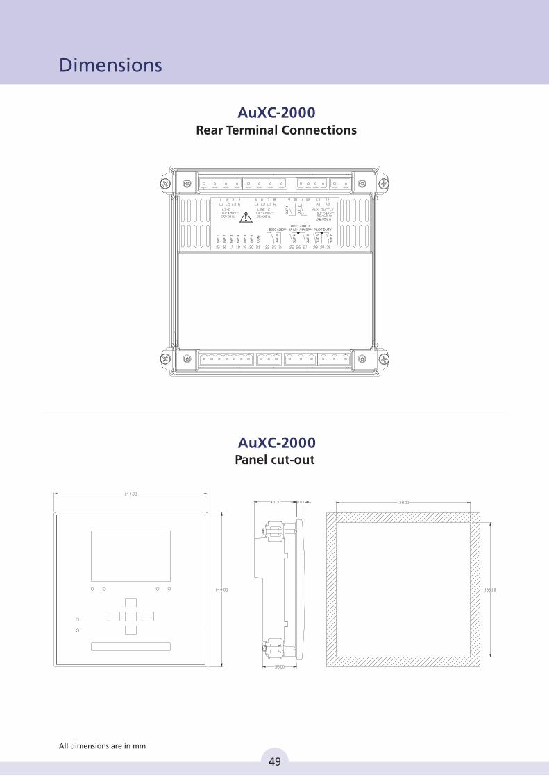
Panel cut-out
AuXC-2000
49
All dimensions are in mm
Dimensions
AuXC-2000 Rear Terminal Connections
OU
T 3
OU
T 1
OU
T 2
INP
1
INP
2
INP
3
INP
4
INP
5
INP
6
CO
M
OU
T 4
OU
T 5
OU
T 6
OU
T 7
B300 / 250V~ 8A AC1 / 1A 30V= PILOT DUTY OUT1 - OUT7
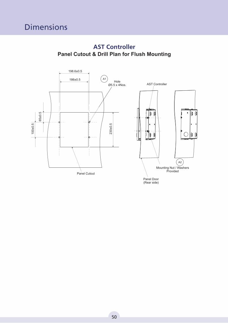
AST ControllerPanel Cutout & Drill Plan for Flush Mounting
Dimensions1
00
±0
.5
65
±0
.5
198.6±0.5
186±0.5
23
0±0
.5
Panel Cutout
HoleØ5.5 x 4Nos.
A1
AST Controller
Panel Door(Rear side)
Mounting Nut / WashersProvided
A2
50
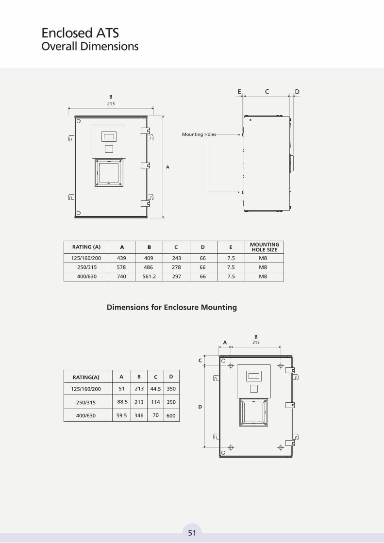
Mounting Holes
RATING (A)
439 409 243 66 M87.5
740 561.2 297 66 M87.5
A B C D E MOUNTING HOLE SIZE
125/160/200
578 486 278 66 M87.5250/315
400/630
A B
A
B
Dimensions for Enclosure Mounting
51
A B C D
213 44.5 350
88.5 213 114 350
59.5 346 70 600
RATING(A)
125/160/200
250/315
400/630
213AB
C
D
Enclosed ATSOverall Dimensions
213
E C D
51
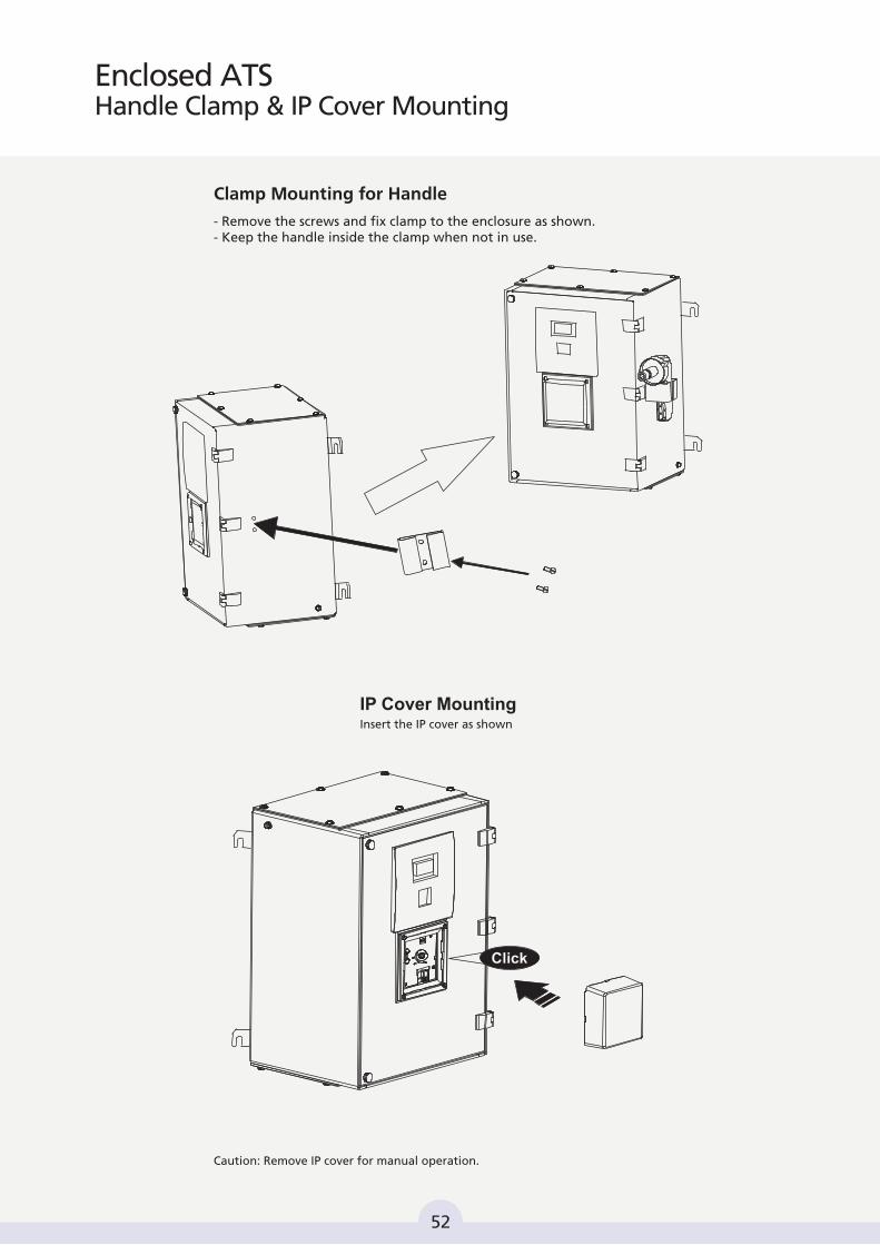
Clamp Mounting for Handle
- Remove the screws and fix clamp to the enclosure as shown.- Keep the handle inside the clamp when not in use.
IP Cover MountingInsert the IP cover as shown
Caution: Remove IP cover for manual operation.
Click
52
Enclosed ATSHandle Clamp & IP Cover Mounting