hp 2510 switch 453564082681
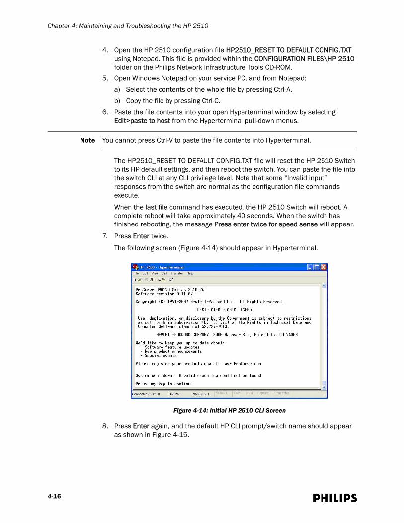
TRANSCRIPT
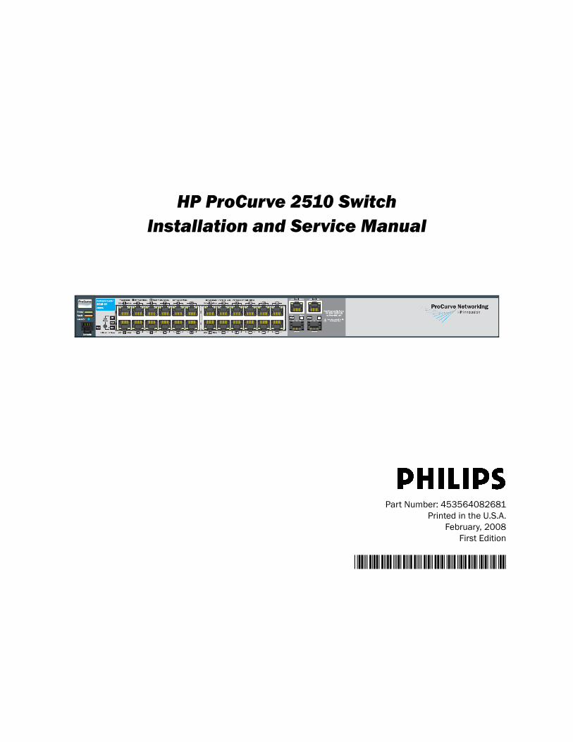
HP ProCurve 2510 SwitchInstallation and Service Manual
Part Number: 453564082681Printed in the U.S.A.
February, 2008First Edition
*453564082681*
Proprietary Information
This document contains proprietary information that is protected by copyright.
Copyright
Copyright © 2008 Koninklijke Philips Electronics N.V. All Rights Reserved.
Manufacturer
Philips Healthcare3000 Minuteman RoadAndover, MA 01810-10991-978-687-1501
This document was printed in the United States of America.
Trademark Acknowledgements
Symbol is a trademark of Symbol Technologies, Inc.HP is a registered trademark of Hewlett-Packard CompanyCisco is a registered trademark of Cisco SystemsMS-SQL is a registered trademark of Microsoft CorporationNortel is a registered trademark of Nortel Networks Limited3COM is a registered trademark of 3COM CorporationExtreme is a registered trademark of Extreme Networks
All other trademarks, trade names and company names referenced herein are used for identification purposes only and are the property of their respective owners.
Warranty
The information contained in this document is subject to change without notice. Philips Medical Systems Nederland B.V. reserves the right to make changes in specifications and/or to discontinue any product at any time without notice or obligation and will not be liable for any consequences resulting from the use of this publication.
Printing History
New editions of this document will incorporate all material updated since the previous edition. The documentation printing date and part number indicate its current edition. The printing date and edition number change when a new edition is printed. The document part number changes when extensive technical changes are incorporated.
First Edition .................................................................................................................................................................February, 2008
ii
ContentsAbout This Guide
Audience. . . . . . . . . . . . . . . . . . . . . . . . . . . . . . . . . . . . . . . . . . . . . . . . . . . . . . . . . . . .vi
Document Organization . . . . . . . . . . . . . . . . . . . . . . . . . . . . . . . . . . . . . . . . . . . . . . .vi
Notational Conventions. . . . . . . . . . . . . . . . . . . . . . . . . . . . . . . . . . . . . . . . . . . . . . . .vi
Related Documentation . . . . . . . . . . . . . . . . . . . . . . . . . . . . . . . . . . . . . . . . . . . . . . vii
Terminology . . . . . . . . . . . . . . . . . . . . . . . . . . . . . . . . . . . . . . . . . . . . . . . . . . . . . . . . viii
Chapter 1: Introduction
Overview. . . . . . . . . . . . . . . . . . . . . . . . . . . . . . . . . . . . . . . . . . . . . . . . . . . . . . . . . . 1-2
HP 2510 Switch Topology Deployment Rules and Restrictions. . . . . . . . . . . . . . 1-2
Hardware Description . . . . . . . . . . . . . . . . . . . . . . . . . . . . . . . . . . . . . . . . . . . . . . . 1-3
Front-panel Ports, Status Indicators, and Controls. . . . . . . . . . . . . . . . . . . . . 1-3Front-panel Ports. . . . . . . . . . . . . . . . . . . . . . . . . . . . . . . . . . . . . . . . . . . . . . 1-3Front-panel Status Indicators and Controls . . . . . . . . . . . . . . . . . . . . . . . . 1-3
Rear Panel Connectors . . . . . . . . . . . . . . . . . . . . . . . . . . . . . . . . . . . . . . . . . . . 1-7
Specifications. . . . . . . . . . . . . . . . . . . . . . . . . . . . . . . . . . . . . . . . . . . . . . . . . . . . . . 1-8
Ordering Information . . . . . . . . . . . . . . . . . . . . . . . . . . . . . . . . . . . . . . . . . . . . . . . . 1-9
Chapter 2: Configuring the HP 2510 Switch
Supported Firmware Revision. . . . . . . . . . . . . . . . . . . . . . . . . . . . . . . . . . . . . . . . . 2-2
Network Switch Configuration Files . . . . . . . . . . . . . . . . . . . . . . . . . . . . . . . . . . . . 2-2Supplied Configuration Files . . . . . . . . . . . . . . . . . . . . . . . . . . . . . . . . . . . . . . 2-2Editing Configuration Files . . . . . . . . . . . . . . . . . . . . . . . . . . . . . . . . . . . . . . . . 2-7
HP 2510 Switch Configuration Procedure. . . . . . . . . . . . . . . . . . . . . . . . . . . . . . . 2-8Required Equipment . . . . . . . . . . . . . . . . . . . . . . . . . . . . . . . . . . . . . . . . . . . . . 2-8Configuration Procedure. . . . . . . . . . . . . . . . . . . . . . . . . . . . . . . . . . . . . . . . . . 2-9
Chapter 3: Installing the HP 2510 Switch
Respecting Patient Care Boundaries . . . . . . . . . . . . . . . . . . . . . . . . . . . . . . . . . . . 3-2
HP 2510 Switch Installation Procedures . . . . . . . . . . . . . . . . . . . . . . . . . . . . . . . . 3-3
Mounting the HP 2510 Switch in an Equipment Rack. . . . . . . . . . . . . . . . . . 3-3Mounting the HP 2510 Switch to a Wall . . . . . . . . . . . . . . . . . . . . . . . . . . . . . 3-5Mounting the HP 2510 Switch to a Table or Desktop . . . . . . . . . . . . . . . . . . 3-6
Powering Up the HP 2510 Switch . . . . . . . . . . . . . . . . . . . . . . . . . . . . . . . . . . . . . 3-6
Installing or Removing SFPs . . . . . . . . . . . . . . . . . . . . . . . . . . . . . . . . . . . . . . . . . . 3-7
HP ProCurve 2510 Switch Installation and Service Manual iii
Contents
Connecting Network Cables to the HP 2510 Switch. . . . . . . . . . . . . . . . . . . . . . . 3-9
Using the RJ-45 Connectors . . . . . . . . . . . . . . . . . . . . . . . . . . . . . . . . . . . . . . . 3-9Connecting Cables to SFPs . . . . . . . . . . . . . . . . . . . . . . . . . . . . . . . . . . . . . . . 3-9
Chapter 4: Maintaining and Troubleshooting the HP 2510
Performing Routine Preventive Maintenance . . . . . . . . . . . . . . . . . . . . . . . . . . . . 4-2
Troubleshooting the HP 2510 Switch . . . . . . . . . . . . . . . . . . . . . . . . . . . . . . . . . . 4-2Using the Network Statistics Tool . . . . . . . . . . . . . . . . . . . . . . . . . . . . . . . . . . 4-2
Status Overview Screen . . . . . . . . . . . . . . . . . . . . . . . . . . . . . . . . . . . . . . . . 4-3Port Counters. . . . . . . . . . . . . . . . . . . . . . . . . . . . . . . . . . . . . . . . . . . . . . . . . 4-3System Information Screen . . . . . . . . . . . . . . . . . . . . . . . . . . . . . . . . . . . . . 4-4Identity Screen . . . . . . . . . . . . . . . . . . . . . . . . . . . . . . . . . . . . . . . . . . . . . . . 4-4Port Configuration Screen . . . . . . . . . . . . . . . . . . . . . . . . . . . . . . . . . . . . . . 4-5Pinging Network Devices . . . . . . . . . . . . . . . . . . . . . . . . . . . . . . . . . . . . . . . 4-6Displaying the Switch Configuration . . . . . . . . . . . . . . . . . . . . . . . . . . . . . . 4-7
Troubleshooting Switch Operation using its Front-panel Status Indicators . 4-7
Loading New Firmware on a HP 2510 Switch . . . . . . . . . . . . . . . . . . . . . . . . . . . 4-10
Required Materials/Prerequisites . . . . . . . . . . . . . . . . . . . . . . . . . . . . . . . . . 4-10Loading Firmware from Your Service PC to the HP 2510 . . . . . . . . . . . . . . 4-10
Restoring the HP 2510 Factory-default Configuration . . . . . . . . . . . . . . . . . . . . 4-14
Required Equipment . . . . . . . . . . . . . . . . . . . . . . . . . . . . . . . . . . . . . . . . . . . . 4-15Procedure . . . . . . . . . . . . . . . . . . . . . . . . . . . . . . . . . . . . . . . . . . . . . . . . . . . . 4-15
Chapter 5: Validating the HP 2510 Installation
Executing Validation Tests . . . . . . . . . . . . . . . . . . . . . . . . . . . . . . . . . . . . . . . . . . . 5-2
Performing Visual Tests. . . . . . . . . . . . . . . . . . . . . . . . . . . . . . . . . . . . . . . . . . . . . . 5-2
Performing Test and Inspection Procedures . . . . . . . . . . . . . . . . . . . . . . . . . . . . . 5-2
iv

About This GuideThis HP ProCurve 2510 Switch Installation and Service Manual provides complete instructions and procedures for installing and configuring the Hewlett-Packard ProCurve 2510 Switch for use in a Philips IntelliVue Clinical Network (ICN) or IntelliVue Telemetry System (ITS) deployment. This section describes the document and includes:
• Audience
• Document Organization
• Notational Conventions
• Related Documentation
• Terminology
HP ProCurve 2510 Switch Installation and Service Manual v
About This Guide
AudienceThe HP ProCurve 2510 Switch Installation and Service Manual is written for Philips-trained service personnel who will install and configure the HP 2510 Switch as part of an overall IntelliVue Clinical Network (ICN) or IntelliVue Telemetry System (ITS) deployment.
Document OrganizationThe information in this guide is organized and presented as follows:
• Chapter 1, Introduction, provides an overview of the HP 2510 Switch including a description of its controls and indicators, specifications, and ordering information.
• Chapter 2, Configuring the HP 2510 Switch, gives complete procedures to configure the HP 2510 Switch for use in a Philips ICN or ITS.
• Chapter 3, Installing the HP 2510 Switch, provides procedures for physically installing the switch.
• Chapter 4, Maintaining and Troubleshooting the HP 2510, includes procedures to perform routine switch maintenance and troubleshoot switch operational issues.
• Chapter 5, Inspecting and Testing the HP 2510 Switch, lists procedures to verify that the HP 2510 Switch is operating properly.
Notational ConventionsThis guide uses the following notational conventions to convey information:
Note Notes call attention to important information.
Caution Cautionary statements call attention to a condition that could result in loss of data or damage to equipment.
Warning Warnings call attention to a condition that could result in physical injury.
vi
About This Guide
Related DocumentationPlease refer to these other documents for additional installation service information about the IntelliVue Clinical Network and IntelliVue Telemetry System:
• IntelliVue Clinical Network Installation and Service Guide (M1385-91928)
• IntelliVue Clinical Network Installation Guidelines and Topologies Guide (M1385-91931)
• HP2524 Switch Device Installation and Service Manual (M1385-91919)
• Cisco 2950 Switch Device Installation and Service Manual (M1385-91914)
• Cisco 2960 Switch Installation and Service Manual (453564057351)
• Cisco 3550 Router Device Installation and Service Manual(M3185-91917)
• Cisco 3560 Router Device Installation and Service Manual(M3185-91929)
• Cisco 3750 Router Device Installation and Service Manual(M3185-91930)
• Philips Access Point Controller Installation and Service Manual(M3171-91901)
• IntelliVue Telemetry System Infrastructure Installation and ServiceGuide (M3185-91934)
• 1.4 GHz IntelliVue Telemetry System Access Point Installation Guide(M4842-91003)
• 1.4 GHz IntelliVue Telemetry System Core Access Point/Remote Antenna Installation Guide (M4843-91901)
• 2.4 GHz IntelliVue Telemetry System Access Point Installation Guide(M4852-91901)
• Philips Sync Unit Installation and Service Manual(M4844-90025)
• ITS Transceiver Installation and Service Manual(M4841-90060)
• IntelliVue 802.11 Switch/Thin AP Installation and Configuration Guide (M3185-91932)
• IntelliVue 802.11 Standalone Thick AP Installation and Configuration Guide (M3185-91933)
The IntelliVue Clinical Network Installation and Service Manual provides detailed information about the DBS Domain, and the IntelliVue Telemetry System Infrastructure Installation and Service Guide provides complete information on the 1.4 GHz/2.4 GHz IntelliVue Telemetry System wireless network rules and topologies.
HP ProCurve 2510 Switch Installation and Service Manual vii

About This Guide
TerminologyPlease note the following terms, acronyms, and abbreviations used throughout this document:
• IntelliVue Clinical Network (ICN) - This term refers to the entire Philips network. In a routed topology, the ICN includes the routers and all inter-connected Database Domain(s) and the IntelliVue Telemetry System Wireless Subnet.
• Database Domain (DBS) - This term is used to describe the “network” that contains the Standalone IntelliVue Information Center, or the IntelliVue Database Server and its connected Information Centers, Clients, bedsides, and infrastructure. This term applies to both routed and non-routed topologies.
• IntelliVue Telemetry System Wireless Subnet - This term is used to describe the IntelliVue Telemetry System (ITS) “network” that contains the infrastructure used in a routed topology to connect the IntelliVue Telemetry System devices.
• VLAN (Virtual Local Area Network) - A logical grouping of two or more nodes which are not necessarily on the same physical network segment but which share the same IP network number.
viii

1
IntroductionThis chapter provides an introduction to the HP 2510 Switch, and includes:
• Overview
• HP 2510 Switch Topology Deployment Rules and Restrictions
• Hardware Description
• Specifications
• Ordering Information
HP ProCurve 2510 Switch Installation and Service Manual 1-1
Chapter 1: Introduction
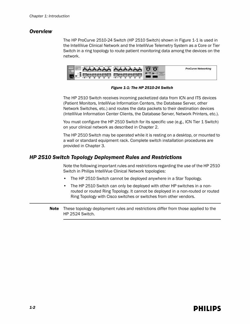
OverviewThe HP ProCurve 2510-24 Switch (HP 2510 Switch) shown in Figure 1-1 is used in the IntelliVue Clinical Network and the IntelliVue Telemetry System as a Core or Tier Switch in a ring topology to route patient monitoring data among the devices on the network.
The HP 2510 Switch receives incoming packetized data from ICN and ITS devices (Patient Monitors, IntelliVue Information Centers, the Database Server, other Network Switches, etc.) and routes the data packets to their destination devices (IntelliVue Information Center Clients, the Database Server, Network Printers, etc.).
You must configure the HP 2510 Switch for its specific use (e.g., ICN Tier 1 Switch) on your clinical network as described in Chapter 2.
The HP 2510 Switch may be operated while it is resting on a desktop, or mounted to a wall or standard equipment rack. Complete switch installation procedures are provided in Chapter 3.
HP 2510 Switch Topology Deployment Rules and RestrictionsNote the following important rules and restrictions regarding the use of the HP 2510 Switch in Philips IntelliVue Clinical Network topologies:
• The HP 2510 Switch cannot be deployed anywhere in a Star Topology.
• The HP 2510 Switch can only be deployed with other HP switches in a non-routed or routed Ring Topology. It cannot be deployed in a non-routed or routed Ring Topology with Cisco switches or switches from other vendors.
Note These topology deployment rules and restrictions differ from those applied to the HP 2524 Switch.
Figure 1-1: The HP 2510-24 Switch
1 3 5 7 9 11 13 15 17 19 21 23
2 4 6 8 10 12 14 16 18 20 22 24
Act
FDx
SpdTest
ProCurve Switch
2510-24
J9019A
ProCurve * Spd Mode, Off Mbps, Flash + 100 Mbps On=10000Mbps 10/100 Base T Ports are HP Auto MDI-X
Reset Clear Link Mode Link Mode
Link Mode Link Mode
Power
LocatorFault
Console
LEDMode
Link 25T Mode Link 26T Mode
Mode 26s Link
26s
Dual-Personality Ports 10/100/1000-T (T) or SFP (S)
!Use only one (T or S) for each Port
ProCurve Networking
1-2
Hardware Description
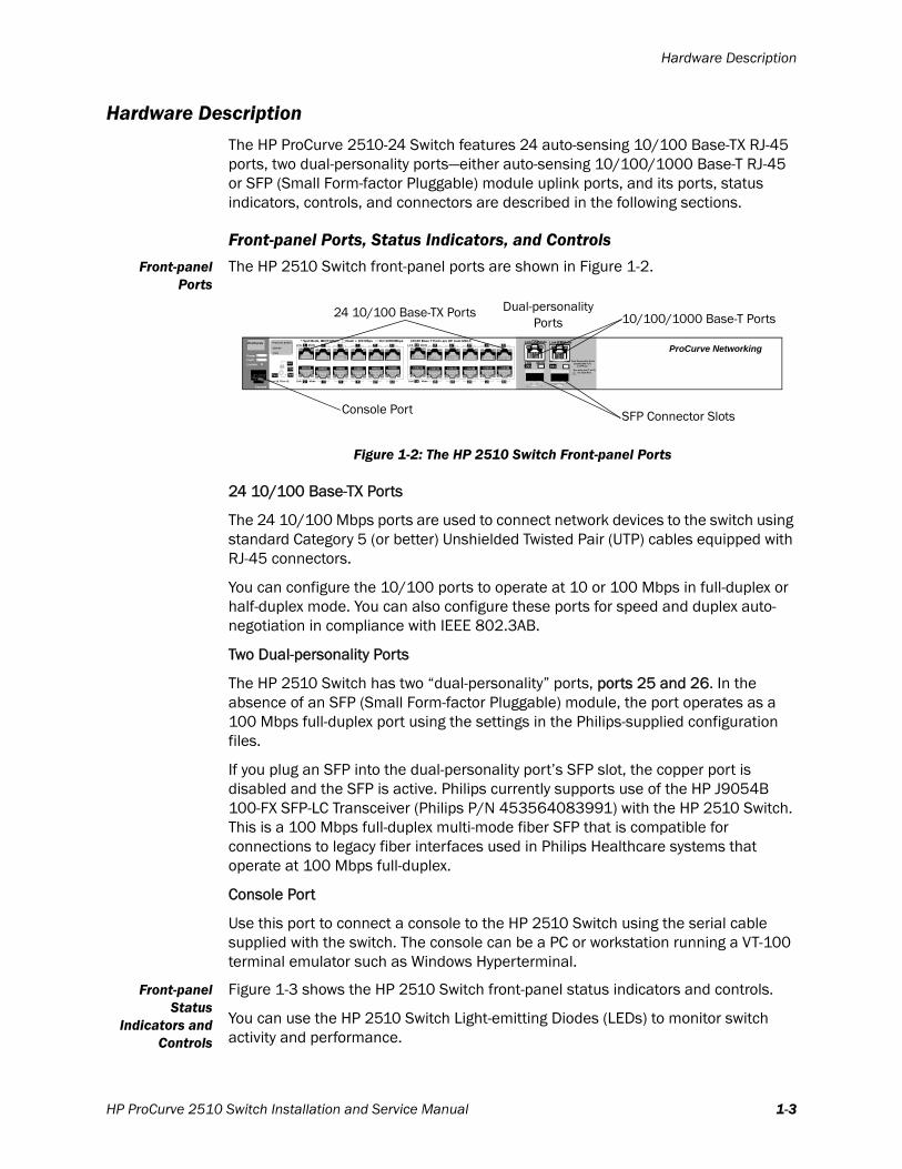
Hardware DescriptionThe HP ProCurve 2510-24 Switch features 24 auto-sensing 10/100 Base-TX RJ-45 ports, two dual-personality ports—either auto-sensing 10/100/1000 Base-T RJ-45 or SFP (Small Form-factor Pluggable) module uplink ports, and its ports, status indicators, controls, and connectors are described in the following sections.
Front-panel Ports, Status Indicators, and ControlsFront-panel
PortsThe HP 2510 Switch front-panel ports are shown in Figure 1-2.
24 10/100 Base-TX Ports
The 24 10/100 Mbps ports are used to connect network devices to the switch using standard Category 5 (or better) Unshielded Twisted Pair (UTP) cables equipped with RJ-45 connectors.
You can configure the 10/100 ports to operate at 10 or 100 Mbps in full-duplex or half-duplex mode. You can also configure these ports for speed and duplex auto-negotiation in compliance with IEEE 802.3AB.
Two Dual-personality Ports
The HP 2510 Switch has two “dual-personality” ports, ports 25 and 26. In the absence of an SFP (Small Form-factor Pluggable) module, the port operates as a 100 Mbps full-duplex port using the settings in the Philips-supplied configuration files.
If you plug an SFP into the dual-personality port’s SFP slot, the copper port is disabled and the SFP is active. Philips currently supports use of the HP J9054B 100-FX SFP-LC Transceiver (Philips P/N 453564083991) with the HP 2510 Switch. This is a 100 Mbps full-duplex multi-mode fiber SFP that is compatible for connections to legacy fiber interfaces used in Philips Healthcare systems that operate at 100 Mbps full-duplex.
Console Port
Use this port to connect a console to the HP 2510 Switch using the serial cable supplied with the switch. The console can be a PC or workstation running a VT-100 terminal emulator such as Windows Hyperterminal.
Front-panelStatus
Indicators andControls
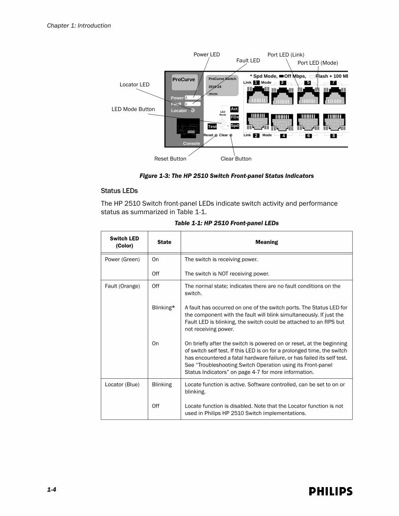
Figure 1-3 shows the HP 2510 Switch front-panel status indicators and controls.
You can use the HP 2510 Switch Light-emitting Diodes (LEDs) to monitor switch activity and performance.
Figure 1-2: The HP 2510 Switch Front-panel Ports
1 3 5 7 9 11 13 15 17 19 21 23
2 4 6 8 10 12 14 16 18 20 22 24
Act
FDx
SpdTest
ProCurve Switch
2510-24
J9019A
ProCurve * Spd Mode, Off Mbps, Flash + 100 Mbps On=10000Mbps 10/100 Base T Ports are HP Auto MDI-X
Reset Clear Link Mode Link Mode
Link Mode Link Mode
Power
LocatorFault
Console
LEDMode
Link 25T Mode Link 26T Mode
Mode 26s Link
26s
Dual-Personality Ports 10/100/1000-T (T) or SFP (S)
!Use only one (T or S) for each Port
ProCurve Networking
24 10/100 Base-TX Ports 10/100/1000 Base-T Ports
Dual-personalityPorts
SFP Connector SlotsConsole Port
HP ProCurve 2510 Switch Installation and Service Manual 1-3
Chapter 1: Introduction
Status LEDs
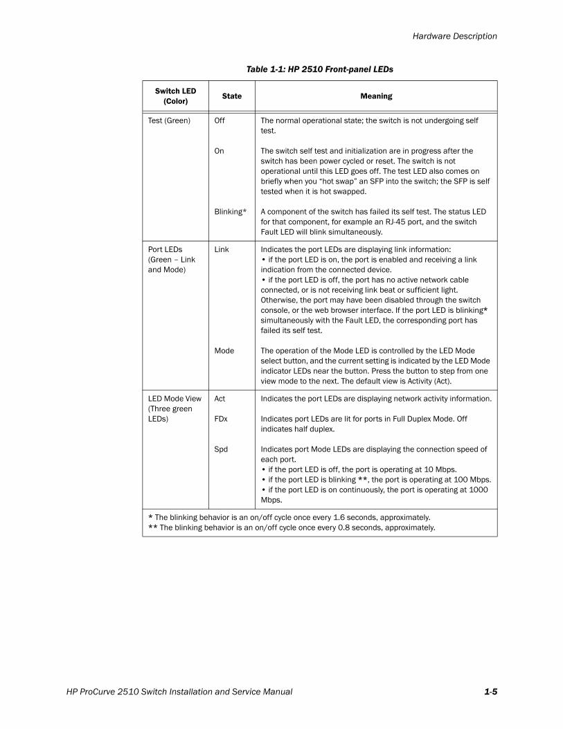
The HP 2510 Switch front-panel LEDs indicate switch activity and performance status as summarized in Table 1-1.
Figure 1-3: The HP 2510 Switch Front-panel Status Indicators
Table 1-1: HP 2510 Front-panel LEDs
Switch LED(Color)
State Meaning
Power (Green) On
Off
The switch is receiving power.
The switch is NOT receiving power.
Fault (Orange) Off
Blinking*
On
The normal state; indicates there are no fault conditions on the switch.
A fault has occurred on one of the switch ports. The Status LED for the component with the fault will blink simultaneously. If just the Fault LED is blinking, the switch could be attached to an RPS but not receiving power.
On briefly after the switch is powered on or reset, at the beginning of switch self test. If this LED is on for a prolonged time, the switch has encountered a fatal hardware failure, or has failed its self test. See “Troubleshooting Switch Operation using its Front-panel Status Indicators” on page 4-7 for more information.
Locator (Blue) Blinking
Off
Locate function is active. Software controlled, can be set to on or blinking.
Locate function is disabled. Note that the Locator function is not used in Philips HP 2510 Switch implementations.
1 3 5 7
2 4 6 8
Act
FDx
SpdTest
ProCurve Switch
2510-24
J9019A
ProCurve * Spd Mode, Off Mbps, Flash + 100 Mb
Reset Clear Link Mode
Link Mode
Power
LocatorFault
Console
LEDMode
LED Mode Button
Port LED (Link)Power LEDFault LED
Locator LED
Reset Button Clear Button
Port LED (Mode)
1-4
Hardware Description
Test (Green) Off
On
Blinking*
The normal operational state; the switch is not undergoing self test.
The switch self test and initialization are in progress after the switch has been power cycled or reset. The switch is not operational until this LED goes off. The test LED also comes on briefly when you “hot swap” an SFP into the switch; the SFP is self tested when it is hot swapped.
A component of the switch has failed its self test. The status LED for that component, for example an RJ-45 port, and the switch Fault LED will blink simultaneously.
Port LEDs(Green – Link and Mode)
Link
Mode
Indicates the port LEDs are displaying link information:• if the port LED is on, the port is enabled and receiving a link indication from the connected device.• if the port LED is off, the port has no active network cable connected, or is not receiving link beat or sufficient light. Otherwise, the port may have been disabled through the switch console, or the web browser interface. If the port LED is blinking* simultaneously with the Fault LED, the corresponding port has failed its self test.
The operation of the Mode LED is controlled by the LED Mode select button, and the current setting is indicated by the LED Mode indicator LEDs near the button. Press the button to step from one view mode to the next. The default view is Activity (Act).
LED Mode View (Three green LEDs)
Act
FDx
Spd
Indicates the port LEDs are displaying network activity information.
Indicates port LEDs are lit for ports in Full Duplex Mode. Off indicates half duplex.
Indicates port Mode LEDs are displaying the connection speed of each port.• if the port LED is off, the port is operating at 10 Mbps.• if the port LED is blinking **, the port is operating at 100 Mbps.• if the port LED is on continuously, the port is operating at 1000 Mbps.
* The blinking behavior is an on/off cycle once every 1.6 seconds, approximately.** The blinking behavior is an on/off cycle once every 0.8 seconds, approximately.
Table 1-1: HP 2510 Front-panel LEDs
Switch LED(Color)
State Meaning
HP ProCurve 2510 Switch Installation and Service Manual 1-5
Chapter 1: Introduction
LED Mode Select Button and Indicator LEDs
To optimize the amount of information displayed for each of the switch ports without overwhelming you with LEDs, the HP 2510 Switch uses two LEDs for each port. The operation of these LEDs is controlled by the LED Mode Select button, and the current setting is indicated by the LED Mode indicator LEDs near the button. Press the button to step from one view mode to the next.
• Each port has a Link LED. If it is lit, the port has a link. If the Link LED is blinking, the port has failed its self test. The Fault and Test LEDs will be blinking simultaneously.
• If the Activity (Act) indicator LED is lit, each port Mode LED displays activity information for the associated port.it flickers as network traffic is received and transmitted through the port.
• If the Full Duplex (FDx) indicator LED is lit, the port Mode LEDs light for those ports that are operating in full duplex.
• If the Speed (Spd) indicator LED is lit, the port Mode LEDs behave as follows to indicate the connection speed for the port:
- Off = 10 Mbps
- Blinking = 100 Mbps (the flashing behavior is a repeated on/off cycle once every 0.5 sec.)
- On = 1000 Mbps
Reset Button
Press this button to reset the switch while it is powered on. This action clears any temporary error conditions that may have occurred and executes the switch self test. Note that pressing the Reset button will interrupt the flow of data traffic through the switch.
Caution Do not press the Reset button when the HP2510 switch is connected to a live patient monitoring system.
Clear Button
When pressed by itself for at least one second, the Clear button deletes any switch console access passwords that you may have configured. Use this feature if you have misplaced the password and need console access.
This button is provided for your convenience, but its presence means that if you are concerned with the security of the switch configuration and operation, you should make sure the switch is installed in a secure location, such as a locked wiring closet.
1-6

Hardware Description
Rear Panel Connectors
The single connector located on the HP 2510 Switch rear panel is shown in Figure 1-4.
The HP 2510 Switch does not have a power switch; it is powered on when connected to an active AC power source. The HP 2510 Switch automatically adjusts to any voltage between 100-240 volts and either 50 or 60 Hz. No voltage range settings are required.
Connect only the AC power cord shipped with the HP 2510 Switch to the AC power cord receptacle. The HP 2510 Switch must be connected to an Uninterruptible Power Supply (UPS) when used on an IntelliVue Clinical Network or IntelliVue Telemetry System (ITS).
Figure 1-4: The HP 2510 Switch Rear-panel Connector
DLine: 50/60Hz100-127V-0.75A (0.75A)200-240V-0.4A (0.4A)
AC Power CordReceptacle
HP ProCurve 2510 Switch Installation and Service Manual 1-7
Chapter 1: Introduction
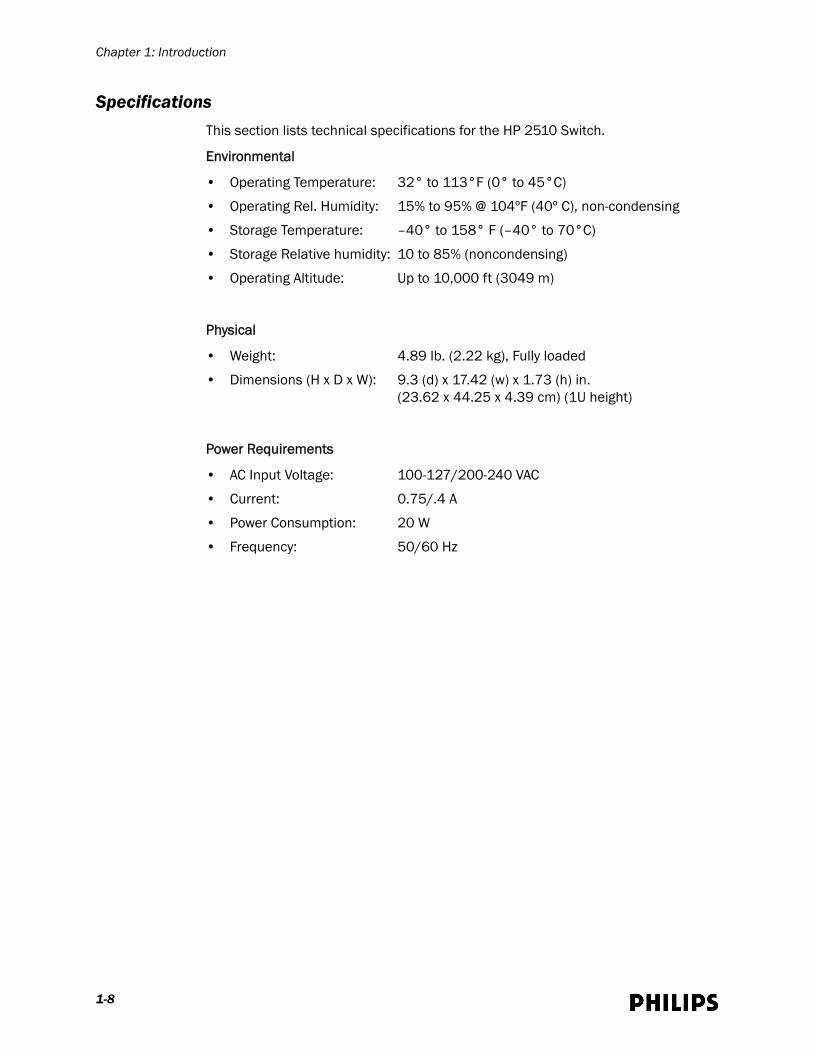
SpecificationsThis section lists technical specifications for the HP 2510 Switch.
Environmental
• Operating Temperature: 32° to 113°F (0° to 45°C)
• Operating Rel. Humidity: 15% to 95% @ 104ºF (40º C), non-condensing
• Storage Temperature: –40° to 158° F (–40° to 70°C)
• Storage Relative humidity: 10 to 85% (noncondensing)
• Operating Altitude: Up to 10,000 ft (3049 m)
Physical
• Weight: 4.89 lb. (2.22 kg), Fully loaded
• Dimensions (H x D x W): 9.3 (d) x 17.42 (w) x 1.73 (h) in.(23.62 x 44.25 x 4.39 cm) (1U height)
Power Requirements
• AC Input Voltage: 100-127/200-240 VAC
• Current: 0.75/.4 A
• Power Consumption: 20 W
• Frequency: 50/60 Hz
1-8
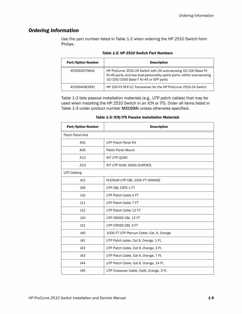
Ordering Information
Ordering InformationUse the part number listed in Table 1-2 when ordering the HP 2510 Switch from Philips.
Table 1-3 lists passive installation materials (e.g., UTP patch cables) that may be used when installing the HP 2510 Switch in an ICN or ITS. Order all items listed in Table 1-3 under product number M3199AI unless otherwise specified.
Table 1-2: HP 2510 Switch Part Numbers
Part/Option Number Description
453564079641 HP ProCurve 2510-24 Switch with 24 auto-sensing 10/100 Base-TX RJ-45 ports, and two dual-personality uplink ports—either auto-sensing 10/100/1000 Base-T RJ-45 or SFP ports
453564083991 HP 100-FX SFP-LC Transceiver for the HP ProCurve 2510-24 Switch
Table 1-3: ICN/ITS Passive Installation Materials
Part/Option Number Description
Patch Panel Kits
A01 UTP Patch Panel Kit
A05 Patch Panel Mount
A12 KIT UTP QUAD
A13 KIT UTP DUAL GANG SURFACE
UTP Cabling
J01 PLENUM UTP CBL 1000 FT ORANGE
J09 UTP CBL CAT5 1 FT
J10 UTP Patch Cable 5 FT
J11 UTP Patch Cable 7 FT
J12 UTP Patch Cable 12 FT
J20 UTP CROSS CBL 12 FT
J21 UTP CROSS CBL 3 FT
J40 1000 FT UTP Plenum Cable, Cat. 6, Orange
J41 UTP Patch cable, Cat 6, Orange, 1 Ft.
J42 UTP Patch Cable, Cat 6, Orange, 3 Ft.
J43 UTP Patch Cable, Cat 6, Orange, 7 Ft.
J44 UTP Patch Cable, Cat 6, Orange, 14 Ft.
J45 UTP Crossover Cable, Cat6, Orange, 3 Ft.
HP ProCurve 2510 Switch Installation and Service Manual 1-9
Chapter 1: Introduction
J46 UTP Crossover Cable, Orange, 14 Ft.
Fiber Cabling
J30 FIB OPTIC CBL 9 FT
J31 3M SC-SC FIBER PATCH PANEL
J32 3M SC-ST FIBER PATCH PANEL
J33 Network Cable 1 Meter MT-RJ To MT-RJ
J34 Network Cable 3 Meter MT-RJ To MT-RJ
J35 Network Cable 1 Meter MT-RJ To SC
J36 Network Cable 3 Meter MT-RJ To SC
J37 MTR/ST 3.3 FT Cable
J38 MTR/ST 6.6 FT Cable
Table 1-3: ICN/ITS Passive Installation Materials
Part/Option Number Description
1-10

2
Configuring the HP 2510 SwitchPrior to installing the HP 2510 Switch on your IntelliVue Clinical Network or IntelliVue Telemetry System wireless subnet, you must first verify that the switch is running the proper version of HP firmware and then configure the switch for its role on your network. This chapter provides the procedures you must follow to configure the HP 2510 Switch, and includes:
• Supported Firmware Revision
• Network Switch Configuration Files
• HP 2510 Switch Configuration Procedure
HP ProCurve 2510 Switch Installation and Service Manual 2-1
Chapter 2: Configuring the HP 2510 Switch
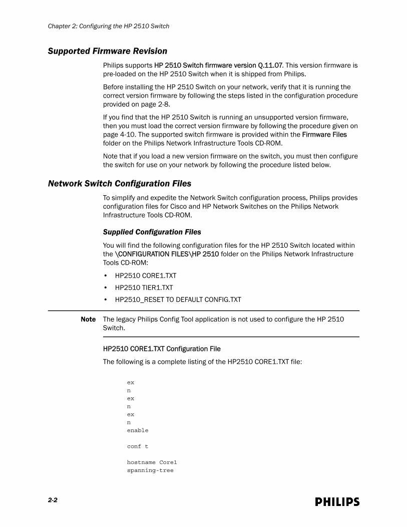
Supported Firmware RevisionPhilips supports HP 2510 Switch firmware version Q.11.07. This version firmware is pre-loaded on the HP 2510 Switch when it is shipped from Philips.
Before installing the HP 2510 Switch on your network, verify that it is running the correct version firmware by following the steps listed in the configuration procedure provided on page 2-8.
If you find that the HP 2510 Switch is running an unsupported version firmware, then you must load the correct version firmware by following the procedure given on page 4-10. The supported switch firmware is provided within the Firmware Files folder on the Philips Network Infrastructure Tools CD-ROM.
Note that if you load a new version firmware on the switch, you must then configure the switch for use on your network by following the procedure listed below.
Network Switch Configuration FilesTo simplify and expedite the Network Switch configuration process, Philips provides configuration files for Cisco and HP Network Switches on the Philips Network Infrastructure Tools CD-ROM.
Supplied Configuration Files
You will find the following configuration files for the HP 2510 Switch located within the \CONFIGURATION FILES\HP 2510 folder on the Philips Network Infrastructure Tools CD-ROM:
• HP2510 CORE1.TXT
• HP2510 TIER1.TXT
• HP2510_RESET TO DEFAULT CONFIG.TXT
Note The legacy Philips Config Tool application is not used to configure the HP 2510 Switch.
HP2510 CORE1.TXT Configuration File
The following is a complete listing of the HP2510 CORE1.TXT file:
ex
n
ex
n
ex
n
enable
conf t
hostname Core1
spanning-tree
2-2

Network Switch Configuration Files
spanning-tree priority 1
spanning-tree 1-24 admin-edge-port
interface 1
name Bedside_Monitor
speed-duplex 10-half
exit
interface 2
name Bedside_Monitor
speed-duplex 10-half
exit
interface 3
name Bedside_Monitor
speed-duplex 10-half
exit
interface 4
name Bedside_Monitor
speed-duplex 10-half
exit
interface 5
name Bedside_Monitor
speed-duplex 10-half
exit
interface 6
name Bedside_Monitor
speed-duplex 10-half
exit
interface 7
name Bedside_Monitor
speed-duplex 10-half
exit
interface 8
name Bedside_Monitor
speed-duplex 10-half
exit
interface 9
name Bedside_Monitor
speed-duplex 10-half
exit
interface 10
name Bedside_Monitor
speed-duplex 10-half
exit
interface 11
name Bedside_Monitor
speed-duplex 10-half
exit
interface 12
name Bedside_Monitor
speed-duplex 10-half
exit
interface 13
name Central_Stations_and_DB_Server
speed-duplex 100-full
HP ProCurve 2510 Switch Installation and Service Manual 2-3

Chapter 2: Configuring the HP 2510 Switch
exit
interface 14
name Central_Stations_and_DB_Server
speed-duplex 100-full
exit
interface 15
name Central_Stations_and_DB_Server
speed-duplex 100-full
exit
interface 16
name Central_Stations_and_DB_Server
speed-duplex 100-full
exit
interface 17
name Central_Stations_and_DB_Server
speed-duplex 100-full
exit
interface 18
name Central_Stations_and_DB_Server
speed-duplex 100-full
exit
interface 19
name Central_Stations_and_DB_Server
speed-duplex 100-full
exit
interface 20
name Central_Stations_and_DB_Server
speed-duplex 100-full
exit
interface 21
name Central_Stations_and_DB_Server
speed-duplex 100-full
exit
interface 22
name Central_Stations_and_DB_Server
speed-duplex 100-full
exit
interface 23
name Central_Stations_and_DB_Server
speed-duplex 100-full
exit
interface 24
name Uplink_Port_for_Adjacent_Network_Switch
speed-duplex 100-full
exit
interface 25
name Uplink_Port_for_Adjacent_Network_Switch
speed-duplex 100-full
exit
interface 26
name Uplink_Port_for_Adjacent_Network_Switch
speed-duplex 100-full
exit
Vlan 1
2-4
Network Switch Configuration Files
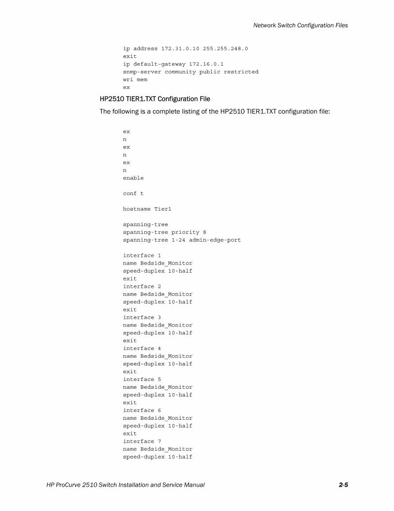
ip address 172.31.0.10 255.255.248.0
exit
ip default-gateway 172.16.0.1
snmp-server community public restricted
wri mem
ex
HP2510 TIER1.TXT Configuration File
The following is a complete listing of the HP2510 TIER1.TXT configuration file:
ex
n
ex
n
ex
n
enable
conf t
hostname Tier1
spanning-tree
spanning-tree priority 8
spanning-tree 1-24 admin-edge-port
interface 1
name Bedside_Monitor
speed-duplex 10-half
exit
interface 2
name Bedside_Monitor
speed-duplex 10-half
exit
interface 3
name Bedside_Monitor
speed-duplex 10-half
exit
interface 4
name Bedside_Monitor
speed-duplex 10-half
exit
interface 5
name Bedside_Monitor
speed-duplex 10-half
exit
interface 6
name Bedside_Monitor
speed-duplex 10-half
exit
interface 7
name Bedside_Monitor
speed-duplex 10-half
HP ProCurve 2510 Switch Installation and Service Manual 2-5

Chapter 2: Configuring the HP 2510 Switch
exit
interface 8
name Bedside_Monitor
speed-duplex 10-half
exit
interface 9
name Bedside_Monitor
speed-duplex 10-half
exit
interface 10
name Bedside_Monitor
speed-duplex 10-half
exit
interface 11
name Bedside_Monitor
speed-duplex 10-half
exit
interface 12
name Bedside_Monitor
speed-duplex 10-half
exit
interface 13
name Central_Stations_and_DB_Server
speed-duplex 100-full
exit
interface 14
name Central_Stations_and_DB_Server
speed-duplex 100-full
exit
interface 15
name Central_Stations_and_DB_Server
speed-duplex 100-full
exit
interface 16
name Central_Stations_and_DB_Server
speed-duplex 100-full
exit
interface 17
name Central_Stations_and_DB_Server
speed-duplex 100-full
exit
interface 18
name Central_Stations_and_DB_Server
speed-duplex 100-full
exit
interface 19
name Central_Stations_and_DB_Server
speed-duplex 100-full
exit
interface 20
name Central_Stations_and_DB_Server
speed-duplex 100-full
exit
interface 21
2-6
Network Switch Configuration Files
name Central_Stations_and_DB_Server
speed-duplex 100-full
exit
interface 22
name Central_Stations_and_DB_Server
speed-duplex 100-full
exit
interface 23
name Central_Stations_and_DB_Server
speed-duplex 100-full
exit
interface 24
name Uplink_Port_for_Adjacent_Network_Switch
speed-duplex 100-full
exit
interface 25
name Uplink_Port_for_Adjacent_Network_Switch
speed-duplex 100-full
exit
interface 26
name Uplink_Port_for_Adjacent_Network_Switch
speed-duplex 100-full
exit
Vlan 1
ip address 172.31.0.11 255.255.248.0
exit
ip default-gateway 172.16.0.1
snmp-server community public restricted
wri mem
ex
Editing Configuration Files
We recommend that you copy the provided HP 2510 configuration files from the Philips Network Infrastructure Tools CD-ROM to your service PC.
While in some cases, you may be able to use the files with no editing, there are several parameters defined in the configuration files that may require editing for a given installation. You can open and edit the HP 2510 configuration .txt files using Windows Notepad on your service PC.
In the configuration text files, the HP 2510 Switch interfaces are defined using a text name, with a corresponding speed and duplex setting. In both Philips-supplied HP 2510 configuration files, (HP2510 CORE1.TXT and HP2510 TIER1.TXT), the first 12 ports are set for 10 Mbps half duplex operation, and the second 12 ports are set for 100 Mbps full-duplex operation. If required for your installation, you can edit these parameter settings in the configuration file to change the number of 10-half ports vs. the number of 100-full ports.
The text following the name command is simply a text string that will identify the ports in the management interfaces.
HP ProCurve 2510 Switch Installation and Service Manual 2-7
Chapter 2: Configuring the HP 2510 Switch
The options for the speed command are:
speed-duplex 10-half
speed-duplex 100-full
These commands must be located between the interface x command and the exit command as in the original supplied configuration files.
The text following the hostname command may be changed. You must change the switch’s hostname if for example, there are multiple tier switches at the installation site. There should not be duplicate switch names on the clinical network.
Lastly, you may change the IP address for the switch. The command that sets the switch IP address follows the Vlan 1 command and specifies both the switch's IP address and subnet mask. The default command setting is:
ip address 172.31.0.11 255.255.248.0
and is followed by the exit command.
The default gateway setting follows, and is in the form:
ip default-gateway 172.31.3.0
HP 2510 Switch Configuration ProcedureThis section provides complete instructions for configuring the HP 2510 Switch for use on your IntelliVue Clinical Network or IntelliVue Telemetry System wireless subnet including:
• Required Equipment
• Configuration Procedure
Note You must configure the HP 2510 Switch before connecting it to the network.
Required Equipment
You will need the following equipment to successfully configure the HP 2510 Switch for use on your network:
• Service PC equipped with:
- Ethernet and Serial Ports
- CD-ROM Drive
- Web Browser
• HP DB-9-to-RJ-45 Console Cable (cable shipped with HP 2510 Switch)
You may use a Cisco “blue” DB-9-to-RJ-45 Console Cable to connect to the HP 2510 Switch Console Port if you do not have an HP DB-9-to-RJ-45 Console Cable.
• Standard UTP Patch Cable
• Latest release of the Philips Network Infrastructure Tools CD-ROM
2-8
HP 2510 Switch Configuration Procedure
Configuration Procedure
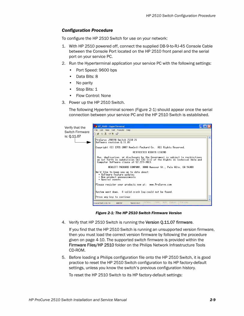
To configure the HP 2510 Switch for use on your network:
1. With HP 2510 powered off, connect the supplied DB-9-to-RJ-45 Console Cable between the Console Port located on the HP 2510 front panel and the serial port on your service PC.
2. Run the Hyperterminal application your service PC with the following settings:
• Port Speed: 9600 bps• Data Bits: 8
• No parity
• Stop Bits: 1• Flow Control: None
3. Power up the HP 2510 Switch.
The following Hyperterminal screen (Figure 2-1) should appear once the serial connection between your service PC and the HP 2510 Switch is established.
4. Verify that HP 2510 Switch is running the Version Q.11.07 firmware.
If you find that the HP 2510 Switch is running an unsupported version firmware, then you must load the correct version firmware by following the procedure given on page 4-10. The supported switch firmware is provided within the Firmware Files/HP 2510 folder on the Philips Network Infrastructure Tools CD-ROM.
5. Before loading a Philips configuration file onto the HP 2510 Switch, it is good practice to reset the HP 2510 Switch configuration to its HP factory-default settings, unless you know the switch’s previous configuration history.
To reset the HP 2510 Switch to its HP factory-default settings:
Figure 2-1: The HP 2510 Switch Firmware Version
Verify that the
Switch Firmwareis: Q.11.07
HP ProCurve 2510 Switch Installation and Service Manual 2-9
Chapter 2: Configuring the HP 2510 Switch
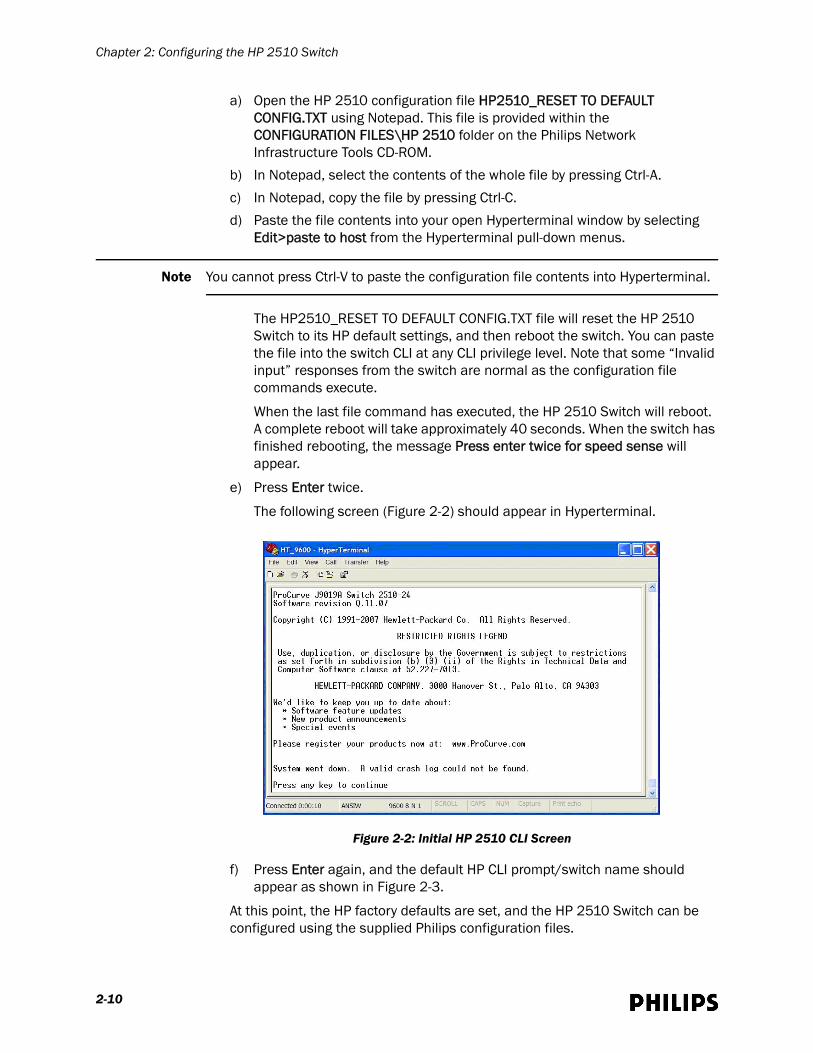
a) Open the HP 2510 configuration file HP2510_RESET TO DEFAULT CONFIG.TXT using Notepad. This file is provided within the CONFIGURATION FILES\HP 2510 folder on the Philips Network Infrastructure Tools CD-ROM.
b) In Notepad, select the contents of the whole file by pressing Ctrl-A.
c) In Notepad, copy the file by pressing Ctrl-C.
d) Paste the file contents into your open Hyperterminal window by selecting Edit>paste to host from the Hyperterminal pull-down menus.
Note You cannot press Ctrl-V to paste the configuration file contents into Hyperterminal.
The HP2510_RESET TO DEFAULT CONFIG.TXT file will reset the HP 2510 Switch to its HP default settings, and then reboot the switch. You can paste the file into the switch CLI at any CLI privilege level. Note that some “Invalid input” responses from the switch are normal as the configuration file commands execute.
When the last file command has executed, the HP 2510 Switch will reboot. A complete reboot will take approximately 40 seconds. When the switch has finished rebooting, the message Press enter twice for speed sense will appear.
e) Press Enter twice.
The following screen (Figure 2-2) should appear in Hyperterminal.
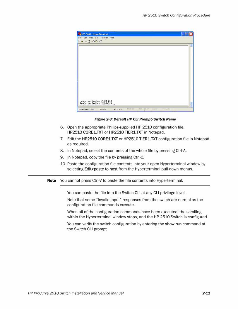
f) Press Enter again, and the default HP CLI prompt/switch name should appear as shown in Figure 2-3.
At this point, the HP factory defaults are set, and the HP 2510 Switch can be configured using the supplied Philips configuration files.
Figure 2-2: Initial HP 2510 CLI Screen
2-10
HP 2510 Switch Configuration Procedure
6. Open the appropriate Philips-supplied HP 2510 configuration file, HP2510 CORE1.TXT or HP2510 TIER1.TXT in Notepad.
7. Edit the HP2510 CORE1.TXT or HP2510 TIER1.TXT configuration file in Notepad as required.
8. In Notepad, select the contents of the whole file by pressing Ctrl-A.
9. In Notepad, copy the file by pressing Ctrl-C.
10. Paste the configuration file contents into your open Hyperterminal window by selecting Edit>paste to host from the Hyperterminal pull-down menus.
Note You cannot press Ctrl-V to paste the file contents into Hyperterminal.
You can paste the file into the Switch CLI at any CLI privilege level.
Note that some “Invalid input” responses from the switch are normal as the configuration file commands execute.
When all of the configuration commands have been executed, the scrolling within the Hyperterminal window stops, and the HP 2510 Switch is configured.
You can verify the switch configuration by entering the show run command at the Switch CLI prompt.
Figure 2-3: Default HP CLI Prompt/Switch Name
HP ProCurve 2510 Switch Installation and Service Manual 2-11

Chapter 2: Configuring the HP 2510 Switch
2-12

3
Installing the HP 2510 SwitchThis chapter provides procedures to physically install the HP 2510 Switch and includes:
• Respecting Patient Care Boundaries
• HP 2510 Switch Installation Procedures
• Powering Up the HP 2510 Switch
• Installing or Removing SFPs
• Connecting Network Cables to the HP 2510 Switch
HP ProCurve 2510 Switch Installation and Service Manual 3-1
Chapter 3: Installing the HP 2510 Switch
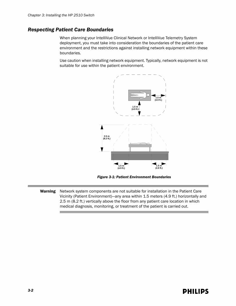
Respecting Patient Care BoundariesWhen planning your IntelliVue Clinical Network or IntelliVue Telemetry System deployment, you must take into consideration the boundaries of the patient care environment and the restrictions against installing network equipment within these boundaries.
Use caution when installing network equipment. Typically, network equipment is not suitable for use within the patient environment.
Warning Network system components are not suitable for installation in the Patient Care Vicinity (Patient Environment)—any area within 1.5 meters (4.9 ft.) horizontally and 2.5 m (8.2 ft.) vertically above the floor from any patient care location in which medical diagnosis, monitoring, or treatment of the patient is carried out.
Figure 3-1: Patient Environment Boundaries
1.5 m (4.9 ft.)
2.5 m (8.2 ft.)
1.5 m (4.9 ft.)
1.5 m (4.9 ft.)
1.5 m (4.9 ft.)
3-2
HP 2510 Switch Installation Procedures
HP 2510 Switch Installation ProceduresFollow the procedures given in this section when physically installing the HP 2510 Switch. You may mount the HP 2510 Switch to a:
• standard equipment rack
• wall
• table or desktop
Mounting the HP 2510 Switch in an Equipment Rack
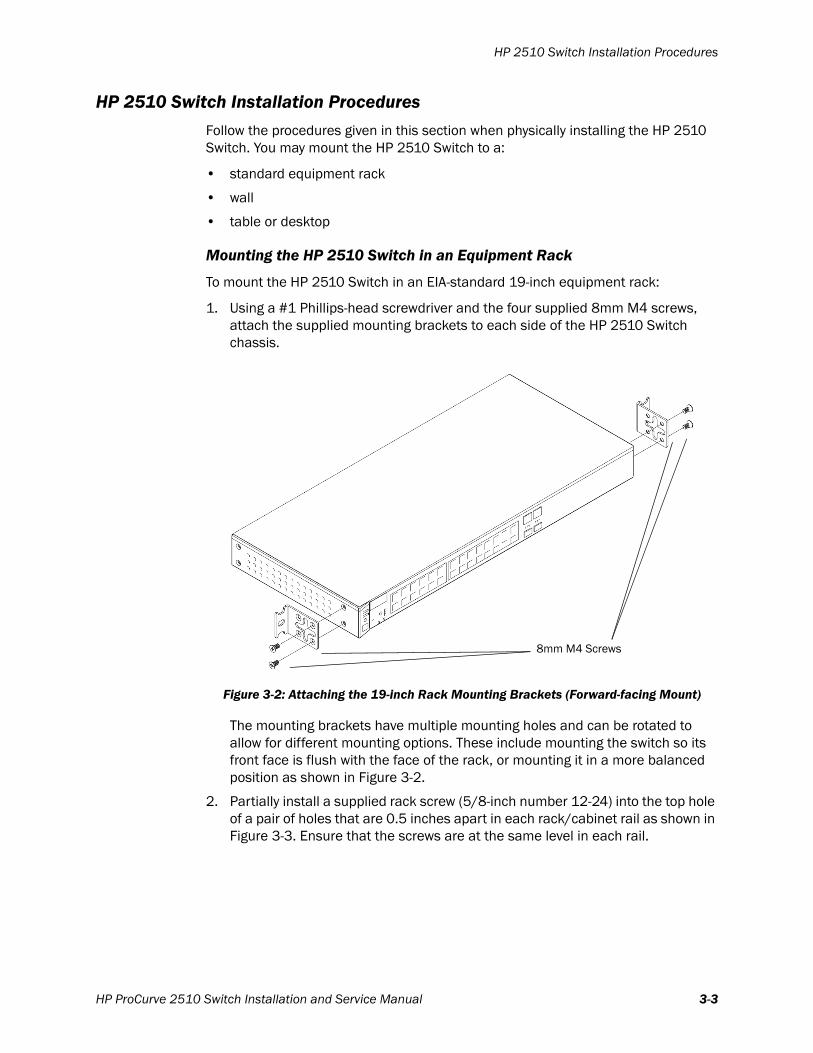
To mount the HP 2510 Switch in an EIA-standard 19-inch equipment rack:
1. Using a #1 Phillips-head screwdriver and the four supplied 8mm M4 screws, attach the supplied mounting brackets to each side of the HP 2510 Switch chassis.
The mounting brackets have multiple mounting holes and can be rotated to allow for different mounting options. These include mounting the switch so its front face is flush with the face of the rack, or mounting it in a more balanced position as shown in Figure 3-2.
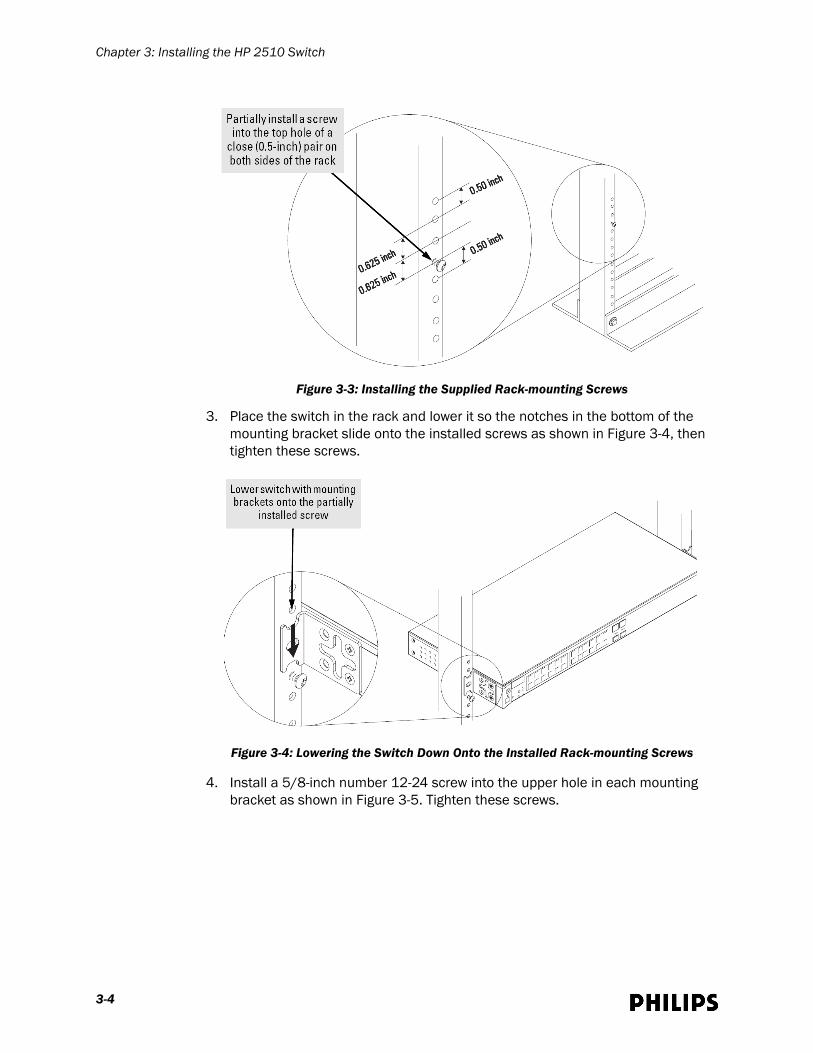
2. Partially install a supplied rack screw (5/8-inch number 12-24) into the top hole of a pair of holes that are 0.5 inches apart in each rack/cabinet rail as shown in Figure 3-3. Ensure that the screws are at the same level in each rail.
Figure 3-2: Attaching the 19-inch Rack Mounting Brackets (Forward-facing Mount)
8mm M4 Screws
HP ProCurve 2510 Switch Installation and Service Manual 3-3
Chapter 3: Installing the HP 2510 Switch
3. Place the switch in the rack and lower it so the notches in the bottom of the mounting bracket slide onto the installed screws as shown in Figure 3-4, then tighten these screws.
4. Install a 5/8-inch number 12-24 screw into the upper hole in each mounting bracket as shown in Figure 3-5. Tighten these screws.
Figure 3-3: Installing the Supplied Rack-mounting Screws
Figure 3-4: Lowering the Switch Down Onto the Installed Rack-mounting Screws
3-4
HP 2510 Switch Installation Procedures
Mounting the HP 2510 Switch to a Wall
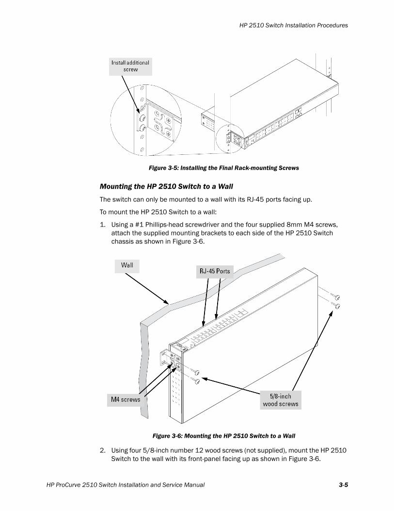
The switch can only be mounted to a wall with its RJ-45 ports facing up.
To mount the HP 2510 Switch to a wall:
1. Using a #1 Phillips-head screwdriver and the four supplied 8mm M4 screws, attach the supplied mounting brackets to each side of the HP 2510 Switch chassis as shown in Figure 3-6.
2. Using four 5/8-inch number 12 wood screws (not supplied), mount the HP 2510 Switch to the wall with its front-panel facing up as shown in Figure 3-6.
Figure 3-5: Installing the Final Rack-mounting Screws
Figure 3-6: Mounting the HP 2510 Switch to a Wall
HP ProCurve 2510 Switch Installation and Service Manual 3-5

Chapter 3: Installing the HP 2510 Switch
For the best support of the switch and cables, ensure the switch is attached securely to wall studs or to a firmly attached plywood mounting backboard.
Mounting the HP 2510 Switch to a Table or Desktop
You may operate the HP 2510 Switch while the switch is resting on a table or other horizontal surface. The switch comes with rubber feet (in the accessory kit) that can be used to help keep the switch from sliding on the horizontal surface.
To mount the HP 2510 Switch on a table or desktop:
1. Locate the four rubber feet supplied with the switch.
2. Attach the rubber feet to the four corners on the bottom of the switch within the embossed angled lines.
3. Place the switch on the table or shelf near the Uninterruptible Power Supply to which the switch will be connected.
You may want to secure the switch networking cables and power cord to the table leg or other part of the surface structure to help prevent people from tripping over the cords.
Ensure the air flow around the sides and back of the switch is not restricted.
Powering Up the HP 2510 SwitchThe HP 2510 Switch does not have a power switch. It is powered on when the power cord is connected to the switch and to a power source.
The switch automatically adjusts to any voltage between 100-127 and 200-240 volts and either 50 or 60 Hz. No voltage range settings are required.
Procedure
Note the following important requirements concerning use of an Uninterruptible Power Supply (UPS) to supply up to 90 seconds of battery power to ICN devices to maintain system operation and eliminate time consuming software rebooting during short power interruptions.
Warning The HP 2510 must be connected to the BATTERY BACKUP outlets of a UPS. Up to three IntelliVue Clinical Network components—switches, repeaters, media translators—may be connected to a single, 650VA UPS.
To power up the HP 2510 Switch:
1. Install the UPS as described in its supplied service documentation.
Depending on the model of UPS you are using, you may be required connect the UPS’s internal battery wire and set its DIP switches before operating the UPS.
2. Connect the UPS to a properly grounded AC outlet, and power the UPS on.
3. Connect the power cord supplied with the HP 2510 Switch to the receptacle located on the back of the switch and to an outlet on the UPS labeled BATTERY BACKUP.
3-6
Installing or Removing SFPs
After the switch powers up, you may connect ICN and ITS devices to the 24 10/100 switch ports using Category 5 (or better) UTP cables equipped RJ-45 connectors. You may also connect the HP 2510 Switch to other Network Switches using its Dual-personality Ports.
Power On Self Test
When the HP 2510 Switch is powered on, it performs a diagnostic self test. The self test takes approximately 50 seconds to complete.
Note the state of the switch LEDs during the self test:
• Initially, all the status, LED Mode and port LEDs are on for most of the duration of the test.
• Most of the LEDs go off and then may come on again during phases of the self test. For the duration of the self test, the Test LED stays on.
When the self test completes successfully:
• The Power LED remains on.
• The Fault and Test LEDs go off.
• The port LEDs on the front of the switch go into their normal operational mode:
- If the ports are connected to active network devices, the LEDs behave according to the LED Mode selected. In the default view mode (Link), the LEDs should be on.
- If the ports are not connected to active network devices, the LEDs will stay off.
If the LED display is different than what is described above, especially if the Fault and Test LEDs stay on for more than 60 seconds or they start blinking, the self test has not completed correctly. See Chapter 4, “Maintaining and Troubleshooting the HP 2510” for more information.
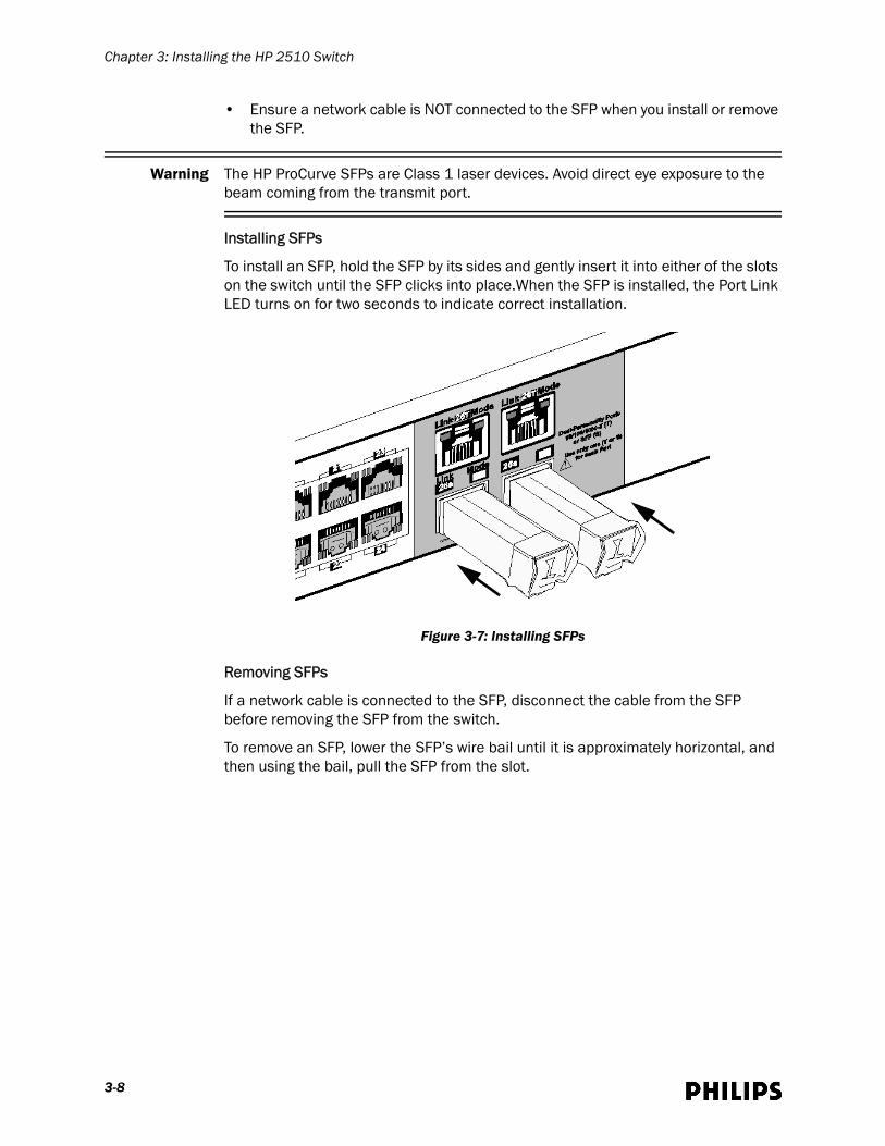
Installing or Removing SFPsYou can install or remove an SFP (Small Form-factor Pluggable) module from an SFP slot without having to power off the switch.
Use only Philips-approved/supplied HP ProCurve SFPs with the HP 2510 Switch. Philips currently supports use of the HP J9054B 100-FX SFP-LC Transceiver (Philips P/N 453564083991) with the HP 2510 Switch. This is a 100 Mbps full-duplex multi-mode fiber SFP that is compatible for connections to legacy fiber interfaces used in Philips Healthcare systems that operate at 100 Mbps full-duplex.
Note the following information concerning the use of SFPs:
• The SFP slots are shared with the two 10/100/1000Base-T RJ-45 ports. If an SFP is installed in a slot, the associated RJ-45 port is disabled and cannot be used.
• The SFP ports operate only at full duplex. Half duplex operation is not supported.
HP ProCurve 2510 Switch Installation and Service Manual 3-7
Chapter 3: Installing the HP 2510 Switch
• Ensure a network cable is NOT connected to the SFP when you install or remove the SFP.
Warning The HP ProCurve SFPs are Class 1 laser devices. Avoid direct eye exposure to the beam coming from the transmit port.
Installing SFPs
To install an SFP, hold the SFP by its sides and gently insert it into either of the slots on the switch until the SFP clicks into place.When the SFP is installed, the Port Link LED turns on for two seconds to indicate correct installation.
Removing SFPs
If a network cable is connected to the SFP, disconnect the cable from the SFP before removing the SFP from the switch.
To remove an SFP, lower the SFP’s wire bail until it is approximately horizontal, and then using the bail, pull the SFP from the slot.
Figure 3-7: Installing SFPs
3-8
Connecting Network Cables to the HP 2510 Switch
Connecting Network Cables to the HP 2510 Switch
Using the RJ-45 Connectors
To connect:
Push the RJ-45 plug into the RJ-45 jack until the tab on the plug clicks into place. When power is on for the switch and for the connected device, the Link LED for the port should light to confirm a powered-on device (for example, an end node) is at the other end of the cable.
If the Link LED does not go on when the network cable is connected to the port, see “Troubleshooting Switch Operation using its Front-panel Status Indicators” on page 4-7 for more information.
To disconnect:
Press down on the small tab on the plug, and pull the plug out of the jack.
Connecting Cables to SFPs
Each of the two SFP slots is shared with the associated 10/100/1000 Base-T RJ-45 port. If an SFP is installed in a slot, the associated RJ- 45 port is disabled.
If you have any SFPs installed in the switch, the type of network connections you will need to use depends on the type of SFPs you have installed.
For SFPs ports, and in general for all the switch ports, when a network cable from an active network device is connected to the port, the port LED for that port should go on. If the port LED does not go on when the network cable is connected to the port, see “Troubleshooting Switch Operation using its Front-panel Status Indicators” on page 4-7 for more information.
HP ProCurve 2510 Switch Installation and Service Manual 3-9

Chapter 3: Installing the HP 2510 Switch
3-10

4
Maintaining and Troubleshooting the HP 2510This chapter provides procedures to maintain and troubleshoot the HP 2510 Switch and includes:
• Performing Routine Preventive Maintenance
• Troubleshooting the HP 2510 Switch
• Loading New Firmware on a HP 2510 Switch
• Restoring the HP 2510 Factory-default Configuration
HP ProCurve 2510 Switch Installation and Service Manual 4-1
Chapter 4: Maintaining and Troubleshooting the HP 2510
Performing Routine Preventive MaintenanceIntelliVue Clinical Network hardware including the HP 2510 Switch is generally maintenance free. However, the equipment should be kept clean and dry and maintained within its environmental specifications.
Note All Preventive Maintenance is the responsibility of the customer.
The recommended frequency at which preventive maintenance procedures should be performed is six months. Preventive maintenance procedures should be performed more frequently in harsh environments.
Over time, fans used to cool electronic devices generally develop a build-up of dust in air intake areas that must be removed to assure proper cooling and circuit operation. You must check the air intakes of all ICN switches regularly and remove any dust buildup that is present.
In addition to ensuring that the switch’s air intakes remain clear and free of dust, you should follow all preventive maintenance procedures listed in the vendor documentation supplied with the HP 2510 Switch.
Troubleshooting the HP 2510 SwitchWe recommend that you troubleshoot operation of the HP 2510 Switch using the:
• Network Statistics Tool on the IntelliVue Information Centers and Clients
• HP 2510 Front-panel Status Indicators
Using the Network Statistics Tool
The Network Statistics Tool provides access to operational information gathered from Switches and Access Points on the IntelliVue Clinical Network. This information allows service personnel to determine if Network Switches and Access Points are operating within normal bounds, troubleshoot network component failures, and correlate observed application events to network communication problems. The Network Statistics Tool runs in monitoring mode and is available on the ICN Database Server and all IntelliVue Information Centers and Clients connected to the ICN.
Warning Do not load any other network management software on the IntelliVue Clinical Network as such software will adversely affect network performance and may result in a loss of patient monitoring.
To access the Network Statistics Tool from an ICN Database Server or IntelliVue Information Center:
1. Click on Network Statistics in the Support Logs menu within the Service Window.
The Network Statistics window appears.
2. Click on Switches.
4-2
Troubleshooting the HP 2510 Switch
3. Select an HP 2510 Switch from the drop-down list. All configured switches are listed on the drop-down list.
The Status Overview screen (Figure 4-1) within the HP 2510 management GUI appears.
The screens that we recommend that you review within the HP 2510 management GUI are described in the sections that follow.
Status OverviewScreen
Figure 4-1 shows the HP 2510 Switch Status Overview screen.
The Alert Log, shown in the lower half of the screen, shows a list of network occurrences, or alerts, that were detected by the switch. Typical alerts are Broadcast Storm, indicating an excessive number of broadcasts received on a port, and Problem Cable, indicating a faulty cable.
Each alert provides the following fields of information:
• Status - the level of severity of the event generated.
• Alert - the specific event identification. “Excessive CRC/alignment” errors alerts indicate speed and duplex mismatches.
• Date/Time - the date and time the event was received by the web browser interface. This value is shown in the format: DD-MM-YY HH:MM:SS AM/PM, for example, 19-04-01 09:15:26 AM.
• Description - a short narrative statement that describes the event.
Port Counters For information on network traffic quality, click the Status tab, and then click Port Counters to display the Port Counters screen (Figure 4-2).
The Port Counters screen lists the network traffic on each switch port with a breakdown of the packet types that have been detected (unicast packets, nonunicast packets, and error packets).
Figure 4-1: The HP 2510 Switch Status Overview Screen
Alert Log Entry Alert Log Control Bar
HP ProCurve 2510 Switch Installation and Service Manual 4-3
Chapter 4: Maintaining and Troubleshooting the HP 2510
To refresh the counters for a specific port, click anywhere in the row for that port, then click Refresh. To display detailed network traffic information for a specific port, click anywhere in the row for that port, then click Details for Selected Port. Note, to reset the port counters to zero, you must reboot the switch.
SystemInformation
Screen
Click the Configuration tab and then click System Info to display the System Information screen (Figure 4-3). Display this screen to view/enter basic switch descriptors including the location of the switch and a contact name for the switch. These descriptors will be listed on the Identity screen (Figure 4-4). After modifying any switch descriptors, click Apply Changes.
Identity Screen Click the Identity tab to display the HP 2510 switch Identity Screen (Figure 4-4).
The Identity screen provides the following HP 2510 Switch information:
• System Name - name of the selected switch.
• System Location - where the switch is located.
• System Contact - person to contact if the system experiences trouble.
• System Up-Time - how long the system has been active.
• System CPU Util(%) - current processor utilization expressed as a percentage.
Figure 4-2: The HP 2510 Switch Port Counters Screen
Figure 4-3: The HP 2510 Switch System Information Screen
4-4
Troubleshooting the HP 2510 Switch
• System Memory - total amount (MB) of memory and amount of available memory.
• Product - lists the switch model number.
• Base MAC Address - lists the switch base MAC address (used by the first (default) VLAN in the switch).
• Serial Number - Serial number assigned to the switch.
• Version - firmware version installed.
• IP Address - IP Address assigned to switch.
• Management Server - lists website URL to go to for help about the HP 2510 management GUI.
PortConfiguration
Screen
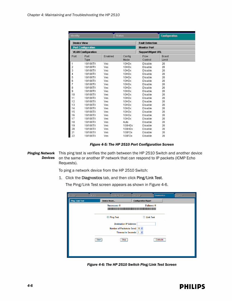
Click the Configuration tab, and then click Port Configuration to display the Port Configuration screen. This screen lists the current port configuration settings on the HP 2510 Switch, as shown in Figure 4-5.
View the Port Configuration screen to determine if speed and duplex mismatches are present between devices and the ports to which the devices connect.
Figure 4-4: The HP 2510 Switch Identity Screen
HP ProCurve 2510 Switch Installation and Service Manual 4-5
Chapter 4: Maintaining and Troubleshooting the HP 2510
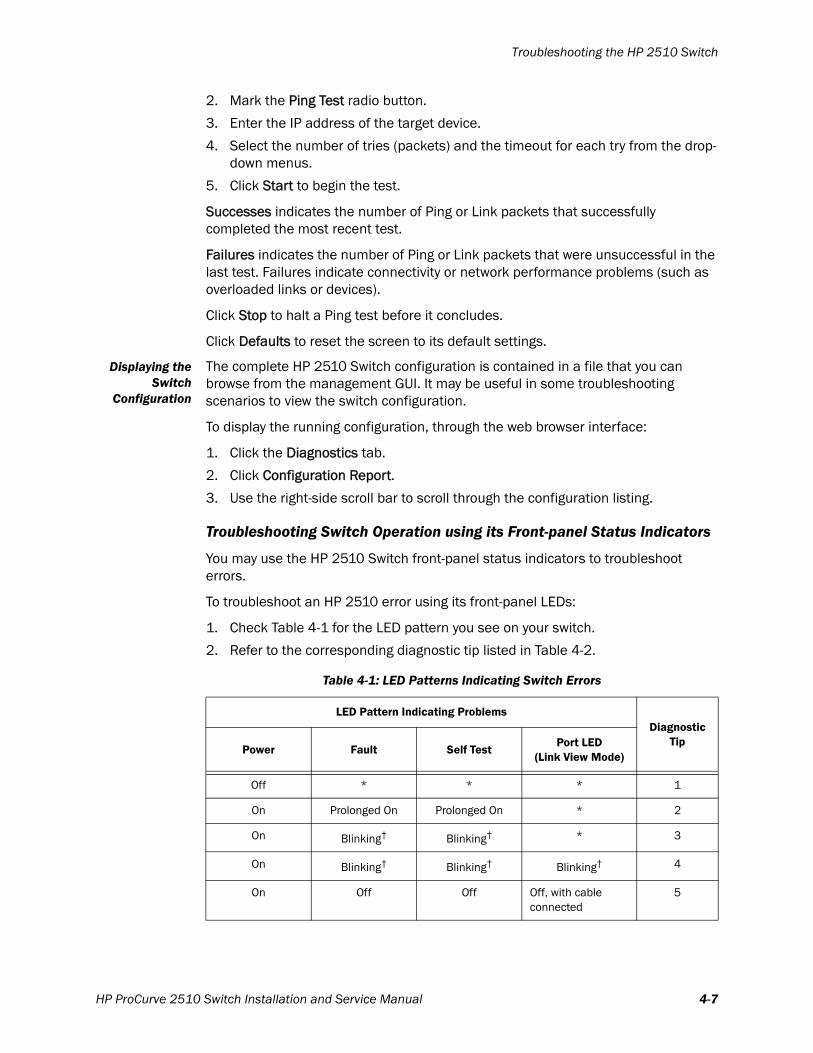
Pinging NetworkDevices
This ping test is verifies the path between the HP 2510 Switch and another device on the same or another IP network that can respond to IP packets (ICMP Echo Requests).
To ping a network device from the HP 2510 Switch:
1. Click the Diagnostics tab, and then click Ping/Link Test.
The Ping/Link Test screen appears as shown in Figure 4-6.
Figure 4-5: The HP 2510 Port Configuration Screen
Figure 4-6: The HP 2510 Switch Ping/Link Test Screen
4-6
Troubleshooting the HP 2510 Switch
2. Mark the Ping Test radio button.
3. Enter the IP address of the target device.
4. Select the number of tries (packets) and the timeout for each try from the drop-down menus.
5. Click Start to begin the test.
Successes indicates the number of Ping or Link packets that successfully completed the most recent test.
Failures indicates the number of Ping or Link packets that were unsuccessful in the last test. Failures indicate connectivity or network performance problems (such as overloaded links or devices).
Click Stop to halt a Ping test before it concludes.
Click Defaults to reset the screen to its default settings.
Displaying theSwitch
Configuration
The complete HP 2510 Switch configuration is contained in a file that you can browse from the management GUI. It may be useful in some troubleshooting scenarios to view the switch configuration.
To display the running configuration, through the web browser interface:
1. Click the Diagnostics tab.
2. Click Configuration Report.
3. Use the right-side scroll bar to scroll through the configuration listing.
Troubleshooting Switch Operation using its Front-panel Status Indicators
You may use the HP 2510 Switch front-panel status indicators to troubleshoot errors.
To troubleshoot an HP 2510 error using its front-panel LEDs:
1. Check Table 4-1 for the LED pattern you see on your switch.
2. Refer to the corresponding diagnostic tip listed in Table 4-2.
Table 4-1: LED Patterns Indicating Switch Errors
LED Pattern Indicating ProblemsDiagnostic
TipPower Fault Self Test
Port LED(Link View Mode)
Off * * * 1
On Prolonged On Prolonged On * 2
On Blinking† Blinking† * 3
On Blinking† Blinking† Blinking† 4
On Off Off Off, with cable connected
5
HP ProCurve 2510 Switch Installation and Service Manual 4-7
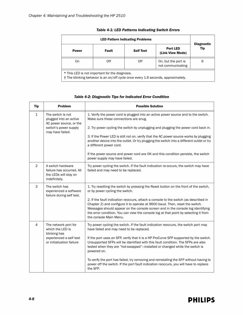
Chapter 4: Maintaining and Troubleshooting the HP 2510
On Off Off On, but the port is not communicating
6
* This LED is not important for the diagnosis.† The blinking behavior is an on/off cycle once every 1.6 seconds, approximately.
Table 4-1: LED Patterns Indicating Switch Errors
LED Pattern Indicating ProblemsDiagnostic
TipPower Fault Self Test
Port LED(Link View Mode)
Table 4-2: Diagnostic Tips for Indicated Error Condition
Tip Problem Possible Solution
1 The switch is not plugged into an active AC power source, or the switch’s power supply may have failed.
1. Verify the power cord is plugged into an active power source and to the switch. Make sure these connections are snug.
2. Try power cycling the switch by unplugging and plugging the power cord back in.
3. If the Power LED is still not on, verify that the AC power source works by plugging another device into the outlet. Or try plugging the switch into a different outlet or try a different power cord.
If the power source and power cord are OK and this condition persists, the switch power supply may have failed.
2 A switch hardware failure has occurred. All the LEDs will stay on indefinitely.
Try power cycling the switch. If the fault indication re-occurs, the switch may have failed and may need to be replaced.
3 The switch has experienced a software failure during self test.
1. Try resetting the switch by pressing the Reset button on the front of the switch, or by power cycling the switch.
2. If the fault indication reoccurs, attach a console to the switch (as described in Chapter 2) and configure it to operate at 9600 baud. Then, reset the switch. Messages should appear on the console screen and in the console log identifying the error condition. You can view the console log at that point by selecting it from the console Main Menu.
4 The network port for which the LED is blinking has experienced a self test or initialization failure
Try power cycling the switch. If the fault indication reoccurs, the switch port may have failed and may need to be replaced.
If the port uses an SFP, verify that it is a HP ProCurve SFP supported by the switch. Unsupported SFPs will be identified with this fault condition. The SFPs are also tested when they are “hot-swapped”—installed or changed while the switch is powered on.
To verify the port has failed, try removing and reinstalling the SFP without having to power off the switch. If the port fault indication reoccurs, you will have to replace the SFP.
4-8
Troubleshooting the HP 2510 Switch
5 The network connection is not working properly.
The cable verification process must include all patch cables from any end devices, including the switch, to any patch panels in the cabling path. Try the following procedures:• For the indicated port, verify both ends of the cabling, at the switch and the connected device, are connected properly.• Verify the connected device and switch are both powered on and operating correctly.• Verify you have used the correct cable type for the connection:– For twisted-pair connections to the fixed 10/100 ports, if the port is configured to “Auto” (auto negotiate), either straight-through or crossover cables can be used because of the switch’s Auto MDI/MDI-X feature of the 10/100-Base-TX port.Note: If the switch port configuration is changed to one of the fixed configuration options (for example, 100 Mbps/Full Duplex), then the port operates as MDI-X only and you must use the correct type of cable for the connection. In general, for connecting an end node (MDI port) to the switch, use straight-through cable; for connecting to MDI-X ports on hubs, other switches, and routers, use crossover cable.– For fiber-optic connections, verify that the transmit port on the switch is connected to the receive port on the connected device, and the switch receive port is connected to the transmit port on the connected device.• For the dual-personality 10/100/1000Base-T ports, be sure an SFP is not installed in the associated slot. • For the dual-personality SFP ports, ensure that only the supported HP SFP module is installed. Use of non-HP or un-supported HP SFPs may result in the inability to establish a link.• Verify the port has not been disabled through a switch configuration change. You can use the console interface, or, if you have configured an IP address on theswitch, use the web browser interface to determine the state of the port and re-enable the port if necessary.• Verify the switch port configuration matches the configuration of the attached device.For example, if the switch port is configured as “Auto,” the port on the attached device also MUST be configured as “Auto.” Depending on the port type, twisted-pair or fiber-optic, if the configurations don’t match, the results could be a very unreliable connection, or no link at all.• If the other procedures don’t resolve the problem, try using a different port or a different connecting cable.
6 The port may be improperly configured, or the port may be in a “blocking” state by thenormal operation of the Spanning Tree, LACP, or IGMP features.
Use the switch console to see if the port is part of a dynamic trunk (through the LACP feature) or to see if Spanning Tree is enabled on the switch, and to see if the port may have been put into a “blocking” state by those features. The show lacp command displays the port status for the LACP feature; the show spanning-tree command displays the port status for Spanning Tree.Also check the Port Status screen using the show interfaces command to see if the port has been configured as “disabled.”Other switch features that may affect the port operation include VLANs and IGMP. Use the switch console to see how the port is configured for these features.Make sure also, that the device at the other end of the connection is indicating a good link to the switch. If it is not, the problem may be with the cabling between the devices or the connectors on the cable.
Table 4-2: Diagnostic Tips for Indicated Error Condition
Tip Problem Possible Solution
HP ProCurve 2510 Switch Installation and Service Manual 4-9

Chapter 4: Maintaining and Troubleshooting the HP 2510
Loading New Firmware on a HP 2510 SwitchIf the HP 2510 Switch has the incorrect version firmware loaded, you must load the latest correct version of firmware on it using the procedure detailed in this section.
Required Materials/Prerequisites
Ensure you have the following materials and that the following prerequisites have been met before beginning the firmware loading procedures:
• Service PC equipped with:
- Ethernet and Serial Ports
- CD-ROM Drive
- Web Browser
• HP DB-9-to-RJ-45 Console Cable (cable shipped with HP 2510 Switch)
• Standard UTP Patch Cable
• Latest release of the Philips Network Infrastructure Tools CD-ROM
• You must have a network interface on your service PC active and configured so that it can reach the HP 2510 Switch via the switch’s configured IP address. If you do not know the HP 2510’s configured IP address or port settings, you must reset the switch to its factory default settings as described on page 4-14 and then set the switch IP address before loading new firmware onto the switch.
Loading Firmware from Your Service PC to the HP 2510
To load a firmware image from your service PC to the HP 2510 Switch:
1. Using a standard UTP patch cable, connect the network interface on your service PC to an available port on the HP 2510 Switch.
Ensure the switch port to which you connect is configured for the same speed and duplex settings as the PC’s network interface.
2. Open a web browser on your service PC and enter the switch’s IP address in the browser address/URL field.
4-10
Loading New Firmware on a HP 2510 Switch
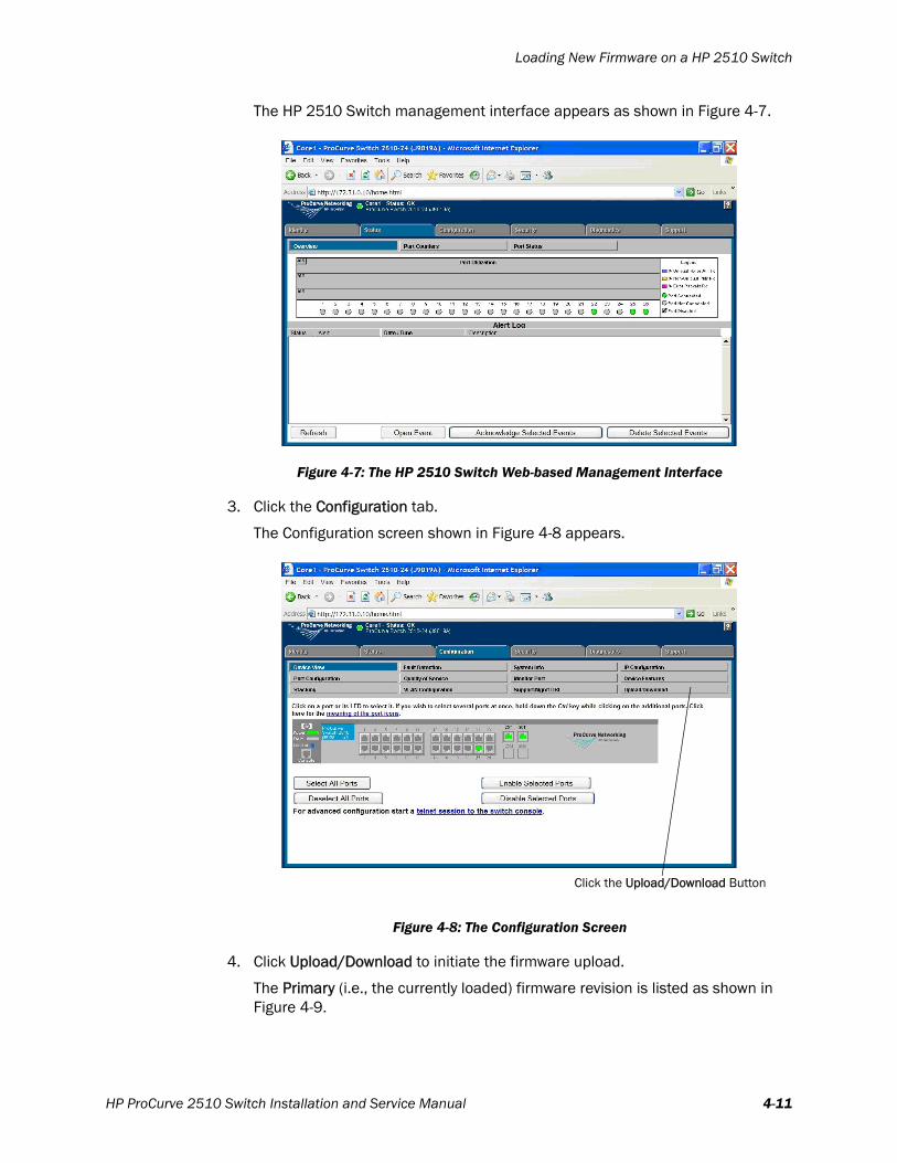
The HP 2510 Switch management interface appears as shown in Figure 4-7.
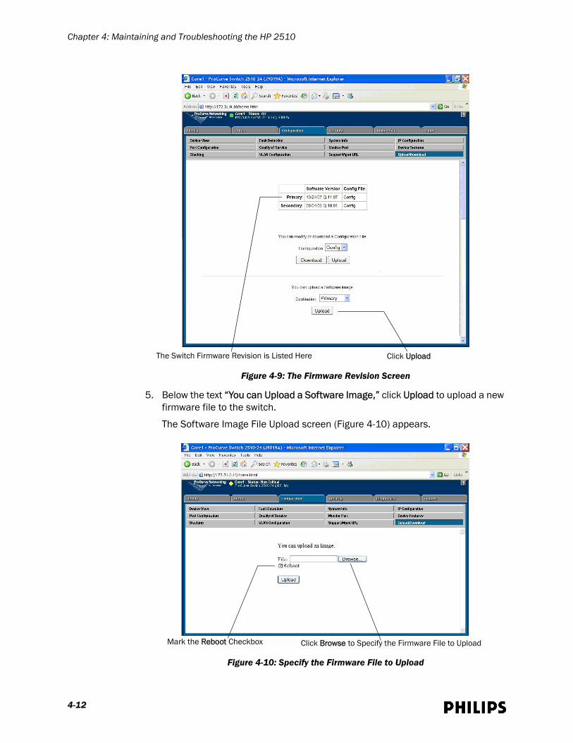
3. Click the Configuration tab.
The Configuration screen shown in Figure 4-8 appears.
4. Click Upload/Download to initiate the firmware upload.
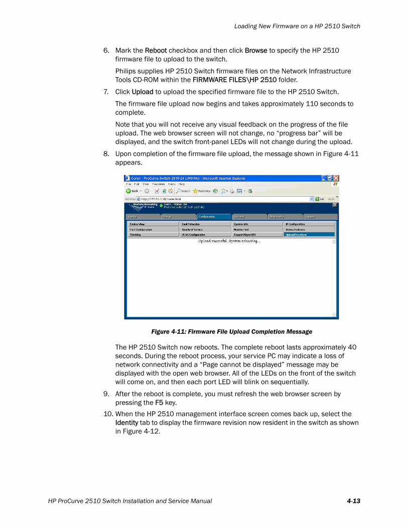
The Primary (i.e., the currently loaded) firmware revision is listed as shown in Figure 4-9.
Figure 4-7: The HP 2510 Switch Web-based Management Interface
Figure 4-8: The Configuration Screen
Click the Upload/Download Button
HP ProCurve 2510 Switch Installation and Service Manual 4-11
Chapter 4: Maintaining and Troubleshooting the HP 2510
5. Below the text “You can Upload a Software Image,” click Upload to upload a new firmware file to the switch.
The Software Image File Upload screen (Figure 4-10) appears.
Figure 4-9: The Firmware Revision Screen
Figure 4-10: Specify the Firmware File to Upload
The Switch Firmware Revision is Listed Here Click Upload
Mark the Reboot Checkbox Click Browse to Specify the Firmware File to Upload
4-12
Loading New Firmware on a HP 2510 Switch
6. Mark the Reboot checkbox and then click Browse to specify the HP 2510 firmware file to upload to the switch.
Philips supplies HP 2510 Switch firmware files on the Network Infrastructure Tools CD-ROM within the FIRMWARE FILES\HP 2510 folder.
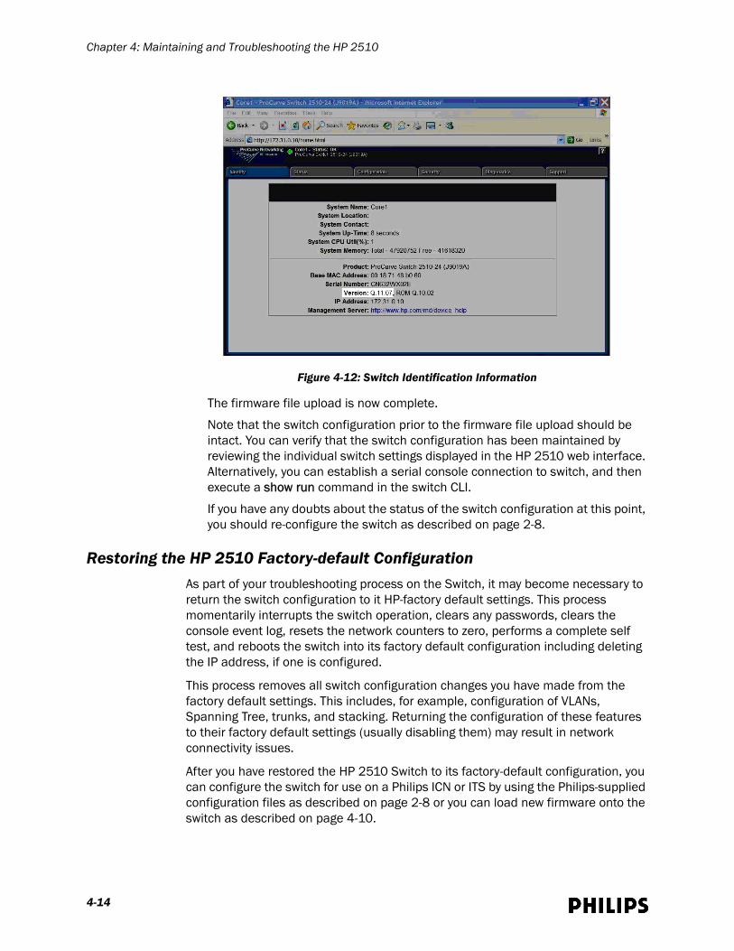
7. Click Upload to upload the specified firmware file to the HP 2510 Switch.
The firmware file upload now begins and takes approximately 110 seconds to complete.
Note that you will not receive any visual feedback on the progress of the file upload. The web browser screen will not change, no “progress bar” will be displayed, and the switch front-panel LEDs will not change during the upload.
8. Upon completion of the firmware file upload, the message shown in Figure 4-11 appears.
The HP 2510 Switch now reboots. The complete reboot lasts approximately 40 seconds. During the reboot process, your service PC may indicate a loss of network connectivity and a “Page cannot be displayed” message may be displayed with the open web browser. All of the LEDs on the front of the switch will come on, and then each port LED will blink on sequentially.
9. After the reboot is complete, you must refresh the web browser screen by pressing the F5 key.
10. When the HP 2510 management interface screen comes back up, select the Identity tab to display the firmware revision now resident in the switch as shown in Figure 4-12.
Figure 4-11: Firmware File Upload Completion Message
HP ProCurve 2510 Switch Installation and Service Manual 4-13
Chapter 4: Maintaining and Troubleshooting the HP 2510
The firmware file upload is now complete.
Note that the switch configuration prior to the firmware file upload should be intact. You can verify that the switch configuration has been maintained by reviewing the individual switch settings displayed in the HP 2510 web interface. Alternatively, you can establish a serial console connection to switch, and then execute a show run command in the switch CLI.
If you have any doubts about the status of the switch configuration at this point, you should re-configure the switch as described on page 2-8.
Restoring the HP 2510 Factory-default ConfigurationAs part of your troubleshooting process on the Switch, it may become necessary to return the switch configuration to it HP-factory default settings. This process momentarily interrupts the switch operation, clears any passwords, clears the console event log, resets the network counters to zero, performs a complete self test, and reboots the switch into its factory default configuration including deleting the IP address, if one is configured.
This process removes all switch configuration changes you have made from the factory default settings. This includes, for example, configuration of VLANs, Spanning Tree, trunks, and stacking. Returning the configuration of these features to their factory default settings (usually disabling them) may result in network connectivity issues.
After you have restored the HP 2510 Switch to its factory-default configuration, you can configure the switch for use on a Philips ICN or ITS by using the Philips-supplied configuration files as described on page 2-8 or you can load new firmware onto the switch as described on page 4-10.
Figure 4-12: Switch Identification Information
4-14
Restoring the HP 2510 Factory-default Configuration
Required Equipment
You will need the following equipment to successfully restore the HP 2510 Switch to its factory-default configuration:
• Service PC equipped with:
- Ethernet and Serial Ports- CD-ROM Drive- Web Browser
• HP DB-9-to-RJ-45 Console Cable (cable shipped with HP 2510 Switch)
• Standard UTP Patch Cable
• Latest release of the Philips Network Infrastructure Tools CD-ROM
Procedure
To restore the factory-default configuration on the HP 2510 Switch:
1. Connect the supplied DB-9-to-RJ-45 Console Cable between the Console Port located on the HP 2510 front panel and the serial port on your service PC.
2. Load the Philips Network Infrastructure Tools CD-ROM in your service PC’s CD-ROM drive.
3. Run the Hyperterminal application your service PC with the following settings:
• Port Speed: 9600 bps• Data Bits: 8
• No parity
• Stop Bits: 1• Flow Control: None
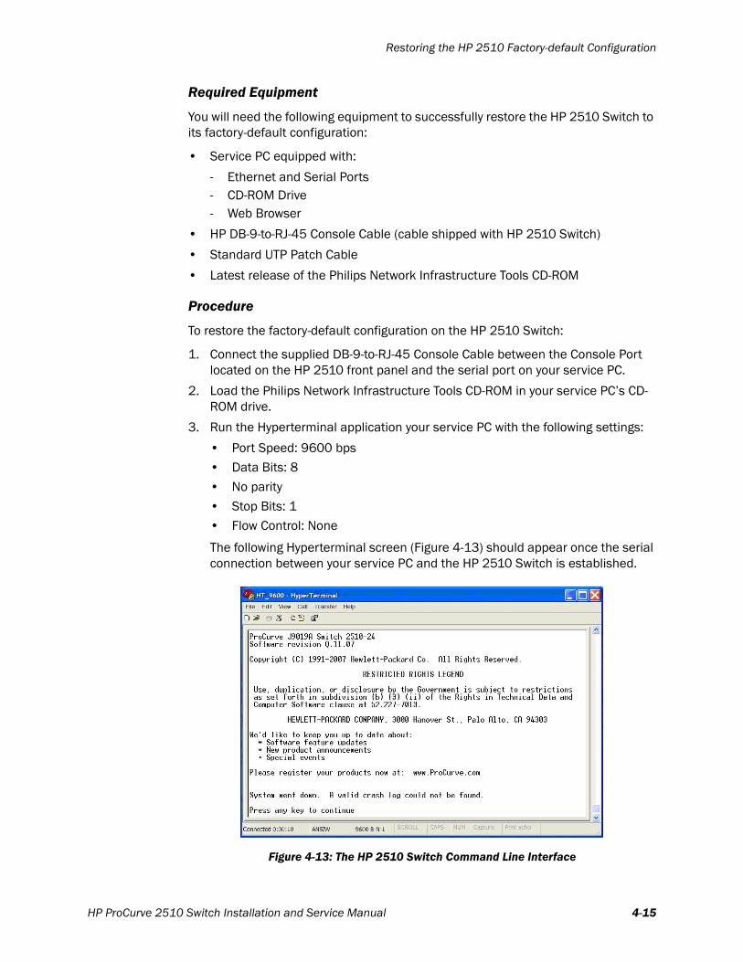
The following Hyperterminal screen (Figure 4-13) should appear once the serial connection between your service PC and the HP 2510 Switch is established.
Figure 4-13: The HP 2510 Switch Command Line Interface
HP ProCurve 2510 Switch Installation and Service Manual 4-15
Chapter 4: Maintaining and Troubleshooting the HP 2510
4. Open the HP 2510 configuration file HP2510_RESET TO DEFAULT CONFIG.TXT using Notepad. This file is provided within the CONFIGURATION FILES\HP 2510 folder on the Philips Network Infrastructure Tools CD-ROM.
5. Open Windows Notepad on your service PC, and from Notepad:
a) Select the contents of the whole file by pressing Ctrl-A.
b) Copy the file by pressing Ctrl-C.
6. Paste the file contents into your open Hyperterminal window by selecting Edit>paste to host from the Hyperterminal pull-down menus.
Note You cannot press Ctrl-V to paste the file contents into Hyperterminal.
The HP2510_RESET TO DEFAULT CONFIG.TXT file will reset the HP 2510 Switch to its HP default settings, and then reboot the switch. You can paste the file into the switch CLI at any CLI privilege level. Note that some “Invalid input” responses from the switch are normal as the configuration file commands execute.
When the last file command has executed, the HP 2510 Switch will reboot. A complete reboot will take approximately 40 seconds. When the switch has finished rebooting, the message Press enter twice for speed sense will appear.
7. Press Enter twice.
The following screen (Figure 4-14) should appear in Hyperterminal.
8. Press Enter again, and the default HP CLI prompt/switch name should appear as shown in Figure 4-15.
Figure 4-14: Initial HP 2510 CLI Screen
4-16
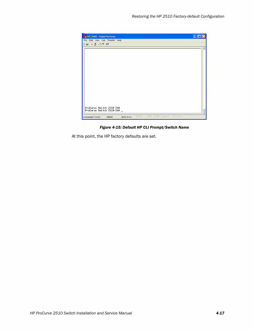
Restoring the HP 2510 Factory-default Configuration
At this point, the HP factory defaults are set.
Figure 4-15: Default HP CLI Prompt/Switch Name
HP ProCurve 2510 Switch Installation and Service Manual 4-17

Chapter 4: Maintaining and Troubleshooting the HP 2510
4-18

5
Validating the HP 2510 InstallationThis chapter provides procedures to validate the HP 2510 Installation you have just completed and includes:
• Executing Validation Tests
• Performing Visual Tests
• Performing Test and Inspection Procedures
HP ProCurve 2510 Switch Installation and Service Manual 5-1
Chapter 5: Validating the HP 2510 Installation
Executing Validation TestsBefore using the IntelliVue Information Center and IntelliVue Clinical Network clinically with patients, you must verify proper performance of the system.
This chapter includes a series of validation tests that should be performed after initial system installation, and after any system repair or upgrade to verify system functionality.
Note These validation tests do not check all system specifications but are intended to verify performance of the primary features of IntelliVue Information Center functionality. However, successful completion of the tests should yield a fully functioning system.
When performing product assurance tests, IntelliVue Information Centers must be connected to the IntelliVue Clinical Network.
Performing Visual TestsPrior to using the Philips system with patients, you must visually inspect all system components, cables, and connectors thoroughly.
To inspect Philips ICN components:
1. Check all components of the IntelliVue Clinical Network for signs of mechanical damage.
If damage to a component is found, assess the damage to determine if repair or replacement is required. Repair or replace the component as required before continuing the Product Validation Tests.
2. Check all cables of the IntelliVue Clinical Network system for signs of abrasion, wear, or other damage.
If any cable shows evidence of damage, repair or replace the cable prior to using the IntelliVue Clinical Network for patient monitoring.
3. Check all cable connectors for signs of mechanical damage and each cable connection for connection integrity.
If any cable connector shows signs of damage, replace the cable prior to using the IntelliVue Clinical Network for patient monitoring.
4. Check that all cable connectors are securely fastened to the rear of each device.
Performing Test and Inspection ProceduresThis section is intended for Philips -trained service providers. It lists the requirements for test, inspection, and results reporting for IntelliVue Clinical Networks to help assure safe and reliable operation.
5-2
Performing Test and Inspection Procedures
Note The tests and inspections listed in the following tables must be followed by Philips-trained service providers when the Philips ICN is initially installed and after any service event.
Table 5-1 describes which tests should be performed for Philips ICN components—IntelliVue Information Centers, Clients, Database Servers, and network infrastructure devices—for each type of service event.
Table 5-2 describes the test or inspection to perform for active M3185 IntelliVue Clinical Network components for each type of test specified in Table 5-1.
Table 5-1: HP 2510 Test and Inspection Requirements
Service Event
When performing....
Test Block(s) Required
....Complete these tests
Installation Visual, Power On
Preventive Maintenance Power On
Any component repair or replacement
Power On
Hardware Upgrade Power On
Software Upgrade Power On
All other Service Events Visual, Power On
Table 5-2: HP 2510 Test and Inspection Matrix
Test Block Name
Test or Inspection to PerformExpected Results
Information to Record on Service
Record
Visual Inspect all system components for obvious damage.
No visible damage.
V:P or V:Fwhere:P = PassF = Fail
Power On: With power connected to each active Network device, observe that all device front-panel LEDs are in their proper state and that no error conditions are indicated.The following is the normal condition for the HP 2510:After it completes its POST, the HP 2510 System LED is solid green and each of the Port Status LEDs is Off (for each to which no device is connected).
Devices power up into expected status; no error indications are shown.
PO:P or PO:Fwhere:P = PassF = Fail
HP ProCurve 2510 Switch Installation and Service Manual 5-3

Chapter 5: Validating the HP 2510 Installation
Performance: No safety test is required P:NAwhere:NA = Not Applicable
Safety: No safety test is required S:NAwhere:NA = Not Applicable
Table 5-2: HP 2510 Test and Inspection Matrix
Test Block Name
Test or Inspection to PerformExpected Results
Information to Record on Service
Record
5-4
Index
AAC power cord receptacle 1-7Air intakes, cleaning 4-2
CClear button 1-6Config Tool application, restrictions against use of 2-2Configuration files on the Network Tools CD-ROM 2-2Configuration procedure 2-8Configuration, restoring factory default 4-14
DDiagnostic self test 3-7
EEquipment rack, mounting procedure for 3-3
FFactory-default configuration, restoring 4-14Factory-default HP configuration settings, resetting the switch to 2-10, 4-16Firmware, loading onto Switch 4-10Firmware, supported version 2-2Front-panel ports 1-3
HHP2510 CORE1.TXT configuration file 2-2HP2510 TIER1.TXT configuration file 2-5HP2510_RESET TO DEFAULT CONFIG.TXT file 2-10, 4-16
IInstallation procedures 3-3
LLaser warning, concerning SFPs 3-8Light-emitting Diodes (LEDs) 1-3
MMounting brackets, installing 3-3, 3-5
HP ProCurve 2510 Switch Installation and Service Manual Index-1
Index
NNetwork statistics tool, using for troubleshooting 4-2
OOrdering information 1-9
PPart numbers 1-9Patient environment, boundaries of 3-2Ports 1-3Power on self test 3-7Power up procedure 3-6
RRear panel connectors 1-7Reset button 1-6Routine preventive maintenance, performing 4-2
SSFP (Small Form-factor Pluggable) module, supported models 1-3SFPs, installing and removing 3-7Specifications for the HP 2510 1-8Status indicators 1-3
TTable or desktop mounting procedure 3-6Test and inspection procedures, performing 5-2Troubleshooting procedures 4-2
UUninterruptible Power Supply (UPS), required use of 3-6
VValidation tests, executing 5-2Visual tests, performing 5-2
WWall mounting procedures 3-5
Index-2