aod hp - alltranz
TRANSCRIPT
AOD-HP Reprogramming Kit™
Fits: 1980-1993 AOD 4 Speed Non-Electronic Transmissions. Short, Firm Shifts with Performance, Durability and “CLASS”. Tunable wide open throttle shifts* From 5500 - 6800 RPM.
This Kit does not provide a wide-open throttle up-shift to 4th. Trans will have full automatic operation in OD or D position. *Kit provides optional Parts to tune max throttle up-shift RPM.
Be cautious when tuning max throttle shifts to avoid engine damage!
© TransGo 2017
For Professional Installation Requires medium to high degree of technical ability and additional tools to install.
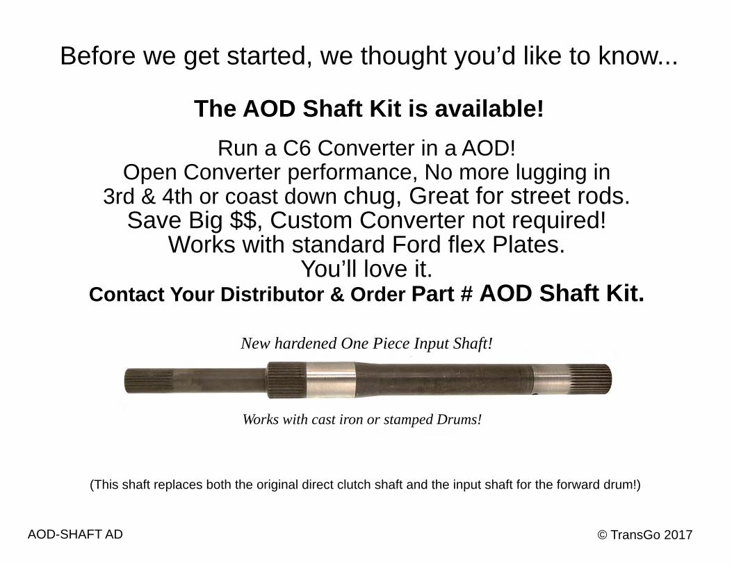
Before we get started, we thought you’d like to know...
The AOD Shaft Kit is available! Run a C6 Converter in a AOD!
Open Converter performance, No more lugging in 3rd & 4th or coast down chug, Great for street rods.
Save Big $$, Custom Converter not required! Works with standard Ford flex Plates.
You’ll love it. Contact Your Distributor & Order Part # AOD Shaft Kit.
New hardened One Piece Input Shaft!
Works with cast iron or stamped Drums!
(This shaft replaces both the original direct clutch shaft and the input shaft for the forward drum!)
© TransGo 2017 AOD-SHAFT AD
Page 1
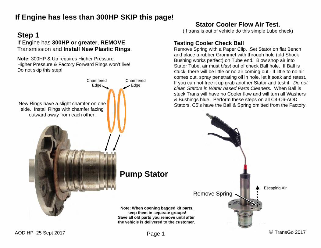
Stator Cooler Flow Air Test. (If trans is out of vehicle do this simple Lube check)
Pump Stator
Step 1 If Engine has 300HP or greater, REMOVE Transmission and Install New Plastic Rings.
Note: 300HP & Up requires Higher Pressure. Higher Pressure & Factory Forward Rings won’t live! Do not skip this step!
New Rings have a slight chamfer on one side. Install Rings with chamfer facing
outward away from each other.
Remove Spring
Testing Cooler Check Ball Remove Spring with a Paper Clip. Set Stator on flat Bench and place a rubber Grommet with through hole (old Shock Bushing works perfect) on Tube end. Blow shop air into Stator Tube, air must blast out of check Ball hole. If Ball is stuck, there will be little or no air coming out. If little to no air comes out, spray penetrating oil in hole, let it soak and retest. If you can not free it up grab another Stator and test it. Do not clean Stators in Water based Parts Cleaners. When Ball is stuck Trans will have no Cooler flow and will turn all Washers & Bushings blue. Perform these steps on all C4-C6-AOD Stators, C5’s have the Ball & Spring omitted from the Factory.
© TransGo 2017 AOD HP 25 Sept 2017
Escaping Air
Note: When opening bagged kit parts, keep them in separate groups!
Save all old parts you remove until after the vehicle is delivered to the customer.
Chamfered Edge
Chamfered Edge
If Engine has less than 300HP SKIP this page!
Step 1
Page 2
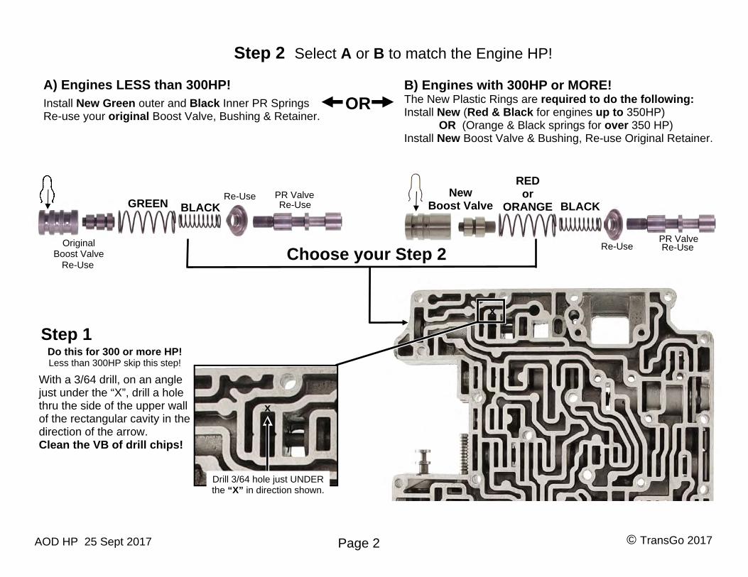
A) Engines LESS than 300HP!Install New Green outer and Black Inner PR Springs Re-use your original Boost Valve, Bushing & Retainer.
B) Engines with 300HP or MORE!The New Plastic Rings are required to do the following: Install New (Red & Black for engines up to 350HP) OR (Orange & Black springs for over 350 HP)Install New Boost Valve & Bushing, Re-use Original Retainer.
BLACK GREEN
Choose your Step 2
RED or
ORANGE BLACK
x
x
Drill 3/64 hole just UNDER the “X” in direction shown.
With a 3/64 drill, on an angle just under the “X”, drill a hole thru the side of the upper wall of the rectangular cavity in the direction of the arrow. Clean the VB of drill chips!
Do this for 300 or more HP! Less than 300HP skip this step!
Re-Use
Original Boost Valve
New Boost Valve
PR Valve
PR Valve Re-Use
Re-Use Re-Use
Re-Use
Step 2 Select A or B to match the Engine HP!
OR
© TransGo 2017 AOD HP 25 Sept 2017
GREEN Re-use
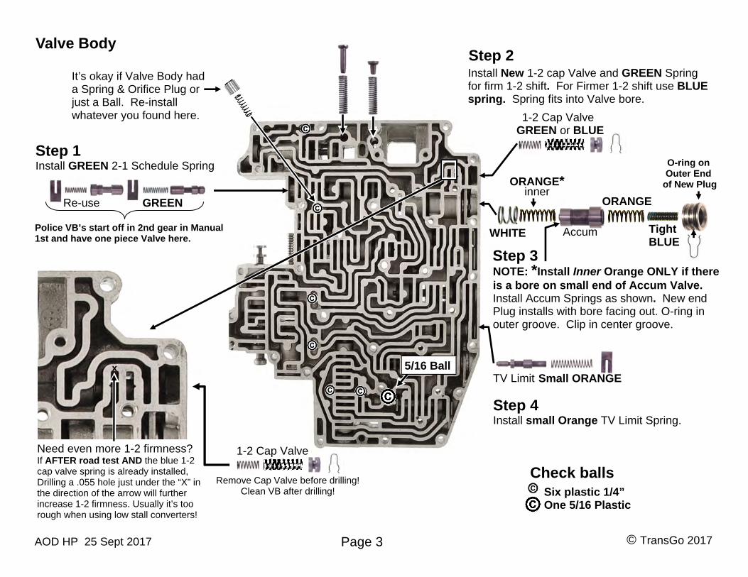
Step 1 Install GREEN 2-1 Schedule Spring
Step 3
Step 2 Install New 1-2 cap Valve and GREEN Spring for firm 1-2 shift. For Firmer 1-2 shift use BLUE spring. Spring fits into Valve bore.
Page 3
WHITE
1-2 Cap Valve
ORANGE
Tight BLUE
ORANGE* inner
Valve Body
Accum
Six plastic 1/4” One 5/16 Plastic
Check balls
5/16 Ball TV Limit
It’s okay if Valve Body had a Spring & Orifice Plug or just a Ball. Re-install whatever you found here.
GREEN or BLUE
Small ORANGE
Police VB’s start off in 2nd gear in Manual 1st and have one piece Valve here.
x
Need even more 1-2 firmness? If AFTER road test AND the blue 1-2 cap valve spring is already installed, Drilling a .055 hole just under the “X” in the direction of the arrow will further increase 1-2 firmness. Usually it’s too rough when using low stall converters!
1-2 Cap Valve
Remove Cap Valve before drilling! Clean VB after drilling!
Step 4 Install small Orange TV Limit Spring.
NOTE: *Install Inner Orange ONLY if thereis a bore on small end of Accum Valve. Install Accum Springs as shown. New end Plug installs with bore facing out. O-ring in outer groove. Clip in center groove.
O-ring onOuter End
of New Plug
© TransGo 2017 AOD HP 25 Sept 2017
Page 4
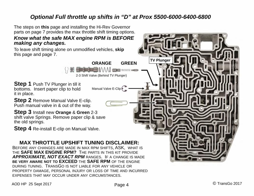
Step 1 Push TV Plunger in till itbottoms. Insert paper clip to hold it in place.
Step 2 Remove Manual Valve E-clip.Push manual valve in & out of the way.
Step 3 Install new Orange & Green 2-3shift valve Springs. Remove paper clip & save the old springs.
Step 4 Re-install E-clip on Manual Valve.
The steps on this page and installing the Hi-Rev Governor parts on page 7 provides the max throttle shift timing options.
Know what the safe MAX engine RPM is BEFORE making any changes.
To leave shift timing alone on unmodified vehicles, skip this page and page 7.
Optional Full throttle up shifts in “D” at Prox 5500-6000-6400-6800
ORANGE GREEN TV Plunger
MAX THROTTLE UPSHIFT TUNING DISCLAIMER: BEFORE ANY CHANGES ARE MADE IN MAX RPM SHIFTS, ASK, WHAT IS THE SAFE MAX ENGINE RPM? THE PARTS IN THIS KIT PROVIDE APPROXIMATE, NOT EXACT RPM RANGES. IF A CHANGE IS MADE BE VERY AWARE NOT TO EXCEED THE SAFE RPM OF THE ENGINE DURING TUNING. TRANSGO IS NOT LIABLE FOR ANY VEHICLE OR PROPERTY DAMAGE, PERSONAL INJURY OR LOSS OF TIME AND INCURRED EXPENSES THAT MAY OCCUR UNDER ANY CIRCUMSTANCES.
2-3 Shift Valve (Behind TV Plunger)
Manual Valve E-Clip
© TransGo 2017 AOD HP 25 Sept 2017
Page 5
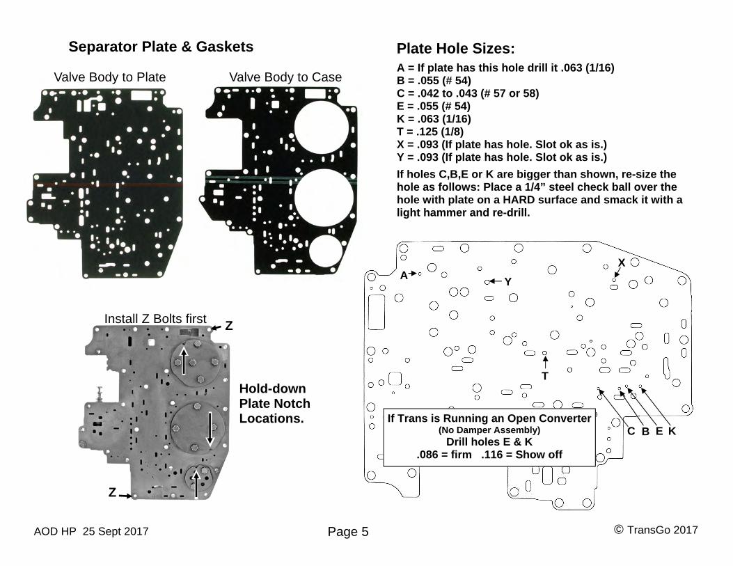
Plate Hole Sizes: A = If plate has this hole drill it .063 (1/16) B = .055 (# 54) C = .042 to .043 (# 57 or 58) E = .055 (# 54) K = .063 (1/16) T = .125 (1/8) X = .093 (If plate has hole. Slot ok as is.) Y = .093 (If plate has hole. Slot ok as is.)If holes C,B,E or K are bigger than shown, re-size the hole as follows: Place a 1/4” steel check ball over the hole with plate on a HARD surface and smack it with a light hammer and re-drill.
Y A
C B E K
X
T
If Trans is Running an Open Converter (No Damper Assembly)
Drill holes E & K .086 = firm .116 = Show off
Separator Plate & Gaskets
Valve Body to Plate Valve Body to Case
Hold-down Plate Notch Locations.
Z
ZInstall Z Bolts first
© TransGo 2017 AOD HP 25 Sept 2017
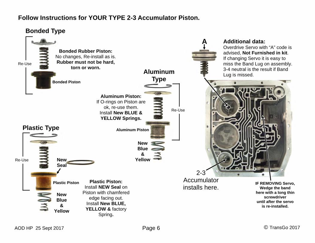
IF REMOVING Servo, Wedge the band
here with a long thin screwdriver
until after the servo is re-installed.
Follow Instructions for YOUR TYPE 2-3 Accumulator Piston.
Page 6
Additional data: Overdrive Servo with “A” code is advised, Not Furnished in kit. If changing Servo it is easy to miss the Band Lug on assembly. 3-4 neutral is the result if BandLug is missed.
Plastic Piston
New Seal
A
Plastic Piston: Install NEW Seal on
Piston with chamfered edge facing out.
Install New BLUE, YELLOW & factory
Spring.
New Blue
& Yellow
Re-Use
Bonded Piston
Re-Use
Aluminum Piston
Aluminum Piston: If O-rings on Piston are
ok, re-use them. Install New BLUE & YELLOW Springs.
Re-Use
New Blue
& Yellow
2-3Accumulator installs here.
Bonded Rubber Piston: No changes, Re-install as is. Rubber must not be hard,
torn or worn.
Bonded Type
Aluminum Type
Plastic Type
© TransGo 2017 AOD HP 25 Sept 2017
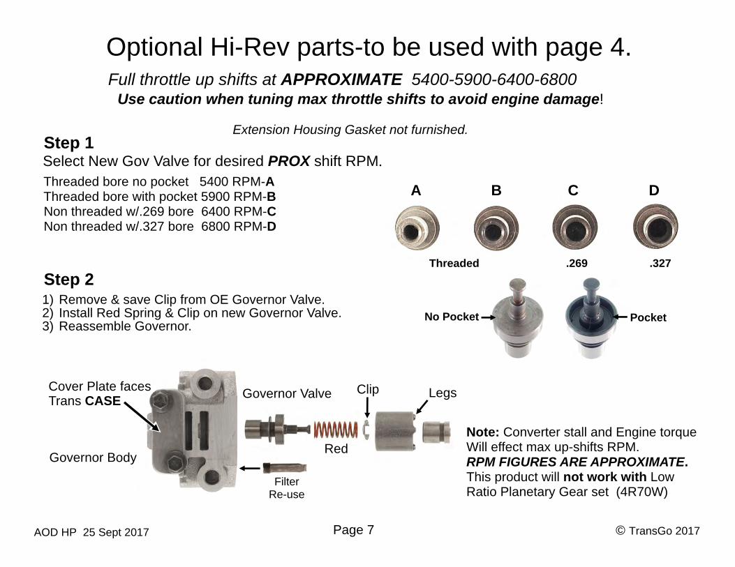
Note: Converter stall and Engine torque Will effect max up-shifts RPM. RPM FIGURES ARE APPROXIMATE. This product will not work with Low Ratio Planetary Gear set (4R70W)
Optional Hi-Rev parts-to be used with page 4.
Step 2
Page 7
Full throttle up shifts at APPROXIMATE 5400-5900-6400-6800
Threaded bore no pocket 5400 RPM-A Threaded bore with pocket 5900 RPM-B Non threaded w/.269 bore 6400 RPM-C Non threaded w/.327 bore 6800 RPM-D
Pocket No Pocket
A B C D
Threaded .269 .327
1) Remove & save Clip from OE Governor Valve.2) Install Red Spring & Clip on new Governor Valve.3) Reassemble Governor.
Clip Governor Valve Cover Plate faces Trans CASE
Governor Body
Legs
Extension Housing Gasket not furnished. Step 1 Select New Gov Valve for desired PROX shift RPM.
Use caution when tuning max throttle shifts to avoid engine damage!
Red
Filter Re-use
© TransGo 2017 AOD HP 25 Sept 2017
MAX THROTTLE UPSHIFT TUNING DISCLAIMER:
BEFORE ANY CHANGES ARE MADE IN MAX RPM SHIFTS, ASK, WHAT IS THE SAFE MAX ENGINE RPM? THE PARTS IN THIS KIT PROVIDE APPROXIMATE, NOT EXACT RPM RANGES. IF A CHANGE IS MADE BE VERY AWARE NOT TO EXCEED THE SAFE RPM OF THE ENGINE DURING TUNING. TRANSGO IS NOT LIABLE FOR ANY VEHICLE OR PROPERTY DAMAGE, PERSONAL INJURY OR LOSS OF TIME AND INCURRED EXPENSES THAT MAY OCCUR UNDER ANY CIRCUMSTANCES.
Page 8
ADDITIONAL DATA: READ CAREFULLY! This product is designed to work with a Factory Throttle pressure linkage. Correct Throttle pressure linkage setup is crucial for proper transmission function, durability and performance. A throttle cable that’s hooked up to the trans & carb on a transplant, conversion or even just a replacement aftermarket carburetor may not have the correct geometry like the factory linkage does. If it’s not correct, it can compromise durability & performance. Engine power and line pressure MUST rise together from minimum line pressure at engine idle, to max line pressure at wide open throttle. Pressure should start to rise as soon as throttle is added and continue going up as throttle increases.
Mr. Shift “Thanks for Listening”
®
© TransGo 2017 AOD HP 25 Sept 2017