on-off output
TRANSCRIPT
OON-OFF output············································································Open collector··············································································Operating humidity range····························································Operating indicator light·······························································Operating pressure range····························································Operating temperature range···························································Orifice··························································································
PPanel-mounting············································································Peak high display mode·······························································Peak low display mode································································PNP output··················································································Proof pressure·············································································Protective construction································································
RReducer·······················································································Reed switch·················································································Relative pressure·········································································Repeatability················································································Residual voltage··········································································Response time·············································································Reversed output mode································································Ripple···························································································
SSelf-diagnostic function································································Sequence controller (PLC)··························································Shock resistance·········································································Solid state switch·········································································Stainless diaphragm····································································Suction filter·················································································Supply power voltage···································································SUS ∗∗∗·······················································································Switch output···············································································
TTemperature characteristics························································The amount of leakage································································TSJ······························································································Turning angle of setting trimmer·····················································
UUnit conversion············································································URJ······························································································
VVacuum breaking pressure··························································Vibration resistance·····································································Voltage resistance·······································································
WWindow comparator mode···························································
ZZero out (Zero ADJ)·····································································
0-92-wire type pressure switch·························································
AAbsolute pressure······································································Accuracy···················································································Analog output function······························································Auto preset function··································································Auto shift function·····································································
CChattering··················································································Condensation············································································Connection port size··································································Connector·················································································Current consumption·································································
DDetection range·········································································Diffusion type semi-conductor pressure sensor·······························································Digit (Minimum displayable unit)························································Digital pressure switch································································DIN rail······················································································
EEjector··························································································Extended analog output·······································································
FF.S.····························································································Failure predict output function······························································Frequency response···································································Full scale·····················································································Full span····················································································
GGas contact part··········································································Gauge pressure·········································································Grommet·····················································································
HHysteresis····················································································Hysteresis mode············································································
IInput impedance········································································Insulation resistance·······································································Internal voltage drop·······································································
KKey lock mode··············································································
LLeakage current·········································································LED level meter·········································································Liquid contact part·····································································Load···························································································Load current················································································Load impedance·········································································Load lock chamber·······································································Load voltage··············································································
MMaximum operating pressure···························································Minimum displayable····································································Minimum setting pressure unit (digit)···················································
NNoise resistance··········································································NPN output···············································································Normal output mode············································································
P. 934P. 935
P. 936
P. 936
P. 936
P. 937
P. 937
P. 937
P. 937
P. 937
P. 937
P. 934
P. 935
P. 935
P. 935
P. 934
P. 935
P. 934
P. 934
P. 934
P. 935
P. 935
Glossary of Terms
Glossary of Terms/Technical Information
932

Outline ················································································································································
How pressure is detected ··················································································································
Difference between ON-OFF and analog output ··········································································
Difference between NPN and PNP output ······················································································
Hysteresis mode ······························································································································
Window comparator mode ··············································································································
Peak high and peak low display modes ························································································
Temperature characteristics ··········································································································
Repeatability ····································································································································
Failure predict function ···················································································································
Auto preset function ························································································································
Auto shift function ···························································································································
2-wire pressure switch connections ······························································································
Voltage and current output pressure sensors ···············································································
Protective construction ····················································································································
Pressure units conversion (Approximation) ··················································································
Operable fluids by pressure switch for general purpose fluids ··················································
P. 941
P. 942
P. 940
P. 943
P. 939
P. 938
P. 944
P. 945
P. 946
Technical Information
933
ZSE30ISE30
ZSE40ISE40
ZSE10ISE10
ISE70ZSE80ISE80
ZSEISE
ZSP
PS
ISA2
PSE
IS
ISG
ZSM1

5 V
1 V
0 Pressure → Rated pressure
Out
put
volta
ge →
Graph (1)
AAbsolute pressureThe pressure based on the absolute vacuum condition (0 standard).
AccuracyThe maximum difference between the true value and that indicated by an instrument is the measure of the instrument’s accuracy. It is expressed as a percentage of the full-scale value of the reading according to the type of instrument.
Analog output functionA voltage or current output which has a value proportional to the measured pressure.
Auto preset functionRefer to “Technical Information” on page 942 ⁄1.
Auto shift functionRefer to “Technical Information” on page 942 ⁄2.
CChatteringIf the ON and OFF setpoints are of identical value with no hysteresis, “chattering” occurs. Chattering refers to the repeated change of an output from “High” to “Low” at a high frequency.
CondensationNatural phenomenon. Humidity in the air collects on colder surfaces and liquefies.
Connection port sizeSize of the process connection on the switch.
ConnectorType for wiring by a lead wire with a connector.
Current consumptionMaximum current needed for normal operation. Does not include the load current.
DDetection rangeDistance at which an instrument such as the Air Catch Sensor is operational.
Diffusion type semi-conductor pressure sensorPressure sensor, which sensor part (sensor chip) for detecting the pressure is formed by the diffusion resistance on a diaphragm made of silicone.
Digit (Minimum displayable unit)When displaying pressure by Digital Pressure Switch, it indicates how fine it can display or set. In case of 1 digit = 1 kPa, it is displayed like 1, 2, 3 . . . 99, 100, with displaying every 1 kPa.
Digital pressure switchThe pressure switch manages signals via a sensor using a micro computer like a CPU, it indicates pressure value in digital output, ON-OFF.
DIN railThe rail equivalent to DIN Standard in Germany. The products introduced in this catalogue are corresponding to 35 [mm] width type.
EEjectorSimple piece of equipment to generate a vacuum. Positive air pressure is used to generate a vacuum. No moving parts.
Extended analog outputPressure range that exceeds the rated pressure range, which analog output corresponds.
FF.S.F.S. is the abbreviation for Full Span or Full Scale. The maximum fluctuation width. EX.) When output voltage is 1 to 5 [V],
F.S. = The max. voltage – The min. voltage= 5 [V] – 1 [V] = 4 [V]
(Reference: 1% F.S. = 4 x 0.01 = 0.04 [V])
Failure predict output functionRefer to “Technical information” on page 942 ⁄0.
Frequency responseThe inverse number of response time. The higher the frequency becomes, the shorter the response time becomes.
Full scaleSame meaning as F.S.
Full spanSame meaning as F.S.
GGas contact partWetted parts. Parts that are in contact with the process gas.
Gauge pressurePressure converted as the atmospheric pressure to be the reference value (0).
GrommetNo worry about coming it off with vibration, etc.
Glossary of Terms
934
HHysteresisThe difference between the “OFF” state and “ON” state value at a given setpoint value.
Hysteresis modeRefer to “Technical Information” on page 940 b.
IInput impedanceThe impedance at the input terminals of a circuit, transmission line, etc., “seen” by a signal source, expressed in ohms.
Insulation resistanceResistance between electrical circuit and the body.
Internal voltage dropCaused by the resistance of an electrical part in an electronic circuit. Example is a 2-wire pneumatic pressure switch.
KKey lock modeIt is the function to prevent from malfunctioning. Commands other than unlocking key lock mode by pressing the botton can not to be accepted.
LLeakage currentCurrent flow at the “OFF” state. Ideally, this value is “0”.
LED level meterThe indicator light which shows how much the current value differs from the setting value in the Air Catch Sensor.
Liquid contact partWetted parts. Parts that are in contact with the process fluid.
LoadElectrical appliance connected to the output, e.g. relay, solenoid, etc.
Load currentCurrent flow through the electrical appliance once the output is energized.
Load impedanceResistance of the load that impedes the current flow.
Load lock chamberVacuum chamber located in front of the main vacuum chamber in semiconductor production line. Prevents main vacuum chamber to be contaminated (loss of vacuum) during the loading and unloading process.
Load voltageVoltage supplied to load.
MMaximum operating pressureMaximum operating pressure the unit is designed for. Exceeding this pressure could result in malfunction of or damage to the unit.
Minimum displayable pressure unit (digit)Minimum unit to indicate pressure. If the min. display unit is 1 [kPa], display indicates in each 1 [kPa] (by [kPa]) i.e. 0, 1, 2, 3 . . . 99, 100 [kPa].
Minimum setting pressure unit (digit)The least possible unit to set pressure value on the digital pressure switch. If the minimum setting unit is 1 [kPa], setting is possible only with integer multiplies of that number i.e. 1, 2, 3 . . . (Not available 1.5, 2.5 . . . .)
NNoise resistanceAmount of electrical noise, an electrical appliance can withstand without malfunctioning.
NPN outputRefer to “Technical Information” on page 939 v.
Normal output modeRefer to “Technical Information” on page 940 b, n.
OON-OFF outputRefer to “Technical Information” on page 938 c. Switch output.
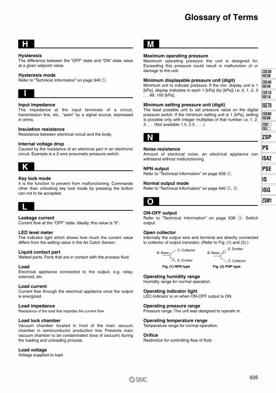
Open collectorInternally the output wire and terminal are directly connected to collector of output transistor. (Refer to Fig. (1) and (2).)
Operating humidity rangeHumidity range for normal operation.
Operating indicator lightLED indicator is on when ON-OFF output is ON.
Operating pressure rangePressure range. The unit was designed to operate in.
Operating temperature rangeTemperature range for normal operation.
OrificeRestriction for controlling flow of fluid.
Glossary of Terms
Fig. (1) NPN type
C: Collector
E: Emitter
B: Base
Fig. (2) PNP type
E: Emitter
C: Collector
B: Base
935
ZSE30ISE30
ZSE40ISE40
ZSE10ISE10
ISE70ZSE80ISE80
ZSEISE
ZSP
PS
ISA2
PSE
IS
ISG
ZSM1

PPanel mountingTo allow a product to be mounted on a panel in an appealing and secure fashion.SMC panel mount type is designed in advance for easy installment on a panel.
Peak high display modeRefer to “Technical Information” on page 940 m.
Peak low display modeRefer to “Technical Information” on page 940 m.
PNP outputRefer to “Technical Information” on page 939 v.
Proof pressureA pressure exceeding the upper limit. It will result in damage to product.
Protective constructionRefer to “Technical Information” on page 946 ⁄5.
RReducerOne of the connection types. Connect directly to the “One-touch” fittings.
Reed switchType of switch in which two strips of magnetic material sealed inside a glass tube are caused to come into contact by the magnetic field of a nearby magnet.
Relative pressureConverted pressure value based on any own decided standard pressure. When based on the absolute vacuum, it is called Absolute Pressure, while based on the atmospheric pressure, it is called Gauge Pressure.
RepeatabilityRefer to “Technical Information” on page 941 ..
Residual voltageVoltage occurred in COM and output when the switch output is in ON state. It varies depending on an applied load current. It is ideal to be “0”.
Response timeThe inverse number of frequency response. The shorter the response time becomes, the higher the frequency becomes.
Reversed output modeRefer to “Technical Information” on page 940 b, n.
RippleA small AC voltage superimposed on top of DC voltage. In the case of Fig. (3), ripple 10% meansV' ≥ V"V'/V x 100 = 10% When no pulsation has occurred, ripple is 0%.
SSelf-diagnostic functionError message is displayed if the unit is operated outside its designed operational envelope.
Sequence controller (PLC)Programmable logic controller. Depending on application, it can utilize inputs from pressure or limit switches and control outputs executing a control program down loaded in its memory.
Shock resistanceThe amount or severity of shock, an appliance can withstand without damage.
Solid state switchTypically a transistor. A solid state switch does not have any mechanical parts.
Stainless diaphragmMaterial of a diaphragm for detecting pressure is made of stainless steel.
Suction filterFilter installed between the vacuum pad and the ejector to prevent dust entry to the ejector.
Supply power voltageVoltage range for normal operation.
SUS ∗∗∗Symbol classifying the grade of stainless steel.
Switch outputRefer to “Technical Information” on page 938 c, ON-OFF
Time →
V
V'V"
Fig. (3)
Glossary of Terms
936
Glossary of Terms
TTemperature characteristicsRefer to “Technical Information” on page 941 ,.
The amount of leakageAs an example, testing for detecting leakage is called a leak test.
TSJAbbreviation of Tube Swage Joint. We recommend the Swagelok® fitting made by Swagelok Company be used.
∗ Swagelok® is a registered trademark of Swagelok Company.
Turning angle of setting trimmerThe maximum number of turns of the trimmer when adjusting the setpoint. The greater the turning angle, the finer the possible adjustments.
UUnit conversionRefer to “Technical Information” on page 946 ⁄6.
URJ fittingAbbreviation of Union Ring Joint. We recommend the VCR® fitting made by Swagelok Company be used.
∗ VCR® is a registered trademark of Swagelok Company.
VVacuum breaking pressurePositive pressure added for releasing the work or quickly returning to atmospheric pressure after breaking the vacuum condition.
Vibration resistanceThe amount of vibration a device can withstand without damage.
Voltage resistanceMaximum voltage level when voltage runs between electrical circuit and body. The value indicates strength against voltage. If higher voltage runs, product may be damaged. (In this case, voltage is different from power supply voltage to operate product.)
WWindow comparator modeRefer to “Technical Information” on page 940 n.
ZZero-outReset of the display to zero at atmospheric pressure.
0-92-wire type pressure switchRefer to “Technical Information” on page 944 ⁄3.
937
ZSE30ISE30
ZSE40ISE40
ZSE10ISE10
ISE70ZSE80ISE80
ZSEISE
ZSP
PS
ISA2
PSE
IS
ISG
ZSM1
Ana
log
Out
put
Pressure
5
1
20
4
0 Rated voltage
Analog Output—Pressure Characteristic Graph
Vacuum Absolute vacuum
Voltage output
[V]
Current output[mA]
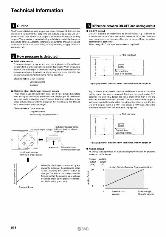
The Pressure Switch detects pressure of gases or liquids. Built-in circuitry allows for the adjustment of set points and outputs. Outputs are ON-OFF solid state or reed switch type outputs. Some models feature analog outputs. The pressure is detected using solid state, metal diaphragm or piston type sensors. Applications for pressure switches are numerous and include areas such as positioning, leakage testing, supply pressure verification, etc.
Fig. (2) shows an equivalent circuit of a NPN switch with the output on. In this circuit the load is powered. Besides, the input par t of PLC becomes low level. PLC detects the signal change from high to low and then can proceed to the next process. The point at which the output is switched is variable freely within the allowable setting range. For the ON-OFF output, there is a PNP type beside a NPN type. About the difference between NPN and PNP, refer to page 881.
Analog outputAn analog output provides an output that is proportional to the pressure measured by the sensor.
ON-OFF outputON-OFF output is also referred to as switch output. Fig. (1) shows an equivalent circuit of a NPN switch with the output off. In this circuit the load is not powered, because there is no current f low. Negative potential is not connected. When using a PLC, the input section sees a high level.
Solid state sensorThis sensor is used in dry air and inert gas applications. Four diffused resistors form a bridge circuit on a silicon diaphragm. When pressure is applied, the diaphragm is deflected causing the diffused resistors to change resistance. An electrical signal, which is proportional to the pressure change, is inputted during normal operation.
Characteristics: Quick response
Long service life
Compact
Stainless steel diaphragm pressure sensorThis sensor is used in humid air, water or oil. Four diffused resistors form a bridged circuit on a stainless steel diaphragm. All pressured parts are made of stainless steel. Pressure detection is identical to the silicon diffused sensor with the exception that the resistors are diffused on to the stainless steel diaphragm.
Characteristics: Quick response
Long service life
Wide variety of applicable fluid
Outline
V: Sensor output voltage
4 diffused resistors forming a bridge circuit.
Silicon diaphragmor stainless diaphragm
P: Pressure
Sens
or o
utpu
t vol
tage
V
Pressure P
1
How pressure is detected2
Difference between ON-OFF and analog output3
Fig. (1) Equivalent circuit of a NPN type switch with the output off
Fig. (2) Equivalent circuit of a NPN type switch with the output on
No current flow.Load is not powered.
PLC High level
4 diffused resistors from a bridged circuit on silicon diaphragm.
When the diaphragm is deformed by ap-plying the pressure, the resistance value varies, causing the sensor output to change. Generally, the bridge circuit is formed so that the sensor output voltage becomes larger as the pressure increas-es. (Refer to the graph left.)
Technical Information
Load
Mai
n ci
rcui
t of s
witc
h
Current flows.Load is powered.
PLC Low level
Mai
n ci
rcui
t of s
witc
h
Load
938
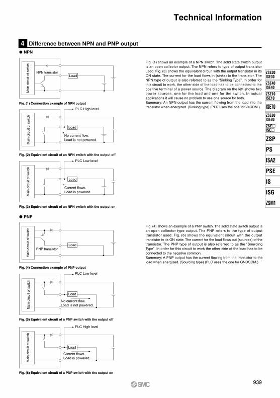
Fig. (1) shows an example of a NPN switch. The solid state switch output is an open collector output. The NPN refers to type of output transistor used. Fig. (3) shows the equivalent circuit with the output transistor in its ON state. The current for the load flows in (sinks) to the transistor. The NPN type of output is also referred to as the “Sinking Type”. In order for this circuit to work, the other side of the load has to be connected to the positive terminal of a power source. The diagram on the left shows two power sources, one for the load and one for the switch. In actual applications it will cause no problem to use one source for both. Summary: An NPN output has the current flowing from the load into the transistor when energized. (Sinking type) (PLC uses the one for VaCOM.)
Fig. (4) shows an example of a PNP switch. The solid state switch output is an open collector type output. The PNP refers to the type of output transistor used. Fig. (6) shows the equivalent circuit with the output transistor in its ON state. The current for the load flows out (sources) of the transistor. The PNP type of output is also referred to as the “Sourcing Type”. In order for this circuit to work the other side of the load has to be connected to the negative common. Summary: A PNP output has the current flowing from the transistor to the load when energized. (Sourcing type) (PLC uses the one for GNDCOM.)
Difference between NPN and PNP output
Fig. (1) Connection example of NPN output
Fig. (2) Equivalent circuit of an NPN switch with the output off
Fig. (3) Equivalent circuit of an NPN switch with the output on
Fig. (4) Connection example of PNP output
Fig. (5) Equivalent circuit of a PNP switch with the output off
Fig. (6) Equivalent circuit of a PNP switch with the output on
4
PNP
Technical Information
NPN
Mai
n ci
rcui
t of s
witc
h
NPN transistorLoad
No current flow.Load is not powered.
Mai
n ci
rcui
t of s
witc
h
Load
PLC High level
Current flows.Load is powered.
Mai
n ci
rcui
t of s
witc
h
PLC Low level
Load
Mai
n ci
rcui
t of s
witc
h
PNP transistorLoad
No current flow.Load is not powered.
Mai
n ci
rcui
t of s
witc
h
Load
PLC Low level
Current flows.Load is powered.
Mai
n ci
rcui
t of s
witc
h
Load
PLC High level
939
ZSE30ISE30
ZSE40ISE40
ZSE10ISE10
ISE70ZSE80ISE80
ZSEISE
ZSP
PS
ISA2
PSE
IS
ISG
ZSM1
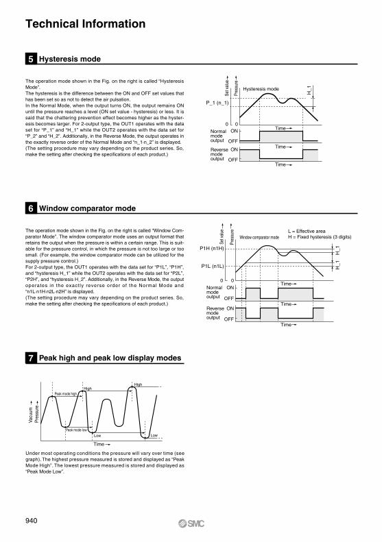
The operation mode shown in the Fig. on the right is called “Hysteresis Mode”.The hysteresis is the difference between the ON and OFF set values that has been set so as not to detect the air pulsation.In the Normal Mode, when the output turns ON, the output remains ON until the pressure reaches a level (ON set value - hysteresis) or less. It is said that the chattering prevention effect becomes higher as the hyster-esis becomes larger. For 2-output type, the OUT1 operates with the data set for “P_1” and “H_1” while the OUT2 operates with the data set for “P_2” and “H_2”. Additionally, in the Reverse Mode, the output operates in the exactly reverse order of the Normal Mode and “n_1·n_2” is displayed. (The setting procedure may vary depending on the product series. So, make the setting after checking the specifications of each product.)
The operation mode shown in the Fig. on the right is called “Window Com-parator Mode”. The window comparator mode uses an output format that retains the output when the pressure is within a certain range. This is suit-able for the pressure control, in which the pressure is not too large or too small. (For example, the window comparator mode can be utilized for the supply pressure control.)For 2-output type, the OUT1 operates with the data set for “P1L”, “P1H”, and “hysteresis H_1” while the OUT2 operates with the data set for “P2L”, “P2H”, and “hysteresis H_2”. Additionally, in the Reverse Mode, the output operates in the exact ly reverse order of the Normal Mode and “n1L·n1H·n2L·n2H” is displayed.(The setting procedure may vary depending on the product series. So, make the setting after checking the specifications of each product.)
H_1
H_1
Under most operating conditions the pressure will vary over time (see graph). The highest pressure measured is stored and displayed as “Peak Mode High”. The lowest pressure measured is stored and displayed as “Peak Mode Low”.
Hysteresis mode5
Peak high and peak low display modes7
Window comparator mode6
Time
Time
Time
Set v
alue
Pres
sure
0 0
Hysteresis mode
ON
OFF
Normal modeoutput
Reverse modeoutput
ON
OFF
Time
Time
Time
Set v
alue
Pres
sure
Window comparator mode
P1H (n1H)
P1L (n1L)
0 0
ON
OFF
ON
OFF
L = Effective areaH = Fixed hysteresis (3 digits)
Peak mode highHigh
High
Low LowPeak mode low
Time
Pre
ssur
eVa
cuum
Normal modeoutput
Reverse modeoutput
Technical Information
P_1 (n_1)
H_1
940
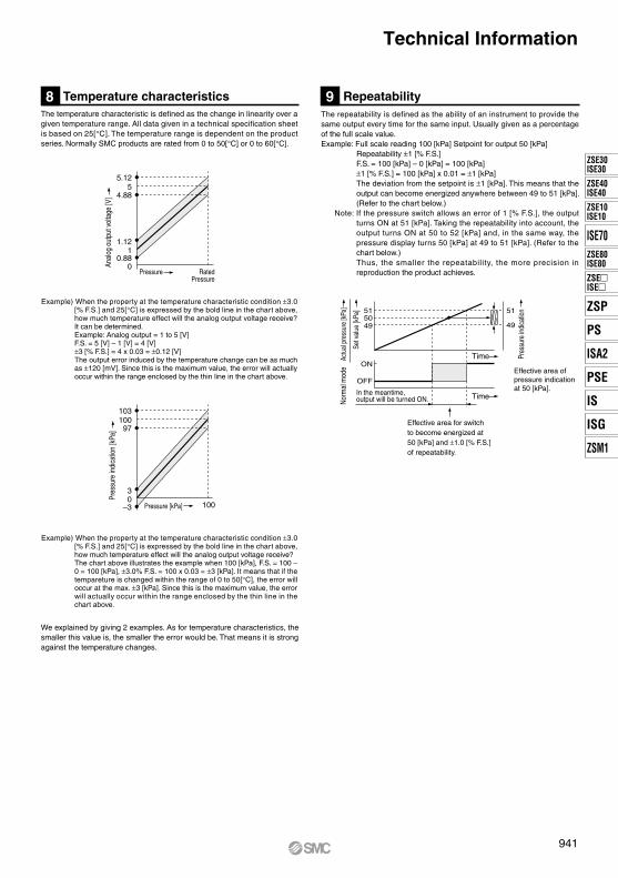
The temperature characteristic is defined as the change in linearity over a given temperature range. All data given in a technical specification sheet is based on 25[°C]. The temperature range is dependent on the product series. Normally SMC products are rated from 0 to 50[°C] or 0 to 60[°C].
We explained by giving 2 examples. As for temperature characteristics, the smaller this value is, the smaller the error would be. That means it is strong against the temperature changes.
The repeatability is defined as the ability of an instrument to provide the same output every time for the same input. Usually given as a percentage of the full scale value.Example: Full scale reading 100 [kPa] Setpoint for output 50 [kPa]
Repeatability ±1 [% F.S.]F.S. = 100 [kPa] – 0 [kPa] = 100 [kPa]±1 [% F.S.] = 100 [kPa] x 0.01 = ±1 [kPa]The deviation from the setpoint is ±1 [kPa]. This means that the output can become energized anywhere between 49 to 51 [kPa]. (Refer to the chart below.)
Note: If the pressure switch allows an error of 1 [% F.S.], the output turns ON at 51 [kPa]. Taking the repeatability into account, the output turns ON at 50 to 52 [kPa] and, in the same way, the pressure display turns 50 [kPa] at 49 to 51 [kPa]. (Refer to the chart below.)Thus, the smaller the repeatability, the more precision in reproduction the product achieves.
Repeatability9
Time
TimeIn the meantime, output will be turned ON.
515049
ON
OFF
Pres
sure
indi
catio
n
Set v
alue
[kPa
]
Actu
al p
ress
ure
[kPa
]No
rmal
mod
e
51
49
Temperature characteristics8
5.125
4.88
1.121
0.88
Pressure RatedPressure
10310097
30
–3 Pressure [kPa] 100
Anal
og o
utpu
t vol
tage
[V]
Pres
sure
indi
catio
n [k
Pa]
0
Effective area for switchto become energized at50 [kPa] and ±1.0 [% F.S.]of repeatability.
Example) When the property at the temperature characteristic condition ±3.0 [% F.S.] and 25[°C] is expressed by the bold line in the chart above, how much temperature effect will the analog output voltage receive? It can be determined.Example: Analog output = 1 to 5 [V]F.S. = 5 [V] – 1 [V] = 4 [V]±3 [% F.S.] = 4 x 0.03 = ±0.12 [V]The output error induced by the temperature change can be as much as ±120 [mV]. Since this is the maximum value, the error will actually occur within the range enclosed by the thin line in the chart above.
Example) When the property at the temperature characteristic condition ±3.0 [% F.S.] and 25[°C] is expressed by the bold line in the chart above, how much temperature effect will the analog output voltage receive?The chart above illustrates the example when 100 [kPa], F.S. = 100 – 0 = 100 [kPa], ±3.0% F.S. = 100 x 0.03 = ±3 [kPa]. It means that if the tempareture is changed within the range of 0 to 50[°C], the error will occur at the max. ±3 [kPa]. Since this is the maximum value, the error will actually occur within the range enclosed by the thin line in the chart above.
Effective area of pressure indication at 50 [kPa].
Technical Information
941
ZSE30ISE30
ZSE40ISE40
ZSE10ISE10
ISE70ZSE80ISE80
ZSEISE
ZSP
PS
ISA2
PSE
IS
ISG
ZSM1

H_1
In the case of performance decrement caused by clogging up the silencer of vacuum system (ejector), cracking of vacuum pad, or decreasing the vacuum reaching degree by leakage from vacuum piping, it detects the abnormality quickly and send out the output to the outside right before the system comes to a stop. In case the ON-OFF output is in the normal mode, when the failure predict output switches ON (over P1), and the pressure turns OFF without reaching the failure predict pressure (P3), the number of failure predict detection is counted. When it is consecutively counted up to the failure predict numbers (EC) preset, the failure predict output will turn ON. When a switch turns ON, (over P1) and the pressure exceeds the failure predict pressure (P3), the count of failure predict numbers will be reset.
Ex.) When an error count (number of the failure predict) (EC) is set to be 3.
Failure predict function10
P3
ON
OFF
Vac
uum
ON
OFF
P2
OU
T1
Failu
re
pred
ict
outp
ut
Time
Time
Time
Output ON
Failure predict number (EC) Since it is normal,
the number count is reset EC = 0.
AbnormalEC = 1
AbnormalEC = 2
AbnormalEC = 3
P1
Auto preset function enables automatic selection of the optimum set point value when the pressure switch is used for adsorption confirmation simply by repeating the adsorption and release cycle with the workpiece.Refer to the catalog and instruction manual for how to enter the auto preset mode. This section describes calculation of the set value.
How to Calculate the Set ValueA = Max. pressure value in auto preset modeB = Tentative min. pressure value in auto preset modeP_1 (P_2) =A− (A – B)/4 or n_1 (n_2) =B + (A – B)/4H_1 (H_2) =| (A – B)/2|Manual adjustment is possible after finishing in the auto preset mode.
Auto preset function11
A
Vac
uum
Time
Starting Finished
Adsorption Adsorption AdsorptionAdsorption Adsorption Adsorption
No adsorption Released Released ReleasedReleased
P_1
n_1
B
NOTE: Make sure to generate a vacuum before calibration.
NOTE: Make sure to continue vacuum vacuum when finished.
Technical Information
942
Supply pressure normal Supply pressure drop Supply pressure increase
Vac
uum
Set
val
ue
ON
OFFNorm
al m
ode
Time
Time
Auto shift input time
When the Auto Shift Function is used.
Operating normally Operating normally Operating normally
AUTO
-SH
IFT
inpu
t
Hi
Lo
Note) Auto shift input time Series PSE 200: 10 [ms] or longerOther series: 5 [ms] or longer
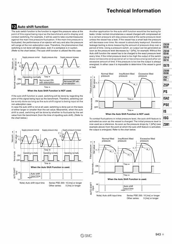
Another application for the auto shift function would be the testing for leaks. Under normal circumstances a vessel charged with compressed air to a certain pressure will stay pressurized at the same pressure level unless the vessel has a leak. If the vessel has a small leak the pressure will decrease over time. No vessel is absolutely leakproof, therefore leakage testing is done measuring the amount of pressure drop over a period of time. Using a pressure switch, an output can be generated as soon as the pressure level decreases by 1 [kPa], for example. Without the Auto shift function the vessel has to be charged to the exact pressure level every time. If the initial pressure level is too high the output of the switch does not become energized at a l l or becomes energized af ter an excessive amount of time. If the pressure is too low the output is always energized. In either case it is impossible to determine if the vessel is good or bad.
To combat fluctuations in initial pressure level, the auto shift feature is activated as soon as the vessel is charged. The initial pressure level is now used as a reference. As soon as the pressure drops by 1 [kPa] (see example above) from the point at which the auto shift feature is activated, the output is energized. Refer to the chart below.
If the auto shift function is used, switching will be done by regarding the point of this signal being input as the benchmark. Therefore, switching can be surely done as long as the auto shif t signal is being input at the non-adsorption case.In case the auto shift is not at all used, switching is done just on the basis of either larger or smaller than the set value. Meanwhile, when the auto shift is used, switching will be done by whether to fluctuate by the set value from the benchmark (from the time of inputting auto shift). (Refer to the chart below.)
Supply pressure normal Supply pressure drop Supply pressure increase
Not turned OFF with non-adsorption
Not turned ON with adsorption
Vac
uum
Set
val
ue P_1
ON
OFF
Nor
mal
mod
e Time
Time
When the Auto Shift Function is NOT used.
Operating normally
Technical Information
H_1
P_1H_1 P_1
H_1
P_1H_1
Fill
ed p
ress
ure
Set
val
ue
Normal filled pressure
Insufficient filled pressure
Excessive filled pressure
Time
TimeRev
erse
mod
e
When the Auto Shift Function is NOT used.
n_1H_1
Time
Time
Auto shift input time
Hi
Lo
Note) Auto shift input time Series PSE 200: 10 [ms] or longerOther series: 5 [ms] or longer
Normal filled pressure
Insufficient filled pressure
Excessive filled pressure
Fill
ed p
ress
ure
Set
val
ueRe
vers
e m
ode
AU
TO-S
HIF
T
inpu
t
n_1H_1
H_1
H_1
The auto switch function is the function to regard the pressure value at the point of this signal being input as the benchmark and to display and conduct switching. For example, it will be used to take countermeasures against the main line pressure fluctuation. If the main line pressure is fluctuated, the performance of an ejector will vary and also the pressure will cange at the non-adsorption case. Therefore, the phenomenon that switching is not done will take place, even if a workpiece is in suction. (Refer to the chart below.) The auto shift function is utilized like this case.
Auto shift function12
ON
OFF
When the Auto Shift Function is used.
n_1
n_1
ON
OFF
943
ZSE30ISE30
ZSE40ISE40
ZSE10ISE10
ISE70ZSE80ISE80
ZSEISE
ZSP
PS
ISA2
PSE
IS
ISG
ZSM1
A

How to Activate the Auto Shift FunctionConnect the auto shift input with GND for at least 5 [ms] (PSE200: at least 10 [ms]).Based on the pressure at this moment, switching will be done.
Example: The figure below is based on the condition of set values as P_1 = 40 [kPa] and H_1 = 20 [kPa].
Actu
al p
ress
ure
(kPa
)A
uto
shift
inpu
t
100
Hi
Lo
50
0Time
Sw
itch
outp
ut
ON
OFF
Note) Series PSE 200 A: 10 [ms] or longer B: 15 [ms] or shorter
B10 [ms] or shorter
B10[ms] or shorter
A5 [ms] or longer
Auto shift function12
O p e r a t e i n t h e manner same as ordinary since auto shift function is not used.
Since auto shift signal is inputted at applying 50 kPa, switching is done at pressures of 90 [kPa] and 70 [kPa].
2-wire pressure switch connections13
Connection example when used as a sinking type
U
12 to
24
[VD
C]
Connection example when used as a sourcing type
Connection example with NPN compliant, sourcing type input unit
Connection example with PNP compliant, sinking type input unit
U
Connection example with PLC
“PS1000, PS1100, PS1200”
Caution
A 3-wire type switch is a switch that has an output line other than the positive and negative lines that supply the electricity. When there are 2 outputs, 4 lines will be required in total. This type of switch belongs to the family of 3-wire type switches. 2-wire type switches have only positive and negative wires that are used for supplying the electricity from the power source and for providing the output as well.
The 2-wire type works with both the sinking type (current runs into the switch) and the sourcing type (current is flown out of the switch). It is dependant upon whether a load is connected with the positive or negative side. These switches are known for high speed response, longevity, and they can reduce wiring work.
The load current range for a PS1000 and PS1100 is between 5 [mA] and 40 [mA].If 40 [mA] is exceeded the output transistor could be damaged. Besides, do not connect a PLC, which can detect 1 [mA], since there is a leak current of 1 [mA] in OFF state.
Switch
Switch
When the auto shift input is 10 [ms] or shorter, switch output responds.
Technical Information
Mai
n ci
rcui
t of s
witc
h Brown OUT(+)
Blue OUT(–)
5 to 40 [mA]
LoadM
ain
circ
uit o
f sw
itch Brown OUT(+)
Blue OUT(–)
5 to 40 [mA]
Load
Brown Input
BlueCOM
NPN compliant sourcing type Input unit
InputBlue
Brown
PNP compliant sinking typeInput unit
COM
12 to
24
[VD
C]
944

Protective construction15
Second characteristic numeral
IP
First characteristic numeral
0
1
2
3
4
5
6
Non-protected
Protected against solid foreign objects of 50 mm ø and greater
Protected against solid foreign objects of 12 mm ø and greater
Protected against solid foreign objects of 2.5 mm ø and greater
Protected against solid foreign objects of 1.0 mm ø and greater
Dust-protected
Dusttight
Voltage and current output pressure sensors14
Current “I”
CurrentSensor Equipment
GND
Connection of the voltage output
Lead wire resistance “r”
Current “I”
CurrentSensor Equipment
Current is the same value.
GNDConnection of the current output
Lead wire resistance “r”
GND
4 to 20 [mA]
1 to 5 [V]
GND
Voltage output signal is a voltage signal in the range of 1 to 5 [V]. The signal has to be converted by an A/D converter for pressure display or switch output. Current output signal is a current signal in the range of 4 to 20 [mA]. The signal is transformed into a voltage signal before being converted by a A/D converter for pressure display or switch output.
Advantages and Disadvantages (Long distance applications)When the voltage signal has to travel any amount of distance, voltage drops occur due to the resistance of the lead wire. The voltage drop increases propor t ional with the resistance of the wire and thus proportional with the length of the wire.
It appears that it would be of benefit to reduce the current flow as much as possible, however if the current is reduced too much other problems, such as inductive noise from external devices, occur. Result: Voltage outputs are not suitable for long distance applications. SMC’s analog outputs are all of the voltage variety, but tests have proven that there is no problem in applications of 10 [m] or less.
The current flow is the same regardless of the distance. The cost of a current system is higher, because the voltage signal has to be converted to a current signal on one end of the transmission line, then on the other end it has to be converted to a voltage signal again. The packaging size of a current sensor might be larger due to the size of the additional parts.
Voltage drops at the value of “I” x “r”.
It may result in an error when the electric potential difference is caused between sensor’s GND and GND of a receiver device.
First Characteristics: Degrees of protection against solid foreign objects
Second Characteristics: Degrees of protection against water
Non-protected
Protected against vertically falling water drops
Protected against vertically falling water drops when enclosure tilted up to 15°
Protected against splashing water
Protected against water jets
Protected against powerful water jets
Protected against the effects of temporary immersion in water
Protected against the effects of continuous immersion in water
0
1
2
3
4
5
6
7
8
—
Dripproof type 1
Dripproof type 2
Rainproof type
Splashproof type
Low jetproof type
Strongjetproof type
Immersible type
Submersible type
Example) In the case of stipulated as IP65, we can know the degrees of protection is dusttight and water jetproof on the grounds that the first characteristic numeral is 6 and the second characteristic numeral is 5 respectively, that gives it will not be adversely affected by direct water jets from any direction.
Protected against rainfall when enclosure tilted up to 60°
Technical Information
945
ZSE30ISE30
ZSE40ISE40
ZSE10ISE10
ISE70ZSE80ISE80
ZSEISE
ZSP
PS
ISA2
PSE
IS
ISG
ZSM1

Pressure units conversion (Approximation)16
Ex. 1) Convert the units of 350 [mmHg] to [kPa]. 1 [mmHg] = 1.3332 x 10⁻¹ [kPa] 1.3332 x 10–1 x 350 = 46.662 [kPa]Ex. 2) Convert the units of 80 [kPa] to [kgf/cm2]. 1 [kPa] = 1.0197 x 10⁻² [kgf/cm2] 1.01972 x 10–2 x 80 = 0.81576 [kgf/cm2]
1 x 10⁻³
1
1 x 10³
1 x 10²
1 x 10⁻⁶
1 x 10⁻³
1
1 x 10⁻¹
1 x 10⁻⁵
1 x 10⁻²
1 x 10
1
1.0197 x 10⁻⁵
1.0197 x 10⁻²
1.0197 x 10
1.0197
1
1.0332
1 x 10⁻⁴
1.3595 x 10⁻³
7.0338 x 10⁻²
9.8692 x 10⁻⁶
9.8692 x 10⁻³
9.8692
9.8692 x 10⁻¹
9.6784 x 10⁻¹
1
9.6784 x 10⁻⁵
1.3158 x 10⁻³
6.7999 x 10⁻²
1.0197 x 10⁻¹
1.0197 x 10²
1.0197 x 10⁵
1.0197 x 10⁴
1 x 10⁴
1.0332 x 10⁴
1
1.3595 x 10
7.0324 x 10²
7.5006 x 10⁻³
7.5006
7.5006 x 10³
7.5006 x 10²
7.3556 x 10²
7.6000 x 10²
7.3556 x 10⁻²
1
5.1733 x 10
kPa MPa bar kgf/cm2 atm mmH2O or mmAq mmHg or Torr
1.4503 x 10⁻⁴
1.4503 x 10⁻¹
1.4503 x 10²
1.4503 x 10
1.4217 x 10
1.4706 x 10
1.4220 x 10⁻³
1.9330 x 10⁻²
1
PSI
Unit
1
1 x 10³
1 x 10⁶
1 x 10⁵
Pa (N/m2)
9.8067 x 10⁻¹
1.0133
9.8067 x 10⁻⁵
1.3332 x 10⁻³
6.8951 x 10⁻²
9.8067 x 10⁻²
1.0133 x 10⁻¹
9.8067 x 10⁻⁶
1.3332 x 10⁻⁴
6.8951 x 10⁻³
9.8067 x 10
1.0133 x 10²
9.8067 x 10⁻³
1.3332 x 10⁻¹
6.8951
9.8067 x 10⁴
1.0133 x 10⁵
9.8067
1.3332 x 10²
6.8951 x 10³
Operable fluids by pressure switchfor general purpose fluids
Stainless steel
17
Caution
Metal exists in nature as ore (like oxide or sulfide). This means that oxide or sulfide is more stable than pure metal. Accordingly, metallic material chemically oxidizes (metallic constituent becomes ion and melts out). It corrodes in the natural environment.Even though corrosion of metal easily occurs in an environment where oxidizing tendency is stronger, some kinds of metal have a characteristic for which corrosion never happens if the level of oxidizing goes higher than a specific point. In such a case, it is called “metal in passive state”.Stainless steel has corrosion resistance because of a thin coat of passive state on its surface. However, there does not exist stainless steel with absolute corrosion resistance; therefore, many types of stainless steel have been developed for improved corrosion resistance performance.SMC Pressure Switch and Pressure Sensor for general purpose fluids have adopted stainless steel 304 or stainless steel 316L for the fittings where in contact with fluids as well as stainless steel 630 or stainless steel 316L for diaphragm of sensor part.Corrosion resistance performance of both stainless steel 304 and stainless steel 630 is almost the same level in anti-corrosiveness property.
SMC Pressure Switch and Pressure Sensor do not have explosion-proof construction; do not use flammable gases or liquids. Also, do not use toxic gases or liquids.
Technical Information
946