oil tester instruction manual
TRANSCRIPT

Equipo para pruebas Dieléctricas en aceite
WH-HYYJ502A
HYYJ502A INSULATING OIL TESTER INSTRUCTION MANUAL V1.3.3
1 / 17
Insulating Oil Tester Instruction Manual
1 FEATURES
(1) AC220V±10% power supply input
(2) Output voltage:AC 0V~100KV
(3) Rate of voltage rise: 0.5kv/s±10%, 2kv/s±5%, 3kv/s±5%,5kv/s±5%
(4) Max test times: 9
(5) Init wait times:0~999s
(6) Stir time: 0~999s
(7) Wait time: 0~999s
(8) Measurement accuracy: ±(1% of full scale + 2 digits) Resolution:0.1KV
(9) Temperature measurement:
Measurement range : 0℃ to 70℃, or better
Temperature resolution : 1℃, or better
Operating temperature : up to 45℃
(10)Storage:100 groups
(11)7 inch colorful LCD with touch pad
(12)Oil test vessel temperature measurement unit
(13) Weight 38kg
(14) Size: 460 mm*380mm*360mm
2 TEST OPERATION
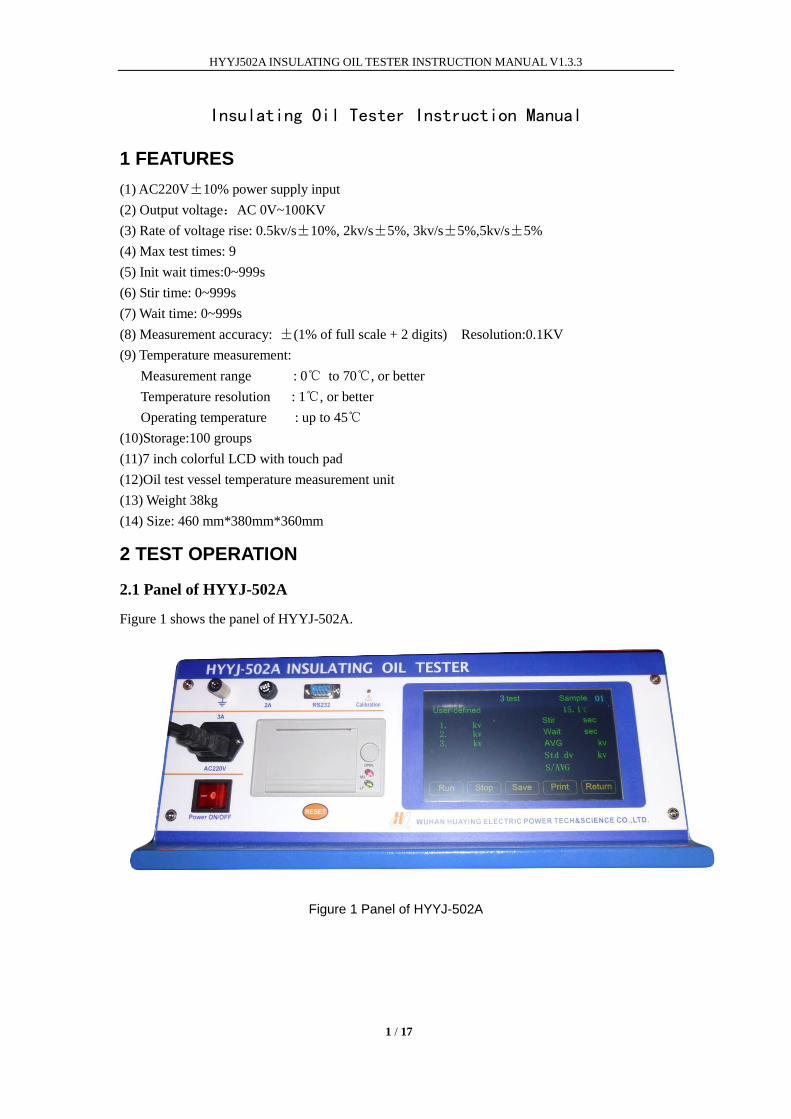
2.1 Panel of HYYJ-502A
Figure 1 shows the panel of HYYJ-502A.
Figure 1 Panel of HYYJ-502A
HYYJ502A INSULATING OIL TESTER INSTRUCTION MANUAL V1.3.3
2 / 17
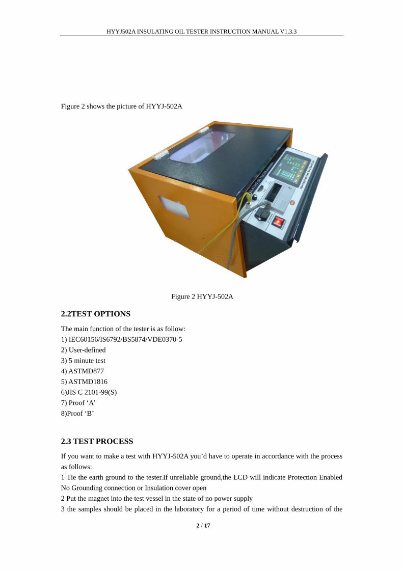
Figure 2 shows the picture of HYYJ-502A
Figure 2 HYYJ-502A
2.2TEST OPTIONS
The main function of the tester is as follow:
1) IEC60156/IS6792/BS5874/VDE0370-5
2) User-defined
3) 5 minute test
4) ASTMD877
5) ASTMD1816
6)JIS C 2101-99(S)
7) Proof „A‟
8)Proof „B‟
2.3 TEST PROCESS
If you want to make a test with HYYJ-502A you‟d have to operate in accordance with the process
as follows:
1 Tie the earth ground to the tester.If unreliable ground,the LCD will indicate Protection Enabled
No Grounding connection or Insulation cover open
2 Put the magnet into the test vessel in the state of no power supply
3 the samples should be placed in the laboratory for a period of time without destruction of the
HYYJ502A INSULATING OIL TESTER INSTRUCTION MANUAL V1.3.3
3 / 17
original package until the temperature of samples are close to the laboratory. Put sample into the
test vessel and then shake vessel gently to clear it for 2 or 3 times.
4 In order to prevent bubble, sample should be put into the oil cup along the wall down slowly
while there is no touch with the electrode, sample and internal of oil cup. Power supply must be
cut off at the whole process.
5 In the state of no power supply, put the cover on the top of two electrode of insulation. And then
cover the high voltage room door of the tester.
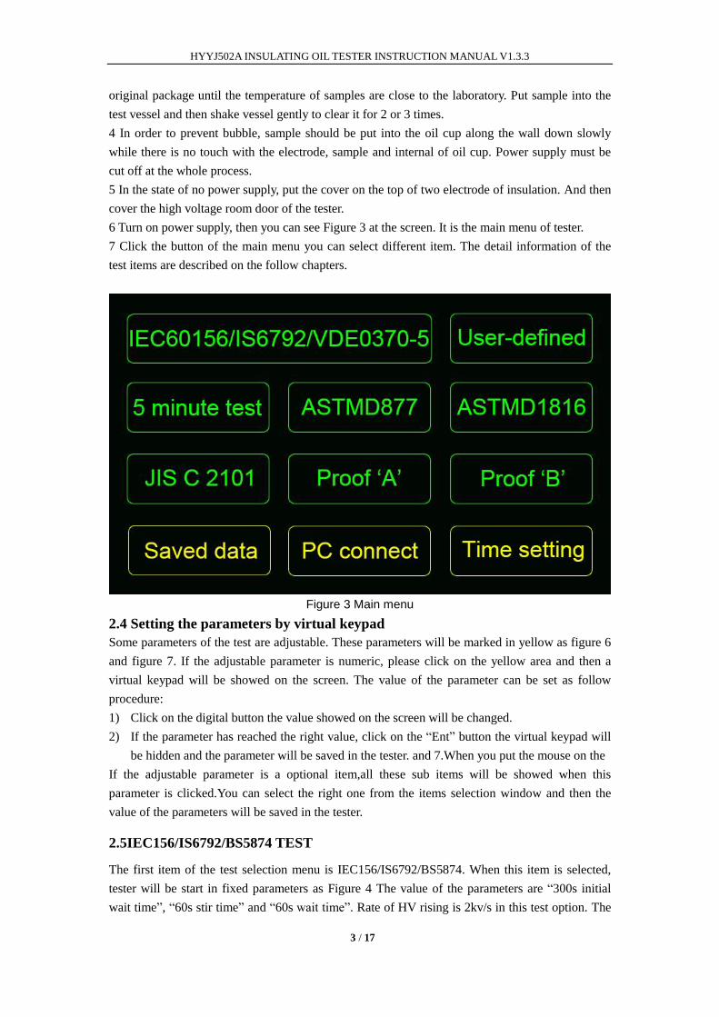
6 Turn on power supply, then you can see Figure 3 at the screen. It is the main menu of tester.
7 Click the button of the main menu you can select different item. The detail information of the
test items are described on the follow chapters.
Figure 3 Main menu
2.4 Setting the parameters by virtual keypad
Some parameters of the test are adjustable. These parameters will be marked in yellow as figure 6
and figure 7. If the adjustable parameter is numeric, please click on the yellow area and then a
virtual keypad will be showed on the screen. The value of the parameter can be set as follow
procedure:
1) Click on the digital button the value showed on the screen will be changed.
2) If the parameter has reached the right value, click on the “Ent” button the virtual keypad will
be hidden and the parameter will be saved in the tester. and 7.When you put the mouse on the
If the adjustable parameter is a optional item,all these sub items will be showed when this
parameter is clicked.You can select the right one from the items selection window and then the
value of the parameters will be saved in the tester.
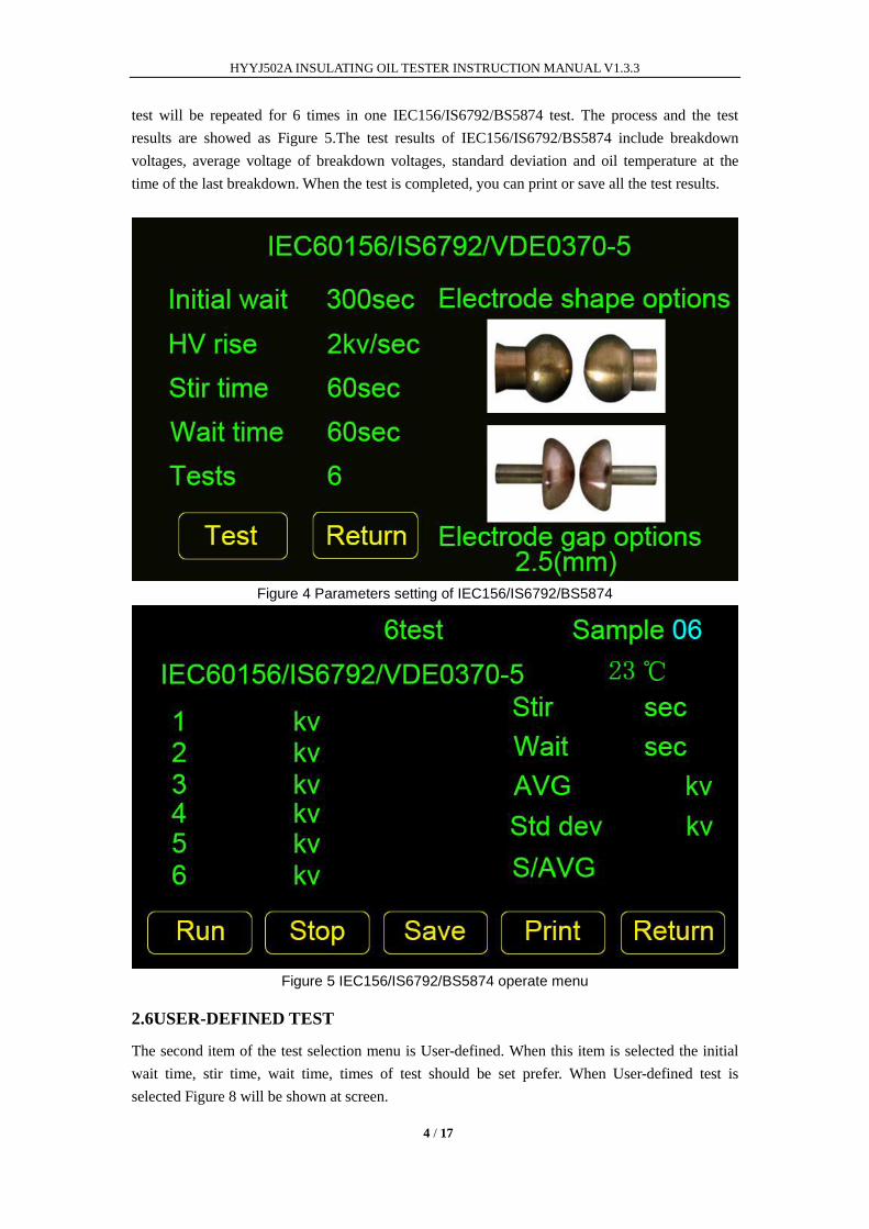
2.5IEC156/IS6792/BS5874 TEST
The first item of the test selection menu is IEC156/IS6792/BS5874. When this item is selected,
tester will be start in fixed parameters as Figure 4 The value of the parameters are “300s initial
wait time”, “60s stir time” and “60s wait time”. Rate of HV rising is 2kv/s in this test option. The
HYYJ502A INSULATING OIL TESTER INSTRUCTION MANUAL V1.3.3
4 / 17
test will be repeated for 6 times in one IEC156/IS6792/BS5874 test. The process and the test
results are showed as Figure 5.The test results of IEC156/IS6792/BS5874 include breakdown
voltages, average voltage of breakdown voltages, standard deviation and oil temperature at the
time of the last breakdown. When the test is completed, you can print or save all the test results.
Figure 4 Parameters setting of IEC156/IS6792/BS5874
Figure 5 IEC156/IS6792/BS5874 operate menu
2.6USER-DEFINED TEST
The second item of the test selection menu is User-defined. When this item is selected the initial
wait time, stir time, wait time, times of test should be set prefer. When User-defined test is
selected Figure 8 will be shown at screen.
HYYJ502A INSULATING OIL TESTER INSTRUCTION MANUAL V1.3.3
5 / 17
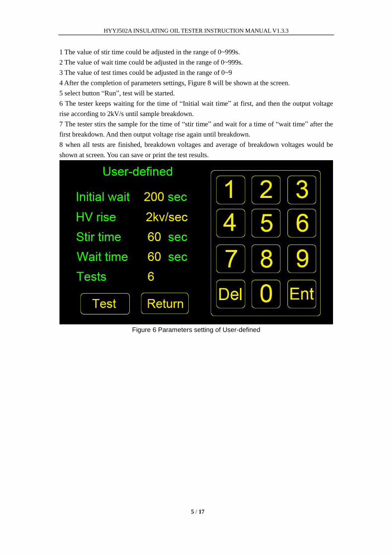
1 The value of stir time could be adjusted in the range of 0~999s.
2 The value of wait time could be adjusted in the range of 0~999s.
3 The value of test times could be adjusted in the range of 0~9
4 After the completion of parameters settings, Figure 8 will be shown at the screen.
5 select button “Run”, test will be started.
6 The tester keeps waiting for the time of “Initial wait time” at first, and then the output voltage
rise according to 2kV/s until sample breakdown.
7 The tester stirs the sample for the time of “stir time” and wait for a time of “wait time” after the
first breakdown. And then output voltage rise again until breakdown.
8 when all tests are finished, breakdown voltages and average of breakdown voltages would be
shown at screen. You can save or print the test results.
Figure 6 Parameters setting of User-defined
HYYJ502A INSULATING OIL TESTER INSTRUCTION MANUAL V1.3.3
6 / 17
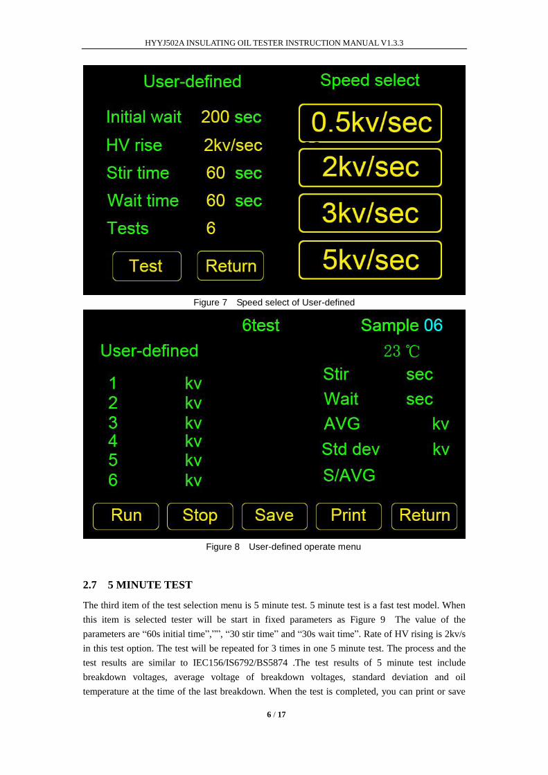
Figure 7 Speed select of User-defined
Figure 8 User-defined operate menu
2.7 5 MINUTE TEST
The third item of the test selection menu is 5 minute test. 5 minute test is a fast test model. When
this item is selected tester will be start in fixed parameters as Figure 9 The value of the
parameters are “60s initial time”,””, “30 stir time” and “30s wait time”. Rate of HV rising is 2kv/s
in this test option. The test will be repeated for 3 times in one 5 minute test. The process and the
test results are similar to IEC156/IS6792/BS5874 .The test results of 5 minute test include
breakdown voltages, average voltage of breakdown voltages, standard deviation and oil
temperature at the time of the last breakdown. When the test is completed, you can print or save
HYYJ502A INSULATING OIL TESTER INSTRUCTION MANUAL V1.3.3
7 / 17
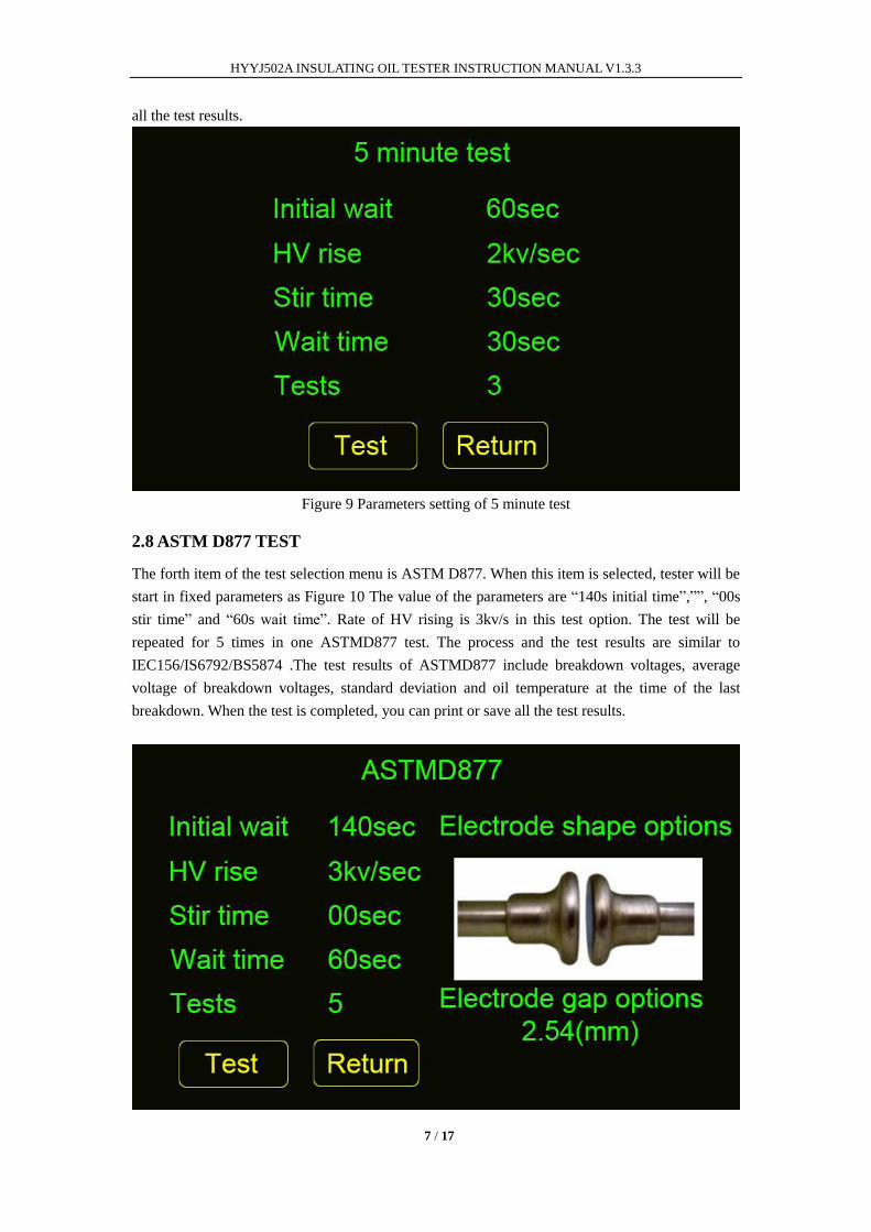
all the test results.
Figure 9 Parameters setting of 5 minute test
2.8 ASTM D877 TEST
The forth item of the test selection menu is ASTM D877. When this item is selected, tester will be
start in fixed parameters as Figure 10 The value of the parameters are “140s initial time”,””, “00s
stir time” and “60s wait time”. Rate of HV rising is 3kv/s in this test option. The test will be
repeated for 5 times in one ASTMD877 test. The process and the test results are similar to
IEC156/IS6792/BS5874 .The test results of ASTMD877 include breakdown voltages, average
voltage of breakdown voltages, standard deviation and oil temperature at the time of the last
breakdown. When the test is completed, you can print or save all the test results.
HYYJ502A INSULATING OIL TESTER INSTRUCTION MANUAL V1.3.3
8 / 17
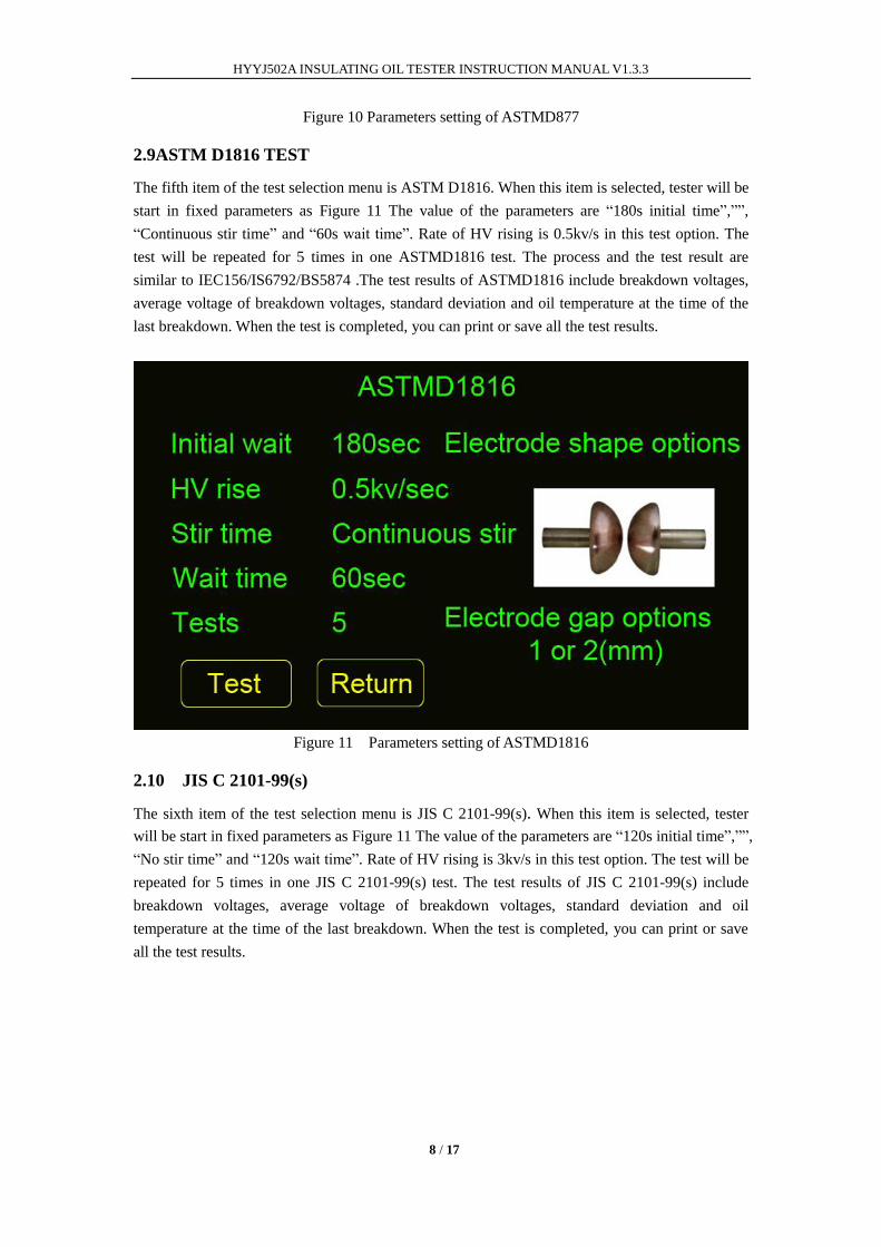
Figure 10 Parameters setting of ASTMD877
2.9ASTM D1816 TEST
The fifth item of the test selection menu is ASTM D1816. When this item is selected, tester will be
start in fixed parameters as Figure 11 The value of the parameters are “180s initial time”,””,
“Continuous stir time” and “60s wait time”. Rate of HV rising is 0.5kv/s in this test option. The
test will be repeated for 5 times in one ASTMD1816 test. The process and the test result are
similar to IEC156/IS6792/BS5874 .The test results of ASTMD1816 include breakdown voltages,
average voltage of breakdown voltages, standard deviation and oil temperature at the time of the
last breakdown. When the test is completed, you can print or save all the test results.
Figure 11 Parameters setting of ASTMD1816
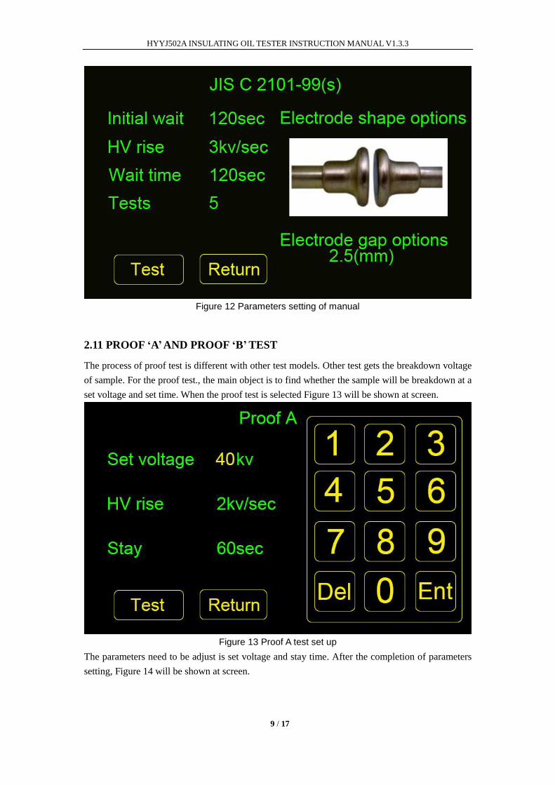
2.10 JIS C 2101-99(s)
The sixth item of the test selection menu is JIS C 2101-99(s). When this item is selected, tester
will be start in fixed parameters as Figure 11 The value of the parameters are “120s initial time”,””,
“No stir time” and “120s wait time”. Rate of HV rising is 3kv/s in this test option. The test will be
repeated for 5 times in one JIS C 2101-99(s) test. The test results of JIS C 2101-99(s) include
breakdown voltages, average voltage of breakdown voltages, standard deviation and oil
temperature at the time of the last breakdown. When the test is completed, you can print or save
all the test results.
HYYJ502A INSULATING OIL TESTER INSTRUCTION MANUAL V1.3.3
9 / 17
Figure 12 Parameters setting of manual
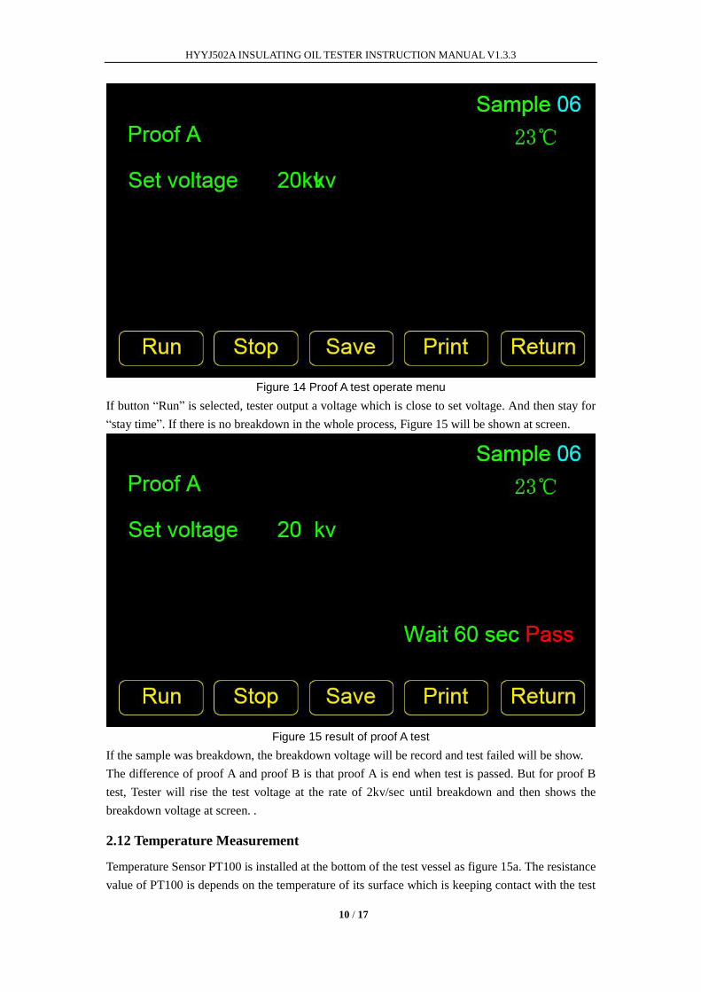
2.11 PROOF „A‟ AND PROOF „B‟ TEST
The process of proof test is different with other test models. Other test gets the breakdown voltage
of sample. For the proof test., the main object is to find whether the sample will be breakdown at a
set voltage and set time. When the proof test is selected Figure 13 will be shown at screen.
Figure 13 Proof A test set up
The parameters need to be adjust is set voltage and stay time. After the completion of parameters
setting, Figure 14 will be shown at screen.
HYYJ502A INSULATING OIL TESTER INSTRUCTION MANUAL V1.3.3
10 / 17
Figure 14 Proof A test operate menu
If button “Run” is selected, tester output a voltage which is close to set voltage. And then stay for
“stay time”. If there is no breakdown in the whole process, Figure 15 will be shown at screen.
Figure 15 result of proof A test
If the sample was breakdown, the breakdown voltage will be record and test failed will be show.
The difference of proof A and proof B is that proof A is end when test is passed. But for proof B
test, Tester will rise the test voltage at the rate of 2kv/sec until breakdown and then shows the
breakdown voltage at screen. .
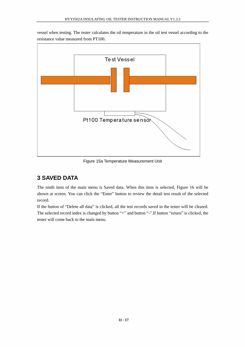
2.12 Temperature Measurement
Temperature Sensor PT100 is installed at the bottom of the test vessel as figure 15a. The resistance
value of PT100 is depends on the temperature of its surface which is keeping contact with the test
HYYJ502A INSULATING OIL TESTER INSTRUCTION MANUAL V1.3.3
11 / 17
vessel when testing. The tester calculates the oil temperature in the oil test vessel according to the
resistance value measured from PT100.
Figure 15a Temperature Measurement Unit
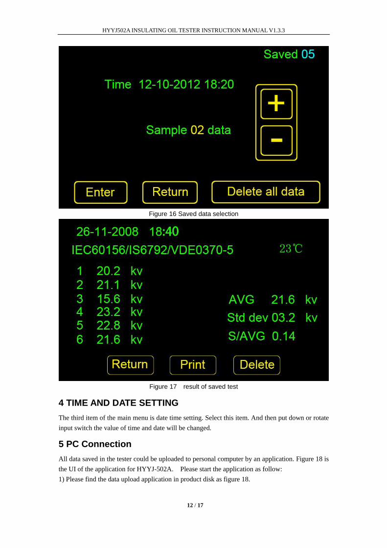
3 SAVED DATA
The ninth item of the main menu is Saved data. When this item is selected, Figure 16 will be
shown at screen. You can click the “Enter” button to review the detail test result of the selected
record.
If the button of “Delete all data” is clicked, all the test records saved in the tester will be cleared.
The selected record index is changed by button “+” and button “-”.If button “return” is clicked, the
tester will come back to the main menu.
HYYJ502A INSULATING OIL TESTER INSTRUCTION MANUAL V1.3.3
12 / 17
Figure 16 Saved data selection
Figure 17 result of saved test
4 TIME AND DATE SETTING
The third item of the main menu is date time setting. Select this item. And then put down or rotate
input switch the value of time and date will be changed.
5 PC Connection
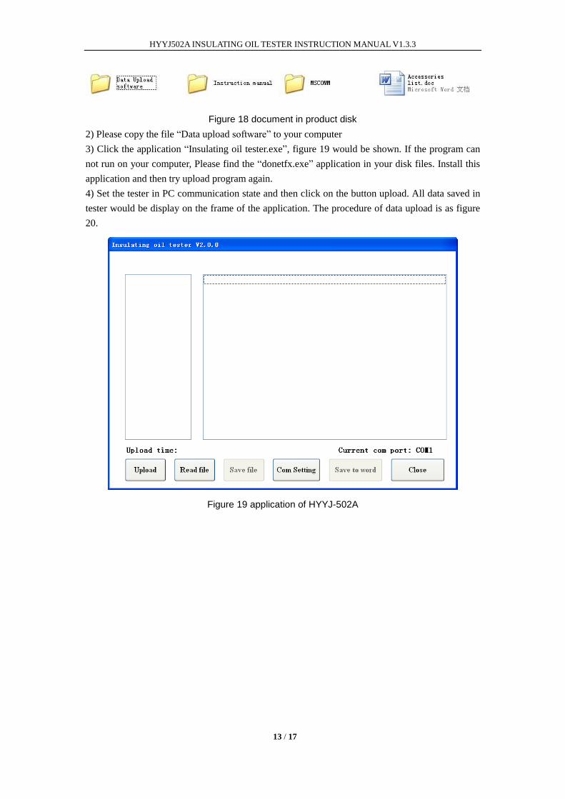
All data saved in the tester could be uploaded to personal computer by an application. Figure 18 is
the UI of the application for HYYJ-502A. Please start the application as follow:
1) Please find the data upload application in product disk as figure 18.
HYYJ502A INSULATING OIL TESTER INSTRUCTION MANUAL V1.3.3
13 / 17
Figure 18 document in product disk
2) Please copy the file “Data upload software” to your computer
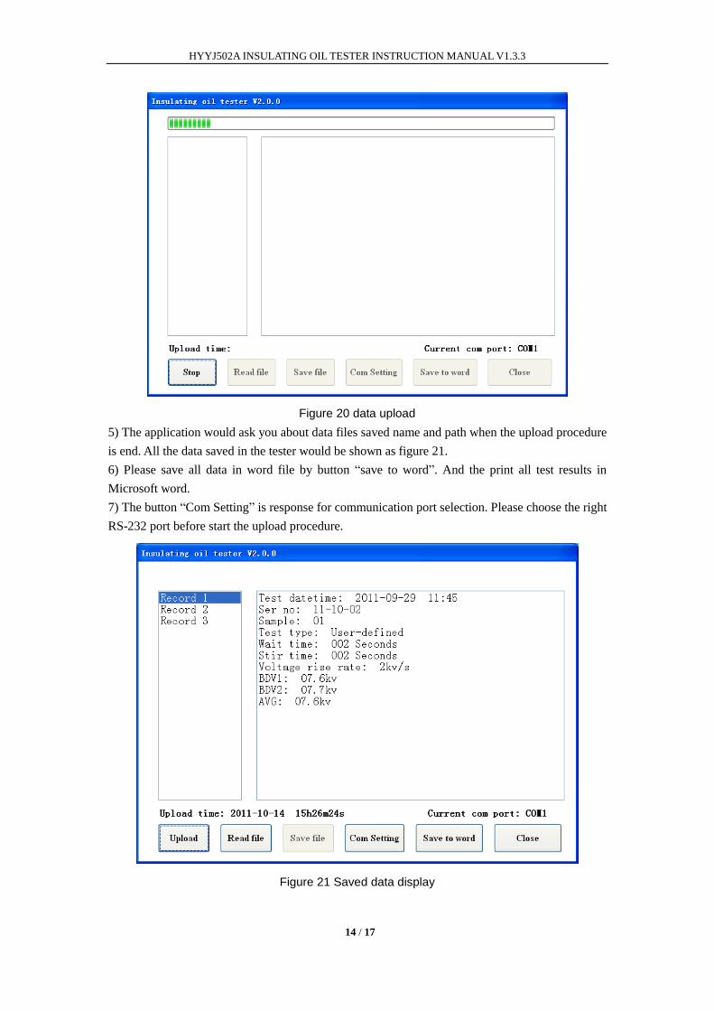
3) Click the application “Insulating oil tester.exe”, figure 19 would be shown. If the program can
not run on your computer, Please find the “donetfx.exe” application in your disk files. Install this
application and then try upload program again.
4) Set the tester in PC communication state and then click on the button upload. All data saved in
tester would be display on the frame of the application. The procedure of data upload is as figure
20.
Figure 19 application of HYYJ-502A
HYYJ502A INSULATING OIL TESTER INSTRUCTION MANUAL V1.3.3
14 / 17
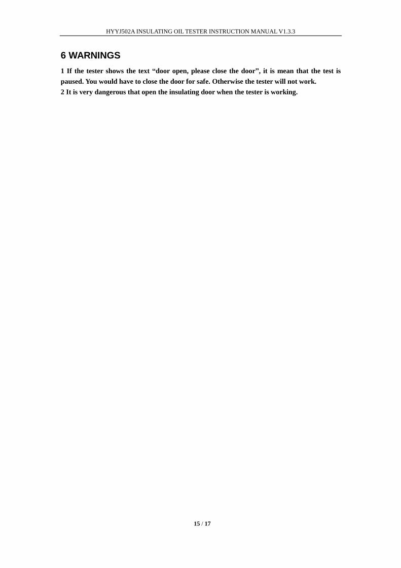
Figure 20 data upload
5) The application would ask you about data files saved name and path when the upload procedure
is end. All the data saved in the tester would be shown as figure 21.
6) Please save all data in word file by button “save to word”. And the print all test results in
Microsoft word.
7) The button “Com Setting” is response for communication port selection. Please choose the right
RS-232 port before start the upload procedure.
Figure 21 Saved data display
HYYJ502A INSULATING OIL TESTER INSTRUCTION MANUAL V1.3.3
15 / 17
6 WARNINGS
1 If the tester shows the text “door open, please close the door”, it is mean that the test is
paused. You would have to close the door for safe. Otherwise the tester will not work.
2 It is very dangerous that open the insulating door when the tester is working.
HYYJ502A INSULATING OIL TESTER INSTRUCTION MANUAL V1.3.3
16 / 17
7 TROUBLE SHOOTING
Trouble Possible cause Remedy
There is no voltage show
and no breakdown in test
vessel when test is started
The low voltage winding of
HV transformer circuit
had been damaged for
transportation or wrong
application
Open the box of tester.
Check whether there is
some unit had been
damaged.
Check the resistance value
of green power resistance
30ohm/20W
Replace the damaged unit
with a new one
There is a sound alarm and
tester does not work when
test is started
1) The insulation door
does not in right
position
2) The insulation door
position detect sensor
had been damaged
3) The insulation door
position detect circuit
does not work
1) Please be sure that the
insulation door in right
position
2) Please replace the door
position detect sensor
with a new one
3) Please contact with
tester manufacturer
for help
There is no voltage show
when test is started. But
breakdown in test vessel is
ok.
1) The connection in
measurement circuit
had been
disconnected for
transportation
2) Some ICs in
measurement circuit
had been damaged
1) Open the box of tester.
Check whether there
are some lines in
disconnection.
2) Check the ICs in main
board whether there
are some ICs had been
damaged. Replace the
bad ICs with a new one
The values of breakdown
voltage are very small.
While the voltage output
unit is ok when there is no
test vessel between
electrodes
The contact between
electrodes and test vessel is
not good
Please relocate the test
vessel between electrodes
The test value is not exact The error of measurement
becomes more and more
for long time work
Please contact with
manufacturer to calibrate
the tester again.
HYYJ502A INSULATING OIL TESTER INSTRUCTION MANUAL V1.3.3
17 / 17
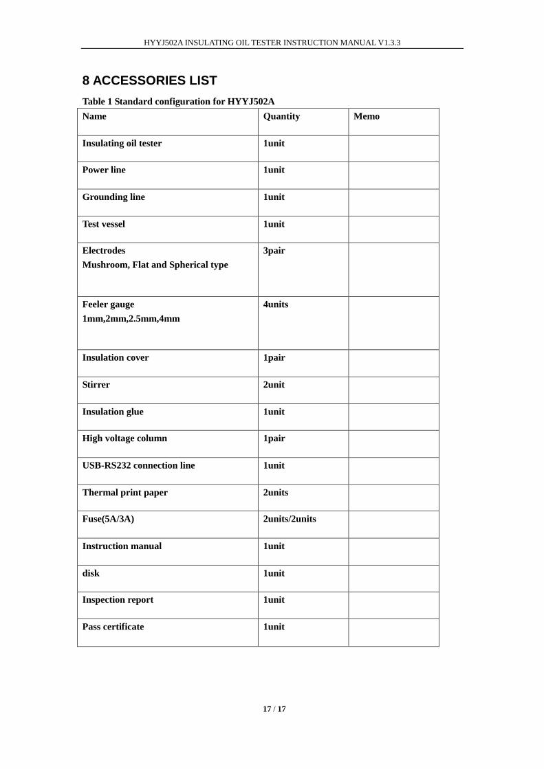
8 ACCESSORIES LIST
Table 1 Standard configuration for HYYJ502A
Name Quantity Memo
Insulating oil tester 1unit
Power line 1unit
Grounding line 1unit
Test vessel 1unit
Electrodes
Mushroom, Flat and Spherical type
3pair
Feeler gauge
1mm,2mm,2.5mm,4mm
4units
Insulation cover 1pair
Stirrer 2unit
Insulation glue 1unit
High voltage column 1pair
USB-RS232 connection line 1unit
Thermal print paper 2units
Fuse(5A/3A) 2units/2units
Instruction manual 1unit
disk 1unit
Inspection report 1unit
Pass certificate 1unit