moisture tester - lkc training ltd
TRANSCRIPT

70-0035 Rev. 2 12.3.03
Specification - Once you have a clear understanding of the problem, you can workout the specification for your Moisture Tester. A specification is a list of things that the finaldesign must do. A good specification will list all the important features in orderof importance.
Specifications are an important part of designing because they provide a check list againstwhich you can review your ideas as you are working. They also give you something againstwhich to evaluate your ideas and your finished product.
For example, "the toy should be painted" does not give the designer enough information."The toy should be painted a primary colour" is a clear statement without restricting the designer.
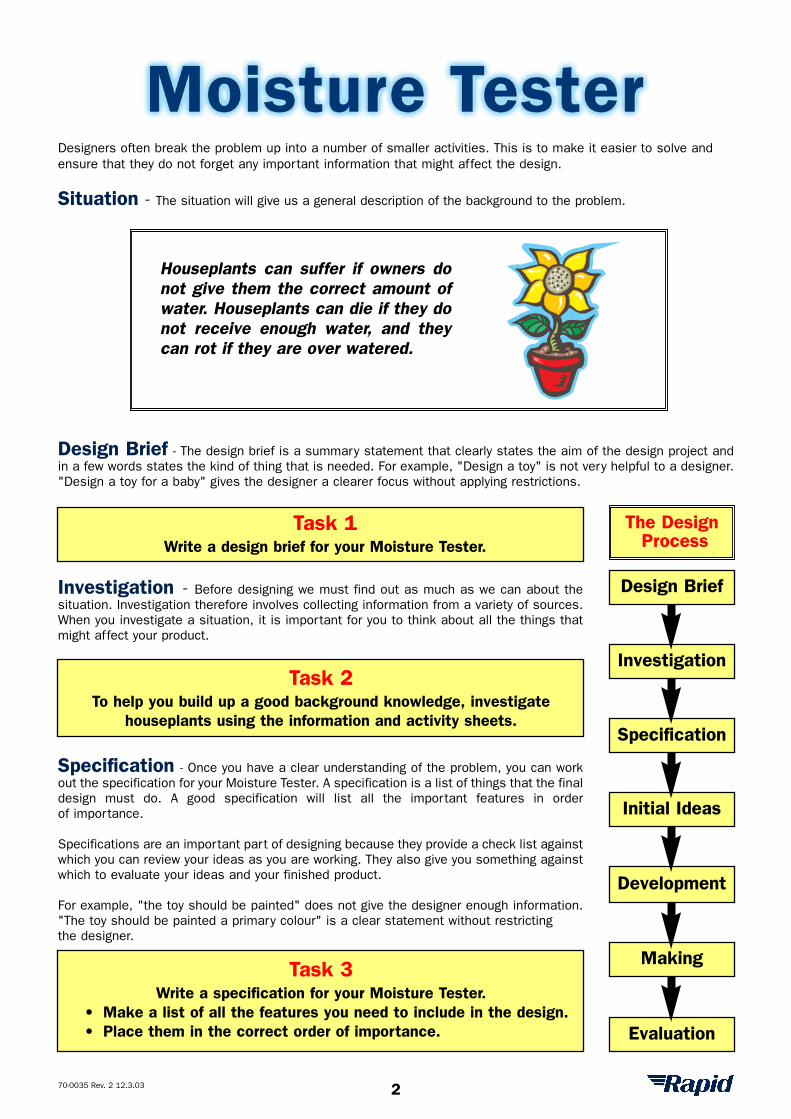
Houseplants can suffer if owners donot give them the correct amount ofwater. Houseplants can die if they donot receive enough water, and theycan rot if they are over watered.
Task 1Write a design brief for your Moisture Tester.
Task 2To help you build up a good background knowledge, investigate
houseplants using the information and activity sheets.
Task 3Write a specification for your Moisture Tester.
• Make a list of all the features you need to include in the design.• Place them in the correct order of importance.
Designers often break the problem up into a number of smaller activities. This is to make it easier to solve andensure that they do not forget any important information that might affect the design.
Situation - The situation will give us a general description of the background to the problem.
Design Brief - The design brief is a summary statement that clearly states the aim of the design project andin a few words states the kind of thing that is needed. For example, "Design a toy" is not very helpful to a designer."Design a toy for a baby" gives the designer a clearer focus without applying restrictions.
Investigation - Before designing we must find out as much as we can about thesituation. Investigation therefore involves collecting information from a variety of sources.When you investigate a situation, it is important for you to think about all the things thatmight affect your product.
Evaluation
Making
Development
Initial Ideas
Specification
Investigation
Design Brief
The DesignProcess
2
70-0035 Rev. 2 12.3.03
House PlantsMillions of houseplants are bought each year from supermarkets and garden centres. However, a large proportionof these suffer because their owners do not know how to look after them properly.
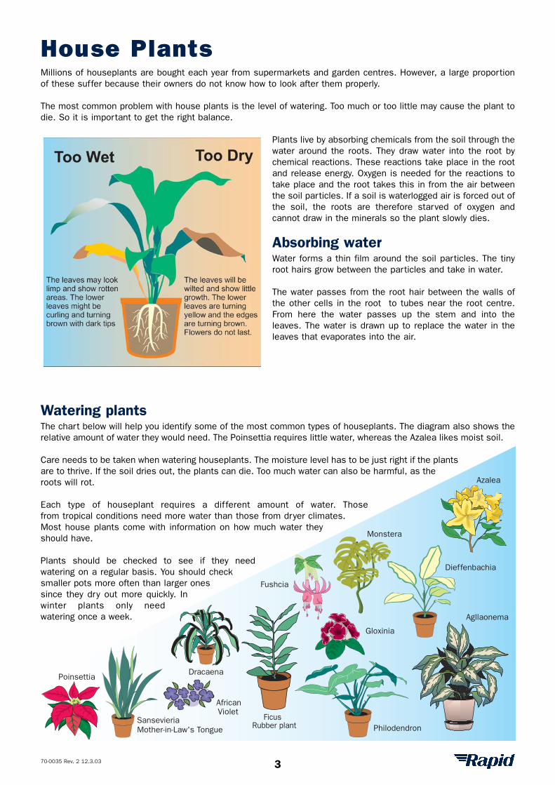
The most common problem with house plants is the level of watering. Too much or too little may cause the plant todie. So it is important to get the right balance.
Plants live by absorbing chemicals from the soil through thewater around the roots. They draw water into the root bychemical reactions. These reactions take place in the rootand release energy. Oxygen is needed for the reactions totake place and the root takes this in from the air betweenthe soil particles. If a soil is waterlogged air is forced out ofthe soil, the roots are therefore starved of oxygen andcannot draw in the minerals so the plant slowly dies.
Absorbing waterWater forms a thin film around the soil particles. The tinyroot hairs grow between the particles and take in water.
The water passes from the root hair between the walls ofthe other cells in the root to tubes near the root centre.From here the water passes up the stem and into theleaves. The water is drawn up to replace the water in theleaves that evaporates into the air.
Watering plantsThe chart below will help you identify some of the most common types of houseplants. The diagram also shows therelative amount of water they would need. The Poinsettia requires little water, whereas the Azalea likes moist soil.
Care needs to be taken when watering houseplants. The moisture level has to be just right if the plantsare to thrive. If the soil dries out, the plants can die. Too much water can also be harmful, as theroots will rot.
Each type of houseplant requires a different amount of water. Thosefrom tropical conditions need more water than those from dryer climates.Most house plants come with information on how much water theyshould have.
Plants should be checked to see if they needwatering on a regular basis. You should checksmaller pots more often than larger onessince they dry out more quickly. Inwinter plants only needwatering once a week.
SansevieriaMother-in-Law's Tongue
Monstera
FicusRubber plant
Agllaonema
Dieffenbachia
Philodendron
Azalea
Gloxinia
Fushcia
Dracaena
AfricanViolet
Poinsettia
3
70-0035 Rev. 2 12.3.03
House plants activity
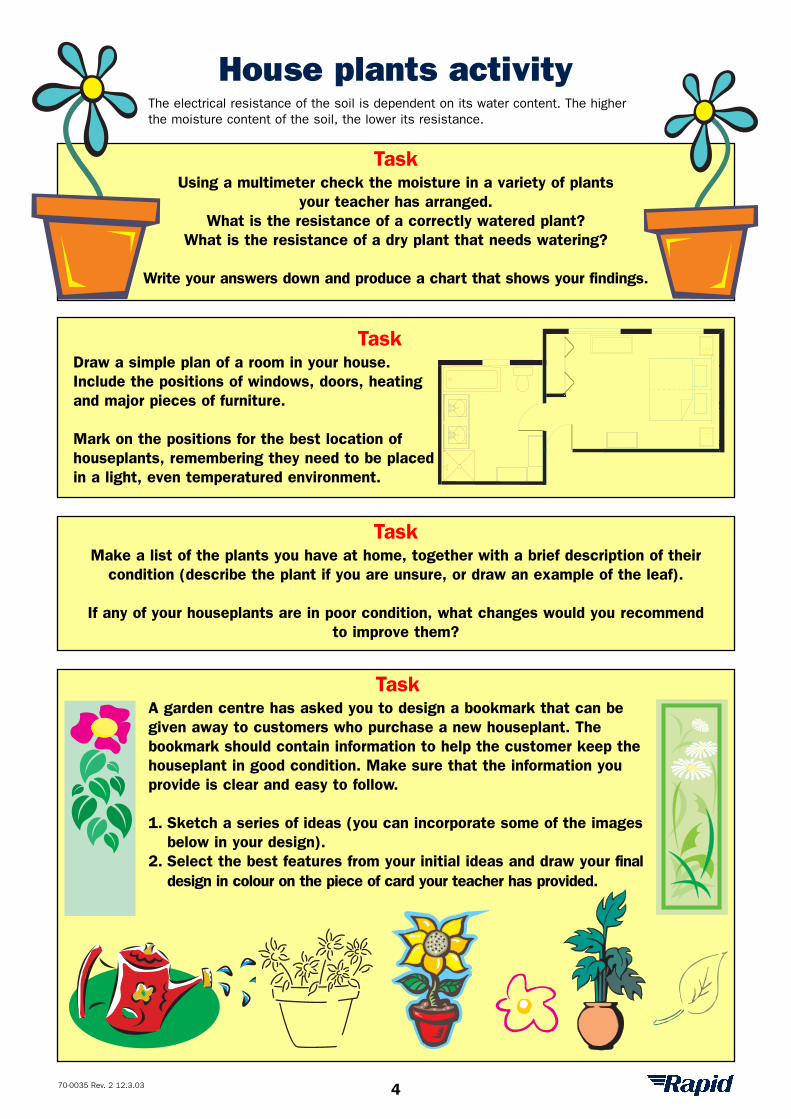
Task Using a multimeter check the moisture in a variety of plants
your teacher has arranged. What is the resistance of a correctly watered plant?
What is the resistance of a dry plant that needs watering?
Write your answers down and produce a chart that shows your findings.
Task Make a list of the plants you have at home, together with a brief description of their
condition (describe the plant if you are unsure, or draw an example of the leaf).
If any of your houseplants are in poor condition, what changes would you recommend to improve them?
Task A garden centre has asked you to design a bookmark that can begiven away to customers who purchase a new houseplant. Thebookmark should contain information to help the customer keep thehouseplant in good condition. Make sure that the information youprovide is clear and easy to follow.
1. Sketch a series of ideas (you can incorporate some of the imagesbelow in your design).
2. Select the best features from your initial ideas and draw your finaldesign in colour on the piece of card your teacher has provided.
Task Draw a simple plan of a room in your house.Include the positions of windows, doors, heatingand major pieces of furniture.
Mark on the positions for the best location ofhouseplants, remembering they need to be placedin a light, even temperatured environment.
The electrical resistance of the soil is dependent on its water content. The higherthe moisture content of the soil, the lower its resistance.
4
ResistorsResistors are used to control the flow of electricity around a circuit. A resistor is manufactured by mixing conductingand non-conducting material that is then formed into a paste and attached to wire connectors. The more conductingmaterial in the paste the lower the resistance. The more the non-conducting material in the paste, the higher the resistance.
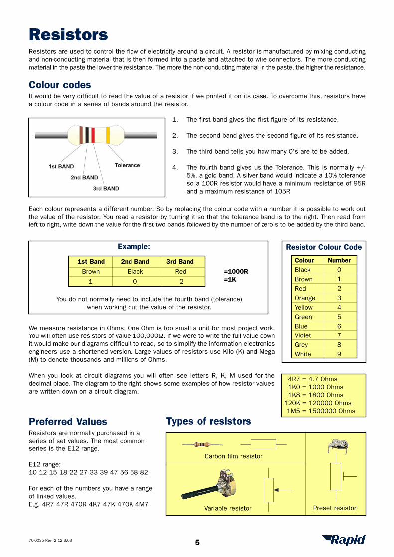
Colour codesIt would be very difficult to read the value of a resistor if we printed it on its case. To overcome this, resistors havea colour code in a series of bands around the resistor.
1. The first band gives the first figure of its resistance.
2. The second band gives the second figure of its resistance.
3. The third band tells you how many 0's are to be added.
4. The fourth band gives us the Tolerance. This is normally +/-5%, a gold band. A silver band would indicate a 10% toleranceso a 100R resistor would have a minimum resistance of 95Rand a maximum resistance of 105R
Each colour represents a different number. So by replacing the colour code with a number it is possible to work outthe value of the resistor. You read a resistor by turning it so that the tolerance band is to the right. Then read fromleft to right, write down the value for the first two bands followed by the number of zero's to be added by the third band.
We measure resistance in Ohms. One Ohm is too small a unit for most project work.You will often use resistors of value 100,000Ω. If we were to write the full value downit would make our diagrams difficult to read, so to simplify the information electronicsengineers use a shortened version. Large values of resistors use Kilo (K) and Mega(M) to denote thousands and millions of Ohms.
When you look at circuit diagrams you will often see letters R, K, M used for thedecimal place. The diagram to the right shows some examples of how resistor valuesare written down on a circuit diagram.
Preferred ValuesResistors are normally purchased in a series of set values. The most common series is the E12 range.
E12 range: 10 12 15 18 22 27 33 39 47 56 68 82
For each of the numbers you have a range of linked values.E.g. 4R7 47R 470R 4K7 47K 470K 4M7
70-0035 Rev. 2 12.3.03
Colour NumberBlack 0Brown 1Red 2Orange 3Yellow 4Green 5Blue 6Violet 7Grey 8White 9
Resistor Colour Code
4R7 = 4.7 Ohms1K0 = 1000 Ohms1K8 = 1800 Ohms
120K = 120000 Ohms1M5 = 1500000 Ohms
Example:
=1000R=1K
You do not normally need to include the fourth band (tolerance) when working out the value of the resistor.
1st Band 2nd Band 3rd Band
Brown Black Red
1 0 2
Variable resistor Preset resistor
Carbon film resistor
Types of resistors
5
70-0035 Rev. 2 12.3.03
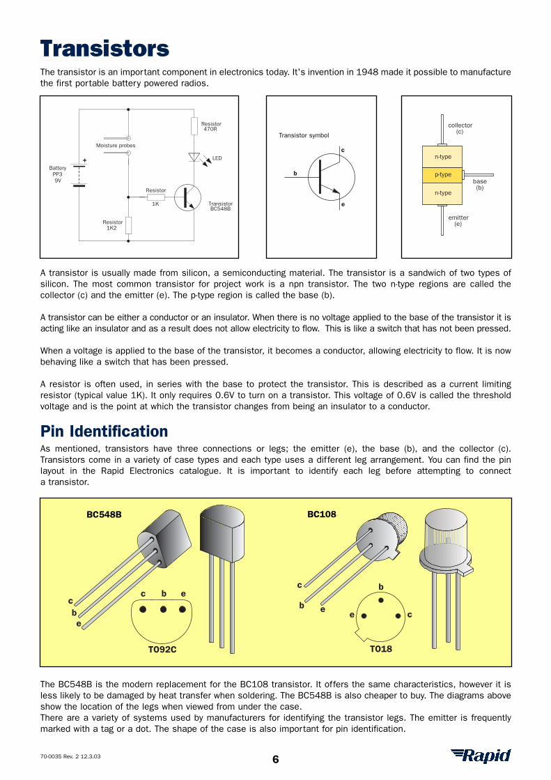
TransistorsThe transistor is an important component in electronics today. It's invention in 1948 made it possible to manufacturethe first portable battery powered radios.
A transistor is usually made from silicon, a semiconducting material. The transistor is a sandwich of two types ofsilicon. The most common transistor for project work is a npn transistor. The two n-type regions are called thecollector (c) and the emitter (e). The p-type region is called the base (b).
A transistor can be either a conductor or an insulator. When there is no voltage applied to the base of the transistor it isacting like an insulator and as a result does not allow electricity to flow. This is like a switch that has not been pressed.
When a voltage is applied to the base of the transistor, it becomes a conductor, allowing electricity to flow. It is nowbehaving like a switch that has been pressed.
A resistor is often used, in series with the base to protect the transistor. This is described as a current limitingresistor (typical value 1K). It only requires 0.6V to turn on a transistor. This voltage of 0.6V is called the thresholdvoltage and is the point at which the transistor changes from being an insulator to a conductor.
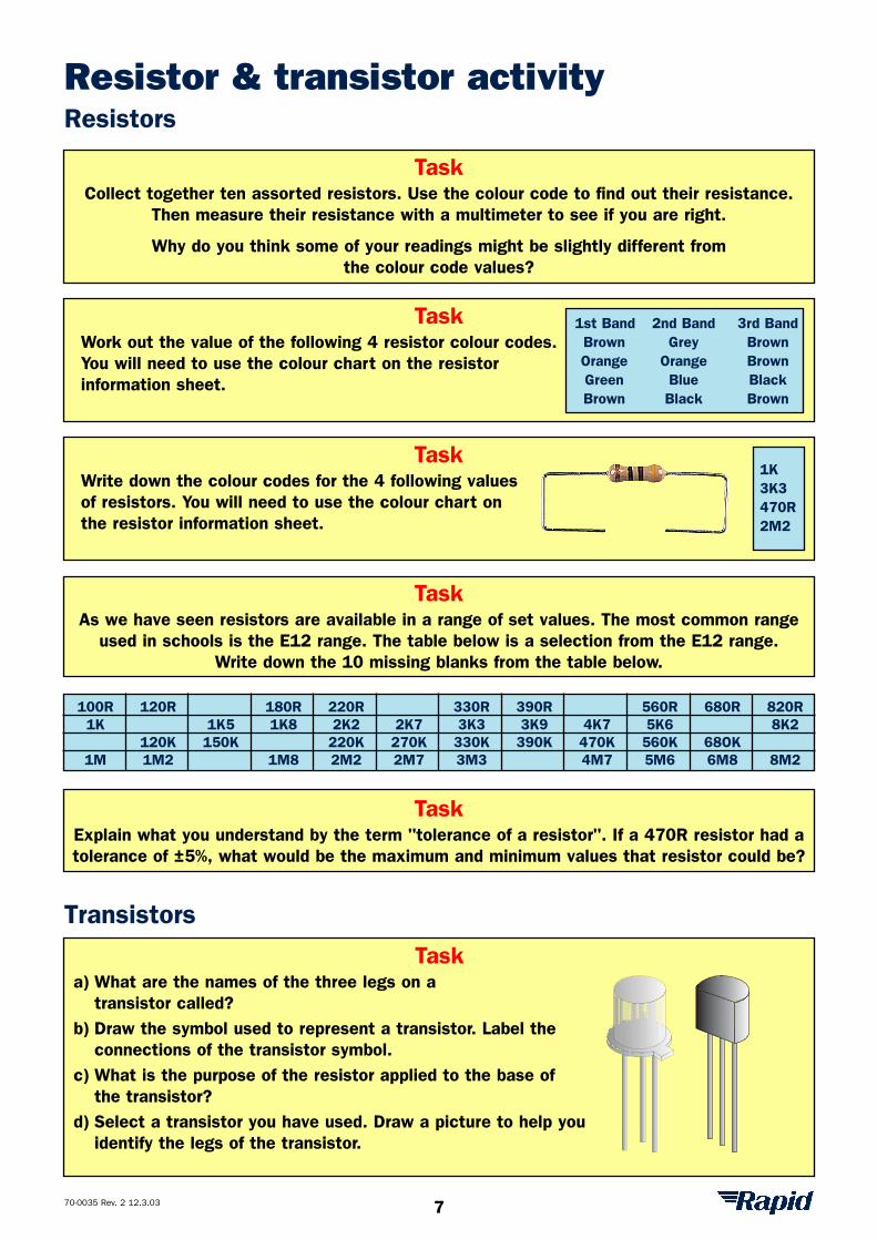
Pin IdentificationAs mentioned, transistors have three connections or legs; the emitter (e), the base (b), and the collector (c).Transistors come in a variety of case types and each type uses a different leg arrangement. You can find the pinlayout in the Rapid Electronics catalogue. It is important to identify each leg before attempting to connecta transistor.
The BC548B is the modern replacement for the BC108 transistor. It offers the same characteristics, however it isless likely to be damaged by heat transfer when soldering. The BC548B is also cheaper to buy. The diagrams aboveshow the location of the legs when viewed from under the case.There are a variety of systems used by manufacturers for identifying the transistor legs. The emitter is frequentlymarked with a tag or a dot. The shape of the case is also important for pin identification.
BC548B
LED
1K
470R
BatteryPP39V
1K2
Moisture probes
Resistor
Resistor
Resistor
Transistor
c
e
b
Transistor symbol
n-type
n-type
p-type
collector(c)
base(b)
emitter(e)
eb
cebc
TO92C
BC548B
b
c
e
b
ce
TO18
BC108
6
Resistor & transistor activityResistors
Transistors
Task Work out the value of the following 4 resistor colour codes.You will need to use the colour chart on the resistor information sheet.
70-0035 Rev. 2 12.3.03
Task Collect together ten assorted resistors. Use the colour code to find out their resistance.
Then measure their resistance with a multimeter to see if you are right.
Why do you think some of your readings might be slightly different from the colour code values?
Task Write down the colour codes for the 4 following valuesof resistors. You will need to use the colour chart onthe resistor information sheet.
1st Band 2nd Band 3rd BandBrown Grey BrownOrange Orange BrownGreen Blue BlackBrown Black Brown
Task As we have seen resistors are available in a range of set values. The most common range
used in schools is the E12 range. The table below is a selection from the E12 range.Write down the 10 missing blanks from the table below.
100R 120R 180R 220R 330R 390R 560R 680R 820R1K 1K5 1K8 2K2 2K7 3K3 3K9 4K7 5K6 8K2
120K 150K 220K 270K 330K 390K 470K 560K 68OK1M 1M2 1M8 2M2 2M7 3M3 4M7 5M6 6M8 8M2
1K3K3470R2M2
Task Explain what you understand by the term "tolerance of a resistor". If a 470R resistor had atolerance of ±5%, what would be the maximum and minimum values that resistor could be?
Task a) What are the names of the three legs on a
transistor called?b) Draw the symbol used to represent a transistor. Label the
connections of the transistor symbol.c) What is the purpose of the resistor applied to the base of
the transistor?d) Select a transistor you have used. Draw a picture to help you
identify the legs of the transistor.
7
70-0035 Rev. 2 12.3.03
SolderingSoldering is the method we use for joining electronic components together. Solder is metal alloy of tin (60%) andlead(40%), that becomes molten at around 200°C. Solder contains flux that helps the joint form correctly.
YOU SHOULD ALWAYS SOLDER IN A WELL-VENTILATED AREA. DO NOT INHALE THE FLUX SMOKE.
TAKE CARE NOT TO TOUCH THE TIP OF THE SOLDERING IRON ON THE CABLE OR YOURSELF.
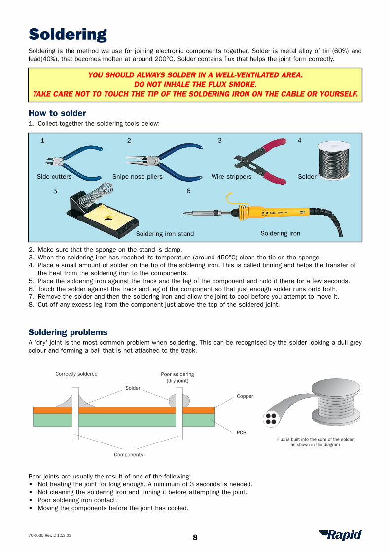
How to solder1. Collect together the soldering tools below:
2. Make sure that the sponge on the stand is damp.3. When the soldering iron has reached its temperature (around 450°C) clean the tip on the sponge.4. Place a small amount of solder on the tip of the soldering iron. This is called tinning and helps the transfer of
the heat from the soldering iron to the components.5. Place the soldering iron against the track and the leg of the component and hold it there for a few seconds.6. Touch the solder against the track and leg of the component so that just enough solder runs onto both.7. Remove the solder and then the soldering iron and allow the joint to cool before you attempt to move it.8. Cut off any excess leg from the component just above the top of the soldered joint.
Soldering problemsA 'dry' joint is the most common problem when soldering. This can be recognised by the solder looking a dull greycolour and forming a ball that is not attached to the track.
Poor joints are usually the result of one of the following:• Not heating the joint for long enough. A minimum of 3 seconds is needed.• Not cleaning the soldering iron and tinning it before attempting the joint.• Poor soldering iron contact. • Moving the components before the joint has cooled.
1 2 3 4
5 6
Correctly soldered Poor soldering(dry joint)
Solder
Copper
PCB
Components
Flux is built into the core of the solderas shown in the diagram
Side cutters Snipe nose pliers Wire strippers Solder
Soldering iron stand Soldering iron
8
70-0035 Rev. 2 12.3.03
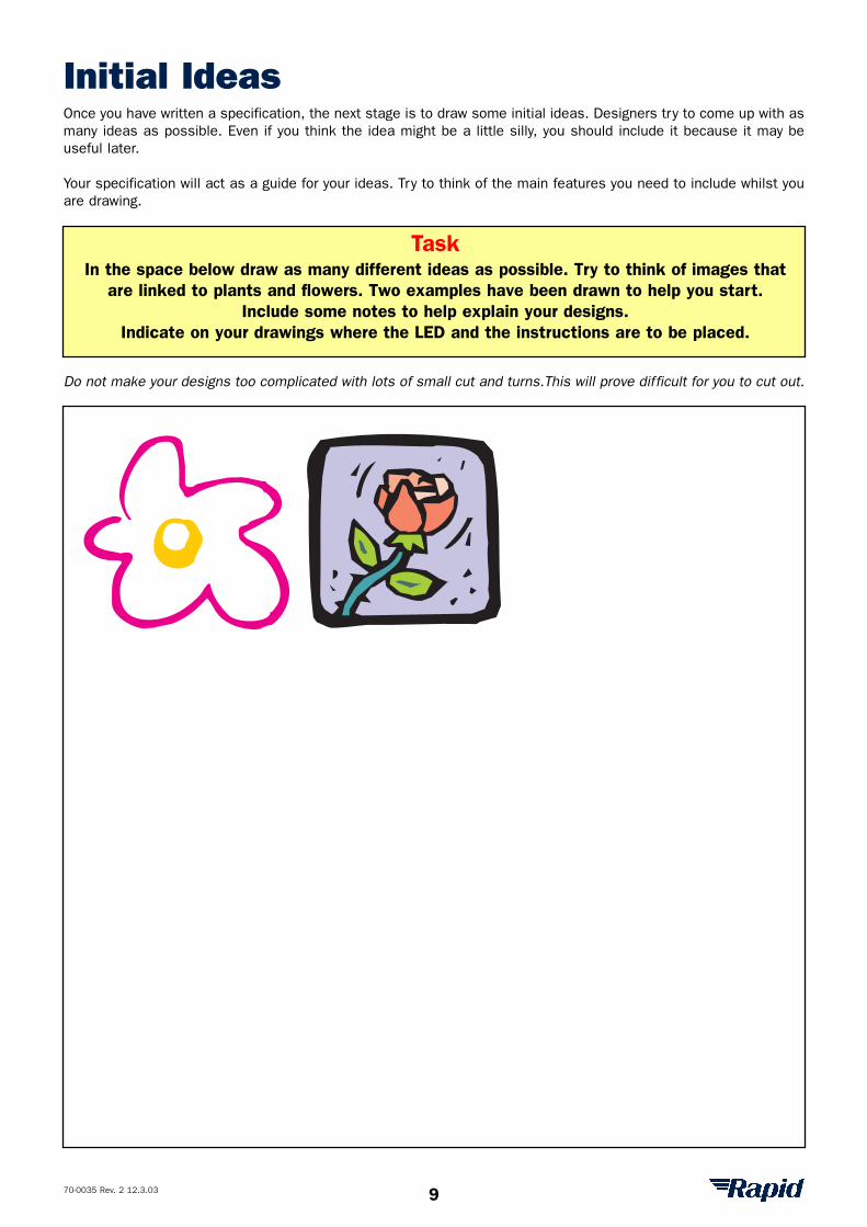
Initial IdeasOnce you have written a specification, the next stage is to draw some initial ideas. Designers try to come up with asmany ideas as possible. Even if you think the idea might be a little silly, you should include it because it may beuseful later.
Your specification will act as a guide for your ideas. Try to think of the main features you need to include whilst youare drawing.
Do not make your designs too complicated with lots of small cut and turns.This will prove difficult for you to cut out.
Task In the space below draw as many different ideas as possible. Try to think of images that
are linked to plants and flowers. Two examples have been drawn to help you start.Include some notes to help explain your designs.
Indicate on your drawings where the LED and the instructions are to be placed.
9
70-0035 Rev. 2 12.3.03
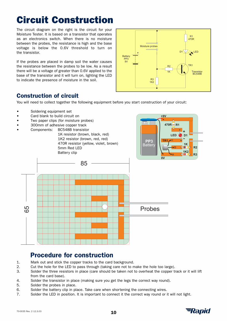
Circuit ConstructionThe circuit diagram on the right is the circuit for yourMoisture Tester. It is based on a transistor that operatesas an electronics switch. When there is no moisturebetween the probes, the resistance is high and the basevoltage is below the 0.6V threshold to turn onthe transistor.
If the probes are placed in damp soil the water causesthe resistance between the probes to be low. As a resultthere will be a voltage of greater than 0.6V applied to thebase of the transistor and it will turn on, lighting the LEDto indicate the presence of moisture in the soil.
+
TransistorBC548B
LED
R2
1K
470R
BatteryPP39V
Moisture probes
R1
1K2
D1
TR1
R3
Construction of circuitYou will need to collect together the following equipment before you start construction of your circuit:
• Soldering equipment set • Card blank to build circuit on• Two paper clips (for moisture probes)• 300mm of adhesive copper track• Components: BC548B transistor
1K resistor (brown, black, red)1K2 resistor (brown, red, red)470R resistor (yellow, violet, brown)5mm Red LEDBattery clip
c
b
e
LED
470R
1K
+
-PP3
Battery
+9V
0V
1K2
R1
R2
D1
R3
TR1
Probes
85
65
Procedure for construction1. Mark out and stick the copper tracks to the card background.2. Cut the hole for the LED to pass through (taking care not to make the hole too large).3. Solder the three resistors in place (care should be taken not to overheat the copper track or it will lift
from the card base).4. Solder the transistor in place (making sure you get the legs the correct way round).5. Solder the probes in place.6. Solder the battery clip in place. Take care when shortening the connecting wires.7. Solder the LED in position. It is important to connect it the correct way round or it will not light.
10
70-0035 Rev. 2 12.3.03
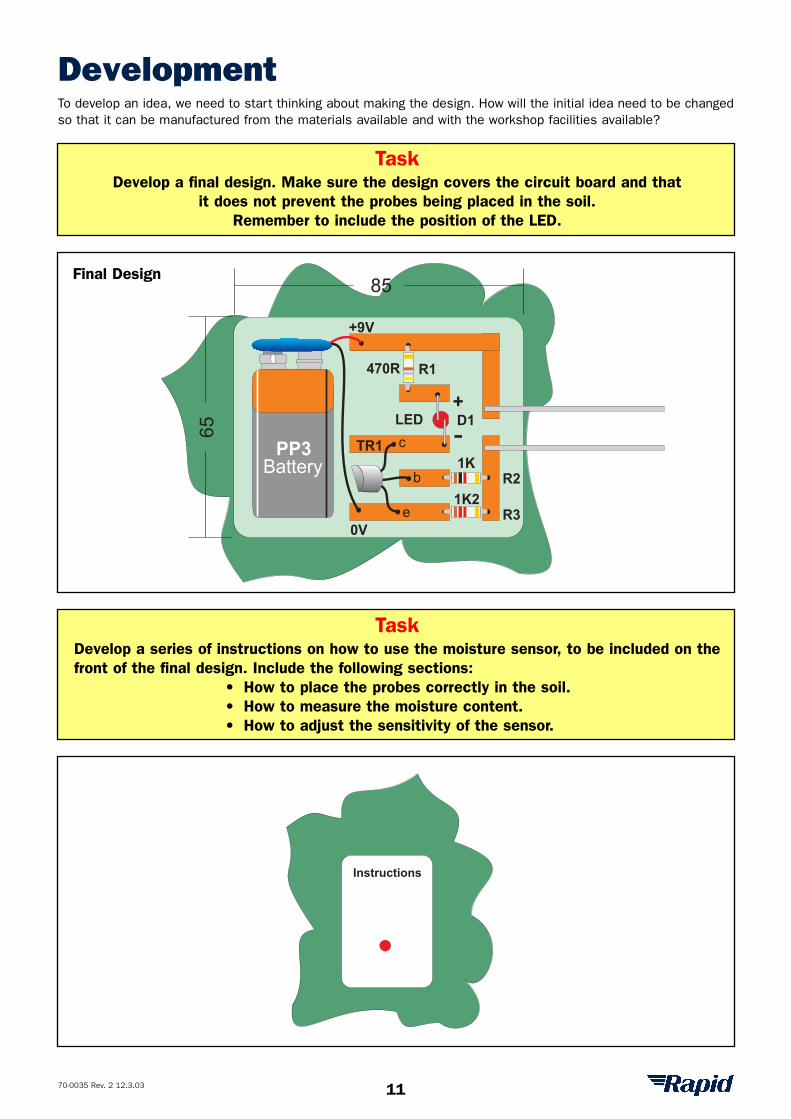
DevelopmentTo develop an idea, we need to start thinking about making the design. How will the initial idea need to be changedso that it can be manufactured from the materials available and with the workshop facilities available?
85
65
c
b
e
LED
470R
1K
+
-PP3
Battery
+9V
0V
1K2
R1
R2
D1
R3
TR1
Instructions
Task Develop a final design. Make sure the design covers the circuit board and that
it does not prevent the probes being placed in the soil.Remember to include the position of the LED.
Task Develop a series of instructions on how to use the moisture sensor, to be included on thefront of the final design. Include the following sections:
• How to place the probes correctly in the soil.• How to measure the moisture content.• How to adjust the sensitivity of the sensor.
Final Design
11
70-0035 Rev. 2 12.3.03
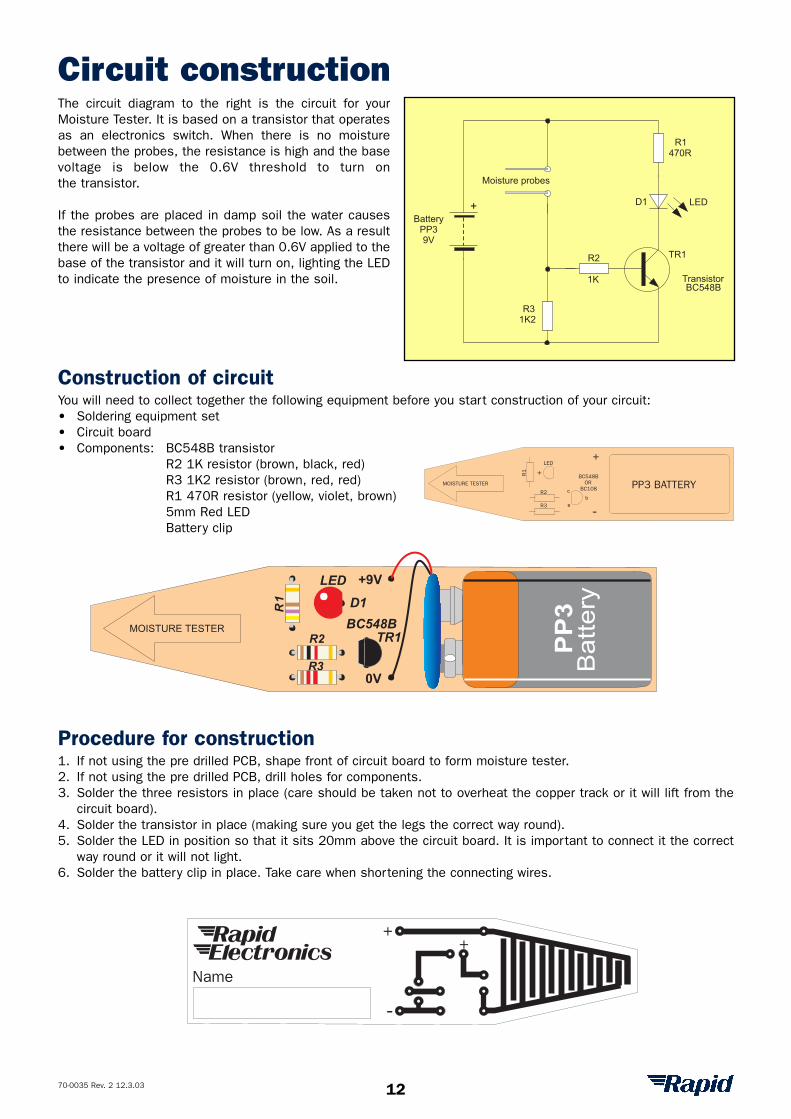
Circuit constructionThe circuit diagram to the right is the circuit for yourMoisture Tester. It is based on a transistor that operatesas an electronics switch. When there is no moisturebetween the probes, the resistance is high and the basevoltage is below the 0.6V threshold to turn onthe transistor.
If the probes are placed in damp soil the water causesthe resistance between the probes to be low. As a resultthere will be a voltage of greater than 0.6V applied to thebase of the transistor and it will turn on, lighting the LEDto indicate the presence of moisture in the soil.
Construction of circuitYou will need to collect together the following equipment before you start construction of your circuit:• Soldering equipment set • Circuit board• Components: BC548B transistor
R2 1K resistor (brown, black, red)R3 1K2 resistor (brown, red, red)R1 470R resistor (yellow, violet, brown)5mm Red LEDBattery clip
Procedure for construction1. If not using the pre drilled PCB, shape front of circuit board to form moisture tester.2. If not using the pre drilled PCB, drill holes for components.3. Solder the three resistors in place (care should be taken not to overheat the copper track or it will lift from the
circuit board).4. Solder the transistor in place (making sure you get the legs the correct way round).5. Solder the LED in position so that it sits 20mm above the circuit board. It is important to connect it the correct
way round or it will not light.6. Solder the battery clip in place. Take care when shortening the connecting wires.
+
TransistorBC548B
LED
R2
1K
470R
BatteryPP39V
Moisture probes
R1
1K2
D1
TR1
R3
R2
R1
R3
BC548B
LED +9V
0V
PP
3
Battery
MOISTURE TESTER
D1
TR1
Name
+
-
+
+
-R2
R1
R3
LED
BC548BOR
BC108cb
e
+
PP3 BATTERYMOISTURE TESTER
12
70-0035 Rev. 2 12.3.03
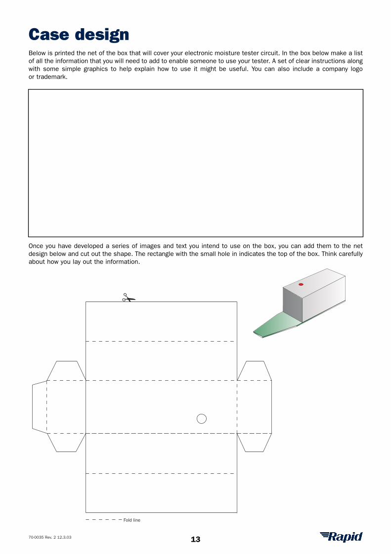
Case designBelow is printed the net of the box that will cover your electronic moisture tester circuit. In the box below make a listof all the information that you will need to add to enable someone to use your tester. A set of clear instructions alongwith some simple graphics to help explain how to use it might be useful. You can also include a company logoor trademark.
Once you have developed a series of images and text you intend to use on the box, you can add them to the netdesign below and cut out the shape. The rectangle with the small hole in indicates the top of the box. Think carefullyabout how you lay out the information.
Fold line
13
70-0035 Rev. 2 12.3.03
Procedure ChartTask
Draw a procedure chart, using a series of pictures to describe how you have manufacturedyour Moisture Tester. Make sure that your diagrams show the important detail.
14
70-0035 Rev. 2 12.3.03
EvaluationEvaluation is an important part of the design process. It is used by designers to check they have produced a gooddesign with all the features they identified in the specification. When you are evaluating a product you are trying tofind out both its good and poor features.
Your own opinions are important, but you must also get some other peoples opinions as well. They may noticequalities you are not aware of.
Task Evaluate your Moisture Tester project by establishing if it meets your specification.
Look at your specification and write down in the boxes below two features to establish thequality of your Moisture Tester.
1.
2.
Task Sketch how your final Moisture Tester design could be improved.
15
70-0035 Rev. 2 12.3.03
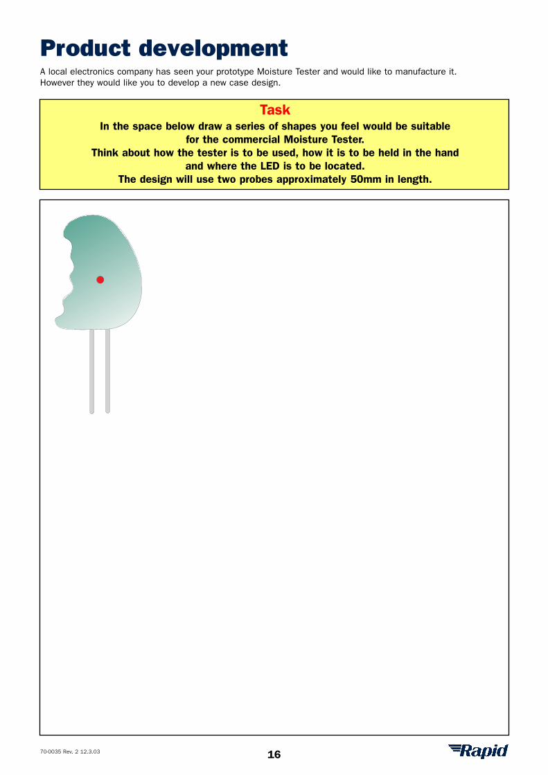
Product developmentA local electronics company has seen your prototype Moisture Tester and would like to manufacture it.However they would like you to develop a new case design.
Task In the space below draw a series of shapes you feel would be suitable
for the commercial Moisture Tester. Think about how the tester is to be used, how it is to be held in the hand
and where the LED is to be located. The design will use two probes approximately 50mm in length.
16
70-0035 Rev. 2 12.3.03
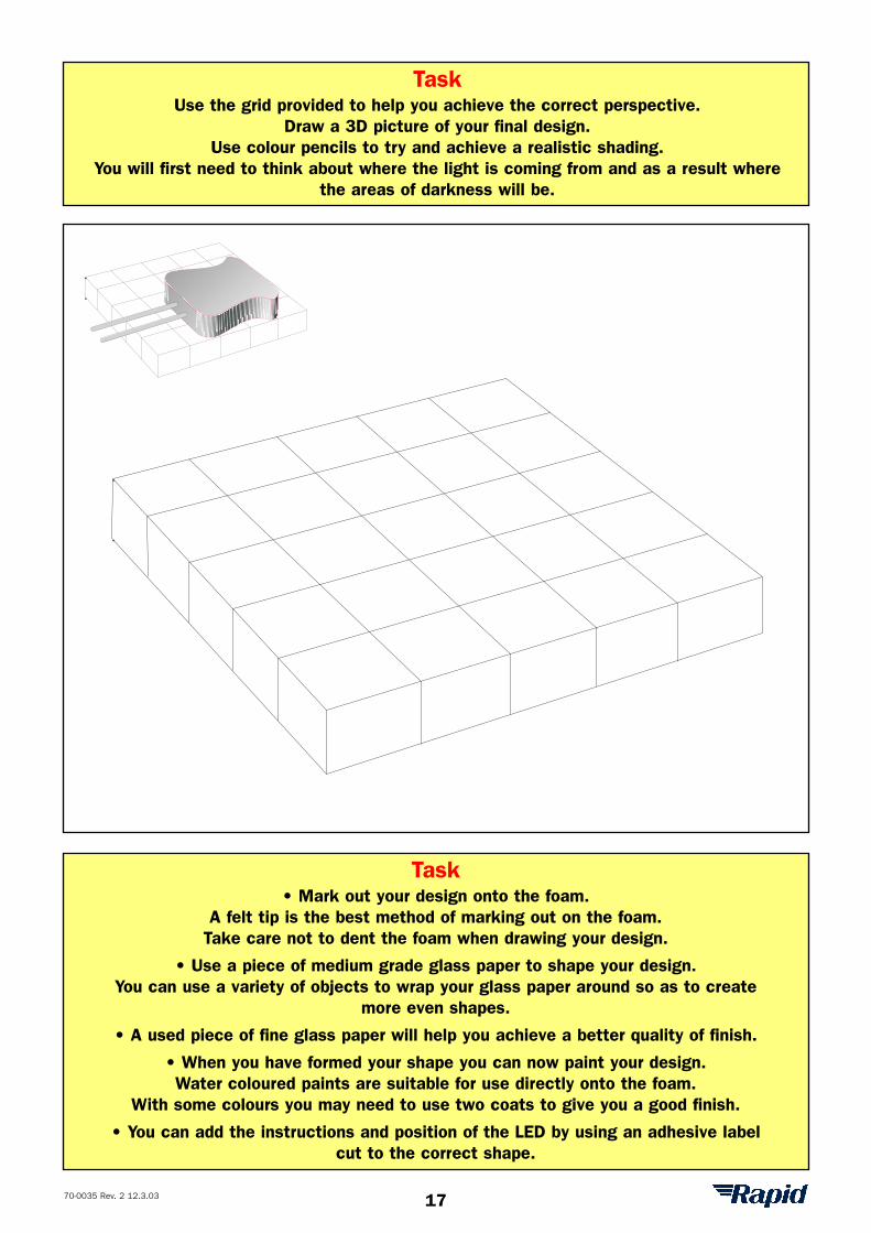
Task Use the grid provided to help you achieve the correct perspective.
Draw a 3D picture of your final design. Use colour pencils to try and achieve a realistic shading.
You will first need to think about where the light is coming from and as a result wherethe areas of darkness will be.
Task • Mark out your design onto the foam.
A felt tip is the best method of marking out on the foam. Take care not to dent the foam when drawing your design.
• Use a piece of medium grade glass paper to shape your design. You can use a variety of objects to wrap your glass paper around so as to create
more even shapes.
• A used piece of fine glass paper will help you achieve a better quality of finish.
• When you have formed your shape you can now paint your design. Water coloured paints are suitable for use directly onto the foam.
With some colours you may need to use two coats to give you a good finish.
• You can add the instructions and position of the LED by using an adhesive label cut to the correct shape.
17
70-0035 Rev. 2 12.3.03
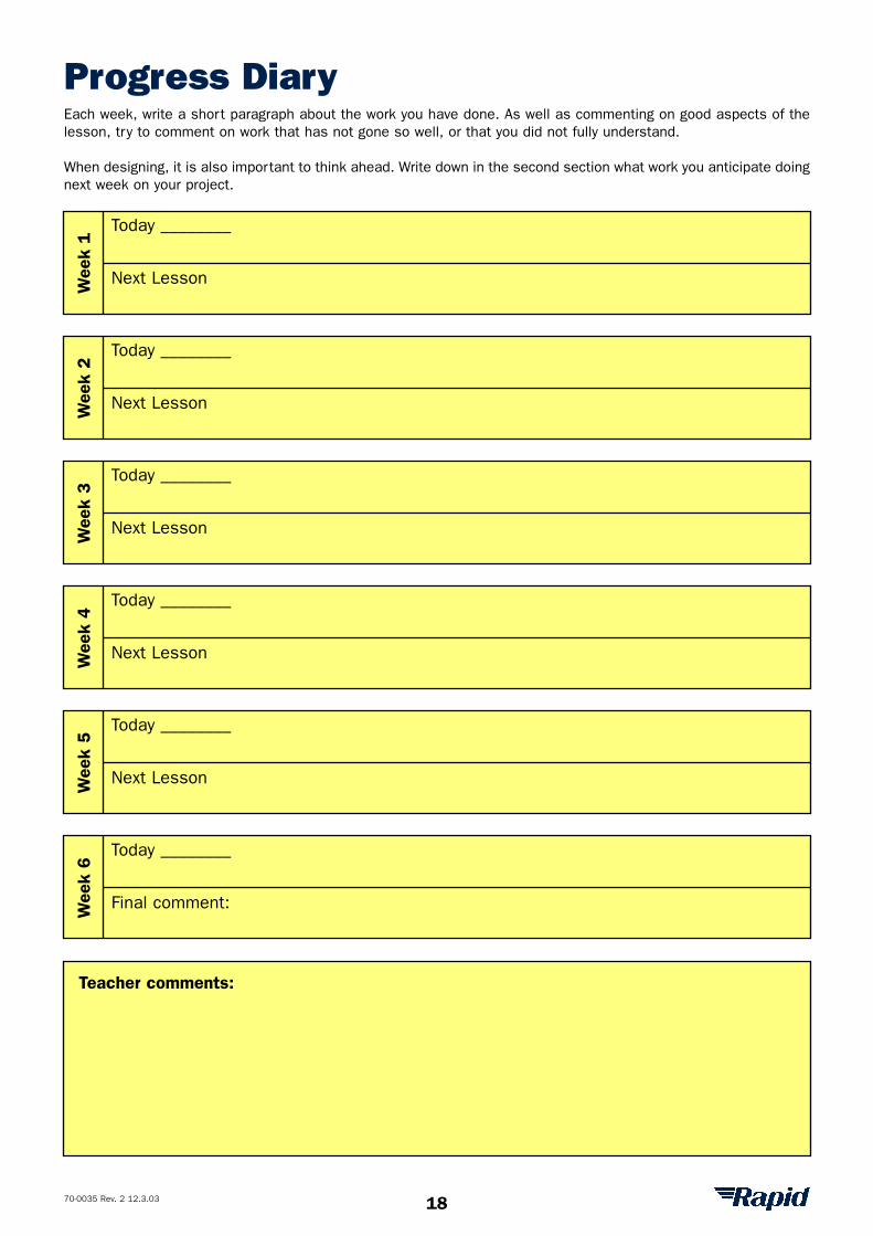
Progress DiaryEach week, write a short paragraph about the work you have done. As well as commenting on good aspects of thelesson, try to comment on work that has not gone so well, or that you did not fully understand.
When designing, it is also important to think ahead. Write down in the second section what work you anticipate doingnext week on your project.
Wee
k 1
Wee
k 2
Wee
k 3
Wee
k 4
Wee
k 5
Wee
k 6
Today ________
Today ________
Next Lesson
Next Lesson
Next Lesson
Next Lesson
Next Lesson
Final comment:
Today ________
Today ________
Today ________
Today ________
Teacher comments:
18

A70-0035 Rev. 2 12.3.03
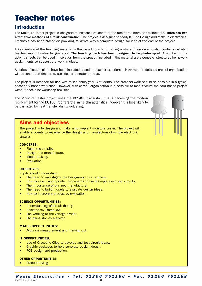
Teacher notesIntroductionThe Moisture Tester project is designed to introduce students to the use of resistors and transistors. There are twoalternative methods of circuit construction. The project is designed for early KS3 to Design and Make in electronics.Emphasis has been placed on providing students with a complete design solution at the end of the project.
A key feature of the teaching material is that in addition to providing a student resource, it also contains detailedteacher support notes for guidance. The teaching pack has been designed to be photocopied. A number of theactivity sheets can be used in isolation from the project. Included in the material are a series of structured homeworkassignments to support the work in class.
A series of lesson plans have been included based on teacher experience. However, the detailed project organisationwill depend upon timetable, facilities and student needs.
The project is intended for use with mixed ability year 8 students. The practical work should be possible in a typicalsecondary based workshop. However, with careful organisation it is possible to manufacture the card based projectwithout specialist workshop facilities.
The Moisture Tester project uses the BC548B transistor. This is becoming the modernreplacement for the BC108. It offers the same characteristics, however it is less likely tobe damaged by heat transfer during soldering.
Aims and objectivesThe project is to design and make a houseplant moisture tester. The project willenable students to experience the design and manufacture of simple electroniccircuits.
CONCEPTS:• Electronic circuits.• Design and manufacture.• Model making.• Evaluation.
OBJECTIVES:Pupils should understand:• The need to investigate the background to a problem.• How to select appropriate components to build simple electronic circuits.• The importance of planned manufacture.• The need to build models to evaluate design ideas.• How to improve a product by evaluation.
SCIENCE OPPORTUNITIES:• Understanding of circuit theory.• Resistance/ Ohms law.• The working of the voltage divider.• The transistor as a switch.
MATHS OPPORTUNITIES:• Accurate measurement and marking out.
IT OPPORTUNITIES:• Use of Crocodile Clips to develop and test circuit ideas.• Graphic packages to help generate design ideas .• PCB design and production.
OTHER OPPORTUNITIES:• Product styling.
R a p i d E l e c t r o n i c s • T e l : 0 1 2 0 6 7 5 1 1 6 6 • F a x : 0 1 2 0 6 7 5 1 1 8 8
B70-0035 Rev. 2 12.3.03
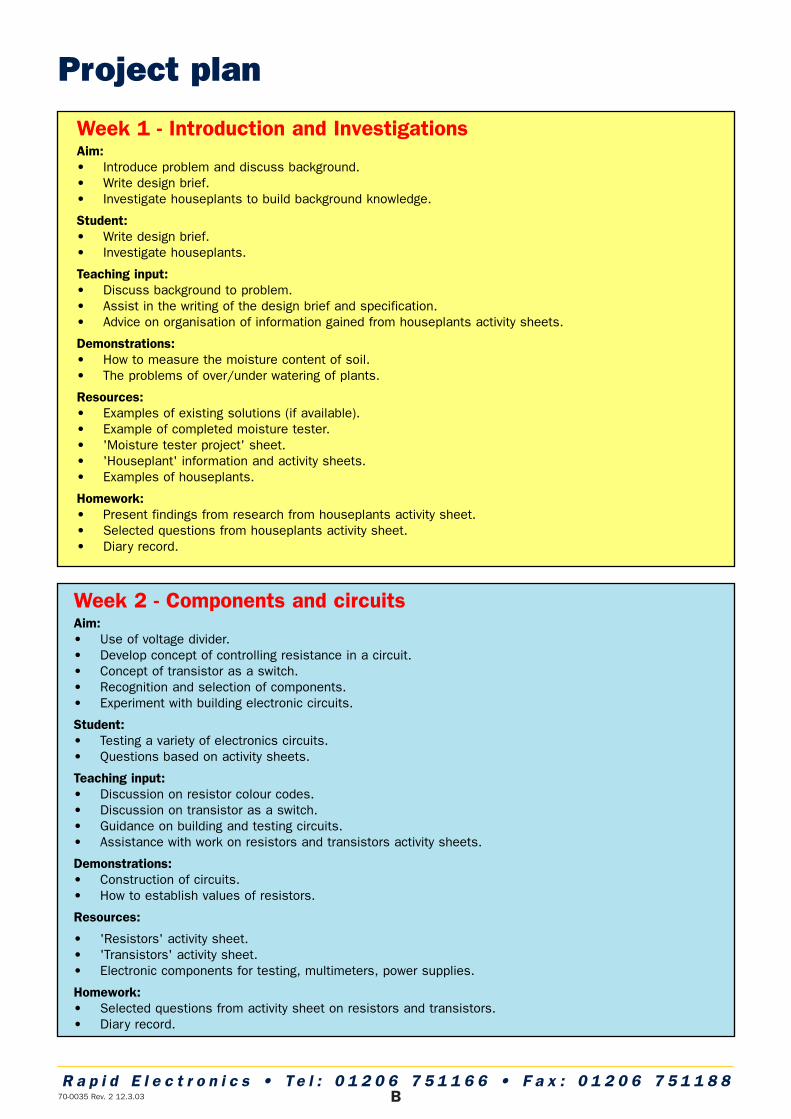
Project plan
Week 1 - Introduction and InvestigationsAim:• Introduce problem and discuss background.• Write design brief.• Investigate houseplants to build background knowledge.
Student:• Write design brief.• Investigate houseplants.
Teaching input:• Discuss background to problem. • Assist in the writing of the design brief and specification.• Advice on organisation of information gained from houseplants activity sheets.
Demonstrations:• How to measure the moisture content of soil. • The problems of over/under watering of plants.
Resources:• Examples of existing solutions (if available).• Example of completed moisture tester.• 'Moisture tester project' sheet.• 'Houseplant' information and activity sheets.• Examples of houseplants.
Homework:• Present findings from research from houseplants activity sheet.• Selected questions from houseplants activity sheet.• Diary record.
Week 2 - Components and circuitsAim:• Use of voltage divider. • Develop concept of controlling resistance in a circuit.• Concept of transistor as a switch.• Recognition and selection of components.• Experiment with building electronic circuits.
Student:• Testing a variety of electronics circuits.• Questions based on activity sheets.
Teaching input:• Discussion on resistor colour codes.• Discussion on transistor as a switch.• Guidance on building and testing circuits.• Assistance with work on resistors and transistors activity sheets.
Demonstrations:• Construction of circuits.• How to establish values of resistors.
Resources:
• 'Resistors' activity sheet.• 'Transistors' activity sheet.• Electronic components for testing, multimeters, power supplies.
Homework:• Selected questions from activity sheet on resistors and transistors.• Diary record.
R a p i d E l e c t r o n i c s • T e l : 0 1 2 0 6 7 5 1 1 6 6 • F a x : 0 1 2 0 6 7 5 1 1 8 8
C70-0035 Rev. 2 12.3.03
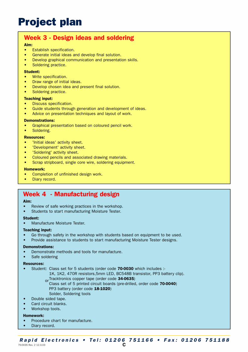
Project planWeek 3 - Design ideas and solderingAim:• Establish specification.• Generate initial ideas and develop final solution.• Develop graphical communication and presentation skills.• Soldering practice.
Student:• Write specification.• Draw range of initial ideas.• Develop chosen idea and present final solution.• Soldering practice.
Teaching input:• Discuss specification. • Guide students through generation and development of ideas.• Advice on presentation techniques and layout of work.
Demonstrations:• Graphical presentation based on coloured pencil work.• Soldering.
Resources:• 'Initial ideas' activity sheet.• 'Development' activity sheet.• 'Soldering' activity sheet.• Coloured pencils and associated drawing materials.• Scrap stripboard, single core wire, soldering equipment.
Homework:• Completion of unfinished design work.• Diary record.
Week 4 - Manufacturing designAim:• Review of safe working practices in the workshop.• Students to start manufacturing Moisture Tester.
Student:• Manufacture Moisture Tester.
Teaching input:• Go through safety in the workshop with students based on equipment to be used.• Provide assistance to students to start manufacturing Moisture Tester designs.
Demonstrations:• Demonstrate methods and tools for manufacture.• Safe soldering
Resources:• Student: Class set for 5 students (order code 70-0030 which includes :-
1K, 1K2, 470R resistors,5mm LED, BC548B transistor, PP3 battery clip).Tracktronics copper tape (order code 34-0635)Class set of 5 printed circuit boards (pre-drilled, order code 70-0040)PP3 battery (order code 18-1020)Solder, Soldering tools
• Double sided tape.• Card circuit blanks.• Workshop tools.
Homework:• Procedure chart for manufacture.• Diary record.
or
R a p i d E l e c t r o n i c s • T e l : 0 1 2 0 6 7 5 1 1 6 6 • F a x : 0 1 2 0 6 7 5 1 1 8 8
D70-0035 Rev. 2 12.3.03
Project planWeek 5 - Product developmentAim:• Complete manufacturing of any unfinished Moisture Testers.• Design and manufacture sales model of Moisture Tester.
Student:• Complete any unfinished construction of Moisture Tester.• Develop design ideas for commercial Moisture Tester.
Teaching input:• Provide support to help students finish the construction of their Moisture Tester.• Discuss styles suitable for commercial design of the Moisture Tester.• Help students in the development of presentational techniques.
Demonstrations:• How to manufacture model from foam. See below for details.• Presentation techniques.
Resources:• Examples of similar style products.• Foam blanks for making models.• Glasspaper.• Paints.
Homework:• 3D view of model in colour.• Diary record.
Week 6 - EvaluationAim:• Completion of commercial model. • Evaluation of Moisture tester and student progress.
Student:• Completion of models.• Evaluation against specification.
Teaching input:• Discussion on important feature to include in project evaluations.
Demonstrations:• None.
Resources:• 'Evaluation' activity sheets.
Homework:• Diary record.
StyrofoamStyrofoam is a high density polystyrene foam, which isexcellent for making prototype models. The foam is easy tocut and sand to shape using the minimum of workshop tools.Styrofoam can be glued together using water based contactadhesive. Use a fibre grade glass paper to provide a smoothfinish for applying water based paints.
Note: Work in a well ventilated area. The wearing of aprotective mask is recommended.
R a p i d E l e c t r o n i c s • T e l : 0 1 2 0 6 7 5 1 1 6 6 • F a x : 0 1 2 0 6 7 5 1 1 8 8
E70-0035 Rev. 2 12.3.03
National Curriculum 2000Design & Technology Programme of Study Key Stage 3During key stage 3 pupils use a wide range of materials to design and make products. They work out their ideaswith some precision, taking into account how products will be used, who will use them, how much they cost andtheir appearance. They develop their understanding of designing and making by investigating products and findingout about the work of professional designers and manufacturing industry. They use computers, including computer-aided design and manufacture (CAD/CAM) and control software, as an integral part of designing and making. Theydraw on knowledge and understanding from other areas of the curriculum.
Knowledge, skills and understanding
Developing, planning and communicating ideas1. Pupils should be taught to:a) identify relevant sources of information, using a range of resources including ICT.b) respond to design briefs and produce their own design specifications for products.c) develop criteria for their designs to guide their thinking and to form a basis for evaluation.d) generate design proposals that match the criteria.e) consider aesthetics and other issues that influence their planning .f) suggest outline plans for designing and making, and change them if necessary.g) prioritise actions and reconcile decisions as a project develops, taking into account the use of time and
costs when selecting materials, components, tools, equipment and production methods.h) use graphic techniques and ICT, including computer-aided design (CAD), to explore, develop, model and
communicate design proposals.
Working with tools, equipment, materials and components to produce quality products2. Pupils should be taught:a) to select and use tools, equipment and processes, including computer-aided design and manufacture
(CAD/CAM), to shape and form materials safely and accurately and finish them appropriately.b) to take account of the working characteristics and properties of materials and components when deciding
how and when to use them.c) to join and combine materials and ready-made components accurately to achieve functional results.d) to make single products and products in quantity, using a range of techniques, including CAD/CAM to
ensure consistency and accuracy.e) about the working characteristics and applications of a range of modern materials, including smart materials.
Evaluating processes and products3. Pupils should be taught to:a) evaluate their design ideas as these develop, and modify their proposals to ensure that their product
meets the design specification.b) test how well their products work, then evaluate them.c) identify and use criteria to judge the quality of other people's products, including the extent to which they
meet a clear need, their fitness for purpose, whether resources have been used appropriately, and theirimpact beyond the purpose for which they were designed.
R a p i d E l e c t r o n i c s • T e l : 0 1 2 0 6 7 5 1 1 6 6 • F a x : 0 1 2 0 6 7 5 1 1 8 8
70-0035 Rev. 2 12.3.03 F
Knowledge and understanding of materials and components4. Pupils should be taught:a) to consider physical and chemical properties and working characteristics of a range of common and
modern materials.b) that materials and components can be classified according to their properties and working characteristics.c) that materials and components can be combined, processed and finished to create more useful properties
and particular aesthetic effects. d) how multiple copies can be made of the same product.
Knowledge and understanding of systems and control5. Pupils should be taught:a) to recognise inputs, processes and outputs in their own and existing products.b) that complex systems can be broken down into sub-systems to make it easier to analyse them, and that
each sub-system also has inputs, processes and outputs.c) the importance of feedback in control systems.d) about mechanical, electrical, electronic and pneumatic control systems, including the use of switches in
electrical systems, sensors in electronic switching circuits, and how mechanical systems can be joinedtogether to create different kinds of movement.
e) how different types of systems and sub-systems can be interconnected to achieve a particular function.f) how to use electronics, microprocessors and computers to control systems, including the use of feedback.g) how to use ICT to design sub-systems and systems.
Knowledge and understanding of structures6. Pupils should be taught:a) to recognise and use structures and how to support and reinforce themb) simple tests and appropriate calculations to work out the effect of loadsc) that forces of compression, tension, torsion and shear produce different effects.
Breadth of study7. During the key stage, pupils should be taught the Knowledge, skills and understanding through:a) product analysis.b) focused practical tasks that develop a range of techniques, skills, processes and knowledge.c) design and make assignments in different contexts. The assignments should include control systems, and
work using a range of contrasting materials, including resistant materials, compliant materials and/or food.
R a p i d E l e c t r o n i c s • T e l : 0 1 2 0 6 7 5 1 1 6 6 • F a x : 0 1 2 0 6 7 5 1 1 8 8
AcknowledgmentsRapid Electronics would like to thank the many teachers who have helped in the development and evaluation of thisproject. In particular we would like to thank Colin Howard, Head of Design Technology at King Edwards High Schoolfor Boys in Birmingham, for the initial idea.
If your school has a project it is willing to share, or would like to help us test and evaluate new project ideas, thenplease contact the Education Section at Rapid Electronics.