oi-6940-xx-xp ops_guide_rev 3.0 - otis instruments
TRANSCRIPT


CAUTION WARNING – EXPLOSION HAZARD – SUBSTITUTION OF COMPONENTS MAY IMPAIR SUITABILITY FOR CLASS I, DIVISION 1, OR EQUIVALENT AS STATED IN USER MANUAL CAUTION: FOR SAFETY REASONS, THIS EQUIPMENT MUST BE OPERATED AND SERVICED BY QUALIFIED PERSONNEL ONLY. READ AND UNDERSTAND THE INSTRUCTION MANUAL COMPLETELY BEFORE OPERATING OR SERVICING. CAUTION – THIS AREA MUST BE FREE OF FLAMMABLE GASES DURING CALIBRATION CAUTION – TO PREVENT IGNITION OF EXPLOSIVE ATMOSPHERES, REMOVE FROM EXPLOSIVE ATMOSPHERE BEFORE SERVICING
DANGER DANGER: OTIS INSTRUMENTS INC. OI-6940-X-X-XP IS AN AMBIENT AIR HAZARDOUS GAS SENSOR ASSEMBLY AND ONLY MONITORS IN THE IMMEDIATE VICINITY OF THE SENSOR HOUSINGS. A SITE SURVEY IS REQUIRED IN ORDER TO DETERMINE THE BEST PLACEMENT AND QUANTITY OF SENSOR ASSEMBLIES. IMPROPER INSTALLATION CAN LEAD TO AN UNDETECTABLE GAS LEAK WHICH COULD RESULT IN PERSONAL INJURY OR LOSS OF LIFE.


TABLE OF CONTENTS
OI-6940-X-X-XP OPS_GUIDE_REV 3.0 i
TABLE OF CONTENTS
1 PRODUCT OVERVIEW .......................................................................................................................................... 1 1.1 INTRODUCTION .................................................................................................................................................... 1 1.2 PRODUCT SPECIFICATIONS ............................................................................................................................... 2 1.3 SYSTEM DIAGRAMS ............................................................................................................................................. 3 1.3.1 EXTERNAL SYSTEM DIAGRAM ........................................................................................................................... 3 1.3.2 INTERNAL SYSTEM DIAGRAM............................................................................................................................. 4 1.3.3 ASSEMBLY DIAGRAM ........................................................................................................................................... 5 2 INSTALLATION AND START-UP .......................................................................................................................... 6 2.1 PRODUCT PLACEMENT ....................................................................................................................................... 6 2.2 PRODUCT MOUNTING ......................................................................................................................................... 7 2.3 WIRING CONFIGURATIONS ................................................................................................................................. 7 2.3.1 OPENING THE ENCLOSURE ................................................................................................................................ 7 2.3.2 CONNECTING THE BATTERY PACK ................................................................................................................... 8 2.3.3 CLOSING THE ENCLOSURE ................................................................................................................................ 8 2.4 SYSTEM START-UP .............................................................................................................................................. 9 2.5 NORMAL OPERATING MODE............................................................................................................................. 10 3 PRODUCT SETTINGS AND CONFIGURATION ................................................................................................. 11 3.1 GLOBAL SETTINGS ............................................................................................................................................ 12 3.1.1 NETWORK ID ....................................................................................................................................................... 12 3.1.2 UNIT INFORMATION ........................................................................................................................................... 13 3.1.3 DISPLAY SCREEN CONTRAST SETTING ......................................................................................................... 14 3.1.4 RETURN TO FACTORY DEFAULT SETTINGS .................................................................................................. 15 3.1.5 BACK MENU ........................................................................................................................................................ 16 3.2 SENSOR SETTINGS ............................................................................................................................................ 17 3.2.1 TURN SENSOR ON/OFF ..................................................................................................................................... 17 3.2.2 NULLING THE SENSOR (AUTO NULL) .............................................................................................................. 19 3.2.3 CALIBRATING THE SENSOR (MANUAL CAL) ................................................................................................... 21 3.2.4 CALIBRATING THE SENSOR (AUTO CAL) ........................................................................................................ 23 3.2.5 SENSOR RADIO ADDRESS ................................................................................................................................ 26 3.2.6 SENSOR RELAY TEST ........................................................................................................................................ 27 3.2.7 SENSOR BACKGROUND SETTING ................................................................................................................... 28 3.2.8 SENSOR BACKGROUND HIGH SETTING ......................................................................................................... 29 3.2.9 SENSOR BACKGROUND LOW SETTING .......................................................................................................... 30 3.2.10 CALIBRATION METHOD ..................................................................................................................................... 31 3.2.11 SENSOR INFORMATION .................................................................................................................................... 32 3.2.12 NULL-CALIBRATION TIMER INFORMATION ..................................................................................................... 33 3.2.13 RESET SENSOR NULL/CAL................................................................................................................................ 34 3.2.14 BACK MENU ........................................................................................................................................................ 35 4 OPERATION SETTINGS ..................................................................................................................................... 36 4.1 POWERING THE DEVICE ................................................................................................................................... 36 4.1.1 POWERING ON ................................................................................................................................................... 36 4.1.2 POWERING OFF .................................................................................................................................................. 36 4.2 DISPLAY BEHAVIOR ABOVE BACKGROUND ................................................................................................... 37

TABLE OF CONTENTS
ii OI-6940-X-X-XP OPS_GUIDE_REV 3.0
5 PRODUCT MAINTENANCE................................................................................................................................. 38 5.1 SCHEDULED MAINTENANCE ............................................................................................................................. 38 5.2 SENSOR REPLACEMENT ................................................................................................................................... 39 5.3 BATTERY REPLACEMENT ................................................................................................................................. 40 5.4 PRODUCT FAULT CODES .................................................................................................................................. 41 5.5 PRODUCT REPLACEMENT PARTS AND ACCESORIES .................................................................................. 42 APPENDIX A: PRODUCT WARRANTY STATEMENT ............................................................................................................. 44 APPENDIX B: INFORMATION ABOUT RMA SERVICE REPAIRS ......................................................................................... 46 APPENDIX C: INFORMATION ABOUT RMA RETURNS FOR CREDIT .................................................................................. 48

INSTALLATION AND START-UP
OI-6940-X-X-XP OPS_GUIDE_REV 3.0 1
1 PRODUCT OVERVIEW
1.1 INTRODUCTION
The Otis Instruments, Inc. (Otis) GEN II Model OI-6940-X-X-XP (OI-6940) Explosion-Proof Ambient Air Quad Hazardous Gas Detector is designed to detect a wide range of toxic gases in potentially hazardous environments. The OI-6940 is component certified for Class I, Division 1, Groups C and D. The OI-6940 features non-intrusive magnetic switches that allow for complete system configuration, regular calibration, and product maintenance to be performed in the field without opening the lid and breaking the seal of the enclosure, thereby compromising the explosion-proof rating. Non-intrusive interface with the OI-6940 is made possible by use of the Otis Magnetic Tool included in the purchase of the device. The OI-6940 continuously monitors the gas level of the surrounding environment and reports once every minute, the reporting rate will increase to once every five seconds when the detected gas is above the Background Gas set-point. This set-point is adjustable, per sensor, to account for sites that may have a constant low level of gas always present allowing the OI-6940 to maintain a long battery life (when not operating on AC power). When the gas level drops below the set-point, for all sensors, the reporting rate will return to once every minute. The OI-6940 display screen will always show the present concentration of gas being detected by the sensor assembly. More information about the Background Gas Set-point is found later in this manual. This document is an operation manual containing diagrams and step-by-step instructions for the proper and safe installation, start-up, configuration and settings, normal operation, and product maintenance of the OI-6940. In this manual, the instructions reference the use of push-buttons, located on the front panel of the device. In certain environments, the activation of the non-intrusive magnetic switches, through the use of the Otis Magnetic Tool, will replace the directive of the button-press actions. To apply the Otis Magnetic Tool, hold the tool to the side of the device enclosure adjacent to the push-button that you wish to activate. When the magnetic switch is toggled, an on-screen indicator will appear on the display screen, signifying that a connection was made.
NOTICE
This document should be read in its entirety before the initial operation of the product.
Should a question arise during the use of the product, this document will serve as a first reference for the end-user. For inquiries beyond the information and instructions provided within this manual, contact the sales representative of this product for assistance.

INSTALLATION AND START-UP
2 OI-6940-X-X-XP OPS_GUIDE_REV 3.0
1.2 PRODUCT SPECIFICATIONS
System Specifications
Operating Voltage 3.6V/76Ah Battery Pack
Battery Life Up to 6 months
Operating Temperature Range -40⁰C to +60⁰C
Humidity Range 0% to 98% Relative Humidity, Noncondensing
Measurement Range Varies based on gas type
Response Time Varies based on gas type
WireFree Option GEN II 900 MHz – 52 Networks, 255 Sensors per Network GEN II 2.4 GHz – 78 Networks, 255 Sensors per Network
RF Connection N-Female Radio Frequency (RF) Connector
Display Transflective (sunlight-readable) 160 X 104 LCD Screen LED Back-Light
Interface 4 Push-Buttons (MENU, ADD, SUB, BACK) 4 Magnetic Switches for Non-Intrusive Calibration
Mechanical Specifications
Enclosure Materials Cast Aluminum Device Enclosure
Sensor Housing Material 303 Stainless Steel Sensor Housing (Up to 4)
Product Dimensions 7" D x 11" W x 24" H (Max Dimensions w/ Attachments)
Product Weight 25 lbs.
Safety Approvals
Enclosure Ratings Explosion/Flame-Proof
Hazardous Location Certification Class I, Division 1 Groups C and D Tamb -40⁰C to +60⁰C

INSTALLATION AND START-UP
OI-6940-X-X-XP OPS_GUIDE_REV 3.0 3
1.3 SYSTEM DIAGRAMS
Refer to the following diagrams for identification of the external and internal system components that may be referred to in this manual.
1.3.1 EXTERNAL SYSTEM DIAGRAM
1 ADD Magnet Button Location 2 MENU Magnet Button Location 3 ADD Push Button 4 MENU Push Button 5 BACK Push Button 6 SUB Push Button 7 Front Panel Handles (2X) 8 Display Screen 9 Enclosure Lid with Glass Window 10 Otis Magnetic Tool
11 Radio Antenna – 900 MHz or 2.4 GHz 12 Antenna Fitting 13 Mounting Feet (2X) 14 BACK Magnet Button Location 15 SUB Magnet Button Location 16 Sensor Rain Guard (Up to 4X) 17 Sensor Housing Number 4 18 Sensor Housing Number 3 19 Sensor Housing Number 2 20 Sensor Housing Number 1

INSTALLATION AND START-UP
4 OI-6940-X-X-XP OPS_GUIDE_REV 3.0
1.3.2 INTERNAL SYSTEM DIAGRAM
1 Mounting Post (4X) 2 Antenna Fitting Connector 3 Radio Module – 900Mhz or 2.4 GHz GEN II 4 Power Cable Connection 5 Battery Pack Plug 6 Mounting Socket (4X) 7 Backup Battery Pack 8 Battery Pack Restraining Strap Thumbscrew (2X) 9 Battery Pack Restraining Strap 10 Sensor 1 Connector 11 Sensor 2 Connector 12 Sensor 3 Connector 13 Sensor 4 Connector 14 Control Board Assembly 15 Terminal Board Assembly

INSTALLATION AND START-UP
OI-6940-X-X-XP OPS_GUIDE_REV 3.0 5
1.3.3 ASSEMBLY DIAGRAM
1 Enclosure Lid with Glass Window 2 Internal System 3 Antenna Fitting Connector 4 Antenna Fitting 5 Sensor Housing Base with Sensor Adapter Board (Up to 4) 6 Sensor Element (Up to 4) 7 Sensor Housing Cap with Flame Arrestor (Up to 4) 8 Sensor Housing Plug (Up to 4) 9 Enclosure

INSTALLATION AND START-UP
6 OI-6940-X-X-XP OPS_GUIDE_REV 3.0
2 INSTALLATION AND START-UP
2.1 PRODUCT PLACEMENT
The installation instructions, and any other information supplied by Otis, provide only basic guidelines relating to the properties of toxic gas and the effects of environmental conditions on the OI-6940 device. Sensor placement should be determined in consultation with the site safety personnel, as well as those knowledgeable of: (1) the site/facility where the equipment is being installed and (2) the potentially present gas types and their dispersion. Otis strongly recommends that the end-user consults with the appropriate third party Health, Safety and Environmental (HSE) and Industrial Hygiene (IH) professionals to determine the final quantity and placement of your gas detection devices. The primary purpose of the OI-6940 is to provide an early warning of the accumulation of hazardous gas, in order to minimize hazards to people and property. Proper placement of the device is paramount to achieving this goal. The following general guidelines should be considered when determining the placement of the OI-6940: The unit should be placed greater than 6.5 Feet/2 Meters away from a monitor in order to ensure reliable
communications The unit shall be placed such that the position of the sensor housings is pointing downward to the ground. Avoid installing the unit in a location where airborne particles could cover or coat the sensor head. The unit should be placed in an area that will produce the highest gas concentration. Enclosed corners and
stopping points of moving devices are two areas susceptible to a buildup of hazardous gas. In order to provide an accurate representative sample of a room, care should be taken to avoid locating the
unit near a room entrance, fresh air intake vent, or vehicle/generator exhaust point. The unit should be placed as close as physically possible to the source of the potential hazardous gas leak. Consider placing the unit in a seldom used area, such as a warehouse, storage area, or other unfrequented
location. Consider accessibility for regular calibration and other required maintenance. When monitoring a ventilated gas cylinder storage area, the unit should be placed near the air return vent. When monitoring an outdoor open-air area, the unit should be placed near the air intake of the HVAC system
of the building. When monitoring for the potential presence of multiple hazardous gas types, the unit should be calibrated for
the least cross-sensitive hazardous gas.
NOTICE
These guidelines are ONLY intended as a general directive for the placement of the OI-6940. This information should NOT server as a complete list when considering all potential parameters for the proper location of the unit. It is STRONGLY advised that a third party Certified Industrial Hygienist, or other Certified Safety Professional, conduct a site survey and annotate the location and quantity of detection devices that should be installed for EVERY installation of EVERY site.

INSTALLATION AND START-UP
OI-6940-X-X-XP OPS_GUIDE_REV 3.0 7
2.2 PRODUCT MOUNTING
It is recommended to mount the unit to a solid structure (Such as a concrete wall, steel column, or angle iron) where a minimum of vibration will be transmitted to the unit. Any style of bolt or screw may be used as long as it is steel and meets or exceeds the following: Maximum 1/2" diameter bolt or screw (length varies with user need) Flat washers for bolts/nuts/screws Minimum Grade 5 (or better) Corrosion protection for all hardware (paint, galvanize, zinc plating, etc.)
2.3 WIRING CONFIGURATIONS
The OI-6940 is powered by a 3.4V/76Ah Lithium-Thionyl battery pack and is NOT rechargeable. The OI-6940 will operate for up to 6 months on the included battery pack.
CAUTION
The internal components can be static sensitive. Use caution when opening the enclosure and handling internal
components.
DO NOT use any metal objects or tools to remove the control board from the enclosure.
WARNING
When securing the lid onto the device, tighten the enclosure lid by hand ONLY. Overtightening of the lid by use of hand-tools could result in damage to the O-ring, potentially compromising the moisture seal, resulting in an unsafe environment.
Use ONLY an Otis supplied battery pack in this device.
2.3.1 OPENING THE ENCLOSURE
To prepare the OI-6940 for installation, you must first open the device enclosure, exposing the control board and its components to connect the battery pack.
1. Remove the enclosure lid, unscrewing it from the device enclosure. Set aside.
2. Gripping the front panel handles, lift the internal system out of the enclosure and rest it against the rim of the enclosure opening.
NOTICE
Disconnecting the sensor connector plugs from the sensor housing connectors and the antenna fittings cable will allow for the complete removal of the internal system from the device enclosure. Disconnecting the internal system may provide ease in accessing the control board terminals for connecting the battery pack to the terminal board. If this step is performed, it is essential that all connections are rejoined before returning the internal system back into the enclosure.

INSTALLATION AND START-UP
8 OI-6940-X-X-XP OPS_GUIDE_REV 3.0
2.3.2 CONNECTING THE BATTERY PACK
The OI-6940 is shipped with the battery pack installed but disconnected from the terminal board. The
battery pack will need to be connected before operation of the unit.
On the GEN II Model OI-6940 Device:
1. Plug the battery cable connector into the battery socket on the terminal board.
2.3.3 CLOSING THE ENCLOSURE 1. Place the internal system back into the device enclosure, matching each mounting post to its
corresponding eyelet anchored within the base of the enclosure.
2. Using the handles, gently push to seat the internal system into the mounting posts.
3. Verify that the O-ring on the enclosure lid is undamaged and correctly seated in place.
4. Affix the enclosure lid back onto the device, rotating the lid until it is tightly screwed into place.

INSTALLATION AND START-UP
OI-6940-X-X-XP OPS_GUIDE_REV 3.0 9
2.4 SYSTEM START-UP
After power is applied, the unit will start and begin its 1 minute, 3 ½ minutes when the Low Power Infrared sensor is installed, warmup period. During warmup, the display will show a countdown of the time remaining until the system start-up is complete. The Otis logo and the unit information will also show on the display screen during start-up.
At the end of the countdown, the device will be in normal operating mode.

INSTALLATION AND START-UP
10 OI-6940-X-X-XP OPS_GUIDE_REV 3.0
2.5 NORMAL OPERATING MODE
During normal operating mode, the OI-6940 continuously samples the air and updates the measured concentration of the target gasses on the display screen. The display, when in normal operation, appears as shown below.
1 Battery Level Indicator (Only visible when backlight is off) 2 Network ID the OI-6940 is transmitting on 3 Sensor radio address (Each sensor has an address) 4 Sensor reading (Each sensor has its own reading display) 5 Sensor gas type (Each sensor is a different gas type) 6 Gas concentration unit of measure 7 Fault indication (Appears in place of Gas concentration unit of measure)
In the event of a device failure, the unit will display a fault code in place of the gas concentration unit of measure. When the fault is corrected, the unit will return to normal operating mode and the gas concentration unit of measure will be displayed again.
For a list of the fault codes of the OI-6940, and their associated meaning, refer to the Product Troubleshooting section of this manual.
NOTICE
After 5 minutes of no interaction with the device, the unit will automatically return to normal operating mode.
⑦

OPERATION SETTINGS
OI-6940-X-X-XP OPS_GUIDE_REV 3.0 11
3 PRODUCT SETTINGS AND CONFIGURATION The product settings and configuration menus allow the end-user to tailor the device settings of the OI-6940 to meet their required specifications and/or site conditions. While the device is in normal operating mode, Press and Hold the MENU button, for approximately 6 seconds, until the product settings and configuration menu is activated and open on the display screen. The product settings and configuration menus consist of the following screens: Global Settings
o Network I.D. o Info Screen o Contrast o Return to Factory Defaults o Back
Sensor 1-4 Settings o Turn Sensor On/Off o Null Sensor o Calibrate Sensor o Sensor Radio Address o Sensor Relay Test o Sensor Background Setting o Calibration Method o Sensor Information o Last Null/Cal Times o Reset Sensor Null/Cal o Back
Exit

OPERATION SETTINGS
12 OI-6940-X-X-XP OPS_GUIDE_REV 3.0
3.1 GLOBAL SETTINGS Use the MENU button for SELECT to enter the Global Settings Menu, any settings under this menu option will affect all aspects of the OI-6940. Use the ADD button for NEXT to advance to the Sensor 1 Settings menu. Use the SUB button for PREV to move to the EXIT menu option. You can also use the BACK button on the OI-6940 to exit the Product Settings and Configuration Menus.
3.1.1 NETWORK ID
The first option under the Global Settings Menu is to configure the Network I.D. of the OI-6940. The Network ID is used to synchronize the communication between the Otis Monitor and OI-6940 assembly and must be set the same to ensure successful communication.
Press the MENU button for SELECT to enter the Network I.D. setting menu. Use the ADD button for NEXT to advance to the Information Screen Menu. Use the SUB button for PREV to move to the BACK menu option. You can also use the BACK button on the OI-6940 to return back to the Main Product Settings and Configuration Menus.
1. After entering the Network I.D. Setting menu, press the ADD or SUB button until the Network ID matches the value being used on the Primary Monitor.
2. Press the MENU or BACK button to return to the Global Settings Menu options.

OPERATION SETTINGS
OI-6940-X-X-XP OPS_GUIDE_REV 3.0 13
3.1.2 UNIT INFORMATION Press the MENU button for SELECT to enter the Information Screen menu. Use the ADD button for NEXT to advance
to the Screen Contrast Menu. Use the SUB button for PREV to move to the Network I.D. menu option. You can also
use the BACK button on the OI-6940 to return back to the Main Product Settings and Configuration Menus.
The unit information screen allows the end-user to view the following information:
The radio link status to the primary monitor The battery voltage of the OI-6940 The date of manufacture of the OI-6940. The serial number of the OI-6940.
This screen is for informational purposes only.
1. Press the MENU or BACK button to return to the Global Settings Menu options.
OPERATION SETTINGS
14 OI-6940-X-X-XP OPS_GUIDE_REV 3.0
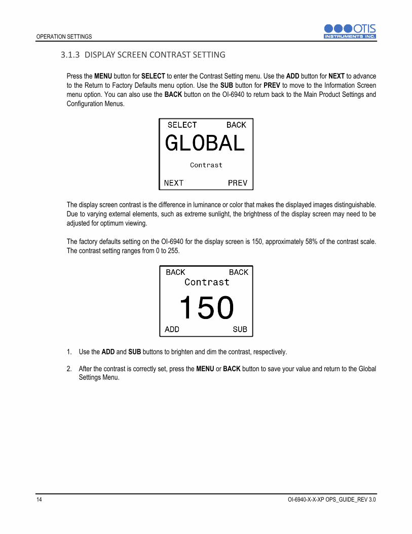
3.1.3 DISPLAY SCREEN CONTRAST SETTING
Press the MENU button for SELECT to enter the Contrast Setting menu. Use the ADD button for NEXT to advance
to the Return to Factory Defaults menu option. Use the SUB button for PREV to move to the Information Screen
menu option. You can also use the BACK button on the OI-6940 to return back to the Main Product Settings and
Configuration Menus.
The display screen contrast is the difference in luminance or color that makes the displayed images distinguishable.
Due to varying external elements, such as extreme sunlight, the brightness of the display screen may need to be
adjusted for optimum viewing.
The factory defaults setting on the OI-6940 for the display screen is 150, approximately 58% of the contrast scale.
The contrast setting ranges from 0 to 255.
1. Use the ADD and SUB buttons to brighten and dim the contrast, respectively.
2. After the contrast is correctly set, press the MENU or BACK button to save your value and return to the Global Settings Menu.

OPERATION SETTINGS
OI-6940-X-X-XP OPS_GUIDE_REV 3.0 15
3.1.4 RETURN TO FACTORY DEFAULT SETTINGS
Press the MENU button for SELECT to enter the Return to Factory Defaults menu. Use the ADD button for NEXT to
advance to the Back menu option. Use the SUB button for PREV to move to the Screen Contrast menu option. You
can also use the BACK button on the OI-6940 to return back to the Main Product Settings and Configuration Menus.
OI-6940 Factory Default Settings
Configuration Setting
Network I.D. 5
Sensor 1-4 On/Off All On
Sensor 1-4 Null All Cleared
Sensor 1-4 Cal All Cleared
Sensor 1-4 Radio Address 1, 2, 3, 4
Sensor 1-4 Background All 4% of scale1
Sensor 1-4 Cal Method All Manual2
1. Press the ADD button for YES to advance to the Return to Factory Default Settings confirmation screen. If you do not wish to return the device to its factory default settings, press the SUB button for NO to leave the factory default settings menu and to return to the Global Settings menu. The MENU and BACK buttons will also both return you to the Global Settings Menu.
NOTICE
1. When an oxygen sensor is being used there will be two background set-points, Background High and Background Low, the default set-points are 22 and 19 respectively.
2. The IR sensor can only be set for Auto-Cal so this setting will not be set to Manual Cal for the corresponding IR sensor

OPERATION SETTINGS
16 OI-6940-X-X-XP OPS_GUIDE_REV 3.0
If YES is selected to return the device to its factory default settings:
1. Press the ADD button for YES to confirm that you want to reset the device to its factory default settings. If you do not wish to return the device to its factory default settings, press the SUB button for NO to leave the factory default settings menu and to return to the Global Settings menu. The MENU and BACK buttons will also both return you to the Global Settings Menu.
2. If YES was selected the following screen will appear to signal completion of the OI-6940 return to factory defaults
process. The MENU or BACK button will return you to the Global Settings Menu.
NOTICE
If the OI-6940 is reset to the factory default settings, the configuration steps MUST be repeated and all sensor elements installed on the device MUST then be nulled and calibrated for proper operation.
3.1.5 BACK MENU
Press the MENU button for SELECT to exit the Global Settings menu and return back to the Main Product Settings
and Configuration Menus. Use the ADD button for NEXT to advance to the Network I.D. menu option. Use the SUB
button for PREV to move to the Return to Factory Defaults menu option. You can also use the BACK button on the
OI-6940 to return back to the Main Product Settings and Configuration Menus.

OPERATION SETTINGS
OI-6940-X-X-XP OPS_GUIDE_REV 3.0 17
3.2 SENSOR SETTINGS Use the MENU button for SELECT to enter the Sensor 1 Settings Menu, any settings under this menu option will only affect the first sensor element of the OI-6940. Use the ADD button for NEXT to advance to the Sensor 2 Settings menu. Use the SUB button for PREV to move to the Global Settings menu option. You can also use the BACK button on the OI-6940 to exit the Product Settings and Configuration Menus.
NOTICE
Sensor 1 Settings is the only sensor settings menu detailed in this manual, the sensor settings menu for Sensors 2, 3, and 4 follow the same menu layout as the Sensor 1 Settings menu.
3.2.1 TURN SENSOR ON/OFF Press the MENU button for SELECT to enter the Turn Sensor ON/OFF menu. Use the ADD button for NEXT to
advance to the Null Sensor menu option. Use the SUB button for PREV to move to the Back menu option. You can
also use the BACK button on the OI-6940 to return back to the Main Product Settings and Configuration Menus.
The OI-6940 is shipped from Otis with the sensors configured as below:
2 Gas OI-6940 – Sensors 1 and 2 turned ON, Sensors 3 and 4 turned OFF
3 Gas OI-6940 – Sensors 1, 2, and 3 turned ON, Sensor 4 turned OFF
4 Gas OI-6940 – Sensors 1, 2, 3, and 4 turned ON, No sensors turned OFF

OPERATION SETTINGS
18 OI-6940-X-X-XP OPS_GUIDE_REV 3.0
The sensor ON/OFF state should only need to be configured in the field if a Return to Factory Defaults occurs.
However, you can turn OFF a sensor if that gas type is not needed for a particular location or you are waiting on a
replacement sensor element.
1. Press the ADD button for ON to turn ON a sensor that was turned OFF. Press the SUB button for OFF to turn OFF a sensor that was turned ON. The MENU and BACK buttons will both return you to the Sensor Settings Menu.

OPERATION SETTINGS
OI-6940-X-X-XP OPS_GUIDE_REV 3.0 19
3.2.2 NULLING THE SENSOR (AUTO NULL) The first step of calibration is nulling the sensor, sometimes referred to as “setting the zero” or “zeroing the sensor.”
The nulling process MUST be performed in known clean air, with no contaminants or hazardous gasses present. If
air quality cannot be guaranteed, a bottle of zero air will be required to properly null the sensor.
Press the MENU button for SELECT to enter the Sensor Null menu. Use the ADD button for NEXT to advance to
the Sensor Calibration menu option. Use the SUB button for PREV to move to the Turn Sensor ON/OFF menu
option. You can also use the BACK button on the OI-6940 to return back to the Main Product Settings and
Configuration Menus.
After entering the Sensor Null menu the OI-6940 will ask if the sensor is in clean air.
1. Press the ADD button for YES to confirm that the sensor is in clean air and to begin nulling the sensor. If the sensor is not in clean air, press the SUB button for NO to discontinue the null process and return to the start of the Null process. The MENU and BACK buttons will also return you to the previous screen.
2. The unit will automatically begin the 12 second null process. During null, the display will show a countdown of the time remaining until the process is complete.

OPERATION SETTINGS
20 OI-6940-X-X-XP OPS_GUIDE_REV 3.0
3. When the null process is completed, press the MENU or BACK button to return to the Sensor Settings Menu.

OPERATION SETTINGS
OI-6940-X-X-XP OPS_GUIDE_REV 3.0 21
3.2.3 CALIBRATING THE SENSOR (MANUAL CAL)
Press the MENU button for SELECT to enter the Sensor Cal menu. Use the ADD button for NEXT to advance to the
Sensor Radio Address menu option. Use the SUB button for PREV to move to the Sensor Null menu option. You
can also use the BACK button on the OI-6940 to return back to the Main Product Settings and Configuration Menus.
You should ONLY perform the calibration of the sensor after the null process has been successfully completed.
For best results, use 50% of the sensor scale of your target gas in an air balance with a flow rate of 0.25 to 0.5
LPM. If the sensor calibration method is set to Autocal (found later in the Sensor Settings Menu), or the sensor
being calibrated is the infrared sensor, please use the instructions in section 3.2.4 to calibrate the sensor element.
1. Affix a Calibration Adapter Kit (sold separately) to the sensor housing being calibrated.
2. Affix a regulator to the calibration gas bottle.
3. Attach the tubing on the Calibration Adapter Kit to the regulator on the calibration gas bottle.
4. Ensure the gas is flowing and watch the reading increase. When the reading stabilizes, approximately 1 ½ to 2 minutes, use the ADD or SUB buttons to adjust the reading on the screen to match the applied calibration gas concentration.
NOTICE
If the sensor responds extremely slow, or does not respond to the applied gas, it may indicate a failed sensor element. The sensor element will need to be replaced before completing the null and calibration process.

OPERATION SETTINGS
22 OI-6940-X-X-XP OPS_GUIDE_REV 3.0
5. When calibration is complete, detach the Calibration Adapter Kit from the sensor housing and reaffix the sensor housing cap. Press the MENU or BACK button to return to the Sensor Settings Menu.

OPERATION SETTINGS
OI-6940-X-X-XP OPS_GUIDE_REV 3.0 23
3.2.4 CALIBRATING THE SENSOR (AUTO CAL)
If you calibrated the sensor manually this section may be skipped and you can continue to section 3.2.5.
Press the MENU button for SELECT to enter the Sensor Cal menu. Use the ADD button for NEXT to advance to the
Sensor Radio Address menu option. Use the SUB button for PREV to move to the Sensor Null menu option. You
can also use the BACK button on the OI-6940 to return back to the Main Product Settings and Configuration Menus.
You should ONLY perform the calibration of the sensor after the null process has been successfully completed.
For best results, use 50% of the sensor scale of your target gas in an air balance with a flow rate of 0.25 to 0.5
LPM. If the sensor calibration method is set to Manual (found later in the Sensor Settings Menu) please use the
instructions in section 3.2.3 to calibrate the sensor element.
1. Press the ADD button to select YES to begin the calibration process and advance to the calibration confirmation screen. If you do not wish to calibrate the sensor, press the SUB button to select NO and return to the Sensor Settings Menu. The MENU or BACK buttons will also return you to the Sensor Settings Menu.
2. Press the ADD button to select YES to confirm that you want to calibrate the sensor and to continue to the
concentration setting screen. If you do not wish to continue to calibrate the sensor, press the SUB button to select NO and return to the Sensor Settings Menu. The MENU and BACK buttons will also return you to the Sensor Settings Menu.

OPERATION SETTINGS
24 OI-6940-X-X-XP OPS_GUIDE_REV 3.0
3. Use the ADD and SUB buttons to adjust the concentration to the calibration gas being used. Press the MENU
button for NEXT to save the gas concentration and to advance to the calibration start screen.
4. Affix a Calibration Adapter Kit (sold separately) to the sensor housing being calibrated.
5. Affix a regulator to the calibration gas bottle.
6. Attach the tubing on the Calibration Adapter Kit to the regulator on the calibration gas bottle.
7. Ensure the gas is flowing and press the MENU button to begin calibrating the sensor, the unit will
automatically begin the calibration process, the amount of time on the timer will vary based on the gas type. During calibration, the display will show a countdown of the time remaining until the process is complete.
NOTICE
Once the calibration countdown has started, the process cannot be stopped without disconnecting the power sources. If the sensor responds extremely slow, or does not respond to the applied gas, it may indicate a failed sensor element. The sensor element will need to be replaced before completing the null and calibration process.

OPERATION SETTINGS
OI-6940-X-X-XP OPS_GUIDE_REV 3.0 25
8. When calibration is complete, detach the Calibration Adapter Kit from the sensor and reaffix the sensor housing cap.
9. The MENU or BACK buttons will return you to the Sensor Settings Menu.

OPERATION SETTINGS
26 OI-6940-X-X-XP OPS_GUIDE_REV 3.0
3.2.5 SENSOR RADIO ADDRESS
Press the MENU button for SELECT to enter the Sensor Radio Address menu. Use the ADD button for NEXT to
advance to the Sensor Relay Test menu option. Use the SUB button for PREV to move to the Calibrate Sensor
menu option. You can also use the BACK button on the OI-6940 to return back to the Main Product Settings and
Configuration Menus.
The OI-6940 sensor radio addresses are adjustable from 1 to 255. Each of the sensors that is turned on has its
own radio address and the address for each sensor must be set to a different value. Each of the OI-6940 sensor
assemblies must have unique addresses on the network in order to avoid a fault at the receiving monitor. The
default address for Sensor 1 is 1, Sensor 2 is 2, Sensor 3 is 3, and Sensor 4 is 4.
1. Press the ADD and SUB buttons to increase and decrease the sensor radio address respectively, the OI-6940 will skip past radio addresses that are in use by the other OI-6940 sensor assemblies.
2. The MENU or BACK buttons will save your selection and return you to the Sensor Settings Menu.

OPERATION SETTINGS
OI-6940-X-X-XP OPS_GUIDE_REV 3.0 27
3.2.6 SENSOR RELAY TEST
Press the MENU button for SELECT to enter the Sensor Relay Test menu. Use the ADD button for NEXT to advance
to the Sensor Background Setting menu option. Use the SUB button for PREV to move to the Sensor Radio Address
menu option. You can also use the BACK button on the OI-6940 to return back to the Main Product Settings and
Configuration Menus.
The relay test simulates a gas level reading, indicating the presence of toxic gas at the sensor. The relay test is used
to ensure the proper functionality of the relay settings on the receiving monitor. The test can also be used to simulate
emergency/safety drills onsite. It is recommended that a relay test be conducted EVERY 30 days, alongside the
maintenance and calibration of the detector. The relay test gas level reading can be increased or decreased in
increments of 5% of the sensor scale, up to 100% of the sensor scale.
NOTICE
The relay test only simulates a reading for the sensor being modified, it will not simulate a reading on the other sensor assemblies installed on the OI-6940. The triggering of relays from the detector will also simulate low and high level alarm relays at the monitor. Monitors cannot distinguish between real and simulated data received. When the monitor relays are triggered, alarming devices will perform as intended, initiating emergency procedures as if a harmful toxic gas was actually present. To prevent this from occurring, set the monitor to calibration mode before performing the relay test. Calibration mode of the monitor will allow the transmission of the data, without the activation of the monitor relays.
1. Press the ADD button until the low and high alarm levels are reached and the relay(s) are triggered to light all visual alarm(s) and sound all audio alarm(s) on the monitor. Once all relays have been tested and the test is complete, press the SUB button to return the relay test reading back to zero and to deactivate the monitor alarm(s).
2. The MENU or BACK buttons will return you to the Sensor Settings Menu.

OPERATION SETTINGS
28 OI-6940-X-X-XP OPS_GUIDE_REV 3.0
3.2.7 SENSOR BACKGROUND SETTING
Press the MENU button for SELECT to enter the Sensor Background Setting menu. Use the ADD button for NEXT
to advance to the Calibration Method Setting menu option. Use the SUB button for PREV to move to the Sensor
Relay Test menu option. You can also use the BACK button on the OI-6940 to return back to the Main Product
Settings and Configuration Menus.
If an oxygen sensor is installed, and is the sensor being configured, please skip to section 3.2.8 and 3.2.9 for an
explanation of the background menus that are present.
The background setting is the gas reading at which the radio transmission changes from once every minute to once
every five seconds. The background setting is adjustable so that if there is a consistent level of gas always present
the sensor will not increase the radio transmission rate, this leads to longer battery life on sites where a consistent
low level of gas is always present in the background. On the OI-6940 when any sensor element rises above the
background level setting all sensor elements will transmit every five seconds, regardless of if they are above or below
their background gas level setting.
The default background level is 4% of the sensor element scale. The minimum the background can be set to is 1% of the sensor element scale. The maximum the background can be set to is 10% of the sensor element scale.
1. Press the ADD or SUB button until the background is set to the desired level.
2. The MENU or BACK buttons will both save your setting and return you to the Sensor Settings Menu.

OPERATION SETTINGS
OI-6940-X-X-XP OPS_GUIDE_REV 3.0 29
3.2.8 SENSOR BACKGROUND HIGH SETTING
Press the MENU button for SELECT to enter the Sensor Background High Setting menu. Use the ADD button for
NEXT to advance to the Background Low Setting menu option. Use the SUB button for PREV to move to the Sensor
Relay Test menu option. You can also use the BACK button on the OI-6940 to return back to the Main Product
Settings and Configuration Menus.
If a non-oxygen sensor is installed, and is the sensor being configured, please reference section 3.2.7 for an
explanation of the background menu and its operation.
The background high setting is the Oxygen reading at which the radio transmission changes from once every minute
to once every five seconds. The background high setting is adjustable so that if the level of Oxygen present is above
standard atmospheric Oxygen levels the sensor will not increase the radio transmission rate, this leads to longer
battery life on sites where a consistent high level of Oxygen is always present. On the OI-6940 when any sensor
element rises above the background level setting all sensor elements will transmit every five seconds, regardless of
if they are above or below their background gas level setting.
The default background high level is 22% O2. The minimum the background high can be set to is 19% O2. The maximum the background high can be set to is 24% O2.
1. Press the ADD or SUB button until the background high is set to the desired level.
2. The MENU or BACK buttons will both save your setting and return you to the Sensor Settings Menu.

OPERATION SETTINGS
30 OI-6940-X-X-XP OPS_GUIDE_REV 3.0
3.2.9 SENSOR BACKGROUND LOW SETTING
Press the MENU button for SELECT to enter the Sensor Background Low Setting menu. Use the ADD button for
NEXT to advance to the Calibration Method menu option. Use the SUB button for PREV to move to the Sensor
Background High Setting menu option. You can also use the BACK button on the OI-6940 to return back to the Main
Product Settings and Configuration Menus.
If a non-oxygen sensor is installed, and is the sensor being configured, please reference section 3.2.7 for an
explanation of the background menu and its operation.
The background low setting is the Oxygen reading at which the radio transmission changes from once every minute
to once every five seconds. The background low setting is adjustable so that if the level of Oxygen present is below
standard atmospheric Oxygen levels the sensor will not increase the radio transmission rate, this leads to longer
battery life on sites where a consistent low level of Oxygen is always present. On the OI-6940 when any sensor
element rises above the background level setting all sensor elements will transmit every five seconds, regardless of
if they are above or below their background gas level setting.
The default background low level is 19% O2. The minimum the background low can be set to is 17% O2. The maximum the background low can be set to is 22% O2.
1. Press the ADD or SUB button until the background low is set to the desired level.
2. The MENU or BACK buttons will both save your setting and return you to the Sensor Settings Menu.

OPERATION SETTINGS
OI-6940-X-X-XP OPS_GUIDE_REV 3.0 31
3.2.10 CALIBRATION METHOD
Press the MENU button for SELECT to enter the Calibration Method Setting menu. Use the ADD button for NEXT
to advance to the Sensor Information menu option. Use the SUB button for PREV to move to the Sensor Background
Setting menu option. You can also use the BACK button on the OI-6940 to return back to the Main Product Settings
and Configuration Menus.
The calibration method selection allows you to choose how you calibrate the sensor element. Manual calibration is
the default method for all gas types, except for LEL and CO2 where Auto Calibration is the only option and this menu
screen will not appear.
Manual calibration lets you use the ADD and SUB buttons during calibration to match the reading shown on the screen to the value of the gas being applied.
Auto calibration will set the reading, after a preset amount of time, to the value entered during the auto calibration setup process.
1. Press the ADD or SUB button to cycle the selection between manual calibration and auto calibration.
2. The MENU or BACK buttons will both save your setting and return you to the Sensor Settings Menu.

OPERATION SETTINGS
32 OI-6940-X-X-XP OPS_GUIDE_REV 3.0
3.2.11 SENSOR INFORMATION
Press the MENU button for SELECT to enter the Sensor Information menu. Use the ADD button for NEXT to advance
to the Last Null & Cal Times menu option. Use the SUB button for PREV to move to the Calibration Method Setting
menu option. You can also use the BACK button on the OI-6940 to return back to the Main Product Settings and
Configuration Menus.
The sensor information screen allows the end-user to view the following information about the sensor element being
configured:
The connection status to the Primary Otis Monitor. The scale of the sensor element. The battery voltage to the OI-6940. The voltage value the sensor was reading when nulled in Volts. The current voltage value the sensor is reading in Volts.
This screen is for information purposes only, press the MENU or BACK button to return to the Sensor Settings Menu.

OPERATION SETTINGS
OI-6940-X-X-XP OPS_GUIDE_REV 3.0 33
3.2.12 NULL-CALIBRATION TIMER INFORMATION
Press the MENU button for SELECT to enter the Last Time Null & Cal Times menu. Use the ADD button for NEXT
to advance to the Reset Sensor Null/Cal menu option. Use the SUB button for PREV to move to the Sensor
Information menu option. You can also use the BACK button on the OI-6940 to return back to the Main Product
Settings and Configuration Menus.
The null/calibration timer information screen allows the end-user to view the following information about the sensor
element being configured:
The days since the sensor assembly being configured was last nulled, only updates while the OI-6940 is turned on.
The days since the sensor assembly being configured was last calibrated, only updates while the OI-6940 is turned on.
This screen is for information purposes only, press the MENU or BACK button to return to the Sensor Settings Menu.

OPERATION SETTINGS
34 OI-6940-X-X-XP OPS_GUIDE_REV 3.0
3.2.13 RESET SENSOR NULL/CAL
Press the MENU button for SELECT to enter the Reset Sensor Null/Cal menu. Use the ADD button for NEXT to
advance to the Back menu option. Use the SUB button for PREV to move to the Last Null & Cal Times menu option.
You can also use the BACK button on the OI-6940 to return back to the Main Product Settings and Configuration
Menus.
The Reset Null/Cal to Default menu allows you to reset the Null and Calibration information for a single sensor
assembly without resetting the whole OI-6940 to factory defaults. This is useful when a sensor element is being
replaced and not wanting to redo the null and calibration process on all sensor elements in the OI-6940.
1. Press the ADD button for YES to advance to the Return Null/Cal to Default confirmation screen. If you do not wish to return the sensor null/cal to its default settings, press the SUB button for NO and return to the Sensor Settings menu. The MENU and BACK buttons will also both return you to the Sensor Settings Menu.
If YES is selected to return the device to its factory default settings:
2. Press the ADD button for YES to confirm that you want to reset the sensor null/cal to its default settings. If you do not wish to return the device to its factory default settings, press the SUB button for NO to leave the Sensor Settings menu. The MENU and BACK buttons will also both return you to the Global Settings Menu.

OPERATION SETTINGS
OI-6940-X-X-XP OPS_GUIDE_REV 3.0 35
3. If YES was selected the following screen will appear to signal completion of the sensor returning the null and calibration to their defaults. The MENU or BACK button will return you to the Sensor Settings Menu.
NOTICE
If the sensor element null and calibration are reset to default you MUST then perform the Null and Calibration Processes as outlined in this manual for proper operation of the OI-6940.
3.2.14 BACK MENU
Press the MENU button for SELECT to exit the Sensor Settings menu and return back to the Main Product Settings
and Configuration Menus. Use the ADD button for NEXT to advance to the Turn Sensor On/Off menu option. Use
the SUB button for PREV to move to the Return Null/Cal to Defaults menu option. You can also use the BACK button
on the OI-6940 to return back to the Main Product Settings and Configuration Menus.

OPERATION SETTINGS
36 OI-6940-X-X-XP OPS_GUIDE_REV 3.0
4 OPERATION SETTINGS
At the time of installation, when the power is first applied to the OI-6940, the unit is automatically powered on and begins the startup sequence. During the 1 minute warmup, 3 ½ minutes with Low Power Infrared sensor installed, the display will show a countdown of the time remaining until the system start-up is complete. The Otis logo and the unit information will also flash on the display screen and, at the end of the countdown, the device will be in normal operating mode.
4.1 POWERING THE DEVICE
4.1.1 POWERING ON
Powering on the device begins the operation of the unit, automatically initiating the system start-up cycle and warmup period. The OI-6940 will be in normal operating mode at the completion of the system start-up countdown.
1. Press the ADD button once to power the unit.
The display screen will continue to show “OFF” for the duration of time that the unit is powered off, as long as long as uninterrupted power is supplied to the unit.
4.1.2 POWERING OFF
Powering off the device stops the operation of the unit. The product settings and configuration, as well as the null and calibration of the sensor will be unaffected.
1. Press and Hold the SUB button for approximately 6 seconds, until OFF shows on the display screen.
The display screen will continue to show OFF for the duration of time that the unit is powered off, as long as the power source, and backup battery, remain connected.

OPERATION SETTINGS
OI-6940-X-X-XP OPS_GUIDE_REV 3.0 37
4.2 DISPLAY BEHAVIOR ABOVE BACKGROUND
When any sensor is above its configured background gas level the display screen will change to show the readings
one sensor assembly at a time. The OI-6940 will scroll among all configured sensor assemblies showing the detected
gas level in a larger font.

PRODUCT MAINTENANCE
38 OI-6940-X-X-XP OPS_GUIDE_REV 3.0
5 PRODUCT MAINTENANCE 5.1 SCHEDULED MAINTENANCE
Otis recommends that our equipment be calibrated a MINIMUM of every 90 days, and STRONGLY advise that
calibration be performed every 30 days. Without knowing the specific application, sensor assembly location, gas
exposure and other factors, the company recommends monthly calibrations – assuming no damage or potential
damage has occurred to the assembly and that there has not been a power outage. If damage has occurred or the
power supplied has changed, a calibration should be completed immediately.
Scheduled maintenance should include the null and calibration of the sensor elements and a relay test. Consult the
Sensor Calibration and Relay Test sections of this manual for further information and instructions on how to perform
these procedures.
The sensor heads should be kept free of airborne particles, dirt, mud, spider webs, bug and insects and/or any
other debris that could potentially cover or coat the sensor. Keeping the sensor heads clear of foreign articles will
allow for proper operation of the device. A brief inspection during scheduled maintenance should suffice, but
dependent upon the location and the environment in which the unit is installed, more frequent inspections may be
warranted.
The OI-6940 may be adversely affected by exposure to certain airborne substances. Loss of sensitivity or corrosion
may be gradual, if such materials are present in sufficient concentrations. The performance of the device may be
impaired during operation in the presence of substances that can cause corrosion on gold plating. Continuous and
high concentrations of corrosive gases may also have a detrimental long-term effect on the product’s service life.
The presence of such substances in an area does not preclude the use of this device, but the likelihood of the
shortened lifetime of the sensor element, as a result, should be noted. Use of the OI-6940 in these environments
may require more frequently scheduled maintenance to ensure safe and reliable system performance.

PRODUCT MAINTENANCE
OI-6940-X-X-XP OPS_GUIDE_REV 3.0 39
5.2 SENSOR REPLACEMENT
The sensor elements used in the OI-6940 detect gas in either % or PPM concentrations, the elements must be fully
functional in order for the system to operate correctly. Otis recommends replacing the sensing element whenever
a slow response to gas is observed during the normal calibration process. After replacing the sensing element the
device MUST then be nulled and calibrated for proper operation of the device.
CAUTION
The internal components can be static sensitive. Use caution when opening the enclosure and handling
internal components.
DO NOT use any metal objects or tool to remove the sensing element from the sensor housing.
1. Press and Hold the SUB button for approximately 6 seconds, until OFF shows on the display screen.
2. Unscrew and remove the sensor housing cap from the sensor housing base. Set aside.
3. Using the thumb and forefinger, gently unplug the sensing element from the sensor housing.
4. Plug in the new sensing element into the sensor housing. Ensure the pins on the sensing element align with the sockets in the sensor housing.
NOTICE
Some electrochemical sensing elements are shipped with a shorting spring between two of the pins, this shorting spring MUST be removed before installing the sensing element.
5. Screw the sensor housing cap back onto the sensor housing base, ensuring the sensor housing cap is only tightened hand tight

PRODUCT MAINTENANCE
40 OI-6940-X-X-XP OPS_GUIDE_REV 3.0
5.3 BATTERY REPLACEMENT The battery in the OI-6940 will operate for up to 6 months with normal usage. The presence of gas will increase the
radio transmission rate and decrease the battery lifetime. It is recommended that the battery pack be replaced when
the voltage reported is 3 Volts or less. To determine the battery voltage you can reference the Product Information
section of this manual. When the battery pack has been replaced, Otis STRONGLY suggests that the sensor
assemblies be nulled and calibrated for proper operation of the OI-6940.
CAUTION
The internal components can be static sensitive. Use caution when opening the enclosure and handling
internal components.
DO NOT use any metal objects or tool to remove any parts from the internal system.
1. Press and Hold the SUB button for approximately 6 seconds, until OFF shows on the display screen.
2. Remove the enclosure lid, unscrewing it from the device enclosure. Set aside.
3. Gripping the front panel handles, lift the internal system out of the enclosure and rest it against the rim of the enclosure opening.
4. Locate the battery terminal located on the terminal board assembly. Squeeze the locking tab on the battery
cable and gently pull it straight out of the battery connector.
5. Unscrew the captive thumbscrews securing the battery bracket into place.
6. Remove the old battery pack.
7. Install the new battery pack in the same orientation as the old battery pack and secure with the battery bracket.
8. Plug the battery cable connector into the battery terminal on the terminal board assembly.
9. Place the internal system back into the device enclosure, matching each mounting post to its corresponding eyelet anchored within the base of the enclosure.
10. Using the handles, gently push to seat the internal system into the mounting posts.
11. Verify that the O-ring on the enclosure lid is undamaged and correctly seated in place.
12. Affix the enclosure lid back onto the device, rotating the lid until it is tightly screwed into place. The unit will automatically being its startup sequence once the new battery pack is installed.
Locking Tab

PRODUCT MAINTENANCE
OI-6940-X-X-XP OPS_GUIDE_REV 3.0 41
5.4 PRODUCT FAULT CODES
OI-6940 Fault Codes
Problem Cause(s) Solution(s)
F4
Check
Sensor
Board
The control board has lost communication with the
sensor element or sensor housing.
1. Replace the sensor element.
2. Replace the sensor housing.
F5
Try to
Null
Again
The unit did not null correctly, due to:
• The presence of gas,
• A sensor error, or
• an analog sensor board error.
1. Re-null the device in clear air.
2. Replace the sensor element.
3. Replace the sensor housing.
F6
Try to
Calibrate
Again
The unit did not calibrate correctly, due to:
• The absence of gas,
• A sensor error, or
• an analog sensor board error.
1. Recalibrate the sensor element and verify
that gas is present during calibration.
2. Replace the sensor element.
3. Replace the sensor housing.
F14
Check
Radio
The sensor assembly has lost communication with
the Primary Monitor potentially due to:
• Network ID is incorrectly configured
• Sensor assembly is obstructed/too far from the
primary monitor
• Radio module is not working in the sensor
assembly
1. Check that the Network ID of the sensor
assembly matches the Network ID of the
Primary Monitor
2. Move the sensor assembly away from the
obstructions or use a high gain antenna
3. Replace the sensor radio module
When replacing the sensor element, the detector must be nulled and calibrated. System faults will activate the fault terminal at the receiving monitor.

PRODUCT MAINTENANCE
42 OI-6940-X-X-XP OPS_GUIDE_REV 3.0
5.5 PRODUCT REPLACEMENT PARTS AND ACCESORIES
While not all of the components on the OI-6940 can be field-replaced, there are several parts that are replaceable by an Otis Approved Service Technician.
To purchase accessories/replacement parts for your device, contact the sales representative of this product for assistance.
OI-6940 Product Replacement Parts and Accessories
External Replacement Parts
Part Name Otis Part Number
Main Enclosure with Lid OI-4100
Sensor Housing Base OI-2005-DSB-6900
Sensor Housing Cap with Flame Arrestor OI-2000-CAP-ASSY
Enclosure Lid OI-4100-LID
Sensor Rain Guard OI-500-B
Female N-type Antenna Fitting OI-AF-RXN
900 MHz Antenna OI-AN-900-FLEX-S
2.4 GHz Antenna OI-AN-2.4.RIGID-S
Internal Replacement Parts
Part Name Otis Part Number
Control Board with LCD Screen OI-6940-CB-PCA
Terminal Board OI-6940-BB-PCA
OI-6940 NXP Faceplate with Label, Handles and Screen Foam OI-6940-FP-KIT
3.6V/76AH Non-Rechargeable Battery Pack OI-6940-BATT
GEN II 900 MHz Radio Module OI-RADIO-900-LAIRD
GEN II 2.4 GHz Radio Module OI-RADIO-2.4-TH
Electrochemical Analog Sensor Board *Specify Gas Type When Ordering
OI-2015-SB-NEC*
Oxygen Analog Sensor Board OI-2016-SB-O2
Low Power IR Sensor Adapter Board OI-2017-SB-LPIR
Product Accessories
Part Name Otis Part Number
Otis Magnetic Tool OI-420-6
Calibration Cup Kit OI-410
Filter for Dusty/Wet Environments OI-2000-CAP-FILTER
Replacement Sensor Housing Cap O-Ring OI-2000-ORING
Replacement Main Enclosure O-Ring OI-4100-O

APPENDICES
OI-6940-X-X-XP OPS_GUIDE_REV 3.0 43
APPENDICES APPENDIX A: OTIS INSTRUMENTS PRODUCT WARRANTY STATEMENT APPENDIX B: INFORMATION ABOUT RMA SERVICE REPAIRS APPENDIX C: INFORMATION ABOUT RMA RETURNS FOR CREDIT

APPENDICES
44 OI-6940-X-X-XP OPS_GUIDE_REV 3.0
APPENDIX A: PRODUCT WARRANTY STATEMENT Warranty Coverage Otis Instruments, Inc., 301 S. Texas Avenue, Bryan, Texas, 77803 (“Otis”) warrants the manufacture of all Otis hardware, firmware, software, components, and product accessories (“Otis Products”), contained in the original packaging, against defects in materials and workmanship when used normally in accordance with Otis’ published guidelines for a period of ONE (1) YEAR from the date of original purchase by the end-user/purchaser from the manufacturer or from the product’s authorized sellers/distributors (“Warranty Period”). Otis’ published guidelines include but are not limited to information contained in technical specifications, operation/user manuals and service communications. Warranty Exclusions This Warranty does not apply to any non-Otis manufactured products, even if packaged or sold with Otis Products. Otis does not warrant that the operation of their manufactured products be uninterrupted or error-free. Otis is not responsible for damage arising from failure to follow instructions relating to the Otis Product’s use. This Warranty does not apply to: (a) batteries; (b) protective coatings that are designed to diminish over time, unless failure has occurred due to a defect in materials or workmanship; (c) cosmetic damage, including scratches, dents and chipping of paint; (d) damage, caused by use with another product accident, abuse, misuse, or any external cause of force majeure; (e) damage, caused by operations outside of Otis’ published guidelines; (f) damage, caused by service performed by anyone who is not a representative of Otis or who is not an Otis authorized service provider; (g) damage, caused by product modifications, alterations of functionality or capability; (h) defects, caused by normal wear and tear or otherwise due to the normal aging of the Otis product, or (i) any product in which a product-labeled serial number has been removed, defaced, or altered in any way. If examination and assessment discloses that the alleged defect in the product does not exist, or was caused by the end-user/ purchaser (or any third-party) misuse, neglect, improper wiring or installation, testing or calibrations, the Otis Product Warranty will be null and void. Any unauthorized attempts of repair, modification, or any other cause of damage beyond the range of the Otis Product’s intended use, including force majeure, voids all liability of the manufacturer. Replaceable Batteries and Sensor Elements All batteries supplied to the end-user/purchaser by Otis are covered, from the date of shipment, for ninety (90) days, unless otherwise excluded and noted†. Sensor elements supplied to the end-user/purchaser by Otis have individual Warranty information, regarding Product Lifetime and Warranty. For more information on sensor element Warranties, refer to the Otis published guidelines. End-User Responsibilities End-user/purchaser should perform periodic null and calibration procedures, recommended every thirty (30) days, not to exceed ninety (90) days, for optimal performance, proper maintenance, and as a precaution against possible operational failures. Before the end-user/purchaser receives the initial Warranty service, Otis may require the end-user to furnish proof of purchase details, respond to questions designed to assist with diagnostics, and follow Otis procedures for obtaining Warranty service. For Otis Products that feature data logging and data storage, the end-user/purchaser should generate a separate backup copy of the information contained on the device, before submitting the Otis Product for Warranty service. Otis Warranty service is not responsible for any loss of data or settings stored on the device while under service/repair.

APPENDICES
OI-6940-X-X-XP OPS_GUIDE_REV 3.0 45
Otis Products submitted to Warranty service must be returned in their complete assembly, as originally shipped from the manufacturer. Warranty service will not service/repair Otis Products that are not in their original condition. For Otis Gas Detection Products, also referred to as Sensor Assemblies, the end-user/purchaser must remove external antenna(s), rain guard(s), and all batteries before shipping. Otis Products submitted to Warranty service will be returned, as originally configured, with the factory default settings, upon completion of the service/repair. Otis is not responsible for maintaining end-user/purchaser settings, resetting the null, recalibration, or any other preparations for reinstallation and/or reintegration of the device. Warranty Service Please refer to the Otis published guidelines and/or the Otis website before seeking Warranty service. If the Otis Product continues to malfunction/error after consulting these resources, please contact the product’s authorized seller/distributor or consult the Otis RMA/Service webpage at www.otisinstruments.com/service for information and instructions on submitting the Otis Product for Warranty service. Otis Warranty service, at their discretion, will (a) repair the device using new or previously used parts that are equivalent to new in performance and reliability, (b) replace the Otis Product with a device that is at least functionally equivalent to the Otis product and is formed from new and/or previously used parts that are equivalent to new in performance and reliability, or (c) exchange the Otis Product for a refund of your purchase price, when an Otis Product is submitted. Otis Warranty service will treat service/repairs as quick-turn exchanges. Otis Warranty service does not replace any board level components, (i.e. magnetic switches, resistors, capacitors, relays, etc.). Otis Products may require the replacement of certain user-installable parts or Otis Products. A replacement part or Otis Product, including a user-installable part that has been installed in accordance with instructions provided by Otis, assumes the remaining term of the Warranty, or ninety (90) days from the date of replacement or repair, whichever provides the longer coverage for the end-user/purchaser. When an Otis product or part is replaced, or a refund is provided, any replacement item becomes your property and the replaced or refunded item becomes Otis’ property. For Otis Products requiring Warranty service that are located outside of the United States, the customer is responsible for compliance of all import/export laws and regulations/requirements, including associated taxes and other charges. Where applicable, Otis Warranty service may repair/replace products with parts that comply with local/regional standards. Otis Products covered under Warranty will receive service/repairs at no charge to the end-user/purchaser. Otis Products not under Warranty will be diagnosed for service/repair and the end-user/purchaser will be notified of the recommended service/repairs and applicable charges. The completion of the service/repairs, or the return of the unrepaired product, is at the discretion of the end-user/purchaser. Charges assessed for service/repair on Otis Products not under Warranty are at a rate of list cost minus dealer/distributor percent discount. Upon completion of Warranty service, Otis Warranty service will return the device to the end-user/purchaser. Please consult the Otis website for more information concerning shipping costs for Warranty service. Otis reserves the right to change the method by which Otis Warranty service is provided. Otis also reserves the right to change the Otis Product’s eligibility to receive a particular method of service. Warranty service may be limited for Otis Products in the country where the manufacturer or product’s authorized sellers/distributors originally sold the product. Warranty service options, parts availability and response times may vary. (†) Battery for the GEN II Model OI-6940 “The Quad” WireFree Explosion-Proof Battery-Powered Multi-Gas Detector is excluded from the ninety (90) day warranty policy.

APPENDICES
46 OI-6940-X-X-XP OPS_GUIDE_REV 3.0
APPENDIX B: INFORMATION ABOUT RMA SERVICE REPAIRS Otis Instruments, Inc. offers technical support to our customers. Please contact the Otis Instruments RMA Service Department for technical support, repair requests, warranty inquiries, end-user commission reports, dealer/distributor support, and Modbus setup inquiries and services. This appendix is for information purposes only. Please visit our website at www.otisinstruments.com/RMA to obtain the latest version of the Otis Instruments, Inc. Return Material Authorization (RMA) Service Repair Form and shipment instructions.
IMPORTANT INFORMATION All RMA Service repairs must be shipped to OTIS Instruments / Repairs, 301 South Texas Ave., Bryan, Texas 77803. To ensure that RMA Service repairs are processed as timely as possible, the Otis Instruments, Inc. Return Material Authorization (RMA) Service Repair Form must be completed in its entirety and included within the box at the time of shipment. Customer contact information and product information, including model number, serial number, and specific reason(s) for service, will need to be accessible in order to complete the form. Shipments received that do not include the form, or if the form is incomplete, will be returned (unrepaired) COD to the customer. Products/parts must be shipped in the proper packaging and the shipping materials must adhere to ESD safety precautions, as applicable. The entire assembly, as originally shipped from the manufacturer, must be returned for repair. When shipping sensor assemblies (gas detectors), the antenna, rain guard, and battery must be removed prior to shipment. Failure to adhere to these instructions will result in the products/parts being returned to sender. Once the RMA Service Repair Form is received by the Otis Instruments RMA Service Department, a RMA Service number will be generated. The RMA Service number will be sent to the email address provided for verification of receipt. RMA Service quotes have a thirty (30) day expiration. Quotes that do not receive a purchase order response within thirty (30) days of the quote will be canceled and all products/parts will be returned (unrepaired) COD to the customer. Discontinued products may not be returned for RMA Service for repair. For a listing of the Otis Instruments, Inc. discontinued products, please visit our website at www.otisinstruments.com/RMA. If your product/part has been discontinued, please contact your local sales representative for replacement options. All RMA Service repairs are treated as quick-return exchanges. Otis Instruments, Inc. does not replace board level components (i.e. magnetic switches, resistors, capacitors, relays, etc.). There is no charge for RMA Service repairs that are within the specified warranty period. For a copy of the Otis Instruments, Inc. Product Warranty Statement, please visit our website at www.otisinstruments.com/official_statements. Products/parts that are not within the specified warranty period will result in a charge to the customer for service. Products/parts that fall within the Otis Instruments, Inc. operating specifications deemed defective due to customer misapplication will be returned as is, and may result in a per unit evaluation fee to the customer. Otis Instruments, Inc. reserves the right to return customer-damaged or no-fault found products/parts from the Otis Instruments RMA Service Department COD to the customer. If advanced replacement is required, please contact the Service Department for more information.

APPENDICES
OI-6940-X-X-XP OPS_GUIDE_REV 3.0 47
INTERNATIONAL RMA SERVICE REPAIRS The customer is responsible for complying with all import/export requirements for shipment of RMA/Service repairs to Otis Instruments, Inc.
OTIS INSTRUMENTS RMA SERVICE DEPARTMENT Otis Instruments / Repairs 301 South Texas Ave. Bryan, Texas 77803 Office: 979.776.7700 Fax: 979.776.7719 [email protected] www.otisinstruments.com/RMA

APPENDICES
48 OI-6940-X-X-XP OPS_GUIDE_REV 3.0
APPENDIX C: INFORMATION ABOUT RMA RETURNS FOR CREDIT Without exception, all RMA Returns for Credit to Otis Instruments, Inc. must receive prior approval before shipment. Otis Products received that do not have prior approval will be returned (uncredited) COD to the customer. For inquiries and approval for RMA Returns for Credit, please contact your local sales representative. This appendix is for information purposes only. Please visit our website at www.otisinstruments.com/RMA to obtain the latest version of the Otis Instruments, Inc. Return Material Authorization (RMA) Return for Credit Form and shipment instructions.
IMPORTANT INFORMATION All RMA Returns for Credit must be shipped to OTIS Instruments / RMA Returns, 301 S. Texas Avenue, Bryan, Texas 77803. Product/part returns must be in their original condition and packaging, as shipped from the manufacturer. Returns that do not meet these specifications will be rejected for return for credit. Otis Instruments, Inc. reserves the right to return products/parts deemed to be inadequate (uncredited) COD to the customer. To ensure that Returns for Credit are processed as timely as possible, the RMA Return for Credit Form must be completed in its entirety and included within the box at the time of shipment. Customer contact information and product information, including model number, serial number, and specific reason(s) for service, will need to be accessible in order to complete the form. Shipments received that do not include the form (or if the form is incomplete) will be returned (uncredited) COD to the customer. Once the shipment is received by the Otis Instruments RMA Returns Department, a RMA number will be generated. The RMA number will be sent to the email address provided for verification of receipt. All RMA Returns for Credit will be processed for approval by the manufacturer. A restocking fee of 15% will be charged for all products/parts returned to the manufacturer. Discontinued products may not be returned for credit. For a listing of Otis Instruments, Inc. discontinued products, please visit our website at www.otisinstruments.com/RMA. If your product/part has been discontinued, please contact your local sales representative for replacement options.
INTERNATIONAL RMA SERVICE REPAIRS The customer is responsible for complying with all import/export requirements for shipment of RMA/Service repairs to Otis Instruments, Inc.
OTIS INSTRUMENTS RMA RETURNS DEPARTMENT Otis Instruments / RMA Returns 301 S. Texas Avenue Bryan, Texas 77803 Office: 979.776.7700 Fax: 979.776.7719 [email protected] www.otisinstruments.com/RMA


Otis Instruments
301 S. Texas Avenue, Bryan, Texas 77803
Tel: 979.776.7700 Fax: 979.776.7719
www.otisinstruments.com