numerical studies of two approaches for surge control in axial compressors
TRANSCRIPT
1
Numerical Studies of Two Approaches for Surge Control in Axial
Compressors
Vishwas Iyengar, Jimmy Tai, Saeid Niazi and Lakshmi N. Sankar
School of Aerospace Engineering
Georgia Institute of Technology, Atlanta, GA 30332-0150
Summary
Axial compression systems have a limited operation range at low-mass flow rates,
sometimes due to occurrence of rotating stall or modified surge. Active bleed control methods
have been developed to eliminate the stall/surge phenomena. While being quite effective, the
bleed control methods have some limitations. ‘Self-Recirculation’ treatment is one such concept
that has been proposed by researchers. The aim of this study is to numerically model these two
concepts on the Rotor 67 configuration and assess the relative advantages and drawbacks.
Preliminary results are presented for the performance map of the Rotor 67 configuration.
Results are also presented for surge control with the aid of active bleed control. Calculations are
in progress for the passive self-recirculation treatment concept.
Introduction
High-speed, high pressure ratio axial compression systems are widely used in many
aerodynamic applications. However they have a limited range of stable operations at low-mass
flow rates because of fluid dynamic instabilities. These instabilities cause deteriorations in
system operations due to the compressor reaching a state of rotating stall or surge. Rotating stall
is essentially a 2-D unsteady local phenomenon where the flow is no longer uniform, where as
surge is global 1-D instability that can affect the whole system. Modified surge, a combination of
rotating stall and surge can also occur in some instances. Throughout the aero-propulsion history,
2
much work has been done to broaden the compressor operating range by developing control
strategies to alleviate the rotating stall and surge.
In the last two decades considerable progress has made in understanding and modeling of
axial compressor stall and surge. With the growth in Computational Fluid Dynamics (CFD) as an
effective analysis technique, in CFD we have a resourceful tool which provides us a way to
simulate and understand the complex flow phenomena in turbomachinery. 3-D codes that are
capable of analyzing unsteady turbomachinery flow with single and multiple blade passages have
been developed by several researchers1-5. But these have been limited to modeling steady flow
phenomena in axial and centrifugal compressors, near or at design conditions. Active control
methodologies, which can alleviate the stall/surge phenomena, such as bleeding and air injection
can be studied extensively by CFD as long as an appropriate numerical model is available.
It is well known that the adverse flow conditions in tip clearance can cause the surge/stall
phenomena and reduce the pressure rise, flow range and efficiency of the turbomachinery.
Blockage development in a transonic axial compressor rotor was studied by Suder6 (1997) and
the impact of shock on blockage was investigated. The flow through the tip clearance region for
Rotor 37 was computed and compared to aerodynamic probe and laser anemometer data by
Chima7 (1996). The interaction of the tip vortex; the passage shock and the casing boundary
layer were described using the computation. End wall and casing treatments for Rotor 67 may be
found in Ref 8.
To model unsteady flow in air breathing vehicles the present authors have developed a 3-
D unsteady flow solver, GT-TURBO3D. Ref. 9 and 10 report results from the application of this
solver to a NASA low-speed centrifugal compressor. In Ref 11 (previously published by current
author) numerical simulation of rotating stall and surge alleviation in carried out for axial
3
compressor (Rotor 67). It was found that the use of bleed valves located on the diffuser walls can
eliminate the adverse phenomena of stall/surge and stable operation can be restored. Open-loop
and closed-loop case were examined, calculation show that both types of bleeding eliminate both
rotating stall and modified surge.
Scope of Present Work
Active Control approaches, while effective, have two drawbacks. Firstly, since the air is
being bleed, we have a loss of high pressure air which hinders the total pressure rise from the
compressor. And secondly there is still the need for an active controller and actuator. Passive
concepts which involve no (or very few) moving parts will be preferable. One such concept
called the “self-recirculation” was recently proposed by Hathaway13 (2002) and has already been
applied by him to the Rotor 67 configuration. The purpose of the present work is to
independently apply this concept to the Rotor 67 and Rotor 37 configurations, and to compare
this concept to the active bleeding that has already been studied for Rotor 67.
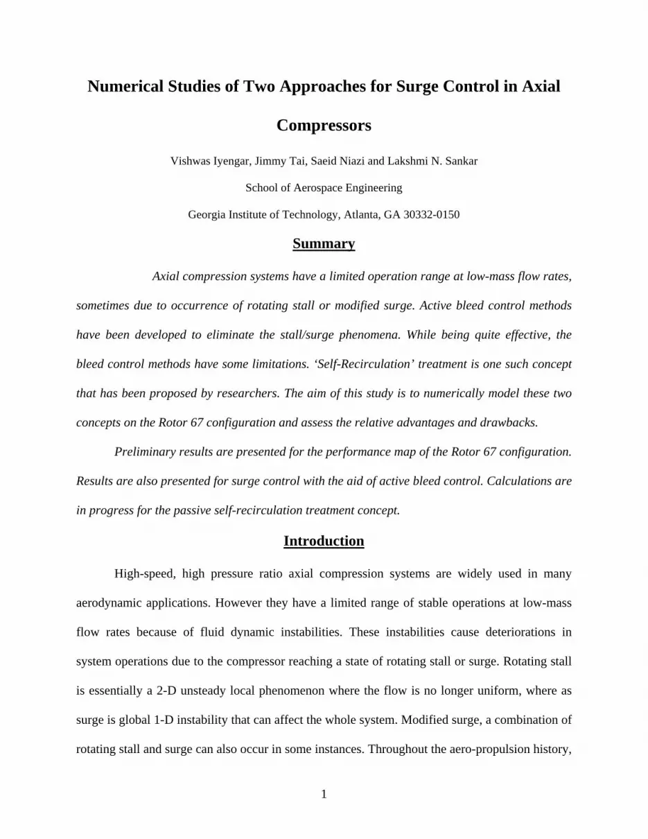
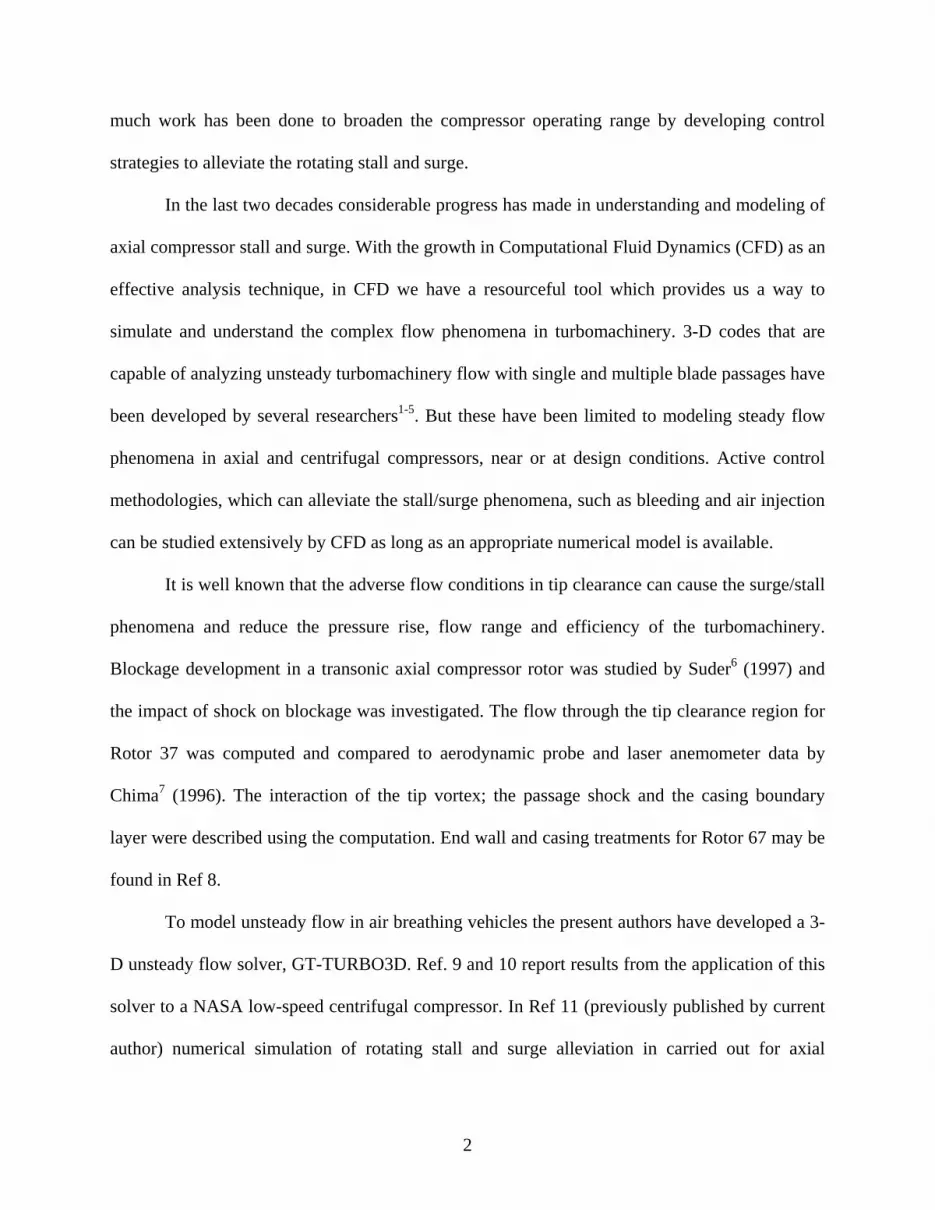
Configurations Being Studied
Figure 1: NASA Rotor 37 Configuration Figure 2: NASA Rotor 67 Configuration13
51.4 cm
4
Two standard configurations (Figure 1 and 2), named NASA Rotor 37 and NASA Rotor 67 are
being used in this study. These configurations were chosen because there has been extensive
work (computational and experimental) done on them. A limited amount of unsteady data is also
available. An algebraically generated H-H-O grid is being used in this work.
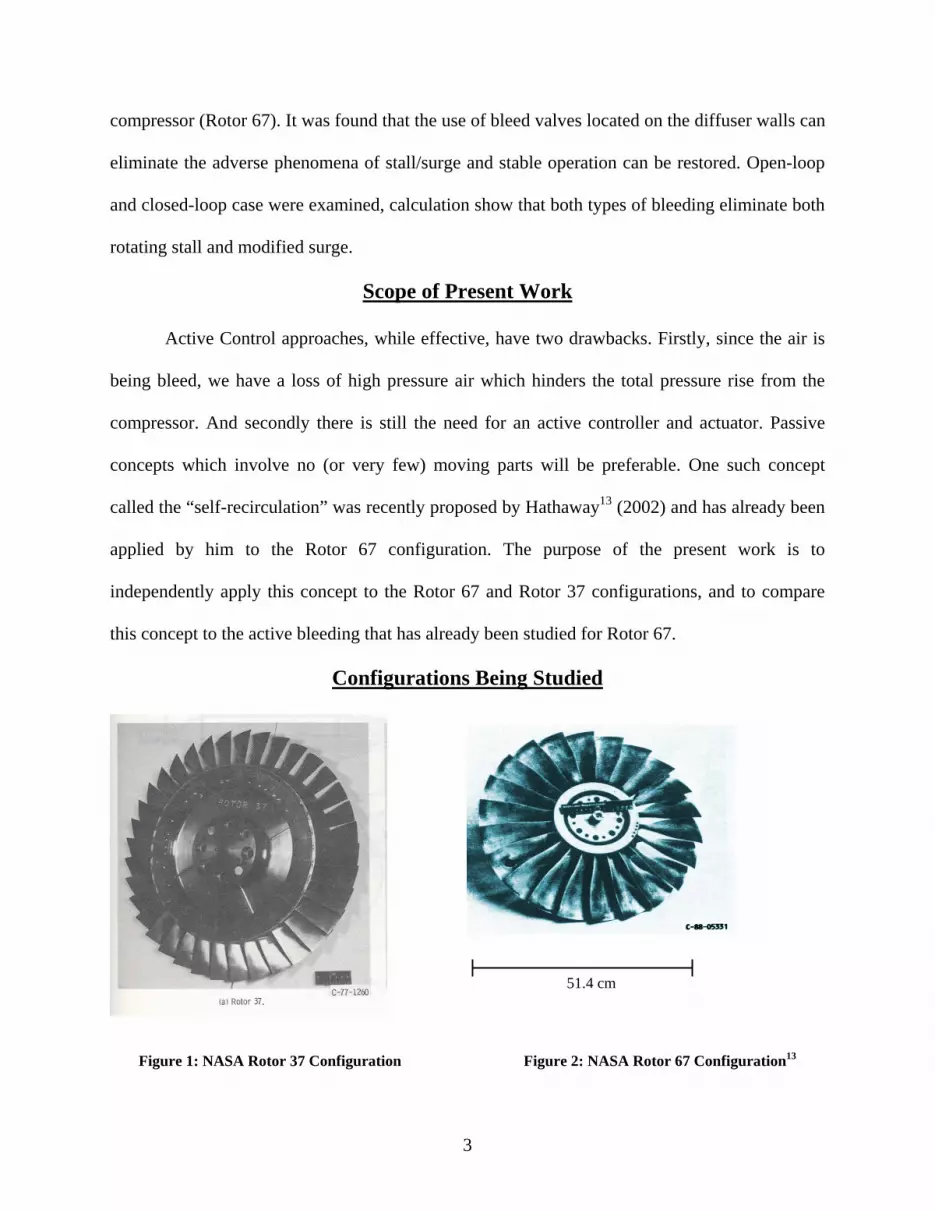
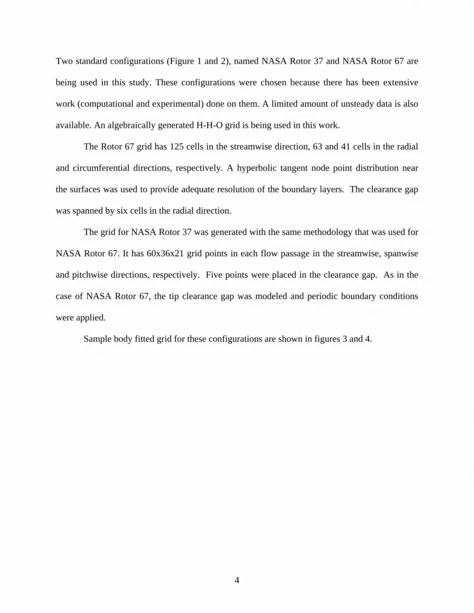
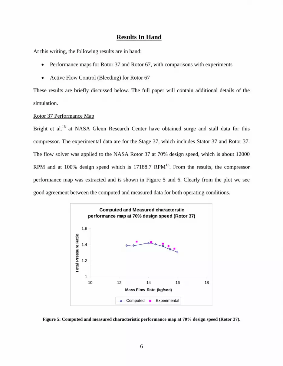
The Rotor 67 grid has 125 cells in the streamwise direction, 63 and 41 cells in the radial
and circumferential directions, respectively. A hyperbolic tangent node point distribution near
the surfaces was used to provide adequate resolution of the boundary layers. The clearance gap
was spanned by six cells in the radial direction.
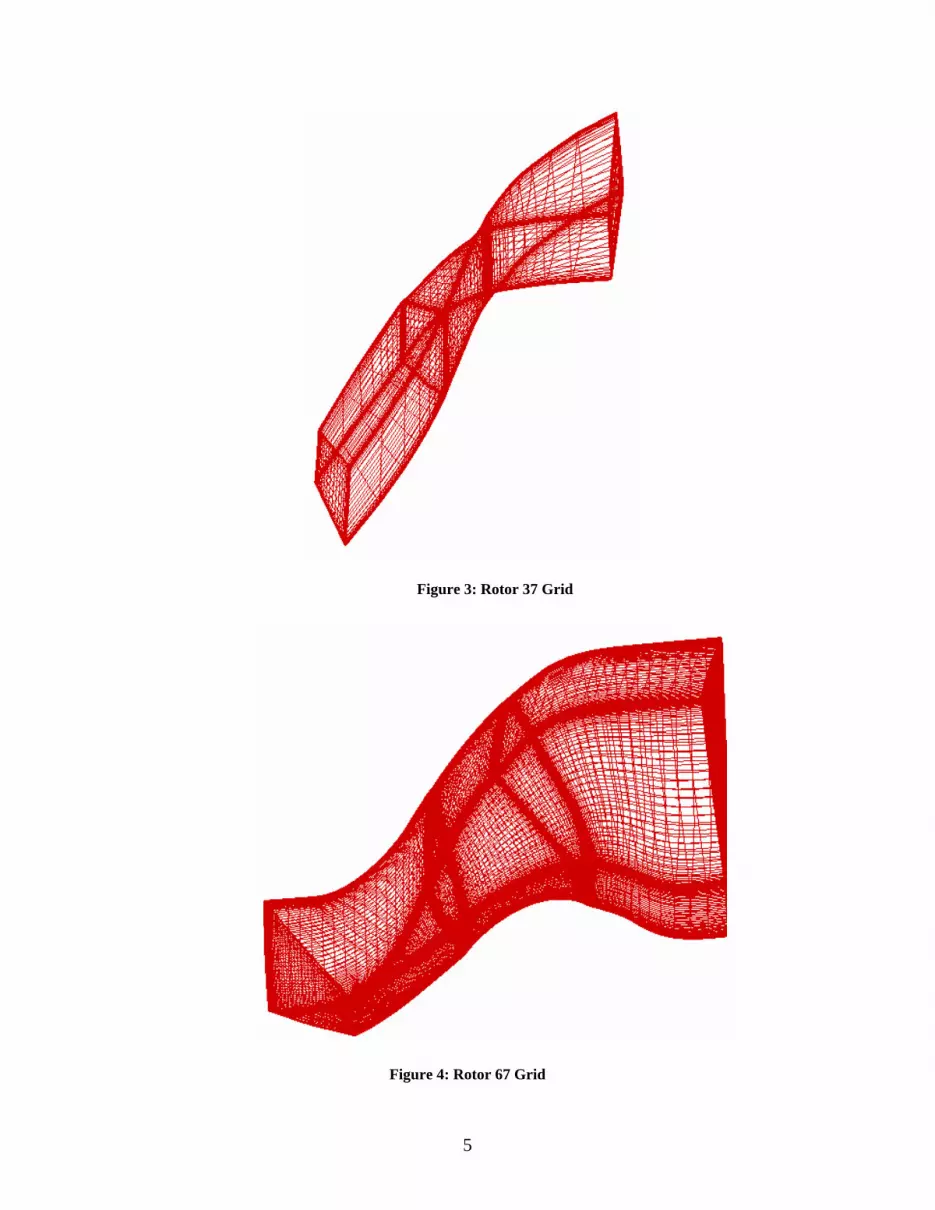
The grid for NASA Rotor 37 was generated with the same methodology that was used for
NASA Rotor 67. It has 60x36x21 grid points in each flow passage in the streamwise, spanwise
and pitchwise directions, respectively. Five points were placed in the clearance gap. As in the
case of NASA Rotor 67, the tip clearance gap was modeled and periodic boundary conditions
were applied.
Sample body fitted grid for these configurations are shown in figures 3 and 4.
5
Figure 3: Rotor 37 Grid
Figure 4: Rotor 67 Grid
6
Results In Hand
At this writing, the following results are in hand:
• Performance maps for Rotor 37 and Rotor 67, with comparisons with experiments
• Active Flow Control (Bleeding) for Rotor 67
These results are briefly discussed below. The full paper will contain additional details of the
simulation.
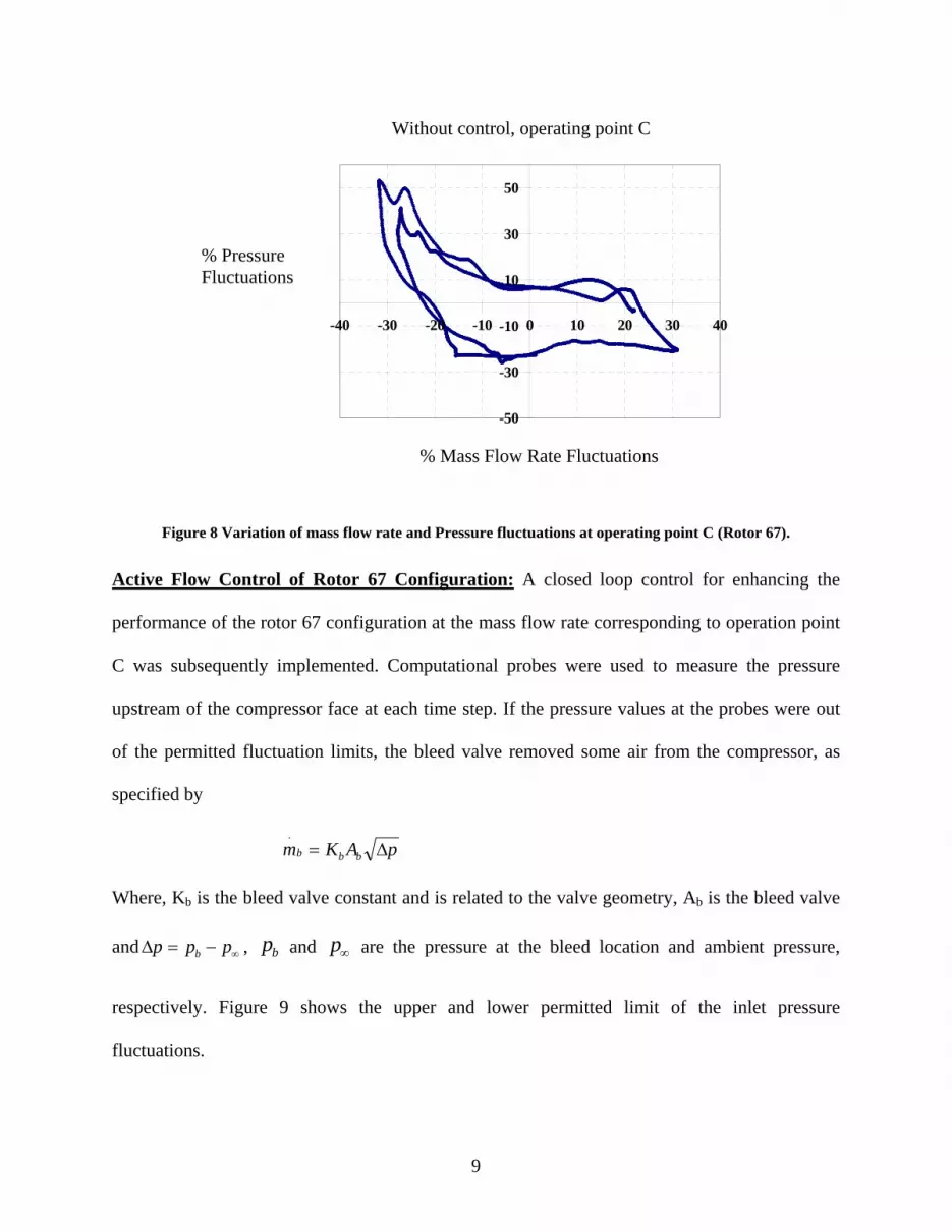
Rotor 37 Performance Map
Bright et al.15 at NASA Glenn Research Center have obtained surge and stall data for this
compressor. The experimental data are for the Stage 37, which includes Stator 37 and Rotor 37.
The flow solver was applied to the NASA Rotor 37 at 70% design speed, which is about 12000
RPM and at 100% design speed which is 17188.7 RPM16. From the results, the compressor
performance map was extracted and is shown in Figure 5 and 6. Clearly from the plot we see
good agreement between the computed and measured data for both operating conditions.
Computed and Measured characterstic performance map at 70% design speed (Rotor 37)
1
1.2
1.4
1.6
10 12 14 16 18
Mass Flow Rate (kg/sec)
Tota
l Pre
ssur
e Ra
tio
Computed Experimental
Figure 5: Computed and measured characteristic performance map at 70% design speed (Rotor 37).

7
Measured characteristic performance map at Design Speed (Rotor 37)
1
1.2
1.4
1.6
1.8
2
2.2
2.4
19 19.5 20 20.5 21
Mass Flow Rate (kg/sec)
Tota
l Pre
ssur
e Ra
tio
Experimental Computed
Figure 6: Computed and measured characteristic performance map at Design Speed (Rotor 37).
Rotor 67 Performance Map
The design rotational speed is 16043 RPM, and the tip leading edge speed is 429 m/sec
with a tip relative Mach number 1.38. The flow solver was applied to NASA Rotor 67, the
calculated total pressure ratio at full speed are plotted verses normalized mass flow and
compared to experimental data in Figure 7. These are previously published results and can be
found in Ref 12, and provide a starting point for the present study.

8
Figure 7: Comparison of measured and computed characteristic performance map (Rotor 67)12.
Three operating points A, B and C indicated on Figure 7 were studied in detail. Point ‘A’
corresponds to a stable operating point for the compressor and is related to the peak efficiency
condition. It was found that decreasing the mass flow through the compressor from point ‘A’ to
point ‘B’ triggers the onset of the rotating stall, further decreasing the mass flow from point ‘B’
to point ‘C’ causes the compressor to reach a instable state of modified surge. The figure below
shows the variation of mass flow rate with time at the operating point C. It is clear that the
compressor is experiencing extreme variations in mass flow rate, indicative of surge. Figure 8
shows the variation of mass flow rate with the fluctuation in pressure at point C.
.
.
Chokedm
m
A
B C
1.3 1.35 1.4
1.45 1.5
1.55 1.6
1.65 1.7
1.75 1.8
0.82 0.84 0.86 0.88 0.9 0.92 0.94 0.96 0.98 1
Tot
al P
ress
ure
Rat
io
CFD Experiment
9
Figure 8 Variation of mass flow rate and Pressure fluctuations at operating point C (Rotor 67).
Active Flow Control of Rotor 67 Configuration: A closed loop control for enhancing the
performance of the rotor 67 configuration at the mass flow rate corresponding to operation point
C was subsequently implemented. Computational probes were used to measure the pressure
upstream of the compressor face at each time step. If the pressure values at the probes were out
of the permitted fluctuation limits, the bleed valve removed some air from the compressor, as
specified by
pAKm bbb ∆=.
Where, Kb is the bleed valve constant and is related to the valve geometry, Ab is the bleed valve
and ∞−=∆ ppp b , bp and ∞p are the pressure at the bleed location and ambient pressure,
respectively. Figure 9 shows the upper and lower permitted limit of the inlet pressure
fluctuations.
-50
-30
-10
10
30
50
-40 -30 -20 -10 0 10 20 30 40
% Pressure Fluctuations
% Mass Flow Rate Fluctuations
Without control, operating point C

10
Figure 9: Upper and lower limit of pressures that trigger closed-loop control (Rotor 67).
Figure 10: Variation of mass flow rate and Pressure fluctuations under closed-loop control (Rotor 67).
As seen in figure 10, the close loop control discussed earlier did a good job of reducing
the fluctuations in mass and pressure. The amplitude of oscillations was reduced by nearly a
factor of 2. Thus, the simple closed loop control is indeed an effective way of alleviating surge. It
does have the disadvantage of removing useful compressed air from the engine, and requires
sensors and bleed valve actuators. The second concept under study is aimed at removing these
shortcomings.
0 5 10 15 20 250.45
0.5
0.55
0.6
0.65
0.7
0.75
0.8
0.85
0.9
0.95
Rotor Revolution, Ωt/2π
refPP
Pressure lower limit
Pressure upper limit
-50
-30
-10
10
30
50
-30 -20 -10 0 10 20
% Mass Flow Rate Fluctuations
% Pressure Fluctuations
11
Results in Progress
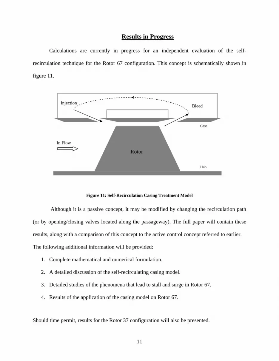
Calculations are currently in progress for an independent evaluation of the self-
recirculation technique for the Rotor 67 configuration. This concept is schematically shown in
figure 11.
Figure 11: Self-Recirculation Casing Treatment Model
Although it is a passive concept, it may be modified by changing the recirculation path
(or by opening/closing valves located along the passageway). The full paper will contain these
results, along with a comparison of this concept to the active control concept referred to earlier.
The following additional information will be provided:
1. Complete mathematical and numerical formulation.
2. A detailed discussion of the self-recirculating casing model.
3. Detailed studies of the phenomena that lead to stall and surge in Rotor 67.
4. Results of the application of the casing model on Rotor 67.
Should time permit, results for the Rotor 37 configuration will also be presented.
Hub
Case
Injection Bleed
Rotor
In Flow

12
References
1. Chima, R. V., and Yokota, J. W., “Numerical Analysis of Three-Dimensional Viscous
Internal Flow,” AIAA Journal, Vol. 28, No. 5, 1990, pp. 798-806.
2. Hall, E. J., “Aerodynamic Modeling of Multistage Compressor Flow Fields - Part 1:
Analysis of Rotor/Stator/Rotor Aerodynamic Interaction,” ASME paper 97-GT-344, 1997.
3. Dawes, W. N., “A Numerical Study of the 3D Flowfield in a Transonic Compressor Rotor
With a Modeling of the Tip Clearance Flow,” AGARD Conference Proceedings n 401,
Neuilly sur Seine, Fr.
4. Hah, C., and Wennerstrom, A. J., “Three-Dimensional Flowfields Inside a Transonic
Compressor With Swept Blades,” Journal of Turbomachinery, Vol. 113, 1991.
5. Hathaway, M. D., and Wood, J. R., “Application of a Multi-Block CFD Code to Investigate
the Impact of Geometry Modeling on Centrifugal Compressor Flow Field Predictions,”
Transactions of the ASME, Vol. 19, Oct 1997, pp. 820-830.
6. Suder, K.L., “Blockage Development in a Transonic, Axial Compressor Rotor,” Turbo-Expo
’97, Orlando, Florida.
7. Chima, R.V., “Calculation of Tip clearance effects in a Transonic Compressor Rotor,”
NASA TM 107216, May 1996
8. Crook, A. J., Greitzer, E. M., Tan, C. S., and Adamczyk J. J., “Numerical Simulation of
Compressor Endwall and Casing Treatment Flow Phenomena,” Journal of Turbomachinery,
Vol. 115, July 1993, pp. 501-511.
9. Niazi, S., Stein, A., and Sankar, L. N., “Development and Application of a CFD Solver to the
Simulation of Centrifugal Compressors,” AIAA paper 98-0934, 1998.
13
10. Stein, A., Niazi, S., and Sankar, L.N., “Computational Analysis of Stall and Separation
Control in Centrifugal Compressors,” AIAA Paper 98-3296, July 1998.
11. Niazi, S., “Numerical Simulation of Rotating Stall and Surge alleviation in axial
compressors” PhD thesis, July 2000.
12. Niazi, S., Stein, A., and Sankar, L.N., “Computational Analysis of Stall Control Using Bleed
Valve in a High-Speed Compressor” AIAA Paper 2000-3507.
13. Hathaway, M.D., “Self-Recirculating Casing Treatment Concept for Enhanced Compressor
Performance” Turbo-Expo 2002, Amsterdam, Holland.
14. Strazisar, A. J., Wood, J. R., Hathaway, M. D., Suder, K. L., "Laser Anemometer
Measurements in a Transonic Axial Flow Fan Rotor," NASA Tp-2879, Nov. 1989.
15. Bright, B. M., Qammar, H. K., and Hartley, T. T., “Dimension Determination of Precursive
Stall Events in a Single Stage High Speed Compressor,” NASA TM 107268, 1996.
16. Reid, L. and Moore, R. D., “Design and Overall Performance of Four Highly Loaded, High-
Speed Inlet Stages for an Advanced High-Pressure-Ratio Core Compressor,” NASA Paper
TM-1337, 1978.