numerical simulation and sensitivity analysis of detailed soot particle size distribution in laminar...
TRANSCRIPT
Numerical Simulation and SensitivityAnalysis of Gravity-Assisted Tertiary
Gas-Injection ProcessesW. Ren, SPE, L.B. Cunha, SPE, and R. Bentsen, SPE, U. of Alberta
SummaryCorefloods and field investigations confirm that a large amount ofincremental tertiary oil can be recovered from dipping waterdrivereservoirs using gravity-assisted tertiary gas-injection processes.These processes include the double-displacement process (DDP)and the second-contact water-displacement (SCWD) process. TheDDP consists of injecting gas into waterflooded oil zones. TheSCWD process consists of submitting these gasflooded zones to anew water-displacement process.
Reservoir simulations performed with an adaptive-implicitsimulator were applied to investigate the macroscopic mechanismsof the two processes. The effects of several important parameterson the performance of the DDP were studied to optimize the oilproduction of the process. Moreover, the SCWD process wassimulated to investigate its feasibility.
The results show that both processes are efficient methods forrecovering the residual oil to water. A good representation of thelaboratory results was obtained through the simulations. It wasconfirmed that oil-film flow plays a very important role in achiev-ing high recovery efficiencies in the DDP. In the SCWD process,trapped gas reduces the possibility of the residual oil being trappedin the center of pores in the secondary water invasion. Conse-quently, residual oil can be recovered quickly by a second water-flood. Therefore, the SCWD process is suitable for application insituations in which the source of gas is not sufficient, and wherethe formation has a high irreducible gas saturation.
IntroductionUpdip gas injection into a dipping reservoir is one of the mostefficient methods to recover waterflood residual oil. Recoveries of85 to 95% of the original oil in place (OOIP) have been reportedfrom field tests,1–3 and higher (even up to 100%) recoveries havebeen obtained in the laboratory.4 The idea of injecting gas torecover the residual oil after a waterflood appeared first in Carl-son’s paper,1 which discussed a gas-injection project in the Haw-kins field. He named the process the double-displacement processand defined it as the use of gas to displace a previously water-displaced oil column. In the same year, Kantzas et al.4–6 showedin the laboratory that gravity drainage played a very important rolein this gas-injection process, which they called the gravity-assistedtertiary gas-injection process. They addressed the fact that thereservoir wettability and spreading coefficient had a large impacton the gravity-assisted tertiary gas-injection process. Strongly wa-ter-wet porous media and a positive spreading coefficient are pref-erable in this process, and the process efficiency is dependent onthe spreading phenomenon. Oren and Pinczewski7 studied the ef-fect of the spreading coefficient on oil recovery using a networkmodel. Their experimental results showed that oil recovery wassignificantly higher for positive spreading systems than it was fornegative systems. Vizika and Lombard8 and Mani and Mohanty9
confirmed these results by conducting gas gravity-drainage experi-ments in a sandpack and a network model.
The incremental oil recovered by the DDP consists of twoparts. The first part is the bypassed oil, which exists as a continu-ous oil phase in the regions of the reservoir unswept by waterowing to reservoir heterogeneity or well placement. The secondpart is the residual oil existing at the microscopic scale as isolatedoil blobs in the water-swept regions of the porous medium owingto the capillary and surface forces. The gas-injection process im-proves the sweep efficiency so that the bypassed oil is recovered.The trapped oil can be recovered by oil-film flow. If the spreadingcoefficient of the oil is positive, when gas comes, the isolated oilblobs may form thin oil films. These oil films connect all of theresidual oil in the gas-swept zone to the oil bank, which is formedin front of the gas front soon after gas injection. The re-establishedhydraulic continuity of the residual oil provides channels (oilfilms) for the oil to flow through to the oil bank. When the oil bankreaches the production wells, both the bypassed oil and the isolatedoil blobs can be produced.
In the gravity-assisted tertiary gas-injection process, the rate ofoil flowing through oil films is critical. Pore-level observation10 ofthe process showed that oil flowing through oil films and layerswas driven not only by its own weight but also by the increasingvolume of the gas. However, after gas breakthrough, the oil-filmflow is driven mainly by gravity so that the flow rate is very low.After the oil bank is produced, the oil-film flow enables only avery low oil-production rate. Thus, because of the low oil-production rate, a very long time is needed to reach a very low oilsaturation. Consequently, the economic viability of the process isunfavorable. To shorten the period of low oil production, theSCWD process has been suggested.11,12 This process, which in-volves a second waterflood after the tertiary gas injection toshorten the period of low oil production, is considered an extensionof the DDP. A study10 of the microscopic mechanisms of theSCWD process has shown that the second waterflood can displacethe oil films and leave some gas trapped in the center of a pore.Therefore, the residual oil will not be trapped in the center of apore as it is in the first waterflood.
Besides the wettability and spreading coefficient, there areother parameters that can affect the DDP significantly. One mainobjective of this reservoir simulation study was to investigate theeffects of additional parameters on the DDP. These parametersinclude the injection and production rates, reservoir dip angles,three-phase relative permeabilities, and capillary pressures. An-other objective was to investigate the feasibility of the SCWDprocess. An adaptive-implicit numerical simulator, IMEX*,13 wasused to conduct the study. Reservoir heterogeneity is also an im-portant factor for the gas-injection process, but it was not consid-ered here. A 3D, homogeneous, anisotropic reservoir model wasconstructed. All the reservoir properties were taken from a sum-mary of several fields in which the DDP was used.
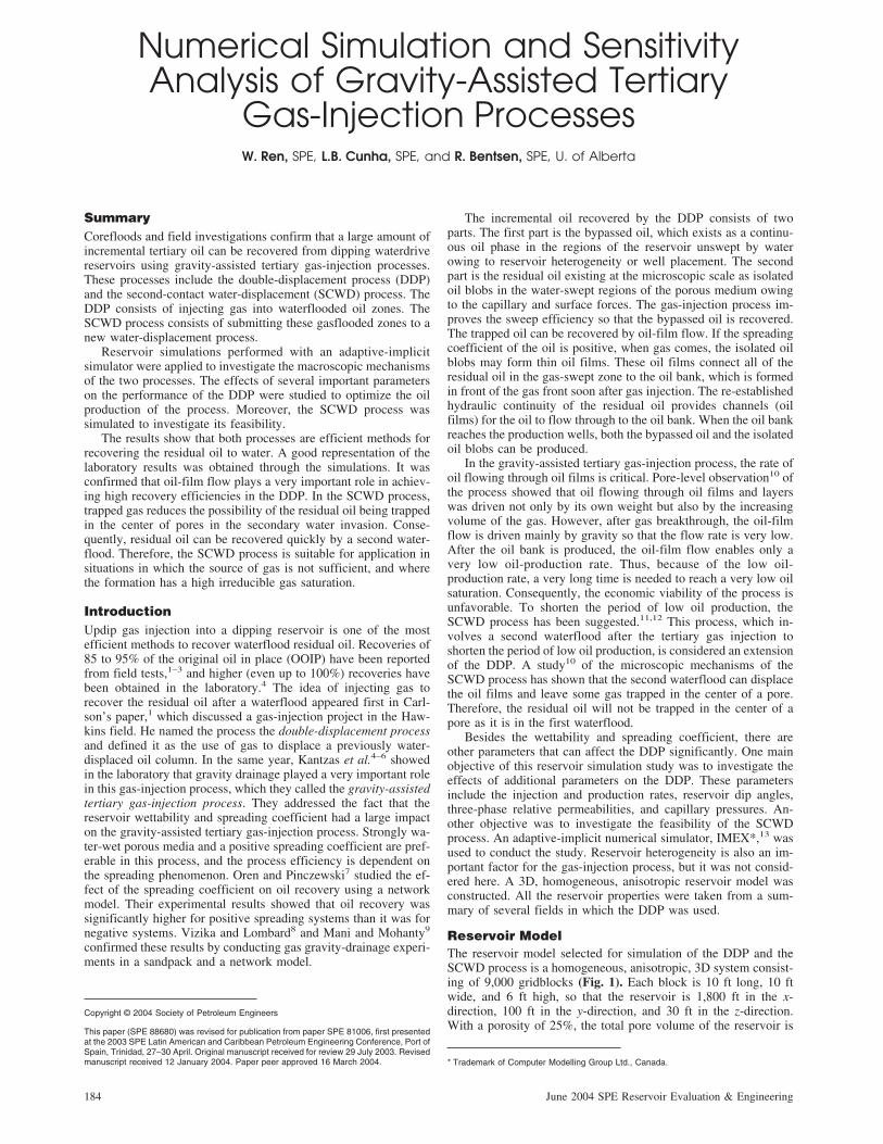
Reservoir ModelThe reservoir model selected for simulation of the DDP and theSCWD process is a homogeneous, anisotropic, 3D system consist-ing of 9,000 gridblocks (Fig. 1). Each block is 10 ft long, 10 ftwide, and 6 ft high, so that the reservoir is 1,800 ft in the x-direction, 100 ft in the y-direction, and 30 ft in the z-direction.With a porosity of 25%, the total pore volume of the reservoir is
Copyright © 2004 Society of Petroleum Engineers
This paper (SPE 88680) was revised for publication from paper SPE 81006, first presentedat the 2003 SPE Latin American and Caribbean Petroleum Engineering Conference, Port ofSpain, Trinidad, 27–30 April. Original manuscript received for review 29 July 2003. Revisedmanuscript received 12 January 2004. Paper peer approved 16 March 2004. * Trademark of Computer Modelling Group Ltd., Canada.
184 June 2004 SPE Reservoir Evaluation & Engineering
1,350,000 ft3. The absolute permeability is 1,500 md in the x andy directions and 800 md in the vertical direction. The formationbed of the reservoir dips at an angle of 8o. All the reservoir andfluid properties are listed in Table 1. The values of these propertieswere selected on the basis of several fields—the Hawkins oil field(Texas),1 the Weeks Island oil field (Louisiana),2 the West Hack-berry oil field (Louisiana),3 and the Handil oil field (Indone-sia)14—in which updip gas injection was undertaken.
Reservoir SimulationIn the DDP, mobile oil comes not only from the gas-invaded waterzone but also from areas bypassed by the waterflood. So, thereservoir for the simulation of the DDP should include both theresidual oil and the bypassed oil. Before the DDP, it is assumedthat the homogeneous reservoir is swept completely by the waterand that the initial oil saturation and pressure are uniformly dis-tributed over the whole reservoir. To add the bypassed oil, theinitial oil saturation was set slightly higher than the residual oilsaturation to water; that is, Soi�30%>Sorw�25%. Then, the res-ervoir simulator was set to run for 2 years so that phase stabiliza-tion was reached in the reservoir. At this time, the distributions ofreservoir pressure, fluid saturations, and other fluid propertieswere closer to the conditions that would pertain at the end of awaterflood. To avoid mass transfer taking place, and to maintainan immiscible displacement, the average reservoir pressure duringthe process was constrained to change over only a narrow rangeof values.
For the best performance, or an optimistic estimate of the oilproduction of the tertiary gas-injection process, two requirementsshould be satisfied. The first one is that the whole formation shouldbe swept totally by gas; that is, no bypassed area or gas fingeringshould occur. The second one is that the time between the gas
injection and the oil production should be as short as possible. Ahigh sweep efficiency means the gas flow in the formation isgravity dominated, as demonstrated by a flat gas/oil front. In thiscase, the flow rate of reservoir fluids should not be fast. However,a quick production response to gas injection requires a fast flowrate. Therefore, only the maximum oil-drainage rate (which satis-fies both requirements) can give the best performance of the DDP.The DDP was simulated primarily to investigate the effects ofvarious parameters on the updip gas-injection process. Initially, theinjection and production rates were studied to determine the maxi-mum drainage rate and the highest oil recovery. The effect ofreservoir dip angles was also studied. Then, the oil relative per-meability and capillary pressure were studied to observe their ef-fects on oil-recovery efficiency. After carrying out these sensitivitystudies on the DDP, the SCWD process was simulated to deter-mine the feasibility of the process.
Injection and Production Rates. Three sets of injection andproduction rates were selected to show their effects on the DDP.The maximum gas-injection rates were set at 8,000 ft3/D, 15,000ft3/D, and 30,000 ft3/D, corresponding to the maximum productionrates of 800 B/D, 1,000 B/D, and 1,500 B/D. For simplicity, 1January 1990 was selected as the beginning of the gas injection.Moreover, the gas injection will be stopped at 1 January 2006.
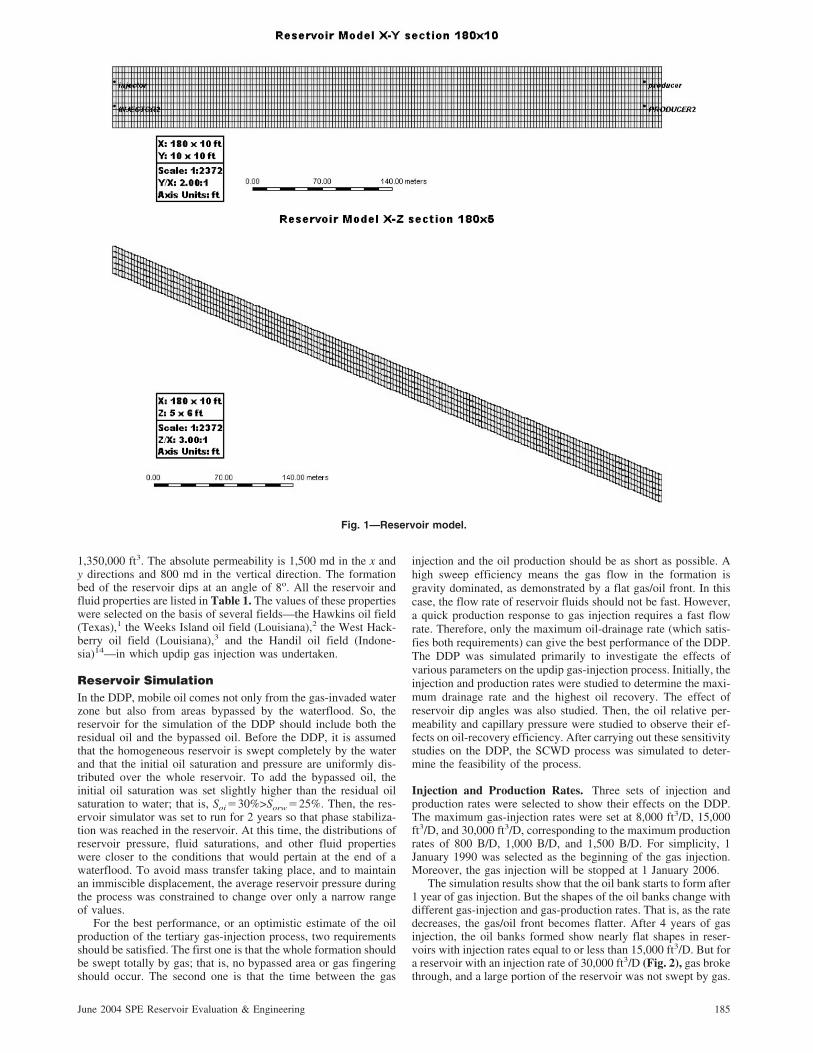
The simulation results show that the oil bank starts to form after1 year of gas injection. But the shapes of the oil banks change withdifferent gas-injection and gas-production rates. That is, as the ratedecreases, the gas/oil front becomes flatter. After 4 years of gasinjection, the oil banks formed show nearly flat shapes in reser-voirs with injection rates equal to or less than 15,000 ft3/D. But fora reservoir with an injection rate of 30,000 ft3/D (Fig. 2), gas brokethrough, and a large portion of the reservoir was not swept by gas.
Fig. 1—Reservoir model.
185June 2004 SPE Reservoir Evaluation & Engineering
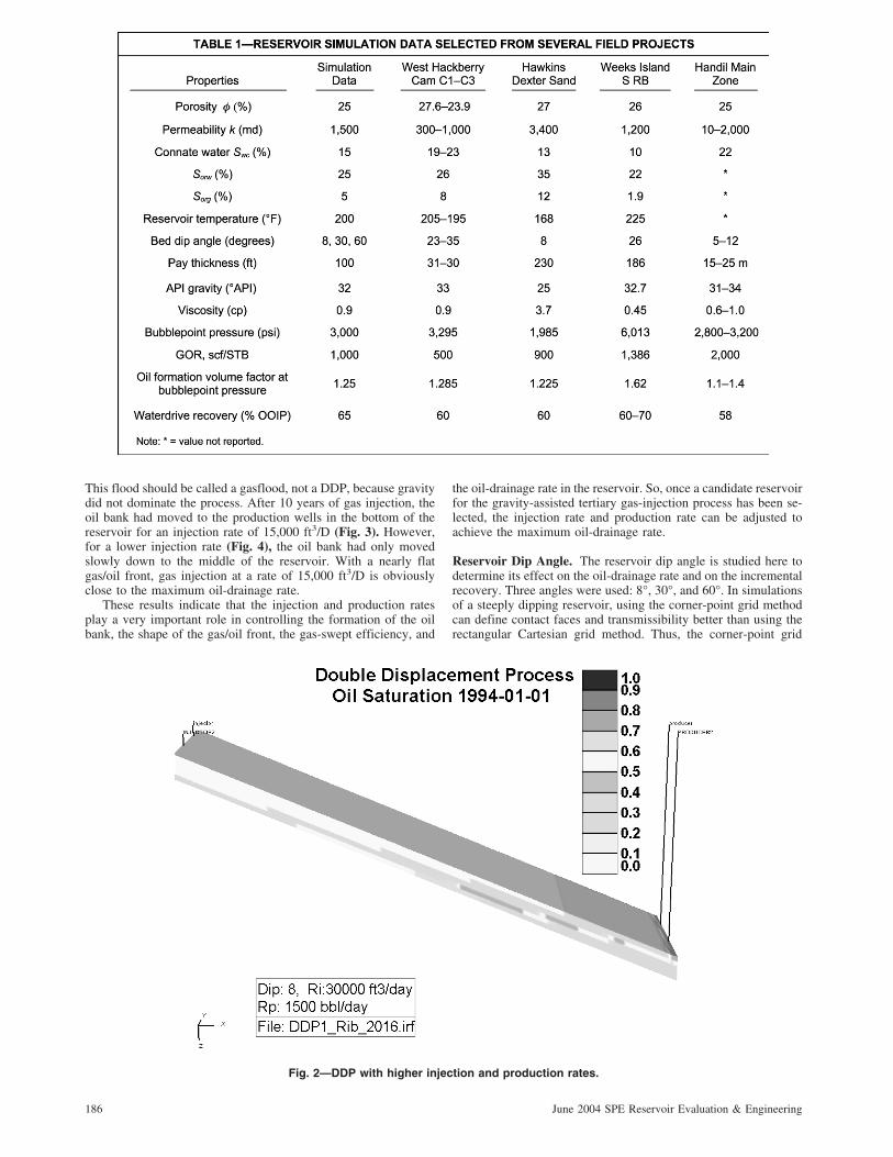
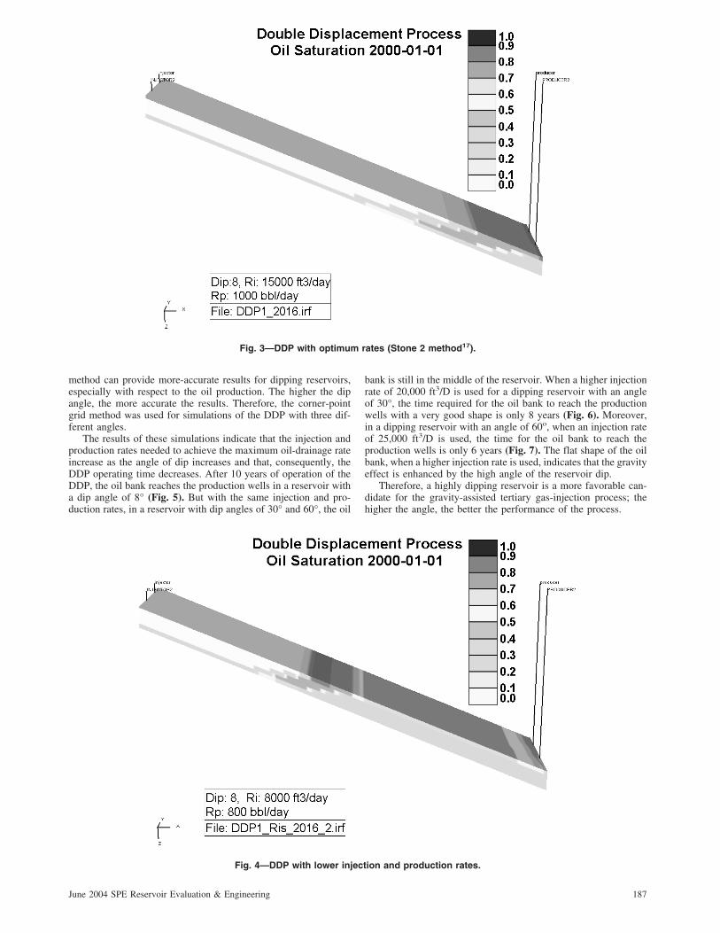
This flood should be called a gasflood, not a DDP, because gravitydid not dominate the process. After 10 years of gas injection, theoil bank had moved to the production wells in the bottom of thereservoir for an injection rate of 15,000 ft3/D (Fig. 3). However,for a lower injection rate (Fig. 4), the oil bank had only movedslowly down to the middle of the reservoir. With a nearly flatgas/oil front, gas injection at a rate of 15,000 ft3/D is obviouslyclose to the maximum oil-drainage rate.
These results indicate that the injection and production ratesplay a very important role in controlling the formation of the oilbank, the shape of the gas/oil front, the gas-swept efficiency, and
the oil-drainage rate in the reservoir. So, once a candidate reservoirfor the gravity-assisted tertiary gas-injection process has been se-lected, the injection rate and production rate can be adjusted toachieve the maximum oil-drainage rate.
Reservoir Dip Angle. The reservoir dip angle is studied here todetermine its effect on the oil-drainage rate and on the incrementalrecovery. Three angles were used: 8°, 30°, and 60°. In simulationsof a steeply dipping reservoir, using the corner-point grid methodcan define contact faces and transmissibility better than using therectangular Cartesian grid method. Thus, the corner-point grid
Fig. 2—DDP with higher injection and production rates.
186 June 2004 SPE Reservoir Evaluation & Engineering
method can provide more-accurate results for dipping reservoirs,especially with respect to the oil production. The higher the dipangle, the more accurate the results. Therefore, the corner-pointgrid method was used for simulations of the DDP with three dif-ferent angles.
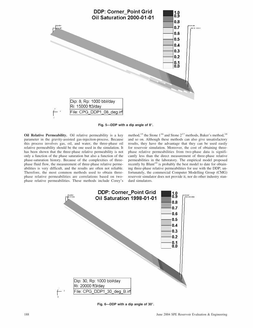
The results of these simulations indicate that the injection andproduction rates needed to achieve the maximum oil-drainage rateincrease as the angle of dip increases and that, consequently, theDDP operating time decreases. After 10 years of operation of theDDP, the oil bank reaches the production wells in a reservoir witha dip angle of 8° (Fig. 5). But with the same injection and pro-duction rates, in a reservoir with dip angles of 30° and 60°, the oil
bank is still in the middle of the reservoir. When a higher injectionrate of 20,000 ft3/D is used for a dipping reservoir with an angleof 30°, the time required for the oil bank to reach the productionwells with a very good shape is only 8 years (Fig. 6). Moreover,in a dipping reservoir with an angle of 60o, when an injection rateof 25,000 ft3/D is used, the time for the oil bank to reach theproduction wells is only 6 years (Fig. 7). The flat shape of the oilbank, when a higher injection rate is used, indicates that the gravityeffect is enhanced by the high angle of the reservoir dip.
Therefore, a highly dipping reservoir is a more favorable can-didate for the gravity-assisted tertiary gas-injection process; thehigher the angle, the better the performance of the process.
Fig. 3—DDP with optimum rates (Stone 2 method17).
Fig. 4—DDP with lower injection and production rates.
187June 2004 SPE Reservoir Evaluation & Engineering
Oil Relative Permeability. Oil relative permeability is a keyparameter in the gravity-assisted gas-injection-process. Becausethis process involves gas, oil, and water, the three-phase oilrelative permeability should be the one used in the simulation. Ithas been shown that the three-phase relative permeability is notonly a function of the phase saturation but also a function of thephase-saturation history. Because of the complexities of three-phase fluid flow, the measurement of three-phase relative perme-abilities is very difficult, and the results are often not reliable.Therefore, the most common methods used to obtain three-phase relative permeabilities are correlations based on two-phase relative permeabilities. These methods include Corey’s
method,15 the Stone 116 and Stone 217 methods, Baker’s method,18
and so on. Although these methods can also give unsatisfactoryresults, they have the advantage that they can be used easilyfor reservoir simulation. Moreover, the cost of obtaining three-phase relative permeabilities from two-phase data is signifi-cantly less than the direct measurement of three-phase relativepermeabilities in the laboratory. The empirical model proposedrecently by Blunt19 is probably the best model to date for obtain-ing three-phase relative permeabilities for use with the DDP; un-fortunately, the commercial Computer Modelling Group (CMG)reservoir simulator does not provide it, nor do other industry stan-dard simulators.
Fig. 5—DDP with a dip angle of 8°.
Fig. 6—DDP with a dip angle of 30°.
188 June 2004 SPE Reservoir Evaluation & Engineering
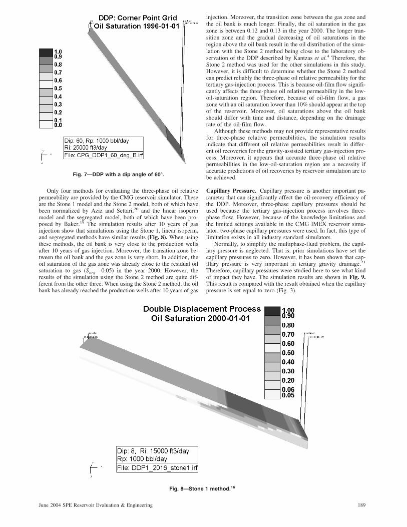
Only four methods for evaluating the three-phase oil relativepermeability are provided by the CMG reservoir simulator. Theseare the Stone 1 model and the Stone 2 model, both of which havebeen normalized by Aziz and Settari,20 and the linear isopermmodel and the segregated model, both of which have been pro-posed by Baker.18 The simulation results after 10 years of gasinjection show that simulations using the Stone 1, linear isoperm,and segregated methods have similar results (Fig. 8). When usingthese methods, the oil bank is very close to the production wellsafter 10 years of gas injection. Moreover, the transition zone be-tween the oil bank and the gas zone is very short. In addition, theoil saturation of the gas zone was already close to the residual oilsaturation to gas (Sorg�0.05) in the year 2000. However, theresults of the simulation using the Stone 2 method are quite dif-ferent from the other three. When using the Stone 2 method, the oilbank has already reached the production wells after 10 years of gas
injection. Moreover, the transition zone between the gas zone andthe oil bank is much longer. Finally, the oil saturation in the gaszone is between 0.12 and 0.13 in the year 2000. The longer tran-sition zone and the gradual decreasing of oil saturations in theregion above the oil bank result in the oil distribution of the simu-lation with the Stone 2 method being close to the laboratory ob-servation of the DDP described by Kantzas et al.4 Therefore, theStone 2 method was used for the other simulations in this study.However, it is difficult to determine whether the Stone 2 methodcan predict reliably the three-phase oil relative permeability for thetertiary gas-injection process. This is because oil-film flow signifi-cantly affects the three-phase oil relative permeability in the low-oil-saturation region. Therefore, because of oil-film flow, a gaszone with an oil saturation lower than 10% should appear at the topof the reservoir. Moreover, oil saturations above the oil bankshould differ with time and distance, depending on the drainagerate of the oil-film flow.
Although these methods may not provide representative resultsfor three-phase relative permeabilities, the simulation resultsindicate that different oil relative permeabilities result in differ-ent oil recoveries for the gravity-assisted tertiary gas-injection pro-cess. Moreover, it appears that accurate three-phase oil relativepermeabilities in the low-oil-saturation region are a necessity ifaccurate predictions of oil recoveries by reservoir simulation are tobe achieved.
Capillary Pressure. Capillary pressure is another important pa-rameter that can significantly affect the oil-recovery efficiency ofthe DDP. Moreover, three-phase capillary pressures should beused because the tertiary gas-injection process involves three-phase flow. However, because of the knowledge limitations andthe limited settings available in the CMG IMEX reservoir simu-lator, two-phase capillary pressures were used. In fact, this type oflimitation exists in all industry standard simulators.
Normally, to simplify the multiphase-fluid problem, the capil-lary pressure is neglected. That is, prior simulations have set thecapillary pressures to zero. However, it has been shown that cap-illary pressure is very important in tertiary gravity drainage.21
Therefore, capillary pressures were studied here to see what kindof impact they have. The simulation results are shown in Fig. 9.This result is compared with the result obtained when the capillarypressure is set equal to zero (Fig. 3).
Fig. 7—DDP with a dip angle of 60°.
Fig. 8—Stone 1 method.16
189June 2004 SPE Reservoir Evaluation & Engineering
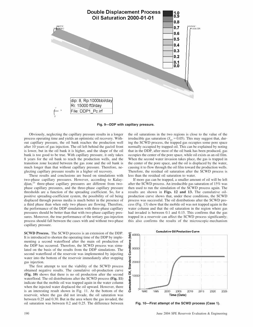
Obviously, neglecting the capillary pressure results in a longerprocess operating time and yields an optimistic oil recovery. With-out capillary pressure, the oil bank reaches the production wellafter 10 years of gas injection. The oil left behind the gas/oil frontis lower, but in the oil bank it is higher, and the shape of the oilbank is too good to be true. With capillary pressure, it only takes8 years for the oil bank to reach the production wells, and thetransition zone located between the gas zone and the oil bank ismuch longer than that without capillary pressure. Therefore, ne-glecting capillary pressure results in a higher oil recovery.
These results and conclusions are based on simulations withtwo-phase capillary pressures. However, according to Kalay-djian,21 three-phase capillary pressures are different from two-phase capillary pressures, and the three-phase capillary pressurethresholds are a function of the spreading coefficient. So, for apositive spreading-coefficient system, the possibility of oil beingdisplaced through porous media is much better in the presence ofa third phase than when only two phases are flowing. Therefore,the performance of the DDP simulation with three-phase capillarypressures should be better than that with two-phase capillary pres-sures. Moreover, the true performance of the tertiary gas-injectionprocess should fall between the cases with and without two-phasecapillary pressure.
SCWD Process. The SCWD process is an extension of the DDP.It is introduced to shorten the operating time of the DDP by imple-menting a second waterflood after the main oil production ofthe DDP has occurred. Therefore, the SCWD process was simu-lated on the basis of the results from the DDP simulations. Thesecond waterflood of the reservoir was implemented by injectingwater into the bottom of the reservoir immediately after stoppinggas injection.
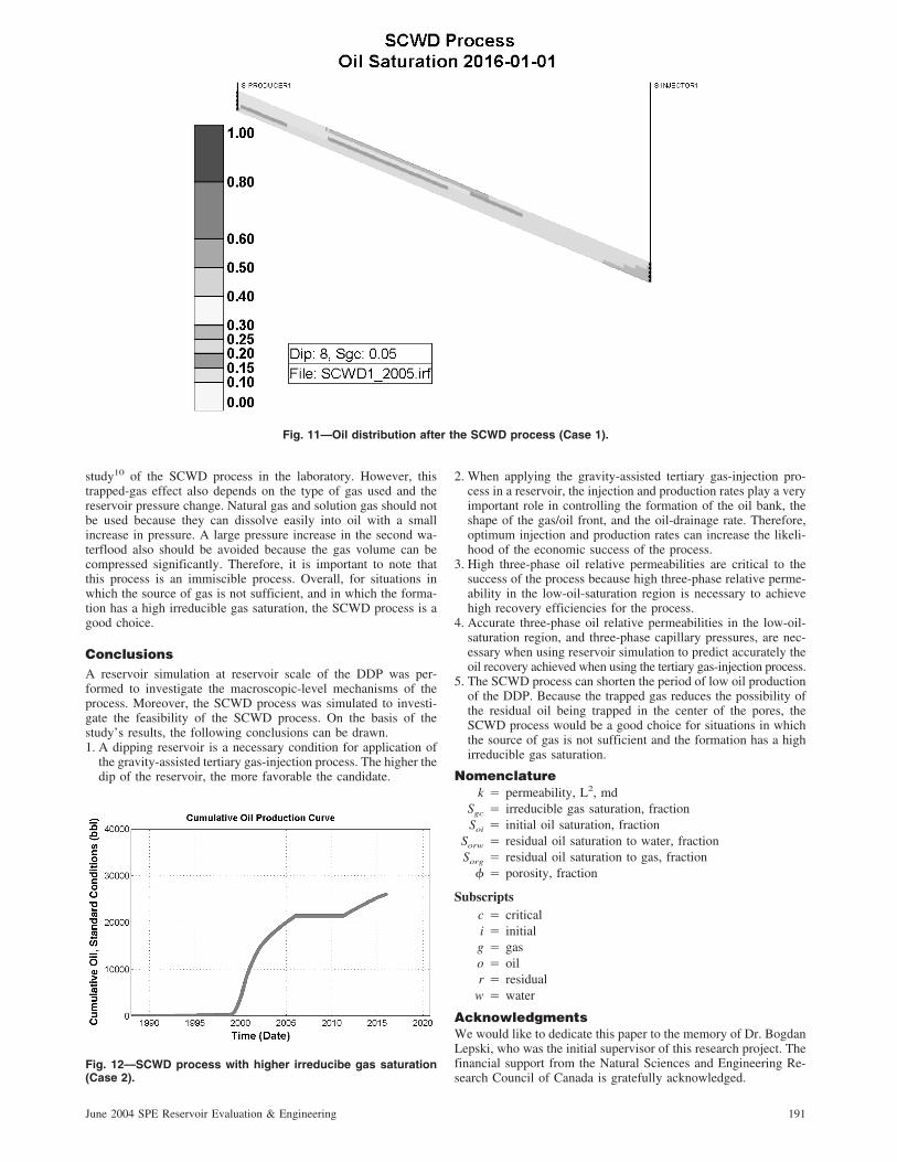
The first attempt to test the viability of the SCWD processobtained negative results. The cumulative oil-production curve(Fig. 10) shows that there is no oil production after the secondwaterflood. The oil distributions after the SCWD process (Fig. 11)indicate that the mobile oil was trapped again in the water columnwhen the injected water displaced the oil upward. However, thereis an interesting result shown in Fig. 11. At the bottom of thereservoir, where the gas did not invade, the oil saturation wasbetween 0.25 and 0.30. But in the area where the gas invaded, theoil saturation was between 0.2 and 0.25. The difference between
the oil saturations in the two regions is close to the value of theirreducible gas saturation (Sgc�0.05). This may suggest that, dur-ing the SCWD process, the trapped gas occupies some pore spacenormally occupied by trapped oil. This can be explained by notingthat in the DDP, after most of the oil bank has been produced, gasoccupies the center of the pore space, while oil exists as an oil film.When the second water invasion takes place, the gas is trapped inthe center of the pore space, and the oil is displaced by the water,causing it to flow through the oil film toward the production wells.Therefore, the residual oil saturation after the SCWD process isless than the residual oil saturation to water.
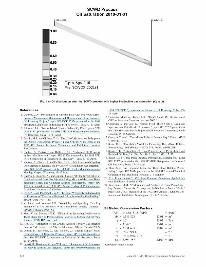
If more gas can be trapped, a smaller amount of oil will be leftafter the SCWD process. An irreducible gas saturation of 15% wasthen used to run the simulation of the SCWD process again. Theresults are shown in Figs. 12 and 13. The cumulative oil-production curve shows that, under these conditions, the SCWDprocess was successful. The oil distributions after the SCWD pro-cess (Fig. 13) show that the mobile oil was not trapped again in thewater column and that the oil saturation in the region where gashad invaded is between 0.1 and 0.15. This confirms that the gastrapped in a reservoir can affect the SCWD process significantly;this also confirms the results of the microscopic-mechanism
Fig. 10—First attempt of the SCWD process (Case 1).
Fig. 9—DDP with capillary pressure.
190 June 2004 SPE Reservoir Evaluation & Engineering
study10 of the SCWD process in the laboratory. However, thistrapped-gas effect also depends on the type of gas used and thereservoir pressure change. Natural gas and solution gas should notbe used because they can dissolve easily into oil with a smallincrease in pressure. A large pressure increase in the second wa-terflood also should be avoided because the gas volume can becompressed significantly. Therefore, it is important to note thatthis process is an immiscible process. Overall, for situations inwhich the source of gas is not sufficient, and in which the forma-tion has a high irreducible gas saturation, the SCWD process is agood choice.
ConclusionsA reservoir simulation at reservoir scale of the DDP was per-formed to investigate the macroscopic-level mechanisms of theprocess. Moreover, the SCWD process was simulated to investi-gate the feasibility of the SCWD process. On the basis of thestudy’s results, the following conclusions can be drawn.1. A dipping reservoir is a necessary condition for application of
the gravity-assisted tertiary gas-injection process. The higher thedip of the reservoir, the more favorable the candidate.
2. When applying the gravity-assisted tertiary gas-injection pro-cess in a reservoir, the injection and production rates play a veryimportant role in controlling the formation of the oil bank, theshape of the gas/oil front, and the oil-drainage rate. Therefore,optimum injection and production rates can increase the likeli-hood of the economic success of the process.
3. High three-phase oil relative permeabilities are critical to thesuccess of the process because high three-phase relative perme-ability in the low-oil-saturation region is necessary to achievehigh recovery efficiencies for the process.
4. Accurate three-phase oil relative permeabilities in the low-oil-saturation region, and three-phase capillary pressures, are nec-essary when using reservoir simulation to predict accurately theoil recovery achieved when using the tertiary gas-injection process.
5. The SCWD process can shorten the period of low oil productionof the DDP. Because the trapped gas reduces the possibility ofthe residual oil being trapped in the center of the pores, theSCWD process would be a good choice for situations in whichthe source of gas is not sufficient and the formation has a highirreducible gas saturation.
Nomenclaturek � permeability, L2, md
Sgc � irreducible gas saturation, fractionSoi � initial oil saturation, fraction
Sorw � residual oil saturation to water, fractionSorg � residual oil saturation to gas, fraction
� � porosity, fraction
Subscriptsc � criticali � initialg � gaso � oilr � residual
w � water
AcknowledgmentsWe would like to dedicate this paper to the memory of Dr. BogdanLepski, who was the initial supervisor of this research project. Thefinancial support from the Natural Sciences and Engineering Re-search Council of Canada is gratefully acknowledged.
Fig. 12—SCWD process with higher irreducibe gas saturation(Case 2).
Fig. 11—Oil distribution after the SCWD process (Case 1).
191June 2004 SPE Reservoir Evaluation & Engineering
References1. Carlson, L.O.: “Performance of Hawkins Field Unit Under Gas Drive-
Pressure Maintenance Operations and Development of an EnhancedOil Recovery Project,” paper SPE/DOE 17324 presented at the 1988SPE/DOE Symposium on Enhanced Oil Recovery, Tulsa, 17–20 April.
2. Johnston, J.R.: “Weeks Island Gravity Stable CO2 Pilot,” paper SPE/DOE 17351 presented at the 1988 SPE/DOE Symposium on EnhancedOil Recovery, Tulsa, 17–20 April.
3. Fassihi, M.R. and Gillham, T.H.: “The Use of Air Injection To Improvethe Double Displacement Process,” paper SPE 26374 presented at the1993 SPE Annual Technical Conference and Exhibition, Houston,3–6 October.
4. Kantzas, A., Chatzis, I., and Dullien, F.A.L.: “Enhanced Oil Recoveryby Inert Gas Injection,” paper SPE 17379 presented at the 1988 SPE/DOE Symposium on Enhanced Oil Recovery, Tulsa, 17–20 April.
5. Kantzas, A., Chatzis, I., and Dullien, F.A.L.: “Mechanisms of CapillaryDisplacement of Residual Oil by Gravity-Assisted Inert Gas Injection,”paper SPE 17506 presented at the 1988 SPE Rocky Mountain RegionalMeeting, Casper, Wyoming, 11–13 May.
6. Chatzis, I., Kantzas, A., and Dullien, F.A.L.: “On the Investigation ofGravity-Assisted Inert Gas Injection Using Micromodels, Long BereaSandstone Cores, and Computer-Assisted Tomography,” paper SPE18284 presented at the 1988 SPE Annual Technical Conference andExhibition, Houston, 2–5 October.
7. Oren, P.E. and Pinczewski, W.V.: “Effect of Wettability and Spreadingon Recovery of Waterflood Residual Oil by Immiscible Gasflooding,”SPEFE (June 1994) 149.
8. Vizika, O. and Lombard, J.M.: “Wettability and Spreading: Two KeyParameters in Oil Recovery With Three-Phase Gravity Drainage,”SPERE (February 1996) 54.
9. Mani, V. and Mohanty, K.K.: “Effect of the Spreading Coefficient onThree-Phase Flow in Porous Media,” Journal of Colloid and InterfaceScience (1997) 187, No. 1, 45.
10. Ren, W.: “Application of the Gravity Assisted Tertiary Gas InjectionProcess,” MS thesis, U. of Alberta, Edmonton, Alberta, Canada (2002).
11. Lepski, B., Bassiouni, Z., and Wolcott, J.: “Second-Contact WaterDisplacement Oil Recovery Process,” paper SPE 35360 presented atthe 1996 SPE/DOE Symposium on Enhanced Oil Recovery, Tulsa,21–24 April.
12. Lepski, B., Bassiouni, Z., and Wolcott, J.: “Screening of Oil ReservoirsFor Gravity Assisted Gas Injection,” paper SPE 39659 presented at the
1998 SPE/DOE Symposium on Enhanced Oil Recovery, Tulsa, 19–22 April.
13. Computer Modelling Group Ltd.: “User’s Guide IMEX: AdvancedOil/Gas Reservoir Simulator Version 2000.”
14. Gunawan, S. and Caié, D.: “Handil Field: Three Years of Lean GasInjection into Waterflooded Reservoirs,” paper SPE 57289 presented atthe 1999 SPE Asia Pacific Improved Oil Recovery Conference, KualaLumpur, 25–26 October.
15. Corey, A.T. et al.: “Three-Phase Relative Permeability,” Trans., AIME(1956) 207, 349.
16. Stone, H.L.: “Probability Model for Estimating Three-Phase RelativePermeability,” JPT (February 1970) 214; Trans., AIME, 249.
17. Stone, H.L.: “Estimation of Three-Phase Relative Permeability andResidual Oil Data,” J. Cdn. Pet. Tech. (April 1973) 12, 53.
18. Baker, L.E.: “Three-Phase Relative Permeability Correlations,” paperSPE 17369 presented at the 1988 SPE/DOE Symposium on EnhancedOil Recovery, Tulsa, 17–20 April.
19. Blunt, M.J.: “An Empirical Model for Three-Phase Relative Perme-ability,” paper SPE 56474 presented at the 1999 SPE Annual TechnicalConference and Exhibition, Houston, 3–6 October.
20. Aziz, K. and Settari, T.: Petroleum Reservoir Simulation, Applied Sci-ence Publishers, London (1979).
21. Kalaydjian, F.J.M.: “Performance and Analysis of Three-Phase Capil-lary Pressure Curves for Drainage and Imbibition in Porous Media,”paper SPE 24878 presented at the 1992 SPE Annual Technical Con-ference and Exhibition, Washington, DC, 4–7 October.
SI Metric Conversion FactorsoAPI 141.5/(131.5+oAPI) � g/cm3
bbl × 1.589 873 E–01 � m3
cp × 1.0* E–03 � Pa·sft × 3.048* E–01 � m
ft3 × 2.831 685 E–02 � m3
oF (oF–32)/1.8 � oCoF (oF+459.67)/1.8 � Kpsi × 6.894 757 E+00 � kPa
*Conversion factor is exact.
Fig. 13—Oil distribution after the SCWD process with higher irreducible gas saturation (Case 2).
192 June 2004 SPE Reservoir Evaluation & Engineering

Weishan Ren is a PhD student in petroleum engineering at theU. of Alberta, Edmonton, Alberta, Canada. Previously, heworked for 5 years as a reservoir engineer for Shengli OilfieldInc. of SINOPEC, Dongying, China. Ren holds a BS degree inpetroleum geological exploration from the Southwest Petro-leum Inst., Nanchong, China, and an MS degree in petroleumengineering from the U. of Alberta. Luciane B. Cunha is anassociate professor of petroleum engineering at the U. of Al-berta. Previously, she worked for 16 years for Petrobras as areservoir engineer and a staff research scientist in the area ofreservoir management, characterization, and simulation. Herresearch interests include enhanced-oil-recovery methods, riskanalysis, reservoir characterization, simulation, and production
optimization. Cunha holds a BS degree in civil engineeringfrom the Federal U. of Rio de Janeiro, Brazil, an MS degree inpetroleum engineering from Campinas State U., Brazil, and aPhD degree in petroleum engineering from the U. of Tulsa. Ra-mon Bentsen currently holds the position of Professor Emeritus inthe School of Mining & Petroleum Engineering at the U. of Al-berta. He joined the U. of Alberta as a member of the Dept. ofChemical and Petroleum Engineering in 1968. Previously, heworked for Schlumberger Surenco in Venezuela and Colom-bia, and with McCullough Tool Co. and Imperial Oil Ltd. inAlberta. Bentsen holds a BS degree in petroleum engineeringfrom the U. of Oklahoma and MS and PhD degrees in petro-leum and natural gas engineering from Pennsylvania State U.
193June 2004 SPE Reservoir Evaluation & Engineering