numerical analysis of heave reduction using eps geofoam
TRANSCRIPT
IOSR Journal of Mechanical and Civil Engineering (IOSR-JMCE)
e-ISSN: 2278-1684,p-ISSN: 2320-334X, Volume 17, Issue 1 Ser. I (Jan - Feb 2020), PP 41-49
www.iosrjournals.org
DOI: 10.9790/1684-1701014149 www.iosrjournals.org 41 | Page
Numerical Analysis of Heave Reduction Using EPS Geofoam Inclusions
Sayed M. Elsayed1, Tamer M. Sorour
1, Ahmed M. Fathy
2
1(Structural Engineering Department, Faculty of Engineering / Ain Shams University, Egypt) 2(Building and Construction Department, Faculty of Engineering / October 6 University, Egypt)
Abstract:
Background: Expansive soils have a destructive influence on civil engineering structures; mainly the light loaded structures
over the world. This damage takes place because the swelling soils undergo significant changes in volume and strength as a
result of changes in moisture content. Expansive soils can swell or shrink when their water content increase or decrease
depending mainly on the kind of clay minerals present in the soil formation. The variation of soil moisture content may be
developed from many sources such as gardening wetting, lawn, pipe leaky, and climate changes. Therefore, the design of the
structural foundation on this problematic soil needs to the knowledge of the behavior and stress-related deformability of the
soil, also the geologic conditions. The prediction of the behavior of expansive, unsaturated soils should deal with many
issues, that included soil properties characterization and a computing tool that can model the non-linear nature of expansive
soils. Many methods can be used for the prediction of the swell/shrink behavior of expansive soil with different degrees of
precision. Due to the difficulties of predicting the swell/shrink behavior of unsaturated soil, the numerical model considered
the most common method for solving the equation of water seepage and soil deformation. Several treatment methods can be
used for controlling the swell/shrink behavior of expansive soil such as soil replacement, moisture control, thermal methods,
and surcharge loading. However, these methods have their limitations concerning costs and their effectiveness. Among the
diverse treatment techniques, EPS geofoam can be used to mitigate the swelling of expansive soils and to reduce the
structural straining actions that result from the ground heave.
Materials and Methods: The EPS, as a soft soil inclusion, allows the expansive soil to swell. As such, structures on
expansive soil may be designed with the aid of EPS to withstand only a small value of the swelling forces that may be
induced by ground heaving under a constrained condition or a small part of the ground heave as the volume change is
diverted away from the foundations. The essential aim of this paper is to present a tool for estimating, predicting, and
mitigating the ground heave that associated with expansive soils. Moreover, study the impact of using EPS geofoam piles to
minimize and reduce the effect of the heave potential associated with unsaturated, expansive soils on the structure
foundations.
Results: Numerical modeling of the behavior of expansive soil considered a powerful computing tool for estimating the
volume change problems of structures rested on expansive soils. EPS geofoam as a compressible inclusion material has a
significant effect on the matric suction distribution of unsaturated, expansive soils, and the decreasing of the soil heave.
Conclusion: Numerical analysis shows that there is a reduction in the vertical swelling of soil with the inclusion of EPS
geofoam. Also, with the increase in EPS dimensions, there is a significant reduction in the soil heave.
Key Word: Volume change behavior; Expansive soil; EPS Geofoam; Soil water characteristic Curve; Swelling potential;
Unsaturated soil.
----------------------------------------------------------------------------------------------------------------------------- ----------
Date of Submission: 11-01-2020 Date of Acceptance: 28-01-2020
------------------------------------------------------------------------------------------------------------------------ ---------------
I. Introduction
With any variation in the soil moisture content due to an environmental change, expansive soils may undergo
significant movements in its volume (heave/shrink). However, the soil in the field near to the surface zone, the lateral
expansion might be prevented by the surrounding soil. As a result of that, the soil expansion or swell predominantly occurs
in the vertical direction. The soil shrinkage may occur by the particle's movements due to a reduction in the pore water
pressure. The soil decreases its volume in the lateral and vertical directions. If the soil volume decreases vertically, it causes
the ground surface to go down (shrink), but the lateral decrease causes the soil to crack if it is enough1. Swelling soils
movements (heave/shrink) can cause extensive damage to building foundations, roads, airports, pipelines, irrigation canals,
and infrastructure near the surface zone. The damage to the light loaded structures constructed on expansive soils exceeds
those the cumulative deleterious effects of floods, hurricanes, tornadoes, and earthquakes combined2. It is reported that the
cost of damage due to expansive soils in the United States had risen dramatically to over $13 billion per year3. In Egypt,
there is no official survey for damage from expansive soils. However, it is clear, for all geotechnical specialists that the costs
of damage or over-design are incredibly high. Volume change prediction of expansive soils can be estimated using many
diverse analytical methods. The finite element analysis method is considered a popular and immensely powerful tool that
could be used to simulate the most geotechnical engineering problems. The finite element method is used in the present
paper for modeling the mechanical behavior of expansive soils by solving both water-flow and equilibrium equations
simultaneously (Coupled approach).
Expanded polystyrene (EPS) geofoam over the last four decades used efficiently as geotechnical material. EPS was
regarded as a polymeric/plastic foam, rigid, and closed-cell with the chemical structure of C8H84. It is considered a super
lightweight fill material, where its weight is about 1% and 10% of that of soil and other lightweight fill materials
respectively. As a result of the low EPS density compared with conventional backfill soils, geofoam can significantly
decrease both lateral and vertical stresses on the system. The use of EPS geofoam in construction projects can reduce the
Numerical Analysis of Heave Reduction Using EPS Geofoam
DOI: 10.9790/1684-1701014149 www.iosrjournals.org 42 | Page
overall cost and construction time5. Because of the variety of its compressive resistances, EPS geofoam can be used with
expansive soils to reduce stresses that result from the ground movements. The EPS compresses and allowing the soil to
swell, so that when designing a structure on expansive soil; a small value of the forces that results from the ground heaving
should be taken into consideration6.
The recent study focused on the modeling of expansive soil using two dependent processes; namely, seepage
analysis (water flow) and stress deformation analysis that is performed by the finite element program SIGMA/W (Geo-slope
2016). Seepage analysis provides the change in pore-water pressure (or hydraulic head) to the stress deformation analysis
that determines the vertical and horizontal displacement. A case study was used to verify the rewritten program results;
namely, a slab on the ground placed on Regina clay subjected infiltration rate7. Moreover, study the effectiveness of using
EPS Geofoam piles and calculate heave reduction percentage for the case study. A parametric analysis is conducted to assess
the factors controlling the use of geofoam, including the geofoam density/stiffness, the diameter of the geofoam piles and the
depth of the piles.
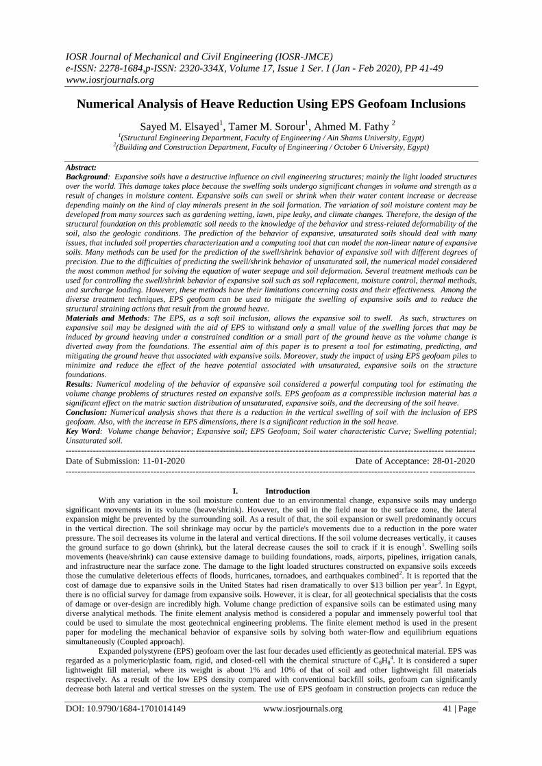
II. Case Study: Slab on Ground Placed on Regina Clay Subjected Infiltration Rate7
This case considered a 5.0 m thick deposit of Regina swelling clay that partially covered with a light loaded
structure. A constant infiltration rate of 2.0 x 10⁻⁸ m/s assigned to the ground surface around the structure over 175.0 days
(Figure no 1). The soil-water characteristic curve (SWCC) for the Regina clay8 and the soil permeability function (k
function) represented in Figure no 2. The mechanical properties of Regina clay presented in Table no 1.
Figure no 1: Geometry and boundary conditions of case study7
For the wetting conditions when cracks in the soil substantially close, the coefficient of the earth pressure at rest
(K0) suggested being 0.67. Thus, the Poisson's ratio μ = 0.4. The modulus of elasticity of unsaturated soil is a function of the
matric suction 𝑢𝑎 − 𝑢𝑤 and the net normal stress 𝑎𝑣 − 𝑢𝑎 . It is suggested that the saturated modulus of elasticity
calculated by the volume change index (Cs) subject to changes in net normal stress for the 2-D plane [9] as the following
equations. For swelling soil having e0 = 0.955, CS = 0.088, = 0.4, the average value of saturated modulus of elasticity of
soil from equation no 1 to be 1100 kPa. A pressure head value of -40.787 m was applied along the bottom boundary (i.e., -
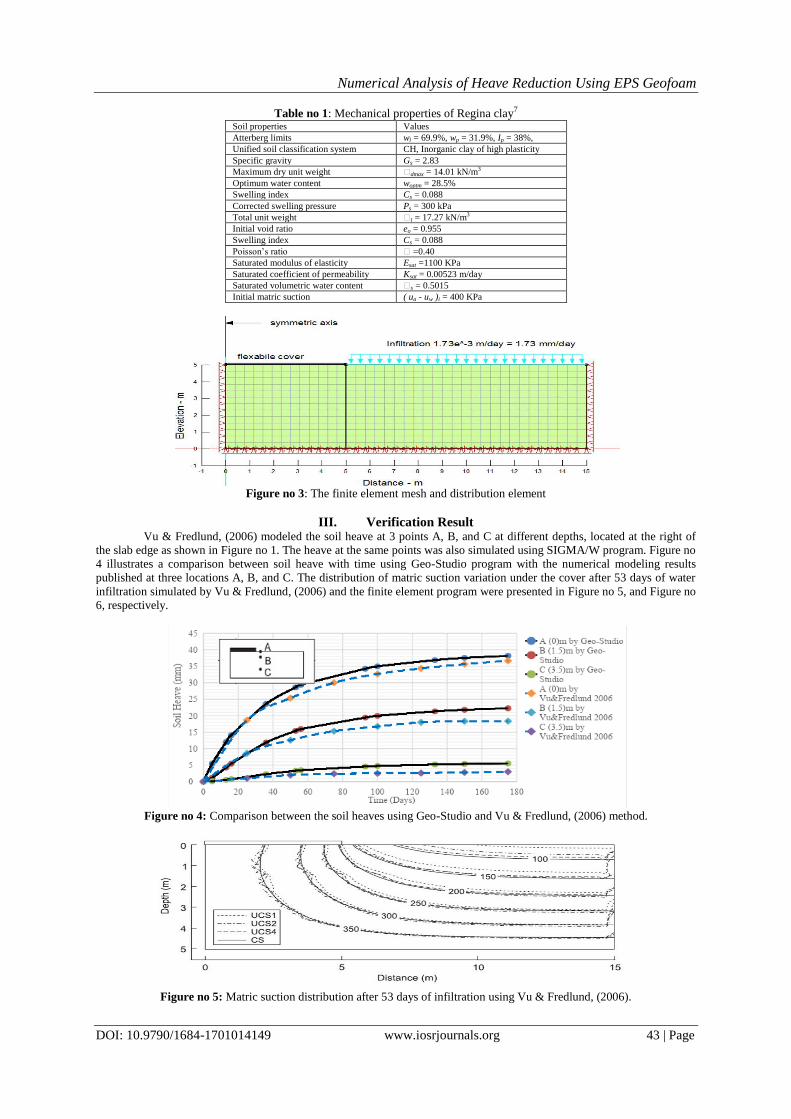
400 kPa / 9.807 kN/m3). The infiltration case study was re-analyzed with the coupled approach using Geo-studio programs.
The same soil properties and the boundary conditions given by Vu & Fredlund, (2006) were adopted. The finite element
geometry and mesh are presented in Figure no 3.
𝐸 =4.605 1 + 1 − 2 1 + 𝑒0
𝐶𝑠
𝑎𝑣 − 𝑢𝑎 (1)
𝐻 =4.605 1 + 1 + 𝑒0
𝐶𝑚
𝑢𝑎 − 𝑢𝑤 (2)
Figure no 2: Hydraulic properties of Regina clay7
Numerical Analysis of Heave Reduction Using EPS Geofoam
DOI: 10.9790/1684-1701014149 www.iosrjournals.org 43 | Page
Table no 1: Mechanical properties of Regina clay7 Soil properties Values
Atterberg limits wl = 69.9%, wp = 31.9%, Ip = 38%,
Unified soil classification system CH, Inorganic clay of high plasticity
Specific gravity Gs = 2.83
Maximum dry unit weight dmax = 14.01 kN/m3
Optimum water content woptm = 28.5%
Swelling index Cs = 0.088
Corrected swelling pressure Ps = 300 kPa
Total unit weight t = 17.27 kN/m3
Initial void ratio eo = 0.955
Swelling index Cs = 0.088
Poisson’s ratio =0.40
Saturated modulus of elasticity Esat =1100 KPa
Saturated coefficient of permeability Ksat = 0.00523 m/day
Saturated volumetric water content s = 0.5015
Initial matric suction ( ua - uw )i = 400 KPa
Figure no 3: The finite element mesh and distribution element
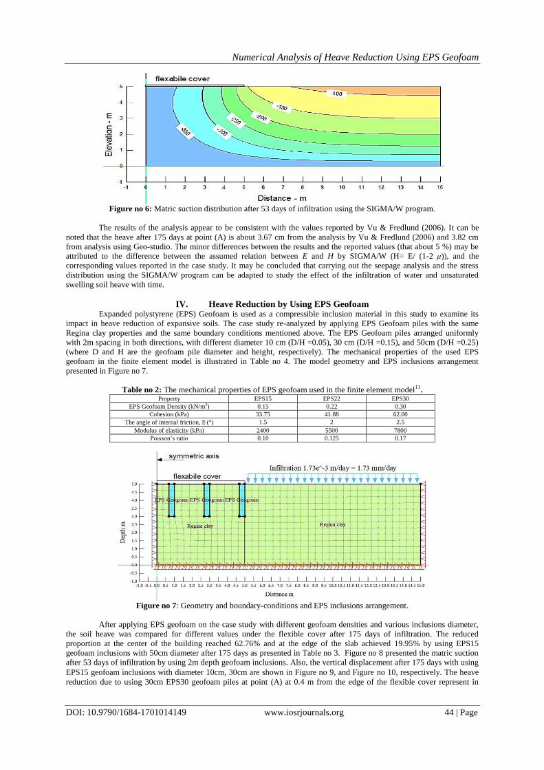
III. Verification Result Vu & Fredlund, (2006) modeled the soil heave at 3 points A, B, and C at different depths, located at the right of
the slab edge as shown in Figure no 1. The heave at the same points was also simulated using SIGMA/W program. Figure no
4 illustrates a comparison between soil heave with time using Geo-Studio program with the numerical modeling results
published at three locations A, B, and C. The distribution of matric suction variation under the cover after 53 days of water
infiltration simulated by Vu & Fredlund, (2006) and the finite element program were presented in Figure no 5, and Figure no
6, respectively.
Figure no 4: Comparison between the soil heaves using Geo-Studio and Vu & Fredlund, (2006) method.
Figure no 5: Matric suction distribution after 53 days of infiltration using Vu & Fredlund, (2006).
Numerical Analysis of Heave Reduction Using EPS Geofoam
DOI: 10.9790/1684-1701014149 www.iosrjournals.org 44 | Page
Figure no 6: Matric suction distribution after 53 days of infiltration using the SIGMA/W program.
The results of the analysis appear to be consistent with the values reported by Vu & Fredlund (2006). It can be
noted that the heave after 175 days at point (A) is about 3.67 cm from the analysis by Vu & Fredlund (2006) and 3.82 cm
from analysis using Geo-studio. The minor differences between the results and the reported values (that about 5 %) may be
attributed to the difference between the assumed relation between E and H by SIGMA/W (H= E/ (1-2 μ)), and the
corresponding values reported in the case study. It may be concluded that carrying out the seepage analysis and the stress
distribution using the SIGMA/W program can be adapted to study the effect of the infiltration of water and unsaturated
swelling soil heave with time.
IV. Heave Reduction by Using EPS Geofoam Expanded polystyrene (EPS) Geofoam is used as a compressible inclusion material in this study to examine its
impact in heave reduction of expansive soils. The case study re-analyzed by applying EPS Geofoam piles with the same
Regina clay properties and the same boundary conditions mentioned above. The EPS Geofoam piles arranged uniformly
with 2m spacing in both directions, with different diameter 10 cm (D/H =0.05), 30 cm (D/H =0.15), and 50cm (D/H =0.25)
(where D and H are the geofoam pile diameter and height, respectively). The mechanical properties of the used EPS
geofoam in the finite element model is illustrated in Table no 4. The model geometry and EPS inclusions arrangement
presented in Figure no 7.
Table no 2: The mechanical properties of EPS geofoam used in the finite element model11. Property EPS15 EPS22 EPS30
EPS Geofoam Density (kN/m3) 0.15 0.22 0.30
Cohesion (kPa) 33.75 41.88 62.00
The angle of internal friction, (°) 1.5 2 2.5
Modulus of elasticity (kPa) 2400 5500 7800
Poisson’s ratio 0.10 0.125 0.17
Figure no 7: Geometry and boundary-conditions and EPS inclusions arrangement.
After applying EPS geofoam on the case study with different geofoam densities and various inclusions diameter,
the soil heave was compared for different values under the flexible cover after 175 days of infiltration. The reduced
proportion at the center of the building reached 62.76% and at the edge of the slab achieved 19.95% by using EPS15
geofoam inclusions with 50cm diameter after 175 days as presented in Table no 3. Figure no 8 presented the matric suction
after 53 days of infiltration by using 2m depth geofoam inclusions. Also, the vertical displacement after 175 days with using
EPS15 geofoam inclusions with diameter 10cm, 30cm are shown in Figure no 9, and Figure no 10, respectively. The heave
reduction due to using 30cm EPS30 geofoam piles at point (A) at 0.4 m from the edge of the flexible cover represent in
Numerical Analysis of Heave Reduction Using EPS Geofoam
DOI: 10.9790/1684-1701014149 www.iosrjournals.org 45 | Page
Figure no 11. A comparison between the surface heave of the flexible cover after 175 days by using 2m depth EPS22
geofoam piles with a different diameter represented in Figure no 12.
Table no 3: Surface heave after 175 days with and without using 2m depth EPS geofoam piles.
inclusions diameter
(cm)
EPS Density
Dia. 10 cm (D/H = 0.05) Dia. 30cm (D/H = 0.15) Dia. 50cm (D/H = 0.25)
Value
(cm)
Reduction
(%)
Value
(cm)
Reduction
(%)
Value
(cm)
Reduction
(%)
Without
geofoam
Center 2.366 ----- 2.366 ----- 2.366 -----
Edge 3.66 ----- 3.66 ----- 3.66 -----
With EPS 15 Center 2.016 14.79% 1.495 36.81% 0.881 62.76%
Edge 3.46 5.46% 3.18 13.11% 2.93 19.95%
With EPS 22 Center 2.169 8.33% 1.819 23.11% 1.333 43.66%
Edge 3.50 4.37% 3.27 10.44% 305 16.67%
With EPS 30 Center 2.210 6.59% 1.929 18.47% 1.523 35.36%
Edge 3.50 4.37% 3.28 10.38% 3.07 16.12%
Figure no 8: The matric suction after 53 days by using 2m depth geofoam inclusions.
Figure no 9: Vertical displacements after 175 days with using 10 cm dia. EPS15 geofoam inclusions.
Figure no 10: Vertical displacements after 175 days with using 30 cm dia. EPS15 geofoam inclusions.
Numerical Analysis of Heave Reduction Using EPS Geofoam
DOI: 10.9790/1684-1701014149 www.iosrjournals.org 46 | Page
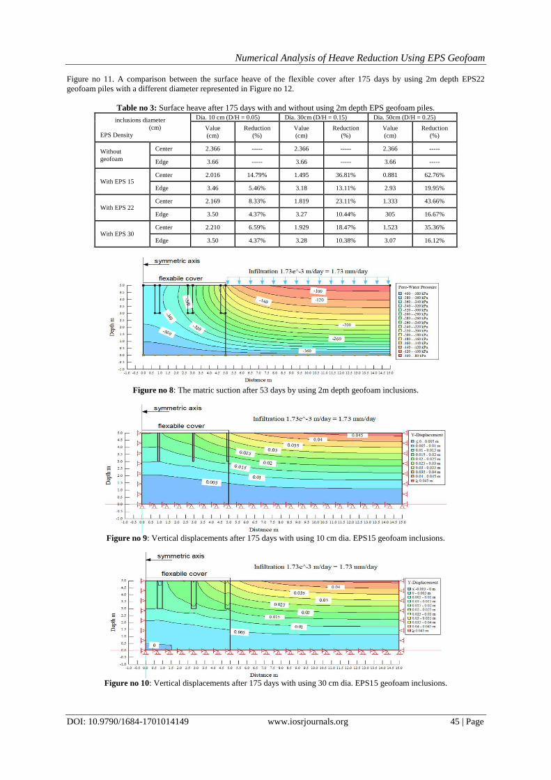
Figure no 11: Heave with time at points (A) at 0.4m from the edge of cover with/out using 30 cm dia. EPS (30) geofoam
inclusions.
Figure no 12: Surface heave after 175 days with/out using EPS22 geofoam inclusions with different diameters.
The soil swelling reduced by increasing the diameter of EPS geofoam piles. The impact of increasing density of
EPS geofoam piles using a constant diameter (30 cm) was slight after 175 days of infiltration as it can be observed from
Figure no 13. The lower value of EPS geofoam density is selected to yield greater compressibility.
Figure no 13: Surface heave with/out using 30 cm EPS Geofoam inclusions with different density after 175 days.
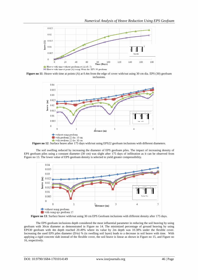
The EPS geofoam inclusions depth considered the most influential parameter in reducing the soil heaving by using
geofoam with 30cm diameter as demonstrated in Figure no 14. The minimized percentage of ground heaving by using
EPS30 geofoam with 4m depth reached 20.49% where its value by 2m depth was 10.38% under the flexible cover. Increasing the used EPS piles diameter (D/ts) % (ts swelling soil layer) leads to a decrease in soil heave with time. With
applying a rigid concrete slab instead of the flexible cover, the soil heave is linear as shown in Figure no 15, and Figure no
16, respectively.
Numerical Analysis of Heave Reduction Using EPS Geofoam
DOI: 10.9790/1684-1701014149 www.iosrjournals.org 47 | Page
Figure no 14: Surface heave after 175 days with/out using 50cm EPS30 geofoam inclusions with different depths (1m, 2m,
3m, 4m).
Figure no 15: Surface heave with/out using EPS (22) geofoam inclusions with a different diameter after 175 days under the
rigid slab.
Figure no 16: Surface heave with/out using EPS (30) geofoam inclusions with a different depth after 175 days under the
rigid slab.
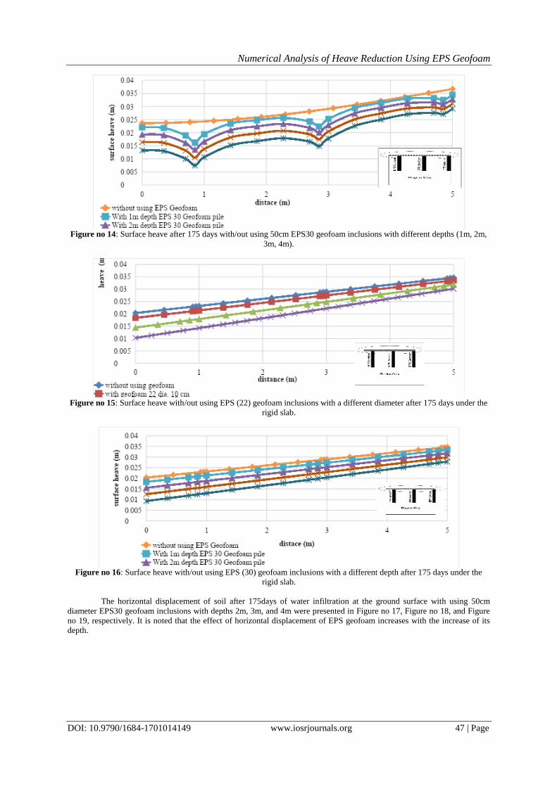
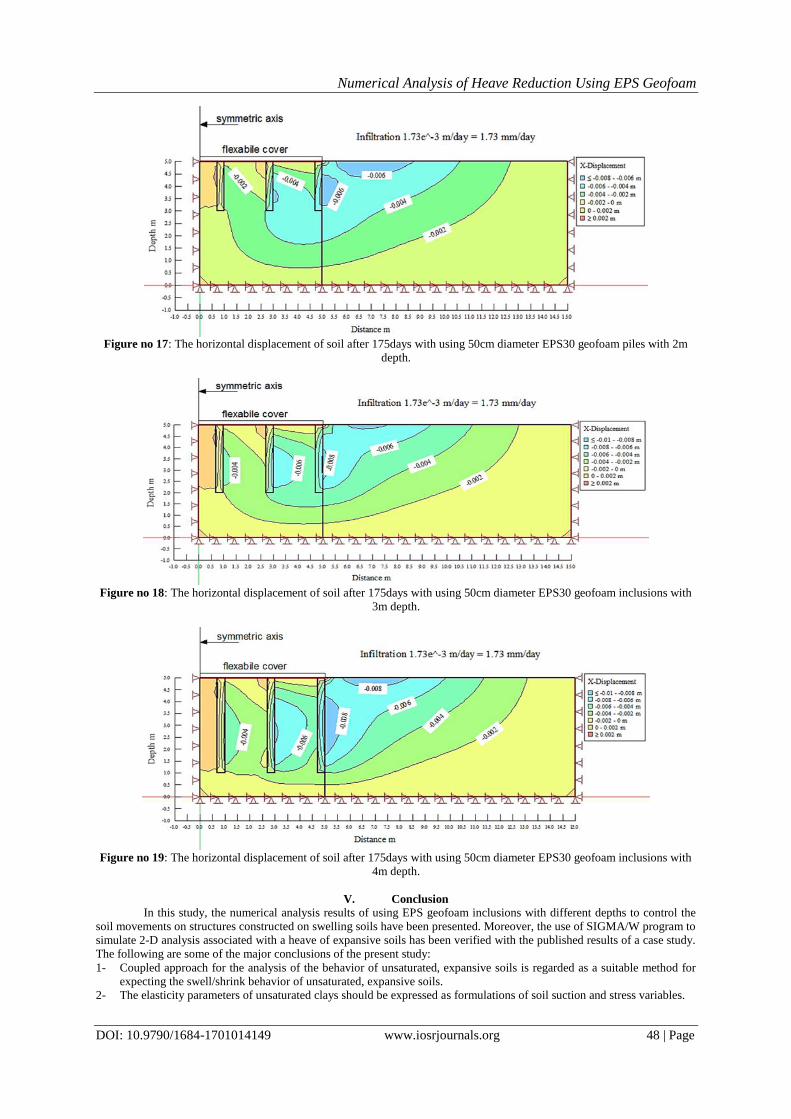
The horizontal displacement of soil after 175days of water infiltration at the ground surface with using 50cm
diameter EPS30 geofoam inclusions with depths 2m, 3m, and 4m were presented in Figure no 17, Figure no 18, and Figure
no 19, respectively. It is noted that the effect of horizontal displacement of EPS geofoam increases with the increase of its
depth.
Numerical Analysis of Heave Reduction Using EPS Geofoam
DOI: 10.9790/1684-1701014149 www.iosrjournals.org 48 | Page
Figure no 17: The horizontal displacement of soil after 175days with using 50cm diameter EPS30 geofoam piles with 2m
depth.
Figure no 18: The horizontal displacement of soil after 175days with using 50cm diameter EPS30 geofoam inclusions with
3m depth.
Figure no 19: The horizontal displacement of soil after 175days with using 50cm diameter EPS30 geofoam inclusions with
4m depth.
V. Conclusion
In this study, the numerical analysis results of using EPS geofoam inclusions with different depths to control the
soil movements on structures constructed on swelling soils have been presented. Moreover, the use of SIGMA/W program to
simulate 2-D analysis associated with a heave of expansive soils has been verified with the published results of a case study.
The following are some of the major conclusions of the present study:
1- Coupled approach for the analysis of the behavior of unsaturated, expansive soils is regarded as a suitable method for
expecting the swell/shrink behavior of unsaturated, expansive soils.
2- The elasticity parameters of unsaturated clays should be expressed as formulations of soil suction and stress variables.
Numerical Analysis of Heave Reduction Using EPS Geofoam
DOI: 10.9790/1684-1701014149 www.iosrjournals.org 49 | Page
3- The final soil suction distributions should be used as input for the stress-deformation analysis to model the swell/shrink
behavior of unsaturated, expansive soils.
4- It is possible to simulate seepage and stress distribution analysis for unsaturated soil using SIGMA/W program to study
the effect of infiltration and soil heave with time.
5- Using EPS geofoam as a compressible inclusion material has a significant effect on the matric suction distribution of
unsaturated, expansive soils, and the decreasing of the soil heave.
6- Increasing the used EPS inclusions diameter (D/ts)% (ts swelling soil layer) leads to a decrease in soil heave with time.
7- The decrease in EPS geofoam density leads to an increase in the percentage of footing heave reduction. This means that
the lower density of EPS geofoam is selected to yield higher compressibility and more heave reduction.
8- Increasing the EPS geofoam inclusions depth is the most significant factor in the soil heave reduction.
9- The soil heave reduction by using EPS geofoam inclusion under the flexible cover is non-linear. The heave decrease
with higher values at the centers of geofoam inclusions compared with its value between the geofoam inclusions.
Conversely, the heave reduction with EPS geofoam is linear under the rigid footing.
10- The effect of horizontal displacement of EPS geofoam increases with the increase of EPS geofoam depth.
11- Decreasing the diameter of the EPS pile near the center of footing and increasing its density can be significant in
reducing the footing differential heave/settlement.
References [1]. Adem, H. H, Modulus of elasticity-based method for estimating the vertical movement of natural unsaturated expansive soils, Ph.D.
thesis, Citeseer, 2015.
[2]. Jones D. E. and Holtz, W. G., “Expansive soils-the hidden disaster,” Civil Engineering, 1973; vol. 43, no. 8, pp. 49-51.
[3]. Puppala A. J. and Cerato A., “Heave distress problems in chemically-treated sulphate-laden materials,” Geo-Strata—Geo-Institute of ASCE, 2009; vol. 10, no. 2, p. 28
[4]. Ravve A., Principles of polymer chemistry, Springer Science & Business Media, 2013.
[5]. Elragi A. F., Selected engineering properties and applications of EPS geofoam, State University of New York. College of Environmental Science and Forestry, Syracuse, NY, 2000.
[6]. Stark T. D., Bartlett S. F., and Arellano D., “Expanded polystyrene (EPS) geofoam applications and technical data,” The EPS
Industry Alliance, 2012; vol. 1298, p. 36. [7]. Vu H. Q. and Fredlund D. G., “Challenges to modeling heave in expansive soils,” Canadian Geotechnical Journal, NRC Research
Press, 2006; vol. 43, no. 12, pp. 1249-1272.
[8]. Hung V. Q. Uncoupled and coupled solutions of volume change problems in expansive soils, Saskatoon, SK, Canada, 329 p: Ph.D. Thesis, University of Saskatchewan, 2003.
[9]. Vu H. Q. and Fredlund D. G., “The prediction of one-, two-, and three-dimensional heave in expansive soils,” Canadian
Geotechnical Journal, 2004; vol. 41, pp. 713--737. [10]. Fredlund D. G. and Xing A., “Equations for the soil-water characteristic curve,” Canadian geotechnical journal, 1994; vol. 31, no.
4, pp. 521-532.
[11]. Padade A. and. Mandal J., “Feasibility studies on expanded polystyrene (EPS) geofoam,” in Proc., Int. Conf. Ground Improvement and Ground Technique, ICGI2012, India, Research Publishing Chennai, 2012, pp. 903-906.
[12]. Vu H. Q. and Fredlund D. G., “Challenges to modeling heave in expansive soils.,” Canadian Geotechnical Journal, 2006; vol. 43 ,
pp. 1249-1272.