nonlinear behavior of thermally loaded curved sandwich panels with a transvesely flexible core
TRANSCRIPT
Seediscussions,stats,andauthorprofilesforthispublicationat:https://www.researchgate.net/publication/245416894
Nonlinearbehaviorofthermallyloadedcurvedsandwichpanelswithatransveselyflexiblecore
ArticleinJournalofMechanicsofMaterialsandStructures·December2009
DOI:10.2140/jomms.2009.4.1287
CITATIONS
4
READS
21
2authors:
Y.Frostig
Technion-IsraelInstituteofTech…
126PUBLICATIONS2,676CITATIONS
SEEPROFILE
OleThyboThomsen
UniversityofSouthampton
168PUBLICATIONS1,635CITATIONS
SEEPROFILE
AllcontentfollowingthispagewasuploadedbyY.Frostigon01August2015.
Theuserhasrequestedenhancementofthedownloadedfile.

Journal of
Mechanics ofMaterials and Structures
NONLINEAR BEHAVIOR OF THERMALLY LOADED CURVEDSANDWICH PANELS WITH A TRANSVESELY FLEXIBLE CORE
Yeoshua Frostig and Ole Thomsen
Volume 4, Nº 7-8 September 2009
mathematical sciences publishers
JOURNAL OF MECHANICS OF MATERIALS AND STRUCTURESVol. 4, No. 7-8, 2009
NONLINEAR BEHAVIOR OF THERMALLY LOADED CURVED SANDWICHPANELS WITH A TRANSVESELY FLEXIBLE CORE
YEOSHUA FROSTIG AND OLE THOMSEN
The nonlinear analysis of a curved sandwich panel with a compliant core subjected to a thermal field andmechanical load is presented. The mathematical formulation is developed first, along with the solutionof the stress and displacement fields for the case of a sandwich core with mechanical properties that areindependent of the temperature. The nonlinear analysis includes geometrical nonlinearities in the facesheets caused by rotation of the face cross sections and high-order effects due to the transversely flexiblecore. The mathematical formulation uses the variational principle of minimum energy along with HSAPT(high-order sandwich panel theory) to derive the nonlinear field equations and the boundary conditions.The full displacement and stress fields of the core with uniform temperature-independent mechanicalproperties and the appropriate governing equations of the sandwich panel are given.
This is followed by the general solution of the core stress and displacement fields when the mechan-ical core properties are dependent on the radial (through-the-thickness) coordinate. The displacementfields of a core with temperature-dependent mechanical properties are determined explicitly using anequivalent polynomial description of the varying properties.
A numerical study then describes the nonlinear response of curved sandwich panels subjected to con-centrated and distributed mechanical loads, thermally induced deformations, and simultaneous thermaland mechanical loads where the mechanical load is below the limit load level of the mechanical responseand the imposed temperature field is made to vary. The results reveal that the thermomechanical responseis linear when the sandwich panel is heated, but becomes nonlinear with limit point behavior when thepanel is cooled down.
Introduction
Curved sandwich structures are increasingly being used in the aerospace, naval and transportation indus-tries, where weight savings combined with high strength and stiffness properties are always in demand.Sandwich structures consist of two thin face sheets, usually metallic or laminated composites, bonded toa core that is often made of honeycomb or a polymer foam with low strength properties. The core usuallyprovides the shear resistance/stiffness to the sandwich structure in the transverse (radial) direction, anda transverse support to the face sheets that is associated to radial normal stresses. Polymer foam or low-strength honeycomb cores are flexible in this (radial/thickness) direction, and this affects both the globaland the local response through changes of the core height (compressible core), and a core cross sectionplane that deforms into a nonlinear pattern.
The manufacture of such sandwich structures often involves elevated temperatures that may be asso-ciated with thermally induced deformations. During service, deformations may be induced by elevated
Keywords: sandwich strcutures, thermal effects, nonlinear geometry, softcore, high-order models.
1287
1288 YEOSHUA FROSTIG AND OLE THOMSEN
temperatures, with or without large gradients, which may degrade the properties of the face sheets andthe core. In a traditional design process of such structures the thermally induced deformations and the de-formations caused by external mechanical loads are considered separately. However, this approach is notnecessarily conservative, since the interaction between the external loads and the elevated temperatures,especially when the deformations are large, may lead to unsafe behavior and loss of structural integrity.
The major goal of this work is to investigate under what circumstances the combination of simultane-ous thermally induced deformations and mechanical loads applied to curved sandwich structures (panels)may lead to an unstable and thereby potentially disastrous load response.
Outline. After a discussion of earlier work in Section 1 we introduce in Section 2 the mathematical for-mulation leading to the field and governing equations, the appropriate boundary conditions, the thermalfields within the core, along with the effects of the degradation of the mechanical core properties as aresult of elevated temperatures. The full nonlinear governing equations for the temperature-independent(TI) case are derived and presented in Section 3. In Section 4 we turn to the general solution for the corestress and displacement fields when the core properties are coordinate-dependent in the radial (through-the-thickness) direction and display mechanical properties that are temperature-dependent (TD). This isfollowed in Section 5 by a numerical investigation into the nonlinear response of sandwich panels; theresults are described in Section 5.1 for TI cores and in Section 5.2 for TD cores. Further discussion ofthe numerical study and overall conclusions occupy Section 6.
1. Antecedents
The well known approach for sandwich plates/panels, due to Reissner and Mindlin, replaces the layeredsandwich panel by an equivalent single layer (ESL) and takes into the account the relaxed Kirchhoff–Lovehypothesis, which assumes that the section plane is not normal to the plate middle surface. This approachhas become the foundation for a large group of research works in the field of sandwich structures, in-cluding [Whitney and Pagano 1970; Noor and Burton 1990; Noor et al. 1994; 1996], to name a few; seealso the references listed in this last paper. Kollar [1990] investigated buckling of generally anisotropicshallow sandwich shells and Vaswani et al. [1988] performed vibration and damping analysis of curvedsandwich beams. These last two models used the Flugge shell theory while assuming that the facesheets are membranes and the core is incompressible. A model for shallow cylindrical sandwich panelswith orthotropic surfaces suggested in [Wang and Wang 1989] follows the same relaxed Kirchhoff–Lovehypothesis for the core as in references quoted above, but in this work the face sheets are attributed withboth in-plane and flexural rigidities. Similarly, using the principle of virtual work along with the Reissner–Mindlin hypothesis and Sanders’ nonlinear stress-displacement relations, a theory for thick shells hasbeen developed [di Sciuva 1987; di Sciuva and Carrera 1990] that takes into account the shear rotation butassumes that the core is incompressible and linear. A stability analysis for cylindrical sandwich panelswith laminated composite faces based on the Reissner hypothesis has been derived [Rao 1985; Raoand Meyer-Piening 1986; 1990]. These authors extended the Reissner–Mindlin theory to derive force-displacement relations of anisotropic sandwich panels with membrane face sheets. As a consequence,local effects, due to localized loads, point supports, presence of load or geometric discontinuities arebeyond the capability of these approaches. This well known approach is accurate as long as the corecan be considered to be incompressible, i.e., the height of the core remains unchanged so the radial
NONLINEARITY IN THERMALLY LOADED CURVED SANDWICH PANELS 1289
displacements of the two face sheets are identical. However, compliant core materials such as relativelysoft polymer foams are used in many modern sandwich structures. Accordingly it is necessary to relaxthe Reissner–Mindlin constraints to account for localized effects caused by the change of core heightduring the deformation of the sandwich structure considered.
A class of high-order theories based on the assumption of cubic and quadratic or trigonometric through-the-thickness distributions for the displacements have been suggested in [Lo et al. 1977; Librescu andHause 2000; Stein 1986; Reddy 1984a; 1984b]. The results usually include terms that have no phys-ical meaning due to the integration through the thickness. Lo et al. [1977] assumed a cubic shapefor the in-plane deformations and a quadratic distribution for the vertical deformation. Stein [1986]used trigonometric series for the displacement distributions. Reddy [1984a; 1984b] also assumed cubicdistributions for the in-plane displacements whereas the vertical displacement is assumed to be uniformacross the thickness. In addition, the condition of zero shear stresses at the outer fibers of the sectionwas also adopted. All the referenced high-order models use integration through the thickness along withvariational principle and in general they are valid for sandwich panels with an incompressible core.
Many investigators have performed numerical analyses of the overall behavior of curved sandwichpanels using FEA; see for example [Hildebrand 1991; Hentinen and Hildebrand 1991; Smidt 1995;1993; Tolf 1983; Kant and Kommineni 1992]. The different analyses, linear or nonlinear, use varioustypes of finite elements along with the limiting Reissner–Mindlin hypothesis, thus ignoring localizedeffects.
A different approach that includes the effect of the transverse (radial) normal stresses on the overallbehavior of sandwich shells has been considered by Kuhhorn and Schoop [1992], who introduced geo-metrically nonlinear kinematic relations along with pre-assumed polynomial deformation patterns forplates and shells. In recent years, the effects of incorporating a vertical flexible core on the local andoverall behavior of the flat and curved sandwich panels have been implemented through the use of thehigh-order theory (HSAPT); see [Frostig et al. 1992] for flat panels, [Bozhevolnaya and Frostig 1997] fornonlinear behavior, [Bozhevolnaya 1998] on shallow sandwich panels, [Karayadi 1998] on cylindricalshells, [Frostig 1999] on the linear behavior of curved sandwich panels, [Bozhevolnaya and Frostig 2001]on the free vibration of curved panels, and [Thomsen and Vinson 2001] on composite sandwich aircraftfuselage structures.
Thermal effects in curved sandwich panels have been considered in [Noor et al. 1997] using a first-order shear deformation computation model with incompressible core. A thermomechanical FE analysiswas conducted by Ko [1999], who looked into the peeling stresses involved at the face-core interfacesunder cryogenic bending loading conditions. Librescu et al. [1994; 2000] investigated the thermomechan-ical response of flat and curved panels using a high-order theory that includes transverse (radial) shearflexibility but ignoring the transverse (radial) flexibility of the core. Fernlund [2005] used a simplifiedsandwich model that ignores the radial stresses as well as the shear deformation in the core in order todetermine the spring-in effects of angled sandwich panels.
The thermal and the thermomechanical nonlinear response of a flat sandwich panel with a compressiblecore has been considered in [Frostig and Thomsen 2008a; 2008b], along with the effect of the thermaldegradation of the mechanical properties of the core; see [Frostig and Thomsen 2007]. This series of pa-pers reveals that the transverse flexibility of the core along with its extension and compression as a resultof the thermally induced deformation play a major role in the nonlinear response of sandwich panels.

1290 YEOSHUA FROSTIG AND OLE THOMSEN
2. Mathematical formulation
The mathematical formulation presented in the paper uses high-order sandwich panel theory (HSAPT) tomodel the nonlinear response of a curved sandwich panel when subjected to thermally induced deforma-tion along with mechanical loads. The sandwich panel is modeled as two curved faces, with membraneand flexural rigidities following the Euler–Bernoulli hypothesis, that are interconnected through com-patibility and equilibrium with a two-dimensional compliant (compressible or extensible) elastic corewith shear and radial (through-the-thickness) normal stress resistance. The HSAPT model for the curvedpanel adopts the following restrictive assumptions:
• The face sheets have in-plane (circumferential) and bending rigidities with small moderate defor-mations class of kinematic relation [Brush and Almroth 1975; Simitses 1976] and negligible sheardeformations.
• The core is considered as a two-dimensional linear elastic continuum obeying small deformationkinematic relations; the core height may change and the section planar does not remain plane afterdeformation.
• The core is assumed to possess shear and radial normal stiffness only, and the in-plane (circumfer-ential) normal stiffness is assumed negligible. Accordingly, the circumferential normal stresses areassumed to be nil.
• Full bonding between the face sheets and the core is assumed and the interfacial layers can resistshear as well as radial normal stresses.
• The loads are applied to the face sheets only.
Field equations and boundary conditions. The field equations and the boundary conditions are derivedfollowing the steps of the HSAPT approach for the curved sandwich panel [Frostig 1999; Bozhevolnayaand Frostig 1997]. The field equations are derived using the variational principle of extremum of thetotal potential energy:
δ(U + V )= 0, (1)
where δ is the variational operator, U is in the internal potential strain energy and V is the externalpotential energy.
The internal potential energy of a fully bonded panel in terms of polar coordinates reads
δU =∫ α
0
∫ 12 d j
−12 d j
∫ 12 bw
−12 bw
σsst(φ, zt)δεsst(φ, zt)rt dy dzt dφ
+
∫ α
0
∫ 12 db
−12 db
∫ 12 bw
−12 bw
σssb(φ, zb)δεssb(φ, zb)rb dy dzb dφ
+
∫ α
0
∫ rtc
rbc
∫ 12 bw
−12 bw(τrs(φ, rc)δγrs(φ, rc)+ σrr (φ, rc)δεrr (φ, rc))rc dy drc dφ, (2)
where σss j (φ, r j ) and εss j (φ, r j ) ( j = t, b) are the stresses and strains, respectively, in the circumferen-tial directions of the face sheets; τrs(φ, rc) and γrs(φ, rc) are the shear stresses and strains; σrr (φ, rc)
and εrr (φ, rc) are the radial normal stresses and strains; r and s refer to the radial and circumferential
NONLINEARITY IN THERMALLY LOADED CURVED SANDWICH PANELS 1291
φ=φjα
φ
A
A
c
Section A-A(b)
mt nt
qt
mb
qb
Mtj
Ntj
Ptj
MbjNbj
Pbj
(a)
dt/2
db/2
rt rb rbc rtc
dt
db
bw
zt,wt
zb,wb
zc,wc
st,uot
sb,uob sc,uc
rtrb
rbc
rtc
Ttt
Tbt=Ttc
Ttb=Tcb
Tbb
Temperature
Distribution
rc
nb
si=riφ (i=t,b,c)
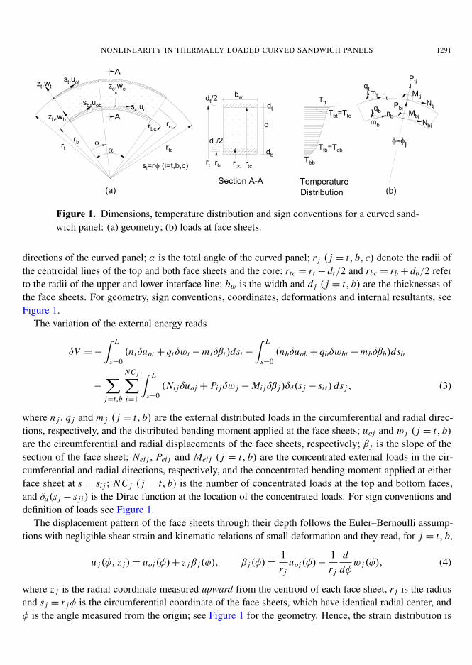
Figure 1. Dimensions, temperature distribution and sign conventions for a curved sand-wich panel: (a) geometry; (b) loads at face sheets.
directions of the curved panel; α is the total angle of the curved panel; r j ( j = t, b, c) denote the radii ofthe centroidal lines of the top and both face sheets and the core; rtc = rt − dt/2 and rbc = rb+ db/2 referto the radii of the upper and lower interface line; bw is the width and d j ( j = t, b) are the thicknesses ofthe face sheets. For geometry, sign conventions, coordinates, deformations and internal resultants, seeFigure 1.
The variation of the external energy reads
δV =−∫ L
s=0(ntδuot + qtδwt −mtδβt)dst −
∫ L
s=0(nbδuob+ qbδwbt −mbδβb)dsb
−
∑j=t,b
NC j∑i=1
∫ L
s=0(Ni jδuoj + Pi jδw j −Mi jδβ j )δd(s j − si t) ds j , (3)
where n j , q j and m j ( j = t, b) are the external distributed loads in the circumferential and radial direc-tions, respectively, and the distributed bending moment applied at the face sheets; uoj and w j ( j = t, b)are the circumferential and radial displacements of the face sheets, respectively; β j is the slope of thesection of the face sheet; Nei j , Pei j and Mei j ( j = t, b) are the concentrated external loads in the cir-cumferential and radial directions, respectively, and the concentrated bending moment applied at eitherface sheet at s = si j ; NC j ( j = t, b) is the number of concentrated loads at the top and bottom faces,and δd(s j − s j i ) is the Dirac function at the location of the concentrated loads. For sign conventions anddefinition of loads see Figure 1.
The displacement pattern of the face sheets through their depth follows the Euler–Bernoulli assump-tions with negligible shear strain and kinematic relations of small deformation and they read, for j = t, b,
u j (φ, z j )= uoj (φ)+ z jβ j (φ), β j (φ)=1r j
uoj (φ)−1r j
ddφw j (φ), (4)
where z j is the radial coordinate measured upward from the centroid of each face sheet, r j is the radiusand s j = r jφ is the circumferential coordinate of the face sheets, which have identical radial center, andφ is the angle measured from the origin; see Figure 1 for the geometry. Hence, the strain distribution is
1292 YEOSHUA FROSTIG AND OLE THOMSEN
also assumed to be linear and it reads
εss j (φ)= εoss j (φ)+ z jχ j (φ), (5)
where the mid-plane strain and the curvature equal
εoss j (φ)=d
dφuoj (φ)+
w j (φ)
r j (φ)+
12β j (φ)
2, χ j (φ)=1r j
ddφβ j (φ)=
1r2
j
ddφ
uoj (φ)−1r2
j
d2
dφ2w j (φ). (6)
Notice that thermal strains do not appear in the terms of the strains of the face sheets.The kinematic relations for the core, under the approximation of small deformations, read
εrrc(φ, r)=∂
∂rwc(φ, r), γc(φ, r)=
∂
∂ruc(φ, r)−
uc(φ, r)r+
1r∂
∂φwc(φ, r), (7)
where wc(φ, r) and uc(φ, r) are the radial and circumferential displacements of the core, respectively.The compatibility conditions corresponding to perfect bonding between the face sheets and the core
require that
uc(φ, r = r jc)= uoj (φ)−λ
2r jd j (uoj (φ)−w j (φ),φ), wc(φ, r = r jc)= w j (φ), (8)
where λ= 1,−1 for j = t, b, respectively; r jc ( j = t, b) are the radii of the upper and lower face-coreinterfaces; and uc(r = r jc, φ), wc(r = r jc, φ) are the displacements of the core in the circumferentialand radial directions at the face-core interfaces.
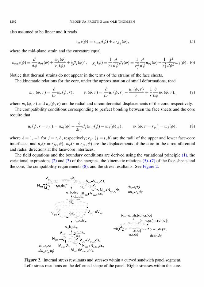
The field equations and the boundary conditions are derived using the variational principle (1), thevariational expressions (2) and (3) of the energies, the kinematic relations (5)–(7) of the face sheets andthe core, the compatibility requirements (8), and the stress resultants. See Figure 2.
Figure 2. Internal stress resultants and stresses within a curved sandwich panel segment.Left: stress resultants on the deformed shape of the panel. Right: stresses within the core.
NONLINEARITY IN THERMALLY LOADED CURVED SANDWICH PANELS 1293
The field equations, after integration by parts and some algebraic manipulations, read as follows(notice that since the strains in the core are linear, the field equations of the core coincide with those forthe geometrically linear case [Frostig 1999] and are presented here only for convenience):
Face sheets ( j = t, b):(−
d j
2r j+ λ
)bwr jcτsr (φ, r = r jc)+
1r j
(uoj (φ)−
dw j (φ)
dφ
)Nss j (φ)−
d Nss j (φ)
dφ
+m j (φ)−1r j
d Mss j (φ)
dφ− r j n j = 0,(
1+1r j
(duoj (φ)
dφ−
d2w j (φ)
dφ2
))Nss j (φ)+
1r j
(uoj (φ)−
dw j (φ)
dφ
)d Nss j (φ)
dφ
+ λbwr jcσrr (φ, r = r jc)−bwd jr jc
2r j
dτsr (φ, r = r jc)
dφ−
1r j
d2 Mss j (φ)
dφ2 +dm j (φ)
dφ− r j qt = 0.
(9)
Core:
rc∂τsr (φ, rc)
∂rc+ 2τsr (φ, rc)= 0, rc
∂σrr (φ, rc)∂rc
+ σrr (φ, rc)+∂τsr (φ, rc)
∂φ= 0. (10)
Here Nss j and Mss j ( j = t, b) are the in-plane and bending moment stress resultants of each face sheet;τsr (φ, r = r jc) and σrr (φ, r = r jc) (with j = t, b) are the shear and vertical normal stresses, respectively,at the face-core interfaces; and λ= 1,−1 for j = t, b. Notice that here the nonlinear terms involve alsoin-plane displacements, unlike the case of flat panels. Note also that, due to the geometrical nonlinearitiesof the face sheets, the equilibrium conditions, which are described by the field equations, correspond tothe deformed shape of the face sheets and the undeformed shape of the core; see Figure 2.
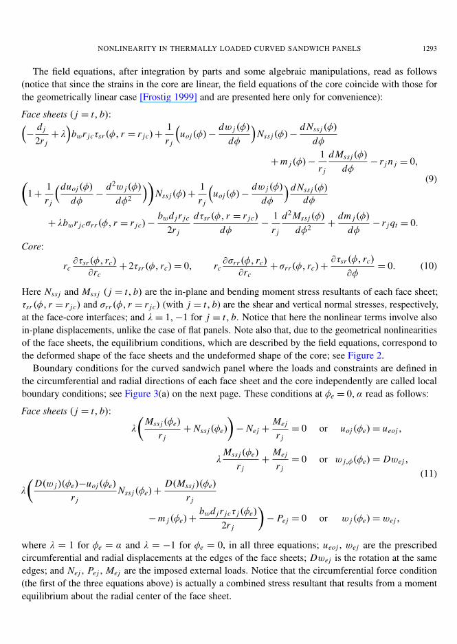
Boundary conditions for the curved sandwich panel where the loads and constraints are defined inthe circumferential and radial directions of each face sheet and the core independently are called localboundary conditions; see Figure 3(a) on the next page. These conditions at φe = 0, α read as follows:
Face sheets ( j = t, b):
λ
(Mss j (φe)
r j+ Nss j (φe)
)− Nej +
Mej
r j= 0 or uoj (φe)= ueoj ,
λMss j (φe)
r j+
Mej
r j= 0 or w j,φ(φe)= Dwej ,
λ
(D(w j )(φe)−uoj (φe)
r jNss j (φe)+
D(Mss j )(φe)
r j
−m j (φe)+bwd jr jcτ j (φe)
2r j
)− Pej = 0 or w j (φe)= wej ,
(11)
where λ = 1 for φe = α and λ = −1 for φe = 0, in all three equations; ueoj , wej are the prescribedcircumferential and radial displacements at the edges of the face sheets; Dwej is the rotation at the sameedges; and Nej , Pej , Mej are the imposed external loads. Notice that the circumferential force condition(the first of the three equations above) is actually a combined stress resultant that results from a momentequilibrium about the radial center of the face sheet.
1294 YEOSHUA FROSTIG AND OLE THOMSEN
Figure 3. Edge conditions at the edge of a curved sandwich panel: (a) conventionaledge with isolated supports; (b) reinforced edge with an edge beam.
Core: The boundary conditions at φe = 0, α, through the depth of the core, at rbc ≤ rc ≤ rtc, read
τrs(φe, rc)= 0 or wc(φe, rc)−wec(rc)= 0, (12)
where wec(r) denotes the prescribed deformations at the ends of the sandwich panel.For the case where an edge beam connects the two face sheets and the core, the two face sheets undergo
identical displacements and rotations; see Figure 3(b). Thus the distribution of the displacement throughthe depth of the sandwich panel follows those of a face sheet, given in (4):
ug(φe, zg)= ugo(φe)+zg
rg
(ugo(φe)− D(wg)(φe)
), (13)
where ugo(φe) denotes the circumferential displacements and D(wg)(φe) the rotation of the centroid lineof the section with the edge beam; see again Figure 3(b). In order to use these displacements, denotedas global displacements, in the variational terms of the boundary conditions that result form the partialintegration of the internal and external potential energy terms and the contribution of the loads at theedges of the panel, the global in-plane displacements and rotations must be defined in terms of thedisplacements and rotation of the face sheets. Hence, these unknowns are determined by imposing theconditions that the global displacements ug(φe, zg) at the centroid of the upper and lower face sheetsmust equal the in-plane displacements uoj (φe) of the face sheets. Thus they read
D(wg)(φe)=rt uob(φe)+ rbuot(φe)
c+ 12 dt +
12 db
, ugo(φe)=zgbuot(φe)+ zgt uob(φe)
c+ 12 dt +
12 db
. (14)
The existence of the edge beam also imposes relations between the displacements of the face sheets:
wt(φe)= wb(φe), βt(φe)= βb(φe), βt(φe)=uot(φe)− uob(φe)
zeb+ zet, (15)
where the last equality results from the requirement that the slope of the section of the face sheets andthat of the edge beam must be identical.
The global boundary conditions are derived by expressing the displacements and rotations of the facesheets in terms of the global displacements using (14) and (15), and substituting them into the variational
NONLINEARITY IN THERMALLY LOADED CURVED SANDWICH PANELS 1295
terms at the edges. Hence, by collecting terms with respect to the in-plane displacement and rotation ofthe edge beam, one obtains for these global conditions
(16)rt Nsst(φe)+Mssb(φe)+Msst(φe)+rb Nssb(φe)+Mge(φe)
rg− Nge(φe)= 0 or ugo(φe)= ugeo,
−Nsst(φe)zgt −Mssb(φe)−Msst(φe)+ Nssb(φe)zgb−Mge(φe)= 0 or D(wg)(φe)= Dwge,
Vsr t(φe)+ Vsrb(φe)+bwrtc(rtc−rbc)τt(φe)
rbc− Pge = 0 or wg(φe)= wge,
where Vsr j (φ) ( j = t, b) is the radial shear stress resultant in each of the face sheets, which equals
Vsr j (φe)=D(w j )(φe)− uoj (φe)
r jNss j (φe)+
D(Mss j )(φe)
r j+
bwd jr jcτsr (φe, r = r jc)
2r j−m j (φe). (17)
Under the assumption of a perfect bond between the edge beam and the core (through the full coredepth) the radial displacement field of the core must be uniform through its depth. This is possible onlywhen the upper and lower face sheets have identical displacements; see (15). This is equivalent to aweaker version of the requirement (12)2, namely
wc(φe)≈1c
∫ rtc
rbc
wc(φe, rc) drc = wge(φe). (18)
3. Governing equations in the temperature-independent case
To determine the governing equations we must first define the stress and displacement fields of the core.
Core displacement and stress fields: uniform mechanical properties (TI). The explicit descriptions ofthe stress and displacement fields of the core are determined through the compatibility conditions (8),applied to the following constitutive relations of an isotropic core:
εrr (φ, rc)=σrr (φ, rc)
Erc+αT cTc(rc, φ), γsr (φ, rc)=
τsr (φ, rc)
Gsrc, (19)
where Tc is the temperature function and Erc,Gsrc are the Young’s and shear moduli of the core in theradial direction.
The stress fields within the core are derived through the solution of the field equations (10) of the core,which reads
τsr (φ, rc)=r2
tc
r2cτt(φ), σrr (φ, rc)=
r2tc
r2c
dτt(φ)
dφ+
Cw1(φ)
rc, τb(φ)=
r2tc
r2bcτt(φ),
σrr j (φ)=r2
tc
r2jc
ddφτt(φ)+
Cw1(φ)
r jc( j = t, b),
(20)
where Cw1(φ) is a coefficient of integration to be determined through the compatibility conditions (8) atthe face-core interfaces; τ j (φ) and σrr j (φ) ( j = t, b) are the shear and radial normal stresses, respectively,
1296 YEOSHUA FROSTIG AND OLE THOMSEN
at the face-core interfaces. The result for the radial stress field is
σrr (φ, rc)=cErcαT c
2rc L
(Tct(φ)+ Tcb(φ)
)−
Erc
rc L
(wt(φ)−wb(φ)
)+
(rtcc
rcrbc L+
r2tc
r2c
)dτt(φ)
dφ, (21)
where we have introduced the temperature functions Tct and Tbt at the core-face interfaces, as well asthe abbreviation
L = ln rbcrtc.
Equation (21) specializes to the vertical normal stresses at the upper and the lower face-core interfaces:
σrr t(φ)=cErcαT c
2rtc L
(Tct(φ)+Tcb(φ)
)−
Erc
rtc L
(wt(φ)−wb(φ)
)+
(c
rbc L+1)
dτt(φ)
d(φ),
σrrb(φ)=cErcαT c
2rbc L
(Tct(φ)+Tcb(φ)
)−
Erc
rbc L
(wt(φ)−wb(φ)
)+
(rtccr2
bc L+
r2tc
r2bc
)dτt(φ)
d(φ).
(22)
The displacement fields of the core in the radial and circumferential directions are determined throughthe constitutive relations (19) and the three compatibility conditions (8) at the upper face-core interfaceand the radial compatibility condition at the lower interface. They read as follows:
wc(φ, rc)=−αT c
2cL
((rtc− rc)
2L − c2 ln rcrtc
)Tct(φ)
+αT c
2cL
((rbc− rc)
2L + c2 ln rcrbc
)Tcb(φ)
+1L
(wb(φ) ln rc
rtc−wt(φ) ln rc
rbc
)+
rtc
Ecrbcrc L
(rtcrc ln rc
rtc− rbcrc ln rc
rbc− rtcrbc L
)dτt(φ)
dφ(23)
uc(φ, rc)= −αT c
2rtccL
(Lrtc
(r2
c − r2tc− 2rcrbc ln rc
rtc+ 2c(rtc− rc)
)− c2
(rtc(1+ ln rc
rtc
)− rc
))dTct(φ)
dφ
+αT c
2rtccL
(Lrtc
(r2
c − r2tc− 2rcrtc ln rc
rtc
)+ c2
(rtc− rc+ rtc ln rc
rtc
))dTcb(φ)
dφ
−1
rtc L
(rtc− rc+ rtc ln rc
rbc+ rc L rtc
rt
)dwt(φ)
dφ
+1
rtc L
(rtc− rc+ rtc ln rc
rtc
)dwb(φ)
dφ+
r2c − r2
tc
2rcGcτt(φ)+
rc
rtuot(φ)
+1
2Ec Lrbcrc
(2crc
(rtc− rc+ rtc ln rc
rbc
)+(2r2
tcrc− (r2tc+ r2
c )rbc)L)d2τt(φ)
dφ2 (24)
Next we give the fifth of the field equations, which results from the compatibility condition at thelower face-core interface in the circumferential direction, and it derived using (8) and (24) along with a
NONLINEARITY IN THERMALLY LOADED CURVED SANDWICH PANELS 1297
nonuniform temperature field:
αT c
2crtc L
(c3+ 2rbcrtc L(c+ rbc L)
)dTct(φ)
dφ+
αT c
2crtc L
(c3− 2rbcrtc L(c+ rtc L)
)dTcb(φ)
dφ
+rbc
rtuot(φ)−
rbc
rbuob(φ)+
2c2+ (r2
tc− r2bc)L
2Ercrbc Ld2τt(φ)
dφ2 −r2
tc− r2bc
2rbcGsrcτt(φ)
+
(c
rtc L+
rbc
rb
)dwb(φ)
dφ−
(c
rtc L+
rbc
rt
)dwt(φ)
dφ= 0. (25)
However, when the temperature distribution is uniform through the length of the panel and the elasticconstants are uniform, nothing is left of the first line and the compatibility equation becomes identicalto the one obtained for the linear case [Frostig 1999]:
rbc
rtuot(φ)−
rbc
rbuob(φ)+
2c2+ (r2
tc− r2bc)L
2Ercrbc Ld2τt(φ)
dφ2 −r2
tc− r2bc
2rbcGsrcτt(φ)
+
(c
rtc L+
rbc
rb
)dwb(φ)
dφ−
(c
rtc L+
rbc
rt
)dwt(φ)
dφ= 0. (26)
The boundary condition of the core when an edge beam is attached to the end of the panel — seeEquation (23) — and the global displacements,
wge(φe)= wt(φe)= wb(φe)= 0,
require the use of the relaxed condition (18) within the core, which yields
rtc
Ecrbc L(−c2+rbcrtc L2)D(τt)(φe)
−αT cc6L
((3c+(3rtc−c)L
)Tct(φe)+
(3c+(3rbc+c)L
)Tcb(φe)
)= 0. (27)
When the temperatures or coefficient of thermal expansion of the core is zero this condition yieldsD(τt)(φe)= 0 for the slope of the stress, which coincides with the linear case of [Frostig 1999].
Governing equations: uniform core (TI). The governing equations assume that the face sheets areisotropic. They are defined using the following load-displacement relations ( j = t, b):
Nss j (φ)= E A j
(1r j
(duoj (φ)
dφ+w j (φ)
)+
12r2
j
(uoj (φ)−
dw j (φ)
dφ
)2−αT j
2
(T j t(φ)+ T jb(φ)
)),
Mss j (φ)= E I j
(1r2
j
(duoj (φ)
dφ−
d2w j (φ)
dφ2
)−αT j
d j
(T j t(φ)− T jb(φ)
)).
(28)
The governing equations are derived upon substitution of these relations and the shear and radialnormal stresses of the core at the upper and lower interfaces, namely (20) and (22), into the equilibrium
1298 YEOSHUA FROSTIG AND OLE THOMSEN
equations (9)–(10). This gives
1rt
(uot(φ) −
dwt(φ)
dφ
)Nsst(φ)+
bwr2tc
rtτt(φ) − rt nt + mt(φ) −
1rt
d Msst(φ)
dφ−
d Nsst(φ)
dφ= 0,
1rb
(uob(φ)−
dwb(φ)
dφ
)Nssb(φ)−
bwr2bc
rbτt(φ)− rbnb+mb(φ)−
1rb
d Mssb(φ)
dφ−
d Nssb(φ)
dφ= 0,
bwErc
L
(wb(φ)−wt(φ)
)+αT cbwcErc
2L
(Tct(φ)+ Tcb(φ)
)+ bwrtc
(rtc
rt+
crbc L
)dτt(φ)
dφ+
1rt
(uot(φ)−
dwt(φ)
dφ
)d Nsst(φ)
dφ
+
(1+
1rt
(duot(φ)
dφ−
d2wt(φ)
dφ2
))Nsst(φ)− rtqt +
ddφ
mt(φ)−1rt
d2 Msst(φ)
dφ2 = 0,
bwErc
L
(wt(φ)−wb(φ)
)−αT cbwcErc
2L
(Tct(φ)+ Tcb(φ)
)− bwrtc
(rtc
rb+
crbc L
)dτt(φ)
dφ+
1rb
(uob(φ)−
dwb(φ)
dφ
)d Nssb(φ)
dφ
+
(1+
1rb
(duob(φ)
dφ−
d2wb(φ)
dφ2
))Nssb(φ)−rbqb+
ddφ
mb(φ)−1rb
d2 Mssb(φ)
dφ2 = 0.
To these four equilibrium equations one must add (25) to obtain the full set of governing equations.
4. Temperature dependence: general solution for the core stress and displacement fields
We now take into account the possibility that the mechanical core properties vary with the radial coor-dinate, as they must if these properties are temperature-dependent and there is a temperature gradient.Specifically, we determine the general solution for the stress and displacement fields within the depth ofthe core for an isotropic core with the constitutive relations (19), which we copy here adding an explicitdependence of the Young’s and shear moduli of the core (Erc and Gsrc) on the radial coordinate rc:
εrr (φ, rc)=σrr (φ, rc)
Erc(rc)+αT cTc(rc, φ),
γsr (φ, rc)=τsr (φ, rc)
Gsrc(rc),
(29)
The displacement fields are derived using these constitutive relations, the expressions (20) for thestress fields, the kinematic relations (7), the compatibility conditions (8) at the upper face-core interface(that is, with j = t), and the compatibility condition (8)2 in the vertical direction at the lower face-coreinterface ( j = b). Hence, the general expression of these fields with the constants of integration where
NONLINEARITY IN THERMALLY LOADED CURVED SANDWICH PANELS 1299
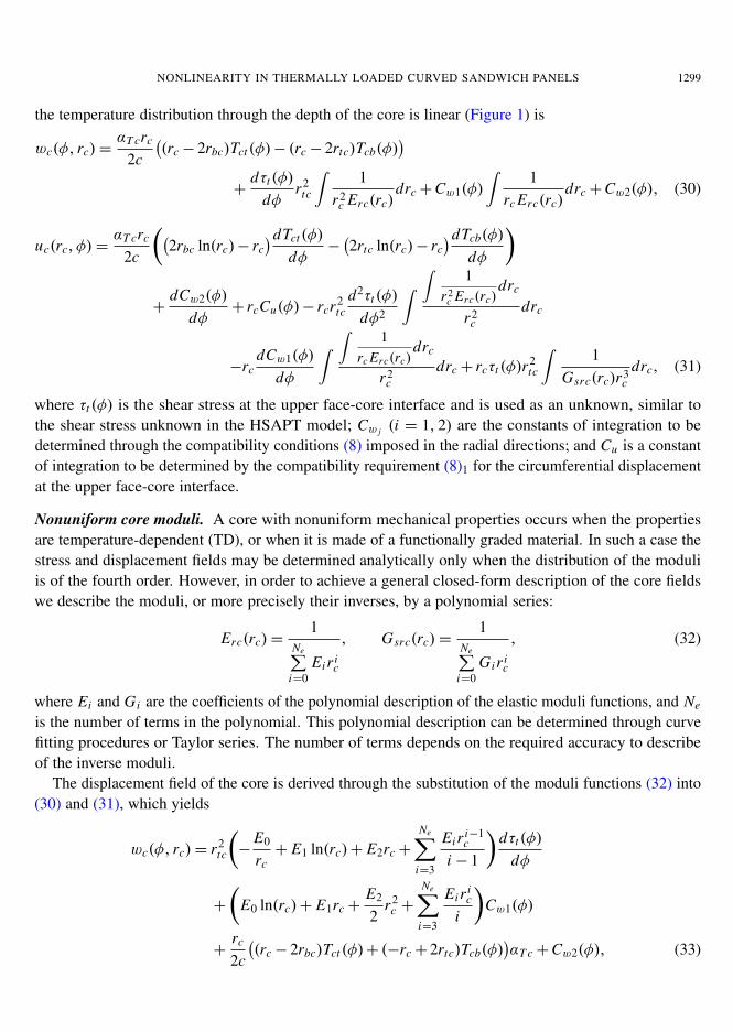
the temperature distribution through the depth of the core is linear (Figure 1) is
wc(φ, rc)=αT crc
2c
((rc− 2rbc)Tct(φ)− (rc− 2rtc)Tcb(φ)
)+
dτt(φ)
dφr2
tc
∫1
r2c Erc(rc)
drc+Cw1(φ)
∫1
rc Erc(rc)drc+Cw2(φ), (30)
uc(rc, φ)=αT crc
2c
((2rbc ln(rc)− rc
)dTct(φ)
dφ−(2rtc ln(rc)− rc
)dTcb(φ)
dφ
)
+dCw2(φ)
dφ+ rcCu(φ)− rcr2
tcd2τt(φ)
dφ2
∫ ∫1
r2c Erc(rc)
drc
r2c
drc
−rcdCw1(φ)
dφ
∫ ∫1
rc Erc(rc)drc
r2c
drc+ rcτt(φ)r2tc
∫1
Gsrc(rc)r3c
drc, (31)
where τt(φ) is the shear stress at the upper face-core interface and is used as an unknown, similar tothe shear stress unknown in the HSAPT model; Cw j (i = 1, 2) are the constants of integration to bedetermined through the compatibility conditions (8) imposed in the radial directions; and Cu is a constantof integration to be determined by the compatibility requirement (8)1 for the circumferential displacementat the upper face-core interface.
Nonuniform core moduli. A core with nonuniform mechanical properties occurs when the propertiesare temperature-dependent (TD), or when it is made of a functionally graded material. In such a case thestress and displacement fields may be determined analytically only when the distribution of the moduliis of the fourth order. However, in order to achieve a general closed-form description of the core fieldswe describe the moduli, or more precisely their inverses, by a polynomial series:
Erc(rc)=1
Ne∑i=0
Eir ic
, Gsrc(rc)=1
Ne∑i=0
Gir ic
, (32)
where Ei and Gi are the coefficients of the polynomial description of the elastic moduli functions, and Ne
is the number of terms in the polynomial. This polynomial description can be determined through curvefitting procedures or Taylor series. The number of terms depends on the required accuracy to describeof the inverse moduli.
The displacement field of the core is derived through the substitution of the moduli functions (32) into(30) and (31), which yields
wc(φ, rc)= r2tc
(−
E0
rc+ E1 ln(rc)+ E2rc+
Ne∑i=3
Eir i−1c
i − 1
)dτt(φ)
dφ
+
(E0 ln(rc)+ E1rc+
E2
2r2
c +
Ne∑i=3
Eir ic
i
)Cw1(φ)
+rc
2c
((rc− 2rbc)Tct(φ)+ (−rc+ 2rtc)Tcb(φ)
)αT c+Cw2(φ), (33)
1300 YEOSHUA FROSTIG AND OLE THOMSEN
uc(φ, rc)= r2tcrc
(−
E0
2r2c+
E1
rc
(ln(rc)+ 1
)− E2 ln(rc)−
Ne∑i=3
Eir i−2c
(i−1)(i−2)
)d2τt(φ)
dφ2
+ rc
(E0
rc
(ln(rc)+ 1
)− E1 ln(rc)−
E2
2rc−
Ne∑i=3
r i−1c Ei(i−1)i
)dCw1(φ)
dφ
+αT crc
2c
((2rbc ln(rc)− rc
)dTct(φ)
dφ−(2rtc ln(rc)− rc
)dTcb(φ)
dφ
)
+ r2tcrc
(−
G0
2r2c+G2 ln(rc)−
G1
rc+G3rc+
Ne∑i=4
Gir i−2c
i − 2
)τt(φ)+
ddφ
Cw2(φ)+ rcCu(φ). (34)
Note that the first three or four terms in the polynomial description are not within the sum terms sincethey involve integration of 1/rc terms.
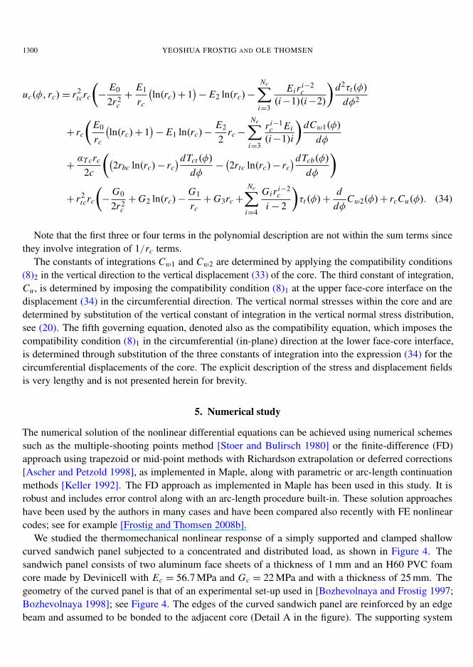
The constants of integrations Cw1 and Cw2 are determined by applying the compatibility conditions(8)2 in the vertical direction to the vertical displacement (33) of the core. The third constant of integration,Cu , is determined by imposing the compatibility condition (8)1 at the upper face-core interface on thedisplacement (34) in the circumferential direction. The vertical normal stresses within the core and aredetermined by substitution of the vertical constant of integration in the vertical normal stress distribution,see (20). The fifth governing equation, denoted also as the compatibility equation, which imposes thecompatibility condition (8)1 in the circumferential (in-plane) direction at the lower face-core interface,is determined through substitution of the three constants of integration into the expression (34) for thecircumferential displacements of the core. The explicit description of the stress and displacement fieldsis very lengthy and is not presented herein for brevity.
5. Numerical study
The numerical solution of the nonlinear differential equations can be achieved using numerical schemessuch as the multiple-shooting points method [Stoer and Bulirsch 1980] or the finite-difference (FD)approach using trapezoid or mid-point methods with Richardson extrapolation or deferred corrections[Ascher and Petzold 1998], as implemented in Maple, along with parametric or arc-length continuationmethods [Keller 1992]. The FD approach as implemented in Maple has been used in this study. It isrobust and includes error control along with an arc-length procedure built-in. These solution approacheshave been used by the authors in many cases and have been compared also recently with FE nonlinearcodes; see for example [Frostig and Thomsen 2008b].
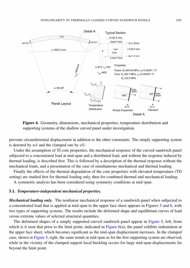
We studied the thermomechanical nonlinear response of a simply supported and clamped shallowcurved sandwich panel subjected to a concentrated and distributed load, as shown in Figure 4. Thesandwich panel consists of two aluminum face sheets of a thickness of 1 mm and an H60 PVC foamcore made by Devinicell with Ec = 56.7 MPa and Gc = 22 MPa and with a thickness of 25 mm. Thegeometry of the curved panel is that of an experimental set-up used in [Bozhevolnaya and Frostig 1997;Bozhevolnaya 1998]; see Figure 4. The edges of the curved sandwich panel are reinforced by an edgebeam and assumed to be bonded to the adjacent core (Detail A in the figure). The supporting system
NONLINEARITY IN THERMALLY LOADED CURVED SANDWICH PANELS 1301
d =1.0 mmb
c=25.0 mm
b=30.0 mm
Typical Section
Lower Face
Upper Face
Core
Detail A
Panel Layout
L=500.0 mm
Detail A
c,g,cc
Fig. 1
r cgc=800mm
rcgc=800
α=36.28o
rt=813 rb=787
c.g.c
Properties:
Faces: Ef=69130 MPa, α
f=0.00001 / Co
φ=α φ=α
EdgeBeam
dt=1.0mm
cl1
ss1/cl1 ss1/cl1
Core: Ec=56.7 MPa, α
c=0.00035 / Co
Gc=22.0 MPa
EdgeBeam
ss1
Temperature
Distribution
Tt
Tb=Tt+∆T
Tct=Tt
Tcb=Tb
Simply-Supported Clamped
Figure 4. Geometry, dimensions, mechanical properties, temperature distribution andsupporting systems of the shallow curved panel under investigation.
prevents circumferential displacement in addition to the other constraints. The simply supporting systemis denoted by ss1 and the clamped one by cl1.
Under the assumption of TI core properties, the mechanical response of the curved sandwich panelsubjected to a concentrated load at mid-span and a distributed load, and without the response induced bythermal loading, is described first. This is followed by a description of the thermal response without themechanical loads, and a presentation of the case of simultaneous mechanical and thermal loading.
Finally the effects of the thermal degradation of the core properties with elevated temperature (TDsetting) are studied first for thermal loading only, then for combined thermal and mechanical loading.
A symmetric analysis has been considered using symmetry conditions at mid-span.
5.1. Temperature-independent mechanical properties.
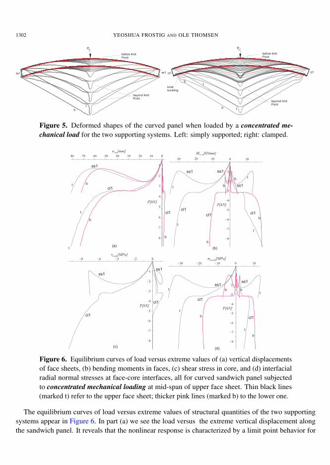
Mechanical loading only. The nonlinear mechanical response of a sandwich panel when subjected toa concentrated load that is applied at mid-span to the upper face sheet appears in Figures 5 and 6, withtwo types of supporting systems. The results include the deformed shape and equilibrium curves of loadversus extreme values of selected structural quantities.
The deformed shapes of a simply supported curved sandwich panel appear in Figure 5, left, fromwhich is it seen that prior to the limit point, indicated in Figure 6(a), the panel exhibits indentation atthe upper face sheet, which becomes significant as the mid-span displacement increases. In the clampedcase, shown in Figure 5, right, the same trends at mid-span as for the first supporting system are observed,while in the vicinity of the clamped support local buckling occurs for large mid-span displacements farbeyond the limit point.
1302 YEOSHUA FROSTIG AND OLE THOMSEN
(a)
(b)
Pt
Pt
Fig. 2
beyond limitPoint
before limitPoint
before limitPoint
beyond limitPoint
ss1
cl1 cl1
ss1
localbuckling
t
b
t
t
b
b
(a)
(b)
Pt
Pt
Fig. 2
beyond limitPoint
before limitPoint
before limitPoint
beyond limitPoint
ss1
cl1 cl1
ss1
localbuckling
t
b
t
t
b
b
Figure 5. Deformed shapes of the curved panel when loaded by a concentrated me-chanical load for the two supporting systems. Left: simply supported; right: clamped.
Fig. 3
t b
t
t
b
b
ss1
cl1
cl1
w [mm]ext
P[kN]
t
t
t
t
b
b
b
b
M [kNmm]ss,ext
P[kN]
ss1
ss1
ss1
cl1cl1cl1
tt,ext[MPa]
P[kN]
ss1ss1
cl1
cl1
P[kN]
srr,ext[MPa]
tt
t
t
b
b
b b
ss1ss1
cl1
cl1
(a)
(c)
(b)
(d)
t
Figure 6. Equilibrium curves of load versus extreme values of (a) vertical displacementsof face sheets, (b) bending moments in faces, (c) shear stress in core, and (d) interfacialradial normal stresses at face-core interfaces, all for curved sandwich panel subjectedto concentrated mechanical loading at mid-span of upper face sheet. Thin black lines(marked t) refer to the upper face sheet; thicker pink lines (marked b) to the lower one.
The equilibrium curves of load versus extreme values of structural quantities of the two supportingsystems appear in Figure 6. In part (a) we see the load versus the extreme vertical displacement alongthe sandwich panel. It reveals that the nonlinear response is characterized by a limit point behavior for
NONLINEARITY IN THERMALLY LOADED CURVED SANDWICH PANELS 1303
both supporting systems. The limit point load for the simply supporting system is lower then that of theclamped case, and it occurs also at a lower displacement as compared with the clamped case. In the ss1case there is a decrease in the vertical displacement beyond the limit point value which changes into anincreasing branch as the displacement reaches larger values. The trends are different in the clamped case,and they consist of a plateau beyond the limit point displacement followed by and increasing branch. Thetrends are similar for the upper and lower faces. The plot of load versus extreme bending moments inthe face sheets, shown in Figure 6(b), exhibits similar trends for the upper face sheet (thin black curvesmarked “t”) but quite erratic behavior for the lower one (thicker pink curves marked “b”). Notice thatthe curves describe the extreme values for each load level which do not necessarily occur at the samesection. The interfacial shear stresses at the upper face-core interface appear on Figure 6(c), and theyexhibit a limit point behavior but with a reduction in their values on the increasing branch for the simplysupporting case and an increase for the clamped case. The interfacial radial normal stresses at the upperand lower face-core interfaces appear in Figure 6(d), which reveals trends similar to those observed forthe vertical displacements.
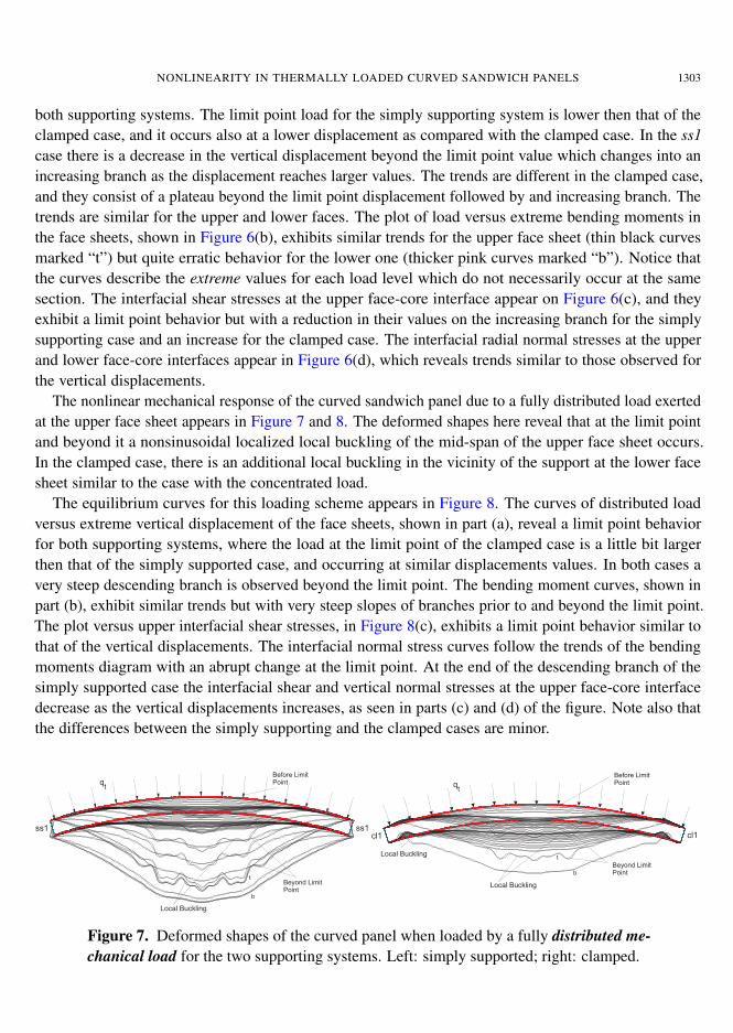
The nonlinear mechanical response of the curved sandwich panel due to a fully distributed load exertedat the upper face sheet appears in Figure 7 and 8. The deformed shapes here reveal that at the limit pointand beyond it a nonsinusoidal localized local buckling of the mid-span of the upper face sheet occurs.In the clamped case, there is an additional local buckling in the vicinity of the support at the lower facesheet similar to the case with the concentrated load.
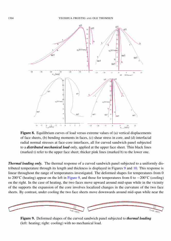
The equilibrium curves for this loading scheme appears in Figure 8. The curves of distributed loadversus extreme vertical displacement of the face sheets, shown in part (a), reveal a limit point behaviorfor both supporting systems, where the load at the limit point of the clamped case is a little bit largerthen that of the simply supported case, and occurring at similar displacements values. In both cases avery steep descending branch is observed beyond the limit point. The bending moment curves, shown inpart (b), exhibit similar trends but with very steep slopes of branches prior to and beyond the limit point.The plot versus upper interfacial shear stresses, in Figure 8(c), exhibits a limit point behavior similar tothat of the vertical displacements. The interfacial normal stress curves follow the trends of the bendingmoments diagram with an abrupt change at the limit point. At the end of the descending branch of thesimply supported case the interfacial shear and vertical normal stresses at the upper face-core interfacedecrease as the vertical displacements increases, as seen in parts (c) and (d) of the figure. Note also thatthe differences between the simply supporting and the clamped cases are minor.
q
q
t
t
(a)
(b)
Fig. 4
ss1
cl1 cl1
ss1
Beyond LimitPoint
Beyond LimitPoint
Before LimitPoint
Before LimitPoint
Local Buckling
Local Buckling
Local Buckling
b
b
t
t
q
q
t
t
Fig. 4
ss1
cl1 cl1
ss1
Beyond LimitPoint
Beyond LimitPoint
Before LimitPoint
Before LimitPoint
Local Buckling
Local Buckling
Local Buckling
b
b
t
t
Figure 7. Deformed shapes of the curved panel when loaded by a fully distributed me-chanical load for the two supporting systems. Left: simply supported; right: clamped.
1304 YEOSHUA FROSTIG AND OLE THOMSEN
Fig. 5
q [kN/mm]t
q [kN/mm]t q [kN/mm]t
q [kN/mm]t
w [mm]ext
ss1
ss1
ss1
ss1ss1
cl1cl1
cl1
cl1
t
tt
t
t
t
b
b
bb
b
b
t b
M [kNmm]ss,ext
tt,ext[MPa]srr,ext[MPa]
cl1
cl1
ss1
ss1 ss1ss1
ss1 ss1
cl1 cl1
bbt
t
t
tb
b
Fig. 5
q [kN/mm]t
q [kN/mm]t q [kN/mm]t
q [kN/mm]t
w [mm]ext
ss1
ss1
ss1
ss1ss1
cl1cl1
cl1
cl1
t
tt
t
t
t
b
b
bb
b
b
t b
M [kNmm]ss,ext
tt,ext[MPa]srr,ext[MPa]
cl1
cl1
ss1
ss1 ss1ss1
ss1 ss1
cl1 cl1
bbt
t
t
tb
b
Figure 8. Equilibrium curves of load versus extreme values of (a) vertical displacementsof face sheets, (b) bending moments in faces, (c) shear stress in core, and (d) interfacialradial normal stresses at face-core interfaces, all for curved sandwich panel subjectedto a distributed mechanical load only, applied at the upper face sheet. Thin black lines(marked t) refer to the upper face sheet; thicker pink lines (marked b) to the lower one.
Thermal loading only. The thermal response of a curved sandwich panel subjected to a uniformly dis-tributed temperature through its length and thickness is displayed in Figures 9 and 10. This response islinear throughout the range of temperatures investigated. The deformed shapes for temperatures from 0to 200◦C (heating) appear on the left in Figure 9, and those for temperatures from 0 to −200◦C (cooling)on the right. In the case of heating, the two faces move upward around mid-span while in the vicinityof the supports the expansion of the core involves localized changes in the curvature of the two facesheets. By contrast, under cooling the two face sheets move downwards around mid-span while near the
Fig. 6
T=20..+200 Co
T=+20..-200 Co
Fig. 6
T=20..+200 Co
T=+20..-200 Co
Figure 9. Deformed shapes of the curved sandwich panel subjected to thermal loading(left: heating; right: cooling) with no mechanical load.
NONLINEARITY IN THERMALLY LOADED CURVED SANDWICH PANELS 1305
w[mm]
f
t
t
t
t
b
b
T=20o
T=--30o
T=--200o
T=--200o
T=--145o
T=--145o
w[mm]
f
t
t
t
b
b
T=20o
T=
--12..
--20
o
T=--200o
T=--200o
T=--150o
T=--110o
--150o
T=-60o
T=-110o
00
M [kNmm]ss
t
b
M [kNmm]ss
t
b
f
N [kN]ss
t
t
t
b
b T=--30o
T=20o
T=--200o
T=--200o
T=--145o
T=--145o
T=--90o
f
N [kN]ss
t
t
b
b
b
T=--12..--20o
T=--200o
T=--200o
T=--150o
T=--110o
T=--60o
T=--110o
T=--150o
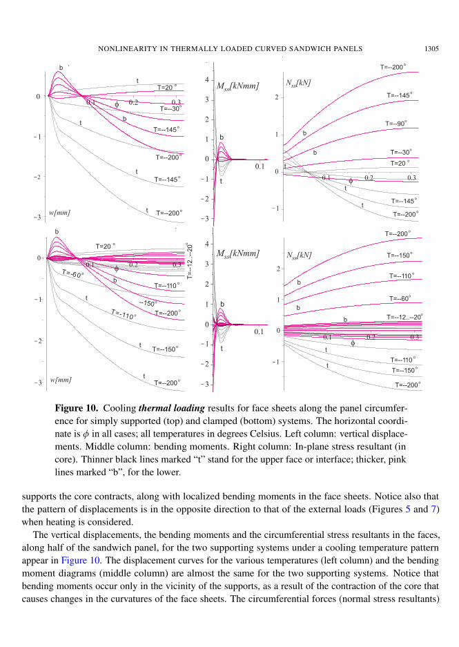
Figure 10. Cooling thermal loading results for face sheets along the panel circumfer-ence for simply supported (top) and clamped (bottom) systems. The horizontal coordi-nate is φ in all cases; all temperatures in degrees Celsius. Left column: vertical displace-ments. Middle column: bending moments. Right column: In-plane stress resultant (incore). Thinner black lines marked “t” stand for the upper face or interface; thicker, pinklines marked “b”, for the lower.
supports the core contracts, along with localized bending moments in the face sheets. Notice also thatthe pattern of displacements is in the opposite direction to that of the external loads (Figures 5 and 7)when heating is considered.
The vertical displacements, the bending moments and the circumferential stress resultants in the faces,along half of the sandwich panel, for the two supporting systems under a cooling temperature patternappear in Figure 10. The displacement curves for the various temperatures (left column) and the bendingmoment diagrams (middle column) are almost the same for the two supporting systems. Notice thatbending moments occur only in the vicinity of the supports, as a result of the contraction of the core thatcauses changes in the curvatures of the face sheets. The circumferential forces (normal stress resultants)
1306 YEOSHUA FROSTIG AND OLE THOMSEN
in the face sheets (rightmost column of Figure 10) reveal that in the case of a simply supported panel thestress resultants at the edges in the two face sheets are in tension, and around mid-span the upper facesheet is in compression whereas the lower face sheet is in tension. In the case of a clamped support thecircumferential stress resultants differs from that of the simply supported case, and the resultants in theupper face sheets are in compression while those of the lower face are in tension. It should be noticed thatin the case of elevated temperatures the displacements and the stress resultant patterns in the face sheetsand the core are opposite to those observed for the cooling case, which yields that the upper face sheets isin tension while the lower one is in compression, Thus, the heating temperature pattern yields stress resul-tants that cancel out the stress resultants of the external mechanical loads that appear in Figures 5 and 7.The response is similar when the temperature distribution has a gradient between the two face sheets.
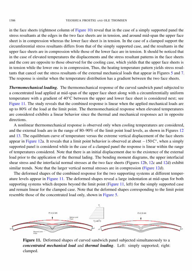
Thermomechanical loading. The thermomechanical response of the curved sandwich panel subjected toa concentrated load applied at mid-span of the upper face sheet along with a circumferentially uniformtemperature with a gradient of 40◦C between the upper and lower face sheet is considered next; seeFigure 11. The study reveals that the combined response is linear when the applied mechanical loads areup to 80% of the load at the limit point. The thermomechanical response when elevated temperaturesare considered exhibits a linear behavior since the thermal and mechanical responses act in oppositedirections.
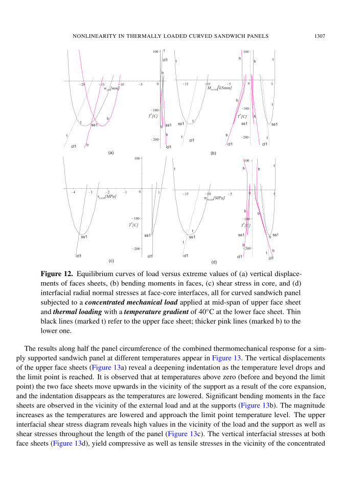
A nonlinear thermomechanical response is observed only when cooling temperatures are considered,and the external loads are in the range of 80–90% of the limit point load levels, as shown in Figures 12and 13. The equilibrium curve of temperature versus the extreme vertical displacement of the face sheetsappear in Figure 12a. It reveals that a limit point behavior is observed at about −150 C◦, when a simplysupported panel is considered while in the case of a clamped panel the response is linear within the rangeof temperatures considered. Note that there is an initial displacement due to the existence of the externalload prior to the application of the thermal lading. The bending moment diagrams, the upper interfacialshear stress and the interfacial normal stresses at the two face sheets (Figures 12b, 12c and 12d) exhibitsimilar trends. Note that the larger vertical normal stresses are in compression (Figure 12d).
The deformed shapes of the combined response for the two supporting systems at different temper-ature levels appear in Figure 11. The deformed shapes reveal a large indentation at mid-span for bothsupporting systems which deepens beyond the limit point (Figure 11, left) for the simply supported caseand remain linear for the clamped case. Note that the deformed shapes corresponding to the limit pointresemble those of the concentrated load only, shown in Figure 5.
(a)
(b)
ss1
cl1 cl1
ss1
Fig. 9
P=2.8 kNt
P=2.2 kNt
Tt
Tt+40 Co
Before LimitPoint
Beyond LimitPoint
(a)
(b)
ss1
cl1 cl1
ss1
Fig. 9
P=2.8 kNt
P=2.2 kNt
Tt
Tt+40 Co
Before LimitPoint
Beyond LimitPoint
(a)
(b)
ss1
cl1 cl1
ss1
Fig. 9
P=2.8 kNt
P=2.2 kNt
Tt
Tt+40 Co
Before LimitPoint
Beyond LimitPoint
Figure 11. Deformed shapes of curved sandwich panel subjected simultaneously to aconcentrated mechanical load and thermal loading. Left: simply supported; right:clamped.
NONLINEARITY IN THERMALLY LOADED CURVED SANDWICH PANELS 1307
(a)
w [mm]ext
T [C]o
T [C]o
T [C]o
T [C]o
M kNmm]ss,ext[
(b)
srr,ext[MPa]tt,ext[MPa]
(c) (d)
b
t
cl1
bt
t
ss1
cl1
cl1
b
b
b
ss1
bb
b
cl1cl1 cl1
ss1 ss1 ss1
t
t
t
b
b
t
t
t
tt
t
t
t
b
b
bb
b
b
b
ss1ss1ss1
cl1cl1 cl1
ss1 ss1
cl1 cl1
Figure 12. Equilibrium curves of load versus extreme values of (a) vertical displace-ments of faces sheets, (b) bending moments in faces, (c) shear stress in core, and (d)interfacial radial normal stresses at face-core interfaces, all for curved sandwich panelsubjected to a concentrated mechanical load applied at mid-span of upper face sheetand thermal loading with a temperature gradient of 40◦C at the lower face sheet. Thinblack lines (marked t) refer to the upper face sheet; thicker pink lines (marked b) to thelower one.
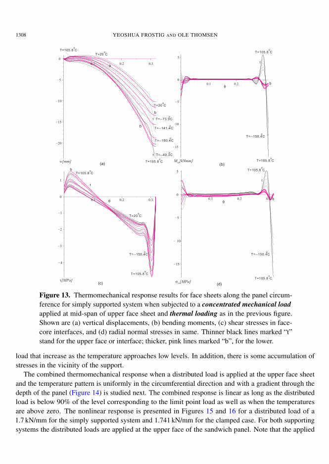
The results along half the panel circumference of the combined thermomechanical response for a sim-ply supported sandwich panel at different temperatures appear in Figure 13. The vertical displacementsof the upper face sheets (Figure 13a) reveal a deepening indentation as the temperature level drops andthe limit point is reached. It is observed that at temperatures above zero (before and beyond the limitpoint) the two face sheets move upwards in the vicinity of the support as a result of the core expansion,and the indentation disappears as the temperatures are lowered. Significant bending moments in the facesheets are observed in the vicinity of the external load and at the supports (Figure 13b). The magnitudeincreases as the temperatures are lowered and approach the limit point temperature level. The upperinterfacial shear stress diagram reveals high values in the vicinity of the load and the support as well asshear stresses throughout the length of the panel (Figure 13c). The vertical interfacial stresses at bothface sheets (Figure 13d), yield compressive as well as tensile stresses in the vicinity of the concentrated
1308 YEOSHUA FROSTIG AND OLE THOMSEN
w[mm]
f
f f
f
t
t
t
t
t
b
b
b
b
b
M kNmm]ss[
t[MPa] srr[MPa]
T=--141.4Co
T=--73.9Co
T=--150.4Co
T=--150.4Co
T=--150.4Co
T=--150.4Co
T=--49.3Co
T=105.8 Co
T=105.8 Co
T=105.8 Co
T=105.8 Co
T=105.8 Co
T=105.8 Co
T=105.8 Co
T=105.8 Co
T=20 Co
T=20 Co
T=20 Co
(a)
(d)
(b)
(c)
Figure 13. Thermomechanical response results for face sheets along the panel circum-ference for simply supported system when subjected to a concentrated mechanical loadapplied at mid-span of upper face sheet and thermal loading as in the previous figure.Shown are (a) vertical displacements, (b) bending moments, (c) shear stresses in face-core interfaces, and (d) radial normal stresses in same. Thinner black lines marked “t”stand for the upper face or interface; thicker, pink lines marked “b”, for the lower.
load that increase as the temperature approaches low levels. In addition, there is some accumulation ofstresses in the vicinity of the support.
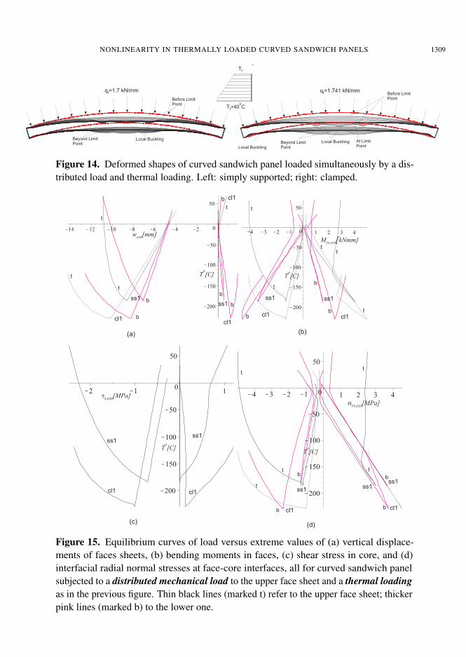
The combined thermomechanical response when a distributed load is applied at the upper face sheetand the temperature pattern is uniformly in the circumferential direction and with a gradient through thedepth of the panel (Figure 14) is studied next. The combined response is linear as long as the distributedload is below 90% of the level corresponding to the limit point load as well as when the temperaturesare above zero. The nonlinear response is presented in Figures 15 and 16 for a distributed load of a1.7 kN/mm for the simply supported system and 1.741 kN/mm for the clamped case. For both supportingsystems the distributed loads are applied at the upper face of the sandwich panel. Note that the applied
NONLINEARITY IN THERMALLY LOADED CURVED SANDWICH PANELS 1309
(b)
Fig. 12
q =1.7 kN/mmt
q =1.741 kN/mmt
Tt
Tt+40 Co
Before LimitPoint
Before LimitPoint
Local Buckling
Local Buckling
Local Buckling
Beyond LimitPoint
Beyond LimitPoint
At LimitPoint
(a)
(b)
Fig. 12
q =1.7 kN/mmt
q =1.741 kN/mmt
Tt
Tt+40 Co
Before LimitPoint
Before LimitPoint
Local Buckling
Local Buckling
Local Buckling
Beyond LimitPoint
Beyond LimitPoint
At LimitPoint
(a)
(b)
Fig. 12
q =1.7 kN/mmt
q =1.741 kN/mmt
Tt
Tt+40 Co
Before LimitPoint
Before LimitPoint
Local Buckling
Local Buckling
Local Buckling
Beyond LimitPoint
Beyond LimitPoint
At LimitPoint
Figure 14. Deformed shapes of curved sandwich panel loaded simultaneously by a dis-tributed load and thermal loading. Left: simply supported; right: clamped.
b
b
b cl1 cl1
(a)
w [mm]ext
t
cl1cl1
cl1
bb
b
b
t
t
ss1ss1
ss1 ss1
T [C]o
T [C]o
T [C]o
T [C]o
t
tt
t
t
t
b
b
b
b
b
tt
tt
t
M kNmm]ss,ext[
(b)
ss1
ss1ss1ss1
ss1
cl1 cl1
cl1cl1
srr,ext[MPa]
tt,ext[MPa]
(c)(d)
Figure 15. Equilibrium curves of load versus extreme values of (a) vertical displace-ments of faces sheets, (b) bending moments in faces, (c) shear stress in core, and (d)interfacial radial normal stresses at face-core interfaces, all for curved sandwich panelsubjected to a distributed mechanical load to the upper face sheet and a thermal loadingas in the previous figure. Thin black lines (marked t) refer to the upper face sheet; thickerpink lines (marked b) to the lower one.
1310 YEOSHUA FROSTIG AND OLE THOMSEN
0
w[mm]
f
f
f
f
M kNmm]ss[
t[MPa]
(a)
(d)
(b)
(c)
t
t
t
t
t
t
t
t
t
t
t
t
b
b
b
b
b
b b
b
b
b
srr[MPa]
T=69.6 Co
T=69.6 Co
T=--184.4..
-179.7 Co
T=--75.4CoT=--75.4C
o
T=--75.4Co
T=--75.4Co
T=--172.2Co
T=7.3 Co
T=--31.8Co
T=--125.7Co
T=--172.2Co
T=--172.2Co
T=--172.2Co
T=--179.7Co
T=--179.7Co
T=--179.7Co
T=--184.5Co
T=--184.5Co
T=--184.5Co
T=69.6 Co
T=69.6 Co
T=69.6 Co
T=69.6 Co
T=69.6 Co
T=69.6 CoT=69.6 C
o
T=69.6 Co
T=69.6 Co
T=69.6 Co
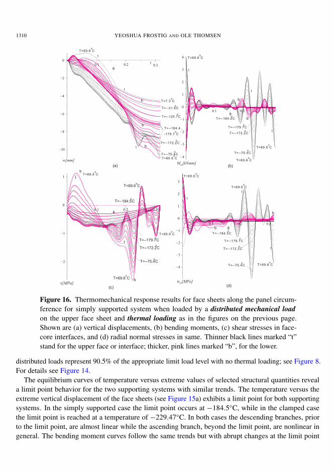
Figure 16. Thermomechanical response results for face sheets along the panel circum-ference for simply supported system when loaded by a distributed mechanical loadon the upper face sheet and thermal loading as in the figures on the previous page.Shown are (a) vertical displacements, (b) bending moments, (c) shear stresses in face-core interfaces, and (d) radial normal stresses in same. Thinner black lines marked “t”stand for the upper face or interface; thicker, pink lines marked “b”, for the lower.
distributed loads represent 90.5% of the appropriate limit load level with no thermal loading; see Figure 8.For details see Figure 14.
The equilibrium curves of temperature versus extreme values of selected structural quantities reveala limit point behavior for the two supporting systems with similar trends. The temperature versus theextreme vertical displacement of the face sheets (see Figure 15a) exhibits a limit point for both supportingsystems. In the simply supported case the limit point occurs at −184.5◦C, while in the clamped casethe limit point is reached at a temperature of −229.47◦C. In both cases the descending branches, priorto the limit point, are almost linear while the ascending branch, beyond the limit point, are nonlinear ingeneral. The bending moment curves follow the same trends but with abrupt changes at the limit point
NONLINEARITY IN THERMALLY LOADED CURVED SANDWICH PANELS 1311
almost like that of a bifurcation behavior (Figure 15b). Note that the lower face sheet exhibits linearbranches before and after the limit point, while the second branch, beyond the limit point descends. Theupper interfacial shear stresses appear in Figure 15c and follow the trends of the bending moment curves.Similarly, the interfacial normal stresses exhibit a linear behavior prior to the limit point and a nonlinearone beyond that, following the trends of the bending moments.
The deformed shapes of the combined response for the two supporting systems appear in Figure14. The two supporting systems exhibits a linear response up to the limit point and then they bothyield a localized local buckling region around mid-span at temperatures in the vicinity of the limit pointtemperature level and beyond it. In addition local buckling of the lower face sheet occurs in the vicinityof the support in the case of a clamped panel. The characteristics of the deformed shape at the limitpoint and above resemble those found for the case of a distributed load and no thermal loading, shownin Figure 7.
The results along half of the panel circumference at different temperatures appear in Figure 16. Thevertical displacements of the face sheets (Figure 16a) reveal that at the limit-point displacement localbuckling waves appear which deepens on the ascending branch of the equilibrium curve (Figure 15a).This local buckling phenomenon is explicitly observed in the bending moment figure (Figure 16b) andthe vertical normal interfacial stresses (Figure 16d). The local buckling affects also the interfacial shearstresses (Figure 16c). In general, the ripple characterization of the local buckling of the upper face sheetaffects the response both globally and locally.
5.2. Temperature-dependent mechanical properties. This part of the investigation deals with the re-sponse of a curved sandwich panel subjected only to thermal loading, followed by a study of the samepanel when subjected to combined thermal and mechanical loading. Both concentrated and distributedmechanical loads are considered, and again both simple support and clamped supporting systems areincluded in the study. The temperature-dependent core material properties adopted here follow thosegiven by Burmann [2005a; 2005b] for cross-linked PVC Divinycell foams (from DIAB AB, Sweden) fora working range of temperatures between 20◦C to 80◦C.
The mechanical properties of the Divinycell foams degrade with increasing temperatures. For thisstudy the temperature-dependent mechanical core material properties are defined through curve fittingof the data that appears in the manufacturer’s data sheet [DIAB 2003] as follows:
Ec(φ, rc)= Eco fT (Tc(φ, rc)), Gc(φ, rc)= Gco fT (Tc(φ, rc)),
where Eco and Gco refer to the Young’s and shear moduli of the core at T = 20◦C, and
fT (T )= 1.1903+ 0.03070734934T − 0.009541812399T 2+ 0.0008705288588T 3
− 0.00003952259514T 4+ 9.70315767110−7T 5
− 1.32513499810−8T 6
+ 9.52831997110−11T 7− 2.82196349610−13T 8, (35)
where T is expressed in degrees Celsius. Note that when a thermal gradient is applied to the core themechanical properties will also be dependent on the radial (through-the-thickness) coordinate. For moredetails see [Frostig and Thomsen 2008b]. In order to use the polynomial expansion (32) of the inverseof the moduli, the coefficients must be found using Taylor series or curve-fitting tools.
1312 YEOSHUA FROSTIG AND OLE THOMSEN
(b)
ss1
cl1 cl1
ss1
Fig. 14
T=20..80 Co
T=20..80 Co
(a)ss1
cl1 cl1
ss1
Fig. 14
T=20..80 Co
T=20..80 Co
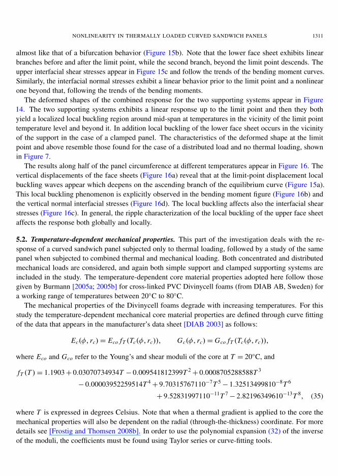
Figure 17. Deformed shapes of curved sandwich panel subjected to uniform thermalloading and with temperature-dependent core properties. Left: simply supported; right:clamped.
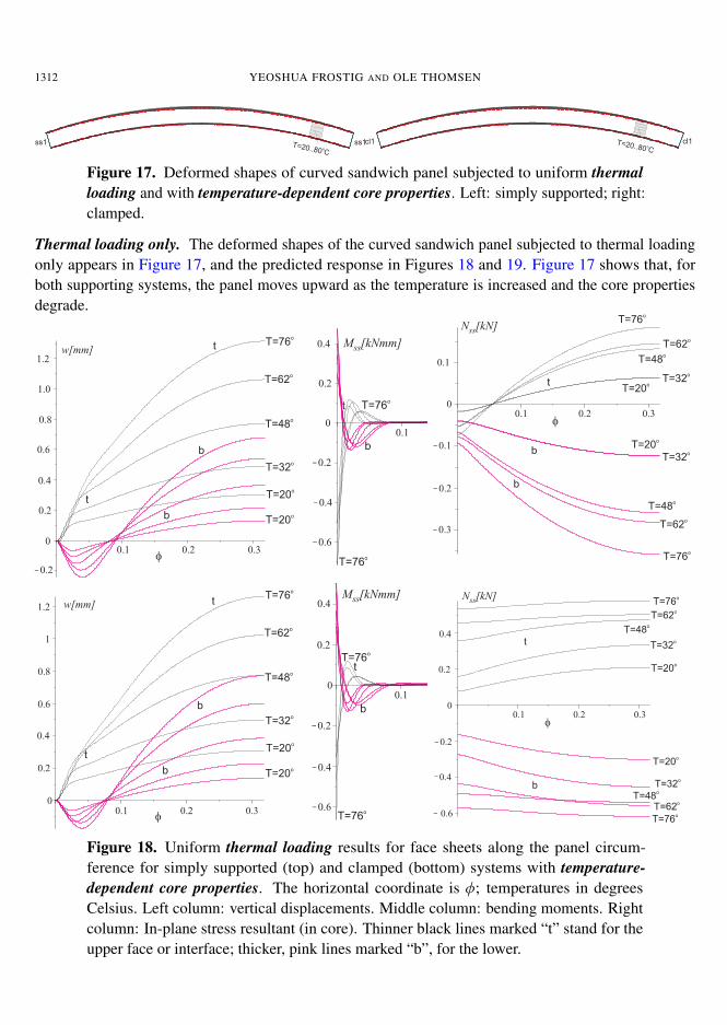
Thermal loading only. The deformed shapes of the curved sandwich panel subjected to thermal loadingonly appears in Figure 17, and the predicted response in Figures 18 and 19. Figure 17 shows that, forboth supporting systems, the panel moves upward as the temperature is increased and the core propertiesdegrade.
w[mm]
f
t
t
b
b
T=20o
T=32o
T=62o
T=48o
T=76o
T=20o
w[mm]
f
t
t
b
b
T=20o
T=32o
T=62o
T=48o
T=76o
T=20o
M [kNmm]ss
t
b
T=76o
T=76o
M [kNmm]ss
t
b
T=76o
T=76o
f
N [kN]ss
t
b
b
T=20o
T=20o
T=32o
T=32o
T=62o
T=62o
T=48o
T=48o
T=76o
T=76o
f
N [kN]ss
t
b
T=20o
T=20o
T=32o
T=32o
T=62o
T=62o
T=48o
T=48o
T=76o
T=76o
Figure 18. Uniform thermal loading results for face sheets along the panel circum-ference for simply supported (top) and clamped (bottom) systems with temperature-dependent core properties. The horizontal coordinate is φ; temperatures in degreesCelsius. Left column: vertical displacements. Middle column: bending moments. Rightcolumn: In-plane stress resultant (in core). Thinner black lines marked “t” stand for theupper face or interface; thicker, pink lines marked “b”, for the lower.
NONLINEARITY IN THERMALLY LOADED CURVED SANDWICH PANELS 1313
The predictions for the face sheets along half of the panel circumference at different temperaturelevels for the two supporting systems appear in Figure 18. The vertical displacements (Figure 18a) andthe bending moments (Figure 18b) of the two supporting systems are almost identical. Also here (seeFigure 10 for comparison) the bending moments exist only in the vicinity of the support as a result ofthe existence of the edge beam. The in-plane stress resultants (Figure 18c) reveal different patterns forthe two supporting systems. In the simply supported case the stress resultants of the two face sheetsare in compression at near and at the support, and this changes into tension in the upper face sheet andcompression in the bottom face sheet away from the supporting region. In the clamped case the upper facesheet is in tension while the lower face sheet is in compression throughout of the length/circumference of
-0.10 -0.08 -0.06 -0.04 -0.02 0
(a)w [mm]ext
T [C]o
T [C]o
T [C]o
T [C]o
M kNmm]ss,ext[(b)
srr,ext[MPa]tt,ext[MPa]
(c) (d)
bb
b
bb
b
t
cl1
cl1
cl1
cl1 cl1
cl1
cl1cl1cl1 cl1
b
t
t
t
t
ss1
ss1
ss1 ss1
ss1
ss1
ss1
ss1
ss1
ss1
60
Figure 19. Equilibrium curves of load versus extreme values of (a) vertical displace-ments of faces sheets, (b) bending moments in faces, (c) shear stress in core, and (d) in-terfacial radial normal stresses at face-core interfaces, all for curved sandwich panel withtemperature-dependent core properties, subjected to uniform thermal loading. Thinblack lines refer to the upper face sheet; thicker pink lines to the lower one.
1314 YEOSHUA FROSTIG AND OLE THOMSEN
the panel. The results are very similar to the results obtained for the curved sandwich panel temperature-independent mechanical properties, shown in Figure 10, except for the opposites signs due to the coolingtemperatures considered for this example.
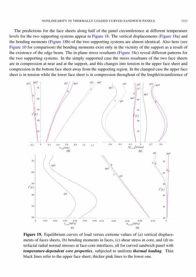
The equilibrium curves of temperatures versus extreme values of selected structural quantities forthe two supporting systems appear in Figure 19. They reveal a nonlinear behavior which is due to thenonlinearities in the mechanical properties as a result of their temperature dependence. In addition, thereare only minor differences between the results of the two supporting systems. The vertical displacementcurves (Figure 19a) are almost linear, but they become nonlinear at the upper range of temperatures. Thebending moment results (Figure 19b) reveal a nonlinear response in both positive and negative bendingmoments. The interfacial shear stress results at the upper face core interface (Figure 19c) also reveal anonlinear response through the range of temperatures. The interfacial radial normal stresses curves, atthe upper and lower face core interfaces (Figure 19d) reveal a linear response for the simply supportedcase and a nonlinear for the clamped case. In both cases the maximum compressive stresses occur in theedge of the panel. However, for the simply supported case there are tensile stresses in the vicinity of thesupport that do not exist in the clamped system.
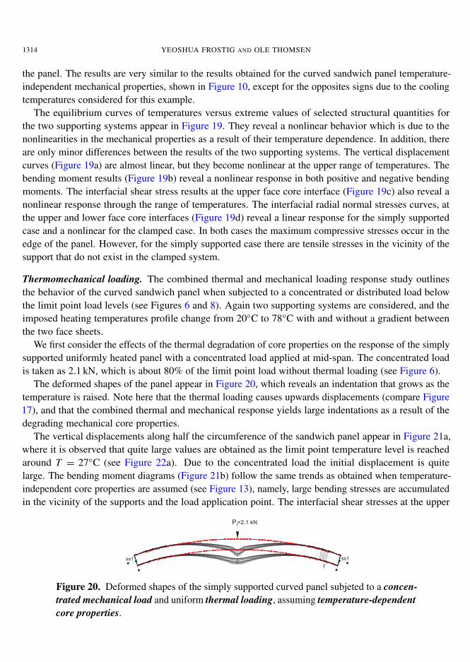
Thermomechanical loading. The combined thermal and mechanical loading response study outlinesthe behavior of the curved sandwich panel when subjected to a concentrated or distributed load belowthe limit point load levels (see Figures 6 and 8). Again two supporting systems are considered, and theimposed heating temperatures profile change from 20◦C to 78◦C with and without a gradient betweenthe two face sheets.
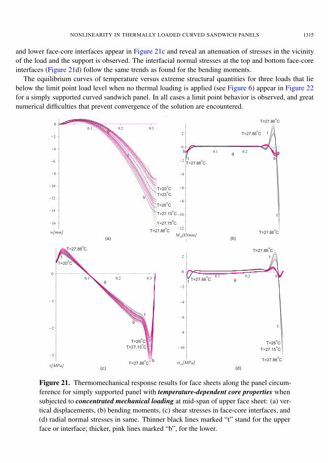
We first consider the effects of the thermal degradation of core properties on the response of the simplysupported uniformly heated panel with a concentrated load applied at mid-span. The concentrated loadis taken as 2.1 kN, which is about 80% of the limit point load without thermal loading (see Figure 6).
The deformed shapes of the panel appear in Figure 20, which reveals an indentation that grows as thetemperature is raised. Note here that the thermal loading causes upwards displacements (compare Figure17), and that the combined thermal and mechanical response yields large indentations as a result of thedegrading mechanical core properties.
The vertical displacements along half the circumference of the sandwich panel appear in Figure 21a,where it is observed that quite large values are obtained as the limit point temperature level is reachedaround T = 27◦C (see Figure 22a). Due to the concentrated load the initial displacement is quitelarge. The bending moment diagrams (Figure 21b) follow the same trends as obtained when temperature-independent core properties are assumed (see Figure 13), namely, large bending stresses are accumulatedin the vicinity of the supports and the load application point. The interfacial shear stresses at the upper
Fig. 17
Pt=2.1 kN
ss1 ss1
w[mm]M kNmm]ss[
t[MPa]srr[MPa]
(b)
(d)
(a)
(e)
(c)
f
ff
ft
t
t
t
t
t
t
t
t
b
b
b
b
b
T=27.86 Co
T=27.86 Co
T=27.86 Co
T=27.86 Co
T=27.86 Co T=27.86 C
o
T=27.86 Co
T=27.86 Co
T=27.86 Co
T=27.86 Co
T=23 Co
T=26 Co
T=26 Co
T=26 Co
T=27.15 Co
T=27.15 Co
T=27.15 Co
T=27.75 Co
T=20 Co
T=20 Co
T
Figure 20. Deformed shapes of the simply supported curved panel subjeted to a concen-trated mechanical load and uniform thermal loading, assuming temperature-dependentcore properties.
NONLINEARITY IN THERMALLY LOADED CURVED SANDWICH PANELS 1315
and lower face-core interfaces appear in Figure 21c and reveal an attenuation of stresses in the vicinityof the load and the support is observed. The interfacial normal stresses at the top and bottom face-coreinterfaces (Figure 21d) follow the same trends as found for the bending moments.
The equilibrium curves of temperature versus extreme structural quantities for three loads that liebelow the limit point load level when no thermal loading is applied (see Figure 6) appear in Figure 22for a simply supported curved sandwich panel. In all cases a limit point behavior is observed, and greatnumerical difficulties that prevent convergence of the solution are encountered.
w[mm]M kNmm]ss[
(a)
(a)
(b)
f
ft
t
t
t
b
b
b
T=27.86 Co
T=27.86 Co
T=27.86 Co
T=27.86 Co
T=27.86 Co
T=27.86 Co
T=27.86 Co
T=23 Co
T=26 Co
T=27.15 Co
T=27.75 Co
T=20 Co
M kNmm]ss[
t[MPa]srr[MPa]
(a)
(c) (d)
(b)
ff
t
t
t
t
t
b
bT=27.86 C
o T=27.86 Co
T=27.86 Co
T=27.86 Co
T=27.86 Co
T=26 Co
T=26 Co
T=27.15 Co
T=27.15 Co
T=20 Co
Figure 21. Thermomechanical response results for face sheets along the panel circum-ference for simply supported panel with temperature-dependent core properties whensubjected to concentrated mechanical loading at mid-span of upper face sheet: (a) ver-tical displacements, (b) bending moments, (c) shear stresses in face-core interfaces, and(d) radial normal stresses in same. Thinner black lines marked “t” stand for the upperface or interface; thicker, pink lines marked “b”, for the lower.
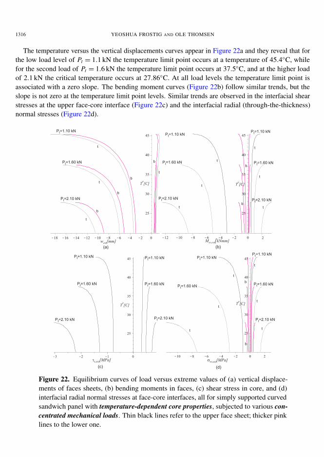
1316 YEOSHUA FROSTIG AND OLE THOMSEN
The temperature versus the vertical displacements curves appear in Figure 22a and they reveal that forthe low load level of Pt = 1.1 kN the temperature limit point occurs at a temperature of 45.4◦C, whilefor the second load of Pt = 1.6 kN the temperature limit point occurs at 37.5◦C, and at the higher loadof 2.1 kN the critical temperature occurs at 27.86◦C. At all load levels the temperature limit point isassociated with a zero slope. The bending moment curves (Figure 22b) follow similar trends, but theslope is not zero at the temperature limit point levels. Similar trends are observed in the interfacial shearstresses at the upper face-core interface (Figure 22c) and the interfacial radial (through-the-thickness)normal stresses (Figure 22d).
(a)
w [mm]ext
T [C]o
T [C]o
T [C]o T [C]
o
M kNmm]ss,ext[
(b)
srr,ext[MPa]tt,ext[MPa]
(c) (d)
b
b
b
b
b
b
b
b
P =2.10 kNt
P =2.10 kNt P =2.10 kNtP =2.10 kNt
P =2.10 kNt P =2.10 kNt
P =1.60 kNt
P =1.60 kNt P =1.60 kNtP =1.60 kNt
P =1.60 kNtP =1.60 kNt P =1.60 kNt
P =1.10 kNt
P =1.10 kNt
P =1.10 kNtP =1.10 kNt
P =1.10 kNtP =1.10 kNt
P =1.10 kNt
t
t
t
t
t
t
t
t
t
t
t
t
t
t
t
t
Figure 22. Equilibrium curves of load versus extreme values of (a) vertical displace-ments of faces sheets, (b) bending moments in faces, (c) shear stress in core, and (d)interfacial radial normal stresses at face-core interfaces, all for simply supported curvedsandwich panel with temperature-dependent core properties, subjected to various con-centrated mechanical loads. Thin black lines refer to the upper face sheet; thicker pinklines to the lower one.
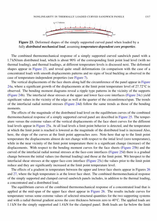
NONLINEARITY IN THERMALLY LOADED CURVED SANDWICH PANELS 1317
Fig. 19
q =1.7 kN/mmt
ss1 ss1
w[mm] M kNmm]ss[
t[MPa] srr[MPa]
(b)
(d) (e)
(c)
f
f
f
f
t
tt
t
t
t
t
t
t
t
t
b
b
b
b
b
b
b
b
T=27.72 Co
T=27.72 Co T=27.72 C
o
T=27.72 Co
T=27.72 Co
T=27.72 Co
T=27.72 Co
T=27.72 Co
T=27.72 Co
T=27.72 Co
T=27.72 Co
T=23 Co
T=20 Co
T=26 Co
T=27.10 Co
T=27.10 Co
T=27.10 Co
T=27.45 Co
T=27.45 Co
T=27.45 Co
T=27.45 Co
T=27.45 Co
T=27.45 Co
T=20 Co
T
Figure 23. Deformed shapes of the simply supported curved panel when loaded by afully distributed mechanical load, assuming temperature-dependent core properties.
The combined thermomechanical response of a simply supported curved sandwich panel with a1.7 kN/mm distributed load, which is about 90% of the corresponding limit point load level (with nothermal loading), and thermal loadings, at different temperature levels is discussed next. The deformedshapes appear in Figure 23, and reveal quite small deformations (in comparison with the case of aconcentrated load) with smooth displacements patterns and no signs of local buckling as observed in thecase of temperature-independent properties (see Figure 7).
The vertical displacements of the face sheets along half the circumference of the panel appear in Figure24a, where a significant growth of the displacements at the limit point temperature level of 27.72◦C isobserved. The bending moment diagrams reveal a ripple type patterns in the vicinity of the supports(Figure 24b). The interfacial shear stresses at the upper and lower face-core interfaces (Figure 24c) yieldsignificant values in the vicinity of the edge as well at the quarter of the circumference/span. The trendsof the interfacial radial normal stresses (Figure 24d) follow the same trends as those of the bendingmoments.
The effects of the magnitude of the distributed load level on the equilibrium curves of the combinedthermomechanical response of a simply supported curved panel are described in Figure 25. The temper-ature versus the extreme values of the vertical displacements of the face sheet curves for the differentload levels appear in Figure 25a. At all load levels a limit point behavior is detected, and the temperatureat which the limit point is reached is lowered as the magnitude of the distributed load is increased Also,here, the slope of the curves at the limit point approaches zero. Note here that up to the limit pointtemperature the displacements almost do not change with respect to the intial level (zero temperature),while in the near vicinity of the limit point temperature there is a significant change (increase) of thedisplacements. With respect to the bending moment curves for the face sheets (Figure 25b) and thecurved of the interfacial radial normal stresses at the face-core interfaces (Figure 25d) there is a gradualchange between the initial values (no thermal loading) and those at the limit point. Wit hrespect to theinterfacial shear stresses at the upper face-core interface (Figure 25c) the values prior to the limit pointreduce and they are significantly increased at the limit point temperature level.
The effects of a gradient in temperature between the upper and lower face sheets appear in Figures 26and 27, where the high temperature is at the lower face sheet. The combined thermomechanical responseof the simply supported and clamped curved sandwich panels includes, in addition to the thermal loading,a concentrated and a distributed load.
The equilibrium curves of the combined thermomechanical response of a concentrated load that isapplied at the mid-span of the upper face sheet appear in Figure 26. The results include curves fortemperature versus some extreme values of selected structural quantities for the two supporting systemsand with a radial thermal gradient across the core thickness between zero to 40◦C. The applied loads are1.1 kN for the simply supported and 1.4 kN for the clamped panel. Both loads are far below the limit
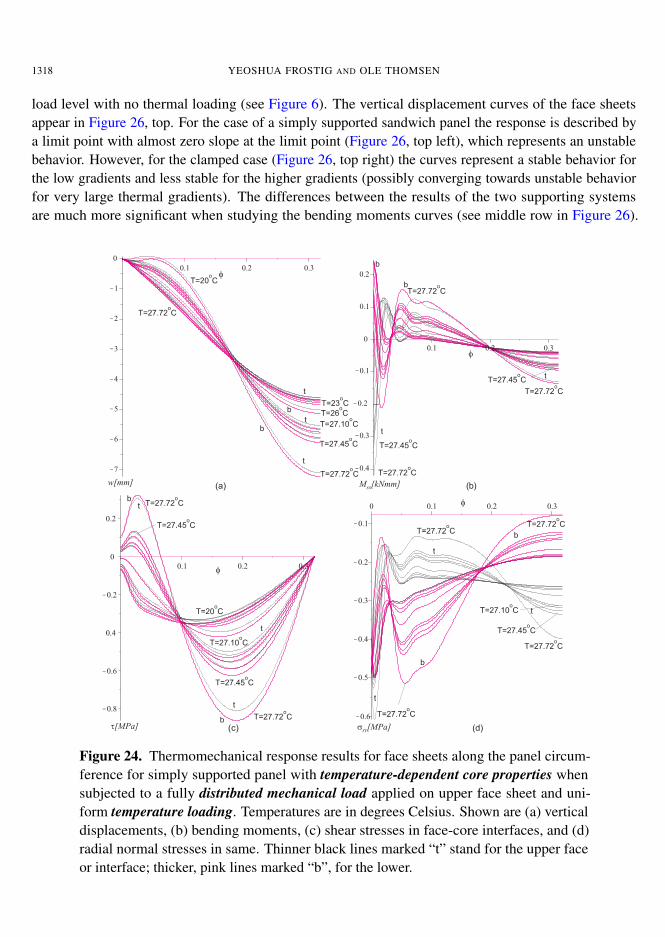
1318 YEOSHUA FROSTIG AND OLE THOMSEN
load level with no thermal loading (see Figure 6). The vertical displacement curves of the face sheetsappear in Figure 26, top. For the case of a simply supported sandwich panel the response is described bya limit point with almost zero slope at the limit point (Figure 26, top left), which represents an unstablebehavior. However, for the clamped case (Figure 26, top right) the curves represent a stable behavior forthe low gradients and less stable for the higher gradients (possibly converging towards unstable behaviorfor very large thermal gradients). The differences between the results of the two supporting systemsare much more significant when studying the bending moments curves (see middle row in Figure 26).
w[mm] M kNmm]ss[
t[MPa] srr[MPa]
(a)
(c) (d)
(b)
f
f
f
f
t
tt
t
t
t
t
t
t
t
t
b
b
b
b
b
b
b
b
T=27.72 Co
T=27.72 Co T=27.72 C
o
T=27.72 Co
T=27.72 Co
T=27.72 Co
T=27.72 Co
T=27.72 Co
T=27.72 Co
T=27.72 Co
T=27.72 Co
T=23 Co
T=20 Co
T=26 Co
T=27.10 Co
T=27.10 Co
T=27.10 Co
T=27.45 Co
T=27.45 Co
T=27.45 Co
T=27.45 Co
T=27.45 Co
T=27.45 Co
T=20 Co
Figure 24. Thermomechanical response results for face sheets along the panel circum-ference for simply supported panel with temperature-dependent core properties whensubjected to a fully distributed mechanical load applied on upper face sheet and uni-form temperature loading. Temperatures are in degrees Celsius. Shown are (a) verticaldisplacements, (b) bending moments, (c) shear stresses in face-core interfaces, and (d)radial normal stresses in same. Thinner black lines marked “t” stand for the upper faceor interface; thicker, pink lines marked “b”, for the lower.
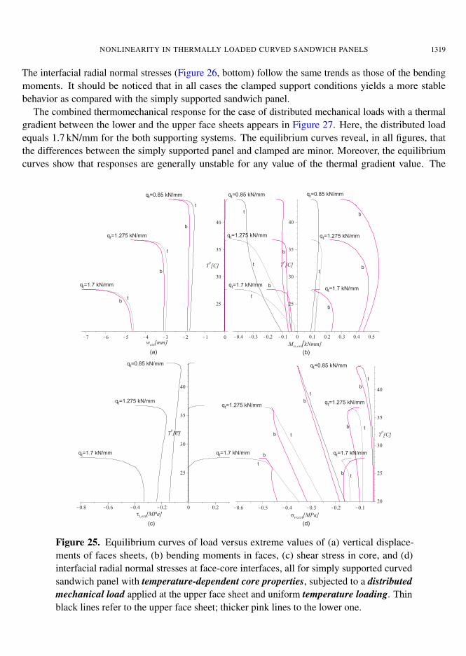
NONLINEARITY IN THERMALLY LOADED CURVED SANDWICH PANELS 1319
The interfacial radial normal stresses (Figure 26, bottom) follow the same trends as those of the bendingmoments. It should be noticed that in all cases the clamped support conditions yields a more stablebehavior as compared with the simply supported sandwich panel.
The combined thermomechanical response for the case of distributed mechanical loads with a thermalgradient between the lower and the upper face sheets appears in Figure 27. Here, the distributed loadequals 1.7 kN/mm for the both supporting systems. The equilibrium curves reveal, in all figures, thatthe differences between the simply supported panel and clamped are minor. Moreover, the equilibriumcurves show that responses are generally unstable for any value of the thermal gradient value. The
(a)
w [mm]ext
T [C]o
T [C]o
T [C]o
T [C]o
M kNmm]ss,ext[
(b)
srr,ext[MPa]tt,ext[MPa]
(c) (d)
b
b
b
b
b
b
b
b
b
b
b
b
b
b
q =1.7 kN/mmt
q =1.7 kN/mmt q =1.7 kN/mmt q =1.7 kN/mmt
q =1.7 kN/mmt q =1.7 kN/mmt
q =0.85 kN/mmt
q =0.85 kN/mmt q =0.85 kN/mmt
q =0.85 kN/mmtq =0.85 kN/mmt
q =1.275 kN/mmt
q =1.275 kN/mmt q =1.275 kN/mmtq =1.275 kN/mmt
q =1.275 kN/mmt q =1.275 kN/mmt
t
t
t
t
t
t
t
t
t
t
t
t
t
Figure 25. Equilibrium curves of load versus extreme values of (a) vertical displace-ments of faces sheets, (b) bending moments in faces, (c) shear stress in core, and (d)interfacial radial normal stresses at face-core interfaces, all for simply supported curvedsandwich panel with temperature-dependent core properties, subjected to a distributedmechanical load applied at the upper face sheet and uniform temperature loading. Thinblack lines refer to the upper face sheet; thicker pink lines to the lower one.
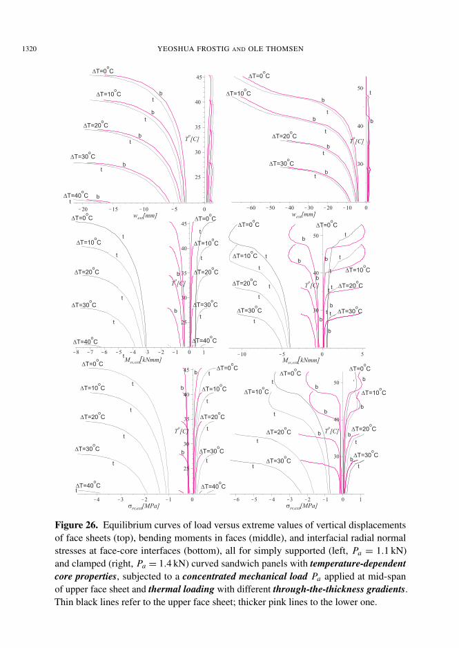
1320 YEOSHUA FROSTIG AND OLE THOMSEN
w [mm]extw [mm]ext
T [C]o
T [C]o
T [C]oT [C]
o
T [C]o
T [C]o
M kNmm]ss,ext[ M kNmm]ss,ext[
srr,ext[MPa]srr,ext[MPa]
b
b
b
b
b
b
b
b
b
b
b
b
b
b
b
b
b
b
b
b
b
DT=30 Co
DT=30 Co
DT=30 Co
DT=30 Co DT=30 C
o
DT=30 Co
DT=20 Co
DT=20 Co
DT=20 Co
DT=20 Co DT=20 C
o
DT=20 Co
DT=10 Co
DT=10 Co
DT=10 Co
DT=10 Co
DT=10 Co
DT=10 Co
DT=0 Co
DT=0 Co
DT=0 Co
DT=0 Co
DT=0 Co
DT=0 Co
DT=0 Co
DT=0 Co
DT=40 Co
t
t
t
t
t
t
t
t
t
t
t
t
t
t
b
b
b
b
b
b
t
t
t
t
t
t
t
t
t
t
t
t
t
t
t
t
t
t
t
t
t
tt
t
DT=0 Co
DT=0 Co
DT=10 Co
DT=10 Co
DT=10 Co
DT=10 Co
DT=20 Co
DT=20 Co
DT=20 Co
DT=20 Co
DT=30 Co
DT=30 Co
DT=30 Co
DT=30 Co
DT=40 Co
DT=40 Co
DT=40 Co
DT=40 Co
t
t
tt
t
t
t
t
b
b
Figure 26. Equilibrium curves of load versus extreme values of vertical displacementsof face sheets (top), bending moments in faces (middle), and interfacial radial normalstresses at face-core interfaces (bottom), all for simply supported (left, Pa = 1.1 kN)and clamped (right, Pa = 1.4 kN) curved sandwich panels with temperature-dependentcore properties, subjected to a concentrated mechanical load Pa applied at mid-spanof upper face sheet and thermal loading with different through-the-thickness gradients.Thin black lines refer to the upper face sheet; thicker pink lines to the lower one.
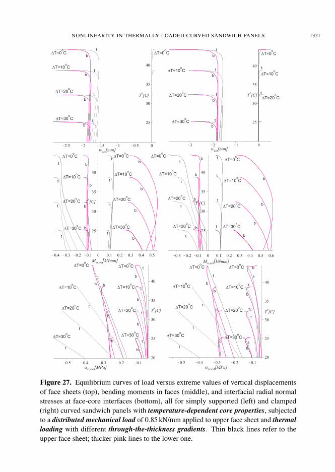
NONLINEARITY IN THERMALLY LOADED CURVED SANDWICH PANELS 1321
b
b
b b
b
b
b
b
b
b
b
b
b b
b
b
b
b
b
b
b
b
b
b
b
b
b
b
b b
b
b
b
b
b
b
bb
b
b
DT=30 Co
DT=30 Co
DT=30 Co
DT=30 Co
DT=30 Co
DT=30 Co
DT=30 Co
DT=30 Co
DT=30 Co
DT=30 Co
DT=20 Co
DT=20 Co
DT=20 Co
DT=20 Co
DT=20 Co
DT=20 Co
DT=20 Co
DT=20 Co
DT=20 Co
DT=20 Co
DT=20 Co
DT=10 Co
DT=10 Co
DT=10 Co
DT=10 Co
DT=10 Co
DT=10 Co
DT=10 Co
DT=10 Co
DT=10 Co
DT=10 Co
DT=10 Co
DT=0 Co
DT=0 Co
DT=0 Co
DT=0 Co
DT=0 Co
DT=0 Co
DT=0 Co
DT=0 Co
DT=0 Co
DT=0 Co
DT=0 Co
t
t
t t
tt
tt
tt
t
t
t t
t
tt
t t
t
t
t t
t
t
t
tt
t t
t
t
t
t
t
tt
t t
t
t
t
w [mm]extw [mm]ext
T [C]o
T [C]o
T [C]oT [C]
o
T [C]o
T [C]o
M kNmm]ss,ext[ M kNmm]ss,ext[
srr,ext[MPa]srr,ext[MPa]
Figure 27. Equilibrium curves of load versus extreme values of vertical displacementsof face sheets (top), bending moments in faces (middle), and interfacial radial normalstresses at face-core interfaces (bottom), all for simply supported (left) and clamped(right) curved sandwich panels with temperature-dependent core properties, subjectedto a distributed mechanical load of 0.85 kN/mm applied to upper face sheet and thermalloading with different through-the-thickness gradients. Thin black lines refer to theupper face sheet; thicker pink lines to the lower one.
1322 YEOSHUA FROSTIG AND OLE THOMSEN
curves of extreme values of the vertical displacements of the face sheets versus temperature (Figure 27,top) yield a limit point behavior with a slope of almost zero for both supporting systems. Here it shouldbe noticed that for both cases significant changes of the displacements occur only in the near vicinity ofthe limit point temperature level. The bending moment curves (Figure 27, middle row) reveal similartrends, with the exception that there is a gradual change between the initial values (corresponding tono thermal loading) and moment values at the limit point. Notice that the negative bending momentsof the clamped case are smaller then those of the simply supported case and vice versa with respect tothe positive bending moments. The relationship between the radial interfacial normal stresses and thetemperature (Figure 27, bottom) is almost linear for the extreme values of the compressive stresses atthe upper interface and nonlinear at the lower interface for both supporting systems.
6. Summary and conclusions
The geometrically nonlinear behavior of curved sandwich panels subjected to thermal and mechanicalloading was studied, under both temperature-independent (TI) and temperature-dependent (TD) assump-tions for the core material properties.
The first half of the paper gives a mathematical formulation for the TI case, based on a variational ap-proach along with high-order sandwich panel theory (HSAPT). The analysis considers the thermal strainsof the core along with the effects of its flexibility in the radial (through-the-thickness) direction. Thenonlinear field equations of the curved sandwich panel are derived along with the appropriate boundaryconditions. The effects of a solid edge beam at the edge of the curved sandwich panel on the boundaryconditions are considered. The stress and displacement fields of the core are derived and solved explicitlyfor the case of a core with uniform mechanical properties. The full nonlinear governing equations arederived and presented.
The second half models thermally induced deformations of curved sandwich panels using the equationspreviously obtained via HSAPT. The stress and displacement fields of the core are derived and solvedexplicitly for cores with both TI and TD mechanical properties. The solution for a core with mechanicalproperties dependent on the radial coordinate is derived and is used to handle the TD case. A polynomialsolution is adopted, and a general solution is presented for the stress and displacement fields. Thenonlinear response is determined through the solution of the nonlinear equations using a finite-differencescheme along with a natural parametric continuation or a pseudo-arclength or similar procedure.
A numerical study then investigates the response of a shallow curved sandwich panel with a geometrythat has been used previously in an experimental study conducted at Aalborg University. The shallowcurved sandwich panel is assumed to be subjected to a concentrated or fully distributed load in addition tothermal loading. The panel consists of two aluminum face sheets and a cross-linked PVC H60 Divinicellfoam core with mechanical properties that degrade with increasing temperature. The loading systemconsists of an edge beam at the edges of the curved sandwich panel, resting on a simply supportedor clamped system with immovable conditions in the radial direction. The thermal loading consistsof heating and cooling temperatures that are uniformly distributed circumferentially, with or without agradient through the depth of the panel.
The numerical study covers all the combinations of the mechanical-thermal response with TI coreproperties. The response due to purely mechanical loading is presented first and reveals a typical limit
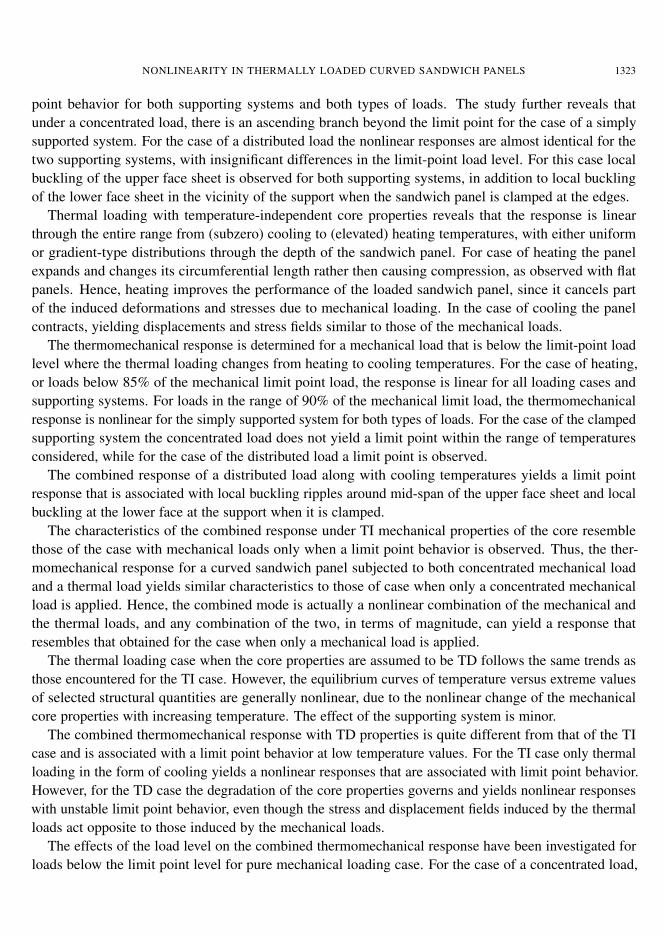
NONLINEARITY IN THERMALLY LOADED CURVED SANDWICH PANELS 1323
point behavior for both supporting systems and both types of loads. The study further reveals thatunder a concentrated load, there is an ascending branch beyond the limit point for the case of a simplysupported system. For the case of a distributed load the nonlinear responses are almost identical for thetwo supporting systems, with insignificant differences in the limit-point load level. For this case localbuckling of the upper face sheet is observed for both supporting systems, in addition to local bucklingof the lower face sheet in the vicinity of the support when the sandwich panel is clamped at the edges.
Thermal loading with temperature-independent core properties reveals that the response is linearthrough the entire range from (subzero) cooling to (elevated) heating temperatures, with either uniformor gradient-type distributions through the depth of the sandwich panel. For case of heating the panelexpands and changes its circumferential length rather then causing compression, as observed with flatpanels. Hence, heating improves the performance of the loaded sandwich panel, since it cancels partof the induced deformations and stresses due to mechanical loading. In the case of cooling the panelcontracts, yielding displacements and stress fields similar to those of the mechanical loads.
The thermomechanical response is determined for a mechanical load that is below the limit-point loadlevel where the thermal loading changes from heating to cooling temperatures. For the case of heating,or loads below 85% of the mechanical limit point load, the response is linear for all loading cases andsupporting systems. For loads in the range of 90% of the mechanical limit load, the thermomechanicalresponse is nonlinear for the simply supported system for both types of loads. For the case of the clampedsupporting system the concentrated load does not yield a limit point within the range of temperaturesconsidered, while for the case of the distributed load a limit point is observed.
The combined response of a distributed load along with cooling temperatures yields a limit pointresponse that is associated with local buckling ripples around mid-span of the upper face sheet and localbuckling at the lower face at the support when it is clamped.
The characteristics of the combined response under TI mechanical properties of the core resemblethose of the case with mechanical loads only when a limit point behavior is observed. Thus, the ther-momechanical response for a curved sandwich panel subjected to both concentrated mechanical loadand a thermal load yields similar characteristics to those of case when only a concentrated mechanicalload is applied. Hence, the combined mode is actually a nonlinear combination of the mechanical andthe thermal loads, and any combination of the two, in terms of magnitude, can yield a response thatresembles that obtained for the case when only a mechanical load is applied.
The thermal loading case when the core properties are assumed to be TD follows the same trends asthose encountered for the TI case. However, the equilibrium curves of temperature versus extreme valuesof selected structural quantities are generally nonlinear, due to the nonlinear change of the mechanicalcore properties with increasing temperature. The effect of the supporting system is minor.
The combined thermomechanical response with TD properties is quite different from that of the TIcase and is associated with a limit point behavior at low temperature values. For the TI case only thermalloading in the form of cooling yields a nonlinear responses that are associated with limit point behavior.However, for the TD case the degradation of the core properties governs and yields nonlinear responseswith unstable limit point behavior, even though the stress and displacement fields induced by the thermalloads act opposite to those induced by the mechanical loads.
The effects of the load level on the combined thermomechanical response have been investigated forloads below the limit point level for pure mechanical loading case. For the case of a concentrated load,
1324 YEOSHUA FROSTIG AND OLE THOMSEN
the response of a simply supported curved sandwich panel is associated with a limit point behavior whichis unstable, while that obtained for the clamped case yields a stable behavior that resembles that of aplate sandwich panel structure. Generally, as the load is increased the limit point temperature reduces.For the case of a fully distributed load both the simply supported and the clamped sandwich panels yieldunstable limit point responses with very similar limit point temperature values as a result of initiation oflocal buckling in the compressed face sheet.
For the case where the highest (heated) temperature is on the lower tensile face sheet an unstablelimit point behavior of the simply supported panel is observed as the gradient increases, whereas astable response is obtained for the clamped panel when a concentrated load is considered. For the caseof a uniform distributed load an unstable limit point response is observed for both supporting systemswith almost identical limit point temperature values. In all cases, an increase of the thermal gradient isassociated with a reduction of the limit point temperature.
Acknowledgement
This work was conducted while Frostig was a visiting professor at the Institute of Mechanical Engineeringat Aalborg University. The visiting professorship and the research presented herein were sponsored bythe US Navy, Office of Naval Research (ONR), Award N000140710227 (“Influence of local effects insandwich structures under general loading conditions and ballistic impact on advanced composite andsandwich structures”, program manager Dr. Yapa D. S. Rajapakse) and by the Ashtrom EngineeringCompany, which supports Frostig’s professorship chair at his home institution. The financial supportreceived is gratefully acknowledged. Special thanks to Silvio Levy, the journal’s technical editor, for hisaccurate and superb work.
References
[Ascher and Petzold 1998] U. M. Ascher and L. Petzold, Computer methods for ordinary differential equations and differential-algebraic equations, SIAM, Philadelphia, 1998.
[Bozhevolnaya 1998] E. Bozhevolnaya, A theoretical and experimental study of shallow sandwich panels, Ph.D. thesis, Instituteof Mechanical Engineering, Aalborg University, Aalborg, 1998. Supervisor: A. Kildegaard.
[Bozhevolnaya and Frostig 1997] E. Bozhevolnaya and Y. Frostig, “Nonlinear closed-form high-order analysis of curved sand-wich panels”, Compos. Struct. 38:1–4 (1997), 383–394.
[Bozhevolnaya and Frostig 2001] E. Bozhevolnaya and Y. Frostig, “Free vibrations of curved sandwich beams with a trans-versely flexible core”, J. Sandw. Struct. Mater. 3:4 (2001), 311–342.
[Brush and Almroth 1975] D. O. Brush and B. O. Almroth, Buckling of bars, plates and shells, McGraw-Hill, New York, 1975.
[Burmann 2005a] M. Burmann, “Testing of compressive properties of Divinycell P and HP grades under elevated temperatures”,Department of Aeronautical and Vehicle Engineering, Royal Institute of Technology, 2005, Stockholm. Test Protocol, C2005-05.
[Burmann 2005b] M. Burmann, “Testing of shear properties of Divinycell P and HP grades under elevated temperatures”,Department of Aeronautical and Vehicle Engineering, Royal Institute of Technology, 2005, Stockholm. Test Protocol, C2005-10.
[DIAB 2003] DIAB, “Data sheets for Divinycell cross-linked PVC foams”, www.diabgroup.com, 2003.
[Fernlund 2005] G. Fernlund, “Spring-in angled sandwich panels”, Compos. Sci. Technol. 65:2 (2005), 317–323.
[Frostig 1999] Y. Frostig, “Bending of curved sandwich panels with a transversely flexible core: closed-form high-order the-ory”, J. Sandw. Struct. Mater. 1:1 (1999), 4–41.
NONLINEARITY IN THERMALLY LOADED CURVED SANDWICH PANELS 1325
[Frostig and Thomsen 2007] Y. Frostig and O. T. Thomsen, “Buckling and nonlinear response of sandwich panels with acompliant core and temperature-dependent mechanical properties”, J. Mech. Mater. Struct. 2:7 (2007), 1355–1380.
[Frostig and Thomsen 2008a] Y. Frostig and O. T. Thomsen, “Thermal buckling and postbuckling of sandwich panels with atransversely flexible core”, AIAA J. 46:8 (2008), 1976–1989.
[Frostig and Thomsen 2008b] Y. Frostig and O. T. Thomsen, “Non-linear thermal response of sandwich panels with a flexiblecore and temperature dependent mechanical properties”, Compos. B Eng. 39:1 (2008), 165–184.
[Frostig et al. 1992] Y. Frostig, M. Baruch, O. Vilnay, and I. Sheinman, “High-order theory for sandwich-beam bending withtransversely flexible core”, J. Eng. Mech. (ASCE) 118:5 (1992), 1026–1043.
[Hentinen and Hildebrand 1991] M. Hentinen and M. Hildebrand, “Nonlinear behavior of single-skin and sandwich hull pan-els”, pp. 1039–1063 in FAST ’91: First International Conference on Fast Sea Transportation (Trondheim, 1991), vol. 2, editedby K. O. Holden et al., Tapir, Trondheim, 1991.
[Hildebrand 1991] M. Hildebrand, On the bending and transverse shearing behaviour of curved sandwich panels, VTT Tiedot-teita - Research Notes 1249, Valtion Teknillinen Tutkimuskeskus, Espoo, 1991.
[Kant and Kommineni 1992] T. Kant and J. R. Kommineni, “Geometrically non-linear analysis of doubly curved laminatedand sandwich fibre reinforced composite shells with a higher order theory and C0 finite elements”, J. Reinf. Plast. Compos.11:9 (1992), 1048–1076.
[Karayadi 1998] E. Karayadi, Collapse behavior of imperfect sandwich cylindrical shells, Ph.D. thesis, Delft University ofTechnology, Faculty of Aerospace Engineering, Delft, 1998. Supervisor: A. Arbocz.
[Keller 1992] H. B. Keller, Numerical methods for two-point boundary value problems, Dover, New York, 1992.
[Ko 1999] W. L. Ko, “Open-mode debonding analysis of curved sandwich panels subjected to heating and cryogenic coolingon opposite faces”, NASA Technical Publication NASA/TP-1999-206580, Dryden Flight Research Center, Edwards, CA, June1999, Available at http://dtrs.dfrc.nasa.gov/archive/00000090.
[Kollár 1990] L. P. Kollár, “Buckling of generally anisotropic shallow sandwich shells”, J. Reinf. Plast. Compos. 9:6 (1990),549–568.
[Kühhorn and Schoop 1992] A. Kühhorn and H. Schoop, “A nonlinear theory for sandwich shells including the wrinklingphenomenon”, Arch. Appl. Mech. 62:6 (1992), 413–427.
[Librescu and Hause 2000] L. Librescu and T. Hause, “Recent developments in the modeling and behavior of advanced sand-wich constructions: a survey”, Compos. Struct. 48:1–3 (2000), 1–17.
[Librescu et al. 1994] L. Librescu, W. Lin, M. P. Nemeth, and J. H. Starnes, Jr., “Effects of tangential edge constraints onthe postbuckling behavior of flat and curved panels subjected to thermal and mechanical loads”, pp. 55–71 in Buckling andpostbuckling of composite structures: proceedings of the 1994 International Mechanical Engineering Congress (Chicago,1994), edited by A. K. Noor, Aerospace Division 41, ASME, New York, 1994. NASA-TM-111522.
[Librescu et al. 2000] L. Librescu, M. P. Nemeth, J. H. Starnes, Jr., and W. Lin, “Nonlinear response of flat and curved panelssubjected to thermomechanical loads”, J. Therm. Stresses 23:6 (2000), 549–582.
[Lo et al. 1977] K. H. Lo, R. M. Christensen, and E. M. Wu, “A high-order theory of plate deformation”, J. Appl. Mech. (ASME)44 (1977), 669–676.
[Noor and Burton 1990] A. K. Noor and W. S. Burton, “Assessment of computational models for multilayered anisotropicplates”, Compos. Struct. 14:3 (1990), 233–265.
[Noor et al. 1994] A. K. Noor, W. S. Burton, and J. M. Peters, “Hierarchical adaptive modeling of structural sandwiches andmultilayered composite panels”, Appl. Numer. Math. 14:1–3 (1994), 69–90.
[Noor et al. 1996] A. K. Noor, W. S. Burton, and C. W. Bert, “Computational models for sandwich panels and shells”, Appl.Mech. Rev. (ASME) 49:3 (1996), 155–199.
[Noor et al. 1997] A. K. Noor, J. H. Starnes, Jr., and J. M. Peters, “Curved sandwich panels subjected to temperature gradientand mechanical loads”, J. Aerosp. Eng. (ASCE) 10:4 (1997), 143–161.
[Rao 1985] K. M. Rao, “Buckling analysis of FRP-faced anisotropic cylindrical sandwich panel”, J. Eng. Mech. (ASCE) 111:4(1985), 529–544.
1326 YEOSHUA FROSTIG AND OLE THOMSEN
[Rao and Meyer-Piening 1986] K. M. Rao and H. R. Meyer-Piening, “Critical shear loading of curved sandwich panels facedwith fiber-reinforced plastic”, AIAA J. 24:9 (1986), 1531–1536.
[Rao and Meyer-Piening 1990] K. M. Rao and H. R. Meyer-Piening, “Buckling analysis of FRP faced cylindrical sandwichpanel under combined loading”, Compos. Struct. 14:1 (1990), 15–34.
[Reddy 1984a] J. N. Reddy, “A simple higher-order theory for laminated composite shells”, J. Appl. Mech. (ASME) 51:4 (1984),745–752.
[Reddy 1984b] J. N. Reddy, “Exact solutions of moderately thick laminated shells”, J. Eng. Mech. (ASCE) 110:5 (1984),794–809.
[di Sciuva 1987] M. di Sciuva, “An improved shear-deformation theory for moderately thick multilayered anisotropic shellsand plates”, J. Appl. Mech. (ASME) 54:3 (1987), 589–596.
[di Sciuva and Carrera 1990] M. di Sciuva and E. Carrera, “Static buckling of moderately thick, anisotropic, laminated andsandwich cylindrical shell panels”, AIAA J. 28:10 (1990), 1782–1793.
[Simitses 1976] G. J. Simitses, An introduction to the elastic stability of structures, Prentice-Hall, Englewood Cliffs, NJ, 1976.
[Smidt 1993] S. Smidt, “Curved sandwich beams and panels: theoretical and experimental studies”, Report 93-10, RoyalInstitute of Technology, Stockholm, 1993.
[Smidt 1995] S. Smidt, “Bending of curved sandwich beams”, Compos. Struct. 33:4 (1995), 211–225.
[Stein 1986] M. Stein, “Nonlinear theory for plates and shells including the effects of transverse shearing”, AIAA J. 24:9 (1986),1537–1544.
[Stoer and Bulirsch 1980] J. Stoer and R. Bulirsch, Introduction to numerical analysis, Springer, New York, 1980.
[Thomsen and Vinson 2001] O. T. Thomsen and J. R. Vinson, “Analysis and parametric study of non-circular pressurizedsandwich fuselage cross section using a high-order sandwich theory formulation”, J. Sandw. Struct. Mater. 3:3 (2001), 220–250.
[Tolf 1983] G. Tolf, “Stresses in a curved laminated beam”, Fibre Sci. Technol. 19:4 (1983), 243–267.
[Vaswani et al. 1988] J. Vaswani, N. T. Asnani, and B. C. Nakra, “Vibration and damping analysis of curved sandwich beamswith a viscoelastic core”, Compos. Struct. 10:3 (1988), 231–245.
[Wang and Wang 1989] Y.-J. Wang and Z.-M. Wang, “Nonlinear stability analysis of a sandwich shallow cylindrical panel withorthotropic surfaces”, Appl. Math. Mech. 10:12 (1989), 1119–1130.
[Whitney and Pagano 1970] J. M. Whitney and N. J. Pagano, “Shear deformation in heterogeneous anisotropic plates”, J. Appl.Mech. (ASME) 37:4 (1970), 1031–1036.
Received 31 Dec 2008. Revised 3 Jun 2009. Accepted 4 Jun 2009.
YEOSHUA FROSTIG: [email protected], Ashtrom Engineering Company Chair in Civil EngineeringTechnion - Israel Institute of Technology, Faculty of Civil and Environmental Engineering, Haifa, 32000, Israel
OLE THOMSEN: [email protected], Head of DepartmentAalborg University, Department of Mechanical Engineering, Pontoppidanstræde 105, 9220 Aalborg Ø, Denmark