non-scanning motionless fluorescence three-dimensional holographic microscopy
TRANSCRIPT
Non-scanning motionless fluorescencethree-dimensional holographic microscopy
JOSEPH ROSEN1,2,3†‡ AND GARY BROOKER1,2,3†*1Johns Hopkins University Microscopy Center, Montgomery County Campus 9605 Medical Center Drive Suite 240, Rockville, Maryland 20850, USA2Johns Hopkins University Department of Chemistry, Zanvyl Krieger School of Arts and Sciences, and Advanced Technology Laboratory, Whiting School of
Engineering, Baltimore, Maryland 21211, USA3CellOptic, 9605 Medical Center Drive Suite 224, Rockville, Maryland 20850, USA†The authors contributed equally to this work.‡On leave from the Department of Electrical and Computer Engineering, Ben-Gurion University of the Negev, Beer-Sheva 84105, Israel.
*e-mail: [email protected]
Published online: 17 February 2008; doi:10.1038/nphoton.2007.300
Holography is an attractive imaging technique as it offers the ability to view a complete three-dimensional volume from one image.However, holography is not widely applied to the field of three-dimensional fluorescence microscopic imaging, because fluorescenceis incoherent and creating holograms requires a coherent interferometer system. Although scanning one beam of an interferometerpattern across the rear aperture of an objective to excite fluorescence in a specimen overcomes the coherence limitation, themechanical scanning is complicated, which makes the image capturing slow, and the process is limited to low-numerical-apertureobjectives. Here we present the first demonstration of a motionless microscopy system (FINCHSCOPE) based on Fresnelincoherent correlation holography, and its use in recording high-resolution three-dimensional fluorescent images of biologicalspecimens. By using high-numerical-aperture objectives, a spatial light modulator, a CCD camera and some simple filters,FINCHSCOPE enables the acquisition of three-dimensional microscopic images without the need for scanning.
Fluorescence holographic microscopy has the potential to viewmicroscopic images in three dimensions and could be simpler andfaster than confocal microscopic techniques because a three-dimensional (3D) image can be viewed in a hologram1, withoutthe need to obtain a series of optical sections to create the 3Dimage. Thus, fluorescence holography offers the advantages ofsimplicity and speed, and the potential to track objects that aremoving rapidly in 3D space. Holographic images are typicallycreated when objects disrupt the interference pattern between twobeams of coherent laser light in a holographic interferometer2.Unfortunately fluorescence is incoherent. Scanning holography3
overcomes the coherence limitation, but is complicated by theneed to scan a coherent laser-generated interference patternexcitation beam over the fluorescent sample4. In practice, thescanning approach is limited to low-numerical-aperture (-NA)objectives, although micrometre resolution has been achieved. InFresnel incoherent correlation holography (FINCH)5,6 theillumination source is not an active part of creating the hologramand thus high-NA objectives can be used, as reported in thispaper. Recently, off-axis holography7 was applied to scanningholography for resolution enhancement. Importantly, thescanning approach restricts the choice of objective to low NAs, andhence any improvement in the scanning holography resolutionthrough the application of off-axis holography is limited by thelow NA of the objectives that can be suitably back-illuminated7.
The FINCH concept, reported in our two previous publications5,6
and not yet applied to microscopy, epifluorescence or high-resolutionimaging, departs from classical holography, which creates thehologram by interference of the specimen with one of the
interferometer beams. For the first time we have applied the FINCHconcept to epifluorescence microscopy in a configuration we callFINCHSCOPE. We have configured the FINCHSCOPE in bothupright and inverted microscopes. High-resolution images ofmicroscopic specimens are rapidly created with each plane in focus,without sectioning or the need for movement in the z direction orany other movement of the microscope or specimen, as is necessaryin confocal or deconvolution microscopy. The resulting hologramsreveal fluorescent specimens in focus at all planes in the imagespace, as if images were taken with a standard microscope bychanging the focus to obtain each image. We present sections atdifferent planes in the images of 6- and 0.5-mm fluorescent beads,fluorescently labelled pollen grains, autofluorescent Convallariarhizom and fluorescently labelled nerve fibres in a skin sectionimaged with high-NA microscope objectives. The FINCHSCOPEshows great promise in rapidly recording 3D information ofmicroscopic specimens, in focus at all planes, from any fluorescentspecimen. The applicability of FINCH to motionless high-resolution 3D microscopic imaging is thus demonstrated.
FINCH does not require the maintenance of a laser interferencepattern or a coherent illumination source, and captures thehologram directly on a digital camera. Moreover, the opticalinterference occurs in a single path and, therefore, is not sensitiveto movements between the two interferometric beams of classicalholographic systems. The holograms are created solely by self-interferences of the radiant points that comprise the object.Hence, FINCH greatly simplifies holography and especially itsapplication to fluorescence holographic microscopy. Hologramsof fluorescent objects can be captured at any excitation or
ARTICLES
nature photonics | VOL 2 | MARCH 2008 | www.nature.com/naturephotonics190
© 2008 Nature Publishing Group
emission wavelength and can take advantage of the resolvingpower and magnification of microscope objectives of any NAand magnification.
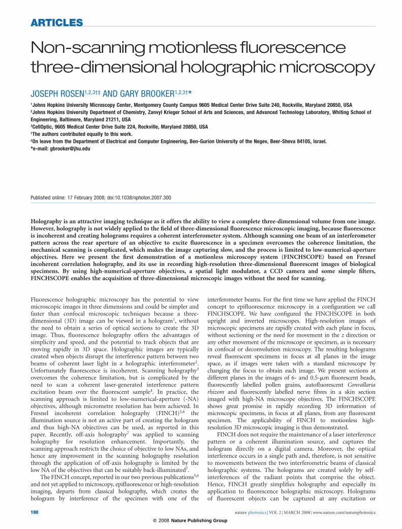
In classical imaging, image formation of objects at differentdistances from the lens results in a sharp image at the imageplane for objects at only one distance from the lens, as shown inFig. 1a. Other objects at other distances from the lens are out offocus. In confocal microscopy8 or deconvolution microscopy9,the lens or specimen is incrementally moved along the z axis tocapture a stack of images so that each of the objects is in focus inat least one of the image slices. FINCH, on the other hand, asdepicted in Fig. 1b, projects a set of rings known as Fresnel zoneplates onto the plane of the image sensor for each and everypoint at every plane of the object being viewed. The depth of thepoints is encoded by the density of the rings such that pointsthat are closer to the sensor project less-dense rings than distantpoints. Because of this encoding method, the 3D information inthe volume being imaged is recorded by the image sensorwithout any movement of the lens or object. Therefore, eachplane in the image space is in focus. Encoding is accomplished bythe presence of a spatial light modulator (SLM) in the imagepath. A pattern displayed on the SLM affects the phase of eachwavefront originating from each point of the 3D specimen toproject the Fresnel zone plate on the image sensor.
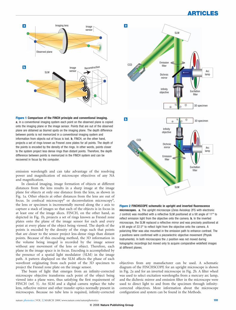
The beam of light that emerges from an infinity-correctedmicroscope objective transforms each point of the object beingviewed into a plane wave, thus satisfying the first requirement ofFINCH (ref. 5). An SLM and a digital camera replace the tubelens, reflective mirror and other transfer optics normally present inmicroscopes. Because no tube lens is required, infinity-corrected
objectives from any manufacturer can be used. A schematicdiagram of the FINCHSCOPE for an upright microscope is shownin Fig. 2a and for an inverted microscope in Fig. 2b. A filter wheelwas used to select excitation wavelengths from a mercury arc lamp,and the dichroic mirror and emission filter in the microscope wereused to direct light to and from the specimen through infinity-corrected objectives. More information about the microscopeconfiguration and system can be found in the Methods.
Reconstruction
Imagesensor
Imagesensor
Imaging lens
SLM
Observed plane
Figure 1 Comparison of the FINCH principle and conventional imaging.
a, In a conventional imaging system each point on the observed plane is copied
onto the imaging plane or the image sensor. Points that are out of the observed
plane are obtained as blurred spots on the imaging plane. The depth difference
between points is not memorized in a conventional imaging system and
information from objects out of focus is lost. b, FINCH, on the other hand,
projects a set of rings known as Fresnel zone plates for all points. The depth of
the points is encoded by the density of the rings. In other words, points closer
to the system project less dense rings than distant points. Therefore, the depth
difference between points is memorized in the FINCH system and can be
recovered in focus by the computer.
3D specimen
Excitation filter
Emissionfilter
Dichroicmirror
Infinityobjective
Infinityobjective
CCD
SLM
Arclamp
3D specimen
Excitationfilter
Emissionfilter
Dichroicmirror
CCD
SLM
Arclamp
Figure 2 FINCHSCOPE schematic in upright and inverted fluorescence
microscopes. a, The upright microscope (Zeiss Axioskop 2FS with electronic
z control) was modified with a reflective SLM positioned at a tilt angle of 1188888 to
reflect emission light from the objective onto the camera. b, In the inverted
microscope, the SLM replaced a reflective mirror and was precisely positioned at
a tilt angle of 22.588888 to reflect light from the objective onto the camera. A
polarizing filter was also mounted in the emission path to enhance contrast. The
z positions were confirmed with a piezoelectric objective movement (Physik
Instrumente). In both microscopes the z position was not moved during
holographic recordings but moved only to acquire comparative widefield images
at different planes.
ARTICLES
nature photonics | VOL 2 | MARCH 2008 | www.nature.com/naturephotonics 191
© 2008 Nature Publishing Group
RESULTS
MULTICOLOUR FLUORESCENCE AND RESOLUTION
The ability of the FINCHSCOPE to resolve multicolour fluorescentsamples was evaluated by first imaging polychromatic fluorescent
beads (Fig. 3). A fluorescent bead slide with the beads positionedon two separate planes was constructed. FocalCheckpolychromatic beads (6 mm) were used to coat one side of a glassmicroscope slide and a glass coverslip. These two surfaces werejuxtaposed and held together at a distance from one another of
z
70 m
8 m 13 m 20 m 24 m
z
70 m
6 m 8 m 11 m 12 m
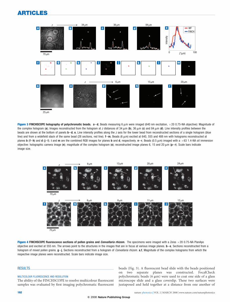
Figure 4 FINCHSCOPE fluorescence sections of pollen grains and Convallaria rhizom. The specimens were imaged with a Zeiss �20 0.75-NA PlanApo
objective and excited at 555 nm. The arrows point to the structures in the images that are in focus at various image planes. b–e, Sections reconstructed from a
hologram of mixed pollen grains. g– j, Sections reconstructed from a hologram of Convallaria rhizom. a,f, Magnitude of the complex holograms from which the
respective image planes were reconstructed. Scale bars indicate image size.
z
70 m
25 m
z 6 m 15 m 20 m
34 m 36 m 84 mWFFINCH
Inte
nsity
0 Z ( m) 100
Figure 3 FINCHSCOPE holography of polychromatic beads. a–d, Beads measuring 6 mm were imaged (640 nm excitation, �20 0.75-NA objective): Magnitude of
the complex hologram (a); Images reconstructed from the hologram at z distances of 34 mm (b), 36 mm (c) and 84 mm (d). Line intensity profiles between the
beads are shown at the bottom of panels b–d. e, Line intensity profiles along the z axis for the lower bead from reconstructed sections of a single hologram (blue
line) and from a widefield stack of the same bead (28 sections, red line). f–m, Beads (6 mm) excited at 640, 555 and 488 nm with holograms reconstructed at
planes b (f–h) and d ( j– l). i and m are the combined RGB images for planes b and d, respectively. n– r, Beads (0.5 mm) imaged with a �63 1.4-NA oil immersion
objective: holographic camera image (n); magnitude of the complex hologram (o); reconstructed image planes 6, 15 and 20 mm (p– r). Scale bars indicate
image size.
ARTICLES
nature photonics | VOL 2 | MARCH 2008 | www.nature.com/naturephotonics192
© 2008 Nature Publishing Group
�50 mm with optical cement (Dymax OP-29). The beads weresequentially excited at 488, 555 and 640 nm (centre wavelengths,10–30 nm bandwidths) with emissions recorded at 515–535 nm,585–615 nm and 660–720 nm, respectively. Figure 3b–d showsreconstructed image planes from 6-mm beads excited at 640 nmand imaged on the FINCHSCOPE with a Zeiss PlanApo �200.75-NA objective. Figure 3a shows the magnitude of thecomplex hologram, which contains all the information aboutthe location and intensity of each bead at every plane in thefield. The Fresnel reconstruction from this hologram was selectedto yield 49 planes of the image, 2 mm apart. Two beads areshown in Fig. 3b, with only the lower bead exactly in focus. Thenext image (Fig. 3c) is 2 mm into the field in the z direction, andthe upper bead is now in focus, with the lower bead slightly outof focus. The focal difference is confirmed by the line profile
drawn between the beads, showing an inversion of intensity forthese two beads between the planes. There is another beadbetween these two beads, but it does not appear in Fig. 3b or c(or in the intensity profile), because it is 48 mm from the upperbead; it instead appears in Fig. 3d (and in the line profile),which is 24 sections away from the section in Fig. 3c. Noticethat the beads in Fig. 3b and c are no longer visible in Fig. 3d. Inthe complex hologram in Fig. 3a, the smaller circles are partof the encoding for the close beads and the larger circles forthe distant central bead. Figure 3e shows that the z resolution ofthe lower bead in Fig. 3b, reconstructed from sectionscreated from a single hologram (blue line), is at least comparableto that from a widefield stack of 28 sections (obtained bymoving the microscope objective in the z direction) of the samefield (red line).
Widefield focus position
+19 m +10 m 0 m
Widefield sections deconvolved
FINCHSCOPE sections
Section 11 Section 12 Section 13
FINCHSCOPE sections deconvolved
50 m
–25 m
Section 14
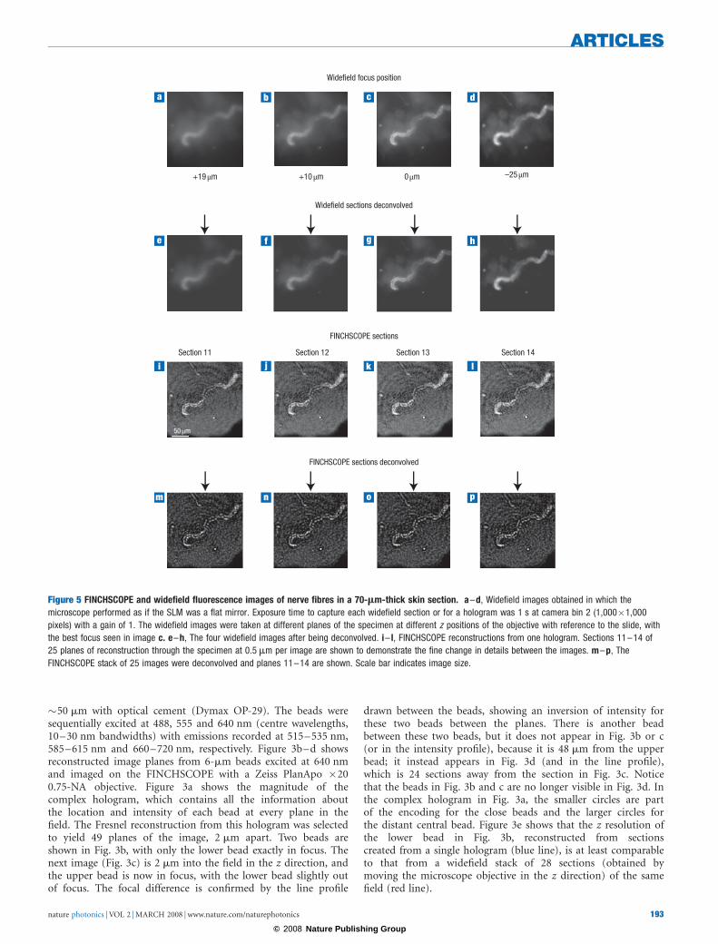
Figure 5 FINCHSCOPE and widefield fluorescence images of nerve fibres in a 70-mm-thick skin section. a–d, Widefield images obtained in which the
microscope performed as if the SLM was a flat mirror. Exposure time to capture each widefield section or for a hologram was 1 s at camera bin 2 (1,000�1,000
pixels) with a gain of 1. The widefield images were taken at different planes of the specimen at different z positions of the objective with reference to the slide, with
the best focus seen in image c. e–h, The four widefield images after being deconvolved. i– l, FINCHSCOPE reconstructions from one hologram. Sections 11–14 of
25 planes of reconstruction through the specimen at 0.5 mm per image are shown to demonstrate the fine change in details between the images. m–p, The
FINCHSCOPE stack of 25 images were deconvolved and planes 11–14 are shown. Scale bar indicates image size.
ARTICLES
nature photonics | VOL 2 | MARCH 2008 | www.nature.com/naturephotonics 193
© 2008 Nature Publishing Group
The co-localization of the fluorescence emissions was confirmedat all excitation wavelengths and at extreme z limits as shown inFig. 3f–m for the 6-mm beads at the planes shown in Fig. 3b(f–i) and 3d (j–m). In Fig. 3n–r, 0.5-mm beads (TetraSpeck,Invitrogen) imaged with a Zeiss PlanApo �63 1.4-NA oilimmersion objective are shown. Figure 3n is one of the hologramscaptured by the camera and Fig. 3o shows the magnitude ofthe complex hologram. Figure 3p–r shows different planes(6, 15 and 20 mm, respectively) in the bead specimen afterreconstruction from the complex hologram of image slices in0.5-mm steps, Arrows show the different beads visualized indifferent z image planes.
A group of fluorescently labelled pollen grains (CarolinaBiological slide no. 30-4264) is shown in Fig. 4. The computerreconstruction along the z axis is shown in Fig. 4b-e. As isexpected from a holographic reconstruction of a 3D object withvolume, any number of planes can be reconstructed. In thisexample, a different pollen grain was in focus in each transverseplane reconstructed from the complex hologram whosemagnitude is shown in Fig. 4a. In Fig. 4b–e, the values of z are8, 13, 20 and 24 mm, respectively. A similar experiment wasperformed with the autofluorescent Convallaria rhizom and theresults are shown in Fig. 4g–j at planes 6, 8, 11 and 12 mm. SeeSupplementary Information for a movie of the 3D reconstructionfrom 25 reconstructed planes (Fig. S1).
HOLOGRAPHIC IMAGING OF A TISSUE SECTION
The design of the FINCHSCOPE makes it easy to convert from aholographic microscope to a widefield microscope simply by notdisplaying any pattern on the SLM, leaving it as a planar mirroras in a normal microscope. The comparative widefield data inFig. 3e was obtained by moving the microscope objective in the zdirection to obtain a stack of widefield images (however, theobjective was not moved during the holographic imageacquisition). The data in Fig. 5 were obtained with the invertedmicroscope, whereas the data in Figs 3 and 4 were obtained withthe upright microscope. In Fig. 5a–d, widefield images of a nervebundle in a 70-mm-thick section of skin are shown at positionsabove and below the plane of best focus. The nerve fibreSchwann cell sheath was immunolabelled with Cy3 S100protein antibody. Excitation was at 555 nm and an Olympus �200.75-NA PlanApo objective was used. Note that all sections showconsiderable out-of-focus information, as is seen on anyfluorescence microscope. When we captured a hologram inFINCHSCOPE mode, using patterns on the SLM, we couldcreate reconstructed sections with various planes of the nervefibres in focus. For convenience, sections 11–14 of 25reconstructed sections are shown in Fig. 5i–l. Careful inspectionof these images shows changes from one to another,demonstrating detail not visible in any of the widefield images.
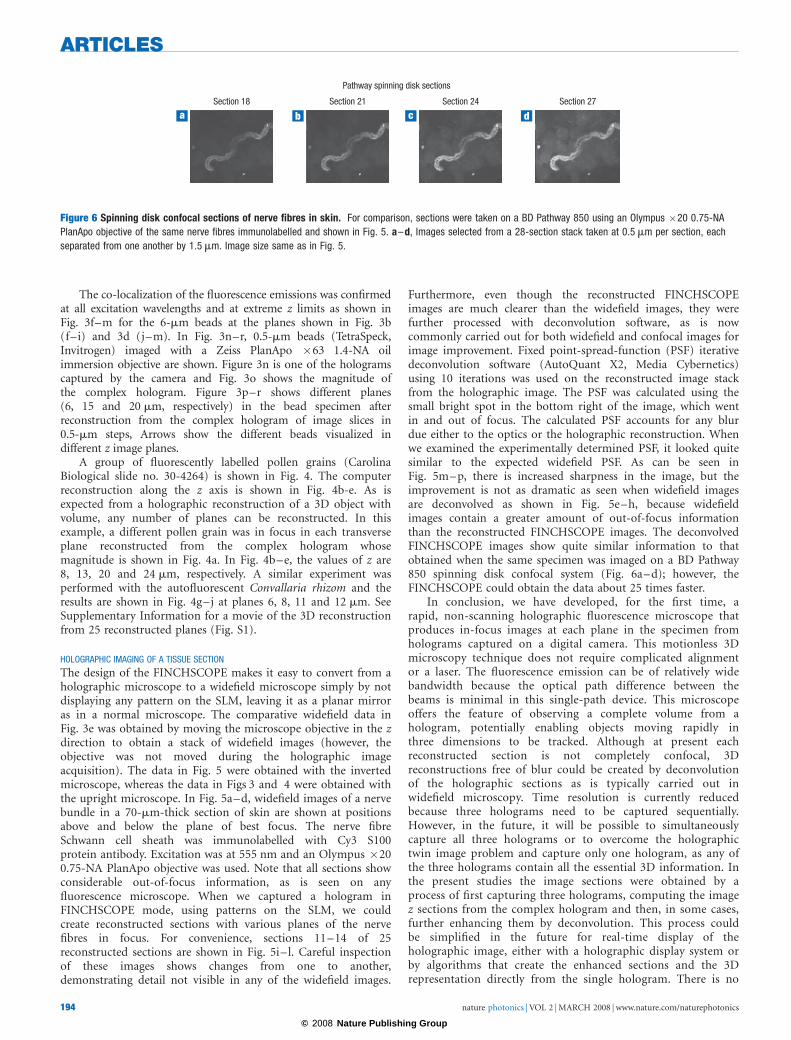
Furthermore, even though the reconstructed FINCHSCOPEimages are much clearer than the widefield images, they werefurther processed with deconvolution software, as is nowcommonly carried out for both widefield and confocal images forimage improvement. Fixed point-spread-function (PSF) iterativedeconvolution software (AutoQuant X2, Media Cybernetics)using 10 iterations was used on the reconstructed image stackfrom the holographic image. The PSF was calculated using thesmall bright spot in the bottom right of the image, which wentin and out of focus. The calculated PSF accounts for any blurdue either to the optics or the holographic reconstruction. Whenwe examined the experimentally determined PSF, it looked quitesimilar to the expected widefield PSF. As can be seen inFig. 5m–p, there is increased sharpness in the image, but theimprovement is not as dramatic as seen when widefield imagesare deconvolved as shown in Fig. 5e–h, because widefieldimages contain a greater amount of out-of-focus informationthan the reconstructed FINCHSCOPE images. The deconvolvedFINCHSCOPE images show quite similar information to thatobtained when the same specimen was imaged on a BD Pathway850 spinning disk confocal system (Fig. 6a–d); however, theFINCHSCOPE could obtain the data about 25 times faster.
In conclusion, we have developed, for the first time, arapid, non-scanning holographic fluorescence microscope thatproduces in-focus images at each plane in the specimen fromholograms captured on a digital camera. This motionless 3Dmicroscopy technique does not require complicated alignmentor a laser. The fluorescence emission can be of relatively widebandwidth because the optical path difference between thebeams is minimal in this single-path device. This microscopeoffers the feature of observing a complete volume from ahologram, potentially enabling objects moving rapidly inthree dimensions to be tracked. Although at present eachreconstructed section is not completely confocal, 3Dreconstructions free of blur could be created by deconvolutionof the holographic sections as is typically carried out inwidefield microscopy. Time resolution is currently reducedbecause three holograms need to be captured sequentially.However, in the future, it will be possible to simultaneouslycapture all three holograms or to overcome the holographictwin image problem and capture only one hologram, as any ofthe three holograms contain all the essential 3D information. Inthe present studies the image sections were obtained by aprocess of first capturing three holograms, computing the imagez sections from the complex hologram and then, in some cases,further enhancing them by deconvolution. This process couldbe simplified in the future for real-time display of theholographic image, either with a holographic display system orby algorithms that create the enhanced sections and the 3Drepresentation directly from the single hologram. There is no
Pathway spinning disk sections
Section 24 Section 27Section 18 Section 21
Figure 6 Spinning disk confocal sections of nerve fibres in skin. For comparison, sections were taken on a BD Pathway 850 using an Olympus �20 0.75-NA
PlanApo objective of the same nerve fibres immunolabelled and shown in Fig. 5. a–d, Images selected from a 28-section stack taken at 0.5 mm per section, each
separated from one another by 1.5 mm. Image size same as in Fig. 5.
ARTICLES
nature photonics | VOL 2 | MARCH 2008 | www.nature.com/naturephotonics194
© 2008 Nature Publishing Group
need for sectioning or scanning or any mechanical movement.Therefore, this system would be expected ultimately to be faster,more simple and more versatile than existing 3D microscopytechniques, which rely on pinhole imaging or deconvolution ofstacks of widefield images. At present, the FINCHSCOPE isalready considerably faster than conventional 3D sectioning. Forexample, the total image capture time for the threeFINCHSCOPE images of the pollen grains in Fig. 4 was justover 1 s, compared with the 30–45 s needed to create a stack of48 widefield or spinning disk confocal images. For the firsttime, we have also demonstrated fluorescence holography usingthe high-NA objectives widely used in biological imaging.FINCHSCOPE is able to spatially resolve small beads, biologicalspecimens and different fluorescence emission colours in x, yand z planes with perfect registration. The system provides asimple, flexible, cost-effective and powerful microscopicplatform for 3D imaging. Our demonstration of this advance inmicroscopy, based on a new, but simple holographic principle,should open up opportunities in many life science andengineering fields, so that living or fixed specimens may bereadily observed in three dimensions and possibly at higherresolution than with currently existing techniques. For example,off-axis holography has been shown to boost the resolvingpower in more classical light7 and electron10 microscopeholographic systems. Application of off-axis holography tothe FINCHSCOPE reported here would be expected to increasethe resolving power of the high-NA objectives already in usein the FINCHSCOPE.
METHODS
Epifluorescence was achieved by a microscope equipped with an excitation filter,dichroic mirror and emission filter (Chroma Technology multiband 84,000 set)as shown in Fig. 2. Changing the excitation filters allowed the imaging of threedistinct dyes of different excitation and emission wavelengths without any imageshift between wavelengths. The emitted fluorescence with wavelengths longerthan the excitation light passed from the objective through the dichroic mirrorand emission filter and was reflected at 118 (upright microscope) or 22.58(inverted microscope) from a phase-only SLM (Holoeye HEO 1080P;1,080 � 1,920 pixels) onto a 12-bit 2,000 � 2,000 pixels digital camera(QImaging Cooled Retiga 4000R). The SLM firmware was modified so a full 2pphase change could be obtained at either angle. A phase pattern was displayed onthe SLM, creating a composition of two different spherical diffractive lenses (oneof them having infinite focal length). Therefore, a single wavefront originatingfrom any object point was split by the SLM into two mutually coherentwavefronts with two different spherical curves. These two beams propagated inthe same direction towards the camera and mutually interfered on the sensorchip. The intensity pattern of the interference originating from the same pointsource was in the shape of the Fresnel zone plate mentioned earlier. Fresnel zoneplates are characterized by a set of concentric rings, with a thickness inverselyproportional to their distance from the centre. The depth location of thisradiating point was encoded by the density of Fresnel zone plate rings, and itstransverse location encoded directly by the transverse location of the Fresnel zoneplate centre. The intensity of this interference pattern was accumulatedincoherently on the camera plane with the other interferences from the otherobject points in the specimen being examined. The resulting pattern was anincoherent hologram that is recorded by the digital camera and introduced intothe computer. This hologram contains only one useful component with thedesired image information of the scene and two other components, a distractingtwin image and a high-intensity, slowly modulated bias term. To eliminate thetwin image and the bias term resulting from each single hologram, threeincoherent holograms were recorded sequentially, each with a differentphase factor of the SLM pattern. In a mathematical formulation, the kth
pattern Rk(x, y) displayed on the SLM, to create the kth hologram out of thethree, is given by
Rk x; yð Þ ¼ 1
2þ 1
2exp � ip
lax2 þ y2� �
� iuk
� �; ð1Þ
where l is the central wavelength used in the system and a is a constant.The first constant term of 1/2 in equation (1) is responsible for the formationof one of the wavefronts, and the quadratic phase term is responsible for theformation of the other wavefront. The angle uk is the phase step needed toeliminate the twin image and the bias term. Using a common computationroutine of phase stepping5,6, the three holograms were superposed in thecomputer, such that the result was a complex-valued Fresnel hologramcontaining only the useful component. When this hologram was reconstructedin the computer using a Fresnel propagation formula11, a 3D image of theobject appeared in the digital reconstruction space. Control of the SLM, imagecapture and calculations (using only the central 1,000 �1,000 pixels of eachimage to speed calculations) were performed by custom software written in theinterpretive MATLAB language.
The desired complex function given by equation (1) cannot be directlydisplayed on the phase-only SLM. As a good approximation for equation (1), wedisplayed the required quadratic phase function randomly on only half of theSLM pixels. These pixels were represented in the second term of equation (1),whereas the rest of the pixels representing the first constant term in equation (1)were modulated with a constant phase5,6. The randomness in distributing thetwo phase functions has been required because organized non-random structureproduces unnecessary diffraction orders, and therefore results in lowerinterference efficiency. The pixels were divided equally, half to each diffractiveelement, to create two wavefronts with equal energy. The phase constants ofu1,2,3 ¼ 08, 1208 and 2408 were introduced into the three quadratic phasefunctions given by equation (1).
Received 26 June 2007; accepted 21 December 2007; published 17 February 2008.
References1. Gabor, D. A new microscopic principle. Nature 161, 777–778 (1948).2. Garcia-Sucerquia, J. et al. Digital in-line holographic microscopy. Appl. Opt. 45, 836–850 (2006).3. Poon, T.-C. Scanning holography and two-dimensional image processing by acousto-optic two-pupil
syntheses. J. Opt. Soc. Am. A 2, 521–527 (1985).4. Schilling, B. W. et al. Three-dimensional holographic fluorescence microscopy. Opt. Lett. 22,
1506–1508 (1997).5. Rosen, J. & Brooker, G. Digital spatially incoherent Fresnel holography. Opt. Lett. 32, 912–914 (2007).6. Rosen, J. & Brooker, G. Fluorescence incoherent color holography. Opt. Express. 15, 2244–2250 (2007).7. Indebetouw, G., Tada, Y., Rosen, J. & Brooker, G. Scanning holographic microscopy with resolution
exceeding the Rayleigh limit of the objective by superposition of off-axis holograms. Appl. Opt. 46,993–1000 (2007).
8. Gu, M. Principles of Three-Dimensional Imaging in Confocal Microscopes (World Scientific,Singapore 1996).
9. McNally, J. G., Karpova, T., Cooper, J. & Conchello, J. A. Three-dimensional imaging bydeconvolution microscopy. Methods 19, 373–385 (1999).
10. Cowley, J. M. Off-axis STEM or TEM holography combined with four-dimensional diffractionimaging. Microsc. Microanal. 10, 9–15 (2004).
11. Goodman, J. W. Introduction to Fourier Optics 2nd edn, 63–95 (McGraw-Hill, New York, 1996).
AcknowledgementsThis work was supported by National Science Foundation grant no. 0420382 and CellOptic. We thankM. DeBernardi, B. Storrie and S. Krueger for valuable comments and A. Hermerschmidt, who providedthe special firmware for the SLM. We also thank W.R. Kennedy and G. Wendelschager-Crabb for theimmunolabelled slide of skin and K. Ryan for deconvolving the stack of images created fromthe hologram.Correspondence should be addressed to G.B.Supplementary information accompanies this paper on www.nature.com/naturephotonics.
Author contributionsAll authors contributed equally to this work.
Competing financial interestsThe authors declare competing financial interests: details accompany the full-text HTML version of thepaper at www.nature.com/naturephotonics.
Reprints and permission information is available online at http://npg.nature.com/reprintsandpermissions/
ARTICLES
nature photonics | VOL 2 | MARCH 2008 | www.nature.com/naturephotonics 195
© 2008 Nature Publishing Group