nitrogen membrane system - access hire
TRANSCRIPT
Access Hire Australia 22 Enterprise Court, Canning Vale WA 6155 P: +61 8 6258 4120
NITROGEN MEMBRANE SYSTEM NGU HR 3000 RC
TABLE OF CONTENT NITROGEN MEMBRANE SYSTEM OVERVIEW ........................................................................ 2 1. INTRODUCTION ................................................................................................................. 3
1.1 BACKGROUND ................................................................................................................... 3 2. PROCESS DESCRIPTION .................................................................................................. 3
2.1 AIR SEPARATION .............................................................................................................. 3 2.2 SYSTEM OPERATION ........................................................................................................ 4 2.3 SYSTEM PERFORMANCE ................................................................................................. 4
3. DESIGN BASIS ................................................................................................................... 5 4. SCOPE OF SUPPLY ........................................................................................................... 5
4.1 AIR PRE-TREATMENT ....................................................................................................... 6 4.2 MEMBRANE BUNDLES ...................................................................................................... 6 4.3 INSTRUMENTATION AND CONTROLS ............................................................................. 6
ATTACHMENT A ......................................................................................................................... 9 ATTACHMENT B ....................................................................................................................... 10
FULL SPEC - NGU HR 3000 RC (AHA) 2 of 10
NITROGEN MEMBRANE SYSTEM OVERVIEW
Our equipment is designed and guaranteed for long-term operation. From application design to continuing production, it provides a cost-effective solution with the following benefits:
• Increased space/weight efficiency
• Unparalleled system reliability
• Efficient maintainability, serviceability, and ease of operation
• Long-term durability
• Seamless system integration
Our integrated solutions are built on a foundation of quality and durability to ensure maximum reliability and performance. Research and development enables the Access Group to provide innovative products that meet today’s applications and standards which helps to reduce total cost of ownership.
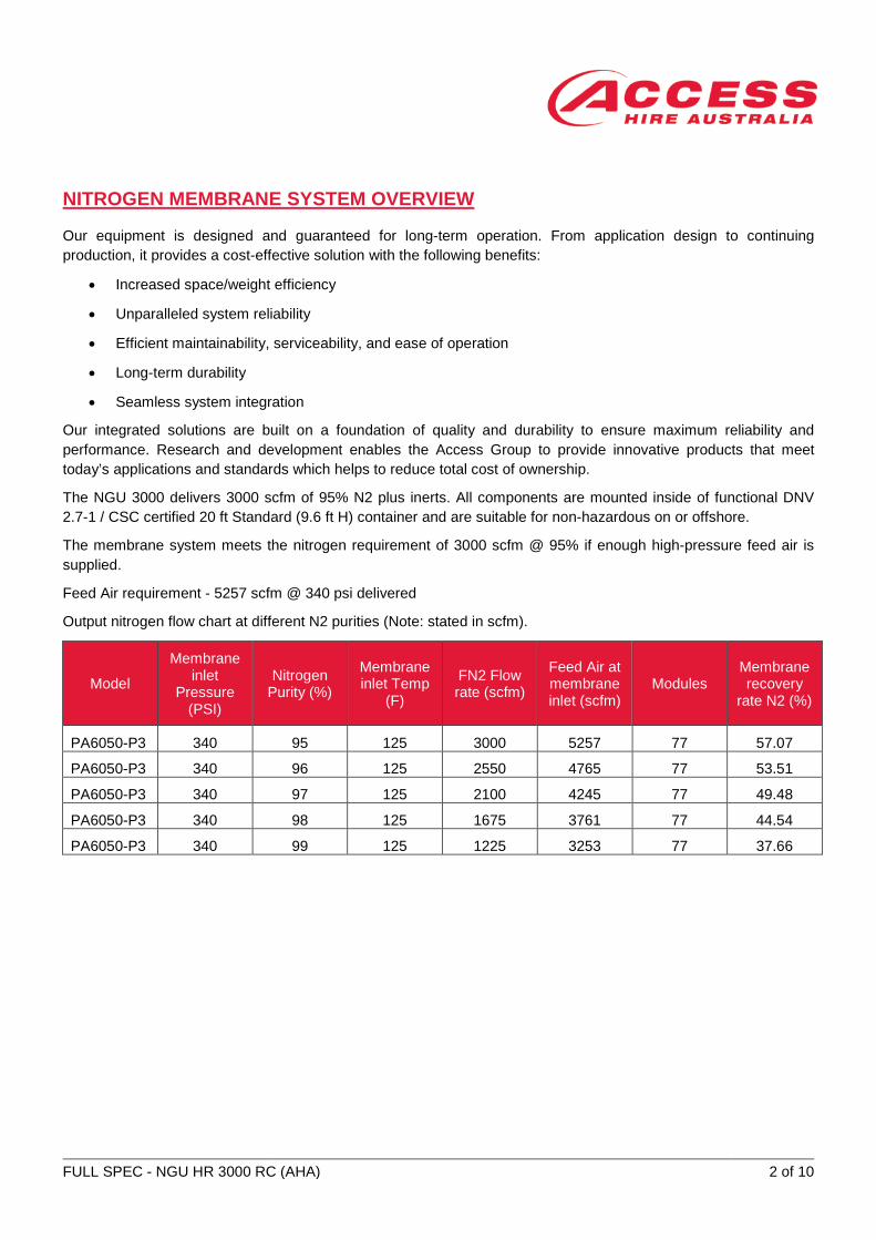
The NGU 3000 delivers 3000 scfm of 95% N2 plus inerts. All components are mounted inside of functional DNV 2.7-1 / CSC certified 20 ft Standard (9.6 ft H) container and are suitable for non-hazardous on or offshore.
The membrane system meets the nitrogen requirement of 3000 scfm @ 95% if enough high-pressure feed air is supplied.
Feed Air requirement - 5257 scfm @ 340 psi delivered
Output nitrogen flow chart at different N2 purities (Note: stated in scfm).
Model
Membrane inlet
Pressure (PSI)
Nitrogen Purity (%)
Membrane inlet Temp
(F)
FN2 Flow rate (scfm)
Feed Air at membrane inlet (scfm)
Modules Membrane recovery
rate N2 (%)
PA6050-P3 340 95 125 3000 5257 77 57.07
PA6050-P3 340 96 125 2550 4765 77 53.51
PA6050-P3 340 97 125 2100 4245 77 49.48
PA6050-P3 340 98 125 1675 3761 77 44.54
PA6050-P3 340 99 125 1225 3253 77 37.66
FULL SPEC - NGU HR 3000 RC (AHA) 3 of 10
1. INTRODUCTION
1.1 BACKGROUND The Membrane Nitrogen System will produce up to 3000 scfm 95 % Nitrogen if supplied with a minimum of 5300 scfm feed air @ 350 psi. The discharge nitrogen pressure and temperature will be estimated at 320 psi and 10 to 15 F above ambient temperature.
DESIGN SPECIFICATIONS
Location: Unknown Ambient temp. range: 32 F to 150 F
Electric Classification: Non-hazardous
Electric Power: +100 kw 480V or 380V 3 phase, 60 Hz or 50 Hz Maximum Gross weight: +/- 30,000 lb
Container: 20 ft high cube ISO dimensions DNV 2.7-1 / CSC
Documentation: includes a GAD and P&ID of current design and 3D model. Upgrades: 1) Eliminate the Carbon tower – combine the carbon filtration
with partial filter.
• Eliminates the possibility of hot spots in the carbon due
to oil residue.
2) Additional Pressure Relieve Valve on the feed inlet manifold.
3) PCL controlled re-heater with high temperature shutdown
• An independent high temperature sensor will shut down
power to the electric re-heater.
4) Feed air inlet emergence shut off valve connected to the
emergence shut down button.
5) Stainless Steel or painted components will be used to
minimize corrosion during offshore operations.
6) Supplied with a set of replacement filters and hand-held
Oxygen Analyzer.
7) Includes Laptop computer with software for Data recording
and remote operation.
2. PROCESS DESCRIPTION
2.1 AIR SEPARATION The nitrogen membrane system uses polymeric hollow fibre membranes. Pressurized air enters at one end of the module and product nitrogen exits at the opposite end of the module.
Gas separation takes place as the pressurized air contacts the membranes. "Fast" gases, such as oxygen, carbon dioxide and water vapor, quickly permeate through the fibre walls and exit at atmospheric pressure through the vent port on the side of the module case.
Nitrogen, a slower gas, does not permeate through the fibre walls as quickly under flowing conditions. As a result, enriched nitrogen exits the product manifold on the end of the module housing at a slightly lower pressure than the air entering the housing.
FULL SPEC - NGU HR 3000 RC (AHA) 4 of 10
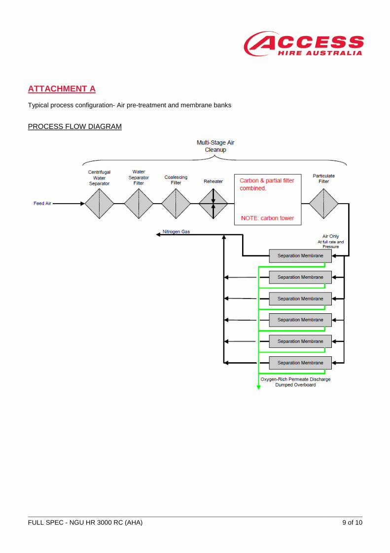
2.2 SYSTEM OPERATION The NGU requires a pressurized feed air stream and electrical power for the reheater. Feed air for the membranes is supplied by a feed air compressor provided by customer. As shown in Attachment A, the compressed feed air is first stripped of free water and suspended oil particles in a de-mister and fed to a series of fine coalescing filters to remove most of the water/oil vapours. To ensure that the compressed air stream contains no free moisture, an electric heater superheats the air stream. The air then enters a carbon bed to adsorb any residual hydrocarbon vapours that may be present in the compressed air stream. A fine micron filter provides final capture of any remaining particles in the feed air stream.
The air then enters the bank of membrane modules where oxygen and water vapor are removed, and highly enriched nitrogen is collected at the product end of the membrane module.
The purity of the nitrogen product gas is controlled by a backpressure control valve. An alarm is provided to alert the operator to high oxygen levels, and the product control valve will vent out of spec nitrogen to atmosphere if the oxygen concentration reaches an unacceptable level. Permeate gas (waste gas) is also vented to the atmosphere. The nitrogen produced from the membrane banks is collected in the discharge header and fed to the booster compressor, also supplied by customer. An orifice flow measurement system will be provided. The metered nitrogen discharge flow, pressure and purity are constantly monitored and displayed at a central operator control panel.
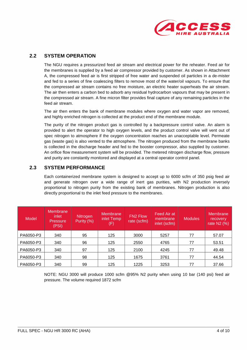
2.3 SYSTEM PERFORMANCE Each containerized membrane system is designed to accept up to 6000 scfm of 350 psig feed air and generate nitrogen over a wide range of inert gas purities, with N2 production inversely proportional to nitrogen purity from the existing bank of membranes. Nitrogen production is also directly proportional to the inlet feed pressure to the membranes.
Model
Membrane inlet
Pressure (PSI)
Nitrogen Purity (%)
Membrane inlet Temp
(F)
FN2 Flow rate (scfm)
Feed Air at membrane inlet (scfm)
Modules Membrane recovery
rate N2 (%)
PA6050-P3 340 95 125 3000 5257 77 57.07
PA6050-P3 340 96 125 2550 4765 77 53.51
PA6050-P3 340 97 125 2100 4245 77 49.48
PA6050-P3 340 98 125 1675 3761 77 44.54
PA6050-P3 340 99 125 1225 3253 77 37.66
NOTE: NGU 3000 will produce 1000 scfm @95% N2 purity when using 10 bar (140 psi) feed air pressure. The volume required 1872 scfm
FULL SPEC - NGU HR 3000 RC (AHA) 5 of 10
3. DESIGN BASIS
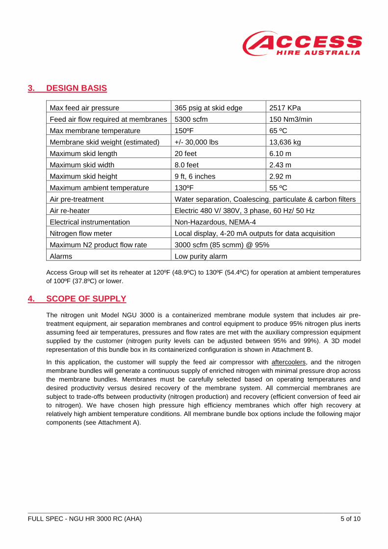
Max feed air pressure 365 psig at skid edge 2517 KPa Feed air flow required at membranes 5300 scfm 150 Nm3/min Max membrane temperature 150ºF 65 ºC Membrane skid weight (estimated) +/- 30,000 lbs 13,636 kg Maximum skid length 20 feet 6.10 m Maximum skid width 8.0 feet 2.43 m Maximum skid height 9 ft, 6 inches 2.92 m Maximum ambient temperature 130ºF 55 ºC Air pre-treatment Water separation, Coalescing. particulate & carbon filters Air re-heater Electric 480 V/ 380V, 3 phase, 60 Hz/ 50 Hz Electrical instrumentation Non-Hazardous, NEMA-4 Nitrogen flow meter Local display, 4-20 mA outputs for data acquisition Maximum N2 product flow rate 3000 scfm (85 scmm) @ 95% Alarms Low purity alarm
Access Group will set its reheater at 120ºF (48.9ºC) to 130ºF (54.4ºC) for operation at ambient temperatures of 100ºF (37.8ºC) or lower.
4. SCOPE OF SUPPLY
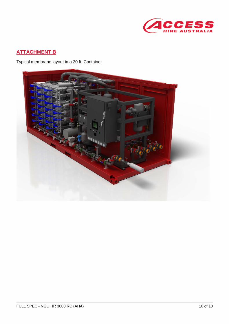
The nitrogen unit Model NGU 3000 is a containerized membrane module system that includes air pre-treatment equipment, air separation membranes and control equipment to produce 95% nitrogen plus inerts assuming feed air temperatures, pressures and flow rates are met with the auxiliary compression equipment supplied by the customer (nitrogen purity levels can be adjusted between 95% and 99%). A 3D model representation of this bundle box in its containerized configuration is shown in Attachment B.
In this application, the customer will supply the feed air compressor with aftercoolers, and the nitrogen membrane bundles will generate a continuous supply of enriched nitrogen with minimal pressure drop across the membrane bundles. Membranes must be carefully selected based on operating temperatures and desired productivity versus desired recovery of the membrane system. All commercial membranes are subject to trade-offs between productivity (nitrogen production) and recovery (efficient conversion of feed air to nitrogen). We have chosen high pressure high efficiency membranes which offer high recovery at relatively high ambient temperature conditions. All membrane bundle box options include the following major components (see Attachment A).
FULL SPEC - NGU HR 3000 RC (AHA) 6 of 10
4.1 AIR PRE-TREATMENT
4.1.1 Centrifugal Water Separator: water knock-out vessel. 4.1.2 Water Separator and Coalescing Filters: additional removal of water vapor and
condensables. 4.1.3 Electric Reheater: provides superheating to the feed air stream and stabilizes
temperatures for improved process control. 4.1.4 Carbon and Particulate Filter: adsorbs any remaining oil aerosols or vapors in
the feed air and final protection against particulates.
4.2 MEMBRANE BUNDLES Adequate membranes have been piped in parallel to meet or exceed process requirements. This membrane system has an efficiency rate of > than 55% at maximum ambient temperature. We use Air products high recovery, high temperature and pressure membrane modules.
4.3 INSTRUMENTATION AND CONTROLS Nitrogen flow measurement, flow control valve, oxygen process analyzer and all necessary shut down and alarms are included.
4.3.1 PRODUCT PURITY CONTROL • Capable of providing the customer adjustable control of product purity from 95% to
99%.
• Process regulation by a pilot-operated backpressure regulating valve to control flow rate and corresponding oxygen level in the product gas.
• Diminishes possibility of intermittent shutdown due to product purity and provides smoother (quicker) recovery from feed air upsets.
• High accuracy nitrogen orifice flow measurement system will be provided on the bundle box outlet.
4.3.2 SAFETY FEATURES • Oxygen analyzer (zirconium-type) to ensure product integrity and process safety.
• Over temperature protection.
• Over pressure protection (PRV).
FULL SPEC - NGU HR 3000 RC (AHA) 7 of 10
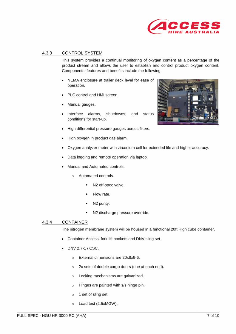
4.3.3 CONTROL SYSTEM This system provides a continual monitoring of oxygen content as a percentage of the product stream and allows the user to establish and control product oxygen content. Components, features and benefits include the following.
• NEMA enclosure at trailer deck level for ease of operation.
• PLC control and HMI screen.
• Manual gauges.
• Interface alarms, shutdowns, and status conditions for start-up.
• High differential pressure gauges across filters.
• High oxygen in product gas alarm.
• Oxygen analyzer meter with zirconium cell for extended life and higher accuracy.
• Data logging and remote operation via laptop.
• Manual and Automated controls.
o Automated controls.
N2 off-spec valve.
Flow rate.
N2 purity.
N2 discharge pressure override.
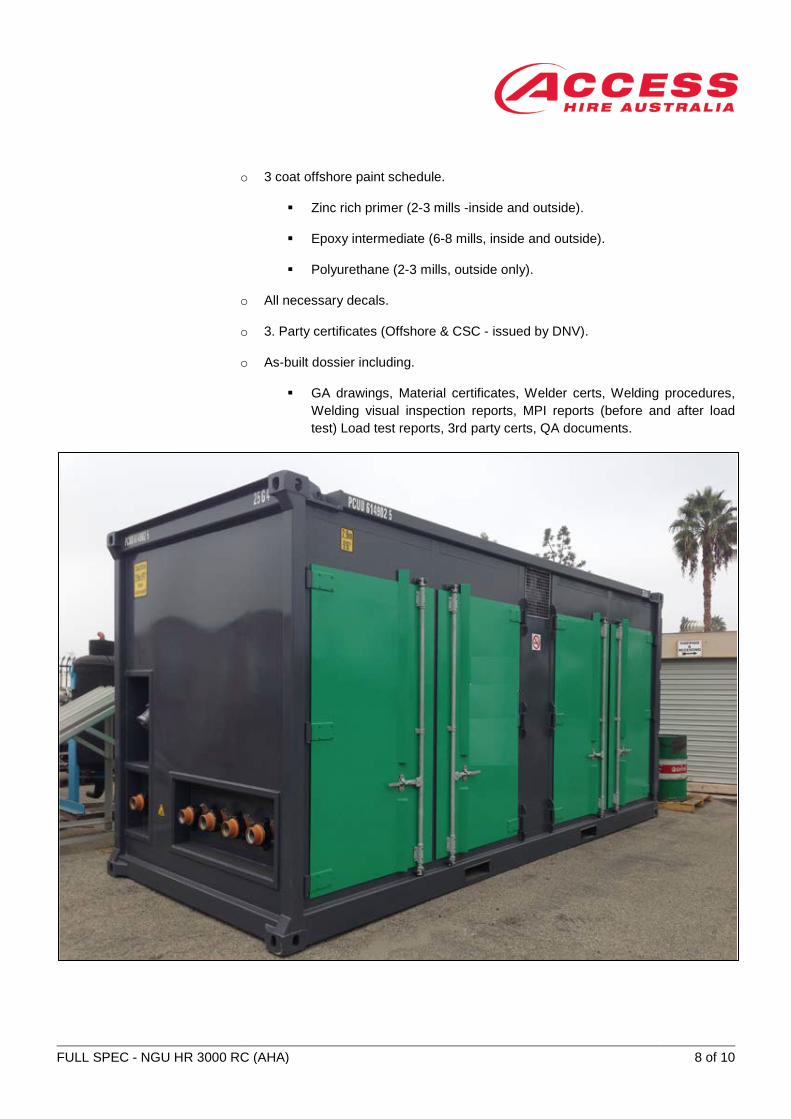
4.3.4 CONTAINER The nitrogen membrane system will be housed in a functional 20ft High cube container.
• Container Access, fork lift pockets and DNV sling set.
• DNV 2.7-1 / CSC.
o External dimensions are 20x8x9-6.
o 2x sets of double cargo doors (one at each end).
o Locking mechanisms are galvanized.
o Hinges are painted with s/s hinge pin.
o 1 set of sling set.
o Load test (2.5xMGW).
FULL SPEC - NGU HR 3000 RC (AHA) 8 of 10
o 3 coat offshore paint schedule.
Zinc rich primer (2-3 mills -inside and outside).
Epoxy intermediate (6-8 mills, inside and outside).
Polyurethane (2-3 mills, outside only).
o All necessary decals.
o 3. Party certificates (Offshore & CSC - issued by DNV).
o As-built dossier including.
GA drawings, Material certificates, Welder certs, Welding procedures, Welding visual inspection reports, MPI reports (before and after load test) Load test reports, 3rd party certs, QA documents.
FULL SPEC - NGU HR 3000 RC (AHA) 9 of 10
ATTACHMENT A
Typical process configuration- Air pre-treatment and membrane banks
PROCESS FLOW DIAGRAM
FULL SPEC - NGU HR 3000 RC (AHA) 10 of 10
ATTACHMENT B
Typical membrane layout in a 20 ft. Container