nissan patrol getting the most from your
TRANSCRIPT

NISSAN PATROLGetting The Most From Your
OWNER’S MANUAL
CONTENTSIllustrated table of contents 0
Safety — seats, seat belts and supplemental restraint system 1
Instruments and controls 2
Pre-driving checks and adjustments 3
Display screen, heater and air conditioner, and audio system 4
Starting and driving 5
In case of emergency 6
Appearance and care 7
Maintenance and do-it-yourself 8
Technical information 9
Index 10
WELCOME TO YOUR NEW NISSAN PATROL
(3,1)
[ Edit: 2020/ 11/ 9 Model: Y62-A ]
GUID-CA59C8CB-C9EB-42C4-B504-F8AF8A73B8DEThis manual was prepared to help you under-stand the operation and maintenance of yourvehicle so that you may enjoy many kilometers(miles) of driving pleasure. Please read throughthis manual before operating your vehicle.A separate Warranty Information & Mainte-nance Booklet explains details about the war-ranties covering your vehicle.Your NISSAN dealer knows your vehicle best.When you require any service or have anyquestions, we will be glad to assist you withthe extensive resources available for you.
IMPORTANT SAFETY INFORMATIONGUID-E20DF1AA-22BC-47CB-B7D0-017CE6DFFFB7
Reminders for safety!GUID-91D0EA2F-7DA9-46D7-92EF-017C6F603E88Follow these important driving rules to helpensure a safe and complete trip for you andyour passengers!. NEVER drive under the influence of alco-
hol or drugs.. ALWAYS observe posted speed limits and
never drive too fast for conditions.. ALWAYS use your seat belts and appro-
priate child restraint systems. Preteenchildren should be seated in the rear seat.
. ALWAYS provide information about theproper use of vehicle safety features toall occupants of the vehicle.
. ALWAYS review this Owner’s Manual forimportant safety information.
When reading the manualGUID-B1BE6CF6-22AD-4020-A43D-3E1D2A7455D1This manual includes information for all optionsavailable on this model. Therefore, you may findsome information that does not apply to yourvehicle.Throughout this manual, some illustrationsmay only show the layout for Left-Hand Drive(LHD) models. For Right-Hand Drive (RHD)models, the illustrated shape and location ofsome components may differ.All information, specifications and illustrationsin this manual are those in effect at the time ofprinting. NISSAN reserves the right to changespecifications or designs without notice andwithout obligation.
MODIFICATION OF YOUR VEHICLEGUID-EF203BB2-ABA2-4612-8FCA-0ACC5C3CE29EThis vehicle should not be modified. Modifica-tion could affect its performance, safety ordurability, and may even violate governmentalregulations. In addition, damage or perfor-mance problems resulting from modificationsmay not be covered under NISSAN warranties.
Read first — then drive safelyGUID-0E4A92DE-D1FE-4675-BF47-F7633898A4C8Before driving your vehicle, read this Owner’sManual carefully. This will ensure familiaritywith controls and maintenance requirements,assisting you in the safe operation of yourvehicle.Throughout this manual we have used thesymbol followed by the word WARNING.This is used to indicate the presence of ahazard that could cause death or seriouspersonal injury. To avoid or reduce the risk,the procedures must be followed precisely.The symbol followed by the word CAU-TION is also used throughout this manual toindicate the presence of a hazard that could
cause minor or moderate personal injury ordamages to your vehicle. To avoid or reducethe risk, the procedures must be followedcarefully.
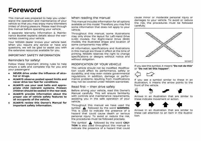
SIC0697
If you see this symbol, it means “Do not do this”or “Do not let this happen”.
NOS1274
If you see a symbol similar to these in anillustration, it means the arrow points to thefront of the vehicle.
NOS1275
Arrows in an illustration that are similar tothese indicate movement or action.
NOS1276
Arrows in an illustration that are similar tothese call attention to an item in the illustra-tion.
Foreword
Condition: 'Except for China'/'Except for China/
(4,1)
[ Edit: 2020/ 11/ 9 Model: Y62-A ]
ON-PAVEMENT AND OFF-ROAD DRIV-ING GUID-8349505F-8EC3-4524-B68F-65A3E4D55DE7This vehicle will handle and maneuver differ-ently from an ordinary passenger car, becauseit has a higher center of gravity for off-road use.As with other vehicles with features of this type,failure to operate this vehicle correctly mayresult in loss of control or an accident.Be sure to read “On-pavement and off-roaddriving precautions” (P.5-5).
NOS1617
Bluetooth® is a trademarkowned by Bluetooth SIG,Inc. and licensed to ClarionCo., Ltd.
© 2020 NISSAN MOTOR CO., LTD.
Condition: 'Except for China'/'Except for China/
(5,1)
[ Edit: 2020/ 11/ 9 Model: Y62-A ]
0 Illustrated table of contents
Seats, seat belts and Supplemental RestraintSystem (SRS) ......................................................................................................... 0-2Exterior front ........................................................................................................ 0-3
Except for Mexico ...................................................................................... 0-3For Mexico ...................................................................................................... 0-4
Exterior rear .......................................................................................................... 0-5Except for Mexico ...................................................................................... 0-5For Mexico ...................................................................................................... 0-6
Exterior (NISMO models) ............................................................................. 0-7Passenger compartment ........................................................................... 0-8
Cockpit ..................................................................................................................... 0-9Left-Hand Drive (LHD) model ........................................................ 0-9Right-Hand Drive (RHD) model ................................................. 0-10
Instrument panel .......................................................................................... 0-12Left-Hand Drive (LHD) model ..................................................... 0-12Right-Hand Drive (RHD) model ................................................. 0-13
Meters and gauges ..................................................................................... 0-14Engine compartment ................................................................................ 0-16
VK56DE engine ..................................................................................... 0-16VK56VD engine ..................................................................................... 0-17VQ40DE engine .................................................................................... 0-18
Condition: 'Except for China'/'Except for China/
(6,1)
[ Edit: 2020/ 11/ 9 Model: Y62-A ]
0-2 Illustrated table of contents
GUID-93031372-E355-481B-83A4-EC9F81506A6B
WAA0103X
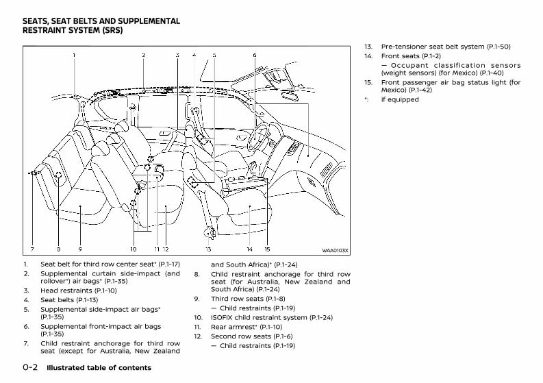
1. Seat belt for third row center seat* (P.1-17)2. Supplemental curtain side-impact (and
rollover*) air bags* (P.1-35)3. Head restraints (P.1-10)4. Seat belts (P.1-13)5. Supplemental side-impact air bags*
(P.1-35)6. Supplemental front-impact air bags
(P.1-35)7. Child restraint anchorage for third row
seat (except for Australia, New Zealand
and South Africa)* (P.1-24)8. Child restraint anchorage for third row
seat (for Australia, New Zealand andSouth Africa) (P.1-24)
9. Third row seats (P.1-8)— Child restraints (P.1-19)
10. ISOFIX child restraint system (P.1-24)11. Rear armrest* (P.1-10)12. Second row seats (P.1-6)
— Child restraints (P.1-19)
13. Pre-tensioner seat belt system (P.1-50)14. Front seats (P.1-2)
— Occupant classif ication sensors(weight sensors) (for Mexico) (P.1-40)
15. Front passenger air bag status light (forMexico) (P.1-42)
*: if equipped
SEATS, SEAT BELTS AND SUPPLEMENTALRESTRAINT SYSTEM (SRS)
Condition: 'Except for China'/'Except for China/
(7,1)
[ Edit: 2020/ 11/ 9 Model: Y62-A ]
GUID-97969169-5391-4C21-BFF6-F18C104F50D6
EXCEPT FOR MEXICOGUID-A7D731C2-C58B-4FEB-B117-40A4E0B39DA1
WAA0094X
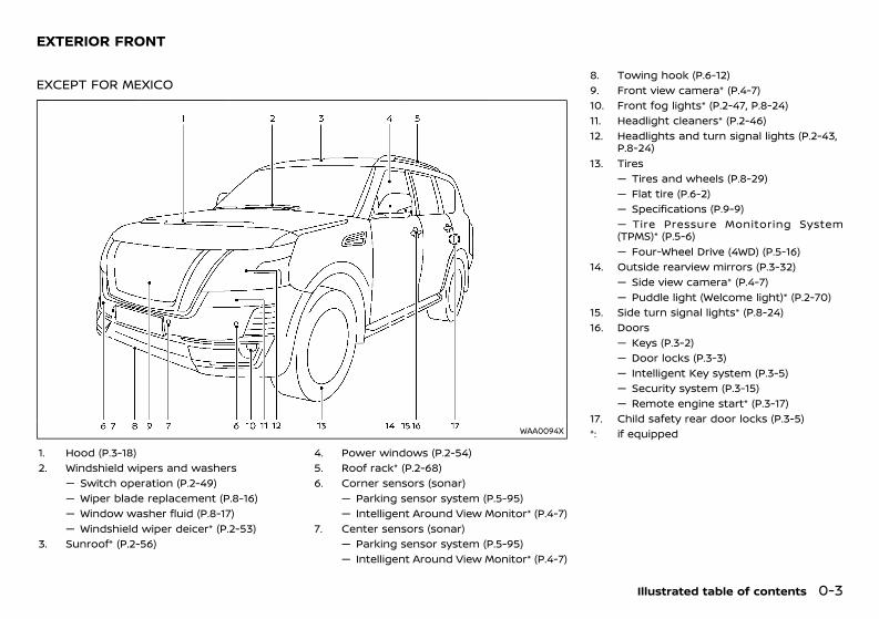
1. Hood (P.3-18)2. Windshield wipers and washers
— Switch operation (P.2-49)— Wiper blade replacement (P.8-16)— Window washer fluid (P.8-17)— Windshield wiper deicer* (P.2-53)
3. Sunroof* (P.2-56)
4. Power windows (P.2-54)5. Roof rack* (P.2-68)6. Corner sensors (sonar)
— Parking sensor system (P.5-95)— Intelligent Around View Monitor* (P.4-7)
7. Center sensors (sonar)— Parking sensor system (P.5-95)— Intelligent Around View Monitor* (P.4-7)
8. Towing hook (P.6-12)9. Front view camera* (P.4-7)10. Front fog lights* (P.2-47, P.8-24)11. Headlight cleaners* (P.2-46)12. Headlights and turn signal lights (P.2-43,
P.8-24)13. Tires
— Tires and wheels (P.8-29)— Flat tire (P.6-2)— Specifications (P.9-9)— Tire Pressure Monitoring System(TPMS)* (P.5-6)— Four-Wheel Drive (4WD) (P.5-16)
14. Outside rearview mirrors (P.3-32)— Side view camera* (P.4-7)— Puddle light (Welcome light)* (P.2-70)
15. Side turn signal lights* (P.8-24)16. Doors
— Keys (P.3-2)— Door locks (P.3-3)— Intelligent Key system (P.3-5)— Security system (P.3-15)— Remote engine start* (P.3-17)
17. Child safety rear door locks (P.3-5)*: if equipped
Illustrated table of contents 0-3
EXTERIOR FRONT
Condition: 'Except for China'/'Except for China/
(8,1)
[ Edit: 2020/ 11/ 9 Model: Y62-A ]
0-4 Illustrated table of contents
FOR MEXICOGUID-01E96AC1-E38E-4CD9-B9CE-90213C0EDF6F
JVC0962X
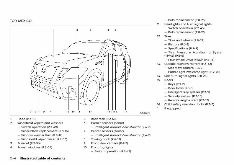
1. Hood (P.3-18)2. Windshield wipers and washers
— Switch operation (P.2-49)— Wiper blade replacement (P.8-16)— Window washer fluid (P.8-17)— Windshield wiper deicer (P.2-53)
3. Sunroof (P.2-56)4. Power windows (P.2-54)
5. Roof rack (P.2-68)6. Corner sensors (sonar)
— Intelligent Around View Monitor (P.4-7)7. Center sensors (sonar)
— Intelligent Around View Monitor (P.4-7)8. Towing hook (P.6-12)9. Front view camera (P.4-7)10. Front fog lights
— Switch operation (P.2-47)
— Bulb replacement (P.8-23)11. Headlights and turn signal lights
— Switch operation (P.2-43)— Bulb replacement (P.8-23)
12. Tires— Tires and wheels (P.8-29)— Flat tire (P.6-2)— Specifications (P.9-9)— Tire Pressure Monitoring System(TPMS) (P.5-6)— Four-Wheel Drive (4WD)* (P.5-16)
13. Outside rearview mirrors (P.3-32)— Side view camera (P.4-7)— Puddle light (Welcome light) (P.2-70)
14. Side turn signal lights (P.8-23)15. Doors
— Keys (P.3-2)— Door locks (P.3-3)— Intelligent Key system (P.3-5)— Security system (P.3-15)— Remote engine start (P.3-17)
16. Child safety rear door locks (P.3-5)*: if equipped
Condition: 'Except for China'/'Except for China/
(9,1)
[ Edit: 2020/ 11/ 9 Model: Y62-A ]
GUID-2462E716-94C1-4E95-89D8-5D63B5D14D92
EXCEPT FOR MEXICOGUID-74D041B7-1D60-49AD-9DE5-35CDEE6972C8
WAA0095X
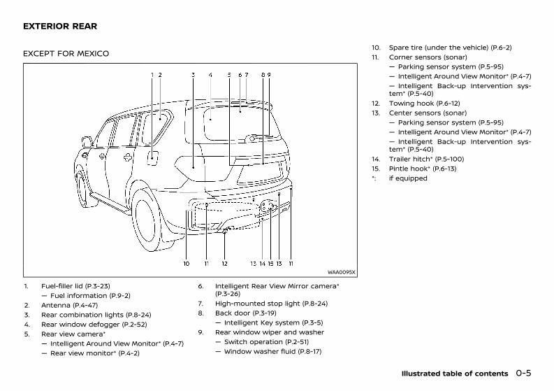
1. Fuel-filler lid (P.3-23)— Fuel information (P.9-2)
2. Antenna (P.4-47)3. Rear combination lights (P.8-24)4. Rear window defogger (P.2-52)5. Rear view camera*
— Intelligent Around View Monitor* (P.4-7)— Rear view monitor* (P.4-2)
6. Intelligent Rear View Mirror camera*(P.3-26)
7. High-mounted stop light (P.8-24)8. Back door (P.3-19)
— Intelligent Key system (P.3-5)9. Rear window wiper and washer
— Switch operation (P.2-51)— Window washer fluid (P.8-17)
10. Spare tire (under the vehicle) (P.6-2)11. Corner sensors (sonar)
— Parking sensor system (P.5-95)— Intelligent Around View Monitor* (P.4-7)— Intelligent Back-up Intervention sys-tem* (P.5-40)
12. Towing hook (P.6-12)13. Center sensors (sonar)
— Parking sensor system (P.5-95)— Intelligent Around View Monitor* (P.4-7)— Intelligent Back-up Intervention sys-tem* (P.5-40)
14. Trailer hitch* (P.5-100)15. Pintle hook* (P.6-13)*: if equipped
Illustrated table of contents 0-5
EXTERIOR REAR
Condition: 'Except for China'/'Except for China/
(10,1)
[ Edit: 2020/ 11/ 9 Model: Y62-A ]
0-6 Illustrated table of contents
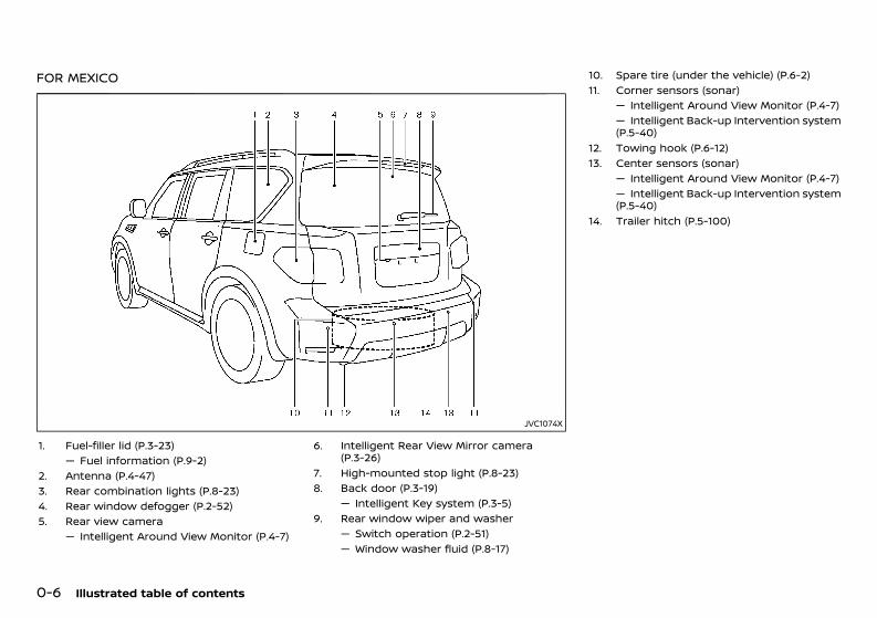
FOR MEXICOGUID-0C7A07D1-F171-4319-851A-57482156CF32
JVC1074X
1. Fuel-filler lid (P.3-23)— Fuel information (P.9-2)
2. Antenna (P.4-47)3. Rear combination lights (P.8-23)4. Rear window defogger (P.2-52)5. Rear view camera
— Intelligent Around View Monitor (P.4-7)
6. Intelligent Rear View Mirror camera(P.3-26)
7. High-mounted stop light (P.8-23)8. Back door (P.3-19)
— Intelligent Key system (P.3-5)9. Rear window wiper and washer
— Switch operation (P.2-51)— Window washer fluid (P.8-17)
10. Spare tire (under the vehicle) (P.6-2)11. Corner sensors (sonar)
— Intelligent Around View Monitor (P.4-7)— Intelligent Back-up Intervention system(P.5-40)
12. Towing hook (P.6-12)13. Center sensors (sonar)
— Intelligent Around View Monitor (P.4-7)— Intelligent Back-up Intervention system(P.5-40)
14. Trailer hitch (P.5-100)
Condition: 'Except for China'/'Except for China/
(11,1)
[ Edit: 2020/ 11/ 9 Model: Y62-A ]
GUID-879734D8-8193-46F6-A78D-12DA47B9A619
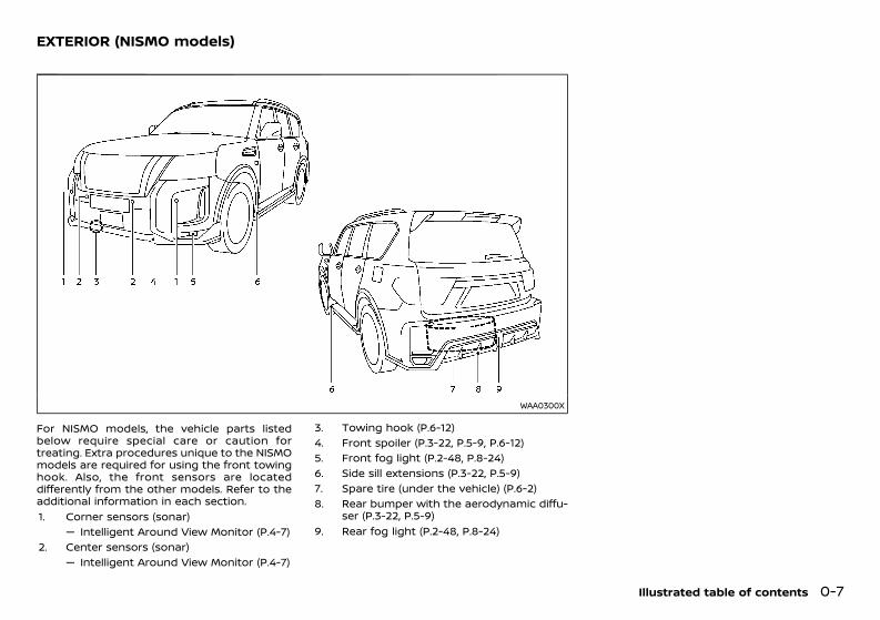
WAA0300X
For NISMO models, the vehicle parts listedbelow require special care or caution fortreating. Extra procedures unique to the NISMOmodels are required for using the front towinghook. Also, the front sensors are locateddifferently from the other models. Refer to theadditional information in each section.1. Corner sensors (sonar)
— Intelligent Around View Monitor (P.4-7)2. Center sensors (sonar)
— Intelligent Around View Monitor (P.4-7)
3. Towing hook (P.6-12)4. Front spoiler (P.3-22, P.5-9, P.6-12)5. Front fog light (P.2-48, P.8-24)6. Side sill extensions (P.3-22, P.5-9)7. Spare tire (under the vehicle) (P.6-2)8. Rear bumper with the aerodynamic diffu-
ser (P.3-22, P.5-9)9. Rear fog light (P.2-48, P.8-24)
Illustrated table of contents 0-7
EXTERIOR (NISMO models)
Condition: 'Except for China'/'Except for China/
(12,1)
[ Edit: 2020/ 11/ 9 Model: Y62-A ]
0-8 Illustrated table of contents
GUID-3236BBA8-79B0-4858-9BB8-AC2BFDEC1572
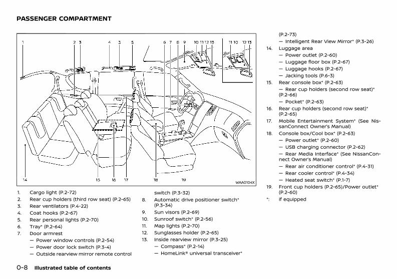
WAA0104X
1. Cargo light (P.2-72)2. Rear cup holders (third row seat) (P.2-65)3. Rear ventilators (P.4-22)4. Coat hooks (P.2-67)5. Rear personal lights (P.2-70)6. Tray* (P.2-64)7. Door armrest
— Power window controls (P.2-54)— Power door lock switch (P.3-4)— Outside rearview mirror remote control
switch (P.3-32)8. Automatic drive positioner switch*
(P.3-34)9. Sun visors (P.2-69)10. Sunroof switch* (P.2-56)11. Map lights (P.2-70)12. Sunglasses holder (P.2-65)13. Inside rearview mirror (P.3-25)
— Compass* (P.2-14)— HomeLink® universal transceiver*
(P.2-73)— Intelligent Rear View Mirror* (P.3-26)
14. Luggage area— Power outlet (P.2-60)— Luggage floor box (P.2-67)— Luggage hooks (P.2-67)— Jacking tools (P.6-3)
15. Rear console box* (P.2-63)— Rear cup holders (second row seat)*(P.2-66)— Pocket* (P.2-63)
16. Rear cup holders (second row seat)*(P.2-65)
17. Mobile Entertainment System* (See Nis-sanConnect Owner’s Manual)
18. Console box/Cool box* (P.2-63)— Power outlet* (P.2-60)— USB charging connector (P.2-62)— Rear Media Interface* (See NissanCon-nect Owner’s Manual)— Rear air conditioner control* (P.4-31)— Rear cooler control* (P.4-34)— Heated seat switch* (P.1-7)
19. Front cup holders (P.2-65)/Power outlet*(P.2-60)
*: if equipped
PASSENGER COMPARTMENT
Condition: 'Except for China'/'Except for China/
(13,1)
[ Edit: 2020/ 11/ 9 Model: Y62-A ]
GUID-1B613D6A-4853-4100-88F1-87CBA0869EC0
LEFT-HAND DRIVE (LHD) MODELGUID-6C24C7CD-830C-4F05-A64A-2E6416EA6857
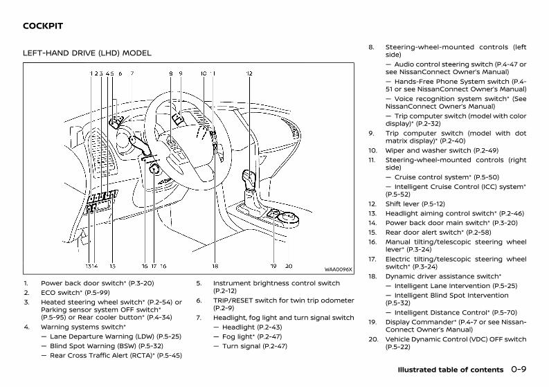
WAA0096X
1. Power back door switch* (P.3-20)2. ECO switch* (P.5-99)3. Heated steering wheel switch* (P.2-54) or
Parking sensor system OFF switch*(P.5-95) or Rear cooler button* (P.4-34)
4. Warning systems switch*— Lane Departure Warning (LDW) (P.5-25)— Blind Spot Warning (BSW) (P.5-32)— Rear Cross Traffic Alert (RCTA)* (P.5-45)
5. Instrument brightness control switch(P.2-12)
6. TRIP/RESET switch for twin trip odometer(P.2-9)
7. Headlight, fog light and turn signal switch— Headlight (P.2-43)— Fog light* (P.2-47)— Turn signal (P.2-47)
8. Steering-wheel-mounted controls (leftside)— Audio control steering switch (P.4-47 orsee NissanConnect Owner’s Manual)— Hands-Free Phone System switch (P.4-51 or see NissanConnect Owner’s Manual)— Voice recognition system switch* (SeeNissanConnect Owner’s Manual)— Trip computer switch (model with colordisplay)* (P.2-32)
9. Trip computer switch (model with dotmatrix display)* (P.2-40)
10. Wiper and washer switch (P.2-49)11. Steering-wheel-mounted controls (right
side)— Cruise control system* (P.5-50)— Intelligent Cruise Control (ICC) system*(P.5-52)
12. Shift lever (P.5-12)13. Headlight aiming control switch* (P.2-46)14. Power back door main switch* (P.3-20)15. Rear door alert switch* (P.2-58)16. Manual tilting/telescopic steering wheel
lever* (P.3-24)17. Electric tilting/telescopic steering wheel
switch* (P.3-24)18. Dynamic driver assistance switch*
— Intelligent Lane Intervention (P.5-25)— Intelligent Blind Spot Intervention(P.5-32)— Intelligent Distance Control* (P.5-70)
19. Display Commander* (P.4-7 or see Nissan-Connect Owner’s Manual)
20. Vehicle Dynamic Control (VDC) OFF switch(P.5-22)
Illustrated table of contents 0-9
COCKPIT
Condition: 'Except for China'/'Except for China/
(14,1)
[ Edit: 2020/ 11/ 9 Model: Y62-A ]
0-10 Illustrated table of contents
Four-Wheel Drive (4WD) shift switch*(P.5-16)Variable 4×4 mode select switch* (P.5-20)Hill descent control switch* (P.5-24)Differential lock mode switch* (P.5-22)SNOW mode switch* (P.5-21)TOW mode switch* (P.5-103)
*: if equipped
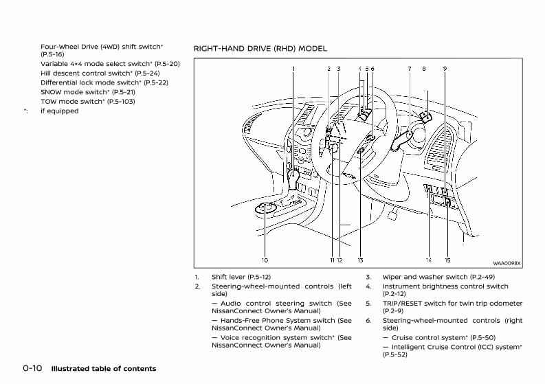
RIGHT-HAND DRIVE (RHD) MODELGUID-62FCC69C-B9E2-41E6-88D8-4600F2449E75
WAA0098X
1. Shift lever (P.5-12)2. Steering-wheel-mounted controls (left
side)— Audio control steering switch (SeeNissanConnect Owner’s Manual)— Hands-Free Phone System switch (SeeNissanConnect Owner’s Manual)— Voice recognition system switch* (SeeNissanConnect Owner’s Manual)
3. Wiper and washer switch (P.2-49)4. Instrument brightness control switch
(P.2-12)5. TRIP/RESET switch for twin trip odometer
(P.2-9)6. Steering-wheel-mounted controls (right
side)— Cruise control system* (P.5-50)— Intelligent Cruise Control (ICC) system*(P.5-52)
Condition: 'Except for China'/'Except for China/
(15,1)
[ Edit: 2020/ 11/ 9 Model: Y62-A ]
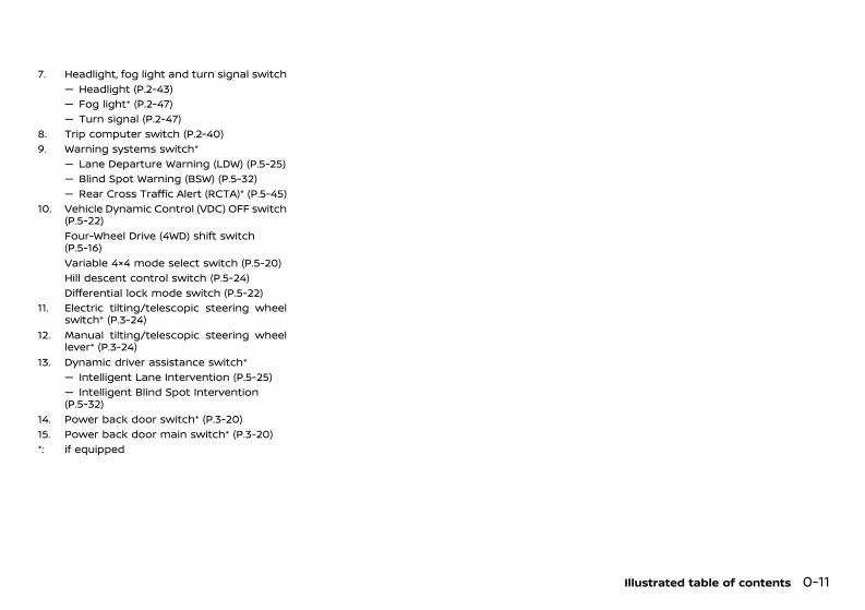
7. Headlight, fog light and turn signal switch— Headlight (P.2-43)— Fog light* (P.2-47)— Turn signal (P.2-47)
8. Trip computer switch (P.2-40)9. Warning systems switch*
— Lane Departure Warning (LDW) (P.5-25)— Blind Spot Warning (BSW) (P.5-32)— Rear Cross Traffic Alert (RCTA)* (P.5-45)
10. Vehicle Dynamic Control (VDC) OFF switch(P.5-22)Four-Wheel Drive (4WD) shift switch(P.5-16)Variable 4×4 mode select switch (P.5-20)Hill descent control switch (P.5-24)Differential lock mode switch (P.5-22)
11. Electric tilting/telescopic steering wheelswitch* (P.3-24)
12. Manual tilting/telescopic steering wheellever* (P.3-24)
13. Dynamic driver assistance switch*— Intelligent Lane Intervention (P.5-25)— Intelligent Blind Spot Intervention(P.5-32)
14. Power back door switch* (P.3-20)15. Power back door main switch* (P.3-20)*: if equipped
Illustrated table of contents 0-11
Condition: 'Except for China'/'Except for China/
(16,1)
[ Edit: 2020/ 11/ 9 Model: Y62-A ]
0-12 Illustrated table of contents
GUID-E7E5A3F7-B385-4AC2-8157-2543504FD64C
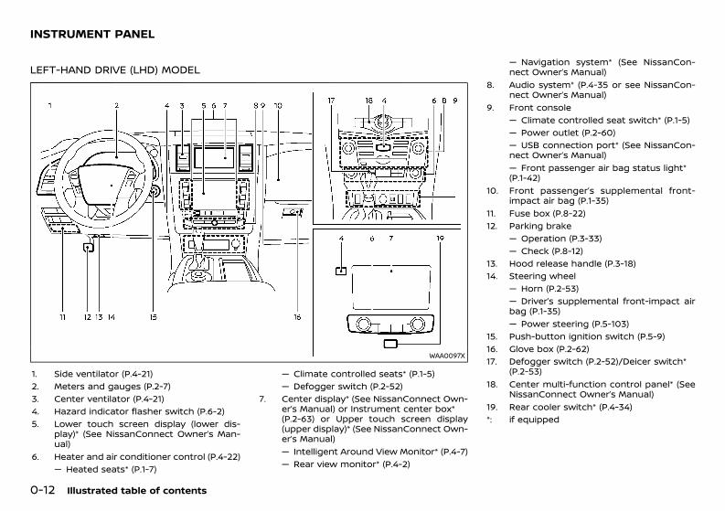
LEFT-HAND DRIVE (LHD) MODELGUID-6D48DE5E-E6B8-4E05-9494-9A537802FFED
WAA0097X
1. Side ventilator (P.4-21)2. Meters and gauges (P.2-7)3. Center ventilator (P.4-21)4. Hazard indicator flasher switch (P.6-2)5. Lower touch screen display (lower dis-
play)* (See NissanConnect Owner’s Man-ual)
6. Heater and air conditioner control (P.4-22)— Heated seats* (P.1-7)
— Climate controlled seats* (P.1-5)— Defogger switch (P.2-52)
7. Center display* (See NissanConnect Own-er’s Manual) or Instrument center box*(P.2-63) or Upper touch screen display(upper display)* (See NissanConnect Own-er’s Manual)— Intelligent Around View Monitor* (P.4-7)— Rear view monitor* (P.4-2)
— Navigation system* (See NissanCon-nect Owner’s Manual)
8. Audio system* (P.4-35 or see NissanCon-nect Owner’s Manual)
9. Front console— Climate controlled seat switch* (P.1-5)— Power outlet (P.2-60)— USB connection port* (See NissanCon-nect Owner’s Manual)— Front passenger air bag status light*(P.1-42)
10. Front passenger’s supplemental front-impact air bag (P.1-35)
11. Fuse box (P.8-22)12. Parking brake
— Operation (P.3-33)— Check (P.8-12)
13. Hood release handle (P.3-18)14. Steering wheel
— Horn (P.2-53)— Driver’s supplemental front-impact airbag (P.1-35)— Power steering (P.5-103)
15. Push-button ignition switch (P.5-9)16. Glove box (P.2-62)17. Defogger switch (P.2-52)/Deicer switch*
(P.2-53)18. Center multi-function control panel* (See
NissanConnect Owner’s Manual)19. Rear cooler switch* (P.4-34)*: if equipped
INSTRUMENT PANEL
Condition: 'Except for China'/'Except for China/
(17,1)
[ Edit: 2020/ 11/ 9 Model: Y62-A ]
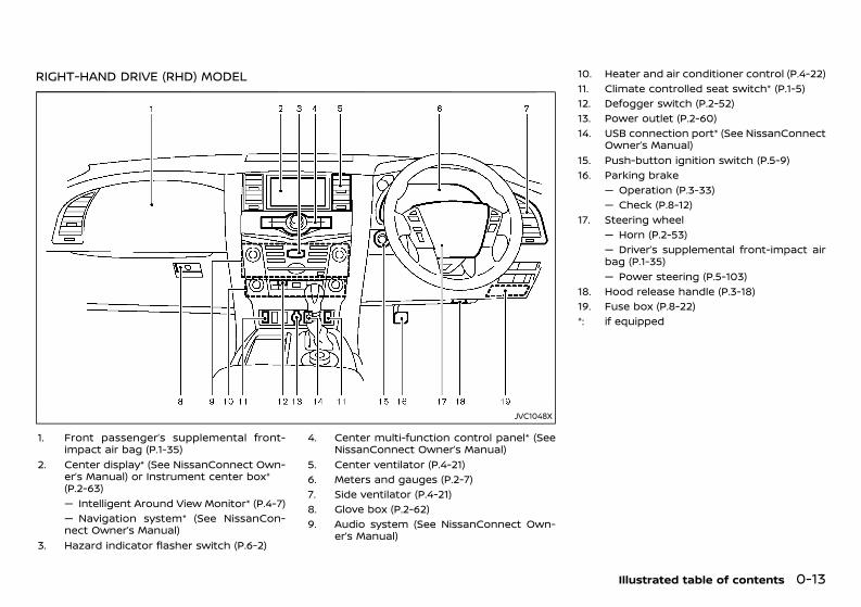
RIGHT-HAND DRIVE (RHD) MODELGUID-5D9F835B-1CCC-4710-93BC-EB5FC79176F2
JVC1048X
1. Front passenger’s supplemental front-impact air bag (P.1-35)
2. Center display* (See NissanConnect Own-er’s Manual) or Instrument center box*(P.2-63)— Intelligent Around View Monitor* (P.4-7)— Navigation system* (See NissanCon-nect Owner’s Manual)
3. Hazard indicator flasher switch (P.6-2)
4. Center multi-function control panel* (SeeNissanConnect Owner’s Manual)
5. Center ventilator (P.4-21)6. Meters and gauges (P.2-7)7. Side ventilator (P.4-21)8. Glove box (P.2-62)9. Audio system (See NissanConnect Own-
er’s Manual)
10. Heater and air conditioner control (P.4-22)11. Climate controlled seat switch* (P.1-5)12. Defogger switch (P.2-52)13. Power outlet (P.2-60)14. USB connection port* (See NissanConnect
Owner’s Manual)15. Push-button ignition switch (P.5-9)16. Parking brake
— Operation (P.3-33)— Check (P.8-12)
17. Steering wheel— Horn (P.2-53)— Driver’s supplemental front-impact airbag (P.1-35)— Power steering (P.5-103)
18. Hood release handle (P.3-18)19. Fuse box (P.8-22)*: if equipped
Illustrated table of contents 0-13
Condition: 'Except for China'/'Except for China/
(18,1)
[ Edit: 2020/ 11/ 9 Model: Y62-A ]
0-14 Illustrated table of contents
GUID-7D8141F7-2424-4721-884D-EA436364D19B
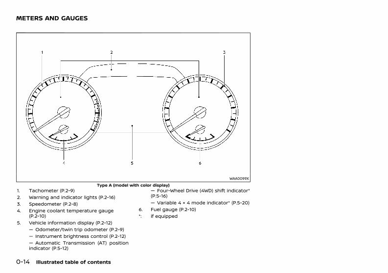
WAA0099XType A (model with color display)
1. Tachometer (P.2-9)2. Warning and indicator lights (P.2-16)3. Speedometer (P.2-8)4. Engine coolant temperature gauge
(P.2-10)5. Vehicle information display (P.2-12)
— Odometer/twin trip odometer (P.2-9)— Instrument brightness control (P.2-12)— Automatic Transmission (AT) positionindicator (P.5-12)
— Four-Wheel Drive (4WD) shift indicator*(P.5-16)— Variable 4 × 4 mode indicator* (P.5-20)
6. Fuel gauge (P.2-10)*: if equipped
METERS AND GAUGES
Condition: 'Except for China'/'Except for China/
(19,1)
[ Edit: 2020/ 11/ 9 Model: Y62-A ]
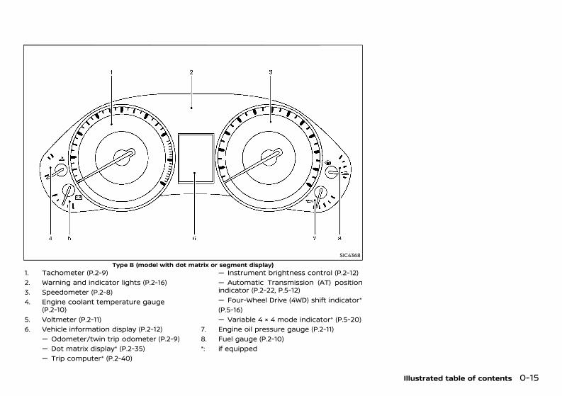
SIC4368Type B (model with dot matrix or segment display)
1. Tachometer (P.2-9)2. Warning and indicator lights (P.2-16)3. Speedometer (P.2-8)4. Engine coolant temperature gauge
(P.2-10)5. Voltmeter (P.2-11)6. Vehicle information display (P.2-12)
— Odometer/twin trip odometer (P.2-9)— Dot matrix display* (P.2-35)— Trip computer* (P.2-40)
— Instrument brightness control (P.2-12)— Automatic Transmission (AT) positionindicator (P.2-22, P.5-12)— Four-Wheel Drive (4WD) shift indicator*(P.5-16)— Variable 4 × 4 mode indicator* (P.5-20)
7. Engine oil pressure gauge (P.2-11)8. Fuel gauge (P.2-10)*: if equipped
Illustrated table of contents 0-15
Condition: 'Except for China'/'Except for China/
(20,1)
[ Edit: 2020/ 11/ 9 Model: Y62-A ]
0-16 Illustrated table of contents
GUID-A6D90333-9F08-48B9-AB33-7AA9C73BD806
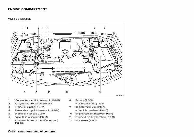
VK56DE ENGINEGUID-CF998BB6-751E-4779-86A2-588D74A375CF
JVO0192X
1. Window washer fluid reservoir (P.8-17)2. Fuse/fusible link holder (P.8-20)3. Engine oil dipstick (P.8-9)4. Power steering fluid reservoir (P.8-14)5. Engine oil filler cap (P.8-9)6. Brake fluid reservoir (P.8-13)7. Fuse/fusible link holder (if equipped)
(P.8-20)
8. Battery (P.8-18)— Jump starting (P.6-8)
9. Radiator filler cap (P.8-7)— Vehicle overheat (P.6-10)
10. Engine coolant reservoir (P.8-7)11. Engine drive belt location (P.8-11)12. Air cleaner (P.8-15)
ENGINE COMPARTMENT
Condition: 'Except for China'/'Except for China/
(21,1)
[ Edit: 2020/ 11/ 9 Model: Y62-A ]
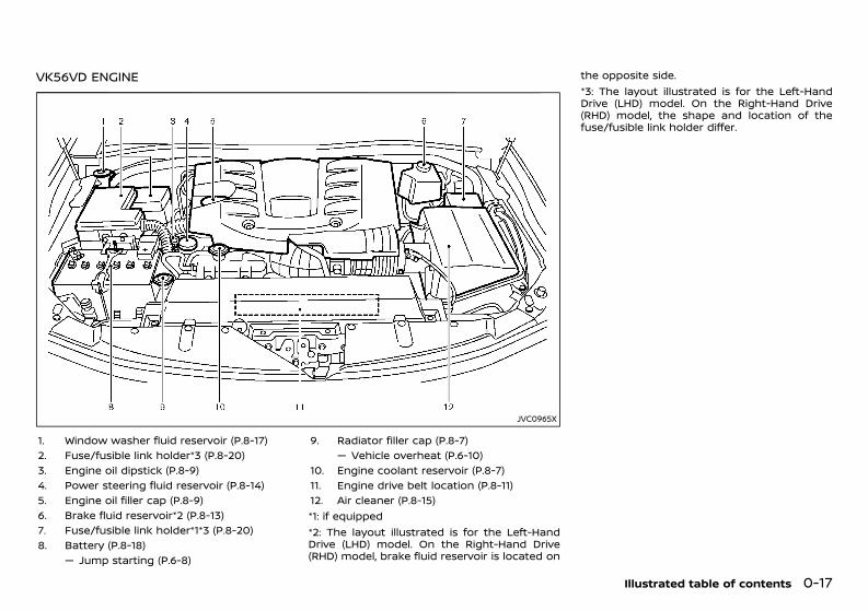
VK56VD ENGINEGUID-9F0E8E2B-AF07-43AF-89EC-059036FCF931
JVC0965X
1. Window washer fluid reservoir (P.8-17)2. Fuse/fusible link holder*3 (P.8-20)3. Engine oil dipstick (P.8-9)4. Power steering fluid reservoir (P.8-14)5. Engine oil filler cap (P.8-9)6. Brake fluid reservoir*2 (P.8-13)7. Fuse/fusible link holder*1*3 (P.8-20)8. Battery (P.8-18)
— Jump starting (P.6-8)
9. Radiator filler cap (P.8-7)— Vehicle overheat (P.6-10)
10. Engine coolant reservoir (P.8-7)11. Engine drive belt location (P.8-11)12. Air cleaner (P.8-15)*1: if equipped*2: The layout illustrated is for the Left-HandDrive (LHD) model. On the Right-Hand Drive(RHD) model, brake fluid reservoir is located on
the opposite side.*3: The layout illustrated is for the Left-HandDrive (LHD) model. On the Right-Hand Drive(RHD) model, the shape and location of thefuse/fusible link holder differ.
Illustrated table of contents 0-17
Condition: 'Except for China'/'Except for China/
(22,1)
[ Edit: 2020/ 11/ 9 Model: Y62-A ]
0-18 Illustrated table of contents
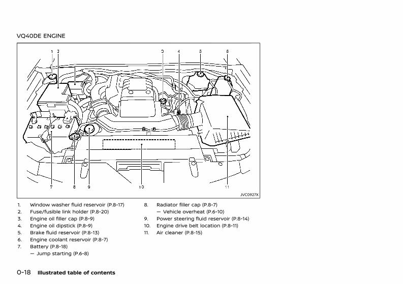
VQ40DE ENGINEGUID-698E9F29-F0A3-4103-8C66-BC9D2B9D9C50
JVC0927X
1. Window washer fluid reservoir (P.8-17)2. Fuse/fusible link holder (P.8-20)3. Engine oil filler cap (P.8-9)4. Engine oil dipstick (P.8-9)5. Brake fluid reservoir (P.8-13)6. Engine coolant reservoir (P.8-7)7. Battery (P.8-18)
— Jump starting (P.6-8)
8. Radiator filler cap (P.8-7)— Vehicle overheat (P.6-10)
9. Power steering fluid reservoir (P.8-14)10. Engine drive belt location (P.8-11)11. Air cleaner (P.8-15)
Condition: 'Except for China'/'Except for China/
(23,1)
[ Edit: 2020/ 11/ 9 Model: Y62-A ]
1 Safety — seats, seat belts and supplementalrestraint system
Seats ........................................................................................................................... 1-2Front seats ..................................................................................................... 1-2Second row seats ..................................................................................... 1-6Third row seats ........................................................................................... 1-8Armrest ......................................................................................................... 1-10
Head restraints ................................................................................................ 1-10Adjustable head restraint ................................................................ 1-10Non-adjustable head restraint .................................................... 1-10Remove .......................................................................................................... 1-11Install ................................................................................................................ 1-11Adjust ............................................................................................................... 1-11Active head restraints (front seats) ......................................... 1-12
Seat belts ............................................................................................................. 1-13Precautions on seat belt usage ................................................. 1-13Child safety ................................................................................................. 1-14Pregnant women ................................................................................... 1-15Injured persons ........................................................................................ 1-15Center mark on seat belts (if equipped) ............................. 1-15Three-point type seat belts ........................................................... 1-15
Seat belt maintenance ................................................................... 1-19Child restraints ............................................................................................... 1-19
Precautions on child restraints usage ............................... 1-19Universal child restraints for front seat andrear seats ................................................................................................... 1-20ISOFIX child restraint system (for secondrow seat) .................................................................................................... 1-24Child restraint anchorage ............................................................ 1-24Child restraint installation using ISOFIX(for second row seat) ....................................................................... 1-25Child restraint installation using three-point typeseat belt ...................................................................................................... 1-27
Supplemental Restraint System (SRS) ......................................... 1-35Precautions on Supplemental RestraintSystem (SRS) ........................................................................................... 1-35Supplemental air bag systems ................................................. 1-40SRS air bag deployment conditions .................................... 1-46Pre-tensioner seat belt system ................................................ 1-50Repair and replacement procedure ..................................... 1-50
Condition: 'Except for China'/'Except for China/
(24,1)
[ Edit: 2020/ 11/ 9 Model: Y62-A ]
1-2 Safety — seats, seat belts and supplemental restraint system
GUID-AF9D401E-0B20-43D9-8346-3BA2A7395517
SSS0133A
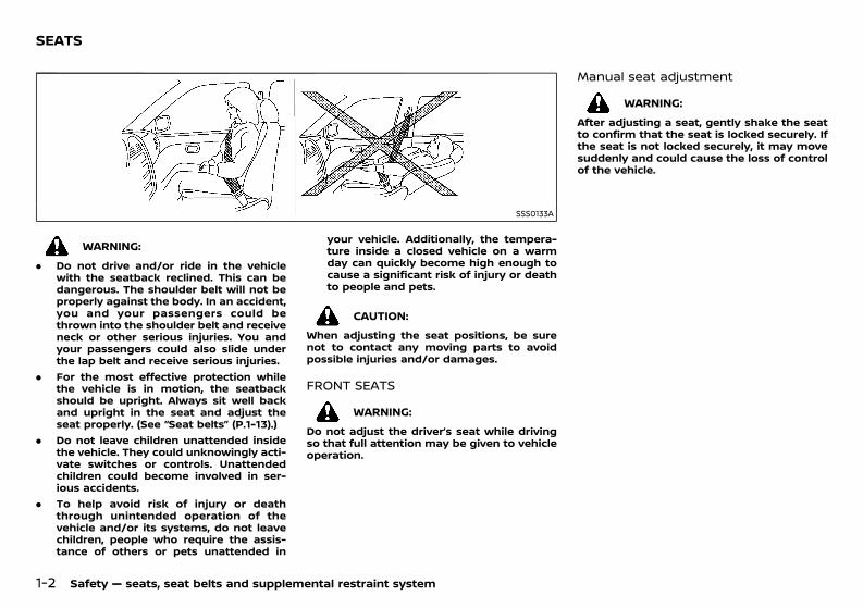
WARNING:. Do not drive and/or ride in the vehicle
with the seatback reclined. This can bedangerous. The shoulder belt will not beproperly against the body. In an accident,you and your passengers could bethrown into the shoulder belt and receiveneck or other serious injuries. You andyour passengers could also slide underthe lap belt and receive serious injuries.
. For the most effective protection whilethe vehicle is in motion, the seatbackshould be upright. Always sit well backand upright in the seat and adjust theseat properly. (See “Seat belts” (P.1-13).)
. Do not leave children unattended insidethe vehicle. They could unknowingly acti-vate switches or controls. Unattendedchildren could become involved in ser-ious accidents.
. To help avoid risk of injury or deaththrough unintended operation of thevehicle and/or its systems, do not leavechildren, people who require the assis-tance of others or pets unattended in
your vehicle. Additionally, the tempera-ture inside a closed vehicle on a warmday can quickly become high enough tocause a significant risk of injury or deathto people and pets.
CAUTION:When adjusting the seat positions, be surenot to contact any moving parts to avoidpossible injuries and/or damages.
FRONT SEATSGUID-8E6EDF11-E312-436C-8C93-90B9587BB033WARNING:
Do not adjust the driver’s seat while drivingso that full attention may be given to vehicleoperation.
Manual seat adjustmentGUID-C387F95D-BF50-4181-A1DE-A3A10A7A6EE4
WARNING:After adjusting a seat, gently shake the seatto confirm that the seat is locked securely. Ifthe seat is not locked securely, it may movesuddenly and could cause the loss of controlof the vehicle.
SEATS
Condition: 'Except for China'/'Except for China/
(25,1)
[ Edit: 2020/ 11/ 9 Model: Y62-A ]
SSS0792
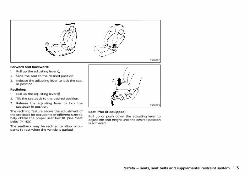
Forward and backward:GUID-C7E1EF24-5AAB-4301-95BE-26917EEE45EF
1. Pull up the adjusting lever .2. Slide the seat to the desired position.3. Release the adjusting lever to lock the seat
in position.Reclining:
GUID-C7E1EF24-5AAB-4301-95BE-26917EEE45EF
1. Pull up the adjusting lever .2. Tilt the seatback to the desired position.3. Release the adjusting lever to lock the
seatback in position.The reclining feature allows the adjustment ofthe seatback for occupants of different sizes tohelp obtain the proper seat belt fit. (See “Seatbelts” (P.1-13).)The seatback may be reclined to allow occu-pants to rest when the vehicle is parked.
SSS0793
Seat lifter (if equipped):GUID-C7E1EF24-5AAB-4301-95BE-26917EEE45EF
Pull up or push down the adjusting lever toadjust the seat height until the desired positionis achieved.
Safety — seats, seat belts and supplemental restraint system 1-3
Condition: 'Except for China'/'Except for China/
(26,1)
[ Edit: 2020/ 11/ 9 Model: Y62-A ]
1-4 Safety — seats, seat belts and supplemental restraint system
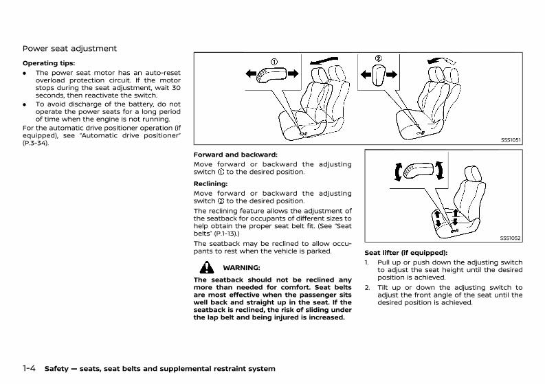
Power seat adjustmentGUID-624568FA-24F3-4D2B-AEE3-5FFE3CFDB812
Operating tips:GUID-C7E1EF24-5AAB-4301-95BE-26917EEE45EF
. The power seat motor has an auto-resetoverload protection circuit. If the motorstops during the seat adjustment, wait 30seconds, then reactivate the switch.
. To avoid discharge of the battery, do notoperate the power seats for a long periodof time when the engine is not running.
For the automatic drive positioner operation (ifequipped), see “Automatic drive positioner”(P.3-34). SSS1051
Forward and backward:GUID-C7E1EF24-5AAB-4301-95BE-26917EEE45EF
Move forward or backward the adjustingswitch to the desired position.Reclining:
GUID-C7E1EF24-5AAB-4301-95BE-26917EEE45EF
Move forward or backward the adjustingswitch to the desired position.The reclining feature allows the adjustment ofthe seatback for occupants of different sizes tohelp obtain the proper seat belt fit. (See “Seatbelts” (P.1-13).)The seatback may be reclined to allow occu-pants to rest when the vehicle is parked.
WARNING:The seatback should not be reclined anymore than needed for comfort. Seat beltsare most effective when the passenger sitswell back and straight up in the seat. If theseatback is reclined, the risk of sliding underthe lap belt and being injured is increased.
SSS1052
Seat lifter (if equipped):GUID-C7E1EF24-5AAB-4301-95BE-26917EEE45EF
1. Pull up or push down the adjusting switchto adjust the seat height until the desiredposition is achieved.
2. Tilt up or down the adjusting switch toadjust the front angle of the seat until thedesired position is achieved.
Condition: 'Except for China'/'Except for China/
(27,1)
[ Edit: 2020/ 11/ 9 Model: Y62-A ]
SSS1053
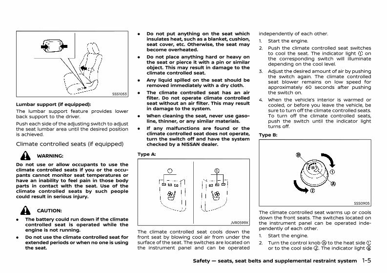
Lumbar support (if equipped):GUID-C7E1EF24-5AAB-4301-95BE-26917EEE45EF
The lumbar support feature provides lowerback support to the driver.Push each side of the adjusting switch to adjustthe seat lumbar area until the desired positionis achieved.
Climate controlled seats (if equipped)GUID-331CBBE0-0815-47E0-8225-58ADE71B8F78
WARNING:Do not use or allow occupants to use theclimate controlled seats if you or the occu-pants cannot monitor seat temperatures orhave an inability to feel pain in those bodyparts in contact with the seat. Use of theclimate controlled seats by such peoplecould result in serious injury.
CAUTION:. The battery could run down if the climate
controlled seat is operated while theengine is not running.
. Do not use the climate controlled seat forextended periods or when no one is usingthe seat.
. Do not put anything on the seat whichinsulates heat, such as a blanket, cushion,seat cover, etc. Otherwise, the seat maybecome overheated.
. Do not place anything hard or heavy onthe seat or pierce it with a pin or similarobject. This may result in damage to theclimate controlled seat.
. Any liquid spilled on the seat should beremoved immediately with a dry cloth.
. The climate controlled seat has an airfilter. Do not operate climate controlledseat without an air filter. This may resultin damage to the system.
. When cleaning the seat, never use gaso-line, thinner, or any similar materials.
. If any malfunctions are found or theclimate controlled seat does not operate,turn the switch off and have the systemchecked by a NISSAN dealer.
Type A:GUID-C7E1EF24-5AAB-4301-95BE-26917EEE45EF
JVR0599X
The climate controlled seat cools down thefront seat by blowing cool air from under thesurface of the seat. The switches are located onthe instrument panel and can be operated
independently of each other.1. Start the engine.2. Push the climate controlled seat switches
to cool the seat. The indicator light onthe corresponding switch will illuminatedepending on the cool level.
3. Adjust the desired amount of air by pushingthe switch again. The climate controlledseat blower remains on low speed forapproximately 60 seconds after pushingthe switch on.
4. When the vehicle’s interior is warmed orcooled, or before you leave the vehicle, besure to turn off the climate controlled seats.To turn off the climate controlled seats,push the switch until the indicator lightturns off.
Type B:GUID-C7E1EF24-5AAB-4301-95BE-26917EEE45EF
SSS0905
The climate controlled seat warms up or coolsdown the front seats. The switches located onthe instrument panel can be operated inde-pendently of each other.1. Start the engine.2. Turn the control knob to the heat side
or to the cool side . The indicator light
Safety — seats, seat belts and supplemental restraint system 1-5
Condition: 'Except for China'/'Except for China/
(28,1)
[ Edit: 2020/ 11/ 9 Model: Y62-A ]
1-6 Safety — seats, seat belts and supplemental restraint system
on the control knob will illuminate.3. Adjust the desired temperature using the
control knob .The temperature will be adjusted automa-tically. When the control knob is turned tothe cool side, the air will flow harder in thebeginning to cool faster.
4. When the vehicle’s interior is warmed orcooled, and/or before you leave the vehicle,be sure to turn the control knob to the“OFF” position (center). The indicator lighton the control knob turns off at the “OFF”position.
To check the air filter for the climate controlledseat, contact a NISSAN dealer.
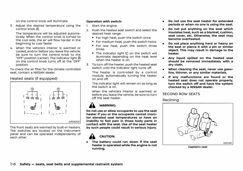
Heated seats (if equipped)GUID-2E1F79AC-B6A7-431F-9E45-2AAA8FF9588C
JVR0600X
The front seats are warmed by built-in heaters.The switches are located on the instrumentpanel and can be operated independently ofeach other.
Operation with switch:GUID-C7E1EF24-5AAB-4301-95BE-26917EEE45EF
1. Start the engine.2. Push the heated seat switch and select the
desired heat range.. For high heat, push the switch once.. For medium heat, push the switch twice.. For low heat, push the switch three
times.. The indicator light on the switch will
illuminate depending on the heat levelwhen the heater is on.
3. To turn off the heater, push the heated seatswitch until the indicator light turns off.The heater is controlled by a controlmodule, automatically turning the heateron and off.The indicator light will remain on as long asthe switch is on.When the vehicle’s interior is warmed, orbefore you leave the vehicle, be sure to turnoff the seat heater.
WARNING:Do not use or allow occupants to use the seatheater if you or the occupants cannot moni-tor elevated seat temperatures or have aninability to feel pain in those body parts incontact with the seat. Use of the seat heaterby such people could result in serious injury.
CAUTION:. The battery could run down if the seat
heater is operated while the engine is notrunning.
. Do not use the seat heater for extendedperiods or when no one is using the seat.
. Do not put anything on the seat whichinsulates heat, such as a blanket, cushion,seat cover, etc. Otherwise, the seat maybecome overheated.
. Do not place anything hard or heavy onthe seat or pierce it with a pin or similarobject. This may result in damage to theheater.
. Any liquid spilled on the heated seatshould be removed immediately with adry cloth.
. When cleaning the seat, never use gaso-line, thinner, or any similar materials.
. If any malfunctions are found or theheated seat does not operate properly,turn the switch off and have the systemchecked by a NISSAN dealer.
SECOND ROW SEATSGUID-AD535E72-1A82-44E4-9DCB-9DB425F1BD66
Reclining GUID-34EFCE7A-79F6-42AB-A330-3DA154666FC1
SSS1081Captain’s seat
Condition: 'Except for China'/'Except for China/
(29,1)
[ Edit: 2020/ 11/ 9 Model: Y62-A ]
SSS1065Bench seat
Pull the lever and position the seatback atthe desired angle. Release the lever afterpositioning the seat at the desired angle.The reclining feature allows adjustment of theseatback for occupants of different sizes tohelp obtain proper seat belt fit. (See “Precau-tions on child restraints usage” (P.1-19).) Theseatback may also be reclined to allow occu-pants to rest when the vehicle is parked.
WARNING:. Do not ride in a moving vehicle when the
seatback is reclined. This can be danger-ous. The shoulder belt will not be againstyour body. In an accident, you could bethrown into it and receive neck or otherserious injuries. You could also slideunder the lap belt and receive seriousinternal injuries.
. For the most effective protection whenthe vehicle is in motion, the seat shouldbe upright. Always sit well back andupright in the seat with both feet on thefloor and adjust the seat belt properly.See “Precautions on child restraintsusage” (P.1-19).
. After adjustment, check to be sure theseat is securely locked.
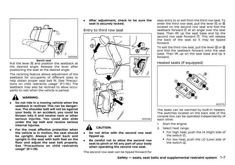
Entry to third row seatGUID-C1E5DFEA-A7F4-4985-B2E0-A2A346DDB6FF
SSS1066
CAUTION:. Do not drive with the second row seat
tipped up.. Be careful not to allow the second row
seat to pinch or hit any part of your bodywhen operating the second row seat.
The second row seat can be tipped forward for
easy entry to or exit from the third row seat. Toenter the third row seat, pull the lever orlocated on the second row seat and fold theseatback forward at an angle over the seatbase. Then lift up the seat base and tip thesecond row seat forward . This will releasethe back of the seat so it may be tippedforward.To exit the third row seat, pull the lever orand fold the seatback forward onto the seatbase. Then lift up on the seat base and tip itforward.
Heated seats (if equipped)GUID-70EF1727-88D0-4AD7-9685-0F7F966CE774
SIC2770
The seats can be warmed by built-in heaters.The switches located on the back side of theconsole box can be operated independently ofeach other.1. Start the engine.2. Select heat range.
. For high heat, push the HI (High) side ofthe switch .
. For low heat, push the LO (Low) side ofthe switch .
Safety — seats, seat belts and supplemental restraint system 1-7
Condition: 'Except for China'/'Except for China/
(30,1)
[ Edit: 2020/ 11/ 9 Model: Y62-A ]
1-8 Safety — seats, seat belts and supplemental restraint system
. The indicator light will illuminate whenthe heater is on.
3. To turn off the heater, return the switch tothe level position. Make sure the indicatorlight turns off.
CAUTION:. The battery could run down if the seat
heater is operated while the engine is notrunning.
. Do not use the seat heater for extendedperiods or when no one is using the seat.
. Do not put anything on the seat whichinsulates heat, such as a blanket, cushion,seat cover, etc. Otherwise, the seat maybecome overheated.
. Do not place anything hard or heavy onthe seat or pierce it with a pin or similarobject. This may result in damage to theseat heater.
. Any liquid spilled on the heated seatshould be removed immediately with adry cloth.
. When cleaning the seat, never use gaso-line, thinner, or any similar materials.
. If any malfunctions are found or theheated seat does not operate, turn theswitch off and have the system checkedby a NISSAN dealer.
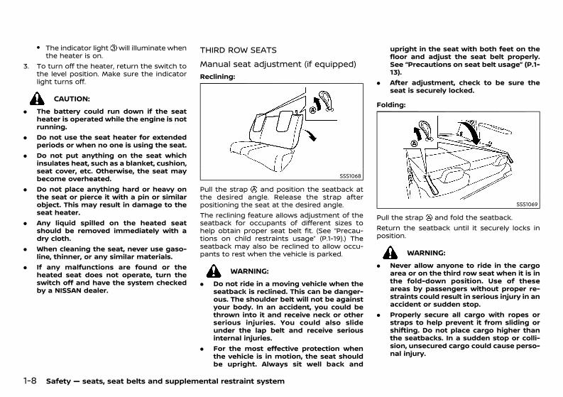
THIRD ROW SEATSGUID-CC3D15A9-D3E9-45BD-8C41-057DAB1AF596
Manual seat adjustment (if equipped)GUID-24161455-BFF3-41F6-AF1C-D1E70BAB2EF1
Reclining:GUID-C7E1EF24-5AAB-4301-95BE-26917EEE45EF
SSS1068
Pull the strap and position the seatback atthe desired angle. Release the strap afterpositioning the seat at the desired angle.The reclining feature allows adjustment of theseatback for occupants of different sizes tohelp obtain proper seat belt fit. (See “Precau-tions on child restraints usage” (P.1-19).) Theseatback may also be reclined to allow occu-pants to rest when the vehicle is parked.
WARNING:. Do not ride in a moving vehicle when the
seatback is reclined. This can be danger-ous. The shoulder belt will not be againstyour body. In an accident, you could bethrown into it and receive neck or otherserious injuries. You could also slideunder the lap belt and receive seriousinternal injuries.
. For the most effective protection whenthe vehicle is in motion, the seat shouldbe upright. Always sit well back and
upright in the seat with both feet on thefloor and adjust the seat belt properly.See “Precautions on seat belt usage” (P.1-13).
. After adjustment, check to be sure theseat is securely locked.
Folding:GUID-C7E1EF24-5AAB-4301-95BE-26917EEE45EF
SSS1069
Pull the strap and fold the seatback.Return the seatback until it securely locks inposition.
WARNING:. Never allow anyone to ride in the cargo
area or on the third row seat when it is inthe fold-down position. Use of theseareas by passengers without proper re-straints could result in serious injury in anaccident or sudden stop.
. Properly secure all cargo with ropes orstraps to help prevent it from sliding orshifting. Do not place cargo higher thanthe seatbacks. In a sudden stop or colli-sion, unsecured cargo could cause perso-nal injury.
Condition: 'Except for China'/'Except for China/
(31,1)
[ Edit: 2020/ 11/ 9 Model: Y62-A ]
. When returning the seatbacks to theupright position, be certain they arecompletely secured in the latched posi-tion. If they are not completely secured,passengers may be injured in an accidentor sudden stop.
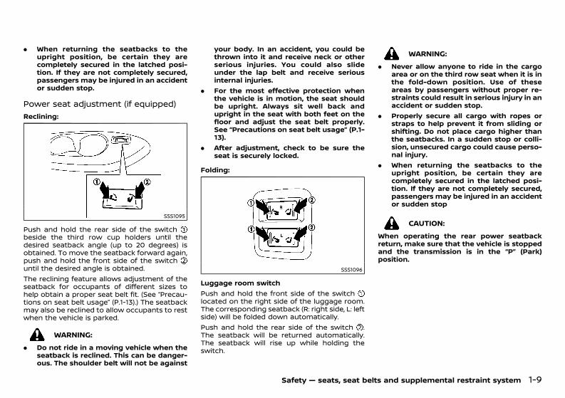
Power seat adjustment (if equipped)GUID-1317C8B1-487B-4DA0-8839-6C7BC9E1B7D7
Reclining:GUID-C7E1EF24-5AAB-4301-95BE-26917EEE45EF
SSS1095
Push and hold the rear side of the switchbeside the third row cup holders until thedesired seatback angle (up to 20 degrees) isobtained. To move the seatback forward again,push and hold the front side of the switchuntil the desired angle is obtained.The reclining feature allows adjustment of theseatback for occupants of different sizes tohelp obtain a proper seat belt fit. (See “Precau-tions on seat belt usage” (P.1-13).) The seatbackmay also be reclined to allow occupants to restwhen the vehicle is parked.
WARNING:. Do not ride in a moving vehicle when the
seatback is reclined. This can be danger-ous. The shoulder belt will not be against
your body. In an accident, you could bethrown into it and receive neck or otherserious injuries. You could also slideunder the lap belt and receive seriousinternal injuries.
. For the most effective protection whenthe vehicle is in motion, the seat shouldbe upright. Always sit well back andupright in the seat with both feet on thefloor and adjust the seat belt properly.See “Precautions on seat belt usage” (P.1-13).
. After adjustment, check to be sure theseat is securely locked.
Folding:GUID-C7E1EF24-5AAB-4301-95BE-26917EEE45EF
SSS1096
Luggage room switchPush and hold the front side of the switchlocated on the right side of the luggage room.The corresponding seatback (R: right side, L: leftside) will be folded down automatically.Push and hold the rear side of the switch .The seatback will be returned automatically.The seatback will rise up while holding theswitch.
WARNING:. Never allow anyone to ride in the cargo
area or on the third row seat when it is inthe fold-down position. Use of theseareas by passengers without proper re-straints could result in serious injury in anaccident or sudden stop.
. Properly secure all cargo with ropes orstraps to help prevent it from sliding orshifting. Do not place cargo higher thanthe seatbacks. In a sudden stop or colli-sion, unsecured cargo could cause perso-nal injury.
. When returning the seatbacks to theupright position, be certain they arecompletely secured in the latched posi-tion. If they are not completely secured,passengers may be injured in an accidentor sudden stop
CAUTION:When operating the rear power seatbackreturn, make sure that the vehicle is stoppedand the transmission is in the “P” (Park)position.
Safety — seats, seat belts and supplemental restraint system 1-9
Condition: 'Except for China'/'Except for China/
(32,1)
[ Edit: 2020/ 11/ 9 Model: Y62-A ]
1-10 Safety — seats, seat belts and supplemental restraint system
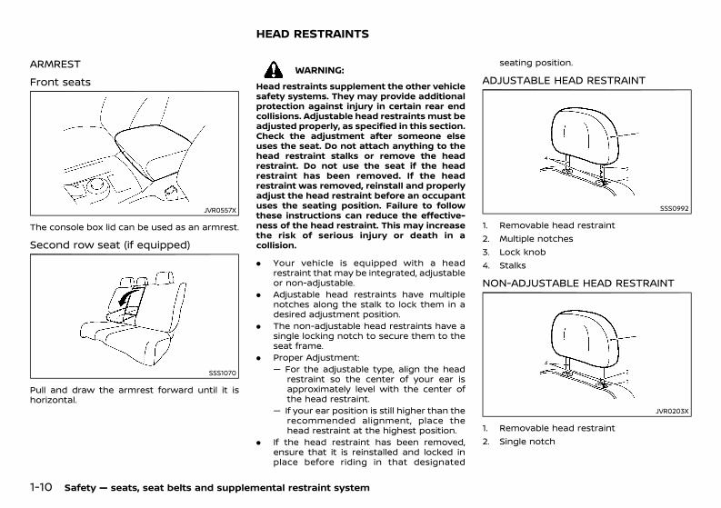
ARMREST GUID-DD2CDA25-66C3-41E8-9A0A-401BA3566F3B
Front seats GUID-13BED175-A637-4F1A-A86E-36E8CE9C3559
JVR0557X
The console box lid can be used as an armrest.
Second row seat (if equipped)GUID-C80DDE75-6659-4BEC-8109-8B70CE499480
SSS1070
Pull and draw the armrest forward until it ishorizontal.
GUID-01E6649B-3F49-4086-A553-08A09A0071D7
WARNING:Head restraints supplement the other vehiclesafety systems. They may provide additionalprotection against injury in certain rear endcollisions. Adjustable head restraints must beadjusted properly, as specified in this section.Check the adjustment after someone elseuses the seat. Do not attach anything to thehead restraint stalks or remove the headrestraint. Do not use the seat if the headrestraint has been removed. If the headrestraint was removed, reinstall and properlyadjust the head restraint before an occupantuses the seating position. Failure to followthese instructions can reduce the effective-ness of the head restraint. This may increasethe risk of serious injury or death in acollision.
. Your vehicle is equipped with a headrestraint that may be integrated, adjustableor non-adjustable.
. Adjustable head restraints have multiplenotches along the stalk to lock them in adesired adjustment position.
. The non-adjustable head restraints have asingle locking notch to secure them to theseat frame.
. Proper Adjustment:— For the adjustable type, align the head
restraint so the center of your ear isapproximately level with the center ofthe head restraint.
— If your ear position is still higher than therecommended alignment, place thehead restraint at the highest position.
. If the head restraint has been removed,ensure that it is reinstalled and locked inplace before riding in that designated
seating position.
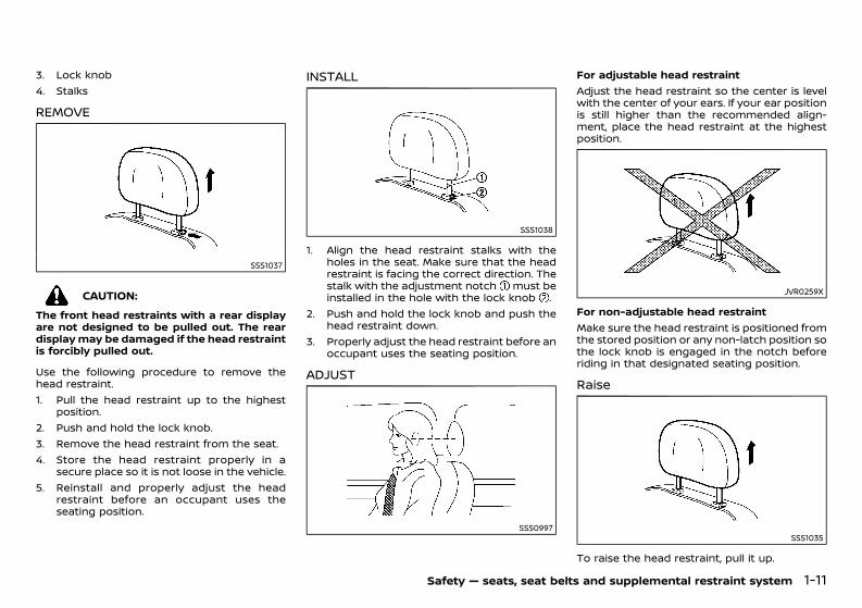
ADJUSTABLE HEAD RESTRAINTGUID-743BB7D0-8BF5-4CE8-B03E-EB82A668C743
SSS0992
1. Removable head restraint2. Multiple notches3. Lock knob4. Stalks
NON-ADJUSTABLE HEAD RESTRAINTGUID-0508AC36-4FCB-417D-ADBD-2309F8027972
JVR0203X
1. Removable head restraint2. Single notch
HEAD RESTRAINTS
Condition: 'Except for China'/'Except for China/
(33,1)
[ Edit: 2020/ 11/ 9 Model: Y62-A ]
3. Lock knob4. Stalks
REMOVE GUID-AA270F31-BC01-4EDE-B8F5-573CAF8B3D10
SSS1037
CAUTION:The front head restraints with a rear displayare not designed to be pulled out. The reardisplaymay be damaged if the head restraintis forcibly pulled out.
Use the following procedure to remove thehead restraint.1. Pull the head restraint up to the highest
position.2. Push and hold the lock knob.3. Remove the head restraint from the seat.4. Store the head restraint properly in a
secure place so it is not loose in the vehicle.5. Reinstall and properly adjust the head
restraint before an occupant uses theseating position.
INSTALL GUID-FF843C7C-419F-4449-AF62-110B5E0E6CB6
SSS1038
1. Align the head restraint stalks with theholes in the seat. Make sure that the headrestraint is facing the correct direction. Thestalk with the adjustment notch must beinstalled in the hole with the lock knob .
2. Push and hold the lock knob and push thehead restraint down.
3. Properly adjust the head restraint before anoccupant uses the seating position.
ADJUST GUID-34073139-5FC8-4489-9E79-8D37884FFAF5
SSS0997
For adjustable head restraintAdjust the head restraint so the center is levelwith the center of your ears. If your ear positionis still higher than the recommended align-ment, place the head restraint at the highestposition.
JVR0259X
For non-adjustable head restraintMake sure the head restraint is positioned fromthe stored position or any non-latch position sothe lock knob is engaged in the notch beforeriding in that designated seating position.
Raise GUID-03D7BA58-E870-4EAB-A470-80E2E818E758
SSS1035
To raise the head restraint, pull it up.
Safety — seats, seat belts and supplemental restraint system 1-11
Condition: 'Except for China'/'Except for China/
(34,1)
[ Edit: 2020/ 11/ 9 Model: Y62-A ]
1-12 Safety — seats, seat belts and supplemental restraint system
Make sure the head restraint is positioned fromthe stored position or any non-latch position sothe lock knob is engaged in the notch beforeriding in that designated seating position.
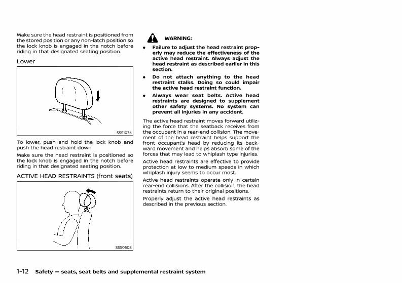
Lower GUID-62531C41-6946-4AC1-A69A-618CE8CF1A92
SSS1036
To lower, push and hold the lock knob andpush the head restraint down.Make sure the head restraint is positioned sothe lock knob is engaged in the notch beforeriding in that designated seating position.
ACTIVE HEAD RESTRAINTS (front seats)GUID-63FCA450-77FB-4FC9-9108-CD88D174A0CE
SSS0508
WARNING:. Failure to adjust the head restraint prop-
erly may reduce the effectiveness of theactive head restraint. Always adjust thehead restraint as described earlier in thissection.
. Do not attach anything to the headrestraint stalks. Doing so could impairthe active head restraint function.
. Always wear seat belts. Active headrestraints are designed to supplementother safety systems. No system canprevent all injuries in any accident.
The active head restraint moves forward utiliz-ing the force that the seatback receives fromthe occupant in a rear-end collision. The move-ment of the head restraint helps support thefront occupant’s head by reducing its back-ward movement and helps absorb some of theforces that may lead to whiplash type injuries.Active head restraints are effective to provideprotection at low to medium speeds in whichwhiplash injury seems to occur most.Active head restraints operate only in certainrear-end collisions. After the collision, the headrestraints return to their original positions.Properly adjust the active head restraints asdescribed in the previous section.
Condition: 'Except for China'/'Except for China/
(35,1)
[ Edit: 2020/ 11/ 9 Model: Y62-A ]
GUID-E14362D8-0956-4A90-AA28-730EEA28AE4F
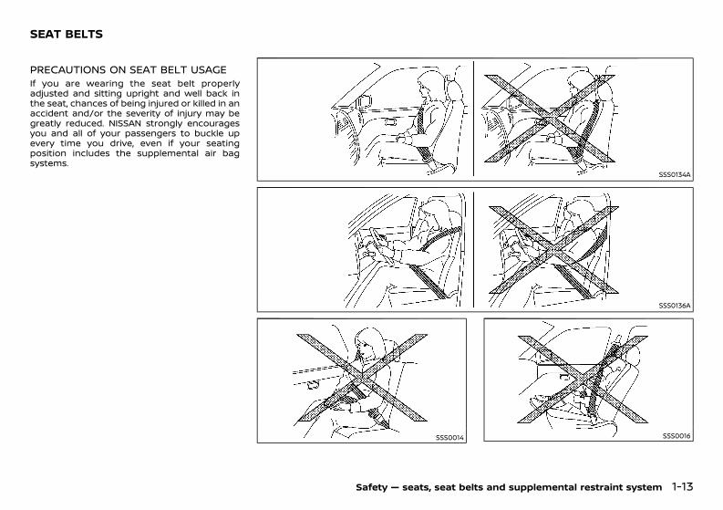
PRECAUTIONS ON SEAT BELT USAGEGUID-18940EF4-D22E-4D9C-A922-1F3396A16D5EIf you are wearing the seat belt properlyadjusted and sitting upright and well back inthe seat, chances of being injured or killed in anaccident and/or the severity of injury may begreatly reduced. NISSAN strongly encouragesyou and all of your passengers to buckle upevery time you drive, even if your seatingposition includes the supplemental air bagsystems.
SSS0134A
SSS0136A
SSS0014 SSS0016
Safety — seats, seat belts and supplemental restraint system 1-13
SEAT BELTS
Condition: 'Except for China'/'Except for China/
(36,1)
[ Edit: 2020/ 11/ 9 Model: Y62-A ]
1-14 Safety — seats, seat belts and supplemental restraint system
WARNING:. Seatbelts are designed to bear upon the
bony structure of the body, and should beworn low across the front of the pelvis orthe pelvis, chest and shoulders, as applic-able; wearing the lap section of the beltacross the abdominal area must beavoided. Serious injury may occur if aseat belt is not worn properly.
. Position the lap belt as low and snug aspossible around the hips, not the waist. Alap belt worn too high could increase therisk of internal injuries in an accident.
. Do not allowmore than one person to usethe same seat belt. Each belt assemblymust only be used by one occupant; it isdangerous to put a belt around a childbeing carried on the occupant’s lap.
. Never carry more people in the vehiclethan there are seat belts.
. Never wear seat belts inside out. Beltsshould not be worn with straps twisted.Doing so may reduce their effectiveness.
. Seatbelts should be adjusted as firmly aspossible, consistent with comfort, to pro-vide the protection for which they havebeen designed. A slack belt will greatlyreduce the protection afforded to thewearer.
. Every person who drives or rides in thisvehicle should use a seat belt at all times.Children should be properly restrained inthe rear seat and, if appropriate, in a childrestraint system.
. Do not put the belt behind your back orunder your arm. Always route theshoulder belt over your shoulder andacross your chest. The belt should be
away from your face and neck, but notfalling off your shoulder. Serious injurymay occur if a seat belt is not wornproperly.
. No modifications or additions should bemade by the user which will either pre-vent the seat belt adjusting devices fromoperating to remove slack, or prevent theseat belt assembly from being adjustedto remove slack.
. Care should be taken to avoid contam-ination of the webbing with polishes, oilsand chemicals, and particularly batteryacid. Cleaning may safely be carried outusing mild soap and water. The beltshould be replaced if webbing becomesfrayed, contaminated or damaged.
. It is essential to replace the entire as-sembly after it has been worn in a severeimpact even if damage to the assembly isnot obvious.
. All seat belt assemblies including retrac-tors and attaching hardware should beinspected after any collision by a NISSANdealer. NISSAN recommends that all seatbelt assemblies in use during a collisionbe replaced unless the collision wasminor and the belts show no damageand continue to operate properly. Seatbelt assemblies not in use during acollision should also be inspected and,when necessary, replaced if either da-mage or improper operation is noted.
. Once the pre-tensioner seat belt hasactivated, it cannot be reused. It mustbe replaced together with the retractor.Contact a NISSAN dealer.
. Removal and installation of the pre-ten-sioner seat belt system components
should be done by a NISSAN dealer.CHILD SAFETYGUID-391C4AD6-2F06-4205-BE55-366EA6C5E424
WARNING:. Infants and children need special protec-
tion. The vehicle’s seat belts may not fitthem properly. The shoulder belt maycome too close to the face or neck. Thelap belt may not fit over their smallhipbones. In an accident, an improperlyfitted seat belt could cause serious orfatal injury.
. Always use an appropriate child restraintsystem.
Children need adults to help protect them.They need to be properly restrained. Theproper restraint depends on the child’s size.
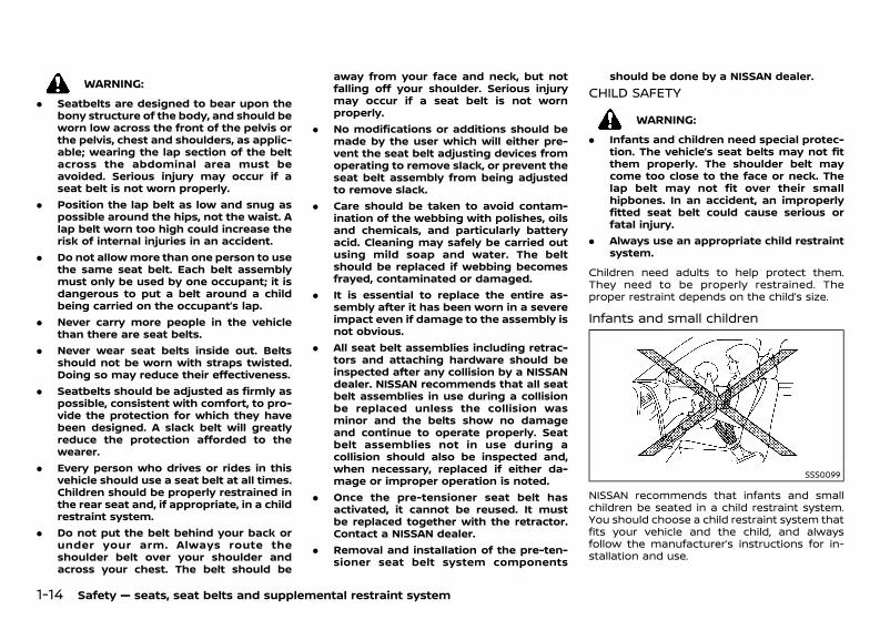
Infants and small childrenGUID-E94847D1-6A40-4650-955B-125C3ECA7686
SSS0099
NISSAN recommends that infants and smallchildren be seated in a child restraint system.You should choose a child restraint system thatfits your vehicle and the child, and alwaysfollow the manufacturer’s instructions for in-stallation and use.
Condition: 'Except for China'/'Except for China/
(37,1)
[ Edit: 2020/ 11/ 9 Model: Y62-A ]
Large childrenGUID-E7E81196-1AD1-4467-B945-35A94DE2AE24WARNING:
. Never allow children to stand or kneel onany seats.
. Never allow children in the luggage areaswhile the vehicle is moving. A child couldbe seriously injured in an accident orsudden stop.
Children who are too large for a child restraintsystem should be seated and restrained by theseat belts that are provided.If the child’s seating position has a shoulderbelt that fits close to the face or neck, the useof a booster seat (commercially available) mayhelp overcome this. The booster seat shouldraise the child so that the shoulder belt isproperly positioned across the top, middleportion of the shoulder and the lap belt is lowon the hips. The booster seat should also fit thevehicle seat. Once the child has grown so thatthe shoulder belt is no longer on or near theface or neck of the child, use the shoulder beltwithout the booster seat. In addition, there aremany types of child restraint systems availablefor larger children that should be used formaximum protection.
PREGNANT WOMENGUID-AEA253B0-0EB2-45A3-8A7C-77A6C8748C8CNISSAN recommends that pregnant womenuse seat belts. The seat belt should be wornsnug, and always position the lap belt as low aspossible around the hips, not the waist. Placethe shoulder belt over your shoulder andacross your chest. Never run the lap/shoulderbelt over your abdominal area. Contact yourdoctor for specific recommendations.
INJURED PERSONSGUID-B729A0D8-0A5A-472D-84AA-4609C350F628NISSAN recommends that injured persons useseat belts. Contact your doctor for specificrecommendations.
CENTER MARK ON SEAT BELTS (ifequipped) GUID-F70C96C8-66B3-454F-9190-A2D551FC54B2
Selecting correct set of seat beltsGUID-FF5C1257-8A87-435E-A0D4-327B0293ED80
SSS0671
The center seat belt buckle is identified by theCENTER mark. The center seat belt tongue canbe fastened only into the center seat beltbuckle.
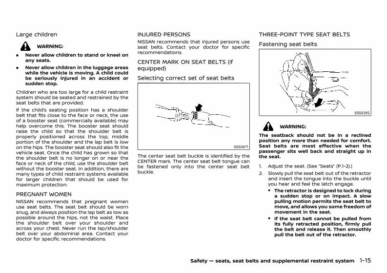
THREE-POINT TYPE SEAT BELTSGUID-3EB40FFA-D110-4A7F-B53A-87C147539DB9
Fastening seat beltsGUID-391FCFD2-B3B9-4010-9B4D-878A71128608
SSS0292
WARNING:The seatback should not be in a reclinedposition any more than needed for comfort.Seat belts are most effective when thepassenger sits well back and straight up inthe seat.
1. Adjust the seat. (See “Seats” (P.1-2).)2. Slowly pull the seat belt out of the retractor
and insert the tongue into the buckle untilyou hear and feel the latch engage.. The retractor is designed to lock during
a sudden stop or on impact. A slowpulling motion permits the seat belt tomove, and allows you some freedom ofmovement in the seat.
. If the seat belt cannot be pulled fromits fully retracted position, firmly pullthe belt and release it. Then smoothlypull the belt out of the retractor.
Safety — seats, seat belts and supplemental restraint system 1-15
Condition: 'Except for China'/'Except for China/
(38,1)
[ Edit: 2020/ 11/ 9 Model: Y62-A ]
1-16 Safety — seats, seat belts and supplemental restraint system
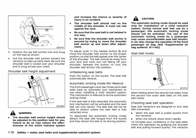
SSS0467
3. Position the lap belt portion low and snugon the hips as shown.
4. Pull the shoulder belt portion toward theretractor to take up extra slack. Be sure theshoulder belt is routed over your shoulderand is snug across your chest.
Shoulder belt height adjustmentGUID-F2656EA9-3735-451A-BE4A-2E4AF50ABE08
SSS0896
WARNING:. The shoulder belt anchor height should
be adjusted to the position best for you.Failure to do so may reduce the effec-tiveness of the entire restraint system
and increase the chance or severity ofinjury in an accident.
. The shoulder belt should rest on themiddle of the shoulder. It must not restagainst the neck.
. Be sure that the seat belt is not twisted inany way.
. Be sure that the shoulder belt anchor issecured by trying to move the shoulderbelt anchor up and down after adjust-ment.
To adjust, push in the release button andmove the shoulder belt anchor to the properposition, so that the belt passes over the centerof the shoulder. The belt should be away fromyour face and neck, but not falling off yourshoulder. Release the button to lock theshoulder belt anchor into position.
Unfastening seat beltsGUID-40FD8093-1590-4D59-83F0-2E67047746BCPush the button on the buckle. The seat beltautomatically retracts.
Automatic locking mode (for Mexico)GUID-1CFC8B7B-54D9-4A99-BC2E-25EDA5767394The front passenger’s and rear three-point seatbelts have an automatic lock mechanism touse when installing a child restraint system.This mechanism is referred to as the automaticlocking mode.If the seat belt is fully extended, the automaticlock mechanism will be activated and the seatbelt can only retract. The seat belt will not beable to extend unless the seat belt is fullyretracted once.To deactivate the automatic locking mode,detach the seat belt tongue from the buckleand fully retract the belt to its storing position.
CAUTION:The automatic locking mode should be usedonly for installation of a child restraintsystem. During normal seat belt use by apassenger, the automatic locking modeshould not be activated. The use of theautomatic locking mode by a passengermay cause uncomfortable seat belt tension.It can also change the operation of the frontpassenger air bag. (See “Supplemental airbag systems” (P.1-40).)
Seat belt hooksGUID-55DA5648-1487-449E-99EA-BE22EB3868A7
SSS1076
When folding down the second row seats, hookthe second row outer seat belts on the seatbelt hooks.
Checking seat belt operationGUID-B794C01F-AA78-4BD9-BB79-DDC7CF7793DFSeat belt retractors are designed to lock seatbelt movement:. When the seat belt is pulled quickly from
the retractor.. When the vehicle slows down rapidly.To increase your confidence in the seat belts,check the operation by grasping the shoulderbelt and pulling forward quickly. The retractor
Condition: 'Except for China'/'Except for China/
(39,1)
[ Edit: 2020/ 11/ 9 Model: Y62-A ]
should lock and restrict further belt movement.If the retractor does not lock during this check,contact a NISSAN dealer immediately.
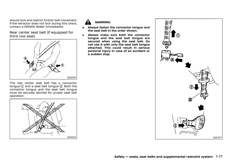
Rear center seat belt (if equipped forthird row seat)GUID-B1FE9B28-8371-4C00-A3A5-32F7A8E233CB
SSS0391
The rear center seat belt has a connectortongue and a seat belt tongue . Both theconnector tongue and the seat belt tonguemust be securely latched for proper seat beltoperation.
SSS0241
WARNING:. Always fasten the connector tongue and
the seat belt in the order shown.. Always make sure both the connector
tongue and the seat belt tongue aresecured when using the seat belt. Donot use it with only the seat belt tongueattached. This could result in seriouspersonal injury in case of an accident ora sudden stop.
SSS1077
Safety — seats, seat belts and supplemental restraint system 1-17
Condition: 'Except for China'/'Except for China/
(40,1)
[ Edit: 2020/ 11/ 9 Model: Y62-A ]
1-18 Safety — seats, seat belts and supplemental restraint system
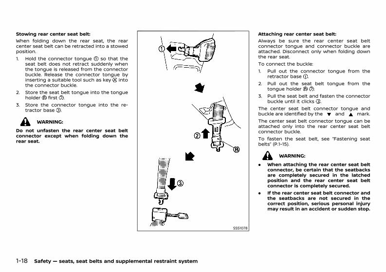
Stowing rear center seat belt:GUID-C7E1EF24-5AAB-4301-95BE-26917EEE45EF
When folding down the rear seat, the rearcenter seat belt can be retracted into a stowedposition.1. Hold the connector tongue so that the
seat belt does not retract suddenly whenthe tongue is released from the connectorbuckle. Release the connector tongue byinserting a suitable tool such as key intothe connector buckle.
2. Store the seat belt tongue into the tongueholder first .
3. Store the connector tongue into the re-tractor base .
WARNING:Do not unfasten the rear center seat beltconnector except when folding down therear seat.
SSS1078
Attaching rear center seat belt:GUID-C7E1EF24-5AAB-4301-95BE-26917EEE45EF
Always be sure the rear center seat beltconnector tongue and connector buckle areattached. Disconnect only when folding downthe rear seat.To connect the buckle:1. Pull out the connector tongue from the
retractor base .2. Pull out the seat belt tongue from the
tongue holder .3. Pull the seat belt and fasten the connector
buckle until it clicks .The center seat belt connector tongue andbuckle are identified by the and mark.The center seat belt connector tongue can beattached only into the rear center seat beltconnector buckle.To fasten the seat belt, see “Fastening seatbelts” (P.1-15).
WARNING:. When attaching the rear center seat belt
connector, be certain that the seatbacksare completely secured in the latchedposition and the rear center seat beltconnector is completely secured.
. If the rear center seat belt connector andthe seatbacks are not secured in thecorrect position, serious personal injurymay result in an accident or sudden stop.
Condition: 'Except for China'/'Except for China/
(41,1)
[ Edit: 2020/ 11/ 9 Model: Y62-A ]
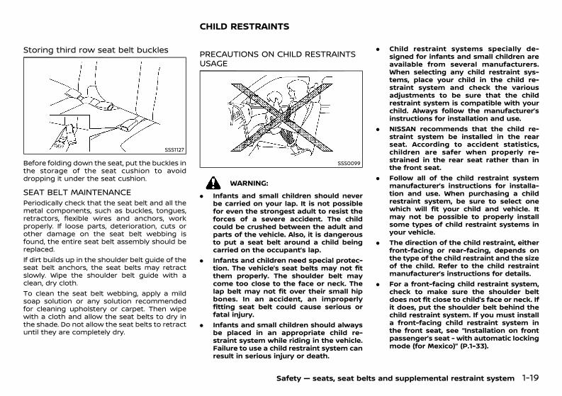
Storing third row seat belt bucklesGUID-F4477BAB-EF7B-4956-AE7A-ECD87C60DAF5
SSS1127
Before folding down the seat, put the buckles inthe storage of the seat cushion to avoiddropping it under the seat cushion.
SEAT BELT MAINTENANCEGUID-6BF4BB35-1E1E-49F1-ADEA-CFFF4CD99C75Periodically check that the seat belt and all themetal components, such as buckles, tongues,retractors, flexible wires and anchors, workproperly. If loose parts, deterioration, cuts orother damage on the seat belt webbing isfound, the entire seat belt assembly should bereplaced.If dirt builds up in the shoulder belt guide of theseat belt anchors, the seat belts may retractslowly. Wipe the shoulder belt guide with aclean, dry cloth.To clean the seat belt webbing, apply a mildsoap solution or any solution recommendedfor cleaning upholstery or carpet. Then wipewith a cloth and allow the seat belts to dry inthe shade. Do not allow the seat belts to retractuntil they are completely dry.
GUID-13C5E90E-D7AE-4922-9F00-D9E6EAF19D7E
PRECAUTIONS ON CHILD RESTRAINTSUSAGE GUID-E1FB12A0-C2B8-4595-A074-B4658FD76E0A
SSS0099
WARNING:. Infants and small children should never
be carried on your lap. It is not possiblefor even the strongest adult to resist theforces of a severe accident. The childcould be crushed between the adult andparts of the vehicle. Also, it is dangerousto put a seat belt around a child beingcarried on the occupant’s lap.
. Infants and children need special protec-tion. The vehicle’s seat belts may not fitthem properly. The shoulder belt maycome too close to the face or neck. Thelap belt may not fit over their small hipbones. In an accident, an improperlyfitting seat belt could cause serious orfatal injury.
. Infants and small children should alwaysbe placed in an appropriate child re-straint system while riding in the vehicle.Failure to use a child restraint system canresult in serious injury or death.
. Child restraint systems specially de-signed for infants and small children areavailable from several manufacturers.When selecting any child restraint sys-tems, place your child in the child re-straint system and check the variousadjustments to be sure that the childrestraint system is compatible with yourchild. Always follow the manufacturer’sinstructions for installation and use.
. NISSAN recommends that the child re-straint system be installed in the rearseat. According to accident statistics,children are safer when properly re-strained in the rear seat rather than inthe front seat.
. Follow all of the child restraint systemmanufacturer’s instructions for installa-tion and use. When purchasing a childrestraint system, be sure to select onewhich will fit your child and vehicle. Itmay not be possible to properly installsome types of child restraint systems inyour vehicle.
. The direction of the child restraint, eitherfront-facing or rear-facing, depends onthe type of the child restraint and the sizeof the child. Refer to the child restraintmanufacturer’s instructions for details.
. For a front-facing child restraint system,check to make sure the shoulder beltdoes not fit close to child’s face or neck. Ifit does, put the shoulder belt behind thechild restraint system. If you must installa front-facing child restraint system inthe front seat, see “Installation on frontpassenger’s seat - with automatic lockingmode (for Mexico)” (P.1-33).
Safety — seats, seat belts and supplemental restraint system 1-19
CHILD RESTRAINTS
Condition: 'Except for China'/'Except for China/
(42,1)
[ Edit: 2020/ 11/ 9 Model: Y62-A ]
1-20 Safety — seats, seat belts and supplemental restraint system
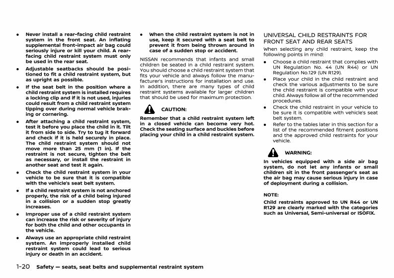
. Never install a rear-facing child restraintsystem in the front seat. An inflatingsupplemental front-impact air bag couldseriously injure or kill your child. A rear-facing child restraint system must onlybe used in the rear seat.
. Adjustable seatbacks should be posi-tioned to fit a child restraint system, butas upright as possible.
. If the seat belt in the position where achild restraint system is installed requiresa locking clip and if it is not used, injuriescould result from a child restraint systemtipping over during normal vehicle brak-ing or cornering.
. After attaching a child restraint system,test it before you place the child in it. Tiltit from side to side. Try to tug it forwardand check if it is held securely in place.The child restraint system should notmove more than 25 mm (1 in). If therestraint is not secure, tighten the beltas necessary, or install the restraint inanother seat and test it again.
. Check the child restraint system in yourvehicle to be sure that it is compatiblewith the vehicle’s seat belt system.
. If a child restraint system is not anchoredproperly, the risk of a child being injuredin a collision or a sudden stop greatlyincreases.
. Improper use of a child restraint systemcan increase the risk or severity of injuryfor both the child and other occupants inthe vehicle.
. Always use an appropriate child restraintsystem. An improperly installed childrestraint system could lead to seriousinjury or death in an accident.
. When the child restraint system is not inuse, keep it secured with a seat belt toprevent it from being thrown around incase of a sudden stop or accident.
NISSAN recommends that infants and smallchildren be seated in a child restraint system.You should choose a child restraint system thatfits your vehicle and always follow the manu-facturer’s instructions for installation and use.In addition, there are many types of childrestraint systems available for larger childrenthat should be used for maximum protection.
CAUTION:Remember that a child restraint system leftin a closed vehicle can become very hot.Check the seating surface and buckles beforeplacing your child in a child restraint system.
UNIVERSAL CHILD RESTRAINTS FORFRONT SEAT AND REAR SEATSGUID-BFCD1BC6-5F4B-4906-A096-F56E1221CA92When selecting any child restraint, keep thefollowing points in mind:. Choose a child restraint that complies with
UN Regulation No. 44 (UN R44) or UNRegulation No.129 (UN R129).
. Place your child in the child restraint andcheck the various adjustments to be surethe child restraint is compatible with yourchild. Always follow all of the recommendedprocedures.
. Check the child restraint in your vehicle tobe sure it is compatible with vehicle’s seatbelt system.
. Refer to the tables later in this section for alist of the recommended fitment positionsand the approved child restraints for yourvehicle.
WARNING:In vehicles equipped with a side air bagsystem, do not let any infants or smallchildren sit in the front passenger’s seat asthe air bag may cause serious injury in caseof deployment during a collision.
NOTE:Child restraints approved to UN R44 or UNR129 are clearly marked with the categoriessuch as Universal, Semi-universal or ISOFIX.
Condition: 'Except for China'/'Except for China/
(43,1)
[ Edit: 2020/ 11/ 9 Model: Y62-A ]
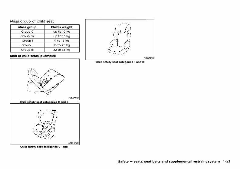
Mass group of child seatGUID-7BBA76F9-91F0-492A-8304-863DBF4DD25D
Mass group Child’s weightGroup 0 up to 10 kgGroup 0+ up to 13 kgGroup I 9 to 18 kgGroup II 15 to 25 kgGroup III 22 to 36 kg
Kind of child seats (example):GUID-C7E1EF24-5AAB-4301-95BE-26917EEE45EF
JVR0371XChild safety seat categories 0 and 0+
JVR0372XChild safety seat categories 0+ and I
JVR0373XChild safety seat categories II and III
Safety — seats, seat belts and supplemental restraint system 1-21
Condition: 'Except for China'/'Except for China/
(44,1)
[ Edit: 2020/ 11/ 9 Model: Y62-A ]
1-22 Safety — seats, seat belts and supplemental restraint system
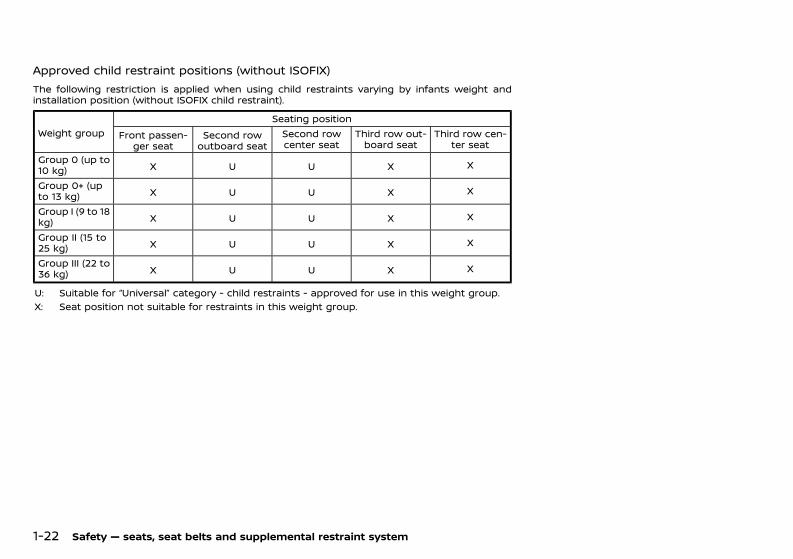
Approved child restraint positions (without ISOFIX)GUID-2922821B-03F5-43F9-903A-F3AA0922F167
The following restriction is applied when using child restraints varying by infants weight andinstallation position (without ISOFIX child restraint).
Weight groupSeating position
Front passen-ger seat
Second rowoutboard seat
Second rowcenter seat
Third row out-board seat
Third row cen-ter seat
Group 0 (up to10 kg) X U U X X
Group 0+ (upto 13 kg) X U U X X
Group I (9 to 18kg) X U U X X
Group II (15 to25 kg) X U U X X
Group III (22 to36 kg) X U U X X
U: Suitable for “Universal” category - child restraints - approved for use in this weight group.X: Seat position not suitable for restraints in this weight group.
Condition: 'Except for China'/'Except for China/
(45,1)
[ Edit: 2020/ 11/ 9 Model: Y62-A ]
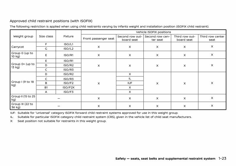
Approved child restraint positions (with ISOFIX)GUID-97F01232-C793-48DE-A4E6-48DDB85AC29F
The following restriction is applied when using child restraints varying by infants weight and installation position (ISOFIX child restraint).
Weight group Size class FixtureVehicle ISOFIX positions
Front passenger seat Second row out-board seat
Second row cen-ter seat
Third row out-board seat
Third row centerseat
CarrycotF ISO/L1
X X X X XG ISO/L2
Group 0 (up to10 kg) E ISO/R1 X X X X X
Group 0+ (up to13 kg)
E ISO/R1X X X X XD ISO/R2
C ISO/R3
Group I (9 to 18kg)
D ISO/R2
X
X
X X XC ISO/R3 ILB ISO/F2 IUFB1 ISO/F2X XA ISO/F3 X
Group II (15 to 25kg) — X X X X X
Group III (22 to36 kg) — X X X X X
IUF: Suitable for “universal” category ISOFIX forward child restraint systems approved for use in this weight group.IL: Suitable for particular ISOFIX category child restraint system (CRS), given in the vehicle list of child seat manufacturers.X: Seat position not suitable for restraints in this weight group.
Safety — seats, seat belts and supplemental restraint system 1-23
Condition: 'Except for China'/'Except for China/
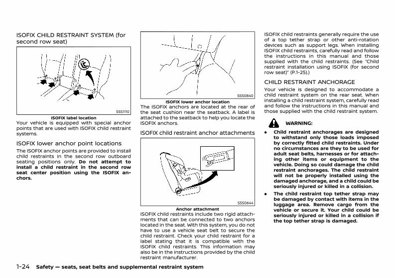
(46,1)
[ Edit: 2020/ 11/ 9 Model: Y62-A ]
1-24 Safety — seats, seat belts and supplemental restraint system
ISOFIX CHILD RESTRAINT SYSTEM (forsecond row seat)GUID-2625D6DA-D143-44A2-AFF8-9894FE590EA4
SSS1110ISOFIX label location
Your vehicle is equipped with special anchorpoints that are used with ISOFIX child restraintsystems.
ISOFIX lower anchor point locationsGUID-C971ABFD-F64A-4E5C-B392-3CE334498110The ISOFIX anchor points are provided to installchild restraints in the second row outboardseating positions only. Do not attempt toinstall a child restraint in the second rowseat center position using the ISOFIX an-chors.
SSS0840ISOFIX lower anchor location
The ISOFIX anchors are located at the rear ofthe seat cushion near the seatback. A label isattached to the seatback to help you locate theISOFIX anchors.
ISOFIX child restraint anchor attachmentsGUID-F47AB528-922F-4CE9-B95F-002193C32B35
SSS0644Anchor attachment
ISOFIX child restraints include two rigid attach-ments that can be connected to two anchorslocated in the seat. With this system, you do nothave to use a vehicle seat belt to secure thechild restraint. Check your child restraint for alabel stating that it is compatible with theISOFIX child restraints. This information mayalso be in the instructions provided by the childrestraint manufacturer.
ISOFIX child restraints generally require the useof a top tether strap or other anti-rotationdevices such as support legs. When installingISOFIX child restraints, carefully read and followthe instructions in this manual and thosesupplied with the child restraints. (See “Childrestraint installation using ISOFIX (for secondrow seat)” (P.1-25).)
CHILD RESTRAINT ANCHORAGEGUID-447E8B16-98E2-4348-8705-99CD5A3FBB6AYour vehicle is designed to accommodate achild restraint system on the rear seat. Wheninstalling a child restraint system, carefully readand follow the instructions in this manual andthose supplied with the child restraint system.
WARNING:. Child restraint anchorages are designed
to withstand only those loads imposedby correctly fitted child restraints. Underno circumstances are they to be used foradult seat belts, harnesses or for attach-ing other items or equipment to thevehicle. Doing so could damage the childrestraint anchorages. The child restraintwill not be properly installed using thedamaged anchorage, and a child could beseriously injured or killed in a collision.
. The child restraint top tether strap maybe damaged by contact with items in theluggage area. Remove cargo from thevehicle or secure it. Your child could beseriously injured or killed in a collision ifthe top tether strap is damaged.
Condition: 'Except for China'/'Except for China/
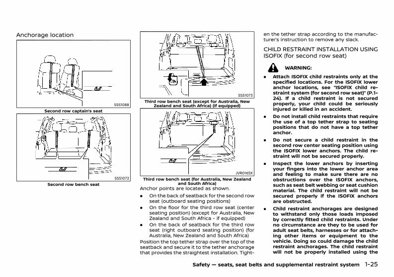
(47,1)
[ Edit: 2020/ 11/ 9 Model: Y62-A ]
Anchorage locationGUID-5D3B4815-F77A-48B1-B607-0B34045C4EA2
SSS1088Second row captain’s seat
SSS1072Second row bench seat
SSS1073Third row bench seat (except for Australia, New
Zealand and South Africa) (if equipped)
JVR0165XThird row bench seat (for Australia, New Zealand
and South Africa)Anchor points are located as shown.. On the back of seatback for the second row
seat (outboard seating positions). On the floor for the third row seat (center
seating position) (except for Australia, NewZealand and South Africa - if equipped)
. On the back of seatback for the third rowseat (right outboard seating position) (forAustralia, New Zealand and South Africa)
Position the top tether strap over the top of theseatback and secure it to the tether anchoragethat provides the straightest installation. Tight-
en the tether strap according to the manufac-turer’s instruction to remove any slack.
CHILD RESTRAINT INSTALLATION USINGISOFIX (for second row seat)GUID-53E0083E-90E8-418A-9F6F-DD6EA4BDCC68
WARNING:. Attach ISOFIX child restraints only at the
specified locations. For the ISOFIX loweranchor locations, see “ISOFIX child re-straint system (for second row seat)” (P.1-24). If a child restraint is not securedproperly, your child could be seriouslyinjured or killed in an accident.
. Do not install child restraints that requirethe use of a top tether strap to seatingpositions that do not have a top tetheranchor.
. Do not secure a child restraint in thesecond row center seating position usingthe ISOFIX lower anchors. The child re-straint will not be secured properly.
. Inspect the lower anchors by insertingyour fingers into the lower anchor areaand feeling to make sure there are noobstructions over the ISOFIX anchors,such as seat belt webbing or seat cushionmaterial. The child restraint will not besecured properly if the ISOFIX anchorsare obstructed.
. Child restraint anchorages are designedto withstand only those loads imposedby correctly fitted child restraints. Underno circumstance are they to be used foradult seat belts, harnesses or for attach-ing other items or equipment to thevehicle. Doing so could damage the childrestraint anchorages. The child restraintwill not be properly installed using the
Safety — seats, seat belts and supplemental restraint system 1-25
Condition: 'Except for China'/'Except for China/
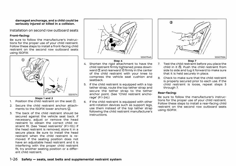
(48,1)
[ Edit: 2020/ 11/ 9 Model: Y62-A ]
1-26 Safety — seats, seat belts and supplemental restraint system
damaged anchorage, and a child could beseriously injured or killed in a collision.
Installation on second row outboard seatsGUID-8A76054C-A93C-4124-918E-E3B13D370514
Front-facing:GUID-C7E1EF24-5AAB-4301-95BE-26917EEE45EF
Be sure to follow the manufacturer’s instruc-tions for the proper use of your child restraint.Follow these steps to install a front-facing childrestraint on the second row outboard seatsusing ISOFIX:
SSS1074Steps 1 and 2
1. Position the child restraint on the seat .2. Secure the child restraint anchor attach-
ments to the ISOFIX lower anchors .3. The back of the child restraint should be
secured against the vehicle seat back. Ifnecessary, adjust or remove the headrestraint to obtain the correct child re-straint fit. (See “Head restraints” (P.1-10).) Ifthe head restraint is removed, store it in asecure place. Be sure to install the headrestraint when the child restraint is re-moved. If the seating position does nothave an adjustable head restraint and it isinterfering with the proper child restraintfit, try another seating position or a differ-ent child restraint.
SSS0754AStep 4
4. Shorten the rigid attachment to have thechild restraint firmly tightened; press down-ward and rearward firmly in the centerof the child restraint with your knee tocompress the vehicle seat cushion andseatback.
5. If the child restraint is equipped with a toptether strap, route the top tether strap andsecure the tether strap to the tetheranchor point. (See “Child restraint ancho-rage” (P.1-24).)
6. If the child restraint is equipped with otheranti-rotation devices such as support legs,use them instead of the top tether strapfollowing the child restraint manufacturer’sinstructions.
SSS0755AStep 7
7. Test the child restraint before you place thechild in it . Push the child restraint fromside to side and tug it forward to make surethat it is held securely in place.
8. Check to make sure that the child restraintis properly secured prior to each use. If thechild restraint is loose, repeat steps 3through 7.
Rear-facing:GUID-C7E1EF24-5AAB-4301-95BE-26917EEE45EF
Be sure to follow the manufacturer’s instruc-tions for the proper use of your child restraint.Follow these steps to install a rear-facing childrestraint on the second row outboard seatsusing ISOFIX:
Condition: 'Except for China'/'Except for China/
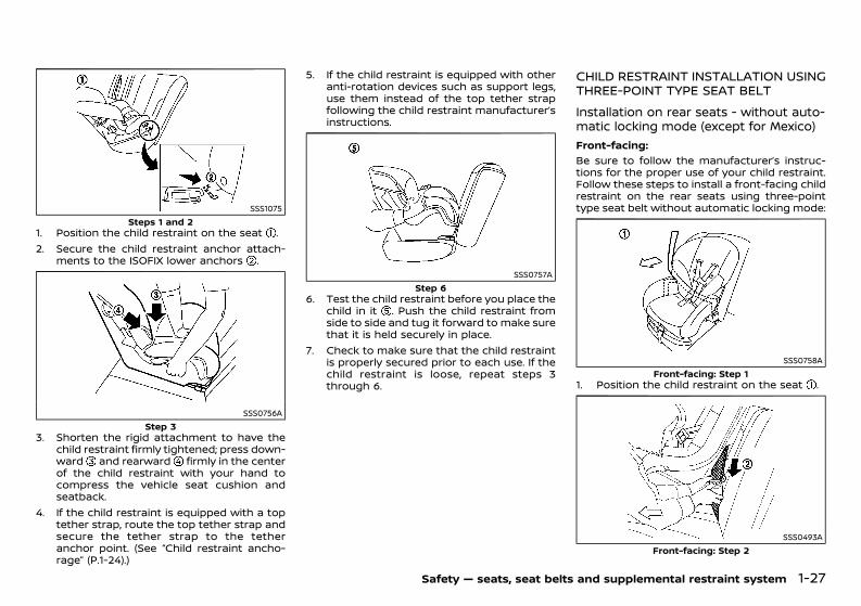
(49,1)
[ Edit: 2020/ 11/ 9 Model: Y62-A ]
SSS1075Steps 1 and 2
1. Position the child restraint on the seat .2. Secure the child restraint anchor attach-
ments to the ISOFIX lower anchors .
SSS0756AStep 3
3. Shorten the rigid attachment to have thechild restraint firmly tightened; press down-ward and rearward firmly in the centerof the child restraint with your hand tocompress the vehicle seat cushion andseatback.
4. If the child restraint is equipped with a toptether strap, route the top tether strap andsecure the tether strap to the tetheranchor point. (See “Child restraint ancho-rage” (P.1-24).)
5. If the child restraint is equipped with otheranti-rotation devices such as support legs,use them instead of the top tether strapfollowing the child restraint manufacturer’sinstructions.
SSS0757AStep 6
6. Test the child restraint before you place thechild in it . Push the child restraint fromside to side and tug it forward to make surethat it is held securely in place.
7. Check to make sure that the child restraintis properly secured prior to each use. If thechild restraint is loose, repeat steps 3through 6.
CHILD RESTRAINT INSTALLATION USINGTHREE-POINT TYPE SEAT BELTGUID-7523374E-6645-44D0-BCEC-CF9EFA4833FE
Installation on rear seats - without auto-matic locking mode (except for Mexico)GUID-C9A11D9C-A3FE-4C1C-83A8-A91A861E6493
Front-facing:GUID-C7E1EF24-5AAB-4301-95BE-26917EEE45EF
Be sure to follow the manufacturer’s instruc-tions for the proper use of your child restraint.Follow these steps to install a front-facing childrestraint on the rear seats using three-pointtype seat belt without automatic locking mode:
SSS0758AFront-facing: Step 1
1. Position the child restraint on the seat .
SSS0493AFront-facing: Step 2
Safety — seats, seat belts and supplemental restraint system 1-27
Condition: 'Except for China'/'Except for China/
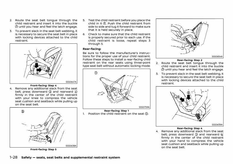
(50,1)
[ Edit: 2020/ 11/ 9 Model: Y62-A ]
1-28 Safety — seats, seat belts and supplemental restraint system
2. Route the seat belt tongue through thechild restraint and insert it into the buckle
until you hear and feel the latch engage.3. To prevent slack in the seat belt webbing, it
is necessary to secure the seat belt in placewith locking devices attached to the childrestraint.
SSS0647AFront-facing: Step 4
4. Remove any additional slack from the seatbelt; press downward and rearwardfirmly in the center of the child restraintwith your knee to compress the vehicleseat cushion and seatback while pulling upon the seat belt.
SSS0638AFront-facing: Step 5
5. Test the child restraint before you place thechild in it . Push the child restraint fromside to side and tug it forward to make surethat it is held securely in place.
6. Check to make sure that the child restraintis properly secured prior to each use. If thechild restraint is loose, repeat steps 3through 5.
Rear-facing:GUID-C7E1EF24-5AAB-4301-95BE-26917EEE45EF
Be sure to follow the manufacturer’s instruc-tions for the proper use of your child restraint.Follow these steps to install a rear-facing childrestraint on the rear seats using three-pointtype seat belt without automatic locking mode:
SSS0759ARear-facing: Step 1
1. Position the child restraint on the seat .
SSS0654ARear-facing: Step 2
2. Route the seat belt tongue through thechild restraint and insert it into the buckle
until you hear and feel the latch engage.3. To prevent slack in the seat belt webbing, it
is necessary to secure the seat belt in placewith locking devices attached to the childrestraint.
SSS0639ARear-facing: Step 4
4. Remove any additional slack from the seatbelt; press downward and rearwardfirmly in the center of the child restraintwith your hand to compress the vehicleseat cushion and seatback while pulling upon the seat belt.
Condition: 'Except for China'/'Except for China/
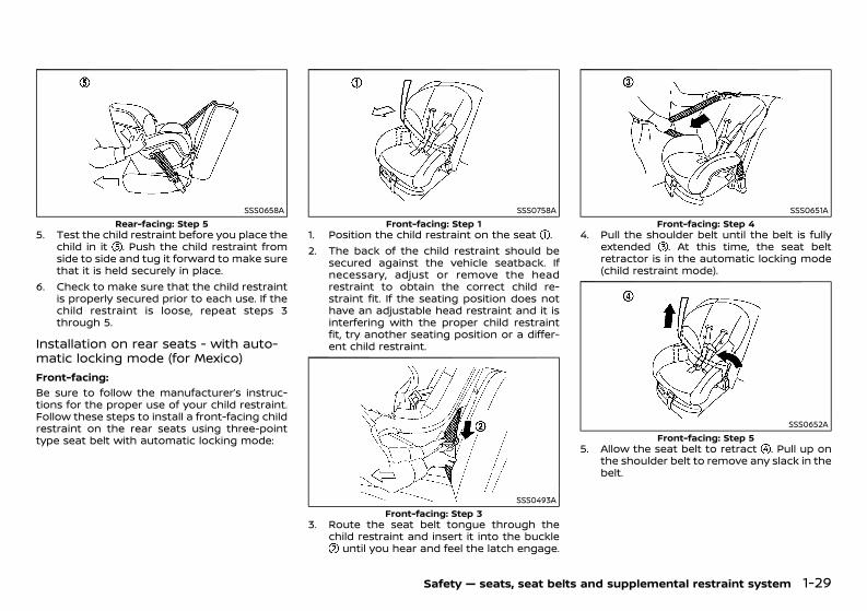
(51,1)
[ Edit: 2020/ 11/ 9 Model: Y62-A ]
SSS0658ARear-facing: Step 5
5. Test the child restraint before you place thechild in it . Push the child restraint fromside to side and tug it forward to make surethat it is held securely in place.
6. Check to make sure that the child restraintis properly secured prior to each use. If thechild restraint is loose, repeat steps 3through 5.
Installation on rear seats - with auto-matic locking mode (for Mexico)GUID-A2A46B3F-DBBB-4982-BB23-D75861541B73
Front-facing:GUID-C7E1EF24-5AAB-4301-95BE-26917EEE45EF
Be sure to follow the manufacturer’s instruc-tions for the proper use of your child restraint.Follow these steps to install a front-facing childrestraint on the rear seats using three-pointtype seat belt with automatic locking mode:
SSS0758AFront-facing: Step 1
1. Position the child restraint on the seat .2. The back of the child restraint should be
secured against the vehicle seatback. Ifnecessary, adjust or remove the headrestraint to obtain the correct child re-straint fit. If the seating position does nothave an adjustable head restraint and it isinterfering with the proper child restraintfit, try another seating position or a differ-ent child restraint.
SSS0493AFront-facing: Step 3
3. Route the seat belt tongue through thechild restraint and insert it into the buckle
until you hear and feel the latch engage.
SSS0651AFront-facing: Step 4
4. Pull the shoulder belt until the belt is fullyextended . At this time, the seat beltretractor is in the automatic locking mode(child restraint mode).
SSS0652AFront-facing: Step 5
5. Allow the seat belt to retract . Pull up onthe shoulder belt to remove any slack in thebelt.
Safety — seats, seat belts and supplemental restraint system 1-29
Condition: 'Except for China'/'Except for China/
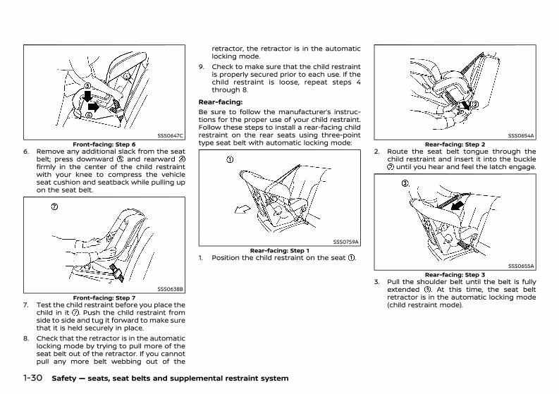
(52,1)
[ Edit: 2020/ 11/ 9 Model: Y62-A ]
1-30 Safety — seats, seat belts and supplemental restraint system
SSS0647CFront-facing: Step 6
6. Remove any additional slack from the seatbelt; press downward and rearwardfirmly in the center of the child restraintwith your knee to compress the vehicleseat cushion and seatback while pulling upon the seat belt.
SSS0638BFront-facing: Step 7
7. Test the child restraint before you place thechild in it . Push the child restraint fromside to side and tug it forward to make surethat it is held securely in place.
8. Check that the retractor is in the automaticlocking mode by trying to pull more of theseat belt out of the retractor. If you cannotpull any more belt webbing out of the
retractor, the retractor is in the automaticlocking mode.
9. Check to make sure that the child restraintis properly secured prior to each use. If thechild restraint is loose, repeat steps 4through 8.
Rear-facing:GUID-C7E1EF24-5AAB-4301-95BE-26917EEE45EF
Be sure to follow the manufacturer’s instruc-tions for the proper use of your child restraint.Follow these steps to install a rear-facing childrestraint on the rear seats using three-pointtype seat belt with automatic locking mode:
SSS0759ARear-facing: Step 1
1. Position the child restraint on the seat .
SSS0654ARear-facing: Step 2
2. Route the seat belt tongue through thechild restraint and insert it into the buckle
until you hear and feel the latch engage.
SSS0655ARear-facing: Step 3
3. Pull the shoulder belt until the belt is fullyextended . At this time, the seat beltretractor is in the automatic locking mode(child restraint mode).
Condition: 'Except for China'/'Except for China/
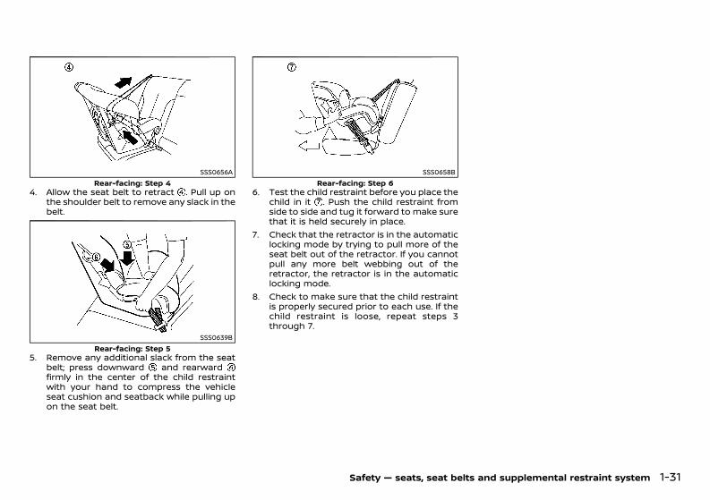
(53,1)
[ Edit: 2020/ 11/ 9 Model: Y62-A ]
SSS0656ARear-facing: Step 4
4. Allow the seat belt to retract . Pull up onthe shoulder belt to remove any slack in thebelt.
SSS0639BRear-facing: Step 5
5. Remove any additional slack from the seatbelt; press downward and rearwardfirmly in the center of the child restraintwith your hand to compress the vehicleseat cushion and seatback while pulling upon the seat belt.
SSS0658BRear-facing: Step 6
6. Test the child restraint before you place thechild in it . Push the child restraint fromside to side and tug it forward to make surethat it is held securely in place.
7. Check that the retractor is in the automaticlocking mode by trying to pull more of theseat belt out of the retractor. If you cannotpull any more belt webbing out of theretractor, the retractor is in the automaticlocking mode.
8. Check to make sure that the child restraintis properly secured prior to each use. If thechild restraint is loose, repeat steps 3through 7.
Safety — seats, seat belts and supplemental restraint system 1-31
Condition: 'Except for China'/'Except for China/
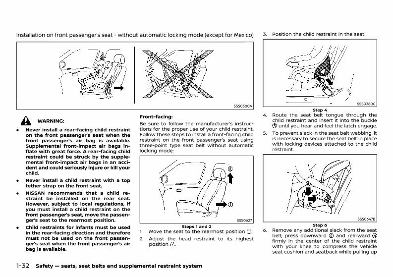
(54,1)
[ Edit: 2020/ 11/ 9 Model: Y62-A ]
1-32 Safety — seats, seat belts and supplemental restraint system
Installation on front passenger’s seat - without automatic locking mode (except for Mexico)GUID-4A862A3B-1836-4277-AED6-831F202B3E6E
SSS0300A
WARNING:. Never install a rear-facing child restraint
on the front passenger’s seat when thefront passenger’s air bag is available.Supplemental front-impact air bags in-flate with great force. A rear-facing childrestraint could be struck by the supple-mental front-impact air bags in an acci-dent and could seriously injure or kill yourchild.
. Never install a child restraint with a toptether strap on the front seat.
. NISSAN recommends that a child re-straint be installed on the rear seat.However, subject to local regulations, ifyou must install a child restraint on thefront passenger’s seat, move the passen-ger’s seat to the rearmost position.
. Child restraints for infants must be usedin the rear-facing direction and thereforemust not be used on the front passen-ger’s seat when the front passenger’s airbag is available.
Front-facing:GUID-C7E1EF24-5AAB-4301-95BE-26917EEE45EF
Be sure to follow the manufacturer’s instruc-tions for the proper use of your child restraint.Follow these steps to install a front-facing childrestraint on the front passenger’s seat usingthree-point type seat belt without automaticlocking mode:
SSS0627Steps 1 and 2
1. Move the seat to the rearmost position .2. Adjust the head restraint to its highest
position .
3. Position the child restraint in the seat.
SSS0360CStep 4
4. Route the seat belt tongue through thechild restraint and insert it into the buckle
until you hear and feel the latch engage.5. To prevent slack in the seat belt webbing, it
is necessary to secure the seat belt in placewith locking devices attached to the childrestraint.
SSS0647BStep 6
6. Remove any additional slack from the seatbelt; press downward and rearwardfirmly in the center of the child restraintwith your knee to compress the vehicleseat cushion and seatback while pulling up
Condition: 'Except for China'/'Except for China/
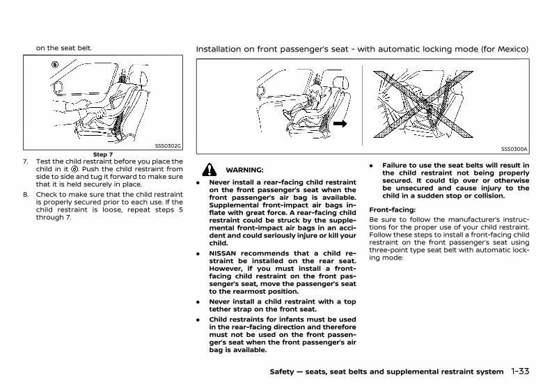
(55,1)
[ Edit: 2020/ 11/ 9 Model: Y62-A ]
on the seat belt.
SSS0302GStep 7
7. Test the child restraint before you place thechild in it . Push the child restraint fromside to side and tug it forward to make surethat it is held securely in place.
8. Check to make sure that the child restraintis properly secured prior to each use. If thechild restraint is loose, repeat steps 5through 7.
Installation on front passenger’s seat - with automatic locking mode (for Mexico)GUID-DE6D2460-D577-4AEC-908A-AE8A0D4E55BA
SSS0300A
WARNING:. Never install a rear-facing child restraint
on the front passenger’s seat when thefront passenger’s air bag is available.Supplemental front-impact air bags in-flate with great force. A rear-facing childrestraint could be struck by the supple-mental front-impact air bags in an acci-dent and could seriously injure or kill yourchild.
. NISSAN recommends that a child re-straint be installed on the rear seat.However, if you must install a front-facing child restraint on the front pas-senger’s seat, move the passenger’s seatto the rearmost position.
. Never install a child restraint with a toptether strap on the front seat.
. Child restraints for infants must be usedin the rear-facing direction and thereforemust not be used on the front passen-ger’s seat when the front passenger’s airbag is available.
. Failure to use the seat belts will result inthe child restraint not being properlysecured. It could tip over or otherwisebe unsecured and cause injury to thechild in a sudden stop or collision.
Front-facing:GUID-C7E1EF24-5AAB-4301-95BE-26917EEE45EF
Be sure to follow the manufacturer’s instruc-tions for the proper use of your child restraint.Follow these steps to install a front-facing childrestraint on the front passenger’s seat usingthree-point type seat belt with automatic lock-ing mode:
Safety — seats, seat belts and supplemental restraint system 1-33
Condition: 'Except for China'/'Except for China/
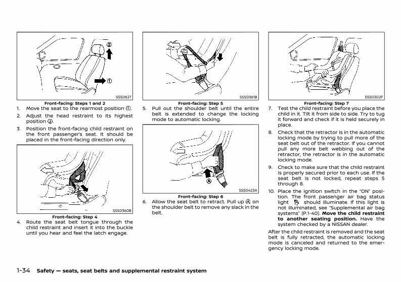
(56,1)
[ Edit: 2020/ 11/ 9 Model: Y62-A ]
1-34 Safety — seats, seat belts and supplemental restraint system
SSS0627Front-facing: Steps 1 and 2
1. Move the seat to the rearmost position .2. Adjust the head restraint to its highest
position .3. Position the front-facing child restraint on
the front passenger’s seat. It should beplaced in the front-facing direction only.
SSS0360BFront-facing: Step 4
4. Route the seat belt tongue through thechild restraint and insert it into the buckleuntil you hear and feel the latch engage.
SSS0361BFront-facing: Step 5
5. Pull out the shoulder belt until the entirebelt is extended to change the lockingmode to automatic locking.
SSS0423AFront-facing: Step 6
6. Allow the seat belt to retract. Pull up onthe shoulder belt to remove any slack in thebelt.
SSS0302FFront-facing: Step 7
7. Test the child restraint before you place thechild in it. Tilt it from side to side. Try to tugit forward and check if it is held securely inplace.
8. Check that the retractor is in the automaticlocking mode by trying to pull more of theseat belt out of the retractor. If you cannotpull any more belt webbing out of theretractor, the retractor is in the automaticlocking mode.
9. Check to make sure that the child restraintis properly secured prior to each use. If theseat belt is not locked, repeat steps 5through 8.
10. Place the ignition switch in the “ON” posi-tion. The front passenger air bag statuslight should illuminate. If this light isnot illuminated, see “Supplemental air bagsystems” (P.1-40). Move the child restraintto another seating position. Have thesystem checked by a NISSAN dealer.
After the child restraint is removed and the seatbelt is fully retracted, the automatic lockingmode is canceled and returned to the emer-gency locking mode.
Condition: 'Except for China'/'Except for China/
(57,1)
[ Edit: 2020/ 11/ 9 Model: Y62-A ]
GUID-7E26D5FA-E059-4E66-8A46-AC447D1179B5
PRECAUTIONS ON SUPPLEMENTAL RE-STRAINT SYSTEM (SRS)GUID-18D44BAF-6407-48CB-B331-F5D77D606C52This Supplemental Restraint System (SRS) sec-tion contains important information concern-ing the driver’s and passenger’s supplementalfront-impact air bags, supplemental side-im-pact air bags, supplemental curtain side-im-pact air bags, supplemental curtain side-impact and rollover air bags and pre-tensionerseat belts.
Supplemental front-impact air bag systemGUID-21371DF7-A120-4D42-A41C-15C2A73132E2This system can help cushion the impact forceto the head and chest area of the driver and/orfront passenger in certain frontal collisions. Thesupplemental front-impact air bag is designedto inflate on the front where the vehicle isimpacted.This section shows two types of the front-impact air bag system:. With Advanced Air Bag System. Without Advanced Air Bag System
Supplemental side-impact air bag sys-tem (if equipped)GUID-94BEE453-443C-4DCC-8159-04683775A22FThis system can help cushion the impact forceto the head, chest and pelvis area of the driverand front passenger in certain side-impactcollisions. The supplemental side-impact airbag is designed to inflate on the side wherethe vehicle is impacted.
Supplemental curtain side-impact airbag system (if equipped)GUID-F16B7D13-E78E-480A-AC9D-DFDA1FC42E71This system can help cushion the impact forceto the head of the driver and passengers infront and rear (second and third) outboardseating positions in certain side-impact colli-sions. The supplemental curtain side-impact airbag is designed to inflate on the side where thevehicle is impacted.
Supplemental curtain side-impact androllover air bag system (if equipped)GUID-A92A94A6-7CD6-40F3-A2DA-6040F89885CCThis system can help cushion the impact forceto the head of the driver and passengers infront and rear (second and third) outboardseating positions in certain side-impact orrollover collisions. In a side-impact, the supple-mental curtain side-impact and rollover air bagis designed to inflate on the side where thevehicle is impacted. In a rollover, the supple-mental curtain side-impact and rollover airbags on both sides are designed to inflate.Under the both side-impact and rollover situa-tions, the supplemental curtain side-impactand rollover air bags will remain inflated for ashort period of time.The SRS is designed to supplement the acci-dent protection provided by the driver’s andpassenger’s seat belts and is not designed tosubstitute for them. The SRS can help savelives and reduce serious injuries. However,inflating air bags may cause abrasions or otherinjuries. Air bags do not provide protection tothe lower body. Seat belts should always becorrectly worn and the occupants should al-ways be seated a suitable distance away fromthe steering wheel, instrument panel and doorfinishers. (See “Seat belts” (P.1-13).) The air bagsinflate quickly in order to help protect theoccupants. The force of the air bags inflating
can increase the risk of injury if the occupantsare too close to, or are against, the air bagmodules during inflation.The front and side-impact air bags will deflatequickly after deployment.The curtain side-impact air bag will remaininflated for a while.The curtain side-impact and rollover air bagswill remain inflated for a short period of time,under both side-impact and rollover situations.The SRS operates only when the ignitionswitch is in the “ON” position.When the ignition switch is in the “ON”position, the SRS air bag warning lightilluminates for about 7 seconds and thenturns off. This indicates that the SRS isoperational. (See “Warning lights, indicatorlights and audible reminders” (P.2-16).)
Safety — seats, seat belts and supplemental restraint system 1-35
SUPPLEMENTAL RESTRAINT SYSTEM (SRS)
Condition: 'Except for China'/'Except for China/
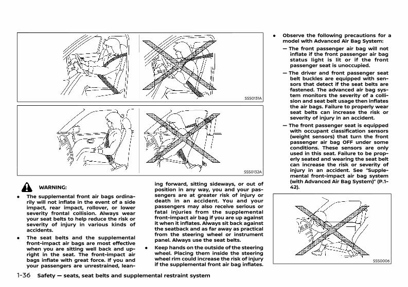
(58,1)
[ Edit: 2020/ 11/ 9 Model: Y62-A ]
1-36 Safety — seats, seat belts and supplemental restraint system
SSS0131A
SSS0132A
WARNING:. The supplemental front air bags ordina-
rily will not inflate in the event of a sideimpact, rear impact, rollover, or lowerseverity frontal collision. Always wearyour seat belts to help reduce the risk orseverity of injury in various kinds ofaccidents.
. The seat belts and the supplementalfront-impact air bags are most effectivewhen you are sitting well back and up-right in the seat. The front-impact airbags inflate with great force. If you andyour passengers are unrestrained, lean-
ing forward, sitting sideways, or out ofposition in any way, you and your pas-sengers are at greater risk of injury ordeath in an accident. You and yourpassengers may also receive serious orfatal injuries from the supplementalfront-impact air bag if you are up againstit when it inflates. Always sit back againstthe seatback and as far away as practicalfrom the steering wheel or instrumentpanel. Always use the seat belts.
. Keep hands on the outside of the steeringwheel. Placing them inside the steeringwheel rim could increase the risk of injuryif the supplemental front air bag inflates.
. Observe the following precautions for amodel with Advanced Air Bag System:— The front passenger air bag will not
inflate if the front passenger air bagstatus light is lit or if the frontpassenger seat is unoccupied.
— The driver and front passenger seatbelt buckles are equipped with sen-sors that detect if the seat belts arefastened. The advanced air bag sys-tem monitors the severity of a colli-sion and seat belt usage then inflatesthe air bags. Failure to properly wearseat belts can increase the risk orseverity of injury in an accident.
— The front passenger seat is equippedwith occupant classification sensors(weight sensors) that turn the frontpassenger air bag OFF under someconditions. These sensors are onlyused in this seat. Failure to be prop-erly seated and wearing the seat beltcan increase the risk or severity ofinjury in an accident. See “Supple-mental front-impact air bag system(with Advanced Air Bag System)” (P.1-42).
SSS0006
Condition: 'Except for China'/'Except for China/
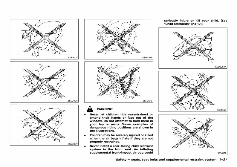
(59,1)
[ Edit: 2020/ 11/ 9 Model: Y62-A ]
SSS0007
SSS0008
SSS0009
SSS0099
SSS0100
WARNING:. Never let children ride unrestrained or
extend their hands or face out of thewindow. Do not attempt to hold them inyour lap or arms. Some examples ofdangerous riding positions are shown inthe illustrations.
. Children may be severely injured or killedwhen the air bags inflate if they are notproperly restrained.
. Never install a rear-facing child restraintsystem in the front seat. An inflatingsupplemental front-impact air bag could
seriously injure or kill your child. (See“Child restraints” (P.1-19).)
SSS0059A
SSS0140
SSS0159
Safety — seats, seat belts and supplemental restraint system 1-37
Condition: 'Except for China'/'Except for China/
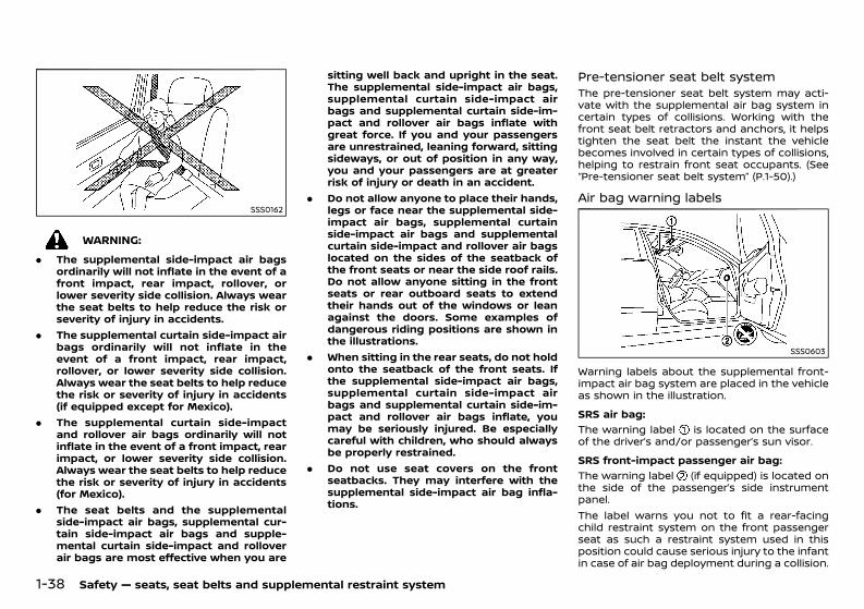
(60,1)
[ Edit: 2020/ 11/ 9 Model: Y62-A ]
1-38 Safety — seats, seat belts and supplemental restraint system
SSS0162
WARNING:. The supplemental side-impact air bags
ordinarily will not inflate in the event of afront impact, rear impact, rollover, orlower severity side collision. Always wearthe seat belts to help reduce the risk orseverity of injury in accidents.
. The supplemental curtain side-impact airbags ordinarily will not inflate in theevent of a front impact, rear impact,rollover, or lower severity side collision.Always wear the seat belts to help reducethe risk or severity of injury in accidents(if equipped except for Mexico).
. The supplemental curtain side-impactand rollover air bags ordinarily will notinflate in the event of a front impact, rearimpact, or lower severity side collision.Always wear the seat belts to help reducethe risk or severity of injury in accidents(for Mexico).
. The seat belts and the supplementalside-impact air bags, supplemental cur-tain side-impact air bags and supple-mental curtain side-impact and rolloverair bags are most effective when you are
sitting well back and upright in the seat.The supplemental side-impact air bags,supplemental curtain side-impact airbags and supplemental curtain side-im-pact and rollover air bags inflate withgreat force. If you and your passengersare unrestrained, leaning forward, sittingsideways, or out of position in any way,you and your passengers are at greaterrisk of injury or death in an accident.
. Do not allow anyone to place their hands,legs or face near the supplemental side-impact air bags, supplemental curtainside-impact air bags and supplementalcurtain side-impact and rollover air bagslocated on the sides of the seatback ofthe front seats or near the side roof rails.Do not allow anyone sitting in the frontseats or rear outboard seats to extendtheir hands out of the windows or leanagainst the doors. Some examples ofdangerous riding positions are shown inthe illustrations.
. When sitting in the rear seats, do not holdonto the seatback of the front seats. Ifthe supplemental side-impact air bags,supplemental curtain side-impact airbags and supplemental curtain side-im-pact and rollover air bags inflate, youmay be seriously injured. Be especiallycareful with children, who should alwaysbe properly restrained.
. Do not use seat covers on the frontseatbacks. They may interfere with thesupplemental side-impact air bag infla-tions.
Pre-tensioner seat belt systemGUID-E600D33A-6AF3-4CFF-92D4-3E4DD418DE2AThe pre-tensioner seat belt system may acti-vate with the supplemental air bag system incertain types of collisions. Working with thefront seat belt retractors and anchors, it helpstighten the seat belt the instant the vehiclebecomes involved in certain types of collisions,helping to restrain front seat occupants. (See“Pre-tensioner seat belt system” (P.1-50).)
Air bag warning labelsGUID-DFFFE86B-BAB2-44F5-8FF1-B78E4ECAC2AF
SSS0603
Warning labels about the supplemental front-impact air bag system are placed in the vehicleas shown in the illustration.SRS air bag:
GUID-C7E1EF24-5AAB-4301-95BE-26917EEE45EF
The warning label is located on the surfaceof the driver’s and/or passenger’s sun visor.SRS front-impact passenger air bag:
GUID-C7E1EF24-5AAB-4301-95BE-26917EEE45EF
The warning label (if equipped) is located onthe side of the passenger’s side instrumentpanel.The label warns you not to fit a rear-facingchild restraint system on the front passengerseat as such a restraint system used in thisposition could cause serious injury to the infantin case of air bag deployment during a collision.
Condition: 'Except for China'/'Except for China/
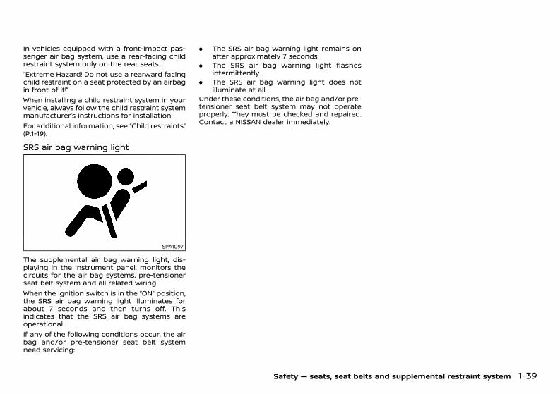
(61,1)
[ Edit: 2020/ 11/ 9 Model: Y62-A ]
In vehicles equipped with a front-impact pas-senger air bag system, use a rear-facing childrestraint system only on the rear seats.“Extreme Hazard! Do not use a rearward facingchild restraint on a seat protected by an airbagin front of it!”When installing a child restraint system in yourvehicle, always follow the child restraint systemmanufacturer’s instructions for installation.For additional information, see “Child restraints”(P.1-19).
SRS air bag warning lightGUID-185219C3-7B6E-4C47-9F3A-1CD8959CAA83
SPA1097
The supplemental air bag warning light, dis-playing in the instrument panel, monitors thecircuits for the air bag systems, pre-tensionerseat belt system and all related wiring.When the ignition switch is in the “ON” position,the SRS air bag warning light illuminates forabout 7 seconds and then turns off. Thisindicates that the SRS air bag systems areoperational.If any of the following conditions occur, the airbag and/or pre-tensioner seat belt systemneed servicing:
. The SRS air bag warning light remains onafter approximately 7 seconds.
. The SRS air bag warning light flashesintermittently.
. The SRS air bag warning light does notilluminate at all.
Under these conditions, the air bag and/or pre-tensioner seat belt system may not operateproperly. They must be checked and repaired.Contact a NISSAN dealer immediately.
Safety — seats, seat belts and supplemental restraint system 1-39
Condition: 'Except for China'/'Except for China/
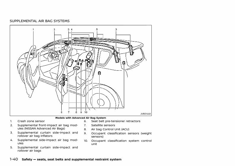
(62,1)
[ Edit: 2020/ 11/ 9 Model: Y62-A ]
1-40 Safety — seats, seat belts and supplemental restraint system
SUPPLEMENTAL AIR BAG SYSTEMSGUID-65D865B3-D7C4-4009-872D-A50CE16351E0
JVR0144XModels with Advanced Air Bag System
1. Crash zone sensor2. Supplemental front-impact air bag mod-
ules (NISSAN Advanced Air Bags)3. Supplemental curtain side-impact and
rollover air bag inflators4. Supplemental side-impact air bag mod-
ules5. Supplemental curtain side-impact and
rollover air bags
6. Seat belt pre-tensioner retractors7. Satellite sensors8. Air bag Control Unit (ACU)9. Occupant classification sensors (weight
sensors)10. Occupant classification system control
unit
Condition: 'Except for China'/'Except for China/
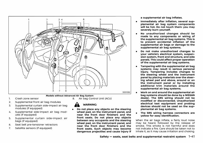
(63,1)
[ Edit: 2020/ 11/ 9 Model: Y62-A ]
SSS1082Models without Advanced Air Bag System
1. Crash zone sensor2. Supplemental front air bag modules3. Supplemental curtain side-impact air bag
modules (if equipped)4. Supplemental side-impact air bag mod-
ules (if equipped)5. Supplemental curtain side-impact air
bags (if equipped)6. Seat belt pre-tensioner retractors7. Satellite sensors (if equipped)
8. Air bag Control Unit (ACU)
WARNING:. Do not place any objects on the steering
wheel pad, on the instrument panel, andnear the front door finishers and thefront seats. Do not place any objectsbetween any occupants and the steeringwheel pad, on the instrument panel, andnear the front door finishers and thefront seats. Such objects may becomedangerous projectiles and cause injury if
a supplemental air bag inflates.. Immediately after inflation, several sup-
plemental air bag system componentswill be hot. Do not touch them: you mayseverely burn yourself.
. No unauthorized changes should bemade to any components or wiring ofthe supplemental air bag systems. This isto prevent accidental inflation of thesupplemental air bags or damage to thesupplemental air bag systems.
. Do not make unauthorized changes toyour vehicle’s electrical system, suspen-sion system, front end structure, and sidepanels. This could affect proper operationof the supplemental air bag systems.
. Tampering with the supplemental air bagsystems may result in serious personalinjury. Tampering includes changes tothe steering wheel and the instrumentpanel by placing materials over the steer-ing wheel pad and above, around or onthe instrument panel or by installingadditional trim materials around thesupplemental air bag systems.
. Work on and around the supplemental airbag systems should be done by a NISSANdealer. The SRS wiring should not bemodified or disconnected. Unauthorizedelectrical test equipment and probingdevices should not be used on the sup-plemental air bag systems.
. The SRS wiring harness connectors areyellow for easy identification.
When the air bags inflate, a fairly loud noisemay be heard, followed by the release ofsmoke. This smoke is not harmful and doesnot indicate a fire. Care should be taken not toinhale it, as it may cause irritation and choking.
Safety — seats, seat belts and supplemental restraint system 1-41
Condition: 'Except for China'/'Except for China/
(64,1)
[ Edit: 2020/ 11/ 9 Model: Y62-A ]
1-42 Safety — seats, seat belts and supplemental restraint system
Those with a history of a breathing conditionshould get fresh air promptly.
Supplemental front-impact air bagsystem (with Advanced Air Bag System)GUID-DDAD574C-3005-4106-9AD1-E5FABA090D86
WARNING:To ensure proper operation of the passen-ger’s advanced air bag system, please ob-serve the following items.. Do not allow a passenger in the rear seat
to push or pull on the seatback pocket.. Do not place heavy loads heavier than 4
kg (9.1 lb) on the seatback, headrest or inthe seatback pocket.
. Do not store luggage behind the seat thatcan press into the seatback.
. Be sure that the front passenger seatdoes not contact the rear seat, instru-ment panel, etc.
. Confirm the operating condition with thefront passenger air bag status light.
. If you notice that the front passenger airbag status light is not operating inaccordance with the above description,please take your vehicle to your NISSANdealer to check the passenger seat ad-vanced air bag system.
. Until you have confirmed with your deal-er that your passenger seat advanced airbag is working properly, position theoccupants in the rear seating positions.
. Do not place objects with sharp edges onthe seat. Also, do not place heavy objectson the seat that will leave permanentimpressions in the seat. Such objects candamage the seat or occupant classifica-tion sensors (weight sensors). This can
affect the operation of the air bag systemand result in serious personal injury.
. Do not use water or acidic cleaners (hotsteam cleaners) on the seat. This candamage the seat or occupant classifica-tion sensors. This can also affect theoperation of the air bag system andresult in serious personal injury.
. Removing or modifying the front passen-ger seat may affect the function of the airbag system and result in serious personalinjury.
. Modifying or tampering with the frontpassenger seat may result in seriouspersonal injury. For example, do notchange the front seats by placing materi-al on the seat cushion or by installingadditional trim material, such as seatcovers, on the seat that is not specificallydesigned to assure proper air bag opera-tion. Additionally, do not stow any objectsunder the front passenger seat or theseat cushion and seatback. Such objectsmay interfere with the proper operationof the occupant classification sensors.
. The front passenger air bag is designedto automatically turn OFF under someconditions. Read this section carefully tolearn how it operates. Proper use of theseat, seat belt and child restraints isnecessary for most effective protection.Failure to follow all instructions in thismanual concerning the use of seats, seatbelts and child restraints can increase therisk or severity of injury in an accident.
If the front passenger air bag status light doesnot illuminate when a child is seated in thefront passenger seat, or illuminates when anadult is seated in the front passenger seat,check to confirm that no loads are applied to
the seat except for the weight of the seatedpassenger. If you have any questions aboutwhether your passenger air bag is functioningas designed, your NISSAN dealer can confirmthat it is working properly by using a specialtool.This vehicle is equipped with Advanced Air BagSystem for the driver and front passengerseats. The driver’s supplemental front-impactair bag is located at the center of the steeringwheel. The passenger’s supplemental front-impact air bag is located at the instrumentpanel above the glove box.The supplemental front-impact air bag systemis designed to inflate in higher severity frontalcollisions, although it may inflate if the forces inanother type of collision are similar to those ofa higher severity frontal impact. It may notinflate in certain frontal collisions. Vehicledamage (or lack of it) is not always an indica-tion of proper supplemental front-impact airbag system operation.The Advanced Air Bag System monitors infor-mation from the crash zone sensor, the Air bagControl Unit (ACU), seat belt buckle sensors andthe occupant classification sensors (weightsensors). Inflator operation is based on theseverity of a collision and seat belt usage. Forthe front right passenger, the occupant classi-fication sensors are also monitored. Based oninformation from the sensors, only one front airbag may inflate in a crash, depending on thecrash severity and whether the front occu-pants are belted or unbelted. Additionally, thefront passenger’s air bag may be automaticallyturned OFF under some conditions, dependingon the information provided by the occupantclassification sensors. If the front passenger airbag is OFF, the front passenger air bag statuslight will be illuminated (if the seat is unoccu-pied, the light will not be illuminated, but the air
Condition: 'Except for China'/'Except for China/
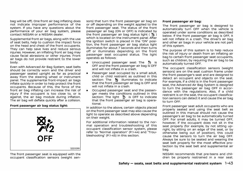
(65,1)
[ Edit: 2020/ 11/ 9 Model: Y62-A ]
bag will be off). One front air bag inflating doesnot indicate improper performance of thesystem. If you have any questions about theperformance of your air bag system, pleasecontact NISSAN or a NISSAN dealer.Supplemental front air bags, along with the useof seat belts, help to cushion the impact forceon the head and chest of the front occupants.They can help save lives and reduce seriousinjuries. However, an inflating front air bag maycause facial abrasions or other injuries. Frontair bags do not provide restraint to the lowerbody.Even with Advanced Air Bag System, seat beltsshould be correctly worn and the driver andpassenger seated upright as far as practicalaway from the steering wheel or instrumentpanel. The supplemental front-impact air bagsinflate quickly in order to help protect the frontoccupants. Because of this, the force of thefront air bag inflating can increase the risk ofinjury if the occupant is too close to, or isagainst, the air bag module during inflation.The air bag will deflate quickly after a collision.Front passenger air bag status light:
GUID-C7E1EF24-5AAB-4301-95BE-26917EEE45EF
SSS1099
The front passenger seat is equipped with theoccupant classification sensors (weight sen-
sors) that turn the front passenger air bag onor off depending on the weight applied to thefront passenger seat. The status of the frontpassenger air bag (ON or OFF) is indicated bythe front passenger air bag status light ( )which is located on the instrument panel. Afterthe ignition switch is placed in the “ON” posi-tion, the front passenger air bag status lightilluminates for about 7 seconds and then turnsoff or illuminates depending on the frontpassenger seat occupied status. The lightoperates as follows:. Unoccupied passenger seat: The is
OFF and the front passenger air bag is OFFand will not inflate in a crash.
. Passenger seat occupied by a small adult,child or child restraint as outlined in thissection: The illuminates to indicatethat the front passenger air bag is OFF andwill not inflate in a crash.
. Occupied passenger seat and the passen-ger meets the conditions outlined in thissection: The light is OFF to indicatethat the front passenger air bag is opera-tional.
In addition to the above, certain objects placedon the front passenger seat may also cause thelight to operate as described above dependingon their weight.For additional information related to the nor-mal operation and troubleshooting of thisoccupant classification sensor system, pleaserefer to “Normal operation” (P.1-44) and “Trou-bleshooting” (P.1-45) in this section.
Front passenger air bag:GUID-C7E1EF24-5AAB-4301-95BE-26917EEE45EF
The front passenger air bag is designed toautomatically turn OFF when the vehicle isoperated under some conditions as describedbelow. If the front passenger air bag is OFF, itwill not inflate in a crash. The driver’s air bagand other air bags in your vehicle are not partof this system.The purpose of this system is to help reducethe risk of injury or death from an inflating airbag to certain front passenger seat occupants,such as children, by requiring the air bag to beautomatically turned OFF.The occupant classification sensors (weightsensors) are on the seat cushion frame underthe front passenger’s seat and are designed todetect an occupant and objects on the seat.For example, if a child is in the front passengerseat, the Advanced Air Bag System is designedto turn the passenger air bag OFF in accor-dance with the regulations. Also, if a childrestraint is on the seat, the occupant classifica-tion sensors can detect it and cause the air bagto turn OFF.Front passenger seat adult occupants who areproperly seated and using the seat belt asoutlined in this manual should not cause thepassenger’s air bag to be automatically turnedOFF. For small adults, it may be turned OFF,however, if the occupant does not sit in theseat properly (for example, by not sitting up-right, by sitting on an edge of the seat, or byotherwise being out of position), this couldcause the sensors to turn the air bag OFF.Always be sure to be seated and wearing theseat belt properly for the most effective pro-tection by the seat belt and supplemental airbag.NISSAN recommends that pre-teens and chil-dren be properly restrained in a rear seat.
Safety — seats, seat belts and supplemental restraint system 1-43
Condition: 'Except for China'/'Except for China/
(66,1)
[ Edit: 2020/ 11/ 9 Model: Y62-A ]
1-44 Safety — seats, seat belts and supplemental restraint system
NISSAN also recommends that appropriatechild restraints and booster seats be properlyinstalled in a rear seat. If this is not possible, theoccupant classification sensors are designed tooperate as described above to turn the frontpassenger’s air bag OFF for specified childrestraints. Failing to properly secure childrestrains and to use the automatic lockingmode (child restraint mode) may allow therestraint to tip or move in an accident orsudden stop. This can also result in thepassenger’s air bag inflating in a crash insteadof being OFF. (See “Child restraints” (P.1-19) forproper use and installation.)If the front passenger’s seat is not occupied,the passenger’s air bag is designed not toinflate in a crash. However, heavy objectsplaced on the seat could result in air baginflation, because of the object being detectedby the occupant classification sensors. Otherconditions could also result in air bag inflation,such as if a child is standing on the seat, or iftwo children are on the seat, contrary to theinstructions in this manual. Always be sure thatyou and all vehicle occupants are seated andrestrained properly.Using the front passenger air bag status light,you can monitor when the front passenger airbag is automatically turned OFF with the seatoccupied. The light will not illuminate when thefront passenger seat is unoccupied.If an adult occupant is in the seat but the frontpassenger air bag status light is illuminated(indicating that the air bag is OFF), it could bethat the person is a small adult, or is not sittingon the seat properly.If a child restraint must be used in the frontseat, the front passenger air bag status lightmay or may not be illuminated, depending onthe size of the child and the type of child
restraint being used. If the front passenger airbag status light is not illuminated (indicatingthat the air bagmight inflate in a crash), it couldbe that the child restraint or seat belt is notbeing used properly. Make sure that the childrestraint is installed properly, the seat belt isused properly and the occupant is positionedproperly. If the front passenger air bag statuslight is still not illuminated, reposition theoccupant or child restraint in a rear seat.If the front passenger air bag status light willnot illuminate even though you believe that thechild restraint, the seat belts and the occupantare properly positioned, the system may besensing an unoccupied seat (in which case theair bag is OFF). Your NISSAN dealer can checkthat the system is OFF by using a special tool.However, until you have confirmed with yourdealer that your air bag is working properly,reposition the occupant or child restraint in arear seat.The Advanced Air Bag System and frontpassenger air bag status light will take a fewseconds to register a change in the passengerseat status. However, if the seat becomesunoccupied, the front passenger air bag statuslight will remain off.If a malfunction occurs in the front passenger’sair bag system, the supplemental air bagwarning light located in the meter andgauges area will blink. Have the systemchecked by a NISSAN dealer.Normal operation:
GUID-C7E1EF24-5AAB-4301-95BE-26917EEE45EF
In order for the occupant classification sensorsystem to classify the front passenger basedon weight, please follow the precautions andsteps outlined below:
Precautions:GUID-C7E1EF24-5AAB-4301-95BE-26917EEE45EF
. Make sure that there are no objects weigh-ing over 4 kg (9.1 lbs) hanging on the seat orplaced in the seatback pocket.
. Make sure that a child restraint or otherobject is not pressing against the rear ofthe seatback.
. Make sure that a rear passenger is notpushing or pulling on the back of the frontpassenger seat.
. Make sure that the front passenger seat orseatback is not forced back against anobject on the seat or floor behind it.
. Make sure that there is no object placedunder the front passenger seat.
Steps:GUID-C7E1EF24-5AAB-4301-95BE-26917EEE45EF
1. Adjust the seat as outlined. (See “Seats” (P.1-2).) Sit upright, leaning against the seat-back, and centered on the seat cushionwith your feet comfortably extended to thefloor.
2. Make sure there are no objects on your lap.3. Fasten the seat belt as outlined. (See “Seat
belts” (P.1-13).)4. Remain in this position for 30 seconds
allowing the system to classify the frontpassenger before the vehicle is put intomotion.
5. Ensure proper classification by checkingthe front passenger air bag status light.
NOTE:This vehicle’s occupant classification sensorsystem locks the classification during drivingso it is important that you confirm that thefront passenger is properly classified prior todriving. Also, the occupant classification sen-sor system may recalculate the weight of the
Condition: 'Except for China'/'Except for China/
(67,1)
[ Edit: 2020/ 11/ 9 Model: Y62-A ]
occupant when the vehicle comes to a stop(i.e. stop light, stop sign, etc.), so the frontpassenger seat occupant should continue toremain seated as outlined above.Troubleshooting:
GUID-C7E1EF24-5AAB-4301-95BE-26917EEE45EF
If you think the front passenger air bag statuslight is incorrect:1. If the light is ON with no front passenger
and no objects on the front passengerseat:
This may be due to the following conditionsthat may be interfering with the weight sen-sors:. An object weighing over 4 kg (9.1 lbs)
hanging on the seat or placed in theseatback pocket.
. A child restraint or other object pressingagainst the rear of the seatback.
. A rear passenger pushing or pulling on theback of the front passenger seat.
. Forcing the front seat or seatback againstan object on the seat or floor behind it.
. An object placed under the front passengerseat.
. An object placed between the seat cushionand center console or between the seatcushion and the door.
If the vehicle is moving, please come to a stopwhen it is safe to do so. Check and correct anyof the above conditions. Restart the vehicle andwait 1 minute.
NOTE:A system check will be performed duringwhich the front passenger air bag statuslight will remain lit for about 7 secondsinitially.If the light is still ON after this, the vehicleshould be checked by a NISSAN dealer as soon
as possible.2. If the light is ON with an adult occupying
the front passenger seat:. Occupant is a small adult — the front
passenger air bag status light is function-ing as intended. The front passenger airbag is suppressed.
However, if the occupant is not a small adult,then this may be due to the following condi-tions that may be interfering with the weightsensors:. Occupant is not sitting upright, leaning
against the seatback, and centered on theseat cushion with his/her feet comfortablyextended to the floor.
. A child restraint or other object pressingagainst the rear of the seatback.
. A rear passenger pushing or pulling on theback of the front passenger seat.
. Forcing the front seat or seatback againstan object on the seat or floor behind it.
. An object placed under the front passengerseat.
. An object placed between the seat cushionand center console or between the seatcushion and the door.
If the vehicle is moving, please come to a stopwhen it is safe to do so. Check and correct anyof the above conditions. Restart the vehicle andwait 1 minute.
NOTE:A system check will be performed duringwhich the front passenger air bag statuslight will remain lit for about 7 secondsinitially.If the light is still ON after this, the personshould be advised not to ride in the frontpassenger seat and the vehicle should be
checked by a NISSAN dealer as soon aspossible.3. If the light is OFF with a small adult, child
or child restraint occupying the frontpassenger seat.This may be due to the following condi-tions that may be interfering with theweight sensors:
. Small adult or child is not sitting upright,leaning against the seatback, and centeredon the seat cushion with his/her feetcomfortably extended to the floor.
. The child restraint is not properly installed,as outlined. (See “Child restraints” (P.1-19).)
. An object weighing over 4 kg (9.1 lbs)hanging on the seat or placed in theseatback pocket.
. A child restraint or other object pressingagainst the rear of the seatback.
. A rear passenger pushing or pulling on theback of the front passenger seat.
. Forcing the front seat or seatback againstan object on the seat or floor behind it.
. An object placed under the front passengerseat.
. An object placed between the seat cushionand center console.
If the vehicle is moving, please come to a stopwhen it is safe to do so. Check and correct anyof the above conditions. Restart the vehicle andwait 1 minute.
NOTE:A system check will be performed duringwhich the front passenger air bag statuslight will remain lit for about 7 secondsinitially.If the light is still OFF after this, the small adult,child or child restraint should be repositioned in
Safety — seats, seat belts and supplemental restraint system 1-45
Condition: 'Except for China'/'Except for China/
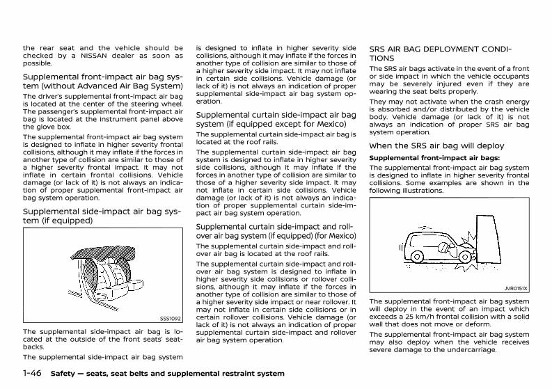
(68,1)
[ Edit: 2020/ 11/ 9 Model: Y62-A ]
1-46 Safety — seats, seat belts and supplemental restraint system
the rear seat and the vehicle should bechecked by a NISSAN dealer as soon aspossible.
Supplemental front-impact air bag sys-tem (without Advanced Air Bag System)GUID-78764968-CC9F-402C-9208-6F588B0EC388The driver’s supplemental front-impact air bagis located at the center of the steering wheel.The passenger’s supplemental front-impact airbag is located at the instrument panel abovethe glove box.The supplemental front-impact air bag systemis designed to inflate in higher severity frontalcollisions, although it may inflate if the forces inanother type of collision are similar to those ofa higher severity frontal impact. It may notinflate in certain frontal collisions. Vehicledamage (or lack of it) is not always an indica-tion of proper supplemental front-impact airbag system operation.
Supplemental side-impact air bag sys-tem (if equipped)GUID-6D270FAE-2DEB-44BB-8BCE-8FAE26687FFC
SSS1092
The supplemental side-impact air bag is lo-cated at the outside of the front seats’ seat-backs.The supplemental side-impact air bag system
is designed to inflate in higher severity sidecollisions, although it may inflate if the forces inanother type of collision are similar to those ofa higher severity side impact. It may not inflatein certain side collisions. Vehicle damage (orlack of it) is not always an indication of propersupplemental side-impact air bag system op-eration.
Supplemental curtain side-impact air bagsystem (if equipped except for Mexico)GUID-AF9C33A5-50BD-4693-9B38-A98DBB4F4DB7The supplemental curtain side-impact air bag islocated at the roof rails.The supplemental curtain side-impact air bagsystem is designed to inflate in higher severityside collisions, although it may inflate if theforces in another type of collision are similar tothose of a higher severity side impact. It maynot inflate in certain side collisions. Vehicledamage (or lack of it) is not always an indica-tion of proper supplemental curtain side-im-pact air bag system operation.
Supplemental curtain side-impact and roll-over air bag system (if equipped) (for Mexico)GUID-65C1A47B-04C1-41B7-9691-E5D03EDB93BFThe supplemental curtain side-impact and roll-over air bag is located at the roof rails.The supplemental curtain side-impact and roll-over air bag system is designed to inflate inhigher severity side collisions or rollover colli-sions, although it may inflate if the forces inanother type of collision are similar to those ofa higher severity side impact or near rollover. Itmay not inflate in certain side collisions or incertain rollover collisions. Vehicle damage (orlack of it) is not always an indication of propersupplemental curtain side-impact and rolloverair bag system operation.
SRS AIR BAG DEPLOYMENT CONDI-TIONS GUID-55E3B910-F2B6-4285-A380-6EFF851E49FFThe SRS air bags activate in the event of a frontor side impact in which the vehicle occupantsmay be severely injured even if they arewearing the seat belts properly.They may not activate when the crash energyis absorbed and/or distributed by the vehiclebody. Vehicle damage (or lack of it) is notalways an indication of proper SRS air bagsystem operation.
When the SRS air bag will deployGUID-0088318E-8EBD-4ACF-85E2-6FE4B28DC5E3
Supplemental front-impact air bags:GUID-C7E1EF24-5AAB-4301-95BE-26917EEE45EF
The supplemental front-impact air bag systemis designed to inflate in higher severity frontalcollisions. Some examples are shown in thefollowing illustrations.
JVR0151X
The supplemental front-impact air bag systemwill deploy in the event of an impact whichexceeds a 25 km/h frontal collision with a solidwall that does not move or deform.The supplemental front-impact air bag systemmay also deploy when the vehicle receivessevere damage to the undercarriage.
Condition: 'Except for China'/'Except for China/
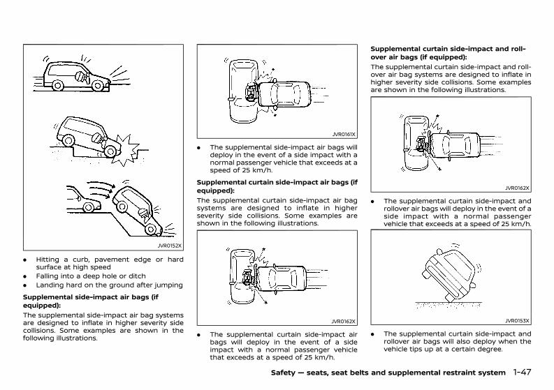
(69,1)
[ Edit: 2020/ 11/ 9 Model: Y62-A ]
JVR0152X
. Hitting a curb, pavement edge or hardsurface at high speed
. Falling into a deep hole or ditch
. Landing hard on the ground after jumpingSupplemental side-impact air bags (ifequipped):
GUID-C7E1EF24-5AAB-4301-95BE-26917EEE45EF
The supplemental side-impact air bag systemsare designed to inflate in higher severity sidecollisions. Some examples are shown in thefollowing illustrations.
JVR0161X
. The supplemental side-impact air bags willdeploy in the event of a side impact with anormal passenger vehicle that exceeds at aspeed of 25 km/h.
Supplemental curtain side-impact air bags (ifequipped):
GUID-C7E1EF24-5AAB-4301-95BE-26917EEE45EF
The supplemental curtain side-impact air bagsystems are designed to inflate in higherseverity side collisions. Some examples areshown in the following illustrations.
JVR0162X
. The supplemental curtain side-impact airbags will deploy in the event of a sideimpact with a normal passenger vehiclethat exceeds at a speed of 25 km/h.
Supplemental curtain side-impact and roll-over air bags (if equipped):
GUID-C7E1EF24-5AAB-4301-95BE-26917EEE45EF
The supplemental curtain side-impact and roll-over air bag systems are designed to inflate inhigher severity side collisions. Some examplesare shown in the following illustrations.
JVR0162X
. The supplemental curtain side-impact androllover air bags will deploy in the event of aside impact with a normal passengervehicle that exceeds at a speed of 25 km/h.
JVR0153X
. The supplemental curtain side-impact androllover air bags will also deploy when thevehicle tips up at a certain degree.
Safety — seats, seat belts and supplemental restraint system 1-47
Condition: 'Except for China'/'Except for China/
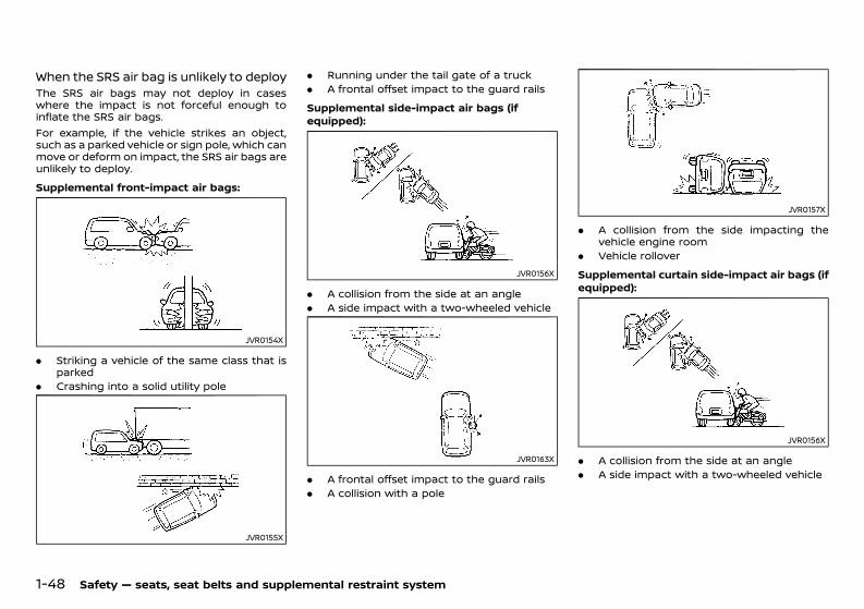
(70,1)
[ Edit: 2020/ 11/ 9 Model: Y62-A ]
1-48 Safety — seats, seat belts and supplemental restraint system
When the SRS air bag is unlikely to deployGUID-0A7A828B-9D5A-47E8-9A11-9352DD16307DThe SRS air bags may not deploy in caseswhere the impact is not forceful enough toinflate the SRS air bags.For example, if the vehicle strikes an object,such as a parked vehicle or sign pole, which canmove or deform on impact, the SRS air bags areunlikely to deploy.Supplemental front-impact air bags:
GUID-C7E1EF24-5AAB-4301-95BE-26917EEE45EF
JVR0154X
. Striking a vehicle of the same class that isparked
. Crashing into a solid utility pole
JVR0155X
. Running under the tail gate of a truck
. A frontal offset impact to the guard railsSupplemental side-impact air bags (ifequipped):
GUID-C7E1EF24-5AAB-4301-95BE-26917EEE45EF
JVR0156X
. A collision from the side at an angle
. A side impact with a two-wheeled vehicle
JVR0163X
. A frontal offset impact to the guard rails
. A collision with a pole
JVR0157X
. A collision from the side impacting thevehicle engine room
. Vehicle rolloverSupplemental curtain side-impact air bags (ifequipped):
GUID-C7E1EF24-5AAB-4301-95BE-26917EEE45EF
JVR0156X
. A collision from the side at an angle
. A side impact with a two-wheeled vehicle
Condition: 'Except for China'/'Except for China/
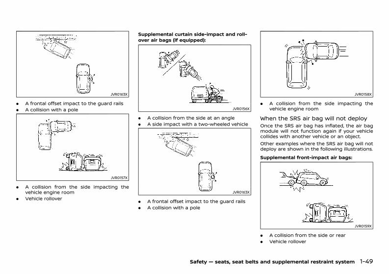
(71,1)
[ Edit: 2020/ 11/ 9 Model: Y62-A ]
JVR0163X
. A frontal offset impact to the guard rails
. A collision with a pole
JVR0157X
. A collision from the side impacting thevehicle engine room
. Vehicle rollover
Supplemental curtain side-impact and roll-over air bags (if equipped):
GUID-C7E1EF24-5AAB-4301-95BE-26917EEE45EF
JVR0156X
. A collision from the side at an angle
. A side impact with a two-wheeled vehicle
JVR0163X
. A frontal offset impact to the guard rails
. A collision with a pole
JVR0158X
. A collision from the side impacting thevehicle engine room
When the SRS air bag will not deployGUID-46599FE3-9E26-4A60-A8BE-23B1DD2A036AOnce the SRS air bag has inflated, the air bagmodule will not function again if your vehiclecollides with another vehicle or an object.Other examples where the SRS air bag will notdeploy are shown in the following illustrations.Supplemental front-impact air bags:
GUID-C7E1EF24-5AAB-4301-95BE-26917EEE45EF
JVR0159X
. A collision from the side or rear
. Vehicle rollover
Safety — seats, seat belts and supplemental restraint system 1-49
Condition: 'Except for China'/'Except for China/
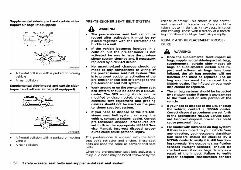
(72,1)
[ Edit: 2020/ 11/ 9 Model: Y62-A ]
1-50 Safety — seats, seat belts and supplemental restraint system
Supplemental side-impact and curtain side-impact air bags (if equipped):
GUID-C7E1EF24-5AAB-4301-95BE-26917EEE45EF
JVR0160X
. A frontal collision with a parked or movingvehicle
. A rear collisionSupplemental side-impact and curtain side-impact and rollover air bags (if equipped):
GUID-C7E1EF24-5AAB-4301-95BE-26917EEE45EF
JVR0160X
. A frontal collision with a parked or movingvehicle
. A rear collision
PRE-TENSIONER SEAT BELT SYSTEMGUID-D2269986-BC03-4575-BCD9-1A9AB182A9A2
WARNING:. The pre-tensioner seat belt cannot be
reused after activation. It must be re-placed together with the retractor andbuckle as a unit.
. If the vehicle becomes involved in acollision but the pre-tensioner is notactivated, be sure to have the pre-ten-sioner system checked and, if necessary,replaced by a NISSAN dealer.
. No unauthorized changes should bemade to any components or wiring ofthe pre-tensioner seat belt system. Thisis to prevent accidental activation of thepre-tensioner seat belt or damage to thepre-tensioner seat belt system.
. Work around or on the pre-tensioner seatbelt system should be done by a NISSANdealer. The SRS wiring should not bemodified or disconnected. Unauthorizedelectrical test equipment and probingdevices should not be used on the pre-tensioner seat belt system.
. If you need to dispose of the pre-ten-sioner seat belt system, or scrap thevehicle, contact a NISSAN dealer. Correctpre-tensioner disposal procedures areset forth in the appropriate NISSAN Ser-vice Manual. Incorrect disposal proce-dures could cause personal injury.
The pre-tensioner is encased with the frontseat belt’s retractor and anchor. These seatbelts are used the same as conventional seatbelts.When the pre-tensioner seat belt activates, afairly loud noise may be heard, followed by the
release of smoke. This smoke is not harmfuland does not indicate a fire. Care should betaken not to inhale it, as it may cause irritationand choking. Those with a history of a breath-ing condition should get fresh air promptly.
REPAIR AND REPLACEMENT PROCE-DURE GUID-DA9FFC93-EF78-48EB-B6C0-0259D95AD0DF
WARNING:. Once the supplemental front-impact air
bags, supplemental side-impact air bags,supplemental curtain side-impact airbags or supplemental curtain side-im-pact and rollover air bags have beeninflated, the air bag modules will notfunction and must be replaced. The airbag modules must be replaced by aNISSAN dealer. The inflated air bag mod-ules cannot be repaired.
. The air bag systems should be inspectedby a NISSAN dealer if there is any damageto the front end or side portion of thevehicle.
. If you need to dispose of the SRS or scrapthe vehicle, contact a NISSAN dealer.Correct disposal procedures are set forthin the appropriate NISSAN Service Man-ual. Incorrect disposal procedures couldcause personal injury.
. For model with Advanced Air Bag System:If there is an impact to your vehicle fromany direction, your occupant classifica-tion sensors should be checked by aNISSAN dealer to verify it is still function-ing correctly. The occupant classificationsensors (weight sensors) should bechecked even if no air bags deploy as aresult of the impact. Failure to verifyproper occupant classification sensors
Condition: 'Except for China'/'Except for China/
(73,1)
[ Edit: 2020/ 11/ 9 Model: Y62-A ]
(weight sensors) function may result inan improper air bag deployment result-ing in injury or death.
The supplemental front-impact air bags, sup-plemental side-impact air bags, supplementalcurtain side-impact air bags, supplementalcurtain side-impact and rollover air bags andpre-tensioner seat belts are designed to acti-vate on a one-time-only basis. As a reminder,unless the SRS air bag warning light is da-maged, the SRS air bag warning light remainsilluminated after inflation has occurred. Therepair and replacement of the SRS should bedone only by a NISSAN dealer.When maintenance work is required on thevehicle, information about the air bags, pre-tensioner seat belts and related parts shouldbe pointed out to the person performing themaintenance. The ignition switch should al-ways be in the “LOCK” position when workingunder the hood or inside the vehicle.
Safety — seats, seat belts and supplemental restraint system 1-51
Condition: 'Except for China'/'Except for China/

(74,1)
[ Edit: 2020/ 11/ 9 Model: Y62-A ]
1-52 Safety — seats, seat belts and supplemental restraint system
MEMO
Condition: 'Except for China'/'Except for China/
(75,1)
[ Edit: 2020/ 11/ 9 Model: Y62-A ]
2 Instruments and controls
Cockpit ...................................................................................................................... 2-3Left-Hand Drive (LHD) model ........................................................... 2-3Right-Hand Drive (RHD) model ....................................................... 2-4
Instrument panel .............................................................................................. 2-5Left-Hand Drive (LHD) model ........................................................... 2-5Right-Hand Drive (RHD) model ....................................................... 2-6
Meters and gauges ......................................................................................... 2-7Speedometer ................................................................................................ 2-8Odometer ........................................................................................................ 2-9Tachometer ................................................................................................... 2-9Engine coolant temperature gauge ....................................... 2-10Fuel gauge ................................................................................................... 2-10Engine oil pressure gauge .............................................................. 2-11Voltmeter ...................................................................................................... 2-11Meter illumination and needle sweep(if equipped) ................................................................................................ 2-12Vehicle information display ........................................................... 2-12Instrument brightness control .................................................... 2-12
Compass (if equipped) ............................................................................... 2-14Zone variation change procedure ............................................ 2-14
Warning lights, indicator lights andaudible reminders ......................................................................................... 2-16
Checking lights ........................................................................................ 2-17Warning lights ........................................................................................... 2-17Indicator lights ......................................................................................... 2-22Audible reminders ................................................................................. 2-25
Vehicle information display (Type A (model withcolor display)) .................................................................................................... 2-26
Indicators for operation .................................................................... 2-27Trip computer ........................................................................................... 2-32Clock and outside air temperature ......................................... 2-34
Vehicle information display (Type B (model with dotmatrix display)) ............................................................................................... 2-35
Indicators for operation and warnings ............................. 2-36Maintenance indicators .................................................................. 2-39Trip computer ........................................................................................ 2-40
Headlight and turn signal switch .................................................... 2-43Headlight switch .................................................................................. 2-43Headlight aiming control (if equipped) .............................. 2-46Battery saver system ....................................................................... 2-46Headlight cleaner (if equipped) ................................................ 2-46Turn signal switch .............................................................................. 2-47
Fog light switch (if equipped) ............................................................. 2-47Front fog lights (if equipped) ..................................................... 2-48Rear fog light (if equipped) .......................................................... 2-48
Wiper and washer switch ....................................................................... 2-49Windshield wiper and washer switch ................................. 2-49Rain-sensing auto wiper system (if equipped) ............ 2-50Rear window wiper and washer operation ................... 2-51
Defogger switch ............................................................................................ 2-52Windshield deicer switch (if equipped) ........................................ 2-53Horn ......................................................................................................................... 2-53Heated steering wheel (if equipped) ............................................. 2-54Windows ............................................................................................................... 2-54
Power windows .................................................................................... 2-54Sunroof (if equipped) ................................................................................. 2-56
Automatic sunroof (Type A) ........................................................ 2-56Automatic sunroof (Type B) ........................................................ 2-57
Clock ....................................................................................................................... 2-58Rear door alert (if equipped) ............................................................... 2-58
Turning the rear door alert system ON/OFF ................ 2-59System operation ................................................................................ 2-59
Condition: 'Except for China'/'Except for China/
>
(76,1)
[ Edit: 2020/ 11/ 9 Model: Y62-A ]
How to temporarily disable the rear dooralert system ................................................................................................ 2-60
Power outlets .................................................................................................... 2-60Type A ............................................................................................................. 2-60Type B (if equipped) ............................................................................. 2-61USB (Universal Serial Bus) charging connector ............. 2-62
Storage .................................................................................................................. 2-62Glove box ...................................................................................................... 2-62Instrument center box (if equipped) ....................................... 2-63Console box ................................................................................................ 2-63Tray (if equipped) ................................................................................... 2-64Sunglasses holder ................................................................................. 2-65Cup holders ................................................................................................ 2-65Coat hooks .................................................................................................. 2-67Luggage hooks ........................................................................................ 2-67Luggage floor box ................................................................................. 2-67Roof rack (if equipped) ...................................................................... 2-68Rear bumper cover (if equipped) .............................................. 2-68
Sun visors ............................................................................................................. 2-69Welcome light (if equipped) ................................................................... 2-70
Battery saver system .......................................................................... 2-70
Interior lights .................................................................................................... 2-70Interior light switch (Type A) ...................................................... 2-70Interior light switch (Type B) ...................................................... 2-71Console light (if equipped) ........................................................... 2-71Map lights .................................................................................................. 2-71Rear personal lights .......................................................................... 2-72Vanity mirror lights ............................................................................ 2-72Cargo light ................................................................................................ 2-72Battery saver system ....................................................................... 2-72
HomeLink® Universal Transceiver (if equipped) ................... 2-73Programming HomeLink® ............................................................ 2-73Using the garage doortwo-way communication ............................................................. 2-75If the device has time-out control ........................................ 2-75Operating the HomeLink®Universal Transceiver ....................................................................... 2-75Programming troubleshooting ................................................ 2-75Clearing the programmed information ............................. 2-76Reprogramming a single HomeLink® button ............... 2-76If your vehicle is stolen ................................................................... 2-76
Condition: 'Except for China'/'Except for China/
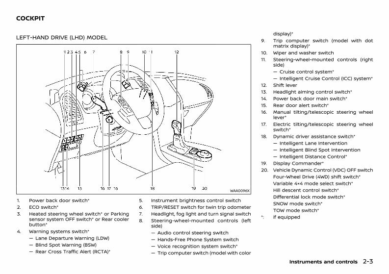
(77,1)
[ Edit: 2020/ 11/ 9 Model: Y62-A ]
GUID-EB56C13A-C6EE-4C84-8505-4D4397DB8CB5
LEFT-HAND DRIVE (LHD) MODELGUID-461D724C-E8D4-431A-A211-9398D746ADCD
WAA0096X
1. Power back door switch*2. ECO switch*3. Heated steering wheel switch* or Parking
sensor system OFF switch* or Rear coolerbutton*
4. Warning systems switch*— Lane Departure Warning (LDW)— Blind Spot Warning (BSW)— Rear Cross Traffic Alert (RCTA)*
5. Instrument brightness control switch6. TRIP/RESET switch for twin trip odometer7. Headlight, fog light and turn signal switch8. Steering-wheel-mounted controls (left
side)— Audio control steering switch— Hands-Free Phone System switch— Voice recognition system switch*— Trip computer switch (model with color
display)*9. Trip computer switch (model with dot
matrix display)*10. Wiper and washer switch11. Steering-wheel-mounted controls (right
side)— Cruise control system*— Intelligent Cruise Control (ICC) system*
12. Shift lever13. Headlight aiming control switch*14. Power back door main switch*15. Rear door alert switch*16. Manual tilting/telescopic steering wheel
lever*17. Electric tilting/telescopic steering wheel
switch*18. Dynamic driver assistance switch*
— Intelligent Lane Intervention— Intelligent Blind Spot Intervention— Intelligent Distance Control*
19. Display Commander*20. Vehicle Dynamic Control (VDC) OFF switch
Four-Wheel Drive (4WD) shift switch*Variable 4×4 mode select switch*Hill descent control switch*Differential lock mode switch*SNOW mode switch*TOW mode switch*
*: if equipped
Instruments and controls 2-3
COCKPIT
Condition: 'Except for China'/'Except for China/
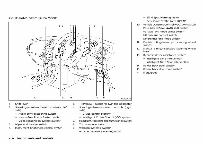
(78,1)
[ Edit: 2020/ 11/ 9 Model: Y62-A ]
2-4 Instruments and controls
RIGHT-HAND DRIVE (RHD) MODELGUID-2BA9F5D7-8161-4D7A-9F5D-F31107169F9F
WAA0098X
1. Shift lever2. Steering-wheel-mounted controls (left
side)— Audio control steering switch— Hands-Free Phone System switch— Voice recognition system switch*
3. Wiper and washer switch4. Instrument brightness control switch
5. TRIP/RESET switch for twin trip odometer6. Steering-wheel-mounted controls (right
side)— Cruise control system*— Intelligent Cruise Control (ICC) system*
7. Headlight, fog light and turn signal switch8. Trip computer switch9. Warning systems switch*
— Lane Departure Warning (LDW)
— Blind Spot Warning (BSW)— Rear Cross Traffic Alert (RCTA)*
10. Vehicle Dynamic Control (VDC) OFF switchFour-Wheel Drive (4WD) shift switchVariable 4×4 mode select switchHill descent control switchDifferential lock mode switch
11. Electric tilting/telescopic steering wheelswitch*
12. Manual tilting/telescopic steering wheellever*
13. Dynamic driver assistance switch*— Intelligent Lane Intervention— Intelligent Blind Spot Intervention
14. Power back door switch*15. Power back door main switch**: if equipped
Condition: 'Except for China'/'Except for China/
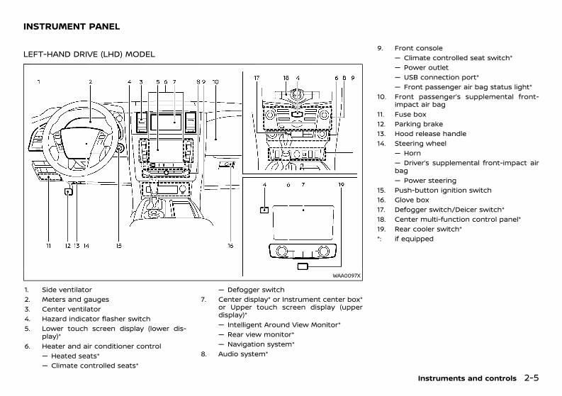
(79,1)
[ Edit: 2020/ 11/ 9 Model: Y62-A ]
GUID-A32C3578-39F4-4F2E-A8D4-97767F14EA26
LEFT-HAND DRIVE (LHD) MODELGUID-BF7DBE9A-3AB8-4A46-A5E5-E602A487762A
WAA0097X
1. Side ventilator2. Meters and gauges3. Center ventilator4. Hazard indicator flasher switch5. Lower touch screen display (lower dis-
play)*6. Heater and air conditioner control
— Heated seats*— Climate controlled seats*
— Defogger switch7. Center display* or Instrument center box*
or Upper touch screen display (upperdisplay)*— Intelligent Around View Monitor*— Rear view monitor*— Navigation system*
8. Audio system*
9. Front console— Climate controlled seat switch*— Power outlet— USB connection port*— Front passenger air bag status light*
10. Front passenger’s supplemental front-impact air bag
11. Fuse box12. Parking brake13. Hood release handle14. Steering wheel
— Horn— Driver’s supplemental front-impact airbag— Power steering
15. Push-button ignition switch16. Glove box17. Defogger switch/Deicer switch*18. Center multi-function control panel*19. Rear cooler switch**: if equipped
Instruments and controls 2-5
INSTRUMENT PANEL
Condition: 'Except for China'/'Except for China/
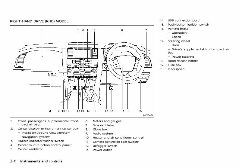
(80,1)
[ Edit: 2020/ 11/ 9 Model: Y62-A ]
2-6 Instruments and controls
RIGHT-HAND DRIVE (RHD) MODELGUID-5FA2A1E5-7EFC-4D9A-9A04-D2F72399C238
JVC1048X
1. Front passenger’s supplemental front-impact air bag
2. Center display* or Instrument center box*— Intelligent Around View Monitor*— Navigation system*
3. Hazard indicator flasher switch4. Center multi-function control panel*5. Center ventilator
6. Meters and gauges7. Side ventilator8. Glove box9. Audio system10. Heater and air conditioner control11. Climate controlled seat switch*12. Defogger switch13. Power outlet
14. USB connection port*15. Push-button ignition switch16. Parking brake
— Operation— Check
17. Steering wheel— Horn— Driver’s supplemental front-impact airbag— Power steering
18. Hood release handle19. Fuse box*: if equipped
Condition: 'Except for China'/'Except for China/
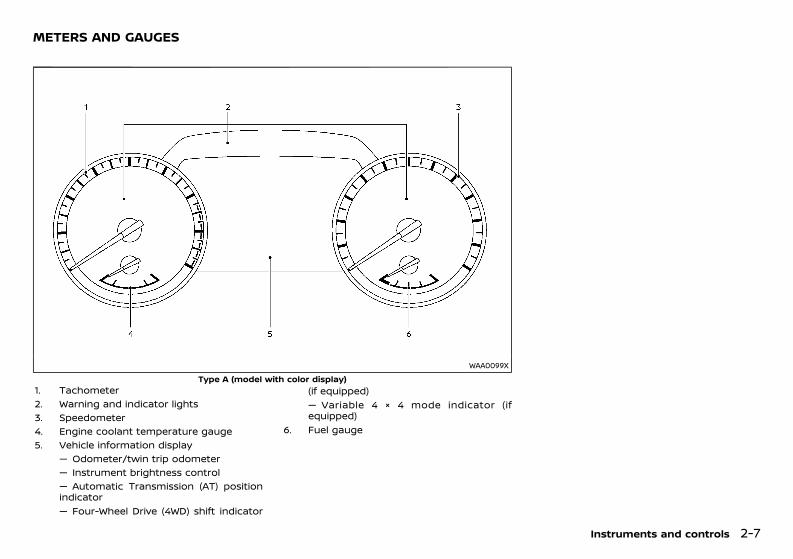
(81,1)
[ Edit: 2020/ 11/ 9 Model: Y62-A ]
GUID-D4E88DDF-8318-4796-9304-D1B3E060B8C6
WAA0099XType A (model with color display)
1. Tachometer2. Warning and indicator lights3. Speedometer4. Engine coolant temperature gauge5. Vehicle information display
— Odometer/twin trip odometer— Instrument brightness control— Automatic Transmission (AT) positionindicator— Four-Wheel Drive (4WD) shift indicator
(if equipped)— Variable 4 × 4 mode indicator (ifequipped)
6. Fuel gauge
Instruments and controls 2-7
METERS AND GAUGES
Condition: 'Except for China'/'Except for China/
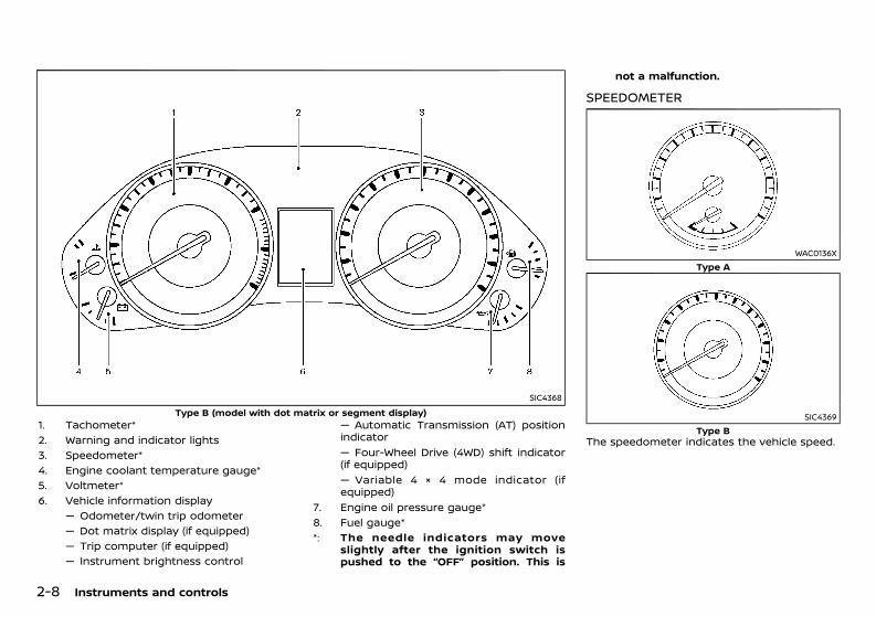
(82,1)
[ Edit: 2020/ 11/ 9 Model: Y62-A ]
2-8 Instruments and controls
SIC4368Type B (model with dot matrix or segment display)
1. Tachometer*2. Warning and indicator lights3. Speedometer*4. Engine coolant temperature gauge*5. Voltmeter*6. Vehicle information display
— Odometer/twin trip odometer— Dot matrix display (if equipped)— Trip computer (if equipped)— Instrument brightness control
— Automatic Transmission (AT) positionindicator— Four-Wheel Drive (4WD) shift indicator(if equipped)— Variable 4 × 4 mode indicator (ifequipped)
7. Engine oil pressure gauge*8. Fuel gauge**: The needle indicators may move
slightly after the ignition switch ispushed to the “OFF” position. This is
not a malfunction.
SPEEDOMETERGUID-7E6E68E9-F9BC-4A88-A81D-BC41B54485DC
WAC0136XType A
SIC4369Type B
The speedometer indicates the vehicle speed.
Condition: 'Except for China'/'Except for China/
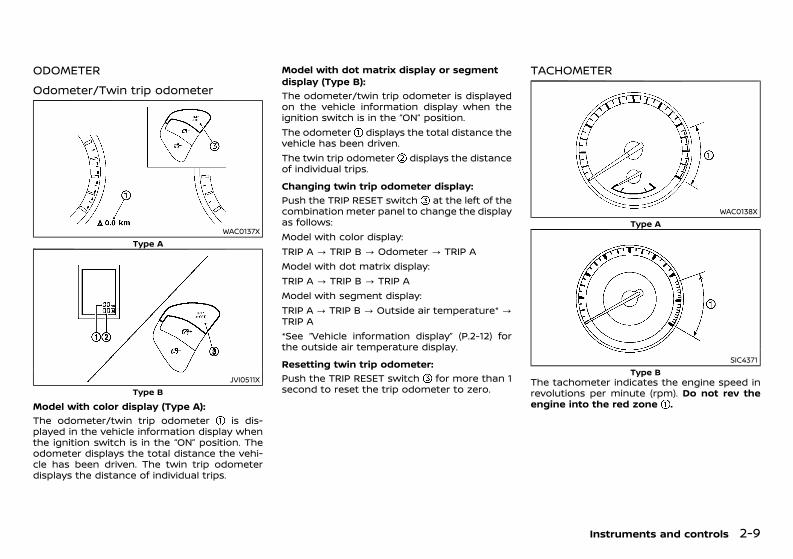
(83,1)
[ Edit: 2020/ 11/ 9 Model: Y62-A ]
ODOMETER GUID-F3E7C26F-4F54-4860-8BC2-76B62D9BE4FE
Odometer/Twin trip odometerGUID-9685759D-5FDC-4063-B5F7-3B9FB6483287
WAC0137XType A
JVI0511XType B
Model with color display (Type A):GUID-C7E1EF24-5AAB-4301-95BE-26917EEE45EF
The odometer/twin trip odometer is dis-played in the vehicle information display whenthe ignition switch is in the “ON” position. Theodometer displays the total distance the vehi-cle has been driven. The twin trip odometerdisplays the distance of individual trips.
Model with dot matrix display or segmentdisplay (Type B):
GUID-C7E1EF24-5AAB-4301-95BE-26917EEE45EF
The odometer/twin trip odometer is displayedon the vehicle information display when theignition switch is in the “ON” position.The odometer displays the total distance thevehicle has been driven.The twin trip odometer displays the distanceof individual trips.Changing twin trip odometer display:
GUID-C7E1EF24-5AAB-4301-95BE-26917EEE45EF
Push the TRIP RESET switch at the left of thecombination meter panel to change the displayas follows:Model with color display:TRIP A ? TRIP B ? Odometer ? TRIP AModel with dot matrix display:TRIP A ? TRIP B ? TRIP AModel with segment display:TRIP A ? TRIP B ? Outside air temperature* ?TRIP A*See “Vehicle information display” (P.2-12) forthe outside air temperature display.Resetting twin trip odometer:
GUID-C7E1EF24-5AAB-4301-95BE-26917EEE45EF
Push the TRIP RESET switch for more than 1second to reset the trip odometer to zero.
TACHOMETERGUID-06253D39-9193-4F62-A944-DD6BDD06C0C9
WAC0138XType A
SIC4371Type B
The tachometer indicates the engine speed inrevolutions per minute (rpm). Do not rev theengine into the red zone .
Instruments and controls 2-9
Condition: 'Except for China'/'Except for China/
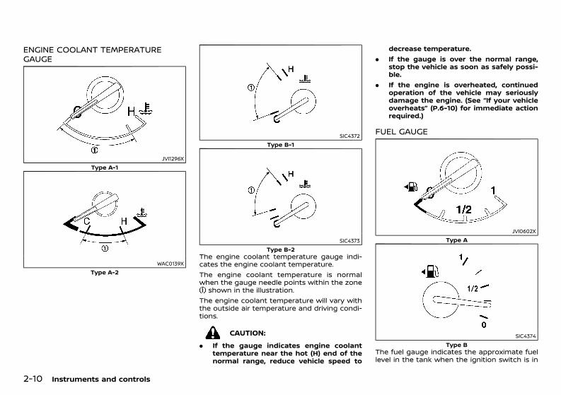
(84,1)
[ Edit: 2020/ 11/ 9 Model: Y62-A ]
2-10 Instruments and controls
ENGINE COOLANT TEMPERATUREGAUGE GUID-AC507E4D-748F-49CB-9422-D729C2C86322
JVI1296XType A-1
WAC0139XType A-2
SIC4372Type B-1
SIC4373Type B-2
The engine coolant temperature gauge indi-cates the engine coolant temperature.The engine coolant temperature is normalwhen the gauge needle points within the zone
shown in the illustration.The engine coolant temperature will vary withthe outside air temperature and driving condi-tions.
CAUTION:. If the gauge indicates engine coolant
temperature near the hot (H) end of thenormal range, reduce vehicle speed to
decrease temperature.. If the gauge is over the normal range,
stop the vehicle as soon as safely possi-ble.
. If the engine is overheated, continuedoperation of the vehicle may seriouslydamage the engine. (See “If your vehicleoverheats” (P.6-10) for immediate actionrequired.)
FUEL GAUGEGUID-DE289BE5-492C-468F-9950-9FF1FBBC01FE
JVI0602XType A
SIC4374Type B
The fuel gauge indicates the approximate fuellevel in the tank when the ignition switch is in
Condition: 'Except for China'/'Except for China/
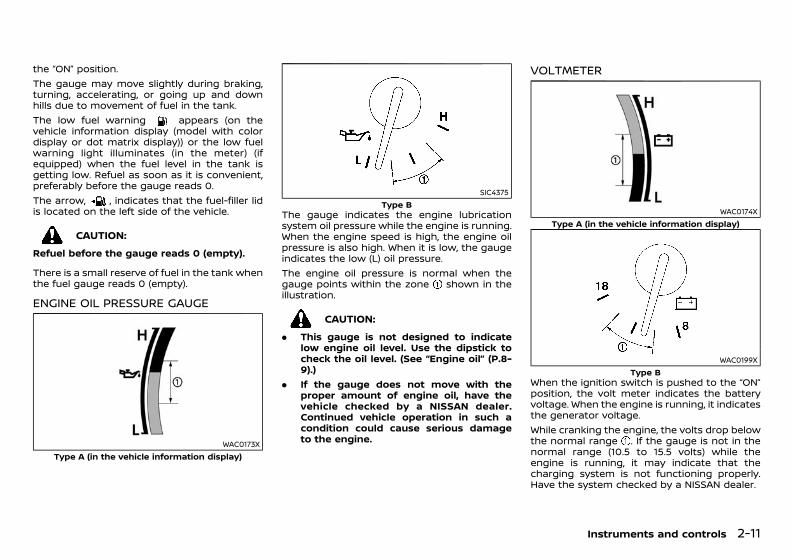
(85,1)
[ Edit: 2020/ 11/ 9 Model: Y62-A ]
the “ON” position.The gauge may move slightly during braking,turning, accelerating, or going up and downhills due to movement of fuel in the tank.The low fuel warning appears (on thevehicle information display (model with colordisplay or dot matrix display)) or the low fuelwarning light illuminates (in the meter) (ifequipped) when the fuel level in the tank isgetting low. Refuel as soon as it is convenient,preferably before the gauge reads 0.The arrow, , indicates that the fuel-filler lidis located on the left side of the vehicle.
CAUTION:Refuel before the gauge reads 0 (empty).
There is a small reserve of fuel in the tank whenthe fuel gauge reads 0 (empty).
ENGINE OIL PRESSURE GAUGEGUID-6CC6D27B-30DE-4961-845D-35CD8FF7B26F
WAC0173XType A (in the vehicle information display)
SIC4375Type B
The gauge indicates the engine lubricationsystem oil pressure while the engine is running.When the engine speed is high, the engine oilpressure is also high. When it is low, the gaugeindicates the low (L) oil pressure.The engine oil pressure is normal when thegauge points within the zone shown in theillustration.
CAUTION:. This gauge is not designed to indicate
low engine oil level. Use the dipstick tocheck the oil level. (See “Engine oil” (P.8-9).)
. If the gauge does not move with theproper amount of engine oil, have thevehicle checked by a NISSAN dealer.Continued vehicle operation in such acondition could cause serious damageto the engine.
VOLTMETERGUID-00E242A3-7294-4FE9-A06A-2985FFF4C0C2
WAC0174XType A (in the vehicle information display)
WAC0199XType B
When the ignition switch is pushed to the “ON”position, the volt meter indicates the batteryvoltage. When the engine is running, it indicatesthe generator voltage.While cranking the engine, the volts drop belowthe normal range . If the gauge is not in thenormal range (10.5 to 15.5 volts) while theengine is running, it may indicate that thecharging system is not functioning properly.Have the system checked by a NISSAN dealer.
Instruments and controls 2-11
Condition: 'Except for China'/'Except for China/
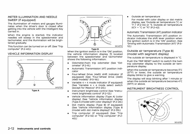
(86,1)
[ Edit: 2020/ 11/ 9 Model: Y62-A ]
2-12 Instruments and controls
METER ILLUMINATION AND NEEDLESWEEP (if equipped)GUID-66022067-4EB5-48C2-AC93-660608AF5C4EThe illumination of meters and gauges illumi-nates when the driver’s door is closed aftergetting into the vehicle with the Intelligent Keycarried in.When the engine is started, the indicatorneedles will sweep in the speedometer andtachometer, and the illumination will be brigh-tened gradually.This function can be turned on or off. (See “Tripcomputer” (P.2-40).)
VEHICLE INFORMATION DISPLAYGUID-C5EFB522-5F48-4869-B27E-3ABBC18CC2D0
JVI1272XType A
SIC4379Type B
When the ignition switch is in the “ON” position,the vehicle information display locatedbetween the speedometer and tachometershows the following information:. Odometer/twin trip odometer (See “Od-
ometer” (P.2-9).). Automatic Transmission (AT) position indi-
cator. Four-Wheel Drive (4WD) shift indicator (if
equipped) (See “Four-Wheel Drive (4WD)(4WD models)” (P.5-16).)
. Variable 4 × 4 mode indicator (if equipped)(See “Variable 4 × 4 mode select switch(except for Mexico)” (P.5-20).)
. Instrument brightness control (See “Instru-ment brightness control” (P.2-12).)
. Vehicle information display (Type A) (colordisplay) (See “Vehicle information display(Type A (model with color display))” (P.2-26).)
. Dot matrix display (Type B) (if equipped)(See “Vehicle information display (Type B(model with dot matrix display))” (P.2-35).)
. Trip computer (if equipped) (See “Tripcomputer” (P.2-32) or “Trip computer” (P.2-40).)
. Outside air temperatureFor model with color display or dot matrixdisplay, see “Outside air temperature (°C or°F )” (P.2-34) or “5. Outside air temperature(ICY — °C or °F)” (P.2-42).
Automatic Transmission (AT) position indicatorGUID-18227366-0881-4676-BDB9-F70953655D15The Automatic Transmission (AT) position in-dicator indicates the shift lever position whenthe ignition switch is in the “ON” position. (See“Driving with Automatic Transmission (AT)” (P.5-12).)
Outside air temperature (Type B)(model with segment display)GUID-1B5FDD39-C4C4-40AA-87A1-160F2CEC6CB1The outside air temperature is displayed in °C.Push the TRIP RESET switch to switch the twintrip odometer display to the outside air tem-perature display.When the outside air temperature becomes 3°C(37°F) or lower, the outside air temperaturedisplay blinks to give a warning.The display will stop blinking after 1 minute orwhen the outside air temperature becomes 4°C(39°F) or above.
INSTRUMENT BRIGHTNESS CONTROLGUID-DCB79E8B-13E0-4540-BE37-A0BB2FD164FB
SIC4378
Condition: 'Except for China'/'Except for China/
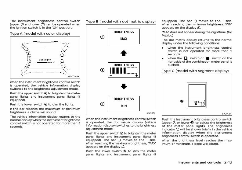
(87,1)
[ Edit: 2020/ 11/ 9 Model: Y62-A ]
The instrument brightness control switch(upper and lower ) can be operated whenthe ignition switch is in the “ON” position.
Type A (model with color display)GUID-61752D22-07A4-450C-9ACE-2A27E745A228
WAC0148X
When the instrument brightness control switchis operated, the vehicle information displayswitches to the brightness adjustment mode.Push the upper switch to brighten the meterpanel lights and instrument panel lights (ifequipped).Push the lower switch to dim the lights.If the bar reaches the maximum or minimumbrightness, a chime will sound.The vehicle information display returns to thenormal display when the instrument brightnesscontrol switch is not operated for more than 5seconds.
Type B (model with dot matrix display)GUID-0E824C34-5F1D-4AD1-BDBF-A063B9E7D705
SIC4377
When the instrument brightness control switchis operated, the dot matrix display (vehicleinformation display) switches to the brightnessadjustment mode.Push the upper switch to brighten the meterpanel lights and instrument panel lights (ifequipped). The bar moves to the + side.When reaching the maximum brightness, “MAX”appears on the display .Push the lower switch to dim the meterpanel lights and instrument panel lights (if
equipped). The bar moves to the − side.When reaching the minimum brightness, “MIN”appears on the display .“MIN” does not appear during the nighttime. (forMexico)The dot matrix display returns to the normaldisplay under the following conditions:. when the instrument brightness control
switch is not operated for more than 5seconds.
. when the switch or switch on theright side of the combination meter panel ispushed.
Type C (model with segment display)GUID-8B3DD8EE-C5F8-4DAC-B883-B7A74FD6580C
SIC4424
Push the instrument brightness control switch(upper or lower ) to adjust the brightnessof the meter panel lights. The brightnessindicator will be shown briefly in the vehicleinformation display when the instrumentbrightness control switch is operated.When the brightness level reaches the max-imum or minimum, a beep will sound.
Instruments and controls 2-13
Condition: 'Except for China'/'Except for China/
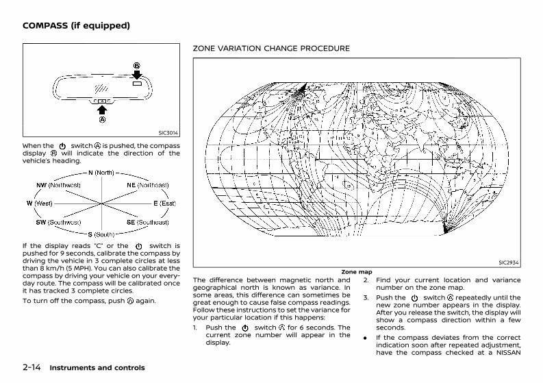
(88,1)
[ Edit: 2020/ 11/ 9 Model: Y62-A ]
2-14 Instruments and controls
GUID-01D0AD42-7C34-478C-BE0A-AB53390CC69A
SIC3014
When the switch is pushed, the compassdisplay will indicate the direction of thevehicle’s heading.
NOS1741
If the display reads “C” or the switch ispushed for 9 seconds, calibrate the compass bydriving the vehicle in 3 complete circles at lessthan 8 km/h (5 MPH). You can also calibrate thecompass by driving your vehicle on your every-day route. The compass will be calibrated onceit has tracked 3 complete circles.To turn off the compass, push again.
ZONE VARIATION CHANGE PROCEDUREGUID-2718F03A-A601-42DC-A0D8-3547C8784058
SIC2934Zone map
The difference between magnetic north andgeographical north is known as variance. Insome areas, this difference can sometimes begreat enough to cause false compass readings.Follow these instructions to set the variance foryour particular location if this happens:1. Push the switch for 6 seconds. The
current zone number will appear in thedisplay.
2. Find your current location and variancenumber on the zone map.
3. Push the switch repeatedly until thenew zone number appears in the display.After you release the switch, the display willshow a compass direction within a fewseconds.
. If the compass deviates from the correctindication soon after repeated adjustment,have the compass checked at a NISSAN
COMPASS (if equipped)
Condition: 'Except for China'/'Except for China/
(89,1)
[ Edit: 2020/ 11/ 9 Model: Y62-A ]
dealer.. The compass may not indicate the correct
compass point in tunnels or while drivingup or down a steep hill. (The compassreturns to the correct compass point whenthe vehicle moves to an area where thegeomagnetism is stabilized.)
CAUTION:. Do not install a ski rack, antenna, etc.
which are attached to the vehicle bymeans of a magnet. They affect theoperation of the compass.
. When cleaning the mirror, use a papertowel or similar material dampened withglass cleaner. Do not spray glass cleanerdirectly on the mirror as it may cause theliquid cleaner to enter the mirror housing.
Instruments and controls 2-15
Condition: 'Except for China'/'Except for China/
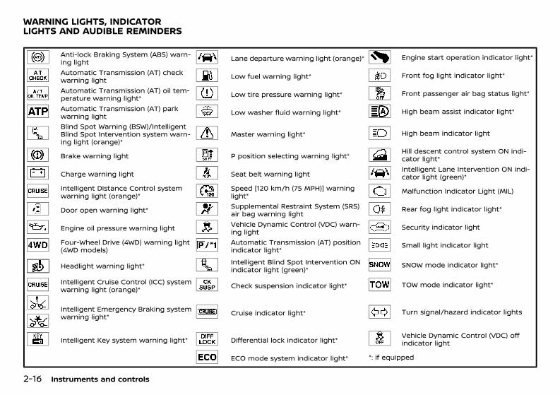
(90,1)
[ Edit: 2020/ 11/ 9 Model: Y62-A ]
2-16 Instruments and controls
GUID-AD8EF343-0C2A-4154-942C-A52FCBB257CF
Anti-lock Braking System (ABS) warn-ing light Lane departure warning light (orange)* Engine start operation indicator light*
Automatic Transmission (AT) checkwarning light Low fuel warning light* Front fog light indicator light*
Automatic Transmission (AT) oil tem-perature warning light* Low tire pressure warning light* Front passenger air bag status light*
Automatic Transmission (AT) parkwarning light Low washer fluid warning light* High beam assist indicator light*
Blind Spot Warning (BSW)/IntelligentBlind Spot Intervention system warn-ing light (orange)*
Master warning light* High beam indicator light
Brake warning light P position selecting warning light* Hill descent control system ON indi-cator light*
Charge warning light Seat belt warning light Intelligent Lane Intervention ON indi-cator light (green)*
Intelligent Distance Control systemwarning light (orange)*
Speed [120 km/h (75 MPH)] warninglight* Malfunction Indicator Light (MIL)
Door open warning light* Supplemental Restraint System (SRS)air bag warning light Rear fog light indicator light*
Engine oil pressure warning light Vehicle Dynamic Control (VDC) warn-ing light Security indicator light
Four-Wheel Drive (4WD) warning light(4WD models)
Automatic Transmission (AT) positionindicator light* Small light indicator light
Headlight warning light* Intelligent Blind Spot Intervention ONindicator light (green)* SNOW mode indicator light*
Intelligent Cruise Control (ICC) systemwarning light (orange)* Check suspension indicator light* TOW mode indicator light*
Intelligent Emergency Braking systemwarning light* Cruise indicator light* Turn signal/hazard indicator lights
Intelligent Key system warning light* Differential lock indicator light* Vehicle Dynamic Control (VDC) offindicator light
ECO mode system indicator light* *: if equipped
WARNING LIGHTS, INDICATORLIGHTS AND AUDIBLE REMINDERS
Condition: 'Except for China'/'Except for China/
(91,1)
[ Edit: 2020/ 11/ 9 Model: Y62-A ]
CHECKING LIGHTSGUID-C3DCFB9F-3B36-48BF-B075-04BBF7FFE059With all doors closed, apply the parking brake,fasten the seat belts and place the ignitionswitch in the “ON” position without starting theengine. The following lights (if equipped) willcome on: , , , , , , ,
The following lights (if equipped) will come onbriefly and then go off : , , , ,
, , , , , , ,If any light does not come on or operates in away other than described, it may indicate aburned-out bulb and/or a system malfunction.Have the system checked, and if necessaryrepaired, by a NISSAN dealer promptly.Some indicators and warnings are also dis-played on the vehicle information display(model with color display or dot matrix display).(See “Vehicle information display (Type A (mod-el with color display))” (P.2-26) or “Vehicleinformation display (Type B (model with dotmatrix display))” (P.2-35).)
WARNING LIGHTSGUID-AEC68437-7054-4650-9125-B914C7CC7484
Anti-lock Braking System (ABS)warning light
GUID-95F75F33-0AC2-433D-B35E-0A77C0073ABDWhen the ignition switch is in the “ON” position,the Anti-lock Braking System (ABS) warninglight illuminates and then turns off. This in-dicates the ABS is operational.If the ABS warning light illuminates while theengine is running, or while driving, it mayindicate the ABS is not functioning properly.Have the system checked by a NISSAN dealer.If an ABS malfunction occurs, the anti-lockfunction is turned off. The brake system thenoperates normally, but without anti-lock assis-tance. (See “Anti-lock Braking System (ABS)”
(P.5-104).)Except for Mexico: While the differential lockis engaged, the ABS warning light illumi-nates. This indicates that the anti-lock func-tion is not fully operating. (See “Differentiallock mode switch (except for Mexico)” (P.5-22)for the rear differential lock function.)
Automatic Transmission (AT)check warning light
GUID-7E363A6B-AA3B-4B27-97BB-4074A85B66A2When the ignition switch is in the “ON” position,the Automatic Transmission (AT) check warn-ing light illuminates and then turns off. Thisindicates that the AT is operational.If the AT check warning light illuminates whilethe engine is running, or while driving, it mayindicate that the AT is not functioning properlyand may need servicing. Have the systemchecked, and if necessary repaired, by a NISSANdealer promptly.
Automatic Transmission (AT) oiltemperature warning light (if equipped)
GUID-9552F09A-923C-4CBE-9A3F-5A899478BD79This light illuminates when the AutomaticTransmission (AT) oil temperature is too high.If the light illuminates while driving, reduce thevehicle speed as soon as safely possible untilthe light turns off.
CAUTION:Continued vehicle operation when the AT oiltemperature warning light is onmay damagethe AT.
Automatic Transmission (AT) parkwarning light
GUID-AB3E74EE-50FC-409B-B44A-B2C1683A5A0DThis light indicates that the Automatic Trans-mission (AT) parking function is not engaged. Ifthe transfer control is not secured in anydriving position while the AT shift lever is inthe “P” (Park) position, the transmission willdisengage and the wheels will not lock.For 4WD models: If the AT park warning lightilluminates with the shift lever in the “P”(Park) position, shift the Four-Wheel Drive(4WD) shift switch to the AUTO, 4H or 4Lposition again with the shift lever in the N(Neutral) position. (See “Four-Wheel Drive(4WD) (4WD models)” (P.5-16).)
Blind Spot Warning (BSW)/Intelli-gent Blind Spot Intervention systemwarning light (orange; if equipped)
GUID-D488790C-CD8F-4A4F-96EC-7C8C6AE1D8F3When the ignition switch is pushed to the “ON”position, the indicator light will first illuminate inorange and turn green before turning off. Thisindicates that the Blind Spot Warning (BSW) andIntelligent Blind Spot Intervention systems areoperational.If the light comes on in orange and remains on,it may indicate that the BSW, Intelligent BlindSpot Intervention and RCTA (if equipped) sys-tems are not functioning properly. Althoughthe vehicle is still driveable, have the systemschecked by a NISSAN dealer. See “Blind SpotWarning/Intelligent Blind Spot Intervention/In-telligent Back-up Intervention” (P.5-32) or “RearCross Traffic Alert (RCTA)” (P.5-45).
Instruments and controls 2-17
Condition: 'Except for China'/'Except for China/
(92,1)
[ Edit: 2020/ 11/ 9 Model: Y62-A ]
2-18 Instruments and controls
Brake warning lightGUID-072B34F3-2D63-4028-A88A-893DA8182F4A
WARNING:. If the brake fluid level is below the
minimum mark on the brake fluid reser-voir, do not drive the vehicle until thebrake system has been checked by aNISSAN dealer.
. Even if you judge it to be safe, have yourvehicle towed because driving it could bedangerous.
. Depressing the brake pedal without theengine running and/or with a low brakefluid level could increase the stoppingdistance and require greater pedal traveldistance and effort.
The brake warning light indicates the parkingbrake system operation, low brake fluid level/low hydraulic pressure of the brake system andAnti-lock Braking System (ABS) malfunction.Parking brake warning indicator:
GUID-C7E1EF24-5AAB-4301-95BE-26917EEE45EF
When the ignition switch is pushed to the “ON”position with the parking brake applied, thebrake warning light illuminates. When theparking brake is released, the brake warninglight turns off.If the parking brake is not fully released, thebrake warning light remains on. Be sure thatthe brake warning light has turned off beforedriving. (See “Parking brake” (P.3-33).)Low brake fluid warning indicator:
GUID-C7E1EF24-5AAB-4301-95BE-26917EEE45EF
If the brake warning light illuminates while theengine is running, or while driving, and theparking brake is released, it may indicate thatthe brake fluid level is low.When the brake warning light illuminates while
driving, stop the vehicle safely as soon aspossible. Stop the engine and check the brakefluid level. If the brake fluid level is at theminimum mark, add brake fluid as necessary.(See “Brake fluid” (P.8-13).)If the brake fluid level is sufficient, have thebrake system checked by a NISSAN dealerpromptly.Low hydraulic pressure warning indicator:
GUID-C7E1EF24-5AAB-4301-95BE-26917EEE45EF
If the brake warning light illuminates when theengine is running, or while driving with theparking brake is released, check the brake fluidlevel. If the brake fluid level is sufficient, it mayindicate low hydraulic pressure in the brakebooster. Have the brake system checked by aNISSAN dealer promptly.Anti-lock Braking System (ABS) warning in-dicator:
GUID-C7E1EF24-5AAB-4301-95BE-26917EEE45EF
When the parking brake is released and thebrake fluid level is sufficient, if both the brakewarning light and the Anti-lock Braking System(ABS) warning light illuminate, it may indicatethat the ABS is not functioning properly. Havethe brake system checked, and if necessaryrepaired, by a NISSAN dealer promptly. (See“Anti-lock Braking System (ABS) warning light”(P.2-17).)
Charge warning lightGUID-7DA4BC3D-8950-462F-B990-05ABD772B349
When the ignition switch is in the “ON” position,the charge warning light illuminates. Afterstarting the engine, the charge warning lightturns off. This indicates that the chargingsystem is operational.If the charge warning light illuminates while theengine is running, or while driving, it mayindicate that the charging system is notfunctioning properly and may need servicing.
When the charge warning light illuminateswhile driving, stop the vehicle safely as soonas possible. Stop the engine and check thealternator belt. If the alternator belt is loose,broken or missing, the charging system needsrepair. (See “Drive belt” (P.8-11).)If the alternator belt appears to be functioningcorrectly but the charge warning light remainsilluminated, have the charging system checkedby a NISSAN dealer promptly.
CAUTION:Do not continue driving if the alternator beltis loose, broken or missing.
Intelligent Distance Control sys-tem warning light (orange; if equipped)
GUID-4DE7D3E2-8372-4977-B818-8E63188DA43DThis light comes on if there is a malfunction inthe Intelligent Distance Control system.If the warning light illuminates, park the vehiclein a safe place. Turn the engine off, restart theengine, resume driving and turn on the Intelli-gent Distance Control system again.If it is not possible to turn on the system orthe warning light stays on, it may indicatethat the system is malfunctioning. Althoughthe vehicle is still driveable under normalconditions, have the vehicle checked at aNISSAN dealer. See “Intelligent Distance Con-trol system (for Mexico)” (P.5-70).
Condition: 'Except for China'/'Except for China/
(93,1)
[ Edit: 2020/ 11/ 9 Model: Y62-A ]
Door open warning light (if equipped)GUID-CFB7703D-36CD-4F92-9812-B53867DDC314
When the ignition switch is in the “ON” position,the door open warning light illuminates if anyof the doors and/or back door are open or notclosed securely.
Engine oil pressure warning lightGUID-BEB55964-50B0-4874-BD54-80439B7021D7
When the ignition switch is in the “ON” position,the engine oil pressure warning light illumi-nates. After starting the engine, the engine oilpressure warning light turns off. This indicatesthat the oil pressure sensors in the engine areoperational.If the engine oil pressure warning light illumi-nates or blinks while the engine is running, itmay indicate that the engine oil pressure is low.Stop the vehicle safely as soon as possible.Stop the engine immediately and call a NISSANdealer.
CAUTION:. Running the engine with the engine oil
pressure warning light illuminated couldcause serious damage to the engine.
. The engine oil pressure warning light isnot designed to indicate a low oil level.The oil level should be checked using thedipstick. (See “Engine oil” (P.8-9).)
Four-Wheel Drive (4WD) warninglight (4WD models)
GUID-9D66E455-2D5B-493D-B956-556AF3C7B351When the ignition switch is in the “ON” position,the Four-Wheel Drive (4WD) warning lightilluminates. After starting the engine, the 4WDwarning light turns off.If the 4WD system malfunctions or the revolu-tion or radius of the front and the rear wheeldiffers, the warning light will either remainilluminated or blink. (See “Four-Wheel Drive(4WD) (4WD models)” (P.5-16).)
CAUTION:. If the 4WD warning light illuminates or
blinks while driving, reduce the vehiclespeed and have your vehicle checked bya NISSAN dealer as soon as possible.
. If the 4WD warning light turns on whendriving on dry or hard surfaced roads:— in the 4H position, shift the 4WD shift
switch to AUTO— in the 4L position, stop the vehicle and
shift the transmission shift lever tothe “N” (Neutral) position and shift the4WD shift switch to AUTO
If the warning light is still on after the aboveoperations, have your vehicle checked by aNISSAN dealer as soon as possible.
Headlight warning light (if equipped)GUID-15BD1646-42F9-4703-9364-BBC33252D720
This light illuminates if the LED headlights aremalfunctioning. Contact a NISSAN dealer.
Intelligent Cruise Control (ICC) sys-tem warning light (orange; if equipped)
GUID-CC18AFAE-986E-4656-935D-EB059FAD99B4When the ignition switch is in the “ON” position,the Intelligent Cruise Control (ICC) systemwarning light illuminates. After starting theengine, the ICC system warning light turns off.This indicates that the ICC system is opera-tional.This light illuminates if there is a malfunction inthe ICC system.If the ICC system warning light illuminates, parkthe vehicle in a safe location. Turn the engineoff, restart the engine, resume driving and setthe ICC system again.If it is not possible to set the system or the ICCsystem warning light remains on, it mayindicate that the system is malfunctioning.Although the vehicle is still driveable undernormal conditions, have the system checked bya NISSAN dealer.See “Intelligent Cruise Control (ICC) system”(P.5-52).
/ Intelligent Emergency Brak-ing system warning light (if equipped)
GUID-5B84F320-919C-49A0-8765-F896E9A6584DWhen the ignition switch is in the “ON” position,the Intelligent Emergency Braking systemwarning light illuminates. After starting theengine, the Intelligent Emergency Braking sys-tem warning light turns off.This light illuminates when the IntelligentEmergency Braking system is set to “OFF” on
Instruments and controls 2-19
Condition: 'Except for China'/'Except for China/

(94,1)
[ Edit: 2020/ 11/ 9 Model: Y62-A ]
2-20 Instruments and controls
the lower display (model with dual display) orthe center display (model with single display).If the light illuminates when the IntelligentEmergency Braking system is “ON”, it mayindicate that the system is unavailable. See“Intelligent Emergency Braking with pedestriandetection system” (P.5-77) or “Intelligent Emer-gency Braking system” (P.5-85) for more details.
Intelligent Key system warninglight (if equipped)
GUID-BB5AE835-E825-4BE7-9C5B-48BDD7299454After the ignition switch is placed in the “ON”position, this light comes on for about 2seconds and then turns off.This light illuminates or blinks as follows:. The light blinks in yellow when the door is
closed with the Intelligent Key left outsidethe vehicle and the ignition switch in the“ACC” or “ON” position. Make sure that theIntelligent Key is inside the vehicle (modelwith segment display).
. The light blinks in green when the Intelli-gent Key battery is running out of power.Replace the battery with a new one (modelwith segment display). (See “Battery” (P.8-18).)
. The light illuminates in yellow when itwarns of a malfunction with the electricalsteering lock system or the Intelligent Keysystem.
If the warning light illuminates in yellow whilethe engine is stopped, it may be impossible tofree the steering lock or to start the engine. Ifthe light comes on while the engine is running,you can drive the vehicle. However in thesecases, contact a NISSAN dealer for repair assoon as possible.
Lane departure warning light(orange; if equipped)
GUID-CF3B1A0F-7E88-43EC-AAEC-F9A7D72EF392When the ignition switch is pushed to the ONposition, the light will come on in orange, turngreen, and then turn off. This indicates that theLane Departure Warning (LDW) and IntelligentLane Intervention systems are operational.While the LDW and/or Intelligent Lane Inter-vention system is on, the light will blink inorange and a warning chime will sound if thevehicle is traveling close to either the left or theright of a traveling lane with detectable lanemarkers.If the light comes on in orange and remains on,it may indicate that the LDW and IntelligentLane Intervention systems are not functioningproperly. Have the systems checked by aNISSAN dealer.See “Lane Departure Warning (LDW) system/Intelligent Lane Intervention system” (P.5-25).
Low fuel warning light (if equipped)GUID-98A780C9-A3F9-45A4-9CE8-8C23D4C61237
The low fuel warning light illuminates when thefuel level in the tank is getting low. Refuel assoon as it is convenient, preferably before thefuel gauge reaches the empty (0) position.There will be a small reserve of fuel remain-ing in the tank when the fuel gauge reachesthe empty (0) position.
Low tire pressure warning light (ifequipped)
GUID-DF16204C-5F47-4633-B6BD-D23CECDBBCA4When the ignition switch is in the “ON” position,the low tire pressure warning light illuminatesand then turns off. This indicates that the lowtire pressure warning system is operational.This light illuminates if there is low tire pressureor a tire pressure warning system malfunction.The Tire Pressure Monitoring System (TPMS)monitors the tire pressure of all tires except thespare.Low tire pressure warning:
GUID-C7E1EF24-5AAB-4301-95BE-26917EEE45EF
If the vehicle is being driven with low tirepressure, the warning light will illuminate. Acheck tire pressure warning (if equipped) alsoappears on the vehicle information display.When the low tire pressure warning lightilluminates, you should stop and adjust the tirepressure to the recommended COLD tire pres-sure shown on the tire placard. Use a tirepressure gauge to check the tire pressure.The low tire pressure warning light may notautomatically turn off when the tire pressure isadjusted. After the tire is inflated to therecommended pressure, drive the vehicle atspeeds above 25 km/h (16 MPH) to activate theTPMS and turn off the low tire pressurewarning light.For additional information, see “Tire PressureMonitoring System (TPMS)” (P.5-6).
Condition: 'Except for China'/'Except for China/
(95,1)
[ Edit: 2020/ 11/ 9 Model: Y62-A ]
TPMS malfunction:GUID-C7E1EF24-5AAB-4301-95BE-26917EEE45EF
If the TPMS is not functioning properly, the lowtire pressure warning light will flash for ap-proximately 1 minute when the ignition switchis pushed ON. The light will remain on after 1minute. Have the system checked by a NISSANdealer.The check tire pressure warning (if equipped)does not appear if the low tire pressurewarning light illuminates to indicate a TPMSmalfunction.For additional information, see “Tire PressureMonitoring System (TPMS)” (P.5-6).
WARNING:. If the light does not illuminate with the
ignition switch pushed ON, have thevehicle checked by a NISSAN dealer assoon as possible.
. If the light illuminates while driving, avoidsudden steering maneuvers or abruptbraking, reduce vehicle speed, pull offthe road to a safe location and stop thevehicle as soon as possible. Driving withunder-inflated tires may permanentlydamage the tires and increase the like-lihood of tire failure. Serious vehicledamage could occur and may lead to anaccident and could result in seriouspersonal injury. Check the tire pressurefor all four tires. Adjust the tire pressureto the recommended COLD tire pressureshown on the tire placard to turn the lowtire pressure warning light OFF. If thelight still illuminates while driving afteradjusting the tire pressure, a tire may beflat or the TPMS may be malfunctioning.If you have a flat tire, replace it with aspare tire as soon as possible. If no tire is
flat and all tires are properly inflated,have the vehicle checked by a NISSANdealer.
. Since the spare tire is not equipped withthe TPMS, when a spare tire is mountedor a wheel is replaced, the TPMS will notfunction and the low tire pressure warn-ing light will flash for approximately 1minute. The light will remain on after 1minute. Contact your NISSAN dealer assoon as possible for tire replacementand/or system resetting.
. Replacing tires with those not originallyspecified by NISSAN could affect theproper operation of the TPMS.
CAUTION:. The TPMS is not a substitute for the
regular tire pressure check. Be sure tocheck the tire pressure regularly.
. If the vehicle is being driven at speeds ofless than 25 km/h (16 MPH), the TPMSmay not operate correctly.
. Be sure to correctly install the specifiedsize of tires to all four wheels.
Low washer fluid warning light (ifequipped)
GUID-0E567A9E-4568-4221-927E-D35D93D9B087The low washer fluid warning light illuminateswhen the washer fluid in the reservoir is at alow level. Add washer fluid as necessary. (See“Window washer fluid” (P.8-17).)
Master warning light (if equipped)GUID-51CB32D6-7FE9-4CBE-A710-7584FA819D77
The master warning light illuminates when awarning message appears in the vehicle in-formation display.(See “Vehicle information display (Type A (mod-el with color display))” (P.2-26) or “Vehicleinformation display (Type B (model with dotmatrix display))” (P.2-35).)
P position selecting warning light(if equipped)
GUID-BD6B4941-BC59-4E0D-9146-47001C1136B3The warning light blinks in red when theignition switch is pushed to stop the enginewith the shift lever in any position except the “P”(Park) position.If this warning appears, move the shift lever tothe “P” (Park) position or push the ignitionswitch to the “ON” position.An inside warning chime will also sound.See “Intelligent Key system” (P.3-5).
Seat belt warning lightGUID-04BB8868-2CD5-4FDC-861D-1FEF0B6AC70D
Type A:GUID-C7E1EF24-5AAB-4301-95BE-26917EEE45EF
The light illuminates whenever the ignitionswitch is placed in the “ON” position, and willremain illuminated until the driver’s seat belt isfastened.For precautions on seat belt usage, see “Seatbelts” (P.1-13).
Instruments and controls 2-21
Condition: 'Except for China'/'Except for China/
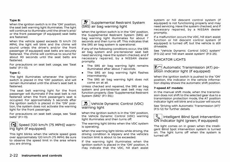
(96,1)
[ Edit: 2020/ 11/ 9 Model: Y62-A ]
2-22 Instruments and controls
Type B:GUID-C7E1EF24-5AAB-4301-95BE-26917EEE45EF
When the ignition switch is in the “ON” position,the seat belt warning light illuminates. The lightwill continue to illuminate until the driver’s and/or the front passenger (if equipped) seat beltsare fastened.When the vehicle speed exceeds 15 km/h (10MPH), the light will blink and the chime willsound unless the driver’s and/or the frontpassenger (if equipped) seat belts are securelyfastened. The chime will continue to sound forabout 90 seconds until the seat belts arefastened.For precautions on seat belt usage, see “Seatbelts” (P.1-13).Type C:
GUID-C7E1EF24-5AAB-4301-95BE-26917EEE45EF
The light illuminates whenever the ignitionswitch is placed in the “ON” position, and willremain illuminated until the driver’s seat belt isfastened.The seat belt warning light for the frontpassenger will illuminate if the seat belt is notfastened when the front passenger’s seat isoccupied. For approximately 5 seconds afterthe ignition switch is placed in the “ON” posi-tion, the system does not activate the warninglight for the front passenger.For precautions on seat belt usage, see “Seatbelts” (P.1-13).
Speed [120 km/h (75 MPH)] warn-ing light (if equipped)
GUID-3E7773DC-6BC0-4002-9116-4B0EBE340194This light blinks when the vehicle speed goesover approximately 120 km/h (75 MPH). Be sureto observe the speed limit in the area whereyou are driving.
Supplemental Restraint System(SRS) air bag warning light
GUID-EBA6777D-2073-40AB-A761-2DADC3D2F88BWhen the ignition switch is in the “ON” position,the Supplemental Restraint System (SRS) airbag warning light illuminates for about 7seconds and then turns off. This indicates thatthe SRS air bag system is operational.If any of the following conditions occur, the SRSair bag system and pre-tensioner seat beltneed servicing. Have the system checked, and ifnecessary repaired, by a NISSAN dealerpromptly.. The SRS air bag warning light remains
illuminated after about 7 seconds.. The SRS air bag warning light flashes
intermittently.. The SRS air bag warning light does not
come on at all.Unless checked and repaired, the SRS air bagsystem and pre-tensioner seat belt may notfunction properly. (See “Supplemental RestraintSystem (SRS)” (P.1-35).)
Vehicle Dynamic Control (VDC)warning light
GUID-5771FC1A-F17D-47B7-94A4-181B23BE9400When the ignition switch is in the “ON” position,the Vehicle Dynamic Control (VDC) warninglight illuminates and then turns off.The warning light blinks when the VDC systemis operating.When the warning light blinks while driving, thedriving condition is slippery and the vehicle’straction limit is about to be exceeded.If the warning light illuminates when theignition switch is placed in the “ON” position, itmay indicate that the VDC, hill start assist
system or hill descent control system (ifequipped) is not functioning properly and mayneed servicing. Have the system checked, and ifnecessary repaired, by a NISSAN dealerpromptly.If a malfunction occurs the VDC, hill start assistfunction or hill descent control system (ifequipped) is turned off, but the vehicle is stilldriveable.See “Vehicle Dynamic Control (VDC) system”(P.5-22) and “Hill start assist system” (P.5-25).
INDICATOR LIGHTSGUID-E1E02D55-A2C2-40E5-AA45-A99A557B60BC
Automatic Transmission (AT) po-sition indicator light (if equipped)
GUID-7864E95D-8411-4CD4-9D22-C9A7EBC3BA77When the ignition switch is pushed to the “ON”position, the indicator in the vehicle informa-tion display shows the automatic shift position.7-speed AT models:
GUID-C7E1EF24-5AAB-4301-95BE-26917EEE45EF
In the manual shift mode, when the transmis-sion does not shift to the selected gear due to atransmission protection mode, the AT positionindicator light will blink and a buzzer will sound.See “Driving with Automatic Transmission (AT)”(P.5-12) for further details.
Intelligent Blind Spot InterventionON indicator light (green; if equipped)
GUID-1063EAEA-2270-44D9-A5C9-901377D24E80The light comes on in green when the Intelli-gent Blind Spot Intervention system is turnedon. The light turns off when the system isturned off.
Condition: 'Except for China'/'Except for China/
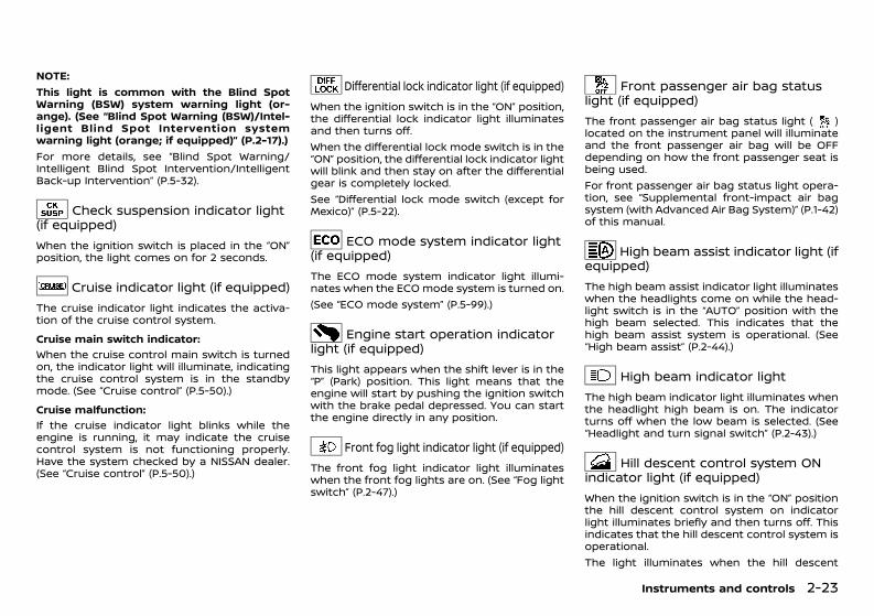
(97,1)
[ Edit: 2020/ 11/ 9 Model: Y62-A ]
NOTE:This light is common with the Blind SpotWarning (BSW) system warning light (or-ange). (See “Blind Spot Warning (BSW)/Intel-ligent Blind Spot Intervention systemwarning light (orange; if equipped)” (P.2-17).)For more details, see “Blind Spot Warning/Intelligent Blind Spot Intervention/IntelligentBack-up Intervention” (P.5-32).
Check suspension indicator light(if equipped)
GUID-4D4AC642-DB73-4584-B2E2-99F27A72DD72When the ignition switch is placed in the “ON”position, the light comes on for 2 seconds.
Cruise indicator light (if equipped)GUID-DE189D0D-282E-438A-B8D3-B4956DB2E2A6
The cruise indicator light indicates the activa-tion of the cruise control system.Cruise main switch indicator:
GUID-C7E1EF24-5AAB-4301-95BE-26917EEE45EF
When the cruise control main switch is turnedon, the indicator light will illuminate, indicatingthe cruise control system is in the standbymode. (See “Cruise control” (P.5-50).)Cruise malfunction:
GUID-C7E1EF24-5AAB-4301-95BE-26917EEE45EF
If the cruise indicator light blinks while theengine is running, it may indicate the cruisecontrol system is not functioning properly.Have the system checked by a NISSAN dealer.(See “Cruise control” (P.5-50).)
Differential lock indicator light (if equipped)GUID-00B64D3E-05BC-4ECB-9167-7A053A169016
When the ignition switch is in the “ON” position,the differential lock indicator light illuminatesand then turns off.When the differential lock mode switch is in the“ON” position, the differential lock indicator lightwill blink and then stay on after the differentialgear is completely locked.See “Differential lock mode switch (except forMexico)” (P.5-22).
ECO mode system indicator light(if equipped)
GUID-20E6B4A3-2E85-40E4-9F8E-B1EB7B2B6535The ECO mode system indicator light illumi-nates when the ECO mode system is turned on.(See “ECO mode system” (P.5-99).)
Engine start operation indicatorlight (if equipped)
GUID-A52BB17A-B442-43BD-A3AE-195591478910This light appears when the shift lever is in the“P” (Park) position. This light means that theengine will start by pushing the ignition switchwith the brake pedal depressed. You can startthe engine directly in any position.
Front fog light indicator light (if equipped)GUID-8A2C070E-8395-49A8-AA90-84EEBFB3159A
The front fog light indicator light illuminateswhen the front fog lights are on. (See “Fog lightswitch” (P.2-47).)
Front passenger air bag statuslight (if equipped)
GUID-FA5B4F4F-3C96-4D65-A817-8F589083ED27The front passenger air bag status light ( )located on the instrument panel will illuminateand the front passenger air bag will be OFFdepending on how the front passenger seat isbeing used.For front passenger air bag status light opera-tion, see “Supplemental front-impact air bagsystem (with Advanced Air Bag System)” (P.1-42)of this manual.
High beam assist indicator light (ifequipped)
GUID-183D30D5-50A3-49A4-98BE-5BBAD75EAF8FThe high beam assist indicator light illuminateswhen the headlights come on while the head-light switch is in the “AUTO” position with thehigh beam selected. This indicates that thehigh beam assist system is operational. (See“High beam assist” (P.2-44).)
High beam indicator lightGUID-FEF4DDF3-7F73-4905-A057-45AC536CD27A
The high beam indicator light illuminates whenthe headlight high beam is on. The indicatorturns off when the low beam is selected. (See“Headlight and turn signal switch” (P.2-43).)
Hill descent control system ONindicator light (if equipped)
GUID-EF25455E-E240-4499-AA83-B923F6BD3E7EWhen the ignition switch is in the “ON” positionthe hill descent control system on indicatorlight illuminates briefly and then turns off. Thisindicates that the hill descent control system isoperational.The light illuminates when the hill descent
Instruments and controls 2-23
Condition: 'Except for China'/'Except for China/
(98,1)
[ Edit: 2020/ 11/ 9 Model: Y62-A ]
2-24 Instruments and controls
control system is activated.If the hill descent control switch is on and theindicator light blinks, the system is not en-gaged.If the indicator light does not illuminate or blinkwhen the hill descent control switch is on, thesystem may not be functioning properly. Havethe system checked by a NISSAN dealer.For additional information, see “Hill descentcontrol system (except for Mexico)” (P.5-24).
Intelligent Lane Intervention ONindicator light (green; if equipped)
GUID-11F885DF-F86C-4C34-9C5E-081CBFC910E4The light comes on in green when the Intelli-gent Lane Intervention system is turned on.The light turns off when the system is turnedoff.
NOTE:This light is common with the lane departurewarning light (orange). (See “Lane departurewarning light (orange; if equipped)” (P.2-20).)For more details, see “Lane Departure Warning(LDW) system/Intelligent Lane Intervention sys-tem” (P.5-25).
Malfunction Indicator Light (MIL)GUID-0B4283D4-EF4C-4DE4-A781-0CEEC7D95F90
CAUTION:. Continuing vehicle operation without
proper servicing of the engine controlsystem could lead to poor driveability,reduced fuel economy, and damage tothe engine control system, which mayaffect the vehicle’s warranty coverage.
. Incorrect setting of the engine controlsystem may lead to non-compliance oflocal and national emission laws andregulations.
When the ignition switch is in the “ON” position,the Malfunction Indicator Light (MIL) illumi-nates. After starting the engine, the MIL turnsoff. This indicates that the engine controlsystem is operational.Except for Mexico:
GUID-C7E1EF24-5AAB-4301-95BE-26917EEE45EF
If the MIL illuminates while the engine isrunning, it may indicate that the engine controlsystem is not functioning properly and mayneed servicing. Have the vehicle checked, and ifnecessary repaired, by a NISSAN dealerpromptly.If the MIL blinks while the engine is running, itmay indicate a potential malfunction in theemission control system. In this case, theemission control system may not functionproperly and may need servicing. Have thesystem checked, and if necessary repaired, by aNISSAN dealer promptly.For Mexico:
GUID-C7E1EF24-5AAB-4301-95BE-26917EEE45EF
When the ignition switch is in the “ON” position,sometimes the MIL may illuminate for 20seconds and then blink for 10 seconds, withoutthe engine running. This is due to a function ofchecking the engine control system, and it isnot a malfunction. After a few normal drives,this function will not occur and the MIL staysilluminated with the ignition switch in the “ON”position.If the MIL illuminates while the engine isrunning, it may indicate that the engine controlsystem is not functioning properly and mayneed servicing. Have the vehicle checked, and ifnecessary repaired, by a NISSAN dealerpromptly.
If the MIL blinks while the engine is running, itmay indicate a potential malfunction in theemission control system. In this case, theemission control system may not functionproperly and may need servicing. Have thesystem checked, and if necessary repaired, by aNISSAN dealer promptly.Precautions:
GUID-C7E1EF24-5AAB-4301-95BE-26917EEE45EF
To reduce or avoid possible damage to theengine control system when the MIL blinks:. Avoid driving at speeds above 70 km/h (43
MPH).. Avoid sudden acceleration or deceleration.. Avoid going up steep uphill grades.. Avoid carrying or towing unnecessary
loads.
Rear fog light indicator light (if equipped)GUID-58531DAB-98FE-4707-81EA-C0923D6D0AC2
The rear fog light indicator light illuminateswhen the rear fog light turns on. (See “Fog lightswitch” (P.2-47).)
Security indicator lightGUID-C74EBAC9-9741-4A50-811A-6EB642B9C33A
The security indicator light blinks when theignition switch is in the “ACC”, “OFF” or “LOCK”position. This function indicates that the secur-ity system equipped on the vehicle is opera-tional.If the security system is malfunctioning, thislight will remain on while the ignition switch isin the “ON” position. (See “Security system” (P.3-15) for additional information.)
Condition: 'Except for China'/'Except for China/
(99,1)
[ Edit: 2020/ 11/ 9 Model: Y62-A ]
Small light indicator lightGUID-600FC456-F0A9-4A3E-BA1B-2E956D2572EB
The small light indicator light illuminates whenthe front clearance lights, instrument panellights (if equipped), rear combination lights andlicense plate lights are on. The indicator lightturns off when the small light is turned off.
SNOW mode indicator light (if equipped)GUID-9A7A8A4E-C128-43B7-8B9B-7AE667F14462
When selecting SNOW mode while the engine isrunning, this light will illuminate. (See “SNOWmode (for Mexico)” (P.5-21).)
TOW mode indicator light (if equipped)GUID-82F3A0E7-1056-455B-B593-C60102BCBE9A
This light will illuminate when the TOW mode isselected while the engine is running. (See “TOWmode (for Mexico)” (P.5-103).)
Turn signal/hazard indicator lightsGUID-9E0C85D0-5B38-48BD-8B46-D02710E6F24A
The turn signal/hazard indicator lights blinkwhen the turn signal switch lever or hazardindicator flasher switch is on. (See “Headlightand turn signal switch” (P.2-43) or “Hazardindicator flasher switch” (P.6-2).)
Vehicle Dynamic Control (VDC) offindicator light
GUID-7A02E0E9-504B-4F4C-8A80-19F9EBB69E49When the ignition switch is in the “ON” position,the Vehicle Dynamic Control (VDC) off indicatorlight illuminates and then turns off.The VDC off indicator light illuminates when theVDC OFF switch is pushed to the “OFF” position.When the VDC OFF switch is pushed to the“OFF” position, the VDC system is turned off.For Mexico: When the 4L position is selected
with the Four-Wheel Drive (4WD) shift switch,the VDC system is disabled and the VDC offindicator light illuminates. (4WD models) (See“Vehicle Dynamic Control (VDC) system” (P.5-22).)Except for Mexico: When the rear differentiallock is engaged with the differential lock modeswitch or the 4L position is selected with theFour-Wheel Drive (4WD) shift switch, the VDCsystem is disabled and the VDC off indicatorlight illuminates. (See “Vehicle Dynamic Control(VDC) system” (P.5-22) and “Differential lockmode switch (except for Mexico)” (P.5-22).)
AUDIBLE REMINDERSGUID-F5972024-F271-4F2A-B723-62196BC8F39A
Brake pad wear warningGUID-1AA598B7-5EEE-490E-9919-E25A422F1360The disc brake pads have audible wear warn-ings. When a brake pad requires replacement, itwill make a high pitched scraping sound whenthe vehicle is in motion. This scraping soundwill first occur only when the brake pedal isdepressed. After more wear of the brake pad,the sound will always be heard even if thebrake pedal is not depressed. Have the brakeschecked as soon as possible if the wearwarning sound is heard.Have the system checked, and if necessaryrepaired, by a NISSAN dealer promptly. (See“Brakes” (P.8-12).)
Door lock warning chimeGUID-0B1FED55-2983-44EA-8186-66DB0B9F95D5When the chime sounds, be sure to check boththe vehicle and the Intelligent Key. (See “Trou-bleshooting guide” (P.3-10).)
Light reminder chimeGUID-74A9AC67-D32F-488C-AE2D-89B350798479The light reminder chime will sound if thedriver’s side door is opened headlight switchis in either the or position, and theignition switch is in the “ACC”, “OFF” or “LOCK”position.Be sure to turn the headlight switch to the“OFF” or “AUTO” position (with the fog lightswitch in the “OFF” position) when you leave thevehicle.Except for Mexico: The chime will also sound for2 seconds when the ignition switch is placed inthe “OFF” position with the fog lights on whilethe headlight switch is in the “AUTO” position.
Parking brake reminder chimeGUID-6E1C8FA1-9001-4734-97CC-BC4213A1A993The parking brake reminder chime will sound ifthe vehicle is driven at more than 7 km/h (4MPH) with the parking brake applied. Stop thevehicle and release the parking brake.
Seat belt warning chime (if equipped)GUID-DD74E011-004E-4A74-AF17-C72AF1C8C413
Type A:GUID-C7E1EF24-5AAB-4301-95BE-26917EEE45EF
The chime will sound for about 6 secondsunless the driver’s seat belt is securely fas-tened.Type B:
GUID-C7E1EF24-5AAB-4301-95BE-26917EEE45EF
When the vehicle speed exceeds 15 km/h (10MPH), the chime will sound unless the front seatbelts are securely fastened. The chime willcontinue to sound for about 90 seconds untilthe front seat belts are fastened.
Instruments and controls 2-25
Condition: 'Except for China'/'Except for China/
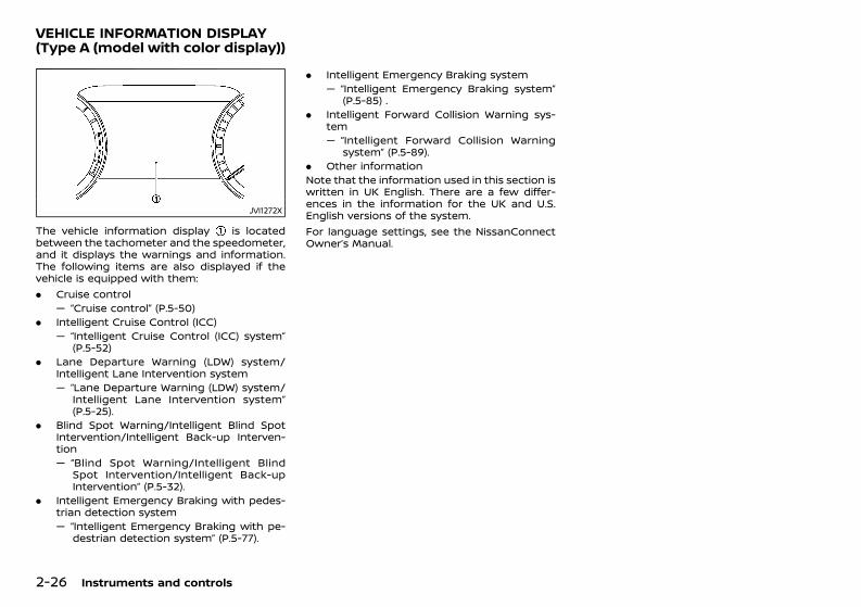
(100,1)
[ Edit: 2020/ 11/ 9 Model: Y62-A ]
2-26 Instruments and controls
GUID-2A6F437E-54BD-423A-BEA6-BA8A2E039259
JVI1272X
The vehicle information display is locatedbetween the tachometer and the speedometer,and it displays the warnings and information.The following items are also displayed if thevehicle is equipped with them:. Cruise control
— “Cruise control” (P.5-50). Intelligent Cruise Control (ICC)
— “Intelligent Cruise Control (ICC) system”(P.5-52)
. Lane Departure Warning (LDW) system/Intelligent Lane Intervention system— “Lane Departure Warning (LDW) system/
Intelligent Lane Intervention system”(P.5-25).
. Blind Spot Warning/Intelligent Blind SpotIntervention/Intelligent Back-up Interven-tion— “Blind Spot Warning/Intelligent Blind
Spot Intervention/Intelligent Back-upIntervention” (P.5-32).
. Intelligent Emergency Braking with pedes-trian detection system— “Intelligent Emergency Braking with pe-
destrian detection system” (P.5-77).
. Intelligent Emergency Braking system— “Intelligent Emergency Braking system”
(P.5-85) .. Intelligent Forward Collision Warning sys-
tem— “Intelligent Forward Collision Warning
system” (P.5-89).. Other informationNote that the information used in this section iswritten in UK English. There are a few differ-ences in the information for the UK and U.S.English versions of the system.For language settings, see the NissanConnectOwner’s Manual.
VEHICLE INFORMATION DISPLAY(Type A (model with color display))
Condition: 'Except for China'/'Except for China/
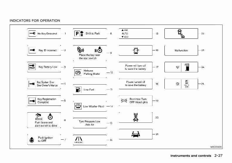
(101,1)
[ Edit: 2020/ 11/ 9 Model: Y62-A ]
INDICATORS FOR OPERATIONGUID-2578DF56-0008-473C-A846-ECC0E4CAEDE7
WAC0140X
Instruments and controls 2-27
Condition: 'Except for China'/'Except for China/
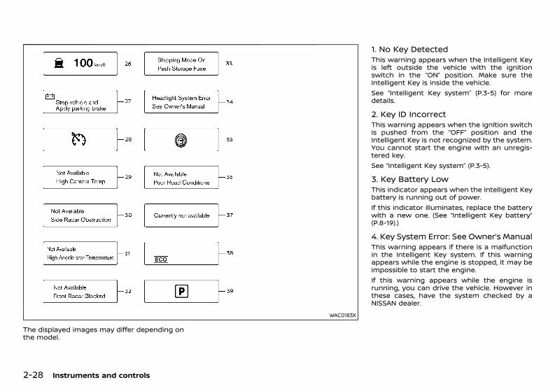
(102,1)
[ Edit: 2020/ 11/ 9 Model: Y62-A ]
2-28 Instruments and controls
WAC0183X
The displayed images may differ depending onthe model.
1. No Key DetectedGUID-EC6A341B-64CB-4B72-A15A-1C178745894BThis warning appears when the Intelligent Keyis left outside the vehicle with the ignitionswitch in the “ON” position. Make sure theIntelligent Key is inside the vehicle.See “Intelligent Key system” (P.3-5) for moredetails.
2. Key ID IncorrectGUID-07248669-EC78-47A5-AF14-AF4BE7CC9F5FThis warning appears when the ignition switchis pushed from the “OFF” position and theIntelligent Key is not recognized by the system.You cannot start the engine with an unregis-tered key.See “Intelligent Key system” (P.3-5).
3. Key Battery LowGUID-8D62A100-C468-493C-BDA6-0D7221822492This indicator appears when the Intelligent Keybattery is running out of power.If this indicator illuminates, replace the batterywith a new one. (See “Intelligent Key battery”(P.8-19).)
4. Key System Error: See Owner’s ManualGUID-65D6F4E6-4D09-40EF-A3A5-CCA7E37161F8This warning appears if there is a malfunctionin the Intelligent Key system. If this warningappears while the engine is stopped, it may beimpossible to start the engine.If this warning appears while the engine isrunning, you can drive the vehicle. However inthese cases, have the system checked by aNISSAN dealer.
Condition: 'Except for China'/'Except for China/
(103,1)
[ Edit: 2020/ 11/ 9 Model: Y62-A ]
5. Key Registration CompleteGUID-53A0671C-4245-44E9-9954-0E5233D19112This indicator appears when a new IntelligentKey is registered to the vehicle.
6. Push brake and start switch to driveGUID-511E4DBE-0D27-4402-84E2-86309E4C8B83This indicator appears when the vehicle is inthe “P” (Park) position.This indicator also appears when the vehiclehas been started using the Remote EngineStart function (if equipped).This indicator means that the engine will startby pushing the ignition switch with the brakepedal depressed. You can start the engine fromany position of the ignition switch.
7. Push Ignition to OFFGUID-AC46701D-15D8-478C-B124-8B007110CE14After the Push Ignition to OFF warning illumi-nates, the warning will illuminate if the ignitionswitch is placed in the “ACC” position when theshift lever moves into the “P” position.To turn off the warning, place the ignitionswitch in the “ON” position and then in the“LOCK” position.
8. Shift to ParkGUID-619A5200-8B83-433F-BF6B-927D500B4700This warning appears when the ignition switchis pushed to stop the engine with the shift leverin any position except the “P” (Park) position.If this warning appears, move the shift lever tothe “P” (Park) position or push the ignitionswitch to the “ON” position.An inside warning chime will also sound. (See“Intelligent Key system” (P.3-5).)
9. Engine start operation for Intelligent Keysystem indicator (if I-Key battery level is low)GUID-14C04D7D-D560-4C3A-A150-E7B22E9C1FC1This indicator appears when the battery of theIntelligent Key is low and when the IntelligentKey system and the vehicle are not commu-nicating normally.If this indicator appears, touch the ignitionswitch with the Intelligent Key while depressingthe brake pedal. For additional information,refer to “Intelligent Key battery discharge” (P.5-11).
10. Release Parking BrakeGUID-D63F317B-5FD3-4C6B-AEE2-0F2BF7DEFC19This warning appears when the vehicle speedis above 7 km/h (4 MPH) and the parking brakeis applied. Stop the vehicle and release theparking brake.
11. Low FuelGUID-8C0AC1C2-5CD9-4519-A5C4-C59FF6064270This warning appears when the fuel level in thetank is getting low. Refuel as soon as it isconvenient, preferably before the fuel gaugereaches the empty (0) position.There is a small reserve of fuel remaining inthe tank when the fuel gauge reaches theempty (0) position.
12. Low Washer FluidGUID-5DEB218D-5F48-4543-A003-A5F7A62DDB7FThis warning appears when the washer tankfluid is at a low level. Add washer fluid asnecessary. (See “Window washer fluid” (P.8-17).)
13. Tyre Pressure Low Add Air (if equipped)GUID-05572F9A-990C-4C14-968E-7B69A3845B85This warning (“Tire Pressure Low Add Air” and avehicle icon - if equipped) appears when thelow tire pressure warning light in the meterilluminates and low tire pressure is detected.The warning appears each time the ignitionswitch is placed in the “ON” position as long asthe low tire pressure warning light remainsilluminated. If this warning appears, stop thevehicle and adjust the pressure to the recom-mended COLD tire pressure shown on the tireplacard. (See “Low tire pressure warning light”(P.2-20) and “Tire Pressure Monitoring System(TPMS)” (P.5-6).)
14. Variable 4 × 4 mode indicatorGUID-A5E72E49-FE4D-4CE7-99D8-0C5213D6E74EThis indicator shows the driving mode (ONROAD, ROCK, SNOW or SAND) that is selected bythe variable 4 x 4 mode select switch. (See“Variable 4 × 4 mode select switch (except forMexico)” (P.5-20).)
15. Four-Wheel Drive (4WD) shift indica-tor (4WD models)GUID-528C1208-8968-4DE7-99D0-BC1100C3FACEThis indicator shows the Four-Wheel Drive(4WD) driving mode (AUTO, 4HI or 4LO) that isselected by the 4WD shift switch. (See “Four-Wheel Drive (4WD) (4WD models)” (P.5-16).)
16. Door open warningGUID-FC143B80-9760-41A3-8AF5-65843B385826This warning appears if any of the doors areopen or not closed securely. The vehicle iconindicates which door is open on the display.
Instruments and controls 2-29
Condition: 'Except for China'/'Except for China/
(104,1)
[ Edit: 2020/ 11/ 9 Model: Y62-A ]
2-30 Instruments and controls
17. Power will turn off to save the batteryGUID-0A182F9C-F9C5-4758-B6F5-8B4E7AC76F80This warning appears after a period of time ifthe ignition switch is in “ACC” or “ON” position.
18. Power turned off to save the batteryGUID-25790DBA-4A5B-4552-B277-690731781807This warning appears after the ignition switchis automatically turned OFF to save the battery.
19. Light reminder warningGUID-50224C5E-0816-4E6C-A77E-41E576D47B27This warning appears when the driver sidedoor is opened with the headlight switch is leftON and the ignition switch is placed in the “OFF”or “LOCK” position. Place the headlight switch in“OFF” or “AUTO” position. For additional infor-mation, see “Headlight and turn signal switch”(P.2-43).
20-22. Driver assist system indicator (if equipped)GUID-2906A78D-4011-4AFB-AF6F-865EEFB987C2This indicator shows the status of the followingsystems, if the vehicle is equipped with them.. Intelligent Emergency Braking. Intelligent Emergency Braking with pedes-
trian detection. Intelligent Forward Collision Warning. Lane Departure Warning (LDW). Intelligent Lane Intervention system. Blind Spot Warning (BSW). Intelligent Blind Spot InterventionFor more details, see “Intelligent EmergencyBraking system” (P.5-85), “Intelligent EmergencyBraking with pedestrian detection system” (P.5-77), “Intelligent Forward Collision Warning sys-tem” (P.5-89), “Lane Departure Warning (LDW)system/Intelligent Lane Intervention system”(P.5-25), “Blind Spot Warning/Intelligent BlindSpot Intervention/Intelligent Back-up Interven-tion” (P.5-32).The figure and color of these indicators willchange depending on the conditions of the
above systems.
23. Malfunction (if equipped)GUID-84051078-7AF6-4BBA-A914-92A0C2F4386AThis warning appears when one or more of thefollowing systems (if equipped) is not function-ing properly:. Intelligent Emergency Braking. Intelligent Emergency Braking with pedes-
trian detection. Intelligent Forward Collision Warning. Lane Departure Warning (LDW). Intelligent Lane Intervention system. Blind Spot Warning (BSW). Intelligent Blind Spot Intervention. Rear Cross Traffic Alert (RCTA) systemIf one or more of these warning appears, havethe system checked by a NISSAN dealer.
24. Wiper Mode GuidanceGUID-F4BE7360-41B0-42B8-ADE8-BD548F7263E0This indicator shows the wiper and washerswitch position.The selected position is illuminated as orangewhen the wiper switch position is changed.
25. Lights Mode GuidanceGUID-1E19190F-D41B-43D1-8617-5F4667CBF014This indicator shows the headlight switchposition.The selected position is illuminated as orangewhen the headlight switch position is changed.
26. Intelligent Cruise Control (ICC) in-dicators (if equipped)GUID-80FDAC5F-A292-4004-B289-EEBFB0AD0A43These indicators show the Intelligent CruiseControl (ICC) system status. For additionalinformation, refer to “Intelligent Cruise Control(ICC) system” (P.5-52).
27. Stop vehicle and Apply parkingbrake (if equipped)GUID-397C27FA-69B8-47C5-A3DF-C030C54662B5This warning may appear when the batterycharge is low.Park the vehicle as soon as possible. It isrecommended that you visit a NISSAN dealer.
28. Cruise indicatorGUID-57CFFA9B-DBEB-4490-A23A-EBE60D19D3A4
Models without Intelligent Cruise Control(ICC) system:
GUID-C7E1EF24-5AAB-4301-95BE-26917EEE45EF
This indicator shows the cruise control systemstatus. The status is shown by the color.See “Cruise control” (P.5-50) for details.Models with Intelligent Cruise Control (ICC)system:
GUID-C7E1EF24-5AAB-4301-95BE-26917EEE45EF
This indicator shows the conventional (fixedspeed) cruise control mode status. The status isshown by the color.See “Conventional (fixed speed) cruise controlmode” (P.5-66) for details.
29. Not Available: High Camera Temp (if equipped)GUID-C32E1F9C-A778-4E7A-A548-9AB5D2B02793This message appears when the camera de-tects an interior temperature of more than40°C (104°F). For additional information, refer to“Lane Departure Warning (LDW) system/Intelli-gent Lane Intervention system” (P.5-25), “BlindSpot Warning/Intelligent Blind Spot Interven-tion/Intelligent Back-up Intervention” (P.5-32),or “Intelligent Emergency Braking with pedes-trian detection system” (P.5-77).
Condition: 'Except for China'/'Except for China/
(105,1)
[ Edit: 2020/ 11/ 9 Model: Y62-A ]
30. Not Available: Side Radar Obstruc-tion (if equipped)GUID-8B3E4EF8-6E67-41E0-A22E-6DAAF0F4BEC9This message appears when the Blind SpotWarning (BSW)/Intelligent Blind Spot Interven-tion/Intelligent Back-up Intervention (ifequipped)/Rear Cross Traffic Alert (RCTA) (ifequipped) systems become unavailable be-cause a radar blockage is detected. For addi-tional information, refer to “Blind Spot Warning/Intelligent Blind Spot Intervention/IntelligentBack-up Intervention” (P.5-32) or “Rear CrossTraffic Alert (RCTA)” (P.5-45).
31. Not Available: High AcceleratorTemperature (if equipped)GUID-A4D43997-CD77-415E-A11B-944E2461A58FThis message appears when the IntelligentBack-up Intervention system becomes unavail-able because of an interior temperature great-er than approximately 40°C (104°F). Foradditional information, refer to “Blind SpotWarning/Intelligent Blind Spot Intervention/In-telligent Back-up Intervention” (P.5-32).
32. Not Available: Front Radar Blocked(if equipped) GUID-F19FE067-D682-4430-B916-313442D5E622This message appears when the IntelligentCruise Control (ICC), Intelligent EmergencyBraking, Intelligent Emergency Braking withpedestrian detection, Intelligent EmergencyBraking or Intelligent Forward Collision Warningsystems become unavailable because the frontradar is obstructed. For additional information,refer to “Intelligent Cruise Control (ICC) system”(P.5-52), “Intelligent Emergency Braking withpedestrian detection system” (P.5-77), “Intelli-gent Emergency Braking system” (P.5-85) or“Intelligent Forward Collision Warning system”(P.5-89).
33. Extended storage fuse warning (if equipped)GUID-91604052-38E1-4F78-BF57-FFD9EE223BFEThis warning may appear if the extendedstorage fuse switch is not pushed in (switchedon). When this warning appears, push in (switchon) the extended storage fuse switch to turnoff the warning. For more information, see“Extended storage fuse switch” (P.8-22).
34. Headlight warning (if equipped)GUID-C96491CF-B817-4D4F-A721-033B73FAB38CThis warning appears if the LED headlights aremalfunctioning. Have the system checked by aNISSAN dealer.
35. Intelligent Blind Spot Intervention/IntelligentLane Intervention ON indicator (if equipped)GUID-88BC94BF-DBC1-4555-A29E-27C84E1BABE9This indicator appears when one or more of thefollowing systems (if equipped) is activated.. Intelligent Blind Spot Intervention system. Intelligent Lane Intervention systemFor more details, see “Lane Departure Warning(LDW) system/Intelligent Lane Intervention sys-tem” (P.5-25) or “Blind Spot Warning/IntelligentBlind Spot Intervention/Intelligent Back-up In-tervention” (P.5-32).
36. Not Available: Poor Road Conditions(if equipped)GUID-67808263-8462-46C1-A81A-95D5A011C506This warning may appear when the IntelligentBlind Spot Intervention system, the IntelligentLane Intervention system, or the IntelligentCruise Control (ICC) system is engaged.Under the following conditions, the IntelligentBlind Spot Intervention, the Intelligent LaneIntervention system or the ICC system isautomatically canceled:. When the Vehicle Dynamic Control (VDC)
operates
. When a wheel slipsThe above system cannot be used in somesituations. (VDC operates and a wheel slips.)
37. Currently not available (if equipped)GUID-B6BEBB93-60CF-44D3-A83A-91D576191764This message appears and the Intelligent BlindSpot Intervention system and the IntelligentLane Intervention system will be turned offautomatically under the following conditions:. When the VDC system is turned off.. When the ROCK, SNOW or SAND mode is
selected (variable 4 × 4 mode select switch).. When the 4WD shift switch is in the 4H or 4L
position. (4WD models).“Vehicle Dynamic Control (VDC) system” (P.5-22), “Blind Spot Warning/Intelligent Blind SpotIntervention/Intelligent Back-up Intervention”(P.5-32) and “Lane Departure Warning (LDW)system/Intelligent Lane Intervention system”(P.5-25).
38. ECOmode system indicator (if equipped)GUID-35AC1D41-F31B-4BBE-8428-96AE4DBED25BThe ECO mode system indicator appears whenthe ECO mode system is turned on.See “ECO mode system” (P.5-99).
39. Automatic Transmission (AT) posi-tion indicatorGUID-6C4E9BCD-9880-491A-93CC-030C63E05A07This indicator shows the transmission shiftposition.See “Driving with Automatic Transmission (AT)”(P.5-12) for further details.
Instruments and controls 2-31
Condition: 'Except for China'/'Except for China/
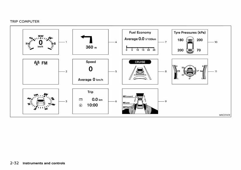
(106,1)
[ Edit: 2020/ 11/ 9 Model: Y62-A ]
2-32 Instruments and controls
TRIP COMPUTERGUID-C2F8647A-68B6-48E4-A1A7-C03362930394
WAC0141X
Condition: 'Except for China'/'Except for China/
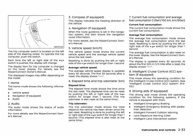
(107,1)
[ Edit: 2020/ 11/ 9 Model: Y62-A ]
WAC0142X
The trip computer switch is located on the leftside of the steering wheel. To operate the tripcomputer, push the switch.Each time the left or right side of theswitch is pushed, the display will change.The display item for trip computer is changedon the lower display. For details, see theNissanConnect Owner’s Manual.The displayed images may differ depending onthe model.
1. Home GUID-76BE5262-ADC0-416E-A2D3-7EFF0812F8C9The Home mode shows the following informa-tion.. Vehicle speed. Navigation (if equipped). Audio
2. Audio GUID-FEFC9996-6CB9-4314-B864-5F9C43B28BE9The audio mode shows the status of audioinformation.For more details, see the NissanConnect Own-er’s Manual.
3. Compass (if equipped)GUID-E88FD36B-1D64-4E20-A73D-06E3F83CFA32This display indicates the heading direction ofthe vehicle.
4. Navigation (if equipped)GUID-73B7A6FB-26DD-440C-BA78-98920C67D886When the route guidance is set in the naviga-tion system, this item shows the navigationroute information.For more details, see the NissanConnect Own-er’s Manual.
5. Vehicle speed (km/h)GUID-9FAFB49B-D049-4D8E-B65C-32BC5CC7AD13The vehicle speed mode shows the currentvehicle speed and the average vehicle speedsince the last reset.Resetting is done by pushing the left or rightside of the switch for longer than 1 second.Average vehicle speed:
GUID-C7E1EF24-5AAB-4301-95BE-26917EEE45EF
The average vehicle speed display is updatedevery 30 seconds. The first 30 seconds after areset, the display shows “——”.
6. Elapsed time and trip odometer (km)GUID-30709803-DE70-4E01-A162-0C934D2C4359
Elapsed time:GUID-C7E1EF24-5AAB-4301-95BE-26917EEE45EF
The elapsed time mode shows the time sincethe last reset. The displayed time can be resetby pushing the left or right side of theswitch for longer than 1 second. (The tripodometer is also reset at the same time.)Trip odometer:
GUID-C7E1EF24-5AAB-4301-95BE-26917EEE45EF
The trip odometer mode shows the totaldistance the vehicle has been driven since thelast reset. Resetting is done by pushing the leftor right side of the switch for longer than 1second. (The elapsed time is also reset at thesame time.)
7. Current fuel consumption and averagefuel consumption (l (liter)/100 km, km/l(liter))GUID-386ABA27-E790-41D5-985D-4824BEC6EB2E
Current fuel consumption:GUID-C7E1EF24-5AAB-4301-95BE-26917EEE45EF
The current fuel consumption mode shows thecurrent fuel consumption.Average fuel consumption:
GUID-C7E1EF24-5AAB-4301-95BE-26917EEE45EF
The average fuel consumption mode showsthe average fuel consumption since the lastreset. Resetting is done by pushing the left orright side of the switch for longer than 1second.The average fuel consumption is also reset onthe lower display. See the NissanConnect Own-er’s Manual.The display is updated every 30 seconds. Atabout the first 500 m (1/3 mile) after a reset, thedisplay shows “——”.
8. Intelligent Cruise Control (ICC) sys-tem (if equipped)GUID-3AE6D08A-B298-4030-8C77-4E12080F5EA2This mode shows the operating condition forthe Intelligent Cruise Control (ICC) system. (See“Intelligent Cruise Control (ICC) system” (P.5-52).)
9. Driving aids (if equipped)GUID-03D98BEB-6D96-4C26-8FEA-B1B40B786EA0The driving aids mode shows the operatingcondition for the following systems, if thevehicle is equipped with them.. Intelligent Emergency Braking. Intelligent Emergency Braking with pedes-
trian detection. Intelligent Forward Collision Warning. Lane Departure Warning (LDW). Intelligent Lane Intervention system
Instruments and controls 2-33
Condition: 'Except for China'/'Except for China/
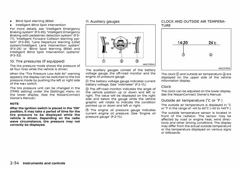
(108,1)
[ Edit: 2020/ 11/ 9 Model: Y62-A ]
2-34 Instruments and controls
. Blind Spot Warning (BSW)
. Intelligent Blind Spot InterventionFor more details, see “Intelligent EmergencyBraking system” (P.5-85), “Intelligent EmergencyBraking with pedestrian detection system” (P.5-77), “Intelligent Forward Collision Warning sys-tem” (P.5-89), “Lane Departure Warning (LDW)system/Intelligent Lane Intervention system”(P.5-25) or “Blind Spot Warning (BSW) andIntelligent Blind Spot Intervention systems”(P.5-32).
10. Tire pressures (if equipped)GUID-5811F9F5-C298-4A48-844C-C6B4B19A9ED9The tire pressure mode shows the pressure ofall four tires while the vehicle is driven.When the “Tire Pressure Low Add Air” warningappears, the display can be switched to the tirepressure mode by pushing the left or right sideof the switch.The tire pressure unit can be changed in the[TPMS setting] under the [Settings] menu onthe lower display. (See the NissanConnectOwner’s Manual.)
NOTE:After the ignition switch is placed in the “ON”position, it may take a period of time for thetire pressure to be displayed while thevehicle is driven. Depending on the radiowave circumstance, tire pressure may notcorrectly be displayed.
11. Auxiliary gaugesGUID-8069A102-B40E-4EC7-8D23-B17D832AA037
WAC0184X
The auxiliary gauges consist of the batteryvoltage gauge, the off-road monitor and theengine oil pressure gauge.
The battery voltage gauge indicates currentbattery voltage. (See “Voltmeter” (P.2-11).)
The off-road monitor indicates the angle ofthe vehicle position up or down and left orright. The value will be displayed on the rightside and below the gauge while the vehiclegraphic will rotate to indicate the conditionpointed up or down and left or right.
The engine oil pressure gauge indicatescurrent engine oil pressure. (See “Engine oilpressure gauge” (P.2-11).)
CLOCK AND OUTSIDE AIR TEMPERA-TURE GUID-BC410DE7-B947-4452-8936-FD250DA72100
WAC0190X
The clock and outside air temperature aredisplayed on the upper side of the vehicleinformation display.
Clock GUID-22ABAE71-AD89-49AC-B800-5B8504C517FBThe clock can be adjusted on the lower display.See the NissanConnect Owner’s Manual.
Outside air temperature (°C or °F )GUID-557C4989-A274-41FC-B18F-843DC98698B8The outside air temperature is displayed in °Cor °F in the range of −40 to 60°C (−40 to 140°F ).The outside temperature sensor is located infront of the radiator. The sensor may beaffected by road or engine heat, wind direc-tions and other driving conditions. The displaymay differ from the actual outside temperatureor the temperature displayed on various signsor billboards.
Condition: 'Except for China'/'Except for China/
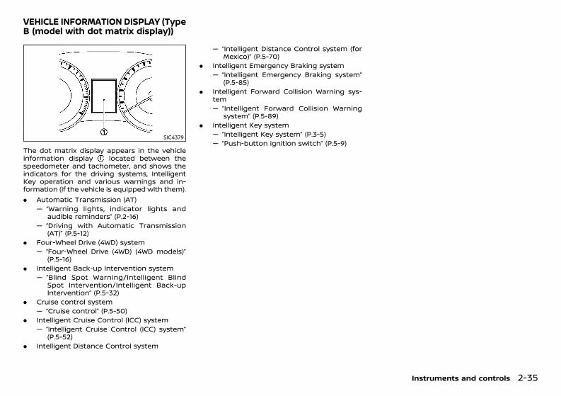
(109,1)
[ Edit: 2020/ 11/ 9 Model: Y62-A ]
GUID-57FBC015-EF50-4559-95D0-748989FD0737
SIC4379
The dot matrix display appears in the vehicleinformation display located between thespeedometer and tachometer, and shows theindicators for the driving systems, IntelligentKey operation and various warnings and in-formation (if the vehicle is equipped with them).. Automatic Transmission (AT)
— “Warning lights, indicator lights andaudible reminders” (P.2-16)
— “Driving with Automatic Transmission(AT)” (P.5-12)
. Four-Wheel Drive (4WD) system— “Four-Wheel Drive (4WD) (4WD models)”
(P.5-16). Intelligent Back-up Intervention system
— “Blind Spot Warning/Intelligent BlindSpot Intervention/Intelligent Back-upIntervention” (P.5-32)
. Cruise control system— “Cruise control” (P.5-50)
. Intelligent Cruise Control (ICC) system— “Intelligent Cruise Control (ICC) system”
(P.5-52). Intelligent Distance Control system
— “Intelligent Distance Control system (forMexico)” (P.5-70)
. Intelligent Emergency Braking system— “Intelligent Emergency Braking system”
(P.5-85). Intelligent Forward Collision Warning sys-
tem— “Intelligent Forward Collision Warning
system” (P.5-89). Intelligent Key system
— “Intelligent Key system” (P.3-5)— “Push-button ignition switch” (P.5-9)
Instruments and controls 2-35
VEHICLE INFORMATION DISPLAY (TypeB (model with dot matrix display))
Condition: 'Except for China'/'Except for China/
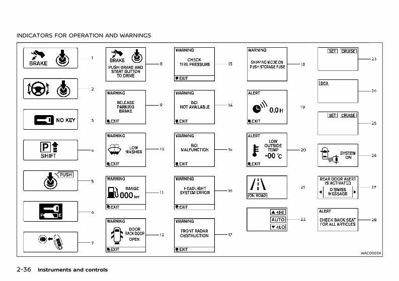
(110,1)
[ Edit: 2020/ 11/ 9 Model: Y62-A ]
2-36 Instruments and controls
INDICATORS FOR OPERATION AND WARNINGSGUID-18E3585E-D122-4CC9-9C24-D2C46D2F99A5
WAC0003X
Condition: 'Except for China'/'Except for China/
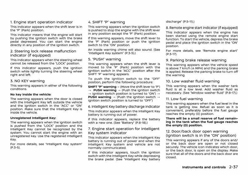
(111,1)
[ Edit: 2020/ 11/ 9 Model: Y62-A ]
1. Engine start operation indicatorGUID-3685162D-5526-4230-9F59-B5077835AD1AThis indicator appears when the shift lever is inthe “P” (Park) position.This indicator means that the engine will startby pushing the ignition switch with the brakepedal depressed. You can start the enginedirectly in any position of the ignition switch.
2. Steering lock release malfunctionindicator (if equipped)GUID-3D338252-160E-4B81-974D-797F205A8E7BThis indicator appears when the steering wheelcannot be released from the “LOCK” position.If this indicator appears, push the ignitionswitch while lightly turning the steering wheelright and left.
3. NO KEY warningGUID-F64EE7FA-F59A-44CE-8AE4-1BC5155B33B9This warning appears in either of the followingconditions.No key inside the vehicle:
GUID-C7E1EF24-5AAB-4301-95BE-26917EEE45EF
The warning appears when the door is closedwith the Intelligent Key left outside the vehicleand the ignition switch in the “ACC” or “ON”position. Make sure that the Intelligent Key isinside the vehicle.Unregistered Intelligent Key:
GUID-C7E1EF24-5AAB-4301-95BE-26917EEE45EF
The warning appears when the ignition switchis pushed from the “LOCK” position and theIntelligent Key cannot be recognized by thesystem. You cannot start the engine with anunregistered key. Use the registered IntelligentKey.For more details, see “Intelligent Key system”(P.3-5).
4. SHIFT “P” warningGUID-E6B0B268-3E58-4764-B127-EE6C672D5BD3This warning appears when the ignition switchis pushed to stop the engine with the shift leverin any position except the “P” (Park) position.If this warning appears, move the shift lever tothe “P” (Park) position or push the ignitionswitch to the “ON” position.An inside warning chime will also sound. (See“Intelligent Key system” (P.3-5).)
5. “PUSH” warningGUID-DD853589-E798-4C0B-86E4-3283F8AACCA0This warning appears when the shift lever ismoved to the “P” (Park) position with theignition switch in the “ACC” position after theSHIFT “P” warning appears.To push the ignition switch to the “OFF”position, perform the following procedure:SHIFT “P” warning? (Move the shift lever to “P”)? PUSH warning ? (Push the ignition switch? ignition switch position is turned to “ON”) ?PUSH warning ? (Push the ignition switch ?ignition switch position is turned to “OFF”)
6. Intelligent Key battery discharge indicatorGUID-9D00606A-213C-41ED-9792-F3E66A959317This indicator appears when the Intelligent Keybattery is running out of power.If this indicator appears, replace the batterywith a new one. (See “Battery” (P.8-18).)
7. Engine start operation for IntelligentKey system indicatorGUID-EFD2075E-835F-41D3-8E8C-317F0E5CA58FThis indicator appears when the Intelligent Keybattery is running out of power and when theIntelligent Key system and vehicle are notnormally communicated.If this indicator appears, touch the ignitionswitch with the Intelligent Key while depressingthe brake pedal. (See “Intelligent Key battery
discharge” (P.5-11).)
8. Remote engine start indicator (if equipped)GUID-93AA0424-DCE5-4EDB-973D-0CB7AE246463This indicator appears when the engine hasbeen started using the remote engine startfunction. To start the vehicle, depress the brakepedal and place the ignition switch in the “ON”position.For more details, see “Remote engine start”(P.3-17).
9. Parking brake release warningGUID-6A6D3759-59B4-4C7C-8187-F80181DAA03EThis warning appears when the vehicle speedis above 7 km/h (4 MPH) and the parking brakeis applied. Release the parking brake to turn offthe warning.
10. Low washer fluid warningGUID-F72E4EC8-674E-4082-AF63-BC6B7F44725AThis warning appears when the washer tankfluid is at a low level. Add washer fluid asnecessary. (See “Window washer fluid” (P.8-17).)
11. Low fuel warningGUID-39DE6A87-B634-4ABC-9C88-4C7E0E00EAB3This warning appears when the fuel level in thetank is getting low. Refuel as soon as it isconvenient, preferably before the fuel gaugereaches the empty (0) position.There will be a small reserve of fuel remain-ing in the tank when the fuel gauge reachesthe empty (0) position.
12. Door/back door open warning(ignition switch is in the “ON” position)GUID-78C0BB65-D967-46C1-B1D9-707BEEF061E2This warning appears if any of the doors and/or the back door are open or not closedsecurely. The vehicle icon indicates which door,or the back door, is open on the display. Makesure that all of the doors and the back door areclosed.
Instruments and controls 2-37
Condition: 'Except for China'/'Except for China/
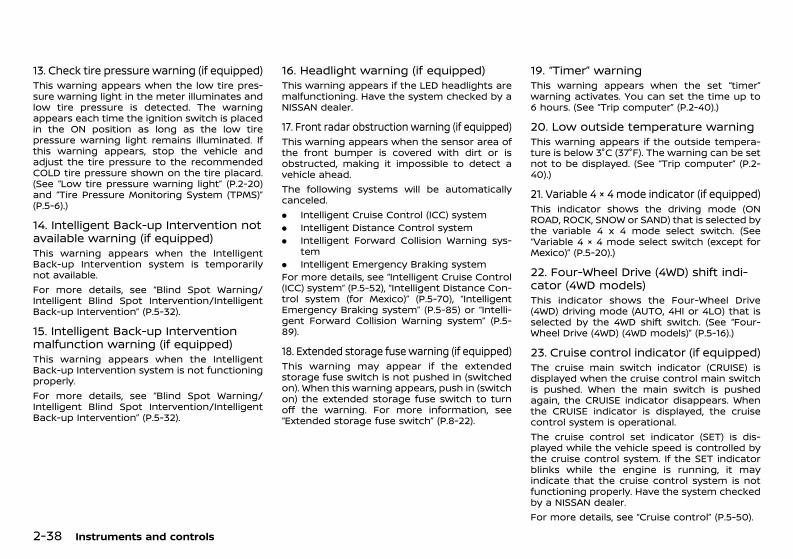
(112,1)
[ Edit: 2020/ 11/ 9 Model: Y62-A ]
2-38 Instruments and controls
13. Check tire pressure warning (if equipped)GUID-C34BB878-0F3B-4261-B58F-6F53B8A41DD2This warning appears when the low tire pres-sure warning light in the meter illuminates andlow tire pressure is detected. The warningappears each time the ignition switch is placedin the ON position as long as the low tirepressure warning light remains illuminated. Ifthis warning appears, stop the vehicle andadjust the tire pressure to the recommendedCOLD tire pressure shown on the tire placard.(See “Low tire pressure warning light” (P.2-20)and “Tire Pressure Monitoring System (TPMS)”(P.5-6).)
14. Intelligent Back-up Intervention notavailable warning (if equipped)GUID-CA9A5762-298B-4DB2-A8C6-2CBECD11D401This warning appears when the IntelligentBack-up Intervention system is temporarilynot available.For more details, see “Blind Spot Warning/Intelligent Blind Spot Intervention/IntelligentBack-up Intervention” (P.5-32).
15. Intelligent Back-up Interventionmalfunction warning (if equipped)GUID-5A2DA046-3C9B-4CD7-8618-60BB44BBB9E1This warning appears when the IntelligentBack-up Intervention system is not functioningproperly.For more details, see “Blind Spot Warning/Intelligent Blind Spot Intervention/IntelligentBack-up Intervention” (P.5-32).
16. Headlight warning (if equipped)GUID-1553E4FD-0C62-4432-AD4A-3BE0CEA0262FThis warning appears if the LED headlights aremalfunctioning. Have the system checked by aNISSAN dealer.
17. Front radar obstruction warning (if equipped)GUID-75B5DA3E-E53E-4D02-8B35-A2F780EA9B33This warning appears when the sensor area ofthe front bumper is covered with dirt or isobstructed, making it impossible to detect avehicle ahead.The following systems will be automaticallycanceled.. Intelligent Cruise Control (ICC) system. Intelligent Distance Control system. Intelligent Forward Collision Warning sys-
tem. Intelligent Emergency Braking systemFor more details, see “Intelligent Cruise Control(ICC) system” (P.5-52), “Intelligent Distance Con-trol system (for Mexico)” (P.5-70), “IntelligentEmergency Braking system” (P.5-85) or “Intelli-gent Forward Collision Warning system” (P.5-89).
18. Extended storage fuse warning (if equipped)GUID-5D72B03C-CC98-4D0D-A169-54DAFC336C39This warning may appear if the extendedstorage fuse switch is not pushed in (switchedon). When this warning appears, push in (switchon) the extended storage fuse switch to turnoff the warning. For more information, see“Extended storage fuse switch” (P.8-22).
19. “Timer” warningGUID-A160B3D2-0964-4299-878F-2A4A1BE068BAThis warning appears when the set “timer”warning activates. You can set the time up to6 hours. (See “Trip computer” (P.2-40).)
20. Low outside temperature warningGUID-5FAAD290-5EF7-417C-AB0C-286E7B37E104This warning appears if the outside tempera-ture is below 3°C (37°F). The warning can be setnot to be displayed. (See “Trip computer” (P.2-40).)
21. Variable 4 × 4 mode indicator (if equipped)GUID-DE5D11E4-F31B-410A-81B7-66ACB1C3A3BCThis indicator shows the driving mode (ONROAD, ROCK, SNOW or SAND) that is selected bythe variable 4 x 4 mode select switch. (See“Variable 4 × 4 mode select switch (except forMexico)” (P.5-20).)
22. Four-Wheel Drive (4WD) shift indi-cator (4WD models)GUID-C992B6F6-0DFA-4275-8540-BEB4B9246DB3This indicator shows the Four-Wheel Drive(4WD) driving mode (AUTO, 4HI or 4LO) that isselected by the 4WD shift switch. (See “Four-Wheel Drive (4WD) (4WD models)” (P.5-16).)
23. Cruise control indicator (if equipped)GUID-8F42A74C-6268-4C08-A24B-445326ED67FAThe cruise main switch indicator (CRUISE) isdisplayed when the cruise control main switchis pushed. When the main switch is pushedagain, the CRUISE indicator disappears. Whenthe CRUISE indicator is displayed, the cruisecontrol system is operational.The cruise control set indicator (SET) is dis-played while the vehicle speed is controlled bythe cruise control system. If the SET indicatorblinks while the engine is running, it mayindicate that the cruise control system is notfunctioning properly. Have the system checkedby a NISSAN dealer.For more details, see “Cruise control” (P.5-50).
Condition: 'Except for China'/'Except for China/
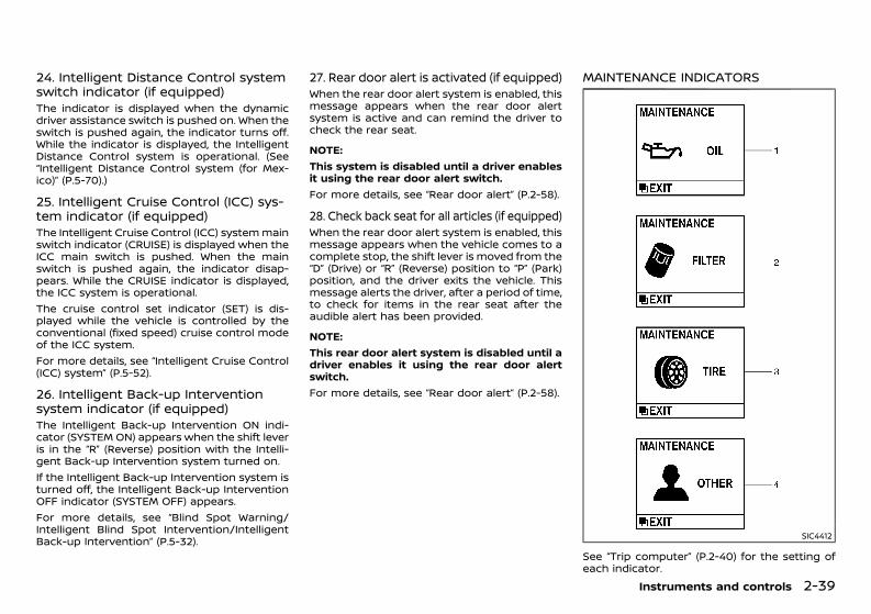
(113,1)
[ Edit: 2020/ 11/ 9 Model: Y62-A ]
24. Intelligent Distance Control systemswitch indicator (if equipped)GUID-6D6F12D2-3C95-4C1E-B14C-C4B297ECAFDEThe indicator is displayed when the dynamicdriver assistance switch is pushed on. When theswitch is pushed again, the indicator turns off.While the indicator is displayed, the IntelligentDistance Control system is operational. (See“Intelligent Distance Control system (for Mex-ico)” (P.5-70).)
25. Intelligent Cruise Control (ICC) sys-tem indicator (if equipped)GUID-21002F9B-80BD-422F-A1D5-87C5B973FFF0The Intelligent Cruise Control (ICC) systemmainswitch indicator (CRUISE) is displayed when theICC main switch is pushed. When the mainswitch is pushed again, the indicator disap-pears. While the CRUISE indicator is displayed,the ICC system is operational.The cruise control set indicator (SET) is dis-played while the vehicle is controlled by theconventional (fixed speed) cruise control modeof the ICC system.For more details, see “Intelligent Cruise Control(ICC) system” (P.5-52).
26. Intelligent Back-up Interventionsystem indicator (if equipped)GUID-120C3359-B507-4D28-A12C-B084B8653A83The Intelligent Back-up Intervention ON indi-cator (SYSTEM ON) appears when the shift leveris in the “R” (Reverse) position with the Intelli-gent Back-up Intervention system turned on.If the Intelligent Back-up Intervention system isturned off, the Intelligent Back-up InterventionOFF indicator (SYSTEM OFF) appears.For more details, see “Blind Spot Warning/Intelligent Blind Spot Intervention/IntelligentBack-up Intervention” (P.5-32).
27. Rear door alert is activated (if equipped)GUID-FE8180A1-C84F-4712-86E8-86C182A7268BWhen the rear door alert system is enabled, thismessage appears when the rear door alertsystem is active and can remind the driver tocheck the rear seat.
NOTE:This system is disabled until a driver enablesit using the rear door alert switch.For more details, see “Rear door alert” (P.2-58).
28. Check back seat for all articles (if equipped)GUID-0BF25884-A294-438C-8569-C10DCD066D6BWhen the rear door alert system is enabled, thismessage appears when the vehicle comes to acomplete stop, the shift lever is moved from the“D” (Drive) or “R” (Reverse) position to “P” (Park)position, and the driver exits the vehicle. Thismessage alerts the driver, after a period of time,to check for items in the rear seat after theaudible alert has been provided.
NOTE:This rear door alert system is disabled until adriver enables it using the rear door alertswitch.For more details, see “Rear door alert” (P.2-58).
MAINTENANCE INDICATORSGUID-43791F7F-89DA-41B7-94FC-AEF196BEE4BB
SIC4412
See “Trip computer” (P.2-40) for the setting ofeach indicator.
Instruments and controls 2-39
Condition: 'Except for China'/'Except for China/
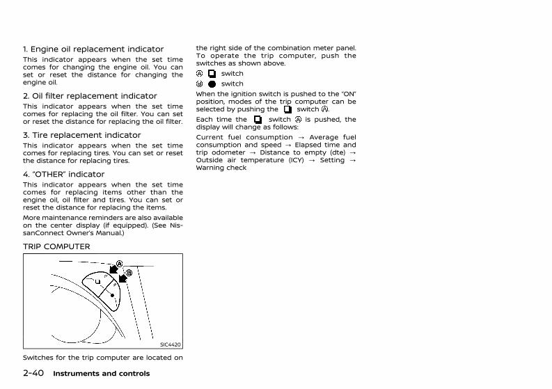
(114,1)
[ Edit: 2020/ 11/ 9 Model: Y62-A ]
2-40 Instruments and controls
1. Engine oil replacement indicatorGUID-E77454B1-1A05-4A55-B36F-77ECBA159AA3This indicator appears when the set timecomes for changing the engine oil. You canset or reset the distance for changing theengine oil.
2. Oil filter replacement indicatorGUID-9E148840-30F1-4042-87A6-575A5AC28FC2This indicator appears when the set timecomes for replacing the oil filter. You can setor reset the distance for replacing the oil filter.
3. Tire replacement indicatorGUID-9A3AB9DF-26B3-488A-BCE9-FCDAEEE3287BThis indicator appears when the set timecomes for replacing tires. You can set or resetthe distance for replacing tires.
4. “OTHER” indicatorGUID-51C5CC26-79AC-46F7-91DF-B24297F821FDThis indicator appears when the set timecomes for replacing items other than theengine oil, oil filter and tires. You can set orreset the distance for replacing the items.More maintenance reminders are also availableon the center display (if equipped). (See Nis-sanConnect Owner’s Manual.)
TRIP COMPUTERGUID-3AA3A200-A3C1-4DE6-B125-974CC600FB76
SIC4420
Switches for the trip computer are located on
the right side of the combination meter panel.To operate the trip computer, push theswitches as shown above.
switchswitch
When the ignition switch is pushed to the “ON”position, modes of the trip computer can beselected by pushing the switch .Each time the switch is pushed, thedisplay will change as follows:Current fuel consumption ? Average fuelconsumption and speed ? Elapsed time andtrip odometer ? Distance to empty (dte) ?Outside air temperature (ICY) ? Setting ?Warning check
Condition: 'Except for China'/'Except for China/
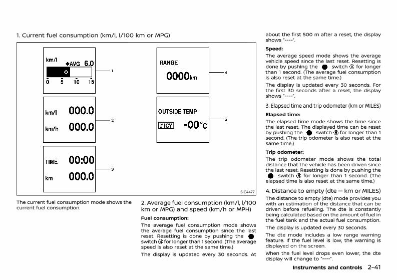
(115,1)
[ Edit: 2020/ 11/ 9 Model: Y62-A ]
1. Current fuel consumption (km/l, l/100 km or MPG)GUID-44146A22-D7AD-449D-A590-D96F0840765E
SIC4477
The current fuel consumption mode shows thecurrent fuel consumption.
2. Average fuel consumption (km/l, l/100km or MPG) and speed (km/h or MPH)GUID-C341790C-4A51-4D91-8512-AEA856D4936A
Fuel consumption:GUID-C7E1EF24-5AAB-4301-95BE-26917EEE45EF
The average fuel consumption mode showsthe average fuel consumption since the lastreset. Resetting is done by pushing theswitch for longer than 1 second. (The averagespeed is also reset at the same time.)The display is updated every 30 seconds. At
about the first 500 m after a reset, the displayshows “----”.Speed:
GUID-C7E1EF24-5AAB-4301-95BE-26917EEE45EF
The average speed mode shows the averagevehicle speed since the last reset. Resetting isdone by pushing the switch for longerthan 1 second. (The average fuel consumptionis also reset at the same time.)The display is updated every 30 seconds. Forthe first 30 seconds after a reset, the displayshows “----”.
3. Elapsed time and trip odometer (km or MILES)GUID-F5274350-04B0-4656-A93C-F7C274A8E2DE
Elapsed time:GUID-C7E1EF24-5AAB-4301-95BE-26917EEE45EF
The elapsed time mode shows the time sincethe last reset. The displayed time can be resetby pushing the switch for longer than 1second. (The trip odometer is also reset at thesame time.)Trip odometer:
GUID-C7E1EF24-5AAB-4301-95BE-26917EEE45EF
The trip odometer mode shows the totaldistance that the vehicle has been driven sincethe last reset. Resetting is done by pushing the
switch for longer than 1 second. (Theelapsed time is also reset at the same time.)
4. Distance to empty (dte — km or MILES)GUID-5207C2AD-081C-44F8-B62E-9FF6C636F786The distance to empty (dte) mode provides youwith an estimation of the distance that can bedriven before refueling. The dte is constantlybeing calculated based on the amount of fuel inthe fuel tank and the actual fuel consumption.The display is updated every 30 seconds.The dte mode includes a low range warningfeature. If the fuel level is low, the warning isdisplayed on the screen.When the fuel level drops even lower, the dtedisplay will change to “----”.
Instruments and controls 2-41
Condition: 'Except for China'/'Except for China/
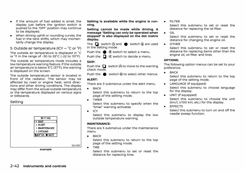
(116,1)
[ Edit: 2020/ 11/ 9 Model: Y62-A ]
2-42 Instruments and controls
. If the amount of fuel added is small, thedisplay just before the ignition switch ispushed to the “OFF” position may continueto be displayed.
. When driving uphill or rounding curves, thefuel in the tank shifts, which may momen-tarily change the display.
5. Outside air temperature (ICY — °C or °F)GUID-E5575A81-772B-4506-AA29-20E6873DB21CThe outside air temperature is displayed in °Cor °F in the range of −30 to 55°C (−22 to 131°F).The outside air temperature mode includes alow temperature warning feature. If the outsideair temperature is below 3°C (37°F), the warningis displayed on the screen.The outside temperature sensor is located infront of the radiator. The sensor may beaffected by road or engine heat, wind direc-tions and other driving conditions. The displaymay differ from the actual outside temperatureor the temperature displayed on various signsor billboards.
Setting GUID-17EBA149-8B23-4234-891B-D6E3FB8B7624
SIC4381example
Setting is available while the engine is run-ning.Setting cannot be made while driving. Amessage “Setting can only be operated whenstopped” is also displayed on the dot matrixdisplay.The switch and switch are usedin the setting mode.Push the switch to select a menu.Push the switch to decide a menu.SKIP:
GUID-C7E1EF24-5AAB-4301-95BE-26917EEE45EF
Push the switch to move to the warningcheck mode.Push the switch to select other menus.ALERT:
GUID-C7E1EF24-5AAB-4301-95BE-26917EEE45EF
There are 3 submenus under the alert menu.. BACK
Select this submenu to return to the toppage of the setting mode.
. TIMERSelect this submenu to specify when the“timer” warning activates.
. ICYSelect this submenu to display the lowoutside temperature warning.
MAINTENANCE:GUID-C7E1EF24-5AAB-4301-95BE-26917EEE45EF
There are 5 submenus under the maintenancemenu.. BACK
Select this submenu to return to the toppage of the setting mode.
. TIRESelect this submenu to set or reset thedistance for replacing tires.
. FILTERSelect this submenu to set or reset thedistance for replacing the oil filter.
. OILSelect this submenu to set or reset thedistance for changing the engine oil.
. OTHERSelect this submenu to set or reset thedistance for replacing items other than theengine oil, oil filter and tires.
OPTIONS:GUID-C7E1EF24-5AAB-4301-95BE-26917EEE45EF
The following option menus can be set to yourpreference.. BACK
Select this submenu to return to the toppage of the setting mode.
. LANGUAGE (if equipped)Select this submenu to choose languagefor the display.
. UNIT (if equipped)Select this submenu to choose the unit(km/l, l/100 km, etc.) for the display.
. EFFECTSSelect this submenu to turn on and off theneedle sweep function.
Condition: 'Except for China'/'Except for China/
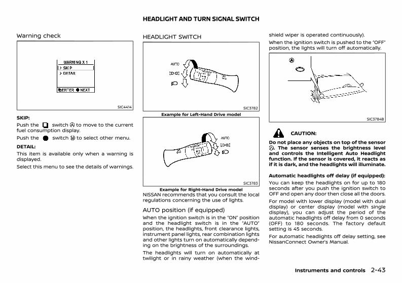
(117,1)
[ Edit: 2020/ 11/ 9 Model: Y62-A ]
Warning checkGUID-8A601D7D-5F4F-4C2C-9303-C735397A7F76
SIC4414
SKIP:GUID-C7E1EF24-5AAB-4301-95BE-26917EEE45EF
Push the switch to move to the currentfuel consumption display.Push the switch to select other menu.DETAIL:
GUID-C7E1EF24-5AAB-4301-95BE-26917EEE45EF
This item is available only when a warning isdisplayed.Select this menu to see the details of warnings.
GUID-6BD41B7B-CF45-4CAD-97FD-5EB346C2B9B0
HEADLIGHT SWITCHGUID-8F22D1F3-29F1-4E2E-8F73-95D0077A17AA
SIC3782Example for Left-Hand Drive model
SIC3783Example for Right-Hand Drive model
NISSAN recommends that you consult the localregulations concerning the use of lights.
AUTO position (if equipped)GUID-A9CFC1F2-751C-49B4-AD13-AB14A0B0B79EWhen the ignition switch is in the “ON” positionand the headlight switch is in the “AUTO”position, the headlights, front clearance lights,instrument panel lights, rear combination lightsand other lights turn on automatically depend-ing on the brightness of the surroundings.The headlights will turn on automatically attwilight or in rainy weather (when the wind-
shield wiper is operated continuously).When the ignition switch is pushed to the “OFF”position, the lights will turn off automatically.
SIC3784B
CAUTION:Do not place any objects on top of the sensor. The sensor senses the brightness level
and controls the Intelligent Auto Headlightfunction. If the sensor is covered, it reacts asif it is dark, and the headlights will illuminate.
Automatic headlights off delay (if equipped):GUID-C7E1EF24-5AAB-4301-95BE-26917EEE45EF
You can keep the headlights on for up to 180seconds after you push the ignition switch toOFF and open any door then close all the doors.For model with lower display (model with dualdisplay) or center display (model with singledisplay), you can adjust the period of theautomatic headlights off delay from 0 seconds(OFF) to 180 seconds. The factory defaultsetting is 45 seconds.For automatic headlights off delay setting, seeNissanConnect Owner’s Manual.
Instruments and controls 2-43
HEADLIGHT AND TURN SIGNAL SWITCH
Condition: 'Except for China'/'Except for China/
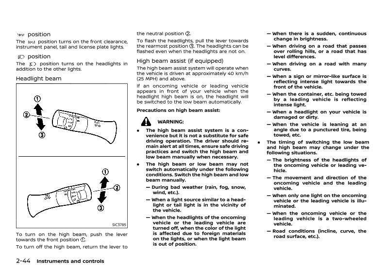
(118,1)
[ Edit: 2020/ 11/ 9 Model: Y62-A ]
2-44 Instruments and controls
positionGUID-B60F4D75-B29F-408F-8E76-A8B97DDFB986The position turns on the front clearance,instrument panel, tail and license plate lights.
positionGUID-4DAB4169-1827-49E8-B896-70450926F885The position turns on the headlights inaddition to the other lights.
Headlight beamGUID-78E65D41-DBAA-4ACA-83EF-06C8D93514A3
SIC3785
To turn on the high beam, push the levertowards the front position .To turn off the high beam, return the lever to
the neutral position .To flash the headlights, pull the lever towardsthe rearmost position . The headlights can beflashed even when the headlights are not on.
High beam assist (if equipped)GUID-941C6995-CE6D-4668-AD6E-CA04E3DCFCF2The high beam assist system will operate whenthe vehicle is driven at approximately 40 km/h(25 MPH) and above.If an oncoming vehicle or leading vehicleappears in front of your vehicle when theheadlight high beam is on, the headlight willbe switched to the low beam automatically.Precautions on high beam assist:
GUID-C7E1EF24-5AAB-4301-95BE-26917EEE45EF
WARNING:. The high beam assist system is a con-
venience but it is not a substitute for safedriving operation. The driver should re-main alert at all times, ensure safe drivingpractices and switch the high beam andlow beam manually when necessary.
. The high beam or low beam may notswitch automatically under the followingconditions. Switch the high beam and lowbeam manually.— During bad weather (rain, fog, snow,
wind, etc.).— When a light source similar to a head-
light or tail light is in the vicinity ofthe vehicle.
— When the headlights of the oncomingvehicle or the leading vehicle areturned off, when the color of the lightis affected due to foreign materialson the lights, or when the light beamis out of position.
— When there is a sudden, continuouschange in brightness.
— When driving on a road that passesover rolling hills, or a road that haslevel differences.
— When driving on a road with manycurves.
— When a sign or mirror-like surface isreflecting intense light towards thefront of the vehicle.
— When the container, etc. being towedby a leading vehicle is reflectingintense light.
— When a headlight on your vehicle isdamaged or dirty.
— When the vehicle is leaning at anangle due to a punctured tire, beingtowed, etc.
. The timing of switching the low beamand high beam may change under thefollowing situations.— The brightness of the headlights of
the oncoming vehicle or leading ve-hicle.
— The movement and direction of theoncoming vehicle and the leadingvehicle.
— When only one light on the oncomingvehicle or the leading vehicle is illu-minated.
— When the oncoming vehicle or theleading vehicle is a two-wheeledvehicle.
— Road conditions (incline, curve, theroad surface, etc.).
Condition: 'Except for China'/'Except for China/
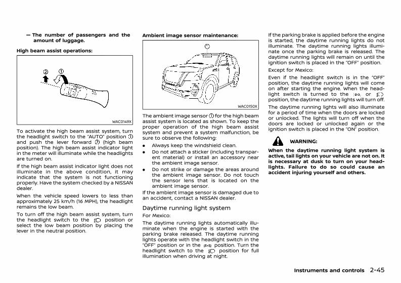
(119,1)
[ Edit: 2020/ 11/ 9 Model: Y62-A ]
— The number of passengers and theamount of luggage.
High beam assist operations:GUID-C7E1EF24-5AAB-4301-95BE-26917EEE45EF
WAC0149X
To activate the high beam assist system, turnthe headlight switch to the “AUTO” positionand push the lever forward (high beamposition). The high beam assist indicator lightin the meter will illuminate while the headlightsare turned on.If the high beam assist indicator light does notilluminate in the above condition, it mayindicate that the system is not functioningproperly. Have the system checked by a NISSANdealer.When the vehicle speed lowers to less thanapproximately 25 km/h (16 MPH), the headlightremains the low beam.To turn off the high beam assist system, turnthe headlight switch to the position orselect the low beam position by placing thelever in the neutral position.
Ambient image sensor maintenance:GUID-C7E1EF24-5AAB-4301-95BE-26917EEE45EF
WAC0150X
The ambient image sensor for the high beamassist system is located as shown. To keep theproper operation of the high beam assistsystem and prevent a system malfunction, besure to observe the following:. Always keep the windshield clean.. Do not attach a sticker (including transpar-
ent material) or install an accessory nearthe ambient image sensor.
. Do not strike or damage the areas aroundthe ambient image sensor. Do not touchthe sensor lens that is located on theambient image sensor.
If the ambient image sensor is damaged due toan accident, contact a NISSAN dealer.
Daytime running light systemGUID-24196D50-C6DD-4A46-9F9C-967D3689AC01For Mexico:The daytime running lights automatically illu-minate when the engine is started with theparking brake released. The daytime runninglights operate with the headlight switch in the“OFF” position or in the position. Turn theheadlight switch to the position for fullillumination when driving at night.
If the parking brake is applied before the engineis started, the daytime running lights do notilluminate. The daytime running lights illumi-nate once the parking brake is released. Thedaytime running lights will remain on until theignition switch is placed in the “OFF” position.Except for Mexico:Even if the headlight switch is in the “OFF”position, the daytime running lights will comeon after starting the engine. When the head-light switch is turned to the orposition, the daytime running lights will turn off.The daytime running lights will also illuminatefor a period of time when the doors are lockedor unlocked. The lights will turn off when thedoors are locked or unlocked again or theignition switch is placed in the “ON” position.
WARNING:When the daytime running light system isactive, tail lights on your vehicle are not on. Itis necessary at dusk to turn on your head-lights. Failure to do so could cause anaccident injuring yourself and others.
Instruments and controls 2-45
Condition: 'Except for China'/'Except for China/
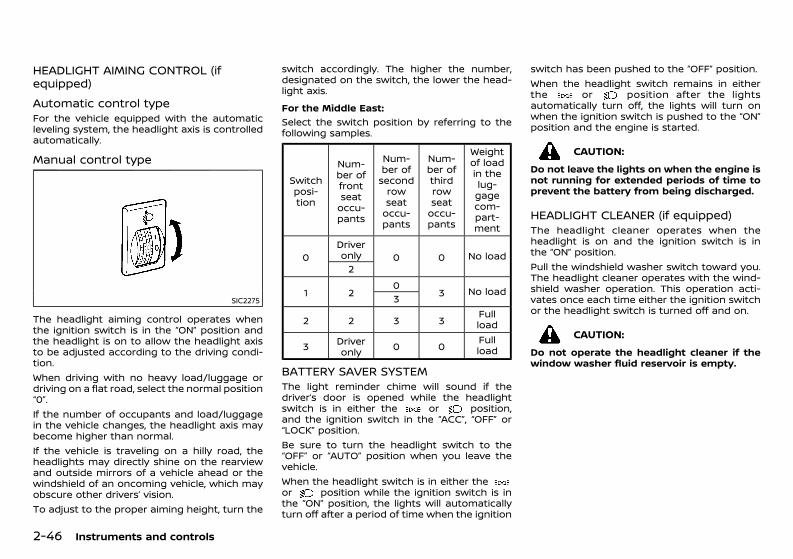
(120,1)
[ Edit: 2020/ 11/ 9 Model: Y62-A ]
2-46 Instruments and controls
HEADLIGHT AIMING CONTROL (ifequipped) GUID-59F97C06-0802-4175-A156-C550A1E0F0E5
Automatic control typeGUID-DE053859-FDAE-4FCC-905E-6CC3D0D45DFCFor the vehicle equipped with the automaticleveling system, the headlight axis is controlledautomatically.
Manual control typeGUID-CDB0116F-B200-46EB-A942-4B06B485EAC9
SIC2275
The headlight aiming control operates whenthe ignition switch is in the “ON” position andthe headlight is on to allow the headlight axisto be adjusted according to the driving condi-tion.When driving with no heavy load/luggage ordriving on a flat road, select the normal position“0”.If the number of occupants and load/luggagein the vehicle changes, the headlight axis maybecome higher than normal.If the vehicle is traveling on a hilly road, theheadlights may directly shine on the rearviewand outside mirrors of a vehicle ahead or thewindshield of an oncoming vehicle, which mayobscure other drivers’ vision.To adjust to the proper aiming height, turn the
switch accordingly. The higher the number,designated on the switch, the lower the head-light axis.For the Middle East:
GUID-C7E1EF24-5AAB-4301-95BE-26917EEE45EF
Select the switch position by referring to thefollowing samples.
Switchposi-tion
Num-ber offrontseatoccu-pants
Num-ber ofsecondrowseatoccu-pants
Num-ber ofthirdrowseatoccu-pants
Weightof loadin thelug-gagecom-part-ment
0Driveronly 0 0 No load2
1 20
3 No load3
2 2 3 3 Fullload
3 Driveronly 0 0 Full
load
BATTERY SAVER SYSTEMGUID-416BDCC8-32EC-47FE-965C-0EA7AA8E281AThe light reminder chime will sound if thedriver’s door is opened while the headlightswitch is in either the or position,and the ignition switch in the “ACC”, “OFF” or“LOCK” position.Be sure to turn the headlight switch to the“OFF” or “AUTO” position when you leave thevehicle.When the headlight switch is in either theor position while the ignition switch is inthe “ON” position, the lights will automaticallyturn off after a period of time when the ignition
switch has been pushed to the “OFF” position.When the headlight switch remains in eitherthe or position after the lightsautomatically turn off, the lights will turn onwhen the ignition switch is pushed to the “ON”position and the engine is started.
CAUTION:Do not leave the lights on when the engine isnot running for extended periods of time toprevent the battery from being discharged.
HEADLIGHT CLEANER (if equipped)GUID-500A5E6D-B645-43F7-8CDB-A2DED673DD6AThe headlight cleaner operates when theheadlight is on and the ignition switch is inthe “ON” position.Pull the windshield washer switch toward you.The headlight cleaner operates with the wind-shield washer operation. This operation acti-vates once each time either the ignition switchor the headlight switch is turned off and on.
CAUTION:Do not operate the headlight cleaner if thewindow washer fluid reservoir is empty.
Condition: 'Except for China'/'Except for China/
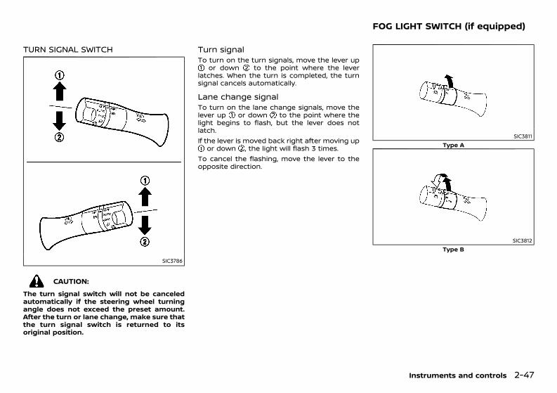
(121,1)
[ Edit: 2020/ 11/ 9 Model: Y62-A ]
TURN SIGNAL SWITCHGUID-E756AA92-11EB-46FA-A0DF-E301D3A32C48
SIC3786
CAUTION:The turn signal switch will not be canceledautomatically if the steering wheel turningangle does not exceed the preset amount.After the turn or lane change, make sure thatthe turn signal switch is returned to itsoriginal position.
Turn signal GUID-B798680C-0546-4E1F-A232-689AFE376B87To turn on the turn signals, move the lever up
or down to the point where the leverlatches. When the turn is completed, the turnsignal cancels automatically.
Lane change signalGUID-BDB58A07-C1CC-4CA8-A2BB-73EC4F9E5FD7To turn on the lane change signals, move thelever up or down to the point where thelight begins to flash, but the lever does notlatch.If the lever is moved back right after moving up
or down , the light will flash 3 times.To cancel the flashing, move the lever to theopposite direction.
GUID-011E9CC1-DA20-416E-A390-DC409772A27C
SIC3811Type A
SIC3812Type B
Instruments and controls 2-47
FOG LIGHT SWITCH (if equipped)
Condition: 'Except for China'/'Except for China/
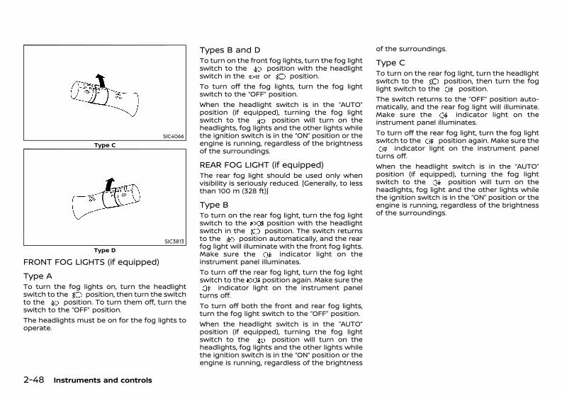
(122,1)
[ Edit: 2020/ 11/ 9 Model: Y62-A ]
2-48 Instruments and controls
SIC4066Type C
SIC3813Type D
FRONT FOG LIGHTS (if equipped)GUID-E1E703A4-8F0E-4356-9671-F82D9C08FF2C
Type A GUID-378ADE2E-4FA7-4159-9486-C36AAB62BF70To turn the fog lights on, turn the headlightswitch to the position, then turn the switchto the position. To turn them off, turn theswitch to the “OFF” position.The headlights must be on for the fog lights tooperate.
Types B and DGUID-DC6F2DBA-9C23-4608-8B89-8BA91335EF1BTo turn on the front fog lights, turn the fog lightswitch to the position with the headlightswitch in the or position.To turn off the fog lights, turn the fog lightswitch to the “OFF” position.When the headlight switch is in the “AUTO”position (if equipped), turning the fog lightswitch to the position will turn on theheadlights, fog lights and the other lights whilethe ignition switch is in the “ON” position or theengine is running, regardless of the brightnessof the surroundings.
REAR FOG LIGHT (if equipped)GUID-0B19826E-095C-43FD-9949-7A2AC81256CEThe rear fog light should be used only whenvisibility is seriously reduced. [Generally, to lessthan 100 m (328 ft)]
Type B GUID-7F9BBB3A-B0EB-4BEA-B405-B87AB7509274To turn on the rear fog light, turn the fog lightswitch to the position with the headlightswitch in the position. The switch returnsto the position automatically, and the rearfog light will illuminate with the front fog lights.Make sure the indicator light on theinstrument panel illuminates.To turn off the rear fog light, turn the fog lightswitch to the position again. Make sure the
indicator light on the instrument panelturns off.To turn off both the front and rear fog lights,turn the fog light switch to the “OFF” position.When the headlight switch is in the “AUTO”position (if equipped), turning the fog lightswitch to the position will turn on theheadlights, fog lights and the other lights whilethe ignition switch is in the “ON” position or theengine is running, regardless of the brightness
of the surroundings.
Type C GUID-56829B36-1EF9-43B5-AA81-15D40D5E71F5To turn on the rear fog light, turn the headlightswitch to the position, then turn the foglight switch to the position.The switch returns to the “OFF” position auto-matically, and the rear fog light will illuminate.Make sure the indicator light on theinstrument panel illuminates.To turn off the rear fog light, turn the fog lightswitch to the position again. Make sure the
indicator light on the instrument panelturns off.When the headlight switch is in the “AUTO”position (if equipped), turning the fog lightswitch to the position will turn on theheadlights, fog light and the other lights whilethe ignition switch is in the “ON” position or theengine is running, regardless of the brightnessof the surroundings.
Condition: 'Except for China'/'Except for China/
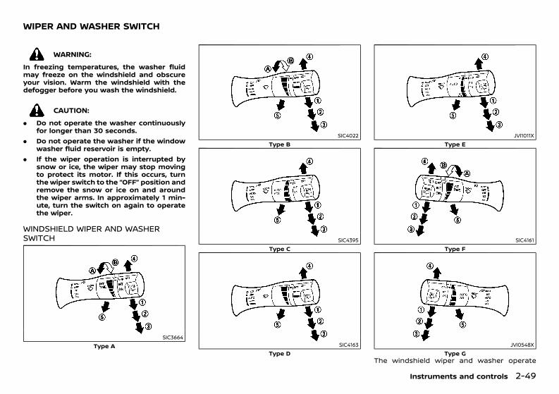
(123,1)
[ Edit: 2020/ 11/ 9 Model: Y62-A ]
GUID-28323B90-2B96-4C32-A0F2-BC87FE71DD71
WARNING:In freezing temperatures, the washer fluidmay freeze on the windshield and obscureyour vision. Warm the windshield with thedefogger before you wash the windshield.
CAUTION:. Do not operate the washer continuously
for longer than 30 seconds.. Do not operate the washer if the window
washer fluid reservoir is empty.. If the wiper operation is interrupted by
snow or ice, the wiper may stop movingto protect its motor. If this occurs, turnthe wiper switch to the “OFF” position andremove the snow or ice on and aroundthe wiper arms. In approximately 1 min-ute, turn the switch on again to operatethe wiper.
WINDSHIELD WIPER AND WASHERSWITCH GUID-E1F8A672-3BE2-4AE4-9491-C85650BBA454
SIC3664Type A
SIC4022Type B
SIC4395Type C
SIC4163Type D
JVI1011XType E
SIC4161Type F
JVI0548XType G
The windshield wiper and washer operate
Instruments and controls 2-49
WIPER AND WASHER SWITCH
Condition: 'Except for China'/'Except for China/
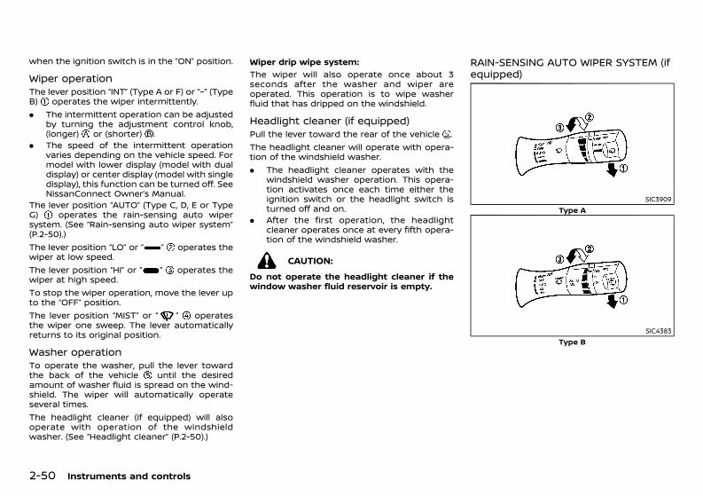
(124,1)
[ Edit: 2020/ 11/ 9 Model: Y62-A ]
2-50 Instruments and controls
when the ignition switch is in the “ON” position.
Wiper operationGUID-6DF76079-383B-4207-8A41-F4630E87AB5BThe lever position “INT” (Type A or F) or “–” (TypeB) operates the wiper intermittently.. The intermittent operation can be adjusted
by turning the adjustment control knob,(longer) or (shorter) .
. The speed of the intermittent operationvaries depending on the vehicle speed. Formodel with lower display (model with dualdisplay) or center display (model with singledisplay), this function can be turned off. SeeNissanConnect Owner’s Manual.
The lever position “AUTO” (Type C, D, E or TypeG) operates the rain-sensing auto wipersystem. (See “Rain-sensing auto wiper system”(P.2-50).)The lever position “LO” or “ ” operates thewiper at low speed.The lever position “HI” or “ ” operates thewiper at high speed.To stop the wiper operation, move the lever upto the “OFF” position.The lever position “MIST” or “ ” operatesthe wiper one sweep. The lever automaticallyreturns to its original position.
Washer operationGUID-5268D467-1F46-4E5E-BBC6-BD09FA5B4906To operate the washer, pull the lever towardthe back of the vehicle until the desiredamount of washer fluid is spread on the wind-shield. The wiper will automatically operateseveral times.The headlight cleaner (if equipped) will alsooperate with operation of the windshieldwasher. (See “Headlight cleaner” (P.2-50).)
Wiper drip wipe system:GUID-C7E1EF24-5AAB-4301-95BE-26917EEE45EF
The wiper will also operate once about 3seconds after the washer and wiper areoperated. This operation is to wipe washerfluid that has dripped on the windshield.
Headlight cleaner (if equipped)GUID-8C9CCA8B-ECFD-4B58-A598-CEB951125292Pull the lever toward the rear of the vehicle .The headlight cleaner will operate with opera-tion of the windshield washer.. The headlight cleaner operates with the
windshield washer operation. This opera-tion activates once each time either theignition switch or the headlight switch isturned off and on.
. After the first operation, the headlightcleaner operates once at every fifth opera-tion of the windshield washer.
CAUTION:Do not operate the headlight cleaner if thewindow washer fluid reservoir is empty.
RAIN-SENSING AUTO WIPER SYSTEM (ifequipped) GUID-598944DD-7121-4E2E-B245-B4FB7B2706DF
SIC3909Type A
SIC4383Type B
Condition: 'Except for China'/'Except for China/
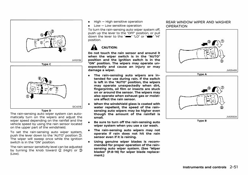
(125,1)
[ Edit: 2020/ 11/ 9 Model: Y62-A ]
JVI1013XType C
SIC4018Type D
The rain-sensing auto wiper system can auto-matically turn on the wipers and adjust thewiper speed depending on the rainfall and thevehicle speed by using the rain sensor locatedon the upper part of the windshield.To set the rain-sensing auto wiper system,push the lever down to the “AUTO” position .The wiper will sweep once while the ignitionswitch is in the “ON” position.The rain sensor sensitivity level can be adjustedby turning the knob toward (High) or(Low).
. High — High sensitive operation
. Low — Low sensitive operationTo turn the rain-sensing auto wiper system off,push up the lever to the “OFF” position, or pulldown the lever to the “ ” “LO” or “ ” “HI”position.
CAUTION:Do not touch the rain sensor and around itwhen the wiper switch is in the “AUTO”position and the ignition switch is in the“ON” position. The wipers may operate un-expectedly and cause an injury or maydamage a wiper.. The rain-sensing auto wipers are in-
tended for use during rain. If the switchis left in the “AUTO” position, the wipersmay operate unexpectedly when dirt,fingerprints, oil film or insects are stuckon or around the sensor. The wipers mayalso operate when exhaust gas or moist-ure affect the rain sensor.
. When the windshield glass is coated withwater repellent, the speed of the rain-sensing auto wipers may be higher eventhough the amount of the rainfall issmall.
. Be sure to turn off the rain-sensing autowiper system when you use a car wash.
. The rain-sensing auto wipers may notoperate if rain does not hit the rainsensor even if it is raining.
. Using genuine wiper blades is recom-mended for proper operation of the rain-sensing auto wiper system. (See “Wiperblades” (P.8-16) for wiper blade replace-ment.)
REAR WINDOW WIPER AND WASHEROPERATIONGUID-E5C536DA-7871-48D5-B536-B2979A02B2BD
JVI0549XType A
JVI0550XType B
Instruments and controls 2-51
Condition: 'Except for China'/'Except for China/
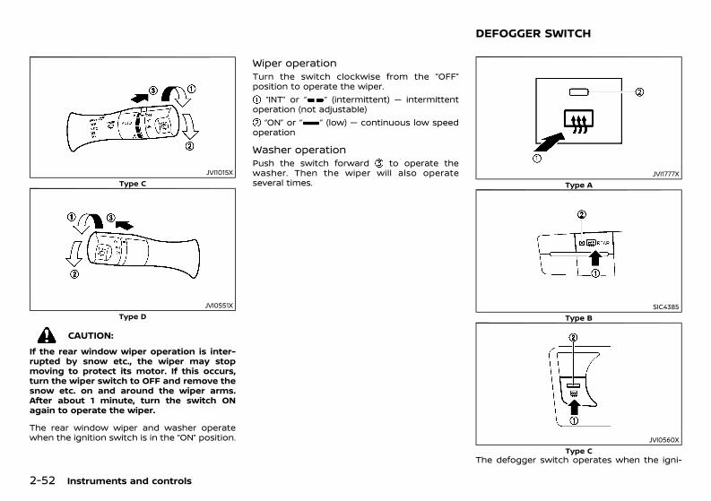
(126,1)
[ Edit: 2020/ 11/ 9 Model: Y62-A ]
2-52 Instruments and controls
JVI1015XType C
JVI0551XType D
CAUTION:If the rear window wiper operation is inter-rupted by snow etc., the wiper may stopmoving to protect its motor. If this occurs,turn the wiper switch to OFF and remove thesnow etc. on and around the wiper arms.After about 1 minute, turn the switch ONagain to operate the wiper.
The rear window wiper and washer operatewhen the ignition switch is in the “ON” position.
Wiper operationGUID-25F0F17C-9C42-44AF-BB46-0FC2F16587A4Turn the switch clockwise from the “OFF”position to operate the wiper.
“INT” or “ ” (intermittent) — intermittentoperation (not adjustable)
“ON” or “ ” (low) — continuous low speedoperation
Washer operationGUID-406B636F-B1D8-4639-A9A3-24BA5766636FPush the switch forward to operate thewasher. Then the wiper will also operateseveral times.
GUID-BBFFE30E-1D67-4D70-B145-F3EE746350C3
JVI1777XType A
SIC4385Type B
JVI0560XType C
The defogger switch operates when the igni-
DEFOGGER SWITCH
Condition: 'Except for China'/'Except for China/
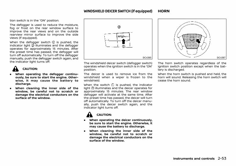
(127,1)
[ Edit: 2020/ 11/ 9 Model: Y62-A ]
tion switch is in the “ON” position.The defogger is used to reduce the moisture,fog or frost on the rear window surface toimprove the rear views and on the outsiderearview mirror surface to improve the sideviews (if equipped).When the defogger switch is pushed, theindicator light illuminates and the defoggeroperates for approximately 15 minutes. Afterthe preset time has passed, the defogger willturn off automatically. To turn off the defoggermanually, push the defogger switch again, andthe indicator light turns off.
CAUTION:. When operating the defogger continu-
ously, be sure to start the engine. Other-wise, it may cause the battery todischarge.
. When cleaning the inner side of thewindow, be careful not to scratch ordamage the electrical conductors on thesurface of the window.
GUID-40606BE6-4C2C-4B4A-9D67-412FA0D15C23
SIC4385
The windshield deicer switch (defogger switch)operates when the ignition switch is in the “ON”position.The deicer is used to remove ice from thewindshield when a wiper is frozen to thewindshield.When the switch is pushed, the indicatorlight illuminates and the deicer operates forapproximately 15 minutes. The rear windowdefogger will activate at the same time. Afterthe preset time has passed, the deicer will turnoff automatically. To turn off the deicer manu-ally, push the deicer switch again, and theindicator light turns off.
CAUTION:. When operating the deicer continuously,
be sure to start the engine. Otherwise, itmay cause the battery to discharge.
. When cleaning the inner side of thewindow, be careful not to scratch ordamage the electrical conductors on thesurface of the window.
GUID-558C3494-5C96-43AB-A3EA-176750978BB3
SIC4387
The horn switch operates regardless of theignition switch position except when the bat-tery is discharged.When the horn switch is pushed and held, thehorn will sound. Releasing the horn switch willcease the horn sound.
Instruments and controls 2-53
WINDSHIELD DEICER SWITCH (if equipped) HORN
Condition: 'Except for China'/'Except for China/
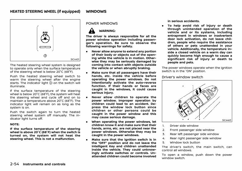
(128,1)
[ Edit: 2020/ 11/ 9 Model: Y62-A ]
2-54 Instruments and controls
GUID-B9468024-1BC7-4BFA-AABE-900BBB71AA74
SIC4401
The heated steering wheel system is designedto operate only when the surface temperatureof the steering wheel is below 20°C (68°F).Push the heated steering wheel switch towarm the steering wheel after the enginestarts. The indicator light on the switch willilluminate.If the surface temperature of the steeringwheel is below 20°C (68°F), the system will heatthe steering wheel and cycle off and on tomaintain a temperature above 20°C (68°F). Theindicator light will remain on as long as thesystem is on.Push the switch again to turn the heatedsteering wheel system off manually. The in-dicator light turns off.
NOTE:If the surface temperature of the steeringwheel is above 20°C (68°F) when the switch isturned on, the system will not heat thesteering wheel. This is not a malfunction.
GUID-037EA0C9-B46E-4467-B8E3-89747E9741CA
POWER WINDOWSGUID-019EDE71-1D6E-4678-9A74-B55ABF424541
WARNING:The driver is always responsible for all thepower window operation including passen-ger’s operation. Be sure to observe thefollowing warnings for safety.. Never allow anyone to extend any portion
of their body or objects out of the open-ing while the vehicle is in motion. Other-wise they may be seriously damaged bycoming into contact with objects outsidethe vehicle or when abruptly braking.
. Make sure that all passengers have theirhands, etc. inside the vehicle beforeoperating the power windows. Do notintentionally activate the auto-reversefunction. If their hands or faces arecaught in the windows, it could causeserious injury.
. Never allow children to operate thepower window. Improper operation bychildren could lead to an accident. De-press the window lock button sincechildren or other persons could becaught in the power window and thismay cause serious damage.
. When operating the power windows, letchildren know it and make sure that theirhands, arms, etc. are not placed near thepower windows. Otherwise they may becaught in the power windows.
. Make sure that the ignition switch is inthe “OFF” position and do not leave theIntelligent Key and children unattendedinside the vehicle. They could unknow-ingly activate switches or controls. Un-attended children could become involved
in serious accidents.. To help avoid risk of injury or death
through unintended operation of thevehicle and or its systems, includingentrapment in windows or inadvertentdoor lock activation, do not leave chil-dren, people who require the assistanceof others or pets unattended in yourvehicle. Additionally, the temperature in-side a closed vehicle on a warm day canquickly become high enough to cause asignificant risk of injury or death topeople and pets.
The power windows operate when the ignitionswitch is in the “ON” position.
Driver’s window switchGUID-A9BD29BC-A482-48F5-905A-77C13C896BD7
SIC4463
1. Driver side window2. Front passenger side window3. Rear left passenger side window4. Rear right passenger side window5. Window lock buttonThe driver’s switch, the main switch, cancontrol all windows.To open a window, push down the powerwindow switch.
HEATED STEERING WHEEL (if equipped) WINDOWS
Condition: 'Except for China'/'Except for China/
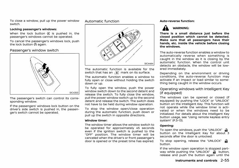
(129,1)
[ Edit: 2020/ 11/ 9 Model: Y62-A ]
To close a window, pull up the power windowswitch.Locking passenger’s windows:
GUID-C7E1EF24-5AAB-4301-95BE-26917EEE45EF
When the lock button is pushed in, thepassenger’s windows cannot be operated.To cancel the passenger’s windows lock, pushthe lock button again.
Passenger’s window switchGUID-5AA34D81-AF36-43F5-98DA-ACC04400FDB8
SIC4353
The passenger’s switch can control its corre-sponding window.If the passengers’ windows lock button on thedriver’s side switch is pushed in, the passen-ger’s switch cannot be operated.
Automatic functionGUID-C93B5CE7-0AAF-432B-93BD-BCF6558519A9
SIC4464
The automatic function is available for theswitch that has an mark on its surface.The automatic function enables a window tofully open or close without holding the switchdown or up.To fully open the window, push the powerwindow switch down to the second detent andrelease the switch. To fully close the window,pull the power window switch up to the seconddetent and release the switch. The switch doesnot have to be held during window operation.To stop the window open/close operationduring the automatic function, push down orpull up the switch in opposite directions.Window timer:
GUID-C7E1EF24-5AAB-4301-95BE-26917EEE45EF
The window timer allows the window switch tobe operated for approximately 45 secondseven if the ignition switch is pushed to the“OFF” position. The window timer will becanceled when the driver’s or front passenger’sdoor is opened or the preset time has expired.
Auto-reverse function:GUID-C7E1EF24-5AAB-4301-95BE-26917EEE45EF
WARNING:There is a small distance just before theclosed position which cannot be detected.Make sure that all passengers have theirhands, etc. inside the vehicle before closingthe windows.
The auto-reverse function enables a window toautomatically reverse when something iscaught in the window as it is closing by theautomatic function. When the control unitdetects an obstacle, the window will be low-ered immediately.Depending on the environment or drivingconditions, the auto-reverse function mayactivate if an impact or load similar to some-thing being caught in the window occurs.
Operating windows with Intelligent Key(if equipped)GUID-4B33F154-A0BC-44BC-B0AC-3A444AC85F40The windows can be opened or closed (ifequipped) by pushing the “LOCK” or “UNLOCK”button on the Intelligent Key. This function willnot operate while the window timer is acti-vated or when the windows need to beinitialized. For details about the Intelligent Keybutton usage, see “Using remote keyless entrysystem” (P.3-13).Opening:
GUID-C7E1EF24-5AAB-4301-95BE-26917EEE45EF
To open the windows, push the “UNLOCK”button on the Intelligent Key for about 3seconds after the door is unlocked.To stop opening, release the “UNLOCK”button.If the window open operation is stopped part-way while pushing the “UNLOCK” button,release and push the button again until the
Instruments and controls 2-55
Condition: 'Except for China'/'Except for China/
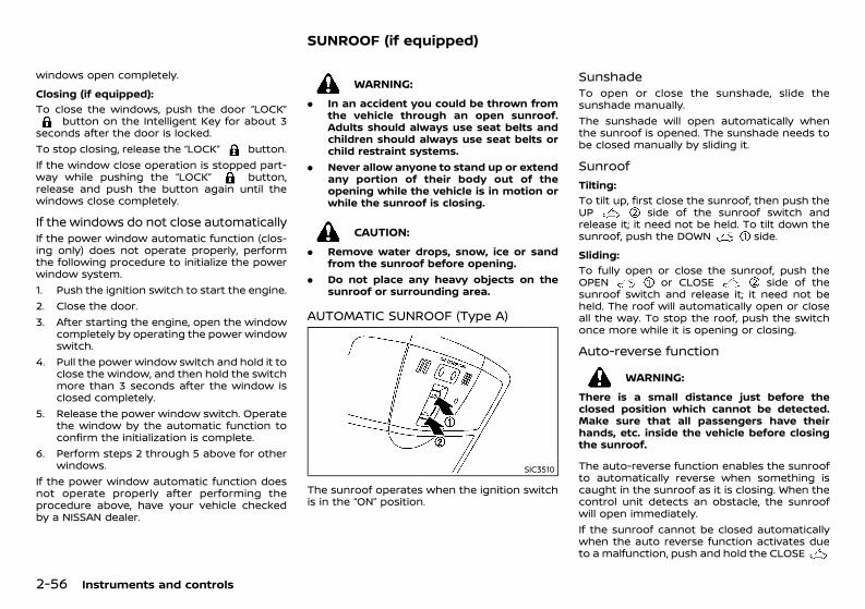
(130,1)
[ Edit: 2020/ 11/ 9 Model: Y62-A ]
2-56 Instruments and controls
windows open completely.Closing (if equipped):
GUID-C7E1EF24-5AAB-4301-95BE-26917EEE45EF
To close the windows, push the door “LOCK”button on the Intelligent Key for about 3
seconds after the door is locked.To stop closing, release the “LOCK” button.If the window close operation is stopped part-way while pushing the “LOCK” button,release and push the button again until thewindows close completely.
If the windows do not close automaticallyGUID-7697C7D0-FDC0-4911-8630-F93CB6220D37If the power window automatic function (clos-ing only) does not operate properly, performthe following procedure to initialize the powerwindow system.1. Push the ignition switch to start the engine.2. Close the door.3. After starting the engine, open the window
completely by operating the power windowswitch.
4. Pull the power window switch and hold it toclose the window, and then hold the switchmore than 3 seconds after the window isclosed completely.
5. Release the power window switch. Operatethe window by the automatic function toconfirm the initialization is complete.
6. Perform steps 2 through 5 above for otherwindows.
If the power window automatic function doesnot operate properly after performing theprocedure above, have your vehicle checkedby a NISSAN dealer.
GUID-CA6C7F41-0553-40AA-937A-7E0A43385E04
WARNING:. In an accident you could be thrown from
the vehicle through an open sunroof.Adults should always use seat belts andchildren should always use seat belts orchild restraint systems.
. Never allow anyone to stand up or extendany portion of their body out of theopening while the vehicle is in motion orwhile the sunroof is closing.
CAUTION:. Remove water drops, snow, ice or sand
from the sunroof before opening.. Do not place any heavy objects on the
sunroof or surrounding area.
AUTOMATIC SUNROOF (Type A)GUID-E219D963-1EA9-4B99-A687-768FB5513A7A
SIC3510
The sunroof operates when the ignition switchis in the “ON” position.
Sunshade GUID-3A47073D-14CC-4A80-A445-AB7EB5052AA0To open or close the sunshade, slide thesunshade manually.The sunshade will open automatically whenthe sunroof is opened. The sunshade needs tobe closed manually by sliding it.
Sunroof GUID-8653DAD9-BD28-4DEF-938A-23281964A74D
Tilting:GUID-C7E1EF24-5AAB-4301-95BE-26917EEE45EF
To tilt up, first close the sunroof, then push theUP side of the sunroof switch andrelease it; it need not be held. To tilt down thesunroof, push the DOWN side.Sliding:
GUID-C7E1EF24-5AAB-4301-95BE-26917EEE45EF
To fully open or close the sunroof, push theOPEN or CLOSE side of thesunroof switch and release it; it need not beheld. The roof will automatically open or closeall the way. To stop the roof, push the switchonce more while it is opening or closing.
Auto-reverse functionGUID-DD9B3F5F-8338-4590-97C0-F7BB96B5AEE4
WARNING:There is a small distance just before theclosed position which cannot be detected.Make sure that all passengers have theirhands, etc. inside the vehicle before closingthe sunroof.
The auto-reverse function enables the sunroofto automatically reverse when something iscaught in the sunroof as it is closing. When thecontrol unit detects an obstacle, the sunroofwill open immediately.If the sunroof cannot be closed automaticallywhen the auto reverse function activates dueto a malfunction, push and hold the CLOSE
SUNROOF (if equipped)
Condition: 'Except for China'/'Except for China/
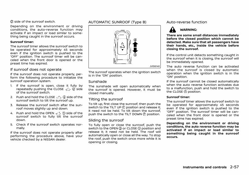
(131,1)
[ Edit: 2020/ 11/ 9 Model: Y62-A ]
side of the sunroof switch.Depending on the environment or drivingconditions, the auto-reverse function mayactivate if an impact or load similar to some-thing being caught in the sunroof occurs.Sunroof timer:
GUID-C7E1EF24-5AAB-4301-95BE-26917EEE45EF
The sunroof timer allows the sunroof switch tobe operated for approximately 45 secondseven if the ignition switch is pushed to the“OFF” position. The sunroof timer will be can-celed when the front door is opened or thepreset time has expired.
If sunroof does not operateGUID-314045A5-1912-45DE-8238-FA872B8B506EIf the sunroof does not operate properly, per-form the following procedure to initialize thesunroof operation system.1. If the sunroof is open, close it fully by
repeatedly pushing the CLOSE sideof the sunroof switch.
2. Push and hold the CLOSE side of thesunroof switch to tilt the sunroof up.
3. Release the sunroof switch after the sun-roof moves slightly up and down.
4. Push and hold the OPEN side of thesunroof switch to fully tilt the sunroofdown.
5. Check if the sunroof switch operates nor-mally.
If the sunroof does not operate properly afterperforming the procedure above, have yourvehicle checked by a NISSAN dealer.
AUTOMATIC SUNROOF (Type B)GUID-04041B9B-6B45-47AD-997C-43484ECDEA81
JVI0614X
The sunroof operates when the ignition switchis in the “ON” position.
Sunshade GUID-75EA450B-02A4-4723-A33C-29603E858954The sunshade will open automatically whenthe sunroof is opened. However, it must beclosed manually.
Tilting the sunroofGUID-65672F3C-3DDA-445C-8094-3F747FD7D7A5To tilt up, first close the sunroof, then push theswitch to the TILT UP position and release it;it need not be held. To tilt down the sunroof,push the switch to the TILT DOWN position.
Sliding the sunroofGUID-42E006FC-3C0C-4BBB-B979-BB5683E6C985To fully open or close the sunroof, push theswitch to the OPEN or CLOSE position andrelease it; it need not be held. The roof willautomatically open or close all the way. To stopthe roof, push the switch once more while it isopening or closing.
Auto-reverse functionGUID-D296C550-FFEB-41B9-BED7-B6567C73F5B3
WARNING:There are some small distances immediatelybefore the closed position which cannot bedetected. Make sure that all passengers havetheir hands, etc., inside the vehicle beforeclosing the sunroof.
If the control unit detects something caught inthe sunroof when it is closing, the sunroof willbe immediately opened.The auto reverse function can be activatedwhen the sunroof is closed by automaticoperation when the ignition switch is in the“ON” position.If the sunroof cannot be closed automaticallywhen the auto reverse function activates dueto a malfunction, push and hold the switch tothe CLOSE position.Sunroof timer:
GUID-C7E1EF24-5AAB-4301-95BE-26917EEE45EF
The sunroof timer allows the sunroof switch tobe operated for approximately 45 secondseven if the ignition switch is pushed to the“OFF” position. The sunroof timer will be can-celed when the front door is opened or thepreset time has expired.Depending on the environment or drivingconditions, the auto reverse function may beactivated if an impact or load similar tosomething being caught in the sunroofoccurs.
Instruments and controls 2-57
Condition: 'Except for China'/'Except for China/
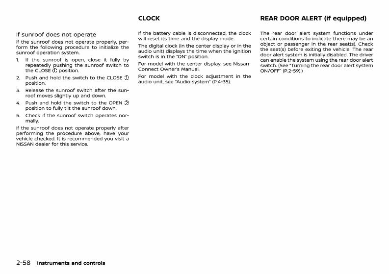
(132,1)
[ Edit: 2020/ 11/ 9 Model: Y62-A ]
2-58 Instruments and controls
If sunroof does not operateGUID-28D391B9-CE54-4EB1-811B-10276FE47D20If the sunroof does not operate properly, per-form the following procedure to initialize thesunroof operation system.1. If the sunroof is open, close it fully by
repeatedly pushing the sunroof switch tothe CLOSE position.
2. Push and hold the switch to the CLOSEposition.
3. Release the sunroof switch after the sun-roof moves slightly up and down.
4. Push and hold the switch to the OPENposition to fully tilt the sunroof down.
5. Check if the sunroof switch operates nor-mally.
If the sunroof does not operate properly afterperforming the procedure above, have yourvehicle checked. It is recommended you visit aNISSAN dealer for this service.
GUID-AC429A84-F0D4-4DBE-B4D4-43748AC4018BIf the battery cable is disconnected, the clockwill reset its time and the display mode.The digital clock (in the center display or in theaudio unit) displays the time when the ignitionswitch is in the “ON” position.For model with the center display, see Nissan-Connect Owner’s Manual.For model with the clock adjustment in theaudio unit, see “Audio system” (P.4-35).
GUID-A9BD981B-F994-4FBE-AD3E-9E496699AB3FThe rear door alert system functions undercertain conditions to indicate there may be anobject or passenger in the rear seat(s). Checkthe seat(s) before exiting the vehicle. The reardoor alert system is initially disabled. The drivercan enable the system using the rear door alertswitch. (See “Turning the rear door alert systemON/OFF” (P.2-59).)
CLOCK REAR DOOR ALERT (if equipped)
Condition: 'Except for China'/'Except for China/
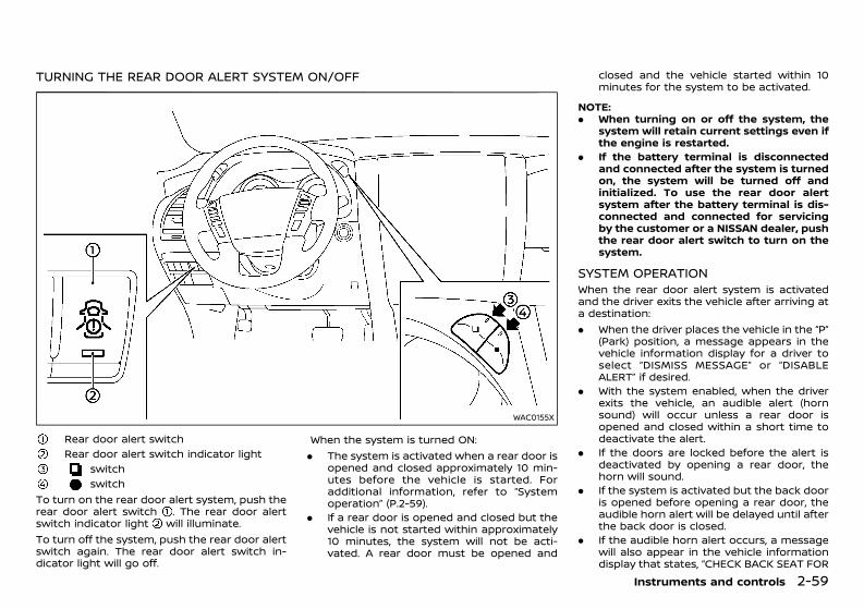
(133,1)
[ Edit: 2020/ 11/ 9 Model: Y62-A ]
TURNING THE REAR DOOR ALERT SYSTEM ON/OFFGUID-1DEBB93A-143E-4899-86DD-7CA3D21C9D2F
WAC0155X
Rear door alert switchRear door alert switch indicator light
switchswitch
To turn on the rear door alert system, push therear door alert switch . The rear door alertswitch indicator light will illuminate.To turn off the system, push the rear door alertswitch again. The rear door alert switch in-dicator light will go off.
When the system is turned ON:. The system is activated when a rear door is
opened and closed approximately 10 min-utes before the vehicle is started. Foradditional information, refer to “Systemoperation” (P.2-59).
. If a rear door is opened and closed but thevehicle is not started within approximately10 minutes, the system will not be acti-vated. A rear door must be opened and
closed and the vehicle started within 10minutes for the system to be activated.
NOTE:. When turning on or off the system, the
system will retain current settings even ifthe engine is restarted.
. If the battery terminal is disconnectedand connected after the system is turnedon, the system will be turned off andinitialized. To use the rear door alertsystem after the battery terminal is dis-connected and connected for servicingby the customer or a NISSAN dealer, pushthe rear door alert switch to turn on thesystem.
SYSTEM OPERATIONGUID-1D6F9EC8-DEC1-44B3-8DDE-4983FBDFA74DWhen the rear door alert system is activatedand the driver exits the vehicle after arriving ata destination:. When the driver places the vehicle in the “P”
(Park) position, a message appears in thevehicle information display for a driver toselect “DISMISS MESSAGE” or “DISABLEALERT” if desired.
. With the system enabled, when the driverexits the vehicle, an audible alert (hornsound) will occur unless a rear door isopened and closed within a short time todeactivate the alert.
. If the doors are locked before the alert isdeactivated by opening a rear door, thehorn will sound.
. If the system is activated but the back dooris opened before opening a rear door, theaudible horn alert will be delayed until afterthe back door is closed.
. If the audible horn alert occurs, a messagewill also appear in the vehicle informationdisplay that states, “CHECK BACK SEAT FOR
Instruments and controls 2-59
Condition: 'Except for China'/'Except for China/
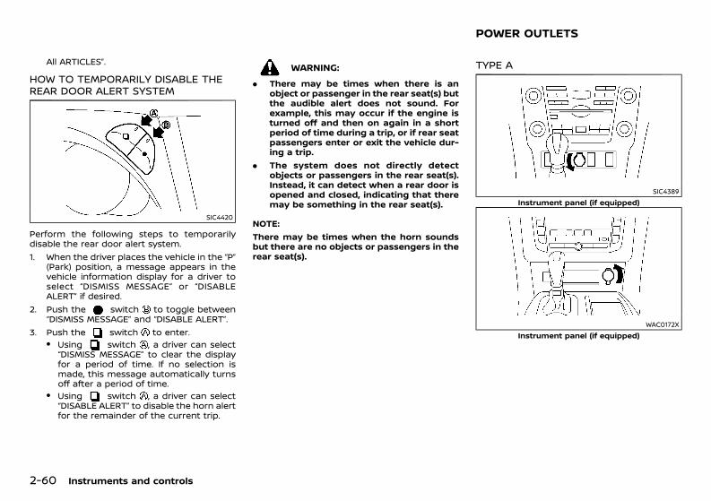
(134,1)
[ Edit: 2020/ 11/ 9 Model: Y62-A ]
2-60 Instruments and controls
All ARTICLES”.
HOW TO TEMPORARILY DISABLE THEREAR DOOR ALERT SYSTEMGUID-DB3F3AA3-157E-4F8A-9586-FD66170FBF08
SIC4420
Perform the following steps to temporarilydisable the rear door alert system.1. When the driver places the vehicle in the “P”
(Park) position, a message appears in thevehicle information display for a driver toselect “DISMISS MESSAGE” or “DISABLEALERT” if desired.
2. Push the switch to toggle between“DISMISS MESSAGE” and “DISABLE ALERT”.
3. Push the switch to enter.. Using switch , a driver can select
“DISMISS MESSAGE” to clear the displayfor a period of time. If no selection ismade, this message automatically turnsoff after a period of time.
. Using switch , a driver can select“DISABLE ALERT” to disable the horn alertfor the remainder of the current trip.
WARNING:. There may be times when there is an
object or passenger in the rear seat(s) butthe audible alert does not sound. Forexample, this may occur if the engine isturned off and then on again in a shortperiod of time during a trip, or if rear seatpassengers enter or exit the vehicle dur-ing a trip.
. The system does not directly detectobjects or passengers in the rear seat(s).Instead, it can detect when a rear door isopened and closed, indicating that theremay be something in the rear seat(s).
NOTE:There may be times when the horn soundsbut there are no objects or passengers in therear seat(s).
GUID-71B10566-178F-44B7-9586-EB31A2CB2FF1
TYPE A GUID-DBCC74BE-E2CE-4185-98AD-C07FAC12A703
SIC4389Instrument panel (if equipped)
WAC0172XInstrument panel (if equipped)
POWER OUTLETS
Condition: 'Except for China'/'Except for China/
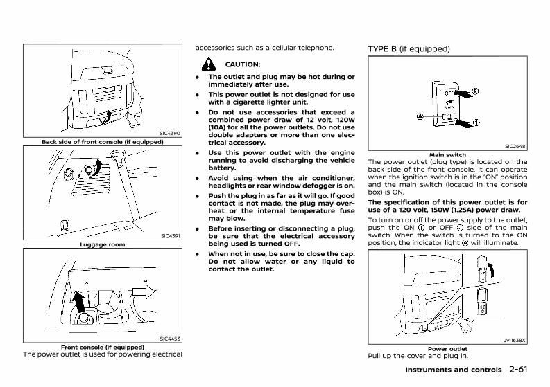
(135,1)
[ Edit: 2020/ 11/ 9 Model: Y62-A ]
SIC4390Back side of front console (if equipped)
SIC4391Luggage room
SIC4453Front console (if equipped)
The power outlet is used for powering electrical
accessories such as a cellular telephone.
CAUTION:. The outlet and plug may be hot during or
immediately after use.. This power outlet is not designed for use
with a cigarette lighter unit.. Do not use accessories that exceed a
combined power draw of 12 volt, 120W(10A) for all the power outlets. Do not usedouble adapters or more than one elec-trical accessory.
. Use this power outlet with the enginerunning to avoid discharging the vehiclebattery.
. Avoid using when the air conditioner,headlights or rear window defogger is on.
. Push the plug in as far as it will go. If goodcontact is not made, the plug may over-heat or the internal temperature fusemay blow.
. Before inserting or disconnecting a plug,be sure that the electrical accessorybeing used is turned OFF.
. When not in use, be sure to close the cap.Do not allow water or any liquid tocontact the outlet.
TYPE B (if equipped)GUID-E1DF1DC4-75EB-42B8-86E5-DD05FAC2010E
SIC2648Main switch
The power outlet (plug type) is located on theback side of the front console. It can operatewhen the ignition switch is in the “ON” positionand the main switch (located in the consolebox) is ON.The specification of this power outlet is foruse of a 120 volt, 150W (1.25A) power draw.To turn on or off the power supply to the outlet,push the ON or OFF side of the mainswitch. When the switch is turned to the ONposition, the indicator light will illuminate.
JVI1638XPower outlet
Pull up the cover and plug in.
Instruments and controls 2-61
Condition: 'Except for China'/'Except for China/
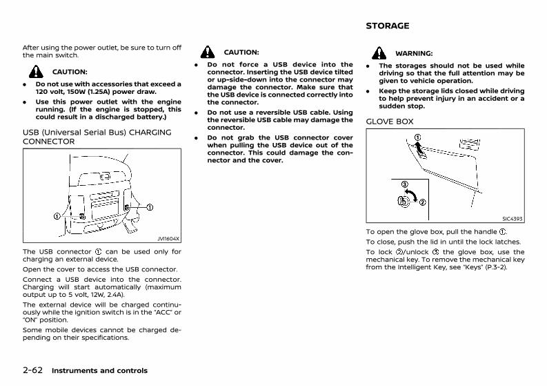
(136,1)
[ Edit: 2020/ 11/ 9 Model: Y62-A ]
2-62 Instruments and controls
After using the power outlet, be sure to turn offthe main switch.
CAUTION:. Do not use with accessories that exceed a
120 volt, 150W (1.25A) power draw.. Use this power outlet with the engine
running. (If the engine is stopped, thiscould result in a discharged battery.)
USB (Universal Serial Bus) CHARGINGCONNECTORGUID-C2D01AC7-5A8F-490A-B091-0D89E1389A6F
JVI1604X
The USB connector can be used only forcharging an external device.Open the cover to access the USB connector.Connect a USB device into the connector.Charging will start automatically (maximumoutput up to 5 volt, 12W, 2.4A).The external device will be charged continu-ously while the ignition switch is in the “ACC” or“ON” position.Some mobile devices cannot be charged de-pending on their specifications.
CAUTION:. Do not force a USB device into the
connector. Inserting the USB device tiltedor up-side-down into the connector maydamage the connector. Make sure thatthe USB device is connected correctly intothe connector.
. Do not use a reversible USB cable. Usingthe reversible USB cable may damage theconnector.
. Do not grab the USB connector coverwhen pulling the USB device out of theconnector. This could damage the con-nector and the cover.
GUID-E4DBC035-E53E-4441-88DA-A00F0E88CB21
WARNING:. The storages should not be used while
driving so that the full attention may begiven to vehicle operation.
. Keep the storage lids closed while drivingto help prevent injury in an accident or asudden stop.
GLOVE BOXGUID-EFAE8038-23E5-4DB0-AA90-2DED70AADF90
SIC4393
To open the glove box, pull the handle .To close, push the lid in until the lock latches.To lock /unlock the glove box, use themechanical key. To remove the mechanical keyfrom the Intelligent Key, see “Keys” (P.3-2).
STORAGE
Condition: 'Except for China'/'Except for China/
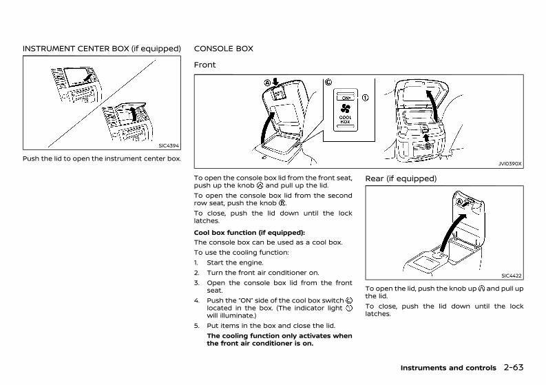
(137,1)
[ Edit: 2020/ 11/ 9 Model: Y62-A ]
INSTRUMENT CENTER BOX (if equipped)GUID-CC7D3628-9CB5-40A1-B918-941C1BFCD08F
SIC4394
Push the lid to open the instrument center box.
CONSOLE BOXGUID-426EBCD3-362C-4965-880D-17349E870070
FrontGUID-8046EBA0-ACEC-4710-8E56-257F7621187C
JVI0390X
To open the console box lid from the front seat,push up the knob and pull up the lid.To open the console box lid from the secondrow seat, push the knob .To close, push the lid down until the locklatches.Cool box function (if equipped):
GUID-C7E1EF24-5AAB-4301-95BE-26917EEE45EF
The console box can be used as a cool box.To use the cooling function:1. Start the engine.2. Turn the front air conditioner on.3. Open the console box lid from the front
seat.4. Push the “ON” side of the cool box switch
located in the box. (The indicator lightwill illuminate.)
5. Put items in the box and close the lid.The cooling function only activates whenthe front air conditioner is on.
Rear (if equipped)GUID-FE4A1320-16B9-431E-B04B-C52C1E641EC8
SIC4422
To open the lid, push the knob up and pull upthe lid.To close, push the lid down until the locklatches.
Instruments and controls 2-63
Condition: 'Except for China'/'Except for China/
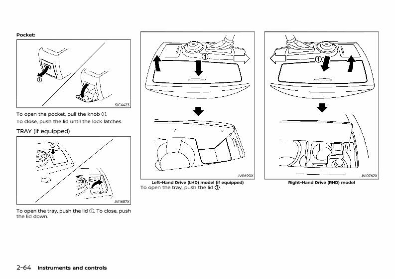
(138,1)
[ Edit: 2020/ 11/ 9 Model: Y62-A ]
2-64 Instruments and controls
Pocket:GUID-C7E1EF24-5AAB-4301-95BE-26917EEE45EF
SIC4423
To open the pocket, pull the knob .To close, push the lid until the lock latches.
TRAY (if equipped)GUID-E8A9CBC6-C08A-48BF-88CA-A3E24054C044
JVI1687X
To open the tray, push the lid . To close, pushthe lid down.
JVI1690XLeft-Hand Drive (LHD) model (if equipped)
To open the tray, push the lid .
JVI0762XRight-Hand Drive (RHD) model
Condition: 'Except for China'/'Except for China/
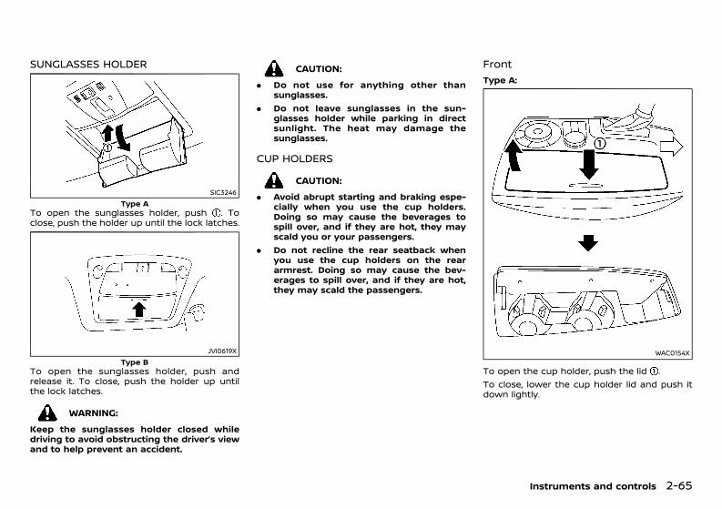
(139,1)
[ Edit: 2020/ 11/ 9 Model: Y62-A ]
SUNGLASSES HOLDERGUID-BE56EC99-6D94-411E-957E-594FAF359F97
SIC3246Type A
To open the sunglasses holder, push . Toclose, push the holder up until the lock latches.
JVI0619XType B
To open the sunglasses holder, push andrelease it. To close, push the holder up untilthe lock latches.
WARNING:Keep the sunglasses holder closed whiledriving to avoid obstructing the driver’s viewand to help prevent an accident.
CAUTION:. Do not use for anything other than
sunglasses.. Do not leave sunglasses in the sun-
glasses holder while parking in directsunlight. The heat may damage thesunglasses.
CUP HOLDERSGUID-254417BA-3214-47CC-8182-9A8F0C55B921CAUTION:
. Avoid abrupt starting and braking espe-cially when you use the cup holders.Doing so may cause the beverages tospill over, and if they are hot, they mayscald you or your passengers.
. Do not recline the rear seatback whenyou use the cup holders on the reararmrest. Doing so may cause the bev-erages to spill over, and if they are hot,they may scald the passengers.
Front GUID-5014D297-12CB-4AED-B413-5F54D1DBF6BB
Type A:GUID-C7E1EF24-5AAB-4301-95BE-26917EEE45EF
WAC0154X
To open the cup holder, push the lid .To close, lower the cup holder lid and push itdown lightly.
Instruments and controls 2-65
Condition: 'Except for China'/'Except for China/
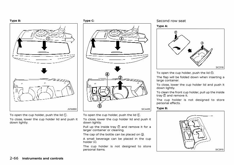
(140,1)
[ Edit: 2020/ 11/ 9 Model: Y62-A ]
2-66 Instruments and controls
Type B:GUID-C7E1EF24-5AAB-4301-95BE-26917EEE45EF
JVI1688X
To open the cup holder, push the lid .To close, lower the cup holder lid and push itdown lightly.
Type C:GUID-C7E1EF24-5AAB-4301-95BE-26917EEE45EF
SIC4495
To open the cup holder, push the lid .To close, lower the cup holder lid and push itdown lightly.Pull up the inside tray and remove it for alarger container or cleaning.The cap of the bottle can be placed on .A small beverage can be placed in the cupholder .The cup holder is not designed to storepersonal items.
Second row seatGUID-82BC5D4D-DA40-4805-B5B0-4718375819F3
Type A:GUID-C7E1EF24-5AAB-4301-95BE-26917EEE45EF
SIC3118
To open the cup holder, push the lid .The flap will be folded down when inserting alarge container.To close, lower the cup holder lid and push itdown lightly.To clean the front cup holder, pull up the insidetray and remove it.The cup holder is not designed to storepersonal effects.Type B:
GUID-C7E1EF24-5AAB-4301-95BE-26917EEE45EF
SIC2915
Condition: 'Except for China'/'Except for China/
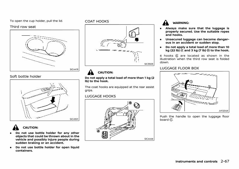
(141,1)
[ Edit: 2020/ 11/ 9 Model: Y62-A ]
To open the cup holder, pull the lid.
Third row seatGUID-22302515-0798-47D5-BC03-97795F02E8AB
SIC4419
Soft bottle holderGUID-61EFB93A-87D5-44A0-BA9E-DFAAA14CFFC7
SIC4501
CAUTION:. Do not use bottle holder for any other
objects that could be thrown about in thevehicle and possibly injure people duringsudden braking or an accident.
. Do not use bottle holder for open liquidcontainers.
COAT HOOKSGUID-A95C7E48-C2E4-4F72-8AB1-3E662EDF0E4C
SIC3505
CAUTION:Do not apply a total load of more than 1 kg (2lb) to the hook.
The coat hooks are equipped at the rear assistgrips.
LUGGAGE HOOKSGUID-F06C64B9-297E-4E54-828B-2B7D5682CA7A
SIC4446
WARNING:. Always make sure that the luggage is
properly secured. Use the suitable ropesand hooks.
. Unsecured luggage can become danger-ous in an accident or sudden stop.
. Do not apply a total load of more than 10kg (22 lb) and 3 kg (7 lb) to the hook.
6 hooks are located as shown in theillustration when the third row seat is foldeddown.
LUGGAGE FLOOR BOXGUID-3F77E25E-6890-40F9-8372-3E01E8720631
JVI1204X
Push the handle to open the luggage floorboard .
Instruments and controls 2-67
Condition: 'Except for China'/'Except for China/
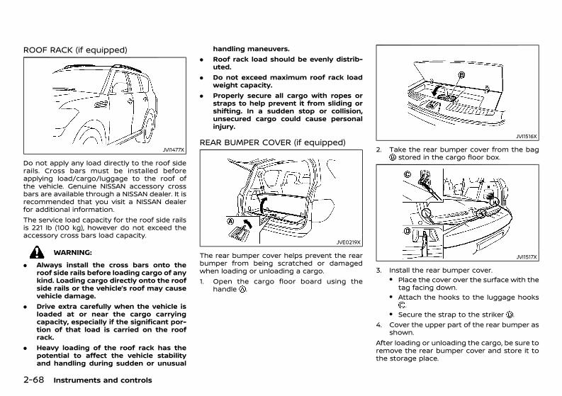
(142,1)
[ Edit: 2020/ 11/ 9 Model: Y62-A ]
2-68 Instruments and controls
ROOF RACK (if equipped)GUID-A254913F-D72A-475B-BC9B-87AC5AA250F7
JVI1477X
Do not apply any load directly to the roof siderails. Cross bars must be installed beforeapplying load/cargo/luggage to the roof ofthe vehicle. Genuine NISSAN accessory crossbars are available through a NISSAN dealer. It isrecommended that you visit a NISSAN dealerfor additional information.The service load capacity for the roof side railsis 221 lb (100 kg), however do not exceed theaccessory cross bars load capacity.
WARNING:. Always install the cross bars onto the
roof side rails before loading cargo of anykind. Loading cargo directly onto the roofside rails or the vehicle’s roof may causevehicle damage.
. Drive extra carefully when the vehicle isloaded at or near the cargo carryingcapacity, especially if the significant por-tion of that load is carried on the roofrack.
. Heavy loading of the roof rack has thepotential to affect the vehicle stabilityand handling during sudden or unusual
handling maneuvers.. Roof rack load should be evenly distrib-
uted.. Do not exceed maximum roof rack load
weight capacity.. Properly secure all cargo with ropes or
straps to help prevent it from sliding orshifting. In a sudden stop or collision,unsecured cargo could cause personalinjury.
REAR BUMPER COVER (if equipped)GUID-DA2E3565-D7D5-46F8-80B7-0F6A0136270B
JVE0219X
The rear bumper cover helps prevent the rearbumper from being scratched or damagedwhen loading or unloading a cargo.1. Open the cargo floor board using the
handle .
JVI1516X
2. Take the rear bumper cover from the bagstored in the cargo floor box.
JVI1517X
3. Install the rear bumper cover.. Place the cover over the surface with the
tag facing down.. Attach the hooks to the luggage hooks
.. Secure the strap to the striker .
4. Cover the upper part of the rear bumper asshown.
After loading or unloading the cargo, be sure toremove the rear bumper cover and store it tothe storage place.
Condition: 'Except for China'/'Except for China/
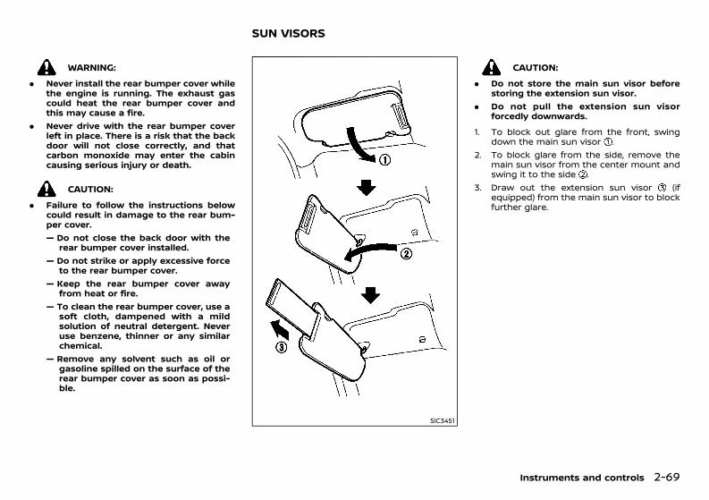
(143,1)
[ Edit: 2020/ 11/ 9 Model: Y62-A ]
WARNING:. Never install the rear bumper cover while
the engine is running. The exhaust gascould heat the rear bumper cover andthis may cause a fire.
. Never drive with the rear bumper coverleft in place. There is a risk that the backdoor will not close correctly, and thatcarbon monoxide may enter the cabincausing serious injury or death.
CAUTION:. Failure to follow the instructions below
could result in damage to the rear bum-per cover.— Do not close the back door with the
rear bumper cover installed.— Do not strike or apply excessive force
to the rear bumper cover.— Keep the rear bumper cover away
from heat or fire.— To clean the rear bumper cover, use a
soft cloth, dampened with a mildsolution of neutral detergent. Neveruse benzene, thinner or any similarchemical.
— Remove any solvent such as oil orgasoline spilled on the surface of therear bumper cover as soon as possi-ble.
GUID-9FAD8DB4-278F-4DB9-847D-80BB3C4BAFC1
SIC3451
CAUTION:. Do not store the main sun visor before
storing the extension sun visor.. Do not pull the extension sun visor
forcedly downwards.1. To block out glare from the front, swing
down the main sun visor .2. To block glare from the side, remove the
main sun visor from the center mount andswing it to the side .
3. Draw out the extension sun visor (ifequipped) from the main sun visor to blockfurther glare.
Instruments and controls 2-69
SUN VISORS
Condition: 'Except for China'/'Except for China/
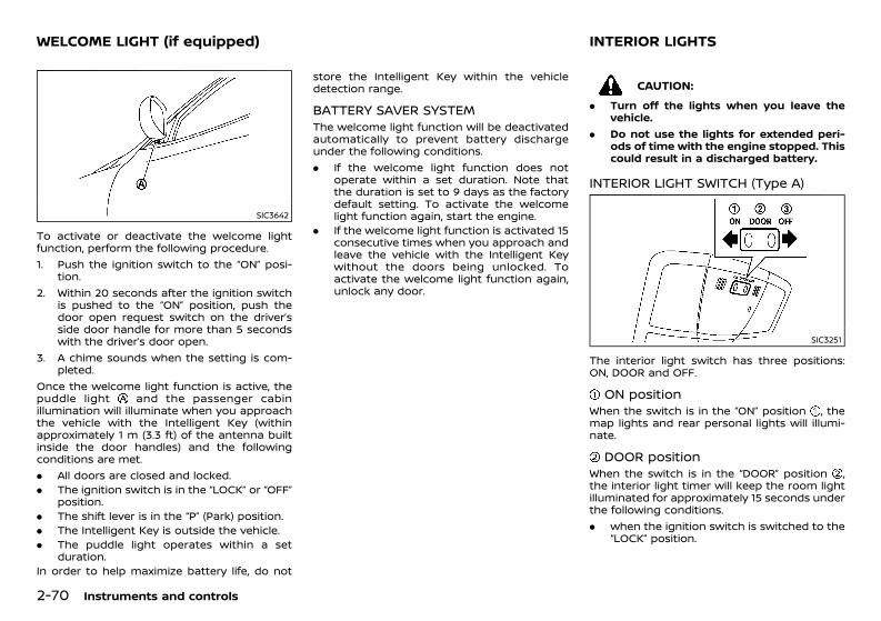
(144,1)
[ Edit: 2020/ 11/ 9 Model: Y62-A ]
2-70 Instruments and controls
GUID-22710D59-2841-46CB-8BE2-30E40CACCE88
SIC3642
To activate or deactivate the welcome lightfunction, perform the following procedure.1. Push the ignition switch to the “ON” posi-
tion.2. Within 20 seconds after the ignition switch
is pushed to the “ON” position, push thedoor open request switch on the driver’sside door handle for more than 5 secondswith the driver’s door open.
3. A chime sounds when the setting is com-pleted.
Once the welcome light function is active, thepuddle light and the passenger cabinillumination will illuminate when you approachthe vehicle with the Intelligent Key (withinapproximately 1 m (3.3 ft) of the antenna builtinside the door handles) and the followingconditions are met.. All doors are closed and locked.. The ignition switch is in the “LOCK” or “OFF”
position.. The shift lever is in the “P” (Park) position.. The Intelligent Key is outside the vehicle.. The puddle light operates within a set
duration.In order to help maximize battery life, do not
store the Intelligent Key within the vehicledetection range.
BATTERY SAVER SYSTEMGUID-E12112A4-307A-4217-83E4-A304E48D3CEEThe welcome light function will be deactivatedautomatically to prevent battery dischargeunder the following conditions.. If the welcome light function does not
operate within a set duration. Note thatthe duration is set to 9 days as the factorydefault setting. To activate the welcomelight function again, start the engine.
. If the welcome light function is activated 15consecutive times when you approach andleave the vehicle with the Intelligent Keywithout the doors being unlocked. Toactivate the welcome light function again,unlock any door.
GUID-FA9338D7-11A2-43A6-8438-0B351CFC6054
CAUTION:. Turn off the lights when you leave the
vehicle.. Do not use the lights for extended peri-
ods of time with the engine stopped. Thiscould result in a discharged battery.
INTERIOR LIGHT SWITCH (Type A)GUID-918F32F5-6B92-4E92-854A-E07D0404B9E6
SIC3251
The interior light switch has three positions:ON, DOOR and OFF.
ON positionGUID-862DA493-06B8-403B-ABF0-A11D8ACEC2B8When the switch is in the “ON” position , themap lights and rear personal lights will illumi-nate.
DOOR positionGUID-3504F81B-7BB9-4138-B52F-4BA1E543A32EWhen the switch is in the “DOOR” position ,the interior light timer will keep the room lightilluminated for approximately 15 seconds underthe following conditions.. when the ignition switch is switched to the
“LOCK” position.
WELCOME LIGHT (if equipped) INTERIOR LIGHTS
Condition: 'Except for China'/'Except for China/
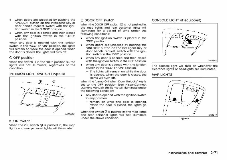
(145,1)
[ Edit: 2020/ 11/ 9 Model: Y62-A ]
. when doors are unlocked by pushing the“UNLOCK” button on the Intelligent Key ordoor handle request switch with the igni-tion switch in the “LOCK” position.
. when any door is opened and then closedwith the ignition switch in the “LOCK”position.
When any door is opened with the ignitionswitch in the “ACC” or “ON” position, the lightswill remain on while the door is opened. Whenthe door is closed, the lights will turn off.
OFF positionGUID-6B997E5E-26B8-43E2-934C-F8004442BE20When the switch is in the “OFF” position , thelights will not illuminate, regardless of thecondition.
INTERIOR LIGHT SWITCH (Type B)GUID-B66CAB0D-9CA7-4EA7-B2AD-6431D73839EC
JVI0760X
ON switchGUID-7F5A70D0-5C35-417C-9328-9F8314FF1DDBWhen the ON switch is pushed in, the maplights and rear personal lights will illuminate.
DOOR OFF switchGUID-8E59057B-A5F2-4441-B472-AFC108BF7EF5When the DOOR OFF switch is not pushed in,the map lights and rear personal lights willilluminate for a period of time under thefollowing conditions:. when the ignition switch is placed in the
“OFF” position.. when doors are unlocked by pushing the
“UNLOCK” button on the Intelligent Key ordoor handle request switch with the igni-tion switch in the “OFF” position.
. when any door is opened and then closedwith the ignition switch in the OFF position.
. when any door is opened with the ignitionswitch in the “ACC” or “ON” position.— The lights will remain on while the door
is opened. When the door is closed, thelights will turn off.
When the “Lamp ON When Door Unlocks” key isset to the OFF position (see NissanConnectOwner’s Manual), the lights will illuminate underthe following condition:. any door is opened with the ignition switch
in any position— remain on while the door is opened.
When the door is closed, the lights gooff.
When the switch is pushed in, the map lightsand rear personal lights will not illuminateunder the above condition.
CONSOLE LIGHT (if equipped)GUID-84A8422E-9516-48EA-87DA-5D872939A568
JVI0759X
The console light will turn on whenever theclearance lights or headlights are illuminated.
MAP LIGHTSGUID-9A3E5C9F-5F2F-4425-8052-22F0EA398925
SIC3249Type A
Instruments and controls 2-71
Condition: 'Except for China'/'Except for China/
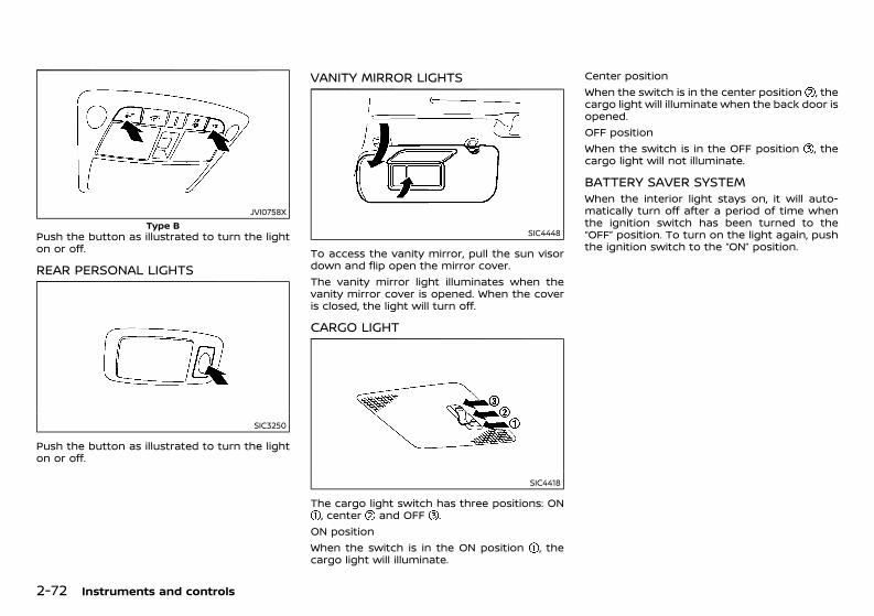
(146,1)
[ Edit: 2020/ 11/ 9 Model: Y62-A ]
2-72 Instruments and controls
JVI0758XType B
Push the button as illustrated to turn the lighton or off.
REAR PERSONAL LIGHTSGUID-CD771C4A-B056-4C39-98B6-0E0DCB44387E
SIC3250
Push the button as illustrated to turn the lighton or off.
VANITY MIRROR LIGHTSGUID-F71B392F-DC48-4C8A-9B29-81919B81501C
SIC4448
To access the vanity mirror, pull the sun visordown and flip open the mirror cover.The vanity mirror light illuminates when thevanity mirror cover is opened. When the coveris closed, the light will turn off.
CARGO LIGHTGUID-7BAE8269-2274-45BA-B564-98C5DF9C4635
SIC4418
The cargo light switch has three positions: ON, center and OFF .
ON positionWhen the switch is in the ON position , thecargo light will illuminate.
Center positionWhen the switch is in the center position , thecargo light will illuminate when the back door isopened.OFF positionWhen the switch is in the OFF position , thecargo light will not illuminate.
BATTERY SAVER SYSTEMGUID-C241DC06-FBF7-4835-95A1-DEC0F43BB5C8When the interior light stays on, it will auto-matically turn off after a period of time whenthe ignition switch has been turned to the“OFF” position. To turn on the light again, pushthe ignition switch to the “ON” position.
Condition: 'Except for China'/'Except for China/
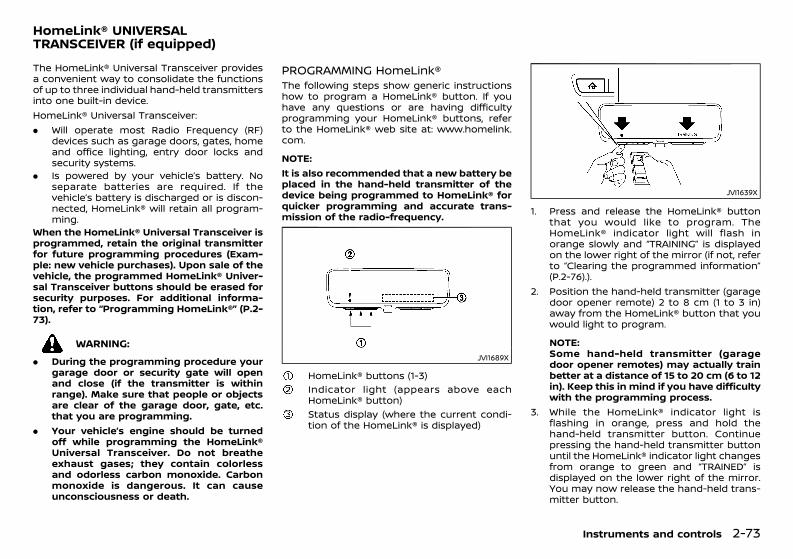
(147,1)
[ Edit: 2020/ 11/ 9 Model: Y62-A ]
GUID-225D5D13-1CB7-45C5-A3E4-893E7EC1BA6FThe HomeLink® Universal Transceiver providesa convenient way to consolidate the functionsof up to three individual hand-held transmittersinto one built-in device.HomeLink® Universal Transceiver:. Will operate most Radio Frequency (RF)
devices such as garage doors, gates, homeand office lighting, entry door locks andsecurity systems.
. Is powered by your vehicle’s battery. Noseparate batteries are required. If thevehicle’s battery is discharged or is discon-nected, HomeLink® will retain all program-ming.
When the HomeLink® Universal Transceiver isprogrammed, retain the original transmitterfor future programming procedures (Exam-ple: new vehicle purchases). Upon sale of thevehicle, the programmed HomeLink® Univer-sal Transceiver buttons should be erased forsecurity purposes. For additional informa-tion, refer to “Programming HomeLink®” (P.2-73).
WARNING:. During the programming procedure your
garage door or security gate will openand close (if the transmitter is withinrange). Make sure that people or objectsare clear of the garage door, gate, etc.that you are programming.
. Your vehicle’s engine should be turnedoff while programming the HomeLink®Universal Transceiver. Do not breatheexhaust gases; they contain colorlessand odorless carbon monoxide. Carbonmonoxide is dangerous. It can causeunconsciousness or death.
PROGRAMMING HomeLink®GUID-8A2498A3-27DF-4E62-880C-9BFD8B04E974The following steps show generic instructionshow to program a HomeLink® button. If youhave any questions or are having difficultyprogramming your HomeLink® buttons, referto the HomeLink® web site at: www.homelink.com.
NOTE:It is also recommended that a new battery beplaced in the hand-held transmitter of thedevice being programmed to HomeLink® forquicker programming and accurate trans-mission of the radio-frequency.
JVI1689X
HomeLink® buttons (1-3)Indicator light (appears above eachHomeLink® button)Status display (where the current condi-tion of the HomeLink® is displayed)
JVI1639X
1. Press and release the HomeLink® buttonthat you would like to program. TheHomeLink® indicator light will flash inorange slowly and “TRAINING” is displayedon the lower right of the mirror (if not, referto “Clearing the programmed information”(P.2-76).).
2. Position the hand-held transmitter (garagedoor opener remote) 2 to 8 cm (1 to 3 in)away from the HomeLink® button that youwould light to program.
NOTE:Some hand-held transmitter (garagedoor opener remotes) may actually trainbetter at a distance of 15 to 20 cm (6 to 12in). Keep this in mind if you have difficultywith the programming process.
3. While the HomeLink® indicator light isflashing in orange, press and hold thehand-held transmitter button. Continuepressing the hand-held transmitter buttonuntil the HomeLink® indicator light changesfrom orange to green and “TRAINED” isdisplayed on the lower right of the mirror.You may now release the hand-held trans-mitter button.
Instruments and controls 2-73
HomeLink® UNIVERSALTRANSCEIVER (if equipped)
Condition: 'Except for China'/'Except for China/
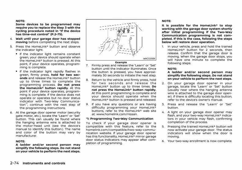
(148,1)
[ Edit: 2020/ 11/ 9 Model: Y62-A ]
2-74 Instruments and controls
NOTE:Some devices to be programmed mayrequire you to replace the Step 3 with thecycling procedure noted in “If the devicehas time-out control” (P.2-75).
4. Wait until your garage door has stoppedmoving before completing the next steps.
5. Press the HomeLink® button and observethe indicator light.. If the indicator light remains constant
green, your device should operate whenthe HomeLink® button is pressed. At thispoint, if your device operates, program-ming is complete.
. If the indicator light rapidly flashes ingreen, firmly press, hold for two sec-onds and release the HomeLink® buttonup to three times to complete theprogramming process. Do not pressthe HomeLink® button rapidly. At thispoint if your device operates, program-ming is complete. If the device does notoperate or operates but no door statusindicator with Two-Way Communica-tion*1, continue with the next step ofthe programming instructions.
6. At the garage door opener motor (securitygate motor, etc.), locate the “Learn” or “Set”button. This can usually be found wherethe hanging antenna wire is attached tothe motor-head unit (see the device’smanual to identify this button.). The nameand color of the button may vary bymanufacturer.
NOTE:A ladder and/or second person maysimplify the following steps. Do not standon your vehicle to perform the next steps.
WAC0258XExample
7. Firmly press and release the “Learn” or “Set”button until the indicator illuminates. Oncethe button is pressed, you have approxi-mately 30 seconds to initiate the next step.
8. Return to the vehicle and firmly press, holdfor two seconds and release theHomeLink® button up to three times. Donot press the HomeLink® button rapidly.At this point programming is complete andyour device should operate when theHomeLink® button is pressed and released.
9. If you have any questions or are havingdifficulty programming your HomeLink®buttons, refer to the HomeLink® web siteat: www.homelink.com/nissan.
*1: Programming Two-Way CommunicationTo check if your garage door opener iscompatible with this feature, refer to thehomelink.com/compatible/two-way-commu-nication website. If your garage door openerhas this functionality, HomeLink® mirror garagedoor status indicators may appear after com-pletion of programming.
NOTE:It is possible for the HomeLink® to stopworking with the garage door system shortlyafter initial programming if the Two-WayCommunication programming is not com-pleted. If this is the case, following the stepsbelow will restore door operation.1. In your vehicle, press and hold the trained
HomeLink® button for 2 seconds, thenrelease. Confirm that the garage door ismoving. When the garage door stops, youwill have one minute to complete thefollowing steps:
NOTE:A ladder and/or second person maysimplify the following steps. Do not standon your vehicle to perform the next steps.
2. On your garage door opener in yourgarage, locate the “Learn” or “Set” button(usually near where the hanging antennawire is attached to the garage door open-er). If there is difficulty locating this button,refer to the device’s owner’s manual.
3. Press and release the “Learn” or “Set”button.
4. A light on your garage door opener mayflash, and your two-way HomeLink® indica-tors in your vehicle may flash, confirmingcompletion of the process.
5. Pressing the trained HomeLink® button willnow activate your garage door. The statusindicators will show when the door ismoving.
6. Your two-way enrollment is now complete.
Condition: 'Except for China'/'Except for China/
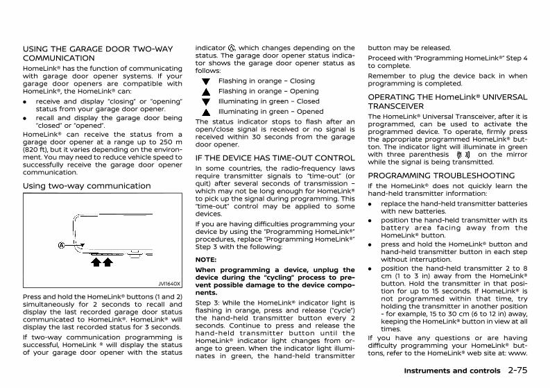
(149,1)
[ Edit: 2020/ 11/ 9 Model: Y62-A ]
USING THE GARAGE DOOR TWO-WAYCOMMUNICATIONGUID-0A3F1A7A-11DE-4CF0-90EE-45938320797CHomeLink® has the function of communicatingwith garage door opener systems. If yourgarage door openers are compatible withHomeLink®, the HomeLink® can:. receive and display “closing” or “opening”
status from your garage door opener.. recall and display the garage door being
“closed” or “opened”.HomeLink® can receive the status from agarage door opener at a range up to 250 m(820 ft), but it varies depending on the environ-ment. You may need to reduce vehicle speed tosuccessfully receive the garage door openercommunication.
Using two-way communicationGUID-12AD15F6-A0B6-46A2-98DA-46E09A3FA5F7
JVI1640X
Press and hold the HomeLink® buttons (1 and 2)simultaneously for 2 seconds to recall anddisplay the last recorded garage door statuscommunicated to HomeLink®. HomeLink® willdisplay the last recorded status for 3 seconds.If two-way communication programming issuccessful, HomeLink ® will display the statusof your garage door opener with the status
indicator , which changes depending on thestatus. The garage door opener status indica-tor shows the garage door opener status asfollows:
Flashing in orange – ClosingFlashing in orange – OpeningIlluminating in green – ClosedIlluminating in green – Opened
The status indicator stops to flash after anopen/close signal is received or no signal isreceived within 30 seconds from the garagedoor opener.
IF THE DEVICE HAS TIME-OUT CONTROLGUID-833FFA9A-49B2-4E38-8721-24AB57E469AAIn some countries, the radio-frequency lawsrequire transmitter signals to “time-out” (orquit) after several seconds of transmission –which may not be long enough for HomeLink®to pick up the signal during programming. This“time-out” control may be applied to somedevices.If you are having difficulties programming yourdevice by using the “Programming HomeLink®”procedures, replace “Programming HomeLink®”Step 3 with the following:
NOTE:When programming a device, unplug thedevice during the “cycling” process to pre-vent possible damage to the device compo-nents.Step 3: While the HomeLink® indicator light isflashing in orange, press and release (“cycle”)the hand-held transmitter button every 2seconds. Continue to press and release thehand-held transmitter button until theHomeLink® indicator light changes from or-ange to green. When the indicator light illumi-nates in green, the hand-held transmitter
button may be released.Proceed with “Programming HomeLink®” Step 4to complete.Remember to plug the device back in whenprogramming is completed.
OPERATING THE HomeLink® UNIVERSALTRANSCEIVERGUID-68E3B8DC-B681-4D55-A7A8-624D9ABFFEFCThe HomeLink® Universal Transceiver, after it isprogrammed, can be used to activate theprogrammed device. To operate, firmly pressthe appropriate programmed HomeLink® but-ton. The indicator light will illuminate in greenwith three parenthesis on the mirrorwhile the signal is being transmitted.
PROGRAMMING TROUBLESHOOTINGGUID-7BFDA99A-D52B-4AED-B717-BAE284199967If the HomeLink® does not quickly learn thehand-held transmitter information:. replace the hand-held transmitter batteries
with new batteries.. position the hand-held transmitter with its
battery area facing away from theHomeLink® button.
. press and hold the HomeLink® button andhand-held transmitter button in each stepwithout interruption.
. position the hand-held transmitter 2 to 8cm (1 to 3 in) away from the HomeLink®button. Hold the transmitter in that posi-tion for up to 15 seconds. If HomeLink® isnot programmed within that time, tryholding the transmitter in another position- for example, 15 to 30 cm (6 to 12 in) away,keeping the HomeLink® button in view at alltimes.
If you have any questions or are havingdifficulty programming your HomeLink® but-tons, refer to the HomeLink® web site at: www.
Instruments and controls 2-75
Condition: 'Except for China'/'Except for China/
(150,1)
[ Edit: 2020/ 11/ 9 Model: Y62-A ]
2-76 Instruments and controls
homelink.com.
CLEARING THE PROGRAMMED INFOR-MATION GUID-5EC839BA-252C-4FA3-B5F0-46C8165FB923The following procedure clears the pro-grammed information from three buttons.Individual buttons cannot be cleared. However,individual buttons can be reprogrammed, see“Reprogramming a single HomeLink® button”(P.2-76).
To clear all programmingGUID-C945D149-237A-485B-9A99-7ED409207B3D1. Press and hold the two outer HomeLink®
buttons until the indicator light begins toflash in green and “CLEARED” is displayedon the mirror, in approximately 10 seconds.Do not hold for longer than 20 seconds.
2. Release both buttons.HomeLink® is now in the programming modeand can be programmed at any time beginningwith “Programming HomeLink®” - Step 1.
REPROGRAMMING A SINGLE HomeLink®BUTTON GUID-E127E880-E889-4D5F-AF58-F8FD8F124D4BTo reprogram a HomeLink® button, completethe following.1. Press and hold the desired HomeLink®
button. DO NOT release the button.2. The indicator light will illuminate in green,
and after 20 seconds it will begin to flash inorange and “TRAINING” is displayed on themirror.
3. Release the HomeLink® button and pro-ceed with “Programming HomeLink®” —Step 3.
For quest ions or comments , contactHomeLink® at: www.homelink.com.The HomeLink® button has now been repro-
grammed. The new device can be activated bypressing the HomeLink® button that was justprogrammed. This procedure will not affect anyother programmed HomeLink® buttons.If a new device is not programmed to theHomeLink® button, it will revert to the pre-viously stored programming.
IF YOUR VEHICLE IS STOLENGUID-C47EF816-0BBE-4E25-B53A-230FCACE4DABIf your vehicle is stolen, you should change thecodes of any non-rolling code device that hasbeen programmed into HomeLink®. Consult theOwner’s Manual of each device or call themanufacturer or dealer of those devices foradditional information.When your vehicle is recovered, you will needto reprogram the HomeLink® UniversalTransceiver with your new transmitter infor-mation.
Condition: 'Except for China'/'Except for China/
(151,1)
[ Edit: 2020/ 11/ 9 Model: Y62-A ]
3 Pre-driving checks and adjustments
Keys ............................................................................................................................. 3-2Intelligent Key .............................................................................................. 3-2Mechanical key ............................................................................................ 3-3
Doors .......................................................................................................................... 3-3Locking with key ........................................................................................ 3-3Opening and closing windows with key (except forAustralia, New Zealand and South Africa) ............................. 3-4Locking with inside lock knob ........................................................ 3-4Locking with power door lock switch ...................................... 3-4Vehicle speed sensing door lock mechanism ................... 3-4Impact sensing door lock releasing mechanism(if equipped) ................................................................................................... 3-5Child safety rear door locks ............................................................. 3-5
Intelligent Key system ................................................................................... 3-5Intelligent Key operating range ..................................................... 3-6Using Intelligent Key system ............................................................ 3-6Battery saver system ............................................................................. 3-8Warning signals .......................................................................................... 3-8Troubleshooting guide ...................................................................... 3-10Using remote keyless entry system ........................................ 3-13Hazard indicator and horn operation ................................... 3-14
Security system ............................................................................................... 3-15Theft warning system (if equipped) ........................................ 3-15NISSAN Anti-Theft System (NATS) ............................................ 3-16
Remote engine start (if equipped) ................................................... 3-17Remote engine start operating range ................................ 3-17Remote starting the engine .......................................................... 3-17Extending engine run time ............................................................. 3-17
Canceling a remote engine start ........................................... 3-18Conditions the remote engine start willnot work ..................................................................................................... 3-18
Hood ........................................................................................................................ 3-18Opening hood ........................................................................................ 3-19Closing hood ........................................................................................... 3-19
Back door ............................................................................................................ 3-19Operating manual back door .................................................... 3-19Operating power back door (if equipped) ...................... 3-20Auto closure ............................................................................................ 3-22Back door release lever .................................................................. 3-22
Front, side and rear unique parts (NISMO models) ........... 3-22Fuel-filler lid ....................................................................................................... 3-23
Opening fuel-filler lid ........................................................................ 3-23Fuel-filler cap .......................................................................................... 3-24
Steering wheel ................................................................................................ 3-24Manual steering wheel adjustment ...................................... 3-24Electric steering wheel adjustment ...................................... 3-25
Mirrors .................................................................................................................... 3-25Inside rearview mirror ..................................................................... 3-25Outside rearview mirrors .............................................................. 3-32Vanity mirror ........................................................................................... 3-33
Parking brake ................................................................................................... 3-33Automatic drive positioner (if equipped) ................................... 3-34
Entry/exit function ............................................................................. 3-34Memory storage (if equipped) ................................................... 3-34Setting memory function (if equipped) ............................. 3-35System operation ................................................................................ 3-35
Condition: 'Except for China'/'Except for China/
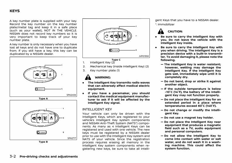
(152,1)
[ Edit: 2020/ 11/ 9 Model: Y62-A ]
3-2 Pre-driving checks and adjustments
GUID-ACCC2553-DC55-48E0-B662-29078F813DF5A key number plate is supplied with your key.Record the key number on the key numberplate/metal tag and keep it in a safe place(such as your wallet), NOT IN THE VEHICLE.NISSAN does not record key numbers so it isvery important to keep track of your keynumber plate.A key number is only necessary when you havelost all keys and do not have one to duplicatefrom. If you still have a key, this key can beduplicated by a NISSAN dealer.
SPA2406Type A
SPA2717Type B
JVP0155XType C
1. Intelligent Key (2)2. Mechanical key (inside Intelligent Key) (2)3. Key number plate (1)
WARNING:. The Intelligent Key transmits radio waves
that can adversely affect medical electricequipment.
. If you have a pacemaker, you shouldcontact the medical equipment manufac-turer to ask if it will be affected by theIntelligent Key signal.
INTELLIGENT KEYGUID-EC72DF8E-3839-4A10-B653-5A3C21AA4EAAYour vehicle can only be driven with theIntelligent Keys, which are registered to yourvehicle’s Intelligent Key system componentsand NISSAN Anti-Theft System (NATS*) compo-nents. As many as 4 Intelligent Keys can beregistered and used with one vehicle. The newkeys must be registered by a NISSAN dealerprior to use with the Intelligent Key system andNATS of your vehicle. Since the registrationprocess requires erasing all memory in theIntelligent Key system components when re-gistering new keys, be sure to take all Intelli-
gent Keys that you have to a NISSAN dealer.*: Immobilizer
CAUTION:. Be sure to carry the Intelligent Key with
you. Do not leave the vehicle with theIntelligent Key inside.
. Be sure to carry the Intelligent Key withyou when driving. The Intelligent Key is aprecision device with a built-in transmit-ter. To avoid damaging it, please note thefollowing.— The Intelligent Key is water resistant;
however, wetting may damage theIntelligent Key. If the Intelligent Keygets wet, immediately wipe until it iscompletely dry.
— Do not bend, drop or strike it againstanother object.
— If the outside temperature is below-10°C (14°F), the battery of the Intelli-gent Key may not function properly.
— Do not place the Intelligent Key for anextended period in a place wheretemperatures exceed 60°C (140°F).
— Do not change or modify the Intelli-gent Key.
— Do not use a magnet key holder.— Do not place the Intelligent Key near
equipment that produces a magneticfield such as a TV, audio equipmentand personal computers.
— Do not allow the Intelligent Key tocome into contact with water or saltwater, and do not wash it in a wash-ing machine. This could affect thesystem function.
KEYS
Condition: 'Except for China'/'Except for China/
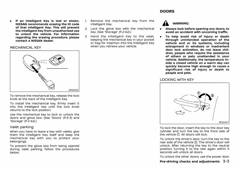
(153,1)
[ Edit: 2020/ 11/ 9 Model: Y62-A ]
. If an Intelligent Key is lost or stolen,NISSAN recommends erasing the ID codeof that Intelligent Key. This will preventthe Intelligent Key from unauthorized useto unlock the vehicle. For informationregarding the erasing procedure, pleasecontact a NISSAN dealer.
MECHANICAL KEYGUID-27686E3E-B0BA-4AE2-BC3C-098622CFBBB4
SPA2033
To remove the mechanical key, release the lockknob at the back of the Intelligent Key.To install the mechanical key, firmly insert itinto the Intelligent Key until the lock knobreturns to the lock position.Use the mechanical key to lock or unlock thedoors and glove box. (See “Doors” (P.3-3) and“Storage” (P.2-62).)
Valet parkingGUID-4BAC6CFD-74B5-4985-9BFC-41DF87C577F1When you have to leave a key with valets, givethem the Intelligent Key itself and keep themechanical key with you to protect yourbelongings.To prevent the glove box from being openedduring valet parking, follow the proceduresbelow.
1. Remove the mechanical key from theIntelligent Key.
2. Lock the glove box with the mechanicalkey. (See “Storage” (P.2-62).)
3. Hand the Intelligent Key to the valet,keeping the mechanical key in your pocketor bag for insertion into the Intelligent Keywhen you retrieve your vehicle.
GUID-31D89129-E8CB-49D1-AFC6-56EC9681D9FC
WARNING:. Always look before opening any doors, to
avoid an accident with oncoming traffic.. To help avoid risk of injury or death
through unintended operation of thevehicle and or its systems, includingentrapment in windows or inadvertentdoor lock activation, do not leave chil-dren, people who require the assistanceof others or pets unattended in yourvehicle. Additionally, the temperature in-side a closed vehicle on a warm day canquickly become high enough to cause asignificant risk of injury or death topeople and pets.
LOCKING WITH KEYGUID-8B237026-903C-4D03-957E-B72E3EA5A527
SPA2457
To lock the door, insert the key to the door keycylinder and turn the key to the front side ofthe vehicle . All doors will lock.To unlock the driver’s door, turn the key to therear side of the vehicle . The driver’s door willunlock. After returning the key to the neutralposition, turning it to the rear again within 5seconds will unlock all doors.To unlock the other doors, use the power doorPre-driving checks and adjustments 3-3
DOORS
Condition: 'Except for China'/'Except for China/
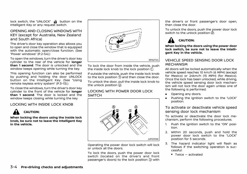
(154,1)
[ Edit: 2020/ 11/ 9 Model: Y62-A ]
3-4 Pre-driving checks and adjustments
lock switch, the “UNLOCK” button on theIntelligent Key or any request switch.
OPENING AND CLOSING WINDOWS WITHKEY (except for Australia, New Zealandand South Africa)GUID-2D347F72-3639-4121-89B1-4B7D5FBAD0EAThe driver’s door key operation also allows youto open and close the window that is equippedwith the automatic open/close function. (See“Power windows” (P.2-54).)To open the windows, turn the driver’s door keycylinder to the rear of the vehicle for longerthan 1 second. The door is unlocked and thewindow keeps opening while turning the key.This opening function can also be performedby pushing and holding the door UNLOCKbutton on the Intelligent Key. (See “Usingremote keyless entry system” (P.3-13).)To close the windows, turn the driver’s door keycylinder to the front of the vehicle for longerthan 1 second. The door is locked and thewindow keeps closing while turning the key.
LOCKING WITH INSIDE LOCK KNOBGUID-400056F2-0846-4545-85D1-1C86A35F664C
CAUTION:When locking the doors using the inside lockknob, be sure not to leave the Intelligent Keyin the vehicle.
SPA2744
To lock the door from inside the vehicle, pushthe inside lock knob to the lock position .If outside the vehicle, push the inside lock knobto the lock position and then close the door.To unlock the door, pull the inside lock knob tothe unlock position .
LOCKING WITH POWER DOOR LOCKSWITCH GUID-C1BC5CD1-4D66-45B1-AC0C-C52510A64912
JVP0319X
Operating the power door lock switch will lockor unlock all the doors.To lock the doors, push the power door lockswitch (located on the driver’s and frontpassenger’s doors) to the lock position with
the driver’s or front passenger’s door open,then close the door.To unlock the doors, push the power door lockswitch to the unlock position .
CAUTION:When locking the doors using the power doorlock switch, be sure not to leave the Intelli-gent Key in the vehicle.
VEHICLE SPEED SENSING DOOR LOCKMECHANISMGUID-CB4F80A4-91CC-4717-9CDB-29770CDFDD6FAll doors will be locked automatically when thevehicle speed reaches 10 km/h (6 MPH) (exceptfor Mexico) or 24km/h (15 MPH) (for Mexico).Once the lock has been unlocked, while driving,the vehicle speed sensing door lock mechan-ism will not lock the door again unless one ofthe following is performed.. Opening any doors.. Pushing the ignition switch to the “LOCK”
position.
To activate or deactivate vehicle speedsensing door lock mechanismGUID-7EB81074-56F5-4F69-B305-41E9CEA74AB0To activate or deactivate the door lock me-chanism, perform the following procedures.1. Push the ignition switch to the “ON” posi-
tion.2. Within 20 seconds, push and hold the
power door lock switch to the “LOCK”position for 5 seconds.
3. The hazard indicator light will flash asfollows if the switching operation is suc-cessful:. Twice — activated
Condition: 'Except for China'/'Except for China/
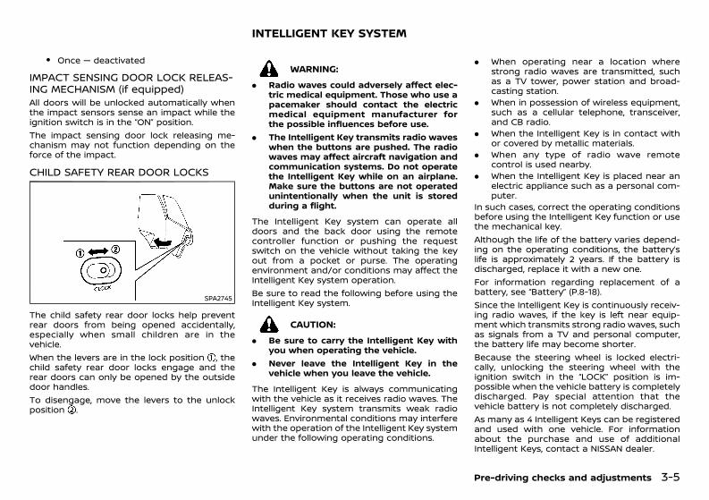
(155,1)
[ Edit: 2020/ 11/ 9 Model: Y62-A ]
. Once — deactivated
IMPACT SENSING DOOR LOCK RELEAS-ING MECHANISM (if equipped)GUID-0BBF354E-504E-4615-9B34-1A2284AF7B04All doors will be unlocked automatically whenthe impact sensors sense an impact while theignition switch is in the “ON” position.The impact sensing door lock releasing me-chanism may not function depending on theforce of the impact.
CHILD SAFETY REAR DOOR LOCKSGUID-DE2ADFA6-D1FE-4BF4-9A9D-07DC9F6D8457
SPA2745
The child safety rear door locks help preventrear doors from being opened accidentally,especially when small children are in thevehicle.When the levers are in the lock position , thechild safety rear door locks engage and therear doors can only be opened by the outsidedoor handles.To disengage, move the levers to the unlockposition .
GUID-36655C14-19F3-4063-B4BE-A5E958C80806
WARNING:. Radio waves could adversely affect elec-
tric medical equipment. Those who use apacemaker should contact the electricmedical equipment manufacturer forthe possible influences before use.
. The Intelligent Key transmits radio waveswhen the buttons are pushed. The radiowaves may affect aircraft navigation andcommunication systems. Do not operatethe Intelligent Key while on an airplane.Make sure the buttons are not operatedunintentionally when the unit is storedduring a flight.
The Intelligent Key system can operate alldoors and the back door using the remotecontroller function or pushing the requestswitch on the vehicle without taking the keyout from a pocket or purse. The operatingenvironment and/or conditions may affect theIntelligent Key system operation.Be sure to read the following before using theIntelligent Key system.
CAUTION:. Be sure to carry the Intelligent Key with
you when operating the vehicle.. Never leave the Intelligent Key in the
vehicle when you leave the vehicle.
The Intelligent Key is always communicatingwith the vehicle as it receives radio waves. TheIntelligent Key system transmits weak radiowaves. Environmental conditions may interferewith the operation of the Intelligent Key systemunder the following operating conditions.
. When operating near a location wherestrong radio waves are transmitted, suchas a TV tower, power station and broad-casting station.
. When in possession of wireless equipment,such as a cellular telephone, transceiver,and CB radio.
. When the Intelligent Key is in contact withor covered by metallic materials.
. When any type of radio wave remotecontrol is used nearby.
. When the Intelligent Key is placed near anelectric appliance such as a personal com-puter.
In such cases, correct the operating conditionsbefore using the Intelligent Key function or usethe mechanical key.Although the life of the battery varies depend-ing on the operating conditions, the battery’slife is approximately 2 years. If the battery isdischarged, replace it with a new one.For information regarding replacement of abattery, see “Battery” (P.8-18).Since the Intelligent Key is continuously receiv-ing radio waves, if the key is left near equip-ment which transmits strong radio waves, suchas signals from a TV and personal computer,the battery life may become shorter.Because the steering wheel is locked electri-cally, unlocking the steering wheel with theignition switch in the “LOCK” position is im-possible when the vehicle battery is completelydischarged. Pay special attention that thevehicle battery is not completely discharged.As many as 4 Intelligent Keys can be registeredand used with one vehicle. For informationabout the purchase and use of additionalIntelligent Keys, contact a NISSAN dealer.
Pre-driving checks and adjustments 3-5
INTELLIGENT KEY SYSTEM
Condition: 'Except for China'/'Except for China/
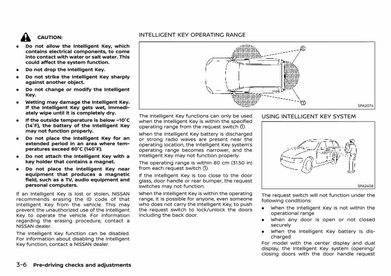
(156,1)
[ Edit: 2020/ 11/ 9 Model: Y62-A ]
3-6 Pre-driving checks and adjustments
CAUTION:. Do not allow the Intelligent Key, which
contains electrical components, to comeinto contact with water or salt water. Thiscould affect the system function.
. Do not drop the Intelligent Key.
. Do not strike the Intelligent Key sharplyagainst another object.
. Do not change or modify the IntelligentKey.
. Wetting may damage the Intelligent Key.If the Intelligent Key gets wet, immedi-ately wipe until it is completely dry.
. If the outside temperature is below −10°C(14°F), the battery of the Intelligent Keymay not function properly.
. Do not place the Intelligent Key for anextended period in an area where tem-peratures exceed 60°C (140°F).
. Do not attach the Intelligent Key with akey holder that contains a magnet.
. Do not place the Intelligent Key nearequipment that produces a magneticfield, such as a TV, audio equipment andpersonal computers.
If an Intelligent Key is lost or stolen, NISSANrecommends erasing the ID code of thatIntelligent Key from the vehicle. This mayprevent the unauthorized use of the IntelligentKey to operate the vehicle. For informationregarding the erasing procedure, contact aNISSAN dealer.The Intelligent Key function can be disabled.For information about disabling the IntelligentKey function, contact a NISSAN dealer.
INTELLIGENT KEY OPERATING RANGEGUID-729560DD-8205-4DC4-9F2F-DAD351CC5E3A
SPA2074
The Intelligent Key functions can only be usedwhen the Intelligent Key is within the specifiedoperating range from the request switch .When the Intelligent Key battery is dischargedor strong radio waves are present near theoperating location, the Intelligent Key system’soperating range becomes narrower, and theIntelligent Key may not function properly.The operating range is within 80 cm (31.50 in)from each request switch .If the Intelligent Key is too close to the doorglass, door handle or rear bumper, the requestswitches may not function.When the Intelligent Key is within the operatingrange, it is possible for anyone, even someonewho does not carry the Intelligent Key, to pushthe request switch to lock/unlock the doorsincluding the back door.
USING INTELLIGENT KEY SYSTEMGUID-F0B1F0DE-CCA9-43E9-A09A-237106A1A966
SPA2408
The request switch will not function under thefollowing conditions:. When the Intelligent Key is not within the
operational range. When any door is open or not closed
securely. When the Intelligent Key battery is dis-
chargedFor model with the center display and dualdisplay, the Intelligent Key system (opening/closing doors with the door handle request
Condition: 'Except for China'/'Except for China/
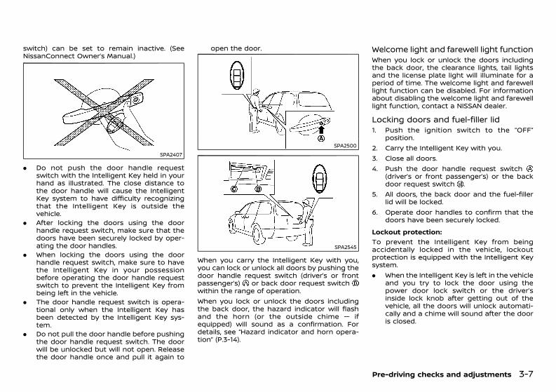
(157,1)
[ Edit: 2020/ 11/ 9 Model: Y62-A ]
switch) can be set to remain inactive. (SeeNissanConnect Owner’s Manual.)
SPA2407
. Do not push the door handle requestswitch with the Intelligent Key held in yourhand as illustrated. The close distance tothe door handle will cause the IntelligentKey system to have difficulty recognizingthat the Intelligent Key is outside thevehicle.
. After locking the doors using the doorhandle request switch, make sure that thedoors have been securely locked by oper-ating the door handles.
. When locking the doors using the doorhandle request switch, make sure to havethe Intelligent Key in your possessionbefore operating the door handle requestswitch to prevent the Intelligent Key frombeing left in the vehicle.
. The door handle request switch is opera-tional only when the Intelligent Key hasbeen detected by the Intelligent Key sys-tem.
. Do not pull the door handle before pushingthe door handle request switch. The doorwill be unlocked but will not open. Releasethe door handle once and pull it again to
open the door.
SPA2500
SPA2545
When you carry the Intelligent Key with you,you can lock or unlock all doors by pushing thedoor handle request switch (driver’s or frontpassenger’s) or back door request switchwithin the range of operation.When you lock or unlock the doors includingthe back door, the hazard indicator will flashand the horn (or the outside chime — ifequipped) will sound as a confirmation. Fordetails, see “Hazard indicator and horn opera-tion” (P.3-14).
Welcome light and farewell light functionGUID-0E219ED3-C130-46F8-AA27-A7E662BDE70FWhen you lock or unlock the doors includingthe back door, the clearance lights, tail lightsand the license plate light will illuminate for aperiod of time. The welcome light and farewelllight function can be disabled. For informationabout disabling the welcome light and farewelllight function, contact a NISSAN dealer.
Locking doors and fuel-filler lidGUID-B4FCD40E-8D09-4976-994F-25AB13213F3F1. Push the ignition switch to the “OFF”
position.2. Carry the Intelligent Key with you.3. Close all doors.4. Push the door handle request switch
(driver’s or front passenger’s) or the backdoor request switch .
5. All doors, the back door and the fuel-fillerlid will be locked.
6. Operate door handles to confirm that thedoors have been securely locked.
Lockout protection:GUID-C7E1EF24-5AAB-4301-95BE-26917EEE45EF
To prevent the Intelligent Key from beingaccidentally locked in the vehicle, lockoutprotection is equipped with the Intelligent Keysystem.. When the Intelligent Key is left in the vehicle
and you try to lock the door using thepower door lock switch or the driver’sinside lock knob after getting out of thevehicle, all the doors will unlock automati-cally and a chime will sound after the dooris closed.
Pre-driving checks and adjustments 3-7
Condition: 'Except for China'/'Except for China/
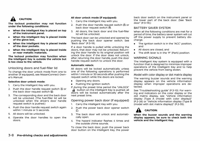
(158,1)
[ Edit: 2020/ 11/ 9 Model: Y62-A ]
3-8 Pre-driving checks and adjustments
CAUTION:The lockout protection may not functionunder the following conditions:. When the Intelligent Key is placed on top
of the instrument panel.. When the Intelligent Key is placed inside
of the glove box.. When the Intelligent Key is placed inside
of the door pockets.. When the Intelligent Key is placed inside
or near metallic materials.The lockout protection may function whenthe Intelligent Key is outside the vehicle butis too close to the vehicle.
Unlocking doors and fuel-filler lidGUID-1DD71CE6-1253-433C-BB5E-B249A1017F04To change the door unlock mode from one toanother (if equipped), see NissanConnect Own-er’s Manual.Selective door unlock mode:
GUID-C7E1EF24-5AAB-4301-95BE-26917EEE45EF
1. Carry the Intelligent Key with you.2. Push the door handle request switch or
the back door request switch .3. The corresponding door and the back door
will be unlocked. (The fuel-filler lid will beunlocked when the driver’s door handlerequest switch is pushed.)
4. Push the door handle request switch againwithin 1 minute or 5 seconds.
5. All doors will be unlocked.6. Operate the door handles to open the
doors.
All door unlock mode (if equipped):GUID-C7E1EF24-5AAB-4301-95BE-26917EEE45EF
1. Carry the Intelligent Key with you.2. Push the door handle request switch or
back door request switch .3. All doors, the back door and the fuel-filler
lid will be unlocked.The back door can be unlocked and opened bypushing the back door opener switch. See“Back door” (P.3-19).If a door handle is pulled while unlocking thedoors, that door may not be unlocked. Return-ing the door handle to its original position willunlock the door. If the door does not unlock,after returning the door handle, push the doorhandle request switch to unlock the door.Automatic relock:
GUID-C7E1EF24-5AAB-4301-95BE-26917EEE45EF
All doors will be locked automatically unlessone of the following operations is performedwithin 1 minute or 30 seconds after pushing therequest switch while the doors are locked.. Opening any doors.. Pushing the ignition switch.If during the preset time period the “UNLOCK”
button on the Intelligent Key is pushed, alldoors will be locked automatically after thenext preset time.
Opening power back door (if equipped)GUID-D616C5D4-20DF-45D7-BD3C-987AA749F42C1. Carry the Intelligent Key with you.2. Push the power back door opener switch
.3. The back door will unlock and automati-
cally open.4. The hazard indicator flashes 4 times and
the outside chime sounds.To close the back door, push the power backdoor button on the Intelligent Key, the power
back door switch on the instrument panel orthe lower part of the back door. (See “Backdoor” (P.3-19).)
BATTERY SAVER SYSTEMGUID-694B9242-4F14-4C6C-A7EF-1DBC79A799B6When all the following conditions are met for aperiod of time, the battery saver system will cutoff the power supply to prevent battery dis-charge.. The ignition switch is in the “ACC” position,
and. All doors are closed, and. The shift lever is in the “P” (Park) position.
WARNING SIGNALSGUID-52B7210C-448C-4D23-B94E-29C54E13C25EThe Intelligent Key system is equipped with afunction that is designed to minimize improperoperations of the Intelligent Key and to helpprevent the vehicle from being stolen.
Model with color display or dot matrix displayGUID-DDA7C592-A644-4801-BD08-8A4F2C68A73DThe warning buzzer sounds and the warningdisplay appears on the vehicle informationdisplay when improper operations are de-tected.See “Troubleshooting guide” (P.3-10). For warn-ing and indicators on the color display or thedot matrix display, see “Vehicle informationdisplay (Type A (model with color display))”(P.2-26) or “Vehicle information display (Type B(model with dot matrix display))” (P.2-35).
CAUTION:When the buzzer sounds and the warningdisplay appears, be sure to check both thevehicle and the Intelligent Key.
Condition: 'Except for China'/'Except for China/
(159,1)
[ Edit: 2020/ 11/ 9 Model: Y62-A ]
Model with segment displayGUID-A89901F4-8766-42A2-932A-3FC19BA3C528A chime or beep sounds inside and outside thevehicle and a warning light in the meterilluminates or blinks.See “Troubleshooting guide” (P.3-10) and “Warn-ing lights, indicator lights and audible remin-ders” (P.2-16).Intelligent Key system warning light:P position selecting warning light:
CAUTION:When the chime or beep sounds or thewarning light illuminates or blinks, be sureto check both the vehicle and the IntelligentKey.
Pre-driving checks and adjustments 3-9
Condition: 'Except for China'/'Except for China/
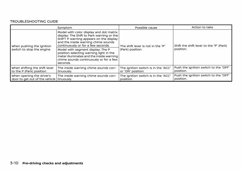
(160,1)
[ Edit: 2020/ 11/ 9 Model: Y62-A ]
3-10 Pre-driving checks and adjustments
TROUBLESHOOTING GUIDEGUID-8566B9C0-7A4A-4F93-A35E-3FE8C23026E2
Symptom Possible cause Action to take
When pushing the ignitionswitch to stop the engine
Model with color display and dot matrixdisplay: The Shift to Park warning or theSHIFT P warning appears on the displayand the inside warning chime soundscontinuously or for a few seconds. The shift lever is not in the “P”
(Park) position.Shift the shift lever to the “P” (Park)position.Model with segment display: The P
position selecting warning light in themeter illuminates and the inside warningchime sounds continuously or for a fewseconds.
When shifting the shift leverto the P (Park) position.
The inside warning chime sounds con-tinuously.
The ignition switch is in the “ACC”or “ON” position.
Push the ignition switch to the “OFF”position.
When opening the driver’sdoor to get out of the vehicle
The inside warning chime sounds con-tinuously.
The ignition switch is in the “ACC”position.
Push the ignition switch to the “OFF”position.
Condition: 'Except for China'/'Except for China/
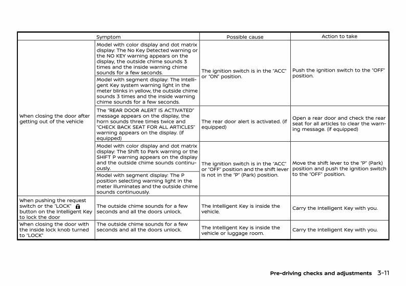
(161,1)
[ Edit: 2020/ 11/ 9 Model: Y62-A ]
Symptom Possible cause Action to take
When closing the door aftergetting out of the vehicle
Model with color display and dot matrixdisplay: The No Key Detected warning orthe NO KEY warning appears on thedisplay, the outside chime sounds 3times and the inside warning chimesounds for a few seconds. The ignition switch is in the “ACC”
or “ON” position.Push the ignition switch to the “OFF”position.
Model with segment display: The Intelli-gent Key system warning light in themeter blinks in yellow, the outside chimesounds 3 times and the inside warningchime sounds for a few seconds.The “REAR DOOR ALERT IS ACTIVATED”message appears on the display, thehorn sounds three times twice and“CHECK BACK SEAT FOR ALL ARTICLES”warning appears on the display. (ifequipped)
The rear door alert is activated. (ifequipped)
Open a rear door and check the rearseat for all articles to clear the warn-ing message. (if equipped)
Model with color display and dot matrixdisplay: The Shift to Park warning or theSHIFT P warning appears on the displayand the outside chime sounds continu-ously.
The ignition switch is in the “ACC”or “OFF” position and the shift leveris not in the “P” (Park) position.
Move the shift lever to the “P” (Park)position and push the ignition switchto the “OFF” position.Model with segment display: The P
position selecting warning light in themeter illuminates and the outside chimesounds continuously.
When pushing the requestswitch or the “LOCK”button on the Intelligent Keyto lock the door
The outside chime sounds for a fewseconds and all the doors unlock.
The Intelligent Key is inside thevehicle. Carry the Intelligent Key with you.
When closing the door withthe inside lock knob turnedto “LOCK”
The outside chime sounds for a fewseconds and all the doors unlock. The Intelligent Key is inside the
vehicle or luggage room. Carry the Intelligent Key with you.
Pre-driving checks and adjustments 3-11
Condition: 'Except for China'/'Except for China/
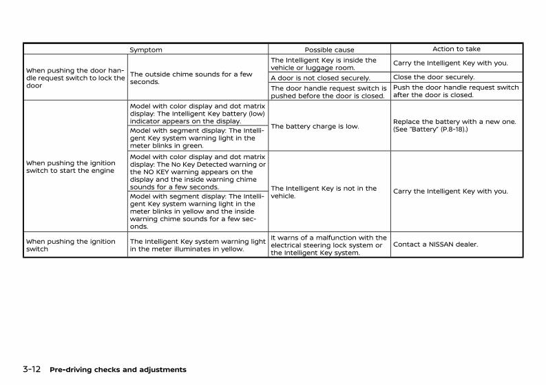
(162,1)
[ Edit: 2020/ 11/ 9 Model: Y62-A ]
3-12 Pre-driving checks and adjustments
Symptom Possible cause Action to take
When pushing the door han-dle request switch to lock thedoor
The outside chime sounds for a fewseconds.
The Intelligent Key is inside thevehicle or luggage room. Carry the Intelligent Key with you.
A door is not closed securely. Close the door securely.The door handle request switch ispushed before the door is closed.
Push the door handle request switchafter the door is closed.
When pushing the ignitionswitch to start the engine
Model with color display and dot matrixdisplay: The Intelligent Key battery (low)indicator appears on the display.
The battery charge is low. Replace the battery with a new one.(See “Battery” (P.8-18).)Model with segment display: The Intelli-
gent Key system warning light in themeter blinks in green.Model with color display and dot matrixdisplay: The No Key Detected warning orthe NO KEY warning appears on thedisplay and the inside warning chimesounds for a few seconds. The Intelligent Key is not in the
vehicle. Carry the Intelligent Key with you.Model with segment display: The Intelli-gent Key system warning light in themeter blinks in yellow and the insidewarning chime sounds for a few sec-onds.
When pushing the ignitionswitch
The Intelligent Key system warning lightin the meter illuminates in yellow.
It warns of a malfunction with theelectrical steering lock system orthe Intelligent Key system.
Contact a NISSAN dealer.
Condition: 'Except for China'/'Except for China/
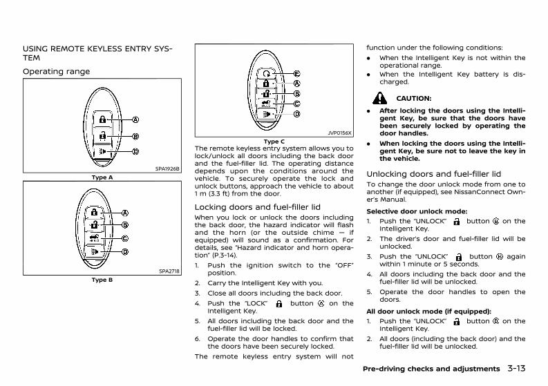
(163,1)
[ Edit: 2020/ 11/ 9 Model: Y62-A ]
USING REMOTE KEYLESS ENTRY SYS-TEM GUID-E7D0CA4D-6DD6-4AFE-932D-D82D33985439
Operating rangeGUID-5959E3AE-2DFF-4E2E-BDE3-D207B89B5409
SPA1926BType A
SPA2718Type B
JVP0156XType C
The remote keyless entry system allows you tolock/unlock all doors including the back doorand the fuel-filler lid. The operating distancedepends upon the conditions around thevehicle. To securely operate the lock andunlock buttons, approach the vehicle to about1 m (3.3 ft) from the door.
Locking doors and fuel-filler lidGUID-31CB5205-857D-428C-AA5E-34F6B26F8C2FWhen you lock or unlock the doors includingthe back door, the hazard indicator will flashand the horn (or the outside chime — ifequipped) will sound as a confirmation. Fordetails, see “Hazard indicator and horn opera-tion” (P.3-14).1. Push the ignition switch to the “OFF”
position.2. Carry the Intelligent Key with you.3. Close all doors including the back door.4. Push the “LOCK” button on the
Intelligent Key.5. All doors including the back door and the
fuel-filler lid will be locked.6. Operate the door handles to confirm that
the doors have been securely locked.The remote keyless entry system will not
function under the following conditions:. When the Intelligent Key is not within the
operational range.. When the Intelligent Key battery is dis-
charged.
CAUTION:. After locking the doors using the Intelli-
gent Key, be sure that the doors havebeen securely locked by operating thedoor handles.
. When locking the doors using the Intelli-gent Key, be sure not to leave the key inthe vehicle.
Unlocking doors and fuel-filler lidGUID-E8368828-6C46-45BC-A5E3-1FCB244F2D0CTo change the door unlock mode from one toanother (if equipped), see NissanConnect Own-er’s Manual.Selective door unlock mode:
GUID-C7E1EF24-5AAB-4301-95BE-26917EEE45EF
1. Push the “UNLOCK” button on theIntelligent Key.
2. The driver’s door and fuel-filler lid will beunlocked.
3. Push the “UNLOCK” button againwithin 1 minute or 5 seconds.
4. All doors including the back door and thefuel-filler lid will be unlocked.
5. Operate the door handles to open thedoors.
All door unlock mode (if equipped):GUID-C7E1EF24-5AAB-4301-95BE-26917EEE45EF
1. Push the “UNLOCK” button on theIntelligent Key.
2. All doors (including the back door) and thefuel-filler lid will be unlocked.
Pre-driving checks and adjustments 3-13
Condition: 'Except for China'/'Except for China/
(164,1)
[ Edit: 2020/ 11/ 9 Model: Y62-A ]
3-14 Pre-driving checks and adjustments
Automatic relock:GUID-C7E1EF24-5AAB-4301-95BE-26917EEE45EF
All doors including the back door and the fuel-filler lid will be locked automatically unless oneof the following operations is performed within1 minute or 30 seconds after pushing the“UNLOCK” button on the Intelligent Keywhile the doors are locked.. Opening any doors.. Pushing the ignition switch.If during the preset time period the “UNLOCK”
button on the Intelligent Key is pushed,all doors will be locked automatically after thenext preset time.
Opening windows (except for Australia,New Zealand and South Africa)GUID-9CB68334-5E88-494C-BF2D-170A284652A2To open the windows, push the door “UNLOCK”
button for about 3 seconds after thedoor is unlocked.To stop opening, release the “UNLOCK”button.Windows cannot be closed using the button onthe key.The door windows can be opened or closed byturning the mechanical key in a door lock.
Opening or closing back door (if equipped)GUID-51962A4A-AC7C-41CD-B39E-42A6E087112EThe power back door button cannotbe operated when the ignition switch is in the“ON” position depending on the models.Opening:
GUID-C7E1EF24-5AAB-4301-95BE-26917EEE45EF
1. Push the power back door buttonfor more than 1 second.
2. The back door will automatically open.The hazard indicator flashes 4 times and theoutside chime sounds for approximately 3seconds.
Closing:GUID-C7E1EF24-5AAB-4301-95BE-26917EEE45EF
1. Push the power back door buttonfor more than 1 second.
2. The back door will automatically close.If the power back door button ispushed while the back door is being opened orclosed, the back door will reverse.
Using panic alarmGUID-FD48317A-2376-47EC-9DF6-2C5E0819D657If you are near your vehicle and feel threatened,you may activate the alarm to call attention asfollows:1. Push the “PANIC” button on the
Intelligent Key for more than 1 second.2. The theft warning alarm will sound for 25
seconds.3. The panic alarm stops when:
. It has run for 25 seconds, or
. Any of the buttons on the Intelligent Keyare pushed. (Note: “PANIC” buttonshould be pushed for more than 1second.)
Remote engine start (if equipped)GUID-C02A6BF2-E99D-4BEB-8971-049303C3D785The remote engine start button is on theIntelligent Key if the vehicle has remote enginestart function. This function allows the engineto start from outside the vehicle. See “Remoteengine start” (P.3-17) for more details.
HAZARD INDICATOR AND HORN OP-ERATION GUID-94843816-613A-4053-B67B-10D93D55A1C9When you lock or unlock the doors includingthe back door, the hazard indicator will flashand the horn (or the outside chime) will soundas a confirmation.The following descriptions show how thehazard indicator and horn/chime will activatewhen locking or unlocking the doors includingthe back door.
Condition: 'Except for China'/'Except for China/
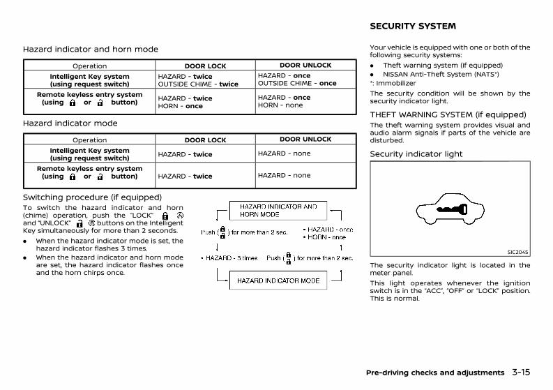
(165,1)
[ Edit: 2020/ 11/ 9 Model: Y62-A ]
Hazard indicator and horn modeGUID-743DDE4E-2E8E-4D5C-958C-62CD715EB3B1
Operation DOOR LOCK DOOR UNLOCKIntelligent Key system(using request switch)
HAZARD - twiceOUTSIDE CHIME - twice
HAZARD - onceOUTSIDE CHIME - once
Remote keyless entry system(using or button) HAZARD - twice
HORN - onceHAZARD - onceHORN - none
Hazard indicator modeGUID-6B98D737-7117-4FAD-8E8D-1E0FCA7056D8
Operation DOOR LOCK DOOR UNLOCKIntelligent Key system(using request switch) HAZARD - twice HAZARD - none
Remote keyless entry system(using or button) HAZARD - twice HAZARD - none
Switching procedure (if equipped)GUID-A596F4B4-F469-4DE8-8E87-2BCD4385CAD1To switch the hazard indicator and horn(chime) operation, push the “LOCK”and “UNLOCK” buttons on the IntelligentKey simultaneously for more than 2 seconds.. When the hazard indicator mode is set, the
hazard indicator flashes 3 times.. When the hazard indicator and horn mode
are set, the hazard indicator flashes onceand the horn chirps once.
NOS1695
GUID-29739652-5ED9-4FD5-8F38-8D3466951538Your vehicle is equipped with one or both of thefollowing security systems:. Theft warning system (if equipped). NISSAN Anti-Theft System (NATS*)*: ImmobilizerThe security condition will be shown by thesecurity indicator light.
THEFT WARNING SYSTEM (if equipped)GUID-E65DC1C3-0170-4689-8FE8-6BBD291A0C08The theft warning system provides visual andaudio alarm signals if parts of the vehicle aredisturbed.
Security indicator lightGUID-F7A4BE61-F271-46B4-B093-14AA63B7102B
SIC2045
The security indicator light is located in themeter panel.This light operates whenever the ignitionswitch is in the “ACC”, “OFF” or “LOCK” position.This is normal.
Pre-driving checks and adjustments 3-15
SECURITY SYSTEM
Condition: 'Except for China'/'Except for China/
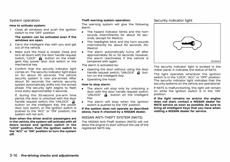
(166,1)
[ Edit: 2020/ 11/ 9 Model: Y62-A ]
3-16 Pre-driving checks and adjustments
System operationGUID-3625B789-BB8D-4367-AB98-59918602B271
How to activate system:GUID-C7E1EF24-5AAB-4301-95BE-26917EEE45EF
1. Close all windows and push the ignitionswitch to the “OFF” position.The system can be activated even if thewindows are open.
2. Carry the Intelligent Key with you and getout of the vehicle.
3. Make sure the hood is closed. Close andlock all doors with the door handle requestswitch, “LOCK” button on the Intelli-gent Key, power door lock switch or themechanical key.
4. Confirm that the security indicator lightcomes on. The security indicator light stayson for about 30 seconds. The vehiclesecurity system is now pre-armed. Afterabout 30 seconds the vehicle securitysystem automatically shifts into the armedphase. The security light begins to flashonce every approximately 3 seconds.If, during this 30-second pre-arm timeperiod, the door is unlocked with the doorhandle request switch, the “UNLOCK”button on the Intelligent Key, the powerdoor lock switch, or the ignition switch ispushed to the “ACC” or “ON” position, thesystem will not arm.
Even when the driver and/or passengers arein the vehicle, the systemwill activate with alldoors locked and ignition switch in the“LOCK” position. Push the ignition switch tothe “ACC” or “ON” position to turn the systemoff.
Theft warning system operation:GUID-C7E1EF24-5AAB-4301-95BE-26917EEE45EF
The warning system will give the followingalarm:. The hazard indicator blinks and the horn
sounds intermittently for about 30 sec-onds. (except for Mexico)
. The headlights blink and the horn soundsintermittently for about 50 seconds. (forMexico)
. The alarm automatically turns off afterapproximately 30 or 50 seconds. However,the alarm reactivates if the vehicle istampered with again.
The alarm is activated by:. Opening the door without using the door
handle request switch, “UNLOCK” but-ton on the Intelligent Key.
. Operating the hood.How to stop alarm:
GUID-C7E1EF24-5AAB-4301-95BE-26917EEE45EF
. The alarm will stop only by unlocking adoor with the door handle request switch,“UNLOCK” button on the IntelligentKey.
. The alarm will stop when the ignitionswitch is pushed to the “ON” position.
If the system does not operate as describedabove, have it checked by a NISSAN dealer.
NISSAN ANTI-THEFT SYSTEM (NATS)GUID-6466DFA7-344C-45EE-BAEF-BADA8E5EC151The NISSAN Anti-Theft System (NATS) will notallow the engine to start without the use of theregistered NATS key.
Security indicator lightGUID-EA15431A-E4B2-406E-B918-FC6C45EB7F68
SIC2045
The security indicator light is located in themeter panel. It indicates the status of NATS.The light operates whenever the ignitionswitch is in the “LOCK”, “ACC” or “OFF” position.The security indicator light indicates that thesecurity systems on the vehicle are operational.If NATS is malfunctioning, this light will remainon while the ignition switch is in the “ON”position.If the light remains on and/or the enginedoes not start, contact a NISSAN dealer forNATS service as soon as possible. Be sure tobring all Intelligent Keys that you have whenvisiting a NISSAN dealer for service.
Condition: 'Except for China'/'Except for China/
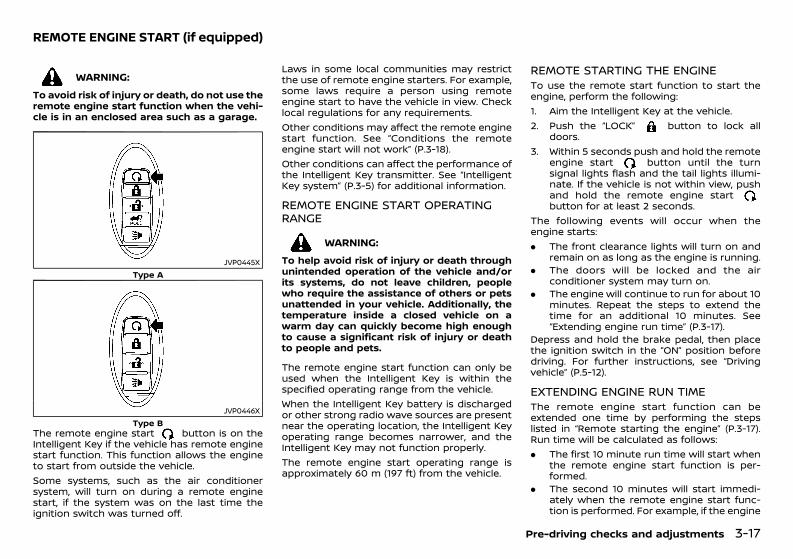
(167,1)
[ Edit: 2020/ 11/ 9 Model: Y62-A ]
GUID-66C34BED-8901-4B73-BBA5-8680A6BC82AC
WARNING:To avoid risk of injury or death, do not use theremote engine start function when the vehi-cle is in an enclosed area such as a garage.
JVP0445XType A
JVP0446XType B
The remote engine start button is on theIntelligent Key if the vehicle has remote enginestart function. This function allows the engineto start from outside the vehicle.Some systems, such as the air conditionersystem, will turn on during a remote enginestart, if the system was on the last time theignition switch was turned off.
Laws in some local communities may restrictthe use of remote engine starters. For example,some laws require a person using remoteengine start to have the vehicle in view. Checklocal regulations for any requirements.Other conditions may affect the remote enginestart function. See “Conditions the remoteengine start will not work” (P.3-18).Other conditions can affect the performance ofthe Intelligent Key transmitter. See “IntelligentKey system” (P.3-5) for additional information.
REMOTE ENGINE START OPERATINGRANGE GUID-CD71740F-1B71-4AA2-9506-5F1F9502928C
WARNING:To help avoid risk of injury or death throughunintended operation of the vehicle and/orits systems, do not leave children, peoplewho require the assistance of others or petsunattended in your vehicle. Additionally, thetemperature inside a closed vehicle on awarm day can quickly become high enoughto cause a significant risk of injury or deathto people and pets.
The remote engine start function can only beused when the Intelligent Key is within thespecified operating range from the vehicle.When the Intelligent Key battery is dischargedor other strong radio wave sources are presentnear the operating location, the Intelligent Keyoperating range becomes narrower, and theIntelligent Key may not function properly.The remote engine start operating range isapproximately 60 m (197 ft) from the vehicle.
REMOTE STARTING THE ENGINEGUID-B2AC6E3A-02BF-45A9-BA38-9F2587F1004DTo use the remote start function to start theengine, perform the following:1. Aim the Intelligent Key at the vehicle.2. Push the “LOCK” button to lock all
doors.3. Within 5 seconds push and hold the remote
engine start button until the turnsignal lights flash and the tail lights illumi-nate. If the vehicle is not within view, pushand hold the remote engine startbutton for at least 2 seconds.
The following events will occur when theengine starts:. The front clearance lights will turn on and
remain on as long as the engine is running.. The doors will be locked and the air
conditioner system may turn on.. The engine will continue to run for about 10
minutes. Repeat the steps to extend thetime for an additional 10 minutes. See“Extending engine run time” (P.3-17).
Depress and hold the brake pedal, then placethe ignition switch in the “ON” position beforedriving. For further instructions, see “Drivingvehicle” (P.5-12).
EXTENDING ENGINE RUN TIMEGUID-42E5AF17-4538-4FB1-AE20-07FBB71324F7The remote engine start function can beextended one time by performing the stepslisted in “Remote starting the engine” (P.3-17).Run time will be calculated as follows:. The first 10 minute run time will start when
the remote engine start function is per-formed.
. The second 10 minutes will start immedi-ately when the remote engine start func-tion is performed. For example, if the engine
Pre-driving checks and adjustments 3-17
REMOTE ENGINE START (if equipped)
Condition: 'Except for China'/'Except for China/
(168,1)
[ Edit: 2020/ 11/ 9 Model: Y62-A ]
3-18 Pre-driving checks and adjustments
has been running for 5 minutes, and 10minutes are added, the engine will run for atotal of 15 minutes.
. Extending engine run time will count to-wards the two remote engine start limit.
A maximum of two remote engine starts, or asingle start with an extension, are allowedbetween ignition cycles.The ignition switch must be cycled to the “ON”position and then back to the “OFF” positionbefore the remote engine start procedure canbe used again.
CANCELING A REMOTE ENGINE STARTGUID-93D82CD3-8A64-4541-A4D9-7BD07411858ETo cancel a remote engine start, perform oneof the following:. Aim the Intelligent Key at the vehicle and
push and hold the remote engine startbutton until the front clearance lights turnoff.
. Turn on the hazard indicator flashers.
. Cycle the ignition switch “ON” and then“OFF”.
. The extended engine run time has expired.
. The first 10 minute timer has expired.
. The engine hood has been opened.
. The shift lever is moved out of “P” (Park).
. The theft alarm sounds due to illegal entryinto the vehicle.
. The ignition switch is pushed without anIntelligent Key in the vehicle.
. The ignition switch is pushed with anIntelligent Key in the vehicle but the brakepedal is not depressed.
CONDITIONS THE REMOTE ENGINESTART WILL NOT WORKGUID-449A04EC-D328-40C2-A672-82F3CE4D40A6The remote engine start will not operate if anyof the following conditions are present:. The ignition switch is placed in the “ON”
position.. The hood is not securely closed.. The hazard indicator flashers are on.. The engine is still running. The engine must
be completely stopped. Wait at least 6seconds if the engine goes from runningto off. This is not applicable when extend-ing engine run time.
. The remote engine start button is notpushed and held for at least 2 seconds.
. The remote engine start button is notpushed and held within 5 seconds ofpushing the “LOCK” button.
. The brake pedal is depressed.
. The doors are not closed and locked.
. The back door is open.
. The Intelligent Key system warning lightremains on in the vehicle information dis-play.
. An Intelligent Key is left inside the vehicle.
. The theft alarm sounds due to illegal entryinto the vehicle.
. Two remote engine starts, or a singleremote engine start with an extension,have already been used.
. The shift lever is not in the “P” (Park)position.
The remote engine start may display a warningor indicator in the vehicle information display.For an explanation of the warning or indicator,see “Indicators for operation and warnings”(P.2-36).
GUID-8D1A6611-B742-4C67-9DEA-06DF085C8601
WARNING:. The hood must be closed and latched
securely before driving. Failure to do socould cause the hood to fly open andresult in an accident.
. Never open the hood if steam or smoke iscoming from the engine compartment toavoid injury.
HOOD
Condition: 'Except for China'/'Except for China/
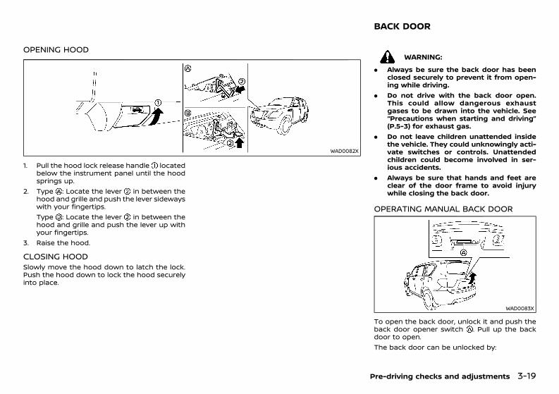
(169,1)
[ Edit: 2020/ 11/ 9 Model: Y62-A ]
OPENING HOODGUID-C77E2F1D-60B4-4D2B-B5AC-A9D195216B86
WAD0082X
1. Pull the hood lock release handle locatedbelow the instrument panel until the hoodsprings up.
2. Type : Locate the lever in between thehood and grille and push the lever sidewayswith your fingertips.Type : Locate the lever in between thehood and grille and push the lever up withyour fingertips.
3. Raise the hood.
CLOSING HOODGUID-8E45C7D5-FF02-4C67-9E5B-AD84F0F3834ESlowly move the hood down to latch the lock.Push the hood down to lock the hood securelyinto place.
GUID-19F829F8-A245-4A52-A7E7-3EF244DB9C9B
WARNING:. Always be sure the back door has been
closed securely to prevent it from open-ing while driving.
. Do not drive with the back door open.This could allow dangerous exhaustgases to be drawn into the vehicle. See“Precautions when starting and driving”(P.5-3) for exhaust gas.
. Do not leave children unattended insidethe vehicle. They could unknowingly acti-vate switches or controls. Unattendedchildren could become involved in ser-ious accidents.
. Always be sure that hands and feet areclear of the door frame to avoid injurywhile closing the back door.
OPERATING MANUAL BACK DOORGUID-38C7BF3F-6192-49B0-8F7D-4DE21D89BFE8
WAD0083X
To open the back door, unlock it and push theback door opener switch . Pull up the backdoor to open.The back door can be unlocked by:
Pre-driving checks and adjustments 3-19
BACK DOOR
Condition: 'Except for China'/'Except for China/
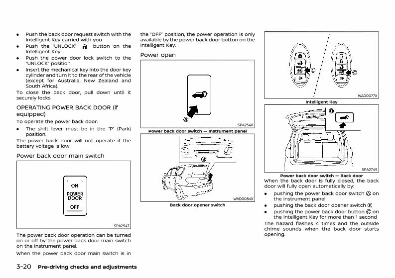
(170,1)
[ Edit: 2020/ 11/ 9 Model: Y62-A ]
3-20 Pre-driving checks and adjustments
. Push the back door request switch with theIntelligent Key carried with you.
. Push the “UNLOCK” button on theIntelligent Key.
. Push the power door lock switch to the“UNLOCK” position.
. Insert the mechanical key into the door keycylinder and turn it to the rear of the vehicle(except for Australia, New Zealand andSouth Africa).
To close the back door, pull down until itsecurely locks.
OPERATING POWER BACK DOOR (ifequipped) GUID-486A1CC8-9BA0-404F-8C9C-BC1FC6AED380To operate the power back door:. The shift lever must be in the “P” (Park)
position.The power back door will not operate if thebattery voltage is low.
Power back door main switchGUID-D33958F3-F3C1-4273-82E0-C65246C59329
SPA2547
The power back door operation can be turnedon or off by the power back door main switchon the instrument panel.When the power back door main switch is in
the “OFF” position, the power operation is onlyavailable by the power back door button on theIntelligent Key.
Power openGUID-411BAA68-E388-4044-BCA0-9E8939FCC920
SPA2548Power back door switch — Instrument panel
WAD0084XBack door opener switch
WAD0077XIntelligent Key
SPA2749Power back door switch — Back door
When the back door is fully closed, the backdoor will fully open automatically by:. pushing the power back door switch on
the instrument panel. pushing the back door opener switch. pushing the power back door button on
the Intelligent Key for more than 1 secondThe hazard flashes 4 times and the outsidechime sounds when the back door startsopening.
Condition: 'Except for China'/'Except for China/
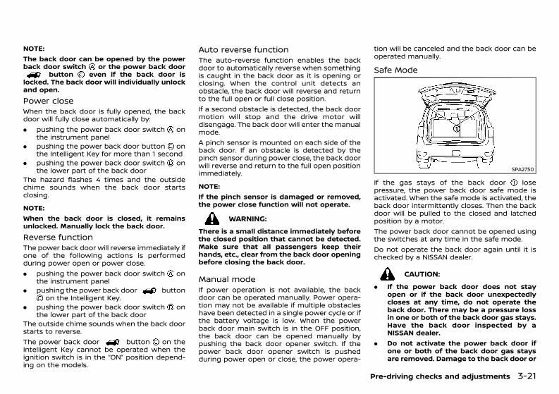
(171,1)
[ Edit: 2020/ 11/ 9 Model: Y62-A ]
NOTE:The back door can be opened by the powerback door switch or the power back door
button even if the back door islocked. The back door will individually unlockand open.Power close GUID-FB4251F5-5814-4B67-B6F6-1AEE37222298When the back door is fully opened, the backdoor will fully close automatically by:. pushing the power back door switch on
the instrument panel. pushing the power back door button on
the Intelligent Key for more than 1 second. pushing the power back door switch on
the lower part of the back doorThe hazard flashes 4 times and the outsidechime sounds when the back door startsclosing.
NOTE:When the back door is closed, it remainsunlocked. Manually lock the back door.Reverse functionGUID-9320BEF6-4A57-4B1E-94E6-5EAE6E90965BThe power back door will reverse immediately ifone of the following actions is performedduring power open or power close.. pushing the power back door switch on
the instrument panel. pushing the power back door button
on the Intelligent Key.. pushing the power back door switch on
the lower part of the back doorThe outside chime sounds when the back doorstarts to reverse.The power back door button on theIntelligent Key cannot be operated when theignition switch is in the “ON” position depend-ing on the models.
Auto reverse functionGUID-B96AC6B8-6528-49F3-9642-46CAAC227954The auto-reverse function enables the backdoor to automatically reverse when somethingis caught in the back door as it is opening orclosing. When the control unit detects anobstacle, the back door will reverse and returnto the full open or full close position.If a second obstacle is detected, the back doormotion will stop and the drive motor willdisengage. The back door will enter the manualmode.A pinch sensor is mounted on each side of theback door. If an obstacle is detected by thepinch sensor during power close, the back doorwill reverse and return to the full open positionimmediately.
NOTE:If the pinch sensor is damaged or removed,the power close function will not operate.
WARNING:There is a small distance immediately beforethe closed position that cannot be detected.Make sure that all passengers keep theirhands, etc., clear from the back door openingbefore closing the back door.
Manual modeGUID-179B3DD6-5D1B-4074-976D-FADC46BA9531If power operation is not available, the backdoor can be operated manually. Power opera-tion may not be available if multiple obstacleshave been detected in a single power cycle or ifthe battery voltage is low. When the powerback door main switch is in the OFF position,the back door can be opened manually bypushing the back door opener switch. If thepower back door opener switch is pushedduring power open or close, the power opera-
tion will be canceled and the back door can beoperated manually.
Safe Mode GUID-5C941509-11FD-4AB2-A173-93F6B9FC1019
SPA2750
If the gas stays of the back door losepressure, the power back door safe mode isactivated. When the safe mode is activated, theback door intermittently closes. Then the backdoor will be pulled to the closed and latchedposition by a motor.The power back door cannot be opened usingthe switches at any time in the safe mode.Do not operate the back door again until it ischecked by a NISSAN dealer.
CAUTION:. If the power back door does not stay
open or if the back door unexpectedlycloses at any time, do not operate theback door. There may be a pressure lossin one or both of the back door gas stays.Have the back door inspected by aNISSAN dealer.
. Do not activate the power back door ifone or both of the back door gas staysare removed. Damage to the back door or
Pre-driving checks and adjustments 3-21
Condition: 'Except for China'/'Except for China/
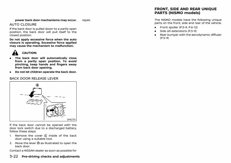
(172,1)
[ Edit: 2020/ 11/ 9 Model: Y62-A ]
3-22 Pre-driving checks and adjustments
power back door mechanismsmay occur.AUTO CLOSUREGUID-1F51EB7A-04C2-417D-930D-AE8E786C02F4If the back door is pulled down to a partly openposition, the back door will pull itself to theclosed position.Do not apply excessive force when the autoclosure is operating. Excessive force appliedmay cause the mechanism to malfunction.
CAUTION:. The back door will automatically close
from a partly open position. To avoidpinching, keep hands and fingers awayfrom back door opening.
. Do not let children operate the back door.
BACK DOOR RELEASE LEVERGUID-E0D5215E-BE8B-425C-813C-16C1C242DA53
SPA2751
If the back door cannot be opened with thedoor lock switch due to a discharged battery,follow these steps.1. Remove the cover inside of the back
door using a suitable tool.2. Move the lever as illustrated to open the
back door.Contact a NISSAN dealer as soon as possible for
repair.GUID-D69140E7-0DD2-4D96-83A9-C453A246D7CA
The NISMO models have the following uniqueparts on the front, side and rear of the vehicle.. Front spoiler (P.5-9, P.6-12). Side sill extensions (P.5-9). Rear bumper with the aerodynamic diffuser
(P.5-9)
FRONT, SIDE AND REAR UNIQUEPARTS (NISMO models)
Condition: 'Except for China'/'Except for China/
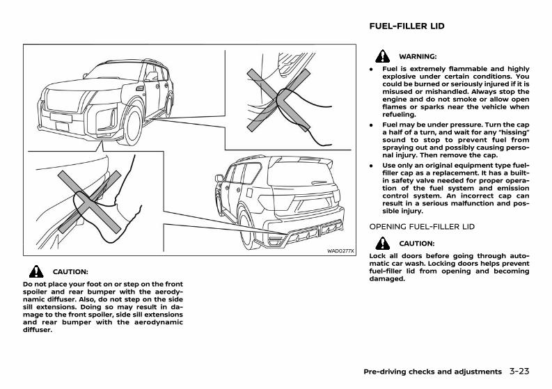
(173,1)
[ Edit: 2020/ 11/ 9 Model: Y62-A ]
WAD0277X
CAUTION:Do not place your foot on or step on the frontspoiler and rear bumper with the aerody-namic diffuser. Also, do not step on the sidesill extensions. Doing so may result in da-mage to the front spoiler, side sill extensionsand rear bumper with the aerodynamicdiffuser.
GUID-75C5E040-E470-4D10-8395-5143E2BA5528
WARNING:. Fuel is extremely flammable and highly
explosive under certain conditions. Youcould be burned or seriously injured if it ismisused or mishandled. Always stop theengine and do not smoke or allow openflames or sparks near the vehicle whenrefueling.
. Fuel may be under pressure. Turn the capa half of a turn, and wait for any “hissing”sound to stop to prevent fuel fromspraying out and possibly causing perso-nal injury. Then remove the cap.
. Use only an original equipment type fuel-filler cap as a replacement. It has a built-in safety valve needed for proper opera-tion of the fuel system and emissioncontrol system. An incorrect cap canresult in a serious malfunction and pos-sible injury.
OPENING FUEL-FILLER LIDGUID-7D906A5C-3C1D-4861-AE04-D1F167942F05
CAUTION:Lock all doors before going through auto-matic car wash. Locking doors helps preventfuel-filler lid from opening and becomingdamaged.
Pre-driving checks and adjustments 3-23
FUEL-FILLER LID
Condition: 'Except for China'/'Except for China/
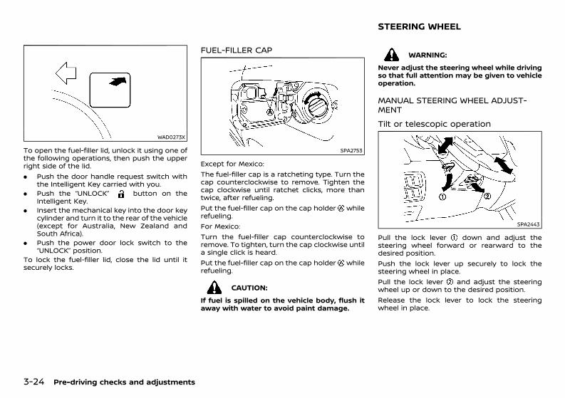
(174,1)
[ Edit: 2020/ 11/ 9 Model: Y62-A ]
3-24 Pre-driving checks and adjustments
WAD0273X
To open the fuel-filler lid, unlock it using one ofthe following operations, then push the upperright side of the lid.. Push the door handle request switch with
the Intelligent Key carried with you.. Push the “UNLOCK” button on the
Intelligent Key.. Insert the mechanical key into the door key
cylinder and turn it to the rear of the vehicle(except for Australia, New Zealand andSouth Africa).
. Push the power door lock switch to the“UNLOCK” position.
To lock the fuel-filler lid, close the lid until itsecurely locks.
FUEL-FILLER CAPGUID-1DA66975-73C5-44CC-BFE5-F35B2D17EDB4
SPA2753
Except for Mexico:The fuel-filler cap is a ratcheting type. Turn thecap counterclockwise to remove. Tighten thecap clockwise until ratchet clicks, more thantwice, after refueling.Put the fuel-filler cap on the cap holder whilerefueling.For Mexico:Turn the fuel-filler cap counterclockwise toremove. To tighten, turn the cap clockwise untila single click is heard.Put the fuel-filler cap on the cap holder whilerefueling.
CAUTION:If fuel is spilled on the vehicle body, flush itaway with water to avoid paint damage.
GUID-8A7BE58E-154C-4BBC-95D3-B8F9DB5246CA
WARNING:Never adjust the steering wheel while drivingso that full attention may be given to vehicleoperation.
MANUAL STEERING WHEEL ADJUST-MENT GUID-AF41A378-43A9-483A-8718-BCEDAB4DB1D4
Tilt or telescopic operationGUID-3EEBB680-3166-41D4-A88E-48CAB7016BDE
SPA2443
Pull the lock lever down and adjust thesteering wheel forward or rearward to thedesired position.Push the lock lever up securely to lock thesteering wheel in place.Pull the lock lever and adjust the steeringwheel up or down to the desired position.Release the lock lever to lock the steeringwheel in place.
STEERING WHEEL
Condition: 'Except for China'/'Except for China/
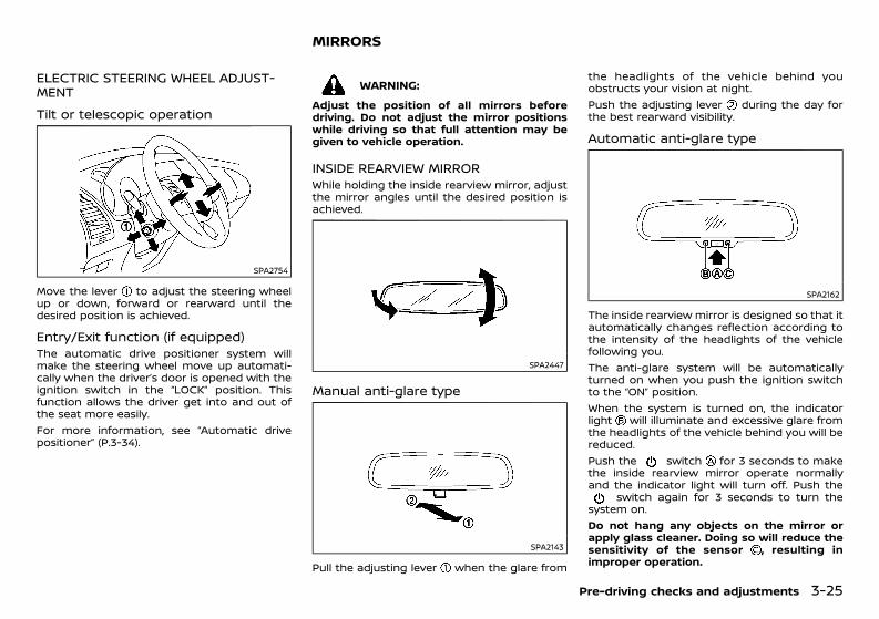
(175,1)
[ Edit: 2020/ 11/ 9 Model: Y62-A ]
ELECTRIC STEERING WHEEL ADJUST-MENT GUID-5AF04EF0-DCFE-4592-9F04-A39C1674B152
Tilt or telescopic operationGUID-239814A7-5BD3-4E2B-A54A-9C6CBBB87917
SPA2754
Move the lever to adjust the steering wheelup or down, forward or rearward until thedesired position is achieved.
Entry/Exit function (if equipped)GUID-575986A5-02D0-43B3-A886-1A354FA2245EThe automatic drive positioner system willmake the steering wheel move up automati-cally when the driver’s door is opened with theignition switch in the “LOCK” position. Thisfunction allows the driver get into and out ofthe seat more easily.For more information, see “Automatic drivepositioner” (P.3-34).
GUID-7FC36ADA-46BB-4890-BDD2-D75687834708
WARNING:Adjust the position of all mirrors beforedriving. Do not adjust the mirror positionswhile driving so that full attention may begiven to vehicle operation.
INSIDE REARVIEW MIRRORGUID-3D311780-23D0-4B3C-AF4C-8B38BCD0F0BBWhile holding the inside rearview mirror, adjustthe mirror angles until the desired position isachieved.
SPA2447
Manual anti-glare typeGUID-69390AAA-15FF-4756-90E5-258C9D86F713
SPA2143
Pull the adjusting lever when the glare from
the headlights of the vehicle behind youobstructs your vision at night.Push the adjusting lever during the day forthe best rearward visibility.
Automatic anti-glare typeGUID-4AF8C068-04D6-4644-BCA3-700071184967
SPA2162
The inside rearview mirror is designed so that itautomatically changes reflection according tothe intensity of the headlights of the vehiclefollowing you.The anti-glare system will be automaticallyturned on when you push the ignition switchto the “ON” position.When the system is turned on, the indicatorlight will illuminate and excessive glare fromthe headlights of the vehicle behind you will bereduced.Push the switch for 3 seconds to makethe inside rearview mirror operate normallyand the indicator light will turn off. Push the
switch again for 3 seconds to turn thesystem on.Do not hang any objects on the mirror orapply glass cleaner. Doing so will reduce thesensitivity of the sensor , resulting inimproper operation.
Pre-driving checks and adjustments 3-25
MIRRORS
Condition: 'Except for China'/'Except for China/
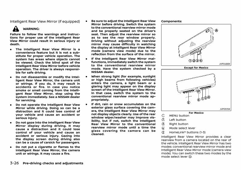
(176,1)
[ Edit: 2020/ 11/ 9 Model: Y62-A ]
3-26 Pre-driving checks and adjustments
Intelligent Rear View Mirror (if equipped)GUID-7303410E-C85D-44C3-8383-059B1C48E4C6
WARNING:Failure to follow the warnings and instruc-tions for proper use of the Intelligent RearView Mirror could result in serious injury ordeath.. The Intelligent Rear View Mirror is a
convenience feature but it is not a sub-stitute for proper vehicle operation. Thesystem has areas where objects cannotbe viewed. Check the blind spot of theIntelligent Rear ViewMirror before vehicleoperation. The driver is always responsi-ble for safe driving.
. Do not disassemble or modify the Intel-ligent Rear View Mirror, the camera unitor wirings. If you do, it may result inaccidents or fire. In case you noticesmoke or smell coming from the Intelli-gent Rear View Mirror, stop using thesystem immediately. See a NISSAN dealerfor servicing.
. Do not operate the Intelligent Rear ViewMirror while driving. Doing so can be adistraction and it could lose control ofyour vehicle and cause an accident orserious injury.
. Do not gaze into the Intelligent Rear ViewMirror display during driving. It maycause a distraction and it could losecontrol of your vehicle and cause anaccident or serious injury. Gazing intothe display screen during driving alsocan be a cause of carsick for passengers.
. Do not put a cigarette or flames to theIntelligent Rear View Mirror, the cameraunit or wirings. It may cause a fire.
. Be sure to adjust the Intelligent Rear ViewMirror before driving. Switch the systemto the conventional rearviewmirror modeand be properly seated on the driver’sseat. Then adjust the rearview mirror soas to see the rear window properly.Driving without adjusting the rearviewmirror may cause difficulty in watchingthe display at Intelligent Rear View Mirrormode (camera view mode) due to thereflection from the surface of the mirror.
. If the Intelligent Rear View Mirror mal-functions, immediately switch the systemto the conventional rearview mirrormode. Have the system checked by aNISSAN dealer.
. When strong light (for example, sunlightor high beams from following vehicles)enters the camera, a light beam or aglaring light may appear on the displayscreen of the Intelligent Rear View Mirror.In that case, switch the system to theconventional rearview mirror mode ap-propriately.
. If dirt, rain or snow accumulates on theexterior glass surface covering the cam-era, the Intelligent Rear View Mirror maynot display objects clearly. Use of the rearwindow wiper/washer may improve vis-ibility, but if not, switch the IntelligentRear View Mirror to the conventionalrearview mirror mode until a time theglass covering the camera can becleaned.
Components:GUID-C7E1EF24-5AAB-4301-95BE-26917EEE45EF
JVP0488XExcept for Mexico
JVP0515XFor Mexico
MENU buttonLeft buttonRight buttonMode select leverHomeLink® buttons (1-3)
Intelligent Rear View Mirror provides a clearrearview from a camera located on the rear ofthe vehicle. Intelligent Rear View Mirror has twomodes: conventional rearviewmirror mode andIntelligent Rear View Mirror mode (camera viewmode). You can switch these two modes by themode select lever .
Condition: 'Except for China'/'Except for China/
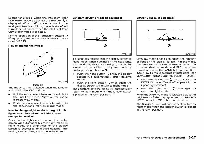
(177,1)
[ Edit: 2020/ 11/ 9 Model: Y62-A ]
Except for Mexico: When the Intelligent RearView Mirror mode is selected, the indicator isdisplayed. (If a malfunction occurs in theIntelligent Rear View Mirror, the indicator willturn off or not appear when the Intelligent RearView Mirror mode is selected.)For the operation of the HomeLink® buttons(if equipped), see “HomeLink® Universal Trans-ceiver” (P.2-73).How to change the mode:
GUID-C7E1EF24-5AAB-4301-95BE-26917EEE45EF
JVP0489XExample
The mode can be switched when the ignitionswitch is in the “ON” position.. Pull the mode select lever to switch to
the Intelligent Rear View Mirror mode(camera view mode).
. Push the mode select lever to switch tothe conventional rearview mirror mode.
How to change night mode setting of Intel-ligent Rear View Mirror on initial screen(except for Mexico):
GUID-C7E1EF24-5AAB-4301-95BE-26917EEE45EF
Once the headlights are turned on, the displayscreen will automatically enter night mode. Innight mode, the brightness of the displayscreen is decreased to reduce dazzling. Thissetting can be changed on the initial screen.
Constant daytime mode (if equipped)
JVP0495X
If it is not desirable to shift the display screen tonight mode when turning on the headlights,such as during daytime or twilight, the displayscreen can be shifted to daytime mode bypushing the right button .. Push the right button once, the display
screen will automatically enter daytimemode.
. Push the right button once again, thedisplay screen will return to night mode.
The constant daytime mode will automaticallyreturn to night mode when the ignition switchis placed in the “OFF” position.
DIMMING mode (if equipped)
JVP0573X
DIMMING mode enables to adjust the amountof light on the display screen. In night mode,the DIMMING mode can be selected when theconstant daytime mode and PLS mode areturned off under the MENU button operation.(See “How to make settings of Intelligent RearView Mirror (MENU button operation)” (P.3-28).). Push the right button once to select the
DIMMING mode. (“DIMMING” appears in theupper right corner.)
. Push the right button once again toreturn to night mode.
When the DIMMING mode is selected, adjust thebrightness of the display screen in “BRIGHT-NESS” under the MENU button operation.The DIMMING mode will automatically return tonight mode when the ignition switch is placedin the “OFF” position.
Pre-driving checks and adjustments 3-27
Condition: 'Except for China'/'Except for China/
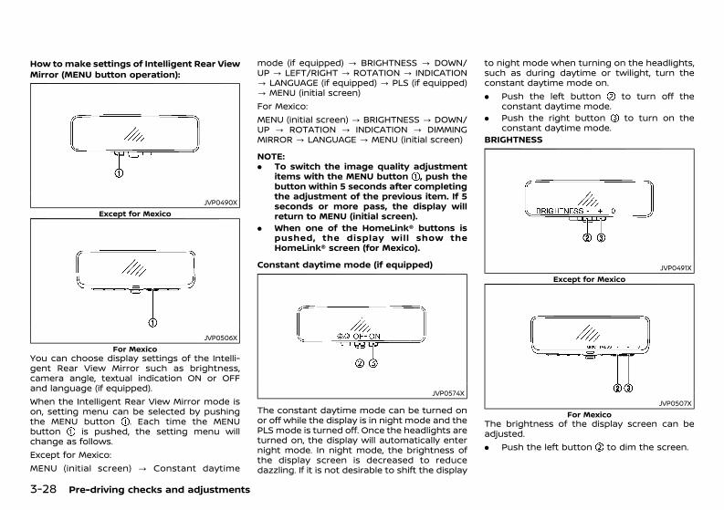
(178,1)
[ Edit: 2020/ 11/ 9 Model: Y62-A ]
3-28 Pre-driving checks and adjustments
How to make settings of Intelligent Rear ViewMirror (MENU button operation):
GUID-C7E1EF24-5AAB-4301-95BE-26917EEE45EF
JVP0490XExcept for Mexico
JVP0506XFor Mexico
You can choose display settings of the Intelli-gent Rear View Mirror such as brightness,camera angle, textual indication ON or OFFand language (if equipped).When the Intelligent Rear View Mirror mode ison, setting menu can be selected by pushingthe MENU button . Each time the MENUbutton is pushed, the setting menu willchange as follows.Except for Mexico:MENU (initial screen) ? Constant daytime
mode (if equipped) ? BRIGHTNESS ? DOWN/UP ? LEFT/RIGHT ? ROTATION ? INDICATION? LANGUAGE (if equipped) ? PLS (if equipped)? MENU (initial screen)For Mexico:MENU (initial screen) ? BRIGHTNESS ? DOWN/UP ? ROTATION ? INDICATION ? DIMMINGMIRROR ? LANGUAGE ? MENU (initial screen)
NOTE:. To switch the image quality adjustment
items with the MENU button , push thebutton within 5 seconds after completingthe adjustment of the previous item. If 5seconds or more pass, the display willreturn to MENU (initial screen).
. When one of the HomeLink® buttons ispushed, the display will show theHomeLink® screen (for Mexico).
Constant daytime mode (if equipped)
JVP0574X
The constant daytime mode can be turned onor off while the display is in night mode and thePLS mode is turned off. Once the headlights areturned on, the display will automatically enternight mode. In night mode, the brightness ofthe display screen is decreased to reducedazzling. If it is not desirable to shift the display
to night mode when turning on the headlights,such as during daytime or twilight, turn theconstant daytime mode on.. Push the left button to turn off the
constant daytime mode.. Push the right button to turn on the
constant daytime mode.BRIGHTNESS
JVP0491XExcept for Mexico
JVP0507XFor Mexico
The brightness of the display screen can beadjusted.. Push the left button to dim the screen.
Condition: 'Except for China'/'Except for China/
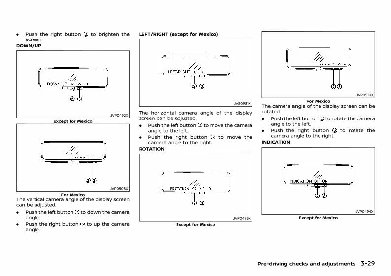
(179,1)
[ Edit: 2020/ 11/ 9 Model: Y62-A ]
. Push the right button to brighten thescreen.
DOWN/UP
JVP0492XExcept for Mexico
JVP0508XFor Mexico
The vertical camera angle of the display screencan be adjusted.. Push the left button to down the camera
angle.. Push the right button to up the camera
angle.
LEFT/RIGHT (except for Mexico)
JVS0981X
The horizontal camera angle of the displayscreen can be adjusted.. Push the left button to move the camera
angle to the left.. Push the right button to move the
camera angle to the right.ROTATION
JVP0493XExcept for Mexico
JVP0510XFor Mexico
The camera angle of the display screen can berotated.. Push the left button to rotate the camera
angle to the left.. Push the right button to rotate the
camera angle to the right.INDICATION
JVP0494XExcept for Mexico
Pre-driving checks and adjustments 3-29
Condition: 'Except for China'/'Except for China/
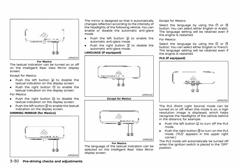
(180,1)
[ Edit: 2020/ 11/ 9 Model: Y62-A ]
3-30 Pre-driving checks and adjustments
JVP0511XFor Mexico
The textual indication can be turned on or offon the Intelligent Rear View Mirror displayscreen.Except for Mexico:. Push the left button to disable the
textual indication on the display screen.. Push the right button to enable the
textual indication on the display screen.For Mexico:. Push the right button to disable the
textual indication on the display screen.. Push the left button to enable the textual
indication on the display screen.DIMMING MIRROR (for Mexico)
JVP0514X
The mirror is designed so that it automaticallychanges reflection according to the intensity ofthe headlights of the following vehicle. You canenable or disable the automatic anti-glaremode.. Push the left button to enable the
automatic anti-glare mode.. Push the right button to disable the
automatic anti-glare mode.LANGUAGE (if equipped)
JVP0544XExcept for Mexico
JVP0512XFor Mexico
The language of the textual indication can beselected on the Intelligent Rear View Mirrordisplay screen.
Except for Mexico:Select the language by using the orbutton. You can select either English or Arabic.The language setting will be retained even ifthe engine is restarted.For Mexico:Select the language by using the orbutton. You can select either English or French.The language setting will be retained even ifthe engine is restarted.PLS (if equipped)
JVP0575X
The PLS (Point Light Source) mode can beturned on or off. When this mode is on, a highresolution image is displayed, which helpsrecognize the headlights of the vehicle behindin the distance, for example.. Push the left button to turn off the PLS
mode.. Push the right button to turn on the PLS
mode. (“PLS” appears in the upper rightcorner.)
The PLS mode will automatically be turned offwhen the ignition switch is placed in the “OFF”position.
Condition: 'Except for China'/'Except for China/
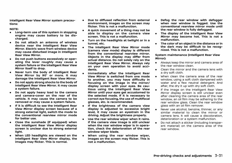
(181,1)
[ Edit: 2020/ 11/ 9 Model: Y62-A ]
Intelligent Rear View Mirror system precau-tions:
GUID-C7E1EF24-5AAB-4301-95BE-26917EEE45EF
NOTE:. Long-term use of this system in stopping
engine may cause battery to be dis-charged.
. Do not attach an antenna of wirelessdevice near the Intelligent Rear ViewMirror. Electric wave from wireless devicemay cause disturbed image in IntelligentRear View Mirror.
. Do not push buttons excessively or oper-ating the lever roughly may cause asystem failure or the Intelligent Rear ViewMirror itself to drop.
. Never turn the body of Intelligent RearView Mirror by 90° or more. It maydamage the Intelligent Rear View Mirror.
. Do not apply strong shocks to the body ofIntelligent Rear View Mirror. It may causea system failure.
. Do not apply heavy load to the cameraand camera-cover on the rear of thevehicle. It may cause the camera to beremoved or may cause a system failure.
. If it is difficult to see the Intelligent RearView Mirror display screen because of astrong external light, switch the mode tothe conventional rearview mirror modefor better use.
. Close the sunshade (if equipped) whenthe Intelligent Rear View Mirror displayscreen is unclear due to strong externallight.
. When LED headlights are viewed on theIntelligent Rear View Mirror display, theimages may flicker. This is normal.
. Due to diffused reflection from externalenvironment, images on the screen mayflicker. This is not a malfunction.
. A quick movement of a thing may not beable to display on the camera viewscreen. This is not a malfunction.
. Turn on the headlights at twilight or in atunnel, etc.
. The Intelligent Rear View Mirror mode(camera view mode) display is differentfrom the conventional rearview mirror.Objects in the display may differ fromactual distance. Do not solely rely on theIntelligent Rear View Mirror. Always relyon your own operation to avoid acci-dents.
. Immediately after the Intelligent RearView Mirror is switched from one modeto another, you may have difficulty infocusing on the image in the mirror/display screen with your eyes. Be cau-tious using the Intelligent Rear ViewMirror until your eyes get accustomed tothe selected mode. If it is necessary tocorrect eye focusing, the use of multifocalglasses, etc. is recommended.
. If the brightness of the camera viewdisplay is adjusted to excessive brightlevel, it may cause an eyestrain in thedriving. Adjust the brightness properly.
. Use the rear window wiper when it rains.If the camera view image is still unclearwhen the rear window wiper is in opera-tion, check the deterioration of the rearwindow wiper blade.
. When using the rear window wiper,images on the screen may flicker. This isnot a malfunction.
. Defog the rear window with defoggerwhen rear window is fogged. Use theconventional rearview mirror mode untilthe rear window is fully defogged.
. The display of the Intelligent Rear ViewMirror may become hot. This is not amalfunction.
. The color of an object in the distance or inthe dark may be difficult to be recog-nized. This is not a malfunction.
System maintenance (Intelligent Rear ViewMirror):
GUID-C7E1EF24-5AAB-4301-95BE-26917EEE45EF
. Always keep the mirror and camera area ofthe rear window clean.
. Clean the mirror and the camera lens witha dry soft cloth.
. When clean the camera area of the rearwindow, using a soft cloth dampened withwater and a few neutral detergent. Andafter, the dry it up with dry soft cloth.
. If the image on the Intelligent Rear ViewMirror display screen is still unclear evenafter cleaning the camera area of the rearwindow, an oil film may be adhering to therear window glass. Clean the rear windowglass with an oil film remover.
. Never use alcohol, benzine, thinner, or anysimilar material to clean the mirror orcamera lens. It will cause a discoloration,deterioration or a system malfunction.
. Do not attach a sticker (including transpar-ent material) on the camera area of therear window.
Pre-driving checks and adjustments 3-31
Condition: 'Except for China'/'Except for China/
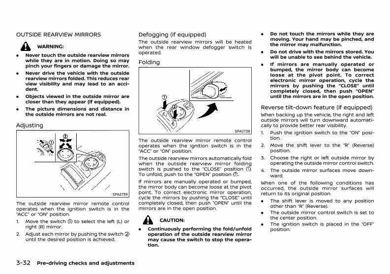
(182,1)
[ Edit: 2020/ 11/ 9 Model: Y62-A ]
3-32 Pre-driving checks and adjustments
OUTSIDE REARVIEW MIRRORSGUID-A58F5C79-53BB-4B4C-99AE-FA7AA426C90E
WARNING:. Never touch the outside rearview mirrors
while they are in motion. Doing so maypinch your fingers or damage the mirror.
. Never drive the vehicle with the outsiderearviewmirrors folded. This reduces rearview visibility and may lead to an acci-dent.
. Objects viewed in the outside mirror arecloser than they appear (if equipped).
. The picture dimensions and distance inthe outside mirrors are not real.
Adjusting GUID-6CD14C69-6323-4940-BD8D-C96CE05BE1D2
SPA2739
The outside rearview mirror remote controloperates when the ignition switch is in the“ACC” or “ON” position.1. Move the switch to select the left (L) or
right (R) mirror.2. Adjust each mirror by pushing the switch
until the desired position is achieved.
Defogging (if equipped)GUID-18AC3950-3615-4493-A1A6-B3BDD8A8CB68The outside rearview mirrors will be heatedwhen the rear window defogger switch isoperated.
Folding GUID-C551A3E7-B939-41F3-A08E-85B4352893EF
SPA2738
The outside rearview mirror remote controloperates when the ignition switch is in the“ACC” or “ON” position.The outside rearview mirrors automatically foldwhen the outside rearview mirror foldingswitch is pushed to the “CLOSE” position .To unfold, push to the “OPEN” position .If mirrors are manually operated or bumped,the mirror body can become loose at the pivotpoint. To correct electronic mirror operation,cycle the mirrors by pushing the “CLOSE” untilcompletely closed, then push “OPEN” until themirrors are in the open position.
CAUTION:. Continuously performing the fold/unfold
operation of the outside rearview mirrormay cause the switch to stop the opera-tion.
. Do not touch the mirrors while they aremoving. Your hand may be pinched, andthe mirror may malfunction.
. Do not drive with the mirrors stored. Youwill be unable to see behind the vehicle.
. If mirrors are manually operated orbumped, the mirror body can becomeloose at the pivot point. To correctelectronic mirror operation, cycle themirrors by pushing the “CLOSE” untilcompletely closed, then push “OPEN”until the mirrors are in the open position.
Reverse tilt-down feature (if equipped)GUID-7AE4190E-C648-44A6-BC65-50E584FA2A51When backing up the vehicle, the right and leftoutside mirrors will turn downward automati-cally to provide better rear visibility.1. Push the ignition switch to the “ON” posi-
tion.2. Move the shift lever to the “R” (Reverse)
position.3. Choose the right or left outside mirror by
operating the outsidemirror control switch.4. The outside mirror surfaces move down-
ward.When one of the following conditions hasoccurred, the outside mirror surfaces willreturn to its original position.. The shift lever is moved to any position
other than “R” (Reverse).. The outside mirror control switch is set to
the center position.. The ignition switch is placed in the “OFF”
position.
Condition: 'Except for China'/'Except for China/
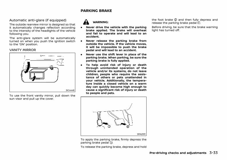
(183,1)
[ Edit: 2020/ 11/ 9 Model: Y62-A ]
Automatic anti-glare (if equipped)GUID-B4227027-C7B2-4618-8497-BB6849189A1FThe outside rearview mirror is designed so thatit automatically changes reflection accordingto the intensity of the headlights of the vehiclefollowing you.The anti-glare system will be automaticallyturned on when you push the ignition switchto the “ON” position.
VANITY MIRRORGUID-10CA0FE3-AB2E-485E-8594-B07AED9965F2
SIC4448
To use the front vanity mirror, pull down thesun visor and pull up the cover.
GUID-13486B6E-8238-4DF0-9F9B-1B1BA4711EA7
WARNING:. Never drive the vehicle with the parking
brake applied. The brake will overheatand fail to operate and will lead to anaccident.
. Never release the parking brake fromoutside the vehicle. If the vehicle moves,it will be impossible to push the brakepedal and will lead to an accident.
. Never use the shift lever in place of theparking brake. When parking, be sure theparking brake is fully applied.
. To help avoid risk of injury or deaththrough unintended operation of thevehicle and/or its systems, do not leavechildren, people who require the assis-tance of others or pets unattended inyour vehicle. Additionally, the tempera-ture inside a closed vehicle on a warmday can quickly become high enough tocause a significant risk of injury or deathto people and pets.
SPA2331
To apply the parking brake, firmly depress theparking brake pedal .To release the parking brake, depress and hold
the foot brake and then fully depress andrelease the parking brake pedal .Before driving, be sure that the brake warninglight has turned off.
Pre-driving checks and adjustments 3-33
PARKING BRAKE
Condition: 'Except for China'/'Except for China/
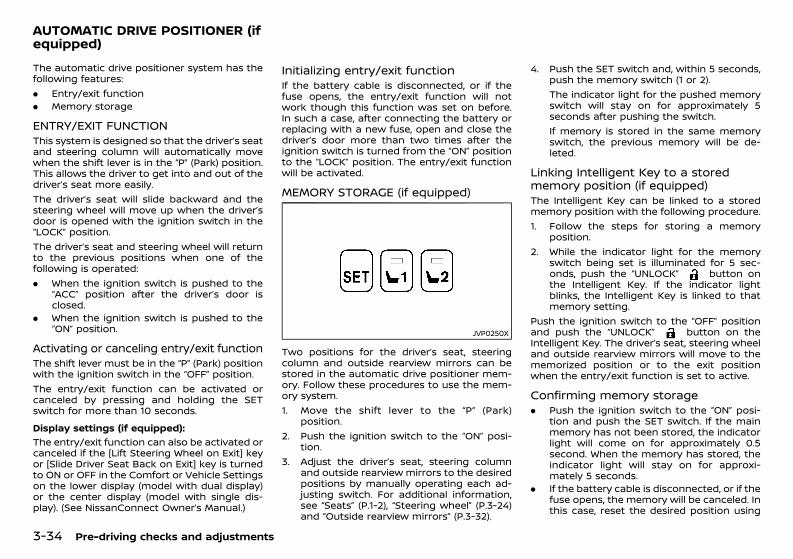
(184,1)
[ Edit: 2020/ 11/ 9 Model: Y62-A ]
3-34 Pre-driving checks and adjustments
GUID-A66E4F9D-588E-45F6-8910-C9D4836DCC77The automatic drive positioner system has thefollowing features:. Entry/exit function. Memory storage
ENTRY/EXIT FUNCTIONGUID-438E461D-1300-49FF-AE03-DD1204AFC90DThis system is designed so that the driver’s seatand steering column will automatically movewhen the shift lever is in the “P” (Park) position.This allows the driver to get into and out of thedriver’s seat more easily.The driver’s seat will slide backward and thesteering wheel will move up when the driver’sdoor is opened with the ignition switch in the“LOCK” position.The driver’s seat and steering wheel will returnto the previous positions when one of thefollowing is operated:. When the ignition switch is pushed to the
“ACC” position after the driver’s door isclosed.
. When the ignition switch is pushed to the“ON” position.
Activating or canceling entry/exit functionGUID-F9A3613A-906F-4837-979D-64A4648523AAThe shift lever must be in the “P” (Park) positionwith the ignition switch in the “OFF” position.The entry/exit function can be activated orcanceled by pressing and holding the SETswitch for more than 10 seconds.Display settings (if equipped):
GUID-C7E1EF24-5AAB-4301-95BE-26917EEE45EF
The entry/exit function can also be activated orcanceled if the [Lift Steering Wheel on Exit] keyor [Slide Driver Seat Back on Exit] key is turnedto ON or OFF in the Comfort or Vehicle Settingson the lower display (model with dual display)or the center display (model with single dis-play). (See NissanConnect Owner’s Manual.)
Initializing entry/exit functionGUID-DFA49EF5-A7C4-411B-9FE4-4E182863BDF1If the battery cable is disconnected, or if thefuse opens, the entry/exit function will notwork though this function was set on before.In such a case, after connecting the battery orreplacing with a new fuse, open and close thedriver’s door more than two times after theignition switch is turned from the “ON” positionto the “LOCK” position. The entry/exit functionwill be activated.
MEMORY STORAGE (if equipped)GUID-7A01696A-64EB-4479-8BC5-1C15938B7F89
JVP0250X
Two positions for the driver’s seat, steeringcolumn and outside rearview mirrors can bestored in the automatic drive positioner mem-ory. Follow these procedures to use the mem-ory system.1. Move the shift lever to the “P” (Park)
position.2. Push the ignition switch to the “ON” posi-
tion.3. Adjust the driver’s seat, steering column
and outside rearview mirrors to the desiredpositions by manually operating each ad-justing switch. For additional information,see “Seats” (P.1-2), “Steering wheel” (P.3-24)and “Outside rearview mirrors” (P.3-32).
4. Push the SET switch and, within 5 seconds,push the memory switch (1 or 2).The indicator light for the pushed memoryswitch will stay on for approximately 5seconds after pushing the switch.If memory is stored in the same memoryswitch, the previous memory will be de-leted.
Linking Intelligent Key to a storedmemory position (if equipped)GUID-5DEC72A2-DD93-400C-A857-76AA32451A58The Intelligent Key can be linked to a storedmemory position with the following procedure.1. Follow the steps for storing a memory
position.2. While the indicator light for the memory
switch being set is illuminated for 5 sec-onds, push the “UNLOCK” button onthe Intelligent Key. If the indicator lightblinks, the Intelligent Key is linked to thatmemory setting.
Push the ignition switch to the “OFF” positionand push the “UNLOCK” button on theIntelligent Key. The driver’s seat, steering wheeland outside rearview mirrors will move to thememorized position or to the exit positionwhen the entry/exit function is set to active.
Confirming memory storageGUID-404C5EA5-B34E-4391-8F41-027E306200CE. Push the ignition switch to the “ON” posi-
tion and push the SET switch. If the mainmemory has not been stored, the indicatorlight will come on for approximately 0.5second. When the memory has stored, theindicator light will stay on for approxi-mately 5 seconds.
. If the battery cable is disconnected, or if thefuse opens, the memory will be canceled. Inthis case, reset the desired position using
AUTOMATIC DRIVE POSITIONER (ifequipped)
Condition: 'Except for China'/'Except for China/
(185,1)
[ Edit: 2020/ 11/ 9 Model: Y62-A ]
the previous procedure.. If optional Intelligent Keys are added to
your vehicle, the memory storage proce-dure to switch 1 or 2 and linking IntelligentKey procedure to a stored memory positionshould be performed again for each Intel-ligent Key. For additional Intelligent Keyinformation, see “Keys” (P.3-2).
Selecting memorized positionGUID-1AB82F70-9550-4EF1-BF6C-1BB0C658DE921. Move the shift lever to the “P” (Park)
position.2. Use one of the following methods to move
the driver’s seat, the outside mirrors andthe steering wheel.. Turn the ignition switch to the “ON”
position and push the memory switch (1or 2).
. Within 45 seconds of opening the driver’sdoor with the ignition switch in the “OFF”position, push the memory switch (1 or2).
3. The driver’s seat, steering column and out-side rearview mirrors will move to thememorized position or to the exit positionwhen the entry/exit function is set to activewith the indicator light flashing, and thenthe light will stay on for approximately 5seconds.
Setting memory functionGUID-402A7014-81DA-4527-8413-3305ECD95F0CThe status of the following settings can belinked to the Intelligent Key and the memorizedsettings can be available for each IntelligentKey.. Air conditioner system. Navigation system (if equipped)
. Audio systemTo use the memory function, lock the doorswith the Intelligent Key that is linked to thesettings.To enable the memorized settings:1. Carry the Intelligent Key that is linked to the
settings, and unlock the doors by pushingthe driver’s door handle request switch or“UNLOCK” button on the IntelligentKey.
2. Push the ignition switch to the “ON” posi-tion. “Connection with the key has beendone” will be displayed on the screen andthe memorized settings are available (onlywhen a new Intelligent Key is used).
SETTING MEMORY FUNCTION (ifequipped) GUID-BA71A0C3-D504-4676-8B77-AB4176087A8AThe status of the following settings can belinked to the Intelligent Key and the memorizedsettings can be made available for up to twoIntelligent Keys.. Air conditioner system. Navigation system (if equipped). Audio systemTo use the memory function, lock the doorswith the Intelligent Key that is linked to thesettings.To enable the memorized settings:1. Carry the Intelligent Key that is linked to the
settings, and unlock the doors by pushingthe driver’s door handle request switch or“UNLOCK” button on the IntelligentKey.
2. Push the ignition switch to the “ON” posi-tion. “Connection with the key has beendone” will be displayed on the screen andthe memorized settings are available (only
when a new Intelligent Key is used).
SYSTEM OPERATIONGUID-D559A0EA-3B55-4519-8E5F-B2186B2F5636The automatic drive positioner system will notwork or will stop operating under the followingconditions:. When the vehicle speed is above 7 km/h (4
MPH). When either the automatic drive positioner
switch (SET switch, memory 1 or 2 switch)or the adjusting switch for the driver’s seator steering column is operated while theautomatic drive positioner is operating
. When the seat, steering wheel and outsiderearview mirrors have already been movedto the memorized position
. When no position is stored in the memoryswitch
. When the engine is started while movingthe automatic drive positioner
. When the shift lever is moved from the “P”(Park) position to any other position (How-ever, it will not be canceled if the shift leveris moved from the “P” (Park) position whilethe seat and steering column are returningto the previous positions (entry/exit func-tion).
. When the driver’s door remains open formore than 45 seconds with the ignitionswitch in the “ACC”, “OFF” or “LOCK” posi-tion.
Pre-driving checks and adjustments 3-35
Condition: 'Except for China'/'Except for China/

(186,1)
[ Edit: 2020/ 11/ 9 Model: Y62-A ]
3-36 Pre-driving checks and adjustments
MEMO
Condition: 'Except for China'/'Except for China/

(187,1)
[ Edit: 2020/ 11/ 9 Model: Y62-A ]
4 Display screen, heater and air conditioner,and audio system
NissanConnect Owner’s Manual (if equipped) .......................... 4-2Safety precautions ........................................................................................... 4-2Rear view monitor (if equipped) ........................................................... 4-2
How to read displayed lines ............................................................. 4-3How to park with predictive course lines ............................. 4-3Difference between predictive andactual distances ......................................................................................... 4-4Rear view monitor settings ............................................................... 4-6Operating tips .............................................................................................. 4-7
Intelligent Around View Monitor (if equipped) .......................... 4-7Intelligent Around View Monitor main operation ........... 4-9How to view Intelligent Around ViewMonitor screen ............................................................................................ 4-9How to see each view ........................................................................ 4-10Difference between predictive andactual distances ...................................................................................... 4-12Camera aiding parking sensor (sonar) function ........... 4-14Moving Object Detection (MOD) ................................................. 4-15Intelligent Around View Monitor settings ........................... 4-16Operating tips ........................................................................................... 4-20
Ventilators ........................................................................................................... 4-21Center ventilators .................................................................................. 4-21Side ventilators ........................................................................................ 4-21Rear ventilators ....................................................................................... 4-22
Heater and air conditioner ..................................................................... 4-22Operating tips ........................................................................................... 4-22
Automatic air conditioner (Type A) ....................................... 4-23Automatic air conditioner (Type B) ....................................... 4-26Automatic air conditioner (Type C) ...................................... 4-29Rear automatic air conditioning system(if equipped) ............................................................................................. 4-31Rear automatic cooling system (if equipped) .............. 4-34Linking Intelligent Key (if equipped) ..................................... 4-35Servicing air conditioner ............................................................... 4-35
Audio system (if equipped) ................................................................... 4-35Audio operation precautions ..................................................... 4-35FM-AM radio with USB (Universal Serial Bus)connection port .................................................................................... 4-40USB memory care ............................................................................... 4-46Audio control steering switch ................................................... 4-47
Antenna ................................................................................................................ 4-47Window antenna .................................................................................. 4-47
Car phone and CB radio ......................................................................... 4-48Mobile Link (if equipped) ......................................................................... 4-48
Apple CarPlay (if equipped) ......................................................... 4-48Android AutoTM (if equipped) ..................................................... 4-49
Bluetooth® Hands-Free Phone System (ifequipped) ........................................................................................................... 4-51
Regulatory information .................................................................. 4-51Control buttons and microphone ......................................... 4-51Using the system ................................................................................. 4-52Bluetooth® Hands-Free Phone settings ............................ 4-54
Condition: 'Except for China'/'Except for China/
(188,1)
[ Edit: 2020/ 11/ 9 Model: Y62-A ]
4-2 Display screen, heater and air conditioner, and audio system
GUID-808913FC-1F98-43A5-82C5-54F0886A33CFModels with dual display:For models with NissanConnect System, referto the NissanConnect Owner’s Manual regard-ing the following information.. Settings. Audio system. Bluetooth® Hands-Free Phone System. Information. Navigation system (if equipped). Voice recognitionModels with single display:For models with NissanConnect with Naviga-tion (if equipped) and Apps, refer to theNissanConnect Owner’s Manual regarding thefollowing information.. Settings. Audio system. Bluetooth® Hands-Free Phone System. Information. NissanConnect Apps. Navigation system (if equipped). Voice recognition
GUID-B34AAD47-D464-4320-8D14-7C930DB50A7C
WARNING:. Do not adjust the display controls, heater
and air conditioner controls or audiocontrols while driving so that full atten-tion may be given to vehicle operation.
. If you noticed any foreign objects enter-ing the system hardware, spilled liquid onthe system, or noticed smoke or fumescoming out from the system, or any otherunusual operation is observed, stop usingthe system immediately and contact thenearest NISSAN dealer. Ignoring suchconditions may lead to an accident, fireor electric shock.
. Do not disassemble or modify this sys-tem. If you do, it may lead to an accident,fire, or electric shock.
CAUTION:Do not use the systemwhen the engine is notrunning for extended periods of time toprevent battery discharge.
GUID-67038440-E46E-4028-B208-86F68E32BBE9When the shift lever is shifted into the “R”(Reverse) position, the upper display showsview to the rear of the vehicle.The system is designed as an aid to the driverin detecting large stationary objects to helpavoid damaging the vehicle. The system willnot detect small objects below the bumper andmay not detect objects that are too close to thebumper or on the ground.Designs and items displayed on the screen mayvary depending on the country and model.
WARNING:Failure to follow the warnings and instruc-tions for proper use of the rear view monitorcould result in serious injury or death.. The rear view monitor is a convenience
but it is not a substitute for properbacking. Always turn and look out thewindows, and check mirrors to be surethat it is safe to move before operatingthe vehicle. Always back up slowly.
. The system is designed as an aid to thedriver in showing large stationary objectsdirectly behind the vehicle, to help avoiddamaging the vehicle.
. The system cannot completely eliminateblind spots and may not show everyobject.
. Underneath the bumper and the cornerareas of the bumper cannot be viewed onthe rear view monitor because of itsmonitoring range limitation. The systemwill not show small objects below thebumper, and may not show objects closeto the bumper or on the ground.
NISSANCONNECT OWNER’SMANUAL (if equipped) SAFETY PRECAUTIONS REAR VIEW MONITOR (if equipped)
Condition: 'Except for China'/'Except for China/
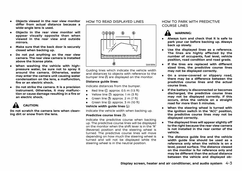
(189,1)
[ Edit: 2020/ 11/ 9 Model: Y62-A ]
. Objects viewed in the rear view monitordiffer from actual distance because awide-angle lens is used.
. Objects in the rear view monitor willappear visually opposite than whenviewed in the rear view and outsidemirrors.
. Make sure that the back door is securelyclosed when backing up.
. Do not put anything on the rear viewcamera. The rear view camera is installedabove the license plate.
. When washing the vehicle with high-pressure water, be sure not to spray itaround the camera. Otherwise, watermay enter the camera unit causing watercondensation on the lens, a malfunction,fire or an electric shock.
. Do not strike the camera. It is a precisioninstrument. Otherwise, it may malfunc-tion or cause damage resulting in a fire oran electric shock.
CAUTION:Do not scratch the camera lens when clean-ing dirt or snow from the lens.
HOW TO READ DISPLAYED LINESGUID-EEB3AB4E-8CC7-4876-9A5D-6AF390BE7522
SAA1896
Guiding lines which indicate the vehicle widthand distances to objects with reference to thebumper line are displayed on the monitor.Distance guide lines:Indicate distances from the bumper.. Red line : approx. 0.5 m (1.5 ft). Yellow line : approx. 1 m (3 ft). Green line : approx. 2 m (7 ft). Green line : approx. 3 m (10 ft)Vehicle width guide lines :Indicate the vehicle width when backing up.Predictive course lines :Indicate the predictive course when backingup. The predictive course lines will be displayedon the monitor when the shift lever is in the “R”(Reverse) position and the steering wheel isturned. The predictive course lines will movedepending on how much the steering wheel isturned and will not be displayed while thesteering wheel is in the neutral position.
HOW TO PARK WITH PREDICTIVECOURSE LINESGUID-023B2FB6-39D0-4C1B-8417-C7376BCAFE30
WARNING:. Always turn and check that it is safe to
park your car before backing up. Alwaysback up slowly.
. Use the displayed lines as a reference.The lines are highly affected by thenumber of occupants, fuel level, vehicleposition, road condition and road grade.
. If the tires are replaced with differentsized tires, the predictive course linesmay not be displayed correctly.
. On a snow-covered or slippery road,there may be a difference between thepredictive course lines and the actualcourse lines.
. If the battery is disconnected or becomesdischarged, the predictive course linesmay not be displayed correctly. If thisoccurs, drive the vehicle on a straightroad for more than 5 minutes.
. When the steering wheel is turned withthe ignition switch in the “ACC” position,the predictive course lines may not bedisplayed correctly.
. The displayed lines will appear slightly offto the right because the rear view camerais not installed in the rear center of thevehicle.
. The distance guide line and the vehiclewidth guide line should be used as areference only when the vehicle is on alevel, paved surface. The distance viewedon the monitor is for reference only andmay be different than the actual distancebetween the vehicle and displayed ob-
Display screen, heater and air conditioner, and audio system 4-3
Condition: 'Except for China'/'Except for China/
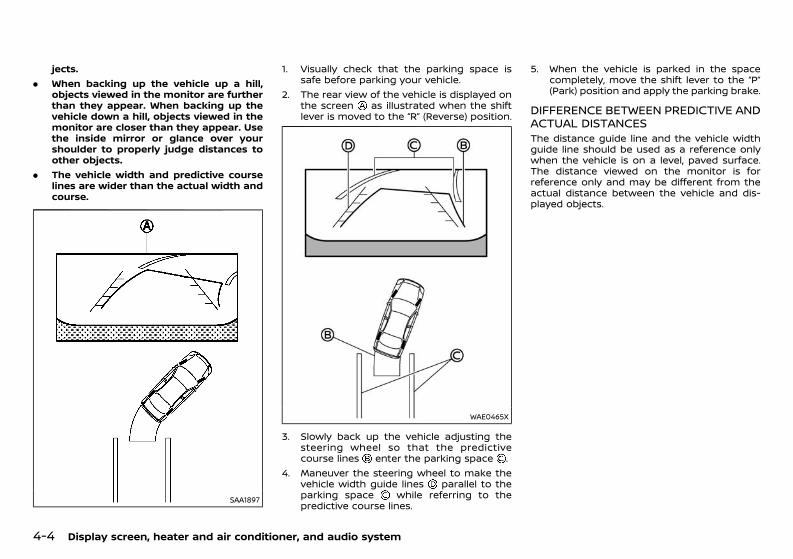
(190,1)
[ Edit: 2020/ 11/ 9 Model: Y62-A ]
4-4 Display screen, heater and air conditioner, and audio system
jects.. When backing up the vehicle up a hill,
objects viewed in the monitor are furtherthan they appear. When backing up thevehicle down a hill, objects viewed in themonitor are closer than they appear. Usethe inside mirror or glance over yourshoulder to properly judge distances toother objects.
. The vehicle width and predictive courselines are wider than the actual width andcourse.
SAA1897
1. Visually check that the parking space issafe before parking your vehicle.
2. The rear view of the vehicle is displayed onthe screen as illustrated when the shiftlever is moved to the “R” (Reverse) position.
WAE0465X
3. Slowly back up the vehicle adjusting thesteering wheel so that the predictivecourse lines enter the parking space .
4. Maneuver the steering wheel to make thevehicle width guide lines parallel to theparking space while referring to thepredictive course lines.
5. When the vehicle is parked in the spacecompletely, move the shift lever to the “P”(Park) position and apply the parking brake.
DIFFERENCE BETWEEN PREDICTIVE ANDACTUAL DISTANCESGUID-381869EE-105E-412F-BF85-68FF60FD9A77The distance guide line and the vehicle widthguide line should be used as a reference onlywhen the vehicle is on a level, paved surface.The distance viewed on the monitor is forreference only and may be different from theactual distance between the vehicle and dis-played objects.
Condition: 'Except for China'/'Except for China/
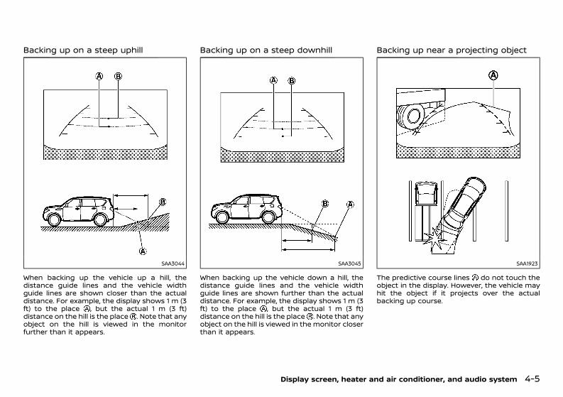
(191,1)
[ Edit: 2020/ 11/ 9 Model: Y62-A ]
Backing up on a steep uphillGUID-47D0F5D1-DA05-4593-A5DE-AB3308CD7156
SAA3044
When backing up the vehicle up a hill, thedistance guide lines and the vehicle widthguide lines are shown closer than the actualdistance. For example, the display shows 1 m (3ft) to the place , but the actual 1 m (3 ft)distance on the hill is the place . Note that anyobject on the hill is viewed in the monitorfurther than it appears.
Backing up on a steep downhillGUID-A37C8639-5AB9-48AB-8EA9-BE23593C4BEE
SAA3045
When backing up the vehicle down a hill, thedistance guide lines and the vehicle widthguide lines are shown further than the actualdistance. For example, the display shows 1 m (3ft) to the place , but the actual 1 m (3 ft)distance on the hill is the place . Note that anyobject on the hill is viewed in the monitor closerthan it appears.
Backing up near a projecting objectGUID-61CB3331-BB6C-4D3B-BC16-8596F1944C1F
SAA1923
The predictive course lines do not touch theobject in the display. However, the vehicle mayhit the object if it projects over the actualbacking up course.
Display screen, heater and air conditioner, and audio system 4-5
Condition: 'Except for China'/'Except for China/
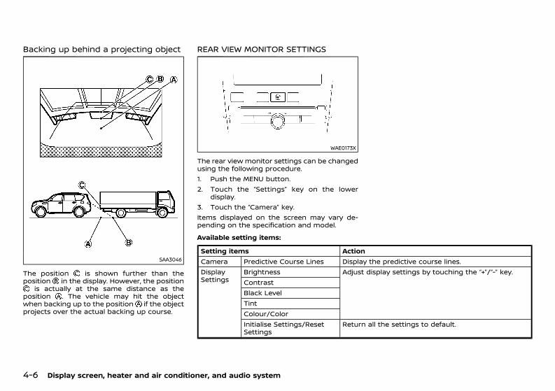
(192,1)
[ Edit: 2020/ 11/ 9 Model: Y62-A ]
4-6 Display screen, heater and air conditioner, and audio system
Backing up behind a projecting objectGUID-DFEA601B-CEF1-4381-AAE7-D82CB94086E5
SAA3046
The position is shown further than theposition in the display. However, the position
is actually at the same distance as theposition . The vehicle may hit the objectwhen backing up to the position if the objectprojects over the actual backing up course.
REAR VIEW MONITOR SETTINGSGUID-DFFA5D88-DDE3-427F-94FB-FA7429B2848B
WAE0173X
The rear view monitor settings can be changedusing the following procedure.1. Push the MENU button.2. Touch the “Settings” key on the lower
display.3. Touch the “Camera” key.Items displayed on the screen may vary de-pending on the specification and model.
Available setting items:GUID-DFFA5D88-DDE3-427F-94FB-FA7429B2848B
Setting items ActionCamera Predictive Course Lines Display the predictive course lines.DisplaySettings
Brightness Adjust display settings by touching the “+”/“-” key.ContrastBlack LevelTintColour/ColorInitialise Settings/ResetSettings
Return all the settings to default.
Condition: 'Except for China'/'Except for China/
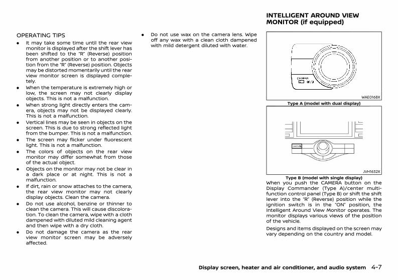
(193,1)
[ Edit: 2020/ 11/ 9 Model: Y62-A ]
OPERATING TIPSGUID-02AC0C95-7AF6-4642-891C-75B8199BFBAA. It may take some time until the rear view
monitor is displayed after the shift lever hasbeen shifted to the “R” (Reverse) positionfrom another position or to another posi-tion from the “R” (Reverse) position. Objectsmay be distorted momentarily until the rearview monitor screen is displayed comple-tely.
. When the temperature is extremely high orlow, the screen may not clearly displayobjects. This is not a malfunction.
. When strong light directly enters the cam-era, objects may not be displayed clearly.This is not a malfunction.
. Vertical lines may be seen in objects on thescreen. This is due to strong reflected lightfrom the bumper. This is not a malfunction.
. The screen may flicker under fluorescentlight. This is not a malfunction.
. The colors of objects on the rear viewmonitor may differ somewhat from thoseof the actual object.
. Objects on the monitor may not be clear ina dark place or at night. This is not amalfunction.
. If dirt, rain or snow attaches to the camera,the rear view monitor may not clearlydisplay objects. Clean the camera.
. Do not use alcohol, benzine or thinner toclean the camera. This will cause discolora-tion. To clean the camera, wipe with a clothdampened with diluted mild cleaning agentand then wipe with a dry cloth.
. Do not damage the camera as the rearview monitor screen may be adverselyaffected.
. Do not use wax on the camera lens. Wipeoff any wax with a clean cloth dampenedwith mild detergent diluted with water.
GUID-43E404DD-FA5E-4D70-AAC4-A7AFECB8F18A
WAE0168XType A (model with dual display)
JVH1632XType B (model with single display)
When you push the CAMERA button on theDisplay Commander (Type A)/center multi-function control panel (Type B) or shift the shiftlever into the “R” (Reverse) position while theignition switch is in the “ON” position, theIntelligent Around View Monitor operates. Themonitor displays various views of the positionof the vehicle.Designs and items displayed on the screen mayvary depending on the country and model.
Display screen, heater and air conditioner, and audio system 4-7
INTELLIGENT AROUND VIEWMONITOR (if equipped)
Condition: 'Except for China'/'Except for China/
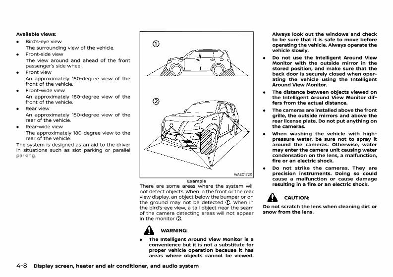
(194,1)
[ Edit: 2020/ 11/ 9 Model: Y62-A ]
4-8 Display screen, heater and air conditioner, and audio system
Available views:. Bird’s-eye view
The surrounding view of the vehicle.. Front-side view
The view around and ahead of the frontpassenger’s side wheel.
. Front viewAn approximately 150-degree view of thefront of the vehicle.
. Front-wide viewAn approximately 180-degree view of thefront of the vehicle.
. Rear viewAn approximately 150-degree view of therear of the vehicle.
. Rear-wide viewThe approximately 180-degree view to therear of the vehicle.
The system is designed as an aid to the driverin situations such as slot parking or parallelparking.
WAE0172XExample
There are some areas where the system willnot detect objects. When in the front or the rearview display, an object below the bumper or onthe ground may not be detected . When inthe bird’s-eye view, a tall object near the seamof the camera detecting areas will not appearin the monitor .
WARNING:. The Intelligent Around View Monitor is a
convenience but it is not a substitute forproper vehicle operation because it hasareas where objects cannot be viewed.
Always look out the windows and checkto be sure that it is safe to move beforeoperating the vehicle. Always operate thevehicle slowly.
. Do not use the Intelligent Around ViewMonitor with the outside mirror in thestored position, and make sure that theback door is securely closed when oper-ating the vehicle using the IntelligentAround View Monitor.
. The distance between objects viewed onthe Intelligent Around View Monitor dif-fers from the actual distance.
. The cameras are installed above the frontgrille, the outside mirrors and above therear license plate. Do not put anything onthe cameras.
. When washing the vehicle with high-pressure water, be sure not to spray itaround the cameras. Otherwise, watermay enter the camera unit causing watercondensation on the lens, a malfunction,fire or an electric shock.
. Do not strike the cameras. They areprecision instruments. Doing so couldcause a malfunction or cause damageresulting in a fire or an electric shock.
CAUTION:Do not scratch the lens when cleaning dirt orsnow from the lens.
Condition: 'Except for China'/'Except for China/
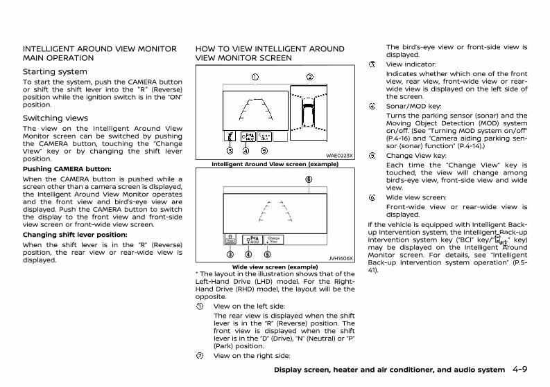
(195,1)
[ Edit: 2020/ 11/ 9 Model: Y62-A ]
INTELLIGENT AROUND VIEW MONITORMAIN OPERATIONGUID-D62414FD-4ADC-44F6-B512-9D910C13C71D
Starting systemGUID-BFB11C57-40ED-4B2A-B592-10B3024F089DTo start the system, push the CAMERA buttonor shift the shift lever into the "R" (Reverse)position while the ignition switch is in the “ON”position.
Switching viewsGUID-735D90B8-9512-4870-A918-125CA2F1BAABThe view on the Intelligent Around ViewMonitor screen can be switched by pushingthe CAMERA button, touching the “ChangeView” key or by changing the shift leverposition.Pushing CAMERA button:When the CAMERA button is pushed while ascreen other than a camera screen is displayed,the Intelligent Around View Monitor operatesand the front view and bird’s-eye view aredisplayed. Push the CAMERA button to switchthe display to the front view and front-sideview screen or front-wide view screen.Changing shift lever position:When the shift lever is in the “R” (Reverse)position, the rear view or rear-wide view isdisplayed.
HOW TO VIEW INTELLIGENT AROUNDVIEW MONITOR SCREENGUID-BB527EAC-18F9-4C2E-905E-2EDC35FC4148
WAE0223XIntelligent Around View screen (example)
JVH1606XWide view screen (example)
* The layout in the illustration shows that of theLeft-Hand Drive (LHD) model. For the Right-Hand Drive (RHD) model, the layout will be theopposite.
View on the left side:The rear view is displayed when the shiftlever is in the “R” (Reverse) position. Thefront view is displayed when the shiftlever is in the “D” (Drive), “N” (Neutral) or “P”(Park) position.View on the right side:
The bird’s-eye view or front-side view isdisplayed.View indicator:Indicates whether which one of the frontview, rear view, front-wide view or rear-wide view is displayed on the left side ofthe screen.Sonar/MOD key:Turns the parking sensor (sonar) and theMoving Object Detection (MOD) systemon/off. (See “Turning MOD system on/off”(P.4-16) and “Camera aiding parking sen-sor (sonar) function” (P.4-14).)Change View key:Each time the “Change View” key istouched, the view will change amongbird’s-eye view, front-side view and wideview.Wide view screen:Front-wide view or rear-wide view isdisplayed.
If the vehicle is equipped with Intelligent Back-up Intervention system, the Intelligent Back-upIntervention system key (“BCI” key/“ ” key)may be displayed on the Intelligent AroundMonitor screen. For details, see “IntelligentBack-up Intervention system operation” (P.5-41).
Display screen, heater and air conditioner, and audio system 4-9
Condition: 'Except for China'/'Except for China/
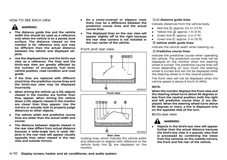
(196,1)
[ Edit: 2020/ 11/ 9 Model: Y62-A ]
4-10 Display screen, heater and air conditioner, and audio system
HOW TO SEE EACH VIEWGUID-49C86CF9-5394-4FFE-9EE2-B6068FFA7A4F
WARNING:. The distance guide line and the vehicle
width line should be used as a referenceonly when the vehicle is on a paved, levelsurface. The distance viewed on themonitor is for reference only and maybe different than the actual distancebetween the vehicle and displayed ob-jects.
. Use the displayed lines and the bird’s-eyeview as a reference. The lines and thebird’s-eye view are greatly affected bythe number of occupants, fuel level,vehicle position, road condition and roadgrade.
. If the tires are replaced with differentsized tires, the predictive course lines andthe bird’s-eye view may be displayedincorrectly.
. When driving the vehicle up a hill, objectsviewed in the monitor are further thanthey appear. When driving the vehicledown a hill, objects viewed in the monitorare closer than they appear. Use themirrors or actually look to properly judgedistances to other objects.
. The vehicle width and predictive courselines are wider than the actual width andcourse.
. The distance between objects viewed inthe rear view differs from actual distancebecause a wide-angle lens is used. Ob-jects in the rear view will appear visuallyopposite than when viewed in the rearview and outside mirrors.
. On a snow-covered or slippery road,there may be a difference between thepredictive course lines and the actualcourse lines.
. The displayed lines on the rear view willappear slightly off to the right becausethe rear view camera is not installed inthe rear center of the vehicle.
Front and rear viewGUID-6737016E-C9E9-45CE-8922-6A19C860AF64
SAA1840Front view
SAA1896Rear view
Guiding lines, which indicate the vehicle widthand distances to objects with reference to thevehicle body line , are displayed on themonitor.
- Distance guide lines:Indicate distances from the vehicle body.. Red line : approx. 0.5 m (1.5 ft). Yellow line : approx. 1 m (3 ft). Green line : approx. 2 m (7 ft). Green line : approx. 3 m (10 ft)
Vehicle width guide lines:Indicate the vehicle width when backing up.
Predictive course lines:Indicate the predictive course when operatingthe vehicle. The predictive course lines will bedisplayed on the monitor when the steeringwheel is turned. The predictive course lines willmove depending on how much the steeringwheel is turned and will not be displayed whilethe steering wheel is in the neutral position.The front view will not be displayed when thevehicle speed is above 8 km/h (5 MPH).
NOTE:When themonitor displays the front view andthe steering wheel turns about 90 degrees orless from the neutral position, both the rightand left predictive course lines are dis-played. When the steering wheel turns about90 degrees or more, a line is displayed onlyon the opposite side of the turn.Bird’s-eye viewGUID-255681D4-3246-463A-9DC6-E188B3C138EA
WARNING:. Objects in the bird’s-eye view will appear
further than the actual distance becausethe bird’s-eye view is a pseudo view thatis processed by combining the viewsfrom the cameras on the outside mirrors,the front and the rear of the vehicle.
Condition: 'Except for China'/'Except for China/
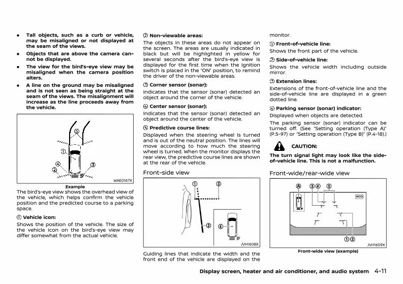
(197,1)
[ Edit: 2020/ 11/ 9 Model: Y62-A ]
. Tall objects, such as a curb or vehicle,may be misaligned or not displayed atthe seam of the views.
. Objects that are above the camera can-not be displayed.
. The view for the bird’s-eye view may bemisaligned when the camera positionalters.
. A line on the ground may be misalignedand is not seen as being straight at theseam of the views. The misalignment willincrease as the line proceeds away fromthe vehicle.
WAE0167XExample
The bird’s-eye view shows the overhead view ofthe vehicle, which helps confirm the vehicleposition and the predicted course to a parkingspace.
Vehicle icon:GUID-C7E1EF24-5AAB-4301-95BE-26917EEE45EF
Shows the position of the vehicle. The size ofthe vehicle icon on the bird’s-eye view maydiffer somewhat from the actual vehicle.
Non-viewable areas:GUID-C7E1EF24-5AAB-4301-95BE-26917EEE45EF
The objects in these areas do not appear onthe screen. The areas are usually indicated inblack but will be highlighted in yellow forseveral seconds after the bird’s-eye view isdisplayed for the first time when the ignitionswitch is placed in the “ON” position, to remindthe driver of the non-viewable areas.
Corner sensor (sonar):GUID-C7E1EF24-5AAB-4301-95BE-26917EEE45EF
Indicates that the sensor (sonar) detected anobject around the corner of the vehicle.
Center sensor (sonar):GUID-C7E1EF24-5AAB-4301-95BE-26917EEE45EF
Indicates that the sensor (sonar) detected anobject around the center of the vehicle.
Predictive course lines:GUID-C7E1EF24-5AAB-4301-95BE-26917EEE45EF
Displayed when the steering wheel is turnedand is out of the neutral position. The lines willmove according to how much the steeringwheel is turned. When the monitor displays therear view, the predictive course lines are shownat the rear of the vehicle.
Front-side viewGUID-C5850C62-F3F7-4136-AD3E-174BB3176CAA
JVH1608X
Guiding lines that indicate the width and thefront end of the vehicle are displayed on the
monitor.Front-of-vehicle line:
GUID-C7E1EF24-5AAB-4301-95BE-26917EEE45EF
Shows the front part of the vehicle.Side-of-vehicle line:
GUID-C7E1EF24-5AAB-4301-95BE-26917EEE45EF
Shows the vehicle width including outsidemirror.
Extension lines:GUID-C7E1EF24-5AAB-4301-95BE-26917EEE45EF
Extensions of the front-of-vehicle line and theside-of-vehicle line are displayed in a greendotted line.
Parking sensor (sonar) indicator:GUID-C7E1EF24-5AAB-4301-95BE-26917EEE45EF
Displayed when objects are detected.The parking sensor (sonar) indicator can beturned off. (See “Setting operation (Type A)”(P.5-97) or “Setting operation (Type B)” (P.4-18).)
CAUTION:The turn signal light may look like the side-of-vehicle line. This is not a malfunction.
Front-wide/rear-wide viewGUID-E19E9ECC-764B-4419-A024-E1654FBCC7D0
JVH1609XFront-wide view (example)
Display screen, heater and air conditioner, and audio system 4-11
Condition: 'Except for China'/'Except for China/
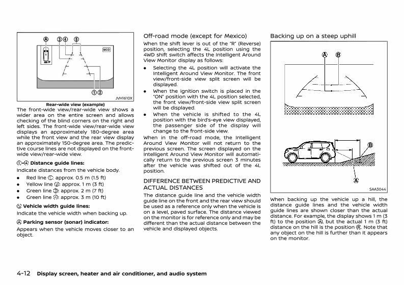
(198,1)
[ Edit: 2020/ 11/ 9 Model: Y62-A ]
4-12 Display screen, heater and air conditioner, and audio system
JVH1610XRear-wide view (example)
The front-wide view/rear-wide view shows awider area on the entire screen and allowschecking of the blind corners on the right andleft sides. The front-wide view/rear-wide viewdisplays an approximately 180-degree areawhile the front view and the rear view displayan approximately 150-degree area. The predic-tive course lines are not displayed on the front-wide view/rear-wide view.- Distance guide lines:
GUID-C7E1EF24-5AAB-4301-95BE-26917EEE45EF
Indicate distances from the vehicle body.. Red line : approx. 0.5 m (1.5 ft). Yellow line : approx. 1 m (3 ft). Green line : approx. 2 m (7 ft). Green line : approx. 3 m (10 ft)
Vehicle width guide lines:GUID-C7E1EF24-5AAB-4301-95BE-26917EEE45EF
Indicate the vehicle width when backing up.Parking sensor (sonar) indicator:
GUID-C7E1EF24-5AAB-4301-95BE-26917EEE45EF
Appears when the vehicle moves closer to anobject.
Off-road mode (except for Mexico)GUID-655A09F5-0B33-4A72-A133-1BADB9375E3FWhen the shift lever is out of the “R” (Reverse)position, selecting the 4L position using the4WD shift switch affects the Intelligent AroundView Monitor display as follows:. Selecting the 4L position will activate the
Intelligent Around View Monitor. The frontview/front-side view split screen will bedisplayed.
. When the ignition switch is placed in the“ON” position with the 4L position selected,the front view/front-side view split screenwill be displayed.
. When the vehicle is shifted to the 4Lposition with the bird’s-eye view displayed,the passenger side of the display willchange to the front-side view.
When in the off-road mode, the IntelligentAround View Monitor will not return to theprevious screen. The screen displayed on theIntelligent Around View Monitor will automati-cally return to the previous screen 3 minutesafter the vehicle was shifted out of the 4Lposition.
DIFFERENCE BETWEEN PREDICTIVE ANDACTUAL DISTANCESGUID-5AB823FF-44D6-4F8B-85B4-0330B05C2618The distance guide line and the vehicle widthguide line on the front and the rear view shouldbe used as a reference only when the vehicle ison a level, paved surface. The distance viewedon the monitor is for reference only and may bedifferent than the actual distance between thevehicle and displayed objects.
Backing up on a steep uphillGUID-EC040AC1-294F-49A6-8330-BAA6F455663A
SAA3044
When backing up the vehicle up a hill, thedistance guide lines and the vehicle widthguide lines are shown closer than the actualdistance. For example, the display shows 1 m (3ft) to the position , but the actual 1 m (3 ft)distance on the hill is the position . Note thatany object on the hill is further than it appearson the monitor.
Condition: 'Except for China'/'Except for China/
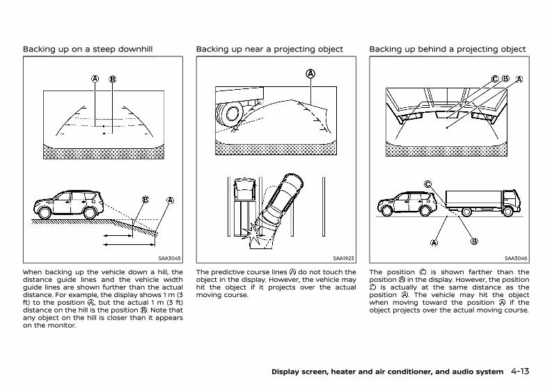
(199,1)
[ Edit: 2020/ 11/ 9 Model: Y62-A ]
Backing up on a steep downhillGUID-E5597C44-33A8-4F74-81E0-2E56ADD0049A
SAA3045
When backing up the vehicle down a hill, thedistance guide lines and the vehicle widthguide lines are shown further than the actualdistance. For example, the display shows 1 m (3ft) to the position , but the actual 1 m (3 ft)distance on the hill is the position . Note thatany object on the hill is closer than it appearson the monitor.
Backing up near a projecting objectGUID-E9504629-50E9-4DDC-B8DF-F4AE6F5208D7
SAA1923
The predictive course lines do not touch theobject in the display. However, the vehicle mayhit the object if it projects over the actualmoving course.
Backing up behind a projecting objectGUID-FCC1B5E4-CC56-430E-9B1C-F00F114D520B
SAA3046
The position is shown farther than theposition in the display. However, the position
is actually at the same distance as theposition . The vehicle may hit the objectwhen moving toward the position if theobject projects over the actual moving course.
Display screen, heater and air conditioner, and audio system 4-13
Condition: 'Except for China'/'Except for China/
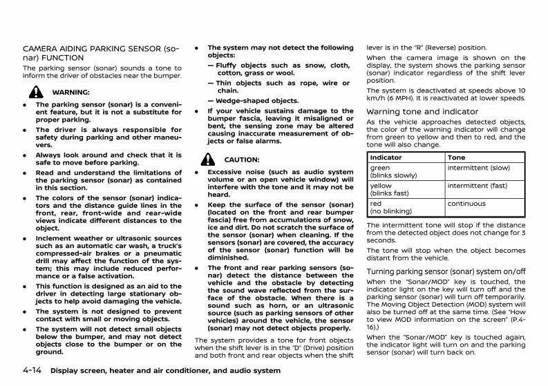
(200,1)
[ Edit: 2020/ 11/ 9 Model: Y62-A ]
4-14 Display screen, heater and air conditioner, and audio system
CAMERA AIDING PARKING SENSOR (so-nar) FUNCTIONGUID-ECD4C63E-EDD2-4570-8165-A4DBC6D5F54CThe parking sensor (sonar) sounds a tone toinform the driver of obstacles near the bumper.
WARNING:. The parking sensor (sonar) is a conveni-
ent feature, but it is not a substitute forproper parking.
. The driver is always responsible forsafety during parking and other maneu-vers.
. Always look around and check that it issafe to move before parking.
. Read and understand the limitations ofthe parking sensor (sonar) as containedin this section.
. The colors of the sensor (sonar) indica-tors and the distance guide lines in thefront, rear, front-wide and rear-wideviews indicate different distances to theobject.
. Inclement weather or ultrasonic sourcessuch as an automatic car wash, a truck’scompressed-air brakes or a pneumaticdrill may affect the function of the sys-tem; this may include reduced perfor-mance or a false activation.
. This function is designed as an aid to thedriver in detecting large stationary ob-jects to help avoid damaging the vehicle.
. The system is not designed to preventcontact with small or moving objects.
. The system will not detect small objectsbelow the bumper, and may not detectobjects close to the bumper or on theground.
. The system may not detect the followingobjects:— Fluffy objects such as snow, cloth,
cotton, grass or wool.— Thin objects such as rope, wire or
chain.— Wedge-shaped objects.
. If your vehicle sustains damage to thebumper fascia, leaving it misaligned orbent, the sensing zone may be alteredcausing inaccurate measurement of ob-jects or false alarms.
CAUTION:. Excessive noise (such as audio system
volume or an open vehicle window) willinterfere with the tone and it may not beheard.
. Keep the surface of the sensor (sonar)(located on the front and rear bumperfascia) free from accumulations of snow,ice and dirt. Do not scratch the surface ofthe sensor (sonar) when cleaning. If thesensors (sonar) are covered, the accuracyof the sensor (sonar) function will bediminished.
. The front and rear parking sensors (so-nar) detect the distance between thevehicle and the obstacle by detectingthe sound wave reflected from the sur-face of the obstacle. When there is asound such as horn, or an ultrasonicsource (such as parking sensors of othervehicles) around the vehicle, the sensor(sonar) may not detect objects properly.
The system provides a tone for front objectswhen the shift lever is in the “D” (Drive) positionand both front and rear objects when the shift
lever is in the “R” (Reverse) position.When the camera image is shown on thedisplay, the system shows the parking sensor(sonar) indicator regardless of the shift leverposition.The system is deactivated at speeds above 10km/h (6 MPH). It is reactivated at lower speeds.
Warning tone and indicatorGUID-E83B9FEA-E75A-4035-8706-B50F438AEE2AAs the vehicle approaches detected objects,the color of the warning indicator will changefrom green to yellow and then to red, and thetone will also change.
Indicator Tonegreen(blinks slowly)
intermittent (slow)
yellow(blinks fast)
intermittent (fast)
red(no blinking)
continuous
The intermittent tone will stop if the distancefrom the detected object does not change for 3seconds.The tone will stop when the object becomesdistant from the vehicle.
Turning parking sensor (sonar) system on/offGUID-61F616F2-8F80-4EC5-81B6-69CFA2F5D565When the “Sonar/MOD” key is touched, theindicator light on the key will turn off and theparking sensor (sonar) will turn off temporarily.The Moving Object Detection (MOD) system willalso be turned off at the same time. (See “Howto view MOD information on the screen” (P.4-16).)When the “Sonar/MOD” key is touched again,the indicator light will turn on and the parkingsensor (sonar) will turn back on.
Condition: 'Except for China'/'Except for China/
(201,1)
[ Edit: 2020/ 11/ 9 Model: Y62-A ]
In the cases below, the parking sensor (sonar)will be turned back on automatically:. When the shift lever is in the “R” (Reverse)
position.. When the CAMERA button is pushed and a
screen other than the camera view isshown on the display.
. When vehicle speed decreases below ap-proximately 8 km/h (5 MPH).
. When the ignition switch is placed in the“OFF” position and turned back to the “ON”position again.
. When the “Sonar/MOD” key is selected, theMOD function will also be turned off.
Model with dual display: To prevent the parkingsensor (sonar) system from activating alto-gether, change the setting from the parkingsensor (sonar) setting menu. (See “Settingoperation (Type A)” (P.5-97).)Model with single display: To prevent theparking sensor (sonar) system from activatingaltogether, change the setting from the cam-era setting menu. (See “Setting operation (TypeB)” (P.4-18).)Touching the “Sonar/MOD” key will also turnthe parking sensor (sonar) system on/offtemporarily.
MOVING OBJECT DETECTION (MOD)GUID-73AC0780-6935-4BEE-966F-28E04CF3035DThe Moving Object Detection (MOD) system caninform the driver of moving objects surround-ing the vehicle when driving out of garages,maneuvering into parking lots and other suchinstances.The MOD system detects moving objects byusing image processing technology on theimage shown on the display.The MOD system operates in the followingconditions when the camera view is displayed:
. When the shift lever is in the “P” (Park) or “N”(Neutral) position and the vehicle isstopped, the MOD system detects themoving objects in the bird’s-eye view. TheMOD system will not operate if the outsidemirror is moving in or out or if either door isopened.
. When the shift lever is in the “D” (Drive)position and the vehicle speed is belowapproximately 8 km/h (5 MPH), the MODsystem detects moving objects in the frontview or front-wide view.
. When the shift lever is in the “R” (Reverse)position and the vehicle speed is belowapproximately 8 km/h (5 MPH), the MODsystem detects moving objects in the rearview or rear-wide view. The MOD systemwill not operate if the back door is open.
NOTE:. The MOD system does not detect moving
objects in the front-side view. The MODindicator is not displayed on the screenwhen in this view.
. While the parking sensor (sonar)/Intelli-gent Back-up Intervention warning toneis sounding, the MOD system does notchime.
WARNING:. The MOD system is not a substitute for
proper vehicle operation and is not de-signed to prevent contact with the ob-jects surrounding the vehicle. Whenmaneuvering, always use the outsidemirror and rear view mirror and turnand check the surrounding to ensure itis safe to maneuver.
. The MOD system does not detect sta-tionary objects.
. Do not use the MOD system when towinga trailer (if available). The systemmay notfunction properly.
. Excessive noise (such as from the audiosystem or an open vehicle window) willinterfere with the chime sound, and itmay not be audible.
. The MOD system performance will belimited according to environmental con-ditions and surrounding objects such as:— When there is low contrast between
the background and moving objects— When there is blinking source of light— When strong light such as another
vehicle’s headlights or sunlight ispresent
— When the camera orientation is not inits usual position, such as whenmirror is folded
— When there is dirt, water drops orsnow on the camera lens
— When the position of the movingobjects in the display is not changed
. The MOD systemmight detect somethinglike flowing water droplets on the cameralens, white smoke from the muffler, ormoving shadows, etc.
. The MOD system may not function prop-erly depending on the speed, direction,distance or shape of the moving objects.
. If your vehicle sustains damage to thearea where the camera is installed, leav-ing it misaligned or bent, the sensingzone may be altered and the MOD systemmay not detect objects properly.
Display screen, heater and air conditioner, and audio system 4-15
Condition: 'Except for China'/'Except for China/
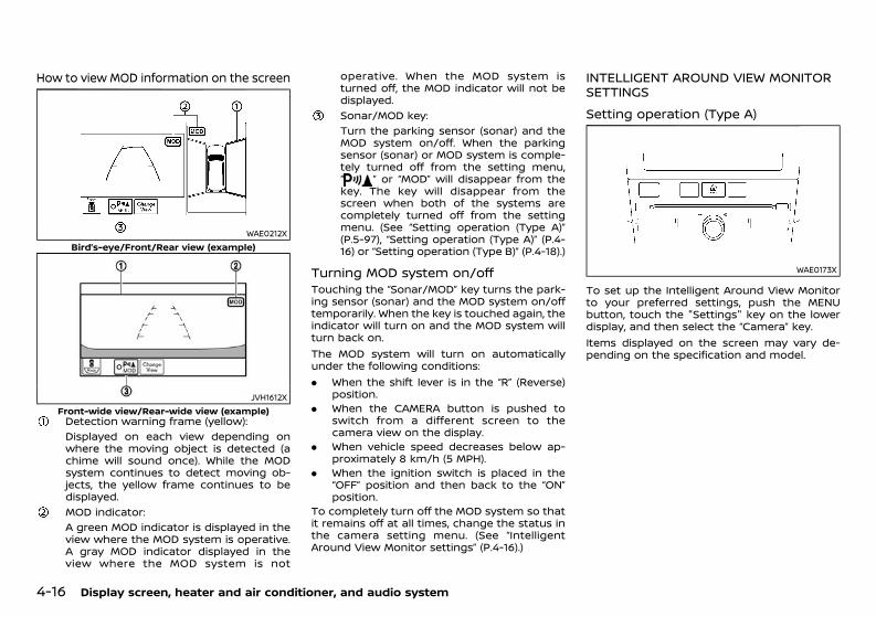
(202,1)
[ Edit: 2020/ 11/ 9 Model: Y62-A ]
4-16 Display screen, heater and air conditioner, and audio system
How to view MOD information on the screenGUID-D430EF90-3BCE-4463-932D-4AFCE47929DE
WAE0212XBird’s-eye/Front/Rear view (example)
JVH1612XFront-wide view/Rear-wide view (example)Detection warning frame (yellow):Displayed on each view depending onwhere the moving object is detected (achime will sound once). While the MODsystem continues to detect moving ob-jects, the yellow frame continues to bedisplayed.MOD indicator:A green MOD indicator is displayed in theview where the MOD system is operative.A gray MOD indicator displayed in theview where the MOD system is not
operative. When the MOD system isturned off, the MOD indicator will not bedisplayed.Sonar/MOD key:Turn the parking sensor (sonar) and theMOD system on/off. When the parkingsensor (sonar) or MOD system is comple-tely turned off from the setting menu,“ ” or “MOD” will disappear from thekey. The key will disappear from thescreen when both of the systems arecompletely turned off from the settingmenu. (See “Setting operation (Type A)”(P.5-97), “Setting operation (Type A)” (P.4-16) or “Setting operation (Type B)” (P.4-18).)
Turning MOD system on/offGUID-63750FDC-1E50-4761-825E-8485516228D9Touching the “Sonar/MOD” key turns the park-ing sensor (sonar) and the MOD system on/offtemporarily. When the key is touched again, theindicator will turn on and the MOD system willturn back on.The MOD system will turn on automaticallyunder the following conditions:. When the shift lever is in the “R” (Reverse)
position.. When the CAMERA button is pushed to
switch from a different screen to thecamera view on the display.
. When vehicle speed decreases below ap-proximately 8 km/h (5 MPH).
. When the ignition switch is placed in the“OFF” position and then back to the “ON”position.
To completely turn off the MOD system so thatit remains off at all times, change the status inthe camera setting menu. (See “IntelligentAround View Monitor settings” (P.4-16).)
INTELLIGENT AROUND VIEW MONITORSETTINGS GUID-358E021C-6FBC-4FA8-B929-10C4C9A645A8
Setting operation (Type A)GUID-10FA6C65-33B2-473C-BA84-875365D7A033
WAE0173X
To set up the Intelligent Around View Monitorto your preferred settings, push the MENUbutton, touch the "Settings" key on the lowerdisplay, and then select the “Camera” key.Items displayed on the screen may vary de-pending on the specification and model.
Condition: 'Except for China'/'Except for China/
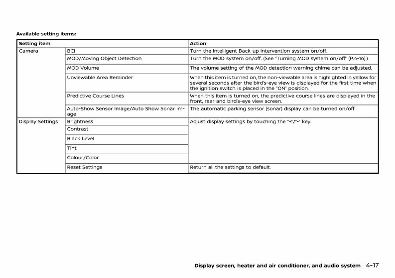
(203,1)
[ Edit: 2020/ 11/ 9 Model: Y62-A ]
Available setting items:GUID-10FA6C65-33B2-473C-BA84-875365D7A033
Setting item ActionCamera BCI Turn the Intelligent Back-up Intervention system on/off.
MOD/Moving Object Detection Turn the MOD system on/off. (See “Turning MOD system on/off” (P.4-16).)
MOD Volume The volume setting of the MOD detection warning chime can be adjusted.
Unviewable Area Reminder When this item is turned on, the non-viewable area is highlighted in yellow forseveral seconds after the bird’s-eye view is displayed for the first time whenthe ignition switch is placed in the “ON” position.
Predictive Course Lines When this item is turned on, the predictive course lines are displayed in thefront, rear and bird’s-eye view screen.
Auto-Show Sensor Image/Auto Show Sonar Im-age
The automatic parking sensor (sonar) display can be turned on/off.
Display Settings Brightness Adjust display settings by touching the “+”/“-” key.Contrast
Black Level
Tint
Colour/Color
Reset Settings Return all the settings to default.
Display screen, heater and air conditioner, and audio system 4-17
Condition: 'Except for China'/'Except for China/
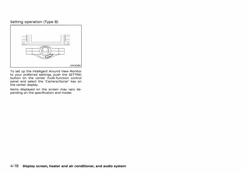
(204,1)
[ Edit: 2020/ 11/ 9 Model: Y62-A ]
4-18 Display screen, heater and air conditioner, and audio system
Setting operation (Type B)GUID-CBE55A03-21BB-40F6-BE89-DBC51E08ECCB
JVH1628X
To set up the Intelligent Around View Monitorto your preferred settings, push the SETTINGbutton on the center multi-function controlpanel and select the “Camera/Sonar” key onthe center display.Items displayed on the screen may vary de-pending on the specification and model.
Condition: 'Except for China'/'Except for China/
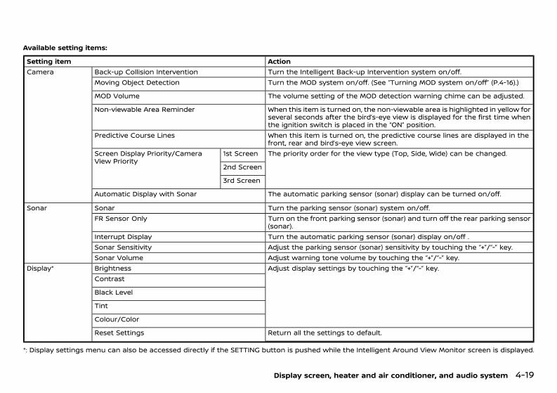
(205,1)
[ Edit: 2020/ 11/ 9 Model: Y62-A ]
Available setting items:GUID-CBE55A03-21BB-40F6-BE89-DBC51E08ECCB
Setting item ActionCamera Back-up Collision Intervention Turn the Intelligent Back-up Intervention system on/off.
Moving Object Detection Turn the MOD system on/off. (See “Turning MOD system on/off” (P.4-16).)
MOD Volume The volume setting of the MOD detection warning chime can be adjusted.
Non-viewable Area Reminder When this item is turned on, the non-viewable area is highlighted in yellow forseveral seconds after the bird’s-eye view is displayed for the first time whenthe ignition switch is placed in the “ON” position.
Predictive Course Lines When this item is turned on, the predictive course lines are displayed in thefront, rear and bird’s-eye view screen.
Screen Display Priority/CameraView Priority
1st Screen The priority order for the view type (Top, Side, Wide) can be changed.
2nd Screen
3rd Screen
Automatic Display with Sonar The automatic parking sensor (sonar) display can be turned on/off.
Sonar Sonar Turn the parking sensor (sonar) system on/off.FR Sensor Only Turn on the front parking sensor (sonar) and turn off the rear parking sensor
(sonar).Interrupt Display Turn the automatic parking sensor (sonar) display on/off .Sonar Sensitivity Adjust the parking sensor (sonar) sensitivity by touching the “+”/“-” key.Sonar Volume Adjust warning tone volume by touching the “+”/“-” key.
Display* Brightness Adjust display settings by touching the “+”/“-” key.Contrast
Black Level
Tint
Colour/Color
Reset Settings Return all the settings to default.
*: Display settings menu can also be accessed directly if the SETTING button is pushed while the Intelligent Around View Monitor screen is displayed.
Display screen, heater and air conditioner, and audio system 4-19
Condition: 'Except for China'/'Except for China/
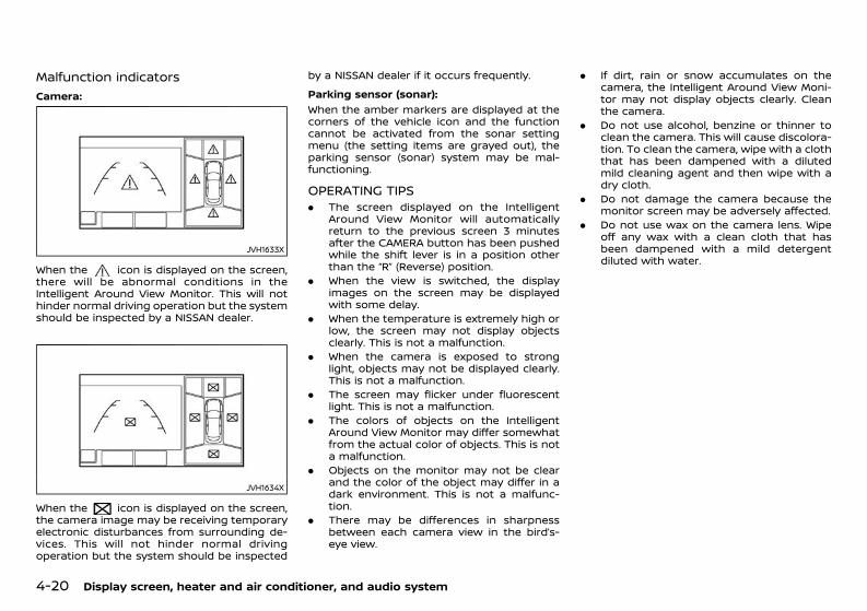
(206,1)
[ Edit: 2020/ 11/ 9 Model: Y62-A ]
4-20 Display screen, heater and air conditioner, and audio system
Malfunction indicatorsGUID-43AB5B42-D9AB-4F6B-8BCA-C999BFF6178F
Camera:GUID-C7E1EF24-5AAB-4301-95BE-26917EEE45EF
JVH1633X
When the icon is displayed on the screen,there will be abnormal conditions in theIntelligent Around View Monitor. This will nothinder normal driving operation but the systemshould be inspected by a NISSAN dealer.
JVH1634X
When the icon is displayed on the screen,the camera image may be receiving temporaryelectronic disturbances from surrounding de-vices. This will not hinder normal drivingoperation but the system should be inspected
by a NISSAN dealer if it occurs frequently.Parking sensor (sonar):
GUID-C7E1EF24-5AAB-4301-95BE-26917EEE45EF
When the amber markers are displayed at thecorners of the vehicle icon and the functioncannot be activated from the sonar settingmenu (the setting items are grayed out), theparking sensor (sonar) system may be mal-functioning.
OPERATING TIPSGUID-FC75F997-C15E-46F8-A7D6-37631CD8477F. The screen displayed on the Intelligent
Around View Monitor will automaticallyreturn to the previous screen 3 minutesafter the CAMERA button has been pushedwhile the shift lever is in a position otherthan the “R” (Reverse) position.
. When the view is switched, the displayimages on the screen may be displayedwith some delay.
. When the temperature is extremely high orlow, the screen may not display objectsclearly. This is not a malfunction.
. When the camera is exposed to stronglight, objects may not be displayed clearly.This is not a malfunction.
. The screen may flicker under fluorescentlight. This is not a malfunction.
. The colors of objects on the IntelligentAround View Monitor may differ somewhatfrom the actual color of objects. This is nota malfunction.
. Objects on the monitor may not be clearand the color of the object may differ in adark environment. This is not a malfunc-tion.
. There may be differences in sharpnessbetween each camera view in the bird’s-eye view.
. If dirt, rain or snow accumulates on thecamera, the Intelligent Around View Moni-tor may not display objects clearly. Cleanthe camera.
. Do not use alcohol, benzine or thinner toclean the camera. This will cause discolora-tion. To clean the camera, wipe with a cloththat has been dampened with a dilutedmild cleaning agent and then wipe with adry cloth.
. Do not damage the camera because themonitor screen may be adversely affected.
. Do not use wax on the camera lens. Wipeoff any wax with a clean cloth that hasbeen dampened with a mild detergentdiluted with water.
Condition: 'Except for China'/'Except for China/
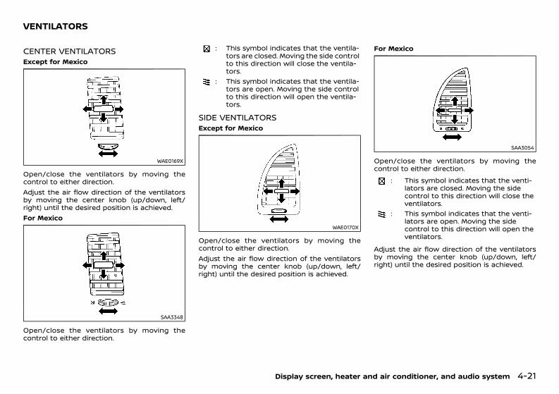
(207,1)
[ Edit: 2020/ 11/ 9 Model: Y62-A ]
GUID-8F206902-B1E0-4EE3-A75B-965E3A845AF0
CENTER VENTILATORSGUID-F72A1997-8A5D-4519-BE35-AD1AEE64A361Except for Mexico
WAE0169X
Open/close the ventilators by moving thecontrol to either direction.Adjust the air flow direction of the ventilatorsby moving the center knob (up/down, left/right) until the desired position is achieved.For Mexico
SAA3348
Open/close the ventilators by moving thecontrol to either direction.
: This symbol indicates that the ventila-tors are closed. Moving the side controlto this direction will close the ventila-tors.
: This symbol indicates that the ventila-tors are open. Moving the side controlto this direction will open the ventila-tors.
SIDE VENTILATORSGUID-EA989714-8ECE-4195-8068-E54557C6D0BFExcept for Mexico
WAE0170X
Open/close the ventilators by moving thecontrol to either direction.Adjust the air flow direction of the ventilatorsby moving the center knob (up/down, left/right) until the desired position is achieved.
For Mexico
SAA3054
Open/close the ventilators by moving thecontrol to either direction.
: This symbol indicates that the venti-lators are closed. Moving the sidecontrol to this direction will close theventilators.
: This symbol indicates that the venti-lators are open. Moving the sidecontrol to this direction will open theventilators.
Adjust the air flow direction of the ventilatorsby moving the center knob (up/down, left/right) until the desired position is achieved.
Display screen, heater and air conditioner, and audio system 4-21
VENTILATORS
Condition: 'Except for China'/'Except for China/
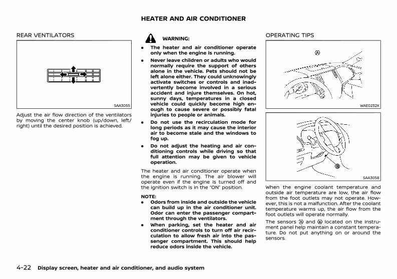
(208,1)
[ Edit: 2020/ 11/ 9 Model: Y62-A ]
4-22 Display screen, heater and air conditioner, and audio system
REAR VENTILATORSGUID-72F8CCDB-EE55-4F6A-AAC8-EE53454DB540
SAA3055
Adjust the air flow direction of the ventilatorsby moving the center knob (up/down, left/right) until the desired position is achieved.
GUID-A96BB9A9-5DDE-4383-B3F9-A346A4393F71
WARNING:. The heater and air conditioner operate
only when the engine is running.. Never leave children or adults who would
normally require the support of othersalone in the vehicle. Pets should not beleft alone either. They could unknowinglyactivate switches or controls and inad-vertently become involved in a seriousaccident and injure themselves. On hot,sunny days, temperatures in a closedvehicle could quickly become high en-ough to cause severe or possibly fatalinjuries to people or animals.
. Do not use the recirculation mode forlong periods as it may cause the interiorair to become stale and the windows tofog up.
. Do not adjust the heating and air con-ditioning controls while driving so thatfull attention may be given to vehicleoperation.
The heater and air conditioner operate whenthe engine is running. The air blower willoperate even if the engine is turned off andthe ignition switch is in the “ON” position.
NOTE:. Odors from inside and outside the vehicle
can build up in the air conditioner unit.Odor can enter the passenger compart-ment through the ventilators.
. When parking, set the heater and airconditioner controls to turn off air recir-culation to allow fresh air into the pas-senger compartment. This should helpreduce odors inside the vehicle.
OPERATING TIPSGUID-EE3F8FBC-77D0-48F9-B213-64D23E4B7DFD
WAE0232X
SAA3058
When the engine coolant temperature andoutside air temperature are low, the air flowfrom the foot outlets may not operate. How-ever, this is not a malfunction. After the coolanttemperature warms up, the air flow from thefoot outlets will operate normally.The sensors and located on the instru-ment panel help maintain a constant tempera-ture. Do not put anything on or around thesensors.
HEATER AND AIR CONDITIONER
Condition: 'Except for China'/'Except for China/
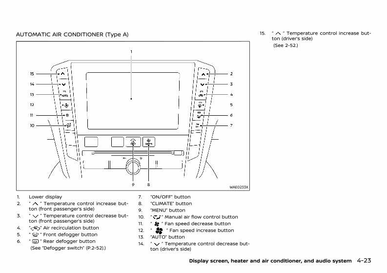
(209,1)
[ Edit: 2020/ 11/ 9 Model: Y62-A ]
AUTOMATIC AIR CONDITIONER (Type A)GUID-E617E9A0-60C9-490A-8D12-DB678A189285
WAE0233X
1. Lower display2. “ ” Temperature control increase but-
ton (front passenger’s side)3. “ ” Temperature control decrease but-
ton (front passenger’s side)4. “ ” Air recirculation button5. “ ” Front defogger button6. “ ” Rear defogger button
(See “Defogger switch” (P.2-52).)
7. “ON/OFF” button8. “CLIMATE” button9. “MENU” button10. “ ” Manual air flow control button11. “ ” Fan speed decrease button12. “ ” Fan speed increase button13. “AUTO” button14. “ ” Temperature control decrease but-
ton (driver’s side)
15. “ ” Temperature control increase but-ton (driver’s side)(See 2-52.)
Display screen, heater and air conditioner, and audio system 4-23
Condition: 'Except for China'/'Except for China/
(210,1)
[ Edit: 2020/ 11/ 9 Model: Y62-A ]
4-24 Display screen, heater and air conditioner, and audio system
Automatic operation (AUTO)GUID-B3A1CA0B-9C9E-4655-B2C3-E9B94BF211DB
Cooling and dehumidified heating (AUTO):GUID-C7E1EF24-5AAB-4301-95BE-26917EEE45EF
1. Push the “AUTO” button.The AUTO indicator light will illuminate. TheClimate screen will be displayed on thelower display and “AUTO” will appear on theClimate screen.
2. Push the temperature control buttons onthe corresponding side to set the preferredtemperature.. You can individually set temperatures for
the driver’s side and front passenger’sside when in the DUAL mode. See “DUALmode setting” (P.4-25).
. The temperature of the passenger com-partment will be maintained automati-cally. Air flow distribution and fan speedwill also be controlled automatically.
3. To turn off the heater and air conditionersystem, push the “ON/OFF” button.
A visible mist may be seen coming from theventilators in hot, humid conditions as the air iscooled rapidly. This does not indicate a mal-function.Heating (A/C off):
GUID-C7E1EF24-5AAB-4301-95BE-26917EEE45EF
The air conditioner does not activate in thismode. Use this mode when you only need toheat.1. Push the “CLIMATE” button.
The Climate screen will be displayed on thelower display.
2. Touch the “A/C” key on the lower display.The “A/C” indicator will turn off. See “Opera-tions on touch panel screen” (P.4-25).
3. Push the temperature control buttons onthe corresponding side to set the preferred
temperature.. You can individually set temperatures for
the driver’s side and front passenger’sside when in the DUAL mode. See “DUALmode setting” (P.4-25).
. The temperature of the passenger com-partment will be maintained automati-cally. Air flow distribution and fan speedwill also be controlled automatically.
NOTE:. Do not set the temperature lower than
the outside air temperature. Otherwisethe system may not work properly.
. This mode is not recommended if thewindows fog up.
Dehumidified defrosting/defogging:GUID-C7E1EF24-5AAB-4301-95BE-26917EEE45EF
1. Push the “ ” front defogger button. Theindicator light will illuminate.
2. Push the temperature control buttons onthe driver’s side to set the preferred tem-perature.
NOTE:. To quickly remove ice from the outside of
the windows, push the “ ” fan speedincrease button and set it to the max-imum position.
. As soon as possible after the windshieldis cleaned, push the “AUTO” button toreturn to the auto mode.
. When the “ ” front defogger button ispushed, the air conditioner will automa-tically be turned on at outside tempera-tures above −5°C (23°F) to defog thewindshield, and the air recirculate modewill automatically be turned off.
Manual operationGUID-5EC19176-2F41-49B9-88E2-3D09447B7BE4The manual mode can be used to control theheater and air conditioner to your desiredsettings.To turn off the heater and air conditioner, pushthe “ON/OFF” button.Fan speed control:
GUID-C7E1EF24-5AAB-4301-95BE-26917EEE45EF
Push the “ ” fan speed increase button toincrease the fan speed.Push the “ ” fan speed decrease button todecrease the fan speed.Push the “AUTO” button to change the fanspeed to the automatic mode.Air flow control:
GUID-C7E1EF24-5AAB-4301-95BE-26917EEE45EF
Push the “ ” manual air flow control buttonto change the air flow mode.
: Air flows from the center and sideventilators.
: Air flows from the center and sideventilators, and foot outlets.
: Air flows mainly from the foot outlets.: Air flows from the defogger and foot
outlets.
Temperature control:GUID-C7E1EF24-5AAB-4301-95BE-26917EEE45EF
Push the “ ” temperature control increasebutton or the “ ” temperature control de-crease button to set the desired temperature.You can individually set temperatures for thedriver’s side and front passenger’s side when inthe DUAL mode. See “DUAL mode setting” (P.4-25).
Condition: 'Except for China'/'Except for China/
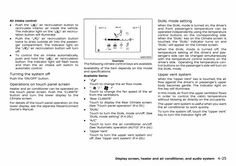
(211,1)
[ Edit: 2020/ 11/ 9 Model: Y62-A ]
Air intake control:GUID-C7E1EF24-5AAB-4301-95BE-26917EEE45EF
. Push the “ ” air recirculation button torecirculate interior air inside the vehicle.The indicator light on the “ ” air recircu-lation button will illuminate.
. Push the “ ” air recirculation buttontwice to draw outside air into the passen-ger compartment. The indicator light onthe “ ” air recirculation button will turnoff.
. To control the air intake automatically,push and hold the “ ” air recirculationbutton. The indicator light will flash twice,and then the air intake will switch toautomatic control.
Turning the system offGUID-45931C4C-66FC-490E-8417-294DC79AD00EPush the “ON/OFF” button.
Operations on touch panel screenGUID-A019CC61-4B1E-4D72-AB00-C71AF78E881CHeater and air conditioner can be operated onthe touch panel screen. Push the “CLIMATE”button and turn the lower display to theClimate screen.For details of the touch panel operation on thelower display, see the separate NissanConnectOwner’s Manual.
WAE0183XExample
The following climate control keys are available.Availability of the item depends on the modeland specifications.Available items:. “ ”
Touch to change the air flow mode.. “- ”/ “ +”
Touch to change the fan speed of the airfrom the ventilators.
. “Rear CLIMATE”Touch to display the Rear Climate screen.(See “Touch panel operation” (P.4-31).)
. “DUAL”Touch to turn the DUAL mode on/off. (See“DUAL mode setting” (P.4-25).)
. “A/C”Touch to turn the air conditioner on/off.(See “Automatic operation (AUTO)” (P.4-24).)
. “Upper Vent”Touch to turn the upper vent system on/off. (See “Upper vent system” (P.4-25).)
DUAL mode settingGUID-84EDECC8-33A1-4512-B4D0-9FFC1615B83AWhen the DUAL mode is turned on, the driver’sand front passenger’s temperature can beoperated independently using the temperaturecontrol buttons on the corresponding side.When the “DUAL” key on the Climate screen istouched, the “DUAL” indicator turns on and“DUAL” will appear on the Climate screen.When the DUAL mode is turned off, thetemperature setting of the driver’s and pas-senger’s side can be changed simultaneouslywith the temperature control buttons on thedriver’s side. Operating the temperature con-trol buttons on the passenger’s side will turn onthe DUAL mode.
Upper vent systemGUID-ED154FBE-1E99-4581-B182-0E208EA2DBE1When the “Upper Vent” key is touched, the airflow against the driver’s or passenger’s upperbody becomes gentle. The indicator light onthe key will illuminate.In this mode, air from the upper ventilator flowsin order to control the cabin temperaturewithout blowing air directly on the occupants.The upper vent system is useful when you wantthe air conditioner to work quickly.To turn the system off, touch the “Upper Vent”key to turn the indicator light off.
Display screen, heater and air conditioner, and audio system 4-25
Condition: 'Except for China'/'Except for China/
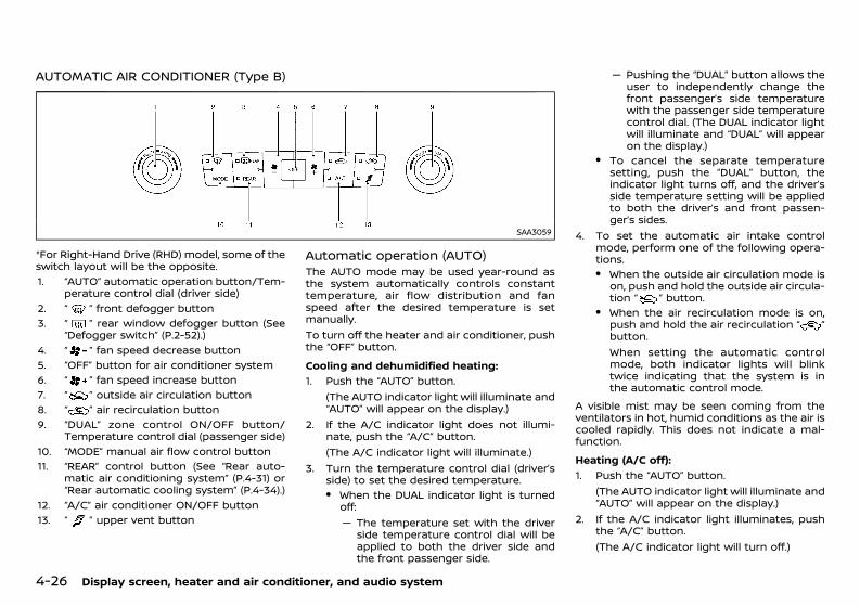
(212,1)
[ Edit: 2020/ 11/ 9 Model: Y62-A ]
4-26 Display screen, heater and air conditioner, and audio system
AUTOMATIC AIR CONDITIONER (Type B)GUID-44034773-0914-4586-98EF-4C1AE8718310
SAA3059
*For Right-Hand Drive (RHD) model, some of theswitch layout will be the opposite.1. “AUTO” automatic operation button/Tem-
perature control dial (driver side)2. “ ” front defogger button3. “ ” rear window defogger button (See
“Defogger switch” (P.2-52).)4. “ ” fan speed decrease button5. “OFF” button for air conditioner system6. “ ” fan speed increase button7. “ ” outside air circulation button8. “ ” air recirculation button9. “DUAL” zone control ON/OFF button/
Temperature control dial (passenger side)10. “MODE” manual air flow control button11. “REAR” control button (See “Rear auto-
matic air conditioning system” (P.4-31) or“Rear automatic cooling system” (P.4-34).)
12. “A/C” air conditioner ON/OFF button13. “ ” upper vent button
Automatic operation (AUTO)GUID-674FE584-A48E-49BE-A0A0-3C767DA6E2AFThe AUTO mode may be used year-round asthe system automatically controls constanttemperature, air flow distribution and fanspeed after the desired temperature is setmanually.To turn off the heater and air conditioner, pushthe “OFF” button.Cooling and dehumidified heating:
GUID-C7E1EF24-5AAB-4301-95BE-26917EEE45EF
1. Push the “AUTO” button.(The AUTO indicator light will illuminate and“AUTO” will appear on the display.)
2. If the A/C indicator light does not illumi-nate, push the “A/C” button.(The A/C indicator light will illuminate.)
3. Turn the temperature control dial (driver’sside) to set the desired temperature.. When the DUAL indicator light is turned
off:— The temperature set with the driver
side temperature control dial will beapplied to both the driver side andthe front passenger side.
— Pushing the “DUAL” button allows theuser to independently change thefront passenger’s side temperaturewith the passenger side temperaturecontrol dial. (The DUAL indicator lightwill illuminate and “DUAL” will appearon the display.)
. To cancel the separate temperaturesetting, push the “DUAL” button, theindicator light turns off, and the driver’sside temperature setting will be appliedto both the driver’s and front passen-ger’s sides.
4. To set the automatic air intake controlmode, perform one of the following opera-tions.. When the outside air circulation mode is
on, push and hold the outside air circula-tion “ ” button.
. When the air recirculation mode is on,push and hold the air recirculation “ ”button.When setting the automatic controlmode, both indicator lights will blinktwice indicating that the system is inthe automatic control mode.
A visible mist may be seen coming from theventilators in hot, humid conditions as the air iscooled rapidly. This does not indicate a mal-function.Heating (A/C off):
GUID-C7E1EF24-5AAB-4301-95BE-26917EEE45EF
1. Push the “AUTO” button.(The AUTO indicator light will illuminate and“AUTO” will appear on the display.)
2. If the A/C indicator light illuminates, pushthe “A/C” button.(The A/C indicator light will turn off.)
Condition: 'Except for China'/'Except for China/
(213,1)
[ Edit: 2020/ 11/ 9 Model: Y62-A ]
3. Turn the temperature control dial to set thedesired temperature.. When the DUAL indicator light is turned
off:— Turning the driver’s side temperature
control dial changes both the driver’sand front passenger’s side tempera-ture.
— Pushing the “DUAL” button allows theuser to independently change thefront passenger’s side temperaturewith the passenger side temperaturecontrol dial. (The DUAL indicator lightwill illuminate and “DUAL” will appearon the display.)
. To cancel the separate temperaturesetting, push the “DUAL” button, theindicator light turns off, and the driver’sside temperature setting will be appliedto both the driver’s and front passen-ger’s sides.
4. To set the automatic air intake controlmode, perform one of the following opera-tions.. When the outside air circulation mode is
on, push and hold the outside air circula-tion “ ” button.
. When the air recirculation mode is on,push and hold the air recirculation “ ”button.When setting the automatic controlmode, both indicator lights will blinktwice indicating that the system is inthe automatic control mode.
. Do not set the temperature lower thanthe outside air temperature. Doing somay cause the temperature not to becontrolled properly.
. To dehumidify the air, push the “A/C”button before turning on the heater.
Dehumidified defrosting/defogging:GUID-C7E1EF24-5AAB-4301-95BE-26917EEE45EF
1. Push the “ ” button. (The indicator lightwill illuminate.)
2. Turn the temperature control dial to set thedesired temperature.. To remove frost from the outside surface
of the windshield quickly, set the tem-perature control and fan speed controlto their maximum position.
. After the windshield is cleared, push the“AUTO” button to set to the automaticmode.
. When the “ ” button is pushed, the airconditioner will automatically turn onwhen the outside air temperature isabove −5°C (23°F) to defog the wind-shield. The air recirculation mode willautomatically turn off. The outside aircirculation mode will be selected toimprove the defogging performance.
Manual operationGUID-E7C072E6-19B5-4011-8013-072F15386029The manual mode can be used to control theheater and air conditioner to your desiredsettings.To turn off the heater and air conditioner, pushthe “OFF” button.Fan speed control:
GUID-C7E1EF24-5AAB-4301-95BE-26917EEE45EF
Push the fan speed control “ ” button toincrease the fan speed.Push the fan speed control “ ” button todecrease the fan speed.Push the “AUTO” button to change the fanspeed to the automatic mode.
Air intake control:GUID-C7E1EF24-5AAB-4301-95BE-26917EEE45EF
. Push the air recirculation “ ” button torecirculate interior air inside the vehicle.The indicator light on the air recirculation“ ” button will illuminate.
. Push the outside air circulation “ ”button to draw outside air into the pas-senger compartment.The indicator light on the outside aircirculation “ ” button will illuminate.
. To set the automatic air intake controlmode, perform one of the following opera-tions:— When the outside air circulation mode is
on, push and hold the outside aircirculation “ ” button.
— When the air recirculation mode is on,push and hold the air recirculation “ ”button.
When automatic control mode is set, theindicator lights will blink twice indicatingthat the system is in the automatic controlmode.
Air flow control:GUID-C7E1EF24-5AAB-4301-95BE-26917EEE45EF
Push the “MODE” button to change the air flowmode.
: Air flows from the center and sideventilators.
: Air flows from the center and sideventilators, and foot outlets.
: Air flows mainly from the foot outlets.: Air flows from the defogger and foot
outlets.
Display screen, heater and air conditioner, and audio system 4-27
Condition: 'Except for China'/'Except for China/
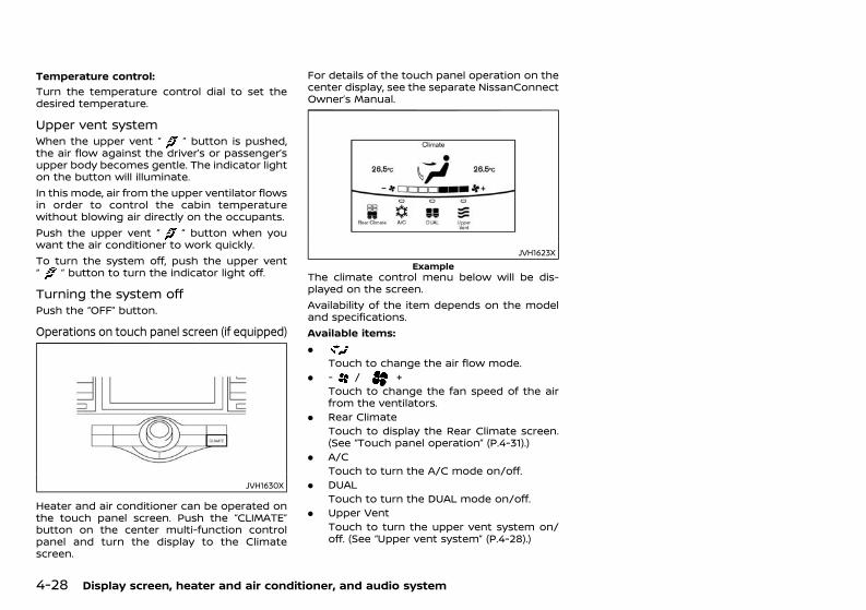
(214,1)
[ Edit: 2020/ 11/ 9 Model: Y62-A ]
4-28 Display screen, heater and air conditioner, and audio system
Temperature control:GUID-C7E1EF24-5AAB-4301-95BE-26917EEE45EF
Turn the temperature control dial to set thedesired temperature.
Upper vent systemGUID-AFCC1D62-7AAD-4FAC-B254-648498BCF85AWhen the upper vent “ ” button is pushed,the air flow against the driver’s or passenger’supper body becomes gentle. The indicator lighton the button will illuminate.In this mode, air from the upper ventilator flowsin order to control the cabin temperaturewithout blowing air directly on the occupants.Push the upper vent “ ” button when youwant the air conditioner to work quickly.To turn the system off, push the upper vent“ ” button to turn the indicator light off.
Turning the system offGUID-58C4FAD1-C479-4260-B35C-9C58558C3557Push the “OFF” button.
Operations on touch panel screen (if equipped)GUID-267651EF-D1F9-4E25-9FC0-DB08C5A9F7C5
JVH1630X
Heater and air conditioner can be operated onthe touch panel screen. Push the “CLIMATE”button on the center multi-function controlpanel and turn the display to the Climatescreen.
For details of the touch panel operation on thecenter display, see the separate NissanConnectOwner’s Manual.
JVH1623XExample
The climate control menu below will be dis-played on the screen.Availability of the item depends on the modeland specifications.Available items:.
Touch to change the air flow mode.. - / +
Touch to change the fan speed of the airfrom the ventilators.
. Rear ClimateTouch to display the Rear Climate screen.(See “Touch panel operation” (P.4-31).)
. A/CTouch to turn the A/C mode on/off.
. DUALTouch to turn the DUAL mode on/off.
. Upper VentTouch to turn the upper vent system on/off. (See “Upper vent system” (P.4-28).)
Condition: 'Except for China'/'Except for China/
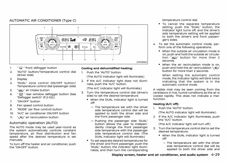
(215,1)
[ Edit: 2020/ 11/ 9 Model: Y62-A ]
AUTOMATIC AIR CONDITIONER (Type C)GUID-3CF22D9E-9051-4E31-A9FF-E392B2016D8B
JVH0366X
1. “ ” front defogger button2. “AUTO” button/Temperature control dial
(driver side)3 Display4. “DUAL” zone control ON/OFF button/
Temperature control dial (passenger side)5. “ ” air intake button6. “ ” rear window defogger button (See
“Defogger switch” (P.2-52).)7. “ON·OFF” button8. Fan speed control button9. “MODE” (air flow control) button10. “A/C” air conditioner ON/OFF button11. “ ” air recirculation button
Automatic operation (AUTO)GUID-10E04568-915B-449B-987F-69AA13F0CB34The AUTO mode may be used year-round asthe system automatically controls constanttemperature, air flow distribution and fanspeed after the desired temperature is setmanually.To turn off the heater and air conditioner, pushthe “ON·OFF” button.
Cooling and dehumidified heating:GUID-C7E1EF24-5AAB-4301-95BE-26917EEE45EF
1. Push the “AUTO” button.(The AUTO indicator light will illuminate.)
2. If the A/C indicator light does not illumi-nate, push the “A/C” button.(The A/C indicator light will illuminate.)
3. Turn the temperature control dial (driver’sside) to set the desired temperature.. When the DUAL indicator light is turned
off:— The temperature set with the driver
side temperature control dial will beapplied to both the driver side andthe front passenger side.
— Pushing the passenger side “DUAL”button allows the user to indepen-dently change the front passengerside temperature with the passengerside temperature control dial. (TheDUAL indicator light will illuminate.)
. To set separate desired temperatures forthe driver and front passenger, push the“DUAL” button, the indicator light illumi-nates, and then turn the corresponding
temperature control dial.. To cancel the separate temperature
setting, push the “DUAL” button, theindicator light turns off, and the driver’sside temperature setting will be appliedto both the driver’s and front passen-ger’s sides.
4. To set the automatic control mode, per-form one of the following operations.. When the outside air circulation mode is
on, push and hold the outside air circula-tion “ ” button for more than 2seconds.
. When the air recirculation mode is on,push and hold the air recirculation “ ”button for more than 2 seconds.When setting the automatic controlmode, the indicator lights will blink twiceindicating that the system is in theautomatic control mode.
A visible mist may be seen coming from theventilators in hot, humid conditions as the air iscooled rapidly. This does not indicate a mal-function.Heating (A/C off):
GUID-C7E1EF24-5AAB-4301-95BE-26917EEE45EF
1. Push the “AUTO” button.(The AUTO indicator light will illuminate.)
2. If the A/C indicator light illuminates, pushthe “A/C” button.(The A/C indicator light will turn off.)
3. Turn the temperature control dial to set thedesired temperature.. When the DUAL indicator light is turned
off:— The temperature set with the driver
side temperature control dial will beapplied to both the driver side and
Display screen, heater and air conditioner, and audio system 4-29
Condition: 'Except for China'/'Except for China/
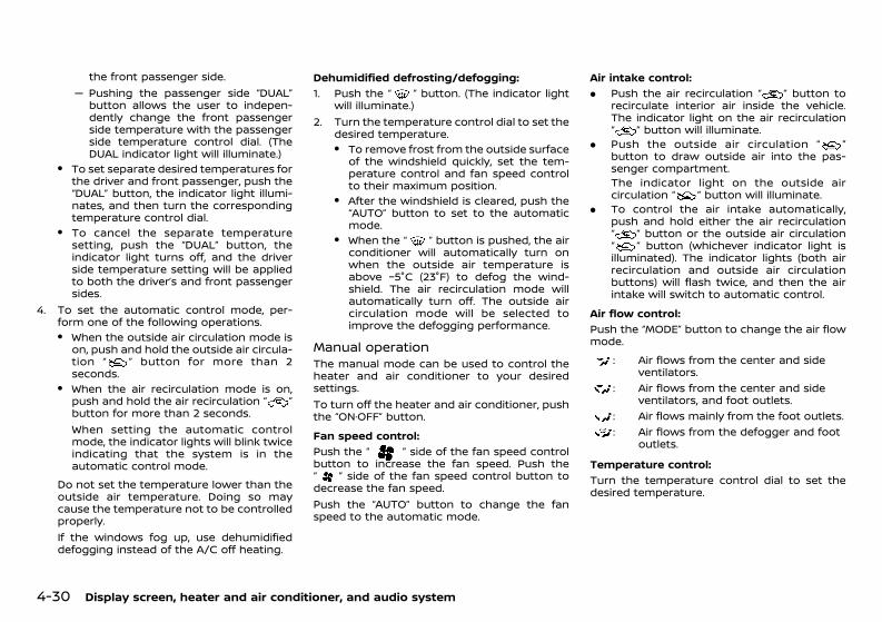
(216,1)
[ Edit: 2020/ 11/ 9 Model: Y62-A ]
4-30 Display screen, heater and air conditioner, and audio system
the front passenger side.— Pushing the passenger side “DUAL”
button allows the user to indepen-dently change the front passengerside temperature with the passengerside temperature control dial. (TheDUAL indicator light will illuminate.)
. To set separate desired temperatures forthe driver and front passenger, push the“DUAL” button, the indicator light illumi-nates, and then turn the correspondingtemperature control dial.
. To cancel the separate temperaturesetting, push the “DUAL” button, theindicator light turns off, and the driverside temperature setting will be appliedto both the driver’s and front passengersides.
4. To set the automatic control mode, per-form one of the following operations.. When the outside air circulation mode is
on, push and hold the outside air circula-tion “ ” button for more than 2seconds.
. When the air recirculation mode is on,push and hold the air recirculation “ ”button for more than 2 seconds.When setting the automatic controlmode, the indicator lights will blink twiceindicating that the system is in theautomatic control mode.
Do not set the temperature lower than theoutside air temperature. Doing so maycause the temperature not to be controlledproperly.If the windows fog up, use dehumidifieddefogging instead of the A/C off heating.
Dehumidified defrosting/defogging:GUID-C7E1EF24-5AAB-4301-95BE-26917EEE45EF
1. Push the “ ” button. (The indicator lightwill illuminate.)
2. Turn the temperature control dial to set thedesired temperature.. To remove frost from the outside surface
of the windshield quickly, set the tem-perature control and fan speed controlto their maximum position.
. After the windshield is cleared, push the“AUTO” button to set to the automaticmode.
. When the “ ” button is pushed, the airconditioner will automatically turn onwhen the outside air temperature isabove −5°C (23°F) to defog the wind-shield. The air recirculation mode willautomatically turn off. The outside aircirculation mode will be selected toimprove the defogging performance.
Manual operationGUID-CFCC1143-7854-48F9-B014-962F1E7C884EThe manual mode can be used to control theheater and air conditioner to your desiredsettings.To turn off the heater and air conditioner, pushthe “ON·OFF” button.Fan speed control:
GUID-C7E1EF24-5AAB-4301-95BE-26917EEE45EF
Push the “ ” side of the fan speed controlbutton to increase the fan speed. Push the“ ” side of the fan speed control button todecrease the fan speed.Push the “AUTO” button to change the fanspeed to the automatic mode.
Air intake control:GUID-C7E1EF24-5AAB-4301-95BE-26917EEE45EF
. Push the air recirculation “ ” button torecirculate interior air inside the vehicle.The indicator light on the air recirculation“ ” button will illuminate.
. Push the outside air circulation “ ”button to draw outside air into the pas-senger compartment.The indicator light on the outside aircirculation “ ” button will illuminate.
. To control the air intake automatically,push and hold either the air recirculation“ ” button or the outside air circulation“ ” button (whichever indicator light isilluminated). The indicator lights (both airrecirculation and outside air circulationbuttons) will flash twice, and then the airintake will switch to automatic control.
Air flow control:GUID-C7E1EF24-5AAB-4301-95BE-26917EEE45EF
Push the “MODE” button to change the air flowmode.
: Air flows from the center and sideventilators.
: Air flows from the center and sideventilators, and foot outlets.
: Air flows mainly from the foot outlets.: Air flows from the defogger and foot
outlets.
Temperature control:GUID-C7E1EF24-5AAB-4301-95BE-26917EEE45EF
Turn the temperature control dial to set thedesired temperature.
Condition: 'Except for China'/'Except for China/
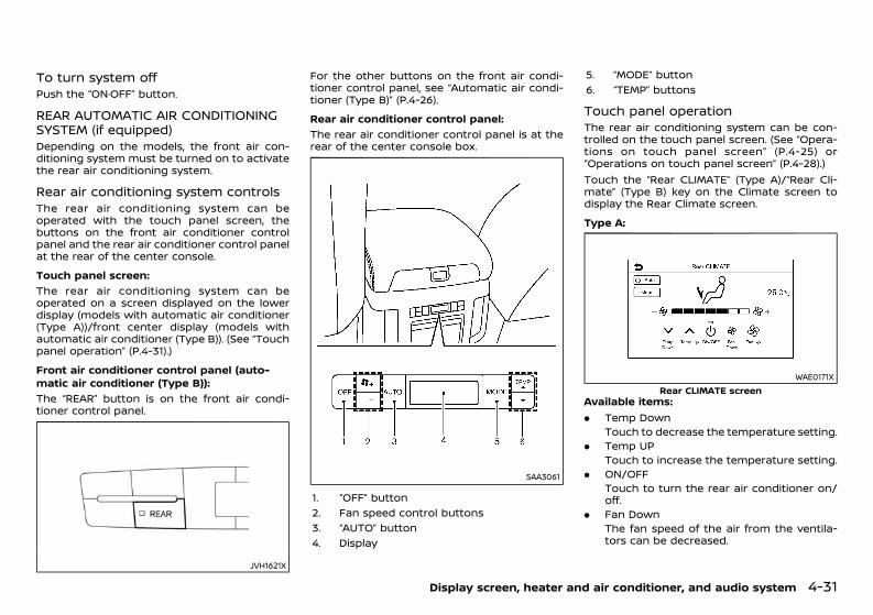
(217,1)
[ Edit: 2020/ 11/ 9 Model: Y62-A ]
To turn system offGUID-1F0BD91E-AAE8-4F3D-AEDC-D153F0ABC141Push the “ON·OFF” button.
REAR AUTOMATIC AIR CONDITIONINGSYSTEM (if equipped)GUID-67649D08-4179-4255-BF6C-481C882845B5Depending on the models, the front air con-ditioning system must be turned on to activatethe rear air conditioning system.
Rear air conditioning system controlsGUID-A25155F0-750F-4597-B7A3-8BB284622911The rear air conditioning system can beoperated with the touch panel screen, thebuttons on the front air conditioner controlpanel and the rear air conditioner control panelat the rear of the center console.Touch panel screen:
GUID-C7E1EF24-5AAB-4301-95BE-26917EEE45EF
The rear air conditioning system can beoperated on a screen displayed on the lowerdisplay (models with automatic air conditioner(Type A))/front center display (models withautomatic air conditioner (Type B)). (See “Touchpanel operation” (P.4-31).)Front air conditioner control panel (auto-matic air conditioner (Type B)):
GUID-C7E1EF24-5AAB-4301-95BE-26917EEE45EF
The “REAR” button is on the front air condi-tioner control panel.
JVH1621X
For the other buttons on the front air condi-tioner control panel, see “Automatic air condi-tioner (Type B)” (P.4-26).Rear air conditioner control panel:
GUID-C7E1EF24-5AAB-4301-95BE-26917EEE45EF
The rear air conditioner control panel is at therear of the center console box.
SAA3061
1. “OFF” button2. Fan speed control buttons3. “AUTO” button4. Display
5. “MODE” button6. “TEMP” buttons
Touch panel operationGUID-C9381D30-F3C4-41C1-A747-DCB26A804104The rear air conditioning system can be con-trolled on the touch panel screen. (See “Opera-tions on touch panel screen” (P.4-25) or“Operations on touch panel screen” (P.4-28).)Touch the “Rear CLIMATE” (Type A)/“Rear Cli-mate” (Type B) key on the Climate screen todisplay the Rear Climate screen.Type A:
GUID-C7E1EF24-5AAB-4301-95BE-26917EEE45EF
WAE0171XRear CLIMATE screen
Available items:. Temp Down
Touch to decrease the temperature setting.. Temp UP
Touch to increase the temperature setting.. ON/OFF
Touch to turn the rear air conditioner on/off.
. Fan DownThe fan speed of the air from the ventila-tors can be decreased.
Display screen, heater and air conditioner, and audio system 4-31
Condition: 'Except for China'/'Except for China/
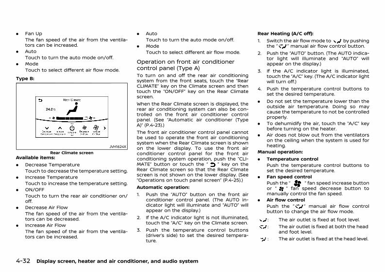
(218,1)
[ Edit: 2020/ 11/ 9 Model: Y62-A ]
4-32 Display screen, heater and air conditioner, and audio system
. Fan UpThe fan speed of the air from the ventila-tors can be increased.
. AutoTouch to turn the auto mode on/off.
. ModeTouch to select different air flow mode.
Type B:GUID-C7E1EF24-5AAB-4301-95BE-26917EEE45EF
JVH1624XRear Climate screen
Available items:. Decrease Temperature
Touch to decrease the temperature setting.. Increase Temperature
Touch to increase the temperature setting.. ON/OFF
Touch to turn the rear air conditioner on/off.
. Decrease Air FlowThe fan speed of the air from the ventila-tors can be decreased.
. Increase Air FlowThe fan speed of the air from the ventila-tors can be increased.
. AutoTouch to turn the auto mode on/off.
. ModeTouch to select different air flow mode.
Operation on front air conditionercontrol panel (Type A)GUID-D667AA1F-BEBD-4D99-9729-67158D35FD5ATo turn on and off the rear air conditioningsystem from the front seats, touch the “RearCLIMATE” key on the Climate screen and thentouch the “ON/OFF” key on the Rear Climatescreen.When the Rear Climate screen is displayed, therear air conditioning system can also be con-trolled on the front air conditioner controlpanel. (See “Automatic air conditioner (TypeA)” (P.4-23).)The front air conditioner control panel cannotbe used to operate the front air conditioningsystem when the Rear Climate screen is shownon the lower display. To use the front airconditioner control panel for the front airconditioning system operation, push the “CLI-MATE” button or touch the “ ” key on theRear Climate screen so that the Rear Climatescreen is not shown on the lower display. (See“Operations on touch panel screen” (P.4-25).)Automatic operation:1. Push the “AUTO” button on the front air
conditioner control panel. (The AUTO in-dicator light will illuminate and “AUTO” willappear on the display.)
2. If the A/C indicator light is not illuminated,touch the “A/C” key on the Climate screen.
3. Push the temperature control buttons(driver’s side) to set the desired tempera-ture.
Rear Heating (A/C off):1. Switch the air flowmode to by pushing
the “ ” manual air flow control button.2. Push the “AUTO” button. (The AUTO indica-
tor light will illuminate and “AUTO” willappear on the display.)
3. If the A/C indicator light is illuminated,touch the “A/C” key. (The A/C indicator lightwill turn off.)
4. Push the temperature control buttons toset the desired temperature.
. Do not set the temperature lower than theoutside air temperature. Doing so maycause the temperature to not be controlledproperly.
. To dehumidify the air, touch the “A/C” keybefore turning on the heater.
. Air does not blow out from the ventilatorson the ceiling when the system is used forheating.
Manual operation:. Temperature control
Push the temperature control buttons toset the desired temperature.
. Fan speed controlPush the “ ” fan speed increase buttonor “ ” fan speed decrease button tomanually control the fan speed.
. Air flow controlPush the “ ” manual air flow controlbutton to change the air flow mode.: The air outlet is fixed at foot level.: The air outlet is fixed at both the head
and foot level.: The air outlet is fixed at the head level.
Condition: 'Except for China'/'Except for China/
(219,1)
[ Edit: 2020/ 11/ 9 Model: Y62-A ]
Operation on front air conditionercontrol panel (Type B)GUID-3020B232-E979-4814-BE6C-889DF163A0DBTo turn on and off the rear air conditioningsystem from the front seats, push the “REAR”button on the front air conditioner controlpanel.When the Rear Climate screen is displayed, therear air conditioning system can also be con-trolled on the front air conditioner controlpanel. (See “Automatic air conditioner (TypeB)” (P.4-26).)The front air conditioner control panel cannotbe used to operate the front air conditioningsystem when the Rear Climate screen is shownon the front center display. To use the front airconditioner control panel for the front airconditioning system operation, push the “CLI-MATE” button or touch the “ ” key on theRear Climate screen so that the Rear Climatescreen is not shown on the front center display.(See “Operations on touch panel screen” (P.4-28).)Automatic operation:1. Push the “AUTO” button on the front air
conditioner control panel. (The AUTO in-dicator light will illuminate and “AUTO” willappear on the display.)
2. If the A/C indicator light is not illuminated,push the “A/C” button. (The A/C indicatorlight will illuminate.)
3. Turn the temperature control dial (driver’sside) to set the desired temperature.
Rear Heating (A/C off):1. Switch the air flowmode to by pushing
the “MODE” button.2. Push the “AUTO” button. (The AUTO indica-
tor light will illuminate and “AUTO” willappear on the display.)
3. If the A/C indicator light is illuminated, pushthe “A/C” button. (The A/C indicator lightwill turn off.)
4. Turn the temperature control dial to set thedesired temperature.
. Do not set the temperature lower than theoutside air temperature. Doing so maycause the temperature to not be controlledproperly.
. To dehumidify the air, push the “A/C”button before turning on the heater.
. Air does not blow out from the ventilatorson the ceiling when the system is used forheating.
Manual operation:. Temperature control
Turn the temperature control dial (driver’sside) to set the desired temperature.
. Fan speed controlPush the fan speed control “ ” button or“ ” button to manually control the fanspeed.
. Air flow controlPush the “MODE” button to change the airflow mode.: The air outlet is fixed at foot level.: The air outlet is fixed at both the head
and foot level.: The air outlet is fixed at the head level.
Operation on rear air conditioner control panelGUID-3C02254C-791A-47F6-9EBB-42F742FE5A9BThe rear seat passengers can operate the rearair conditioning system using the rear airconditioner control panel at the rear of thecenter console. (See “Rear air conditioner con-trol panel” (P.4-31).)The rear air conditioner control panel does notfunction when the Rear Climate screen isshown on the lower display (Type A)/the frontcenter display (Type B). To activate the rear airconditioner control panel, push the “CLIMATE”button or touch the “ ” key on the RearClimate screen so that the Rear Climate screenis not shown on the lower display (Type A)/thefront center display (Type B). (See “Operationson touch panel screen” (P.4-25) or “Operationson touch panel screen” (P.4-28).)“OFF” button: Rear automatic air conditioningsystem offFan speed control buttons: Rear fan speedcontrol up/down“AUTO” button: Rear automatic air condition-ing system on, AUTO mode on“MODE” button: Rear air flow control change“TEMP” buttons: Rear temperature control up/down
Display screen, heater and air conditioner, and audio system 4-33
Condition: 'Except for China'/'Except for China/
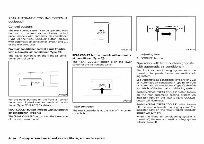
(220,1)
[ Edit: 2020/ 11/ 9 Model: Y62-A ]
4-34 Display screen, heater and air conditioner, and audio system
REAR AUTOMATIC COOLING SYSTEM (ifequipped) GUID-FF9106F3-260F-4D3A-869C-DBF270A91A78
Control buttonsGUID-16E4462C-2437-414F-A408-1F34ACA4093CThe rear cooling system can be operated withbuttons on the front air conditioner controlpanel (models with automatic air conditioner(Type B)), the “REAR COOLER” button (modelswith automatic air conditioner (Type A and C)),or the rear controller.Front air conditioner control panel (modelswith automatic air conditioner (Type B)):
GUID-C7E1EF24-5AAB-4301-95BE-26917EEE45EF
The “REAR” button is on the front air condi-tioner control panel.
JVH1621X
For the other buttons on the front air condi-tioner control panel, see “Automatic air condi-tioner (Type B)” (P.4-26) for details.REAR COOLER button (models with automaticair conditioner (Type A)):
GUID-C7E1EF24-5AAB-4301-95BE-26917EEE45EF
The "REAR COOLER" button is on the lower sideof the instrument panel.
WAE0558X
REAR COOLER button (models with automaticair conditioner (Type C)):
GUID-C7E1EF24-5AAB-4301-95BE-26917EEE45EF
The “REAR COOLER” button is on the lowercenter of the instrument panel.
SAA3063
Rear controller:GUID-C7E1EF24-5AAB-4301-95BE-26917EEE45EF
The rear controller is at the rear of the centerconsole box.
JVH1649X
1. Adjusting lever2. “COOLER” button
Operation with front buttons (modelswith automatic air conditioner)GUID-F9EACAAB-4E6E-4657-AE0B-264AB61C504FThe front air conditioning system must beturned on to operate the rear automatic cool-ing system.See “Automatic air conditioner (Type A)” (P.4-23)or “Automatic air conditioner (Type B)” (P.4-26)or “Automatic air conditioner (Type C)” (P.4-29)for details of the front air conditioning system.Push the “REAR”/“REAR COOLER” button to turnon the rear automatic cooling system. Anindicator light on the “REAR”/“REAR COOLER”button will illuminate.Push the “REAR”/“REAR COOLER” button to turnoff the rear automatic cooling system. Theindicator light on the “REAR”/“REAR COOLER”button will turn off.When the front air conditioning system isturned off, the rear automatic cooling systemwill also turn off.
Condition: 'Except for China'/'Except for China/
(221,1)
[ Edit: 2020/ 11/ 9 Model: Y62-A ]
Operation on rear controllerGUID-DD791298-308E-40E5-B5C1-98DAA97E6FD3The front air conditioning system must beturned on to operate the rear automatic cool-ing system.Push the “COOLER” button to turn on the rearcooler. The indicator light on the button willilluminate.Push the “COOLER” button again to turn off therear cooler. The indicator light on the buttonwill turn off.Fan speed control:Move the adjusting lever to adjust the fanspeed.Move the adjusting lever to the right side toincrease the fan speed.Move the adjusting lever to the left side todecrease the fan speed.The “AUTO” position is for automatic fan speedcontrol.
LINKING INTELLIGENT KEY (if equipped)GUID-849FE607-101B-4ADE-9172-1ED0962957B8The air conditioner system settings can bememorized for up to two Intelligent Keys. Formore details, see “Setting memory function”(P.3-35).
SERVICING AIR CONDITIONERGUID-9F752093-0527-482A-9807-9D6094D39781
WARNING:The air conditioner system contains refriger-ant under high pressure. To avoid personalinjury, any air conditioner service should bedone only by an experienced technician withthe proper equipment.
The air conditioner system in your vehicle ischarged with a refrigerant designed with theenvironment in mind.
This refrigerant will not harm the earth’sozone layer. However, it may contribute in asmall part to global warming.Special charging equipment and lubricant arerequired when servicing your vehicle’s air con-ditioner. Using improper refrigerants or lubri-cants will cause severe damage to the airconditioner system. (See “Air conditioner sys-tem refrigerant and lubricant” (P.9-6).)A NISSAN dealer will be able to service yourenvironmentally friendly air conditioner system.
Air conditioner filterGUID-472FCC94-343D-4D14-A626-6AF8292681FDThe air conditioner system is equipped with anair conditioner filter which collects and neutra-lizes dirt, pollen, dust, etc. To make sure thatthe air conditioner heats, defogs and ventilatesefficiently, replace the filter in accordance withthe specified maintenance intervals listed in theseparate maintenance booklet. To replace thefilter, contact a NISSAN dealer.The filter should be replaced if the air flowdecreases significantly or if windows fog upeasily when operating the heater or air condi-tioner.
GUID-E18D8971-0757-4224-B300-B467F6BF2711For models with NissanConnect System andNissanConnect with Navigation (if equipped)and Apps, see the separate NissanConnectOwner’s manual.
AUDIO OPERATION PRECAUTIONSGUID-CA00060F-2DDB-4CF3-B5D7-21131D87FD3D
WARNING:Do not adjust the audio system while drivingso that full attention may be given to vehicleoperation.
Radio GUID-79E0692F-3B8D-4115-B18A-E6BE04D6E6CC. Radio reception is affected by station signal
strength, distance from radio transmitter,buildings, bridges, mountains and otherexternal influences. Intermittent changesin reception quality normally are caused bythese external influences.
. Using a cellular phone in or near the vehiclemay influence radio reception quality.
USB (Universal Serial Bus) connection portGUID-78705111-C92A-4508-A034-CF21147A7F73
WARNING:Do not connect, disconnect or operate theUSB device while driving. Doing so can be adistraction. If distracted you could lose con-trol of your vehicle and cause an accident orserious injury.
CAUTION:. Do not force the USB device into the USB
connection port. Depending on the USBconnection port, inserting the USB devicetilted or upside down may damage theport. Make sure that the USB device isconnected correctly into the USB connec-
Display screen, heater and air conditioner, and audio system 4-35
AUDIO SYSTEM (if equipped)
Condition: 'Except for China'/'Except for China/
(222,1)
[ Edit: 2020/ 11/ 9 Model: Y62-A ]
4-36 Display screen, heater and air conditioner, and audio system
tion port.. Do not grab the USB connection port
cover (if equipped) when pulling the USBdevice out of the port. This could damagethe port and the cover.
. Do not leave the USB cable in a placewhere it can be pulled unintentionally.Pulling the cable may damage the port.
The vehicle is not equipped with a USB device.USB devices should be purchased separately asnecessary.This system cannot be used to format USBdevices. To format a USB device, use a personalcomputer.In some states/area, the USB device for thefront seats plays only sound without images forregulatory reasons, even when the vehicle isparked.This system supports various USB memorydevices, USB hard drives and iPod players.Some USB devices may not be supported bythis system.. Partitioned USB devices may not be played
correctly.. Some characters used in other languages
(Chinese, Japanese, etc.) are not displayedproperly on display. Using English languagecharacters with a USB device is recom-mended.
General notes for USB use:Refer to your device manufacturer’s ownerinformation regarding the proper use and careof the device.
Notes for iPod use:“Made for iPod”, “Made for iPhone”, and “Madefor iPad” mean that an electronic accessory hasbeen designed to connect specifically to iPod,iPhone, or iPad, respectively, and has beencertified by the developer to meet Appleperformance standards.Apple is not responsible for the operation ofthis device or its compliance with safety andregulatory standards.Please note that the use of this accessory withiPod, iPhone, or iPad may affect wirelessperformance.iPad, iPhone, iPod, iPod classic, iPod nano, iPodshuffle, and iPod touch are trademarks of AppleInc., registered in the U.S. and other countries.Lightning is a trademark of Apple Inc.
Bluetooth® audio playerGUID-C82446EA-6506-4881-A55B-5A4E6F78E040. Some Bluetooth® audio devices may not be
used with this system. For detailed infor-mation about Bluetooth® audio devicesthat are available for use with this system,contact a NISSAN dealer.
. Before using a Bluetooth® audio system,the initial registration process for the audiodevice is necessary.
. Operation of the Bluetooth® audio systemmay vary depending on the audio devicethat is connected. Confirm the operationprocedure before use.
. The playback of Bluetooth® audio will bepaused under the following conditions. Theplayback will be resumed after the follow-ing conditions are completed.— while using a hands-free phone— while checking a connection with a cell
phone
. The in-vehicle antenna for Bluetooth® com-munication is built in the system. Do notplace the Bluetooth® audio device in anarea surrounded by metal, far away fromthe system or in a narrow space where thedevice closely contacts the body or theseat. Otherwise, sound degradation orconnection interference may occur.
. While a Bluetooth® audio device is con-nected through the Bluetooth® wirelessconnection, the battery power of the devicemay discharge quicker than usual.
. This system is compatible with the Blue-tooth® AV profile (A2DP and AVRCP).
Bluetooth® is a trademarkowned by Bluetooth SIG, Inc.and licensed to Clarion Co.,Ltd.
Compressed audio files (MP3/WMA/AAC/WAV)GUID-D9C8F8D4-7915-46EF-B0AB-D47C17C1DB6A
Terms:GUID-C7E1EF24-5AAB-4301-95BE-26917EEE45EF
. MP3 — MP3 is short for Moving PicturesExperts Group Audio Layer 3. MP3 is themost well known compressed digital audiofile format. This format allows for near “CDquality” sound, but at a fraction of the sizeof normal audio files. MP3 conversion of anaudio track from CD can reduce the file sizeby approximately 10:1 ratio (Sampling: 44.1kHz, Bit rate: 128 kbps) with virtually noperceptible loss in quality. MP3 compres-sion removes the redundant and irrelevantparts of a sound signal that the human eardoesn’t hear.
. WMA — Windows Media Audio (WMA) is acompressed audio format created by Mi-crosoft as an alternative to MP3. The WMAcodec offers greater file compression thanthe MP3 codec, enabling storage of moredigital audio tracks in the same amount of
Condition: 'Except for China'/'Except for China/
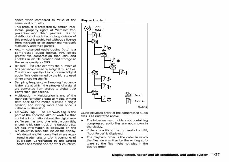
(223,1)
[ Edit: 2020/ 11/ 9 Model: Y62-A ]
space when compared to MP3s at thesame level of quality.This product is protected by certain intel-lectual property rights of Microsoft Cor-poration and third parties. Use ordistribution of such technology outside ofthis product is prohibited without a licensefrom Microsoft or an authorized Microsoftsubsidiary and third parties.
. AAC — Advanced Audio Coding (AAC) is acompressed audio format. AAC offersgreater file compression than MP3 andenables music file creation and storage atthe same quality as MP3.
. Bit rate — Bit rate denotes the number ofbits per second used by a digital music files.The size and quality of a compressed digitalaudio file is determined by the bit rate usedwhen encoding the file.
. Sampling frequency — Sampling frequencyis the rate at which the samples of a signalare converted from analog to digital (A/Dconversion) per second.
. Multisession — Multisession is one of themethods for writing data to media. Writingdata once to the media is called a singlesession, and writing more than once iscalled a multisession.
. ID3/WMA Tag — The ID3/WMA tag is thepart of the encoded MP3 or WMA file thatcontains information about the digital mu-sic file such as song title, artist, album title,encoding bit rate, track time duration, etc.ID3 tag information is displayed on theAlbum/Artist/Track title line on the display.
* Windows® and Windows Media® are regis-tered trademarks and/or trademarks ofMicrosoft Corporation in the UnitedStates of America and/or other countries.
Playback order:GUID-C7E1EF24-5AAB-4301-95BE-26917EEE45EF
SAA2494
Music playback order of the compressed audiofiles is as illustrated above.. The folder names of folders not containing
compressed audio files are not shown inthe display.
. If there is a file in the top level of a USB,“Root Folder” is displayed.
. The playback order is the order in whichthe files were written by the writing soft-ware, so the files might not play in thedesired order.
Display screen, heater and air conditioner, and audio system 4-37
Condition: 'Except for China'/'Except for China/
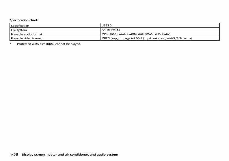
(224,1)
[ Edit: 2020/ 11/ 9 Model: Y62-A ]
4-38 Display screen, heater and air conditioner, and audio system
Specification chart:GUID-C7E1EF24-5AAB-4301-95BE-26917EEE45EF
Specification USB2.0File system FAT16, FAT32Playable audio format MP3 (.mp3), WMA* (.wma), AAC (.m4a), WAV (.wav)Playable video format MPEG (.mpg, .mpeg), MPEG-4 (.mp4, .mkv, avi), WMV7/8/9 (.wmv)
* Protected WMA files (DRM) cannot be played.
Condition: 'Except for China'/'Except for China/
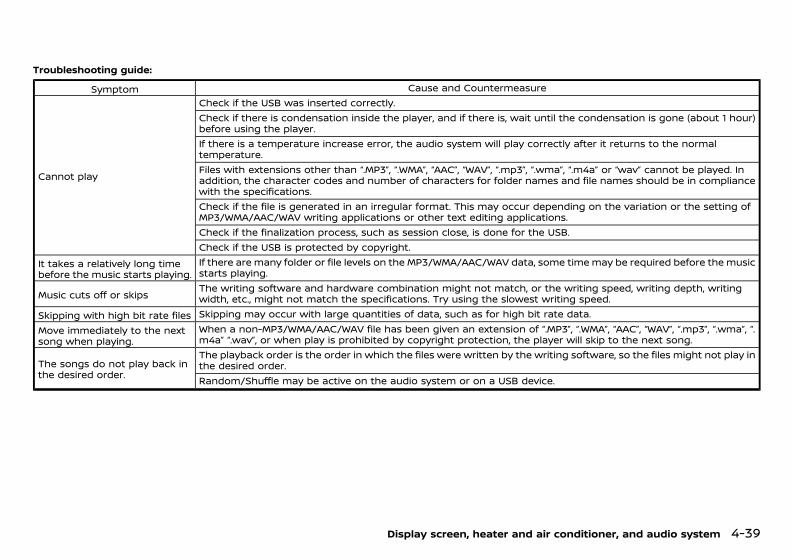
(225,1)
[ Edit: 2020/ 11/ 9 Model: Y62-A ]
Troubleshooting guide:GUID-C7E1EF24-5AAB-4301-95BE-26917EEE45EF
Symptom Cause and Countermeasure
Cannot play
Check if the USB was inserted correctly.Check if there is condensation inside the player, and if there is, wait until the condensation is gone (about 1 hour)before using the player.If there is a temperature increase error, the audio system will play correctly after it returns to the normaltemperature.Files with extensions other than “.MP3”, “.WMA”, “AAC”, “WAV”, “.mp3”, “.wma”, “.m4a” or “wav” cannot be played. Inaddition, the character codes and number of characters for folder names and file names should be in compliancewith the specifications.Check if the file is generated in an irregular format. This may occur depending on the variation or the setting ofMP3/WMA/AAC/WAV writing applications or other text editing applications.Check if the finalization process, such as session close, is done for the USB.Check if the USB is protected by copyright.
It takes a relatively long timebefore the music starts playing.
If there are many folder or file levels on the MP3/WMA/AAC/WAV data, some time may be required before the musicstarts playing.
Music cuts off or skips The writing software and hardware combination might not match, or the writing speed, writing depth, writingwidth, etc., might not match the specifications. Try using the slowest writing speed.
Skipping with high bit rate files Skipping may occur with large quantities of data, such as for high bit rate data.Move immediately to the nextsong when playing.
When a non-MP3/WMA/AAC/WAV file has been given an extension of “.MP3”, “.WMA”, “AAC”, “WAV”, “.mp3”, “.wma”, “.m4a” “.wav”, or when play is prohibited by copyright protection, the player will skip to the next song.
The songs do not play back inthe desired order.
The playback order is the order in which the files were written by the writing software, so the files might not play inthe desired order.Random/Shuffle may be active on the audio system or on a USB device.
Display screen, heater and air conditioner, and audio system 4-39
Condition: 'Except for China'/'Except for China/
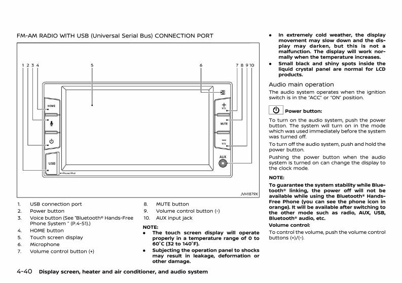
(226,1)
[ Edit: 2020/ 11/ 9 Model: Y62-A ]
4-40 Display screen, heater and air conditioner, and audio system
FM-AM RADIO WITH USB (Universal Serial Bus) CONNECTION PORTGUID-AB0D1E2B-B02F-4277-AD91-8F25F9EFD3A3
JVH1879X
1. USB connection port2. Power button3. Voice button (See “Bluetooth® Hands-Free
Phone System ” (P.4-51).)4. HOME button5. Touch screen display6. Microphone7. Volume control button (+)
8. MUTE button9. Volume control button (-)10. AUX input jack
NOTE:. The touch screen display will operate
properly in a temperature range of 0 to60°C (32 to 140°F).
. Subjecting the operation panel to shocksmay result in leakage, deformation orother damage.
. In extremely cold weather, the displaymovement may slow down and the dis-play may darken, but this is not amalfunction. The display will work nor-mally when the temperature increases.
. Small black and shiny spots inside theliquid crystal panel are normal for LCDproducts.
Audio main operationGUID-1E85B213-2288-4EC0-952A-0280B69B4166The audio system operates when the ignitionswitch is in the “ACC” or “ON” position.
Power button:GUID-C7E1EF24-5AAB-4301-95BE-26917EEE45EF
To turn on the audio system, push the powerbutton. The system will turn on in the modewhich was used immediately before the systemwas turned off.To turn off the audio system, push and hold thepower button.Pushing the power button when the audiosystem is turned on can change the display tothe clock mode.
NOTE:To guarantee the system stability while Blue-tooth® linking, the power off will not beavailable while using the Bluetooth® Hands-Free Phone (you can see the phone icon inorange). It will be available after switching tothe other mode such as radio, AUX, USB,Bluetooth® audio, etc.Volume control:
GUID-C7E1EF24-5AAB-4301-95BE-26917EEE45EF
To control the volume, push the volume controlbuttons (+)/(-).
Condition: 'Except for China'/'Except for China/
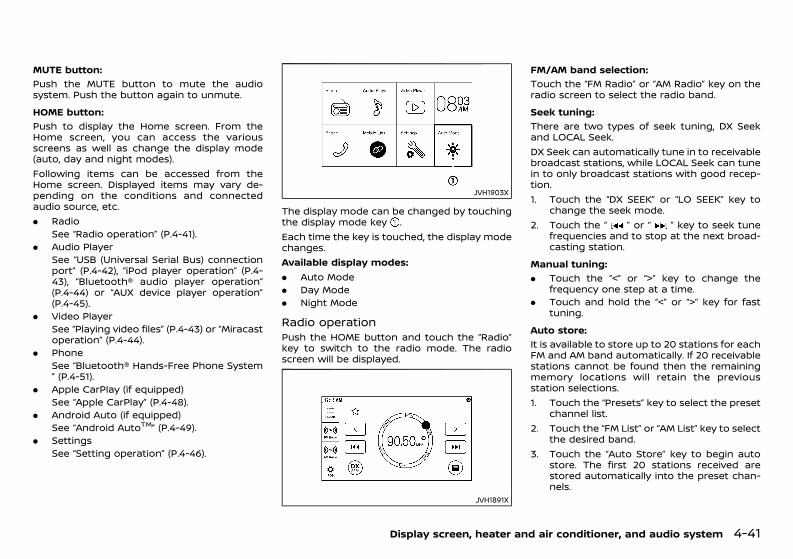
(227,1)
[ Edit: 2020/ 11/ 9 Model: Y62-A ]
MUTE button:GUID-C7E1EF24-5AAB-4301-95BE-26917EEE45EF
Push the MUTE button to mute the audiosystem. Push the button again to unmute.HOME button:
GUID-C7E1EF24-5AAB-4301-95BE-26917EEE45EF
Push to display the Home screen. From theHome screen, you can access the variousscreens as well as change the display mode(auto, day and night modes).Following items can be accessed from theHome screen. Displayed items may vary de-pending on the conditions and connectedaudio source, etc.. Radio
See “Radio operation” (P.4-41).. Audio Player
See “USB (Universal Serial Bus) connectionport” (P.4-42), “iPod player operation” (P.4-43), “Bluetooth® audio player operation”(P.4-44) or “AUX device player operation”(P.4-45).
. Video PlayerSee “Playing video files” (P.4-43) or “Miracastoperation” (P.4-44).
. PhoneSee “Bluetooth® Hands-Free Phone System” (P.4-51).
. Apple CarPlay (if equipped)See “Apple CarPlay” (P.4-48).
. Android Auto (if equipped)See “Android AutoTM” (P.4-49).
. SettingsSee “Setting operation” (P.4-46).
JVH1903X
The display mode can be changed by touchingthe display mode key .Each time the key is touched, the display modechanges.Available display modes:. Auto Mode. Day Mode. Night Mode
Radio operationGUID-C0141D8C-B8D4-4ECC-AD4F-D618E99AA8CEPush the HOME button and touch the “Radio”key to switch to the radio mode. The radioscreen will be displayed.
JVH1891X
FM/AM band selection:GUID-C7E1EF24-5AAB-4301-95BE-26917EEE45EF
Touch the “FM Radio” or “AM Radio” key on theradio screen to select the radio band.Seek tuning:
GUID-C7E1EF24-5AAB-4301-95BE-26917EEE45EF
There are two types of seek tuning, DX Seekand LOCAL Seek.DX Seek can automatically tune in to receivablebroadcast stations, while LOCAL Seek can tunein to only broadcast stations with good recep-tion.1. Touch the “DX SEEK” or “LO SEEK” key to
change the seek mode.2. Touch the “ ” or “ ” key to seek tune
frequencies and to stop at the next broad-casting station.
Manual tuning:GUID-C7E1EF24-5AAB-4301-95BE-26917EEE45EF
. Touch the “<” or “>” key to change thefrequency one step at a time.
. Touch and hold the “<” or “>” key for fasttuning.
Auto store:GUID-C7E1EF24-5AAB-4301-95BE-26917EEE45EF
It is available to store up to 20 stations for eachFM and AM band automatically. If 20 receivablestations cannot be found then the remainingmemory locations will retain the previousstation selections.1. Touch the “Presets” key to select the preset
channel list.2. Touch the “FM List” or “AM List” key to select
the desired band.3. Touch the “Auto Store” key to begin auto
store. The first 20 stations received arestored automatically into the preset chan-nels.
Display screen, heater and air conditioner, and audio system 4-41
Condition: 'Except for China'/'Except for China/
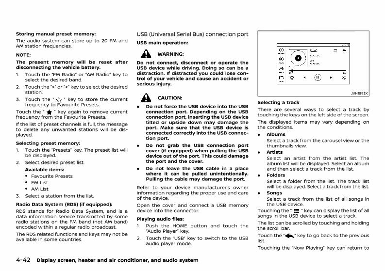
(228,1)
[ Edit: 2020/ 11/ 9 Model: Y62-A ]
4-42 Display screen, heater and air conditioner, and audio system
Storing manual preset memory:GUID-C7E1EF24-5AAB-4301-95BE-26917EEE45EF
The audio system can store up to 20 FM andAM station frequencies.
NOTE:The present memory will be reset afterdisconnecting the vehicle battery.1. Touch the “FM Radio” or “AM Radio” key to
select the desired band.2. Touch the “<” or “>” key to select the desired
station.3. Touch the “ ” key to store the current
frequency to Favourite Presets.Touch the “ ” key again to remove currentfrequency from the Favourite Presets.If the list of preset channels is full, the messageto delete any unwanted stations will be dis-played.Selecting preset memory:
GUID-C7E1EF24-5AAB-4301-95BE-26917EEE45EF
1. Touch the “Presets” key. The preset list willbe displayed.
2. Select desired preset list.Available items:. Favourite Presets. FM List. AM List
3. Select a station from the list.Radio Data System (RDS) (if equipped):
GUID-C7E1EF24-5AAB-4301-95BE-26917EEE45EF
RDS stands for Radio Data System, and is adata information service transmitted by someradio stations on the FM band (not AM band)encoded within a regular radio broadcast.The RDS related functions and keys may not beavailable in some countries.
USB (Universal Serial Bus) connection portGUID-E0EF8479-49C3-48D3-B75C-1361190DEA1D
USB main operation:GUID-C7E1EF24-5AAB-4301-95BE-26917EEE45EF
WARNING:Do not connect, disconnect or operate theUSB device while driving. Doing so can be adistraction. If distracted you could lose con-trol of your vehicle and cause an accident orserious injury.
CAUTION:. Do not force the USB device into the USB
connection port. Depending on the USBconnection port, inserting the USB devicetilted or upside down may damage theport. Make sure that the USB device isconnected correctly into the USB connec-tion port.
. Do not grab the USB connection portcover (if equipped) when pulling the USBdevice out of the port. This could damagethe port and the cover.
. Do not leave the USB cable in a placewhere it can be pulled unintentionally.Pulling the cable may damage the port.
Refer to your device manufacturer’s ownerinformation regarding the proper use and careof the device.Open the cover and connect a USB memorydevice into the connector.Playing audio files:
GUID-C7E1EF24-5AAB-4301-95BE-26917EEE45EF
1. Push the HOME button and touch the“Audio Player” key.
2. Touch the “USB” key to switch to the USBaudio player mode.
JVH1893X
Selecting a trackThere are several ways to select a track bytouching the keys on the left side of the screen.The displayed items may vary depending onthe conditions.. Albums
Select a track from the carousel view or thethumbnails view.
. ArtistsSelect an artist from the artist list. Thealbum list will be displayed. Select an albumand then select a track from the list.
. FoldersSelect a folder from the list. The track listwill be displayed. Select a track from the list.
. SongsSelect a track from the list of all songs inthe USB device.
Touching the “ ” key can display the list of allsongs in the USB device to select a track.The list can be scrolled by touching and holdingthe scroll bar.Touch the “ ” key to go back to the previouslist.Touching the “Now Playing” key can return to
Condition: 'Except for China'/'Except for China/
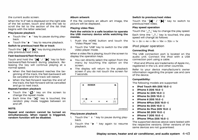
(229,1)
[ Edit: 2020/ 11/ 9 Model: Y62-A ]
the current audio screen.When the “A-Z” tab is displayed on the right sideof the list screen, touch and slide the tab toscroll the list to the section of the list thatbegins with the letter selected.Play/pause playback. Touch the “ ” key to pause during play-
back.. Touch the “ ” key to resume playback.Switch to previous/next file or trackTouch the “ ” / “ ” key during playback toplay previous/next track.Fast-backward/fast-forwardTouch and hold the “ ” / “ ” key to fast-backward/fast-forward during playback. Re-leasing the key will continue playing at anormal speed.. When the fast-backward reaches the be-
ginning of the track, the fast-backward willbe cancelled and the track will restart.
. When the fast-forward reaches the end ofthe track, the fast-forward will be cancelledand go to next track.
Repeat/random playback. Touch the “ ” key on the screen to
change the repeat mode.. Each time the “ ” key is touched, the
random play mode toggles between onand off.
NOTE:Repeat and random cannot be turned onsimultaneously. When repeat is triggered,random function will be disabled.
Album artworkIf the file contains an album art image, thepicture will be displayed.Playing video files:
GUID-C7E1EF24-5AAB-4301-95BE-26917EEE45EF
Park the vehicle in a safe location to operatethe USB memory device while watching themovies.1. Push the HOME button and touch the
“Video Player” key.2. Touch the “USB” key to switch to the USB
video player mode.When a video file is playing, touch the screen todisplay the operation keys.. You can directly select the option from the
menu by touching the option on thescreen.
. The display will return to the playbackscreen if you do not touch the screen for7 seconds.
JVH1892X
Play/pause playback1. Touch the “ ” key to pause during play-
back.2. Touch the “ ” key again to resume
playback.
Switch to previous/next videoTouch the “ ” / “ ” key to switch toprevious/next video.Play speed operationTouch the “ ” key to change the play speed.Each time the “ ” key is touched, the playspeed will change as follows:1x � 2x � 4x � 8x � 16x � 32x � 1x
iPod player operationGUID-44553B3F-7E9B-49AE-B6C8-D4C65A0BEF6B
Connecting iPod:GUID-C7E1EF24-5AAB-4301-95BE-26917EEE45EF
The USB connection port is located on theaudio unit. Connect the iPod with a USBconnection port using a cable.* iPod and iPhone are trademarks of Apple Inc.,registered in the U.S. and other countries.Refer to your device manufacturer’s ownerinformation regarding the proper use and careof the device.Compatibility:
GUID-C7E1EF24-5AAB-4301-95BE-26917EEE45EF
The following models are supported:. iPod Touch 6th (iOS 10.0 -). iPhone 5 (iOS 10.0 -). iPhone 5c (iOS 10.0 -). iPhone 5s (iOS 10.0 -). iPhone 6 (iOS 10.0 -). iPhone 6Plus (iOS 10.0 -). iPhone 6s (iOS 10.0 -). iPhone 6s Plus (iOS 10.0 -). iPhone SE (iOS 10.0 -). iPhone 7 (iOS 10.0 -). iPhone 7Plus (iOS 10.0 -)The supported devices above were tested withthe respective versions. Other versions of thesame devices are not guaranteed.
Display screen, heater and air conditioner, and audio system 4-43
Condition: 'Except for China'/'Except for China/
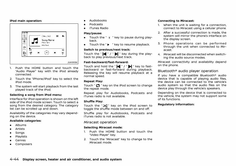
(230,1)
[ Edit: 2020/ 11/ 9 Model: Y62-A ]
4-44 Display screen, heater and air conditioner, and audio system
iPod main operation:GUID-C7E1EF24-5AAB-4301-95BE-26917EEE45EF
JVH1919X
1. Push the HOME button and touch the“Audio Player” key with the iPod alreadyconnected.
2. Touch the “iPhone/iPod” key to select theiPod mode.
3. The system will start playback from the lastplayed track of the iPod.
Selecting a song from iPod menu:GUID-C7E1EF24-5AAB-4301-95BE-26917EEE45EF
Interface for iPod operation is shown on the leftside of the iPod mode screen. Touch to select asong from the desired category. The categorylist can be scrolled up and down.Availability of the categories may vary depend-ing on the device.Available categories:. Albums. Artists. Songs. Playlists. Genres. Composers
. Audiobooks
. Podcasts
. iTunes RadioPlay/pause:
GUID-C7E1EF24-5AAB-4301-95BE-26917EEE45EF
. Touch the “ ” key to pause during play-back.
. Touch the “ ” key to resume playback.Switch to previous/next track:
GUID-C7E1EF24-5AAB-4301-95BE-26917EEE45EF
Touch the “ ” / “ ” key during the play-back to play previous/next track.Fast-backward/fast-forward:
GUID-C7E1EF24-5AAB-4301-95BE-26917EEE45EF
Touch and hold the “ ” / “ ” key to fast-backward or fast-forward during playback.Releasing the key will resume playback at anormal speed.Repeat Play:
GUID-C7E1EF24-5AAB-4301-95BE-26917EEE45EF
Touch “ ” key on the iPod screen to changethe repeat mode.Repeat play for Audiobooks, Podcasts andiTunes radio is not available.Shuffle Play:
GUID-C7E1EF24-5AAB-4301-95BE-26917EEE45EF
Touch the “ ” key on the iPod screen totoggle the shuffle mode between on and off.Shuffle play for Audiobooks, Podcasts andiTunes radio is not available.
Miracast operationGUID-1C0DB664-7616-43C8-9760-24B65873EFB0
Selecting Miracast mode:GUID-C7E1EF24-5AAB-4301-95BE-26917EEE45EF
1. Push the HOME button and touch the“Video Player” key.
2. Touch the “Miracast” key to change to theMiracast mode.
Connecting to Miracast:GUID-C7E1EF24-5AAB-4301-95BE-26917EEE45EF
1. When the unit is waiting for a connection,connect to Miracast using a cellular phone.
2. After a successful connection is made, thesystem will mirror the phone’s interface onthe display screen.
3. Phone operations can be performedthrough the unit when connected to Mir-acast.
4. Miracast will be disconnected when switch-ing the audio source modes.
Miracast connectivity and availability dependon the phone.
Bluetooth® audio player operationGUID-E1BBFCC8-B8A1-4C94-9BFE-DF31E30A16DAIf you have a compatible Bluetooth® audiodevice that is capable of playing audio files,the device can be connected to the vehicle’saudio system so that the audio files on thedevice play through the vehicle’s speakers.Depending on the device that is connected tothe vehicle, the system may not support someof its functions.Regulatory information:
GUID-C7E1EF24-5AAB-4301-95BE-26917EEE45EF
Condition: 'Except for China'/'Except for China/
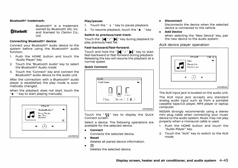
(231,1)
[ Edit: 2020/ 11/ 9 Model: Y62-A ]
Bluetooth® trademark:Bluetooth® is a trademarkowned by Bluetooth SIG, Inc.and licensed to Clarion Co.,Ltd.
Connecting Bluetooth® device:GUID-C7E1EF24-5AAB-4301-95BE-26917EEE45EF
Connect your Bluetooth® audio device to thesystem before using the Bluetooth® audiofunction.1. Push the HOME button and touch the
“Audio Player” key.2. Touch the “Bluetooth Audio” key to select
the Bluetooth® Audio mode.3. Touch the “Connect” key and connect the
Bluetooth® audio device to the audio unit.After the connection with a Bluetooth® audioplayer is established, the play mode is auto-matically changed.When the playback does not start, touch the“ ” key to start playing manually.
JVH1901X
Play/pause:GUID-C7E1EF24-5AAB-4301-95BE-26917EEE45EF
1. Touch the “ ” key to pause playback.2. To resume playback, touch the “ ” key.Switch to previous/next track:
GUID-C7E1EF24-5AAB-4301-95BE-26917EEE45EF
Touch the “ ” / “ ” key during playback toplay previous/next file.Fast-backward/fast-forward:
GUID-C7E1EF24-5AAB-4301-95BE-26917EEE45EF
Touch and hold the “ ” / “ ” key to startfast-backward or fast-forward during playback.Releasing the key will resume the playback at anormal speed.Quick Connect:
GUID-C7E1EF24-5AAB-4301-95BE-26917EEE45EF
JVH1902X
Touch the “ ” key to display the QuickConnect screen.Select a device. The following operations areavailable for the selected device.. Connect
Connects the selected device.. Reset
Deletes all paired device information..
Deletes the selected device.
. DisconnectDisconnects the device when the selecteddevice is connected to the vehicle.
. Add DeviceWhen selecting the “New Device” key, pairthe new device to the audio system.
AUX device player operationGUID-E2F3C7D8-9A31-4393-B098-280BCA4750FE
JVH1894X
The AUX input jack is located on the audio unit.The AUX input jack accepts any standardanalog audio input such as from a portablecassette tape/CD player, MP3 player or laptopcomputer.NISSAN strongly recommends using a stereomini plug cable when connecting your musicdevice to the audio system. Music may not playproperly when a monaural cable is used.1. Push the HOME button and touch the
"Audio Player" key.2. Touch the "AUX" key to switch to the AUX
mode.
Display screen, heater and air conditioner, and audio system 4-45
Condition: 'Except for China'/'Except for China/
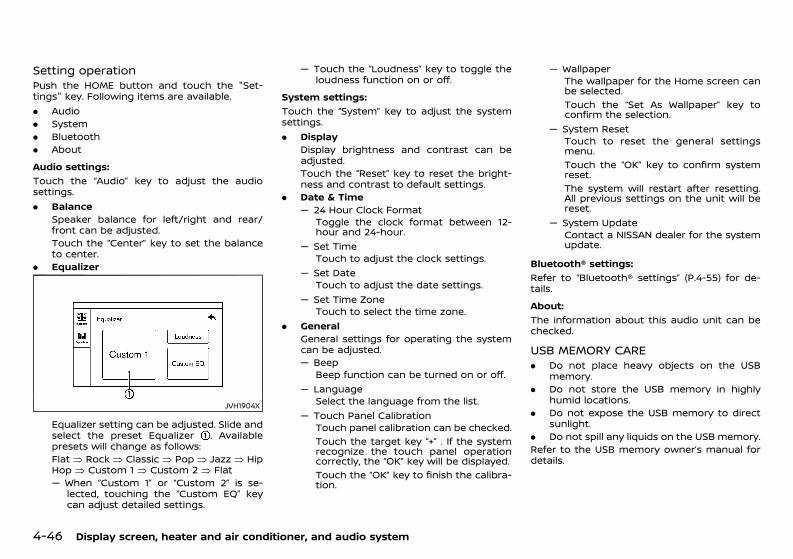
(232,1)
[ Edit: 2020/ 11/ 9 Model: Y62-A ]
4-46 Display screen, heater and air conditioner, and audio system
Setting operationGUID-8DC62B4C-659A-48E8-8C48-2E66177B7BD4Push the HOME button and touch the "Set-tings" key. Following items are available.. Audio. System. Bluetooth. AboutAudio settings:
GUID-C7E1EF24-5AAB-4301-95BE-26917EEE45EF
Touch the “Audio” key to adjust the audiosettings.. Balance
Speaker balance for left/right and rear/front can be adjusted.Touch the “Center” key to set the balanceto center.
. Equalizer
JVH1904X
Equalizer setting can be adjusted. Slide andselect the preset Equalizer . Availablepresets will change as follows:Flat � Rock � Classic � Pop � Jazz � HipHop � Custom 1 � Custom 2 � Flat— When “Custom 1” or “Custom 2” is se-
lected, touching the “Custom EQ” keycan adjust detailed settings.
— Touch the “Loudness” key to toggle theloudness function on or off.
System settings:GUID-C7E1EF24-5AAB-4301-95BE-26917EEE45EF
Touch the “System” key to adjust the systemsettings.. Display
Display brightness and contrast can beadjusted.Touch the “Reset” key to reset the bright-ness and contrast to default settings.
. Date & Time— 24 Hour Clock Format
Toggle the clock format between 12-hour and 24-hour.
— Set TimeTouch to adjust the clock settings.
— Set DateTouch to adjust the date settings.
— Set Time ZoneTouch to select the time zone.
. GeneralGeneral settings for operating the systemcan be adjusted.— Beep
Beep function can be turned on or off.— Language
Select the language from the list.— Touch Panel Calibration
Touch panel calibration can be checked.Touch the target key “+” . If the systemrecognize the touch panel operationcorrectly, the “OK” key will be displayed.Touch the “OK” key to finish the calibra-tion.
— WallpaperThe wallpaper for the Home screen canbe selected.Touch the “Set As Wallpaper” key toconfirm the selection.
— System ResetTouch to reset the general settingsmenu.Touch the “OK” key to confirm systemreset.The system will restart after resetting.All previous settings on the unit will bereset.
— System UpdateContact a NISSAN dealer for the systemupdate.
Bluetooth® settings:GUID-C7E1EF24-5AAB-4301-95BE-26917EEE45EF
Refer to “Bluetooth® settings” (P.4-55) for de-tails.About:
GUID-C7E1EF24-5AAB-4301-95BE-26917EEE45EF
The information about this audio unit can bechecked.
USB MEMORY CAREGUID-F386FC2F-5971-414B-AB0E-53F33CDC4C3E. Do not place heavy objects on the USB
memory.. Do not store the USB memory in highly
humid locations.. Do not expose the USB memory to direct
sunlight.. Do not spill any liquids on the USB memory.Refer to the USB memory owner’s manual fordetails.
Condition: 'Except for China'/'Except for China/
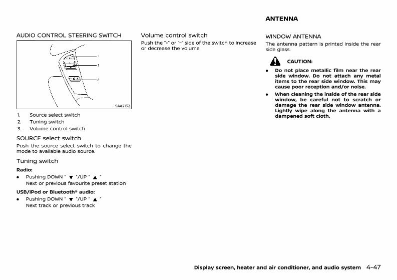
(233,1)
[ Edit: 2020/ 11/ 9 Model: Y62-A ]
AUDIO CONTROL STEERING SWITCHGUID-984AAEFE-935C-4272-A89D-0411CCBD5D2C
SAA2132
1. Source select switch2. Tuning switch3. Volume control switch
SOURCE select switchGUID-F0DD76D0-A40B-4DFE-AA68-56DA39707814Push the source select switch to change themode to available audio source.
Tuning switchGUID-4BDA154C-546B-4E8E-8031-4ED9033EDE86
Radio:GUID-C7E1EF24-5AAB-4301-95BE-26917EEE45EF
. Pushing DOWN “ ”/UP “ ”Next or previous favourite preset station
USB/iPod or Bluetooth® audio:GUID-C7E1EF24-5AAB-4301-95BE-26917EEE45EF
. Pushing DOWN “ ”/UP “ ”Next track or previous track
Volume control switchGUID-B522C2A2-2939-4636-88A9-338DA44D5FD6Push the “+” or “−” side of the switch to increaseor decrease the volume.
GUID-B07FDDFC-EA47-40CE-ADCF-49FC05B0A3F2
WINDOW ANTENNAGUID-7AC919D9-928C-4C86-8B27-D7A5DF6A9E67The antenna pattern is printed inside the rearside glass.
CAUTION:. Do not place metallic film near the rear
side window. Do not attach any metalitems to the rear side window. This maycause poor reception and/or noise.
. When cleaning the inside of the rear sidewindow, be careful not to scratch ordamage the rear side window antenna.Lightly wipe along the antenna with adampened soft cloth.
Display screen, heater and air conditioner, and audio system 4-47
ANTENNA
Condition: 'Except for China'/'Except for China/
(234,1)
[ Edit: 2020/ 11/ 9 Model: Y62-A ]
4-48 Display screen, heater and air conditioner, and audio system
GUID-C9F42D99-55CE-484B-9D3B-BFB47CF60B48When installing a CB, ham radio or a car phonein your vehicle, be sure to observe the followingcautions, otherwise the new equipment mayadversely affect the Engine Control System andother electronic parts.
CAUTION:. Keep the antenna as far away as possible
from the Electronic Control Module.. Keep the antenna wire at least 20 cm (8
in) away from the Engine Control har-nesses. Do not route the antenna wirenext to any harnesses.
. Adjust the antenna standing wave ratioas recommended by the manufacturer.
. Connect the ground wire from the radiochassis to the body.
. For details, consult a NISSAN dealer.
GUID-644A87C7-2443-45FD-9468-4EB16B86308FFor models with NissanConnect System orNissanConnect with Navigation (if equipped)and Apps, see the separate NissanConnectOwner’s Manual.
Apple CarPlay (if equipped)GUID-9352A19C-5964-4D1F-A84F-04F428391C0D
WARNING:. Stop your vehicle in a safe location and
apply the parking brake before connect-ing your iPhone to the vehicle or operat-ing your connected iPhone for setup.
. If you are unable to devote full attentionto vehicle operation while using AppleCarPlay, pull off the road to a safelocation and stop your vehicle.
You can use Apple CarPlay by connecting acompatible iPhone to your vehicle via a USBcable (see “FM-AM radio with USB (UniversalSerial Bus) connection port” (P.4-40) for thelocation of the USB connection port).To connect your iPhone with the in-vehiclesystem, it is recommended to use the AppleLightning cable (Mfi certified) that was providedwith your iPhone.With Apple CarPlay, your in-vehicle system canbe used as a display and a controller for someof the iPhone functions. Apple CarPlay featuresSiri which enables operations via voice controls.Visit Apple.com for information about thefunctions that are available and details aboutApple’s privacy policy.Certain vehicle information (e.g. location andspeed) may be shared with your device whileApple CarPlay is in use. Carrier charges mayapply to use Apple CarPlay.Refer to the Apple website for more informa-tion.
NOTE:. In some countries, iPhone in the market
may not be supported by Apple CarPlay.. For best results, always update your
device to the latest software version.. Apple CarPlay will take the place of your
Bluetooth® audio and Bluetooth® hands-free phone functionality.
Apple CarPlay operationGUID-8F336ECD-58A8-4E55-A1EF-19E4A5278038
Initializing Apple CarPlay:GUID-C7E1EF24-5AAB-4301-95BE-26917EEE45EF
. When a new iPhone is connected to theUSB connection port via a Lightning cable,Apple CarPlay will start immediately andthe Apple CarPlay screen will be displayedautomatically.
. When a connected iPhone is not recog-nized by the system, the system does notswitch to Apple CarPlay.
Switching to Apple CarPlay screen:GUID-C7E1EF24-5AAB-4301-95BE-26917EEE45EF
There are various ways to switch to the AppleCarPlay screen.. Push the HOME button and touch the
“Apple CarPlay” key to go to the AppleCarPlay screen.
. Push the HOME button and touch the“Phone” key to go to the Apple CarPlaytelephony screen.
. Push the HOME button and touch the"Audio Player" key, and then touch the“Apple CarPlay” key to go to the AppleCarPlay now playing screen.
Siri operation:GUID-C7E1EF24-5AAB-4301-95BE-26917EEE45EF
With Siri, some of the functions in your iPhonecan be voice controlled.Make sure that Siri on your iPhone is turned on.
CAR PHONE AND CB RADIO MOBILE LINK (if equipped)
Condition: 'Except for China'/'Except for China/
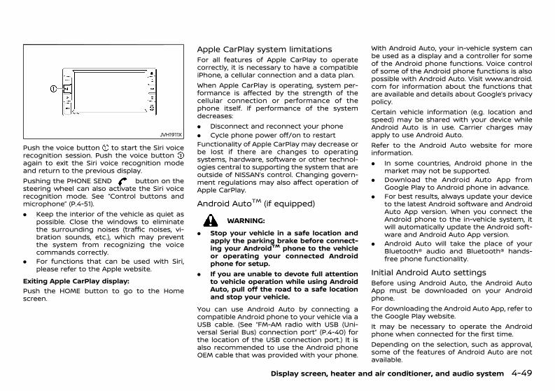
(235,1)
[ Edit: 2020/ 11/ 9 Model: Y62-A ]
JVH1911X
Push the voice button to start the Siri voicerecognition session. Push the voice buttonagain to exit the Siri voice recognition modeand return to the previous display.Pushing the PHONE SEND button on thesteering wheel can also activate the Siri voicerecognition mode. See “Control buttons andmicrophone” (P.4-51).. Keep the interior of the vehicle as quiet as
possible. Close the windows to eliminatethe surrounding noises (traffic noises, vi-bration sounds, etc.), which may preventthe system from recognizing the voicecommands correctly.
. For functions that can be used with Siri,please refer to the Apple website.
Exiting Apple CarPlay display:GUID-C7E1EF24-5AAB-4301-95BE-26917EEE45EF
Push the HOME button to go to the Homescreen.
Apple CarPlay system limitationsGUID-A1B244A3-FBC7-498B-A036-02BB3FF5AD8CFor all features of Apple CarPlay to operatecorrectly, it is necessary to have a compatibleiPhone, a cellular connection and a data plan.When Apple CarPlay is operating, system per-formance is affected by the strength of thecellular connection or performance of thephone itself. If performance of the systemdecreases:. Disconnect and reconnect your phone. Cycle phone power off/on to restartFunctionality of Apple CarPlay may decrease orbe lost if there are changes to operatingsystems, hardware, software or other technol-ogies central to supporting the system that areoutside of NISSAN’s control. Changing govern-ment regulations may also affect operation ofApple CarPlay.
Android AutoTM (if equipped)GUID-7920B7C5-7715-44BB-B5B2-EA597B237CA7
WARNING:. Stop your vehicle in a safe location and
apply the parking brake before connect-ing your AndroidTM phone to the vehicleor operating your connected Androidphone for setup.
. If you are unable to devote full attentionto vehicle operation while using AndroidAuto, pull off the road to a safe locationand stop your vehicle.
You can use Android Auto by connecting acompatible Android phone to your vehicle via aUSB cable. (See “FM-AM radio with USB (Uni-versal Serial Bus) connection port” (P.4-40) forthe location of the USB connection port.) It isalso recommended to use the Android phoneOEM cable that was provided with your phone.
With Android Auto, your in-vehicle system canbe used as a display and a controller for someof the Android phone functions. Voice controlof some of the Android phone functions is alsopossible with Android Auto. Visit www.android.com for information about the functions thatare available and details about Google’s privacypolicy.Certain vehicle information (e.g. location andspeed) may be shared with your device whileAndroid Auto is in use. Carrier charges mayapply to use Android Auto.Refer to the Android Auto website for moreinformation.. In some countries, Android phone in the
market may not be supported.. Download the Android Auto App from
Google Play to Android phone in advance.. For best results, always update your device
to the latest Android software and AndroidAuto App version. When you connect theAndroid phone to the in-vehicle system, itwill automatically update the Android soft-ware and Android Auto App version.
. Android Auto will take the place of yourBluetooth® audio and Bluetooth® hands-free phone functionality.
Initial Android Auto settingsGUID-63EFC7CE-B4EE-4349-B8A8-801E2A6DBB56Before using Android Auto, the Android AutoApp must be downloaded on your Androidphone.For downloading the Android Auto App, refer tothe Google Play website.It may be necessary to operate the Androidphone when connected for the first time.Depending on the selection, such as approval,some of the features of Android Auto are notavailable.
Display screen, heater and air conditioner, and audio system 4-49
Condition: 'Except for China'/'Except for China/
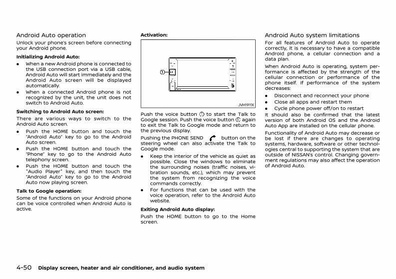
(236,1)
[ Edit: 2020/ 11/ 9 Model: Y62-A ]
4-50 Display screen, heater and air conditioner, and audio system
Android Auto operationGUID-73C94A26-096E-473E-B689-B70B3E6FCBACUnlock your phone’s screen before connectingyour Android phone.Initializing Android Auto:
GUID-C7E1EF24-5AAB-4301-95BE-26917EEE45EF
. When a new Android phone is connected tothe USB connection port via a USB cable,Android Auto will start immediately and theAndroid Auto screen will be displayedautomatically.
. When a connected Android phone is notrecognized by the unit, the unit does notswitch to Android Auto.
Switching to Android Auto screen:GUID-C7E1EF24-5AAB-4301-95BE-26917EEE45EF
There are various ways to switch to theAndroid Auto screen.. Push the HOME button and touch the
“Android Auto” key to go to the AndroidAuto screen.
. Push the HOME button and touch the“Phone” key to go to the Android Autotelephony screen.
. Push the HOME button and touch the"Audio Player" key, and then touch the“Android Auto” key to go to the AndroidAuto now playing screen.
Talk to Google operation:GUID-C7E1EF24-5AAB-4301-95BE-26917EEE45EF
Some of the functions on your Android phonecan be voice controlled when Android Auto isactive.
Activation:GUID-C7E1EF24-5AAB-4301-95BE-26917EEE45EF
JVH1911X
Push the voice button to start the Talk toGoogle session. Push the voice button againto exit the Talk to Google mode and return tothe previous display.Pushing the PHONE SEND button on thesteering wheel can also activate the Talk toGoogle mode.. Keep the interior of the vehicle as quiet as
possible. Close the windows to eliminatethe surrounding noises (traffic noises, vi-bration sounds, etc.), which may preventthe system from recognizing the voicecommands correctly.
. For functions that can be used with thevoice operation, refer to the Android Autowebsite.
Exiting Android Auto display:GUID-C7E1EF24-5AAB-4301-95BE-26917EEE45EF
Push the HOME button to go to the Homescreen.
Android Auto system limitationsGUID-DA422BC3-B4B1-4884-AA44-0BAC4A1BFD6AFor all features of Android Auto to operatecorrectly, it is necessary to have a compatibleAndroid phone, a cellular connection and adata plan.When Android Auto is operating, system per-formance is affected by the strength of thecellular connection or performance of thephone itself. If performance of the systemdecreases:. Disconnect and reconnect your phone. Close all apps and restart them. Cycle phone power off/on to restartIt should also be confirmed that the latestversion of both Android OS and the AndroidAuto App are installed on the cellular phone.Functionality of Android Auto may decrease orbe lost if there are changes to operatingsystems, hardware, software or other technol-ogies central to supporting the system that areoutside of NISSAN’s control. Changing govern-ment regulations may also affect the operationof Android Auto.
Condition: 'Except for China'/'Except for China/
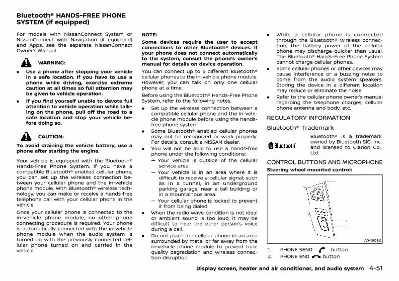
(237,1)
[ Edit: 2020/ 11/ 9 Model: Y62-A ]
GUID-EBD9E07A-BF75-4A7E-84CD-3D25DE5A67CAFor models with NissanConnect System orNissanConnect with Navigation (if equipped)and Apps, see the separate NissanConnectOwner’s Manual.
WARNING:. Use a phone after stopping your vehicle
in a safe location. If you have to use aphone while driving, exercise extremecaution at all times so full attention maybe given to vehicle operation.
. If you find yourself unable to devote fullattention to vehicle operation while talk-ing on the phone, pull off the road to asafe location and stop your vehicle be-fore doing so.
CAUTION:To avoid draining the vehicle battery, use aphone after starting the engine.
Your vehicle is equipped with the Bluetooth®Hands-Free Phone System. If you have acompatible Bluetooth® enabled cellular phone,you can set up the wireless connection be-tween your cellular phone and the in-vehiclephone module. With Bluetooth® wireless tech-nology, you can make or receive a hands-freetelephone call with your cellular phone in thevehicle.Once your cellular phone is connected to thein-vehicle phone module, no other phoneconnecting procedure is required. Your phoneis automatically connected with the in-vehiclephone module when the audio system isturned on with the previously connected cel-lular phone turned on and carried in thevehicle.
NOTE:Some devices require the user to acceptconnections to other Bluetooth® devices. Ifyour phone does not connect automaticallyto the system, consult the phone’s owner’smanual for details on device operation.You can connect up to 5 different Bluetooth®cellular phones to the in-vehicle phone module.However, you can talk on only one cellularphone at a time.Before using the Bluetooth® Hands-Free PhoneSystem, refer to the following notes.. Set up the wireless connection between a
compatible cellular phone and the in-vehi-cle phone module before using the hands-free phone system.
. Some Bluetooth® enabled cellular phonesmay not be recognized or work properly.For details, consult a NISSAN dealer.
. You will not be able to use a hands-freephone under the following conditions:— Your vehicle is outside of the cellular
service area.— Your vehicle is in an area where it is
difficult to receive a cellular signal; suchas in a tunnel, in an undergroundparking garage, near a tall building orin a mountainous area.
— Your cellular phone is locked to preventit from being dialed.
. When the radio wave condition is not idealor ambient sound is too loud, it may bedifficult to hear the other person’s voiceduring a call.
. Do not place the cellular phone in an areasurrounded by metal or far away from thein-vehicle phone module to prevent tonequality degradation and wireless connec-tion disruption.
. While a cellular phone is connectedthrough the Bluetooth® wireless connec-tion, the battery power of the cellularphone may discharge quicker than usual.The Bluetooth® Hands-Free Phone Systemcannot charge cellular phones.
. Some cellular phones or other devices maycause interference or a buzzing noise tocome from the audio system speakers.Storing the device in a different locationmay reduce or eliminate the noise.
. Refer to the cellular phone owner’s manualregarding the telephone charges, cellularphone antenna and body, etc.
REGULATORY INFORMATIONGUID-6C23BB4C-C105-47E8-B9AC-750A62A2F429
Bluetooth® TrademarkGUID-98445435-9C30-4853-A60E-A898A867D4A8
Bluetooth® is a trademarkowned by Bluetooth SIG, Inc.and licensed to Clarion Co.,Ltd.
CONTROL BUTTONS AND MICROPHONEGUID-B226C496-03F2-4AEC-89BA-CEAF533D45CASteering wheel mounted control:
JVH1905X
1. PHONE SEND button2. PHONE END button
Display screen, heater and air conditioner, and audio system 4-51
Bluetooth® HANDS-FREE PHONESYSTEM (if equipped)
Condition: 'Except for China'/'Except for China/
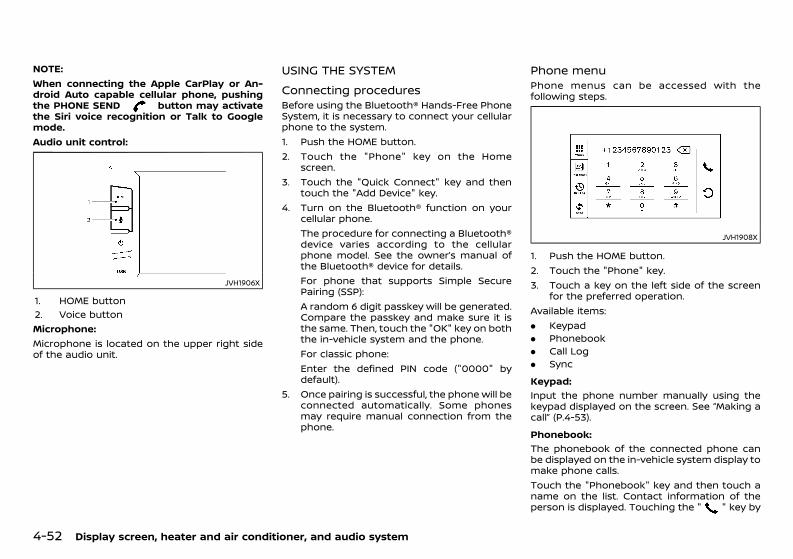
(238,1)
[ Edit: 2020/ 11/ 9 Model: Y62-A ]
4-52 Display screen, heater and air conditioner, and audio system
NOTE:When connecting the Apple CarPlay or An-droid Auto capable cellular phone, pushingthe PHONE SEND button may activatethe Siri voice recognition or Talk to Googlemode.Audio unit control:
JVH1906X
1. HOME button2. Voice buttonMicrophone:Microphone is located on the upper right sideof the audio unit.
USING THE SYSTEMGUID-31C91351-99C0-46F7-959F-572B878469D8
Connecting proceduresGUID-8598CA3C-95D3-48BF-A13B-22294C939FC0Before using the Bluetooth® Hands-Free PhoneSystem, it is necessary to connect your cellularphone to the system.1. Push the HOME button.2. Touch the "Phone" key on the Home
screen.3. Touch the "Quick Connect" key and then
touch the "Add Device" key.4. Turn on the Bluetooth® function on your
cellular phone.The procedure for connecting a Bluetooth®device varies according to the cellularphone model. See the owner’s manual ofthe Bluetooth® device for details.For phone that supports Simple SecurePairing (SSP):A random 6 digit passkey will be generated.Compare the passkey and make sure it isthe same. Then, touch the "OK" key on boththe in-vehicle system and the phone.For classic phone:Enter the defined PIN code ("0000" bydefault).
5. Once pairing is successful, the phone will beconnected automatically. Some phonesmay require manual connection from thephone.
Phone menuGUID-7FE32CF8-CB33-42E7-A5A2-D18ECD4FCC79Phone menus can be accessed with thefollowing steps.
JVH1908X
1. Push the HOME button.2. Touch the "Phone" key.3. Touch a key on the left side of the screen
for the preferred operation.Available items:. Keypad. Phonebook. Call Log. SyncKeypad:
GUID-C7E1EF24-5AAB-4301-95BE-26917EEE45EF
Input the phone number manually using thekeypad displayed on the screen. See “Making acall” (P.4-53).Phonebook:
GUID-C7E1EF24-5AAB-4301-95BE-26917EEE45EF
The phonebook of the connected phone canbe displayed on the in-vehicle system display tomake phone calls.Touch the "Phonebook" key and then touch aname on the list. Contact information of theperson is displayed. Touching the " " key by
Condition: 'Except for China'/'Except for China/
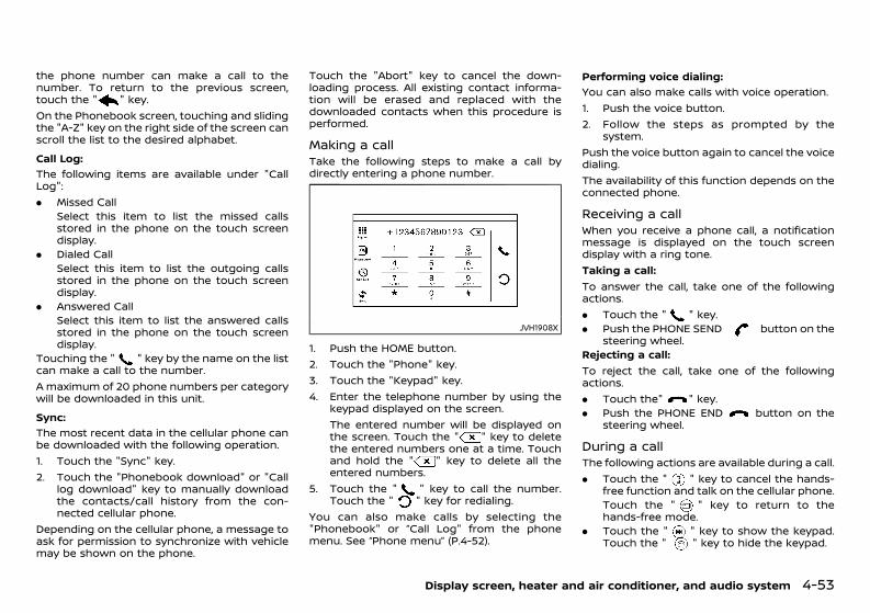
(239,1)
[ Edit: 2020/ 11/ 9 Model: Y62-A ]
the phone number can make a call to thenumber. To return to the previous screen,touch the " " key.On the Phonebook screen, touching and slidingthe "A-Z" key on the right side of the screen canscroll the list to the desired alphabet.Call Log:
GUID-C7E1EF24-5AAB-4301-95BE-26917EEE45EF
The following items are available under "CallLog":. Missed Call
Select this item to list the missed callsstored in the phone on the touch screendisplay.
. Dialed CallSelect this item to list the outgoing callsstored in the phone on the touch screendisplay.
. Answered CallSelect this item to list the answered callsstored in the phone on the touch screendisplay.
Touching the " " key by the name on the listcan make a call to the number.A maximum of 20 phone numbers per categorywill be downloaded in this unit.Sync:
GUID-C7E1EF24-5AAB-4301-95BE-26917EEE45EF
The most recent data in the cellular phone canbe downloaded with the following operation.1. Touch the "Sync" key.2. Touch the "Phonebook download" or "Call
log download" key to manually downloadthe contacts/call history from the con-nected cellular phone.
Depending on the cellular phone, a message toask for permission to synchronize with vehiclemay be shown on the phone.
Touch the "Abort" key to cancel the down-loading process. All existing contact informa-tion will be erased and replaced with thedownloaded contacts when this procedure isperformed.
Making a callGUID-EF733C12-69D2-4308-AE0D-C9E4A9F7A3C6Take the following steps to make a call bydirectly entering a phone number.
JVH1908X
1. Push the HOME button.2. Touch the "Phone" key.3. Touch the "Keypad" key.4. Enter the telephone number by using the
keypad displayed on the screen.The entered number will be displayed onthe screen. Touch the " " key to deletethe entered numbers one at a time. Touchand hold the " " key to delete all theentered numbers.
5. Touch the " " key to call the number.Touch the " " key for redialing.
You can also make calls by selecting the"Phonebook" or ”Call Log" from the phonemenu. See “Phone menu” (P.4-52).
Performing voice dialing:GUID-C7E1EF24-5AAB-4301-95BE-26917EEE45EF
You can also make calls with voice operation.1. Push the voice button.2. Follow the steps as prompted by the
system.Push the voice button again to cancel the voicedialing.The availability of this function depends on theconnected phone.
Receiving a callGUID-BA1542E7-4883-4398-8D38-3EE13B5B353BWhen you receive a phone call, a notificationmessage is displayed on the touch screendisplay with a ring tone.Taking a call:To answer the call, take one of the followingactions.. Touch the " " key.. Push the PHONE SEND button on the
steering wheel.Rejecting a call:To reject the call, take one of the followingactions.. Touch the" " key.. Push the PHONE END button on the
steering wheel.
During a callGUID-19E84A30-6D76-4B9E-86BE-9A5C616C4D37The following actions are available during a call.. Touch the " " key to cancel the hands-
free function and talk on the cellular phone.Touch the " " key to return to thehands-free mode.
. Touch the " " key to show the keypad.Touch the " " key to hide the keypad.
Display screen, heater and air conditioner, and audio system 4-53
Condition: 'Except for China'/'Except for China/
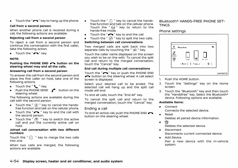
(240,1)
[ Edit: 2020/ 11/ 9 Model: Y62-A ]
4-54 Display screen, heater and air conditioner, and audio system
. Touch the " " key to hang up the phone.Call from a second person:
GUID-C7E1EF24-5AAB-4301-95BE-26917EEE45EF
When another phone call is received during acall, the following actions are available.Rejecting call from a second personTo reject a call from a second person andcontinue the conversation with the first caller,take the following action.. Touch the " " key.
NOTE:Pushing the PHONE END button on thesteering wheel may end all the calls.Answering call from a second personTo answer the call from the second person andplace the first caller on hold, take one of thefollowing actions.. Touch the " " key.. Push the PHONE SEND button on the
steering wheel.The following actions are available during thecall with the second person.. Touch the " " key to cancel the hands-
free function and talk on the cellular phone.. Touch the " " key to end the call with
the second person.. Touch the " " key to switch the active
call and put the currently active call onhold.
Joined call conversation with two differentnumbersTouch the " " key to merge the two callsinto one.When two calls are merged, the followingactions are available.
. Touch the " " key to cancel the hands-free function and talk on the cellular phone.Touch the " " key to return to thehands-free mode.
. Touch the " " key to end the call.
. Touch the " " key to split the two calls.Switching between call conversationsTwo merged calls are split back into twoseparate calls by touching the " " key.Touch the caller name displayed on the screenyou wish to be on line with. To cancel the splitcall and return to the merged conversation,touch the "Cancel" key.End call during multiple call conversationsTouch the " " key or push the PHONE END
button on the steering wheel. A call selectscreen is displayed.Select your desired call to be ended. Theselected call will hang up and the split callmode will end.To end all calls, touch the "End All" key.To cancel the split call and return to themerged conversation, touch the "Cancel" key.
Ending a callGUID-0FCBD4CE-07FE-43DC-98C7-C89D6823EBA9To end an active call, push the PHONE ENDbutton on the steering wheel.
Bluetooth® HANDS-FREE PHONE SET-TINGS GUID-66621D6E-A160-48D1-B5C9-094E1828B65E
Phone settingsGUID-E122A54D-CC69-4C52-B15E-B6998BA586D0
JVH1907X
1. Push the HOME button.2. Touch the "Settings" key on the Home
screen.3. Touch the "Bluetooth" key and then touch
the "Handsfree" key. Select the Bluetooth®device. Following options are available.
Available items:. Connect
Connects the selected device.. Reset
Deletes all paired device information..
Deletes the selected device.. Disconnect
Disconnects current connected device.. Add Device
Pair a new device with the in-vehiclesystem.
Condition: 'Except for China'/'Except for China/
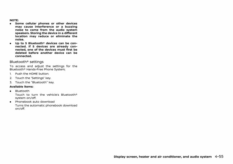
(241,1)
[ Edit: 2020/ 11/ 9 Model: Y62-A ]
NOTE:. Some cellular phones or other devices
may cause interference or a buzzingnoise to come from the audio systemspeakers. Storing the device in a differentlocation may reduce or eliminate thenoise.
. Up to 5 Bluetooth® devices can be con-nected. If 5 devices are already con-nected, one of the devices must first bedeleted before another device can beconnected.
Bluetooth® settingsGUID-CD67D75E-6185-47E8-9058-E4A43B673F0DTo access and adjust the settings for theBluetooth® Hands-Free Phone System;1. Push the HOME button.2. Touch the “Settings” key.3. Touch the "Bluetooth" key.Available items:. Bluetooth
Touch to turn the vehicle’s Bluetooth®system on/off.
. Phonebook auto downloadTurns the automatic phonebook downloadon/off.
Display screen, heater and air conditioner, and audio system 4-55
Condition: 'Except for China'/'Except for China/

(242,1)
[ Edit: 2020/ 11/ 9 Model: Y62-A ]
4-56 Display screen, heater and air conditioner, and audio system
MEMO
Condition: 'Except for China'/'Except for China/
(243,1)
[ Edit: 2020/ 11/ 9 Model: Y62-A ]
5 Starting and driving
Break-in schedule ............................................................................................. 5-3Before starting engine .................................................................................. 5-3Precautions when starting and driving .......................................... 5-3
Exhaust gas (carbon monoxide) ................................................... 5-4Three-way catalyst .................................................................................. 5-4
On-pavement and off-road driving precautions ..................... 5-5Driving safety precautions ................................................................. 5-5Tire Pressure Monitoring System (TPMS)(if equipped) ................................................................................................... 5-6
Care when driving ............................................................................................ 5-8Engine cold start period ...................................................................... 5-8Loading luggage ........................................................................................ 5-8Driving in wet conditions .................................................................... 5-8Driving in winter conditions ............................................................. 5-9For NISMO models .................................................................................... 5-9
Push-button ignition switch .................................................................... 5-9Precautions on push-button ignitionswitch operation ........................................................................................ 5-9Intelligent Key system ........................................................................... 5-9Automatic Transmission (AT) ....................................................... 5-10Steering lock (if equipped) .............................................................. 5-10Ignition switch positions .................................................................. 5-10Intelligent Key battery discharge .............................................. 5-11
Starting engine ................................................................................................ 5-12Remote engine start (if equipped) ........................................... 5-12
Driving vehicle .................................................................................................. 5-12Driving with Automatic Transmission (AT) ........................ 5-12
Four-Wheel Drive (4WD) (4WD models) ........................................ 5-16All mode 4WD system ........................................................................ 5-174WD shift switch ..................................................................................... 5-184WD shift indicator ............................................................................... 5-194WD warning light ................................................................................. 5-19
Variable 4 × 4 mode select switch (exceptfor Mexico) ................................................................................................ 5-20SNOW mode (for Mexico) .............................................................. 5-21
Differential lock mode switch (except for Mexico) ............. 5-22Vehicle Dynamic Control (VDC) system ...................................... 5-22
Vehicle Dynamic Control (VDC) OFF switch ................... 5-23Hill descent control system (except for Mexico) .................. 5-24
Hill descent control switch .......................................................... 5-24Hill start assist system .............................................................................. 5-25Lane Departure Warning (LDW) system/IntelligentLane Intervention system ...................................................................... 5-25
Lane Departure Warning (LDW) system ............................ 5-26Intelligent Lane Intervention system ................................... 5-28
Blind Spot Warning/Intelligent Blind SpotIntervention/Intelligent Back-up Intervention ....................... 5-32
Blind Spot Warning (BSW) and Intelligent BlindSpot Intervention systems ........................................................... 5-32BSW system operation .................................................................... 5-33Intelligent Blind Spot Interventionsystem operation ................................................................................ 5-34BSW/Intelligent Blind Spot Interventiondriving situations ................................................................................. 5-36Intelligent Back-up Intervention system(if equipped) ............................................................................................. 5-40Intelligent Back-up Intervention system operation(if equipped) ............................................................................................. 5-41System maintenance ....................................................................... 5-44
Rear Cross Traffic Alert (RCTA) (if equipped) .......................... 5-45RCTA system operation ................................................................. 5-46How to enable/disable the RCTA system ....................... 5-47RCTA system limitations ................................................................ 5-48System temporarily unavailable .............................................. 5-49System malfunction .......................................................................... 5-50
Condition: 'Except for China'/'Except for China/
(244,1)
[ Edit: 2020/ 11/ 9 Model: Y62-A ]
System maintenance .......................................................................... 5-50Cruise control (if equipped) ................................................................... 5-50
Precautions on cruise control ..................................................... 5-51Cruise control operations ............................................................... 5-51
Intelligent Cruise Control (ICC) system (if equipped) ......... 5-52Selecting vehicle-to-vehicle distancecontrol mode ............................................................................................. 5-53Vehicle-to-vehicle distance control mode ......................... 5-53Precautions on vehicle-to-vehicle distancecontrol mode ............................................................................................. 5-53Vehicle-to-vehicle distance controlmode operation ...................................................................................... 5-54Conventional (fixed speed) cruise control mode ......... 5-66
Intelligent Distance Control system (for Mexico) ................. 5-70Precautions on Intelligent DistanceControl system ......................................................................................... 5-70Intelligent Distance Control operation ................................. 5-71
Intelligent Emergency Braking with pedestriandetection system (if equipped) ........................................................... 5-77
Intelligent Emergency Braking with pedestriandetection system operation .......................................................... 5-78Turning the Intelligent Emergency Braking withpedestrian detection system ON/OFF .................................. 5-79Intelligent Emergency Braking with pedestriandetection system limitations ........................................................ 5-79System temporarily unavailable ................................................. 5-83System malfunction ............................................................................. 5-84System maintenance .......................................................................... 5-84
Intelligent Emergency Braking system (if equipped) ......... 5-85System operation ................................................................................... 5-86
Intelligent Forward Collision Warning system(if equipped) ....................................................................................................... 5-89
System operation ................................................................................... 5-89Fuel Efficiency and Carbon Dioxide Reductiondriving tips .......................................................................................................... 5-92
Increasing fuel economy and reducing CarbonDioxide emissions ......................................................................................... 5-93Parking .................................................................................................................. 5-93Parking sensor system ............................................................................. 5-95
Parking sensor indicator (if equipped) ............................... 5-96Parking sensor system OFF switch(if equipped) ............................................................................................. 5-96Parking sensor system setting (if equipped) ................ 5-97
ECO mode system (if equipped) ....................................................... 5-99Trailer towing (models without trailer hitch) ..................... 5-100Trailer towing (models with trailer hitch) .............................. 5-100
Operating precautions ................................................................ 5-100Maximum load limits (for Australia) .................................. 5-101Tire pressure ....................................................................................... 5-101Safety chains ...................................................................................... 5-101Trailer brakes ...................................................................................... 5-101Trailer detection (if equipped) ............................................... 5-101Trailer hitch (if equipped) .......................................................... 5-102Trailer lights (if equipped) ......................................................... 5-102
TOW mode (for Mexico) ....................................................................... 5-103Power steering ............................................................................................ 5-103Brake system ............................................................................................... 5-104
Brake precautions .......................................................................... 5-104Brake assist .......................................................................................... 5-104Anti-lock Braking System (ABS) ........................................... 5-104
Vehicle security .......................................................................................... 5-105Cold weather driving ............................................................................. 5-106
Battery ..................................................................................................... 5-106Engine coolant .................................................................................. 5-106Tire equipment .................................................................................. 5-106Special winter equipment ........................................................ 5-106Parking brake ..................................................................................... 5-107Corrosion protection .................................................................... 5-107
Condition: 'Except for China'/'Except for China/
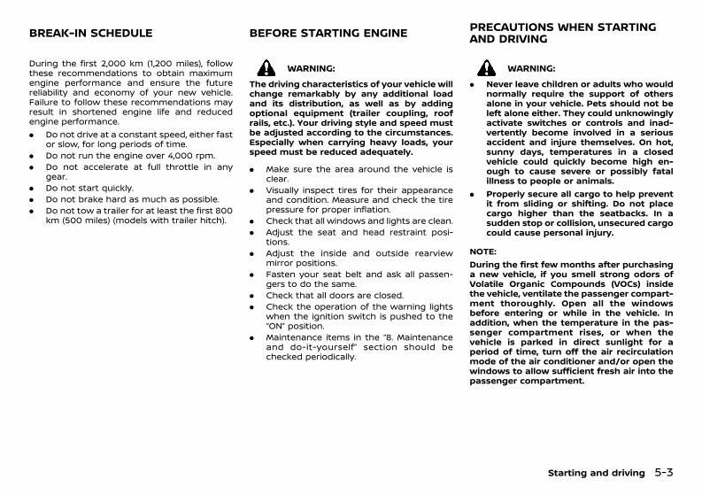
(245,1)
[ Edit: 2020/ 11/ 9 Model: Y62-A ]
GUID-A49D9F41-2ED8-4FC3-9670-7475EE5E937DDuring the first 2,000 km (1,200 miles), followthese recommendations to obtain maximumengine performance and ensure the futurereliability and economy of your new vehicle.Failure to follow these recommendations mayresult in shortened engine life and reducedengine performance.. Do not drive at a constant speed, either fast
or slow, for long periods of time.. Do not run the engine over 4,000 rpm.. Do not accelerate at full throttle in any
gear.. Do not start quickly.. Do not brake hard as much as possible.. Do not tow a trailer for at least the first 800
km (500 miles) (models with trailer hitch).
GUID-2B44AEEF-EA98-431C-A771-50D9ED42E601
WARNING:The driving characteristics of your vehicle willchange remarkably by any additional loadand its distribution, as well as by addingoptional equipment (trailer coupling, roofrails, etc.). Your driving style and speed mustbe adjusted according to the circumstances.Especially when carrying heavy loads, yourspeed must be reduced adequately.
. Make sure the area around the vehicle isclear.
. Visually inspect tires for their appearanceand condition. Measure and check the tirepressure for proper inflation.
. Check that all windows and lights are clean.
. Adjust the seat and head restraint posi-tions.
. Adjust the inside and outside rearviewmirror positions.
. Fasten your seat belt and ask all passen-gers to do the same.
. Check that all doors are closed.
. Check the operation of the warning lightswhen the ignition switch is pushed to the“ON” position.
. Maintenance items in the “8. Maintenanceand do-it-yourself” section should bechecked periodically.
GUID-B129AECA-2865-40DF-8A4D-1A0AB4DFEEE7
WARNING:. Never leave children or adults who would
normally require the support of othersalone in your vehicle. Pets should not beleft alone either. They could unknowinglyactivate switches or controls and inad-vertently become involved in a seriousaccident and injure themselves. On hot,sunny days, temperatures in a closedvehicle could quickly become high en-ough to cause severe or possibly fatalillness to people or animals.
. Properly secure all cargo to help preventit from sliding or shifting. Do not placecargo higher than the seatbacks. In asudden stop or collision, unsecured cargocould cause personal injury.
NOTE:During the first few months after purchasinga new vehicle, if you smell strong odors ofVolatile Organic Compounds (VOCs) insidethe vehicle, ventilate the passenger compart-ment thoroughly. Open all the windowsbefore entering or while in the vehicle. Inaddition, when the temperature in the pas-senger compartment rises, or when thevehicle is parked in direct sunlight for aperiod of time, turn off the air recirculationmode of the air conditioner and/or open thewindows to allow sufficient fresh air into thepassenger compartment.
Starting and driving 5-3
BREAK-IN SCHEDULE BEFORE STARTING ENGINE PRECAUTIONS WHEN STARTINGAND DRIVING
Condition: 'Except for China'/'Except for China/
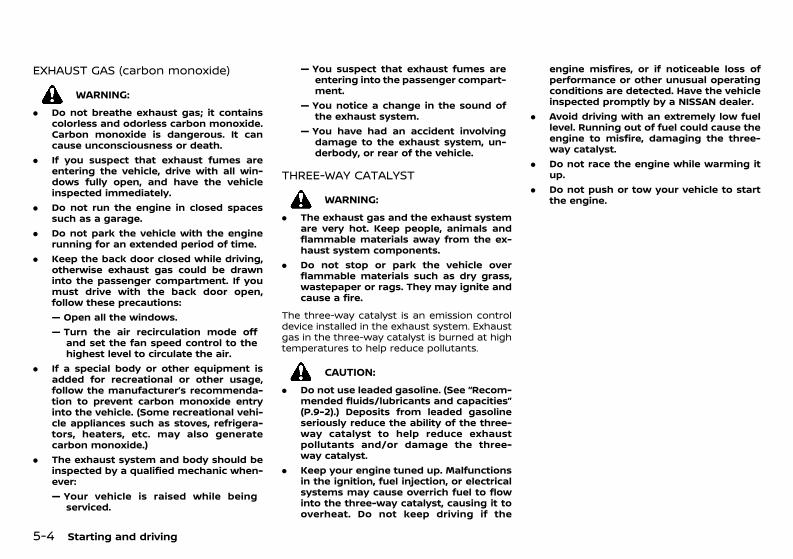
(246,1)
[ Edit: 2020/ 11/ 9 Model: Y62-A ]
5-4 Starting and driving
EXHAUST GAS (carbon monoxide)GUID-5F1AD384-CD8D-48F8-9A11-E6AB3746A2F9
WARNING:. Do not breathe exhaust gas; it contains
colorless and odorless carbon monoxide.Carbon monoxide is dangerous. It cancause unconsciousness or death.
. If you suspect that exhaust fumes areentering the vehicle, drive with all win-dows fully open, and have the vehicleinspected immediately.
. Do not run the engine in closed spacessuch as a garage.
. Do not park the vehicle with the enginerunning for an extended period of time.
. Keep the back door closed while driving,otherwise exhaust gas could be drawninto the passenger compartment. If youmust drive with the back door open,follow these precautions:— Open all the windows.— Turn the air recirculation mode off
and set the fan speed control to thehighest level to circulate the air.
. If a special body or other equipment isadded for recreational or other usage,follow the manufacturer’s recommenda-tion to prevent carbon monoxide entryinto the vehicle. (Some recreational vehi-cle appliances such as stoves, refrigera-tors, heaters, etc. may also generatecarbon monoxide.)
. The exhaust system and body should beinspected by a qualified mechanic when-ever:— Your vehicle is raised while being
serviced.
— You suspect that exhaust fumes areentering into the passenger compart-ment.
— You notice a change in the sound ofthe exhaust system.
— You have had an accident involvingdamage to the exhaust system, un-derbody, or rear of the vehicle.
THREE-WAY CATALYSTGUID-6094F4BA-C4E5-4254-8DEA-AA925380AF12
WARNING:. The exhaust gas and the exhaust system
are very hot. Keep people, animals andflammable materials away from the ex-haust system components.
. Do not stop or park the vehicle overflammable materials such as dry grass,wastepaper or rags. They may ignite andcause a fire.
The three-way catalyst is an emission controldevice installed in the exhaust system. Exhaustgas in the three-way catalyst is burned at hightemperatures to help reduce pollutants.
CAUTION:. Do not use leaded gasoline. (See “Recom-
mended fluids/lubricants and capacities”(P.9-2).) Deposits from leaded gasolineseriously reduce the ability of the three-way catalyst to help reduce exhaustpollutants and/or damage the three-way catalyst.
. Keep your engine tuned up. Malfunctionsin the ignition, fuel injection, or electricalsystems may cause overrich fuel to flowinto the three-way catalyst, causing it tooverheat. Do not keep driving if the
engine misfires, or if noticeable loss ofperformance or other unusual operatingconditions are detected. Have the vehicleinspected promptly by a NISSAN dealer.
. Avoid driving with an extremely low fuellevel. Running out of fuel could cause theengine to misfire, damaging the three-way catalyst.
. Do not race the engine while warming itup.
. Do not push or tow your vehicle to startthe engine.
Condition: 'Except for China'/'Except for China/
(247,1)
[ Edit: 2020/ 11/ 9 Model: Y62-A ]
GUID-24C916D0-7EF3-4E4D-9021-B3F17E4CDBACUtility vehicles have a significantly higherrollover rate than other types of vehicles.They have higher ground clearance than pas-senger cars to make them capable of perform-ing in a wide variety of on-pavement and off-road applications. This gives them a highercenter of gravity than ordinary cars. An advan-tage of higher ground clearance is a betterview of the road, allowing you to anticipateproblems. However, they are not designed forcornering at the same speeds as conventionalpassenger cars any more than low-slungsports cars are designed to perform satisfac-torily under off-road conditions. If at all possi-ble, avoid sharp turns or abrupt maneuvers,particularly at high speeds. As with othervehicles of this type, failure to operate thisvehicle correctly may result in loss of control orvehicle rollover.For information about driving using Four-WheelDrive (4WD), see “Four-Wheel Drive (4WD) (4WDmodels)” (P.5-16).
DRIVING SAFETY PRECAUTIONSGUID-E071D5BB-5068-4A96-9FB2-01698070A082Your NISSAN is designed for both normal andoff-road use. It has a higher ground clearanceand a bigger suspension stroke to make itsuitable for off-road use.Please observe the following precautions:
WARNING:. Drive carefully when off the road and
avoid dangerous areas. Every person whodrives or rides in this vehicle should beseated with their seat belt fastened. Thiswill keep you and your passengers inposition when driving over rough terrain.
. Do not drive across steep slopes. Insteaddrive either straight up or straight downthe slopes. Off-road vehicles can tip oversidewaysmuchmore easily than they canforward or backward.
. Many hills are too steep for any vehicle. Ifyou drive up them, you may stall. If youdrive down them, you may not be able tocontrol your speed. If you drive acrossthem, you may roll over.
. Do not shift ranges while driving ondownhill grades as this could cause lossof control of the vehicle.
. Stay alert when driving to the top of a hill.At the top there could be a drop-off orother hazard that could cause an acci-dent.
. If your engine stalls or you cannot makeit to the top of a steep hill, never attemptto turn around. Your vehicle could tip orroll over. Always back straight down in R(Reverse) range. Never back down in N(Neutral), using only the brake, as thiscould cause loss of control.
. Heavy braking going down a hill couldcause your brakes to overheat and fade,resulting in loss of control and an acci-dent. Apply brakes lightly and use a lowrange to control your speed.
. Unsecured cargo can be thrown aroundwhen driving over rough terrain. Properlysecure all cargo so it will not be thrownforward and cause injury to you or yourpassengers.
. To avoid raising the center of gravityexcessively, do not exceed the ratedcapacity of the roof rack (if equipped)and evenly distribute the load. Secureheavy loads in the cargo area as far
forward and as low as possible. Do notequip the vehicle with tires larger thanspecified in this manual. This could causeyour vehicle to roll over.
. Do not grip the inside or spokes of thesteering wheel when driving off-road.The steering wheel could move suddenlyand injure your hands. Instead drive withyour fingers and thumbs on the outsideof the rim.
. Before operating the vehicle, ensure thatthe driver and all passengers have theirseat belts fastened.
. Always drive with the floor mats in placeas the floor may became hot.
. Lower your speed when encounteringstrong crosswinds. With a higher centerof gravity, your NISSAN is more affectedby strong side winds. Slower speedsensure better vehicle control.
. Do not drive beyond the performancecapability of the tires, even with 4WDengaged.
. Do not attempt to raise two wheels offthe ground and shift the transmission toany drive or reverse position with theengine running. Doing so may result indrivetrain damage or unexpected vehiclemovement which could result in seriousvehicle damage or personal injury.
. Do not attempt to test a 4WD equippedvehicle on a 2-wheel dynamometer orsimilar equipment even if the other twowheels are raised off the ground. Makesure you inform test facility personnelthat your vehicle is equipped with 4WDbefore it is placed on a dynamometer.Using the wrong test equipment mayresult in drivetrain damage or unex-
Starting and driving 5-5
ON-PAVEMENT AND OFF-ROADDRIVING PRECAUTIONS
Condition: 'Except for China'/'Except for China/
(248,1)
[ Edit: 2020/ 11/ 9 Model: Y62-A ]
5-6 Starting and driving
pected vehicle movement which couldresult in serious vehicle damage or per-sonal injury.
. When a wheel is off the ground due to anunlevel surface, do not spin the wheelexcessively.
. Accelerating quickly, sharp steering man-euvers or sudden braking may cause lossof control.
. If at all possible, avoid sharp turningmaneuvers, particularly at high speeds.Your vehicle has a higher center ofgravity than a conventional passengercar. The vehicle is not designed forcornering at the same speeds as conven-tional passenger cars. Failure to operatethis vehicle correctly could result in lossof control and/or a rollover accident.
. Always use tires of the same type, size,brand, construction (bias, bias-belted orradial), and tread pattern on all fourwheels. Install tire chains on the rearwheels when driving on slippery roadsand drive carefully.
. Be sure to check the brakes immediatelyafter driving in mud or water. See “Brakesystem” (P.5-104) for wet brakes.
. Avoid parking your vehicle on steep hills.If you get out of the vehicle and it rollsforward, backward or sideways, youcould be injured.
. Whenever you drive off-road throughsand, mud or water as deep as the wheelhub, more frequent maintenance may berequired. See the maintenance informa-tion in a separate maintenance booklet.
TIRE PRESSURE MONITORING SYSTEM(TPMS) (if equipped)GUID-584D4DB4-8218-4BBB-8A54-AC0298389287Each tire, including the spare (if provided),should be checked monthly when cold andinflated to the inflation pressure recommendedby the vehicle manufacturer on the vehicleplacard or tire inflation pressure label. (If yourvehicle has tires of a different size than the sizeindicated on the vehicle placard or tire inflationpressure label, you should determine the prop-er tire inflation pressure for those tires.)As an added safety feature, your vehicle hasbeen equipped with a Tire Pressure MonitoringSystem (TPMS) that illuminates a low tirepressure telltale when one or more of yourtires is significantly under-inflated. Accordingly,when the low tire pressure telltale illuminates,you should stop and check your tires as soonas possible, and inflate them to the properpressure. Driving on a significantly under-in-flated tire causes the tire to overheat and canlead to tire failure. Under-inflation also reducesfuel efficiency and tire tread life, and may affectthe vehicle’s handling and stopping ability.Please note that the TPMS is not a substitutefor proper tire maintenance, and it is thedriver’s responsibility to maintain correct tirepressure, even if under-inflation has notreached the level to trigger illumination of theTPMS low tire pressure telltale.Your vehicle has also been equipped with aTPMS malfunction indicator to indicate whenthe system is not operating properly. The TPMSmalfunction indicator is combined with the lowtire pressure telltale. When the system detectsa malfunction, the telltale will flash for approxi-mately one minute and then remain continu-ously illuminated. This sequence will continueupon subsequent vehicle start-ups as long asthe malfunction exists. When the malfunction
indicator is illuminated, the system may not beable to detect or signal low tire pressure asintended. TPMS malfunctions may occur for avariety of reasons, including the installation ofreplacement or alternate tires or wheels on thevehicle that prevent the TPMS from functioningproperly. Always check the TPMS malfunctiontelltale after replacing one or more tires orwheels on your vehicle to ensure that thereplacement or alternate tires and wheelsallow the TPMS to continue to function prop-erly.
Additional informationGUID-458E8687-F9CF-4F39-A090-1E20AFC92625. Since the spare tire is not equipped with
the TPMS, the TPMS does not monitor thetire pressure of the spare tire.
. The TPMS will activate only when thevehicle is driven at speeds above 25 km/h(16 MPH). Also, this system may not detect asudden drop in tire pressure (for example, aflat tire while driving).
. The low tire pressure warning light may notautomatically turn off when the tire pres-sure is adjusted. After the tire is inflated tothe recommended pressure, drive the ve-hicle at speeds above 25 km/h (16 MPH) toactivate the TPMS and turn off the low tirepressure warning light. Use a tire pressuregauge to check the tire pressure.
. The check tire pressure warning (ifequipped) appears on the vehicle informa-tion display when the low tire pressurewarning light is illuminated and low tirepressure is detected. The check tire pres-sure warning turns off when the low tirepressure warning light turns off.The check tire pressure warning appearseach time the ignition switch is placed inthe ON position as long as the low tirepressure warning light remains illuminated.
Condition: 'Except for China'/'Except for China/
(249,1)
[ Edit: 2020/ 11/ 9 Model: Y62-A ]
The check tire pressure warning does notappear if the low tire pressure warning lightilluminates to indicate a TPMS malfunction.
. Tire pressure rises and falls depending onthe heat caused by the vehicle’s operationand the outside temperature. Do not re-duce the tire pressure after driving becausethe tire pressure rises after driving. Lowoutside temperature can lower the tem-perature of the air inside the tire which cancause a lower tire inflation pressure. Thismay cause the low tire pressure warninglight to illuminate. If the warning lightilluminates in low ambient temperature,check the tire pressure for all four tires.
. For model with the dual display and centerdisplay, you can also check the pressure ofall tires (except the spare tire) on thedisplay screen (model with single display)or vehicle information display (model withdual display). The order of the tire pressurefigures displayed on the screen does notcorrespond with the actual order of the tireposition. (See NissanConnect Owner’s Man-ual.)
For additional information, see “Low tire pres-sure warning light” (P.2-20) and “Tire PressureMonitoring System (TPMS) ” (P.6-2).
WARNING:. If the low tire pressure warning light
illuminates while driving, avoid suddensteering maneuvers or abrupt braking,reduce vehicle speed, pull off the road toa safe location and stop the vehicle assoon as possible. Driving with under-inflated tires may permanently damagethe tires and increase the likelihood oftire failure. Serious vehicle damage couldoccur and may lead to an accident and
could result in serious personal injury.Check the tire pressure for all four tires.Adjust the tire pressure to the recom-mended COLD tire pressure shown on thetire placard to turn the low tire pressurewarning light OFF. If the light still illumi-nates while driving after adjusting thetire pressure, a tire may be flat or theTPMS may be malfunctioning. If you havea flat tire, replace it with a spare tire assoon as possible. If no tire is flat and alltires are properly inflated, have the ve-hicle checked by a NISSAN dealer.
. Since the spare tire is not equipped withthe TPMS, when a spare tire is mountedor a wheel is replaced, the TPMS will notfunction and the low tire pressure warn-ing light will flash for approximately 1minute. The light will remain on after 1minute. Contact a NISSAN dealer as soonas possible for tire replacement and/orsystem resetting.
. Replacing tires with those not originallyspecified by NISSAN could affect theproper operation of the TPMS.
. Do not inject any tire liquid or aerosol tiresealant into the tires, as this may cause amalfunction of the tire pressure sensors.
CAUTION:. The TPMS may not function properly
when the wheels are equipped with tirechains or the wheels are buried in snow.
. Do not place metalized film or any metalparts (antenna, etc.) on the windows. Thismay cause poor reception of the signalsfrom the tire pressure sensors, and theTPMS will not function properly.
Some devices and transmitters may tempora-rily interfere with the operation of the TPMSand cause the low tire pressure warning lightto illuminate. Some examples are:. Facilities or electric devices using similar
radio frequencies are near the vehicle.. If a transmitter set to similar frequencies is
being used in or near the vehicle.. If a computer (or similar equipment) or a
DC/AC converter is being used in or nearthe vehicle.
Low tire pressure warning light may illuminatein the following cases.. If the vehicle is equipped with a wheel and
tire without TPMS.. If the TPMS has been replaced and the ID
has not been registered.. If the wheel is not originally specified by
NISSAN.
TPMS with tire inflation indicator (if equipped)GUID-FAB6BB21-4692-4681-82BC-A19AE886D121When tire pressure is low, the low tire pressurewarning light illuminates.This vehicle provides visual and audible signalsto help you inflate the tires to the recom-mended COLD tire pressure.Vehicle set-up:
GUID-C7E1EF24-5AAB-4301-95BE-26917EEE45EF
1. Park the vehicle in a safe and level place.2. Apply the parking brake and place the shift
lever in the “P” (Park) position.3. Place the ignition switch in the “ON” posi-
tion. Do not start the engine.
Starting and driving 5-7
Condition: 'Except for China'/'Except for China/
(250,1)
[ Edit: 2020/ 11/ 9 Model: Y62-A ]
5-8 Starting and driving
Operation:GUID-C7E1EF24-5AAB-4301-95BE-26917EEE45EF
1. Add air to the tire.2. After a few seconds, the hazard indicators
will start flashing.3. When the designated pressure is reached,
the horn beeps once and the hazardindicators stop flashing.
4. Perform the above steps for each tire.. If the tire is over-inflated more than
approximately 30 kPa (4 psi), the hornbeeps and the hazard indicators flash 3times. To correct the pressure, push thecore of the valve stem on the tire briefly torelease pressure. When the pressurereaches the designated pressure, the hornbeeps once.
. If the hazard indicator does not flash inapproximately 15 seconds after starting toinflate the tire, it indicates that the tireinflation indicator is not operating.
. The TPMS will not activate the tire inflationindicator under the following conditions:— If there is interference from an external
device or transmitter— The air pressure from the inflation device
such as those using a power socket isnot sufficient to inflate the tire
— If an electrical equipment is being usedin or near the vehicle
— There is a malfunction in the TPMSsystem
— There is a malfunction in the horn orhazard indicators
. If the tire inflation indicator does notoperate due to TPMS interference, movethe vehicle about 1m (3 ft) backward orforward and try again.
If the tire inflation indicator is not working, use
a tire pressure gauge.GUID-A917C9CC-63C5-4B98-81ED-0EA08A5212FC
Driving your vehicle to fit the circumstances isessential for your safety and comfort. As adriver, you should be the one who knows besthow to drive in the given circumstances.
ENGINE COLD START PERIODGUID-21A55567-B34C-4C27-B2B4-70B2DA1E5430Due to the higher engine speeds, when theengine is cold, extra caution must be exercisedwhen selecting a gear during the engine warm-up period after starting the engine.
LOADING LUGGAGEGUID-528ED040-7127-4474-A856-D6E519A27850Loads and their distribution and the attach-ment of equipment (coupling devices, roofbaggage carriers, etc.) will considerably changethe driving characteristics of the vehicle. Yourdriving style and speed must be adjustedaccording to the circumstances.
DRIVING IN WET CONDITIONSGUID-FD8038A7-F86E-43B5-96B6-CE9AF366EC0B. Avoid accelerating or stopping suddenly.. Avoid sharp turning or lane changing
suddenly.. Avoid following too close to the vehicle in
front.When water covers the road surface with waterpuddles, small water streams, etc., reducespeed to prevent hydroplaning which cancause skidding and loss of control. Worn tireswill increase this risk.
CARE WHEN DRIVING
Condition: 'Except for China'/'Except for China/
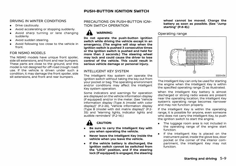
(251,1)
[ Edit: 2020/ 11/ 9 Model: Y62-A ]
DRIVING IN WINTER CONDITIONSGUID-D189FD17-30EF-4E56-AB9D-3C4D6A3A5B10. Drive cautiously.. Avoid accelerating or stopping suddenly.. Avoid sharp turning or lane changing
suddenly.. Avoid sudden steering.. Avoid following too close to the vehicle in
front.
FOR NISMO MODELSGUID-1109A82A-405B-41FF-85B9-DAC7C443D504The NISMO models have unique front spoiler,side sill extensions, and front and rear bumpers.These parts are close to the ground, and thismodel is not designed for off-road (rough road)use. If the vehicle is driven under such acondition, it may damage the front spoiler, sidesill extensions, and front and rear bumpers .
GUID-D3979686-22CE-40B8-931F-22229FAF4940
PRECAUTIONS ON PUSH-BUTTON IGNI-TION SWITCH OPERATIONGUID-83A269DB-20E2-4F53-AB17-01668D414991
WARNING:Do not operate the push-button ignitionswitch while driving the vehicle except in anemergency. (The engine will stop when theignition switch is pushed 3 consecutive timesor the ignition switch is pushed and held formore than 2 seconds.) The steering wheelmay lock and could cause the driver to losecontrol of the vehicle. This could result inserious vehicle damage or personal injury.
INTELLIGENT KEY SYSTEMGUID-90F6D579-2F7A-4204-83F7-9AB8762D9D63The Intelligent Key system can operate theignition switch without taking the key out fromyour pocket or bag. The operating environmentand/or conditions may affect the IntelligentKey system operation.Some indicators and warnings for operationare displayed on the vehicle information display(if equipped) and/or in the meter. (See “Vehicleinformation display (Type A (model with colordisplay))” (P.2-26), “Vehicle information display(Type B (model with dot matrix display))” (P.2-35) and “Warning lights, indicator lights andaudible reminders” (P.2-16).)
CAUTION:. Be sure to carry the Intelligent Key with
you when operating the vehicle.. Never leave the Intelligent Key inside the
vehicle when you leave the vehicle.. If the vehicle battery is discharged, the
ignition switch cannot be switched fromthe “LOCK” position, and if the steeringlock (if equipped) is engaged, the steering
wheel cannot be moved. Charge thebattery as soon as possible. (See “Jumpstarting” (P.6-8).)
Operating rangeGUID-C2898BBB-53FE-4BEF-8401-68D2263DB87D
SSD0436
The Intelligent Key can only be used for startingthe engine when the Intelligent Key is withinthe specified operating range as illustrated.When the Intelligent Key battery is almostdischarged or strong radio waves are presentnear the operating location, the Intelligent Keysystem’s operating range becomes narrowerand may not function properly.If the Intelligent Key is within the operatingrange, it is possible for anyone, even someonewho does not carry the Intelligent Key, to pushthe ignition switch to start the engine.. The luggage room area is not included in
the operating range of the engine startfunction.
. If the Intelligent Key is placed on theinstrument panel, inside the glove box, doorpocket or the corner of the interior com-partment, the Intelligent Key may notfunction.
Starting and driving 5-9
PUSH-BUTTON IGNITION SWITCH
Condition: 'Except for China'/'Except for China/
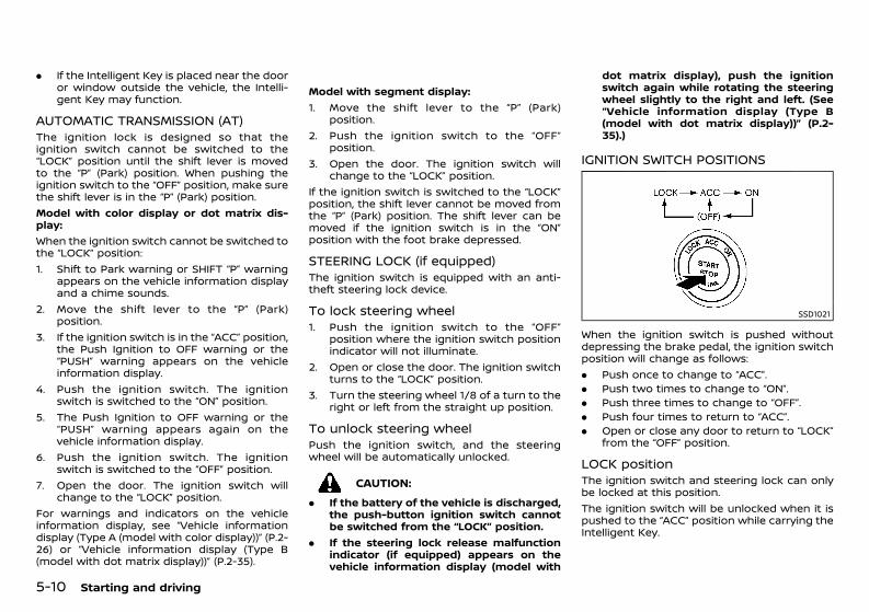
(252,1)
[ Edit: 2020/ 11/ 9 Model: Y62-A ]
5-10 Starting and driving
. If the Intelligent Key is placed near the dooror window outside the vehicle, the Intelli-gent Key may function.
AUTOMATIC TRANSMISSION (AT)GUID-E0D7F3B0-8127-4DD1-A0E8-4712947ED842The ignition lock is designed so that theignition switch cannot be switched to the“LOCK” position until the shift lever is movedto the “P” (Park) position. When pushing theignition switch to the “OFF” position, make surethe shift lever is in the “P” (Park) position.Model with color display or dot matrix dis-play:When the ignition switch cannot be switched tothe “LOCK” position:1. Shift to Park warning or SHIFT “P” warning
appears on the vehicle information displayand a chime sounds.
2. Move the shift lever to the “P” (Park)position.
3. If the ignition switch is in the “ACC” position,the Push Ignition to OFF warning or the“PUSH” warning appears on the vehicleinformation display.
4. Push the ignition switch. The ignitionswitch is switched to the “ON” position.
5. The Push Ignition to OFF warning or the“PUSH” warning appears again on thevehicle information display.
6. Push the ignition switch. The ignitionswitch is switched to the “OFF” position.
7. Open the door. The ignition switch willchange to the “LOCK” position.
For warnings and indicators on the vehicleinformation display, see “Vehicle informationdisplay (Type A (model with color display))” (P.2-26) or “Vehicle information display (Type B(model with dot matrix display))” (P.2-35).
Model with segment display:1. Move the shift lever to the “P” (Park)
position.2. Push the ignition switch to the “OFF”
position.3. Open the door. The ignition switch will
change to the “LOCK” position.If the ignition switch is switched to the “LOCK”position, the shift lever cannot be moved fromthe “P” (Park) position. The shift lever can bemoved if the ignition switch is in the “ON”position with the foot brake depressed.
STEERING LOCK (if equipped)GUID-9501DE5B-3EC0-4DD7-B2E4-39072D2B1662The ignition switch is equipped with an anti-theft steering lock device.
To lock steering wheelGUID-C753BFFF-0B37-48EE-A880-207BC28FCCFE1. Push the ignition switch to the “OFF”
position where the ignition switch positionindicator will not illuminate.
2. Open or close the door. The ignition switchturns to the “LOCK” position.
3. Turn the steering wheel 1/8 of a turn to theright or left from the straight up position.
To unlock steering wheelGUID-9F3BF8F3-E1DC-4EEC-BB91-9C91E0DC17C7Push the ignition switch, and the steeringwheel will be automatically unlocked.
CAUTION:. If the battery of the vehicle is discharged,
the push-button ignition switch cannotbe switched from the “LOCK” position.
. If the steering lock release malfunctionindicator (if equipped) appears on thevehicle information display (model with
dot matrix display), push the ignitionswitch again while rotating the steeringwheel slightly to the right and left. (See“Vehicle information display (Type B(model with dot matrix display))” (P.2-35).)
IGNITION SWITCH POSITIONSGUID-434A2803-2481-44B2-BC6D-2A5654A3D2A6
SSD1021
When the ignition switch is pushed withoutdepressing the brake pedal, the ignition switchposition will change as follows:. Push once to change to “ACC”.. Push two times to change to “ON”.. Push three times to change to “OFF”.. Push four times to return to “ACC”.. Open or close any door to return to “LOCK”
from the “OFF” position.
LOCK positionGUID-13EAC4B8-294C-43EE-80EB-860DF692C223The ignition switch and steering lock can onlybe locked at this position.The ignition switch will be unlocked when it ispushed to the “ACC” position while carrying theIntelligent Key.
Condition: 'Except for China'/'Except for China/
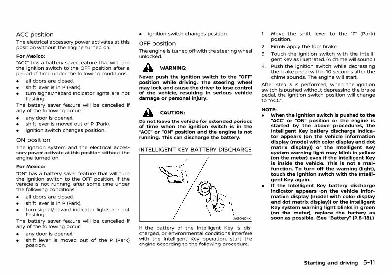
(253,1)
[ Edit: 2020/ 11/ 9 Model: Y62-A ]
ACC positionGUID-5EE40441-19D8-4364-98EF-D70EDE9B72D6The electrical accessory power activates at thisposition without the engine turned on.For Mexico:
GUID-C7E1EF24-5AAB-4301-95BE-26917EEE45EF
“ACC” has a battery saver feature that will turnthe ignition switch to the OFF position after aperiod of time under the following conditions:. all doors are closed.. shift lever is in P (Park).. turn signal/hazard indicator lights are not
flashingThe battery saver feature will be cancelled ifany of the following occur:. any door is opened.. shift lever is moved out of P (Park).. ignition switch changes position.
ON positionGUID-C0122229-99D6-4DB9-A50D-49E0BF5D52BCThe ignition system and the electrical acces-sory power activate at this position without theengine turned on.For Mexico:
GUID-C7E1EF24-5AAB-4301-95BE-26917EEE45EF
“ON” has a battery saver feature that will turnthe ignition switch to the OFF position, if thevehicle is not running, after some time underthe following conditions:. all doors are closed.. shift lever is in P (Park).. turn signal/hazard indicator lights are not
flashingThe battery saver feature will be cancelled ifany of the following occur:. any door is opened.. shift lever is moved out of the P (Park)
position.
. ignition switch changes position.
OFF positionGUID-F10989AD-05BB-41F0-B3D5-C4B4D65F5079The engine is turned off with the steering wheelunlocked.
WARNING:Never push the ignition switch to the “OFF”position while driving. The steering wheelmay lock and cause the driver to lose controlof the vehicle, resulting in serious vehicledamage or personal injury.
CAUTION:Do not leave the vehicle for extended periodsof time when the ignition switch is in the“ACC” or “ON” position and the engine is notrunning. This can discharge the battery.
INTELLIGENT KEY BATTERY DISCHARGEGUID-6AD12075-0F90-482B-A8A9-5D798ABAEF36
JVS0404X
If the battery of the Intelligent Key is dis-charged, or environmental conditions interferewith the Intelligent Key operation, start theengine according to the following procedure:
1. Move the shift lever to the “P” (Park)position.
2. Firmly apply the foot brake.3. Touch the ignition switch with the Intelli-
gent Key as illustrated. (A chime will sound.)4. Push the ignition switch while depressing
the brake pedal within 10 seconds after thechime sounds. The engine will start.
After step 3 is performed, when the ignitionswitch is pushed without depressing the brakepedal, the ignition switch position will changeto “ACC”.
NOTE:. When the ignition switch is pushed to the
“ACC” or “ON” position or the engine isstarted by the above procedures, theIntelligent Key battery discharge indica-tor appears (on the vehicle informationdisplay (model with color display and dotmatrix display)) or the Intelligent Keysystem warning light may blink in yellow(on the meter) even if the Intelligent Keyis inside the vehicle. This is not a mal-function. To turn off the warning (light),touch the ignition switch with the Intelli-gent Key again.
. If the Intelligent Key battery dischargeindicator appears (on the vehicle infor-mation display (model with color displayand dot matrix display)) or the IntelligentKey system warning light blinks in green(on the meter), replace the battery assoon as possible. (See “Battery” (P.8-18).)
Starting and driving 5-11
Condition: 'Except for China'/'Except for China/
(254,1)
[ Edit: 2020/ 11/ 9 Model: Y62-A ]
5-12 Starting and driving
GUID-6C674376-A1C2-4EBD-8BC6-BEAB2FC6E65E1. Apply the parking brake.2. Move the shift lever to the “P” (Park) or the
“N” (Neutral) position.The starter is designed to operate onlywhen the shift lever is in the properposition.The Intelligent Key must be carried whenoperating the ignition switch.
3. Push the ignition switch to the “ON” posi-tion. Firmly depress the brake pedal andpush the ignition switch to start the engine.To start the engine immediately, push andrelease the ignition switch while depressingthe brake pedal with the ignition switch inany position.
4. Immediately release the ignition switchwhen the engine starts. If the engine starts,but fails to run, repeat the above proce-dures.If the engine is very hard to start inextremely cold or hot weather, depressthe accelerator pedal and hold it. Push theignition switch for up to 15 seconds whileholding. Release the accelerator pedalwhen the engine starts.
CAUTION:. As soon as the engine has started,
release the ignition switch immediately.. Do not operate the starter for more than
15 seconds at a time. If the engine doesnot start, push the ignition switch to the“OFF” position and wait 10 seconds be-fore cranking the engine again. Other-wise, the starter could be damaged.
. If it becomes necessary to start theengine with a booster battery and jumpercables, the instructions and cautions
contained in the “6. In case of emergency”section should be carefully followed.
5. Allow the engine to idle for at least 30seconds after starting the engine to warm-up. Drive at moderate speeds for a shortdistance first, especially in cold weather.
CAUTION:Do not leave the vehicle unattended whilethe engine is warming up.
6. To stop the engine, move the shift lever tothe “P” (Park) position, apply the parkingbrake and push the ignition switch to the“OFF” position.
For VK56VD engine model, in preparation forthe next engine start, the engine may have aslightly delayed shutoff after placing the igni-tion switch in the OFF position, depending onthe driving conditions.
REMOTE ENGINE START (if equipped)GUID-DD3432A7-4409-4433-AB2F-D10A9A9C8B52Vehicles started with the remote engine startfunction require the ignition switch to beplaced in the ON position before the shift levercan be moved from the P (Park) position. Toplace the ignition switch in the ON position,perform the following steps:1. Make sure that the Intelligent Key is on you.2. Depress the brake pedal.3. Push the ignition switch once to the ON
position.For additional information about the remoteengine start function, see “Remote engine start”(P.3-17).
GUID-E7D545DD-C9D2-4F21-94C5-693AFF273F14
DRIVING WITH AUTOMATIC TRANSMIS-SION (AT) GUID-D53AADA2-7E82-438E-A9C6-73261C06D641The Automatic Transmission (AT) in your vehi-cle is electronically controlled to produce max-imum power and smooth operation.The recommended operating procedures forthis transmission are shown on the followingpages. Follow these procedures for maximumvehicle performance and driving enjoyment.
CAUTION:. The cold engine idle speed is high, so use
caution when shifting into a forward orreverse gear before the engine haswarmed up.
. Avoid revving up the engine while thevehicle is stopped. This could cause un-expected vehicle movement.
. Do not downshift abruptly on slipperyroads. This may cause a loss of control.
. Never shift to either the “P” (Park) or “R”(Reverse) position while the vehicle ismoving forward and “P” (Park) or “D”(Drive) position while the vehicle is mov-ing rearward. This could cause seriousdamage to the transmission.
. Except in an emergency, do not shift tothe “N” (Neutral) position while driving.Coasting with the transmission in the “N”(Neutral) position may cause serious da-mage to the transmission.
. Start the engine in either the “P” (Park) or“N” (Neutral) position. The engine will notstart in any other gear position. If it does,have your vehicle checked by a NISSANdealer.
STARTING ENGINE DRIVING VEHICLE
Condition: 'Except for China'/'Except for China/
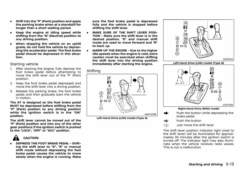
(255,1)
[ Edit: 2020/ 11/ 9 Model: Y62-A ]
. Shift into the “P” (Park) position and applythe parking brake when at a standstill forlonger than a short waiting period.
. Keep the engine at idling speed whileshifting from the “N” (Neutral) position toany driving position.
. When stopping the vehicle on an uphillgrade, do not hold the vehicle by depres-sing the accelerator pedal. The foot brakepedal should be depressed in this situa-tion.
Starting vehicleGUID-5203B09F-C87E-4EBF-9EF8-75C2FCD83BD71. After starting the engine, fully depress the
foot brake pedal before attempting tomove the shift lever out of the “P” (Park)position.
2. Keep the foot brake pedal depressed andmove the shift lever into a driving position.
3. Release the parking brake, the foot brakepedal, and then gradually start the vehiclein motion.
The AT is designed so the foot brake pedalMUST be depressed before shifting from the“P” (Park) position to any driving positionwhile the ignition switch is in the “ON”position.The shift lever cannot be moved out of the“P” (Park) position and into any of the othergear positions if the ignition switch is pushedto the “LOCK”, “OFF” or “ACC” position.
CAUTION:. DEPRESS THE FOOT BRAKE PEDAL - Shift-
ing the shift lever to “D”, “R” or manualshift mode without depressing the footbrake pedal causes the vehicle to moveslowly when the engine is running. Make
sure the foot brake pedal is depressedfully and the vehicle is stopped beforeshifting the shift lever.
. MAKE SURE OF THE SHIFT LEVER POSI-TION - Make sure the shift lever is in thedesired position. “D” and manual shiftmode are used to move forward and “R”to back up.
. WARM UP THE ENGINE - Due to the higheridle speeds when the engine is cold, extracaution must be exercised when shiftingthe shift lever into the driving positionimmediately after starting the engine.
Shifting GUID-9F637E0A-E3E2-4DA1-AFD5-A004185AD060
WAF0238XLeft-Hand Drive (LHD) model (Type A)
SSD0945Left-Hand Drive (LHD) model (Type B)
JVS0158XRight-Hand Drive (RHD) model
: Push the button while depressing thebrake pedal
: Push the button: Just move the shift lever
The shift lever position indicator light (next tothe shift lever) will be illuminated for approxi-mately 30 minutes after the ignition switch isturned off. The indicator light may also illumi-nate when the vehicle receives radio waves.This is not a malfunction.
Starting and driving 5-13
Condition: 'Except for China'/'Except for China/
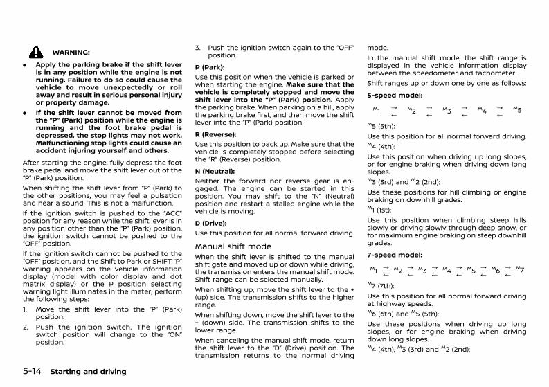
(256,1)
[ Edit: 2020/ 11/ 9 Model: Y62-A ]
5-14 Starting and driving
WARNING:. Apply the parking brake if the shift lever
is in any position while the engine is notrunning. Failure to do so could cause thevehicle to move unexpectedly or rollaway and result in serious personal injuryor property damage.
. If the shift lever cannot be moved fromthe “P” (Park) position while the engine isrunning and the foot brake pedal isdepressed, the stop lights may not work.Malfunctioning stop lights could cause anaccident injuring yourself and others.
After starting the engine, fully depress the footbrake pedal and move the shift lever out of the“P” (Park) position.When shifting the shift lever from “P” (Park) tothe other positions, you may feel a pulsationand hear a sound. This is not a malfunction.If the ignition switch is pushed to the “ACC”position for any reason while the shift lever is inany position other than the “P” (Park) position,the ignition switch cannot be pushed to the“OFF” position.If the ignition switch cannot be pushed to the“OFF” position, and the Shift to Park or SHIFT “P”warning appears on the vehicle informationdisplay (model with color display and dotmatrix display) or the P position selectingwarning light illuminates in the meter, performthe following steps:1. Move the shift lever into the “P” (Park)
position.2. Push the ignition switch. The ignition
switch position will change to the “ON”position.
3. Push the ignition switch again to the “OFF”position.
P (Park):GUID-C7E1EF24-5AAB-4301-95BE-26917EEE45EF
Use this position when the vehicle is parked orwhen starting the engine. Make sure that thevehicle is completely stopped and move theshift lever into the “P” (Park) position. Applythe parking brake. When parking on a hill, applythe parking brake first, and then move the shiftlever into the “P” (Park) position.R (Reverse):
GUID-C7E1EF24-5AAB-4301-95BE-26917EEE45EF
Use this position to back up. Make sure that thevehicle is completely stopped before selectingthe “R” (Reverse) position.N (Neutral):
GUID-C7E1EF24-5AAB-4301-95BE-26917EEE45EF
Neither the forward nor reverse gear is en-gaged. The engine can be started in thisposition. You may shift to the “N” (Neutral)position and restart a stalled engine while thevehicle is moving.D (Drive):
GUID-C7E1EF24-5AAB-4301-95BE-26917EEE45EF
Use this position for all normal forward driving.
Manual shift modeGUID-C44C5269-B111-4076-A731-A16FA94EA2DFWhen the shift lever is shifted to the manualshift gate and moved up or down while driving,the transmission enters the manual shift mode.Shift range can be selected manually.When shifting up, move the shift lever to the +(up) side. The transmission shifts to the higherrange.When shifting down, move the shift lever to the− (down) side. The transmission shifts to thelower range.When canceling the manual shift mode, returnthe shift lever to the “D” (Drive) position. Thetransmission returns to the normal driving
mode.In the manual shift mode, the shift range isdisplayed in the vehicle information displaybetween the speedometer and tachometer.Shift ranges up or down one by one as follows:5-speed model:
GUID-C7E1EF24-5AAB-4301-95BE-26917EEE45EF
M1 ?/
M2 ?/
M3 ?/
M4 ?/
M5
M5 (5th):Use this position for all normal forward driving.M4 (4th):Use this position when driving up long slopes,or for engine braking when driving down longslopes.M3 (3rd) and M2 (2nd):Use these positions for hill climbing or enginebraking on downhill grades.M1 (1st):Use this position when climbing steep hillsslowly or driving slowly through deep snow, orfor maximum engine braking on steep downhillgrades.7-speed model:
GUID-C7E1EF24-5AAB-4301-95BE-26917EEE45EF
M1 ?/M2 ?/
M3 ?/M4 ?/
M5 ?/M6 ?/
M7
M7 (7th):Use this position for all normal forward drivingat highway speeds.M6 (6th) and M5 (5th):Use these positions when driving up longslopes, or for engine braking when drivingdown long slopes.M4 (4th), M3 (3rd) and M2 (2nd):
Condition: 'Except for China'/'Except for China/
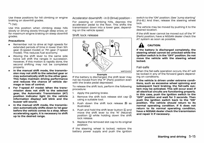
(257,1)
[ Edit: 2020/ 11/ 9 Model: Y62-A ]
Use these positions for hill climbing or enginebraking on downhill grades.M1 (1st):Use this position when climbing steep hillsslowly or driving slowly through deep snow, orfor maximum engine braking on steep downhillgrades.Precautions:
GUID-C7E1EF24-5AAB-4301-95BE-26917EEE45EF
. Remember not to drive at high speeds forextended periods of time in lower than 5thgear (5-speed model) or 7th gear (7-speedmodel). This reduces fuel economy.
. Moving the shift lever to the same sidetwice will shift the ranges in succession.However, if this motion is rapidly done, thesecond shifting may not be completedproperly.
. In the manual shift mode, the transmis-sion may not shift to the selected gear ormay automatically shift to the other gear.This helps maintain driving performanceand reduces the chance of vehicle da-mage or loss of control.
. For 7-speed AT model: When the trans-mission does not shift to the selectedgear, the Automatic Transmission (AT)position indicator light (in the vehicleinformation display) will blink and thebuzzer will sound.
. In the manual shift mode, the transmis-sion automatically shifts down to 1st gearbefore the vehicle comes to a stop. Whenaccelerating again, it is necessary to shiftup to the desired range.
Accelerator downshift - in D (Drive) position -GUID-DFCA6910-8FE6-42C8-9E08-0547E2580CC0For passing or climbing hills, depress theaccelerator pedal to the floor. This shifts thetransmission down into a lower gear, depend-ing on the vehicle speed.
Shift lock releaseGUID-D542B7A3-4228-4AFB-B367-04BEFAD75B94
WAF0240XExample
If the battery is discharged, the shift lever maynot be moved from the “P” (Park) position evenwith the brake pedal depressed.To release the shift lock, perform the followingprocedure:1. Apply the parking brake.2. Remove the shift lock release slot cap
using a suitable tool.3. Push down the shift lock release as
illustrated.4. Push and hold the shift lever button and
move the shift lever to the “N” (Neutral)position while holding down the shiftlock release.
5. Replace the removed slot cap to its originalposition.
If the steering wheel is locked, restore thebattery power supply and push the ignition
switch to the “ON” position. (See “Jump starting”(P.6-8).) And then, release the steering wheellock.The vehicle may be moved by pushing it to thedesired location.If the shift lever cannot be moved out of the “P”(Park) position, have a NISSAN dealer check theAT system as soon as possible.
CAUTION:If the battery is discharged completely, thesteering wheel cannot be unlocked while theignition switch is in the “OFF” position. Do notmove the vehicle with the steering wheellocked.
Fail-safe GUID-CE544870-295F-4C51-AD1F-3CB783F5DA1DWhen the fail-safe operation occurs, the AT willbe locked in any of the forward gears depend-ing on conditions.If the vehicle is driven under extreme condi-tions, such as excessive wheel spinning andsubsequent hard braking, the fail-safe sys-tem may be activated. This will occur even ifall electrical circuits are functioning properly.In this case, push the ignition switch to the“OFF” position and wait for 3 seconds. Thenpush the ignition switch back to the “ON”position. The vehicle should return to itsnormal operating condition. If it does notreturn to its normal operating condition,have a NISSAN dealer check the transmissionand repair it if necessary.
Starting and driving 5-15
Condition: 'Except for China'/'Except for China/
(258,1)
[ Edit: 2020/ 11/ 9 Model: Y62-A ]
5-16 Starting and driving
GUID-93BF1A9C-7115-4482-82D3-DF5ECF6F7F1D
WARNING:. Do not attempt to raise two wheels off
the ground and shift the transmission toany drive or reverse position with theengine running. Doing so may result indrivetrain damage or unexpected vehiclemovement which could result in seriousvehicle damage or personal injury.
. Do not attempt to test a 4WD equippedvehicle on a 2-wheel dynamometer orsimilar equipment even if the other twowheels are raised off the ground. Makesure you inform test facility personnelthat your vehicle is equipped with 4WDbefore it is placed on a dynamometer.Using the wrong test equipment mayresult in drivetrain damage or unex-pected vehicle movement which couldresult in serious vehicle damage or per-sonal injury.
CAUTION:. Do not drive the vehicle in the 4H or 4L
position on dry hard surface roads. Driv-ing on dry, hard surfaces in 4H or 4L maycause unnecessary noise, tire wear andincreased fuel consumption.
If the Four-Wheel Drive (4WD) warninglight turns on when driving on dry hardsurface roads:— in the 4H position, shift the 4WD shift
switch to AUTO.— in the 4L position, stop the vehicle and
shift the transmission lever to the “N”(Neutral) position with the brake ped-al depressed and shift the 4WD shiftswitch to AUTO.
If the 4WD warning light is still onafter the above operation, have yourvehicle checked by a NISSAN dealeras soon as possible.
. The transfer case may be damaged if youcontinue driving with the 4WD warninglight blinking.
See “On-pavement and off-road driving pre-cautions” (P.5-5) for other precautions for off-road driving.
FOUR-WHEEL DRIVE (4WD) (4WD models)
Condition: 'Except for China'/'Except for China/
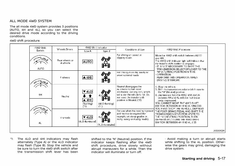
(259,1)
[ Edit: 2020/ 11/ 9 Model: Y62-A ]
ALL MODE 4WD SYSTEMGUID-E90D06BA-41D8-4D17-BC10-1F6A3B15AB30
The all mode 4WD system provides 3 positions(AUTO, 4H and 4L), so you can select thedesired drive mode according to the drivingconditions.4WD shift procedure:
JVS0092M
*1: The 4LO and 4HI indicators may flashalternately (Type A) or the 4LO indicatormay flash (Type B). Stop the vehicle andbe sure to turn the 4WD shift switch afterthe transmission shift lever has been
shifted to the “N” (Neutral) position. If theindicator keeps flashing after the 4WDshift procedure, drive slowly withoutabrupt maneuvers for a while. Then theindicator will illuminate or turn off.
· Avoid making a turn or abrupt startswhile shifting to the 4L position. Other-wise the gears may grind, damaging thedrive system.
Starting and driving 5-17
Condition: 'Except for China'/'Except for China/
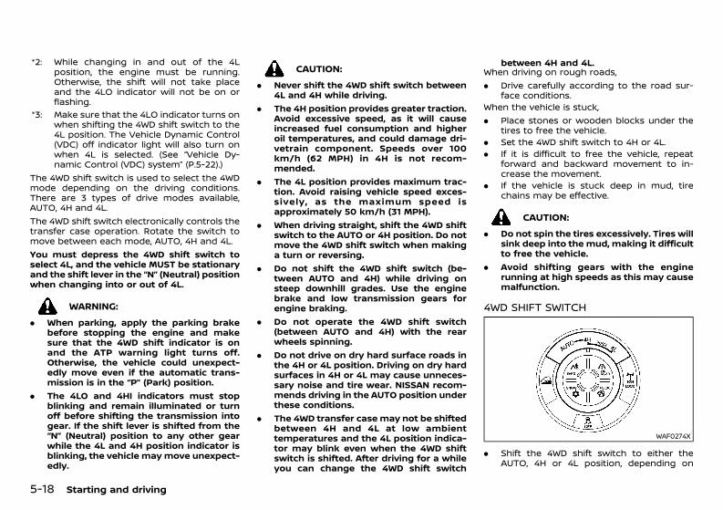
(260,1)
[ Edit: 2020/ 11/ 9 Model: Y62-A ]
5-18 Starting and driving
*2: While changing in and out of the 4Lposition, the engine must be running.Otherwise, the shift will not take placeand the 4LO indicator will not be on orflashing.
*3: Make sure that the 4LO indicator turns onwhen shifting the 4WD shift switch to the4L position. The Vehicle Dynamic Control(VDC) off indicator light will also turn onwhen 4L is selected. (See “Vehicle Dy-namic Control (VDC) system” (P.5-22).)
The 4WD shift switch is used to select the 4WDmode depending on the driving conditions.There are 3 types of drive modes available,AUTO, 4H and 4L.The 4WD shift switch electronically controls thetransfer case operation. Rotate the switch tomove between each mode, AUTO, 4H and 4L.You must depress the 4WD shift switch toselect 4L, and the vehicle MUST be stationaryand the shift lever in the “N” (Neutral) positionwhen changing into or out of 4L.
WARNING:. When parking, apply the parking brake
before stopping the engine and makesure that the 4WD shift indicator is onand the ATP warning light turns off.Otherwise, the vehicle could unexpect-edly move even if the automatic trans-mission is in the “P” (Park) position.
. The 4LO and 4HI indicators must stopblinking and remain illuminated or turnoff before shifting the transmission intogear. If the shift lever is shifted from the“N” (Neutral) position to any other gearwhile the 4L and 4H position indicator isblinking, the vehicle may move unexpect-edly.
CAUTION:. Never shift the 4WD shift switch between
4L and 4H while driving.. The 4H position provides greater traction.
Avoid excessive speed, as it will causeincreased fuel consumption and higheroil temperatures, and could damage dri-vetrain component. Speeds over 100km/h (62 MPH) in 4H is not recom-mended.
. The 4L position provides maximum trac-tion. Avoid raising vehicle speed exces-sively, as the maximum speed isapproximately 50 km/h (31 MPH).
. When driving straight, shift the 4WD shiftswitch to the AUTO or 4H position. Do notmove the 4WD shift switch when makinga turn or reversing.
. Do not shift the 4WD shift switch (be-tween AUTO and 4H) while driving onsteep downhill grades. Use the enginebrake and low transmission gears forengine braking.
. Do not operate the 4WD shift switch(between AUTO and 4H) with the rearwheels spinning.
. Do not drive on dry hard surface roads inthe 4H or 4L position. Driving on dry hardsurfaces in 4H or 4L may cause unneces-sary noise and tire wear. NISSAN recom-mends driving in the AUTO position underthese conditions.
. The 4WD transfer case may not be shiftedbetween 4H and 4L at low ambienttemperatures and the 4L position indica-tor may blink even when the 4WD shiftswitch is shifted. After driving for a whileyou can change the 4WD shift switch
between 4H and 4L.When driving on rough roads,. Drive carefully according to the road sur-
face conditions.When the vehicle is stuck,. Place stones or wooden blocks under the
tires to free the vehicle.. Set the 4WD shift switch to 4H or 4L.. If it is difficult to free the vehicle, repeat
forward and backward movement to in-crease the movement.
. If the vehicle is stuck deep in mud, tirechains may be effective.
CAUTION:. Do not spin the tires excessively. Tires will
sink deep into the mud, making it difficultto free the vehicle.
. Avoid shifting gears with the enginerunning at high speeds as this may causemalfunction.
4WD SHIFT SWITCHGUID-520BF100-A44E-44AC-B57F-91A162E58E30
WAF0274X
. Shift the 4WD shift switch to either theAUTO, 4H or 4L position, depending on
Condition: 'Except for China'/'Except for China/
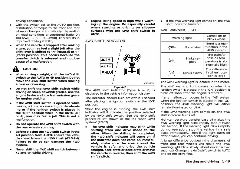
(261,1)
[ Edit: 2020/ 11/ 9 Model: Y62-A ]
driving conditions.. With the switch set to the AUTO position,
distribution of torque to the front and rearwheels changes automatically, dependingon road conditions encountered [ratio; 0 :100 (2WD) ? 50 : 50 (4WD)]. This results inimproved driving stability.
. When the vehicle is stopped after makinga turn, you may feel a slight jolt after theshift lever is shifted to “N” (Neutral) or “P”(Park) position. This occurs because thetransfer clutch is released and not be-cause of a malfunction.
CAUTION:. When driving straight, shift the 4WD shift
switch to the AUTO or 4H position. Do notmove the 4WD shift switch when makinga turn or reversing.
. Do not shift the 4WD shift switch whiledriving on steep downhill grades. Use theengine brake and low transmission gearsfor engine braking.
. If the 4WD shift switch is operated whilemaking a turn, accelerating or decelerat-ing or if the ignition switch is placed inthe “OFF” position while in the AUTO, 4Hor 4L, you may feel a jolt. This is not amalfunction.
. Do not operate the 4WD shift switch withthe rear wheels spinning.
. Before placing the 4WD shift switch in the4H position from AUTO, ensure the vehi-cle speed is less than 100 km/h (62 MPH).Failure to do so can damage the 4WDsystem.
. Never shift the 4WD shift switch between4L and 4H while driving.
. Engine idling speed is high while warm-ing up the engine. Be especially carefulwhen starting or driving on slipperysurfaces with the 4WD shift switch inAUTO.
4WD SHIFT INDICATORGUID-80CA9BD9-C099-4DDB-A298-95998425794D
JVS0093XType A/B
The 4WD shift indicator (Type A or B) isdisplayed in the vehicle information display.The indicator should turn off within 1 secondafter placing the ignition switch in the “ON”position.While the engine is running, the 4WD shiftindicator will illuminate the position selectedby the 4WD shift switch. (See the 4WD shiftprocedure list shown in the “All mode 4WDsystem” (P.5-17).). The 4WD shift indicator may blink while
shifting from one drive mode to theother. When the shifting is completed,the 4WD shift indicator will come on. Ifthe indicator does not come on immedi-ately, make sure the area around thevehicle is safe, and drive the vehiclestraight, accelerate or decelerate or movethe vehicle in reverse, then shift the 4WDshift switch.
. If the 4WD warning light comes on, the 4WDshift indicator turns off.
4WD WARNING LIGHTGUID-756BD005-A93B-49B9-968A-C3FB16BBA51A
Warning light Comes on orblinks when:
IlluminatesThere is a mal-function in the4WD system
Blinks ra-pidly
The transfercase oil tem-perature is ab-normally high
Blinks slowlyThe differencein wheel rota-tion is large
The 4WD warning light is located in the meter.The 4WD warning light comes on when theignition switch is placed in the “ON” position. Itturns off soon after the engine is started.If any malfunction occurs in the 4WD systemwhen the ignition switch is placed in the “ON”position, the 4WD warning light will eitherremain illuminated or blink.If the 4WD warning light comes on, the 4WDshift indicator turns off.High-temperature transfer case oil makes the4WD warning light blink rapidly (about twiceper second). If the warning light blinks rapidlyduring operation, stop the vehicle in a safeplace immediately. Then if the light turns offafter a while, you can continue driving.A large difference between the diameters offront and rear wheels will make the 4WDwarning light blink slowly (about once per twoseconds). Change the 4WD shift switch to AUTOand do not drive fast.
Starting and driving 5-19
Condition: 'Except for China'/'Except for China/
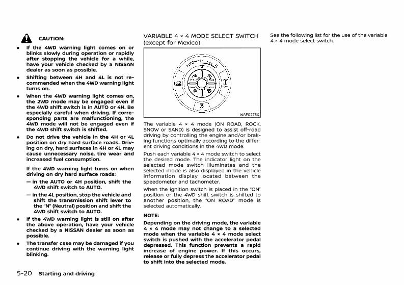
(262,1)
[ Edit: 2020/ 11/ 9 Model: Y62-A ]
5-20 Starting and driving
CAUTION:. If the 4WD warning light comes on or
blinks slowly during operation or rapidlyafter stopping the vehicle for a while,have your vehicle checked by a NISSANdealer as soon as possible.
. Shifting between 4H and 4L is not re-commended when the 4WD warning lightturns on.
. When the 4WD warning light comes on,the 2WD mode may be engaged even ifthe 4WD shift switch is in AUTO or 4H. Beespecially careful when driving. If corre-sponding parts are malfunctioning, the4WD mode will not be engaged even ifthe 4WD shift switch is shifted.
. Do not drive the vehicle in the 4H or 4Lposition on dry hard surface roads. Driv-ing on dry, hard surfaces in 4H or 4L maycause unnecessary noise, tire wear andincreased fuel consumption.
If the 4WD warning light turns on whendriving on dry hard surface roads:— in the AUTO or 4H position, shift the
4WD shift switch to AUTO.— in the 4L position, stop the vehicle and
shift the transmission shift lever tothe “N” (Neutral) position and shift the4WD shift switch to AUTO.
. If the 4WD warning light is still on afterthe above operation, have your vehiclechecked by a NISSAN dealer as soon aspossible.
. The transfer case may be damaged if youcontinue driving with the warning lightblinking.
VARIABLE 4 × 4 MODE SELECT SWITCH(except for Mexico)GUID-35541FB8-BF0C-4F27-9EEB-2A52F6ED8480
WAF0275X
The variable 4 × 4 mode (ON ROAD, ROCK,SNOW or SAND) is designed to assist off-roaddriving by controlling the engine and/or brak-ing functions optimally according to the differ-ent driving conditions in the 4WD mode.Push each variable 4 × 4 mode switch to selectthe desired mode. The indicator light on theselected mode switch illuminates and theselected mode is also displayed in the vehicleinformation display located between thespeedometer and tachometer.When the ignition switch is placed in the “ON”position or the 4WD shift switch is shifted toanother position, the “ON ROAD” mode isselected automatically.
NOTE:Depending on the driving mode, the variable4 × 4 mode may not change to a selectedmode when the variable 4 × 4 mode selectswitch is pushed with the accelerator pedaldepressed. This function prevents a rapidincrease of engine power. If this occurs,release or fully depress the accelerator pedalto shift into the selected mode.
See the following list for the use of the variable4 × 4 mode select switch.
Condition: 'Except for China'/'Except for China/
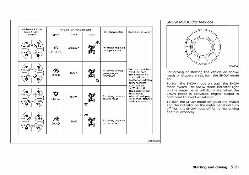
(263,1)
[ Edit: 2020/ 11/ 9 Model: Y62-A ]
WAF0268X
SNOW MODE (for Mexico)GUID-6CE0EFF4-E2BC-4526-84CA-A88C0E474BC9
SIC4454
For driving or starting the vehicle on snowyroads or slippery areas, turn the SNOW modeon.To turn the SNOW mode on, push the SNOWmode switch. The SNOW mode indicator lighton the meter panel will illuminate. When theSNOW mode is activated, engine output iscontrolled to avoid wheel spin.To turn the SNOW mode off, push the switchand the indicator on the meter panel will turnoff. Turn the SNOW mode off for normal drivingand fuel economy.
Starting and driving 5-21
Condition: 'Except for China'/'Except for China/
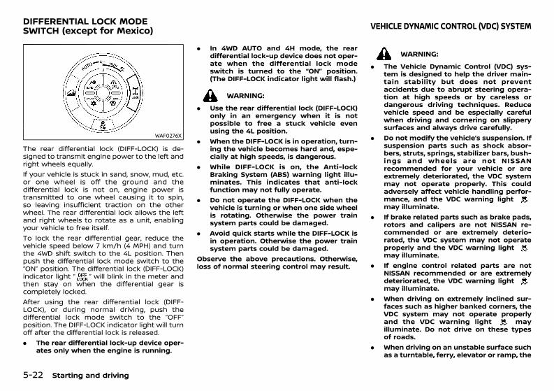
(264,1)
[ Edit: 2020/ 11/ 9 Model: Y62-A ]
5-22 Starting and driving
GUID-82E45AD4-C208-41AF-B9D8-411946DB6EDA
WAF0276X
The rear differential lock (DIFF-LOCK) is de-signed to transmit engine power to the left andright wheels equally.If your vehicle is stuck in sand, snow, mud, etc.or one wheel is off the ground and thedifferential lock is not on, engine power istransmitted to one wheel causing it to spin,so leaving insufficient traction on the otherwheel. The rear differential lock allows the leftand right wheels to rotate as a unit, enablingyour vehicle to free itself.To lock the rear differential gear, reduce thevehicle speed below 7 km/h (4 MPH) and turnthe 4WD shift switch to the 4L position. Thenpush the differential lock mode switch to the“ON” position. The differential lock (DIFF-LOCK)indicator light “ ” will blink in the meter andthen stay on when the differential gear iscompletely locked.After using the rear differential lock (DIFF-LOCK), or during normal driving, push thedifferential lock mode switch to the “OFF”position. The DIFF-LOCK indicator light will turnoff after the differential lock is released.. The rear differential lock-up device oper-
ates only when the engine is running.
. In 4WD AUTO and 4H mode, the reardifferential lock-up device does not oper-ate when the differential lock modeswitch is turned to the “ON” position.(The DIFF-LOCK indicator light will flash.)
WARNING:. Use the rear differential lock (DIFF-LOCK)
only in an emergency when it is notpossible to free a stuck vehicle evenusing the 4L position.
. When the DIFF-LOCK is in operation, turn-ing the vehicle becomes hard and, espe-cially at high speeds, is dangerous.
. While DIFF-LOCK is on, the Anti-lockBraking System (ABS) warning light illu-minates. This indicates that anti-lockfunction may not fully operate.
. Do not operate the DIFF-LOCK when thevehicle is turning or when one side wheelis rotating. Otherwise the power trainsystem parts could be damaged.
. Avoid quick starts while the DIFF-LOCK isin operation. Otherwise the power trainsystem parts could be damaged.
Observe the above precautions. Otherwise,loss of normal steering control may result.
GUID-D0CCF6D5-5CD3-4D2A-8A47-0582A6B00861
WARNING:. The Vehicle Dynamic Control (VDC) sys-
tem is designed to help the driver main-tain stability but does not preventaccidents due to abrupt steering opera-tion at high speeds or by careless ordangerous driving techniques. Reducevehicle speed and be especially carefulwhen driving and cornering on slipperysurfaces and always drive carefully.
. Do not modify the vehicle’s suspension. Ifsuspension parts such as shock absor-bers, struts, springs, stabilizer bars, bush-ings and wheels are not NISSANrecommended for your vehicle or areextremely deteriorated, the VDC systemmay not operate properly. This couldadversely affect vehicle handling perfor-mance, and the VDC warning lightmay illuminate.
. If brake related parts such as brake pads,rotors and calipers are not NISSAN re-commended or are extremely deterio-rated, the VDC system may not operateproperly and the VDC warning lightmay illuminate.
. If engine control related parts are notNISSAN recommended or are extremelydeteriorated, the VDC warning lightmay illuminate.
. When driving on extremely inclined sur-faces such as higher banked corners, theVDC system may not operate properlyand the VDC warning light mayilluminate. Do not drive on these typesof roads.
. When driving on an unstable surface suchas a turntable, ferry, elevator or ramp, the
DIFFERENTIAL LOCK MODESWITCH (except for Mexico) VEHICLE DYNAMIC CONTROL (VDC) SYSTEM
Condition: 'Except for China'/'Except for China/
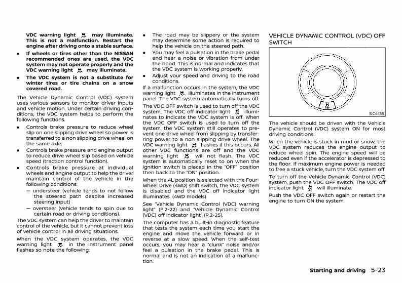
(265,1)
[ Edit: 2020/ 11/ 9 Model: Y62-A ]
VDC warning light may illuminate.This is not a malfunction. Restart theengine after driving onto a stable surface.
. If wheels or tires other than the NISSANrecommended ones are used, the VDCsystemmay not operate properly and theVDC warning light may illuminate.
. The VDC system is not a substitute forwinter tires or tire chains on a snowcovered road.
The Vehicle Dynamic Control (VDC) systemuses various sensors to monitor driver inputsand vehicle motion. Under certain driving con-ditions, the VDC system helps to perform thefollowing functions.. Controls brake pressure to reduce wheel
slip on one slipping drive wheel so power istransferred to a non slipping drive wheel onthe same axle.
. Controls brake pressure and engine outputto reduce drive wheel slip based on vehiclespeed (traction control function).
. Controls brake pressure at individualwheels and engine output to help the drivermaintain control of the vehicle in thefollowing conditions:— understeer (vehicle tends to not follow
the steered path despite increasedsteering input)
— oversteer (vehicle tends to spin due tocertain road or driving conditions).
The VDC system can help the driver to maintaincontrol of the vehicle, but it cannot prevent lossof vehicle control in all driving situations.When the VDC system operates, the VDCwarning light in the instrument panelflashes so note the following:
. The road may be slippery or the systemmay determine some action is required tohelp the vehicle on the steered path.
. You may feel a pulsation in the brake pedaland hear a noise or vibration from underthe hood. This is normal and indicates thatthe VDC system is working properly.
. Adjust your speed and driving to the roadconditions.
If a malfunction occurs in the system, the VDCwarning light illuminates in the instrumentpanel. The VDC system automatically turns off.The VDC OFF switch is used to turn off the VDCsystem. The VDC off indicator light illumi-nates to indicate the VDC system is off. Whenthe VDC OFF switch is used to turn off thesystem, the VDC system still operates to pre-vent one drive wheel from slipping by transfer-ring power to a non slipping drive wheel. TheVDC warning light flashes if this occurs. Allother VDC functions are off and the VDCwarning light will not flash. The VDCsystem is automatically reset to on when theignition switch is placed in the “OFF” positionthen back to the “ON” position.When the 4L position is selected with the Four-Wheel Drive (4WD) shift switch, the VDC systemis disabled and the VDC off indicator lightilluminates. (4WD models)See “Vehicle Dynamic Control (VDC) warninglight” (P.2-22) and “Vehicle Dynamic Control(VDC) off indicator light” (P.2-25).The computer has a built-in diagnostic featurethat tests the system each time you start theengine and move the vehicle forward or inreverse at a slow speed. When the self-testoccurs, you may hear a “clunk” noise and/orfeel a pulsation in the brake pedal. This isnormal and is not an indication of a malfunc-tion.
VEHICLE DYNAMIC CONTROL (VDC) OFFSWITCH GUID-C40ADF15-B0E4-4B5A-BCFA-C6FC4EB114B7
SIC4455
The vehicle should be driven with the VehicleDynamic Control (VDC) system ON for mostdriving conditions.When the vehicle is stuck in mud or snow, theVDC system reduces the engine output toreduce wheel spin. The engine speed will bereduced even if the accelerator is depressed tothe floor. If maximum engine power is neededto free a stuck vehicle, turn the VDC system off.To turn off the Vehicle Dynamic Control (VDC)system, push the VDC OFF switch. The VDC offindicator light will illuminate.Push the VDC OFF switch again or restart theengine to turn ON the system.
Starting and driving 5-23
Condition: 'Except for China'/'Except for China/

(266,1)
[ Edit: 2020/ 11/ 9 Model: Y62-A ]
5-24 Starting and driving
GUID-3355359D-0C57-464E-A840-67F848C5C9FC
WARNING:. Never rely solely on the hill descent
control system to control vehicle speedwhen driving on steep downhill grades.Always drive carefully when using the hilldescent control system and deceleratethe vehicle speed by depressing thebrake pedal if necessary. Be especiallycareful when driving on frozen, muddy orextremely steep downhill roads. Failureto control vehicle speed may result in aloss of control of the vehicle and possibleserious injury or death.
. The hill descent control system may notcontrol the vehicle speed on a hill underall load or road conditions. Always beprepared to depress the brake pedal tocontrol vehicle speed. Failure to do somay result in a collision or serious perso-nal injury.
When the hill descent control system is acti-vated, it automatically applies smooth brakesto control speed on a steep and slipperydescent or off the road without brake oraccelerator operation. The hill descent controlsystem helps maintain vehicle speed whendriving under 25 km/h (16 MPH) on a steepdescent that engine braking alone in the 4H or4L mode cannot control the speed.
NOTE:When the hill descent control system oper-ates continuously for a long time, the tem-perature of the Vehicle Dynamic Control(VDC) system actuator may increase and thehill descent control system may be tempora-rily disabled. The hill descent control systemon indicator light will turn off. The hilldescent control system will resume operat-
ing automatically and the indicator light willilluminate again when the temperature ofthe VDC system actuator is reduced. If theindicator light does not illuminate, turn offthe system.HILL DESCENT CONTROL SWITCHGUID-3281DB10-46C1-4A82-860C-12C6C2DFFB87
WAF0277X
When additional braking is required on steepdownhill roads, activate the hill descent controlsystem by pushing the hill descent controlswitch on.When the hill descent control system is acti-vated, the hill descent control system onindicator light will illuminate. (See “Hill descentcontrol system ON indicator light” (P.2-23).) Also,the stop/tail lights illuminate while the hilldescent control system is applying the brakesto control the vehicle speed.To activate the hill descent control system,satisfy all of the following conditions:. Shift the transmission to the forward or
reverse gear.. Shift the Four-Wheel Drive (4WD) shift
switch to the 4H or 4L position and drivethe vehicle at a speed under 25 km/h (16MPH).
. Push the hill descent control switch to the“ON” position.
If the accelerator or brake pedal is depressedwhile the hill descent control system is on, thesystem will stop operating temporarily. As soonas the accelerator or brake pedal is released,the hill descent control system begins tofunction again if the hill descent controloperating conditions are fulfilled.The hill descent control system on indicatorlight blinks if the hill descent control switch ison and all conditions for system activation arenot met, or if the system becomes disengagedfor any reason.To turn off the hill descent control system, pushthe hill descent control switch to the “OFF”position.
HILL DESCENT CONTROL SYSTEM(except for Mexico)
Condition: 'Except for China'/'Except for China/
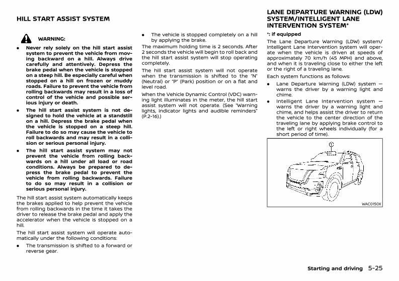
(267,1)
[ Edit: 2020/ 11/ 9 Model: Y62-A ]
GUID-B80DCF91-72A5-4FCF-BD76-0511FBD5355C
WARNING:. Never rely solely on the hill start assist
system to prevent the vehicle from mov-ing backward on a hill. Always drivecarefully and attentively. Depress thebrake pedal when the vehicle is stoppedon a steep hill. Be especially careful whenstopped on a hill on frozen or muddyroads. Failure to prevent the vehicle fromrolling backwards may result in a loss ofcontrol of the vehicle and possible ser-ious injury or death.
. The hill start assist system is not de-signed to hold the vehicle at a standstillon a hill. Depress the brake pedal whenthe vehicle is stopped on a steep hill.Failure to do so may cause the vehicle toroll backwards and may result in a colli-sion or serious personal injury.
. The hill start assist system may notprevent the vehicle from rolling back-wards on a hill under all load or roadconditions. Always be prepared to de-press the brake pedal to prevent thevehicle from rolling backwards. Failureto do so may result in a collision orserious personal injury.
The hill start assist system automatically keepsthe brakes applied to help prevent the vehiclefrom rolling backwards in the time it takes thedriver to release the brake pedal and apply theaccelerator when the vehicle is stopped on ahill.The hill start assist system will operate auto-matically under the following conditions:. The transmission is shifted to a forward or
reverse gear.
. The vehicle is stopped completely on a hillby applying the brake.
The maximum holding time is 2 seconds. After2 seconds the vehicle will begin to roll back andthe hill start assist system will stop operatingcompletely.The hill start assist system will not operatewhen the transmission is shifted to the “N”(Neutral) or “P” (Park) position or on a flat andlevel road.When the Vehicle Dynamic Control (VDC) warn-ing light illuminates in the meter, the hill startassist system will not operate. (See “Warninglights, indicator lights and audible reminders”(P.2-16).)
GUID-4A5DD9EB-4AFB-4EDF-9B5A-46B19C0D49DA*: if equippedThe Lane Departure Warning (LDW) system/Intelligent Lane Intervention system will oper-ate when the vehicle is driven at speeds ofapproximately 70 km/h (45 MPH) and above,and when it is traveling close to either the leftor the right of a traveling lane.Each system functions as follows:. Lane Departure Warning (LDW) system —
warns the driver by a warning light andchime.
. Intelligent Lane Intervention system —warns the driver by a warning light andchime, and helps assist the driver to returnthe vehicle to the center direction of thetraveling lane by applying brake control tothe left or right wheels individually (for ashort period of time).
WAC0150X
Starting and driving 5-25
HILL START ASSIST SYSTEMLANE DEPARTURE WARNING (LDW)SYSTEM/INTELLIGENT LANEINTERVENTION SYSTEM*
Condition: 'Except for China'/'Except for China/
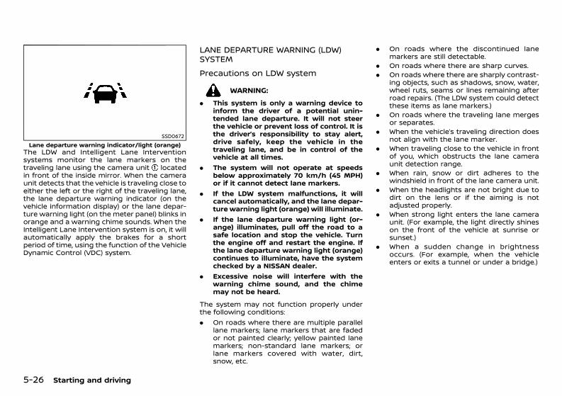
(268,1)
[ Edit: 2020/ 11/ 9 Model: Y62-A ]
5-26 Starting and driving
SSD0672Lane departure warning indicator/light (orange)
The LDW and Intelligent Lane Interventionsystems monitor the lane markers on thetraveling lane using the camera unit locatedin front of the inside mirror. When the cameraunit detects that the vehicle is traveling close toeither the left or the right of the traveling lane,the lane departure warning indicator (on thevehicle information display) or the lane depar-ture warning light (on the meter panel) blinks inorange and a warning chime sounds. When theIntelligent Lane Intervention system is on, it willautomatically apply the brakes for a shortperiod of time, using the function of the VehicleDynamic Control (VDC) system.
LANE DEPARTURE WARNING (LDW)SYSTEM GUID-70C43B57-B3EA-45B1-9BFF-5CEFF6CFCE8A
Precautions on LDW systemGUID-556D7354-122F-4E51-A840-E2566E1AFBE9
WARNING:. This system is only a warning device to
inform the driver of a potential unin-tended lane departure. It will not steerthe vehicle or prevent loss of control. It isthe driver’s responsibility to stay alert,drive safely, keep the vehicle in thetraveling lane, and be in control of thevehicle at all times.
. The system will not operate at speedsbelow approximately 70 km/h (45 MPH)or if it cannot detect lane markers.
. If the LDW system malfunctions, it willcancel automatically, and the lane depar-ture warning light (orange) will illuminate.
. If the lane departure warning light (or-ange) illuminates, pull off the road to asafe location and stop the vehicle. Turnthe engine off and restart the engine. Ifthe lane departure warning light (orange)continues to illuminate, have the systemchecked by a NISSAN dealer.
. Excessive noise will interfere with thewarning chime sound, and the chimemay not be heard.
The system may not function properly underthe following conditions:. On roads where there are multiple parallel
lane markers; lane markers that are fadedor not painted clearly; yellow painted lanemarkers; non-standard lane markers; orlane markers covered with water, dirt,snow, etc.
. On roads where the discontinued lanemarkers are still detectable.
. On roads where there are sharp curves.
. On roads where there are sharply contrast-ing objects, such as shadows, snow, water,wheel ruts, seams or lines remaining afterroad repairs. (The LDW system could detectthese items as lane markers.)
. On roads where the traveling lane mergesor separates.
. When the vehicle’s traveling direction doesnot align with the lane marker.
. When traveling close to the vehicle in frontof you, which obstructs the lane cameraunit detection range.
. When rain, snow or dirt adheres to thewindshield in front of the lane camera unit.
. When the headlights are not bright due todirt on the lens or if the aiming is notadjusted properly.
. When strong light enters the lane cameraunit. (For example, the light directly shineson the front of the vehicle at sunrise orsunset.)
. When a sudden change in brightnessoccurs. (For example, when the vehicleenters or exits a tunnel or under a bridge.)
Condition: 'Except for China'/'Except for China/
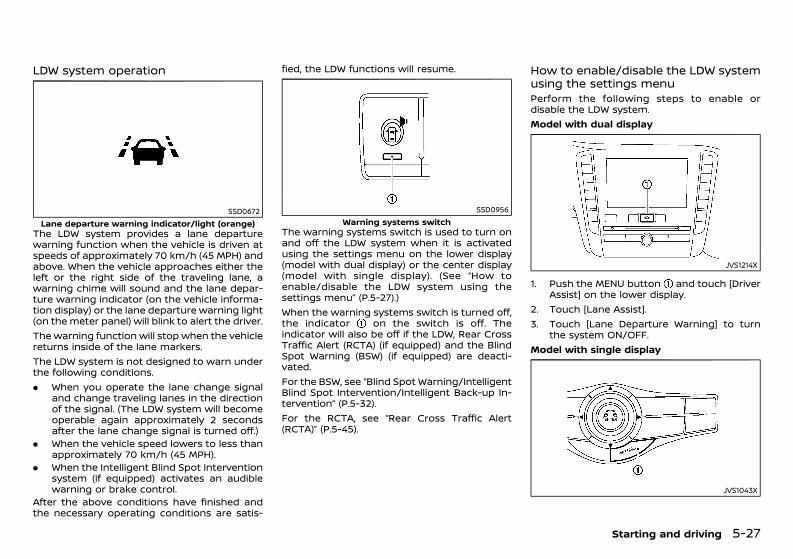
(269,1)
[ Edit: 2020/ 11/ 9 Model: Y62-A ]
LDW system operationGUID-04A79FEA-E02C-49E7-ADF2-64DEC74FB26F
SSD0672Lane departure warning indicator/light (orange)
The LDW system provides a lane departurewarning function when the vehicle is driven atspeeds of approximately 70 km/h (45 MPH) andabove. When the vehicle approaches either theleft or the right side of the traveling lane, awarning chime will sound and the lane depar-ture warning indicator (on the vehicle informa-tion display) or the lane departure warning light(on the meter panel) will blink to alert the driver.The warning function will stop when the vehiclereturns inside of the lane markers.The LDW system is not designed to warn underthe following conditions.. When you operate the lane change signal
and change traveling lanes in the directionof the signal. (The LDW system will becomeoperable again approximately 2 secondsafter the lane change signal is turned off.)
. When the vehicle speed lowers to less thanapproximately 70 km/h (45 MPH).
. When the Intelligent Blind Spot Interventionsystem (if equipped) activates an audiblewarning or brake control.
After the above conditions have finished andthe necessary operating conditions are satis-
fied, the LDW functions will resume.
SSD0956Warning systems switch
The warning systems switch is used to turn onand off the LDW system when it is activatedusing the settings menu on the lower display(model with dual display) or the center display(model with single display). (See “How toenable/disable the LDW system using thesettings menu” (P.5-27).)When the warning systems switch is turned off,the indicator on the switch is off. Theindicator will also be off if the LDW, Rear CrossTraffic Alert (RCTA) (if equipped) and the BlindSpot Warning (BSW) (if equipped) are deacti-vated.For the BSW, see “Blind Spot Warning/IntelligentBlind Spot Intervention/Intelligent Back-up In-tervention” (P.5-32).For the RCTA, see “Rear Cross Traffic Alert(RCTA)” (P.5-45).
How to enable/disable the LDW systemusing the settings menuGUID-86B38547-9CC3-45BF-852F-BAF7C67CFE47Perform the following steps to enable ordisable the LDW system.Model with dual display
JVS1214X
1. Push the MENU button and touch [DriverAssist] on the lower display.
2. Touch [Lane Assist].3. Touch [Lane Departure Warning] to turn
the system ON/OFF.Model with single display
JVS1043X
Starting and driving 5-27
Condition: 'Except for China'/'Except for China/
(270,1)
[ Edit: 2020/ 11/ 9 Model: Y62-A ]
5-28 Starting and driving
1. Push the SETTING button .2. Touch [Driver Assistance] on the center
display.3. Touch [Lane Assist].4. Touch [Lane Departure Warning] to turn
the system ON/OFF.
Temporary disabled status at high temperatureGUID-D46E955D-1F59-4A29-A72B-EEF204084EB1Model with color displayIf the vehicle is parked in direct sunlight underhigh temperature conditions (over approxi-mately 40°C [104°F]) and then started, theLDW system may be deactivated automaticallyand the following message will appear in thevehicle information display: “Not available: HighCamera Temp.”When the interior temperature is reduced, theLDW system will resume operating automati-cally.Model without color displayIf the vehicle is parked in direct sunlight underhigh temperature conditions (over approxi-mately 40°C (104°F) and then started, the LDWsystem may be deactivated automatically. Thelane departure warning light (orange) will flash.When the interior temperature is reduced, theLDW system will resume operating automati-cally and the lane departure warning light(orange) will stop flashing.
System malfunctionGUID-2A52E0E0-6E74-488E-A52F-355A22A6DC17Model with color displayWhen the LDW system malfunctions, it will turnoff automatically. The “Malfunction” warningmessage will appear in the vehicle informationdisplay.Stop the vehicle in a safe location, turn theengine off and restart the engine. If the
message continues to appear, have the systemchecked by a NISSAN dealer.Model without color displayWhen the LDW system malfunctions, it will turnoff automatically. The lane departure warninglight (orange) will illuminate.Stop the vehicle in a safe location, turn theengine off and restart the engine. If the warninglight continues to illuminate, have the systemchecked by a NISSAN dealer.
INTELLIGENT LANE INTERVENTION SYS-TEM GUID-5BC9B68F-A741-4206-A0B9-382920723FC4
Precautions on Intelligent Lane Inter-vention systemGUID-D22A391D-ADD2-459B-910F-06617D0D8071
WARNING:. The Intelligent Lane Intervention system
will not steer the vehicle or prevent lossof control. It is the driver’s responsibilityto stay alert, drive safely, keep the vehiclein the traveling lane, and be in control ofvehicle at all times.
. The Intelligent Lane Intervention systemis primarily intended for use on well-developed freeways or highways. It maynot detect the lane markers in certainroads, weather or driving conditions.
. Using the Intelligent Lane Interventionsystem under some conditions of road,lane marker or weather, or when youchange lanes without using the lanechange signal could lead to an unex-pected system operation. In such condi-tions, you need to correct the vehicle’sdirection with your steering operation toavoid accidents.
. When the Intelligent Lane Interventionsystem is operating, avoid excessive orsudden steering maneuvers. Otherwise,you could lose control of the vehicle.
. The Intelligent Lane Intervention systemwill not operate at speeds below approxi-mately 70 km/h (45 MPH) or if it cannotdetect lane markers.
. The Intelligent Lane Intervention systemmay not function properly under thefollowing conditions, and do not use theIntelligent Lane Intervention system:— During bad weather (rain, fog, snow,
wind, etc.).— When driving on slippery roads, such
as on ice or snow, etc.— When driving off-road such as on
sand or rock, etc.— When driving on winding or uneven
roads.— When there is a lane closure due to
road repairs.— When driving in a makeshift lane.— When driving on roads where the lane
width is too narrow.— When driving without normal tire
conditions (for example, tire wear,low tire pressure, installation of sparetire, tire chains, non-standardwheels).
— When the vehicle is equipped withnon-original brake parts or suspen-sion parts.
— When towing a trailer or other vehicle(models with trailer hitch).
Condition: 'Except for China'/'Except for China/
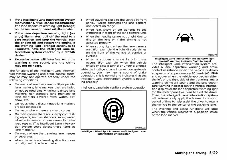
(271,1)
[ Edit: 2020/ 11/ 9 Model: Y62-A ]
. If the Intelligent Lane Intervention systemmalfunctions, it will cancel automatically.The lane departure warning light (orange)on the instrument panel will illuminate.
. If the lane departure warning light (or-ange) illuminates, pull off the road to asafe location and stop the vehicle. Turnthe engine off and restart the engine. Ifthe warning light (orange) continues toilluminate, have the Intelligent Lane In-tervention system checked by a NISSANdealer.
. Excessive noise will interfere with thewarning chime sound, and the chimemay not be heard.
The functions of the Intelligent Lane Interven-tion system (warning and brake control assist)may or may not operate properly under thefollowing conditions:. On roads where there are multiple parallel
lane markers; lane markers that are fadedor not painted clearly; yellow painted lanemarkers; non-standard lane markers; orlane markers covered with water, dirt,snow, etc.
. On roads where discontinued lane markersare still detectable.
. On roads where there are sharp curves.
. On roads where there are sharply contrast-ing objects, such as shadows, snow, water,wheel ruts, seams or lines remaining afterroad repairs. (The Intelligent Lane Interven-tion system could detect these items aslane markers.)
. On roads where the traveling lane mergesor separates.
. When the vehicle’s traveling direction doesnot align with the lane marker.
. When traveling close to the vehicle in frontof you, which obstructs the lane cameraunit detection range.
. When rain, snow or dirt adheres to thewindshield in front of the lane camera unit.
. When the headlights are not bright due todirt on the lens or if the aiming is notadjusted properly.
. When strong light enters the lane cameraunit. (For example, the light directly shineson the front of the vehicle at sunrise orsunset.)
. When a sudden change in brightnessoccurs. (For example, when the vehicleenters or exits a tunnel or under a bridge.)
While the Intelligent Lane Intervention system isoperating, you may hear a sound of brakeoperation. This is normal and indicates that theIntelligent Lane Intervention system is operat-ing properly.
Intelligent Lane Intervention system operationGUID-142F3F03-C7B8-4DC6-8A33-F13BB8690CFE
WAF0257XIntelligent Blind Spot Intervention/Intelligent Lane
Intervention ON indicator
SSD0672Intelligent Lane Intervention ON indicator light
(green)/ Warning indicator/light (orange)The Intelligent Lane Intervention system pro-vides a lane departure warning and brakecontrol assistance when the vehicle is drivenat speeds of approximately 70 km/h (45 MPH)and above. When the vehicle approaches eitherthe left or the right side of the traveling lane, awarning chime will sound and the lane depar-ture warning indicator (on the vehicle informa-tion display) or the lane departure warning light(on the meter panel) will blink to alert the driver.Then, the Intelligent Lane Intervention systemwill automatically apply the brakes for a shortperiod of time to help assist the driver to returnthe vehicle to the center of the traveling lane.The warning and assist functions will stopwhen the vehicle returns to a position insideof the lane marker.
Starting and driving 5-29
Condition: 'Except for China'/'Except for China/
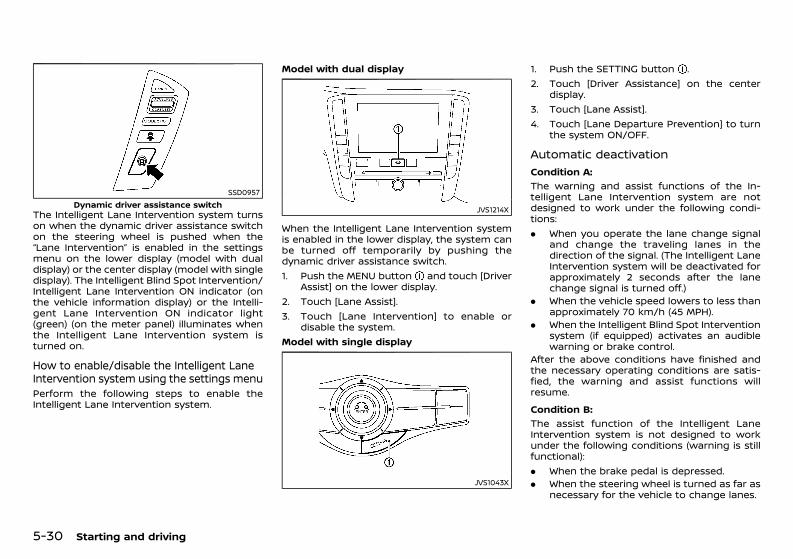
(272,1)
[ Edit: 2020/ 11/ 9 Model: Y62-A ]
5-30 Starting and driving
SSD0957Dynamic driver assistance switch
The Intelligent Lane Intervention system turnson when the dynamic driver assistance switchon the steering wheel is pushed when the“Lane Intervention” is enabled in the settingsmenu on the lower display (model with dualdisplay) or the center display (model with singledisplay). The Intelligent Blind Spot Intervention/Intelligent Lane Intervention ON indicator (onthe vehicle information display) or the Intelli-gent Lane Intervention ON indicator light(green) (on the meter panel) illuminates whenthe Intelligent Lane Intervention system isturned on.
How to enable/disable the Intelligent LaneIntervention system using the settings menuGUID-EABA22BD-DD15-45EE-AC53-8267309833BBPerform the following steps to enable theIntelligent Lane Intervention system.
Model with dual display
JVS1214X
When the Intelligent Lane Intervention systemis enabled in the lower display, the system canbe turned off temporarily by pushing thedynamic driver assistance switch.1. Push the MENU button and touch [Driver
Assist] on the lower display.2. Touch [Lane Assist].3. Touch [Lane Intervention] to enable or
disable the system.Model with single display
JVS1043X
1. Push the SETTING button .2. Touch [Driver Assistance] on the center
display.3. Touch [Lane Assist].4. Touch [Lane Departure Prevention] to turn
the system ON/OFF.
Automatic deactivationGUID-D17B595B-5FA4-45F0-80EB-2221964B604D
Condition A:GUID-C7E1EF24-5AAB-4301-95BE-26917EEE45EF
The warning and assist functions of the In-telligent Lane Intervention system are notdesigned to work under the following condi-tions:. When you operate the lane change signal
and change the traveling lanes in thedirection of the signal. (The Intelligent LaneIntervention system will be deactivated forapproximately 2 seconds after the lanechange signal is turned off.)
. When the vehicle speed lowers to less thanapproximately 70 km/h (45 MPH).
. When the Intelligent Blind Spot Interventionsystem (if equipped) activates an audiblewarning or brake control.
After the above conditions have finished andthe necessary operating conditions are satis-fied, the warning and assist functions willresume.Condition B:
GUID-C7E1EF24-5AAB-4301-95BE-26917EEE45EF
The assist function of the Intelligent LaneIntervention system is not designed to workunder the following conditions (warning is stillfunctional):. When the brake pedal is depressed.. When the steering wheel is turned as far as
necessary for the vehicle to change lanes.
Condition: 'Except for China'/'Except for China/
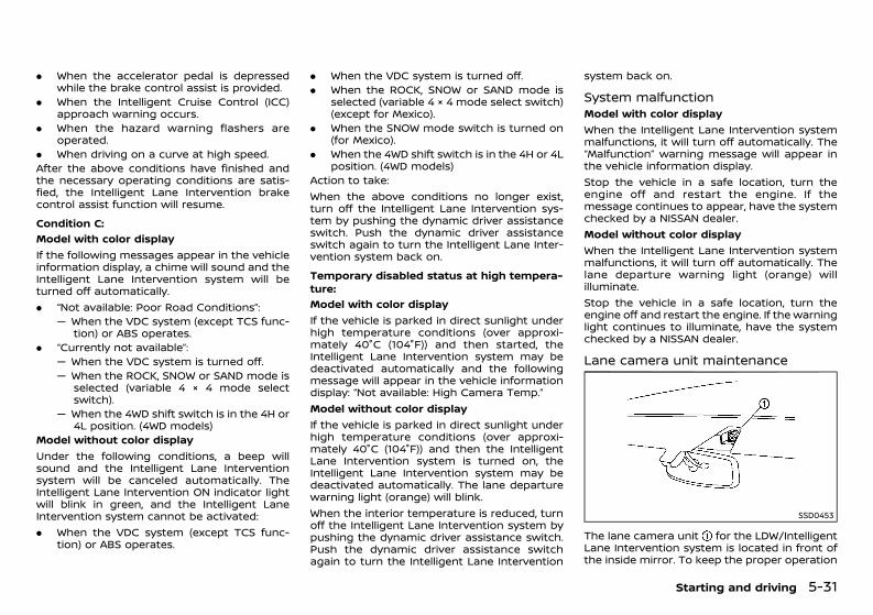
(273,1)
[ Edit: 2020/ 11/ 9 Model: Y62-A ]
. When the accelerator pedal is depressedwhile the brake control assist is provided.
. When the Intelligent Cruise Control (ICC)approach warning occurs.
. When the hazard warning flashers areoperated.
. When driving on a curve at high speed.After the above conditions have finished andthe necessary operating conditions are satis-fied, the Intelligent Lane Intervention brakecontrol assist function will resume.Condition C:
GUID-C7E1EF24-5AAB-4301-95BE-26917EEE45EF
Model with color displayIf the following messages appear in the vehicleinformation display, a chime will sound and theIntelligent Lane Intervention system will beturned off automatically.. “Not available: Poor Road Conditions”:
— When the VDC system (except TCS func-tion) or ABS operates.
. “Currently not available”:— When the VDC system is turned off.— When the ROCK, SNOW or SAND mode is
selected (variable 4 × 4 mode selectswitch).
— When the 4WD shift switch is in the 4H or4L position. (4WD models)
Model without color displayUnder the following conditions, a beep willsound and the Intelligent Lane Interventionsystem will be canceled automatically. TheIntelligent Lane Intervention ON indicator lightwill blink in green, and the Intelligent LaneIntervention system cannot be activated:. When the VDC system (except TCS func-
tion) or ABS operates.
. When the VDC system is turned off.
. When the ROCK, SNOW or SAND mode isselected (variable 4 × 4 mode select switch)(except for Mexico).
. When the SNOW mode switch is turned on(for Mexico).
. When the 4WD shift switch is in the 4H or 4Lposition. (4WD models)
Action to take:When the above conditions no longer exist,turn off the Intelligent Lane Intervention sys-tem by pushing the dynamic driver assistanceswitch. Push the dynamic driver assistanceswitch again to turn the Intelligent Lane Inter-vention system back on.Temporary disabled status at high tempera-ture:
GUID-C7E1EF24-5AAB-4301-95BE-26917EEE45EF
Model with color displayIf the vehicle is parked in direct sunlight underhigh temperature conditions (over approxi-mately 40°C (104°F)) and then started, theIntelligent Lane Intervention system may bedeactivated automatically and the followingmessage will appear in the vehicle informationdisplay: “Not available: High Camera Temp.”Model without color displayIf the vehicle is parked in direct sunlight underhigh temperature conditions (over approxi-mately 40°C (104°F)) and then the IntelligentLane Intervention system is turned on, theIntelligent Lane Intervention system may bedeactivated automatically. The lane departurewarning light (orange) will blink.When the interior temperature is reduced, turnoff the Intelligent Lane Intervention system bypushing the dynamic driver assistance switch.Push the dynamic driver assistance switchagain to turn the Intelligent Lane Intervention
system back on.
System malfunctionGUID-77FC0823-AD81-44C9-9222-3B6926FC77F1Model with color displayWhen the Intelligent Lane Intervention systemmalfunctions, it will turn off automatically. The“Malfunction” warning message will appear inthe vehicle information display.Stop the vehicle in a safe location, turn theengine off and restart the engine. If themessage continues to appear, have the systemchecked by a NISSAN dealer.Model without color displayWhen the Intelligent Lane Intervention systemmalfunctions, it will turn off automatically. Thelane departure warning light (orange) willilluminate.Stop the vehicle in a safe location, turn theengine off and restart the engine. If the warninglight continues to illuminate, have the systemchecked by a NISSAN dealer.
Lane camera unit maintenanceGUID-2F123F7B-4F3B-41B1-8F72-5AB785F7DE9B
SSD0453
The lane camera unit for the LDW/IntelligentLane Intervention system is located in front ofthe inside mirror. To keep the proper operation
Starting and driving 5-31
Condition: 'Except for China'/'Except for China/
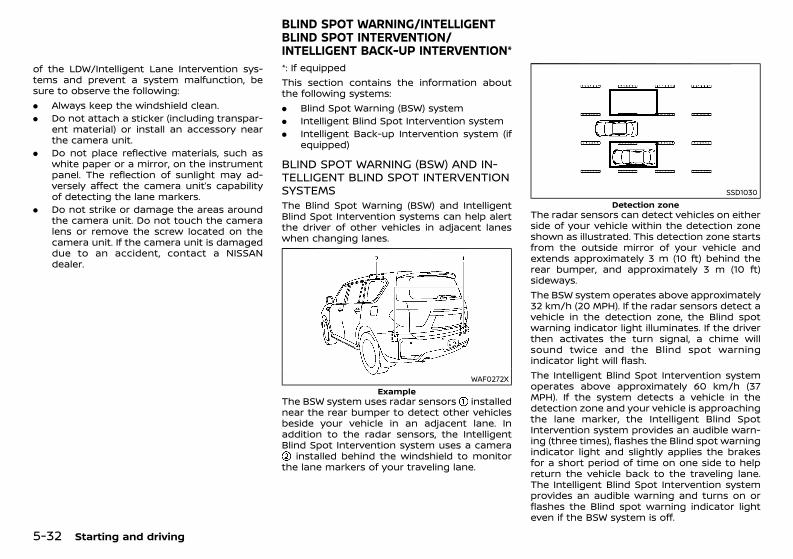
(274,1)
[ Edit: 2020/ 11/ 9 Model: Y62-A ]
5-32 Starting and driving
of the LDW/Intelligent Lane Intervention sys-tems and prevent a system malfunction, besure to observe the following:. Always keep the windshield clean.. Do not attach a sticker (including transpar-
ent material) or install an accessory nearthe camera unit.
. Do not place reflective materials, such aswhite paper or a mirror, on the instrumentpanel. The reflection of sunlight may ad-versely affect the camera unit’s capabilityof detecting the lane markers.
. Do not strike or damage the areas aroundthe camera unit. Do not touch the cameralens or remove the screw located on thecamera unit. If the camera unit is damageddue to an accident, contact a NISSANdealer.
GUID-95B4DD5C-99DB-4A9B-AFE9-F62AACF2645D*: If equippedThis section contains the information aboutthe following systems:. Blind Spot Warning (BSW) system. Intelligent Blind Spot Intervention system. Intelligent Back-up Intervention system (if
equipped)
BLIND SPOT WARNING (BSW) AND IN-TELLIGENT BLIND SPOT INTERVENTIONSYSTEMS GUID-800516B3-55E5-4415-B4B5-6E8D66E1F78CThe Blind Spot Warning (BSW) and IntelligentBlind Spot Intervention systems can help alertthe driver of other vehicles in adjacent laneswhen changing lanes.
WAF0272XExample
The BSW system uses radar sensors installednear the rear bumper to detect other vehiclesbeside your vehicle in an adjacent lane. Inaddition to the radar sensors, the IntelligentBlind Spot Intervention system uses a camera
installed behind the windshield to monitorthe lane markers of your traveling lane.
SSD1030Detection zone
The radar sensors can detect vehicles on eitherside of your vehicle within the detection zoneshown as illustrated. This detection zone startsfrom the outside mirror of your vehicle andextends approximately 3 m (10 ft) behind therear bumper, and approximately 3 m (10 ft)sideways.The BSW system operates above approximately32 km/h (20 MPH). If the radar sensors detect avehicle in the detection zone, the Blind spotwarning indicator light illuminates. If the driverthen activates the turn signal, a chime willsound twice and the Blind spot warningindicator light will flash.The Intelligent Blind Spot Intervention systemoperates above approximately 60 km/h (37MPH). If the system detects a vehicle in thedetection zone and your vehicle is approachingthe lane marker, the Intelligent Blind SpotIntervention system provides an audible warn-ing (three times), flashes the Blind spot warningindicator light and slightly applies the brakesfor a short period of time on one side to helpreturn the vehicle back to the traveling lane.The Intelligent Blind Spot Intervention systemprovides an audible warning and turns on orflashes the Blind spot warning indicator lighteven if the BSW system is off.
BLIND SPOT WARNING/INTELLIGENTBLIND SPOT INTERVENTION/INTELLIGENT BACK-UP INTERVENTION*
Condition: 'Except for China'/'Except for China/
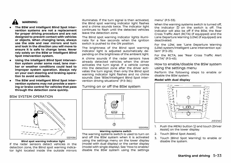
(275,1)
[ Edit: 2020/ 11/ 9 Model: Y62-A ]
WARNING:. The BSW and Intelligent Blind Spot Inter-
vention systems are not a replacementfor proper driving procedure and are notdesigned to prevent contact with vehiclesor objects. When changing lanes, alwaysuse the side and rear mirrors and turnand look in the direction you will move toensure it is safe to change lanes. Neverrely solely on the BSW or Intelligent BlindSpot Intervention system.
. Using the Intelligent Blind Spot Interven-tion system under some road, lane mar-ker or weather conditions could lead toimproper system operation. Always relyon your own steering and braking opera-tion to avoid accidents.
. The BSW and Intelligent Blind Spot Inter-vention systemsmay not provide a warn-ing or brake control for vehicles that passthrough the detection zone quickly.
BSW SYSTEM OPERATIONGUID-2EAFF753-6C0A-4CE1-B6F8-A9AE2D7EF678
SSD1086Blind spot warning indicator light
If the radar sensors detect vehicles in thedetection zone, the Blind spot warning indica-tor light located inside the outside mirrors
illuminates. If the turn signal is then activated,the Blind spot warning indicator light flashesand a chime sounds twice. The indicator lightcontinues to flash until the detected vehiclesleave the detection zone.The Blind spot warning indicator lights illumi-nate for a few seconds when the ignitionswitch is pushed to the ON position.The brightness of the Blind spot warningindicator light is adjusted automatically de-pending on the brightness of the ambient light.A chime sounds if the radar sensors havealready detected vehicles when the driveractivates the turn signal. If a vehicle comesinto the detection zone after the driver acti-vates the turn signal, then only the Blind spotwarning indicator light flashes and no chimesounds. (See “BSW/Intelligent Blind Spot Inter-vention driving situations” (P.5-36).)
Turning on or off the BSW systemGUID-13129540-98F7-4D80-BAA0-F4A061DF05EC
SSD0956Warning systems switch
The warning systems switch is used to turn onand off the BSW system when it is activatedusing the settings menu on the lower display(model with dual display) or the center display(model with single display). See “How to enable/disable the BSW system using the settings
menu” (P.5-33).When the warning systems switch is turned off,the indicator on the switch is off. Theindicator will also be off if the BSW, the RearCross Traffic Alert (RCTA) (if equipped) and theLane Departure Warning (LDW) (if equipped) aredeactivated.For the LDW, see “Lane Departure Warning(LDW) system/Intelligent Lane Intervention sys-tem” (P.5-25).For the RCTA, see “Rear Cross Traffic Alert(RCTA)” (P.5-45).
How to enable/disable the BSW systemusing the settings menuGUID-3DADB131-9C55-418C-B1FE-794B08C6276EPerform the following steps to enable ordisable the BSW system.Model with dual display
JVS1214X
1. Push the MENU button and touch [DriverAssist] on the lower display.
2. Touch [Blind Spot Assist].3. Touch [Blind Spot Warning] to enable or
disable the system.
Starting and driving 5-33
Condition: 'Except for China'/'Except for China/
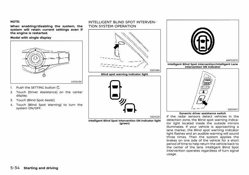
(276,1)
[ Edit: 2020/ 11/ 9 Model: Y62-A ]
5-34 Starting and driving
NOTE:When enabling/disabling the system, thesystem will retain current settings even ifthe engine is restarted.Model with single display
JVS1043X
1. Push the SETTING button .2. Touch [Driver Assistance] on the center
display.3. Touch [Blind Spot Assist].4. Touch [Blind Spot Warning] to turn the
system ON/OFF.
INTELLIGENT BLIND SPOT INTERVEN-TION SYSTEM OPERATIONGUID-1A18CAC2-545A-448A-96C2-313A8B48ED1A
SSD1086Blind spot warning indicator light
SSD1029Intelligent Blind Spot Intervention ON indicator light
(green)
WAF0257XIntelligent Blind Spot Intervention/Intelligent Lane
Intervention ON indicator
SSD0957Dynamic driver assistance switch
If the radar sensors detect vehicles in thedetection zone, the Blind spot warning indica-tor light located inside the outside mirrorsilluminates. If your vehicle is approaching alane marker, the Blind spot warning indicatorlight flashes and an audible warning will soundthree times. Then the system applies thebrakes on one side of the vehicle for a shortperiod of time to help return the vehicle back tothe center of the lane. Intelligent Blind SpotIntervention operates regardless of turn signalusage.
Condition: 'Except for China'/'Except for China/
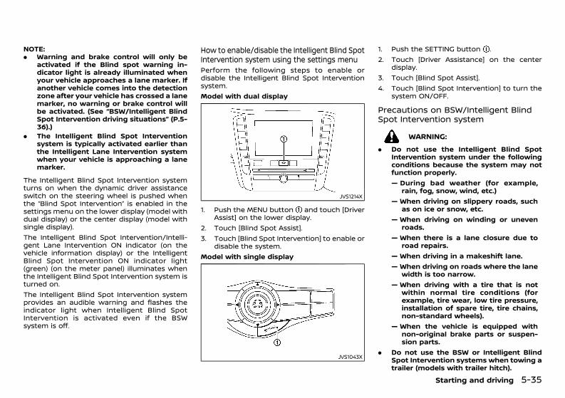
(277,1)
[ Edit: 2020/ 11/ 9 Model: Y62-A ]
NOTE:. Warning and brake control will only be
activated if the Blind spot warning in-dicator light is already illuminated whenyour vehicle approaches a lane marker. Ifanother vehicle comes into the detectionzone after your vehicle has crossed a lanemarker, no warning or brake control willbe activated. (See “BSW/Intelligent BlindSpot Intervention driving situations” (P.5-36).)
. The Intelligent Blind Spot Interventionsystem is typically activated earlier thanthe Intelligent Lane Intervention systemwhen your vehicle is approaching a lanemarker.
The Intelligent Blind Spot Intervention systemturns on when the dynamic driver assistanceswitch on the steering wheel is pushed whenthe “Blind Spot Intervention” is enabled in thesettings menu on the lower display (model withdual display) or the center display (model withsingle display).The Intelligent Blind Spot Intervention/Intelli-gent Lane Intervention ON indicator (on thevehicle information display) or the IntelligentBlind Spot Intervention ON indicator light(green) (on the meter panel) illuminates whenthe Intelligent Blind Spot Intervention system isturned on.The Intelligent Blind Spot Intervention systemprovides an audible warning and flashes theindicator light when Intelligent Blind SpotIntervention is activated even if the BSWsystem is off.
How to enable/disable the Intelligent Blind SpotIntervention system using the settings menuGUID-45A30F37-86BE-4B1A-9907-9945F5831F6DPerform the following steps to enable ordisable the Intelligent Blind Spot Interventionsystem.Model with dual display
JVS1214X
1. Push the MENU button and touch [DriverAssist] on the lower display.
2. Touch [Blind Spot Assist].3. Touch [Blind Spot Intervention] to enable or
disable the system.Model with single display
JVS1043X
1. Push the SETTING button .2. Touch [Driver Assistance] on the center
display.3. Touch [Blind Spot Assist].4. Touch [Blind Spot Intervention] to turn the
system ON/OFF.
Precautions on BSW/Intelligent BlindSpot Intervention systemGUID-C0B00239-CCF3-4DE9-B1BE-E2505197058C
WARNING:. Do not use the Intelligent Blind Spot
Intervention system under the followingconditions because the system may notfunction properly.— During bad weather (for example,
rain, fog, snow, wind, etc.)— When driving on slippery roads, such
as on ice or snow, etc.— When driving on winding or uneven
roads.— When there is a lane closure due to
road repairs.— When driving in a makeshift lane.— When driving on roads where the lane
width is too narrow.— When driving with a tire that is not
within normal tire conditions (forexample, tire wear, low tire pressure,installation of spare tire, tire chains,non-standard wheels).
— When the vehicle is equipped withnon-original brake parts or suspen-sion parts.
. Do not use the BSW or Intelligent BlindSpot Intervention systems when towing atrailer (models with trailer hitch).
Starting and driving 5-35
Condition: 'Except for China'/'Except for China/
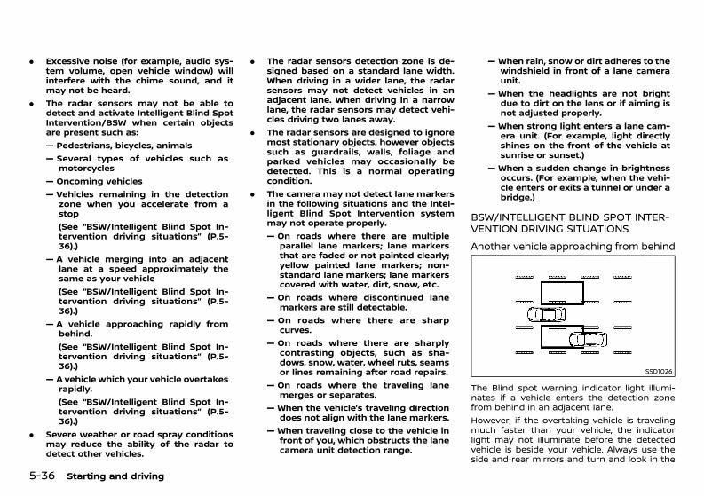
(278,1)
[ Edit: 2020/ 11/ 9 Model: Y62-A ]
5-36 Starting and driving
. Excessive noise (for example, audio sys-tem volume, open vehicle window) willinterfere with the chime sound, and itmay not be heard.
. The radar sensors may not be able todetect and activate Intelligent Blind SpotIntervention/BSW when certain objectsare present such as:— Pedestrians, bicycles, animals— Several types of vehicles such as
motorcycles— Oncoming vehicles— Vehicles remaining in the detection
zone when you accelerate from astop(See “BSW/Intelligent Blind Spot In-tervention driving situations” (P.5-36).)
— A vehicle merging into an adjacentlane at a speed approximately thesame as your vehicle(See “BSW/Intelligent Blind Spot In-tervention driving situations” (P.5-36).)
— A vehicle approaching rapidly frombehind.(See “BSW/Intelligent Blind Spot In-tervention driving situations” (P.5-36).)
— A vehicle which your vehicle overtakesrapidly.(See “BSW/Intelligent Blind Spot In-tervention driving situations” (P.5-36).)
. Severe weather or road spray conditionsmay reduce the ability of the radar todetect other vehicles.
. The radar sensors detection zone is de-signed based on a standard lane width.When driving in a wider lane, the radarsensors may not detect vehicles in anadjacent lane. When driving in a narrowlane, the radar sensors may detect vehi-cles driving two lanes away.
. The radar sensors are designed to ignoremost stationary objects, however objectssuch as guardrails, walls, foliage andparked vehicles may occasionally bedetected. This is a normal operatingcondition.
. The camera may not detect lane markersin the following situations and the Intel-ligent Blind Spot Intervention systemmay not operate properly.— On roads where there are multiple
parallel lane markers; lane markersthat are faded or not painted clearly;yellow painted lane markers; non-standard lane markers; lane markerscovered with water, dirt, snow, etc.
— On roads where discontinued lanemarkers are still detectable.
— On roads where there are sharpcurves.
— On roads where there are sharplycontrasting objects, such as sha-dows, snow, water, wheel ruts, seamsor lines remaining after road repairs.
— On roads where the traveling lanemerges or separates.
— When the vehicle’s traveling directiondoes not align with the lane markers.
— When traveling close to the vehicle infront of you, which obstructs the lanecamera unit detection range.
— When rain, snow or dirt adheres to thewindshield in front of a lane cameraunit.
— When the headlights are not brightdue to dirt on the lens or if aiming isnot adjusted properly.
— When strong light enters a lane cam-era unit. (For example, light directlyshines on the front of the vehicle atsunrise or sunset.)
— When a sudden change in brightnessoccurs. (For example, when the vehi-cle enters or exits a tunnel or under abridge.)
BSW/INTELLIGENT BLIND SPOT INTER-VENTION DRIVING SITUATIONSGUID-94A50BBC-4009-4ABA-B562-13553895B47D
Another vehicle approaching from behindGUID-DE583C70-8C45-42DA-87A9-51070AC6A019
SSD1026
The Blind spot warning indicator light illumi-nates if a vehicle enters the detection zonefrom behind in an adjacent lane.However, if the overtaking vehicle is travelingmuch faster than your vehicle, the indicatorlight may not illuminate before the detectedvehicle is beside your vehicle. Always use theside and rear mirrors and turn and look in the
Condition: 'Except for China'/'Except for China/
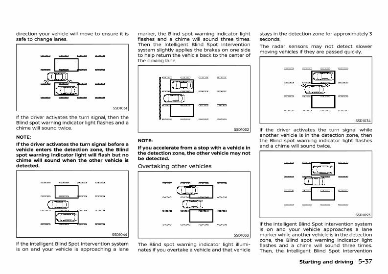
(279,1)
[ Edit: 2020/ 11/ 9 Model: Y62-A ]
direction your vehicle will move to ensure it issafe to change lanes.
SSD1031
If the driver activates the turn signal, then theBlind spot warning indicator light flashes and achime will sound twice.
NOTE:If the driver activates the turn signal before avehicle enters the detection zone, the Blindspot warning indicator light will flash but nochime will sound when the other vehicle isdetected.
SSD1044
If the Intelligent Blind Spot Intervention systemis on and your vehicle is approaching a lane
marker, the Blind spot warning indicator lightflashes and a chime will sound three times.Then the Intelligent Blind Spot Interventionsystem slightly applies the brakes on one sideto help return the vehicle back to the center ofthe driving lane.
SSD1032
NOTE:If you accelerate from a stop with a vehicle inthe detection zone, the other vehicle may notbe detected.Overtaking other vehiclesGUID-03782E4A-A92C-40DE-8815-5D768D4AB60A
SSD1033
The Blind spot warning indicator light illumi-nates if you overtake a vehicle and that vehicle
stays in the detection zone for approximately 3seconds.The radar sensors may not detect slowermoving vehicles if they are passed quickly.
SSD1034
If the driver activates the turn signal whileanother vehicle is in the detection zone, thenthe Blind spot warning indicator light flashesand a chime will sound twice.
SSD1093
If the Intelligent Blind Spot Intervention systemis on and your vehicle approaches a lanemarker while another vehicle is in the detectionzone, the Blind spot warning indicator lightflashes and a chime will sound three times.Then, the Intelligent Blind Spot Intervention
Starting and driving 5-37
Condition: 'Except for China'/'Except for China/
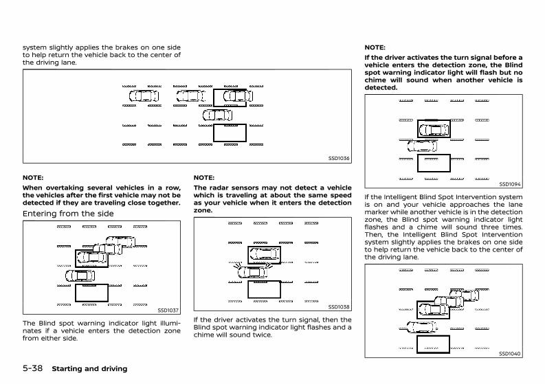
(280,1)
[ Edit: 2020/ 11/ 9 Model: Y62-A ]
5-38 Starting and driving
system slightly applies the brakes on one sideto help return the vehicle back to the center ofthe driving lane.
SSD1036
NOTE:When overtaking several vehicles in a row,the vehicles after the first vehicle may not bedetected if they are traveling close together.Entering from the sideGUID-C8F76E72-7B74-44E8-98C9-4C11EA15C1BD
SSD1037
The Blind spot warning indicator light illumi-nates if a vehicle enters the detection zonefrom either side.
NOTE:The radar sensors may not detect a vehiclewhich is traveling at about the same speedas your vehicle when it enters the detectionzone.
SSD1038
If the driver activates the turn signal, then theBlind spot warning indicator light flashes and achime will sound twice.
NOTE:If the driver activates the turn signal before avehicle enters the detection zone, the Blindspot warning indicator light will flash but nochime will sound when another vehicle isdetected.
SSD1094
If the Intelligent Blind Spot Intervention systemis on and your vehicle approaches the lanemarker while another vehicle is in the detectionzone, the Blind spot warning indicator lightflashes and a chime will sound three times.Then, the Intelligent Blind Spot Interventionsystem slightly applies the brakes on one sideto help return the vehicle back to the center ofthe driving lane.
SSD1040
Condition: 'Except for China'/'Except for China/
(281,1)
[ Edit: 2020/ 11/ 9 Model: Y62-A ]
NOTE:. The Intelligent Blind Spot Intervention
system will not operate if your vehicle ison a lane marker when another vehicleenters the detection zone. In this caseonly the BSW system operates.
. Intelligent Blind Spot Intervention brak-ing will not operate or will stop operatingand only a warning chime will soundunder the following conditions.— When the brake pedal is depressed.— When the accelerator pedal is de-
pressed while brake control assist isprovided.
— When steering quickly— When the ICC, Intelligent Distance Con-
trol, Intelligent Forward CollisionWarning or Intelligent EmergencyBraking warnings sound.
— When the hazard warning flashers areoperated.
— When driving on a curve at a highspeed.
BSW/Intelligent Blind Spot Interventiontemporarily not availableGUID-7A838324-52D6-413B-ABB7-5B775C71C14EModel with color display. If the following messages appear in the
vehicle information display, a chime willsound and the Intelligent Blind Spot Inter-vention system will be turned off automa-tically.— “Not available: Poor Road Conditions”:
- When the VDC system (except TCSfunction) or ABS operates.
— “Currently not available”:- When the VDC system is turned off.- When the ROCK, SNOW or SAND modeis selected (variable 4 × 4 mode select
switch).- When the 4WD shift switch is in the 4Hor 4L position. (4WD models)
Action to take:Turn off the Intelligent Blind Spot Interventionsystem and turn it on again when the aboveconditions no longer exist.. If the following messages appear in the
vehicle information display, a chime willsound and the BSW and or the IntelligentBlind Spot Intervention system will beturned off automatically. The BSW and/orIntelligent Blind Spot Intervention systemsare not available until the conditions nolonger exist.— “Not available: High Camera Temp”:
When the camera detects that theinterior temperature is high (over ap-proximately 40°C (104°F)).
— “Not available: Side Radar Obstruction”:When radar blockage is detected.
The radar sensors may be blocked by tempor-ary ambient conditions such as splashingwater, mist or fog. The blocked condition mayalso be caused by objects such as ice, frost ordirt obstructing the radar sensors.Action to take:When the above conditions no longer exist, thesystem will resume automatically.If the “Not available: Side Radar Obstruction”warning message continues to appear, havethe system checked by a NISSAN dealer.Model without color display. Under the following conditions, the Intelli-
gent Blind Spot Intervention system will beturned off automatically, a beep will soundand the Intelligent Blind Spot InterventionON indicator light (green) will blink. The BSW
system is still available, but the IntelligentBlind Spot Intervention system will not beavailable until the conditions no longerexist.— When the VDC system (except TCS func-
tion) or ABS operates.— When the VDC system is turned off.— When the ROCK, SNOW or SAND mode is
selected (variable 4 X 4 mode selectswitch) (except for Mexico).
— When the 4WD shift switch is in the 4H or4L position. (4WD models)
— When the SNOW mode switch is turnedon (for Mexico).
Action to take:Turn off the Intelligent Blind Spot Interventionsystem and turn it on again when the aboveconditions no longer exist.. Under the following conditions, the BSW
and Intelligent Blind Spot Intervention sys-tems will be turned off automatically, abeep will sound and the BSW/IntelligentBlind Spot Intervention system warninglight (orange) will blink. The BSW andIntelligent Blind Spot Intervention systemsare not available until the conditions nolonger exist.— When the camera detects that the inter-
ior temperature is high (over approxi-mately 40°C (104°F)).
— When radar blockage is detected.The radar sensors may be blocked by tempor-ary ambient conditions such as splashingwater, mist or fog. The blocked condition mayalso be caused by objects such as ice, frost ordirt obstructing the radar sensors.Action to take:When the above conditions no longer exist, theBSW system will resume automatically. For the
Starting and driving 5-39
Condition: 'Except for China'/'Except for China/
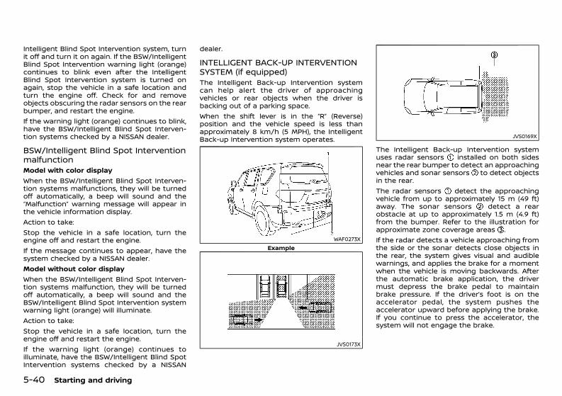
(282,1)
[ Edit: 2020/ 11/ 9 Model: Y62-A ]
5-40 Starting and driving
Intelligent Blind Spot Intervention system, turnit off and turn it on again. If the BSW/IntelligentBlind Spot Intervention warning light (orange)continues to blink even after the IntelligentBlind Spot Intervention system is turned onagain, stop the vehicle in a safe location andturn the engine off. Check for and removeobjects obscuring the radar sensors on the rearbumper, and restart the engine.If the warning light (orange) continues to blink,have the BSW/Intelligent Blind Spot Interven-tion systems checked by a NISSAN dealer.
BSW/Intelligent Blind Spot InterventionmalfunctionGUID-D7DC5AC0-A73C-4F82-8AAA-D5CED04F2FF6Model with color displayWhen the BSW/Intelligent Blind Spot Interven-tion systems malfunctions, they will be turnedoff automatically, a beep will sound and the“Malfunction” warning message will appear inthe vehicle information display.Action to take:Stop the vehicle in a safe location, turn theengine off and restart the engine.If the message continues to appear, have thesystem checked by a NISSAN dealer.Model without color displayWhen the BSW/Intelligent Blind Spot Interven-tion systems malfunction, they will be turnedoff automatically, a beep will sound and theBSW/Intelligent Blind Spot Intervention systemwarning light (orange) will illuminate.Action to take:Stop the vehicle in a safe location, turn theengine off and restart the engine.If the warning light (orange) continues toilluminate, have the BSW/Intelligent Blind SpotIntervention systems checked by a NISSAN
dealer.
INTELLIGENT BACK-UP INTERVENTIONSYSTEM (if equipped)GUID-868DD297-D44D-4AE4-B17B-3AA93BC42666The Intelligent Back-up Intervention systemcan help alert the driver of approachingvehicles or rear objects when the driver isbacking out of a parking space.When the shift lever is in the “R” (Reverse)position and the vehicle speed is less thanapproximately 8 km/h (5 MPH), the IntelligentBack-up Intervention system operates.
WAF0273XExample
JVS0173X
JVS0169X
The Intelligent Back-up Intervention systemuses radar sensors installed on both sidesnear the rear bumper to detect an approachingvehicles and sonar sensors to detect objectsin the rear.The radar sensors detect the approachingvehicle from up to approximately 15 m (49 ft)away. The sonar sensors detect a rearobstacle at up to approximately 1.5 m (4.9 ft)from the bumper. Refer to the illustration forapproximate zone coverage areas .If the radar detects a vehicle approaching fromthe side or the sonar detects close objects inthe rear, the system gives visual and audiblewarnings, and applies the brake for a momentwhen the vehicle is moving backwards. Afterthe automatic brake application, the drivermust depress the brake pedal to maintainbrake pressure. If the driver’s foot is on theaccelerator pedal, the system pushes theaccelerator upward before applying the brake.If you continue to press the accelerator, thesystem will not engage the brake.
Condition: 'Except for China'/'Except for China/
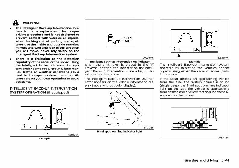
(283,1)
[ Edit: 2020/ 11/ 9 Model: Y62-A ]
WARNING:. The Intelligent Back-up Intervention sys-
tem is not a replacement for properdriving procedure and is not designed toprevent contact with vehicles or objects.When backing out of parking space, al-ways use the inside and outside rearviewmirrors and turn and look in the directionyou will move. Never rely solely on theIntelligent Back-up Intervention system.
. There is a limitation to the detectioncapability of the radar or the sonar. Usingthe Intelligent Back-up Intervention sys-tem under some road, ground, lane mar-ker, traffic or weather conditions couldlead to improper system operation. Al-ways rely on your own operation to avoidaccidents.
INTELLIGENT BACK-UP INTERVENTIONSYSTEM OPERATION (if equipped)GUID-EABE5ED8-7DE7-4BF3-B4D7-96C00B16CDC6
JVS0304XExample
JVS0197XIntelligent Back-up Intervention ON indicator
When the shift lever is placed in the “R”(Reverse) position, the indicator on the Intelli-gent Back-up Intervention system key illu-minates on the display.The Intelligent Back-up Intervention ON indi-cator appears on the vehicle information dis-play (model without color display).
SSD1086Blind spot warning indicator light
JVS0307XExample
The Intelligent Back-up Intervention systemoperates by detecting the vehicles and/orobjects using either the radar or sonar (park-ing) sensors.If the radar detects an approaching vehiclefrom the side, the system chimes a sound(single beep), the Blind spot warning indicatorlight on the side the vehicle is approachingfrom flashes and a yellow rectangular frameappears on the display.
JVS0172X
Starting and driving 5-41
Condition: 'Except for China'/'Except for China/
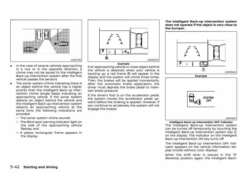
(284,1)
[ Edit: 2020/ 11/ 9 Model: Y62-A ]
5-42 Starting and driving
JVS0173X
. In the case of several vehicles approachingin a row or in the opposite direction, achime may not be issued to the IntelligentBack-up Intervention system after the firstvehicle passes the sensors.
. The sonar system chime indicating there isan object behind the vehicle has a higherpriority than the Intelligent Back-up Inter-vention chime (single beep) indicating anapproaching vehicle. If the sonar systemdetects an object behind the vehicle andthe Intelligent Back-up Intervention systemdetects an approaching vehicle at thesame time, the following indications areprovided:— The sonar system chime sounds— The Blind spot warning indicator light on
the side of the approaching vehicleflashes, and
— A yellow rectangular frame appears inthe display.
JVS0307XExample
If an approaching vehicle or close object behindthe vehicle is detected when your vehicle isbacking up, a red frame will appear in thedisplay and the system will chime three times.Then, the brakes will be applied momentarily.After the automatic brake application, thedriver must depress the brake pedal to main-tain brake pressure.If the driver’s foot is on the accelerator pedal,the system moves the accelerator pedal up-ward before the braking is applied. However, ifyou continue to accelerate, the system will notengage the brakes.
The Intelligent Back-up Intervention systemdoes not operate if the object is very close tothe bumper.
JVS0304XExample
JVS0182XIntelligent Back-up Intervention OFF indicator
The Intelligent Back-up Intervention systemcan be turned off temporarily by touching theIntelligent Back-up Intervention system keyon the display. The indicator on the IntelligentBack-up Intervention ON key turns off.The Intelligent Back-up Intervention OFF indi-cator appears on the vehicle information dis-play (model without color display).When the shift lever is placed in the “R”(Reverse) position again, the Intelligent Back-
Condition: 'Except for China'/'Except for China/
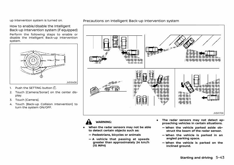
(285,1)
[ Edit: 2020/ 11/ 9 Model: Y62-A ]
up Intervention system is turned on.
How to enable/disable the IntelligentBack-up Intervention system (if equipped)GUID-1EA99DEE-24BE-4083-95AF-194610AE64FFPerform the following steps to enable ordisable the Intelligent Back-up Interventionsystem.
JVS1043X
1. Push the SETTING button .2. Touch [Camera/Sonar] on the center dis-
play.3. Touch [Camera].4. Touch [Back-up Collision Intervention] to
turn the system ON/OFF.
Precautions on Intelligent Back-up Intervention systemGUID-3B0F88AC-E57B-41E0-B624-0BA880FC3EED
JVS0170X
WARNING:. When the radar sensors may not be able
to detect certain objects such as:— Pedestrians, bicycles or animals— A vehicle that passing at speeds
greater than approximately 24 km/h(15 MPH)
. The radar sensors may not detect ap-proaching vehicles in certain situations.— When the vehicle parked aside ob-
struct the beam of the radar sensor.— When the vehicle is parked in an
angled parking space.— When the vehicle is parked on the
inclined ground.
Starting and driving 5-43
Condition: 'Except for China'/'Except for China/
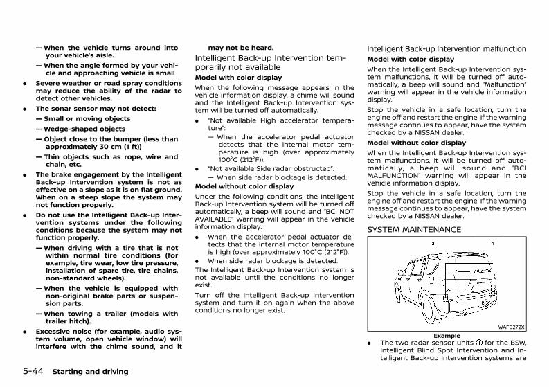
(286,1)
[ Edit: 2020/ 11/ 9 Model: Y62-A ]
5-44 Starting and driving
— When the vehicle turns around intoyour vehicle’s aisle.
— When the angle formed by your vehi-cle and approaching vehicle is small
. Severe weather or road spray conditionsmay reduce the ability of the radar todetect other vehicles.
. The sonar sensor may not detect:— Small or moving objects— Wedge-shaped objects— Object close to the bumper (less than
approximately 30 cm (1 ft))— Thin objects such as rope, wire and
chain, etc.. The brake engagement by the Intelligent
Back-up Intervention system is not aseffective on a slope as it is on flat ground.When on a steep slope the system maynot function properly.
. Do not use the Intelligent Back-up Inter-vention systems under the followingconditions because the system may notfunction properly.— When driving with a tire that is not
within normal tire conditions (forexample, tire wear, low tire pressure,installation of spare tire, tire chains,non-standard wheels).
— When the vehicle is equipped withnon-original brake parts or suspen-sion parts.
— When towing a trailer (models withtrailer hitch).
. Excessive noise (for example, audio sys-tem volume, open vehicle window) willinterfere with the chime sound, and it
may not be heard.Intelligent Back-up Intervention tem-porarily not availableGUID-9E14F0D6-3BC2-4EED-8170-C528A4904667Model with color displayWhen the following message appears in thevehicle information display, a chime will soundand the Intelligent Back-up Intervention sys-tem will be turned off automatically.. “Not available High accelerator tempera-
ture”:— When the accelerator pedal actuator
detects that the internal motor tem-perature is high (over approximately100°C (212°F)).
. “Not available Side radar obstructed”:— When side radar blockage is detected.
Model without color displayUnder the following conditions, the IntelligentBack-up Intervention system will be turned offautomatically, a beep will sound and “BCI NOTAVAILABLE” warning will appear in the vehicleinformation display.. When the accelerator pedal actuator de-
tects that the internal motor temperatureis high (over approximately 100°C (212°F)).
. When side radar blockage is detected.The Intelligent Back-up Intervention system isnot available until the conditions no longerexist.Turn off the Intelligent Back-up Interventionsystem and turn it on again when the aboveconditions no longer exist.
Intelligent Back-up Intervention malfunctionGUID-0FCFD63F-C853-4B68-A65F-6CB8DE78D2ADModel with color displayWhen the Intelligent Back-up Intervention sys-tem malfunctions, it will be turned off auto-matically, a beep will sound and “Malfunction”warning will appear in the vehicle informationdisplay.Stop the vehicle in a safe location, turn theengine off and restart the engine. If the warningmessage continues to appear, have the systemchecked by a NISSAN dealer.Model without color displayWhen the Intelligent Back-up Intervention sys-tem malfunctions, it will be turned off auto-matically, a beep will sound and “BCIMALFUNCTION” warning will appear in thevehicle information display.Stop the vehicle in a safe location, turn theengine off and restart the engine. If the warningmessage continues to appear, have the systemchecked by a NISSAN dealer.
SYSTEM MAINTENANCEGUID-A1D6ED32-40C8-43B3-8985-76B71575C0EE
WAF0272XExample
. The two radar sensor units for the BSW,Intelligent Blind Spot Intervention and In-telligent Back-up Intervention systems are
Condition: 'Except for China'/'Except for China/
(287,1)
[ Edit: 2020/ 11/ 9 Model: Y62-A ]
located near the rear bumper.— Always keep the area near the radar
sensors clean.— Do not attach stickers (including trans-
parent material), install accessories orapply additional paint near the radarsensors.
— Do not strike or damage the area aroundthe radar sensors.
— Consult a NISSAN dealer if the areaaround the radar sensors is damageddue to a collision.
. The Intelligent Blind Spot Intervention sys-tem uses the same camera that is usedby the LDW/Intelligent Lane Interventionsystem located in front of the inside mirror.
For maintenance of the camera, see “LaneDeparture Warning (LDW) system/IntelligentLane Intervention system” (P.5-25).
GUID-08F1C6DC-F6FE-4980-A6D1-CB6388125E74
WARNING:Failure to follow the warnings and instruc-tions for proper use of the RCTA system couldresult in serious injury or death.The RCTA system is not a replacement forproper driving procedures and is not de-signed to prevent contact with vehicles orobjects. When backing out of a parkingspace, always use the side and rear mirrorsand turn and look in the direction yourvehicle will move. Never rely solely on theRCTA system.
The RCTA system will assist you when backingout from a parking space. When the vehicle is inreverse, the system is designed to detect othervehicles approaching from the right or left ofthe vehicle. If the system detects cross traffic, itwill alert you.
Starting and driving 5-45
REAR CROSS TRAFFIC ALERT(RCTA) (if equipped)
Condition: 'Except for China'/'Except for China/
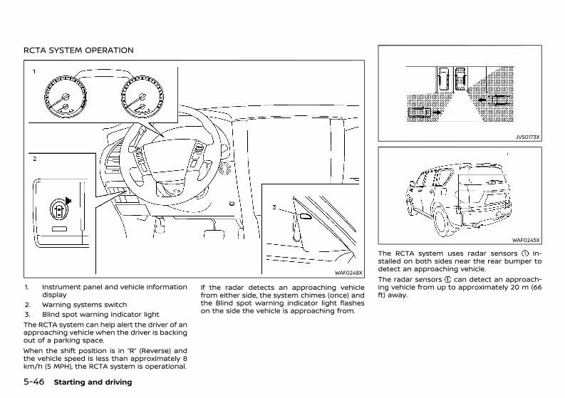
(288,1)
[ Edit: 2020/ 11/ 9 Model: Y62-A ]
5-46 Starting and driving
RCTA SYSTEM OPERATIONGUID-30D3F1DA-B6DC-4777-88DC-526AAEEA876C
WAF0248X
1. Instrument panel and vehicle informationdisplay
2. Warning systems switch3. Blind spot warning indicator lightThe RCTA system can help alert the driver of anapproaching vehicle when the driver is backingout of a parking space.When the shift position is in “R” (Reverse) andthe vehicle speed is less than approximately 8km/h (5 MPH), the RCTA system is operational.
If the radar detects an approaching vehiclefrom either side, the system chimes (once) andthe Blind spot warning indicator light flasheson the side the vehicle is approaching from.
JVS0173X
WAF0245X
The RCTA system uses radar sensors in-stalled on both sides near the rear bumper todetect an approaching vehicle.The radar sensors can detect an approach-ing vehicle from up to approximately 20 m (66ft) away.
Condition: 'Except for China'/'Except for China/
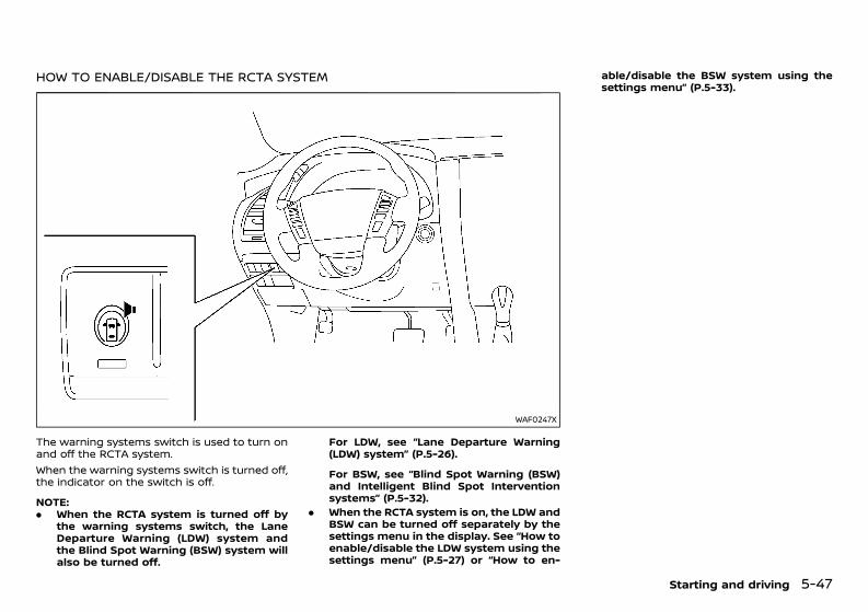
(289,1)
[ Edit: 2020/ 11/ 9 Model: Y62-A ]
HOW TO ENABLE/DISABLE THE RCTA SYSTEMGUID-9B611003-0CF6-4A68-9653-C3488F53575B
WAF0247X
The warning systems switch is used to turn onand off the RCTA system.When the warning systems switch is turned off,the indicator on the switch is off.
NOTE:. When the RCTA system is turned off by
the warning systems switch, the LaneDeparture Warning (LDW) system andthe Blind Spot Warning (BSW) system willalso be turned off.
For LDW, see “Lane Departure Warning(LDW) system” (P.5-26).
For BSW, see “Blind Spot Warning (BSW)and Intelligent Blind Spot Interventionsystems” (P.5-32).
. When the RCTA system is on, the LDW andBSW can be turned off separately by thesettings menu in the display. See “How toenable/disable the LDW system using thesettings menu” (P.5-27) or “How to en-
able/disable the BSW system using thesettings menu” (P.5-33).
Starting and driving 5-47
Condition: 'Except for China'/'Except for China/
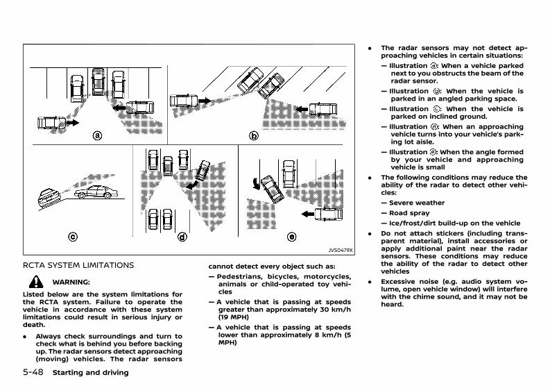
(290,1)
[ Edit: 2020/ 11/ 9 Model: Y62-A ]
5-48 Starting and driving
JVS0479X
RCTA SYSTEM LIMITATIONSGUID-322045C3-652F-4B0E-8128-45238AF46AFF
WARNING:Listed below are the system limitations forthe RCTA system. Failure to operate thevehicle in accordance with these systemlimitations could result in serious injury ordeath.. Always check surroundings and turn to
check what is behind you before backingup. The radar sensors detect approaching(moving) vehicles. The radar sensors
cannot detect every object such as:— Pedestrians, bicycles, motorcycles,
animals or child-operated toy vehi-cles
— A vehicle that is passing at speedsgreater than approximately 30 km/h(19 MPH)
— A vehicle that is passing at speedslower than approximately 8 km/h (5MPH)
. The radar sensors may not detect ap-proaching vehicles in certain situations:— Illustration : When a vehicle parked
next to you obstructs the beam of theradar sensor.
— Illustration : When the vehicle isparked in an angled parking space.
— Illustration : When the vehicle isparked on inclined ground.
— Illustration : When an approachingvehicle turns into your vehicle’s park-ing lot aisle.
— Illustration : When the angle formedby your vehicle and approachingvehicle is small
. The following conditions may reduce theability of the radar to detect other vehi-cles:— Severe weather— Road spray— Ice/frost/dirt build-up on the vehicle
. Do not attach stickers (including trans-parent material), install accessories orapply additional paint near the radarsensors. These conditions may reducethe ability of the radar to detect othervehicles
. Excessive noise (e.g. audio system vo-lume, open vehicle window) will interferewith the chime sound, and it may not beheard.
Condition: 'Except for China'/'Except for China/
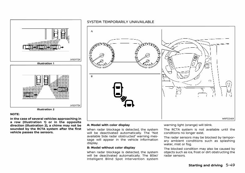
(291,1)
[ Edit: 2020/ 11/ 9 Model: Y62-A ]
JVS0172XIllustration 1
JVS0173XIllustration 2
NOTE:In the case of several vehicles approaching ina row (Illustration 1) or in the oppositedirection (Illustration 2), a chime may not besounded by the RCTA system after the firstvehicle passes the sensors.
SYSTEM TEMPORARILY UNAVAILABLEGUID-E8B7A2D8-EE15-4949-A09F-E27D832CE899
WAF0246X
A: Model with color displayWhen radar blockage is detected, the systemwill be deactivated automatically. The “Notavailable Side radar obstructed” warning mes-sage will appear in the vehicle informationdisplay.B: Model without color displayWhen radar blockage is detected, the systemwill be deactivated automatically. The BSW/Intelligent Blind Spot Intervention system
warning light (orange) will blink.The RCTA system is not available until theconditions no longer exist.The radar sensors may be blocked by tempor-ary ambient conditions such as splashingwater, mist or fog.The blocked condition may also be caused byobjects such as ice, frost or dirt obstructing theradar sensors.
Starting and driving 5-49
Condition: 'Except for China'/'Except for China/
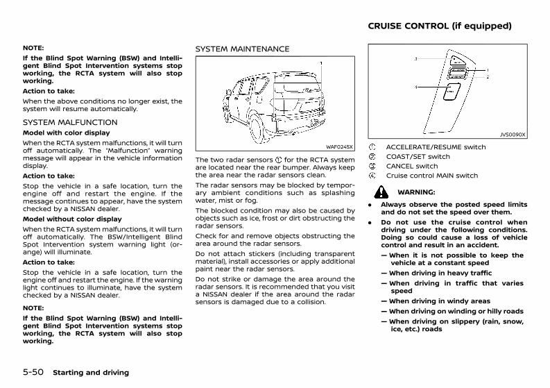
(292,1)
[ Edit: 2020/ 11/ 9 Model: Y62-A ]
5-50 Starting and driving
NOTE:If the Blind Spot Warning (BSW) and Intelli-gent Blind Spot Intervention systems stopworking, the RCTA system will also stopworking.Action to take:When the above conditions no longer exist, thesystem will resume automatically.
SYSTEM MALFUNCTIONGUID-11C77F30-C75E-46D8-A782-25F1D9CF6F60Model with color displayWhen the RCTA systemmalfunctions, it will turnoff automatically. The “Malfunction” warningmessage will appear in the vehicle informationdisplay.Action to take:Stop the vehicle in a safe location, turn theengine off and restart the engine. If themessage continues to appear, have the systemchecked by a NISSAN dealer.Model without color displayWhen the RCTA systemmalfunctions, it will turnoff automatically. The BSW/Intelligent BlindSpot Intervention system warning light (or-ange) will illuminate.Action to take:Stop the vehicle in a safe location, turn theengine off and restart the engine. If the warninglight continues to illuminate, have the systemchecked by a NISSAN dealer.
NOTE:If the Blind Spot Warning (BSW) and Intelli-gent Blind Spot Intervention systems stopworking, the RCTA system will also stopworking.
SYSTEM MAINTENANCEGUID-4472CCAD-C4BD-4FEB-8307-D0AA1B2C55FC
WAF0245X
The two radar sensors for the RCTA systemare located near the rear bumper. Always keepthe area near the radar sensors clean.The radar sensors may be blocked by tempor-ary ambient conditions such as splashingwater, mist or fog.The blocked condition may also be caused byobjects such as ice, frost or dirt obstructing theradar sensors.Check for and remove objects obstructing thearea around the radar sensors.Do not attach stickers (including transparentmaterial), install accessories or apply additionalpaint near the radar sensors.Do not strike or damage the area around theradar sensors. It is recommended that you visita NISSAN dealer if the area around the radarsensors is damaged due to a collision.
GUID-A6EFB01C-011B-4484-9175-865FCB500F51
JVS0090X
ACCELERATE/RESUME switchCOAST/SET switchCANCEL switchCruise control MAIN switch
WARNING:. Always observe the posted speed limits
and do not set the speed over them.. Do not use the cruise control when
driving under the following conditions.Doing so could cause a loss of vehiclecontrol and result in an accident.— When it is not possible to keep the
vehicle at a constant speed— When driving in heavy traffic— When driving in traffic that varies
speed— When driving in windy areas— When driving on winding or hilly roads— When driving on slippery (rain, snow,
ice, etc.) roads
CRUISE CONTROL (if equipped)
Condition: 'Except for China'/'Except for China/
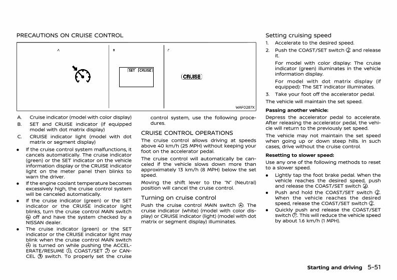
(293,1)
[ Edit: 2020/ 11/ 9 Model: Y62-A ]
PRECAUTIONS ON CRUISE CONTROLGUID-B41AEA0B-A463-448F-8C6D-62A19D75EF7A
WAF0287X
A. Cruise indicator (model with color display)B. SET and CRUISE indicator (if equipped
model with dot matrix display)C. CRUISE indicator light (model with dot
matrix or segment display). If the cruise control system malfunctions, it
cancels automatically. The cruise indicator(green) or the SET indicator on the vehicleinformation display or the CRUISE indicatorlight on the meter panel then blinks towarn the driver.
. If the engine coolant temperature becomesexcessively high, the cruise control systemwill be canceled automatically.
. If the cruise indicator (green) or the SETindicator or the CRUISE indicator lightblinks, turn the cruise control MAIN switch
off and have the system checked by aNISSAN dealer.
. The cruise indicator (green) or the SETindicator or the CRUISE indicator light mayblink when the cruise control MAIN switch
is turned on while pushing the ACCEL-ERATE/RESUME , COAST/SET or CAN-CEL switch. To properly set the cruise
control system, use the following proce-dures.
CRUISE CONTROL OPERATIONSGUID-E11A67AE-9ABE-40F0-A47C-CB17158BE060The cruise control allows driving at speedsabove 40 km/h (25 MPH) without keeping yourfoot on the accelerator pedal.The cruise control will automatically be can-celed if the vehicle slows down more thanapproximately 13 km/h (8 MPH) below the setspeed.Moving the shift lever to the “N” (Neutral)position will cancel the cruise control.
Turning on cruise controlGUID-173B1891-B5E6-473E-BA40-F0FC65E483C6Push the cruise control MAIN switch . Thecruise indicator (white) (model with color dis-play) or CRUISE indicator (light) (model with dotmatrix or segment display) illuminates.
Setting cruising speedGUID-841C526E-EA4B-49A5-AF29-5EF5BD1CC6311. Accelerate to the desired speed.2. Push the COAST/SET switch and release
it.For model with color display: The cruiseindicator (green) illuminates in the vehicleinformation display.For model with dot matrix display (ifequipped): The SET indicator illuminates.
3. Take your foot off the accelerator pedal.The vehicle will maintain the set speed.Passing another vehicle:
GUID-C7E1EF24-5AAB-4301-95BE-26917EEE45EF
Depress the accelerator pedal to accelerate.After releasing the accelerator pedal, the vehi-cle will return to the previously set speed.The vehicle may not maintain the set speedwhen going up or down steep hills. In suchcases, drive without the cruise control.Resetting to slower speed:
GUID-C7E1EF24-5AAB-4301-95BE-26917EEE45EF
Use any one of the following methods to resetto a slower speed.. Lightly tap the foot brake pedal. When the
vehicle reaches the desired speed, pushand release the COAST/SET switch .
. Push and hold the COAST/SET switch .When the vehicle reaches the desiredspeed, release the COAST/SET switch .
. Quickly push and release the COAST/SETswitch . This will reduce the vehicle speedby about 1.6 km/h (1 MPH).
Starting and driving 5-51
Condition: 'Except for China'/'Except for China/
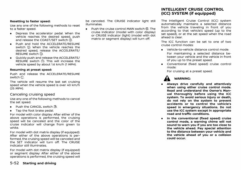
(294,1)
[ Edit: 2020/ 11/ 9 Model: Y62-A ]
5-52 Starting and driving
Resetting to faster speed:GUID-C7E1EF24-5AAB-4301-95BE-26917EEE45EF
Use any one of the following methods to resetto a faster speed.. Depress the accelerator pedal. When the
vehicle reaches the desired speed, pushand release the COAST/SET switch .
. Push and hold the ACCELERATE/RESUMEswitch . When the vehicle reaches thedesired speed, release the ACCELERATE/RESUME switch .
. Quickly push and release the ACCELERATE/RESUME switch . This will increase thevehicle speed by about 1.6 km/h (1 MPH).
Resuming at preset speed:GUID-C7E1EF24-5AAB-4301-95BE-26917EEE45EF
Push and release the ACCELERATE/RESUMEswitch .The vehicle will resume the last set cruisingspeed when the vehicle speed is over 40 km/h(25 MPH).
Canceling cruising speedGUID-DFDB4816-A5C3-4FF1-A538-2B8CE6C8149EUse any one of the following methods to cancelthe set speed.. Push the CANCEL switch .. Tap the foot brake pedal.For model with color display: After either of theabove operations is performed, the cruisingspeed will be canceled and the color of thecruise indicator will change from green towhite.For model with dot matrix display (if equipped):After either of the above operations is per-formed, the cruising speed will be canceled andthe SET indicator will turn off. The CRUISEindicator still illuminates.For model with dot matrix display (if equipped)or segment display: After either of the aboveoperations is performed, the cruising speed will
be canceled. The CRUISE indicator light stillilluminates.. Push the cruise control MAIN switch . The
cruise indicator (model with color display)or CRUISE indicator (light) (model with dotmatrix or segment display) will turn off.
GUID-8036C508-858D-4B4D-ADCA-6CD9CA085D3FThe Intelligent Cruise Control (ICC) systemautomatically maintains a selected distancefrom the vehicle traveling in front of youaccording to that vehicle’s speed (up to theset speed), or at the set speed when the roadahead is clear.The ICC function can be set to one of twocruise control modes:. Vehicle-to-vehicle distance control mode:
For maintaining a selected distance be-tween your vehicle and the vehicle in frontof you up to the preset speed.
. Conventional (fixed speed) cruise controlmode:For cruising at a preset speed.
WARNING:. Always drive carefully and attentively
when using either cruise control mode.Read and understand the Owner’s Man-ual thoroughly before using the ICCsystem. To avoid serious injury or death,do not rely on the system to preventaccidents or to control the vehicle’sspeed in emergency situations. Do notuse the ICC system except in appropriateroad and traffic conditions.
. In the conventional (fixed speed) cruisecontrol mode, a warning chime will notsound to warn you if you are too close tothe vehicle ahead. Pay special attentionto the distance between your vehicle andthe vehicle ahead of you or a collisioncould occur.
INTELLIGENT CRUISE CONTROL(ICC) SYSTEM (if equipped)
Condition: 'Except for China'/'Except for China/
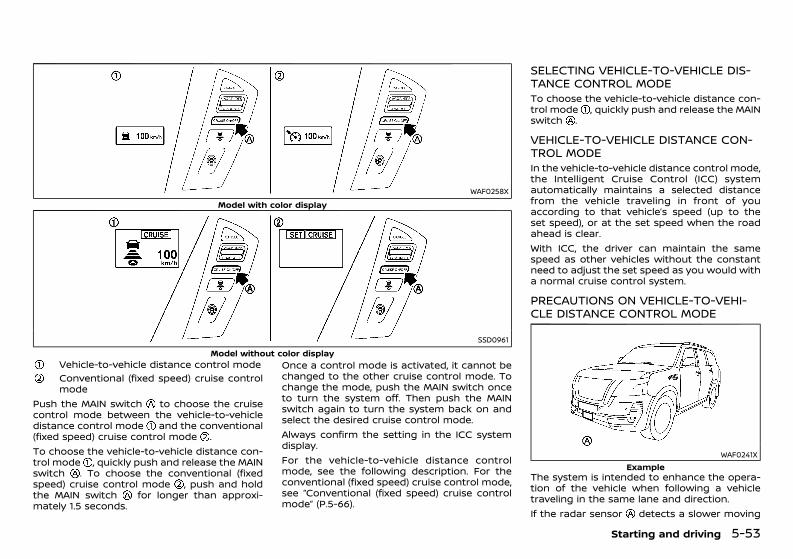
(295,1)
[ Edit: 2020/ 11/ 9 Model: Y62-A ]
WAF0258XModel with color display
SSD0961Model without color display
Vehicle-to-vehicle distance control modeConventional (fixed speed) cruise controlmode
Push the MAIN switch to choose the cruisecontrol mode between the vehicle-to-vehicledistance control mode and the conventional(fixed speed) cruise control mode .To choose the vehicle-to-vehicle distance con-trol mode , quickly push and release the MAINswitch . To choose the conventional (fixedspeed) cruise control mode , push and holdthe MAIN switch for longer than approxi-mately 1.5 seconds.
Once a control mode is activated, it cannot bechanged to the other cruise control mode. Tochange the mode, push the MAIN switch onceto turn the system off. Then push the MAINswitch again to turn the system back on andselect the desired cruise control mode.Always confirm the setting in the ICC systemdisplay.For the vehicle-to-vehicle distance controlmode, see the following description. For theconventional (fixed speed) cruise control mode,see “Conventional (fixed speed) cruise controlmode” (P.5-66).
SELECTING VEHICLE-TO-VEHICLE DIS-TANCE CONTROL MODEGUID-83757AB7-EE58-4533-88AF-7A344394B2C0To choose the vehicle-to-vehicle distance con-trol mode , quickly push and release the MAINswitch .
VEHICLE-TO-VEHICLE DISTANCE CON-TROL MODEGUID-98965DE1-CF6A-4142-9E3D-6B8D987088C4In the vehicle-to-vehicle distance control mode,the Intelligent Cruise Control (ICC) systemautomatically maintains a selected distancefrom the vehicle traveling in front of youaccording to that vehicle’s speed (up to theset speed), or at the set speed when the roadahead is clear.With ICC, the driver can maintain the samespeed as other vehicles without the constantneed to adjust the set speed as you would witha normal cruise control system.
PRECAUTIONS ON VEHICLE-TO-VEHI-CLE DISTANCE CONTROL MODEGUID-A810092D-E86A-4782-B5FC-E22913F6CA9B
WAF0241XExample
The system is intended to enhance the opera-tion of the vehicle when following a vehicletraveling in the same lane and direction.If the radar sensor detects a slower moving
Starting and driving 5-53
Condition: 'Except for China'/'Except for China/
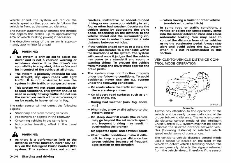
(296,1)
[ Edit: 2020/ 11/ 9 Model: Y62-A ]
5-54 Starting and driving
vehicle ahead, the system will reduce thevehicle speed so that your vehicle follows thevehicle in front at the selected distance.The system automatically controls the throttleand applies the brakes (up to approximately40% of vehicle braking power) if necessary.The detection range of the sensor is approxi-mately 200 m (650 ft) ahead.
WARNING:. This system is only an aid to assist the
driver and is not a collision warning oravoidance device. It is the driver’s re-sponsibility to stay alert, drive safely andbe in control of the vehicle at all times.
. The system is primarily intended for useon straight, dry, open roads with lighttraffic. It is not advisable to use thesystem in city traffic or congested areas.
. This system will not adapt automaticallyto road conditions. This system should beused in evenly flowing traffic. Do not usethe system on roads with sharp curves, oron icy roads, in heavy rain or in fog.
The radar sensor will not detect the followingobjects:. Stationary and slow moving vehicles. Pedestrians or objects in the roadway. Oncoming vehicles in the same lane. Motorcycles traveling offset in the travel
lane
WARNING:. As there is a performance limit to the
distance control function, never rely so-lely on the Intelligent Cruise Control (ICC)system. This system does not correct
careless, inattentive or absent-mindeddriving, or overcome poor visibility in rain,fog, or other bad weather. Decelerate thevehicle speed by depressing the brakepedal, depending on the distance to thevehicle ahead and the surrounding cir-cumstances in order to maintain a safedistance between vehicles.
. If the vehicle ahead comes to a stop, thevehicle decelerates to a standstill withinthe limitations of the system. The systemwill cancel once it judges that the vehiclehas come to a standstill and sound awarning chime. To prevent the vehiclefrommoving, the driver must depress thebrake pedal.
. The system may not function properlyunder the following conditions. To avoidaccidents, never use the ICC systemunder the following conditions:— On roads where the traffic is heavy or
there are sharp curves— On slippery road surfaces such as on
ice or snow, etc.— During bad weather (rain, fog, snow,
etc.)— When rain, snow or dirt adhere to the
system sensor— On steep downhill roads (the vehicle
may go beyond the set vehicle speedand frequent braking may result inoverheating the brakes)
— On repeated uphill and downhill roads— When traffic conditions make it diffi-
cult to keep a proper distance be-tween vehicles because of frequentacceleration or deceleration
— When towing a trailer or other vehicle(models with trailer hitch)
. In some road or traffic conditions, avehicle or object can unexpectedly comeinto the sensor detection zone and causeautomatic braking. You may need tocontrol the distance from other vehiclesusing the accelerator pedal. Always stayalert and avoid using the ICC systemwhen it is not recommended in thissection.
VEHICLE-TO-VEHICLE DISTANCE CON-TROL MODE OPERATIONGUID-4F212EBB-7BBD-49DD-9557-DEF14235B9FD
WAF0241XExample
Always pay attention to the operation of thevehicle and be ready to manually control theproper following distance. The vehicle-to-vehi-cle distance control mode of the IntelligentCruise Control (ICC) system may not be able tomaintain the selected distance between vehi-cles (following distance) or selected vehiclespeed under some circumstances.The vehicle-to-vehicle distance control modeuses a sensor located on the front of thevehicle to detect vehicles traveling ahead. Thesensor generally detects the signals returnedfrom the vehicle ahead. Therefore, if the sensor
Condition: 'Except for China'/'Except for China/
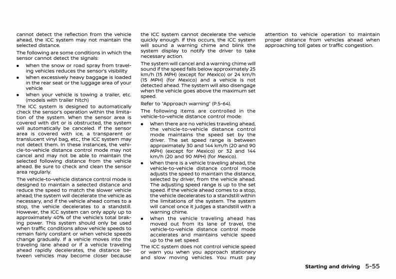
(297,1)
[ Edit: 2020/ 11/ 9 Model: Y62-A ]
cannot detect the reflection from the vehicleahead, the ICC system may not maintain theselected distance.The following are some conditions in which thesensor cannot detect the signals:. When the snow or road spray from travel-
ing vehicles reduces the sensor’s visibility. When excessively heavy baggage is loaded
in the rear seat or the luggage area of yourvehicle
. When your vehicle is towing a trailer, etc.(models with trailer hitch)
The ICC system is designed to automaticallycheck the sensor’s operation within the limita-tion of the system. When the sensor area iscovered with dirt or is obstructed, the systemwill automatically be canceled. If the sensorarea is covered with ice, a transparent ortranslucent vinyl bag, etc., the ICC system maynot detect them. In these instances, the vehi-cle-to-vehicle distance control mode may notcancel and may not be able to maintain theselected following distance from the vehicleahead. Be sure to check and clean the sensorarea regularly.The vehicle-to-vehicle distance control mode isdesigned to maintain a selected distance andreduce the speed to match the slower vehicleahead; the system will decelerate the vehicle asnecessary, and if the vehicle ahead comes to astop, the vehicle decelerates to a standstill.However, the ICC system can only apply up toapproximately 40% of the vehicle’s total brak-ing power. This system should only be usedwhen traffic conditions allow vehicle speeds toremain fairly constant or when vehicle speedschange gradually. If a vehicle moves into thetraveling lane ahead or if a vehicle travelingahead rapidly decelerates, the distance be-tween vehicles may become closer because
the ICC system cannot decelerate the vehiclequickly enough. If this occurs, the ICC systemwill sound a warning chime and blink thesystem display to notify the driver to takenecessary action.The systemwill cancel and a warning chime willsound if the speed falls below approximately 25km/h (15 MPH) (except for Mexico) or 24 km/h(15 MPH) (for Mexico) and a vehicle is notdetected ahead. The systemwill also disengagewhen the vehicle goes above the maximum setspeed.Refer to “Approach warning” (P.5-64).The following items are controlled in thevehicle-to-vehicle distance control mode:. When there are no vehicles traveling ahead,
the vehicle-to-vehicle distance controlmode maintains the speed set by thedriver. The set speed range is betweenapproximately 30 and 144 km/h (20 and 90MPH) (except for Mexico) or 32 and 144km/h (20 and 90 MPH) (for Mexico).
. When there is a vehicle traveling ahead, thevehicle-to-vehicle distance control modeadjusts the speed to maintain the distance,selected by driver, from the vehicle ahead.The adjusting speed range is up to the setspeed. If the vehicle ahead comes to a stop,the vehicle decelerates to a standstill withinthe limitations of the system. The systemwill cancel once it judges a standstill with awarning chime.
. When the vehicle traveling ahead hasmoved out from its lane of travel, thevehicle-to-vehicle distance control modeaccelerates and maintains vehicle speedup to the set speed.
The ICC system does not control vehicle speedor warn you when you approach stationaryand slow moving vehicles. You must pay
attention to vehicle operation to maintainproper distance from vehicles ahead whenapproaching toll gates or traffic congestion.
Starting and driving 5-55
Condition: 'Except for China'/'Except for China/
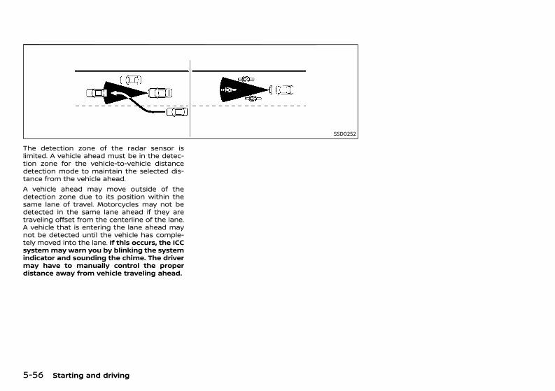
(298,1)
[ Edit: 2020/ 11/ 9 Model: Y62-A ]
5-56 Starting and driving
SSD0252
The detection zone of the radar sensor islimited. A vehicle ahead must be in the detec-tion zone for the vehicle-to-vehicle distancedetection mode to maintain the selected dis-tance from the vehicle ahead.A vehicle ahead may move outside of thedetection zone due to its position within thesame lane of travel. Motorcycles may not bedetected in the same lane ahead if they aretraveling offset from the centerline of the lane.A vehicle that is entering the lane ahead maynot be detected until the vehicle has comple-tely moved into the lane. If this occurs, the ICCsystemmay warn you by blinking the systemindicator and sounding the chime. The drivermay have to manually control the properdistance away from vehicle traveling ahead.
Condition: 'Except for China'/'Except for China/
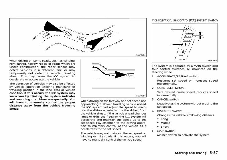
(299,1)
[ Edit: 2020/ 11/ 9 Model: Y62-A ]
SSD0253
When driving on some roads, such as winding,hilly, curved, narrow roads, or roads which areunder construction, the radar sensor maydetect vehicles in a different lane, or maytemporarily not detect a vehicle travelingahead. This may cause the ICC system todecelerate or accelerate the vehicle.The detection of vehicles may also be affectedby vehicle operation (steering maneuver ortraveling position in the lane, etc.) or vehiclecondition. If this occurs, the ICC system maywarn you by blinking the system indicatorand sounding the chime unexpectedly. Youwill have to manually control the properdistance away from the vehicle travelingahead.
SSD0254
When driving on the freeway at a set speed andapproaching a slower traveling vehicle ahead,the ICC system will adjust the speed to main-tain the distance, selected by the driver, fromthe vehicle ahead. If the vehicle ahead changeslanes or exits the freeway, the ICC system willaccelerate and maintain the speed up to theset speed. Pay attention to the driving opera-tion to maintain control of the vehicle as itaccelerates to the set speed.The vehicle may not maintain the set speed onwinding or hilly roads. If this occurs, you willhave to manually control the vehicle speed.
Intelligent Cruise Control (ICC) system switchGUID-4D441E6F-723B-486B-A0C2-AC761307DD32
SSD0964
The system is operated by a MAIN switch andfour control switches, all mounted on thesteering wheel.1. ACCELERATE/RESUME switch:
Resumes set speed or increases speedincrementally.
2. COAST/SET switch:Sets desired cruise speed, reduces speedincrementally.
3. CANCEL switch:Deactivates the system without erasing theset speed.
4. DISTANCE switch:Changes the vehicle’s following distance:. Long. Middle. Short
5. MAIN switch:Master switch to activate the system
Starting and driving 5-57
Condition: 'Except for China'/'Except for China/
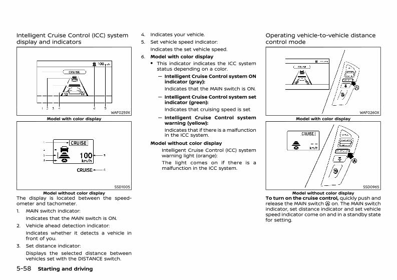
(300,1)
[ Edit: 2020/ 11/ 9 Model: Y62-A ]
5-58 Starting and driving
Intelligent Cruise Control (ICC) systemdisplay and indicatorsGUID-96DF0031-DEE7-4300-A12C-648A27A8144A
WAF0259XModel with color display
SSD1005Model without color display
The display is located between the speed-ometer and tachometer.1. MAIN switch indicator:
Indicates that the MAIN switch is ON.2. Vehicle ahead detection indicator:
Indicates whether it detects a vehicle infront of you.
3. Set distance indicator:Displays the selected distance betweenvehicles set with the DISTANCE switch.
4. Indicates your vehicle.5. Set vehicle speed indicator:
Indicates the set vehicle speed.6. Model with color display
. This indicator indicates the ICC systemstatus depending on a color.— Intelligent Cruise Control system ON
indicator (gray):Indicates that the MAIN switch is ON.
— Intelligent Cruise Control system setindicator (green):Indicates that cruising speed is set
— Intelligent Cruise Control systemwarning (yellow):Indicates that if there is a malfunctionin the ICC system.
Model without color displayIntelligent Cruise Control (ICC) systemwarning light (orange):The light comes on if there is amalfunction in the ICC system.
Operating vehicle-to-vehicle distancecontrol modeGUID-FF6D3D65-DB8C-4AA9-B2F1-3520D916CFAA
WAF0260XModel with color display
SSD0965Model without color display
To turn on the cruise control, quickly push andrelease the MAIN switch on. The MAIN switchindicator, set distance indicator and set vehiclespeed indicator come on and in a standby statefor setting.
Condition: 'Except for China'/'Except for China/

(301,1)
[ Edit: 2020/ 11/ 9 Model: Y62-A ]
WAF0261XModel with color display
SSD0966Model without color display
To set cruising speed, accelerate your vehicleto the desired speed, push the COAST/SETswitch and release it. (Vehicle ahead detectionindicator, set distance indicator and set vehiclespeed indicator come on.) Take your foot offthe accelerator pedal. Your vehicle will maintainthe set speed.
JVS1229XModel with color display
SSD1007Model without color display
When the COAST/SET switch is pushed underthe following conditions, the system cannot beset and the set vehicle speed indicator will blinkfor approximately 2 seconds:. When traveling below 30 km/h (20 MPH)
(except for Mexico) or 32 km/h (20 MPH) (forMexico) and the vehicle ahead is notdetected.
. When the shift lever is not in the D ormanual shift mode
. When the brakes are operated by the driver
. When the parking brake is applied
Model with color displayWhen the COAST/SET switch is pushed underthe following conditions, the system cannot beset.A warning chime will sound and a message willpop up:. “Not available Poor Road Conditions”:
— When VDC (including the traction controlsystem) is operating
— When a wheel is slipping (To use the ICCsystem, make sure the wheels are nolonger slipping. Push the MAIN switch toturn off the ICC, and reset the ICCsystem by pushing the MAIN switchagain.)
. “Not available”:— When the ROCK, SAND or SNOW mode is
selected (variable 4 × 4 mode selectswitch) (To use the ICC system, selectthe ON ROAD mode, push the MAINswitch to turn off the ICC and reset theICC switch by pushing the MAIN switchagain.)For details about the variable 4 × 4modeselect switch, see “Four-Wheel Drive(4WD) (4WD models)” (P.5-16).
— When the 4WD shift switch is in the 4H or4L position (for 4WD models). (To use theICC system, place the 4WD shift switch inthe AUTO position, push the MAINswitch to turn off the ICC system andreset the ICC switch by pushing theMAIN switch again.For details about the 4WD shift switch,see “Four-Wheel Drive (4WD) (4WD mod-els)” (P.5-16).
— When the VDC system is off (To use theICC system, turn on the VDC system.Push the MAIN switch to turn off the ICC
Starting and driving 5-59
Condition: 'Except for China'/'Except for China/
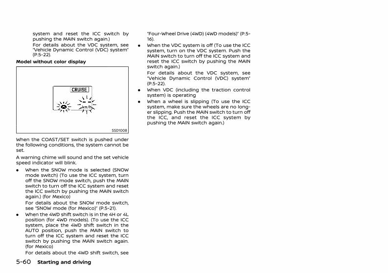
(302,1)
[ Edit: 2020/ 11/ 9 Model: Y62-A ]
5-60 Starting and driving
system and reset the ICC switch bypushing the MAIN switch again.)For details about the VDC system, see“Vehicle Dynamic Control (VDC) system”(P.5-22).
Model without color display
SSD1008
When the COAST/SET switch is pushed underthe following conditions, the system cannot beset.A warning chime will sound and the set vehiclespeed indicator will blink.. When the SNOW mode is selected (SNOW
mode switch) (To use the ICC system, turnoff the SNOW mode switch, push the MAINswitch to turn off the ICC system and resetthe ICC switch by pushing the MAIN switchagain.) (for Mexico)For details about the SNOW mode switch,see “SNOW mode (for Mexico)” (P.5-21).
. When the 4WD shift switch is in the 4H or 4Lposition (for 4WD models). (To use the ICCsystem, place the 4WD shift switch in theAUTO position, push the MAIN switch toturn off the ICC system and reset the ICCswitch by pushing the MAIN switch again.(for Mexico)For details about the 4WD shift switch, see
“Four-Wheel Drive (4WD) (4WD models)” (P.5-16).
. When the VDC system is off (To use the ICCsystem, turn on the VDC system. Push theMAIN switch to turn off the ICC system andreset the ICC switch by pushing the MAINswitch again.)For details about the VDC system, see“Vehicle Dynamic Control (VDC) system”(P.5-22).
. When VDC (including the traction controlsystem) is operating
. When a wheel is slipping (To use the ICCsystem, make sure the wheels are no long-er slipping. Push the MAIN switch to turn offthe ICC, and reset the ICC system bypushing the MAIN switch again.)
Condition: 'Except for China'/'Except for China/
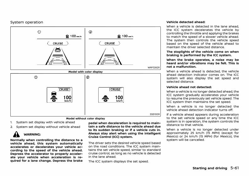
(303,1)
[ Edit: 2020/ 11/ 9 Model: Y62-A ]
System operationGUID-E385E260-8BEA-4952-8AD4-32F14193A504
WAF0262XModel with color display
SSD1009Model without color display
1. System set display with vehicle ahead2. System set display without vehicle ahead
WARNING:Normally when controlling the distance to avehicle ahead, this system automaticallyaccelerates or decelerates your vehicle ac-cording to the speed of the vehicle ahead.Depress the accelerator to properly acceler-ate your vehicle when acceleration is re-quired for a lane change. Depress the brake
pedal when deceleration is required to main-tain a safe distance to the vehicle ahead dueto its sudden braking or if a vehicle cuts in.Always stay alert when using the IntelligentCruise Control (ICC) system.
The driver sets the desired vehicle speed basedon the road conditions. The ICC system main-tains the set vehicle speed, similar to standardcruise control, as long as no vehicle is detectedin the lane ahead.The ICC system displays the set speed.
Vehicle detected ahead:GUID-C7E1EF24-5AAB-4301-95BE-26917EEE45EF
When a vehicle is detected in the lane ahead,the ICC system decelerates the vehicle bycontrolling the throttle and applying the brakesto match the speed of a slower vehicle ahead.The system then controls the vehicle speedbased on the speed of the vehicle ahead tomaintain the driver selected distance.The stoplights of the vehicle come on whenbraking is performed by the ICC system.When the brake operates, a noise may beheard and/or vibrations may be felt. This isnot a malfunction.When a vehicle ahead is detected, the vehicleahead detection indicator comes on. The ICCsystem will also display the set speed andselected distance.Vehicle ahead not detected:
GUID-C7E1EF24-5AAB-4301-95BE-26917EEE45EF
When a vehicle is no longer detected ahead, theICC system gradually accelerates your vehicleto resume the previously set vehicle speed. TheICC system then maintains the set speed.When a vehicle is no longer detected thevehicle ahead detection indicator turns off.If a vehicle ahead appears during accelerationto the set vehicle speed or any time the ICCsystem is in operation, the system controls thedistance to that vehicle.When a vehicle is no longer detected underapproximately 25 km/h (15 MPH) (except forMexico) or 24 km/h (15 MPH) (for Mexico), thesystem will be cancelled.
Starting and driving 5-61
Condition: 'Except for China'/'Except for China/
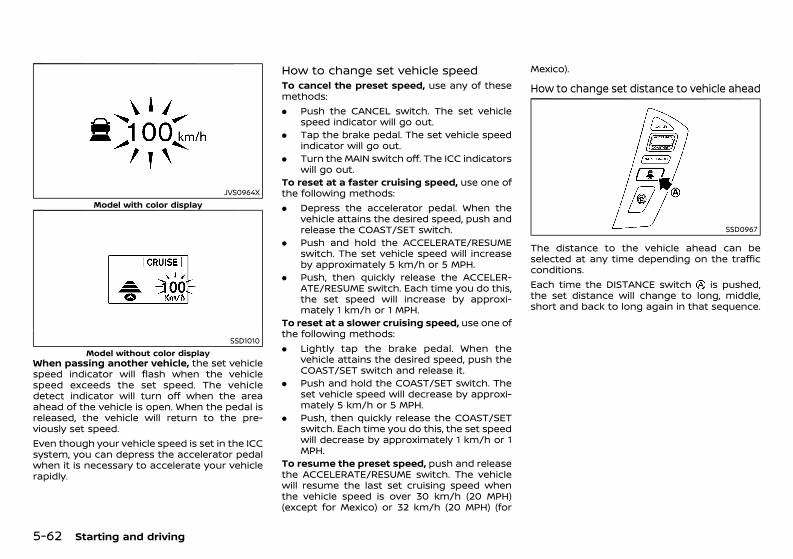
(304,1)
[ Edit: 2020/ 11/ 9 Model: Y62-A ]
5-62 Starting and driving
JVS0964XModel with color display
SSD1010Model without color display
When passing another vehicle, the set vehiclespeed indicator will flash when the vehiclespeed exceeds the set speed. The vehicledetect indicator will turn off when the areaahead of the vehicle is open. When the pedal isreleased, the vehicle will return to the pre-viously set speed.Even though your vehicle speed is set in the ICCsystem, you can depress the accelerator pedalwhen it is necessary to accelerate your vehiclerapidly.
How to change set vehicle speedGUID-C399D9DB-7993-4919-BBA4-BDA2BF1F9D8ATo cancel the preset speed, use any of thesemethods:. Push the CANCEL switch. The set vehicle
speed indicator will go out.. Tap the brake pedal. The set vehicle speed
indicator will go out.. Turn the MAIN switch off. The ICC indicators
will go out.To reset at a faster cruising speed, use one ofthe following methods:. Depress the accelerator pedal. When the
vehicle attains the desired speed, push andrelease the COAST/SET switch.
. Push and hold the ACCELERATE/RESUMEswitch. The set vehicle speed will increaseby approximately 5 km/h or 5 MPH.
. Push, then quickly release the ACCELER-ATE/RESUME switch. Each time you do this,the set speed will increase by approxi-mately 1 km/h or 1 MPH.
To reset at a slower cruising speed, use one ofthe following methods:. Lightly tap the brake pedal. When the
vehicle attains the desired speed, push theCOAST/SET switch and release it.
. Push and hold the COAST/SET switch. Theset vehicle speed will decrease by approxi-mately 5 km/h or 5 MPH.
. Push, then quickly release the COAST/SETswitch. Each time you do this, the set speedwill decrease by approximately 1 km/h or 1MPH.
To resume the preset speed, push and releasethe ACCELERATE/RESUME switch. The vehiclewill resume the last set cruising speed whenthe vehicle speed is over 30 km/h (20 MPH)(except for Mexico) or 32 km/h (20 MPH) (for
Mexico).
How to change set distance to vehicle aheadGUID-69EC89D0-13B1-4BF3-A4CC-0FF60C9F0FA7
SSD0967
The distance to the vehicle ahead can beselected at any time depending on the trafficconditions.Each time the DISTANCE switch is pushed,the set distance will change to long, middle,short and back to long again in that sequence.
Condition: 'Except for China'/'Except for China/
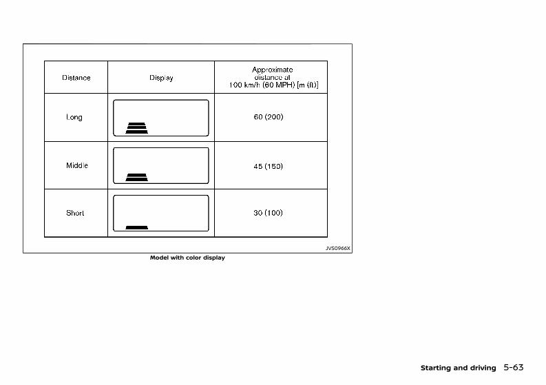
(305,1)
[ Edit: 2020/ 11/ 9 Model: Y62-A ]
JVS0966XModel with color display
Starting and driving 5-63
Condition: 'Except for China'/'Except for China/
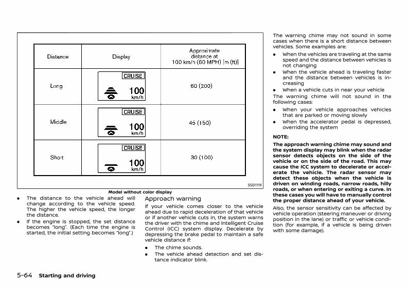
(306,1)
[ Edit: 2020/ 11/ 9 Model: Y62-A ]
5-64 Starting and driving
SSD1119Model without color display
. The distance to the vehicle ahead willchange according to the vehicle speed.The higher the vehicle speed, the longerthe distance.
. If the engine is stopped, the set distancebecomes “long”. (Each time the engine isstarted, the initial setting becomes “long”.)
Approach warningGUID-EFAA6647-71A9-4DE7-A6A9-A5775299DA1DIf your vehicle comes closer to the vehicleahead due to rapid deceleration of that vehicleor if another vehicle cuts in, the system warnsthe driver with the chime and Intelligent CruiseControl (ICC) system display. Decelerate bydepressing the brake pedal to maintain a safevehicle distance if:. The chime sounds.. The vehicle ahead detection and set dis-
tance indicator blink.
The warning chime may not sound in somecases when there is a short distance betweenvehicles. Some examples are:. When the vehicles are traveling at the same
speed and the distance between vehicles isnot changing
. When the vehicle ahead is traveling fasterand the distance between vehicles is in-creasing
. When a vehicle cuts in near your vehicleThe warning chime will not sound in thefollowing cases:. When your vehicle approaches vehicles
that are parked or moving slowly. When the accelerator pedal is depressed,
overriding the system
NOTE:The approach warning chimemay sound andthe system display may blink when the radarsensor detects objects on the side of thevehicle or on the side of the road. This maycause the ICC system to decelerate or accel-erate the vehicle. The radar sensor maydetect these objects when the vehicle isdriven on winding roads, narrow roads, hillyroads, or when entering or exiting a curve. Inthese cases you will have to manually controlthe proper distance ahead of your vehicle.Also, the sensor sensitivity can be affected byvehicle operation (steering maneuver or drivingposition in the lane) or traffic or vehicle condi-tion (for example, if a vehicle is being drivenwith some damage).
Condition: 'Except for China'/'Except for China/
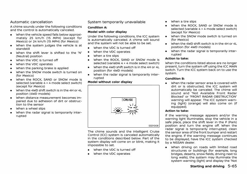
(307,1)
[ Edit: 2020/ 11/ 9 Model: Y62-A ]
Automatic cancellationGUID-2F70E95B-E926-4B83-B624-29CDA2DB7B98A chime sounds under the following conditionsand the control is automatically canceled.. When the vehicle speed falls below approxi-
mately 25 km/h (15 MPH) (except forMexico) or 24 km/h (15 MPH) (for Mexico)
. When the system judges the vehicle is atstandstill
. When the shift lever is shifted to the “N”(Neutral) position
. When the VDC is turned off
. When the VDC operates
. When the parking brake is applied
. When the SNOW mode switch is turned on(for Mexico)
. When the ROCK, SAND or SNOW mode isselected (variable 4 × 4 mode select switch)(except for Mexico)
. When the 4WD shift switch is in the 4H or 4Lposition (4WD models)
. When distance measurement becomes im-paired due to adhesion of dirt or obstruc-tion to the sensor
. When a wheel slips
. When the radar signal is temporarily inter-rupted
System temporarily unavailableGUID-26A0ED84-61FF-42E4-8799-AD0E4E8CA0F8
Condition A:GUID-C7E1EF24-5AAB-4301-95BE-26917EEE45EF
Model with color displayUnder the following conditions, the ICC systemis automatically canceled. A chime will soundand the system will not be able to be set.. When the VDC is turned off. When the VDC operates. When a tire slips. When the ROCK, SAND or SNOW mode is
selected (variable 4 × 4 mode select switch). When the 4WD shift switch is in the 4H or 4L
position (for 4WD models). When the radar signal is temporarily inter-
ruptedModel without color display
SSD1008
The chime sounds and the Intelligent CruiseControl (ICC) system is canceled automaticallyin the conditions described below. Part of thesystem display will come on or blink, making itimpossible to set.. When the VDC is turned off. When the VDC operates
. When a tire slips
. When the ROCK, SAND or SNOW mode isselected (variable 4 × 4 mode select switch)(except for Mexico)
. When the SNOW mode switch is turned on(for Mexico)
. When the 4WD shift switch is in the 4H or 4Lposition (for 4WD models)
. When the radar signal is temporarily inter-rupted
Action to take:When the conditions listed above are no longerpresent, turn the system off using the ICC MAINswitch. Turn the ICC system back on to use thesystem.Condition B:
GUID-C7E1EF24-5AAB-4301-95BE-26917EEE45EF
. When the radar sensor area is covered withdirt or is obstructed, the ICC system willautomatically be canceled. The chime willsound and “Not Available Front RadarBlocked” or “FRONT RADAR OBSTRUCTION”warning will appear. The ICC system warn-ing (light) (orange) will also come on (ifequipped).
Action to take:If the warning message appears and/or thewarning light illuminates, stop the vehicle in asafe place, place the shift lever in the P (Park)position and turn the engine off. When theradar signal is temporarily interrupted, cleanthe sensor area of the front bumper and restartthe engine. If the warning message continuesto be displayed, have the ICC system checkedby a NISSAN dealer.. When driving on roads with limited road
structures or buildings (for example, longbridges, deserts, snow fields, driving next tolong walls), the system may illuminate thesystem warning (light) and display the “Not
Starting and driving 5-65
Condition: 'Except for China'/'Except for China/
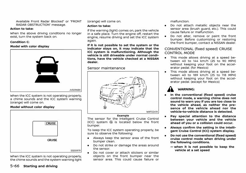
(308,1)
[ Edit: 2020/ 11/ 9 Model: Y62-A ]
5-66 Starting and driving
Available Front Radar Blocked” or “FRONTRADAR OBSTRUCTION” message.
Action to take:When the above driving conditions no longerexist, turn the system back on.Condition C:
GUID-C7E1EF24-5AAB-4301-95BE-26917EEE45EF
Model with color display
JVS0968X
When the ICC system is not operating properly,a chime sounds and the ICC system warning(orange) will come on.Model without color display
SSD0979
When the ICC system is not operating properly,the chime sounds and the systemwarning light
(orange) will come on.Action to take:If the warning (light) comes on, park the vehiclein a safe place. Turn the engine off, restart theengine, resume driving and set the ICC systemagain.If it is not possible to set the system or theindicator stays on, it may indicate that theICC system is malfunctioning. Although thevehicle is still driveable under normal condi-tions, have the vehicle checked at a NISSANdealer.
Sensor maintenanceGUID-6E495F2E-EF61-4215-827B-D5C5B5D619DE
WAF0241XExample
The sensor for the Intelligent Cruise Control(ICC) system is located below the frontbumper.To keep the ICC system operating properly, besure to observe the following:. Always keep the sensor area of the front
bumper clean.. Do not strike or damage the areas around
the sensor.. Do not cover or attach stickers or similar
objects on the front bumper near thesensor area. This could cause failure or
malfunction.. Do not attach metallic objects near the
sensor area (brush guard, etc.). This couldcause failure or malfunction.
. Do not alter, remove or paint the frontbumper. Before customizing or restoringthe front bumper, contact a NISSAN dealer.
CONVENTIONAL (fixed speed) CRUISECONTROL MODEGUID-C09E5FD3-77F4-40CA-9A87-BE59F1C62D10. This mode allows driving at a speed be-
tween 40 to 144 km/h (25 to 90 MPH)without keeping your foot on the accel-erator pedal. (for Mexico)
. This mode allows driving at a speed be-tween 40 to 189 km/h (25 to 118 MPH)without keeping your foot on the accel-erator pedal. (except for Mexico)
WARNING:. In the conventional (fixed speed) cruise
control mode, a warning chime does notsound to warn you if you are too close tothe vehicle ahead, as neither the pre-sence of the vehicle ahead nor thevehicle-to-vehicle distance is detected.
. Pay special attention to the distancebetween your vehicle and the vehicleahead of you or a collision could occur.
. Always confirm the setting in the Intelli-gent Cruise Control (ICC) system display.
. Do not use the conventional (fixed speed)cruise control mode when driving underthe following conditions.— when it is not possible to keep the
vehicle at a set speed
Condition: 'Except for China'/'Except for China/
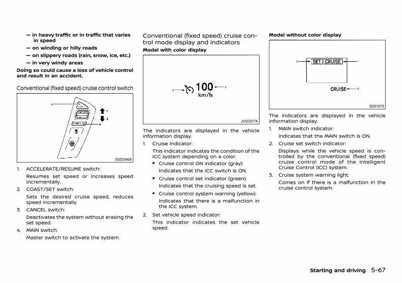
(309,1)
[ Edit: 2020/ 11/ 9 Model: Y62-A ]
— in heavy traffic or in traffic that variesin speed
— on winding or hilly roads— on slippery roads (rain, snow, ice, etc.)— in very windy areas
Doing so could cause a loss of vehicle controland result in an accident.
Conventional (fixed speed) cruise control switchGUID-BC287138-8C1D-4653-AD6B-38005633B7D9
SSD0968
1. ACCELERATE/RESUME switch:Resumes set speed or increases speedincrementally.
2. COAST/SET switch:Sets the desired cruise speed, reducesspeed incrementally.
3. CANCEL switch:Deactivates the system without erasing theset speed.
4. MAIN switch:Master switch to activate the system.
Conventional (fixed speed) cruise con-trol mode display and indicatorsGUID-4DEAC92A-2D5C-40D7-9E0D-89619D1DECFAModel with color display
JVS0317X
The indicators are displayed in the vehicleinformation display.1. Cruise indicator:
This indicator indicates the condition of theICC system depending on a color.. Cruise control ON indicator (gray):
Indicates that the ICC switch is ON.. Cruise control set indicator (green):
Indicates that the cruising speed is set.. Cruise control system warning (yellow):
Indicates that there is a malfunction inthe ICC system.
2. Set vehicle speed indicator:This indicator indicates the set vehiclespeed.
Model without color display
SSD1013
The indicators are displayed in the vehicleinformation display.1. MAIN switch indicator:
Indicates that the MAIN switch is ON.2. Cruise set switch indicator:
Displays while the vehicle speed is con-trolled by the conventional (fixed speed)cruise control mode of the IntelligentCruise Control (ICC) system.
3. Cruise system warning light:Comes on if there is a malfunction in thecruise control system.
Starting and driving 5-67
Condition: 'Except for China'/'Except for China/
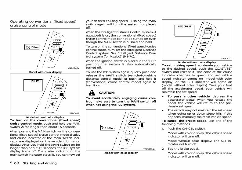
(310,1)
[ Edit: 2020/ 11/ 9 Model: Y62-A ]
5-68 Starting and driving
Operating conventional (fixed speed)cruise control modeGUID-9030E296-7D16-49BC-907C-4793F8D2A7D6
WAF0263XModel with color display
SSD0969Model without color display
To turn on the conventional (fixed speed)cruise control mode, push and hold the MAINswitch for longer than about 1.5 seconds.When pushing the MAIN switch on, the conven-tional (fixed speed) cruise control mode displayand cruise indicator or the main switch indi-cator are displayed on the vehicle informationdisplay. After you hold the MAIN switch on forlonger than about 1.5 seconds, the ICC systemdisplay turns off. The cruise indicator or themain switch indicator stays lit. You can now set
your desired cruising speed. Pushing the MAINswitch again will turn the system completelyoff.When the Intelligent Distance Control system (ifequipped) is on, the conventional (fixed speed)cruise control mode cannot be turned on eventhough the MAIN switch is pushed and held.To turn on the conventional (fixed speed) cruisecontrol mode, turn off the Intelligent DistanceControl system. See “Intelligent Distance Con-trol system (for Mexico)” (P.5-70).When the ignition switch is placed in the “OFF”position, the system is also automaticallyturned off.To use the ICC system again, quickly push andrelease the MAIN switch (vehicle-to-vehicledistance control mode) or push and hold it(conventional cruise control mode) again toturn it on.
CAUTION:To avoid accidentally engaging cruise con-trol, make sure to turn the MAIN switch offwhen not using the ICC system.
WAF0264XModel with color display
SSD0970Model without color display
To set cruising speed, accelerate your vehicleto the desired speed, push the COAST/SETswitch and release it. The color of the cruiseindicator changes to green and set vehiclespeed indicator comes on (model with colordisplay) or the SET indicator will come on(model without color display). Take your footoff the accelerator pedal. Your vehicle willmaintain the set speed.. To pass another vehicle, depress the
accelerator pedal. When you release thepedal, the vehicle will return to the pre-viously set speed.
. The vehicle may not maintain the set speedwhen going up or down steep hills. If thishappens, manually maintain vehicle speed.
To cancel the preset speed, use one of thefollowing methods:1. Push the CANCEL switch.
Model with color display: The vehicle speedindicator will turn off.Model without color display: The SET in-dicator will turn off.
2. Tap the brake pedal.Model with color display: The vehicle speedindicator will turn off.
Condition: 'Except for China'/'Except for China/

(311,1)
[ Edit: 2020/ 11/ 9 Model: Y62-A ]
Model without color display: The SET in-dicator will turn off.
3. Turn the MAIN switch off.Model with color display: Both the cruiseindicator and vehicle speed indicator willturn off.Model without color display: Both the MAINswitch and SET indicator will turn off.
To reset at a faster cruising speed, use one ofthe following three methods:1. Depress the accelerator pedal. When the
vehicle attains the desired speed, push andrelease the COAST/SET switch.
2. Push and hold the ACCELERATE/RESUMEset switch. When the vehicle attains thedesired speed, release the switch.
3. Push, then quickly release the ACCELER-ATE/RESUME switch. Each time you do this,the set speed will increase by about 1.6km/h (1 MPH).
To reset at a slower cruising speed, use one ofthe following three methods:1. Lightly tap the brake pedal. When the
vehicle attains the desired speed, push theCOAST/SET switch and release it.
2. Push and hold the COAST/SET switch.Release the switch when the vehicle slowsdown to the desired speed.
3. Push, then quickly release the COAST/SETswitch. Each time you do this, the set speedwill decrease by about 1.6 km/h (1 MPH).
To resume the preset speed, push and releasethe ACCELERATE/RESUME switch. The vehiclewill resume the last set cruising speed whenthe vehicle speed is over 40 km/h (25 MPH).
Automatic cancellationGUID-F925B9ED-A2D1-4B3C-ABCE-233DAB16933CA chime sounds under the following conditionsand the control is automatically canceled.. When the vehicle slows down more than 13
km/h (8 MPH) below the set speed. When the shift lever is shifted to the “N”
(Neutral) position. When the parking brake is applied. When the VDC (including the traction con-
trol system) operates.. When a wheel slips
Warning lightGUID-3AACB09B-E52C-4497-966B-2408EC1FB5C2
JVS0306XModel with color display
SSD0979Model without color display
When the system is not operating properly, thechime sounds and the system warning (light)will come on in yellow (model with colordisplay) or orange (model without color dis-play).Action to take:
GUID-C7E1EF24-5AAB-4301-95BE-26917EEE45EF
If the warning (light) comes on, park the vehiclein a safe place. Turn the engine off, restart theengine, resume driving and then perform thesetting again.If it is not possible to set or the warning stayson, it may indicate that the system ismalfunctioning. Although the vehicle is stilldriveable under normal conditions, have thevehicle checked at a NISSAN dealer.
Starting and driving 5-69
Condition: 'Except for China'/'Except for China/
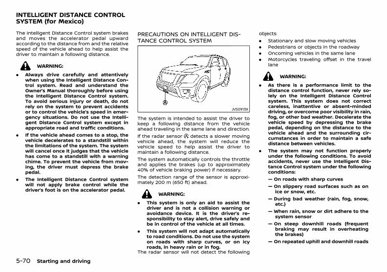
(312,1)
[ Edit: 2020/ 11/ 9 Model: Y62-A ]
5-70 Starting and driving
GUID-A6C18E10-0CCB-427E-8C28-968B6F44700DThe Intelligent Distance Control system brakesand moves the accelerator pedal upwardaccording to the distance from and the relativespeed of the vehicle ahead to help assist thedriver to maintain a following distance.
WARNING:. Always drive carefully and attentively
when using the Intelligent Distance Con-trol system. Read and understand theOwner’s Manual thoroughly before usingthe Intelligent Distance Control system.To avoid serious injury or death, do notrely on the system to prevent accidentsor to control the vehicle’s speed in emer-gency situations. Do not use the Intelli-gent Distance Control system except inappropriate road and traffic conditions.
. If the vehicle ahead comes to a stop, thevehicle decelerates to a standstill withinthe limitations of the system. The systemwill cancel once it judges that the vehiclehas come to a standstill with a warningchime. To prevent the vehicle from mov-ing, the driver must depress the brakepedal.
. The Intelligent Distance Control systemwill not apply brake control while thedriver’s foot is on the accelerator pedal.
PRECAUTIONS ON INTELLIGENT DIS-TANCE CONTROL SYSTEMGUID-9F531E65-1675-4219-99AC-CF5AB718991B
JVS0913X
The system is intended to assist the driver tokeep a following distance from the vehicleahead traveling in the same lane and direction.If the radar sensor detects a slower movingvehicle ahead, the system will reduce thevehicle speed to help assist the driver tomaintain a following distance.The system automatically controls the throttleand applies the brakes (up to approximately40% of vehicle braking power) if necessary.The detection range of the sensor is approxi-mately 200 m (650 ft) ahead.
WARNING:. This system is only an aid to assist the
driver and is not a collision warning oravoidance device. It is the driver’s re-sponsibility to stay alert, drive safely andbe in control of the vehicle at all times.
. This system will not adapt automaticallyto road conditions. Do not use the systemon roads with sharp curves, or on icyroads, in heavy rain or in fog.
The radar sensor will not detect the following
objects:. Stationary and slow moving vehicles. Pedestrians or objects in the roadway. Oncoming vehicles in the same lane. Motorcycles traveling offset in the travel
lane
WARNING:. As there is a performance limit to the
distance control function, never rely so-lely on the Intelligent Distance Controlsystem. This system does not correctcareless, inattentive or absent-mindeddriving, or overcome poor visibility in rain,fog, or other bad weather. Decelerate thevehicle speed by depressing the brakepedal, depending on the distance to thevehicle ahead and the surrounding cir-cumstances in order to maintain a safedistance between vehicles.
. The system may not function properlyunder the following conditions. To avoidaccidents, never use the Intelligent Dis-tance Control system under the followingconditions:— On roads with sharp curves— On slippery road surfaces such as on
ice or snow, etc.— During bad weather (rain, fog, snow,
etc.)— When rain, snow or dirt adhere to the
system sensor— On steep downhill roads (frequent
braking may result in overheatingthe brakes)
— On repeated uphill and downhill roads
INTELLIGENT DISTANCE CONTROLSYSTEM (for Mexico)
Condition: 'Except for China'/'Except for China/
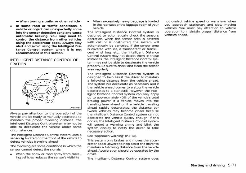
(313,1)
[ Edit: 2020/ 11/ 9 Model: Y62-A ]
— When towing a trailer or other vehicle. In some road or traffic conditions, a
vehicle or object can unexpectedly comeinto the sensor detection zone and causeautomatic braking. You may need tocontrol the distance from other vehiclesusing the accelerator pedal. Always stayalert and avoid using the Intelligent Dis-tance Control system when it is notrecommended in this section.
INTELLIGENT DISTANCE CONTROL OP-ERATION GUID-8F2A5F41-696D-4513-B9EF-1D7A213C0401
JVS0913X
Always pay attention to the operation of thevehicle and be ready to manually decelerate tomaintain the proper following distance. TheIntelligent Distance Control system may not beable to decelerate the vehicle under somecircumstances.The Intelligent Distance Control system uses asensor located on the front of the vehicle todetect vehicles traveling ahead.The following are some conditions in which thesensor cannot detect the signals:. When the snow or road spray from travel-
ing vehicles reduces the sensor’s visibility
. When excessively heavy baggage is loadedin the rear seat or the luggage room of yourvehicle
The Intelligent Distance Control system isdesigned to automatically check the sensor’soperation. When the sensor area is coveredwith dirt or is obstructed, the system willautomatically be canceled. If the sensor areais covered with ice, a transparent or translu-cent vinyl bag, etc., the Intelligent DistanceControl system may not detect them. In theseinstances, the Intelligent Distance Control sys-tem may not be able to decelerate the vehicleproperly. Be sure to check and clean the sensorarea regularly.The Intelligent Distance Control system isdesigned to help assist the driver to maintaina following distance from the vehicle ahead.The system will decelerate as necessary and ifthe vehicle ahead comes to a stop, the vehicledecelerates to a standstill. However, the Intel-ligent Distance Control system can only applyup to approximately 40% of the vehicle’s totalbraking power. If a vehicle moves into thetraveling lane ahead or if a vehicle travelingahead rapidly decelerates, the distance be-tween vehicles may become closer becausethe Intelligent Distance Control system cannotdecelerate the vehicle quickly enough. If thisoccurs, the Intelligent Distance Control systemwill sound a warning chime and blink thesystem display to notify the driver to takenecessary action.See “Approach warning” (P.5-76).This system only brakes and moves the accel-erator pedal upward to help assist the driver tomaintain a following distance from the vehicleahead. Acceleration should be operated by thedriver.The Intelligent Distance Control system does
not control vehicle speed or warn you whenyou approach stationary and slow movingvehicles. You must pay attention to vehicleoperation to maintain proper distance fromvehicles ahead.
Starting and driving 5-71
Condition: 'Except for China'/'Except for China/
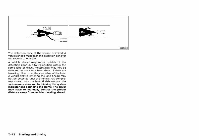
(314,1)
[ Edit: 2020/ 11/ 9 Model: Y62-A ]
5-72 Starting and driving
SSD0252
The detection zone of the sensor is limited. Avehicle ahead must be in the detection zone forthe system to operate.A vehicle ahead may move outside of thedetection zone due to its position within thesame lane of travel. Motorcycles may not bedetected in the same lane ahead if they aretraveling offset from the centerline of the lane.A vehicle that is entering the lane ahead maynot be detected until the vehicle has comple-tely moved into the lane. If this occurs, thesystemmay warn you by blinking the systemindicator and sounding the chime. The drivermay have to manually control the properdistance away from vehicle traveling ahead.
Condition: 'Except for China'/'Except for China/

(315,1)
[ Edit: 2020/ 11/ 9 Model: Y62-A ]
SSD0253
When driving on some roads, such as winding,hilly, curved, narrow roads, or roads which areunder construction, the sensor may detectvehicles in a different lane, or may temporarilynot detect a vehicle traveling ahead. This maycause the system to work inappropriately.The detection of vehicles may also be affectedby vehicle operation (steering maneuver ortraveling position in the lane, etc.) or vehiclecondition. If this occurs, the systemmay warnyou by blinking the system indicator andsounding the chime unexpectedly. You willhave to manually control the proper distanceaway from the vehicle traveling ahead.
Intelligent Distance Control systemdisplay and indicatorsGUID-A660B810-201B-405D-8E88-D10CB77451DB
SSD0994
The display is located between the speed-ometer and tachometer.1. Intelligent Distance Control system switch
indicator:Indicates that the dynamic driver assis-tance switch is ON.
2. Vehicle ahead detection indicator:Indicates whether it detects a vehicle infront of you.
3. Intelligent Distance Control system warn-ing light (orange):The light comes on if there is a malfunctionin the Intelligent Distance Control system.
Operating Intelligent Distance Control systemGUID-A783D118-A488-4918-9610-81D7358A8A53
SSD1049
The Intelligent Distance Control system turnson when the dynamic driver assistance switchon the steering wheel is pushed when the“Distance Control Assist” is enabled in thesettings menu on the center display. TheIntelligent Distance Control system indicatorin the dot matrix liquid crystal display appearswhen the Intelligent Distance Control system isturned on.The system will start to operate after thevehicle speed becomes above approximately5 km/h (3 MPH).
Starting and driving 5-73
Condition: 'Except for China'/'Except for China/
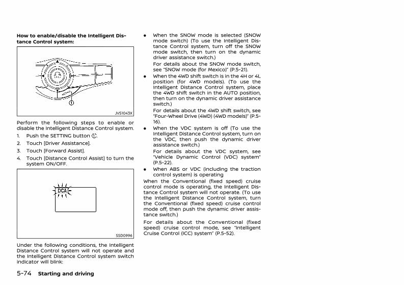
(316,1)
[ Edit: 2020/ 11/ 9 Model: Y62-A ]
5-74 Starting and driving
How to enable/disable the Intelligent Dis-tance Control system:
GUID-C7E1EF24-5AAB-4301-95BE-26917EEE45EF
JVS1043X
Perform the following steps to enable ordisable the Intelligent Distance Control system.1. Push the SETTING button .2. Touch [Driver Assistance].3. Touch [Forward Assist].4. Touch [Distance Control Assist] to turn the
system ON/OFF.
SSD0996
Under the following conditions, the IntelligentDistance Control system will not operate andthe Intelligent Distance Control system switchindicator will blink:
. When the SNOW mode is selected (SNOWmode switch) (To use the Intelligent Dis-tance Control system, turn off the SNOWmode switch, then turn on the dynamicdriver assistance switch.)For details about the SNOW mode switch,see “SNOW mode (for Mexico)” (P.5-21).
. When the 4WD shift switch is in the 4H or 4Lposition (for 4WD models). (To use theIntelligent Distance Control system, placethe 4WD shift switch in the AUTO position,then turn on the dynamic driver assistanceswitch.)For details about the 4WD shift switch, see“Four-Wheel Drive (4WD) (4WD models)” (P.5-16).
. When the VDC system is off (To use theIntelligent Distance Control system, turn onthe VDC, then push the dynamic driverassistance switch.)For details about the VDC system, see“Vehicle Dynamic Control (VDC) system”(P.5-22).
. When ABS or VDC (including the tractioncontrol system) is operating
When the Conventional (fixed speed) cruisecontrol mode is operating, the Intelligent Dis-tance Control system will not operate. (To usethe Intelligent Distance Control system, turnthe Conventional (fixed speed) cruise controlmode off, then push the dynamic driver assis-tance switch.)For details about the Conventional (fixedspeed) cruise control mode, see “IntelligentCruise Control (ICC) system” (P.5-52).
Condition: 'Except for China'/'Except for China/
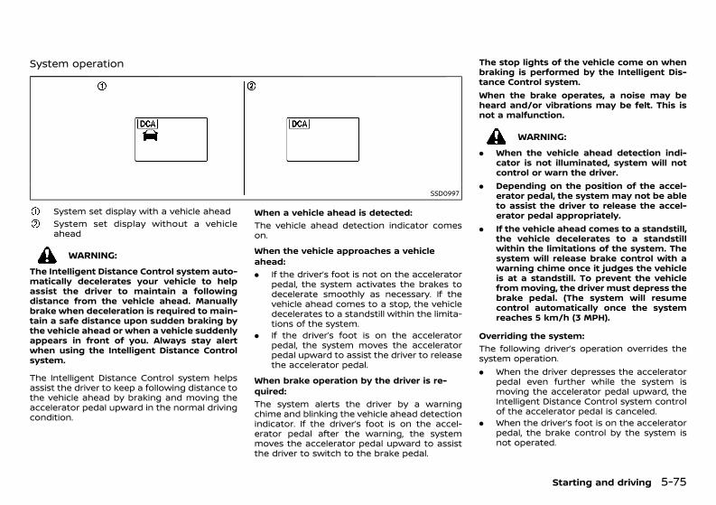
(317,1)
[ Edit: 2020/ 11/ 9 Model: Y62-A ]
System operationGUID-D6DA96A5-0B6E-4718-8E15-115E361F6BBB
SSD0997
System set display with a vehicle aheadSystem set display without a vehicleahead
WARNING:The Intelligent Distance Control system auto-matically decelerates your vehicle to helpassist the driver to maintain a followingdistance from the vehicle ahead. Manuallybrake when deceleration is required to main-tain a safe distance upon sudden braking bythe vehicle ahead or when a vehicle suddenlyappears in front of you. Always stay alertwhen using the Intelligent Distance Controlsystem.
The Intelligent Distance Control system helpsassist the driver to keep a following distance tothe vehicle ahead by braking and moving theaccelerator pedal upward in the normal drivingcondition.
When a vehicle ahead is detected:GUID-C7E1EF24-5AAB-4301-95BE-26917EEE45EF
The vehicle ahead detection indicator comeson.When the vehicle approaches a vehicleahead:
GUID-C7E1EF24-5AAB-4301-95BE-26917EEE45EF
. If the driver’s foot is not on the acceleratorpedal, the system activates the brakes todecelerate smoothly as necessary. If thevehicle ahead comes to a stop, the vehicledecelerates to a standstill within the limita-tions of the system.
. If the driver’s foot is on the acceleratorpedal, the system moves the acceleratorpedal upward to assist the driver to releasethe accelerator pedal.
When brake operation by the driver is re-quired:
GUID-C7E1EF24-5AAB-4301-95BE-26917EEE45EF
The system alerts the driver by a warningchime and blinking the vehicle ahead detectionindicator. If the driver’s foot is on the accel-erator pedal after the warning, the systemmoves the accelerator pedal upward to assistthe driver to switch to the brake pedal.
The stop lights of the vehicle come on whenbraking is performed by the Intelligent Dis-tance Control system.When the brake operates, a noise may beheard and/or vibrations may be felt. This isnot a malfunction.
WARNING:. When the vehicle ahead detection indi-
cator is not illuminated, system will notcontrol or warn the driver.
. Depending on the position of the accel-erator pedal, the system may not be ableto assist the driver to release the accel-erator pedal appropriately.
. If the vehicle ahead comes to a standstill,the vehicle decelerates to a standstillwithin the limitations of the system. Thesystem will release brake control with awarning chime once it judges the vehicleis at a standstill. To prevent the vehiclefrommoving, the driver must depress thebrake pedal. (The system will resumecontrol automatically once the systemreaches 5 km/h (3 MPH).
Overriding the system:GUID-C7E1EF24-5AAB-4301-95BE-26917EEE45EF
The following driver’s operation overrides thesystem operation.. When the driver depresses the accelerator
pedal even further while the system ismoving the accelerator pedal upward, theIntelligent Distance Control system controlof the accelerator pedal is canceled.
. When the driver’s foot is on the acceleratorpedal, the brake control by the system isnot operated.
Starting and driving 5-75
Condition: 'Except for China'/'Except for China/
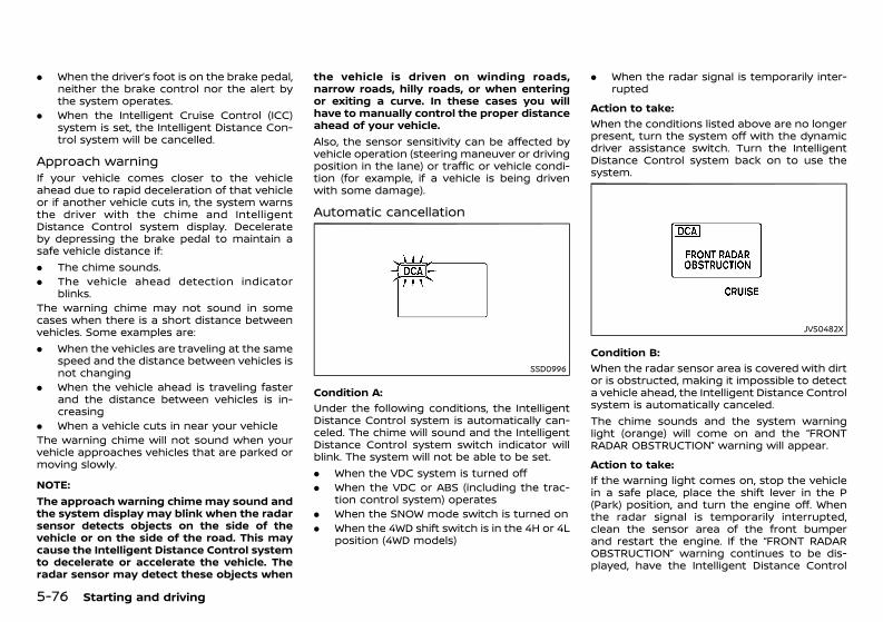
(318,1)
[ Edit: 2020/ 11/ 9 Model: Y62-A ]
5-76 Starting and driving
. When the driver’s foot is on the brake pedal,neither the brake control nor the alert bythe system operates.
. When the Intelligent Cruise Control (ICC)system is set, the Intelligent Distance Con-trol system will be cancelled.
Approach warningGUID-79E44031-1B8B-4A4D-9DEB-677289CA20D9If your vehicle comes closer to the vehicleahead due to rapid deceleration of that vehicleor if another vehicle cuts in, the system warnsthe driver with the chime and IntelligentDistance Control system display. Decelerateby depressing the brake pedal to maintain asafe vehicle distance if:. The chime sounds.. The vehicle ahead detection indicator
blinks.The warning chime may not sound in somecases when there is a short distance betweenvehicles. Some examples are:. When the vehicles are traveling at the same
speed and the distance between vehicles isnot changing
. When the vehicle ahead is traveling fasterand the distance between vehicles is in-creasing
. When a vehicle cuts in near your vehicleThe warning chime will not sound when yourvehicle approaches vehicles that are parked ormoving slowly.
NOTE:The approach warning chimemay sound andthe system display may blink when the radarsensor detects objects on the side of thevehicle or on the side of the road. This maycause the Intelligent Distance Control systemto decelerate or accelerate the vehicle. Theradar sensor may detect these objects when
the vehicle is driven on winding roads,narrow roads, hilly roads, or when enteringor exiting a curve. In these cases you willhave to manually control the proper distanceahead of your vehicle.Also, the sensor sensitivity can be affected byvehicle operation (steering maneuver or drivingposition in the lane) or traffic or vehicle condi-tion (for example, if a vehicle is being drivenwith some damage).
Automatic cancellationGUID-52D3FA27-1071-4CC3-955B-49A0BD49A3E7
SSD0996
Condition A:GUID-C7E1EF24-5AAB-4301-95BE-26917EEE45EF
Under the following conditions, the IntelligentDistance Control system is automatically can-celed. The chime will sound and the IntelligentDistance Control system switch indicator willblink. The system will not be able to be set.. When the VDC system is turned off. When the VDC or ABS (including the trac-
tion control system) operates. When the SNOW mode switch is turned on. When the 4WD shift switch is in the 4H or 4L
position (4WD models)
. When the radar signal is temporarily inter-rupted
Action to take:GUID-C7E1EF24-5AAB-4301-95BE-26917EEE45EF
When the conditions listed above are no longerpresent, turn the system off with the dynamicdriver assistance switch. Turn the IntelligentDistance Control system back on to use thesystem.
JVS0482X
Condition B:GUID-C7E1EF24-5AAB-4301-95BE-26917EEE45EF
When the radar sensor area is covered with dirtor is obstructed, making it impossible to detecta vehicle ahead, the Intelligent Distance Controlsystem is automatically canceled.The chime sounds and the system warninglight (orange) will come on and the “FRONTRADAR OBSTRUCTION” warning will appear.Action to take:
GUID-C7E1EF24-5AAB-4301-95BE-26917EEE45EF
If the warning light comes on, stop the vehiclein a safe place, place the shift lever in the P(Park) position, and turn the engine off. Whenthe radar signal is temporarily interrupted,clean the sensor area of the front bumperand restart the engine. If the “FRONT RADAROBSTRUCTION” warning continues to be dis-played, have the Intelligent Distance Control
Condition: 'Except for China'/'Except for China/
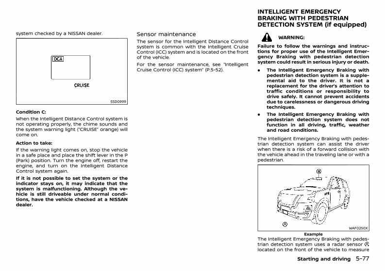
(319,1)
[ Edit: 2020/ 11/ 9 Model: Y62-A ]
system checked by a NISSAN dealer.
SSD0999
Condition C:GUID-C7E1EF24-5AAB-4301-95BE-26917EEE45EF
When the Intelligent Distance Control system isnot operating properly, the chime sounds andthe system warning light (“CRUISE” orange) willcome on.Action to take:
GUID-C7E1EF24-5AAB-4301-95BE-26917EEE45EF
If the warning light comes on, stop the vehiclein a safe place and place the shift lever in the P(Park) position. Turn the engine off, restart theengine, and turn on the Intelligent DistanceControl system again.If it is not possible to set the system or theindicator stays on, it may indicate that thesystem is malfunctioning. Although the ve-hicle is still driveable under normal condi-tions, have the vehicle checked at a NISSANdealer.
Sensor maintenanceGUID-61866615-9BE8-441E-A6EA-3997682B5255The sensor for the Intelligent Distance Controlsystem is common with the Intelligent CruiseControl (ICC) system and is located on the frontof the vehicle.For the sensor maintenance, see “IntelligentCruise Control (ICC) system” (P.5-52).
GUID-E19D4421-FF16-44F6-AD58-5AD1BB0DA145
WARNING:Failure to follow the warnings and instruc-tions for proper use of the Intelligent Emer-gency Braking with pedestrian detectionsystem could result in serious injury or death.. The Intelligent Emergency Braking with
pedestrian detection system is a supple-mental aid to the driver. It is not areplacement for the driver’s attention totraffic conditions or responsibility todrive safely. It cannot prevent accidentsdue to carelessness or dangerous drivingtechniques.
. The Intelligent Emergency Braking withpedestrian detection system does notfunction in all driving, traffic, weatherand road conditions.
The Intelligent Emergency Braking with pedes-trian detection system can assist the driverwhen there is a risk of a forward collision withthe vehicle ahead in the traveling lane or with apedestrian.
WAF0250XExample
The Intelligent Emergency Braking with pedes-trian detection system uses a radar sensorlocated on the front of the vehicle to measure
Starting and driving 5-77
INTELLIGENT EMERGENCYBRAKING WITH PEDESTRIANDETECTION SYSTEM (if equipped)
Condition: 'Except for China'/'Except for China/
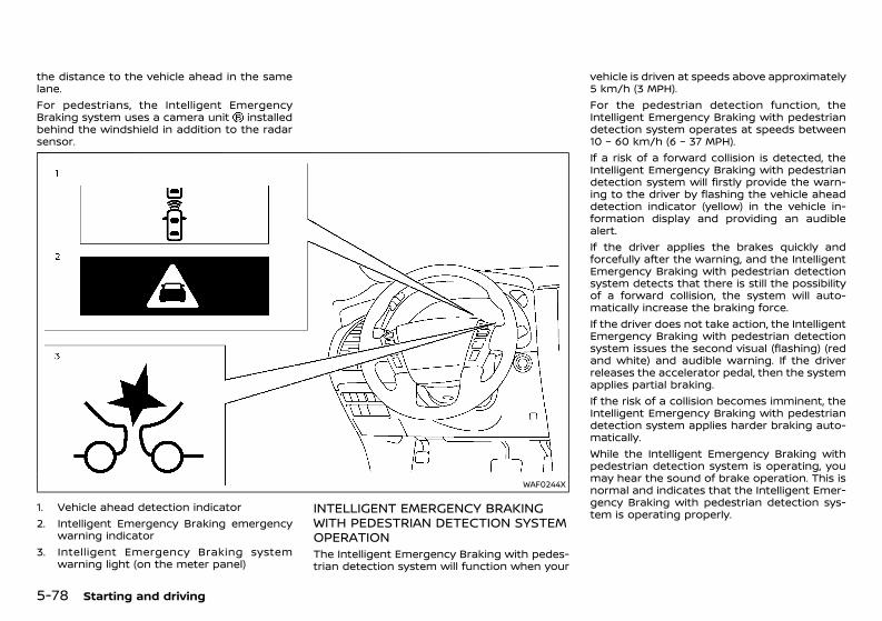
(320,1)
[ Edit: 2020/ 11/ 9 Model: Y62-A ]
5-78 Starting and driving
the distance to the vehicle ahead in the samelane.For pedestrians, the Intelligent EmergencyBraking system uses a camera unit installedbehind the windshield in addition to the radarsensor.
WAF0244X
1. Vehicle ahead detection indicator2. Intelligent Emergency Braking emergency
warning indicator3. Intelligent Emergency Braking system
warning light (on the meter panel)
INTELLIGENT EMERGENCY BRAKINGWITH PEDESTRIAN DETECTION SYSTEMOPERATIONGUID-78959F28-C0B4-4D97-8D57-78DB0D8C5245The Intelligent Emergency Braking with pedes-trian detection system will function when your
vehicle is driven at speeds above approximately5 km/h (3 MPH).For the pedestrian detection function, theIntelligent Emergency Braking with pedestriandetection system operates at speeds between10 – 60 km/h (6 – 37 MPH).If a risk of a forward collision is detected, theIntelligent Emergency Braking with pedestriandetection system will firstly provide the warn-ing to the driver by flashing the vehicle aheaddetection indicator (yellow) in the vehicle in-formation display and providing an audiblealert.If the driver applies the brakes quickly andforcefully after the warning, and the IntelligentEmergency Braking with pedestrian detectionsystem detects that there is still the possibilityof a forward collision, the system will auto-matically increase the braking force.If the driver does not take action, the IntelligentEmergency Braking with pedestrian detectionsystem issues the second visual (flashing) (redand white) and audible warning. If the driverreleases the accelerator pedal, then the systemapplies partial braking.If the risk of a collision becomes imminent, theIntelligent Emergency Braking with pedestriandetection system applies harder braking auto-matically.While the Intelligent Emergency Braking withpedestrian detection system is operating, youmay hear the sound of brake operation. This isnormal and indicates that the Intelligent Emer-gency Braking with pedestrian detection sys-tem is operating properly.
Condition: 'Except for China'/'Except for China/
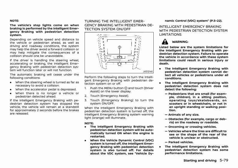
(321,1)
[ Edit: 2020/ 11/ 9 Model: Y62-A ]
NOTE:The vehicle’s stop lights come on whenbraking is performed by the Intelligent Emer-gency Braking with pedestrian detectionsystem.Depending on vehicle speed and distance tothe vehicle or pedestrian ahead, as well asdriving and roadway conditions, the systemmay help the driver avoid a forward collision ormay help mitigate the consequences of acollision should one be unavoidable.If the driver is handling the steering wheel,accelerating or braking, the Intelligent Emer-gency Braking with pedestrian detection sys-tem will function later or will not function.The automatic braking will cease under thefollowing conditions:. When the steering wheel is turned as far as
necessary to avoid a collision.. When the accelerator pedal is depressed.. When there is no longer a vehicle or
pedestrian detected ahead.If the Intelligent Emergency Braking with pe-destrian detection system has stopped thevehicle, the vehicle will remain at a standstillfor approximately 2 seconds before the brakesare released.
TURNING THE INTELLIGENT EMER-GENCY BRAKING WITH PEDESTRIAN DE-TECTION SYSTEM ON/OFFGUID-DE73ACBD-C640-4A3E-B60D-510674F224A8
JVS1214X
Perform the following steps to turn the Intelli-gent Emergency Braking with pedestrian de-tection system on or off.1. Push the MENU button and touch [Driver
Assist] on the lower display.2. Touch [Emergency Assist].3. Touch [Emergency Braking] to turn the
system ON/OFF.When the Intelligent Emergency Braking withpedestrian detection system is turned off, theIntelligent Emergency Braking system warninglight (orange) will illuminate.
NOTE:. The Intelligent Emergency Braking with
pedestrian detection system will be auto-matically turned ON when the engine isrestarted.
. When the Vehicle Dynamic Control (VDC)system is turned off, the Intelligent Emer-gency Braking with pedestrian detectionsystem is also turned off. For detailsabout the VDC system, see “Vehicle Dy-
namic Control (VDC) system” (P.5-22).
INTELLIGENT EMERGENCY BRAKINGWITH PEDESTRIAN DETECTION SYSTEMLIMITATIONSGUID-97474250-48A2-4908-9736-6E545016B4B3
WARNING:Listed below are the system limitations forthe Intelligent Emergency Braking with pe-destrian detection system. Failure to operatethe vehicle in accordance with these systemlimitations could result in serious injury ordeath.. The Intelligent Emergency Braking with
pedestrian detection system cannot de-tect all vehicles or pedestrians under allconditions.
. The Intelligent Emergency Braking withpedestrian detection system does notdetect the following:— Pedestrians that are small (for exam-
ple, children), in a sitting position,operating toys/skateboards, onscooters or in wheelchairs, or not inan upright standing or walking posi-tion.
— Animals of any size.— Obstacles (for example, cargo or deb-
ris) on the roadway or roadside.— Oncoming or crossing vehicles.— Vehicles where the tires are difficult to
see or the shape of the rear of thevehicle is unclear or obstructed.
— Parked vehicles.. The Intelligent Emergency Braking with
pedestrian detection system has someperformance limitations.
Starting and driving 5-79
Condition: 'Except for China'/'Except for China/
(322,1)
[ Edit: 2020/ 11/ 9 Model: Y62-A ]
5-80 Starting and driving
— If a stationary vehicle is in the vehi-cle’s path, the system will not func-tion when the vehicle approaches thestationary vehicle at speeds overapproximately 80 km/h (50 MPH).
— Pedestrian detection will not functionwhen the vehicle is driven at speedsover approximately 60 km/h (37MPH) or below approximately 10km/h (6 MPH).
. For pedestrians, the Intelligent Emer-gency Braking with pedestrian detectionsystem will not issue the first warning.
. The Intelligent Emergency Braking withpedestrian detection system may notfunction properly or detect a vehicle orpedestrian ahead in the following condi-tions:— In poor visibility conditions (such as
rain, snow, fog, dust storms, sandstorms, smoke, and road spray fromother vehicles).
— If dirt, ice, snow, fog or other materialis covering the radar sensor area orcamera area of the windshield.
— If strong light (for example, sunlightor high beams) enters the front cam-era or a sudden change in brightnessoccurs (for example, entering a tun-nel or driving in lightning).
— In dark or dimly lit conditions, such asat night or in tunnels, including caseswhere your vehicle’s headlights areoff or dim, or the tail lights of thevehicle ahead are off.
— When the direction of the camera ismisaligned.
— When driving on a steep downhillslope, on roads with sharp curves,and/or bumpy or dirt roads.
— If there is interference by other radarsources.
— When your vehicle’s position or move-ment is changed quickly or signifi-cantly (for example, lane change,turning vehicle, abrupt steering, sud-den acceleration or deceleration).
— When your vehicle or the vehicle orpedestrian ahead moves quickly orsignificantly such that the systemcannot detect and react in time (forexample, pedestrian moving quicklytoward the vehicle at close range,vehicle cutting in, changing lanes,making a turn, steering abruptly,sudden acceleration or deceleration).
— When the vehicle or pedestrian isoffset from the vehicle’s forwardpath.
— If the speed difference between thetwo vehicles is small.
— The pedestrian’s profile is partiallyobscured or unidentifiable; for exam-ple, due to transporting luggage,pushing a stroller, wearing bulky orvery loose-fitting clothing or acces-sories, or being in a unique posture(such as raising hands).
— There is poor contrast of a person tothe background, such as havingclothing color or pattern which issimilar to the background.
— For approximately 15 seconds afterstarting the engine.
— If the vehicle ahead has a unique orunusual shape, extremely low or highclearance heights, or unusual cargoloading or is narrow (for example, amotorcycle).
— When the vehicle or pedestrian islocated near a traffic sign, a reflectivearea (for example, water on road), oris in a shadow.
— When multiple pedestrians aregrouped together.
— When the view of the pedestrian isobscured by a vehicle or other object.
— While towing a trailer or other vehicle(models with trailer hitch).
. The system performance may be de-graded in the following conditions:— The vehicle is driven on a slippery
road.— The vehicle is driven on a slope.— Excessively heavy baggage is loaded
in the rear seat or the cargo area ofyour vehicle.
. The system is designed to automaticallycheck the sensor (radar and camera)’sfunctionality, within certain limitations.The system may not detect some formsof obstruction of the sensor area such asice, snow or stickers, for example. Inthese cases, the system may not be ableto warn the driver properly. Be sure thatyou check, clean and clear sensor areasregularly.
. In some road and traffic conditions, theIntelligent Emergency Braking with pe-destrian detection system may unex-pectedly apply partial braking. Whenacceleration is necessary, depress the
Condition: 'Except for China'/'Except for China/
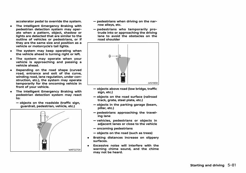
(323,1)
[ Edit: 2020/ 11/ 9 Model: Y62-A ]
accelerator pedal to override the system.. The Intelligent Emergency Braking with
pedestrian detection system may oper-ate when a pattern, object, shadow orlights are detected that are similar to theoutline of vehicles or pedestrians, or ifthey are the same size and position as avehicle or motorcycle’s tail lights.
. The system may keep operating whenthe vehicle ahead is turning right or left.
. The system may operate when yourvehicle is approaching and passing avehicle ahead.
. Depending on the road shape (curvedroad, entrance and exit of the curve,winding road, lane regulation, under con-struction, etc.), the system may operatetemporarily for the oncoming vehicle infront of your vehicle.
. The Intelligent Emergency Braking withpedestrian detection system may reactto:— objects on the roadside (traffic sign,
guardrail, pedestrian, vehicle, etc.)
WAF0270X
— pedestrians when driving on the nar-row alleys, etc.
— pedestrians who temporarily pro-trude into or approaching the drivinglane to avoid the obstacles on theroad shoulder
JVS1183X
— objects above road (low bridge, trafficsign, etc.)
— objects on the road surface (railroadtrack, grate, steel plate, etc.)
— objects in the parking garage (beam,pillar, etc.)
— pedestrians approaching the travel-ing lane
— vehicles, pedestrians or objects inadjacent lanes or close to the vehicle
— oncoming pedestrians— objects on the road (such as trees)
. Braking distances increase on slipperysurfaces.
. Excessive noise will interfere with thewarning chime sound, and the chimemay not be heard.
Starting and driving 5-81
Condition: 'Except for China'/'Except for China/
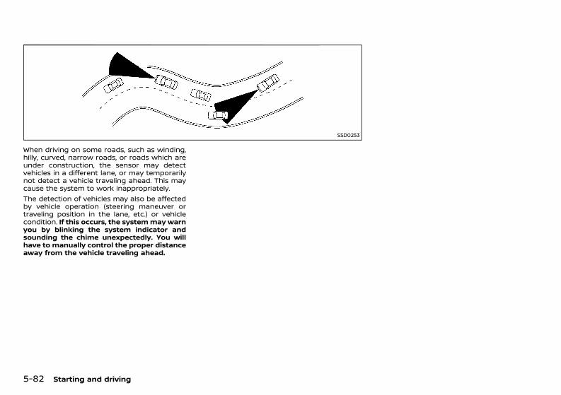
(324,1)
[ Edit: 2020/ 11/ 9 Model: Y62-A ]
5-82 Starting and driving
SSD0253
When driving on some roads, such as winding,hilly, curved, narrow roads, or roads which areunder construction, the sensor may detectvehicles in a different lane, or may temporarilynot detect a vehicle traveling ahead. This maycause the system to work inappropriately.The detection of vehicles may also be affectedby vehicle operation (steering maneuver ortraveling position in the lane, etc.) or vehiclecondition. If this occurs, the systemmay warnyou by blinking the system indicator andsounding the chime unexpectedly. You willhave to manually control the proper distanceaway from the vehicle traveling ahead.
Condition: 'Except for China'/'Except for China/
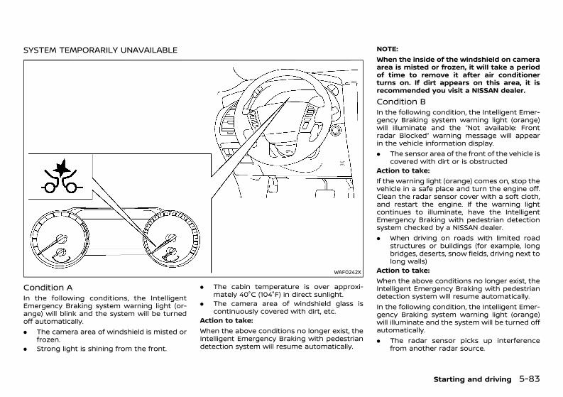
(325,1)
[ Edit: 2020/ 11/ 9 Model: Y62-A ]
SYSTEM TEMPORARILY UNAVAILABLEGUID-F97A1D31-CB4C-4E6B-A796-25E5743DA5A7
WAF0242X
Condition AGUID-6386693D-5FAC-482A-8067-F493E384EC36In the following conditions, the IntelligentEmergency Braking system warning light (or-ange) will blink and the system will be turnedoff automatically.. The camera area of windshield is misted or
frozen.. Strong light is shining from the front.
. The cabin temperature is over approxi-mately 40°C (104°F) in direct sunlight.
. The camera area of windshield glass iscontinuously covered with dirt, etc.
Action to take:When the above conditions no longer exist, theIntelligent Emergency Braking with pedestriandetection system will resume automatically.
NOTE:When the inside of the windshield on cameraarea is misted or frozen, it will take a periodof time to remove it after air conditionerturns on. If dirt appears on this area, it isrecommended you visit a NISSAN dealer.Condition BGUID-48D872B9-7021-4D94-837F-F55CC4EDE758In the following condition, the Intelligent Emer-gency Braking system warning light (orange)will illuminate and the “Not available: Frontradar Blocked” warning message will appearin the vehicle information display.. The sensor area of the front of the vehicle is
covered with dirt or is obstructedAction to take:If the warning light (orange) comes on, stop thevehicle in a safe place and turn the engine off.Clean the radar sensor cover with a soft cloth,and restart the engine. If the warning lightcontinues to illuminate, have the IntelligentEmergency Braking with pedestrian detectionsystem checked by a NISSAN dealer.. When driving on roads with limited road
structures or buildings (for example, longbridges, deserts, snow fields, driving next tolong walls)
Action to take:When the above conditions no longer exist, theIntelligent Emergency Braking with pedestriandetection system will resume automatically.In the following condition, the Intelligent Emer-gency Braking system warning light (orange)will illuminate and the system will be turned offautomatically.. The radar sensor picks up interference
from another radar source.
Starting and driving 5-83
Condition: 'Except for China'/'Except for China/
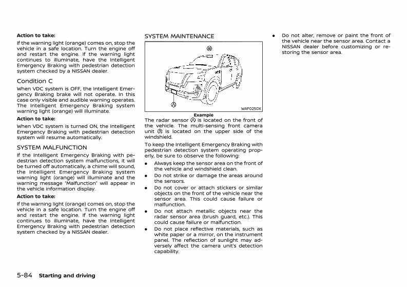
(326,1)
[ Edit: 2020/ 11/ 9 Model: Y62-A ]
5-84 Starting and driving
Action to take:If the warning light (orange) comes on, stop thevehicle in a safe location. Turn the engine offand restart the engine. If the warning lightcontinues to illuminate, have the IntelligentEmergency Braking with pedestrian detectionsystem checked by a NISSAN dealer.
Condition CGUID-2FDA673E-89EC-435B-8444-DE3149900B2CWhen VDC system is OFF, the Intelligent Emer-gency Braking brake will not operate. In thiscase only visible and audible warning operates.The Intelligent Emergency Braking systemwarning light (orange) will illuminate.Action to take:When VDC system is turned ON, the IntelligentEmergency Braking with pedestrian detectionsystem will resume automatically.
SYSTEM MALFUNCTIONGUID-76313A35-9C42-4E7D-B25F-E301D0530323If the Intelligent Emergency Braking with pe-destrian detection system malfunctions, it willbe turned off automatically, a chime will sound,the Intelligent Emergency Braking systemwarning light (orange) will illuminate and thewarning message “Malfunction” will appear inthe vehicle information display.Action to take:If the warning light (orange) comes on, stop thevehicle in a safe location. Turn the engine offand restart the engine. If the warning lightcontinues to illuminate, have the IntelligentEmergency Braking with pedestrian detectionsystem checked by a NISSAN dealer.
SYSTEM MAINTENANCEGUID-C0794F37-85A0-4680-9C17-76EC8CC0C379
WAF0250XExample
The radar sensor is located on the front ofthe vehicle. The multi-sensing front cameraunit is located on the upper side of thewindshield.To keep the Intelligent Emergency Braking withpedestrian detection system operating prop-erly, be sure to observe the following:. Always keep the sensor area on the front of
the vehicle and windshield clean.. Do not strike or damage the areas around
the sensors.. Do not cover or attach stickers or similar
objects on the front of the vehicle near thesensor area. This could cause failure ormalfunction.
. Do not attach metallic objects near theradar sensor area (brush guard, etc.). Thiscould cause failure or malfunction.
. Do not place reflective materials, such aswhite paper or a mirror, on the instrumentpanel. The reflection of sunlight may ad-versely affect the camera unit’s detectioncapability.
. Do not alter, remove or paint the front ofthe vehicle near the sensor area. Contact aNISSAN dealer before customizing or re-storing the sensor area.
Condition: 'Except for China'/'Except for China/
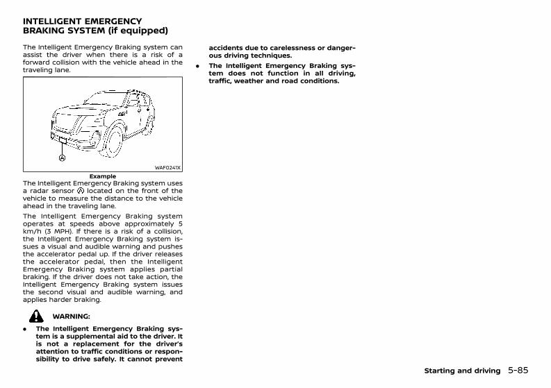
(327,1)
[ Edit: 2020/ 11/ 9 Model: Y62-A ]
GUID-F3FF7A5F-B1DC-4506-BE98-19F5554CFBD6The Intelligent Emergency Braking system canassist the driver when there is a risk of aforward collision with the vehicle ahead in thetraveling lane.
WAF0241XExample
The Intelligent Emergency Braking system usesa radar sensor located on the front of thevehicle to measure the distance to the vehicleahead in the traveling lane.The Intelligent Emergency Braking systemoperates at speeds above approximately 5km/h (3 MPH). If there is a risk of a collision,the Intelligent Emergency Braking system is-sues a visual and audible warning and pushesthe accelerator pedal up. If the driver releasesthe accelerator pedal, then the IntelligentEmergency Braking system applies partialbraking. If the driver does not take action, theIntelligent Emergency Braking system issuesthe second visual and audible warning, andapplies harder braking.
WARNING:. The Intelligent Emergency Braking sys-
tem is a supplemental aid to the driver. Itis not a replacement for the driver’sattention to traffic conditions or respon-sibility to drive safely. It cannot prevent
accidents due to carelessness or danger-ous driving techniques.
. The Intelligent Emergency Braking sys-tem does not function in all driving,traffic, weather and road conditions.
Starting and driving 5-85
INTELLIGENT EMERGENCYBRAKING SYSTEM (if equipped)
Condition: 'Except for China'/'Except for China/
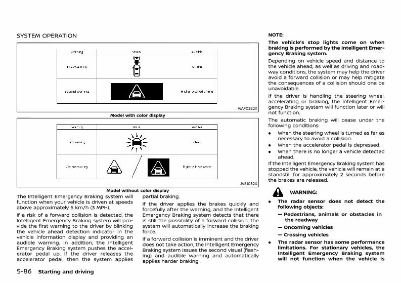
(328,1)
[ Edit: 2020/ 11/ 9 Model: Y62-A ]
5-86 Starting and driving
SYSTEM OPERATIONGUID-B68D961C-7D6F-44BE-BFD0-9E0F9932D1D6
WAF0282XModel with color display
JVS1052XModel without color display
The Intelligent Emergency Braking system willfunction when your vehicle is driven at speedsabove approximately 5 km/h (3 MPH).If a risk of a forward collision is detected, theIntelligent Emergency Braking system will pro-vide the first warning to the driver by blinkingthe vehicle ahead detection indicator in thevehicle information display and providing anaudible warning. In addition, the IntelligentEmergency Braking system pushes the accel-erator pedal up. If the driver releases theaccelerator pedal, then the system applies
partial braking.If the driver applies the brakes quickly andforcefully after the warning, and the IntelligentEmergency Braking system detects that thereis still the possibility of a forward collision, thesystem will automatically increase the brakingforce.If a forward collision is imminent and the driverdoes not take action, the Intelligent EmergencyBraking system issues the second visual (flash-ing) and audible warning and automaticallyapplies harder braking.
NOTE:The vehicle’s stop lights come on whenbraking is performed by the Intelligent Emer-gency Braking system.Depending on vehicle speed and distance tothe vehicle ahead, as well as driving and road-way conditions, the system may help the driveravoid a forward collision or may help mitigatethe consequences of a collision should one beunavoidable.If the driver is handling the steering wheel,accelerating or braking, the Intelligent Emer-gency Braking system will function later or willnot function.The automatic braking will cease under thefollowing conditions:. When the steering wheel is turned as far as
necessary to avoid a collision.. When the accelerator pedal is depressed.. When there is no longer a vehicle detected
ahead.If the Intelligent Emergency Braking system hasstopped the vehicle, the vehicle will remain at astandstill for approximately 2 seconds beforethe brakes are released.
WARNING:. The radar sensor does not detect the
following objects:— Pedestrians, animals or obstacles in
the roadway— Oncoming vehicles— Crossing vehicles
. The radar sensor has some performancelimitations. For stationary vehicles, theIntelligent Emergency Braking systemwill not function when the vehicle is
Condition: 'Except for China'/'Except for China/
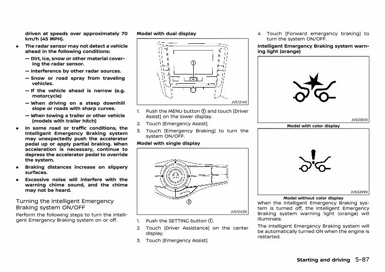
(329,1)
[ Edit: 2020/ 11/ 9 Model: Y62-A ]
driven at speeds over approximately 70km/h (45 MPH).
. The radar sensor may not detect a vehicleahead in the following conditions:— Dirt, ice, snow or other material cover-
ing the radar sensor.— Interference by other radar sources.— Snow or road spray from traveling
vehicles.— If the vehicle ahead is narrow (e.g.
motorcycle)— When driving on a steep downhill
slope or roads with sharp curves.— When towing a trailer or other vehicle
(models with trailer hitch). In some road or traffic conditions, the
Intelligent Emergency Braking systemmay unexpectedly push the acceleratorpedal up or apply partial braking. Whenacceleration is necessary, continue todepress the accelerator pedal to overridethe system.
. Braking distances increase on slipperysurfaces.
. Excessive noise will interfere with thewarning chime sound, and the chimemay not be heard.
Turning the Intelligent EmergencyBraking system ON/OFFGUID-B6FC6EFD-D36B-4631-B76F-690D0C03960CPerform the following steps to turn the Intelli-gent Emergency Braking system on or off.
Model with dual display
JVS1214X
1. Push the MENU button and touch [DriverAssist] on the lower display.
2. Touch [Emergency Assist].3. Touch [Emergency Braking] to turn the
system ON/OFF.Model with single display
JVS1043X
1. Push the SETTING button .2. Touch [Driver Assistance] on the center
display.3. Touch [Emergency Assist].
4. Touch [Forward emergency braking] toturn the system ON/OFF.
Intelligent Emergency Braking system warn-ing light (orange)
JVS0361XModel with color display
JVS0299XModel without color display
When the Intelligent Emergency Braking sys-tem is turned off, the Intelligent EmergencyBraking system warning light (orange) willilluminate.The Intelligent Emergency Braking system willbe automatically turned ON when the engine isrestarted.
Starting and driving 5-87
Condition: 'Except for China'/'Except for China/
(330,1)
[ Edit: 2020/ 11/ 9 Model: Y62-A ]
5-88 Starting and driving
NOTE:When the Intelligent Emergency Brakingsystem setting is turned ON or OFF, theIntelligent Forward Collision Warning systemis also turned ON or OFF simultaneously.System temporarily unavailableGUID-D7F25F29-A3F8-429F-A5EB-AA5FC6A017DC
Condition A:GUID-C7E1EF24-5AAB-4301-95BE-26917EEE45EF
When the radar sensor picks up interferencefrom another radar source, making it impos-sible to detect a vehicle ahead, the IntelligentEmergency Braking system is automaticallyturned off. The Intelligent Emergency Brakingsystem warning light (orange) will illuminate.Action to take:When the above conditions no longer exist, theIntelligent Emergency Braking system will re-sume automatically.Condition B:
GUID-C7E1EF24-5AAB-4301-95BE-26917EEE45EF
. When the sensor area of the front bumperis covered with dirt or is obstructed, makingit impossible to detect a vehicle ahead, theIntelligent Emergency Braking system isautomatically turned off. The IntelligentEmergency Braking system warning light(orange) will illuminate and the “Not Avail-able Front Radar Blocked” (model with colordisplay) or “FRONT RADAR OBSTRUCTION”(model without color display) warning mes-sage will appear in the vehicle informationdisplay.
Action to take:If the warning light (orange) comes on, park thevehicle in a safe place, and turn the engine off.Clean the radar cover on lower grille with a softcloth, and restart the engine. If the warninglight continues to illuminate, have the Intelli-gent Emergency Braking system checked by aNISSAN dealer.
. When driving on roads with limited roadstructures or buildings (for example, longbridges, deserts, snow fields, driving next tolong walls), the system may illuminate thesystem warning light and display the “NotAvailable Front Radar Blocked” (model withcolor display) or “FRONT RADAR OBSTRUC-TION” (model without color display) mes-sage.
Action to take:When the above driving conditions no longerexist, turn the system back on.Condition C:
GUID-C7E1EF24-5AAB-4301-95BE-26917EEE45EF
When the accelerator pedal actuator detectsthat the internal motor temperature is high, theIntelligent Emergency Braking system is auto-matically turned off. The Intelligent EmergencyBraking system warning light (orange) willilluminate.Action to take:When the above conditions no longer exist, theIntelligent Emergency Braking system will re-sume automatically.
System malfunctionGUID-CC1E9210-2EBB-429C-85AF-7C369C8C94FBIf the Intelligent Emergency Braking systemmalfunctions, it will be turned off automatically,a chime will sound, the Intelligent EmergencyBraking system warning light (orange) willilluminate and the “Malfunction” warning willappear (model with color display).Action to take:If the warning light (orange) comes on, park thevehicle in a safe location, turn the engine offand restart the engine. If the warning lightcontinues to illuminate, have the IntelligentEmergency Braking system checked by aNISSAN dealer.
Sensor maintenanceGUID-32B6EEF2-17C2-4ACF-981E-FE7CE9D9276FFor the radar sensor maintenance, see “Intelli-gent Cruise Control (ICC) system” (P.5-52).
Condition: 'Except for China'/'Except for China/
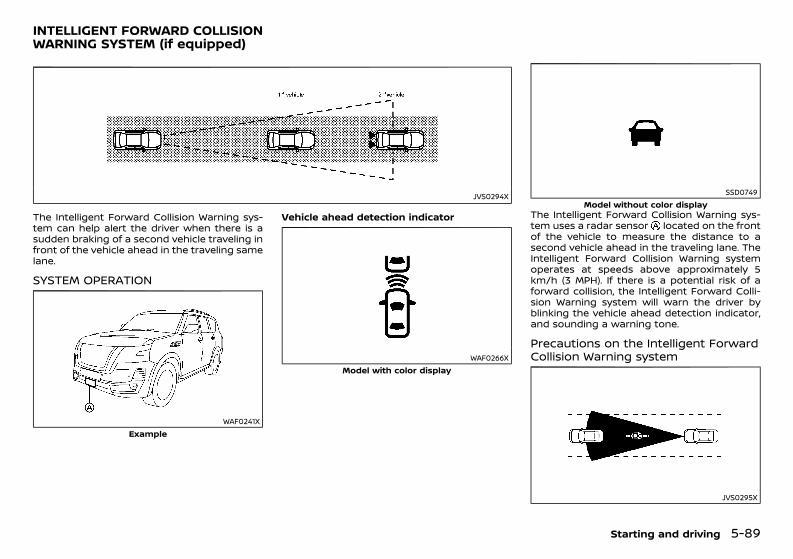
(331,1)
[ Edit: 2020/ 11/ 9 Model: Y62-A ]
GUID-36634C26-CF22-46A3-B351-8A41CA303578
JVS0294X
The Intelligent Forward Collision Warning sys-tem can help alert the driver when there is asudden braking of a second vehicle traveling infront of the vehicle ahead in the traveling samelane.
SYSTEM OPERATIONGUID-E3A89D5C-3B15-4CDB-BEAB-B385A017DFF5
WAF0241XExample
Vehicle ahead detection indicator
WAF0266XModel with color display
SSD0749Model without color display
The Intelligent Forward Collision Warning sys-tem uses a radar sensor located on the frontof the vehicle to measure the distance to asecond vehicle ahead in the traveling lane. TheIntelligent Forward Collision Warning systemoperates at speeds above approximately 5km/h (3 MPH). If there is a potential risk of aforward collision, the Intelligent Forward Colli-sion Warning system will warn the driver byblinking the vehicle ahead detection indicator,and sounding a warning tone.
Precautions on the Intelligent ForwardCollision Warning systemGUID-53C7DB0B-2809-4DA4-91FB-F60901A5D4D8
JVS0295X
Starting and driving 5-89
INTELLIGENT FORWARD COLLISIONWARNING SYSTEM (if equipped)
Condition: 'Except for China'/'Except for China/
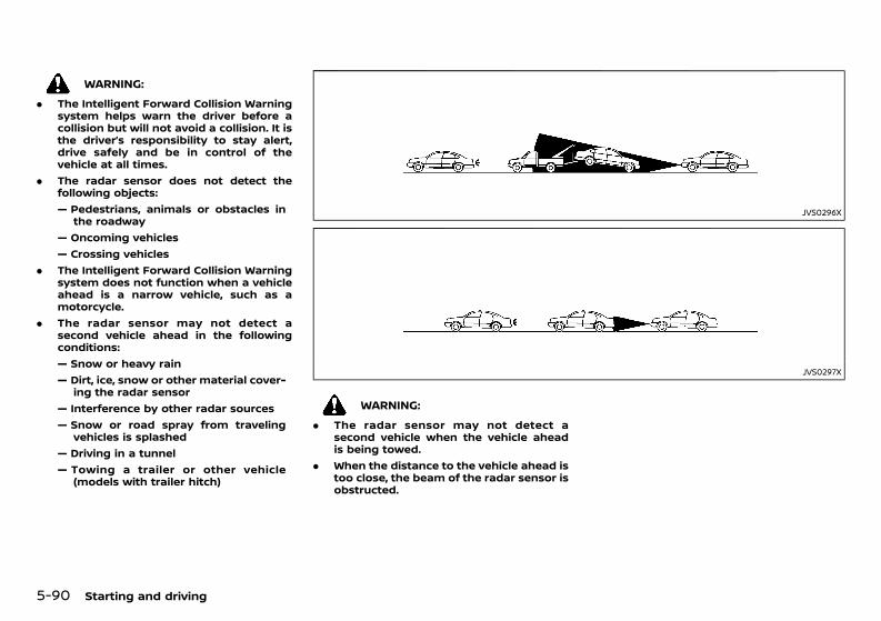
(332,1)
[ Edit: 2020/ 11/ 9 Model: Y62-A ]
5-90 Starting and driving
WARNING:. The Intelligent Forward Collision Warning
system helps warn the driver before acollision but will not avoid a collision. It isthe driver’s responsibility to stay alert,drive safely and be in control of thevehicle at all times.
. The radar sensor does not detect thefollowing objects:— Pedestrians, animals or obstacles in
the roadway— Oncoming vehicles— Crossing vehicles
. The Intelligent Forward Collision Warningsystem does not function when a vehicleahead is a narrow vehicle, such as amotorcycle.
. The radar sensor may not detect asecond vehicle ahead in the followingconditions:— Snow or heavy rain— Dirt, ice, snow or other material cover-
ing the radar sensor— Interference by other radar sources— Snow or road spray from traveling
vehicles is splashed— Driving in a tunnel— Towing a trailer or other vehicle
(models with trailer hitch)
JVS0296X
JVS0297X
WARNING:. The radar sensor may not detect a
second vehicle when the vehicle aheadis being towed.
. When the distance to the vehicle ahead istoo close, the beam of the radar sensor isobstructed.
Condition: 'Except for China'/'Except for China/
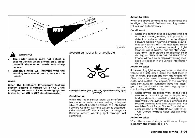
(333,1)
[ Edit: 2020/ 11/ 9 Model: Y62-A ]
JVS0298X
WARNING:. The radar sensor may not detect a
second vehicle when driving on a steepdownhill slope or on roads with sharpcurves.
. Excessive noise will interfere with thewarning tone sound, and it may not beheard.
NOTE:When the Intelligent Emergency Brakingsystem setting is turned ON or OFF, theIntelligent Forward Collision Warning systemis also turned ON or OFF simultaneously.
System temporarily unavailableGUID-6C17F065-9A66-4344-9C33-C6A817AF98E7
JVS0361XIntelligent Emergency Braking system warning light
(orange)Condition A:
GUID-C7E1EF24-5AAB-4301-95BE-26917EEE45EF
When the radar sensor picks up interferencefrom another radar source, making it impos-sible to detect a vehicle ahead, the IntelligentForward Collision Warning system is automati-cally turned off. The Intelligent EmergencyBraking system warning light (orange) willilluminate.
Action to take:When the above conditions no longer exist, theIntelligent Forward Collision Warning systemwill resume automatically.Condition B:
GUID-C7E1EF24-5AAB-4301-95BE-26917EEE45EF
. When the sensor area is covered with dirtor is obstructed, making it impossible todetect a vehicle ahead, the IntelligentForward Collision Warning system is auto-matically turned off. The Intelligent Emer-gency Braking system warning light(orange) will illuminate and the “Not Avail-able Front Radar Blocked” (model with colordisplay) or “FRONT RADAR OBSTRUCTION”(model without color display) warning mes-sage will appear in the vehicle informationdisplay.
Action to take:If the warning light (orange) comes on, stop thevehicle in a safe place, place the shift lever inthe “P” (Park) position and turn the engine off.Clean the radar cover on lower grille with a softcloth, and restart the engine. If the warninglight continues to illuminate, have the Intelli-gent Forward Collision Warning systemchecked by a NISSAN dealer.. When driving on roads with limited road
structures or buildings (for example, longbridges, deserts, snow fields, driving next tolong walls), the system may illuminate thesystem warning light and display the “NotAvailable Front Radar Blocked” (model withcolor display) or “FRONT RADAR OBSTRUC-TION” (model without color display) mes-sage.
Action to take:When the above driving conditions no longerexist, turn the system back on.
Starting and driving 5-91
Condition: 'Except for China'/'Except for China/
(334,1)
[ Edit: 2020/ 11/ 9 Model: Y62-A ]
5-92 Starting and driving
System malfunctionGUID-557B32EC-0944-4967-B5CA-A7D787E099C9If the Intelligent Forward Collision Warningsystem malfunctions, it will be turned offautomatically, a chime will sound, the Intelli-gent Emergency Braking system warning light(orange) will illuminate and the “Malfunction”warning will appear (model with color display).Action to take:If the warning light (orange) illuminates, stopthe vehicle in a safe location and place the shiftlever in the “P” (Park) position. Turn the engineoff and restart the engine. If the warning lightcontinues to illuminate, have the IntelligentForward Collision Warning system checked bya NISSAN dealer.
Sensor maintenanceGUID-B719ACE0-8EF4-450E-B638-B545546C4059For the radar sensor maintenance, see “Intelli-gent Cruise Control (ICC) system” (P.5-52).
GUID-1C088183-5208-48FC-9DAF-03EC14D51600Follow these easy-to-use Fuel Efficiency andCarbon Dioxide Reduction Driving Tips to helpyou achieve the most fuel economy from yourvehicle and reduce carbon dioxide emissions.1. Use smooth accelerator and brake pedal
application.. Avoid rapid starts and stops.. Use smooth, gentle accelerator and
brake application whenever possible.. Maintain constant speed while commut-
ing and coast whenever possible.2. Maintain constant speed.
. Look ahead to try and anticipate andminimize stops.
. Synchronizing your speed with trafficlights allows you to reduce your numberof stops.
. Maintaining a steady speed can mini-mize red light stops and improve fuelefficiency.
3. Drive at economical speeds and distances.. Observing the speed limit and not ex-
ceeding 97 km/h (60 MPH) (where legallyallowed) can improve fuel efficiency dueto reduced aerodynamic drag.
. Maintaining a safe following distancebehind other vehicles reduces unneces-sary braking.
. Safely monitoring traffic to anticipatechanges in speed permits reduced brak-ing and smooth acceleration changes.
. Select a gear range suitable to roadconditions.
4. Use cruise control.. Using cruise control during highway
driving helps maintain a steady speed.
. Cruise control is particularly effective inproviding fuel savings when driving onflat terrains.
5. Plan for the shortest route.. Utilize a map or navigation system (if
equipped) to determine the best route tosave time.
6. Avoid idling.. Shutting off your engine when safe for
stops exceeding 30-60 seconds savesfuel and reduces emissions.
7. Buy an automated pass for toll roads.. Automated passes permit drivers to use
special lanes to maintain cruising speedthrough the toll and avoid stopping andstarting.
8. Winter warm up.. Limit idling time to minimize impact to
fuel economy.. Vehicles typically need no more than 30
seconds of idling at start-up to effec-tively circulate the engine oil beforedriving.
. Your vehicle will reach its ideal operatingtemperature more quickly while drivingversus idling.
9. Keeping your vehicle cool.. Park your vehicle in a covered parking
area or in the shade whenever possible.. When entering a hot vehicle, opening the
windows will help to reduce the insidetemperature faster, resulting in reduceddemand on your A/C system.
10. Do not carry excessive weight.. Remove unnecessary objects from the
vehicle to reduce vehicle weight.
FUEL EFFICIENCY AND CARBONDIOXIDE REDUCTION DRIVING TIPS
Condition: 'Except for China'/'Except for China/
(335,1)
[ Edit: 2020/ 11/ 9 Model: Y62-A ]
GUID-7FD3A24A-258F-4A6F-A32F-0DDFCF3E0145. Keep your engine tuned up.. Follow the recommended scheduled main-
tenance.. Keep the tires inflated to the correct
pressure. Low tire pressure increases tirewear and lowers fuel economy.
. Keep the wheels in correct alignment.Improper alignment increases tire wearand lowers fuel economy.
. Use the recommended viscosity engine oil.(See “Recommended fluids/lubricants andcapacities” (P.9-2).)
GUID-3E4C4E3B-6B1C-4ECA-A585-021856F1DE28
WARNING:. Do not stop or park the vehicle over
flammable materials such as dry grass,waste paper or rags. They may ignite andcause a fire.
. Safe parking procedures require thatboth the parking brake be applied andthe shift lever placed into the “P” (Park)position. Failure to do so could cause thevehicle to move unexpectedly or rollaway and result in an accident.
. When parking the vehicle, make sure theshift lever is moved to the “P” (Park)position. The shift lever cannot be movedout of the “P” (Park) position withoutdepressing the foot brake pedal.
. Never leave the engine running while thevehicle is unattended.
. Do not leave children unattended insidethe vehicle. They could unknowingly acti-vate switches or controls. Unattendedchildren could become involved in ser-ious accidents.
. To help avoid risk of injury or deaththrough unintended operation of thevehicle and/or its systems, do not leavechildren, people who require the assis-tance of others or pets unattended inyour vehicle. Additionally, the tempera-ture inside a closed vehicle on a warmday can quickly become high enough tocause a significant risk of injury or deathto people and pets.
Starting and driving 5-93
INCREASING FUEL ECONOMY ANDREDUCING CARBON DIOXIDE EMISSIONS PARKING
Condition: 'Except for China'/'Except for China/
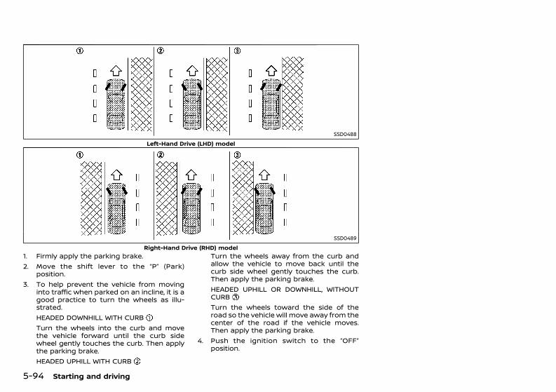
(336,1)
[ Edit: 2020/ 11/ 9 Model: Y62-A ]
5-94 Starting and driving
SSD0488Left-Hand Drive (LHD) model
SSD0489Right-Hand Drive (RHD) model
1. Firmly apply the parking brake.2. Move the shift lever to the “P” (Park)
position.3. To help prevent the vehicle from moving
into traffic when parked on an incline, it is agood practice to turn the wheels as illu-strated.HEADED DOWNHILL WITH CURBTurn the wheels into the curb and movethe vehicle forward until the curb sidewheel gently touches the curb. Then applythe parking brake.HEADED UPHILL WITH CURB
Turn the wheels away from the curb andallow the vehicle to move back until thecurb side wheel gently touches the curb.Then apply the parking brake.HEADED UPHILL OR DOWNHILL, WITHOUTCURBTurn the wheels toward the side of theroad so the vehicle will move away from thecenter of the road if the vehicle moves.Then apply the parking brake.
4. Push the ignition switch to the “OFF”position.
Condition: 'Except for China'/'Except for China/
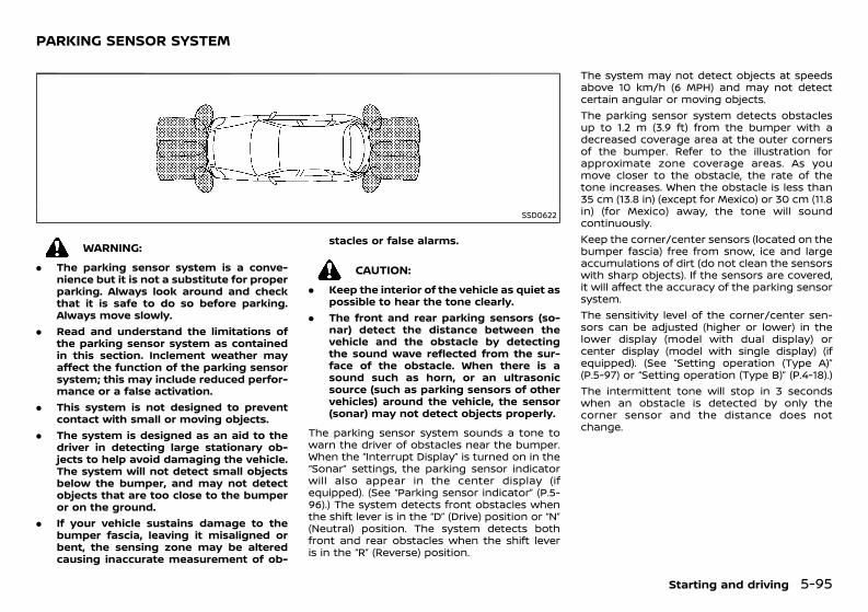
(337,1)
[ Edit: 2020/ 11/ 9 Model: Y62-A ]
GUID-93C2715E-0576-4BC2-B4BA-4AE4CE352435
SSD0622
WARNING:. The parking sensor system is a conve-
nience but it is not a substitute for properparking. Always look around and checkthat it is safe to do so before parking.Always move slowly.
. Read and understand the limitations ofthe parking sensor system as containedin this section. Inclement weather mayaffect the function of the parking sensorsystem; this may include reduced perfor-mance or a false activation.
. This system is not designed to preventcontact with small or moving objects.
. The system is designed as an aid to thedriver in detecting large stationary ob-jects to help avoid damaging the vehicle.The system will not detect small objectsbelow the bumper, and may not detectobjects that are too close to the bumperor on the ground.
. If your vehicle sustains damage to thebumper fascia, leaving it misaligned orbent, the sensing zone may be alteredcausing inaccurate measurement of ob-
stacles or false alarms.
CAUTION:. Keep the interior of the vehicle as quiet as
possible to hear the tone clearly.. The front and rear parking sensors (so-
nar) detect the distance between thevehicle and the obstacle by detectingthe sound wave reflected from the sur-face of the obstacle. When there is asound such as horn, or an ultrasonicsource (such as parking sensors of othervehicles) around the vehicle, the sensor(sonar) may not detect objects properly.
The parking sensor system sounds a tone towarn the driver of obstacles near the bumper.When the “Interrupt Display” is turned on in the“Sonar” settings, the parking sensor indicatorwill also appear in the center display (ifequipped). (See “Parking sensor indicator” (P.5-96).) The system detects front obstacles whenthe shift lever is in the “D” (Drive) position or “N”(Neutral) position. The system detects bothfront and rear obstacles when the shift leveris in the “R” (Reverse) position.
The system may not detect objects at speedsabove 10 km/h (6 MPH) and may not detectcertain angular or moving objects.The parking sensor system detects obstaclesup to 1.2 m (3.9 ft) from the bumper with adecreased coverage area at the outer cornersof the bumper. Refer to the illustration forapproximate zone coverage areas. As youmove closer to the obstacle, the rate of thetone increases. When the obstacle is less than35 cm (13.8 in) (except for Mexico) or 30 cm (11.8in) (for Mexico) away, the tone will soundcontinuously.Keep the corner/center sensors (located on thebumper fascia) free from snow, ice and largeaccumulations of dirt (do not clean the sensorswith sharp objects). If the sensors are covered,it will affect the accuracy of the parking sensorsystem.The sensitivity level of the corner/center sen-sors can be adjusted (higher or lower) in thelower display (model with dual display) orcenter display (model with single display) (ifequipped). (See “Setting operation (Type A)”(P.5-97) or “Setting operation (Type B)” (P.4-18).)The intermittent tone will stop in 3 secondswhen an obstacle is detected by only thecorner sensor and the distance does notchange.
Starting and driving 5-95
PARKING SENSOR SYSTEM
Condition: 'Except for China'/'Except for China/
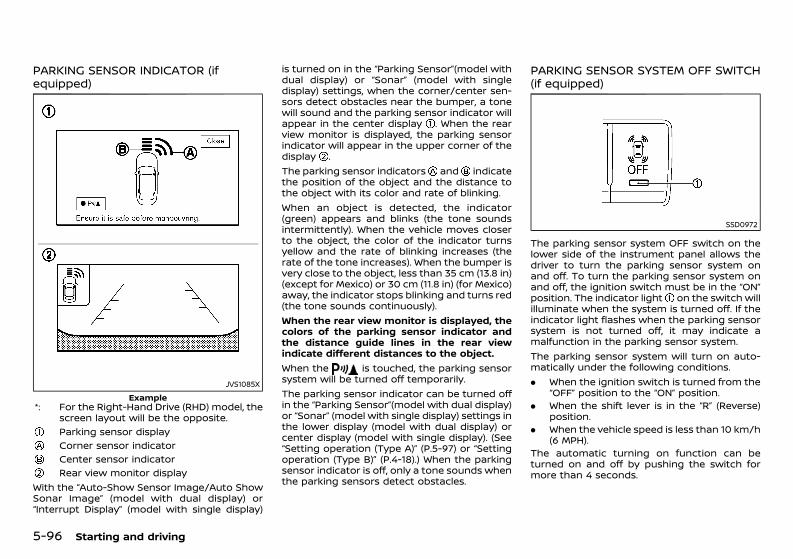
(338,1)
[ Edit: 2020/ 11/ 9 Model: Y62-A ]
5-96 Starting and driving
PARKING SENSOR INDICATOR (ifequipped) GUID-30F0F0DC-CBE2-4601-BB85-078E71D4585A
JVS1085XExample
*: For the Right-Hand Drive (RHD) model, thescreen layout will be the opposite.Parking sensor displayCorner sensor indicatorCenter sensor indicatorRear view monitor display
With the “Auto-Show Sensor Image/Auto ShowSonar Image” (model with dual display) or“Interrupt Display” (model with single display)
is turned on in the “Parking Sensor”(model withdual display) or “Sonar” (model with singledisplay) settings, when the corner/center sen-sors detect obstacles near the bumper, a tonewill sound and the parking sensor indicator willappear in the center display . When the rearview monitor is displayed, the parking sensorindicator will appear in the upper corner of thedisplay .The parking sensor indicators and indicatethe position of the object and the distance tothe object with its color and rate of blinking.When an object is detected, the indicator(green) appears and blinks (the tone soundsintermittently). When the vehicle moves closerto the object, the color of the indicator turnsyellow and the rate of blinking increases (therate of the tone increases). When the bumper isvery close to the object, less than 35 cm (13.8 in)(except for Mexico) or 30 cm (11.8 in) (for Mexico)away, the indicator stops blinking and turns red(the tone sounds continuously).When the rear view monitor is displayed, thecolors of the parking sensor indicator andthe distance guide lines in the rear viewindicate different distances to the object.When the is touched, the parking sensorsystem will be turned off temporarily.The parking sensor indicator can be turned offin the “Parking Sensor”(model with dual display)or “Sonar” (model with single display) settings inthe lower display (model with dual display) orcenter display (model with single display). (See“Setting operation (Type A)” (P.5-97) or “Settingoperation (Type B)” (P.4-18).) When the parkingsensor indicator is off, only a tone sounds whenthe parking sensors detect obstacles.
PARKING SENSOR SYSTEM OFF SWITCH(if equipped)GUID-A7926AA7-3A42-4477-8038-9D86A6BE5381
SSD0972
The parking sensor system OFF switch on thelower side of the instrument panel allows thedriver to turn the parking sensor system onand off. To turn the parking sensor system onand off, the ignition switch must be in the “ON”position. The indicator light on the switch willilluminate when the system is turned off. If theindicator light flashes when the parking sensorsystem is not turned off, it may indicate amalfunction in the parking sensor system.The parking sensor system will turn on auto-matically under the following conditions.. When the ignition switch is turned from the
“OFF” position to the “ON” position.. When the shift lever is in the “R” (Reverse)
position.. When the vehicle speed is less than 10 km/h
(6 MPH).The automatic turning on function can beturned on and off by pushing the switch formore than 4 seconds.
Condition: 'Except for China'/'Except for China/
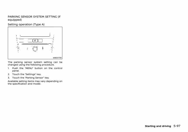
(339,1)
[ Edit: 2020/ 11/ 9 Model: Y62-A ]
PARKING SENSOR SYSTEM SETTING (ifequipped) GUID-3F405702-E9AE-473A-9E05-A2DD89AF5F74
Setting operation (Type A)GUID-1B49FE5B-FB10-4BE5-A5BD-F1E2405FF227
WAE0173X
The parking sensor system setting can bechanged using the following procedure.1. Push the “MENU” button on the control
panel.2. Touch the “Settings” key.3. Touch the “Parking Sensor” key.Available setting items may vary depending onthe specification and model.
Starting and driving 5-97
Condition: 'Except for China'/'Except for China/
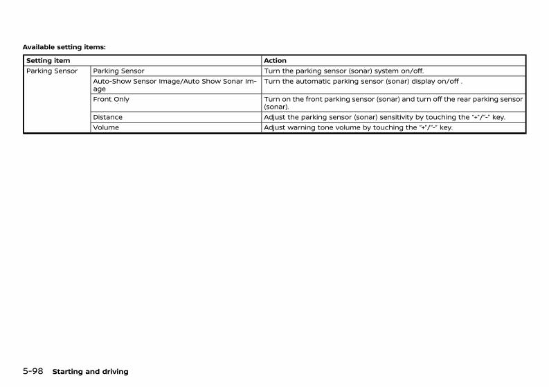
(340,1)
[ Edit: 2020/ 11/ 9 Model: Y62-A ]
5-98 Starting and driving
Available setting items:GUID-1B49FE5B-FB10-4BE5-A5BD-F1E2405FF227
Setting item ActionParking Sensor Parking Sensor Turn the parking sensor (sonar) system on/off.
Auto-Show Sensor Image/Auto Show Sonar Im-age
Turn the automatic parking sensor (sonar) display on/off .
Front Only Turn on the front parking sensor (sonar) and turn off the rear parking sensor(sonar).
Distance Adjust the parking sensor (sonar) sensitivity by touching the “+”/“-” key.Volume Adjust warning tone volume by touching the “+”/“-” key.
Condition: 'Except for China'/'Except for China/
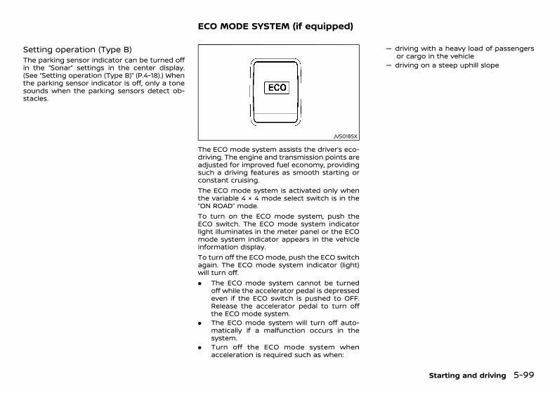
(341,1)
[ Edit: 2020/ 11/ 9 Model: Y62-A ]
Setting operation (Type B)GUID-A50900CD-82FC-498B-9389-1D2FFFB8C1D4The parking sensor indicator can be turned offin the “Sonar” settings in the center display.(See “Setting operation (Type B)” (P.4-18).) Whenthe parking sensor indicator is off, only a tonesounds when the parking sensors detect ob-stacles.
GUID-C8F300BD-297D-4315-9503-EFADC6D59EE0
JVS0185X
The ECO mode system assists the driver’s eco-driving. The engine and transmission points areadjusted for improved fuel economy, providingsuch a driving features as smooth starting orconstant cruising.The ECO mode system is activated only whenthe variable 4 × 4 mode select switch is in the“ON ROAD” mode.To turn on the ECO mode system, push theECO switch. The ECO mode system indicatorlight illuminates in the meter panel or the ECOmode system indicator appears in the vehicleinformation display.To turn off the ECO mode, push the ECO switchagain. The ECO mode system indicator (light)will turn off.. The ECO mode system cannot be turned
off while the accelerator pedal is depressedeven if the ECO switch is pushed to OFF.Release the accelerator pedal to turn offthe ECO mode system.
. The ECO mode system will turn off auto-matically if a malfunction occurs in thesystem.
. Turn off the ECO mode system whenacceleration is required such as when:
— driving with a heavy load of passengersor cargo in the vehicle
— driving on a steep uphill slope
Starting and driving 5-99
ECO MODE SYSTEM (if equipped)
Condition: 'Except for China'/'Except for China/
(342,1)
[ Edit: 2020/ 11/ 9 Model: Y62-A ]
5-100 Starting and driving
GUID-6EF39720-109E-42B1-B05F-A878E365A8BCYour vehicle was designed to be used to carrypassengers and luggage. NISSAN does notrecommend trailer towing, because it placesadditional loads on your vehicle’s engine, drive-train, steering, braking, and other systems.
CAUTION:Vehicle damage resulting from towing atrailer is not covered by the warranties.
GUID-10FF763A-123C-4CC7-BCBC-7C6FA9158B95Your new vehicle was designed to be usedprimarily to carry passengers and luggage.Towing a trailer will place additional loads onyour vehicle’s engine, drive train, steering,braking and other systems. The towing of atrailer will exaggerate other conditions such assway caused by crosswinds, rough road sur-faces or passing trucks.Your driving style and speed must be adjustedaccording to the circumstances. Before towinga trailer, see a NISSAN dealer for an explanationabout the proper use of towing equipment.
OPERATING PRECAUTIONSGUID-93EBCBA5-57FB-48BD-94FB-D107949EB122. Avoid towing a trailer during the break-in
period.. Before driving, make sure that the lighting
system of the trailer works properly.. Observe the legal maximum speeds for
trailer operation.. Avoid abrupt starts, accelerations and
stops.. Avoid sharp turns and lane changes.. Always drive your vehicle at a moderate
speed.. Do not use the Intelligent Lane Intervention
system (if equipped).. Do not use the Intelligent Blind Spot Inter-
vention system (if equipped).. Do not use the Intelligent Cruise Control
(ICC) system (if equipped).. Do not use the Intelligent Distance Control
system (if equipped).. Do not use the Intelligent Emergency Brak-
ing system (if equipped).. Do not use the Intelligent Back-up Inter-
vention system (if equipped).
. Do not use the Intelligent Forward CollisionWarning system (if equipped).
. Follow the trailer manufacturer’s instruc-tions.
. Choose proper coupling devices (trailerhitch, safety chain, roof carrier, etc.) foryour vehicle and trailer. These devices areavailable from a NISSAN dealer where youcan also obtain more detailed informationabout trailer towing.
. Never allow the total trailer load (trailerweight plus its cargo weight) to exceed themaximum set for the vehicle and thecoupling device. See a NISSAN dealer formore information.
. The trailer must be loaded so that heavygoods are placed over the axle. The max-imum allowable vertical load on the trailerhitch must not be exceeded.
. Have your vehicle serviced more often thanat the intervals specified in a separatemaintenance booklet.
. Trailer towing requires more fuel thanunder normal circumstances because of aconsiderable increase in traction powerand resistance.
While towing a trailer, check the enginecoolant temperature indicator to preventthe vehicle from overheating.
TRAILER TOWING (models withouttrailer hitch)
TRAILER TOWING (models withtrailer hitch)
Condition: 'Except for China'/'Except for China/
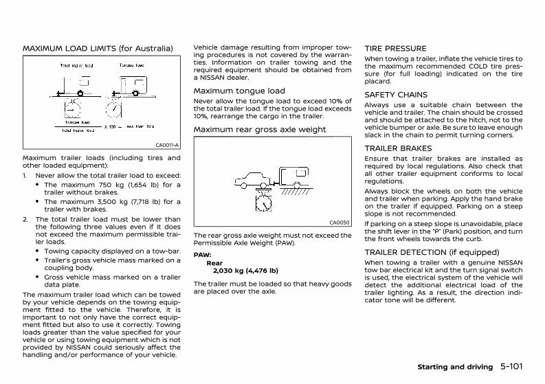
(343,1)
[ Edit: 2020/ 11/ 9 Model: Y62-A ]
MAXIMUM LOAD LIMITS (for Australia)GUID-7C3D64EA-957F-4C80-BB59-70B7A46346B0
CA0011-A
Maximum trailer loads (including tires andother loaded equipment):1. Never allow the total trailer load to exceed:
. The maximum 750 kg (1,654 lb) for atrailer without brakes.
. The maximum 3,500 kg (7,718 lb) for atrailer with brakes.
2. The total trailer load must be lower thanthe following three values even if it doesnot exceed the maximum permissible trai-ler loads.. Towing capacity displayed on a tow-bar.. Trailer’s gross vehicle mass marked on a
coupling body.. Gross vehicle mass marked on a trailer
data plate.The maximum trailer load which can be towedby your vehicle depends on the towing equip-ment fitted to the vehicle. Therefore, it isimportant to not only have the correct equip-ment fitted but also to use it correctly. Towingloads greater than the value specified for yourvehicle or using towing equipment which is notprovided by NISSAN could seriously affect thehandling and/or performance of your vehicle.
Vehicle damage resulting from improper tow-ing procedures is not covered by the warran-ties. Information on trailer towing and therequired equipment should be obtained froma NISSAN dealer.
Maximum tongue loadGUID-0E59A7A2-C9EF-43E2-9FED-317EF4EB8B0BNever allow the tongue load to exceed 10% ofthe total trailer load. If the tongue load exceeds10%, rearrange the cargo in the trailer.
Maximum rear gross axle weightGUID-922F084C-947A-4926-9C40-254E5CDB846F
CA0050
The rear gross axle weight must not exceed thePermissible Axle Weight (PAW).PAW:
GUID-C7E1EF24-5AAB-4301-95BE-26917EEE45EFRear2,030 kg (4,476 lb)
The trailer must be loaded so that heavy goodsare placed over the axle.
TIRE PRESSUREGUID-2D481BDE-68D2-4377-A5BD-D99886A0A3C6When towing a trailer, inflate the vehicle tires tothe maximum recommended COLD tire pres-sure (for full loading) indicated on the tireplacard.
SAFETY CHAINSGUID-B75C586F-7C41-4A2F-922B-55AB7E875B60Always use a suitable chain between thevehicle and trailer. The chain should be crossedand should be attached to the hitch, not to thevehicle bumper or axle. Be sure to leave enoughslack in the chain to permit turning corners.
TRAILER BRAKESGUID-69ACDC13-5C3E-4015-8572-6585B65A098CEnsure that trailer brakes are installed asrequired by local regulations. Also check thatall other trailer equipment conforms to localregulations.Always block the wheels on both the vehicleand trailer when parking. Apply the hand brakeon the trailer if equipped. Parking on a steepslope is not recommended.If parking on a steep slope is unavoidable, placethe shift lever in the “P” (Park) position, and turnthe front wheels towards the curb.
TRAILER DETECTION (if equipped)GUID-14BC0770-373C-4B96-B07B-7EC869ED2A85When towing a trailer with a genuine NISSANtow bar electrical kit and the turn signal switchis used, the electrical system of the vehicle willdetect the additional electrical load of thetrailer lighting. As a result, the direction indi-cator tone will be different.
Starting and driving 5-101
Condition: 'Except for China'/'Except for China/
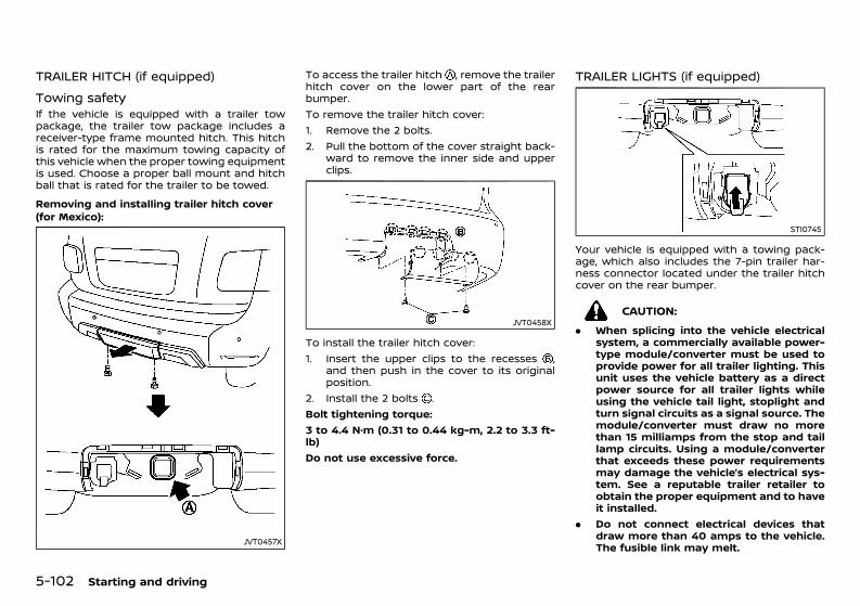
(344,1)
[ Edit: 2020/ 11/ 9 Model: Y62-A ]
5-102 Starting and driving
TRAILER HITCH (if equipped)GUID-B13D1FA9-EC48-4FC1-85D1-9C6AE8283ADF
Towing safetyGUID-A23DCDDA-45E0-4EC5-9DBC-DC8E88CCE58BIf the vehicle is equipped with a trailer towpackage, the trailer tow package includes areceiver-type frame mounted hitch. This hitchis rated for the maximum towing capacity ofthis vehicle when the proper towing equipmentis used. Choose a proper ball mount and hitchball that is rated for the trailer to be towed.Removing and installing trailer hitch cover(for Mexico):
GUID-C7E1EF24-5AAB-4301-95BE-26917EEE45EF
JVT0457X
To access the trailer hitch , remove the trailerhitch cover on the lower part of the rearbumper.To remove the trailer hitch cover:1. Remove the 2 bolts.2. Pull the bottom of the cover straight back-
ward to remove the inner side and upperclips.
JVT0458X
To install the trailer hitch cover:1. Insert the upper clips to the recesses ,
and then push in the cover to its originalposition.
2. Install the 2 bolts .Bolt tightening torque:3 to 4.4 N·m (0.31 to 0.44 kg-m, 2.2 to 3.3 ft-lb)Do not use excessive force.
TRAILER LIGHTS (if equipped)GUID-7C53A718-E5B9-4B45-8E9B-BDBDA54A4A9A
STI0745
Your vehicle is equipped with a towing pack-age, which also includes the 7-pin trailer har-ness connector located under the trailer hitchcover on the rear bumper.
CAUTION:. When splicing into the vehicle electrical
system, a commercially available power-type module/converter must be used toprovide power for all trailer lighting. Thisunit uses the vehicle battery as a directpower source for all trailer lights whileusing the vehicle tail light, stoplight andturn signal circuits as a signal source. Themodule/converter must draw no morethan 15 milliamps from the stop and taillamp circuits. Using a module/converterthat exceeds these power requirementsmay damage the vehicle’s electrical sys-tem. See a reputable trailer retailer toobtain the proper equipment and to haveit installed.
. Do not connect electrical devices thatdraw more than 40 amps to the vehicle.The fusible link may melt.
Condition: 'Except for China'/'Except for China/

(345,1)
[ Edit: 2020/ 11/ 9 Model: Y62-A ]
Trailer lights should comply with federal and/orlocal regulations. For assistance in hooking uptrailer lights, contact a NISSAN dealer or repu-table trailer retailer.
GUID-A1A4FDFD-528A-4C55-9F20-BED3DDFF7114
SIC4474
TOW mode should be used when pulling aheavy trailer or hauling a heavy load. Drivingthe vehicle in the TOW mode with no trailer/load or light trailer/light load will not cause anydamage. However, fuel economy may be re-duced, and the transmission/engine drivingcharacteristics may feel unusual.Push the TOW mode switch to activate TOWmode. The indicator light on the TOW modeswitch illuminates when TOW mode is selected.Press the TOW mode switch again to turn TOWmode OFF.TOW mode is automatically canceled when theignition switch is placed in the OFF position.For additional information, refer to “Trailertowing (models with trailer hitch)” (P.5-100).
GUID-87C8421D-559D-43F2-B29C-3246CB23890A
WARNING:If the engine is not running or is turned offwhile driving, the power assist for the steer-ing will not work. The steering will be muchharder to operate.
The power assisted steering is designed to usea hydraulic pump driven by the engine, to assiststeering.If the engine stops or the drive belt breaks, youwill still have control of the vehicle. However,greater steering effort is needed, especially insharp turns and at low speeds.
Starting and driving 5-103
TOW MODE (for Mexico) POWER STEERING
Condition: 'Except for China'/'Except for China/
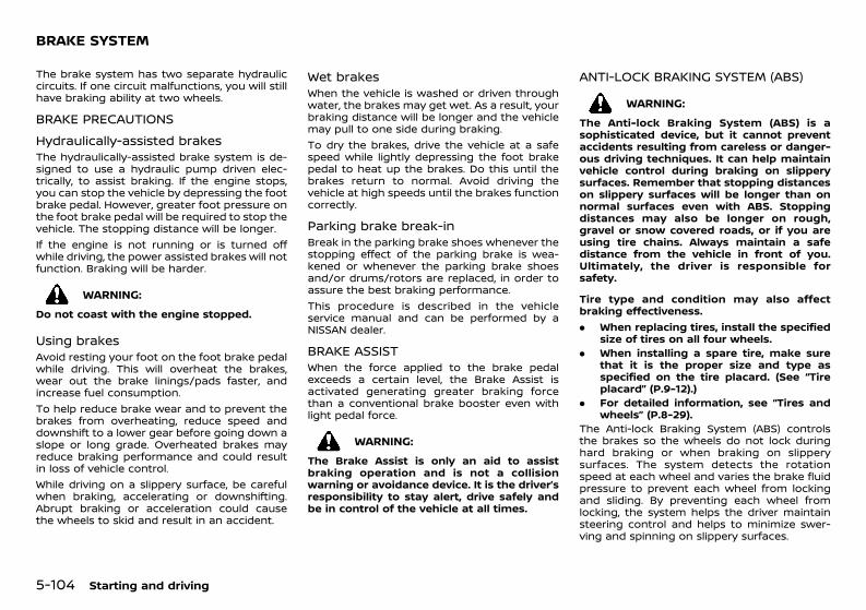
(346,1)
[ Edit: 2020/ 11/ 9 Model: Y62-A ]
5-104 Starting and driving
GUID-943CB8CC-7A93-4635-838C-02D7D2292797The brake system has two separate hydrauliccircuits. If one circuit malfunctions, you will stillhave braking ability at two wheels.
BRAKE PRECAUTIONSGUID-B0E4998A-846B-4FEB-BFD6-689E6A742199
Hydraulically-assisted brakesGUID-B79B7AF5-3AF9-49F1-973E-41C0E1227FF7The hydraulically-assisted brake system is de-signed to use a hydraulic pump driven elec-trically, to assist braking. If the engine stops,you can stop the vehicle by depressing the footbrake pedal. However, greater foot pressure onthe foot brake pedal will be required to stop thevehicle. The stopping distance will be longer.If the engine is not running or is turned offwhile driving, the power assisted brakes will notfunction. Braking will be harder.
WARNING:Do not coast with the engine stopped.
Using brakesGUID-87D8A2FA-59DD-4B7D-A620-25C82316B771Avoid resting your foot on the foot brake pedalwhile driving. This will overheat the brakes,wear out the brake linings/pads faster, andincrease fuel consumption.To help reduce brake wear and to prevent thebrakes from overheating, reduce speed anddownshift to a lower gear before going down aslope or long grade. Overheated brakes mayreduce braking performance and could resultin loss of vehicle control.While driving on a slippery surface, be carefulwhen braking, accelerating or downshifting.Abrupt braking or acceleration could causethe wheels to skid and result in an accident.
Wet brakesGUID-47B5DF9F-42DB-4939-8B98-06F9D4E0CB02When the vehicle is washed or driven throughwater, the brakes may get wet. As a result, yourbraking distance will be longer and the vehiclemay pull to one side during braking.To dry the brakes, drive the vehicle at a safespeed while lightly depressing the foot brakepedal to heat up the brakes. Do this until thebrakes return to normal. Avoid driving thevehicle at high speeds until the brakes functioncorrectly.
Parking brake break-inGUID-978FD217-606F-4D72-B7E4-297404318734Break in the parking brake shoes whenever thestopping effect of the parking brake is wea-kened or whenever the parking brake shoesand/or drums/rotors are replaced, in order toassure the best braking performance.This procedure is described in the vehicleservice manual and can be performed by aNISSAN dealer.
BRAKE ASSISTGUID-FD6BF796-F244-4EC8-8209-9F61FF2D1209When the force applied to the brake pedalexceeds a certain level, the Brake Assist isactivated generating greater braking forcethan a conventional brake booster even withlight pedal force.
WARNING:The Brake Assist is only an aid to assistbraking operation and is not a collisionwarning or avoidance device. It is the driver’sresponsibility to stay alert, drive safely andbe in control of the vehicle at all times.
ANTI-LOCK BRAKING SYSTEM (ABS)GUID-9869AB77-87E9-4609-A21B-1BD9B918266C
WARNING:The Anti-lock Braking System (ABS) is asophisticated device, but it cannot preventaccidents resulting from careless or danger-ous driving techniques. It can help maintainvehicle control during braking on slipperysurfaces. Remember that stopping distanceson slippery surfaces will be longer than onnormal surfaces even with ABS. Stoppingdistances may also be longer on rough,gravel or snow covered roads, or if you areusing tire chains. Always maintain a safedistance from the vehicle in front of you.Ultimately, the driver is responsible forsafety.
Tire type and condition may also affectbraking effectiveness.. When replacing tires, install the specified
size of tires on all four wheels.. When installing a spare tire, make sure
that it is the proper size and type asspecified on the tire placard. (See “Tireplacard” (P.9-12).)
. For detailed information, see “Tires andwheels” (P.8-29).
The Anti-lock Braking System (ABS) controlsthe brakes so the wheels do not lock duringhard braking or when braking on slipperysurfaces. The system detects the rotationspeed at each wheel and varies the brake fluidpressure to prevent each wheel from lockingand sliding. By preventing each wheel fromlocking, the system helps the driver maintainsteering control and helps to minimize swer-ving and spinning on slippery surfaces.
BRAKE SYSTEM
Condition: 'Except for China'/'Except for China/
(347,1)
[ Edit: 2020/ 11/ 9 Model: Y62-A ]
Using systemGUID-468B0649-A666-40E4-A4BE-4A9D909844D6Depress the brake pedal and hold it down.Depress the brake pedal with firm steadypressure, but do not pump the brakes. TheABS will operate to prevent the wheels fromlocking up. Steer the vehicle to avoid obstacles.
WARNING:Do not pump the brake pedal. Doing so mayresult in increased stopping distances.
Self-test featureGUID-AA5A2FB9-74FD-480F-8A75-EE2F2D342E6BThe ABS includes electronic sensors, electricpumps, hydraulic solenoids and a computer.The computer has a built-in diagnostic featurethat tests the system each time you start theengine and move the vehicle at a low speed inforward or reverse. When the self-test occurs,you may hear a “clunk” noise and/or feel apulsation in the brake pedal. This is normal anddoes not indicate a malfunction. If the compu-ter senses a malfunction, it switches the ABSoff and illuminates the ABS warning light on theinstrument panel. The brake system thenoperates normally, but without anti-lock assis-tance. If the ABS warning light illuminatesduring the self-test or while driving, have thevehicle checked by a NISSAN dealer.
Normal operationGUID-6AE7A07C-6596-439E-A05B-643D6BD02DAAThe ABS operates at speeds above 5 to 10km/h (3 to 6 MPH). The speed varies accordingto road conditions.When the ABS senses that one or more wheelsare close to locking up, the actuator rapidlyapplies and releases hydraulic pressure. Thisaction is similar to pumping the brakes veryquickly. You may feel a pulsation in the brakepedal and hear a noise from under the hood or
feel a vibration from the actuator when it isoperating. This is normal and indicates that theABS is operating properly. However, the pulsa-tion may indicate that road conditions arehazardous and extra care is required whiledriving.Except for Mexico: When the differential lockmode switch is engaged, the ABS warning lightilluminates. This may indicate that the ABS isdisabled while the differential lock is engaged.(See “Differential lock mode switch (except forMexico)” (P.5-22).)
GUID-3379387A-C03F-4BBD-9228-95DD384B5AEFWhen leaving your vehicle unoccupied:. Always take the key with you - even when
leaving the vehicle in your own garage.. Close all windows completely and lock all
doors.. Always park your vehicle where it can be
seen. Park in a well lit area during the night.. If the security system is equipped, use it -
even for a short period.. Never leave children or pets in the vehicle
unattended.. Never leave valuables inside the vehicle.
Always take valuables with you.. Never leave the vehicle documents in the
vehicle.. Never leave articles on a roof rack. Remove
them from the rack and keep and lockthem inside the vehicle.
. Never leave the spare key in the vehicle.
Starting and driving 5-105
VEHICLE SECURITY
Condition: 'Except for China'/'Except for China/
(348,1)
[ Edit: 2020/ 11/ 9 Model: Y62-A ]
5-106 Starting and driving
GUID-34C6DF68-5354-4435-AB7D-D60EC96708E9
WARNING:. Whatever the condition, drive with cau-
tion. Accelerate and decelerate with greatcare. If accelerating or decelerating toofast, the drive wheels will lose even moretraction.
. Allow more stopping distance in coldweather driving. Braking should bestarted sooner than on dry pavement.
. Keep at a greater distance from thevehicle in front of you on slippery roads.
. Wet ice (0°C, 32°F and freezing rain), verycold snow and ice can be slick and verydifficult to drive on. The vehicle will havea lot less traction or grip under theseconditions. Try to avoid driving on wet iceuntil the road is salted or sanded.
. Watch for slippery spots (glaring ice).These may appear on an otherwise clearroad in shaded areas. If a patch of ice isseen ahead, brake before reaching it. Trynot to brake while actually on the ice, andavoid any sudden steering maneuvers.
. Do not use cruise control on slipperyroads.
. Snow can trap dangerous exhaust gasunder your vehicle. Keep snow clear ofthe exhaust pipe and from around yourvehicle.
BATTERY GUID-62AD019A-9B73-44D9-BF40-E02A5FC76E8AIf the battery is not fully charged duringextremely cold weather conditions, the batteryfluid may freeze and damage the battery. Tomaintain maximum efficiency, the batteryshould be checked regularly. For details, see“Battery” (P.8-18) of this manual.
ENGINE COOLANTGUID-AEA45FD1-54DC-4FE8-B96C-3C06886FFCF2If the vehicle is to be left outside without anti-freeze, drain the cooling system, including theengine block. Refill before operating the vehicle.For details, see “Changing engine coolant” (P.8-8) of this manual.
TIRE EQUIPMENTGUID-47960355-89A2-4CC5-BB66-23F707B17A611. If you have snow tires installed on the
front/rear wheels of your vehicle, theyshould be of the same size, loading range,construction and type (bias, bias-belted orradial) as the rear/front tires.
2. If the vehicle is to be operated in severewinter conditions, snow tires should beinstalled on all four wheels.
3. For additional traction on icy roads,studded tires may be used. However, somecountries, provinces and states prohibittheir use. Check local, state and provinciallaws before installing studded tires.Skid and traction capabilities of studdedsnow tires, on wet or dry surfaces, maybe poorer than that of non-studded snowtires.
4. Snow chains may be used if desired. Makesure they are the proper size for the tires onyour vehicle and are installed according tothe chain manufacturer’s instructions. Usechain tensioners when recommended bythe tire chain manufacturer to ensure a
tight fit. Loose end links of the tire chainsmust be secured or removed to prevent thepossibility of whipping action damage tothe fenders or underbody. In addition, driveat a reduced speed, otherwise, your vehiclemay be damaged and/or vehicle handlingand performance may be adversely af-fected.
SPECIAL WINTER EQUIPMENTGUID-FFB9E7B0-B2EB-4567-8659-49F951A54F88It is recommended that the following items becarried in the vehicle during the winter:. A scraper and stiff-bristled brush to remove
ice and snow from the windows.. A sturdy, flat board to be placed under the
jack to give it firm support.. A shovel to dig the vehicle out of snow-
drifts.
Engine block heater (if equipped)GUID-70969DF2-16E7-46B9-AF95-D4918C3A5130
WARNING:Do not use the heater with an ungroundedelectrical system or two-pronged (cheater)adapters. You can be injured by an electricalshock if you use an ungrounded connection.
An engine block heater to assist in extremecold temperature starting is available througha NISSAN dealer.
COLD WEATHER DRIVING
Condition: 'Except for China'/'Except for China/
(349,1)
[ Edit: 2020/ 11/ 9 Model: Y62-A ]
PARKING BRAKEGUID-511E41D9-29DF-41C3-B25D-2BDE4996FC30When parking in the area where the outsidetemperature is below 0°C (32°F), do not applythe parking brake to prevent it from freezing.For safe parking:. Place the shift lever in the “P” (Park) posi-
tion.. Securely block the wheels.
CORROSION PROTECTIONGUID-D5D7F310-073E-4924-913D-1CBFB66C7D76Chemicals used for road surface deicing areextremely corrosive and will accelerate corro-sion and the deterioration of underbody com-ponents such as the exhaust system, fuel andbrake lines, brake cables, floor pan and fenders.In the winter, the underbody must be cleanedperiodically. For additional information, see“Corrosion protection” (P.7-5) of this manual.For additional protection against rust andcorrosion, which may be required in someareas, consult a NISSAN dealer.
Starting and driving 5-107
Condition: 'Except for China'/'Except for China/

(350,1)
[ Edit: 2020/ 11/ 9 Model: Y62-A ]
5-108 Starting and driving
MEMO
Condition: 'Except for China'/'Except for China/
(351,1)
[ Edit: 2020/ 11/ 9 Model: Y62-A ]
6 In case of emergency
Hazard indicator flasher switch ............................................................ 6-2Flat tire ...................................................................................................................... 6-2
Tire Pressure Monitoring System (TPMS) (ifequipped) ....................................................................................................... 6-2Stopping vehicle ........................................................................................ 6-2Preparing tools and spare tire ....................................................... 6-3Blocking wheels ......................................................................................... 6-5Removing tire ............................................................................................... 6-5Installing spare tire .................................................................................. 6-7Stowing damaged tire and tools ................................................. 6-7
Jump starting ..................................................................................................... 6-8Push starting ....................................................................................................... 6-9If your vehicle overheats ........................................................................ 6-10Towing your vehicle ................................................................................... 6-10
Towing precautions .......................................................................... 6-10Towing recommended by NISSAN ........................................ 6-11
Four-Wheel Drive (4WD) manual shifting(4WD models) ................................................................................................... 6-14
When 4WD warning light illuminates .................................. 6-14Operating procedure ........................................................................ 6-14
Condition: 'Except for China'/'Except for China/
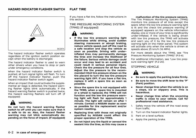
(352,1)
[ Edit: 2020/ 11/ 9 Model: Y62-A ]
6-2 In case of emergency
GUID-885105FE-6415-47AD-942A-9FA3F32FC607
SIC2574
The hazard indicator flasher switch operatesregardless of the ignition switch position ex-cept when the battery is discharged.The hazard indicator flasher is used to warnother drivers when you have to stop or parkunder emergency conditions.When the hazard indicator flasher switch ispushed, all turn signal lights will flash. To turnoff the hazard indicator flasher, push thehazard indicator flasher switch again.When an impact that could activate the supple-mental air bags is detected, the hazard warn-ing flasher lights blink automatically. If thehazard warning flasher switch is pushed twice,the hazard warning flashers will turn off. (ifequipped)
WARNING:Do not turn the hazard warning flasherswitch to off until you can make sure that itis safe to do so. Also, the hazard flasherwarning may not blink automatically de-pending on the force of impact. (if equipped)
GUID-087AADF5-1581-4F56-80C8-BA3D0364B3C2If you have a flat tire, follow the instructions inthis section.
TIRE PRESSURE MONITORING SYSTEM(TPMS) (if equipped)GUID-D0CA2ED1-48A2-4295-9F47-02AA7F8BF0E7
WARNING:. If the low tire pressure warning light
illuminates while driving, avoid suddensteering maneuvers or abrupt braking,reduce vehicle speed, pull off the road toa safe location and stop the vehicle assoon as possible. Driving with under-inflated tires may permanently damagethe tires and increase the likelihood oftire failure. Serious vehicle damage couldoccur and may lead to an accident andcould result in serious personal injury.Check the tire pressure for all four tires.Adjust the tire pressure to the recom-mended COLD tire pressure shown on thetire placard to turn the low tire pressurewarning light OFF. If you have a flat tire,replace it with a spare tire as soon aspossible.
. Since the spare tire is not equipped withthe TPMS, when a spare tire is mountedor a wheel is replaced, the TPMS will notfunction and the low tire pressure warn-ing light will flash for approximately 1minute. The light will remain on after 1minute. Contact a NISSAN dealer as soonas possible for tire replacement and/orsystem resetting.
. Replacing tires with those not originallyspecified by NISSAN could affect theproper operation of the TPMS.
. Do not inject any tire liquid or aerosol tiresealant into the tires, as this may cause a
malfunction of the tire pressure sensors.The Tire Pressure Monitoring System (TPMS)monitors tire pressure of all tires except thespare. When the low tire pressure warning lightis lit and the check tire pressure warning (ifequipped) appears on the vehicle informationdisplay, one or more of your tires is significantlyunder-inflated. If the vehicle is being drivenwith low tire pressure, the TPMS will activateand warn you of it by the low tire pressurewarning light (in the meter panel). This systemwill activate only when the vehicle is driven atspeeds above 25 km/h (16 MPH).For more details about the TPMS, see “TirePressure Monitoring System (TPMS)” (P.5-6).For additional information, see “Low tire pres-sure warning light” (P.2-20).
STOPPING VEHICLEGUID-A2E722CC-0CAB-45A9-ACC2-8497528C2144
WARNING:. Be sure to apply the parking brake firmly.. Be sure to move the shift lever to the “P”
(Park) position.. Never change tires when the vehicle is on
a slope, ice or slippery area. This ishazardous.
. Never change tires when the oncomingtraffic is close to your vehicle. Call forprofessional road assistance.
1. Safely move the vehicle off the road awayfrom traffic.
2. Turn on the hazard indicator flasher lights.3. Park on a level surface.4. Apply the parking brake.
HAZARD INDICATOR FLASHER SWITCH FLAT TIRE
Condition: 'Except for China'/'Except for China/
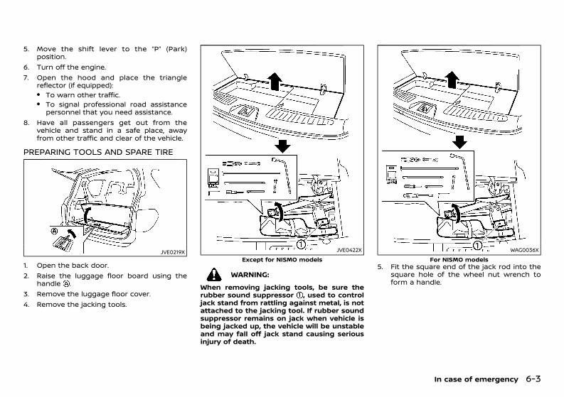
(353,1)
[ Edit: 2020/ 11/ 9 Model: Y62-A ]
5. Move the shift lever to the “P” (Park)position.
6. Turn off the engine.7. Open the hood and place the triangle
reflector (if equipped):. To warn other traffic.. To signal professional road assistance
personnel that you need assistance.8. Have all passengers get out from the
vehicle and stand in a safe place, awayfrom other traffic and clear of the vehicle.
PREPARING TOOLS AND SPARE TIREGUID-BC4D90AB-D2B2-4090-83D6-630B975EA744
JVE0219X
1. Open the back door.2. Raise the luggage floor board using the
handle .3. Remove the luggage floor cover.4. Remove the jacking tools.
JVE0422XExcept for NISMO models
WARNING:When removing jacking tools, be sure therubber sound suppressor , used to controljack stand from rattling against metal, is notattached to the jacking tool. If rubber soundsuppressor remains on jack when vehicle isbeing jacked up, the vehicle will be unstableand may fall off jack stand causing seriousinjury of death.
WAG0036XFor NISMO models
5. Fit the square end of the jack rod into thesquare hole of the wheel nut wrench toform a handle.
In case of emergency 6-3
Condition: 'Except for China'/'Except for China/
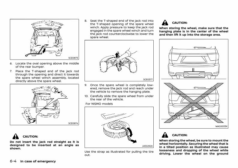
(354,1)
[ Edit: 2020/ 11/ 9 Model: Y62-A ]
6-4 In case of emergency
SCE0873
6. Locate the oval opening above the middleof the rear bumper.
7. Place the T-shaped end of the jack rodthrough the opening and direct it towardsthe spare wheel winch assembly, locateddirectly above the spare wheel.
SCE0874
CAUTION:Do not insert the jack rod straight as it isdesigned to be inserted at an angle asshown.
8. Seat the T-shaped end of the jack rod intothe T-shaped opening of the spare wheelwinch. Apply pressure to keep the jack rodengaged in the spare wheel winch and turnthe jack rod counterclockwise to lower thespare wheel.
SCE0377
9. Once the spare wheel is completely low-ered, remove the jack rod and reach underthe vehicle to remove the hanging plate.
10. Carefully slide the spare wheel from underthe rear of the vehicle.
For NISMO models
JVE0292X
Use the strap as illustrated for pulling the tireout.
CAUTION:When storing the wheel, make sure that thehanging plate is in the center of the wheeland then lift it up into the storage area.
WAG0033X
CAUTION:When storing the wheel, be sure to mount thewheel horizontally. Securing the wheel that isin a tilted position as illustrated may causelooseness and dropping of the wheel whiledriving. Lower the wheel on the ground
Condition: 'Except for China'/'Except for China/
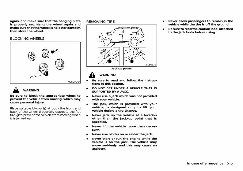
(355,1)
[ Edit: 2020/ 11/ 9 Model: Y62-A ]
again, and make sure that the hanging plateis properly set. Hang the wheel again andmake sure that the wheel is held horizontally,then store the wheel.
BLOCKING WHEELSGUID-8395098A-ABB8-49F8-B42E-63A3D5E2646F
MCE0001D
WARNING:Be sure to block the appropriate wheel toprevent the vehicle from moving, which maycause personal injury.
Place suitable blocks at both the front andback of the wheel diagonally opposite the flattire to prevent the vehicle frommoving whenit is jacked up.
REMOVING TIREGUID-243FE501-4417-4A86-9000-0AD1EFFC2758
SCE0875Jack-up points
WARNING:. Be sure to read and follow the instruc-
tions in this section.. DO NOT GET UNDER A VEHICLE THAT IS
SUPPORTED BY A JACK.. Never use a jack which was not provided
with your vehicle.. The jack, which is provided with your
vehicle, is designed only to lift yourvehicle during a tire change.
. Never jack up the vehicle at a locationother than the jack-up point that isspecified.
. Never lift the vehicle more than neces-sary.
. Never use blocks on or under the jack.
. Never start or run the engine while thevehicle is on the jack. The vehicle maymove suddenly, and this may cause anaccident.
. Never allow passengers to remain in thevehicle while the tire is off the ground.
. Be sure to read the caution label attachedto the jack body before using.
In case of emergency 6-5
Condition: 'Except for China'/'Except for China/
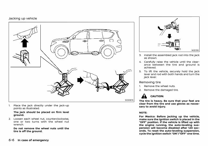
(356,1)
[ Edit: 2020/ 11/ 9 Model: Y62-A ]
6-6 In case of emergency
Jacking up vehicleGUID-57F60746-7772-477C-8E66-ABC596D11CC3
SCE0876
1. Place the jack directly under the jack-uppoints as illustrated.The jack should be placed on firm levelground.
2. Loosen each wheel nut, counterclockwise,one or two turns with the wheel nutwrench.Do not remove the wheel nuts until thetire is off the ground.
NCE130
3. Install the assembled jack rod into the jackas shown.
4. Carefully raise the vehicle until the clear-ance between the tire and ground isachieved.
5. To lift the vehicle, securely hold the jacklever and rod with both hands and turn thejack lever.
Removing tireGUID-066AD6B2-BA09-42A4-85B3-B5EF13C4DC911. Remove the wheel nuts.2. Remove the damaged tire.
CAUTION:The tire is heavy. Be sure that your feet areclear from the tire and use gloves as neces-sary to avoid injury.
NOTE:For Mexico: Before jacking up the vehicle,make sure the ignition switch is placed in the“OFF” position. If the vehicle is lifted up withthe engine running, the auto-leveling sus-pension will become disabled after 120 sec-onds. To reset the auto-leveling suspension,cycle the ignition switch “ON”/“OFF” one time.
Condition: 'Except for China'/'Except for China/
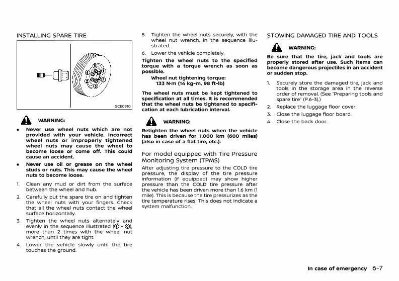
(357,1)
[ Edit: 2020/ 11/ 9 Model: Y62-A ]
INSTALLING SPARE TIREGUID-6B745FBE-4633-46DD-8F1C-63F78926B25C
SCE0910
WARNING:. Never use wheel nuts which are not
provided with your vehicle. Incorrectwheel nuts or improperly tightenedwheel nuts may cause the wheel tobecome loose or come off. This couldcause an accident.
. Never use oil or grease on the wheelstuds or nuts. This may cause the wheelnuts to become loose.
1. Clean any mud or dirt from the surfacebetween the wheel and hub.
2. Carefully put the spare tire on and tightenthe wheel nuts with your fingers. Checkthat all the wheel nuts contact the wheelsurface horizontally.
3. Tighten the wheel nuts alternately andevenly in the sequence illustrated ( - ),more than 2 times with the wheel nutwrench, until they are tight.
4. Lower the vehicle slowly until the tiretouches the ground.
5. Tighten the wheel nuts securely, with thewheel nut wrench, in the sequence illu-strated.
6. Lower the vehicle completely.Tighten the wheel nuts to the specifiedtorque with a torque wrench as soon aspossible.
Wheel nut tightening torque:133 N·m (14 kg-m, 98 ft-lb)
The wheel nuts must be kept tightened tospecification at all times. It is recommendedthat the wheel nuts be tightened to specifi-cation at each lubrication interval.
WARNING:Retighten the wheel nuts when the vehiclehas been driven for 1,000 km (600 miles)(also in case of a flat tire, etc.).
For model equipped with Tire PressureMonitoring System (TPMS)GUID-32CC674A-55B6-4C37-A637-0B4D8981C291After adjusting tire pressure to the COLD tirepressure, the display of the tire pressureinformation (if equipped) may show higherpressure than the COLD tire pressure afterthe vehicle has been driven more than 1.6 km (1mile). This is because the tire pressurizes as thetire temperature rises. This does not indicate asystem malfunction.
STOWING DAMAGED TIRE AND TOOLSGUID-ADE46C5C-5C07-4076-AF08-8049224EE449
WARNING:Be sure that the tire, jack and tools areproperly stored after use. Such items canbecome dangerous projectiles in an accidentor sudden stop.
1. Securely store the damaged tire, jack andtools in the storage area in the reverseorder of removal. (See “Preparing tools andspare tire” (P.6-3).)
2. Replace the luggage floor cover.3. Close the luggage floor board.4. Close the back door.
In case of emergency 6-7
Condition: 'Except for China'/'Except for China/
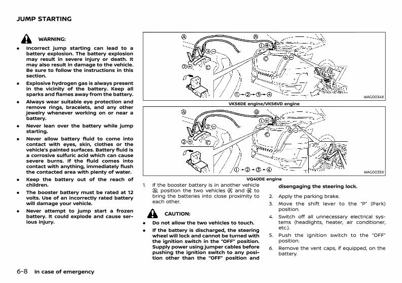
(358,1)
[ Edit: 2020/ 11/ 9 Model: Y62-A ]
6-8 In case of emergency
GUID-EE3D792C-AD0C-46DF-9465-D06434453F20
WARNING:. Incorrect jump starting can lead to a
battery explosion. The battery explosionmay result in severe injury or death. Itmay also result in damage to the vehicle.Be sure to follow the instructions in thissection.
. Explosive hydrogen gas is always presentin the vicinity of the battery. Keep allsparks and flames away from the battery.
. Always wear suitable eye protection andremove rings, bracelets, and any otherjewelry whenever working on or near abattery.
. Never lean over the battery while jumpstarting.
. Never allow battery fluid to come intocontact with eyes, skin, clothes or thevehicle’s painted surfaces. Battery fluid isa corrosive sulfuric acid which can causesevere burns. If the fluid comes intocontact with anything, immediately flushthe contacted area with plenty of water.
. Keep the battery out of the reach ofchildren.
. The booster battery must be rated at 12volts. Use of an incorrectly rated batterywill damage your vehicle.
. Never attempt to jump start a frozenbattery. It could explode and cause ser-ious injury.
WAG0034XVK56DE engine/VK56VD engine
WAG0035XVQ40DE engine
1. If the booster battery is in another vehicle, position the two vehicles and to
bring the batteries into close proximity toeach other.
CAUTION:. Do not allow the two vehicles to touch.. If the battery is discharged, the steering
wheel will lock and cannot be turned withthe ignition switch in the “OFF” position.Supply power using jumper cables beforepushing the ignition switch to any posi-tion other than the “OFF” position and
disengaging the steering lock.
2. Apply the parking brake.3. Move the shift lever to the “P” (Park)
position.4. Switch off all unnecessary electrical sys-
tems (headlights, heater, air conditioner,etc.).
5. Push the ignition switch to the “OFF”position.
6. Remove the vent caps, if equipped, on thebattery.
JUMP STARTING
Condition: 'Except for China'/'Except for China/
(359,1)
[ Edit: 2020/ 11/ 9 Model: Y62-A ]
7. Cover the battery with a firmly wrung outmoist cloth to reduce the hazard of anexplosion.
8. Connect the jumper cables in the sequenceas illustrated ( , , , ).
CAUTION:. Always connect positive + to positive +
and negative 7 to body ground, NOT tothe battery’s negative 7.
. Be sure that the jumper cables do nottouch moving parts in the engine com-partment.
. Be sure that the jumper cable’s clamps donot contact any other metal.
9. Start the engine of the booster vehicleand let it run for a few minutes.
10. Depress the accelerator pedal of the boos-ter vehicle at about 2,000 rpm.
11. Start the engine of the jumped vehicle inthe normal manner.
CAUTION:Never keep the starter motor engaged formore than 10 seconds. If the engine does notstart right away, push the ignition switch tothe “LOCK” position and wait at least 10seconds before trying again.
12. After the engine is started, carefully dis-connect the jumper cables in the oppositesequence from that illustrated ( , , , ).
13. Remove and dispose of the cloth properlyas it may be contaminated with corrosiveacid.
14. Replace the vent caps, if removed.15. Put the battery cover and the engine
compartment cover back to the originallocation.
GUID-5CC36DFE-5276-41D3-8217-B03F2712B197Do not attempt to start the engine by pushingthe vehicle.
CAUTION:. Automatic Transmission (AT) model can-
not be started by pushing. Attempting todo so may cause damage to the trans-mission.
. Three-way catalyst equipped modelsshould not be started by pushing. At-tempting to do so may cause damage tothe three-way catalyst.
. Never try to start the engine by towing.When the engine starts, the forwardsurge could cause the vehicle to collidewith the towing vehicle.
In case of emergency 6-9
PUSH STARTING
Condition: 'Except for China'/'Except for China/
(360,1)
[ Edit: 2020/ 11/ 9 Model: Y62-A ]
6-10 In case of emergency
GUID-7014DDE8-5D3E-42F2-96D2-FBBBE965DF8F
WARNING:. Never continue driving if your vehicle
overheats. Doing so could cause enginedamage and/or a vehicle fire.
. Never open the hood if steam is comingout.
. Never remove the radiator or coolantreservoir cap while the engine is hot. Ifthe radiator or coolant reservoir cap isremoved when the engine is hot, pres-surized hot water will spurt out andpossibly cause burning, scalding or ser-ious injury.
. If steam or coolant is coming from theengine, stand clear of the vehicle toprevent getting scalded.
. The engine cooling fan can start at anytime when the coolant temperature ex-ceeds preset degrees.
. Be careful not to allow your hands, hair,jewelry or clothing to come into contactwith, or to get caught in the cooling fan ordrive belts.
If your vehicle is overheating (indicated by thehigh temperature indicator), or if you feel a lackof engine power, detect unusual noise, etc.,take the following steps:1. Safely move the vehicle off the road away
from traffic.2. Turn on the hazard indicator flashers.3. Apply the parking brake.4. Move the shift lever to the “P” (Park)
position.DO NOT STOP THE ENGINE.
5. Open all the windows.6. Turn off the air conditioner. Move the
temperature control to maximum hot andthe fan control to high speed.
7. Get out from the vehicle.8. Visually inspect and listen for steam or
coolant escaping from the radiator beforeopening the hood. Wait until no steam orcoolant can be seen before proceeding.
9. Open the engine hood.10. Visually inspect if the cooling fan is running.11. Visually inspect the radiator and radiator
hoses for leakage. If the cooling fan is notrunning or the coolant is leaking, stop theengine.
12. After the engine cools down, check thecoolant level in the reservoir with theengine running. Do not open the radiatoror coolant reservoir cap.
13. Add coolant to the reservoir if necessary.Have your vehicle inspected/repaired at aNISSAN dealer.
GUID-48D6CD00-C971-4287-BB64-52A307F3A2ECWhen towing your vehicle, local regulations fortowing must be followed. Incorrect towingequipment could damage your vehicle. Toassure proper towing and to prevent acciden-tal damage to your vehicle, NISSAN recom-mends that you have professional roadassistance personnel tow your vehicle. It isadvisable to have the professional road assis-tant carefully read the following precautions.
TOWING PRECAUTIONSGUID-4F55A07C-277A-4C61-959B-DA70C4B44F55. Be sure that the transmission, steering
system and powertrain are in workingcondition before towing. If any units aredamaged, the vehicle must be towed usinga dolly or flatbed tow truck. (Two-WheelDrive (2WD) model)
. NISSAN recommends that your vehicle betowed with the driving wheels off theground. (Two-Wheel Drive (2WD) model)
. Always attach safety chains before towing.
. Never tow Four-Wheel Drive (4WD) modelwith any of the wheels on the ground asthis may cause serious and expensivedamage to the drivetrain.
IF YOUR VEHICLE OVERHEATS TOWING YOUR VEHICLE
Condition: 'Except for China'/'Except for China/
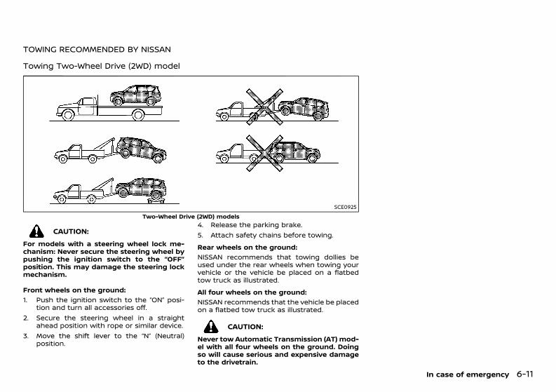
(361,1)
[ Edit: 2020/ 11/ 9 Model: Y62-A ]
TOWING RECOMMENDED BY NISSANGUID-CBEEFF0E-FEE6-4F26-8119-94C66A048852
Towing Two-Wheel Drive (2WD) modelGUID-3A80B018-97CE-475A-A80B-19437F5755A4
SCE0925Two-Wheel Drive (2WD) models
CAUTION:For models with a steering wheel lock me-chanism: Never secure the steering wheel bypushing the ignition switch to the “OFF”position. This may damage the steering lockmechanism.
Front wheels on the ground:GUID-C7E1EF24-5AAB-4301-95BE-26917EEE45EF
1. Push the ignition switch to the “ON” posi-tion and turn all accessories off.
2. Secure the steering wheel in a straightahead position with rope or similar device.
3. Move the shift lever to the “N” (Neutral)position.
4. Release the parking brake.5. Attach safety chains before towing.Rear wheels on the ground:
GUID-C7E1EF24-5AAB-4301-95BE-26917EEE45EF
NISSAN recommends that towing dollies beused under the rear wheels when towing yourvehicle or the vehicle be placed on a flatbedtow truck as illustrated.All four wheels on the ground:
GUID-C7E1EF24-5AAB-4301-95BE-26917EEE45EF
NISSAN recommends that the vehicle be placedon a flatbed tow truck as illustrated.
CAUTION:Never tow Automatic Transmission (AT) mod-el with all four wheels on the ground. Doingso will cause serious and expensive damageto the drivetrain.
In case of emergency 6-11
Condition: 'Except for China'/'Except for China/
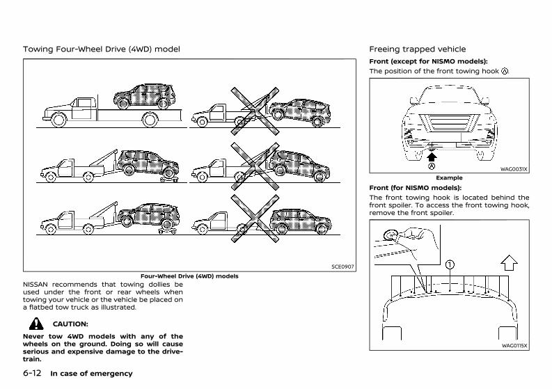
(362,1)
[ Edit: 2020/ 11/ 9 Model: Y62-A ]
6-12 In case of emergency
Towing Four-Wheel Drive (4WD) modelGUID-82446E9D-DF83-48FB-A6E3-C1573EFAAECB
SCE0907Four-Wheel Drive (4WD) models
NISSAN recommends that towing dollies beused under the front or rear wheels whentowing your vehicle or the vehicle be placed ona flatbed tow truck as illustrated.
CAUTION:Never tow 4WD models with any of thewheels on the ground. Doing so will causeserious and expensive damage to the drive-train.
Freeing trapped vehicleGUID-28A40C0C-F43D-48F6-9AF2-BBDDF72CFE7B
Front (except for NISMO models):GUID-C7E1EF24-5AAB-4301-95BE-26917EEE45EF
The position of the front towing hook .
WAG0031XExample
Front (for NISMO models):GUID-C7E1EF24-5AAB-4301-95BE-26917EEE45EF
The front towing hook is located behind thefront spoiler. To access the front towing hook,remove the front spoiler.
WAG0115X
Condition: 'Except for China'/'Except for China/
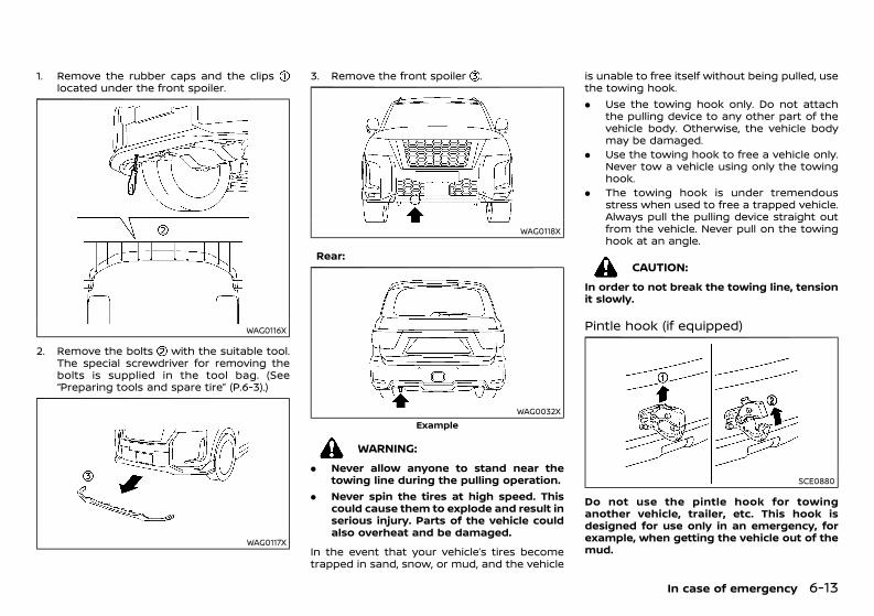
(363,1)
[ Edit: 2020/ 11/ 9 Model: Y62-A ]
1. Remove the rubber caps and the clipslocated under the front spoiler.
WAG0116X
2. Remove the bolts with the suitable tool.The special screwdriver for removing thebolts is supplied in the tool bag. (See“Preparing tools and spare tire” (P.6-3).)
WAG0117X
3. Remove the front spoiler .
WAG0118X
Rear:GUID-C7E1EF24-5AAB-4301-95BE-26917EEE45EF
WAG0032XExample
WARNING:. Never allow anyone to stand near the
towing line during the pulling operation.. Never spin the tires at high speed. This
could cause them to explode and result inserious injury. Parts of the vehicle couldalso overheat and be damaged.
In the event that your vehicle’s tires becometrapped in sand, snow, or mud, and the vehicle
is unable to free itself without being pulled, usethe towing hook.. Use the towing hook only. Do not attach
the pulling device to any other part of thevehicle body. Otherwise, the vehicle bodymay be damaged.
. Use the towing hook to free a vehicle only.Never tow a vehicle using only the towinghook.
. The towing hook is under tremendousstress when used to free a trapped vehicle.Always pull the pulling device straight outfrom the vehicle. Never pull on the towinghook at an angle.
CAUTION:In order to not break the towing line, tensionit slowly.
Pintle hook (if equipped)GUID-2B038CD2-E179-4D2B-893E-F7073B7C2865
SCE0880
Do not use the pintle hook for towinganother vehicle, trailer, etc. This hook isdesigned for use only in an emergency, forexample, when getting the vehicle out of themud.
In case of emergency 6-13
Condition: 'Except for China'/'Except for China/
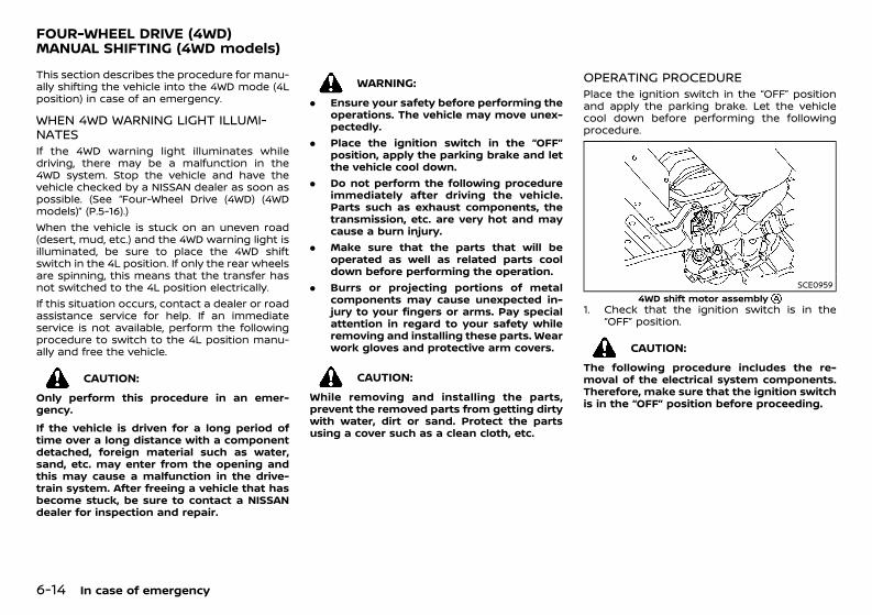
(364,1)
[ Edit: 2020/ 11/ 9 Model: Y62-A ]
6-14 In case of emergency
GUID-553DE697-92A1-4B2A-8209-39449B21A226This section describes the procedure for manu-ally shifting the vehicle into the 4WD mode (4Lposition) in case of an emergency.
WHEN 4WD WARNING LIGHT ILLUMI-NATES GUID-77DD4644-12D6-4C8B-9F7F-30E90F33E2B4If the 4WD warning light illuminates whiledriving, there may be a malfunction in the4WD system. Stop the vehicle and have thevehicle checked by a NISSAN dealer as soon aspossible. (See “Four-Wheel Drive (4WD) (4WDmodels)” (P.5-16).)When the vehicle is stuck on an uneven road(desert, mud, etc.) and the 4WD warning light isilluminated, be sure to place the 4WD shiftswitch in the 4L position. If only the rear wheelsare spinning, this means that the transfer hasnot switched to the 4L position electrically.If this situation occurs, contact a dealer or roadassistance service for help. If an immediateservice is not available, perform the followingprocedure to switch to the 4L position manu-ally and free the vehicle.
CAUTION:Only perform this procedure in an emer-gency.If the vehicle is driven for a long period oftime over a long distance with a componentdetached, foreign material such as water,sand, etc. may enter from the opening andthis may cause a malfunction in the drive-train system. After freeing a vehicle that hasbecome stuck, be sure to contact a NISSANdealer for inspection and repair.
WARNING:. Ensure your safety before performing the
operations. The vehicle may move unex-pectedly.
. Place the ignition switch in the “OFF”position, apply the parking brake and letthe vehicle cool down.
. Do not perform the following procedureimmediately after driving the vehicle.Parts such as exhaust components, thetransmission, etc. are very hot and maycause a burn injury.
. Make sure that the parts that will beoperated as well as related parts cooldown before performing the operation.
. Burrs or projecting portions of metalcomponents may cause unexpected in-jury to your fingers or arms. Pay specialattention in regard to your safety whileremoving and installing these parts. Wearwork gloves and protective arm covers.
CAUTION:While removing and installing the parts,prevent the removed parts from getting dirtywith water, dirt or sand. Protect the partsusing a cover such as a clean cloth, etc.
OPERATING PROCEDUREGUID-44BC73D9-FC99-4382-B9BD-3686CB57BECFPlace the ignition switch in the “OFF” positionand apply the parking brake. Let the vehiclecool down before performing the followingprocedure.
SCE09594WD shift motor assembly
1. Check that the ignition switch is in the“OFF” position.
CAUTION:The following procedure includes the re-moval of the electrical system components.Therefore, make sure that the ignition switchis in the “OFF” position before proceeding.
FOUR-WHEEL DRIVE (4WD)MANUAL SHIFTING (4WD models)
Condition: 'Except for China'/'Except for China/
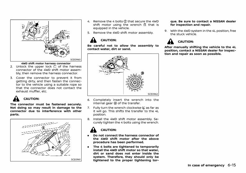
(365,1)
[ Edit: 2020/ 11/ 9 Model: Y62-A ]
SCE09604WD shift motor harness connector
2. Unlock the upper lock of the harnessconnector of the 4WD shift motor assem-bly, then remove the harness connector.
3. Cover the connector to prevent it fromgetting dirty, and then fasten the connec-tor to the vehicle using a suitable rope sothat the connector does not contact theexhaust muffler, etc.
CAUTION:The connector must be fastened securely.Not doing so may result in damage to theconnector due to interference with otherparts.
SCE0961
4. Remove the 4 bolts that secure the 4WDshift motor using the wrench that isequipped in the vehicle.
5. Remove the 4WD shift motor assembly.
CAUTION:Be careful not to allow the assembly tocontact water, dirt or sand.
SCE0962
6. Completely insert the wrench into theinternal gear of the transfer.
7. Fully turn the wrench clockwise as far asit will go. This shifts the transfer to the 4Lposition.
8. Install the 4WD shift motor assembly. Se-curely tighten the 4 bolts using the wrench.
CAUTION:. Do not connect the harness connector of
the 4WD shift motor after the aboveprocedure has been performed.
. The 4 bolts are tightened to temporarilyinstall the 4WD shift motor so that water,dirt or sand does not enter inside thesystem. Therefore, they should only betightened to the proper tightening tor-
que. Be sure to contact a NISSAN dealerfor inspection and repair.
9. With the 4WD system in the 4L position, freethe stuck vehicle.
CAUTION:After manually shifting the vehicle to the 4Lposition, contact a NISSAN dealer for inspec-tion and repair as soon as possible.
In case of emergency 6-15
Condition: 'Except for China'/'Except for China/

(366,1)
[ Edit: 2020/ 11/ 9 Model: Y62-A ]
6-16 In case of emergency
MEMO
Condition: 'Except for China'/'Except for China/
(367,1)
[ Edit: 2020/ 11/ 9 Model: Y62-A ]
7 Appearance and care
Cleaning exterior ............................................................................................... 7-2Washing ............................................................................................................ 7-2Removing spots ......................................................................................... 7-2Waxing ................................................................................................................ 7-2Glass .................................................................................................................... 7-3Underbody ...................................................................................................... 7-3Wheels ................................................................................................................ 7-3Aluminum alloy wheels ........................................................................ 7-3Chrome parts ............................................................................................... 7-3
Cleaning interior ............................................................................................... 7-3Air fresheners ............................................................................................ 7-4Floor mats .................................................................................................... 7-4Glass ................................................................................................................. 7-4Seat belts ...................................................................................................... 7-4
Corrosion protection .................................................................................... 7-5Most common factors contributing tovehicle corrosion .................................................................................... 7-5Environmental factors influence the rateof corrosion ................................................................................................ 7-5To protect your vehicle from corrosion .............................. 7-5
Condition: 'Except for China'/'Except for China/
(368,1)
[ Edit: 2020/ 11/ 9 Model: Y62-A ]
7-2 Appearance and care
GUID-2C1475A6-F2C1-42EF-BC13-19870821EE84In order to maintain the appearance of yourvehicle, it is important to take proper care of it.Whenever possible, park your vehicle inside agarage or in a covered area to minimize thechances of damaging the paint surface of yourvehicle.When it is necessary to park outside, park in ashady area or protect the vehicle with a bodycover. Be careful not to scratch the paintsurface when putting on or removing thebody cover.
WASHING GUID-52CA2A90-9B93-4E97-985F-079D905A0AAEIn the following instances, wash your vehicle assoon as possible to protect the paint surface:. After a rainfall, which may cause the paint
surface damage from acid rain.. After driving on coastal roads, which may
cause rusting from the sea breeze.. When contaminants such as soot, bird
droppings, tree sap, metal particles or bugsget on the paint surface.
. When dust or mud builds up on the paintsurface.
1. Wash the vehicle surface with a wet spongeand plenty of water.
2. Clean the vehicle surface gently and thor-oughly using a mild soap, a special vehiclesoap or a general purpose dishwashingliquid mixed with clean, lukewarm (neverhot) water.
CAUTION:. Do not wash the vehicle with strong
household soap, strong chemical deter-gents, gasoline or solvents.
. Do not wash the vehicle in direct sunlightor while the vehicle body is hot, as thepaint surface may become water-spotted.
. Avoid using tight-napped or rough cloths,such as washing mitts. Care must betaken when removing caked-on dirt orother foreign substances so the paintsurface is not scratched or damaged.
. Lock all doors before going throughautomatic car wash. Locking doors helpsprevent fuel-filler lid from opening andbecoming damaged.
3. Rinse the vehicle thoroughly with plenty ofclean water.
4. Use a dampened chamois to dry the paintsurface and avoid leaving water spots.
When washing the vehicle, take care of thefollowing:. Inside flanges, joints and folds on the doors,
hatches and hood are particularly vulner-able to the effects of road salt. Therefore,these areas must be cleaned regularly.
. Be sure that the drain holes in the loweredge of the doors are not clogged.
. Spray water to the underbody and in thewheel wells to loosen the dirt and/or washaway road salt.
REMOVING SPOTSGUID-6D039294-F855-4C03-8E99-80C6C84682C7Remove tar and oil spots, industrial dust,insects, and tree sap as quickly as possiblefrom the paint surface to avoid lasting damageor staining. Special cleaning products areavailable at a NISSAN dealer or any automotiveaccessory store.
WAXING GUID-24E6F882-0573-4260-86FB-6F3FA0A23C19Regular waxing protects the paint surface andhelps maintain a new vehicle appearance.After waxing, polishing is recommended toremove built-up residue and to avoid a weath-ered appearance.A NISSAN dealer can assist you in choosing theappropriate waxing products.
CAUTION:. Wash your vehicle thoroughly and com-
pletely before applying wax to the paintsurface.
. Always follow themanufacturer’s instruc-tions supplied with the wax.
. Do not use a wax containing any abra-sives, cutting compounds or cleanersthat may damage the vehicle finish.
Machine compounding or aggressive polishingon a base coat/clear coat paint finish may dullthe finish or leave swirl marks.
CLEANING EXTERIOR
Condition: 'Except for China'/'Except for China/
(369,1)
[ Edit: 2020/ 11/ 9 Model: Y62-A ]
GLASS GUID-5F272933-652F-4477-9808-C6F712A65783Use glass cleaner to remove smoke and dustfilm from the glass surfaces. It is normal forglass to become coated with a film after thevehicle is parked in the hot sun. Glass cleanerand a soft cloth will easily remove this film.
UNDERBODYGUID-E8FB3E0B-FA23-415E-AF19-FFD0C0F73D65In areas where road salt is used in the winter, itis necessary to clean the vehicle’s underbodyregularly in order to prevent dirt and salt frombuilding up and causing the acceleration ofcorrosion on the underbody and suspension.Before the winter and again in the spring, theunderseal must be checked and, if necessary,re-treated.
WHEELS GUID-F3433C47-E23B-43DD-9EA7-BC455ABB3E7B. Wash the wheels when washing the vehicle
to maintain their appearance.. Clean the inner side of the wheels when the
wheel is changed or the underside of thevehicle is washed.
. Do not use abrasive cleaners when wash-ing the wheels.
. Inspect wheel rims regularly for dents orcorrosion. This may cause loss of pressureor damage the tire bead.
. NISSAN recommends that the road wheelsbe waxed to protect against road salt inareas where it is used during winter.
ALUMINUM ALLOY WHEELSGUID-9208A50C-BAB6-40FD-9E69-1ACA9E664A64Wash the wheels regularly with a spongedampened in a mild soap solution, especiallyduring winter in areas where road salt is used.The salt residue from road salt could discolorthe wheels if it is not washed off regularly.
CAUTION:Follow the directions below to avoid stainingor discoloring the wheels:. Do not use a cleaner that uses strong acid
or alkali contents to clean the wheels.. Do not apply wheel cleaners to the
wheels when they are hot. The wheeltemperature should be the same asambient temperature.
. Rinse the wheel to completely removethe cleaner within 15 minutes after thecleaner is applied.
CHROME PARTSGUID-A45ADD0A-D2C3-4DE6-9BA8-E87AAE41F658Clean all chrome parts regularly with a non-abrasive chrome polish to maintain the finish.
GUID-2EB96DB0-EC26-4717-8559-EF1F5A9D89C1Occasionally remove loose dust from the inter-ior trim, plastic parts and seats using a vacuumcleaner or soft bristled brush. Wipe the vinyland leather surfaces with a clean, soft clothdampened in mild soap solution, then wipeclean with a dry, soft cloth.Regular care and cleaning is required in orderto maintain the appearance of the leather.Before using any fabric protector, read themanufacturer’s recommendations. Some fabricprotectors contain chemicals that may stain orbleach the seat material.Use a soft cloth dampened only with water toclean the meter and gauge lens covers.
WARNING:For model with Advanced Air Bag System, donot use water or acidic cleaners (hot steamcleaners) on the seat. This can damage theseat or occupant classification sensors. Thiscan also affect the operation of the air bagsystem and result in serious personal injury.
CAUTION:. Never use benzine, thinner or any similar
material.. Small dirt particles can be abrasive and
damaging to leather surfaces and shouldbe removed promptly. Do not use saddlesoap, car waxes, polishes, oils, cleaningfluids, solvents, detergents or ammonia-based cleaners as they damage theleather natural finish.
. Never use fabric protectors unless re-commended by the manufacturer.
. Do not use glass or plastic cleaner onmeter or gauge lens covers. It maydamage the lens covers.
Appearance and care 7-3
CLEANING INTERIOR
Condition: 'Except for China'/'Except for China/
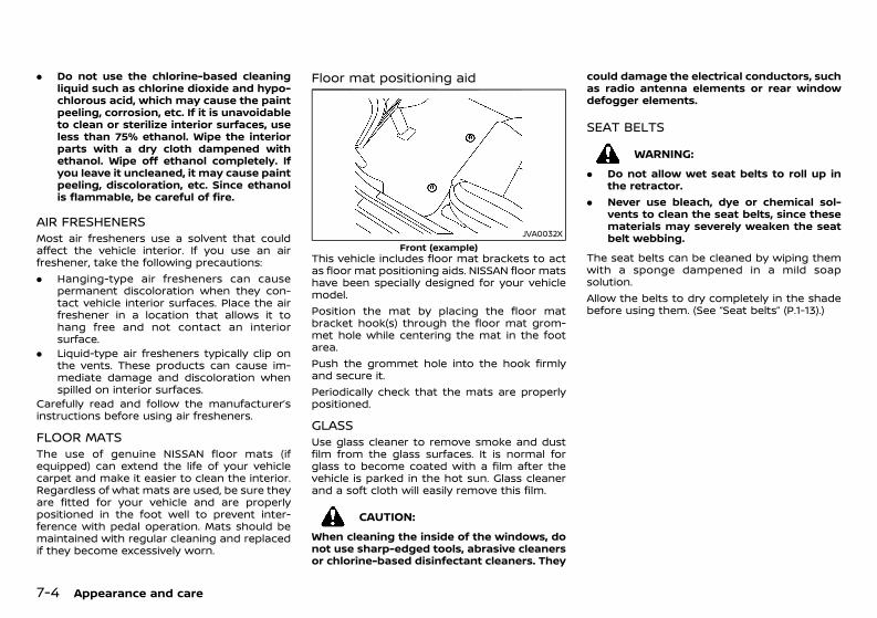
(370,1)
[ Edit: 2020/ 11/ 9 Model: Y62-A ]
7-4 Appearance and care
. Do not use the chlorine-based cleaningliquid such as chlorine dioxide and hypo-chlorous acid, which may cause the paintpeeling, corrosion, etc. If it is unavoidableto clean or sterilize interior surfaces, useless than 75% ethanol. Wipe the interiorparts with a dry cloth dampened withethanol. Wipe off ethanol completely. Ifyou leave it uncleaned, it may cause paintpeeling, discoloration, etc. Since ethanolis flammable, be careful of fire.
AIR FRESHENERSGUID-FA2A8AC5-49FC-4603-BBED-21B6BEFFA035Most air fresheners use a solvent that couldaffect the vehicle interior. If you use an airfreshener, take the following precautions:. Hanging-type air fresheners can cause
permanent discoloration when they con-tact vehicle interior surfaces. Place the airfreshener in a location that allows it tohang free and not contact an interiorsurface.
. Liquid-type air fresheners typically clip onthe vents. These products can cause im-mediate damage and discoloration whenspilled on interior surfaces.
Carefully read and follow the manufacturer’sinstructions before using air fresheners.
FLOOR MATSGUID-1B314048-1190-4006-BB9A-CBB1718218B2The use of genuine NISSAN floor mats (ifequipped) can extend the life of your vehiclecarpet and make it easier to clean the interior.Regardless of what mats are used, be sure theyare fitted for your vehicle and are properlypositioned in the foot well to prevent inter-ference with pedal operation. Mats should bemaintained with regular cleaning and replacedif they become excessively worn.
Floor mat positioning aidGUID-22B0FB6B-8E5A-4F97-A6CA-B63DA7A84991
JVA0032XFront (example)
This vehicle includes floor mat brackets to actas floor mat positioning aids. NISSAN floor matshave been specially designed for your vehiclemodel.Position the mat by placing the floor matbracket hook(s) through the floor mat grom-met hole while centering the mat in the footarea.Push the grommet hole into the hook firmlyand secure it.Periodically check that the mats are properlypositioned.
GLASS GUID-9761A1A8-C4ED-46D9-9C09-F4950BF5F3CCUse glass cleaner to remove smoke and dustfilm from the glass surfaces. It is normal forglass to become coated with a film after thevehicle is parked in the hot sun. Glass cleanerand a soft cloth will easily remove this film.
CAUTION:When cleaning the inside of the windows, donot use sharp-edged tools, abrasive cleanersor chlorine-based disinfectant cleaners. They
could damage the electrical conductors, suchas radio antenna elements or rear windowdefogger elements.
SEAT BELTSGUID-FE5CC456-C87A-4BAB-BC26-0344E0699D4DWARNING:
. Do not allow wet seat belts to roll up inthe retractor.
. Never use bleach, dye or chemical sol-vents to clean the seat belts, since thesematerials may severely weaken the seatbelt webbing.
The seat belts can be cleaned by wiping themwith a sponge dampened in a mild soapsolution.Allow the belts to dry completely in the shadebefore using them. (See “Seat belts” (P.1-13).)
Condition: 'Except for China'/'Except for China/
(371,1)
[ Edit: 2020/ 11/ 9 Model: Y62-A ]
GUID-88A6F4F0-C55B-4C54-9334-304853510A3E
MOST COMMON FACTORS CONTRI-BUTING TO VEHICLE CORROSIONGUID-68180AEC-B281-4CBA-8800-5C71C7841E52. The accumulation of moisture-retaining
dirt and debris in body panel sections,cavities, and other areas.
. Damage to the paint surface and otherprotective coatings caused by gravel andstone chips or minor traffic accidents.
ENVIRONMENTAL FACTORS INFLUENCETHE RATE OF CORROSIONGUID-9F4F2623-2EB3-4361-BD51-00CB2422B44F
Moisture GUID-4650C177-5FD9-4D3D-B04A-9C7C7BD90460The accumulation of sand, dirt and water onthe inside floor of the vehicle can acceleratecorrosion. Wet floor carpet/floor mats will notdry completely inside the vehicle. They shouldbe removed and completely dried to avoid floorpanel corrosion.
Relative humidityGUID-4183169E-6E23-4B79-9D33-52C71E1DE663Corrosion will be accelerated in areas of highrelative humidity.
TemperatureGUID-E477FDFB-4836-4774-8832-6318E7E4B86BHigh temperatures accelerate the rate ofcorrosion to those parts which are not wellventilated.Corrosion will also be accelerated in areaswhere the temperatures stay above freezing.
Air pollutionGUID-05B60743-6EE4-46A4-BAF5-B6871C45413FIndustrial pollution, the presence of salt in theair in coastal areas, or heavy road salt useaccelerates the corrosion process. Road saltalso accelerates the disintegration of paintsurfaces.
TO PROTECT YOUR VEHICLE FROMCORROSIONGUID-3347F399-5EAD-40C8-8FE4-20C72DDAD308. Wash and wax your vehicle often to keep
the vehicle clean.. Always check for minor damage to the
paint surface and if any exists, repair it assoon as possible.
. Keep the drain holes in the lower edge ofthe doors open to avoid water accumula-tion.
. Check the vehicle underbody for accumu-lation of sand, dirt or salt. If present, washwith water as soon as possible.
CAUTION:. Never remove dirt, sand or other debris
from the passenger compartment bywashing it out with a hose. Remove dirtwith a vacuum cleaner.
. Never allow water or other liquids tocome in contact with electronic compo-nents inside the vehicle as this maydamage them.
Chemicals used for road surface deicing areextremely corrosive. They accelerate corrosionand deterioration of underbody componentssuch as the exhaust system, fuel and brakelines, brake cables, floor pan and fenders.In the winter, the underbody must be cleanedperiodically.For additional protection against rust andcorrosion, which may be required in someareas, consult a NISSAN dealer.
Appearance and care 7-5
CORROSION PROTECTION
Condition: 'Except for China'/'Except for China/

(372,1)
[ Edit: 2020/ 11/ 9 Model: Y62-A ]
7-6 Appearance and care
MEMO
Condition: 'Except for China'/'Except for China/
(373,1)
[ Edit: 2020/ 11/ 9 Model: Y62-A ]
8 Maintenance and do-it-yourself
Maintenance requirements ...................................................................... 8-2Scheduled maintenance ...................................................................... 8-2General maintenance ............................................................................ 8-2Where to go for service ........................................................................ 8-2
General maintenance .................................................................................... 8-2Explanation of general maintenance items ........................ 8-2Maintenance precautions .................................................................. 8-4
Engine compartment check locations ............................................ 8-5VK56DE engine model .......................................................................... 8-5VK56VD engine model ......................................................................... 8-6VQ40DE engine model ......................................................................... 8-7
Engine cooling system ................................................................................. 8-7Checking engine coolant level ....................................................... 8-8Changing engine coolant ................................................................... 8-8
Engine oil ................................................................................................................. 8-9Checking engine oil level .................................................................... 8-9Changing engine oil and oil filter ................................................. 8-9Protect environment ........................................................................... 8-10
Drive belt .............................................................................................................. 8-11Spark plugs ......................................................................................................... 8-11
Iridium-tipped spark plugs ............................................................. 8-11Brakes ..................................................................................................................... 8-12
Checking parking brake ................................................................... 8-12Checking foot brake ............................................................................ 8-12Brake booster ........................................................................................... 8-12
Brake fluid ............................................................................................................ 8-13Automatic Transmission Fluid (ATF) .............................................. 8-14
5-speed Automatic Transmission (AT) model ................ 8-147-speed Automatic Transmission (AT) model ................ 8-14
Power steering fluid ................................................................................... 8-14Air cleaner filter .............................................................................................. 8-15Wiper blades ..................................................................................................... 8-16
Windshield wiper blades ................................................................ 8-16Window washer fluid .................................................................................. 8-17Battery ................................................................................................................... 8-18
Vehicle battery ...................................................................................... 8-18Intelligent Key battery ..................................................................... 8-19
Variable voltage control system ....................................................... 8-20Fuses ....................................................................................................................... 8-20
Types of fuse .......................................................................................... 8-20Engine compartment ....................................................................... 8-21Passenger compartment .............................................................. 8-22
Lights ...................................................................................................................... 8-23Headlights ................................................................................................. 8-23Exterior lights ......................................................................................... 8-24Interior lights ........................................................................................... 8-24Light locations ....................................................................................... 8-25
Tires and wheels ........................................................................................... 8-29Tire Pressure Monitoring System (TPMS)(if equipped) ............................................................................................. 8-29Tire inflation pressure ..................................................................... 8-29Types of tires .......................................................................................... 8-29Tire chains ................................................................................................. 8-30Tire rotation ............................................................................................. 8-30Tire wear and damage ................................................................... 8-31Tire age ....................................................................................................... 8-31Changing tires and wheels ......................................................... 8-31Wheel balance ........................................................................................ 8-32Spare tire ................................................................................................... 8-32
Condition: 'Except for China'/'Except for China/
(374,1)
[ Edit: 2020/ 11/ 9 Model: Y62-A ]
8-2 Maintenance and do-it-yourself
GUID-657BA42B-68B2-4D12-884F-7E07F3608FADSome day-to-day and regular maintenance isessential to maintain your vehicle’s good me-chanical condition, as well as its emission andengine performance.It is the owner’s responsibility to make sure thatthe specified maintenance, as well as generalmaintenance, is performed.As the vehicle owner, you are the only one whocan ensure that your vehicle receives theproper maintenance care.
SCHEDULED MAINTENANCEGUID-8776E2C4-F455-4EC7-8E9C-884C20BF1210For your convenience, the required scheduledmaintenance items are described and listed ina separate Warranty Information and Mainte-nance booklet. You must refer to that bookletto ensure that necessary maintenance is per-formed on your vehicle at regular intervals.
GENERAL MAINTENANCEGUID-49F086AD-E54B-4B05-AA60-0FCEA79B6754General maintenance includes those itemswhich should be checked during normal day-to-day operation of the vehicle. They areessential if your vehicle is to continue tooperate properly. It is your responsibility toperform these procedures regularly as pre-scribed.Performing general maintenance checks re-quires minimal mechanical skill and only a fewgeneral automotive tools.These checks or inspections can be done byyourself, a qualified technician, or if you prefer,your NISSAN dealer.
WHERE TO GO FOR SERVICEGUID-A0CE9CE4-E7F2-479F-B6EC-ABBE69B3FC4AIf maintenance service is required or yourvehicle appears to malfunction, have the sys-tems checked and tuned by an authorizedNISSAN dealer.
GUID-B5A92B6E-ED44-4375-86B5-6618C49C8921During normal day-to-day operation of thevehicle, general maintenance should be per-formed regularly as prescribed in this section. Ifyou detect any unusual sounds, vibrations orsmells, be sure to check for the cause or have aNISSAN dealer do it promptly. In addition, youshould notify a NISSAN dealer if you think thatrepairs are required.When performing any checks or maintenancework, closely observe “Maintenance precau-tions” (P.8-4).
EXPLANATION OF GENERAL MAINTE-NANCE ITEMSGUID-DCA24E7B-D710-452B-884D-AA69578F7AF9Additional information on the followingitems with “*” is found later in this section.
Outside vehicleGUID-B906E59F-E3CA-481E-B84E-25F0B03C367EThe maintenance items listed here should beperformed from time to time, unless otherwisespecified.Doors and hood:
GUID-C7E1EF24-5AAB-4301-95BE-26917EEE45EF
Check that all doors and the hood operatesmoothly as well as the back door, trunk lid andhatch. Also make sure that all latches locksecurely. Lubricate if necessary. Make sure thatthe secondary latch keeps the hood fromopening when the primary latch is released.When driving in areas using road salt or othercorrosive materials, check lubrication fre-quently.Lights*:
GUID-C7E1EF24-5AAB-4301-95BE-26917EEE45EF
Clean the headlights on a regular basis. Makesure that the headlights, stop lights, tail lights,turn signal lights, and other lights are alloperating properly and installed securely. Alsocheck the aim of the headlights.
MAINTENANCE REQUIREMENTS GENERAL MAINTENANCE
Condition: 'Except for China'/'Except for China/
(375,1)
[ Edit: 2020/ 11/ 9 Model: Y62-A ]
Tires*:GUID-C7E1EF24-5AAB-4301-95BE-26917EEE45EF
Check the pressure with a gauge often andalways prior to long distance trips. Adjust thepressure in all tires, including the spare, to thepressure specified. Check carefully for damage,cuts or excessive wear.Tire rotation*:
GUID-C7E1EF24-5AAB-4301-95BE-26917EEE45EF
In the case that Two-Wheel Drive (2WD) andfront and rear tires are same size; tires shouldbe rotated every 10,000 km (6,000 miles). Tiresmarked with directional indicators can only berotated between front and rear. Make sure thatthe directional indicators point in the directionof wheel rotation after the tire rotation iscompleted.In the case that Four-Wheel Drive and All WheelDrive (4WD/AWD) and front and rear tires aresame size; tires should be rotated every 5,000km (3,000 miles). Tires marked with directionalindicators can only be rotated between frontand rear. Make sure that the directional in-dicators point in the direction of wheel rotationafter the tire rotation is completed.In the case that front tires are different sizefrom rear tires; tires cannot be rotated.The timing for tire rotation may vary accordingto your driving habits and the road surfaceconditions.Tire Pressure Monitoring System (TPMS)transmitter components (if so equipped):
GUID-C7E1EF24-5AAB-4301-95BE-26917EEE45EF
Replace the TPMS transmitter grommet seal,valve core and cap when the tires are replaceddue to wear or age.
Wheel alignment and balance:GUID-C7E1EF24-5AAB-4301-95BE-26917EEE45EF
If the vehicle should pull to either side whiledriving on a straight and level road, or if youdetect uneven or abnormal tire wear, theremay be a need for wheel alignment. If thesteering wheel or seat vibrates at normalhighway speeds, wheel balancing may beneeded.Windshield:
GUID-C7E1EF24-5AAB-4301-95BE-26917EEE45EF
Clean the windshield on a regular basis. Checkthe windshield at least every six months forcracks or other damage. Repair as necessary.Wiper blades*:
GUID-C7E1EF24-5AAB-4301-95BE-26917EEE45EF
Check for cracks or wear if not functioningcorrectly. Replace as necessary.
Inside vehicleGUID-C30F89A2-BD24-450C-BE29-CACC3954D796The maintenance items listed here should bechecked on a regular basis, such as whenperforming periodic maintenance, cleaningthe vehicle, etc.Accelerator pedal:
GUID-C7E1EF24-5AAB-4301-95BE-26917EEE45EF
Check the pedal for smooth operation andmake sure that the pedal does not catch orrequire uneven effort. Keep the floor mats awayfrom the pedal.Brake pedal*:
GUID-C7E1EF24-5AAB-4301-95BE-26917EEE45EF
Check the pedal for smooth operation andmake sure that it is the proper distance fromthe floor mat when depressed fully. Check thebrake booster function. Be sure to keep thefloor mats away from the pedal.
Parking brake*:GUID-C7E1EF24-5AAB-4301-95BE-26917EEE45EF
Check the parking brake operation regularly.Check that the lever (if so equipped) or thepedal (if so equipped) has the proper travel.Also make sure that the vehicle is held securelyon a fairly steep hill when only the parkingbrake is applied.Seat belts:
GUID-C7E1EF24-5AAB-4301-95BE-26917EEE45EF
Check that all parts of the seat belt system (forexample, buckles, anchors, adjusters and re-tractors) operate properly and smoothly, andare installed securely. Check the belt webbingfor cuts, fraying, wear or damage.Steering wheel:
GUID-C7E1EF24-5AAB-4301-95BE-26917EEE45EF
Check for changes in the steering condition,such as excessive play, hard steering or strangenoises.Warning lights and chimes:
GUID-C7E1EF24-5AAB-4301-95BE-26917EEE45EF
Make sure that all warning lights and chimesare operating properly.Windshield defogger:
GUID-C7E1EF24-5AAB-4301-95BE-26917EEE45EF
Check that the air comes out of the defoggeroutlets properly and in good quantity whenoperating the heater or air conditioner.Windshield wiper and washer*:
GUID-C7E1EF24-5AAB-4301-95BE-26917EEE45EF
Check that the wipers and washer operateproperly and that the wipers do not streak.
Under hood and vehicleGUID-292CAE27-FEEB-4E90-AF7A-3CF671B66363The maintenance items listed here should bechecked periodically (for example, each timeyou check the engine oil or refuel).
Maintenance and do-it-yourself 8-3
Condition: 'Except for China'/'Except for China/
(376,1)
[ Edit: 2020/ 11/ 9 Model: Y62-A ]
8-4 Maintenance and do-it-yourself
Battery (except for maintenance free bat-teries)* :
GUID-C7E1EF24-5AAB-4301-95BE-26917EEE45EF
Check the fluid level in each cell. It should bebetween the UPPER and LOWER lines. Vehiclesoperated in high temperatures or under severeconditions require frequent checks of thebattery fluid level.Brake (and clutch) fluid level(s)*:
GUID-C7E1EF24-5AAB-4301-95BE-26917EEE45EF
For Manual Transmission (MT) model; makesure that the brake and clutch fluid levels arebetween the MAX and MIN lines on the reser-voirs.Except for Manual Transmission (MT) model;make sure that the brake fluid level is betweenthe MAX and MIN lines on the reservoir.Engine coolant level*:
GUID-C7E1EF24-5AAB-4301-95BE-26917EEE45EF
Check the coolant level when the engine iscold. Make sure that the coolant level isbetween the MAX and MIN lines on the reser-voir.Engine drive belt(s)*:
GUID-C7E1EF24-5AAB-4301-95BE-26917EEE45EF
Make sure that drive belt(s) is not frayed, worn,cracked or oily.Engine oil level*:
GUID-C7E1EF24-5AAB-4301-95BE-26917EEE45EF
Check the level after parking the vehicle (on alevel ground) and turning off the engine.Fluid leaks:
GUID-C7E1EF24-5AAB-4301-95BE-26917EEE45EF
Check under the vehicle for fuel, oil, water orother fluid leaks after the vehicle has beenparked for a while. Water dripping from the airconditioner after use is normal. If you shouldnotice any leaks or if fuel fumes are evident,check for cause and have it corrected immedi-ately.
Power steering fluid level and lines*:GUID-C7E1EF24-5AAB-4301-95BE-26917EEE45EF
Check the level when the fluid is cold with theengine off. Check the lines for proper attach-ment, leaks, cracks, etc.Windshield washer fluid*:
GUID-C7E1EF24-5AAB-4301-95BE-26917EEE45EF
Check that there is adequate fluid in thereservoir.
MAINTENANCE PRECAUTIONSGUID-043D059F-5005-4A6E-BCBD-FE125C83927CWhen performing any inspection or mainte-nance work on your vehicle, always take care toprevent serious accidental injury to yourself ordamage to the vehicle. The following aregeneral precautions which should be closelyobserved.
WARNING:. Park the vehicle on a level surface, apply
the parking brake securely and block thewheels to prevent the vehicle from mov-ing. Move the shift lever to the “P” (Park)position.
. Be sure the ignition switch is in the“LOCK” position when performing anyparts replacement or repairs.
. Do not work under the hood while theengine is hot. Always turn off the engineand wait until it cools down.
. If youmust work with the engine running,keep your hands, clothing, hair and toolsaway from moving fans, belts and anyother moving parts.
. It is advisable to secure or remove anyloose clothing and any jewelry, such asrings, watches, etc. before working onyour vehicle.
. If you must run the engine in an enclosedspace such as a garage, be sure there isproper ventilation for exhaust gases toescape.
. Never get under the vehicle while it issupported by a jack.
. Keep smoking materials, flame andsparks away from fuel and the battery.
. Never connect or disconnect either thebattery or any transistorized componentconnector while the ignition switch is inthe “ON” position.
. On gasoline engine models with theMultiport Fuel Injection (MFI) system, thefuel filter and fuel lines should be ser-viced by a NISSAN dealer because the fuellines are under high pressure even whenthe engine is turned off.
. Your vehicle is equipped with an auto-matic engine cooling fan. It may come onat any time without warning, even if theignition switch is in the “OFF” positionand the engine is not running. To avoidinjury, always disconnect the negativebattery cable before working near thefan.
. Always wear eye protection wheneveryou work on your vehicle.
. Never leave the engine or the transmis-sion related component harness connec-tor disconnected while the ignitionswitch is in the “ON” position.
. Avoid direct contact with used engine oiland coolant. Improperly disposed engineoil, engine coolant, and/or other vehiclefluids can hurt the environment. Alwaysconform to local regulations for disposalof vehicle fluids.
This “8. Maintenance and do-it-yourself” section
Condition: 'Except for China'/'Except for China/
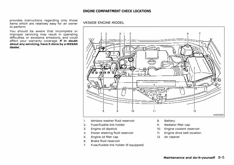
(377,1)
[ Edit: 2020/ 11/ 9 Model: Y62-A ]
provides instructions regarding only thoseitems which are relatively easy for an ownerto perform.You should be aware that incomplete orimproper servicing may result in operatingdifficulties or excessive emissions, and couldaffect your warranty coverage. If in doubtabout any servicing, have it done by a NISSANdealer.
GUID-B0E19A5D-2B8A-4CE8-8A3D-CF55C5F014E5
VK56DE ENGINE MODELGUID-FE34AD79-9FED-4C44-B5AF-8F46493E8FB6
JVO0192X
1. Window washer fluid reservoir2. Fuse/fusible link holder3. Engine oil dipstick4. Power steering fluid reservoir5. Engine oil filler cap6. Brake fluid reservoir7. Fuse/fusible link holder (if equipped)
8. Battery9. Radiator filler cap10. Engine coolant reservoir11. Engine drive belt location12. Air cleaner
Maintenance and do-it-yourself 8-5
ENGINE COMPARTMENT CHECK LOCATIONS
Condition: 'Except for China'/'Except for China/
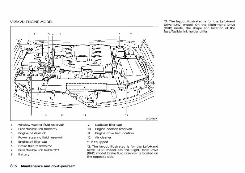
(378,1)
[ Edit: 2020/ 11/ 9 Model: Y62-A ]
8-6 Maintenance and do-it-yourself
VK56VD ENGINE MODELGUID-55DF11EB-8487-4DBF-8985-86A8E4FFC949
JVC0965X
1. Window washer fluid reservoir2. Fuse/fusible link holder*33. Engine oil dipstick4. Power steering fluid reservoir5. Engine oil filler cap6. Brake fluid reservoir*27. Fuse/fusible link holder*1*38. Battery
9. Radiator filler cap10. Engine coolant reservoir11. Engine drive belt location12. Air cleaner*1: if equipped*2: The layout illustrated is for the Left-HandDrive (LHD) model. On the Right-Hand Drive(RHD) model, brake fluid reservoir is located onthe opposite side.
*3: The layout illustrated is for the Left-HandDrive (LHD) model. On the Right-Hand Drive(RHD) model, the shape and location of thefuse/fusible link holder differ.
Condition: 'Except for China'/'Except for China/
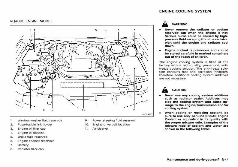
(379,1)
[ Edit: 2020/ 11/ 9 Model: Y62-A ]
VQ40DE ENGINE MODELGUID-E9DB11C1-889C-498A-888B-FBD3A63A20B5
JVC0927X
1. Window washer fluid reservoir2. Fuse/fusible link holder3. Engine oil filler cap4. Engine oil dipstick5. Brake fluid reservoir6. Engine coolant reservoir7. Battery8. Radiator filler cap
9. Power steering fluid reservoir10. Engine drive belt location11. Air cleaner
GUID-96329247-8EB6-4011-A05E-FCC3820809BB
WARNING:. Never remove the radiator or coolant
reservoir cap when the engine is hot.Serious burns could be caused by high-pressure fluid escaping from the radiator.Wait until the engine and radiator cooldown.
. Engine coolant is poisonous and shouldbe stored carefully in marked containersout of the reach of children.
The engine cooling system is filled at thefactory with a high-quality, year-round, anti-freeze coolant solution. The anti-freeze solu-tion contains rust and corrosion inhibitors,therefore additional cooling system additivesare not necessary.
CAUTION:. Never use any cooling system additives
such as radiator sealer. Additives mayclog the cooling system and cause da-mage to the engine, transmission and/orcooling system.
. When adding or replacing coolant, besure to use only Genuine NISSAN EngineCoolant or equivalent in its quality withthe proper mixture ratio. Examples of themixture ratio of coolant and water areshown in the following table:
Maintenance and do-it-yourself 8-7
ENGINE COOLING SYSTEM
Condition: 'Except for China'/'Except for China/
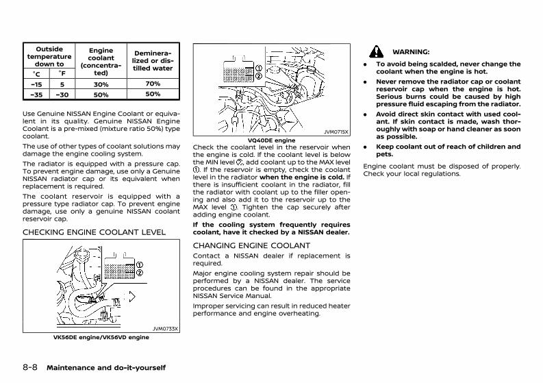
(380,1)
[ Edit: 2020/ 11/ 9 Model: Y62-A ]
8-8 Maintenance and do-it-yourself
Outsidetemperature
down to
Enginecoolant
(concentra-ted)
Deminera-lized or dis-tilled water
°C °F−15 5 30% 70%−35 −30 50% 50%
Use Genuine NISSAN Engine Coolant or equiva-lent in its quality. Genuine NISSAN EngineCoolant is a pre-mixed (mixture ratio 50%) typecoolant.The use of other types of coolant solutions maydamage the engine cooling system.The radiator is equipped with a pressure cap.To prevent engine damage, use only a GenuineNISSAN radiator cap or its equivalent whenreplacement is required.The coolant reservoir is equipped with apressure type radiator cap. To prevent enginedamage, use only a genuine NISSAN coolantreservoir cap.
CHECKING ENGINE COOLANT LEVELGUID-3B7E47D5-52CA-4B47-A1B2-25BEB0E9587D
JVM0733XVK56DE engine/VK56VD engine
JVM0715XVQ40DE engine
Check the coolant level in the reservoir whenthe engine is cold. If the coolant level is belowthe MIN level , add coolant up to the MAX level. If the reservoir is empty, check the coolant
level in the radiator when the engine is cold. Ifthere is insufficient coolant in the radiator, fillthe radiator with coolant up to the filler open-ing and also add it to the reservoir up to theMAX level . Tighten the cap securely afteradding engine coolant.If the cooling system frequently requirescoolant, have it checked by a NISSAN dealer.
CHANGING ENGINE COOLANTGUID-2A172ABB-940C-4C2F-BE7D-E44BD59E98A1Contact a NISSAN dealer if replacement isrequired.Major engine cooling system repair should beperformed by a NISSAN dealer. The serviceprocedures can be found in the appropriateNISSAN Service Manual.Improper servicing can result in reduced heaterperformance and engine overheating.
WARNING:. To avoid being scalded, never change the
coolant when the engine is hot.. Never remove the radiator cap or coolant
reservoir cap when the engine is hot.Serious burns could be caused by highpressure fluid escaping from the radiator.
. Avoid direct skin contact with used cool-ant. If skin contact is made, wash thor-oughly with soap or hand cleaner as soonas possible.
. Keep coolant out of reach of children andpets.
Engine coolant must be disposed of properly.Check your local regulations.
Condition: 'Except for China'/'Except for China/
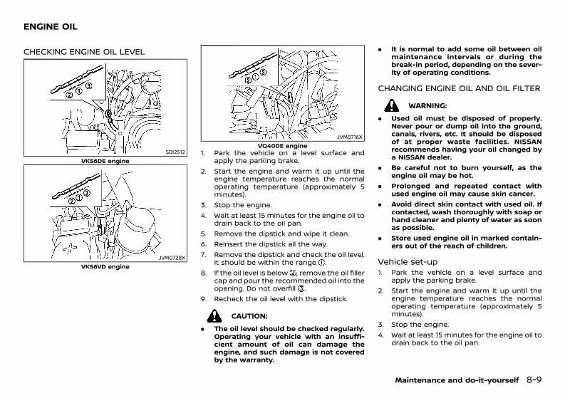
(381,1)
[ Edit: 2020/ 11/ 9 Model: Y62-A ]
GUID-10680CA8-8B78-40B1-A83A-227B79D2E364
CHECKING ENGINE OIL LEVELGUID-069FBAB5-4144-4EFE-901A-68C91CDE0C7D
SDI2512VK56DE engine
JVM0728XVK56VD engine
JVM0716XVQ40DE engine
1. Park the vehicle on a level surface andapply the parking brake.
2. Start the engine and warm it up until theengine temperature reaches the normaloperating temperature (approximately 5minutes).
3. Stop the engine.4. Wait at least 15 minutes for the engine oil to
drain back to the oil pan.5. Remove the dipstick and wipe it clean.6. Reinsert the dipstick all the way.7. Remove the dipstick and check the oil level.
It should be within the range .8. If the oil level is below , remove the oil filler
cap and pour the recommended oil into theopening. Do not overfill .
9. Recheck the oil level with the dipstick.
CAUTION:. The oil level should be checked regularly.
Operating your vehicle with an insuffi-cient amount of oil can damage theengine, and such damage is not coveredby the warranty.
. It is normal to add some oil between oilmaintenance intervals or during thebreak-in period, depending on the sever-ity of operating conditions.
CHANGING ENGINE OIL AND OIL FILTERGUID-0ACC8AC6-310B-4A22-9F0A-DF3A054A4253
WARNING:. Used oil must be disposed of properly.
Never pour or dump oil into the ground,canals, rivers, etc. It should be disposedof at proper waste facilities. NISSANrecommends having your oil changed bya NISSAN dealer.
. Be careful not to burn yourself, as theengine oil may be hot.
. Prolonged and repeated contact withused engine oil may cause skin cancer.
. Avoid direct skin contact with used oil. Ifcontacted, wash thoroughly with soap orhand cleaner and plenty of water as soonas possible.
. Store used engine oil in marked contain-ers out of the reach of children.
Vehicle set-upGUID-0991D218-36C5-44BA-812E-3531DDC277C71. Park the vehicle on a level surface and
apply the parking brake.2. Start the engine and warm it up until the
engine temperature reaches the normaloperating temperature (approximately 5minutes).
3. Stop the engine.4. Wait at least 15 minutes for the engine oil to
drain back to the oil pan.
Maintenance and do-it-yourself 8-9
ENGINE OIL
Condition: 'Except for China'/'Except for China/
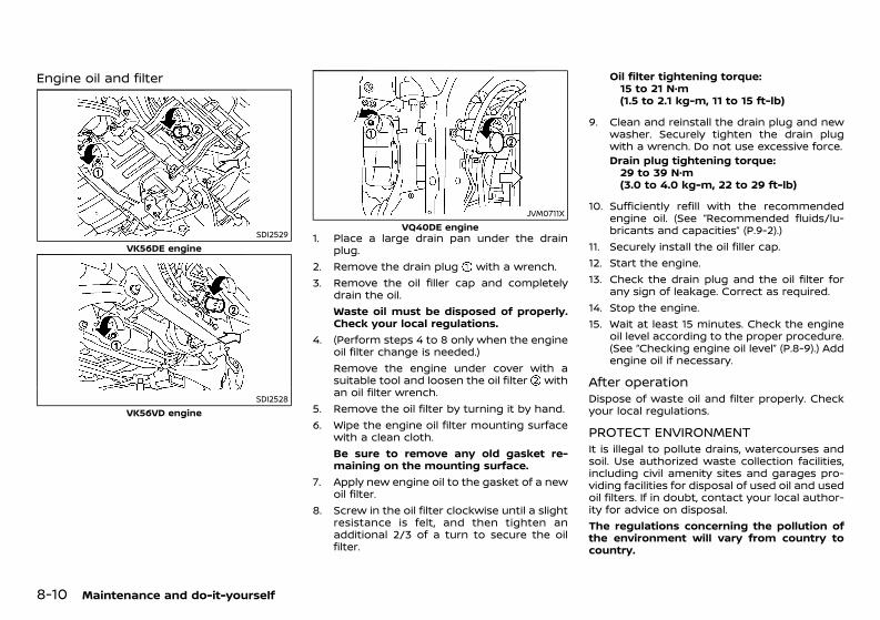
(382,1)
[ Edit: 2020/ 11/ 9 Model: Y62-A ]
8-10 Maintenance and do-it-yourself
Engine oil and filterGUID-3C60555F-9670-4DBC-90EA-5462503BFEF4
SDI2529VK56DE engine
SDI2528VK56VD engine
JVM0711XVQ40DE engine
1. Place a large drain pan under the drainplug.
2. Remove the drain plug with a wrench.3. Remove the oil filler cap and completely
drain the oil.Waste oil must be disposed of properly.Check your local regulations.
4. (Perform steps 4 to 8 only when the engineoil filter change is needed.)Remove the engine under cover with asuitable tool and loosen the oil filter withan oil filter wrench.
5. Remove the oil filter by turning it by hand.6. Wipe the engine oil filter mounting surface
with a clean cloth.Be sure to remove any old gasket re-maining on the mounting surface.
7. Apply new engine oil to the gasket of a newoil filter.
8. Screw in the oil filter clockwise until a slightresistance is felt, and then tighten anadditional 2/3 of a turn to secure the oilfilter.
Oil filter tightening torque:15 to 21 N·m(1.5 to 2.1 kg-m, 11 to 15 ft-lb)
9. Clean and reinstall the drain plug and newwasher. Securely tighten the drain plugwith a wrench. Do not use excessive force.Drain plug tightening torque:29 to 39 N·m(3.0 to 4.0 kg-m, 22 to 29 ft-lb)
10. Sufficiently refill with the recommendedengine oil. (See “Recommended fluids/lu-bricants and capacities” (P.9-2).)
11. Securely install the oil filler cap.12. Start the engine.13. Check the drain plug and the oil filter for
any sign of leakage. Correct as required.14. Stop the engine.15. Wait at least 15 minutes. Check the engine
oil level according to the proper procedure.(See “Checking engine oil level” (P.8-9).) Addengine oil if necessary.
After operationGUID-F20DAB39-9CE9-4A22-97E2-601DD3FC578FDispose of waste oil and filter properly. Checkyour local regulations.
PROTECT ENVIRONMENTGUID-56A1B774-53AD-4829-9DF0-63C8F4E96BDFIt is illegal to pollute drains, watercourses andsoil. Use authorized waste collection facilities,including civil amenity sites and garages pro-viding facilities for disposal of used oil and usedoil filters. If in doubt, contact your local author-ity for advice on disposal.The regulations concerning the pollution ofthe environment will vary from country tocountry.
Condition: 'Except for China'/'Except for China/
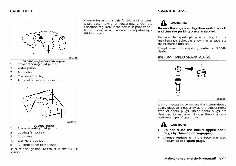
(383,1)
[ Edit: 2020/ 11/ 9 Model: Y62-A ]
GUID-C822882C-483C-4A63-B474-3253CCE55FAB
SDI2533VK56DE engine/VK56VD engine
1. Power steering fluid pump2. Water pump3. Alternator4. Crankshaft pulley5. Air conditioner compressor
JVM0712XVQ40DE engine
1. Power steering fluid pump2. Cooling fan pulley3. Alternator4. Crankshaft pulley5. Air conditioner compressorBe sure the ignition switch is in the “LOCK”position.
Visually inspect the belt for signs of unusualwear, cuts, fraying or looseness. Check thecondition regularly. If the belt is in poor condi-tion or loose, have it replaced or adjusted by aNISSAN dealer.
GUID-E4248712-B871-471D-BAEB-4916D1160313
WARNING:Be sure the engine and ignition switch are offand that the parking brake is applied.
Replace the spark plugs according to themaintenance schedule shown in a separatemaintenance booklet.If replacement is required, contact a NISSANdealer.
IRIDIUM-TIPPED SPARK PLUGSGUID-3D20E08A-32CA-4152-B455-21A137D99BB0
SDI2020
It is not necessary to replace the iridium-tippedspark plugs as frequently as the conventionaltype of spark plugs. These spark plugs aredesigned to last much longer than the con-ventional type of spark plug.
CAUTION:. Do not reuse the iridium-tipped spark
plugs by cleaning or re-gapping.. Always replace with the recommended
iridium-tipped spark plugs.
Maintenance and do-it-yourself 8-11
DRIVE BELT SPARK PLUGS
Condition: 'Except for China'/'Except for China/
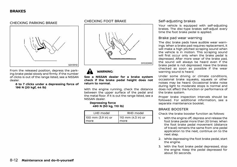
(384,1)
[ Edit: 2020/ 11/ 9 Model: Y62-A ]
8-12 Maintenance and do-it-yourself
GUID-BE4EF884-FE90-4EB0-8511-BAF5D3759AD5
CHECKING PARKING BRAKEGUID-98E2AF65-2EA8-483F-8670-224474C4708F
SDI1391D
From the released position, depress the park-ing brake pedal slowly and firmly. If the numberof clicks is out of the range listed, see a NISSANdealer.
6 to 7 clicks under a depressing force of196 N (20 kgf, 44 lb)
CHECKING FOOT BRAKEGUID-A6E7990A-0C48-4A3D-83E8-86D5CF7CA546
DI1020MM
WARNING:See a NISSAN dealer for a brake systemcheck if the brake pedal height does notreturn to normal.
With the engine running, check the distancebetween the upper surface of the pedal andthe metal floor. If it is out the range listed, see aNISSAN dealer.
Depressing force490 N (50 kg, 110 lb)
LHD model RHD model100 mm (3.9 in) ormore
110 mm (4.3 in) ormore
Self-adjusting brakesGUID-0C6E6015-0917-47EC-BBDB-86DDB7286457Your vehicle is equipped with self-adjustingbrakes. The disc-type brakes self-adjust everytime the foot brake pedal is applied.
Brake pad wear warningGUID-3E1D67C3-A509-4E87-A5FB-2771BC469217The disc brake pads have audible wear warn-ings. When a brake pad requires replacement, itwill make a high pitched scraping sound whenthe vehicle is in motion. This scraping soundwill first occur only when the brake pedal isdepressed. After more wear of the brake pad,the sound will always be heard even if thebrake pedal is not depressed. Have the brakeschecked as soon as possible if the wearwarning sound is heard.Under some driving or climate conditions,occasional brake squeaks, squeals or othernoises may be heard. Occasional brake noiseduring light to moderate stops is normal anddoes not affect the function or performance ofthe brake system.Proper brake inspection intervals should befollowed. For additional information, see aseparate maintenance booklet.
BRAKE BOOSTERGUID-55153F45-24C9-49B8-AEB9-07D36E1EF616Check the brake booster function as follows:1. With the engine off, depress and release the
foot brake pedal more than 20 times. Whenthe foot brake pedal movement (distanceof travel) remains the same from one pedalapplication to the next, continue on to thenext step.
2. While depressing the foot brake pedal, startthe engine.
3. With the foot brake pedal depressed, stopthe engine. Keep the pedal depressed forabout 30 seconds.
BRAKES
Condition: 'Except for China'/'Except for China/
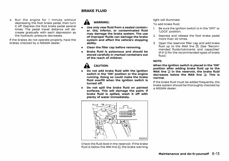
(385,1)
[ Edit: 2020/ 11/ 9 Model: Y62-A ]
4. Run the engine for 1 minute withoutdepressing the foot brake pedal, then turnit off. Depress the foot brake pedal severaltimes. The pedal travel distance will de-crease gradually with each depression asthe hydraulic pressure decreases.
If the brakes do not operate properly, have thebrakes checked by a NISSAN dealer.
GUID-91B9BF58-F889-4E42-B748-7B3FA793135D
WARNING:. Use only new fluid from a sealed contain-
er. Old, inferior, or contaminated fluidmay damage the brake system. The useof improper fluids can damage the brakesystem and affect the vehicle’s stoppingability.
. Clean the filler cap before removing.
. Brake fluid is poisonous and should bestored carefully in marked containers outof the reach of children.
CAUTION:. Do not add brake fluid with the ignition
switch in the “ON” position or the enginerunning. Doing so could make the brakefluid overfill when the ignition switch isturned off.
. Do not spill the brake fluid on paintedsurfaces. This will damage the paint. Ifbrake fluid is spilled, wash it off withplenty of water immediately.
SDI2513
Check the fluid level in the reservoir. If the brakefluid is below the MIN line , the brake warning
light will illuminate.To add brake fluid:1. Be sure the ignition switch is in the “OFF” or
“LOCK” position.2. Depress and release the foot brake pedal
more than 40 times.3. Open the reservoir filler cap and add brake
fluid up to the MAX line . (See “Recom-mended fluids/lubricants and capacities”(P.9-2) for the recommended types of brakefluid.)
NOTE:When the ignition switch is placed in the “ON”position after adding brake fluid up to theMAX line in the reservoir, the brake fluiddecreases below the MAX line . This isnormal.If the brake fluid must be added frequently, thebrake system should be thoroughly checked bya NISSAN dealer.
Maintenance and do-it-yourself 8-13
BRAKE FLUID
Condition: 'Except for China'/'Except for China/
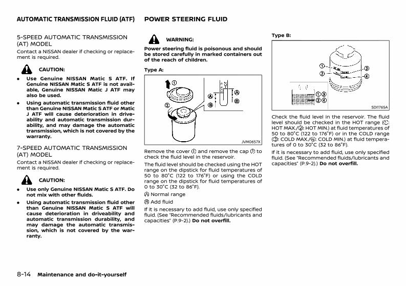
(386,1)
[ Edit: 2020/ 11/ 9 Model: Y62-A ]
8-14 Maintenance and do-it-yourself
GUID-80F68299-9A50-4059-B13A-F3C7214E6AF4
5-SPEED AUTOMATIC TRANSMISSION(AT) MODELGUID-D1C7AAAB-4B68-43CC-A126-792DE0EAF9B9Contact a NISSAN dealer if checking or replace-ment is required.
CAUTION:. Use Genuine NISSAN Matic S ATF. If
Genuine NISSAN Matic S ATF is not avail-able, Genuine NISSAN Matic J ATF mayalso be used.
. Using automatic transmission fluid otherthan Genuine NISSANMatic S ATF or MaticJ ATF will cause deterioration in drive-ability and automatic transmission dur-ability, and may damage the automatictransmission, which is not covered by thewarranty.
7-SPEED AUTOMATIC TRANSMISSION(AT) MODELGUID-E8E93B62-0798-4D05-BB8C-82AC15F03CCBContact a NISSAN dealer if checking or replace-ment is required.
CAUTION:. Use only Genuine NISSAN Matic S ATF. Do
not mix with other fluids.. Using automatic transmission fluid other
than Genuine NISSAN Matic S ATF willcause deterioration in driveability andautomatic transmission durability, andmay damage the automatic transmis-sion, which is not covered by the war-ranty.
GUID-55392F99-C85E-48BA-AE4A-DEE2198E7F8D
WARNING:Power steering fluid is poisonous and shouldbe stored carefully in marked containers outof the reach of children.
Type A:
JVM0657X
Remove the cover and remove the cap tocheck the fluid level in the reservoir.The fluid level should be checked using the HOTrange on the dipstick for fluid temperatures of50 to 80°C (122 to 176°F) or using the COLDrange on the dipstick for fluid temperatures of0 to 30°C (32 to 86°F).
Normal rangeAdd fluid
If it is necessary to add fluid, use only specifiedfluid. (See “Recommended fluids/lubricants andcapacities” (P.9-2).) Do not overfill.
Type B:
SDI1765A
Check the fluid level in the reservoir. The fluidlevel should be checked in the HOT range ( :HOT MAX./ : HOT MIN.) at fluid temperatures of50 to 80°C (122 to 176°F) or in the COLD range( : COLD MAX./ : COLD MIN.) at fluid tempera-tures of 0 to 30°C (32 to 86°F).If it is necessary to add fluid, use only specifiedfluid. (See “Recommended fluids/lubricants andcapacities” (P.9-2).) Do not overfill.
AUTOMATIC TRANSMISSION FLUID (ATF) POWER STEERING FLUID
Condition: 'Except for China'/'Except for China/
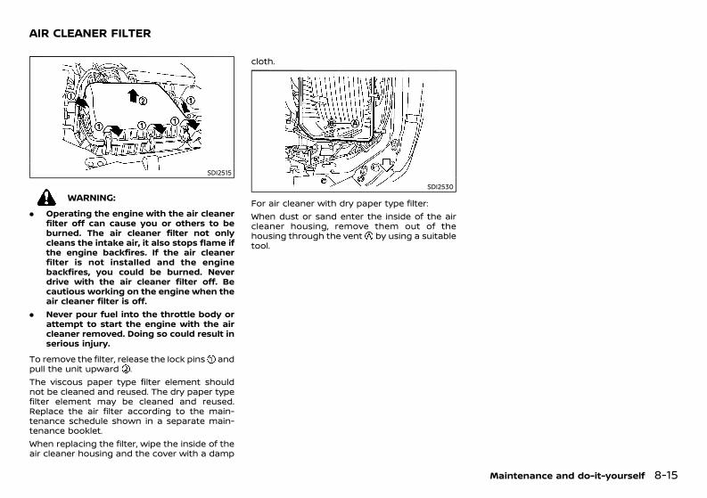
(387,1)
[ Edit: 2020/ 11/ 9 Model: Y62-A ]
GUID-D7B6C71D-56EF-4C2F-B0AC-A8AC7FF0CC57
SDI2515
WARNING:. Operating the engine with the air cleaner
filter off can cause you or others to beburned. The air cleaner filter not onlycleans the intake air, it also stops flame ifthe engine backfires. If the air cleanerfilter is not installed and the enginebackfires, you could be burned. Neverdrive with the air cleaner filter off. Becautious working on the engine when theair cleaner filter is off.
. Never pour fuel into the throttle body orattempt to start the engine with the aircleaner removed. Doing so could result inserious injury.
To remove the filter, release the lock pins andpull the unit upward .The viscous paper type filter element shouldnot be cleaned and reused. The dry paper typefilter element may be cleaned and reused.Replace the air filter according to the main-tenance schedule shown in a separate main-tenance booklet.When replacing the filter, wipe the inside of theair cleaner housing and the cover with a damp
cloth.
SDI2530
For air cleaner with dry paper type filter:When dust or sand enter the inside of the aircleaner housing, remove them out of thehousing through the vent by using a suitabletool.
Maintenance and do-it-yourself 8-15
AIR CLEANER FILTER
Condition: 'Except for China'/'Except for China/
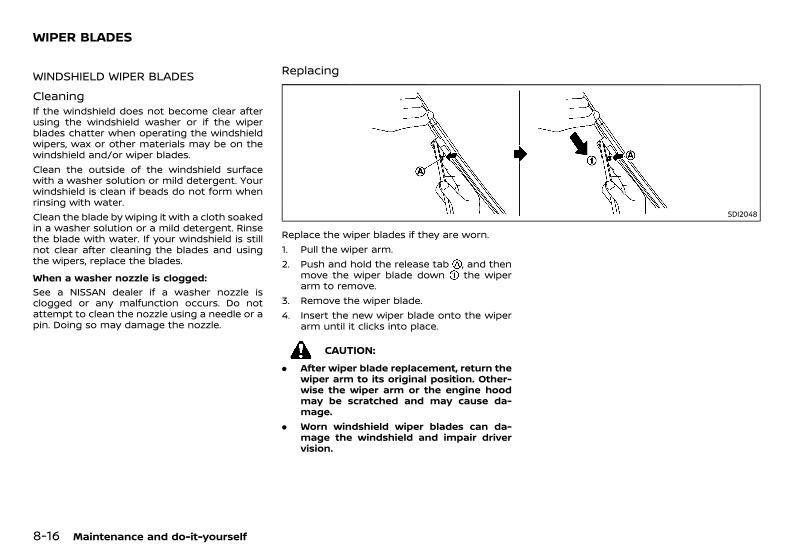
(388,1)
[ Edit: 2020/ 11/ 9 Model: Y62-A ]
8-16 Maintenance and do-it-yourself
GUID-A8F4FAAC-58EC-4B82-B6BF-6D497F20DB48
WINDSHIELD WIPER BLADESGUID-458EB34C-8495-4162-AA3B-37E2DBD524DC
Cleaning GUID-FD840453-EA93-4689-8C87-3D85BC14EC01If the windshield does not become clear afterusing the windshield washer or if the wiperblades chatter when operating the windshieldwipers, wax or other materials may be on thewindshield and/or wiper blades.Clean the outside of the windshield surfacewith a washer solution or mild detergent. Yourwindshield is clean if beads do not form whenrinsing with water.Clean the blade by wiping it with a cloth soakedin a washer solution or a mild detergent. Rinsethe blade with water. If your windshield is stillnot clear after cleaning the blades and usingthe wipers, replace the blades.When a washer nozzle is clogged:
GUID-C7E1EF24-5AAB-4301-95BE-26917EEE45EF
See a NISSAN dealer if a washer nozzle isclogged or any malfunction occurs. Do notattempt to clean the nozzle using a needle or apin. Doing so may damage the nozzle.
ReplacingGUID-2E138D69-409B-4DC9-A988-26639F137809
SDI2048
Replace the wiper blades if they are worn.1. Pull the wiper arm.2. Push and hold the release tab , and then
move the wiper blade down the wiperarm to remove.
3. Remove the wiper blade.4. Insert the new wiper blade onto the wiper
arm until it clicks into place.
CAUTION:. After wiper blade replacement, return the
wiper arm to its original position. Other-wise the wiper arm or the engine hoodmay be scratched and may cause da-mage.
. Worn windshield wiper blades can da-mage the windshield and impair drivervision.
WIPER BLADES
Condition: 'Except for China'/'Except for China/
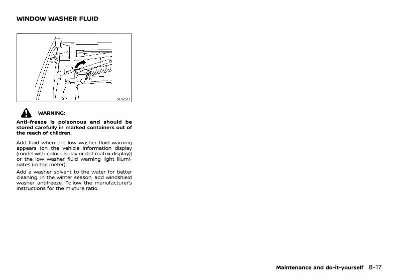
(389,1)
[ Edit: 2020/ 11/ 9 Model: Y62-A ]
GUID-6C0A13AC-963E-4B0B-B543-B6A448FD7E04
SDI2517
WARNING:Anti-freeze is poisonous and should bestored carefully in marked containers out ofthe reach of children.
Add fluid when the low washer fluid warningappears (on the vehicle information display(model with color display or dot matrix display))or the low washer fluid warning light illumi-nates (in the meter).Add a washer solvent to the water for bettercleaning. In the winter season, add windshieldwasher antifreeze. Follow the manufacturer’sinstructions for the mixture ratio.
Maintenance and do-it-yourself 8-17
WINDOW WASHER FLUID
Condition: 'Except for China'/'Except for China/
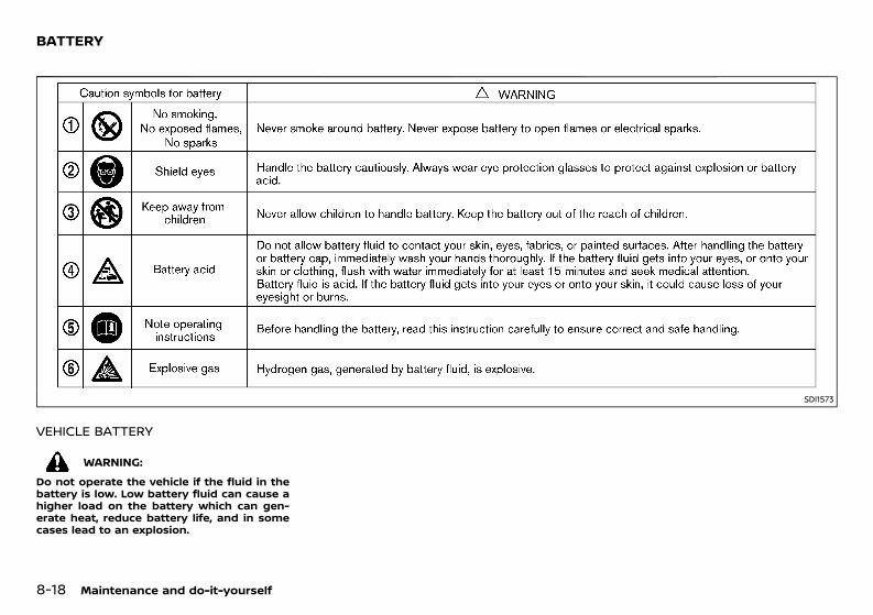
(390,1)
[ Edit: 2020/ 11/ 9 Model: Y62-A ]
8-18 Maintenance and do-it-yourself
GUID-9D14B82B-B588-42BC-9813-56308F54E782
SDI1573
VEHICLE BATTERYGUID-2B8F4112-43D6-4F22-8C12-423FCAA11BF4
WARNING:Do not operate the vehicle if the fluid in thebattery is low. Low battery fluid can cause ahigher load on the battery which can gen-erate heat, reduce battery life, and in somecases lead to an explosion.
BATTERY
Condition: 'Except for China'/'Except for China/
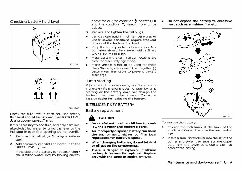
(391,1)
[ Edit: 2020/ 11/ 9 Model: Y62-A ]
Checking battery fluid levelGUID-3D0153AC-ACD1-4AEC-92F6-233F842AF00F
DI0137MD
SDI1480D
Check the fluid level in each cell. The batteryfluid level should be between the UPPER LEVEL
and LOWER LEVEL lines.If it is necessary to add fluid, add only deminer-alized/distilled water to bring the level to theindicator in each filler opening. Do not overfill.1. Remove the cell plugs using a suitable
tool.2. Add demineralized/distilled water up to the
UPPER LEVEL line.If the side of the battery is not clear, checkthe distilled water level by looking directly
above the cell; the condition indicates OKand the condition needs more to beadded.
3. Replace and tighten the cell plugs.. Vehicles operated in high temperatures or
under severe conditions require frequentchecks of the battery fluid level.
. Keep the battery surface clean and dry. Anycorrosion should be cleared with a firmlywrung out moist cloth.
. Make certain the terminal connections areclean and securely tightened.
. If the vehicle is not to be used for morethan 30 days, disconnect the negative (−)battery terminal cable to prevent batterydischarge.
Jump startingGUID-BE336D38-925A-44F9-B19D-862D45C27323If jump starting is necessary, see “Jump start-ing” (P.6-8). If the engine does not start by jumpstarting or the battery does not charge, thebattery may have to be replaced. Contact aNISSAN dealer for replacing the battery.
INTELLIGENT KEY BATTERYGUID-B98195EA-CA41-4494-8F50-3F7C436E3D9D
Battery replacementGUID-E450EFA1-BF09-42BF-8DAC-08685BC684C2
CAUTION:. Be careful not to allow children to swal-
low the battery and removed parts.. An improperly disposed battery can harm
the environment. Always confirm localregulations for battery disposal.
. When changing batteries, do not let dustor oil get on the components.
. There is danger of explosion if lithiumbattery is incorrectly replaced. Replaceonly with the same or equivalent type.
. Do not expose the battery to excessiveheat such as sunshine, fire, etc.
SDI2451
To replace the battery:1. Release the lock knob at the back of the
Intelligent Key and remove the mechanicalkey.
2. Insert a small screwdriver into the slit of thecorner and twist it to separate the upperpart from the lower part. Use a cloth toprotect the casing.
Maintenance and do-it-yourself 8-19
Condition: 'Except for China'/'Except for China/
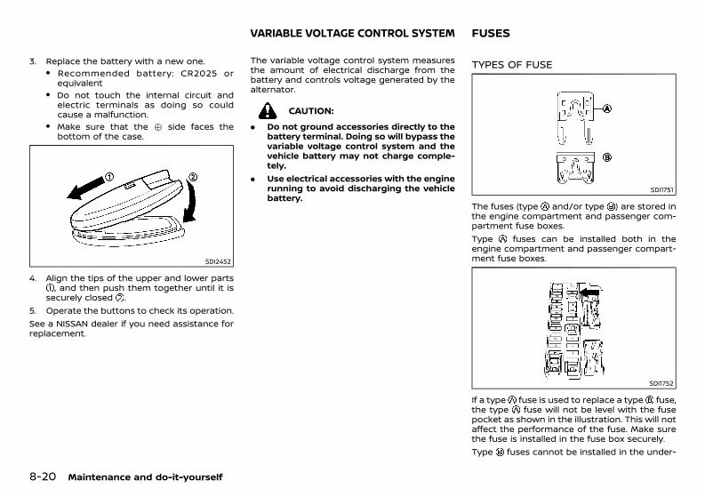
(392,1)
[ Edit: 2020/ 11/ 9 Model: Y62-A ]
8-20 Maintenance and do-it-yourself
3. Replace the battery with a new one.. Recommended battery: CR2025 or
equivalent. Do not touch the internal circuit and
electric terminals as doing so couldcause a malfunction.
. Make sure that the + side faces thebottom of the case.
SDI2452
4. Align the tips of the upper and lower parts, and then push them together until it is
securely closed .5. Operate the buttons to check its operation.See a NISSAN dealer if you need assistance forreplacement.
GUID-F4B3BC6D-C385-4B1C-BB38-0C3317095856The variable voltage control system measuresthe amount of electrical discharge from thebattery and controls voltage generated by thealternator.
CAUTION:. Do not ground accessories directly to the
battery terminal. Doing so will bypass thevariable voltage control system and thevehicle battery may not charge comple-tely.
. Use electrical accessories with the enginerunning to avoid discharging the vehiclebattery.
GUID-A0705B18-2E51-4E9E-8F82-63256F160676
TYPES OF FUSEGUID-B92EDE01-D2B0-4C4D-AE46-CC8348311D2D
SDI1751
The fuses (type and/or type ) are stored inthe engine compartment and passenger com-partment fuse boxes.Type fuses can be installed both in theengine compartment and passenger compart-ment fuse boxes.
SDI1752
If a type fuse is used to replace a type fuse,the type fuse will not be level with the fusepocket as shown in the illustration. This will notaffect the performance of the fuse. Make surethe fuse is installed in the fuse box securely.Type fuses cannot be installed in the under-
VARIABLE VOLTAGE CONTROL SYSTEM FUSES
Condition: 'Except for China'/'Except for China/
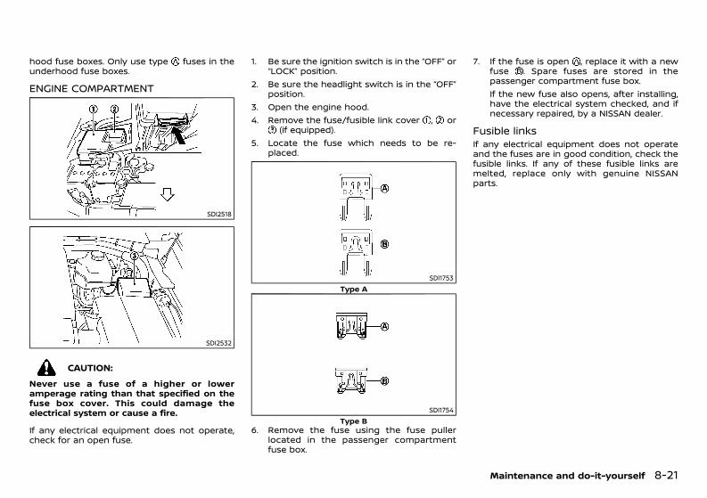
(393,1)
[ Edit: 2020/ 11/ 9 Model: Y62-A ]
hood fuse boxes. Only use type fuses in theunderhood fuse boxes.
ENGINE COMPARTMENTGUID-6BADCD3E-544E-4478-8E05-FDE788FEFDA1
SDI2518
SDI2532
CAUTION:Never use a fuse of a higher or loweramperage rating than that specified on thefuse box cover. This could damage theelectrical system or cause a fire.
If any electrical equipment does not operate,check for an open fuse.
1. Be sure the ignition switch is in the “OFF” or“LOCK” position.
2. Be sure the headlight switch is in the “OFF”position.
3. Open the engine hood.4. Remove the fuse/fusible link cover , or
(if equipped).5. Locate the fuse which needs to be re-
placed.
SDI1753Type A
SDI1754Type B
6. Remove the fuse using the fuse pullerlocated in the passenger compartmentfuse box.
7. If the fuse is open , replace it with a newfuse . Spare fuses are stored in thepassenger compartment fuse box.If the new fuse also opens, after installing,have the electrical system checked, and ifnecessary repaired, by a NISSAN dealer.
Fusible linksGUID-A3F371BD-6E7F-460C-BBE8-B484EB711BAAIf any electrical equipment does not operateand the fuses are in good condition, check thefusible links. If any of these fusible links aremelted, replace only with genuine NISSANparts.
Maintenance and do-it-yourself 8-21
Condition: 'Except for China'/'Except for China/
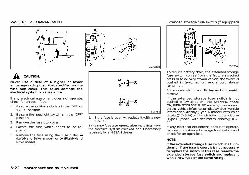
(394,1)
[ Edit: 2020/ 11/ 9 Model: Y62-A ]
8-22 Maintenance and do-it-yourself
PASSENGER COMPARTMENTGUID-9F4C187C-98E0-47F4-AC30-6B2F92D00A5B
JVM0202X
CAUTION:Never use a fuse of a higher or loweramperage rating than that specified on thefuse box cover. This could damage theelectrical system or cause a fire.
If any electrical equipment does not operate,check for an open fuse.1. Be sure the ignition switch is in the “OFF” or
“LOCK” position.2. Be sure the headlight switch is in the “OFF”
position.3. Remove the fuse box cover.4. Locate the fuse which needs to be re-
placed.5. Remove the fuse using the fuse puller
(Left-Hand Drive model) or (Right-HandDrive model).
SDI1754
6. If the fuse is open , replace it with a newfuse .
If the new fuse also opens, after installing, havethe electrical system checked, and if necessaryrepaired, by a NISSAN dealer.
Extended storage fuse switch (if equipped)GUID-E2FC7D10-F4B1-4B15-ABE6-4C8A3FE8A432
SDI2704
To reduce battery drain, the extended storagefuse switch comes from the factory switchedoff. Prior to delivery of your vehicle, the switch ispushed in (switched on) and should alwaysremain on.For models with color display and dot matrixdisplay:If the extended storage fuse switch is notpushed in (switched on), the “SHIPPING MODEON, PUSH STORAGE FUSE” warning may appearon the vehicle information display. See “Vehicleinformation display (Type A (model with colordisplay))” (P.2-26) or “Vehicle information display(Type B (model with dot matrix display))” (P.2-35).If any electrical equipment does not operate,remove the extended storage fuse switch andcheck for an open fuse.
NOTE:If the extended storage fuse switch malfunc-tions or if the fuse is open, it is not necessaryto replace the switch. In this case, remove theextended storage fuse switch and replace itwith a new fuse of the same rating.
Condition: 'Except for China'/'Except for China/
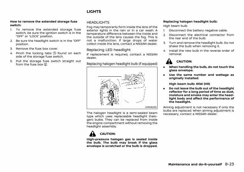
(395,1)
[ Edit: 2020/ 11/ 9 Model: Y62-A ]
How to remove the extended storage fuseswitch:
GUID-C7E1EF24-5AAB-4301-95BE-26917EEE45EF
1. To remove the extended storage fuseswitch, be sure the ignition switch is in the“OFF” or “LOCK” position.
2. Be sure the headlight switch is in the “OFF”position.
3. Remove the fuse box cover.4. Pinch the locking tabs found on each
side of the storage fuse switch.5. Pull the storage fuse switch straight out
from the fuse box .
GUID-E98CB186-43DE-42CE-8114-D9E8A87B06F9
HEADLIGHTSGUID-2C489B1A-2225-4AEE-88D8-6F2B8F7820FEFog may temporarily form inside the lens of theexterior lights in the rain or in a car wash. Atemperature difference between the inside andthe outside of the lens causes the fog. This isnot a malfunction. If large drops of watercollect inside the lens, contact a NISSAN dealer.
Replacing LED headlightGUID-08192005-5F1A-40A5-8F0D-A86C05110EADIf replacement is required, contact a NISSANdealer.
Replacing halogen headlight bulb (if equipped)GUID-40AA33AE-8008-4E82-9C91-ACF0DDE05F02
JVM0823X
The halogen headlight is a semi-sealed beamtype which uses replaceable headlight (halo-gen) bulbs. They can be replaced from insidethe engine compartment without removing theheadlight assembly.
CAUTION:High-pressure halogen gas is sealed insidethe bulb. The bulb may break if the glassenvelope is scratched or the bulb is dropped.
Replacing halogen headlight bulb:GUID-C7E1EF24-5AAB-4301-95BE-26917EEE45EF
High beam bulb1. Disconnect the battery negative cable.2. Disconnect the electrical connector from
the rear end of the bulb.3. Turn and remove the headlight bulb. Do not
shake the bulb when removing it.4. Install the new bulb in the reverse order of
removal.
CAUTION:. When handling the bulb, do not touch the
glass envelope.. Use the same number and wattage as
originally installed:
High beam bulb: 65W (H9). Do not leave the bulb out of the headlight
reflector for a long period of time as dust,moisture and smokemay enter the head-light body and affect the performance ofthe headlight.
Aiming adjustment is not necessary if only thebulbs are replaced. When aiming adjustment isnecessary, contact a NISSAN dealer.
Maintenance and do-it-yourself 8-23
LIGHTS
Condition: 'Except for China'/'Except for China/
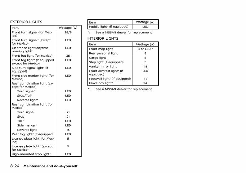
(396,1)
[ Edit: 2020/ 11/ 9 Model: Y62-A ]
8-24 Maintenance and do-it-yourself
EXTERIOR LIGHTSGUID-4A1154A6-C2AF-406B-BB25-CDE38FCA506D
Item Wattage (W)Front turn signal (for Mex-ico)
28/8
Front turn signal* (exceptfor Mexico)
LED
Clearance light/daytimerunning light*
LED
Front fog light (for Mexico) 35Front fog light* (if equippedexcept for Mexico)
LED
Side turn signal light* (ifequipped)
LED
Front side marker light* (forMexico)
LED
Rear combination light (ex-cept for Mexico)
Turn signal* LEDStop/Tail* LEDReverse light* LED
Rear combination light (forMexico)
Turn signal 21Stop 21Tail* LEDSide marker* LEDReverse light 16
Rear fog light* (if equipped) LEDLicense plate light (for Mex-ico)
5
License plate light* (exceptfor Mexico)
5
High-mounted stop light* LED
Item Wattage (W)Puddle light* (if equipped) LED
*: See a NISSAN dealer for replacement.
INTERIOR LIGHTSGUID-41A861EB-5A1B-49A4-870F-83BAD8CB1E27
Item Wattage (W)Front map light 8 or LED *Rear personal light 8Cargo light 8Step light (if equipped) 5Vanity mirror light 1.8Front armrest light* (ifequipped)
LED
Footwell light* (if equipped) 1.4Glove box light* 1.4
*: See a NISSAN dealer for replacement.
Condition: 'Except for China'/'Except for China/
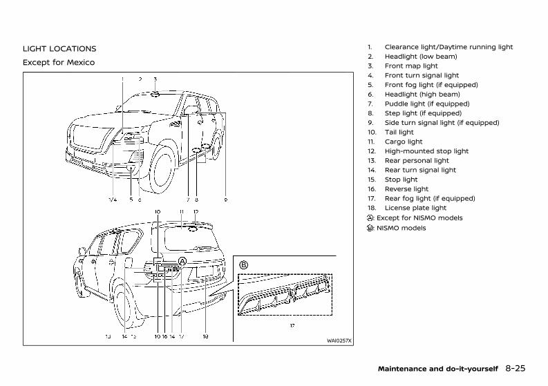
(397,1)
[ Edit: 2020/ 11/ 9 Model: Y62-A ]
LIGHT LOCATIONSGUID-B28D1D3A-648E-458B-876E-D95A5B6821FE
Except for MexicoGUID-081812CC-A643-4293-9092-976E1FC20ED7
WAI0257X
1. Clearance light/Daytime running light2. Headlight (low beam)3. Front map light4. Front turn signal light5. Front fog light (if equipped)6. Headlight (high beam)7. Puddle light (if equipped)8. Step light (if equipped)9. Side turn signal light (if equipped)10. Tail light11. Cargo light12. High-mounted stop light13. Rear personal light14. Rear turn signal light15. Stop light16. Reverse light17. Rear fog light (if equipped)18. License plate light: Except for NISMO models: NISMO models
Maintenance and do-it-yourself 8-25
Condition: 'Except for China'/'Except for China/
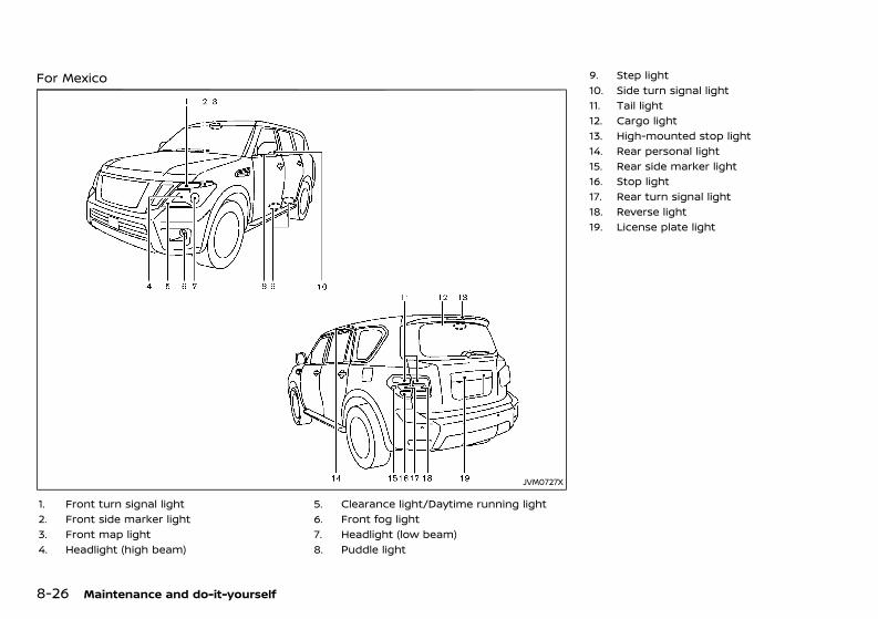
(398,1)
[ Edit: 2020/ 11/ 9 Model: Y62-A ]
8-26 Maintenance and do-it-yourself
For MexicoGUID-9C8D4BEA-D00E-4642-BC99-E4D0AEC92080
JVM0727X
1. Front turn signal light2. Front side marker light3. Front map light4. Headlight (high beam)
5. Clearance light/Daytime running light6. Front fog light7. Headlight (low beam)8. Puddle light
9. Step light10. Side turn signal light11. Tail light12. Cargo light13. High-mounted stop light14. Rear personal light15. Rear side marker light16. Stop light17. Rear turn signal light18. Reverse light19. License plate light
Condition: 'Except for China'/'Except for China/
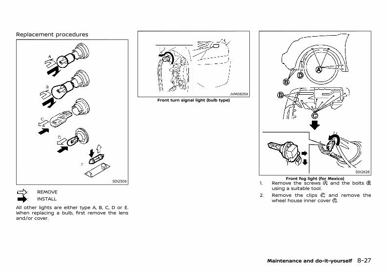
(399,1)
[ Edit: 2020/ 11/ 9 Model: Y62-A ]
Replacement proceduresGUID-75FDF35A-40F7-4669-B637-489609E43D8F
SDI2306
: REMOVE: INSTALL
All other lights are either type A, B, C, D or E.When replacing a bulb, first remove the lensand/or cover.
JVM0825XFront turn signal light (bulb type)
SDI2628Front fog light (for Mexico)
1. Remove the screws and the boltsusing a suitable tool.
2. Remove the clips and remove thewheel house inner cover .
Maintenance and do-it-yourself 8-27
Condition: 'Except for China'/'Except for China/
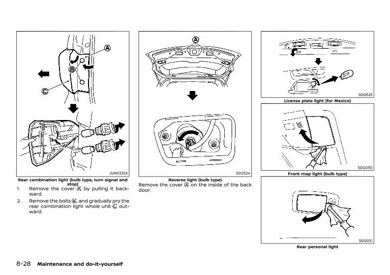
(400,1)
[ Edit: 2020/ 11/ 9 Model: Y62-A ]
8-28 Maintenance and do-it-yourself
JVM0335XRear combination light (bulb type, turn signal and
stop)1. Remove the cover by pulling it back-
ward.2. Remove the bolts , and gradually pry the
rear combination light whole unit out-ward.
SDI2524Reverse light (bulb type)
Remove the cover on the inside of the backdoor.
SDI2525License plate light (for Mexico)
SDI2030Front map light (bulb type)
SDI2031Rear personal light
Condition: 'Except for China'/'Except for China/

(401,1)
[ Edit: 2020/ 11/ 9 Model: Y62-A ]
SDI1729Cargo light
SDI2277Step light
SDI2032Vanity mirror light
GUID-AE69B6E0-40C4-41BD-BBA1-219A674F9C1CIf you have a flat tire, see “Flat tire” (P.6-2).
TIRE PRESSURE MONITORING SYSTEM(TPMS) (if equipped)GUID-C445D033-BFC6-4984-8A7D-5DCAB78EAF3AThe Tire Pressure Monitoring System (TPMS)monitors tire pressure of all tires except thespare. When the low tire pressure warning lightis lit and the check tire pressure warning (ifequipped) appears on the vehicle informationdisplay, one or more of your tires is significantlyunder-inflated.The TPMS will activate only when the vehicle isdriven at speeds above 25 km/h (16 MPH). Also,this system may not detect a sudden drop intire pressure (for example, a flat tire whiledriving).For more details about the TPMS, see “TirePressure Monitoring System (TPMS)” (P.5-6).For additional information, see “Low tire pres-sure warning light” (P.2-20) and NissanConnectOwner’s Manual (if equipped).
TIRE INFLATION PRESSUREGUID-A3EC7C52-D2BB-4E17-9BE3-4E7D46CD905APeriodically check the pressure of the tires,including the spare. An incorrect tire pressuremay adversely affect tire life and vehicle hand-ling. The tire pressure should be checked whentires are COLD. Tires are considered COLD afterthe vehicle has been parked for 3 or morehours, or driven less than 1.6 km (1 mile). COLDtire pressures are shown on the tire placard.Insufficient pressure can lead to an overheat-ing of the tire and subsequent internal damage.At high speeds, this could result in treadseparation and even bursting of the tire.
TPMS with tire inflation indicator (if equipped)GUID-A589587B-693E-4B02-8EB3-F079ECC5DFABTPMS also provides visual and audible signalsoutside the vehicle for inflating the tires to therecommended COLD tire pressure. (See “TirePressure Monitoring System (TPMS)” (P.5-6)about the TPMS with tire inflation indicator.)
TYPES OF TIRESGUID-6795CDAA-3948-4877-927B-12072A6E5202
CAUTION:When changing or replacing tires, be sure allfour tires are of the same type (that is,summer, all season or snow) and construc-tion. A NISSAN dealer may be able to help youwith information about tire type, size, speedrating and availability.
Replacement tires may have a lower speedrating than the factory equipped tires, and theymay not match the potential maximum vehiclespeed. Never exceed the maximum speedrating of the tire.
All season tiresGUID-E51B944F-1499-4173-868F-7269F630E6B0NISSAN specifies all season tires on somemodels to provide good performance all year,including snowy and icy road conditions. Allseason tires are identified by ALL SEASON and/or M&S on the tire sidewall. Snow tires havebetter snow traction than all season tires andmay be more appropriate in some areas.
Maintenance and do-it-yourself 8-29
TIRES AND WHEELS
Condition: 'Except for China'/'Except for China/
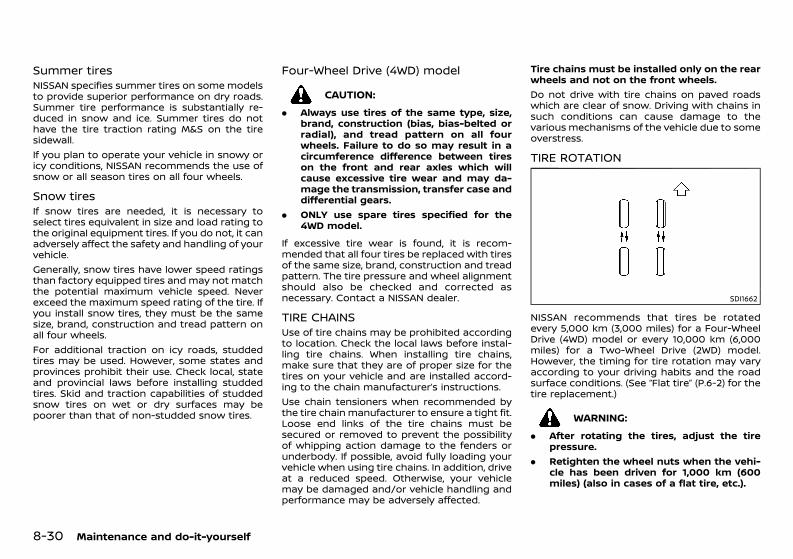
(402,1)
[ Edit: 2020/ 11/ 9 Model: Y62-A ]
8-30 Maintenance and do-it-yourself
Summer tiresGUID-72AAA2F0-E863-456C-8C4C-6183FCCA6F67NISSAN specifies summer tires on some modelsto provide superior performance on dry roads.Summer tire performance is substantially re-duced in snow and ice. Summer tires do nothave the tire traction rating M&S on the tiresidewall.If you plan to operate your vehicle in snowy oricy conditions, NISSAN recommends the use ofsnow or all season tires on all four wheels.
Snow tires GUID-57CB87E4-FACE-41F4-9BDB-65A1B2F5CFC5If snow tires are needed, it is necessary toselect tires equivalent in size and load rating tothe original equipment tires. If you do not, it canadversely affect the safety and handling of yourvehicle.Generally, snow tires have lower speed ratingsthan factory equipped tires and may not matchthe potential maximum vehicle speed. Neverexceed the maximum speed rating of the tire. Ifyou install snow tires, they must be the samesize, brand, construction and tread pattern onall four wheels.For additional traction on icy roads, studdedtires may be used. However, some states andprovinces prohibit their use. Check local, stateand provincial laws before installing studdedtires. Skid and traction capabilities of studdedsnow tires on wet or dry surfaces may bepoorer than that of non-studded snow tires.
Four-Wheel Drive (4WD) modelGUID-5A000B3B-9C45-450E-B069-99CE03BFEA0C
CAUTION:. Always use tires of the same type, size,
brand, construction (bias, bias-belted orradial), and tread pattern on all fourwheels. Failure to do so may result in acircumference difference between tireson the front and rear axles which willcause excessive tire wear and may da-mage the transmission, transfer case anddifferential gears.
. ONLY use spare tires specified for the4WD model.
If excessive tire wear is found, it is recom-mended that all four tires be replaced with tiresof the same size, brand, construction and treadpattern. The tire pressure and wheel alignmentshould also be checked and corrected asnecessary. Contact a NISSAN dealer.
TIRE CHAINSGUID-F2CF20EA-51D4-4282-AF61-8B4AA00858B3Use of tire chains may be prohibited accordingto location. Check the local laws before instal-ling tire chains. When installing tire chains,make sure that they are of proper size for thetires on your vehicle and are installed accord-ing to the chain manufacturer’s instructions.Use chain tensioners when recommended bythe tire chain manufacturer to ensure a tight fit.Loose end links of the tire chains must besecured or removed to prevent the possibilityof whipping action damage to the fenders orunderbody. If possible, avoid fully loading yourvehicle when using tire chains. In addition, driveat a reduced speed. Otherwise, your vehiclemay be damaged and/or vehicle handling andperformance may be adversely affected.
Tire chains must be installed only on the rearwheels and not on the front wheels.Do not drive with tire chains on paved roadswhich are clear of snow. Driving with chains insuch conditions can cause damage to thevarious mechanisms of the vehicle due to someoverstress.
TIRE ROTATIONGUID-ACE755DD-E4BB-46A4-9F62-496D13BFF28A
SDI1662
NISSAN recommends that tires be rotatedevery 5,000 km (3,000 miles) for a Four-WheelDrive (4WD) model or every 10,000 km (6,000miles) for a Two-Wheel Drive (2WD) model.However, the timing for tire rotation may varyaccording to your driving habits and the roadsurface conditions. (See “Flat tire” (P.6-2) for thetire replacement.)
WARNING:. After rotating the tires, adjust the tire
pressure.. Retighten the wheel nuts when the vehi-
cle has been driven for 1,000 km (600miles) (also in cases of a flat tire, etc.).
Condition: 'Except for China'/'Except for China/
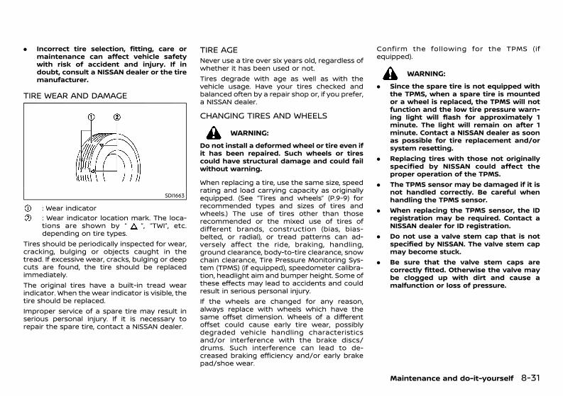
(403,1)
[ Edit: 2020/ 11/ 9 Model: Y62-A ]
. Incorrect tire selection, fitting, care ormaintenance can affect vehicle safetywith risk of accident and injury. If indoubt, consult a NISSAN dealer or the tiremanufacturer.
TIRE WEAR AND DAMAGEGUID-30CC6DEB-1C96-46A9-841D-67EBB9AFB121
SDI1663
: Wear indicator: Wear indicator location mark. The loca-tions are shown by “ ”, “TWI”, etc.depending on tire types.
Tires should be periodically inspected for wear,cracking, bulging or objects caught in thetread. If excessive wear, cracks, bulging or deepcuts are found, the tire should be replacedimmediately.The original tires have a built-in tread wearindicator. When the wear indicator is visible, thetire should be replaced.Improper service of a spare tire may result inserious personal injury. If it is necessary torepair the spare tire, contact a NISSAN dealer.
TIRE AGE GUID-228B8BE1-7F61-4781-9F67-E03ABE1C166FNever use a tire over six years old, regardless ofwhether it has been used or not.Tires degrade with age as well as with thevehicle usage. Have your tires checked andbalanced often by a repair shop or, if you prefer,a NISSAN dealer.
CHANGING TIRES AND WHEELSGUID-AE234277-C1BE-46F1-8E0D-ED221CBB7A84
WARNING:Do not install a deformed wheel or tire even ifit has been repaired. Such wheels or tirescould have structural damage and could failwithout warning.
When replacing a tire, use the same size, speedrating and load carrying capacity as originallyequipped. (See “Tires and wheels” (P.9-9) forrecommended types and sizes of tires andwheels.) The use of tires other than thoserecommended or the mixed use of tires ofdifferent brands, construction (bias, bias-belted, or radial), or tread patterns can ad-versely affect the ride, braking, handling,ground clearance, body-to-tire clearance, snowchain clearance, Tire Pressure Monitoring Sys-tem (TPMS) (if equipped), speedometer calibra-tion, headlight aim and bumper height. Some ofthese effects may lead to accidents and couldresult in serious personal injury.If the wheels are changed for any reason,always replace with wheels which have thesame offset dimension. Wheels of a differentoffset could cause early tire wear, possiblydegraded vehicle handling characteristicsand/or interference with the brake discs/drums. Such interference can lead to de-creased braking efficiency and/or early brakepad/shoe wear.
Confirm the following for the TPMS (ifequipped).
WARNING:. Since the spare tire is not equipped with
the TPMS, when a spare tire is mountedor a wheel is replaced, the TPMS will notfunction and the low tire pressure warn-ing light will flash for approximately 1minute. The light will remain on after 1minute. Contact a NISSAN dealer as soonas possible for tire replacement and/orsystem resetting.
. Replacing tires with those not originallyspecified by NISSAN could affect theproper operation of the TPMS.
. The TPMS sensor may be damaged if it isnot handled correctly. Be careful whenhandling the TPMS sensor.
. When replacing the TPMS sensor, the IDregistration may be required. Contact aNISSAN dealer for ID registration.
. Do not use a valve stem cap that is notspecified by NISSAN. The valve stem capmay become stuck.
. Be sure that the valve stem caps arecorrectly fitted. Otherwise the valve maybe clogged up with dirt and cause amalfunction or loss of pressure.
Maintenance and do-it-yourself 8-31
Condition: 'Except for China'/'Except for China/
(404,1)
[ Edit: 2020/ 11/ 9 Model: Y62-A ]
8-32 Maintenance and do-it-yourself
WHEEL BALANCEGUID-0201BE0C-9A67-422C-A87B-6E890267D904Unbalanced wheels may affect vehicle handlingand tire life. Even with regular use, wheels canget out of balance. Therefore, they should bebalanced as required.
SPARE TIRE GUID-43FF3387-E41A-42CF-98C6-2DD7A6F8FF98The spare tire supplied with your vehicle variesdepending on the model. See “Tires andwheels” (P.9-9) for applicable spare tire.
Conventional spare tireGUID-CC448C03-D06A-48F2-B2C3-60DE7FF91D4CA standard tire (the same size as the originaltire) is supplied with your vehicle.
Condition: 'Except for China'/'Except for China/
(405,1)
[ Edit: 2020/ 11/ 9 Model: Y62-A ]
9 Technical information
Recommended fluids/lubricants and capacities .................... 9-2Fuel information ......................................................................................... 9-4Recommended SAE viscosity number ..................................... 9-5Air conditioner system refrigerant and lubricant ........... 9-6
Engine ........................................................................................................................ 9-7Technical characteristics (for Gulf Standard models) ......... 9-8Tires and wheels ............................................................................................... 9-9
Except for Mexico ...................................................................................... 9-9For Mexico ................................................................................................... 9-10
Dimensions ......................................................................................................... 9-10When travelling or registering in another country ............. 9-11Vehicle identification ................................................................................... 9-11
Vehicle identification label (if equipped) .............................. 9-11Vehicle Identification Number (VIN) plate(if equipped) ................................................................................................ 9-11Vehicle Identification Number (VIN) ......................................... 9-11Engine serial number .......................................................................... 9-12Certification label (if equipped) ................................................... 9-12
Tire placard .............................................................................................. 9-12Air conditioner specification label ......................................... 9-12
License plate installation (for city type model) .................... 9-13Installing front license plate (for Mexico) .................................. 9-13Uniform tire quality grading (if equipped) ................................ 9-13
Treadwear ................................................................................................. 9-13Traction AA, A, B and C .................................................................. 9-13Temperature A, B and C ................................................................ 9-14
Installation of an RF-transmitter ...................................................... 9-14Radio approval number and information ................................. 9-14
For the United Arab Emirates ................................................... 9-14For Jordan ................................................................................................. 9-17For Pakistan ............................................................................................. 9-19For Mexico ................................................................................................. 9-19For South Africa ................................................................................... 9-20For Oman ................................................................................................... 9-21For Australia and New Zealand ............................................... 9-21For Bahrain ............................................................................................... 9-21
Condition: 'Except for China'/'Except for China/
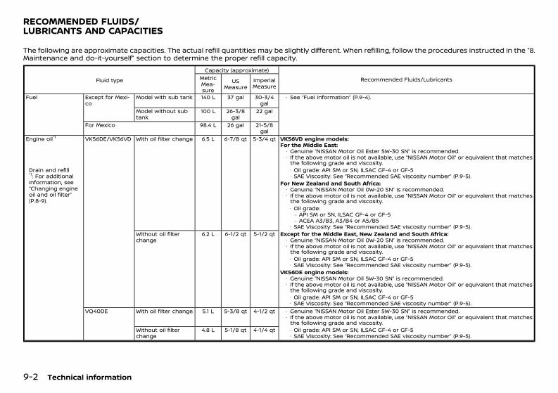
(406,1)
[ Edit: 2020/ 11/ 9 Model: Y62-A ]
9-2 Technical information
GUID-CEAE5A50-CAB8-4BA6-8D4B-FCC3B1B24D70The following are approximate capacities. The actual refill quantities may be slightly different. When refilling, follow the procedures instructed in the “8.Maintenance and do-it-yourself” section to determine the proper refill capacity.
Fluid type
Capacity (approximate)Recommended Fluids/LubricantsMetric
Mea-sure
USMeasure
ImperialMeasure
Fuel Except for Mexi-co
Model with sub tank 140 L 37 gal 30-3/4gal
· See “Fuel information” (P.9-4).
Model without subtank
100 L 26-3/8gal
22 gal
For Mexico 98.4 L 26 gal 21-5/8gal
Engine oil*1 VK56DE/VK56VD With oil filter change 6.5 L 6-7/8 qt 5-3/4 qt VK56VD engine models:For the Middle East:· Genuine “NISSAN Motor Oil Ester 5W-30 SN” is recommended.· If the above motor oil is not available, use “NISSAN Motor Oil” or equivalent that matchesthe following grade and viscosity.
Drain and refill*1: For additionalinformation, see“Changing engineoil and oil filter”(P.8-9).
· Oil grade: API SM or SN, ILSAC GF-4 or GF-5· SAE Viscosity: See “Recommended SAE viscosity number” (P.9-5).
For New Zealand and South Africa:· Genuine “NISSAN Motor Oil 0W-20 SN” is recommended.· If the above motor oil is not available, use “NISSAN Motor Oil” or equivalent that matchesthe following grade and viscosity.· Oil grade:– API SM or SN, ILSAC GF-4 or GF-5– ACEA A3/B3, A3/B4 or A5/B5
· SAE Viscosity: See “Recommended SAE viscosity number” (P.9-5).Without oil filterchange
6.2 L 6-1/2 qt 5-1/2 qt Except for the Middle East, New Zealand and South Africa:· Genuine “NISSAN Motor Oil 0W-20 SN” is recommended.· If the above motor oil is not available, use “NISSAN Motor Oil” or equivalent that matchesthe following grade and viscosity.· Oil grade: API SM or SN, ILSAC GF-4 or GF-5· SAE Viscosity: See “Recommended SAE viscosity number” (P.9-5).
VK56DE engine models:· Genuine “NISSAN Motor Oil 5W-30 SN” is recommended.· If the above motor oil is not available, use “NISSAN Motor Oil” or equivalent that matchesthe following grade and viscosity.· Oil grade: API SM or SN, ILSAC GF-4 or GF-5· SAE Viscosity: See “Recommended SAE viscosity number” (P.9-5).
VQ40DE With oil filter change 5.1 L 5-3/8 qt 4-1/2 qt · Genuine “NISSAN Motor Oil Ester 5W-30 SN” is recommended.· If the above motor oil is not available, use “NISSAN Motor Oil” or equivalent that matchesthe following grade and viscosity.
Without oil filterchange
4.8 L 5-1/8 qt 4-1/4 qt · Oil grade: API SM or SN, ILSAC GF-4 or GF-5· SAE Viscosity: See “Recommended SAE viscosity number” (P.9-5).
RECOMMENDED FLUIDS/LUBRICANTS AND CAPACITIES
Condition: 'Except for China'/'Except for China/
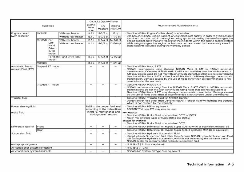
(407,1)
[ Edit: 2020/ 11/ 9 Model: Y62-A ]
Fluid type
Capacity (approximate)Recommended Fluids/LubricantsMetric
Mea-sure
USMeasure
ImperialMeasure
Engine coolant(with reservoir)
VK56DE With rear heater 14.8 L 15-5/8 qt 13 qt · Genuine NISSAN Engine Coolant (blue) or equivalent· Use Genuine NISSAN Engine Coolant, or equivalent in its quality, in order to avoid possiblealuminum corrosion within the engine cooling system caused by the use of non-genuineengine coolant. Note that any repairs for the incidents within the engine cooling systemwhile using non-genuine engine coolant may not be covered by the warranty even ifsuch incidents occurred during the warranty period.
Without rear heater 13.1 L 13-7/8 qt 11-1/2 qtVK56VD For
Left-HandDrive(LHD)model
With rear heater 16.3 L 17-1/4 qt 14-3/8 qtWithout rear heater 14.6 L 15-3/8 qt 12-7/8 qt
For Right-Hand Drive (RHD)model
16.5 L 17-1/2 qt 14-1/2 qt
VQ40DE 13.4 L 14-1/8 qt 11-3/4 qtAutomatic Trans-mission Fluid (ATF)
5-speed AT model — — — · Genuine NISSAN Matic S ATF· NISSAN recommends using Genuine NISSAN Matic S ATF in NISSAN automatictransmissions. If Genuine NISSAN Matic S ATF is not available, Genuine NISSAN Matic JATF may also be used. Do not mix with other fluids. Using fluids that are not equivalent toGenuine NISSAN Matic S ATF or Genuine NISSAN Matic J ATF may damage the automatictransmission. Damage caused by the use of fluids other than as recommended is notcovered under the warranty.
7-speed AT model — — — · Genuine NISSAN Matic S ATF· NISSAN recommends using Genuine NISSAN Matic S ATF ONLY in NISSAN automatictransmissions. Do not mix with other fluids. Using fluids that are not equivalent toGenuine NISSAN Matic S ATF may damage the automatic transmission. Damage causedby the use of fluids other than as recommended is not covered under the warranty.
Transfer fluid — — — · Genuine NISSAN Transfer Fluid for ATX90A transfer· Using transfer fluid other than Genuine NISSAN Transfer Fluid will damage the transfer,which is not covered by the warranty.
Power steering fluid Refill to the proper fluid levelaccording to the instructionsin the “8. Maintenance and
do-it-yourself” section.
· Genuine NISSAN PSF or equivalent· DEXRONTM VI type ATF may also be used.
Brake fluid For Mexico:· Genuine NISSAN Brake Fluid, or equivalent DOT3 or DOT4· Never mix different types of fluids (DOT3 and DOT4).
Except for Mexico:· Genuine NISSAN Brake Fluid, or equivalent DOT3
Differential gear oil Front — — — · Genuine NISSAN Differential Oil Hypoid Super GL-5 80W-90 or equivalent (mineral oil)Rear — — — · Genuine NISSAN Differential Oil Hypoid Super-S GL-5 synthetic 75W-90 or equivalent
Suspension fluid — — — · Genuine NISSAN Hydraulic Suspension Fluid· Using Hydraulic Suspension fluid other than Genuine NISSAN Hydraulic Suspension Fluidwill damage the Hydraulic Suspension, which is not covered by the warranty. See aNISSAN dealer for recommended hydraulic suspension fluid.
Multi-purpose grease — — — · NLGI No. 2 (Lithium soap base)Air conditioner system refrigerant — — — · HFC-134a (R-134a)Air conditioner system lubricants — — — · NISSAN A/C System Oil Type S or equivalent
Technical information 9-3
Condition: 'Except for China'/'Except for China/
(408,1)
[ Edit: 2020/ 11/ 9 Model: Y62-A ]
9-4 Technical information
FUEL INFORMATIONGUID-98205A26-3AD9-4B1F-8857-A48DC4601D72
Model with three-way catalystGUID-97A49324-500D-48C4-ABCC-B5F9B3159362
CAUTION:Do not use leaded gasoline. Using leadedgasoline will damage the three-way catalyst.
VK56DE engine model:GUID-C7E1EF24-5AAB-4301-95BE-26917EEE45EF
Use UNLEADED REGULAR gasoline with anoctane rating of at least 91 (RON).VK56VD engine model (except for Mexico):
GUID-C7E1EF24-5AAB-4301-95BE-26917EEE45EF
Except for South Africa: Use UNLEADED PRE-MIUM gasoline with an octane rating of at least95 to 98 (RON).For South Africa: Use UNLEADED PREMIUMgasoline with an octane rating of at least 95(RON).If unleaded premium gasoline is not used,UNLEADED REGULAR gasoline with an octanerating of at least 91 (RON) may be used atslightly reduced performance. However, formaximum vehicle performance and the bestdriveability, the use of unleaded premiumgasoline is recommended.VK56VD engine model (for Mexico):
GUID-C7E1EF24-5AAB-4301-95BE-26917EEE45EF
Use UNLEADED REGULAR gasoline with anoctane rating of at least 87 AKI (Anti-KnockIndex) number.VQ40DE engine model (except for Algeria,Turkmenistan and Iraq):
GUID-C7E1EF24-5AAB-4301-95BE-26917EEE45EF
Use UNLEADED REGULAR gasoline with anoctane rating of at least 91 (RON).
VQ40DE engine model (for Algeria, Turkme-nistan and Iraq):
GUID-C7E1EF24-5AAB-4301-95BE-26917EEE45EF
Use UNLEADED PREMIUM gasoline with anoctane rating of at least 91 (RON).
Condition: 'Except for China'/'Except for China/
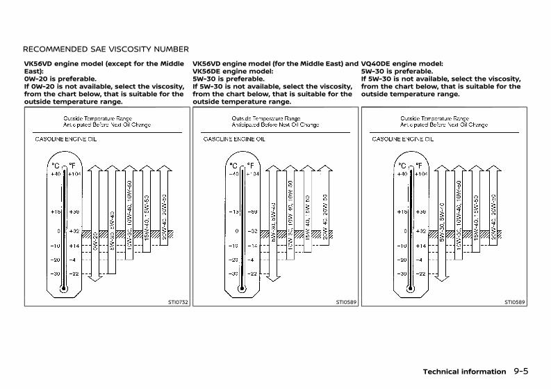
(409,1)
[ Edit: 2020/ 11/ 9 Model: Y62-A ]
RECOMMENDED SAE VISCOSITY NUMBERGUID-881EDE31-CA7D-44C7-9994-FF3EC887607B
VK56VD engine model (except for the MiddleEast):0W-20 is preferable.If 0W-20 is not available, select the viscosity,from the chart below, that is suitable for theoutside temperature range.
VK56VD engine model (for the Middle East) andVK56DE engine model:5W-30 is preferable.If 5W-30 is not available, select the viscosity,from the chart below, that is suitable for theoutside temperature range.
VQ40DE engine model:5W-30 is preferable.If 5W-30 is not available, select the viscosity,from the chart below, that is suitable for theoutside temperature range.
STI0732 STI0589 STI0589
Technical information 9-5
Condition: 'Except for China'/'Except for China/
(410,1)
[ Edit: 2020/ 11/ 9 Model: Y62-A ]
9-6 Technical information
AIR CONDITIONER SYSTEM REFRIGER-ANT AND LUBRICANTGUID-C73B3F0F-D600-4BFE-8BA0-FCFEAD5D4992The air conditioner system of your vehicle mustbe charged with the refrigerant HFC-134a(R134a) and the lubricant NISSAN A/C SystemOil Type S or equivalents.
CAUTION:Use of any other refrigerants or lubricantswill cause severe damage, and you may needto replace your vehicle’s entire air condi-tioner system.
The release of refrigerants into the atmosphereis prohibited in many countries and regions.The refrigerant HFC-134a (R-134a) in yourvehicle will not harm the Earth’s ozone layer.However, it may contribute in a small part tothe global warming effect. NISSAN recom-mends that the refrigerant be appropriatelyrecovered and recycled. Contact a NISSANdealer when servicing the air conditionersystem.
Condition: 'Except for China'/'Except for China/
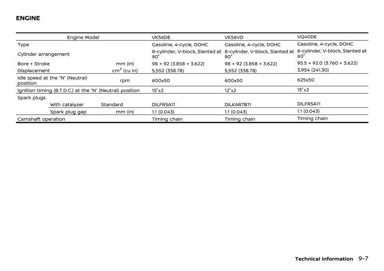
(411,1)
[ Edit: 2020/ 11/ 9 Model: Y62-A ]
GUID-0DBB8908-01C5-4F91-8E53-8E62D232FE7C
Engine Model VK56DE VK56VD VQ40DEType Gasoline, 4-cycle, DOHC Gasoline, 4-cycle, DOHC Gasoline, 4-cycle, DOHC
Cylinder arrangement 8-cylinder, V-block, Slanted at90°
8-cylinder, V-block, Slanted at90°
6-cylinder, V-block, Slanted at60°
Bore × Stroke mm (in) 98 × 92 (3.858 × 3.622) 98 × 92 (3.858 × 3.622) 95.5 × 92.0 (3.760 × 3.622)Displacement cm3 (cu in) 5,552 (338.78) 5,552 (338.78) 3,954 (241.30)Idle speed at the “N” (Neutral)position rpm 600±50 600±50 625±50
Ignition timing (B.T.D.C.) at the “N” (Neutral) position 15°±2 12°±2 15°±2Spark plugs
With catalyzer Standard DILFR5A11 DILKAR7B11 DILFR5A11Spark plug gap mm (in) 1.1 (0.043) 1.1 (0.043) 1.1 (0.043)
Camshaft operation Timing chain Timing chain Timing chain
Technical information 9-7
ENGINE
Condition: 'Except for China'/'Except for China/
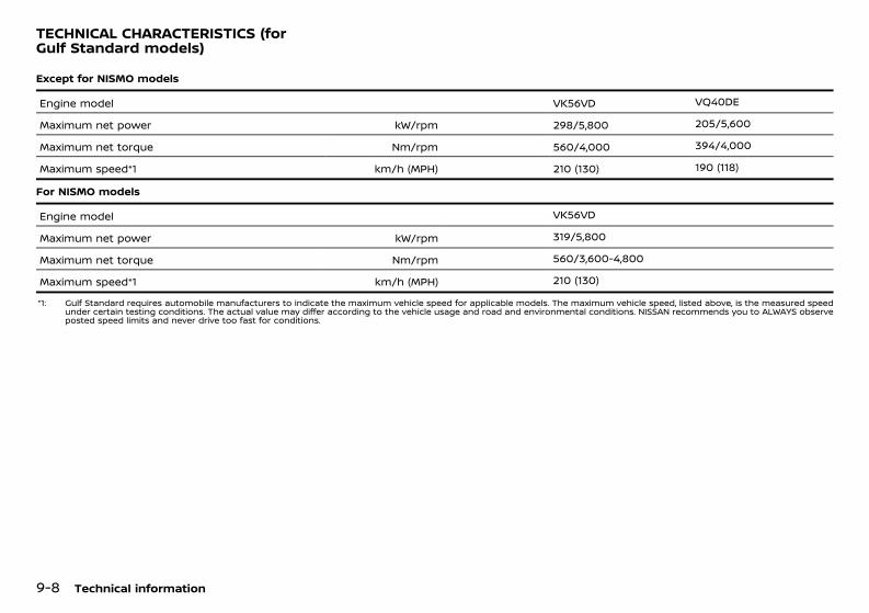
(412,1)
[ Edit: 2020/ 11/ 9 Model: Y62-A ]
9-8 Technical information
GUID-9E8E9491-7EF3-438A-AE25-071DC442F6BFExcept for NISMO models
Engine model VK56VD VQ40DE
Maximum net power kW/rpm 298/5,800 205/5,600
Maximum net torque Nm/rpm 560/4,000 394/4,000
Maximum speed*1 km/h (MPH) 210 (130) 190 (118)
For NISMO models
Engine model VK56VD
Maximum net power kW/rpm 319/5,800
Maximum net torque Nm/rpm 560/3,600-4,800
Maximum speed*1 km/h (MPH) 210 (130)
*1: Gulf Standard requires automobile manufacturers to indicate the maximum vehicle speed for applicable models. The maximum vehicle speed, listed above, is the measured speedunder certain testing conditions. The actual value may differ according to the vehicle usage and road and environmental conditions. NISSAN recommends you to ALWAYS observeposted speed limits and never drive too fast for conditions.
TECHNICAL CHARACTERISTICS (forGulf Standard models)
Condition: 'Except for China'/'Except for China/
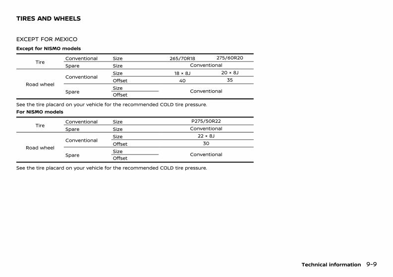
(413,1)
[ Edit: 2020/ 11/ 9 Model: Y62-A ]
GUID-32D91669-C2F5-4E0E-BBEA-29474C1F1CB8
EXCEPT FOR MEXICOGUID-0FFD7B65-66DC-4591-B2AC-F9729D24455E
Except for NISMO models
TireConventional Size 265/70R18 275/60R20Spare Size Conventional
Road wheelConventional
Size 18 × 8J 20 × 8JOffset 40 35
SpareSize ConventionalOffset
See the tire placard on your vehicle for the recommended COLD tire pressure.For NISMO models
TireConventional Size P275/50R22Spare Size Conventional
Road wheelConventional
Size 22 × 8JOffset 30
SpareSize ConventionalOffset
See the tire placard on your vehicle for the recommended COLD tire pressure.
Technical information 9-9
TIRES AND WHEELS
Condition: 'Except for China'/'Except for China/
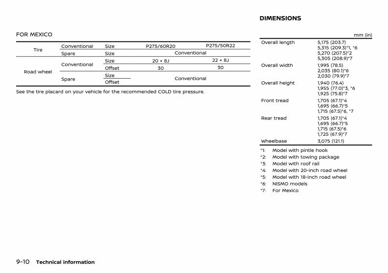
(414,1)
[ Edit: 2020/ 11/ 9 Model: Y62-A ]
9-10 Technical information
FOR MEXICOGUID-66AA93C4-BA6A-4E28-B49E-8CB313E6C192
TireConventional Size P275/60R20 P275/50R22Spare Size Conventional
Road wheelConventional
Size 20 × 8J 22 × 8JOffset 30 30
SpareSize ConventionalOffset
See the tire placard on your vehicle for the recommended COLD tire pressure.
GUID-B71682FB-3F2F-4D32-B390-D729996F92A4mm (in)
Overall length 5,175 (203.7)5,315 (209.3)*1, *65,270 (207.5)*25,305 (208.9)*7
Overall width 1,995 (78.5)2,035 (80.1)*62,030 (79.9)*7
Overall height 1,940 (76.4)1,955 (77.0)*3, *61,925 (75.8)*7
Front tread 1,705 (67.1)*41,695 (66.7)*51,715 (67.5)*6, *7
Rear tread 1,705 (67.1)*41,695 (66.7)*51,715 (67.5)*61,725 (67.9)*7
Wheelbase 3,075 (121.1)
*1: Model with pintle hook*2: Model with towing package*3: Model with roof rail*4: Model with 20-inch road wheel*5: Model with 18-inch road wheel*6: NISMO models*7: For Mexico
DIMENSIONS
Condition: 'Except for China'/'Except for China/
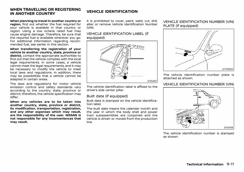
(415,1)
[ Edit: 2020/ 11/ 9 Model: Y62-A ]
GUID-5206BEA1-7A12-43CB-BA6A-7A72093E525EWhen planning to travel in another country orregion, find out whether the fuel required foryour vehicle is available in that country orregion. Using a low octane rated fuel maycause engine damage. Therefore, be sure thatthe required fuel is available wherever you go.For additional information regarding recom-mended fuel, see earlier in this section.When transferring the registration of yourvehicle to another country, state, province ordistrict, contact the appropriate authorities tofind out that the vehicle complies with the locallegal requirements. In some cases, a vehiclecannot meet the legal requirements, and it maybe necessary to modify the vehicle to meetlocal laws and regulations. In addition, theremay be possibilities that a vehicle cannot beadapted in certain areas.The laws and regulations for motor vehicleemission control and safety standards varyaccording to the country, state, province ordistrict; therefore, the vehicle specification maydiffer.When any vehicles are to be taken intoanother country, state, province or district,its modification, transportation, registration,and any other expenses which may result,are the responsibility of the user. NISSAN isnot responsible for any inconveniences thatmay result.
GUID-78A4AF94-13F4-40B4-9A89-655F96477517It is prohibited to cover, paint, weld, cut, drill,alter or remove Vehicle Identification Number(VIN).
VEHICLE IDENTIFICATION LABEL (ifequipped) GUID-A0929215-3C8B-4CC6-8015-188DAF5B2B51
STI0493
The vehicle identification label is affixed to thedriver’s side center pillar.
Built date (if equipped)GUID-EE489A82-FB3A-4FBE-98ED-AE515986E32CBuilt date is stamped on the vehicle identifica-tion label.The built date means the calendar month andthe year in which the body shell and powertrain subassemblies are conjoined and thevehicle is driven or moved from the productionline.
VEHICLE IDENTIFICATION NUMBER (VIN)PLATE (if equipped)GUID-BF96A2E2-E7FF-4164-845A-D510451CBE5E
JVT0352X
The vehicle identification number plate isattached as shown.
VEHICLE IDENTIFICATION NUMBER (VIN)GUID-991241BF-064B-465E-9D48-72665A1106C1
STI0708
The vehicle identification number is stampedas shown.
Technical information 9-11
WHEN TRAVELLING OR REGISTERINGIN ANOTHER COUNTRY VEHICLE IDENTIFICATION
Condition: 'Except for China'/'Except for China/
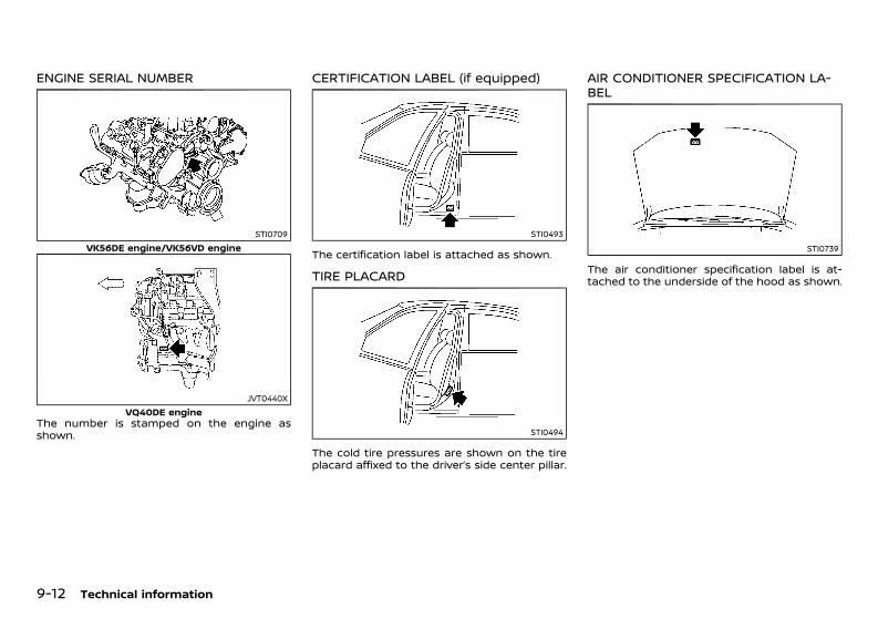
(416,1)
[ Edit: 2020/ 11/ 9 Model: Y62-A ]
9-12 Technical information
ENGINE SERIAL NUMBERGUID-612A927C-4864-4E41-AD24-FDD1DA82D0AC
STI0709VK56DE engine/VK56VD engine
JVT0440XVQ40DE engine
The number is stamped on the engine asshown.
CERTIFICATION LABEL (if equipped)GUID-3B94A36D-952D-4236-88BE-F1FD7AA85E60
STI0493
The certification label is attached as shown.
TIRE PLACARDGUID-315B3589-2C96-4DDF-9BBB-7B7AA6BAEEEB
STI0494
The cold tire pressures are shown on the tireplacard affixed to the driver’s side center pillar.
AIR CONDITIONER SPECIFICATION LA-BEL GUID-6609D790-6DC1-4AD3-8CCC-920665A13E14
STI0739
The air conditioner specification label is at-tached to the underside of the hood as shown.
Condition: 'Except for China'/'Except for China/
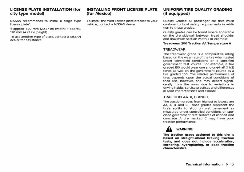
(417,1)
[ Edit: 2020/ 11/ 9 Model: Y62-A ]
GUID-65FFF41A-DE77-4D61-98DD-070EE286CEECNISSAN recommends to install a single typelicense plate*.*: approx. 520 mm (20.47 in) (width) × approx.120 mm (4.72 in) (height)To use another type of plate, contact a NISSANdealer for assistance.
GUID-0AF336BE-2A0A-4C9F-B14C-B64E69CBA6E9To install the front license plate bracket to yourvehicle, contact a NISSAN dealer.
GUID-19873E48-F87F-485D-832F-ABEFA0D1B4F8Quality Grades: All passenger car tires mustconform to local safety requirements in addi-tion to these grades.Quality grades can be found where applicableon the tire sidewall between tread shoulderand maximum section width. For example:Treadwear 200 Traction AA Temperature A
TREADWEARGUID-F8DF68D3-A0C7-4968-9C0F-B3B4F933CD49The treadwear grade is a comparative ratingbased on the wear rate of the tire when testedunder controlled conditions on a specifiedgovernment test course. For example, a tiregraded 150 would wear one and one-half (1 1/2)times as well on the government course as atire graded 100. The relative performance oftires depends upon the actual conditions oftheir use, however, and may depart signifi-cantly from the norm due to variations indriving habits, service practices and differencesin road characteristics and climate.
TRACTION AA, A, B AND CGUID-53AC010A-3ACA-47B5-A387-62C7B3634342The traction grades, from highest to lowest, areAA, A, B, and C. Those grades represent thetire’s ability to stop on wet pavement asmeasured under controlled conditions on spe-cified government test surfaces of asphalt andconcrete. A tire marked C may have poortraction performance.
WARNING:The traction grade assigned to this tire isbased on straight-ahead braking tractiontests, and does not include acceleration,cornering, hydroplaning, or peak tractioncharacteristics.
Technical information 9-13
LICENSE PLATE INSTALLATION (forcity type model)
INSTALLING FRONT LICENSE PLATE(for Mexico)
UNIFORM TIRE QUALITY GRADING(if equipped)
Condition: 'Except for China'/'Except for China/
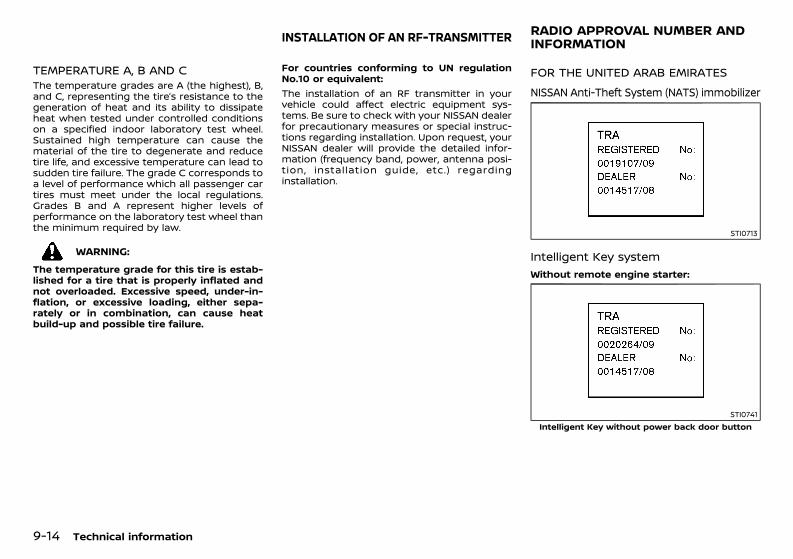
(418,1)
[ Edit: 2020/ 11/ 9 Model: Y62-A ]
9-14 Technical information
TEMPERATURE A, B AND CGUID-6EFD0322-46E9-482B-BAC9-F2DC6E55513AThe temperature grades are A (the highest), B,and C, representing the tire’s resistance to thegeneration of heat and its ability to dissipateheat when tested under controlled conditionson a specified indoor laboratory test wheel.Sustained high temperature can cause thematerial of the tire to degenerate and reducetire life, and excessive temperature can lead tosudden tire failure. The grade C corresponds toa level of performance which all passenger cartires must meet under the local regulations.Grades B and A represent higher levels ofperformance on the laboratory test wheel thanthe minimum required by law.
WARNING:The temperature grade for this tire is estab-lished for a tire that is properly inflated andnot overloaded. Excessive speed, under-in-flation, or excessive loading, either sepa-rately or in combination, can cause heatbuild-up and possible tire failure.
GUID-2A32A700-39F3-4675-BE92-46D1618157C2For countries conforming to UN regulationNo.10 or equivalent:The installation of an RF transmitter in yourvehicle could affect electric equipment sys-tems. Be sure to check with your NISSAN dealerfor precautionary measures or special instruc-tions regarding installation. Upon request, yourNISSAN dealer will provide the detailed infor-mation (frequency band, power, antenna posi-tion, installation guide, etc.) regardinginstallation.
GUID-B0AEA852-260F-44F1-8263-1C2957E87717
FOR THE UNITED ARAB EMIRATESGUID-F1C20AA9-76F3-4157-914F-E69913F1DF6C
NISSAN Anti-Theft System (NATS) immobilizerGUID-ECC9323A-7C51-42CB-A845-A9665AF98CE5
STI0713
Intelligent Key systemGUID-7A36B164-F522-46A0-BCE1-5E0AC4F8F8E9
Without remote engine starter:GUID-C7E1EF24-5AAB-4301-95BE-26917EEE45EF
STI0741Intelligent Key without power back door button
INSTALLATION OF AN RF-TRANSMITTER RADIO APPROVAL NUMBER ANDINFORMATION
Condition: 'Except for China'/'Except for China/
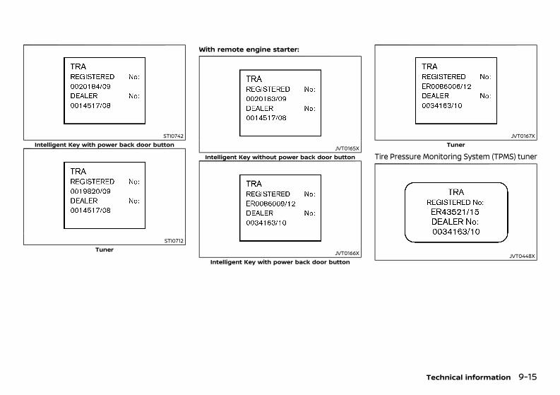
(419,1)
[ Edit: 2020/ 11/ 9 Model: Y62-A ]
STI0742Intelligent Key with power back door button
STI0712Tuner
With remote engine starter:GUID-C7E1EF24-5AAB-4301-95BE-26917EEE45EF
JVT0165XIntelligent Key without power back door button
JVT0166XIntelligent Key with power back door button
JVT0167XTuner
Tire Pressure Monitoring System (TPMS) tunerGUID-03668EE0-48FD-44DE-A88A-1230476254DA
JVT0448X
Technical information 9-15
Condition: 'Except for China'/'Except for China/
(420,1)
[ Edit: 2020/ 11/ 9 Model: Y62-A ]
9-16 Technical information
Tire Pressure Monitoring System(TPMS) transmitterGUID-5B132521-9D82-4E10-8F17-B33122FAAA41
WAJ0045X
JVT0451X
JVT0452X
WAJ0058X
Condition: 'Except for China'/'Except for China/
(421,1)
[ Edit: 2020/ 11/ 9 Model: Y62-A ]
Front radar (if equipped)GUID-DFC1BA62-AF2A-479E-AE48-68DA844A6678
WAJ0061X
Side radar (if equipped)GUID-0AC8A49F-384E-46E0-A055-50D9BB3AEA76
WAJ0064X
Blind Spot Warning (BSW) system (if equipped)GUID-AA897C07-FF14-4766-B5AB-005B11B445BC
STI0763
FOR JORDANGUID-D1BF19A2-981E-473E-A582-9DE814BB0B68
Intelligent Key systemGUID-43FA523B-4972-4F9C-AFEE-FD4A8A12FAB4
Without remote engine starter:GUID-C7E1EF24-5AAB-4301-95BE-26917EEE45EF
Intelligent Key with power back door buttonContains module approved by TRC/LPD/2010/06TunerContains module approved by TRC/LPD/2010/07With remote engine starter:
GUID-C7E1EF24-5AAB-4301-95BE-26917EEE45EF
Intelligent Key with power back door buttonContains module approved by TRC/LPD/2012/50Intelligent Key without power back door buttonContains module approved by TRC/LPD/2010/34TunerContains module approved by TRC/LPD/2012/51
NISSAN Anti-Theft System (NATS)GUID-FEE727A4-4DCD-4B17-A396-F4EA6769A4F2Model No. TWK1A004AContains module approved by TRC/LPD/2009/105
Tire Pressure Monitoring System (TPMS) tunerGUID-3322A685-855E-4E81-A694-B49081314AB7
JVT0449X
Technical information 9-17
Condition: 'Except for China'/'Except for China/
(422,1)
[ Edit: 2020/ 11/ 9 Model: Y62-A ]
9-18 Technical information
Tire Pressure Monitoring System(TPMS) transmitterGUID-B8EF8C83-4F23-468C-9414-3F2E3E98DC39
WAJ0046X
JVT0453X
JVT0454X
WAJ0059X
Bluetooth® Audio Player and Hands-Free Phone System (if equipped)GUID-E1AE5FA4-A1B6-4229-BB60-550EAEE2DE52This product contains approved BluetoothModule “VBTDC1.5”.Type approval No. : TRC/LPD/2013/41 (In thecase of “VBTDC1.5”)
Condition: 'Except for China'/'Except for China/
(423,1)
[ Edit: 2020/ 11/ 9 Model: Y62-A ]
Front radar (if equipped)GUID-4C91499D-517A-4451-B0A7-30A3A93E702B
WAJ0063X
Side radar (if equipped)GUID-3079E56F-D2F6-4CD8-A08B-B58B199C3EA9
WAJ0066X
FOR PAKISTANGUID-31AE2478-67D2-4513-A74A-F30763CC3553NISSAN Anti-Theft System (NATS) im-mobilizer and Intelligent Key systemGUID-38721DF6-8F85-4019-9533-0B50FDDD6BEB
JVT0175X
FOR MEXICOGUID-7C24830B-C24B-4000-A0B0-E887B1A128B3Intelligent Key systemGUID-2F363B89-1D6D-4DB3-A54F-44C964A15813
JVT0471X
Technical information 9-19
Condition: 'Except for China'/'Except for China/
(424,1)
[ Edit: 2020/ 11/ 9 Model: Y62-A ]
9-20 Technical information
NISSAN Anti-Theft System (NATS) immobilizerGUID-6DDA1652-F02A-4122-A464-FE09A3A26C92
JVT0075X
Tire Pressure Monitoring System (TPMS) tunerGUID-88F270E2-A1EC-4189-8EA6-9A35BFC13B59
JVT0525X
Front radar sensorGUID-ECF3B3D6-C3F5-4CD0-B3D4-F885555CB18A
JVT0252X
FOR SOUTH AFRICAGUID-01AC7443-9C64-4DF8-9449-C470FB7C8B9B
Intelligent Key system (tuner)GUID-4A5EE786-0B0C-4121-8381-81A120C35918
JVT0141X
Intelligent Key system (transmitter)GUID-19C1FE86-1384-4141-87CC-AB0A39D719CA
JVT0142X
NISSAN Anti-Theft System (NATS) immobilizerGUID-BB019020-90EA-4A4D-8475-00E86ED2EDED
JVT0140X
Condition: 'Except for China'/'Except for China/
(425,1)
[ Edit: 2020/ 11/ 9 Model: Y62-A ]
Blind Spot Warning (BSW) system/In-telligent Blind Spot Intervention systemGUID-5305E8B4-D79E-4C5E-9D86-D1AA2E370AA0
JVT0114X
Tire Pressure Monitoring System(TPMS) transmitterGUID-0A2048EF-7F4D-4B41-9B66-CA2488CC5941
JVT0539X
FOR OMAN GUID-5F3A1251-469B-4F10-A115-2E0C139F442B
Front radar (if equipped)GUID-F2F6886A-9AB1-42B4-A9D0-A04BC5035D95
WAJ0062X
Side radar (if equipped)GUID-7057E1C6-D061-4F94-9467-8277B420BA8F
WAJ0065X
FOR AUSTRALIA AND NEW ZEALANDGUID-50CA1754-4830-472C-A594-D348F7657550
Side radar (if equipped)GUID-83977D12-FB68-4EB2-9137-302F4D5C9181
JVT0464X
FOR BAHRAINGUID-5E6F18E3-E954-4470-822C-D6AEB96DF44EFront radar (if equipped)GUID-E6E6DF94-55C3-4628-AB8F-3844F805C839The Equipment Identified hereon is approvedfor use under the following rules.1- This equipment must not cause harmfulinterference to other services.2- This equipment is subject to harmful inter-ference, and the owner of this equipment mustnot claim for protection.
Side radar (if equipped)GUID-104B67F4-3F95-4B38-9682-AF2699EA91C7The Equipment Identified hereon is approvedfor use under the following rules.1- This equipment must not cause harmfulinterference to other services.2- This equipment is subject to harmful inter-ference, and the owner of this equipment mustnot claim for protection.
Technical information 9-21
Condition: 'Except for China'/'Except for China/

(426,1)
[ Edit: 2020/ 11/ 9 Model: Y62-A ]
9-22 Technical information
MEMO
Condition: 'Except for China'/'Except for China/
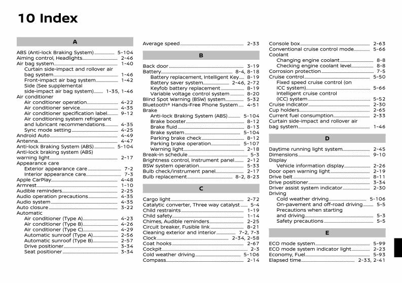
(429,1)
[ Edit: 2020/ 11/ 9 Model: Y62-A ]
10 IndexA
ABS (Anti-lock Braking System) ....................... 5-104Aiming control, Headlights ...................................... 2-46Air bag system .................................................................. 1-40
Curtain side-impact and rollover airbag system ................................................................... 1-46Front-impact air bag system ......................... 1-42Side (See supplementalside-impact air bag system) ............ 1-35, 1-46
Air conditionerAir conditioner operation .................................. 4-22Air conditioner service ......................................... 4-35Air conditioner specification label .............. 9-12Air conditioning system refrigerantand lubricant recommendations ................ 4-35Sync mode setting ................................................. 4-25
Android Auto ...................................................................... 4-49Antenna .................................................................................. 4-47Anti-lock Braking System (ABS) ....................... 5-104Anti-lock braking system (ABS)warning light ...................................................................... 2-17Appearance care
Exterior appearance care .................................... 7-2Interior appearance care ...................................... 7-3
Apple CarPlay ..................................................................... 4-48Armrest ................................................................................... 1-10Audible reminders .......................................................... 2-25Audio operation precautions ................................ 4-35Audio system ..................................................................... 4-35Auto closure ....................................................................... 3-22Automatic
Air conditioner (Type A) ...................................... 4-23Air conditioner (Type B) ...................................... 4-26Air conditioner (Type C) ...................................... 4-29Automatic sunroof (Type A) ............................ 2-56Automatic sunroof (Type B) ............................ 2-57Drive positioner ......................................................... 3-34Seat positioner .......................................................... 3-34
Average speed .................................................................. 2-33
BBack door ............................................................................. 3-19Battery .......................................................................... 8-4, 8-18
Battery replacement, Intelligent Key ........ 8-19Battery saver system ............................. 2-46, 2-72Keyfob battery replacement .......................... 8-19Variable voltage control system ................. 8-20
Blind Spot Warning (BSW) system ..................... 5-32Bluetooth® Hands-Free Phone System ........ 4-51Brake
Anti-lock Braking System (ABS) ............... 5-104Brake booster ............................................................. 8-12Brake fluid ..................................................................... 8-13Brake system .......................................................... 5-104Parking brake check ............................................. 8-12Parking brake operation ................................ 5-107Warning light ............................................................... 2-18
Break-in schedule .............................................................. 5-3Brightness control, Instrument panel ............ 2-12BSW system operation ............................................... 5-33Bulb check/instrument panel ............................... 2-17Bulb replacement ................................................ 8-2, 8-23
CCargo light ........................................................................... 2-72Catalytic converter, Three way catalyst .......... 5-4Child restraints ................................................................. 1-19Child safety .......................................................................... 1-14Chimes, Audible reminders ..................................... 2-25Circuit breaker, Fusible link .................................... 8-21Cleaning exterior and interior ...................... 7-2, 7-3Clock .......................................................................... 2-34, 2-58Coat hooks .......................................................................... 2-67Cockpit ........................................................................................ 2-3Cold weather driving ................................................ 5-106Compass ................................................................................ 2-14
Console box ........................................................................ 2-63Conventional cruise control mode ................... 5-66Coolant
Changing engine coolant .................................... 8-8Checking engine coolant level ......................... 8-8
Corrosion protection ....................................................... 7-5Cruise control .................................................................... 5-50
Fixed speed cruise control (onICC system) ................................................................... 5-66Intelligent cruise control(ICC) system ................................................................. 5-52
Cruise indicator ................................................................ 2-30Cup holders ......................................................................... 2-65Current fuel consumption ....................................... 2-33Curtain side-impact and rollover airbag system .......................................................................... 1-46
DDaytime running light system .............................. 2-45Dimensions .......................................................................... 9-10Display
Vehicle information display ............................. 2-26Door open warning light .......................................... 2-19Drive belt ............................................................................... 8-11Drive positioner ................................................................ 3-34Driver assist system indicator .............................. 2-30Driving
Cold weather driving ........................................ 5-106On-pavement and off-road driving ............. 5-5Precautions when startingand driving ....................................................................... 5-3Safety precautions .................................................... 5-5
EECO mode system ......................................................... 5-99ECO mode system indicator light ..................... 2-23Economy, Fuel ................................................................... 5-93Elapsed time ........................................................ 2-33, 2-41
Condition: 'Except for China'/'Except for China/
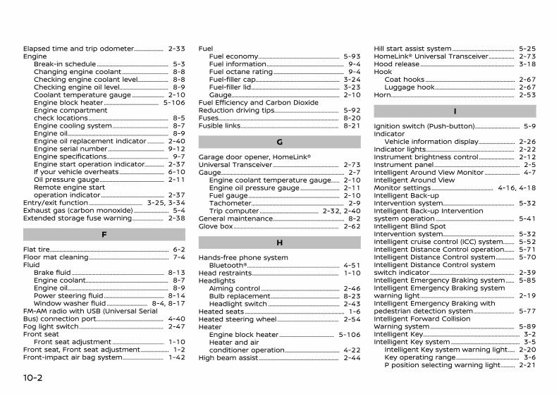
(430,1)
[ Edit: 2020/ 11/ 9 Model: Y62-A ]
10-2
Elapsed time and trip odometer ........................ 2-33Engine
Break-in schedule ...................................................... 5-3Changing engine coolant .................................... 8-8Checking engine coolant level ......................... 8-8Checking engine oil level ...................................... 8-9Coolant temperature gauge .......................... 2-10Engine block heater .......................................... 5-106Engine compartmentcheck locations ............................................................ 8-5Engine cooling system ........................................... 8-7Engine oil ........................................................................... 8-9Engine oil replacement indicator ............... 2-40Engine serial number ........................................... 9-12Engine specifications ............................................... 9-7Engine start operation indicator ................. 2-37If your vehicle overheats ................................... 6-10Oil pressure gauge ................................................. 2-11Remote engine startoperation indicator ................................................ 2-37
Entry/exit function ......................................... 3-25, 3-34Exhaust gas (carbon monoxide) ............................ 5-4Extended storage fuse warning ......................... 2-38
FFlat tire ........................................................................................ 6-2Floor mat cleaning ............................................................ 7-4Fluid
Brake fluid ..................................................................... 8-13Engine coolant .............................................................. 8-7Engine oil ........................................................................... 8-9Power steering fluid .............................................. 8-14Window washer fluid ................................ 8-4, 8-17
FM-AM radio with USB (Universal SerialBus) connection port ................................................... 4-40Fog light switch ............................................................... 2-47Front seat
Front seat adjustment ........................................ 1-10Front seat, Front seat adjustment ....................... 1-2Front-impact air bag system ................................ 1-42
FuelFuel economy ............................................................. 5-93Fuel information .......................................................... 9-4Fuel octane rating ..................................................... 9-4Fuel-filler cap ............................................................... 3-24Fuel-filler lid .................................................................. 3-23Gauge ................................................................................ 2-10
Fuel Efficiency and Carbon DioxideReduction driving tips ................................................. 5-92Fuses ......................................................................................... 8-20Fusible links ......................................................................... 8-21
GGarage door opener, HomeLink®Universal Transceiver .................................................. 2-73Gauge ........................................................................................... 2-7
Engine coolant temperature gauge ......... 2-10Engine oil pressure gauge ............................... 2-11Fuel gauge .................................................................... 2-10Tachometer ..................................................................... 2-9Trip computer ............................................. 2-32, 2-40
General maintenance ...................................................... 8-2Glove box .............................................................................. 2-62
HHands-free phone system
Bluetooth® ..................................................................... 4-51Head restraints ................................................................. 1-10Headlights
Aiming control ........................................................... 2-46Bulb replacement .................................................... 8-23Headlight switch ...................................................... 2-43
Heated seats .......................................................................... 1-6Heated steering wheel ............................................... 2-54Heater
Engine block heater .......................................... 5-106Heater and airconditioner operation .......................................... 4-22
High beam assist ............................................................ 2-44
Hill start assist system ............................................... 5-25HomeLink® Universal Transceiver ..................... 2-73Hood release ...................................................................... 3-18Hook
Coat hooks ................................................................... 2-67Luggage hook ............................................................ 2-67
Horn ........................................................................................... 2-53
IIgnition switch (Push-button) ................................... 5-9Indicator
Vehicle information display ............................. 2-26Indicator lights .................................................................. 2-22Instrument brightness control ............................ 2-12Instrument panel ................................................................ 2-5Intelligent Around View Monitor ............................ 4-7Intelligent Around ViewMonitor settings ............................................... 4-16, 4-18Intelligent Back-upIntervention system ...................................................... 5-32Intelligent Back-up Interventionsystem operation ........................................................... 5-41Intelligent Blind SpotIntervention system ...................................................... 5-32Intelligent cruise control (ICC) system ........... 5-52Intelligent Distance Control operation .......... 5-71Intelligent Distance Control system ................ 5-70Intelligent Distance Control systemswitch indicator ............................................................... 2-39Intelligent Emergency Braking system ......... 5-85Intelligent Emergency Braking systemwarning light ...................................................................... 2-19Intelligent Emergency Braking withpedestrian detection system ................................ 5-77Intelligent Forward CollisionWarning system ............................................................... 5-89Intelligent Key ........................................................................ 3-2Intelligent Key system .................................................... 3-5
Intelligent Key system warning light ........ 2-20Key operating range ................................................ 3-6P position selecting warning light ............. 2-21
Condition: 'Except for China'/'Except for China/
(431,1)
[ Edit: 2020/ 11/ 9 Model: Y62-A ]
Warning signals ............................................................ 3-8Intelligent Lane Intervention system .............. 5-28Intelligent Rear View Mirror .................................... 3-26Interior lights ...................................................................... 2-70
JJump starting ........................................................................ 6-8
KKeys ............................................................................................... 3-2
For Intelligent Key system ................................... 3-5
LLabels
Air conditioner specification label .............. 9-12Engine serial number ........................................... 9-12Vehicle identification number (VIN) ........... 9-11
Lane departure warning (LDW) system ........ 5-26Light
Bulb replacement ........................................ 8-2, 8-23Cargo light .................................................................... 2-72Fog light switch ........................................................ 2-47Headlight switch ...................................................... 2-43Headlights bulb replacement ........................ 8-23Indicator lights ........................................................... 2-22Interior lights ............................................................... 2-70Light locations ........................................................... 8-25Map lights ...................................................................... 2-71Replacement ................................................... 8-2, 8-23Vanity mirror lights ................................................ 2-72Warning/indicator lights andaudible reminders ................................................... 2-17
LockBack door lock ........................................................... 3-19Vehicle speed sensing doorlock mechanism .......................................................... 3-4
Low fuel warning ............................................................ 2-37Low fuel warning light ............................................... 2-20
Low tire pressure warning (Tire PressureLow Add Air) ....................................................................... 2-29Low tire pressure warning light ......................... 2-20Low tire pressure warning system(See Tire Pressure MonitoringSystem (TPMS)) ..................................................................... 5-6Luggage floor box ......................................................... 2-67Luggage hooks ................................................................ 2-67
MMaintenance
Battery .................................................................. 8-4, 8-18General maintenance .............................................. 8-2Maintenance precautions .................................... 8-4Maintenance requirements ................................ 8-2Seat belt maintenance ........................................ 1-19System maintenance ............................................ 5-44
Malfunction indicator light (MIL) ......................... 2-24Map lights ............................................................................. 2-71Master warning light .................................................... 2-21Mechanical key (Intelligent Key system) .......... 3-3Memory function ............................................................ 3-35Memory storage, Automaticdrive positioner ................................................................ 3-34Meter
Trip computer ............................................. 2-32, 2-40Meters and gauges ........................................................... 2-7
Instrument brightness control ..................... 2-12Mirror
Intelligent Rear View Mirror ............................. 3-26Mirror, Vanity mirror ..................................................... 3-33Mobile Link ........................................................................... 4-48Moving Object Detection (MOD) ......................... 4-15
NNew vehicle break-in ....................................................... 5-3
OOil
Checking engine oil level ...................................... 8-9Engine oil ........................................................................... 8-9Engine oil pressure gauge ............................... 2-11Oil filter replacement indicator .................... 2-40
OperationIndicators for operation ..................................... 2-27
Outside air temperature ........................................... 2-34Overheat, If your vehicle overheats ................. 6-10
PPanic alarm .......................................................................... 3-14Parking
Brake break-in ....................................................... 5-104Parking brake operation ................................ 5-107
Parking sensor (sonar) system setting ......... 5-97Phone
Bluetooth® Hands-FreePhone System ............................................................ 4-51
Phone menu ....................................................................... 4-52Phone settings .................................................................. 4-54Pocket ...................................................................................... 2-64Power
Power outlet ................................................................ 2-60Power steering fluid .............................................. 8-14Power windows ........................................................ 2-54
Pre-tensioner seat belt system ............ 1-38, 1-50Precautions
Audio operation ........................................................ 4-35Cruise control ............................................................. 5-51Cruise control operations ................................. 5-15Driving safety ................................................................. 5-5Lane departure warning(LDW) system ............................................................... 5-26Maintenance ................................................................... 8-4On-pavement and off-road driving ............. 5-5Precautions on SupplementalRestraint System ...................................................... 1-35
10-3
Condition: 'Except for China'/'Except for China/
(432,1)
[ Edit: 2020/ 11/ 9 Model: Y62-A ]
10-4
Seat belt usage ......................................................... 1-13When starting and driving ................................... 5-3
Push starting .......................................................................... 6-9Push-button ignition switch ...................................... 5-9
RRadio ......................................................................................... 4-35
FM-AM radio with USBconnection port ........................................................ 4-40
Rear automatic airconditioning system ..................................................... 4-31Rear automatic cooling system .......................... 4-34Rear bumper cover ....................................................... 2-68Rear Cross Traffic Alert (RCTA) ............................ 5-45Rear door alert ................................................................. 2-58Rear personal lights ..................................................... 2-72Rear view monitor settings ........................................ 4-6Remote engine start .................................................... 3-17Repair and replacement procedure ................ 1-50Roof, Roof rack ................................................................. 2-68
SSafety, Child seat belts ............................................... 1-14Seat adjustment
Front seats .................................................................... 1-10Seat adjustment, Front seats ................................... 1-2Seat belt(s)
Child safety ................................................................... 1-14Injured persons ......................................................... 1-15Pre-tensioner seatbelt system .................................................... 1-38, 1-50Precautions on seat belt usage ................... 1-13Pregnant women ..................................................... 1-15Seat belt cleaning ...................................................... 7-4Seat belt hooks ......................................................... 1-16Seat belt maintenance ........................................ 1-19Seat belt warning light ....................................... 2-21Seat belts ....................................................................... 1-13Shoulder belt height adjustment ............... 1-16
Seat(s)Driver-side memory ............................................... 3-34Heated seats .................................................................. 1-6Seats ..................................................................................... 1-2
Servicing air conditioner ........................................... 4-35Shift lever
Shift lock release ...................................................... 5-15Shift lock release
Transmission ............................................................... 5-15Shoulder belt height adjustment ...................... 1-16Side-impact air bag system .................... 1-35, 1-46Small light indicator light ......................................... 2-25SNOW mode ........................................................................ 5-21Spare tire ............................................................................... 8-32Spark plugs .......................................................................... 8-11Starting
Jump starting ................................................................ 6-8Precautions when startingand driving ....................................................................... 5-3Push starting .................................................................. 6-9
SteeringHeated steering wheel ........................................ 2-54Power steering fluid .............................................. 8-14Steering lock ................................................................ 5-10Steering lock releasemalfunction indicator ........................................... 2-37Tilting steering wheel ........................................... 3-24
Sunglasses holder .......................................................... 2-65Sunroof ................................................................................... 2-56
Automatic sunroof (Type A) ............................ 2-56Automatic sunroof (Type B) ............................ 2-57
Supplemental air bag systems ............................ 1-40Supplemental curtain side-impact androllover air bag system .............................................. 1-46Supplemental front-impact airbag system .......................................................................... 1-42Supplemental side-impact airbag system ........................................................... 1-35, 1-46Switch
Fog light switch ........................................................ 2-47Headlight aiming control .................................. 2-46
Headlight switch ...................................................... 2-43Power door lock switch ........................................ 3-4Turn signal switch .................................................. 2-47
TTachometer ............................................................................. 2-9Technical characteristics .............................................. 9-8Temperature gauge, Engine coolanttemperature gauge ...................................................... 2-10Three-way catalyst ............................................................ 5-4Tilting steering wheel .................................................. 3-24Tire
Pressure, Low tire pressurewarning light ............................................................... 2-20Spare tire ........................................................................ 8-32Tire replacement indicator .............................. 2-40
TiresFlat tire ................................................................................ 6-2Tire chains ..................................................................... 8-30Tire Pressure Low Add Air warning .......... 2-29Tire Pressure MonitoringSystem (TPMS) ................................................... 5-6, 6-2Tire rotation ..................................................... 8-3, 8-30Types of tires .............................................................. 8-29Uniform tire quality grading ........................... 9-13
Tow mode ......................................................................... 5-103Towing, Tow truck towing ...................................... 6-10TPMS, Tire PressureMonitoring System ................................................ 5-6, 6-2
TPMS with tire inflation indicator .................. 5-7Trailer towing (models withtrailer hitch) ...................................................................... 5-100Trailer towing (models withouttrailer hitch) ...................................................................... 5-100Transceiver, HomeLink®Universal Transceiver .................................................. 2-73Transmission, Transmission shift leverlock release ......................................................................... 5-15Trip computer .................................................... 2-32, 2-40Trip odometer .................................................... 2-33, 2-41
Condition: 'Except for China'/'Except for China/
(433,1)
[ Edit: 2020/ 11/ 9 Model: Y62-A ]
Turn signal switch ......................................................... 2-47
UUnderbody cleaning ......................................................... 7-3Uniform tire quality grading .................................. 9-13USB (Universal Serial Bus)charging connector ...................................................... 2-62USB memory care .......................................................... 4-46
VVanity mirror ...................................................................... 3-33Vanity mirror lights ....................................................... 2-72Variable voltage control system ........................ 8-20Vehicle
Dimensions ................................................................... 9-10Identification number (VIN) .............................. 9-11Information display ................................................ 2-12Speed sensing door lock mechanism ........ 3-4Vehicle dynamic control(VDC) system ............................................................... 5-22Vehicle dynamic control (VDC)warning light ............................................................... 2-22
Vehicle information display .................................... 2-26Vehicle speed ..................................................................... 2-33Vehicle-to-vehicle distancecontrol mode ..................................................................... 5-53Ventilators ............................................................................ 4-21Voltmeter .............................................................................. 2-11
WWarning
Intelligent Forward CollisionWarning system ........................................................ 5-89Lane departure warning(LDW) system ............................................................... 5-26Lights ................................................................................. 2-17Tire Pressure Low Add Air warning .......... 2-29
Tire Pressure MonitoringSystem (TPMS) ................................................... 5-6, 6-2Vehicle information display ............................. 2-26Warning lights, indicator lights andaudible reminders ................................................... 2-16
Warning light4WD warning light .................................................. 5-19Anti-lock braking system (ABS)warning light ............................................................... 2-17Brake warning light ............................................... 2-18Door open warning light ................................... 2-19Intelligent Emergency Braking systemwarning light ............................................................... 2-19Intelligent Key system warning light ........ 2-20Low fuel warning light ........................................ 2-20Low tire pressure warning light .................. 2-20Seat belt warning light ....................................... 2-21
Washer switch, Windshield wiper andwasher switch ................................................................... 2-49Washing ...................................................................................... 7-2Waxing ......................................................................................... 7-2Welcome light .................................................................... 2-70Wheels and tires
Care of wheels .............................................................. 7-3Cleaning aluminum alloy wheels ................... 7-3Tires and wheels .......................................... 8-29, 9-9
Window washer fluid ........................................ 8-4, 8-17Window(s)
Cleaning .................................................................. 7-3, 7-4Power windows ........................................................ 2-54
Windshield wiper and washer switch ............. 2-49Wiper
Windshield wiper andwasher switch ............................................................ 2-49Wiper blades ................................................................ 8-16
10-5
Condition: 'Except for China'/'Except for China/
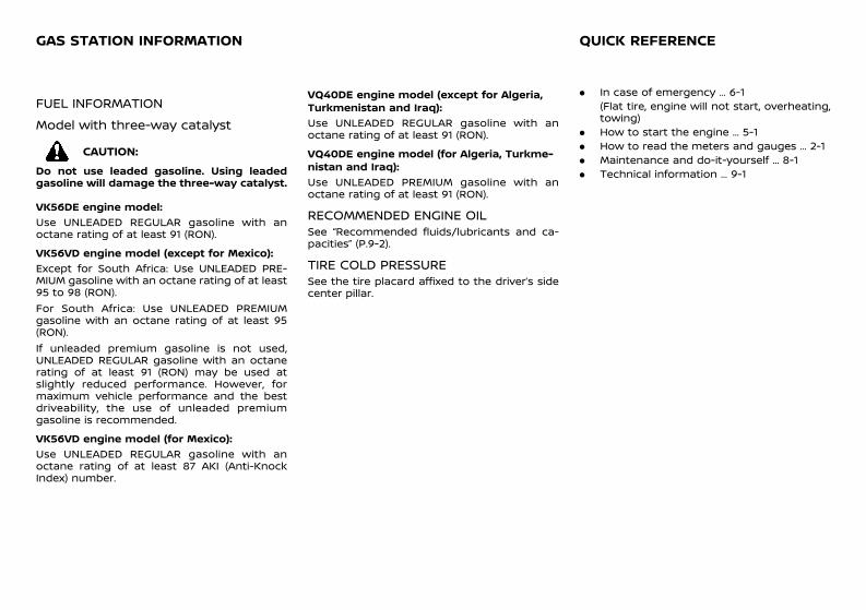
(439,1)
[ Edit: 2020/ 11/ 9 Model: Y62-A ]
11 EpilogueGUID-E382FEC2-1FED-4E52-9FEF-5BE26C4BBF3C
FUEL INFORMATIONGUID-44C177D5-CB2E-4D61-8B94-23469B24487D
Model with three-way catalystGUID-60E574A6-D3DA-4005-BA2D-E1F7281B4712
CAUTION:Do not use leaded gasoline. Using leadedgasoline will damage the three-way catalyst.
VK56DE engine model:GUID-C7E1EF24-5AAB-4301-95BE-26917EEE45EF
Use UNLEADED REGULAR gasoline with anoctane rating of at least 91 (RON).VK56VD engine model (except for Mexico):
GUID-C7E1EF24-5AAB-4301-95BE-26917EEE45EF
Except for South Africa: Use UNLEADED PRE-MIUM gasoline with an octane rating of at least95 to 98 (RON).For South Africa: Use UNLEADED PREMIUMgasoline with an octane rating of at least 95(RON).If unleaded premium gasoline is not used,UNLEADED REGULAR gasoline with an octanerating of at least 91 (RON) may be used atslightly reduced performance. However, formaximum vehicle performance and the bestdriveability, the use of unleaded premiumgasoline is recommended.VK56VD engine model (for Mexico):
GUID-C7E1EF24-5AAB-4301-95BE-26917EEE45EF
Use UNLEADED REGULAR gasoline with anoctane rating of at least 87 AKI (Anti-KnockIndex) number.
VQ40DE engine model (except for Algeria,Turkmenistan and Iraq):
GUID-C7E1EF24-5AAB-4301-95BE-26917EEE45EF
Use UNLEADED REGULAR gasoline with anoctane rating of at least 91 (RON).VQ40DE engine model (for Algeria, Turkme-nistan and Iraq):
GUID-C7E1EF24-5AAB-4301-95BE-26917EEE45EF
Use UNLEADED PREMIUM gasoline with anoctane rating of at least 91 (RON).
RECOMMENDED ENGINE OILGUID-BDE335F3-46F3-4207-AFAB-941D2F10193BSee “Recommended fluids/lubricants and ca-pacities” (P.9-2).
TIRE COLD PRESSUREGUID-9E3CE568-A19B-4D0F-A7DD-98A8DCE3CE42See the tire placard affixed to the driver’s sidecenter pillar.
GUID-CB8576A8-9B00-4E97-8E6F-F28C2AAD0786. In case of emergency ... 6-1
(Flat tire, engine will not start, overheating,towing)
. How to start the engine ... 5-1
. How to read the meters and gauges ... 2-1
. Maintenance and do-it-yourself ... 8-1
. Technical information ... 9-1
GAS STATION INFORMATION QUICK REFERENCE
Condition: 'Except for China'/'Except for China/