nanosized polycrystalline diamond cladding for surface protection of zirconium nuclear fuel tubes
TRANSCRIPT
Nz
IJa
b
c
d
a
ARRAA
KPNMv
1
ZcpdrfmHs(ohhti
RT
h0
Journal of Materials Processing Technology 214 (2014) 2600–2605
Contents lists available at ScienceDirect
Journal of Materials Processing Technology
jo ur nal home p ag e: www.elsev ier .com/ locate / jmatprotec
anosized polycrystalline diamond cladding for surface protection ofirconium nuclear fuel tubes
. Kratochvílováa,d,∗, R. Skodab, J. Skarohlídb, P. Ashcheulova,d, A. Jägera,
. Raceka, A. Taylora, L. Shaoc
Institute of Physics, Academy of Sciences Czech Republic v.v.i, Na Slovance 2, CZ-182 21 Prague 8, Czech RepublicCzech Technical University in Prague, Faculty of Mechanical Engineering, Technická 4, CZ-160 07 Prague 6, Czech RepublicTexas A&M University, Department of Nuclear Engineering TAMU-3133, College Station, TX 77843, USAFaculty of Nuclear Physics and Physical Engineering, Czech Technical University in Prague, Zikova 1, CZ-160 00 Prague 6, Czech Republic
r t i c l e i n f o
rticle history:eceived 5 February 2014eceived in revised form 5 May 2014ccepted 6 May 2014vailable online 13 May 2014
a b s t r a c t
A 300 nm thick polycrystalline diamond layer has been used for protection of zirconium alloy nuclear fuelcladding against undesirable oxidation with no loss of chemical stability and preservation of its function-ality. Deposition of polycrystalline diamond layer was carried out using microwave plasma enhancedchemical vapor deposition apparatus with linear antenna delivery (which enables deposition of PCDlayers over large areas). Polycrystalline diamond coated zirconium alloy fuel tubes were subjected to
eywords:olycrystalline diamond filmuclear fuel cladding protectionicrowave plasma enhanced chemical
apor deposition
corrosion tests to replicate nuclear reactor conditions, namely irradiation and hot steam oxidation. Stableradiation tolerance of the polycrystalline diamond layer and its protective capabilities against hot steamoxidation of the zirconium alloy were confirmed. Finally, the use of polycrystalline diamond layers as asensor of specific conditions (temperature/pressure dependent phase transition) in nuclear reactors issuggested.
© 2014 Elsevier B.V. All rights reserved.
. Introduction
Zirconium alloys (with a common subgroup trademarkedircaloy2) are a material used in all modern hot steam waterooled commercial nuclear reactors. Such a material must com-ly with stringent material requirements; Zinkle and Was (2013)escribed the recent material challenges of nuclear-reactor mate-ials. Zircaloy2 is a material with very useful properties for nuclearacilities applications: it has a low absorption cross-section of ther-
al electrons, high ductility, hardness and corrosion resistance.owever, it also has significant weakness, as it reacts with water
team, as recently reviewed by Burns et al. (2012). During thisoxidative) reaction hydrogen gas is released; the oxidation ratef such a reaction was studied by Causey et al. (2006). The releasedydrogen then partly diffuses into the alloy forming zirconium
ydrides, which are less dense and are mechanically weaker thanhe original Zircaloy2 material. Their formation results in blister-ng and finally cracking of the cladding, mechanisms of which were∗ Corresponding author at: Institute of Physics, Academy of Sciences Czechepublic v.v.i, Na Slovance 2, CZ-182 21 Prague 8, Czech Republic.el.: +420 723814810.
E-mail address: [email protected] (I. Kratochvílová).
ttp://dx.doi.org/10.1016/j.jmatprotec.2014.05.009924-0136/© 2014 Elsevier B.V. All rights reserved.
studied by Puls (1990). Moreover, a large production of hydrogengas can result in a hydrogen-air chemical explosions (as seen in therecent Fukushima accident, the reasons and effects of which arethoroughly analyzed by Hirano et al. (2012) and Högberg (2013)). Asthese effects are surface related, a solution to the problem, namelyhow to fully utilize the advantages of the bulk of the zirconium-based material and to reinforce its surface chemical resistance,is to cover the surface with a thin film of a protective substance.Recently, many materials have been applied to protect zirconiumalloy surfaces from destruction, but without any significant success.For example, Steinbruk et al. (2011) describes newly developedmaterials such as Zircaloy-4, or Bryan US patent EP 0673539 pro-posed a wear-resistant coating comprising a ceramic material withglass.
In this work, we provide a proof of concept for a new strategy ofzirconium-alloy nuclear fuel cladding (NFC) surface protection, bythe use of polycrystalline diamond (PCD) film. PCD films have beengrown in a microwave plasma enhanced chemical vapor depositionapparatus with linear antenna delivery system (MW-LA-PECVD) asdescribed in Fendrych et al. (2010). Polycrystalline diamond lay-
ers consist of crystalline (sp3) and amorphous (sp2) carbon phases.Diamond has excellent material properties, it withstands very hightemperatures, has high thermal conductivity and low chemicalreactivity and does not degrade over time (studied by Kratochvílová
I. Kratochvílová et al. / Journal of Materials Processing Technology 214 (2014) 2600–2605 2601
e tube
ebaBt
oasa
piuan
2
2
dtamtpeosm
Fse
Fig. 1. MW-LA-PECVD deposition chamber and mounting of the Zircaloy2 sampl
t al. (2011) and Petráková et al. (2012)). Therefore, it has alreadyeen considered as a material of choice for a large variety ofpplications. Such applications were described by May (2000) andalmer et al. (2009) in their reviews and include high power/highemperature or radiation-hard electronics and detectors.
Pure carbon has perfect neutron cross-section properties. More-ver, polycrystalline diamond layers consisting of crystalline (sp3)nd amorphous (sp2) carbon phases have suitable thermal expan-ion. To the best of our knowledge, diamond has never been studieds a possible protective coating for NFC.
Various diamond films are now being used in industry for therotection of materials and devices, usually enhancing the mechan-
cal properties. The combination of the already well-establishedsage and the simple, but novel idea we have put forward implies
significant application potential of diamond coated zirconiumuclear fuel claddings.
. Experimental
.1. Growth of PCD
Prior to growth Zircaloy2 tubular samples (length: 25 mm andiameter: 10 mm) were immersed in a water based dispersion con-aining nanodiamond particles (NanoAmando®), which act as seedsnd therefore induce sites for PCD growth. Samples were thenounted onto a holder to ensure that the whole circumference of
he tube is exposed to the plasma, and placed into the microwavelasma enhanced chemical vapor deposition apparatus with lin-
ar antenna delivery (MW-LA-PECVD) chamber. The temperaturef the Zircaloy2 samples was measured during the diamond depo-ition by a Williamson Pro 92-38 infrared thermometer capable ofeasurements in the 450–1000 ◦C range.ig. 2. (a) Raman spectra of the PCD coating prior to corrosion tests. Spectra were collectehows the samples after the deposition of the PCD layer. (b) XPS spectra of the PCD coatinlement depth profile.
s ensuring the growth of PCD layer completely around the tubes’ circumference.
The MW-LA-PECVD apparatus is capable of producing bothcontinuous wave (at a maximum of 3 kW) and tunable pulsedmicrowaves (at a maximum of 10 kW). Microwaves are deliveredinto the growth chamber in a linear form by four pairs of anten-nas enclosed in quartz envelopes. The plasma sources are arrangedparallel to one another above the substrate holder which enablesdeposition of PCD onto substrates with sizes, currently, as large as50 cm × 30 cm, using a gas mixture of H2 + CH4 + CO2 at low pro-cess pressures (<1 mBar) as described by Taylor et al. (2011). TheMW-LA-PECVD system enables a surface wave to be sustained lin-early along the antennas, therefore the size of microwave dischargeis not limited by the wavelength of inputted microwave power,in addition to this the system is of a modular design (in all axis).These factors therefore can, in the future, facilitate coating of actualfull lengths of fuel cladding tubes (3–4 m), see Liehr et al. (2006).Photographs of the system and the sample holder are presented inFig. 1.
Owing to its diffuse plasma properties, due to a combina-tion of low electron temperature (1.5 eV), high plasma density(>1011/cm3) (see Tsugawa et al., 2006) low power density and highatomic hydrogen concentrations (details see Vlcek et al., 2012), theMW-LA-PECVD system enables growth on 3D objects with goodhomogeneity over large areas (as evidenced in Figs. 1 and 2) even ifthe object is held static during the deposition, which other plasmaenhanced techniques such as cavity based microwave and hot fil-ament systems would not be able to due to issues such as plasmafocusing.
2.2. PCD characterization techniques
Raman spectroscopy measurements were carried out at roomtemperature using a Renishaw InVia Raman Microscope with
d from various positions over the sample and indicate good homogeneity. The insetg prior to corrosion tests acquired at the depth of 65 nm, the inset represents XPS
2602 I. Kratochvílová et al. / Journal of Materials Processing Technology 214 (2014) 2600–2605
F loy2 t( ges in
t(oQTvopbohOiaqwv
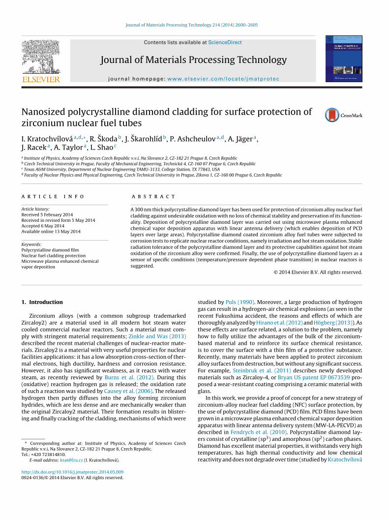
ig. 3. SEM images of PCD-coated (first column) and uncoated (second column) Zircasecond row) and after hot steam oxidation (third row). The arrows in the SEM ima
he following conditions: laser excitation wavelength of 488 nm25 mW), 50× Olympus objective, 65 �m slits, spot focus, gratingf 2400 l/mm. The surface of the PCD layers was analyzed by a FEIuanta 3D FEG Scanning Electron Microscope (SEM) fitted with aSL/EDAX energy dispersive spectrometer (EDS). The acceleratingoltage in high resolution mode was kept in the range 2–5 kV, inrder to minimize the interaction volume (Figs. 3 and 4). X-rayhotoelectron spectroscopy was carried out using an ESCA Probey Omicron Nanotechnology. The depth concentration profile wasbtained using Ar ion sputtering at 5 keV up to a depth of 120 nm. Itas been shown by many authors (Lucas et al., 2013; Tan et al., 2011;lsson and Landolt, 2004) that XPS is a sensitive method for study-
ng the surface of Zr alloys containing carbide and carbon. In our XPS
nalysis, particular attention was given to obtain a reproducibleuantification of the PCD film and the oxide layer development,hich was well distinguishable in the survey scan as well as in indi-idual peaks of XPS spectra O 1s and C 1s. The data analysis routine
ubes. The samples were measured as-prepared (first row), after ion-beam irradiationdicate areas where the top-most layer was intentionally scratched off.
(sensitivity factor, curve fitting, background subtraction, etc.), usedfor this purpose permitted quantification of the chemical composi-tion. X-Ray diffraction (XRD) measurements were performed usinga PANalytical diffractometer XıPert PRO equipped with a Co anode(� = 0.178901 nm). In order to enhance the contribution of the sur-face layers a parabolic mirror and a parallel plate collimator wereused in the primary and the diffracted beam, respectively. The angleof incidence of the primary beam was 3◦. The Rietveld-like programTopas was used for the analysis of the measurement. Since the sam-ple was textured, the Pawley refinement mode was used to improvethe preciseness of lattice parameters and crystallite sizes.
2.3. Hot steam oxidation
For hot steam oxidation of the PCD coated Zircaloy2 samples asilica glass tube, 40 mm in diameter was used, which was placedinside a vertically oriented furnace with a maximum operating
I. Kratochvílová et al. / Journal of Materials Processing Technology 214 (2014) 2600–2605 2603
F ircaloZ
tthsTtbitts
2
cio3btbwb
treHnib
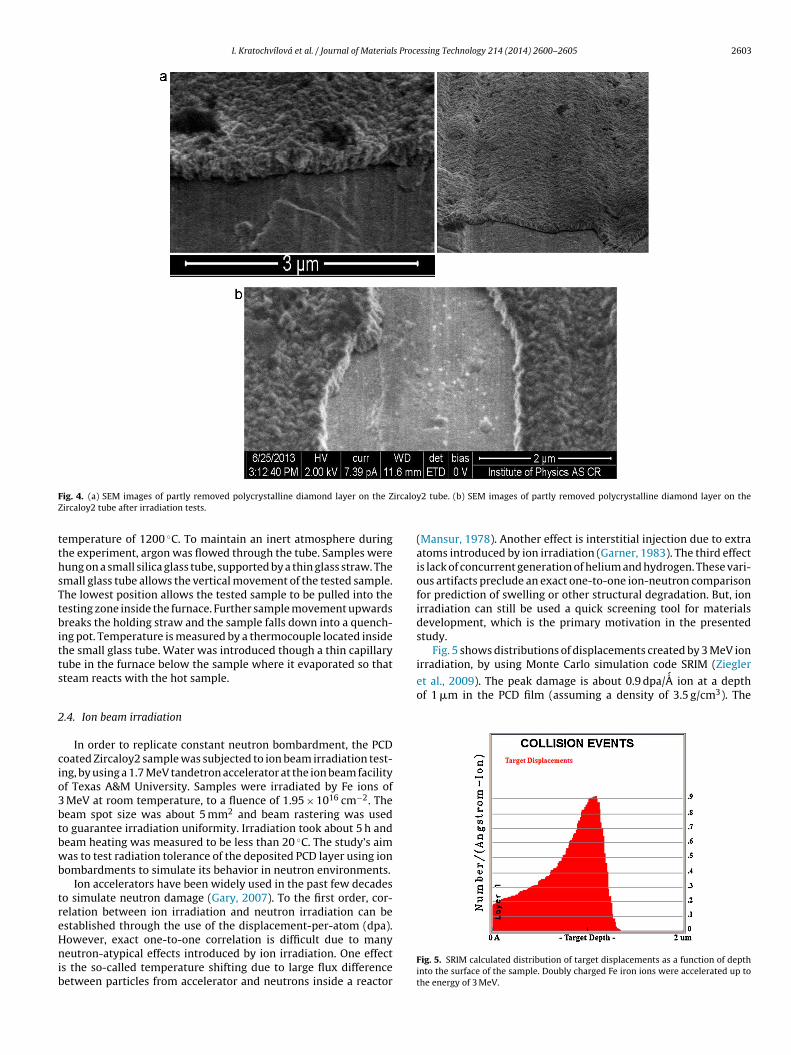
irradiation, by using Monte Carlo simulation code SRIM (Ziegler
et al., 2009). The peak damage is about 0.9 dpa/ ´A ion at a depthof 1 �m in the PCD film (assuming a density of 3.5 g/cm3). The
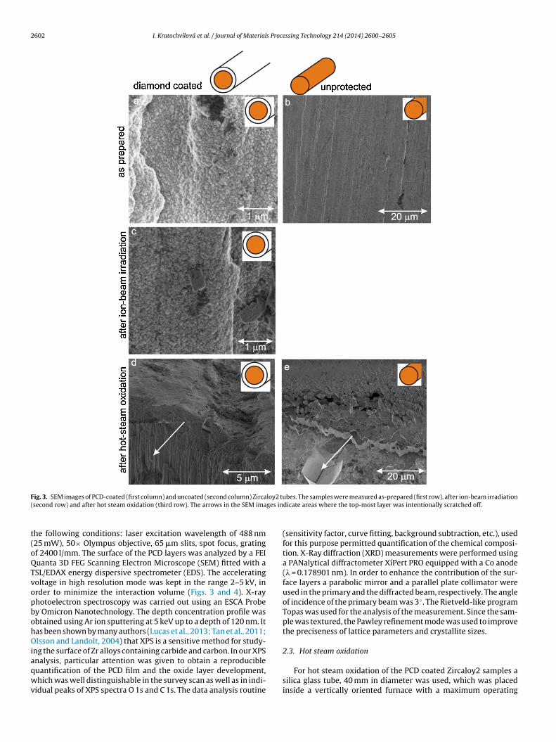
ig. 4. (a) SEM images of partly removed polycrystalline diamond layer on the Zircaloy2 tube after irradiation tests.
emperature of 1200 ◦C. To maintain an inert atmosphere duringhe experiment, argon was flowed through the tube. Samples wereung on a small silica glass tube, supported by a thin glass straw. Themall glass tube allows the vertical movement of the tested sample.he lowest position allows the tested sample to be pulled into theesting zone inside the furnace. Further sample movement upwardsreaks the holding straw and the sample falls down into a quench-
ng pot. Temperature is measured by a thermocouple located insidehe small glass tube. Water was introduced though a thin capillaryube in the furnace below the sample where it evaporated so thatteam reacts with the hot sample.
.4. Ion beam irradiation
In order to replicate constant neutron bombardment, the PCDoated Zircaloy2 sample was subjected to ion beam irradiation test-ng, by using a 1.7 MeV tandetron accelerator at the ion beam facilityf Texas A&M University. Samples were irradiated by Fe ions of
MeV at room temperature, to a fluence of 1.95 × 1016 cm−2. Theeam spot size was about 5 mm2 and beam rastering was usedo guarantee irradiation uniformity. Irradiation took about 5 h andeam heating was measured to be less than 20 ◦C. The study’s aimas to test radiation tolerance of the deposited PCD layer using ion
ombardments to simulate its behavior in neutron environments.Ion accelerators have been widely used in the past few decades
o simulate neutron damage (Gary, 2007). To the first order, cor-elation between ion irradiation and neutron irradiation can bestablished through the use of the displacement-per-atom (dpa).
owever, exact one-to-one correlation is difficult due to manyeutron-atypical effects introduced by ion irradiation. One effects the so-called temperature shifting due to large flux differenceetween particles from accelerator and neutrons inside a reactor
y2 tube. (b) SEM images of partly removed polycrystalline diamond layer on the
(Mansur, 1978). Another effect is interstitial injection due to extraatoms introduced by ion irradiation (Garner, 1983). The third effectis lack of concurrent generation of helium and hydrogen. These vari-ous artifacts preclude an exact one-to-one ion-neutron comparisonfor prediction of swelling or other structural degradation. But, ionirradiation can still be used a quick screening tool for materialsdevelopment, which is the primary motivation in the presentedstudy.
Fig. 5 shows distributions of displacements created by 3 MeV ion
Fig. 5. SRIM calculated distribution of target displacements as a function of depthinto the surface of the sample. Doubly charged Fe iron ions were accelerated up tothe energy of 3 MeV.
2604 I. Kratochvílová et al. / Journal of Materials Processing Technology 214 (2014) 2600–2605
FT
sstsratish
3
sP1raNaupowwcstig
ed
acldtcaowa
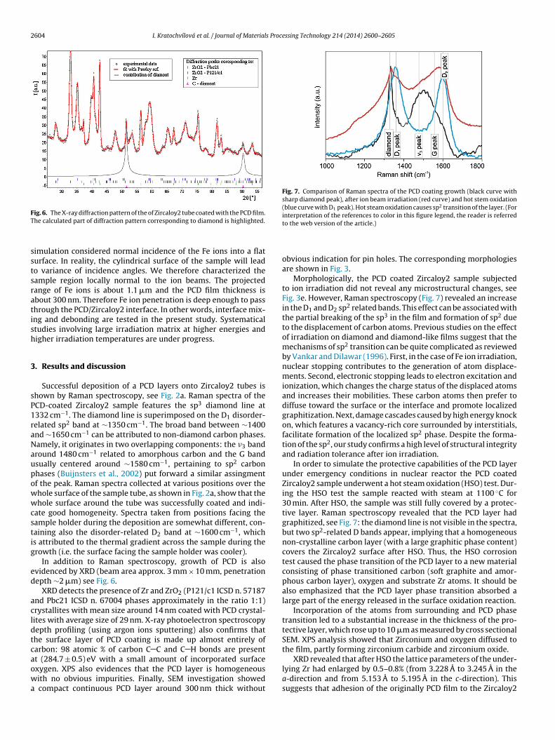
Fig. 7. Comparison of Raman spectra of the PCD coating growth (black curve withsharp diamond peak), after ion beam irradiation (red curve) and hot stem oxidation(blue curve with D1 peak). Hot steam oxidation causes sp2 transition of the layer. (Forinterpretation of the references to color in this figure legend, the reader is referred
ig. 6. The X-ray diffraction pattern of the of Zircaloy2 tube coated with the PCD film.he calculated part of diffraction pattern corresponding to diamond is highlighted.
imulation considered normal incidence of the Fe ions into a flaturface. In reality, the cylindrical surface of the sample will leado variance of incidence angles. We therefore characterized theample region locally normal to the ion beams. The projectedange of Fe ions is about 1.1 �m and the PCD film thickness isbout 300 nm. Therefore Fe ion penetration is deep enough to passhrough the PCD/Zircaloy2 interface. In other words, interface mix-ng and debonding are tested in the present study. Systematicaltudies involving large irradiation matrix at higher energies andigher irradiation temperatures are under progress.
. Results and discussion
Successful deposition of a PCD layers onto Zircaloy2 tubes ishown by Raman spectroscopy, see Fig. 2a. Raman spectra of theCD-coated Zircaloy2 sample features the sp3 diamond line at332 cm−1. The diamond line is superimposed on the D1 disorder-elated sp2 band at ∼1350 cm−1. The broad band between ∼1400nd ∼1650 cm−1 can be attributed to non-diamond carbon phases.amely, it originates in two overlapping components: the �3 bandround 1480 cm−1 related to amorphous carbon and the G bandsually centered around ∼1580 cm−1, pertaining to sp2 carbonhases (Buijnsters et al., 2002) put forward a similar assingmentf the peak. Raman spectra collected at various positions over thehole surface of the sample tube, as shown in Fig. 2a, show that thehole surface around the tube was successfully coated and indi-
ate good homogeneity. Spectra taken from positions facing theample holder during the deposition are somewhat different, con-aining also the disorder-related D2 band at ∼1600 cm−1, whichs attributed to the thermal gradient across the sample during therowth (i.e. the surface facing the sample holder was cooler).
In addition to Raman spectroscopy, growth of PCD is alsovidenced by XRD (beam area approx. 3 mm × 10 mm, penetrationepth ∼2 �m) see Fig. 6.
XRD detects the presence of Zr and ZrO2 (P121/c1 ICSD n. 57187nd Pbc21 ICSD n. 67004 phases approximately in the ratio 1:1)rystallites with mean size around 14 nm coated with PCD crystal-ites with average size of 29 nm. X-ray photoelectron spectroscopyepth profiling (using argon ions sputtering) also confirms thathe surface layer of PCD coating is made up almost entirely ofarbon: 98 atomic % of carbon C C and C H bonds are presentt (284.7 ± 0.5) eV with a small amount of incorporated surface
xygen. XPS also evidences that the PCD layer is homogeneousith no obvious impurities. Finally, SEM investigation showedcompact continuous PCD layer around 300 nm thick without
to the web version of the article.)
obvious indication for pin holes. The corresponding morphologiesare shown in Fig. 3.
Morphologically, the PCD coated Zircaloy2 sample subjectedto ion irradiation did not reveal any microstructural changes, seeFig. 3e. However, Raman spectroscopy (Fig. 7) revealed an increasein the D1 and D2 sp2 related bands. This effect can be associated withthe partial breaking of the sp3 in the film and formation of sp2 dueto the displacement of carbon atoms. Previous studies on the effectof irradiation on diamond and diamond-like films suggest that themechanisms of sp2 transition can be quite complicated as reviewedby Vankar and Dilawar (1996). First, in the case of Fe ion irradiation,nuclear stopping contributes to the generation of atom displace-ments. Second, electronic stopping leads to electron excitation andionization, which changes the charge status of the displaced atomsand increases their mobilities. These carbon atoms then prefer todiffuse toward the surface or the interface and promote localizedgraphitization. Next, damage cascades caused by high energy knockon, which features a vacancy-rich core surrounded by interstitials,facilitate formation of the localized sp2 phase. Despite the forma-tion of the sp2, our study confirms a high level of structural integrityand radiation tolerance after ion irradiation.
In order to simulate the protective capabilities of the PCD layerunder emergency conditions in nuclear reactor the PCD coatedZircaloy2 sample underwent a hot steam oxidation (HSO) test. Dur-ing the HSO test the sample reacted with steam at 1100 ◦C for30 min. After HSO, the sample was still fully covered by a protec-tive layer. Raman spectroscopy revealed that the PCD layer hadgraphitized, see Fig. 7: the diamond line is not visible in the spectra,but two sp2-related D bands appear, implying that a homogeneousnon-crystalline carbon layer (with a large graphitic phase content)covers the Zircaloy2 surface after HSO. Thus, the HSO corrosiontest caused the phase transition of the PCD layer to a new materialconsisting of phase transitioned carbon (soft graphite and amor-phous carbon layer), oxygen and substrate Zr atoms. It should bealso emphasized that the PCD layer phase transition absorbed alarge part of the energy released in the surface oxidation reaction.
Incorporation of the atoms from surrounding and PCD phasetransition led to a substantial increase in the thickness of the pro-tective layer, which rose up to 10 �m as measured by cross sectionalSEM. XPS analysis showed that Zirconium and oxygen diffused tothe film, partly forming zirconium carbide and zirconium oxide.
XRD revealed that after HSO the lattice parameters of the under-˚ ˚
lying Zr had enlarged by 0.5–0.8% (from 3.228 A to 3.245 A in thea-direction and from 5.153 A to 5.195 A in the c-direction). Thissuggests that adhesion of the originally PCD film to the Zircaloy2
s Proce
sp
apoerwnotciaffactanmwiapwsmttPd
ralOfiaocfpdto
4
aMcci
•
I. Kratochvílová et al. / Journal of Material
urface is reasonably good, since tensile strain is preferred overeeling off the layer.
The protective capabilities of the PCD layer were compared with standard uncoated Zircaloy2 tube after HSO test. The XPS depthrofile on the as received Zircaloy2 tube surface showed a thinxide layer of 100 nm, identified the relative and constant pres-nce of zirconium carbide bonds, binding energy 281.5 eV, probablyesulting from acrylate resin. After the HSO test a 10 �m thick layeras formed (SEM, XPS). In contrast to the PCD coated sample, theew layer on the unprotected Zircaloy2 tube is composed mainlyf ZrO2 (XPS), implying a large intake of oxygen (accompanied byhe release of hydrogen from the stripped water molecules). Theracked surface with columns is clearly visible in Fig. 3e, differ-ng morphologically from the phase-changed PCD layer, showinglso the widening of zirconium oxide layer after HSO test. Startingrom 20 nm below the HSO treated PCD coated Zircaloy2 sur-ace we found a higher concentration of zirconium carbide (10tomic %) and a smaller concentration of oxygen (10 atomic %) asompared to the surface layer of the unprotected Zircaloy2. Fur-hermore, when we compared O:Zr ratio of PCD protected Zircaloy2nd unprotected Zircaloy2 tube after applied HSO we found sig-ificant difference. Normal O:Zr ratio (same as in basic Zircaloy2aterial) of protected Zircaloy2 was at 50 nm under the surfacehereas in the Zircaloy2 without protection the same O:Zr ratio as
n standard Zircaloy2 was found at 100 nm under the surface. Also, larger post HSO weight gain of the unprotected Zircaloy2 sam-les (2.04 g dm−2) than PCD:ZrA (1.29 g dm−2) can be connectedith their greater oxygen intake, as oxides massively enters the
urface of the unprotected and temperature changed Zircaloy2aterial surface and strongly changing its properties. The unpro-
ected Zircaloy2 tube after HSO was also significantly more fragilehan the PCD coated sample. All of these results clearly show thatCD protects Zircaloy2 even at high temperature emergency con-itions.
The final decision about feasibility of the proposed techniqueelies not only on the structural, but also on the mechanicalnd electronic changes. Fine-tuning of the properties of the PCDayer, such as surface roughness or thickness, will be necessary.bviously, a key issue will be strength of the bonding between thelm and the underlying Zircaloy2. Damage cascade induced mixingt the interface can strengthen the bonding, but the accumulationf gas atoms and the difference in thermal expansion coefficientsan, on the other hand, weaken it. These complexities will be care-ully addressed in the future. PCD’s layer temperature dependenthase transition can be also used as marker/sensor of specific con-itions in nuclear reactors–high temperature (above 900 ◦C) causehe phase transition of the PCD layer to a new material consistingf phase transitioned carbon.
. Conclusions
Cylindrical Zircaloy2 nuclear fuel cladding was covered by 300 nm thick protective polycrystalline diamond layer usingW-LA-PECVD deposition technique. We showed that the poly-
rystalline diamond layer protects zirconium alloy nuclear fuelladding against undesirable oxidation and consolidates its chem-
cal stability while preserving its functionality:Using MW-LA-PECVD, which as the ability to coat full 3 m–4 mlengths, nuclear fuel cladding surface was covered by a compact
ssing Technology 214 (2014) 2600–2605 2605
and homogeneous layer consisting of sp3 and sp2 carbon phaseswith high crystalline diamond content and low roughness (SEM,Raman spectroscopy, XPS and XRD),
• after ion beam irradiation (10 dpa, 3 MeV Fe2+) the PCD film stillshows satisfactory structural integrity with both sp3 and sp2 car-bon phases (SEM, Raman spectroscopy),
• the exposure of the PCD protected Zircaloy2 to hot steam(1100 ◦C, 30 min) caused the infusion of both oxygen and Zr sub-strate atoms into the protective layer as well as a phase changeof diamond to sp2 phase (XPS, Raman spectroscopy, XRD), theZircaloy2 under the carbon-based protective layer after hot steamoxidation test differed from the original Zircaloy2 material com-position only very slightly (XPS) – the PCD coating increases thematerial resistance to high temperature oxidation, PCD’s layertemperature dependent phase transition can be also used asmarker/sensor of specific conditions in nuclear reactors.
Acknowledgements
The authors acknowledge financial support from European R&Dprojects FP7 ITN Grant No. 238201-MATCON, TA01011165, MEYSgrant LM2011026, Grant Agency of the Czech Republic (ContractNo. 13-31783S), J Drahokoupil is acknowledged for XRD measure-ment.
References
Balmer, R.S., et al., 2009. J. Phys.: Condens. Matter 21, 364221.J.W. Bryan, Wear resistant coating for components of fuel assemblies and con-
trol assemblies and method of applying a wear resistant coating, US patent EP0673539 B1.
Buijnsters, J.G., Shankar, P., Fleischer, W., van Enckevort, W.J.P., Schermer, J.J., terMeulen, J.J., 2002. Diamond Relat. Mater. 11, 536.
Burns, P.C., Ewing, R.C., Navrotsky, A., 2012. Science 335, 1184–1188.Causey, R.A., Cowgill, D.F., Nilson, R.H., 2006. Review of the Oxidation Rate of Zirco-
nium Alloys. Sandia National Laboratory Report SAND2005-6006.Fendrych, F., Taylor, A., Peksa, L., Kratochvilova, I., Vlcek, J., Rezacova, V., Petrak, V.,
Kluiber, Z., Fekete, L., Liehr, M., Nesladek, M., 2010. J. Phys. D: Appl. Phys. 43,374018.
Garner, F.A., 1983. J. Nucl. Mater. 117, 177.Gary, S. Was, 2007. Fundamentals of Radiation Materials Science: Metals and Alloys.
Springer, New York.Hirano, M., Yonomoto, T., Ishigaki, M., Watanabe, N., Maruyama, Y., Sibamoto, Y.,
Watanabe, T., Moriyama, K., 2012. J. Nucl. Sci. Technol. 49, 1.Högberg, L., 2013. Ambio 42, 267.Kratochvílová, I., Kovalenko, A., Fendrych, F., Petráková, V., Zális, S., Nesládek, M.,
2011. J. Mater. Chem. 21, 18248.Liehr, M., Wieder, S., Dieguez-Campo, M., 2006. Thin Solid Films 502, 9.Lucas, R., Pizon, D., Laborde, E., Trolliard, G., Foucaud, S., Maitre, A., 2013. Appl. Surf.
Sci. 287, 411.Mansur, L.K., 1978. J. Nucl. Mater. 78, 156.May, P.W., 2000. Philos. Trans. R. Soc. London Ser. A 358, 473.Olsson, C.O.A., Landolt, D., 2004. Corros. Sci. 46, 213.Petráková, V., Taylor, A., Kratochvílová, I., Fendrych, F., Vacík, J., Kucka, J., Stursa, J.,
Cígler, P., Ledvina, M., Fiserová, A., Kneppo, P., Nesládek, M., 2012. Adv. Funct.Mater. 22, 812.
Puls, M.P., 1990. Metall. Mater. Trans 21, 2905.Steinbruk, M., Vér, N., Große, M., 2011. Oxid. Metals 76, 215.Taylor, A., Fendrych, F., Fekete, L., Vlcek, J., Rezácová, V., Petrák, V., Krucky, J., Nes-
ládek, M., Liehr, M., 2011. Diamond Relat. Mater. 20, 613.Tan, M., Liu, Q., Zhang, N., Hu, H., Li, B., Kang, X., 2011. J. Alloys Compd. 509,
5926.Tsugawa, K., Ishihara, M., Kim, J., Hasegawa, M., Koga, Y., 2006. New Diamond Front.
Carbon Technol. 16, 6.Vankar, V.D., Dilawar, N., 1996. Vaccum 47, 1275.
Vlcek, J., Fendrych, F., Taylor, A., Novotny, M., Liehr, M., 2012. J. Mater. Res. 27,863.Ziegler, J.F., Biersack, J.P., Ziegler, M.D., 2009. SRIM: The Stopping and Range of Ions
in Matter. Lulu Press, Morrisville, NC.Zinkle, S.J., Was, G.S., 2013. Acta Mater. 61, 735.