nanoparticles at liquid interfaces: rotational dynamics and angular locking
TRANSCRIPT
Rotational Dynamics and Angular Locking of Nanoparticles at liquid
InterfacesSepideh Razavi,1 Ilona Kretzschmar,1 Joel Koplik,2 and Carlos E. Colosqui3, a)1)Department of Chemical Engineering, City College of City University of New York, New York, NY 10031,
USA.2)Department of Physics and The Benjamin Levich Institute for Physico-chemical Hydrodynamics,
City College of City University of New York, New York, NY 10031, USA.3)Department of Mechanical Engineering, Stony Brook University, Stony Brook, NY 11790,
USA.
(Dated: 15 October 2013)
Nanoparticles with different surface morphologies that straddle the interface between two immiscible liquidsare studied via molecular dynamics simulations. The methodology employed allows us to compute the in-terfacial free energy at different angular orientations of the nanoparticle. Due to their atomistic nature, thestudied nanoparticles present both microscale and macroscale geometrical features and cannot be accuratelymodeled as a perfectly smooth body (e.g., spheres, cylinders). Under certain physical conditions, microscalefeatures can produce free energy barriers that are much larger than the thermal energy of the surroundingmedia. The presence of these energy barriers can effectively “lock” the particle at specific angular orientationswith respect to the liquid-liquid interface. This work provides new insights on the rotational dynamics ofBrownian particles at liquid interfaces and suggests possible strategies to exploit the effects of microscalefeatures with given geometric characteristics.
PACS numbers: 82.70.Dd, 05.40.-a,68.35.Md, 68.05.-n, 68.03.CdKeywords: interface phenomena, nanoparticles, Brownian motion, molecular dynamics method, Lennard-Jones potential
I. INTRODUCTION
The dynamic behavior of colloidal particles at fluid in-terfaces is relevant to a vast field of applications rang-ing from drug delivery to synthesis of nanostructuredmaterials1. Owing to recent developments in the syn-thesis of nanoparticles2,3, complex geometries and het-erogeneous surfaces (e.g., patchy particles) can be en-gineered to fully exploit physical phenomena such assurface activity4,5 and colloidal self-assembly6,7. The-oretical models based on continuum thermodynamicsare well developed for idealized particle geometries8,9
such as spheres, ellipsoids, or cylinders. Recent stud-ies, however, point out significant limitations of suchmodels in the presence of microscale features that aremuch smaller than the particle and are not consideredby idealized geometric representations of the macroscalemorphology10,11. These microscale features of physicalor chemical nature can cause metastability11, which canlead to a very slow relaxation to equilibrium, or even thejamming of single particles at a non-equilibrium state.Analytical models considering the transitions betweenmetastable states11 predict that colloidal particles atfluid interfaces can remain in a given (non-equilibrium)position and angular orientation over unexpectedly longtimes; this can be highly desirable or undesirable depend-ing on the specific application. A better understandingof dynamic effects produced by microscale features and
a)Electronic mail: [email protected]
surface heterogeneities could enable novel technical ap-plications in which it is desirable to prescribe the trans-lational and rotational motion of the particle.
In the present study, we employ Molecular Dynam-ics (MD) techniques to investigate the effect of localizedfeatures, smaller than the particle size, on the rotationaldynamics of nanoparticles that straddle a liquid-liquid in-terface. The article is organized as follows. In Sec. II, wedescribe the particle geometries studied and the method-ology employed to compute the system free energy as afunction of the angular orientation of the particle. In Sec.III, we report main findings and discuss the effects of lo-calized geometric features on the rotational free energy.The computed free energies reveal that the atomistic na-ture of the studied nanoparticles produces nontrivial sur-face morphologies described by an effective diameter thatvaries as the particle rotates. MD simulations show thepresence of long-lived metastable states where the parti-cle remains “locked” at angular orientations where cer-tain localized features lie at the interface. The observedlifetime of these metastable states compares well withpredictions from Kramers’ escape theory12,13. In Sec.IV, we discuss the relevance of our findings for diversetechnical applications (e.g., nanoparticle synthesis andself-assembly, reactive emulsions) and possible strategiesto exploit the studied effects.
arX
iv:1
310.
3287
v1 [
cond
-mat
.sof
t] 1
1 O
ct 2
013
2
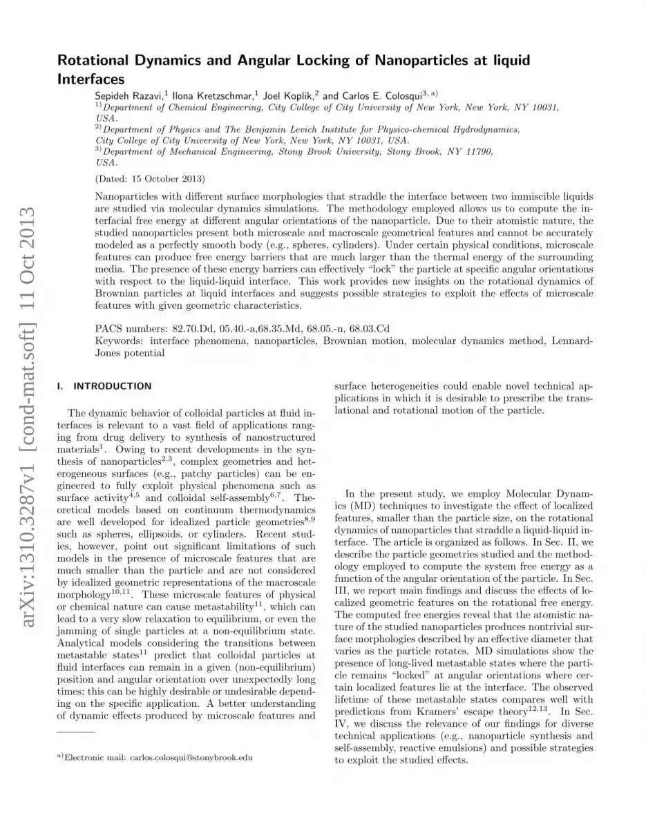
FIG. 1. (color online) (a) Snapshot of the simulation box; (b)Top view; (c) Side view.
II. METHODOLOGY
A. Molecular Dynamics Simulations
Numerical simulations in this work are performed viastandard MD techniques14–16 employing a generalizedLennard-Jones (LJ) potential
U(rij) = 4ǫ
[
(
σ
rij
)12
−Ass′
(
σ
rij
)6]
(1)
Here, rij = |ri − rj| is the separation between any twoatoms (i, j = 1, N) of the species s and s′, σ is the re-pulsive core diameter, and ǫ is the depth of potentialminimum at rij = (2/Ass′)
1/6σ. Following standardprocedures15,16 the potential is cut off at rc = 2.5σ inorder to improve the computational efficiency. The sym-metric coefficient matrix Ass′ = As′s determines the in-tensity of attractive interactions between atoms of dif-ferent species, which in turn determines the wettabilityof the particle17. The simulated system has four atomicspecies; fluid 1 (s = 1), fluid 2 (s = 2), solid particle (s =3), and the surrounding solid wall (s = 4). The temper-ature of the system is maintained constant at T = ǫ/kB(kB is the Boltzmann constant) by a Nose-Hoover ther-mostat, while the number density is ρ = 0.8/σ3 for allspecies. A proper combination of parameters defines acharacteristic time scale τ =
√
mσ2/ǫ where m is theatomic mass; the same atomic mass (m = 1) is employedfor species s = 1–3, whereas the wall atoms have a largermass (mw = 100m).In order to model two macroscopially immiscible flu-
ids, we set A12 = A21 = 0.5 for cross-interactions, whileA11 = A22 = 1 for self-interactions. An interfacial ten-sion of γ = 1.5ǫ/σ2 is measured for this set of parame-ters. The solid particles have symmetric interactions withboth liquids (A13 = A23 = 0.5) and thus exhibit neu-tral wetting (i.e., the equilibrium contact angle is π/2).The two fluids are confined by two solid walls locatedat y = ±Ly/2 and the interface is centered at y = 0.
Periodic boundary conditions are applied in the x and zdirections (see Fig. 1).
B. Effective Size and Morphology of the Nanoparticles
In this work, we study cylindrical particles in order tocharacterize the rotational dynamics about a single axisof rotation (i.e., the longitudinal axis of the cylinder).Furthermore, cylindrical particles are relevant to variousapplications as they are shown to be more effective sta-bilizers than spherical and disk-shaped particles18. Themodeled particles are composed of Np atoms that arecarved out of an atomic cubic lattice. The cubic latticehas a spacing of ∆x = ∆y = ∆z = ρ−1/3 and the centerof each atom is thus located at xijk = (±xi,±xj ,±xk)where xi = (i − 0.5)∆x; i, j, k > 0 are any (nonzero) in-tegers. The atoms of the three particles are chosen to bewithin a cylinder of baseline axial length Lo = 6σ andthree different radii R = 3σ, 6σ, and 8.3σ. The simula-tion domain (cf. Fig. 1) is a box of dimensions Lx = 6R,Ly = 20∆x + 2R, and Lz = 3Lo that scale with theparticle radius.The set of baseline radii employed produces the three
symmetric cross sections reported in Fig. 2(a) where theoutermost atoms are located at (±Xmax,±x1,±x3) and(±x1,±Xmax,±x3) with Xmax = 2.5∆x, 5.5∆x, and7.5∆x, respectively. A different choice of baseline radiiproduces different cross sections where the outermostatomic positions do not lie near the main particle axesas discussed later in Sec. IIID.As described above, the local minimum for the LJ po-
tential employed (Eq. 1) is observed when the interatomicdistance is σa = (2/A13)
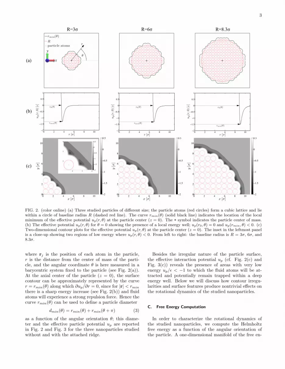
1/6σ ≃ 1.26σ; this value can beconsidered as an effective atomic diameter (i.e., the Vander Waals diameter). Since the atomic diameter is notnegligible when compared to the particle dimensions, weadopt D = 2(Xmax + σa) as the reference particle diam-eter, which gives D ≃ 8σ, 14.5σ, and 19σ for the threestudied particles; similarly the effective axial length isL = 2(x3 + σa) = 7.9σ in all cases. Since typical val-ues of σ range from 0.1 to 0.4 nanometers, the referencediameters of the studied particles correspond to 1 to 8nanometers in physical units. To study the effects of lo-calized features, we attach to the three studied particlesa satellite feature or “ridge” on the surface, consistingof two rows of atoms with length L, that protrudes onelattice unit ∆x ≃ 1.08σ from the original surface alongthe positive x-axis as shown in Fig. 3(a).The atomistic nature of the studied nanoparticles pro-
duces a diversity of localized surface features and theparticles cannot be accurately represented by a perfectlysmooth geometry (e.g., cylinder). In order to elucidatethe particle morphology it is useful to analyze the effec-tive potential
up(r, θ) =
Np∑
j=1
U(|r− rj |) (2)
3
0 2 4 6 8 100
2
4
6
8
10
x [σ]
y[σ]
2
1.5
1
0.5
0
0.5
0 2 4 6 8 100
2
4
6
8
10
x [σ]
y[σ]
2
1.5
1
0.5
0
0.5
0 2 4 6 8 102
1.5
1
0.5
0
0.5
1
r0(θ)
rmin(θ)
r [σ]
up(r,0)[ε]
0 2 4 6 8 100
2
4
6
8
10
x [σ]
y[σ]
2
1.5
1
0.5
0
0.5
2 3 4
2
3
4
2
1.5
1
0.5
0
0.5
θ
r
rmin(θ)
R
particle atoms
(a)
(b)
(c)
R=3σ R=6σ
R=8.3σ
x
y
0 2 4 6 8 102
1.5
1
0.5
0
0.5
1
r0(θ)
rmin(θ)
r [σ]
up(r,0)[ε]
0 2 4 6 8 102
1.5
1
0.5
0
0.5
1
r0(θ)
rmin(θ)
r [σ]
up(r,0)[ε]
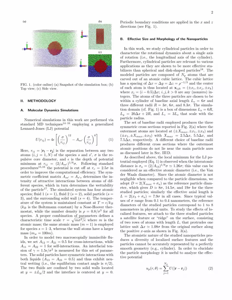
FIG. 2. (color online) (a) Three studied particles of different size; the particle atoms (red circles) form a cubic lattice and liewithin a circle of baseline radius R (dashed red line). The curve rmin(θ) (solid black line) indicates the location of the localminimum of the effective potential up(r, θ) at the particle center (z = 0). The + symbol indicates the particle center of mass.(b) The effective potential up(r, θ) for θ = 0 showing the presence of a local energy well; up(r0, θ) = 0 and up(rmin, θ) < 0. (c)Two-dimensional contour plots for the effective potential up(r, θ) at the particle center (z = 0). The inset in the leftmost panelis a close-up showing two regions of low energy where up(r, θ) < 0. From left to right: the baseline radius is R = 3σ, 6σ, and8.3σ.
where rj is the position of each atom in the particle,r is the distance from the center of mass of the parti-cle, and the angular coordinate θ is here measured in abarycentric system fixed to the particle (see Fig. 2(a)).At the axial center of the particle (z = 0), the surfacecontour can be approximately represented by the curver = rmin(θ) along which ∂up/∂r = 0, since for |r| < rmin
there is a sharp energy increase (see Fig. 2(b)) and fluidatoms will experience a strong repulsion force. Hence thecurve rmin(θ) can be used to define a particle diameter
dmin(θ) = rmin(θ) + rmin(θ + π) (3)
as a function of the angular orientation θ; this diame-ter and the effective particle potential up are reportedin Fig. 2 and Fig. 3 for the three nanoparticles studiedwithout and with the attached ridge.
Besides the irregular nature of the particle surface,the effective interaction potential up (cf. Fig. 2(c) andFig. 3(c)) reveals the presence of areas with very lowenergy up/ǫ < −1 to which the fluid atoms will be at-tracted and potentially remain trapped within a deepenergy well. Below we will discuss how contour irregu-larities and surface features produce nontrivial effects onthe rotational dynamics of the studied nanoparticles.
C. Free Energy Computation
In order to characterize the rotational dynamics ofthe studied nanoparticles, we compute the Helmholtzfree energy as a function of the angular orientation ofthe particle. A one-dimensional manifold of the free en-
4
θ
r
rmin(θ)
R
particle atoms
(a)
(b)
R=3σ R=6σ
R=8.3σ
x
y
0 2 4 6 8 100
2
4
6
8
10
x [σ]
y[σ]
2
1.5
1
0.5
0
0.5
0 2 4 6 8 100
2
4
6
8
10
x [σ]
y[σ]
2
1.5
1
0.5
0
0.5
0 2 4 6 8 100
2
4
6
8
10
x [σ]
y[σ]
2
1.5
1
0.5
0
0.5
2 31
3
2
4
2
1.5
1
0.5
0
0.5
FIG. 3. (color online) (a) Three studied particles of different size with a satellite feature, the particle atoms (red circles) forma cubic lattice and lie within a circle of baseline radius R (dashed red line) while a ridge of size ∆D ∼ 1.08σ is attached. Thecurve rmin(θ) (solid black line) indicates the location of the local minimum of the effective potential up(r, θ) at the particlecenter (z = 0). The + symbol indicates the particle center of mass. (b) Two-dimensional contour plots for the effective potentialup(r, θ) at the particle center (z = 0). The inset in the leftmost panel is a close-up showing a large region with low energyup(r, θ) < 0. From left to right: the baseline radius is R = 3σ, 6σ, and 8.3σ.
ergy landscape is computed using constrained moleculardynamics19,20. In this type of MD simulation the angu-lar orientation θ with respect to the fluid-fluid interfaceis adjusted in a sequence of rotation-relaxation steps; allother degrees of freedom are prescribed, the center ofmass of the particle is fixed at y = 0. Each step in thesequence consists of a ∆θ = 1◦ rotation about the z-axisin a time interval tr = 500τ , after which the angular ori-entation θ is constrained during an equally long intervalof tf = 500τ . During this relaxation interval tf , the time-averaged torque 〈T 〉θ⋆ about the z-axis is measured andthe sequence of rotation-relaxation steps is performed forθ = [0, 2π].The Helmholtz free energy F is determined by the work
done on the system during the imposed quasi-static rota-tion of the particle. Changes in the free energy of the sys-tem are thus computed by integrating the time-averagedtorque:
∆F(θ) = F(θ)−F(θref) = −
∫ θ
θref
〈T 〉θ⋆ dθ⋆ (4)
where θref is a reference orientation; for the studied par-ticles it is convenient to choose θref = π/2 as explainedbelow.
D. Free Energy and Effective Diameter
According to continuum thermodynamics and underthe studied conditions (i.e., constant volume and tem-perature, neutral wetting), changes in the Helmholtz freeenergy are determined by the area removed from thefluid-fluid interface (i.e., change in interfacial free en-ergy). When the particle straddles the interface at agiven angle θ, two contact lines are formed at distancesr(θ) and r(θ + π) from the particle center of mass. Theinterfacial area A(θ) = Ld(θ) removed as the particlerotates is determined by the effective particle diameterd(θ) = r(θ) + r(θ+ π) given by the distance between thetwo contact lines. Assuming a planar interface lying onthe horizontal xz-plane where y = 0, the rotational freeenergy of the studied particles can be cast as
F(θ) = C − γLd(θ) (5)
where C is an arbitrary constant and γ is the interfacialtension of the two liquids.Given the symmetry with respect to the xz-plane of the
three modeled particles, in both cases with or without asatellite feature, we have d(π/2) = 2r(π/2) = 2r(−π/2).Considering the finite size of particle atoms and their in-
5
2
4
6
8
10
30
210
60
240
90
270
120
300
150
330
180 0
2
4
6
8
30
210
60
240
90
270
120
300
150
330
180 0
0 5 10 15
6
6.5
7
7.5
8
8.5
Rθ[σ]
1
2
3
4
30
210
60
240
90
270
120
300
150
330
180 0
(a) (b)
R=3σ
R=6σ
R=8.3σ
0 5
3
3.5
4
4.5
5
5.5
Rθ[σ]
dmin(θ)2 [Eq.3]
d(θ)2 [Eq.6]
0 5 10 15 20 25
8.5
9
9.5
10
10.5
Rθ[σ]
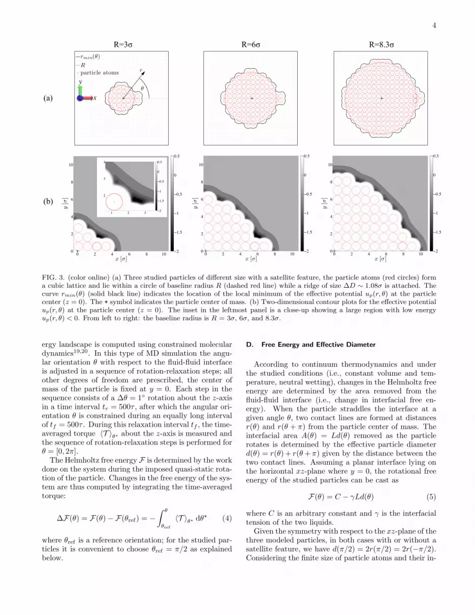
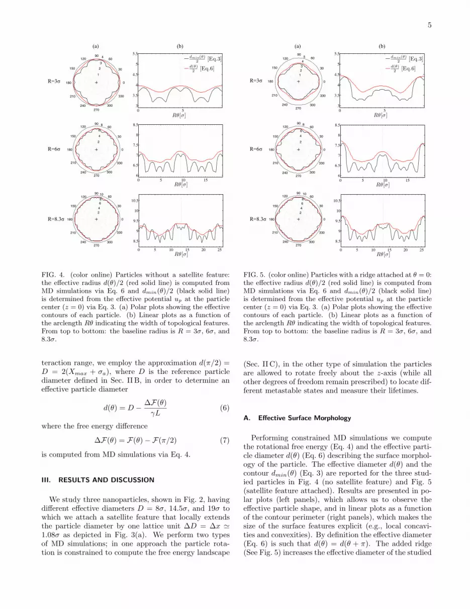
FIG. 4. (color online) Particles without a satellite feature:the effective radius d(θ)/2 (red solid line) is computed fromMD simulations via Eq. 6 and dmin(θ)/2 (black solid line)is determined from the effective potential up at the particlecenter (z = 0) via Eq. 3. (a) Polar plots showing the effectivecontours of each particle. (b) Linear plots as a function ofthe arclength Rθ indicating the width of topological features.From top to bottom: the baseline radius is R = 3σ, 6σ, and8.3σ.
teraction range, we employ the approximation d(π/2) =D = 2(Xmax + σa), where D is the reference particlediameter defined in Sec. II B, in order to determine aneffective particle diameter
d(θ) = D −∆F(θ)
γL(6)
where the free energy difference
∆F(θ) = F(θ)−F(π/2) (7)
is computed from MD simulations via Eq. 4.
III. RESULTS AND DISCUSSION
We study three nanoparticles, shown in Fig. 2, havingdifferent effective diameters D = 8σ, 14.5σ, and 19σ towhich we attach a satellite feature that locally extendsthe particle diameter by one lattice unit ∆D = ∆x ≃1.08σ as depicted in Fig. 3(a). We perform two typesof MD simulations; in one approach the particle rota-tion is constrained to compute the free energy landscape
2
4
6
8
10
30
210
60
240
90
270
120
300
150
330
180 0
0 5 10 15 20 25
8.5
9
9.5
10
10.5
Rθ[σ]
2
4
6
8
30
210
60
240
90
270
120
300
150
330
180 0
0 5 10 15
6
6.5
7
7.5
8
8.5
Rθ[σ]
1
2
3
4
5
30
210
60
240
90
270
120
300
150
330
180 0
0 5
3
3.5
4
4.5
5
5.5
Rθ[σ]
dmin(θ)2 [Eq.3]
d(θ)2 [Eq.6]
(a) (b)
R=3σ
R=6σ
R=8.3σ
FIG. 5. (color online) Particles with a ridge attached at θ = 0:the effective radius d(θ)/2 (red solid line) is computed fromMD simulations via Eq. 6 and dmin(θ)/2 (black solid line)is determined from the effective potential up at the particlecenter (z = 0) via Eq. 3. (a) Polar plots showing the effectivecontours of each particle. (b) Linear plots as a function ofthe arclength Rθ indicating the width of topological features.From top to bottom: the baseline radius is R = 3σ, 6σ, and8.3σ.
(Sec. II C), in the other type of simulation the particlesare allowed to rotate freely about the z-axis (while allother degrees of freedom remain prescribed) to locate dif-ferent metastable states and measure their lifetimes.
A. Effective Surface Morphology
Performing constrained MD simulations we computethe rotational free energy (Eq. 4) and the effective parti-cle diameter d(θ) (Eq. 6) describing the surface morphol-ogy of the particle. The effective diameter d(θ) and thecontour dmin(θ) (Eq. 3) are reported for the three stud-ied particles in Fig. 4 (no satellite feature) and Fig. 5(satellite feature attached). Results are presented in po-lar plots (left panels), which allows us to observe theeffective particle shape, and in linear plots as a functionof the contour perimeter (right panels), which makes thesize of the surface features explicit (e.g., local concavi-ties and convexities). By definition the effective diameter(Eq. 6) is such that d(θ) = d(θ + π). The added ridge(See Fig. 5) increases the effective diameter of the studied
6
(a)
(b)
(c)
0 30 60 90 120 150 18020
15
10
5
0
5
10
15
20
θ[◦]
∆F[ε]
∆F2
∆F1
0 30 60 90 120 150 18020
15
10
5
0
5
10
15
20
θ[◦]
∆F[ε]
∆F1
∆F2
0 30 60 90 120 150 18020
15
10
5
0
5
10
15
20
θ[◦]
∆F[ε]
∆F1
∆F2
∆DD∆θf
tan(∆θf/2) =∆D
∆D +D
∆θf/2
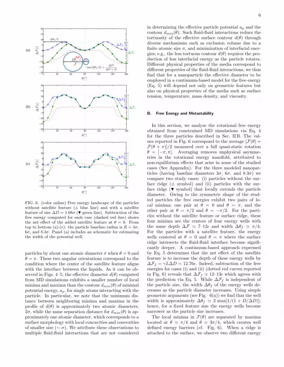
FIG. 6. (color online) Free energy landscape of the particleswithout satellite feature (△ blue line) and with a satellitefeature of size ∆D = 1.08σ (H green line). Subtraction of thefree energy computed for each case (dashed red line) showsthe net effect of the added satellite feature at θ = 0. Fromtop to bottom (a)-(c): the particle baseline radius is R = 3σ,6σ, and 8.3σ. Panel (a) includes an schematic for estimatingthe width of the potential well.
particles by about one atomic diameter σ when θ = 0 andθ = π. These two angular orientations correspond to thecondition where the center of the satellite feature alignswith the interface between the liquids. As it can be ob-served in Figs. 4–5, the effective diameter d(θ) computedfrom MD simulations exhibits a smaller number of localminima and maxima than the contour dmin(θ) of minimalpotential energy, up, for single atoms interacting with theparticle. In particular, we note that the minimum dis-tance between neighboring minima and maxima in theprofile of d(θ) is approximately two atomic diameters,2σ, while the same separation distance for dmin(θ) is ap-proximately one atomic diameter, which corresponds to asurface morphology with local concavities and convexitiesof smaller size (∼ σ). We attribute these observations tomultiple fluid-fluid interactions that are not considered
in determining the effective particle potential up and thecontour dmin(θ). Such fluid-fluid interactions reduce thetortuosity of the effective surface contour d(θ) throughdiverse mechanisms such as exclusion volume due to afinite atomic size σ, and minimization of interfacial ener-gies; e.g., the less tortuous contour d(θ) requires the pro-duction of less interfacial energy as the particle rotates.Different physical properties of the media correspond todifferent properties of the fluid-fluid interactions, we thusfind that for a nanoparticle the effective diameter to beemployed in a continuum-based model for the free energy(Eq. 5) will depend not only on geometric features butalso on physical properties of the media such as surfacetension, temperature, mass density, and viscosity.
B. Free Energy and Metastability
In this section, we analyze the rotational free energyobtained from constrained MD simulations via Eq. 4for the three particles described in Sec. II B. The val-ues reported in Fig. 6 correspond to the average [F(θ) +F(θ + π)]/2 measured over a full quasi-static rotationθ = [−π, π]. Averaging removes unphysical asymme-tries in the rotational energy manifold, attributed tonon-equilibrium effects that arise in some of the studiedcases (See Appendix). For the three modeled nanopar-ticles (having baseline diameters 3σ, 6σ, and 8.3σ) wecompare two study cases: (i) particles without the sur-face ridge (△ symbol) and (ii) particles with the sur-face ridge (H symbol) that locally extends the particlediameter. Owing to the symmetric shape of the stud-ied particles the free energies exhibit two pairs of lo-cal minima; one pair at θ = 0 and θ = π, and theother pair at θ = π/2 and θ = −π/2. For the parti-cles without the satellite feature or surface ridge, thesefour minima are the centers of four energy wells withthe same depth ∆F ≃ 7–12ǫ and width ∆θf ≃ π/4.For the particles with a satellite feature, the energywells centered at θ = 0 and θ = π where the surfaceridge intersects the fluid-fluid interface become signifi-cantly deeper. A continuum-based approach expressedby Eq. 5 determines that the net effect of the satellitefeature is to increase the depth of these energy wells by∆Ff = γL∆D = 12.76ǫ. Indeed, subtraction of the freeenergies for cases (i) and (ii) (dotted red curves reportedin Fig. 6) reveals that ∆Ff ≃ 12–13ǫ which agrees withthe prediction via Eq. 5. While ∆Ff is independent ofthe particle size, the width ∆θf of the energy wells de-creases as the particle diameter increases. Using simplegeometric arguments (see Fig. 6(a)) we find that the wellwidth is approximately ∆θf ≃ 2 atan[1/(1 + D/∆D)];hence, for a fixed feature size the energy wells becomenarrower as the particle size increases.The local minima in F(θ) are separated by maxima
located at θ ≃ π/4 and θ ≃ 3π/4, which creates welldefined energy barriers (cf. Fig. 6). When a ridge isattached to the surface, we observe two different energy
7
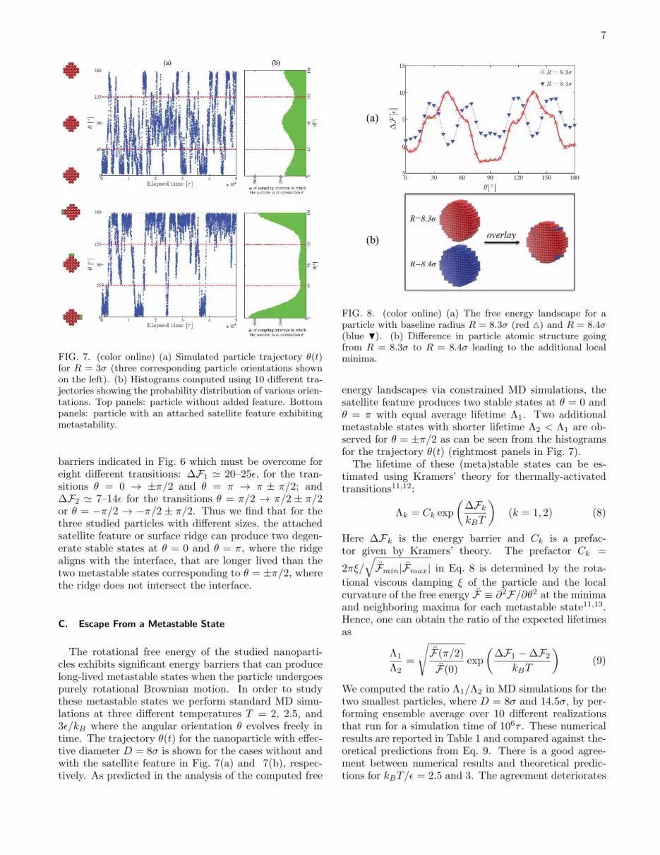
FIG. 7. (color online) (a) Simulated particle trajectory θ(t)for R = 3σ (three corresponding particle orientations shownon the left). (b) Histograms computed using 10 different tra-jectories showing the probability distribution of various orien-tations. Top panels: particle without added feature. Bottompanels: particle with an attached satellite feature exhibitingmetastability.
barriers indicated in Fig. 6 which must be overcome foreight different transitions: ∆F1 ≃ 20–25ǫ, for the tran-sitions θ = 0 → ±π/2 and θ = π → π ± π/2; and∆F2 ≃ 7–14ǫ for the transitions θ = π/2 → π/2 ± π/2or θ = −π/2 → −π/2 ± π/2. Thus we find that for thethree studied particles with different sizes, the attachedsatellite feature or surface ridge can produce two degen-erate stable states at θ = 0 and θ = π, where the ridgealigns with the interface, that are longer lived than thetwo metastable states corresponding to θ = ±π/2, wherethe ridge does not intersect the interface.
C. Escape From a Metastable State
The rotational free energy of the studied nanoparti-cles exhibits significant energy barriers that can producelong-lived metastable states when the particle undergoespurely rotational Brownian motion. In order to studythese metastable states we perform standard MD simu-lations at three different temperatures T = 2, 2.5, and3ǫ/kB where the angular orientation θ evolves freely intime. The trajectory θ(t) for the nanoparticle with effec-tive diameter D = 8σ is shown for the cases without andwith the satellite feature in Fig. 7(a) and 7(b), respec-tively. As predicted in the analysis of the computed free
FIG. 8. (color online) (a) The free energy landscape for aparticle with baseline radius R = 8.3σ (red △) and R = 8.4σ(blue H). (b) Difference in particle atomic structure goingfrom R = 8.3σ to R = 8.4σ leading to the additional localminima.
energy landscapes via constrained MD simulations, thesatellite feature produces two stable states at θ = 0 andθ = π with equal average lifetime Λ1. Two additionalmetastable states with shorter lifetime Λ2 < Λ1 are ob-served for θ = ±π/2 as can be seen from the histogramsfor the trajectory θ(t) (rightmost panels in Fig. 7).The lifetime of these (meta)stable states can be es-
timated using Kramers’ theory for thermally-activatedtransitions11,12:
Λk = Ck exp
(
∆Fk
kBT
)
(k = 1, 2) (8)
Here ∆Fk is the energy barrier and Ck is a prefac-tor given by Kramers’ theory. The prefactor Ck =
2πξ/√
F̈min|F̈max| in Eq. 8 is determined by the rota-
tional viscous damping ξ of the particle and the localcurvature of the free energy F̈ ≡ ∂2F/∂θ2 at the minimaand neighboring maxima for each metastable state11,13.Hence, one can obtain the ratio of the expected lifetimesas
Λ1
Λ2=
√
F̈(π/2)
F̈(0)exp
(
∆F1 −∆F2
kBT
)
(9)
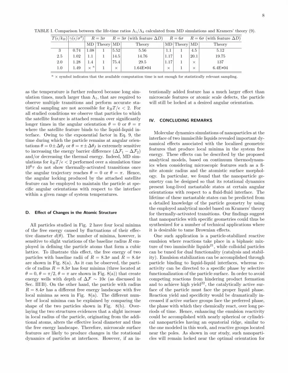
We computed the ratio Λ1/Λ2 in MD simulations for thetwo smallest particles, where D = 8σ and 14.5σ, by per-forming ensemble average over 10 different realizationsthat run for a simulation time of 106τ . These numericalresults are reported in Table 1 and compared against the-oretical predictions from Eq. 9. There is a good agree-ment between numerical results and theoretical predic-tions for kBT/ǫ = 2.5 and 3. The agreement deteriorates
8
TABLE I. Comparison between the life-time ratios Λ1/Λ2 calculated from MD simulations and Kramers’ theory (9).
T (ǫ/kB) γ(ǫ/σ2) R = 3σ R = 3σ (with feature ∆D) R = 6σ R = 6σ (with feature ∆D)
MD Theory MD Theory MD Theory MD Theory
3 0.74 1.08 1 5.52 5.56 1.1 1 4.5 5.12
2.5 1.02 1.1 1 14.5 14.76 1.17 1 20.1 19.75
2.0 1.28 1.4 1 75.4 29.5 1.17 1 × 137
1.0 1.49 ×a 1 × 1.64E+04 × 1 × 6.4E+04
a× symbol indicates that the available computation time is not enough for statistically relevant sampling.
as the temperature is further reduced because long sim-ulation times, much larger than Λ1, that are required toobserve multiple transitions and perform accurate sta-tistical sampling are not accessible for kBT/ǫ < 2. Forall studied conditions we observe that particles to whichthe satellite feature is attached remain over significantlylonger times in the angular orientation θ = 0 or θ = πwhere the satellite feature binds to the liquid-liquid in-terface. Owing to the exponential factor in Eq. 9, thetime during which the particle remains at angular orien-tations θ = 0±∆θf or θ = π±∆θf is extremely sensitiveto increasing the energy barrier difference (∆F1 −∆F2)and/or decreasing the thermal energy. Indeed, MD sim-ulations for kBT/ǫ < 2 performed over a simulation time106τ do not show thermally-activated transitions oncethe angular trajectory reaches θ = 0 or θ = π. Hence,the angular locking produced by the attached satellitefeature can be employed to maintain the particle at spe-cific angular orientations with respect to the interfacewithin a given range of system temperatures.
D. Effect of Changes in the Atomic Structure
All particles studied in Fig. 2 have four local minimaof the free energy caused by fluctuations of their effec-tive diameter d(θ). The number of minima, however, issensitive to slight variations of the baseline radius R em-ployed in defining the particle atoms that form a cubiclattice. To illustrate this effect, the free energy of twoparticles with baseline radii of R = 8.3σ and R = 8.4σare shown in Fig. 8(a). As it can be observed, the parti-cle of radius R = 8.3σ has four minima (three located atθ = 0, θ = π/2, θ = π are shown in Fig. 8(a)) that createenergy wells with depth of ∆F ∼ 10ǫ (as discussed inSec. III B). On the other hand, the particle with radiusR = 8.4σ has a different free energy landscape with fivelocal minima as seen in Fig. 8(a). The different num-ber of local minima can be explained by comparing theshape of the two particles shown in Fig. 8(b). Over-laying the two structures evidences that a slight increasein local radius of the particle, originating from the addi-tional atoms, alters the effective local diameter and thusthe free energy landscape. Therefore, microscale surfacefeatures are likely to produce changes in the rotationaldynamics of particles at interfaces. However, if an in-
tentionally added feature has a much larger effect thanmicroscale features or atomic scale defects, the particlewill still be locked at a desired angular orientation.
IV. CONCLUDING REMARKS
Molecular dynamics simulations of nanoparticles at theinterface of two immiscible liquids revealed important dy-namical effects associated with the localized geometricfeatures that produce local minima in the system freeenergy. These effects can be described by the proposedanalytical models, based on continuum thermodynam-ics when considering microscopic features such as a fi-nite atomic radius and the atomistic surface morphol-ogy. In particular, we found that the nanoparticle ge-ometry can be designed so that its rotational dynamicspresent long-lived metastable states at certain angularorientations with respect to a fluid-fluid interface. Thelifetime of these metastable states can be predicted froma detailed knowledge of the particle geometry by usingthe employed analytical model based on Kramers’ theoryfor thermally-activated transitions. Our findings suggestthat nanoparticles with specific geometries could thus besynthesized for a number of technical applications whereit is desirable to tame Brownian effects.One such application is a particle-stabilized reactive
emulsion where reactions take place in a biphasic mix-ture of two immiscible liquids21, while colloidal particlescan be tuned for dual functionality (catalysis and stabil-ity). Emulsion stabilization can be accomplished throughparticle binding to liquid-liquid interfaces, whereas re-activity can be directed to a specific phase by selectivefunctionalization of the particle surface. In order to avoidcompeting reactions from hindering product formationand to achieve high yield22, the catalytically active sur-face of the particle must face the proper liquid phase.Reaction yield and specificity would be dramatically in-creased if active surface groups face the preferred phase,the phase with which they chemically react, over long pe-riods of time. Hence, enhancing the emulsion reactivitycould be accomplished with nearly spherical or cylindri-cal nanoparticles having an equatorial ridge, similar tothe one modeled in this work, and reactive groups locatednear the poles. As shown in our study, such nanoparti-cles will remain locked near the optimal orientation for
9
enhanced reactivity when the system temperature is re-duced below a given threshold value. Other importantapplications where similar ideas can be exploited are syn-thesis of patchy particles, drug delivery, surface cataly-sis, and interfacial self-assembly. Future work will in-clude studying the coupling between translational androtational degrees of freedom (see Appendix), which re-quires the computation of multidimensional free energylandscapes.
ACKNOWLEDGMENTS
This work was partially supported by the City Uni-versity of New York High Performance Computing Cen-ter under NSF Grants CNS-0855217 and CNS-0958379.Support from the National Science Foundation throughawards CBET-1067501 and PREM (DMR-0934206) isacknowledged.
Appendix
1. Density Profiles and Mean Potential Field
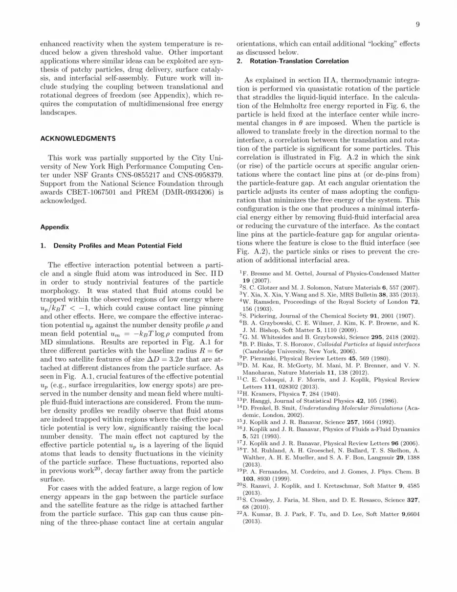
The effective interaction potential between a parti-cle and a single fluid atom was introduced in Sec. IIDin order to study nontrivial features of the particlemorphology. It was stated that fluid atoms could betrapped within the observed regions of low energy whereup/kBT < −1, which could cause contact line pinningand other effects. Here, we compare the effective interac-tion potential up against the number density profile ρ andmean field potential um = −kBT log ρ computed fromMD simulations. Results are reported in Fig. A.1 forthree different particles with the baseline radius R = 6σand two satellite features of size ∆D = 3.2σ that are at-tached at different distances from the particle surface. Asseen in Fig. A.1, crucial features of the effective potentialup (e.g., surface irregularities, low energy spots) are pre-served in the number density and mean field where multi-ple fluid-fluid interactions are considered. From the num-ber density profiles we readily observe that fluid atomsare indeed trapped within regions where the effective par-ticle potential is very low, significantly raising the localnumber density. The main effect not captured by theeffective particle potential up is a layering of the liquidatoms that leads to density fluctuations in the vicinityof the particle surface. These fluctuations, reported alsoin previous work20, decay farther away from the particlesurface.For cases with the added feature, a large region of low
energy appears in the gap between the particle surfaceand the satellite feature as the ridge is attached fartherfrom the particle surface. This gap can thus cause pin-ning of the three-phase contact line at certain angular
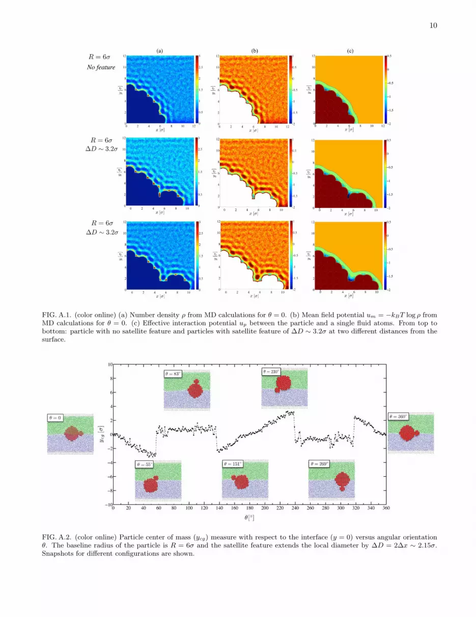
orientations, which can entail additional “locking” effectsas discussed below.2. Rotation-Translation Correlation
As explained in section IIA, thermodynamic integra-tion is performed via quasistatic rotation of the particlethat straddles the liquid-liquid interface. In the calcula-tion of the Helmholtz free energy reported in Fig. 6, theparticle is held fixed at the interface center while incre-mental changes in θ are imposed. When the particle isallowed to translate freely in the direction normal to theinterface, a correlation between the translation and rota-tion of the particle is significant for some particles. Thiscorrelation is illustrated in Fig. A.2 in which the sink(or rise) of the particle occurs at specific angular orien-tations where the contact line pins at (or de-pins from)the particle-feature gap. At each angular orientation theparticle adjusts its center of mass adopting the configu-ration that minimizes the free energy of the system. Thisconfiguration is the one that produces a minimal interfa-cial energy either by removing fluid-fluid interfacial areaor reducing the curvature of the interface. As the contactline pins at the particle-feature gap for angular orienta-tions where the feature is close to the fluid interface (seeFig. A.2), the particle sinks or rises to prevent the cre-ation of additional interfacial area.
1F. Bresme and M. Oettel, Journal of Physics-Condensed Matter19 (2007).
2S. C. Glotzer and M. J. Solomon, Nature Materials 6, 557 (2007).3Y. Xia, X. Xia, Y.Wang and S. Xie, MRS Bulletin 38, 335 (2013).4W. Ramsden, Proceedings of the Royal Society of London 72,156 (1903).
5S. Pickering, Journal of the Chemical Society 91, 2001 (1907).6B. A. Grzybowski, C. E. Wilmer, J. Kim, K. P. Browne, and K.J. M. Bishop, Soft Matter 5, 1110 (2009).
7G. M. Whitesides and B. Grzybowski, Science 295, 2418 (2002).8B. P. Binks, T. S. Horozov, Colloidal Particles at liquid interfaces
(Cambridge University, New York, 2006).9P. Pieranski, Physical Review Letters 45, 569 (1980).
10D. M. Kaz, R. McGorty, M. Mani, M. P. Brenner, and V. N.Manoharan, Nature Materials 11, 138 (2012).
11C. E. Colosqui, J. F. Morris, and J. Koplik, Physical ReviewLetters 111, 028302 (2013).
12H. Kramers, Physica 7, 284 (1940).13P. Hanggi, Journal of Statistical Physics 42, 105 (1986).14D. Frenkel, B. Smit, Understanding Molecular Simulations (Aca-demic, London, 2002).
15J. Koplik and J. R. Banavar, Science 257, 1664 (1992).16J. Koplik and J. R. Banavar, Physics of Fluids a-Fluid Dynamics5, 521 (1993).
17J. Koplik and J. R. Banavar, Physical Review Letters 96 (2006).18T. M. Ruhland, A. H. Groeschel, N. Ballard, T. S. Skelhon, A.Walther, A. H. E. Mueller, and S. A. F. Bon, Langmuir 29, 1388(2013).
19P. A. Fernandes, M. Cordeiro, and J. Gomes, J. Phys. Chem. B103, 8930 (1999).
20S. Razavi, J. Koplik, and I. Kretzschmar, Soft Matter 9, 4585(2013).
21S. Crossley, J. Faria, M. Shen, and D. E. Resasco, Science 327,68 (2010).
22A. Kumar, B. J. Park, F. Tu, and D. Lee, Soft Matter 9,6604(2013).
10
FIG. A.1. (color online) (a) Number density ρ from MD calculations for θ = 0. (b) Mean field potential um = −kBT log ρ fromMD calculations for θ = 0. (c) Effective interaction potential up between the particle and a single fluid atoms. From top tobottom: particle with no satellite feature and particles with satellite feature of ∆D ∼ 3.2σ at two different distances from thesurface.
FIG. A.2. (color online) Particle center of mass (ycg) measure with respect to the interface (y = 0) versus angular orientationθ. The baseline radius of the particle is R = 6σ and the satellite feature extends the local diameter by ∆D = 2∆x ∼ 2.15σ.Snapshots for different configurations are shown.