laminar counterflow recuperator rotational phase separator
TRANSCRIPT

Innovative process design : laminar counterflow recuperatorrotational phase separatorCitation for published version (APA):Kemenade, van, H. P. (2006). Innovative process design : laminar counterflow recuperator rotational phaseseparator. Technische Universiteit Eindhoven.
Document status and date:Published: 01/01/2006
Document Version:Publisher’s PDF, also known as Version of Record (includes final page, issue and volume numbers)
Please check the document version of this publication:
• A submitted manuscript is the version of the article upon submission and before peer-review. There can beimportant differences between the submitted version and the official published version of record. Peopleinterested in the research are advised to contact the author for the final version of the publication, or visit theDOI to the publisher's website.• The final author version and the galley proof are versions of the publication after peer review.• The final published version features the final layout of the paper including the volume, issue and pagenumbers.Link to publication
General rightsCopyright and moral rights for the publications made accessible in the public portal are retained by the authors and/or other copyright ownersand it is a condition of accessing publications that users recognise and abide by the legal requirements associated with these rights.
• Users may download and print one copy of any publication from the public portal for the purpose of private study or research. • You may not further distribute the material or use it for any profit-making activity or commercial gain • You may freely distribute the URL identifying the publication in the public portal.
If the publication is distributed under the terms of Article 25fa of the Dutch Copyright Act, indicated by the “Taverne” license above, pleasefollow below link for the End User Agreement:www.tue.nl/taverne
Take down policyIf you believe that this document breaches copyright please contact us at:[email protected] details and we will investigate your claim.
Download date: 30. Jul. 2022

··r .
laminar counterflow recuperator rotational,phase separator
Erik van Kemenade
••• .-•.. "'<\.
,•;... •• ..-. , ,.j
... . ........

Innovative Process Design
laminar counterflow reeoperator rotational phase separator
Erik van Kemenade

ii
Copyright ©2006 byErik van Kemenade
All rights reserved.
No part of the material protected by this copyright notice may be reproduced in any
form whatsoever or by any means, electron ie or mechanica!, included photocopying,
recording or by any information starage a nd retrieval system, without permission
from the author.
A catalogue record is available from the Library Eindhoven University ofTechnology
lSBN-1!): 90-386-2928-1
ISBN-13: 978-90-386-2928-5

Contents
Preface
Nomendature
1 lnnovations and patents
1.1 Goals of innovation .
1.2 i nnovation diffusion
1.3 Pa ten ts . . . . . . . . 1.4 Pa tent application ..
1.5 Filing an application
1.6 Economie rationale
1.7 Scope .. .
2 Energy market
2.1 Energy for the developing world
2.2 Reserves and energy security ..
2.2.1 Peak debate ... . .. . .
2.2.2 Resource holders perspective
2.2.3 Coat, renewables and nuclear
2.3 Emissions .....
2.4 Short term forecast . . . . . .
3 Laminar counterflow recuperator
3.1 Thermionic energy conversion
3.1.1 Research history . .. .
3.1.2 research at the TU / e ..
3.1 .3 Thermion ie cogeneration system
3.1.4 Test rig . . . . . . .
3.2 Compact heat exchangers
3.3 Design considerations ..
V
vii
1
1
2
3
5
8
10
12
15
16
18
19
22
24
24
28
29
29 30 31
32
34
37
38

iv
3.3.1 Thermadynamie analysis
33.2 Test rig .. . .... .
3.4 Prototypes . ...... . . .
3.4.1 Recuperative burner
3.4.2 Design process . . .
3.4.3 experiments ... . .
3.4.4 Polymer heat exchanger
3.5 Market penetranon ..
4 Rotational phase separator
4.1 Gas centrifuges
4.2 Working principle .
4.3 prototypes . ....
4.3.1 Cleaning . .
4.3.2 Manufacturing and costs
4.4 Naturally driven RPS ..... .
4.4.1 Natura] gas production
4.4.2 State of the art . . .. .
4.4.3 Design considerations
4.4.4 Experiments ..
4.5 Further developments ..
5 Separation by phase transition
5.1 Aerosol emissions in biomass cambustion
5.2 Condensing heat exchanger
5.2.1 Model .... . .
5.2.2 Heat exchangers
5.2.3 Experiments .. .
5.2.4 Current status ..
5.3 Centrifugal gas cleaning
5.3.1 Centrifugation with wall condensation
5.3.2 Cooling and separating
5.4 RPS versus Cyclone .
5.5 Current status
6 ·~•osure
7 Literature
CONTENTS
39 43
49
50 51
55 56
59
63
63 64
68 71
73
74 75 77
78 83
93
97
97
100 101
105
108 112
113
114
116
121
128
131
135

Preface
This text is prepared for the graduale course "Innovative Process Technology" at
the Eindhoven University of Technology, department mechanica) engineering. The
course is intended to provide insight in the relation between scientific (university)
research and industrial applications based on the activities in the section Process Technology. Chapter 1, about innovations and intellectual property management is
mainly basedon the lectures given in 2004 and 2005 by ir. Hein v.d. Heuvel (Paten
twerk b.v.) with additional information from Wikipedia. Chapter 2 about the Energy market is excerpted from "The Shell Global Scenario's to 2025" (2006) and BP's "Sta
tistica) Review of World Energy 2006". Apart from the lectures of ir. Bart Veltkamp,
for compiling chapter 3, "the Iaminar counterflow recuperator", I had access to the
LEVEL energy technology b.v. internal reports, while prof. dr. ir. Bert Brouwers and
dr. ir. Eva Mondt supplied the material for chapter 3 and 4 about the rotational phase
separator. The latest developments in using phase transfer mechanisms with the heat
exchanger and the rotational phase separator, are based on the work of ir. Carlo de
Best and ir. Ralph van Wissen tagether with the lecture of dr. Michael Golombok
(Royal Dutch Shell PLC)in 2004.
Eindhoven, August 2006,
Erik van Kemenade

VI Prrface

Nomenclature
A surface [m2] R gas constant 8.134 JMol- 1K-1
Cp heat ca pa city [Jkg-1 K- 1] R radius [m]
Cc Cunningham slip factor T radial position [m[
Cm torque coefficient [ -] Re Reynolds number
D diffusion coefficient [ m2ç 1] 5 entropy generation [WJ
Dh hydraulic diameter [m] Sc Schmidt number
de channel diameter [m] s distance [m]
dp partiele diameter [m] T temperature [K]
dp plate thickness [m] Ta Taylor number [-]
E efficiency [ -] time [s]
E energy consumption ra te [Jç 1] Ub bulk velocity [mçl]
F force [N] ud deposition velocity [ms-1]
F1h thermophoretic force [N] Uf axial fluid velocity [mÇ1]
f friction factor [ -] Up partiele velocity [mç1 ]
G angular momenturn [Nm] Uth thermophoretic velocity[ mÇ 1]
H heating value [Jkg-1] Va x axial velocity [mç1]
H height [m] VaxO axial velocity at t = 0 [ mÇ 1]
H correction factor Vt tangential velocity at t = 0 [mç 1]
J mass flux per unit length VtO tangential velocity at t = 0 [mç 1 ]
[kg m-lçl] w width [m]
k total heat transfer coefficient w axial velocity [ mÇ 1]
[Wm- 2K-1] w tangential velocity [mç1]
L length [m] x male fraction
M partiele concentra ti on x* ratio length/diameter [-] [mgNm-3]
ri1 mass flow [kg ç 1] 11: heat transfer coefficient[Wm- 2K-1 J
N number concentration [m-3] 11: blade angle [rad]
Ns entropy generation number f3 axial velocity decay parameter[-[
n strain hardening exponent t5 inner to outer diameter ratio[-]
p pressure [Pa] € effectivi ty [ -]
Q volume vlow [m3ç 1] € surface reduction ratio[-]

viii Nomendature
E specific energy consumption [Jkg- 1]
IJ efficiency
cp stochiometric air ratio
(/5 correction factor [ -]
;\ free molecular length [-]
;\ heat conduction coefficient [Wm- 1K-1]
11 dynamic viscosity p density [kg m-3]
T relaxation time [s]
T residence time [s]
e angular position [rad] w mass fraction [-]
n angularvelocity[radç1]

1 Innovations and patents
"Innovation" can be defined as the process of making changes to something estab
lished by introducing something new and is a continuation of an invention, a creation
(a new device or process) resulting from study and experimentation, in the sense that
it involves a change that creates a new dimension of performance. lnnovations in
volve a series of scientific, technological, organisational, financial and commercial
activities. The major part of what is called innovation is essentially evolutionary in
character: a step forward along a technology trajectory, or from the known to the
unknown, with a high chance of success and low uncertainty about outcomes. The
subject of this course however is radical innovation: it involves larger leaps of un
derstanding, perhaps demanding a new way of seeing the whole problem, probably
takinga much larger risk than many people involved are happy a bout. The chancesof
success are difficult to estimate. There may be considerable opposition to the proposal
and q uestions a bout the ethics, practicality or costof the proposal may be raised. Peo
ple may question if this is, or is not, an advancement of a technology or process.
1.1 Goals of innovation
Technological companies need to in nova te in order to survive as a Jack of i nnovation
leads to stagnation. It is not surprising, therefore, that companies have embraced the
management of innovation enthusiastically, with the primary goal of driving growth
and, consequently, improving shareholder value. In genera!, business organisations
spend a significant amount of their turnover on innovation i.e. making changes to
their established products, processes and services. The amount of investment can
vary from as low as a half a percent of turnover for organisations with a low rate
of change to anything over twenty percent of turnover for organisations with a high
rate of change. The average investment across all types of organizations is about
four percent. This budget wil! typically be spread across various functions including
m31 rketing, product design, information systems, manufacturing systems and quality
assurance. Organisational innovation programs are most frequently anven by- (ln ___________.

2
decreasing order of popularity):
1. lmproved quality
2. Creation of new markets
3. Extension of the product range
4. Reduced Iabour costs
5. lmproved production processes
ó. Reduced materials
7. Reduced environmental damage
R. Replacement of products /services
9. Reduced energy consumption
10. Conformanee to regulations
lnnovations and patents
While evolutionary innovation may be focussed on only one of the items above, rad
ical innovation typically adresses more items at the same time. In organisations in
novations often fail if it is seen as a mechanistic process "pull lever obtain result",
futthermare innovation, implies change, and can be counter to an organisatien's or
thodoxy. lt should be realised however that innovation is "enacted" - recognised, developed, applied and adopted- through individuals.
1.2 innovation diffusion
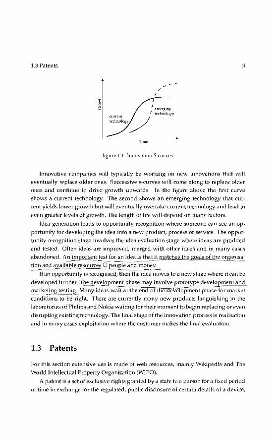
The life cycle of innovations can bedescribed using the 's-curve' or diffusion curve.
The s-curve maps growth of revenue or productivity against time . In the early stage
of a pilrticular innovation, growth is relatively slow as the new product establishes
itself. At some point customers begin to demand and the product growth increases more rapidly. New incremental innovations or changes to the product allow growth
to continue. Towards the end of its life cycle growth slows and may even begin to
decline . ln the later stages, no amount of new investrnent in that product will yield a
nornal rate of return.
The s-curve is derived from half of a normal distribution curve. There is an as
sumption that new product are likely to have "product Life" . i.e. a start-up phase, a
rapid increase in revenue and eventual decline. In fact the great majority of innova
tions never get off the bottorn of the curve, and never produce normal returns.
1.3 Patents
Time
/
I
emerging lechnology
figure 1.1: Innovation S curves
3
lnnovative companies wil! typically be working on new innovations that will
eventually replace older ones. Successive s-curves will come along to replace older
ones and continue to drive growth upwards. In the figure above the first curve
shows a current technology. The second shows an emerging technology that cur
rent yields lower growth but wil! eventually overtake current technology and lead to
even greater levels of growth. The lengthof life will depend on many factors.
ldea generation leads to opportunity recognition where someone can see an op
portunity for developing the idea into a new product, processor service. The oppor
tunity recognition stage involves the idea evaluation stage where ideas are prodded
and tested. Often ideas are improved, merged with other ideas and in many cases
abandoned. A~portant test for an idea is that it matches the goals of the organisa
~ and available resources Ü people and money.
lf an opportunity is recognised, then the i de a movestoa new stage where it can be
developed further. The develo ment phase may involve prototype development and marketing testing. Many ideas wait at the end o t e eve opment phase for market
conditions to be right. There are currently many new products languishing in the
laboratories of Philips and Nokia waiting fortheir moment to begin replacing or even
disrupting existing technology. The final stage of the i nnovation processis realisation
and in many cases exploitation where the customer makes the final evaluation.
1.3 Patents
For this section extensive use is made of web resources, mainly Wikipedia and The
World lntellectual Property Organization (WIPO).
A patent is a set of exclusive rights granted by a statetoa person fora fixed period
of time in exchange for the regulated, pubtic disdosure of eertaio details of a device,

4 Innovations and patents
method, processor composition of matter (substance) (known as an invention) which
is new, inventive, and useful or industrially applicable.
Although there is evidence suggesting that sarnething like patents was used among some ancient Greek cities, patentsin the modern sense originated in Italy. The first
patent law was a Venetian Statute of 1474 in which the Republic of Venice issued a
decree by which new and inventive devices, once they had been put into practice,
had to be communicated to the Republic in order to obtain legal proteetion against
potential infringers. England foliowed with the Statute of Monopolies in 1623 under
King Ja mes I. Prior to this time, the crown would issue letters patent (meaning "open
letter", as opposed to a letter under seal) providing any person with a "monopoly"
to produce particular goods or provide particular services. The first of them was
gr11nted by Henry VI in 1449 toa Flemish man a 20 year monopoly on the manufac
ture of stained glass.
A modern patent provides the right to exclude others from mak.ing, using, selling,
offering for sale, or importing the patented invention for the term of the patent. A
patent is, in effect, a limited property right that the government offers to inventors in
exchange for their agreement to share the details of their inventions with the pub lic.
In order to obtain a patent, an applicant must provide a written description of his
or her invention in sufficient detail for a person skilied in the art to make and use
the invention. This written description is provided in what is known as the ~t
specification, which oftenis accompanied by figures that show how the invention is ~ made and how it operates. In addition,~~d of the specification, the aerlicant
must provide the patent office with one or more claims that distinctly~t
the applicant regards as .Jlli._g~n. A claim, unlike the body of the speci
fica !ion, is nota detailed description of the invention, but a succinct series of words
designed to provide the pubtic with notice of precisely what the patent owner has a
right to exclude others from making, using, or selling. Claims are often analogised
to a deed or other instrument that, in the context of real property, sets the metes and bounds of an owner's right to exclude. It is the claims that de · cov-
~oe~;-14o.l.ÇQ~ A single patent may contain numerous claims, each of which is reg11rded as i1 distinct invention.
l n order for a patent to be granted, that is to take Ie gal effect, the patent application must meet the requirements of the nationallaw, in particular those reiated to
patentilbility.
A patent is an exclusionary right-it gives the right to exclude others from infring
ing the patent, but that does not necessarily give the owner of the patent the right to
exploit the patent. This is so since many inventions relate to improvements of prior
inventions which may still be covered by someone else's patent. For example, if an

1.4 Patent application 5
inventor takes an existing patented mouse trap design, adds a new feature to make an
improved mouse trap, and obtains a patent on the improvement, he or she can only
legally build his or her improved mouse trap with permission from the patent holder
of the original mouse trap, assuming the original patent is still in force. On the other
hand, the owner of the improved mouse trap can exclude the original patent owner
from using the impravement
Patents are typically enforced through civillawsuits (for example, fora US patent,
by an action for patent infringement in a United States federal court). Typically, the
patent owner wil\ seek monetary compensation for past infringement, and wiJl seek
an injunction prohibiting the defendant from engaging in future acts of infringement.
In order to prove infringement, the patent owner must establish that the accused
infringer practices all of the requirements of at least one of the claims of the patent.
An important limitation on the ability of a patent owner to successfully assert
his or hèr patent.in.Jjyillitigation is the accused infringer's right to challenge the
v:;Jictity of that patent. Civil courts hearing patent cases can and aften do declar~ patents invalid . The grounds on which a patent can be found invalid are set out in the relevant patent legislation and vary between countries. Often, the grounds are a
sub-set of the requirements for patentability in the relevant country.
The vast majority of patent rights, however, are not determined through litigation,
but are resolved privately through patent licensing. Patent licensing agreements are
effectively contracts in which the patent owner (the licensor) agrees not to sue the
licensee for infringement of the licensor's patent rights. lt is not uncommon for com
panies engaged in complex technica! fields toenter into dozensof license agreements
associated with the production of a single product. Moreover, it is equally common
for competitors in such fields to license patents to each other under cross-licensing
agreements in order to gain access toeach other's patents. A cross license agreement
could be highly desirabie to the mouse trap developers discussed above, for example, because it would permit both parties to profit off each other's inventions.
1.4 Patent application
Patent laws usually require that, in order for an invention to be patentable, it must
• be of patentable subject matter, ie a kind of subject-matter that is eligible for
patent proteetion
• be novel

6 Innovations and patents
• be non-obvious (in Uniled Stales patent law) or involve an inventive step (in
European patent law)
• be useful (in U.S. patent law) or be susceptible of industrial application (in Eu
ropean patent law)
Usually the term " atentability" only refers to "subs!?Jltille~.conditions, and does
not refer to forma) conditions suc a . .:sufficiency of disclosure", the "unity of in
véntf(;'~;, or the "best mode requirement". Judging patentability is one aspect of the of
ficial examination of a patent application performed by a patent examiner. Although
the grant of a patent ereales a presumption that the claimed invention is patentable,
errors in the granting procedure may occur and previously unconsidered prior art
may be brought to light only after the patent was granted. P~al:e.f!!_é!P
plica_t~r:_, inventors s~~~Q.bta.iruL!2illentability_Q~.Q!lil9.Dlll_P~r patent attorney regarding __ whether an invention satisfies the substantive conditions ofpiltentäl)lilty- . -· -
A patent application is a request pending at a patent office for the grant of a patent
for the invention described and claimed by !hal application. An application consists
of a description of the invention (the patent specification), logether with official forms
and correspondence relating to the application. The term patent application is also
used to refer to the process of applying for a patent, or to the patent specificabon
itself.
In order to obtain the grant of a patent, a person, either Iegal or natura), must file
an application at a patent office with jurisdiction to grant a patent in the geographic
area over which coverage is required . This will often be a national patent office,
such as the Uniled Kingdom Patent Office or the Uniled StatesPatent and Trademark Office (USPTO), but could be a regional body, such as the European Patent office.
Once the patent specificabon complies with the laws of the office concerned, a patent
may be granted for the invention described and claimed by the specification.
T~_rocess of "negotiating" or "arguing" with a patent office for the _grant of a
patent, and interaction with a patent office with regard toa p~-~~er its ~nt, is
known aS'ifatént prosecution. Patent prosecution is distinct from patent litigation ~
which relales to I ega! proceedings for infringement of a patentafterit is granted
Depending upon the office at which a patent application is filed, that application
could either be an application fora patent in a given country, or may be an applica
tion fora patent in a range of countries. The former are known as "national (patent)
applications", and the latter as "regional (patent) applications". National applications
are generally filedat a national patent office, such as the Uniled Kingdom Patent Of
fice, to obtain a patent in the country of that office . The application may either be

1.4 Patent application 7
filed directly at that office, or may result from a regional application or from an in
ternational application under the Patent Cooperation Treaty (PCT), once it enters the
national phase. A regionat patent application is one which may have effect in a range
of countries. The European Patent Office (EPO) is an example of a Regionat patent
office. The EPO grants patents which can take effectinsome or all countries contract
ing to the European Patent Convention (EPC), following a single application process.
Filing and prosecuting an application at a regionat granting office is advantageous as
it allows patentsin a number of countries to be obtained without ha ving to prosecute
apptications in all of those countries. The castand complexity of obtaining proteetion
is therefore reduced.
It is important to file a patent apptication befare publicly disclosing the details of
the invention. In genera!, any invention which is made public befare a!l application
is filed would be_considered prior art (although the definition of the term "prior art" is not unified at the international level, in many countries, it consistsof any in forma
tion which has been made available to the pubtic anywhere in the world by written
or oral disclosure). In countries which apply the above definition of the term 'prior
art', the appticant's pubtic disciosure of the invention prior to fitinga patent applica
tion would prevent hirn/ her from obtaining a va lid patent for that inventio~, si nee
such invention would not comply with the "novelty" requirement. Same countries,
however, allow for a grace period, which provides a safeguard for applicants who
disclosed their inventions befare filing a patent application, and the novelty criteria
may be interpreled dlfferently depending on the applicable law. lf it is inevitable
to disclose your invention to, for example, a potential investor or a business part
ner, before filing a patent application, such a disdosure should be accompanied by a
CO!} tid.ential_liy_;~ greemenL
At present, no "world patents" or "international patents" exist. In genera!, an ap
plication fora patent must be filed, and a patent shall be granted and enforced, in
each country in which you seek patent proteetion for your invention, in accordance
with the law of that country. Insome regions, a regional patent office, for example,
the European Patent Office (EPO) and the African Regional Intellectual Property Or
ganization (ARIPO), accepts regional patent applications, or grants patents, which
have the same effect as applications filed, or patents granted, in the member States
of that region. Further, any resident or national of a Contracting State of the Patent
Cooperation Trea_~y (PCT) may file an international application under the PCT. A sin
gle international patent application has the sameeffect as national applications filed
in each designated Contrading State of the PCT. However, under the PCT system, in
order to obtain patent proteetion in the designated States, a patent shall be gra nted
byeach designated State to the claimed invention contained in the international ap-

lnnovations and patents
plication.
1.5 Filing an application
In obtaining patent rights for an inventor, the practitioner first drafts an application
typically by interviewing the inventor to understand the nature of the invention and
help clarify novel features (and often to ascertain what is already known to people fa
miliar with the general field of the invention- such already-known material is termed
the prior art), and to obtain drawings and written notes regarding the features of the
invention and the background. During this initia! phase, termed "patent prepara
tion", the practitioner may also seek to determine precisely who contributèêl to flie
making of the invention (because an incorrect listing of inventors may incurably in
validate any patent that might result from an application), and to find out whether any publications, offers for sale, or other such public disclosures of the invention
we re made. These issues are important because under certain circumstances, public disclosures or offers to sell an invention prior to filing an application fora patent may
preventor the issuance of a patent for the invention, under the laws or reguiabons
of some jurisdictions (in the United States, the laws preventing obtaining patents be
cause of previous disclosures or offers to sell are termed "statutory bars").
After drafting an application for patent, complying with any further rules (such
as having the inventor or inventors review the application prior to filing), and ob
taining the applicant's permission, the practitioner then files the patent application
with the patent office. Usually, the practitioner seeks to file the application as soon as
possible, because in a majority of jurisdictions (such as Europe and Japan) if two or
more applications for the sa me subject matter are filed, then only the party who filed
first will be entitled toseek a patent (this is known as the "first-to-fi.le rule"). Even in
other jurisdictions (such as the United States, which does not follow the "first-to-file
rule"), early filing rnay prevent the use of certain matenals from being applied against
the patent application as prior art while the patent application is pending before the
patent office.
The filing date of an application is important as it sets a cutoff date after which
any pubtic disclosures will not form prior art (but the priority date must a lso be con
sidered), and a lso because, in most jurisdictions (notably, not the USA) the right toa
patent for an invention lies with the first person to file an application for proteetion
of that invention. Jt is therefore generally beneficia! to file an application as soon as
possible.
Jn order to obtain a filing date the document'> filed must comply with the regula-
1.5 Filing an application 9
tions of the patent office in which it was filed. A full specification complying withall
rules may not be required to obtain a filing date, for example in the United Kingdom,
claims and an abstract are nat required to obtain a filing date, but can be added later.
However, no subject matter can be added to an application after the filing date and
soit is vita! that an application disdoses all material relevant to the application at the
time of filing. If the requirements for the award of a filing date are not met, the Patent
Office wil! notify the Applicant of the deficiencies. Depending upon the law of the
patent office in question, correction may be possible without rnaving the filing date,
or the application may be awarded a filing date adjusted to the date on which the
requirements are completed.
A patent application may make a claim to priority from a nother previously filed
application, in order to take advantage of the filing date of information disclosed in
that earlier application. Claiming priority is desirabie because the earlier effective filing date reduces the number of prior art disclosures, increasing the likehhood of
obtaining a patent. The priority system is principally useful in fihng patent appli
cations in many countries, as the cast of the filings can be delayed by up to a year,
without any of the applications made earlier for the sa me invention counting against
later applications. The rules relating to priority claims are derived from the Paris
Convention for the Proteetion of Industrial Property and countries which provide a
priority system in conformity with the Paris convention are said to be convention
countries. These should nat be confused with the rules under the Patent Couperation
Treaty (PCT), outlined above.
Patent applications are generally pubhshed 18 months after the earliest priority
date of the application. Prior to that pubheation the apphcation is confidential to
the patent office. After publication, depending upon local rules, eertaio partsof the
application file may remaio confidential, but it is camman for all communications
between an Applicant (ar his agent) and the patentoffice to be pubhcly available. The
pubheation of a patent application marks the date at which it is publicly available and
therefore at which it farms fuU prior art for other patent applications worldwide.
After filing, and when requested, a patent application is researched to reveal prior
art which may be relevant to the patentability of the invention. The search report
is published, generally with the application 18 months after the priority date with
the apphcation, and as such is a public document. The search report is useful to
the applicant to determine whether the application should be pursued or if there is
prior art that prevents the grant of a useful patent, in which case the application
may be abandoned befare incurring further expense. Same jurisdictions, for example
the USA, do nat conduct a separate search, but rather search and examinabon are
combined. In that case, a separate search report is not issued and it is not until the

Hl Innovations and patents
application is examined that the applicant is informed of prior art that the patent
office examiner considers relevant.
Examination is the processof ensuring an application complies with the require
ments of the relevant patent laws. Examination is generally an iterative process, in
which the patent office writes to the applicant notifying him/her of its objections to
which the applicant responds with arguments and/ or amendments to overcome the
objections. Amendments and arguments may then be accepted or rejected, triggering
further response, and so forth, until a patent is issuedor the application is abandoned.
Many jurisdictions require periodic payment of maintenance feesin order to retain
the validity of a patentafterit is issued and during its term. Faiture to timely pay the
fees results in loss of the patent's protection. The validity of an issued patent may also be subject to post-issue challenges of various types, some of which may cause the patent office to re-examine the application.
The word "infringement" means an enemachment u pon the domain betonging to
a pa tentee that is described by the claims of her /his patent. If a patent is analogised
to real property, the claims correspond to the boundary recited in the deed . lnva
sion of the boundary of a landowner's real estate is called trespass, while invasion
of a patentee's claims is called infringement. A determination of patent infringe
ment involves a two-step process. First, the claims are analysed by studying all of
the relevant patent documents. Second, the claims must "read on" the accused de
vice or process. This merely means that the device or processis examined to see if it
is substantially described by the claims; in other words, the claims are tested to see
whether they describe the accused infringement. Infringement can be direct, indirect,
or contributory. Anyone who makes, uses, or sells the patented invention is a direct
infringer. lf a person actively eneaurages another to make, use, or sell the invention,
the person so inducing is liable for indirect infringement. Contributory infringement
can be committed by knowingly selling or supplying an item for which the only use
is in conneetion with a patented invention. Good faithor ignorance is no defense for
direct infringement, but it can be for indirect or contributory infringement.
V~~) 1.6 Economie rationale l ~·, JY tD There are four primary justifications for granting patents: innovation, disclosure, pro-duction investment, and designing around. ~ = ~
first, in accordance with the original definition of the term "patent", it is argued
that patents facilitate and encourage disdosure of innovations into the pubtic do
main for the common good. lf inventors did nothave the legal proteetion of patents,

1.6 Economie rationale 11
they may prefer ortend to keep their inventions secret. Awarding patents generally
makes the details of new technology publicly available, for exploitation by anyone af
ter patent proteetion ends, or for further impravement by other inventors (who may in turn patent these improvements). Furthermore, when a pa tent's term has expired,
the pubtic record ensures that the patentee's idea is notlost to humanity.
Second, it is broadly believed that patents incentivize economically efficient re
search and development (R&D). Many large modem corporations have annual R&D budgets of hundreds of millions or even billions of dollars. Without patent protec
tion, R&D spending would be significantly less or eliminated altogether, limiting the
possibility of technological ad vances or breakthroughs. Corporations would be much
more conservative about the R&D investments they made, as third parties would be
free to exploit any developments. This second justification is closely related to the ba
sic idea underlying traditional property rights: why build a house if another person could freely occupy it?
Third, in many industries (especially those with high fixed costs and low marginal
costs and low reverse engineering costs - pharmaceuticals and computer software
being the two prototyical examples), once an invention exists and has been tested,
the costof actually turning it into a product is typically six times or more the R&D
cost. Unless there is some way to prevent copies from competing at the marginal cost
of production, companies wîll notmake that productisation investment.
Fourth, many believe that patent rights create an incentive for companies to de
velop workarounds to patented inventions, thereby creating improved or alternative
technologies that might not otherwise have been developed.
One interesting side effect of modern day patent usage is that the smali-time in
ventor can use the exclusive right status to become a licensor. Th is allows the inventor to accuroulate capita) quickly from licensing the invention and may allow rapid inno
vation to occur because he/ she may choose to notmanage a manufacturing buildup
for the invention. Thus, time and energy can bespent on pure innovation and allow
others to concentra te on manufacturability.
There are arguments in opposition to patent rights. Granting a patent confers a
"negative right" upon a patent owner, because he or she may legally exclude com
petitors from using or exploiting the invention, even if the competitor subsequently
(either subsequent to the date of invention, or to the priority date, depending upon
the relevant patent law- see First to file and first to invent) independently develops
the same invention. It is argued that monopolies create inefficiency, and that if the
grant of a patent is, assumed to be, the grant of a monopoly, the patent system may
stifle competition and result in higher prices, lower quality, and shortages.
All patents are published and so there is a tension to the applicant between includ-

12 Innovations and patents
ing sufficient detail to secure patent proteetion and including excessive information
and thereby giving away "trade secrets" to the disadvantage of their company. It
has been argued that the sufficiency requirements of patents are not rigorous enough
and that patents are sometimes granted without any knowledge being imparted to
society. lt has also been suggested that market incentives alone would be sufficient
incentive to in nova te even in the absence of patents.
1.7 Scope
In this text the abstract concepts mentioned above are made concrete using two exam
ples from the research carried out by the section Process Technology of the Eindhoven
University of Technology. The two concepts that made it to commercial products are
the \aminar counterflow heatexchangerand the rotational phase separator. Both ex
amples have in common that they were conceived within projects with a different
aim and both could nothave been developed within the frameworkof the initia! re
search alliance. Recognition and subsequent patenting of the concepts has been the
key element for further development in both cases utilising changing research and
development environments as the products mature.
Both products are also similar in that they have their origins in basic scientific
research while the course of development was guided by the interaction of science
and engineering. Contrary to the scientific publications, in here detailed attention is
given to the influence of the iterative development path concept- model- prototypes
- experiments on the final product.
The innovations were conceived and are still mainly applied in the field of en
ergy supply and conservation and consequently are notdirect consumer products.
The general pubtic is less interested in heaving an energy supply at reasonable cost
and less in the technology behind it. Market influences on the innovations under
discussion are mainly feit through the interaction between government regulations
regarding pollutant emissions or energy conservation and the needof market parties
for cost efficient solutions and priorities seem to change from year to year. Technolog
ica i innovation, with a typical incubation time of 10 to 20 years can not follow these
short time fluctuations of interest so the key for successfuJ innovations in this market
is to provide a betterand cheaper product or process with a multitude of applica
tions inside and outside the energy market. Further development of a concept can be
achieved by developing the general idea for applications that are of interest in a spe
cific time frame and / or specific process. Such fruitful areas for development for the
heatexchangerand the phase exc.hanger have been or are (amongst others): nuclear

1.7 Scope 13
energy, gas-fired cogeneration, air conditioning, coal/biomass combustion, industrial
gas cleaning and oil/ gas prod uction. Each individ ua I development has advanced the
leve of understanding of the basic process and technological know-how opening up further applications.

14 Innovations and patents

2 Energy market
Since the industrial revolution, coal has been gradually supersecled by oil and to a
lesser degree gas as thema in energy souree (Shell2006). Global economie growth has
once again become more dependent on energy as a result, notably, of the rapid de
velopment of China and India. A "global middle class" is now knocking on the door
of prosperity, with energy a fundamental enabler. With China the world's manufac
turing hub, global economie growth as a whole has become more energy-intensive
again.
A second souree of strain is e~ergy security, a concept rooted in geology and tech
nology as wellas in politics and international relations. The reserves debate took on
a new impetus as markets were confronted: with inconsistencies in reserves categori
sations by companies; with unease about longer-term access and supply reliability
from some important non-OECD (Organisation for Economie Co-operation and De
velopment) regions; and even with some observers ex pressing doubts a bout the state and nature of the vast reserves bases in the Middle East. Production of conventional
oil and gas in non-OPEC countries appears a bout toplateau within a decade or so. A
number of producer countries, within and outside of OPEC, maya lso find it in their
interests to keep production at a lower plateau fora Jonger period, astheir concerns
for future generabons may outweigh pressures for immedia te revenue maximisation.
The notion that supplies are flexible enough to meet demand in almost any foresee
able circumstance can no Jonger taken for granted. It is clear that massive investment
must be made -and protected- in very challenging regions for the energy consumer to carry on turning the car key or switching on the light without even thinking a bout
where the gasoline, or electricity, co mes from.
The third major discontinuity is the one introduced by regulatory and market de
velopments thaLmake carbon a commodity in its own right, even though the price ~
of that commodity is negative (i.e. the price to dispose of it is positive). The energy
system will therefore be operating, to an unprecedented extent, as an energy and
carbon system. The public, in Europe but also in many parts of the US, and in de
veloping countries most at risk -ex peet this system todeliver both high growth and a

16 Energy market
(ow-carbon economy. In all scenarios, the "carbon" discontinuity makesits impact feit
by influencing Ie gislation and reguiabon of markets, by fostering the development of
alternative fuels, and by affecting the whole structure of relative prices throughout
the value chain.
2.1 Energy for the developing world
The correlation between overall primary energy growth and GOP (gross dornestic
product) growth had decreased from 1.2 in the mid-1960s toa low of 0.3 by 2000,
as the oil price shocks of the 1970s fostered higher efficiency, technological change
and diversification of supply. Si nee 2000, however, this long-term trend of reducing
energy content per unit GOP growth has reversed, and the correlation more than
doubled from around 0.3 to 0.7.
.... ---co=ows.:.:.-.. - 1.0
I CDP
s 0.9
'-' ralio
~ 4 0~
• 0.7
~ )
J 2
0.6
0.4
1 1 0.2
8 0.0
1~1970 1971-75 1976-$0 1981..&5 1986-90 1991-95 1996-00 2001-0S
figure 2.1: world total energy growth versus GDP growth
This relationship can be further analysed as a combination of income elasticity
and price elasticity. The energy ladder econometrie studies indicate that, in genera I:
Low-income countries are highly dependent on traditional energy sourees (with
the risk that deforestation makestheir needs increasingly hard to satisfy)
• Once countries reach the threshold of about USO 3000 per capita GOP, energy
demand explodes as industrialisation and personal mobility take off
• From around USO 15,000, demand grows more slowly as services begin to dom
ina te
• Beyond USO 25,000, it is possible for economie growth to continue without sig
nificant energy increases (although the true picture may differ if one corrects for
the relocation of energy-intensive industries to lower-income countries)

2.1 Energy for the developing world 17
With global economie growth fuelled, in large part, by the development of Asia and
the "BR!Cs" (Brazil, Russia, India, and China), the energy ladder becomes an essential
consideration for the global energy markets. However, the intensity of energy usage at each stage of development, including on the high-income "plateaux", differs widely
across countries. While Japan and some European countries have per capita income
levels similar to US ones, their per capita energy consumption is only about half of
the US level. This reflects different geographical and elirnatic conditions, but a lso the
cumulative impact of policies directed at improving energy conservation (whether
to reduce trade imbalances or, increasingly, to proteet the environment). A critica!
uncertainty for the world's energy outlook is which of the two paths -the A merican
or the Euro-Japanese one -China, Indiaandother emerging markets wil! now follow.
400
350
China
5
. .. ! ·~
s ·=- ,. .. ·· .. 10: .....
~ . . A stralia , .. .
.fl... . .... . ; .t'• EU ~ r• .. 'i.~ , • JI"'S•• ".... J pan
Kor a
10 15 20 25 30 35 1000 USO/capita
figure 2.2: the energy ladder 1965-2000
China's energy efficiency has remained substantially lower than the world aver
age. Whereas the Chinese economy requires almost 1.5 barrels of oil to produce USO
1000 of output, the global economy needs only half that amount. This is of criti
cal importance because, having doubled its oil demand over the last ten years to 6.4
million bbl/d, of which around 3 million bbl / dis now imported, China is now the
world's second largest oil consumer. Even more strikingly, China accounted for no
less than 40% of the new demand for oil in the 2001-2004 period. This rapid growth
will continue: "depending on how demand for energy services are met, China could
quadrupJe its dornestic product between 1998 and 2020 with energy use rising by
70-130% . By contrast, the OECD's share of global oil demand dropped from around
75% in the mid-1960s to slightly more than 60% in the early 2000s. In termsof total

lR
- 2 ~
~1.8 · - WoTld 0 ê 1.6
g 1.4 0 ~ 1.2
§ I
~0.8
'6 0.6 -"! ~ 04
.0 0.2
1980 1990 2000 2001 2002 2004 2004
figure 2.3: oil intensity in China and the global economy
Energy market
primary energy demand, stressing that few governments in the world are as deter
mined as the Chinese one to promote higher energy efficiency, the IEA (International
Energy Agency) forecasts that it will be sufheient for China's energy consumption to
rise by 2.2% pa in 2002-2030 in order for China's economy to expand by 5% pa dur
ing this period. Oil demand growth would be considerably more rapid at 3.7% pa,
however. The fastest increase is forecast for gas, whose demand would rise by 4.6%
pa. The IEA projections imply therefore that China's demand elasticity with respect
to income is falling below the world average. As a result, the energy intensity of the
Chinese economy will decline and gradually approach that of the world economy.
However, if this occurs at a slow pace, tensionsin global energy markets will not be
removed, or might even be increased if Chinese growth is stronger than the projected
5%, or if energy-efficiency policies face difficulties when implemented at the local
level. Making room for the BRICs in world energy consumption will therefore im
ply much higher levels of energy investment worldwide. As discussed below, it will
also compound the C02 emission challenge toa degree u nforeseen when the Kyoto
Protocol was signed in 1992.
2.2 Reserves and energy security
The second discontinuity is concerns-whether for geological and technological rea
sans or for political ones- over security of energy supplies. The increased risk of

2.2 Reserves and energy security 19
figure 2.4: world oil consumption: making room for the BRICS
reaching a peak in oil supplies in the relatively near future has been debated for decades. However, the failure of previous warnings to materialise is no reason to
dismiss the new ones. Whether one is concerned about conventional oil and gas or
about energy supply in genera!, the essential question is the ex tent to which the price
mechanism can be trusted togenera te the appropriate signals, investments and tech
nological developments in time for economie growth and development to proceed
smoothly.
The static image of reserves has long since given way to a dynamic relationship
between needs and capacities in which the key is investment -whether in exploration,
in alternative technologies, or in new distribution and organisational infrastructures.
Energy investments in producing countries with high export dependency are increas
ingly accompanied by diplomatie, military and hu man development assistance from
importing countries, concerned a bout their security of supply.
2.2.1 Peak debate
The most visible component of the debate concerns expected ultimate recoverable
reserves. The "Hubbert peak" debate, named after the Shell Oil geophysicist who
predicted in 1956 that US oil production would peak in the early 1970s, is again in
full swing, albeit now globally. Uncertainties in statistica! and geological data have
potentially huge implications: a sensitivity study by the US Department of Energy
indicated timings for oil production to plateau as divergent as 2040 and 2015, de
pending on the resource base assumptions at the optimistic and pessimistic endsof
the range.

20 Energy market
4000
3500
3000 -- -------------------------------------------~------------------
2~ -- ---------------------~~------------------~-----------------
2000 ----- ---
1500 - -
1000 -- c----- ---l---t-~l----t--l-----t------lf---+------l-+-----1---~---1----l-----+----lf--+------y--------
500 --- -- I--- - - --+-- l- +-----1----l------l---l-----+----ll----+- ll---+-----1---l----l--------.---.---
8 ~ ~ ~ ~ ~ ~ ~ ~ ~
" ~ j ~ I ~ ~ l I ~ ;:[ 0- 0- ~ ~ 3 3 ;:[ z ~
x
figure 2.5: sixty years of estimates of world crude oil reserves
.>Dil
250
~ 200 .0 c
~ 150 :0
100
50
figure 2.6: annual discovered reserves
While mJjor new finds cannot be ruled out, recent statistics do provide worrisome
signa Is. Reserves estimates have increased over time but the annual average increase
in proven oil reserves, which stood at 4.5% in the 1980s, has slowed down consid
erably since the early 1990s to around 1%. Discoveries only replaced some 45% of production since 1999. In addition, the number of discoveries is increasing but dis
coveries are getting smaller in size. The 25 biggest fields hold some 33% of discovered
reserves and the top 100 fields 53%: all but two of the giant fields were discovered
before 1970. A simple extrapolation of the volumes discovered annually suggests
that volumes to be found between now and 2050 could be as low as 500 biJlion boe.
However, this magnitude of undiscovered potential is considered conservative by
some, whobelieve it is influenced too much by the declining ex ploration successes of
late and by cautious views about the commercial viability of future finds. Limiting
the discussion to conventional hydrocarbons would give an increasingly incomplete
2.2 Reserves and energy security 21
picture as unconventionals become more important.
The presently known conventional gas reserves are equivalent to about 85% oi
known oil reserves, but only a quarter has so far been produced. Gas reserves in
creased on average at a rate of 3.3% pa over the last two decades, and discoveries
more than replaced produced volumes.
Overall, the gas supply outlook is generally reported to be robust. However, sig
nificant efforts and investment will be needed in developing infrastructure to move
gas to major consuming markets. The environment in each of the scenarios would
present different challenges to the timeliness and adequacy of such infrastructure.
This would in turn entail challenges befare the end of the scenario period on the
availability of adequate supplies to gas tosome markel'i. Geographic concentration
of gas reserves creates other types of challenges for importing countries. Russia, Iran
and Qatar tagether contain over 55% of the world's proved reserves. Reserves in
North America and Europe, 4% and 3% respectively of the world's proved reserves
are in decline. lt seems unlikely that significant new conventional gas volumes wil!
be discovered so gas supply sourees will remain highly concenh·ated.
Enhanced recovery of resources has been a key feature of the oil and gas industry
from its inception, proionging the life of many fields well beyond initia! expectations.
The present average oil recovery factor is nearly 30%, but technological progress
could still increase the recovery factor by 10-15%. This would lift the available re
serves by about 530 billion barrels, or 17 years of consumption at present levels. For
gas, there seems to be less scope, with an expected recovery factor of around 70% of
the conventional resource base.
In Europe, the key issue is the region's heavy dependenee on Russia, which ac
counts for around 40% of its gas imports. A competitive market develops, with har
monised regulation for crossborder trade. This framework recognises the need to un
bundle the ownership of infrastructure, such as pipelines, from the rest of the value
chain for competition and investment to develop. While strong regulation is likely to
increase the costof gas market development, regulatory relaxation for specific "strate
gie" investments is possible. Diversity of supply drives simultaneous development of LNG and pipeline supply. LNG is a price-taker as it competes for market share with
long-term contract pipeline gas.
In the US, there is growing realisation that the indigenous resource base is under
pressure. Even maintaining production near current levels probably requires sus
tained high prices; this concern is compounded by the fear that significant increases
in gas imports from outside North America may increase global gas prices. NGOs
voice strong opposition to the opening of federal lands. Concerns about physical
security and regulatory hurdles delay the development of import infrastructure.

22 Energy market
In Asia, China and India emerge as the new growth poles for LNG demand, and
shop forthebest overall value (price, infrastructure, upstream share). Iran and Qatar
target Asia as the main market to unlock resources and revenues.
figure 2.7: proven oil gas and coal reserves in millions ton equivalent of oil
2.2.2 Resource holders perspeelive
Production levels by OPEC member countries wil! be an increasingly important varia bie, bath for price formation and for security of suppiy. OPEC's announced growth
aspirations to 2010 outstrip expected total market growth; indeed, in all three of our
scenarios, OPEC's "market share" is set to increase. The growing dornestic consump
tion of energy by OPEC countries and the paths they follow to development are in
creasingly important considerations. Most OPEC countries remain dependent on oil
revenues and many face rapid demographic growth. Their energy consumption is
bound to rise steeply, and they will need increasingly higher oil prices to balance their
national budgets and to keeptheir social expenditure per capita at least constant. lnsufficiently diversified economies, such as those of the Middle East and Russia, aften
have a preferenee for many years of stabie revenues over short-term oil production
and revenue maximisation.

2.2 Reserves and energy security 23
Alternatively, countries may produce more and ring-fenee a part of their revenues
in a fund for future generations, as Kuwait and Norway have done. The trends we
have described suggest that, if they remain cohesive in the low-growth scenario,
OPEC members can defend a floor-price for their oil. By contrast, maintaining a
ceiling-price in periods of high demand will be more elusive, especially if spare ca
pacity will be expanded only in ways that make commercial sense for the individual
carte) member. lndeed, 2004-2005 events challenge the traditional assumption that
OPEC will be able to balance the world's oil markets over the longer term without
major price increases. The steep rise in reserves declared by all OPEC countries in
the early 1980s, and the few revisions since then, suggest that oil production has been
replaced by new reserves although there is little discussion of these matters. Politica!
considerations, resulting in opposition to investment by foreign companies, may alter
the pace of exploration and production from country to country. Altogether, a new
balance must be found between the producer ("resource-holder") countries' perspee
live in which economie diversification and job creation matter immensely, and the need for higher levels of investrnent -including international investment -at a time
when the IEA is beginning to worry that the world is falling behind in this respect.
-+oil
············• gas
figure 2.8: major export routes for oil and gas
24 Energy market
2.2.3 Coal, renewables and nuclear
Coal dominates and maintains its share of the global power market. For China, this
alleviates energy security concerns while also raising major logistical problems -coal
already represents 60% of Chinese rail freight traffic. New clean technologies (e.g.
lntegrated Gasification Combined Cycle (IGCC) and C02 sequestration) enhance its
use in the power sector, while Coal-to-Liquids (CTL) technology does so in the trans
port sector.
Renewables and indigenous energy sourees are stimulated by government policy,
particularly in Europe. Renewables grow by more than 10% per annum and gradu
ally achieve close to 5% market share by 2025. Wind is the fastest growing non-hydro
renewable, foliowed by solar. Solar photovoltaic (PV) rapidly develops, at a ra te of
almast four times that of solar therm al, as PV provides extensive distributed and cen
tralised power generation solutions. Ocean energy, predominantly from waves and
tidal flows, sees increased installed capacity over this period.
Nuclear energy faces public opposition in Europe and North America, but the
example of China and the concerns about the impact of coal lead to a gradual re
assessment. The next generations of power plants may therefore achieve the levels
of support needed for politicians to take the risk of launching new construction pro
grammes in a number of European countries and in the US.
2.3 Emissions
While politica] stances remain widely divergent, a quick look at reports by teading
insurers and re-insurersl shows clearly that elimate change has become a significant
risk on the ba la nee sheet of companies.
Compared with a pre-industrial level of around 280 ppm, C02 concentration in
the atmosphere is now at 380 ppm. After years of intense controversy, it is generally
accepted that this reflects largely the impact of human activities and that this "anthro
pogenic" change has been a key driver in the rise of average temperatures in recent
decades. It is also accepted that levels in the range of 700-1000 ppm would lead to
very darnaging impacts, possibly calling for the relocation of millions of people, as
described notably in scenarios developed by the lntergovernmental Panel on Climate
Change (IPCC). A level of 500-550 ppm is expected to help avoid the worst calami
ties.2 Containing the increase in C02 concentration within 500-550 ppm will require
considerable effort: according to the most recent IPCC assessment, such a level could
already be reached by 2050 with further increases throughout the 21st century unless
precautionary action is taken.

2.3 Emissions 25
Such action should be considered a matter of some urgency, in light of recent
changes in our understanding of elimate history. The earth's natura) cycles -highly
predictabie variations in sunlight due to three types of orbital movement -are well
researched and are often invoked as alternative explanations for any warming trend
beyond short-term oscillation. However, far from providing alternative explanations of the present, they have had the effect of cooling the earth and have offset maninduced global warming. Indeed, ice cores in Antarctica show that C02 oscillated
duringa long sequence of ice ages and interglacial periods between 240 and 275 ppm.
Anthropogenic warming is more than likely to have begun as early as 6000 years a go,
as a result of changes in land use resulting from neolithic agricultural revolution and,
later, flooding in large areas for rice cultivation in China and India.
Carbon emissions can be reduced through qualitatively different changes. Key
options are to:
1. Impose efficiency gains, to reduce demand growth
2. Consider alternatives that are cleaner
3. Add "tailpipe solutions" such as sequestration, which solve the problem after
the event, quite oftenat high cost.
Examples of all three options are reviewed in the following chapters. Different com
binations of such polides can be expected to prevail in different regions, with the US
more inclined to support technology based solutions and the EU favouring a precau
tionary approach, through taxes and standards.
The Kyoto Protocol, ratified by 127 countries representing 55% of total C02 emis
sions in 1990, came into force on February 16, 2005. lts essential feature is the combi
nation of a discretionary politica[ and administrative decision -to cap carbon ernissions
with a set of market mechanisms (trading schemes) in order to achieve that politica[
objective in a cost-effective manner. In addition, the Kyoto process is open-ended:
progress achieved in one period is expected to drive more ambitious objectives in
termsof emission capping and in termsof the range of participating countries. How
this happens in Kyoto can be compared, if not to the EU integration process, at least
to the processof global trade liberalisation. Under the first commitment period from
2008 to 2012, industrialised countries are the only ones toface binding targets regard
ing theemission of the main greenhouse gases (GHGs), including C02. These targets
reflect underlying national differences in emissions, wealth and capacity. They now apply to all developed countries, except Australia (which vowed to stick to the agreed
targets) and the US.
26 Energy market
The US exception matters immensely, as the country accounted for 36of GHG
emissions in 1990, against 30% for the EU, 17% for Russia and 9% for Japan. Yet,
while the US is likely to stay out of the Protocol, states such as New York and Cali
fornia are coming up with schemes of their own. Efforts to reduce other pollutants
-notably in power generation-maya lso provide other channels through which Kyoto
like cap-and-trade schemes could materialise in the US. Kyoto signatories can resort
to four policy options that encourage a braader view of ecosystem managementand
that give an essenhal role to market pricing mechanisms through "cap-and-trade" in
struments:
• First, remembering that about 20% of present carbon emissions are due to deforestation, countries are allowed to subtract from their industrial carbon emissions certain increases in carbon sequestered in "sinks" such as forests.
• Second, the Protocol recognises emissions trading, which allows countries to
buy allowances from other countries that reduce their emissions beyond their commitment.
• Third, under the Joint Implementation scheme, an investor from a country with
a commitment may obtain carbon credits from the implementation of a project
in another country member of the Protocol.
• Fourth, while the Clean Development Mechanism (CDM) is also project related,
it involves countries that have not adoptedcommitments, thereby potentially
expanding the ways in which creditscan be claimed. The "pricing-in" of carbon
in the economy 2005 may well be remembered as the year when what is known
as "the energy industry" became "the energy-and-carbon industry".
While a genuine "hydragen economy" may take decades to materialise -if it ever does
economistscan make the case that we have already moved from the a ge of hydrocar
bons to that of hydragen and carbon, as bath cammodities now carry a price tag. Atoms of carbon are convenient "vehicles" todeliver hydragen into the world's bii
Jions of cambustion chambers. Until Kyoto, what happened to the atoms of carbon
was of concern to ecologists but not to economists. This is no langer the case. The
price discovery mechanism behind the carbon emissions schemes -notably the Euro
pean Emissions Trading Scheme (EU ETS)- has been patterned after similar markets
for nitrogen oxide and sulphur oxide set up in the US to achieve efficient pollution
abatement. As a result of the EU ETS, a whole new set of markets can be expected
to develop to help companies, investors and speculators to unbundle the rights and
2.3 Emissions 27
liabilities attached to the carbon part of hydrocarbons from those attached to the hy
drogen part. These marketscan develop befare engineers have put in place the capac
ities and systems needed to manage carbon separately from hydrogen, e.g. through
various forms of sequestration and processing. In this sense, the economy is ahead of
the energy infrastructure.
There are many paths toa lower carbon world but they all require step-change
evolutions. A further shift to natura) gas, nuclear energy, renewables and bio prod
ucts wiJl all need to be a critica! part of a comprehensive approach to keep C02 con
centrabons below 550 ppm; so wil! carbon capture and storage, and advanced vehi
cle technologies. Taking into account existing commitments for the Kyoto period and
assuming a carbon price of euro 13.5/ tonne C02 the European Commission has sim
ulated a carbon-abatement case in w hich a 21 % reduction in world C02 emissions
compared to the reference case comes from both reduction in energy demand and decrease in the carbon intensity of the energy mix. The biggest loser is projected to be
coal, foliowed by oil. Natura! gas, by contrast, is not affected as the dow nward pres
sure on gas consumption is compensated by coal-to-gas substitutions. The market
shares los t by coal and oil are taken up by nuclear and renewable energies. Within
the renewables category, the Commission's model foresees a 20-fold increase in wind,
solar and small hydra. Clearly, different paths to a lower carbon world are possible;
an alternative one has been outlined, for example, by the World Business Council for
Sustainable Development (WBCSD). All forecasts have in common, however, a de
cline in the iocome elasticity of energy demand and rapid development of nuclear
and renewables.
As a worst case let us look a t the scenario tha t the Kyoto Protocol unravels as
one country after another follows the US lead and bails ou t. Without any sense of
reciprocity, governments go their own way on the issue of elimate change. While the
EU tries to put on a brave front and insists that controls on GHG emissions will be
implemented across its 30-country zone, "free-riding" by other nations soon makes
this policy untenable. A number of countries, for instance, will accept payments for
carbon credits while not really pursuing environmentally sound policies . With its
competitiveness erading in the face of products coming into the global marketplace
from other jurisdictions where companies bear no climate-change-related reg ulatory
costs, Brussels eventually abandonsits GHG control program me. Those parties w ho
have not signed up to the Protocol may nevertheless promate higher efficiency in the
use of hydracarbon fuels as part of their energy security and environmental agendas.
Societal pressure will in fact lead states, such as China, to stimulate cleaner technolo
gies to address the impact of burning coal or of vehicle emissions. Reductions in
GHG emissions, however, are largely incidental to these local pressures. A lower-
2R Energy market
carbon economy develops therefore, reflecting not so much the consumer's choice
but rather lower global economie growth, national aspirations to self-sufficiency as wellas concerns over local pollution.
2.4 Short term forecast
In the case of a fast increasing shortage of oil, it is most likely that synthetic pro
duction of fuels from coal will fill the gap. The mondial coal reserves are enormous
and there is ample experience with the technology both for coal and biomass com
bustion through the Fischer-Trops process, like being used in the Buggenurn power
plant. This solution is much appreciated in China with their large coal reserves. Gas
to liquids solutions (GTL) can provide Iiquid fuels from natura) gas, as Shell is doing
in their Bintulu plant (Malaysia), but in general this option is less attractive as a the
gas demand is expected to riseeven faster than the oil demand in the coming years
and also the gas supplies are limited. Gas heaters and power plants are attractive as
they are cheap and quick to build. Furtherm01-e the gas reserves are mainly found in
combination with oil, a bout 80 % of the gas is su pplied by seven countries so they
can form a monopoly like OPEC. Coal is found in a much Iarger geographical area.
lf sufficient oil supply continuous fora little while, the Hydrogen economy can be
prepared. Technology (fuel cells) have to improve quite lot however to make a hy
drogen economy possible, not to speak of the distri bution yet to be developed . Large
scale production of bio-fuels is not likely, considering the amount of conventional fu
els needed to sustain production and the competition with food production. The EU
only stimulates Bio-fuel production as just a little less C02 is produced, the main rea
son being that the current agricultural system can be maintained . The ma in problem
is however: who is to be concerned about global warming when confronted with a
sudden shortage of oil ?
lt depends on technology and price developments if the large tar fieldsin Venezuela
and Canada will be developed or that a straight change to natura! gas will occur.
Large scale use of coal can be expected in all cases. Public opposition to nuclear en
ergy may Jessen as no recent calamities have occurred and in that case nuclear power
will increase fast. Uranium however can never provide the definitive solution as it is
only suited for the production of electricity. Tha t many countries a re concerned to a
large extend with global warming while looking for other energy sourees is unlikely.
Emerging economies will use the argument tha t the present high C02 levels are the
consequence of unlimited emissions for 150 years by the western industrialised coun
tries.
3 Laminar counterflow recuperator
The laminar counterflow recuperator represents the case where during scientific re
search a new heat exchanger concept was developed. The opening to succesful ap
plication in a different market was present as the operations of the inventor were not
restricted toa singular market as might have been the case fora large company. Al
though the original aim was to license the invention, market circumstances forced the
inventor to pursue the development until the manufacturing stage.
3.1 Thermionic energy conversion
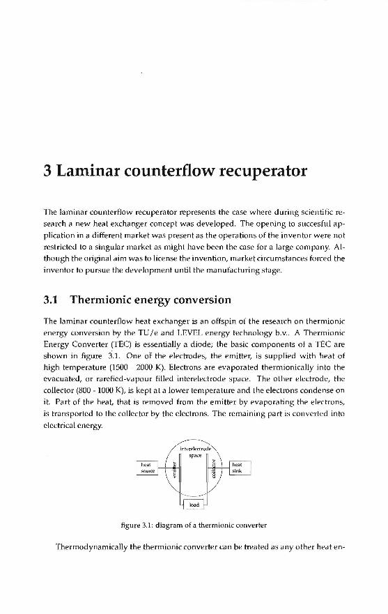
The laminar counterflow heatexchangeris an offspin of the research on thermionic
energy conversion by the TU/e and LEVEL energy technology b.v .. A Thermionic Energy Converter (TEC) is essentially a diode; the basic components of a TEC are
shown in figure 3.1. One of the el~ctrodes, the emitter, is supplied with heat of high temperature (1500 - 2000 K). Electrans are evaporated thermionically into the
evacuated, or rarefied-vapour filled interelectrode space. The other electrode, the
collector (800- 1000 K), is kept at a lower temperature and the electrans condenseon
it. Part of the heat, that is removed from the emitter by evaporating the electrons,
is transported to the collector by the electrons. The remaining part is converted into
electrical energy.
figure 3.1: diagram of a thermionic converter
Thermodynamically the thermionic converter can be treated as any other heat en-

30 Laminar counterflow recuperator
gine. The path from point 1 to 2 in the T-S diagram (figure 3.2) represents the heating
of the electrans and oh mie losses. The electrans are emitted at a constant temperature
(2-3). In a close spaeed diode the electrans travel through the interelectrode space at a
constant temperature (3-4). In the case that an ignited plasma is present, the electrans
wil I experience a sharp rise and decrease in temperature. The path from point 4 to
1 represents the condensing of the electrans on the collector, where electrical energy
is produced. By adding the TEC to simple cambustion systems, the thermadynamie
efficiency can be raised to produce both heat and electricity (cogeneration).
(,--\
T
heat in 1 1
I / \ • I i
0/ I f
heat out
s
figure 3.2: TS diagram of a thermionic converter
3.1.1 Research history
The start of the study of thermionics coincides with the invention of the electrical
lamp. Because Edison had troubles during his experiments with the life time of the
filamentsin his electricallamp, he used morefilamentsin one evacuated glass enclo
sure. During his experiments it was observed that an electric current could be made
to flow between two electrades in vacuum (the filaments) if one of them was heated.
Although the effect was of no interest to Edison and his group, the effect was duly
reported (Preece 1885).
Thirty years went by before emission of electrans was analysed and investigated
by Richardson (1912). Schlichter (1915) recognised that this process could be used to
convert heat to electricity and a patent was issued in 1923. Though Langmuir (1923)
and his co-workers formulated the fundamentals for the understanding of the process
in 1923, no further interest was shown in this conversion technique for many years.
In 1941 Gurtovoy published experimental data demonstrating the conversion of heat
into elechicity by means of a thermionic converter. In 1957 the threshold of practical
thermionic conversion was reached by several groups.
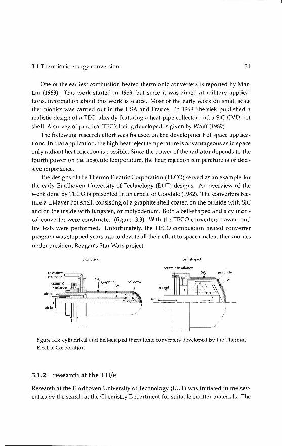
3.1 Thermionic energy conversion 31
One of the earliest cambustion heated thermionic converters is reported by Mar
tini (1963). This work started in 1959, but since it was aimed at military applica
tions, information about this work is scarce. Most of the early workon small scale
thermionics was carried out in the USA and France. In 1969 Shefsiek published a
realistic design of a TEC, already featuring a heat pipe collector and a SiC-CVD hot
shell. A survey of practical TEC's being developed is given by Wolff (19R9).
The following research effort was focused on the development of space applica
tions. In that application, the high heat reject temperature is advantageous as inspace
only radiant heat rejection is possible. Since the power of the radiator depends to the
fourth power on the absolute temperature, the heat rejection temperature is of deci
sive importance.
The designs of the Thermo Electric Corporation (TECO) servedas an example for the early Eindhoven University of Technology (EUT) designs. An overview of the
work done by TECO is presented in an artiele of Goodale (1982). The converters fea
ture a tri-layer hot shell, consisting of a graphite shell coated on the outside with SiC
and on the inside with tungsten, or molybdenum. Both a bell-shaped and a cylindri
cal converter were constructed (figure 3.3). With the TECO converters power- and
life tests were performed. Unfortunately, the TECO cambustion heated converter
program was stopped years ago to devote all their effort tospace nuclear thermionics
under president Reagan's Star Wars project.
cylindrical bell shaped
cerarnic insulalion
figure 3.3: cylindrical and bell-shaped thermionic converters developed by the Thermal Electric Corporation
3.1.2 research at the TU/e
Research at the Eindhoven University of Technology (EUT) was initiated in the sev
enties by the search at the Chemistry Department for suitable emitter materials. The

32 Laminar counterflow recuperator
objective was to raise the performance of the TEC by materials development. A new
emitter material was developed, based on a directionally solidified metal-ceramic
eutectic (Wolff 19R2). Beside the emitter material, the confinement which serves to
proteet the TEC from the cambustion environment, the hot shell and the elecbical
insulation between emitter and collector, the ceramic seal, were studied. This study
evolved in the design and construction of a water-caoled TEC (figure 3.4). Several
problems occurred during the operation of the water-caoled TEC. After start-up, the
collector head became too hot, causing explosive boiling of the cooling water. Fur
thermore, the sapphire spacers crushed the brittie hot shell.
figure 3.4: wilter caoled TEC designed ilt the EUT (Gubbels 1986)
Research was taken over by the Department of Mechanica! Engineering. The ob
jective was to redesign the water caoled TEC to an air-caoled TEC (figure 3.5) with
a heat pipe collector for measurement purposes (Veltkamp 1989). Air cooling has the
advantage over water-cooling that the rejected heat is available at a higher tempera
ture level, thus increasing the Carnot efficiency. Due to the lower heat capacity and
consequently lower heat exchange capacity as compared to water cooling, air c~
ing requires a larger heat exchange area and flow rate .. A geometry that allows for
the necessary heat exchange area in the bell shaped collector is rather complex. A
heat pipe collector eliminates this disadvantage as this passive isothermal element
can amplify the heat exchange area at a more convenient location outside the TEC.
3.1.3 Thermionic cogeneration system
In thermionic cogeneration systems, the heat demand has the priority, while the
electricity produced is a bonus. The heat produced by cooling the converter is not
dumped as in sp<Ke applications, but used to heat the house. In its simplest form the
thermionic cogeneration system consistsof a burner, healing the TEC which in turn
heats the boiler. Such a system operates at very low efficiencies as the exhaust gases

3.1 Thermionic energy conversion 33
coohng fuu c-eram1c insul.lllon
figure 3.5: air cooled TEC designed at the EUT (Veltkamp 1989)
cannot be Jower in temperature than the emitter, teading to a low burner efficiency.
Furthermore, it takes time to heat the TEC and therefore electricity is not immediately
produced when starting the burner. Heating systems without thermal starage switch on 'ánd off frequently and consequently electricity is produced duringa fraction of the operating period of the burner only. Therefore two subsystems have to be con
sidered: a recuperator to regenera te heat from the flue gases and a thermal storag~_ to_
increase the operating time of the thermionic converter.
Only a small part of the energy present in the fuel is converted to work because
the temperature of the flue gases cannot be lower than the emitter temperature. By
using the heat in the flue gases to preheat the air or air-fuel mixture, the efficiency
can be increased . The heat can be transferred by recuperation or regeneration. L counterflow recuperator is the best salution thermodynamically, but even in that case
notall the heat can be recuperated due to the difference in heat ca pa city between the
flue gases and air. Furthermore, the fuel (natura! gas) can only be preheated toa bout 900 K to prevent carbonisation. An example of a recuperative burner system is given
by Veltkamp (1993) (figure 3.6). Air streams through a recuperator where it is heated
by the flue gases. Natura! gas is injected in the air stream and the mixture is burned
in a vortex burner. The flue gases heat one of the headers of the recuperator which
radiates to the hot shell.
One little question remained however: how do you make a recuperator able to
withstand the high temperatures? Metals are not able to withstand the extreme tem
peratures, so ceramic materials have to be used . The brittie ceramics are susceptible
to thermoschock, so the local temperature differences in the construction have to. be ..
small. Fora heat exchanger this impHes that it has to have a high effectivity and .tb<.~t
the heat capacity flows (ma ss flow times heat capacity) are al most equal toeach othe.r,
see figure 3.7. To keep the temperature difference over the dividing walls smal i, they should be thin. To maintain structural integrity in a thin walled structure, the chan
nels should be small, teadingtoa laminar velocity profile. Realising that this concept
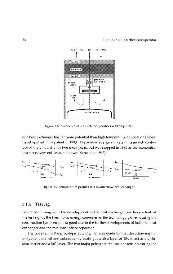
34 Laminar counterflow recuperator
gas air- 300 K
(" hot shell1725 K
figure 3.fi: burner structure with recuperator (Veltkamp 1993)
of a heat exchanger has far more potential than high temperature applications alone,
Level applied fora patent in 1993. Thermionic energy conversion reserarch contin
uedat the university for two more years, but was stopped in 1995 as the economical
prospects were not favourable (van Kemenade 1995).
figure 3.7: temperature profiles in a counterflow heat exhanger
3.1.4 Test rig
Before continuing with the development of the heat exchanger, we have a look at
the test rig for the thermionic energy converter as the technology gained during the
construction ~as been put to good use in the further developments of both the heat
exchangerand the rotational phase separator.
The hot shell of the prototype TEC (fig 3.8) was made by first deepdrawing the
molybdenum shell and subsequently coating it with a Iayer of TiN to act as a diffu
sion barrier and a SiC layer. The two major points are the isostatic tension during the
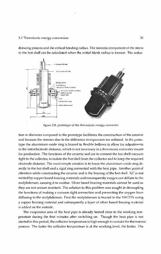
3.1 Thermionic energy conversion 35
drawing process and the critica! bending radius. The isostatic component of the stress
in the hot shell can be calculated when the initia! blank radius is known. The reduc-
ISO
Dii:::-J.lol:l.--7 :..Jurninium nitride ir\Sub.hon roolmgch.:.nnid roppcrs.:a.l
tigure 3.8: prototype of the thermionic energy converter
!ion in diameter compared to the prototype facilitates the construction of the ceramic seal because the stresses due to the difference in expansion are reduced. In the proto
type the aluminium oxide ring is brazed to Aexible bellows to allow for adjustments
in the interelectrode distance, which is not necessary in a thermionic converter meant
for production. The functions of the ceramic seal are to conneet the hot shell vacuum
light to the coUector, to isolate the hot shell from the collector and to keep the required
electrode distance. The most simple solution is to braze the aluminium oxide ring di
rectly to the hotshelland a rigid ring connected with the heat pipe. A nother point of
attention while constructing the ceramic seal is the brazing of the hot shell. SiC is not
wetted by copper based brazing materials and consequently oxygen can diffuse to the
molybdenum, causing it to oxidise . Si! ver based brazing materials cannot be used as
they arenotcesium resistant. The solution to this problem was sought in decoupling
the functions of makinga vacuum tight conneetion and preventing the oxygen from
diffusing to the molybdenum. First the molybdenum is brazed to the VA CON using
a copper brazing material and subsequently a layer of silver based brazing material
is added on the outside.
The evaporator area of the heatpipeis already heated close to the working tem
perature during the first minutes after switching on. Though the heat pipe is not
started in this period, the collector temperature is high enough to sustain the thermion ie
process. The faster the collector tempera ture is at the working level, the better. The
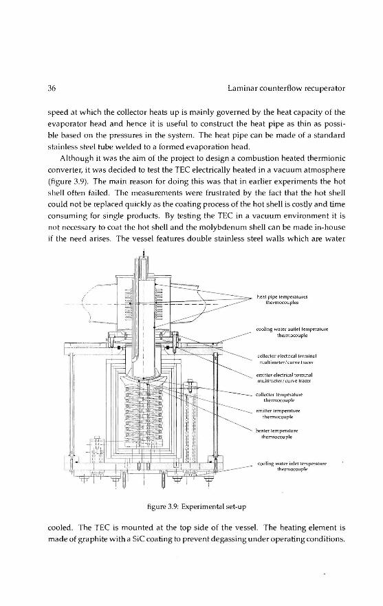
36 Lam i nar counterflow recuperator
speed at which the collector heats up is mainly governed by the heat capacity of the
evaporator head and hence it is useful to construct the heat pipe as thin as possi
bie based on the pressures in the system. The heat pipe can be made of a standard
stainless steel tube welded toa formed evaporation head.
Although it was the aim of the project to design a combustion heated thermionic
converter, it was decided to test the TEC electrically heated in a vacuum atmosphere
(figure 3.9). The ma in reason for doing this was that in earlier experiments the hot
shell often failed. The measurements were frustrated by the fact that the hot shell
could not be replaced quickly as the coatingprocessof the hotshellis costly and time
consuming for single products. By testing the TEC in a vacuum environment it is
not necessary to coat the hotshelland the molybdenum shell can bemadein-house
if the need arises. The vessel features double stainless steel walls which are water
figure 3.9: Experimentalset-up
heat pipe temperalures thennocouples
cooling water outlet temperature thennocouple
collector electricalterminal multimeter / curve tracer
emiller elee1ricalterminal mullimeter/curve tracer
collector temperature thermocouplf>
emitter lemperature thermocouple
heat er temperature themlocouple
cooling water i niet temperature thermocouple
cooled. The TEC is mounted at the top side of the vessel. The heating element is
made of graphite with a SiC coating to prevent degassing under operating conditions.

3.2 Compact heat exchangers 37
Provisions are made to instaU thermocouples. The top side of the heating element
follows the curvature of the hot shell to achieve a controlled radiative heat transfer.
The heating element itself is in turn heated by radiation from a molybdenum wire,
isolated by ceramic aluminium oxide rings. The heating wireis connected to copper
electrical terminals which are coated with nickel and cooled by water. The heating
element is surrounded by five molybdenum radiation shields to reduce heat losses
to the walls. Furthermore, the vessel is equipped with a sapphire window to allow
optica! measurements. The cooling elements are connected in series to allow for an
easy measurement of the heat removed by the cooling system. To ascertain that there
will be no electrical short through the cooling system, a closed demineralised water
loop is used which is cooled through a heat exchanger.
3.2 Compact heat exchangers
The various economie sectors in which thermal equipment plays an important role
are heating, refrigeration and air conditioning, electrical power generation, transportalion applications (automotive, aerospace), the process industry (chemica!, petrochemical, paper, glass, cryogenic). More generally, it concerns the industrial sectors
associated with the rational use of energy. During the 1990s, advances in develop
ment and understanding of traditional heat exchangers gave rise to new types of heat exchangers that are more compact, more economical and more efficient. While
the Compact Heat Exchanger (CHE) technology has been advancing considerably
over the last coup ie of decades, the cost, space and efficiency impravement pressures
and significant interest in development of new technologies such as nanotechnology,
fuel cell technology, etc. have spurred a significant interest in further development of
more compact and enhanced heat exchangers thus reducing mass and volume of the
exchanger in such applications. CHEs are characterized by high heat transfer areas
per unit volume and per unit mass, usually achieved by construction techniques that
result in a large number of small channels, now advancing to mini and microchan'
nels with significant improvement in heat transfer surface area density ,(meso heat
exchangers 3000 m2 / m3 and a hydraulic diameter Dh= 1 mm; micro heat exchangers
15,000 m2 / m3 and Dh= 100 mm). The resistance to introducing these technologies
in industry is driven by concerns about fouling and cleanability, ruggedness, safety
(especially in high temperature, high pressure applications), and designability. How
ever, continuing ad vances at both the fundamental and equipment-development lev
els and a growing database of successful plant experiences have demonstraled that
significant capita I and operating cost savings can be achieved by the reasoned appli-
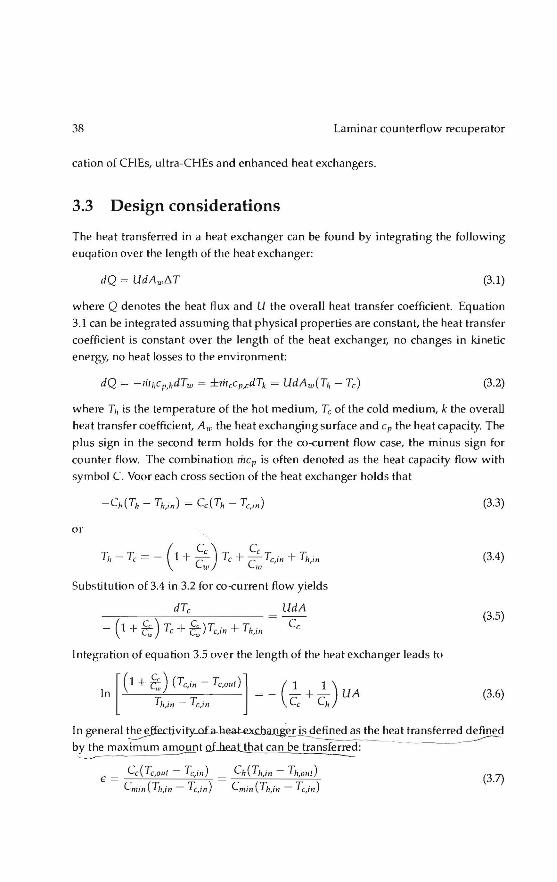
3R La mi nar counterflow recuperator
cation of CI-!Es, ultra-CHEs and enhanced heat exchangers.
3.3 Design considerations
The heat transferred in a heat exchanger can be found by integrating the following
euqation over the lengthof the heat exchanger:
dQ = UdA wl'.T (3.1)
where Q denotes the heat flux and U the overall heat transfer coefficient. Equation
3.1 can be integrated assuming that physical properties are constant, the heat transfer
coefficient is constant over the length of the heat exchanger, no changes in kinetic
energy, no heat losses to the environment:
(3.2)
where T" is the temperature of the hot medium, Tc of the co\d medium, k the overall
heat transfer coefficient, Aw the heat exchanging surface and cp the heat capacity. The
plus sign in the second term holds for the co-current flow case, the minus sign for
counter flow. The combination mep is often denoted as the heat capacity flow with symbol C. Voor each cross section of the heat exchanger holds tha t
or
Substitution of 3.4 in 3.2 for co-current flow yields
( c) c - 1 + Ç Tc + Ç)Tc,in + Th,in
UdA
Cc
I ntegration of equation 3.5 over the lengthof the heat exchanger leads to
[(H-é, ).(Tc,in - Tc,oul)l ( 1 1)
In = - - +- UA ~.,m - Tc,in Cc Ch
(3.3)
(3.4)
(3.5)
(3.6)
In general ~ofa..hw-exc.b.aJli~!l~j~eat transferred defined by the maximum amount of heat that can be transferred: _______...----~ -
€ = Cc(Tc,oul - Tc,in) = Ch(Th,in - Th,oul) Cmin(~,,in - Tc,in) Cmin(Th,in - Tc,in)
(3.7)
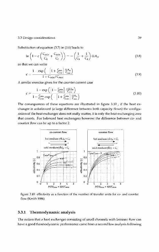
3.3 Design considerations 3':1
Substitution of equation (3.7) in (3.6)'leads to
In (1-t: (C",;" + C",;")) =- (~ + __!_) UAw Ch Cc Ch Ck
(3.8)
so that we can write
1 - exp (- [1 + Snm.J ~) lmax ffUn
€= ------~~~~~~~~ 1 +Cm in/ Cmax
(3.':1)
A similar exercise gives for the counter current case
1- exp ( [ 1- ~] -CUA.,) € == max m1n
1 _ Snm. exp (- [1 + Cmin l UA.,) l,,,ax ~ ~
(3.10)
The consequences of these equations are illustrated in figure 3.10 , if the heat ex
changer is unbalanced (a large difference between both capacity flows) the configu
ration of the heat exchanger does not really matter, it is only the heat exchanging area
that counts. For balanced heat exchangers however the difference between co- and counter flow can be up toa factor 2.
·f 0.6
tl :!: 0.4
"'
co·current flow
hot medium (me);, = C;,
cold medium(mc), = C,
0.8 ..!..
·f 0.6 ·-e ~ 0.4
"' 0.2
counter flow
cold medium(mc), = C,
figure 3.10: effectivity as a function of the number of transfer units for co- and counter flow (Kreith 1986)
3.3.1 Thermodynamic analysis
The notion that a heat exchanger consisting of small channels with laminar flow can
have a good thermadynamie performance came from a second law a na lysis following

40 Laminar counterflow recuperator
Bejan(1988). In the case of a balanced heat exchanger, where the capacity flows (mass
flow times heat capacity) of both flows are equal, the effectiveness can be expressed
as
€ = Th,in - Th ,oul
Th,in - Tc,in
Tc,oul - Tc,in
Th,in - Tc,in
kAw!C 1- kAw!C
For ideal gasses the entropy generation can be derived as
(3.11)
Ns = Sgen = In ( Th,oul) +In ( Tc,out) _~In ( Ph,oul) _ ~ln ( Pc,oul) (3_12) C Th,in Tc,in Cp Ph,in Cp Pc,in
For heat exchangers with a high efficiency ((1- €) « 1) equation( 3.12) simplifies to
. 2 N, = Sg~n = (1 _ €) (Th,in- Tc,in) + ~ [ ( óp) + ( óp) ]
C Th,in Tc,in Cp P h P c (3.13)
The first right hand term of equation (3.13)is the entropy generation due to heat trans
ferand the second the entropy generation due to the pressure drop. Proposed design
variations have an opposite effect on both contributions and an optima) trade off ex
ists, see Bejan (2001) for examples. As can beseen in figure 3.11 the minimal entropy generation is proportional to the bulk velocity g. The dependance on Reynolds is
relatively weak, so it can be stated that entropy generation is governed by the bulk
velocity if the channel dimensions are optimised for minimum entropy generation.
------î"og(uo:; · · . . _, log (Re)
figure 3.11: entropy generation as a function of Reynolds, channel dimensions and bulk velocity
Entropy generation due to friction does notdepend on the direction of the flow if
we assume constant physical properties. A comparison between the flow configura
tions can therefore be made by looking at the first term of equation (3 .13) only. Figure

3.3 Design considerations 41
3.12 is constructed fora balanced situation, comparing some flow geometries. Noth
ing is happeningfora heat exchanging surface of zero and conseguently the entropy
production is zero. As soon as there is any heat exchange, the entropy production
goes up quickly. Fora heat exchanger with an effectivity of 1 the temperature differ
ence before and after the heat exchanger remains the same: the outlet temperature of
the hot side equals the inlet temperature of the cold side and the other way around.
In that case the entropy generation is zero. co-current flow has the maximum energy
production (full mixing) and the other configurations are somewhere in between. The
important lesson of figure 3.12 is that the flow configuration only becomes important
for NTU numbers larger than 2. To illustrate the influence o f the un balance, we look
]'Is____ Ns,max 0.8
0.6
0.4
0.2
4 6 JO NTU=UJVC
figure 3.12: entropy generation for several flow configurations as a functi on of the number
of transfer units
at an otherwise perfect heat exchanger: t.p = \0 and UAw/C = oo. The unbala nce
w between both si des of the heat exchanger is defined as w = Cd Cz, w > 1.The
effectivity of the heat exchanger can be written as
1- exp ([1- w-1] -c~.~w)
ê = ----"---;-------'=--<-,
1- w - 1 exp (- [1 + w-1] ~) (3.14)
if C2 is the minimum capacity flow. In that case the entropy generation is
Ns = Sgen = In ( ( Tz) w [1 + ( Tz - 1) _..!::!..___] l+<v ) 1i1c p T1 Tl 1 + w
(3 .15)
In figure 3.13 this relation is plotted for TJIT2 = 2. Maximum entropy generation
is ~eac ~e~_if one of_!h~ n:edia cjoes _no! ~ha_~e i !'I_ temperature, .~!Jish i~ _the case

42 Laminar counterflow recuperator
when a phase change occurs in one of the media. The second main condusion is that
although entropy generation in a co current heat exchanger compa.red to a counter
flow heat exchanger, the relative importanceis minor when the unbalance wis larger
than 5.
~ 0.15
~ ~ 0.1
-t 0.05
w 10
figure 3.13: entropy generation due to unbalance in the capacity flows
The conclusions of the thermadynamie analysis are summarised in figure 3.14. In
most cases the unbalance in a given application is given and can not be changed.
Entropy generation can not be reduced by the construction of the heat exchanger.
lf there is a large unbalance (w > 5) go for the easiest construction. Look at the efficiency needed for the application to assess the minimum NTU number needed
for the application . lf this value is below 2, optimisa.tion of the heatexchangeris a
wasted effort. In other cases an optimisation can be performed for minimum entropy
generation by friction and by heat transfer. Using a larger heat exchanger always
gives a lower entropy generation, but the reason is that we have neglected the entropy
generation associated with the use of materiaL In practical situations an economie
criterion can be used to find the optimum values.
In Veltkamp(1993) several options for the shape of the heat exchanger channels
are described. All ducts are surrounded by ducts containing the second medium, so
all the wall area is also heat transferring surface (figure 3.15). I-leaders are integrated
to the ducts to provide a means to distribute the media over the ducts and collect
them after passing through the ducts. The resulting structure is a counterflow heat
exchanger in between two halvesof a cross flow heat exchanger. The effectiveness of
this heatexchangeris in between cross- and counterflowfora low number of transfer
units (NTU = kAw!C) and closetoa counterflow heatexchanger for large values of
NTU(figure 3.16).

3.3 Design considerations 43
Ns.nT
larger heal excbange~
figure 3.14: swnmary of entropy generation in a heat exchanger
3.3.2 Test rig
One of the more challenging tasks during the development of the recuperator was the
experimental verification of the used design tools. The intended production method
for the heat exchanger plates was by forming, but fabricating dies was far too ex
pensive for a prototype. The first heat exchanger was therefore manufactured by
stereolithography, a process that uses a CAD model to guide a laser through a poly
mer solution. The laser hardens the salution within the boundary of the part, one thin
layer at a time, to produce a real, three-dimensional mockup. Only low temperature
measurements could be performed with this prototype
As the effectivity comes near the maximum value small deviations in the mea
sured temperatures have a large impact on the recorded effectiveness (equation 3.11 ).
As the effectiveness is directly related to the capacity of the heat exchanger defined
by the overall heat transfer coefficient multiplied by the heat transferring surface, it is
an important parameter to campare design alternatives and validate simulation tools.
To illustrate what had to be done in order to measure with the required accuracy. fig
ure 3.17 shows a schematic of the test rig buildat the TU /e (van Kemenade 1999). In
figure 3.18 the dependance of the necessary accuracy for the temperature and flow
measurement are given. In order todetermine the effectivity, the bulk temperatures of the air flow have to be measured on the locations indicated in figure 3.17. The prob
lem to be solved is how the measure the bulk temperature which is not identical to
the mean temperature in a cross section as the veloeities may differ. Consequently it

44 Laminar counterflow recuperator
figure 3.15: heat exchanger concept
is necessary to mix the airflow thoroughly before measuring the temperature locaUy.
Because air hardly radiates, optica! temperature sensors are not suitable in this
project. As the old mercury thermometer, still being used widely for calibration pur
poses, shows non-electrical thermometerscan be very good. Nevertheless electrical
contact sensors are chosen as they allow fora relatively easy data acquisition. Hav
ing made that decision, the option fora thermocouple and a resistivity method (plain
or with NTC's) remains. Thermocouples, though trusty and widely applied, have a
low temperature dependenee and a very low voltage output. lt is very hard to get a
accurélcy below 1 K. Although they tend to hilve a large drift, NTC thermistors where
used insteadof PT-100 as they have a larger voltage output. NTC thermistors have
a negative temperature dependence, the resistance globally varies from -3 to -6 % per Kelvin temperature rise. Most thermistors are producedas spheres or cylinders
covered with a proteelive glass layer. Normally the thermistor are part of a wheat
stone bridge, keeping either the current through- or the voltage over the thermistor
constant. As a current flows through the thermistor, ohmic heating will occur, which
must be accounted for. Also the thermistor has to be connected and is subject to heat

3.3 Design considerations
(Ui\.,~• itlAw
(I.A .. J<-~ • (1-t)Lo\...
45
figure 3.16: effectiveness of the heat exchangeras a function of the total number of heat
transfe r units
figure 3.17: schematic of the heat exchanger test rig transfer units
conduction through the wires. A third error may occur due to heat exchange with the
surroundings. The air flows are thoroughly mixed in the ducts so tha t in principle one thermistor can be used to measure the bulk temperature. Th ree thermistors are
applied however to be able to detect a faulty thermistor. The design of the temper
ature measurement uni ts are in figure 3.19. The results are corrected according to a
model incorporating the following energy flows :
• ohmic heating of the thermistor
• conveetien to the thermistor
• radiative heat transfer with the surroundings
• conduction through the support
• convection to the conneetion wires
• ohmic heating of the conneetion wires
· • conduction through the conneetion wires

46 Laminar counterflow recuperator
02 0.4 0.6 0.8 nbtiv~ enor in thc CAp..cily Oow f'J.I
figure 3.18: dependance of the necessary accuracy temperature and flow measurement
The thermistors are mounted within radiation shields consisting of a chromium plated
brass tube (15x60 mm) to reduce the radiative heat exchange. The dimensions of the
radiation shield are such that a large part of the heat transfer with the surroundings
are suppressed with a minimum disturbance of the convective heat transfer to the
thermistor. The electrical conneetion of the thermistor plays a major role in the accu
racy of the thermistor. As heat- and electrical conductance are closely related, there
exist no materials with a high electrical- and a low thermal conduction. Thermal con
duction can be reduced by applying a long thin wire but in that case the electrica l
resistance also rises which is undesired. Optimisation of bath effects resulted in an
impractical small diameter or long length of the wire. For that reason another ap
proach is taken. A small wire (0.12 mm) is placed inside the air stream fora eertaio
distance before it is firmly attached to the inner wall. At the inner wall it takes the
wall tempera ture. Optimisation resulted in a wire lengthof 0.22 m.
figure 3.19: temperature sensors
In the test rig, the secondary air temperature is hea ted to accomplish a temper
ature difference between the primary and secundary flow. The resulting air s tream

3.3 Design considerations 47
doesnothave a homogeneaus temperature profile however. For that reason the air stream is mixed to obtain a homogeneaus (bulk) temperature. The desired mixing
effectivity can be reached by applying static mixers as are manufactured by Sulzer for instanee (figure 3.20). Besides the Sulzer static mixer a home made variety, desig
nated by FT-150, was tested. The air stream is stratified by a heater comprising four
separate convectors which can be regulated separately. To makesure that a stratified
flow develops, a flow straightener is placed behind the heater. The temperature dis
tribution is measured before and after the mixing section with a Cross containing 13
T-type thermocouples (figure 3.21). In the mixing section several static mixerscan
be placed. For one static mixer the axial veloeities were measured behind the static
figure 3.20: Sulzer, FT-150 static mixers and temparature measurement unit
w;nerheater
! ~'-~ .... .. .... .. {1·
: t~raturo llowmoter l'lelll~unls m&ASUremenr
lloe»2000
S:lalk::rrUtt ~8SSI,If8rneasl.l'&mel'l
·-p~·-• •· ·e-~ figure 3.21: test rig
mixers using a Pitot tube. lmmediately after the static mixer, the profiles are chaotic
as can be expected. Aftera settling lengthof one diameter (10) the turbulent velocity

4R La mi nar counterflow recuperator
profile starts to develop and after 30 the velocity is almost constant. This distance
is taken for the temperature measurements. The measured deviations in the velocity
profile are used to calculate the uncertainty in the resulting bulk temperature. In the
next experiment two mixers were used at several distances between each other. The
Sulzer mixer is not very sensitive to variations in the initia! temperature profile, the
mixing effectivity is between 95 and 98% in all cases. The FT-150 mixer is more sen
silive totheinlet temperature profile. For both mixer types the best mixing effectivity
is reached when the air stream is allowed to settie for 10 between the two mixers. lf
the distance is less, the chaotic temperature profile hinders the second mixer, if the
elistance is larger, stratification occurs.
The mass flow can be measured directly (hot wire, Corioü) but these principles
cannot meet the demanded accuracy. Volume flow measurement can be done by pos
itive displacement meters and techniques where in a cross section the time and posi
tion averaged velocity is measured. Positive displacement meterscan reach the best
accurélcy. An !GA rotary displacement flow meter is used. Measurement errors are
mainly ctue to internalleak as deviations in the counter mechanism can be calibrated.
The measurement results are depicted in figure 3.22. There is a smal! but persistent deviation in the calculated and measured efficiency of the heat exchanger. The
reason was that although the heat exchanger was overall in balance, locally this is
not necessary so. A two dimensional model assuming a fully developed la mi nar pro-
140
I 120 EVEL A i. / ~ ~ ~:~c~~~~~~~~~oSSf!i ~ I I .
1110
40
~ ~ - A tB j I • mc.lSII rtmcnts f) · ·
/ /
/-:
50
/
/ /
.. / . /
.. '········?'- . . / /
.. ~./,. /
/
.--··
100 150 200 250 flow (m·' hr'l
..... . ·r-·
I ' 0.% .. ;. .
0.85
50 100 ISO 200 ZSO now(mlhr11
figure 3.22: effectiveness and pressure drop of the heat exchanger
file over the lengthof the heat exchanger, but incorporating temperature dependent
physical properties was developed for further optimisation of the heat exchanger. As
shown in figure 3.23 the assumption that the flow through the heatexchangeris sym
metrical, made to construct figure 3.16, is reasonable for low temperature differences
between the inlets of both media . For larger temperature differences (figure 3.24)the
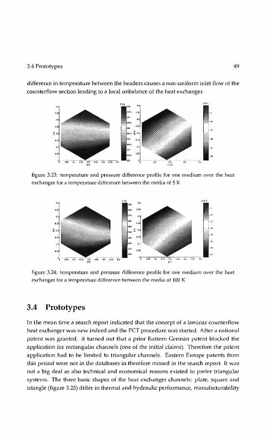
3.4 Prototypes 49
difference in temperature between the headers causes a non-uniform i niet flow of the
counterflow section leading toa local unbalance of the heat exchanger.
figure 3.23: temperature and pressure difference profile for one medium over the heat exchanger fora temperature difference between the media of 5 K
figure 3.24: temperature and pressure difference profile for one medium over the heat exchanger fora temperature difference between the media of 100 K
3.4 Prototypes
In the mean time a search report indicated that the concept of a laminar counterflow heat exchanger was new indeed and the PCT procedure was started. After a national
patent was granted. it turned out that a prior Eastern German patent blocked the
applica tion for rectangular channels (one of the initia! claims). Therefore the patent
application had to be limited to triangular channels. Eastern Europe patents from
this period were not in the databases in therefore missed in the search report. lt was
nol a big deal as also technica! and economical reasoos existed to prefer triangular
systems. The three basic shapes of the hea t exchanger channels: plate, square and
triangle (figure 3.25) differ inthermal and hydraulic performance, manufacturability

50 Laminar counterflow recuperator
and mechanica! strength. While manufacturing a heat exchanger stack of separate
sheets displacements and rotations may occur that can effect the performance of the
recuperator. A displacement in triangular channels doesnothave an effect on perfor
mance, while displacement of square channels can leadtoa reduction in performance
of 50% (figure ~.26). The reduction in performance due toa rotation of the sheetscan
be 25% and again has no effect in the triangular case. Further considerations are
figure 3.25: basic geometries for the heat exchanger channels
~~111111:
figure 3.26: displacement and rotation of the heat exchanger channels
• triangular channels can be constructed using alternatinga formed and an un
formed plate with a low degree of deformation so stainless steel can be used
• rectangular channels require a small toleranee and have a degree of deformation
in the order of 2
• a triangular shape is stabie and allows high internat pressures, plates and toa
lesser extend squares do nothave this advantage
The production method adopted led toa basic shape of the heatexchangeras shown
in figure 3.27.
3.4.1 Recuperative burner
For application by Philipsin a glass furnace a recuperative burner was developed as
reptacement for electrical elementsin glass furnaces. Processes where a recuperative
burner can be applied range from 200 to 1400 °C. Within Philips most energy is con
sumed in processes up to 800 °C, in this range efficient burners are required. Above

3.4 Prototypes 51
figure 3.27: heat exchanger concept and duet cross section
800 °C the options are limited: existing recuperative burners are sparsely used due
to their limited control range and may lead to instabilities in the system. A survey
under plant operators indicated that there is a need for modulating burners with a
power output of about 20 kW, while most suppliers start at 50 kW. This is not in
agreement with the trend that furnaces and heating processes are being segmented
requiring more heating elements. As the potential of application in Thermionic sys
tems was judged low, tagether with Winnox, Royal Schelde and the Gasunie a 20 kW
recuperative burner was designed and tested.
3.4.2 Design process
To define the dimensions of the heat exchanger, a sensitivity a na lysis was performed
under the following assumptions:
• constant physical properties
• fully developed laminar flow
• constant mass flow
The 2-D model was used afterwards to check if these assumptions hold in the ex
tremes of the sensitivity analysis. Under these assumptions, the heat transfer coefficient can be derived analytically: a:= 48A/11Dh (i.e. Holman 1982), where A is the
heat conductivity of the fluid and Dh the hydraulic diameter of the channels. The
heat transferred is inversely proportional with the diameter of the channels, in this
case even quadratic as a lso the number of channels within a given volume increases.
The limit is given by the heat resistance of the sheetsitself (figure 3.28). Increasing the
width or the height of the hea t exchanger leads to an increase in the heat transferred
(figure 3.29) . Fora fully developed laminar profile the pressure loss over a triangular
channel is given by (i.e. Holman 1982)
48 L 1 2 !lp= ---pub (3.16) ReDh2

52
20 .... •
15 •
~ =. 1o CY
0
•
10 IS base/2 (mm)
Laminar counterflow recuperator
20
18
------------~ 16
0 14
• 12
10 20 3.5 4.5 5.5
ln(lenglh) [mmJ
figure 3.28: heat transferred as a function of half the base(left)and the length of the chan
nel~ (righ t)
20CQ,-------------------,
1500
~1000 <;a
500
• I
•• o~~~~~~~~~~
0 0.002 0.004 0.006 0.008 O.DI widtJrl heighth·l [mm·IJ
figure 3.2Y: hea t tr<.msferred as a function of the width and the height of the recuperator
Under the assumption that the influence of the wal! thickness an be neglected and a
constant mass flow, the bulk velocity can be written as ub = mI (2W Hp), W being
the width of the recuperator and H the height. Figure 3.30 shows that this approx
imation is only valid for large channel diameters. For smal! channel diameters the
pressure drop increases fast due to the thickness of the walls (in these calculations
0.2 mm). On increasing the lengthof the recuperator the temperature profiles and
consequently the physical properties will change (figure 3.31), but this influence can
hardly be noticed. Figures 3.28 to 3.31 show that optimisation to maximum heat
transferfora minimal pressure drop leadsto a very voluminous hea t exchanger so
economie and technica! boundaries have to be applied. The recuperator consistsof a multitude of formed sheets. The channels can be pressed one by one requiring low
tooling costs but a high positioning tolera nee, or a die for the complete shape can be

3.4 Prototypes 53
1600
1400 • 1200
1000
~ 800 ·• ~
600
400
200~ 0~~~~~~~~~~~
0 0.05 0.1 2 0.15 0.2 (base/2) [mm·2]
figure 3.30: pressure drop as a function of half the base(left)and the lengthof the channels
(right)
2000,------------------.
1500
1[1000 ~
500
• I
•• 0 0.002 0.004 0.006 0.008 0.0 I
widlh -1 heigtuh -I lmm -1]
figure 3.31 : pressure drop as a function of the width and the height of the recuperator
manufactured. Normally two dies are necessary to press the complicated shape in
the me tal, but to keep costs down only one die was made, using a rubber on the other
side. For the operating conditions in a recuperative burner, the following materials
were considered:
• Avesta 253MA
• lnconel 601
• Haynes 214
• Haynes 230
Based on physical and mechanica! properties, costs and availability Avesta 253 MA
was selected . Theelastic limit of this material is 1.4 implying that the top angle of the

54 Laminar counterflow recuperator
triangle can not exceed Tr/2. Furthermore plastic instabilities limit the radius of the
top angle. Kals (1983) showsbasedon stability criteria that in most practical cases
the limit is given by Rcr/dp = 1/n where dp is the plate thickness and n the strain
hardening exponent. The minimum radius is also limited by the Youngs modulus
of the rubber being used. lf the radius is to small the radius will not be completely
formed, this effect was determined experimentally.
Another limit is imposed by the maximum pressure drop allowed over the recu
perator. In the concept of the recuperative burner are several components with a considerable flow resistance: the heat exchanger, the burner and the radiative tube. All
these components become smallerand cheaper if a larger pressure drop over them is
allowed, the fan huwever becomes more expensive. Consiclering the requirements of
the other components it was judged that a pressure drop of 1 kPa over the recuperator
is reasonable.
Although it would be preferabie to form the conneebons directly in the sheets this
was to expensive for the prototype so separate sealing strips were applied, manu
factured by laser cutting. The hot header provided the major pressure drop in this
application and was modified so that the flow resistance over each channel is the
same to assure balanced conditions in the counterflow part. The resulting design is
shown in figure 3.32 and 3.33
210
tigure 3.32: heat exchanger sheets

3.4 Prototypes 55
figure 3.33: heat exchanger stack
3.4.3 experiments
Befare assembling the recuperative burner, the heat exchanger was tested using the
sametest rig as used for the plastic protoype. As the sealing strips were point welded to the sheets leakage occurred between the sheets short circuiting 15% of the air from
the high to the low pressure side of the heat exchanger so a method to correct the
measuring results had to be devised . The efficiency of the total system can sill be
measured by looking at the energy content of the flue gasses, divided by the heating
value of the gas supplied:
_ 1
_ (cp + 1)m8Cpf (Tf ,out)Tf,ou t + (ma - cprn8 )Cpa(Tf,o ut)T1,out YJs- H
8m
8+m.Cp.T., in + m
8Cp
8T
8,in (3·
17)
cp is the stochiometric air ratio, m the mass flow, Cp the specific heat capacity a nd H the heating value. The subscripts a denote air, g the supplied gas and f the fl ue gas. The first term in the fraction is the energy contained in the flue gasses, the second the
energy contained in the air, whether it has gone through the burner or not.
The construction after assembly is shown in figure 3.34. During the first exper
iments (figure 3.35 and 3.36) the radiant tube was placed open in the environment.
Contrary to expectations the tube temperature increases with increasing air ratio in
dicating that the burner is still heating up and not eno ugh time elapsed between the
measuring points. Forthermore the calculated recuperator efficiency is lower tha n expected, also due to time dependent effects. In the second experiment the burner
tube was insula ted to obtain higher temperatures of the radiant tube and it was de
cided to wait langer between the measurements. The consequences are shown in the
figures 3.37 to 3.39. The burner was started schochiometrically at 20 kW. After 12
minutes the power was reduced to 10kWat an ai r ra tio of 2 to obtain a stabie oper
ating procedure. This is normal e perating procedure for radiant tube burners as the
excess air keeps the temperatures low and the operators wentfora coffee break. This
burner however was equipped with a reeoperator and the tem pera tures continued to

56 Laminar counterflow recuperator
ilir in
figure 3.34: recuperative burner
800
I 500 • , .
I . • I I
I • . .. ! • ., 400 . . • • I I • ! Ç"700 . Ç" •Tr,oll! __ I
~ . Tb 1 I -;Joo
• 2
: ~;::::::; ~ [ • Tb2 e E • Tb) hoo .!! (,(lf) !! • • • • • • • • 100
500 1.5 2.5 1.5 2.5
ai r ratio[-) airratio [-}
figure 3.35: temperatures of the tube (left) and the recuperator (right) during an experi
ment at 20 kW gas power
ri se till above the melting temperature of the used heat resistant steel. A.fter these
experiments further development of the high temperature heat exchanger was put on
ice, partly because of the demise of Royal Schelde and partly because developing the
plas tic recuperator for balanced ventilation units required all resources at LEVEL.
3.4.4 Polymer heat exchanger
The thermionic energy converter was initia ted as an energy conversion option for the
building environment. Soon it was realised however that a far more interesting op
bon was to use an efficient recuperator polymer for balanced ventilation. Balanced
ventilation systems, if properly designed and installed, neither pressurize nor depres-
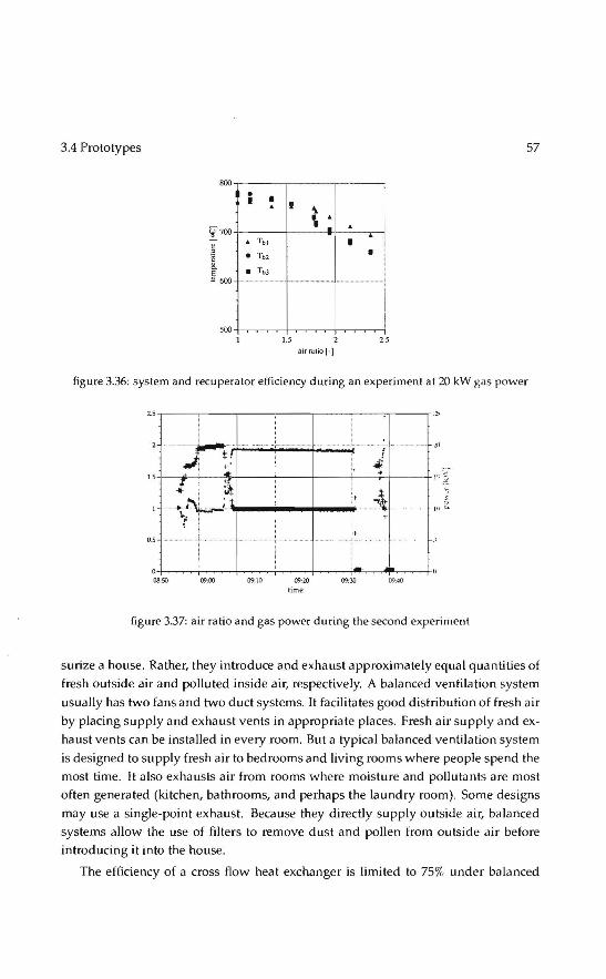
3.4 Prototypes 57
800
i • I I . I -\
.~ .. . 'l • 700
~ . Tbl I I
• Toz • ~ __ j !l. • TbJ ~ 600 ··········- ····-·· ------·····-······
1.5 2.5
airralioH
figure 3.36: system and recuperator efficiency during an experiment at 20 kW gas power
2.5,-----,----.----,----r---,..--;-r------r ":S
....... ~.l.··:: : .· ······· - cL::: ···· ;;1 ... , '" ./i ~ i. ~
15~---.~~--~ ""+---+----t---+---r-t---+t ~::;:;
~~L~_,_· ....... 1
_,__..,.1
• .... :-t 0.5
08:.50
·r . i +
09:00 09:10 09:20 lime
·t .
09:30 0?:40
figure 3.37: air ratio and gas power during the second experiment
surize a house. Rather, they introduce and exhaust approximately equal quantities of
fresh outside air and polluted inside air, respectively. A balanced ventilation system
usually has two fans and two duet systems. It facilitates good distribution of fresh air
by placing supply and exhaust vents in appropriate places. Fresh air supply and ex
haust ventscan be installed in every room. But a typical balanced ventilation system
is designed to su pply fresh air to bedrooms and living rooms where people spend the
most time. lt also exhausts air from rooms where moisture and pollutants are most
often generaled (kitchen, bathrooms, and perhaps the laundry room). Some designs
may use a single-point exhaust. Because they directly supply outside air, balanced systems allow the use of filters to remave dust and pollen from outside air before
introducing it into the house.
The efficiency of a cross flow heat exchanger is limited to 75% under balanced

SR Laminar counterflow recuperator
1<00
time
figure 3.38: temperatures during the second experiment
figure 3.39: broken radiant tube
conditions (Kreith 1986) and consequenUy the difference between the incoming and
outgoing air could exceed 5 oe under cold outside conditions introducing an uncom
fortable cold natura! draught. As aresult the use of balanced ventilation systems was
not well penetrated and users of the system tended to switch off the system under
cold conditions teading to unhealthy indoor conditions. The minimal effectivity of
the heat exchanger should exceed 90%, a value easily within reach of the concept
of the la mi nar counterflow recuperator. Furthermore the thin walls allow the use of
material which are bad conductors like plastics. As both the costand manufacturing
costs of plastics are lower than metals a lso an economie advantage was in reach .
A lso the building environment market allowedfora relatively "safe" play ground
for the development of polymer heat exchangers. Their acceptance in the process
industries is not yet widespread . The reasons for this are the Jack of awareness of
polymer compact heat exchanger benefits and the absence of reliable design meth
ods, a long with investigations under actual operating conditions. Perhaps industrial
applications are limited only by the imagination of process designers, particularly as

3.5 Market penetration 59
these materials are increasingly used in pumps, valves and other plant ancillaries.
With grants from the Dutch government, the first prototype was developed. An optimisation a long the same lines as in the previous paragraph was perfonned lead
ing to a channel size of 1 mm and a manufacturing method developed to produce
plastic sheets as shown in figure 3.40. The sheets are vacuum formed. Vacuum form
ing is a simplified version of thermoforming, whereby a sheet of plastic is heated
to a forming temperature, stretched onto or into a single-surface mold, and held against the mold by applying vacuum between the mold surface and the sheet. Normally vacuum forming is restricted to forming plastic parts that are rather shallow in
depth, but relatively deep partscan be formed if the formabie sheet is mechanically or
pneumatically stretched prior tobringing it in contact with the mold surface and be
fore vacuum is applied (Throne 1999). Suitable materia is for use in vacuum forming
are conventionally thermoplastics, the most common and easyest being High Impact Polystyrene Sheeting (HIPS) which was used in the end. The major challenge was to
keep the product tolerances low as imperfections multiply with the number of sheets.
Using this technology a fust heat exchanger was produced by glueing the sheets by
hand, a rather boring job and the prototype was installed in the LEVEL office in sum
mer. Under dry conditions the recuperator performed fine, but as soon as it became
a little colder outside condensation started inside the heat exchang.e_r_cbaiJnJ:ls....an.d
capillary blockage occurred. A moving bubble on a surface can macroscopically have
two different contact angles at the both sides leading toa net force that can equal the
fan pressure. Analysis showed that a base of 3 mm is sufficient to prevent capillary
blockage.
3.5 Market penetration
At this point there was a concept, a patent, a working prototype and a production
process giving a betterand cheaper product, success assured it seemed. At first the
two leading Dutch manufacturers were contacted and although the idea was well received they both went into a stalling tactic. In retrospect there is some logic to
their attitude: a producer wants to produce using his existing production line for as
long as possible unless competition forces him to change. Next the idea was picked up by lnatherm b.v., a trading subsidiary of Verhuist· b.v. specialising in smaller air treatment units and CCM build a flexible (mechatronic) production machine. After
a couple of years the production capacity of 25.000 recuperators a year was reached and a new production was developed by Wees offering less flexibility but a more
robust process and a higher capacity. The old machine is now being used tostart the

60 La mi nar counterflow recuperator
production of new designs and as a backup for the production machine .
For the continuity of the company Recair, which now does the production and
sa les of the recuperator, it is important to be able to offer new products and applica
tions and to this end LEVEL develops new systems for new application area 's like
• (automotive) adiabatic cooling
• condensors for drying processes
• green house elimate control
For a small specialised engineering company as LEVEL it is necessary to innovate
continuously and guard the innovations using patents. LEVEL focusses on innova
tions ilnd leaves manufacturability (mainly) to others. Further development of the
recuperator can beseen as evolutionary innovation. RadicaUy innovating actions are
now taken in other fields like vacuum insulation in the building environment. The
experience gained with the me tal high temperature heat exchanger tagether with the
condensation phenomena is used again in the aerosol desublimator (chapter 4).

3.5 Market penetratien 61
figure 3.40: plastic heat exchanger sheet

62 Laminar counterflow recuperator

4 Rotational phase separator
4.1 Gas centrifuges
Like the laminar counterflow recuperator, the Rotational Phase Separator has its ori
gins in nuclear energy related research . When uranium is mined, it consistsof heavy
weight atoms (about 99.3% of the ma ss), middle-weight atoms (0.7/), ), and lightweight atoms (< 0.01 %). These are the different isotopes of uranium, which means
that while they all contain 92 protons in the atom's center (which is what makes it
uranium), the heavy-weight atoms contain 146 neutrons, the middle-weight contain
143 neutrons, and the light-weight have just 142 neutrons. To refer to these isotopes,
the number of protons and neutrons is added and the total is put after the name:
uranium-234 or U-234, uranium-235 or U-235, and uranium-238 or U-238.
The fuel for nuclear reactors has to have a higher concentration of U-235 than
exists in natura! uranium ore. This is because U-235 is the key ingredient that starts
a nuclear reaction and keeps it going. Normally, the amount of the U-235 isotope is
enriched from 0.7% of the uranium mass toabout 5
In the famous Manhattan project (that produced the atomie bomb) uranium en
richment was achieved by a diffusion process. Gaseous diffusion is still the only pro
cess being used in the United States to commercially enrich uranium although the US
National Reguiatory Commission is conducting licensing activities concerning two
planned centrifuge facilities. Gaseous diffusion is basedon the separation effect aris
ing from molecular effusion (i.e., the flow of gas through small holes). In a vessel
containing a mixture of two gases, molecules of the gas with lower molecular weight (U-235 as opposed to the heavier and more plentiful U-238) travel faster and strike the
walls of the vessel more frequently, relative to their concentration, than do molecules
with higher molecular weight. Assuming the walls of the vessel are semi-permeable,
more of the lighter molecules flow through the waU than the heavier molecules. The
gas that escapes the vessel is enriched in the lighter isotope.
Soon after WOII the possibilities of isotope separation by centrifugation was in
vestigated in the Netherlands, especially by the laboratory for fundamental research
64 Rotational phase separator
on matter (FOM) of prof. Dr. J. Kistemaker. Similar initiatives were taken in England
and Germany resulting in a cooperation. The process uses a large number of rotating
cylinders interconnected to form cascades. The UF6 gas is placed in the cylinder and
rotaled at a high speed. The rotation creates a strong centrifugal force that draws
the heavier gas molecules (containing the U-238) toward the outside of the cylinder,
while the lighter gas molecules (containing the U-235) tend to collect closer to the
center. The stream that is slightly enriched in U-235 is withdrawn and fed into the
next higher stage, while the slightly depleted stream is recycled back into the next
lower stage. Significant! .J.ll~-~.ri~ be obtained from a single gas centrifu e stag~ than _{rpm a ~o.gle....gaseo..us...diffusio.n..stage..-
ln the general process industry cyclones are commonly used to separate particles
or bubbles from a fluid stream. Air flows in a spiral pattern, beginning at the top
(wide end) of the cyclone and ending at the bottorn (narrow) end before exiting the
cyclone in a straight stream through the center of the cyclone and out the top. Larger
particles in the rotating air stream have too much inertia to follow the tight curve of
the air stream and strike the outside wal), falling then to the bottorn of the cyclone
where they can be removed. In a conical system, as the rotating air-flow moves towards the narrow end of the cyclone the rotational radius of the air stream is reduced,
separating smallerand smaller particles from the air stream. The ~'
to~~ with air flow ra te, de fin es the cut point of the cyclone:-filiS is the sizeof par
tiele that wiU be removed from the air stream with a 50% efficiency. Particles larger than the cut point wil! be removed with a greater efficiency, and smaller particles with
a lower efficiency. A drawback of a cyclone is that it is very hard to separate particles
smaller than 10 ttm (van Esch 2005).
In the rotational partiele separator the priciple of a gas centrifuge, especially the rotating wall is applied to the applications of a cyclone, essentially reducing the cut
diameter by one order.
4.2 Working principle
Phase separation by centrifugation in the rotational partiele separator involves the
application of a separation element which is cylindrical in shape and which rotales
around its axial symmetry-axis: figure 4.1 (Brouwers 2002). The element consistsof
a large number of small channels, typically 1 mm in diameter, which are arranged in
parallel to the symmetry and rotation axis. When a fluid is led through the channels,
phases and particles entrained in the fluid are driven by the centrifugal force to the
walls; to the outer walls if the phases or particles are heavier than the carrier fluid,

4.2 Working principle 65
figure 4.1: left: filter element of the rotational partiele separator consisting of u multitude
of axial channels. Right: while the channels rotute around a common axis, particles en
trained in the gas flowing through these channels are centrifuged towards the channel
wal!.
to the inner walls if lighter. As the radial distances over which phases and particles
have to move to arrive at the collecting surfaces of each channel are small, phases
and particles of small size are capable of being separated: e.g. solid and liquid parti
cles entrained in gases with sizes of the order of 0.5 flm; hydracarboneaus phases in
water with sizes of the order of 10 flm. In case of solid particles in gases the larger
sized fraction of such particles wil! stay at the collecting surface as a result of dry or
Coulomb friction apparent under the action of eentrifuga I forces. The sma ller par
ticles (1 flm) adhere at the wall because of Van Der Waals' forces. Under partially
humid conditions surface lension causes particles to stick to the walls. It prevents
separated material from re-entrainment in the gas.
Separated material collectedat the waUs can be removed periodically, if necessary,
by blowingor flushing fluids through the channels. In case of mists or tiquid phases
entrained in gases or liquids, the separated material forms films along the collecting surfaces. The liquid films are squeezed out of the channels in the form of dropiets
being centrifuged in the chambers up- and downst.ream of the rotating separation
element. Under typical conditions pressure drops over the channels of the sepa ration
element are limited to some hundred Pascals for gases as carrier fluid and to some
thousands of Pascals for liquids as carrier fluid.
/ Consider a situation where a fluid rotales as a rigid body and flows axially paral
V lel to the rotation axis in a laminar fashion. By design such a situation prevails in the
channels of the separation element of the rotational partiele separator. As particles
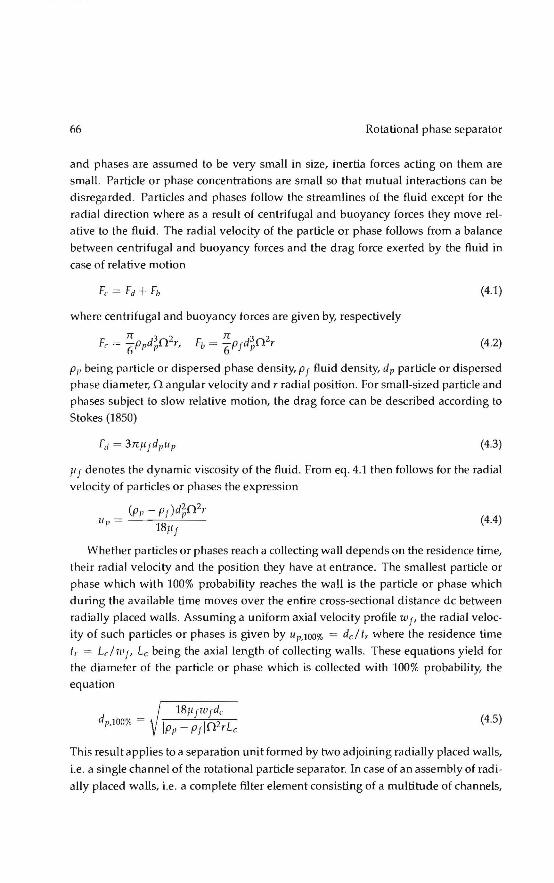
66 Rotational phase separator
and phases are assumed to be very smal! in size, inertia forces acting on them are
smal!. Partiele or phase concentrations are small so that mutual interactions can be disregarded. Particles and phases follow the streamlines of the fluid except for the
radial direction where as a result of centrifugal and buoyancy forces they move rel
ative to the fluid. The radial velocity of the partiele or phase follows from a balance
between centrifugal and buoyancy forces and the drag force exerted by the fluid in
case of relative motion
(4.1)
where eentrifuga I and buoyancy forces are given by, respectively
(4.2)
p1, being p<Hticle or dispersed phase density, p f fluid density, dp partiele or dispersed phase diameter, 0 angular velocity and r radial position. For small-sized partiele and
phases subject to slow relative motion, the drag force can be described according to
Stokes (1850)
(4.3)
11 f denotes the dynamic viscosity of the fluid . From eq. 4.1 then follows for the radial velocity of particles or phases the expression
(p1,- PJ )d~02r Up = 18Jij (4.4)
Whether particles or phases reach a collecting wall depends on the residence time,
their radial velocity and the position they have at entrance. The smallest partiele or
phase which with 100% probability reaches the wal! is the partiele or phase which
during the available time moves over the entire cross-sectionat distance de between
radially placed walls. Assuming a uniform axial velocity profile w 1, the radial veloc
ity of such particles or phases is given by up,tOO% = del t, where the residence time
t,. = Lclw1, Lc being the axiallength of collecting walls. These equations yield for the diameter of the partiele or phase which is collected with 100% probability, the
equation
(4.5)
Th is result applies toa separation unit formed by two adjoining radially placed walls,
i.e. a single channel of the rotational partiele separator. In case of an assembly of radi
ally placed walls, i.e. a complete filter element consisting of a multitude of channels,
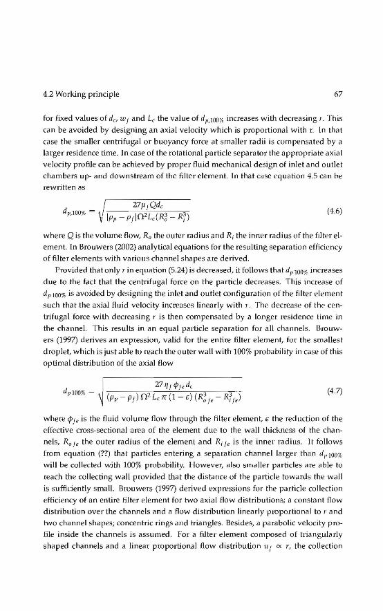
4.2 Work.ing principle 67
for fixed values of de, Wj and Lc the value of dp,IOO% increases with decreasing r. This
can be avoided by designing an axial velocity which is proportional with r. In that
case the smaller centrifugal or buoyancy force at smaller radü is compensated by a
larger residence time. In case of the rotational partiele separator the appropriate axial
velocity profile can be achieved by properfluid mechanica! design of i niet and outlet
chambers up- and downstreamof the filter element. In that case equation 4.5 can be
rewritten as
dp,IOO% = (4.6)
where Q is the volume flow, Ra the outer radius and R; the inner radius of the filter el
ement. In Brouwers (2002) analytica! equations for the resulting separation efficiency
of filter elements with various channel shapes are derived.
Provided that only r in equation (5.24) is decreased, it follows that dP I DO% increases
due to the fact that the centrifugal force on the partiele decreases. This increase of
dP IOO% is avoided by designing the in let and outlet contiguration of the filter element
such that the axial fluid velocity increases linearly with r. The decrease of the cen
bifugal force with decreasing r is then compensated by a Jonger residence time in
the channel. This results in an equal partiele separation for all channels. Brouw
ers (1997) derives an expression, valid for the entire filter element, for the smallest
droplet, which is just able to reach the outer wall with 100% probability in case of this
optima! distribution of the axial flow
(4.7)
where cfJJe is the fluid volume flow through the filter element, e the reduction of the
effective cross-sectionat area of the element due to the wall thickness of the chan
nels, Rafe the outer radius of theelementand Ri fe is the inner radius. lt follows
from equation (??) that particles entering a sepa ration channel larger than d1, lOO%
will be colleeled with 100% probability. However, also smaller particles are able to
reach the collecting wall provided that the dis tance of the partiele towards the wall
is sufficiently small. Brouwers (1997) derived expressions for the partiele collection
efficiency of an entire filter element for two axial flow distributions; a constant flow
distribution over the channels and a flow distribution linearly proportional tor and
two channel shapes; concentric rings and triangles. Besides, a parabalie velocity pro
file inside the channels is assumed. For a filter element composed of triangularly
shaped channels and a linear proportional flow dis tribution u f ex r, the collection

Rotaticnat phase separator
efficiency of the whole element is given by
E = { 1
2 ( 3 (x2) l/3) 2x 1- 4 2 (4.8)
where x = dp ! d1, JoO%·
The smallest fractions, which are separated in the RPS, move with a radial veloc
ity, which is equal to the ratio of the channel height to the channellength times the
axial fluid velocity. In practical applications the ratio between the channel height and
channel length is very smal(, in the order of 10-2. Thus the dropiets move with a
radial velocity, which is only a few percent of the axial fluid velocity u Je· This means
that the process of radial migration of the dropiets to the channel walls is already
disturbed when secondary flowsof one percent in magnitude of the axial fluid veloc
ity occur in planes perpendicular to the axial channel axis. To avoid these secondary
flows, the flow in the channels of the filter element has to be laminar. It is known
that for non-rotating channels such flow only occurs for limited value of the axial
Reynolds number
(4.9)
for rotating channels a much strenger condition must be fulfilled to sat.isfy stabil
ity, as rotatien is an additional destabilization factor. In the case of a tube rotating
around its own symmetry axis, not only condition (4.9) must be satisfied but also the
rotational Reynolds number, defined as
P!.Od~ Reo =---
'7! (4.10)
should not be larger than 108. If however, Ren exceeds 108, the axial Reynolds num
ber should become less than 166, see figure 4.2. Brouwers (1995) shows that these
considerations are also valid for tubes rotating around an axis not coinciding with
but parallel to their symmetry axis. A further consideration is that tubes should be
parallel within a few degrees to prevent secondary flow due to Coriolis forces.
4.3 prototypes
The rotatiQnal Rhas~. :>,eparato..r . has_t.iJ~ advantage that it is relatively easy to realise
a mockcup of a filter elemenl A coupl; ~f"differenf si~~d. t~bes with a lot of dri-;:,k
ing straws will do, so quite a number of prototypes have been manufactured and
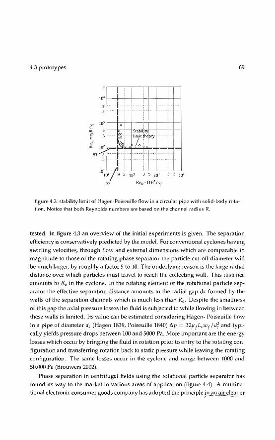
4.3 prototypes 69
3
JO'
lt··· 5 ... · -·-··
3 , ......
j(}l :>-- ~0
figure 4.2: stability limit of Hagen-Poiseuille flow in a circular pipe withsolid-body rotation. Notice that both Reynolds numbers arebasedon the channel radius R.
tested. In figure 4.3 an overview of the initia! experimentsis given. The separation
efficiency is conservatively predicted by the model. For conventional cyclones ha ving
swirling velocities, through flow and external dimensions which are comparable in
magnitude to those of the rotating phase separator the partiele cut-off diameter will
be much larger, by roughly a factor 5 to 10. The underlying reason is the large radial distance over which particles must travel to reach the collecting wall. This distance
amounts to R0 in the cyelone. In the rotating element of the rotational partiele sep
arator the effective separation distance amounts to the radial gap de forn1ed by the
walls of the separation channels which is much less than R0 . Despite the smallness
of this gap the axial pressure losses the fluid is subjected to while flowing in between
these walls is limited. lts value can be estimated considering Hagen- Poiseuille flow
in a pipe of diameter de (Hagen 1839, Poiseuille 1840) !':.p = 32ttrLcwrlci~ and typically yields pressure drops between 100 and 5000 Pa. More important are the energy
losses which occur by brioging the fluid in rotation priortoen try to the rotating con
figuration and transferring rotation back to static pressure while leaving the rotating
configuration. The same losses occur in the cyclone and range between 1000 and
50.000 Pa (Brouwers 2002).
Phase separation in centrifugal fields using the rotational partiele separator has
found its way to the market in various areas of application (figure 4.4) . A multina
tional electronic consumer goods company has adopted the principle in an air cl~~~er

70
0.8
0.6 >-
:~ ~ 0.4
0.2
..
.
. . -· ..., . .. !- .. '
throrie
tobilcco smoke
· · • oil
• dust
... NaCI
dimt>nsionless partiele diamE.'ter 1-1
figure 4.3: initia! experiments
Rotaticnat phase separator
(4). The device, which is sold world-wide, servestoremove air-borne particles which
can cause respiratory allergie reactions tomen in houses and offices. For this appli
cation the filter element is made from platic by injection moulding. In this case the
company obtained a full license from the inventor for application of the product in
this specific market.
3
figure 4.4: applications of the rotational partiele separator
Another applicati~b.e_cQU~on of powde~~~rticles from_gases
in food and pharmaceutical processes. A specifka:aVantage in this area is the possi--- - ~ bility to fabricate the entire apparatus of stainless steel. It enables to meet strongest
conditions on hygiene and cleaning. A design has been shown in figure 4.4 (1) and
(2). The rotating element has been integrated in a cyclone. The cyclone acts as a
pre-separator in which the gas is fittered from course particles material prior toen
trance in the separation element. The cyclone also serves as a pre-swirter within
which the gas is brought in rotation before entering the rotating separation element.
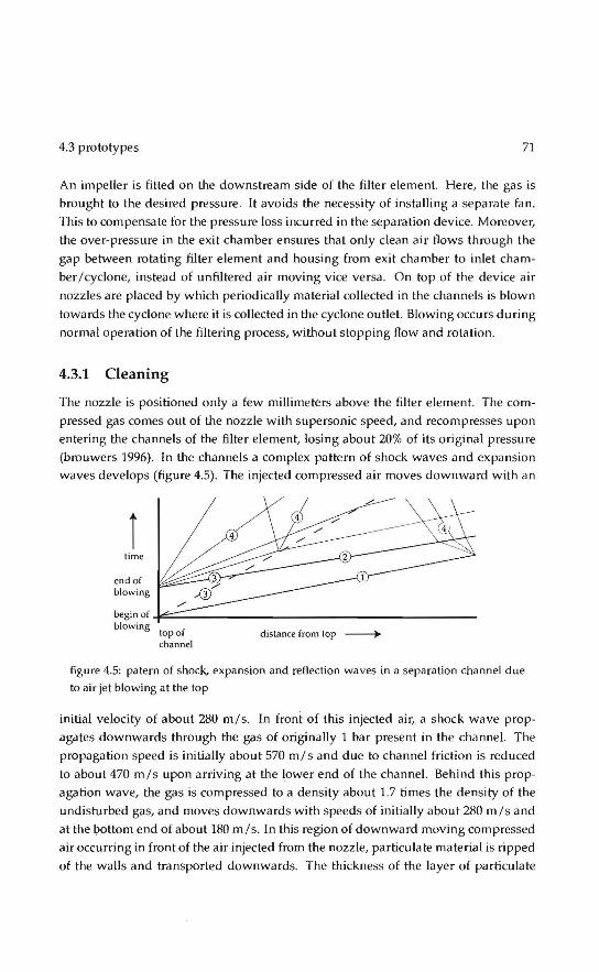
4.3 prototypes 71
An impeller is fitted on the downstream side of the filter element. Here, the gas is
brought to the desired pressure. lt avoids the necessity of instaHing a separate fan.
This to compensate for the pressure loss incurred in the separation device. Moreover,
the over-pressure in the exit chamber ensures that only clean air flows through the
gap between rotating filter element and housing from exit chamber to inlet cham
ber/cyclone, insteadof unfiltered air moving vice versa . On top of the device air
nozzles are placed by which periodically material collected in the channels is blown
towards the cyclone where it is collected in the cyclone outlet Blowing <Keurs during
normal operahon of the filtering process, without stopping flow and rotation.
4.3.1 Cleaning
The nozzle is positioned only a few millimeters above the filter element. The com
pressed gascomes out of the nozzle with supersonic speed, and recompresses u pon entering the channels of the filter element, losinga bout 20% of its original pressure
(brouwers 1996). In the channels a complex pattem of shock waves and expansion
waves develops (figure 4.5). The injected compressed air moves downward with an
Î time
end of blowing
be~nof~~-----------------------------------------blowing top of
channel distance from top -----+
figure 4.5: patern of shock, expansion and reflection waves in a separation channel due
to air jet blowingat the top
initia! velocity of about 280 m/s. In front of this injected air, a shock wave prop
agates downwards through the gas of originally 1 bar present in the channel. The
propagation speed is initially a bout 570 m/ s and due to channel friction is red u eed
toabout 470 m/s upon arriving at the lower end of the channel. Behind this prop
agation wave, the gas is compressed toa density about 1.7 times the density of the
undisturbed gas, and moves downwards with speeds of initially about 280 m/s and
at the bottorn end of about 180 m/s. In this region of downward moving compressed
air occurring in front of the air injected frorn the nozzle, particulate material is ripped
of the walls and transported downwards. The thickness of the layer of parhculate
72 Rotational phase separator
milterial which moves downwards can be assessed from a balance between the shear
force exerted by the gas and the friction between particles due to centrifugal pressure. It is found to besome tensof micrometers.
Due to filter rotation, a moment wil! occur when the channel has passed the col
umn of air blown from the nozzle. At th.is moment expansion waves start to develop
from the top of the channel, and the intt:.nsity of the axial momenturn of the gas begins
to decrease. Characteristically for supetsonic conditions, the front of the expansion
waves propagates faster than the compression wave. As cleaning occurs beh.ind the front of the compression wave, one should avoid a situation where the front of the
expansion waves (line 2 in figure 4.5) catches up with the compression wave (line 1
in figure 4.5) befare the latter arrives at the lower end of the channel. Therefore the
jet should blow sufficiently long. This is achieved by designing the nozzle such that
its length in the circumferential direction is sufficiently large.
Under the above conditions, for practical versionsof the rotational partiele separator it has been established that about 1 kg of fine particles material collected in
the channel can be removed by injecting about 1 kg of compressed air at 6 bar. This
result is obtained under normal eperating conditions with the filter element under
full rotiltion. It compares reasonably well with theoretica! predictions based on pre
viously described physics of shock waves and layers of particulate material being
moved downwards. Taking account of pre-separatien in the cyclone, fora range of
practical applications a realistic value for the loading of the filter element is 1 g of fine particles milterial per unit of gas to be purîfied. The power consumption of the
compressor per unit of purified gas is the assessed as about 300 Jm- 3. If required,
these va lues of compressed air consumption and related power consumption can be
reduced significantly by adopting a system in which the filter is taken off-line and subsequently cleanedat reduced rotational speed.
As alternative to air (or other gases), cleaning of the filter element may be accom
plished by periodically injecting water (or other liquids). In practice it has been es
tablished that (hot) water at pressures of 50 to 100 bar can be injected using the same
nozzle as the one used for air. lt offers the possibility to clean from time to time the
filter very thoroughly in addition to regular air clean ing. I t is particularly interesting for applications where high standards of hygiene apply.
A third methad for removing particles material from the channels of the filter ele
ment is to continuously add liquid. Thîs can occur by dispersing a spray of fine Iiquid
particles in the gas upstream of the filter element. The fine Iiquid particles are cen
trifuged towards the outer walls of the channels of the filter element Here they form
a liquid film which moves towards and which carries away the other (solid) parti
cles. Th is technigue has been successfully applied to bath the axial and the tangenbal

4.3 prototypes 73
version of the rotational partiele separator.
A nother method for permanent wetting of the filter element involves addition of
liquid from the top of the filter element. In practice this has been realised by using
a small nozzle which moves slowly up and down in radial direction while the filter
rotates. The desired amount of liquid (at 5 bar) is injected into the channels and
forms a stabie film along the outer walls of the channels. In this film centrifuged
solid particles are collected, are dissolved or remain floating, and are transported
downwards. The advantage of adding liquid from the top of the filter element is that
the created liquid film extends over the entire lengthof the filter element.
The wet version of the rotational; partiele separator appears to be an attractive al
ternative to existing wet scrubbers often employed in chemica! and process industry.
In contrast to wet scrubbers, in the rotational partiele separator water is not injected to
separate particles, but only totransport particles material being centrifuged towards
the walls. This results in much lower (up to two orders of magnitude) amounts of
washing liquids. This is a lso one of the reasoos why the power consumption is much
less. For equal separation performance, the power consumption quoted for conven
tional wet scrubbers (Brouwers 1996) is about five times larger than that established
for the rotational partiele separator.
4.3.2 Manufacturing and costs
The costs of manufacturing the rotational partiele separator are closely related to the
kind of application. Costs can be limited as most components are common products:
motor, housing, impeller, equipment for cleaning, electronic controls etc. The only
item which is not standard is the filter element. The further development of this line
of rotational partiele separators came toa standstill as insome more demanding sit
uations reliability issues with the filter element arose and the producer of this type of
RPS went out of bussiness. The filter element is produced by winding up around a
shaft layers of corrugated and uncorrugated sheet material (figure 4.6). Subsequently
the sheets were bonded together in a vacuum brazing furnace using an active filler
materiaL The idea was that temperature uniformity is maintained on the work piece when heating in a vacuum, greatly reducing residual stresses because of slow heating
and cooling cycles. Radiation however is the only heat transfer mechanism in a vac
uum furnace and the filter element acts as a very effective radiation shield. Temperature uniformity is not achieved and the bonding can not be complete throughout the
filter element. Normally this is not a problem as the sandwich construction formed
by the corrugated and flat sheets is stressed by the outer wal!, but the local tensions
induced by the cleaning system led to fatigue failure. Recently a welding technique

74 Rotational phase separator
Ö has been developed to solve this problem and the program is continued now with a
pilot project in China and several projectsin the Netherlands.
filter .:-Ie ment
s tainltsS steel colts
figure 4.6: filter element production
Studies were carried out on the costs of filtering systems basedon the rotational partiele separator. Considering stainless steel designs suited for industrial applications, the discounted value of annual costs was assessed. These included purchasing costs, utility costs, costs of assembly and re placement, engineering casts and casts of constructjon and erection. For installations with a total gas flow up toabout 100,000
m - 3hr -l, it was found that the discounted value of annual costs, expressed in dollars
per unit of gas flow being purified, were lower than those of existing filtering meth
ods, in particular for installations with lower gas flows. In the case of baghouse filters
and electrastatic precipitators, the cost advantage can be ascribed to lower casts for reptacement and investment. For wet scrubbers, such as venturi scrubbers, the cost
advantage is due to lower utility costs (lower power requirements).
With the development of the RPS for partiele-gas separation well under way, the
mean research focus shifted to other fields, in particular liquid-Iiquid or liquid-gas separation. This shift in focus was again triggered by previous experience with oil
exploitation and production (Brouwers 1987).
4.4 Naturally driven RPS
With Jonger exploitation of offshore wells, the amount of liquid, especially water, in
the product stream increases. This is mainly due tothefact that water is usually used
to keep the well under pressure. The increase in liquid contamin'ants requires im
provement of current separation methods. In commonly used separators gravity is
used to separate the dispersed phase. To allow for sufficient settling time, gas veloei
ties in theseparators have to be low. As a resu.lt these devices are volumine us, heavy and expensive and with increasing liquid amount the capacity is no Jonger sufficient.
More a nd I or heavier separation devices are needed a nd sametimes even heavier and

4.4 Naturally driven RPS 75
figure 4.7: schematic representation of the RPS-based separator, which is designed to
purify natura! gas under high pressure.
more expensive supporting structures are required . In some cases, although consicterable gas reserves are still present, the exploitation of a well has to be stopped, as current gas treatment techniques are not economically viable. A device which ful fills
these requirements is the naturally driven Rotational Phase Separator as depicted in
figure 4.7 (van Kemenade 2003, Mondt 2005) .
4.4.1 Natura! gas production
Natura! gas used by consumers is almast entirely composed of methane. However,
natura! gas extracted from offshore gas deposits, although still composed primarily
of methane, is by no means pure. lt contains oil, different semi-Iiquid hydrocarbons,
water in the form of reservoir brine and condensate (va por), sand and other large par
tiele impurities (me 1974). The remaval of thesecontaminantsis the most important
process step befare the gas can be distributed as sales gas. The solid particles have to
be removed from the gas because of eww.n..problems. Water has to be removed for
two reasons. First, in the presence of~2S, two other possible components
of natura! gas, it forms a highly c~r:r.osive mixture. Second, water tagether with hy
drocarbon componentscan form hydrates, flaky solids, which could cause plugging.
Finally, the hydracarbon condensateSä"I; re~ved f~m th~ gas bef;re it i; delivered
to the customers. To prevent erosion, eerrosion and plugging of process equipment,
water and the solid particles have to be removed in the earliest stages of production.
Hydracarbon condensates can be removed in a later stage as they form less hazards
during processing.
The J?1ajor transportation pipelines and in particular the compressors, used to
transp .· t the gas to shore, impose restrictions on the amount of solid and liquid con
ta · ants. Offshore platforms are therefore built to remave those contaminants from
the gas in a number of steps, depending on the composition and quality of the gas

7ó
Gas .-ell --- ....___
Condensate
Rotational phase separator
Offshore Onshare processmg Transporlahon processmg
i p•pehne i
=L=~as Condensate
ligure 4.8: Simplified schematic offshore separation flow sheet.
extracted. A schematic overview of the separation steps is given in figure 4.8. Natura I
gas extrilcted from a reservoir reaches the surface at pressures up to several hundred
bar. Subsequently the gas is transported along a high-pressure pipeline into the first
separation step, also called wellhead separation. In this stage separation takes place
in i1 conventional separator, a knock-out drum. It consists of a closed tank, where
gravity serves to separate the heavier solid contaminants and already condensed liq
uids, like oil and water under high pressure.
As the pressure of the gas is too high for the transportation pipeünes, the pressure
must be reduced . This is done in aso-called throttling Ooule-Thomson) valve. In a
throttling valve the gas is expanded. Due to this expansion not only the pressure, but
also the temperature of the gas is reduced. The reduction in temperature causes con
densation of the hydracarbon vapors and water va por. When the well pressure is too
low for cooling the gas by expansion, the gas is mechanically refrigerated. Besides
condensation, sametimes condensable vapors are removed by adding solid or liquid
desiccants. These desiccants absorb the liquid phases and are subsequently regener
il led. The condensed liquids and/ or desiccants are removed in the second separation
step. This step usually consists of several interdependent treating steps. In these
steps the gas is brought to the required specifications for pipeline transportation to
onshore facilities.
Studies on aerosol size dis tribution in a natura! gas stream have identified that sig
nificant quantities of dropiets below 5 microns are the norm whenever choke valves
ilnd other restrictions are present (Regan 1992) or when vapors are at !heir dew points
(Perry 19R4). The measurements were performed todetermine the concentration of

4.4 Naturally driven RPS 77
liquid aerosols in the natura! gas stream sampled downstream of vane separators
(combination of gravity separator and horizontal filter barrier and equivalent to a
mist eliminator pad). Results show that in many cases, large quantities of aerosols
cao go through this type of separator because the dropiets are too smalt to be trapped
by these separation devices. As a result, a liquid I gas coalescer should be the tech
nology of choice whenever high recovery rates are required to proteet downstream
equipment or to reeover valuable liquid products.
4.4.2 State of the art
In a gravity separator or knock-out drum, gravitational forces control separation. The
lower the gas velocity and the larger the vessel size, the more efficient the liquid/ gas
separation. Because of the large vessel size required to achieve settling, gravity sepa
rators are rarely designed to remove dropiets smaller than 300 microns. A knock-out
drum is typically used for bulk separation or as a first stage scrubber. A knock-out
drum is also useful when vessel internals are required to be kept toa minimum as in
a relief system or in fouling service. Gravity separators are oot recommended as the
soul souree of remaval if high separation efficiency is required.
In centrifugal or cyclone separators, centrifugal forcescan act on an aerosol at a
force several times greater than gravity. Generally, cyclonic separators are used for
removing aerosols greater than 100 llm in diameter and a properly sized cyclone can
have a reasanabie remaval efficiency of aerosols as low as 10 llm. A cyclone's remaval
efficiency is very low on mist particles smaller than 10ftm6 Both cyclones and knack
out drums are recommended for waxy or coklng materia is.
The separation mechanism for mist eliminator pads is inertial impaction. Typi
cally, mist eliminator pads, consisting of fibers or knitted mes hes, ca n re move dropJets
down to 1-5 microns but the vessel containing them is relatively large because they
must be operated at low veloeities to prevent liquid reentrainment
Vane separators are simply a series of baffles or plates within a vessel. The mech
anism cantrolling separation is inertial impaction. Vane separators are sensitive to
mass velocity for remaval efficiency, but generally cao operate at higher veloeities
than mist eliminators, mainly because a more effective liquid drainage reduces liq
uid reentrainment. However, because of the relatively large paths between the plates
constituting the tortuous network, vane separator can only remove relatively large
droplet sizes (10 microns and above). Often, vane separators are used to retrofit mist
eliminator pad vessels when gas velocity exceeds design velocity.
Liquid/ gas coalescer cartridges combine features of both mist eliminator pads
and vane separators, but are usually not specified for removing bulk liquids. In bulk

7R Rotational phase separator
liquid systems, a high efficiency coalescer is generally placed downstreamof a knack
out drum or impingement separator. Gas flows through a very fine pack of bound
fibrous material with a wrap on the outer surface to promote liquid drainage. A coa
lescer cartridge cantrap dropiets down to 0.1 micron. When properly designed and
sized, drainage of the coalesced dropJets from the fibrous pack allows gas veloeities
much higher than in the case of mist eliminator pads and vane separators with no
liquid reentrainment or increase in pressure drop across the assembly. L~g_a~
co a leseer ~~ rtrid_g~s _cQmbine _fe_~ty.res...oJ..botJ:wnisLeJiminator__p_<Jds __ ~ators, but are usually not specified for removing bulk liquids. In bulk liquid systems, a
higlïêfficiency coalescer is generally pJaced downstreamof a knock-out drum or im
pingement separator. Gas flows through a very fine pack of bound fibrous material
with a wrap on the outer surface to promote Jiquid drainage. A coalescer cartridge
cantrap dropiets down to 0.1 micron. When properly designed and sized, drainage of
the coalesced dropJets from the fibrous pack allows gas veloeities much higher than
in the case of mist eliminator pads and vane separators with no liquid reentrainment
or increase in pressure drop across the assembly.
4.4.3 Design considerations
A schematic representation of the naturally driven RPS is given in figure 4.7. After
passing the inJet part, which mainly serves as a bearing support, the contaminated
fluid (gas/liquid) enters a swirl generator where the fluid is brought in a rotational
motion ilS it passes its static vanes.
After the swirl generator, the mixture enters the pre-separation room, which serves
as a kind of axial cyclone. In this separation room large contaminants are swept out
of the flow, due to the centrifugal motion of the fluid . The contaminants Ieave the sepilrator through the pre-separator outlets, which are situated before the filter ele
ment at the outside of the separator. The filter element is brought into rotation by
the angular momenturn of the fluid. Due to the centrifugal force, the dropiets in the
fJuid are driven towards the wallof the channels where a liquid film is formed. This
film breaks up at the end of the filter element and larger dropiets are formed which
can easily be separated in the post-separator (figure 4.9). lf the dispersed phase is the
lighter medium, as is the case for oil dropiets dispersed in water, it is swept to the
core of the post-separator. In the case of liquid dropiets in a gas flow, the dropiets
move towards the outer wal!. The liquid separated frorn the fluid flow leaves the separator through the post-separator outlets, which are positioned at the outer ra
dius of the separator. The purified gas leaves theseparator axially through the main
outlet. Downstream of the post-separator a de-swirler is placed. The stator vanes

4.4 Naturally driven RPS 79
convert a large part of the rotational energx_QLtbe fluid into static~ssure. Without
the de-swirler the rotational energy is completely dissipated in heat and thus wasted.
Reeavering part of the kinetic energy, means that the separation process generates the
waste stream at high pressure. This enables re-injection of the contaminants back into
the gas reservoir from which they originally came.
E---figure 4.9: the filter element operales as a coalescer when separating dispersed liquid phases from gas. Entering dropiets are centrifuged towards the outer walls of each channel, creating a liquid film. At the end of each channel the liquid film breaks up in larger droplets. These dropiets are colleeled at the outerwallof the post-separation area.
In the pre-separator coarse particles are removed from the flow. Although the
streamlines in the pre-separator partly point to the inner radius, large particles can
move, as a result of centrifugal and buoyancy forces, in a radial direction opposite
to the fluid stream. Particles, which have a radial velocity that is larger than the
average radial velocity of the gas stream are driven towards the outer radius of the
pre-separator and can be collected there. The diameter of the particles that can reach
the wall can be determined analogous to equation (4.6).
dp pre = 18 YfJ VpreT
.(pp- PJ) w~ ( 4.11)
where Vpre is the average radial gas velocity in the pre-separator and wl' is the tan
gential velocity of the partiele at radius r.
The pre-separator can be considered as an axial cyclone. In the core of a cyclone
the tangenbal velocity component can be approximated by asolid body rotation (w Ir = constant). While at the outside of a cyclone the tangenbal velocity component
comes closetoa free vortex (wr =constant).

RO Rotational phase separator
The general expression for the tangential velocity component in case of a solid
body rotation is w = 0 r. Substituting this expression in equation (4.11) gives the
smallest droplet or partiele diameter, which is separated in case the fluid flow in the
pre-separator is regardedas a solid body rotation
181Jf Vpre
dl'l''e = \ (p,,- PJ) 02r (4.12)
In case of a free vortex, the tangential velocity component is given by w = Cr/r
with Cr = r /2n and ris the magnitude of the circulation. Substituting this expres
sion in equation (4.11) gives the relation for the smallest droplet or partiele diameter,
which is separated in case of a free vortex
df>pr.' = 72 Tr2 17 f V pre r3
(pp-pf)f2 (4 .13)
Besides that the pre-separator prevents blockage of the filter element channels, the
pre-separator is also designed such that the desired axial fluid velocity profile at the
i niet of the filter element is created.
The post-separator is a tubular section located after the filter element (figure 4.7).
lt receives flows from all the individual filter element channels. The droplets, which
reach the walls of the filter element, coalesce and form a liquid film. At the exit of
the channels this liquid film breaks up into relatively large droplets. In the post
separabon area the rotational motion of the gas forces these dropJets towards the
outer wal[, where they are separated from thema in flow. However, before the dropJets
reach the outer collecting walt, they may break-up into smaller dropiets as a result of
centrifugal forces and/ or forces due to the turbulent motion of the fluid. As a result
these small dropiets may leave the separator tagether with the gas stream and this
deteriorates the separation performance. Therefore, the minimum diameter of the
dropiets present in the post-separator area is an important quantity for the design of
the post-separator. j The dropJets that can reach the walls of the filter elementforma liquid film. At the
V exit of the channels the film breaks up due to centrifugal forces and/or turbulence.
According to Hinze (1955) the maximum stabie droplet diameter in an isotropic, ho
mogeneous turbulent flow can be expressed by
_ (P!)-~ _z dmox = C (i t 5 (4.14)
if the shear forces on the dropJetscan be neglected. This is the case if the viseaus
forces inside the droplet are small compared to other forces . C is a constant and CT
4.4 Naturally driven RPS 81
denotes the interfacial tension . The energy dissipation per unit mass can be estimated
by
2Ju~ean f:=---
dpipe (4.15)
where fis the friction factor, Umean the mean velocity in the pipe and d pipe the pipe diameter. lt is assumed that the minimum droplet diameter equals half the maximum
stabie droplet diameter.
Droplets arealso generated due to centrifugal forces. The interfacial tension gives
rise toa surface force that counteracts this deformation process. The droplet size at
which break-up occurs can be found by equalling these forces
d p,breakup = 6CT
(4.Hi)
The length necessary for the post-separator is found analogous to equation (4.fi). The
post-separator is an open space receiving flows from individual filter element chan
nels. The angular momenturn ensures further phase separation takes place.
In the swirl generator the angular momenturn required to drive the filter element
is generated. The angular momenturn equals the momenturn lossesin other partsof
the separator. The parts that contribute the mosttothese losses are the filter element,
the pre-separator, the gap between the filter element and the static housing and the bearings
Ge,swirl = Ge,Je + Ge,gap + Ge,decay-pre + Ge,bearings (4.17)
The general definition of angular momenturn is
(4.18)
where 5 is the cross sectional area. The angular momenturn of the flow leaving the
filter element is given by Hendriks (2000)
(4.1Y)
Fora linear axial velocity distribution u f = br, with ba constant, as desired for an
optima! performance, it follows that the axial fluid velocity is given by
3Q (4.20)

i\2 Rotational phase separator
Substitution of equation (4.20) in (4.19) gives the lossof angular momenturn in the
filter element
(4 .21)
where the subscript e denotes the entrance. In Li and Tomata (1994) arelation is given
fur the axial decay of angular momenturn in a hydraulically smooth tube . With this
re lation the lussof momenturn in the pre-separator can bedescribed as
~ _ G . (1 _ 10-o.OJ60s(x' )0·8) Ce,drrny-JliP - e,s7VId (4.22)
where x* denotes the ratio between the pipe lengthand hydraulic diameter of the
tube. The momenturn required to turn a cylinder in a static housing is given by
Schlichting (1979)
, r' 1 02R4L c.e,gnJ> = '--1112 np 0 (4.23)
fora turbulent flow the torque coefficient Cm is given by Cm = 0.019886Ta- 02 . The
Taylur number Ta can be written as
(4.24)
where ss denotes the gap size between the rotating filter element and the static hous
ing. The loss of angular momenturn in the hearings due to friction is dependent on
the type of bearing chosen.
The pressure drop over the filter element is due to friction at the channel walls
and the development of a free vortex in the pre-separator to a solid body rotation
in the filter element. The pressure toss due to friction in the channels is given by
(Schlichting 1979)
óPfritlion,fe = (1 ~: + 1.16) ~p j t12 (4.25)
This equation is corrected forentrance effects. In a laminar pipe flow the friction co
efficient f equals 64 / Re. The pressure loss due toa difference between the ta ngential
velocity component prior to and in the filter element can be estimated from the con
servation of ma ss and momenturn over the filter element. The pressure drop due to
different tangential veloeities can be written as
óP,,etdifJ = PJ ( < wt > - < w~ >) (4.26)

4.4 Naturally driven RPS 83
< wr > and < w~ > denote the mean tangenbal veloeibes at the filter in- and outlet
respecbvely. The tangenbal velocity of a free vortex is given by w = Cr Ir with Cr =
r I (2n), ris the magnitude of the circulabon. The tangential velocity in asolid body rotabon is . Inlegration over the cross secbons and substitution in equation (4.26)
leads to
[2Cf in(Ro l R;) 1 2 2 2 ]
11Pveldiff = p R~ _ Rf - 20 (Ro + R;) (4.27)
The unknown Cr can be calculated by considering conservation of mass over the control volume
O(R~ - RJ) Cr= 3(R
0-R; (4.28)
The pressure drop over the swirl generator is due to friction in the small annulus
and the introduetion of a tangenbal velocity component. The flow relations of a fluid
with viscous effects in a duet of constant cross-sectio na! area give the pressure drop
due to friction in case a compressible flow is considered (Owczarek 1 964). In case of
an incompressible flow equation (4.25) gives the pressure drop due to friction. The
pressure drop caused by introducing a swirl component in the flow can be estimated
by
1 2 1 2 11Pswirl = zPWJ = zp(urtana:) (4.29)
where a is the blade angle of the vanes.
4.4.4 Experiments
A full scale prototype was build for separating water dropiets from naural gas., capa
bie to handle the volume flow of one typical wellhead under high pressure (80 bar)
and which separates dropiets down to 2 micron (table 4.1 ).
The performance of theseparator was measured in two test facilities. In one test
facility the separabon performance and the hydrodynamic performance of the prototype at low (atmospheric) pressure was measured. In the second test facility hy
drodynamic performance of the separator was simulated at elevated pressures. A
schematic overview of the low pressure test facility is shown in figure 4.10. In this
test loop air is used as the work.ing fluid . The pressure and temperature inside the test loop are respectively a bout 1.2 bar and 283 K. The measuring equipment is listed
in table 4.2.
The pressure drop over the filter element is measured by using the 4 equally
spaeed pressure holes situated at the circumference of the housing upstream as well

R4 Rotational phase separator
tal:>el4.1: Desired operating characteristics for the RPS-based natura I gas- water separa
tor
dt1l00%
Do L
Volume flow gas
Volume fraction contaminants
Pressure
Temperature
Pressure drop
Value
2]-lm
0.6m
0.36 m
0.65 m 3 s-1 (pg ~ 50 kg m - 3)
0.1 - 1% 80 bar
340K
< 1 bar
Compre=d winlet
® Absolute pTHStltt" sensor @ Speed Tran.mltter
0 FIO'W' meter ® Diffurwlö&l pressu.re meter
@ lnjection point particles RPS Rotadonal Partkle Separator
figure 4.10: schematic representation of the low pressure tes t facility.
as downstream of the filter element (figure 4.11). The 4 holes were interconnected
such that, before as well as behind the element, the average pressure is measured .
Besides one pressure hole is located upstream of the swirl generator. By using this
pressure hole the total pressure drop over theseparator can be measured.
The high pressure loop is fitled with Sulfur Hexa fluoride (SF6). SF6 is a high
density gas, with a density of 5 to 6 times the density of natura! gas. This means that
at relatively low pressures, high fluid density flowscan be simulated. Measurements
were performed at 3 different absolute mean pressures: 1.9 bar, 2.9 bar and 3.6 bar,
con·esponding to fluid densities of respectively: 11.2, 17.5 and 22.2 kgm - 3
The separation efficiency of the prototype was determined by injecting calcium
hydroxide (Ca(OHh), a lso called chalk hydra te or slaked I i me (supplied by Carmeuse)

4.4 Naturally driven RPS 85
Pressure hole
figure 4.11: loca tion of the pressure holes and angular speed sensor on !he prototype of
the natura! gas- water separator.
tabel 4.2: operating conditions of the measuring devicesin the low pressure test loop.
Flow Abs. pres. Diff. pres. Induclive
me let" sensoch sensor"
Operating range 0.0042 - 0.55 m 3 ç 1 0 - 21 bar• 0 - 0.2 bar
Temp. medium 255-473 K 227-394 K 227-394 K
Ambient temp. 233-358 K 233-358 K 233-358 K
Static pressure 100 bar 150 bar 150 bar
ra ting
Accuracy Re < 20000: 2% < 0.075% 0.2%
Re > 20000: 1%
"lnvensys vortex tlow meter, type 83F "lnvensys 1/ A series absolute pressure sensor, type l GPlO <Jnvensys 1/ A series differential pressure sensor, type l DPl O dTurck inductive sensor, type 8il-EG05-AP6X ' absolute or gauge uni ts
sensor'1
0 - 100 Hz
not applicable
248-343 K
no t npplicable
:::: 2%
into the low pressure setup a t the injection point (lP in figure 4.10). The partiele size
distributions both up- and downstream of the separator were determined by sam
pling the flow isokinebcally with an eight stage Andersen impactor type Mark 11.
In figure 4.13 the rotational speed n is depicted as a function of the flow rate through the separator for air at 1.2 bar. The solid line represents the model, the cir
cles, crosses and dots each represent one measurement series. lt can beseen tha t the

86 Rotational phase separator
measurements are well reproducible. Comparing the measurement results with the
theoretica! model shows good agreement, except fora slight deviation at low flow rates. For flow rates smaller than about 0.06 m3 çl the filter element does not rotate.
This is mainly due to the static bearing friction. The model a lso prediets the onset of
rotation well. The small bend in the model at small flow rates is due to the fact that
the relation for the dynamic bearing friction at low angular speeds differs from the
one at higher speeds (SKF 1990).
161l0 x Meas. 1 Meas. 2
1400 o Meas. 3
]_1200 1lrooo ~
-;;; 800 c .Q
::<i 600 0
"' 400 .
200
0o 0.05 0.1 0.15 0.2 0.25 0.3 0.35 0.4 0.45 Flow ra te [rn3 s ·IJ
figure 4.12: rotational speed of the filter element as a function of flow rate for air at 1.2
bar.
In figure 4.14 the rotational speed at elevated fluid densities is depicted as a func
tion of the flow ra te through the separator. The solid fine represents the model, while
the crosses represent the measurement data. As the temperature and absolute pres
sure in the test setup varied during one measurement cycle, the mean temperature and pressure values of one measurement cycle are used to calculate the theoretica!
hydrodynamic performance of the separator. The density and viscosity of SF6 are
interpolated from the measured data of Wilhelm (2005). For the two lowest fluid densities the models predicta slightly lower rotational
speed than measured . Comparing the three measurement results at elevated pres
sures shows that the rotational speed of the filter element hardly depends on the
fluid density. This is expected as both the generated momenturn and the lossof an
gular momenturn in the filter element, which has the highest contribution to the total
dissipated momentum, are linearly dependent on the gas density. In figure 4.15 the pressure drop over the filter element for air as the working fluid is depicted. The
crosses and dots each represent one measurement series, while the !i nes re present the

4.4 Naturally driven RPS
IBOOr;==7Më=o=:'de=;olo:;--~~-~-~-~-~~
1600 x Meas. I Meas. 2
1400 o Meas. 3
]_1200
~1000 ~ (ij 800 c 0
·~ 600 0
"' 400
200
0
0
0o 0.05 0.1 0.15 0.2 0.25 0.3 0.35 0.4 0.45 Flow rate (m3 s -IJ
87
figure 4.13: rotational speed of the filter element as a function of flow rate for air at 1.2
bar.
model. Losses are calculated for the two types of channel shapes: triangular and si
nusoidal. It follows that the pressure loss over the filter element is best represented by
the model, assuming sinusoidal channels. This is also expected, as the filter element
channels of the prototype have a more or less sinusoidal shape. The model assumes
a fully developed flow in the channels of the filter element. In reality this is not true,
as the dynamic entrance length, L11y for the channels is rather large. The dynamic
entrance length is defined as the required duet length to achieve a maximal duet ve
locity of 99% of that for fully developed flow when the entering fluid velocity profile
is uniform (Shah 1978). For example, for sinusoids channels for which the width is
much larger than the height, Shah and London give a dimensionless entrance length
L:Y (=L"yl (011 Re)) of 0.0648. The hydra ui ie diameter of the channels is 1·10-3 mand the Reynolds number in the channels during the measurements is of the order 1·103 .
This means that the dynamic entrance length is about 0.0648 m, which is about one
third of the total channellength (Lc=0.18 m). Although the model neglects the en
trance length, there is a good agreement between the measurements and the model.
In figure 4.16 the total pressure loss over theseparator together the pressure loss
over the filter element is given. It follows that total pressure lossis well predicted by
the theoretica! model. The pressure lossin the pre- and post-separator and pressure
drop in the pipe before the swirl generator are not included in the model, as they are
negligible compared to the other losses. It can a lsobeseen that pressure loss over the
filter element is the main contributor to the total pressure loss over the separator. In

RR Rotational phase separator
~~rr~==~M=oo=~~d~--~----~-----.-----.--,
2500 ~15. /11
"o 0.1
2500
"r"'"
500
o.2 o.J o.4 o.s 0o~-----;;o':". I-----;;o':. 2-----;;o':.3-----;;o:-;_,-----;;o:';.s-Fiow r.lle jm3 s"1
) Flow r,lte [m3 s "1]
2SOO~~===r--.---.---.-~---.--.---,
500
-Modt>l x Meas.
00 O.O.<; 0. 1 0.15 O.Z O.ZS 0.3 0.35 0.4 0.45
Flowrate[mJ s-1]
figure 4.14: ro tutional speed of the filter element as a function of the SF6 flow ra te. From
Ie ft to rig ht the density of SF6 is respectively 11.2, 17.5 and 22.2 kg m-3.
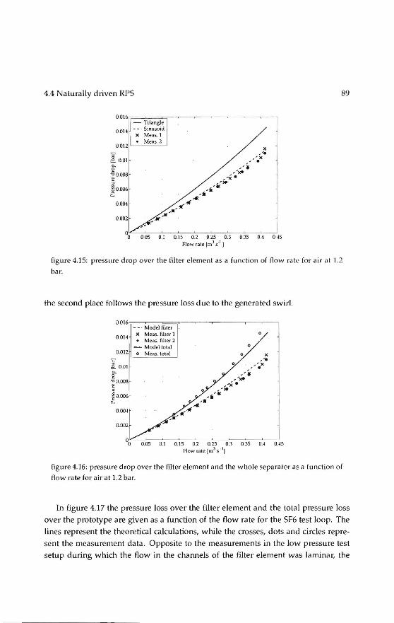
4.4 Naturally driven RPS
0.016 r;====:;=;===;<=;-~-~-~-~-~-~--, - Triangle
0.014
0.012
"' e om 0.. 2
""0.008 t ~
50.006 ê:
0.004
0.002
Sinuscid X Meas. 1 • Meas. 2
0.05 0.1 0.15 0.2 0.25 0.3 0.35 0.4 0.45 Flow rale [m3 s·1
J
89
figure 4.15: pressure drop over the filter element as a function of flow rate for air at 1.2
bar.
the second place follows the pressure loss due to the generated swirl.
0'016 r;==-_=:M=:'o'Cdccel=:fil::='t=er=;r-~---.---.----,-~-~
X Me as. filter 1 0.014
• Me as. filter 2 - Model total
0.012 o Meas. lolal
0
'i:' e o.o1 0.. g ." 0.008 t
~ 0.006 0..
0.004
0.002
0.05 0.1 0.15 0.2 0.25 0.3 0.35 OA OAS Flow rate (m3 s -IJ
figure 4.16: pressure drop over the filter element and the whole separator as a function of
flow ra te for air at 1.2 bar.
In figure 4.17 the pressure loss over the filter element and the total pressure loss
over the prototype are given as a function of the flow ra te for the SF6 test loop. The
lines represent the theoretica! calculations, while the crosses, dots and circles repre
sent the measurement data . Opposite to the measurements in the low pressure test
setup during which the flow in the channels of the filter element was laminar, the

90 Rotational phase separator
channel flow during the high pressure measurements was turbulent (the Reynolds
number in the channels va ried between 9·103 and 2·104). For calculating the pressure
drop over the filter element due to friction, the Blasius (1907) relation is used. A value
of 2 is assumed forthefactor ~' which represents the additional pressure drop at the
entrance region of the duet.
All measurement series show a gradual increase of the pressure loss with in
creasing flow rate. The filter element has again the highest contribution to the to
tal pressure loss. The measurement data of the pressure loss over the filter element
are slightly betow the predieled pressure loss. The measurement data for the to
t<JI pressure loss on the other hand are somewhat higher than predicted. This can
be attributed to the fact that in the model some flow phenomena in the swirl gen
erillor which contribute to an additional pressure toss are neglected. One of these
phenomena is the fact that the angle of incidence of the fluid at the inlet of the va nes
differs from the angle of the vanes itself. Furthermore, there will be an additional
pressure loss due to the acceleration of the fluid as it enters the vanes (decrease in
cross-sectional area due to thickness of the va nes). Besides, wakes may occur at the
trailing edges of the vanes, which cause an extra pressure toss. Furthermore, it can
beseen that for increasing fluid density, the pressure losses increase. This is also pre
dieled by the model as all pressure loss contributions increase for increasing fluid
density. In an ideal situation the total partiele concentration upstream the separator Cus
measured with the impactor equals the injected partiele concentration. In practice,
however, the impactor concentration was 2 to 3 times less than the injected concen
tration due to the toss of lime from the injection point to the impactor.
The total partiele concentration downstream of the separator can be determined
with an absolute filter. Measurements performed at the University of Twente, however, showed that the total partiele concentration downstreamof an RPS-based sepa
rator is approximately equal to the total partiele concentration on the impactor plates
when measuring downstreamof the separator. In these experiments also calcium hy
droxide and the sa me Anderson impactor were used. Equal concentrations can be ex
pected, as the impactor works as a kind of absolute filter. Therefore, in processing the
measurement results the concentration downstream of the separator Cds is assumed
equal to the total impactor concentration of the downstream measurements.
When the total injected concentration and the total impactor concentra !ion down
streamof theseparator are known, the total efficiency E101 a1 follows from
( Cds) Etnl"l = 1 - Cus 100% (4.30)
In figure 4.18 the results of the measurements are shown logether with two analyt-
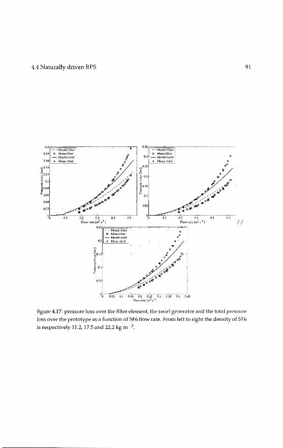
4.4 Naturally driven RPS
o.zr;=_=_=_ ';';MC"od"'•lc;fi';;'Jt,=,l""""'~-~--....,---...-,
0.18 X Meas.fther - Modeilotal
0 16 o Me.as. total
-.:::'0. 14
~0.12 e
-c 0.1 ~
ao.oa ~0.06
0.04
0.02
,· ..
%L-~~~-~o~.2--~o~.J~--o~ .. ~--7os~~
Flowrate !m3s'1 J
O.JSr,= __ =_ ';';M=cod;c,,t';:;më=t,=i, ---~----->< Meas.filler
0.3 - Modeilotal o Meas. total
0.1
0.05
0 .,
0 .0
02S rr_=_=_~MC"od;=c,,c:',;;;'l"=' "---~~-~~--~ X Meas.fllter
- Modeilotal 0.2 o Meas. tolal
j ~0. 15
~ l ~ 0.1 .. 0~5
0 0
035 0.4 0.45
91
11
figure 4.17: pressure loss over the filter element, theswirl generatorand the totill pressure
loss over the prototype as a function of SF6 Aow ra te. From left to right the densi ty of Sfh
is respectively 11.2, 17.5 and 22.2 kg m - 3.

92 Rotational phase separator
120r;=====;-~--~-~--~-~----,
-ur o::l __ . uf oc r
0.5 1 1.5 2 2.5 3.5 Dimensionless pa rtiele diameter I
rigure 4.1R separation efficiency as a function of partiele size. The solid line represents
the theoretica] efficiency prediction for a constant axial flow distribution, the dotled line
represents the theoretica] efficiency prediction for an axial flow dis tribution, which is
linearly proportional to ,. and the circles represent the measurement data (vertical bar
denotes the standard deviation) .
ical prediebons of the filter separation efficiency. The circles represent the mean sep
aration efficiencies per size class obtained from the measurements, while the vertical
lines through the circles represent the standard deviation. In the figure eight mea
surement points are depicted. These represent all colleebon plates of the impactor,
except the pre-separator and the back-up filter. The pre-separator is not accounted
for as it only serves to remove coarse particles from the flow. The back-up filter is
not regarded because, after the measurements upstream of the separator, no weight
increase of the back-up filter could be measured . The filter efficiency is given as a
function of the dimensionless partiele diameter x. This diameter represents the mean
partiele diameter per size elass divided by the diameter of the smallest partiele which
is separated with 100% probability in the filter element (Brouwers 2002).
Analytica) expressions for the separation efficiency of the filter element were de
rived by Brouwers (1997). In figure 4.18 the dotted line represents the theoretica[ sep
aration efficiency for triangularly shaped channels, which have a flow distribution
linearly proportional to radial distance r, while the solid line represents the efficiency
for triangular channels in which the axial flow distribution is constant over the chan
nels, 11 f ex 1. In both models a parabol ie velocity profile in the channels is assumed
(in reality this is not valid, as the dynarnic entrance Iength, Lhy for the channels is
rather large) . Theoretica) expressions for triangular channels are used, as they are

4.5 Further developments 93
100 X A 0 ... 0 0 .
90 ~· 0
~ 80 x
è' 70 0
~ 0 ·o ox ij 60
~ 50 0
~ x
8 40
~
30
~ 0.. 20
I :
Current meas. 10 Chalk hydra te
Sodium chloride 00 0.5 1 1.5 2 2.5 3.5
Oimensionless p«rticle diameter [-J
figure 4.19: separation efficiency as a function of partiele size. Comparison of current
measurements (circles) with previously performed measurements (asterisks and trian
gles).
easier to derive than expressions for sinusoidally shaped channels. Besides, the the
oretica! results for biangularly shaped channels are a good approximation to those
of sinusoidally shaped channels. Furthermore, in practice the channel shape is quite
irregular and also the sinusoidal shape is only an approximation of the actual channel
shape.
lt can beseen that the standard deviation increases forsmaller partiele sizes. This
is expected as the measurement errors are largerinthese size ranges, duetoasmaller
weight difference between the impactor plates prior to and after the measurements.
For partiele sizes around x = 1 and larger, the agreement between theory and exper
imentsis reasonable. However, for partiele sizes smaller than x=l a large difference
between the models and the experiments is observed. Previously performed mea
surements with an electrical driven RPS, using the same Anderson cascade impactor
to measure efficiency, showed similar results (Brouwers 1996), see figure 4.19. lt can
therefore be coneluded that the naturally driven RPS has the samepartiele separation
efficiency as an externally driven RPS.
4.5 Further developments
At this stage the naturally driven RPS was proven as a technique for the removal wa
ter dropiets in oil (with the help of Royal Dutch Shell) and to remove liquid dropiets

94 Rotational phase separator
from natura! gas (with the help of CDS engineering b.v.). The main application is
offshore oil I gas production where the production life of existing platforms can be
elongated by using these techniques as retrofitting large settling tanks to the plat
forms is not an option. A further step would be to bypass the platform altogether
and use the RPS for down-hole separation (figure 4.20 thus eliminating the need to
bring the water up. To that end the design is such that all fits inline in standard sized
pipes.
Further development of this design is now taken over by the cooperating indus
tries as actual demonstration on a platform requires a large coordinated effort to guar
antee safety and production. Independent manufacturing and marketing as in the
case of the heatexchangerand the cyclone type heatexchangeris notanoption here. Nevertheless the inventor has still an influence on the process through licensing the original and subsequent patents.
During the research of the naturally driven RPS, cantacts with industry (Royal
Dutch Shell in particular) ledtoa new research area: combining phase transition with
separation to remove unwanted components in natura! gas, opening up yet a nother
field of applications for the RPS.

4.5 Further developments 95
figure 4.20: Statoil subsea facilities

Rotational phase separator
overview
(ift.er element
I
I in let part
swirl generator
swirlgenerator filter element
figure 4.21: overview of the naturally deiven RPS

5 Separation by phase transition
In this chapter two innovations are discussed that are based on a new combination
of existing elements, specifically the combination of the high temperature heat ex
changer and the naturally driven rotational phase separator with phase transition.
These inventions serve as an example how seemingly independent lines of research
may leadtoa patentable innovation when combined.
5.1 Aerosol emissions in biomass combustion
One of the limiting factors preventing large scale introduetion of small biomass com
bustion units are the associated parbeulate emissions. Large cambustion units in
general are equipped with electrastatic precipitators and can achieve very low par
beulate matter emissions (<50 mgNm-3), while small scale units (in the order of 1
Mw) have at most a cyclone. Micro scale ( < 100 kW) units are not equipped with gas cleaning devicesapart from the heat exchanger. At the end of the previous century
it turned out to be difficult to meet the lower emission standards for medium scale
units, even with cyclones as particles below 10 ~mare hard to catchdevicesof this type. While investigating potential application of the RPS, measurements showed
that the partiele matter emissions of a biomass cambustion plantexhibita bi-modal
distribution (5.1 ).
The partiele size of the coarse fly ash fraction can vary betweensome few 11 m up to
about 200 ~m. The second fraction consistsof aerosols, formed during the cooling of the flue gas in the heat exchanger section. lf the concentration of ash-forming vapours
in the flue gas and the cooling rate in the heat exchangerare bath high, supersatu
ration of these vapours could occur, causing formation of new formed particles by
nucleation. The aerosol-forming vapours are mainly chlorides and sulfates of alkali
components. The particles formed by nucleation are very small in size, a bout 5 to 10
nm, but on their way in the flue gas, these particles are able to grow by coagulation,
agglomeration and condensation of ash-forming vapours (Obernberger 2001, Brun
ner 1998, Jolier 2005, Valmari 1998, Chrisbansen 2000, van Loo 2002). These particles
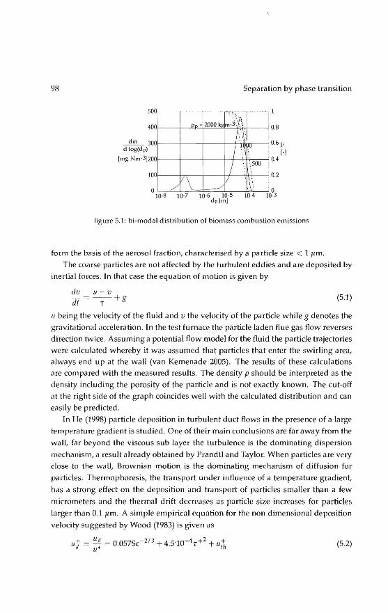
9R
500
400
~300 d log(dp)
(mg Nm-3]200
100
0
p,
/ V\
I0-8 10-7
Separation by phase transition
...
2000 k ' ~ ;!\ m-3'.',
(\'{ I ~~t."
' '
I \ 500
: \
V ' l~ _/
10-6 10-5 dp[m]
10-4
'
:
:
•
0.8
0.6 F
[-1 0.4
0.2
0 10-3
figure 5.1: bi-modal distribution of biomass cambustion emissions
form the basis of the aerosol fraction, characterised by a partiele size < 1 flm,
The coarse particles are not affected by the turbulent eddies and are deposited by
inertial forces_ In that case the equation of motion is given by
dv u-v dt = -T-+g (5,1)
u being the velocity of the fluid and v the velocity of the partiele while g denotes the
gravitational acceleration . Inthetest furnace the partiele laden flue gas flow reverses
direction twice. Assuming a potential flow model forthefluid the partiele trajectories
were calculated whereby it was assumed that particles that enter the swirling area, always end up at the wall (van Kemenade 2005). The results of these calculations are compared with the measured results. The density p should be interpreled as the
density including the porosity of the partiele and is nol exactly known. The cut-off
at the right side of the graph coincides wel! with the calculated distribution and can
easily be predicted.
In He (199R) partiele deposition in turbulent duetflowsin the presence of a large
temperature gradient is studied_ One of their main conclusions are far away from the
wal!, far beyond the viseaus sub layer the turbulence is the dominating dispersion
mechanism, a result already obtained by Prandtl and Taylor. When particles are very
close to the wal!, Brownian motion is the dominating mechanism of diffusion for
particles. Thermophoresis, the transport under influence of a temperature gradient,
has a strong effect on the deposition and transport of particles smaller than a few
micrometers and the thermal drift decreases as partiele size increases for particles
larger than 0.1 f!m. A simpte empirica! equation for the non dimensional deposition
velocity suggested by Wood (1983) is given as
(5.2)

5.1 Aerosol emissions in biomass cambustion 99
where ud is the deposition velocity, u• is the shear velocity, Sc= Jl I p8 DJI is the Schrnidt
number, Dp is the partiele diffusivity, u~ is the nondimensional thermophoretic sed
imentation velocity and. The non-dimensional partiele relaxation time is given by
.2 p d2C .2 r+ = Tpgu = ~pgu
Jlg 18J1g Jl g (5.3)
The correction factor Cc is due to Cunningham (1910) describing the deviation from
continuurn behaviour when the partiele diameter is comparable to the molecular
mean free path.
Cc = 1 + 2Kn ( 1.257 + 0.4 exp ( -1.1 :n)) (5.4)
The Knudsen number is defined as Kn =À/ dp, where À is the mean free path in the
gas. The mean free path is defined as the average distance travelled by a molecule
between successive collisions and can bedescribed by
À= 1 .Jinnd'!;,
(5.5)
n is the density of the gas and dm the molecular diameter. For air at 20 °C and at
mospheric pressure the molecular diameter is 0.00037 mm and the mean free path is
0.066 mm.
The first term in equation 5.2 is the partiele deposition rate due to Brownian mo
tion and eddy diffusion, the second term is partiele deposition induced by eddy
diffusion-impactation and the third term is due to thermophoresis. Yarious func
tions are available to describe the experimentally observed velocity profile for fully
developed turbulent pipe flow. One such function which accurately describes the
time averaged streamwise velocity sufficiently far from the wall over a braad range
of Reynolds numbers is given by Bird (1960)
u ( ')1 / 7 Umax = 1- R
Uavg
Umax
4
5 (5.6)
When a temperature gradient is established in a gas, the aerosol particles in that gas
experience a force in the direction of decreasing temperature. The motion of the parti
ele resulting from this force is called thermophoresis. The magnitude of this force de
pends on gas and partiele properties and the thermal gradient. The relation between
the shear velocity can be found as u* = Uavg (f /8) 112 where fis the Darcy friction
factor (Tandon 1998). The theoretica) thermal force on a partiele is (Waldmann 1966)
-pÀd~'ilT F1h = T dp < À (5.7)
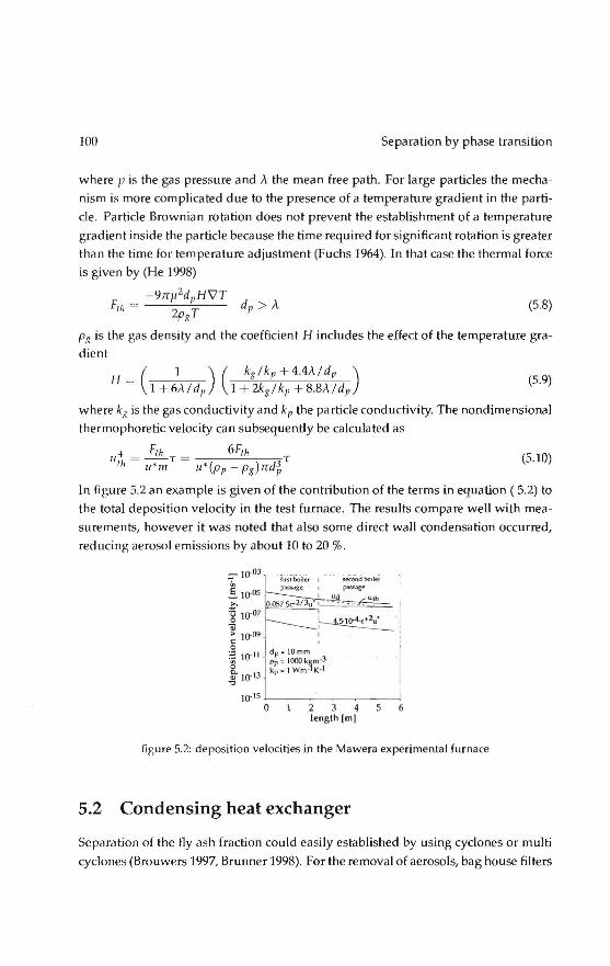
100 Separation by phase transition
where pis the gas pressure and À the mean free path. For large particles the mecha
nism is more complicated due to the presence of a temperature gradient in the parti
cle. Partiele Brownian rotation does notprevent the establishment of a temperature
gradient inside the partiele because the time required for significant rotation is greater
than the time for temperature adjustment (Fuchs 1964). In that case the thermal force
is given by (He 1998)
-97f!t2d" H\1T d
Fu, = 2 T P > À PK
(5.8)
pg is the gas density and the coefficient H includes the effect of the temperature gra
dient
( 1 ) ( k8 !kp + 4.4À/dp )
H =' l + ót\fd1, 1 +2kgl kp +8.8À/dp (5.9)
where kg is the gas conductivity and kp the partiele conductivity. The nondimensional
thermophoretic velocity can subsequently be calculated as
,,+ = F,h T = 6F,h T (5.10) '" u•m u*(pp-pg)nd~
In figure 5.2 an example is given of the contribution of the termsin equation ( 5.2) to
the total deposition velocity in the test furnace. The results compare well with mea
surements, however it was noted that also some direct wall condensation occurred,
reducing aerosol emissions by a bout 10 to 20 %.
~-; ' .
' dp= IOmm Pp ; 1000 kgm·3 kp; 1 wm ·lK-1
2 3 4 length [m)
6
figure 5.2: deposition veloeities in the Mawera experimental furnace
5.2 Condensing heat exchanger
Separation of the fly ash fraction could easily established by using cyclones or multi
cyclones (Brouwers 1997, Brunner 1998). For the removal of aerosols, bag house filters
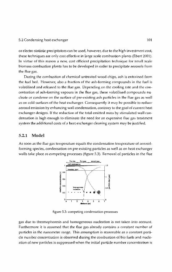
5.2 Condensing heat exchanger 101
or electro stalistic precipitators can be used, however, due to the high investment cost,
these techniques are only cost effective in large scale cambustion plants (Ebert 2001). In virtue of this reason a new, cost efficient precipitation technique for small scale
biomass cambustion plants has to be developed in order to precipitate aerosols from
the flue gas.
During the cambustion of chemica! untreated wood chips, ash is entrained from
the fuel bed. However, also a fraction of the ash-forming compounds in the fuel is
volatilised and released to the flue gas. Depending on the cooling rate and the con
centration of ash-forming vapours in the flue gas, these volatilised compounds nu
cleate or condenseon the surface of pre-existing ash particles in the flue gas as well
as on cold surfaces of the heat exchanger. Consequently it may be possible to reduce aerosol emission by enhancing wal! condensation, contrary to the goal of current heat
exchanger designs. lf the reduction of the total emitted mass by stimulated wall con
densation is high enough to eliminate the need for an expensive flue gas treatment
system the additional costs of a heat exchanger cleaning system may be justified.
5.2.1 Model
As soon as the flue gas temperature equals the condensation temperature of aerosol
forming species, condensation on pre-existing particles as well as on heat exchanger
walls take place as competing processes (figure 5.3). Remaval of particles in the flue
ruerubc fin,,... secood paN~
u
:r; 0.8
~ ·1 § 0.6 \ ~ a \ ! 0.4
\ ~ i 02 -~-
o.s c.
•
figure 5.3: competing condensation processes
gas due to thermophoresis and homogeneaus nucleation is not taken into account. Furthermore it is assumed that the flue gas already contains a constant number of
particles in the nanometre range. This assumption is reasanabie as a constant parti
ele number concentration is observed during the cambustion of bio fuels and nucle
ation of new particles is suppressed when the initia! partiele number concentration is

102 Separation by phase transition
within the sa me range as the final partiele number concentration Obernberger 2001,
Jensen 2000).
Besides assumptions regarding remaval mechanisms and partiele formation pro
cesses, a lso assumptions with respect to the flow behaviour are made. For the model,
a Ja mi nar flow in a axis-symmetric heat exchanger tube is assumed, which is charac
terised by a Reynolds number lower than 2300 (Bird 1960 ):
o,p u Re= ____!____Q____Q < 2300
l'g (5.11)
In Eq. 5.11, Oh represents the hydra u !ie diameter of one heat exchanger tube, which is
defined as i'f, where A represents the cross section of the conduit and 0 is the wetted
perimeter. Ps and flg represent the density and the dynamic viscosity of the flue gas,
whereas us represents the axial bulk velocity of the flue gas. Since a fully developed la mi nar flow is assumed, a lso the distribution of the aerosol-forming vapours exhibits
a parabalie profile over the radius r of a heat exchanger tube and can be written as:
(5.12)
where p~ (r) is the mass concentration of the aerosol-forming species as function of
the radius r, whereas R1, represents the hydraulic radius of one heat exchanger tube,
which is equal to i 0". The initia! ma ss concentration is expressed by p~,O· A general
description of the mass fraction of the aerosol-forming species w~ is given by (Bird
2002)
P~ wt\=-Pinl
(5.13)
where Ptot represents the total mass density of the flue gas. Fick's law of diffusion is
applied, which describes how the mass of species tt in a binary mixture is transported
by means of molecular motions (Bird 2002)
(5.14)
In Eq. 5.14, j~ represents the mass flux, whereas D represents the dilfusion coefficient.
Axial diffusion is neglected in order to calculate the mass flux towards the wall. Fur
thermore it is assumed that the total mass density Ptot remains constant, which is
acceptable due tothefact that Ptot >> Pa,O· Now, the mass flux per unit length to

5.2 Condensing heat exchanger 103
the wall J:,w can bedescribed by applying these assumptions and combining Eq. 5.14
and a wall surface area per unitlengthof 2nReq:
(5.15)
As the particles follow the streamlines, the number concentration N also exhibits a
parabolic profile:
(5.16)
where No denotes the initia! number concentration. Equation 5.17 describes thema ss
vapour density profile around a partiele with diameter dp:
Pa (r*) =Pa (r) (1- ~r~P) (5.17)
The spherical coordinate originating at the centre of the partiele is represented by r*.
For the sake of brevity, Pa (r*) is denoted as p~ . Now, the mass vapour concentration
around a partiele w: is defined as:
• w; = .&... Ptot
(5.18)
The mass vapour flux of the aerosol-forming species towards the partiele at the sa me
axial position in a heat exchanger passage can be written as:
(5.19)
where cp is an average correction factor for diffusion outside the continuurn limit.
Equation 5.19 is basedon diffusion of molecules to the surface of the particle. How
ever when particles are within the mean free path regime, transport is controlled by
kinetic processes. The effect of the correction factor cp results in a slowing down of
the growth rate and is defined as (Davies 1978)
(5.20)

104 Separation by phase transition
In Eq. 5.20, A represents the mean free path in the flue gas. In this research the mean
free path mainly depends on the temperature of the flue gas and is evaluated at the
saturation temperature of the aerosol-forrning species. The average value for the cor
rection factor ïp as described in Eq. 5.19, during the growth process is calculated by
integrating Eq . 5.20 with respect to dp from 0 todpand dividing the whole integral
by d1,. The total vapour flux towards the particles can subsequently be found by:
If wall condensation as wellas heterogeneaus condensation take place at the sa me
moment, the absolute wall condensation ra te IJabs can be expressedas the ratio of the vapour flux towards the walls compared to the total vapour flux :
/
}tt,W 1l n1Js - ., -t
}tt,W + h ,p (5.22)
Using the fact that R eq is equal to ~Deq, now the absolute wall condensation rate can
be found by substituting Eq. 5.15 and Eq. 5.21 into Eq 5.22:
12 IJnl>.< = 12 + mN D2 d
't' on eq p (5.23)
The partiele diameter dp in Eq. 5.23 is related to the initia! mass density of aerosol
forming species Ptt,O as wellas to the mass density of the condensate Pp · Conservation
of mass is applied in order to calculate the mean partiele size under assumption of a
constant number concentration No:
I
d _ ( 6ptt,O ) 3
r - Noppn (1 - IJabs) (5.24)
Due tothefact tha t Eq. 5.23 is coupled with Eq . 5.24 via the partiele diameter dp, an
iterative method is used in order to determine the absolute wall condensation rate
IJnl" and the conesponding final partiele diameter dp. Experiments performed at a biomass cambustion plant with a horizontally mov
ing grate showed that the concentration of aerosols in the flue gas increases from
spruce (about 20 mg/ Nm3 related to dry flue gas and 13 vol.% 0 2) tobark (up to 60 mg/ Nm 3) (Obernberger 2001) These aerosol concentrations, in combination with the

5.2 Condensing heat exchanger 105
fact that almost all volatilised components are transferred into aerosol particles allows
us to use a typ i cal initia] aerosol-forming vapour density Pa,O of 50 mg I N m3 . Several
independent measurements show that the final number concentration of aerosols af
ter the heatexchangeris typically 1 · 1013 Nm- 3 Oohansson 2001, Christiansen 2000,
Jensen 2000). Combining these properties with the fact that a large amount of the
aerosol-forming vapours consistsof potassium sulfate, K2S04, results in a wall con
densation rate as a function of the radius of the tube Req' depicted in Fig. 5.4. The
density of the condensed phase pp, in this case solid K2S0 4, is 2662 kg I m3 Oanz 1967)
~ 08 .. è € 0.6
" 1l 0 -; 0.4
ä ·~ 0.2
.s <
%L_ ____ ~5----~,7o ----~,5~--~20
Equivalen t diameter, 0 eq (mm]
figure 5.4: The effect of varying the tube radius on the absolute wull condensution effi
ciency, l/obs· Initia! conditions: Pa,O = 50 mg/ Nm3, No= 1·1013 and Pp = 2662 kg I m3
From Fig. 5.4 it can beseen that decreasing the tube diameter up to typically 2mm
results in a significant increase of the wall condensation ra te . Applying conservation
of mass, subsequently decreasing the tube diameter results in a significant decrease
of the particulate emission at the outlet of the heat exchanger, which is a desirabie
·result. Theoretically, a wall condensation rate of almost 100 % could be achieved
applying a tube diameter smaller than 2 mm. Increasing the diameter results that
condensa tion of aerosol-forming vapours on pre-existing surfaces becomes rapidly
the dominating process. Consequently, the assumption having a laminar flow, stated
in the beginning of this section, is va lid due to the small dimensions of the tubes of the
heat exchanger. A suitable candidate to tes t this hypothesis is the high temperature
laminar counterflow heat exchanger.
5.2.2 Heat exchangers
The most common types of fire tube boilers for biomass cumbustion plants require
high turbulence intensity. The Reynolds number, as denoted in Eq. 5.11, is a mea-

106 Separation by phase transition
sure for the turbulence intensity; the higher the Reynolds number, the higher the
turbulence intensity. In~ the Reynolds number results in an increase of the
convec_tive hea! _~a_!!sfer between the~plls of the heat exch~J>f the
flow, but causes a hig~R[e_~~ and conse uently reguires aJoL~. [?] ----=-----------· -
Comra_ry ~~n!_~~~_!l~'!!_e)(chang~rs, lélf!1J_n_a.Lflo_w..b.ea1J~1'Çh_é!_n~d
on con_d~.b-~?_!_~_[l_s_f_e!"_élrrQ_<;:a_uses a i<~we_~_ .P!~~?JI..!~gro~ require a higher
numbe~. The flow inside the heatexchangeris laminar when then
Reynolds number is below 2300.
Reducing the tube diameter automatically results in a laminar flow behaviour.
Based on this theory, three laminar flow heat exchangers with different dimensions
were designed in order to measure the influence of the tube diameter on the particu
late reduction. The boundary conditions, with respect to the design of these exchang
ers were caused due to physical and practicallimitations:
• The Reynolds number basedon the flue gas velocity inside the heat exchanger
should always below 2300 in order to achieve a laminar flow.
• The Aue gas temperature after the heat exchanger should be less than 200 °C
in order to makesure that the condensation processof all volatilised species in
the flue gas is fully completed. lt this way comparison of the particulate reduc
tion with common boiler designs is permitted. Furthermore, a large flue gas
temperature difference is required in order to achieve a reasonable heat transfer
efficiency, the main essence of a heat exchanger.
• The pressure drop over the heat exchanger should be Ie ss than 350 Pa and there
fore be comparable with usually applied boiler designs.
• A minimum Aue gas velocity of 6 mIs in the measurement section is required
in order to perform accurate BLPI measurements.
Two laminar flow shell and tube water cooled heat exchangerand the compact
laminar counterflow gas-gas heat exchanger of chapter 3 are used for the experi
ments. A shell and tube heat exchanger with variabie inner tube diameter was de
veloped based on the boundary conditions described in Sec. 5.2.2, see Fig. 5.5. Water
flows aruund the ei reular tubes. Five and fifteen tubes for respectively tube diameters
of 12.50 and 6.20 111111 were used for the experiments. A thermostalie valve near the
cooling water outlet was used to control the water temperature by flow regulation.
The tubes inside the heat exchanger have a fixed lengthof one metre which and could
easily be exchanged by other diameters. The side of the heat exchanger which is di
rectly in contact with the flue gas is covered with a heat resistance insulation plate.

5.2 Condensing heat exchanger 107
This isolation plate minimises the temperature drop of the flue gas in front of the inlet of the heat exchanger due to radiation. When the inlet temperature of the flue gas
is below the condensation temperature of the aerosol forming species, condensation
can already occur in front of the heat exchanger, insteadof inside the heat exchanger
which is an undesirable result.
figure 5.5: Schematic picture of shell and tube heat exchanger.
For the calculations, the wall temperature was kept constant at 70 °C. An adapted
equation for the heat transfer coefficient fora thermally and hydrodynamically devel
oping entrance region was applied in order to calculate the temperature profile . Fig
ure 5.6 shows the calculated bulk flow temperature profile inside one heat exchanger
tube, using ani niet temperature of 1000 °C. The i niet velocity, necessary for calculat
ing the heat transfer coefficient in one heat exchanger tube, was calculated in such a
way that the velocity in the measurement section was constant at 6 mI s. From Fig. 5.6
can be observed that the calculated outlet temperatures for both tube diameters are
below 200 °C, whlch satisfied the boundary conditions described in Sec. 5.2.2. Conservation of mass, in combination with temperature dependent physical properties
were applied in order to calculate the Reynolds number. From Fig. 5.7, an increasing Reynolds number can be observed while decreasing the flue gas temperature, how
ever the flow is always laminar, indicated by a Reynolds number < 2300. The pres
sure drop over the heatexchangeris depicted in Fig. 5.8. For both tube diameters, the
maximum pressure drop was always below 350 Pa.
5-2.3 Experiments
High quality, chemica! untreated wood chips with a typical dimension of a couple of
centimetres are chosen as a fuel for the experiments. The composition of this fuel is
depicted in Tab. 5.1.

lOR Separation by phase transition
1000,---~------------------,
' '
200 ' ' '
0.2
--Deq = 12.50 [mmJ
-- -Deq = 6.20 JmmJ
........... __ _ ------------------------
0.4 0.6 Length [mJ
0.8
figure ~.6: Cvlculated fluc gas temperature for two different tubedimensions as a function
of the length using the water cooled heat exchanger
The biomass cambustion plant itself consistsof a furnace equipped with a hori
zontally moving grate, staged air injection, a secondary cambustion zone and a flame
tube boiler consisting of a fire tube and two ducts of flame tubes with an inner di
ameter of 1!", see Fig. 5.9. The first and second duet of the flame tube boiler was
equipped with respectively 30 and 16 tubes. Cambustion temperatures we re sampled
continuously and controlled by flue gas recirculation below and above the grate. The
nomina i boiler capacity was 180 kW1h.
The heat exchanger was connected with the secondary combustion zone via a slip
stream (see Fig. 5.9). The flow through the special designed test heatexchangerand
measurement section was established by a flue gas fan. The measurement section
after the test heat exchanger consists of a 1 t" tube. Measuring devices for measur
ing the flue gas temperature, velocity, oxygen contentand the particulate emissions
we re installed in this section, denoted with respectively (T), (V), (Oz) and (BLP J) (see
fi g. 5.9). The smne measurement devices were also mounted in the chimney after
the ordinary boiler (see Fig. 5.9). Type K thermocouples were used to measure the
temperatures, whereas Prandtl tubes were used for measuring the flue gas veloci
ties. Nine stage Berner-type low pressure impactors (BLPI) and upstream nozzles for
iso-k.inetic sampling were used for measuring the particulate emissions downstream
the test heat exchangers as wellas downstream the ordinary boiler. In contradiebon
to the previous mentioned measuring devices, these impactor measurements are not
continuous measurement devices.
A steady state temperature distribution inside the furnace was reguired for the

5.2 Condensing heat exchanger
0o~--,o:""::.2:----::-0 . ..,.4 -----:o:-':.6:----::-o_':-s -__) Length I mi
109
figure 5.7: Calculated Reynolds number for two different tube dimensions as a function
of the length using the water cooled heat exchanger
experiments. The flue gas temperatures in the secondary cambustion zone were
956.6 oe and 949.8 oe during the impactor measurements after respect:ively the heat
exchangerand the boiler. The oxygen content was measured in order to normalise the
particulate emissions related to dry flue gas with an oxygen content of 13 vol%. The
oxygen content after both the test heatexchangerand the boiler for each coupled set
of measurements did notchange very much, indicated by the low fluctuations. The
mean oxygen content after the test heatexchangerand the boiler were equal within
the statistica! accuracy, as were the normalised particulate emissions. The particulate
reductions obtained with the special designed heat exchangers l)rel.cxp are calculated
according to the following relation:
( M tesl )
17rel,exp = 1-~ bot Ier
(5.25)
In Eq. 5.25, Mtest and Mooiier represent the normalised particulate concentrabon ex
pressed in mg I Nm3 related to dry flue gas (13 vol% 0 2) after respectively the test
heat exchanger and the ordinary boiler. Despite the use of high quality, chemica!
untreated wood chips, fluctuations of the aerosol-forming species concentratien and
inhomogeneity of the fuel cannot be avoided . Therefore, several coupled sets of mea
surements were required in order to determine a statistically proven particulate re
duction. The average relative particulate reduction 1]rel,exp is depicted in Tab. 5.2 and
is calculated according to the following relation:
1 n
17rel,exp = - L 17rel,exp n i = 1
(5.26)
where 1]rel,exp represents the p articulate reduction for one coupled set of impactor

110 Separation by phase transition
IUO.------ - -----------.
80
-D,, = 12.5/mm/ _- -D." = 6.20 /mml
.-------------------------- ----· .. ----.
20 :~----------~ 0o 0.2 0.4 0.6 0.8
Length /mi
fipue 5.8: c~lcul~ted pressure drop for two different tube dimensions as a function of
the leng th us ing !he water cooled heat exchanger
measurements and n represents the number of coupled set of measurements. It is
noticed tha t average particulate reduction is nonlinear inthe input parameters yields
that the ca lculated average relative particulate reductions, Yfrel,exp (Mt est, M boiler ), is
not equal to 1Jrel,ex p ( Mtest, Mboiler ) .
From the experiments is observed that the particulate emissions after the ordi
nary boiler fluctuates between respectively 19.7 and 60.0 mg I Nm3 . Due to these
large deviations, simulations in order to calculate the absolute particulate reductions,
Y/abs• after the aerosol reducing heatexchangerare performed for the minimum and
maximum amount of particulate forming species. These minimum and maximum
amounts of pa rticulate forming species a re calculated from the particulate emissions
after the boiler, in combination with the absolute amount of aerosol forming species
which ends up in the fire tube and the boiler. The resulting minimum and ma ximum
amount of aerosol forming species in the flue gas for the simulations of the absolute
parbeulate reductions we re respectively 22 and 75 mg I Nm 3. The initia! number con
centration, No, for the simulations was always constant at 1 · 1013 Nm- 3, whereas the
partiele density, pp, was 2662 kg I Nm 3.
Now the theoretica! relative particulate reduction can bedescribed as,
11 _ (1'/a bs -1'/boi/er ) . 100 01 'l rel, flwo - I ro ,
- 1'/boi/er (5.27)
where IJrel,theo represents the theoretica! relative particulate reduction. The absolute
amount of aerosol forming species which end up in the fire tube and the boiler is
represented by, 1'/boiler• and is 12% of the total amount of aerosol forming species in
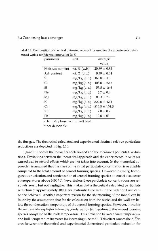
5.2 Condensing heat exchanger 111
tabel5.1: Composition of chemica! untreated wood chips used for the experiments deler-mined with a confidential interval of 95 2&
parameter unit average value
Moisture content wt. % (w.b.) 20.89 ± 0.83
Ash content wt. % (d.b.) 0.39 ± 0.04
s mg/ kg (d .b.) 160.8 ± 1.3
Cl mg/ kg (d .b.) 108.0 ± 22.2
Si mg/ kg (d .b.) 53.8 ± 16.6
Na mg/ kg (d .b.) 6.7 ± 0.9
Mg mg/kg (d .b.) 83.3 ± 7.9
K mg/kg (d .b.) 822.0 ± 42.3
Ca mg/kg (d .b.) 815.8 ± 154.3
Zn mg/ kg (d .b.) 2.0 ± 0.7
Pb mg/ kg (d .b.) 10.0 ± 0"
d.b . ... dry base; w.b . ... wet base a not detectable
the flue gas. The theoretica! calculated and experimental obtained relative particulate
reductions are depicted in Fig. 5.10.
Figure 5.10 shows the theoretica! determined and the measured particulate reduc
tions. Deviations between the theoretica! approach and the experimental results are
caused due to several effects which are not taken into account. In the theoretica! ap
proach it is assumed that the mass of the initia! parbeulate concentration is negligible
compared to the total amount of aerosol fonning species. However in reality, homo
geneaus nucleation and condensation of aerosol forming species on nuclei a lso occur
at temperatures above 1000 °C. Nevertheless these particulate concentrations are rel
atively smal(, but not negligible . This makes that a theoretica! calculated particulate
reduction of approximately 100% for hydraulic tube radii in the order of 1 111111 can
not be achieved. A nother important reason for the shortcoming of the model can be
found by the assumption that for the calculation both the nuclei and the wall are be
low the condensation temperature of the aerosol forming species. 1-lowever, in rea lity
the wall are always faster below the condensation temperature of the aerosol forming
species compared to the bulk temperature. This deviation between wall temperature
and bulk temperature increases for increasing tube radii . This effect causes the differ
ence between the theoretica( and experimental determined particula te reduction for

112 Separation by phase transition
figure 5.9: Experimental set-up of the biomass cumbustion plant with measurement point~ after both the test heatexchangerand the boiler
tabel S.2: Overview of the average particulate reduction, related to dry flue gas, 13 vol%
0 2, determined with 95 % confidential interval. The equivalent tube diameter of the boiler Wil" ulways 18.8 [mm)
run[-) I D eq [mm)
1 2.22
2 6.20
3 12.50
tube radii larger then 5 111111, see Fig. 5.10.
5.2.4 Current status
1Jrel,exp [-]
0.72 ± 0.021
0.36 ± 0.055
0.23 ± 0.064
The condusion to be drawn from the experiments is that the concept of an aerosol
condensor might workandis especially applicable in small (domestic) biomass com
bustion combustion plants by exchanging the current heatexchangerand an added
cleaning system keeping the costs approximately equal.
Current state of the art for dornestic biomass fired heating systems are finned steel
heat exchangers comparable to the heat exchangers used in oil fired heating systems.
By changing to a design as being used in high efficient gas fired heaters a considerable
material reduction and thus cost reduction can be achieved while maintaining the
desired distance to the wall for desublimation .

5.3 Centrifugal gas cleaning
ç-"E 0.8
c'
iJ o.6
" ~ ~ 0.4
a t: a. 0.2 o;
"'
-- -P,.o = 22 mg/ Nnl
-P,1,o = 75 rng /Nn~
~L-----~5~----~10~-----15~--~20
Equiva lent diameter, 0 eq (mm]
113
figure 5.10: Theoretica! (continuous and dashed line) and measured (o = gas-gas heat
exchanger, D = water cooled heat exchanger) particulate reductions compared to the
ordinary boiler design (l]bciler = 12%). Measured particulate reductions are de termined
with a 95 % confidential interval, related to 13 vol % Oz in dry flue gas.
As the pitfalls in the development of this type of heatexchangerare known from
the high temperature laminar counterflow recuperator and the condensing heat ex
changers in both gas-fired heaters and balanced ventilation units, further develop
ment of the aerosol condensor is done in-house. The main issues here are thermal
design to minimise temperature induced stresses in combination with the material selection and production methods.
5.3 Centrifugal gas cleaning
lncreasing shortages in world natura I gas supply over the next few decades could be
mitigated if existing large but contaminated gas fields could be utilised in an environ
mentally responsible manner (Wissen 2006). Current large throughput gas cleaning
processes are not able to deal with highly contaminated gas .elds. Amine treatment
is typically used for removing these contaminants - COz and HzS - from gas, but is
noteconomie or practicabie for highly contaminated gas, that is, where the concen
trations of COz and HzS are above ca. 10 and 5 % respectively. Together with Royal
Dutch Shell a gas centrifuge was investigated as an alternative process (Wissen 2005)
drawing on previous experience with uranium enrichment and the RPS, but a purely
gaseous is too slow for practical application.
Previously established analytica! approximations are not applicable for natura!
gas decontamination . Numerical simulations based on the batch case show that al -

114 Separation by phase transition
though the separative strengthof the centrifuge is quite good, its throughput is very
limited. Both enrichment and throughput are only a function of lengthand peripheral
velocity. A centrifuge with a lengthof Sm and a peripheral velocity of approximately
800 m/s would have a throughput of 0.57 mol/s and a product flow of 0.17 mol/s.
These numbers are calculated with the assumption that the centrifuge is refilled and
spun up instantaneously. The results for the countercurrent centrifuge show how the
production ra te varies as a function of in tema! circulation, product-feed ratio, periph
era I velocity and centrifugelengthand radius. Under conditions similar to those of
the batch case the production is approximately half compared to the batch case, i.e.,
0.08 mol/s. Optimization can yield a higher production at the costof lower enrich
ment. Consiclering the current natura! gas prices and the low production rate of the
centrifuge, it is certain that the gas centrifuge will not generate enough revenue to
make up for the high investrnent costs.
lncreasing the pressure is not that helpful for component separation in the gas
phase, because to a first approximation the product of diffusion and pressure pD is
constant, that is, at higher pressure the diffusion constant decreases (Golombok 2004).
However, at the higher pressures generated in a centrifuge, there is a second much
more dominant mechanism which will also cause separation, namely condensation
due to wall condensation.
5.3.1 Centrifugation with wall condensation
figure 5.11 shows the condensation curves at different temperatures for various mix
tures of methane as a function of the concentration of C02 in the mixture.
150 .,..--.,.--,----,----,--------------,
::..:..:.::,.)1 - -pd(O)
• - -pd(-25):
- • pd(-50) --:-c-.--\·--- ......
'-.. •. ...._
---.i '--.._ ·--~-~-~--
0~1-----------~------~----~~ 0.5
%C02in NG
figure 5.11: condensation curves at different temperatures as a function of percentage
co2 in gas
There are, in the case of a condensing centrifuge, two mechanisms for condensa-

5.3 Centrifugal gas cleaning 115
tion. Pure compression work corresponds to moving up the vertical pressure line: for
example, with a 50/50 C02/CH4 mixture at 25 °C, if we increase the pressure (for
example, along the radius of the centrifuge rotor) then around 40 bar, condensation
of a C02 rich waste liquid starts to occur. Pure enrichment work corresponds to mov
ing horizontally to the right whereby the Jocal concentration of C02 at any point is
increased as aresult of centrifugally induced diffusion. For exa mple, if we starled
with a 25 bar 50 / 50 mixture of C02 / CH4 and allowed C02 enrichment to proceed
near the rotor wall, then around xd = 0.6, condensation will occur.
The co reideais toopera te the centrifuge with a sufficiently high feed pressure that
the when the centrifuge is spinning, condensation will occur (figure 5.12). lnitially the
process runs identically to the gas-gas centrifuge. However, at one point along the
radius, at r = r d' the pressure is sufficient that the condensing pressure is reached. lnitially, when the pressure profile is (almost instantaneously) established, we still
have a uniform composition throughout the cylinder, because the diffusion process
concentrating C02 near the wall occurs more slowly than the fa st pressure generation
profile -at this point rd is determined purely by the partial pressure. Subsequently,
centrifugally driven mass transfer occurs of C02 from the center to the outer region
of the centrifuge. This net transport of C02 has the effect of shifting condensation
closer to the center to the equilibrium value.
I'"'~"'" <kwpoiut
' co,
n.. \îu ~
figure 5.12: principle of operation for condensing centrifuge
The region where condensation occurs is shown in Figure 2 by the shaded area,
where the pressure exceeds that required for condensation of liguid (referred to as the "dewpoint"). The condensing separation is faster than pure gas-phase separation
because C02 is removed from the gas phase. This will act to further drive the mass
transport of co2 from the center to the outer radial annulus.
In a gas centrifuge, the dimensionless partial differential equation descrihing the

1111 Separation by phase transition
time-dependent mole fraction distribution of one component is (Cohen 1951)
prijox; 1 a ( .ax; ( ) ( )( *))2 -- == --. r - + Az- A1 x1 1- x1 ror pO ot r* or• or*
(5.28)
where 0 is the diffusion coefficient, p the mixture mass density, ro the wall radius, r *
the dimensionless radial coordinate, defined as r* = r I ro, t denotes time, x; the mole
fraction of component i. Whereas for a centrifuge where only gas-gas separation
occurs, the boundary conditions are constant, in a condensing centrifuge these vary
continually and are a function of composition. Condensation occurs, resulting in
liquid, which because of its higher density and the large centrifugal forces, is pushed
to the wal!, where it is extracted. This removal of mass from the system results in
new boundary conditions, those for the gas / gas case are no Jonger va lid. The feed
concentration is eg ual to the condensation concentration for the wall pressure at t = 0
(5.29)
Any liquid that is formed by condensation is considered to be removed instanta
neously. Since this will only occur at the wall, it is sufficient to correct the boundary
conditions at the wall
if Pwa/1 2: Psnt then x(ro,t) == (Pwau(t)), forD < z* < 1 (5.30)
Figure 5.13 shows that condensation processes yield a product flow that is approx
imately twice that of the gas/ gas centrifuge. The doubling of the removal ra te due to
condensation of a centrifugally enriched mixture is still small compared to the pure
compression work which removes a large amount of the C02. For pure centrifugal
condensation, the ra te is still dependent on the C02 molecules diffusing to the wall
where they concentrate sufficiently to decrease the local condensing pressure below
the local quasi-stationary pressure. The process, thus, still depends on diffusion, but
over a smaller distance. Experiments (Golombok 2005) indicate that an impravement
of several orders of magnitude is required to make gas/ gas centrifugation a viabie
option for removing contaminating gases from natura! gas streams. Condensation by
compression has more potential, since it is nota diffusion dominated process. How
ever, since the gas centrifuge is not a dedicated compression device, a nd the benefits
of the centrifugal enrichment are limited, it is be tter to seek for other means to opti
mize this process.
5.3.2 Cooling and separating
A way to accelerate the processis by employing phase change: changing the ther
modynamic sta te of the mixture such that the C02 is tra nsformed to the liquid state.

5.3 Centrifugal gas cleaning 117
o.oa
100 600 1100 1600
Peripheral velocity (mis)
figure 5.13: principle of operation for condensing centrifuge
This idea resulted in the navel process shown in figure 5.14 and consistsof two steps:
o Cooling the gas to a temperature whereby the gaseaus contaminant becomes
liquid in the form of micron sized drop iets.
o Separating the mist from the gas by the rotational partiele separator, this is the
core innovation in the process
To achieve feasible gas/ gas separation in an economically attractive manner, one
of the components has to be transformed into a phase capable of forming particles.
This can be achieved by cooling and condensation. Since gas in reservoirs is already
compressed (130-450 bars is typical), then expansion can be used to attain the neces
sary cooling for contaminant condensation. Even the reduced pressures available top
hole (80-130 bar) are still sufficient to drive expansion cooling. An expansion turbine
is in most cases preferred to techniques employing expansion by acceleration such as
the Joule-Thomson process. The turbine can be used to drive a compressortobring
the gas back to system pressure. In addition, after the turbine the velocity of the
gas can be kept relatively small, cooling occurs by withdrawing power from the gas
rather than from gas-speed. This avoids the risk of heating up by internal friction of
the gas- the ultra-fine condensed dropiets could easily evapara te. The separation of
components using condensation to forma phase boundary is well established (Buon
icore 1984) The methad used is invariably reduction of temperature, although usually
by heat exchange rather than the direct expansion methad which we apply. The latter
is standard in preparation of for example cryogenic gases or LNG. However the main
problem which we address here is the spatial separation of the two phases which are
aften intimately dispersed and difficult to split into apart streams.

llR Separation by phase transition
Contominaled gas Clean gas
figure 5.14: schematic of condensed contaminant centrifugal separation
The low pressure side of the expansion refers to a condition which is sufficient
to lead to cooling so that two separate phases form. The product phase is gaseous
and enriched in methane (and thus depleted in COz). The waste phase is liquid and
is enriched in C02 and depleted in methane. Of course this process does not spon
taneously lead to a nicely separated liquid and gas phase - a mixture of fine C02
rich droptets in a methane riched gas forms. Between the expansion and separation
steps the microdropiets have to grow toa sufficient size that they can be separated.
This so-called "induction" process is known for knock-out vessels of for example,
condensate components using cyclones. However thesedevicescan only be used at
high volume throughputs for droplet sizes greater than around 15 micrometer and
with much lower ma ss loadings than are present in contaminated gases. (Removal of
smaller droptets is possible but only for extremely low throughputs, so-called micro
cyclones.) In our case droplet sizes will besmaller than this with mass loading much
higher than condensate in gases.
Consider a feed flow(Qf) of contaminated gas which is split into a cleaned-up
stream (Qc) and a waste stream (Qw) of C02 rich liquid. Conservalion of mass re
quires that input is the same as output
(5.31)
a mass balanceon the methane component yields
(5.32)
The most obvious condition is that we wish to have the highest concentration xr of
methane possible in the product stream. Simultaneously we need to minimise the

5.3 eentrifuga I gas cleaning 119
lossof incoming feed methane into the waste stream so that the maximum number
of molecules of methane in the feed end up in the product stream. This corresponds
to maximising the recovery r given by
(5.33)
The recovery is purely a function of the methane concentrations x;: this can beseen by
dividingeq. 5.31 and 5.32 by Qf and solvingfor the two variables Q,/Qf and Q111 / Qf. Since we specify the input concentration, the recovery is then purely a function of the
product and waste concentrations derived from the thermodynamics. We calculate
the methane content in the clean and waste streams (x, and x",) from the pressure and temperature p, T however there are a large range of feasible p, T conditions with corresponding solutions for xc and Xw . We need to find realistic values which also
optimise the recovery r, at the same time.
eonsider a 50 / 50 mixture of eH4 /e02, which is representative for contaminated gas and which we use as a basis of design. We wish to ascertain the optimum val
ues of product concentration x, and methane recovery r for a variety of pressures
and temperatures (Shavit 1995). The lower bound for these conditions can be ob
tained from an evaluation of the phase boundary for pure carbon dioxide as shown
in fig. 5.15 which shows the freeze-out curve. Most materials have a triple point be
low atmospheric pressure with normal melting and boiling points corresponding to
the temperature points at 1 atm. (i.e. ca . 1 bar) where solid-liquid and liquid-gas
transitions occur respectively. However for eo2 the triple point is actually above at
mospheric pressure. For eo2 pt=5.1 bar and T,=-56 .6 oe, the subscript t referring to
triple point conditions. Fig. 5.15 shows that operation in the üquid regime requires
that we be above 5 bar and -56 oe and this forms the minimum value for our ther
modynamic conditions. The maximum value is set by reasonable pressures for the
expansion and bearing in mind that this will be after the cooling expansion phase.
Fig. 5.16 shows the methane recovery r plotted against methane product coneen
teation x, fora range of pressures and temperatures. This was obtained from an extended cubic equation of sta te simulation basedon the Soave-Redlich-Kwong model.
This shows that in a single separation step it is possible to get high methane recov
eries however the problem is maximising the methane concentration in the product
stream. At the ideal point Xe ~ r ~ 0.85, the turbine inlet pressure would be 600 bar
which is clearly unrealistic. In genera!, given the restrictions for pipe wall thickness
and conesponding safety and handling considerations, we would wish to be below
200 bar at the inlet.

120 Separation by phase transition
figure 5.15: Phase diagram for C02 showing triple point at 5 bar and -58 oe
0.5 Methane in product
figure S.lii: Methane recovery as a function of methane concentranon in product stream,
displayed fora variety of pressure and temperature separation conditions
5.4 RPS versus Cyelone 121
The question then is to choose the optima! realistic p, T values for the operation
of the separator. If there is too much expansion, the temperature may be sufficiently
low but the pressure will be too low for Iiquefaction to take place. lf we restriet
the expansion process we may have sufficient pressure but not enough cooling and
hence insufficient yield. An examination of the various p, T conditions coupled to the
parameters above shows that an expansion to around the regime 25-30 bar providing
the in let pressure is above 100 bar gives significant phase separation.
From a practical engineering standpoint, an inlet pressure of 102 bar to the ex
pander is sufficient to reeover ca. 95% of the methane into the product gas stream
with a concentration of around 67 %. Note that phase separation is only initiated by
the expansion and is only complete by the end of the induction period - he re the liq
uid state is materialised in dropiets of a few microns in size. Subsequently, the spa tial
separation of the dispersed waste and purified product takes place in the rotational
partiele separator. The foregoing analysis assumes that the C02 rich liquid is already
in the dispersed waste material of flow rate W which will be spatially concentrated
and separated to the waste stream in the rps.
The droplet removal neects to occur within a very short time and for vety small
droplet sizes. In principle a standard cyelone would be capable of doing this, how
ever for very small droplet sizes a long residence time is required and this is difficult
to attain when the throughput is very high. The main advantage of the rotational
partiele separator (rps) is that it enables this to happen much more quickly (i.e. at
much higher throughputs) and for much smaller dropiets than is the case withother
eentrifuga I methods such as the cyclone or the gas centrifuge as is shown in the next
section.
5.4 RPS versus Cyclone
The axial cyelone, a lso known as vortex tube or uniflow cyelone, consistsof a station
a ry cylindrical pipe which contains at the enh·ance s tationaty va nes or blad es: figure
5.17 (Wissen 2006). Fluid which enters the pipe and passes through these blades ob
tains a swirling motion. Dispersed phase entrained in the fluid obtains this swirling
motion as welt. Having a density which is higher than the density of the carrier fluid,
the dispersed phase will be subjected toa centrifugal force which causes it to move
radially towards the cylindrical walt. It leaves the device via outiets so situated at
the end of the pipe cons~tuting the axial cyclone. Detailed investigations of swirling
flowsin pipes (Svarovsky 1984) have shown that the tangential velocity vt changes
its radial shape with axial distance from the point where the swirl is initiated. While

122 Separation by phase transition
~ Swir1 generalor
I ( =-::L_
Rj i\'t ~~v ; - lA - -- -- _u- - - - - - - -
Jj___ - ~1 --Liquid colleclion
figure 5.17: schematic drawing of the axial cyclone
initially the radial profile may be more like that of a free vortex, with axial distance
tangenhal velocity profiles evolve more towards that of solid-body rotation. At the
sa me time the strengthof the swirling motion decays as a result of wall friction. In
the present analysis we shall assume that Vt is constant with respect to r. This is
some kind of campromise between solid body rotation and the free vortex. The ax
ial decay is described by an exponential function in accordance with experimental
observations.
VJ = v10 exp ( -i/3) (5.34)
where z is axial distance, R radius of cyelone wall and f3 an empirica! factor which
for conditions existing in cyclones is about 0.05. Furthermore, it is assumed that the
axial velocity of the carrier fluid in the cyelone is constant with respect to radius,
Va = V11o. Again this is a reasonable campromise for the various profiles encountered
in measurements . Tangenhal and axial velocity of dispersed profiles are to first order
equal to those of the carrier fluid. The axial position of a partiele is thus given by
dz I dl = v110, which u pon inlegration yields z = Vaot, where it is assumed that at time
I = 0 the partiele is at the entrance of the cyclone, i.e. z = 0. While a partiele follows
to firstorder the gas in axial and tangential direction, it wiJl migrate in radial direction
according to equation (4.4). Noting that its radial position ris given by (d I dt)r = v",, imptementing (4.4) and (5.34), and using z = vaat to eliminale z, gives:
1dr = (pp-PJ)d~vfoexp(-f3vnat) dl 18f1 R
(5.35)
U pon inlegrating one obtains
,-2(t) = 2(pp -PJ)d~vfo (_!___ (-exp (-f3vaot) + 1)) +r2(0) (5.36) 18}t f3vno R
where r(O) is the radial position of the partiele at the entrance of the cyclone. The
axial velocity of carrier fluid and particles is taken constant with respect to radius.

5.4 RPS versus Cyelone 123
It implies that 50 % of partiele which enter the cyelone wiJl be present in the area
r > RI .Ji, 50 % in the area r < RI J{2) . The diameter of the particles which has a
probability of 50 % of reaching the collecting wall in a cyclone of length L can there
fore be calculated from (5.36) by taking for r(t) = R, r(O) = R I .J2 and t = L/ va). lt results in
l8f1R f3v ao
4(pp- Pg) v~o 1- exp ( -flk) (5.37)
Energy consumption occurs through the pressure drop the fluid undergoes when
flowing through the cyclone. One can assume that the kinetic energy use of the swirl
which is induced at the entrance and all radial pressure build-up by swirl is eventu
ally lost: the irreversible pressure toss can be taken equal to pvl0 . The total energy
tosscan be calculated by integrating over all radial positions:
Ê = fo2n loR pvfvaxrdrdiJ (5.38)
For v1o and Va constant with respect tor, the result is: Ê = pv~0 Q, where Q is volume
flow through the cyclone: Q = varcR2. Energy consumption per unit mass flow
f = Êl(pfQ) then reads as: f = vf0. The pressure drop over the cyclone relates tof
asfip =fPJ · The degree of swirl imposed at the inlet of the cyclone is in generallimited. For
large va lues of the ratio of swirl velocity to axial velocity a reverse flow in the centre of the cyclone will appear which leads to mixing of separated materiaL To avoid
this, the swirl velocity is limited to a magnitude which is twice the axial velocity:
vw = 2va0· The residence time of the fluid in the cyclone is given by T = Llvao· lt is now possible to express dpso% as a function of the volume flow of carrier fluid , Q,
which is to be filtered:
(5 .39)
where
- (?!_)l/2Tf3/ 4 "(- f3 8 Ql/2 (5 .40)
In the above relation two important design parameters occur: the residence time T
which is a measure for the size of the device and thereby for the investment costs,
and the energy consumption f which de terminestoa large ex tent the operating costs.
The separation process taking place in the channels of the RPS is equal to that in
the cyclone. The diameter of the partiele which is collected with 50% probability can
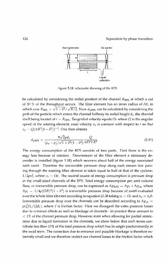
124
Swirl generalor
R
Separation by phase transition
De-swirler
Liquid collection
figure 5.18: schematic drawing of the RPS
be calculated by consictering the radial position of the channel Rso% at which a cut
of 50 % of the throughput occurs. The filter element has an inner radius of c5R, in
which case Rso% = ~I JR/2. Now dpso% can be calculated by consictering the
pathof the partiele which enters the channel halfway its radial height d0 the channel
itself being located at r = Rso%- Tangential velocity equals Or where 0 is the angular
speed of the rotating element; axial velocity Va is constant with respecttorso that
Va = Q(nR2(1- 02))- 1 One then obtains
i 9J2~dc Q 'p50% = (pp - p f) V1 + c52(1 - c52) n02LR3
(5.41)
The energy consumption of the RPS consists of two parts. First there is the en
ergy loss because of rotation. Downstream of the filter element a stationary de
swirler is installed (figure 5.18) which reeovers about half of the energy associated
with swirl. Therefore the irreversible pressure drop along each stream line pass
ing through the rotating filter element is taken equal to half of that of the cyclone:
1 I 2pv~, where Vt = Or. The second souree of energy consumption is pre ss ure drop
in the small-sized channels of the RPS. Total energy consumption per unit volume
flow, or irreversible pressure drop, can be expressed as !'!.pRPS = !'!.pt + !'!.pch' where
!'!.p1 = 1 I 4p(OR) 2 (1 + c52) is irreversible pressure drop because of swirl evaluated
over the whole filter element according to equation (5.38 taking v1 = Or and Va = v.O.
Irreversible pressure drop over the channels can be described according to !'!.pch =
pv~f L/ (2dc ), where f is friction factor. Here we disregard the extra pressure losses
duetoentrance effects as wel! as blockage of channels- in practice these amount to
< 1% of the eh a nnel pressure drop. However even when allowing for partial restric
tions due to liquid formation in the channels, we show below that such terms con
tribute less than 15% of the total pressure drop which has its origin predominantly in
the swirl term. The correction due toentrance and possible blockage is therefore ex
tremely smal! and we therefore restriet our channel Josses to the friction factor which
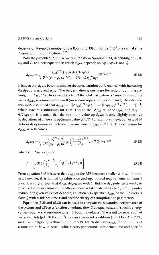
5.4 RPS versus Cyclone 125
depends on Reynolds number of the flow (Bird 1960). For Re< 105 one can take the
Blasius formula: f = 0.316Re-0·25.
With the presented formulae we cantransfarm equation (5.41, depending on L, R,
Vao and 0, toa new equation in which dpso% depends on ó.p1, ó.p0 T, and Q:
(5.42)
lt is seen that dpso% becomes smaller (better separation performance) with increasing
dissipations ó.p, and ó.peh· The best situation is one were the ratio of bath dissipa
tions, x = Ó.Peh I ó.p1, has a value such that the total dissipation is a maximum and the
value dpsO% is a minimum as well (maximum separation performance). To calculate
this ratio it is noted that dpsO% ~ ((ó.Peh)116ó.p1) -1 = ((ó.PRPsf16x116(1 - x)) - 1,
which reaches a minimum for x = 1/7, so that Ó.Pch = 1/ 7ó.pRps, and ó.p1 ~-
6/7ó.PRPS· lt is noted that the minimum value op dpsO% is only slightly sensitive
to deviations of x from its optimum value of 1/7. For example a deviation of x of 20
% from its optimum value leads to an increase of dpsO% of 0.2 %. The expression for
d pSO% now becomes
d /i c ~ - 7/6Ql / 2 - 5 / 6 9 d5/6J116 (1 <2 )1 / 2
pSO% = 2513(pp- Pg)n1 12 1- J2 E T (5.43)
(5.44)
From equation 5.43 it is seen that dpso% of the RPS becomes smaller with de. In prac
tice, however, de is limited by fabrication and operational requirements to about 1
mm. It is further seen that dpso% decreases with !5. But the dependenee is weak; in
practice the inner radius of the filter element is taken about 1/2 to 1/ 3 of the outer
radius. For given values of de and 15, equation 5.43 specifies dpso% of the RPS versus
flow Q with residence timeTand specific energy consumption E as parameters.
Equations (5.39 and (5.43) can be used to campare the separative performance of
the cyclone and RPS as a function of volume flowQat equal va lues of specific energy
consumption E and residence timeT (=building volume). The result for separation of
water draplets (p :::::: 1000 kgm - 3) from air at ambient conditions (P = 1 bar, T = 20"C,
and p = 1.2 kgm- 3) is shown in figure 5.19, which displays dpso% for both units as
a function of flow in actual cubic meters per second. Residence time and specific

126
".
,.. I ~
" ,..
". ,..
Separation by phase transition
figure 5.19: dpso% as a function of volume flow
I - ---- - --1 ~
"•
oo',--------------;o===;-J
~ , ..
fi)?.ure 5.20: d pSO% ilS a function of residence time and energy consumption
energy consumption are set at values commonly found in practice of T = 0.1 s and
€ "' 2 kJkg- 1 which corresponds toP ~ 2500 Pa at P = 1 bar and T = 20"C. The
RPS channel diameter and inner/outer radius ratio are taken equal to the standard
production va lues of de = 1.5 mm and o = 0.5.
As can be seen, the smallest particles colleeled by the RPS areanorder of magni
tude smaller than those colleeled by the axial cyclone. To resolve such small particles,
a conventional cyclone would require extremely fast supersonic peripheral gas veloc
ities. This is associated with very high energy consumption - huwever note that we
have specifically excluded this regime: we have restricted the specific energy con
suroption and limited the swirl number to 2 - this ensures that tangential veloeities
stay an order of magnitude smaller than acoustic veloei ties. In fact, the RPS can take a
throughput 10000 times higher than a cyclone when it comes to collecting 1J-Lm sized
droplets. Figure 5.20 shows the results for varying values of residence time and en
ergy consumption respectively. Throughput is fixed here at a moderate value of 1
m 3ç 1. The results for the RPS are in both cases again an order of magnitude bet
ter than that of the axial cyclone. Both units show a large increase in performance
for higher residence time and energy consumption . Although figures 5.19 and 5.20
a re plotled using the properties of air at ambient conditions, they are approximately
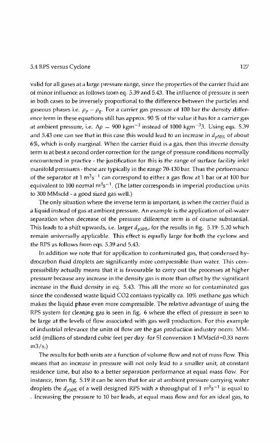
5.4 RPS versus Cyclone 127
va lid for all gases at a large pressure range, since the properties of the carrier fluid are
of minor influence as follows from eq. 5.39 and 5.43. The influence of pressure is seen
in both cases to be inversely proportional to the difference between the particles and
gaseaus phases i.e. Pp - p8 . Fora carrier gas pressure of 100 bar the density differ
ence term in these equations still has approx. 90% of the value it has fora carrier gas
at ambient pressure, i.e. !'J.p = 900 kgm-3 instead of 1000 kgm - 33. Using eqs. 5.39
and 5.43 one can see that in this case this would lead to an increase in dpso% of about
6%, which is only marginal. When the carrier fluid is a gas, then this inverse density
term is at best asecondorder correction for the range of pressure conditions normally
encountered in practice- the justification for this is the range of surface facility inlet
manifold pressures- these are typically in the range 70-130 bar. Thus the performance
of theseparator at 1 m3ç 1 can correspond to either a gas flow at 1 bar or at 100 bar equivalent to 100 normal m3ç 1. (The latter corresponds in imperia) production units
to 300 MMscfd- a good sized gas well.)
The only situation where the inverse term is important, is when the carrier fluid is
a liquid insteadof gas at ambient pressure. An example is the application of oil-water
separation when decrease of the pressure difference term is of course substantial.
This leadstoa shift upwards, i.e. Iarger dpso%, for the results in fig. 5.19- 5.20 which
remain universally applicable. This effect is equally large for both the cyclone and
the RPS as follows from eqs. 5.39 and 5.43.
In addition we note that for application to contaminated gas, that condensed hy
drocarbon fluid dropiets are significantly more compressible than water. This com
pressibility actually means that it is favourable to carry out the processes at higher
pressure because any increase in the density gas is more than offset by the significant
increase in the fluid density in eq. 5.43. This all the more so for contaminated gas
since the condensed waste liquid C02 contains typically ca. 10% methane gas which
makes the liquid phase even more compressible. The relative advantage of using the
RPS system for cleaning gas is seen in fig. 6 where the effect of pressure is seen to
be large at the levels of flow associated with gas well production. For this example
of industrial relevanee the units of flow are the gas production industry norm: MM
scfd (millions of standard cubic feet per day -for SI conversion 1 MMscfd=0.33 norm
m3/s.)
The results for both units are a function of volume flow and not of ma ss flow. Th is
means that an increase in pressure will not only lead to a smaller unit, at constant
residence time, but also to a better separation performance at equal mass flow. For instance, from fig. 5.19 it can beseen that for air at ambient pressure carrying water
dropiets the dpsO% of a well designed RPS with a throughput of 1 m3ç 1 is equal to . Increasing the pressure to 10 bar leads, at equal mass flow and for an ideal gas, to

128 Separation by phase transition
"'.----------;====;-,
~ ".
"''::" . .---='-----::":;--. --~~-------' a I MMsct/dl
figure 5.21: d1,.s11 r., ~s ~ function of normal (i.e. molar) flowfora 50/50 Cl-14/C02 separa
tion sy~tem ilt p=27 b~r, T=-47 C
a vol u me flow of 0.1 m3ç 1. Fig. 5.19 shows that for this flow the dp50% for an RPS
reduces to 0.2 fLm. At the sa me time the volume of the RPS has decreased equally with the volume flow, to 0.1 times the original size. lf the original separation performance,
befure the pressure increase, was satisfactory, then one could a lso, by increasing the
pressure, reduce the residence time or energy consumption, without affecting the
separation performance. This leads toaneven smaller device or to lower operational
costs.
Application of the RPS implies the introduetion of rotating equipment. Complica
tions involved with rotation, however, are limited. Peripheral speeds of the rotating
body are limited, typically to 50 m/s which is far below the speeds where structural
integrity might become problematic. In fact, the speeds are Iimited because of con
strilins on energy consumption (value of ê). Sealing problems of shafts penetrating
through stationary walls do not exist either. The RPS is internally driven by the swirl
of the gas entering the rotating body. Extemal drive by a motor is not necessary. In
summary, the complexities involved with rotation are rather modest; they are out
weighed by the advantages being the possibility to collect micron-seized particles in
a device of limited dimension.
5.5 Current status
The processes discussed here part of a joint development by Royal Dutch Shell and
the university. Currently a demonstrabon set-up is being constructed by Shell. The
prototype RPS was designed and tested by the EUT (figure 5.22 drawing on the ex
perience gained in the development of the naturally driven RPS for gas cleaning sec.
As the economie impact of the processcan potentially be high, i.e. exploitation of the
large but contaminated gas reservoirs near lndonesia might become economically vi
able, subsequent development of the basic idea is largely kept out of open literature.

5.5 Current status 129
As the initia! notion of cooling and subsequent separating was already indicated
in one of the first patents regarding the RPS, the inventor took out a subsequent, more
detailed patent on the process thus being able to influence further development to a
certain extend.

130 Separation by phase transition
. . ~ - - ! rr; - at · -EJ:·4 ~-- -F-+~
- ; l
figure 5.22: Protoype RPS for natura] gas cleaning
.. t~ ~ '
6 Ciosure
The cases discussed illustrate that although science plays a critica) role in in innova
tions, it is not necessarily the driver of new products, processes, and services. New
ideas for innovation can stem from many sources, including new manufacturing ca
pabilities and recognition of new market needs, as wellas scientific and technologica I
discoveries. Innovation does not necessarily proceed linearly from basic scientific re
search to product development; it is an iterative process of both matching market
needs to technologica I capabilities and conducting research to fill gaps in knowledge,
whether during product conception, product design, manufacturing, marketing, or
other phases of the innovation process. Innovation is an iterative process that re
sponds to both demand and supply side forces. Successful innovations tend to un
dergo extensive modification during development. This is due to changes in percep
tions of user requirements and of producers' abilities to offer the product, process, or
service with the necessary featuresatan acceptable cost. Innovators continually try to
find new applications for science and technology and ways of satisfying market de
mands, but not until technology pushand market pull are combined do innovations
find market success.
Research activities can be distinguished in those to explore and develop a new body of knowledge and those pursued to solve particular problems in the develop
ment process. In the former case, the goals of the research are often diffuse and the
benefits are difficult for any one company or institution to monopolize. In the latter
case, research results are more targeted and the results easier to appropriate. Researchers, therefore, tend to collaborale more widely on the former type of R&D and
to share information more freely. In the latter case, researchers will usually try to
solve the R&D problem with internal resources or with limited use of outside capa
bilities.
Technology is not merely the application of knowledge generated by scientific
activity; it is a body of knowledge about certain classes of events and activities. lt is a
knowledge of techniques, methods, and designs that work, and that workin certain
ways and with certain consequences, even when one cannot explain exactly why.

132 Ciosure
Science and technology are best thought of as two parallel streams of cumulative
knowied ge that have many interdependencies and cross relations, but whose internat
connections are much stronger than their cross connections . As a result, technological
progressis not necessarily dependent on scientific progress or the other way around.
Though all the innovations presented here, have their origins in basic scientific
research in the field of heat and mass transfer, exploitation of the ideas have only
been possible as the researchers had direct access to the technology used in the field
of energy technology. ConsequenUy the major applications of the discussions are to
be found in that field and less so in related areasas for instanee food processingor
the fine chemica! industry. This can be attributed to the background of the inventors:
when introducing a new technology, it is imperative to introduce only one new el
ement at the time. Thorough (inside) knowledge of the state of the art in a specific
field of application is required to make this assessment.
Translating new science into new productsis typically a slow, laborieus process.
Much of the difficulty in commercializing scientific breakthroughs is in determining
suitable applications and understanding the engineering limitations of new devices.
In many cases, the science is still not sufficienUy understood for scientists and engi
neers to select the application with the highest probability of successor the most fa
vorable financial return. New technology often finds its greatest successin products
that were noteven conceived of at the time of discovery. Considerable time and effort
must be allocated to applied research in which the capabilities of the new technology
in different applications are evaluated. This processoften requires considerable trial and error because performance cannot be predicted with accurate models. New tech
nologiesoften have difficulty dislociging an entrenched technology because of resis
tance from potenhal users of the new product. Customers must be convineed that
the new technology offers superior performance in their particular application and
is reliable-characteristics a new technology cannot always achieve at first. Similarly,
manufacturers of the existing technology often haveastrong disincentive to invest in
new technologies. By their very nature, new technologies tend to destray the compe
tencies that firms have developed in certain technica! areas; they often require capa
bilities and skilis different from those used in manufacturing the entrenched technol
ogy.
Succesfull commercialisation is nota simpte matter of getting to the market first.
A competitive advantage in the marketplace must be found by by staking out and
protecting a proprietary position through patents, trade secrets, or market barriers,
and by securing the complementary assets and skiiJs neerled to ensure proper man
ufacturing, marketing, and support. Often the most difficult stage is that of convert
ing a prototype into a salable product.The profitability of i nnovation depends on the

133
costs of commercialisation. In some industries or technologies, the sheer size of the
investment required is the largest single hurdle to commercialisation. Uncertainties
regarding cost alsoenter the decisionmak.ing process. Especially in new industries
that are expected to demonstra te strong learningcurve effects, decisionmakers often
cannot delermine how quickly production costs will droptoa desired level. For first
movers, rapid cost reduction is important tobuilding harrierstoen try and to ex pand
ing markets. For imitators trying to catch up with a market leader, uncertainties over
cost make it difficult todetermine the period of time required to become a competitive
player in a market.
Innovators have several mechanisms for protecting their innovations from com
petitors. They can use patents and software copyrights to legally ba rother firms from
copying their invention without an explicit license; they can keeptheir i nnovation se
cret from potential imitators; or they can take advantage of other harriers to market entry. The choice of method is, in many ways, determined by the nature of the tech
nology itself.
Patents arguably offer the strongest form of protection, but are highly effective for
only a limited number of product types, in a Jimited number of industries. l)atents
allow innovators the rights totheir inventions for 20 years after the patent applica
tion is filed, allowing them a period of exclusivity during which they can a ttempt to earn monopolistic returns on their innovation. Patenting requires innovators to
publicly disclose the details of their innovation; insome fields, competitors can then
invent around the patent by devising a somewhat different way to provide the sa me
functionality. The elementsof a product's design and manufacture can be gleaned
through careful analysis, and similar productscan be manufactured tha t perform al
most identicaJly. This capability makes it more difficult for innovators to capture or
appropriate the returns from a new innovation because they cannot maintain their
monopoly positions for long.
In cases in which patent proteetion is not effective, innovators may instead opt
to keep the work.ings of their inventions secret, to the extent possible. The Jaw pro
vides only partial proteetion for trade secrets. Firms can attempt to restrain former
employees from competing with them by using knowledge gained during their em
ployment. Similarly, they can sue firms that illegally gain access totrade secrets. But
the law norma lly permits competitors to analyze products, figure out how they work,
and find ways to produce similar products.
Many firms must, therefore, rely on other harrierstoentry toproteet their innova
tions. In industries characterised by significanteconomiesof scale or steep learning
curves, innovatorscan often gain proteetion by being first to market and rapidly ex
panding production. Although this strategy may often require large up-front inves t-

134 Ciosure
mentsin plantand equipment, it can enable companies to rapidly reduce their pro
duction costs by spreading the capita] investment over a larger number of products
and by allowing them to rapidly gain experience with the manufacturing process.
Such experience frequently translates into lower manufacturing costs over time, as
workers and managers begin to understand the subtie interactions between compo
nentsof a system or the effects of changes in manufacturing conditions on product
performance. Experiential knowledge of this sort, often referred to as tacit knowl
edge, is not easily codified and conveyed; therefore, it cannot easily be acquired by a competitor whodoes notmake a similar investrnent in production.
Firms can a lso erect barriers to entry through superior strategies for product de
velopment, sales, or service. Rapid product development, for example, can allow
an innovator to put new, im proved products on the market more quickly than its
competitors, thereby incorporating newer technology and responding to more recent changes in market demand.
The innovations discussed here use a combination of methods. The first concepts
are protected by patents to enable open scientific discussion about the underlying
physical phenomena and encourage further understanding and development of gen
eral design rules. To secure a lead over possible imitators, advancements in for in
stance manufacturing technology or details of the designs, which often have taken years to achieve, are kept out of the open literature. In all cases the designs are as
close as possible to existing technology to avoid pitfalls as the "not invented here"
syndrome and/or reliability issues. Keeping the detailed information about both the
scientific background and the used technology within a limited group of people al
lows for quick decisions about the commercialisation of the inventions in a specific
application in accordance with the needs and conventionsof that specific market.
7 Literature
1839 Hagen, G., Über die Bewegung des Wassers in engen Cljlindriscl!en Rohren, Poggendorfs
Ann. Phys. Chem. 46:423-442.
1840 Poiseu ille, J. L. M. Recherches expérimentales sur Ie mouvement des liquides dans les lubes de
tres-petits diametres. CR Acad. Sci. Paris. 11:961-967
1850 Stokes, G.G., On the Effect of the lnternal Friction of Fluids on the Molion of Perululums,
Transactions of the Cambridge Philosophical Society, Vol. IX., p.8
1885 Preece, W.H., On peculiar behaviour of glow-lamps when raised to high incandence, Proc. Roy.
Soc, series A, vol. 38, p. 219
1907 Blasius, H. (1908) Grenzschichten in Fliissigkeiten mil kleiner Reibung. leitschrifl für Matil
ematik und Physik 56, 1-37
1915 Schlichter, W., Die spontane Electronenemission glühender Metalle wui das gliiileleklrische
element, Ann. Physic, vol. 47, p. 573-640
1923 Langmuir, I, The colleeled works of /rving Langmuir, Volumes 3 and 5, Pergamon press,
New York, 1961
1941 Gurtovoy, M.Y. and G.l. Kovalenko, A study of the opera/ion of a diode in cesium vapour,
Fizichni Zapiski, vol. 9, p. 240
1951 Cohen, K.P., The TheonJ of lsotape Separation as Applied to tl1e Lmge- Scale Production of
U-235, McGraw-Hill Book Company, New York
1955 Hinze, J.O., A!ChE. )., I, (1955), No.3, pp. 289-295.
1960 Bird, R.B., Stewart, W.E., Lightfoot, E.N., Transport Phenomena, John Wiley & Sons, New
York, 1960, 2002
1%3 Martini, W.R., lnternal flame-heated thermionic converters, Thermionic specialist con
ference, Oct 7-91963, Gatl.inborg, Tennessee, p. 356
1964 Fuchs, N.A., The mechanics of Ae.,-osols, Pergamon press

136 Literature
1964 Owczurek, J.A., Fundamentals of gas dynamics, International Textbook Company, Seran
Ion Pennsylvania
1966 Waldmann, L. K.H. Schmidt, Thermophoresis and diffusiophoresis of aerosols, in: Aerosol
Science, Academie Press, London - New York
1967 Janz, G.J. Molten Salts Handbook; London Accadamic Press: London
1969 Shefsiek, P.K. and J.P. Angello, Test results from an impmved flame fired thermionic diode,
IEEE TCSC Oct 21-23 1969, p. 521
1978 Dilvies, C.N.; In Fundamental of Aerosol Science; Shaw, D.T., Ed.; Wiley, New York
1978 Shah, R.K., London, A.L., Laminar Flow Forced Conveelion in Duels: a Souree Book for
Compact Heat Exchanger Analytica! Data, Academie Press, London
1979 Schlichting, H., Boundary-layer theory, McGraw-Hill, London
1982 Hol man, J.P., Heat Transfer, McGraw Hili, London
1983 Kals, J.A.G., J.H. Dautzenberg and J.A .H. Ramaekers, Bewerkingstechnologie, Eind
hoven University of Technology, I eeture notes no. 4558
1983 Wood, N.B., The Mnss transfer of Particles and Acid Vapour to Caoled Surfaces, Journal In
stitute of Energy, Vol. 76, pp. 76-93
1984 Buonicore, A.J., L. Theodore and G. Tchobanoglous, Waste Management in Ferry's Chem
ica! Engineers' Handbook (McGraw-Hill, New York, 1984)
1984 Perry's Cltemical Engineers Handbook, 6th Edition, McGraw-Hill, New York, 1984, Chap.
18, pp.48-5ó.
1984 3. Svarovsky L. Hydmcyclones. London: Holt;
1986 Kreith, F., M.S. Bohm, Principlesof Heat Transfer, Thomson Learning College
1987 Brouwers, .I.J .H., P.H.J. Verbeek, W.R. Thomson, Analytica/ System Availability Techniques,
Reliability Eng., 17,9-22, (1987)
1988 Bejan, A. "A St>cond Look at the Second Law," Mechanica! Engineering, Vol. 110, No. 5,
Muy 1988, pp. 58-1\5.
1989 Veltkarnp, W.B., et al., Design and testing of a heatpipe caoled thennionic energy converter,
proc. 25th IECEC, p. 1171
1989 Wolff, L.R., Pe~fannance of terrestrial thermionic converters, Thermionic Energy Conver
sion short course, Eindhoven
1990 SKF Hoofdcatalogus, Veenendaal: Svenska Kullagerfabriken Nederland

137
1992 Regan, C.A.G., A Navel Separa/01/Scrubber Design Pmgmm • The Impnel of Upslrenm nnd
Downstream Equipment on Separation Performance, Paper presenled at the 9th Continental
Meeting of the Gas Processing Association, European Chapter, May 14-15, 1992
1994 Li, H., Tomita, Y., J. Fluids Eng., 116 (1994), pp. 370-373
1995 Brouwers, J.J.H ., Appl. Sci. Res. (1995), pp. 95-105
1995 Kemenade, H.P. van, The design of a cambustion heated thennionic converter, f'hD thesis,
Eindhoven University of Technology
1995 Shavit, C. Gutfinger, Thermodynamics: from concepts to applications, (Prentice Ha ll, Lon
don
1996 Brouwers, J.J.H., Rotnting Partiele Separator: a New Methad for Separaling Fi1w Pmticles nnd
Mists from Cases, Chem. Eng. Techn., 19, pp. 1-10
1996 Laagland, G.H.M., J.J.H. Brouwers, J. Poorting, The rotating air filter fin· gaslurbilws, Proc.
Power-Gen. Europe 96 2 (1996) 413-439.
1997 Brouwers, Partiele Collee/ion Efficienc~; of /he Rotational Partiele Sepnrnlor, Powder Techn.,
92, pp. 89-99
1997 Obernberger, 1.; Biedermann, F.; Widmann, W.; Riedi, R. Biomass {>' Bioe11e1g!f, 1997, 12
(3), pp. 211-234
1998 Brunner T., I. Obernberger, J.J.H. Brouwers, Z. Preveden, Efficimt nnd economie dus/ sepn
rntion from flue gns by /he rotational partiele separator ns nn in novalive IPchnology for /Jiomnss
cambustion and gasification plants, Proceedings of the Tenth European Bioenergy Confer
eence, 1998, pp. 1630-1633.
1998 Hasler, Ph, Th. Nussbaumer, H.P. Scharner, J.J.H. Brouwers, Reduction of nerosol particles
in fiue gases from biomass cambustion in n rotnting partiele separator RPS, Proceedings of the
Tenth European Bioenergy Conference, 1998, pp. 1353-1355.
1998 He, C., G. Ahmadi, Partiele Deposition with Thermophoresis in Laminnr and Turbulent Duel
Flows, Aerosol science and technology, Vol. 29. pp. 525-546
1998 Tandon, P., M.A. Adewumi, Partiele deposition from turbulent flow in n pipe, , Aerosol
Science, Vol. 29, pp 141-156
1998 Valmari, T.; Ka u pinnen, E.I.; Kurkela, J.; Jokiniemi, J.K.; Sfiris, G.; Revitzer, H.; /. Arrosol
Sci., 1998, 29 (4), pp. 445-459
1999 Kernen a de, H.P. van, Heat Exchanger test rig, Eindhoven University of Technology

13R Literature
2000 Aart, F. v~n, N. Bolt, B. de Boer, J.J.H . Brouwers, W. Niggeschmidt, A. Strehlow, Opera
lionnll'xperiences with the rotating air in/et filter atthe 3.6 Megawatt industrial gasturbine of
lcnfrpn, Proc. Power-Gen Europe 2000
2000 Christensen, K.A.; Stenholm, M.; Livbjerg, H . ]. Aerosol Sci., 1998, 29 (4), pp. 421-444
2000 Hendriks, A.J.A.M., Graduation thesis, Eindhoven University of Technology, Depart
ment of Mechanica] Engineering
2000 Jensen, J.H.; Nielsen, L.B.; Schultz-M01ler, C.; Wede!, 5.; Livbjerg, I-1. Aerosol Sci. and
T!'ch., 2000, 33, pp. 490-509
2000 Jensen, P.A.; Frandsen, F.J.; Dam-Johansen, K.; Sander, B. Energy & Fuels, 2000, 14, pp.
1280-1285
2001 Be jan A., Thcrmodynamic Optimizalion of Geometry in Engineering F/(JUJ Systems", Exergy,
~n International journal, Vol. I , No. 4, 2001, pp. 269-277
2001 Br~un-Fahrländer, C. In Proceedings of !he IEA Seminar "Aerosols from /3iomass Combus
linll", Zürich, Switserland; Nussbaumer, T., Ed .; Verenum: Zürich, 2001; pp 11-18.
2001 Ebert, F.; In Proceedings of the /EA Seminar "Aerosols from Biomass Cambustion ", Zürich,
Switserland; Nussbaumer, T., Ed.; Veren urn: Zürich, 2001; pp 41-46
2001 joh~m;son, L.; Tullin, C.; Leckner, B.; In Proceedings of the IEA Seminar "Aerosols from
/3iomn.-s Cambustion ",Zürich, Switserland; Nussbaumer, T., Ed.; Verenum: Zürich, 2001;
pp 87-92
2001 Obernberger, 1.; Brunner, T.; jöller, M. In Proceedings of the IEA Seminar "Aerosols from
Biomnss Combustion ",Zürich, Switserland; Nussbaumer, T., Ed.; Veren urn: Zürich, 2001;
pp 69-74
2002 Bird, R.B.; Steward, W.E.; Lightfoot, E.N. Transport Phenomena, second edilion; john Wiley
& Sons Jnc.: New York
2002 Brouwers, J.J.H., Phnse Sepnrntion in Cen!rifugal Fields with Emphasis onthe Rotational Par
Iiele Separator, Exp. ThermalFluid Science, 26, pp. 325-334
2002 Brunner, T.; Jiiller, M.; Obernberger, I.; Frandsen, F.In 12th European Conference and Tech
nology Exhibilion on Biomass for Energy, lndustry and Climate Proteel ion, Amsterdam, Au
gust 2002
2002 Loo, S. van; Koppejan, J. Handbook of Biomass Combustion and Co-Firing; Twente Univer
sity Press: Enschede, 2002
2003 Kemenade H.r. van, E. Mondt, A.j.A.M. Hendriks, P.H.). Verbeek, Liquid-Phase Separa
lion wilh !he Rotational Partiele Separator, Chem. Eng, Techn., 26, pp. 1176-1183,

139
2004 Golombok, M., L. Chewter, Centrifugal separntion for cleaning well gns strea1115, lnd. Eng.
Chem. Res., 43(7), 1734
2005 Frandsen, F.J.; Moiraghi, L.; Van Lith, S.; Jensen, A.J.; Glarborg, P. In Aervsvl in Biomass
Combuslion; Obernberger, 1., Ed.; Medienfabrik Graz: Graz, 2005, pp. 65-77
2005 Golombok, M., K. Bil, lnd. Eng. Chem. Res., 44(13), 4721
2005 Jöller, M.; Brunner, T.; Obernberger, I. Energy & Fuels, 19, pp. 311- 323
2005 Kemenade, H.P. van, In Aerosols in Biomass Combustion; Obernberger, 1., Ed .; Medienfab
rik Graz: Graz, 2005, pp. 107-118
2005 Mondt, E., Compact Centrifugal Separator of Dispersed Phases, PhD thes is, Eindhoven Uni
versity of Technology
2005 Wilhelm, J., Seibt, D., Bich, E., Vogel, E., Hassel, E., Viscosity Measuremenls '"' Caseaus
Sulfur Hexafluoride, J. Chem. Eng. Data, 50, pp. 896-906
2005 Wissen, R.J.E. van, M. Golombok and J.J.H. Brouwers, Chem. Eng. Sci.60(16),4397
2006 BP, Stal islical Review of World EnergJJ 2006
2006 Royal Dutch Shell,The Shell Global SeeMrio's lo 2025
2006 Wissen, R.J.E. van, M. Golombok and J.J.H. Brouwers, Gas Cenlrifugntion with Wall Con
densalion, A.I. Chem. E. J. 52(3), 1271