mvac250-9200 medical vacuum systems
TRANSCRIPT
BeaconMedæsMedical vacuum plant
mVAC 250, mVAC 300, mVAC 330, mVAC 400, mVAC 500, mVAC 620,mVAC 660, mVAC 800, mVAC 1000, mVAC 1200, mVAC 1280, mVAC1500, mVAC 1860, mVAC 2560, mVAC 3000, mVAC 3300, mVAC 3840,mVAC 3900, mVAC 4500, mVAC 4950, mVAC 5850, mVAC 6000, mVAC6600, mVAC 7800, mVAC 8000, mVAC 9200
Instruction book


BeaconMedæsMedical vacuum plant
mVAC 250, mVAC 300, mVAC 330, mVAC 400, mVAC 500,mVAC 620, mVAC 660, mVAC 800, mVAC 1000, mVAC 1200,mVAC 1280, mVAC 1500, mVAC 1860, mVAC 2560, mVAC3000, mVAC 3300, mVAC 3840, mVAC 3900, mVAC 4500,mVAC 4950, mVAC 5850, mVAC 6000, mVAC 6600, mVAC7800, mVAC 8000, mVAC 9200
Instruction bookOriginal instructions
Copyright noticeAny unauthorized use or copying of the contents or any part thereof is prohibited.
This applies in particular to trademarks, model denominations, part numbers and drawings.
This instruction book is valid for CE as well as non-CE labelled machines. It meets therequirements for instructions specified by the applicable European directives as identifiedin the Declaration of Conformity.
2012 - 10
No. 2920 7108 30
www.beaconmedaes.com
Table of contents
1 Safety precautions..........................................................................................................5
1.1 SAFETY ICONS...................................................................................................................................5
1.2 SAFETY PRECAUTIONS, GENERAL...........................................................................................................5
1.3 SAFETY PRECAUTIONS DURING INSTALLATION...........................................................................................5
1.4 SAFETY PRECAUTIONS DURING OPERATION..............................................................................................6
1.5 SAFETY PRECAUTIONS DURING MAINTENANCE OR REPAIR...........................................................................6
2 General description........................................................................................................8
2.1 VACUUM AND FLOW RATE.....................................................................................................................8
2.2 INTRODUCTION...................................................................................................................................9
2.3 PLANT DESCRIPTION.........................................................................................................................11
2.4 VACUUM VESSEL(S) .........................................................................................................................13
2.5 VACUUM PUMPS...............................................................................................................................14
2.6 BACTERIAL VACUUM FILTERS...............................................................................................................15
2.7 PRESSURE SENSORS.........................................................................................................................15
2.8 PUMP CONTROL UNITS.......................................................................................................................16
2.9 CENTRAL CONTROL UNIT....................................................................................................................17
3 Installation.....................................................................................................................18
3.1 INTRODUCTION.................................................................................................................................18
3.2 INSTALLATION WARNINGS...................................................................................................................18
3.3 MECHANICAL INSTALLATION................................................................................................................20
3.4 STORAGE.......................................................................................................................................25
3.5 ELECTRICAL CONNECTIONS.................................................................................................................25
4 Commisioning...............................................................................................................26
4.1 INTRODUCTION.................................................................................................................................26
4.2 PRE-START INSPECTION.....................................................................................................................26
Instruction book
2 2920 7108 30
4.3 ELECTRICAL FUNCTIONAL CHECK.........................................................................................................27
4.4 SETTING THE PNEUMATIC SYSTEM........................................................................................................27
4.5 AUTOMATIC OPERATION AND LEAK CHECK..............................................................................................27
4.6 STARTING THE PLANT........................................................................................................................28
5 Operation user guide....................................................................................................29
5.1 INTRODUCTION.................................................................................................................................29
5.2 PUMP CONTROLLER..........................................................................................................................29
5.3 CENTRAL CONTROLLER (ES-VAC).....................................................................................................40
5.4 CONTROLLER ALARMS AND FAULTS......................................................................................................63
6 Maintenance..................................................................................................................69
6.1 INTRODUCTION.................................................................................................................................69
6.2 MAINTENANCE WARNINGS..................................................................................................................69
6.3 CHECKS AND INTERVALS....................................................................................................................71
6.4 OIL, OIL FILTER AND OIL SEPARATOR CHANGE........................................................................................73
6.5 OIL SPECIFICATIONS..........................................................................................................................74
6.6 BACTERIAL FILTER REPLACEMENT........................................................................................................75
6.7 DRAIN FLASK CHANGE.......................................................................................................................76
6.8 NON-RETURN VALVE AND INLET SCREEN REPLACEMENT...........................................................................76
6.9 CHANGE FROM MINERAL OIL TO SYNTHETIC OIL......................................................................................77
6.10 VACUUM PUMP REPLACEMENT.............................................................................................................77
6.11 DISMANTLING AND DISPOSAL...............................................................................................................78
6.12 SERVICE KITS..................................................................................................................................78
7 Pictographs...................................................................................................................79
8 Problem solving............................................................................................................80
8.1 INTRODUCTION AND WARNINGS............................................................................................................80
8.2 FAULTS AND REMEDIES......................................................................................................................81
Instruction book
2920 7108 30 3
9 Technical data...............................................................................................................93
9.1 ELECTRIC CABLE SIZE.......................................................................................................................93
9.2 FUSE VALUES..................................................................................................................................94
9.3 REFERENCE CONDITIONS AND LIMITATIONS............................................................................................95
9.4 PERFORMANCE DATA.........................................................................................................................95
9.5 DESIGN DATA..................................................................................................................................97
10 Usability.........................................................................................................................99
11 Declaration of conformity..........................................................................................101
12 Appendix.....................................................................................................................102
12.1 DECLARATION OF CONTAMINATION STATUS..........................................................................................102
Instruction book
4 2920 7108 30
1 Safety precautions
1.1 Safety icons
Explanation
Danger for life
Warning
Important note
1.2 Safety precautions, general
General precautions
All responsibility for any damage or injury resulting from neglecting these precautions, ornon-observance of the normal caution and care required for installation, operation,maintenance and repair, even if not expressly stated, will be disclaimed by themanufacturer.
1. The operator must employ safe working practices and observe all related work safety requirements andregulations.
2. If any of the following statements does not comply with the applicable legislation, the stricter of the twoshall apply.
3. Installation, operation, maintenance and repair work must only be performed by authorized, trained,specialized personnel.
1.3 Safety precautions during installation
Precautions during installation
1. Place the device where the ambient air is as cool and clean as possible, within the limitations for operation(see section Reference conditions and Limitations).
2. During installation or any other intervention on one of the connected pumps or cubicles, the pump mustbe stopped, de-energized and the isolating switch opened and locked before any maintenance or repair.As a further safeguard, persons switching on remotely controlled machines shall take adequate precautionsto ensure that there is no one checking or working on the machine. To this end, a suitable notice shall beaffixed to the start equipment.
3. The electrical connections must correspond to the local codes. The device must be earthed and protectedagainst short circuits by fuses in all phases. A lockable power isolating switch must be installed near thedevice.
4. Never remove or tamper with the safety devices.
Instruction book
2920 7108 30 5
Also consult following safety precautions: Safety precautions during operation and Safetyprecautions during maintenance or repair.These precautions apply to the mVAC plant.For precautions applying to the connected equipment consult the relevant instruction book.Some precautions are general and cover several machine types and equipment; hence somestatements may not apply to your device.
1.4 Safety precautions during operation
Precautions during operation
1. Persons switching on remotely controlled machines shall take adequate precautions to ensure that thereis no one checking or working on the machine. To this end, a suitable notice shall be affixed to the remotestart equipment.
2. Never operate the device in the presence of flammable or toxic fumes, vapours or particles.3. Never operate the machine below or in excess of its limit ratings.4. Wear ear protectors if applicable. People staying in environments or rooms where the sound pressure level
reaches or exceeds 90 dB(A) shall wear ear protectors.5. Periodically check that:
• All guards and fasteners are in place and tight• All hoses and/or pipes are in good condition, secure and not rubbing• There are no leaks• All electrical leads are secure and in good order
6. Never remove or tamper with the safety devices.
Also consult following safety precautions: Safety precautions during installation and Safetyprecautions during maintenance or repair.These precautions apply to the mVAC plant.For precautions applying to the connected equipment consult the relevant instruction book.Some precautions are general and cover several machine types and equipment; hence somestatements may not apply to your device.
1.5 Safety precautions during maintenance or repair
Precautions during maintenance or repair
1. Use only the correct tools for maintenance and repair work.2. Use only genuine spare parts.3. A warning sign bearing a legend such as <<Work in progress - do not start>> shall be attached to the
starting equipment, including all remote start equipment.4. Persons switching on remotely controlled machines shall take adequate precautions to ensure that there
is no one checking or working on the machine. To this end, a suitable notice shall be affixed to the remotestart equipment.
5. Never use flammable solvents or carbon tetrachloride for cleaning parts. Take safety precautions againsttoxic vapours of cleaning liquids.
6. Scrupulously observe cleanliness during maintenance and repair. Keep dirt away by cleaning the partsand exposed openings with a clean cloth, paper or tape.
Instruction book
6 2920 7108 30

7. Never use a light source with open flame for inspecting the interior of the device.8. All regulating and safety devices shall be maintained with due care to ensure that they function properly.
They may not be put out of action.9. Before clearing the device for use after maintenance or repair, check that operating pressures, temperatures
and time settings are correct. Check that all control and shutdown devices are fitted and that they functioncorrectly.
Also consult following safety precautions:Safety precautions during installation and Safetyprecautions during operation.These precautions apply to the mVAC plant.For precautions applying to the connected equipment consult the relevant instruction book.Some precautions are general and cover several machine types and equipment; hence somestatements may not apply to your device.
Units and/or used parts should be disposed of in an environmentally friendly and safe manner andin line with the local recommendations and legislation.
Instruction book
2920 7108 30 7
2 General description
2.1 Vacuum and flow rate
What is vacuum and how to denote
A vacuum is any pressure in a system that is below the ambient atmospheric pressure. It can be denoted inabsolute terms or in effective (gauge) terms:
• mbar(a) – absolute pressure – denotes how much the pressure is above the absolute vacuum.• mbar(e) – the effective or gauge pressure – denotes how much the pressure is below local atmospheric
pressure.
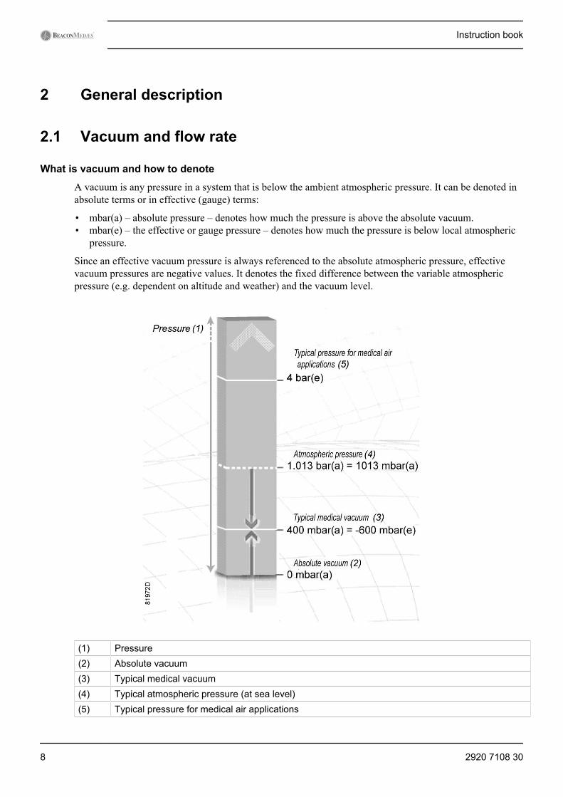
Since an effective vacuum pressure is always referenced to the absolute atmospheric pressure, effectivevacuum pressures are negative values. It denotes the fixed difference between the variable atmosphericpressure (e.g. dependent on altitude and weather) and the vacuum level.
(1) Pressure(2) Absolute vacuum(3) Typical medical vacuum(4) Typical atmospheric pressure (at sea level)(5) Typical pressure for medical air applications
Instruction book
8 2920 7108 30
Atmospheric pressure at sea level is roughly 1 bar or 1000 mbar(a). For typical medical vacuum applications,a vacuum of 600 mbar below atmospheric pressure is required, which is denoted as -600 mbar(e). From theillustration it can be seen clearly that this value is also equivalent to 400 mbar above absolute zero vacuumand can therefore also be denoted as 400 mbar(a).
It is important to understand which type of reference is required before selecting a pressure instrument formeasuring the vacuum. The mVAC application uses the effective pressure system since it corresponds mostwith performance characteristics.
It must be noted that this distinction isn’t relevant for a pressure difference (Δ P, e.g. pressure loss), since itis always the result of subtracting 2 pressures (whether stated as absolute or effective pressures).
Flow rate definitions
It should be clearly understood that there is a difference between the volume of ‘Free Air Aspired’ (FAA) atthe terminal units (atmospheric pressure) and the volume of that same quantity of air handled by the pumpsat a given vacuum level. For example: 100 liters of free air aspired at atmospheric pressure corresponds toapproximately 200 liters of air at a vacuum of -507 mbar(e) (-380 mmHg), and approximately 300 liters at avacuum of -667 mbar(e) (-500 mmHg).
The volume of rarefied air flowing in a pipeline is consequently around three times the volume of the totaldesign flow which is specified in terms of Free Air Aspired. A clear distinction should therefore be madebetween the FAA and the capacity (volumetric displacement) of the pumps. In order to avoid confusion, thecapacity of the pumps should be given in terms of both free air and volumetric flow rate at the operatingvacuum level.
Hence there are 2 common but different ways to denote flow rate in vacuum. The first one is based on thedisplacement or volumetric flow rate and the second one is based on the throughput or mass flow rate.
Displacement/volumetric flow rate
Over the relevant pressure range, an mVAC pump operates at quasi constant motor speed (rotations perminute) and since the compression chambers have fixed dimensions, the same volume of air is pumped frominlet to outlet with falling vacuum level. Over the relevant pressure range, this makes the volumetric flow ratequasi independent of the vacuum level. It is the expression of the flow rate inside the piping at the governingvacuum level, and always higher than the free air aspiration flow rate.
Free Air Aspiration or FAA (based on throughput/mass flow rate)
Even if the volumetric flow rate is practically unchanged with vacuum level, the number of molecules in thatpumped volume is not. By definition: the deeper the vacuum, the lower the amount of molecules in the samevolume of air. This means that the mass flow will decrease with decreasing (absolute) pressure. It is clear thata flow rate must be stated at a certain vacuum level when using this denotation. For this medical vacuumapplication, the FAA of the plant is measured at -600 mbar(e) (-450 mmHg) and referred to free air at 1013mbar(a) and 20 °C. Hence the FAA also expresses a volumetric flow rate which is always lower than thedisplacement flow rate described above.
2.2 IntroductionThe medical VACuum Plant (mVAC) is specifically designed and manufactured to fully satisfy therequirements of the European Medical Device Directive and the additional requirements of the UnitedKingdom National Health Service HTM (Health Technical Memorandum) versions 2022 and 02-01. To thiseffect, the mVAC range consists of 2 up to 6 identical pumps which can work independently to satisfy therequired vacuum flow. They keep the vacuum level at the point of connection at least as deep as -600 mbar(e) (-450 mmHg) at all times, provided the correct plant type is chosen for the hospital flow demand (see
Instruction book
2920 7108 30 9
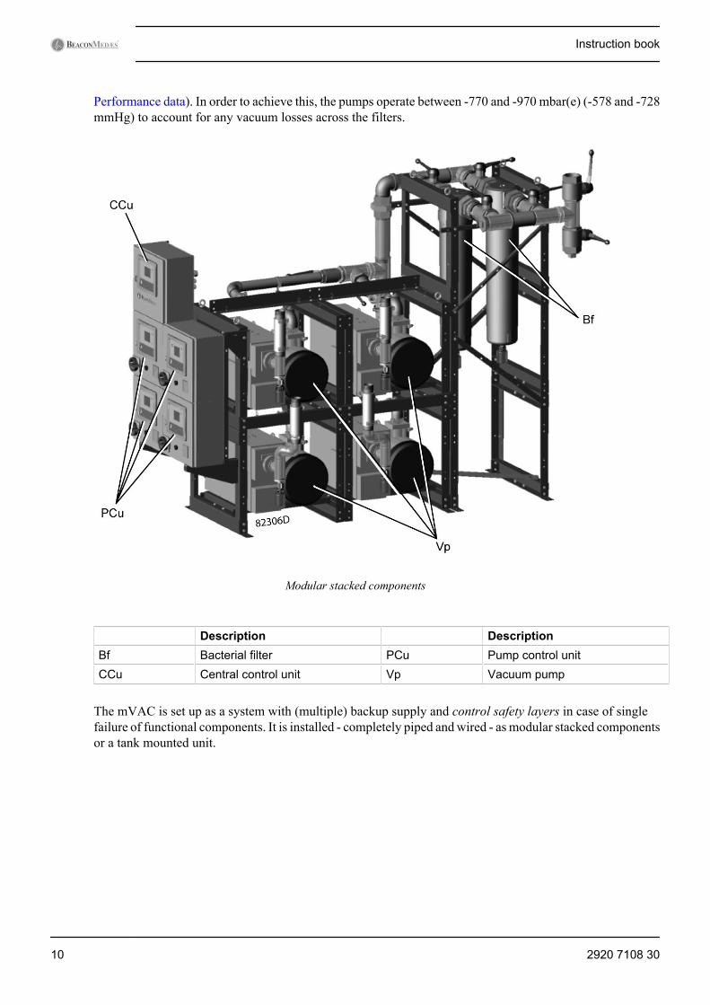
Performance data). In order to achieve this, the pumps operate between -770 and -970 mbar(e) (-578 and -728mmHg) to account for any vacuum losses across the filters.
Modular stacked components
Description DescriptionBf Bacterial filter PCu Pump control unitCCu Central control unit Vp Vacuum pump
The mVAC is set up as a system with (multiple) backup supply and control safety layers in case of singlefailure of functional components. It is installed - completely piped and wired - as modular stacked componentsor a tank mounted unit.
Instruction book
10 2920 7108 30
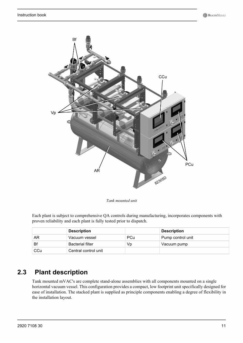
Tank mounted unit
Each plant is subject to comprehensive QA controls during manufacturing, incorporates components withproven reliability and each plant is fully tested prior to dispatch.
Description DescriptionAR Vacuum vessel PCu Pump control unitBf Bacterial filter Vp Vacuum pumpCCu Central control unit
2.3 Plant descriptionTank mounted mVAC's are complete stand-alone assemblies with all components mounted on a singlehorizontal vacuum vessel. This configuration provides a compact, low footprint unit specifically designed forease of installation. The stacked plant is supplied as principle components enabling a degree of flexibility inthe installation layout.
Instruction book
2920 7108 30 11
mVAC systems complying with HTM 02-01 and ISO 7396-1 are provided with at least 2 standbypumps, e.g. the design flow of a system with 3 pumps is provided by a single pump.mVAC systems complying with HTM 2022 are provided with at least 1 standby pump, e.g. thedesign flow of a system with 2 pumps is provided by a single pump.
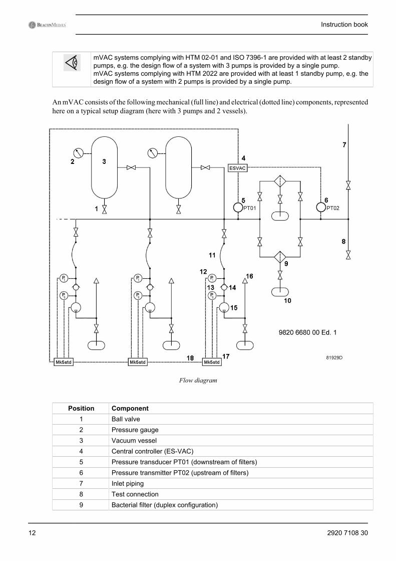
An mVAC consists of the following mechanical (full line) and electrical (dotted line) components, representedhere on a typical setup diagram (here with 3 pumps and 2 vessels).
Flow diagram
Position Component1 Ball valve2 Pressure gauge3 Vacuum vessel4 Central controller (ES-VAC)5 Pressure transducer PT01 (downstream of filters)6 Pressure transmitter PT02 (upstream of filters)7 Inlet piping8 Test connection9 Bacterial filter (duplex configuration)
Instruction book
12 2920 7108 30
Position Component10 Drain flask11 Flexible hose12 Pressure transducer PT (pump inlet)13 Pressure switch Ps (FTGOL - Failed To Go On Load)14 Non-return valve15 Vacuum pump16 Exhaust17 Pump controller18 CAN (controller area network) connection
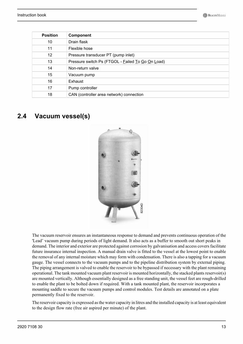
2.4 Vacuum vessel(s)
The vacuum reservoir ensures an instantaneous response to demand and prevents continuous operation of the'Lead’ vacuum pump during periods of light demand. It also acts as a buffer to smooth out short peaks indemand. The interior and exterior are protected against corrosion by galvanisation and access covers facilitatefuture insurance internal inspection. A manual drain valve is fitted to the vessel at the lowest point to enablethe removal of any internal moisture which may form with condensation. There is also a tapping for a vacuumgauge. The vessel connects to the vacuum pumps and to the pipeline distribution system by external piping.The piping arrangement is valved to enable the reservoir to be bypassed if necessary with the plant remainingoperational. The tank mounted vacuum plant reservoir is mounted horizontally, the stacked plants reservoir(s)are mounted vertically. Although essentially designed as a free standing unit, the vessel feet are rough-drilledto enable the plant to be bolted down if required. With a tank mounted plant, the reservoir incorporates amounting saddle to secure the vacuum pumps and control modules. Test details are annotated on a platepermanently fixed to the reservoir.
The reservoir capacity is expressed as the water capacity in litres and the installed capacity is at least equivalentto the design flow rate (free air aspired per minute) of the plant.
Instruction book
2920 7108 30 13
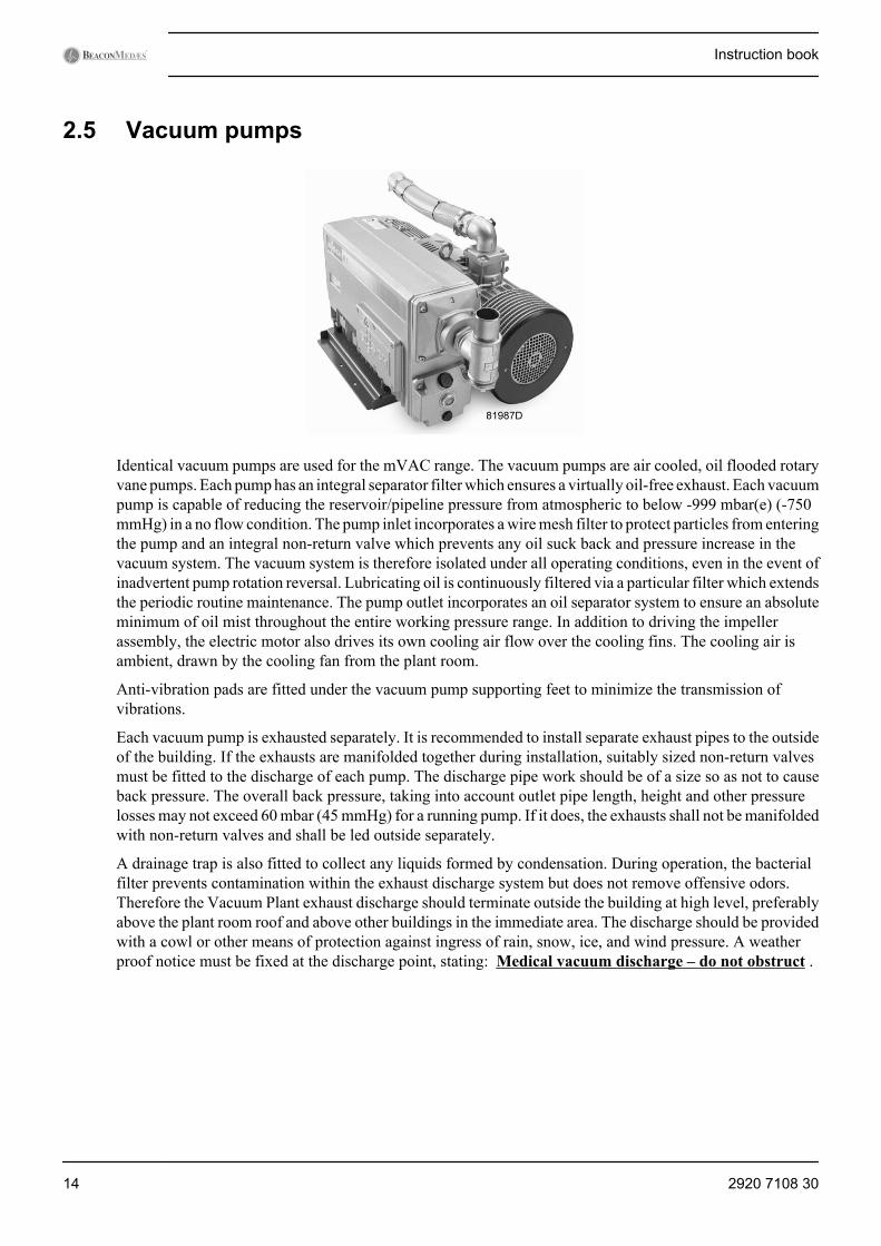
2.5 Vacuum pumps
Identical vacuum pumps are used for the mVAC range. The vacuum pumps are air cooled, oil flooded rotaryvane pumps. Each pump has an integral separator filter which ensures a virtually oil-free exhaust. Each vacuumpump is capable of reducing the reservoir/pipeline pressure from atmospheric to below -999 mbar(e) (-750mmHg) in a no flow condition. The pump inlet incorporates a wire mesh filter to protect particles from enteringthe pump and an integral non-return valve which prevents any oil suck back and pressure increase in thevacuum system. The vacuum system is therefore isolated under all operating conditions, even in the event ofinadvertent pump rotation reversal. Lubricating oil is continuously filtered via a particular filter which extendsthe periodic routine maintenance. The pump outlet incorporates an oil separator system to ensure an absoluteminimum of oil mist throughout the entire working pressure range. In addition to driving the impellerassembly, the electric motor also drives its own cooling air flow over the cooling fins. The cooling air isambient, drawn by the cooling fan from the plant room.
Anti-vibration pads are fitted under the vacuum pump supporting feet to minimize the transmission ofvibrations.
Each vacuum pump is exhausted separately. It is recommended to install separate exhaust pipes to the outsideof the building. If the exhausts are manifolded together during installation, suitably sized non-return valvesmust be fitted to the discharge of each pump. The discharge pipe work should be of a size so as not to causeback pressure. The overall back pressure, taking into account outlet pipe length, height and other pressurelosses may not exceed 60 mbar (45 mmHg) for a running pump. If it does, the exhausts shall not be manifoldedwith non-return valves and shall be led outside separately.
A drainage trap is also fitted to collect any liquids formed by condensation. During operation, the bacterialfilter prevents contamination within the exhaust discharge system but does not remove offensive odors.Therefore the Vacuum Plant exhaust discharge should terminate outside the building at high level, preferablyabove the plant room roof and above other buildings in the immediate area. The discharge should be providedwith a cowl or other means of protection against ingress of rain, snow, ice, and wind pressure. A weatherproof notice must be fixed at the discharge point, stating: Medical vacuum discharge – do not obstruct .
Instruction book
14 2920 7108 30
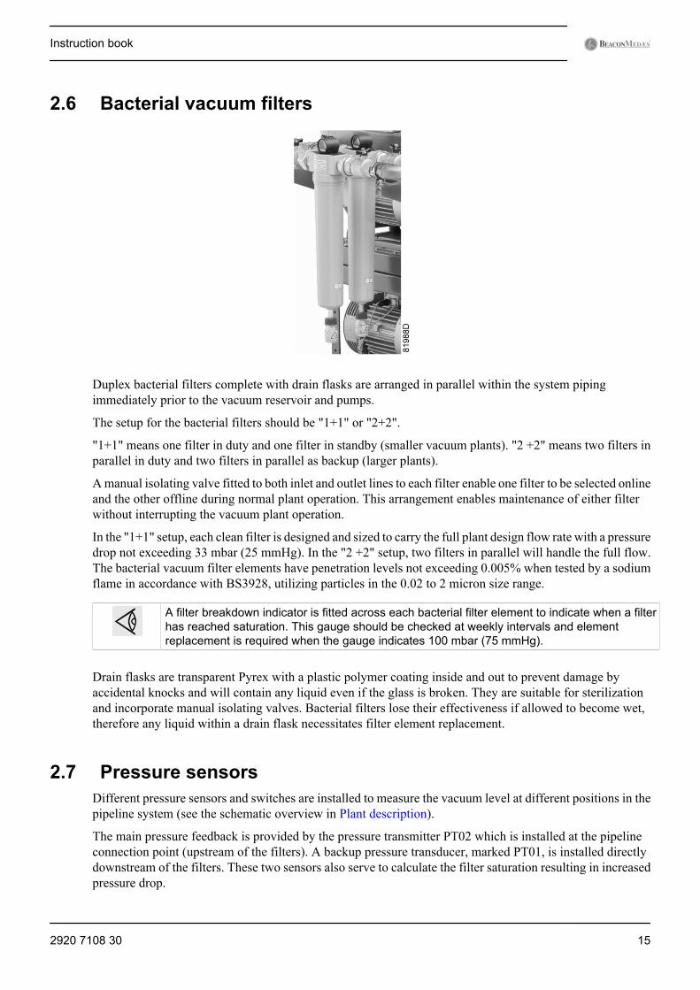
2.6 Bacterial vacuum filters
Duplex bacterial filters complete with drain flasks are arranged in parallel within the system pipingimmediately prior to the vacuum reservoir and pumps.
The setup for the bacterial filters should be "1+1" or "2+2".
"1+1" means one filter in duty and one filter in standby (smaller vacuum plants). "2 +2" means two filters inparallel in duty and two filters in parallel as backup (larger plants).
A manual isolating valve fitted to both inlet and outlet lines to each filter enable one filter to be selected onlineand the other offline during normal plant operation. This arrangement enables maintenance of either filterwithout interrupting the vacuum plant operation.
In the "1+1" setup, each clean filter is designed and sized to carry the full plant design flow rate with a pressuredrop not exceeding 33 mbar (25 mmHg). In the "2 +2" setup, two filters in parallel will handle the full flow.The bacterial vacuum filter elements have penetration levels not exceeding 0.005% when tested by a sodiumflame in accordance with BS3928, utilizing particles in the 0.02 to 2 micron size range.
A filter breakdown indicator is fitted across each bacterial filter element to indicate when a filterhas reached saturation. This gauge should be checked at weekly intervals and elementreplacement is required when the gauge indicates 100 mbar (75 mmHg).
Drain flasks are transparent Pyrex with a plastic polymer coating inside and out to prevent damage byaccidental knocks and will contain any liquid even if the glass is broken. They are suitable for sterilizationand incorporate manual isolating valves. Bacterial filters lose their effectiveness if allowed to become wet,therefore any liquid within a drain flask necessitates filter element replacement.
2.7 Pressure sensorsDifferent pressure sensors and switches are installed to measure the vacuum level at different positions in thepipeline system (see the schematic overview in Plant description).
The main pressure feedback is provided by the pressure transmitter PT02 which is installed at the pipelineconnection point (upstream of the filters). A backup pressure transducer, marked PT01, is installed directlydownstream of the filters. These two sensors also serve to calculate the filter saturation resulting in increasedpressure drop.
Instruction book
2920 7108 30 15
Each pump inlet is also provided with a pressure transducer upstream of the non-return valve and a pressureswitch downstream of the non-return valve. The pressure switch ensures feedback about whether a pump isoperating satisfactory, while the pressure transducer is used to control the pump in Local mode (see chapterPump controller operation).
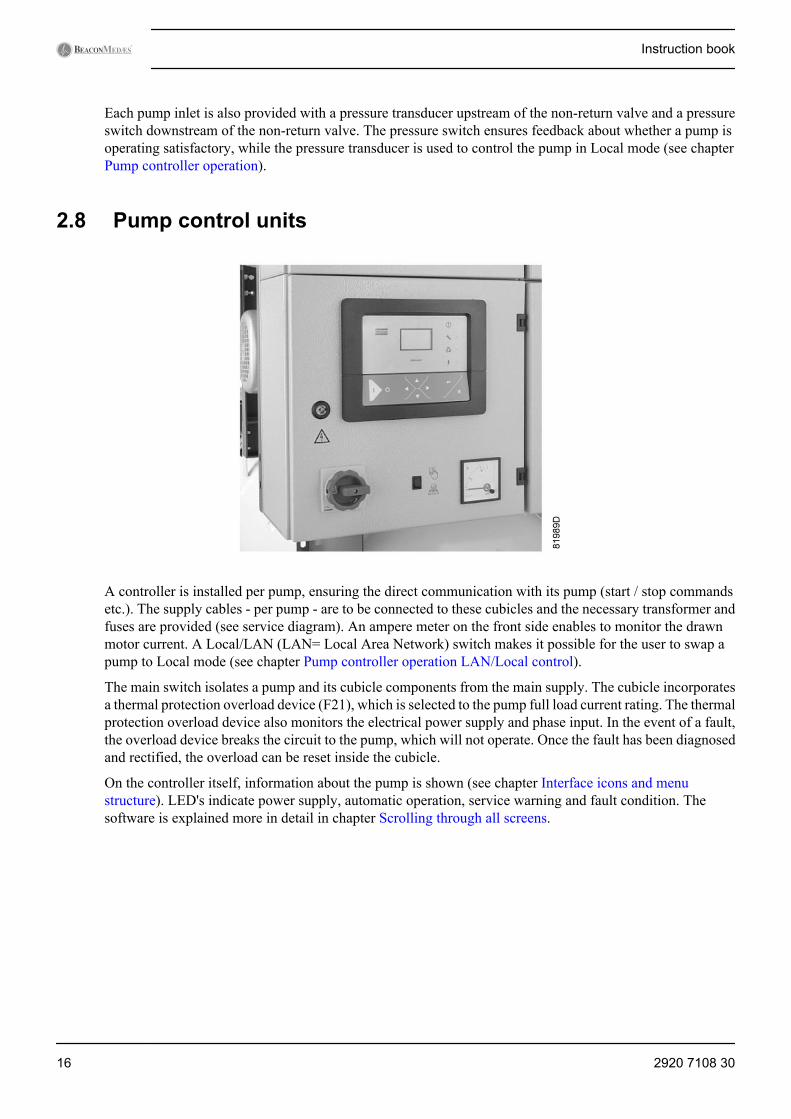
2.8 Pump control units
A controller is installed per pump, ensuring the direct communication with its pump (start / stop commandsetc.). The supply cables - per pump - are to be connected to these cubicles and the necessary transformer andfuses are provided (see service diagram). An ampere meter on the front side enables to monitor the drawnmotor current. A Local/LAN (LAN= Local Area Network) switch makes it possible for the user to swap apump to Local mode (see chapter Pump controller operation LAN/Local control).
The main switch isolates a pump and its cubicle components from the main supply. The cubicle incorporatesa thermal protection overload device (F21), which is selected to the pump full load current rating. The thermalprotection overload device also monitors the electrical power supply and phase input. In the event of a fault,the overload device breaks the circuit to the pump, which will not operate. Once the fault has been diagnosedand rectified, the overload can be reset inside the cubicle.
On the controller itself, information about the pump is shown (see chapter Interface icons and menustructure). LED's indicate power supply, automatic operation, service warning and fault condition. Thesoftware is explained more in detail in chapter Scrolling through all screens.
Instruction book
16 2920 7108 30

2.9 Central control unit
A central controller is connected to the pump controllers through a CAN system. A 210-230 V supply needsto be connected to this cubicle, wherein the necessary transformer and fuses are foreseen (see service diagram).The central controller is based on a master control system referred to as ES-VAC.
The central controller monitors the pressure at the pipeline connection point and sends start / stop commandsto the pump controllers based on an even-wear, ΔP/ΔT algorithm. It also tracks the pressure drop over thefilters and warns when service is required. It receives information about the pumps, groups it into a clearoverview (see chapter Interface icons and menu structure) and transmits the appropriate alarms to the screenand to potential free output contacts. LED's are provided to indicate power supply, automatic operation, servicewarning and fault condition. The software is explained more in detail in chapter Central controlleroperation.
Instruction book
2920 7108 30 17
3 Installation
3.1 IntroductionInstallation of a medical vacuum plant must be carried out by suitably qualified and competentpersonnel who fully understand the standards required when working on a piped medical gasdistribution system and are conversant with the information contained in this Instruction book.Installation must be carried out strictly in accordance with the specific installation proposal (seechapter Installation proposal) and service diagram issued with the plant.
The mVAC must be installed within a plant room which provides adequate ventilation for the cooling ofelectric motors, bearing in mind that approximately 75% of all energy consumed is dissipated into the plantroom as heat. At least 500 mm must be allowed between the plant and any walls or other obstructions andadditional headroom is required to enable installation. Specific plant dimensions must be taken in to accountespecially where access is limited. Install the unit in an area where the noise levels do not cause aninconvenience. When bolting the unit to the floor, take into account that the hole diameters in the frame arebetween 10 mm and 13 mm.
Upon installation, take into account the warnings provided in chapter Installation warnings.
3.2 Installation warningsSpecial attention should be taken for all next points.
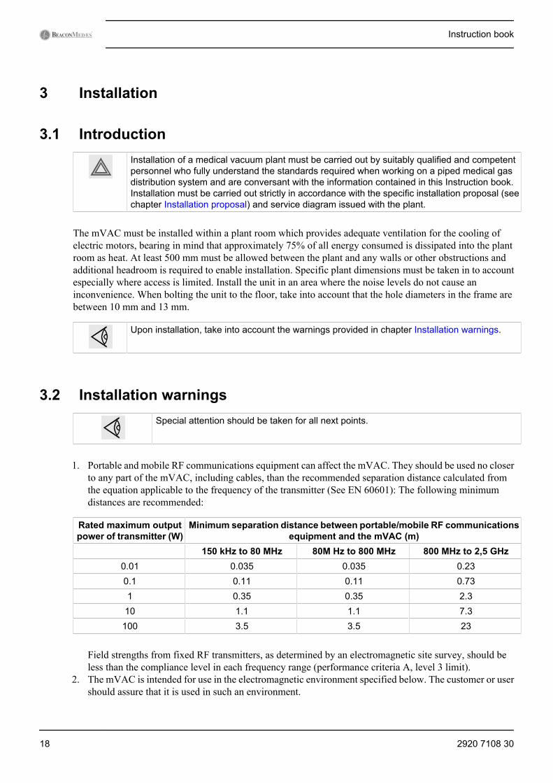
1. Portable and mobile RF communications equipment can affect the mVAC. They should be used no closerto any part of the mVAC, including cables, than the recommended separation distance calculated fromthe equation applicable to the frequency of the transmitter (See EN 60601): The following minimumdistances are recommended:
Rated maximum outputpower of transmitter (W)
Minimum separation distance between portable/mobile RF communicationsequipment and the mVAC (m)
150 kHz to 80 MHz 80M Hz to 800 MHz 800 MHz to 2,5 GHz0.01 0.035 0.035 0.230.1 0.11 0.11 0.731 0.35 0.35 2.3
10 1.1 1.1 7.3100 3.5 3.5 23
Field strengths from fixed RF transmitters, as determined by an electromagnetic site survey, should beless than the compliance level in each frequency range (performance criteria A, level 3 limit).
2. The mVAC is intended for use in the electromagnetic environment specified below. The customer or usershould assure that it is used in such an environment.
Instruction book
18 2920 7108 30
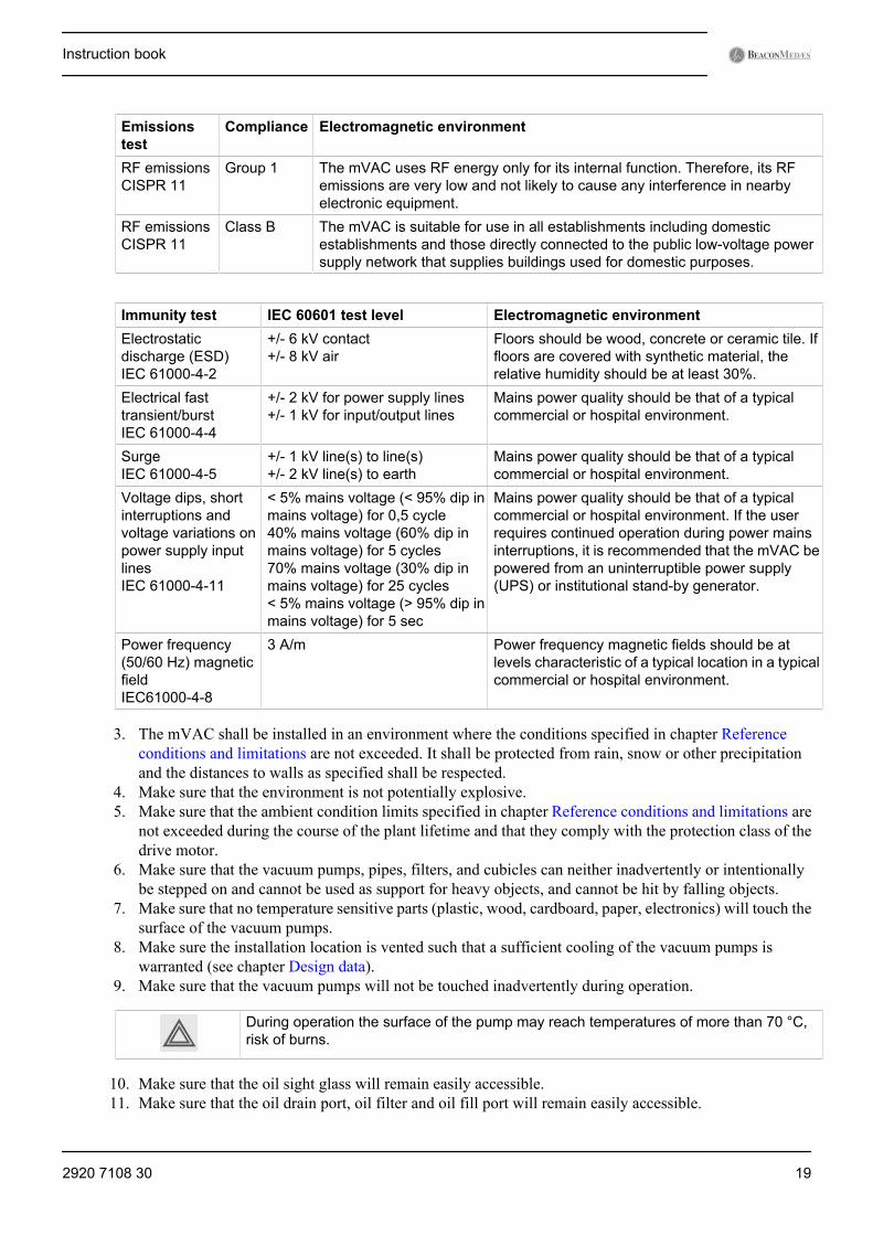
Emissionstest
Compliance Electromagnetic environment
RF emissionsCISPR 11
Group 1 The mVAC uses RF energy only for its internal function. Therefore, its RFemissions are very low and not likely to cause any interference in nearbyelectronic equipment.
RF emissionsCISPR 11
Class B The mVAC is suitable for use in all establishments including domesticestablishments and those directly connected to the public low-voltage powersupply network that supplies buildings used for domestic purposes.
Immunity test IEC 60601 test level Electromagnetic environmentElectrostaticdischarge (ESD)IEC 61000-4-2
+/- 6 kV contact+/- 8 kV air
Floors should be wood, concrete or ceramic tile. Iffloors are covered with synthetic material, therelative humidity should be at least 30%.
Electrical fasttransient/burstIEC 61000-4-4
+/- 2 kV for power supply lines+/- 1 kV for input/output lines
Mains power quality should be that of a typicalcommercial or hospital environment.
SurgeIEC 61000-4-5
+/- 1 kV line(s) to line(s)+/- 2 kV line(s) to earth
Mains power quality should be that of a typicalcommercial or hospital environment.
Voltage dips, shortinterruptions andvoltage variations onpower supply inputlinesIEC 61000-4-11
< 5% mains voltage (< 95% dip inmains voltage) for 0,5 cycle40% mains voltage (60% dip inmains voltage) for 5 cycles70% mains voltage (30% dip inmains voltage) for 25 cycles< 5% mains voltage (> 95% dip inmains voltage) for 5 sec
Mains power quality should be that of a typicalcommercial or hospital environment. If the userrequires continued operation during power mainsinterruptions, it is recommended that the mVAC bepowered from an uninterruptible power supply(UPS) or institutional stand-by generator.
Power frequency(50/60 Hz) magneticfieldIEC61000-4-8
3 A/m Power frequency magnetic fields should be atlevels characteristic of a typical location in a typicalcommercial or hospital environment.
3. The mVAC shall be installed in an environment where the conditions specified in chapter Referenceconditions and limitations are not exceeded. It shall be protected from rain, snow or other precipitationand the distances to walls as specified shall be respected.
4. Make sure that the environment is not potentially explosive.5. Make sure that the ambient condition limits specified in chapter Reference conditions and limitations are
not exceeded during the course of the plant lifetime and that they comply with the protection class of thedrive motor.
6. Make sure that the vacuum pumps, pipes, filters, and cubicles can neither inadvertently or intentionallybe stepped on and cannot be used as support for heavy objects, and cannot be hit by falling objects.
7. Make sure that no temperature sensitive parts (plastic, wood, cardboard, paper, electronics) will touch thesurface of the vacuum pumps.
8. Make sure the installation location is vented such that a sufficient cooling of the vacuum pumps iswarranted (see chapter Design data).
9. Make sure that the vacuum pumps will not be touched inadvertently during operation.
During operation the surface of the pump may reach temperatures of more than 70 °C,risk of burns.
10. Make sure that the oil sight glass will remain easily accessible.11. Make sure that the oil drain port, oil filter and oil fill port will remain easily accessible.
Instruction book
2920 7108 30 19
12. Make sure that the power supply is compatible with the data on the nameplate of the drive motor.13. Electrical installation work must only be executed by qualified personnel that knows and observes the
following regulations:• BS 7671• IEC 364 or CENELEC HD 384• IEC-report 664• national accident prevention regulation
14. Before disconnecting any piping, pneumatically isolate the section and slowly in-bleed air to raise thepressure to atmospheric pressure. Do not suddenly open any isolating valve that may cause rapid pressurerelease (increase). Open valves slowly and allow sufficient time for pressure to stabilise.
15. A checklist / logbook will be made wherein the installer will mark the adherence of the installation to thefollowing paragraphs:• Mechanical positioning (see Installation proposal).• Piping connections (see Installation proposal).• Electrical connections (see Electrical connections).• Pre-start inspection (see Pre-start inspection).• Electrical functional check (see Electrical functional check).• Pneumatic settings (see Setting the pneumatic system).• Automatic operation and leak check (see Automatic operation & leak check).
16. Transportation should be carried out according to section Transporting.
3.3 Mechanical installation3.3.1 Transporting
Once the unit is unpacked from the crate it can be transported by forklift or by crane.• Forklift: the forklift arms should be placed underneath the lowest plates on which the pumps are mounted.
Pay attention to position the forklift arms for optimal weight distribution.• Crane: use all lifting eyes provided and pay attention to put equal tension on all lifting chains (if
applicable).
Instruction book
20 2920 7108 30
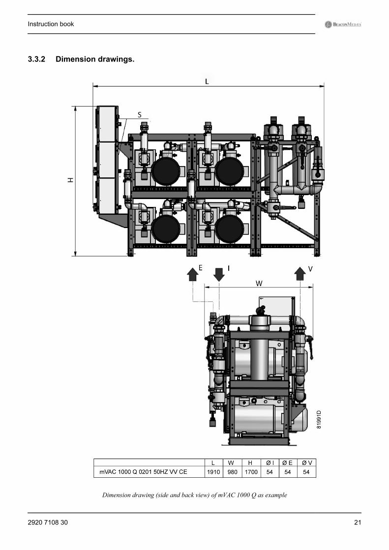
3.3.2 Dimension drawings.
Dimension drawing (side and back view) of mVAC 1000 Q as example
Instruction book
2920 7108 30 21
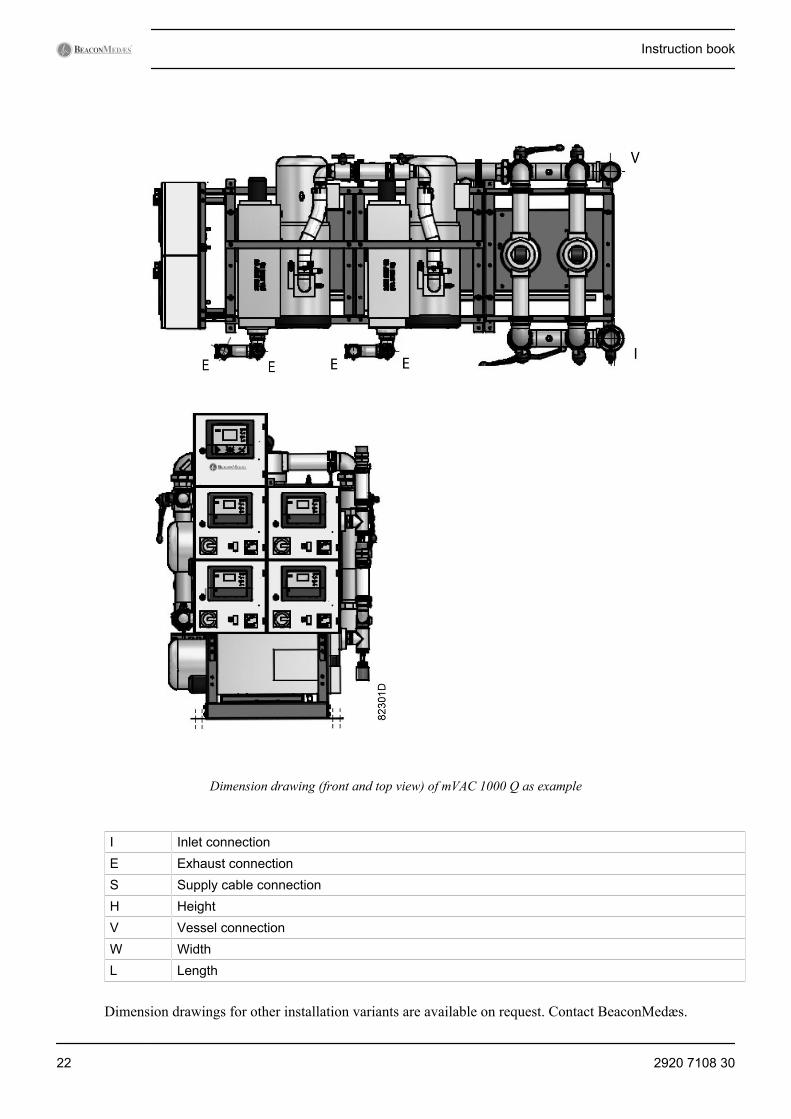
Dimension drawing (front and top view) of mVAC 1000 Q as example
I Inlet connectionE Exhaust connectionS Supply cable connectionH HeightV Vessel connectionW WidthL Length
Dimension drawings for other installation variants are available on request. Contact BeaconMedæs.
Instruction book
22 2920 7108 30

3.3.3 Installation proposal
Installation proposal (side view) of mVAC 1000 Q as example
I Inlet connectionE Exhaust connection
Instruction book
2920 7108 30 23

Installation proposal (front view) of mVAC 1000 Q as example
Installation proposal drawings for other installation variants are available on request. Contact BeaconMedæs.
For maintenance and cooling purposes it is recommended to respect the installation proposal for the specifictype of mVAC.
1. Move the frame mounted unit into position and drill the floor to receive anchor nuts.2. Fit mounting bolt anchor nuts into the floor. Fit mounting bolts, washers and nuts and fully tighten down.
If the device must be installed with or connected to other medical devices or equipment in order to operateas required for its intended purpose, sufficient details of its characteristics must be obtained to identifythe correct devices or equipment in order to obtain a safe combination.
3. Take the vessel connection parts (in loose box, if applicable) and mount them on the vessels.4. Connecting piping. Remove the transport protection caps from the pipes. Check that no ingress has
occurred, if necessary clean the pipes. Clean the piping network before brazing. Connect the distributionpipeline installation to the suction inlet. The connecting pipe work must be secured to give added stability.Each vacuum pump incorporates its own exhaust pipe, preferably to be routed separately to discharge intoa safe area (see also the warning provision in chapter Installation warnings). The flexible outlet hose willnot support the weight of the connecting pipe work. The connecting pipe work must be secured to giveadded stability. The diameter of the outlet pipe must be large enough to avoid pressure buildup. Backpressure has a negative impact on the performance of the pumps and must be limited as much as possible(max. 60 mbar).
5. Take the drain flasks (inside the cubicle, or in loose box) and mount them on the bacterial filters andexhaust using the plastic washer provided. Check that biological warning labels are attached at each drainflask.
Instruction book
24 2920 7108 30
Warning label, biological hazard
3.4 StorageIf the medical vacuum plant installation is going to be stored, protective measures mustbe taken.
• Protect the mVAC against dust and moisture. Store in a clean, cool, dry and well ventilated area.• Make sure that the medical vacuum plant installation is not subject to vibration.• If the vacuum plant installation is stored in packing, put some vapour corrosion inhibitor (VCI) paper into
the packing.• If the vacuum plant installation is stored for one year or more, consult BeaconMedæs.
3.5 Electrical connectionsOn larger vacuum plants, the filter module comes apart and needs to be connected to the pump frame. Connectthe sensor cables of the ES VAC controller cabinet (marked PT01 and PT02) to the sensors on the filter piping:connect PT01 to the pressure sensor downstream the bacterial filters (backup sensor) and PT02 to the pressuretransmitter upstream the bacterial filters measuring the net pressure.
Consult the service diagram (it can be found inside the cubicles) and verify the motor data plates. Ensure thatthe power supply is off and correctly isolated before connecting to the cubicles. All wiring must be inaccordance with IEE regulations. Cable sizes and fuses given in chapter Electrical cable size arerecommendations. All cable sizes and protective devices must be sized by a qualified electrician.
The mVAC requires a separate power supply for each vacuum pump, preferably from an essential circuit, andrequires a 210-230 V AC supply to the central controller cubicle.
Check that the central controller power LED is lit and the controller screen is operational when the 210-230V supply is connected.
Earth the vessels and other piping as required.
Usually it is required to have a central alarm panel (in the engineering control room or telephone exchangeetc.) Therefore potential free contacts (with the alarm signals) are foreseen in the central controller cubicle.Provide electrical wires between the central alarm panel and the mVAC and connect them according to theservice diagram provided.
Set up the alarm panel and carry out the alarm test according to Central controller operation.
When in normal status, the alarm signals to the alarm panel are forced closed and when an alarm is triggered,they open. This also means that all alarms will trigger at the central alarm panel when power supply to thecentral controller is lost.
Instruction book
2920 7108 30 25
4 Commisioning
4.1 IntroductionCommissioning of a medical vacuum plant must be carried out strictly in accordance with the followingprocedures, which are designed to ensure that the installation is correct and ensure that the mVAC operatescorrectly. The full commissioning procedure must be carried out after the installation before the system isbrought into use. The relevant sections of the commissioning procedure must be repeated following majorcomponent replacement or whenever the plant operation or performance is suspect. Commissioning must onlybe undertaken by suitably qualified and competent personnel who are fully conversant with the informationcontained in this manual. It is recommended that for a full commissioning procedure, the following paragraphsare carried out in strict sequence. This ensures that at each step the plant is correctly set for the next procedure.
Where applicable, a work permit must be obtained before commencing any work on the medical vacuumsystem.
These procedures are designed in accordance with EN 7396-1 (e.g. integrity of the pipeline installation, checksystem design performance and functionally test all components).
4.2 Pre-start inspectionThe pre-start inspection is essential to ensure that all components are secure, correctly assembled and that nodamage occurs to the plant during initial start-up. The procedure to carry out the pre-start inspection is asfollows:
1. Ensure that all electrical power supplies to the plant are off and isolated at the controllers (isolator switchesturned OFF).
2. Check the rating of the power supply fuses and fuses in the controller cubicles.3. Check the security of all components inside the cubicles and examine all connections. Inspect for any
obvious damage and rectify if necessary.4. Check the security of the electrical connections between the vacuum pumps and their respective control
cubicles. Check the security of the electrical connections between all cubicles. Ensure that all exposedwiring is correctly routed and secure.
5. Check all external piping connections for security and damage with special attention to flexible hoses.6. Verify on the sight glass of all pumps that the oil reaches the upper half of the glass, if necessary add oil.7. Fully close all ball valves.8. Ensure that the vacuum plant inlet is correctly connected to the distribution system. Ensure that the
distribution system is isolated from the plant by closing the distribution system ball valve at the inletconnection point.
9. Ensure that each vacuum pump is connected to the exhaust system and that there are no closed ball valvespresent or other elements blocking the exhaust.
10. Ensure that all loose articles are removed from the vicinity of the plant.11. Check the drain flasks for damage to the bowl or connection, order spare parts if needed.12. Where applicable, check that the pipeline installation is correctly identified and labelled with identification
tape at 10 metre intervals and on both sides of any dividing wall.
Instruction book
26 2920 7108 30
4.3 Electrical functional checkFollowing the initial electrical power connection and every time the electrical power supply connections havebeen disturbed for any reason, all electrical connections must be checked for security and the electricalfunctional check must be carried out.
1. Verify that each Local/LAN switch is set to Local. Jog each motor briefly by switching On and Off theisolator switch on the pump control cubicles, while checking the rotation of the corresponding pump(cubicle and pump are marked with the same number). The correct rotation is marked by an arrow on thepump. If the rotation is wrong, switch off the pump immediately. Switch off and isolate the power supplyand swap 2 phase connections in the cubicle. Carry out the procedure again to check for correct rotation.Check that each vacuum pump operates normally without any unusual noise or vibration. Verify that theampere meter registers approximately full load current (see Fuse values).
2. If a motor doesn’t rotate during this check, check the connections in the connection box on the motor andcheck the connections inside the cubicle. Check the overload settings and the fuses (section Fusevalues). When the problem is corrected, carry out the rotational check again.
3. Check that the central controller power LED is lit and the controller screen is operational when the 210-230V supply is connected. Check that the pump controllers powered LED's are lit and the screens areoperational when the isolator switches are On.
4.4 Setting the pneumatic systemPrior to checking the automatic operation, the pneumatic system must be selected as follows:
1. Fully open the drain valves at the exhausts of each pump.2. Fully open the valves at the inlets of each pumps.3. Fully open the valves at each vessel connection.4. Fully open the valves before and after the lead bacterial filter(s).5. Fully close the valves before and after the stand-by bacterial filter(s).6. Fully open the drain valves at the bottom of the bacterial filter(s).7. Fully close the (full flow) test connection ball valve.8. Fully close the vessel drain valves.9. Fully close the inlet connection valve which connects the plant to the distribution piping while proving
the plant operation (see: Automatic operation & leak check).10. After proving the plant operation, making sure that all terminal units are correctly fitted, and after
successfully completing the pipeline carcass pressure test, the inlet connection ball valve can be opened.
4.5 Automatic operation and leak checkThe following initial start-up procedure ensures that the plant is set to operate normally and the vessel isevacuated to a vacuum level of at least -870 mbar(e) (-653 mmHg).
1. Set the Local/LAN switch to LAN on all pump controllers.2. Power the central controller and proceed to chapter Central controller operation to start the software.3. Set all isolators to On, powering the complete system.4. Observe that the plant emergency and pressure fault alarms are active.5. Observe that the pumps are being called and the pressure on the controllers approaches vacuum. Open the
test connection (unplug the plug) slightly to simulate a vacuum flow demand, observe that the pumpsrespond to maintain vacuum.
6. Ensure that each vacuum pump operates normally without any unusual noise or vibration. Should anyfault occur, the respective vacuum pump must be switched off immediately. Refer to Faults andremedies and restart the commissioning.
Instruction book
2920 7108 30 27

7. After at least 1 hour, fully close the test connection and refit the plug. Observe the gauge(s) on the vessel(s)until a vacuum is reached. At this point all pumps should stop.
8. Observe that the alarms are now extinguished.9. With the complete system at nominal distribution pressure, with the source of supply isolated and with
all other valves open, the pressure increase in the pipeline shall not exceed 200 mbar (150 mmHg) after1 hour. The pressure drop shall be corrected for variations due to temperature according to the ideal gaslaws (see EN 7396-1 annex E). In case the pressure increase in 1 hour is greater, close off sections of thepipeline, track leaks (audibly or through other means), and fix them. Then redo the test.
10. Ensure that the system continues to operate within the design flow rate and that the pumps operate normallywith no signs of problems for at least one hour.
11. Per pump cubicle, read out the value of the drawn nominal current on the amp meter and note down thevalue.
4.6 Starting the plantAfter going through the procedures explained in the previous paragraphs (make sure that the valves are setaccording to paragraph Setting the pneumatic system), the plant can be left to run automatically. Ensure thatall local/LAN switches are set to LAN and that the automatic operation LED's are lit on every controller. Seepicture at Pump controller overview. Ensure that paragraph Central controller operation is followed to startthe software. Follow the guidelines explained in chapter Checks and intervals to ensure trouble free andreliable operation throughout the life of the plant.
Instruction book
28 2920 7108 30
5 Operation user guide
5.1 IntroductionAs mentioned in chapter Plant description, both a pump controller per pump is foreseen and a central controllerwhich centrally receives information from the pump controllers and sends commands to those pumpcontrollers. The pump controllers are Elektronikon® controllers with text display, while the central controlleris an Elektronikon® Graphic+.
Together they form the control system for the medical vacuum plant, performing following functions:1. Overall plant control and indication2. Individual pump starting and stopping3. Plant status monitoring and indication4. Alarm status signalling
First the individual pump controllers will be explained. In the default situation they are controlled by thecentral controller, explained in section Central controller - Interface icons and menu structure.
5.2 Pump controller5.2.1 Interface, icons and menu structure
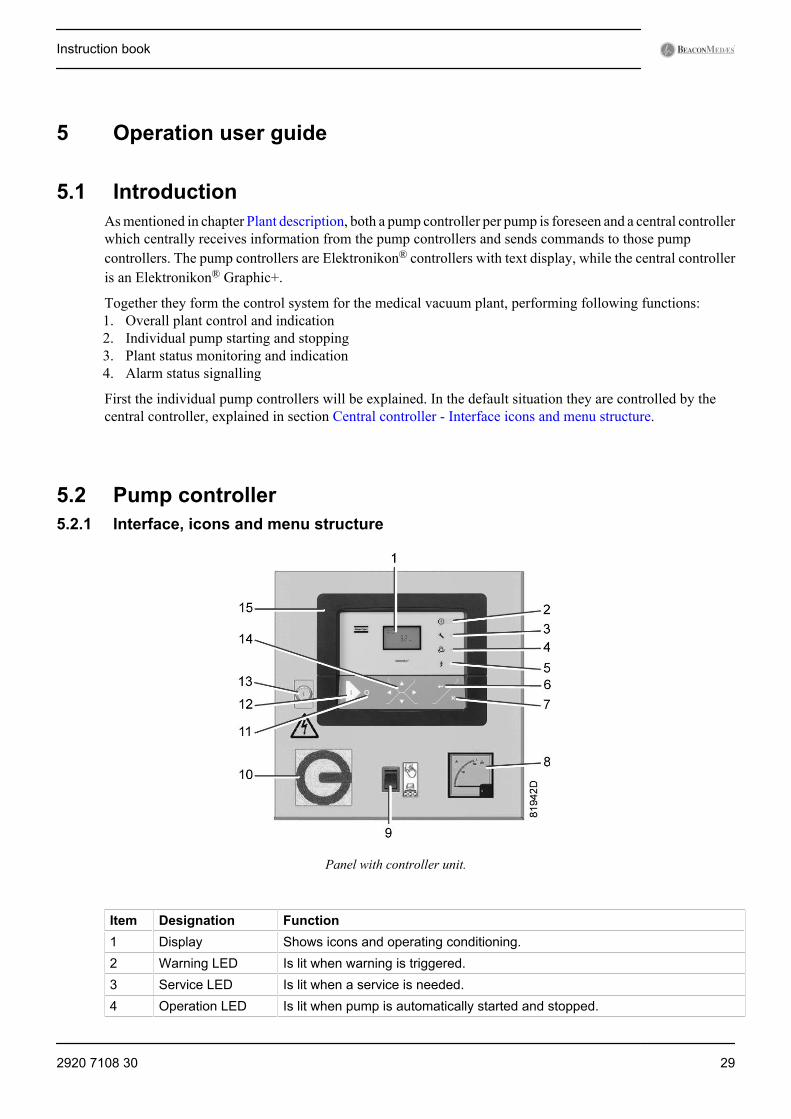
Panel with controller unit.
Item Designation Function1 Display Shows icons and operating conditioning.2 Warning LED Is lit when warning is triggered.3 Service LED Is lit when a service is needed.4 Operation LED Is lit when pump is automatically started and stopped.
Instruction book
2920 7108 30 29

Item Designation Function5 Voltage LED Indicates that the voltage is switched on.6 Enter button Confirm action.7 Escape button Go to previous screen or end current action.8 Amp meter Real-time measurement of the drawn current.9 Local/LAN switch Puts the pump in LAN control or in Local control.10 Isolating switch Electrically isolates the cubicle from the supply.11 Stop button This button stops the pump when in Local mode.12 Start button This button puts the pump in automatic operation when in Local mode. The
operation LED (3) lights up. Elektronikon® is operative.13 Cubicle lock Can be opened with a key to open the cubicle.14 Scroll buttons Use these buttons to scroll through the menu.15 Elektronikon® Controller
Display on controller unit.
Item Icon Appearance Description1 Blinking FTGOL fault (the pump Failed To Go On Load)
2 Rotating Running
Steady Stopped
3 Steady Under LAN control
Blinking Forced Local mode
Instruction book
30 2920 7108 30

Item Icon Appearance Description4 Pump cooldown, to prevent too many motor starts per
hour (maximum is 20 starts/hour)
When shown, value must be multiplied by 10 to get theactual value.
When shown, value must be multiplied by 100 to get theactual value.
When shown, value must be multiplied by 1000 to get theactual value.
Hours
5 Temperature indication (degrees C)
Temperature indication (degrees F)
6 MPa (Pressure unit)
Psi (Pressure unit)
Bar (Pressure unit)
7 Blinking Oil level switch (option): indicates the oil level is too low
8 Steady Number of motor starts
Blinking Motor overload
9 Emergency stop
10 Service required
11 Blinking Emergency Forced Local mode (triggered by localpressure)
12 Steady Automatic restart after voltage failure
Instruction book
2920 7108 30 31

Item Icon Appearance Description Sensor error
5.2.2 Scrolling through all screens
Controller panel
Controller panel
Scroll buttons are used to scroll through all screens. The screens are divided into register screens, measureddata screens, digital input screens (numbered as <d. In>, <d. 1>, ...), parameter screens (numbered as <P. 1>,<P. 2>, ...), and test screens (numbered as <t. 1>,...).
During scrolling, the numbers of the screens appear in a consecutive order. For most screens, the unit ofmeasurement and the related pictograph are shown together with the screen number.
Example (operating hours)
The screen shows the screen number <d. 1>, the unit used <hrs> and the related icon (operation). Press Enterkey to call up the number of operating hours.
Overview of the screens
Digital inputscreens
Designation
<d. In> Status of the digital inputs<d. 1> Running hours (hrs or x1000 hrs)<d. 2> Motor starts (x1 or x1000)<d. 3> Module hours (hrs or x1000 hrs)
Instruction book
32 2920 7108 30
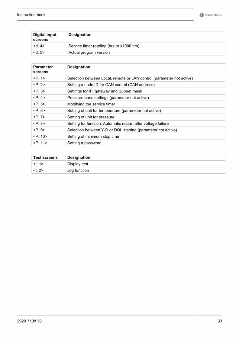
Digital inputscreens
Designation
<d. 4> Service timer reading (hrs or x1000 hrs)<d. 5> Actual program version
Parameterscreens
Designation
<P. 1> Selection between Local, remote or LAN control (parameter not active)<P. 2> Setting a node ID for CAN control (CAN address)<P. 3> Settings for IP, gateway and Subnet mask<P. 4> Pressure band settings (parameter not active)<P. 5> Modifying the service timer<P. 6> Setting of unit for temperature (parameter not active)<P. 7> Setting of unit for pressure<P. 8> Setting for function: Automatic restart after voltage failure<P. 9> Selection between Y-D or DOL starting (parameter not active)<P. 10> Setting of minimum stop time<P. 11> Setting a password
Test screens Designation<t. 1> Display test<t. 2> Jog function
Instruction book
2920 7108 30 33
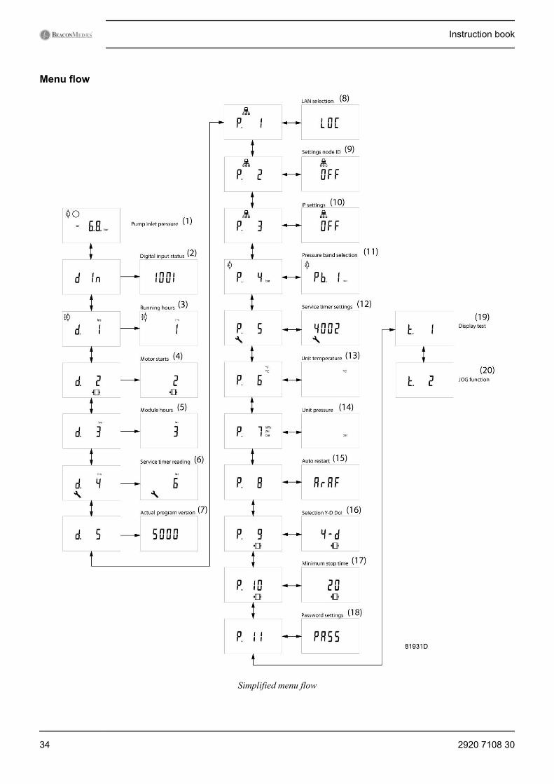
Menu flow
Simplified menu flow
Instruction book
34 2920 7108 30
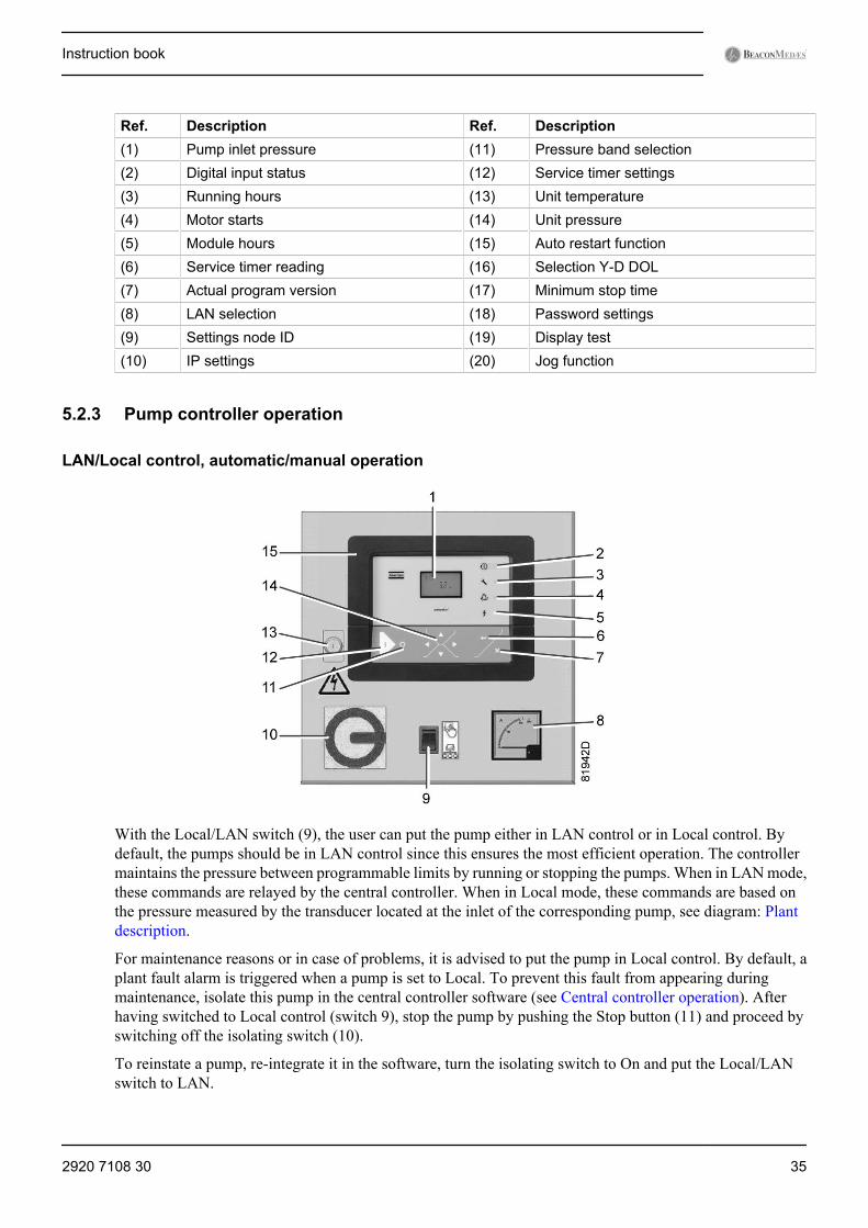
Ref. Description Ref. Description(1) Pump inlet pressure (11) Pressure band selection(2) Digital input status (12) Service timer settings(3) Running hours (13) Unit temperature(4) Motor starts (14) Unit pressure(5) Module hours (15) Auto restart function(6) Service timer reading (16) Selection Y-D DOL(7) Actual program version (17) Minimum stop time(8) LAN selection (18) Password settings(9) Settings node ID (19) Display test(10) IP settings (20) Jog function
5.2.3 Pump controller operation
LAN/Local control, automatic/manual operation
With the Local/LAN switch (9), the user can put the pump either in LAN control or in Local control. Bydefault, the pumps should be in LAN control since this ensures the most efficient operation. The controllermaintains the pressure between programmable limits by running or stopping the pumps. When in LAN mode,these commands are relayed by the central controller. When in Local mode, these commands are based onthe pressure measured by the transducer located at the inlet of the corresponding pump, see diagram: Plantdescription.
For maintenance reasons or in case of problems, it is advised to put the pump in Local control. By default, aplant fault alarm is triggered when a pump is set to Local. To prevent this fault from appearing duringmaintenance, isolate this pump in the central controller software (see Central controller operation). Afterhaving switched to Local control (switch 9), stop the pump by pushing the Stop button (11) and proceed byswitching off the isolating switch (10).
To reinstate a pump, re-integrate it in the software, turn the isolating switch to On and put the Local/LANswitch to LAN.
Instruction book
2920 7108 30 35
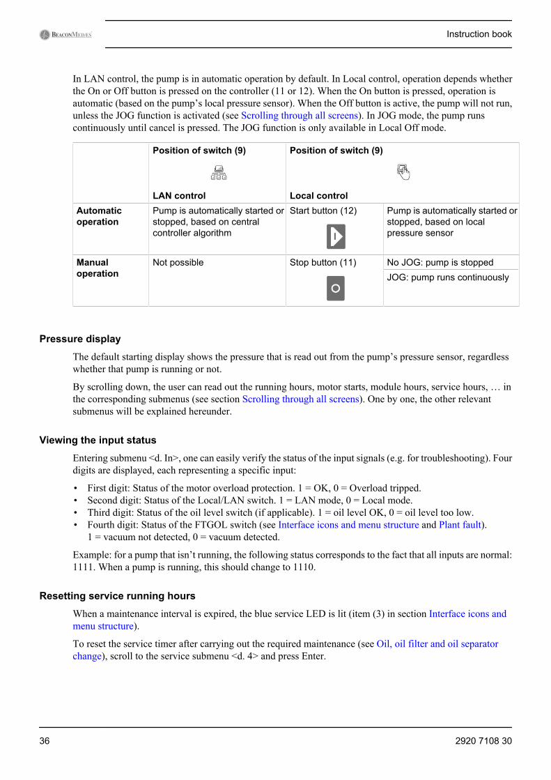
In LAN control, the pump is in automatic operation by default. In Local control, operation depends whetherthe On or Off button is pressed on the controller (11 or 12). When the On button is pressed, operation isautomatic (based on the pump’s local pressure sensor). When the Off button is active, the pump will not run,unless the JOG function is activated (see Scrolling through all screens). In JOG mode, the pump runscontinuously until cancel is pressed. The JOG function is only available in Local Off mode.
Position of switch (9)
LAN control
Position of switch (9)
Local controlAutomaticoperation
Pump is automatically started orstopped, based on centralcontroller algorithm
Start button (12) Pump is automatically started orstopped, based on localpressure sensor
Manualoperation
Not possible Stop button (11) No JOG: pump is stoppedJOG: pump runs continuously
Pressure display
The default starting display shows the pressure that is read out from the pump’s pressure sensor, regardlesswhether that pump is running or not.
By scrolling down, the user can read out the running hours, motor starts, module hours, service hours, … inthe corresponding submenus (see section Scrolling through all screens). One by one, the other relevantsubmenus will be explained hereunder.
Viewing the input status
Entering submenu <d. In>, one can easily verify the status of the input signals (e.g. for troubleshooting). Fourdigits are displayed, each representing a specific input:
• First digit: Status of the motor overload protection. 1 = OK, 0 = Overload tripped.• Second digit: Status of the Local/LAN switch. 1 = LAN mode, 0 = Local mode.• Third digit: Status of the oil level switch (if applicable). 1 = oil level OK, 0 = oil level too low.• Fourth digit: Status of the FTGOL switch (see Interface icons and menu structure and Plant fault).
1 = vacuum not detected, 0 = vacuum detected.
Example: for a pump that isn’t running, the following status corresponds to the fact that all inputs are normal:1111. When a pump is running, this should change to 1110.
Resetting service running hours
When a maintenance interval is expired, the blue service LED is lit (item (3) in section Interface icons andmenu structure).
To reset the service timer after carrying out the required maintenance (see Oil, oil filter and oil separatorchange), scroll to the service submenu <d. 4> and press Enter.
Instruction book
36 2920 7108 30
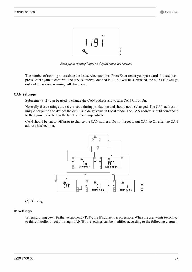
Example of running hours on display since last service.
The number of running hours since the last service is shown. Press Enter (enter your password if it is set) andpress Enter again to confirm. The service interval defined in <P. 5> will be subtracted, the blue LED will goout and the service warning will disappear.
CAN settings
Submenu <P. 2> can be used to change the CAN address and to turn CAN Off or On.
Normally these settings are set correctly during production and should not be changed. The CAN address isunique per pump and defines the cut-in and delay value in Local mode. The CAN address should correspondto the figure indicated on the label on the pump cubicle.
CAN should be put to Off prior to change the CAN address. Do not forget to put CAN to On after the CANaddress has been set.
(*) Blinking
IP settings
When scrolling down further to submenu <P. 3>, the IP submenu is accessible. When the user wants to connectto this controller directly through LAN/IP, the settings can be modified according to the following diagram.
Instruction book
2920 7108 30 37
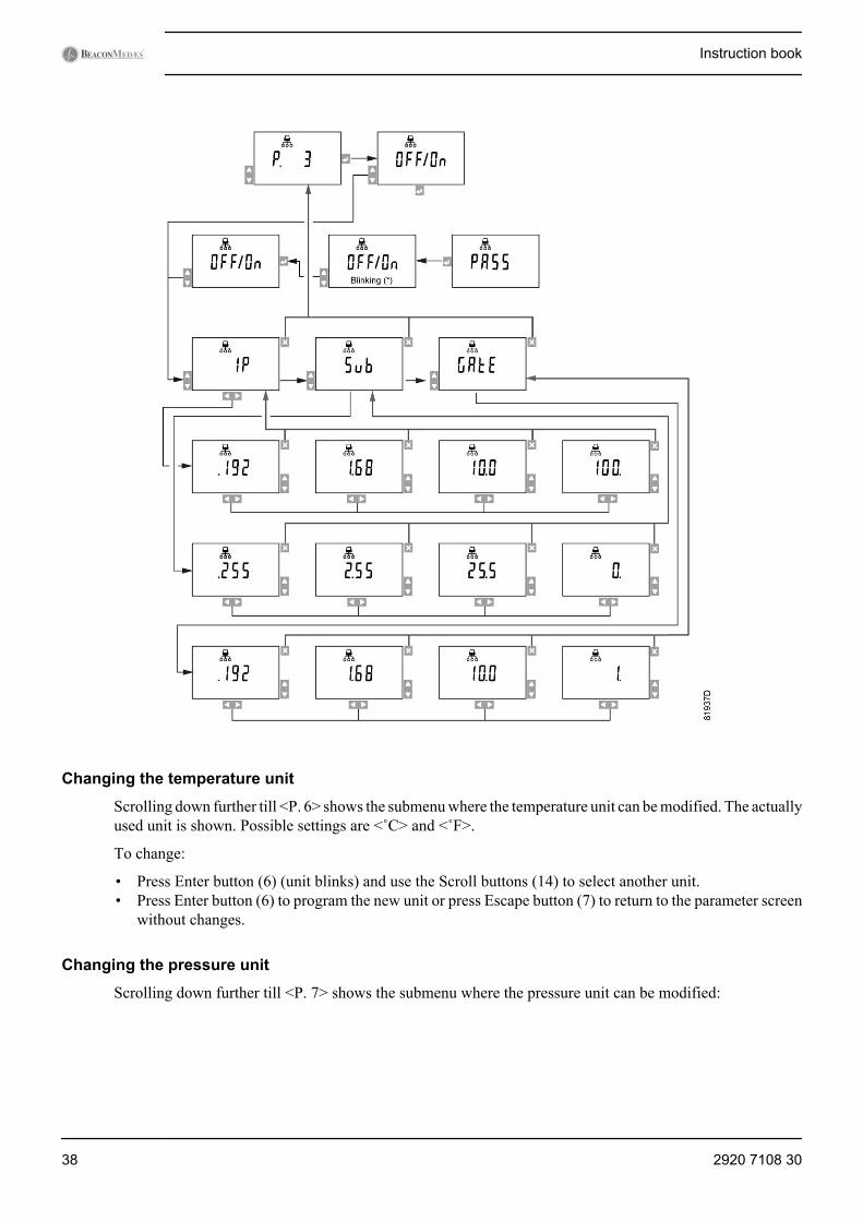
Changing the temperature unit
Scrolling down further till <P. 6> shows the submenu where the temperature unit can be modified. The actuallyused unit is shown. Possible settings are <˚C> and <˚F>.
To change:
• Press Enter button (6) (unit blinks) and use the Scroll buttons (14) to select another unit.• Press Enter button (6) to program the new unit or press Escape button (7) to return to the parameter screen
without changes.
Changing the pressure unit
Scrolling down further till <P. 7> shows the submenu where the pressure unit can be modified:
Instruction book
38 2920 7108 30
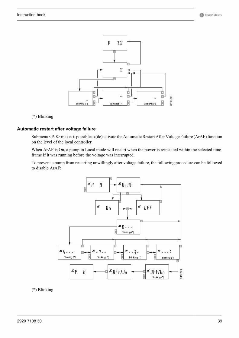
(*) Blinking
Automatic restart after voltage failure
Submenu <P. 8> makes it possible to (de)activate the Automatic Restart After Voltage Failure (ArAF) functionon the level of the local controller.
When ArAF is On, a pump in Local mode will restart when the power is reinstated within the selected timeframe if it was running before the voltage was interrupted.
To prevent a pump from restarting unwillingly after voltage failure, the following procedure can be followedto disable ArAF:
(*) Blinking
Instruction book
2920 7108 30 39
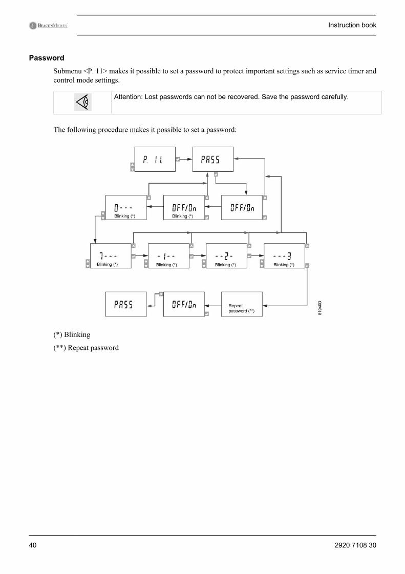
Password
Submenu <P. 11> makes it possible to set a password to protect important settings such as service timer andcontrol mode settings.
Attention: Lost passwords can not be recovered. Save the password carefully.
The following procedure makes it possible to set a password:
(*) Blinking
(**) Repeat password
Instruction book
40 2920 7108 30
5.3 Central controller (ES-VAC)5.3.1 Interface, icons and menu structure
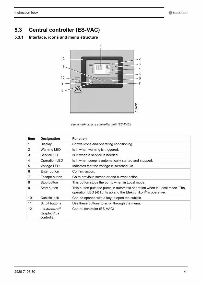
Panel with central controller unit (ES-VAC)
Item Designation Function1 Display Shows icons and operating conditioning.2 Warning LED Is lit when warning is triggered.3 Service LED Is lit when a service is needed.4 Operation LED Is lit when pump is automatically started and stopped.5 Voltage LED Indicates that the voltage is switched On.6 Enter button Confirm action.7 Escape button Go to previous screen or end current action.8 Stop button This button stops the pump when in Local mode.9 Start button This button puts the pump in automatic operation when in Local mode. The
operation LED (4) lights up and the Elektronikon® is operative.10 Cubicle lock Can be opened with a key to open the cubicle.11 Scroll buttons Use these buttons to scroll through the menu.12 Elektronikon®
GraphicPluscontroller
Central controller (ES-VAC)
Instruction book
2920 7108 30 41
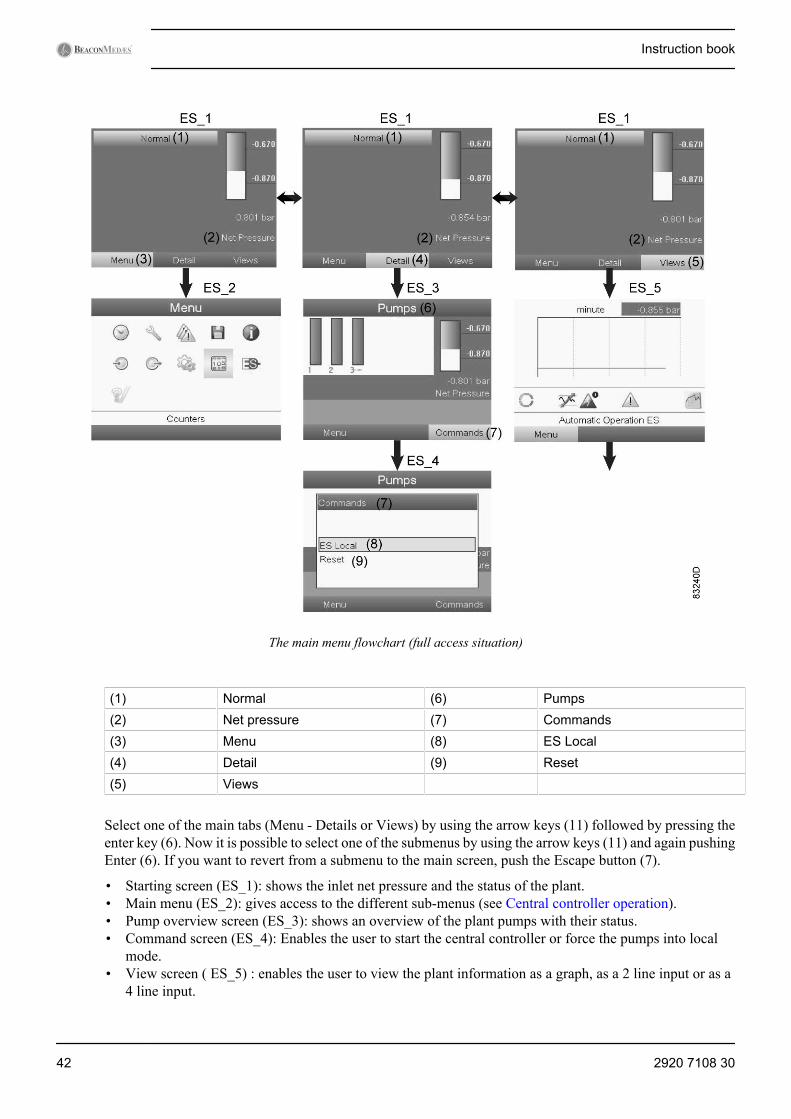
The main menu flowchart (full access situation)
(1) Normal (6) Pumps(2) Net pressure (7) Commands(3) Menu (8) ES Local(4) Detail (9) Reset(5) Views
Select one of the main tabs (Menu - Details or Views) by using the arrow keys (11) followed by pressing theenter key (6). Now it is possible to select one of the submenus by using the arrow keys (11) and again pushingEnter (6). If you want to revert from a submenu to the main screen, push the Escape button (7).
• Starting screen (ES_1): shows the inlet net pressure and the status of the plant.• Main menu (ES_2): gives access to the different sub-menus (see Central controller operation).• Pump overview screen (ES_3): shows an overview of the plant pumps with their status.• Command screen (ES_4): Enables the user to start the central controller or force the pumps into local
mode.• View screen ( ES_5) : enables the user to view the plant information as a graph, as a 2 line input or as a
4 line input.
Instruction book
42 2920 7108 30
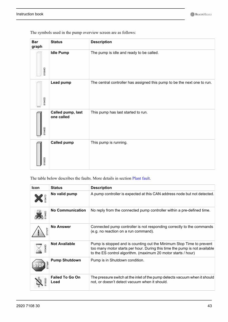
The symbols used in the pump overview screen are as follows:
Bargraph
Status Description
Idle Pump The pump is idle and ready to be called.
Lead pump The central controller has assigned this pump to be the next one to run.
Called pump, lastone called
This pump has last started to run.
Called pump This pump is running.
The table below describes the faults. More details in section Plant fault.
Icon Status DescriptionNo valid pump A pump controller is expected at this CAN address node but not detected.
No Communication No reply from the connected pump controller within a pre-defined time.
No Answer Connected pump controller is not responding correctly to the commands(e.g. no reaction on a run command).
Not Available Pump is stopped and is counting out the Minimum Stop Time to preventtoo many motor starts per hour. During this time the pump is not availableto the ES control algorithm. (maximum 20 motor starts / hour)
Pump Shutdown Pump is in Shutdown condition.
Failed To Go OnLoad
The pressure switch at the inlet of the pump detects vacuum when it shouldnot, or doesn’t detect vacuum when it should.
Instruction book
2920 7108 30 43
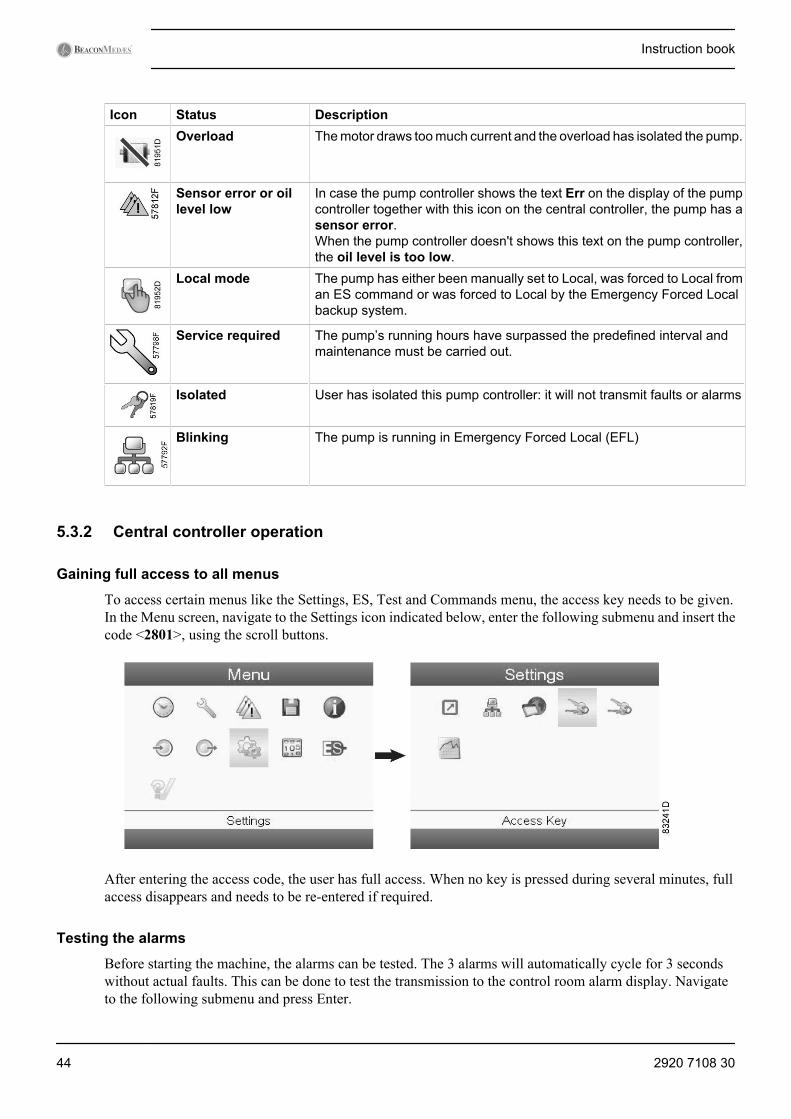
Icon Status DescriptionOverload The motor draws too much current and the overload has isolated the pump.
Sensor error or oillevel low
In case the pump controller shows the text Err on the display of the pumpcontroller together with this icon on the central controller, the pump has asensor error.When the pump controller doesn't shows this text on the pump controller,the oil level is too low.
Local mode The pump has either been manually set to Local, was forced to Local froman ES command or was forced to Local by the Emergency Forced Localbackup system.
Service required The pump’s running hours have surpassed the predefined interval andmaintenance must be carried out.
Isolated User has isolated this pump controller: it will not transmit faults or alarms
Blinking The pump is running in Emergency Forced Local (EFL)
5.3.2 Central controller operation
Gaining full access to all menus
To access certain menus like the Settings, ES, Test and Commands menu, the access key needs to be given.In the Menu screen, navigate to the Settings icon indicated below, enter the following submenu and insert thecode <2801>, using the scroll buttons.
After entering the access code, the user has full access. When no key is pressed during several minutes, fullaccess disappears and needs to be re-entered if required.
Testing the alarms
Before starting the machine, the alarms can be tested. The 3 alarms will automatically cycle for 3 secondswithout actual faults. This can be done to test the transmission to the control room alarm display. Navigateto the following submenu and press Enter.
Instruction book
44 2920 7108 30
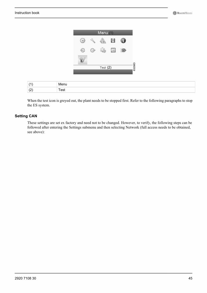
(1) Menu(2) Test
When the test icon is greyed out, the plant needs to be stopped first. Refer to the following paragraphs to stopthe ES system.
Setting CAN
These settings are set ex factory and need not to be changed. However, to verify, the following steps can befollowed after entering the Settings submenu and then selecting Network (full access needs to be obtained,see above):
Instruction book
2920 7108 30 45
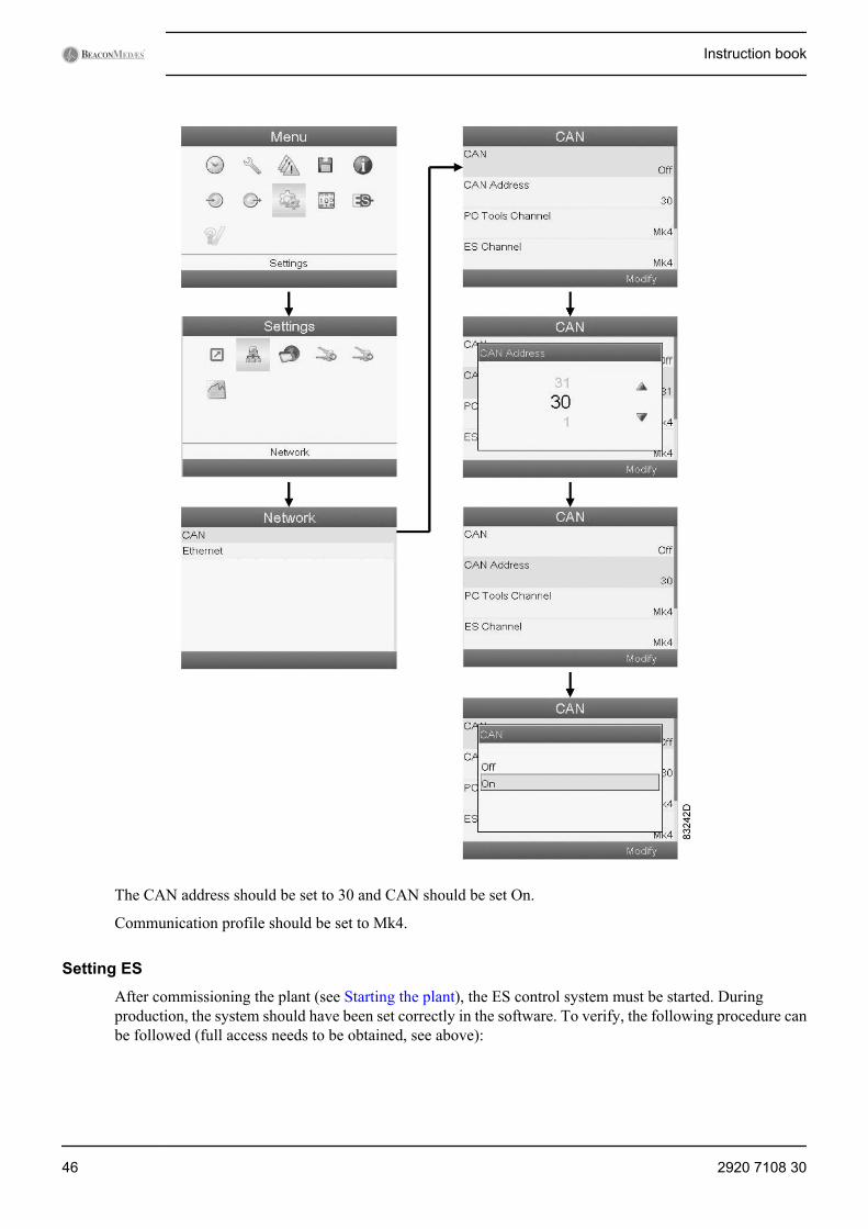
The CAN address should be set to 30 and CAN should be set On.
Communication profile should be set to Mk4.
Setting ES
After commissioning the plant (see Starting the plant), the ES control system must be started. Duringproduction, the system should have been set correctly in the software. To verify, the following procedure canbe followed (full access needs to be obtained, see above):
Instruction book
46 2920 7108 30
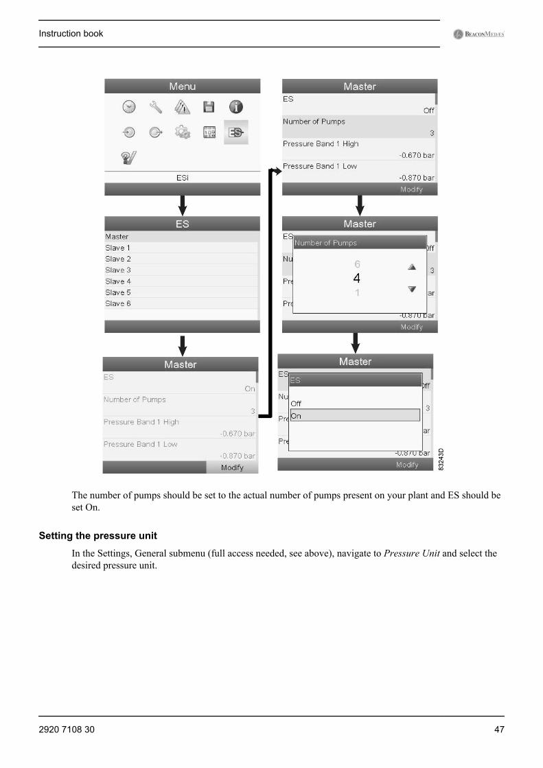
The number of pumps should be set to the actual number of pumps present on your plant and ES should beset On.
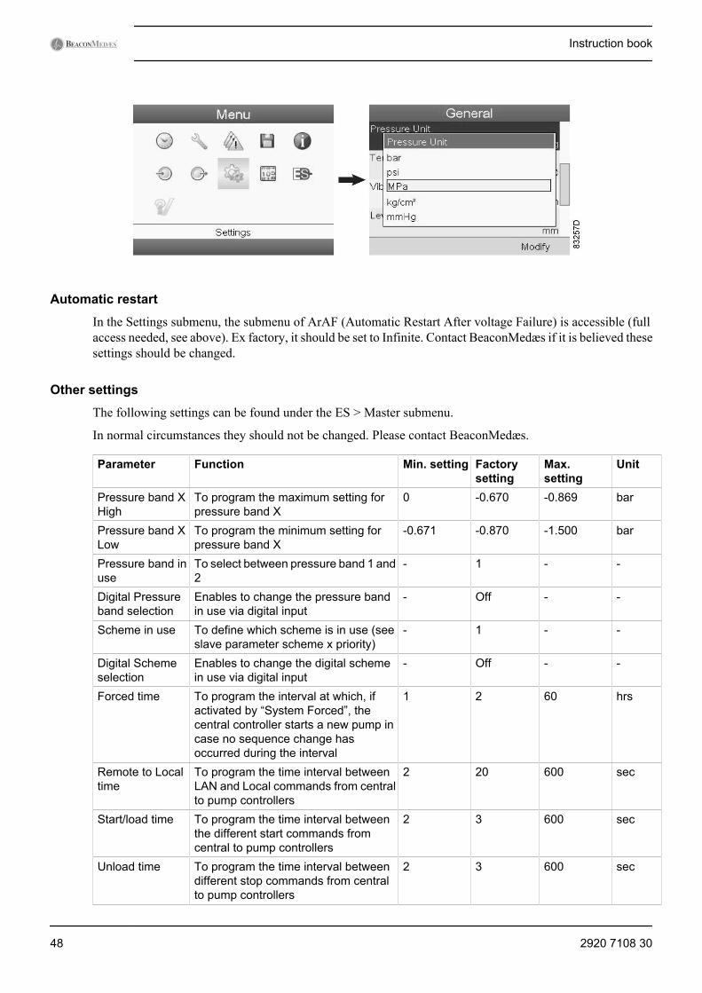
Setting the pressure unit
In the Settings, General submenu (full access needed, see above), navigate to Pressure Unit and select thedesired pressure unit.
Instruction book
2920 7108 30 47
Automatic restart
In the Settings submenu, the submenu of ArAF (Automatic Restart After voltage Failure) is accessible (fullaccess needed, see above). Ex factory, it should be set to Infinite. Contact BeaconMedæs if it is believed thesesettings should be changed.
Other settings
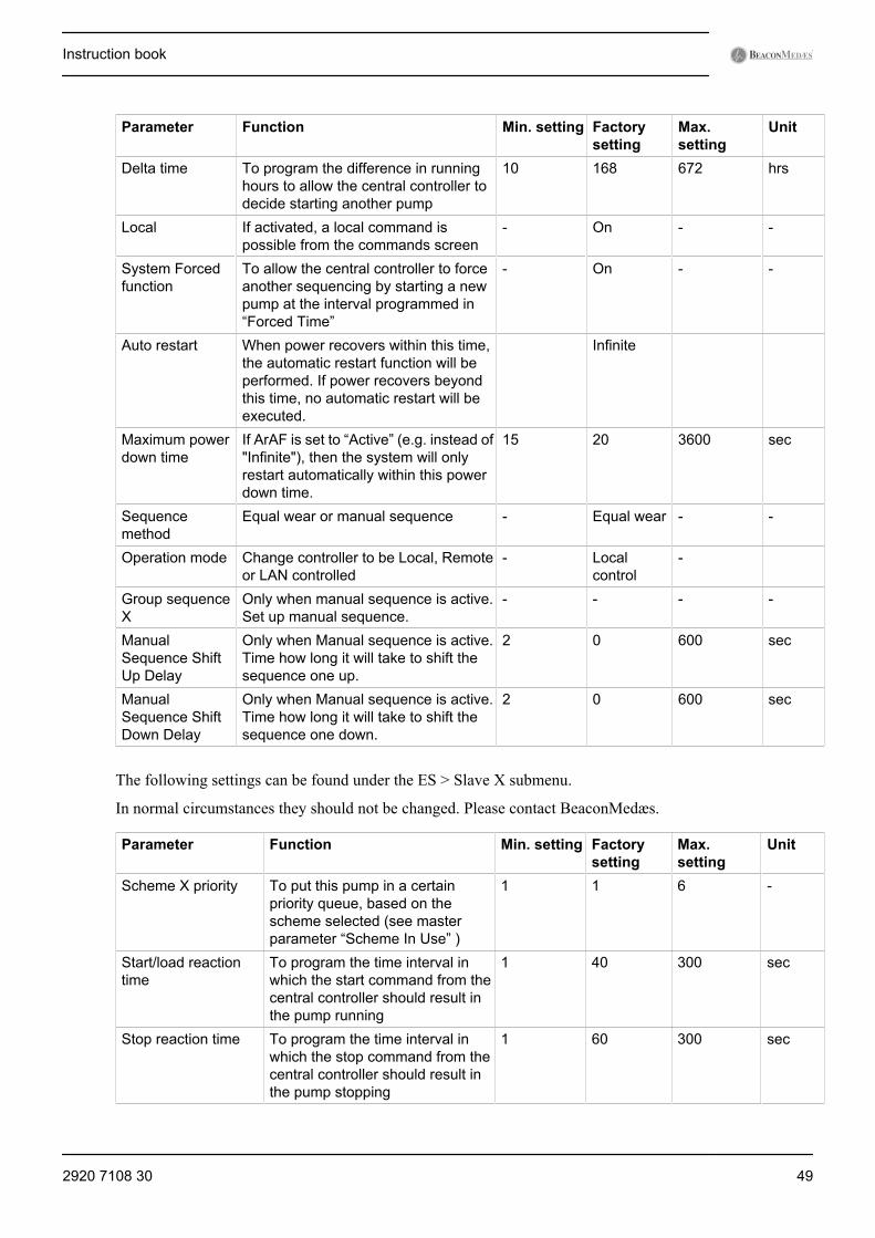
The following settings can be found under the ES > Master submenu.
In normal circumstances they should not be changed. Please contact BeaconMedæs.
Parameter Function Min. setting Factorysetting
Max.setting
Unit
Pressure band XHigh
To program the maximum setting forpressure band X
0 -0.670 -0.869 bar
Pressure band XLow
To program the minimum setting forpressure band X
-0.671 -0.870 -1.500 bar
Pressure band inuse
To select between pressure band 1 and2
- 1 - -
Digital Pressureband selection
Enables to change the pressure bandin use via digital input
- Off - -
Scheme in use To define which scheme is in use (seeslave parameter scheme x priority)
- 1 - -
Digital Schemeselection
Enables to change the digital schemein use via digital input
- Off - -
Forced time To program the interval at which, ifactivated by “System Forced”, thecentral controller starts a new pump incase no sequence change hasoccurred during the interval
1 2 60 hrs
Remote to Localtime
To program the time interval betweenLAN and Local commands from centralto pump controllers
2 20 600 sec
Start/load time To program the time interval betweenthe different start commands fromcentral to pump controllers
2 3 600 sec
Unload time To program the time interval betweendifferent stop commands from centralto pump controllers
2 3 600 sec
Instruction book
48 2920 7108 30
Parameter Function Min. setting Factorysetting
Max.setting
Unit
Delta time To program the difference in runninghours to allow the central controller todecide starting another pump
10 168 672 hrs
Local If activated, a local command ispossible from the commands screen
- On - -
System Forcedfunction
To allow the central controller to forceanother sequencing by starting a newpump at the interval programmed in“Forced Time”
- On - -
Auto restart When power recovers within this time,the automatic restart function will beperformed. If power recovers beyondthis time, no automatic restart will beexecuted.
Infinite
Maximum powerdown time
If ArAF is set to “Active” (e.g. instead of"Infinite"), then the system will onlyrestart automatically within this powerdown time.
15 20 3600 sec
Sequencemethod
Equal wear or manual sequence - Equal wear - -
Operation mode Change controller to be Local, Remoteor LAN controlled
- Localcontrol
-
Group sequenceX
Only when manual sequence is active.Set up manual sequence.
- - - -
ManualSequence ShiftUp Delay
Only when Manual sequence is active.Time how long it will take to shift thesequence one up.
2 0 600 sec
ManualSequence ShiftDown Delay
Only when Manual sequence is active.Time how long it will take to shift thesequence one down.
2 0 600 sec
The following settings can be found under the ES > Slave X submenu.
In normal circumstances they should not be changed. Please contact BeaconMedæs.
Parameter Function Min. setting Factorysetting
Max.setting
Unit
Scheme X priority To put this pump in a certainpriority queue, based on thescheme selected (see masterparameter “Scheme In Use” )
1 1 6 -
Start/load reactiontime
To program the time interval inwhich the start command from thecentral controller should result inthe pump running
1 40 300 sec
Stop reaction time To program the time interval inwhich the stop command from thecentral controller should result inthe pump stopping
1 60 300 sec
Instruction book
2920 7108 30 49
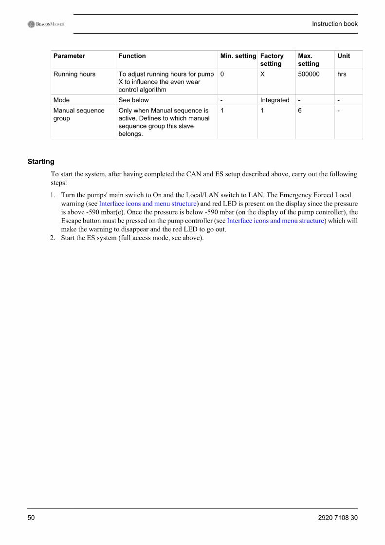
Parameter Function Min. setting Factorysetting
Max.setting
Unit
Running hours To adjust running hours for pumpX to influence the even wearcontrol algorithm
0 X 500000 hrs
Mode See below - Integrated - -Manual sequencegroup
Only when Manual sequence isactive. Defines to which manualsequence group this slavebelongs.
1 1 6 -
Starting
To start the system, after having completed the CAN and ES setup described above, carry out the followingsteps:
1. Turn the pumps' main switch to On and the Local/LAN switch to LAN. The Emergency Forced Localwarning (see Interface icons and menu structure) and red LED is present on the display since the pressureis above -590 mbar(e). Once the pressure is below -590 mbar (on the display of the pump controller), theEscape button must be pressed on the pump controller (see Interface icons and menu structure) which willmake the warning to disappear and the red LED to go out.
2. Start the ES system (full access mode, see above).
Instruction book
50 2920 7108 30

Text on image
(1) Detail (3) Commands(2) Pumps (4) ES Start
Navigate to the Start button and press Enter. A spinning circle on the display should appear to indicate thatthe ES system is operating.
Stopping and resetting
To stop a certain pump, see section Pump controller operation. To force all pumps local, go to the commandsscreen and select the Local button.
Instruction book
2920 7108 30 51
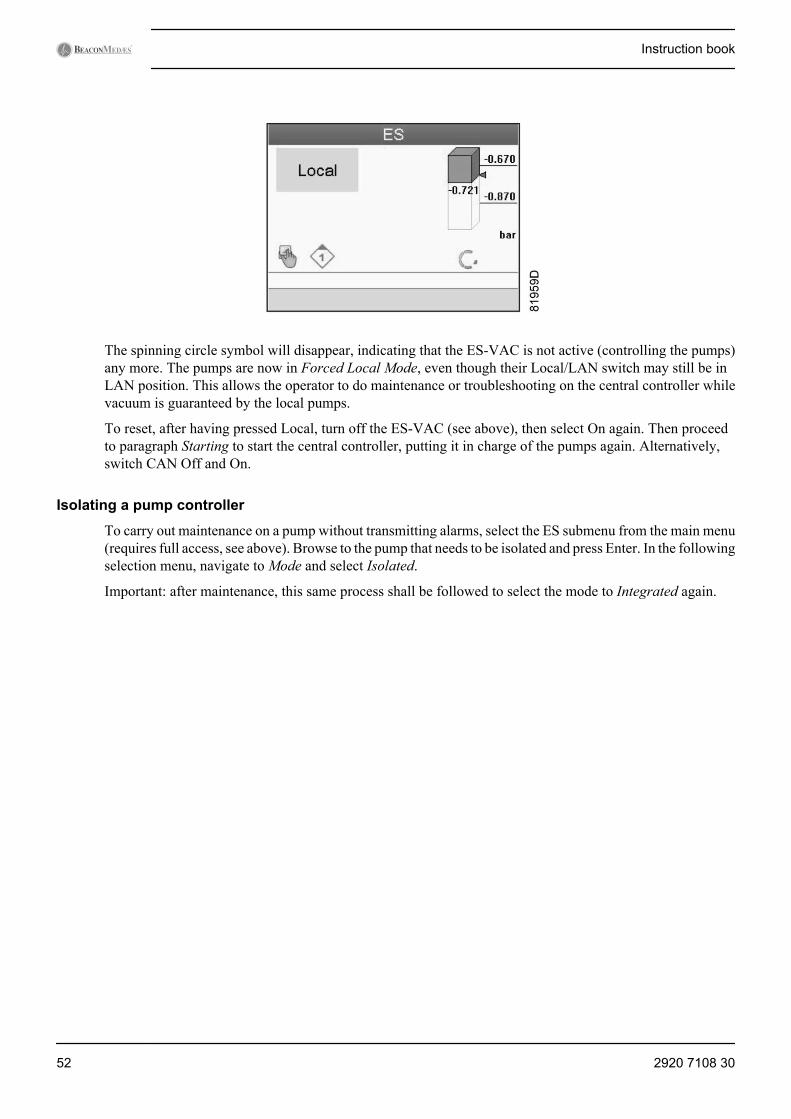
The spinning circle symbol will disappear, indicating that the ES-VAC is not active (controlling the pumps)any more. The pumps are now in Forced Local Mode, even though their Local/LAN switch may still be inLAN position. This allows the operator to do maintenance or troubleshooting on the central controller whilevacuum is guaranteed by the local pumps.
To reset, after having pressed Local, turn off the ES-VAC (see above), then select On again. Then proceedto paragraph Starting to start the central controller, putting it in charge of the pumps again. Alternatively,switch CAN Off and On.
Isolating a pump controller
To carry out maintenance on a pump without transmitting alarms, select the ES submenu from the main menu(requires full access, see above). Browse to the pump that needs to be isolated and press Enter. In the followingselection menu, navigate to Mode and select Isolated.
Important: after maintenance, this same process shall be followed to select the mode to Integrated again.
Instruction book
52 2920 7108 30
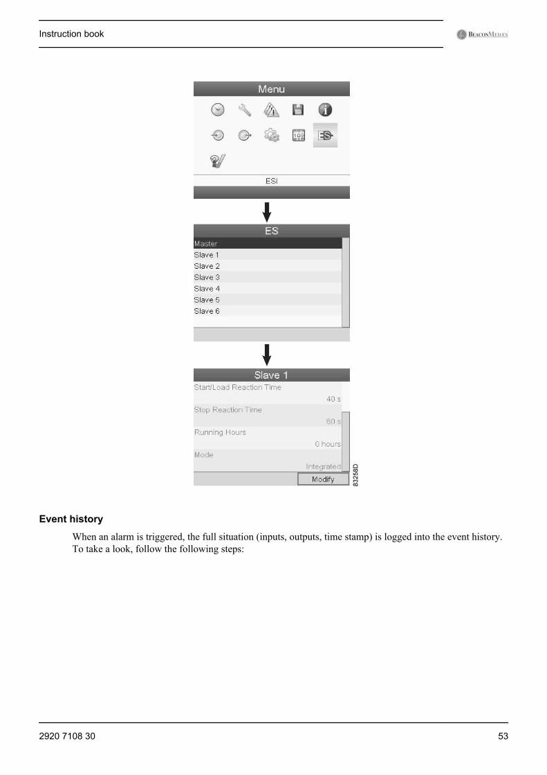
Event history
When an alarm is triggered, the full situation (inputs, outputs, time stamp) is logged into the event history.To take a look, follow the following steps:
Instruction book
2920 7108 30 53
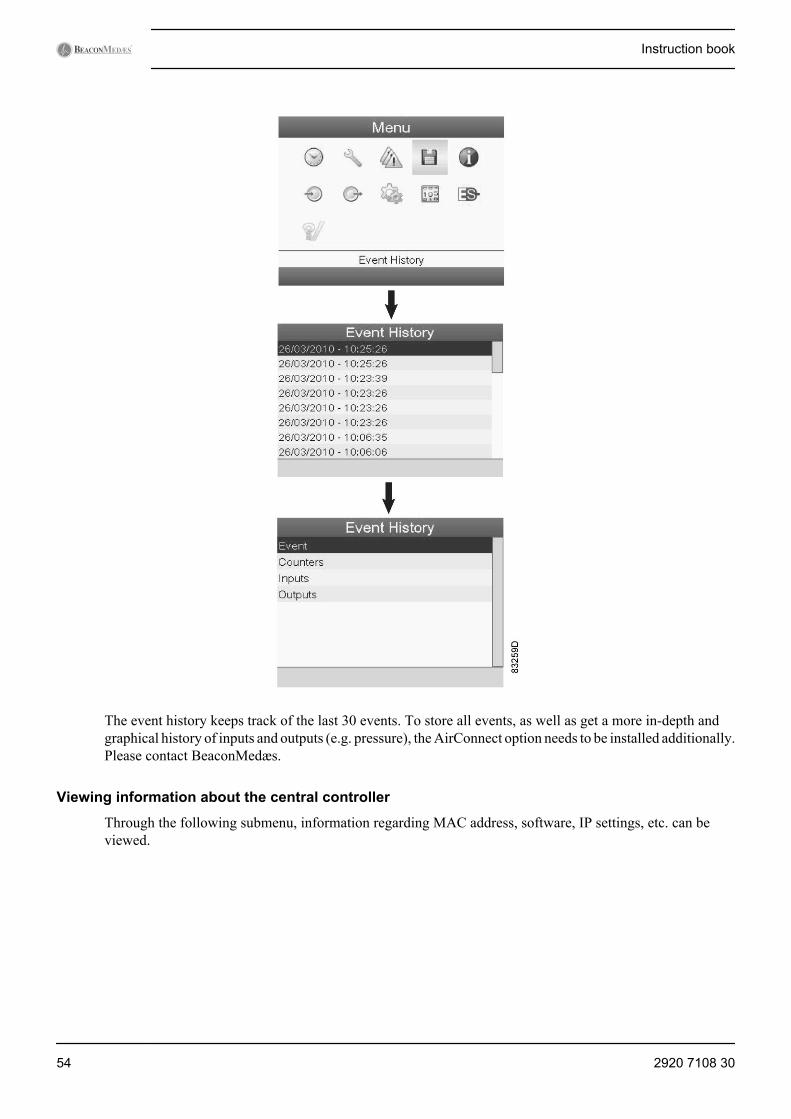
The event history keeps track of the last 30 events. To store all events, as well as get a more in-depth andgraphical history of inputs and outputs (e.g. pressure), the AirConnect option needs to be installed additionally.Please contact BeaconMedæs.
Viewing information about the central controller
Through the following submenu, information regarding MAC address, software, IP settings, etc. can beviewed.
Instruction book
54 2920 7108 30
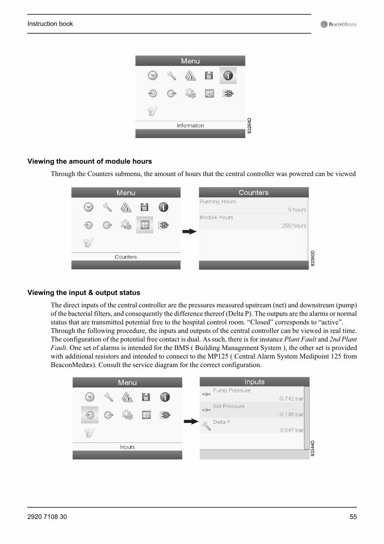
Viewing the amount of module hours
Through the Counters submenu, the amount of hours that the central controller was powered can be viewed
Viewing the input & output status
The direct inputs of the central controller are the pressures measured upstream (net) and downstream (pump)of the bacterial filters, and consequently the difference thereof (Delta P). The outputs are the alarms or normalstatus that are transmitted potential free to the hospital control room. “Closed” corresponds to “active”.Through the following procedure, the inputs and outputs of the central controller can be viewed in real time.The configuration of the potential free contact is dual. As such, there is for instance Plant Fault and 2nd PlantFault. One set of alarms is intended for the BMS ( Building Management System ), the other set is providedwith additional resistors and intended to connect to the MP125 ( Central Alarm System Medipoint 125 fromBeaconMedæs). Consult the service diagram for the correct configuration.
Instruction book
2920 7108 30 55
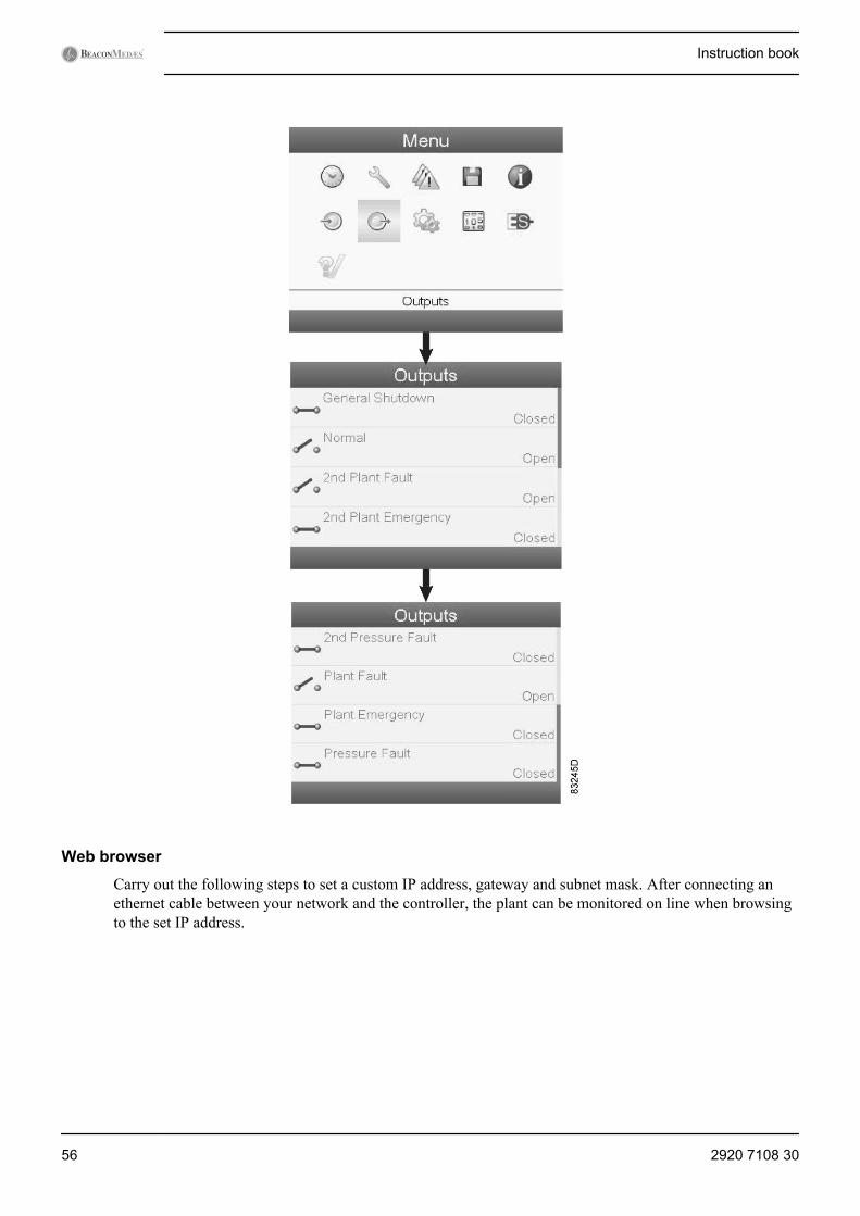
Web browser
Carry out the following steps to set a custom IP address, gateway and subnet mask. After connecting anethernet cable between your network and the controller, the plant can be monitored on line when browsingto the set IP address.
Instruction book
56 2920 7108 30
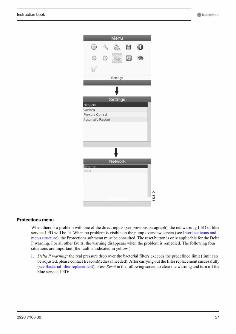
Protections menu
When there is a problem with one of the direct inputs (see previous paragraph), the red warning LED or blueservice LED will be lit. When no problem is visible on the pump overview screen (see Interface icons andmenu structure), the Protections submenu must be consulted. The reset button is only applicable for the DeltaP warning. For all other faults, the warning disappears when the problem is remedied. The following foursituations are important (the fault is indicated in yellow ):
1. Delta P warning: the real pressure drop over the bacterial filters exceeds the predefined limit (limit canbe adjusted, please contact BeaconMedæs if needed). After carrying out the filter replacement successfully(see Bacterial filter replacement), press Reset in the following screen to clear the warning and turn off theblue service LED:
Instruction book
2920 7108 30 57
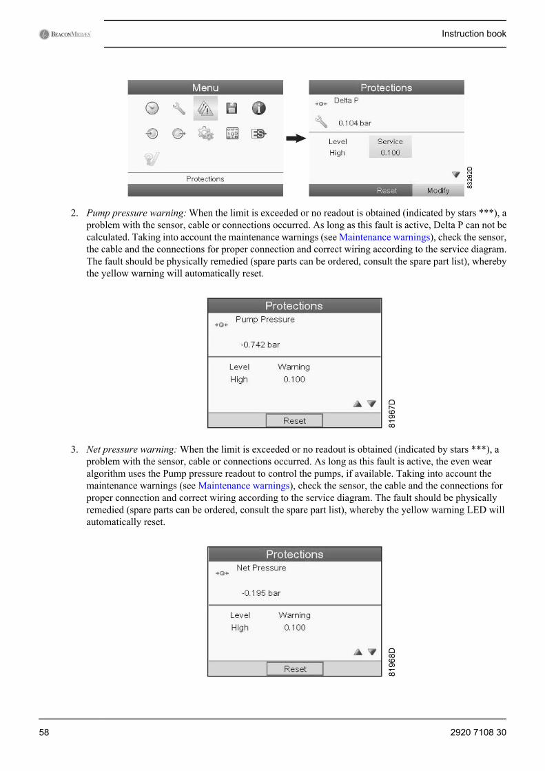
2. Pump pressure warning: When the limit is exceeded or no readout is obtained (indicated by stars ***), aproblem with the sensor, cable or connections occurred. As long as this fault is active, Delta P can not becalculated. Taking into account the maintenance warnings (see Maintenance warnings), check the sensor,the cable and the connections for proper connection and correct wiring according to the service diagram.The fault should be physically remedied (spare parts can be ordered, consult the spare part list), wherebythe yellow warning will automatically reset.
3. Net pressure warning: When the limit is exceeded or no readout is obtained (indicated by stars ***), aproblem with the sensor, cable or connections occurred. As long as this fault is active, the even wearalgorithm uses the Pump pressure readout to control the pumps, if available. Taking into account themaintenance warnings (see Maintenance warnings), check the sensor, the cable and the connections forproper connection and correct wiring according to the service diagram. The fault should be physicallyremedied (spare parts can be ordered, consult the spare part list), whereby the yellow warning LED willautomatically reset.
Instruction book
58 2920 7108 30
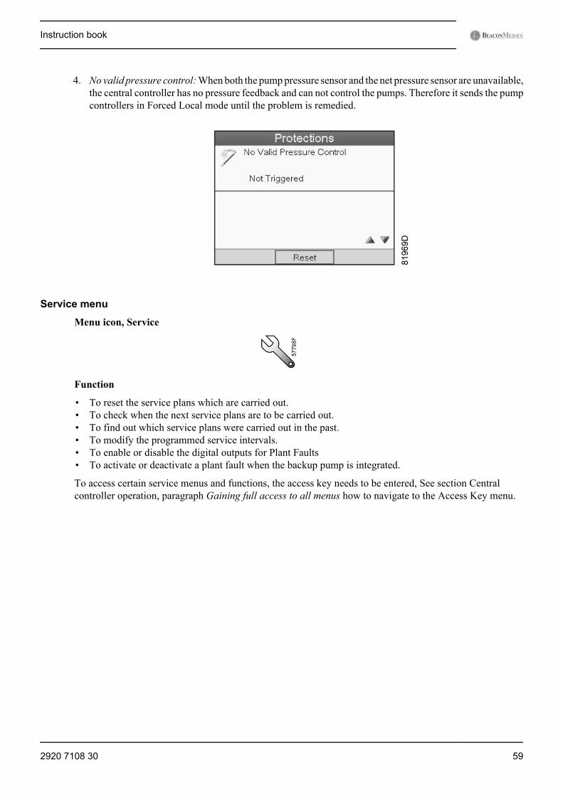
4. No valid pressure control: When both the pump pressure sensor and the net pressure sensor are unavailable,the central controller has no pressure feedback and can not control the pumps. Therefore it sends the pumpcontrollers in Forced Local mode until the problem is remedied.
Service menu
Menu icon, Service
Function
• To reset the service plans which are carried out.• To check when the next service plans are to be carried out.• To find out which service plans were carried out in the past.• To modify the programmed service intervals.• To enable or disable the digital outputs for Plant Faults• To activate or deactivate a plant fault when the backup pump is integrated.
To access certain service menus and functions, the access key needs to be entered, See section Centralcontroller operation, paragraph Gaining full access to all menus how to navigate to the Access Key menu.
Instruction book
2920 7108 30 59
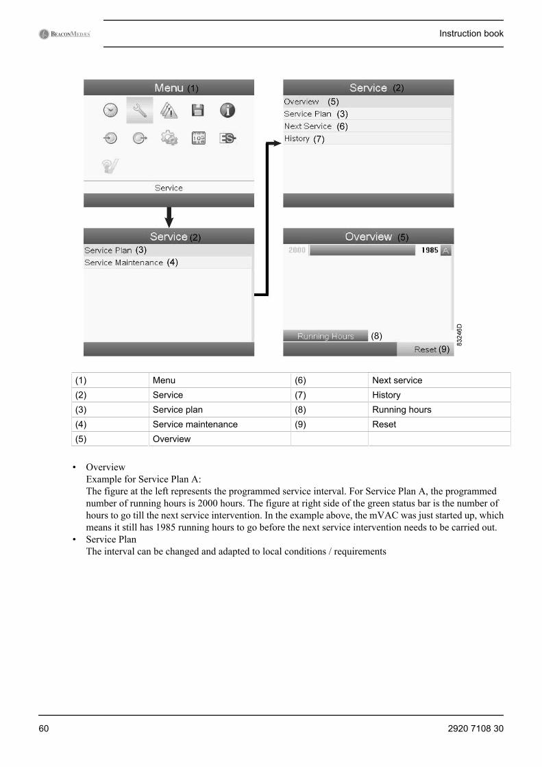
(1) Menu (6) Next service(2) Service (7) History(3) Service plan (8) Running hours(4) Service maintenance (9) Reset(5) Overview
• OverviewExample for Service Plan A:The figure at the left represents the programmed service interval. For Service Plan A, the programmednumber of running hours is 2000 hours. The figure at right side of the green status bar is the number ofhours to go till the next service intervention. In the example above, the mVAC was just started up, whichmeans it still has 1985 running hours to go before the next service intervention needs to be carried out.
• Service PlanThe interval can be changed and adapted to local conditions / requirements
Instruction book
60 2920 7108 30
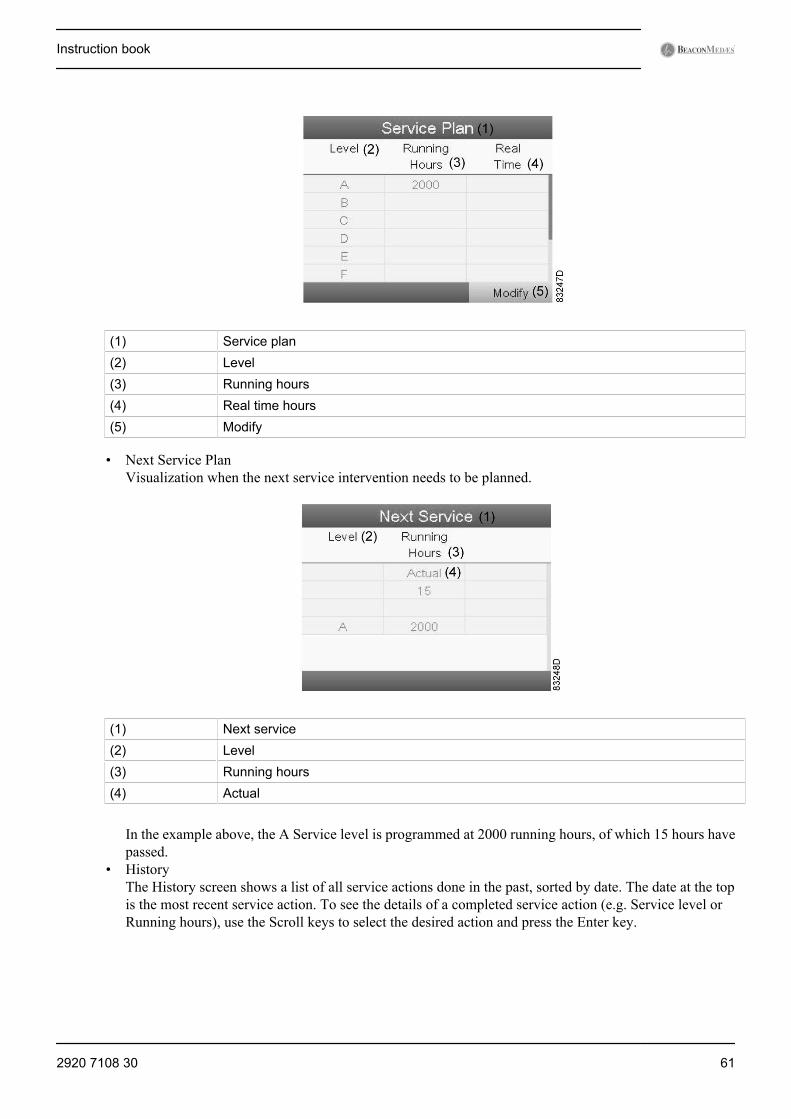
(1) Service plan(2) Level(3) Running hours(4) Real time hours(5) Modify
• Next Service PlanVisualization when the next service intervention needs to be planned.
(1) Next service(2) Level(3) Running hours(4) Actual
In the example above, the A Service level is programmed at 2000 running hours, of which 15 hours havepassed.
• HistoryThe History screen shows a list of all service actions done in the past, sorted by date. The date at the topis the most recent service action. To see the details of a completed service action (e.g. Service level orRunning hours), use the Scroll keys to select the desired action and press the Enter key.
Instruction book
2920 7108 30 61
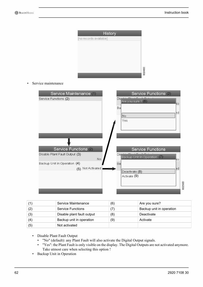
• Service maintenance
(1) Service Maintenance (6) Are you sure?(2) Service Functions (7) Backup unit in operation(3) Disable plant fault output (8) Deactivate(4) Backup unit in operation (9) Activate(5) Not activated
• Disable Plant Fault Output• "No" (default): any Plant Fault will also activate the Digital Output signals.• "Yes": the Plant Fault is only visible on the display. The Digital Outputs are not activated anymore.
Take utmost care when selecting this option !• Backup Unit in Operation
Instruction book
62 2920 7108 30
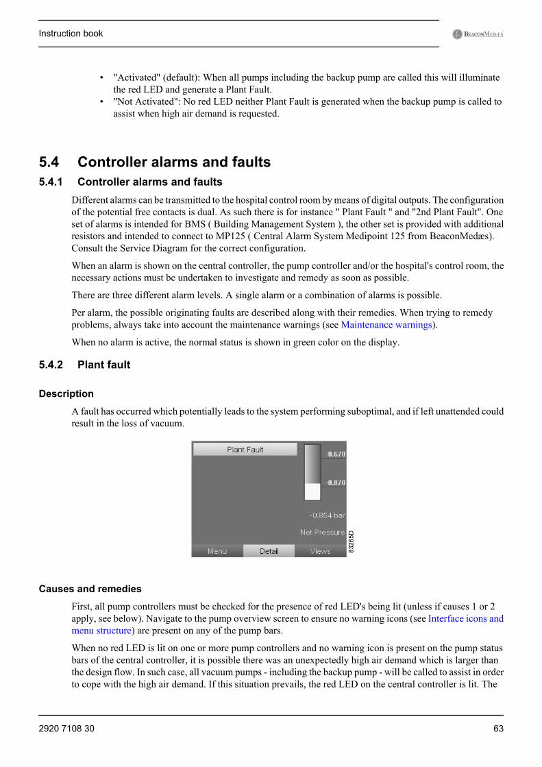
• "Activated" (default): When all pumps including the backup pump are called this will illuminatethe red LED and generate a Plant Fault.
• "Not Activated": No red LED neither Plant Fault is generated when the backup pump is called toassist when high air demand is requested.
5.4 Controller alarms and faults5.4.1 Controller alarms and faults
Different alarms can be transmitted to the hospital control room by means of digital outputs. The configurationof the potential free contacts is dual. As such there is for instance " Plant Fault " and "2nd Plant Fault". Oneset of alarms is intended for BMS ( Building Management System ), the other set is provided with additionalresistors and intended to connect to MP125 ( Central Alarm System Medipoint 125 from BeaconMedæs).Consult the Service Diagram for the correct configuration.
When an alarm is shown on the central controller, the pump controller and/or the hospital's control room, thenecessary actions must be undertaken to investigate and remedy as soon as possible.
There are three different alarm levels. A single alarm or a combination of alarms is possible.
Per alarm, the possible originating faults are described along with their remedies. When trying to remedyproblems, always take into account the maintenance warnings (see Maintenance warnings).
When no alarm is active, the normal status is shown in green color on the display.
5.4.2 Plant fault
Description
A fault has occurred which potentially leads to the system performing suboptimal, and if left unattended couldresult in the loss of vacuum.
Causes and remedies
First, all pump controllers must be checked for the presence of red LED's being lit (unless if causes 1 or 2apply, see below). Navigate to the pump overview screen to ensure no warning icons (see Interface icons andmenu structure) are present on any of the pump bars.
When no red LED is lit on one or more pump controllers and no warning icon is present on the pump statusbars of the central controller, it is possible there was an unexpectedly high air demand which is larger thanthe design flow. In such case, all vacuum pumps - including the backup pump - will be called to assist in orderto cope with the high air demand. If this situation prevails, the red LED on the central controller is lit. The
Instruction book
2920 7108 30 63
red LED will be extinguished as soon as vacuum equals the value under Pressure band 1 High (default is-870 mbar(e)) is reached and the backup pump is stopped.
In case it is not desired that a Plant Fault is generated when the backup pump is called at high air demands,there is the option to deactivate this function in the submenu Service Maintenance. Put Backup unit inOperation to "Not Activated" and no red LED neither Plant Fault will be shown on the central controller.
It is also possible to suppress the relay output for Plant fault on the IO2 module. This can be done by puttingDisable Plant Fault Output to "Yes" in the submenu Service Maintenance. In this case the red LED and PlantFault is shown on the central controller but there will be no Digital output to BMS (Building ManagementSystem) nor MP125. Take care with this option because selecting "Yes" for "Disable Plant Fault Output" willbe valid for any Plant Fault which might prevail.
If a red LED is lit on a pump controller, the corresponding problem should occur both on the pump overviewscreen and on the main display of the pump controller, where it should appear as a blinking icon (see Interfaceicons and menu structure):
1. a. Slave switched to Local:Check if the Emergency Forced Local symbol and red LED are present on the pump controller (seeInterface icons and menu structure). If so, a fault may have occurred whereby the system itself did notsustain the vacuum at the required minimum. Emergency Forced Local will start every pump (that isnot in Local Stopped status) automatically based on only one input: the pump's local pressure transducersensing a pressure less deep than -590 mbar(e). Please contact your customer contact. Once the causeis fixed, and pressure is deeper than -590 mbar(e), the user can only reset the warning by pressing theEscape button, otherwise the pump will run infinitely in this safety mode. If the Local/LAN switch isset to Local and there is no reason for it, please switch it back to LAN control.This is not a fault as such but constitutes a situation which is sub-optimal (the central controller can’tcontrol the pump to ensure even wear or respond to the demand based on pressure difference per unitof time).
b. No answer:Interrelated with the previous fault, sometimes the Emergency Forced Local fault can cause the centralcontroller (ES-VAC) not to find the pump controller. After resetting the Emergency Forced Local asdescribed above, also the following procedure must be carried out (full access needs to be obtained,see Central controller operation): go to submenu Commands and press Reset.
Instruction book
64 2920 7108 30

2. No Communication: Either the controller has no electrical supply or there is a CAN network error.Taking into account the precautions of chapter Maintenance warnings, check that the controller isadequately electrically supplied and fix if necessary. If supply is adequate, check the software CANsettings in both the pump controllers and the central controller (see previous chapters).Verify that the CAN cables at the backside of the cubicles are correctly connected to the other cubicles.If so, open the cubicle and verify that the CAN cable is correctly connected between the cubicle back plateand the controller. If that is the case, open the CAN connectors and verify that the wires are correctlyconnected. Contact BeaconMedæs for further investigation.After fixing the problem, the status should automatically reset. If it doesn’t, press “Local” in the commandsscreen of the central controller and select ES "Off” in the ES menu (see Central controller operation).Then select On again and press Start in the commands menu. Alternatively, in the CAN menu, press CANOff and On.
3. Sensor error: A problem with the pump’s local pressure sensor, cable or connections has occurred or thepressure is out of range (e.g. -1,1 bar). Unless if the pump is in Local Off mode, this error will always startthe pump (Emergency Forced Local mode).Taking into account the precautions of chapter Maintenance warnings, check the sensor, the cable and theconnections for proper connection and correct wiring according to the service diagram. The fault shouldbe physically remedied (spare parts can be ordered, consult the spare parts list), whereby the alarm willautomatically reset. If however the pressure is believed to be out of range (pump runs in Emergency ForcedLocal mode and plant inlet is closed or no vacuum demand), this error will reset automatically once thepressure is in range again..
4. Failed To Go On Load (FTGOL): Two situations can be discerned:a. When the fault appears when the pump is running, two causes can lead to this fault:
• The switch, cable or connections lead to a short circuit. Taking into account the precautions ofchapter Maintenance warnings, check the sensor, the cable and the connections for properconnection and correct wiring according to the service diagram. The fault should be physicallyremedied (spare parts can be ordered, consult the spare parts list), whereby the alarm willautomatically reset.
Instruction book
2920 7108 30 65
• The pump does not succeed in producing a vacuum deeper than -380 mbar(e) (-285 mmHg) within10 seconds after the pump has been called (asked to run by the controller). This means that thepump is most likely defect. Check that the pump is rotating when called. If not, verify the electricalconnections to the pump. If the pump does rotate, flow demand may exceed the plant flow capacity,there may be a leak or a blockage.
b. When the fault appears when the pump isn’t running, following causes are possible:• The switch, cable or connections are broken or loose. Check the sensor, the cable and the
connections for proper connection and correct wiring according to the service diagram. The faultshould be physically remedied (spare parts can be ordered, consult the spare parts list), wherebythe alarm will automatically reset.
• The non-return valve, installed upstream of the FTGOL (Failed To Go On Load) switch and pumpinlet, is locked in open position. This could lead to oil being sucked out from the pump into thepiping and must be attended to as soon as possible. Order a non-return valve service kit (consultthe spare parts list) and proceed to replacing the non-return valve according to chapter Non-returnvalve and inlet screen replacement.
Pump is called Pump is not called<<0>> signalreceived fromFTGOL switch
OK PLANT FAULT ALARM - switch, cable orconnections disconnected - non-returnvalve locked open
<<1>> signalreceived fromFTGOL switch
PLANT FAULT ALARM - switch, cable orconnections short-circuited - pump defect
OK
5. Motor tripped: (In case an oil level switch is installed: see cause 6 first.) The motor draws more current(for several seconds) than the value set in the overload protection. This fault will always stop the pumpand hence requires immediate attention.Taking into account the precautions of chapter Maintenance warnings, open the corresponding cubicleand verify if the overload setting is according to the recommendation of chapter Fuse values. If so, verifythat the supply matches the required voltage +/-10%.A voltage dip or current surge may have occurred. If the supply is adequate, verify that all connectionsbetween cubicle and motor are in order and attached correctly (see service diagram). If so, verify that thepump is maintained as required by chapter Checks and intervals in terms of e.g. oil and filter replacementsand inspect the pump for any defaults or blockages.If no cause can be established, please contact BeaconMedæs.After fixing the problem, press the Reset button on the overload protection inside the cubicle (see picture),close the cubicle and switch On the isolating switch. Press the Escape button (see Interface icons and menustructure to clear the display. Verify that the pump runs without problems for 10 minutes at least (e.g. bytesting with JOG function, see Pump controller operation).
Instruction book
66 2920 7108 30
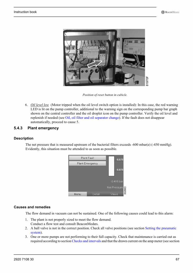
Position of reset button in cubicle.
6. Oil level low (Motor tripped when the oil level switch option is installed): In this case, the red warningLED is lit on the pump controller, additional to the warning sign on the corresponding pump bar graphshown on the central controller and the oil droplet icon on the pump controller. Verify the oil level andreplenish if needed (see Oil, oil filter and oil separator change). If the fault does not disappearautomatically, proceed to cause 5.
5.4.3 Plant emergency
Description
The net pressure that is measured upstream of the bacterial filters exceeds -600 mbar(e) (-450 mmHg).Evidently, this situation must be attended to as soon as possible.
Causes and remedies
The flow demand in vacuum can not be sustained. One of the following causes could lead to this alarm:
1. The plant is not properly sized to meet the flow demand.Conduct a flow test and consult BeaconMedæs.
2. A ball valve is not in the correct position. Check all valve positions (see section Setting the pneumaticsystem).
3. One or more pumps are not performing to their full capacity. Check that maintenance is carried out asrequired according to section Checks and intervals and that the drawn current on the amp meter (see section
Instruction book
2920 7108 30 67
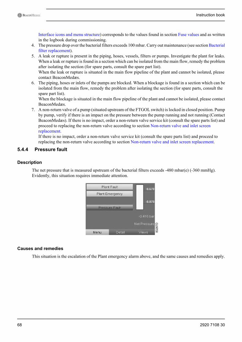
Interface icons and menu structure) corresponds to the values found in section Fuse values and as writtenin the logbook during commissioning.
4. The pressure drop over the bacterial filters exceeds 100 mbar. Carry out maintenance (see section Bacterialfilter replacement).
5. A leak or rupture is present in the piping, hoses, vessels, filters or pumps. Investigate the plant for leaks.When a leak or rupture is found in a section which can be isolated from the main flow, remedy the problemafter isolating the section (for spare parts, consult the spare part list).When the leak or rupture is situated in the main flow pipeline of the plant and cannot be isolated, pleasecontact BeaconMedæs.
6. The piping, hoses or inlets of the pumps are blocked. When a blockage is found in a section which can beisolated from the main flow, remedy the problem after isolating the section (for spare parts, consult thespare part list).When the blockage is situated in the main flow pipeline of the plant and cannot be isolated, please contactBeaconMedæs.
7. A non-return valve of a pump (situated upstream of the FTGOL switch) is locked in closed position. Pumpby pump, verify if there is an impact on the pressure between the pump running and not running (ContactBeaconMedæs). If there is no impact, order a non-return valve service kit (consult the spare parts list) andproceed to replacing the non-return valve according to section Non-return valve and inlet screenreplacement.If there is no impact, order a non-return valve service kit (consult the spare parts list) and proceed toreplacing the non-return valve according to section Non-return valve and inlet screen replacement.
5.4.4 Pressure fault
Description
The net pressure that is measured upstream of the bacterial filters exceeds -480 mbar(e) (-360 mmHg).Evidently, this situation requires immediate attention.
Causes and remedies
This situation is the escalation of the Plant emergency alarm above, and the same causes and remedies apply.
Instruction book
68 2920 7108 30
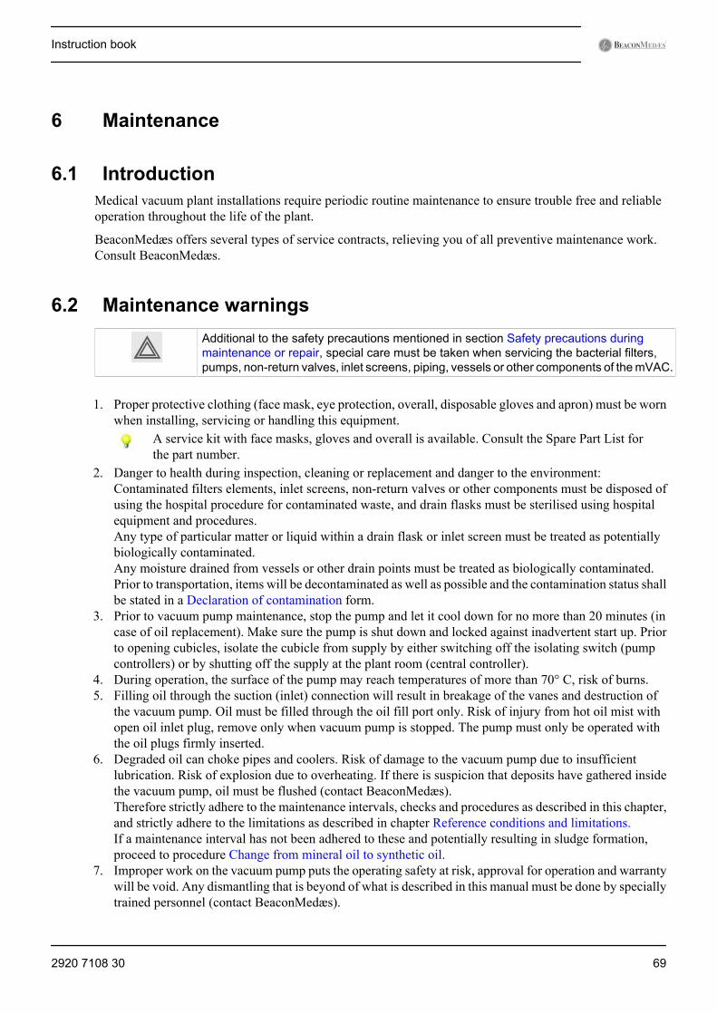
6 Maintenance
6.1 IntroductionMedical vacuum plant installations require periodic routine maintenance to ensure trouble free and reliableoperation throughout the life of the plant.
BeaconMedæs offers several types of service contracts, relieving you of all preventive maintenance work.Consult BeaconMedæs.
6.2 Maintenance warningsAdditional to the safety precautions mentioned in section Safety precautions duringmaintenance or repair, special care must be taken when servicing the bacterial filters,pumps, non-return valves, inlet screens, piping, vessels or other components of the mVAC.
1. Proper protective clothing (face mask, eye protection, overall, disposable gloves and apron) must be wornwhen installing, servicing or handling this equipment.
A service kit with face masks, gloves and overall is available. Consult the Spare Part List forthe part number.
2. Danger to health during inspection, cleaning or replacement and danger to the environment:Contaminated filters elements, inlet screens, non-return valves or other components must be disposed ofusing the hospital procedure for contaminated waste, and drain flasks must be sterilised using hospitalequipment and procedures.Any type of particular matter or liquid within a drain flask or inlet screen must be treated as potentiallybiologically contaminated.Any moisture drained from vessels or other drain points must be treated as biologically contaminated.Prior to transportation, items will be decontaminated as well as possible and the contamination status shallbe stated in a Declaration of contamination form.
3. Prior to vacuum pump maintenance, stop the pump and let it cool down for no more than 20 minutes (incase of oil replacement). Make sure the pump is shut down and locked against inadvertent start up. Priorto opening cubicles, isolate the cubicle from supply by either switching off the isolating switch (pumpcontrollers) or by shutting off the supply at the plant room (central controller).
4. During operation, the surface of the pump may reach temperatures of more than 70° C, risk of burns.5. Filling oil through the suction (inlet) connection will result in breakage of the vanes and destruction of
the vacuum pump. Oil must be filled through the oil fill port only. Risk of injury from hot oil mist withopen oil inlet plug, remove only when vacuum pump is stopped. The pump must only be operated withthe oil plugs firmly inserted.
6. Degraded oil can choke pipes and coolers. Risk of damage to the vacuum pump due to insufficientlubrication. Risk of explosion due to overheating. If there is suspicion that deposits have gathered insidethe vacuum pump, oil must be flushed (contact BeaconMedæs).Therefore strictly adhere to the maintenance intervals, checks and procedures as described in this chapter,and strictly adhere to the limitations as described in chapter Reference conditions and limitations.If a maintenance interval has not been adhered to these and potentially resulting in sludge formation,proceed to procedure Change from mineral oil to synthetic oil.
7. Improper work on the vacuum pump puts the operating safety at risk, approval for operation and warrantywill be void. Any dismantling that is beyond of what is described in this manual must be done by speciallytrained personnel (contact BeaconMedæs).
Instruction book
2920 7108 30 69
8. All maintenance work must be carried out by a competent person who must be fully conversant with theprocedures and standards required when working on medical vacuum systems. Maintenance personnelmust follow the information contained in this manual and must fully appreciate the safety precautionsrequired. Electrical work must only be executed by qualified personnel that knows and observes thefollowing regulations:• BS 7671• IEC 364 or CENELEC HD 384• IEC-report 664• National accident prevention regulation.
9. The vacuum pumps emit noise of high intensity. Risk of damage to the hearing. Persons staying in thevicinity of a non noise insulated vacuum pump over extended periods shall wear ear protection.
10. Before disconnecting any piping or opening bypass valves (e.g. over filters), pneumatically isolate thesection and slowly in-bleed air to raise the pressure to atmospheric pressure. Do not suddenly open anyisolating valve that may cause rapid evacuation of any section that may be at atmospheric pressure. Openvalves slowly and allow sufficient time for pressure to stabilise.
11. Check with the hospital if a work permit is required, obtain if necessary.12. It is essential that only genuine spare parts are used during maintenance. Any damage or malfunction
caused by the use of unauthorised parts is not covered by warranty or product liability.13. The electrical power supply to the central controller must be switched off and isolated prior to carrying
out any electrical maintenance work to the central controllers’ cubicle.14. Foresee the correct tools before beginning any maintenance work. During use, it is possible that tools will
become contaminated with oil or grease, it is therefore important that tools are cleaned and degreasedfollowing any maintenance operation, especially if the same tools are subsequently used with an OxygenSystem. When the tools come into contact with possible bacteria contaminated parts (e.g. if the bacterialfilters were ruptured), they must be sterilised after completion.
15. Should maintenance personnel come across a doubtful situation such as contamination by mucus or blood,they must stop work and report the situation to the hospitals authorised person. If asked to proceed withmaintenance, personnel must follow the guidance of the hospital, and regardless, the following rules mustalways be observed:a. Biological contamination may appear crystalline or organic.b. Do not be deceived by appearance and treat any foreign material as a possible hazard.c. Do not commence any work on a vacuum system suspected of contamination without authorisation
and guidance of the authorised person.d. Do not eat or smoke when working on vacuum systems or components suspected as being
contaminated.e. Do not dispose potentially contaminated material and oil in ordinary waste bins, but according to
hospital procedures (e.g. sealed in marked bag and entrusted to hospital authorities for safe disposal).Contact the authorised person if in doubt.
f. Do not place contaminated tools or equipment into your tool box.g. Inspect for cuts or abrasions before applying waterproof dressing as necessary to effectively cover all
lesions.h. Wear all protective clothing throughout all work stages. Wear the waterproof gloves provided and
ensure that they remain intact throughout all work stages. Wear an overall and ensure that it remainsfully buttoned.
i. Take care not to cut yourself. If a glove is punctured, remove glove and allow wound to bleed freely.The contaminated area should be washed gently under running water and not scrubbed. Inform theauthorised person of the incident immediately, and seek medical advice on appropriate action. Reportthe incident in accordance with company rules.
16. Immediately upon completion of work, remove any contaminated clothing and wash hands (and, ifnecessary, contaminated tools) in a 2% glutaraldehyde solution (or similar) and rinse under running water.
17. Any leakage should be attended to immediately. Damaged hoses or flexible joints must be replaced.18. Always consult BeaconMedæs if a timer setting has to be changed.
Instruction book
70 2920 7108 30
19. Do not overfill with oil as this may lead to oil loss at high intake pressures.20. If the bacterial filter drain is often filled with fluid, it could indicate contamination of the pipeline and
must be investigated. The bacterial filter must be replaced after the source of contamination has beenidentified and removed, and after the filter pipeline has been dried out.
21. A logbook will be kept with all maintenance activities and their date and running hours.
6.3 Checks and intervals
Regular checks
When no alarm system is in place that warns personnel directly, check the controller displays daily for readingsand messages.
When problems with the power supply have occurred, it is advised to check the displays immediately.Normally, the display shows the plant / pumps inlet pressure and the status of the plant / pumps.
Remedy the problem if alarm LED's are lit or alarms are present on the displays, see section Interface, iconsand menu structure.
The service (blue) LED's will be lit or the display will show a service message if a service level for a monitoredcomponent has been exceeded. Carry out the service actions of the indicated plans or replace the componentand reset the relevant item, see following sections.
Maintenance and inspection of vacuum vessels
The applicable national regulations must be observed. The corrosion allowance is 1 mm. After internal checks,the seals of the inspection opening(s) must be replaced.
No measures which will in any way modify the structure (e.g. welding, heat treatment, etc.) must be performedon the pressure vessel.
Intervals (see also the service plan on the controller)
The following intervals are a guideline for nominal working conditions.BeaconMedæs may overrule the maintenance schedule, especially the service intervals,depending on the environmental and working conditions of the plant.
Weekly
• Check the oil level of each pump. After stopping, the oil level should be around the middle of the sightglass.The oil colour should be light, either transparent, a little foamy or a little tarnished. A milky discolorationthat does not vanish after sedation of the oil indicates contamination with foreign material.• If the level is too low, add oil. See section Oil, oil filter and oil separator change.• If the oil is abnormally discoloured, replace the oil, oil filter and the oil separator. See section Oil, oil
filter and oil separator change. Oil that is either contaminated with foreign material or burnt, oxidatedor carbonised must be changed. In such case, replace oil filter, exhaust oil separators, cooler, and anyother component that is suspected or inspected/verified to contain oil sludge to prevent oil sludge fromblocking the oil channels.If the discoloration happens sooner than expected based on the intervals described below, it is advisedto check if the ambient temperature regularly exceeds 30 °C. If this is the case, it is advised to usesynthetic oil instead of mineral oil. Change-over between oil types must be carried out strictly accordingto the procedure described in paragraph Change from mineral oil to synthetic oil.
Instruction book
2920 7108 30 71
Ambient temperatures consistently over 40 °C are not covered by the operating conditions and willnecessitate very frequent maintenance. Synthetic oil is mandatory and it is advised to install sufficientcooling.
• An oil analysis can additionally be carried out every 500 running hours to establish the change intervalbased on the specific operating conditions.
• Visually inspect all vacuum pumps for dust, security and any sign of oil leakage. Clean off dust and rectifyall defects as necessary taking into account the warnings in paragraph Maintenance warnings.
• Check the bacterial filter drain flask and the pump exhaust drain flask to ensure no liquid is present. Ifany liquid is present, proceed to paragraph Drain flask change.
• Check the bacterial filter breakdown indicator. The pressure drop across a bacterial filter depends uponthe flow passing through the filter. Therefore this check should be carried out with at least one vacuumpump running. If the differential pressure indicator is in the red zone, replace the bacterial filter elementin accordance with section Bacterial filter replacement. This is also the case when the central controllerwarns for a pressure difference over 100 mbar. (see Central controller operation)
Monthly
Check the function of the oil separator by inspecting the drawn current on the amp meter. It should be in theusual range and as written down in the logbook during commissioning. If there is a substantial decrease orincrease in the nominal drawn current, the oil separator is clogged or ruptured and must be replaced with newones. Oil in the exhaust drain flask can also be indicative of a saturated or ruptured oil separator. See sectionOil, oil filter and oil separator change to replace the oil separator.
6 - monthly or every 1000 running hours(*)
Every 6 months or 1000 hours, oil change and oil filter change is required if standard mineral oil is beingused. See paragraph Oil, oil filter and oil separator change. Order the small maintenance kit that correspondsto your pump type (consult the spare parts list). Order also the right amount of 5 litre oil cans to cover thetotal amount of oil needed for your pumps, see Design data.
• Clean the fan cowlings, fan wheels, ventilation protection screen and cooling fins.• Inspect the flexible hoses and pipes for damaged braiding, loose connections and corrosion. Rectify or
replace as necessary.• Drain the vessels. Vessel per vessel, close the air isolation valve and dismount the plug underneath the
drain valve, open the drain valve and allow any liquid to drain into a receptacle. Dispose according tosection Maintenance warnings, close the drain valve and open the vessel isolation valve.
Yearly or every 2000 running hours(*) - Service plan A
Additional to the previously described maintenance procedures, each pump now requires an oil change, oilfilter change and oil separator change. See paragraph Oil, oil filter and oil separator change. Order themaintenance kit that corresponds to your pump type. Order also the right amount of 5 litre oil cans to coverthe total amount of oil needed for your pumps, see Design data.
At least once a year, the bacterial inlet filters need to be replaced. Proceed to chapter Maintenancewarnings. Order the kit that corresponds to your plant type.
2 - yearly or every 4000 running hours(*)
Additional to the previously described maintenance procedures, the pump inlet system requires replacement,see paragraph Non-return valve and inlet screen replacement.
5- yearly or every 10000 running hours(*)
At this point, each pump requires a major check and all flexible hoses must be replaced. Please contactBeaconMedæs.
(*): whichever comes first.
Instruction book
72 2920 7108 30
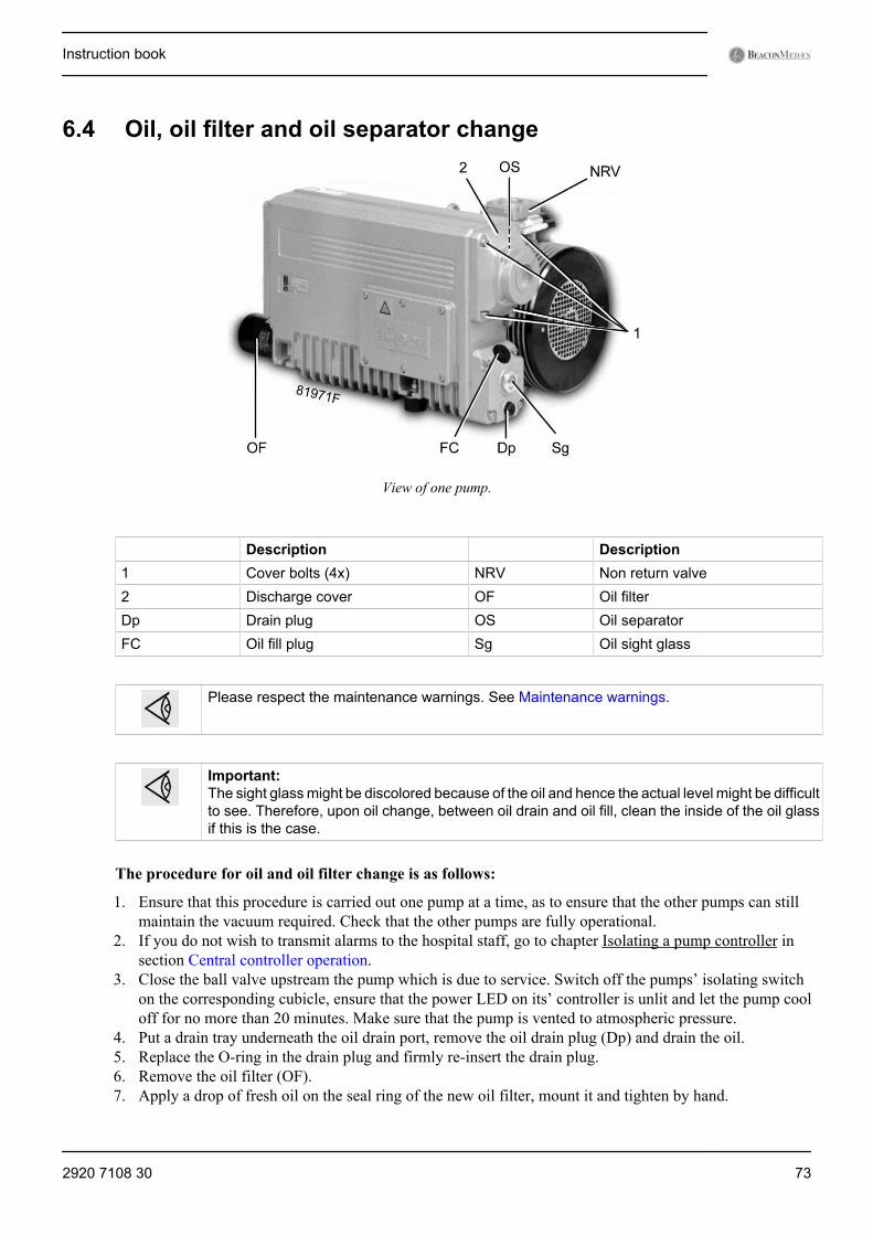
6.4 Oil, oil filter and oil separator change
View of one pump.
Description Description1 Cover bolts (4x) NRV Non return valve2 Discharge cover OF Oil filterDp Drain plug OS Oil separatorFC Oil fill plug Sg Oil sight glass
Please respect the maintenance warnings. See Maintenance warnings.
Important:The sight glass might be discolored because of the oil and hence the actual level might be difficultto see. Therefore, upon oil change, between oil drain and oil fill, clean the inside of the oil glassif this is the case.
The procedure for oil and oil filter change is as follows:
1. Ensure that this procedure is carried out one pump at a time, as to ensure that the other pumps can stillmaintain the vacuum required. Check that the other pumps are fully operational.
2. If you do not wish to transmit alarms to the hospital staff, go to chapter Isolating a pump controller insection Central controller operation.
3. Close the ball valve upstream the pump which is due to service. Switch off the pumps’ isolating switchon the corresponding cubicle, ensure that the power LED on its’ controller is unlit and let the pump cooloff for no more than 20 minutes. Make sure that the pump is vented to atmospheric pressure.
4. Put a drain tray underneath the oil drain port, remove the oil drain plug (Dp) and drain the oil.5. Replace the O-ring in the drain plug and firmly re-insert the drain plug.6. Remove the oil filter (OF).7. Apply a drop of fresh oil on the seal ring of the new oil filter, mount it and tighten by hand.
Instruction book
2920 7108 30 73

8. Remove the oil fill plug (FC) and fill in oil until the level in the sight glass (Sg) is close to the MAXindication.
9. Replace the O-ring in the fill plug and re-insert the fill plug firmly.10. Open the ball valve upstream the pump, switch the isolating switch back to On and integrate the pump in
the software.11. Observe the pump during a few cycles to make sure it is running normally.12. Reset the Service counter in the pump controller (d.4), see chapter Resetting service running hours in
section Pump controller operation.
The procedure for changing the oil separator (OS) is as follows:
1. Ensure that this procedure is carried out one pump at a time, as to ensure that the other pumps can stillmaintain the vacuum required. Check that the other pumps are fully operational.
2. If you do not wish to transmit alarms to the hospital staff, go to chapter Isolating a pump controller insection Central controller operation.
3. Close the ball valve upstream the pump, switch off the pumps’ isolating switch on the correspondingcubicle, ensure that the power LED on its’ controller is unlit and let the pump cool off for no more than20 minutes. Make sure that the pump is vented to atmospheric pressure.
4. Unscrew the 4 bolts (1) in the discharge cover (2). Bend the flexible hose of the discharge line slightly sothat the discharge cover is removed from the pump. If required, loosen the coupling ring at the copperstub connection, effectively disconnecting the flexible hose from the exhaust pipe.
5. Release and remove the spring elements by unscrewing the attached screws.6. Remove the oil separator element(s), O-ring and seal ring.7. Insert the new oil separator, O-ring and seal ring. Be sure to fit the oil separator correctly as indicated by
the arrow.8. Mount the spring elements and apply a tension to them by means of the tension screws.9. Bring the exhaust flexible back into place and mount the discharge cover (2) with the screws (1). Remount
the coupling ring, re-attaching the flexible hose to the exhaust pipe, if applicable.10. Open the ball valve, switch the isolating switch back to On and integrate the pump in the software.11. Observe the pump during a few cycles to make sure it is running normally.12. Reset the service counter in the central controller (ES-VAC), see chapter Service in section Central
controller operation.
6.5 Oil specificationsIt is strongly recommended to use only the genuine recommended lubricants.
They are the result of years of field experience and research. See section Checks and intervals for the advisedreplacement intervals and consult your spare parts list for part number information.
Never mix lubricants of different brands or types as they may not be compatible and theoil mix will have inferior properties.Always drain the pump as good as possible. Used oil left in the pump shortens the lifetimeof the new oil.
Petroleum based vacuum pump oil
Petroleum based vacuum pump oil is a lubricant, specially developed for use in rotary vane vacuum pumpsusing standard ISO-100 mineral based oil. Its specific composition keeps the pumps in excellent condition.It can be used for pumps operating at ambient temperatures between 0 ˚C (32 ˚F) and 30˚C (86 ˚F). If thepump is regularly operating in ambient temperatures between 30°C (86 °F) and 40 °C (104 °F), it isrecommended to use PAO-based vacuum pump oil.
Instruction book
74 2920 7108 30

PAO-based vacuum pump oil
PAO-based vacuum pump oil is a high quality synthetic lubricant for rotary vane vacuum pumps operatingat ambient temperatures between 0 ˚C (32 ˚F) and 40 ˚C (104 ˚F). Because of its excellent oxidation stability,PAO-based vacuum pump oil is recommended for pumps operating at ambient temperatures between 30 ˚C(86 ˚F) and 40 ˚C (104 ˚F).
6.6 Bacterial filter replacementAlways respect the maintenance warnings. See Maintenance warnings.Filter elements cannot be cleaned or reused. Dispose of in accordance with hospitalprocedures for contaminated waste.Do not overtighten the filter element as distortion of the O-ring seals may occur and preventan effective seal.
The procedure to replace the bacterial filter is as follows:1. For mVAC types with the filters housed in a (separate) frame, it is allowed to dismount the support beams
at the side to allow easier access to the filters.2. Set the filter(s) that is (are) not going to be changed online by slowly, fully opening the valves before and
after the filter(s).3. Isolate the filter(s) that is (are) going to be changed by fully closing the valves before and after the filter(s).4. Isolate the drain flask (Df) in use by closing the isolating valve. If any liquid is present, follow the
instructions as given in Maintenance warnings and notify the Authorised Person (MGPS) immediately.Otherwise, remove the drain flask.
5. Remove the filter housing. Unscrew/unclamp the filter housing and remove. To unscrew the filter housing,it may be convenient to use a special strap tool.
6. Remove the filter element (Bfe) and dispose it according to hospital procedures for contaminated waste.7. Fit the new filter element and secure it with the retaining nut (if applicable). Tighten by hand.8. Refit the filter bowl housing, screw the drain flask back on and open the drain valve.9. Reset the Delta P warning in the ES-VAC if necessary (see paragraph Service Menu in section Central
controller operation).
Bacterial filter with drain flask
Instruction book
2920 7108 30 75
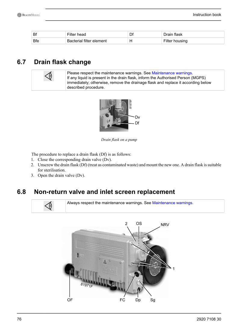
Bf Filter head Df Drain flaskBfe Bacterial filter element H Filter housing
6.7 Drain flask changePlease respect the maintenance warnings. See Maintenance warnings.If any liquid is present in the drain flask, inform the Authorised Person (MGPS)immediately; otherwise, remove the drainage flask and replace it according belowdescribed procedure.
Drain flask on a pump
The procedure to replace a drain flask (Df) is as follows:1. Close the corresponding drain valve (Dv).2. Unscrew the drain flask (Df) (treat as contaminated waste) and mount the new one. A drain flask is suitable
for sterilisation.3. Open the drain valve (Dv).
6.8 Non-return valve and inlet screen replacementAlways respect the maintenance warnings. See Maintenance warnings.
Instruction book
76 2920 7108 30
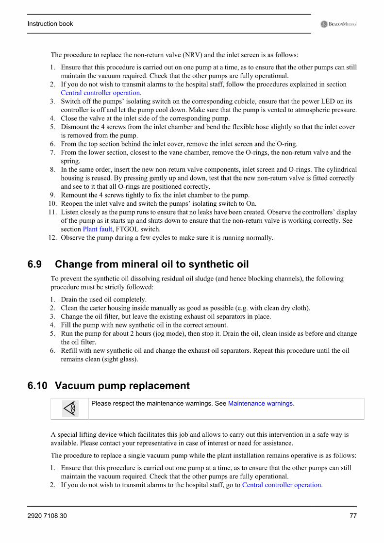
The procedure to replace the non-return valve (NRV) and the inlet screen is as follows:
1. Ensure that this procedure is carried out on one pump at a time, as to ensure that the other pumps can stillmaintain the vacuum required. Check that the other pumps are fully operational.
2. If you do not wish to transmit alarms to the hospital staff, follow the procedures explained in sectionCentral controller operation.
3. Switch off the pumps’ isolating switch on the corresponding cubicle, ensure that the power LED on itscontroller is off and let the pump cool down. Make sure that the pump is vented to atmospheric pressure.
4. Close the valve at the inlet side of the corresponding pump.5. Dismount the 4 screws from the inlet chamber and bend the flexible hose slightly so that the inlet cover
is removed from the pump.6. From the top section behind the inlet cover, remove the inlet screen and the O-ring.7. From the lower section, closest to the vane chamber, remove the O-rings, the non-return valve and the
spring.8. In the same order, insert the new non-return valve components, inlet screen and O-rings. The cylindrical
housing is reused. By pressing gently up and down, test that the new non-return valve is fitted correctlyand see to it that all O-rings are positioned correctly.
9. Remount the 4 screws tightly to fix the inlet chamber to the pump.10. Reopen the inlet valve and switch the pumps’ isolating switch to On.11. Listen closely as the pump runs to ensure that no leaks have been created. Observe the controllers’ display
of the pump as it starts up and shuts down to ensure that the non-return valve is working correctly. Seesection Plant fault, FTGOL switch.
12. Observe the pump during a few cycles to make sure it is running normally.
6.9 Change from mineral oil to synthetic oilTo prevent the synthetic oil dissolving residual oil sludge (and hence blocking channels), the followingprocedure must be strictly followed:
1. Drain the used oil completely.2. Clean the carter housing inside manually as good as possible (e.g. with clean dry cloth).3. Change the oil filter, but leave the existing exhaust oil separators in place.4. Fill the pump with new synthetic oil in the correct amount.5. Run the pump for about 2 hours (jog mode), then stop it. Drain the oil, clean inside as before and change
the oil filter.6. Refill with new synthetic oil and change the exhaust oil separators. Repeat this procedure until the oil
remains clean (sight glass).
6.10 Vacuum pump replacementPlease respect the maintenance warnings. See Maintenance warnings.
A special lifting device which facilitates this job and allows to carry out this intervention in a safe way isavailable. Please contact your representative in case of interest or need for assistance.
The procedure to replace a single vacuum pump while the plant installation remains operative is as follows:
1. Ensure that this procedure is carried out one pump at a time, as to ensure that the other pumps can stillmaintain the vacuum required. Check that the other pumps are fully operational.
2. If you do not wish to transmit alarms to the hospital staff, go to Central controller operation.
Instruction book
2920 7108 30 77

3. Switch off the pumps’ isolating switch on the corresponding cubicle, ensure that the power LED on its’controller is unlit and let the pump cool off for no more than 20 minutes. Make sure that the pump is ventedto atmospheric pressure.
4. Close the valve at the inlet side of the corresponding pump.5. Dismount the flexible hoses from the inlet and outlet of the pump and unscrew the bolts at the underside
of the plate on which the pump is fixed.6. Open the motor electrical box and disconnect the wires.7. Lift the pump slightly upward and outward towards the exhaust side of the plant. It might be needed to
dismount cable guiders or support beams, do this carefully and re-attach them after removing the pump.8. The new or refurbished pump can then be refit in the same manner: gently lift the pump into place, mount
connection bolts, inlets and outlets and connect the electric wires.9. Make sure to install and commission the pump according to sections Electrical functional check.10. Reopen the inlet valve and switch the pumps’ isolating switch to On.11. Observe the pump during a few cycles to make sure it is running normally.
6.11 Dismantling and disposalPlease respect the maintenance warnings. See Maintenance warnings.
The procedure to dismantle and dispose of the vacuum plant is as follows:
1. Switch off all isolating switches and the main power supply switches.2. Clean drains and filters as described in sections Bacterial filter replacement and Drain flask change.3. Close the inlet connection point valve and open one of the drain valves without drain flask slowly to bring
the pressure inside the pipes to atmospheric pressure.4. Disconnect all electric cables and dismount the cubicles.5. Drain all oil from the vacuum pumps and remove the oil filters.6. Separate all materials and components to be treated as special waste from the pump.7. Dispose of the oil and contaminated items (piping, filters, …) in compliance with the applicable
regulations.8. Dispose of electric components according to the applicable regulations.9. Dispose of any other uncontaminated material as scrap metal.
6.12 Service kitsA wide range of service kits is available. Service kits comprise all parts required for servicing the componentsand offer the benefits of genuine parts while keeping the maintenance budget low. Consult the spare parts listfor part numbers. For parts which are not listed (e.g. pump parts not included in the service kits), please contactyour supplier.
Instruction book
78 2920 7108 30
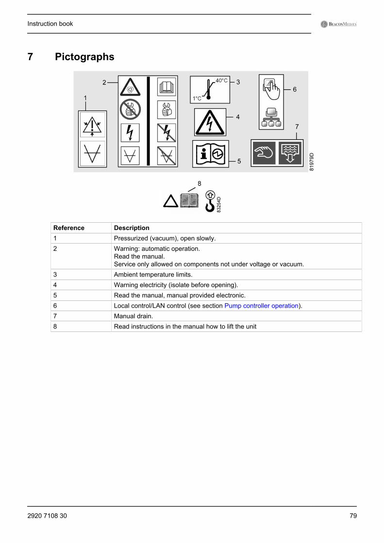
7 Pictographs
Reference Description1 Pressurized (vacuum), open slowly.2 Warning: automatic operation.
Read the manual.Service only allowed on components not under voltage or vacuum.
3 Ambient temperature limits.4 Warning electricity (isolate before opening).5 Read the manual, manual provided electronic.6 Local control/LAN control (see section Pump controller operation).7 Manual drain.8 Read instructions in the manual how to lift the unit
Instruction book
2920 7108 30 79
8 Problem solving
8.1 Introduction and warningsFor location and names of components, refer to the previous chapters. Item numbers ofspare parts needed to remedy problems can be found in the spare part list.If not, please contact BeaconMedæs.When a remedy corresponds to a procedure specifically explained in chapterMaintenance, consult the relevant paragraph and follow the procedure.
All precautions of chapter Safety precautions during maintenance or repair and Maintenance warnings applywhen attempting to remedy faults.
Instruction book
80 2920 7108 30

8.2 Faults and remedies
Drive
Component Condition Potential cause of the fault RemedyMotor Motor does not
rotate• Defect of motor• Impeller or motor mechanically
blocked
• Check motor connections• Check for obstructions in the
housingMotor can rotate, butstops during startupprocess
• Protection active• Voltage interruption• Voltage too low• Load too high• Supply phase missing• Earth fault• Short circuit
• Check motor connections• Check software• Check supply
Motor rotates inreverse direction(after test)
Motor phases connected in wrongorder
Switch 2 phases
Motor runs too slow • Load too high• Supply phase interrupted• Wear• Back pressure rise (oil
separator saturation)
• Check motor connections• Replace oil separator• Replace defective
components (contactBeaconMedæs)
Motor runs too fast Wrong frequency Check frequency of supply voltageand frequency of mVAC
Motor runsirregularly
• Bearing defect• Winding defect• Wire loose
• Check motor connections• Replace worn parts (contact
BeaconMedæs)
Motor speeddecreases over time
Back pressure rise (oil separatorsaturation)
• Replace oil separator• Replace defective
components (contactBeaconMedæs)
Motor draws toohigh current or eventrips on overload.
Clogged or saturated oil separatorfiltersToo high back pressure in theoutlet piping
Replace oil separator andinvestigate reason for clogging.Check size of outlet piping.
Component Condition Potential cause of the fault RemedyEncasing Holes exposing
moving parts• Supplier fault• Hole exposed during
operation/maintenance
Cover hole (contactBeaconMedæs)
Instruction book
2920 7108 30 81
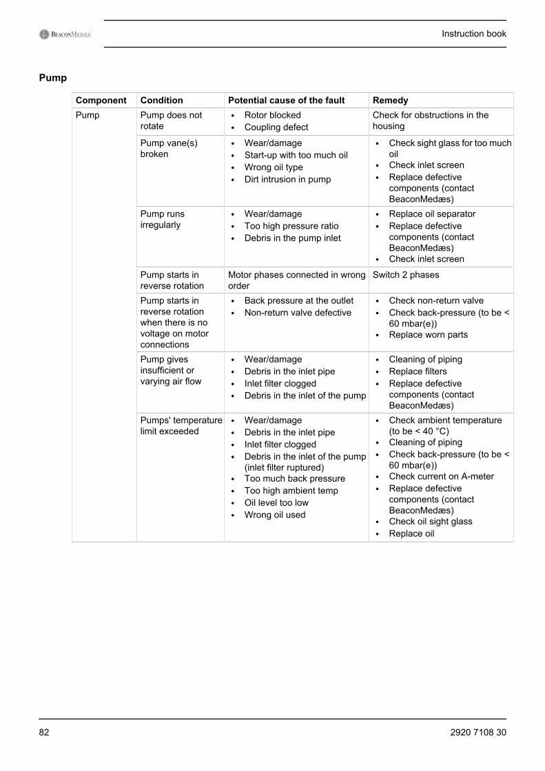
Pump
Component Condition Potential cause of the fault RemedyPump Pump does not
rotate• Rotor blocked• Coupling defect
Check for obstructions in thehousing
Pump vane(s)broken
• Wear/damage• Start-up with too much oil• Wrong oil type• Dirt intrusion in pump
• Check sight glass for too muchoil
• Check inlet screen• Replace defective
components (contactBeaconMedæs)
Pump runsirregularly
• Wear/damage• Too high pressure ratio• Debris in the pump inlet
• Replace oil separator• Replace defective
components (contactBeaconMedæs)
• Check inlet screen
Pump starts inreverse rotation
Motor phases connected in wrongorder
Switch 2 phases
Pump starts inreverse rotationwhen there is novoltage on motorconnections
• Back pressure at the outlet• Non-return valve defective
• Check non-return valve• Check back-pressure (to be <
60 mbar(e))• Replace worn parts
Pump givesinsufficient orvarying air flow
• Wear/damage• Debris in the inlet pipe• Inlet filter clogged• Debris in the inlet of the pump
• Cleaning of piping• Replace filters• Replace defective
components (contactBeaconMedæs)
Pumps' temperaturelimit exceeded
• Wear/damage• Debris in the inlet pipe• Inlet filter clogged• Debris in the inlet of the pump
(inlet filter ruptured)• Too much back pressure• Too high ambient temp• Oil level too low• Wrong oil used
• Check ambient temperature(to be < 40 °C)
• Cleaning of piping• Check back-pressure (to be <
60 mbar(e))• Check current on A-meter• Replace defective
components (contactBeaconMedæs)
• Check oil sight glass• Replace oil
Instruction book
82 2920 7108 30
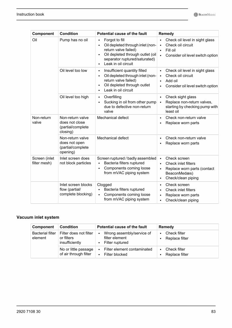
Component Condition Potential cause of the fault RemedyOil Pump has no oil • Forgot to fill
• Oil depleted through inlet (non-return valve failed)
• Oil depleted through outlet (oilseparator ruptured/saturated)
• Leak in oil circuit
• Check oil level in sight glass• Check oil circuit• Fill oil• Consider oil level switch option
Oil level too low • Insufficient quantity filled• Oil depleted through inlet (non-
return valve failed)• Oil depleted through outlet• Leak in oil circuit
• Check oil level in sight glass• Check oil circuit• Add oil• Consider oil level switch option
Oil level too high • Overfilling• Sucking in oil from other pump
due to defective non-returnvalve
• Check sight glass• Replace non-return valves,
starting by checking pump withleast oil
Non-returnvalve
Non-return valvedoes not close(partial/completeclosing)
Mechanical defect • Check non-return valve• Replace worn parts
Non-return valvedoes not open(partial/completeopening)
Mechanical defect • Check non-return valve• Replace worn parts
Screen (inletfilter mesh)
Inlet screen doesnot block particles
Screen ruptured / badly assembled• Bacteria filters ruptured• Components coming loose
from mVAC piping system
• Check screen• Check inlet filters• Replace worn parts (contact
BeaconMedæs)• Check/clean piping
Inlet screen blocksflow (partial/complete blocking)
Clogged• Bacteria filters ruptured• Components coming loose
from mVAC piping system
• Check screen• Check inlet filters• Replace worn parts• Check/clean piping
Vacuum inlet system
Component Condition Potential cause of the fault RemedyBacterial filterelement
Filter does not filteror filtersinsufficiently
• Wrong assembly/service offilter element
• Filter ruptured
• Check filter• Replace filter
No or little passageof air through filter
• Filter element contaminated• Filter blocked
• Check filter• Replace filter
Instruction book
2920 7108 30 83
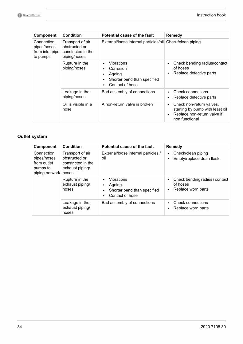
Component Condition Potential cause of the fault RemedyConnectionpipes/hosesfrom inlet pipeto pumps
Transport of airobstructed orconstricted in thepiping/hoses
External/loose internal particles/oil Check/clean piping
Rupture in thepiping/hoses
• Vibrations• Corrosion• Ageing• Shorter bend than specified• Contact of hose
• Check bending radius/contactof hoses
• Replace defective parts
Leakage in thepiping/hoses
Bad assembly of connections • Check connections• Replace defective parts
Oil is visible in ahose
A non-return valve is broken • Check non-return valves,starting by pump with least oil
• Replace non-return valve ifnon functional
Outlet system
Component Condition Potential cause of the fault RemedyConnectionpipes/hosesfrom outletpumps topiping network
Transport of airobstructed orconstricted in theexhaust piping/hoses
External/loose internal particles /oil
• Check/clean piping• Empty/replace drain flask
Rupture in theexhaust piping/hoses
• Vibrations• Ageing• Shorter bend than specified• Contact of hose
• Check bending radius / contactof hoses
• Replace worn parts
Leakage in theexhaust piping/hoses
Bad assembly of connections • Check connections• Replace worn parts
Instruction book
84 2920 7108 30
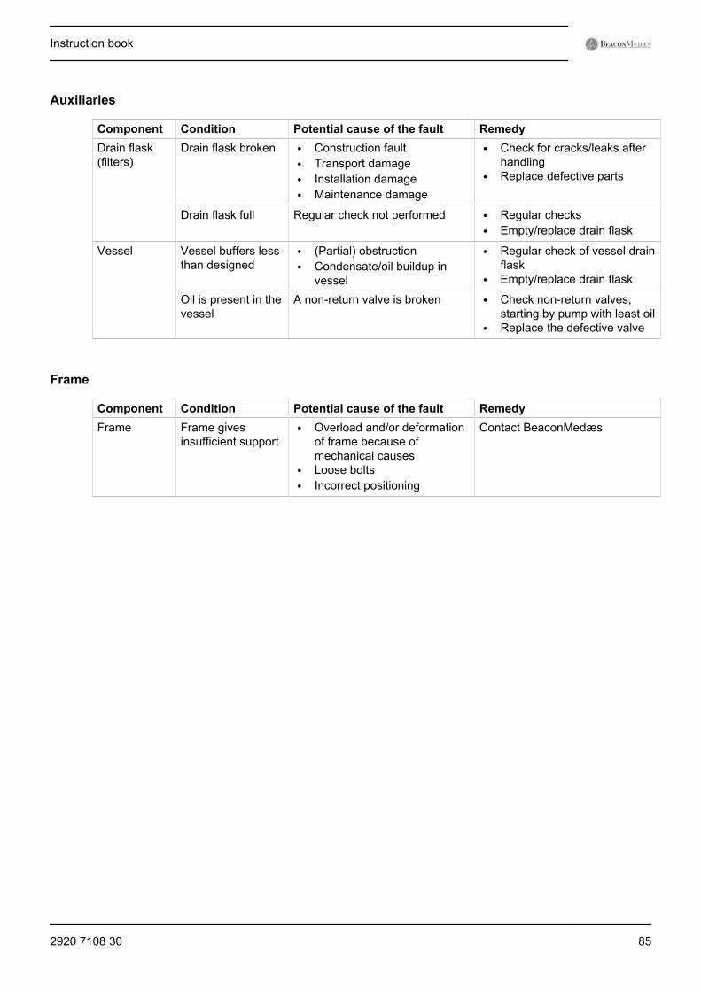
Auxiliaries
Component Condition Potential cause of the fault RemedyDrain flask(filters)
Drain flask broken • Construction fault• Transport damage• Installation damage• Maintenance damage
• Check for cracks/leaks afterhandling
• Replace defective parts
Drain flask full Regular check not performed • Regular checks• Empty/replace drain flask
Vessel Vessel buffers lessthan designed
• (Partial) obstruction• Condensate/oil buildup in
vessel
• Regular check of vessel drainflask
• Empty/replace drain flask
Oil is present in thevessel
A non-return valve is broken • Check non-return valves,starting by pump with least oil
• Replace the defective valve
Frame
Component Condition Potential cause of the fault RemedyFrame Frame gives
insufficient support• Overload and/or deformation
of frame because ofmechanical causes
• Loose bolts• Incorrect positioning
Contact BeaconMedæs
Instruction book
2920 7108 30 85
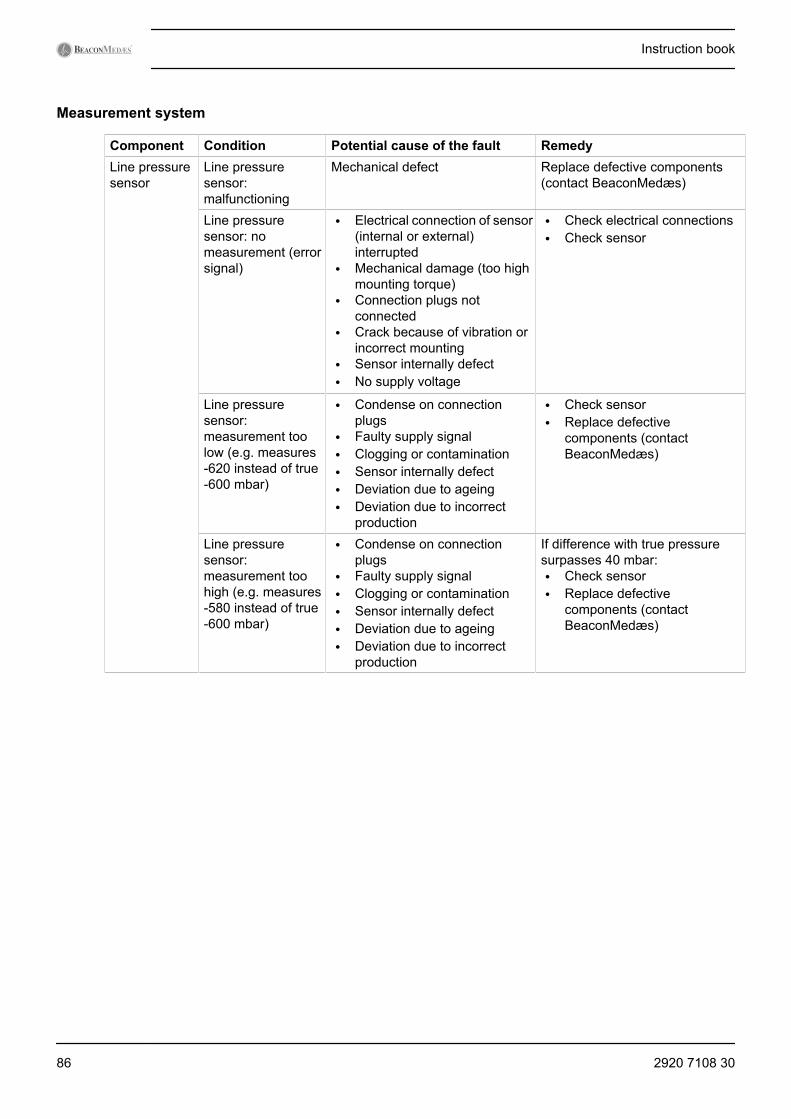
Measurement system
Component Condition Potential cause of the fault RemedyLine pressuresensor
Line pressuresensor:malfunctioning
Mechanical defect Replace defective components(contact BeaconMedæs)
Line pressuresensor: nomeasurement (errorsignal)
• Electrical connection of sensor(internal or external)interrupted
• Mechanical damage (too highmounting torque)
• Connection plugs notconnected
• Crack because of vibration orincorrect mounting
• Sensor internally defect• No supply voltage
• Check electrical connections• Check sensor
Line pressuresensor:measurement toolow (e.g. measures-620 instead of true-600 mbar)
• Condense on connectionplugs
• Faulty supply signal• Clogging or contamination• Sensor internally defect• Deviation due to ageing• Deviation due to incorrect
production
• Check sensor• Replace defective
components (contactBeaconMedæs)
Line pressuresensor:measurement toohigh (e.g. measures-580 instead of true-600 mbar)
• Condense on connectionplugs
• Faulty supply signal• Clogging or contamination• Sensor internally defect• Deviation due to ageing• Deviation due to incorrect
production
If difference with true pressuresurpasses 40 mbar:• Check sensor• Replace defective
components (contactBeaconMedæs)
Instruction book
86 2920 7108 30
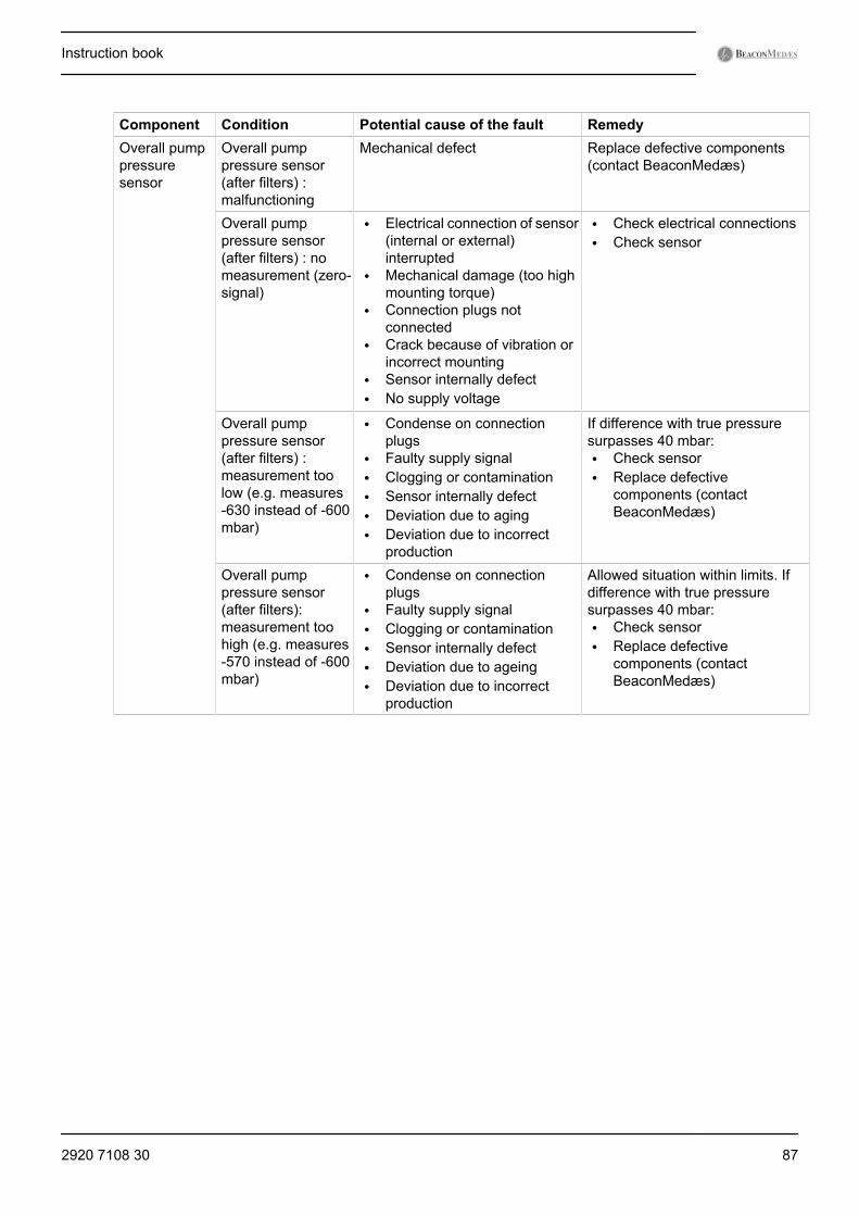
Component Condition Potential cause of the fault RemedyOverall pumppressuresensor
Overall pumppressure sensor(after filters) :malfunctioning
Mechanical defect Replace defective components(contact BeaconMedæs)
Overall pumppressure sensor(after filters) : nomeasurement (zero-signal)
• Electrical connection of sensor(internal or external)interrupted
• Mechanical damage (too highmounting torque)
• Connection plugs notconnected
• Crack because of vibration orincorrect mounting
• Sensor internally defect• No supply voltage
• Check electrical connections• Check sensor
Overall pumppressure sensor(after filters) :measurement toolow (e.g. measures-630 instead of -600mbar)
• Condense on connectionplugs
• Faulty supply signal• Clogging or contamination• Sensor internally defect• Deviation due to aging• Deviation due to incorrect
production
If difference with true pressuresurpasses 40 mbar:• Check sensor• Replace defective
components (contactBeaconMedæs)
Overall pumppressure sensor(after filters):measurement toohigh (e.g. measures-570 instead of -600mbar)
• Condense on connectionplugs
• Faulty supply signal• Clogging or contamination• Sensor internally defect• Deviation due to ageing• Deviation due to incorrect
production
Allowed situation within limits. Ifdifference with true pressuresurpasses 40 mbar:• Check sensor• Replace defective
components (contactBeaconMedæs)
Instruction book
2920 7108 30 87
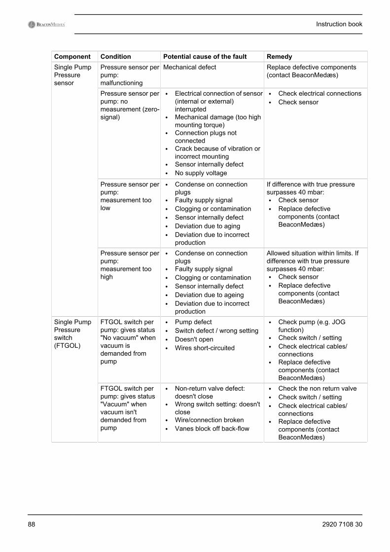
Component Condition Potential cause of the fault RemedySingle PumpPressuresensor
Pressure sensor perpump:malfunctioning
Mechanical defect Replace defective components(contact BeaconMedæs)
Pressure sensor perpump: nomeasurement (zero-signal)
• Electrical connection of sensor(internal or external)interrupted
• Mechanical damage (too highmounting torque)
• Connection plugs notconnected
• Crack because of vibration orincorrect mounting
• Sensor internally defect• No supply voltage
• Check electrical connections• Check sensor
Pressure sensor perpump:measurement toolow
• Condense on connectionplugs
• Faulty supply signal• Clogging or contamination• Sensor internally defect• Deviation due to aging• Deviation due to incorrect
production
If difference with true pressuresurpasses 40 mbar:• Check sensor• Replace defective
components (contactBeaconMedæs)
Pressure sensor perpump:measurement toohigh
• Condense on connectionplugs
• Faulty supply signal• Clogging or contamination• Sensor internally defect• Deviation due to ageing• Deviation due to incorrect
production
Allowed situation within limits. Ifdifference with true pressuresurpasses 40 mbar:• Check sensor• Replace defective
components (contactBeaconMedæs)
Single PumpPressureswitch(FTGOL)
FTGOL switch perpump: gives status"No vacuum" whenvacuum isdemanded frompump
• Pump defect• Switch defect / wrong setting• Doesn't open• Wires short-circuited
• Check pump (e.g. JOGfunction)
• Check switch / setting• Check electrical cables/
connections• Replace defective
components (contactBeaconMedæs)
FTGOL switch perpump: gives status"Vacuum" whenvacuum isn'tdemanded frompump
• Non-return valve defect:doesn't close
• Wrong switch setting: doesn'tclose
• Wire/connection broken• Vanes block off back-flow
• Check the non return valve• Check switch / setting• Check electrical cables/
connections• Replace defective
components (contactBeaconMedæs)
Instruction book
88 2920 7108 30
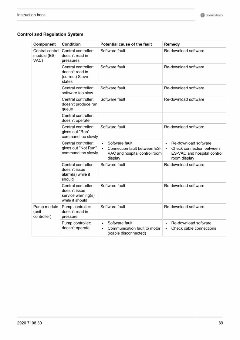
Control and Regulation System
Component Condition Potential cause of the fault RemedyCentral controlmodule (ES-VAC)
Central controller:doesn't read inpressures
Software fault Re-download software
Central controller:doesn't read in(correct) Slavestates
Software fault Re-download software
Central controller:software too slow
Software fault Re-download software
Central controller:doesn't produce runqueue
Software fault Re-download software
Central controller:doesn't operate
Central controller:gives out "Run"command too slowly
Software fault Re-download software
Central controller:gives out "Not Run"command too slowly
• Software fault• Connection fault between ES-
VAC and hospital control roomdisplay
• Re-download software• Check connection between
ES-VAC and hospital controlroom display
Central controller:doesn't issuealarm(s) while itshould
Software fault Re-download software
Central controller:doesn't issueservice warning(s)while it should
Software fault Re-download software
Pump module(unitcontroller)
Pump controller:doesn't read inpressure
Software fault Re-download software
Pump controller:doesn't operate
• Software fault• Communication fault to motor
(/cable disconnected)
• Re-download software• Check cable connections
Instruction book
2920 7108 30 89
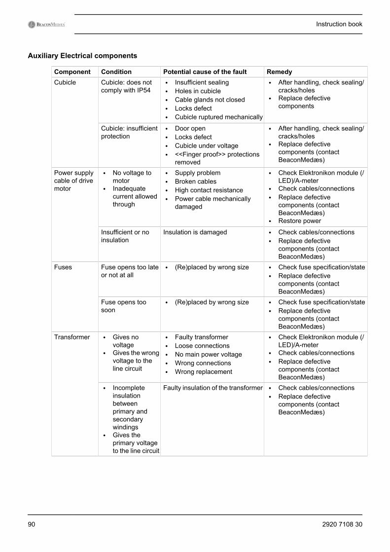
Auxiliary Electrical components
Component Condition Potential cause of the fault RemedyCubicle Cubicle: does not
comply with IP54• Insufficient sealing• Holes in cubicle• Cable glands not closed• Locks defect• Cubicle ruptured mechanically
• After handling, check sealing/cracks/holes
• Replace defectivecomponents
Cubicle: insufficientprotection
• Door open• Locks defect• Cubicle under voltage• <<Finger proof>> protections
removed
• After handling, check sealing/cracks/holes
• Replace defectivecomponents (contactBeaconMedæs)
Power supplycable of drivemotor
• No voltage tomotor
• Inadequatecurrent allowedthrough
• Supply problem• Broken cables• High contact resistance• Power cable mechanically
damaged
• Check Elektronikon module (/LED)/A-meter
• Check cables/connections• Replace defective
components (contactBeaconMedæs)
• Restore power
Insufficient or noinsulation
Insulation is damaged • Check cables/connections• Replace defective
components (contactBeaconMedæs)
Fuses Fuse opens too lateor not at all
• (Re)placed by wrong size • Check fuse specification/state• Replace defective
components (contactBeaconMedæs)
Fuse opens toosoon
• (Re)placed by wrong size • Check fuse specification/state• Replace defective
components (contactBeaconMedæs)
Transformer • Gives novoltage
• Gives the wrongvoltage to theline circuit
• Faulty transformer• Loose connections• No main power voltage• Wrong connections• Wrong replacement
• Check Elektronikon module (/LED)/A-meter
• Check cables/connections• Replace defective
components (contactBeaconMedæs)
• Incompleteinsulationbetweenprimary andsecondarywindings
• Gives theprimary voltageto the line circuit
Faulty insulation of the transformer • Check cables/connections• Replace defective
components (contactBeaconMedæs)
Instruction book
90 2920 7108 30

Component Condition Potential cause of the fault RemedyElectricalconnections
Electricalconnection broken
• Faulty connection• Connection came loose
• Check Elektronikon module (/LED)/A-meter
• Check cables/connections• Replace defective
components (contactBeaconMedæs)
Insufficient or noInsulation
Faulty insulation • Check cables/connections• Replace defective
components (contactBeaconMedæs)
LAN/Localswitch
LAN/Local switch:does not open
• Faulty button• Faulty control module• Bad wire connections
• Check button orientation withregard to label
• Check connections
LAN/Local switch:does not close
• Faulty button• Faulty control module• Bad wire connections
• Check button orientation withregard to label
• Check connections
Oil level switch(option)
Doesn't indicatewhen oil level is toolow
• Wrong assembly• Wrong switch• Switch fault• Short circuit
• Check orientation• Check switch• Replace defective
components (contactBeaconMedæs)
Indicates too lowlevel while level isO.K.
• Level switch is installed as<<Rise to open>> insteadof<<Fall to open>>
• Broken wire
• Check orientation• Check switch• Replace defective
components (contactBeaconMedæs)
A-meter Does not indicate(correct) current
• Faulty connection• Faulty component
• Check in test procedure• Check connections• Replace defective
components (contactBeaconMedæs)
Main switch Does not connect Contactor is blocked open • Check contactor• Replace defective
components (contactBeaconMedæs)
Does not disconnect Contactor is blocked closed • Check contactor• Replace defective
components (contactBeaconMedæs)
Door can be opened Lock does not work Check during test andcommissioning and regularly (e.g.during servicing)
Power supplycable ES-VAC
No/inadequatepower
• Supply problem• Broken cables• High contact resistance• Power cable mechanically
damaged
• Check Elektronikon module (/LED)/A-meter
• Check cables/connections• Replace defective
components (contactBeaconMedæs)
Instruction book
2920 7108 30 91
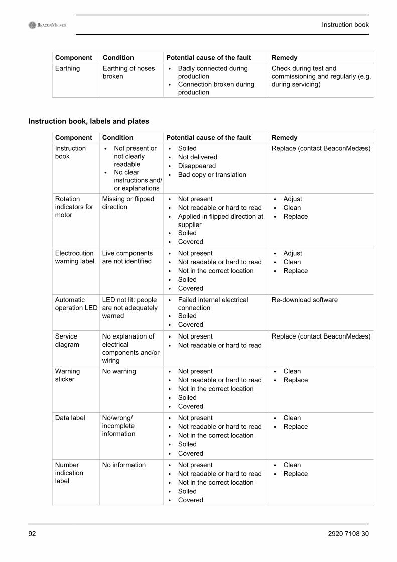
Component Condition Potential cause of the fault RemedyEarthing Earthing of hoses
broken• Badly connected during
production• Connection broken during
production
Check during test andcommissioning and regularly (e.g.during servicing)
Instruction book, labels and plates
Component Condition Potential cause of the fault RemedyInstructionbook
• Not present ornot clearlyreadable
• No clearinstructions and/or explanations
• Soiled• Not delivered• Disappeared• Bad copy or translation
Replace (contact BeaconMedæs)
Rotationindicators formotor
Missing or flippeddirection
• Not present• Not readable or hard to read• Applied in flipped direction at
supplier• Soiled• Covered
• Adjust• Clean• Replace
Electrocutionwarning label
Live componentsare not identified
• Not present• Not readable or hard to read• Not in the correct location• Soiled• Covered
• Adjust• Clean• Replace
Automaticoperation LED
LED not lit: peopleare not adequatelywarned
• Failed internal electricalconnection
• Soiled• Covered
Re-download software
Servicediagram
No explanation ofelectricalcomponents and/orwiring
• Not present• Not readable or hard to read
Replace (contact BeaconMedæs)
Warningsticker
No warning • Not present• Not readable or hard to read• Not in the correct location• Soiled• Covered
• Clean• Replace
Data label No/wrong/incompleteinformation
• Not present• Not readable or hard to read• Not in the correct location• Soiled• Covered
• Clean• Replace
Numberindicationlabel
No information • Not present• Not readable or hard to read• Not in the correct location• Soiled• Covered
• Clean• Replace
Instruction book
92 2920 7108 30
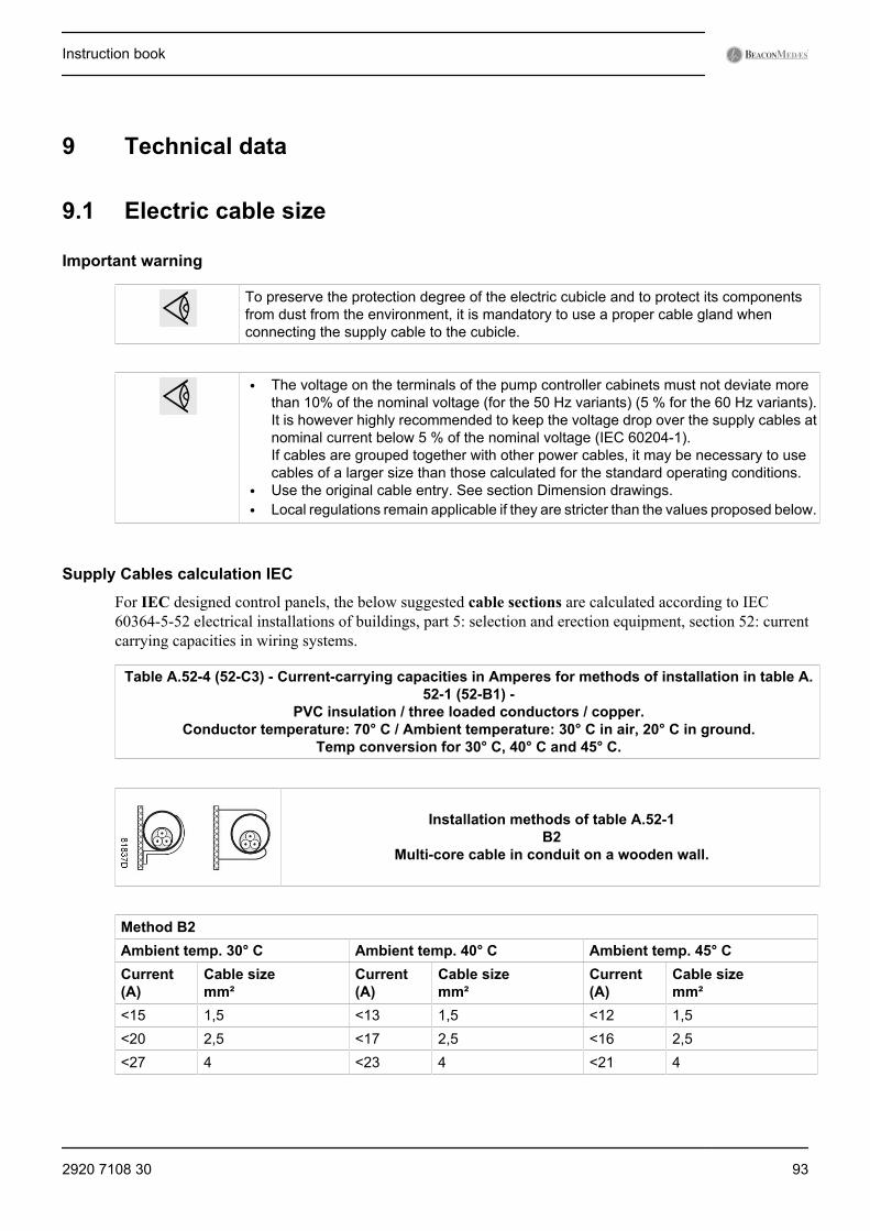
9 Technical data
9.1 Electric cable size
Important warning
To preserve the protection degree of the electric cubicle and to protect its componentsfrom dust from the environment, it is mandatory to use a proper cable gland whenconnecting the supply cable to the cubicle.
• The voltage on the terminals of the pump controller cabinets must not deviate morethan 10% of the nominal voltage (for the 50 Hz variants) (5 % for the 60 Hz variants).It is however highly recommended to keep the voltage drop over the supply cables atnominal current below 5 % of the nominal voltage (IEC 60204-1).If cables are grouped together with other power cables, it may be necessary to usecables of a larger size than those calculated for the standard operating conditions.
• Use the original cable entry. See section Dimension drawings.• Local regulations remain applicable if they are stricter than the values proposed below.
Supply Cables calculation IEC
For IEC designed control panels, the below suggested cable sections are calculated according to IEC60364-5-52 electrical installations of buildings, part 5: selection and erection equipment, section 52: currentcarrying capacities in wiring systems.
Table A.52-4 (52-C3) - Current-carrying capacities in Amperes for methods of installation in table A.52-1 (52-B1) -
PVC insulation / three loaded conductors / copper.Conductor temperature: 70° C / Ambient temperature: 30° C in air, 20° C in ground.
Temp conversion for 30° C, 40° C and 45° C.
Installation methods of table A.52-1B2
Multi-core cable in conduit on a wooden wall.
Method B2Ambient temp. 30° C Ambient temp. 40° C Ambient temp. 45° CCurrent(A)
Cable sizemm²
Current(A)
Cable sizemm²
Current(A)
Cable sizemm²
<15 1,5 <13 1,5 <12 1,5<20 2,5 <17 2,5 <16 2,5<27 4 <23 4 <21 4
Instruction book
2920 7108 30 93

Installation methods of table A.52-1C
Single core or multi core cable on a wooden wall.
Method CAmbient temp. 30° C Ambient temp. 40° C Ambient temp. 45° CCurrent(A)
Cable sizemm²
Current(A)
Cable sizemm²
Current(A)
Cable sizemm²
<17 1,5 <15 1,5 <14 1,5<24 2,5 <21 2,5 <19 2,5<32 4 <28 4 <25 4
9.2 Fuse valuesFuse calculations for IEC are done according to IEC 60364-4-43 - electrical installations of buildings, part 4:protection for safety, section 43: protection against overcurrent. Fuse sizes are calculated in order to protectagainst short circuit.
The mVAC cubicles are foreseen with fuses and a main switch per pump, but it is recommended to also installfuses in the supply lines and a general main switch. Fuse type aM is recommended.
The cubicles are also foreseen with an overload protection. The overload value is given here for informationpurposes.
Voltage Freq. Approval Current (1) Main fuses(2)
Overload relay(3)
(V) (Hz) (A) (A) (A)RA0040 400 50 IEC 2.9 12 3.3RA0040 380 60 IEC 4.0 12 4.6RA0063 400 50 IEC 3.8 12 4.4RA0063 380 60 IEC 5.7 12 6.6RA0100 400 50 IEC 5.2 12 6.0RA0100 380 60 IEC 7.4 12 8.5RA0250 400 50 IEC 12.4 25 15.5RA0250 380 60 IEC 18.5 25 21.3RA0302 400 50 IEC 15.6 25 18.0RA0302 380 60 IEC 20.8 25 23.0
Remarks :
(1): Nominal motor current
(2): Maximal fuse size (IEC class gL/gG) - to be installed by customer - see F0’ (and F10) on service diagram
(3): see F21 on service diagram
Instruction book
94 2920 7108 30
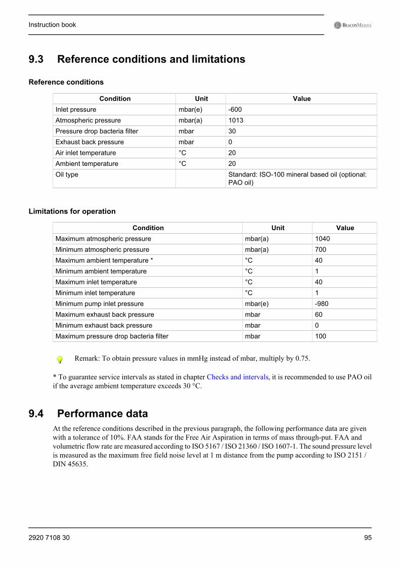
9.3 Reference conditions and limitations
Reference conditions
Condition Unit ValueInlet pressure mbar(e) -600Atmospheric pressure mbar(a) 1013Pressure drop bacteria filter mbar 30Exhaust back pressure mbar 0Air inlet temperature °C 20Ambient temperature °C 20Oil type Standard: ISO-100 mineral based oil (optional:
PAO oil)
Limitations for operation
Condition Unit ValueMaximum atmospheric pressure mbar(a) 1040Minimum atmospheric pressure mbar(a) 700Maximum ambient temperature * °C 40Minimum ambient temperature °C 1Maximum inlet temperature °C 40Minimum inlet temperature °C 1Minimum pump inlet pressure mbar(e) -980Maximum exhaust back pressure mbar 60Minimum exhaust back pressure mbar 0Maximum pressure drop bacteria filter mbar 100
Remark: To obtain pressure values in mmHg instead of mbar, multiply by 0.75.
* To guarantee service intervals as stated in chapter Checks and intervals, it is recommended to use PAO oilif the average ambient temperature exceeds 30 °C.
9.4 Performance dataAt the reference conditions described in the previous paragraph, the following performance data are givenwith a tolerance of 10%. FAA stands for the Free Air Aspiration in terms of mass through-put. FAA andvolumetric flow rate are measured according to ISO 5167 / ISO 21360 / ISO 1607-1. The sound pressure levelis measured as the maximum free field noise level at 1 m distance from the pump according to ISO 2151 /DIN 45635.
Instruction book
2920 7108 30 95
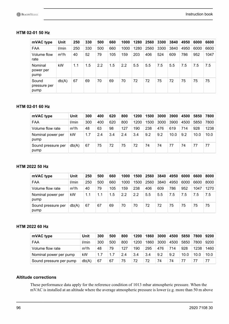
HTM 02-01 50 Hz
mVAC type Unit 250 330 500 660 1000 1280 2560 3300 3840 4950 6000 6600FAA l/min 250 330 500 660 1000 1280 2560 3300 3840 4950 6000 6600Volume flowrate
m³/h 40 52 79 105 159 203 406 524 609 786 952 1047
Nominalpower perpump
kW 1.1 1.5 2.2 1.5 2.2 5.5 5.5 7.5 5.5 7.5 7.5 7.5
Soundpressure perpump
db(A) 67 69 70 69 70 72 72 75 72 75 75 75
HTM 02-01 60 Hz
mVAC type Unit 300 400 620 800 1200 1500 3000 3900 4500 5850 7800FAA l/min 300 400 620 800 1200 1500 3000 3900 4500 5850 7800Volume flow rate m³/h 48 63 98 127 190 238 476 619 714 928 1238Nominal power perpump
kW 1.7 2.4 3.4 2.4 3.4 9.2 9.2 10.0 9.2 10.0 10.0
Sound pressure perpump
db(A) 67 75 72 75 72 74 74 77 74 77 77
HTM 2022 50 Hz
mVAC type Unit 250 500 660 1000 1500 2560 3840 4950 6000 6600 8000FAA l/min 250 500 660 1000 1500 2560 3840 4950 6000 6600 8000Volume flow rate m³/h 40 79 105 159 238 406 609 786 952 1047 1270Nominal power perpump
kW 1.1 1.1 1.5 2.2 2.2 5.5 5.5 7.5 7.5 7.5 7.5
Sound pressure perpump
db(A) 67 67 69 70 70 72 72 75 75 75 75
HTM 2022 60 Hz
mVAC type Unit 300 500 800 1200 1860 3000 4500 5850 7800 9200FAA l/min 300 500 800 1200 1860 3000 4500 5850 7800 9200Volume flow rate m³/h 48 79 127 190 295 476 714 928 1238 1460Nominal power per pump kW 1.7 1.7 2.4 3.4 3.4 9.2 9.2 10.0 10.0 10.0Sound pressure per pump db(A) 67 67 75 72 72 74 74 77 77 77
Altitude corrections
These performance data apply for the reference condition of 1013 mbar atmospheric pressure. When themVAC is installed at an altitude where the average atmospheric pressure is lower (e.g. more than 50 m above
Instruction book
96 2920 7108 30
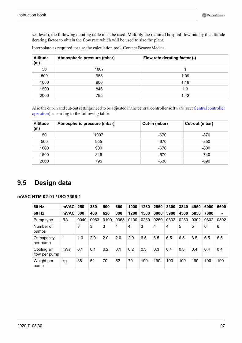
sea level), the following derating table must be used. Multiply the required hospital flow rate by the altitudederating factor to obtain the flow rate which will be used to size the plant.
Interpolate as required, or use the calculation tool. Contact BeaconMedæs.
Altitude(m)
Atmospheric pressure (mbar) Flow rate derating factor (-)
50 1007 1500 955 1.09
1000 900 1.191500 846 1.32000 795 1.42
Also the cut-in and cut-out settings need to be adjusted in the central controller software (see: Central controlleroperation) according to the following table.
Altitude(m)
Atmospheric pressure (mbar) Cut-in (mbar) Cut-out (mbar)
50 1007 -670 -870500 955 -670 -850
1000 900 -670 -8001500 846 -670 -7402000 795 -630 -690
9.5 Design data
mVAC HTM 02-01 / ISO 7396-1
50 Hz mVAC 250 330 500 660 1000 1280 2560 3300 3840 4950 6000 660060 Hz mVAC 300 400 620 800 1200 1500 3000 3900 4500 5850 7800 -Pump type RA 0040 0063 0100 0063 0100 0250 0250 0302 0250 0302 0302 0302Number ofpumps
3 3 3 4 4 3 4 4 5 5 6 6
Oil capacityper pump
l 1.0 2.0 2.0 2.0 2.0 6.5 6.5 6.5 6.5 6.5 6.5 6.5
Cooling airflow per pump
m³/s 0.1 0.1 0.2 0.1 0.2 0.3 0.3 0.4 0.3 0.4 0.4 0.4
Weight perpump
kg 38 52 70 52 70 190 190 190 190 190 190 190
Instruction book
2920 7108 30 97
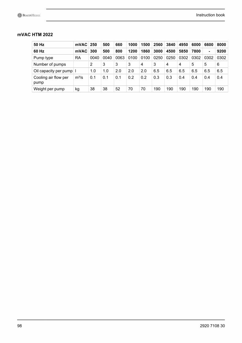
mVAC HTM 2022
50 Hz mVAC 250 500 660 1000 1500 2560 3840 4950 6000 6600 800060 Hz mVAC 300 500 800 1200 1860 3000 4500 5850 7800 - 9200Pump type RA 0040 0040 0063 0100 0100 0250 0250 0302 0302 0302 0302Number of pumps 2 3 3 3 4 3 4 4 5 5 6Oil capacity per pump l 1.0 1.0 2.0 2.0 2.0 6.5 6.5 6.5 6.5 6.5 6.5Cooling air flow perpump
m³/s 0.1 0.1 0.1 0.2 0.2 0.3 0.3 0.4 0.4 0.4 0.4
Weight per pump kg 38 38 52 70 70 190 190 190 190 190 190
Instruction book
98 2920 7108 30
10 Usability
Intended use
1. DescriptionThe mVAC plant provides a source for vacuum (suction) for a variety of applications in the hospital,mainly in operating theatres, intensive care, emergency and respirology units. Specific applicationsinclude:• Wound drainage• Assisted wound closure• Chest and lung drainage• Removal of excess blood during surgery• Collection of other bodily fluids• Gastric emptying• Cleaning endotracheal tubes• Liposuction (lipoplasty)
2. mVAC application specification• Medical purpose
1. To provide vacuum (suction) for a variety of applications in the hospital, mainly in operatingtheatres, intensive care, emergency and respirology units
2. Condition(s) or disease(s) to be screened, monitored, treated or diagnosed: none• Patient population
1. Age: newborn to geriatric2. Weight: not relevant3. Health: not relevant4. Nationality: multiple5. Patient state:
• Patient is operator: patient is never intended to be the operator• Patient is not operator: default case
• Part of the body or type of tissue applied or interacted withDirect contact is not foreseen, the device connects to the patient via a transport piping system.
• Intended operator1. Education:
• minimum: At least 21 years old, high school or equivalent.• maximum: none
2. Knowledge:• minimum: Can read and understand westernized Arabic numerals. Basic technical knowledge
and software understanding required.• maximum: none
3. Language understanding: Language of the instruction book and preferably also English4. Experience:
• minimum: no special experience necessary• maximum: none
5. Permissible impairments: Mild reading vision impairment or vision corrected to log MAR 0,2 (6/10or 20/32), at least one arm/hand capable of guiding device, average degree of ageing-related shortterm memory impairment.
• Applications1. Environment:
• general: plant room in a hospital• conditions of visibility: well lit room• physical: 1 to 40 °C
2. frequency of use: every day intermittently or continuously
Instruction book
2920 7108 30 99
3. mobility: stationary device
Primary operating functions
1. Critical functions :Switching OnMaintenance
2. Frequent functions :None
Risk analysis
1. Intended use :See above
2. Operator Profile :See above : Intended operator
3. Things that could go wrong :Sources: literature, complaint file, sales force, nursing experts, risk analysis.a. During normal use: See: Faults and remedies e.g. loss of vacuumb. Use errors: Misuse / no or wrong maintenancec. Environment:
• above 40 °C• below 1 °C
d. Patient: not applicablee. Reading: not applicablef. Hygiene: not applicableg. Application: outside of operating room
4. Task requirements :Maintenance
5. The context of use :See above: Applications
6. Information on Hazards known for existing similar device :Included in Things that could go wrong.
7. Resulting Hazards :See Installation warnings and Maintenance warnings.
8. Preliminary review of the Operator-Equipment interface concept :According to design process.Conclusion: no issue.
Use scenarios
Worst case scenarios to provide a basis for validation with <<Patient = Operator>> is not applicable.
- Patient is never intended to be the operator.
1. Operator actions related to primary operating functions :See operation user guide
2. Operator-equipment interface requirements for the primary operating functions :According to design process.
3. Operator-equipment interface requirements for those use scenarios that are frequent or related tobasic safety or essential performance :According to design process.
Instruction book
100 2920 7108 30
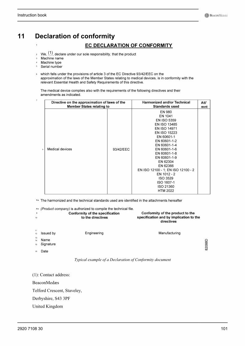
11 Declaration of conformity
Typical example of a Declaration of Conformity document
(1): Contact address:
BeaconMedæs
Telford Crescent, Staveley,
Derbyshire, S43 3PF
United Kingdom
Instruction book
2920 7108 30 101
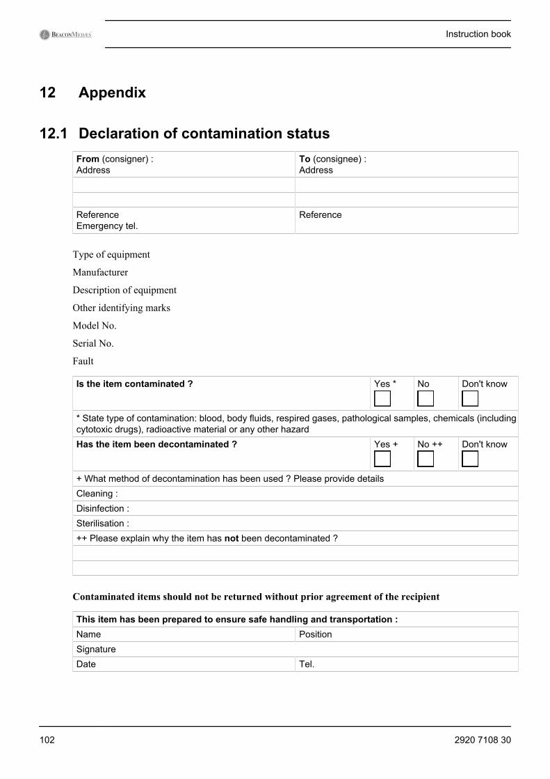
12 Appendix
12.1 Declaration of contamination statusFrom (consigner) :Address
To (consignee) :Address
ReferenceEmergency tel.
Reference
Type of equipment
Manufacturer
Description of equipment
Other identifying marks
Model No.
Serial No.
Fault
Is the item contaminated ? Yes * No Don't know
* State type of contamination: blood, body fluids, respired gases, pathological samples, chemicals (includingcytotoxic drugs), radioactive material or any other hazardHas the item been decontaminated ? Yes + No ++ Don't know
+ What method of decontamination has been used ? Please provide detailsCleaning :Disinfection :Sterilisation :++ Please explain why the item has not been decontaminated ?
Contaminated items should not be returned without prior agreement of the recipient
This item has been prepared to ensure safe handling and transportation :Name PositionSignatureDate Tel.
Instruction book
102 2920 7108 30


No.
292
0 71
08 3
0 / 2
012
- 10
- Prin
ted
in B
elgi
um
www.beaconmedaes.com