multifunctional carbon nanotube/bioceramics modulate the directional growth and activity of...
TRANSCRIPT

Copyright © 2013 American Scientific PublishersAll rights reservedPrinted in the United States of America
ArticleJournal of
BiomedicalNanotechnologyVol. 9, 1–19, 2013www.aspbs.com/jbn
Multifunctional Carbon Nanotube/Bioceramics Modulatethe Directional Growth and Activity of Osteoblastic Cells
D. Mata1�∗, F. J. Oliveira1, M. Ferro1, P. S. Gomes2, M. H. Fernandes2, M. A. Lopes3, and R. F. Silva11CICECO, Materials and Ceramic Engineering, Department, University of Aveiro, 3810-193 Aveiro, Portugal2Faculty of Dental Medicine, Laboratory for Bone Metabolism and Regeneration, University of Porto, 4200-465 Porto, Portugal3Faculty of Engineering, CEMUC, Metallurgical and Materials Engineering Department, University of Porto, 4200-465 Porto, Portugal
Biomaterials can still be reinvented to become simple and universal bone regeneration solutions. Following this roadmap,a bone graft of carbon nanotube (CNT)/glass/hydroxyapatite (HA) with controlled CNT agglomeration state was designedwith multifunctionalities able to stimulate the bone cell phenotype. The preparation route, the mechanical and electricalbehavior and the in vitro profiles of degradation and osteocompatibility were described. A non-destructive dynamic routewas found to have a higher influence than the Diels-Alder functionalization one on controlling the CNT agglomerate statein the ceramic-matrix composite. Biologically safe CNT agglomerates, with diameter sizes below 3 �m homogenouslydistributed, were obtained in non-functionalized and functionalized composites. Yet, the lowest CNT damage and thehighest mechanical and electrical properties were found for the non-functionalized materials. Even though that thesecomposites present higher degradation rate at pH:3 than the ceramic matrix, the CNT agglomerates are released withsafe diameter sizes. Also, non-functionalized composites allowed cellular adhesion and modulated the orientation of thecell growth, with a proliferation/differentiation relationship favoring osteoblastic functional activity. Findings offer furthercontributions for bone tissue engineering by showing that multifunctional bone grafts with high electroconductivity, andintegrating CNT agglomerates with maximized interfacing area, allow the in situ control of bone cell functions.
KEYWORDS:
INTRODUCTIONThe roadmap for biomaterials to become simple and uni-versal bone regeneration solution includes “smart” bonegrafts that have been designed with new functionalitiesable to stimulate specific bone cell responses.1 Regardingthe well-known beneficial effects of endogenous electricalsignals in natural bone,2�3 electron conductivity emergesas an exciting functionality. Electron currents can bedelivery in situ to damaged bone site by external fieldsthat are expected to be confined on highly electrocon-ductive materials.4 To assure this, the materials must bemore conductive than the living bone (5× 10⁻³–6�5×10⁻² S ·m−15) and the interstitial and intracellular mediums(0.28–1.25 S ·m−1�.6
Such promising candidates for non-metallic conductivesmart bone grafts, to work under electrical stimulationroutines without corrosion related toxicological risks,7 are
∗Author to whom correspondence should be addressed.Email: [email protected]: 12 February 2013Accepted: 6 June 2013
the carbon nanotube (CNT) reinforced composites, highlyconductive 100 S ·m−1 at low electrical percolation thresh-olds of 0.64 vol.%.8 Those use either flexible polymers9 orbioactive glass/hydroxyapatite (HA)10 as matrices. Of rel-evance, the latter bioceramic-based ones have been shownpromising in vitro/vivo biocompatibility profiles, accordingto data compiled by Lahiri et al.10
Other equally exciting functionalities of the CNT com-posites can be explored by simply controlling the CNTagglomerates since they increase the interfacing areabetween contiguous CNTs and bone tissue. CNT agglom-erates having nano-topography may facilitate control ofcell orientation, migration and also enhance cell adhesionand proliferation.11 Moreover, CNT agglomerates could besupplemented with functional groups able to anchor bioac-tive molecules (e.g., bone morphogenic proteins—BMPs)and drugs (e.g., antibiotics) that can be then control-lably delivered in situ to the fractured site by an electro-stimulated release.12
CNT agglomerates should have controlled diametersizes due to toxicological issues. Flexible individualized
J. Biomed. Nanotechnol. 2013, Vol. 9, No. xx 1550-7033/2013/9/001/019 doi:10.1166/jbn.2013.1749 1

Multifunctional Carbon Nanotube/Bioceramics Modulate the Directional Growth and Activity of Osteoblastic Cells Mata et al.
CNTs with length sizes as small as 2 �m are biologicallysafe through being internalized/trafficked within cells withno detected cell apoptosis and by being easily excreted bythe renal route and/or by lymphatic route.13–16 On the otherhand, cells/macrophages struggle to internalize/engulfhighly stiff and long (> 2 �m) individualized CNTs17
or big CNT agglomerates (> 20 �m).18 Still, less rigidand low density 20 �m maximum sized CNT agglom-erates are biologically safe by being engulfed/digestedby polymorphonuclear phagocytes (PMNs)18 and mononu-clear phagocytes such as Kupffer cells and sinusoidalcells19 (of 15–30 �m in size, representing about 50% of allmacrophages in living organisms,16 or simply by interfacealone20 or in composites21–23 with tissues in the absence ofacute toxic responses.Even so, the control of the CNT agglomerate state in
composites is not straightforward because CNTs have hightendency to agglomerate due to strong van der Waals andhydrophobic interactions. Particularly for biocomposites,this becomes even harder. Most of the dispersion agents(e.g., triton X-100, sodium dodecyl sulfate—SDS) suc-cessfully used to disperse CNTs alone or in ordinary com-posites are not suitable since they are unconcerned tocontamination.24 Inorganic impurities might be retained inthe consolidated ceramic-matrix composites affecting neg-atively their biological profile.Taking this into account, the processing of biocompos-
ites with controlled CNT agglomeration state becomes amajor challenge since it should contemplate the conjuga-tion of the following requisites: (1) minor introduction ofcontaminants; (2) preservation of the CNT structure andintrinsic properties; (3) homogeneous distribution of CNTsin the ceramic matrix.Having these requisites in consideration, pure solvents
are probably the best processing route to control theCNT agglomeration state and achieve nearly stable CNT-ceramic suspensions for composites preparation with lowlevel of contaminants and negligible change of CNTstructure/properties.25 Non-aqueous polar solvents can besuccessfully used with maximum CNT concentration lim-its in the range of 0.001–0.095 g · l−1,26 depending on thesign and strength of the charge on their outer walls resultedfrom the interactions with the solvent.27
To maximize the control of the CNT agglomeration stateand the powder interactions in polar solvents, CNTs can becharged by means of chemical functionalization. The cova-lent approach, yielding less organic deposits on the CNTwalls than the non-covalent polymeric grafting,28 promoteslower interference during sintering. These organic depositsare not fully eliminated during the calcination step, usu-ally performed at relatively low temperature in order tolimit CNT oxidation. As a result of this, the organic groupswill burn during the sintering process, facilitating CNToxidation, and contributing to increase the porosity that,ultimately, deteriorates the composite properties.
Sidewall functionalization, such as the cycloadditionreactions, allows a controlled addition of organic depositswith minor damage to CNT structure and change ofthe intrinsic electrical conductivity.29 Particularly, the onedeveloped by Proença et al.30 the Diels-alder cycloaddi-tion of 1,3-butadiene has proved the efficient stabiliza-tion of CNTs in polar solvents by steric and electrostaticinteractions.The present work focuses on the preparation route,
properties and biological evaluation of multifunctionalCNT/Glass/HA bone grafts with controlled CNT agglom-eration. All processing steps were fully optimized to pre-serve the CNT structure and to minimize the level ofcontaminants. The influence of the mechanical dispersionmulti-steps and the CNT functionalization on the CNTagglomeration state and distribution homogeneity in thematrix was assessed. The translation of the CNT function-alization effects into the mechanical and electrical proper-ties of the hot-pressed composites was also investigated.Further evaluation of the in vitro degradation and in vitroosteoblastic cytocompatibility of CNT/Glass/HA compos-ites was accomplished.
EXPERIMENTAL DETAILSCNT Purification and FunctionalizationMWCNTs (NC7000) were provided by Nanocyl supplier.Raw CNTs have average length and diameter sizes of∼ 3 �m and ∼ 20 nm, respectively, and a content of inor-ganic contaminants of ∼ 12 wt.%.31 CNTs were purified bya high temperature annealing process in an open graphitecrucible inside a graphite furnace working under a highlypure Ar atmosphere (purity> 99�9999%), as follows: heat-ing rate of 10 �C ·min−1 with a fixed dwelling time of 8 hat temperature ranging from 1500–1900 �C, followed bycooling at rate of 10 �C ·min−1 to room temperature. Thecarried gas flow was kept constant at 20 sccm to drag-outvaporized impurities from the furnace.CNTs were functionalised by a Diels-Alder cycloaddi-
tion reaction of 1,3-butadiene, generated in situ from sulfo-lene (≥ 98%, Sigma-Aldrich), upon heating at 150 �C for 7days in diethylene glycol dimethyl ether (≥ 99.5%, Sigma-Aldrich). The alkene functional groups on their outer CNTwalls were further converted into carboxylic acid groups(COOH) by means of oxidation with a 0.1 M aqueoussolution of KMnO4 solution (≥ 99%, Sigma-Aldrich) atroom temperature. Further details of the process can befound elsewhere.30
Preparation of CNT/Glass/HA CompositesGlass/HA powders containing 2.5 wt% of P2O5-glass(65P2O5, 15CaO, 10CaF2, 10Na2O mol%) with a final par-ticle diameter size of D0�5 = 1�8± 1�4 �m were preparedas detailed previously.31 CNT/Glass/HA composite pow-ders were mixed with 2.5 wt% of CNTs (4.4 vol.%) by anon-destructive process in alcohol suspensions following
2 J. Biomed. Nanotechnol. 9, 1–19, 2013

Mata et al. Multifunctional Carbon Nanotube/Bioceramics Modulate the Directional Growth and Activity of Osteoblastic Cells
5 main steps. The CNTs start to be processed alone witha concentration of 1.8 g · l−1 in ethanol (≥ 99.9%, Sigma-Aldrich) and isopropyl alcohol (≥ 99.8%, Sigma-Aldrich)suspensions for comparison: (1) high-speed shearing(HSS) for 15 min (IKA T25-Ultra-Turrax, working at20,500 rpm) with a shearing force of 96 Pa (calculatedaccording to Ref. [32]) to uniformize the CNT agglomer-ate size by eliminating big agglomerates; (2) soft sonica-tion (S) (Selecta, working at 60 kHz, 200 W) with timevarying in the range of 5–120 min to obtain mixturesof individualized CNTs and controlled size agglomerates.Afterwards, the Glass/HA powders were added to the CNTsuspension and (3) sonicated (S) for 15 min to deagglom-erate soft ceramic clusters and to initiate the interactionsof individual CNT-HA particles. The composite powderswere then mixed by (4) a high-speed shearing (HSS) for15 min with the same conditions of the initial CNT sus-pension. In order to avoid phase separation, the compositepowders were dried by a (5) fast evaporation combiningheating at 80 �C and vacuum under a magnetic shearing(MS) until a consistent slurry was obtained. Subsequently,the slurry was slowly evaporated in an oven at 60 �C for24 h. Finally, the dried powders were crushed in an agatemortar and sieved to less than 75 �m.The CNT/Glass/HA composite powders were consoli-
dated by hot-pressing (HP) at fixed pressure of 30 MPa for60 min at 1100 �C. The detailed description of the sinter-ing process was presented elsewhere.31 The final compactsare disc-shaped samples with two dimensions: 20 mm and50 mm in diameter, and 15±1 mm and 10±1 mm thick,respectively. The smaller discs were cut into slices of 1±0.05 mm for bending testing and also into parallelepipedform of 2.5× 2.5× 4.5 mm3 for compression testing andelectrical measurements. On the other hand, the biggerdiscs were used to determine the dynamic Young’s andshear modules. These discs were also used for the in vitroexperiments. For the degradation testing the discs werecrushed and sieved to obtain granules of 250–500 �m,while for the cell cultures the discs were cut into squareslices of 5× 5× 1 mm,3 ground and polished (P4000).Before the in vitro testing, the materials were ultrasoni-cally cleaned in ethanol and sterilized by autoclaving.
Characterization of MaterialsAssessment of CNT Purification and FunctionalizationQuantitative analyses of the CNT amorphous carbon andinorganic impurities were performed by thermogravimetry(TG, Setsys Setaram) in N2 (TGN2
� and O2 (TGO2� atmo-
spheres, respectively, under a constant flow of 200 sccm at10 �C ·min−1. The level of inorganic impurities was alsomeasured by inductively coupled plasma atomic emissionspectroscopy (ICP-AES, Jobin Yvon Activa-M).The functional groups of the CNT outer walls were
quantified by TGN2and specific surface area measurements
(BET, Micromeritics Gemini 2370 V5). For both analyses,samples of the same batch were firstly dried for 24 h at
60 �C. Eight partial pressures were applied to further cal-culate the surface area after degassing the samples in N2
at 120 �C for at least 2 h.Qualitative analyses of the CNT purification and func-
tionalization treatments were performed by:(1) DC electrical conductivity measurements of disc-shaped CNT membranes, 10 mm in diameter and 170±30 �m thick, following a Van der Pauw configuration,reported previously;31
(2) high-resolution transmission electron microscopy(HR-TEM, JEOL 2200FS working at 200 keV, resolutionof 0.1 nm) to identify organic deposits on the CNT side-walls. The samples were prepared by suspending CNTs inisopropyl alcohol and dropping the suspension on lacey-carbon Cu grids (Agar Scientific) and drying afterwardsat 100 �C under vacuum ∼ 1 Pa for 30 h to reducecontamination;(3) electron energy loss spectroscopy (EELS, resolutionof 1 eV—full width at half maximum (FWHM) of the zeroloss peak) to detect the oxygen element of the chemicalgroups and their effect on CNT �- and �-bands;(4) Selected-area Electron Diffraction (SAED) patternswere recorded with a camera length of 60 cm using anaccelerating voltage of 200 keV.
The structural crystallinity of CNTs, the in-plane crys-tallite size (La� and the c-axis crystallite size (Lc�, wereestimated by micro-Raman spectroscopy (at 532 nm inthe wavenumber range of 1000–2000 cm−1, Jobin YvonT64000) and X-ray diffraction analyses (XRD, CuK�1
radiation, �= 0�154056 nm, from 5 to 80�, with a step sizeof 0.02�, X’PERT-MPD Philips), respectively. For quan-titative analyses, all spectra were baseline corrected bylinear background removal and fitted with a Lorentzianline-shape. While the La was calculated by measuring theratio of the integral area of theD-band andG-band and usingthe Cançado’s equation,33 the graphite c-axis crystallite size(Lc� was determined by analysing the integral area of the(002)peak fromXRDandapplying theScherrer’sequation.34
Evaluation of the CNT Stabilization andAgglomeration State in Solvents and theMorphology of Hot-Pressed CompositesZeta potential (ZP) and electrical conductivity measure-ments (Malvern, Zetasizer Nano Series) were accom-plished to assess the powders stabilization in alcohol sol-vents. Measurements of CNTs alone and sieved (< 75 �m)CNT/Glass/HA powders were performed in triplicate atnatural pH and the ZP was calculated according to Smolu-chowski’s equation.35
Optical microscopy (Nikon microphot) assisted by acoupled camera (Infinity 1-3C-NS) was used to analyze theCNT morphology and distribution homogeneity in the finalhot-pressed composites, and to investigate the influence ofthe mechanical multi-step treatments and functionalizationon the morphology of the CNT agglomerates in 0.1 g · l−1
J. Biomed. Nanotechnol. 9, 1–19, 2013 3

Multifunctional Carbon Nanotube/Bioceramics Modulate the Directional Growth and Activity of Osteoblastic Cells Mata et al.
suspensions. The agglomeration state was evaluated by an“instantaneous freezing,” just after each mixing treatment.This was obtained by an ultra-fast vacuum suction of theCNT suspension when dropped in a 0.22 �m pore sizedisc filters (hydrophilic polycarbonate, Millipore) placedon a Büchner funnel/Kitasato flask connected to a rotaryvacuum pump. The membranes were then collected foroptical observation.UV spectroscopy (UV-3100 Shimadzu) measurements
were performed to evaluate the effect of the sonica-tion treatment on the CNT disentanglement process in0.05 g · l−1 suspensions.Complementary size distribution profiles of CNTs and
CNT/Glass/HA composites were obtained by a laserdiffraction equipment (Coulter LS230). Aqueous pow-der suspensions of 0.1 g · l−1 were stabilized with anaqueous-based surfactant with a concentration of 2 g · l−1
(nanosperse AQ, Nanolab).For a more detailed morphological investigation of the
CNTs alone with concentration of 0.1 g · l−1 and of theCNT/Glass/HA green powders, a scanning transmissionelectron microscopy (STEM) performed with a transmit-ted electron detector coupled to a high resolution scanningmicroscope (HR-SEM, Hitachi SU70) was used.HR-SEM (working at 15 keV with a resolution of
1 nm) was used to analyse the microstructure of polishedand fracture surfaces. The samples were ground with SiCpapers (grades P1000, P1200, P2500, P4000) followed bya colloidal silica (50 nm) polishing. The experimental andtheoretical densities of sintered composites were respec-tively obtained by the Archimedes method in ethylene gly-col and by the rule of mixtures considering the phasesidentified previously.31
Electrical and Mechanical Properties ofHot-Pressed CompositesDC electrical conductivity measurements contemplated theuse of samples with copper wires directly fixed to bothsurface extremities. The tests were performed at room tem-perature in two different apparatus: (1) a Keighley 617programmable electrometer with a stepped applied voltageof 0.5 V in the range of 0–100 V for dielectric samples;(2) a ISO-TECH IPS-603 programmable power supplywith a stepped applied voltage of 0.1 V in the range of0–1 V for conductive samples.The mechanical properties assessed were: (1) the
dynamic Young’s and shear moduli, by an impulse exci-tation of vibration method, according to ASTM C1259-96; (2) the compressive and bending strengths, using aZwick/Roell Z020 equipment with a load cell of 2.5 kNunder a constant displacement rate of 0.3 mm ·min−1 and1 mm ·min−1, respectively. The bending strength valueswere determined by a piston on three ball test, accordingto ASTM F394-78; (3) Vickers micro-hardness, conductedin a micro-indenter (type M, Shimadzu) on 50 nm pol-ished samples with a 3 N applied load (15 indentations
for each specimen); (4) the fracture toughness (KIC), bythe Niihara’s indentation method considering Palmqvistradial cracks.36 All mechanical and electrical tests wereperformed with five specimens for each condition.
In Vitro Degradation TestingThe degradation testing was performed according to theInternational Standard ISO 10993-14 “Biological evalua-tion of medical devices- Part 14: Identification and quan-tification of degradation products from ceramics.” Two setsof experiments were performed at different pH values. Thefirst set was conducted at pH 3.0 using citric acid and itis referred as extreme solution testing, and the second onewas performed at pH 7.4 using Tris-HCl solution, referredto as simulation solution testing. A ratio of 5 g of gran-ules/100 mL of testing solution was used. The sampleswere incubated for 24 and 72 h, at 37 �C, and contain-ers agitated at 2 Hz using a circular movement; triplicatesamples were used. At these time points, the solid andliquid phases were separated by filtering (0.22 mm). Thesolid samples were then washed in deionised water anddried in an oven to constant weight. A relative weight losspercentage (WL� after a certain time of immersion, t, ofthe samples was calculated from the following equation:WL% = W0−Wt�/W0×100, where W0 and Wt stand forinitial and final weight after a specific immersion time,respectively. Quantitative analyses of Na, Ca, Fe and Coelements in the liquid phase was performed by atomicabsorption spectroscopy (AAS, GBC Avanta).
In Vitro Biological EvaluationHuman osteoblastic-like cells (MG63 cells, ATCC num-ber CRL-1427™) were cultured in �-Minimal EssentialMedium (�-MEM), supplemented with 10% fetal bovineserum, 50 �g ·ml−1 ascorbic acid, 50 �g ·ml−1 gentam-icin and 2.5 �g ·ml−1 fungizone, at 37 �C, in a humidifiedatmosphere of 5% CO2 in air. For sub-culturing, the celllayer (at around 70–80% confluence) was detached withtrypsin—EDTA solution (0.05% trypsin, 0.25% EDTA;5 minutes, 37 �C), and the cell suspension was used in thecell response studies.Cells were cultured (5 × 10⁴ cells · cm−2� over the
p-CNT/Glass/HA composites, for 1 and 4 days. Colonizedsamples were evaluated for cell morphology and pattern ofcell growth by confocal laser scanning microscopy (CLSM)and scanning electron microscopy (SEM), and for cell via-bility/proliferation (MTT and LDH assays) and alkalinephosphatase (ALP) activity. Parallel experiments were per-formed on standard cell culture plates and over Glass/HAcomposites.
SEM and CLSM ObservationsFor SEM observation, samples were fixed (1.5% glu-taraldehyde in 0.14 M sodium cacodylate buffer, pH =7.3, 10 min), dehydrated in graded alcohols, critical-pointdried, sputter-coated with an Au/Pd thin film (SPI Module
4 J. Biomed. Nanotechnol. 9, 1–19, 2013

Mata et al. Multifunctional Carbon Nanotube/Bioceramics Modulate the Directional Growth and Activity of Osteoblastic Cells
Sputter Coater equipment), and observed in a High resolu-tion (Schottky) Environmental Scanning Electron Micro-scope (Quanta 400 FEG ESEM). For CLSM assessment,samples were fixed (3.7% paraformaldehyde, 15 min).Cell cytoskeleton filamentous actin (F -actin) was visu-alized by treating the cells with Alexa Fluor 488 Phal-loidin (1:20 dilution in PBS, 1 h) and counterstaining withpropidium iodide (1 �g/ml, 10 minutes) for cell nucleilabelling. Labelled cultures were mounted in Vectashield®
and examined with a Leica SP2 AOBS (Leica Microsys-tems) microscopy.
MTT AssayThe MTT (3-(4,5-Dimethylthiazol-2-yl)-2,5-diphenyl-tetrazolium) assay is based in the ability of mitochondrialdehydrogenase to reduce the MTT to a dark blue formazanproduct. MTT (0.5 mg/ml) was added to each well, andcultures were incubated for 3 hours at 37 �C. Following,the formazan salts were dissolved in dimethylsulphox-ide (DMSO) and the absorbance (A) was determined at� = 600 nm on an Elisa reader (Synergy HT, Biotek).Results were expressed as A · cm−2.
LDH AssayThe lactate dehydrogenase (LDH) assay is based on thereduction of NAD by the action of LDH released to themedium. The resulting reduced NAD (NADH) is utilizedin the stoichiometric conversion of a tetrazolium dye.Determination of the total LDH was performed using theIn vitro toxicology assay kit lactate dehydrogenase based(Sigma-Aldrich; St. Louis, MO), according to the manu-facturers’ instructions. The amount of LDH leakage to themedium was normalized by total LDH, and calculated asfollows: LDH leakage%= LDH medium/total LDH×100.
ALP ActivityALP activity was evaluated in cell lysates (0.1% TritonX-100, 5 min) by the hydrolysis of p-nitrophenyl phos-phate in alkaline buffer solution (pH ∼ 10.3; 30 min,37 �C) and colorimetric determination of the product(p-nitrophenol) at 400 nm in an ELISA plate reader (Syn-ergy HT, Biotek). ALP activity was normalized to totalprotein content (quantified by Bradford’s method) and wasexpressed as nmol/min ·mg−1
protein.
Statistical AnalysisThree independent experiments were performed; in eachexperiment, three replicas were accomplished for the bio-chemical assays and two replicas for the qualitative assays.Results are presented as mean± standard deviation (SD).Groups of data were evaluated using a two-way analysisof variance (ANOVA) and no significant differences in thepattern of the cell behaviour were found. Statistical differ-ences between Glass/HA and CNT/Glass/HA compositeswere assessed by Bonferroni’s method. Values of p≤ 0�05were considered statistically significant.
RESULTS AND DISCUSSIONNon-Destructive Purification andFunctionalization of CNTsThe SEM image of raw CNT (r-CNT) powders with highlevel of contaminant particles easily detected by electroncharging bright particles (Fig. 1(a)). These particles are ofAl and have a wide range of sizes from 100 nm to 2 �mwith platelet-like geometries, as shown in the STEM imageand EDS map insets of Figure 1(a). The local EDS spec-trum of r-CNTs (Fig. 1(b)) also indentifies traces of Si,Fe and Co. The metallic impurities corresponds to smallcatalyst particles (5–20 nm), commonly used in CNT syn-thesizes, disposed on the top of the large Al particles(Fig. 1(c)).The XRD spectrum of the TGAO2
ash residues ofr-CNTs shows that these contaminants are combinedmainly in the oxide and silicate phases (Fig. 1(d)). This
Figure 1. Low magnification SEM image of (a) r -CNTs (STEMimage and EDS map of an Al particle as insets). (b) EDS spec-tra of the CNT impurities of (a). (c) High magnification viewshowing the small sized metallic particles of the r -CNTs in (a).(d) XRD spectrum of the impurities of (c), � SiO2, �FeSO3,� Al2SiO4, • Al2O3, � Al3Co. (e)–(g) Respective data for p-CNTsat 1900 �C/8 h being almost free of impurities.
J. Biomed. Nanotechnol. 9, 1–19, 2013 5

Multifunctional Carbon Nanotube/Bioceramics Modulate the Directional Growth and Activity of Osteoblastic Cells Mata et al.
Figure 2. Sequence of photographs of the bottom of thegraphite crucible: (a) before the purification treatment; (b) afterthe treatment and (c) two weeks after the treatment showingthe collected impurity powder. (d) XRD spectra of the impuri-ties of (c), � SiO2, � FeSO3, � Al2SiO4, • Fe2Al4Si5O18, � Al3Co.
information was further used to select the temperature ofthe purification process (1900 �C), which should be higherthan the higher melting temperature (Tm� of the identifiedimpurities, in this case the range of 1377–1597 �C thatincludes the iron oxide or metallic iron phases.37 This pro-cess proves to be highly efficient resulting in purified CNTs(p-CNT) almost free of contaminants, as shows the respec-tive SEM micrographs and EDS spectrum (Figs. 1(e)–(g)).Large portion of Al-transition metals contaminants were
fully melted and incorporated inside the graphite at thebottom of the crucible, acting as a getter, by liquid-phasediffusion. This phenomenon is shown in the sequence ofimages of the bottom of the graphite crucible (Figs. 2(a)–(c)). Before purification, the crucible was empty witha clean bottom (Fig. 2(a)). Then, after the purificationtreatment, the bottom appearance changed to a metallic-glowing one (Fig. 2(b)). Surprisingly, two weeks after thetreatment the glowing bottom of the crucible was replacedby a greyish powder contaminant (Fig. 2(c)). The powderwas formed by a re-oxidation of the Al-transition met-als solid solutions inside the bulk graphite under ambientconditions. This oxidation was followed by a volume
Table I. Physical-chemical and morphological characteristics of r -CNTs, p-CNTs and p� f-CNTs.
Oxidation Inorganic Amorphous COOH Surface Structural Structural Electricaltemperature impurities carbon impurities groups area cristallinity, cristallinity, conductivity
Sample (�C)b (wt.%)b (wt.%)c (wt.%)c (m2 ·g−1) La (nm)d Lc (nm)e (S ·m−1)
r-CNT 562±2 12±1 3±1 – 256±7 18�2±0�4 1�5±0�02 3×10³±9×10²
p-CNT 651±2 1�1±2 NM – 299±3 31�8±1�8 3�1±0�2 1�6×10²±8×101
p� f -CNT 650±2 0�8±2 NM 9±1 247±1 34�5±0�3 1�43±0�03 1�3×10²±3�5×101
Notes: r–Raw; p–Purified at 1900 �C/8 h; f–Functionalised; bTGA; O2 flow; cTGA; N2 flow; dMicro-Raman (532 nm); eXRD, NM-Non measurable.
change that forced the exudation of contaminants from thegraphite walls. The XRD spectra (Fig. 2(d)) shows thatthe greyish powder is mainly oxide and silicate phases ofAl, Si, Fe and Co, with similar phase composition of thecontaminants at the starting powder (Fig. 1(d)).The reduction by one order of magnitude of the inor-
ganic impurities led to p-CNTs with increased surface areaof ∼ 15% but a decreased electrical conductivity of morethan one order of magnitude (Table I). The conductivityloss is explained by a decrease of Al, Fe and Co elec-troconductive impurities in ∼ 80%, ∼ 73% and ∼ 72%,respectively, according to elemental quantitative ICP-AESanalyses. EDS spectrum of Figure 1(f) corroborates theseobservations by showing almost impurity-free CNTs.To assess the effects of purification and functionaliza-
tion steps on the CNT structure, HRTEM analyses wereperformed (Figs. 3(a)–(f)). Figure 3(a) shows a typicalHRTEM image of the raw materials and the respectiveSAED pattern as inset. The SAED ring pattern, typical ofa polycrystalline material, can be ascribed to the contribu-tion of several MWCNTs (analysed area as inset, Fig. 3(a))with typical planes indexed to graphitic-like structures.38
The pattern also shown carbon structures free of metalparticles with the absence of dot patterns.HRTEM micrographs of the purified CNTs give full evi-
dence of the efficiency of the temperature on the elimina-tion of amorphous carbon deposits (Figs. 3(a)–(d)). Muchcleaner sidewalls can be seen in the purified CNTs at1900 �C (Figs. 3(c) and (d)) comparatively to the rawmaterial (Figs. 3(a) and (b)). Purified and functionalizedCNTs (Figs. 3(e) and (f)) also present intact sidewalls asthose of the purified CNTs (Figs. 3(c) and (d)), althoughuniformly coated with a ∼ 4 nm thick organic layer. Theseobservations prove that the adopted purification and func-tionalization processes are intrinsically non-destructive toCNTs, as unlike the commonly used acid treatments toboth purify and functionalize CNTs in a single step.39
Complementary characterization was accomplished tosupport these observations (Table I). According to dataof Figure 3(g), the high temperature annealing not onlyis non-destructive, but also allowed a refinement of theCNT structure. This is confirmed by a 16% increase ofthe temperature for the onset CNT oxidation (Fig. 3(g)).These observations are in agreement with the literature.40
Moreover, both in-plane (La� and c-axis (Lc� crystal-lite sizes increase by ∼ 74% and ∼ 110%, respectively,
6 J. Biomed. Nanotechnol. 9, 1–19, 2013

Mata et al. Multifunctional Carbon Nanotube/Bioceramics Modulate the Directional Growth and Activity of Osteoblastic Cells
Figure 3. HRTEM images of the (a) and (b) r -CNT (SAED pat-tern and respective image of the analysed area as insets),(c) and (d) p-CNTs at 1900 �C/8 h and (e) and (f) p� f-CNT.(g) Plot showing the influence of the purification temperatureon the CNT structure. (h) EELS spectra of the (c) and (e) show-ing the differences in the level of oxygen containing groups(schematic image of the CNT sidewall chemical functionaliza-tion as inset).
with the increasing purification temperature (Fig. 3(g)).The increased crystallinity can be also associated with theelimination of amorphous carbon deposits on the CNTsidewalls.32 The absence of any measurable deposits byTGN2
further corroborates this (Table I).TGN2
data of p, f -CNTs indicates a reaction yieldof ∼ 9% of functional groups (Table I). Of interest, theLa crystallinity of the CNTs was not affected by the4 nm thick organic layer (Figs. 3(e) and (f)), according
to previous observations,31 but the Lc was decreased by∼ 54%, relatively to the p-CNT condition (Table I). Also,the functionalization decreased the surface area of CNTsby ∼ 17% and slightly decreased the electrical conductiv-ity by ∼ 19% (Table I), as was previously shown.31
The organic layer corresponds to the ciclic chains usedto sterically stabilize the CNTs, highlighted in green inthe inset sketch of Figure 3(h). In order to guarantee this,the cycloaddition was active until an ciclic chain with alength size superior to ∼ 0.336 nm was formed, this beingthe range of the van der Waals attraction predicted fortwo crossed MWCNTs.41 Additionally, the organic layerthickness was kept the thinnest possible to minimize theinterference with the following sintering cycle, at anycase much thinner than the non-covalent polymer graftingdeposits of 4–14 nm obtained by Kong et al.28
One alkene group allocated to the ends of the ciclicchain are converted into two electron donor carboxylicgroups (COOH) groups by means of oxidation (insetsketch of Fig. 3(h)), as previously recognised.30 The oxy-gen containing groups can also be identified by EELS(Fig. 3(h)). The O k-edge peaks at 537 eV and 557 eV isnegligible for the p-CNT samples but it are clearly seenin the p, f -CNTs.
Processing Route of CNT/Glass/HA Compositeswith Controlled CNT AgglomeratesSelection of the Dispersion SolventThe selection for the best dispersion solvent betweenethanol (EtOH) and isopropyl alcohol (iPrOH), com-monly applied in bioceramic processing,42 was doneaccordingly to the universal solubility parameters ofHansen:43 (a) hydrogen bonding component (h�; (b)polar component (p�; (c) dispersion component (d�.The plotting of these parameters (Fig. 2(a)) forsome commonly used solvents to disperse CNTs(red dots: (1) DMF;26�44 (2) Benzyl alcohol—BnOH;25
(3) Chloroform;26�44 (4) N -methylpyrrolidone—NMP44�45)can be advantageously used as references to select othersolvents applied in bioceramic processing (blue dot: (5)water—H2O; (6) gray dot: EtOH, (7) green dot: iPrOH).The 3D graph of Figure 4(a) shows that the contributionof each Hansen parameter in the CNT dispersion is notevident, a fact also mentioned by others.26 Both solvents(2) and (4), efficiently disperse CNTs but present diver-gent parameters. Nonetheless, a pattern is visible, show-ing that solvents with low polarity, p ∼ 6 MPa1/2 (1,3, 4), low hydrogen bonds, h < 15 MPa1/2 (1, 2, 3, 4)and high dispersibility, d > 15 MPa1/2 (1, 2, 3) havetheir solubility efficiency maximised. This corroborates theoptimised Hansen parameter found for SWCNTs of p =7�5 MPa1/2, h = 7�6 MPa1/2, d = 17�8 MPa1/2.46 Con-sidering this, the Hansen parameter of iPrOH ((7): p =6�1 MPa1/2, h = 16�4 MPa1/2; d = 15�8 MPa1/2� indi-cates that this alcohol has higher efficiency to disperse
J. Biomed. Nanotechnol. 9, 1–19, 2013 7

Multifunctional Carbon Nanotube/Bioceramics Modulate the Directional Growth and Activity of Osteoblastic Cells Mata et al.
Figure 4. (a) 3D scattered plot of the Hansen parameters ofpure solvents. (b) Photographs of p-CNT and p, f-CNT suspen-sions in iPrOH and EtOH. Evaluation of HSS+S suspensionsfor resting times of 0 h, 24 h and 60 days.
CNTs than EtOH ((6): p = 8�8 MPa1/2, h = 19�4 MPa1/2,d = 15�8 MPa1/2�, as also found by Ham et al.44
To further confirm the superiority of the iPrOH solventover EtOH, a systematic suspension test was accomplishedwith a constant CNT concentration of 0.1 g · l−1 (Fig. 4(b)).This value was selected to be higher than the dispersionlimits of pure organic solvents 0.001–0.095 g · l−1 26 tobetter evaluate the effect of the functional groups on theCNT stabilization. The powder suspensions were mixed
in the following conditions: (1) high-speed shearing at20.500 rpm for 15 min (HSS); (2) HSS+ sonication for60 min (S). The time evolution of the HSS+S suspensions(2) was also investigated for 0 h, 24 h and 60 days.Overall, the iPrOH suspensions present higher CNT
stabilisation than EtOH. This can be already seen evenfor the first HSS step (1) (first row in Fig. 2(b)). Thefollowing step (2) of sonication for 60 min yields uni-form black colour suspensions for all conditions (secondrow in Fig. 2(b)). The stabilization differences betweensuspensions become evident for long periods of resting(Fig. 4(b)). After 24 h (HSS+ S, 24 h), the p-CNT inEtOH settled down in the bottom of the flask but not iniPrOH and the same occurred for the p� f -CNT in iPrOH,but only after 60 days. These results clearly show that theiPrOH gives more stable CNT suspensions than EtOH andthe functional groups extend the CNT stabilisation time(Fig. 4(b)).
Control of the CNT Agglomeration StateAcross the Multi-Step Processing MethodThe CNT agglomerate diameter size was controlled tobe below 20 �m, the upper limit size for biologicallysafe CNT agglomerates (see Introduction). This controlwas accomplished in the chemical functionalization anddynamic processing routes (see Section Preparation ofCNT/Glass/HA Composites).A high shearing treatment (HSS: step 1) were firstly
applied to convert the initial wide size range CNT agglom-erates into a narrower distribution of agglomerate sizes(distribution curves not shown) below 100 �m. This wastraduced in a reduction of the CNT agglomerate averagesize and variation coefficient of 92% and 30%, respec-tively, for p-CNT, and 85% and 26% for p� f -CNT (valuescalculated from the size distribution curves). The valuesare suggestive of a neglected influence of the chemicalfunctionalization on the CNT agglomerate sizes.Sonication processing (S: step 2) was then performed
to reduce the CNT agglomerate sizes below 100 �m.Figure 5(a) shows the influence of the functional groupsand sonication time on the agglomeration state of HSS+Streated CNTs (see Section Evaluation of the CNT Sta-bilization and Agglomeration State in Solvents and theMorphology of Hot-Pressed Composites). Without soni-cation (only the HSS treatment), the p-CNT present aless uniform agglomeration size than p� f -CNT, as is indi-cated by the much higher maximum values of the for-mer. But when sonication is applied the differences ofthe agglomeration state between for the p-CNT and p� f -CNT are no longer observed even for long sonicationtimes (Fig. 5(a)). This clearly shows that the sonicationattenuates the effect of the functional groups on the CNTagglomeration state. Moreover, the agglomerate averagesize and variation coefficient decreases by ∼ 45% and∼ 61%, respectively, for p-CNT, and ∼ 54% and ∼ 1% for
8 J. Biomed. Nanotechnol. 9, 1–19, 2013

Mata et al. Multifunctional Carbon Nanotube/Bioceramics Modulate the Directional Growth and Activity of Osteoblastic Cells
Figure 5. (a) Plot depicting the influence of the sonicationtime on the agglomerate size of p-CNT and p, f-CNT in iPrOHsuspensions. (b) Respective optical images showing the evo-lution of the p-CNT agglomerate morphology with the soni-cation time. (c) Plot screening the dependence of UV spec-troscopy curves of p-CNTs in iPrOH with the sonication time(• 232 nm, � 270 nm). (d) Continuous UV spectroscopy mea-surements of the CNT suspensions stability in iPrOH for rest-ing times up to 3 h. Three conditions were evaluated: (1) HSS+S:60 min; (2) resuspended by S:5 min; (3) resuspended by MS.
p� f -CNT with the increasing sonication time (Fig. 5(a)).It is also interesting to note that the sonication treatmentwas more decisive to obtain final uniform CNT agglom-erate size distributions for thep-CNT samples than for
p� f -CNTs. The p-CNT morphology evolution with thesonication time is shown in Figure 5(b).The effect of the sonication time on the control of the
CNT agglomeration state was further confirmed by UVspectroscopy studies of the p-CNT sample (Fig. 5(c)).The absorbance of the CNT related peaks at 232 and270 nm due to 1D van Hove singularities,47 increase withthe sonication time up to 40-fold as a result of the increas-ing exfoliation of the CNT agglomerates. Additionally, bycomparing the curves of 60 and 120 min (Fig. 5(c)) it canbe seen the loss of effectiveness of sonication in reducingthe agglomerate size for periods longer than 60 min. Thiscorroborates the results of similar experiments accom-plished by Yu et al.48
Further investigation on the influence of the dynamicprocessing route and the chemical functionalization routeon the control of the CNT agglomeration state across themulti-step powder processing method, including steps 3to 5 (see Section Preparation of CNT/Glass/HA Compos-ites), was accomplished.To thoroughly evaluate the influence of the dynamic
processing route on the CNT agglomeration state, uninter-rupted UV spectroscopy measurements of p-CNT suspen-sions, at 232 nm peak, for resting times up to 3 h, wereaccomplished (Fig. 5(d)). Isopropyl alcohol suspensionswere evaluated consecutively under similar conditionsused in the powder processing (see Section Preparationof CNT/Glass/HA Composites): (A) HSS+ S: 60 min(step 1+ step 2); (B) condition (A)+ S: 5 min (step 3);(C) condition (B) + magnetic shearing (MS): 5 min(step 5).Considering the first condition, the absorbance of the
232 nm peak decreases with the increasing resting with apronounced reduction after just 30 min (Fig. 5(d)). Overtime, there is a change of the CNT agglomeration state,with individualised CNTs starting to link together lead-ing to an increase of the agglomerate size, forming aswollen structure, also reported by others.44 Yet, theseCNT agglomeration events were not detected by eye, asshown by the uniformly black suspensions over 24 hof resting time (Fig. 4(b)). Moreover, by comparing thecurves of condition B and C with the starting conditionA (Fig. 5(d)) it can be reasoned that the big agglomeratesformed over the resting time are soft structures that canbe easily re-dispersed to an almost full recovery of theCNT agglomeration state when gently stirred by S and MS(Figs. 5(d) and (e)). Similar observations were reported inbenzyl alcohol by Xu et al.25 This is explained by the simi-lar polar component (p� of Hansen for benzyl (2) and iso-propyl (7) alcohols of 6.3 and 6.1, respectively (Fig. 4(a)).According to Ham et al. solvents with low polar compo-nents are successful in the dispersion of non-functionalizedCNTs due to the high hydrophobicity of these materials.44
The easily re-dispersion of the p-CNT in iPrOH is thusintimately related to the chemical interactions between theCNTs and the iPrOH solvent.
J. Biomed. Nanotechnol. 9, 1–19, 2013 9

Multifunctional Carbon Nanotube/Bioceramics Modulate the Directional Growth and Activity of Osteoblastic Cells Mata et al.
Generally, solid particles are charged by electrontransfer27 or adsorption/desorption of ions49 between theparticle and the solvent medium. Concerning the latter,pure iPrOH (Eq. (1)) or aqueous alcohol solution (Eq. (2))ionizes into a protonated alcohol and an alkoxide ion,accordingly to the following,
C3H7OHl�+C3H7O−Hl�
↔ C3H7O−l�+C3H7OH
+2l� (1)
C3H7O−Haq�+H2Oaq� ↔ C3H7O−aq�+H3O
+aq� (2)
Of interest, the p-CNT and p� f -CNT samples have neg-ative zeta potentials in iPrOH of −98�9± 6�4 mV and−122�7± 7�2 mV, respectively. With high potentials isexpectable strong repulsive electrostatic forces involvingCNT–CNT in iPrOH which might explain the easily re-dispersion of CNTs in this alcoholic medium. These val-ues are in line with those found for carbon black par-ticles in iPrOH suspensions of −71�1 mV.50 The morenegative charges on the p� f -CNT compared to the p-CNT is explained by the combined contribution of theadsorbed alkoxide ions (Eqs. (1) and (2)) and the nega-tive dipole of the COOH functional groups on the CNTsidewalls.The uninterrupted UV measurements prove that after
setting a CNT agglomeration state, this can be kept almostpreserved across the multi-step powder processing methodby using a dynamic processing route where all the involvedsteps are performed under continuous stirring. To supportthese observations and also investigate the influence of thefunctionalization route, the morphology and diameter sizedistribution of the CNT agglomerates was assessed at twocrucial conditions (Fig. 6): (A′) solo dispersed CNTs insuspension (HSS+ S:60 min) and (B′) sieved final com-posite powders.Regarding the condition A′, the low magnification
STEM images depict uniform agglomerate morphologieswith sizes below 5 �m for both samples, p-CNT and p� f -CNT (Figs. 6(a) and (b)). At higher magnification, it canbe also seen that p-CNT and p� f -CNT samples (Figs. 6(b)and (e)) show agglomerates interconnected by well indi-vidualised CNTs, forming an organised 3D arrangement.For a complete picture of the agglomerate size of these
two samples, the respective size distribution curves areshown in Figures 6(c) and (f). The p-CNT curve is moresymmetric than the p� f -CNT one which indicates a higheruniformity of the agglomerates sizes. Also, the cumulativevolume percentage of agglomerate size < 3 �m, is lowerfor p-CNT than for p� f -CNT, 21% and 28%, respectively.This is explained by the higher effectiveness of the func-tional groups on the CNT disentanglement.Contrarily to the CNTs alone, the composite powders
(condition B′) present some differences between them(Figs. 6(g)–(l)). Bigger particle aggregates of p� f -CNT/Glass/HA comparatively to the p-CNT/Glass/HA are seen
(Figs. 6(g) and (j)). This highlights the stronger attractiveelectrostatic forces in the p� f -CNT/Glass/HA powdersdue to the more negative charge density in p� f -CNT. Thisoccurs because the Glass/HA mixture has a zeta potentialin iPrOH at natural pH of +21�1± 2�1 mV, intermediatebetween those of the individual constituents of −16�2±2�6 mV for glass and +31�3± 1�5 mV for HA (similarvalue of +22�6 mV were observed by Javidi et al.51).Though, the respective high magnified images do not makeobvious the differences between the two powders (Figs.6(h) and (k)). Both powders dispose a CNT network deco-rated by ceramic particles intimately attached to individualCNTs.Moreover, the low magnification images of the both type
of composite powders also gives clue to a slight reductionof the CNT agglomerates (Figs. 6(g) and (j)) compara-tively to the CNTs alone (Figs. 6(a) and (b)). This mightby endorsed to the disentanglement action of the ceramicpowders under shearing forces.Complementary size distribution measurements of the
composite powders (Figs. 6(i) and (l)) corroborate theseSTEM observations. The distribution curve of the com-posite powders is shifted to lower sizes when com-pared to the curves of solo CNT suspensions (Figs. 6(c)and (f)). Also, the stronger powder interactions in p� f -CNT/Glass/HA over p-CNT/Glass/HA become obviouswhen comparing the centre position of the Glass/HAsize distribution band is at 1.4 �m with the compositepowders (Figs. 6(i) and (l)). While the p-CNT/Glass/HApowder shows a band centred at a similar position of1.3 �m, in p� f -CNT/Glass/HA the centre was deviatedto 2.9 �m. Furthermore, the slight distinction betweenGlass/HA andp-CNT/Glass/HA curves concerns the smallright-side band centre at about 5.3 �m in the latter curve.This band probably corresponds to the p-CNT (Fig. 6(c))which may indicate a minor interaction between CNT andGlass/HA. On the other hand, the p� f -CNT/Glass/HAcurve show a right-side band shifted to 7.5 �m, a valuehigher than p-CNT/Glass/HA because of the CNTs them-selves (Fig. 6(f)) or due to a higher interaction between thecomposite powders. The p� f -CNT/Glass/HA curve (Fig.6(l)) also shows a singularity at 800 nm that results fromthe small size CNTs presented in Figure 6(f). Furthermore,the higher interactions in the p� f -CNT/Glass/HA pow-ders comparing to the p-CNT/Glass/HA ones also promotea slightly lower homogeneous green powders in the firstcase.
Effects of Functional Groups onthe CNT Structure Under HighTemperature Sintering ConditionsThe effect of functional groups on the CNT thermal stabil-ity was evaluated by TG analysis (Fig. 7(a)). By comparingthe TGO2
curves of the Glass/HA and p-CNT/Glass/HA(data not shown) a weight fraction of CNTs of ∼ 2.8 wt%in the green composite powder was determined.
10 J. Biomed. Nanotechnol. 9, 1–19, 2013

Mata et al. Multifunctional Carbon Nanotube/Bioceramics Modulate the Directional Growth and Activity of Osteoblastic Cells
Figure 6. STEM micrographs and size distribution plots of HSS+S:60 min treated (a)–(c) p-CNT and (d)–(f) p, f-CNT, and ofsieved composite powders (g)–(i) p-CNT/Glass/HA and (j)–(l) p, f-CNT/Glass/HA powders.
In order to reproduce the inert atmosphere used in hot-pressing, the present TG study was accomplished in N2
atmospheres. Figure 7(a) shows the TGN2curves of the
following powders: (1) p-CNT; (2) p-CNT; (3) Glass/HA;(4) p-CNT/Glass/HA; (5) p� f -CNT/Glass/HA. Underinert atmospheres it is expected that p-CNT does not oxi-dise, giving negligible weight loss (curve 1). When thep-CNT is incorporated in the p-CNT/Glass/HA compositepowder it can be seen that ∼ 1.1 wt% CNTs oxidised at
1300 �C (difference of weight losses of curves 3 and 4).The CNT oxidation starts to occur visibly at ∼ 1000 �C(curve 4) by reaction with oxygen containing groupsreleased from the HA dehydroxylation.31 Below 1000 �C,the curves 3 and 4 present similar profiles (Fig. 7(a)). Yet,a contradictory behaviour is seen for curves (3) and (5)under 1000 �C. The p� f -CNT/Glass/HA powder (curve 5)starts to lose weight at ∼ 280 �C due to the breakage ofthe functional groups, known to start at ∼ 250 �C, as given
J. Biomed. Nanotechnol. 9, 1–19, 2013 11

Multifunctional Carbon Nanotube/Bioceramics Modulate the Directional Growth and Activity of Osteoblastic Cells Mata et al.
Figure 7. (a) TGN2analyses of (1) p-CNT, (2) p� f-CNT,
(3) Glass/HA, (4) p-CNT/Glass/HA and (5) p� f-CNT/Glass/HA.(b) �-Raman of the p-CNT and p� f-CNT alone and incorpo-rated in the hot-pressed ceramic matrix.
by curve 2. The total weight loss of organic compounds(CNT+COOH groups) was ∼ 2.53 wt% at 1300 �C (dif-ference of weight losses of curves 3 and 5). The weightfraction of functional groups on the CNT sidewalls is∼ 9.2 wt%, calculated from curve 2, so a 2.8 wt% CNTcontaining p� f -CNT/Glass/HA powder should fully loose∼ 0.26 wt% of functional groups. This means that for the∼ 2.3 wt% of CNT oxidised at 1300 �C (curve 5), 1.2 wt%loss was caused by reaction with the functional groups thatremain on the CNT sidewalls in the temperature range of600 �C to 1000 �C (curve 2) and 1.1 wt% loss was pro-moted by reaction with O2 from the HA dehydroxylationabove 1000 �C.The TG experiments with free powders having high
reactivity showed that the organic functional groups oxi-dise the CNT phases at high temperatures. So, this
becomes a drawback during the high temperature sinter-ing of the composite powders. Yet, the composite powdersare sintered under a constant applied pressure of 30 MPa(see Section Preparation of CNT/Glass/HA Composites),thus these powder compacts should have different reactiv-ity from those used in the TG experiments. A preliminarystudy showed in fact that during hot-pressing under vac-uum, the entrapped H2O from the HA dehydroxylation didnot oxidise the CNTs due to the fast dragging out by thecombined applied pressure and vacuum.31 Nonetheless, thepotential CNT oxidation by functional groups linked toimpurity-free sidewalls (Figs. 3(e) and 3(f)) was not yetevaluated.Figure 7(b) shows the �-Raman spectra of p-CNTs
and p� f -CNTs alone and incorporated in the hot-pressedcomposites. The results depict a negligible change of thedefect-related D-band in the hot-pressed p-CNTs whichproves that the processing route is non-destructive to theCNTs. Conversely, the intensity and FWHM of the D-bandof the p, f -CNTs in the composite slightly increases afterelimination of the functional groups during hot-pressing,indicating that some defects were left in the CNT surfacedue to oxidative reactions.
Effects of Functional Groups on the Morphologyand Properties of Hot-Pressed CompositesSEM micrographs of the polished and fracture surfaces ofthe hot-pressed p-CNT/Glass/HA and p� f -CNT/Glass/HAcomposites are shown in Figures 8(a)–(i). The polishedsurfaces show p-CNT/Glass/HA and p, f -CNT/Glass/HAcomposites having comparable microstructures with CNTagglomerates homogeneously dispersed in the ceramicmatrix (Figs. 8(a)–(c)). It can be also seen that the porosityof the two CNT composites is low, similar and close to thatof the cortical bone (Table II). Yet, the presence of CNTagglomerates increases the porosity of the microstruc-ture in comparison to the matrix alone (Table II). Theporosity differences explain the better overall mechani-cal properties of the Glass/HA samples comparatively tothe p-CNT/Glass/HA and p, f -CNT/Glass/HA compos-ites. Still, the mechanical properties of the CNT compos-ites outperform those of the cortical bone, with exceptionto the fracture toughness (Table II). Yet, CNTs work asefficient toughening agents in the p-CNT/Glass/HA com-posites improving the fracture toughness of the Glass/HAmatrix by 50%, making it closer to the value of the natu-ral bone (Table II). The toughening potential of CNTs iswell recognised in the literature.52 Additionally, the overallmechanical properties of the p-CNT/Glass/HA are higherthan those of p, f -CNT/Glass/HA. The evolution of CNTagglomerates size and distribution inside the compositesand identification of closed porosity were studied by anal-ysis of the fracture surfaces shown in Figures 8(d)–(i).There are no evident differences of closed porosity or of3D arrangement agglomerates in the two CNT compos-ites. So, the differences of the mechanical performance
12 J. Biomed. Nanotechnol. 9, 1–19, 2013

Mata et al. Multifunctional Carbon Nanotube/Bioceramics Modulate the Directional Growth and Activity of Osteoblastic Cells
Figure 8. SEM images of the polished surfaces of hot-pressed (a) Glass/HA, (b) p-CNT/Glass/HA and (c) p� f-CNT/Glass/HAcompacts. (d)–(i) Respective SEM micrographs of the fracture surface of (a)–(c). (j)–(l) Macro-scale optical images of the (a)–(c)samples.
between the CNT composites can be resulted from theloss of the organic groups on the CNT sidewalls duringthe hot-pressing. The elimination of these organic groupsis followed by the increase of defects in the CNT struc-ture (Fig. 7(b)) and thus deterioration of the CNT-matrixinterface.At a nano-sized scale (Figs. 8(g)–(i)), it is clear
that there are individualised CNTs that form interfaceswith the matrix. This points towards the existence ofa microstructure with a 3D CNT network formed by
micro-sized agglomerates together with individualisedCNTs, as previously shown by the 2D arrangement in thegreen composite powders, Figures 6(b), (e), (h), (k). Theformation of an organised 3D CNT network in both CNTcomposites allowed an increase of the electrical conduc-tivity by ten orders of magnitude relatively to the matrixalone (Table II). Also, the superior preservation of thep-CNTs over the p, f -CNTs (Fig. 7(b)) helps understandthe slight electrical conductivity differences of the respec-tive composites (Table II).
J. Biomed. Nanotechnol. 9, 1–19, 2013 13

Multifunctional Carbon Nanotube/Bioceramics Modulate the Directional Growth and Activity of Osteoblastic Cells Mata et al.
Table II. Mechanical and electrical properties of the natural bone and the hot-pressed Glass/HA, p-CNT/Glass/HA and p� f-CNT/Glass/HA materials.
Properties Cortical bone Glass/HA p-CNT/Glass/HA p� f -CNT/Glass/HA
Porosity (%) 5.4–14.2a 1±0�01 7±0�01 7±0�01Young’s Modulus, E (GPa) 6.5–20.7a�b 119±4 87±1 n/aShear Modulus, G (GPa) 2.2–5.5a 47±1 34±2 n/aHardness, Hv (GPa) 0.31–0.58c 6�8±0�4 3�5±0�2 3�3±0�2Fracture toughness, KlC (MPa ·m.1/2) 2–12b 1±0�04 1�33±0�19 n/aCompressive strength (MPa) 100–230d 894±78 725±18 749±24Bending strength, �R (MPa) 50–150b 236±13 162±10 147±3Electrical conductivity, � (S ·m−1) 5×10⁻³–6�5×10⁻²e 5×10⁻⁹±3×10⁻⁹ 55±1 24±3
Notes: n/a: Not assessed; aRef. [53]; bRef. [54]; cRef. [55]; dRef. [56]; eRef. [5].
The organisation of the 3D CNT network is thus repro-ducible at a macro-sized scale (Figs. 8(j)–(l)). Overall, theoptical micrographs show CNT composites with well dis-tributed agglomerates with diameter sizes below 20 �m(maximum area < 320 �m2�, as expressly intended inthe introductory section. Though, a more precise quanti-tative analyses demonstrate that the CNT agglomerates ofthep-CNT/Glass/HA composites have a marginally higherhomogeneity and lower diameter sizes than those of thep� f -CNT/Glass/HA composites, 2 and 3 �m respectively.These results are in accordance with the green powdercharacteristics (Figs. 8(g)–(l)).The results reported in the previous 3.3 and present
sections did not show relevant advantages of the func-tionalization in the composites preparation. In addition,the mechanical and electrical properties of the p-CNT/Glass/HA composites were marginally superior to thoseof p, f -CNT/Glass/HA due to the full elimination of thefunctional groups during the high temperature sinteringstep. In this context, only the p-CNT/Glass/HA compositewas further evaluated for its degradation and osteoblasticcytocompatibility.
In Vitro Degradation Testing ofp-CNT/Glass/HA Compositescalcium phosphate-based bone grafts when applied in vivo,in contact with bone tissue, undergo osteoclastic degra-dation/reabsorption, accordingly to the bone regenerationcycle, and/or by simple chemical degradation. Alongsidewith the ceramic matrix degradation, it is expectable therelease of CNTs to the living milieu. Once the agglom-eration state of the released CNTs dictates their in vivotoxicity,18 further investigation on the degradation profileof the p-CNT/Glass/HA composites and on the agglomer-ation degree of the released materials becomes particularlyrelevant when bone regeneration purposes are envisaged.To evaluate this, an in vitro acellular degradation test withgranule samples of 250–500 �m was performed undertwo conditions simulating both degradation mechanismsreferred above (Fig. 9). An extreme solution with pH:3 thatmimics the acid environment produced by osteoclasts.57
and a pH:7.4 solution that better simulates the in vivo mil-lieu conditions.The weight loss was found to be lower at pH:7.4 than
at pH:3 after 24 and 72 h of immersion (Fig. 9(a)),as expected, since most calcium phosphate phases aremore soluble at low pH.58 At pH:7.4, no significant dif-ferences were observed between the weight loss profileof p-CNT/Glass/HA and Glass/HA materials, being thehighest degradation achieved after 72 h of immersion(Fig. 9(a)). After 24 h of immersion in the buffer solu-tion of pH:3, both materials presented similar weight loss,but after 72 h the composite containing CNT showed lessdegradation (Fig. 9(a)).Despite the similar chemical phase composition of both
materials, the presence of some pits in the surface of p-CNT/Glass/HA composite may had caused a higher degra-dation after 72 h at pH:3, and by the occurrence ofa dissolution-precipitation process originate an apparentreduction in weight loss, ions release and a low pH change(Figs. 9(a)–(c)). The pH and calcium release ion profilepatterns of Figures 8(b) and (c) reflects this degradationbehavior.Regarding the release profile of Na ions (Fig. 9(c)),
the materials behaved slightly different, being the amountreleased at pH:7.4 much less than at pH:3 for bothmaterials.By observing the Na profile release mainly at pH:3, it
can be speculated that the small sodium ions, presented inthe glass liquid phase that was spread through the CNT andHA during the sintering process, may had been entrappedin the CNT channels during the sintering process. Thiswas confirmed by EDS detection of Na on the surfaceof a CNT agglomerate released from the ceramic matrix,after immersion for 72 h at pH:3 (Fig. 9(d)). Also, metallicimpurities such as Fe and Co were not observed either byEDS on the CNT agglomerates or by AAS in the collectedimmersion liquid (even for high concentrated conditions).Moreover, Figure 9(d) shows a released CNT agglomeratewith biological safe diameter sizes. The controlled size andhigh purity of CNT agglomerates makes these compositespromising bone grafts to interface with bone tissue.
14 J. Biomed. Nanotechnol. 9, 1–19, 2013

Mata et al. Multifunctional Carbon Nanotube/Bioceramics Modulate the Directional Growth and Activity of Osteoblastic Cells
Figure 9. Plots of in vitro degradation tests of Glass/HA andp-CNT/Glass/HA samples showing the influence of the immer-sion time on their (a) weight loss and on the (b) pH and (c)ion concentration profiles of the collected immersion liquid.(d) Representative SEM micrograph of a released CNT agglom-erate (EDS spectrum of the agglomerate as inset, � C, • O,� Na, � P, � Ca).
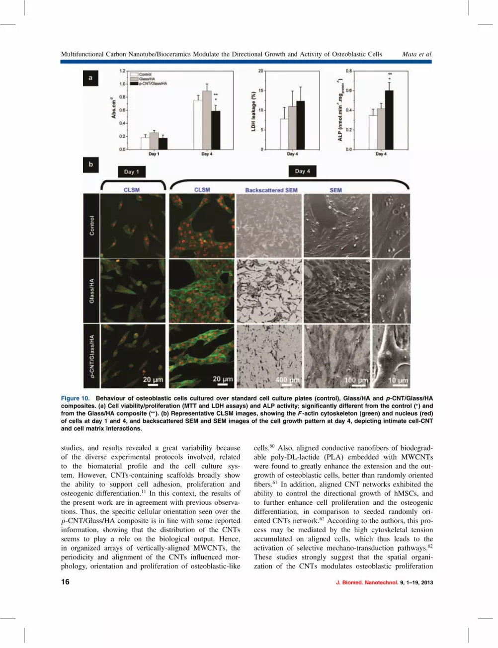
Osteoblastic Cell Responseto p-CNT/Glass/HA CompositesFigure 10(a) shows the results for the viabil-ity/proliferation (evaluated by the MTT and LDH assays)and ALP activity of osteoblastic cells cultured overp-CNT/Glass/HA composite, compared to those onGlass/HA composite and standard cell culture plate (con-trol). At day 1, MTT reduction values were similar onthe three surfaces, showing that comparable number ofcells adhered to these substrates (although the Glass/HAcomposite presented slightly higher values). However, atday 4, cell proliferation on the CNT/Glass/HA compositewas lower than that on the Glass/HA surface and controlcultures. On the LDH assay, the similar values observedon the two composites suggest that the attached cellswere viable on both surfaces. In spite of the lower cellproliferation seen on the p-CNT/Glass/HA composite,significantly higher values were found for ALP activity.This enzyme is an important osteoblastic differentiationmarker, as it plays a relevant role in the mineralization ofthe bone collagenous matrix.59
CLSM images at day 1 (Fig. 10(b)) show that MG63cells adhered to the tested surfaces, and exhibited an orga-nized F -actin cytoskeleton with intense staining at thecell boundaries. However, differences were noted on thecell morphology and distribution over the surface. Cellsattached to the control surface and to the Glass/HA com-posite showed a polygonal/elongated morphology and arandom distribution, whereas, on the p-CNT/Glass/HAcomposite, cells were more elongated and displayed a ten-dency for an oriented alignment. Cell division was alreadyvisible, at day 1, on the three surfaces.Cells proliferated throughout the culture time, as shown
in the CLSM images at day 4 (Fig. 10(b)). Cells dis-played a healthy behaviour, with a prominent nucleus,a well-developed F -actin cytoskeleton and signs of activeon-going proliferation on control cultures and on bothcomposites. However, the pattern of cell growth wasclearly distinct, i.e., the cell layer was randomly orga-nized over Glass/HA composite, but revealed a definedoriented alignment over the p-CNT/Glass/HA composite.These observations were further confirmed by SEM analy-ses (Fig. 10(b)). Cells cultured over the p-CNT/Glass/HAcomposite displayed a tendency to follow the align-ment/orientation of the CNT agglomerates on the materialsurface (Fig. 10(b)). At high magnification (bottom right inFig. 10(b)), an intimate cell-CNT interaction was observedwith cells exhibiting a normal morphology with abundantcytoplasm expansions over CNT agglomerates, being fullyintegrated in the tube’s fibrilar morphology. A high mag-nification image (bottom right in Fig. 10(b)) shows anosteoblast attached to a CNTs agglomerate, exhibiting anormal morphology and abundant cytoplasm expansions tothe composie matrix.Cell response to CNT-containing materials for bone
tissue applications has been addressed in a variety of
J. Biomed. Nanotechnol. 9, 1–19, 2013 15
Multifunctional Carbon Nanotube/Bioceramics Modulate the Directional Growth and Activity of Osteoblastic Cells Mata et al.
Figure 10. Behaviour of osteoblastic cells cultured over standard cell culture plates (control), Glass/HA and p-CNT/Glass/HAcomposites. (a) Cell viability/proliferation (MTT and LDH assays) and ALP activity; significantly different from the control (∗) andfrom the Glass/HA composite (∗∗). (b) Representative CLSM images, showing the F -actin cytoskeleton (green) and nucleus (red)of cells at day 1 and 4, and backscattered SEM and SEM images of the cell growth pattern at day 4, depicting intimate cell-CNTand cell matrix interactions.
studies, and results revealed a great variability becauseof the diverse experimental protocols involved, relatedto the biomaterial profile and the cell culture sys-tem. However, CNTs-containing scaffolds broadly showthe ability to support cell adhesion, proliferation andosteogenic differentiation.11 In this context, the results ofthe present work are in agreement with previous observa-tions. Thus, the specific cellular orientation seen over thep-CNT/Glass/HA composite is in line with some reportedinformation, showing that the distribution of the CNTsseems to play a role on the biological output. Hence,in organized arrays of vertically-aligned MWCNTs, theperiodicity and alignment of the CNTs influenced mor-phology, orientation and proliferation of osteoblastic-like
cells.60 Also, aligned conductive nanofibers of biodegrad-able poly-DL-lactide (PLA) embedded with MWCNTswere found to greatly enhance the extension and the out-growth of osteoblastic cells, better than randomly orientedfibers.61 In addition, aligned CNT networks exhibited theability to control the directional growth of hMSCs, andto further enhance cell proliferation and the osteogenicdifferentiation, in comparison to seeded randomly ori-ented CNTs network.62 According to the authors, this pro-cess may be mediated by the high cytoskeletal tensionaccumulated on aligned cells, which thus leads to theactivation of selective mechano-transduction pathways.62
These studies strongly suggest that the spatial organi-zation of the CNTs modulates osteoblastic proliferation
16 J. Biomed. Nanotechnol. 9, 1–19, 2013

Mata et al. Multifunctional Carbon Nanotube/Bioceramics Modulate the Directional Growth and Activity of Osteoblastic Cells
and differentiation events. Due to the established inverserelationship between proliferation and differentiation dur-ing the development of the osteolastic phenotype,59 thelower cell proliferation but higher ALP activity observed inthe present work on the p-CNT/Glass/HA composite sug-gests an inductive effect on the osteoblastic differentiation,compared to that observed over the Glass/HA compos-ite. Increased ALP activity was also observed in MC3T3-E1 pre-osteoblastic cells with the inclusion of MWCNTsin hydroxyapatite coatings, compared to that attained onthe bare substrate (titanium alloy) and pure HA coating.63
In another study, mouse mesenchymal stem cells culturedover a complex of SWCNT grafted with the polysac-charide glucosamine revealed a higher ALP activity andenhanced mineralization, as compared to glucosaminealone.64 On the other hand, application of CNTs insteadof collagen fibers in bone tissue, as a proposed approachfor improving bone mechanical properties, should be care-fully considered. Thus, such a replacement, as addressedby a finite element analysis, can cause a reduction in strainenergy density and distribution,65 leading the authors tospeculate about the possibility of disturbed bone mechan-ical and biological functions.
CONCLUSIONSMultifunctional carbon nanotube/bioceramic bone graftswith controlled CNT agglomeration were processed by anoptimized functionalization-free route with minor contam-inant levels and damage to CNTs.The non-functionalized CNT composites presented
homogenously dispersed CNT agglomerates with diam-eter sizes below 3 �m similar to those resulting fromDiels-Alder functionalization. The latter improved theCNT stabilization and CNT-ceramic interactions. How-ever, this functionalization was less decisive than thefunctionalization-free processing route in the final proper-ties of the biocomposite, due to in situ oxidation of CNTsduring the high temperature sintering.CNTs worked as efficient toughening agents in non-
functionalized composites improving the fracture tough-ness of the ceramic matrix, making it closer to the oneof natural cortical bone. The remaining mechanical andelectrical properties of the composite outperformed thoseof the natural bone. These composites degraded at higherrates in in vitro testing than the ceramic matrix, but withreleasing of CNTs with biological safe diameter sizes.The CNT/bioceramic composites allowed cell adhesionand proliferation, further enhancing the functional activityand modulating the orientation of the cell growth alongthe alignment of the CNT agglomerates on the compositesurface.The present highly electroconductive and tough mul-
tifunctional bone grafts including biologically safe andimpurity-free CNT agglomerates are apt to interface with
bone tissue and offer high perspectives to control its regen-eration rate by in situ electrical stimulation.
Acknowledgments: D. Mata acknowledges the finan-cial support of FCT (SFRH/BD/36273/2007). The authorsgratefully acknowledge R. F. Araújo (Centre of Chemistry,University of Minho) for kindly supplying the functional-ized CNTs and A. J. S. Fernandes (Physics Department,University of Aveiro) for the �-Raman measurements.
REFERENCES1. L. L. Hench and J. M. Polak, Third-generation biomedical materials.
Science 295, 1014 (2002).2. Z. B. Friedenberg and C. T. Brighton, Bioelectric potentials in bone.
J. Bone Joint Surg. Am. 48, 915 (1966).3. E. Fukada and I. Yasuda, On the piezoelectic effect of bone. J. Phys.
Soc. Japan. 12, 1158 (1957).4. S. Grimnes and O. G. Martinsen (eds.), Bioimpedance and Bioelec-
tricity Basics, Academic Press, UK (2008).5. S. Saha and P. A. Williams, Electric and dielectric properties of
wet human cortical bone as a function of frequency IEEE. Trans.Biomed. Eng. 39, 1298 (1992).
6. K. W. Altman and R. Plonsey, Analysis of the longitudinal andradial resistivity measurements of the nerve trunk. Ann. Biomed. Eng.17, 313 (1989).
7. D. A. Puleo and W. W. Huh, Acute toxicity of metal ions in culturesof osteogenic cells derived from bone marrow stromal cells. J. Appl.Biomater. 6, 109 (1995).
8. S. Rul, F. Lefèvre-schlick, E. Capria, C. Laurent, and A. Peigney,Percolation of single-walled carbon nanotubes in ceramic matrixnanocomposites. Acta Mater. 52, 1061 (2004).
9. P. R. Supronowicz, P. M. Ajayan, K. R. Ullmann, B. P. Arulanandam,D. W. Metzger, and R. Bizios, Novel current-conducting compositesubstrates for exposing osteoblasts to alternating current stimulation.J. Biomed. Mater. Res. A59, 499 (2002).
10. D. Lahiri, S. Ghosh, and A. Agarwal, Carbon nanotube reinforcedhydroxyapatite composite for orthopedic application: A review.Mater. Sci. Eng. C32, 1727 (2012).
11. J. Meng, L. Song, L. Meng, H. Kong, G. Zhu, and C. Wang,Using single-walled carbon nanotubes nonwoven films as scaffoldsto enhance long-term cell proliferation in vitro. J. Biomed. Mater.Res. A 79, 298 (2006).
12. A. Guiseppi-Elie, Electroconductive hydrogels: Synthesis, character-ization and biomedical applications. Biomaterials 31, 2701 (2010).
13. Q. Mu, D. L. Broughton, and B. Yan, Endosomal leakage andnuclear translocation of multiwalled carbon nanotubes: Developinga model for cell uptake. Nano Lett. 9, 4370 (2009).
14. L. Lacerda, M. H. Herrero, K. Venner, A. Bianco, M. Prato, andK. Kostarelos, Carbon-nanotube shape and individualization criticalfor renal excretion. Small 4, 1130 (2008).
15. C. Bussy, J. Cambedouzou, S. Lanone, E. Leccia, V. Heresanu,M. Pinault, et al., Carbon nanotubes in macrophages: Imaging andchemical analysis by X-ray fluorescence microscopy. Nano Lett.8, 2659 (2008).
16. R. A. Freitas (ed.), Nanomedicine Volume IIA: Biocompatibility,Landes Bioscience, Texas (2003).
17. V. Stone and K. Donaldson, Signs of stress. Nat. Nanotechnol. 1, 23(2006).
18. C. Poland, R. Duffin, I. Kinloch, A. Maynard, W. Wallace, A. Seatonet al., Carbon nanotubes introduced into the abdominal cavityof mice show asbestos-like pathogenicity in a pilot study. Nat.Nanotechnol. 3, 423 (2008).
19. M. L. Schipper, N. Nakayama-Ratchford, C. R. Davis, N. W. S.Kam, P. Chu, Z. Liu et al., A pilot toxicology study of single-walled
J. Biomed. Nanotechnol. 9, 1–19, 2013 17

Multifunctional Carbon Nanotube/Bioceramics Modulate the Directional Growth and Activity of Osteoblastic Cells Mata et al.
carbon nanotubes in a small sample of mice nature. Nat. Nanotech-nol. 221 (2008).
20. Y. Sato, A. Yokoyama, K.-I. Shibata, Y. Akimoto, S.-I. Ogino, andY. Nodasaka, Influence of length on cytotoxicity of multi-walledcarbon nanotubes against human acute monocytic leukemia cell lineTHP-1 in vitro and subcutaneous tissue of rats in vivo. Mol. Bio.Syst. 1, 176 (2005).
21. A. Abarrategi, M. C. Gutiérrez, M. Moreno-Vicente, M. J.Hortigüela, V. Ramosa, J. L. Lopéz-Lacomba et al., Multiwall car-bon nanotube scaffolds for tissue engineering purposes. Biomaterials29, 94 (2008).
22. S. K. Yadav, T. Bera, P. S. Saxena, A. K. Maurya, R. S. Garbyal,R. Vajtai, et al., MWCNTs as reinforcing agent to the Hap-Gelnanocomposite for artificial bone grafting. J. Biomed. Mater. Res.93A, 886 (2010).
23. W. Wang, Y. Zhu, F. Watari, S. Liao, A. Yokoyama, M. Omoriet al., Carbon nanotubes/hydroxyapatite nanocomposites fabricatedby spark plasma sintering for bone graft applications. Appl. Surf.Sci. 262, 194 (2012).
24. L. Dong, C. M. Witkowski, M. M. Craig, M. M. Greenwade,and K. L. Joseph, Cytotoxicity effects of different surfactantmolecules conjugated to carbon nanotubes on human astrocytomacells. Nanoscale Res. Lett. 4, 1517 (2009).
25. G. H. Xu, Q. Zhang, J. Q. Huang, M. Q. Zhao, W. P. Zhou, andF. Wei, A two-step shearing strategy to disperse long carbon nano-tubes from vertically aligned multiwalled carbon nanotube arrays fortransparent conductive films. Langmuir 26, 2798 (2010).
26. Q. Cheng, S. Debnath, E. Gregan, and H. J. Byrne, Ultrasound-assisted SWNTs dispersion: Effects of sonication parameters andsolvent properties. J. Phys. Chem. C 114, 8821 (2010).
27. M. E. Labib and R. Williams, The use of zeta-potential measure-ments in organic solvents to determine the donor–acceptor propertiesof solid surfaces. J. Colloid Interface Sci. 97, 356 (1984).
28. H. Kong, C. Gao, and D. Yan, Controlled functionalization of mul-tiwalled carbon nanotubes by in situ atom transfer radical polymer-ization. J. Am. Chem. Soc. 126, 412 (2004).
29. Y. S. Lee and N. Marzari, Cycloaddition functionalizations to pre-serve or control the conductance of carbon nanotubes. Phys. Rev.Lett. 97, 116801 (2006).
30. M. F. Proença, R. F. Araújo, M. C. Paiva, and C. J. R. Silva, TheDiels-Alder cycloaddition reaction in the functionalization of carbonnanofibers. J. Nanosci. Nanotechnol. 9, 6234 (2009).
31. D. Mata, F. J. Oliveira, N. M. Ferreira, R. F. Araújo, A. J. S.Fernandes, M. A. Lopes, and R. F. Silva, Sintering strategies forsmart electroconductive carbon nanotube/glass/hydroxyapatite bonegrafts. Biomed. Mater. submitted.
32. D. Mata, R. M. Silva, A. J. S. Fernandes, F. J. Oliveira, P. M. F. J.Costa, and R. F. Silva, Upscaling potential of the CVD stackinggrowth method to produce dimensionally-controlled and catalyst-freemultiwalled carbon nanotubes. Carbon 50, 3585 (2012).
33. L. G. Cançado, K. Takai, T. Enoki, M. Endo, Y. A. Kim,H. Mizusaki, et al., General equation for the determination of thecrystallite size La of nanographite by Raman spectroscopy. Appl.Phys. Lett. 88, 163106 (2006).
34. A. L. Patterson, The Scherrer formula for X-ray particle size deter-mination. Phys. Rev. 56, 978 (1939).
35. P. Hiemenz and R. Rajagopalan (eds.), Principles of Colloid andSurface and Chemistry, Marcel Dekker, New York (1997).
36. K. Niihara, R. Morena, and D. P. H. Hasselman, Evaluation of Kicof brittle solids by the indentation method with low crack-to-indentratios. J. Mater. Sci. Lett. 1, 13 (1982).
37. ASM Handbook: Alloy Phase Diagrams, ASM International, USA(1992).
38. M. Terrones, N. Grobert, J. Olivares, J. P. Zhang, H. Terrones,K. Kordatos et al., Controlled productionof aligned-nanotubebundles.Nature 388, 52 (1997).
39. J. Zhang, H. Zou, Q. Qing, Y. Yang, Q. Li, and Z. Liu, Effect ofchemical oxidation on the structure of single-walled carbon nano-tubes. J. Phys. Chem. B 107, 3712 (2003).
40. W. Huang, Y. Wang, G. Luo, and F. Wei, 99.9% purity multi-walledcarbon nanotubes by vacuum high-temperature annealing. Carbon41, 2585 (2003).
41. A. I. Zhbanov, E. G. Pogorelov, and Y. C. Chang, Van der Waalsinteraction between two crossed carbon nanotubes. ACS Nano4, 5937 (2010).
42. M. A. Lopes, J. D. Santos, F. J. Monteiro, C. Ohtsuki, A. Osaka,S. Kaneko, and H. Inoue, Push-out testing and histological evaluationof glass reinforced hydroxyapatite composites implanted in the tibiaof rabbits. J. Biomed. Mater. Res. 54, 463 (2001).
43. C. M. Hansen and A. L. Smith, Using Hansen solubility parametersto correlate solubility of C60 fullerene in organic solvents and inpolymers. Carbon 42, 1591 (2004).
44. H. T. Ham, Y. S. Choi, and I. J. Chung, An explanation of dispersionstates of single-walled carbon nanotubes in solvents and aqueoussurfactant solutions using solubility parameters. J. Colloid InterfaceSci. 286, 216 (2005).
45. S. D. Bergin, V. Nicolosi, P. V. Streich, S. Giordani, Z. Sun, A. H.Windle, et al., Towards solutions of single-walled carbon nanotubesin common solvents. Adv. Mater. 20, 1876 (2008).
46. S. D. Bergin, Z. Y. Sun, D. Rickard, P. V. Streich, J. P. Hamil-ton, and J. N. Coleman, Multicomponent solubility parameters forsingle-walled carbon nanotube-solvent mixtures. ACS Nano 3, 2340(2009).
47. H. Kataura, Y. Kumazawa, Y. Maniwa, I. Umezu, S. Suzuki, Y. Oht-suka, et al., Optical properties of single-wall carbon nanotubes.Synth. Met. 103, 2555 (1999).
48. J. Yu, N. Grossiord, C. E. Koning, and J. Loos, Controlling the dis-persion of multi-wall carbon nanotubes in aqueous surfactant solu-tion. Carbon 45, 618 (2007).
49. R. Damodaran and B. M. Moudgil, Electrophoretic deposition of cal-cium phosphates from non-aqueous media. Colloids Surf. A: Physic-ochem. Eng. Aspects 80, 191 (1993).
50. R. Xu, C. Wu, and H. Xu, Particle size and zeta potential of carbonblack in liquid media. Carbon 45, 2806 (2007).
51. M. Javidi, M. E. Bahrololoom, S. Javadpour, and J. Ma, Studyingsurface charge and suspension stability of hydroxyapatite powderin isopropyl alcohol to prepare stable suspension for electrophoreticdeposition. Adv. Appl. Ceram. 108, 241 (2009).
52. G. D. Han, J. D. Kuntz, J. Wan, and A. K. Mukherjee, Single-wallcarbon nanotubes as attractive toughening agents in alumina-basednanocomposites. Nat. Mater. 2, 38 (2003).
53. N. X. Dong and X. E. Guo, The dependence of transversely isotropicelasticity of human femoral cortical bone on porosity. J. Biomech.37, 1281 (2004).
54. L. L. Hench, Bioceramics: From concept to clinic. J. Am. Ceram.Soc. 74, 1487 (1991).
55. J. K. Weaver, The microscopic hardness of bone. J. Bone. Joint Surg.48, 273 (1966).
56. F. G. Evans and R. Vincentell, Relations of the compressive proper-ties of human cortical bone to histological structure and calcification.J. Biomech. 71 (1974).
57. R. Baron, L. Neff, D. Louvard, and P. J. Courtoy, Cell-mediatedextracellular acidification and bone-resorption—evidence for a lowph in resorbing lacunae and localization of a 100-kD lysosomalmembrane-protein at the osteoclast ruffled border. J. Cell Biol.101, 2210 (1985).
58. A. G. Dias, I. R. Gibson, J. D. Santos, and M. A. Lopes, Physico-chemical degradation studies of calcium phosphate glass ceramic inthe CaO–P2O5–MgO–TiO2 system. Acta Biomater. 326, 3 (2007).
59. J. Aubin, Mesenchymal stem cell and osteoblast differentiation, Prin-ciples of Bone Biology, edited by J. P. Bilezikian, L. G. Raisz, andT. J. Martin, Academic Press, USA (2008), pp. 85–107.
18 J. Biomed. Nanotechnol. 9, 1–19, 2013

Mata et al. Multifunctional Carbon Nanotube/Bioceramics Modulate the Directional Growth and Activity of Osteoblastic Cells
60. S. Giannona, I. Firkowska, J. Rojas-Chapana, and M. Giersig,Vertically aligned carbon nanotubes as cytocompatible materialfor enhanced adhesion and proliferation of osteoblast-like cells.J. Nanosci. Nanotechnol. 7, 1679 (2007).
61. S. Shao, S. Zhou, L. Li, J. Li, C. Luo, J. Wang, et al., Osteoblastfunction on electrically conductive electrospun PLA/MWCNTsnanofibers. Biomaterials 32, 2821 (2011).
62. S. Namgung, K. Y. Baik, J. Park, and S. Hong, Controlling the growthand differentiation of human mesenchymal stem cells by the arrange-ment of individual carbon nanotubes. ACS Nano 5, 7383 (2011).
63. B.-D. Hahn, J.-M. Lee, D.-S. Park, J.-J. Choi, J. Ryu, W.-E. Yoon,et al., Mechanical and in vitro biological performances ofhydroxyapatite–carbon nanotube composite coatings deposited on Tiby aerosol deposition. Acta Biomater. 5, 3205 (2009).
64. J. Venkatesan and S. K. Kim, Stimulation of minerals by carbonnanotube grafted glucosamine in mouse mesenchymal stem cells forbone tissue engineering. J. Biomed. Nanotechnol. 8, 676 (2012).
65. N. Jamilpour, A. Fereidoon, and G. Rouhi, The effects of replacingcollagen fibers with carbon nanotubes on the rate of bone remodelingprocess. J. Biomed. Nanotechnol. 7, 542 (2011).
J. Biomed. Nanotechnol. 9, 1–19, 2013 19