multiband ,coplanar and small antenna systems for wireless hand held devices
TRANSCRIPT
3782 IEEE TRANSACTIONS ON ANTENNAS AND PROPAGATION, VOL. 61, NO. 7, JULY 2013
Multiband and Small Coplanar Antenna System forWireless Handheld Devices
Jaume Anguera, Senior Member, IEEE, Aurora Andújar, Student Member, IEEE, and Carlos García
Abstract—Multiband and small antennas are strongly de-manded in current wireless handheld or portable devices thatrequire multiband operation. Nowadays, trends are focused onexciting ground plane radiation modes in order to reduce as muchas possible the volume devoted to the antenna element. This paperstudies different geometries for determining which one betterexcites a ground plane radiation mode at different frequencyregions. The results demonstrate that a non-resonant pad elementattains the best tradeoff between performance and geometry com-plexity. A multiband antenna system featuring small coplanar padelements is proposed for providing operation at the communica-tion standards LTE700 (698–787 MHz), GSM850 (824–894 MHz),GSM900 (880–960 MHz), GSM1800 (1710–1880 MHz), GSM1900(1850–1990MHz), UMTS (1920–2170MHz), LTE2100 (1920–2170MHz), LTE2300 (2300–2400 MHz), LTE2500 (2500–2690 MHz)as well as at the satellite positioning systems GPS (1575 MHz),Galileo L1 (1559–1591 MHz), Glonass (1592–1609 MHz). A ra-diofrequency system comprising broadband matching networks isincluded to provide the required impedance bandwidth. Numer-ical results give physical insight into the behavior of the proposedplanar element. A prototype is built to demonstrate the feasibilityof the proposal. The proposed radiating system is appealing forthe new wireless handheld devices due to its small size (153 ),planar profile, and multiband performance.
Index Terms—Broadband matching networks, ground planemodes, handset antennas, quality factor, small/multi-band.
I. INTRODUCTION
W IRELESS handheld devices are adopting new form fac-tors and incorporating new mobile network technolo-
gies. Examples of new form factors are smart-phones featuredby a large display. Smart-phones are rapidly substituting otherwell-known form factors such as for example small bar-typesphones, sliders, and clamshells. In regard the new mobile net-work technologies, LTE is acquiring relevance because it willdeliver very fast data with speeds up to 100 Mbs in the down-link. Accordingly, there is a strong need of multiband and smallradiating systems in the ever growing wireless market. Many
Manuscript received August 06, 2012; revised December 31, 2012; acceptedFebruary 09, 2013. Date of publication March 28, 2013; date of current versionJuly 01, 2013. This work was supported by Fractus.J. Anguera is with the Technology and Intellectual Property Rights De-
partment, Fractus, 08174 Barcelona, Spain and also with the Electronicsand Telecommunications Department of the Universitat Ramon Llull, 08022Barcelona, Spain (e-mail: [email protected]).A. Andújar is with the Technology and Intellectual Property Rights Depart-
ment, Fractus, 08174 Barcelona, Spain.C. García was with the Electronics and Telecommunications Department of
the Universitat Ramon Llull, 08022 Barcelona, Spain. He is now with the LGAITechnological Center (Applus+), 08193 Barcelona, Spain.Color versions of one or more of the figures in this paper are available online
at http://ieeexplore.ieee.org.Digital Object Identifier 10.1109/TAP.2013.2253297
antenna techniques including PIFAs [1], [2], monopoles [3]–[6],loops [7], slots [8], [9], balanced antennas [10], and combina-tions [11], [12] have been proposed in the literature and industry.Since the ground plane plays an important role in the elec-
tromagnetic performance of a wireless handheld device, othertechniques rely on adding intelligence to it [13]–[21]. Other so-lutions propose small c-shape elements to provide coupling toexcite the ground plane [22]. Finally, the ground plane is usedas the main radiator by means of small elements that have beenproposed for multiband operation [23]–[26]. Taking into ac-count this trend, this paper analyzes which geometry is preferredfor maximizing the transfer of energy to the efficient radiationmodes that a ground plane of a handset platform supports at mo-bile frequencies. The paper not only discusses the ground planeinteraction with resonant antenna elements having different ge-ometries (inspired Hilbert monopoles of two and three iterationsand spiral monopoles) but also analyzes such interaction whensmall non-resonant ground plane boosters are used. The studyreveals that non-resonant antenna elements are preferable forexciting ground plane radiation modes since they maximize theattainable inherent bandwidth.In this direction, the present paper describes a multiband
and small radiating system for providing operation at LTE700,GSM850, GSM900, GSM1800, GSM1900, UMTS, LTE2100,LTE2300, LTE2500 as well as GPS/Galileo L1/Glonass usingcoplanar elements (i.e. they lie on the same plane as the groundplane). Section II compares the influence of several geometrieson the ground plane mode excitation, and hence, in the inherentbandwidth. Once an element has been selected, Section IIIproposes a multiband, small, and planar radiating system forproviding operation at the above communication systems. Aprototype is built for the sake of validating the feasibility ofthe proposal in Section IV. Finally, Section V presents theconclusions.
II. ON THE BEHAVIOR OF SEVERAL GEOMETRIES
Usually, the most challenging situation for designing multi-band-small antennas for wireless handheld devices occurs atthe lowest frequencies of operation (690–960 MHz where somecommunications standards such as LTE700, GSM850, andGSM900 are allocated). In this frequency region, the groundplane is small in terms of wavelength and in some situationsit does not support an efficient radiating mode. This section isfocused on determining which element becomes preferred forexciting efficient radiation modes of a typical ground plane ofa wireless handheld device. With this aim, four elements areanalyzed: a spiral, two fractal-inspired elements based on theHilbert geometry (second (H2) and third iteration (H3)) [27],and a non-resonant element called pad (Fig. 1).
0018-926X/$31.00 © 2013 IEEE
ANGUERA et al.: MULTIBAND AND SMALL COPLANAR ANTENNA SYSTEM FOR WIRELESS HANDHELD DEVICES 3783
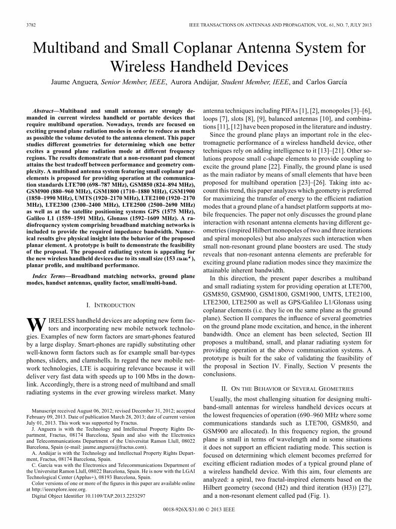
Fig. 1. Geometry of the proposed structures (spiral, H2, H3, and pad) in aground plane of 90 mm 40 mm etched in a 1 mm FR4 substrate
. For this case, spiral, H2, and H3 resonate at 900 MHz.
All elements are 15 mm 15 mm. In a first experiment, thespiral and the two Hilbert-based antennas are tuned to resonateat 900 MHz (approximately the center frequency of the fre-quency region comprising GSM850–900) whereas the pad hasits first resonance at 1921 MHz, well above the frequency re-gion of operation. Simulations are performed usingMoM (IE3Dsoftware). The ground plane dimensions are 90 mm 40 mmand is printed on a thin FR4 substrate of 1 mm thick ( ,
). For this ground plane dimensions, the first char-acteristic mode resonates at 1170MHz. This resonance hasbeen calculated using characteristic mode analysis, computingthe zero crossing of the eigenvalue [28], [29]. For this reason,in the second experiment, the spiral, H2, and H3 are tuned to res-onate at 1170 MHz, i.e. at the same frequency as the eigenmode. The basis for these two experiments is found on the electrical
circuit modeling an antenna with a ground plane [13], [19]. Theprevious circuit analysis demonstrates that the bandwidth of aradiating system is improvedwhen the resonant frequency of theantenna and that of the ground plane are the same. At 900 MHz,the antenna can be easily resonating but not the ground planeunless it has enough length (approximately [1], which re-sults in 133 mm at 900 MHz). Previous work in the literature[13]–[19], teaches that the resonant frequency of short groundplanes (around 100 mm), can be shifted down to 900 MHz byintroducing slots that force currents to travel a longer path, thusemulating a longer ground plane. For the present paper, the ap-proach is not focused on manipulating the ground plane, but onanalyzing the effect of the relation between the resonant fre-quency of the antenna element in relation to that of the groundplane and also the effect of the antenna geometry over the in-herent bandwidth. In order to solve these questions, the pro-posed experiments analyze three antennas with a different ge-ometry (spiral, H2, and H3) having a resonance at three differentfrequencies:1) 900 MHz, center frequency of the frequency region wherethe communication standards GSM850–900 are allocated.
2) 1170 MHz, coinciding with the resonant frequency ofthe fundamental mode of a ground plane (eigenmode )having dimensions of 90 mm 40 mm.
3) a frequency above the resonance frequency of .The behavior of the previous proposals is further compared
with a pad element having a resonant frequency well above theresonance of the ground plane.
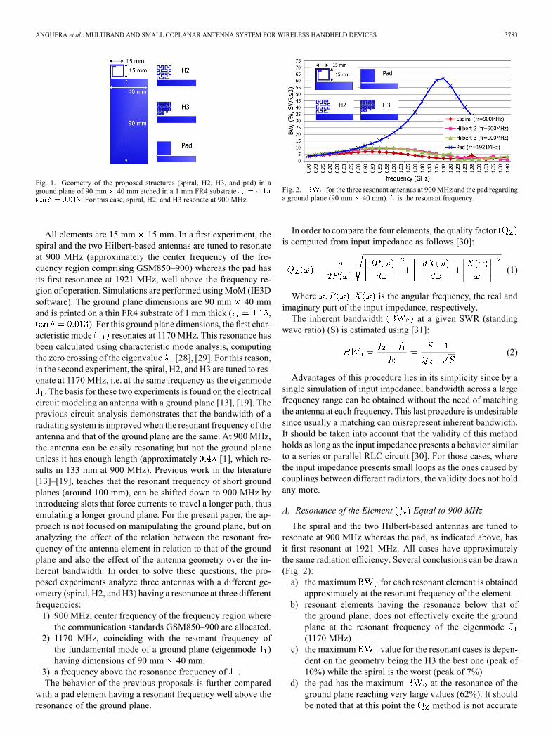
Fig. 2. for the three resonant antennas at 900MHz and the pad regardinga ground plane (90 mm 40 mm). is the resonant frequency.
In order to compare the four elements, the quality factoris computed from input impedance as follows [30]:
(1)
Where is the angular frequency, the real andimaginary part of the input impedance, respectively.The inherent bandwidth at a given SWR (standing
wave ratio) (S) is estimated using [31]:
(2)
Advantages of this procedure lies in its simplicity since by asingle simulation of input impedance, bandwidth across a largefrequency range can be obtained without the need of matchingthe antenna at each frequency. This last procedure is undesirablesince usually a matching can misrepresent inherent bandwidth.It should be taken into account that the validity of this methodholds as long as the input impedance presents a behavior similarto a series or parallel RLC circuit [30]. For those cases, wherethe input impedance presents small loops as the ones caused bycouplings between different radiators, the validity does not holdany more.
A. Resonance of the Element Equal to 900 MHz
The spiral and the two Hilbert-based antennas are tuned toresonate at 900 MHz whereas the pad, as indicated above, hasit first resonant at 1921 MHz. All cases have approximatelythe same radiation efficiency. Several conclusions can be drawn(Fig. 2):a) the maximum for each resonant element is obtainedapproximately at the resonant frequency of the element
b) resonant elements having the resonance below that ofthe ground plane, does not effectively excite the groundplane at the resonant frequency of the eigenmode(1170 MHz)
c) the maximum value for the resonant cases is depen-dent on the geometry being the H3 the best one (peak of10%) while the spiral is the worst (peak of 7%)
d) the pad has the maximum at the resonance of theground plane reaching very large values (62%). It shouldbe noted that at this point the method is not accurate
3784 IEEE TRANSACTIONS ON ANTENNAS AND PROPAGATION, VOL. 61, NO. 7, JULY 2013
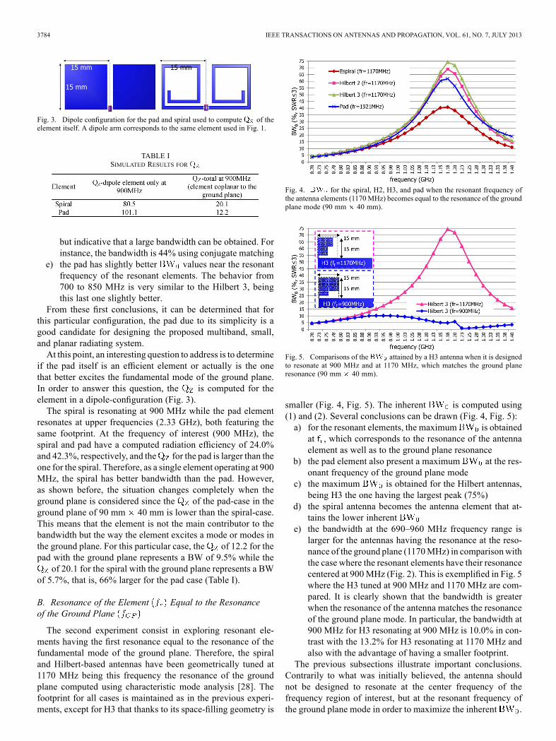
Fig. 3. Dipole configuration for the pad and spiral used to compute of theelement itself. A dipole arm corresponds to the same element used in Fig. 1.
TABLE ISIMULATED RESULTS FOR
but indicative that a large bandwidth can be obtained. Forinstance, the bandwidth is 44% using conjugate matching
e) the pad has slightly better values near the resonantfrequency of the resonant elements. The behavior from700 to 850 MHz is very similar to the Hilbert 3, beingthis last one slightly better.
From these first conclusions, it can be determined that forthis particular configuration, the pad due to its simplicity is agood candidate for designing the proposed multiband, small,and planar radiating system.At this point, an interesting question to address is to determine
if the pad itself is an efficient element or actually is the onethat better excites the fundamental mode of the ground plane.In order to answer this question, the is computed for theelement in a dipole-configuration (Fig. 3).The spiral is resonating at 900 MHz while the pad element
resonates at upper frequencies (2.33 GHz), both featuring thesame footprint. At the frequency of interest (900 MHz), thespiral and pad have a computed radiation efficiency of 24.0%and 42.3%, respectively, and the for the pad is larger than theone for the spiral. Therefore, as a single element operating at 900MHz, the spiral has better bandwidth than the pad. However,as shown before, the situation changes completely when theground plane is considered since the of the pad-case in theground plane of 90 mm 40 mm is lower than the spiral-case.This means that the element is not the main contributor to thebandwidth but the way the element excites a mode or modes inthe ground plane. For this particular case, the of 12.2 for thepad with the ground plane represents a BW of 9.5% while theof 20.1 for the spiral with the ground plane represents a BW
of 5.7%, that is, 66% larger for the pad case (Table I).
B. Resonance of the Element Equal to the Resonanceof the Ground Plane
The second experiment consist in exploring resonant ele-ments having the first resonance equal to the resonance of thefundamental mode of the ground plane. Therefore, the spiraland Hilbert-based antennas have been geometrically tuned at1170 MHz being this frequency the resonance of the groundplane computed using characteristic mode analysis [28]. Thefootprint for all cases is maintained as in the previous experi-ments, except for H3 that thanks to its space-filling geometry is
Fig. 4. for the spiral, H2, H3, and pad when the resonant frequency ofthe antenna elements (1170MHz) becomes equal to the resonance of the groundplane mode (90 mm 40 mm).
Fig. 5. Comparisons of the attained by a H3 antenna when it is designedto resonate at 900 MHz and at 1170 MHz, which matches the ground planeresonance (90 mm 40 mm).
smaller (Fig. 4, Fig. 5). The inherent is computed using(1) and (2). Several conclusions can be drawn (Fig. 4, Fig. 5):a) for the resonant elements, the maximum is obtainedat , which corresponds to the resonance of the antennaelement as well as to the ground plane resonance
b) the pad element also present a maximum at the res-onant frequency of the ground plane mode
c) the maximum is obtained for the Hilbert antennas,being H3 the one having the largest peak (75%)
d) the spiral antenna becomes the antenna element that at-tains the lower inherent
e) the bandwidth at the 690–960 MHz frequency range islarger for the antennas having the resonance at the reso-nance of the ground plane (1170MHz) in comparisonwiththe case where the resonant elements have their resonancecentered at 900MHz (Fig. 2). This is exemplified in Fig. 5where the H3 tuned at 900 MHz and 1170 MHz are com-pared. It is clearly shown that the bandwidth is greaterwhen the resonance of the antenna matches the resonanceof the ground plane mode. In particular, the bandwidth at900 MHz for H3 resonating at 900 MHz is 10.0% in con-trast with the 13.2% for H3 resonating at 1170 MHz andalso with the advantage of having a smaller footprint.
The previous subsections illustrate important conclusions.Contrarily to what was initially believed, the antenna shouldnot be designed to resonate at the center frequency of thefrequency region of interest, but at the resonant frequency ofthe ground plane mode in order to maximize the inherent .
ANGUERA et al.: MULTIBAND AND SMALL COPLANAR ANTENNA SYSTEM FOR WIRELESS HANDHELD DEVICES 3785
The results further illustrate that this resonance could be alsoplaced well above the resonant frequency of the fundamentalmode of the ground plane (pad element) without a significantloss of performance. In fact, the pad element offers a larger
at 900 MHz than the other antenna elements resonatingat this particular frequency. This conclusion is completelyaligned with that obtained from the electrical model presentedin [19] where the bandwidth was maximized if the resonantfrequency of the antenna matched that of the ground plane.However, a new conclusion is derived here since if the resonantfrequency of the element is placed above that of the groundplane, bandwidth can be large enough and very similar to thatobtained in those cases where both resonances, become thesame (Fig. 4, Fig. 5).
C. Resonance of the Element Above to the Resonanceof the Ground Plane
Finally, the spiral, H2, H3 are geometrically tuned at a fre-quency above the resonance of the ground plane (the resonanceof the eigenmode which is 1170 MHz). For this case, all theelements are 5 mm 5 mm. The resonant frequencies for thespiral, H2, H3, and pad are 2500 MHz, 3800 MHz, 2300 MHz,and 5800 MHz, respectively which are well above 1170 MHz.For this experiment, all cases present the same at the fre-quency region of 690–960 MHz which is similar to the resultshown in Fig. 4.For the previous reasons as well as for simplicity purposes
and performance, the pad element is selected as the preferred el-ement to design a multiband, small, and planar radiating systemto operate in multiple frequency bands.
III. SIMULATION RESULTS
Once the candidate has been selected, the purpose of thispaper consists in demonstrating its feasibility to provide amultiband and small radiating system. The ground plane isselected to be representative of that associated to a smart-phone device: the ground plane is 120 mm 50 mm. Thesize of the pad is designed according to the previous rulesof thumb as the one sufficient for covering the requiredbandwidth at each frequency region. For this particular case,the target is to operate at the following communicationsystems: LTE700, GSM850/900, GPS/Galileo L1/Glonass,GSM1800/1900/UMTS, and LTE2100/2300/2500 (Table II).
A. Selection of the Pad Dimensions
Prior to the pad design, a broadband matching mechanism isbriefly reviewed [32]. The broadband network is suitable for en-hancing bandwidth if the input impedance follows that approx-imating a series or parallel RLC circuit [32], [33]. Since the padhas an RC response across the frequency of operation, an in-ductive series element is added to modify its input impedance(Fig. 6(a)) to bring the resonance to the center frequency of theband of interest. For example, for covering the communicationstandards GSM850 and GSM900 (Table II), a series inductorcapable of making the pad resonant at 892 MHz is required(Fig. 6(b)). Since the input impedance follows approximately aseries RLC circuit, a broadband matching network as described
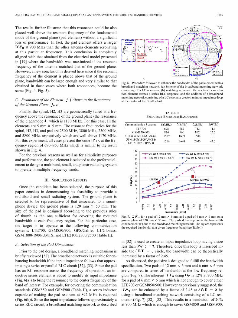
Fig. 6. Procedure followed to enhance the bandwidth of the pad element with abroadband matching network. (a) Scheme of the broadband matching networkconsisting of a LC resonator; (b) matching sequence: the reactance cancella-tion element creates a series RLC response, and the addition of a broadbandmatching network consisting of a LC resonator creates an input impedance loopat the center of the Smith chart.
TABLE IIFREQUENCY BANDS AND BANDWIDTHS
Fig. 7. for a pad of 12 mm 6 mm and a pad of 6 mm 6 mm on aground plane of 120 mm 50 mm. The dashed line represents the bandwidthenhancement (F) due to the broadband matching network. The square representsthe required bandwidth at a given frequency band (see Table I).
in [32] is used to create an input impedance loop having a sizeless than . Therefore, once this loop is inscribed in-side the circle, the bandwidth can be theoreticallyincreased by a factor of 2.45.As discussed, the pad size is designed to fulfill the bandwidth
specification. Two pads of 12 mm 6 mm and 6 mm 6 mmare compared in terms of bandwidth at the low frequency re-gion (Fig. 7). The inherent using is 12% at 900 MHzfor a pad of 6 mm 6 mm which is not enough to cover eitherLTE700 or GSM850/900. However as previously suggested, the
can be enhanced by a factor of 2.45 at byusing a broadband matching network consisting of a LC res-onator (Fig. 7) [32], [33]. This results in a bandwidth of 20%at 900 MHz which is enough to cover GSM850 and GSM900.
3786 IEEE TRANSACTIONS ON ANTENNAS AND PROPAGATION, VOL. 61, NO. 7, JULY 2013
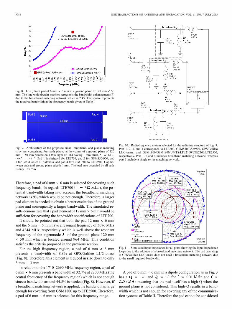
Fig. 8. for a pad of 6 mm 6 mm in a ground plane of 120 mm 50mm. The line with circular markers represents the bandwidth enhancement (F)due to the broadband matching network which is 2.45. The square representsthe required bandwidth at the frequency bands given in Table I.
Fig. 9. Architecture of the proposed small, multiband, and planar radiatingstructure, comprising four pads placed at the corner of a ground plane of 120mm 50 mm printed on a thin layer of FR4 having 1 mm thick, ,
. Pad 1 is designed for LTE700, pad 2 for GSM850-900, pad3 for GPS/Galileo L1/Glonass, and pad 4 for GSM1800 to LTE2500. Gap be-tween pads and ground plane edge is 1 mm. The total area occupied by all padsis only 153 .
Therefore, a pad of 6 mm 6 mm is selected for covering suchfrequency bands. In regards LTE700 , the po-tential bandwidth taking into account the broadband matchingnetwork is 9% which would be not enough. Therefore, a largerpad element is needed to obtain a better excitation of the groundplane and consequently a larger bandwidth. The simulated re-sults demonstrate that a pad element of 12mm 6mmwould besufficient for covering the bandwidth specifications of LTE700.It should be pointed out that both the pad 12 mm 6 mm
and the 6 mm 6 mm have a resonant frequency of 3076 MHzand 4244 MHz, respectively which is well above the resonantfrequency of the eigenmode of the ground plane 120 mm50 mm which is located around 964 MHz. This condition
satisfies the criteria proposed in the previous section.For the high frequency region, a pad of 6 mm 6 mm
presents a bandwidth of 8.8% at GPS/Galileo L1/Glonass(Fig. 8). Therefore, this element is reduced in size down to only3 mm 3 mm.In relation to the 1710–2690 MHz frequency region, a pad of
6 mm 6 mm presents a bandwidth of 32.7% at 2200 MHz (thecentral frequency of the frequency region) which is not enoughsince a bandwidth around 44.5% is needed (Fig. 8). However, ifa broadbandmatching network is applied, the bandwidth is largeenough for covering fromGSM1800 up to LTE2500. Therefore,a pad of 6 mm 6 mm is selected for this frequency range.
Fig. 10. Radiofrequency system selected for the radiating structure of Fig. 9.Port 1, 2, 3, and 3 corresponds to LTE700, GSM850/GSM900, GPS/GalileoL1/Glonass, and GSM1800/GSM1900/UMTS/LTE2100/LTE2300/LTE2500,respectively. Port 1, 2 and 4 includes broadband matching networks whereasport 3 include a single series matching network.
Fig. 11. Simulated input impedance for all ports showing the input impedanceloops due to the addition of a broadband matching network. The pad operatingat GPS/Galileo L1/Glonass does not need a broadband matching network dueto the small required bandwidth.
A pad of 6 mm 6 mm in a dipole configuration as in Fig. 3has a and for and
meaning that the pad itself has a high-Q when theground plane is not considered. This high-Q results in a band-width which is not enough for covering any of the communica-tion systems of Table II. Therefore the pad cannot be considered
ANGUERA et al.: MULTIBAND AND SMALL COPLANAR ANTENNA SYSTEM FOR WIRELESS HANDHELD DEVICES 3787
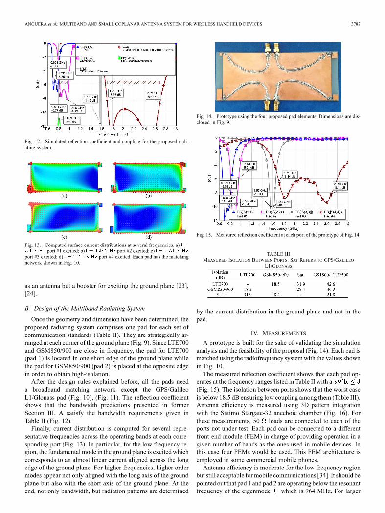
Fig. 12. Simulated reflection coefficient and coupling for the proposed radi-ating system.
Fig. 13. Computed surface current distributions at several frequencies. a)port #1 excited; b) port #2 excited; c)
port #3 excited; d) port #4 excited. Each pad has the matchingnetwork shown in Fig. 10.
as an antenna but a booster for exciting the ground plane [23],[24].
B. Design of the Multiband Radiating System
Once the geometry and dimension have been determined, theproposed radiating system comprises one pad for each set ofcommunication standards (Table II). They are strategically ar-ranged at each corner of the ground plane (Fig. 9). Since LTE700and GSM850/900 are close in frequency, the pad for LTE700(pad 1) is located in one short edge of the ground plane whilethe pad for GSM850/900 (pad 2) is placed at the opposite edgein order to obtain high-isolation.After the design rules explained before, all the pads need
a broadband matching network except the GPS/GalileoL1/Glonass pad (Fig. 10), (Fig. 11). The reflection coefficientshows that the bandwidth predictions presented in formerSection III. A satisfy the bandwidth requirements given inTable II (Fig. 12).Finally, current distribution is computed for several repre-
sentative frequencies across the operating bands at each corre-sponding port (Fig. 13). In particular, for the low frequency re-gion, the fundamental mode in the ground plane is excited whichcorresponds to an almost linear current aligned across the longedge of the ground plane. For higher frequencies, higher ordermodes appear not only aligned with the long axis of the groundplane but also with the short axis of the ground plane. At theend, not only bandwidth, but radiation patterns are determined
Fig. 14. Prototype using the four proposed pad elements. Dimensions are dis-closed in Fig. 9.
Fig. 15. Measured reflection coefficient at each port of the prototype of Fig. 14.
TABLE IIIMEASURED ISOLATION BETWEEN PORTS. SAT REFERS TO GPS/GALILEO
L1/GLONASS
by the current distribution in the ground plane and not in thepad.
IV. MEASUREMENTS
A prototype is built for the sake of validating the simulationanalysis and the feasibility of the proposal (Fig. 14). Each pad ismatched using the radiofrequency systemwith the values shownin Fig. 10.The measured reflection coefficient shows that each pad op-
erates at the frequency ranges listed in Table II with a(Fig. 15). The isolation between ports shows that the worst caseis below 18.5 dB ensuring low coupling among them (Table III).Antenna efficiency is measured using 3D pattern integrationwith the Satimo Stargate-32 anechoic chamber (Fig. 16). Forthese measurements, 50 loads are connected to each of theports not under test. Each pad can be connected to a differentfront-end-module (FEM) in charge of providing operation in agiven number of bands as the ones used in mobile devices. Inthis case four FEMs would be used. This FEM architecture isemployed in some commercial mobile phones.Antenna efficiency is moderate for the low frequency region
but still acceptable for mobile communications [34]. It should bepointed out that pad 1 and pad 2 are operating below the resonantfrequency of the eigenmode which is 964 MHz. For larger
3788 IEEE TRANSACTIONS ON ANTENNAS AND PROPAGATION, VOL. 61, NO. 7, JULY 2013
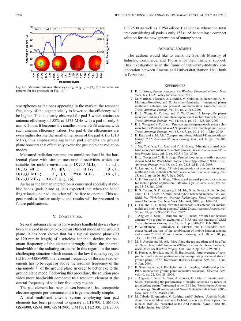
Fig. 16. Measured antenna efficiency and radiationpatterns for the prototype of Fig. 14.
smartphones as the ones appearing in the market, the resonantfrequency of the eigenmode is lower so the efficiency willbe higher. This is clearly observed for pad 3 which attains anantenna efficiency of 58% at 1575 MHz with a pad of only 3mm 3 mm. It becomes the smallest known GPS antenna withsuch antenna efficiency values. For pad 4, the efficiencies areeven higher despite the small dimensions of the pad 4: (to 1710MHz), thus emphasizing again that pad elements are groundplane boosters that effectively excite the ground plane radiationmodes.Measured radiation patterns are omnidirectional in the hor-
izontal plane with similar measured directivities which aresuitable for mobile environments ,
, ,, ,
(Fig. 16).As far as the human interaction is concerned specially at mo-
bile bands (pads 2 and 4), it is expected that when the hand/finger loads one pad, the other will be free to operate. This as-pect needs a further analysis and results will be presented infuture publications.
V. CONCLUSIONS
Several antenna elements for wireless handheld devices havebeen analyzed in order to excite an efficient mode of the groundplane. It has been shown that for a typical ground plane (90to 120 mm in length) of a wireless handheld device, the res-onant frequency of the elements strongly affects the inherentbandwidth of the radiating structure. In this regard, in the mostchallenging situation which occurs at the low frequency region(LTE700-GSM900), the resonant frequency of the analyzed el-ements has to be equal or above the resonant frequency of theeigenmode of the ground plane in order to better excite theground plane mode. Following this procedure, the solution pro-vides more bandwidth compared to a resonant element at thecentral frequency of said low frequency region.The pad element has been chosen because it has acceptable
electromagnetic performance and it is geometrically simple.A small-multiband antenna system employing four pad
elements has been proposed to operate at LTE700, GSM850,GSM900, GSM1800, GSM1900, UMTS, LTE2100, LTE2300,
LTE2500 as well as GPS/Galileo L1/Glonass where the totalarea considering all pads is only 153 becoming a compactsolution for the new generation of smartphones.
ACKNOWLEDGMENT
The authors would like to thank the Spanish Ministry ofIndustry, Commerce, and Tourism for their financial support.This investigation is in the frame of University-Industry col-laboration between Fractus and Universitat Ramon Llull bothin Barcelona.
REFERENCES
[1] K. L. Wong, Planar Antennas for Wireless Communications. NewYork, NY, USA: Wiley Inter-Science, 2003.
[2] M. Martínez-Vázquez, O. Litschke, M. Geissler, D. Heberling, A. M.Martínez-González, and D. Sánchez-Hernández, “Integrated planarmultiband antennas for personal communication handsets,” IEEETrans. Antennas Propag., vol. 54, no. 2, Feb. 2006.
[3] K. L. Wong, G. Y. Lee, and T. W. Chiou, “A low-profile planarmonopole antenna for multiband operation of mobile handsets,” IEEETrans. Antennas Propag., vol. 51, no. 1, pp. 121–125, Jan. 2003.
[4] K. L.Wong and S. C. Chen, “Printed single-strip monopole using a chipinductor for Penta-band WWAN operation in the mobile phone,” IEEETrans. Antennas Propag., vol. 58, no. 3, pp. 1011–1014, Mar. 2010.
[5] H. Kanj and S. M. Ali, “Compact multiband folded 3-D monopole an-tenna,” IEEE Antennas Wireless Propag. Lett., vol. 8, pp. 185–188,2009.
[6] J. Ma, Y. Z. Yin, J. L. Guo, and Y. H. Huang, “Miniature printed octa-band monopole antenna for mobile phones,” IEEE Antennas and Wire-less Propag. Lett., vol. 9, pp. 1033–1036, 2010.
[7] K. L. Wong and C. H. Huang, “Printed loop antenna with a perpen-dicular feed for Penta-band mobile phone application,” IEEE Trans.Antennas Propag., vol. 56, no. 7, pp. 2138–2141, Jul. 2008.
[8] C. Lin and K. L. Wong, “Printed monopole slot antenna for internalmultiband mobile phone antenna,” IEEE Trans. Antennas Propag., vol.55, no. 2, pp. 3690–3697, Dec. 2007.
[9] C. H. Wu and K. L. Wong, “Hexa-band internal printed slot antennafor mobile phone application,” Microw. Opt. Technol. Lett., vol. 50,pp. 35–38, Jan. 2008.
[10] B. S. Collins, S. P. Kingsley, J. M. Ide, S. A. Saario, R. W. Schlub,and S. G. O’Keefe, “A multi-band hybrid balanced antenna,” in Proc.IEEE Int. Workshop on Antenna Technology: Small Antennas andNovel Metamaterials, New York, Mar. 6–8, 2006, pp. 100–103.
[11] C. Lin and K. L. Wong, “Printed monopole slot antenna for internalmultiband mobile phone antenna,” IEEE Trans. Antennas Propag., vol.55, no. 12, pp. 3690–3697, Dec. 2007.
[12] J. Anguera, I. Sanz, J. Mumbrú, and C. Puente, “Multi-band handsetantenna with a parallel excitation of PIFA and slot radiators,” IEEETrans. Antennas Propag., vol. 58, no. 2, pp. 348–356, Feb. 2010.
[13] P. Vainikainen, J. Ollikainen, O. Kivekäs, and I. Kelander, “Res-onator-based analysis of the combination of mobile handset antennaand chassis,” IEEE Trans. Antennas Propag., vol. 50, no. 10, pp.1433–1444, Oct. 2002.
[14] M. F. Abedin and M. Ali, “Modifying the ground plane and its effecton Planar Inverted-F Antennas (PIFAs) for mobile phone handsets,”IEEE Antennas Wireless Propag. Lett., vol. 2, pp. 226–229, 2003.
[15] R. Hossa, A. Byndas, and M. E. Bialkowski, “Improvement of com-pact terminal antenna performance by incorporating open-end slots inground plane,” IEEE Microwave Wireless Compon. Lett., vol. 14, no.6, Jun. 2004.
[16] B. Sanz-Izquierdo, J. Batchelor, and R. Langley, “Multiband printedPIFA antenna with ground plane capacitive resonator,” Electron. Lett.,vol. 40, no. 22, Oct. 28, 2004.
[17] J. Anguera, I. Sanz, A. Sanz, A. Condes, D. Gala, C. Puente, and J.Soler, “Enhancing the performance of handset antennas by means ofgroundplane design,” presented at the IEEE Int. Workshop on AntennaTechnology: Small Antennas and Novel Metamaterials (iWAT 2006),New York, USA, March 2006.
[18] M. Cabedo, E. Antonino, V. Rodrigo, and C. Suárez, “Análisis Modalde un Plano de Masa Radiante Doblado y con una Ranura para Ter-minales Móviles,” presented at the XXI National Symp. URSI ’06,Oviedo, Spain, Sep. 2006.
ANGUERA et al.: MULTIBAND AND SMALL COPLANAR ANTENNA SYSTEM FOR WIRELESS HANDHELD DEVICES 3789
[19] A. Cabedo, J. Anguera, C. Picher, M. Ribó, and C. Puente, “Multi-bandhandset antenna combining a PIFA, slots, and ground plane modes,”IEEE Trans. Antennas Propag., vol. 57, no. 9, pp. 2526–2533, Sep.2009.
[20] W. L. Schroeder, T. Famdie, and K. Solbach, “Utilisation and tuning ofthe chassis modes of a handheld terminal for the design of multibandradiation characteristics,” IEEWideband andMulti-band Antennas andArrays, pp. 117–121, Sep. 7, 2005.
[21] P. Lindberg and E. Öjefors, “A bandwidth enhancement techniquefor mobile handset antennas using wavetraps,” IEEE Trans. AntennasPropag., vol. 54, no. 8, Aug. 2006.
[22] J. Villanen, J. Ollikainen, O. Kivekäs, and P. Vainikainen, “Couplingelement based mobile terminal antenna structures,” IEEE Trans. An-tennas Propag., vol. 54, no. 7, pp. 2142–2153, July 2006.
[23] J. Anguera, A. Andújar, C. Puente, and J. Mumbru, “AntennalessWire-less Device,” Patent Appl. WO2010/015365, Jul. 31, 2009.
[24] J. Anguera, A. Andújar, C. Puente, and J. Mumbru, “AntennalessWire-less Device Capable of Operation in Multiple Frequency Regions,”Patent Appl. WO2010/015364, Jul. 31, 2009.
[25] A. Andújar, J. Anguera, and C. Puente, “Ground plane boosters asa compact antenna technology for wireless handheld devices,” IEEETrans. Antennas Propag., vol. 59, no. 5, pp. 1668–1677, May 2011.
[26] A. Andújar and J. Anguera, “On the radiofrequency system of groundplane booster antenna technology,” Electron. Lett., vol. 48, no. 14, pp.815–817, 2012.
[27] J. Anguera, C. Puente, E. Martínez, and E. Rozan, “The fractal Hilbertmonopole: A two-dimensional wire,”Microw. Opt. Technol. Lett., vol.36, no. 2, pp. 102–104, Jan. 2003.
[28] R. F. Harrington and J. R. Mautz, “Theory of characteristic modesfor conducting bodies,” IEEE Trans. Antennas Propag., vol. 19, pp.622–628, Sep. 1971.
[29] M. Cabedo, E. Antonino, A. Valero, and M. Ferrando, “The theory ofcharacteristic modes revisited: A contribution to the design of antennasfor modern applications,” IEEE Antennas Propag. Mag., vol. 49, no.5, pp. 52–68, Oct. 2007.
[30] S. R. Best, “The inverse relationship between quality factor and band-width in multiple resonant antennas,” in Proc. IEEE Antennas andPropagation Society Int. Symp., 2006, pp. 623–626.
[31] H. F. Pues and A. R. Van de Capelle, “An impedance-matchingtechnique for increasing the bandwidth of microstrip antennas,” IEEETrans. Ant. Propag., vol. 37, no. 11, pp. 1345–1354., Nov. 1989.
[32] A. Andújar, J. Anguera, and C. Puente, “"A systematic method to de-sign broadband matching networks,” presented at the Eur. Conf. onAntennas and Propagation, Barcelona, Apr. 2010.
[33] J. Anguera, C. Puente, C. Borja, G. Font, and J. Soler, “A systematicmethod to design single-patch broadband microstrip patch antennas,”Microw. Opt. Technol. Lett., vol. 31, no. 3, pp. 185–188, Nov. 2001.
[34] C. W. Yang, Y. B. Jung, and C. W. Jung, “Octaband internal antennafor 4G mobile handset,” IEEE Antennas Wireless Propag. Lett., vol.10, pp. 817–819, 2011.
Jaume Anguera (S’99–M’03–SM’09) was born inVinaròs, Spain, in 1972. He received the TechnicalEngineering degree in Electronic Systems andEngineering degree in Electronic Engineering, bothfrom the Ramon Llull University (URL), Barcelona,Spain, in 1994 and 1998, respectively, and the En-gineering and Ph.D. degrees in telecommunicationengineering, both from the Polytechnic Universityof Catalonia (UPC), Barcelona, Spain, in 1998 and2003, respectively.In 1997–1999, he joined the Electromagnetic and
Photonic Engineering Group, Signal Theory and Communications Department,UPC, as a Researcher in microstrip fractal-shaped antennas. In 1999, he was aresearcher at Sistemas Radiantes, Madrid, Spain, where he was involved in thedesign of a dual-frequency dual-polarized fractal-inspiredmicrostrip patch arrayfor mobile communications. In the same year, he became an Assistant Professorat the Department of Electronics and Telecommunications, Universitat RamonLlull-Barcelona, where he is currently teaching antenna theory. Since 1999, hehas been with Fractus, Barcelona, Spain, where he holds the position of R&Dmanager. At Fractus he leaded projects on antennas for base station systems,antennas for automotive and currently managing handset and wireless antennaprojects. His current research interests are multiband and small antennas, broad-bandmatching networks, diversity antenna systems, electromagnetic dosimetry,genetic optimized antennas, and handset antennas. From September 2003 toMay 2004, he was with Fractus-Korea (Republic South of Korea) were he wasmanaging projects for miniature and multiband antennas for handset and wire-
less applications. Since 2005, he has been leading research projects in the an-tenna field for handset and wireless applications in a frame of Industry-Univer-sity collaboration: Fractus and the Department of Electronics and Telecommu-nications of Universitat Ramon Llull-Barcelona, Spain. He holds more than 70granted invention patents and 50 more pending patents in the antenna field. Heis author of more than 150 journals, international and national conference pa-pers and he has directed more than 60 bachelor and master thesis.Dr. Anguera was a member of the fractal team that in 1998 received the Eu-
ropean Information Technology Grand Prize from the European Council for theApplied Science an Engineering and the European Commission for the fractal-shaped antenna application to cellular telephony. 2003 Finalist to the Best Doc-toral Thesis (Fractal and Broadband Techniques on Miniature, Multifrequency,and High-Directivity Microstrip Patch Antennas) (Ph.D.) on UMTS, prize pro-moted by “Technology plan of UMTS promotion” given by Telefónica MóvilesEspaña. New faces of Engineering 2004 (promoted by IEEE and IEEE founda-tion). In the same year he received the Best Doctoral Thesis (Ph.D.) in “Net-work and Broad Band Services” (XXIV Prize Edition “Ingenieros de Teleco-municación”) organized by Colegio Oficial de Ingenieros de Telecomunicación(COIT) and the Company ONO. He is reviewer for the IEEE TRANSACTIONSAND ANTENNAS AND PROPAGATION, IEEE Antennas and Wireless PropagationLetters, IEEE Antennas and Propagation Magazine, Progress in Electromag-netic Research (PIER), IEE Electronics Letters, IETMicrowaves, Antennas, andPropagation, and ETRI journal (Electronics and Telecommunications ResearchInstitute, South Korea). He is editor of International Journal on Antennas andPropagation (IJAP). His biography is listed in Who’s Who in the World, Who’sWho in Science and Engineering, Who’s Who in Emerging Leaders and in IBC(International Biographical Center, Cambridge-England).
Aurora Andújar (S’11) was born in Barcelona,Spain, 1984. She received the Bachelor’s degreein Telecommunication Engineering specializing inTelecommunication Systems in 2005, the Masterdegree in Telecommunications Engineering in 2007and the Master of Science in TelecommunicationEngineering andManagement in 2007 from the Poly-technic University of Catalonia (UPC), Barcelona,Spain. She is working toward the Ph.D. degree in thefield of small and multiband antennas for handsetsand wireless devices.
In 2004–2005, she received a research fellowship in the field of electromag-netic compatibility from the Signal Theory and Communications Department,UPC. In 2005, she worked as a Software Test Engineer for applications intendedfor handset wireless devices. In 2006, she worked as a Software Engineer de-signing a load simulation tool for testing Digital Campus in academic envi-ronments and developing improvements in the performance of web servers re-ferred to the management of static and dynamics contents. Since 2007, she isworking as an R&D Engineer in Fractus, Barcelona, Spain, where she activelycontributes to the prosecution and growth of the patent portfolio of the com-pany. She is also involved in several projects in the field of small and multibandhandset antenna design. Since 2009, she is leading research projects in the an-tenna field for handheld wireless devices in the collaborative university-industryframework. She has published more than 50 journals, international and nationalconference papers. She is also author of 7 invention patents in the antenna field.She has directed 6 bachelor and master thesis.Mrs. Andújar is a member of the COIT (Colegio Oficial de Ingenieros de
Telecomunicación) and AEIT (Asociación Española de Ingenieros de Teleco-municación). She is an Editor of International Journal on Antennas and Prop-agation (IJAP).
Carlos García was born in Igualada, Barcelona. Hereceived the Bachelor degree from La Salle, Univer-sitat Ramon Llull, Barcelona, Spain, in 2012.He is a Terminal Testing Engineer at the LGAI
Technological Center (Applus+), Barcelona, Spain,where he engages in Smart Card Testing and RFtesting. He is currently evaluating contact TerminalsLevel 2 (functional testing) and has solid experiencewith EMV Specifications. He also has experiencewith Smart Cards in Level 1 (physical testing withPaypass—ISO/IEC14443) and Smart Cards in Level
2 (functional testing) with Visa Specifications in different type of products(VGP, VSDC, VMPA).