multi-objective optimization of functionally graded thick shells for thermal loading
TRANSCRIPT
www.elsevier.com/locate/compstruct
Composite Structures 81 (2007) 386–400
Multi-objective optimization of functionally gradedthick shells for thermal loading
Senthil S. Vel *, Jacob L. Pelletier
Department of Mechanical Engineering, University of Maine, Orono, ME 04469, USA
Available online 17 November 2006
Abstract
Presented herein is a methodology for the multi-objective optimization of material distribution of functionally graded cylindricalshells for steady thermomechanical processes. The proposed approach focuses on isotropic metal/ceramic and metal/metal functionallygraded materials, which offer great promise in high temperature and high heat flux applications. The material composition is assumed tovary only in the thickness direction. The volume fractions of the constituent material phases at a point are obtained through piecewisecubic interpolation of volume fractions defined at a finite number of evenly spaced control points. The effective material properties areestimated using the self-consistent homogenization scheme. The volume fractions at the control points, which are chosen as the designvariables, are optimized using an elitist, non-dominated sorting multi-objective genetic algorithm. Candidate designs are evaluated usingan exact power-series solution to the two-dimensional quasi-static heat conduction and plane strain thermoelasticity problems. The for-mulation, which is applicable to both thin and thick functionally graded shells, can also be used to analyze and optimize functionallygraded plates in the limit that the midsurface radius of the shell approaches infinity. The proposed methodology is illustrated by opti-mizing the material composition profile for two model problems. In the first model problem, both the mass and the peak hoop stress ofZirconia/Titanium alloy plates and shells are simultaneously minimized for a prescribed temperature load with a constraint on the max-imum temperature experienced by the metal. The goal of the second model problem is to simultaneously minimize the mass and max-imize the factor of safety of Tungsten/Copper alloy functionally graded plates and shells under an applied heat flux, subject to aconstraint on the factor of safety.� 2006 Elsevier Ltd. All rights reserved.
Keywords: FGM; Inhomogeneous material; Multi-criteria optimization; Evolutionary algorithms; Genetic algorithms
1. Introduction
Functionally graded materials (FGMs) are advancedcomposite materials that consist of two or more materialingredients that are engineered to have a continuous spatialvariation of material properties. This is achieved by gradu-ally changing the volume fractions and/or microstructureof the constituent materials during fabrication. The constit-uent material phases for FGMs are chosen based on func-tional performance requirements. For example, metal/ceramic FGMs are primarily used in high temperature
0263-8223/$ - see front matter � 2006 Elsevier Ltd. All rights reserved.
doi:10.1016/j.compstruct.2006.08.027
* Corresponding author. Tel.: +1 207 581 2777.E-mail address: [email protected] (S.S. Vel).
applications. Typically, ceramic-rich material would beused in the high temperature regions and metal-rich mate-rial would be placed at locations where mechanical proper-ties, such as toughness, need to be high. FGMs permittailoring of material composition so as to derive maximumbenefits from their inhomogeneity and they offer greatpromise in applications where the operating conditionsare severe, including spacecraft heat shields, coatings ongas turbine blades, plasma facings for fusion reactors,etc. [1]. In the case of the future International Thermonu-clear Experimental Reactor (ITER), the plasma divertormust survive high heat flux loads, and in addition, mustefficiently transfer heat energy to an active cooling mecha-nism [2,3]. Numerous designs have been developed for
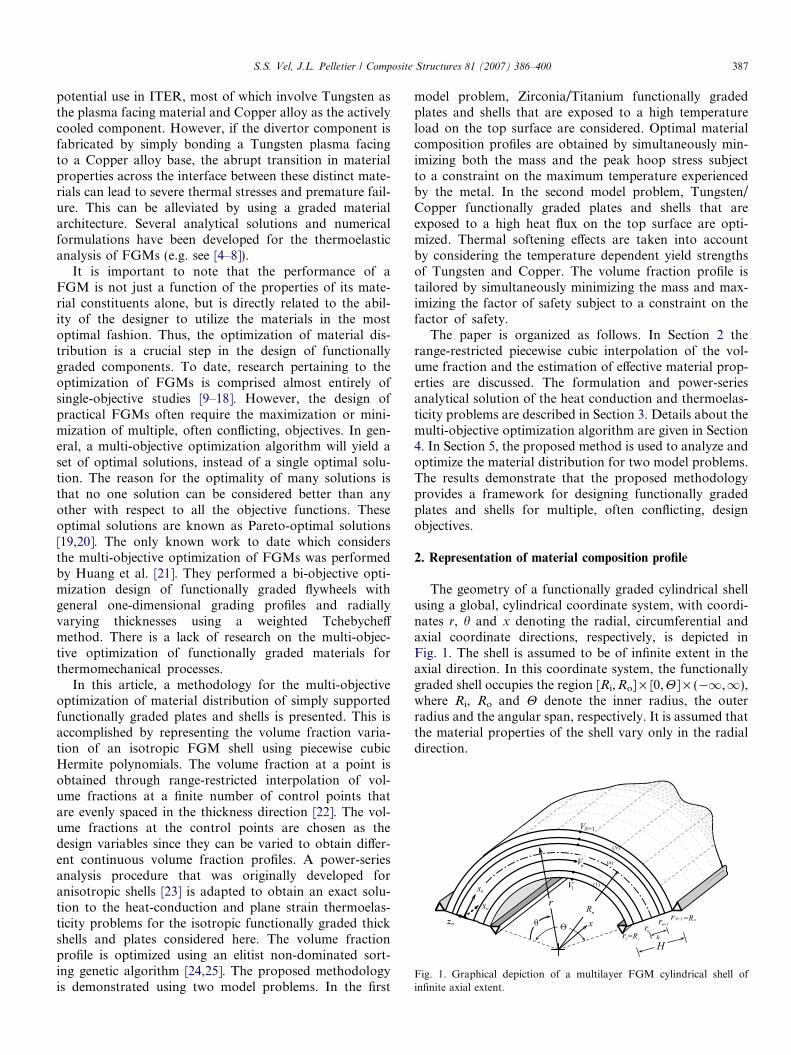
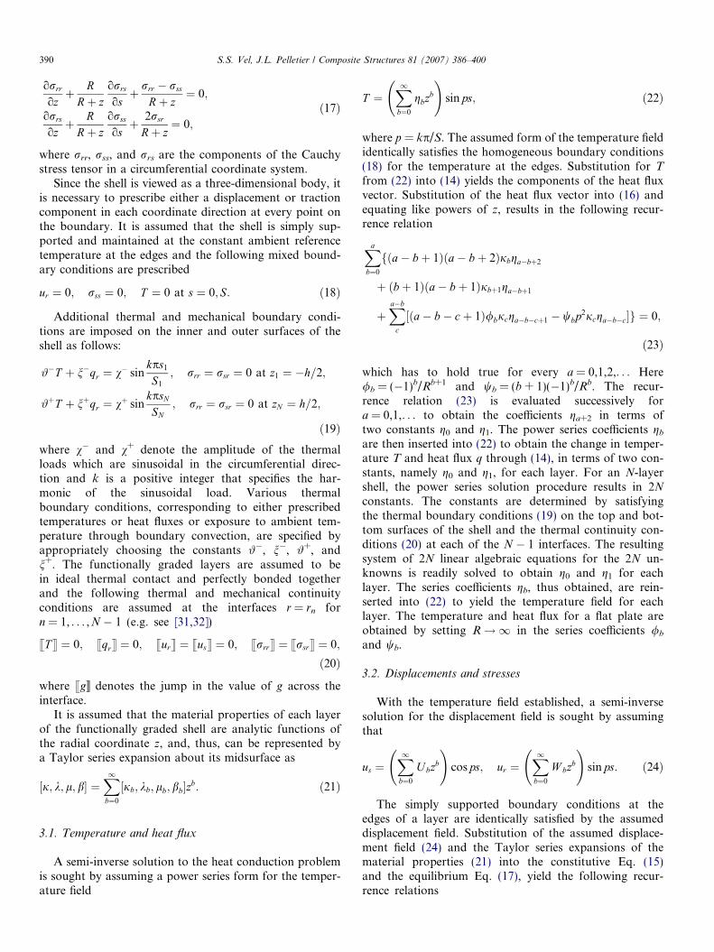
Fig. 1. Graphical depiction of a multilayer FGM cylindrical shell ofinfinite axial extent.
S.S. Vel, J.L. Pelletier / Composite Structures 81 (2007) 386–400 387
potential use in ITER, most of which involve Tungsten asthe plasma facing material and Copper alloy as the activelycooled component. However, if the divertor component isfabricated by simply bonding a Tungsten plasma facingto a Copper alloy base, the abrupt transition in materialproperties across the interface between these distinct mate-rials can lead to severe thermal stresses and premature fail-ure. This can be alleviated by using a graded materialarchitecture. Several analytical solutions and numericalformulations have been developed for the thermoelasticanalysis of FGMs (e.g. see [4–8]).
It is important to note that the performance of aFGM is not just a function of the properties of its mate-rial constituents alone, but is directly related to the abil-ity of the designer to utilize the materials in the mostoptimal fashion. Thus, the optimization of material dis-tribution is a crucial step in the design of functionallygraded components. To date, research pertaining to theoptimization of FGMs is comprised almost entirely ofsingle-objective studies [9–18]. However, the design ofpractical FGMs often require the maximization or mini-mization of multiple, often conflicting, objectives. In gen-eral, a multi-objective optimization algorithm will yield aset of optimal solutions, instead of a single optimal solu-tion. The reason for the optimality of many solutions isthat no one solution can be considered better than anyother with respect to all the objective functions. Theseoptimal solutions are known as Pareto-optimal solutions[19,20]. The only known work to date which considersthe multi-objective optimization of FGMs was performedby Huang et al. [21]. They performed a bi-objective opti-mization design of functionally graded flywheels withgeneral one-dimensional grading profiles and radiallyvarying thicknesses using a weighted Tchebycheffmethod. There is a lack of research on the multi-objec-tive optimization of functionally graded materials forthermomechanical processes.
In this article, a methodology for the multi-objectiveoptimization of material distribution of simply supportedfunctionally graded plates and shells is presented. This isaccomplished by representing the volume fraction varia-tion of an isotropic FGM shell using piecewise cubicHermite polynomials. The volume fraction at a point isobtained through range-restricted interpolation of vol-ume fractions at a finite number of control points thatare evenly spaced in the thickness direction [22]. The vol-ume fractions at the control points are chosen as thedesign variables since they can be varied to obtain differ-ent continuous volume fraction profiles. A power-seriesanalysis procedure that was originally developed foranisotropic shells [23] is adapted to obtain an exact solu-tion to the heat-conduction and plane strain thermoelas-ticity problems for the isotropic functionally graded thickshells and plates considered here. The volume fractionprofile is optimized using an elitist non-dominated sort-ing genetic algorithm [24,25]. The proposed methodologyis demonstrated using two model problems. In the first
model problem, Zirconia/Titanium functionally gradedplates and shells that are exposed to a high temperatureload on the top surface are considered. Optimal materialcomposition profiles are obtained by simultaneously min-imizing both the mass and the peak hoop stress subjectto a constraint on the maximum temperature experiencedby the metal. In the second model problem, Tungsten/Copper functionally graded plates and shells that areexposed to a high heat flux on the top surface are opti-mized. Thermal softening effects are taken into accountby considering the temperature dependent yield strengthsof Tungsten and Copper. The volume fraction profile istailored by simultaneously minimizing the mass and max-imizing the factor of safety subject to a constraint on thefactor of safety.
The paper is organized as follows. In Section 2 therange-restricted piecewise cubic interpolation of the vol-ume fraction and the estimation of effective material prop-erties are discussed. The formulation and power-seriesanalytical solution of the heat conduction and thermoelas-ticity problems are described in Section 3. Details about themulti-objective optimization algorithm are given in Section4. In Section 5, the proposed method is used to analyze andoptimize the material distribution for two model problems.The results demonstrate that the proposed methodologyprovides a framework for designing functionally gradedplates and shells for multiple, often conflicting, designobjectives.
2. Representation of material composition profile
The geometry of a functionally graded cylindrical shellusing a global, cylindrical coordinate system, with coordi-nates r, h and x denoting the radial, circumferential andaxial coordinate directions, respectively, is depicted inFig. 1. The shell is assumed to be of infinite extent in theaxial direction. In this coordinate system, the functionallygraded shell occupies the region [Ri,Ro] · [0,H] · (�1,1),where Ri, Ro and H denote the inner radius, the outerradius and the angular span, respectively. It is assumed thatthe material properties of the shell vary only in the radialdirection.
388 S.S. Vel, J.L. Pelletier / Composite Structures 81 (2007) 386–400
2.1. Volume fraction distribution
The optimization of the material distribution of a two-phase functionally graded material is equivalent to the opti-mization of the volume fraction distribution V(r) of one ofits constituent phases. A direct pointwise optimization ofthe volume fraction at every radial location is computation-ally intractable. Therefore, the present formulation utilizesa finite number of control points in the radial direction toreduce the number of design variables. The volume fractionat an arbitrary radial location is obtained via piecewisecubic interpolation from the volume fractions at the controlpoints. Thus, the volume fraction distribution in the thick-ness direction of the shell can be tailored using the volumefraction values at the control points.
A total of N + 1 equally spaced control points in theradial direction at locations rn = Ri + (Ro � Ri)(n � 1)/Nis utilized, where n = 1, . . . ,N + 1. The volume fraction atthe control point located at rn is denoted by Vn. In the pres-ent formulation, the volume fractions V1, . . . ,VN+1 at thecontrol points are treated as the design variables. The phys-ical constraints of the problem require that the interpolatedvolume fraction be strictly in the range of zero to one at allpoints within the domain, i.e., 0 6 V(r) 6 1. In order toobtain smooth material composition profiles, a range-restricted piecewise cubic interpolation for the volume frac-tion [22] is employed. This method, which is based onsufficiency conditions for univariate piecewise cubic inter-polation to preserve positivity [26], performs range-restricted interpolation while preserving C1 continuity.The restriction of the interpolant to remain betweendesired bounding values is achieved by setting upper andlower limits on the slope of the interpolated volume frac-tion distribution at the control points.
The volume fraction distribution V(r) in the intervalr 2 [rn, rn+1] is interpolated as follows:
V ðrÞ ¼ V nH 1ðrÞ þ SnH 2ðrÞ þ V nþ1H 3ðrÞ þ Snþ1H 4ðrÞ; ð1Þ
where Vn and Sn denote the volume fraction and slope ofthe volume fraction distribution, respectively, at the con-trol points located at rn. The functions Hk(r) are the Her-mite basis functions (e.g. see [27]),
H 1ðrÞ ¼2
h3r � rn þ
h2
� �ðr � rnþ1Þ2;
H 2ðrÞ ¼1
h2ðr � rnÞðr � rnþ1Þ2;
H 3ðrÞ ¼ �2
h3ðr � rnÞ2 r � rnþ1 �
h2
� �;
H 4ðrÞ ¼1
h2ðr � rnÞ2ðr � rnþ1Þ;
ð2Þ
where h = rn+1 � rn = (Ro � Ri)/N. In order to completelyspecify the interpolated volume fraction distribution V(r),it is apparent from (1) that the slopes Sn at the controlpoints must be supplied in some manner. The volume frac-tion values Vn at the control points are chosen as the design
variables in the present formulation. Although the slopesSn may also be considered as design variables, it is advan-tageous to estimate them based on the neighboring controlpoint values, since this will result in a smaller set of designvariables and a more efficient optimization algorithm. Inthe present work, the slopes are estimated based on a 3-point centered finite difference formula,
Sn ¼ ðV nþ1 � V n�1Þ=2h for n ¼ 2; 3; . . . ;N : ð3ÞThe slopes at the top and bottom surfaces of the shell areevaluated based on one sided finite difference formulae,
S1 ¼ ð�3V 1 þ 4V 2 � V 3Þ=2h;
SNþ1 ¼ ð3V Nþ1 � 4V N þ V N�1Þ=2h:ð4Þ
With the slopes of the volume fraction distribution esti-mated at the control points, they must be checked to makesure that they are within certain upper and lower bounds toachieve proper range restriction of the volume fraction dis-tribution. The appropriate bounds are given by Brodlieet al. [22]. If the estimated slopes lie outside these bounds,the estimated values are simply projected on to the validrange. For the interior control points the valid range ofthe slopes are as follows:
Maxf�3ð1� V nÞ=h;�3V n=hg 6 Sn
6Minf3ð1� V nÞ=h; 3V n=hg; ð5Þ
for n = 2, 3, . . . ,N. Corresponding one-sided conditions forthe first and last control points are,
� 3V 1=h 6 S1 6 3ð1� V 1Þ=h;
� 3ð1� V Nþ1Þ=h 6 SNþ1 6 3V Nþ1=h:ð6Þ
If the slope at a control point, estimated using (3) or (4),happens to lie outside the valid upper and lower boundsstated in (5) or (6), it is corrected by setting it equal tothe violated bound. This ensures that the interpolated vol-ume fraction distribution satisfies the physical constraints,0 6 V(r) 6 1, at every point within the domain providedthat the design variables Vn are constrained to lie in therange [0, 1].
2.2. Effective moduli of two-phase composite materials
Consider a functionally graded composite material thatis fabricated by mixing two distinct material phases, forexample, a metal and a ceramic. Often, precise informationabout the size, shape and distribution of the particles maynot be available and the effective moduli of the gradedcomposite must be evaluated based only on the volumefraction distributions and the approximate shape of the dis-persed phase. Several micromechanics models have beendeveloped over the years to infer the effective propertiesof macroscopically homogeneous composite materials. Inthe present work, the effective material properties are esti-mated using the self-consistent method [28].
The self-consistent method assumes that each reinforce-ment inclusion is embedded in a continuum material whose
S.S. Vel, J.L. Pelletier / Composite Structures 81 (2007) 386–400 389
effective properties are those of the composite. It isassumed that K1, l1, j1 and a1 denote the bulk modulus,the shear modulus, the thermal conductivity and the ther-mal expansion coefficient, respectively, of the first materialphase, and V denotes its volume fraction. The correspond-ing material properties of the second material phase aredenoted by K2, l2, j2, and a2. For two-phase functionallygraded materials considered here, the volume fraction ofthe second material phase is 1 � V. The locally effectivebulk, K, and shear moduli, l, obtained using the self-con-sistent method are
d=K ¼ V =ðK � K2Þ þ ð1� V Þ=ðK � K1Þ;g=l ¼ V =ðl� l2Þ þ ð1� V Þ=ðl� l1Þ;
ð7Þ
where d = 3 � 5g = K/(K + 4l/3). These are implicitexpressions for the unknowns K and l. The first equationin (7) can be solved to determine K in terms of l,
K ¼ 1=ðV =ðK1 þ 4l=3Þ þ ð1� V Þ=ðK2 þ 4l=3ÞÞ � 4l=3;
ð8Þand l is obtained by solving the following quartic equation:
½VK1=ðK1 þ 4l=3Þ þ ð1� V ÞK2=ðK2 þ 4l=3Þ�þ 5½V l2=ðl� l2Þ þ ð1� V Þl1=ðl� l1Þ� þ 2 ¼ 0: ð9Þ
The self-consistent estimate of the thermal conductivitycoefficient, j, is in the implicit form [29]
V ðj1 � jÞ=ðj1 þ 2jÞ þ ð1� V Þðj2 � jÞ=ðj2 þ 2jÞ ¼ 0;
ð10Þand the coefficient of thermal expansion, a, is determinedfrom the correspondence relation [30]
ða� a1Þ=ða2 � a1Þ ¼ ð1=K � 1=K1Þ=ð1=K2 � 1=K1Þ: ð11Þ
3. Analysis of the heat conduction and thermomechanical
problems
The functionally graded shell is partitioned into N
functionally graded layers by introducing N � 1 hypothet-ical interfaces in the radial direction. These interfaces arechosen to coincide with the location of the control points,rn, for n = 2, . . . ,N. Each layer is assumed to have asmooth variation of material properties in the radialdirection due to the range-restricted cubic interpolationof the volume fraction. A particular layer of the shell,denoted by the superscript n, extends from rn to rn+1 inthe radial direction. In order to provide a more generalshell solution that is also applicable to flat plates, a layer-wise, local circumferential coordinate system with coordi-nate directions, sn, xn, and zn having the origin at the leftedge (h = 0) of nth layer’s midsurface is introduced asshown in Fig. 1. The local circumferential coordinate sys-tem is related to the global cylindrical coordinate systemthrough the transformations
sn ¼ Rnh; zn ¼ r � Rn; xn ¼ x; ð12Þ
where sn and zn are the local arc length and local thicknesscoordinate, respectively, with respect to the midsurface ofthe nth lamina. The midsurface radius Rn and midsurfacecircumferential length Sn of each layer are defined as
Rn ¼1
2ðrn þ rnþ1Þ; Sn ¼ RnH: ð13Þ
In the local circumferential coordinate system, the nth layeroccupies a region in R3 space denoted by [�h/2,h/2] · [0, Sn] · (�1,1). Henceforth, the subscript n is omit-ted for simplicity of notation with the understanding thatall material constants, geometric parameters and solutionvariables are for the nth layer is dropped unless the layernumber is explicitly denoted by a subscript. Since the ap-plied loads and material properties are independent of x
and the body is of infinite extent in the x-direction, it ispostulated that the change in temperature from thestress-free reference configuration, T, and displacementcomponents, ur and us, are functions of z and s only. Theaxial component of the displacement, ux, is assumed tobe zero. Thus, the functionally graded shell is assumed tobe in a state of plane strain.
Fourier’s law of heat conduction, which relates the heatflux to the temperature gradient, in the local circumferen-tial coordinate system is
qs ¼ �jR
Rþ zoTos; qr ¼ �j
oToz; ð14Þ
where j is the thermal conductivity. The thermomechanicalconstitutive equations, which relate the stresses to thedeformation and change in temperature, are
rss ¼ ðkþ 2lÞ RRþ z
ous
osþ ur
Rþ z
� �þ k
our
oz� bT ;
rxx ¼ kR
Rþ zous
osþ ur
Rþ zþ our
oz
� �� bT ;
rrr ¼ ðkþ 2lÞ our
ozþ k
RRþ z
ous
osþ ur
Rþ z
� �� bT ;
rrs ¼ lR
Rþ zour
osþ ous
oz� us
Rþ z
� �;
ð15Þ
where k and l are Lame constants and b is the stress-tem-perature moduli. It should be noted that the Lame con-stant, k, is related to the bulk and shear moduli byk = K � 2l/3 and the stress-temperature modulus, b, isdetermined from the bulk modulus and thermal expansioncoefficient using the relation b = 3Ka. Since the shell isgraded in the radial direction, the material properties j,k, l, and b are functions of the radial coordinate z.
Assuming that internal heat sources and body forces areabsent, the three-dimensional steady-state heat conductionequation, expressed in terms of the local coordinates, is
oqr
ozþ R
Rþ zoqs
osþ qr
Rþ z¼ 0; ð16Þ
where qr and qs are the components of the heat flux vector.The corresponding mechanical equilibrium equations, are
390 S.S. Vel, J.L. Pelletier / Composite Structures 81 (2007) 386–400
orrr
ozþ R
Rþ zorrs
osþ rrr � rss
Rþ z¼ 0;
orrs
ozþ R
Rþ zorss
osþ 2rsr
Rþ z¼ 0;
ð17Þ
where rrr, rss, and rrs are the components of the Cauchystress tensor in a circumferential coordinate system.
Since the shell is viewed as a three-dimensional body, itis necessary to prescribe either a displacement or tractioncomponent in each coordinate direction at every point onthe boundary. It is assumed that the shell is simply sup-ported and maintained at the constant ambient referencetemperature at the edges and the following mixed bound-ary conditions are prescribed
ur ¼ 0; rss ¼ 0; T ¼ 0 at s ¼ 0; S: ð18Þ
Additional thermal and mechanical boundary condi-tions are imposed on the inner and outer surfaces of theshell as follows:
#�T þ n�qr ¼ v� sinkps1
S1
; rrr ¼ rsr ¼ 0 at z1 ¼ �h=2;
#þT þ nþqr ¼ vþ sinkpsN
SN; rrr ¼ rsr ¼ 0 at zN ¼ h=2;
ð19Þwhere v� and v+ denote the amplitude of the thermalloads which are sinusoidal in the circumferential direc-tion and k is a positive integer that specifies the har-monic of the sinusoidal load. Various thermalboundary conditions, corresponding to either prescribedtemperatures or heat fluxes or exposure to ambient tem-perature through boundary convection, are specified byappropriately choosing the constants #�, n�, #+, andn+. The functionally graded layers are assumed to bein ideal thermal contact and perfectly bonded togetherand the following thermal and mechanical continuityconditions are assumed at the interfaces r = rn forn = 1, . . . ,N � 1 (e.g. see [31,32])
sT t ¼ 0; sqrt ¼ 0; surt ¼ sust ¼ 0; srrrt ¼ srsrt ¼ 0;
ð20Þ
where sgb denotes the jump in the value of g across theinterface.
It is assumed that the material properties of each layerof the functionally graded shell are analytic functions ofthe radial coordinate z, and, thus, can be represented bya Taylor series expansion about its midsurface as
½j; k; l; b� ¼X1b¼0
½jb; kb; lb; bb�zb: ð21Þ
3.1. Temperature and heat flux
A semi-inverse solution to the heat conduction problemis sought by assuming a power series form for the temper-ature field
T ¼X1b¼0
gbzb
!sin ps; ð22Þ
where p = kp/S. The assumed form of the temperature fieldidentically satisfies the homogeneous boundary conditions(18) for the temperature at the edges. Substitution for T
from (22) into (14) yields the components of the heat fluxvector. Substitution of the heat flux vector into (16) andequating like powers of z, results in the following recur-rence relation
Xa
b¼0
fða� bþ 1Þða� bþ 2Þjbga�bþ2
þ ðbþ 1Þða� bþ 1Þjbþ1ga�bþ1
þXa�b
c
½ða� b� cþ 1Þ/bjcga�b�cþ1 � wbp2jcga�b�c�g ¼ 0;
ð23Þ
which has to hold true for every a = 0,1,2,. . . Here/b = (�1)b/Rb+1 and wb = (b + 1)(�1)b/Rb. The recur-rence relation (23) is evaluated successively fora = 0,1,. . . to obtain the coefficients ga+2 in terms oftwo constants g0 and g1. The power series coefficients gb
are then inserted into (22) to obtain the change in temper-ature T and heat flux q through (14), in terms of two con-stants, namely g0 and g1, for each layer. For an N-layershell, the power series solution procedure results in 2N
constants. The constants are determined by satisfyingthe thermal boundary conditions (19) on the top and bot-tom surfaces of the shell and the thermal continuity con-ditions (20) at each of the N � 1 interfaces. The resultingsystem of 2N linear algebraic equations for the 2N un-knowns is readily solved to obtain g0 and g1 for eachlayer. The series coefficients gb, thus obtained, are rein-serted into (22) to yield the temperature field for eachlayer. The temperature and heat flux for a flat plate areobtained by setting R!1 in the series coefficients /b
and wb.
3.2. Displacements and stresses
With the temperature field established, a semi-inversesolution for the displacement field is sought by assumingthat
us ¼X1b¼0
U bzb
!cos ps; ur ¼
X1b¼0
W bzb
!sin ps: ð24Þ
The simply supported boundary conditions at theedges of a layer are identically satisfied by the assumeddisplacement field. Substitution of the assumed displace-ment field (24) and the Taylor series expansions of thematerial properties (21) into the constitutive Eq. (15)and the equilibrium Eq. (17), yield the following recur-rence relations
Xa
b¼0
fða� bþ 1Þða� bþ 2Þðkb þ 2lbÞW a�bþ2 þ ðbþ 1Þða� bþ 1Þðkbþ1 þ 2lbþ1ÞW a�bþ1 � ða� bþ 1Þbbga�bþ1
� ðbþ 1Þbbþ1ga�b þXa�b
c¼0
½wb½ð�1
R2ðkc þ 2lcÞ � p2lcÞW a�b�c þ
pRðkc þ 3lcÞU a�b�c�
þ /b½ðcþ 1Þkcþ1W a�b�c þ ða� b� cþ 1Þðkc þ 2lcÞW a�b�cþ1�þ 1b½�pðcþ 1Þkcþ1Ua�b�c � pða� b� cþ 1Þðkc þ lcÞU a�b�cþ1��g ¼ 0; ð25ÞXa
b¼0
fða� bþ 1Þða� bþ 2ÞlbU a�bþ2 þ ðbþ 1Þða� bþ 1Þlbþ1U a�bþ1
þXa�b
c¼0
½wb½pRðkc þ 3lcÞW a�b�c � p2R2ðkc þ 2lc þ
1
p2R2lcÞUa�b�c� þ 1b½�pbðcÞga�b�c þ pðcþ 1Þlcþ1W a�b�c
þ pða� b� cþ 1Þðkc þ lcÞW a�b�cþ1� þ /b½�ðcþ 1Þlcþ1Ua�b�c þ ða� b� cþ 1ÞlcU a�b�cþ1��g ¼ 0; ð26Þ
S.S. Vel, J.L. Pelletier / Composite Structures 81 (2007) 386–400 391
which have to hold true for every a = 0,1,2,. . . Here1b = (�1)b/Rb. The recurrence relations (25) and (26) areevaluated successively for a = 0,1,. . . to obtain two simul-taneous equations, which are solved to obtain Ua+2 andWa+2 in terms of four unknown constants U0, U1, W0
and W1. The power series coefficients Ub and Wb are in-serted into (24) to obtain the components of the displace-ment field us and ur in terms of the four constants foreach layer. For an N-layer shell, the power series solutionprocedure results in 4N constants. The constants are deter-mined by satisfying the traction boundary conditions (19)on the top and bottom surfaces of the shell and themechanical continuity conditions (20) at each of theN � 1 interfaces. The resulting system of 4N linear alge-braic equations for the 4N unknowns is readily solved toobtain U0, U1, W0, and W1 for each layer. The solutionfor a flat plate is obtained by setting the midsurface radiusR!1 in the recurrence relations (25) and (26) for alllayers.
4. Optimization using a genetic algorithm
4.1. Formulation of the multi-objective optimization problem
In the present formulation, optimization of material dis-tribution is achieved by tailoring the volume fractions val-ues at the control points. A constrained optimizationproblem is written in the following form:
Find V ;
Maximize f iðVÞ; i ¼ 1; 2; . . . ;A;
Subject to gjðVÞ 6 0; j ¼ 1; 2; . . . ;B;
0 6 V n 6 1; n ¼ 1; 2; . . . ;N þ 1;
ð27Þ
where V = [V1,V2, . . . ,VN+1] is the vector of volume frac-tions at the control points, fi(V) is the ith objective func-tion to be minimized and gj(V) is the jth inequalityconstraint. In the above problem, there are N + 1 optimi-zation parameters. It should be noted that if it is desired
to minimize one or more objective function, the dualityprinciple [20] states that a minimization problem can beconverted to a maximization problem by multiplying thecorresponding objective function values by �1. Specificforms of the objective functions and inequality constraintsare considered in Section 5.
4.2. The genetic algorithm
The Pareto-optimal designs are obtained using a dis-crete-coded version of the non-dominated sorting geneticalgorithm (NSGA-II) [24,25]. A genetic algorithm workswith a population of M individuals. Each individual con-sists of a single chromosome which, for the present volumefraction optimization problem, is chosen to contain inte-ger-coded values of the volume fractions at the controlpoints
X ¼ ½I1I2 . . . In . . . INþ1�; ð28Þwhere In is an integer value between 0 and Imax. The valueof the volume fraction at the nth control point can be in-ferred from the integer In using the relationV n ¼ In=Imax. Finer resolution of the volume fractions atthe control points can be obtained by choosing a larger va-lue for Imax. In order to compute the objective functionsand constraints for an individual X, first the radial volumefraction profile is constructed from the volume fraction val-ues at the control points. Next, a thermomechanical analy-sis for a given set of loads will yield the temperature, heatflux, displacement and stress fields. These values are thenutilized to create and assign the values of the objectivefunctions, fi(X), and constraint violations, gj(X), corre-sponding to the individual X. Thus the objective functionsand constraint violations of the entire population can beobtained.
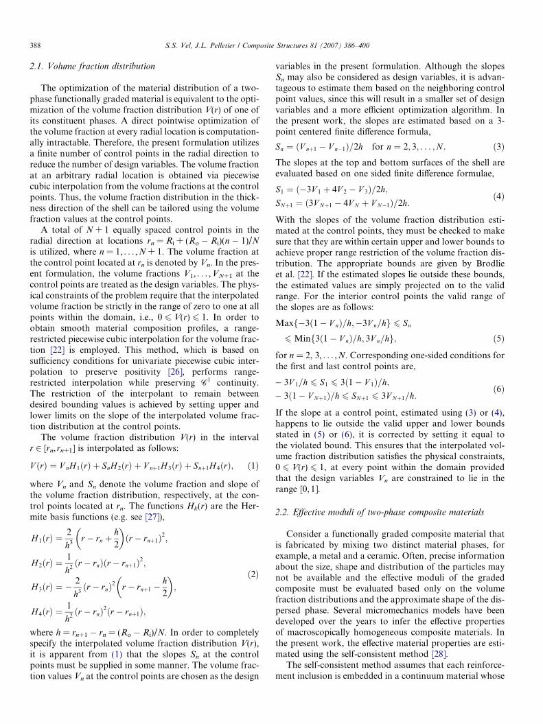
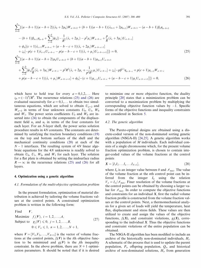
The NSGA-II algorithm has been modified to include anarchive of the historically non-dominated individuals, Ht.A schematic of the process that is used to update the parentpopulation, Pt, offspring population, Qt, and historicalarchive of non-dominated solutions, Ht, from generation
}
}
}
}
}}
}
Pt
Qt
r1r2r3r4
r5
Non-constrain-dominated Sort
CrowdedDistance Sort
Pt+1
Qt+1
Controlled Elist Selection of Parents
Mating Pool viaTournament Selection Children via
Crossover and Mutation
}
Update HistoricalArchive with r1
Controlled NSGA-IIEvolutionarySearch Cycle
Yes
No
Report on Archive&
STOP
Sub-loop to determine termination of
NSGA-II Search Routine
START
InitializeP0 and Q 0
HtHt+1
Determine non-constrain-dominated rank 1 individuals of (Ht U r1)
Rt
Rt+1
Terminate?
Fig. 2. Schematic of the controlled elitist non-dominated sorted multi-objective genetic algorithm with historical archive.
392 S.S. Vel, J.L. Pelletier / Composite Structures 81 (2007) 386–400
t to t + 1 is shown in Fig. 2. Details about each step of themulti-objective genetic algorithm are given below in Sec-tions 4.2.1–4.2.5. The genetic algorithm begins at genera-tion t = 0, with a random set of individuals for P0 andQ0. The process of updating the individuals using NSGA-II from generation t to t + 1 is as follows. The parent pop-ulation, Pt, and offspring population, Qt, each consisting ofM individuals, are combined to form a population, Rt. Theobjective functions and constraint violations of each indi-vidual in Rt are computed and they are non-dominatedsorted and ranked. The archive of non-dominated solu-tions Ht is updated to include the better ranked individuals.Next, a crowded distance sort of the individuals is per-formed within each rank of Rt and a controlled elitist selec-tion process is used to form an updated parent population,Pt+1. Subsequently, an intermediate mating pool isobtained from the parent population, Pt+1, using acrowded tournament selection operation and the offspringpopulation, Qt+1, is generated by crossover and mutation.The process is iterated over several generations and thealgorithm is terminated when it fails to yield significantimprovements to the non-dominated historical archiveHt. Upon termination, the set of non-dominated individu-als Ht are the numerically obtained Pareto-optimal designs.It should be noted that in the present work, the terms indi-vidual and design are used interchangeably.
4.2.1. Non-dominated sorting
The parent population Pt and offspring population Qt
are combined to create Rt = Pt [ Qt where t denotes thegeneration number. The combined population Rt is sortedaccording to non-constrain-dominance and the individualsare ranked. Following the definition by Deb [20], an indi-vidual X(a) 2 Rt is said to constrain-dominate an individualX(b) 2 R t, if any of the following conditions are true:
ð1Þ X ðaÞ and X ðbÞ are feasible;with
ðaÞ X ðaÞ is no worse than X ðbÞ in all objectives;and
ðbÞ X ðaÞ is strictly better than X ðbÞ in at least one objective:
ð2Þ X ðaÞ is feasible while individual X ðbÞ is not:
ð3Þ X ðaÞ and X ðbÞ are both infeasible;but X ðaÞ
has a smaller constraint violation:
ð29ÞHere, the constraint violation CðXÞ of an individual X isdefined to be equal to the sum of the violated constraintfunction values [33],
CðXÞ ¼XB
j¼1
HðgjðXÞÞgjðXÞ; ð30Þ
where H is the Heaviside step function. The concept of con-strain-domination enables us to compare two individuals in
(X)
(X)
Feasible Individual
Infeasible Individual
Maximize
Maximize
r
r
f2
f1
X(1)
X(4)
X(6)
X(7)
X(9)
X(3)X(5)
X(2)X(8)
X(10)
(1)
(2)
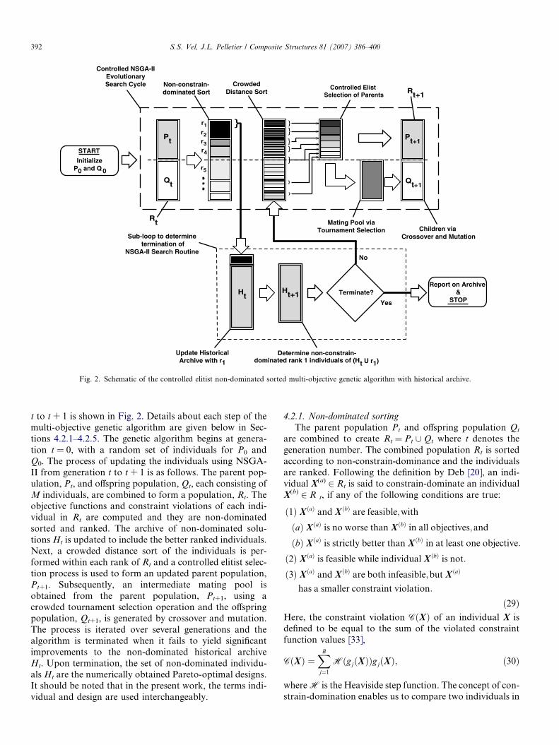
Fig. 3. Depiction of the constrain dominance relations for the simulta-neous maximization of two objective functions.
S.S. Vel, J.L. Pelletier / Composite Structures 81 (2007) 386–400 393
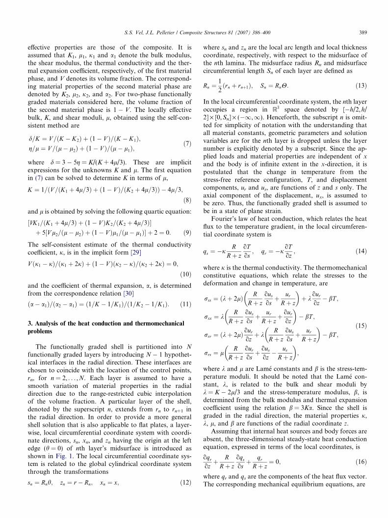
problems that have multiple objectives and constraints,since if X(a) constrain-dominates X(b), then X(a) is betterthan X(b). If none of the three conditions in (29) are true,then X(a) does not constrain-dominate X(b). Perhaps mosteasily visualized in the case of two objective functions,Fig. 3 provides a graphical depiction of the dominance rela-tion where two objectives are to be maximized. Shaded re-gions represent the line of sight of a particular individual.When comparing two feasible individuals X(a) and X(b),X(b) is considered to be dominated by X(a) if X(b) is able tosee X(a). Conversely, feasible individuals that lack any otherfeasible individuals in their line of sight are found to be to benon-dominated. When both solutions are infeasible, theconcept is extended to define constrain-domination basedon the magnitude of constraint violation. In Fig. 3, X(7) isdominated by X(3) and X(8), since X(3) is strictly better thanX(7) in both objectives; and X(8) is equal (no worse) in objec-tive 2, while it is strictly better in objective 1. Although X(5)
and X(10), are within the line of sight of X(7), they are infea-sible and therefore dominated in all cases by feasible indi-viduals. The non-constrain-dominated set consisting ofX(9), X(3), X(8), and X(2), are designated to be of rank 1, de-noted by r(1) = {X(9), X(3), X(8), X(2)}. In order to find therank 2 individuals, the rank 1 individuals are temporarilydiscarded from the population and the non-constrain-dom-inated solutions of the remaining population are found anddesignated as the rank 2 set. In Fig. 3, r(2) = {X(7), X(1), X(4),X(6)}. This procedure is continued until the entire popula-tion is classified into various subpopulations r(q) of rankq. Infeasible solutions are ranked according to the magni-tude of their constraint violation.
4.2.2. Crowding distance
One of the goals of a multi-objective genetic algorithm isto ensure population diversity in the non-dominated set.This is achieved by giving preference to individuals thatare more evenly spaced (i.e., less crowded) in the objectivespace. To this end, the concept of crowding distance isintroduced, wherein each individual of a ranked subpopu-lation is given a crowding distance based on its closeness toadjacent neighbors with equal rank in the objective space.
The crowding distance metric proposed by Deb [20] is uti-lized, where the crowding distance of an individual is theperimeter of the rectangle with its nearest neighbors atdiagonally opposite corners.
4.2.3. Controlled elitism sortOnce individuals of equal rank are sorted in descending
order of crowding distance, a controlled elitism mechanismis used to obtain an updated parent population, Pt+1, fromthe combined population Rt. To preserve diversity, theinfluence of elitism is controlled by choosing the numberof individuals from each subpopulation r(q) according tothe geometric distribution,
Sq ¼ S1� c1� cw
cq�1; ð31Þ
to form a parent search population, Pt+1, of size S, where0 < c < 1. Note that Sq is the number of individuals takenfrom non-dominated subpopulation r(q) with preference gi-ven to those individuals that have a large crowding dis-tance, c is a parameter that governs the shape of thegeometric distribution and w is the total number of rankednon-dominated subpopulations that comprise the parentpopulation. This method has been shown to provide im-proved convergence to the true Pareto-optimal front whencompared to a standard elitist NSGA-II [34].
4.2.4. Tournament selectionNow that the parent population, Pt+1, has been defined,
the next step in the process is the crowded tournamentselection routine, where each individual competes inexactly two tournaments with randomly selected individu-als, a procedure which imitates survival of the fittest in nat-ure. Individual X(a) is said to win a tournament withindividual X(b) if any of the following conditions are true:
ð1Þ X ðaÞ has a smallerði:e:; betterÞ rank than X ðbÞ;
ð2Þ X ðaÞ and X ðbÞ have the same rank; but X ðaÞ
has a larger crowding distance:
ð32Þ
In this manner, an intermediate mating pool is generatedfrom the parent population that has a higher occurrenceof better ranked and less crowded individuals. Inclusionof the crowded distance metric enables the genetic algo-rithm to seek out a well distributed Pareto-optimal front.
4.2.5. Crossover and mutation
Uniform crossover and random uniform mutation areemployed to obtain the offspring population, Qt+1. An inte-ger representation such as that shown in (28) may bedirectly manipulated by these operators. The integer-baseduniform crossover operator takes two distinct parent indi-viduals and interchanges each corresponding design vari-able with a probability, 0 < pc 6 0.5. Following crossover,the mutation operator changes each of the children’s integercoded design variable with a mutation probability, pm, fromits current value to a random integer between 0 and Imax.
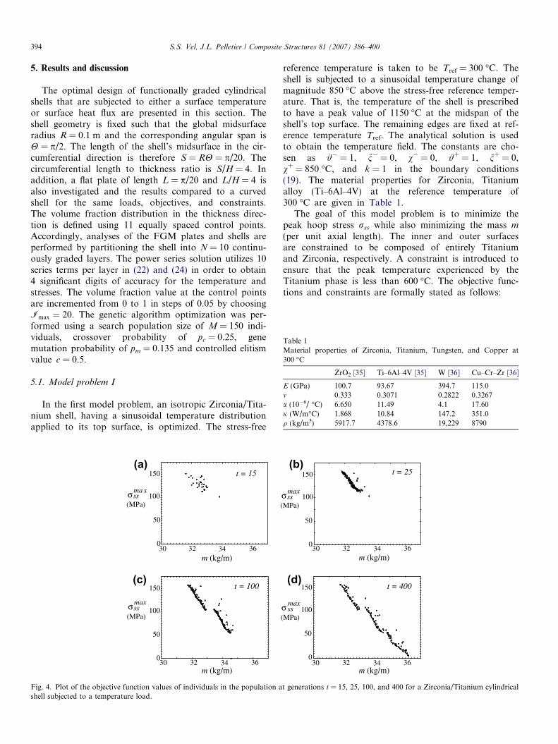
Table 1Material properties of Zirconia, Titanium, Tungsten, and Copper at300 �C
ZrO2 [35] Ti–6Al–4V [35] W [36] Cu–Cr–Zr [36]
E (GPa) 100.7 93.67 394.7 115.0m 0.333 0.3071 0.2822 0.3267a (10�6/ �C) 6.650 11.49 4.1 17.60j (W/m�C) 1.868 10.84 147.2 351.0q (kg/m3) 5917.7 4378.6 19,229 8790
394 S.S. Vel, J.L. Pelletier / Composite Structures 81 (2007) 386–400
5. Results and discussion
The optimal design of functionally graded cylindricalshells that are subjected to either a surface temperatureor surface heat flux are presented in this section. Theshell geometry is fixed such that the global midsurfaceradius R = 0.1 m and the corresponding angular span isH = p/2. The length of the shell’s midsurface in the cir-cumferential direction is therefore S = RH = p/20. Thecircumferential length to thickness ratio is S/H = 4. Inaddition, a flat plate of length L = p/20 and L/H = 4 isalso investigated and the results compared to a curvedshell for the same loads, objectives, and constraints.The volume fraction distribution in the thickness direc-tion is defined using 11 equally spaced control points.Accordingly, analyses of the FGM plates and shells areperformed by partitioning the shell into N = 10 continu-ously graded layers. The power series solution utilizes 10series terms per layer in (22) and (24) in order to obtain4 significant digits of accuracy for the temperature andstresses. The volume fraction value at the control pointsare incremented from 0 to 1 in steps of 0.05 by choosingImax ¼ 20. The genetic algorithm optimization was per-formed using a search population size of M = 150 indi-viduals, crossover probability of pc = 0.25, genemutation probability of pm = 0.135 and controlled elitismvalue c = 0.5.
5.1. Model problem I
In the first model problem, an isotropic Zirconia/Tita-nium shell, having a sinusoidal temperature distributionapplied to its top surface, is optimized. The stress-free
0
50
100
150
σssma x
(MPa)
30 32 34 36m (kg/m)
t = 15
t = 100
0
50
100
150
30 32 34 36m (kg/m)
(
σssmax
(MPa)
(c)
(a)
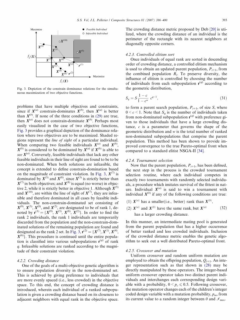
Fig. 4. Plot of the objective function values of individuals in the population ashell subjected to a temperature load.
reference temperature is taken to be Tref = 300 �C. Theshell is subjected to a sinusoidal temperature change ofmagnitude 850 �C above the stress-free reference temper-ature. That is, the temperature of the shell is prescribedto have a peak value of 1150 �C at the midspan of theshell’s top surface. The remaining edges are fixed at ref-erence temperature Tref. The analytical solution is usedto obtain the temperature field. The constants are cho-sen as #� = 1, n� = 0, v� = 0, #+ = 1, n+ = 0,v+ = 850 �C, and k = 1 in the boundary conditions(19). The material properties for Zirconia, Titaniumalloy (Ti–6Al–4V) at the reference temperature of300 �C are given in Table 1.
The goal of this model problem is to minimize thepeak hoop stress rss while also minimizing the mass m
(per unit axial length). The inner and outer surfacesare constrained to be composed of entirely Titaniumand Zirconia, respectively. A constraint is introduced toensure that the peak temperature experienced by theTitanium phase is less than 600 �C. The objective func-tions and constraints are formally stated as follows:
t = 25
t = 400
0
50
100
150
30 32 34 36
0
50
100
150
30 32 34 36
m (kg/m)
m (kg/m)
σssmax
MPa)
σ ssmax
(MPa)
(b)
(d)
t generations t = 15, 25, 100, and 400 for a Zirconia/Titanium cylindrical
S.S. Vel, J.L. Pelletier / Composite Structures 81 (2007) 386–400 395
Find V ;
Minimize f 1ðVÞ ¼ m ¼Z H
0
Z Ro
Ri
ðV ZrO2qZrO2
þ ð1� V ZrO2ÞqTiÞr dr dh;
f 2ðVÞ ¼ rmaxss ¼ max
x2Drss;
Subject to g1ðVÞ ¼ T maxTi � 600 6 0;
V 1 ¼ 0; V Nþ1 ¼ 1;
0 6 V n 6 1; n ¼ 2; . . . ;N ;
ð33Þ
where Vn denotes the volume fraction of Zirconia at thecontrol point located at rn and V ZrO2
is the interpolated va-lue of Zirconia at point in the domain D obtained from (1).
Fig. 4 shows the evolution of the parent population asthe algorithm progresses. The objective function values ofthe parent population, Pt, at t = 15, 25, 100, and 400 gen-erations are depicted in Fig. 4a–d for a curved shell. A total
Shell, R = 0.1mPlate, R 8
0
25
50
75
100
125
150
175
30 31 32 33 34 35 36 37
σssmax
(MPa)
m (kg/m)
A
B C
D E
F
GH
I
J K
L
Fig. 5. Pareto-optimal fronts for the Zirconia/Titanium flat plate andcylindrical shell subjected to a temperature load.
1/2
-1/2
-1/4
1/4
0z/H
0 1.2 .4 .6 .8V
ZrO2
1/2
-1/2
-1/4
1/4
0z/H
0 .2 .4V
1/2
-1/2
-1/4
1/4
0z/H
0 1.2 .4 .6 .8V
ZrO2
1/2
-1/2
-1/4
1/4
0z/H
0 .2 .4V
TTi
= 570.59 Co
= 30.332 kg/m
max
σ = 152.75 MPamax
ss
T
= 30.9
σ = 130max
ss
TTi
= 599.56 Co
= 32.808 kg/mmax
σ = 79.809 MPamax
ss
TTi
= 526. = 33.4
max
σ = 79.3max
ss
Design A De
Design D De
m
m
m m
(a) (b)
(e)(d)
Fig. 6. Volume fraction profiles and performance data for designs A through
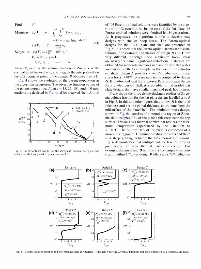
of 103 Pareto-optimal solutions were identified by the algo-rithm in 412 generations. In the case of the flat plate, 96Pareto-optimal solutions were obtained in 434 generations.As it progresses, the algorithm is able to develop newdesigns with smaller hoop stress. The Pareto-optimaldesigns for the FGM plate and shell are presented inFig. 5. It is noted that the Pareto-optimal fronts are discon-tinuous. For example, the masses of design B and C arevery different, although their maximum hoop stressare nearly the same. Significant reductions in stresses areobtained for moderate increases in mass for both flat platesand curved shells. For example, in the case of the cylindri-cal shells, design L provides a 96.76% reduction in hoopstress for a 14.08% increase in mass as compared to designG. It is observed that for a chosen Pareto-optimal designfor a graded curved shell, it is possible to find graded flatplate designs that have smaller mass and peak hoop stress.
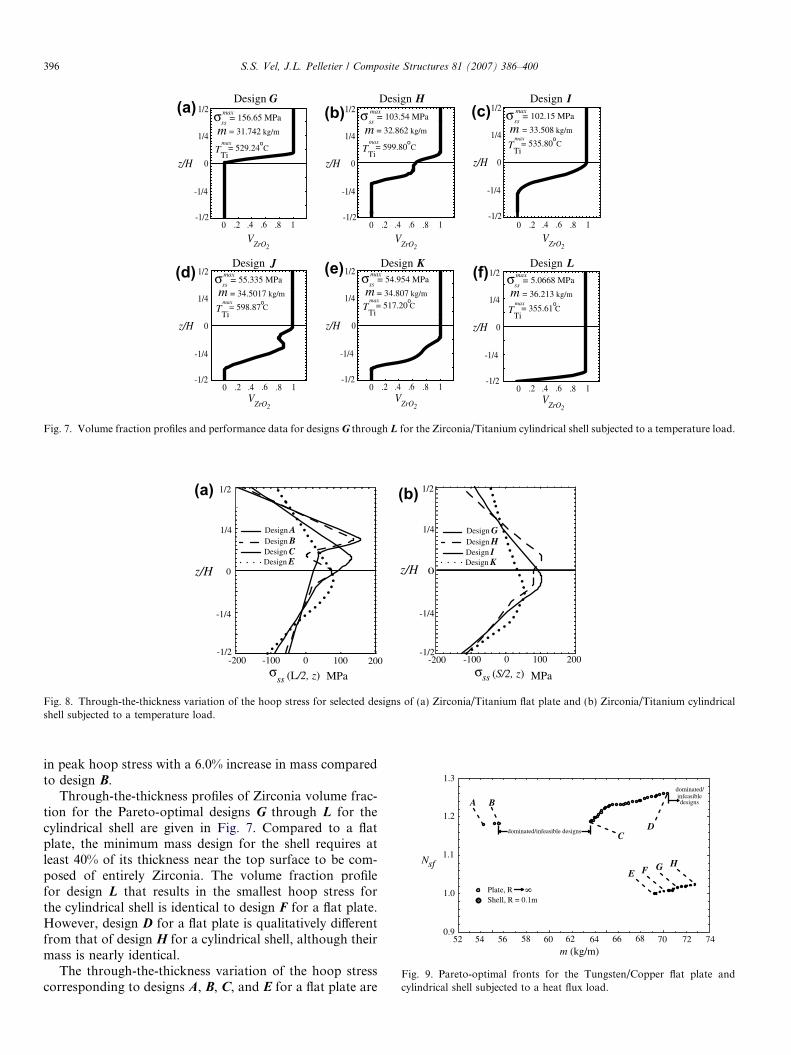
Fig. 6 shows the through-the-thickness profiles of Zirco-nia volume fraction for the flat plate designs labelled A to Fin Fig. 5. In this and other figures that follow, H is the totalthickness and z is the global thickness coordinate from themidsurface of the plate/shell. The minimum mass design,shown in Fig. 6a, consists of a monolithic region of Zirco-nia that occupies 30% of the plate’s thickness near the topsurface. This acts as a thermal barrier that reduces the max-imum temperature experienced by the Titanium to570.6 �C. The bottom 60% of the plate is composed of amonolithic region of Titanium to reduce the mass and thereis a steep grading between the two monolithic regions.Fig. 6 demonstrates that multiple volume fraction profilesgive nearly the same thermal barrier protection. Forexample, designs B and D both satisfy the temperature con-straint within 1 �C, yet design D offers a 38.72% reduction
1.6 .8
ZrO2
1/2
-1/2
-1/4
1/4
0z/H
0 1.2 .4 .6 .8V
ZrO2
1.6 .8
ZrO2
Ti= 599.61 C
o
49 kg/m
max
.25 MPa
TTi
= 531.21 Co
= 31.709 kg/mmax
σ = 130.20 MPamax
ss
71 Co
17 kg/m
99 MPa1/2
-1/2
-1/4
1/4
0z/H
0 1.2 .4 .6 .8V
ZrO2
TTi
= 346.28 Co
= 36.147 kg/mmax
σ = 39.116 MPamax
ss
sign B Design C
sign E Design F
m
m
(c)
(f)
F for the Zirconia/Titanium flat plate subjected to a temperature load.
1/2
-1/2
-1/4
1/4
0z/H
0 1.2 .4 .6 .8
VZrO2
1/2
-1/2
-1/4
1/4
0z/H
0 1.2 .4 .6 .8
VZrO2
1/2
-1/2
-1/4
1/4
0z/H
0 1.2 .4 .6 .8
VZrO2
1/2
-1/2
-1/4
1/4
0z/H
0 1.2 .4 .6 .8V
ZrO2
1/2
-1/2
-1/4
1/4
0z/H
0 1.2 .4 .6 .8V
ZrO2
TTi
= 529.24 Co
= 31.742 kg/mmax
σ = 156.65 MPamax
ss
TTi
= 599.80 Co
= 32.862 kg/mmax
σ = 103.54 MPamax
ss
TTi
= 535.80 Co
= 33.508 kg/mmax
σ = 102.15 MPamax
ss
TTi
= 598.87 Co
= 34.5017 kg/mmax
σ = 55.335 MPamax
ss
TTi
= 355.61 Co
= 36.213 kg/mmax
σ = 5.0668 MPamax
ss
1/2
-1/2
-1/4
1/4
0z/H
0 1.2 .4 .6 .8V
ZrO2
TTi
= 517.20 Co
= 34.807 kg/mmax
σ = 54.954 MPamax
ss
m m m
mmm
Design G Design H Design I
Design J Design K Design L
(a)
(d) (e)
(b) (c)
(f)
Fig. 7. Volume fraction profiles and performance data for designs G through L for the Zirconia/Titanium cylindrical shell subjected to a temperature load.
1/2
-1/2
-1/4
1/4
0z/H
σss (S/2, z) MPa
1000 200-100-200
1/2
-1/2
-1/4
1/4
0z/H
σss (L/2, z) MPa
1000 200-100-200
Design ADesign BDesign CDesign E
Design GDesign HDesign IDesign K
(a) (b)
Fig. 8. Through-the-thickness variation of the hoop stress for selected designs of (a) Zirconia/Titanium flat plate and (b) Zirconia/Titanium cylindricalshell subjected to a temperature load.
0.9
1.0
1.1
1.3
Nsf
52 54 56 58 60 7462 64 66 70 7268
dominated/infeasible designs
dominated/infeasibledesigns
1.2
A
m (kg/m)
B
CD
E F G H
Shell, R = 0.1mPlate, R 8
Fig. 9. Pareto-optimal fronts for the Tungsten/Copper flat plate andcylindrical shell subjected to a heat flux load.
396 S.S. Vel, J.L. Pelletier / Composite Structures 81 (2007) 386–400
in peak hoop stress with a 6.0% increase in mass comparedto design B.
Through-the-thickness profiles of Zirconia volume frac-tion for the Pareto-optimal designs G through L for thecylindrical shell are given in Fig. 7. Compared to a flatplate, the minimum mass design for the shell requires atleast 40% of its thickness near the top surface to be com-posed of entirely Zirconia. The volume fraction profilefor design L that results in the smallest hoop stress forthe cylindrical shell is identical to design F for a flat plate.However, design D for a flat plate is qualitatively differentfrom that of design H for a cylindrical shell, although theirmass is nearly identical.
The through-the-thickness variation of the hoop stresscorresponding to designs A, B, C, and E for a flat plate are
S.S. Vel, J.L. Pelletier / Composite Structures 81 (2007) 386–400 397
shown in Fig. 8a. It shows that the hoop stress rss has a con-tinuous variation and the peak tensile value for designs Band C are essentially the same, although the radial locationswhere the peak hoop stress values occur are different. Theradial variation of the hoop stress corresponding to designsG through L for a cylindrical shell are depicted in Fig. 8b.
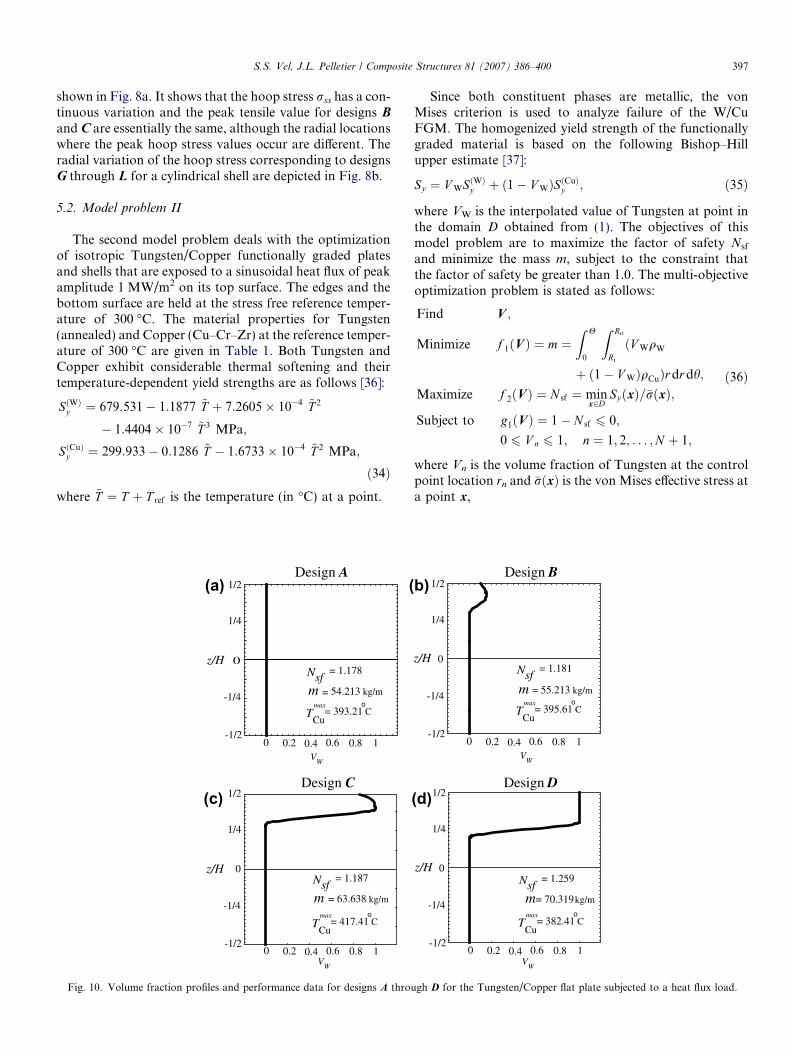
5.2. Model problem II
The second model problem deals with the optimizationof isotropic Tungsten/Copper functionally graded platesand shells that are exposed to a sinusoidal heat flux of peakamplitude 1 MW/m2 on its top surface. The edges and thebottom surface are held at the stress free reference temper-ature of 300 �C. The material properties for Tungsten(annealed) and Copper (Cu–Cr–Zr) at the reference temper-ature of 300 �C are given in Table 1. Both Tungsten andCopper exhibit considerable thermal softening and theirtemperature-dependent yield strengths are as follows [36]:
SðWÞy ¼ 679:531� 1:1877 ~T þ 7:2605� 10�4 ~T 2
� 1:4404� 10�7 ~T 3 MPa;
SðCuÞy ¼ 299:933� 0:1286 ~T � 1:6733� 10�4 ~T 2 MPa;
ð34Þwhere ~T ¼ T þ T ref is the temperature (in �C) at a point.
1/2
-1/2
-1/4
1/4
0z/H
1/2
-1/2
-1/4
1/4
0z/H
TCu
= 393.21 Co
= 54.213 kg/mmax
Nsf= 1.178
TCu
= 417.41 Co
= 63.638 kg/m
max
Nsf= 1.187
0 10.2 0.4 0.6 0.8V
W
0 10.2 0.4 0.6 0.8V
W
m
m
Design A
Design C
(a) (
(c)
Fig. 10. Volume fraction profiles and performance data for designs A throu
Since both constituent phases are metallic, the vonMises criterion is used to analyze failure of the W/CuFGM. The homogenized yield strength of the functionallygraded material is based on the following Bishop–Hillupper estimate [37]:
Sy ¼ V WSðWÞy þ ð1� V WÞSðCuÞy ; ð35Þ
where VW is the interpolated value of Tungsten at point inthe domain D obtained from (1). The objectives of thismodel problem are to maximize the factor of safety Nsf
and minimize the mass m, subject to the constraint thatthe factor of safety be greater than 1.0. The multi-objectiveoptimization problem is stated as follows:
Find V ;
Minimize f 1ðVÞ ¼ m ¼Z H
0
Z Ro
Ri
ðV WqW
þ ð1� V WÞqCuÞr dr dh;
Maximize f 2ðVÞ ¼ N sf ¼ minx2D
SyðxÞ=�rðxÞ;
Subject to g1ðVÞ ¼ 1� N sf 6 0;
0 6 V n 6 1; n ¼ 1; 2; . . . ;N þ 1;
ð36Þ
where Vn is the volume fraction of Tungsten at the controlpoint location rn and �rðxÞ is the von Mises effective stress ata point x,
1/2
-1/2
-1/4
1/4
0z/H
0 10.2 0.4 0.6 0.8V
W
1/2
-1/2
-1/4
1/4
0z/H
TCu
= 395.61 Co
= 55.213 kg/mmax
Nsf= 1.181
TCu
= 382.41 Co
m= 70.319 kg/m
max
Nsf= 1.259
0 10.2 0.4 0.6 0.8V
W
m
Design B
Design D
b)
(d)
gh D for the Tungsten/Copper flat plate subjected to a heat flux load.
TCu
= 445.98 Co
= 69.166 kg/mmax
Nsf= 1.005
TCu
= 448.18 Co
= 69.981 kg/mmax
Nsf= 1.007
TCu
= 451.60 Co
= 71.156 kg/mmax
Nsf= 1.016
TCu
= 402.06 Co
= 72.683 kg/mmax
Nsf= 1.025
0 10.2 0.4 0.6 0.8V
W
0 10.2 0.4 0.6 0.8V
W
0 10.2 0.4 0.6 0.8V
W
0 10.2 0.4 0.6 0.8V
W
Design E Design F
Design G Design H
1/2
-1/2
-1/4
1/4
0z/H
1/2
-1/2
-1/4
1/4
z/H 0
1/2
-1/2
-1/4
1/4
0z/H
1/2
-1/2
-1/4
1/4
z/H 0
m m
mm
(a) (b)
(d)(c)
Fig. 11. Volume fraction profiles and performance data for designs E through H for the Tungsten/Copper cylindrical shell subjected to a heat flux load.
398 S.S. Vel, J.L. Pelletier / Composite Structures 81 (2007) 386–400
�r ¼ffiffiffiffiffiffiffiffiffiffiffiffiffiffi3
2~rij~rji
r; ~r ¼ r� 1
3ðtr rÞI: ð37Þ
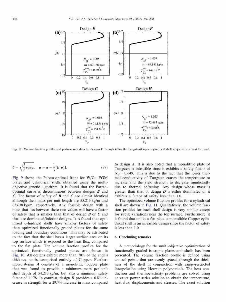
Fig. 9 shows the Pareto-optimal front for W/Cu FGMplates and cylindrical shells obtained using the multi-objective genetic algorithm. It is found that the Pareto-optimal curve is discontinuous between designs B andC. The factor of safety of B and C are almost identicalalthough their mass per unit length are 55.213 kg/m and63.638 kg/m, respectively. Any feasible design with amass that lies between these two values will have a factorof safety that is smaller than that of design B or C andthus are dominated/inferior designs. It is found that opti-mized cylindrical shells have smaller factors of safetythan optimized functionally graded plates for the sameloading and boundary conditions. This may be attributedto the fact that the shell has a larger surface area on itstop surface which is exposed to the heat flux, comparedto the flat plate. The volume fraction profiles for theoptimized functionally graded plates are shown inFig. 10. All designs exhibit more than 70% of the shell’sthickness to be comprised entirely of Copper. Further-more, design A consists of a monolithic Copper platethat was found to provide a minimum mass per unitshell depth of 54.213 kg/m, but also a minimum safetyfactor of 1.178. In contrast, design D provides a 6.8% in-crease in strength for a 29.7% increase in mass compared
to design A. It is also noted that a monolithic plate ofTungsten is infeasible since it exhibits a safety factor ofNsf = 0.649. This is due to the fact that the lower ther-mal conductivity of Tungsten causes the temperature toincrease and the yield strength to decrease significantlydue to thermal softening. Any design whose mass isgreater than that of design D is either dominated or itexhibits a factor of safety less than 1.0.
The optimized volume fraction profiles for a cylindricalshell are shown in Fig. 11. Qualitatively, the volume frac-tion profiles for each shell design is very similar exceptfor subtle variations near the top surface. Furthermore, itis found that unlike a flat plate, a monolithic Copper cylin-drical shell is an infeasible design since the factor of safetyis less than 1.0.
6. Concluding remarks
A methodology for the multi-objective optimization offunctionally graded isotropic plates and shells has beenpresented. The volume fraction profile is defined usingcontrol points that are evenly spaced through the thick-ness of the shell in conjunction with range-restrictedinterpolation using Hermite polynomials. The heat con-duction and thermoelasticity problems are solved usingan exact power series solution to obtain the temperature,heat flux, displacements and stresses. The exact solution
S.S. Vel, J.L. Pelletier / Composite Structures 81 (2007) 386–400 399
is used to evaluate the objective functions and con-straints for candidate designs. The volume fraction val-ues at the control points are chosen as the designvariables for the discretely coded elitist multi-objectivegenetic algorithm.
In the first model problem, functionally graded Zirco-nia/Titanium plates and shells are subjected to a sinusoi-dal temperature load on the top surface. They areoptimized for minimum hoop stress and minimum masssubject to a constraint on the maximum temperatureexperienced by the Titanium phase. It is found that sig-nificant reductions in hoop stress are obtainable, whileonly moderately increasing the mass of the plate or shell.It is also found that the optimized flat plate designsdominate the curved shell designs throughout the objec-tive space. In the second model problem, a set of Par-eto-optimal designs are obtained for Tungsten/Copperisotropic plate and shells subjected to a sinusoidal heatflux on the top surface, while the remaining surfaceswere maintained at the reference temperature. A rangeof volume fraction profiles are presented for a function-ally graded plate with varying degrees of strength andmass, one of which included a pure monolithic Copperplate. The results demonstrate the effectiveness of theproposed methodology for tailoring the volume fractionprofile of functionally graded materials used in high tem-perature and high heat flux applications.
Acknowledgement
The support provided by the U.S. National ScienceFoundation through Grant DMI-0423485 is gratefullyacknowledged.
References
[1] Miyamoto Y, Kaysser WA, Rabin BH, Kawasaki A, Ford RG.Functionally Graded Materials: Design, Processing and Applica-tions. Boston: Kluwer Academic; 1999.
[2] Federici G, Coad JP, Haasz AA, Janeschitz G, Noda N, Phillipps V,et al. Critical plasma-wall interaction issues for plasma-facingmaterials and components in near-term fusion devices. J Nucl Mater2000;283–287:110–9.
[3] Mattas RF, Smith DL, Wu CH, Kuroda T, Shatalov G. Materialsissues in the design of the ITER first wall, blanket, and divertor. JNucl Mater 1992;191–194:139–45.
[4] Vel SS, Batra RC. Exact solution for thermoelastic deformations offunctionally graded thick rectangular plates. AIAA J2002;40:1421–33.
[5] Vel SS, Batra RC. Three-dimensional analysis of transient thermalstresses in functionally graded plates. Int J Solid Struct2003;40:7181–96.
[6] Ching HK, Yen SC. Transient thermoelastic deformations of 2Dfunctionally graded beams under nonuniformly convective heatsupply. Compos Struct 2006;73:381–93.
[7] Ootao Y, Tanigawa Y. Transient thermoelastic problem of function-ally graded thick strip due to nonuniform heat supply. Compos Struct2004;63:139–46.
[8] Zhu H, Sankar BV. Analysis of sandwich TPS panel with functionallygraded foam core by Galerkin method. Compos Struct2007;77(3):280–7.
[9] Tanaka K, Tanaka Y, Enomoto K, Poterasu VF, Sugano Y. Designof thermoelastic materials using direct sensitivity and optimizationmethods: Reduction of thermal stresses in functionally gradientmaterials. Comput Method Appl Mech Eng 1993;106:271–84.
[10] Tanaka K, Watanabe H, Sugano Y, Poterasu VF. A multicriterialtailoring of a hollow cylinder in functionally gradient materials:scheme to global reduction of thermoelastic stresses. Comput MethodAppl Mech Eng 1996;135:369–80.
[11] Ootao Y, Tanigawa Y, Ishimaru O. Optimization of materialcomposition of functionally graded plate for thermal stress relaxationusing a genetic algorithm. J Therm Stresses 2000;23:257–71.
[12] Cho JR, Ha DY. Volume faction optimization for minimizingthermal stress in Ni–Al2O3 functionally graded materials. Mater SciEng A 2002;334:147–55.
[13] Cho JR, Ha DY. Optimal tailoring of 2D volume-fraction distribu-tions for heat-resisting functionally graded materials using FDM.Comput Method Appl Mech Eng 2002;191:3195–211.
[14] Lipton R. Design of functionally graded composite structures inthe presence of stress constraints. Int J Solid Struct 2002;39:2575–2586.
[15] Turteltaub S. Functionally graded materials for prescribed fieldevolution. Comput Method Appl Mech Eng 2002;191:2283–96.
[16] Turteltaub S. Optimal control and optimization of functionallygraded materials for thermomechanical process. Int J Solid Struct2002;39:3175–97.
[17] Cho JR, Choi JH. A yield-criteria tailoring of the volume fraction inmetal–ceramic functionally graded material. Eur J Mech A/Solid2004;23:271–81.
[18] Goupee A, Vel SS. Two-dimensional optimization of materialcomposition of functionally graded materials using meshless analysesand a genetic algorithm. Comput Method Appl Mech Eng2006;195:5926–48.
[19] Pareto V. Manual of political economy. New York: A.M. Kelley;1971.
[20] Deb K. Multi-objective optimization using evolutionary algo-rithms. Chichester: John Wiley and Sons Ltd.; 2001.
[21] Huang J, Fadel GM, Blouin VY, Grujicic M. Bi-objective optimiza-tion design of functionally gradient materials. Mater Design2002;23:657–66.
[22] Brodlie K, Mashwama P, Butt S. Visualization of surface data topreserve positivity and other simple constraints. Comput Graph1995;19:585–94.
[23] Pelletier JL, Vel SS. An exact solution for the steady-state thermo-elastic response of functionally graded orthotropic cylindrical shells.Int J Solid Struct 2006;3:1131–58.
[24] Deb K, Agrawal S, Pratap A, Meyarivan T. A fast and elitist multi-objective genetic algorithm: NSGA-II, Technical Report 200001.Indian Institute of Technology, Kanpur: Kanpur Genetic AlgorithmsLaboratory (KanGAL); 2000.
[25] Deb K, Agrawal S, Pratap A, Meyarivan T. A fast elitist non-dominated sorting genetic algorithm for multi-objective optimization:NSGA-II. In: Proceedings of the parallel problem solving fromNature VI (PPSN-VI); 2000. p. 849–58.
[26] Schmidt JW, Hess W. Positivity of cubic polynomial on intervals andpositive spline interpolation. BIT 1988;28:340–52.
[27] Lancaster P, Salkauskas K. Surfaces generated by moving leastsquares methods. Math Comput 1981;37:141–58.
[28] Hill R. A self-consistent mechanics of composite materials. J MechPhys Solid 1965;13:213–22.
[29] Hashin Z. Assessment of the self consistent scheme approximation:conductivity of composites. J Compos Mater 1968;4:284–300.
[30] Rosen BW, Hashin Z. Effective thermal expansion coefficients andspecific heats of composite materials. Int J Eng Sci 1970;8:157–73.
[31] Nowinski JL. Theory of thermoelasticity with applications. Alphenaan den Rijn, the Netherlands: Sijthoff & Noordhoff InternationalPublishers B.V.; 1978.
[32] Hyer MW, Rousseau CQ. Thermally induced stresses and deforma-tions in angle–ply composite tubes. J Compos Mater 1987;21:454–80.

400 S.S. Vel, J.L. Pelletier / Composite Structures 81 (2007) 386–400
[33] Deb K. An efficient constraint handling method for genetic algo-rithms. Comput Method Appl Mech Eng 2000;186:311–88.
[34] Deb K, Goel T. Controlled elitist non-dominated sorting geneticalgorithms for better convergence. In: Proceedings of the firstinternational conference on evolutionary multi-criterion optimiza-tion. Zurich; 2001. p. 385–99.
[35] Tanigawa Y, Oka N, Akai T, Kawamura R. One-dimensionaltransient thermal stress problem for nonhomogenous hollow circular
cylinder and its optimization of material composition for thermalstress relaxation. Trans Jpn Soc Mech Eng, Ser A1997;40(2):117–27.
[36] ITER Material Properties Handbook, ITER Document No. S 74 RE1; 1997.
[37] Bishop JFW, Hill R. A theory of the plastic distortion of apolycrystalline aggregate under combined stresses. Philos Mag1951;42:414–27.